108SD and 114SD Driver's Manual
212
Introduction This manual provides information needed to operate and understand the vehicle and its components. More detailed information is contained in the Owner’s Warranty Information for North America booklet, and in the vehicle’s workshop and maintenance manuals. Custom-built Freightliner vehicles are equipped with various chassis and cab components. Not all of the information contained in this manual applies to every vehicle. For details about components in your ve- hicle, refer to the chassis specification pages in- cluded in all new vehicles and to the vehicle specifi- cation decal, located inside the vehicle. For your reference, keep this manual in the vehicle at all times. IMPORTANT: Descriptions and specifications in this manual were in effect at the time of printing. For the most up-to-date information visit https:// freightliner.com/ for the latest version of the driver’s and maintenance manuals. Freightliner reserves the right to discontinue models and to change specifications or design at any time without notice and without incurring obligation. Descriptions and specifications con- tained in this publication provide no warranty, expressed or implied, and are subject to revi- sions and editions without notice. Environmental Concerns and Recommendations Whenever you see instructions in this manual to dis- card materials, you should first attempt to reclaim and recycle them. To preserve our environment, fol- low appropriate environmental rules and regulations when disposing of materials. Data Logging This vehicle is equipped with a control module that performs data logging capabilities. This vehicle is equipped with one or more devices that record specific vehicle data and may perform some of the same functionality as a regulated Event Data Recorder but the device(s) are not subject to, nor designed pursuant to, 49 C.F.R. Part 563. The type and amount of data recorded varies de- pending on how the vehicle is equipped (such as the brand of engine, if an air bag is installed, or if the vehicle features a collision avoidance system, etc.). GPS location data, fault codes, and other technical data may be recorded. This data may help provide a better understanding of the circumstances of a crash. Personal data such as name, gender, and age are not recorded. However, other parties such as law enforcement, could combine the data logger’s con- tents with the type of personally identifying data rou- tinely acquired during a crash investigation. Emissions and Fuel Efficiency Compliance This vehicle must be regularly inspected and main- tained as indicated in the 108SD and 114SD Mainte- nance Manual, and in the Pre- and Post-Trip Inspec- tions and Maintenance chapter in this manual, in order to continue satisfactory performance and en- sure coverage of the vehicle under the manufactur- er’s warranty. Many maintenance procedures ensure that the ve- hicle and engine continue to comply with applicable emissions standards. Maintenance procedures, using components engineered to comply with greenhouse gas emissions and fuel efficiency regulations, may be performed by an authorized Daimler Truck North America dealer, an independent outlet, or the vehicle owner or operator. The vehicle owner is responsible for determining the suitability of replacement components to maintain compliance with federal and local jurisdictional regu- lations. Components including, but not limited to, tires, cab/sleeper side extenders, chassis fairings, bumper, hood, vehicle speed limiters, and idle reduc- tion timers are specifically designed and manufac- tured to exacting standards for regulatory fuel effi- ciency and greenhouse gas emissions compliance. It is important that these components are always re- placed with components that meet or exceed the per- formance of the originally installed components. Foreword STI-496-7 (02/03/2022) Part Number STI-496 Printed in U.S.A.
-
Upload
khangminh22 -
Category
Documents
-
view
3 -
download
0
Transcript of 108SD and 114SD Driver's Manual

IntroductionThis manual provides information needed to operateand understand the vehicle and its components.More detailed information is contained in the Owner’sWarranty Information for North America booklet, andin the vehicle’s workshop and maintenance manuals.
Custom-built Freightliner vehicles are equipped withvarious chassis and cab components. Not all of theinformation contained in this manual applies to everyvehicle. For details about components in your ve-hicle, refer to the chassis specification pages in-cluded in all new vehicles and to the vehicle specifi-cation decal, located inside the vehicle.
For your reference, keep this manual in the vehicleat all times.
IMPORTANT: Descriptions and specifications inthis manual were in effect at the time of printing.For the most up-to-date information visit https://freightliner.com/ for the latest version of thedriver’s and maintenance manuals.
Freightliner reserves the right to discontinuemodels and to change specifications or designat any time without notice and without incurringobligation. Descriptions and specifications con-tained in this publication provide no warranty,expressed or implied, and are subject to revi-sions and editions without notice.
Environmental Concerns andRecommendationsWhenever you see instructions in this manual to dis-card materials, you should first attempt to reclaimand recycle them. To preserve our environment, fol-low appropriate environmental rules and regulationswhen disposing of materials.
Data LoggingThis vehicle is equipped with a control module thatperforms data logging capabilities.
This vehicle is equipped with one or more devicesthat record specific vehicle data and may performsome of the same functionality as a regulated EventData Recorder but the device(s) are not subject to,nor designed pursuant to, 49 C.F.R. Part 563.
The type and amount of data recorded varies de-pending on how the vehicle is equipped (such as thebrand of engine, if an air bag is installed, or if thevehicle features a collision avoidance system, etc.).GPS location data, fault codes, and other technicaldata may be recorded.
This data may help provide a better understanding ofthe circumstances of a crash.
Personal data such as name, gender, and age arenot recorded. However, other parties such as lawenforcement, could combine the data logger’s con-tents with the type of personally identifying data rou-tinely acquired during a crash investigation.
Emissions and Fuel EfficiencyComplianceThis vehicle must be regularly inspected and main-tained as indicated in the 108SD and 114SD Mainte-nance Manual, and in the Pre- and Post-Trip Inspec-tions and Maintenance chapter in this manual, inorder to continue satisfactory performance and en-sure coverage of the vehicle under the manufactur-er’s warranty.
Many maintenance procedures ensure that the ve-hicle and engine continue to comply with applicableemissions standards. Maintenance procedures, usingcomponents engineered to comply with greenhousegas emissions and fuel efficiency regulations, may beperformed by an authorized Daimler Truck NorthAmerica dealer, an independent outlet, or the vehicleowner or operator.
The vehicle owner is responsible for determining thesuitability of replacement components to maintaincompliance with federal and local jurisdictional regu-lations. Components including, but not limited to,tires, cab/sleeper side extenders, chassis fairings,bumper, hood, vehicle speed limiters, and idle reduc-tion timers are specifically designed and manufac-tured to exacting standards for regulatory fuel effi-ciency and greenhouse gas emissions compliance. Itis important that these components are always re-placed with components that meet or exceed the per-formance of the originally installed components.
Foreword
STI-496-7 (02/03/2022)Part Number STI-496
Printed in U.S.A.

Customer Assistance CenterHaving trouble finding service? Call the CustomerAssistance Center at 1-800-385-4357 or 1-800-FTL-HELP. For dealer referrals and breakdown support,call night or day, weekdays or weekends. For specifi-cation requests and all other concerns and inquiries,the Customer Assistance Center is available 6:00A.M. to 3:30 P.M. PST Monday through Friday. Ourpeople are knowledgeable, professional, and commit-ted to following through to help you keep your truckmoving.
Reporting Safety DefectsVehicles domiciled in the USA that are thought tohave a defect that could cause a crash, injury, ordeath, should immediately be reported to the Na-tional Highway Traffic Safety Administration(NHTSA) and Daimler Truck North America LLC.
If the NHTSA receives similar complaints, it mayopen an investigation; if it finds that a safety de-fect exists in a group of vehicles, it may order arecall and remedy campaign. However, NHTSAcannot become involved in individual problemsbetween you, your dealer, or Daimler Truck NorthAmerica LLC.
To contact NHTSA, call the Vehicle Safety Hotlinetoll-free at 1-888-327-4236 (TTY: 1-800-424-9153).
To e-mail NHTSA, go to www.safertruck.gov/.
You can contact NHTSA by mail at: Administrator,NHTSA Headquarters, 1200 New Jersey AvenueSE, West Building, Washington, DC 20590.
For more information about motor vehicle safety,go to www.safertruck.gov/.
To contact Freightliner about a concern about aspecific vehicle call the Customer Assistance Cen-ter at 1-800-385-4357 or complete a ProductConcern Form.
Vehicles domiciled in Canada that are thought tohave a defect that could cause a crash, injury, ordeath, should immediately be reported to Trans-port Canada and Daimler Truck North AmericaLLC.
If Transport Canada receives similar complaints, itmay open an investigation; if it finds that a safetydefect exists in a group of vehicles, it may order arecall and remedy campaign. However, TransportCanada cannot become involved in individualproblems between you, your dealer, or DaimlerTruck North America LLC.
To contact Freightliner about a concern about aspecific vehicle call the Customer Assistance Cen-ter at 1-800-385-4357 or complete a ProductConcern Form.
To contact Transport Canada, call the Defect In-vestigations and Recalls Division toll-free inCanada at 1-800-333-0510 or 819-994-3328 in theGatinuau-Ottawa area or internationally.
You can also contact Transport Canada by mail at:Transport Canada, 330 Sparks Street, Ottawa, On-tario, K1A 0N5 Canada.
The following websites contain more informationon Canadian recalls:
English: www.tc.gc.ca/recalls.
French: www.tc.gc.ca/rappels.
For additional road safety information, please visitthe Road Transportation website:
English: www.tc.gc.ca/en/services/road
French: www.tc.gc.ca/fr/services/routier
© 2011-2022 Daimler Truck North America LLC. All rights reserved. Daimler Truck North America LLC is a Daimler
company.
No part of this publication, in whole or part, may be translated, reproduced, stored in a retrieval system, or transmittedin any form by any means, electronic, mechanical, photocopying, recording, or otherwise, without the prior written per-mission of Daimler Truck North America LLC. For additional information, please contact Daimler Truck North AmericaLLC, Service Systems and Documentation, P.O. Box 3849, Portland OR 97208–3849 U.S.A. or refer to https://northamerica.daimlertruck.com/ and https://freightliner.com/.
Foreword
STI-496-7 (02/03/2022)Part Number STI-496
Printed in U.S.A.

ContentsChapter Page
Introduction, Environmental Concerns and Recommendations,Data Logging, Emissions and Fuel Efficiency Compliance,Customer Assistance Center, Reporting Safety Defects . . . . . . . . . . . . . . . . . . . . Foreword
1 Vehicle Identification . . . . . . . . . . . . . . . . . . . . . . . . . . . . . . . . . . . . . . . . . . . . . . . . . . . . . . 1.12 Vehicle Access . . . . . . . . . . . . . . . . . . . . . . . . . . . . . . . . . . . . . . . . . . . . . . . . . . . . . . . . . . 2.13 Electrical System . . . . . . . . . . . . . . . . . . . . . . . . . . . . . . . . . . . . . . . . . . . . . . . . . . . . . . . . 3.14 Instruments . . . . . . . . . . . . . . . . . . . . . . . . . . . . . . . . . . . . . . . . . . . . . . . . . . . . . . . . . . . . . 4.15 Driver Controls . . . . . . . . . . . . . . . . . . . . . . . . . . . . . . . . . . . . . . . . . . . . . . . . . . . . . . . . . . 5.16 Seats and Restraints . . . . . . . . . . . . . . . . . . . . . . . . . . . . . . . . . . . . . . . . . . . . . . . . . . . . . 6.17 Climate Control . . . . . . . . . . . . . . . . . . . . . . . . . . . . . . . . . . . . . . . . . . . . . . . . . . . . . . . . . . 7.18 Cab Features . . . . . . . . . . . . . . . . . . . . . . . . . . . . . . . . . . . . . . . . . . . . . . . . . . . . . . . . . . . 8.19 Engine Starting, Operation, and Shutdown . . . . . . . . . . . . . . . . . . . . . . . . . . . . . . . . . . . . 9.1
10 Optional Engine Systems . . . . . . . . . . . . . . . . . . . . . . . . . . . . . . . . . . . . . . . . . . . . . . . . . 10.111 Emissions and Fuel Efficiency . . . . . . . . . . . . . . . . . . . . . . . . . . . . . . . . . . . . . . . . . . . . . 11.112 Brake Systems . . . . . . . . . . . . . . . . . . . . . . . . . . . . . . . . . . . . . . . . . . . . . . . . . . . . . . . . . 12.113 Manual Transmissions and Clutch . . . . . . . . . . . . . . . . . . . . . . . . . . . . . . . . . . . . . . . . . . 13.114 Automated and Automatic Transmissions . . . . . . . . . . . . . . . . . . . . . . . . . . . . . . . . . . . . 14.115 Drive Axles and Transfer Cases . . . . . . . . . . . . . . . . . . . . . . . . . . . . . . . . . . . . . . . . . . . 15.116 Steering System . . . . . . . . . . . . . . . . . . . . . . . . . . . . . . . . . . . . . . . . . . . . . . . . . . . . . . . . 16.117 Fifth Wheels . . . . . . . . . . . . . . . . . . . . . . . . . . . . . . . . . . . . . . . . . . . . . . . . . . . . . . . . . . . 17.118 Trailer Couplings . . . . . . . . . . . . . . . . . . . . . . . . . . . . . . . . . . . . . . . . . . . . . . . . . . . . . . . . 18.119 Natural Gas Vehicle . . . . . . . . . . . . . . . . . . . . . . . . . . . . . . . . . . . . . . . . . . . . . . . . . . . . . 19.120 Pre- and Post-Trip Checklists . . . . . . . . . . . . . . . . . . . . . . . . . . . . . . . . . . . . . . . . . . . . . 20.121 Pre- and Post-Trip Inspections and Maintenance . . . . . . . . . . . . . . . . . . . . . . . . . . . . . . 21.122 Cab Appearance . . . . . . . . . . . . . . . . . . . . . . . . . . . . . . . . . . . . . . . . . . . . . . . . . . . . . . . . 22.123 Headlight Aiming . . . . . . . . . . . . . . . . . . . . . . . . . . . . . . . . . . . . . . . . . . . . . . . . . . . . . . . . 23.124 In an Emergency . . . . . . . . . . . . . . . . . . . . . . . . . . . . . . . . . . . . . . . . . . . . . . . . . . . . . . . 24.125 Telematics Data . . . . . . . . . . . . . . . . . . . . . . . . . . . . . . . . . . . . . . . . . . . . . . . . . . . . . . . . 25.126 Driver Assistance Features . . . . . . . . . . . . . . . . . . . . . . . . . . . . . . . . . . . . . . . . . . . . . . . 26.1
Index . . . . . . . . . . . . . . . . . . . . . . . . . . . . . . . . . . . . . . . . . . . . . . . . . . . . . . . . . . . . . . . . . . I.1


1
Vehicle IdentificationComponent Information Label . . . . . . . . . . . . . . . . . . . . . . . . . . . . . . . . . . . . . . . . . . . . . . . . . . . . . . . 1.1Component GWR Label . . . . . . . . . . . . . . . . . . . . . . . . . . . . . . . . . . . . . . . . . . . . . . . . . . . . . . . . . . . . 1.1Federal Motor Vehicle Safety Standard Label . . . . . . . . . . . . . . . . . . . . . . . . . . . . . . . . . . . . . . . . . . 1.1Canada Certification Label . . . . . . . . . . . . . . . . . . . . . . . . . . . . . . . . . . . . . . . . . . . . . . . . . . . . . . . . . . 1.1Mexico Labeling . . . . . . . . . . . . . . . . . . . . . . . . . . . . . . . . . . . . . . . . . . . . . . . . . . . . . . . . . . . . . . . . . . 1.2Emission Labels . . . . . . . . . . . . . . . . . . . . . . . . . . . . . . . . . . . . . . . . . . . . . . . . . . . . . . . . . . . . . . . . . . 1.3Customer Assistance Label . . . . . . . . . . . . . . . . . . . . . . . . . . . . . . . . . . . . . . . . . . . . . . . . . . . . . . . . . 1.6

Component Information LabelNOTE: Labels shown in this chapter are ex-amples only. Actual specifications may vary fromvehicle to vehicle.
The component information label lists the vehiclemodel, identification number, and major componentmodels and serial numbers.
For vehicles domiciled in Mexico, this label will be inSpanish as shown in Fig. 1.1. Otherwise it will beprinted in English as shown in Fig. 1.2.
The component information label is located on theunderside of the driver’s sun visor.
Component GWR LabelNOTE: Vehicles manufactured for the Canadianmarket will have a Canadian Certification labelinstead of a component GWR label.
The component GWR label (see Fig. 1.3) providesmaximum GWR ratings for each component. For ve-hicles domiciled in Mexico, this label will be in Span-ish as shown in Fig. 1.4.
The component GWR label is located on the right-hand B-pillar as shown in Fig. 1.5.
Federal Motor Vehicle SafetyStandard LabelTractors with or without fifth wheels manufactured forthe U.S. are marked as certified by means of a fed-eral motor vehicle safety standard (FMVSS) label,which also lists suitable tire and rim combinations.See Fig. 1.6.
For vehicles domiciled in the United States, this labelis attached to the left-hand side B-pillar as shown inFig. 1.7.
For vehicles manufactured for U.S./Canada opera-tion, this label is applied below the door lock andnext to the Canada certification label.
Vehicles domiciled in Mexico are labeled with aSpanish weights and measurement label that listssuitable tire and rim combinations. See Fig. 1.8.
The tire and rim combinations listed on these labelsare those that can be installed on the vehicle for thegiven gross axle weight rating. Tires and rims in-stalled on the vehicle at the time of manufacture mayhave a higher load capacity than that certified by thetire and rim label. If the tires and rims currently onthe vehicle have a lower load capacity than thatshown on the tire and rim label, then the tires andrims determine the load limitations on each of theaxles.
Trucks built without a cargo body that are intendedfor service in the U.S. have an incomplete FMVSSvehicle certification label. This label will be attachedto the incomplete vehicle document included with thevehicle, and certifies that the vehicle conforms to allapplicable FMVSS regulations in effect on the date ofcompletion. The final certification label must be at-tached by the final-stage manufacturer.
Canada Certification LabelComplete tractors with fifth wheels manufactured forCanada or dual Canada/United States operations,are marked with a Canada certification label (seeFig. 1.9) attached to the right-hand B-pillar.
f080196s09/29/2020
USE EL NUMERO DE IDENTIFICACION
DE VEHICULO CUANDO ORDENE PARTES.FABRICADO POR: DAIMLER VEHICULOS COMERCIALES MEXICO
MODELO: MM106064S MODELO BASE: M2106 FECHA DE FABRIC: 06/20
NO. DE SERIE VEH: 3ALHCYD28MDMN5409 DIST. ENTRE EJE: 230
MOTOR:
TRANS PRINCIPAL:
EJE DELANTERO:
EJE INT. 2DO:
EJE INT. 3RO:
EJE INT. 4TO:
EJE INT. 5TO:
EJE INT. 6TO:
EJE TRASERO:
PROVEEDOR
NO. DE PINTURA:
EJE INT. 1RO:
CLIENTE: V83361
DD8 7.7L 6 CYL SINGLE STAGE 280 HP / 220
ALLISON 3000 RDS AUTOMATICTRANSMISSION
DETROIT DA-F-12.0-3 12,000# FF1 71.5 KPI
MT-40-14X 40,000# R-SERIES TANDEM REAR A
MT-40-14X 40,000# R-SERIES TANDEM REAR A
ELITE EY PAINT C
MOTOR:TRANSMISION:
EJE DELANTERO:
EJE INT. 1RO:
EJE INT. 2DO:
EJE INT. 3RO:
EJE INT. 4TO:
EJE INT. 5TO:
EJE INT. 6TO:
EJE TRASERO:
RELACION:
PARA INFORMACION COMPLETA DE
PINTURA, VER HOJA DE
CAB COLOR A: L0006EY
936913S0010863
6511714361
739912B0165864
DRA21199653
DRA21199652
6.14
INFORMACION DE COMPONENTES
DE PINTURA:
ESPECIFICACIONES DE L VEHICULO.
PTO: PTO:
Fig. 1.1, Component Information Label (Spanish)
f08019606/21/2016
MANUFACTURED BY: DAIMLER TRUCKS NORTH AMERICA LLC
COMPONENT INFORMATIONSEE VEHICLE ID NO.WHEN ORDERING PARTS
PX113064S T BASE MODEL: CA113DC DATE OF MFR: 07/15MODEL:
1FUJGBDV4GLZZ9999 WHEELBASE: 164CUSTOMER: N00000VEHICLE ID NO:
ENGINE MOD:
MAIN TRANS MOD:
FRONT AXLE MOD:
2ND INT AXLE MOD:
3RD INT AXLE MOD:
4TH INT AXLE MOD:
5TH INT AXLE MOD:
6TH INT AXLE MOD:
REAR AXLE MOD:
PAINT CODE:
1ST INT AXLE MOD:
PAINT MFR:
PTO. MOD:
DETROIT DD13 12.8L 410 HP / 1800 RPM, 20
DT12-DB-1450 HEAVY DUTY 12-SPEED DIRECT
MFS-12-143A 12,000# FF1 SINGLE FRONT AXL
MT-40-14X 40,000# R-SERIES DUALTRAC 74-7
MT-40-14X 40,000# R-SERIES DUALTRAC 74-7
ELITE BC PAINT CCAB COLOR A: L0306EB
ENGINE NO:
TRANS NO:
FRONT AXLE NO:
1ST INT AXLE NO:
2ND INT AXLE NO:
3RD INT AXLE NO:
4TH INT AXLE NO:
5TH INT AXLE NO:
6TH INT AXLE NO:
REAR AXLE NO:
RATIO:
999999S9999999
99999999999999
MON99999999
FOR99999999
FOR99999999
2.47
PTO. NO:
FOR COMPLETE PAINT INFORMATIONSEE VEHICLE SPECIFICATION SHEET.
Fig. 1.2, Component Information Label (English)
Vehicle Identification
1.1

NOTE: Vehicles manufactured for Canada willhave a Canada certification label instead of acomponent GWR label.
Trucks built without a cargo body and tractors builtwithout a fifth wheel that are intended for service inCanada will have an incomplete Canada certificationlabel attached to the left-hand B-pillar. After comple-tion of the vehicle, a complete Canada certificationlabel must be attached by the final-stage manufac-turer to certify that the vehicle conforms to all appli-cable vehicle safety regulations in effect on the dateof completion.
NOTE: Older vehicles may be marked with aCanada National Safety Mark label.
Mexico LabelingMexico Certification LabelThe Mexico certification label states that the vehiclecomplies with the Normas Oficiales Mexicanas(NOMs) standards in effect on the date the vehiclewas manufactured. See Fig. 1.10.
Vehicles domiciled in Mexico will have a Mexico cer-tification label applied to the right-hand B-pillar asshow in Fig. 1.5.
f08020006/21/2016
MA
XIM
UM
GW
R B
Y
CO
MP
ON
EN
T(K
G)L
BS COMPONENT
AXLES:
SUSPENSION:
TIRES:
RIMS:
HUBS/SPOKES:
BRAKES:
STEERING:
FRONT AXLE 2ND INT AXLE 3RD INT AXLE 4TH INT AXLE 5TH INT AXLE 6TH INT AXLE REAR AXLE COMPONENT GVWR
( 5443) 12000 ( 9072) 20000 ( 9072) 20000 CHASSIS:
ENG/TRANS:
5TH WHEEL:
PARK BRAKE:
AXLE:
VIN: 1FUJGBDV4GLZZ9999
1ST INT AXLE
( 5443) 12000
( 5601) 12350
( 6713) 14800
( 6032) 13300
( 6032) 13300
( 6032) 13300
( 9072) 20000
( 9253) 20400
(11612) 25600
(10432) 23000
( 9072) 20000
( 9072) 20000
( 9253) 20400
(11612) 25600
(10432) 23000
( 9072) 20000
Fig. 1.3, Component GWR Label (English)
f080200s09/29/2020
PE
SO
MA
XIM
O
PO
R C
OM
PO
NE
NT
E
(KG
)LB
COMPONENTE
EJE:
SUSPENSION:
NEUMATICOS:
RIM/AROS:
CUBOS/RADIOS:
FRENOS:
DIRECCION:
DELANTERO PRIMERO 2DO 3RO 4TO 5TO 6TO EJE TRASERO PESO BRUTO DEL COMPONENTE
( 5443) 12000 ( 9072) 20000 ( 9072) 20000 LARGUERO:
MOTOR/TRANS:
QUINTA RUEDA:
FRENO ESTAC:
EJE:
VIN:
(36288) 80000
3ALHCYD28MDMN5409
1RO
( 5443) 12000
( 5996) 13220
( 6713) 14800
( 6032) 13300
( 5443) 12000
( 6032) 13300
( 9072) 20000
(10596) 23360
(13426) 29600
(11793) 26000
( 9525) 21000
( 9072) 20000
(10596) 23360
(13426) 29600
(11793) 26000
( 9525) 21000
Fig. 1.4, Component GWR Label (Spanish)
f080186a06/12/2020
1
2
3
1. Component GWR Label (United States and Mexico)2. Mexico Certification Label (Mexico)3. Entry/Exit Warning Label
Fig. 1.5, Right-Hand Door Frame Labels
Vehicle Identification
1.2

Spanish Weights and Measures LabelVehicles with a Mexico certification label will alsohave a Spanish weights and measures label. SeeFig. 1.8 for an example.
Emission LabelsAftertreatment System IndicatorsLabelModel year 2007 and later diesel engines in vehiclesdomiciled in the U.S. or Canada are required to meetall EPA exhaust gas emission regulations effective asper the applicable emission model year, and areequipped with an emission aftertreatment system(ATS).
Vehicles domiciled outside of the U.S. and Canadamay not have aftertreatment equipment, dependingupon local statutory emissions guidelines.
See Table 1.1 and Table 1.2 at the end of this chap-ter for additional information on what EPA and GHGregulations apply to different model years.
See Fig. 1.12 for information on the driver’s visorwarning label for important warning indicators in theinstrument cluster that pertain to the ATS.
It is a violation of U.S. federal law to alter exhaustplumbing, ATS, or other components in any way thatwould bring the engine/vehicle out of compliance withcertification requirements [Ref: 42 U.S.C. S7522(a)(3)]. It is the owner’s responsibility to maintain thevehicle so that it conforms to EPA regulations.
Vehicle Emission Control InformationLabelModel year 2013 and later vehicles meet require-ments as specified by GHG14, GHG17 and GHG21regulations, respectively. These vehicles areequipped with components that increase fuel effi-ciency and reduce greenhouse gas (GHG) emis-sions. Components may include, but are not limitedto, low-rolling resistance tires; aerodynamic devicessuch as hood, cab side extenders, and fuel tank fair-ings; vehicle speed limiters; and idle shutdown tim-ers.
f08019908/31/2020
DAIMLER TRUCKS LLCN.A.07/15
52,00023,587 110
120
120
SS
S
MANUFACTURED BY:DATE OF MFR:
GVWR PNBV LBS/ - :GVWR PNBV KG/ - :
THIS VEHICLE COMPLIES WITH ALLAPPLICABLE FEDERAL MOTOR VEHICLESAFETY STANDARDS IN EFFECT AT THE DATEOF MANUFACTURE SHOWN ABOVE.VEHICLE ID NO:
TYPE TRUCK TRACTOR TT CT: / /
1 4 9999FUJGBDV GLZZ
COUNTRY OF ORIGIN: U.S.A.
PSI "S"COLD
12,00020,000
20,000
LBSGAWR PNBE/
9,072
KGSGAWR PNBE/
5,4439,072
FRONT AXLE:
2 :ND INT AXLE
3 :RD INT AXLE
4 :TH INT AXLE
5 :TH INT AXLE
6 :TH INT AXLEREAR AXLE:
1 :ST INT AXLE275/80R22.5(G)445/50R22.5(L)
445/50R22.5(L)
TIRES
22.5X8.2522.5X14.0
22.5X14.0
RIMSCOLDKPA
758827
827
Fig. 1.6, FMVSS Certification Label (complete vehicle)
f08018604/08/2020
1
2
3
4
1. Customer Assistance Label2. FMVSS Certification Label3. Noise Emission Label4. Entry/Exit Warning Label
Fig. 1.7, Left-Hand B-Pillar Labels, United States
Vehicle Identification
1.3

A vehicle emission control information label is locatedon the left-hand door. See Fig. 1.11. Among otherGHG relevant information the label indicates theemission model year of the vehicle. As this label isabout meeting United States federal requirements, itis printed in English.
It is the owner’s responsibility to maintain the vehicleso that it conforms to U.S. EPA and NHTSAregulations.
Noise Emission Control LabelsFor vehicles manufactured for operation in the UnitedStates, an English language EPA noise emissioncontrol label is applied to attest that the vehicle con-forms to United States EPA regulations for noise.See Fig. 1.14.
For vehicles manufactured for operation in Mexico, aSpanish language Normas Oficiales Mexicanas(NOM) vehicle noise emission control label attestingthat the vehicle conforms to Mexican NOM regula-tions for noise is applied. See Fig. 1.15.
f080199s09/29/2020
FABRICADO POR:
FECHA DE FABRICACION:
PBV (GVWR)-LBS:
PBV (GVWR)-KG:
NO. SERIE VEHICULO:
CHASIS-CABINA
DAIMLER VEHICULOS COMERCIALES MEXICO
06/20
52,000
23,587
3ALHCYD28MDMN5409
EJE DELANTERO:
2DO:
3RO:
4TO:
5TO:
6TO:
EJE TRASERO:
PV-KGS PV-LBS NEUMATICOS RIM/AROS KPA PSI
5,443 12,000 11R22.5(H) 22.5X8.25 827 120 S
9,072
9,072
20,000
20,000
"S"ENCILLA/
1RO: 11R22.5(G)
11R22.5(G)
22.5X8.25 724
724
105
105
D
D
FRIO
22.5X8.25
FRIO "D"OBLE
FABRIC. DE MEX.
Fig. 1.8, Spanish Weights and Measures Label
f080218a08/31/2020
CANADA CERTIFICATIONVIN/NIV: DATE OF MFR: 01/20XXXXXXXXXXXXXXXXX
THIS VEHICLE CONFORMS TO ALL APPLICABLE STANDARDS PRESCRIBED UNDER THE CANADIAN MOTOR VEHICLE SAFETY REGULATIONS IN
EFFECT ON THE DATE OF MANUFACTURE / CE VEHICULE EST CONFORME A TOUTES LES NORMES QUI LUI SONT APPLICABLES EN VERTU DU
REGLEMENT SUR LA SECURITE DES VEHICULES AUTOMOBILES DU CANADA EN VIGUEUR A LA DATE DE SA FABRICATION.
Fig. 1.9, Canada Certification Label
f080228s09/29/2020
INFORMACION CONTROL DE ESPECIFICACIONES DE SEGURIDAD DEL VEHICULO
DAIMLER VEHICULOS COMERCIALES MEXICO S. DE R.L. DE C.V. 06/20
ESTE VEHICULO CUMPLE CON LA NORMA OFICIAL MEXICANA: NOM-068-SCT-2-2014 AL MOMENTO DE SER ENAJENADO.
FECHA DE FABRICACION:
Fig. 1.10, Mexico Certification Label
f08022204/08/2020
1
1. Vehicle Emission Control Information Label
Fig. 1.11, Left-Hand Door Label
Vehicle Identification
1.4

For vehicles manufactured for dual Mexico/UnitedStates operation, both labels are applied.
It is the owner’s responsibility to maintain the vehicleso it conforms to all applicable regulations (EPA,NOM).
IMPORTANT: Certain Freightliner incompletevehicles may be produced for the United Statesmarket with incomplete noise control hardware.
Such vehicles will have an incomplete vehiclenoise emission control information label. SeeFig. 1.16. For such vehicles, it is the final-stagemanufacturer’s responsibility to complete thevehicle in conformity to the applicable regula-tions and label it for compliance.
f08023410/23/2020
Fig. 1.12, ATS Indicators, EPA10 and Newer
f08019806/21/2016
VEHICLE EMISSION CONTROL INFORMATIONManufactured By: DAIMLER TRUCKS NORTH AMERICA LLC Date of Manufacture: 07/15VIN/NIV:
GVWR-PNBV-KG:GVWR-PNBV-LBS:
GDTN2TRAC13C23,58752,000
VEH FAMILY CD:1FUJGBDV4GLZZ9999
EMISSION CONTROL IDENTIFIERS:
REGULATORY CLASS: High-roof day cab tractors above 33,000
LRRA, ARF, TGR
THIS VEHICLE COMPLIES WITH U.S. EPA AND CALIFORNIA REGULATIONS FOR 2016
pounds GVWR.
HEAVY DUTY VEHICLES. See owner's manual for proper maintenance of this vehicle.
1. Vehicle Emission Control Information Label
Fig. 1.13, Vehicle Emission Control Information Label
f08019706/21/2016
VEHICLE NOISE EMISSION CONTROL INFORMATIONDAIMLER TRUCKS NORTH AMERICA LLC DATE OF MANUFACTURE: 07/15
THIS COMPLETE VEHICLE CONFORMS TO U.S. EPA REGULATIONS FOR NOISE EMISSIONSAPPLICABLE TO MEDIUM AND HEAVY TRUCKS. THE FOLLOWING ACTS, OR THE CAUSINGTHEREOF BY ANY PERSON ARE PROHIBITED BY THE NOISE CONTROL ACT OF 1972.A. THE REMOVAL OR RENDERING INOPERABLE OF, OTHER THAN FOR PURPOSES OF
MAINTENANCE, REPAIR OR REPLACEMENT OF ANY NOISE CONTROL DEVICE ORELEMENT OF DESIGN (LISTED IN THE OWNER'S MANUAL) INCORPORATED INTO THIS
VEHICLE IN COMPLIANCE WITH THE NOISE CONTROL ACT.B. THE USE OF THIS VEHICLE AFTER SUCH DEVICE OR ELEMENT OF DESIGN HAS BEEN
REMOVED OR RENDERED INOPERABLE.
Fig. 1.14, EPA Vehicle Noise Emission Control Label(complete vehicle)
Vehicle Identification
1.5

Certified Clean Idle LabelThe California Air Resources Board (CARB) requiresmodel year 2008 and newer heavy-duty diesel en-gines to meet CARB’s Heavy-Duty Diesel EngineIdling Requirement in order to limit emissions of par-ticulate matter and NOx.
Certified vehicles are equipped with a label placednear the bottom edge of the left-hand door. SeeFig. 1.17.
Customer Assistance LabelThe customer assistance center telephone number isprinted on the customer assistance label. The labelalso includes a QR code encoded with the VIN, read-able by dealer apps, to bring up information aboutthe vehicle.
For vehicles domiciled in Mexico this label will be inSpanish as shown in Fig. 1.18. For vehicles domi-ciled in the United States it will printed in English asshown in Fig. 1.19.
The customer assistance label is located on the left-hand B-pillar, as shown in Fig. 1.7.
EPA RegulationsRegulation Emissions Components
EPA07 (Reduction of nitrogenoxides (NOx) emissions to 1.1g/bhp-hr, and particulate matteremissions to 0.01 g/bhp-hr)
Aftertreatment device (ATD) containing a diesel particulate filter that traps soot andash.*
f080197s09/29/2020
INFORMACION CONTROL DE EMISION DE RUIDO DEL VEHICULODAIMLER VEHICULOS COMERCIALES MEXICO FECHA DE FABRICACION:
ESTE VEHICULO CUMPLE CON LA NORMA OFICIAL MEXICANA: NOM-079-ECOL-1994 QUEESTABLIECE LIMITES MAXIMOS PERMISIBLES DE LA EMISION DE RUIDO DE LOS VEHICULOSAUTOMTORES NUEVOS EN PLANTA Y SU METODO DE MEDICION PUBLICADA EN EL D.O.F. DEL12 DE ENERO DE 1995.
06/20
Fig. 1.15, NOM Vehicle Noise Emission Control Label(complete vehicle)
f080201a10/17/2016
VEHICLE NOISE EMISSION CONTROL INFORMATIONDAIMLER TRUCKS NORTH AMERICA LLC DATE OF MANUFACTURE: 01/16
THIS INCOMPLETE VEHICLE AS DELIVERED BY DAIMLER TRUCKS NORTH AMERICA LLCCONFORMS TO U.S. EPA REGULATIONS FOR NOISE EMISSIONS APPLICABLE TO MEDIUMAND HEAVY TRUCKS. IT IS THE RESPONSIBILITY OF THE FINAL STAGE MANUFACTURERTO COMPLETE THIS VEHICLE WHILE MAINTAINING CONFORMANCE TO 40 CFR PART 205,INCLUDING LABELING FOR COMPLIANCE (SEC. 205.55-41).
Fig. 1.16, EPA Vehicle Noise Emission Control Label(incomplete vehicle)
CERTIFIEDCLEAN IDLE
02/20/2012 f080179
Fig. 1.17, CARB Clean Idle Label
f080207s09/29/2020
CENTRO DE ASISTENCIA
AL CLIENTE LLAMA COSTO AL
01-800-590-2000
24 HRS/DIA
7 DIAS/SEMANA
Fig. 1.18, Customer Assistance Label, Spanish
f08020709/28/2020
FOR CUSTOMER
ASSISTANCE CENTER:
1-800-FTL-HELP
1-800-385-4357
24 HRS/DAY
7 DAYS/WEEK
Fig. 1.19, Customer Assistance Label, English
Vehicle Identification
1.6

EPA RegulationsRegulation Emissions Components
EPA10 (Reduction of NOxemissions to 0.2 g/bhp-hr)
EPA07-type ATD, with additional selective catalyst reduction (SCR) technology thatutilizes diesel exhaust fluid (DEF) to convert NOx to nitrogen and water vapor.
GHG14 (Reduction of greenhousegas emissions)
Fuel efficiency components including, but not limited to, engines, tires, aerodynamiccomponents, vehicle speed limiters, and idle reduction timers specifically designed tomeet regulatory fuel efficiency and greenhouse gas emissions standards.
GHG17Fuel efficiency components including, but not limited to, engines, tires, aerodynamiccomponents, vehicle speed limiters, and idle reduction timers specifically designed tomeet regulatory fuel efficiency and greenhouse gas emissions standards.
GHG21GHG14/17 components plus additional components including, but not limited to,transmissions, axles, predictive technologies, idle reduction technologies forvocational vehicles, and tire pressure monitoring systems.
* Cummins and Detroit ATD’s are also equipped with a diesel oxidation catalyst to break down pollutants.
Table 1.1, EPA Regulations
Emission Regulations by Model YearModel Year Engine Regulation Vehicle Regulation2007–2009 EPA07 N/A2010–2012 EPA10 N/A2013–2015 EPA10, GHG14 GHG14
2016 EPA10, GHG17 GHG142017–2020 EPA10, GHG17 GHG17
2021–and later EPA10, GHG21 GHG21
Table 1.2, Emission Regulations by Model Year
Vehicle Identification
1.7

2
Vehicle AccessDoor Locks and Handles . . . . . . . . . . . . . . . . . . . . . . . . . . . . . . . . . . . . . . . . . . . . . . . . . . . . . . . . . . . 2.1Cab Entry and Exit . . . . . . . . . . . . . . . . . . . . . . . . . . . . . . . . . . . . . . . . . . . . . . . . . . . . . . . . . . . . . . . . 2.1Back-of-Cab Access . . . . . . . . . . . . . . . . . . . . . . . . . . . . . . . . . . . . . . . . . . . . . . . . . . . . . . . . . . . . . . . 2.3Hood Opening and Closing . . . . . . . . . . . . . . . . . . . . . . . . . . . . . . . . . . . . . . . . . . . . . . . . . . . . . . . . . 2.4

Door Locks and HandlesOne key operates the ignition switch and all of thedoor locks.
IMPORTANT: Each key is numbered. Recordthe number so a duplicate key can be made, ifneeded.
To unlock the driver’s door from outside the cab, in-sert the key in the lockset and turn it one-quarter turnclockwise (Fig. 2.1). To remove the key, turn it coun-terclockwise to its original position. Pull out on thedoor pull handle to open the door.
To unlock the passenger’s door from outside the cab,insert the key in the lockset and turn it one-quarterturn counterclockwise. Turn the key clockwise to theoriginal position to remove it.
To open the door from the inside, lift up on the doorlever. This will unlatch the door whether or not it islocked. See Fig. 2.2.
NOTE: The cab door locks can be operatedwhen the doors are open.
To lock a door from outside the cab, insert the key inthe lockset and turn it in the direction opposite to theunlocking direction (counterclockwise for the driver’sdoor, clockwise for the passenger’s door). Close thedoor if it is open.
To lock either door from inside the cab, push the lockbutton downwards (Fig. 2.3). To unlock the doorwithout unlatching it, push the lock button upwards. Ared dot will show below the lock button when it isunlocked.
Cab Entry and ExitFor ease of entry and exit, there are three grabhandles, one on the A-pillar, one on the inner B-pillar,and an optional one on the inside of the door. In ad-dition, the steering wheel may be used to provide
f72039702/02/2017
1
2
3
1. Key2. Lock
3. Door Pull Handle
Fig. 2.1, Exterior Door Handle
10/25/2001 f720398
1 2
3 4
5
To open the door from the inside, lift up on the door lever(arrow).
1. Lock Button2. Armrest/Handle3. Door Lever
4. Window Crank5. Inner Door Grab
Handle (optional)
Fig. 2.2, Door Interior
10/24/2001 f720401
1
2
3
Move the button down to lock, and up to unlock (arrows).The door is unlocked when the red dot shows.
1. Door2. Lock Button
3. Red Dot
Fig. 2.3, Door Lock Button
Vehicle Access
2.1

secure handholds. There are at least two accesssteps to provide secure footholds.
NOTE: The A-pillar grab handle is not installedon the driver’s side.
The grab handles, access steps, and steering wheelare all part of the cab access system. Use these"helping hands" when getting into, or out of, the cab.They will increase your security and comfort.
Entering from the Driver’s SideTo enter the cab on the driver’s side, use the grabhandles and access steps as follows:
1. Open the driver-side door and place anythingthat you are carrying in the cab.
2. Grasp the B-pillar grab handle with your righthand. See Fig. 2.4.
3. Grasp the door grab handle with your left hand.
4. Place your right foot on the bottom step, and pullyourself up.
5. Place your left foot on the top step.
6. Grasp the steering wheel with your left hand, andstep up.
7. Step into the cab with your right foot first, andgrasp the steering wheel with your right hand.
Exiting from the Driver’s SideTo exit the cab from the driver’s side, use the grabhandles and access steps as follows:
IMPORTANT: Do not attempt to exit the cabwhile carrying any items in your hands.
1. If you wish to take any items with you out of thecab, place them in an accessible location on theseat or cab floor. Make sure they will not get inyour way as you exit.
WARNINGAlways face in when exiting the cab. Do not at-tempt to exit with your back to the cab, as youwould going down a flight of stairs. It is easier toslip or lose your balance. If you slip when exitingin this way, there is a greater likelihood of per-sonal injury.
2. Grasp the steering wheel with both hands, placeyour left foot on the top step, then stand on thethreshold facing into the cab. See Fig. 2.4.
3. Using your right hand, grasp the B-pillar grabhandle.
4. Move your right foot to the bottom step.
5. Move your left hand to the door grab handle.
6. Step to the ground with your left foot first.
7. Retrieve from the cab any items that you wish totake with you.
Entering from the Passenger’s SideTo enter the cab on the passenger side, use the grabhandles and access steps as follows:
1. Open the passenger-side door and place any-thing that you are carrying in the cab.
2. Using your left hand, grasp the B-pillar grabhandle. See Fig. 2.5.
12/20/2010 f720726
1
2
3
4
5
6
7
1. Bottom Step2. Top Step3. Door Grab Handle4. Armrest
5. Steering Wheel6. Sidewall Grab Handle7. B-Pillar Grab Handle
Fig. 2.4, Cab Access System, Driver’s Side
Vehicle Access
2.2

3. Using your right hand, grasp the door grabhandle.
4. Place your left foot on the bottom step.
5. Place your right foot on the top step.
6. Move your right hand to the A-pillar grab handle.
7. Place your left foot on the top step, then moveyour left hand to the A-pillar grab handle.
8. Step into the cab with your left foot first.
Exiting from the Passenger’s SideTo exit the cab from the passenger side, use thegrab handles and access steps as follows:
IMPORTANT: Do not attempt to exit the cabwhile carrying any items in your hands.
1. If you wish to take any items with you out of thecab, place them in an accessible location on theseat or cab floor. Make sure they will not get inyour way as you exit.
WARNINGAlways face in when exiting the cab. Do not at-tempt to exit with your back to the cab, as youwould going down a flight of stairs. It is easier toslip or lose your balance. If you slip when exitingin this way, there is a greater likelihood of per-sonal injury.
2. Grasp the A-pillar grab handle with both hands,then place your right foot on the top step whilestanding up from the seat facing inward. SeeFig. 2.5.
3. Place your left foot on the top step.
4. Move your left hand to the B-pillar grab handle.
5. Move your left foot to the bottom step.
6. Move your right hand to the door grab handle.
7. Step to the ground with your right foot first.
8. Retrieve from the cab any items that you wish totake with you.
Back-of-Cab Access
WARNINGExternal surfaces of the exhaust system remainhot after the engine has been shut down. Whenaccessing the back of the cab or sleeper, do nottouch any part of the exhaust system, or severeburns could occur.
When trailer air and electrical connections cannot bereached conveniently from the ground, Federal MotorCarrier Safety Regulations require commercial carri-ers to provide back-of-cab access.
Optional grab handles are mounted on each cabsidewall, or on the left sidewall only. See Fig. 2.6.Steps are mounted either on the fuel tank(s) or onmetal brackets. When a deck plate is necessary, it ismounted across the top of the frame rails.
IMPORTANT: Climb onto, and down from, back-of-cab access facing in toward the vehicle, as
12/17/2010 f720727
12
3
4
5
6
7
1. Bottom Step2. Top Step3. B-Pillar Grab Handle4. ATD Grab Handle
(optional)
5. A-Pillar Grab Handle6. Armrest7. Door Grab Handle
Fig. 2.5, Cab Access System, Passenger’s Side andBack of Cab
Vehicle Access
2.3
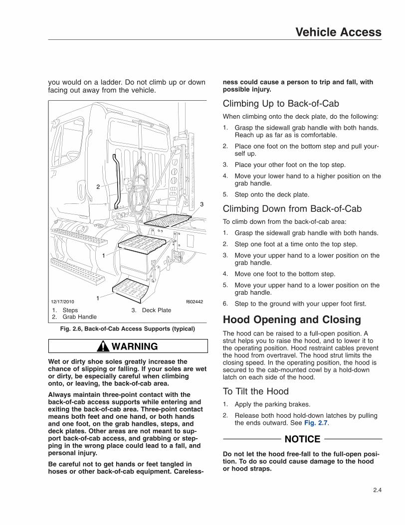
you would on a ladder. Do not climb up or downfacing out away from the vehicle.
WARNINGWet or dirty shoe soles greatly increase thechance of slipping or falling. If your soles are wetor dirty, be especially careful when climbingonto, or leaving, the back-of-cab area.
Always maintain three-point contact with theback-of-cab access supports while entering andexiting the back-of-cab area. Three-point contactmeans both feet and one hand, or both handsand one foot, on the grab handles, steps, anddeck plates. Other areas are not meant to sup-port back-of-cab access, and grabbing or step-ping in the wrong place could lead to a fall, andpersonal injury.
Be careful not to get hands or feet tangled inhoses or other back-of-cab equipment. Careless-
ness could cause a person to trip and fall, withpossible injury.
Climbing Up to Back-of-CabWhen climbing onto the deck plate, do the following:
1. Grasp the sidewall grab handle with both hands.Reach up as far as is comfortable.
2. Place one foot on the bottom step and pull your-self up.
3. Place your other foot on the top step.
4. Move your lower hand to a higher position on thegrab handle.
5. Step onto the deck plate.
Climbing Down from Back-of-CabTo climb down from the back-of-cab area:
1. Grasp the sidewall grab handle with both hands.
2. Step one foot at a time onto the top step.
3. Move your upper hand to a lower position on thegrab handle.
4. Move one foot to the bottom step.
5. Move your upper hand to a lower position on thegrab handle.
6. Step to the ground with your upper foot first.
Hood Opening and ClosingThe hood can be raised to a full-open position. Astrut helps you to raise the hood, and to lower it tothe operating position. Hood restraint cables preventthe hood from overtravel. The hood strut limits theclosing speed. In the operating position, the hood issecured to the cab-mounted cowl by a hold-downlatch on each side of the hood.
To Tilt the Hood1. Apply the parking brakes.
2. Release both hood hold-down latches by pullingthe ends outward. See Fig. 2.7.
NOTICEDo not let the hood free-fall to the full-open posi-tion. To do so could cause damage to the hoodor hood straps.
12/17/2010 f6024421
1
2
3
1. Steps2. Grab Handle
3. Deck Plate
Fig. 2.6, Back-of-Cab Access Supports (typical)
Vehicle Access
2.4

3. Standing in front of the hood, raise the rear ofthe hood upward until it reaches the over-centerposition (45 degrees from vertical). See Fig. 2.8.Then slowly bring it to a stop.
To Return the Hood1. Push the hood over center.
2. As the hood goes over center, the strut automati-cally slows its rate of descent. If needed, youcan also slow its descent with your hand.
3. Make sure the hood is flush with the cowl, thensecure the hood by engaging both hood hold-down latches.
IMPORTANT: Make sure that both hold-downlatches are fully engaged before operating thevehicle.
10/24/2001 f880555
1
2
3
4
1. Fender2. Latch Hook
3. Latch Handle4. Cowl
Fig. 2.7, Hood Hold-Down Latch
02/02/2011 f602441
Fig. 2.8, Hood Tilting
Vehicle Access
2.5

3
Electrical SystemVehicle Power Distribution . . . . . . . . . . . . . . . . . . . . . . . . . . . . . . . . . . . . . . . . . . . . . . . . . . . . . . . . . . 3.1Load Disconnect Switch . . . . . . . . . . . . . . . . . . . . . . . . . . . . . . . . . . . . . . . . . . . . . . . . . . . . . . . . . . . . 3.1Battery Access . . . . . . . . . . . . . . . . . . . . . . . . . . . . . . . . . . . . . . . . . . . . . . . . . . . . . . . . . . . . . . . . . . . 3.2

Vehicle Power Distribution
WARNINGDo not attempt to modify, add, splice, or removeelectrical wiring on this vehicle. Doing so coulddamage the electrical system and result in a firethat could cause serious personal injury or prop-erty damage.
Power Distribution ModulesThe main power distribution module (PDM) is locatedunder the hood on the driver-side splash shield. SeeFig. 3.1. The PDM contains the circuit breakers andfuses required to protect the vehicle cab circuits. Thelabel on the inside of the PDM cover identifies typicalset of fuses.
The powertrain PDM (PTPDM) is mounted in the en-gine compartment near the main PDM. See Fig. 3.1.It controls power to the engine, aftertreatment system(ATS), transmission, and other powertrain-relatedcircuits.
The auxiliary PDM is located on the cab back wall,behind the driver’s seat. See Fig. 3.2. The auxiliaryPDM may contain the auxiliary powernet distributionbox, the body lighting PDM, and the trailer PDM, ifso equipped.
Main Powernet Distribution BoxThe main powernet distribution box (PNDB) ismounted on the cab frontwall next to the bulkheadmodule. See Fig. 3.1. It supplies power to thePTPDM and main PDM, and powers other vehiclefunctions, including the clock. The label on the PNDBfuse cover identifies typical circuits.
An auxiliary PNDB may also be located on the cabback wall, behind the driver’s seat.
Load Disconnect Switch
WARNINGTurning the load disconnect switch to the OFFposition does not disconnect the connection be-tween the battery and the starter. To work on thevehicle safely, the negative leads must be discon-nected from the battery.
The optional load disconnect switch (Fig. 3.3) isused to avoid excessive draw on the battery whenthe vehicle is parked for an extended period of time.
When the load disconnect switch is set to OFF, it sig-nals the PNDB to disconnect battery power to pow-ertrain and accessory loads.
The load disconnect switch is mounted in one of twolocations:
• inside the cab on the left side of the driver’sseat;
• on/near the battery box;
IMPORTANT: The ignition should be turned OFFbefore using the load disconnect switch.
11/24/2010 f545704
1
2
3
4
1. Bulkhead Module2. Powernet Distribution Box (PNDB)3. Main Power Distribution Module (PDM)4. Powertrain PDM (PTPDM)
Fig. 3.1, Power Distribution Module Locations
Electrical System
3.1

Battery AccessThe batteries on a standard vehicle are located onthe driver’s side, behind the fuel tank. See Fig. 3.4.
To access the batteries, pull the cotter pin from thelatch on the battery box cover, then release the latchand lift off the cover.
12/15/2010 f545719
1
2
3
1. Auxiliary PNDB2. Trailer PDM
3. Body Lighting PDM
Fig. 3.2, Auxiliary Power Distribution Module
05/13/2009 f545527
Fig. 3.3, Load Disconnect Switch
12/03/2010 f545714
1
2 3
1. Back-of-Cab2. Fuel Tank
3. Battery Compartment
Fig. 3.4, Standard Battery Compartment Location
Electrical System
3.2


4
InstrumentsInstrumentation Control Unit . . . . . . . . . . . . . . . . . . . . . . . . . . . . . . . . . . . . . . . . . . . . . . . . . . . . . . . . 4.1Warning and Indicator Lights . . . . . . . . . . . . . . . . . . . . . . . . . . . . . . . . . . . . . . . . . . . . . . . . . . . . . . . . 4.3Driver Message Center . . . . . . . . . . . . . . . . . . . . . . . . . . . . . . . . . . . . . . . . . . . . . . . . . . . . . . . . . . . . 4.7Instruments . . . . . . . . . . . . . . . . . . . . . . . . . . . . . . . . . . . . . . . . . . . . . . . . . . . . . . . . . . . . . . . . . . . . . . 4.9Overhead Instrument Panel . . . . . . . . . . . . . . . . . . . . . . . . . . . . . . . . . . . . . . . . . . . . . . . . . . . . . . . . 4.13

Instrumentation Control UnitThe instrumentation control unit (ICU) provides thedriver with engine and vehicle information. It is com-prised of standard and optional gauges, an audiblewarning, a driver message center, and a lightbar con-taining warning and indicator lamps (also known astelltales). Warning and indicator lamps illuminate inred (danger), amber (caution), green (status advi-sory), or blue (high-beam headlights active).
Figure 4.1 shows a typical ICU3 instrument cluster.
Figure 4.2 shows the ICU3S instrument cluster.
The following headings in this chapter provide addi-tional information and operating instructions for ICUcomponents:
• "Warning and Indicator Lights"
• "Instruments"
• "Driver Message Center"
Ignition SequenceWhen the ignition is turned on, the ICU runs a self-check. See Fig. 4.3. Observing the ignition sequenceis a good way to ensure the ICU is functioningproperly.
IMPORTANT: Do not crank the engine until theICU self-check is complete.
When the ignition is turned on, the following actionsshould occur:
• electronic gauges complete a full sweep oftheir dials
• some warning and indicator lamps illuminate,then are extinguished
f610525a
1
2 3 4 5
6
7
8
12
11 10 909/10/2009
NOTE: This instrument cluster is shown with the U.S. speedometer, which shows miles per hour (mph) more prominentlythan kilometers per hour (km/h).
1. Engine Oil Pressure Gauge2. Lightbar3. Driver Message Center4. Headlight High-Beam Indicator
5. Fuel/DEF Level Gauge6. Primary Air Pressure Gauge7. Mode/Reset Button8. Secondary Air Pressure Gauge
9. Speedometer (U.S. version)10. Tachometer11. Transmission Temperature Gauge12. Coolant Temperature Gauge
Fig. 4.1, Typical ICU3 (U.S. shown)
Instruments
4.1

• audible alert sounds until sufficient air pressurebuilds up in the primary and secondary air sys-tems
• DEF level indicator illuminates all segmentsgreen, then turns them off one at a time beforeturning the leftmost segment amber, then red
• software revision level of the ICU is displayedon the driver message center, followed by ac-tive faults
NOTE: Air gauges do not complete a sweep oftheir dials during the ignition sequence.
IMPORTANT: If any red or amber warning andindicator lamps, or telltales, do not illuminateduring the ICU self-check, take the vehicle to anauthorized Freightliner service facility as soonas possible. If any of the red or amber telltalesor do not go out after the self-check completes,
use Table 4.1 to determine if the lamp illumi-nated indicates a problem requiring service.
If the ICU receives active fault codes, it displaysthem one after the other until the parking brake isreleased or the ignition is turned off. Once the park-ing brake is completely released, the ICU displaysthe odometer. If there are no active faults, the ICUdisplays the odometer after the self-check completes.
NOTE: If active faults are present, take the ve-hicle to an authorized Freightliner service facilityas soon as possible.
Audible AlertsAn audible alert sounds during the ignition sequenceand whenever one of the following conditions exists:
• Engine oil pressure falls below the minimumpreset value.
f611292b10/26/2018
12
10
3 24
5
6
789
NOTE: This instrument cluster is shown with the U.S. speedometer, which shows miles per hour (mph) more prominentlythan kilometers per hour (km/h).
1. Engine Oil Pressure Gauge2. Optional Telltales3. Driver Message Center4. Fuel/DEF Level Gauge
5. Primary Air Pressure Gauge6. Secondary Air Pressure Gauge7. Speedometer (U.S. version)
8. Tachometer9. Transmission Temperature Gauge10. Coolant Temperature Gauge
Fig. 4.2, ICU3S (GHG14 and newer shown)
Instruments
4.2

• Coolant temperature rises above the maximumpreset value.
• Air pressure falls below about 70 psi (483kPa).
• Parking brake is set with the vehicle movingfaster than two miles per hour.
• System voltage falls below 12 volts.
• Door is open with the headlights on and theparking brake off.
• Driver seat belt is not fastened with the parkingbrake off (optional).
• Outside temperature falls below 35°F (1.7°C)(optional).
Warning and Indicator LightsThere can be up to 28 telltales installed in the ICU. Ifan optional lamp is not requested, the position isblank.
See Table 4.1 for a list of standard and commonlyused warning and indicator lamps.
Warning and indicator lamps illuminate in red (dan-ger), amber (caution), green (status advisory), orblue (high-beam headlights active).
IMPORTANT: Depending upon local jurisdic-tional emissions guidelines, vehicles and/or en-gines that are domiciled outside of the U.S. andCanada may not be compliant with EPA10 orGHG21 regulations. Noncompliant vehicles maynot be equipped with all of the warning and indi-cator lamps shown.
Common Warning and Indicator LampsLamp Description Color
STOP STOP Engine*
Indicates a serious fault that requires engine shutdownimmediately. The engine protection system will reduce themaximum engine torque and speed, and, if the conditiondoes not improve, will shut down the engine within 30 to 60seconds.
Safely bring the vehicle to a stop on the side of the roadand shut down the engine as soon as the red light is seen.If the engine shuts down while the vehicle is in ahazardous location, turn the key to the OFF position fora few seconds, then restart the engine and move thevehicle to a safer location.
Red
High Coolant Temperature Indicates the coolant temperature is above the maximumallowable temperature. Red
Low Air Pressure Indicates air pressure in the primary or secondary reservoirhas dropped below approximately 70 psi (483 kPa). Red
IGNITION SWITCH
PARKING BRAKERELEASED
IF NO FAULTSWERE DETECTED
IF FAULT DETECTED
APU 190123456.7
12.3 VOLTS
123456.7
12.3 VOLTS
MI
MI
01/18/2012 f040420c
PARKING BRAKERELEASED
TURNED TO ON
ICU PERFORMSSELF−TEST
Fig. 4.3, Ignition Sequence
Instruments
4.3

Common Warning and Indicator LampsLamp Description Color
Low Engine Oil Pressure Indicates the engine oil pressure is below the minimumallowable pressure. Red
Transmission Overheat Indicates high transmission temperature. Red
Parking Brake Indicates the parking brake is engaged. Red
Low Battery Voltage Indicates that battery voltage is 11.9 volts or less. Red
Unfastened Seat Belt
Activates with an audible alert when the system detects thatthe parking brake is off and the driver seat belt is notfastened on some vehicles. On other vehicles, this lampilluminates for 15 seconds when the ignition is first turnedon.
Red
CHECK CHECK Engine*
Indicates an engine condition (low oil pressure, low coolantlevel, high coolant temperature, high DPF soot level, oruncontrolled DPF regeneration) that requires correction.Correct the condition as soon as possible. If the conditionworsens, the STOP engine lamp will illuminate.
Amber
High Exhaust SystemTemperature (HEST)*
Slow (10-second) flashing indicates a regeneration (regen)is in progress.
IMPORTANT: When the HEST lamp is illuminated, donot park the vehicle near flammable material.
Solid illumination indicates high exhaust temperatures at theoutlet of the tail pipe when speed is below 5 mph (8 km/h).
Amber
Diesel Particulate Filter(DPF) Status
Solid illumination indicates a regen is required. Change to amore challenging duty cycle (such as highway driving ) toraise exhaust temperatures for at least twenty minutes, orperform a parked regen.
Blinking indicates that a parked regen is requiredimmediately. An engine derate and shutdown will occur.
Amber
Malfunction IndicatorLamp (MIL)
Indicates an emissions-related fault. See the engineoperation manual for details. Amber
Vehicle ABS
Momentary illumination indicates the vehicle ABS isengaged.
Solid illumination indicates a problem with the vehicle ABS.Repair the ABS immediately to ensure full brakingcapability.
Amber
Trailer ABS
Momentary illumination indicates the trailer ABS is engaged.
Solid illumination indicates a problem with the trailer ABS.Repair the ABS immediately to ensure full brakingcapability.
Amber
Instruments
4.4

Common Warning and Indicator LampsLamp Description Color
NOCHARGE No Charge Indicates the alternator is not properly powering the
electrical system. Amber
Water in Fuel Indicates the fuel may contain water. Drain any watercollected in the fuel/water separators. Amber
Fuel Filter Restriction Indicates the fuel filter is clogged and requires service. Amber
IDLE
MGMT Optimized Idle Indicates optimized idle is enabled. Amber
Check Transmission Indicates an undesirable transmission condition. Amber
WAIT
TO START Wait To Start (EPA10)
Indicates that the system is preventing the starter fromcranking. This can occur when the ignition switch is turnedto START before the gauge sweep has completed, or if thestarter has overheated.
Turn the ignition switch back to ON, wait for the lamp to goout, then turn the ignition switch to START again.
Amber
START
BLOCKEDStart Blocked (GHG14only)
Indicates that the system is preventing the starter fromcranking. This can occur when the ignition switch is turnedto START before the gauge sweep has completed, or if thestarter has overheated.
NOTE: Illumination of the Start Blocked lamp does notindicate a problem with the starter.
Turn the ignition switch back to ON, wait for the lamp to goout, then turn the ignition switch to START again.
Amber
WHEELSPIN Wheel Spin (pre-EPA16)
Flashing indicates the ATC system is active, or the ATCbutton has been pressed to allow wheel slip.
Solid illumination indicates ATC is shut off or unavailabledue to a system fault. In the event of a system fault, repairthe ATC system immediately to ensure full brakingcapability.
Amber
Stability Event (EPA16and newer)
Flashing indicates a stability event has been detected, andthe ESC system is active. Solid illumination indicates aproblem with the stability system. Repair the ESC systemimmediately to ensure full stability capability.
Amber
ATC Deactivated (EPA16and newer)
Flashing indicates the ATC SPIN button has been pressedto allow wheel slip.
Solid illumination indicates ATC is shut off or unavailabledue to a system fault. In the event of a system fault, repairthe ATC system immediately to ensure full brakingcapability.
Amber
Instruments
4.5

Common Warning and Indicator LampsLamp Description Color
Roll Stability (pre-EPA16)
Momentary illumination indicates that a stability event hasoccurred.
On vehicles that are also equipped with ATC, flashingindicates the ATC button has been pressed to allow wheelslip. Solid illumination indicates ATC is shut off orunavailable due to a system fault. In the event of a systemfault, repair the ATC system immediately to ensure fullbraking capability.
Amber
Hill Start Aid (HSA)Override
Indicates the HSA switch has been pressed to override thehill start assist feature. Amber
Engine Brake Indicates the engine brake is enabled. Green
Left-Turn Signal Flashing indicates the outside left-turn signal lights areactivated. Green
Right-Turn Signal Flashing indicates the outside right-turn signal lights areactivated. Green
Cruise Control
Indicates the cruise control is enabled.
NOTE: The ICU4Me does not have a green cruise controltelltale.
Green
High-Beam Headlights Indicates the high-beam headlights are on. Blue
* See Fig. 4.4 for an explanation of the aftertreatment system (ATS) warning indicators, and actions required to avoid further engine protection steps.
Table 4.1, Common Warning and Indicator Lamps
Engine Protection System
WARNINGWhen the red STOP engine lamp illuminates,most engines are programmed to shut down au-tomatically within 30 seconds. The driver mustimmediately move the vehicle to a safe locationat the side of the road to prevent causing a haz-ardous situation that could cause bodily injury,property damage, or severe damage to the en-gine.
See Fig. 4.4 for an explanation of the aftertreatmentsystem (ATS) warning indicators, and actions re-quired to avoid further engine protection steps.
The STOP engine lamp illuminates when the engineprotection system is activated in one of two ways. Onsome engines, the engine protection system will der-
ate the engine, allowing it to run at lower rpm andslower vehicle speed. Drive the vehicle to a safe lo-cation or to a service facility.
IMPORTANT: Safely bring the vehicle to a stopon the side of the road and shut down the en-gine as soon as the red light is seen. If the en-gine shuts down while the vehicle is in a haz-ardous location, turn the key to the OFF positionfor a few seconds, then restart the engine andmove the vehicle to a safer location.
On other engines, the engine protection system willshut down the engine. It will first derate the engine,then shut it down completely 30 to 60 seconds afterthe indicator illuminates (depending on the criticalfault type) if the condition does not improve. Bringthe vehicle to a stop on the side of the road beforethe engine shuts down.
Instruments
4.6

Some vehicles may have a shutdown-overrideswitch, which may be used to momentarily overridethe shutdown sequence. See Chapter 10 for detailedinformation regarding the shutdown process.
IMPORTANT: Do not attempt to restart the en-gine while the vehicle is moving. Bring the ve-hicle to a safe stop, then restart the engine.
To restart the engine, turn the ignition to OFF, leaveit there a few seconds, then turn the ignition toSTART. The engine will run for a short period andshut down again if the condition does not improve.
Driver Message CenterThe driver message center is controlled using themode/reset switch, located on the right side of theICU. See Fig. 4.1. Tap the mode/reset switch to ad-vance one screen; press and hold the switch to se-lect a menu choice or reset the display. When thedisplay resets, an audible chirp sounds.
Driving ScreensThe following screens are available when the parkingbrake is off (when the vehicle is mobile) and no ac-tive fault codes are found. Use the mode/reset switchto scroll through the screens. To reset any values,
press and hold the mode/reset switch. The drivingscreens appear in the following order:
i. Odometer
ii. Trip distance
iii. Trip hours
iv. Outside temperature
Parked Screens/MenusThe parked screens and menus are available whenthe parking brake is on and no active fault codes arefound. See Fig. 4.5. Use the mode/reset switch toscroll through the parked screens. To reset any val-ues, press and hold the mode/reset switch. Theparked screens appear in the following order:
i. Odometer
ii. Trip distance
iii. Trip hours
iv. Outside temperature
v. Select units
vi. Temperature alert
vii. Diagnostics
viii. Engine miles
f080156
EXHAUST AFTERTREATMENT SYSTEM INFORMATION
Switch.
Level 1 Level 3Level 2 Level 4Filter RegenerationRecommended.
Filter is reaching
Bring vehicle tohighway speeds to
Filter Regeneration
Filter is nowreaching maximumcapacity.
To avoid enginederate, bring vehicle
Parked RegenerationRequired − EngineDerate
Filter has reachedmaximum capacity.
Vehicle must beparked, and a Parked
Service Regeneration Required.Engine Derate To Idle Only.
Filter has exceeded maximumcapacity.
Vehicle must be parked, and aService Regeneration must be
(Solid) (Flashing) (Flashing)
CHECKINDICATORLAMP(S)
Indicator LampMessage(s)
Diesel ParticulateFilter Condition
Required Action
capacity.
STOP
allow for an AutomaticRegeneration orperform a Parked
to highway speedsto allow for anAutomaticRegeneration, orperform a ParkedRegeneration assoon as possible.
Regeneration mustbe performed.Engine will beginderate.
performed. Check engineoperator’s manual for details.Engine will shut down.
For a driver performed Parked Regeneration, vehicle must be equipped with a dash mounted Regeneration Switch.
02/20/2009
WARNING
HEST (High ExhaustSystem Temperature)
Exhaust componentsand exhaust gas are athigh temperature. Whenstationary, keep awayfrom people andflammable materials orvapors.
A regeneration is inprogress.
Flashing
Solid
Regeneration.
Necessary
Fig. 4.4, ATS Warning Lamps
Instruments
4.7

ix. Engine hours
x. Setup
Temperature AlertWhen the outside temperature drops to 35°F (1.7°C)or less, the ICU displays a caution text at one-second intervals for five seconds, and an audiblealert sounds. Tap the mode/reset switch to acknowl-edge the message. The audible alert will not soundagain unless the temperature cycles above 37°F(4°C) and back to 35°F (1.7°C) or less. This warningonly occurs while the ignition is on and the parkingbrake is released.
The temperature alert message allows the driver toenable or disable the ambient temperature warning.
Press and hold the mode/reset switch to toggle be-tween on and off. Release the mode/reset switch,then tap it to select the displayed choice.
DiagnosticsWhen the DIAG screen is displayed, press and holdthe mode/reset switch to access the various diagnos-tic screens.
The diagnostic screens are used by trained techni-cians to retrieve fault codes and other diagnostic in-formation pertaining to the vehicle. If active faultcodes display during start-up or at any other time,make a note of the fault code and take the vehicle toan authorized Freightliner service facility
If fault codes are displayed, press and hold themode/reset switch to view the next fault code untilreaching the DIAG screen.
Engine Miles/HoursWhen the engine miles/hours screen is displayed,press and hold the mode/reset switch to access theengines screen submenu.
03/26/2004 f040636a
Push
Push
123456.7TRIP MI 12.3 VOLTS
Push
123456.7MI 12.3 VOLTS
Push
123456.7TRIP HOURS
12.3 VOLTS
SELECtMI
dIAGMI HOURS
n
Push
Push
123456.7MI
EC
Push
CLEAr
Push
123456.7HOURS
EC
EnG oIL *Lo
SEtUP **MI **HOURS**no
Default OdometerDispay Screen
To Reset Trip MilesHold
To Reset Trip HoursHold
To Toggle between UnitsHold
Dispay DiagnosticsHold
Dispay Oil LevelHold
Dispay Service IntervalCycle Screens
Hold
To Dispay Total Engine HoursEC = Engine Control
To Dispay Total Engine MilesEC = Engine Control
Clear DefaultsHold
Push Push
n = Number of Active Fault CodesMI = CYCLE Miles EnabledHOURS = Cycle Hours Enabled
*Lo = Oil Level LowHI = Oil Level HighBlank = Oil Level OK− − = No Message
MI<−−−−>KM
**MI = CYCLE Miles Active Mode**HOURS = CYCLE Hours Active Mode**no = Service CYCLE Inactive
NOTE: The engine oil level screen displays for Mercedes-Benz engines only (if equipped and enabled).
Fig. 4.5, ICU3 Stationary Screens
Instruments
4.8

SetupThe setup menu allows the driver to manage ICUparameters. The setup screen submenu allows thedriver to enable and change service intervals.
If service intervals are enabled and service distanceor time has been exceeded, the text SERVICEHOUR/MI (KM) will display at start-up to indicate ve-hicle service is required.
For each parameter, press and hold the mode/resetswitch to navigate to the parameter change screen.In each change screen, tap the mode/reset switch totoggle between options.
The last screen in the setup menu, RESET EE, is forresetting certain parameters to the original settings.Press and hold the mode/reset switch to reset theantilock braking system (ABS), SAMs roll call, auto-mated transmission display, transmission heartbeat,sensor fault codes, seat belt switch learning, and en-gine oil level.
InstrumentsStandard instruments are present on every vehicle.They are listed here in alphabetical order to makethe information easier to find.
Optional instruments, typically located on the auxil-iary dash panel or right-hand control panel, are notfound on every vehicle. They are listed here in alpha-betical order, to make the information easier to find.
Air Intake Restriction GaugeThe air intake restriction gauge indicates the vacuumon the engine side of the air cleaner. On standardinstallations, it is mounted on the air intake duct inthe engine compartment. As an option for easierviewing, the air intake restriction indicator (seeFig. 4.6) can be mounted on the dash, usually on theright-hand control panel.
NOTE: Rain or snow can wet the filter andcause a temporary high reading.
Air intake restriction vacuum is measured in inchesof water (inH2O). For vehicles equipped with agraduated indicator or a restriction gauge on thedash, check the gauge with the engine off. If the yel-low signal stays locked in the red zone once the en-gine is shut down, or is at or above the valuesshown in Table 4.2, the air cleaner element needs tobe replaced.
Vehicles may be equipped with a go/no-go restrictionindicator without graduations (see Fig. 4.7) instead ofa graduated indicator.
Air Intake Maximum Restriction Values (in H2O)
Engine MakeGHG14, GHG17,
and GHG21Engines
Cummins 25Detroit 18
Table 4.2, Air Intake Maximum Restriction Values
Coolant Temperature Gauge
NOTICEA sudden increase in coolant temperature mayindicate engine or cooling system failure. Bringthe vehicle to a safe stop and investigate the
02/12/2015 f090514
Fig. 4.6, Air Intake Restriction Indicator
04/08/2005 f090431
Fig. 4.7, Manual-Reset Air Restriction Indicator, Go/No-Go
Instruments
4.9

cause to prevent further damage. Do not operatethe engine until the cause has been determinedand corrected.
During normal engine operation, the coolant tem-perature gauge, as shown in Fig. 4.8, should read175 to 195°F (79 to 91°C). If the temperature re-mains below 160°F (71°C), inspect the cooling sys-tem to determine the cause.
If coolant temperature rises above the maximumtemperature listed in Table 4.3, the CHECK enginelamp will illuminate. If the condition does not im-prove, the STOP engine lamp will also illuminate andan audible warning will sound. The engine will thenderate or shut down, depending on the type of en-gine protection system installed.
Maximum Coolant TemperatureEngine Make Temperature: °F (°C)
Caterpillar 230 (110)Cummins 221 (105)Detroit DD13/DD15/DD16 234 (112)
Mercedes-Benz 222 (105)
Table 4.3, Maximum Coolant Temperature
Drive Axle Oil Temperature Gauges
NOTICEA sudden increase in oil temperature that is notcaused by a load increase may indicate mechani-cal failure. Bring the vehicle to a safe stop andinvestigate the cause to prevent further damage.Do not operate the vehicle until the cause hasbeen determined and corrected.
During normal operation, the drive axle oil tempera-ture gauges should read as follows:
• 160 to 220°F (71 to 104°C) for Detroit ClassicModel 2, 4, and 6 axles.
• 160 to 275°F (71 to 135°C) for Meritor™ driveaxles.
Under heavy loads, such as when climbing steepgrades, temperatures that exceed the normal oil tem-perature range for a short period are not unusual. Ifthe temperature returns to normal when the load de-creases, there is no problem.
Engine Oil Pressure Gauge
NOTICEA sudden decrease or absence of oil pressuremay indicate mechanical failure. Bring the vehicleto a safe stop and investigate the cause to pre-vent further damage. Do not operate the engineuntil the cause has been determined and cor-rected.
The engine oil pressure gauge, as shown inFig. 4.10, displays the current engine oil pressure. Ifengine oil pressure falls below the minimum levelsshown in Table 4.4, the CHECK engine lamp will illu-minate. If the condition does not improve, the STOPengine lamp will also illuminate and an audible warn-ing will sound. The engine will then derate or shutdown, depending on the type of engine protectionsystem installed.
10/09/2001 f610565
WATER
100
150 200
250
F°
Fig. 4.8, Coolant Temperature Gauge
FWD
150 250
300100
°F
04/19/2013 f611205
Fig. 4.9, Forward-Rear Drive Axle Oil TemperatureGauge
Instruments
4.10
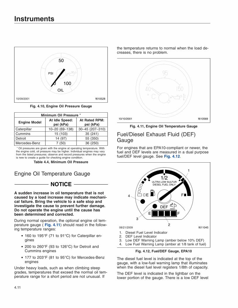
Minimum Oil Pressure *
Engine ModelAt Idle Speed:
psi (kPa)At Rated RPM:
psi (kPa)Caterpillar 10–20 (69–138) 30–45 (207–310)Cummins 15 (103) 35 (241)Detroit 14 (97) 55 (350)Mercedes-Benz 7 (50) 36 (250)* Oil pressures are given with the engine at operating temperature. With
the engine cold, oil pressure may be higher. Individual engines may varyfrom the listed pressures; observe and record pressures when the engineis new to create a guide for checking engine condition.
Table 4.4, Minimum Oil Pressure
Engine Oil Temperature Gauge
NOTICEA sudden increase in oil temperature that is notcaused by a load increase may indicate mechani-cal failure. Bring the vehicle to a safe stop andinvestigate the cause to prevent further damage.Do not operate the engine until the cause hasbeen determined and corrected.
During normal operation, the optional engine oil tem-perature gauge ( Fig. 4.11) should read in the follow-ing temperature ranges:
• 160 to 195°F (71 to 91°C) for Caterpillar en-gines
• 200 to 260°F (93 to 126°C) for Detroit andCummins engines
• 177 to 203°F (81 to 95°C) for Mercedes-Benzengines
Under heavy loads, such as when climbing steepgrades, temperatures that exceed the normal oil tem-perature range for a short period are not unusual. If
the temperature returns to normal when the load de-creases, there is no problem.
Fuel/Diesel Exhaust Fluid (DEF)GaugeFor engines that are EPA10-compliant or newer, thefuel and DEF levels are measured in a dual purposefuel/DEF level gauge. See Fig. 4.12.
The diesel fuel level is indicated at the top of thegauge, with a low-fuel warning lamp that illuminateswhen the diesel fuel level registers 1/8th of capacity.
The DEF level is indicated in the lightbar on thelower portion of the gauge. There is a low DEF level
10/09/2001
0 100
50
PSI
OIL
f610528
Fig. 4.10, Engine Oil Pressure Gauge
10/10/2001 f610569
Fig. 4.11, Engine Oil Temperature Gauge
08/21/2009
1/2ULTRA LOW SULFURDIESEL FUEL ONLY
E F
DEF
FE
f611045
1
2
3
4
1. Diesel Fuel Level Indicator2. DEF Level Indicator3. Low DEF Warning Lamp (amber below 10% DEF)4. Low Fuel Warning Lamp (amber at 1/8 tank of fuel)
Fig. 4.12, Fuel/DEF Gauge, EPA10
Instruments
4.11

warning lamp that illuminates amber when the DEFlevel reaches 10% of capacity. See Chapter 7 fordetails of the DEF gauge functions.
Primary and Secondary Air PressureGauges
WARNINGIf air pressure falls below minimum pressure, thebraking ability of the vehicle will be limited. Slowthe vehicle down and bring it to a gradual stop.Do not attempt to move the vehicle until air pres-sure has risen above the minimum level. Movinga vehicle without adequate braking power couldcause an accident resulting in property damage,personal injury, or death.
Air pressure gauges, as shown in Fig. 4.13, registerthe pressure in the primary and secondary air sys-tems. The gauges are labeled for the A or B reser-voir. Normal pressure with the engine running is 100to 120 psi (689 to 827 kPa) in both systems.
A low-air-pressure warning light and audible alert,connected to both the primary and secondary sys-tems, activate when air pressure in either systemdrops below approximately 70 psi (483 kPa).
When the engine is started, the warning light andaudible warning remain on until air pressure in bothsystems exceeds minimum pressure.
SpeedometerThree speedometer options are available. The U.S.version of the speedometer registers speed in bothmiles per hour (mph) and kilometers per hour (km/h),with mph in larger numbers. The metric version ofthe speedometer face reverses this arrangement,
with km/h in larger numbers. The metric-only versionshows km/h exclusively.
TachometerThe tachometer indicates engine speed in revolutionsper minute (rpm) and serves as a guide for shiftingthe transmission and keeping the engine in the ap-propriate rpm range. For low idle and rated rpm, seethe engine identification plate.
Transmission Fluid TemperatureGaugeThe transmission fluid temperature gauge, shown inFig. 4.14, measures the transmission lubricant oper-ating temperature. Temperatures vary by application,but the transmission fluid temperature gauge readingshould not exceed 250°F (121°C).
NOTICEA sudden increase in transmission fluid tempera-ture that is not caused by a load increase mayindicate mechanical failure. Bring the vehicle to asafe stop and investigate the cause to preventfurther damage. Do not operate the vehicle untilthe cause has been determined and corrected.
Under heavy loads, such as when climbing steepgrades, temperatures that exceed the normal oil tem-perature range for a short period are not unusual. Ifthe temperature returns to normal when the load de-creases, there is no problem.
Turbocharger Boost Pressure GaugeA turbocharger boost pressure gauge indicates thepressure in the intake manifold, in excess of atmos-pheric pressure, being created by the turbocharger.
05/14/2001 f610556
Fig. 4.13, Air Pressure Gauge (reservoir A shown)
10/30/2001 f610600
TRANS
125 350
F
275200
Fig. 4.14, Transmission Fluid Temperature Gauge
Instruments
4.12

VoltmeterThe voltmeter indicates the vehicle charging systemvoltage when the engine is running and the batteryvoltage when the engine is off. By monitoring thevoltmeter, the driver can stay aware of potential bat-tery charging problems and have them fixed beforethe batteries discharge enough to create starting diffi-culties. Cascadia vehicles are equipped with either avoltmeter gauge, or a digital voltmeter readout lo-cated on the bottom line of the dash message center.
The voltmeter will normally show approximately 13.7to 14.1 volts when the engine is running. The voltageof a fully charged battery is 12.7 to 12.8 volts whenthe engine is off. Battery voltage under 12.0 volts isconsidered a low battery, and a completely dis-charged battery will produce only about 11.0 volts.
If the voltmeter shows an undercharged or over-charged condition for an extended period, have thecharging system and batteries checked at an autho-rized Freightliner service facility.
On a vehicle equipped with a battery isolator system,the voltmeter measures the average voltage of all thebatteries when the engine is running. When the en-gine is off, the voltmeter shows only the isolated bat-tery voltage and does not indicate the voltage of theengine-starting batteries.
Overhead Instrument PanelThe optional overhead instrument panel (Fig. 4.15)may hold a citizen’s band (C/B) radio, a microphoneclip, and any switches that can not be accommo-dated on the driver’s or auxiliary dash panels.
The underside of the overhead console also holdsthe sun visors and the optional dome/reading lightassembly. For more information on the dome/readinglight assembly, see Chapter 8.
04/19/2002 f680028
1 2
1
3 4
1. Storage Area with Netting2. C/B Radio
3. Microphone Clip4. Dome/Reading Light Assembly
Fig. 4.15, Overhead Instrument Panel
Instruments
4.13

5
Driver ControlsIgnition Switch . . . . . . . . . . . . . . . . . . . . . . . . . . . . . . . . . . . . . . . . . . . . . . . . . . . . . . . . . . . . . . . . . . . 5.1Control Panels . . . . . . . . . . . . . . . . . . . . . . . . . . . . . . . . . . . . . . . . . . . . . . . . . . . . . . . . . . . . . . . . . . . 5.1Lighting Controls . . . . . . . . . . . . . . . . . . . . . . . . . . . . . . . . . . . . . . . . . . . . . . . . . . . . . . . . . . . . . . . . . . 5.2Multifunction Turn Signal Lever Controls . . . . . . . . . . . . . . . . . . . . . . . . . . . . . . . . . . . . . . . . . . . . . . . 5.5Horn Controls . . . . . . . . . . . . . . . . . . . . . . . . . . . . . . . . . . . . . . . . . . . . . . . . . . . . . . . . . . . . . . . . . . . . 5.6Powertrain Controls . . . . . . . . . . . . . . . . . . . . . . . . . . . . . . . . . . . . . . . . . . . . . . . . . . . . . . . . . . . . . . . 5.7AWD Controls . . . . . . . . . . . . . . . . . . . . . . . . . . . . . . . . . . . . . . . . . . . . . . . . . . . . . . . . . . . . . . . . . . . 5.10Brake Controls . . . . . . . . . . . . . . . . . . . . . . . . . . . . . . . . . . . . . . . . . . . . . . . . . . . . . . . . . . . . . . . . . . 5.11Adjustable Steering Column Controls . . . . . . . . . . . . . . . . . . . . . . . . . . . . . . . . . . . . . . . . . . . . . . . . 5.12Suspension Controls . . . . . . . . . . . . . . . . . . . . . . . . . . . . . . . . . . . . . . . . . . . . . . . . . . . . . . . . . . . . . 5.12Climate Controls . . . . . . . . . . . . . . . . . . . . . . . . . . . . . . . . . . . . . . . . . . . . . . . . . . . . . . . . . . . . . . . . . 5.13Seat Controls . . . . . . . . . . . . . . . . . . . . . . . . . . . . . . . . . . . . . . . . . . . . . . . . . . . . . . . . . . . . . . . . . . . 5.13

Ignition SwitchNOTE: Freightliner vehicles are offered withvarious chassis and body components. Becauseof the various options, the information containedin this chapter may not apply to every vehicle.
The ignition switch (Fig. 5.1) is located on the lowerportion of the left-hand dash. The switch has fourpositions: OFF, ACCESSORY, ON, and START.
In the OFF position, the key slot is vertical. The keycan be inserted and removed only in the OFF posi-tion.
The following functions are operable when the igni-tion switch is in the OFF position (regardless ofwhether the key is inserted):
• low-beam headlights
• taillights
• brake lights
• dome lights
• clearance lights
• turn signals
• hazard warning lights
• horn
• CB radio
• power windows
• cigarette lighter
• clock
Turn the key counterclockwise to reach the ACCES-SORY position. In addition to all the functions that
are operable with the ignition switch in the OFF posi-tion, the following functions are operable when theswitch is in the ACCESSORY position:
• radio or stereo system
• mirror heat
• air dryer
• backup lights
• windshield fan(s)
Turn the key clockwise past the OFF position toreach the ON position. With the switch in the ON po-sition, all electrical systems are operable and the in-strument control unit (ICU3) runs through the ignitionsequence. See Fig. 5.2.
When the ignition switch is turned to the ON position,all electronic gauges complete a full sweep of theirdials, the warning and indicator lamps illuminate, andthe buzzer sounds for three seconds. Wait for thegauge sweep to complete before starting the engine.
Switching on the ignition and releasing the parkingbrakes automatically activates the daytime runninglights, if equipped. The daytime running lights willoperate until the parking brakes are applied or theheadlights are turned on.
NOTE: Daytime running lights are standard onall vehicles domiciled in Canada.
Turn the key clockwise past the ON position to reachthe START position and start the engine. Do not op-erate the starter longer than thirty seconds, and waitat least two minutes between starting attempts toallow the starter to cool. Release the key the mo-ment the engine starts.
Control PanelsThe left-hand control panel (Fig. 5.3, Item 1) con-tains a face vent and four switches arranged in avertical line. In the standard cab, the four switchesusually consist of the headlight, panel light increase/decrease, and the cruise control on/off and set/resume switches.
The instrument cluster is located directly behind thesteering wheel. The mode/reset button, located onthe right side of the instrument cluster, allows thedriver to scroll through a number of options on thedriver display screen.
The right-hand control panel (Fig. 5.3, Item 3) usu-ally contains the transmission push-button shift selec-tor (vehicles with an automatic transmission) and the
f61080502/03/2017
Fig. 5.1, Ignition Switch Positions
Driver Controls
5.1
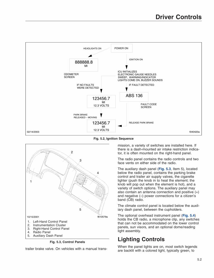
trailer brake valve. On vehicles with a manual trans-
mission, a variety of switches are installed here. Ifthere is a dash-mounted air intake restriction indica-tor, it is often mounted on the right-hand panel.
The radio panel contains the radio controls and twoface vents on either side of the radio.
The auxiliary dash panel (Fig. 5.3, Item 5), locatedbelow the radio panel, contains the parking brakecontrol and trailer air supply valves, the cigarettelighter (push the knob in to heat the element; theknob will pop out when the element is hot), and avariety of switch options. The auxiliary panel mayalso contain an antenna connection and positive (+)and negative (–) power connections for a citizen’sband (CB) radio.
The climate control panel is located below the auxil-iary dash panel, between the cupholders.
The optional overhead instrument panel (Fig. 5.4)holds the CB radio, a microphone clip, any switchesthat can not be accommodated on the lower controlpanels, sun visors, and an optional dome/readinglight assembly.
Lighting ControlsWhen the panel lights are on, most switch legendsare backlit with a colored light, typically green, to
POWER ON
PARK BRAKE
IGNITION ON
HEADLIGHTS ON
RELEASE PARK BRAKE
f040420a02/14/2003
RELEASED − MOVING
FAULT CODESCREEN
IF NO FAULTSWERE DETECTED
ELECTRONIC GAUGE NEEDLESSWEEP, WARNING/INDICATORLIGHTS COME ON, BUZZER SOUNDS
IF FAULT DETECTED
ICU INITIALIZES
888888.8
ABS 136
ODOMETERSCREEN
123456.7
12.3 VOLTS
123456.7
12.3 VOLTS
MI
MI
MI
Fig. 5.2, Ignition Sequence
10/15/2001 f610579a
1
2
3
4
5
1. Left-Hand Control Panel2. Instrumentation Cluster3. Right-Hand Control Panel4. Radio Panel5. Auxiliary Dash Panel
Fig. 5.3, Control Panels
Driver Controls
5.2
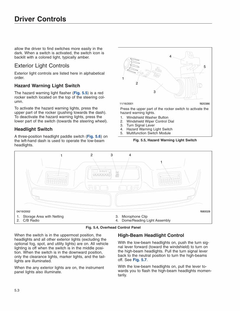
allow the driver to find switches more easily in thedark. When a switch is activated, the switch icon isbacklit with a colored light, typically amber.
Exterior Light ControlsExterior light controls are listed here in alphabeticalorder.
Hazard Warning Light SwitchThe hazard warning light flasher (Fig. 5.5) is a redrocker switch located on the top of the steering col-umn.
To activate the hazard warning lights, press theupper part of the rocker (pushing towards the dash).To deactivate the hazard warning lights, press thelower part of the switch (towards the steering wheel).
Headlight SwitchA three-position headlight paddle switch (Fig. 5.6) onthe left-hand dash is used to operate the low-beamheadlights.
When the switch is in the uppermost position, theheadlights and all other exterior lights (excluding theoptional fog, spot, and utility lights) are on. All vehiclelighting is off when the switch is in the middle posi-tion. When the switch is in the downward position,only the clearance lights, marker lights, and the tail-lights are illuminated.
When the any exterior lights are on, the instrumentpanel lights also illuminate.
High-Beam Headlight ControlWith the low-beam headlights on, push the turn sig-nal lever forward (toward the windshield) to turn onthe high-beam headlights. Pull the turn signal leverback to the neutral position to turn the high-beamsoff. See Fig. 5.7.
With the low-beam headlights on, pull the lever to-wards you to flash the high-beam headlights momen-tarily.
04/19/2002 f680028
1 2
1
3 4
1. Storage Area with Netting2. C/B Radio
3. Microphone Clip4. Dome/Reading Light Assembly
Fig. 5.4, Overhead Control Panel
f820386
12
3
4
5
11/16/2001
Press the upper part of the rocker switch to activate thehazard warning lights.1. Windshield Washer Button2. Windshield Wiper Control Dial3. Turn Signal Lever4. Hazard Warning Light Switch5. Multifunction Switch Module
Fig. 5.5, Hazard Warning Light Switch
Driver Controls
5.3

When the high-beam headlights are on, a blue lightilluminates on the instrument cluster between the ta-chometer and speedometer.
The low-beam headlights remain on continuouslyduring high-beam headlight operation. If the low-beams are turned off, the high-beams turn off also.
Marker Light Interrupt SwitchThe marker light interrupt (MRKR INT) paddle switch(Fig. 5.8) temporarily deactivates the marker lightsand taillights, if equipped.
With the vehicle lights on, raise and hold the paddleswitch to briefly turn off the marker lights and tail-lights. The dash lights will flash with the marker lightswhen the switch is actuated. When the paddle is re-leased the marker lights will return to normal opera-tion. With the vehicle lights off, raise the paddleswitch briefly to turn the marker lights on.
Panel Light Increase/Decrease SwitchWhen the instrument panel lights are on, they can bebrightened or dimmed by using the INCR/DECRrocker switch (Fig. 5.9), located just below the head-light switch.
To brighten the panel lights, press the upper part ofthe rocker switch. To dim the panel lights, press thelower part of the rocker switch.
10/15/2001 f610580
Raise the paddle to illuminate the low-beam headlights.
Lower the paddle to illuminate the clearance lights,marker lights, and taillights.
Fig. 5.6, Headlight Switch
10/17/2001 f820385
1
2
Push the lever away from you to turn on the high-beamheadlights. Pull the lever back to the neutral position toturn them off.
Pull the lever towards you to flash the high-beamheadlights momentarily.
1. Turn Signal Lever 2. Boot
Fig. 5.7, High-Beam Headlight Operation
05/09/2002 f610581
Raise the paddle to flash the marker lights.
Fig. 5.8, Marker Light Interrupt Switch
f61059810/29/2001
Fig. 5.9, Panel Light Increase/Decrease Switch
Driver Controls
5.4

Spotlight SwitchThe spotlight switch is located on the pivoting handleof the spotlight. There may be a single spotlight as-sembly mounted on the driver’s door, or one on eachdoor.
Utility Light SwitchThe utility light switch, if equipped, operates one ofthe following lights or sets of lights:
• A single utility light swivel-mounted in the cen-ter of the cab roof;
• Two fixed utility lights mounted on each side ofthe cab roof;
• Two flush-mounted utility lights mounted oneach side of the back of the cab.
To turn the utility light(s) on, press the upper part ofthe utility light (UTLY LAMP) rocker switch(Fig. 5.10). To turn the utility light(s) off, press thelower part of the rocker switch.
Interior Light ControlsOverhead Console LightsIn cabs with an overhead console, there is an op-tional overhead light assembly containing a diffusedome light and clear reading lights. See Fig. 5.11.
Like the rear dome light, the reading lights aredoor-activated.
Rear Dome LightThe standard rear dome light is installed on the backof the cab above the rear window.
In the standard cab, there is one switch in thedriver’s door that controls dome light illumination
when the driver’s door is open. A second optionalswitch may be installed that controls illuminationwhen the passenger-side door is open.
Multifunction Turn SignalLever ControlsThe turn signal lever is mounted on the steering col-umn. The lever operates the following functions:
• Turn signals
• Windshield wipers and washers
• Headlight high-beams (see "Light Controls"section above)
Turn Signal ControlsMoving the turn signal lever down (Fig. 5.12) turnson the left-turn signal; moving it up turns on the right-turn signal.
When a turn signal is activated, a green indicatorlight flashes on the right or left side of the instrumentcluster.
The turn signal lever automatically returns to theneutral position (self-cancels) when the steeringwheel returns to the straight ahead position after aturn. To manually cancel the signal, move the leverto the neutral position.
10/15/2001 f610583
Fig. 5.10, Utility Light Switch
10/17/2001 f610587
1
2
3
1. Overhead Console2. Trim Plate
3. Light Assembly
Fig. 5.11, Overhead Console Dome Lights
Driver Controls
5.5
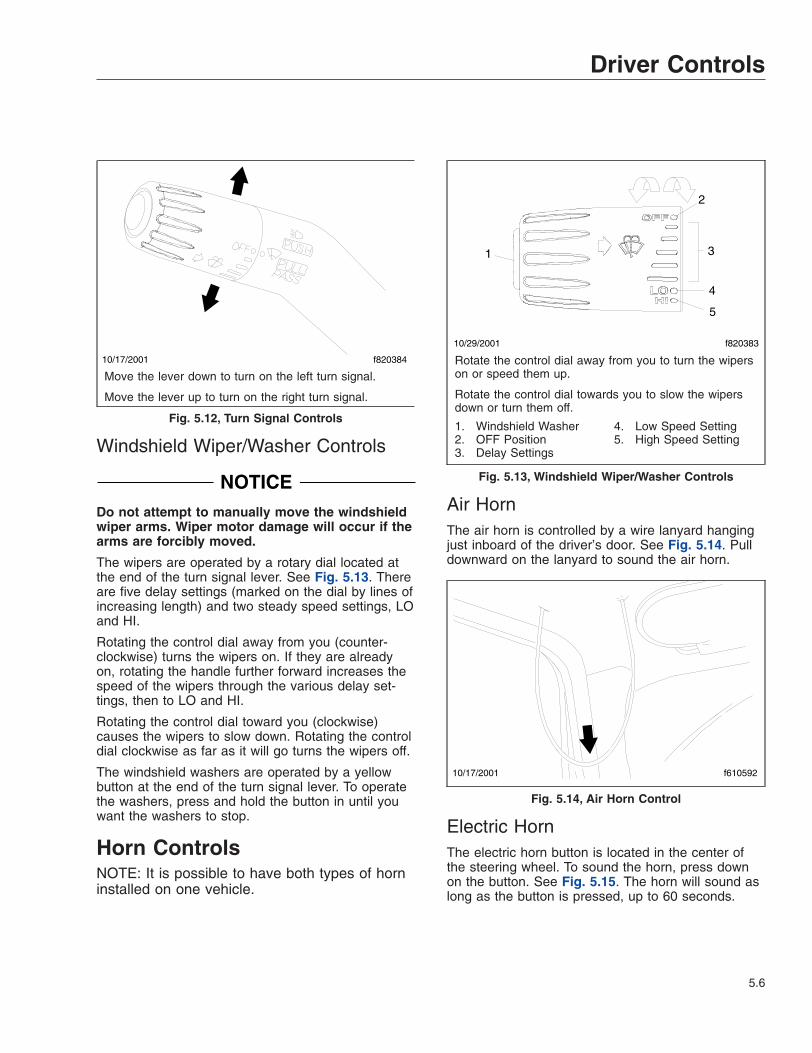
Windshield Wiper/Washer Controls
NOTICEDo not attempt to manually move the windshieldwiper arms. Wiper motor damage will occur if thearms are forcibly moved.
The wipers are operated by a rotary dial located atthe end of the turn signal lever. See Fig. 5.13. Thereare five delay settings (marked on the dial by lines ofincreasing length) and two steady speed settings, LOand HI.
Rotating the control dial away from you (counter-clockwise) turns the wipers on. If they are alreadyon, rotating the handle further forward increases thespeed of the wipers through the various delay set-tings, then to LO and HI.
Rotating the control dial toward you (clockwise)causes the wipers to slow down. Rotating the controldial clockwise as far as it will go turns the wipers off.
The windshield washers are operated by a yellowbutton at the end of the turn signal lever. To operatethe washers, press and hold the button in until youwant the washers to stop.
Horn ControlsNOTE: It is possible to have both types of horninstalled on one vehicle.
Air HornThe air horn is controlled by a wire lanyard hangingjust inboard of the driver’s door. See Fig. 5.14. Pulldownward on the lanyard to sound the air horn.
Electric HornThe electric horn button is located in the center ofthe steering wheel. To sound the horn, press downon the button. See Fig. 5.15. The horn will sound aslong as the button is pressed, up to 60 seconds.
10/17/2001 f820384
Move the lever down to turn on the left turn signal.
Move the lever up to turn on the right turn signal.
Fig. 5.12, Turn Signal Controls
f820383
1 3
2
4
5
10/29/2001
Rotate the control dial away from you to turn the wiperson or speed them up.
Rotate the control dial towards you to slow the wipersdown or turn them off.
1. Windshield Washer2. OFF Position3. Delay Settings
4. Low Speed Setting5. High Speed Setting
Fig. 5.13, Windshield Wiper/Washer Controls
10/17/2001 f610592
Fig. 5.14, Air Horn Control
Driver Controls
5.6
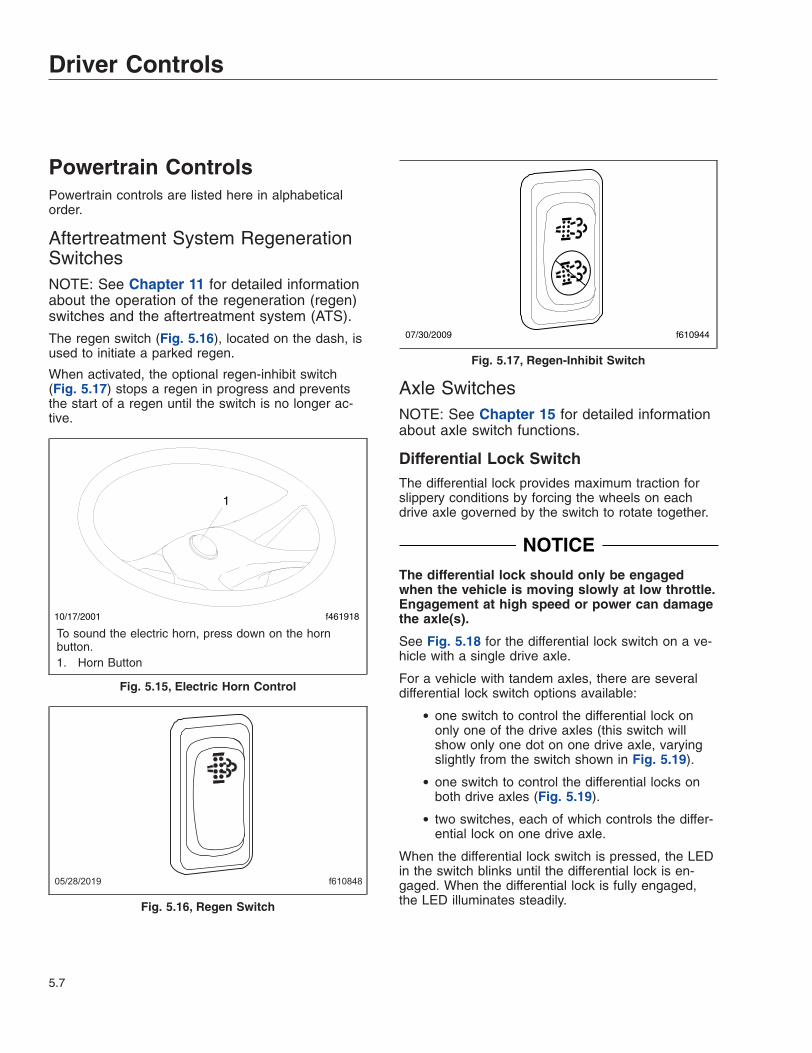
Powertrain ControlsPowertrain controls are listed here in alphabeticalorder.
Aftertreatment System RegenerationSwitchesNOTE: See Chapter 11 for detailed informationabout the operation of the regeneration (regen)switches and the aftertreatment system (ATS).
The regen switch (Fig. 5.16), located on the dash, isused to initiate a parked regen.
When activated, the optional regen-inhibit switch(Fig. 5.17) stops a regen in progress and preventsthe start of a regen until the switch is no longer ac-tive.
Axle SwitchesNOTE: See Chapter 15 for detailed informationabout axle switch functions.
Differential Lock SwitchThe differential lock provides maximum traction forslippery conditions by forcing the wheels on eachdrive axle governed by the switch to rotate together.
NOTICEThe differential lock should only be engagedwhen the vehicle is moving slowly at low throttle.Engagement at high speed or power can damagethe axle(s).
See Fig. 5.18 for the differential lock switch on a ve-hicle with a single drive axle.
For a vehicle with tandem axles, there are severaldifferential lock switch options available:
• one switch to control the differential lock ononly one of the drive axles (this switch willshow only one dot on one drive axle, varyingslightly from the switch shown in Fig. 5.19).
• one switch to control the differential locks onboth drive axles (Fig. 5.19).
• two switches, each of which controls the differ-ential lock on one drive axle.
When the differential lock switch is pressed, the LEDin the switch blinks until the differential lock is en-gaged. When the differential lock is fully engaged,the LED illuminates steadily.
10/17/2001 f461918
1
To sound the electric horn, press down on the hornbutton.1. Horn Button
Fig. 5.15, Electric Horn Control
f61084805/28/2019
Fig. 5.16, Regen Switch
f61094407/30/2009
Fig. 5.17, Regen-Inhibit Switch
Driver Controls
5.7

Interaxle Lock SwitchThe interaxle lock switch (Fig. 5.20) allows the driverto lock the drive axles together, causing the driveaxle shafts to rotate together. Use this feature onlyunder adverse road conditions where greater tractionis needed.
NOTICEThe interaxle lock should only be engaged whenthe vehicle is moving slowly at low throttle. En-gagement at high speed or power can damagethe axle(s).
When the interaxle lock switch is pressed, the LED inthe switch blinks until the interaxle lock is engaged.When the interaxle lock is fully engaged, the LEDilluminates steadily.
Cruise Control SwitchesNOTE: See Chapter 10 for detailed informationabout cruise control operation.
Cruise control is activated by two dash-mountedswitches (Fig. 5.21).
• On/Off Switch—a two-position rocker labeledSPD CNTL on the lower half of the switch.When cruise control is on, an amber light illu-minates the top part of the switch.
• Set/Resume Switch—a three-position paddleswitch labeled RES/ACC above the paddle andSET/CST below the paddle.
NOTICEWhen the cruise control is engaged, do not at-tempt to shift gears without using the clutchpedal. Failure to follow this precaution will resultin a temporarily uncontrolled increase in enginespeed. Transmission damage and gear strippingcould result.
Engine Brake SwitchNOTE: See Chapter 10 for detailed informationabout engine brake operation.
Two dash-mounted switches control the enginebrake:
• The On/Off switch (ENG BRK), is used to turnthe engine brake on and off. See Fig. 5.22.
• The engine brake intensity switch (HI/MED/LOor, in some cases, HI/LO) controls the amountof engine braking.
Engine Fan SwitchThe engine cooling fan can be manually activatedwith the engine fan switch. The fan will continue tooperate for a set amount of time and then turn offunless the coolant temperature is high enough tocontinue the fan operation.
To turn the engine fan on, press the upper part of therocker switch. See Fig. 5.23. Press the bottom of theswitch to deactivate it.
10/26/2001 f610596
Fig. 5.18, Differential Lock on Single Drive Axle
f61079702/17/2006
Fig. 5.19, Differential Lock on Both Axles
10/26/2001 f610595
Fig. 5.20, Interaxle Lock Switch
Driver Controls
5.8
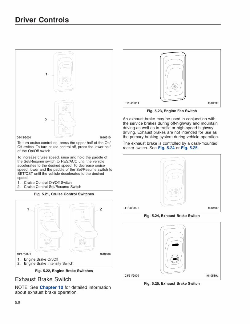
Exhaust Brake SwitchNOTE: See Chapter 10 for detailed informationabout exhaust brake operation.
An exhaust brake may be used in conjunction withthe service brakes during off-highway and mountaindriving as well as in traffic or high-speed highwaydriving. Exhaust brakes are not intended for use asthe primary braking system during vehicle operation.
The exhaust brake is controlled by a dash-mountedrocker switch. See Fig. 5.24 or Fig. 5.25.
09/13/2001
1
2
f610510
To turn cruise control on, press the upper half of the On/Off switch. To turn cruise control off, press the lower halfof the On/Off switch.
To increase cruise speed, raise and hold the paddle ofthe Set/Resume switch to RES/ACC until the vehicleaccelerates to the desired speed. To decrease cruisespeed, lower and the paddle of the Set/Resume switch toSET/CST until the vehicle decelerates to the desiredspeed.1. Cruise Control On/Off Switch2. Cruise Control Set/Resume Switch
Fig. 5.21, Cruise Control Switches
10/17/2001 f610588
1 2
1. Engine Brake On/Off2. Engine Brake Intensity Switch
Fig. 5.22, Engine Brake Switches
f61059001/04/2011
Fig. 5.23, Engine Fan Switch
f61058911/28/2001
Fig. 5.24, Exhaust Brake Switch
f610589a03/31/2009
Fig. 5.25, Exhaust Brake Switch
Driver Controls
5.9

Transmission ControlsManual Transmissions
NOTE: See Chapter 13 for complete manualtransmission operating instructions.
If so equipped, the transmission range control andsplitter valves are attached to the gear shift knob.
The range-preselection lever allows the selection ofthe low or high range for each transmission ratio. It isused once during an upshift sequence and once dur-ing a downshift sequence.
Dependent on the transmission model, some ratioscan be split using the splitter-control button.
Eaton Automated Transmissions
NOTE: See Chapter 14 for complete automatedtransmission operating instructions.
The SmartShift electronic transmission control is in-stalled with the Eaton® Fuller® UltraShift™, UltraShiftPLUS, and AutoShift™ transmissions. The SmartShiftcontrol is operated by the fingers of the driver’s righthand, allowing both hands to remain on the steeringwheel.
A two-position driving mode slide switch is mountedon the body of the control lever just before thepaddle widens out. The slide switch allows the driverto choose automatic (AUTO) or manual (MAN) mode.See Fig. 5.26.
Allison Automatic Transmissions
NOTE: See Chapter 14 for complete automatictransmission operating instructions.
Automatic transmissions have up to six forwardspeeds and one reverse speed. These transmissionshave electronic shift controls that can be pro-grammed to allow the use of different gearedspeeds. See Fig. 5.27.
AWD ControlsThe AWD switch allows the driver to direct power tothe steer axle. For more information about transfercases and driven steer axles, see Chapter 15.
AWD Operation SwitchThe AWD operation switch (LOCKED AWD) is a two-position rocker switch. See Fig. 5.28.
f27012002/02/2017
12
34
5 6
8
9
10
1112
7
To upshift manually, pull the lever back (towards thedriver). To downshift manually, push the lever forward(away from the driver).1. SmartShift Control Lever2. Slide Switch (forward driving mode switch)3. MAN Mode (of slide switch)4. AUTO Mode (of slide switch)5. Upshift Direction6. Reverse Position (of selector switch)7. Selector Switch8. Neutral Lock Button9. Neutral Position (of selector switch)10. Drive Position (of selector switch)11. Low Position (of selector switch)12. Downshift Direction
Fig. 5.26, SmartShift Control (Eaton Fuller UltraShift,UltraShift PLUS, and AutoShift transmissions)
f600369a02/02/2017
1
2
1. Indicator Panel 2. Mode ID
Fig. 5.27, Allison Push Button Shift Selector
Driver Controls
5.10

To engage the steer axle, press the upper half of therocker switch. To disengage it, press the lower half ofthe switch.
For operating guidelines for Meritor MTC andMarmon-Herrington transfer cases, see Chapter 15.
Transfer Case Range Switch
CAUTIONBefore selecting the neutral (N-TRL) position,stop the vehicle and set the parking brake to pre-vent the vehicle from rolling and causing damageand/or personal injury.
NOTICETo prevent damage to the transfer case and thedriveline, stop the vehicle and put the transmis-sion in neutral before using the range switch.
IMPORTANT: Use this switch only when thesteer axle has been engaged.
There are two transfer case range switches: a two-position rocker switch with LO and HIGH RANGE,and a three-position switch that has a neutral (N-TRL) position in the middle for vehicles with a powertake-off (PTO) unit. See Fig. 5.29.
For operating guidelines for Meritor MTC andMarmon-Herrington transfer cases, see Chapter 15.
Brake ControlsParking Brake Control ValveNOTE: See Chapter 12 for detailed informationabout brake systems.
NOTICEDo not step on the service brake pedal while theparking brakes are applied. To do so can causedamage to the brake mechanisms.
The yellow diamond-shaped knob operates the park-ing brake valve. Pulling the knob out applies both thetractor and trailer spring parking brakes. SeeFig. 5.30. Pushing the knob in releases the tractorspring parking brakes.
If the trailer is not equipped with spring parkingbrakes, pulling out the parking brake valve appliesthe tractor parking brakes and the trailer servicebrakes.
Trailer Air Supply ValveThe red octagonal-shaped knob operates the trailerair supply valve. See Fig. 5.30. After the vehicle andits air hoses are connected to a trailer and the pres-sure in the air system is at least 65 psi (447 kPa),push the trailer air supply valve knob in (and leave it
08/10/2006 f610807
LOCKED
AWD
Fig. 5.28, AWD Operation Switch
1
f610808
LO
RANGEHIGH
RANGELO
RANGEHIGH
N−TRL
01/06/2015
2
1. Two-Position Switch2. Three-Position Switch
Fig. 5.29, Transfer Case Range Switches
f61029102/02/2017
12
1. Trailer Air Supply Valve (red knob)2. Parking Brake Control Valve (yellow knob)
Fig. 5.30, Brake Valve Control Knobs
Driver Controls
5.11

in) to charge the trailer air supply system and releasethe trailer spring parking brakes.
Pull the trailer air supply valve out before disconnect-ing a trailer or when operating a vehicle without atrailer.
Trailer Brake LeverThe trailer brake lever is used for applying the trailerservice brakes without applying the truck or tractorservice brakes. It is usually mounted on the right-hand control panel. See Fig. 5.31. The valve can bepartially or fully applied, but in any partially on posi-tion it will be overridden by a full application of theservice brake pedal. Moving the lever down appliesthe trailer brakes, while moving it up releases thetrailer brakes. The lever will automatically return tothe up position when it is released.
Antilock Braking SystemThe Meritor™ WABCO® Antilock Braking System(ABS) passively monitors vehicle wheel speed at alltimes, and controls wheel speed during emergencystops or wheel lock situations.
During emergency or reduced-traction stops, fullydepress the brake pedal until the vehicle comes to asafe stop. Do not pump the brake pedal. With thebrake pedal fully depressed, the ABS will control allwheels to provide steering control and a reducedbraking distance.
The ABS is designed to communicate with a trailerABS, if they are compatible. Compatibility will resultin the illumination of the TRAILER ABS lamp duringvehicle start-up and fault detection. The TRAILERABS lamp will not illuminate unless a compatibletrailer is connected to the tractor.
Vehicles with ABS may have Automatic Traction Con-trol (ATC). On these vehicles, the ATC system auto-matically limits wheel spin during reduced-tractionsituations. In normal braking applications, the stan-dard air brake system is in effect.
ATC includes a deep snow and mud option to in-crease available traction on extra-soft surfaces likesnow, mud, or gravel. A rocker switch labeled ATCwill be located on the dash. Pressing the switch willtemporarily allow more drive wheel spin. The activa-tion of the deep snow and mud option is indicated bya flashing WHEEL SPIN lamp. Pressing the switchagain will shift the system back to normal operation.
NOTICEThe deep snow and mud option is intended to beused under specific slippery conditions that re-quire momentary increased wheel spin. Usingthis option for an extended period of time maydamage the brake system.
Adjustable Steering ColumnControlsAdjust the seat to the desired ride position, then tiltor telescope the steering column as needed.
To tilt the steering column, press down on the footpedal located on the steering column. Tilt the steer-ing column up or down to the desired position. Re-lease the foot pedal to lock the steering column inplace.
To telescope the steering column, press down on thefoot pedal located on the steering column. Pull thesteering wheel closer to you or push the steeringwheel away from you. Release the foot pedal to lockthe steering column in place.
Suspension ControlsOther right-hand control panel options are listed herein alphabetical order.
Air Suspension Autofill Override ValveThe suspension autofill override option is a dash airvalve (Fig. 5.32) that keeps the suspension deflatedwhen the ignition is turned off.
To prevent the suspension from filling automatically,turn off the ignition and push the override valve in.
f61059102/03/2017
Fig. 5.31, Trailer Brake Lever
Driver Controls
5.12
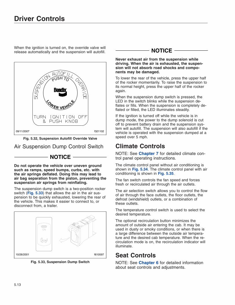
When the ignition is turned on, the override valve willrelease automatically and the suspension will autofill.
Air Suspension Dump Control Switch
NOTICEDo not operate the vehicle over uneven groundsuch as ramps, speed bumps, curbs, etc. withthe air springs deflated. Doing this may lead toair bag separation from the piston, preventing thesuspension air springs from reinflating.
The suspension dump switch is a two-position rockerswitch (Fig. 5.33) that allows the air in the air sus-pension to be quickly exhausted, lowering the rear ofthe vehicle. This makes it easier to connect to, ordisconnect from, a trailer.
NOTICENever exhaust air from the suspension whiledriving. When the air is exhausted, the suspen-sion will not absorb road shocks and compo-nents may be damaged.
To lower the rear of the vehicle, press the upper halfof the rocker momentarily. To raise the suspension toits normal height, press the upper half of the rockeragain.
When the suspension dump switch is pressed, theLED in the switch blinks while the suspension de-flates or fills. When the suspension is completely de-flated or filled, the LED illuminates steadily.
If the ignition is turned off while the vehicle is indump mode, the power to the dump solenoid is cutoff to prevent battery drain and the suspension sys-tem will autofill. The suspension will also autofill if thevehicle is operated with the suspension dumped at aspeed over 5 mph.
Climate ControlsNOTE: See Chapter 7 for detailed climate con-trol panel operating instructions.
The climate control panel without air conditioning isshown in Fig. 5.34. The climate control panel with airconditioning is shown in Fig. 5.35.
The fan switch controls the fan speed and forcesfresh or recirculated air through the air outlets.
The air selection switch allows you to control the flowof air through the face outlets, the floor outlets, thedefrost (windshield) outlets, or a combination ofthese outlets.
The temperature control switch is used to select thedesired temperature.
The optional recirculation button minimizes theamount of outside air entering the cab. It may beused in dusty or smoky conditions, or when there isa large difference between the outside air tempera-ture and the desired cab temperature. When the re-circulation mode is on, the recirculation indicator willilluminate.
Seat ControlsNOTE: See Chapter 6 for detailed informationabout seat controls and adjustments.
PUSH TO
09/11/2007 f321102
Fig. 5.32, Suspension Autofill Override Valve
10/26/2001 f610597
Fig. 5.33, Suspension Dump Switch
Driver Controls
5.13

WARNINGKeep hands, tools, and other objects away fromthe scissor points under the seats. Failure to doso could cause personal injury.
The following is a description of adjustments that canbe made to various seats. Not all seats have all ofthe adjustments listed below. See Fig. 5.36.
• Backrest tilt
• Lumbar support
• Isolator
• Height adjustment
• Bottom cushion angle (fore-and-aft bottomcushion height)
• Fore-and-aft seat slide (seat track adjustment)
• Seat tilt
• Headrest adjustment
Bench SeatsThe full bench seat (Fig. 5.37) is optional. The fullbench seat has a seat slide adjustment to allow moreor less leg room for the driver and passengers. Re-lease the seat slide lever and push backwards orforwards to move the seat along its track.
231
40
1 2 3
f831452a06/17/2003
1. Fan Switch 2. Air Selection Switch 3. Temperature Control Switch
Fig. 5.34, Climate Control Panel Without Air Conditioning
1 2 3
5 4 f831453a06/18/2003
231
40
1. Fan Switch2. Air Selection Switch
3. Temperature Control Switch4. Recirculation Button
5. Recirculation Indicator
Fig. 5.35, Climate Control Panel With Air Conditioning
Driver Controls
5.14

No adjustments are possible on the two-personbench seat or the non-suspended passenger seat.
f910149a02/03/2017
1
2
3 4
56 7
8
1. Backrest Tilt2. Lumbar Support3. Isolator Feature4. Height Adjustment
5. Bottom Cushion Angle (fore-and-aft cushion height)
6. Fore-and-Aft Seat Slide (seattrack adjustment)
7. Seat Tilt8. Upper Backrest Adjustment
Fig. 5.36, General Seat Adjustments
10/05/2001 f910481
1
2
1. Bench Seat 2. Seat Slide Lever
Fig. 5.37, Full Bench Seat
Driver Controls
5.15

6
Seats and RestraintsSeats, General Information . . . . . . . . . . . . . . . . . . . . . . . . . . . . . . . . . . . . . . . . . . . . . . . . . . . . . . . . . 6.1Freightliner High-Back Seat . . . . . . . . . . . . . . . . . . . . . . . . . . . . . . . . . . . . . . . . . . . . . . . . . . . . . . . . . 6.2Bostrom Seat . . . . . . . . . . . . . . . . . . . . . . . . . . . . . . . . . . . . . . . . . . . . . . . . . . . . . . . . . . . . . . . . . . . . 6.3Sears Atlas Seat . . . . . . . . . . . . . . . . . . . . . . . . . . . . . . . . . . . . . . . . . . . . . . . . . . . . . . . . . . . . . . . . . . 6.4National 2000 Series Seat . . . . . . . . . . . . . . . . . . . . . . . . . . . . . . . . . . . . . . . . . . . . . . . . . . . . . . . . . . 6.5Seat Belts and Tether Belts . . . . . . . . . . . . . . . . . . . . . . . . . . . . . . . . . . . . . . . . . . . . . . . . . . . . . . . . . 6.6

Seats, General InformationUnless otherwise noted, all seat adjustments shouldbe made while seated and before the engine isstarted.
Due to the maximum adjustability of mid- and high-back air suspension seats, it is possible to combinethe seat back recline adjustment and the seat slideadjustment so that the seat back contacts the back-wall. It is the responsibility of the driver to adjust theseat to prevent damage to the seat and the cabinterior.
WARNINGKeep hands, tools, and other objects away fromthe scissor points under the seats. Failure to doso could cause personal injury.
The following is a description of adjustments that canbe made to various Freightliner-installed seats. Notall seats have all of the adjustments listed below.See Fig. 6.1.
1. Backrest Tilt: This adjustment enables the back-rest to pivot forward or backward.
2. Lumbar Support: Lumbar support changes theshape of the seat back to give more or less sup-port to the occupant’s lumbar (lower back) area.This adjustment is either mechanical or air con-trolled, depending on make and model of theseat.
3. Isolator: This feature reduces the amount of roadshock by isolating the occupant from the motionof the vehicle, and allowing the upper seat tomove in a simple pendulum motion. A lockoutfeature is used whenever the isolator is not de-sired.
4. Height Adjustment: This adjustment moves theentire seat up or down. The adjustment is eithermanually- or air-controlled, depending on themake of the seat.
5. Bottom Cushion Angle, or Fore-and-Aft BottomCushion Height: This adjustment enables the oc-cupant to raise or lower the front or back of thebottom cushion. This adjustment is easier to per-form when all weight is removed from the seat.
6. Fore-and-Aft Seat Slide, or Seat Track Adjust-ment: This adjustment moves the entire seat for-ward or backward on its track.
f910149a02/03/2017
1
2
3 4
56 7
8
1. Backrest Tilt2. Lumbar Support3. Isolator Feature4. Height Adjustment
5. Bottom Cushion Angle (fore-and-aft cushion height)
6. Fore-and-Aft Seat Slide (seattrack adjustment)
7. Seat Tilt8. Upper Backrest Adjustment
Fig. 6.1, General Seat Adjustments
Seats and Restraints
6.1

7. Seat Tilt: This adjustment allows the seat assem-bly (back and bottom cushions) to tilt forward orbackward.
8. Headrest Adjustment: This adjustment changesthe angle of the upper part of the backrest toprovide head and upper back support.
Bench SeatsThe full bench seat is optional. See Fig. 6.2.
The full bench seat has a seat slide adjustment toallow more or less leg room for the driver and pas-sengers. Release the seat slide lever and push back-wards or forwards to move the seat along its track.
High-back air suspension seats are optional for bothdriver’s and passenger’s seats. Also available are anon-suspended passenger’s seat, and a two-personbench seat with a safe or tool box located under theseat.
No adjustments are possible on the two-personbench seat or the non-suspended passenger seat.
Freightliner High-Back SeatSee Fig. 6.3 for seat adjustment controls. Not allmodels of the seat have all the adjustments listedbelow.
Backrest TiltTo tilt the backrest, lean forward slightly to removepressure from the cushion, then turn the knob for-ward or rearward to achieve the desired position.
Lumbar SupportTo adjust the lumbar support, use the lumbar supportswitches on the side of the seat.
Height AdjustmentTo raise or lower the height of the seat, use theheight adjustment switch on the side of the seat.
Bottom Cushion ExtensionTo adjust the fore-and-aft position of the seat cush-ion, remove your weight from the seat, then lift upand pull forward on the cushion adjustment handle.To return the cushion to the aft position, lift up andpush rearward.
Fore/Aft Seat SlideTo adjust the fore-and-aft position of the entire seat,move the fore-and-aft seat adjustment lever to theleft and slide the seat forward or backward to thedesired position. Move the lever back to its originalposition to lock the seat in place.
Fore/Aft IsolatorTo engage the isolator, turn the isolator knob rear-ward to the unlocked position. Turn the isolator knobforward to the locked position when the isolator fea-ture is not desired.
Shock AbsorberTo adjust the amount of damping the shock absorberprovides, move the lever up to increase damping;move the lever down to decrease damping.
Front Cushion HeightTo adjust the height of the front of the cushion, re-move your weight from the seat, then turn the adjust-ment knob toward the front of the seat (clockwise) toincrease cushion height. To lower the cushion height,turn the adjustment knob toward the rear of the seat(counterclockwise).
10/05/2001 f910481
1
2
1. Bench Seat 2. Seat Slide Lever
Fig. 6.2, Full Bench Seat
Seats and Restraints
6.2

Rear Cushion HeightTo adjust the height of the rear of the seat cushion,remove your weight from the seat and turn the rearcushion adjustment knob to one of three positions.
HeaterTo turn on the heat option, press the button. To turnoff the heat option, press the button again. If the ve-hicle has Optimized Idle, seat heating will not oper-ate with the key in accessory mode. Optimized Idlemay also turn seat heating off to reduce stress onthe batteries.
Bostrom SeatSee Fig. 6.4 for Bostrom seat adjustment controls.
Backrest Tilt, Bostrom SeatTo tilt the backrest, lean forward slightly to removepressure from the cushion and hold the backrest tiltlever rearward. Lean backward slowly to the desiredposition and release the lever to lock the backrest inplace. To adjust backrest forward, hold the backresttilt lever rearward while leaning forward.
Lumbar Support, Bostrom SeatTo increase lumbar support on luxury seat option(LSO) models, press the plus sign on the lumbarsupport switch. To decrease lumbar support on LSOmodels, press the minus sign on the switch.
To increase lumbar support on non-LSO models, ro-tate the lumbar support knob forward. To decrease
f910576
5
4
78
9
10
6
07/18/2007
1
2
3
NOTE: Not all models of the seat have all the adjustment controls shown.
1. Rear Cushion Height AdjustmentKnob
2. Fore/Aft Isolator3. Front Cushion Height Adjustment
Knob
4. Bottom Cushion Extension Handle5. Fore/Aft Seat Slide Lever6. Backrest Tilt Knob7. Heater Button
8. Shock Absorber Lever9. Height Adjustment Switch10 Lumbar Support Switches
Fig. 6.3, Freightliner High-Back Seat
Seats and Restraints
6.3

lumbar support on non-LSO models, rotate the knobrearward.
Height Adjustment, Bostrom SeatTo raise the seat, press the upper portion of theheight adjustment switch. To lower the seat, pressthe lower portion of the switch.
Bottom Cushion Tilt, Bostrom SeatTo adjust the bottom cushion tilt, rotate the bottomcushion tilt knob to increase or decrease bottomcushion tilt.
Fore-and-Aft Seat Adjustment,Bostrom SeatTo adjust the fore-and-aft position of the entire seat,hold the fore-and-aft adjustment lever to the left andslide the seat forward or backward to the desiredposition.
Isolator, Bostrom SeatTo engage the isolator, put the isolator lever in thecenter position. Lock out the isolator by moving thelever to the right.
Sears Atlas SeatSee Fig. 6.5 for seat adjustment controls.
1
2
34
5
6
12/03/2010 f910131a
1. Backrest Tilt Lever2. Lumbar Support Switches (LSO models)3. Height Adjustment Switch4. Bottom Cushion Tilt Knob5. Fore-and-Aft Seat Adjustment and Isolator Lever6. Lumbar Support Knob (non-LSO models)
Fig. 6.4, Bostrom Seat Adjustment Controls
11/24/2009 f910615
1
2
3
4
5
6
7
1. Seat Tilt/Extension Adjustment Handle2. Fore-and-Aft Slide Adjustment Bar3. Isolatior Lever4. Suspension (Ride) Adjustment Switch5. Lumbar Support Switches6. Backrest Adjustment Handle7. Armrest
Fig. 6.5, Sears Atlas Seat Adjustment Controls
Seats and Restraints
6.4

Seat Tilt/Extension Adjustment, SearsAtlas SeatTo adjust the seat tilt/extension, lift the handle up-ward and move the seat cushion to the desired posi-tion. Three positions are available.
Fore-and-Aft Seat Adjustment, SearsAtlas SeatTo adjust the fore-and-aft position of the entire seat,lift the bar and slide the seat to the desired positon.
IsolatorTo engage the isolator, put the isolator lever in theleft position. Lock out the isolator by moving the leverto the right.
Height Adjustment, Sears Atlas SeatTo inflate and raise the suspension, push forward onthe front rocker switch. To deflate and lower the sus-pension, push rearward on the switch.
Lumbar Support, Sears Atlas SeatTo inflate or deflate the lower lumbar bag, push therear rocker switch.
to inflate or deflate the upper lumbar bag, push thecenter rocker switch.
Backrest Tilt, Sears Atlas SeatTo tilt the backrest, lean forward slightly to removepressure from the cushion and pull upward on thebackrest adjustment handle. Lean backward slowly tothe desired position and release the lever to lock thebackrest in place. To adjust backrest forward, pullupward on the recliner handle while leaning forward.
Armrest Adjustment, Sears Atlas SeatTo adjust the armrest the the desired angle, rotatethe control knob (located on the underside of thearmrest).
National 2000 Series SeatSee Fig. 6.6 for seat adjustment controls.
Backrest Tilt, National 2000 SeriesSeatTo tilt the backrest, turn the backrest tilt knob untilthe desired position is reached.
Lumbar Support, National 2000Series SeatTo adjust the lumbar support, use the lumbar supportswitch on the side of the seat to give more or lesssupport to your lower back.
Height Adjustment, National 2000Series SeatTo raise or lower the height of the seat, use theheight adjustment switch on the side of the seat.
Fore-and-Aft Seat Adjustment,National 2000 Series SeatTo adjust the fore-and-aft position of the entire seat,move the fore-and-aft seat adjustment lever to the
11/14/2000
1
234
5
f910445
6
7
1. Backrest Tilt Knob2. Lumbar Support Switch3. Height Adjustment Switch4. Fore-and-Aft Seat Adjustment Lever5. Bottom Cushion Fore-and-Aft Adjustment Handle6. Isolator Handle7. Rear Cushion Adjustment Knob
Fig. 6.6, National 2000 Series Seat Adjustment Controls
Seats and Restraints
6.5

left and slide the seat forward or backward to thedesired position. Move the lever back to its originalposition to lock the seat in place.
Bottom Cushion Fore-and-AftAdjustment, National 2000 SeriesSeatTo adjust just bottom cushion, lift the bottom cushionadjustment handle and pull forward or push back tothe desired setting.
Isolator, National 2000 Series SeatTo engage the isolator, turn the isolator handle to thehorizontal position. Lock out the isolator by turningthe isolator handle down.
Rear Cushion Adjustment, National2000 Series SeatTo adjust the height of the rear of the seat cushion,remove your weight from the seat and turn the rearcushion adjustment knob to one of three positions.
Seat Belts and Tether BeltsGeneral Information, Seat Belts andTether BeltsSeat belt assemblies are designed to secure personsin the vehicle to help reduce the chance of injury, orthe amount of injury, resulting from accidents or sud-den stops. For this reason, Daimler Truck NorthAmerica LLC urges that the driver and all passen-gers, regardless of age or physical condition, useseat belts when riding in the vehicle.
WARNINGAlways use the vehicle’s seat belt system whenoperating the vehicle. Failure to do so can resultin severe personal injury or death.
Seat belt assemblies in Daimler Truck North America(DTNA) vehicles meet Federal Motor Vehicle SafetyStandard 209, "Type 1" and "Type 2" requirements.
When transporting a child, always use a child re-straint system or the vehicle seat belts as appropri-ate. To determine whether a child restraint system isrequired, review and comply with applicable stateand local laws. Any child restraint used must complywith Federal Motor Vehicle Safety Standard 213,"Child Restraint Systems." When providing a child
restraint system, always carefully read and follow allinstructions pertaining to installation and usage forthe child. Make certain the child remains in the re-straint system at all times when the vehicle is in mo-tion.
In addition to seat belt assemblies, tether belts areinstalled on suspension-type seats. Tether belts pro-vide a flexible extension of the cab structure. Theyhelp secure the seat to the floor, and are intended torestrain the seat and seat belt in case of an accidentor sudden stop.
IMPORTANT: Seat belts and tethers have a fi-nite life which may be much shorter than the lifeof the vehicle. Regular inspections and replace-ment as needed are the only assurance of ad-equate seat belt security over the life of thevehicle.
Inspection, Seat Belts and TetherBelts
WARNINGInspect and maintain seat belts. When any part ofa seat belt system needs replacement, the entireseat belt must be replaced, both retractor andbuckle side. Any time a vehicle is involved in anaccident, and the seat belt system was in use,the entire vehicle seat belt system must be re-placed before operating the vehicle. Do not at-tempt to modify the seat belt system; doing socould change the effectiveness of the system.Failure to replace worn or damaged seat belts, ormaking any modifications to the system, may re-sult in personal injury or death.
Inspect the seat belts and tether belts (if soequipped).
1. Check the web for fraying, cuts, extreme dirt anddust, or for severe fading from exposure to sun-light, especially near the buckle latch plate and inthe D-loop guide area.
2. Check operation of the buckle, latch, KomfortLatch or Sliding Komfort Latch (if equipped), webretractor, and upper seat belt mount on the doorpillar. Check all visible components for wear ordamage.
3. Check the seat belt and tether belt connectionpoints and tighten any that are loose.
Seats and Restraints
6.6

Seat Belt OperationThree-Point Seat Belt With Komfort Latchor Sliding Komfort Latch
NOTE: For vehicles not equipped with the Kom-fort Latch or the Sliding Komfort Latch, see theseat belt operation under the heading "Three-Point Seat Belt."
WARNINGWear three-point seat belts only as describedbelow. Three-point seat belts are designed to beworn by one person at a time. In case of an acci-dent or sudden stop, personal injury or deathcould result from misuse.
Fasten the seat belts before driving. Fastening athree-point seat belt while driving creates a haz-ard.
When engaged and used properly, the Komfort Latch(Fig. 6.7) and the Sliding Komfort Latch (Fig. 6.8)introduce a small amount of slack into the seat belt,resulting in a more comfortable ride.
1. Slowly pull the latch end of the three-point seatbelt out of the retractor and pull it across yourlap (from outboard to inboard) far enough to en-
gage the buckle. If the retractor locks too soon,allow the belt to retract slightly, then slowly pull itout again. See Fig. 6.9.
2. Fasten the three-point seat belt by pushing thelatch into the buckle. Listen for an audible click.
3. Tug on the seat belt to make sure it is securelyfastened. If the buckle unlatches, repeat thisstep. If the problem continues, replace the three-point seat belt.
4. Snug the seat belt to your waist.
WARNINGBefore activating the Komfort Latch or the Slid-ing Komfort Latch, make sure the amount ofslack in the shoulder strap is set as describedbelow. Excess slack in the shoulder strap re-duces the effectiveness of the seat belt, and in-creases the risk of injury or death in an accident.
5. Position the shoulder strap diagonally acrossyour chest with the adjustable D-loop bracket (ifequipped). The shoulder strap must be centeredon your shoulder and chest, away from your faceand neck. See Fig. 6.10. If desired, engage theKomfort Latch or Sliding Komfort Latch as fol-lows.
If equipped with a Sliding Komfort Latch, makesure that the shoulder strap is snug against yourchest. Without loosening the shoulder strap,
03/11/2010 f910620
A B
A. Disengaged B. Engaged
Fig. 6.7, Komfort Latch
11/18/2010 f910621a
Fig. 6.8, Sliding Komfort Latch
Seats and Restraints
6.7

push the Sliding Komfort Latch switch to the"ON" position. See Fig. 6.8. To activate the latchlean forward until you hear a click. This will allowfor approximately 1 inch (2.5 cm) of slack be-tween your chest and the shoulder harness.Once engaged, the latch will allow you to leanforward about 5 inches (13 cm) without having toreset the latch. Leaning forward more than 5inches (13 cm) will disengage the Sliding Kom-fort Latch, requiring it to be reset.
If equipped with a Komfort Latch, pull on theshoulder strap to lessen the pressure of the strapon your shoulder and chest. Allow no more than1 inch (2.5 cm) of slack between your chest andthe shoulder harness. More slack can signifi-cantly reduce the seat belt effectiveness in anaccident or a sudden stop. While holding the beltslack, press the Komfort Latch lever up, clamp-ing the seat belt webbing (Fig. 6.11 andFig. 6.12).
07/02/2007 f910578
1
2
1. Latch 2. Buckle
Fig. 6.9, Three-Point Seat Belt Operation
f91063402/03/2017
A B C
A. Correct—Belt is centered on your shoulder andchest, away from your face and neck.
B. Wrong—Belt must not rub against face or neck.C. Wrong—Belt must not hang off shoulder.
Fig. 6.10, Proper Shoulder Strap Fit
f910048a02/03/2017
A
A. 1 Inch (2.5 cm) Maximum
Fig. 6.11, Adjusting Shoulder Harness Clearance,Komfort Latch
f91014402/03/2017
Fig. 6.12, Locking the Komfort Latch
Seats and Restraints
6.8

6. Unbuckle the three-point seat belt and releasethe Komfort Latch or the Sliding Komfort Latchas follows.
If equipped with a Sliding Komfort Latch, un-buckle the seat belt, then tug on the shoulderbelt to release the Sliding Komfort Latch, orpress the Sliding Komfort latch to the "OFF" po-sition, then unbuckle the seat belt.
If equipped with a Komfort Latch, unbuckle theseat belt, then release the Komfort Latch by giv-ing the shoulder belt a quick tug. If you lean for-ward against the shoulder belt, the Komfort Latchwill automatically release, and will need to bereset.
NOTE: Neither the Komfort Latch nor the SlidingKomfort Latch need to be manually released inan emergency situation. Each will release byitself under rough road or other abnormal condi-tions. Make sure the three-point seat belt iscompletely retracted when it is not in use.
Three-Point Seat Belt
NOTE: For vehicles equipped with the KomfortLatch or the Sliding Komfort Latch, see the seatbelt operation under the heading "Three-PointSeat Belt With Komfort Latch or Sliding KomfortLatch."
WARNINGWear three-point seat belts only as describedbelow. Three-point seat belts are designed to beworn by one person at a time. In case of an acci-dent or sudden stop, personal injury or deathcould result from misuse.
Fasten the seat belts before driving. Fastening athree-point seat belt while driving creates a haz-ard.
1. Slowly pull the link end of the three-point seatbelt out of the retractor and pull it across yourlap (from outboard to inboard) far enough to en-gage the buckle. If the retractor locks too soon,allow the belt to retract slightly, then slowly pull itout again. See Fig. 6.8.
2. Fasten the three-point seat belt by pushing thelatch into the buckle. Listen for an audible click.
3. Tug on the seat belt to make sure it is securelyfastened. If the buckle unlatches, repeat this
step. If the problem continues, replace the three-point seat belt.
4. Snug the seat belt to your waist.
5. Position the shoulder strap diagonally acrossyour chest with the adjustable D-loop bracket (ifequipped). The shoulder strap must be centeredon your shoulder and chest, away from your faceand neck. See Fig. 6.10.
6. To unbuckle the three-point seat belt, press therelease button on the buckle.
NOTE: Make sure the three-point seat belt iscompletely retracted when it is not in use.
Seats and Restraints
6.9

7
Climate ControlClimate Control Panel . . . . . . . . . . . . . . . . . . . . . . . . . . . . . . . . . . . . . . . . . . . . . . . . . . . . . . . . . . . . . 7.1

Climate Control PanelThe climate control panel allows you to control theheating, ventilating, defrosting, and air conditioningfunctions. The climate control panel without air condi-tioning is shown in Fig. 7.1. The climate controlpanel with air conditioning is shown in Fig. 7.2.
Fan SwitchThe fan switch controls the fan speed and forcesfresh or recirculated air through the air outlets. Thefan switch has eight fan speeds and an off position.
To increase airflow, turn the fan switch to the righttoward a higher number. To decrease the airflow, turnthe switch to the left toward a lower number.
Air Selection SwitchThe air selection switch allows you to control the flowof air through the face outlets, the floor outlets, thedefrost (windshield) outlets, or a combination ofthese outlets to give you nine air selection modes ona system without air conditioning. See Fig. 7.3. Asystem with air conditioning has eleven air selectionmodes, four of which are air conditioning modes. SeeFig. 7.4.
Air Selection Switch Without AirConditioning
1. Face Mode: Directs all airflow through the faceor instrument panel outlets.
231
40
1 2 3
f831452a06/17/2003
1. Fan Switch 2. Air Selection Switch 3. Temperature Control Switch
Fig. 7.1, Climate Control Panel Without Air Conditioning
1 2 3
5 4 f831453a06/18/2003
231
40
1. Fan Switch2. Air Selection Switch
3. Temperature Control Switch4. Recirculation Button
5. Recirculation Indicator
Fig. 7.2, Climate Control Panel With Air Conditioning
Climate Control
7.1

2. Selection between Face Mode and Bi-LevelMode: Directs 75 percent of the airflow throughthe face outlets and 25 percent through the flooroutlets.
3. Bi-Level Mode: Directs the airflow equally to theface outlets and the floor outlets.
4. Selection between Bi-Level Mode and FloorMode: Directs 25 percent of the airflow throughthe face outlets and 75 percent through the flooroutlets.
5. Floor Mode: Directs all airflow through the flooroutlets.
6. Selection between Floor Mode and Floor/Defrost Mode: Directs 75 percent of the airflowthrough the floor outlets and 25 percent throughthe defrost outlets.
7. Floor/Defrost Mode: Directs the airflow equallyto the floor outlets and the defrost outlets.
8. Selection between Floor/Defrost Mode andDefrost Mode: Directs 75 percent of the airflowthrough the defrost outlets and 25 percentthrough the floor outlets.
9. Defrost Mode: Directs all airflow through thedefrost outlets.
Air Selection Switch With AirConditioning1. Air Conditioning Face Mode: Directs all airflow
through the face or instrument panel outlets.
2. Selection between the Air Conditioning FaceMode and the Air Conditioning Bi-LevelMode: Directs 75 percent of the airflow to theface outlets and 25 percent to the floor outlets.
3. Air Conditioning Bi-Level Mode: Directs theairflow equally to the face outlets and the flooroutlets.
4. Selection between the Air Conditioning Bi-Level Mode and the Face Mode: Directs 25percent of the airflow to the face outlets and 75percent to the floor outlets.
5. Face Mode: Directs all airflow through the faceoutlets.
6. Selection between Face Mode and FloorMode: Directs the airflow equally through theface outlets and the floor outlets.
06/17/2003
1
2
34
5
6
7
8
9
f831455
1. Face Mode2. Selection Between Face Mode and Bi-Level Mode3. Bi-Level Mode4. Selection Between Bi-Level Mode and Floor Mode5. Floor Mode6. Selection Between Floor Mode and Floor/Defrost
Mode7. Floor/Defrost Mode8. Selection Between Floor/Defrost Mode and Defrost
Mode9. Defrost Mode
Fig. 7.3, Air Selection Switch Without Air Conditioning
f831462
1
2
3
4
56
7
8
9
10
1106/18/2003
A
A. Air Conditioning Modes1. Air Conditioning Face Mode2. Selection Between Air Conditioning Face Mode and
Air Conditioning Bi-Level Mode3. Air Conditioning Bi-Level Mode4. Selection Between Air Conditioning Bi-Level Mode
and Face Mode5. Face Mode6. Selection Between Face Mode and Floor Mode7. Floor Mode8. Selection between Floor Mode and Floor/Defrost
Mode9. Floor/Defrost Mode10. Selection between Floor/Defrost Mode and Defrost
Mode11. Defrost Mode
Fig. 7.4, Air Selection Switch With Air Conditioning
Climate Control
7.2

7. Floor Mode: Directs all airflow through the flooroutlets.
8. Selection between Floor Mode and Floor/Defrost Mode: Directs 75 percent of the airflowthrough the floor outlets and 25 percent throughthe defrost outlets.
9. Floor/Defrost Mode: Directs the airflow equallyto the floor outlets and the defrost outlets. Therecirculation button will not work in this mode.
10. Selection between Floor/Defrost Mode andDefrost Mode: Directs 75 percent of the airflowthrough the defrost outlets and 25 percentthrough the floor outlets. The recirculation buttonwill not work in this mode.
11. Defrost Mode: Directs all airflow through thedefrost outlets. The recirculation button will notwork in this mode.
Temperature Control SwitchThe temperature control switch is used to select thedesired temperature. Turn the switch to the left(counterclockwise) for cool air, or to the right (clock-wise) for hot air. There are 21 positions on the tem-perature control switch ranging from full cool air tofull hot air.
Fresh Air ModeFresh air, or outside air, is circulated through theheating and air conditioning system unless the recir-culation mode, if equipped, is turned on.
Recirculation ModeThe recirculation mode is only available on vehicleswith air conditioning.
The recirculation mode limits the amount of outsideair entering the cab. Press the recirculation button toprevent dusty or smoky air from entering the cab.The recirculation mode can also be used to decreasethe time required to cool or heat the cab interior dur-ing extreme outside temperature conditions. Whenthe recirculation mode is on, the recirculation indica-tor will illuminate. See Fig. 7.2.
The recirculation mode is not available when the airselection switch is in one of the following modes:
• floor/defrost mode
• selection between floor/defrost mode and de-frost mode
• defrost mode
When the recirculation mode is turned on, it will stayon for 20 minutes, or until the recirculation button ispressed again, or the air selection switch is turned toa defrost mode.
IMPORTANT: The system will enter a partial re-circulation mode for five minutes after being infull recirculation mode for twenty minutes. Thiscycle will repeat as long as the system is in re-circulation mode.
DefrostingBefore using any of the defrost modes, clear thescreen at the base of the windshield of any ice orsnow.
Air Conditioning, OptionalThe four air conditioning settings on the air selectionswitch, as well as the selection between the air con-ditioning bi-level mode and the face mode, are blue.
NOTE: The heating and air conditioning systemhas a brushless blower motor with a protectionor shutdown mode to prevent damage due tooverheating and overcurrent conditions. If thebrushless blower motor goes into protectionmode, the motor will operate at a slower speed.If the overheating or overcurrent condition con-tinues, the motor will shut down and stop com-pletely.
The motor will resume proper operation after themotor has cooled or the overcurrent conditionhas been resolved. It will be necessary to cyclethe fan switch off and then on, to reset themotor. If the problem appears repeatedly, takethe vehicle to a Freightliner dealer or authorizedservice outlet for repairs.
Accessory HeatersOptional accessary heaters are available from thefactory in several configurations. Familiarize yourselfwith the equipment on your specific vehicle, and fol-low the manufacturer’s operating and maintenanceinstructions.
WARNINGDo not operate fuel-operated heaters in an areawhere flammable vapors, including gasoline or
Climate Control
7.3

diesel fumes, are present, such as at filling sta-tions and tank farms. Turn off a fuel-operatedheater and allow it shut down completely beforeentering an area where flammable gases or liq-uids are present. Heaters continue to operate forup to three minutes after being turned off.
Failure to observe these precautions could causean explosion or fire, resulting in serious propertydamage, and personal injury or death.
Climate Control
7.4


8
Cab FeaturesCab Amenities . . . . . . . . . . . . . . . . . . . . . . . . . . . . . . . . . . . . . . . . . . . . . . . . . . . . . . . . . . . . . . . . . . . 8.1Mirrors and Windows . . . . . . . . . . . . . . . . . . . . . . . . . . . . . . . . . . . . . . . . . . . . . . . . . . . . . . . . . . . . . . 8.1

Cab AmenitiesCup HoldersThere are two cup holders molded into the lower partof the auxiliary dash panel, one on either side of theclimate control panel.
Cab StorageThere are storage bins in the dash and the overheadconsole.
Vehicles without an overhead console have two stor-age bins located above the windshield.
Some vehicles equipped with an overhead consolemay have a storage bin located in the overhead con-sole. Those that don’t have a storage bin in the over-head console will have a CB radio in its place.
On vehicles with individual driver’s and passenger’sseats, a center storage console can be installed be-tween the seats.
The center storage console has a table top that canbe lifted to deploy a writing surface. See Fig. 8.1.
The center storage console may also be equippedwith an optional printer top with a paper slot in it.See Fig. 8.2.
Mirrors and WindowsMirrorsThe standard outside mirrors are mounted on thedoor frame. There is a primary rear view mirror and aconvex mirror.
Mirror Heat Switch, OptionalOne or both outside door mirrors can be heated tokeep them clear of fog, frost, and ice.
To heat the mirrors, press the upper part of the mir-ror heat switch (MIRR HEAT) on the dash. SeeFig. 8.3. When the mirror heat switch is on, anamber indicator light illuminates inside the switch.
Power Mirrors, OptionalThe main outside mirrors, if heated, can be equippedwith an electrical remote control located on thedriver’s door. See Fig. 8.4.
To select the mirrors on the left-hand side, press theleft side of the mirror select switch. To select the mir-rors on the right-hand side, press the right side of themirror select switch.
The keypad has four arrow keys, pointing up, down,left, and right. To adjust mirror position, press thekeypad in the direction you want the mirror to move.
10/08/2001 f680026
1
2
3
4
1. Table Top2. Storage Console
Cover
3. Storage Area4. Storage Console Base
Fig. 8.1, Center Storage Console (with writing surface)
10/08/2001 f680025
1
2
3
1. Printer Top2. Printer/Paper Area
3. Storage Console Base
Fig. 8.2, Center Storage Console (printer option)
Cab Features
8.1

Down View Mirror, OptionalA down view mirror can be installed on the top of thepassenger door frame to allow the driver a view ofthe area adjacent to the right side of the cab. SeeFig. 8.5.
WindowsStandard windows operate mechanically using ahand crank.
Power windows are optional, and can be installed onone side or both sides. One power window switchwill be installed on the dash for each window. SeeFig. 8.6. To raise the window, press up on theswitch. To lower the window, press down on theswitch. Releasing the switch will cause the window tostop.
Standard vent (wing) windows do not open. Operat-ing vent windows are optional. To open the operatingvent window, turn the latch on the window and pushthe window open. See Fig. 8.7.
MIRRHEAT
10/09/2001 f610524
To heat the mirrors, press up on the switch. To turn offheat to the mirrors, press down on the switch.
Fig. 8.3, Mirror Heat Switch
10/05/2001 f610523
1
2
To adjust the mirror position, press the keypad on thedoor in the direction you want the mirror to move.
1. Mirror Select Switch 2. Keypad
Fig. 8.4, Power Mirror Switch Pad
10/05/2001 f720396
1
1. Mirror
Fig. 8.5, Down View Mirror (optional)
10/09/2001 f610522
Press up to raise the window; press down to lower thewindow. Releasing the switch causes the window to stop.
Fig. 8.6, Power Window Switch
Cab Features
8.2
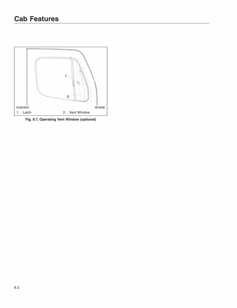
10/05/2001 f670096
1
2
1. Latch 2. Vent Window
Fig. 8.7, Operating Vent Window (optional)
Cab Features
8.3

9
Engine Starting, Operation,and Shutdown
Engine Starting . . . . . . . . . . . . . . . . . . . . . . . . . . . . . . . . . . . . . . . . . . . . . . . . . . . . . . . . . . . . . . . . . . . 9.1Engine Operation . . . . . . . . . . . . . . . . . . . . . . . . . . . . . . . . . . . . . . . . . . . . . . . . . . . . . . . . . . . . . . . . . 9.2Engine Shutdown . . . . . . . . . . . . . . . . . . . . . . . . . . . . . . . . . . . . . . . . . . . . . . . . . . . . . . . . . . . . . . . . . 9.3

Engine StartingThis engine chapter is to serve as a guide for bestpractices only. Each make and model engine mayhave operating characteristics that are unique to thatparticular engine, and will be documented in the en-gine manufacturer’s literature. Always refer to specificinstructions and recommendations from the enginemanufacturer.
NOTE: Before starting the engine, read Chap-ter 4 for detailed information on how to read theinstruments and see Chapter 5 for detailed in-formation on how to operate the controls. Readthe operating instructions in the manufacturer’sengine operation manual before starting theengine.
WARNINGNever pour fuel or other flammable liquid into theair inlet opening in the air intake in an attempt tostart the vehicle. This could result in a flash firecausing serious personal injury or propertydamage.
1. Before engine start-up, complete the engine pre-trip and post-trip inspections and maintenanceprocedures in Chapter 20 and Chapter 21.
2. Set the parking brake.
3. For manual transmissions, place the transmis-sion in neutral and fully depress the clutch pedal.Do not depress the accelerator pedal.
For automatic transmissions, put the transmis-sion in neutral. Do depress the accelerator pedal.
NOTICEIf the warning lights stay on, or do not come onmomentarily after turning on the ignition, do notoperate the engine. To do so may result in enginedamage.
4. Turn the ignition switch to the ON position. SeeFig. 9.1. Electronic gauges on the instrumenta-tion control unit (ICU) will complete a full sweepof their dials, the warning and indicator lamps willilluminate, and the buzzer will sound for threeseconds.
During cold conditions, the WAIT TO STARTlamp may illuminate on vehicles with Cumminsengines. Wait until the lamp goes out beforeturning the ignition key to START.
NOTE: The length of time the WAIT TO STARTlamp remains illuminated depends on the ambi-ent temperature. The lower the ambient tem-perature, the longer the lamp will be illuminated.
NOTE: The engine electronics supply the cor-rect amount of fuel for starting the engine. Ac-celerator pedal pressure is unnecessary, andcould interfere with engine starting.
5. Turn the ignition key to the START position. Donot depress the accelerator pedal.
Release the key the moment the engine starts.
6. Apply load gradually during the warm-up period.
NOTICEDo not rev the engine if the oil pressure gaugeindicates no oil pressure. Shut down the enginewithin approximately ten seconds to avoid enginedamage.
7. Check the oil pressure gauge for any drop in lu-bricating oil pressure or mechanical malfunctionin the lubricating oil system.
Cold-Weather StartingSee the engine manufacturer’s operation manual forstarting aids that are approved for specific engines.
Starting After Extended ShutdownBefore engine start-up, complete the engine pretripand post-trip inspections and maintenance proce-dures in Chapter 20 and Chapter 21.
f61080502/03/2017
Fig. 9.1, Ignition Switch
Engine Starting, Operation, and Shutdown
9.1

NOTICEFailure to eliminate water-diluted lubricating oilmay lead to serious engine damage at startup.
An engine in storage for an extended period of time(over winter, for example) may accumulate water inthe oil pan through normal condensation of moistureon the internal surfaces of the engine. Oil diluted bywater cannot provide adequate bearing protection atstart-up. For this reason, change the engine oil andfilters after extended storage.
Engine OperationSafety and EnvironmentalConsiderationsAll Freightliner diesel engines comply with the re-quirements of the Federal (U.S.) Clean Air Act. Oncean engine is placed in service, the responsibility formeeting both state and local regulations is with theowner/operator.
NOTICEIt is extremely important that the following guide-lines be followed for engines that comply withEPA10 or newer regulations, or damage mayoccur to the aftertreatment device, and the war-ranty may be compromised.
• Use ultralow-sulfur diesel with 15 ppm sul-fur content or less.
• Do not use fuel blended with used enginelube oil or kerosene.
• Use only engine lube oil with a sulfated ashlevel less than 1.0 wt%; currently referredto as CJ-4 oil.
A Top Tier™ compliant fuel is recommended. Look forthe symbol that denotes a Top Tier compliant fuel;see Fig. 9.2.
Adequate maintenance of the engine and the dieselparticulate filter (DPF) are the responsibility of theowner/operator, and are essential to keep the emis-sion levels low. Good operating practices, regularmaintenance, and correct adjustments are factorsthat will help keep emissions within the regulations.
The driver should be familiar with the vehicle warningsystem in order to bring the vehicle to a safe stop ifthe engine malfunctions. If the driver doesn’t under-stand how the warning system works, an engineshutdown could occur, causing a safety hazard. SeeChapter 10 for more information.
Engine Break-InEach engine must pass a full-load operating test ona dynamometer before shipment, thereby eliminatingthe need for a break-in. Before running the enginefor the first time, follow the instructions in the enginemanufacturer’s operation manual specific to yourengine.
Normal Operation
WARNINGDo not operate the engine in an area where flam-mable vapors such as gasoline or diesel fumesare present. Shut off the engine when in an areawhere flammable liquids or gases are beinghandled. Failure to observe these precautionscould result in serious injury or death.
Every engine has an operating range in which it per-forms most efficiently. The operating range extendsfrom maximum torque rpm at the low end, to enginerated speed at the high end. Most engines deliverbest fuel economy when operated in the low- andmid-speed segments of the efficiency range and pro-duce maximum horsepower at rated speed, which isalso the recommended maximum speed of the en-gine. For further engine-specific information, refer tothe engine manufacturer’s operation manual.
Prolonged idling of engines is not recommended, andis illegal in some states. Idling produces sulfuric acid,that is absorbed by the lubricating oil, and eats intobearings, rings, valve stems, and engine surfaces. Ifyou must idle the engine for cab heat or cooling, usethe high idle function of the cruise control switches.An idle speed of 900 rpm should be enough to pro-vide cab heat in above freezing ambient tempera-tures.
f47069804/27/2017
Fig. 9.2, Top Tier Fuel Symbol
Engine Starting, Operation, and Shutdown
9.2

If the engine is programmed with the idle shutdowntimer, ninety seconds before the preset shutdowntime, the CHECK ENGINE light will begin to flash ata rapid rate. If the position of the clutch pedal or ser-vice brake changes during this final ninety secondsthe idle shutdown timer will be disabled until reset.
Cold-Weather OperationSatisfactory performance of a diesel engine operatingin low ambient temperatures requires modification ofthe engine, surrounding equipment, operating prac-tices, and maintenance procedures. The lower thetemperature, the greater the amount of modificationrequired. For service products approved for use incold weather for your engine, see the engine manu-facturer’s engine operation manual, supplied in thevehicle documentation package.
If satisfactory engine temperature is not maintained,maintenance costs will increase due to greater en-gine wear. If the engine coolant temperature be-comes too low, raw fuel will wash the lubricating oiloff the cylinder walls and dilute the crankcase oil,causing all moving parts of the engine to suffer frompoor lubrication.
If the engine is in good mechanical condition and theprecautions necessary for cold-weather operation aretaken, ordinary cold weather will not cause difficultyin starting or loss of efficiency.
The following points are important to observe whenoperating in cold weather:
• Check for cracks in the batteries, for corrosionof the terminals, and for tightness of the cableclamps at the terminals.
• Charge the batteries to full capacity. Replaceany battery that is damaged.
• If equipped, turn off the load disconnect switchafter the engine is shut down, to prevent bat-tery discharge.
• Have the alternator output checked at an au-thorized service provider.
• Check the condition and tension of the drivebelts.
• Refer to the engine manufacturer’s engine op-eration manual for recommended heaters, low-viscosity lubricating oils, wintergrade fuels, andapproved coolants.
A winterfront may be used to improve cab heatingwhile idling. If a winterfront is used, at least 25% ofthe grille opening should remain open in sectioned
stripes that run perpendicular to the charge air coolertube-flow direction. This assures even cooling acrosseach tube, and reduces header to tube stress, andpossible failure. Winterfronts should only be usedwhen the ambient temperature remains below 10°F(-12°C).
Engine Shutdown1. With the vehicle stopped, apply the parking
brake and place the transmission in neutral.
NOTICEIdle the engine one to two minutes before shut-ting it down. After hard operation, shutting downthe engine without idling may cause damage tothe turbocharger.
2. Allow the engine to idle one to two minutes be-fore shutting it down. This allows the lubricatingoil and the coolant to carry heat away from thecombustion chambers, bearings, shafts, andseals. The extreme heat may cause bearings toseize or oil seals to leak.
IMPORTANT: Bearings and seals in the turbo-charger are subjected to the high heat of com-bustion exhaust gases. While the engine is run-ning, this heat is carried away by oil circulation,but if the engine is stopped suddenly, the turbo-charger temperature may rise as much as 115°F(46°C).
NOTICEExcept in an emergency, do not shut down theengine when the coolant temperature is above194°F (90°C). To do so could damage the engine.
3. Turn off the ignition switch and shut down theengine.
Engine Starting, Operation, and Shutdown
9.3

10
Optional Engine SystemsEngine Protection—Warning and Shutdown . . . . . . . . . . . . . . . . . . . . . . . . . . . . . . . . . . . . . . . . . . 10.1Engine Idle Limiting . . . . . . . . . . . . . . . . . . . . . . . . . . . . . . . . . . . . . . . . . . . . . . . . . . . . . . . . . . . . . . 10.1Cruise Control . . . . . . . . . . . . . . . . . . . . . . . . . . . . . . . . . . . . . . . . . . . . . . . . . . . . . . . . . . . . . . . . . . . 10.2Auxiliary Braking Applications . . . . . . . . . . . . . . . . . . . . . . . . . . . . . . . . . . . . . . . . . . . . . . . . . . . . . . 10.3Power Takeoff (PTO) Governor . . . . . . . . . . . . . . . . . . . . . . . . . . . . . . . . . . . . . . . . . . . . . . . . . . . . . 10.5

Engine Protection—Warningand ShutdownThe driver should be familiar with the vehicle warningsystem in order to bring the vehicle to a safe stop ifthe engine malfunctions. If the driver doesn’t under-stand how the warning system works, an engineshutdown could occur.
The engine will begin a warning and shutdown pro-cess if the engine coolant temperature, coolant level,engine oil pressure, or exhaust aftertreatment system(ATS) reach preset levels. On some engines, the en-gine will also begin the warning and shutdown pro-cess when the engine oil temperature or the intakeair temperature reach preset levels. Detroit Dieselengines will also begin the warning and shutdownprocess if water is detected in the fuel.
See the engine manufacturer’s operation manual forspecific details for your vehicle.
See Chapter 11 in this manual for the warning andshutdown modes associated with the ATS.
Electronic engine protection is programmable as anoption, and can be specified as the following: DER-ATE and SHUTDOWN mode (factory default),WARNING mode, or OFF mode.
WARNINGWhen the red STOP engine or engine protectionlight illuminates, most engines are programmedto shut down automatically within 30 seconds.The driver must immediately move the vehicle toa safe location at the side of the road to preventcausing a hazardous situation that could causebodily injury, property damage, or severe damageto the engine.
In the DERATE and SHUTDOWN mode, the redSTOP engine lamp will illuminate when the problemis serious enough to reduce power or speed. SeeFig. 10.1. Engine power will ramp down, then theengine will shut down if the problem continues. Thedriver has 30 seconds or 60 seconds (depending onthe critical fault type) after the STOP engine lampilluminates to move the vehicle safely off the road. Ifthe vehicle cannot be moved to a safe location withinthat time, the engine can be restarted by turning theignition switch to the OFF position for at least fiveseconds, then back ON. Repeat this action until thevehicle is safely off the road.
Some vehicles may have a shutdown-overrideswitch, which may be used to momentarily overridethe shutdown sequence. See Fig. 10.2. This switchresets the shutdown timer, restoring power to thelevel before the derate for another 30 or 60 seconds(depending on the critical fault type). The switchmust be pressed again after 5 seconds to obtain asubsequent override. It can be used to move the ve-hicle to a safe stopping area. Do not operate the ve-hicle further until the problem has been corrected.
If the engine protection parameters are set toWARNING mode, the amber CHECK engine lampwill flash and a buzzer will sound. The engine elec-tronics log the event for diagnostic purposes. TheCHECK engine lamp will go out if the problem stops.
If the engine protection parameters are set to OFFmode, the individual sensor indicator lamps will illu-minate if a problem exists, but no shutdown actionwill be started and the event will not be recorded.
Engine Idle LimitingIdle Shutdown TimerThis feature is an optional 1- to 100-minute idle shut-down system. Its purpose is to conserve fuel by
07/09/2009 f6110361 2 3
CHECK STOP
1. Malfunction IndicatorLamp (MIL)
2. CHECK Engine Lamp3. STOP Engine Lamp
Fig. 10.1, Engine Warning Lights
08/13/2009 f611040
Fig. 10.2, Shutdown Override Switch
Optional Engine Systems
10.1

eliminating excessive idling and allowing a turbo-charger cool-down period. Idle shutdown timing andparameters are programmable. See the enginemanufacturer’s operation manual for specific detailsfor your vehicle.
Cruise Control
WARNINGDo not use the cruise control system when driv-ing conditions do not permit maintaining a con-stant speed, such as in heavy traffic or on roadsthat are winding, icy, snow-covered, slippery, orroads with a loose driving surface. Failure to fol-low this precaution could cause a collision orloss of vehicle control, possibly resulting in per-sonal injury or property damage.
NOTICEWhen the cruise control is engaged, do not at-tempt to shift gears without using the clutchpedal. Failure to follow this precaution will resultin a temporarily uncontrolled increase in enginespeed. Transmission damage and gear strippingcould result.
Cruise control is activated by two dash-mountedswitches (Fig. 10.3).
• On/Off Switch—this two-position rocker is la-beled SPD CNTL on the lower half of theswitch. When cruise control is on, an amberlight illuminates the top part of the switch.
• Set/Resume Switch—this three-position paddleswitch is labeled RES/ACC above the paddleand SET/CST below the paddle.
1. To cruise at a particular speed:
1.1 Press the upper half of the On/Off switch.
1.2 Hold the accelerator pedal down until thespeedometer reaches the desired speed.
1.3 Momentarily lower the paddle of the Set/Resume switch to SET/CST.
2. To disengage the cruise control:
2.1 Depress the brake pedal (on an automaticor manual transmission) or
Depress the clutch pedal (on a manualtransmission only).
2.2 Press the lower half of the On/Off switch.
3. To resume a preselected cruise speed:
3.1 Ensure the On/Off switch is on.
3.2 Momentarily raise the paddle of the Set/Resume switch to RES/ACC. Cruise willreturn to the last speed selected.
NOTE: When the vehicle speed drops belowthe minimum cruise control speed, cruisecontrol will disengage. To resume to the pre-selected cruise speed, increase vehiclespeed to above minimum cruise controlspeed and momentarily raise the paddled ofthe Set/Resume switch to RES/ACC.
NOTE: The speed memory is lost whenever theignition is turned off or the cruise control switchis toggled to Off.
09/13/2001
1
2
f610510
To turn cruise control on, press the upper half of the On/Off switch. To turn cruise control off, press the lower halfof the On/Off switch.
To increase cruise speed, raise and hold the paddle ofthe Set/Resume switch to RES/ACC until the vehicleaccelerates to the desired speed. To decrease cruisespeed, lower and the paddle of the Set/Resume switch toSET/CST until the vehicle decelerates to the desiredspeed.1. Cruise Control On/Off Switch2. Cruise Control Set/Resume Switch
Fig. 10.3, Cruise Control Switches
Optional Engine Systems
10.2

4. To increase cruise speed, raise and hold thepaddle of the Set/Resume switch to RES/ACCuntil the vehicle accelerates to the desiredspeed.
5. To decrease cruise speed, lower and the paddleof the Set/Resume switch to SET/CST until thevehicle decelerates to the desired speed.
Auxiliary Braking ApplicationsEngine BrakeEach engine manufacturer uses a specific enginebrake for their engine. Regardless of the manufac-turer, the engine brake is operated with the principlesoutlined in this chapter. Refer to the engine manufac-turer’s operation manual for details of their particularengine brake product.
WARNINGTo avoid injury from loss of vehicle control, donot activate the engine brake system under thefollowing conditions:
• on wet or slippery pavement, unless thevehicle is equipped with antilock brakingsystem (ABS) and you have had prior expe-rience driving under these conditions;
• when driving without a trailer or pulling anempty trailer;
• if the tractor drive wheels begin to lock, orthere is fishtail motion after the enginebrake is activated.
Whenever vehicle braking is required on good roadconditions, the engine brake may be used in con-junction with the service brakes. There is no timelimit for operation of the engine brake. However, anengine brake does not provide the precise control of,and is not a substitute for, service brakes.
WARNINGUsage of the engine brake as the primary brakingsystem can cause unpredictable stopping dis-tances, that could result in personal injury orproperty damage. Service brakes are the primaryvehicle braking system.
Two dash-mounted switches control the enginebrake:
• The On/Off switch (ENG BRK), is used to turnthe engine brake on and off. See Fig. 10.4.When the engine brake is on, an amber lightwill illuminate behind the switch.
• The engine brake intensity switch (HI/MED/LOor, in some cases, HI/LO) controls the amountof engine braking. When the panel lights areon, the ENG BRK legend is backlit in green.
Since the engine brake is most effective at rated en-gine speed, gear selection is very important. Gearingdown the vehicle within the limits of the rated enginespeed makes the engine brake more effective. Rec-ommended engine braking speed is above 1800 rpmand below the rated speed.
WARNINGThe engine brake must be disengaged whenshifting gears using the clutch pedal. If the en-gine brake is engaged when the transmission isin neutral, the braking power of the engine brakecan stall the engine, which could result in loss ofvehicle control, possibly causing personal injuryand property damage.
"Control speed" is the speed at which the enginebrake performs 100 percent of the required downhillbraking, resulting in a constant speed of descent.The control speed varies, depending on vehicleweight and the downhill grade.
For faster descent, select a higher gear than thatused for control speed. Service brakes must then beused intermittently to prevent engine overspeed andto maintain desired vehicle speed.
10/17/2001 f610588
1 2
1. Engine Brake On/Off2. Engine Brake Intensity Switch
Fig. 10.4, Engine Brake Switches
Optional Engine Systems
10.3

For slower descent, select a lower gear, being care-ful not to overspeed the engine. Occasional deactiva-tion of the engine brake may be necessary to main-tain the designated road speed under theseconditions.
If the engine is equipped with both cruise control andan engine brake, the engine brake can operate auto-matically while in cruise control mode. If the cruisecontrol/engine brake function is turned on in theDDEC VI system programming, the engine brake willcome on low when the set road speed increases afew miles-per-hour (kilometers-per-hour) above thecruise set speed. The maximum amount of braking isselected with the dash switches. When the vehiclereturns to the set cruise speed, the engine brake willturn off.
The engine brake will only operate when the accel-erator pedal is fully released. Depressing the clutchwill also prevent the engine brake from operating.
Vehicles equipped with ABS have the ability to turnthe engine brake off if wheel slip is detected. Theengine brake will automatically turn back on oncewheel slip is no longer detected.
The DDEC VI system will deactivate the enginebrake when the engine speed falls below 1000 rpmor when the vehicle slows down to a preset speed,depending on DDEC programming. This preventsstalling the engine.
Engine Brake OperationDepending on the brake type, the engine brake maybe disabled when engine temperature falls below aset level.
NOTICEDo not allow the engine to exceed 2500 rpm. Se-rious engine damage could result.
To activate the engine brake after the engine iswarmed up and the vehicle is in motion:
1. Remove your feet from both the clutch andthrottle pedals.
2. Press the On/Off switch to toggle the enginebrake on. See Fig. 10.4. The engine brake willengage at the rate last set on the brake intensityswitch.
3. Move the intensity switch to the desired intensity.
On vehicles with a HI/MED/LO intensity switch,LO will provide 1/3 of the full braking capacity of
the engine, MED will provide 2/3 of the full brak-ing capacity, and HI will provide maximum enginebraking. On vehicles with a HI/LO intensityswitch, LO will provide ½ of the full braking ca-pacity of the engine; HI will provide maximumengine braking.
4. Use the intensity switch set at the LO positionwhen driving on flat, open stretches of road. Ifthe service brakes are still required to slow downon a grade, switch to a higher setting on thedash switch until there is no need for the servicebrakes. Grade descent speed should be suchthat the service brakes are used infrequently andremain cool, thus retaining their effectiveness.
5. For maximum retarding, maintain the top gov-erned speed of the engine through the appropri-ate selection of gears. When shifting gears, theengine brake will disengage when the clutchpedal is depressed, then engage when the clutchpedal is released.
6. To cancel the engine brake application, togglethe On/Off to off.
Exhaust Brake, Cummins EnginesAn exhaust brake is an optional auxiliary braking sys-tem that assists but does not replace the servicebrake system. The exhaust brake may be used inconjunction with the service brakes in off-highwayand mountain driving as well as in traffic or high-speed highway driving. Exhaust brakes are not in-tended for use as the primary braking system duringvehicle operation.
The exhaust brake is controlled by a dash-mountedrocker switch. See Fig. 10.5 or Fig. 10.6.
To turn the exhaust brake on, press the upper part ofthe rocker. When the exhaust brake is on, an amber
f61058911/28/2001
Fig. 10.5, Exhaust Brake Switch
Optional Engine Systems
10.4

light illuminates behind the switch. When the panellights are on, the EXHST BRK legend is backlit ingreen.
The exhaust brake turns itself off automatically. Inaddition, depressing the accelerator or clutch pedaldeactivates the exhaust brake. The ABS, when ac-tive, also deactivates the exhaust brake.
Exhaust Brake Operation
WARNINGDo not use the exhaust brake when driving onslippery or low-traction road surfaces. Failure tofollow this precaution could result in a loss ofvehicle control and possible personal injury orproperty damage.
1. Before starting the engine, make sure that theexhaust brake is off. Wait until the engine hasreached normal operating temperature to turn onthe exhaust brake.
2. When approaching a downhill grade, press theupper half of the exhaust brake switch to turn theexhaust brake on. When the exhaust brake is on,an amber light will illuminate behind the switch.
3. Remove your feet from the accelerator andclutch pedals.
NOTICEDo not allow the engine to exceed its governedspeed, or serious engine damage could result.
NOTE: The exhaust brake is only active whenengine speed is between 1100 and 2700 rpm.
4. While going down the grade, use a low enoughgear to safely descend with a minimum applica-tion of the service brakes. As a general guide-line, use the same gear as you would to ascendthe hill.
The following conditions should exist if the brakeis operating properly:
• A slight change in the sound of the enginemay be noticed when the exhaust brake isapplied.
• Exhaust smoke should appear normal.
• Engine temperature should remain in thenormal operating range.
• Road speed usually decreases when theexhaust brake is applied during a descent.When the vehicle is carrying a heavy loador the grade is extremely steep, you mayneed to apply the service brakes occasion-ally.
• Do not expect a retarding effect similar tosudden hard application of the servicebrakes. The exhaust brake retards the ve-hicle with a smooth braking effect.
• During a descent, the tachometer usuallyshows a drop in rpm, depending on thegrade and the vehicle load.
• Depending on the grade and vehicle load,you may or may not feel the retarding forceacting against your body when the brake isapplied. The retarding force of the brakemay not always be noticed, but it is actu-ally preventing the vehicle from goingmuch faster.
5. Apply the service brakes to reduce the enginerpm or make a slower descent by using a lowergear.
6. Make sure the exhaust brake is turned off beforeshutting down the engine.
Power Takeoff (PTO) GovernorEngine power takeoffs (PTO) are devices used to tapinto engine power to run auxiliary devices, such ashydraulic pumps that power additional equipment.The following instructions are general guidelines foroperating a PTO.
1. Set the parking brake and put the transmission inneutral.
f610589a03/31/2009
Fig. 10.6, Exhaust Brake Switch
Optional Engine Systems
10.5

2. Press the dash-mounted PTO switch. Releasethe switch when the amber light behind theswitch begins to blink.
When the light is steadily illuminated, the PTO isengaged and ready to operate. In stationarymode, the vehicle must remain in neutral with theparking brake set.
3. To activate the mobile mode, shift from neutral toreverse, 1st, or 2nd gear. The clutch will openand the PTO will disengage for a moment.
4. Touch the throttle pedal to close the clutch andengage the PTO in mobile mode. The PTO maybe operated with the transmission in reverse,neutral, 1st, or 2nd gears only.
NOTE: Do not attempt to change gears whilethe vehicle is moving. The transmission will ig-nore the request.
5. To end the mobile mode, bring the vehicle to astop. The clutch will open and shut down powerto the PTO.
6. To resume stationary mode, shift to neutral. ThePTO will engage.
7. To end stationary mode, press the dash switch.When the light in the switch goes out, power tothe PTO is shut off.
Optional Engine Systems
10.6


11
Emissions and FuelEfficiency
Greenhouse Gas Emissions and Fuel Consumption Standards . . . . . . . . . . . . . . . . . . . . . . . . . . . 11.1EPA-Regulated Emissions Aftertreatment System . . . . . . . . . . . . . . . . . . . . . . . . . . . . . . . . . . . . . . 11.1Diesel Exhaust Fluid and Tank . . . . . . . . . . . . . . . . . . . . . . . . . . . . . . . . . . . . . . . . . . . . . . . . . . . . . 11.6

Greenhouse Gas Emissionsand Fuel ConsumptionStandardsModel year 2007 and later vehicles and/or enginesdomiciled in the U.S. or Canada are designed tomeet Emission and Fuel Efficiency Standards of the
U.S. (Federal) Environmental Protection Agency(EPA), the National Highway Traffic Safety Adminis-tration (NHTSA), Emission Regulations under theCanada Motor Vehicle Safety Act in Canada, and theCalifornia Air Resources Board (CARB) effective asper the applicable emission model year. To determinean engine’s or vehicle’s emission model year, refer tothe respective EPA/CARB certification label.
EPA RegulationsRegulation Emissions Components
EPA07 (Reduction of nitrogenoxides (NOx) emissions to 1.1g/bhp-hr, and particulate matteremissions to 0.01 g/bhp-hr)
Aftertreatment device (ATD) containing a diesel particulate filter that traps soot andash.*
EPA10 (Reduction of NOxemissions to 0.2 g/bhp-hr)
EPA07-type ATD, with additional selective catalyst reduction (SCR) technology thatutilizes diesel exhaust fluid (DEF) to convert NOx to nitrogen and water vapor.
GHG14 (Reduction of greenhousegas emissions)
Fuel efficiency components including, but not limited to, engines, tires, aerodynamiccomponents, vehicle speed limiters, and idle reduction timers specifically designed tomeet regulatory fuel efficiency and greenhouse gas emissions standards.
GHG17Fuel efficiency components including, but not limited to, engines, tires, aerodynamiccomponents, vehicle speed limiters, and idle reduction timers specifically designed tomeet regulatory fuel efficiency and greenhouse gas emissions standards.
GHG21GHG14/17 components plus additional components including, but not limited to,transmissions, axles, predictive technologies, idle reduction technologies forvocational vehicles, tire pressure monitoring systems.
* Cummins and Detroit ATD’s are also equipped with a diesel oxidation catalyst to break down pollutants.
Table 11.1, EPA Regulations
Emission Regulations by Model YearModel Year Engine Regulation GHG Regulation
2007–2009 EPA07 N/A2010–2012 EPA10 N/A2013–2015 EPA10, GHG14 GHG142016 EPA10, GHG17 GHG142017–2020 EPA10, GHG17 GHG172021–and later EPA10, GHG21 GHG21
Table 11.2, Emission Regulations by Model Year
EPA-Regulated EmissionsAftertreatment System
NOTICEIt is extremely important that the guidelinesbelow are followed for engines that comply withEPA10 and newer regulations, or damage mayoccur to the aftertreatment device, and the war-ranty may be compromised.
• Use ultralow-sulfur diesel with 15 ppm sul-fur content or less.
• Do not use fuel blended with used enginelube oil or kerosene.
• Use only engine lube oil with a sulfated ashlevel less than 1.0 wt%; currently referredto as CJ-4 oil.
IMPORTANT: Using non-specification fuels oroils can lead to shortened diesel particulate filter(DPF) cleaning or replacement intervals. Forexample, using CJ-4+ oil with 1.3% sulfated ash
Emissions and Fuel Efficiency
11.1

(30% more ash content) may result in the needfor DPF cleaning or replacement 20 to 30%sooner than would normally be required.
IMPORTANT: See the engine manufacturer’soperation manual for complete details and op-eration of the ATS.
Euro V Emission Compliant Enginesfor ExportIMPORTANT: Depending upon local jurisdic-tional emissions guidelines, vehicles that aredomiciled outside of the U.S. and Canada maynot have engines and/or emissions aftertreat-ment systems that are compliant with EPA10 orGHG21 regulations.
Vehicles sold with Euro V engines for export arerequired to use diesel with a maximum sulfurcontent as follows:
• Cummins Engines 50 ppm (tolerant to 500ppm)
• Detroit Engines 50 ppm
See Fig. 11.1 for an example of the label.
EPA10 and Newer EnginesThe EPA mandates that all engines built after De-cember 31, 2009 must reduce the level of emissionsexhausted by the engine to the following levels:
• Nitrogen Oxides (NOx) – 0.2 g/bhp-hr
• Particulate Matter (PM) – .01 g/bhp-hr
To meet EPA guidelines, engines that are compliantwith EPA10 and newer regulations use technology
known as selective catalytic reduction (SCR) in theexhaust aftertreatment system (ATS). The ATS in-cludes an aftertreatment device (ATD), with the addi-tion of SCR to reduce NOx downstream of the en-gine. The SCR process requires the introduction ofdiesel exhaust fluid (DEF) into the exhaust stream.
After exhaust gases leave the engine, they flow intothe ATS. First they flow into a two-part ATD, com-prised of a diesel oxidation catalyst (DOC) and a die-sel particulate filter (DPF). The DPF traps soot par-ticles, then exhaust heat converts the soot to ash, ina process called regeneration (regen). After exhaustgases leave the DPF, a controlled quantity of dieselexhaust fluid (DEF) is injected into the exhauststream. In the presence of heat, DEF is converted toammonia gas, which reacts with NOx in the selectivecatalyst chamber to yield nitrogen and water vapor,which exit through the tailpipe.
RegenerationThe harder an engine works, the better it disposes ofsoot. If the exhaust temperature is high enough, aprocess called passive regeneration (regen) occursas the vehicle is driven normally. However, if the en-gine isn’t running hot enough, the electronic controlsmay initiate an active regen, whereby extra fuel isinjected into the exhaust stream to superheat andreduce the soot trapped in the DPF to ash. Activeregen happens only when the vehicle is movingabove a certain speed, determined by the enginemanufacturer. See your engine operation manual forcomplete details. Both active and passive regen hap-pen automatically, without driver input.
WARNINGActive regeneration can occur automatically any-time the vehicle is moving. The exhaust gas tem-perature could reach 1500°F (800°C), which is hotenough to cause a fire, heat damage to objectsor materials, or personal injury to persons nearthe exhaust outlet. The exhaust temperature canremain high even after the vehicle has stopped.When stopping the vehicle shortly after an auto-matic regen, ensure the exhaust outlets are di-rected away from structures, vegetation, flam-mable materials, and anything else that may beharmed by exposure to high heat.
See Regen Switches, below, for instructions onpreventing automatic regen if necessary.
When operating conditions do not allow for ATD filtercleaning by active or passive regen, the vehicle may
f08020306/11/2018
USA DIÉSEL CON
50 PPM MÁXIMO
DE AZUFRE24-01472-002
(Use diesel with a maximum sulfur content of 50 ppm)
Fig. 11.1, Euro V Engine Label (Detroit engine labelshown)
Emissions and Fuel Efficiency
11.2

require a driver-activated parked regen. When thisoccurs, the DPF lamp illuminates, indicating that aregen is required. The driver must either bring thevehicle up to highway speed to increase the load(thus starting an active regen), or park the vehicleand initiate a parked regen. See Regen Switches,below, for instructions on initiating a parked regen.
Regen SwitchesThe regen request switch, located on the dash, isused to initiate a parked regen. See Fig. 11.2. Thefunction of the switch varies by the engine make andmodel in the vehicle. See the engine operationmanual for switch operation details.
Some vehicles may be equipped with a regenrequest/inhibit switch. See Fig. 11.3. To stop a regenin progress or prevent the start of a regen, press thelower half of the switch. Regen is then delayed untilthe switch is no longer active.
NOTE: The regen switch can initiate a parkedregen only when the DPF lamp is illuminated.
WARNINGDuring parked regen, exhaust temperatures arevery high and could cause a fire, heat damage toobjects or materials, or personal injury to per-sons near the exhaust outlet.
Before initiating a parked regeneration, make cer-tain the exhaust outlets are directed away fromstructures, vegetation, flammable materials, andanything else that may be harmed by prolongedexposure to high heat.
To initiate a parked regen, perform the followingsteps.
1. Park the vehicle away from all flammable materi-als, put the transmission in neutral, and set theparking brake.
2. Start and warm the engine until the coolant tem-perature is at least 150°F (66°C).
3. Lift the regen request switch guard and pressand hold the yellow button for five seconds. Asthe regen process is initiated, engine rpm in-creases and the HEST lamp illuminates to indi-cate extremely high exhaust temperatures.
IMPORTANT: The driver is responsible forensuring, during the entire regen cycle, thatanything that could be harmed by exposure tohigh heat does not come in contact with theexhaust gases flowing from the outlets.
4. The regen cycle will finish after 20 to 60 minutes,at which time engine idle speed drops to normaland the vehicle can be driven normally. TheHEST lamp is extinguished when vehicle speedexceeds 5 mph (8 km/h) or the system hascooled to normal operating temperature.
5. To stop a parked regen at any time during theprocess:
• depress the clutch pedal, brake pedal, oraccelerator pedal;
• press and hold the regen inhibit switch untilidle returns to normal;
• shut down the engine.
ATS Warning LampsThere are three warning lamps that alert the driver ofthe need to perform a regen, high exhaust tempera-ture, or a need to refill the diesel exhaust (DEF) fluid
f61084805/28/2019
Fig. 11.2, Regen Request Switch
f61094407/30/2009
Fig. 11.3, Regen Request/Inhibit Switch
Emissions and Fuel Efficiency
11.3

tank. A label attached to the driver’s sun visor ex-plains these indicators. See Fig. 11.4.
See Fig. 11.5 for an explanation of the ATS warn-ings, and actions required to avoid engine protectionsequences.
Malfunction Indicator Lamp (MIL)A steadily illuminated yellow malfunction indicatorlamp (MIL) indicates an engine fault that affectsemissions. See Fig. 11.6.
DPF Status LampWhen soot accumulates in the DPF and the DPF sta-tus lamp illuminates, see Fig. 11.7, perform a parkedregen or bring the vehicle up to highway speed toincrease the load (thus starting an active regen).
If the DPF status lamp blinks while the CHECK en-gine lamp is illuminated, initiate a parked regen im-mediately in order to prevent an engine derate.
If the red STOP engine lamp illuminates with theblinking DPF lamp and the CHECK engine lamp,begin a parked regen in order to prevent an engineshutdown. Park the vehicle and perform a parkedregen.
High Exhaust System Temperature(HEST) LampSlow (10-second) flashing of the high exhaust sys-tem temperature (HEST) lamp indicates that aparked regen is in progress, and the engine’s highidle speed is being controlled by the engine software,not the vehicle driver.
Steady illumination of the HEST lamp alerts thedriver of high exhaust temperature during the regenprocess if the vehicle speed is below 5 mph (8 km/
h), or during a parked regen. See Fig. 11.8.
f08023410/23/2020
Fig. 11.4, Warning Lamp Decal, Sun Visor
Emissions and Fuel Efficiency
11.4

DPF MaintenanceEventually ash will accumulate in the DPF and thefilter will require servicing. DPF servicing must beperformed by an authorized technician, following theengine manufacturer’s instructions. A record must bemaintained for warranty purposes, that includes:
• date of cleaning or replacement;
• vehicle mileage;
• particulate filter part number and serial number.
f080147
EXHAUST AFTERTREATMENT SYSTEM INFORMATION
Switch.
Level 1 Level 3Level 2 Level 4Filter RegenerationRecommended
Filter is reaching
Bring vehicle tohighway speeds to
Filter RegenerationNecessary
Filter is nowreaching maximumcapacity.
To avoid enginederate bring vehicle
Parked RegenerationRequired − EngineDerate
Filter has reachedmaximum capacity.
Vehicle must beparked and a Parked
Parked Regeneration Required −Engine Shut Down
Filter has exceededmaximum capacity
Vehicle must be parked and aParked Regeneration or Service
(Solid) (Flashing) (Flashing)
CHECK CHECK
(Flashing)
INDICATORLAMP(S)
Indicator LampMessage(s)
Diesel ParticulateFilter Condition
Required Action
capacity. .
STOP
See Engine Operator’s Manual for complete Regeneration Instructions.
allow for an AutomaticRegeneration orperform a ParkedRegeneration.
to highway speedsto allow for anAutomaticRegeneration orperform a ParkedRegeneration assoon as possible.
Regeneration mustbe performed −engine will beginderate.
Regeneration must be performed.Check engine operator’s manualfor details −engine will shut down.
For a driver performed Parked Regeneration, vehicle must be equipped with a dash mounted Regeneration Switch.
06/29/2009
24−01583−000B
WARNING
HEST (High ExhaustSystem Temperature)
Exhaust Componentsand exhaust gas areat high temperature. When stationary, keepaway from people andflammable materialsor vapors.
A regeneration is inprogress.
Flashing
Solid
Fig. 11.5, ATS Warning Lamps
09/25/2006 f610814a
Fig. 11.6, Malfunction Indicator Lamp (MIL)
09/25/2006 f610815a
Fig. 11.7, DPF Status Lamp
09/25/2006 f610816a
Fig. 11.8, HEST Lamp
Emissions and Fuel Efficiency
11.5

Diesel Exhaust Fluid and TankDiesel Exhaust FluidDiesel exhaust fluid (DEF) is used in the ATS tolower NOx in the exhaust stream. DEF is colorlessand close to odorless (it may have a slightly pungentodor similar to ammonia). It is nontoxic, nonflam-mable, and biodegradable. It is mildly corrosive toaluminum, but does not affect the strength or struc-ture of the aluminum.
White crystals may be noticeable around compo-nents that come into contact with DEF. The crystalsare easily removed with water.
DEF consumption varies depending on ambient con-ditions and vehicle application.
Freezing ConditionsDEF freezes to slush at around 12°F (-11°C). It is notdamaged or destroyed if frozen, and is fully usablewhen thawed. The DEF in the tank is allowed tofreeze while a vehicle is non-operational. At start-up,normal operation of the vehicle is not inhibited if theDEF is frozen; an immersion heater with engine cool-ant flowing through it warms the DEF once the en-gine is running, allowing the SCR system to operate.
Pre-2013 DEF supply lines are electrically-heatedand are purged when the engine is shut down; com-plete purging of the DEF lines requires approximatelyfive minutes after the engine is shut down.
DEF supply lines with engine model year 2013 andnewer are designed to survive freezing conditionswhile containing DEF, so purging is not required.
DEF TankEngines that are compliant with EPA10 and newerregulations are equipped with a DEF tank located onthe driver’s side of the vehicle behind the battery boxor forward of the fuel tank. See Fig. 11.9 andFig. 11.10. The DEF tank has a 19 mm filler neckinlet that prevents the hose from a diesel outlet frombeing inserted, and has a blue cap for easyidentification.
Fuel/DEF GaugeThe diesel fuel and DEF levels are measured in adual-purpose gauge. See Fig. 11.11.
Fuel level is indicated at the top of the gauge. Belowthe fuel level, a low fuel warning lamp illuminates
amber when the fuel level drops below 1/8th of thecapacity.
The lower portion of the gauge has a DEF warninglamp that illuminates amber when the DEF tank isnear empty, and a lightbar that indicates the level ofDEF in the tank. The DEF light bar illuminates as fol-lows:
• Four bars illuminated green—Between 75%and 100% full
• Three bars illuminated green—Between 50%and 75% full
07/24/2009 f470542
1
2
1. Batteries 2. DEF Tank
Fig. 11.9, DEF Tank Located Behind the Battery Box
07/24/2009 f470541
12
1. DEF Tank 2. Fuel Tank
Fig. 11.10, DEF Tank Located Forward of the Fuel Tank
Emissions and Fuel Efficiency
11.6

• Two bars illuminated green—Between 25%and 50% full
• One bar illuminated green—Between approxi-mately 10% and 25% full
• One bar illuminated amber—DEF very low, re-fill DEF
• One bar flashing red—DEF empty, refill DEF
DEF Warnings and Engine LimitsIMPORTANT: Ignoring the DEF warning lightsresults in limited engine power, with the applica-tion of a 5 mph (8 km/h) speed limit after theengine is shut down and started again.
DEF Level Low—Initial WarningWhen the DEF level is low, the following lamps notifythe driver. See Fig. 11.12. Refill the DEF tank inorder to cancel the warning sequence.
• One bar of the DEF level indicator illuminatesamber—DEF very low, refill DEF
• The DEF warning lamp illuminates solid amber
DEF EmptyWhen the DEF level reads empty, the followinglamps notify the drive. See Fig. 11.13.
• One bar of the DEF level indicator flashesred—DEF empty, refill DEF
• The DEF warning lamp flashes amber
• The MIL lamp illuminates
Pre-2013 Detroit engines: Power is limited, with a 55mph (90 km/h) speed limit.
Cummins and 2013 Detroit engines: Power is limitedwith progressively harsher engine power limitsapplied.
DEF Tank Empty and IgnoredIf the empty warning is ignored and the DEF tank isnot refilled, the red STOP engine lamp illuminates inaddition to the MIL lamp and CHECK engine lamp(on vehicles with a Cummins ISB or ISC/L engine).See Fig. 11.14.
11/08/2010 f611037
B
1/2ULTRA LOW SULFURDIESEL FUEL ONLY
E F
DEF
FE
1/2ULTRA LOW SULFURDIESEL FUEL ONLY
E F
DEF
FE
1/2ULTRA LOW SULFURDIESEL FUEL ONLY
E F
DEF
FE
A C
1 2
A. Green bars—DEF level indicatorsB. One bar illuminated amber—DEF very low, refill DEF
C. One bar flashing red—DEF empty, refill DEF
1. Low Fuel Warning Lamp 2. DEF Warning Lamp
Fig. 11.11, Fuel/DEF Gauge
A
B
07/09/2009 f470537
A. DEF Warning Lamp (illuminated)B. DEF Lightbar (one bar amber)
Fig. 11.12, DEF Level Low Initial Warning
Emissions and Fuel Efficiency
11.7

If the DEF is not refilled, a 5 mph (8 km/h) speedlimit is applied after the next engine shutdown or if afuel refill is detected.
DEF Contamination or SCR Tampering
NOTICEOnce contaminated DEF or tampering has beendetected, the vehicle must be taken to an autho-rized service facility to check the SCR system fordamage and to deactivate the warning lights andengine limits.
If contaminated DEF or tampering with the ATS isdetected, the DEF warning light flashes and the MILlamp illuminates to warn the driver. The CHECK en-gine lamp also illuminates on vehicles with a Cum-mins ISB or ISC/L engine. See Fig. 11.14.
• Detroit engines: Engine power is limited withprogressively harsher limits applied. If the faultis not corrected, the STOP engine light illumi-nates and a 5 mph (8 km/h) speed limit is ap-plied after the next engine shutdown, whileparked and idling, or if a fuel refill is detected.
• Cummins engines: Engine power is limited withprogressively harsher limits applied. If the faultis not corrected, the STOP engine light illumi-nates and a 5 mph (8 km/h) speed limit is ap-plied after the next engine shutdown, or whileparked and idling.
A
B
11/08/2010 f470539a
NOTE: MIL illuminates. CHECK engine lamp illuminatesif Cummins ISB or ISC/L engine. Engine power is lim-ited.A. DEF Warning Lamp (flashing)B. DEF Lightbar (one bar flashing red)
Fig. 11.13, DEF Empty Warning
A
B
11/08/2010 f470540a
NOTE: STOP engine light and MIL illuminate, enginepower is limited, speed limit of 5 mph (8 km/h)A. DEF Warning Lamp (flashing)B. DEF Lightbar (one bar flashing red)
Fig. 11.14, DEF Empty and Ignored Warning
Emissions and Fuel Efficiency
11.8


12
Brake SystemsAir Brake System . . . . . . . . . . . . . . . . . . . . . . . . . . . . . . . . . . . . . . . . . . . . . . . . . . . . . . . . . . . . . . . . 12.1Meritor WABCO® Antilock Braking System . . . . . . . . . . . . . . . . . . . . . . . . . . . . . . . . . . . . . . . . . . . 12.3Enhanced Stability Control . . . . . . . . . . . . . . . . . . . . . . . . . . . . . . . . . . . . . . . . . . . . . . . . . . . . . . . . . 12.4Roll Stability Advisor/Control . . . . . . . . . . . . . . . . . . . . . . . . . . . . . . . . . . . . . . . . . . . . . . . . . . . . . . . 12.5

Air Brake SystemBrake System General InformationA dual air brake system consists of two independentair systems that use a single set of brake controls.Each system has its own reservoirs, plumbing, andbrake chambers. The primary system operates theservice brakes on the rear axle; the secondary sys-tem operates the service brakes on the front axle.Service brake signals from both systems are sent tothe trailer.
WARNINGDo not operate the vehicle with the front brakesbacked off or disconnected. Backing off or dis-connecting the front brakes will not improve ve-hicle handling and may lead to loss of vehiclecontrol, resulting in property damage or personalinjury.
Brake System ConditionsThe warning light and buzzer come on if air pressuredrops below 64 to 76 psi (441 to 524 kPa) in eithersystem. If this happens, check the dual system airpressure gauge to determine which system has lowair pressure. Although the vehicle’s speed can bereduced using the foot brake control pedal, either thefront or rear service brakes will not be operating atfull capacity, causing a longer stopping distance.Bring the vehicle to a safe stop and have the air sys-tem repaired before continuing.
IMPORTANT: In the event of a total loss of ser-vice brakes with full system air pressure, usethe parking brake control valve (yellow knob) tobring the vehicle to a complete stop in the saf-est location possible.
Before a vehicle with insufficient system air pressurecan be moved, the spring parking brakes must bereleased by applying an external air source at thegladhands, or by manually caging the parking brakesprings.
WARNINGDo not release the spring parking brakes andthen drive the vehicle. There would be no meansof stopping the vehicle, which could result in se-rious personal injury or vehicle damage. Beforereleasing the spring parking brakes, make theconnection to a towing vehicle or chock the tires.
After correcting the brake system problem, uncagethe spring parking brakes before resuming normalvehicle operation.
Primary Air Brake SystemLoss of air pressure in the primary air system causesthe rear service brakes to become inoperative. Thesecondary air system will continue to operate thefront brakes and the trailer brakes (if equipped).
Secondary Air SystemLoss of air pressure in the secondary air systemcauses the front axle brakes to become inoperative.The primary air system will continue to operate therear service brakes and the trailer brakes (ifequipped).
Brake System OperationBefore driving your vehicle, allow time for the aircompressor to build up a minimum of 100 psi (689kPa) pressure in both the primary and secondarysystems. Monitor the air pressure system by observ-ing the dual system air pressure gauge and the low-air-pressure warning light and buzzer. The warninglight and buzzer shut off when air pressure in bothsystems reaches 64 to 76 psi (441 to 524 kPa).
IMPORTANT: Before driving the vehicle, secure allloose items in the cab so that they will not fly forwardduring a full brake application. Make sure all passen-gers are wearing seat belts.
During normal brake stops, depress the foot brakecontrol pedal until braking action slows down the ve-hicle. Increase or decrease the pressure on thepedal so that the vehicle comes to a smooth, safestop. Apply the spring parking brakes if the vehicle isto be parked.
IMPORTANT: An air brake proportioning systemmay be used in tractor air brake systems whenthe vehicle is not equipped with antilock brakingsystem (ABS). When operating in bobtail mode,the rear brake chambers (on which the axleload has been greatly reduced) receive reduced(proportional) air pressure, while the front axlebrake chambers receive full (normal) air pres-sure. This results in a different brake pedal"feel," as the pedal seems to require more traveland/or effort to slow or stop the vehicle. How-ever, the air brake proportioning system actuallyimproves vehicle control when the tractor is inbobtail mode. When the tractor is towing a
Brake Systems
12.1
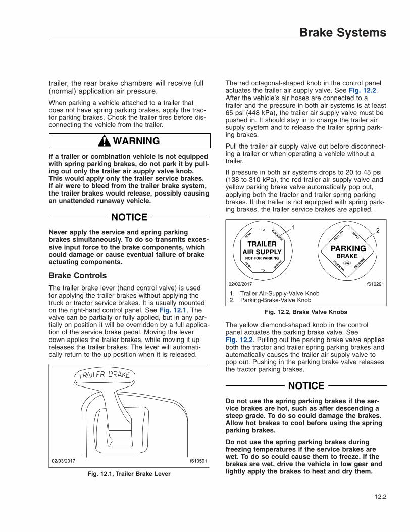
trailer, the rear brake chambers will receive full(normal) application air pressure.
When parking a vehicle attached to a trailer thatdoes not have spring parking brakes, apply the trac-tor parking brakes. Chock the trailer tires before dis-connecting the vehicle from the trailer.
WARNINGIf a trailer or combination vehicle is not equippedwith spring parking brakes, do not park it by pull-ing out only the trailer air supply valve knob.This would apply only the trailer service brakes.If air were to bleed from the trailer brake system,the trailer brakes would release, possibly causingan unattended runaway vehicle.
NOTICENever apply the service and spring parkingbrakes simultaneously. To do so transmits exces-sive input force to the brake components, whichcould damage or cause eventual failure of brakeactuating components.
Brake ControlsThe trailer brake lever (hand control valve) is usedfor applying the trailer brakes without applying thetruck or tractor service brakes. It is usually mountedon the right-hand control panel. See Fig. 12.1. Thevalve can be partially or fully applied, but in any par-tially on position it will be overridden by a full applica-tion of the service brake pedal. Moving the leverdown applies the trailer brakes, while moving it upreleases the trailer brakes. The lever will automati-cally return to the up position when it is released.
The red octagonal-shaped knob in the control panelactuates the trailer air supply valve. See Fig. 12.2.After the vehicle’s air hoses are connected to atrailer and the pressure in both air systems is at least65 psi (448 kPa), the trailer air supply valve must bepushed in. It should stay in to charge the trailer airsupply system and to release the trailer spring park-ing brakes.
Pull the trailer air supply valve out before disconnect-ing a trailer or when operating a vehicle without atrailer.
If pressure in both air systems drops to 20 to 45 psi(138 to 310 kPa), the red trailer air supply valve andyellow parking brake valve automatically pop out,applying both the tractor and trailer spring parkingbrakes. If the trailer is not equipped with spring park-ing brakes, the trailer service brakes are applied.
The yellow diamond-shaped knob in the controlpanel actuates the parking brake valve. SeeFig. 12.2. Pulling out the parking brake valve appliesboth the tractor and trailer spring parking brakes andautomatically causes the trailer air supply valve topop out. Pushing in the parking brake valve releasesthe tractor parking brakes.
NOTICEDo not use the spring parking brakes if the ser-vice brakes are hot, such as after descending asteep grade. To do so could damage the brakes.Allow hot brakes to cool before using the springparking brakes.
Do not use the spring parking brakes duringfreezing temperatures if the service brakes arewet. To do so could cause them to freeze. If thebrakes are wet, drive the vehicle in low gear andlightly apply the brakes to heat and dry them.
f61059102/03/2017
Fig. 12.1, Trailer Brake Lever
f61029102/02/2017
12
1. Trailer Air-Supply-Valve Knob2. Parking-Brake-Valve Knob
Fig. 12.2, Brake Valve Knobs
Brake Systems
12.2

If the trailer is not equipped with spring parkingbrakes, pulling out the parking brake valve appliesthe tractor spring parking brakes and the trailer ser-vice brakes. When the tractor and trailer parkingbrakes (or trailer service brakes) are both applied,the trailer brakes are released by pushing in thetrailer air supply valve, leaving the tractor parkingbrakes applied. Air pressure in the primary or sec-ondary reservoir must be at least 65 psi (447 kPa)before the tractor spring parking brakes, or the trailerservice or spring parking brakes, can be released.
Automatic Slack AdjustersAutomatic slack adjusters should never be manuallyadjusted except during routine maintenance of thefoundation brakes (e.g., replacing shoes), duringslack adjuster installation, or in an emergency situa-tion.
When the brake pushrod stroke exceeds the legalbrake adjustment limit on a vehicle, there is likely amechanical problem with the foundation brake com-ponents or the adjuster is improperly installed.
Visit a repair facility as soon as possible whenbrakes equipped with automatic slack adjusters aredetermined to be out of adjustment.
NOTICEManually adjusting an automatic slack adjuster tobring the pushrod stroke within legal limits is notrepairing. In fact, continual adjustment of auto-matic slack adjusters may result in prematurewear of the adjuster itself. Further, the improperadjustment of some automatic slack adjustersmay cause internal damage to the adjuster,thereby preventing it from properly functioning.
Meritor WABCO® AntilockBraking SystemThe Meritor WABCO Antilock Braking System (ABS)is an electronic wheel speed monitoring and controlsystem that works with the standard air brake sys-tem. ABS passively monitors vehicle wheel speed atall times, and controls wheel speed during emer-gency stops or wheel lock situations.
IMPORTANT: For proper ABS system operation,do not change tire sizes. The sizes of the tiresinstalled during production are programmed intothe electronic control unit. Installing different-
sized tires could result in a reduced brakingforce, leading to longer stopping distances.
ABS includes signal-generating tone wheels and sen-sors located in the wheel hubs of each sensedwheel. The sensors transmit vehicle wheel speedinformation to an electronic control unit (located be-hind the center dash). The control unit’s main circuitinterprets the speed sensor signals and calculateswheel speed, wheel retardation, and a vehicle refer-ence speed. If the calculations indicate wheel lockup,the main circuit signals the appropriate modulatorvalve to reduce braking pressure. During emergencybraking, the modulator valve alternately reduces, in-creases, or maintains air pressure supply in thebrake chamber to prevent front and rear wheellockup.
The electronic control unit also has a safety circuitthat constantly monitors the wheel sensors, tractioncontrol valve (if equipped), modulator valves, and theelectrical circuitry.
The Meritor WABCO ABS combines one front-axlecontrol channel with one rear-axle control channel toform one control circuit. For example, the sensor andmodulator valve on the left-front axle form a controlcircuit with the sensor and modulator valve on theright-rear axle. If, during vehicle operation, the safetycircuit senses a failure in any part of the ABS, thetractor warning lamp (TRACTOR ABS) illuminatesand the control circuit where the failure occurred isswitched to normal braking action. The remainingcontrol circuit will retain the ABS effect. Even if theABS is completely inoperative, normal braking abilityis maintained. An exception would be if a modulatorvalve (or combination modulator valve) is damagedand inoperative. As these components are an integralpart of the air brake system, normal braking may beimpaired or inoperative.
During emergency or reduced-traction stops, fullydepress the brake pedal until the vehicle comes to asafe stop. Do not pump the brake pedal. With thebrake pedal fully depressed, the ABS will control allwheels to provide steering control and a reducedbraking distance.
Although the ABS improves vehicle control duringemergency braking situations, the driver still has theresponsibility to change driving styles depending onexisting traffic and road conditions. For example, theABS cannot prevent an accident if the driver isspeeding or following too closely.
Brake Systems
12.3

Trailer ABS CompatibilityThe Meritor WABCO ABS is designed to communi-cate with a trailer ABS, if they are compatible. Com-patibility will result in the illumination of the TRAILERABS lamp during vehicle start-up and fault detection.
The TRAILER ABS lamp will not illuminate unless acompatible trailer is connected to the tractor. Thedash-mounted lamp will operate as follows when acompatible trailer is properly connected to the tractor:
• When the ignition key is turned to the ON posi-tion, the TRAILER ABS lamp will illuminate mo-mentarily, then turn off.
• If the lamp illuminates momentarily during ve-hicle operation, then shuts off, a fault was de-tected and corrected.
• If the lamp illuminates and stays on during ve-hicle operation, there is a fault with the trailerABS. Repair the trailer ABS system immedi-ately to ensure full antilock braking capability.
IMPORTANT: If a compatible trailer is con-nected, and the lamp is not illuminating momen-tarily when the ignition key is turned to the ONposition, it is possible that the lamp is burnt out.
Automatic Traction ControlVehicles with electronic engines and ABS may haveAutomatic Traction Control (ATC). On these vehicles,the ATC system automatically limits wheel spin dur-ing reduced-traction situations. In normal braking ap-plications, the standard air brake system is in effect.
An additional solenoid valve is installed. Duringreduced-traction situations, the ATC solenoid valvecontrols air pressure to the modulator valves andthey in turn increase, hold, or reduce pressure to theappropriate brake chambers to provide better tractionwhenever wheel spin occurs.
When the ATC system is in the NORMAL mode, itwill apply gentle braking to the spinning wheel, tofeed power to the wheel(s) with better traction. Ifboth wheels are spinning, the system will signal theengine to reduce power.
ATC includes a deep snow and mud option to in-crease available traction on extra soft surfaces likesnow, mud, or gravel. A momentary contact rockerswitch labeled ATC will be located on the dash.Pressing the switch will temporarily allow more drivewheel spin. The activation of the deep snow andmud option is indicated by a flashing WHEEL SPIN
lamp. Pressing the switch again will cycle the systemback to normal operation.
NOTICEThe deep snow and mud option is intended to beused under specific slippery conditions that re-quire momentary increased wheel spin. Usingthis option for an extended period of time maydamage the vehicle brake system.
After the ignition switch is turned on, the TRACTORABS lamp and the WHEEL SPIN indicator lampcome on for about three seconds. After three sec-onds, the warning lights go out if all of the tractor’sABS components are working.
IMPORTANT: If any of the ABS warning lightsdo not work as described above, or come onwhile driving, repair the ABS immediately to en-sure full antilock braking capability.
Enhanced Stability Control
WARNINGThe Enhanced Stability Control system is in-tended only as an aid for a conscientious andalert driver and is not a substitute for safe driv-ing procedures. Failure to drive safely, and usethe system properly, could result in personal in-jury and/or death and property damage.
The Enhanced Stability Control (ESC) system offersthe capability of complete directional stability (yawcontrol) in oversteer and understeer conditions toreduce the likelihood of drift-out or jackknife. Thesystem determines where the driver is attempting tosteer the vehicle and how much brake demand isrequired in order to more precisely control the vehiclein an emergency situation.
ESC works by constantly comparing the driver’s in-tention with the vehicles’ actual behavior. The systemdoes this by monitoring systems such as wheelspeed, steering angle, yaw rate, lateral acceleration,throttle position, and brake application. A central mi-crocomputer analyzes the collected data and triggersa response to keep the vehicle on course when anunstable condition is detected.
When the system detects that the vehicle is at risk ofrolling over, it applies individual tractor wheel end
Brake Systems
12.4

brakes and trailer brakes, activates the engine re-tarder (if equipped), and/or cuts engine power, de-pending on the severity. As a result, the driver hasfull control over the vehicle until the system detects apotential rollover and intervenes accordingly. ESCoperates automatically; the driver does not monitor oractivate the system.
Roll Stability Advisor/ControlThe enhanced stability system may include the rollstability advisor (RSA) only, or it may also include theroll stability control (RSC).
A decal (Fig. 12.3) on the auxiliary dash panel, andan amber-colored dash indicator light (Fig. 12.4), in-dicate that the vehicle is equipped with roll stabilitysystem components. On these vehicles, the roll sta-bility indicator light replaces the wheel spin indicatorlight.
Roll Stability AdvisorIMPORTANT: This is not an advance warningsystem. The roll stability advisor displays a mes-sage only after the driving maneuver is com-pleted.
The roll stability system uses a lateral-accelerationsensor that monitors rollover risk. Shortly after a
curve, lane change, or other driving maneuver thatresults in a rollover-risk detection, a dash warninglight illuminates, an audible tone sounds, and a driveradvisory message is displayed in the driver messagecenter. The purpose is to advise the driver that theprevious maneuver produced a rollover risk.
The roll stability advisor displays different text mes-sages depending on the severity of the risk of eachoccurrence of risky driving. From the highest risklevel to the lowest risk level, the system will soundan audible alert, and display a message, as shown inFig. 12.5.
NOTE: The system will calculate and recom-mend a speed reduction value. It may be differ-ent than the values shown here.
Bring the vehicle to an authorized service facility if asystem failure message is displayed.
Roll Stability Control
WARNINGThe Roll Stability Control system is intended onlyas an aid for a conscientious and alert driver.Carefully read the information in this manual tounderstand this system and its limitations. TheRoll Stability Control system is not a substitutefor safe driving procedures. Failure to drivesafely, and use the system properly, could resultin personal injury and/or death and propertydamage.
The roll stability control system automatically reducesengine power, applies the engine brake, and/or ap-plies the tractor and trailer brakes when the accelera-tion sensor detects that the vehicle is at risk of rollingover. The control can intervene even before an advi-sory message is displayed.
The dash indicator light illuminates whenever the rollstability control system intervenes.
Hard-Braking AdvisorThe hard-braking advisor uses the information fromthe ABS wheel speed sensors to determine whenbraking is severe enough to produce lockup at oneor more wheels on the tractor, and/or very rapid ve-hicle deceleration. Shortly after a hard-braking eventoccurs, an advisory message is displayed in thedriver message center, indicating that the brakingbehavior was too aggressive for the current road sur-face conditions. This system is not a replacement for
lamp indicates tractionOR roll control event.Follow instructions indriver’s manual.
24−01204−000
07/11/2003 f080125
SAFETY INSTRUCTIONS
Fig. 12.3, Roll Stability Decal
f60212802/03/2017
Fig. 12.4, Roll Stability Indicator Lamp
Brake Systems
12.5

a driver’s good judgment. Sometimes it is necessaryto brake hard.
From the highest risk level to the lowest risk level,the system will sound an audible alert, and display amessage, as shown in Fig. 12.5.
Trip/Leg TotalsThe driver message center records the number ofmessages received, and displays the number ofmessages as counts. Roll stability advisor (RSA) andhard-braking event data (HBED) counts can beviewed in the trip advisory screen, and the leg advi-sory screen.
Counts can be reset using the + key on the steeringwheel. Clearing RSA and HBED leg counts will alsoreset the leg miles and leg hours. Clearing RSA andHBED trip counts will also reset trip miles, trip hours,leg miles, leg hours, and leg advisory counts. In ad-dition, resetting leg miles will clear leg counts. Clear-ing trip miles will reset miles, hours, and counts inboth the leg and trip screens.
The TRIP and LEG advisor screens count both theroll stability advisories (ROLL) and hard-brakingevents (BRK). For example, if during a TRIP, thedriver message center recorded the events inTable 12.1, the message center would display asshown in Fig. 12.6.
RSA/HBED CountMessage Received Message Counts
RSA Level 3 2RSA Level 2 3RSA Level 1 7
HBED Level 3 5HBED Level 2 1HBED Level 1 8
Table 12.1, RSA/HBED Count
If the count reaches more than 9 occurrences an up-arrow symbol will appear, to indicate to the driverthat the count has exceeded 9 counts. SeeFig. 12.7.
Message to Display
4 1
MessageMSG
No.
System Fault1WARNING
RAC SYSTEM FAIL
ACTIVE SLOWING
ROLLOVER RISK
4 NoneRSC2
VERY HIGH RISK OF
ROLLOVER DETECTED
REDUCE SPEED
AT LEAST 11 KPH
REDUCE SPEED
AT LEAST 7 MPH
or in metric
19.6 10RSA Level 33
HIGH RISK OF
ROLLOVER DETECTED
REDUCE SPEED
AT LEAST 11 KPH
REDUCE SPEED
AT LEAST 7 MPH
or in metric
14 5RSA Level 24
ROLLOVER RISK
DETECTED
REDUCE SPEED
AT LEAST 11 KPH
or in metric
REDUCE SPEED
AT LEAST 7 MPH
8.4 2RSA Level 15
HARD BRAKING WITH
ABS ACTIVATED
LOOK AHEAD
BRAKE SOONER
14 0.5HBED Level 36
HARD BRAKING
DETECTED
LOOK AHEAD
BRAKE SOONER
14 0.5HBED Level 27
LOSS OF TRACTION
ABS ACTIVATED
ROAD SURFACE
MAY BE POOR
14 0.5HBED Level 18
07/25/2008 f040769
DisplayTime:
Seconds
BuzzerTime:
Seconds
Fig. 12.5, Roll Stability and Hard-Braking Warnings
07/25/2008
TRIP ADVISORIES
237 ROLL 518 BRK
f040770A B C D E F
A. RSA lev. 3 Count (2)B. RSA lev. 2 Count (3)C. RSA lev. 1 Count (7)
D. HBED lev. 3 Count (5)E. HBED lev. 2 Count (1)F. HBED lev. 1 Count (8)
Fig. 12.6, Trip Advisor Message Screen
Brake Systems
12.6

07/25/2008
TRIP ADVISORIES
23 ROLL 518 BRK
f040771A
A. RSA Lev. 1 has more than 9 counts.
Fig. 12.7, Trip Advisor Message Screen (more than 9counts)
Brake Systems
12.7

13
Manual Transmissions andClutch
Eaton Fuller 13-Speed and 18-Speed Splitter and Range-Shift Transmissions . . . . . . . . . . . . . . . 13.1Eaton Fuller 10-Speed Range-Shift Transmissions . . . . . . . . . . . . . . . . . . . . . . . . . . . . . . . . . . . . . 13.3Clutch . . . . . . . . . . . . . . . . . . . . . . . . . . . . . . . . . . . . . . . . . . . . . . . . . . . . . . . . . . . . . . . . . . . . . . . . . 13.5
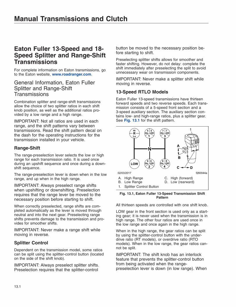
Eaton Fuller 13-Speed and 18-Speed Splitter and Range-ShiftTransmissionsFor complete information on Eaton transmissions, goto the Eaton website, www.roadranger.com.
General Information, Eaton FullerSplitter and Range-ShiftTransmissionsCombination splitter and range-shift transmissionsallow the choice of two splitter ratios in each shiftknob position, as well as the additional ratios pro-vided by a low range and a high range.
IMPORTANT: Not all ratios are used in eachrange, and the shift patterns vary betweentransmissions. Read the shift pattern decal onthe dash for the operating instructions for thetransmission installed in your vehicle.
Range-ShiftThe range-preselection lever selects the low or highrange for each transmission ratio. It is used onceduring an upshift sequence and once during a down-shift sequence.
The range-preselection lever is down when in the lowrange, and up when in the high range.
IMPORTANT: Always preselect range shiftswhen upshifting or downshifting. Preselectionrequires that the range lever be moved to thenecessary position before starting to shift.
When correctly preselected, range shifts are com-pleted automatically as the lever is moved throughneutral and into the next gear. Preselecting rangeshifts prevents damage to the transmission and pro-vides for smoother shifts.
IMPORTANT: Never make a range shift whilemoving in reverse.
Splitter ControlDependent on the transmission model, some ratioscan be split using the splitter-control button (locatedon the side of the shift knob).
IMPORTANT: Always preselect splitter shifts.Preselection requires that the splitter-control
button be moved to the necessary position be-fore starting to shift.
Preselecting splitter shifts allows for smoother andfaster shifting. However, do not delay: complete theshift immediately after preselecting the split to avoidunnecessary wear on transmission components.
IMPORTANT: Never make a splitter shift whilemoving in reverse.
13-Speed RTLO ModelsEaton Fuller 13-speed transmissions have thirteenforward speeds and two reverse speeds. Each trans-mission consists of a 5-speed front section and a3-speed auxiliary section. The auxiliary section con-tains low- and high-range ratios, plus a splitter gear.See Fig. 13.1 for the shift pattern.
All thirteen speeds are controlled with one shift knob.
LOW gear in the front section is used only as a start-ing gear; it is never used when the transmission is inhigh range. The other four ratios are used once inthe low range and once again in the high range.
When in the high range, the gear ratios can be splitby using the splitter-control button with the under-drive ratio (RT models), or overdrive ratio (RTOmodels). When in the low range, the gear ratios can-not be split.
IMPORTANT: The shift knob has an interlockfeature that prevents the splitter-control buttonfrom being activated when the range-preselection lever is down (in low range). When
f260044a02/03/2017
R1 3
2 4LOW
Dir OD5 5
Dir OD
Dir OD Dir OD
7 7
6 6 8 8
Hi
Lo
A
B
C D
1
N
A. High RangeB. Low Range
C. High (forward)D. Low (rearward)
1. Splitter Control Button
Fig. 13.1, Eaton Fuller 13-Speed Transmission ShiftPattern
Manual Transmissions and Clutch
13.1

in high range with the splitter-control button acti-vated, the range-preselection lever cannot bemoved down.
18-Speed RTLO Splitter and Range-ShiftModelsEaton Fuller 18-speed transmissions have eighteenforward speeds and four reverse speeds. Each trans-mission consists of a 5-speed front section and a4-speed auxiliary section. The auxiliary section con-tains low- and high-range ratios, plus a splitter gear.
All eighteen speeds are controlled with one shiftknob. All nine ratios in both the low and high rangescan be split.
LOW gear in the front section is used only as a start-ing gear; it is never used when the transmission is inhigh range. LOW gear can be split, to provide both adirect and an overdrive ratio.
Operation Tips, Eaton Fuller Splitterand Range-Shift TransmissionsThe following tips highlight important operation prin-ciples.
• For all conditions, use the highest gear that isstill low enough to start the vehicle moving withthe engine at or near idle speed, and withoutslipping the clutch excessively.
When operating on-highway with no load orunder ideal conditions, use 1st gear to start thevehicle moving forward.
When operating off-road or under adverse con-ditions, use LOW gear to start the vehicle mov-ing forward.
• Use the clutch brake to stop gear rotationwhen shifting into LOW or reverse while thevehicle is stationary. The clutch brake is actu-ated by depressing the clutch pedal all the wayto the floor.
• Partially disengage the clutch to break enginetorque during normal gear shifts.
• Double-clutch between all upshifts and down-shifts that require movement of the shift knob.Splitting of gears does not require movementof the shift knob.
• Never push the range-preselection lever downinto low range while operating in high range,except when downshifting from 5th gear to 4thgear.
• Do not shift from high range to low range athigh vehicle speeds.
• Preselect all range and splitter shifts. Move therange-preselection lever and/or splitter-controlbutton to the needed position before starting toshift.
• Never make a range shift or a splitter shiftwhile the vehicle is in reverse.
• Never move the range-preselection lever withthe shift knob in neutral while the vehicle ismoving.
• Skip ratios while shifting only when operatingconditions permit, depending on the load,grade, and road speed.
• Never coast with the shift knob in the neutralposition.
Upshifting1. Position the gear shift knob in neutral. Start the
engine and bring the air system pressure up to100 to 120 psi (689 to 827 kPa).
2. Position the range-preselection lever down, inlow range. See Fig. 13.2.
3. Make sure the splitter-control button is in the low(rearward) position. See Fig. 13.2.
4. For 13-speed transmissions:
To start the vehicle moving, press the clutchpedal to the floor, shift into LOW or 1st gear,then engage the clutch with the engine at or nearidle speed. Accelerate to 80 percent of enginegoverned speed.
f260157a02/03/2017
N
R 1Dir
5Dir
5OD1
OD3
Dir
7Dir
7OD3
OD
2Dir
6Dir
6OD2
OD4
Dir
8Dir
8OD4
OD
LOWDir
LOWOD
A
B
C D
1
A. High RangeB. Low Range
C. Overdrive (forward)D. Direct Drive (rearward)
1. Splitter Control Button
Fig. 13.2, Eaton Fuller 18-Speed Transmission ShiftPattern
Manual Transmissions and Clutch
13.2

For 18-speed transmissions:
To start the vehicle moving, press the clutchpedal to the floor, shift into LOW, then engagethe clutch with the engine at or near idle speed.To shift from LOW direct to LOW overdrive,move the splitter-control button into the overdrive(forward) position, then immediately release theaccelerator. Press and release the clutch pedal.After releasing the clutch pedal, accelerateagain.
5. For 13-speed transmissions:
Upshift from LOW (or 1st gear) through 4th gear,double-clutching during knob shifts, and acceler-ating to 80 percent of engine governed speed.See Fig. 13.1.
For 18-speed transmissions:
Upshift from LOW overdrive to 1st direct by firstmoving the splitter-control button into the directdrive (rearward) position (Fig. 13.2). Double-clutch and move the shift knob through neutral tothe 1st gear position.
Continue upshifting through the shift pattern.Double-clutch during knob shifts (1st to 2nd to3rd to 4th); single-clutch during split shifts (1stdirect to 1st overdrive, etc.).
6. When in 4th gear (13-speed transmissions) or4th overdrive (18-speed transmissions), use therange-preselection lever and the splitter-controlbutton to upshift to 5th gear.
While in 4th gear, pull the range-preselectionlever up into high range and move the splitter-control button to the low (rearward) position.Double-clutch through neutral and into 5th gear,engage the clutch, and accelerate the engine.
7. Upshift progressively through the high rangegears.
To shift from 5th direct to 5th overdrive (or 5thunderdrive to 5th direct on RT model transmis-sions), move the splitter-control button to thehigh (forward) position, then immediately releasethe accelerator. Press and release the clutchpedal. After releasing the clutch, accelerateagain.
Continue upshifting through the shift pattern.Double-clutch during knob shifts (6th to 7th, etc.);single-clutch during split shifts (6th direct to 6thoverdrive, etc.).
Downshifting
IMPORTANT: Never use the clutch brake whendownshifting, or as a brake to slow the vehicle.
1. To downshift from 8th overdrive to 8th direct (or8th direct to 8th underdrive on RT model trans-missions), move the splitter-control button to thelow (rearward) position, then immediately releasethe accelerator. Press and release the clutchpedal, then accelerate the engine once the trans-mission has shifted.
2. Start the downshift from 8th direct to 7th over-drive by moving the splitter-control button to thehigh (forward) position, then immediately double-clutch through neutral, moving the shift knobfrom 8th gear to 7th gear.
3. Downshift progressively through each of the highrange gears, alternating the procedures in steps1 and 2 above until reaching 5th direct.
4. When in 5th direct and ready for the downshift to4th (13-speed transmissions) or 4th overdrive(18-speed transmissions), push the range-preselection lever down and move the splitter-control button to the high (forward) position.Double-clutch through neutral and into 4th gear,engage the clutch, and accelerate the engine.
5. Continue downshifting from 4th gear to 1st gear.
For 13-speed transmissions:
Downshift through the low range gears as condi-tions require.
For 18-speed transmissions:
Continue downshifting from 4th overdrive to 4thdirect, then 4th direct to 3rd overdrive, etc.Double-clutch during knob shifts (4th to 3th, etc.);single-clutch during split shifts (4th direct to 3rdoverdrive, etc.).
Eaton Fuller 10-Speed Range-Shift TransmissionsFor complete information on Eaton transmissions, goto the Eaton website, www.roadranger.com.
Manual Transmissions and Clutch
13.3

General Information, 10-SpeedRange-Shift TransmissionsEaton Fuller 10-speed transmissions have ten for-ward speeds and two reverse speeds. Each trans-mission has a 5-speed front section and a 2-speedauxiliary section.
A range-shift transmission allows for additional ratiosprovided by a low range and a high range. The tenforward speeds are obtained by twice using a5-speed shift pattern: first in the low range, then inthe high range. See Fig. 13.3 for the shift patterns.
The range-preselection lever selects the low or highrange for each ratio. It is used once during an upshiftsequence and once during a downshift sequence.The range-preselection lever is down when in the lowrange, and up when in the high range.
IMPORTANT: Always preselect range shiftswhen upshifting or downshifting. Preselectionrequires that the range lever be moved to thenecessary position before starting to shift.
When correctly preselected, range shifts are com-pleted automatically as the lever is moved throughneutral and into the next gear. Preselecting rangeshifts prevents damage to the transmission and pro-vides for smoother shifts.
To operate a range-shift transmission, move the shiftknob through all the low-range gear positions andthen pull the range-preselection lever up to move intothe high-range ratios. Use the same shift knob posi-tions in both the low and high ranges.
IMPORTANT: Shift patterns vary between trans-missions. Be sure to read the shift pattern decal
on the dash for the operating instructions for thetransmission installed in your vehicle.
NOTE: The 4th/9th and the 5th/10th shift posi-tions in the RT (direct ratio) and RTX (overdriveratio) transmissions are directly opposite in theRTO (overdrive ratio) transmissions.
Operation Tips, Eaton Fuller Range-Shift TransmissionsThe following tips highlight important operation prin-ciples.
• For all conditions, use the highest gear that isstill low enough to start the vehicle moving withthe engine at or near idle speed, and withoutslipping the clutch excessively.
• Use the clutch brake to stop gear rotationwhen shifting into LOW or reverse while thevehicle is stationary. The clutch brake is actu-ated by depressing the clutch pedal all the wayto the floor.
• Partially disengage the clutch to break enginetorque during normal gear shifts.
• Double-clutch between all upshifts and down-shifts.
• Never push the range-preselection lever downinto low range while operating in high range,except when downshifting from 5th gear to 4thgear.
• Do not shift from high range to low range athigh vehicle speeds.
• Preselect all range shifts. Move the range-preselection lever to the needed position be-fore starting to shift.
• Never make a range shift while the vehicle isin reverse.
• Never move the range-preselection lever withthe shift knob in neutral while the vehicle ismoving.
• Skip ratios while shifting only when operatingconditions permit, depending on the load,grade, and road speed.
• Never coast with the shift knob in the neutralposition.
f26105302/03/2017
4
N
7
2
9
6
1
8
3
10
5
RHI
LO
A
B
A. High Range B. Low Range
Fig. 13.3, Eaton Fuller 10-Speed Transmission ShiftPatterns
Manual Transmissions and Clutch
13.4

Upshifting1. Position the gear shift knob in neutral. Start the
engine and bring the air system pressure up to100 to 120 psi (689 to 827 kPa).
2. Position the range-preselection lever down, inlow range. See Fig. 13.2.
3. To start the vehicle moving, press the clutchpedal to the floor; shift into 1st gear (Table 13.1),then engage the clutch with the engine at or nearidle speed. Accelerate to 80 percent of enginegoverned speed.
Eaton Fuller Shift ProgressionsTRANS. MODEL LOW RANGE HIGH RANGE
10-Speed Director Overdrive (RT
or RTX)
2
3
4
1f260329
R
5
9
8 10
7
f260330
R
6
Table 13.1, Eaton Fuller Range-Shift ShiftProgressions
4. Upshift progressively from 1st gear through 5thgear (Table 13.1), double-clutching betweenshifts, and accelerating to 80 percent of enginegoverned speed.
5. When in 5th gear and ready to move to 6th gear,pull the range-preselection lever up into the highrange. Double-clutch through neutral and into 6thgear, engage the clutch, and accelerate the en-gine.
NOTE: If after attempting to shift into the highrange the transmission remains in neutral withthe shift knob in gear, the range synchronizerprotection device may be activated. Move theshift knob into neutral to allow the range shift tocomplete, then move the shift knob back intogear.
6. Upshift progressively through the high rangegears (Table 13.1), double-clutching betweenshifts and accelerating to 80 percent of enginegoverned speed.
Downshifting
IMPORTANT: Never use the clutch brake whendownshifting, or as a brake to slow the vehicle.
1. Downshift progressively through each of the highrange gears, double-clutching between shifts.
2. When in 5th gear and ready to move to 4th gear,push the range-preselection lever down into thelow range. Double-clutch through neutral and into4th gear, engage the clutch, and accelerate theengine.
NOTE: If after attempting to shift into the highrange the transmission remains in neutral withthe shift knob in gear, the range synchronizerprotection device may be activated. Move theshift knob into neutral to allow the range shift tocomplete, then move the shift knob back intogear.
3. Downshift progressively through the low rangegears, double-clutching between shifts, as condi-tions require.
ClutchClutch General InformationTo ensure long service life of the clutch, start in theright gear, be alert to clutch malfunctions, and knowwhen to adjust the clutch.
Typical operation will not break down the clutch fric-tion surfaces. Heat and wear are almost nonexistentwhen a clutch is fully engaged. However, during themoment of engagement, when the clutch is pickingup the load, considerable heat is generated. If aclutch slips excessively, high temperatures developquickly between the flywheel, driven discs, and pres-sure plates. An improperly adjusted or slipping clutchcan generate temperatures high enough to cause thefriction-facing material to char and burn, destroyingthe clutch.
Clutch OperationClutch Break-InThe clutch may slip for a short time while the frictionsurfaces break-in on a new or newly-installed clutch.However, allowing the clutch to slip for more thantwo seconds can severely damage the clutch disc,pressure plate, and the flywheel.
NOTICEDo not allow sustained slippage of the clutch;which will severely damage the clutch disc, pres-sure plate, or flywheel. Damage caused by clutchslippage due to improper break-in is not warrant-able.
Manual Transmissions and Clutch
13.5

During initial operation of a new vehicle or a vehiclewith a new clutch, check for clutch slippage duringacceleration. If the clutch slips, decelerate until theclutch does not slip. Allow the clutch to cool 15 to 30seconds, then gradually accelerate again. If theclutch continues to slip, repeat the procedure asmany as five times. If the clutch slips after five at-tempts, stop the vehicle and allow the clutch to coolfor at least one hour. Notify your Freightliner dealerof the problem.
Moving the Vehicle in the Proper GearAn empty vehicle can be started in a higher trans-mission gear than can a partially- or fully-loaded ve-hicle. Select the gear combination that allows thevehicle to start moving with an idling engine or, ifnecessary, just enough throttle to prevent stalling theengine. After the clutch is fully engaged, the enginecan be accelerated to the correct rpm for the upshiftinto a higher gear.
Gear Shifting TechniquesUpshift into a higher gear when the vehicle speedallows the transmission input shaft speed to matchthe flywheel speed when engaging the clutch. Thistechnique results in the smallest speed differencebetween the clutch disc and the flywheel, and causesthe least heat and wear on the clutch assembly.When downshifting, increase the input shaft speed tomatch the flywheel by slightly revving the engine. Fortransmission operating instructions, refer to the trans-mission headings in this chapter.
Vehicle LoadingClutches are designed for specific vehicle applica-tions and loads. Do not exceed these weight limita-tions.
NOTICEExceeding vehicle load limits can result in dam-age to the clutch and the entire powertrain.
Clutch BrakeApply the clutch brake by depressing the clutchpedal all the way to the floor plate. The last part ofthe clutch pedal travel will compress the clutch brakeplates together, stopping the transmission input shaft.The clutch brake stops the transmission gears fromrotating in order to quickly engage a transmissiongear after idling in neutral.
NOTICENever apply the clutch brake when the vehicle ismoving. If the clutch brake is applied when thevehicle is moving, the clutch brake will try tostop or decelerate the vehicle, causing rapidwear of the clutch brake friction discs. Consider-able heat will be generated, causing damage tothe release bearings and the transmission frontbearings.
Using the ClutchUse the clutch pedal only when starting the engine,launching the vehicle from a stop, or shifting. Tolaunch a stationary vehicle, depress the clutch pedalall the way to the floor plate (see "Using the ClutchBrake" above) and shift from neutral to a low gear.Slowly raise your foot until the clutch starts to en-gage. In this position the clutch is starting to connectthe transmission input shaft to the flywheel and iscausing the most heat and wear. Slightly increasethe engine speed and smoothly allow the clutchpedal to return to the rest position. Do not allow theclutch to remain in the partially-engaged position anylonger than necessary to obtain a smooth start.
Double-clutch to shift gears while the vehicle is mov-ing. Depress the clutch pedal most of the way in, butnot all the way to the floor plate. Depressing theclutch pedal to the floor plate will engage the clutchbrake. Shift the transmission into neutral and fullyrelease the clutch pedal. When upshifting, wait longenough for the engine speed to decrease to the roadspeed. When downshifting, increase the enginespeed to match the road speed. Again, depress theclutch pedal part way and then move the shift leverto the next gear position. Fully release the clutchpedal after completing the shift.
NOTICERiding the clutch while driving is damaging tothe clutch because partial clutch engagementcauses slippage and heat. Resting your foot onthe clutch pedal will also put a constant thrustload on the release bearing, thinning the bearinglubricant and increasing the wear on the bearing.
Holding the Vehicle On an InclineAlways use the vehicle service brakes to prevent thevehicle from rolling backwards while stopped on ahill. Slipping the clutch on a hill to maintain vehicleposition will quickly damage the clutch assembly.
Manual Transmissions and Clutch
13.6

CoastingCoasting with the clutch pedal depressed and thetransmission in a low gear can cause high drivendisc speed. The clutch speed can be much higherunder these conditions than when the engine is driv-ing the clutch. This condition creates a hazardoussituation due to the lack of vehicle control and due tothe high clutch disc speed. Engaging the clutchunder these conditions can cause component dam-age because of the shock loads to the clutch anddrivetrain.
WARNINGAlways shift into the gear that is correct for thetraveling speed of the vehicle and engage theclutch. Coasting with the clutch disengaged canprevent engagement of the correct transmissiongear which can cause loss of vehicle control,possibly resulting in personal injury or propertydamage.
High clutch disc speeds while coasting can alsocause the clutch facing to be thrown off the disc.Flying debris from the clutch can cause injury topersons in the cab.
Clutch MaintenanceChecking the Clutch AdjustmentReport erratic clutch operation as soon as possible togive maintenance personnel a chance to inspect, lu-bricate, and adjust the clutch components. Noticeany gradual decrease in the distance the clutchpedal moves before resistance is felt.
NOTICEOperating the vehicle with incorrect free pedalcould result in clutch damage.
A correctly adjusted clutch must have about 3/4 inch(19 mm) of travel at the top of its stroke before astronger resistance can be felt. See Fig. 13.4. If thefree pedal travel is less than this distance, have theclutch adjusted.
Check the clutch free pedal travel daily and note it inthe driver’s report.
Adjusting the ClutchClutches have an internal adjustment and externallinkage adjustment. See Group 25 of the 108SD and
114SD Workshop Manual for clutch adjustment pro-cedures and specifications.
Checking the Clutch Brake OperationClutch brake operation can be felt as an increasedresistance as the clutch pedal approaches the bot-tom of its stroke. If the gears grind when shifting intofirst or reverse gear from neutral with the clutchpedal fully depressed, the clutch pedal is out of ad-justment or the clutch brake is worn and needs to bereplaced.
Lubricating the Clutch Release BearingOn vehicles equipped with a greaseable releasebearing, the release bearing should be lubricated atfrequent intervals. See Group 25 of the 108SD and114SD Maintenance Manual for intervals and proce-dures.
02/09/96 f250306
A. Free Pedal
Fig. 13.4, Clutch Free Pedal Travel
Manual Transmissions and Clutch
13.7

14
Automated and AutomaticTransmissions
Freightliner SmartShift Shift Control . . . . . . . . . . . . . . . . . . . . . . . . . . . . . . . . . . . . . . . . . . . . . . . . . 14.1Eaton Fuller UltraShift PLUS Automated Transmissions . . . . . . . . . . . . . . . . . . . . . . . . . . . . . . . . . 14.1Eaton Fuller AutoShift Automated Transmissions . . . . . . . . . . . . . . . . . . . . . . . . . . . . . . . . . . . . . . . 14.5Allison Automatic Transmissions . . . . . . . . . . . . . . . . . . . . . . . . . . . . . . . . . . . . . . . . . . . . . . . . . . . . 14.8

Freightliner SmartShift ShiftControlGeneral Information, SmartShiftControlThe SmartShift electronic transmission control is in-stalled with the following transmissions:
• Eaton Fuller UltraShift PLUS
• Eaton Fuller AutoShift™
It replaces the typical floor-mounted shift lever ordash-mounted push button control.
SmartShift accepts driver requests for transmissionfunctions and transmits them through hard wiring tothe transmission control unit (TCU). SmartShift is atrue shift-by-wire system.
SmartShift offers two main advantages over conven-tional transmission control devices. Without a floor-mounted shift control, usable cab space is increased.The SmartShift control is operated by the fingers ofthe driver’s right hand, allowing both hands to remainon the steering wheel.
A two-position driving mode slide switch is mountedon the body of the control lever just before thepaddle widens out. The slide switch allows the driverto choose automatic (AUTO) or manual (MAN) mode.See Fig. 14.1.
In AUTO mode, gears shift automatically withoutdriver interaction. Manual gearshifts are accom-plished by a momentary pull or push on the control inthe plane perpendicular to the steering wheel. Pullupward (toward the driver) on the control to upshiftand push downward (away from the driver) to down-shift. The control is spring-loaded and returns to itsrest position when released after an upshift or down-shift.
A four-position (R, N, D, L) gear selector switch islocated at the end of the lever. See Fig. 14.1.
A small neutral lock button is embedded in the gearselector switch to prevent accidental shifts into gearfrom neutral. Any time you shift through neutral,press down on the neutral lock button to move theswitch from neutral (N) to another gear, such as drive(D), low (L), or reverse (R). When shifting to neutral,it is not necessary to press the neutral lock button.
Eaton Fuller UltraShift PLUSAutomated TransmissionsEaton Fuller UltraShift PLUS automated transmis-sions use shift selection software and electric clutchactuation; a clutch pedal is not needed to operate thevehicle. These transmissions use the four-positionSmartShift control (see Fig. 14.1) on the steeringcolumn to select mode, direction, neutral, low, and tomake manual shifts. To know what gear the transmis-sion is in, see the current gear indicator on the dash.Forward shifts can be made either manually orautomatically.
Power UpNOTE: Engine cranking is delayed until thetransmission power-up is complete and the geardisplay shows a solid "N".
1. With the parking brake set, turn the ignitionswitch to the ON position.
2. Start the engine.
f27012002/02/2017
12
34
5 6
8
9
10
1112
7
To upshift manually, pull the lever back (towards thedriver). To downshift manually, push the lever forward(away from the driver).1. SmartShift Control Lever2. Slide Switch (forward driving mode switch)3. MAN Mode (of slide switch)4. AUTO Mode (of slide switch)5. Upshift Direction6. Reverse Position (of selector switch)7. Selector Switch8. Neutral Lock Button9. Neutral Position (of selector switch)10. Drive Position (of selector switch)11. Low Position (of selector switch)12. Downshift Direction
Fig. 14.1, SmartShift Control (with Eaton FullerUltraShift PLUS and AutoShift)
Automated and Automatic Transmissions
14.1

3. Apply the service brake.
NOTE: If the service brake is not applied whileselecting a starting gear, the initial start gear willnot be found and the driver will need to selectNeutral and press the service brake while se-lecting the desired mode.
4. Select the desired mode and starting gear. (Inap-propriate start gear selections are ignored toavoid damaging the transmission.)
5. Release the parking brake.
6. Release the service brake and apply the accel-erator.
Power Down1. Select Neutral on the shift control.
NOTE: If the gear display does not show a solid"N", neutral has not yet been obtained. Neutralshould always be reached before poweringdown an UltraShift PLUS, except in cases ofemergency.
2. Set the parking brake.
3. Turn off the ignition, and shut down the engine.
Reverse (R)NOTE: If attempting to select a non-Neutralmode without applying the service brakes, thetransmission will not shift into gear. To shift intogear, select Neutral, apply the service brakes,and select the desired mode again. Also, thevehicle will not engage reverse above 2 mph (3km/h).
Reverse (R) is at the upper end of the four-positionselector switch located at the end of the SmartShiftcontrol. To select R, press in the neutral lock buttonand move the selector switch to the position aboveneutral. The default Reverse gear is engaged.
NOTICEAvoid launching the vehicle in high range.Launching the vehicle in high range increasesthe likelihood of clutch abuse and could be detri-mental to clutch life.
Automatic Mode (AUTO)In automatic drive mode (AUTO), upshifts and down-shifts are made by the UltraShift PLUS without driverintervention. Press in the neutral lock button, movethe selector switch to Drive (D), and press down onthe throttle pedal. The transmission will shift auto-matically.
NOTE: If attempting to select a non-Neutralmode without applying the service brakes, thetransmission will not shift into gear. To shift intogear, select Neutral, apply the service brakes,and select the desired mode again.
In Drive, the start gear is automatically selected. Theselected start gear can vary depending on severalvehicle inputs such as load, grade, and axle/transmission ratio. The start gear can be changedusing the SmartShift control, provided the selectedgear would allow the vehicle to launch without dam-aging the transmission. If the start gear is changedusing the SmartShift control, it will be the default untilthe vehicle is powered down or the selection ischanged again manually.
IMPORTANT: Prior to ascending a steep grade,either reduce the default start gear by one(using the SmartShift control) or apply fullthrottle for the duration of the grade so the ve-hicle maintains the proper engine and vehiclespeed during the entire grade.
In Drive, the transmission automatically performs up-shifts and downshifts. However, when the transmis-sion is near the shift point, the shift can be forcedusing the upshift or downshift function of the Smart-Shift control.
NOTE: The transmission may deny a shift whileascending or descending a grade if the load ofthe vehicle and grade of the terrain in combina-tion with the drivetrain ratio and engine torquefall outside of the acceptable range to perform ashift. If the shift is denied, a tone will sound.
Manual Mode (MAN)In manual mode (MAN), the driver selects upshiftsand downshifts instead of letting the UltraShift PLUSselect them automatically. Manual shifting may behelpful when traversing a work site, railroad tracks,or steep grades, for example. To drive forward, pressin the neutral lock button, move the selector switch toDrive (D), and press down on the throttle pedal. Toshift up, pull the lever up (towards you); to shift
Automated and Automatic Transmissions
14.2

down, push the lever down (away from you). Thesystem holds the current gear unless a shift is re-quested or if the system initiates a manual modeoverride.
NOTE: The transmission may deny a shift whileascending or descending a grade if the load ofthe vehicle and grade of the terrain in combina-tion with the drivetrain ratio and engine torquefall outside of the acceptable range to perform ashift. If the shift is denied, a tone will sound.
NOTE: If attempting to select a non-Neutralmode without applying the service brakes, thetransmission will not shift into gear. To shift intogear, select Neutral, apply the service brakes,and select the desired mode again.
Manual Mode OverrideThe system is equipped with a manual mode over-ride function. If the vehicle is being "back driven" (forexample, descending a grade and vehicle speed ex-ceeds engine speed) and the engine speed is exces-sively high, the system will upshift automatically.Also, if the start gear is changed and it causes theengine to lug at takeoff, the system will override thecurrent position and select the best available gear.
Low (L)Low (L) is at the lower end of the four-position selec-tor switch located at the end of the SmartShift con-trol. Use Low when wanting to maximize enginebraking and minimize the use of the brake pedal—forexample, when driving down long grades or whencoming to a stop. To select Low, press in the neutrallock button and move the selector switch to the Lposition. The lowest available start gear will be se-lected (the starting gear cannot be changed in Low).
If Low is selected while moving, the transmission willnot upshift (unless the system initiates a Low over-ride). The system will downshift at the earliest oppor-tunity to provide maximum engine braking.
NOTE: If attempting to select a non-Neutralmode without applying the service brakes, thetransmission will not shift into gear. To shift intogear, select Neutral, apply the service brakes,and select the desired mode again.
Low OverrideThe system is equipped with a Low override function.If the vehicle is being "back driven" (for example, de-
scending a grade and vehicle speed exceeds enginespeed) and the engine speed is excessively high, thesystem will upshift automatically. Also, if the startgear is changed and it causes the engine to lug attakeoff, the system will override the current positionand upshift.
Clutch Abuse ProtectionAlthough a vehicle equipped with an UltraShift PLUSuses an automated clutch, the clutch can still over-heat and slip with improper use. The clutch abuseprotection feature helps protect the clutch if the auto-mated clutch starts to overheat. When the clutchabuse protection feature initiates and sounds a warn-ing tone, full clutch actuation must be completedquickly. If it is not completed quickly enough, the sys-tem will either open the clutch (if the throttle pedal isnot being pressed) or close the clutch (if the throttlepedal is being pressed). If the abuse continues, thesystem will open the clutch and take away throttlecontrol briefly to allow the clutch to cool down.
To protect the clutch:
• Select the lowest possible start gear for theapplication.
• Use Creep Mode when appropriate.
• Use the service brakes and the Hill Start Aidwhen launching on a grade.
• Minimize the time it takes to engage the clutchfrom rest.
• Do not use the throttle to hold the vehicle on agrade; use the service brakes.
• Do not use the throttle to stop roll back on anincline after Hill Start Aid disengages; use theservice brakes, and then relaunch.
• Do not continually start and stop, especiallywhen loaded; use a lower gear or Creep Mode.
Creep ModeThe Creep Mode function allows the vehicle to main-tain a constant speed at engine idle without thedriver holding the throttle pedal position. This modeis useful for very low-speed maneuvering and appli-cations where steady vehicle speed is required. Thevehicle speed is determined by the selected gearratio operating at governed low engine idle speed.Any available gear may be selected, though thetransmission will downshift or exit Creep Mode toprevent stalling if the engine lugs due to load condi-tions.
Automated and Automatic Transmissions
14.3

By default, Creep Mode can be activated while inManual Mode or Low. Eaton’s ServiceRanger diag-nostic software can be used to enable Creep Modein Automatic Mode and/or Reverse.
Engaging Creep ModeTo engage Creep Mode:
1. Select Low or Manual Mode and the desiredgear (while stopped or moving).
2. Apply the throttle pedal to accelerate the vehicleuntil the clutch is closed (engaged).
3. Release the throttle pedal. The vehicle will con-tinue moving at governed low engine idle speed.
Exiting Creep ModeTo exit Creep Mode, apply the throttle pedal to accel-erate temporarily, or select a higher gear in ManualMode. (Creep Mode can be resumed in the selectedgear by releasing the throttle pedal.)
NOTE: The transmission will exit Creep Mode ifthe engine lugs 150 rpm below the governedlow engine idle speed. In this case, a lower gearshould be selected if available.
Hill Start AidUltraShift PLUS transmissions are equipped with aHill Start Aid (HSA) feature to prevent the vehiclefrom rolling while on grades steeper than 3% andallow for a controlled launch. A grade sensor is usedto determine when to engage the feature.
HSA is "on" by default. It can be turned off by press-ing and releasing the override switch on the dash.HSA will turn back on after the first successfullaunch.
When the vehicle is stopped on a grade greater than3% and in a forward mode or reverse, depress theservice brakes then release them. The vehicle willbegin to move after 3 seconds, and the clutch willperform partial engagements to slow the vehicle mo-tion. Either step on the brake or apply the throttle tocontinue negotiating the grade.
Engine Overspeed ProtectionThe system will upshift if necessary to prevent en-gine overspeed in Drive, Manual, and Low.
Shuttle ShiftingShuttle shifting from reverse to any forward mode isonly allowed if the vehicle speed is approximatelyzero.
Auto Start Gear Selection andOverrideThe UltraShift PLUS system uses various inputs toautomatically select the best start gear in Drive andManual. This selection can be changed using theSmartShift control; however, if the selection re-quested could cause damage or engine lugging, therequest will be denied and a tone will sound.
Skip ShiftingWhen appropriate, the UltraShift PLUS system mayskip shift in Drive. When prevailing conditions likeload and grade allow, skip shifts can be performed inManual mode using the SmartShift control.
Auto NeutralThe UltraShift PLUS system will automatically shift toneutral if the vehicle is left in Drive and the parkingbrake is set. "AN" will show on the gear display. Tore-engage the transmission, select Neutral and theneither Drive or Reverse on the shift control (it will re-engage regardless of whether the parking brake isreleased).
Automatic Traction ControlThe UltraShift PLUS system requires the AutomaticTraction Control (ATC) option to be enabled whendriving in soft soil/sand to prevent wheel slippageand shifting issues. The ATC system has two modes:"normal" (for sand and loose road surface) and amud/snow setting.
ATC Normal ModeIn normal mode, the system will engage the brakeson the wheel or side that the wheel slip is occurringto help the vehicle gain traction. The point at whichthe traction control will actuate the braking systemincreases with throttle: low throttle allows the systemto brake the wheels earlier; heavy/full throttle raisesthe point of the acceptable wheel slip.
Adhere to the following points when driving in ATCnormal mode:
• If using Automatic mode in soft soil and/orsand, maintain the engine speed between
Automated and Automatic Transmissions
14.4

1000 and 1300 rpm to prevent unnecessaryupshifting.
• If using Manual mode in soft soil and/or sand,do not attempt an upshift and try to maintainthe current gear.
• If the vehicle comes to a stop in the sand itmay be necessary to back up prior to attempt-ing forward movement.
ATC Mud/Snow ModeTo select the mud/snow mode, depress the ATCswitch. This mode raises the wheel slip speed that isallowed before the traction control activates. Thepoint at which the traction control will actuate thebraking system increases with throttle: low throttleallows the system to brake the wheels earlier; heavy/full throttle raises the point of the acceptable wheelslip.
Load-Based ShiftingThe UltraShift PLUS system is adaptive and willchange the shift points based on grade, engine RPM,throttle position, and vehicle load. After changingloads or powering up, the system needs to relearnthese inputs for the first few shifts to make theproper adjustments.
CoastingWhen coasting to a stop on level terrain, the Ultra-Shift PLUS system may not downshift into the lowergears. It will select a gear after the throttle is applied.
Ultrashift PLUS DiagnosticsSystem ProblemIn the event of a problem, do the following steps.
1. Note the driving conditions at the time the prob-lem occurred.
2. Record the status of the transmission at the timeof the problem (AUTO or MAN mode, gear set-ting R, N, D, or L, current gear, engine speed,etc.)
3. Reset the system, using the procedure below.
Reset ProcedureTransmission operation can sometimes be restoredby doing the following reset procedure:
1. Stop the vehicle when it is safe to do so. Set theparking brake.
2. Place the selector switch in neutral and turn offthe ignition.
3. Check all harness connectors as described inChapter 21.
4. Wait at least two minutes with the engine shutdown.
5. Restart the engine.
If the problem continues, contact an authorizedFreightliner or Eaton service facility.
Eaton Fuller AutoShiftAutomated TransmissionsRefer to the Eaton website for additional information,www.roadranger.com.
General Information, AutoShiftTransmissionsEaton Fuller AutoShift transmissions have ten oreighteen forward speeds and two reverse speeds.The driver must use the clutch to start and stop thevehicle. However, the driver does not need to usethe clutch to shift gears. The transmission signals theengine controller when to break torque and the en-gine controller automatically increases or decreasesengine speed. When engine speed is correct, thetransmission engages the next gear and signals theengine controller to resume operation.
Operation, AutoShift TransmissionsAutomatic and Manual ModesThe SmartShift control lever has a slide switch lo-cated on the body of the control lever just before thepaddle widens out. See Fig. 14.2. The slide switchcontrols the forward driving mode, automatic (AUTO)or manual (MAN).
To change mode at any time, move the slide switchin the desired direction. This allows the driver to re-spond to a wide range of driving conditions, such asblind corners, tight curves, and steep hills.
In either mode, the gear indicator displays the cur-rent gear. See Fig. 14.3.
At the start of a shift, the current gear continues todisplay until the transmission has been pulled intoneutral. As the transmission is synchronizing for the
Automated and Automatic Transmissions
14.5

new (target) gear, the gear indicator flashes the num-ber of the target gear.
When the shift is complete, the gear indicator dis-plays the new gear, without flashing.
Automatic ModeIn automatic drive mode, upshifts and downshifts re-quire no driver interaction. Press in the neutral lockbutton, move the gear selector switch to drive (D),depress the clutch to engage the gear selected, re-lease the clutch, and press down on the throttlepedal. The transmission will shift automatically basedon vehicle and transmission conditions.
If the vehicle is stopped while in drive, pull up orpush down on the SmartShift control lever to changethe starting gear.
If driving conditions require, it is possible to request amanual shift. The transmission will make the shift ifthe engine speed is within 75 rpm of the load-basedshift point for that gear.
Manual ModeIn manual drive mode (MAN), upshifts and down-shifts are made by the driver. Manual mode shouldbe used whenever you want to select the shifts in-stead of letting the transmission shift automatically.
To upshift, pull the lever up (towards the driver). Todownshift, push the lever down (away from thedriver). The system will hold the current gear until thedriver requests a shift. In downhill situations in par-ticular, the driver must be alert to vehicle speed bydownshifting and/or using the service brakes asneeded.
A shift request will be refused if the selected gearwould cause engine overspeed or excessive lugging.
If the vehicle is stopped while in drive, pull up orpush down on the SmartShift control lever to changethe starting gear.
Power Up1. With the parking brake set, select neutral (N) by
moving the gear selector switch to the N posi-tion.
2. Depress the clutch pedal all the way down to thefloor.
3. Start the engine. The CHECK TRANS andTRANS TEMP lamps illuminate and go out again(bulb check).
4. Release the clutch to allow the speed sensor onthe input shaft to get a reading.
5. Depress the clutch again and release the parkingand service brakes.
6. Select the desired starting gear.
7. Release the clutch.
Selecting a Starting Gear1. In automatic mode, select drive (D) by sliding the
gear selector switch downward to the next posi-tion below the neutral position.
2. Depress the clutch to engage the gear selected.Release the clutch and drive the vehicle.
f270079c03/29/2017
12
3
1. Driving Mode SlideSwitch
2. Gear Selector Switch3. Neutral Lock Button
Fig. 14.2, Shift Controls and Indicators, UltraShift PLUSand AutoShift Transmissions
f61158101/23/2019
1
NOTE: The gear indicator displays the current gear. Inthis example, it displays twelfth gear.1. Gear Display
Fig. 14.3, Gear Indicator: Current Gear
Automated and Automatic Transmissions
14.6

Changing the Default Starting GearTo select a starting gear other than the default start-ing gear, follow the instructions below.
1. Make sure the vehicle is stopped and in drive.
2. In either automatic or manual mode, pull upward(to increase) or push downward (to decrease) onthe SmartShift control lever. Each pull upward onthe control increases the starting gear by onegear, but no higher than fourth gear.
3. The number of the gear selected will flash on thegear indicator until the driver releases the clutch.This gear will be stored in memory as the defaultstarting gear until either a different starting gearis selected by the driver or the engine is shutdown.
NOTE: The transmission may also be pro-grammed so that it is not possible to select astarting gear other than the preprogrammed de-fault starting gear.
Upshifting
NOTE: With the transmission in drive in the au-tomatic mode, upshifts require no driver interac-tion.
1. With the transmission in drive in the manualmode, pull the control lever up (towards thedriver) to upshift. If the requested gear is avail-able, the transmission will upshift and the newgear will display on the gear indicator.
NOTE: Two consecutive, momentary upwardpulls will cause a skip shift when the next twohigher gears are available and conditions areappropriate.
2. To skip shift, move the control twice in less than½-second. The number of the gear engaged willappear on the gear indicator.
NOTE: The Eaton Fuller AutoShift transmissionis able to perform triple upshifts when the nextthree higher gears are available and conditionsare appropriate. To triple-shift, move the controlthree times in less than ½-second.
If the gear requested is unavailable, a tone willsound. An unavailable requested upshift is notstored in memory; the upshift must be re-quested again.
Downshifting
NOTE: With the transmission in drive in the au-tomatic mode, downshifts require no driver inter-action.
1. With the transmission in drive in the manualmode, push the control lever down (away fromthe driver) to downshift. If the requested gear isavailable, the transmission will downshift.
NOTE: Two consecutive, momentary downwardpushes will cause a skip shift, when the nexttwo lower gears are available and conditions areappropriate.
2. To skip shift, move the control lever two times inless than ½-second. The number of the gear en-gaged will appear on the gear indicator.
NOTE: The Eaton Fuller AutoShift transmissionis able to perform triple downshifts when thenext three lower gears are available and condi-tions are appropriate. To triple shift, move thecontrol lever three times in less than ½-second.
If the gear requested is unavailable, a tone willsound. An unavailable requested downshift isstored in memory and the shift will be madewhen the gear is available. The time limit for thismemory is a programmable parameter.
NeutralSelect neutral by sliding the gear selector switch tothe N position.
N is located directly below R on the four-positiongear selector switch on the SmartShift control lever.To select N, move the gear selector switch to the po-sition below R. When neutral is selected, the letter Ndisplays on the current gear indicator.
NOTE: Neutral is always available during operation.When in neutral, upshift and downshift requests areignored. If the gear selector switch is moved fromneutral (N) to drive (D) while the vehicle is moving,the transmission will shift into the gear that is appro-priate for the road speed of the vehicle.
DriveDrive (D) is located directly below N on the four-position gear selector switch on the SmartShift con-trol lever. To select D, press the neutral lock buttonand move the gear selector switch to the position
Automated and Automatic Transmissions
14.7

below N. When D is selected, the number of the cur-rently selected forward gear displays on the gear in-dicator. See Fig. 14.3.
When in drive, requests to upshift or downshift areenabled. Either manual or automatic mode can beselected on the slide switch.
ReverseReverse (R) is located at the upper end of the four-position gear selector switch on the SmartShift con-trol lever. To select R, press the neutral lock buttonand move the gear selector switch upward to the po-sition above neutral and depress the clutch pedal.
NOTE: AutoShift transmissions have a dual-range reverse. Reverse low (RL) is the defaultreverse gear.
Select reverse high (RH) by pulling upward on theSmartShift control lever. When reverse low is se-lected, the letter R displays on the current gear indi-cator. When reverse high is selected, the letter H dis-plays on the current gear indicator.
NOTE: Reverse may be engaged below a pro-grammable forward speed in order to rock thevehicle. If reverse is selected above the pro-grammed forward speed, an audible warning willsound indicating that the gear is not available.
Low Gear OperationUse low (L) to maximize engine braking and mini-mize the use of the brake pedal. It is most usefulwhen descending steep hills or when coming to astop. Engine speed will be increased by 200 rpm andshift points will be offset by 200 rpm. The efficiencyof the exhaust brake will be maximized.
Low (L) is located at the lower end of the four-position gear selector switch on the SmartShift con-trol lever. To select L, press the neutral lock buttonand move the gear selector switch to the positionbelow D.
Allison AutomaticTransmissionsRefer to the Allison website for additional information,www.allisontransmission.com.
General Information, AllisonTransmissionsHD-series automatic transmissions have six forwardspeeds and one reverse speed. These transmissionshave electronic shift controls that can be pro-grammed to allow the use of different numbers ofgeared speeds. For instance, the transmission canbe programmed to operate as a 4-speed, 5-speed, or6-speed unit in the "primary" shift mode. If needed, a"secondary" shift mode can be programmed to pro-vide another shift configuration to optimize vehicleuse under different operating conditions. To activatea secondary shift mode, or other special functionsprogrammed into the electronic control unit (ECU),depress the Mode button. See Fig. 14.4. "Mode On"is displayed in the indicator panel just above thepush buttons. A label just above the Mode buttonidentifies the special function.
NOTE: Each time a push button is depressedon the shift selector, a short beep will be heard.This indicates that the ECU has received inputto change operation.
f600369a02/02/2017
1
2
1. Indicator Panel 2. Mode ID
Fig. 14.4, Allison Push Button Shift Selector
Automated and Automatic Transmissions
14.8

Operation Tips, Allison Transmissions
WARNINGNever shift from neutral (N) to drive (D) or re-verse (R) at engine speeds above idle. The ve-hicle will lurch forward or backward, which couldcause property damage and personal injury.
NOTICEThe engine should never be operated for morethan thirty seconds at full throttle with the trans-mission in gear and the output stalled. Prolongedoperation of this type will overheat the transmis-sion fluid and will result in severe damage to thetransmission.
NOTICEDo not allow the vehicle to coast in neutral. Thiscan result in severe transmission damage. Also,no engine braking is available.
The following tips highlight important operation prin-ciples.
• Start the engine, then check the digital displayon the shift selector. Under "Select" at the topof the unit, the display should always show the"primary" shift mode. Under "Monitor," the cur-rent gear should be displayed.
• Use reverse (R) to back the vehicle. Com-pletely stop the vehicle before shifting from aforward gear to reverse, or from reverse to for-ward. There is only one reverse gear.
• Select drive (D) for all normal driving condi-tions. The vehicle will start out in 1st gear, andas speed increases, the transmission will up-shift through each gear automatically. As thevehicle slows down, the transmission willdownshift to the correct gear automatically.
• The pressure of your foot on the acceleratorpedal influences the automatic shifting. Whenthe pedal is fully depressed, the transmissionwill automatically upshift near the governedspeed of the engine. A partially-depressed po-sition of the pedal will cause the upshifts tooccur at a lower engine speed.
• Occasionally the road, load, or traffic conditionsmake it desirable to restrict the automatic shift-
ing to a lower range. The lower the gear range,the greater the engine braking power.
• Use the up or down arrow buttons on the shiftselector to reach the desired gear. The "Select"indicator will display your choice, and the"Monitor" indicator will show the selected gearonce it is reached. In the lower gear ranges,the transmission will not upshift above thehighest gear selected unless the engine gov-erned speed is exceeded.
• Use neutral and apply the parking brake whenthe vehicle is parked with the engine running.
Automated and Automatic Transmissions
14.9

15
Drive Axles and TransferCases
Differential Lock, Drive Axles . . . . . . . . . . . . . . . . . . . . . . . . . . . . . . . . . . . . . . . . . . . . . . . . . . . . . . . 15.1Interaxle Lock, Tandem and Tridem Axles . . . . . . . . . . . . . . . . . . . . . . . . . . . . . . . . . . . . . . . . . . . . 15.2Transfer Cases . . . . . . . . . . . . . . . . . . . . . . . . . . . . . . . . . . . . . . . . . . . . . . . . . . . . . . . . . . . . . . . . . . 15.3

Differential Lock, Drive AxlesThe driver-controlled differential lock feature (side-to-side wheel lock, traction control, or traction equalizer)is available on vehicles with single- or tandem-driveaxles.
The differential lock provides maximum traction forslippery conditions by forcing the wheels on eachdrive axle governed by the switch to rotate together.When the differential lock is engaged, the clutch col-lar completely locks the differential case, gearing,and axle shafts together, maximizing the traction ofboth wheels.
Differential Lock SwitchSee Fig. 15.1 for the differential lock switch on a ve-hicle with a single drive axle.
For a vehicle with tandem axles, there are severaldifferential lock options available:
• one switch to control the differential lock ononly one of the drive axles (this switch willshow only one dot on one drive axle, varyingslightly from the switch shown in Fig. 15.2).
• one switch to control the differential locks onboth drive axles (Fig. 15.2).
• two switches, each of which controls the differ-ential lock on one drive axle.
When the differential lock switch is pressed, threeresponses are possible:
• Normal Response: The LED in the switchblinks until the differential lock is engaged. Atthis point, the LED illuminates steadily. In nor-mal operation, the wheels may lock so quicklythat the blinking of the LED is barely notice-able.
If engagement of the differential lock mecha-nism is not possible for any reason (ignition isturned off, vehicle is moving faster than 25mph, etc.), the LED will stop blinking and turnoff.
• Slow Response: If engagement of the differen-tial lock mechanism is slowed for any reason(vehicle moving too fast, low air pressure, etc.),the LED will continue to blink until the wheelsare able to lock. As in the normal response,the LED illuminates steadily once the wheelshave locked.
• Abnormal Response: If the LED blinks for morethan 30 seconds, the lock mechanism may notbe fully engaged/disengaged. Bring the vehicleto an authorized Freightliner service facility fortesting.
Differential Lock OperationNOTE: On some vehicles, the differential locksystem is connected through the low speedrange of the transmission. If this system is used,the transmission must be in the low speedrange for the wheels to fully lock. In addition,shifting out of low speed range will also disen-gage the differential lock.
WARNINGLocking the wheels when the vehicle is travelingdown steep grades or when the wheels are slip-ping could damage the differential and/or lead toloss of vehicle control, causing personal injuryand property damage.
10/26/2001 f610596
Fig. 15.1, Differential Lock on Single Drive Axle
f61079702/17/2006
Fig. 15.2, Differential Lock on Both Axles
Drive Axles and Transfer Cases
15.1

NOTICEEngage the differential lock only when the ve-hicle is stopped or moving slowly at low speed,less than 5 mph (8 km/h). Engaging the differen-tial lock at high speeds can cause internal axledamage.
1. With the engine running, press the upper half ofthe differential lock switch to engage the differen-tial lock.
2. If the vehicle is moving, briefly let up on the ac-celerator to relieve torque on the gearing, allow-ing the differential to fully lock.
WARNINGBe especially careful when driving under slipperyconditions with the differential locked. Thoughforward traction is improved, the vehicle can stillslip sideways, causing possible loss of vehiclecontrol, personal injury, and property damage.
3. Drive cautiously and do not exceed 25 mph (40km/h). When the differential is fully locked, theturning radius will increase because the vehicleundersteers. See Fig. 15.3.
4. Press the upper half of the differential lock switchagain to disengage the differential lock after leav-ing poor road conditions.
NOTE: If the differential lock is engaged whenthe engine is shut down, the differential lock willdisengage.
5. If the vehicle is moving, briefly let up on the ac-celerator to allow the wheels to fully unlock, thenresume driving at normal speed.
Single Drive Axles with TractionEqualizerSome single drive axles are equipped with a tractionequalizer that is a load-sensing, self-actuating fea-ture. A traction equalizer provides normal differentialaction where traction is good. When one wheel be-gins to spin faster than the other, clutch plates in thedifferential housing automatically engage, deliveringpower to both wheels. There is no operator controlwith this feature.
NOTICETire sizes on both rear wheels should be thesame on axles equipped with a traction equalizer.If not, excessive wear may occur in the tractionequalizer.
Interaxle Lock, Tandem andTridem AxlesThe interaxle lock (axle lock, interaxle differentiallockout) feature causes the drive axle shafts to rotatetogether, and is recommended for use under adverseroad conditions where greater traction is needed.
See the axle manufacturer’s website for more infor-mation.
When engaged, the interaxle lock essentially makesthe driveshaft a solid connection between the driveaxles. Power entering the forward axle is transmittedstraight through to the rearmost axle(s). Drivelinetorque is now delivered equally and the drive axles,and wheels, turn together at the same speed. Theinteraxle lock increases drivetrain and tire wear andshould be used only when improved traction isrequired.
Interaxle Lock SwitchThe interaxle lock switch (Fig. 15.4) allows the driverto lock the drive axles together.
When the interaxle lock switch is pressed, three re-sponses are possible:
• Normal Response: The LED in the switchblinks until the interaxle lock is engaged. Atthis point, the LED illuminates steadily. In nor-mal operation, the interaxle lock may engage
f350079a02/03/2017
A
B
A. Turning Radius When the Differential Lock isEngaged (understeer condition)
B. Turning Radius When the Differential Lock isDisengaged
Fig. 15.3, Turning Radii
Drive Axles and Transfer Cases
15.2

so quickly that the blinking of the switch isbarely noticeable.
If engagement of the interaxle lock mechanismis not possible for any reason (ignition isturned off, vehicle is moving too fast, etc.), theLED will stop blinking and turn off.
• Slow Response: If engagement of the interaxlelock mechanism is slowed for any reason (bycold weather, low air pressure, etc.), the switchwill continue to blink until the axles lock to-gether, or for a maximum of 10 seconds. As inthe normal response, the LED illuminatessteadily once the lock mechanism is engaged.
• Abnormal Response: If the LED blinks for morethan 30 seconds, the lock mechanism may notbe fully engaged/disengaged. Bring the vehicleto an authorized Freightliner service facility fortesting.
Interaxle Lock Operation
NOTICEThe interaxle lock should not be engaged on avehicle with obviously spinning wheels. Engage-ment at high speed or power can damage theaxle(s).
1. With the engine running, press the upper half ofthe interaxle lock switch to engage the interaxlelock. Do not wait until traction is lost and the tiresare spinning before engaging the interaxle lock.
2. If the vehicle is moving, briefly let up on the ac-celerator until the interaxle lock engages. Thered interaxle indicator light illuminates on thedash message center when interaxle lock is en-gaged.
NOTICEDo not operate the vehicle continuously with theinteraxle locked during extended good road con-ditions. To do so could result in damage to theaxle gearing and excessive driveline and tirewear.
3. Proceed over poor road conditions with caution.
4. Press the upper half of the interaxle lock switchagain to disengage the interaxle lock after leav-ing poor road conditions.
NOTE: If the interaxle lock is engaged when theengine is turned off, the interaxle lock will disen-gage.
5. If the vehicle is moving, briefly let up on the ac-celerator to allow the interaxle lock to disengage,then resume driving at normal speed. Once theinteraxle lock disengages, the indicator light willgo off.
Transfer CasesMeritor MTC SeriesNOTE: Meritor MTC Series transfer cases areavailable on 108SD vehicles. 108SD and 114SDvehicles may be equipped with an alternatetransfer case. For more information about othertransfer cases, see the manufacturer’s docu-mentation.
Some vehicles are equipped with a Meritor MTC Se-ries transfer case for part-time 4x4, 6x6, or 8x8 op-eration. Meritor MTC Series transfer cases have twogear sets: HIGH RANGE and LO RANGE.
WARNINGDo not engage a Meritor MTC Series transfercase when driving on normal highway conditions.Severe personal injury and/or damage to compo-nents can result when the transfer case is mis-used.
IMPORTANT: Steer axle engagement is limitedto 20% or less of annual vehicle mileage.
Follow the operating guidelines in Table 15.1 whendriving a vehicle equipped with a Meritor MTC trans-fer case.
10/26/2001 f610595
Fig. 15.4, Interaxle Lock Switch
Drive Axles and Transfer Cases
15.3

Engaging and Disengaging the SteerAxleDash-mounted switches control the transfer casefunctions; see Chapter 5 for more information.
IMPORTANT: The wheels must not slip duringengagement of the steer axle driveline.
To engage the steer axle driveline, drive the vehicleat a constant speed below 10 mph (16 km/h) and
press the AWD switch. An audible engagement maybe heard.
To disengage the steer axle, drive the vehicle at aconstant speed below 10 mph (16 km/h) and pressthe AWD switch. An audible disengagement may beheard. If the steer axle driveline does not disengage,the steer axle driveline coupling may be in a bind.Turn the steering wheel back and forth while driving,or briefly drive the vehicle in reverse.
Disengaged Steer Axle Engaged Steer Axle
Range Traction ConditionsApplicable
VehicleSpeeds
Traction ConditionsApplicable
VehicleSpeeds
HIGHRANGE
Most normal driving conditions (such asdry or wet pavement or mixed roadsurfaces) when moderate to highvehicle speeds are appropriate.
0 mph (0km/h) to
maximumvehicle speed
When more traction is needed atmoderate to low vehicle speeds on dirt
or gravel surface with shallow tomoderate grades (8% maximum), icy or
snow-covered roads, or hard-packedsand.
20 mph (32km/h) or less
LORANGE
Not applicable. Do not use LO RANGE unless the steeraxle is engaged.
When maximum power and maximumtraction is needed on steeper grades(15% maximum), deeply rutted tracks,deep mud or snow, extremely rocky
surfaces, or soft, loamy sand.
15 mph (24km/h) or less
IMPORTANT: Engaging the steer axle will increase the turning radius of the vehicle.
Table 15.1, Operating Guidelines, Meritor MTC Transfer Cases
Shifting Between HIGH RANGE and LORANGEMTC Series transfer cases use an air cylinder to shiftbetween HIGH RANGE and LO RANGE. A dash-mounted switch operates the shift mechanism (seeChapter 5 for more information).
Shift between HIGH RANGE and LO RANGE, asfollows:
1. Stop the vehicle.
2. Shift the transmission to NEUTRAL.
3. Apply the parking brake.
4. Move the dash-mounted switch to the HIGH orLO RANGE position to pressurize the shiftmechanism in the transfer case. An audible en-gagement may be heard (which is normal).
5. Shift the transmission to FIRST gear and applylight torque to test the engagement.
If the shifter does not engage when shifting fromHIGH RANGE to LO RANGE, shift the transmis-
sion into REVERSE, then NEUTRAL, and applylight torque to engage LO RANGE.
Engaging PTOSome vehicles are equipped with a PTO mounted toa Meritor MTC transfer case. For these vehicles, en-gage the PTO only when the transfer case is in neu-tral, the transmission is in neutral/park, and the park-ing brake is applied. To begin using the PTO, selectthe drive gear based on the PTO system operator’smanual.
Marmon-Herrington MVG-1600NOTE: Marmon-Herrington MVG-1600 transfercases are available on 108SD and 114SD ve-hicles. Some 108SD vehicles are equipped withan alternate transfer case. For more informationabout other transfer cases, see "Meritor MTCSeries" in this chapter or the manufacturer’sdocumentation. For more information aboutMarmon-Herrington transfer cases, refer towww.marmon-herrington.com.
Drive Axles and Transfer Cases
15.4

Vehicles equipped with a Marmon-Herrington MVG-1600 transfer case may be used in applications re-quiring up to full-time 4x4, 6x6, or 8x8 operation. TheMVG-1600 transfer case has two gear sets: HIGHRANGE and LO RANGE.
WARNINGDo not engage a Marmon-Herrington MVG-1600transfer case when driving on normal highwayconditions. Severe personal injury and/or damageto components can result when the transfer caseis misused.
Engaging and Disengaging the SteerAxleDash-mounted switches control the transfer casefunctions; see Chapter 5 for more information.
IMPORTANT: The wheels must not slip duringengagement of the steer axle driveline.
To engage the steer axle driveline, stop the vehicle,place the transmission in neutral, and press the AWDswitch. Then place the transmission in gear and pro-ceed at a slow pace of less than 5 mph (8 km/h) untilthe AWD dash indicator illuminates. An audible en-gagement may be heard.
To disengage the steer axle, stop the vehicle, placethe main transmission in neutral, and press the AWDswitch. Continue at a slow pace of less than 5 mph(8 km/h) until the dash indicator light turns off. Anaudible disengagement may be heard. If the steeraxle driveline does not disengage, the steer axledriveline coupling may be in a bind. Turn the steeringwheel back and forth while driving, or briefly drive thevehicle in reverse.
Shifting Between HIGH RANGE and LORANGEMarmon-Herrington MVG-1600 transfer cases use anair cylinder to shift between HIGH RANGE and LORANGE. A dash-mounted switch operates the shiftmechanism (see Chapter 5 for more information).
Shift between HIGH RANGE and LO RANGE, asfollows:
1. Stop the vehicle.
2. Shift the transmission to NEUTRAL.
3. Apply the parking brake.
4. Move the dash-mounted switch to the HIGH orLO RANGE position to pressurize the shiftmechanism in the transfer case. An audible en-gagement may be heard (which is normal).
5. Shift the transmission to FIRST gear and applylight torque to test the engagement.
If the shifter does not engage when shifting fromHIGH RANGE to LO RANGE, shift the transmis-sion into REVERSE, then NEUTRAL, and applylight torque to engage LO RANGE.
Engaging PTOSome vehicles are equipped with a PTO mounted toa Marmon-Herrington transfer case. For these ve-hicles, engage the PTO only when the transfer caseis in neutral, the transmission is in neutral/park, theengine is at idle speed, and the parking brake is ap-plied. To begin using the PTO, select the drive gearbased on the PTO system operator’s manual.
Drive Axles and Transfer Cases
15.5

16
Steering SystemPower Steering System . . . . . . . . . . . . . . . . . . . . . . . . . . . . . . . . . . . . . . . . . . . . . . . . . . . . . . . . . . . 16.1

Power Steering SystemThe power steering system includes the power steer-ing gear, hydraulic hoses, power steering pump, res-ervoir, steering wheel and column, and other compo-nents. Some models are also equipped with aseparate hydraulic power cylinder on the right side ofthe front axle, or a right-hand slave gear.
The power steering pump, driven by the engine, pro-vides the power assist for the steering system. If theengine is not running, there is no power assist.
WARNINGDriving the vehicle without the power-assist fea-ture of the steering system requires much greatereffort, especially in sharp turns or at low speeds,which could result in an accident and possibleinjury.
If the power-assist feature does not work due to hy-draulic fluid loss, steering pump damage, or anothercause, bring the vehicle to a safe stop. Do not drivethe vehicle until the cause of the problem has beencorrected.
NOTICENever steam clean or high-pressure wash thesteering gear. Internal damage to gear seals, andultimately the steering gear, can result.
Drivers should carefully use the power available witha power steering system. If the front tires becomelodged in a deep hole or rut, drive the vehicle outinstead of using the steering system to lift the tiresout of the hole.
NOTICEAvoid turning the tires when they are against acurb, as this places a heavy load on steeringcomponents and could damage them.
Steering Wheel AdjustmentTwo steering wheels are available: a standard 18-inch (450-mm) steering wheel and an optional 20-inch (500-mm) steering wheel.
When there is no load on the vehicle and the fronttires are pointed straight ahead, the standard steer-ing wheel spokes should be at the 3 o’clock and 9o’clock positions or within 10 degrees of these posi-tions. See Fig. 16.1.
On the optional 20-inch (500-mm) wheel, the steeringwheel spokes should be at the 4 o’clock and 8o’clock positions or within 10 degrees of these posi-tions. For steering wheel adjustment procedures, seeGroup 46 of the 108SD and 114SD WorkshopManual.
05/10/2007 f462075
10°
10°
1 2
10°
10°
1. 9 o’Clock 2. 3 o’Clock
Fig. 16.1, Steering Wheel Centered
Steering System
16.1

17
Fifth WheelsFifth Wheels, General Information . . . . . . . . . . . . . . . . . . . . . . . . . . . . . . . . . . . . . . . . . . . . . . . . . . . 17.1Fifth Wheel Coupling . . . . . . . . . . . . . . . . . . . . . . . . . . . . . . . . . . . . . . . . . . . . . . . . . . . . . . . . . . . . . 17.1Fifth Wheel Uncoupling . . . . . . . . . . . . . . . . . . . . . . . . . . . . . . . . . . . . . . . . . . . . . . . . . . . . . . . . . . . 17.4Fifth Wheel Slide . . . . . . . . . . . . . . . . . . . . . . . . . . . . . . . . . . . . . . . . . . . . . . . . . . . . . . . . . . . . . . . . 17.6

Fifth Wheels, GeneralInformation
WARNINGDo not use any fifth wheel that fails to operateproperly. Doing so may cause loss of vehiclecontrol, possibly resulting in severe personal in-jury or death.
Air-Suspension Dump ValveThe air-suspension dump valve may be used to ad-just the vehicle height in order to aid with coupling toor uncoupling from a trailer. See Fig. 17.1. When theswitch is set to LOWER, the air-suspension dumpvalve deflates the air springs to lower the rear of thevehicle. In the AUTO position, the automatic ride-control valves operate for normal driving.
WARNINGNever exhaust air from the suspension whiledriving. The suspension will not absorb roadshocks, possibly damaging components, and ve-hicle handling may be compromised. This couldresult in loss of vehicle control, possibly result-ing in severe personal injury or death.
NOTICEDo not operate the vehicle over uneven groundsuch as ramps, speed bumps, curbs, etc. withthe air springs deflated. Doing this may lead toair bag separation from the piston, preventing thesuspension air springs from inflating.
Fifth Wheel Lubrication
WARNINGA standard fifth wheel plate must be kept lubri-cated to prevent binding between the tractor andtrailer. A binding fifth wheel could cause erraticsteering and loss of vehicle control, possibly re-sulting in personal injury or death.
The standard fifth wheel plate must be kept well lu-bricated with chassis grease to prevent friction andbinding between the vehicle fifth wheel plate and thetrailer.
For a low-lube fifth wheel plate, inspect the conditionof the low-lube pads. There should be no damagedor missing pieces. Slight puckering at the outsideedges is normal.
For lubrication instructions, see Group 31 of the108SD and 114SD Maintenance Manual.
Fifth Wheel CouplingFifth wheel coupling is activated with the lock controlhandle located on either the right or left side of thefifth wheel. Coupling is complete when the kingpinhas been forced into the jaws and the lock controlhandle has moved to the locked position.
NOTICESome fifth wheels may be mounted on slidingrails. Before attempting to couple a trailer to asliding fifth wheel, the slide feature must belocked to prevent the top plate from sliding rap-idly forward or rearward, causing damage to thefifth wheel or kingpin.
Fontaine and Holland Fifth WheelsCoupling1. Chock the front and rear trailer tires.
2. Ensure the fifth wheel jaw is fully open and theoperating rod is in the unlocked position. SeeFig. 17.2 or Fig. 17.3.
3. Make sure the fifth wheel top plate is tilted so theramps are as low as possible.
4. Position the vehicle so that the center of the fifthwheel is in line with the trailer kingpin. The king-pin should be in a position to enter the throat ofthe locking mechanism.
10/26/2001 f610597
Fig. 17.1, Air-Suspension Dump Valve
Fifth Wheels
17.1

NOTICEAttempting to couple at the wrong height maycause improper coupling, which could result indamage to the fifth wheel or kingpin.
5. Adjust the trailer height if required.
For a standard fifth wheel plate, the trailershould contact the fifth wheel approximately 4 to8 inches (10 to 20 cm) behind the fifth wheelpivot. See Fig. 17.4.
For a low-lube fifth wheel plate, the fifth wheelmust slide freely under the trailer, and the trailershould contact the fifth wheel at the pivot. SeeFig. 17.5.
6. With the fifth wheel lock opening aligned with thetrailer kingpin, back the vehicle slowly toward thetrailer. After sliding under the trailer, STOP toprevent from hitting the kingpin too hard, thenresume backing slowly until the fifth wheel locks.
On a standard fifth wheel, the fifth wheel must liftthe trailer.
On a low-lube fifth wheel, do not lift the trailer asthis may damage the fifth wheel plate.
7. Apply the vehicle parking brake.
WARNINGA visual inspection is required by law. Some im-proper couplings can pass a pull test. Sound is
f310110a04/06/2017
1
1
2
2
A
B
NOTE: Make sure the safety latch is down when thecontrol handle is locked.
A. Unlocked B. Locked1. Safety Latch 2. Lock Control Handle
Fig. 17.2, Fontaine Locking Mechanism
f31044704/19/2017
1
1
2
3
1. Safety Latch2. Operating Rod
(locked)
3. Operating Rod(unlocked)
Fig. 17.3, Holland Simplex SE Locking Mechanism
f31112404/28/2017
A
B
C
D
A. Fifth wheel must lifttrailer
B. Adjust trailer height
C. Ramps tilted downD. 4 to 8 inches
Fig. 17.4, Trailer Connection Point, Standard FifthWheel Plate
Fifth Wheels
17.2

not reliable. Get out of the cab and look. Incor-rect coupling could cause the trailer to discon-nect, possibly resulting in serious personal injuryor death.
8. Perform a coupling inspection, checking thatthere is no gap between the bottom of the trailerand the fifth wheel, and that the kingpin is se-curely locked. See Fig. 17.6
When lockup has occurred, the fifth wheel con-trol handle moves to the locked position. Makesure that the safety latch is down over the lockcontrol handle to hold the control handle in thelocked position (the safety latch will only rotatedown if the operating rod is fully retracted in thelocked position). See Fig. 17.2 for Fontaine fifthwheels. See Fig. 17.3 for Holland fifth wheels.
9. Release the vehicle parking brake. Test for king-pin lockup by slowly inching the vehicle forward,pulling on the trailer against the chocks.
10. After lockup is completed, connect the tractor-to-trailer air system lines and the electrical cable tothe trailer. Take care to prevent dirt or foreignmaterial from entering the air system lines.
NOTICEAlways make sure the connection hanger keepsthe trailer air hoses and electrical cables posi-tioned so that they do not rub on anything. Rub-bing may wear through hoses or cables, resultingin air leaks, or exposed or broken wires, poten-tially affecting trailer brake or electrical systems.
11. Charge the air brake system with air, checkingthat the air connections do not leak.
WARNINGIncorrect fifth wheel lock adjustment could causethe trailer to disconnect, possibly resulting in se-rious personal injury or death.
12. With the trailer tires chocked and the brakes set,check for clearance between the kingpin and thefifth wheel jaws by moving the vehicle forwardand backward against the locked kingpin. If slackis present, uncouple the trailer and have the fifthwheel inspected and adjusted by a certifiedtechnician.
Jost Fifth Wheel Coupling1. Tilt the ramp down.
2. Open the kingpin locks. See Fig. 17.7.
3. Back the vehicle close to the trailer, centering thekingpin on the fifth wheel.
4. Chock the trailer tires.
5. Connect the air lines and electrical cable.
f31112504/28/2017
A
B
A. Adjust trailer height B. Ramps tilted down
Fig. 17.5, Trailer Connection Point, Low-Lube FifthWheel Plate
f31112604/28/2017
A B
A. No gap between trailerand fifth wheel
B. Kingpin inside lock
Fig. 17.6, Coupling Inspectionf31112804/28/2017
A
A. Lock held open by catch mechanism
Fig. 17.7, Jost Release Handle Unlocked
Fifth Wheels
17.3

6. Ensure that the red trailer air supply valve (trailerbrake) is pulled out, and that the trailer parkingbrakes are set. See Chapter 5 in this manual foroperation of the dash-mounted brake controls.
NOTICEAttempting to couple at the wrong height maycause improper coupling, which could result indamage to the fifth wheel or kingpin.
7. Adjust the trailer height (if required).
For a standard fifth wheel plate, the trailershould contact the fifth wheel approximately 4 to8 inches (10 to 20 cm) behind the pivot. SeeFig. 17.4.
For a low-lube fifth wheel plate, the fifth wheelmust slide freely under the trailer, and the trailershould contact the fifth wheel at the pivot. SeeFig. 17.5.
8. Back the vehicle under the trailer.
On a standard fifth wheel, the fifth wheel must liftthe trailer.
On a low-lube fifth wheel, do not lift the trailer asthis may damage the fifth wheel plate.
9. After sliding under the trailer, STOP to preventfrom hitting the kingpin too hard, then resumebacking slowly until the fifth wheel locks.
10. Apply the vehicle parking brake.
WARNINGA visual inspection is required by law. Some im-proper couplings can pass a pull test. Sound isnot reliable. Get out of the cab and look. Incor-rect coupling could cause the trailer to discon-nect, possibly resulting in serious personal injuryor death.
11. Perform a physical check for positive kingpinlockup, ensuring that there is no gap betweenthe trailer and the fifth wheel. See Fig. 17.6.
12. Ensure that the release handle is in the lockedposition adjacent to the casting. See Fig. 17.8.
13. Release the vehicle parking brake and test forkingpin lockup by slowly moving the vehicle for-ward, pulling on the trailer against the chocks.
Fifth Wheel UncouplingManual Uncoupling1. Apply the vehicle and trailer parking brakes.
2. Chock the trailer rear wheels.
3. Lower the trailer landing gear until the weight isremoved from the fifth wheel.
4. Disconnect the tractor-to-trailer air system linesand electrical cable. Plug the air lines to preventdirt or foreign material from entering the lines.
5. Verify that both the yellow parking-brake and redtrailer air supply knobs are out, the vehicle andtrailer parking brakes are set, and that the traileris prepared for uncoupling.
6. Release the kingpin locking mechanism followingthe instructions for each manufacturer lilstedbelow.
6.1 Fontaine: Lift the safety latch and pull thelock control handle to the unlocked posi-tion. See Fig. 17.2.
6.2 Holland: In the locked position the safetyindicator swings freely over the operatingrod. See Fig. 17.9, View A.
To unlock the mechanism, manually rotatethe safety indicator toward the rear of thefifth wheel. See Fig. 17.9, View B.
Pull the operating rod out. When theupper operating rod shoulder is outsidethe slot, raise the handle and place theshoulder of the upper rod against the platecasting, above the slot. See Fig. 17.9,View C.
The fifth wheel is now in the lockset posi-tion and is ready for uncoupling. As thevehicle pulls away from the trailer thekingpin forces the jaw to rotate, contactingthe lock. Continued rotation of the jawforces the lock to move outward, anddrops the upper rod back into the slot.See Fig. 17.9 View D. The wheel is nowready for coupling.
6.3 Jost: Pull the retractable handle out, thensecure it in the open position with thecatch. See Fig. 17.7.
7. Release the vehicle parking brake, then driveforward slowly, allowing the trailer to slide downthe fifth wheel and pick-up ramps.
Fifth Wheels
17.4

Air-Actuated UncouplingAn air-actuated kingpin release valve is optional withall fifth wheels. See Fig. 17.10.
NOTE: In the event of an air system failure, air-actuated kingpins can be manually released fol-lowing the instructions for manual unlocking.
WARNINGOnce the kingpin release valve has been pulledthe kingpin lock is released. The vehicle MUSTNOT be driven with the trailer until the trailer hasbeen uncoupled and coupled again. Failure to doso may result in separation of the trailer from thetractor, possibly causing serious personal injuryor death.
Preparing the Trailer for UncouplingBefore using the air valve to unlock a fifth wheelkingpin, prepare the trailer as follows.
1. Apply the vehicle and trailer parking brakes.
2. Chock the rear trailer tires.
3. Lower the trailer landing gear until the weight isremoved from the fifth wheel.
4. Disconnect the tractor-to-trailer air lines and elec-trical cable. Plug the air lines to prevent dirt orforeign material from entering the lines.
Air-Activated Kingpin Unlock, Fontaineand Holland Fifth Wheels1. Verify that both the yellow parking-brake and red
trailer-air supply knobs are out, the vehicle andtrailer parking brakes are set, and that the traileris prepared for uncoupling.
NOTE: If the vehicle parking brake is not set,the air-actuated kingpin-release valve will notactivate.
2. Pull and hold the kingpin release valve until thekingpin lock mechanism opens and locks inplace. See Fig. 17.10.
3. Let go of the kingpin release valve.
4. Release the vehicle parking brake.
5. Drive out from under the trailer.
Air-Activated Kingpin Unlock, Jost FifthWheels1. Verify that both the yellow parking-brake and red
trailer air supply knobs are out, the vehicle andtrailer parking brakes are set, and that the traileris prepared for uncoupling.
NOTE: If the trailer parking brake is not set, theair-actuated valve will not activate.
2. Release the vehicle parking brake.
3. Pull and hold the kingpin release valve, thendrive forward slowly.
f31112704/28/2017
OK OK
Fig. 17.8, Jost Release Handle Locked
Fifth Wheels
17.5

4. After the trailer has slid down the fifth wheel andpick-up ramps, let go of the kingpin releasevalve.
Fifth Wheel Slide
WARNINGAdjust the fifth wheel slide correctly, and do notoverload any tractor axle by incorrectly loadingthe trailer. Incorrect slide adjustment or improperaxle loading could cause erratic steering and
11/02/2010 f311133
A
B
C
D
1
2
3
4
A. Locked PositionB. Unlatched Position (safety indicator rotated towards the rear of the fifth wheel)C. Lockset Position (upper rod resting against casting above slot)D. Open Position (ready for coupling)1. Safety Indicator2. Operating Rod
3. Upper Rod4. Plate Casting
Fig. 17.9, Holland Kingpin Locking Mechanism
Fifth Wheels
17.6

loss of vehicle control, possibly resulting in seri-ous personal injury or death.
On sliding fifth wheel assemblies, the fifth wheelplate is attached to rails that allow forward and rear-ward movement of the fifth wheel in order to opti-mally distribute the load across the axles. Slots areevenly spaced along the slide rails, and retractablewedges are positioned through the slots to hold thefifth wheel in the desired position.
The amount of load distribution on the front steeringaxle and rear drive axle(s) will have a direct effect onthe steering control of the vehicle. Determine thefront and rear axle weights by weighing the vehicleon scales designed for this purpose.
The maximum axle weight ratings are shown on theFederal Motor Vehicle Safety Standard (FMVSS)label or Canadian Motor Vehicle Safety Standard(CMVSS) label attached to the left rear door post ofthe vehicle. The desired load on the axle is no lessthan 80 percent of the maximum axle weight rating,but in no instances should the axle load exceed themaximum axle weight rating given on the FMVSS orCMVSS label.
Manual Slide OperationUse the following procedure to manually slide thefifth wheel. See Fig. 17.11.
1. Stop the vehicle and trailer in a straight line onlevel ground. Pull the red trailer air supply knobto apply the trailer parking brakes.
2. Apply the vehicle parking brake, then release thesliding mechanism using the appropriate methodfor the fifth wheel manufacturer.
2.1 Fontaine: Lift the slide release pull handleto disengage it from the guide plate. Then,pull out the handle until it is in the un-locked position and can be positionedagainst the guide plate to hold it out. Thehandle will stay in the unlocked positionuntil it is manually disengaged from theguide plate. See Fig. 17.12.
2.2 Holland: Pull the operating rod out. Makesure both side plungers have released.See Fig. 17.13.
3. Lower the trailer landing gear just enough to re-move the weight from the vehicle.
4. Chock the front and rear trailer tires to preventthe trailer from moving.
NOTICEWhen moving the fifth wheel to the desired posi-tion, be sure the trailer landing gear will not atany time come in contact with the vehicle frameor other components. Make sure that the front ofthe trailer will not come in contact with the rearof the cab or with other components if they ex-tend beyond the rear of the cab.
5. Release the vehicle parking brake, then slowlymove the vehicle forward or backward until thefifth wheel is in the desired location.
10/26/2010 f611102
Fig. 17.10, Air-Actuated Kingpin Release Valve
07/25/95 f310190
1
2
1. Locking Wedge2. Slide Release Pull Handle
Fig. 17.11, Manual Release Sliding Fifth Wheel,Fontaine
Fifth Wheels
17.7

WARNINGCheck that the locking wedges have seated in theslots. Failure to achieve complete lockup mayallow disengagement of the tractor from thetrailer, possibly resulting in serious personal in-jury or death.
6. Apply the vehicle parking brake, then lock thesliding member in position using one of the fol-lowing methods:
6.1 Fontaine: Disengage the slide releasepull handle from the guide plate. The sliderelease pull handle is spring-loaded in thelocked position and will seek the lockedposition when disengaged from the guideplate. After the slide release pull handlereturns to the fully locked position, visuallyand physically check the locking wedgesto make sure they are fully inserted intothe slots in the slide rails. Make sure thehandle is locked in position against theguide plate.
6.2 Holland: Raise the operating rod so that itis free to move inward. Make sure that thelock pins have seated in the base platerail holes and the operating rod movesinto the locked position.
NOTE: The fifth wheel may need to be movedslightly to enable the locking wedges to enterthe fully locked position.
Air Slide OperationThe slide feature may be operated with a dash-mounted air-slide switch that operates an air cylinderthat locks and unlocks the slide. See Fig. 17.14.
1. Set the air-slide switch to SLIDE. See Fig. 17.14
Ensure the locking plungers have released. SeeFig. 17.15.
For Jost fifth wheels, the mechanism activates asshown in Fig. 17.16.
2. Lower the trailer landing gear just enough to re-move the weight from the vehicle.
3. Pull the red trailer air supply knob to set thetrailer parking brakes.
4. Slowly move the vehicle forward or backwarduntil the fifth wheel is in the desired location.
f31005005/05/2017
Fig. 17.12, Sliding Fifth Wheel Manual Release,Fontaine
f31044505/05/2017
1
2
3
45
6
3
7
8
1. Baseplate2. Bolted Stop3. Baseplate Rail4. Fifth Wheel Mount
5. Slider Saddle Plate6. Safety Latch7. Operating Rod8. Operating Lever
Fig. 17.13, Sliding Fifth Wheel Manual Release, HollandSimplex
02/22/2011 f611114
Fig. 17.14, Air-Slide Switch
Fifth Wheels
17.8

NOTICEEnsure the trailer landing gear does not come incontact with the vehicle frame or other compo-nents, and that the front of the trailer will notcome in contact with the rear of the cab or othercomponents if they extend beyond the rear of thecab.
5. Apply the vehicle parking brake.
WARNINGCheck that the locking wedges have seated in theslots. Failure to achieve complete lockup mayallow disengagement of the tractor from thetrailer, possibly resulting in serious personal in-jury or death.
6. Set the air-slide switch to LOCK. Visually inspectthe locking wedges or plungers to make surethat they are fully inserted in the slide rail slots.Verify that the plungers have engaged by tuggingthe vehicle forward while the trailer brakes arelocked and the tires are chocked.
NOTE: The fifth wheel may need to be movedslightly to enable the locking wedges to fullylock.
07/25/95 f310189
1
2
1. Locking Wedge 2. Air Cylinder
Fig. 17.15, Air-Operated Sliding Fifth Wheel, Fontaine
09/10/2010 f311131
A
B
A. Unlocked B. Locked
Fig. 17.16, Jost Sliding Fifth Wheel
Fifth Wheels
17.9

18
Trailer CouplingsAir-Suspension Dump Valve . . . . . . . . . . . . . . . . . . . . . . . . . . . . . . . . . . . . . . . . . . . . . . . . . . . . . . . 18.1Holland Trailer Coupling . . . . . . . . . . . . . . . . . . . . . . . . . . . . . . . . . . . . . . . . . . . . . . . . . . . . . . . . . . . 18.1Premier Trailer Couplings . . . . . . . . . . . . . . . . . . . . . . . . . . . . . . . . . . . . . . . . . . . . . . . . . . . . . . . . . 18.2

Air-Suspension Dump ValveThe air-suspension height switch may be used to aidin connecting or disconnecting from a trailer. Whenthe switch is set to LOWER, the air-suspensiondump valve deflates the air springs to lower the rearof the vehicle. In the normal position, the automaticride-control valves operate for normal driving.
NOTICEDo not operate the vehicle over uneven groundsuch as ramps, speed bumps, curbs, etc. withthe air springs deflated. Doing this may lead toair bag separation from the piston, preventing thesuspension air springs from reinflating.
NOTICENever exhaust air from the suspension whiledriving. When the air is exhausted, the suspen-sion will not absorb road shocks, and compo-nents may be damaged.
Holland Trailer CouplingGeneral InformationIMPORTANT: Refer to the Holland web site(www.hollandhitch.com) for additional informa-tion.
The Holland trailer coupling (Fig. 18.1) is designedfor use with trailers having a maximum gross weightof 49,000 lbs (22 226 kg). It is a swivel-mount pintlehook designed for heavy-duty construction, utility,and off-road applications. It is fastened to the rearclosing crossmember of the vehicle and is a non-air-adjusted coupling.
Trailer Hookup1. Chock the front and rear tires of the trailer.
2. Remove the cotter pin, then lift the lock and raisethe latch.
3. Back the vehicle up until the drawbar eye is overthe horn of the pintle hook.
4. Lower the trailer until the drawbar eye rests onthe pintle hook.
5. Close the latch, then insert the cotter pin.
NOTICEAlways make sure the connection hanger keepsthe trailer air hoses and electrical cables posi-tioned so that they do not rub on anything. Rub-bing may wear through hoses or cables, resultingin air leaks, or exposed or broken wires, poten-tially affecting trailer brake or electrical systems.
6. Connect the trailer electrical and air lines.
Trailer Release1. Apply the truck and trailer parking brakes.
WARNINGDo not use the trailer air supply for parking trail-ers not equipped with spring parking brakes.This applies the trailer service brakes only. As airbleeds from the trailer brake system, brake appli-cation is lost. This could allow the unattendedvehicle to roll away, possibly resulting in seriouspersonal injury or death.
2. Chock the front and rear tires of the trailer.
3. Disconnect the trailer air and electrical lines.Plug the air lines to keep them free of dirt.
4. Take the weight of the trailer drawbar off thepintle hook.
5. Open the latch by first removing the cotter pin,then lift up the lock and raise the latch.
6. Slowly drive the vehicle away from the trailer.
12/08/2010 f311139
1
2
3
4
1. Lock2. Cotter Pin
3. Latch4. Pintle Hook
Fig. 18.1, Holland PH-760 Trailer Coupling
Trailer Couplings
18.1

Premier Trailer CouplingsGeneral InformationIMPORTANT: Before operating the Premier cou-pling, refer to the Premier web site atwww.premier-mfg.com for complete safety,operation, and maintenance instructions.
Trailer couplings are attached to the rear closingcrossmember. The Premier trailer couplings(Fig. 18.2) are designed for use with trailers having amaximum gross weight of 100,000 lbs (45 455 kg).
The Premier 2200 and 2400 trailer couplings are airadjusted couplings with a rigid pintle hook, attachedto the rear closing crossmember. An air chamber,mounted forward of the coupling, operates a pushrod, which pushes against a shoe inside the cou-pling. The shoe maintains constant pressure on theeye of the trailer drawbar when it’s over the pintlehook. This takes up any slack in the trailer connec-tion, providing smoother towing and less wear on thepintle hook. The air pressure is activated when thetrailer brakes are released.
Trailer Hookup1. Chock the front and rear tires of the trailer.
2. Push the latch lock towards the mounting plateas far as possible then, while holding the latchlock in place against the mounting plate, pull thetop of the latch as far as possible toward thepintle hook.
3. While holding the latch in place, release the latchlock.
4. Back the vehicle up until the drawbar eye is overthe pintle hook, then lower the trailer.
5. Pull the top of the latch as far as possible towardthe pintle hook then, while holding the latch inposition, push the latch lock towards the mount-ing plate.
6. While holding the latch lock in place against themounting plate, release the latch.
7. Release the latch lock and make sure it is fullyseated in the slot on top of the latch.
NOTICE
Always make sure the connection hanger keepsthe trailer air hoses and electrical cables posi-tioned so that they do not rub on anything. Rub-bing may wear through hoses or cables, resulting
12/08/2010 f311138
1 1
2
2
3 3A B
A. Premiere 2400 Trailer Coupling B. Premiere 2200 Trailer Coupling1. Latch Lock2. Latch
3. Pintle Hook
Fig. 18.2, Premiere 2200 and 2400 Trailer Couplings
Trailer Couplings
18.2

in air leaks, or exposed or broken wires, poten-tially affecting trailer brake or electrical systems.
8. Connect the trailer’s electrical and air lines.
Trailer Release1. Apply the truck and trailer parking brakes.
WARNINGDo not use the trailer air supply for parking trail-ers not equipped with spring parking brakes.This applies the trailer service brakes only. As airbleeds from the trailer brake system, brake appli-cation is lost. This could allow the unattendedvehicle to roll away, possibly resulting in seriouspersonal injury or death.
2. Chock the front and rear tires of the trailer.
3. Disconnect the trailer air and electrical lines.Plug the air lines to keep them free of dirt.
4. Take the weight of the trailer drawbar eye off thepintle hook.
5. Push the latch lock towards the mounting plateas far as possible then, while holding the latchlock in this position, pull the top of the latch asfar as possible toward the pintle hook.
6. While holding the latch in place, release the latchlock.
7. Slowly drive the vehicle away from the trailer.
Trailer Couplings
18.3

19
Natural Gas VehicleNatural Gas Vehicles, General Information . . . . . . . . . . . . . . . . . . . . . . . . . . . . . . . . . . . . . . . . . . . . 19.1Natural Gas Vehicles, Safety Precautions . . . . . . . . . . . . . . . . . . . . . . . . . . . . . . . . . . . . . . . . . . . . 19.1Natural Gas Fuel Tank Filling Procedures . . . . . . . . . . . . . . . . . . . . . . . . . . . . . . . . . . . . . . . . . . . . . 19.2Natural Gas Detection System . . . . . . . . . . . . . . . . . . . . . . . . . . . . . . . . . . . . . . . . . . . . . . . . . . . . . 19.5Natural Gas Vehicles, Engine Starting . . . . . . . . . . . . . . . . . . . . . . . . . . . . . . . . . . . . . . . . . . . . . . 19.11Major Repair and Replacement of Natural Gas Components . . . . . . . . . . . . . . . . . . . . . . . . . . . . 19.11

Natural Gas Vehicles, GeneralInformationThe vehicle can be equipped with a compressednatural gas (CNG) fuel system, or a liquefied naturalgas (LNG) fuel system. CNG is made by compress-ing natural gas to less than 1% of its volume at stan-dard atmospheric pressure. LNG is created by con-densing natural gas into a liquid by cooling it toapproximately -259°F (-162°C). CNG often containsan odor-producing chemical, while LNG does nothave any odor.
When vaporized at ambient temperatures, naturalgas is less dense than air, and it rises and disperses.However, LNG is intially heavier than air due to itscryogenic temperature. When released in largeamounts, it may drop or pool on the ground beforeits temperature rises enough to vaporize. Cold at-mospheric conditions may prevent natural gas fromdispersing quickly when released in large amounts.
Natural gas is nontoxic, but it can cause asphyxiationif present in very large concentrations.
For natural gas to burn, it must first vaporize, thenmix with air in the proper proportions (flammablerange is 5 to 15% by volume in air), and then be ig-nited.
A typical natural gas fuel system consists of:
• Fuel supply cylinders that store compressedgas at high pressure (CNG), or a tank thatstores liquefied gas at an extremely low tem-perature (LNG).
• A vaporizor or heat exchanging device thatchanges LNG to gaseous form (LNG fuel sys-tems only).
• Pressure relief and manual fuel shutoff valves.
• A filling connection with a check valve that pre-vents the gas from flowing back out of the fuelfilling line.
• High-pressure and low-pressure fuel filters.
• A pressure control regulator that reduces thehigh fuel tank or cylinder pressure to the lowerpressure needed for the engine.
• A fuel contents gauge that indicates the fuelsupply in the tank or cylinders.
Natural Gas Vehicles, SafetyPrecautions
DANGERNatural gas is highly flammable. Failure to ob-serve the following safety precautions could leadto the ignition of the natural gas, which couldcause serious bodily injury or death.
Follow these safety precautions when operating orrepairing a natural gas vehicle.
• Do not start the engine if a natural gas leak isdetected.
• Do not transfer CNG from one vehicle to an-other, as a buildup of static electricity couldcause a spark and ignite the fuel.
• Do not attempt to cut any fuel supply pipingcomponents.
• Avoid open flames or sparks near a naturalgas vehicle.
• Cover eyes and exposed skin when working ona natural gas fuel system or fueling a naturalgas vehicle.
• Permit no smoking or other ignition sourceswithin thirty feet of a natural gas vehicle.
• Have CO2 fire extinguishers (ABC minimum)located in a highly visible and easily accessiblelocation.
• Use Purple-K powder (PKP) or a similar drypowder to extinguish an LNG fire. Do not at-tempt use water around an LNG fire.
• Always purge the fuel lines before performingmaintenance or repairs on a natural gas fuelsystem. To purge the lines, close the manualfuel shutoff valve, and start the engine. Let thevehicle idle until the fuel lines are empty andthe engine stops.
• Always use a natural gas detector to test thesystem for leaks, whether an odor is present ornot. Routinely inspect the fuel filtering andregulating mechanisms, and the fuel lines. Abubble solution can be used to pinpoint theexact location of leaks.
• Always tighten fasteners and fuel connectionsto the required torque specification. Overtight-ening or undertightening could cause leaks.
Natural Gas Vehicle
19.1

• Close the fuel shutoff valve(s) before perform-ing maintenance and repairs.
• Do not store a natural gas vehicle indoors forany extended period of time. Do not bring anatural gas vehicle indoors unless the work-shop is equipped with a methane detection andventilation system.
In Case of EmergencyIf a vehicle has sustained damage or a leak hasbeen discovered:
1. Turn the ignition switch off, set the parking brake,and disconnect the battery.
2. Remove all ignition sources from the area sur-rounding the vehicle.
3. If it is safe to do so, close all fuel shutoff valves.
4. Open the vehicle doors to introduce fresh air.
5. Use a natural gas detector to identify leaks in thefuel system.
Natural Gas Fuel Tank FillingProceduresCNG Vehicle FuelingCNG is moved from the fuel station storage tanks tothe vehicle cylinders through a metered dispenser.During fueling, as pressure inside of the vehicle cyl-inders increases, so does the temperature. The dis-penser shuts off when it determines the CNG cylin-ders are full.
CNG fuel cylinders cannot be filled to their full capac-ity of 3600 psi (24 800 kPa) in cooler weather. Sincetemperature change causes gas to expand and con-tract, less pressure in the cylinders on a cold day isequal to the same amount of gas at a higher pres-sure on a warm day. The fuel station dispenser has atemperature-pressure compensating device, whichaccounts for ambient temperature during fueling. SeeTable 19.1 for approximate full cylinder pressures atvarious temperatures.
CNG Temperature/Pressure Compensation Values
Temperature:°F (°C)
Fill Station Pressure Set Point3000 psi (20 684kPa) Set Point
3600 psi (24 821kPa) Set Point
100 (37.8) 3415 (23 546) 4086 (28 172)90 (32.2) 3276 (22 587) 3909 (26 952)80 (26.7) 3138 (21 636) 3754 (25 883)
CNG Temperature/Pressure Compensation Values
Temperature:°F (°C)
Fill Station Pressure Set Point3000 psi (20 684kPa) Set Point
3600 psi (24 821kPa) Set Point
70 (21.1) 3000 (20 684) 3600 (24 821)60 (15.6) 2861 (19 726) 3445 (23 752)50 (10) 2723 (18 774) 3288 (22 670)40 (4.4) 2584 (17 816) 3131 (21 587)30 (-1.1) 2446 (16 865) 2973 (20 498)20 (-6.7) 2307 (15 906) 2814 (19 402)
10 (-12.2) 2169 (14 955) 2655 (18 306)0 (-17.8) 2031 (14 003) 2495 (17 202)
-10 (-23.3) 1893 (13 052) 2336 (16 106)-20 (-28.9) 1755 (12 100) 2180 (15 031)-30 (34.4) 1616 (11 142) 2024 (13 955)-40 (-40) 1477 (10 184) 1868 (12 879)
Table 19.1, CNG Temperature/Pressure CompensationValues
Use the following steps to fuel a CNG vehicle.
1. Shut down the engine and apply the parkingbrake.
IMPORTANT: Close all windows and doors dur-ing the fueling process. Keeping windows anddoors closed allows for easier leak detectioninside the cab after fueling.
WARNINGNatural gas fuel tanks, lines, and valves are al-ways pressurized. Always observe safety precau-tions. Failure to do so could lead to loss of con-trol over a filling hose or to ignition of the naturalgas, which could cause serious bodily injury,death, or severe property damage.
2. Ensure all fuel cylinder shutoff valves are open.See Fig. 19.1.
3. Ensure the vehicle fuel system main shutoffvalve is open.
4. Open the CNG fuel panel access door and re-move the dust cap from the vehicle fuel fill port.
5. Ensure the O-ring is present inside the fuel fillport. If the O-ring has been dislodged or is miss-ing, the station dispensing nozzle will not con-nect securely to the fill port.
6. Turn the selector knob on the service pump tothe VENT position, if equipped.
Natural Gas Vehicle
19.2

7. Connect the quick coupling on the dispensingnozzle securely to the vehicle fuel fill port.
8. Turn the selector knob on the service pump tothe FILL position, if equipped.
IMPORTANT: If at any time the service pump orvehicle begins to vent CNG uncontrollably, notifya station attendant or activate the service sta-tion emergency shut-off switch to cease the flowof CNG.
9. Switch on the service pump. A slight hissingnoise may be heard as the fuel cylinders fill.
10. Watch the pressure gauge on the service pump.When the gauge reads approximately 3600 psi(24 800 kPa), or when the fill pressure stopsclimbing, the CNG cylinders are full. The service
pump will shut itself down automatically. SeeTable 19.1 for pressure compensation valuesbased on ambient temperatures.
11. Move the selector knob on the service pump tothe VENT position, if equipped. A short hiss willbe heard as a small amount of natural gas isvented into the hose.
WARNINGDo not attempt to remove the fill station nozzlefrom the tank fill fitting until venting of pressureis noted. If no venting occurs, ask for assistancefrom the station attendant. Removing an un-vented coupling could result in an uncontrolledhose, which could lead to property damage orpersonal injury.
12. Remove the station dispensing nozzle from thevehicle fill port.
13. Install the dust cap on the vehicle fuel fill portand close the fuel panel access door.
LNG Vehicle FuelingThe LNG fuel tank is designed to be filled from anyLNG fuel source that has a 100 micron or finer fuelfilter and a fuel delivery pressure between 120 and225 psi (827 and 1551 kPa).
The LNG fuel tank is designed to be top-filledthrough a single hose with no vent return. As coldLNG is sprayed into the vapor space of the tank, thecold liquid condenses the vapor and creates spacefor itself inside the tank, eliminating any need to ventduring the filling process.
The LNG tank is equipped with a small internal ul-lage tank for vapor space, which allows for fuel ex-pansion and increases vehicle standby time. Whenan LNG tank is full, fuel can continue to flow into theullage tank. However, if the ullage tank is completelyfilled during fueling, standby time will be reduced tozero and the primary relief valve will open almostimmediately after fueling, allowing excess LNG vaporto escape. If fueling is stopped when the ullage tankis empty (i.e., the fuel tank has sufficient vapor spaceto accommodate fuel expansion due to temperatureincrease), the vehicle will have approximately oneweek of standby time before venting will occur.
Use the following steps to fuel an LNG vehicle.
1. Shut down the engine and apply the parkingbrake.
04/22/2010 f470554
1 2
3 4
578 6
1. Fuel Cylinder Storage Box2. Fuel Cylinder Shutoff Valves (qty 5)3. High-Pressure Gauge4. Low-Pressure Gauge5. Fuel Fill Port6. Dust Cap7. Manual Shutoff Valve8. Fuel Panel Access Door
Fig. 19.1, CNG Fuel Cylinder Storage Box (5-cylindersystem shown)
Natural Gas Vehicle
19.3

IMPORTANT: Close all windows and doors dur-ing the fueling process. Keeping windows anddoors closed allows for easier leak detectioninside the cab after fueling.
WARNINGLiquefied natural gas is a cryogenic liquid storedat approximately -259°F (-162°C). Cryogenicburns can be caused by coming into contact withthe pressurized liquid stream, or by coming intocontact with fuel system components that havebeen cooled to cryogenic temperatures. Alwayswear gloves and a face shield, and cover ex-posed skin when fueling.
2. Remove the fuel fill fitting dust cap. SeeFig. 19.2.
3. Using compressed air, remove any dirt, debris, orwater that may have collected in the fuel fill fit-ting and the station dispensing nozzle. Contami-nants in the fuel system can cause drivabilityproblems.
WARNINGNatural gas fuel tanks, lines, and valves are al-ways pressurized. Always observe safety precau-tions. Failure to do so could lead to loss of con-trol over a filling hose or to ignition of the naturalgas, which could cause serious bodily injury,death, or severe property damage.
4. Connect the station fueling nozzle to the tankfuel fill fitting.
5. Connect an electrical ground clamp and cable tothe fuel tank.
IMPORTANT: An LNG tank which is first in-stalled, or is on a vehicle that has not been op-erated in approximately ten days, is consideredto be a hot tank. When fueling a hot tank, LNGentering the tank will immediately vaporize,causing tank pressure to spike above 250 psi(1724 kPa) and automatically shutting down thestation fuel pump. To prevent the pump fromshutting down, connect a vent line to the fill ventfitting on the LNG tank to capture escapingvapor, then open the shroud cover and open thevapor shutoff valve (Fig. 19.3, Item 2).
6. Open the station’s fill valve, if equipped, andstart fueling. Monitor the flow or line pressure asfilling progresses. When filling begins, line pres-sure will spike quickly until the vehicle tank coolsdown. The flow and pressure will then remainstable during the remainder of the fillingprocedure.
IMPORTANT: When fueling a hot tank, initiallyput 5 to 10 gallons (19 to 37 liters) of LNG inthe tank and manually stop the fueling process.Drive the vehicle for 15 to 20 minutes to coolthe tank and reduce tank pressure, then con-tinue fueling the tank to full.
7. When the tank is full, the line pressure will rap-idly spike and the flow rate will fall. When a pres-sure rise or flow rate drop is observed, close thestation’s fill valve, if equipped.
NOTE: Do not over-fill an LNG tank. If the ul-lage tank is completely filled during fueling, tankstandby time will be reduced to zero and theprimary relief valve will open almost immediatelyafter fueling.
05/29/2009 f470534
1
2 3
4
6
5
6
1. Fuel Fill Fitting2. Fuel Outlet Line3. Primary Relief Vent
Line
4. Fill Vent Fitting5. Shroud Cover6. Shroud Cover Latches
Fig. 19.2, LNG Fuel Tank
Natural Gas Vehicle
19.4

8. Disconnect the station hose from the tank fuel fillfitting.
9. Disconnect the electrical ground clamp and cablefrom the fuel tank.
10. Install the dust cap on the tank fuel fill fitting.
Natural Gas Detection SystemA gas detection system is standard equipment in allDaimler Truck natural-gas-fueled vehicles. This sys-tem has a sensor in the engine compartment andone in the cab, both situated in high areas to detectnatural gas buildup as a result of leaks. This deviceis meant to serve as a supplemental warning only. Itis not intended to replace standard safety practicesthat should be conducted around flammable gases.There are two brands of gas detection systems usedon DTNA vehicles; Fireboy, and AMGaDS III Plus.Both systems operate the same way. Only the driver
interface is different. The Fireboy system controlpanel is located on the center dash panel, while theAMGaDS III Plus control panel is located on theoverhead panel.
IMPORTANT: To function properly, the gas de-tection system must be powered at all times.The gas detection system is directly powered bythe batteries, and can only be powered off bydisconnecting the batteries. When servicing anatural-gas-fueled vehicle, disconnect the bat-teries only when necessary, and do not leavethe batteries disconnected for extended periodsof time.
The lower flammability limit (LFL) is the smallestamount of the gas that supports a flame when mixedwith oxygen and ignited. Zero percent (0%) LFL indi-cates a gas-free atmosphere. One hundred percent(100%) LFL indicates that gas concentration hasreached its lower flammability limit (5% gas in air byvolume). The red warning light and audible alarmlocated in the overhead console activate when a sen-sor detects gas fumes in concentrations above 50%LFL, and should allow ample time to utilize safetyprocedures. However, individuals with special needsshould review the system with a professional safetyengineer.
Alarm ProcedureBefore operating the vehicle, the driver must be fa-miliar with the procedures as shown on the interiorsticker on the overhead panel (Fig. 19.4) and theexterior sticker on the door (Fig. 19.5).
05/05/2010 f470533
1
2
3
4
5
67 8
10
11
12
9
1. Pressure Control Regulator2. Vapor Shutoff Valve3. Fuel Fill Hose4. Secondary Relief Valve (red cap)5. Fuel Fill Fitting6. Fuel Level Sender Box7. Primary Relief Valve8. Tank Pressure Gauge9. Fill Vent Fitting10. Excess Flow Valve11. Fuel Shutoff Valve (liquid)12. Fill Check Valve
Fig. 19.3, LNG Fuel Tank Plumbing Components
f08015710/22/2021
Fig. 19.4, Interior Warning Sticker
Natural Gas Vehicle
19.5

IMPORTANT: If an audible alarm activates, donot operate any electrical switch, includinglights. Avoid causing sparks and stay away fromarcing switches and equipment. Do not use atelephone, including cellular phones or anytypes of portable communication or electronicdevices that have a battery.
If the vehicle is in motion when the audible alarmactivates, bring it to a safe stop, shut down the en-gine, and exit the vehicle. Do not open the hood.
If outside the vehicle when the audible alarm acti-vates, do not open the cab door or hood.
In the event of an audible alarm, immediately followthese procedures, as allowed by conditions:
1. Immediately shut off all engines. Extinguish anycigarettes, pilot lights, flames, or other sources ofignition in the area and adjacent areas.
2. Manually close all fuel shutoff valves, includingthose on the LNG tank or CNG cylinders.
3. If the vehicle is indoors (as in a service shop),immediately open windows and doors to provideextra ventilation to the area. Do not start the en-gine or any other type of equipment until the gas
leak is corrected and the area cleared of naturalgas.
4. Evacuate the area.
5. Check the fuel lines, LNG tank/CNG cylinders,and fittings to locate the leak. After the area iscleared of natural gas and the alarm is no longeractive, have the vehicle inspected by a qualifiedtechnician.
IMPORTANT: Do not consider the area clearuntil all alarm indicators are off, and the alarmpanel light returns to green.
SensorsGas detection sensors are located on the cab over-head console and in the engine compartment on thefrontwall. The sensors are located in high areas,where rising gas vapors will pass by or accumulate.
If the system detects that one of the sensors hasbeen disconnected or has malfunctioned, the sensorfault light for that zone will illuminate. A failed sensormay trigger and lock on an alarm. If a fault conditionor locked alarm continues after the sensor’s connec-tion and wiring integrity has been verified, replacethe sensor.
The sensors are sensitive to all hydrocarbon vapors.An alarm may be triggered by the use of chemicalssuch as cleaners, paint, polish, lacquer, gasoline,silicone, silicone spray, or other harsh chemicals.The sensors will also detect hydrogen fumes from anovercharged battery. If a sensor sends an alarm, butno gas fumes are present, check for recent use ofchemicals or a battery charger.
NOTICESilicone-based chemicals and cleaners will per-manently disable the sensors. When cleaning thevehicle, cover the sensors with a plastic cover-ing. Keep the sensors covered until the area hasbeen cleared of any cleaning fumes.
Harsh chemicals and extremely high tempera-tures may damage the sensor.
Puncture of or damage to the seal located insidethe sensor housing will significantly shorten thesensor life.
Frequent exposure to high concentrations of gaswill accelerate sensor deterioration.
f08015810/22/2021
Fig. 19.5, Exterior Warning Sticker
Natural Gas Vehicle
19.6

Fireboy Control Module and AlarmPanelThe Fireboy gas detection system control module islocated on the center dash panel. See Fig. 19.6. Thealarm panel is located on the overhead consol. It hasa green light, a red light, a buzzer, and a sensor. SeeFig. 19.7. It is located within view from outside of thevehicle. The large green light is continuously illumi-nated during normal operating conditions. There isalso an optional forward-facing alarm panel locatedat the top center of the windshield for easy viewingfrom the front of the vehicle. This panel only has thegreen and red lights. See Fig. 19.8.
Before entering the vehicle, always verify that thegreen light is illuminated. If the green light is not illu-minated, do not enter the vehicle. Complete thealarm procedure previously outlined.
The control module and the alarm panels meet theCalifornia Highway Patrol Title 13-2008 and NFPA 522010 requirements. All drivers and technicians usingit should be trained regarding the red and greenlights, and the audible warning.
The control module, located on the center dashpanel, contains the status lights and control buttonsfor the system. The areas that the sensors monitorare defined as Zone 1 (cab) and Zone 2 (engine
09/15/2015 f470667a
1
2
3
5
7
8
9
4 6
1. Interior OK LED (green)2. Interior Fault LED (yellow)3. Interior Danger LED (red)4. Test Button5. Power/Fault LED (green/yellow)6. Reset/Silence7. Engine Danger LED (red)8. Engine Fault LED (yellow)9. Engine OK LED (green)
Fig. 19.6, Fireboy Control Module
09/15/2015 f470673
12
34
1. Sensor2. Buzzer
3. Green Light4. Red Light
Fig. 19.7, Fireboy Alarm Panel (overhead consol)
09/15/2015 f470674
1 2
1. Green Light 2. Red Light
Fig. 19.8, Fireboy Alarm Panel (upper windshield)
Natural Gas Vehicle
19.7

compartment). The control module has lights as-signed to each zone that will illuminate if a sensordetects a trace level leak (between 20% and 50%LFL), Or a dangerous leak (above 50% LFL), or if asensor is disconnected or malfunctioning.
• Green: System is functioning properly.
• Amber: If the system detects that either of thesensors has been disconnected or has mal-functioned, an amber light next to the "FAULT"indicator for that zone will illuminate.
• Red: If either sensor detects gas fumes at aconcentration greater than 20% (2.5% gas inair by volume), the small red light next to the"DANGER" indicator for that zone will flash.After approximately 15 seconds, the large
green light on the alarm panel will switch off,the red light will illuminate, and the buzzer willsound. All alarm indicators will remain on aslong as fumes are detected.
The control module also has buttons used to test orreset the control module and silence the buzzer afteran alarm.
• TEST: Press the "TEST" button to test the LEDand output operation.
• Reset/Silence: If an alarm has been activated,the "RESET/SILENCE" button will silence thebuzzer.
See Table 19.2 for the functions of all lights and but-tons on the control module.
Fireboy Control Module FunctionsItem Display Function Action Required
Interior OK LED (green) Illuminated Interior sensor is detected, signalis OK, and system power is on. None required.
Interior Fault LED (yellow) Illuminated Interior sensor is not detected, orthere is a signal malfunction.
Have the system checkedimmediately.
Interior Danger LED (red) IlluminatedInterior sensor is reading anamount of gas greater than 20%LFL.
Suspend vehicle operationimmediately and follow alarmprocedures.
Test Button — Cycles the LEDs and triggers therelay temporarily.
Press and hold for one minute toactivate a test of all controlmodule components.
Engine OK LED (green) Illuminated Engine sensor is detected, signalis OK, and system power is on. None required.
Engine Fault LED (yellow) Illuminated Engine sensor is not detected, orthere is a signal malfunction.
Have the system checkedimmediately.
Engine Danger LED (red) IlluminatedThe engine sensor is reading anamount of gas greater than 20%LFL.
Suspend vehicle operationimmediately and follow alarmprocedures.
Reset/Silence — Turns the relay off when in alarmmode. Press the buttom.
Power/Fault LED (green/yellow)
Illuminated (green) System is on. None required.Illuminated (yellow) Not used. Not used.
Buzzer Sounding Gas is detected at a level above50% LFL in the specified zone.
Suspend vehicle operationimmediately and follow alarmprocedures.
Table 19.2, Fireboy Control Module Functions
AMGaDS III Plus Control Module andAlarm PanelThe overhead console consists of an alarm panel onthe right side and the control module on the left side.
The alarm panel has a green light, a red light, abuzzer, and a sensor. See Fig. 19.9. It is located
within view from outside of the vehicle. The largegreen light is continuously illuminated during normaloperating conditions.
Before entering the vehicle, always verify that thegreen light is illuminated. If the green light is not illu-minated, do not enter the vehicle. Complete thealarm procedure previously outlined.
Natural Gas Vehicle
19.8

The alarm panel meets the California Highway PatrolTitle 13-2008 and NFPA 52 2010 requirements. Alldrivers and technicians using it should be trained re-garding the red and green lights, and the audiblewarning.
The control module, located on the left side of theoverhead console, contains the status lights and con-trol buttons for the system. The areas that the sen-sors monitor are defined as Zone 1 (cab) and Zone 2(engine compartment). The control module has lightsassigned to each zone that will illuminate if a sensordetects a trace level leak (between 20% and 30%LFL), a significant level leak (above 50% LFL), or if asensor is disconnected or malfunctioning.
• Trace Level: If either sensor detects gas fumesat a concentration greater than 20% to 30%LFL (1% gas in air by volume), the amber lightnext to the "Trace" indicator for that zone willflash. There is no buzzer alarm for a tracelevel detection, and the large green light on thealarm panel will remain illuminated.
• Significant Level: If either sensor detects gasfumes at a concentration greater than 50% to60% LFL (2.5% gas in air by volume), thesmall red light next to the "SIGNIFICANT" indi-cator for that zone will flash. After approxi-
mately 15 seconds, the large green light on thealarm panel will switch off, the red light will illu-minate, and the buzzer will sound. All alarmindicators will remain on as long as fumes aredetected.
• Sensor Fault: If the system detects that eitherof the sensors has been disconnected or hasmalfunctioned, an amber light next to the "Sen-sor Fault" indicator for that zone will illuminate.
The control module also has buttons used to test orreset the control module after an alarm. Red lightsnext to each button indicate when they are engaged.
• Shutdown Reset: If an alarm has been acti-vated and the "Relay Engaged" light is illumi-nated, the "Shutdown Reset" button will reset
04/28/2009 f611034
10 11 12 13
PushTo
Silence
ShutdownReset
Power
SIGNIFICANT
Trace
SilenceEngaged
RelayEngaged
Sensor Fault
Zone 2
Gas Concentration:
Push To Test
AMGaDS III Plus Gas Detection System
Zone 1
2
3
4
5 67
8
91
1. Test Button2. Sensor Fault Indicator Lights3. Zone 1 Leak Indicator Lights4. Power Indicator Light5. Zone 2 Leak Indicator Lights
6. Silence Button7. Silenced Engaged Light8. Relay Engaged Light9. Shutdown Reset Button
10. Buzzer Alarm11 Red Light12. Green Light13. Sensor
Fig. 19.9, AMGaDS III Plus Overhead Console
Natural Gas Vehicle
19.9

the internal relay. Press the "Shutdown Reset"button only after the gas has cleared, thebuzzer has turned off, and the alarm panellight has returned to green.
• Push To Silence: If an alarm has been acti-vated, the "Push To Silence" button will silencethe buzzer.
See Table 19.3 for the functions of all lights and but-tons on the overhead console.
TestingDaimler Truck North America strongly recommendsthat all operators follow California Code of Regula-
tions (CCR) inspection requirements, regardless ofwhere the vehicle is operated. Per Title 13 CCR §
935 (2), gas detection systems should be testedthree times per calendar year at equal intervals. Thetesting procedure should simulate the same operat-ing environment in which the vehicle is used, with thesame gaseous fuel.
Control Module FunctionsItem Display Function Action Required
Green Power Light
Illuminated System is on. None required.
Unlit Detection system is notfunctioning.
Ensure the batteries areconnected and replace any blownfuses. If the gas detection systemis still not functioning, replace thesystem immediately.
SIGNIFICANT GasConcentration Lights Red (illuminated) Dangerous gas concentration
detected.
Suspend vehicle operationimmediately and follow alarmprocedures.
Trace Gas ConcentrationLights Amber (flashing) Minor gas concentration detected. Use caution and monitor the
system.
Sensor Fault LightsOff Sensor is functioning properly. None required.On Sensor has malfunctioned. Replace the sensor immediately.
Shutdown Reset Button — Resets the system after an alarmactivation.
Press to reset the system onlyafter the gas has cleared, thebuzzer has turned off, and thealarm panel light has returned togreen.
Relay Engaged LightOn Relay is engaged and test or
alarm is being cleared. Press the Shutdown Reset button.
Off Normal condition. None required.
Test Button — Tests the overhead consoleoperation and circuitry.
Press and hold for one minute toto activate a test of all overheadconsole components.
Silence Button — Silences the alarm buzzer. Press to silence the alarm buzzer.
Silence Engaged LightOn Indicates the buzzer is active but
silenced.
Suspend vehicle operationimmediately and follow alarmprocedures.
Off Normal condition. None required.
Table 19.3, Control Module Functions
Test results validating the performance of the gasdetection system within the parameters establishedby the component manufacturer and NFPA 52 2010should be maintained as a permanent part of the ve-hicle service records. Use of alcohol, propane, and
other harsh liquids or gases are not acceptablemethods for testing.
Always test the system and sensors after any com-ponent has been replaced, or if the vehicle has been
Natural Gas Vehicle
19.10

involved in an accident or fire. Ensure that the gasdetection system is wired directly to the battery.
It is recommended that the highest level of safetyvalidation be utilized if there are multiple validationrequirements in the state or locality where the vehicleis operated or domiciled.
Overhead Console TestPress and hold the Push To Test button for one min-ute. The system will proceed with a self-diagnostictest that will include illumination of the Trace andSIGNIFICANT gas concentration lights, and the sen-sor fault lights. Verify the large red light and buzzeractivate, and that all lights illuminate or flash to en-sure that all bulbs are operational.
Sensor TestThe gas detection system sensors must be testedregularly by a trained technician, using certified testequipment that satisfies CCR § 935 (2) or NFPA 52regulations.
Natural Gas Vehicles, EngineStartingNOTE: Before starting the engine, read Chap-ter 4 for detailed information on how to read theinstruments and Chapter 5 for detailed informa-tion on how to operate the controls. Read theoperating instructions in the engine manufactur-er’s operation manual before starting the en-gine.
1. Before engine start-up, complete the engine pre-trip and post-trip inspections and maintenanceprocedures in Chapter 20 and Chapter 21.
2. Ensure the fuel shutoff valve is open.
3. Set the parking brake.
4. Ensure that the transmission shift control is inNeutral (N), Park (P), or the Park Brake (PB) po-sition.
5. Without starting the engine, turn the ignitionswitch to the ON position (Fig. 19.10). The elec-tronic gauges on the instrumentation control unit(ICU) will complete a full sweep of their dials, thewarning and indicator lights will illuminate, andthe buzzer will sound for three seconds.
6. Turn the ignition switch to the START position.
Press down on the clutch pedal, if equipped, butdo not press down on the accelerator pedal.
Release the key the moment the engine starts.
7. Bring the engine up to operating speed graduallyas it warms up and develops stable oil pressure.If the vehicle has not been operated previously ina 24-hour period, allow the vehicle to idle for fiveminutes.
NOTICEDo not rev the engine if the oil pressure gaugeindicates no oil pressure. Shut down the enginewithin approximately ten seconds to avoid enginedamage.
8. Check the oil pressure gauge for any drop in lu-bricating oil pressure or mechanical malfunctionin the lubricating oil system.
Major Repair and Replacementof Natural Gas ComponentsIf a natural-gas-fueled vehicle is involved in an acci-dent, remove the fuel tank or cylinders from serviceand have them inspected by a qualified technician.Replace any leaking or damaged fuel tanks/cylindersand fuel lines; repair or replace leaking or damagedfittings. Install parts and components in accordancewith the manufacturer’s instructions.
09/12/2001 f610509
Fig. 19.10, Ignition Switch Positions
Natural Gas Vehicle
19.11

20
Pre- and Post-TripChecklists
Periodic Inspections and Maintenance . . . . . . . . . . . . . . . . . . . . . . . . . . . . . . . . . . . . . . . . . . . . . . . 20.1Checklists . . . . . . . . . . . . . . . . . . . . . . . . . . . . . . . . . . . . . . . . . . . . . . . . . . . . . . . . . . . . . . . . . . . . . . 20.1Fluids Added . . . . . . . . . . . . . . . . . . . . . . . . . . . . . . . . . . . . . . . . . . . . . . . . . . . . . . . . . . . . . . . . . . . . 20.2

Periodic Inspections andMaintenanceRegulations in Canada and the U.S. clearly indicatethat it is the driver’s responsibility to perform an in-spection, and ensure the complete road-worthinessof a vehicle, before placing it into service. Commer-cial vehicles may be subject to inspection by autho-rized inspectors, and an unsafe vehicle can be taken"out of service" until the driver or owner repairs it.
Use the following checklists to ensure that vehiclecomponents are in good working condition beforeeach trip. Careful inspections eliminate stops later tofix overlooked or forgotten items.
The checklists in this chapter can be copied and keptas a record that the procedures have been com-pleted. For details on how to inspect each item onthe checklists, see the corresponding procedure(step number) in Chapter 21.
ChecklistsNOTE: Checklists in this chapter correspondwith the procedures and steps in Chapter 21,Pre- and Post-Trip Inspections and Mainte-nance. Your vehicle may not be equipped withall components listed below.
Daily Pretrip Inspection ChecklistsSee the following tables for a list of procedures thatshould be performed daily, before the first trip. Placea check mark in the complete (Comp.) column toindicate a procedure has been performed.
Inspector Date
Suspension and Slack Adjusters Comp.1 Suspension components2 Slack adjusters
Wheels and Tires Comp.1 Wheel covers2 Tire condition3 Tire inflation4 Rims and wheel components5 Wheel bearing oil seals and lubrication levels6 Mud Flaps
Saddle Tank Areas Comp.
1 Drain air reservoirs (without automatic drainvalves)
2 Fuel tank(s) secure3 Frame rails and crossmembers4 Visible exhaust components
Engine Compartment Comp.1 Leakage under engine2 Air intake system3 Engine oil level4 Power steering reservoir level5 Engine coolant level6 Visible engine wiring7 Frame rails
Cab Comp.
1 Reset dash-mounted air intake restrictionindicator
2 Air-pressure warning systems3 Air governor cut-in and cut-out pressures4 Air pressure build-up time5 Air system leakage6 Air pressure reserve7 Mirrors, windows, windshield8 Horn, windshield wipers, windshield washers9 Heater and defroster10 Interior lights11 Exterior lights12 Seat belts and tether belts13 Fuel level14 Mirror adjustment15 Service brakes16 Backup alarm
Natural Gas Fuel System Inspection Comp.1 Fuel tanks2 Required decals3 Vent caps
4 Plumbing components, fuel fill fitting, fuellines
5 Fuel gauge components, LNG fuel tankpressure
6 Coolant hoses7 LNG fuel tank pressure8 LNG vaporizer
Weekly Post-trip Inspection ChecklistSee the following table for procedures that should beperformed weekly, post-trip. Place a check mark in
Pre- and Post-Trip Checklists
20.1

the complete (Comp.) column to indicate a proce-dure has been performed.
Inspector Date
Engine Compartment Comp.1 Windshield washer reservoir level2 Air intake restriction indicator3 Water evacuation components4 Automatic transmission fluid level5 Water in fuel/water separator6 Steering components7 Serpentine drive belts
Monthly Post-trip InspectionChecklistsSee the following tables for procedures that shouldbe performed monthly, post-trip. Place a check markin the complete (Comp.) column to indicate a proce-dure has been performed.
Inspector Date
Brake Components Comp.1 Brake system components2 Brake chambers3 Air brake lines4 Flex air hoses5 Brake linings and brake drums6 Brake lining thickness
Saddle Tank Areas Comp.
1 Drain air reservoirs (with automatic drainvalves)
2 Batteries (location may vary)3 Aerodynamic components
Engine Compartment Comp.1 Hood and bumper2 Hydraulic clutch reservoir3 Radiator and heater hoses4 Steering wheel play
Natural Gas Fuel System Comp.1 System leak test2 Drain CNG high-pressure fuel filter housing
Fluids AddedUse the following table to note any fluids that wereadded during the inspection and maintenance proce-dures.
Fluids Added During InspectionFluid Amount Added
Wheel Bearing LubricantEngine OilPower Steering FluidEngine CoolantWindshield Washer FluidAutomatic TransmissionFluidHydraulic Clutch Fluid (DOT4 brake fluid)
Pre- and Post-Trip Checklists
20.2


21
Pre- and Post-TripInspections and
MaintenanceSafety Precautions . . . . . . . . . . . . . . . . . . . . . . . . . . . . . . . . . . . . . . . . . . . . . . . . . . . . . . . . . . . . . . . 21.1Daily Pretrip Inspection and Maintenance . . . . . . . . . . . . . . . . . . . . . . . . . . . . . . . . . . . . . . . . . . . . . 21.1Weekly Post-Trip Inspection and Maintenance . . . . . . . . . . . . . . . . . . . . . . . . . . . . . . . . . . . . . . . . . 21.9Monthly Post-Trip Inspection and Maintenance . . . . . . . . . . . . . . . . . . . . . . . . . . . . . . . . . . . . . . . 21.13

Safety Precautions
DANGERWhen working on the vehicle, shut down the en-gine, set the parking brake, and chock the tires.Before working under the vehicle, always placejack stands under the frame rails to ensure thevehicle can not drop. Failure to follow thesesteps could result in serious personal injury ordeath.
Daily Pretrip Inspection andMaintenanceComplete the following inspection and maintenanceprocedures to ensure that vehicle components are ingood working condition before each trip. A driver whois familiar with the vehicle and drives it regularly canperform the daily inspections, then add the weeklyand monthly post-trip inspections as scheduled.
If the driver does not operate the vehicle on a con-sistent basis, all daily, weekly, and monthly inspec-tion and maintenance procedures should be per-formed before the trip.
IMPORTANT: The pre- and post-trip checklists,inspections, and maintenance procedures de-tailed in this chapter are not all-inclusive.Refer to other component and body manufactur-ers’ instructions for specific inspection andmaintenance instructions, as well as local, state,and federal guidelines.
NOTE: If any system or component does notpass this inspection, it must be corrected beforeoperating the vehicle. Whenever equipment re-quires adjustment, replacement, and/or repair,see the 108SD and 114SD Workshop Manualfor procedures and specifications.
Suspension and Slack AdjusterInspectionWalk around the vehicle and visually inspect suspen-sion and slack adjuster components.
1. Inspect the following suspension components forsigns of structural damage, cracks, or wear.
• springs
• spring hangers
• shocks
• suspension arms
• suspension brackets
• axle seats
• bushings
2. Inspect slack adjusters for signs of damage. SeeFig. 21.1, Fig. 21.2, or Fig. 21.3.
• Inspect slack adjuster boots, if equipped,for cuts or tears.
• Inspect anchor straps, if equipped, fordamage.
• Look for worn clevis pins on brake cham-ber pushrods.
• Look for missing or damaged cotter pinson the clevis pins.
• Ensure chamber piston rods are in linewith the slack adjusters.
Wheel and Tire InspectionWalk around the vehicle and visually inspect eachwheel and tire assembly.
f42139802/03/2017
1
2
3
45
6
7
8
10
9
1. 7/16-inch Adjusting Nut2. Grease Fitting3. Boot4. Link5. Brake Chamber Piston Rod6. Clevis7. 1/2-inch Clevis Pin8. 1/4-inch Clevis Pin9. Grease Relief Opening10. Slack Adjuster Spline
Fig. 21.1, Gunite Automatic Slack Adjuster
Pre- and Post-Trip Inspections and Maintenance
21.1

IMPORTANT: Wheel covers decrease drag forceas a vehicle moves, thereby improving fuel effi-ciency. If replacement of a wheel cover is nec-essary, the replacement cover must meet or ex-ceed the drag reduction performance of theoriginally installed cover in order to maintaincompliance with greenhouse gas and fuel effi-ciency regulations.
1. If the vehicle was originally equipped with wheelcovers, ensure all wheel covers are present. In-spect wheel covers for damage or wear. Removewheel covers from rear drive wheels, if equipped,prior to inspecting the tires and wheel compo-nents.
NOTE: During wheel cover installation, ensurethe V-notch in the liner inner retaining ring iscentered on the valve stem. The inner and outerretaining rings should be uniformly aligned toeach other and to the wheel rim. The outer re-taining ring of the liner is equipped with two
canvas flaps. When installing the face cover,make sure the cover retaining ring is insertedbetween the two canvas flaps on the liner outerretaining ring so that the Velcro strips line upbetween the face cover and the liner. Make cer-tain the detachable view cover is centered onthe face cover, and the Velcro strips arepressed firmly in place.
2. Inspect each tire for the following:
• valve stem caps on every tire, screwed onfinger-tight
• bulges, cracks, cuts, and penetrations
f42139702/03/2017
1
2
3
4
5
6
7
8 9
A
A. Rotate the control arm toward the brake chamberuntil you can feel it contacting the internal stop.
1. Clevis2. Slack Adjuster3. Clevis Pin4. Manual Adjusting Nut5. Control Arm6. Control-Arm Washers and Nut7. Anchor Strap Slot8. Anchor Strap9. Brake Chamber
Fig. 21.2, Haldex Automatic Slack Adjuster
f42253005/05/20171
2
3
4
5
6
7
8
910
1. Grease Fitting (if equipped)2. Slack Adjuster Housing3. Brake Chamber Pushrod4. Clevis5. Clevis Pin (large)6. Clevis Pin (small)7. Actuator Rod8. Boot9. Manual Adjusting Nut10. Camshaft Splines
Fig. 21.3, Meritor Automatic Slack Adjuster
Pre- and Post-Trip Inspections and Maintenance
21.2

• oil contamination (petroleum derivatives willsoften the rubber and destroy the tire)
• tread depth—if tread is less than 4/32 inch(3 mm) on any front tire, or less than 2/32inch (1.5 mm) on any rear tire, replace thetire
• debris lodged between dual tire sets
IMPORTANT: Low-rolling resistance (LRR) tiresminimize wasted energy as a tire rolls, therebydecreasing rolling effort and improving fuel effi-ciency. If tire replacement is necessary, replace-ment tires must meet or have less rolling resis-tance than the originally installed tires in orderto maintain compliance with greenhouse gasand fuel efficiency regulations.
Contact your tire manufacturer/supplier to deter-mine the rolling resistance of the originally in-stalled tires. Visit www.epa.gov/smartway foradditional information and resources.
WARNINGDo not operate the vehicle with underinflated oroverinflated tires. Incorrect inflation can stressthe tires and make the tires and rims more sus-ceptible to damage, possibly leading to rim ortire failure and loss of vehicle control, resultingin serious personal injury or death.
3. Check tire inflation.
For inflation pressures and maximum loads, seethe tire manufacturer’s guidelines. Inflate the tiresto the applicable pressures if needed.
If a tire has been run flat or under-inflated, checkthe wheel and tire for damage before adding air.
Keep compressed air reservoirs and lines dryduring tire inflation. Use well-maintained inlinemoisture traps and service them regularly.
NOTICEA weekly pressure loss of 4 psi (28 kPa) or morein a tire may indicate damage. The tire should beinspected and, if necessary, repaired or replacedby a qualified tire service facility.
IMPORTANT: The load and cold inflation pres-sure must not exceed the rim or wheel manu-facturer’s recommendations, even though thetire may be approved for a higher load inflation.
Consult the rim or wheel manufacturer for thecorrect tire inflation pressure for the vehicleload.
4. Examine each rim and wheel component. Checkthe wheel nuts or rim nuts for indications oflooseness.
4.1 Remove all dirt and debris from the as-sembly. Rust streaks or metal build-uparound stud holes, or out-of-round or wornstud holes, may be caused by loose wheelnuts.
WARNINGHave any worn or damaged wheel componentsreplaced by a qualified person using the wheelmanufacturer’s instructions and the wheel indus-try’s standard safety precautions and equipment.Otherwise a vehicle or workshop accident couldoccur, possibly resulting in serious personal in-jury or death.
4.2 Inspect for broken, cracked, badly worn,bent, rusty, or sprung rings and rims.
NOTICEUse the recommended torque values and followthe proper tightening sequence. Insufficientwheel nut torque can cause wheel shimmy, re-sulting in wheel damage, stud breakage, and ex-treme tire tread wear. Excessive wheel nut torquecan break studs, damage threads, and crackdiscs in the stud hole area.
4.3 Make sure all wheel nuts are tightened. Iftightening is necessary, use the tighteningpattern in Fig. 21.4 or Fig. 21.5.
5. Inspect the outboard side of all wheel hubs andthe hub oil seal area on the inboard side of eachwheel for signs of oil leakage. If any oil is foundon wheel and tire or brake components, removethe vehicle from service until the leak has beenfixed.
If needed, fill the hubs to the level indicated onthe hub cap. See Group 35 of the 108SD and114SD Maintenance Manual for recommendedlubricants.
6. Check that mud flaps are undamaged and hang10 inches (25.4 cm) or less from the ground.
Pre- and Post-Trip Inspections and Maintenance
21.3

Saddle Tank Areas Inspection
WARNINGWhen draining the air reservoir, do not look intothe air jets or direct them toward anyone. Dirt orsludge particles may be in the airstream andcould cause injury.
NOTICEIf the water drained from the air reservoirs iscloudy or oily, it may indicate a problem with thecompressor. If oil is allowed to contaminate theair dryer, it will not remove the water from the airbrake system, which could adversely affect brak-ing.
1. Drain the brake system air reservoirs (reservoirswithout automatic drain valves only).
2. Ensure fuel tanks are secured to their mountingbrackets and that the mounting brackets are se-cured to the frame.
3. Inspect visible frame rails for missing bolts, shinyareas, or rust streaks. Check all visible cross-members for damage or signs of looseness.
4. Inspect visible components of the exhaust sys-tem to ensure connections are tight.
Inspect upstream of the aftertreatment device(ATD) for cracking or signs of leaks, such as soottrails. Inspect downstream of the ATD for signs ofexhaust leaks, such as blistering or warping ofnearby components.
Engine Compartment Inspection1. Check the ground underneath the engine for fuel,
oil, or coolant leaks.
2. Inspect the air intake system for leaks or dam-age.
NOTICEFailure to maintain a sealed air intake systemcould allow the entry of dirt and contaminantsinto the engine. This could adversely affect en-gine performance and result in engine damage.
2.1 Push the reset button on the air intakerestriction indicator located on the aircleaner, if equipped.
2.2 Check the engine air intake duct from theair cleaner to the engine intake. Makesure the duct components are secure andairtight.
2.3 Check the vacuator (spitter) valve(s) fordamage, and make sure the lips of thevalve are pliable and free of debris.
3. Check the engine oil level.
NOTICEOperating the engine with the oil level below theminimum fill (or "add") mark or above the maxi-mum fill (or "full") mark could result in enginedamage.
1
2
3
45
6
7
8
9
10
f400081a08/23/93
Fig. 21.4, Tightening Pattern, 10-Hole Wheels
f400052a
1 2
3
4
5 6
7
803/08/2012
Fig. 21.5, Tightening Pattern, 8-Hole Wheels
Pre- and Post-Trip Inspections and Maintenance
21.4

3.1 Check the oil level with the vehicle parkedon a level surface. See the engine manu-facturer’s guidelines for engine shutdowntime requirements prior to checking the oillevel.
IMPORTANT: Vehicles domiciled in the U.S.or Canada require the use of CJ-4 engine oilwith less than 1% sulfated ash. Failure touse CJ-4 oil may void the warranty on emis-sion aftertreatment components.
3.2 If the oil level is at or below the minimumfill (or "add") mark on the dipstick, addenough oil to maintain the level betweenthe minimum and maximum fill marks. Seethe engine operation manual for recom-mended lubricants.
For natural gas vehicles, use only ExxonBusgard® Geo 15W-40 natural gas engineoil.
4. Check the power steering reservoir fluid level.
The power steering fluid level should be betweenthe MIN COLD mark and the middle mark justabove it. See Fig. 21.6. If needed, fill the reser-voir with automatic transmission fluid that meetsDexron III or TES-389 specifications.
IMPORTANT: The surge tank must be cool tocheck the coolant level.
5. Check the engine coolant level in the radiatorsurge tank.
NOTICECoolant must be filled to the COLD MAX line ofthe surge tank. Low coolant could result in en-
gine overheating, which could cause engine dam-age.
5.1 If the coolant is low, fill the surge tank tothe MAX line with a 50/50 mixture of waterand the type of antifreeze currently in-stalled in your vehicle.
For natural gas vehicles, use only Fleet-guard ES Compleat™ EG Premix 50/50engine coolant.
5.2 If the surge tank was empty, start the en-gine after refilling and check the levelagain when the engine is at operatingtemperature.
6. Inspect visible engine wiring for damage orlooseness. See Fig. 21.7.
05/21/2007
1
f462079
1. Filler Cap
Fig. 21.6, Power Steering Fluid Reservoir
11/24/2010 f545704
1
2
3
4
1. Bulkhead Module2. Powernet Distribution Box (PNDB)3. Main Power Distribution Module (PDM)4. Powertrain PDM (PTPDM)
Fig. 21.7, Visible Engine Wiring
Pre- and Post-Trip Inspections and Maintenance
21.5

7. Inspect visible frame rails for missing bolts, shinyareas, or rust streaks.
Cab Inspection1. Push the reset button on the dash-mounted air
intake restriction indicator, if equipped.
2. With the ignition switch in the OFF position,check the air-pressure warning system.
2.1 If not previously drained, drain the air res-ervoirs using moderate brake applicationsuntil pressure in both reservoirs is lessthan 70 psi (483 kPa).
2.2 Turn the ignition to the ON position. TheICU will complete a full gauge sweep andbulb check, and the warning buzzer willsound. Ensure the BRAKE AIR lamp re-mains illuminated and the warning buzzercontinues to sound after the gauge sweepis complete.
3. Check air governor cut-in and cut-out pressures.
3.1 Start the engine and ensure the BRAKEAIR lamp goes out and the buzzer si-lences when pressure reaches approxi-mately 70 psi (483 kPa) in both air reser-voirs.
The air governor should cut out at ap-proximately 120 psi (827 kPa). For ve-hicles with an optional dryer reservoirmodule (DRM), the cut-out pressure isapproximately 130 psi (896 kPa).
3.2 With the engine idling, apply the brakepedal several times. The air governorshould cut in when pressure in the primaryair reservoir (top air gauge) reaches ap-proximately 100 psi (689 kPa).
4. Check air pressure build-up time.
4.1 With the air system fully charged, makeone full brake application and note the airpressure reading on the primary airgauge.
4.2 Further reduce air pressure using moder-ate brake applications, then run the en-gine at governed rpm.
4.3 Note the time that the pressure reachesthe previously noted reading on the pri-mary air gauge, then note the time thatthe air pressure reaches cut-out pressure.
4.4 If it takes longer than 30 seconds to reachcut-out pressure after the primary airgauge passes the previously noted pres-sure (noted after one full brake applica-tion), eliminate any leaks or replace the aircompressor before operating the vehicle.
5. Check air leakage in the system.
5.1 With the parking brake applied, the trans-mission out of gear, and the air systemfully charged, release the service brakesand shut down the engine.
5.2 Wait one minute and note the air pressuredrop in psi (kPa) per minute from the pri-mary air reservoir.
If the pressure drop exceeds the limitsshown in Table 21.1, eliminate any leaksbefore operating the vehicle.
6. Check the air pressure reserve.
With the engine still off, make one full brake ap-plication and observe the pressure drop on theprimary air gauge. If pressure drops more than25 psi (172 kPa), eliminate any leaks before op-erating the vehicle.
Maximum Allowable Air Leakage
DescriptionPressure Drop:
psi (kPa) Per MinuteReleased Applied
Truck or Tractor Only 2 (14) 3 (21)Truck or Tractor w/Single Trailer 3 (21) 4 (28)
Table 21.1, Maximum Allowable Air Leakage
7. Check for fault codes.
Turn the ignition switch to the ON position andcheck the instrumentation control unit (ICU3) forfault codes. Have any active fault codes servicedbefore operating the vehicle.
8. Inspect the mirrors, window glass, and wind-shield for cracks or other damage.
9. Ensure that the horn, windshield wipers, andwindshield washers are operating properly.These devices must be in good working order forsafe vehicle operation.
10. Ensure the heater and defroster are operatingproperly.
11. Check the operation of all interior lights.
Pre- and Post-Trip Inspections and Maintenance
21.6

11.1 Turn on the headlights and leave them on.If equipped, ensure all gauge bulbs illumi-nate. If equipped, ensure ICU screens illu-minate.
11.2 Ensure all equipped driver controlswitches illuminate and verify the interiorcab lights controlled by some of theseswitches illuminate.
11.3 Ensure both turn signal indicators illumi-nate when the turn signal switch is acti-vated.
12. Check the operation of all exterior lamps manu-ally or, if equipped, by using the LIGHT TESTswitch on the dash. See Fig. 21.8.
13. To check exterior lamps manually:
13.1 Turn the ignition switch to the ACC or ONposition.
13.2 Make certain the parking brake is set.
13.3 Activate the high-beam headlamps andhazard warning lamps.
13.4 Exit the cab and check that all exteriorlamps and reflectors are clean and intact.
13.5 Check that the brake lamps, tail lamps,headlamps, turn signals, marker lamps,identification lamps, and clearance lampsare working properly.
14. To check the exterior lamps using the dashLIGHT TEST switch (see Fig. 21.8):
14.1 Make sure the parking brake is set.
NOTE: Factory settings have groups oflamps activate sequentially up to 100 timesor until manually stopped.
14.2 Press the LIGHT TEST switch to begin thepretrip light inspection. If equipped, groupsof lamps will cycle on and off in the follow-ing sequence:
• Group 1: Always ON: marker lamps,clearance lamps, tail lamps, licenceplate lamp
• Group 2: Low beam headlamps
• Group 3: High beam headlamps andstop lamps
• Group 4: Backup lamps and daytimerunning lamps
• Group 5: Front and rear fog lamps
• Group 6: Turn signals and utilitylamps
NOTE: LED accent lighting turns off whenthe high beam headlamps turn on.
14.3 Walk around the truck and check that thelamps are working properly.
14.4 Verify that all exterior lights and reflectorsare clean and intact.
f61143608/04/2016
LIGHTTEST
Fig. 21.8, Pretrip Light Test Switch
01/31/2011 f545733
12
334
5
1. Headlamp2. Turn Signal3. Clearance Marker
Lamps
4. I.D. Marker Lamps5. Fender Marker Lamp
Fig. 21.9, Exterior Lamps
Pre- and Post-Trip Inspections and Maintenance
21.7

14.5 The pretrip light inspection can be stoppedby:
• releasing the parking brake;
• or pressing either the LIGHT TESTswitch on the dash.
15. Inspect the seat belts and tether belts.
WARNINGInspect and maintain seat belts. When any part ofa seat belt system needs replacement, the entireseat belt must be replaced, both retractor andbuckle side. Any time a vehicle is involved in anaccident, and the seat belt system was in use,the entire vehicle seat belt system must be re-placed before operating the vehicle. Do not at-tempt to modify the seat belt system; doing socould change the effectiveness of the system.Failure to replace worn or damaged seat belts, ormaking any modifications to the system, may re-sult in personal injury or death.
15.1 Check the web for fraying, cuts, extremedirt and dust, or for severe fading fromexposure to sunlight, especially near thebuckle latch plate and in the D-loop guidearea.
15.2 Check operation of the buckle, latch, Kom-fort Latch or Sliding Komfort Latch (ifequipped), web retractor, and upper seatbelt mount on the door pillar. Check allvisible components for wear or damage.
15.3 Check the seat belt and tether belt con-nection points and tighten any that areloose.
IMPORTANT: Use ultralow-sulfur diesel (ULSD)with 15 ppm sulfur content or less. Failure touse ULSD fuel may void the warranty on emis-sion components.
16. Check the fuel level in the fuel tank(s). To keepcondensation to a minimum, fuel tanks should befilled at the end of each day.
17. Adjust the rearview and down view mirrors asnecessary.
18. Test the service brakes.
18.1 With the engine running and air systemfully charged, set the parking brake.
18.2 Put the vehicle in the lowest gear andgently attempt to move it forward. The ve-hicle should not move.
If the vehicle moves, the parking brakesare not operating correctly and must berepaired before the vehicle is operated.
Natural Gas Fuel System Inspection,If Equipped1. Inspect fuel tanks for dents, scratches, gouges,
or other signs of damage. Inspect the fuel linesand connections for leaks.
Check that the fuel tanks are securely mounted.Look for signs of abrasion between components.
Compressed Natural Gas (CNG) Fuel System:Ensure that the CNG fuel cylinder storage box issecured to the frame. Inspect for signs of loose-ness.
Liquefied Natural Gas (LNG) Fuel System: En-sure that the LNG fuel tank is secured to themounting brackets and that the mountingbrackets are secured to the frame. Ensure allrubber isolator straps are secure around the LNGfuel tank.
2. Check for the presence of all required decalspresent in the following locations:
• Gas detection system overhead console;
• Above the door handle on both doors;
• Left front bumper;
• End-of-frame crossmember;
• LNG fuel tank fill port (maximum psi), ifequipped.
3. Check for the presence of vent caps on pressurerelief valves and devices. If any caps are miss-ing, have the fuel system inspected by a quali-fied technician.
CNG Fuel System: Each fuel cylinder shouldhave two caps (one on each end), which are vis-ible on the back of the CNG fuel cylinder storagebox. One additional cap is located on the pres-sure relief valve on the inboard side of the CNGfuel box, next to the fuel outlet line.
LNG Fuel System: A red cap should be presenton the secondary relief valve (Fig. 21.10).
4. Inspect all plumbing components, including thefuel shutoff valve(s), primary and secondary relief
Pre- and Post-Trip Inspections and Maintenance
21.8

valves, and the LNG vapor shutoff and excessflow valves, if equipped, for signs of damage orleaks. See Fig. 21.10 or Fig. 21.11.
Inspect the fuel fill fitting for signs of damage orleaks.
Inspect all lines for signs of leaks or damage,and check all threaded connections.
5. Inspect all fuel gauge components for signs ofleaks or damage. Inspect the LNG fuel levelsender cable and wiring, if equipped.
6. Inspect all coolant hoses for signs of chafing,kinks, or leaks. The LNG fuel system utilizescoolant hoses between the engine and the va-porizer; the CNG fuel system utilizes coolanthoses between the engine and the pressureregulator inside the fuel panel.
7. If equipped with an LNG fuel system, check thefuel tank pressure gauge to ensure that pressureis within the normal range of 120 to 150 psi (827to 1034 kPa). If tank pressure exceeds 230 psi(1586 kPa) and the pressure relief valve doesnot open automatically, vent the tank immedi-ately.
8. Inspect the LNG vaporizer for signs of damageor leaks. See Fig. 21.12. Inspect the vaporizermounting brackets for signs of looseness.
Weekly Post-Trip Inspectionand MaintenanceEngine Compartment Inspection
WARNINGWasher fluids may be flammable and poisonous.Do not expose washer fluid to an open flame orany burning material, such as a cigarette. Alwayscomply with the washer fluid manufacturer’s rec-ommended safety precautions.
1. Check the windshield washer reservoir fluid level.The reservoir is usually located near the right-hand frame rail.
2. After resetting the air intake restriction indicatorduring the daily pretrip inspection, check the indi-cator again with the engine off.
05/05/2010 f470533
1
2
3
4
5
67 8
10
11
12
9
1. Pressure Control Regulator2. Vapor Shutoff Valve3. Fuel Fill Hose4. Secondary Relief Valve (red cap)5. Fuel Fill Fitting6. Fuel Level Sender Box7. Primary Relief Valve8. Tank Pressure Gauge9. Fill Vent Fitting10. Excess Flow Valve11. Fuel Shutoff Valve (liquid)12. Fill Check Valve
Fig. 21.10, LNG Tank Plumbing Components
HIGH PRESSURE PRESSURELOW
CYLINDERSINSPECT CYLINDERS
EVERY 36 MONTHSOR 36000 MILES
WHICHEVER OCCURS FIRST
NATURALGAS
VEHICLE110 PSIG
ON
MANUAL
SHUT O
FFVALV
E
OPEN VALVESLOWLY
3600 PSIG MAX.SERVICE PRESSURE
REGULATOR
FILTER
INSPECT PRESSURERELIEF DEVICE
EVERY 2000 MILES
DRAIN HOUSINGEVERY 1500 MILESREPLACE ELEMENTEVERY 3000 MILES
1 2
34
04/30/2010 f470556
1. High Pressure Gauge2. Low Pressure Gauge3. Manual Fuel Shutoff Valve4. Fuel Fill Port
Fig. 21.11, CNG Fuel Panel
Pre- and Post-Trip Inspections and Maintenance
21.9

2.1 Check an indicator with graduations to seeif air restriction exceeds the value shownin Table 21.2.
Check a go/no-go indicator without gradu-ations to see if the colored bar showsthrough the clear window.
Air Intake Maximum Restriction Values (in H2O)
Engine MakeGHG14, GHG17,
and GHG21Engines
Cummins 25Detroit 18
Table 21.2, Air Intake Maximum Restriction Values
2.2 If air restriction exceeds the maximum al-lowable value, operate the vehicle for onemore day, making sure not to run the en-
gine over rated rpm. Refer to the engineoperation manual for more information onrated rpm for your engine.
2.3 If air restriction exceeds the maximumvalue again, replace the air cleaner. Forinstructions, refer to Group 09 of the108SD and 114SD Workshop Manual.
3. If the vehicle is equipped with an Allison auto-matic transmission, check the automatic trans-mission fluid level.
4. Check for water in the fuel/water separator, ifequipped.
4.1 Place a suitable container under the fuel/water separator. Many states now issuefines for draining fuel/water separatorsonto the ground.
NOTE: A hose may be used to direct waterinto the container. On older DAVCO models,
06/29/2009 f4705362
5
6
7
89
1011
12
1
34
1. Pressure Relief Device2. Fuel Inlet Line3. Check Valve4. CNG Quick-Connect Port
5. Coolant Inlet Line6. Vaporizer7. Fuel Shutoff Solenoid Valve8. Coolant Outlet Line
9. Pressure Gauge10. Overpressure Regulator11. Pressure Relief Valve12. Fuel Outlet Line
Fig. 21.12, LNG Vaporizer Assembly
Pre- and Post-Trip Inspections and Maintenance
21.10

the drain valve has a 1/2-inch (12.7-mm)pipe with threads. Use a hose with a 1/2-inch pipe thread to fit correctly and open thedrain valve by turning it one-quarter revolu-tion. On new DAVCO models, the drainvalve has a 3/4-inch (19-mm) slip-on hoseconnection; pipe threads are no longer used.Open the drain valve by turning it one toone-and-a-half revolutions.
4.2 Alliance/Racor Models: Turn the drain plugcounterclockwise to open it. SeeFig. 21.13.
DAVCO Models: Remove the vent capand open the drain. See Fig. 21.14 andFig. 21.15.
4.3 Stop draining fluid when fuel begins todrain out.
4.4 Alliance/Racor Models: turn the drain plugclockwise to close it.
DAVCO Models: close the drain valve.Install and hand-tighten the vent cap.
02/03/2010 f470552
1
2
34
56
7
8
9
10
11
1. Washers (qty 2)2. Nuts (qty 2)3. Frame Rail4. Fuel Outlet Port5. Fuel Inlet Port6. Priming Pump
7. Mounting Head8. Mounting Bolts (qty 2)9. Filter Element10. Sight Bowl11. Drain Plug
Fig. 21.13, Alliance Fuel/Water Separator Assembly andInstallation
05/05/2009 f470530
1
2
3
4
5
6
7
8
9
10
11
12
13
1. Inlet Port/Check Valve2. Lower Housing3. Bypass Valve4. Filter Element5. Spring6. Cover O-Ring7. Clear Cover
8. Vent Cap O-Ring9. Vent Cap10. Collar11. 120VAC Pre-Heater12. 12VDC Pre-Heater13. Drain Valve
Fig. 21.14, DAVCO Fuel Pro 482
Pre- and Post-Trip Inspections and Maintenance
21.11

5. Inspect the steering components. SeeFig. 21.16.
5.1 Inspect tie rods, steering arms, and thedrag link for signs of looseness (i.e., shinyspots or rust tracks).
5.2 Check the steering gear mounting boltsand pitman arm nut for signs of loose-ness.
5.3 Check the drag link nuts for missing cotterpins.
5.4 Inspect the steering intermediate shaft andend yokes for excessive looseness orother damage.
NOTICEDo not drive with a drive belt that is visibly wornor damaged. If it fails, the lack of coolant flowcould rapidly cause damage to engine compo-nents.
6. Inspect the serpentine drive belts for signs ofglazing, frayed edges, breaks, cracks, or oil con-tamination.
1. Drain Valve2. Drain Valve Cap3. 120VAC Pre-Heater4. Inlet Port/Check Valve5. Lower Housing6. Bypass Valve7. 12VDC Pre-Heater
8. Filter Element9. Spring10. Cover O-Ring11. Clear Cover12. Vent Cap O-Ring13. Vent Cap14. Collar
Fig. 21.15, DAVCO Fuel Pro 487
f46191605/16/2017
1
1
1
2
3
3
1. Steering Gear Mounting Bolt2. Pitman Arm Pinch Bolt Nut3. Drag Link Nut
Fig. 21.16, Steering Gear Fasteners
Pre- and Post-Trip Inspections and Maintenance
21.12

Monthly Post-Trip Inspectionand MaintenanceBrake Component InspectionWalk around the vehicle and visually the brake sys-tem components for visible damage.
1. Inspect all visible brake system components formissing fasteners or signs of looseness, such asrust tracks.
NOTICEIf the external breather tube or breather cap ismissing or incorrectly installed, road dirt and de-bris can adversely affect the operation of thebrake chamber. Once inside of the chamber, dirtand debris can cause the internal parts of thechamber to deteriorate faster.
2. Inspect the exterior surfaces of brake chambersfor damage. Make sure that breather holes areopen and free of debris.
NOTE: Do not route air brake lines on top ofanything likely to be stepped on.
3. Inspect air brake lines for dents, swelling, kinks,twisting, abrasion, and damage, especially nearmoving parts.
4. Inspect flex air lines for deterioration or signs ofabrasion.
5. Inspect for cracked, worn, or oil-contaminatedbrake linings and brake drums (or rotors).
6. Check the thickness of the brake linings. Re-place brake linings on all brake assemblies onthe axle if any brake linings are worn to less thanapproximately 1/4 inch (6.4 mm) at the thinnestpoint.
Saddle Tank Areas Inspection
WARNINGWhen draining the air reservoir, do not look intothe air jets or direct them toward anyone. Dirt orsludge particles may be in the airstream andcould cause injury.
NOTICEIf the water drained from the air reservoirs iscloudy or oily, it may indicate a problem with thecompressor. If oil is allowed to contaminate theair dryer, it will not remove the water from the airbrake system, which could adversely affect brak-ing.
1. Drain the brake system air reservoirs (reservoirswith automatic drain valves only).
2. Inspect the batteries.
WARNINGBattery posts, terminals, and related accessoriescontain lead and lead compounds, chemicalsknown to the State of California to cause cancerand reproductive harm. To prevent possible per-sonal injury, always wash your hands after han-dling battery parts and related accessories.
2.1 Remove the battery box cover and inspectall visible battery cables for loose wiring ordamage. See Fig. 21.17.
2.2 Check that the battery hold-down is se-cure.
IMPORTANT: Aerodynamic components de-crease drag force as a vehicle moves, therebyimproving fuel efficiency. If replacement of anaerodynamic component is necessary, replace-ment components must meet or exceed thedrag reduction performance of the originally in-stalled component in order to maintain compli-ance with greenhouse gas and fuel efficiencyregulations.
3. Inspect the following aerodynamic components, ifequipped, for structural damage, cracks, or wear.
• Chassis fairings
• Roof fairing/deflector
• Side skirts
• Cab extenders
• Battery access cover
Pre- and Post-Trip Inspections and Maintenance
21.13

Engine Compartment Inspection andAdjustmentsIMPORTANT: If replacement of the hood orbumper is necessary, the replacement compo-nent must meet or exceed the drag reductionperformance of the originally installed item inorder to maintain compliance with greenhousegas and fuel efficiency regulations.
1. Inspect the bumper and hood for structural dam-age, cracks, or wear.
2. Inspect the radiator and heater hoses, includingthe clamps and support brackets.
2.1 Inspect the radiator and charge air coolerfor damage and accumulated debris.Straighten bent or damaged fins to permitairflow across all areas of the cores.
NOTE: When traveling through areas of highinsect concentration, it may be necessary toclean the exterior of the radiator or the
charge air cooler core as often as every 200miles (320 km).
2.2 Make sure the radiator inlet and outlethoses are pliable and are not cracking orballooning.
2.3 Make sure the heater hoses are pliableand are not cracking or ballooning.
2.4 Tighten hose clamps as necessary.
IMPORTANT: Do not overtighten hoseclamps, as hose life can be adversely af-fected.
2.5 Ensure hose support brackets are se-curely fastened. Make sure hoses are notlocated near sources of wear, abrasion, orhigh heat.
IMPORTANT: When replacing hoses, installservice-type knitted or braided yarn-reinforcedneoprene hose. Extended-service-life siliconehoses may also be used. See the Alliance PartsCatalog at www.alliancebrandparts.com orcontact your Freightliner Dealer.
3. Check the steering wheel for excessive play.
3.1 Start the engine. With the front tiresstraight ahead, turn the steering wheeluntil motion is observed at the frontwheels.
3.2 Align a reference mark on the steeringwheel to a rule, then slowly turn the steer-ing wheel in the opposite direction untilmotion is again detected at the wheels.
3.3 Measure the lash (free play) at the rim ofthe steering wheel. Excessive lash existsif steering wheel movement exceeds 2-1/2inches (64 mm) with a 20-inch (508-mm)steering wheel, or 2-1/4 inches (57 mm)with an 18-inch (450-mm) steering wheel.
3.4 If there is excessive lash, check the steer-ing system for wear or incorrect adjust-ment before operating the vehicle.
Natural Gas Fuel System Inspection,If Equipped1. Leak test all fuel system components, joints, and
fittings using a methane detector. A bubble solu-tion can be used to pinpoint the exact location ofleaks.
12/03/2010 f545714
1
2 3
1. Back-of-Cab2. Fuel Tank
3. Battery Compartment
Fig. 21.17, Standard Battery Compartment Location
Pre- and Post-Trip Inspections and Maintenance
21.14

Replace any leaking or damaged fuel tanks andfuel lines; repair or replace leaking or damagedfittings.
2. Drain the CNG high-pressure fuel filter housing,if equipped.
2.1 Purge the CNG fuel lines by closing theCNG fuel cylinder shutoff valves. Start theengine and let it idle until the fuel lines areempty and the engine stops.
Gauges on the fuel panel should now readat or near 0 psi (0 kPa).
2.2 Close the manual fuel shutoff valve on thefuel panel.
2.3 Remove the two capscrews that securethe access cover to the fuel panel, thenremove the access cover. See Fig. 21.18.Save the capscrews for installation.
2.4 Slowly open the bleed valve on the mani-fold to relieve remaining fuel pressurewithin the system. See Fig. 21.19.
IMPORTANT: Some pressure may remain inthe fuel system between the solenoid valveand the engine. Use caution when looseningfittings, as a small amount of gas may leakout.
2.5 Put a clean receptacle under the filter as-sembly.
2.6 Using an 11/16-inch wrench, remove thedrain plug from the filter bowl.
When all liquid has drained, install andtighten the drain plug on the filter bowl.
2.7 Close the bleed valve on the manifold andopen the manual fuel shutoff valve on thefuel panel.
Open the fuel cylinder shutoff valves.
2.8 Use a methane detector to leak test allfuel system components between the fuelcylinders and the solenoid valve. A bubblesolution can be used to pinpoint the exactlocation of leaks.
Repair or replace any leaking compo-nents.
2.9 Install the access cover on the fuel panel.
05/04/2010 f470557
2
2
34
56
7
8
1
1. Fuel Panel Access Cover2. Capscrews (qty 2)3. Wiring Harness4. Pressure Relief Valve and Cap5. Coolant Outlet Line6. Coolant Inlet Line7. Fuel Inlet Line (to fuel cylinders)8. Fuel Outlet Line (to engine)
Fig. 21.18, CNG Fuel Panel Assembly
Pre- and Post-Trip Inspections and Maintenance
21.15

05/04/2010 f470558
6
7
8
910111213141
2
3
4
5
1. Coolant Inlet Port2. Coolant Outlet Port3. Pressure Relief Valve4. Pressure Regulator5. Wiring Harness6. Manifold Bleed Valve7. Manifold8. Manual Fuel Shutoff
Valve
9. Fuel Fill Port10. Filter Housing11. Filter Bowl12. Filter Drain Plug13. Solenoid Valve14. Fuel Line To Cylinders
Fig. 21.19, CNG Fuel Panel Components
Pre- and Post-Trip Inspections and Maintenance
21.16


22
Cab AppearanceCab Washing and Polishing . . . . . . . . . . . . . . . . . . . . . . . . . . . . . . . . . . . . . . . . . . . . . . . . . . . . . . . . 22.1Care of Fiberglass Parts . . . . . . . . . . . . . . . . . . . . . . . . . . . . . . . . . . . . . . . . . . . . . . . . . . . . . . . . . . 22.1Care of Chrome Parts . . . . . . . . . . . . . . . . . . . . . . . . . . . . . . . . . . . . . . . . . . . . . . . . . . . . . . . . . . . . 22.1Care of Exterior Lights . . . . . . . . . . . . . . . . . . . . . . . . . . . . . . . . . . . . . . . . . . . . . . . . . . . . . . . . . . . . 22.1Dashboard and Instrument Panel Care . . . . . . . . . . . . . . . . . . . . . . . . . . . . . . . . . . . . . . . . . . . . . . . 22.2Vinyl Upholstery Cleaning . . . . . . . . . . . . . . . . . . . . . . . . . . . . . . . . . . . . . . . . . . . . . . . . . . . . . . . . . 22.2Velour Upholstery Cleaning . . . . . . . . . . . . . . . . . . . . . . . . . . . . . . . . . . . . . . . . . . . . . . . . . . . . . . . . 22.3

Cab Washing and PolishingIMPORTANT: Carefully read all instructions be-fore using or applying any cleaner or product onthe vehicle or components. Failure to followmanufacturers’ recommendations can result indamage to the finish.
To protect the finish of your new vehicle, follow theseguidelines carefully.
• During the first 30 days, rinse your vehicle fre-quently with water. If the vehicle is dirty, use amild liquid soap. Do not use detergent.
• During the first 30 days, do not use anythingabrasive on your vehicle. Brushes, chemicals,and cleaners may scratch the finish.
• During the first 120 days, do not wax yourvehicle.
To extend the life of your vehicle’s finish, follow theseguidelines.
• Avoid washing your vehicle in the hot sun.
• Always use water. After the cab is completelywashed, dry it with a towel or chamois.
• Do not dust painted surfaces with a dry cloth,as this will scratch the paint.
• Do not remove ice or snow from a painted sur-face with a scraper of any sort.
• To prevent damage to the finish, wax it regu-larly. Before waxing, if the finish has becomedull, remove oxidized paint using a cleanerspecifically designed for this purpose. Removeall road tar and tree sap before waxing.Freightliner recommends using a high qualitybrand of cleaner or cleaner-polish and polish-ing wax.
• Do not let diesel fuel or antifreeze stand on apainted surface. If either should occur, rinsethe surface off with water.
• To prevent rust, have any nicks or other dam-age on the finish touched up as soon as pos-sible.
• Park your vehicle in a sheltered area wheneverpossible.
To prevent delamination and deterioration of labelsand stickers on the cab, follow these guidlines care-fully:
• Do not pressure wash the label or sticker orsurfaces near it.
• Do not use strong alkaline soaps on or nearthe label or sticker.
Care of Fiberglass PartsWash unpainted fiberglass air fairings and shieldsmonthly with a mild detergent, such as dishwashingliquid. Avoid strong alkaline cleansers.
Apply a wax specifically designed for fiberglass.
Care of Chrome PartsTo prevent rust, keep chrome parts clean and pro-tected at all times. This is especially important duringwinter driving and in coastal areas where there isexposure to salt air.
When cleaning chrome parts, use clean water and asoft cloth or sponge. A mild detergent may also beused.
Sponge gently, then rinse. If necessary, use a non-abrasive chrome cleaner to remove stubborn rust orother material. Do not use steel wool.
To help protect the chrome after cleaning, apply acoat of polishing wax to the surface. Never use waxon parts that are exposed to high heat, such as ex-haust pipes.
Care of Exterior LightsClean the headlight lenses by hand only. Use a flan-nel cloth with mild, non-caustic soap or detergent,and water.
NOTICEDo not use a power buffer, paper towels, chemi-cal solvents, or abrasive cleaners on the head-light lens, all of which can remove the UV coatingfrom the surface, and result in yellowing of thelens.
Cab Appearance
22.1
Dashboard and InstrumentPanel Care
NOTICEWhen cleaning the dashboard, instrument panel,or gauge lens covers, do not use Armor-All Pro-tectant®, STP Son-of-a-Gun®, window cleaner, orother equivalent treatments. These cleaners con-tain vinyl plasticizers which can cause stresscrazing in the interior plastic panels and can re-sult in cracking of the panels. Some cleaners canalso have an adverse effect on the clear plasticof instrument panels and gauge lens covers, re-sulting in a foggy or cloudy appearance. Thistype of damage is not covered by vehicle war-ranty.
To clean the dashboard, instrument panel, and gaugelens covers, use a cloth dampened with warm soapywater. Make certain to wring the cloth out well beforecleaning, as excess water will damage the electricalcomponents.
Vinyl Upholstery CleaningTo prevent soiling, frequent vacuuming or light brush-ing to remove dust and dirt is recommended. Harshcleaning agents can cause permanent damage tovinyl upholstery.
To preserve the upholstery and prevent damage,carefully review the following sections for recom-mended cleaning procedures. Waxing or refinishingimproves soil resistance and cleanability for all vinyls.Use any hard wax, such as that used on automo-biles.
Ordinary DirtWash the upholstery with warm water and mild soap,such as saddle or oil soap. Apply soapy water to alarge area and allow to soak for a few minutes, thenrub briskly with a cloth to remove the dirt. Repeatseveral times, as necessary.
If dirt is deeply imbedded, use a soft bristle brushafter applying the soap.
If dirt is extremely difficult to remove, use a wall-washing preparation such as those normally foundaround the home. Powdered cleaners, such as thoseused for sinks and tiles, are abrasive and must beused with caution as they can scratch the vinyl orgive it a permanent dull appearance.
Chewing GumHarden the gum with an ice cube wrapped in a plas-tic bag, then scrape it off with a dull knife. Removeany remaining traces of gum with an all-purpose lightoil (peanut butter will also work). Wipe off the gumand oil substance.
Tars, Asphalts, and CreosoteEach of these items stains vinyl after prolonged con-tact. Wipe any of these items off immediately andcarefully clean the area using a cloth dampened withnaphtha.
Paint, Shoe Heel MarksRemove paint immediately. Do not use paint removeror liquid-type brush cleaner on vinyl. An unprintedcloth, dampened with naphtha or turpentine may beused. Use care to prevent contact with parts of theupholstery that are not vinyl.
Sulfide StainsSulfide compounds, such as those found in eggs andsome canned goods, can stain after prolonged con-tact with vinyl. Remove these stains by placing aclean, unprinted piece of cloth over the spotted areaand pouring a liberal amount of 6 percent hydrogenperoxide onto the cloth. Allow the saturated cloth toremain on the spot for 30 to 60 minutes. For stub-born spots, allow the hydrogen-peroxide saturatedcloth to remain on the area overnight. Use caution toprevent the solution from seeping into the seams,where it can weaken the cotton thread.
Nail Polish and Nail Polish RemoverProlonged contact with these substances causes per-manent damage to vinyl. Careful blotting immediatelyafter contact minimizes damage. Do not spread theliquid during removal.
Shoe PolishMost shoe polishes contain dyes which penetratevinyl and stain it permanently. Wipe shoe polish offas quickly as possible using naphtha or lighter fluid.If staining occurs, try the procedure used for sulfidestains.
Cab Appearance
22.2

Ball Point InkRub ball point ink immediately with a damp cloth,using water or rubbing alcohol. If this does not work,try the procedure used for sulfide stains.
MiscellaneousIf stains do not respond to any of the treatments de-scribed above, it is sometimes helpful to expose thevinyl to direct sunlight for up to 30 hours. Mustard,ball point ink, certain shoe polishes, and dyes oftenbleach out in direct sunlight, leaving the vinyl undam-aged.
Velour Upholstery CleaningTo prevent soiling, frequent vacuuming or light brush-ing to remove dust and dirt is recommended. Spotclean with a mild solvent or an upholstery shampoo,or the foam from a mild detergent. When using a sol-vent or a dry-cleaning product, follow the instructionscarefully, and clean only in a well-ventilated area.Avoid any product that contains carbon tetrachlorideor other toxic materials. With either method, pretest asmall area before proceeding. Use a professionalupholstery cleaning service when extensive cleaningis needed.
Grease and Oil-Based StainsDampen a small absorbent cloth with dry-cleaningsolvent or spot remover. Apply the cloth carefully tothe spot from the outer edge to the center. Pat andblot the spot with a clean, dry cloth. Repeat severaltimes, as necessary, turning the cloths so that thestain does not redeposit on the fabric.
Sugar and Water-Based StainsApply water-based detergent or cleaner, working incircular motions. Pat and blot as dry as possible. Re-peat, if necessary, before drying thoroughly.
Chewing Gum or WaxHarden the gum or wax with an ice cube wrapped ina plastic bag, then scrape it off with a dull knife. Ab-sorb excess wax by placing a thick white blotter overthe wax and heating with a warm (not hot) iron. Re-move the remainder by using the procedure forgrease and oil-based stains.
MildewBrush the dry fabric with a soft brush. Sponge withdetergent, and blot. If the fabric is colorfast, dilute ateaspoon of bleach in one quart (one liter) of coolwater. Apply with a swab, directly on the mildewstain. Dab repeatedly with clear, cool water, and blotdry.
Cab Appearance
22.3

23
Headlight AimingPreliminary Checks . . . . . . . . . . . . . . . . . . . . . . . . . . . . . . . . . . . . . . . . . . . . . . . . . . . . . . . . . . . . . . . 23.1Checking Headlight Aim . . . . . . . . . . . . . . . . . . . . . . . . . . . . . . . . . . . . . . . . . . . . . . . . . . . . . . . . . . . 23.1Adjusting Headlight Aim . . . . . . . . . . . . . . . . . . . . . . . . . . . . . . . . . . . . . . . . . . . . . . . . . . . . . . . . . . . 23.2
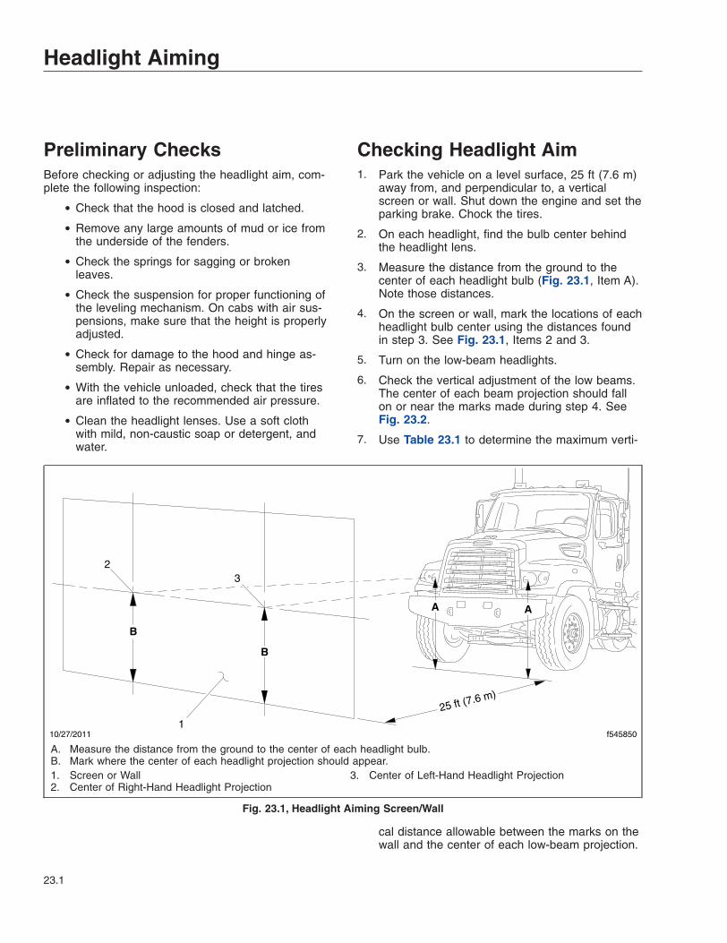
Preliminary ChecksBefore checking or adjusting the headlight aim, com-plete the following inspection:
• Check that the hood is closed and latched.
• Remove any large amounts of mud or ice fromthe underside of the fenders.
• Check the springs for sagging or brokenleaves.
• Check the suspension for proper functioning ofthe leveling mechanism. On cabs with air sus-pensions, make sure that the height is properlyadjusted.
• Check for damage to the hood and hinge as-sembly. Repair as necessary.
• With the vehicle unloaded, check that the tiresare inflated to the recommended air pressure.
• Clean the headlight lenses. Use a soft clothwith mild, non-caustic soap or detergent, andwater.
Checking Headlight Aim1. Park the vehicle on a level surface, 25 ft (7.6 m)
away from, and perpendicular to, a verticalscreen or wall. Shut down the engine and set theparking brake. Chock the tires.
2. On each headlight, find the bulb center behindthe headlight lens.
3. Measure the distance from the ground to thecenter of each headlight bulb (Fig. 23.1, Item A).Note those distances.
4. On the screen or wall, mark the locations of eachheadlight bulb center using the distances foundin step 3. See Fig. 23.1, Items 2 and 3.
5. Turn on the low-beam headlights.
6. Check the vertical adjustment of the low beams.The center of each beam projection should fallon or near the marks made during step 4. SeeFig. 23.2.
7. Use Table 23.1 to determine the maximum verti-
cal distance allowable between the marks on thewall and the center of each low-beam projection.
f54585010/27/2011
B
B
1
23
25 ft (7.6 m)
AA
A. Measure the distance from the ground to the center of each headlight bulb.B. Mark where the center of each headlight projection should appear.1. Screen or Wall2. Center of Right-Hand Headlight Projection
3. Center of Left-Hand Headlight Projection
Fig. 23.1, Headlight Aiming Screen/Wall
Headlight Aiming
23.1

If the distance between either projection centerand the mark made on the wall or screen isgreater than the maximum distance given inTable 23.1, adjust the vertical positioning of thatheadlight.
Adjusting Headlight AimNOTE: Freightliner vehicles are offered withvarious headlight assembly options. Because of
the various options, the location of adjustmentscrews on your vehicle’s headlight assemblymay vary from what is shown here.
The adjusting screw is located on the upper inboardcorner of the headlight assembly. See Fig. 23.3. Turnthe adjusting screw clockwise to raise the beam andcounterclockwise to lower it, until the beam patternmeets the acceptable standard.
Vertical Low-Beam Headlight Variation LimitsDistance Between Ground
and Headlight: in (mm)Desired Variation (Fig. 23.2,
Item 2) : in (mm)Upper Limit (Fig. 23.2, Item
1): in (mm) upLower Limit (Fig. 23.2, Item
3): in (mm) down22–36 (560–900) 0 3.9 (100) 3.9 (100)
36–48 (900–1200) 2 (50) down 2 (50) 6 (150)48–54 (1200–1400) 4 (101.6) down 1.6 (40) 6.5 (165)
Table 23.1, Vertical Low-Beam Headlight Variation Limits
11/03/2011 f545851
A
12
3
1. Low-Beam Angle Upper Limit2. Ideal Low-Beam Projection
3. Low-Beam Angle Lower Limit
Fig. 23.2, Vertical Low-Beam Headlight Variation Limits
Headlight Aiming
23.2

05/13/2009 f545526
Fig. 23.3, Headlight Adjusting
Headlight Aiming
23.3

24
In an EmergencyHazard Warning Lights . . . . . . . . . . . . . . . . . . . . . . . . . . . . . . . . . . . . . . . . . . . . . . . . . . . . . . . . . . . . 24.1Fire Extinguisher . . . . . . . . . . . . . . . . . . . . . . . . . . . . . . . . . . . . . . . . . . . . . . . . . . . . . . . . . . . . . . . . . 24.1Emergency Kit . . . . . . . . . . . . . . . . . . . . . . . . . . . . . . . . . . . . . . . . . . . . . . . . . . . . . . . . . . . . . . . . . . 24.1Emergency Filter Replacement, DAVCO . . . . . . . . . . . . . . . . . . . . . . . . . . . . . . . . . . . . . . . . . . . . . . 24.1Emergency Starting With Jumper Cables . . . . . . . . . . . . . . . . . . . . . . . . . . . . . . . . . . . . . . . . . . . . . 24.2Raising and Lowering a Vehicle . . . . . . . . . . . . . . . . . . . . . . . . . . . . . . . . . . . . . . . . . . . . . . . . . . . . 24.5Towing . . . . . . . . . . . . . . . . . . . . . . . . . . . . . . . . . . . . . . . . . . . . . . . . . . . . . . . . . . . . . . . . . . . . . . . . . 24.6Fire in the Cab . . . . . . . . . . . . . . . . . . . . . . . . . . . . . . . . . . . . . . . . . . . . . . . . . . . . . . . . . . . . . . . . . . 24.9

Hazard Warning LightsThe hazard warning light flasher (Fig. 24.1) is part ofthe multifunction turn signal switch. It is a red rockerswitch located on the top of the multifunction switchmodule.
To activate the hazard warning lights, press down onthe upper part of the rocker (pushing towards thedash). To deactivate the hazard warning lights, pressdown on the lower part of the rocker (towards thesteering wheel).
Fire ExtinguisherA fire extinguisher is located in the cab by thedriver’s door.
Emergency KitAn optional emergency kit is located in the cab. Thekit includes one or more of the following: a first aidkit, a reflective vest, a triangular reflector, a flare kit,and (on vehicles with a DAVCO fuel/water separator)a spin-on fuel filter element.
WARNINGUse extreme care when placing flares in emer-gency situations that involve exposure to flam-mable substances such as fuel. An explosion orfire could occur causing serious personal injury.
If there is an emergency while driving, cautiously pulloff the road. Turn on the hazard warning lights. Placethe flares and reflector along the side of the road toalert other drivers that an emergency situation exists.
Emergency FilterReplacement, DAVCOIf the filter cover on the DAVCO fuel/water separatoris broken, it will not be possible to operate the ve-hicle. A standard spin-on filter will correct this prob-lem.
Refer to the DAVCO web site for additional informa-tion, www.davcotec.com.
WARNINGFluid circulated through the fuel/water separatorto heat the fuel may be diesel fuel returned fromthe engine, or engine coolant. Drain the fuel/water separator only when the engine and fluidshave cooled. Draining it when the engine is hotcould cause severe personal injury due to scald-ing.
If returning fuel is released into the atmosphere,its vapors can ignite in the presence of any igni-tion source. Do not expose the fuel to, or workwith the fuel system near, open flame or intenseheat. To do so could cause fire, possibly result-ing in serious personal injury or property dam-age.
1. Shut down the engine, apply the parking brake,and chock the tires.
2. Put a clean receptacle under the fuel/water sepa-rator and attach a piece of hose to the drainvalve, to direct fuel into the receptacle.
NOTE: The drain valve on the Fuel Pro 382 hasa 1/2-inch (12.7-mm) opening; use a hose witha 1/2-inch pipe thread to fit correctly. Open thedrain valve by turning it one-quarter revolution.
3. Remove the vent cap (Fig. 24.2, Item 4) andopen the drain valve (Fig. 24.2, Item 1) to drainthe fuel to just below the collar level, then closethe drain valve.
4. Using a DAVCO collar wrench (Fig. 24.3), re-move the clear cover and collar.
NOTE: Broken vent cap and collar warrantyclaims will not be accepted if any tool other thana DAVCO collar wrench, p/n 380134 or 382002,
f820386
12
3
4
5
11/16/2001
Press down on the upper part of the rocker to activatethe flashers.
1. Washer Button2. Wiper Control Dial3. Turn Signal Lever
4. Hazard Flasher (red)5. Multifunction Switch
Module
Fig. 24.1, Hazard Warning Flashers
In an Emergency
24.1

is used for removal. During installation, the ventcap is to be hand-tightened only, not tightenedwith a wrench.
5. Remove the filter and dispose of it in an environ-mentally acceptable manner.
6. Clean all threads and sealing surfaces very thor-oughly. Even a small amount of dirt will preventthe fuel/water separator from sealing, and an airleak will result.
7. Ensure that the drain valve is closed.
8. Remove the filter grommet from the filter stud, ifequipped.
9. Fill the housing to the top of the filter elementwith clean diesel fuel.
10. Install a standard fuel filter element on the filterstud. If a standard filter element is not available,install a spin-on fuel filter element (part numberFF105 or equivalent).
11. Install the cover O-ring, clear cover, and the col-lar. Simultaneously apply downward pressure tothe top of the clear cover until it is seated on thebody of the lower housing and hand tighten thecollar until it no longer spins freely. Using the col-lar wrench, tighten the cover 18 lbf·ft (24 N·m).This is equivalent to rotating the collar clockwisetwo or three additional ribs, depending on thespecific filter model.
12. Install and hand-tighten the vent cap O-ring andvent cap.
13. Start the engine. When the lubricating oilreaches its normal operating pressure, increaseengine speed to high idle for one to two minutesto purge air from the system.
Emergency Starting WithJumper CablesWhen using jumper cables, follow the instructionsbelow.
WARNINGBatteries release explosive gas. Do not smokewhen working around batteries. Put out all flamesand remove all sources of sparks or intense heatin the vicinity of the battery. Do not allow the ve-hicles to touch each other. Do not lean over thebatteries when making connections, and keep allother persons away from the batteries. Failure tofollow these precautions could lead to severepersonal injury as a result of an explosion oracid burns.
NOTICEMake sure both electrical systems are the samevoltage. Electronic devices on both vehicles canbe damaged when connected to a vehicle with adifferent operating voltage.
1. Apply the parking brakes and turn off all lightsand other electrical devices. Ensure that the ve-hicles are not touching and both ignition switchesare turned to the OFF position.
f470506b05/05/2009
4
1
3
5
2
6
1. Drain Valve2. Lower Housing3. Clear Cover
4. Vent Cap5. Collar6. Inlet Port/Check Valve
Fig. 24.2, DAVCO Fuel Pro 382
02/16/2009 f470277
VE
NT
CA
P
FOR REMOVAL OF TOP COLLAR ONLY
Fig. 24.3, DAVCO Collar Wrench
In an Emergency
24.2

IMPORTANT: Do not attempt to jump start adamaged battery.
2. Remove the battery box cover. See Fig. 24.4 forthe standard battery compartment location.
NOTICEAlways connect the batteries and jumper cablescorrectly (positive-to-positive and negative-to-negative). Connecting a charging device back-wards (positive-to-negative) can severely damagethe vehicle electrical content and cause non-warrantable failures.
IMPORTANT: On vehicles equipped with op-tional jump start posts, connect to these postsinstead of the battery terminals. Jump startposts may be installed in various locations onthe vehicle. See Fig. 24.5.
3. Connect the positive (+) jumper cable to thepositive terminal or jump start post on the dis-charged battery. See Fig. 24.6.
4. Connect the other end of the positive jumpercable to the positive terminal or jump start poston the booster battery providing the charge.
WARNINGDo the next step exactly as instructed and do notallow the clamps of one cable to touch theclamps of the other cable. Otherwise, a sparkcould occur near a battery, possibly resulting insevere personal injury from explosion or acidburns.
5. Connect the negative (-) jumper cable to thenegative terminal or jump start post on thebooster battery.
6. Connect the other end of the negative jumpercable to the negative ground stud on the vehiclerequiring the jump start.
7. Start the engine of the vehicle providing the jumpstart and let the engine run a few minutes tocharge the batteries of the other vehicle.
8. Attempt to start the engine of the vehicle receiv-ing the jump. Do not operate the starter longerthan 30 seconds, and wait at least two minutesbetween starting attempts to allow the starter tocool.
9. When the engine starts, let it idle a few minutes.
12/03/2010 f545714
1
2 3
1. Back-of-Cab2. Fuel Tank
3. Battery Compartment
Fig. 24.4, Standard Battery Compartment Location
NEG JUMP
START STUD
POS JUMPSTART STUD
01/07/2011 f545726
1
2
3
1. Frame Rail2. Negative Jump Start Post3. Positive Jump Start Post
Fig. 24.5, Possible Jump Start Post Location(passenger-side engine compartment)
In an Emergency
24.3
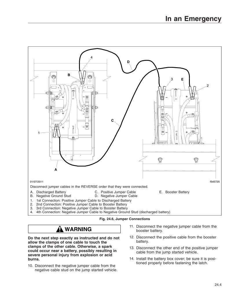
WARNINGDo the next step exactly as instructed and do notallow the clamps of one cable to touch theclamps of the other cable. Otherwise, a sparkcould occur near a battery, possibly resulting insevere personal injury from explosion or acidburns.
10. Disconnect the negative jumper cable from thenegative cable stud on the jump started vehicle.
11. Disconnect the negative jumper cable from thebooster battery.
12. Disconnect the positive cable from the boosterbattery.
13. Disconnect the other end of the positive jumpercable from the jump started vehicle.
14. Install the battery box cover; be sure it is posi-tioned properly before fastening the latch.
01/07/2011 f545725
1
2
3
4
A
C
EB
D
−−
−
−
+
+
+
+
+
+
−
−
Disconnect jumper cables in the REVERSE order that they were connected.
A. Discharged BatteryB. Negative Ground Stud
C. Positive Jumper CableD. Negative Jumper Cable
E. Booster Battery
1. 1st Connection: Positive Jumper Cable to Discharged Battery2. 2nd Connection: Positive Jumper Cable to Booster Battery3. 3rd Connection: Negative Jumper Cable to Booster Battery4. 4th Connection: Negative Jumper Cable to Negative Ground Stud (discharged battery)
Fig. 24.6, Jumper Connections
In an Emergency
24.4

Raising and Lowering aVehicleRaising a Vehicle with Air Suspension1. Park the vehicle on a level surface, set the park-
ing brakes, and shut down the engine. Chock thetires.
WARNINGRemove the air from the suspension. Failure toremove the air from the suspension may causethe vehicle to move or shift on the jack stands asair pressure drains from the system; this couldcause the vehicle to fall, resulting in damage tothe vehicle, serious injury, or death.
2. Exhaust all air from the air suspension.
WARNINGDo not use bottle jacks to raise the vehicle. Al-ways use floor jacks. Bottle jacks can slip, allow-ing the vehicle to fall, which could result in dam-age to the vehicle, serious injury, or death.
IMPORTANT: Only lift unloaded vehicles andvehicles disconnected from trailers. Unload ve-hicles with bodies (drilling rigs, mixers) as muchas possible.
3. Place a floor jack under the axle housing, theclamp group, or the frame rail.
NOTICENOTICE: Do not place jack stands under any ofthe suspension components; doing so couldcause suspension component damage. Jackstands can be placed at any point below the axle,including the differential area.
4. Raise the vehicle. Add additional jack stands, asneeded, under the axles to support the vehicle.
Lowering a Vehicle with AirSuspension
WARNINGDo not use bottle jacks to raise the vehicle. Al-ways use floor jacks. Bottle jacks can slip, allow-
ing the vehicle to fall, which could result in dam-age to the vehicle, serious injury, or death.
NOTICENOTICE: Do not place jack stands under any ofthe suspension components; doing so couldcause suspension component damage. Jackstands can be placed at any point below the axle,including the differential area.
1. Using the floor jack, raise the vehicle to removeany jack stands used to support the vehicle.
2. Slowly lower the vehicle to the ground.
3. Inflate the air suspension, and check for properoperation. Refer to Group 32 in the 108SD and114SD Workshop Manual for instructions.
Raising a Vehicle without AirSuspension1. Park the vehicle on a level surface, set the park-
ing brakes, and shut down the engine. Chock thetires.
WARNINGDo not use bottle jacks to raise the vehicle. Al-ways use floor jacks. Bottle jacks can slip, allow-ing the vehicle to fall, which could result in dam-age to the vehicle, serious injury, or death.
IMPORTANT: Only lift unloaded vehicles andvehicles disconnected from trailers. Unload ve-hicles with bodies (drilling rigs, mixers) as muchas possible.
2. Place a floor jack under the axle housing, theclamp group, or the frame rail.
NOTICENOTICE: Do not place jack stands under any ofthe suspension components; doing so couldcause suspension component damage. Jackstands can be placed at any point below the axle,including the differential area.
3. Raise the vehicle. Add additional jack stands, asneeded, to support the vehicle.
In an Emergency
24.5

Lowering a Vehicle without AirSuspension
WARNINGDo not use bottle jacks to raise the vehicle. Al-ways use floor jacks. Bottle jacks can slip, allow-ing the vehicle to fall, which could result in dam-age to the vehicle, serious injury, or death.
NOTICENOTICE: Do not place jack stands under any ofthe suspension components; doing so couldcause suspension component damage. Jackstands can be placed at any point below the axle,including the differential area.
1. Using the floor jack, raise the vehicle to removeany jack stands used to support the vehicle.
2. Slowly lower the vehicle to the ground.
TowingNOTE: The vehicle shown in the figures is forreference only and may not match the model ofyour vehicle.
1. Shutdown the engine and set the parking brake.
2. Open the hood. Remove the tow hooks, locatedbehind the driver’s-side bumper. See Fig. 24.7.Close and latch the hood.
NOTICENew or ungreased tow hooks may be hard to in-stall. Tow hooks that are not properly installedmay be damaged or break.
3. Install the tow hooks onto the tow hook receiversthrough the tow hook holes in the bumper, rotat-ing the hooks so the hook opening faces down.See Fig. 24.8. Pull the tow hooks to ensure theyare securely engaged in the tow hook receivers.
4. Lower the stinger assembly so that it is level andapproximately 1 inch (0.3 cm) off the ground.Back the tow truck so that the crossbar with liftadaptors is within 6 inches (15 cm) of the Aerobumper. See Fig. 24.9.
NOTICEWhen using tow hooks to move the vehicle, donot pass a sling (for example, a rope or chain)from one hook to another. Known as reeving, this
f13014606/14/2017
Fig. 24.7, Tow Hooks
f13014706/14/2017
Fig. 24.8, Tow Hooks Installed, Facing Down
f13014906/14/2017
Fig. 24.9, Positioning the Stinger Assembly
In an Emergency
24.6

practice is not permissible in most industrial ap-plications of towing and hoisting. Reeving canoverload the hooks and result in damage to thevehicle. See Fig. 24.10.
5. Pull the tow cables out of the tow truck and con-nect the tow cable lifting hooks onto the towhooks, then extend the recovery boom within 4to 6 inches (10 to 15 cm) of being vertical of thetow hooks. See Fig. 24.11.
6. Lift the front of the vehicle until there is enoughclearance for the stinger and crossbar to passunder the bumper. See Fig. 24.12.
If enough clearance can not be gained with asingle lift, jack stands or other means capable ofsupporting the weight on the front axle must beused while the cables are shortened to allow asecond lift.
WARNINGFailure to chock the tires or connect the towtruck’s air brake system before releasing thespring parking brakes could allow the disabledvehicle to suddenly roll. This could cause prop-erty damage or personal injury.
7. Chock the rear tires.
NOTICEReference the applicable axle manufacturer’s in-formation to avoid damaging the axle when tow-ing the truck.
IMPORTANT: Do not reeve when towing.
1. Tow Hook 2. Chain
Fig. 24.10, Reeving
f13015006/14/2017
Fig. 24.11, Tow Cables Connected to the Tow Hooks
f13015106/14/2017
Fig. 24.12, Moving the Stinger and Crossbar Under theBumper
In an Emergency
24.7
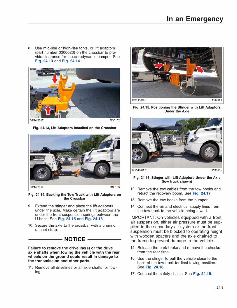
8. Use mid-rise or high-rise forks, or lift adaptors(part number 0200020) on the crossbar to pro-vide clearance for the aerodynamic bumper. SeeFig. 24.13 and Fig. 24.14.
9. Extend the stinger and place the lift adaptorsunder the axle. Make certain the lift adaptors areunder the front suspension springs between theU-bolts. See Fig. 24.15 and Fig. 24.16.
10. Secure the axle to the crossbar with a chain orratchet strap.
NOTICEFailure to remove the driveline(s) or the driveaxle shafts when towing the vehicle with the rearwheels on the ground could result in damage tothe transmission and other parts.
11. Remove all drivelines or all axle shafts for tow-ing.
12. Remove the tow cables from the tow hooks andretract the recovery boom. See Fig. 24.17.
13. Remove the tow hooks from the bumper.
14. Connect the air and electrical supply lines fromthe tow truck to the vehicle being towed.
IMPORTANT: On vehicles equipped with a frontair suspension, either air pressure must be sup-plied to the secondary air system or the frontsuspension must be blocked to operating heightwith wooden spacers and the axle chained tothe frame to prevent damage to the vehicle.
15. Release the park brake and remove the chocksfrom the rear tires.
16. Use the stinger to pull the vehicle close to theback of the tow truck for final towing position.See Fig. 24.18.
17. Connect the safety chains. See Fig. 24.19.
f13015206/14/2017
Fig. 24.13, Lift Adaptors Installed on the Crossbar
f13015306/14/2017
Fig. 24.14, Backing the Tow Truck with Lift Adaptors onthe Crossbar
f13015406/14/2017
Fig. 24.15, Positioning the Stinger with Lift AdaptorsUnder the Axle
f13015506/14/2017
Fig. 24.16, Stinger with Lift Adaptors Under the Axle(tow truck shown)
In an Emergency
24.8

Fire in the CabThe incidence of fire in heavy and medium-dutytrucks is rare, according to data from the NationalHighway Traffic Safety Administration. Federal MotorVehicle Safety Standard #302 limits the flammability
of specified materials used inside the cab but, de-spite this, most materials can burn.
WARNINGDo not allow flames, sparks, or any other heatsources (such as cigarettes or light bulbs) tocontact materials in the cab. Any materials in thecab in contact with such heat sources couldcause serious personal injury as well as damageto the vehicle.
In Case of a Cab FireAs quickly as possible, bring the vehicle to a safestop, apply the parking brake, turn off the ignition,and get out of the vehicle.
f13015606/14/2017
Fig. 24.17, Retracting the Recovery Boom
f13015706/14/2017
Fig. 24.18, Final Towing Position
f13015806/14/2017
Fig. 24.19, Safety Chains Connected on the TowedVehicle
In an Emergency
24.9

25
Telematics DataTerms of Use . . . . . . . . . . . . . . . . . . . . . . . . . . . . . . . . . . . . . . . . . . . . . . . . . . . . . . . . . . . . . . . . . . . 25.1

Terms of UseYour vehicle ("Vehicle") may be equipped with one ormore devices that gather information describedbelow regarding the Vehicle and the environment inwhich it may be operating ("Telematics Information").The devices may periodically send Telematics Infor-mation to Daimler Truck North America LLC("DTNA"). Additionally, DTNA and its dealers maymanually retrieve Telematics Information from thedevices for the purposes described below.
Telematics Information We Collectand Why We Collect ItThe Telematics Information we collect may in-clude, but is not limited to, information regardingthe performance, operation, location, speed,trips, travel history, stop and idle times, fuel con-sumption, fault codes and diagnostic information,steering and braking performance, air bag de-ployment and seatbelt use, decelerations, andother information relating to the performance,operation, health and safety of your Vehicle.DTNA gathers this information in order to improvethe performance, operation, health and safety of yourVehicle and other DTNA vehicles and products, inthe following ways, among others:
• To enable your subscription services. DTNAand other third party service providers havedeveloped a variety of applications and ser-vices that are now available to you to optimizethe performance, use, reliability and safe op-eration of your Vehicle. These services are en-abled by the Telematics Information we receivefrom your Vehicle and will likely be made moreeffective in the future by the use of that Telem-atics Information and similar information wereceive from other DTNA vehicles.
• To make your Vehicle safer and to improveits performance. Depending on the type ofdevice installed on your Vehicle, DTNA mayperiodically update your Vehicle’s on-boardsoftware to improve the performance and safeuse of the Vehicle. We may need to obtain cer-tain Telematics Information to ensure the effec-tiveness of these updates.
• To monitor and manage the health and effi-ciency of your Vehicle. Telematics Informa-tion from your Vehicle may be used by DTNAand its affiliates, dealers and service providersto diagnose and resolve problems with your
Vehicle more effectively and to help you main-tain it.
• To improve your customer service experi-ence. Telematics Information may be used byDTNA and its affiliates, dealers and serviceproviders to provide you a more efficient andeffective customer service experience in con-junction with Vehicle service, maintenance,field service campaigns and recalls.
• For product development and product im-provement. Telematics Information may beanalyzed and used to identify and resolve per-formance and safety issues and to developimprovements to our products that will benefityou and our future customers.
• To develop more meaningful product mar-keting. Telematics Information may be used toprovide more customized and meaningful infor-mation to our customers regarding productsand services that best satisfy their operationalrequirements and improve the performance oftheir businesses.
• To help match our customers with the rightproducts. Telematics Information may be usedto develop future products and services thatbest satisfy the operational requirements of ourcustomers.
What We Do with TelematicsInformation and Who We Share ItWithDTNA may use Telematics Information for any pur-pose allowed by law, including but not limited tousing the information for any of the purposes de-scribed in this chapter. DTNA may share TelematicsInformation with its service providers, affiliates, sub-sidiaries, dealers and distributors, but only for lawfulbusiness purposes. This may include third partieswho process information on behalf of DTNA, thirdparties who you authorize directly to receive informa-tion from us, and law enforcement agencies pursuantto applicable law.
DTNA may also combine Telematics Information itobtains from your Vehicle with data from others, ano-nymize and de-identify that aggregated data ("Aggre-gated Data"), and use and disclose that AggregatedData and derivatives of it indefinitely and for any pur-pose whatsoever, including sharing it with third par-ties for any purpose without restriction. You will not
Telematics Data
25.1

have any rights in any Aggregated Data or any de-rivatives or proceeds of it. DTNA will be the exclusiveowner of all rights, title and interests in and to all Ag-gregated Data. DTNA shall not have any obligation toprovide any Aggregated Data to you or to compen-sate you for any use or disclosure of any AggregatedData.
Collection MethodThe Telematics Information may be transmitted auto-matically or manually from the devices on your Ve-hicle to DTNA or Detroit Diesel Corporation (DDC)through diagnostic tools, including but not limited toDDC DiagnosticLink.
SafeguardsDTNA will use reasonable data security systems andprocedures in an effort to protect Telematics Informa-tion from unauthorized use, access, disclosure, distri-bution, loss or alteration. We do this through physi-cal, electronic and procedural safeguards that aredesigned to protect the confidentiality, integrity andavailability of Telematics Information. However, nosecurity system is perfect. DTNA cannot guaranteethat Telematics Information will not be hacked, de-leted, intercepted or altered. DTNA will also requireother parties to whom Telematics Information is dis-closed to take reasonable steps to protect the Telem-atics Information from unauthorized use, access, dis-closure, distribution, loss or alteration.
Your ConsentBy continuing to provide to us, or allowing us to re-ceive or retrieve, Telematics Information through thedevices on your Vehicle, you consent to its collectionand use as described in this chapter. Although someinformation may be transferred to and processed incountries without laws providing the same level ofdata protection as your country, our use and disclo-sure of your information is subject to these terms ofuse regardless of where your information is trans-ferred. If you have subscribed to a subscriptionservice such as Virtual Technician or Detroit Ana-lytics, the Telematics Terms and Conditions forthat service will apply to DTNA’s collection, stor-age, use and sharing of the data covered bythose Terms and Conditions.
Your RightsYou may ask DTNA to discontinue receiving and re-trieving Telematics Information from the devices onyour Vehicle. If you do so, you will be unable to re-
ceive telematics subscription services relating to yourVehicle and unable to remotely receive important Ve-hicle software updates, among other things. If youare interested in that option, please contact DTNA at:[email protected].
Privacy Statement ChangesDTNA reserves the right to amend these terms ofuse from time to time. Changes will be reflected inthe online version of this document found at: https://dtnacontent-dtna.prd.freightliner.com/content/public/dtna-servicelit/TechLit-Homepage.html?make=freightliner. By continuingto provide to us, or allowing us to receive or re-trieve, Telematics Information through the de-vices on your Vehicle, you consent to and acceptthose changes.
NOTE: These terms of use do not apply to after-market telematics devices that may be providedby others or configured to send information tosomeone other than DTNA or its affiliates,dealers or service providers.
Telematics Data
25.2

26
Driver Assistance FeaturesOnGuard™ Collision Safety System . . . . . . . . . . . . . . . . . . . . . . . . . . . . . . . . . . . . . . . . . . . . . . . . . . 26.1AutoVue® Lane Departure Warning System . . . . . . . . . . . . . . . . . . . . . . . . . . . . . . . . . . . . . . . . . . . 26.4

OnGuard™ Collision SafetySystemMeritor WABCO OnGuard is a forward-looking radar-based safety system. The system includes forwardcollision warning, adaptive cruise control (ACC), andcollision mitigation.
OnGuard equipped vehicles have antilock brakes(ABS) and automatic traction control (ATC), and ei-ther roll stability control (RSC) or electronic stabilitycontrol (ESC). These systems work together to en-hance control of the vehicle. Depending on the situa-tion, any of these features may apply throttle control,engine brakes, and/or service brakes, as needed.
The front-looking antenna assembly transmits radarsignals to, and receives them back from, objectsahead of the vehicle. To be detected, vehicles mustbe within the radar field of view and provide a sur-face area that can reflect the radar. The distance,speed, and angle of the vehicle ahead is calculated,and the driver is warned of potentially dangeroussituations. The system also warns of stationary ob-jects to alert the driver of potential obstructionsahead in their lane.
WARNINGThe Meritor WABCO OnGuard™ Collision SafetySystem is intended solely as an aid for an alertand conscientious professional driver. It is notintended to be relied upon to operate a vehicle.Use the system in conjunction with rearview mir-rors and other instruments to safely operate thevehicle. Operate a vehicle equipped with the On-Guard in the same safe manner as if the CMSwere not present.
The OnGuard Collision Safety System is not asubstitute for safe, normal driving procedures,nor will it compensate for any driver impairmentsuch as drugs, alcohol, or fatigue.
Failure to drive safely and use the system prop-erly could result in personal injury and/or deathand severe property damage.
System LimitationsThe OnGuard Collision Safety System may providelittle or no warning of hazards such as pedestrians,animals, oncoming vehicles, or cross traffic.
OnGuard CMS only brakes for lead vehicles locateddirectly in front of your vehicle, and does not operatewhen vehicle speed is less than 15 mph (25 km/h).
Due to these limitations, the system:
• will not react and alert the operator to objectscrossing in front of the vehicle or oncomingtraffic;
• should not be relied on to track lead vehicleswhen traveling through a severe curve in theroad. Because of this, ACC is not recom-mended for use on winding roads;
• will alert, but not actively brake, on stationaryobjects;
• should not be relied upon to track smaller ob-jects like motorcycles, mopeds, bicycles, orpedestrians;
• should not be relied on to alert drivers to ve-hicles in an adjacent lane.
OnGuard Display UnitThe OnGuard system controls are located in the dis-play unit. The display provides visual and audiblewarnings and messages, as well as verification ofcorrect system operation and faults. Menu selectionsare made by pressing the up and down arrows, andthe MODE button. See Fig. 26.1 .
The display includes:
• an internal speaker
• a graphic display
• buttons to scroll and select options
f61127702/17/2017
12
3
4
1. Mode2. Day/Night Mode
3. Up4. Down
Fig. 26.1, OnGuard Display Unit
Driver Assistance Features
26.1

• day/night display mode
Collision Mitigation System (CMS)The CMS provides the driver with audible and visualalerts when the vehicle’s following distance couldresult in a rear-end collision. The OnGuard displayunit shows a graphic of the condition, enhanced by ascreen color relevant to the intensity of the situation.See Table 26.1. If a potential rear-end collision isimminent, OnGuard’s active braking automaticallyapplies the engine and service brakes to slow thevehicle. The active braking application is intendedonly to provide early braking; the driver is still re-quired to recognize and react to all driving situations.
IMPORTANT: CMS and active braking are notoperational at vehicle speeds below 15 mph (25km/h).
OnGuard Display Screen Background ColorsScreen Color Description
Blue General operation; no lead vehiclesdetected.
Green Lead vehicle detected.
Yellow Following distance alert, accompaniedby an audible alert.
RedCollision warning, stationary objectwarning. Accompanied with audiblealert.
Amber Data Error
Table 26.1, OnGuard Display Screen BackgroundColors
StandbyWhen no lead vehicle is detected, the display showsthat the CMS is on and the radar is searching. SeeFig. 26.2.
A Vehicle is DetectedWhen a lead vehicle is detected in the lane ahead,the display shows that the CMS is on and the radaris tracking a lead vehicle at the speed shown. SeeFig. 26.3.
If the following distance between the vehicle and thelead vehicle is too close, the CMS will emit an au-dible alert and the display background will turn yel-low. The alert will end when the vehicle speed dropsbelow the lead vehicle speed and the following dis-tance is increased.
Collision WarningWhen a lead vehicle is detected traveling slower thanyour vehicle, or the gap between them becomes tooclose, the CMS warns of an impending collision byemitting an urgent audible alert and displaying thecollision warning symbol with a red background. SeeFig. 26.4.
Adaptive Cruise Control (ACC)ACC works in conjunction with conventional cruisecontrol to maintain a minimum following distancewhen a lead vehicle is being tracked. The minimum
f611143c07/15/2021
CMS
Fig. 26.2, CMS Standby (blue)
f611143b07/15/2021
CMS 55 MPH
230FT
Fig. 26.3, CMS Lead Vehicle Detected (green)
f611144a07/15/2021
CMS 15 MPH
15 FT
Fig. 26.4, CMS Collision Warning (red)
Driver Assistance Features
26.2

following distance is maintained by automatically de-celerating the vehicle using throttle, engine, and ser-vice brakes without driver intervention. When thelead vehicle is no longer being tracked, the set cruisecontrol speed resumes automatically.
StandbyWhen no lead vehicle is detected, OnGuard ACCoperates similarly to conventional cruise control. Thecruise control set speed is shown on the OnGuarddisplay unit. See Fig. 26.5.
Lead Vehicle DetectedWhen a lead vehicle is detected in the lane ahead,the display shows that ACC is on and the radar istracking it. See Fig. 26.6.
If the driver uses the accelerator pedal to overridethe cruise control and approach a vehicle too closely,the ACC will emit an audible alert and the displaybackground will turn yellow. The alert will end whenvehicle speed drops below the lead vehicle’s speedand the following distance is increased.
NOTE: The following distance alert does notoperate at speeds below 15 mph (25 km/h).
Collision WarningIf the lead vehicle is traveling slower than the driver’svehicle, the CMS warns of an impending collision byemitting an urgent audible alert and displaying the
collision warning symbol with a red background. SeeFig. 26.7.
The braking control will activate and slow the vehicle.The driver must also initiate braking.
Error ScreensIMPORTANT: The OnGuard collision safety sys-tem is not operational when an error screen isdisplayed. If a fault occurs or OnGuard fails toproperly track a vehicle, take the vehicle in forservice as soon as possible. Standard cruisecontrol will not function with an active OnGuardsystem fault.
If a system fault is detected, the OnGuard displayunit will immediately display an error screen asshown in Fig. 26.8. The first error code transmittedwill be displayed first; additional faults (if any) can beviewed using the up or down buttons. The displaydoes not show stored fault codes.
Refer to the OnGuard Collision Safety System Main-tenance Manual MM-0951 for a full list of faults(www.meritorwabco.com).
Additional FeaturesPress the MODE button to access the OnGuard dis-play unit additional features from the CMS or ACCmain operating screen. Press the up and down ar-rows to scroll through each menu, then press the
f61114502/17/2017
Set: 60 MPH
Fig. 26.5, ACC Standby (blue)
f61114602/17/2017Set: 60 MPH 55 MPH
230 FT
Fig. 26.6, ACC Lead Vehicle Detected (green)
f61114702/17/2017
Set: 60 MPH15 MPH
15 FT
Fig. 26.7, ACC Collision Warning (red)
f61114802/17/2017
ACC1 Link Error
DATA ERROR
Fig. 26.8, OnGuard Error Screen (amber)
Driver Assistance Features
26.3

MODE button to select the value to be changed. Inedit mode, press the up or down arrows to change avalue setting, then press the MODE button to savethe setting. Pressing MODE in each feature screenadvances the display to the next feature.
The Display Control menu allows adjustment of thealarm volume, LCD brightness, LCD contrast, andU.S./metric unit conversion. See Fig. 26.9.
The component test menu provides verification ofsystem component operation and acts as a valuableOnGuard system diagnostic tool. The header will dis-play either COMPONENT TEST or ACC FUNCTION,depending on the software release version of the On-Guard system. The component test screen shown inFig. 26.10 provides access to the following compo-nents (press the up or down arrows to scroll throughthe menu):
• brake pedal position
• EBS brake switch
• CCVS brake switch
• clutch switch
• park brake switch
• accelerator pedal position
• driveline engaged
• cruise control enable
• cruise control set speed switch
• cruise control coast switch
• cruise control resume switch
• cruise control accelerate switch
• cruise control pause switch
AutoVue® Lane DepartureWarning SystemNOTE: The Bendix AutoVue LDW system optionbecame an option on 114SD vehicles in June2021.
OverviewAutoVue is a camera-based warning system thathelps a driver avoid unintentional lane departure.
A camera mounted near the top center of the vehiclewindshield tracks visible lane markings to monitor thevehicle’s position within the lane. When the vehiclecrosses lane markings without the turn signal beingactivated, AutoVue gives an audible warning.
WARNINGThe AutoVue Lane Departure Warning (LDW) sys-tem is intended only as an aid for a conscien-tious and alert driver. It may not warn of unin-tended lane departures under certain conditions.It does not warn of all possible hazards. Do notrely solely on the system to safely operate thevehicle.
The system cannot help prevent an accident ifthe driver is impaired or not driving safely.
Ultimate responsibility for the safe operation ofthe vehicle remains with the driver at all times.
System StartupAutoVue activates when the ignition is turned on.Lane departure warnings are active only when thevehicle is traveling at or above 37 mph (60 kph).
At start-up the system performs a self-test. It thenplays a brief clip of the "rumble strip" alert sound,first through the left speaker, then the right. Thegreen ’enabled’ lamp on the ’LANE ALERT’ switchand the ’LANE SRCHNG’ dash indicator then illumi-nate. See Fig. 26.11 and Fig. 26.12.
f61114902/17/2017
DISPLAY CONTROL
Alarm Volume
Alarm Tone
10
4
LCD Intensity 9
Fig. 26.9, Display Control Menu
f61115102/17/2017
COMPONENT TEST
CCVS Brake Switch
Brake Pedal Position
ON
37%
ON
EBS Brake Switch
Fig. 26.10, Component Test Menu
Driver Assistance Features
26.4

The green ’enabled’ lamp on the switch will go OFFunder the following conditions:
• the driver temporarily disables the system;
• an active diagnostic trouble code (DTC) ispresent.
The lane searching dash indicator will remain ONunder the following conditions:
• vehicle speed is below 37 mph (60 kph);
• an active diagnostic trouble code (DTC) ispresent.
WARNINGIf the system cannot discover right or left lanemarkings, the AutoVue Lane Departure Warningsystem may not deliver expected alerts or errone-ous alerts may occur.
Missed and false alerts may occur in the follow-ing situations:
• Lane markings are difficult to distinguish due tostanding water, snow, ice, mud, sand, dirt, orother debris on the road.
• Lane markings are hidden or obscured byheavy rain, fog, falling snow or sleet, or blow-ing smoke.
• Lane markings are missing or faded.
• Sun glare or other light sources blind the cam-era, obscuring lane markings or making otherroad markings (e.g. tar strips) look like lanemarkings.
• The camera’s view through the windshieldglass is blocked or obscured by dirt, chips,cracks, or some other distortion.
• The camera is mis-installed.
• Headlights are not operating or are mis-aligned.
It is always the responsibility of the driver to re-main vigilant and change driving practices to suittraffic and road conditions.
Intentional Lane ChangesAt or above 37 mph (60 kph), the AutoVue LDW sys-tem tracks both solid and dashed shoulder lines,center lines, and the lines between lanes. For anrepresentation of the camera’s field of view, seeFig. 26.13.
The system identifies intentional lane changes bymonitoring the turn signal. When a lane change ismade with the turn signal on, no warnings are made.
Unintentional Lane DepartureWhen a lane change takes place without the turnsignal being activated, the system alerts the driver tomake a correction. The alert will come from the sideof the vehicle crossing the lane markings.
Alert WarningsThe AutoVue LDW system uses speakers that emit adistinctive "rumble strip" sound on the appropriateside of the cab to alert a driver of an unintentionallane departure. Audible alert volume levels are set atthe factory and cannot be adjusted.
SafetyDirectWhen triggered by a truck safety event, the AutoVueLDW system records ten seconds of video and trans-mits it to the SafetyDirect portal. Fleet managers canuse the video along with vehicle sensor informationto enhance driver training and road safety.
f611156b06/02/2021
Fig. 26.11, AutoVue Lane Alert Switch
f611314b06/02/2021
Fig. 26.12, AutoVue Lane Searching Dash Indicator
Driver Assistance Features
26.5

Cleaning the Windshield in the Areaof the CameraMake sure that the windshield is always kept cleanand unobstructed in the area of the camera.
The driver should switch on the windshield wiper toclean the windshield and remove snow and ice toavoid incorrect lane detection.
If this area of the windshield is damaged, the Auto-Vue LDW system may not work as intended. If thishappens, the windshield must be replaced.
Temporarily Disabling the SystemThe system can be temporarily disabled by pressingthe Lane Alert switch; when the system is disabled,the green ’enabled’ lamp will go off. See Fig. 26.11.The system will re-enable itself after 15 minutes.Warnings can be enabled sooner by pressing theswitch again.
System Offline IndicatorsIf the AutoVue LDW system goes offline while vehiclespeed is at or above 37 mph (60 kph), the ’lanesearching’ dash indicator will illuminate. Conditionsthat may cause this include:
• undetectable lane markings;
• an obscured camera lens;
• a system diagnostic trouble code (DTC).
If the ’lane searching’ dash indicator illuminates for along period of time with the vehicle speed at orabove 37 mph (60 kph), and the green enabled lampremains off despite depressing the Lane Alert switch,the system requires calibration services at an autho-rised dealer.
f54748604/05/2021
A
1 2 3 4
35
A. Camera Field of View1. Equipped Vehicle
2. Windshield Mounted Camera3. Lane Measurement Zones
4. Painted Road Stripes5. Lane Position Evaluation Zone
Fig. 26.13, Camera Field of View
Driver Assistance Features
26.6

Subject Page
AAdjustable Steering Column
Controls . . . . . . . . . . . . . . . . . . . . . . . . . . . . . 5.12Adjusting Headlight Aim . . . . . . . . . . . . . . . . . . . 23.2Air Brake System . . . . . . . . . . . . . . . . . . . . . . . . 12.1
Automatic Slack Adjusters . . . . . . . . . . . . . . . . 12.3Brake System Conditions . . . . . . . . . . . . . . . . 12.1Brake System General
Information . . . . . . . . . . . . . . . . . . . . . . . . . 12.1Brake System Operation . . . . . . . . . . . . . . . . . 12.1
Air-Suspension Dump Valve . . . . . . . . . . . . . . . . . 18.1Allison Automatic Transmissions . . . . . . . . . . . . . . 14.8
General Information, AllisonTransmissions . . . . . . . . . . . . . . . . . . . . . . . 14.8
Operation Tips, AllisonTransmissions . . . . . . . . . . . . . . . . . . . . . . . 14.9
AutoVue® Lane DepartureWarning System . . . . . . . . . . . . . . . . . . . . . . . 26.4Alert Warnings . . . . . . . . . . . . . . . . . . . . . . . . 26.5Cleaning the Windshield in
the Area of the Camera . . . . . . . . . . . . . . . . 26.6Intentional Lane Changes . . . . . . . . . . . . . . . . 26.5Overview . . . . . . . . . . . . . . . . . . . . . . . . . . . 26.4SafetyDirect . . . . . . . . . . . . . . . . . . . . . . . . . 26.5System Offline Indicators . . . . . . . . . . . . . . . . . 26.6System Startup . . . . . . . . . . . . . . . . . . . . . . . 26.4Temporarily Disabling the
System . . . . . . . . . . . . . . . . . . . . . . . . . . . 26.6Unintentional Lane
Departure . . . . . . . . . . . . . . . . . . . . . . . . . . 26.5Auxiliary Braking Applications . . . . . . . . . . . . . . . . 10.3
Engine Brake . . . . . . . . . . . . . . . . . . . . . . . . 10.3Exhaust Brake, Cummins
Engines . . . . . . . . . . . . . . . . . . . . . . . . . . . 10.4AWD Controls . . . . . . . . . . . . . . . . . . . . . . . . . . 5.10
AWD Operation Switch . . . . . . . . . . . . . . . . . . 5.10Transfer Case Range Switch . . . . . . . . . . . . . . 5.11
BBack-of-Cab Access . . . . . . . . . . . . . . . . . . . . . . . 2.3
Climbing Down from Back-of-Cab . . . . . . . . . . . . . . . . . . . . . . . . . . . . . 2.4
Climbing Up to Back-of-Cab . . . . . . . . . . . . . . . . 2.4Battery Access . . . . . . . . . . . . . . . . . . . . . . . . . . 3.2Bostrom Seat . . . . . . . . . . . . . . . . . . . . . . . . . . . 6.3
Backrest Tilt, Bostrom Seat . . . . . . . . . . . . . . . . 6.3Bottom Cushion Tilt, Bostrom
Seat . . . . . . . . . . . . . . . . . . . . . . . . . . . . . . 6.4Fore-and-Aft Seat
Adjustment, Bostrom Seat . . . . . . . . . . . . . . . . 6.4Height Adjustment, Bostrom
Seat . . . . . . . . . . . . . . . . . . . . . . . . . . . . . . 6.4
Subject Page
Isolator, Bostrom Seat . . . . . . . . . . . . . . . . . . . 6.4Lumbar Support, Bostrom
Seat . . . . . . . . . . . . . . . . . . . . . . . . . . . . . . 6.3Brake Controls . . . . . . . . . . . . . . . . . . . . . . . . . . 5.11
Antilock Braking System . . . . . . . . . . . . . . . . . 5.12Parking Brake Control Valve . . . . . . . . . . . . . . . 5.11Trailer Air Supply Valve . . . . . . . . . . . . . . . . . . 5.11Trailer Brake Lever . . . . . . . . . . . . . . . . . . . . . 5.12
CCab Amenities . . . . . . . . . . . . . . . . . . . . . . . . . . . 8.1
Cab Storage . . . . . . . . . . . . . . . . . . . . . . . . . . 8.1Cup Holders . . . . . . . . . . . . . . . . . . . . . . . . . . 8.1
Cab Entry and Exit . . . . . . . . . . . . . . . . . . . . . . . . 2.1Entering from the Driver’s
Side . . . . . . . . . . . . . . . . . . . . . . . . . . . . . . 2.2Entering from the
Passenger’s Side . . . . . . . . . . . . . . . . . . . . . 2.2Exiting from the Driver’s Side . . . . . . . . . . . . . . . 2.2Exiting from the Passenger’s
Side . . . . . . . . . . . . . . . . . . . . . . . . . . . . . . 2.3Cab Washing and Polishing . . . . . . . . . . . . . . . . . 22.1Canada Certification Label . . . . . . . . . . . . . . . . . . 1.1Care of Chrome Parts . . . . . . . . . . . . . . . . . . . . . 22.1Care of Exterior Lights . . . . . . . . . . . . . . . . . . . . 22.1Care of Fiberglass Parts . . . . . . . . . . . . . . . . . . . 22.1Checking Headlight Aim . . . . . . . . . . . . . . . . . . . 23.1Checklists . . . . . . . . . . . . . . . . . . . . . . . . . . . . . 20.1
Daily Pretrip InspectionChecklists . . . . . . . . . . . . . . . . . . . . . . . . . 20.1
Monthly Post-trip InspectionChecklists . . . . . . . . . . . . . . . . . . . . . . . . . 20.2
Weekly Post-trip InspectionChecklist . . . . . . . . . . . . . . . . . . . . . . . . . . 20.1
Climate Control Panel . . . . . . . . . . . . . . . . . . . . . . 7.1Accessory Heaters . . . . . . . . . . . . . . . . . . . . . . 7.3Air Conditioning, Optional . . . . . . . . . . . . . . . . . 7.3Air Selection Switch . . . . . . . . . . . . . . . . . . . . . 7.1Defrosting . . . . . . . . . . . . . . . . . . . . . . . . . . . 7.3Fan Switch . . . . . . . . . . . . . . . . . . . . . . . . . . . 7.1Fresh Air Mode . . . . . . . . . . . . . . . . . . . . . . . . 7.3Recirculation Mode . . . . . . . . . . . . . . . . . . . . . 7.3Temperature Control Switch . . . . . . . . . . . . . . . . 7.3
Climate Controls . . . . . . . . . . . . . . . . . . . . . . . . 5.13Clutch . . . . . . . . . . . . . . . . . . . . . . . . . . . . . . . 13.5
Clutch General Information . . . . . . . . . . . . . . . 13.5Clutch Maintenance . . . . . . . . . . . . . . . . . . . . 13.7Clutch Operation . . . . . . . . . . . . . . . . . . . . . . 13.5
Component GWR Label . . . . . . . . . . . . . . . . . . . . 1.1Component Information Label . . . . . . . . . . . . . . . . 1.1Control Panels . . . . . . . . . . . . . . . . . . . . . . . . . . 5.1
Index
I-1

Subject PageCruise Control . . . . . . . . . . . . . . . . . . . . . . . . . . 10.2Customer Assistance Label . . . . . . . . . . . . . . . . . . 1.6
DDaily Pretrip Inspection and
Maintenance . . . . . . . . . . . . . . . . . . . . . . . . . . 21.1Cab Inspection . . . . . . . . . . . . . . . . . . . . . . . 21.6Engine Compartment
Inspection . . . . . . . . . . . . . . . . . . . . . . . . . 21.4Natural Gas Fuel System
Inspection, If Equipped . . . . . . . . . . . . . . . . . 21.8Saddle Tank Areas
Inspection . . . . . . . . . . . . . . . . . . . . . . . . . 21.4Suspension and Slack
Adjuster Inspection . . . . . . . . . . . . . . . . . . . 21.1Wheel and Tire Inspection . . . . . . . . . . . . . . . . 21.1
Dashboard and InstrumentPanel Care . . . . . . . . . . . . . . . . . . . . . . . . . . . 22.2
Diesel Exhaust Fluid and Tank . . . . . . . . . . . . . . . 11.6DEF Tank . . . . . . . . . . . . . . . . . . . . . . . . . . . 11.6DEF Warnings and Engine
Limits . . . . . . . . . . . . . . . . . . . . . . . . . . . . . 11.7Diesel Exhaust Fluid . . . . . . . . . . . . . . . . . . . . 11.6Fuel/DEF Gauge . . . . . . . . . . . . . . . . . . . . . . 11.6
Differential Lock, Drive Axles . . . . . . . . . . . . . . . . 15.1Differential Lock Operation . . . . . . . . . . . . . . . . 15.1Differential Lock Switch . . . . . . . . . . . . . . . . . . 15.1Single Drive Axles with
Traction Equalizer . . . . . . . . . . . . . . . . . . . . 15.2Door Locks and Handles . . . . . . . . . . . . . . . . . . . . 2.1Driver Message Center . . . . . . . . . . . . . . . . . . . . . 4.7
Driving Screens . . . . . . . . . . . . . . . . . . . . . . . . 4.7Parked Screens/Menus . . . . . . . . . . . . . . . . . . . 4.7
EEaton Fuller 10-Speed Range-
Shift Transmissions . . . . . . . . . . . . . . . . . . . . . 13.3General Information, 10-
Speed Range-ShiftTransmissions . . . . . . . . . . . . . . . . . . . . . . . 13.4
Operation Tips, Eaton FullerRange-Shift Transmissions . . . . . . . . . . . . . . 13.4
Eaton Fuller 13-Speed and 18-Speed Splitter and Range-Shift Transmissions . . . . . . . . . . . . . . . . . . . . . 13.1General Information, Eaton
Fuller Splitter and Range-Shift Transmissions . . . . . . . . . . . . . . . . . . . 13.1
Operation Tips, Eaton FullerSplitter and Range-ShiftTransmissions . . . . . . . . . . . . . . . . . . . . . . . 13.2
Eaton Fuller AutoShiftAutomated Transmissions . . . . . . . . . . . . . . . . . 14.5
Subject Page
General Information,AutoShift Transmissions . . . . . . . . . . . . . . . . 14.5
Operation, AutoShiftTransmissions . . . . . . . . . . . . . . . . . . . . . . . 14.5
Eaton Fuller UltraShift PLUSAutomated Transmissions . . . . . . . . . . . . . . . . . 14.1Auto Neutral . . . . . . . . . . . . . . . . . . . . . . . . . 14.4Auto Start Gear Selection
and Override . . . . . . . . . . . . . . . . . . . . . . . . 14.4Automatic Mode (AUTO) . . . . . . . . . . . . . . . . . 14.2Automatic Traction Control . . . . . . . . . . . . . . . . 14.4Clutch Abuse Protection . . . . . . . . . . . . . . . . . 14.3Coasting . . . . . . . . . . . . . . . . . . . . . . . . . . . . 14.5Creep Mode . . . . . . . . . . . . . . . . . . . . . . . . . 14.3Engine Overspeed
Protection . . . . . . . . . . . . . . . . . . . . . . . . . . 14.4Hill Start Aid . . . . . . . . . . . . . . . . . . . . . . . . . 14.4Load-Based Shifting . . . . . . . . . . . . . . . . . . . . 14.5Low (L) . . . . . . . . . . . . . . . . . . . . . . . . . . . . 14.3Manual Mode (MAN) . . . . . . . . . . . . . . . . . . . . 14.2Power Down . . . . . . . . . . . . . . . . . . . . . . . . . 14.2Power Up . . . . . . . . . . . . . . . . . . . . . . . . . . . 14.1Reverse (R) . . . . . . . . . . . . . . . . . . . . . . . . . 14.2Shuttle Shifting . . . . . . . . . . . . . . . . . . . . . . . 14.4Skip Shifting . . . . . . . . . . . . . . . . . . . . . . . . . 14.4Ultrashift PLUS Diagnostics . . . . . . . . . . . . . . . 14.5
Emergency Filter Replacement,DAVCO . . . . . . . . . . . . . . . . . . . . . . . . . . . . . 24.1
Emergency Kit . . . . . . . . . . . . . . . . . . . . . . . . . . 24.1Emergency Starting With
Jumper Cables . . . . . . . . . . . . . . . . . . . . . . . . 24.2Emission Labels . . . . . . . . . . . . . . . . . . . . . . . . . 1.3
Aftertreatment SystemIndicators Label . . . . . . . . . . . . . . . . . . . . . . 1.3
Certified Clean Idle Label . . . . . . . . . . . . . . . . . 1.6Noise Emission Control
Labels . . . . . . . . . . . . . . . . . . . . . . . . . . . . . 1.4Vehicle Emission Control
Information Label . . . . . . . . . . . . . . . . . . . . . 1.3Engine Idle Limiting . . . . . . . . . . . . . . . . . . . . . . 10.1
Idle Shutdown Timer . . . . . . . . . . . . . . . . . . . . 10.1Engine Operation . . . . . . . . . . . . . . . . . . . . . . . . . 9.2
Cold-Weather Operation . . . . . . . . . . . . . . . . . . 9.3Engine Break-In . . . . . . . . . . . . . . . . . . . . . . . 9.2Normal Operation . . . . . . . . . . . . . . . . . . . . . . 9.2Safety and Environmental
Considerations . . . . . . . . . . . . . . . . . . . . . . . 9.2Engine Protection—Warning
and Shutdown . . . . . . . . . . . . . . . . . . . . . . . . . 10.1Engine Shutdown . . . . . . . . . . . . . . . . . . . . . . . . 9.3Engine Starting . . . . . . . . . . . . . . . . . . . . . . . . . . 9.1
Cold-Weather Starting . . . . . . . . . . . . . . . . . . . 9.1
Index
I-2

Subject Page
Starting After ExtendedShutdown . . . . . . . . . . . . . . . . . . . . . . . . . . 9.1
Enhanced Stability Control . . . . . . . . . . . . . . . . . . 12.4EPA-Regulated Emissions
Aftertreatment System . . . . . . . . . . . . . . . . . . . 11.1ATS Warning Lamps . . . . . . . . . . . . . . . . . . . . 11.3DPF Maintenance . . . . . . . . . . . . . . . . . . . . . . 11.5EPA10 and Newer Engines . . . . . . . . . . . . . . . 11.2Euro V Emission Compliant
Engines for Export . . . . . . . . . . . . . . . . . . . . 11.2Regeneration . . . . . . . . . . . . . . . . . . . . . . . . . 11.2
FFederal Motor Vehicle Safety
Standard Label . . . . . . . . . . . . . . . . . . . . . . . . . 1.1Fifth Wheel Coupling . . . . . . . . . . . . . . . . . . . . . 17.1
Fontaine and Holland FifthWheels Coupling . . . . . . . . . . . . . . . . . . . . . 17.1
Jost Fifth Wheel Coupling . . . . . . . . . . . . . . . . 17.3Fifth Wheel Slide . . . . . . . . . . . . . . . . . . . . . . . . 17.6
Air Slide Operation . . . . . . . . . . . . . . . . . . . . . 17.8Manual Slide Operation . . . . . . . . . . . . . . . . . . 17.7
Fifth Wheel Uncoupling . . . . . . . . . . . . . . . . . . . . 17.4Air-Actuated Uncoupling . . . . . . . . . . . . . . . . . 17.5Manual Uncoupling . . . . . . . . . . . . . . . . . . . . . 17.4
Fifth Wheels, GeneralInformation . . . . . . . . . . . . . . . . . . . . . . . . . . . 17.1Air-Suspension Dump Valve . . . . . . . . . . . . . . . 17.1Fifth Wheel Lubrication . . . . . . . . . . . . . . . . . . 17.1
Fire Extinguisher . . . . . . . . . . . . . . . . . . . . . . . . 24.1Fire in the Cab . . . . . . . . . . . . . . . . . . . . . . . . . 24.9
In Case of a Cab Fire . . . . . . . . . . . . . . . . . . . 24.9Fluids Added . . . . . . . . . . . . . . . . . . . . . . . . . . . 20.2Freightliner High-Back Seat . . . . . . . . . . . . . . . . . . 6.2
Backrest Tilt . . . . . . . . . . . . . . . . . . . . . . . . . . 6.2Bottom Cushion Extension . . . . . . . . . . . . . . . . 6.2Fore/Aft Isolator . . . . . . . . . . . . . . . . . . . . . . . . 6.2Fore/Aft Seat Slide . . . . . . . . . . . . . . . . . . . . . . 6.2Front Cushion Height . . . . . . . . . . . . . . . . . . . . 6.2Heater . . . . . . . . . . . . . . . . . . . . . . . . . . . . . . 6.3Height Adjustment . . . . . . . . . . . . . . . . . . . . . . 6.2Lumbar Support . . . . . . . . . . . . . . . . . . . . . . . 6.2Rear Cushion Height . . . . . . . . . . . . . . . . . . . . 6.3Shock Absorber . . . . . . . . . . . . . . . . . . . . . . . . 6.2
Freightliner SmartShift ShiftControl . . . . . . . . . . . . . . . . . . . . . . . . . . . . . 14.1General Information,
SmartShift Control . . . . . . . . . . . . . . . . . . . . 14.1
Subject Page
GGreenhouse Gas Emissions
and Fuel ConsumptionStandards . . . . . . . . . . . . . . . . . . . . . . . . . . . . 11.1
HHazard Warning Lights . . . . . . . . . . . . . . . . . . . . 24.1Holland Trailer Coupling . . . . . . . . . . . . . . . . . . . 18.1
General Information . . . . . . . . . . . . . . . . . . . . 18.1Trailer Hookup . . . . . . . . . . . . . . . . . . . . . . . . 18.1Trailer Release . . . . . . . . . . . . . . . . . . . . . . . 18.1
Hood Opening and Closing . . . . . . . . . . . . . . . . . . 2.4To Return the Hood . . . . . . . . . . . . . . . . . . . . . 2.5To Tilt the Hood . . . . . . . . . . . . . . . . . . . . . . . . 2.4
Horn Controls . . . . . . . . . . . . . . . . . . . . . . . . . . . 5.6Air Horn . . . . . . . . . . . . . . . . . . . . . . . . . . . . . 5.6Electric Horn . . . . . . . . . . . . . . . . . . . . . . . . . . 5.6
IIgnition Switch . . . . . . . . . . . . . . . . . . . . . . . . . . . 5.1Instrumentation Control Unit . . . . . . . . . . . . . . . . . . 4.1
Audible Alerts . . . . . . . . . . . . . . . . . . . . . . . . . 4.2Ignition Sequence . . . . . . . . . . . . . . . . . . . . . . 4.1
Instruments . . . . . . . . . . . . . . . . . . . . . . . . . . . . 4.9Air Intake Restriction Gauge . . . . . . . . . . . . . . . 4.9Coolant Temperature Gauge . . . . . . . . . . . . . . . 4.9Drive Axle Oil Temperature
Gauges . . . . . . . . . . . . . . . . . . . . . . . . . . . 4.10Engine Oil Pressure Gauge . . . . . . . . . . . . . . . 4.10Engine Oil Temperature
Gauge . . . . . . . . . . . . . . . . . . . . . . . . . . . . 4.11Fuel/Diesel Exhaust Fluid
(DEF) Gauge . . . . . . . . . . . . . . . . . . . . . . . 4.11Primary and Secondary Air
Pressure Gauges . . . . . . . . . . . . . . . . . . . . . 4.12Speedometer . . . . . . . . . . . . . . . . . . . . . . . . 4.12Tachometer . . . . . . . . . . . . . . . . . . . . . . . . . . 4.12Transmission Fluid
Temperature Gauge . . . . . . . . . . . . . . . . . . . 4.12Turbocharger Boost
Pressure Gauge . . . . . . . . . . . . . . . . . . . . . 4.12Voltmeter . . . . . . . . . . . . . . . . . . . . . . . . . . . 4.13
Interaxle Lock, Tandem andTridem Axles . . . . . . . . . . . . . . . . . . . . . . . . . . 15.2Interaxle Lock Operation . . . . . . . . . . . . . . . . . 15.3Interaxle Lock Switch . . . . . . . . . . . . . . . . . . . 15.2
LLighting Controls . . . . . . . . . . . . . . . . . . . . . . . . . 5.2
Index
I-3
Subject Page
Exterior Light Controls . . . . . . . . . . . . . . . . . . . 5.3Interior Light Controls . . . . . . . . . . . . . . . . . . . . 5.5
Load Disconnect Switch . . . . . . . . . . . . . . . . . . . . 3.1
MMajor Repair and Replacement
of Natural Gas Components . . . . . . . . . . . . . . . 19.11Meritor WABCO® Antilock
Braking System . . . . . . . . . . . . . . . . . . . . . . . . 12.3Automatic Traction Control . . . . . . . . . . . . . . . . 12.4Trailer ABS Compatibility . . . . . . . . . . . . . . . . . 12.4
Mexico Labeling . . . . . . . . . . . . . . . . . . . . . . . . . 1.2Mexico Certification Label . . . . . . . . . . . . . . . . . 1.2Spanish Weights and
Measures Label . . . . . . . . . . . . . . . . . . . . . . 1.3Mirrors and Windows . . . . . . . . . . . . . . . . . . . . . . 8.1
Down View Mirror, Optional . . . . . . . . . . . . . . . . 8.2Mirror Heat Switch, Optional . . . . . . . . . . . . . . . 8.1Mirrors . . . . . . . . . . . . . . . . . . . . . . . . . . . . . . 8.1Power Mirrors, Optional . . . . . . . . . . . . . . . . . . 8.1Windows . . . . . . . . . . . . . . . . . . . . . . . . . . . . 8.2
Monthly Post-Trip Inspectionand Maintenance . . . . . . . . . . . . . . . . . . . . . . 21.13Brake Component Inspection . . . . . . . . . . . . . 21.13Engine Compartment
Inspection andAdjustments . . . . . . . . . . . . . . . . . . . . . . . 21.14
Natural Gas Fuel SystemInspection, If Equipped . . . . . . . . . . . . . . . . 21.14
Saddle Tank AreasInspection . . . . . . . . . . . . . . . . . . . . . . . . . 21.13
Multifunction Turn Signal LeverControls . . . . . . . . . . . . . . . . . . . . . . . . . . . . . . 5.5Turn Signal Controls . . . . . . . . . . . . . . . . . . . . . 5.5Windshield Wiper/Washer
Controls . . . . . . . . . . . . . . . . . . . . . . . . . . . . 5.6
NNational 2000 Series Seat . . . . . . . . . . . . . . . . . . . 6.5
Backrest Tilt, National 2000Series Seat . . . . . . . . . . . . . . . . . . . . . . . . . 6.5
Bottom Cushion Fore-and-AftAdjustment, National 2000Series Seat . . . . . . . . . . . . . . . . . . . . . . . . . 6.6
Fore-and-Aft SeatAdjustment, National 2000Series Seat . . . . . . . . . . . . . . . . . . . . . . . . . 6.5
Height Adjustment, National2000 Series Seat . . . . . . . . . . . . . . . . . . . . . 6.5
Isolator, National 2000Series Seat . . . . . . . . . . . . . . . . . . . . . . . . . 6.6
Lumbar Support, National2000 Series Seat . . . . . . . . . . . . . . . . . . . . . 6.5
Subject Page
Rear Cushion Adjustment,National 2000 Series Seat . . . . . . . . . . . . . . . 6.6
Natural Gas Detection System . . . . . . . . . . . . . . . 19.5Alarm Procedure . . . . . . . . . . . . . . . . . . . . . . 19.5AMGaDS III Plus Control
Module and Alarm Panel . . . . . . . . . . . . . . . . 19.8Fireboy Control Module and
Alarm Panel . . . . . . . . . . . . . . . . . . . . . . . . 19.7Sensors . . . . . . . . . . . . . . . . . . . . . . . . . . . . 19.6Testing . . . . . . . . . . . . . . . . . . . . . . . . . . . . 19.10
Natural Gas Fuel Tank FillingProcedures . . . . . . . . . . . . . . . . . . . . . . . . . . . 19.2CNG Vehicle Fueling . . . . . . . . . . . . . . . . . . . 19.2LNG Vehicle Fueling . . . . . . . . . . . . . . . . . . . . 19.3
Natural Gas Vehicles, EngineStarting . . . . . . . . . . . . . . . . . . . . . . . . . . . . 19.11
Natural Gas Vehicles, GeneralInformation . . . . . . . . . . . . . . . . . . . . . . . . . . . 19.1
Natural Gas Vehicles, SafetyPrecautions . . . . . . . . . . . . . . . . . . . . . . . . . . 19.1In Case of Emergency . . . . . . . . . . . . . . . . . . 19.2
OOnGuard™ Collision Safety
System . . . . . . . . . . . . . . . . . . . . . . . . . . . . . 26.1Adaptive Cruise Control
(ACC) . . . . . . . . . . . . . . . . . . . . . . . . . . . . 26.2Additional Features . . . . . . . . . . . . . . . . . . . . 26.3Collision Mitigation System
(CMS) . . . . . . . . . . . . . . . . . . . . . . . . . . . . 26.2Error Screens . . . . . . . . . . . . . . . . . . . . . . . . 26.3OnGuard Display Unit . . . . . . . . . . . . . . . . . . . 26.1System Limitations . . . . . . . . . . . . . . . . . . . . . 26.1
Overhead Instrument Panel . . . . . . . . . . . . . . . . . 4.13
PPeriodic Inspections and
Maintenance . . . . . . . . . . . . . . . . . . . . . . . . . . 20.1Power Steering System . . . . . . . . . . . . . . . . . . . . 16.1
Steering Wheel Adjustment . . . . . . . . . . . . . . . 16.1Power Takeoff (PTO) Governor . . . . . . . . . . . . . . . 10.5Powertrain Controls . . . . . . . . . . . . . . . . . . . . . . . 5.7
Aftertreatment SystemRegeneration Switches . . . . . . . . . . . . . . . . . . 5.7
Axle Switches . . . . . . . . . . . . . . . . . . . . . . . . . 5.7Cruise Control Switches . . . . . . . . . . . . . . . . . . 5.8Engine Brake Switch . . . . . . . . . . . . . . . . . . . . 5.8Engine Fan Switch . . . . . . . . . . . . . . . . . . . . . . 5.8Exhaust Brake Switch . . . . . . . . . . . . . . . . . . . . 5.9Transmission Controls . . . . . . . . . . . . . . . . . . . 5.10
Preliminary Checks . . . . . . . . . . . . . . . . . . . . . . . 23.1
Index
I-4

Subject PagePremier Trailer Couplings . . . . . . . . . . . . . . . . . . 18.2
General Information . . . . . . . . . . . . . . . . . . . . 18.2Trailer Hookup . . . . . . . . . . . . . . . . . . . . . . . . 18.2Trailer Release . . . . . . . . . . . . . . . . . . . . . . . 18.3
RRaising and Lowering a Vehicle . . . . . . . . . . . . . . 24.5
Lowering a Vehicle with AirSuspension . . . . . . . . . . . . . . . . . . . . . . . . 24.5
Lowering a Vehicle withoutAir Suspension . . . . . . . . . . . . . . . . . . . . . . 24.6
Raising a Vehicle with AirSuspension . . . . . . . . . . . . . . . . . . . . . . . . 24.5
Raising a Vehicle without AirSuspension . . . . . . . . . . . . . . . . . . . . . . . . 24.5
Roll Stability Advisor/Control . . . . . . . . . . . . . . . . . 12.5Hard-Braking Advisor . . . . . . . . . . . . . . . . . . . 12.5Roll Stability Advisor . . . . . . . . . . . . . . . . . . . . 12.5Roll Stability Control . . . . . . . . . . . . . . . . . . . . 12.5Trip/Leg Totals . . . . . . . . . . . . . . . . . . . . . . . . 12.6
SSafety Precautions . . . . . . . . . . . . . . . . . . . . . . . 21.1Sears Atlas Seat . . . . . . . . . . . . . . . . . . . . . . . . . 6.4
Armrest Adjustment, SearsAtlas Seat . . . . . . . . . . . . . . . . . . . . . . . . . . 6.5
Backrest Tilt, Sears AtlasSeat . . . . . . . . . . . . . . . . . . . . . . . . . . . . . . 6.5
Fore-and-Aft SeatAdjustment, Sears AtlasSeat . . . . . . . . . . . . . . . . . . . . . . . . . . . . . . 6.5
Height Adjustment, SearsAtlas Seat . . . . . . . . . . . . . . . . . . . . . . . . . . 6.5
Isolator . . . . . . . . . . . . . . . . . . . . . . . . . . . . . 6.5Lumbar Support, Sears Atlas
Seat . . . . . . . . . . . . . . . . . . . . . . . . . . . . . . 6.5Seat Tilt/Extension
Adjustment, Sears AtlasSeat . . . . . . . . . . . . . . . . . . . . . . . . . . . . . . 6.5
Seat Belts and Tether Belts . . . . . . . . . . . . . . . . . . 6.6General Information, Seat
Belts and Tether Belts . . . . . . . . . . . . . . . . . . 6.6Inspection, Seat Belts and
Tether Belts . . . . . . . . . . . . . . . . . . . . . . . . . 6.6Seat Belt Operation . . . . . . . . . . . . . . . . . . . . . 6.7
Seat Controls . . . . . . . . . . . . . . . . . . . . . . . . . . 5.13Bench Seats . . . . . . . . . . . . . . . . . . . . . . . . . 5.14
Seats, General Information . . . . . . . . . . . . . . . . . . 6.1Bench Seats . . . . . . . . . . . . . . . . . . . . . . . . . . 6.2
Suspension Controls . . . . . . . . . . . . . . . . . . . . . . 5.12Air Suspension Autofill
Override Valve . . . . . . . . . . . . . . . . . . . . . . 5.12
Subject Page
Air Suspension DumpControl Switch . . . . . . . . . . . . . . . . . . . . . . . 5.13
TTerms of Use . . . . . . . . . . . . . . . . . . . . . . . . . . . 25.1
Collection Method . . . . . . . . . . . . . . . . . . . . . 25.2Privacy Statement Changes . . . . . . . . . . . . . . . 25.2Safeguards . . . . . . . . . . . . . . . . . . . . . . . . . . 25.2Telematics Information We
Collect and Why WeCollect It . . . . . . . . . . . . . . . . . . . . . . . . . . 25.1
What We Do with TelematicsInformation and Who WeShare It With . . . . . . . . . . . . . . . . . . . . . . . 25.1
Your Consent . . . . . . . . . . . . . . . . . . . . . . . . 25.2Your Rights . . . . . . . . . . . . . . . . . . . . . . . . . . 25.2
Towing . . . . . . . . . . . . . . . . . . . . . . . . . . . . . . . 24.6Transfer Cases . . . . . . . . . . . . . . . . . . . . . . . . . 15.3
Marmon-Herrington MVG-1600 . . . . . . . . . . . . . . . . . . . . . . . . . . . . . 15.4
Meritor MTC Series . . . . . . . . . . . . . . . . . . . . 15.3
VVehicle Power Distribution . . . . . . . . . . . . . . . . . . . 3.1
Main Powernet DistributionBox . . . . . . . . . . . . . . . . . . . . . . . . . . . . . . . 3.1
Power Distribution Modules . . . . . . . . . . . . . . . . 3.1Velour Upholstery Cleaning . . . . . . . . . . . . . . . . . 22.3
Chewing Gum or Wax . . . . . . . . . . . . . . . . . . . 22.3Grease and Oil-Based Stains . . . . . . . . . . . . . . 22.3Mildew . . . . . . . . . . . . . . . . . . . . . . . . . . . . . 22.3Sugar and Water-Based
Stains . . . . . . . . . . . . . . . . . . . . . . . . . . . . 22.3Vinyl Upholstery Cleaning . . . . . . . . . . . . . . . . . . 22.2
Ball Point Ink . . . . . . . . . . . . . . . . . . . . . . . . . 22.3Chewing Gum . . . . . . . . . . . . . . . . . . . . . . . . 22.2Miscellaneous . . . . . . . . . . . . . . . . . . . . . . . . 22.3Nail Polish and Nail Polish
Remover . . . . . . . . . . . . . . . . . . . . . . . . . . 22.2Ordinary Dirt . . . . . . . . . . . . . . . . . . . . . . . . . 22.2Paint, Shoe Heel Marks . . . . . . . . . . . . . . . . . 22.2Shoe Polish . . . . . . . . . . . . . . . . . . . . . . . . . 22.2Sulfide Stains . . . . . . . . . . . . . . . . . . . . . . . . 22.2Tars, Asphalts, and Creosote . . . . . . . . . . . . . . 22.2
WWarning and Indicator Lights . . . . . . . . . . . . . . . . . 4.3
Engine Protection System . . . . . . . . . . . . . . . . . 4.6Weekly Post-Trip Inspection
and Maintenance . . . . . . . . . . . . . . . . . . . . . . . 21.9
Index
I-5

Subject Page
Engine CompartmentInspection . . . . . . . . . . . . . . . . . . . . . . . . . 21.9
Index
I-6