10 1021@am502110p
11
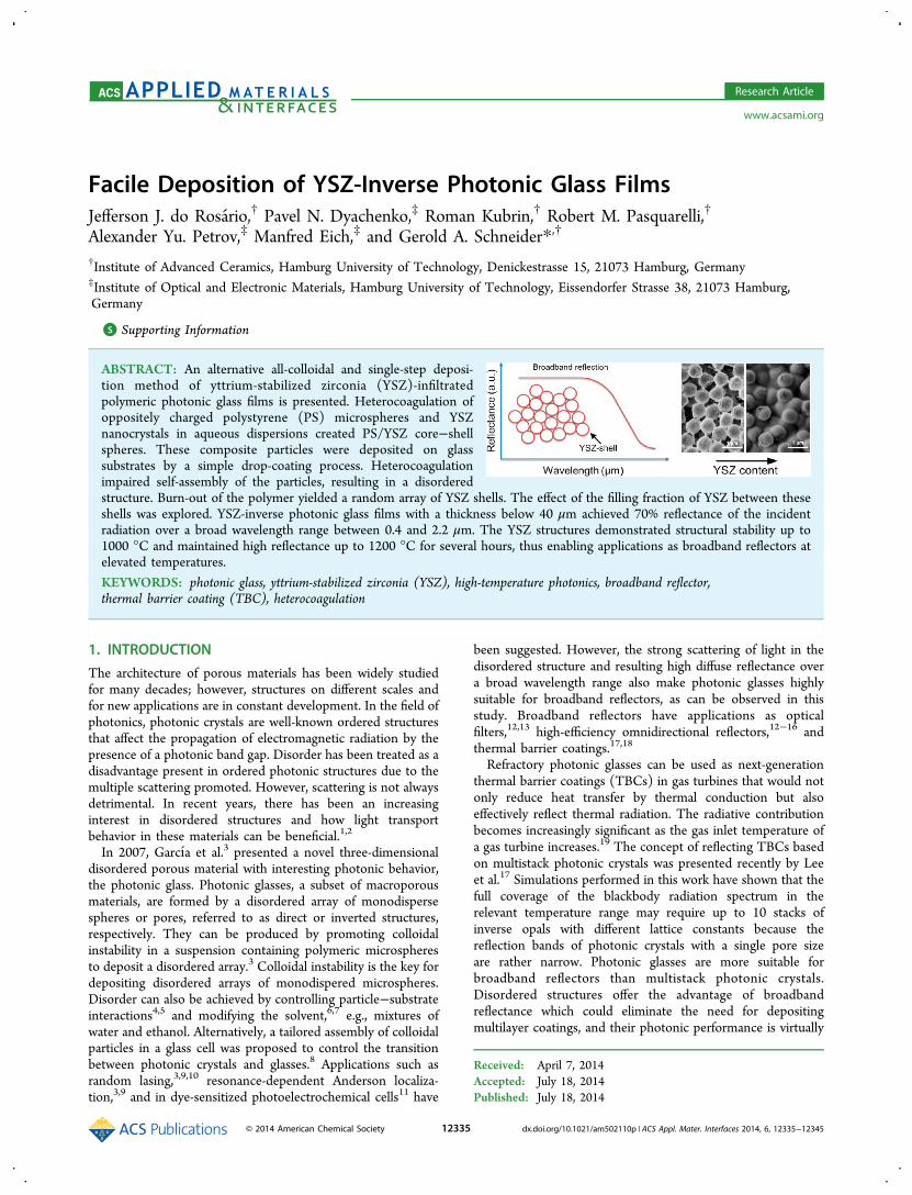
Facile Deposition of YSZ-Inverse Photonic Glass Films Jefferson J. do Rosa ́ rio, † Pavel N. Dyachenko, ‡ Roman Kubrin, † Robert M. Pasquarelli, † Alexander Yu. Petrov, ‡ Manfred Eich, ‡ and Gerold A. Schneider* ,† † Institute of Advanced Ceramics, Hamburg University of Technology, Denickestrasse 15, 21073 Hamburg, Germany ‡ Institute of Optical and Electronic Materials, Hamburg University of Technology, Eissendorfer Strasse 38, 21073 Hamburg, Germany * S Supporting Information ABSTRACT: An alternative all-colloidal and single-step deposi- tion method of yttrium-stabilized zirconia (YSZ)-infiltrated polymeric photonic glass films is presented. Heterocoagulation of oppositely charged polystyrene (PS) microspheres and YSZ nanocrystals in aqueous dispersions created PS/YSZ core−shell spheres. These composite particles were deposited on glass substrates by a simple drop-coating process. Heterocoagulation impaired self-assembly of the particles, resulting in a disordered structure. Burn-out of the polymer yielded a random array of YSZ shells. The effect of the filling fraction of YSZ between these shells was explored. YSZ-inverse photonic glass films with a thickness below 40 μm achieved 70% reflectance of the incident radiation over a broad wavelength range between 0.4 and 2.2 μm. The YSZ structures demonstrated structural stability up to 1000 °C and maintained high reflectance up to 1200 °C for several hours, thus enabling applications as broadband reflectors at elevated temperatures. KEYWORDS: photonic glass, yttrium-stabilized zirconia (YSZ), high-temperature photonics, broadband reflector, thermal barrier coating (TBC), heterocoagulation 1. INTRODUCTION The architecture of porous materials has been widely studied for many decades; however, structures on different scales and for new applications are in constant development. In the field of photonics, photonic crystals are well-known ordered structures that affect the propagation of electromagnetic radiation by the presence of a photonic band gap. Disorder has been treated as a disadvantage present in ordered photonic structures due to the multiple scattering promoted. However, scattering is not always detrimental. In recent years, there has been an increasing interest in disordered structures and how light transport behavior in these materials can be beneficial. 1,2 In 2007, Garcı ́ a et al. 3 presented a novel three-dimensional disordered porous material with interesting photonic behavior, the photonic glass. Photonic glasses, a subset of macroporous materials, are formed by a disordered array of monodisperse spheres or pores, referred to as direct or inverted structures, respectively. They can be produced by promoting colloidal instability in a suspension containing polymeric microspheres to deposit a disordered array. 3 Colloidal instability is the key for depositing disordered arrays of monodispered microspheres. Disorder can also be achieved by controlling particle−substrate interactions 4,5 and modifying the solvent, 6,7 e.g., mixtures of water and ethanol. Alternatively, a tailored assembly of colloidal particles in a glass cell was proposed to control the transition between photonic crystals and glasses. 8 Applications such as random lasing, 3,9,10 resonance-dependent Anderson localiza- tion, 3,9 and in dye-sensitized photoelectrochemical cells 11 have been suggested. However, the strong scattering of light in the disordered structure and resulting high diffuse reflectance over a broad wavelength range also make photonic glasses highly suitable for broadband reflectors, as can be observed in this study. Broadband reflectors have applications as optical filters, 12,13 high-efficiency omnidirectional reflectors, 12−16 and thermal barrier coatings. 17,18 Refractory photonic glasses can be used as next-generation thermal barrier coatings (TBCs) in gas turbines that would not only reduce heat transfer by thermal conduction but also effectively reflect thermal radiation. The radiative contribution becomes increasingly significant as the gas inlet temperature of a gas turbine increases. 19 The concept of reflecting TBCs based on multistack photonic crystals was presented recently by Lee et al. 17 Simulations performed in this work have shown that the full coverage of the blackbody radiation spectrum in the relevant temperature range may require up to 10 stacks of inverse opals with different lattice constants because the reflection bands of photonic crystals with a single pore size are rather narrow. Photonic glasses are more suitable for broadband reflectors than multistack photonic crystals. Disordered structures offer the advantage of broadband reflectance which could eliminate the need for depositing multilayer coatings, and their photonic performance is virtually Received: April 7, 2014 Accepted: July 18, 2014 Published: July 18, 2014 Research Article www.acsami.org © 2014 American Chemical Society 12335 dx.doi.org/10.1021/am502110p | ACS Appl. Mater. Interfaces 2014, 6, 12335−12345
-
Upload
independent -
Category
Documents
-
view
2 -
download
0
Transcript of 10 1021@am502110p
Facile Deposition of YSZ-Inverse Photonic Glass FilmsJefferson J. do Rosario,† Pavel N. Dyachenko,‡ Roman Kubrin,† Robert M. Pasquarelli,†
Alexander Yu. Petrov,‡ Manfred Eich,‡ and Gerold A. Schneider*,†
†Institute of Advanced Ceramics, Hamburg University of Technology, Denickestrasse 15, 21073 Hamburg, Germany‡Institute of Optical and Electronic Materials, Hamburg University of Technology, Eissendorfer Strasse 38, 21073 Hamburg,Germany
*S Supporting Information
ABSTRACT: An alternative all-colloidal and single-step deposi-tion method of yttrium-stabilized zirconia (YSZ)-infiltratedpolymeric photonic glass films is presented. Heterocoagulation ofoppositely charged polystyrene (PS) microspheres and YSZnanocrystals in aqueous dispersions created PS/YSZ core−shellspheres. These composite particles were deposited on glasssubstrates by a simple drop-coating process. Heterocoagulationimpaired self-assembly of the particles, resulting in a disorderedstructure. Burn-out of the polymer yielded a random array of YSZ shells. The effect of the filling fraction of YSZ between theseshells was explored. YSZ-inverse photonic glass films with a thickness below 40 μm achieved 70% reflectance of the incidentradiation over a broad wavelength range between 0.4 and 2.2 μm. The YSZ structures demonstrated structural stability up to1000 °C and maintained high reflectance up to 1200 °C for several hours, thus enabling applications as broadband reflectors atelevated temperatures.
KEYWORDS: photonic glass, yttrium-stabilized zirconia (YSZ), high-temperature photonics, broadband reflector,thermal barrier coating (TBC), heterocoagulation
1. INTRODUCTION
The architecture of porous materials has been widely studiedfor many decades; however, structures on different scales andfor new applications are in constant development. In the field ofphotonics, photonic crystals are well-known ordered structuresthat affect the propagation of electromagnetic radiation by thepresence of a photonic band gap. Disorder has been treated as adisadvantage present in ordered photonic structures due to themultiple scattering promoted. However, scattering is not alwaysdetrimental. In recent years, there has been an increasinginterest in disordered structures and how light transportbehavior in these materials can be beneficial.1,2
In 2007, Garcıa et al.3 presented a novel three-dimensionaldisordered porous material with interesting photonic behavior,the photonic glass. Photonic glasses, a subset of macroporousmaterials, are formed by a disordered array of monodispersespheres or pores, referred to as direct or inverted structures,respectively. They can be produced by promoting colloidalinstability in a suspension containing polymeric microspheresto deposit a disordered array.3 Colloidal instability is the key fordepositing disordered arrays of monodispered microspheres.Disorder can also be achieved by controlling particle−substrateinteractions4,5 and modifying the solvent,6,7 e.g., mixtures ofwater and ethanol. Alternatively, a tailored assembly of colloidalparticles in a glass cell was proposed to control the transitionbetween photonic crystals and glasses.8 Applications such asrandom lasing,3,9,10 resonance-dependent Anderson localiza-tion,3,9 and in dye-sensitized photoelectrochemical cells11 have
been suggested. However, the strong scattering of light in thedisordered structure and resulting high diffuse reflectance overa broad wavelength range also make photonic glasses highlysuitable for broadband reflectors, as can be observed in thisstudy. Broadband reflectors have applications as opticalfilters,12,13 high-efficiency omnidirectional reflectors,12−16 andthermal barrier coatings.17,18
Refractory photonic glasses can be used as next-generationthermal barrier coatings (TBCs) in gas turbines that would notonly reduce heat transfer by thermal conduction but alsoeffectively reflect thermal radiation. The radiative contributionbecomes increasingly significant as the gas inlet temperature ofa gas turbine increases.19 The concept of reflecting TBCs basedon multistack photonic crystals was presented recently by Leeet al.17 Simulations performed in this work have shown that thefull coverage of the blackbody radiation spectrum in therelevant temperature range may require up to 10 stacks ofinverse opals with different lattice constants because thereflection bands of photonic crystals with a single pore sizeare rather narrow. Photonic glasses are more suitable forbroadband reflectors than multistack photonic crystals.Disordered structures offer the advantage of broadbandreflectance which could eliminate the need for depositingmultilayer coatings, and their photonic performance is virtually
Received: April 7, 2014Accepted: July 18, 2014Published: July 18, 2014
Research Article
www.acsami.org
© 2014 American Chemical Society 12335 dx.doi.org/10.1021/am502110p | ACS Appl. Mater. Interfaces 2014, 6, 12335−12345
insensitive to structural flaws. At the same time, suchdisordered structures as well as the ordered ones offer thepotential of very low phononic heat conduction: in the case ofinverted structures, this is due to their high porosity, and in thecase of direct structures this property is a consequence of thelimited contact areas between single spheres. Therefore, it isanticipated that the technical feasibility of thermal radiationbarrier coatings based on photonic glass macroporous coatingswould be superior to that of multistack inverse opals. Themaximum wavelength reflected (broadband cutoff) and theabsolute values of reflectance can be controlled by varying themicrosphere size and by increasing the refractive index contrast.Examples of multistack inverse opals are presented usingmaterials such as TiO2,
12,18 SiO2,13,20 and composites of SiO2−
TiO213 and Al2O3−ZnO-TiO2,
21 none being suitable for high-temperatures applications. The overall reflectance (wavelengthrange and maximal reflectance) achieved with 2 or 3 stacks ofinverse opals with different lattice constants is still notcomparable with what can be achieved with photonicglasses.12,13,18,21 In addition, stacking multiple photonic crystallayers induces losses in the overall reflectance when comparedto its single-stack constituents.17,18,22
So far, the established techniques to fabricate ceramicphotonic glasses consist of depositing a polymeric templatefollowed by infiltration of a ceramic phase using atomic layerdeposition (ALD) or chemical vapor deposition (CVD). Thisapproach is extensively used to fabricate inverse photoniccrystals despite its limitations.17,18,23 These infiltrationtechniques are very time-consuming and have severe limitationsfor the deposition of ternary compounds, such as yttrium-stabilized zirconia (YSZ), due to the deposition temperaturebeing higher than the glass transition of the polymer template(commonly polystyrene or poly(methyl methacrylate)). YSZ isa material widely used for applications in which a combinationof refractory properties, low thermal conductivity, and highhardness are demanded and, due to its high temperature phasestability, is predominantly used for TBCs. As an alternative tosuch two-step deposition procedures, where deposition of thepolymer template and its infiltration by a ceramic phase areperformed separately, simultaneous codeposition of thepolymer and ceramics in a single step can be carried out. Incolloidal systems containing polymer microspheres andalumina24 or zirconia25,26 nanoparticles, heterocoagulation wasused as a tool to create a polymer−ceramic core−shell spheres.Heterocoagulation results from the mutual attraction ofparticles carrying the opposite surface charges in suspension.The mixture of large negatively charged polymer spheres andpositively charged ceramic nanoparticles induces the formationof a ceramic shell on the surface of the polymer. After drying ofthe suspension, the polymer template can be removed bycalcination, resulting in a structure composed of ceramic shells.However, the optical properties of the macroporous filmsobtained in this way have never been studied. In the work onzirconia coatings, Jia et al.25,26 also did not study the relativeconcentration of ceramic nanoparticles regarding its influenceon the layer stability, e.g., shrinkage/cracking.It should be emphasized that heterocoagulation-based
deposition of disordered photonic structures strongly differsfrom the colloidal coassembly methods reported be-fore.13,20,27,28 In this case, all particles in the dispersion mustbear the surface charges of the same sign to favor the self-assembly process. For the deposition of ordered structures,heterocoagulation needs to be avoided. One advantage of
codeposition is that the fabrication of the ceramic phase can bedecoupled from the actual fabrication/deposition of thephotonic structure. As preparation of the ceramic nanoparticlescan be performed separately, other compositions andchemistries are available that could not be achieved otherwise,as in the case of YSZ. Dopants to control other aspects of high-temperature stability can also be readily introduced. Coassem-bly by heterocoagulation with nanoparticles not only offerssimplicity but also allows for the implementation of otherchemistries and materials.In this work, we investigate the feasibility of an all-colloidal
and single-step deposition method of YSZ-infiltrated polymericphotonic glass by means of heterocoagulation. A structureformed by a disordered array of monodisperse PS microspherescoated with YSZ nanoparticles was achieved directly by drop-casting the heterocoagulated suspension. After codeposition,annealing was performed to burn-out the polymeric template,resulting in a disordered array of pores of monodisperse sizewithin an interconnected YSZ structure. This straightforwardprocess allowed for the deposition of thin layers exhibiting highreflectance over a broad wavelength range from the visible tonear-infrared. Additionally, the effect of the amount of YSZnanoparticles on the ceramic shell thickness and filling fractionof the structure, which play a large role on the photonicproprieties, was investigated. The thermal stability of thesestructures was tested up to 1200 °C.
2. EXPERIMENTAL SECTIONAs base materials commercial monodispersed PS spheres with adiameter of 756 nm ± 20 nm (Microparticles GmbH), synthesizedcrystalline YSZ nanoparticles, and deionized water were used. For sakeof comparison, monodispersed PS spheres with a diameter of 2.48 μm± 0.05 μm were also used. Crystalline nanoparticles of YSZ withprimary size below 10 nm were produced by a mild hydrothermalsynthesis route from corresponding nitrates as described by Guiot etal.29 Fully stabilized zirconia nanoparticles with the cubic structurewere produced by exposing aqueous solutions of zirconyl and yttriumnitrates ([Zr4+] = 0.1 M and [Y3+] = 0.05 M) stabilized byacetylacetone (0.1 M) to a temperature of 160 °C in an autoclavefor 3 days. After hydrothermal synthesis, the YSZ stock suspension waspurified by dialysis in deionized water using a tubular cellulosemembrane. The purified suspension was centrifuged for 1 h at 5000gand the supernatant liquid removed. Then the precipitated,concentrated suspension was sonicated for 16 h, resulting in a clearsuspension with a concentration of 70 mg mL−1 (Ultrasonic processorUP100H, Hielscher Ultrasonics).
Suspensions were prepared in deionized water by mixing stocksuspensions of PS spheres with a diameter of 756 nm and YSZparticles. The concentration of PS spheres was maintained constant at20 mg mL−1, and the concentration of YSZ nanoparticles was varied at10, 20, 30, 40, and 50 mg mL−1. These concentrations resulted inYSZ/PS ratios of 0.5, 1.0, 1.5, 2.0, and 2.5 by weight. The mixtureswere ultrasonicated for 30 min to homogenize the suspension and topromote interaction between polymer and ceramic particles.Suspensions were drop-cast within a silicon ring fixed to a clean,hydrophilic soda-lime silica glass substrate or to a quartz substrate (forhigh temperature investigations). The substrates were cleaned bysoaking in an alkaline detergent solution (Mucasol, Merz HygieneGmbH) for several hours in an ultrasonic bath, brushing, rinsingsubsequently with hot tap water and with deionized water, and blowdried by filtered nitrogen. Due to the fixed silicon ring, the resultingarea of the sample was 4.5 cm2. The amount of suspension depositedwas 300 μL for each sample, resulting in thicknesses ranging from 10to 20 μm depending on the YSZ content. The effect of temperatureduring deposition was evaluated by heating the substrate on a hot-plateat 40, 70, and 90 °C. As-cast samples were annealed at 500 °C for 30min in air at a heating rate of 1 °C min−1 to eliminate the polymeric
ACS Applied Materials & Interfaces Research Article
dx.doi.org/10.1021/am502110p | ACS Appl. Mater. Interfaces 2014, 6, 12335−1234512336
template leading to an inverse structure. To increase the overallthickness of the layers, repetitive drop-casting was performed bydepositing an additional suspension on top of a preinverted layer.Inverse structures were subsequently annealed at 1000 and 1200 °Cfor 1 h at a heating rate of 5 °C min−1, analyzed, and then reannealedat the same temperatures for an additional 3 h to investigate theirtemperature stability.Particle size distributions and zeta potentials were measured using a
Zetasizer Nano S (Malvern Instruments) and a Zetasizer 2000(Malvern Instruments), respectively. For these two measurements,dilute suspensions were prepared from the stock suspensions of theinitial materials and from the suspensions used for drop-casting,according to equipment manufacturer guidelines. The microstructuresof the layers and their thickness were observed by a scanningelectronic microscope (SEM, Leo 1530 and Zeiss Supra 55 VP, CarlZeiss). Ordering of spheres in the SEM micrographs was assessed byfast Fourier transform (FFT) implemented in the software ImageJ. X-ray diffraction measurements were performed with Cu−Kα radiationand a GADDS detector (D8 Discover, Bruker AXS). The opticalproprieties in the visible and near-infrared spectral regions weremeasured in diffuse reflectance mode with a spectrometer (Lambda1050, PerkinElmer) equipped with an integrated sphere setup.Simulations of the reflectance were performed using the finite-
difference time-domain method (FDTD), implemented as a freelyavailable software package Meep,30 with a resolution of 64 pixels perlattice spacing and subpixel smoothing31 of the dielectric function formore precise modeling of the finer structural features. The reflectanceof visible and infrared electromagnetic radiation in a broad wavelengthrange was studied. Under normal incidence, the reflectance R dependson the absorption A and the transmission T as follows
= − −R T A1 (1)
Due to the very low absorption of YSZ in the visible and NIR range,32
A = 0 is a good approximation. The reflectance was calculated bymodeling propagation of a plane wave incident on the disorderedstructure along the z-axis direction and comparing the intensities ofreflected and incident waves. The FDTD calculation region spanned4.5 μm × 4.5 μm size in the x−y plane, with periodic boundaryconditions. Along the z-axis direction, perfectly matched layerboundary conditions were imposed. The thickness of the structure isassumed to comprise 8.5 μm along the z-axis direction. The refractiveindex of the YSZ is assumed to be n = 2.12. The spherical pore size(e.g., pore left by the polymer template) was defined to have adiameter of 756 nm and total volume fraction in the structure of 50%.The total transmission for a random system with a slab geometry is
expressed by photonic Ohm’s law which states that the total
transmission T ∼ lt(λ)L−1, where L is the thickness of the sample
and lt(λ) is the transport mean free path (the average distance overwhich the scattered light direction is randomized).33 The necessarycondition for photonic Ohm’s law is the transport mean free path lt(λ)≪ L which means that the light has been multiply scattered in thematerial. An ideal reflector has maximized reflectance in the broadrange spectrum for an as small as possible thickness. The followingfigure of merit function F is proposed
= =−
FT L R L
1 1(1 )av av (2)
where
∫λ λλ λ=
− λ
λT T d
1( )av
2 1 2
2
(3)
is the averaged transmission; Rav = 1 − Tav is the averaged reflection(for nonabsorptive materials); and (λ1, λ2) is the wavelength range.Corresponding to photonic Ohm’s law, the figure of merit function Fis independent of the thickness of the sample. It means F is a functionof geometrical parameters of the sample (shape of particle and fillingfraction) and the refractive index.
3. RESULTS AND DISCUSSION
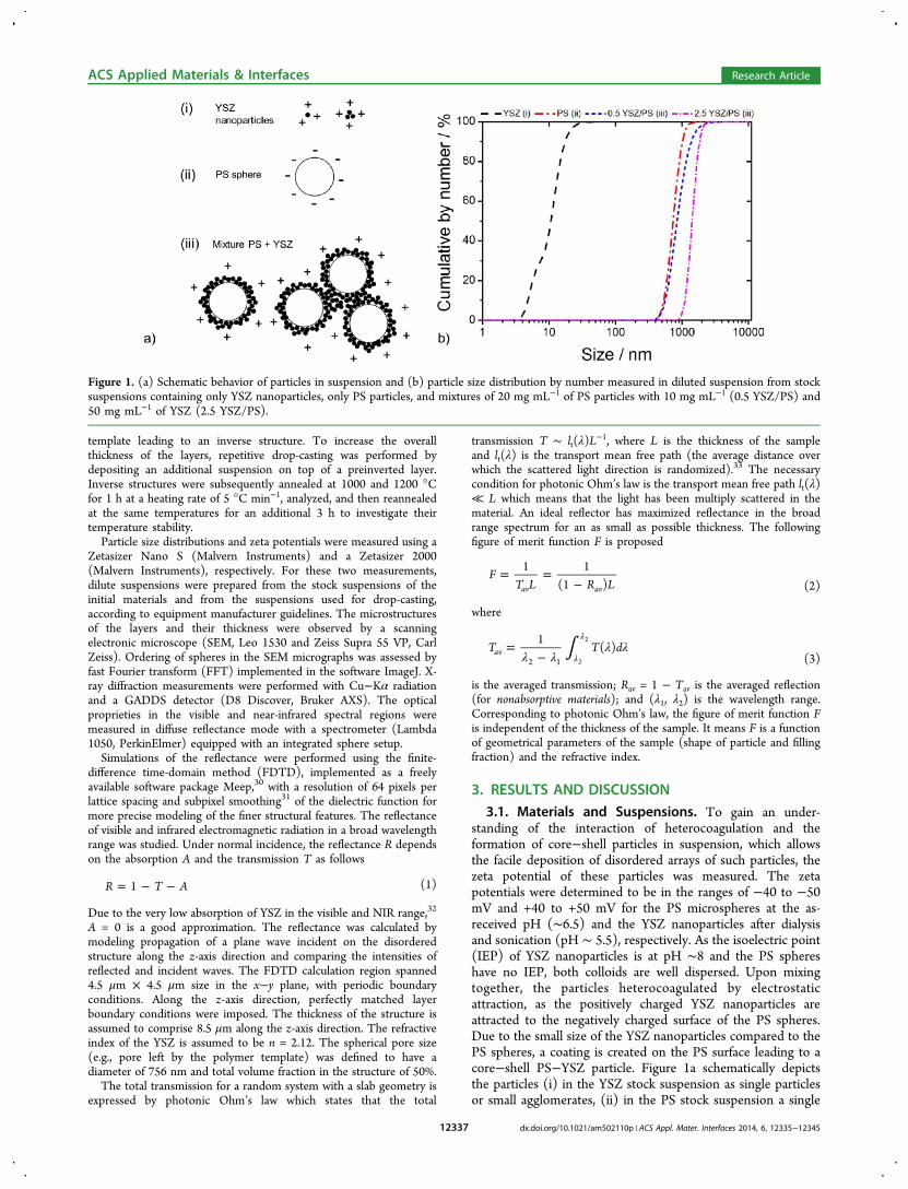
3.1. Materials and Suspensions. To gain an under-standing of the interaction of heterocoagulation and theformation of core−shell particles in suspension, which allowsthe facile deposition of disordered arrays of such particles, thezeta potential of these particles was measured. The zetapotentials were determined to be in the ranges of −40 to −50mV and +40 to +50 mV for the PS microspheres at the as-received pH (∼6.5) and the YSZ nanoparticles after dialysisand sonication (pH ∼ 5.5), respectively. As the isoelectric point(IEP) of YSZ nanoparticles is at pH ∼8 and the PS sphereshave no IEP, both colloids are well dispersed. Upon mixingtogether, the particles heterocoagulated by electrostaticattraction, as the positively charged YSZ nanoparticles areattracted to the negatively charged surface of the PS spheres.Due to the small size of the YSZ nanoparticles compared to thePS spheres, a coating is created on the PS surface leading to acore−shell PS−YSZ particle. Figure 1a schematically depictsthe particles (i) in the YSZ stock suspension as single particlesor small agglomerates, (ii) in the PS stock suspension a single
Figure 1. (a) Schematic behavior of particles in suspension and (b) particle size distribution by number measured in diluted suspension from stocksuspensions containing only YSZ nanoparticles, only PS particles, and mixtures of 20 mg mL−1 of PS particles with 10 mg mL−1 (0.5 YSZ/PS) and50 mg mL−1 of YSZ (2.5 YSZ/PS).
ACS Applied Materials & Interfaces Research Article
dx.doi.org/10.1021/am502110p | ACS Appl. Mater. Interfaces 2014, 6, 12335−1234512337
sphere, and (iii) in a mixture of PS and YSZ particles as a singlecore−shell particle or cluster of core−shell particles.To determine the behavior of the particles in suspension,
particles size analysis was performed. Cumulative particle sizedistributions are shown in Figure 1b. The particle sizedistribution of only YSZ nanoparticles shows a bimodaldistribution with the first inflection point at 5 nm and secondat 12 nm. The first inflection point is related to the primary sizeof nanoparticles and the second to small agglomerates that havenot been broken by sonication. The PS particles present aninflection point at 712 nm with a unimodal distributionconsistent with the monodispersity of the PS stock suspensionfrom the supplier. The PS−YSZ mixtures at 0.5 YSZ/PS and2.5 YSZ/PS also present a unimodal distribution with inflectionpoints at 825 and 1487 nm, respectively. The absence ofparticles in the YSZ size range for these mixtures indicates thatthere are no free YSZ nanoparticles in suspension; i.e., all of thenanoparticles are attached to the surface of the PS particles forthese ratios of mixture. For the higher YSZ/PS ratiosuspension, the increase in particle size after heterocoagulationis larger than expected for one, single-coated PS sphere, whichsuggests flocculation of coated particles into small clusters up to∼3 μm in diameter (as depicted in Figure 1b (iii)). Calculatedthicknesses considering a YSZ density of 3 g cm−3 shell are ∼20
and ∼100 nm for 0.5 YSZ/PS and 2.5 YSZ/PS, respectively.More details on the core−shell heterocoagulated structures willbe discussed later in this paper.The self-assembly of ordered structures is a natural process
when dealing with monodisperse spheres such as the PSspheres used in this work. Conversely, this study shows thatheterocoagulated particles tend to naturally form disorderedstructures. The light flocculation promoted by the hetero-coagulation appears to be one of the reasons for avoiding self-assembly. Clusters of coated particles are more prone to fastsedimentation and, once deposited, inhibit the self-assembly ofother particles. Disorder is further facilitated by favorableparticle−substrate interactions,4,5 e.g., attraction betweencharged particles and charged substrates during self-assembly.The materials of substrates, soda-lime silica glass, and quartzhave their IEP in the pH range of 2−3. In our experiment, thesubstrates are negatively charged, and the YSZ-coated PSparticles are positively charged at the work pH of ∼6. Thus,there is a strong adhesion and low mobility of particles on thesubstrate due to Coulomb attraction between them, resulting ina disordered structure consistent with the conditions proposedin their work.4,5
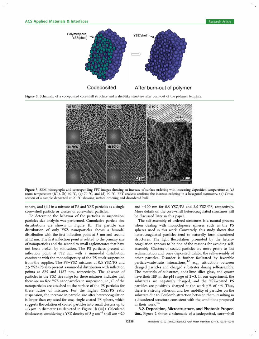
3.2. Deposition, Microstructure, and Photonic Proper-ties. Figure 2 shows a schematic of a codeposited, core−shell
Figure 2. Schematic of a codeposited core-shell structure and a shell-like structure after burn-out of the polymer template.
Figure 3. SEM micrographs and corresponding FFT images showing an increase of surface ordering with increasing deposition temperature at (a)room temperature (RT), (b) 40 °C, (c) 70 °C, and (d) 90 °C. FFT analysis confirms the increase ordering in a hexagonal symmetry. (e) Cross-section of a sample deposited at 90 °C showing surface ordering and disordered bulk.
ACS Applied Materials & Interfaces Research Article
dx.doi.org/10.1021/am502110p | ACS Appl. Mater. Interfaces 2014, 6, 12335−1234512338
structure and the resulting shell-like structure after burn-out ofthe polymer template. Utilization of nanoparticle codepositioncircumnavigates many of the challenges faced by conventionalinfiltration methods. First, the effect of the depositiontemperature on the degree of disorder was explored. Asuspension containing 20 mg mL−1 of PS spheres and 10 mgmL−1 of YSZ nanoparticles (0.5 YSZ/PS) was drop-cast ontoglass substrates at various temperatures ranging from roomtemperature to 90 °C. It was found that the drying time tookaround 30 s at 90 °C and up to 4 h at room temperature (21°C). Initial visual inspection of the films suggested an increase
in ordering with increasing temperature, as they exhibited amore pronounced (but still weak) green iridescence. The SEMmicrographs and corresponding FFT images in Figure 3a−dcompare the surface ordering as a function of depositiontemperature. With increasing temperature, an increase inordering can be observed for the top-view microstructures.The FFT analysis confirms this result, showing a shift from adiffuse ring pattern to discrete spots with hexagonal symmetryas the structure shifts from disordered to ordered. As reportedby Garcıa et al.,9 an ordered surface structure can hidedisordered bulk structures, and for this reason, cross-section
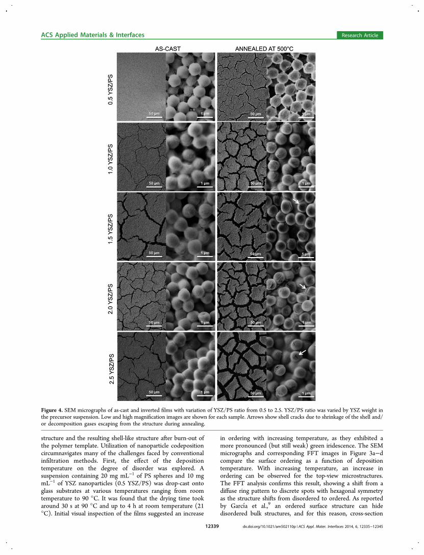
Figure 4. SEM micrographs of as-cast and inverted films with variation of YSZ/PS ratio from 0.5 to 2.5. YSZ/PS ratio was varied by YSZ weight inthe precursor suspension. Low and high magnification images are shown for each sample. Arrows show shell cracks due to shrinkage of the shell and/or decomposition gases escaping from the structure during annealing.
ACS Applied Materials & Interfaces Research Article
dx.doi.org/10.1021/am502110p | ACS Appl. Mater. Interfaces 2014, 6, 12335−1234512339
imaging (Figure 3e) in combination with the diffuse reflectioncan better evaluate the ordering of the entire system. As can beseen in Figure 3e, for the extreme temperature of 90 °C, only afew layers on the top surface are ordered. The diffuse reflectionspectra of these as-cast samples did not show any features of anordered photonic material (i.e., photonic band gap) over themeasured wavelengths (Figure S1, see Supporting Informa-tion). This suggests that the surface ordering has noconsiderable influence on the overall diffuse character of thereflectivity. Coatings deposited at different temperatures hadvery similar reflectance characteristics. However, deposition atroom temperature was used in all further experiments to ensurefull disorder. The lower limit of the ratio of YSZ/PS that stillinhibits self-assembly was not investigated. Nevertheless, thelowest ratio tested (0.5 YSZ/PS) was already enough to fullyinhibit self-assembly. This can be seen in the FTT images inFigure 3 for a sample of 0.5 YSZ/PS deposited at roomtemperature. Lower YSZ/PS ratios were not tested due to thealready thin and deformed shells after calcination at 500 °C, ascan be observed later in this work. Lower ratios could stillinhibit self-assembly but would not result in physically stablestructures and therefore would not be practical.Next, the amount of YSZ nanoparticles in suspension was
varied to increase the YSZ-shell thickness in suspension,increasing the total volume of YSZ in the structure. Figure 4compares as-cast and inverse samples varying the YSZconcentrations in suspension. The creation of a core−shellprior deposition (in suspension) is important to ensurehomogeneity of the deposited structure. Free nanoparticles inthese systems result in electrostatic attraction of these positivelycharged nanoparticles to the negatively charged substrate as canbe seen in Figure S2 (see Supporting Information) in acomparison using suspension with 2.5 YSZ/PS ratio usingdifferent PS sizes (756 nm and 2.48 μm). It is assumed that thelower surface area of the larger PS particles is the reason for alower amount of nanoparticles heterocoagulated. Assuringcomplete heterocoagulation, a homogeneous photonic glasslayer can be obtained.The concentration of YSZ nanoparticles influences the shell
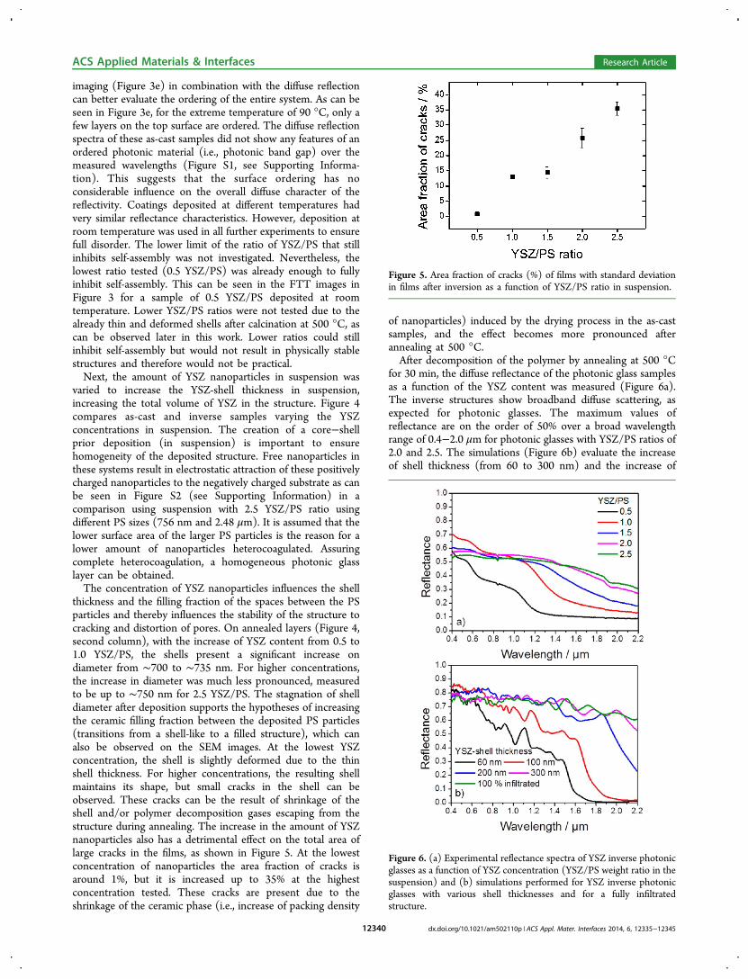
thickness and the filling fraction of the spaces between the PSparticles and thereby influences the stability of the structure tocracking and distortion of pores. On annealed layers (Figure 4,second column), with the increase of YSZ content from 0.5 to1.0 YSZ/PS, the shells present a significant increase ondiameter from ∼700 to ∼735 nm. For higher concentrations,the increase in diameter was much less pronounced, measuredto be up to ∼750 nm for 2.5 YSZ/PS. The stagnation of shelldiameter after deposition supports the hypotheses of increasingthe ceramic filling fraction between the deposited PS particles(transitions from a shell-like to a filled structure), which canalso be observed on the SEM images. At the lowest YSZconcentration, the shell is slightly deformed due to the thinshell thickness. For higher concentrations, the resulting shellmaintains its shape, but small cracks in the shell can beobserved. These cracks can be the result of shrinkage of theshell and/or polymer decomposition gases escaping from thestructure during annealing. The increase in the amount of YSZnanoparticles also has a detrimental effect on the total area oflarge cracks in the films, as shown in Figure 5. At the lowestconcentration of nanoparticles the area fraction of cracks isaround 1%, but it is increased up to 35% at the highestconcentration tested. These cracks are present due to theshrinkage of the ceramic phase (i.e., increase of packing density
of nanoparticles) induced by the drying process in the as-castsamples, and the effect becomes more pronounced afterannealing at 500 °C.After decomposition of the polymer by annealing at 500 °C
for 30 min, the diffuse reflectance of the photonic glass samplesas a function of the YSZ content was measured (Figure 6a).The inverse structures show broadband diffuse scattering, asexpected for photonic glasses. The maximum values ofreflectance are on the order of 50% over a broad wavelengthrange of 0.4−2.0 μm for photonic glasses with YSZ/PS ratios of2.0 and 2.5. The simulations (Figure 6b) evaluate the increaseof shell thickness (from 60 to 300 nm) and the increase of
Figure 5. Area fraction of cracks (%) of films with standard deviationin films after inversion as a function of YSZ/PS ratio in suspension.
Figure 6. (a) Experimental reflectance spectra of YSZ inverse photonicglasses as a function of YSZ concentration (YSZ/PS weight ratio in thesuspension) and (b) simulations performed for YSZ inverse photonicglasses with various shell thicknesses and for a fully infiltratedstructure.
ACS Applied Materials & Interfaces Research Article
dx.doi.org/10.1021/am502110p | ACS Appl. Mater. Interfaces 2014, 6, 12335−1234512340
filling fraction (by comparing thin shells with a completely filledstructure). With the increase of YSZ content two consequencescan be observed: (i) the cutoff of the high-reflectance bandshifts to longer wavelengths and (ii) the overall reflectanceincreases. Both effects have been shown to be stronglydependent on YSZ content, due to an increase of materialvolume of high refractive index (compared with air of pores).These trends are observed both in simulations as well as in themeasurements. Increasing the amount of high reflective index(the YSZ) either by increasing shell thickness or filling fractionof the structure can be used to improve the reflectance ofphotonic glasses.Figure 7 compares the diffuse reflection spectrum of a
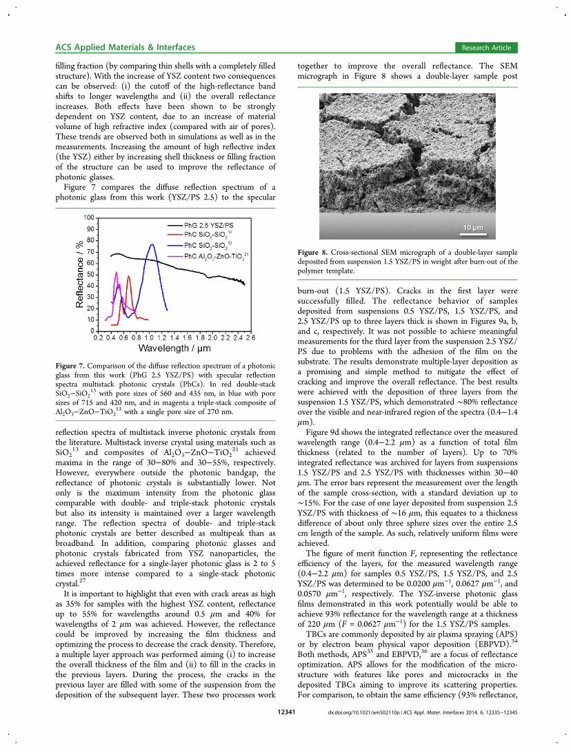
photonic glass from this work (YSZ/PS 2.5) to the specular
reflection spectra of multistack inverse photonic crystals fromthe literature. Multistack inverse crystal using materials such asSiO2
13 and composites of Al2O3−ZnO−TiO221 achieved
maxima in the range of 30−80% and 30−55%, respectively.However, everywhere outside the photonic bandgap, thereflectance of photonic crystals is substantially lower. Notonly is the maximum intensity from the photonic glasscomparable with double- and triple-stack photonic crystalsbut also its intensity is maintained over a larger wavelengthrange. The reflection spectra of double- and triple-stackphotonic crystals are better described as multipeak than asbroadband. In addition, comparing photonic glasses andphotonic crystals fabricated from YSZ nanoparticles, theachieved reflectance for a single-layer photonic glass is 2 to 5times more intense compared to a single-stack photoniccrystal.27
It is important to highlight that even with crack areas as highas 35% for samples with the highest YSZ content, reflectanceup to 55% for wavelengths around 0.5 μm and 40% forwavelengths of 2 μm was achieved. However, the reflectancecould be improved by increasing the film thickness andoptimizing the process to decrease the crack density. Therefore,a multiple layer approach was performed aiming (i) to increasethe overall thickness of the film and (ii) to fill in the cracks inthe previous layers. During the process, the cracks in theprevious layer are filled with some of the suspension from thedeposition of the subsequent layer. These two processes work
together to improve the overall reflectance. The SEMmicrograph in Figure 8 shows a double-layer sample post
burn-out (1.5 YSZ/PS). Cracks in the first layer weresuccessfully filled. The reflectance behavior of samplesdeposited from suspensions 0.5 YSZ/PS, 1.5 YSZ/PS, and2.5 YSZ/PS up to three layers thick is shown in Figures 9a, b,and c, respectively. It was not possible to achieve meaningfulmeasurements for the third layer from the suspension 2.5 YSZ/PS due to problems with the adhesion of the film on thesubstrate. The results demonstrate multiple-layer deposition asa promising and simple method to mitigate the effect ofcracking and improve the overall reflectance. The best resultswere achieved with the deposition of three layers from thesuspension 1.5 YSZ/PS, which demonstrated ∼80% reflectanceover the visible and near-infrared region of the spectra (0.4−1.4μm).Figure 9d shows the integrated reflectance over the measured
wavelength range (0.4−2.2 μm) as a function of total filmthickness (related to the number of layers). Up to 70%integrated reflectance was archived for layers from suspensions1.5 YSZ/PS and 2.5 YSZ/PS with thicknesses within 30−40μm. The error bars represent the measurement over the lengthof the sample cross-section, with a standard deviation up to∼15%. For the case of one layer deposited from suspension 2.5YSZ/PS with thickness of ∼16 μm, this equates to a thicknessdifference of about only three sphere sizes over the entire 2.5cm length of the sample. As such, relatively uniform films wereachieved.The figure of merit function F, representing the reflectance
efficiency of the layers, for the measured wavelength range(0.4−2.2 μm) for samples 0.5 YSZ/PS, 1.5 YSZ/PS, and 2.5YSZ/PS was determined to be 0.0200 μm−1, 0.0627 μm−1, and0.0570 μm−1, respectively. The YSZ-inverse photonic glassfilms demonstrated in this work potentially would be able toachieve 93% reflectance for the wavelength range at a thicknessof 220 μm (F = 0.0627 μm−1) for the 1.5 YSZ/PS samples.TBCs are commonly deposited by air plasma spraying (APS)
or by electron beam physical vapor deposition (EBPVD).34
Both methods, APS35 and EBPVD,36 are a focus of reflectanceoptimization. APS allows for the modification of the micro-structure with features like pores and microcracks in thedeposited TBCs aiming to improve its scattering properties.For comparison, to obtain the same efficiency (93% reflectance,
Figure 7. Comparison of the diffuse reflection spectrum of a photonicglass from this work (PhG 2.5 YSZ/PS) with specular reflectionspectra multistack photonic crystals (PhCs). In red double-stackSiO2−SiO2
13 with pore sizes of 560 and 435 nm, in blue with poresizes of 715 and 420 nm, and in magenta a triple-stack composite ofAl2O3−ZnO−TiO2
13 with a single pore size of 270 nm.
Figure 8. Cross-sectional SEM micrograph of a double-layer sampledeposited from suspension 1.5 YSZ/PS in weight after burn-out of thepolymer template.
ACS Applied Materials & Interfaces Research Article
dx.doi.org/10.1021/am502110p | ACS Appl. Mater. Interfaces 2014, 6, 12335−1234512341
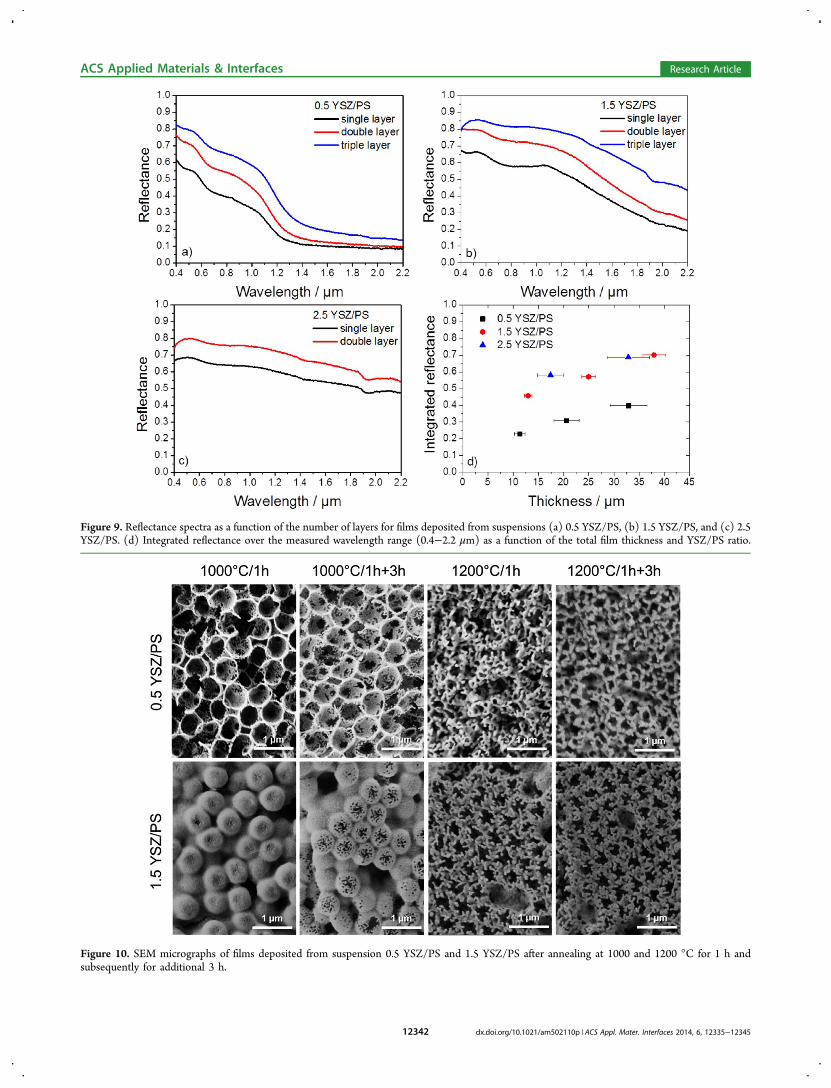
Figure 9. Reflectance spectra as a function of the number of layers for films deposited from suspensions (a) 0.5 YSZ/PS, (b) 1.5 YSZ/PS, and (c) 2.5YSZ/PS. (d) Integrated reflectance over the measured wavelength range (0.4−2.2 μm) as a function of the total film thickness and YSZ/PS ratio.
Figure 10. SEM micrographs of films deposited from suspension 0.5 YSZ/PS and 1.5 YSZ/PS after annealing at 1000 and 1200 °C for 1 h andsubsequently for additional 3 h.
ACS Applied Materials & Interfaces Research Article
dx.doi.org/10.1021/am502110p | ACS Appl. Mater. Interfaces 2014, 6, 12335−1234512342
220 μm thick layer) as the photonic glass deposited from thesuspension 1.5 YSZ/PS, a 370 μm thick layer by plasma-sprayed YSZ deliberately optimized for high diffuse reflectancewould be needed.35 Therefore, the inverse photonic glass filmscan offer an advantage of achieving similar values of reflectanceusing the films about 40% thinner than those produced byother advanced TBC deposition methods.3.3. High-Temperature Behavior. To evaluate the high-
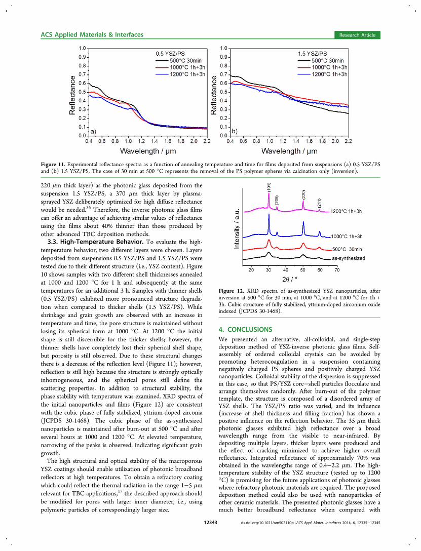
temperature behavior, two different layers were chosen. Layersdeposited from suspensions 0.5 YSZ/PS and 1.5 YSZ/PS weretested due to their different structure (i.e., YSZ content). Figure10 shows samples with two different shell thicknesses annealedat 1000 and 1200 °C for 1 h and subsequently at the sametemperatures for an additional 3 h. Samples with thinner shells(0.5 YSZ/PS) exhibited more pronounced structure degrada-tion when compared to thicker shells (1.5 YSZ/PS). Whileshrinkage and grain growth are observed with an increase intemperature and time, the pore structure is maintained withoutlosing its spherical form at 1000 °C. At 1200 °C the initialshape is still discernible for the thicker shells; however, thethinner shells have completely lost their spherical shell shape,but porosity is still observed. Due to these structural changesthere is a decrease of the reflection level (Figure 11); however,reflection is still high because the structure is strongly opticallyinhomogeneous, and the spherical pores still define thescattering properties. In addition to structural stability, thephase stability with temperature was examined. XRD spectra ofthe initial nanoparticles and films (Figure 12) are consistentwith the cubic phase of fully stabilized, yttrium-doped zirconia(JCPDS 30-1468). The cubic phase of the as-synthesizednanoparticles is maintained after burn-out at 500 °C and afterseveral hours at 1000 and 1200 °C. At elevated temperature,narrowing of the peaks is observed, indicating significant graingrowth.The high structural and optical stability of the macroporous
YSZ coatings should enable utilization of photonic broadbandreflectors at high temperatures. To obtain a refractory coatingwhich could reflect the thermal radiation in the range 1−5 μmrelevant for TBC applications,17 the described approach shouldbe modified for pores with larger inner diameter, i.e., usingpolymeric particles of correspondingly larger size.
4. CONCLUSIONSWe presented an alternative, all-colloidal, and single-stepdeposition method of YSZ-inverse photonic glass films. Self-assembly of ordered colloidal crystals can be avoided bypromoting heterocoagulation in a suspension containingnegatively charged PS spheres and positively charged YSZnanoparticles. Colloidal stability of the dispersion is suppressedin this case, so that PS/YSZ core−shell particles flocculate andarrange themselves randomly. After burn-out of the polymertemplate, the structure is composed of a disordered array ofYSZ shells. The YSZ/PS ratio was varied, and its influence(increase of shell thickness and filling fraction) has shown apositive influence on the reflection behavior. The 35 μm thickphotonic glasses exhibited high reflectance over a broadwavelength range from the visible to near-infrared. Bydepositing multiple layers, thicker layers were produced andthe effect of cracking minimized to achieve higher overallreflectance. Integrated reflectance of approximately 70% wasobtained in the wavelengths range of 0.4−2.2 μm. The high-temperature stability of the YSZ structure (tested up to 1200°C) is promising for the future applications of photonic glasseswhere refractory photonic materials are required. The proposeddeposition method could also be used with nanoparticles ofother ceramic materials. The presented photonic glasses have amuch better broadband reflectance when compared with
Figure 11. Experimental reflectance spectra as a function of annealing temperature and time for films deposited from suspensions (a) 0.5 YSZ/PSand (b) 1.5 YSZ/PS. The case of 30 min at 500 °C represents the removal of the PS polymer spheres via calcination only (inversion).
Figure 12. XRD spectra of as-synthesized YSZ nanoparticles, afterinversion at 500 °C for 30 min, at 1000 °C, and at 1200 °C for 1h +3h. Cubic structure of fully stabilized, yttrium-doped zirconium oxideindexed (JCPDS 30-1468).
ACS Applied Materials & Interfaces Research Article
dx.doi.org/10.1021/am502110p | ACS Appl. Mater. Interfaces 2014, 6, 12335−1234512343
double- or triple-layer stacks of photonic crystals being verysuitable for photonic broadband reflectors.
■ ASSOCIATED CONTENT*S Supporting InformationFigure S1: Diffuse reflection spectra of as-cast samplesdeposited at various temperatures. Figure S2: Layers depositedfrom suspensions 2.5 YSZ/PS using different PS spherediameters of 756 nm and 2.48 μm. This material is availablefree of charge via the Internet at http://pubs.acs.org.
■ AUTHOR INFORMATIONCorresponding Author*E-mail: [email protected] ContributionsThe manuscript was written through contributions of allauthors. All authors have given approval to the final version ofthe manuscript.NotesThe authors declare no competing financial interest.
■ ACKNOWLEDGMENTSThe authors gratefully acknowledge financial support from theGerman Research Foundation (DFG) via SFB 986 “Tailor-Made Multi-Scale Materials Systems: M3”, projects C2, C4, andC5. We also would like to thank Sweety Mohanty and Prof.Irina Smirnova for the support in hydrothermal synthesis ofYSZ nanoparticles.
■ ABBREVIATIONSYSZ, yttrium-stabilized zirconia; PS, polystyrene; TBC, thermalbarrier coating; ALD, atomic layer deposition; CVD, chemicalvapor deposition; FFT, fast Fourier transform; FDTD, finite-difference time-domain (simulation method); IEP, isoelectricpoint
■ REFERENCES(1) Shi, L.; Zhang, Y.; Dong, B.; Zhan, T.; Liu, X.; Zi, J. AmorphousPhotonic Crystals with Only Short-Range Order. Adv. Mater. 2013, 25,5314−5320.(2) Wiersma, D. S. Disordered Photonics. Nat. Photonics 2013, 7,188−196.(3) García, P. D.; Sapienza, R.; Blanco, A.; Lopez, C. Photonic Glass:A Novel Random Material for Light. Adv. Mater. 2007, 19, 2597−2602.(4) Yan, Q.; Gao, L.; Sharma, V.; Chiang, Y.-M.; Wong, C. C. Particleand Substrate Charge Effects on Colloidal Self-Assembly in a SessileDrop. Langmuir 2008, 24, 11518−11522.(5) Tan, K. W.; Koh, Y. K.; Chiang, Y.-M.; Wong, C. C. ParticulateMobility in Vertical Deposition of Attractive Monolayer ColloidalCrystals. Langmuir 2010, 26, 7093−7100.(6) Li, H.-L.; Marlow, F. Solvent Effects in Colloidal CrystalDeposition. Chem. Mater. 2006, 18, 1803−1810.(7) Cai, Z.; Teng, J.; Yan, Q.; Zhao, X. Solvent Effect on the Self-Assembly of Colloidal Microspheres via a Horizontal DepositionMethod. Colloids Surf., A 2012, 402, 37−44.(8) Emoto, A.; Fukuda, T. Tailored Assembly of Colloidal Particles:Alternative Fabrication of Photonic Crystal or Photonic Glass. Appl.Phys. Lett. 2012, 100, 131901.(9) García, P. D.; Sapienza, R.; Lopez, C. Photonic Glasses: A StepBeyond White Paint. Adv. Mater. 2010, 22, 12−19.(10) Gottardo, S.; Sapienza, R.; García, P. D.; Blanco, A.; Wiersma,D. S.; Lopez, C. Resonance-Driven Random Lasing. Nat. Photonics2008, 2, 429−432.
(11) Halaoui, L. I.; Abrams, N. M.; Mallouk, T. E. Increasing theConversion Efficiency of Dye-Sensitized TiO 2 PhotoelectrochemicalCells by Coupling to Photonic Crystals. J. Phys. Chem. B 2005, 109,6334−6342.(12) Yan, Q.; Teh, L. K.; Shao, Q.; Wong, C. C.; Chiang, Y.-M. LayerTransfer Approach to Opaline Hetero Photonic Crystals. Langmuir2008, 24, 1796−1800.(13) Cai, Z.; Liu, Y. J.; Teng, J.; Lu, X. Fabrication of Large DomainCrack-Free Colloidal Crystal Heterostructures with SuperpositionBandgaps Using Hydrophobic Polystyrene Spheres. ACS Appl. Mater.Interfaces 2012, 4, 5562−5569.(14) Chen, K. M.; Sparks, A. W.; Luan, H.-C; Lim, D. R.; Wada, K.;Kimerling, L. C. SiO2/TiO2 Omnidirectional Reflector and Micro-cavity Resonator via the Sol-Gel Method. Appl. Phys. Lett. 1999, 75,3805.(15) Leontyev, V.; Hawkeye, M.; Kovalenko, A.; Brett, M. J.Omnidirectional Reflection from Nanocolumnar TiO2 Films. J. Appl.Phys. 2012, 112, 84317.(16) Ariza-Flores, A. D.; Gaggero-Sager, L. M.; Agarwal, V. WhiteMetal-Like Omnidirectional Mirror from Porous Silicon DielectricMultilayers. Appl. Phys. Lett. 2012, 101, 31119.(17) Lee, H. S.; Kubrin, R.; Zierold, R.; Petrov, A. Yu.; Nielsch, K.;Schneider, G. A.; Eich, M. Thermal Radiation Transmission andReflection Properties of Ceramic 3D Photonic Crystals. J. Opt. Soc.Am. B 2012, 29, 450−457.(18) Kubrin, R.; Lee, H. S.; Zierold, R.; Petrov, A. Yu.; Janssen, R.;Nielsch, K.; Eich, M.; Schneider, G. A. Stacking of Ceramic InverseOpals with Different Lattice Constants. J. Am. Ceram. Soc. 2012, 95,2226−2235.(19) Shklover, V.; Braginsky, L.; Witz, G.; Mishrikey, M.; Hafner, C.High-Temperature Photonic Structures. Thermal Barrier Coatings,Infrared Sources and Other Applications. J. Comput. Theor. Nanosci.2008, 5, 862−893.(20) Hatton, B.; Mishchenko, L.; Davis, S.; Sandhage, K. H.;Aizenberg, J. Assembly of Large-Area, Highly Ordered, Crack-FreeInverse Opal Films. Proc. Natl. Acad. Sci. U.S.A. 2010, 107, 10354−10359.(21) Hwang, D.-K; Noh, H.; Cao, H.; Chang, R. P. H. PhotonicBandgap Engineering with Inverse Opal Multistacks of DifferentRefractive Index Contrasts. Appl. Phys. Lett. 2009, 95, 91101.(22) Koenderink, A.; Lagendijk, A.; Vos, W. Optical Extinction Dueto Intrinsic Structural Variations of Photonic Crystals. Phys. Rev. B2005, 72, 153102.(23) King, J. S.; Graugnard, E.; Summers, C. J. TiO2 Inverse OpalsFabricated Using Low-Temperature Atomic Layer Deposition. Adv.Mater. 2005, 17, 1010−1013.(24) Tang, F.; Fudouzi, H.; Sakka, Y. Fabrication of MacroporousAlumina with Tailored Porosity. J. Am. Ceram. Soc. 2003, 86, 2050−2054.(25) Jia, Y.; Duran, C.; Hotta, Y.; Sato, K.; Watari, K. MacroporousZrO2 Ceramics Prepared from Colloidally Stable NanoparticlesBuilding Blocks and Organic Templates. J. Colloid Interface Sci.2005, 291, 292−295.(26) Jia, Y.; Duran, C.; Hotta, Y.; Sato, K.; Watari, K. The Effect ofPolyelectrolyte on Fabrication of Macroporous ZrO2 Ceramics. J.Mater. Sci. 2005, 40, 2903−2909.(27) Kubrin, R.; do Rosario, J. J.; Lee, H. S.; Mohanty, S.;Subrahmanyam, R. P.; Smirnova, I.; Petrov, A.; Petrov, A. Yu.; Eich,M.; Schneider, G. A. Vertical Convective Coassembly of RefractoryYSZ Inverse Opals from Crystalline Nanoparticles. ACS Appl. Mater.Interfaces 2013, 5, 13146−13152.(28) Seo, Y. G.; Woo, K.; Kim, J.; Lee, H.; Lee, W. Rapid Fabricationof an Inverse Opal TiO2 Photoelectrode for DSSC Using a BinaryMixture of TiO2 Nanoparticles and Polymer Microspheres. Adv. Funct.Mater. 2011, 21, 3094−3103.(29) Guiot, C.; Grandjean, S.; Lemonnier, S.; Jolivet, J.-P.; Batail, P.Nano Single Crystals of Yttria-Stabilized Zirconia. Cryst. Growth Des.2009, 9, 3548−3550.
ACS Applied Materials & Interfaces Research Article
dx.doi.org/10.1021/am502110p | ACS Appl. Mater. Interfaces 2014, 6, 12335−1234512344
(30) Oskooi, A. F.; Roundy, D.; Ibanescu, M.; Bermel, P.;Joannopoulos, J. D.; Johnson, S. G. Meep: A Flexible Free-SoftwarePackage for Electromagnetic Simulations by the FDTD Method.Comput. Phys. Commun. 2010, 181, 687−702.(31) Farjadpour, A.; Roundy, D.; Rodriguez, A.; Ibanescu, M.;Bermel, P.; Joannopoulos, J. D.; Johnson, S. G.; Burr, G. W. ImprovingAccuracy by Subpixel Smoothing in the Finite-Difference TimeDomain. Opt. Lett. 2006, 31, 2972−2974.(32) Wang, D.; Huang, X.; Patnaik, P. Design and Modeling ofMultiple Layered TBC System with High Reflectance. J. Mater. Sci.2006, 41, 6245−6255.(33) Garcia, N.; Genack, A. Z.; Lisyansky, A. A. Measurement of theTransport Mean Free Path of Diffusing Photons. Phys. Rev. B 1992, 46,14475−14479.(34) Clarke, D. R.; Oechsner, M.; Padture, N. P. Thermal-barrierCoatings for More Efficient Gas-Turbine Engines. MRS Bull. 2012, 37,891−898.(35) Stuke, A.; Kassner, H.; Marques, J.-L; Vassen, R.; Stover, D.;Carius, R. Suspension and Air Plasma-Sprayed Ceramic ThermalBarrier Coatings with High Infrared Reflectance. Int. J. Appl. Ceram.Technol. 2012, 9, 561−574.(36) Wolfe, D. E.; Singh, J.; Miller, R. A.; Eldridge, J. I.; Zhu, D.-M.Tailored Microstructure of EB-PVD 8YSZ Thermal Barrier CoatingsWith Low Thermal Conductivity and High Thermal Reflectivity forTurbine Applications. Surf. Coat. Technol. 2005, 190, 132−149.
ACS Applied Materials & Interfaces Research Article
dx.doi.org/10.1021/am502110p | ACS Appl. Mater. Interfaces 2014, 6, 12335−1234512345