
Summary Check Register with Description - 04/01/2019 04/30 ...
Upload
khangminh22Category
view
1download
0
Technical papers
Author: Rick Newlands 1 updated: 04/11/10
The mass properties of a hybrid’s liquid propellant
Introduction It can be tedious to work out the mass properties (Centre of Gravity and moment of inertias) of a rocket vehicle incorporating a hybrid engine, because of the liquid and vapour in the hybrid’s propellant tank. (If the propellant is nitrous oxide, then the vapour is heavy and must be included in the CG calculations.) This paper derives mass property equations for the propellant within three types of tank, each with a different end-dome (the end of the tank): flat end-domes, hemispherical end-domes, and end-domes that are a 45 degree cone. This should cover the majority of commercial and home-made end-domes you are likely to encounter. Equations for the propellant only are derived, as the mass properties of the empty tank can be directly measured, e.g. the tank can be modelled as a compound (physical) pendulum. This will give the moment of inertia as follows: Suspend the tank on the points of a pair of pins and let the tank swing as a pendulum. (Don’t use large swings, small swings are more accurate). Measure the time taken for a swing (measure 10 swings and divide by 10 for accuracy). The moment of inertia about the pins pivot point is then found from the equation for a physical pendulum:
Where is the period of each swing in seconds, m is the tank mass, g is 9.81 m/sec2 and h is
the distance between the pivot pins and the tank’s CG. This gives the moment of inertia about the pins pivot, but you have to convert this to get the moment of inertia about the vehicle CG using the parallel axes theorem (see part 2).

Technical papers
Author: Rick Newlands 2 updated: 04/11/10
Part 1: Centre of Gravity calculations A tank with flat end-domes: This is the simplest case as the tank is a simple cylinder. The liquid height is the liquid volume divided by the tank
cross-sectional area ( ). The centre of gravity of the liquid and vapour are halfway to the liquid height: (the chequered circle is the CG symbol). To get the overall CG, simply add them as:
Where L1 and L2 are the distances to the liquid and vapour CG’s, measured from a common reference point such as the bottom of the tank.
Technical papers
Author: Rick Newlands 3 updated: 04/11/10
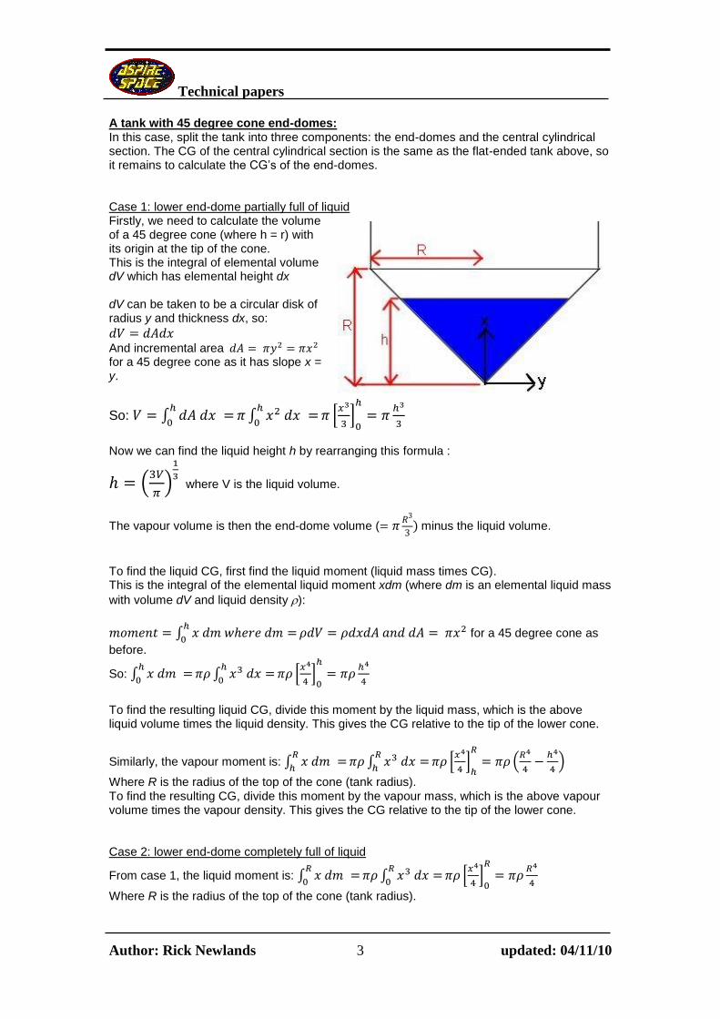
A tank with 45 degree cone end-domes: In this case, split the tank into three components: the end-domes and the central cylindrical section. The CG of the central cylindrical section is the same as the flat-ended tank above, so it remains to calculate the CG’s of the end-domes. Case 1: lower end-dome partially full of liquid Firstly, we need to calculate the volume of a 45 degree cone (where h = r) with its origin at the tip of the cone. This is the integral of elemental volume dV which has elemental height dx dV can be taken to be a circular disk of radius y and thickness dx, so:
And incremental area for a 45 degree cone as it has slope x = y.
So: ∫
∫
*
+
Now we can find the liquid height h by rearranging this formula :
(
)
where V is the liquid volume.
The vapour volume is then the end-dome volume (
minus the liquid volume.
To find the liquid CG, first find the liquid moment (liquid mass times CG). This is the integral of the elemental liquid moment xdm (where dm is an elemental liquid mass
with volume dV and liquid density ):
∫
for a 45 degree cone as
before.
So: ∫
∫
*
+
To find the resulting liquid CG, divide this moment by the liquid mass, which is the above liquid volume times the liquid density. This gives the CG relative to the tip of the lower cone.
Similarly, the vapour moment is: ∫
∫
*
+
(
)
Where R is the radius of the top of the cone (tank radius). To find the resulting CG, divide this moment by the vapour mass, which is the above vapour volume times the vapour density. This gives the CG relative to the tip of the lower cone. Case 2: lower end-dome completely full of liquid
From case 1, the liquid moment is: ∫
∫
*
+
Where R is the radius of the top of the cone (tank radius).

Technical papers
Author: Rick Newlands 4 updated: 04/11/10
To find the resulting liquid CG, divide this moment by the liquid mass, which is the end-dome
volume (
times the liquid density. This gives the answer: liquid CG =
This gives the CG relative to the tip of the lower cone. The vapour moment is zero as there is no vapour. Case 3: upper end-dome partially full of liquid Firstly, we need to calculate the volume of a 45 degree cone (where h = r) with its origin at the base of the cone. If the base radius is R and has height R, then the radius at distance x from the base is given by y = R - x. This is the integral of elemental volume dV which has elemental height dx, so:
And incremental area
( = (
So: ∫
∫ (
*
+
(
)
Finding the liquid height h from this volume formula involves solving a cubic equation in h. This is possible (see http://www.1728.com/cubic.htm) but is extremely tedious. It’s easier to program a search routine to home-in on the answer. You could enter the volume formula into a spreadsheet, and manually adjust the liquid height until the volume is correct to your required accuracy. Or you could program an automatic search: you could use Newton’s method, but I use the following simple routine that could be coded into a spreadsheet:
1. Initial step size is ¼ of R, initial h is zero, set old_aim = aim = 0 2. Reality check: if h > R then set h = R and halve the step size. Similarly, if h < 0 set h
= 0 and halve the step size. 3. Calculate liquid volume using h 4. Set old_aim = aim 5. If liquid volume is too small then increase h by step size and set aim = 1 6. Else if liquid volume is too large then decrease h by step size and set aim = -1 7. Check for overshoot of target: if aim = -1 times old_aim then halve the step size. 8. Go back to step 2 and repeat until the volume is correct to your required accuracy.
This homes-in on the correct h quickly.
The vapour volume is then the end-dome volume (
minus the liquid volume.
Now, to find the liquid CG, first find the liquid moment (liquid mass times CG).
This is the integral of the elemental liquid moment xdm (with liquid density ):
∫
( = ( for a 45 degree cone as before.

Technical papers
Author: Rick Newlands 5 updated: 04/11/10
So: ∫
∫ ( ∫ (
*
+
(
)
Where R is the radius of the base of the cone (tank radius). To find the resulting liquid CG, divide this moment by the liquid mass, which is the above liquid volume times the liquid density. This gives the CG relative to the base of the upper cone. Similarly, the vapour moment is:
∫
∫ ( ∫ (
*
+
(
)
(
)
Where R is the radius of the base of the cone (tank radius). To find the resulting CG, divide this moment by the vapour mass. This gives the CG relative to the base of the upper cone. Case 4: upper end-dome completely full of liquid From case 3, the liquid moment is:
∫
∫ ( ∫ (
*
+
(
) (
)
Where R is the radius of the base of the cone (tank radius). To find the resulting liquid CG, divide this moment by the liquid mass, which is the end-dome
volume (
times the liquid density. This gives the answer: liquid CG =
This gives the CG relative to the base of the upper cone. The vapour moment is zero as there is no vapour.

Technical papers
Author: Rick Newlands 6 updated: 04/11/10
A tank with hemispherical end-domes: In this case, split the tank into three components: the end-domes and the central cylindrical section. The CG of the central cylindrical section is the same as the flat-ended tank given earlier, so it remains to calculate the CG’s of the end-domes. Case 1: lower end-dome partially full of liquid Firstly, we need to calculate the volume of a hemisphere with the origin of the coordinates offset to the bottom of the hemisphere as shown: This is the integral of elemental volume dV which has elemental height dx dV can be taken to be a circular disk of radius y and thickness dx, so:
And incremental area The equation for this hemisphere is:
( so: (
So: ∫
∫ (
*
+
(
)
Finding the liquid height h from this volume formula involves solving a cubic equation in h. This is possible (see http://www.1728.com/cubic.htm) but is extremely tedious. It’s easier to program a search routine to home-in on the answer, as described in the previous section, case 1.
The vapour volume is then the end-dome volume (
minus the liquid volume.
To find the liquid CG, first find the liquid moment (liquid mass times CG).
This is the integral of the elemental liquid moment xdm (with liquid density ):
∫
( as before.
So: ∫
∫ (
∫ (
*
+
(
)
To find the resulting liquid CG, divide this moment by the liquid mass, which is the above liquid volume times the liquid density. This gives the CG relative to the bottom of the hemisphere. Similarly, the vapour moment is:
∫
∫ (
∫ (
*
+
(
) (
)
Where R is the radius of the hemisphere (tank radius).

Technical papers
Author: Rick Newlands 7 updated: 04/11/10
To find the resulting CG, divide this moment by the vapour mass, which is the above vapour volume times the vapour density. This gives the CG relative to the bottom of the hemisphere. Case 2: lower end-dome completely full of liquid From case 1, the liquid moment is:
∫
∫ (
*
+
(
)
Where R is the radius of the hemisphere (tank radius). To find the resulting liquid CG, divide this moment by the liquid mass, which is the end-dome
volume (
times the liquid density. This gives the answer: liquid CG =
This gives the CG relative to the bottom of the hemisphere. The vapour moment is zero as there is no vapour. Case 3: upper end-dome partially full of liquid Firstly, we need to calculate the volume of a hemisphere with its origin at the centre of the hemisphere as shown: This is the integral of elemental volume dV which has elemental height dx, so:
and incremental area dA The equation for this hemisphere is:
so:
So: ∫
∫ (
*
+
(
)
Finding the liquid height h from this volume formula involves solving a cubic equation in h. This is possible (see http://www.1728.com/cubic.htm) but is extremely tedious. It’s easier to program a search routine to home-in on the answer, as described in the previous section, case 1.
The vapour volume is then the end-dome volume (
minus the liquid volume.
To find the liquid CG, first find the liquid moment (liquid mass times CG).
This is the integral of the elemental liquid moment xdm (with liquid density ):
∫
( as before..
So: ∫
∫ (
∫ (
*
+
(
)
To find the resulting liquid CG, divide this moment by the liquid mass, which is the above liquid volume times the liquid density. This gives the CG relative to the bottom of the hemisphere.

Technical papers
Author: Rick Newlands 8 updated: 04/11/10
Similarly, the vapour moment is:
∫
∫ (
*
+
(
) (
)
Where R is the radius of the hemisphere (tank radius). To find the resulting CG, divide this moment by the vapour mass, which is the above vapour volume times the vapour density. This gives the CG relative to the bottom of the hemisphere. Case 4: upper end-dome completely full of liquid From case 3, the liquid moment is:
∫
∫ (
*
+
(
)
Where R is the radius of the hemisphere (tank radius). To find the resulting liquid CG, divide this moment by the liquid mass, which is the end-dome
volume (
times the liquid density. This gives the answer: liquid CG =
This gives the CG relative to the bottom of the hemisphere. The vapour moment is zero as there is no vapour.

Technical papers
Author: Rick Newlands 9 updated: 04/11/10
Overall fluid CG Now all that remains is to collect the separate CG’s together to calculate the overall CG. Designating the lower end-dome as L, the middle cylindrical section as M and the upper end-dome as U, and liq=liquid and vap=vapour, then the overall CG:
Where the individual CG’s are measured from a common reference point such as the tip of the vehicle’s nosecone; the overall CG is then referenced to there.
Technical papers
Author: Rick Newlands 10 updated: 04/11/10
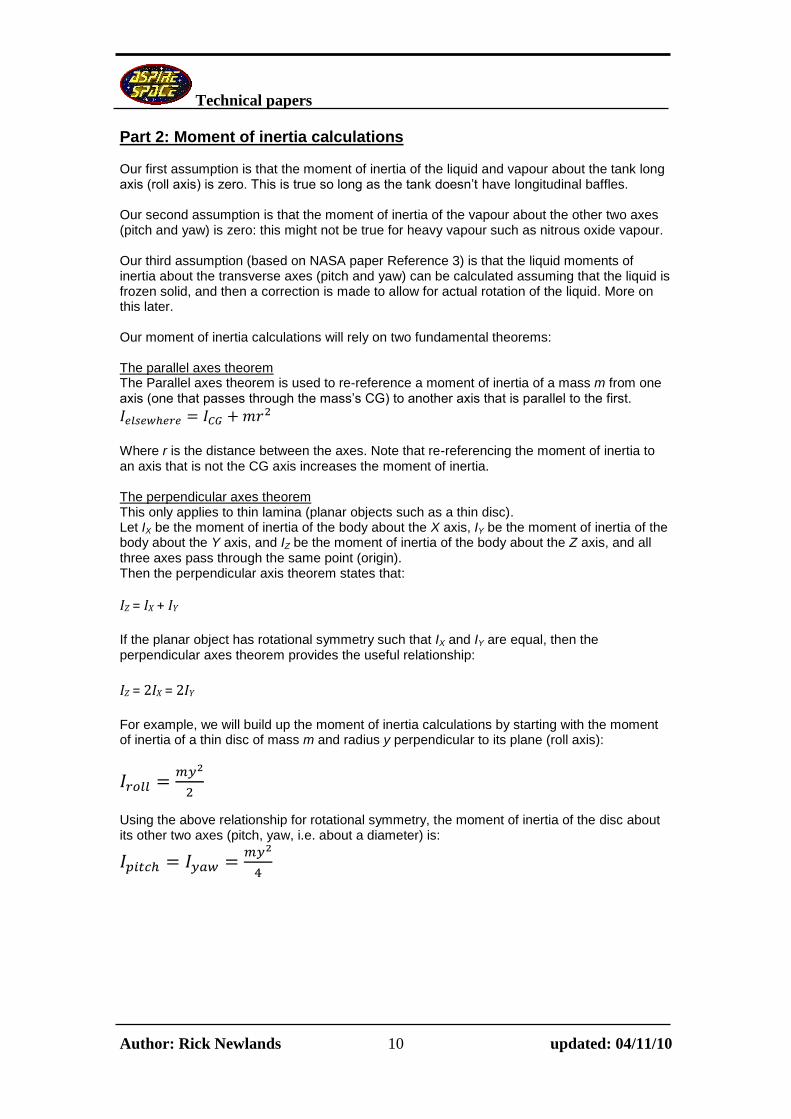
Part 2: Moment of inertia calculations Our first assumption is that the moment of inertia of the liquid and vapour about the tank long axis (roll axis) is zero. This is true so long as the tank doesn’t have longitudinal baffles. Our second assumption is that the moment of inertia of the vapour about the other two axes (pitch and yaw) is zero: this might not be true for heavy vapour such as nitrous oxide vapour. Our third assumption (based on NASA paper Reference 3) is that the liquid moments of inertia about the transverse axes (pitch and yaw) can be calculated assuming that the liquid is frozen solid, and then a correction is made to allow for actual rotation of the liquid. More on this later. Our moment of inertia calculations will rely on two fundamental theorems: The parallel axes theorem The Parallel axes theorem is used to re-reference a moment of inertia of a mass m from one axis (one that passes through the mass’s CG) to another axis that is parallel to the first.
Where r is the distance between the axes. Note that re-referencing the moment of inertia to an axis that is not the CG axis increases the moment of inertia. The perpendicular axes theorem This only applies to thin lamina (planar objects such as a thin disc). Let IX be the moment of inertia of the body about the X axis, IY be the moment of inertia of the body about the Y axis, and IZ be the moment of inertia of the body about the Z axis, and all three axes pass through the same point (origin). Then the perpendicular axis theorem states that:
IZ = IX + IY
If the planar object has rotational symmetry such that IX and IY are equal, then the perpendicular axes theorem provides the useful relationship:
IZ = 2IX = 2IY
For example, we will build up the moment of inertia calculations by starting with the moment of inertia of a thin disc of mass m and radius y perpendicular to its plane (roll axis):
Using the above relationship for rotational symmetry, the moment of inertia of the disc about its other two axes (pitch, yaw, i.e. about a diameter) is:

Technical papers
Author: Rick Newlands 11 updated: 04/11/10
A tank with flat end-domes: This is the simplest case as the tank is a simple cylinder. The transverse moment of inertia of a cylinder is well known, but I’ll derive it here to show the process: From the perpendicular axis theorem, the moment of inertia
of a disc with radius y about a diameter is
where
y is the tank radius R.
For our elementary disk the volume is So and so the moment of inertia of this elementary disc about the diameter is
and the moment of inertia about the base of the tank (y-axis) is from the parallel axis theorem:
and integrating between 0 (the tank base) and h (the liquid height) we get:
∫
*
+
(
)
If you prefer, the moment of inertia can be expressed in terms of the liquid mass m:
and the above inertia result can be rearranged as:
(
) (
) (
) about the base of the tank.
As a check of this result, the standard result for the moment of inertia of a cylinder about its
centre of mass (CG) is: (
)
The centre of mass is
from the bottom of the cylinder, so using the parallel axes theorem:
gives: (
) (
)
(
)
(
(
) (
)
Technical papers
Author: Rick Newlands 12 updated: 04/11/10
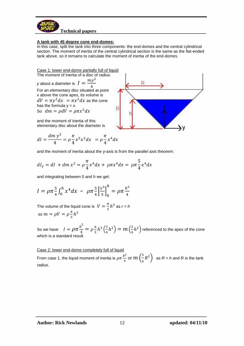
A tank with 45 degree cone end-domes: In this case, split the tank into three components: the end-domes and the central cylindrical section. The moment of inertia of the central cylindrical section is the same as the flat-ended tank above, so it remains to calculate the moment of inertia of the end-domes. Case 1: lower end-dome partially full of liquid The moment of inertia of a disc of radius
y about a diameter is
For an elementary disc situated at point x above the cone apex, its volume is
as the cone
has the formula y = x. So and the moment of inertia of this elementary disc about the diameter is
and the moment of inertia about the y-axis is from the parallel axis theorem:
and integrating between 0 and h we get:
∫
=
*
+
The volume of the liquid cone is
as r = h
so
So we have
(
) (
) referenced to the apex of the cone
which is a standard result.
Case 2: lower end-dome completely full of liquid
From case 1, the liquid moment of inertia is
or (
) as R = h and R is the tank
radius.

Technical papers
Author: Rick Newlands 13 updated: 04/11/10
Case 3: upper end-dome partially full of liquid If the base radius is R and has height R, then the radius at distance x from the base is given by: y = R - x. Now we use the moment of inertia of a flat disc about a diameter and then use the parallel axis theorem to get the moment of inertia about the y-axis. The moment of inertia of a disc about a
diameter is
For our elementary disc at point x the volume is
(
So (
and the moment of inertia of this elementary disc about the diameter is
(
and the moment of inertia about the y-axis is from the parallel axis theorem:
( (
Expanding the powered terms:
[( ]
(
and integrating between 0 and h we get:
∫ (
)
[
]
(
) relative to the base of the cone.
Now the volume of the liquid is:
∫
∫ ∫ (
Technical papers
Author: Rick Newlands 14 updated: 04/11/10
∫ (
[
]
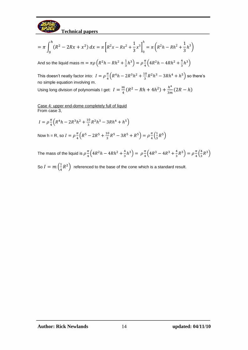
(
)
And so the liquid mass m (
)
(
)
This doesn’t neatly factor into:
(
) so there’s
no simple equation involving m.
Using long division of polynomials I get:
(
(
Case 4: upper end-dome completely full of liquid From case 3,
(
)
Now h = R, so
(
)
(
)
The mass of the liquid is
(
)
(
)
(
)
So (
) referenced to the base of the cone which is a standard result.

Technical papers
Author: Rick Newlands 15 updated: 04/11/10
A tank with hemispherical end-domes: In this case, split the tank into three components: the end-domes and the central cylindrical section. The CG of the central cylindrical section is the same as the flat-ended tank given earlier, so it remains to calculate the CG’s of the end-domes. Case 1: lower end-dome partially full of liquid Again we use the moment of inertia of a flat disc about a diameter and then use the parallel axis theorem to get the moment of inertia about the y-axis. The equation for this hemisphere is:
(
so: (
The moment of inertia of a disc about a
diameter is
For our elementary disk at point x the volume is
( So (
and the moment of inertia of this elementary disc about its diameter is
( (
(
and the moment of inertia about the y-axis is from the parallel axis theorem:
( (
Integrating between 0 and h we get:
∫ (( )
∫ (
*
+
(
) referenced to the bottom of the hemisphere.
Now, the volume of the liquid is:
∫
∫ ∫ (
[
]
(
)

Technical papers
Author: Rick Newlands 16 updated: 04/11/10
And so the liquid mass m is (
)
(
)
This doesn’t neatly factor into:
(
)
so there’s no simple equation involving m.
Using long division of polynomials I get:
(
)
Case 2: lower end-dome completely full of liquid From case 1, the moment of inertia is:
(
)
(
) as h = R
(
)
(
)
And the liquid mass m is:
(
)
(
)
(
)
(
)
So
(
) (
)
referenced to the bottom of the
hemisphere.
As a check of this result, the standard result (ref. 2) for the moment of inertia of a hemisphere
about its centre of mass is: (
)
The centre of mass is
from the bottom of the hemisphere, so using the parallel axes
theorem:
gives: (
) (
)
(
)
(
) (
) (
)
Technical papers
Author: Rick Newlands 17 updated: 04/11/10
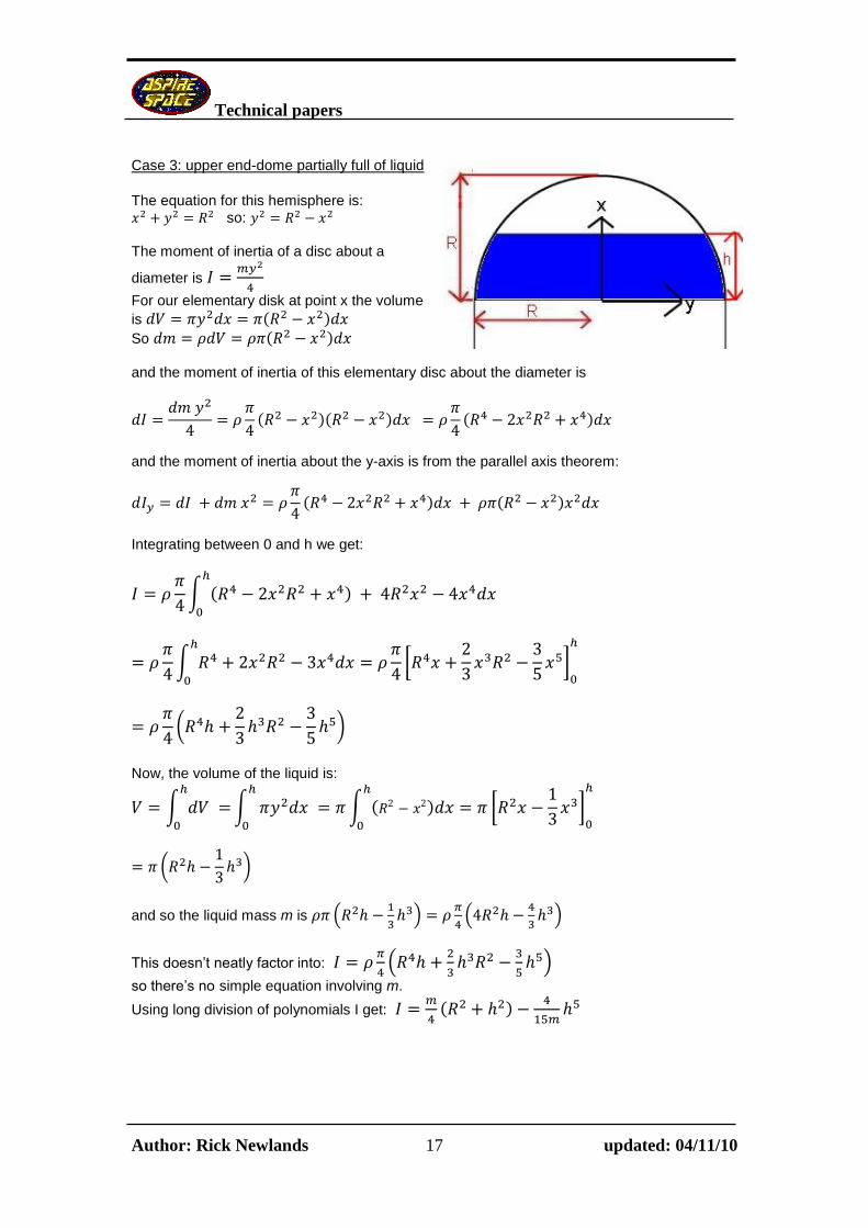
Case 3: upper end-dome partially full of liquid
The equation for this hemisphere is:
so: The moment of inertia of a disc about a
diameter is
For our elementary disk at point x the volume
is (
So ( and the moment of inertia of this elementary disc about the diameter is
( (
(
and the moment of inertia about the y-axis is from the parallel axis theorem:
( (
Integrating between 0 and h we get:
∫ (
∫
[
]
(
)
Now, the volume of the liquid is:
∫
∫ ∫ (
[
]
(
)
and so the liquid mass m is (
)
(
)
This doesn’t neatly factor into:
(
)
so there’s no simple equation involving m.
Using long division of polynomials I get:
(

Technical papers
Author: Rick Newlands 18 updated: 04/11/10
Case 4: upper end-dome completely full of liquid From case 3, the moment of inertia is:
(
)
(
) as h = R
(
)
(
)
And the liquid mass m is:
(
)
(
)
(
)
(
)
So
(
)
referenced to the top of the hemisphere.
As a check of this result, the standard result (ref. 2) for the moment of inertia of a hemisphere
about its centre of mass is: (
)
The centre of mass is
from the top of the hemisphere, so using the parallel axes theorem:
gives: (
) (
)
(
)
(
) (
) (
)

Technical papers
Author: Rick Newlands 19 updated: 04/11/10
Adding the moments of inertia Now that we have the moments of inertia of the component parts, we need to re-reference them to a common datum using the parallel axes theorem. But this theorem only works from the CG of each part, so first we have to re-reference each part to its own local CG. For this we use the parallel axes theorem, but in reverse, as you’re re-referencing to the local CG:
where m is the mass of the section of fluid being re-
referenced and Ielsewhere is the inertia result given earlier for a particular part (e.g. the top end-dome) and r1 is the distance from the original reference point (e.g. the base of the upper hemisphere) to the local CG. This is given earlier as the liquid CG distance. Then use the parallel axis theorem to re-reference each part to a common datum such as the base of the whole tank:
where r is the combined distance from the part’s local CG to
the base of the tank (r = r1 + r2 where r2 is the distance from the original inertia reference, e.g. the base of the upper hemisphere, to the base of the tank.) Later, you can re-reference this inertia to the overall CG of the whole vehicle using the parallel axis theorem in reverse. Liquid effect on the moment of inertia Here’s food for thought: what’s the pitch/yaw moment of inertia of a liquid? (The moment of inertia of the liquid about the roll axis is effectively zero.) So far (above) we’ve treated the liquid as if it was frozen solid, but this clearly isn’t the case. This is a really thorny little problem that has occupied some of science’s best minds, and as the mass of the liquid in a good hybrid system should be a large part of the launch mass, it strongly affects the dynamic stability, i.e. the response of the vehicle to gusts. Observation of different shapes of clear-plastic bottles of water being rotated by hand shows the main effects. Far from the axis of rotation, the fluid is carried round by the walls of the bottle as the bottle rotates, so the moment of inertia here is almost as much as if the liquid were frozen in the bottle, i.e. as if it were solid. The liquid near the axis of rotation of the bottle however, a roughly spherical region of the same diameter as the bottle, isn’t affected by the bottle’s rotation. As the bottle rotates, this roughly spherical shape doesn’t rotate, as if it were a free-to-rotate solid sphere on a low-friction pivot. So this central region effectively has zero moment of inertia. Between these two regions, the effects merge from one to the other: partial rotation. If the tank is long and thin then the tank diameter is small in comparison to the scale of the tank, so the central non-rotating region of liquid is small; the tank’s moment of inertia is almost as large as if the liquid was completely frozen solid. But if the tank is squat, OR the axis of rotation of the tank is near the base of the tank and the tank is almost empty, then most of the liquid is not rotating, so the moment of inertia is very much lower than the value it would be if the liquid were frozen solid. It’s therefore important to find the centre of the vehicle’s rotation, and whether this occurs within the liquid tank. Although you can mathematically assume that the centre of rotation is at the vehicle CG, it actually may not be if the vehicle is lifting sideways as it rotates due to a gust: the instantaneous centre of rotation may be elsewhere.

Technical papers
Author: Rick Newlands 20 updated: 04/11/10
Engineer’s mathematical models of liquid tanks use a simple approximation of the above picture. Reference 3 is typical, where the liquid is replaced by a solid cylinder (as if it were frozen solid) but with a correction (reduction) in moment of inertia to account for the non-rotating region, Reference 3’s mathematical derivation of the exact values of the frozen and rotating parts of the model involves some powerful maths. The fluid is modelled as frictionless and incompressible, and mathematically irrotational (a mathematical construct that says that though successive lumps of fluid rotate as they slide around each other, the lumps themselves do not rotate, rather like the cars on a fairground Ferris wheel.) These assumptions allow the velocity of the fluid at any point within the tank to be obtained as the tank is rotated. (For those who are interested, the usual fluid dynamics method of obtaining the velocity potential within the tank using Laplace’s equation is performed, noting the boundary conditions at the tank walls and the fluid free surface.) Having got the velocity at all points within the tank mapped out, Bernoulii’s equation is then used to get the pressure distribution around the tank, and then this pressure distribution is integrated over the area of the tank walls and base to get the forces that the liquid exerts on the walls as the tank is rotated. Having got the forces that the liquid exerts on the tank walls, Newton’s laws are used to construct a mechanical model of the liquid that uses an array of fixed masses, and moving masses on springs, to simulate the liquid (see chapter 6). It’s a mathematical tour-de-force, but the results tally with other’s analyses as used in the aerospace industry. Reference 4 is a modern revision of reference 3 that is much more readable. First, we take the results we calculated earlier for the moment of inertia of frozen solid liquid in the tank. For example, the moment of inertia of a frozen liquid within a cylindrical tank with flat end-domes about the centre of mass (CG) of the liquid is:
(
)
where: h = the liquid height, R = the tank internal radius, m = the liquid mass Note that we have to use the moment of inertia of the liquid about its CG. You may need to use the Parallel Axes theorem to get the frozen moment of inertia re-referenced to its CG:
2rmIICG where r in this case is the distance between the original reference point (e.g.
the bottom of the tank) and the CG of the liquid. m is the mass of the liquid. Then a correction is applied to reduce the frozen moment of inertia (Ifrozen) to account for the non-rotating liquid region.

Technical papers
Author: Rick Newlands 21 updated: 04/11/10
The ratio of the actual moment of inertia (Iactual) divided by the frozen moment of inertia is given as the following graph (from Ref. 3 figure 6.14 page 211): This depends on the liquid’s height h relative to the tank internal diameter d. Notice that the actual moment of inertia is lowest when the liquid height equals one tank diameter (h/d = 1) as this is the most nearly spherical shape the liquid gets, so the liquid will hardly revolve when the tank is rotated. In tabular form, this graph is (data extrapolated past h/d = 8):
h/d Inertia ratio
0 1
0.14 0.898
0.217 0.814
0.302 0.693
0.378 0.562
0.411 0.479
0.496 0.367
0.565 0.296
0.653 0.233
0.75 0.19
0.82 0.166
0.9 0.153
1.008 0.156
1.116 0.186
1.207 0.222
1.352 0.285
1.58 0.382
1.806 0.466
2.069 0.546
2.358 0.624
2.664 0.689
2.98 0.745
3.348 0.784
3.905 0.832
4.514 0.872
5.088 0.894
5.849 0.92
6.745 0.939
8.017 0.963
9.216 0.975
15 1

Technical papers
Author: Rick Newlands 22 updated: 04/11/10
These results are for a tank with flat end-faces, but reference 3 says that they will be applicable to tanks with other end-domes (conical, spherical) as long as the following correction is made: calculate and use the equivalent liquid height in the above graph. This is what the liquid height would be in a flat-faced tank of the same tank internal radius R, and that
contains an equal liquid volume. So divide your liquid volume by to get the equivalent liquid height. Note that the final moment of inertia given above is about a point that is the centre of mass (CG) of the liquid. Just like any other moment of inertia, this can be converted to the value about the vehicle CG using the Parallel Axes theorem:
2rmIICG where r in this case is the distance between the centre of mass of the liquid
and the vehicle CG, and m here is the mass of the liquid. Note that the nitrous vapour in a hybrid tank is almost as dense as the liquid nitrous below it on a hot day. It is a vapour and not a liquid, so I’ve assumed that it has zero moment of inertia. This may well be too much of an assumption, comments please. Reference 5 gives a guide to calculating the moment of inertia of the liquid in a large tank that requires internal tank baffles to reduce slosh (see our paper ‘hybrid effects on stability’ for an explanation of slosh).

Technical papers
Author: Rick Newlands 23 updated: 04/11/10
References: Ref.1: Doctor Anthony, The Math Forum http://mathforum.org/dr.math/ Ref.2: http://www.efunda.com/math/solids/solids_display.cfm?SolidName=Hemisphere Ref.3: ‘The dynamic behaviour of liquids in moving containers’ NASA SP 106, 1966 Available on the web at: http://sloshcentral.bbbeard.org/ Ref.4: ‘The new dynamic behaviour of liquids in moving containers’ by Franklin T. Dodge, Southwest Research Institute, 2000 Available on the web at: http://sloshcentral.bbbeard.org/ Ref.5: ‘Moment of inertia and damping of liquids in baffled cylindrical tanks’ by Dodge and Kana, NASA contractor report CR-383 (available on the web)
Copyright © 2022 FDOKUMEN