
01.54.455168-1.5 MFM-CMS Central Monitoring System User ...
66
-
Upload
khangminh22 -
Category
Documents
-
view
0 -
download
0
Transcript of 01.54.455168-1.5 MFM-CMS Central Monitoring System User ...
I
About this Manual P/N: 01.54.455168-15
Release Date: August 2013
© Copyright EDAN INSTRUMENTS, INC. 2010-2013. All rights reserved.
Statement
This manual will help you understand the operation and maintenance of the product better. It is reminded that the product shall be used strictly complying with this manual. User’s operation failing to comply with this manual may result in malfunction or accident for which EDAN INSTRUMENTS, INC. (hereinafter called EDAN) can not be held liable.
EDAN owns the copyrights of this manual. Without prior written consent of EDAN, any materials contained in this manual shall not be photocopied, reproduced or translated into other languages.
Materials protected by the copyright law, including but not limited to confidential information such as technical information and patent information are contained in this manual, the user shall not disclose such information to any irrelevant third party.
The user shall understand that nothing in this manual grants him, expressly or implicitly, any right or license to use any of the intellectual properties of EDAN.
EDAN holds the rights to modify, update, and ultimately explain this manual.
Responsibility of the Manufacturer EDAN only considers itself responsible for any effect on safety, reliability and performance of the equipment if:
Assembly operations, extensions, re-adjustments, modifications or repairs are carried out by persons authorized by EDAN, and
The electrical installation of the relevant room complies with national standards, and
The instrument is used in accordance with the instructions for use.
Upon request, EDAN may provide, with compensation, necessary circuit diagrams, and other information to help qualified technician to maintain and repair some parts, which EDAN may define as user serviceable.
II
Terms Used in this Manual This guide is designed to give key concepts on safety precautions.
WARNING
A WARNING label advises against certain actions or situations that could result in personal injury or death.
CAUTION
A CAUTION label advises against actions or situations that could damage equipment, produce inaccurate data, or invalidate a procedure.
NOTE
A NOTE provides useful information regarding a function or a procedure.
III
Table of Contents Chapter 1 Intended Use and Safety Guidance ............................................................................1
1.1 Intended Use........................................................................................................................1
1.2 Safety Guidance ..................................................................................................................1
1.3 Explanation of Symbols ......................................................................................................3
Chapter 2 Introduction..................................................................................................................5
2.1 General ................................................................................................................................5
2.2 System Functions ................................................................................................................6
2.3 Typical Screens of the MFM-CMS .....................................................................................7
2.4 Large Font Display..............................................................................................................9
2.4.1 Entering large Font Window .....................................................................................9
2.4.2 Closing Large Font Window ................................................................................... 11
Chapter 3 Basic Operations ........................................................................................................12
3.1 General ..............................................................................................................................12
3.2 Operating Method .............................................................................................................12
3.2.1 Starting monitoring .................................................................................................12
3.2.2 Shutting down the system .......................................................................................13
3.2.3 Patient Management................................................................................................13
3.2.4 Mouse operation......................................................................................................15
3.3 Patient Section...................................................................................................................15
3.4 System Setup.....................................................................................................................16
3.4.1 Common Setup........................................................................................................16
3.4.2 User Maintain..........................................................................................................17
Chapter 4 Viewing Single Bed.....................................................................................................20
4.1 Setting Patient Information ...............................................................................................20
4.2 Hiding/Showing Multi-lead Waveform.............................................................................20
4.3 Real-time Printing .............................................................................................................20
4.4 Short Trend Review...........................................................................................................20
4.5 Freeze ................................................................................................................................21
4.6 OxyCRG............................................................................................................................21

IV
4.7 Setting Wave Review ........................................................................................................21
4.7.1 Setting Wave Speed.................................................................................................21
4.7.2 Refreshing Waveform .............................................................................................21
4.7.3 Print .........................................................................................................................21
4.8 Setting Alarm Review .......................................................................................................21
4.9 Setting Trend Review........................................................................................................21
4.10 Setting NIBP Review ......................................................................................................22
4.11 Setting Waveforms and Parameters.................................................................................22
4.11.1 Setting Waveforms to be Displayed ......................................................................22
4.11.2 Setting Parameters to be Displayed.......................................................................22
4.12 Bilateral Control in Patient Section.................................................................................23
4.12.1 Controlling NIBP Setup of Bedside Monitor........................................................23
4.12.2 Controlling Alarm Setup of Bedside Monitor.......................................................23
Chapter 5 Review .........................................................................................................................24
5.1 Patient List ........................................................................................................................24
5.1.1 Discharging a Patient ..............................................................................................24
5.1.2 Querying a Patient...................................................................................................24
5.2 Wave Review.....................................................................................................................25
5.2.1 Reviewing Normal Waveforms ...............................................................................25
5.2.2 Reviewing Compressed Waveforms .......................................................................25
5.2.3 Setting Wave Speed.................................................................................................25
5.2.4 Refreshing Waveform .............................................................................................25
5.2.5 Selecting Waveform ................................................................................................25
5.2.6 Print .........................................................................................................................26
5.3 Alarm Review....................................................................................................................26
5.3.1 Locking and Unlocking Alarm Information............................................................26
5.3.2 Printing Alarm Information.....................................................................................26
5.3.3 Sequencing the Alarm List ......................................................................................26
5.3.4 Annotating Alarm....................................................................................................27
5.3.5 Filtering Alarm Events ............................................................................................27
V
5.4 Trend Review ....................................................................................................................27
5.4.1 Setting Resolution ...................................................................................................27
5.4.2 Viewing Parameters selectively ..............................................................................27
5.4.3 Refreshing Data.......................................................................................................28
5.4.4 Printing Trend Review ............................................................................................28
5.4.5 Selecting Trend Table, Trend Graph .......................................................................28
5.5 NIBP Review.....................................................................................................................28
5.6 12-Lead Review ................................................................................................................28
5.7 C.O. Measure Review .......................................................................................................29
5.8 Quick Temp Review..........................................................................................................29
Chapter 6 Alarm Management ...................................................................................................30
6.1 General ..............................................................................................................................30
6.1.1 Physiological Information Alarm............................................................................30
6.1.2 Technical Alarm ......................................................................................................30
6.2 Alarm Level.......................................................................................................................30
6.3 Alarm Mute .......................................................................................................................31
6.4 Alarm Voice Pause ............................................................................................................31
6.5 Alarm Prompt/Response....................................................................................................31
6.6 Alarms for Networking Status...........................................................................................32
Chapter 7 Printing .......................................................................................................................33
7.1 Printing Report with a Printer ...........................................................................................33
7.2 Preview/Settings................................................................................................................33
7.2.1 Preview....................................................................................................................33
7.2.2 Settings....................................................................................................................34
7.3 Exporting the PDF File .....................................................................................................35
Chapter 8 Database Management ..............................................................................................36
8.1 Database Backup...............................................................................................................36
8.2 Reviewing Backup Database.............................................................................................36
Chapter 9 Calculation and Titration Table................................................................................37
9.1 General ..............................................................................................................................37

VI
9.2 Drug Calculation ...............................................................................................................37
9.2.1 Drug Calculation Formula.......................................................................................38
9.2.2 Calculation of Titration Table .................................................................................38
9.3 Hemodynamic Calculation................................................................................................39
9.3.1 Input Parameters......................................................................................................39
9.3.2 Output Parameters...................................................................................................39
9.4 Renal Function Calculation...............................................................................................40
9.4.1 Input Parameters......................................................................................................40
9.4.2 Output Parameters...................................................................................................40
9.5 Oxygenation Calculation...................................................................................................41
9.5.1 Input Parameters......................................................................................................41
9.5.2 Output Parameters...................................................................................................42
9.6 Ventilation Calculation......................................................................................................42
9.6.1 Input Parameters......................................................................................................42
9.6.2 Output Parameters...................................................................................................43
Chapter 10 CMS-WEB Observer ...............................................................................................44
10.1 General ............................................................................................................................44
10.2 Typical Screens of the CMS-WEB..................................................................................44
10.3 Starting/ Shutting Down the System ...............................................................................46
10.3.1 Starting the System ...............................................................................................46
10.3.2 Shutting Down the System....................................................................................47
10.4 System Setup...................................................................................................................47
10.4.1 Common Setup......................................................................................................47
10.4.2 Administrator Setup ..............................................................................................49
10.5 Viewing Single Bed.........................................................................................................50
10.5.1 Patient Information................................................................................................50
10.5.2 Single Bed View....................................................................................................50
10.5.3 Waveform Review.................................................................................................51
10.5.4 Alarm Review........................................................................................................51
10.5.5 Trend Review ........................................................................................................51

VII
10.5.6 NIBP Review.........................................................................................................52
Chapter 11 Safety .........................................................................................................................53
11.1 Control and Safety Index.................................................................................................53
11.2 Characteristics .................................................................................................................53
Chapter 12 Service .......................................................................................................................54
Appendix I Specifications ............................................................................................................55
A1.1 Recommended Hardware Configuration........................................................................55
A1.2 Software Performance ....................................................................................................56

MFM-CMS Central Monitoring System User Manual Intended Use and Safety Guidance
- 1 -
Chapter 1 Intended Use and Safety Guidance
1.1 Intended Use MFM-CMS provides centralized monitoring and critical care management for patients monitored by EDAN bedside monitors. From MFM-CMS, clinicians can gain access to patient information for patients on the Network. MFM-CMS displays waveforms, parameters and alarm status of EDAN bedside monitors for up to 32 patients on a single screen or up to 64 patients using two screens.
1.2 Safety Guidance To use the system safely and effectively and to avoid system failure, please read the user manual in detail and be familiar with the proper operation method. The following WARNING and CAUTION must be observed during the operation of the system. A WARNING label advises against certain actions or situations that could result in personal injury or death. A CAUTION label alerts the user to exercise care necessary for the safe and effective use of the MFM-CMS.
WARNING
1 The system should be installed by a qualified service engineer. Do not switch on power until all cables have been properly connected and verified.
2 The user of this system should get professional training and read this manual thoroughly before using it.
3 Do not use it in the presence of flammable anesthetic due to explosion risk.
4 To avoid the risk of electric shock, do not remove the unit covers.
5 Do not move the main unit and monitor while powering on the system.
6 Only the accessories supplied or recommended by the manufacturer can be connected to the system.
7 Accessory equipment connected to the analog and digital interfaces must be certified according to the respective IEC/EN standards (e.g. IEC/EN 60950 for data processing equipment and IEC/EN 60601-1 for medical equipment). Furthermore all configurations shall comply with the valid version of the standard IEC/EN 60601-1-1. Therefore anybody, who connects additional equipment to the signal input or output connector to configure a medical system, must make sure that it complies with the requirements of the valid version of the system standard IEC/EN60601-1-1. If in doubt, consult our technical service department or your local distributor.
8 Ensure that the environment in which the system is operated is not subject to any sources of strong electromagnetic interference, such as radio transmitters, mobile telephones, etc. Keep them far away.
9 This equipment must be used by or under the guide of physician. This equipment is not intended for home use.
MFM-CMS Central Monitoring System User Manual Intended Use and Safety Guidance
- 2 -
WARNING
10 MFM-CMS system can only collect, supervise, record, store and display the information from Multi-parameter patient monitor but can not replace the monitoring function of the Multi-parameter patient monitor.
11 Ensure that the system can meet the requirements of standard IEC/EN 60601-1-1 before other devices are connected to the system. Other equipments connected to the interfaces of PC station must comply with the respective IEC/EN standards (e.g. IEC/EN 60950 for data processing equipment and IEC/EN 60601-1 for medical equipment). Furthermore, all configurations should comply with the valid version of the system standard IEC/EN 60601-1-1. Everybody who connects additional equipment to the signal input connector or signal output connector configures a medical system, and is therefore responsible for the system complying with the requirements of the valid version of the system standard IEC/EN 60601-1-1. If in doubt, consult our technical service department or your local distributor.
12 The MFM-CMS can only be installed on the device recommended by EDAN.
13 Only use operating systems that are approved by EDAN, such as Windows 7. Using operating systems that are not approved by EDAN may compromise the system performance and cause a potential hazard.
14 Do not rely on the information displayed on MFM-CMS to make therapeutic and diagnostic decisions. Please follow hospital guidelines and best clinical practices.
15 Clinical decision making based on the output of the device is left to the discretion of the provider.
16 Prior to intervening based on data displayed on the Central Monitoring System, providers must verify this data with the corresponding bedside monitor.
CAUTION
1 Federal (U.S.) Law restricts this device to sale by or on the order of a physician.
2 Read this manual prior to using this system.
3 The system should be used within temperature from +5℃ to +40℃.
4 Keep the environment clean. Avoid vibration. Keep it far from corrosive reagents, dust areas, high-temperature and humid environment.
5 The user must check that the equipment, cables and transducers do not have visible evidence of damage that may affect patient safety or monitoring capability before use. The recommended inspection interval is once per week or less. If damage is evident, replacement is recommended before using it.
6 Turn off the system power before connecting or disconnecting any accessory to the system.

MFM-CMS Central Monitoring System User Manual Intended Use and Safety Guidance
- 3 -
CAUTION
7 Please do not operate the system if it is not operating normally or requires service.
8 Turn off the system power and remove the power cable before maintaining the system.
9 Preventive maintenance of the system including periodic cleaning and appearance checking can be finished by the user because this maintenance does not touch the interior.
10 Avoid using attrite material to clean. Removing all dust from the exterior surface of the equipment with a soft brush or cloth or with a soft cloth, slightly dampened with a mild detergent solution or cool disinfector. Especially the tie-in and panel edge should be noticed.
11 Avoid pouring liquids on the equipment while cleaning, and do not immerse any parts of the equipment into any liquids.
12 The system data will be delayed for no more than 5 seconds.
NOTE: The illustrations in this manual are for reference only.
1.3 Explanation of Symbols
Consult Instructions For Use
Serial number
The symbol indicates that the device complies with the European Council Directive 93/42/EEC concerning medical devices.
Authorized representative in the European community
Date of manufacture
MFM-CMS Central Monitoring System User Manual Intended Use and Safety Guidance
- 4 -
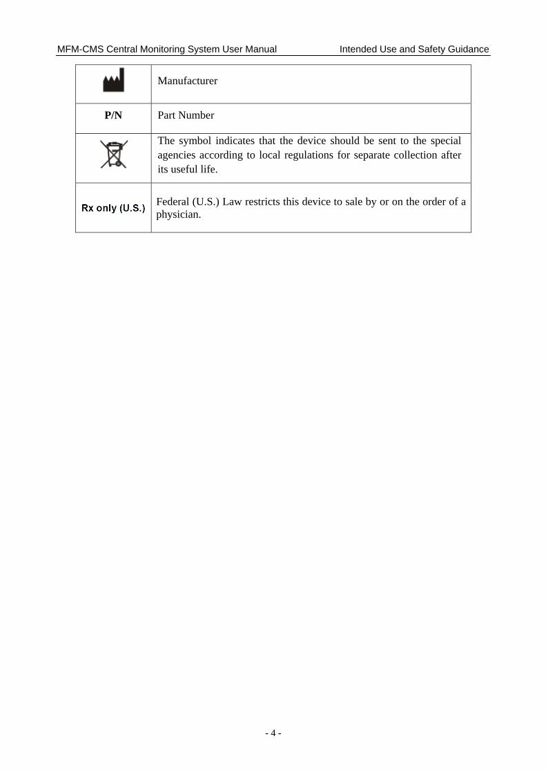
Manufacturer
P/N Part Number
The symbol indicates that the device should be sent to the special agencies according to local regulations for separate collection after its useful life.
Federal (U.S.) Law restricts this device to sale by or on the order of a physician.
MFM-CMS Central Monitoring System User Manual Introduction
- 5 -
Chapter 2 Introduction 2.1 General MFM-CMS Central Monitoring System is a medical information device widely applied in clinical monitoring field. A monitoring network system is constructed by connecting multiple monitors. Being the center of the monitoring network, the system realizes central monitoring by collecting, processing, and analyzing the physiological information from multiple bedside monitors. The central system frees the doctors and nurses from multifarious clinical monitoring work and greatly improves monitoring quality.
This MFM-CMS is capable of connecting up to 64 bedside monitors that comply with the manufacturer network protocol.
This MFM-CMS connects bedside monitors via network and displays physiological information of the patients being monitored by bedside monitors. This system can simultaneously display the information from up to 64 bedside monitors.
Physiological waveforms of each bedside monitor that can be displayed on the MFM-CMS include:
2 ECG waveform
1 RESP waveform
1 PLETH waveform
8 IBP waveform
1 CO2 waveform
4 AG waveforms for CO2, O2, N2O and AA
Physiological parameters of each bedside monitor that can be displayed on the MFM-CMS include:
ECG: HR, ST value, PVCs
RESP: RR
NIBP: SYS, DIA, MAP
SpO2: SpO2, PR
IBP: ART, PA, CVP, RAP, ICP, LAP, P1, P2 (only IBP supported by the monitor will be displayed)
CO2: EtCO2, FiCO2, AwRR
TEMP: T1, T2, TD
Quick TEMP
AG: EtCO2, FiCO2, AwRR; EtO2, FiO2; EtN2O, FiN2O; HAL/ISO/ENF/SEV/DES: Et, Fi, MAC
C.O.: C.O., TB

MFM-CMS Central Monitoring System User Manual Introduction
- 6 -
This MFM-CMS can also make notification in both audio and visual ways for the alarm occurring at the bedside monitor in order to attract the doctor’s attention; as thus the alarm event can be dealt with accurately in time.
The MFM-CMS supports various kinds of peripheral devices such as printer that can output monitoring report. The typical central monitoring system network is shown in Figure 2-1:
Figure 2-1 A Typical Central Monitoring System Network
2.2 System Functions The MFM-CMS can realize the following system functions:
Connecting of up to 64 bedside monitors simultaneously
Alarm management of parameter alarms from bedside monitors
Up to 240-hour of trend data storage and review for each bedside monitor
72-hour physiological waveforms
Storage and review of up to 720 alarm events for each bedside monitor
Up to 12-hour short trend review for each bedside monitor
Review of 720 pieces of NIBP measurements
Review of 720 pieces of 12-lead analysis results
Review of 720 pieces of C.O. measurements
Review of 720 pieces of Quick TEMP measurements
Displaying multi-lead ECG
Monitoring reports of review and alarm records can be output in a certain format
Displaying single bed information for one bedside monitor
Search, browse and maintaining management of patients’ monitoring data
MFM-CMS Central Monitoring System User Manual Introduction
- 7 -
Comprehensive system help function
Power-off storage function available for all kinds of review information
Calculation of drug doses and titration tables
Hemodynamic Calculation
Oxygenation Calculation
Renal Function Calculation
Ventilation Calculation
Various alarm indicating methods
Supporting wired connected monitor
Web observation in the hospital local area network.
Bilateral control
HL7
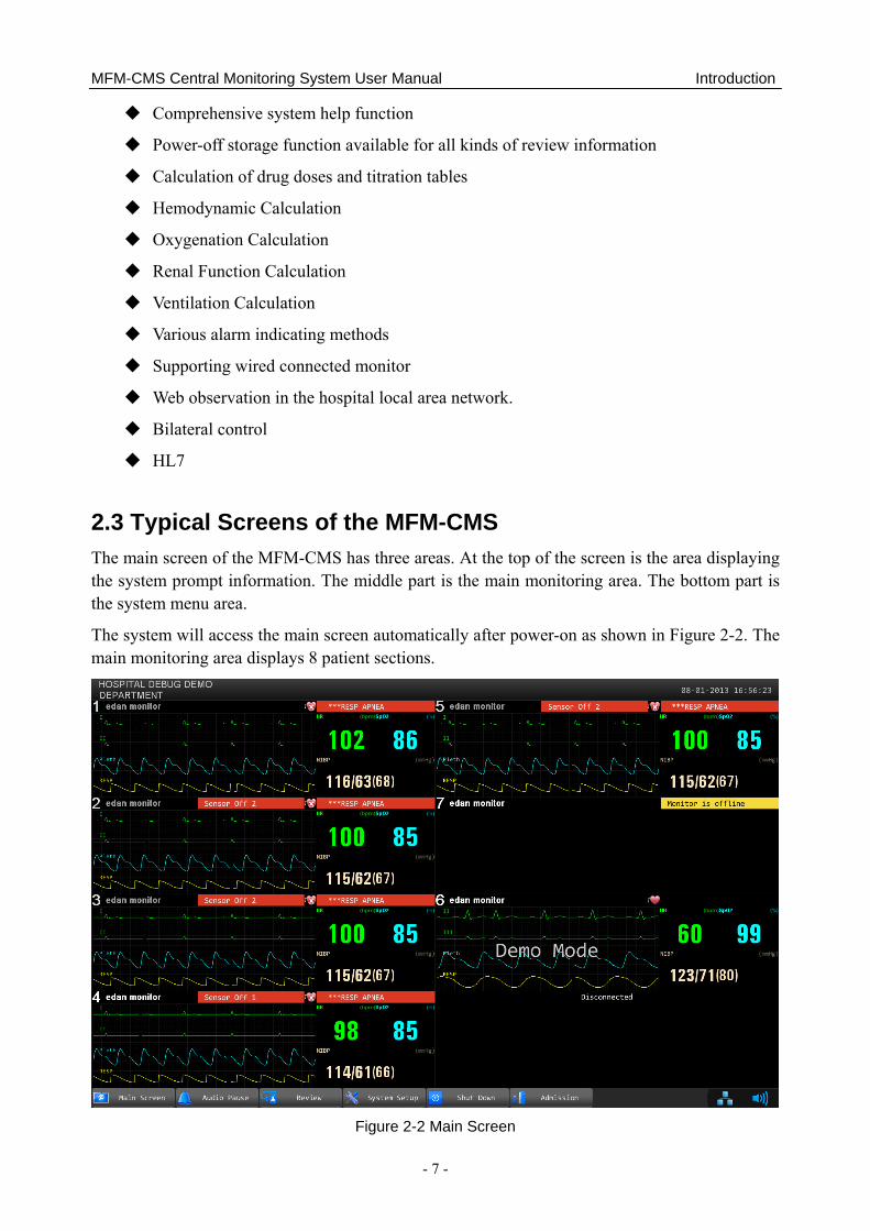
2.3 Typical Screens of the MFM-CMS The main screen of the MFM-CMS has three areas. At the top of the screen is the area displaying the system prompt information. The middle part is the main monitoring area. The bottom part is the system menu area.
The system will access the main screen automatically after power-on as shown in Figure 2-2. The main monitoring area displays 8 patient sections.
Figure 2-2 Main Screen
MFM-CMS Central Monitoring System User Manual Introduction
- 8 -
Structure of the main screen:
1. Main monitoring screen
The black background with the white font Disconnected in a patient section indicates no bedside monitor is assigned to this patient section.
The display of patient information and the low-level alarm message Monitor is offline in the patient section indicates the bedside monitor in this patient section is offline without being discharging. The system will indicate it with a low level alarm sound.
The display of patient information, waveforms, trend data and alarm information indicates the bedside monitor is properly networked and under observation.
Alarm area in the patient section: indicates physiological alarms and technical alarms. (Refer to Chapter 6 Alarm Management for more information about alarms.)
The display of the symbols and :
- The symbol indicates Pace is set to On;
- The symbol indicates Pace is set to Off.
2. Information area
The information area is at the top of the screen. The hospital and department information is displayed on the left side of this area, the system time is displayed on the right side and the prompt messages are displayed in the middle.
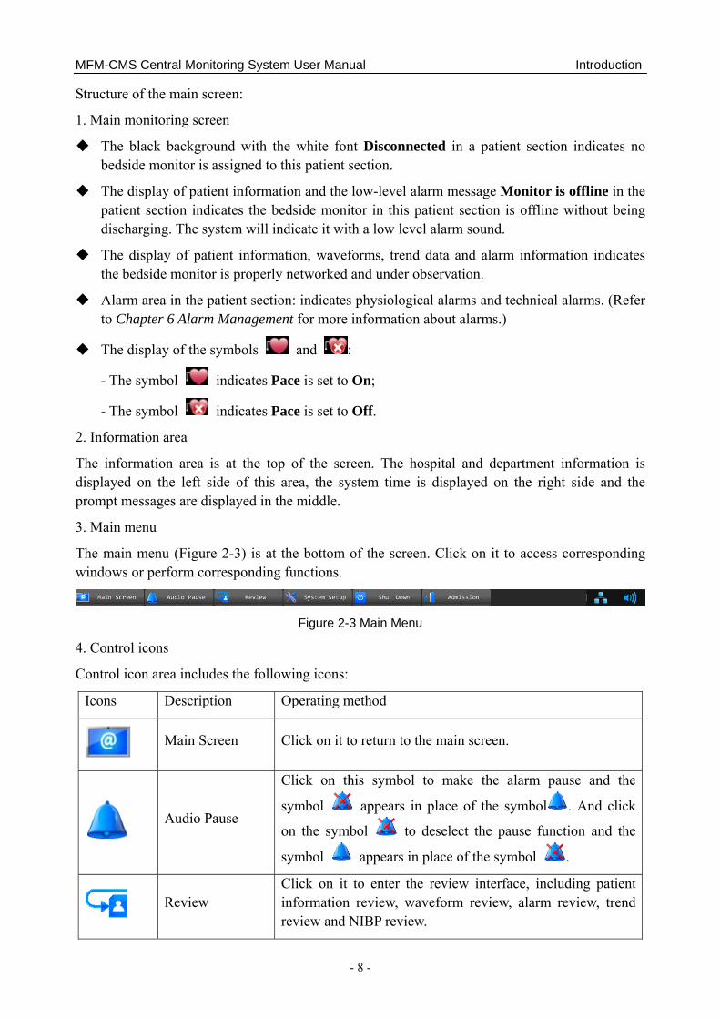
3. Main menu
The main menu (Figure 2-3) is at the bottom of the screen. Click on it to access corresponding windows or perform corresponding functions.
Figure 2-3 Main Menu
4. Control icons
Control icon area includes the following icons:
Icons Description Operating method
Main Screen Click on it to return to the main screen.
Audio Pause
Click on this symbol to make the alarm pause and the
symbol appears in place of the symbol . And click
on the symbol to deselect the pause function and the
symbol appears in place of the symbol .
Review
Click on it to enter the review interface, including patient information review, waveform review, alarm review, trend review and NIBP review.
MFM-CMS Central Monitoring System User Manual Introduction
- 9 -
System Setup Click on it to enter the system setup menu.
Shut Down Click on it to shut down the MFM-CMS and the operating
system.
Admission Click on it to open the patient admission window.
System Volume Adjustor
Click on it, the volume adjustor icon appears. Select the Mute check box, and then enter the password in the text box on the pop-up window; the entire system become mute even if an alarm occurs, and the symbol appears. To deselect the silence function, tick the Mute check box again and the symbol appears. Additionally, the user can drag the volume adjustor to your desired volume.
Network Connecting Click on it to view all networked bedside monitors.
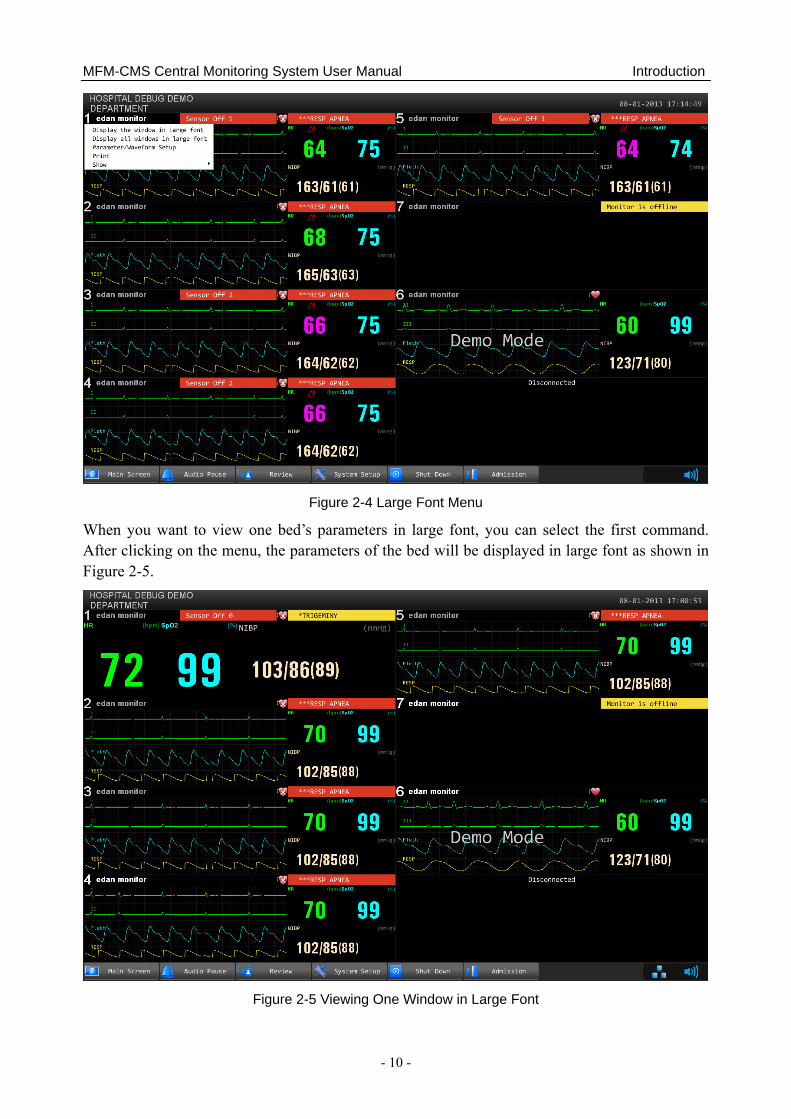
2.4 Large Font Display 2.4.1 Entering large Font Window
Click the patient information area in the patient section, and a menu appears. The first and the second items on the menu are: Display the window in large font, Display all windows in large font. The first menu command is to view one window in large font and the second one is to view all windows in large font. You can view a window or all current windows in large font mode by clicking on the menu commands (Figure 2-4).
MFM-CMS Central Monitoring System User Manual Introduction
- 10 -
Figure 2-4 Large Font Menu
When you want to view one bed’s parameters in large font, you can select the first command. After clicking on the menu, the parameters of the bed will be displayed in large font as shown in Figure 2-5.
Figure 2-5 Viewing One Window in Large Font

MFM-CMS Central Monitoring System User Manual Introduction
- 11 -
When you want to view all parameters of current beds in large font, you can select the Display all windows in large font command. After selecting the command, the parameters of current beds will display in large font (Figure 2-6).
Figure 2-6 Viewing All Windows in Large Font
2.4.2 Closing Large Font Window Click on the bed number on the main screen, and the large font menu pops up. The user can close the large font window by clicking on the first menu command. All current windows in large font can also be closed by clicking on the second menu command.
MFM-CMS Central Monitoring System User Manual Basic Operations
- 12 -
Chapter 3 Basic Operations 3.1 General The basic function of the MFM-CMS is to realize the monitoring of multiple patients at the same time. Its basic monitoring information includes:
Display one group of waveforms in the physiological information transmitted from up to 64 bedside monitors
Display one group of parameters in the physiological information transmitted from up to 64 bedside monitors
Display the latest alarm messages in the alarm information transmitted from up to 64 bedside monitors
The MFM-CMS realizes its basic monitoring functions by means of patient sections on the main screen.
3.2 Operating Method 3.2.1 Starting monitoring NOTE: Before starting the system, please verify that the watchdog has been installed. Otherwise, you may fail to access the system.
When all of its components are correctly connected, press the power button on the front panel of the device. The power indicator on the front panel lights up and the device performs hardware self-test. If the device works normally, the main screen appears. If the device detects abnormity during self-test, it beeps to show alarm and displays error information on the screen. In this case, you should record the error information, shut down the device and contact technical representative of EDAN. After the system self-test is completed, you will access the MFM-CMS system interface and the system will also finish the environment self-test automatically. Meanwhile, the system will sound Do-Do-Do, a test sound. The user should set the volume system and confirm that the volume of the system can be heard clearly.
CAUTION
1 Ensure that the sound equipment is always in a state of activation.
2 The audio adapter and network adapter should be correctly installed, or you may not access the MFM-CMS.
NOTE: Ensure that the MFM-CMS system can give the test sound after startup.
MFM-CMS Central Monitoring System User Manual Basic Operations
- 13 -
3.2.2 Shutting down the system It is important to shut down the system properly. Follow this simple procedure to properly shut down your system. This prevents inadvertent errors from occurring during system shut down.
The MFM-CMS can work continuously for a long time. You do not need to shut it down in order to achieve a longer working life.
You should follow the procedure to shut down the MFM-CMS.
Method 1:
Select Shut Down on the main menu and enter the password. Confirm the password by clicking OK, and the MFM-CMS as well as the operating system will be shut down.
Method 2:
Select System Setup > User Maintain, and enter the password; select Other Setup.
Select Shut Down: the MFM-CMS as well as the operating system will be shut down.
Select Return to Windows: you will exit from MFM-CMS, but the operating system will not be shut down.
WARNING
1 Shut down the system by strictly observing the shutdown procedure to avoid serious result.
2 Although UPS is an optional configuration of this system, if you really force to turn off the UPS, it results in system failure and hence affects the operation of next time.
3 If power cut-off occurs, turn off the system before the UPS exhausts its electricity.
CAUTION
Hospitals without a stable power source should use a UPS to provide power to the MFM-CMS. The UPS must not be turned off. When there is a power failure, the system should be shut down by following the specified shutdown procedure before the UPS is exhausted. If the system has a sudden power failure, system failure may occur and consequently the system may work correctly next time or even have a serious result.
NOTE: If you forget the password, please contact the technical representative of EDAN.
3.2.3 Patient Management 3.2.3.1 Admitting a Patient
Once MFM-CMS starts up and the bedside monitor is properly connected with MFM-CMS, the system will prompt the user to admit patients by displaying the number of pending patients at the information area.

MFM-CMS Central Monitoring System User Manual Basic Operations
- 14 -
You can admit a patient by either of the methods below:
Method 1:
Click Admission on the main menu to display the pending patient list which contains the patients to be admitted. Select the patients you want to admit from the list. Click the Admission button at the bottom of the pending patient list to complete patient admission. The patients who have been chosen will be monitored by MFM-CMS.
Method 2:
Click anywhere in a disconnected patient section to display the menu on which you point to Admission and from the submenu select a bed No. of which the bedside monitor will be assigned to this patient section.
For the bedside monitor that has been offline due to network problems and is networked with MFM-CMS again, you need not admit the patient of this monitor. This monitor will be automatically online in the patient section to which it has been assigned.
WARNING
For bedside monitors that have been networked with MFM-CMS for the first time, you have to complete patient admission by using the methods mentioned above, which enables the monitors to be online and observed by MFM-CMS. Otherwise, the monitors will not be online on MFM-CMS, and the monitoring data will not be saved by MFM-CMS.
3.2.3.2 Changing Patient Information
You can change the patient information on MFM-CMS when you find the information incorrect. To modify the patient information, choose Single Bed View > Patient Mgmt, enter the correct information in the appropriate fields and click Update Monitor when you have finished modifying.
3.2.3.3 Switching Patient Section
For a disconnected patient section (refer to Figure 2-2), click anywhere in it and choose a patient to be assigned to this section from the patient list.
For a connected patient section, select Show from the list shown in Figure2-4, and choose another bedside monitor from the patient list; the chosen bedside monitor will be displayed in this patient section.
3.2.3.4 Discharging a Patient
When the monitor is connected to MFM-CMS, you may choose Single Bed View > Patient Mgmt > Discharge to discharge a patient.
When the monitor is disconnected with MFM-CMS, you may discharge a patient from the patient list. Refer to 5.1.1 Discharging a Patient for more information.
MFM-CMS Central Monitoring System User Manual Basic Operations
- 15 -
3.2.3.5 Transfer a Patient
Select Single Bed View > Patient Mgmt >Transfer,and you will see a list of online patients. From this list, select a patient whose bed will be considered as the destination bed and click OK, and then the current patient will be transferred to the destination bed.
NOTE:
Transferring a patient to the destination bed will at the same time discharge the selected patient on the destination bed.
3.2.3.6 Monitoring Statistics
The monitoring statistics of the selected patients will be shown in the patient management window. The monitoring statistics covers the total monitoring time for waveforms and trends, the number of alarm events, the number of NIBP measuring, the number of C.O. measuring, the number of 12-lead analysis and the number of Quick TEMP measuring.
Click Analysis, the system will:
Analyze the number of high and low limit alarms for each physiological parameter and analyze the percentage of the limit alarms of the parameter in all limit alarms.
Analyze the number of arrhythmia events for each type of arrhythmia and analyze the percentage of a certain type of arrhythmia.
Analyze the average value, maximum/minimum value, and measure time of the maximum/minimum value for the trend values.
3.2.4 Mouse operation Usually, we use the following terms to describe mouse operation:
Left-key:
1. Click: move mouse to the target, then quickly press left-key once and release it.
2. Double-click: move mouse to the target, then quickly press left-key twice and release it.
3. Drag: move mouse to the target, press left-key and move to the destination and then release it.
Right-key:
1. Click: move mouse to the target, then quickly press right-key once and release it.
2. Double-click: move mouse to the target, then quickly press right-key twice and release it.
3.3 Patient Section Patient section is used to display the real-time monitoring data transmitted from bedside monitors including one, two, three or four selected waveforms, a group of selected parameters and alarm of the bedside monitor, etc. Besides, in this area, you can also select the waveform and parameter group.
MFM-CMS can provide up to 64 patient sections with two displays. The user can select the number of patient sections to be displayed on the monitor.

MFM-CMS Central Monitoring System User Manual Basic Operations
- 16 -
The patient section can be divided into five areas including physiological waveform area, parameter value area, alarm information display area, patient information display area and status information area of bedside monitor. And the user can perform various functions through the patient section, including single bed view control.
Waveform display area: display a group of waveforms. The waveform name is displayed on the upper left part of the waveform.
Parameter display area: display the parameter information about the viewed bed. Due to the limited display space, you shall properly choose a group of parameters to better make use of the display area.
Alarm information area: display the alarm information of the patient.
Status information of bedside monitor.
Patient information.
Due to the limited display space of the patient section, users can select a maximum of four waveforms and four parameters to be displayed. To set the displayed waveforms and parameters, you can select Parameter/ Waveform Setup from the list shown in Figure 2-4; also, you may select the tag Parameter/ Waveform Setup in the Single Bed window. Refer to 4.9 Setting Waveforms and Parameters for more information.
For detail information, please refer to the chapter about viewing single bed.
NOTE: 1 Due to the delay of network transmission, the waveform viewed at the MFM-CMS has
a delay of 5 seconds compared with the waveform generated at the corresponding bedside monitor.
2 Due to the operating system schedule, the waveform scan of the MFM-CMS might be suspended for about 20 milliseconds in very few occasions. After the suspension, waveform scan will go back to normal status. The quality of patient monitoring during the suspension will not be affected.
3.4 System Setup The System Setup function is used to modify the display information at the patient section according to the real requirements. By using this function, you can observe the waveform, parameter, and the parameter list as your desire. There are Common Setup, User Maintain, and Factory Maintain to be set.
3.4.1 Common Setup It is mainly used to make some conventional monitoring settings, such as parameter unit setup, color setup and layout setup.
3.4.1.1 Parameter Unit Setup The user can change the unit of IBP, NIBP, CO2, (AG) CO2, (AG) O2, CO, TB and TEMP. For example, to change the unit of IBP, please select Main Screen > System Setup > Common
MFM-CMS Central Monitoring System User Manual Basic Operations
- 17 -
Setup > Param Unit Setup, and select the desired unit among mmHg and kpa from the pull-down list at the right of IBP.
3.4.1.2 Color Setup The user can change the display color of all parameters and the other information of the parameter is displayed as the same color. And the information includes waveform name, gain and filter, real-time value (upper limit and lower limit), review waveform and so on. To change the color of the parameter:
1. Please select Main Screen > System Setup > Common Setup > Color Setup, and click on the Color Setup button on the interface to enter the color setup.
2. And select the parameter from Param Select and select the desired color from the Color Setup on this interface.
3. After this, click on OK to exit the function.
3.4.1.3 Layout Setup The user can set the bed numbers to be viewed on the screen through the button. To change the screens to be viewed, please select Main Screen > System Setup > Common Setup > Layout Settings and choose the desired bed number 4, 6, 8, 10, 12, 14, 16, 32, 64 from the drop-down list of display bed.
NOTE: Two screens are needed if you want to simultaneously display the information of 64 bedside monitors.
3.4.1.4 Help Help information is available on this interface.
3.4.2 User Maintain To access the settings interface of user maintain, you have to input a user password. The default password is “abc”.
3.4.2.1 Monitor Batch Settings You can configure the alarm limit, alarm switch and alarm level for a group of bedside monitors. You need to choose a patient type from Adult, Pediat or Neonat before you configure the alarm settings in Templet of Alarm Limit Adjusting Range. Choose the monitors needing to be configured in the right pane in which you may see a list of bedside monitors, and click Config. The configuration in the left templet pane will be applied to the chosen monitors.
Besides, from the right pane, you can choose a monitor whose alarm settings will serve as the source of batch settings for other monitors. Select one monitor in the right pane and click Obtain Monitor Configuration to obtain its parameter alarm settings. The obtained configuration will be displayed in the left templet pane. Choose the monitors needing to be configured in the right pane and click Config to complete batch settings.
MFM-CMS Central Monitoring System User Manual Basic Operations
- 18 -
NOTE: 1 The function of batch setting is not available for all monitors. If the monitor is labeled
as Not Supported in the Compatibility column in the right pane, this function is not available for this monitor.
2 If the patient type set in Templet of Alarm Limit Adjusting Range is different from the one set on the bedside monitor to be configured, the system may fail to set the configuration for the monitor.
3 The prompt message Success only indicates success in setting the configuration for current activated parameters on the monitor.
3.4.2.2 Date/Time Setup The user can set the correct date and time and their desired format. There are three kinds of date and time format: yyyy-MM-dd, dd-MM-yyyy, MM-dd-yyyy, two kinds of time format: HH-mm-ss (24 hours) and hh-mm-ss tt (12 hours), and three date separator: /, - and. To change the date and time setup, please select Main Screen > System Setup > Common Setup > Date Time Setup, and select the desired settings from the right menu. The time and date displayed on the main screen will also change after change the date and time setup and their format.
NOTE: The user must restart the system to make the change effective.
3.4.2.3 Alarm Setup Alarms, triggered by a physiological sign that appears abnormal or by technical problems of the monitor, are sent to the MFM-CMS by the monitors and then indicated to the users by the MFM-CMS. All alarms originally come from the monitors. The prompts coming from the MFM-CMS are displayed in the system prompt area on the upper screen. The user can enable/disable alarm mute function by selecting/ deselecting the Alarm Mute check box. When Alarm Mute is not selected, the alarm Mute is disabled. When Alarm Mute is selected, the alarm mute function is enabled. The icon is displayed at the top area of the screen. You can set the audio alarm mute duration to 1min, 2min or 3min from the drop-down list.
The user can set alarm sound intervals by selecting Main Screen > System Setup > User Maintain > Alarm Setup, and set the desired intervals from the drop-down list of High Alarm Interval (s), Med Alarm Interval (s) and Low Alarm Interval(s).
NOTE: Once a new alarm occurs, the system will neglect the existing setting of alarm mute and generate a new alarm.
3.4.2.4 Changing Language To change the display language, please select Main Screen > System Setup > User Maintain, and input the correct password. Select Language Setup and select the desired language from the drop-down list.
NOTE: The user must restart the system to make the change effective.
MFM-CMS Central Monitoring System User Manual Basic Operations
- 19 -
3.4.2.5 HL7 Users can set the interval for HL7 data to be sent and set the format of HL7 packing data sent by MFM-CMS. The interval can be set to 1 to 120 minutes. HL7 data is sent in the format of HL7 Lower Level Protocol by default. If the item XML is selected, the data sent by MFM-CMS will be packed in the XML format.
NOTE:
HL7 data is sent via the port 9100 by default.
3.4.2.6 Database Backup For detailed information about database backup, refer to 8.1 Database Backup.
3.4.2.7 Other Setup On this interface, you can:
Set Hospital Info. and Department. The hospital information and department will be displayed at the top left corner on the main screen.
Choose to display or conceal the grid in the View window by selecting or clearing the check box of Display Grid on View.
Return to Windows.
Switch off the system.
3.4.2.8 User Password Setting To modify the password, enter the old password in the Old Password filed and a new one in the New Password field, after which you have to confirm the new password to complete the modification.
NOTE:
If you forget the password, please contact the technical representative of EDAN.
3.4.2.9 About It offers information about the software compiled time and software version.

MFM-CMS Central Monitoring System User Manual Viewing Single Bed
- 20 -
Chapter 4 Viewing Single Bed The display setup function is used to modify the display information at the patient section according to the real requirements. By using this function, you can observe the waveform, parameter, and the parameter list as your desire. To change the display setup, click on any area of the patient section, the Patient Mgmt, Single Bed View, Wave Review, Alarm Review, Trend Review, NIBP Review, Parameter/waveform Setup, Alarm/NIBP Setup, 12-L Review, CO Measure Review, Review Quick Temp and Calculation items are displayed.
4.1 Setting Patient Information
There are two ways to modify the patient information:
Modify the patient information via the monitor. For more information, please refer to the monitor’s operation manual.
Modify patient information via the MFM-CMS.
In the patient management window, the user can modify the patient information, such as Serial No., Patient Name, Type, Gender, Bed No., Date of Birth and so on. After editing the information, click on the Update Monitor button to update the changes on the monitor. The patient information can be printed when the user click on Print.
NOTE: If you have changed the patient type via the MFM-CMS, the patient type on the monitor will be changed accordingly.
4.2 Hiding/Showing Multi-lead Waveform After clicking on any area on the patient section, the Single Bed View interface is displayed. The patient name, bed No., patient type and monitoring waveform are displayed on the single bed view. To view multi-lead waveforms interface, please click on View Selection > Multi-lead on the interface. To hide it, click on it again and the multi-lead waveforms disappear on the interface.
4.3 Real-time Printing To print real-time data from MFM-CMS, click Print in the Single Bed window or select Print from the list shown in Figure 2-4. After you select Print, MFM-CMS starts to collect data for printing and the system will indicate Collecting Data… at the top of the main screen. After the system completes 11-second data collecting, a dialog box for printing setup will appear. The printout includes the 11-second waveform data starting from the time chosen as the beginning time for printing, data of all physiological parameters at the time you select Print and the latest NIBP measurements.
4.4 Short Trend Review After entering the single bed view interface, click on View Selection > Trend Screen and the short trend will be displayed on the left of the interface. Click this area and a dialog box of short trend settings will pop up. You can set the display mode of the short trend with the optional items in Param Select and Interval. You may select the desired parameters needed to be displayed
MFM-CMS Central Monitoring System User Manual Viewing Single Bed
- 21 -
from the drop-down list of Param Select. Also, you can set the interval of the short trend by choosing from 1h, 2h, 4h, 8h and 12h in the drop-down list of Interval.
4.5 Freeze In the Single Bed View window, you can freeze the waveform displayed in this window to analyze waveforms of interest by clicking Freeze and unfreeze the waveform by clicking Unfreeze.
The freeze time and a timeline will also be displayed in the window. You can use the arrow buttons and beside the timeline or drag the pointer on the freeze wave to review more details.
You can review a frozen waveform of 3-minute period in length.
4.6 OxyCRG In the Single Bed View window, click View Selection > OxyCRG, and the OxyCRG window will be open. You can switch the display between respiratory rate and respiratory waveform by clicking RR and RESP. You can also set the interval of the OxyCRG to 1 minute, 2 minutes or 4 minutes.
4.7 Setting Wave Review After click on Wave Review on this screen, the bed No., name, gender and type and wave settings are displayed. To change the displayed waveform, select Select Wave on the screen and a list of available waveforms will be shown. You can select a waveform by ticking its check box. By default, there are 4 waveforms displayed on this screen.
4.7.1 Setting Wave Speed By clicking on the Wave Speed on this screen, you can set the width of waveforms displayed in the waveform area. Available options are 6.25mm/s, 12.5mm/s, 25mm/s and 50mm/s. Changing wave speed will affect the time length of the waveform area.
4.7.2 Refreshing Waveform For the details about the refreshing waveform, please refer to the section about refreshing waveform.
4.7.3 Print For the details about the printing waveform, please refer to the section about printing waveform.
4.8 Setting Alarm Review For the details about the alarm review, please refer to 5.3 Alarm Review.
4.9 Setting Trend Review For the details about the trend review, please refer to 5.4 Trend Review.
MFM-CMS Central Monitoring System User Manual Viewing Single Bed
- 22 -
4.10 Setting NIBP Review For the details about the NIBP review, please refer to 5.5 NIBP Review.
4.11 Setting Waveforms and Parameters The Setup function is used to modify the display information at the patient section according to the real requirements. By using this function, you can observe the waveform and the parameter as your desire.
4.11.1 Setting Waveforms to be Displayed The screen can display 4 waveforms maximumly at a time. To change the waveforms displayed on the screen, please click on any area of the patient section to enter the setting screen of the single bed patient and select Setup. And tick the check box of the desired wave name and click on Update Wave Setup to confirm this operation.
4.11.2 Setting Parameters to be Displayed The screen can display 4 parameters maximally at a time. To change the parameters displayed on the screen, please click on any area of the patient section to enter the setting screen of the single bed patient and select Setup.
Adding a parameter to be displayed
To add a new parameter to be displayed, select the desired parameter name in Available Params and click on Add to add it into Current Params, and then click on Refresh ParamGroup to update the parameters displayed on the patient section.
Removing a parameter displayed
To remove a parameter displayed, select the parameter in the Current Params box, and click on Remove and Refresh ParamGroup.
Setting Parameter Order for Display
To adjust the display position of the parameter, select the parameter name in the Current Params box, and click on Move UP or Move Down. To make the change valid, click on Update ParamGroup.
NOTE: Due to the limited display space, the displayed waveforms and parameters of each patient section will decrease as the displayed patient sections increase. If you want more waveforms and parameters to be displayed on the screen, please modify the display layout by reducing the displayed patient sections.
MFM-CMS Central Monitoring System User Manual Viewing Single Bed
- 23 -
4.12 Bilateral Control in Patient Section 4.12.1 Controlling NIBP Setup of Bedside Monitor Click on Alarm/NIBP Setup on the single bed view screen to access the bi-control interface. Here you can modify the measurement mode and measurement interval of NIBP. The operation steps are shown as follows:
1. Click on the NIBP Setup button on the bilateral control interface;
2. Choose the desired measurement mode or measurement interval ;
3. Click on the Update Monitor button to validate changes.
4.12.2 Controlling Alarm Setup of Bedside Monitor Click on Alarm/NIBP Setup on the single bed view screen to access the bi-control interface. Here you can modify the alarm settings including the alarm switch, alarm level and alarm limits. The operation steps are shown as follows:
1. Click on the Alarm Setup button on the bilateral control interface;
2. Choose the parameter of interest and change the corresponding alarm settings;
3. Click on the Update Monitor button to validate changes.

MFM-CMS Central Monitoring System User Manual Review
- 24 -
Chapter 5 Review MFM-CMS is capable of searching and reviewing the history data of patients. It includes trend review, alarm review, wave review, NIBP review, 12-L Review, CO measure review, Quick Temp review and patient information review. By clicking on the Review button on the main interface, you can enter the review interface.
5.1 Patient List Select Online Database Source, you can review the monitored patients’ information, including online-patient review and history patient review. There are Patient Review and History Patient Review available. Patient Review shows the online patients. History Patient Review shows the history patients that have been discharged. The MFM-CMS is capable of query and review the data of the monitored patients.
Select Offline Database Source, you can review the backup patient list. Refer to 8.2 Reviewing Backup Database for more information.
You can select a patient from the list and click the Patient Mgmt tab to review detailed information of this patient. Also, you can double click the patient name in the list to open the patient management window.
5.1.1 Discharging a Patient Discharging a patient is to terminate monitoring a patient and admit a new patient. There are two ways to discharge a patient:
Click on Review > Patient List to access the review interface for all patients. Select a patient needed to be discharged from the patient list below and click on the Discharge button on the interface. A dialog box will consequently pop up and ask for your confirmation. Click on Yes, the patient is discharged; click on No, the patient will remain.
If a patient is discharged from the Patient Review list, partial information of his or hers can still be reviewed in the History Patient Review list. If a patient is deleted from the History Patient Review list, all information of this patient will be completely deleted from the system.
CAUTION
If you delete a patient from the History Patient Review list, his or her data will be completely removed from the system.
5.1.2 Querying a Patient To querying a patient’s information, input one item of the patient’s information, such as serial No., patient name and doctor, and click on Query. If the patient information is saved, the corresponding information is displayed on the screen.

MFM-CMS Central Monitoring System User Manual Review
- 25 -
5.2 Wave Review The MFM-CMS can review the change process of the physiological waveform of one patient in the latest 72 hours. And the system can provide 72-hour waveform review.
To use 72-hour waveform review, please click on Main Screen > Review > Wave Review. On this screen, you can:
Review normal waveforms or compressed waveforms
Set wave speed
Select wave
Refresh waveform
5.2.1 Reviewing Normal Waveforms Normal waveform review is available to all parameter waveforms. In the normal waveform review window, the waveform is displayed with the same altitude and speed of the real-time waveform.
You can select Show parameters/Hide parameters. If you select Show parameters, the related parameter value will also be displayed accompanying the waveform you choose.
In this window, waveforms can also be presented by automatically sliding forward.
5.2.2 Reviewing Compressed Waveforms Compressed waveform review is only available to ECG waveforms. In the compressed waveform review window, the altitude of the ECG waveform will be compressed so that you can review the waveform containing longer time of data.
5.2.3 Setting Wave Speed By clicking on the Wave Speed button, you can set the width of waveforms displayed in the waveform area. Available options are 6.25 mm/s, 12.5 mm/s, 25 mm/s and 50 mm/s. Changing wave speed will affect the time length of the waveform area.
5.2.4 Refreshing Waveform Waveform will not update automatically. Therefore, if you want to view up-to-date waveform, you have to refresh them manually. Clicking on the Refresh button will refresh the waveform.
5.2.5 Selecting Waveform Click on the Select Wave button, and a list of available waveforms will be shown. By default, all waveforms are selected. You can deselect a waveform by ticking its check box.
MFM-CMS Central Monitoring System User Manual Review
- 26 -
NOTE:
The 72-hour full disclosure waveform storage will occupy a lot of hard disc. Therefore, the user shall be cautious to add additional waveform to the selecting waveform setup.
5.2.6 Print To print the waveform displayed on the current screen, please select Print on the screen to print it by the laser printer.
5.3 Alarm Review Alarm table and waveform may be generated when the MFM-CMS makes secondary notification for the alarm happening at the bedside monitor. Alarm review helps the clinician observe the details of the monitoring information. Alarm information can be stored by the user and thus become important alarm event. An alarm strip in the alarm review is a 16-second waveform.
5.3.1 Locking and Unlocking Alarm Information When the user thinks that an alarm is very important, he/she can save it by locking the alarm information with a symbol √ on the alarm review interface. The symbol √ will appear to its right on this interface when the alarm is locked. The locked alarm cannot be deleted automatically. You can click on the symbol √ to unlock the locked alarm, the symbol √ will disappear.
5.3.2 Printing Alarm Information If the user wants to print alarm table, he/ she can click on Print on the interface to print it by a laser printer.
NOTE: 1 The important alarm events can be deleted but not automatically .The non-important
alarm events can be automatically replaced by new alarm events when they have accumulated to a certain amount.
2 The alarm stripe displays the physiological waveform at 25mm/s when an alarm takes place.
5.3.3 Sequencing the Alarm List You can sequence all alarms ascendingly or descendingly by clicking on the heading of any column:
Alarm Time: Clicking on it will sequence all alarms ascendingly or descendingly by time.
Alarm Information: Clicking on it will sequence all alarms ascendingly or descendingly by parameter.
Alarm Level: Clicking on it will sequence all alarms ascendingly or descendingly by level.
At the same time, one of the following symbols will appear to the right of the heading:
MFM-CMS Central Monitoring System User Manual Review
- 27 -
The symbol ▲ indicates ascending sequence, and
The symbol ▼ indicates descending sequence.
5.3.4 Annotating Alarm You can add notes to illuminate an alarm. To annotate an alarm, select a certain alarm stripe and you will see the title Alarm Note on the bottom of the alarm review interface. Move the cursor 1cm left to the title Alarm Note and a pop-up input box in which you can input detailed information for the alarm will appear. After you complete your notes, move the cursor out of the area of the input box, and MFM-CMS will automatically save the input information.
NOTE:
Input characters are limited to 256.
5.3.5 Filtering Alarm Events You can filter alarm events by selecting or clearing the check boxes before the items in the Alarm Level list and in the Param Select list. The Alarm Review window will only display the alarm events whose alarm level /levels has/have be selected and the alarm events of selected parameters.
5.4 Trend Review Clicking on the Trend Review button will enter the trend review button, through which you can store and review up to 240 hours of trend data. Change of trends can be observed through the graphic and tabular.
On this interface, you can:
set the resolution
view parameters selectively
refresh the data
5.4.1 Setting Resolution You can select a time period as the resolution for viewing the graph and table as required. Options are 1s, 5s, 1m, 5m, 15m, 30m, 60m, Display Time Points for NIBP Measurements and Display Time Points for Quick TEMP Measurements. To change the resolution, select Resolution Setting on the interface and select the desired option from the list.
5.4.2 Viewing Parameters selectively In the parameter list Param Select, you can select modules or parameters by ticking their check boxes as required. Only the selected parameters are displayed in the graph or table.
When a parameter module is selected or unselected, all of its parameters will be selected or unselected accordingly.

MFM-CMS Central Monitoring System User Manual Review
- 28 -
5.4.3 Refreshing Data Trend data will not update automatically. Therefore, if you want to view up-to-date trend data, you have to refresh them manually. Click on the Refresh button to refresh the data to up-to date. After refreshing them, the select status and order of parameters remain unchanged.
5.4.4 Printing Trend Review Clicking on Trend Review > Print > Print Trend Table/ Print Trend Graph, you can print the trend table or the trend graph. By default, the system will print the latest data.
5.4.5 Selecting Trend Table, Trend Graph To review the trend table only, the user can select View Selection on the interface and then select the Trend Table option from the drop-down list. To review the trend graph, the user can select View Selection on the interface and then select the Trend Graph option from the drop-down list. To review the trend table and trend graph, the user can select View Selection on the interface and then select the Trend Table, Trend Graph option from the drop-down list.
5.5 NIBP Review Results of four latest NIBP measurements are displayed in the NIBP area in the Single Bed View window.
To review earlier NIBP measurement results, click the NIBP Review button and enter the NIBP review interface, through which you can view up to 720 groups of NIBP measurements of a patient.
The NIBP review window displays Serial No., Measure Time, SYS, DIA, MAP and PR for each measurement. Additionally, in this window you can:
Click Show parameters, and the measurement values of all physiological parameters at the measure time specified in the selected item will be shown in the lower portion of the window. If you click Hide parameters, these measurements values will not be displayed.
Refresh
Print out the current page
Print out all pages
5.6 12-Lead Review Select 12-L Review and you can review up to 720 groups of 12-lead analysis results of the current patient in this window.
In the 12-L Review window, the following data is available: HR, PR Interval, QRS Duration, QT/QTC Interval, P/QRS/T, RV5/SV1, the value of RV5+SV1 and Diagnosis Result.
Select a diagnosis result from the list and select Waveform on the toolbar, the related 12-lead ECG waveform will be shown.
You can print the diagnosis result list and waveform.
MFM-CMS Central Monitoring System User Manual Review
- 29 -
5.7 C.O. Measure Review Select CO Measure Review and you can review up to 720 groups of C.O. measurement of the current patient in this window.
In the CO Measure Review window, measure results are arranged chronologically on the left. Select a measure result and the measure value as well as the curve will be displayed on the right. A maximum of six groups of measure results can be displayed simultaneously.
At the lower part of the window, the average values of C.O and CI of the selected measure results are displayed.
You can print the selected measure results.
5.8 Quick Temp Review Select Quick TEMP Review and you can review up to 720 groups of Quick TEMP measurement in this window. The Quick TEMP measure result and measure time are available. You can also print the Quick TEMP measurement list.
MFM-CMS Central Monitoring System User Manual Alarm Management
- 30 -
Chapter 6 Alarm Management 6.1 General Alarms, triggered by a physiological sign that appears abnormal or by technical problems of the monitor, are sent to the MFM-CMS by the monitors and then indicated to the users by the MFM-CMS. All alarms originally come from the monitors. The prompts coming from the MFM-CMS are displayed in the system prompt area on the upper screen.
6.1.1 Physiological Information Alarm It includes parameter alarm and arrhythmia alarm.
Physiological information alarm arouses the doctors’ attention by means of visual and audible methods specified in harmonized international standard. Visual method is realized basically by the way of lightening or flicking of the color light. Audible method is realized by the sound for different levels.
Physiological alarms are implemented by alarm limits, which define a range in which a certain physiological parameter is considered to be in the normal status. When a parameter value is beyond the range, the system will consider it to be in an abnormal status and consequently give an alarm. 6.1.2 Technical Alarm Technical alarms refer to the technical alarms of bedside monitor. Technical alarms of bedside monitor refer to alarms other than physiological alarms, including hardware failure, communication error, lead off, etc. For these technical alarms, the system presents four different types of audible and visual prompts.
When a group of technical alarms (for example, transducer falls off) produced by multi-parameter monitors, a piece of alarm prompt information in scrolling mode will appear on the main screen of MFM-CMS. In addition, the MFM-CMS will sound low- level alarm and the corresponding bedside monitor status indicator will also show low-level signal color.
NOTE: The alarm signal will be delayed for no more than 5 seconds.
6.2 Alarm Level Alarm level reflects the severity of an alarm. The MFM-CMS has three levels of alarm:
High level alarm
Medium level alarm
Low level alarm
The MFM-CMS indicates different levels of alarm by varying the color of the alarm area in the patient section.
MFM-CMS Central Monitoring System User Manual Alarm Management
- 31 -
6.3 Alarm Mute Alarm mute means that when an alarm occurs, the system will not give an alarm sound but only maintain a visual prompt.
6.4 Alarm Voice Pause Alarm Voice Pause means that during a period of time, when an alarm occurs, the system will not give alarm announcement.
The duration of alarm voice pause can be set to 1 minute, 2 minutes and 3 minutes. And the duration setting is introduced in 3.4.2.2 Alarm Setup.
When the duration of alarm pause has lasted for the preset-time, the system will stop the status of alarm pause and resume normal alarm automatically.
NOTE: 1 Once a new alarm occurs, the system will neglect the existing settings of Alarm Mute
or Alarm Voice Pause and generate a new alarm.
2 The alarm mute and alarm pause function is only valid for MFM-CMS itself. MFM-CMS cannot silence or pause the bedside monitor’s audible alarm.
6.5 Alarm Prompt/Response Alarm information can be prompted by means of visual and audible methods. Because the alarm information is very important and timely response to the alarm information is highly required, the MFM-CMS provides the following methods to indicate to the user the occurrence of the alarm.
Background refreshing
When a physiological alarm occurs, the system will warn the user by refreshing the background of the corresponding patient section of the bedside monitor into different colors.
Background color of the alarm area in the patient section
The red color indicates the occurring of high level alarm.
The yellow color indicates the occurring of medium or low level alarm.
Alarm sound
If the mute setup is ineffective, the system will warn the user about the alarm with the alarm sound.
The alarm sound can be:
High level alarm: sound "DO-DO-DO DO-DO DO-DO-DO DO-DO";
Medium level alarm: sound "DO-DO-DO";
Low level alarm: sound "DO- ".

MFM-CMS Central Monitoring System User Manual Alarm Management
- 32 -
6.6 Alarms for Networking Status When the monitor is online or offline, the system will indicate it with a low level alarm sound.
If the monitor is offline without being discharged, the system will indicate it with a low level alarm sound at an interval of 1 minute.

MFM-CMS Central Monitoring System User Manual Printing
- 33 -
Chapter 7 Printing 7.1 Printing Report with a Printer MFM-CMS can output the reports by equipped with a laser printer. HP LaserJet Series printers are recommended. The laser printer working with the MFM-CMS is independent of the mainframe. The printer has its independent power supply. It is connected to the mainframe via a USB interface or a network (wired or wireless).
The laser printer generates the following types of printing:
Waveform review printing
Alarm wave printing
Alarm table printing
Trend graph printing
Trend table printing
NIBP review printing
Printing for drug calculation, hemodynamic calculation, oxygenation calculation, renal function calculation and ventilation calculation
Patient information printing
12-lead analysis result printing
C.O. review printing
Quick TEMP review printing
NOTE: MFM-CMS only supports printing on A4 paper.
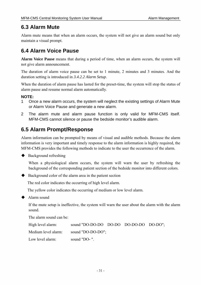
7.2 Preview/Settings 7.2.1 Preview Before the reports are printed, you can preview them on the screen. You will access the preview interface after you select the function of printing. If a report consists of more than one page, you may select a certain page to preview by turning to the page you want. Besides, you can adjust the zoom setting by choosing a certain option from the drop-down list of the SIZE. Below is the preview interface of the wave review:
MFM-CMS Central Monitoring System User Manual Printing
- 34 -
Figure 7-1 Preview
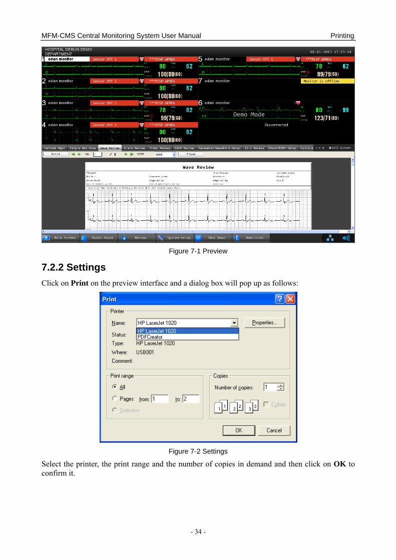
7.2.2 Settings Click on Print on the preview interface and a dialog box will pop up as follows:
Figure 7-2 Settings
Select the printer, the print range and the number of copies in demand and then click on OK to confirm it.
MFM-CMS Central Monitoring System User Manual Printing
- 35 -
7.3 Exporting the PDF File MFM-CMS can export the PDF file by installing a PDF printer software. The software PDFCreator is recommended. You can obtain the installation version of PDFCreator in the MFM-CMS installation disk. Also, you may download it from the website http://www.pdfforge.org/pdfcreator.
To export the PDF file, please choose a PDF printer (for instance, PDFCreator) from the drop-down list when you select the printers (Figure 7-3), and then confirm it by clicking on OK.
Figure 7-3 Select a PDF Printer
MFM-CMS Central Monitoring System User Manual Database Management
- 36 -
Chapter 8 Database Management MFM-CMS provides database backup and review, which allows you to conveniently manage and maintain data.
8.1 Database Backup To backup database, please select Main Screen > System Setup > User Maintain, and input the correct password. Select Database Maintain and click on the button Browse to choose a directory for backup file storage. Then click on Backup Database to start database backup.
NOTE:
1 During database backup, MFM-CMS automatically stops its patient monitoring.
2 MFM-CMS will restart automatically after it completes database backup.
3 If the check box indicating “Empty local database after backup is completed” is ticked, MFM-CMS will empty the local database after database backup is completed.
8.2 Reviewing Backup Database MFM-CMS allows you to review the backup data at any time.
To review backup data, select Review > Patient List, and select the directory for storing backup file from the drop-down list of Offline Database Source. For more information about review, refer to Chapter 5 Review.
NOTE:
1 It takes about 3 to 10 seconds for MFM-CMS to load the backup data.
2 During reviewing backup data, discharging or deleting patients is unavailable.
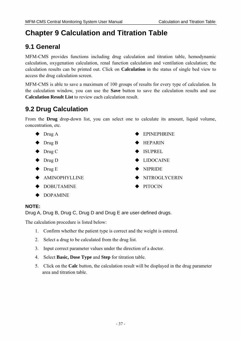
MFM-CMS Central Monitoring System User Manual Calculation and Titration Table
- 37 -
Chapter 9 Calculation and Titration Table
9.1 General MFM-CMS provides functions including drug calculation and titration table, hemodynamic calculation, oxygenation calculation, renal function calculation and ventilation calculation; the calculation results can be printed out. Click on Calculation in the status of single bed view to access the drug calculation screen.
MFM-CMS is able to save a maximum of 100 groups of results for every type of calculation. In the calculation window, you can use the Save button to save the calculation results and use Calculation Result List to review each calculation result.
9.2 Drug Calculation From the Drug drop-down list, you can select one to calculate its amount, liquid volume, concentration, etc.
Drug A
Drug B
Drug C
Drug D
Drug E
AMINOPHYLLINE
DOBUTAMINE
DOPAMINE
EPINEPHRINE
HEPARIN
ISUPREL
LIDOCAINE
NIPRIDE
NITROGLYCERIN
PITOCIN
NOTE: Drug A, Drug B, Drug C, Drug D and Drug E are user-defined drugs.
The calculation procedure is listed below:
1. Confirm whether the patient type is correct and the weight is entered.
2. Select a drug to be calculated from the drug list.
3. Input correct parameter values under the direction of a doctor.
4. Select Basic, Dose Type and Step for titration table.
5. Click on the Calc button, the calculation result will be displayed in the drug parameter area and titration table.
MFM-CMS Central Monitoring System User Manual Calculation and Titration Table
- 38 -
WARNING
1 Be sure to input correct parameter values. The user must verify the correctness of the calculations displayed on the screen before using them.
2 The calculations in the titration table are subject to the drug calculations, therefore, the correctness of the drug calculations must be ensured. Besides, the basic, step and dose type should be ensured correct.
3 We assume no responsibility for the results arising from incorrect inputs and operations.
9.2.1 Drug Calculation Formula Formulas for drug calculation are:
Concentration = amount / volume
Flow rate = dose / concentration
Total dose = dose × duration
Total volume = flow rate × duration
WARNING
Prior to performing drug calculation, you must confirm that the above formulas are what you need. Our company will not be liable for any consequence resulted from using inappropriate formulas.
Relationship between calculation units:
1 g = 1000 mg
1 mg = 1000 mcg
1 K unit = 1000 units
1 M unit = 1000 K units
WARNING
You must enter correct drug unit. Our company will not be liable for any consequence resulted from incorrect input.
9.2.2 Calculation of Titration Table Calculation of titration table is included on the screen of drug calculation. The titration table is located at the lower part of the drug calculation screen. The method for calculation of titration table is:

MFM-CMS Central Monitoring System User Manual Calculation and Titration Table
- 39 -
1. The core method for the calculation of titration table is: concentration = dose / flow rate. The calculating method of titration table is to keep the fixed concentration, change the dose to calculate the flow rate or change the flow rate to calculate the dose. Concentration here is obtained from drug calculation.
2. The titration table can be displayed by way of dose and rate. You can enter the rate step from 1-10. There are four options available for dose unit: mg/hour, mg/min, mg/Kg/hour and mg/Kg/min, among which mg will vary with the unit changes in drug calculation.
3. The calculating result of titration table is displayed in the list. You can click on the scroll bar to browse more calculating results.
WARNING
The calculating result of titration table depends on the calculating result of drug. First of all, the calculating result of drug should be accurate. And then, the calculating result of titration is concerned with the input titration control parameters and the calculating formula. Therefore, you must ensure the correctness of all these mentioned operations. Our company will not be liable for any consequence resulted from improper operations.
9.3 Hemodynamic Calculation 9.3.1 Input Parameters
Abbreviation English Full Name/Description
PAWP Pulmonary artery wedge pressure
CVP Central venous pressure
HR Heart rate
AP MAP Mean Artery Pressure
LV_D Left Ventricular Diameter
PA MAP Pulmonary artery mean pressure
HT Height
WT Weight 9.3.2 Output Parameters
Abbreviation English Full Name/Description
BSA Body surface area
SV Stroke volume
SVI Stroke volume index
SVR Systemic vascular resistance
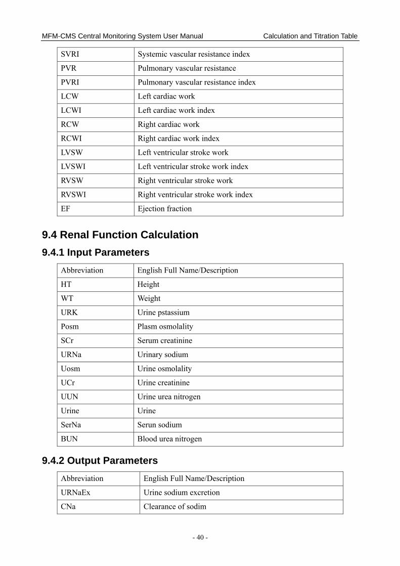
MFM-CMS Central Monitoring System User Manual Calculation and Titration Table
- 40 -
SVRI Systemic vascular resistance index
PVR Pulmonary vascular resistance
PVRI Pulmonary vascular resistance index
LCW Left cardiac work
LCWI Left cardiac work index
RCW Right cardiac work
RCWI Right cardiac work index
LVSW Left ventricular stroke work
LVSWI Left ventricular stroke work index
RVSW Right ventricular stroke work
RVSWI Right ventricular stroke work index
EF Ejection fraction
9.4 Renal Function Calculation 9.4.1 Input Parameters
Abbreviation English Full Name/Description
HT Height
WT Weight
URK Urine pstassium
Posm Plasm osmolality
SCr Serum creatinine
URNa Urinary sodium
Uosm Urine osmolality
UCr Urine creatinine
UUN Urine urea nitrogen
Urine Urine
SerNa Serun sodium
BUN Blood urea nitrogen
9.4.2 Output Parameters Abbreviation English Full Name/Description
URNaEx Urine sodium excretion
CNa Clearance of sodim

MFM-CMS Central Monitoring System User Manual Calculation and Titration Table
- 41 -
FENa Fractional excretion of sodium
CH2O Free water clearance
URKEx Urine potassium excretion
CCr Creatinine clearance rate
FEUr Fractional Excretion of Urea
Na/K Sodium potassium ratio
CUUN Urine urea nitrogen clearance rate
Cosm Osmolar clearance
U/P osm Urine to plasma osmolality ratio
BUN/SCr Blood urea nitrogen creatinine ratio
U/SCr Urine-serum creatinine ratio
9.5 Oxygenation Calculation 9.5.1 Input Parameters
Abbreviation English Full Name/Description
HT Height
WT Weight
C.O. Cardiac output
FiO2 Percentage fraction of inspired oxygen
PaO2 Partial pressure of oxygen in the arteries
PaCO2 Partial pressure of carbon dioxide in the arteries
SaO2 Arterial oxygen saturation
PvO2 Partial pressure of oxygen in venous blood
SvO2 Venous oxygen saturation
Hb Hemoglobin
CaO2 Arterial oxygen content
CvO2 Venous oxygen content
VO2 Oxygen consumption
RQ Respiratory quotient
ATMP Atmospheric pressure

MFM-CMS Central Monitoring System User Manual Calculation and Titration Table
- 42 -
9.5.2 Output Parameters Abbreviation English Full Name/Description BSA Body surface area
VO2 Calc Calculated oxygen consumption
C(a-v)O2 Arterial venous oxygen content difference
O2ER Oxygen extraction ratio
DO2 Oxygen transport
PAO2 Partial pressure of oxygen in the alveoli
AaDO2 Alveolar-arterial oxygen difference
CcO2 Capillary oxygen content
Qs/Qt Venous admixture
C.O. calc Calculated cardiac output
Pa/FiO2 PaO2/FiO2
AaDO2/PaO2 AaDO2/PaO2
Pa/AO2 PaO2/PAO2
DO2I Oxygen Delivery Index
VO2I Oxygen Consumption Index
CaO2 calc Calculated Arterial oxygen content
CvO2 calc Calculated Venous oxygen content
9.6 Ventilation Calculation 9.6.1 Input Parameters
Abbreviation English Full Name/Description FiO2 Percentage fraction of inspired oxygen
RR Respiration rate
PeCO2 Partial pressure of mixed expiratory CO2
PaCO2 Partial pressure of carbon dioxide in the arteries
PaO2 Partial pressure of oxygen in the arteries
VT Tidal volume
RQ Respiratory quotient
ATMP Atmospheric pressure
PIP Peak Inspiratory Pressure
PEEP Positive End-Expiratory Pressure
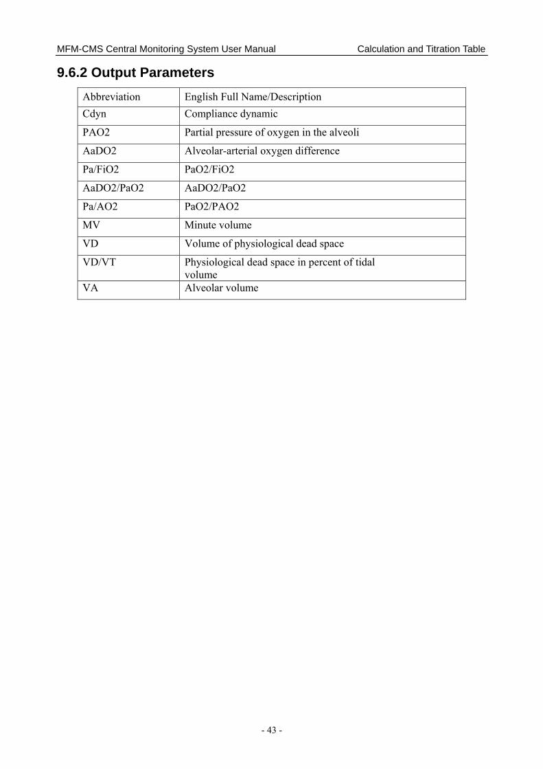
MFM-CMS Central Monitoring System User Manual Calculation and Titration Table
- 43 -
9.6.2 Output Parameters Abbreviation English Full Name/Description Cdyn Compliance dynamic
PAO2 Partial pressure of oxygen in the alveoli
AaDO2 Alveolar-arterial oxygen difference
Pa/FiO2 PaO2/FiO2
AaDO2/PaO2 AaDO2/PaO2
Pa/AO2 PaO2/PAO2
MV Minute volume
VD Volume of physiological dead space
VD/VT Physiological dead space in percent of tidal volume
VA Alveolar volume

MFM-CMS Central Monitoring System User Manual CMS-WEB Observer
- 44 -
Chapter 10 CMS-WEB Observer 10.1 General The CMS-WEB Observer system is a medical information device applied in clinical monitoring field. It realizes remote monitoring by reviewing real-time and history data from central monitoring system through web page. A CMS-WEB network system is constructed by connecting multiple monitors and MFM-CMS central monitoring systems. Being the center of the monitoring network, the system realizes remote monitoring by collecting, processing, and analyzing the physiological information from the central monitoring systems. Medical staff can obtain patient information by visiting the server of MFM-CMS via the browser.
The CMS-WEB Observer displays patients’ physiological information collected by the MFM-CMS central monitoring system. The system displays information of up to 32 bedside monitors from the MFM-CMS.
NOTE: The CMS-WEB Observer is only available via the hospital local area network. 10.2 Typical Screens of the CMS-WEB The CMS-WEB shares similar screen features with the MFM-CMS. The main screen of the CMS-WEB has three areas. At the top of the screen is the area displaying the system prompt information. The middle part is the main monitoring area. The bottom part is the system menu area. Figure 10-1 shows the main screen of the CMS-WEB.
Figure 10-1 Main Screen of CMS-WEB
Structure of the main screen:
1. Information area
Displaying the hospital name and current system time.
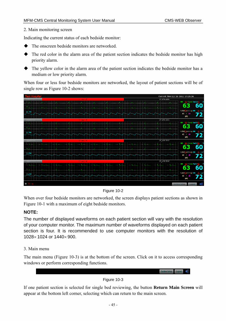
MFM-CMS Central Monitoring System User Manual CMS-WEB Observer
- 45 -
2. Main monitoring screen
Indicating the current status of each bedside monitor:
The onscreen bedside monitors are networked.
The red color in the alarm area of the patient section indicates the bedside monitor has high priority alarm.
The yellow color in the alarm area of the patient section indicates the bedside monitor has a medium or low priority alarm.
When four or less four bedside monitors are networked, the layout of patient sections will be of single row as Figure 10-2 shows:
Figure 10-2
When over four bedside monitors are networked, the screen displays patient sections as shown in Figure 10-1 with a maximum of eight bedside monitors.
NOTE: The number of displayed waveforms on each patient section will vary with the resolution of your computer monitor. The maximum number of waveforms displayed on each patient section is four. It is recommended to use computer monitors with the resolution of 1028×1024 or 1440×900. 3. Main menu
The main menu (Figure 10-3) is at the bottom of the screen. Click on it to access corresponding windows or perform corresponding functions.
Figure 10-3
If one patient section is selected for single bed reviewing, the button Return Main Screen will appear at the bottom left corner, selecting which can return to the main screen.
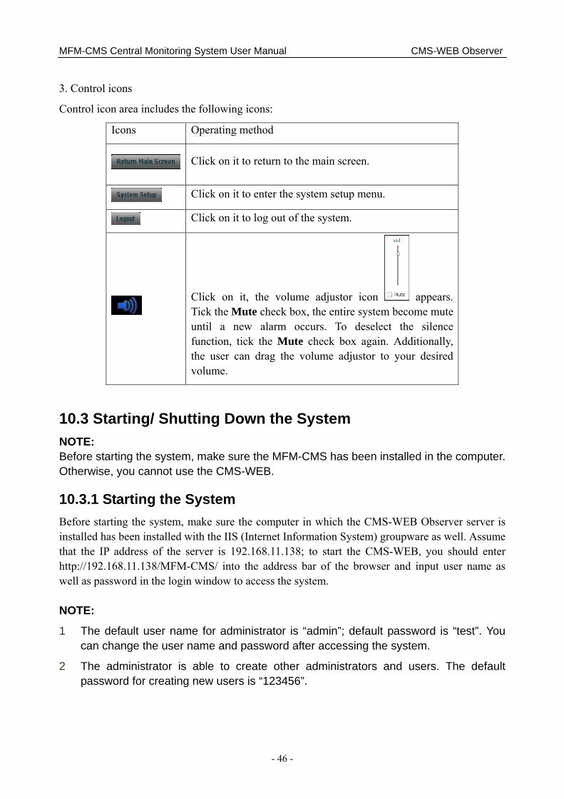
MFM-CMS Central Monitoring System User Manual CMS-WEB Observer
- 46 -
3. Control icons
Control icon area includes the following icons:
Icons Operating method
Click on it to return to the main screen.
Click on it to enter the system setup menu.
Click on it to log out of the system.
Click on it, the volume adjustor icon appears. Tick the Mute check box, the entire system become mute until a new alarm occurs. To deselect the silence function, tick the Mute check box again. Additionally, the user can drag the volume adjustor to your desired volume.
10.3 Starting/ Shutting Down the System NOTE: Before starting the system, make sure the MFM-CMS has been installed in the computer. Otherwise, you cannot use the CMS-WEB.
10.3.1 Starting the System Before starting the system, make sure the computer in which the CMS-WEB Observer server is installed has been installed with the IIS (Internet Information System) groupware as well. Assume that the IP address of the server is 192.168.11.138; to start the CMS-WEB, you should enter http://192.168.11.138/MFM-CMS/ into the address bar of the browser and input user name as well as password in the login window to access the system. NOTE:
1 The default user name for administrator is “admin”; default password is “test”. You can change the user name and password after accessing the system.
2 The administrator is able to create other administrators and users. The default password for creating new users is “123456”.

MFM-CMS Central Monitoring System User Manual CMS-WEB Observer
- 47 -
10.3.2 Shutting Down the System You can shut down the system via either of the following two methods:
Method 1: Click on the Logout button at the bottom right corner onscreen.
Method 2: Click on the button at the top right corner onscreen.
10.4 System Setup You can access the system setup menu by clicking on System Setup and configure the following items: Common Setup and Administrators Setup. NOTE: The available setup items may vary with different users due to different users’ access authority. Both Common Setup and Administrators Setup are available for the administrator while only Common Setup is available for general users.
10.4.1 Common Setup 10.4.1.1 Setting User Information Select System Setup > Common Setup > Personal Infor., and you can change the user name, name, gender, department, and so on.
10.4.1.2 Setting Password Select System Setup > Common Setup > Password Change; you can change the login password.
10.4.1.3 Setting Parameter Unit Select System Setup > Common Setup > Unit Setup; you can change the units of IBP, NIBP, CO2, AG CO2, AG O2, C.O.TB and TEMP.
10.4.1.4 Setting Multi-Bed Waveform Select System Setup > Common Setup > Wave In Multi-bed; you can set the physiological waveforms displayed on the patient sections. In this window, the left column displays the waveform names from which you can choose; the right column displays the waveform names which have been selected.
Adding a waveform to be displayed:
To add a displayed waveform, choose one from the left column and click on Add so that it can be added to the right column.
Deleting a displayed waveform
To delete a displayed waveform, choose one from the right column and click on Remove so that it can be deleted from the waveform display area.
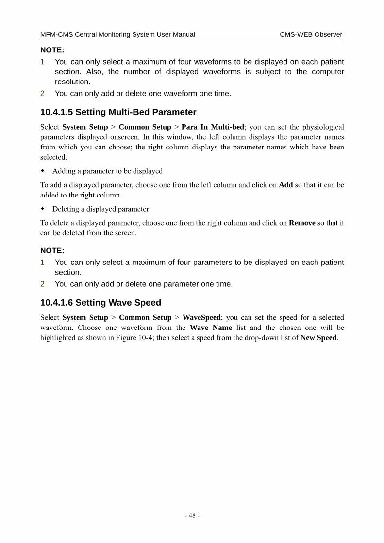
MFM-CMS Central Monitoring System User Manual CMS-WEB Observer
- 48 -
NOTE: 1 You can only select a maximum of four waveforms to be displayed on each patient
section. Also, the number of displayed waveforms is subject to the computer resolution.
2 You can only add or delete one waveform one time.
10.4.1.5 Setting Multi-Bed Parameter Select System Setup > Common Setup > Para In Multi-bed; you can set the physiological parameters displayed onscreen. In this window, the left column displays the parameter names from which you can choose; the right column displays the parameter names which have been selected.
Adding a parameter to be displayed
To add a displayed parameter, choose one from the left column and click on Add so that it can be added to the right column.
Deleting a displayed parameter
To delete a displayed parameter, choose one from the right column and click on Remove so that it can be deleted from the screen.
NOTE: 1 You can only select a maximum of four parameters to be displayed on each patient
section. 2 You can only add or delete one parameter one time.
10.4.1.6 Setting Wave Speed Select System Setup > Common Setup > WaveSpeed; you can set the speed for a selected waveform. Choose one waveform from the Wave Name list and the chosen one will be highlighted as shown in Figure 10-4; then select a speed from the drop-down list of New Speed.

MFM-CMS Central Monitoring System User Manual CMS-WEB Observer
- 49 -
Figure 10-4 Wave Speed Setup
10.4.1.7 Setting Language
Select System Setup > Common Setup > Language, click on and select a language from the drop-down list.
NOTE: To ensure the normal display of CMS-WEB, restart the system after you finish the language configuration.
10.4.2 Administrator Setup
10.4.2.1 User Management Select System Setup > Administrators Setup > User Manage; the administrator can set the user access authority.
Creating a user
In the User Manage window, input the User Name, Name, User Type, Gender, Department and so on, click on Insert and a new user will be created. The default password for creating users is 123456.
Deleting a user
Select a user to be deleted from the user list, click on Delete and the user will be removed.

MFM-CMS Central Monitoring System User Manual CMS-WEB Observer
- 50 -
Modifying user information
Select a user whose information is to be modified and enter new information for the user; then click on Modify to complete the modification.
NOTE: The administrator cannot modify his/her information here. Refer to the section 10.4.1.1 for details.
Resetting user password
Select a user whose password is to be reset and click on Reset password; confirm it by clicking on Confirm on the pop-up dialog box. The password will be reset to the default password.
10.4.2.2 Setting Date/Time Format
Select System Setup > Administrators Setup > TimeFormat, click on the button beside Date Format or Time Format and select a format from the drop-down lists.
10.4.2.3 Setting Waveform Refresh Type Select System Setup > Administrators Setup > Refresh Type; you can set the refresh type of the real-time waveforms. Two options are available: Pen Mode and Move Mode. Click on the
button and select one mode from the drop-down list.
10.5 Viewing Single Bed Via the function of viewing single bed, you can check information of a patient. Click on any area of the patient section and you will access the single bed window. Available items including Patient Infor, Single Bed View, Wave Review, Alarm Review, Trend Review and NIBP Review will be displayed onscreen.
10.5.1 Patient Information You may check patient information via Patient Infor window. CMS-WEB Observer displays the patient information collected by the MFM-CMS. You can only view the patient information via CMS-WEB but not modify them. The readings of Height and Weight will vary with the unit selection. Click on Print if you need to output the patient information.
10.5.2 Single Bed View Multi-waveform display
Click on Multi-lead in the window so that you can view multiple channels of waveforms displayed onscreen. Click on it again to switch to single waveform display mode.
Freezing waveform
Click on Freeze in the window so that you can freeze the waveform displayed onscreen, which may help you analyze the waveform of interest. Click on Freeze again to unfreeze the waveform.
MFM-CMS Central Monitoring System User Manual CMS-WEB Observer
- 51 -
10.5.3 Waveform Review In the Wave Review window, you can:
Select waveforms;
Set wave speed;
Refresh waveforms;
Set the starting time for printing;
Print waveforms.
The system allows you to print the waveform with a maximum time of two minutes. If you have not set the starting time, the system will output the latest data by default. If you have set the starting time, the system will start to output data at the point of the set time.
NOTE: The set starting time for printing will be invalid after the data is output.
For more details about waveform review, refer to relevant content for MFM-CMS in the section 5.2 Wave Review.
10.5.4 Alarm Review In the Alarm Review window, you can:
Refresh alarm information;
Print alarm list;
Print alarm strip.
For more details about alarm review, refer to relevant content for MFM-CMS in the section 5.3 Alarm Review.
10.5.5 Trend Review In the Trend Review window, you can:
Review trend data;
Set resolution;
Select parameters to be reviewed;
Refresh data;
Print trend graph and trend list;
Set the display mode of the trend review window;
Set the starting time for printing.
Printing trend graph: If you have not set the starting time, the system will output the latest data by default. If you have set the starting time, the system will start to output data at the point of the set time. The system allows you to output a maximum of 600 pieces of data.
MFM-CMS Central Monitoring System User Manual CMS-WEB Observer
- 52 -
Printing trend list: If you have not set the starting time, the system will output the latest data by default. If you have set the starting time, the system will start to output data at the point of the set time. The system allows you to output a maximum of 720 pieces of data.
NOTE: The set starting time for printing will be invalid after the data is output.
For more details about trend review, refer to relevant content for MFM-CMS in the section 5.4 Trend Review.
10.5.6 NIBP Review In the NIBP Review window, you can view up to 720 groups of NIBP measurements of an online patient.
The NIBP review window displays Serial No., Measure Time, SYS, DIA, MAP and PR for each measurement. Additionally, you can:
Refresh;
Print.
NOTE:
1 Make sure a PDF reader has been installed in your computer, which enables you to preview and open the printing document.
2 CMS-WEB only supports printing on A4 paper. Make sure you have set the paper size to A4 in the printing setup.
3 If the main menu is not displayed onscreen after clicking on the print button and return to the CMS-WEB screen, check your browser setup. For Firefox browser, select Tools > Options > Tabs, and tick the check box of Always show the tab bar.
MFM-CMS Central Monitoring System User Manual Safety
- 53 -
Chapter 11 Safety 11.1 Control and Safety Index Windows XP/ Windows 7 workstation, printer, UPS (optional), Keyboard, display and mouse should accord with the corresponding safety requirements. They are not suitable for installed in the patients’ environment.
11.2 Characteristics The standard MFM-CMS includes the following characteristics:
Up to 240 hours of trend data storage and review
Storage of patients’ history data
72-hour full disclosure physiological waveforms
12-lead ECG display
12-hour short trend data
Printing report
Monitoring 64 patients simultaneously
Connect patient monitor: M3, M3A, M50, M80, iM50, iM80, iM8, iM8A, iM8B, elite V8.
Transfer waveforms, parameters, alarms, etc.

MFM-CMS Central Monitoring System User Manual Service
- 54 -
Chapter 12 Service If you have any question about maintenance, technical specifications or malfunctions of devices, contact your local distributor.
Alternatively, you can send an email to EDAN service department at: [email protected].
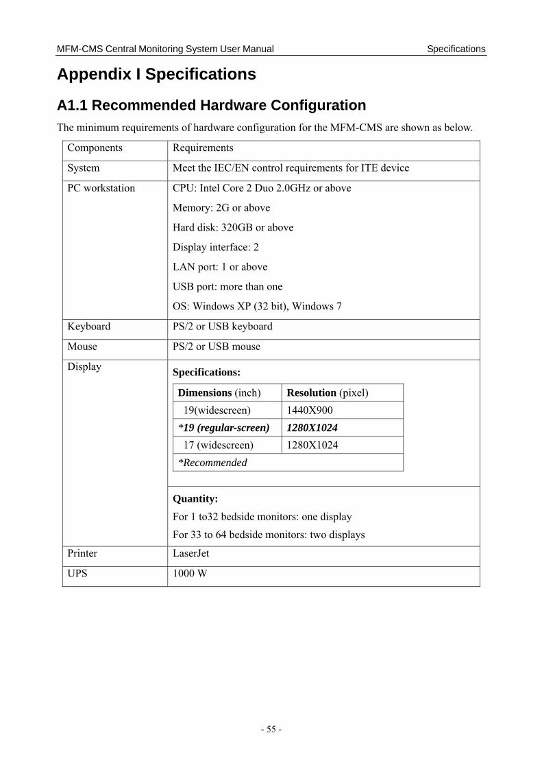
MFM-CMS Central Monitoring System User Manual Specifications
- 55 -
Appendix I Specifications
A1.1 Recommended Hardware Configuration The minimum requirements of hardware configuration for the MFM-CMS are shown as below.
Components Requirements
System Meet the IEC/EN control requirements for ITE device
PC workstation CPU: Intel Core 2 Duo 2.0GHz or above
Memory: 2G or above
Hard disk: 320GB or above
Display interface: 2
LAN port: 1 or above
USB port: more than one
OS: Windows XP (32 bit), Windows 7
Keyboard PS/2 or USB keyboard
Mouse PS/2 or USB mouse
Specifications:
Dimensions (inch) Resolution (pixel) 19(widescreen) 1440X900
*19 (regular-screen) 1280X1024 17 (widescreen) 1280X1024
*Recommended
Display
Quantity:
For 1 to32 bedside monitors: one display
For 33 to 64 bedside monitors: two displays
Printer LaserJet
UPS 1000 W

MFM-CMS Central Monitoring System User Manual Specifications
- 56 -
Structure Ethernet 802.3
Device Network switch
Transmission rate 10M, 100M
Transmitted information Waveforms, parameters and alarms of all networked bedside monitors
Compatible monitors Patient monitors complying with EDAN network protocol
Network device specifications
Maximum number of networked monitors
64
Speaker Built-in speaker is recommended.
CAUTION
Ensure that the computer hardware can meet the requirements of the software installation and running. Also, the video adapter, the audio adapter, the network adapter and their respective drivers should been installed well in the computer; otherwise, the software may not run normally.
NOTE: 1 The hardware specifications require the use of PC that complies with IEC/EN
requirements for ITE equipment.
2 The configuration mentioned above is for reference and not permanent. EDAN preserves the right to change and upgrade system settings.
A1.2 Software Performance Trend 240-hour trend review for each bedside monitor
12-hour short trend dynamic display for each bedside monitor
Alarm waveform 720 pieces of parameter alarm waveforms for each bedside monitor
Alarm type Physiological Alarm
Technical Alarm
Alarm mode 3 levels of audible and visual alarms
Waveform storage and review
72-hour waveform for each bedside monitor
NIBP measurement storage and review
720 pieces of NIBP measurement for each bedside monitor

MFM-CMS Central Monitoring System User Manual Specifications
- 57 -
12-lead analysis results 720 pieces of 12-lead analysis results for each bedside monitor
C.O. measurements 720 pieces of C.O. measurement for each bedside monitor
Quick TEMP measurements
720 pieces of Quick TEMP measurement for each bedside monitor