भारतीयप्रबंधसंस्थानइंदौर - IIM Indore
68
SITC of 3.15 MVA 33/11 KV Power Transformer at IIM Indore Page 1 of 68 भारतीय ब ं ध स ं थान इ ं दौर INDIAN INSTITUTE OF MANAGEMENT INDORE बंध शिखर, राउ-पीथमपुर रोड, इंदौर- ४५३५५६ (म..), भारत दूरभाष: ०७३१-२४३९ ६२०/४४७/६१९ Prabandh Shikhar, Rau-Pithampur Road, Indore – 453556 (M.P.), India Ph. 0731-2439 620/447/619 Tender Notice No.: IIMI/Project/09/2017/43 File No.353 Technical cum Commercial Bid Name of Work: Design, Manufacture, Supply, Installation, Testing & Commissioning of 3.15 MVA, 33/11kV Power Transformer at Utility-I of IIM Indore Certified that the NIT Document contains 68 pages
-
Upload
khangminh22 -
Category
Documents
-
view
2 -
download
0
Transcript of भारतीयप्रबंधसंस्थानइंदौर - IIM Indore

SITC of 3.15 MVA 33/11 KV Power Transformer at IIM Indore Page 1 of 68
भारतीय प्रबंध ससं्थान इदंौर INDIAN INSTITUTE OF MANAGEMENT INDORE
प्रबंध शिखर, राउ-पीथमपुर रोड, इंदौर- ४५३५५६ (म.प्र.), भारत
दरूभाष: ०७३१-२४३९ ६२०/४४७/६१९
Prabandh Shikhar, Rau-Pithampur Road, Indore – 453556 (M.P.), India Ph. 0731-2439 620/447/619
Tender Notice No.: IIMI/Project/09/2017/43
File No.353
Technical cum Commercial Bid
Name of Work:
Design, Manufacture, Supply, Installation, Testing & Commissioning of 3.15 MVA, 33/11kV Power Transformer at Utility-I of IIM Indore
Certified that the NIT Document contains 68 pages

SITC of 3.15 MVA 33/11 KV Power Transformer at IIM Indore Page 2 of 68
INDIAN INSTITUTE OF MANAGEMENT INDORE
INDEX
Sr. No. Contents Page No.
Part-I: Technical cum Commercial Bid
1 Notice Inviting Tender (NIT) 3
a Part “A” NIT Details 3
b Part “B” Tender requirements 4
c Part “C” Other terms & conditions 6
2 Milestones 13
3 Agreement 14
4 Technical Specifications 17
Part-II: Financial Bid
1 Financial Bid 67
SITC of 3.15 MVA 33/11 KV Power Transformer at IIM Indore Page 3 of 68
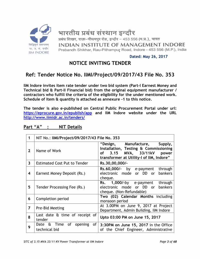
Dated: May 26, 2017
NOTICE INVITING TENDER
Ref: Tender Notice No. IIMI/Project/09/2017/43 File No. 353 IIM Indore invites item rate tender under two bid system (Part-I Earnest Money and Technical bid & Part-II Financial bid) from the original equipment manufacturer / contractors who fulfill the criteria of the eligibility for the under mentioned work. Schedule of item & quantity is attached as annexure -1 to this notice. The tender is also e-published on Central Public Procurement Portal under url: https://eprocure.gov.in/epublish/app and IIM Indore website under the URL http://www.iimidr.ac.in/tenders/
Part “A” : NIT Details
1 NIT No.: IIMI/Project/09/2017/43 File No. 353
2 Name of Work
“Design, Manufacture, Supply, Installation, Testing & Commissioning of 3.15 MVA, 33/11kV power transformer at Utility-I of IIM, Indore”
3 Estimated Cost Put to Tender Rs.30,00,000/-
4 Earnest Money Deposit (Rs.) Rs.60,000/- by e-payment through electronic mode or DD or bankers cheque.
5 Tender Processing Fee (Rs.) Rs. 1,000/-by e-payment through electronic mode or DD or bankers cheque. (Non-Refundable)
6 Completion period Two (02) Calendar Months including monsoon period
7 Pre-Bid Meeting At 3.00PM on June 9, 2017 at Project Department, Admin Building, IIM Indore
8 Last date & time of receipt of tender
Upto 03:00 PM on June 15, 2017
9 Date & Time of opening of
technical bid 3:30PM on June 15, 2017 in the Office of the Chief Engineer, Administrative

SITC of 3.15 MVA 33/11 KV Power Transformer at IIM Indore Page 4 of 68
Block, IIM Indore M.P. -453556
10 Date and Time of opening of
financial bid of qualified bidders Will be notified at a later date
11 Security Deposit 2.5% of tendered value from bills
12 Performance Guarantee 5% of tendered value on acceptance of bid and will be returned 1 month after completion
Part “B”: Tender Requirements
1. Criteria of eligibility for submission of bid documents: In order to fulfill eligibility for acceptance, the following criteria will be followed. The original equipment manufacturer / contractors are required to submit relevant verifiable and self-attested documents.
a. Performance / Work Experience
The bidder must have experience of successfully completed works during the last 5 years ending last day of the month previous to the one in which applications are invited. The works completed upto previous day of last date of submission of tenders shall also be considered.
Three similar completed works costing not less than the amount equal to 40% of estimated cost put to tender,
OR
Two similar completed works, costing not less than the amount equal to 60% of the estimated cost put to tender OR One similar completed work of aggregate cost not less than the amount equal to 80% of the estimated cost.
Important Note: Similar work shall mean: Any manufacturer / contractor having experience in “Supply and / or supply, installation, testing & commissioning of same or higher rating & voltage class of power transformers”. Certificates of work experience (Completion Certificates) and other documents as specified in the tender document shall be submitted.
SITC of 3.15 MVA 33/11 KV Power Transformer at IIM Indore Page 5 of 68
b. Annual Financial Turnover: Should have had average annual financial turnover at least 100% of the estimated cost put to tender during last three years ending March 31, 2016. (Copy of certificate from chartered accountant to be submitted)
c. The bidder should have Valid ‘A’ Class electrical contract license or should associate with an electrical contractor having the above license
d. Type Test Certificates: (copy of certificates to be submitted)
The bidder must have successfully carried out type test of 3.15 MVA, 33/11 KV or above rating transformer from any NABL accredited laboratory. The said type test report should not be prior to 5 year from the date of opening of the technical bid. Type test is mandatory. The loss parameters of the offered transformer shall be identical to that of the one which has been type tested. Details of the type test certificates are as under:
i. Dynamic ability to withstand short circuit test ii. Lightning impluse voltage withstand test. iii. Temperature rise test
e. Certificates: (copy of certificates to be submitted)
i. Latest IT returns for FY 13-14, 14-15 and 15-16 ii. PAN (Permanent Account Number) iii. Service Tax Registration Certificate iv. VAT / Sales Tax Registration Certificate v. Certificate of registration of firm/company vi. Aadhar card copy of the authorized officer of the company who will be
signing agreement etc.
2. Mode of payment of Tender processing fee and EMD:
i) Bidders may deposit the Tender Processing Fee and EMD through NEFT or
RTGS. Details for the same are as below:
Name of beneficiary : Indian Institute of Management Indore Address : Rau-Pithampur Road, Indore -453556, M.P. Account No. : 53018623445 Name of the Bank : State Bank of India Address of the bank : IIM Indore Campus IFSC Code : SBIN0030525
ii) EMD can also be furnished in DD / Bankers cheque etc. drawn in favor of
‘Indian Institute of Management Indore’ payable at ‘Indore’.
Bidders will have to attach Payment details towards cost of tender processing fee & EMD during the submission of tender and the same will be accepted

SITC of 3.15 MVA 33/11 KV Power Transformer at IIM Indore Page 6 of 68
only on verification & confirmation by the Institute. Any delay in credit will not be entertained by the Institute.
3. The Tenderer is required to prepare in two sealed cover comprising of the
following:
Cover-I: Technical Bid
i) EMD & Tender Fee details ii) Documents as mentioned above in the “Criteria of eligibility for submission
of bid documents” Cover-II: Financial Bid i) Financial Bid (in the format given at Annexure-1) Both covers should be kept in one main sealed cover super scribed as “IIMI/Project/09/2017/43 File No. 353: Design, Manufacture, Supply, installation, testing & commissioning of 3.15 MVA, 33/11kV power transformer at Utility-I of IIM, Indore”
4. The tenderer has to drop the cover sealed in above manner in the Tender Box kept at the ‘Project Department, IIM Indore, Administrative Block, Rau- Pithampur Road, Indore -453556 M.P.’ on or before the due date & time positively. The tender shall not be accepted beyond the stipulated date and time under any circumstances whatsoever. Any delay happened in the transition is at the risk of the tenderer and IIM Indore will not be responsible.
5. EMD of unsuccessful bidders shall be returned after award of the contract / order to the successful bidder. No interest will be paid on the EMD.
Part “C”: Other Terms & Conditions
1. The bid submitted shall become invalid and tender processing fee shall not be refunded if: (i) If the bidder is found ineligible. (ii) If the documents submitted by the successful bidder does not match with
the originals before the award of work. 2. The competent authority on behalf of the Director IIM Indore does not bind
itself to accept the lowest or any other bid and reserves to itself the authority to reject any or all the bids received without the assignment of any reason. All bids in which any of the prescribed condition is not fulfilled or any condition including that of conditional rebate is put forth by the bidders shall be summarily rejected.

SITC of 3.15 MVA 33/11 KV Power Transformer at IIM Indore Page 7 of 68
3. Canvassing whether directly or indirectly, in connection with bidders is strictly prohibited and the bids submitted by the contractors who resort to canvassing will be liable for rejection.
4. The competent authority on behalf of the Director, IIM Indore reserves to himself the right of accepting the whole or any part of the bid and the bidders shall be bound to perform the same at the rate quoted or split the work between two parties or among more parties as deemed fit.
5. The bid for the works shall remain open for acceptance for a period of ninety (90) days. If any bidders withdraws his bid before the said period or issue of letter of acceptance, whichever is earlier, or makes any modifications in the terms and conditions of the bid which are not acceptable to the department, then the IIM Indore shall, without prejudice to any other right or remedy, be at liberty to forfeit full amount of the said earnest money as aforesaid. Further the bidders shall not be allowed to participate in the rebidding process of the work.
6. IF ANY INFORMATION FURNISHED by the applicant is found to be incorrect at a later stage, they shall be liable to be debarred from tendering/ taking up works in IIM INDORE.
7. TAXES :
i) This works comes under Works contract. Works contract Tax/MPVAT as applicable shall be deducted from each bill paid to the contractor.
ii) Sales tax or any other tax on material in respect of this contract shall be payable by the contractor and IIM Indore will not entertain any claim whatsoever in this respect.
iii) The contractor should get registered under Service Tax and Service Tax as applicable as per the extent order on the subject work shall be paid by the contractor to concerned department and the same should be considered in his quoted rates.
iv) Labour Welfare cess @ 1 % of gross value of work done shall be recovered
from each bill paid to the contractor.
v) Income Tax and cess as applicable shall be deducted from each bill paid
to the contractor.
vi) Contractor should be registered under EPF & ESIC and as per law, shall
pay EPF & ESIC of contract workers to concerned Department from time
to time.
vii) Any other taxes/cess as per government directives shall be deducted
from each bill paid to the contractor from time to time or as per rule in
case of manufacturer.
8. The specifications, Terms & Conditions, other regulations which are not herein mentioned will be guided by relevant CPWD / IS /Other Central Govt./state Govt. norms, OEM standards applicable for IIM Indore & the decision in this

SITC of 3.15 MVA 33/11 KV Power Transformer at IIM Indore Page 8 of 68
regard will be guided by the decision of the respective authority of IIM Indore which shall be final and binding to the contractor.
9. The party whose tender has been accepted has to execute an agreement on non-judicial stamp paper immediately after work order is issued.
10. Performance guarantee in the form BG or FDR or DD @ 5% of tendered amount
has to be furnished within 10 days of issue of LOA. 11. If called for, originals of the document submitted shall be produced. 12. General condition of contract (GCC) of CPWD will be applicable to the extent
relevant to the job. 13. IIM Indore reserves the full rights to increase/decrease the quantity of items in
the tender as per requirement upto 50% upwards / downwards. 14. Any dispute is subject to the jurisdiction of Civil Court Indore. 15. This work covers Design, Manufacture, supply, installation, testing &
commissioning of 3.15MVA, 33/11 KV Power Transformer including necessary statuary approvals from the Electrical Safety Department & any other department as required for replacement of the old transformer & installation, testing & commissioning of the new power transformer and other associated works as per the schedule of quantity provided in the financial bid. (Note : IIM, Indore will make available the required approved drawing of previous installation of 3.15MVA, 33/11KV Power Transformer for getting the approval of new installation from the Electrical Safety Department)
16. Location: At Utility-I at IIM Indore campus.
17. The work shall be executed as per CPWD general specifications for Civil & electrical works with upto date amendments as per relevant IS and as per directions of Engineer-in-Charge. These additional specifications are to be read in conjunction with above. However, nothing extra shall be paid on account of these additional specifications & conditions as the same are to be read along with schedule of quantities for the work.
18. The Tenderer should in his own interest visit the site and familiarize himself with the site conditions before tendering.
19. No T&P shall be issued by the IIM Indore and nothing extra shall be paid on account of this.
20. Employer reserves the right to alter the mode of selection, accept or reject any or all bids without assigning any reason thereof.

SITC of 3.15 MVA 33/11 KV Power Transformer at IIM Indore Page 9 of 68
21. Necessary clarification required by the IIM Indore shall have to be furnished by the Tenderer within the time given by the IIM Indore for the same. The Tenderer will have to depute his representative to discuss with the officer(s) of the IIM Indore as and when so desired. In case, in the opinion of the IIM Indore a Tenderer is taking undue long time in furnishing the desired clarifications, his bid will be rejected without making any reference.
22. The Tenderer will have to fill up their rates only in the price bid in BoQ format. Tenders in which the price bids are given in any other format are liable to be rejected.
23. A tenderer will also not be allowed to withdraw or modify any condition at a time after the technical bids have been accepted and the decision to open the price bid has been taken by the IIM Indore.
24. The IIM Indore reserves the right to reject any or all the price bids and call for fresh prices/ tenders as the case may be without assigning any reason.
25. Terms of Payment:
Payments shall be released as per General Conditions of contract and the following conditions. All interim payments shall have deductions towards advances and other contract conditions. No advance payment will be made.
60 % of material cost of the item indicated against item of work shall be made after delivery at site in good condition on pro-rata basis subject to deductions to be made against advances and security deposit and also on production of documents indicating price of the material / machine / equipment.
Balance on completion of entire work, testing & commissioning and handing over to the IIM Indore for beneficiary use.
26. Security deposit:
The security deposit will be collected by deductions from the running bill of the contractor at the rate mentioned below. The security deposit can also be deposited in cash or in the form of Government Securities, Fixed Deposit Receipts etc.
A sum @ 2.5% of the gross amount of the bill will be deducted from each running
bill as well as final bill of the contractor. Such deductions will be made unless the contractor has deposited the amount of security at the rate mentioned in cash or Government securities or Fixed Deposit Receipts.
This is in addition to the performance guarantee that the contractor is required
to deposit as per clause mentioned in the tender document.

SITC of 3.15 MVA 33/11 KV Power Transformer at IIM Indore Page 10 of 68
Security deposit can be released against bank guarantee issued by a
nationalized bank on its accumulation to a minimum amount of Rs. 5 lakhs
subject to the condition that amount of any bank guarantee except last one,
shall not be less than Rs. 5 lakhs.
The Bank Guarantee submitted against Security Deposit shall initially be valid up
to the stipulated date of completion of the work plus Defect Liability Period.
Refund of security deposit: The Security Deposit will be released after
completion of defect liability period of one year.
27. Performance Guarantee:
The tender shall guarantee among other things, the following:
(a) Quality, strength and performance of the materials used.
(b) Safe mechanical and stress on all parts under all specified conditions of operation.
(c) Satisfactory operation & stability during the DLP period.
The contractor whose bid is accepted will be required to furnish performance guarantee of 5% (Five Percent) of the bid amount within Ten days of issue of LOI. This guarantee may be in the form of Banker's cheque of any nationalized bank/Demand Draft of any nationalized bank/ Fixed Deposit Receipts or Guarantee Bonds of any nationalized Bank or the State Bank of India in accordance with the prescribed form in CPWD manual. In case the contractor fails to deposit the said performance guarantee within the period as indicated above, including the extended period if any, the Earnest Money deposited by the contractor shall be forfeited automatically without any notice to the contractor. The earnest money deposited along with bid shall be returned after receiving the aforesaid performance guarantee.
Refund of performance guarantee: The performance guarantee shall be
refunded to the contractor one month after the completion of the work and recording of the completion certificate as above.
28. Rates:
a. Subject to the nomenclature of the item as per schedule of quantity, the specification indicated in the tender documents, the rates quoted shall include charges for Designing, manufacturing, supplying, forwarding, insurance, freight and delivery, installation, testing, commissioning at site including necessary statuary approvals from the Electrical Safety department & any other department as required for replacement of the old transformer & installation, testing & commissioning of the new power

SITC of 3.15 MVA 33/11 KV Power Transformer at IIM Indore Page 11 of 68
transformer and other associated works, cost of all materials including royalty & taxes if any, labor, sundry inputs, execution of work including overhead charges and contractor's profit. Nothing extra shall be paid on this account.
b. The Defect Liability Period (DLP) will be of 12 months from the date of handing over. Nothing extra for this period shall be paid.
29. Completeness of tender: All sundry equipment, fittings, units assemblies, accessories, hardware items,
foundation bolts, etc. and all other items which are useful and necessary for installation, testing & commissioning of the power transformer shall be deemed to have been included in the tender irrespectively of the whether such items are specifically mentioned in the tender document or not.
30. The Institute may on request of the contractor make available the room /
proper storage space for storage of material and erection equipments as per the availability. Watch and ward of the stores and their safe custody shall be the responsibility of the contractor till the final taking over of the installation by the IIM Indore.
31. Completion Period:
The completion period of 02 (TWO) months indicated in the tender document is for the entire work of Design, Manufacture, Supply, installation, testing & commissioning of 3.15 MVA, 33/11kV power transformer at Utility-I in IIM campus, Indore including necessary statuary approvals from the Electrical Safety Department & any other department as required for replacement of the old transformer & installation, testing & commissioning of the new power transformer and other associated works and handing over of the entire system to the satisfaction of the Engineer-in-Charge.
32. Guarantee: The Supply of the power transformer shall be guaranteed for a
period of 12 months from the date of taking over by the institute against unsatisfactory performance and/or stability due to defective design, workmanship of material. The material or components, or any part thereof, so found defective during guarantee period shall be forthwith repaired or replaced free of cost, to the satisfaction of the Engineer-in-Charge. In case it is felt by the institute that undue delay is being caused by the contractor in doing this, the same will be got done by the IIM Indore at the risk and cost of the contractor. The decision of the Engineer-in Charge in this regard shall be final.
33. Power Supply: Electric service connection of 415V (±10%), 3 Phase, 4 wires, 50
Hz, AC supply shall be provided by the institute for installation, testing & commissioning purpose.

SITC of 3.15 MVA 33/11 KV Power Transformer at IIM Indore Page 12 of 68
34. Water Supply: Water supply required for ITC work etc shall be provided by the institute.
35. Extent of work:
a. The work shall comprise of design, engineering, manufacture, assembly, stage inspection, final inspection and testing before dispatch, packing and delivery at destination Sub-station by road transport, transit insurance, unloading at site , installation on the existing foundation, testing & commissioning of power transformer including necessary statuary approvals from the Electrical Safety Department & any other department as required for replacement of the old transformer & installation, testing & commissioning of the new power transformer and all materials necessary to make a complete installation as required. The work also includes the power terminations on the transformer HT & LT side, control wirings with the marshalling chamber, earthing strip connections with the transformer and other associated work required for the installation, testing & commissioning of the power transformer. The term complete installation shall not only mean major items covered by specifications but all incidental sundry components necessary for complete execution and satisfactory installation whether or not those have been mentioned in details in the technical specifications under the tender document in connection with this contract.
b. Defect Liability Period of one year from date of completion and handing over.
36. COMPLIANCE WITH REGULATIONS AND INDIAN STANDARDS: All works shall be
carried out in accordance with relevant regulation, both statutory and those specified by the Indian Standards related to the works covered by these specifications.
37. INDEMNITY: The successful tenderer/bidder shall at all times indemnify the IIM
Indore, consequent on this works contract. The successful tenderer/bidder shall be liable, in accordance with the Indian Law and Regulations for any accident occurring due to any cause and the IIM Indore shall not be responsible for any accident or damage incurred or claims arising there from during the period of installation, testing & commissioning of power transformer and putting into operation under the supervision of the successful tenderer/bidder in so far as the latter is responsible. The successful tenderer/bidder shall also provide all insurance including third party insurance as may be necessary to cover the risk. No extra payment would be made to the successful tenderer/bidder due to the above.
38. Mobilization advance: No mobilization advance shall be paid for this work.

SITC of 3.15 MVA 33/11 KV Power Transformer at IIM Indore Page 13 of 68
39. Milestones: The milestones for the subject work will be as below:
Sl. No.
Description of Milestone (Physical)
Time Allowed in days (from date of reckoning start)
Amount to be with-held in case of non-achievement of milestone
1 Submission of necessary drawings etc as mentioned in the tender document for the approval of the client before putting the transformer under manufacturing.
10 Days Rs. 50,000/-
2 Supply of power transformer at site of work at IIM Indore
50 days Rs. 2,00,000/-
3 Installation, Testing & Commissioning and handing over of the power transformer to IIM Indore as per satisfaction to the Engineer-in-Charge
60 days Rs. 1,00,000/-
Total Time allowed for Completion of the Work: 60 Days (Including monsoon) Sd/- Dated: May 26, 2017 (V.P. Thomas) Place: Indore (M.P.) Chief Engineer

SITC of 3.15 MVA 33/11 KV Power Transformer at IIM Indore Page 14 of 68
AGREEMENT
THIS AGREEMENT made at Indore on the __________ day of _________ 2017
between Indian Institute of Management Indore Rau- Pithampur Road, Indore
(hereinafter called "The IIM INDORE" which expression shall, unless repugnant to the
context or meaning thereof, include its administrators, successors and assigns) of the
one part AND_______________________________________________________________
(herein after called "The Contractor" which expression shall, unless repugnant to the
context or meaning thereof, include its successors and permitted assigns) of the other
part.
WHEREAS
The IIM INDORE is desirous of carrying out the “NIT No. IIMI/Project/09/2017/43, File
No. 353 for the work of “Design, Manufacture, Supply, installation, testing &
commissioning of 3.15 MVA, 33/11kV power transformer at Utility-I in IIM campus,
Indore”.
The Works are to be executed as per the schedules mentioned in tender document
drawings and specifications describing the works to be done.
The Contractor has agreed to execute the said works subject to the provisions
hereinafter contained and subject also to General Conditions of Contract, Special
conditions of contract, Safety Code, Model Rules for the protection of health and
Sanitary arrangements for workers, Specifications, Preambles and Schedule of
Quantities and installation schedule (all of which are hereinafter collectively referred
to as the ‘said tender conditions’) and strictly in accordance with the Scope of work
annexed hereto at or for the respective rates set out in the Schedule of Quantities
amounting to the sum as there under arrived at or such other sums as shall become
payable there under (hereinafter referred to as the said tendered amount).
NOW IT IS HEREBY AGREED AS FOLLOWS: -
1. In consideration of the said tendered amount to be paid by The IIM INDORE to
the Contractor at the time and in the manner set forth in the said tender
conditions and in accordance with the Schedule of Payments to execute and
complete the work shown upon the said Drawings strictly in accordance with
the specifications and Schedule of Quantities.
2. The said tender conditions, scope of work and the annexures hereto shall be
read and considered as forming part of this contract and the parties hereto

SITC of 3.15 MVA 33/11 KV Power Transformer at IIM Indore Page 15 of 68
shall respectfully abide by to the said conditions and perform the agreement on
their part respectively contained in the said conditions.
3. The approved drawings if any, notice inviting tenders technical specification
etc. shall also form the basis of this contract.
4. This contract is neither a Lump sum Contract, nor a piece work contract, but is
a contract on item rate basis to be carried out and to be paid for according to
the Schedule of Payments at the rates contained in the Schedule of Quantities.
5. The contract herein contained shall comprise not only the works mentioned
above but all subsidiary works connected therewith within the same site as may
be ordered to be done from time to time by the said Engineer In charge for the
time being, even if such work may not be shown on the said Drawings or
described in the said Specifications and Schedule of Quantities.
6. The IIM INDORE reserves to themselves the right of altering the drawings and
the nature of the work by adding to or omitting from the scope of work any
item of work or portions of the same without prejudice to this contract.
7. Time shall be considered as the essence of this contract and the Contractor
hereby agrees to commence the work within 10 days from the date of work
order or from the date of handing over of the site, as provided for in the said
terms and conditions, whichever is later, and shall complete the entire work
within the specified period, subject nevertheless the provisions for extension of
time as may be agreed to by the IIM INDORE and as contained in the said
conditions.
8. All payments by the IIM INDORE under this contract shall be made only at
Indore.
9. All disputes arising out of or in any way connected with this contract shall be
deemed to have arisen at Indore and courts in Indore only shall have
jurisdiction to determine the same.
10. That the contract and several parts of this contract have been read by the
contractor and fully understood by him. The contractor shall not be entitled for
payment beyond tendered quantities unless ordered specifically by written
instructions of Director IIM INDORE.
11. This contract shall be signed in duplicate, the original whereof shall be kept in
SITC of 3.15 MVA 33/11 KV Power Transformer at IIM Indore Page 16 of 68
the custody of the IIM INDORE, and the duplicate with the Contractor.
IN WITNESS WHEREOF the IIM INDORE has set his hands hereunto and two duplicates
hereof through his duly authorized official and the Contractor has caused these
presents and two duplicates hereof under his common seal by his duly authorized
representative at the place and on the date month and year first herein above
written.
SIGNED, SEALED AND DELIVERED by IIM INDORE, by the hand of
Signature:
Name:
Designation:
IN THE PRESENCE OF
(1) Signature:
Name:
Address:
(2) Signature:
Name:
Address:
SIGNED, SEALED AND DELIVERED BY the Contractor M/s.____________________
____________________________.
Signature:
Name:
Designation:
IN THE PRESENCE OF
(1) Signature:
Name:
Address:
(2) Signature:
Name:
Address:
SITC of 3.15 MVA 33/11 KV Power Transformer at IIM Indore Page 17 of 68
TECHINICAL SPECIFICATION FOR 33/11KV (ONAN) 3.15 MVA POWER TRANSFORMERS
1. SCOPE 1.1 This Specification provides for design, engineering, manufacture, assembly,
stage inspection, final inspection and testing before dispatch, packing and delivery at destination Sub-station by road transport, transit insurance, unloading at site , installation on the existing foundation, testing & commissioning of power transformer including necessary statuary approvals from the Electrical Safety Department & any other department as required for replacement of the old transformer & installation, testing & commissioning of the new power transformer complete with all fittings, accessories, associated equipments, spares, 10% extra Transformer Oil, required for it’s satisfactory operation in sub-station of the IIM, Indore.
1.2 The core shall be constructed either from high grade, non-aging Cold Rolled Grain Oriented (CRGO) silicon steel laminations conforming to HIB grade with lamination thickness not more than 0.23mm to 0.27mm or better( Quoted grade and type shall be used). The maximum flux density in any part of the cores and yoke at normal voltage and frequency shall not be more than 1.5 Tesla. The Bidder shall provide saturation curve of the core material, proposed to be used. Laminations of different grade(s) and different thickness (s) are not allowed to be used in any manner or under any circumstances.
1.3 The Power Transformer shall conform in all respects to highest standards of engineering, design, workmanship, this specification and the latest revisions of relevant standards at the time of offer and the IIM, Indore shall have the power to reject any work or material, which, in his judgement, is not in full accordance therewith. The Transformer(s) offered, shall be complete with all components, necessary for their effective and trouble free operation. Such components shall be deemed to be within the scope of supply, irrespective of whether those are specifically brought out in this specification and / or the commercial order or not. The IIM, Indore reserves the right to reject the transformers if on testing the losses exceed the declared losses beyond tolerance limit as per IS or the temperature rise in oil and / or winding exceeds the value, specified in technical particular or impedance value differ from the guaranteed value including tolerance as per this specification and if any of the test results do not match with the values, given in the guaranteed technical particulars and as per technical specification. The IIM, Indore reserves the right to retain the rejected Transformer and take it into service until the supplier replaces it, at no extra cost to the IIM, Indore by a new transformer. Alternatively, the supplier shall repair or replace the Transformer within a reasonable period as decided by the IIM, Indore to IIM’s satisfaction at no extra cost to the IIM Indore.

SITC of 3.15 MVA 33/11 KV Power Transformer at IIM Indore Page 18 of 68
2. SPECIFIC TECHNICAL REQUIREMENTS
1 Rated MVA (ONAN rating) 3.15 MVA
2 No. of Phases 3
3 Type of installation Outdoor
4 Frequency 50 Hz (5%)
5 Cooling medium Insulating Oil (ONAN)
6 Type of mounting On Wheels, Mounted on rails
7 Rated voltage
a) High Voltage winding 33 KV
b) Low Voltage winding 11 KV
8 Highest continuous system voltage
a) Maximum system voltage ratio (HV/LV)
36 KV / 12 KV
b) Rated voltage ratio (HV/LV) 33 kV / 11 KV
9 No. of windings Two winding Transformers
10 Type of Cooling ONAN (Oil natural and Air natural)
11 MVA Rating corresponding to ONAN cooling system
100%
12 Method of connection :
HV Delta
LV Star
13 Connection Symbol DYn 11
14 System Earthing Neutral of LV side to be solidly earthed
15 Percentage impedance voltage on normal tap and MVA base at 750 C corresponding to HV / LV rating and applicable tolerances
% Impedance % Tolerance
a) 3.15 MVA 6.25 +10
(No negative tolerance will be allowed)
16 Intended regular cyclic overloading of windings
As per IEC – 76-1, Clause 4.2 /IS 6600
17 a)
Anticipated unbalanced loading Around 20%
b) Anticipated continuous loading of windings (HV / LV)
110% of rated current
18a) Type of tap changer i) On-load tap changer
b) Range of taping ii) +5% to – 15% in equal steps of 1.25% each on HV winding for 3.15 MVA Transformers
19 Neutral terminal to be brought On LV side only

SITC of 3.15 MVA 33/11 KV Power Transformer at IIM Indore Page 19 of 68
out
20 Over Voltage operating Capability and duration
112.5% of rated voltage (continuous)
21 Maximum Flux Density in any part of the core and yoke at rated MVA, rated voltage i.e. 33 KV / 11KV and system frequency of 50 HZ
1.5 Tesla
22 Insulation levels for windings 33 KV 11 KV
a) 1.2 / 50 microsecond wave shape Impulse withstand (KVp)
170 75
b) Power frequency voltage withstand (KVrms)
70 28
23 Type of winding insulation
a) HV winding Uniform / Insulating Paper (Min.TPC)
b) LV winding Uniform / Insulating Paper (Min.TPC)
24 Withstand time for three phase short circuit
2 Seconds
25 Noise level at rated voltage and frequency
As per NEMA Publication No. TR-1
26 Permissible Temperature Rise over ambient temperature of 50
⁰ C
a) Of top oil measured by thermometer
40 ⁰ C
b) Of winding measured by resistance
50 ⁰ C
27 Minimum clearances in air (mm) :-
Phase to phase Phase to ground
a) HV 350 320
b) LV 255 140
28 Terminals
a) HV Winding Line end 36 KV oil filled porcelain communicating type of bushings (Antifog type) as per IS 3347
b) LV winding 12 KV porcelain type of bushing (Antifog type) as per IS 3347
29 Insulation level of bushing HV LV
a) Lightning Impulse withstand(KVP) 170 75
b) 1 minute Power Frequency withstand Voltage (KV – 4ms)
70 28

SITC of 3.15 MVA 33/11 KV Power Transformer at IIM Indore Page 20 of 68
c) Creepage distance (MM) (minimum)
900 500
30 Material of HV & LV Conductor Electrolytic copper
31 Maximum Current density for HV and LV winding for rated current
2.5 A / mm2
32 Polarisation index i.e. ratio of megger values at 600 Sec to 60 sec for HV to earth, LV to earth and HV to LV
Shall be greater than or equal to 1.5, but less than or equal to ‘5’
33 Core Assembly Boltless type
34 Temperature Indicator
a) Oil One number
b) Winding One number
35 Maximum permissible no load loss at rated voltage and rated frequency. (Max) for 3.15 MVA
3.6 KW
36 Maximum permissible load loss at rated current and at 75 ⁰C (Max)
3.15 MVA 18.5 KW
2.1 MARSHALLING BOX
A metal enclosed, weather, vermin and dust proof marshalling box fitted with required glands, locks, glass door, terminal Board, heater with switch, illumination lamp with switch etc. shall be provided with transformer to accommodate temperature indicators, terminal blocks etc. It shall have degree of protection of IP 55 or better as per IS: 2147 (Refer Clause 3.12).
2.2 PERFORMANCE
i) Transformer shall be capable of withstanding for two seconds without damage to any external short circuit, with the short circuit MVA available at the terminals.
ii) The maximum flux density in any part of the core and yoke at rated MVA. Voltage and frequency shall be 1.5 Tesla (maximum).
iii) Transformer shall under exceptional circumstances due to sudden disconnection of the load, be capable of operating at the voltage approximately 25% above normal rated voltage for a period of not exceeding one minute and 40% above normal for a period of 5 seconds.
iv) The transformer may be operated continuously without danger on any particular tapping at the rated MVA ± 12.5% of the voltage corresponding to the tapping.
v) The thermal ability to withstand short circuit shall be demonstrated by calculation.

SITC of 3.15 MVA 33/11 KV Power Transformer at IIM Indore Page 21 of 68
vi) Transformer shall be capable of withstanding thermal and mechanical stress caused by any symmetrical and asymmetrical faults on any winding.
2.3 DRAWINGS/ DOCUMENTS INCORPORATING THE FOLLOWING PARTICULARS
SHALL BE SUBMITTED AFTER AWARD OF CONTRACT a) General outline drawing showing shipping dimensions and overall
dimensions, net weights and shipping weights, quality of insulating oil, spacing of wheels in either direction of motion, location of coolers, marshalling box and tap changers etc.
b) Assembly drawings of core, windings etc. and weights of main components / parts.
c) Height of center line on HV and LV connectors of transformers from the rail top level.
d) Dimensions of the largest part to be transported. e) GA drawings / details of various types of bushing f) Tap changing and Name Plate diagram g) Type test certificates of similar transformers. h) Illustrative & descriptive literature of the Transformer. i) Maintenance and Operating Instructions.
2.4 MISCELLANEOUS
i) Padlocks along with duplicate keys as asked for various valves, marshalling box etc. shall be supplied by the supplier, wherever locking arrangement is provided.
ii) Foundation bolts for wheel locking devices of Transformer shall be supplied by the supplier.
2.5 DELIVERY
The quantity of the equipments shall be delivered as per the delivery schedule appended to this specification.
2.6 SCHEDULES All Schedules annexed to the specification shall be duly filled by the bidder separately.
2.7 ALTITUDE FACTOR If the equipment is to be installed in the hilly area, necessary correction factors as given in the Indian Standard for oil temperature rise, insulation level etc. shall be applied to the Standard Technical Parameters given above.
2.8 NAME PLATE Transformer rating plate shall contain the information as given in clause 15 of IS-2026 (part-I). The details on rating plate shall be finalized during the detailed engineering. The name plate shall also include (i) The short circuit rating , (ii) Measured no load current and no load losses at rated voltage and

SITC of 3.15 MVA 33/11 KV Power Transformer at IIM Indore Page 22 of 68
rated frequency, (iii) measured load losses at 75ºC ( normal tap only ), (iv) D.C resistance of each winding at 75ºC.
3 SERVICE CONDITIONS
The service conditions shall be as follows
Peak ambient temperature 50 Degree C
Maximum oil temperature attainable
(45 Degree C + 50 Degree C) 95 degree C under maximum temperature and max. load conditions
Maximum relative humidity 95% (approaches saturation point)
Minimum relative humidity 10%
Average No. of thunderstorm days per annum
40 days
Average number of rainy days per annum
90 days
Number of months of tropical monsoon conditions
3 months
Average annual rainfall 125cm
Wind pressure 100 Kg/m2
Altitudes not exceeding 1000 meters
4 SYSTEM CONDITIONS
The equipment shall be suitable for installation in supply systems of the following characteristics. Frequency 50 Hz + 5% Nominal system voltages 33KV 11KV Maximum system voltages 33 KV System 36.3 KV 11 KV System 12 KV Normal short circuit level (Basing on apparent power) 33 KV System 1.1KA 11 KV System 3.3 KA Insulation levels : 1.2/50 μ sec impulse withstand voltage 33 KV System 170KV (peak) 11 KV System 75KV (peak) Power frequency one minute withstand (wet and dry ) voltage 33 KV System 70KV (rms) 11 KV System 28KV (rms) Neutral earthing arrangements 11 KV System Solidly Earthed
SITC of 3.15 MVA 33/11 KV Power Transformer at IIM Indore Page 23 of 68
5 CODES & STANDARDS 5.1 The design, material, fabrication, manufacture, inspection, testing
before dispatch and performance of power transformers at site shall comply with all currently applicable statutory regulations and safety codes in the locality where the equipment will be installed. The equipment shall also conform to the latest applicable standards and codes of practice. Nothing in this specification shall be construed to relieve the supplier of this responsibility.
5.2 The equipment and materials covered by this specification shall conform to the latest applicable provision of the following standards.
IS:5 : Colour for ready mixed paints IS:325 : Three Phase Induction Motors IS:335 : New insulating oil for transformers, switch gears IS:1271 : Classification of insulating materials
for electrical machinery and apparatus in relation to their stability in services
IS:2026 (Part I to IV) : Power Transformer IS:2071 : Method of high voltage testing IS:2099 : High voltage porcelain bushings IS:2147 : Degree of protection
IS:2705 : Current Transformers IS:3202 : Code of practice for climate
proofing of electrical equipment IS:3347 : Dimensions for porcelain Transformer Bushings IS:3637 : Gas operated relays
IS:3639 : Fittings and accessories for power Transformers
IS:5561 : Electric Power Connectors IS:6600/BS:CP’10:0 : Guide for loading of oil immersed
Transformers IS:10028 : Code of practice for selection,
installation and maintenance of transformers, Part I. II and III
C.B.I.P. Publication : Manual on Transformers If the standard is not quoted for any item, it shall be presumed that the latest version of Indian Standard shall be applicable to that item. The equipment complying other internationally accepted standards, may also be considered if they ensure performance superior to the Indian Standards.

SITC of 3.15 MVA 33/11 KV Power Transformer at IIM Indore Page 24 of 68
5.3 DRAWINGS
a) The contractor shall furnish, within ten days after issuing of Letter of Award. four copies each of the following drawings/documents incorporating the transformer rating for approval.
i) Detailed overall general arrangement drawing showing front and side
elevations and plan of the transformer and all accessories including radiators and external features with details of dimensions, spacing of wheels in either direction of motion, net weights and shipping weights, crane lift for un-tanking, size of lugs and eyes, bushing lifting dimensions, clearances between HV and L.V terminals and ground, quantity of insulating oil etc.
ii) Assembly drawings of core and winging and weights of main components / parts
iii) Foundation plan showing loading on each wheel land jacking points with respect to centre line of transformer for reference only as the foundation is already there in position at site.
iv) GA drawings details of bushing and terminal connectors. v) Name plate drawing with terminal marking and connection diagrams. vi) Wheel locking arrangement drawing. vii) Transportation dimensions drawings. viii) Magnetization characteristic curves of PS class neutral and phase side
current transformers, if applicable. ix) Interconnection diagrams. x) Over fluxing withstand time characteristic of transformer. xi) GA drawing of marshalling box. xii) Control scheme/wiring diagram of marshalling box. xiii) Technical leaflets of major components and fittings. xiiv) Setting of oil temperature indicator, winding temperature indicator. xv) Completed technical data sheets. xvi) Details including write-up of tap changing gear. xvii) HV conductor bushing for connection with 1 x 300 sq. mm HT power cable. xviii) LV conductor bushing for connection with 3 x 300 sq. mm HT power
cable. xix) Bushing Assembly. xx) Bi-metallic connector suitable for connection with HT power cable
Conductor. xxi) GA of HV & LV cable Box. xxii) Radiator type assembly. b) All drawings, documents, technical data sheets and test certificates,
results calculations shall be furnished.
5.4 Any approval given to the detailed drawings by the IIM, Indore shall not relieve the supplier of the responsibility for correctness of the drawing and in the

SITC of 3.15 MVA 33/11 KV Power Transformer at IIM Indore Page 25 of 68
manufacture of the equipment. The approval given by the IIM, Indore shall be general with overall responsibility with supplier.
6 GENERAL CONSTRUCTIONAL FEATURES 6.1 All material used shall be of best quality and of the class most suitable for
working under the conditions specified and shall withstand the variations of temperature and atmospheric conditions without distortion or deterioration or the setting up of undue stresses which may impair suitability of the various parts for the work which they have to perform.
6.2 Similar parts particularly removable ones shall be interchangeable. 6.3 Pipes and pipe fittings, screws, studs, nuts and bolts used for external
connections shall be as per the relevant standards. Steel bolts and nuts exposed to atmosphere shall be galvanized.
6.4 Nuts, bolts and pins used inside the transformers and tap changer compartments shall be provided with lock washer or locknuts.
6.5 Exposed parts shall not have pockets where water can collect. 6.6 Internal design of transformer shall ensure that air is not trapped in any
location. 6.7 Material in contact with oil shall be such as not to contribute to the formation
of acid in oil. Surface in contact with oil shall not be galvanized or cadmium plated.
6.8 Labels, indelibly marked, shall be provided for all identifiable accessories like Relays, switches current transformers etc. All label plates shall be of in corrodible material.
6.9 All internal connections and fastenings shall be capable of operating under overloads and over-excitation, allowed as per specified stands without injury.
6.10 Transformer and accessories shall be designed to facilitate proper operation, inspection, maintenance and repairs.
6.11 No patching, plugging, shimming or other such means of overcoming defects, discrepancies or errors will be accepted.
6.12 Schematic Drawing of the wiring, including external cables shall be put under the prospane sheet on the inside door of the transformer marshalling box.
6.13 Painting 6.13.1 All paints shall be applied in accordance with the paint manufacturer’s
recommendations. Particular attention shall be paid to the following:
a) Proper storage to avoid exposure as well as extremes of temperature. b) Surface preparation prior to painting. c) Mixing and thinning d) Application of paints and the recommended limit on time intervals
between coats. e) Shelf life for storage.

SITC of 3.15 MVA 33/11 KV Power Transformer at IIM Indore Page 26 of 68
6.13.1.1 All paints, when applied in normal full coat, shall be free from runs, sags, wrinkles, patchiness, brush marks or other defects.
6.13.1.2 All primers shall be well marked into the surface, particularly in areas where painting is evident, and the first priming coat shall be applied as soon as possible after cleaning. The paint shall be applied by airless spray according to the manufacturer’s recommendations. However, wherever airless spray is not possible, conventional spray be used with prior approval of IIM, Indore.
6.13.1.3 The supplier shall, prior to painting protect nameplates, lettering gauges, sight glasses, light fittings and similar such items.
6.13.2 Cleaning and Surface Preparation 6.13.2.1 After all machining, forming and welding has been completed, all steel
work surfaces shall be thoroughly cleaned of rust, scale, welding slag or spatter and other contamination prior to any painting.
6.13.2.2 Steel surfaces shall be prepared by Sand/Shot blast cleaning or Chemical
cleaning by Seven tank process including Phosphating to the appropriate quality.
6.13.2.3 The pressure and Volume of the compressed air supply for the blast
cleaning shall meet the work requirements and shall be sufficiently free from all water contamination prior to any painting.
6.13.2.4 Chipping, scraping and steel wire brushing using manual or power driven
tools cannot remove firmly adherent mill-scale and shall only be used where blast cleaning is impractical.
6.13.3 Protective Coating
As soon as all items have been cleaned and within four hours of the subsequent drying, they shall be given suitable anticorrosion protection.
6.13.4 Paint Material
Followings are the type of paints that may be suitably used for the items to be painted at shop and supply of matching paint to site:
i) Heat resistant paint (Hot oil proof) for inside surface. ii) For external surfaces one coat of Thermo Setting Paint or 2 coats of Zinc
chromate followed by 2 coats of POLYURETHANE. The color of the finishing coats shall be dark admiral grey conforming to No.632 or IS 5:1961.
6.13.5 Painting Procedure

SITC of 3.15 MVA 33/11 KV Power Transformer at IIM Indore Page 27 of 68
6.13.5.1 Al painting shall be carried out in conformity with both specifications and with the paint manufacture’s recommendations. All paints in any one particular system. Whether shop or site applied, shall originate from one paint manufacturer.
6.13.5.2 Particular attention shall be paid to the manufacturer’s instructions on storage, mixing, thinning and pot life. The paint shall only be applied in the manner detailed by the manufacturer e.g. brush, roller, conventional or airless spray and shall be applied under the manufacturer’s recommended conditions. Minimum and maximum time intervals between coats shall be closely followed.
6.13.5.3 All prepared steel surfaces should be primed before visible re-rusting occurs
or within 4 hours whichever is sooner. Chemical treated steel surfaces shall be primed as soon as the surface is dry and while the surface is warm.
6.13.5.4 Where the quality of film is impaired by excess film thickness,(wrinkling, mud cracking or general softness) the supplier shall remove the unsatisfactory paint coatings and apply another. As a general rule, dry film thickness should not exceed the specified minimum dry film thickness by more than 25% . In all instances, where two or more coats of the same paints are specifies, such coatings may or may not be of contrasting colors.
6.13.5.5 Paint applied to items that are not be painted, shall be removed at supplier’s expense, leaving the surface clean, un-stained and undamaged.
6.13.6 Damages to Paints Work 6.13.6.1 Any damage occurring to any part of the painting scheme shall be made good
to the same standard of corrosion protection and appearance as that originally employed.
6.13.6.2 Any damaged paint work shall be made as follows: a) The damaged area, together with an area extending 25mm around its
boundary, shall be cleaned down to bare metal. b) A priming coat shall immediately applied, followed by a full paint finish equal
to that originally applied and extending 50mm around the perimeter of the originally damaged.
6.13.6.3 The repainted surface shall present a smooth surface. This shall be obtained by carefully chamfering the paint edges before & after priming.
6.13.7 Dry Film Thickness 6.13.7.1 To the maximum extent practicable, the coats shall be applied as a
continuous film of uniform thickness and free of pores. Over-spray, skips, runs, sags and drips should be avoided. The different coats may or may not be same color.
6.13.7.2 Each coat of paint shall allowed to hardened before the next is applied as per manufacture’s recommendations.
6.13.7.3 Particular attention must be paid to full film thickness at edges.

SITC of 3.15 MVA 33/11 KV Power Transformer at IIM Indore Page 28 of 68
6.13.7.4 The requirement for the dry film thickness (DFT) of paint and the material to be used shall be as given below:
Sl. No Paint Type Area to be painted
No of Coats Total Dry film thickness(Min)
1 Liquid paint a) Zinc Chromate(Primer) b) POLYURETHANE (Finish Coat) c) Hot Oil paint
Out side Out side inside
02 02 01
45 micron 35 micron 35 micron
7.0 DETAILED DESCRIPTION 7.1 Tank 7.1.1 The Transformer tank and cover shall be fabricated from high grade low carbon
plate steel of tested quality. The tank and the shall be of welded construction. 7.1.2 Tank shall be designed to permit lifting by crane or jacks of the complete
transformer assembly filed with oil. Suitable lugs and bossed shall be provided for this purpose.
7.1.3 All breams, flanges, lifting lugs, braces and permanent parts attached to the tank shall be welded and where practicable, they shall be double welded.
7.1.4 The main tank body of the transformer, excluding tap changing compartments and radiators, shall be capable of withstanding pressure of 760mm of Hg.
7.1.5 Inspection hole(s) with welded flange(s) and bolted cover(s) shall be provided on the tank cover. The inspection hole(s) shall be of sufficient size to afford easy access to the lower ends of the bushings, terminals etc.
7.1.6 Gaskets of nitrile rubber or equivalent shall be used to ensure perfect oil tightness. All gaskets shall be closed design (without open ends) and shall be of one piece only. Rubber gaskets used for flange type connections of the various oil compartments, shall be laid in grooves or in groove-equivalent sections on bolt sides of the gasket, throughout their total length. Care shall be taken to secure uniformly distributed mechanical strength over the gaskets and retains throughout the total length. Gaskets of neoprene and / or any kind of impregnated / bonded core or cork only which can easily be damaged by over-pressing are not acceptable. Use of hemp as gasket material is also not acceptable.
7.1.7 Suitable guides shall be provided for positioning the various parts during assemble or dismantling. Adequate space shall be provided between the cores and windings and the bottom of the tank for collection of any sediment.
7.2 Tank Cover

SITC of 3.15 MVA 33/11 KV Power Transformer at IIM Indore Page 29 of 68
The transformer top shall be provided with a detachable tank cover with bolted flanged gasket joint. Lifting lugs shall be provided for removing the cover. The surface of the cover shall be suitable sloped so that it does not retain rain water.
7.3 UNDER CARRIAGE 7.3.1 The transformer tank shall be supported on steel structure with detachable
plain rollers completely filled with oil. Suitable channels for movement of roller with transformer shall be space accordingly, rollers wheels shall be provided with suitable rollers bearings, which will resist rust and corrosion and shall be equipped with fittings for lubrication. It shall be possible to swivel the wheels in two directions, at right angle to or parallel to the main axis of the transformers.
7.4 CORE 7.4.1 Stage level inspection for core construction shall be carried out by the owner. 7.4.2 Each lamination shall be insulated such that it will not deteriorate due to
mechanical pressure and the action of hot transformer oil. 7.4.3 The core shall be constructed either from high grade, non-aging Cold Rolled
Grain Oriented (CRGO) silicon steel laminations conforming to HIB grade with lamination thickness not more than 0.23mm to 0.27mm or better (Quoted grade and type shall be used). The maximum flux density in any part of the cores and yoke at normal voltage and frequency shall not be more than 1.5 Tesla. The Bidder shall provide saturation curve of the core material, proposed to be used. Laminations of different grade(s) and different thickness (s) are not allowed to be used in any manner or under any circumstances.
7.4.4(A) The bidder should offer the core for inspection starting from the material received at works to enable IIM, Indore for deputing inspecting officers for detail verification as given below and approval by the IIM, Indore during the manufacturing stage.
Core material shall be directly procured either from the manufacturer or through their accredited marketing organization of repute, but not through any agent.
7.4.4 (B) For Transformer Manufacturer (TM), who has in-house core-cutting facility,
the packed core coils shall be verified at their works as per followings along with witnessing of core- cutting. a) Purchase Order No. & Date: b) No. of packed coils with Package nos. c) Gross Weight. d) Net Weight e) Mills test certificate f) Grade & Thickness of Core Material : g) Any other information as mentioned on the body of packed coils.
SITC of 3.15 MVA 33/11 KV Power Transformer at IIM Indore Page 30 of 68
7.4.4 ( C ) For those bidders, who have no in-house core-cutting facility, they
should mention the names of at least three sub-vendors to whom they intend to assign their core-cutting. Such sub-vendors should have accredited by some internationally recognized certification body like ISO- 9000 etc. to ensure that a minimum quality parameters & tolerance are maintained. The experience, the details of core-cutting facilities finishing & testing facilities etc. as available which such sub-vendors should be clearly out-lined in the bid
7.4.4 (D) On award of Contract the TM is to assign the core-cutting to such sub-vendors for which approval is to be given by the IIM, Indore.
7.4.5 The laminations shall be free of all burrs and sharp projections. Each sheet shall have an insulting coating resistant to the action of hot oil.
7.4.6 The insulation structure for the core to bolts and core to clamp plates, shall be such as to withstand 2000 V DC voltage for one minute.
7.4.7 The completed core and coil shall be so assembled that the axis and the plane of the outer surface of the core assemble shall not deviate from the vertical plane by more than 25mm.
7.4.8 All steel sections used for supporting the core shall be thoroughly shot or sand blasted, after cutting, drilling and welding.
7.4.9 The finally assembled core with all the clamping structures shall be free from deformation and shall not vibrate during operation.
7.4.10 The core clamping structure shall be designed to minimize eddy current loss.
7.4.11 The framework and clamping arrangements shall be securely earthed. 7.4.12 The core shall be carefully assembled and rigidly clamped to ensure adequate
mechanical strength. 7.4.13 Oil ducts shall be provided, where necessary, to ensure adequate cooling inside
the core. The welding structure and major insulation shall not obstruct the free flow of oil through such ducts.
7.4.14 The design of magnetic circuit shall be such as to avoid static discharges, development of short circuit paths within itself or to the earth clamping structure and production of flux component at right angle to the plane of the lamination, which may cause local heating. The supporting framework of the cores shall be so designed as to avoid the presence of pockets, which would prevent complete emptying of the tank through the drain valve or cause trapping of air during filling.
7.4.15 The construction is to be of boltless core type. The core shall be provided with lugs suitable for lifting the complete core and coil assembly. The core and coil assemble shall be so fixed in the tank that shifting will not occur during transport or short circuits.
7.4.16 The temperature gradient between core & surrounding oil shall be maintained less than 20 deg. Centigrade. The manufacturer shall demonstrate this either through test (procurement to be mutually agreed) or by calculation.

SITC of 3.15 MVA 33/11 KV Power Transformer at IIM Indore Page 31 of 68
7.5 INTERNAL EARTHING 7.5.1 All internal metal parts of the transformer, with the exception of individual
laminations and their individual clamping plates shall be earthed. 7.5.2 The top clamping structure shall be connected to the tank by a copper strap.
The bottom clamping structure shall be earthed by one or more the following methods:
a) By connection through vertical tie-rods to the top structure. b) By direct metal to metal contact with the tank base. c) By a connection to the structure on the same side of the core as the main earth
connection to the tank. 7.5.3 The magnetic circuit shall be connected to the clamping structure at one point
only and this shall be brought out of the top cover of the transformer tank through a suitably rated insulator. A disconnecting link shall be provided on transformer tank to facilitate disconnections from ground for IR measurement purpose.
7.5.4 Coil clamping rings of metal at earth potential shall be connected to the adjacent core clamping structure on the same side as the main earth connections.
7.6 WINDING 7.6.1 Winding shall be subjected to a shrinking and seasoning process, so that no
further shrinkage occurs during service. Adjustable devices shall be provided for taking up possible shrinkage in service.
7.6.2 All low voltage windings for use in the circular coil concentric winding shall be wound on a performed insulating cylinder for mechanical protection of the winding in handling and placing around the core.
7.6.3 Winding shall not contain sharp bends which might damage the insulation or produce high dielectric stresses. No strip conductor wound on edge shall have width exceeding six times the thickness.
7.6.4 Materials used in the insulation and assembly of the windings shall be insoluble, non catalytic and chemically inactive in the hot transformer oil and shall not soften or the otherwise affected under the operating conditions.
7.6.5 Varnish application on coil windings may be given only for mechanical protection and not for improvement in dielectric properties. In no case varnish or other adhesive be used which will seal the coil and prevent evacuation of air and moisture and impregnation by oil.
7.6.6 Winding and connections shall be braced to withstand shocks during transport or short circuit.
7.6.7 Permanent current carrying joints in the windings and leads shall be welded or brazed. Clamping bolts for current carrying parts inside oil shall be made of oil resistant material which shall not be affected by acidity in the oil steel bolts, if used, shall be suitably treated.

SITC of 3.15 MVA 33/11 KV Power Transformer at IIM Indore Page 32 of 68
7.6.8 Terminals of all windings shall be brought out of the tank through bushings for external connections.
7.6.8.1 The completed core and coil assemble shall be dried in vacuum at not more than 0.5mm of mercury absolute pressure and shall be immediately impregnated with oil after the drying process to ensure the elimination of air and moisture within the insulation. Vacuum may be applied in either vacuum over or in the transformer tank.
7.6.8.2 The winding shall be so designed that all coil assembles of identical voltage ratings shall be interchangeable and field repairs to the winding can be made readily without special equipment. The coils shall have high dielectric strength.
7.6.8.3 Coils shall be made of continuous smooth high grade electrolytic copper conductor, shaped and braced to provide for expansion and contraction due to temperature changes.
7.6.8.4 Adequate barriers shall be provided between coils and core and between high and low voltage coil. End turn shall have additional protection against abnormal line disturbances.
7.6.8.5 The insulation of winding shall be designed to withstand voltage stress arising from surge in transmission lines due to atmospheric or transient conditions caused by switching etc.
7.6.8.6 Tapping shall not be brought out from inside the coil or from intermediate turns and shall be so arranged as to preserve as far as possible magnetic balance of transformer at all voltage ratios.
7.6.8.7 Magnitude of impulse surges transferred from HV to LV windings by electromagnetic induction and capacitance coupling shall be limited to BILL of LV winding.
7.6.8.8 The current density adopted in all winding shall not exceed 2.5 A/mm² . The total net cross sectional area of the strip conductors for calculating current density for each winding shall be obtained after deducting the copper area lost doe to rounding up of the sharp edges at the rectangular conductors.
7.7 INSULATING OIL 7.7.1 The insulating oil for the transformer shall be of EHV grade, generally
conforming to IS: 335. No inhibitors shall be used in the oil. 7.7.2 The quantity of oil required for the first filling of the transformer and its full
specification shall be stated in the bid. The bidder shall quote the price of transformer complete with all fittings, accessories and new transformer oil required for first filling plus 10% extra oil. The extra quantity of oil shall be supplied in non-returnable drums along with the oil required for the radiator banks.
7.7.3 The design and materials used in the construction of the transformer shall be such as to reduce the risk of the development of acidity in the oil.
7.7.4 Supplier shall warrant that oil furnished is in accordance with the following specifications.

SITC of 3.15 MVA 33/11 KV Power Transformer at IIM Indore Page 33 of 68
S.No Characteristic Requirement Method of Test
01
Appearance The oil shall be clear & transparent & free from suspended matter or sediment
A representative sample of oil shall be examined in a 100 mm thick layer at ambient temp.
02 Density at 20 ⁰C 0.89 g/cm3 Max. IS:1448
03 Kinematic Viscosity at 27 deg. C Max
27 CST IS:1448
04 Interfacial tension at 27 ⁰C Min.
0.03 N/m IS:6104
05 Flash Point 136 ⁰C IS:1448
06 Pour Point Max. -6 ⁰C IS:1448
07 Naturalization Value (Total Acidity) Max.
0.03 mg KOH/gm IS:335
08 Electric strength Breakdown (voltage) Min.
72.5 KV IS:6792
09 Dielectric dissipation
factor tan delta at 90⁰C
0.03 Max IS:6262
10 Min specific resistance(resistively) at 90⁰C
35X1012 ohm cm (min.) IS:6103
11 Oxidation stability
12 Neutralization value after oxidation
0.40mg KOH/g
13 Total sludge after oxidation
0.10% by weight max.
14 Presence of oxidation Inhibitor
The oil shall not contain anti- oxidant Additives.
IS:335
15 Water content Max: Less than 14ppm IS:2362
7.8 VALVES i) Valves shall be of forged carbon steel up to 50mm size and of gun mental or of
cast iron bodies with gun metal fittings for sizes above 50mm. They shall be of full way type with screwed ends and shall be opened by turning counter clockwise when facing the hand wheel. There shall be no oil leakage when the valves are in closed position.
ii) Each valve shall be provided with an indicator to show the open and closed positions and shall be provided with facility for padlocking in either open or closed position. All screwed valves shall be furnished with pipe plugs for

SITC of 3.15 MVA 33/11 KV Power Transformer at IIM Indore Page 34 of 68
protection. Padlocks with duplicate keys shall be supplied along with the valves.
iii) All valves except screwed valves shall be provided with flanges having machined faced drilled to suit the applicable requirements, Oil tight blanking plates shall be provided for each connection for use when any radiator is detached and for all valves opening to atmosphere. If any special radiator valve tools are required the supplier shall supply the same.
i) Each transformer shall be provided with following valves on the tank: a) Drain valve so located as to completely drain the tank & to be provided with
locking arrangement. b) Two filter valves on diagonally opposite corners of 50mm size & to be provided
with locking arrangement. c) Oil sampling valves not less than 8mm at top and bottom of main tank & to be
provided with locking arrangement. d) One 15mm air release plug. e) Valves between radiators and tank.
Drain and filter valves shall be suitable for applying vacuum as specified in the specifications.
7.9 ACCESSORIES 7.9.1 Bushing i) All porcelain used in bushings shall be homogeneous, non-porous, uniformly
glazed to brown colour and free from blisters, burns and other defects. ii) Stress due to expansion and contraction in any part of the bushing shall not
lead to deterioration. iii) Bushing shall be designed and tested to comply with the applicable standards. iv) Bushing rated for 630A and above shall have non-ferrous flanges and hardware. v) Fittings made of steel or malleable iron shall be galvanized vi) Bushing shall be so located on the transformers that full flashover strength will
be utilized. Minimum clearances as required for the BIL shall be realized between live parts and live parts to earthed structures.
vii) All applicable routine and type tests certificates of the bushings shall be furnished for approval.
viii) Bushing shall be supplied with bi-metallic terminal connector/ clamp/ washers suitable for fixing to bushing terminal and HT power cable as mentioned above. The connector/clamp shall be rated to carry the bushing rated current without
exceeding a temperature rise of 55 ⁰C over an ambient of 50 ⁰C. The connector/clamp shall be designed to be corona free at the maximum rated line to ground voltage.
ix) Bushing of identical voltage rating shall be interchangeable. x) The insulation class of high voltage neutral bushing shall be properly
coordinated with the insulation class of the neutral of the low voltage winding.

SITC of 3.15 MVA 33/11 KV Power Transformer at IIM Indore Page 35 of 68
xi) Each bushing shall be so coordinated with the transformer insulation that all flashover will occur outside the tank.
7.9.2 Protection & Measuring Devices i) Oil Conservator Tank a) The Conservator tank shall have adequate capacity between highest and lowest
visible levels to meet the requirement of expansion of the total cold oil volume in the transformer and cooling equipment.
b) The conservator tank shall be bolted into position so that it can be remove for cleaning purposes.
c) The conservator shall be fitted with magnetic oil level gauge with low level electrically insulated alarm contact.
d) Plain conservator fitted with silica gel breather. ii) Pressure Relief Device.
The pressure relief device provided shall be of sufficient size for rapid release of any pressure that may be generated in the tank and which may result in damage of the equipment. The device shall operate at a static pressure of less than the hydraulic test pressure of transformer tank. It shall be mounted direct on the tank. A pair of electrically insulated contract shall be provided for alarm and tripping.
iii) Buchholz Relay A double float type Buchholz relay shall be provided. Any gas evolved in the transformer shall collect in this relay. The relay shall be provided with a test cock suitable for a flexible pipe connection for checking its operation. A copper tube shall be connected from the gas collector to a valve located about 1200 mm above ground level to facilitate sampling with the transformer in service. The device shall be provided with two electrically independent potential free contracts, one for alarm on gas accumulation and the other for tripping on sudden rise of pressure.
iv) Temperature Indicator a) Oil Temperature Indicator (OTI)
The transformers shall be provided with a mercury contact type thermometer with 150 mm dial for top oil temperature indication. The thermometer shall have adjustable, electrically independent potential free alarm and trip contacts. Maximum reading pointer and resetting device shall be mounted in the local control panel. A temperature sensing element suitably located in a pocket on top oil shall be furnished. This shall be connected to the OTI by means of capillary tubing. Accuracy class of OTI shall be ± 1% or better. One No electrical contact capable of operating at 5 A ac at 230 volt supply.
b) Winding Temperature indicator (WTI)

SITC of 3.15 MVA 33/11 KV Power Transformer at IIM Indore Page 36 of 68
A device for measuring the hot spot temperature of the winding shall be provided. It shall comprise the following.
i) Temperature sensing element. ii) Image Coil. iii) Mercury contacts. iv) Auxiliary CTS, If required to match the image coil, shall be furnished and
mounted in the local control panel. v) 150mm dial local indicating instrument with maximum reading pointer mounted
in local panel and with adjustable electrically independent ungrounded contacts, besides that required for control of cooling equipment, one for high winding temperature alarm and one for trip.
vi) Calibration device. vii) Two number electrical contact each capable of operating at 5 A ac at 230 Volt
supply. 7.9.3 Oil Preservation Equipment 7.9.3.1 Oil Sealing
The oil preservation shall be diaphragm type oil sealing in conservator to prevent oxidation and contamination of oil due to contact with atmospheric moisture. The conservator shall be fitted with a dehydrating filter breather. It shall be so designed that.
i) Passage of air is through a dust filter & Silica gel. ii) Silica gel is isolate from atmosphere by an oil seal. iii) Moisture absorption indicated by a change in colour of the crystals of the
silica gel can be easily ` observed from a distance. iv) Breather is mounted not more than 1400 mm above rail top level. 7.10 MARSHALLING BOX i) Sheet steel, weather, vermin and dust proof marshalling box fitted with
required glands, locks, glass door, terminal Board, heater with switch, illumination lamp with switch, water- tight hinged and padlocked door of a suitable construction shall be provided with transformer to accommodate temperature indicators, terminal blocks etc. The box shall have slopping roof and the interior and exterior painting shall be in accordance with the specification. Padlock along with duplicate keys shall be supplied for marshalling box. The degree of protection shall be IP-55 or better.
ii) The schematic diagram of the circuitry inside the marshalling box be prepared and fixed inside the door under a prospone sheet.
iii) The marshalling box shall accommodate the following equipment: a) Temperature indicators.

SITC of 3.15 MVA 33/11 KV Power Transformer at IIM Indore Page 37 of 68
b) Terminal blocks and gland plates for incoming and outgoing cables.
All the above equipments except b) shall be mounted on panels and back of panel wiring shall be used for inter-connection. The temperature indicators shall be so mounted that the dials are not more than 1600 mm from the ground level and the door (s) of the compartment(s) shall be provided with glazed window of adequate size.
iii) To prevent internal condensation, a metal clad heater with thermostat shall be provided. The heater shall be controlled by a MCB of suitable rating mounted in the box. The ventilation louvers, suitably padded with felt, shall also be provided. The louvers shall be provided with suitable felt pads to prevent ingress of dust.
iv) All incoming cables shall enter the kiosk from the bottom and the gland plate shall not be less than 450 mm from the base of the box. The gland plate and associated compartment shall be sealed in suitable manner to prevent the ingress of moisture from the cable trench.
7.11 TAP CHANGER 7.11.1 ON-LOAD TAP-CHANGERS i ) The transformers shall be provided with On-load Taps ii) The Transformer with on-load tap changing gear shall have taps ranging from
+5% to -15% in equal steps of 1.25% each on HV winding for voltage variation iii) The tap changing switch shall be located in a convenient position so that it can
be operated from ground level. The switch handle shall be provided with locking arrangement along with tap position indication, thus enabling the switch to be locked in position.
7.12 FITTINGS AND ACCESSORIES
The following fittings and accessories shall be provided on the transformers:
i) Conservator with isolating valves, oil filling hole with cap and drain valve. The conservator vessel shall be filled with constant oil pressure diaphragm oil sealing system.
ii) Magnetic type oil level gauge (150 mm dia) with low oil level alarm contacts. iii) Prismatic/ toughened glass oil level gauge. iv) Silica gel breather with oil seal and connecting pipe complete with first fill of
activated silica gel or Alumina mounted at a level of 1300 mm above ground level.
v) Pressure relief devices (including pressure relief valve) and necessary air equalizer connection between this and the conservator with necessary alarm and trip contacts.
vi) Air release plugs in the top cover.

SITC of 3.15 MVA 33/11 KV Power Transformer at IIM Indore Page 38 of 68
vii) Inspection cover, access holes with bolted covers for access to inner ends of bushing etc.
viii) Winding temperature (hot spot) indicating device for local mounting complete in all respects. Winding temperature indicator shall have two set of contacts to operate at different settings :
a) To provide winding temperature high alarm b) To provide temperature too high trip ix) Dial thermometer with pocket for oil temperature indicator with one set of
alarm and one set of trip contacts and maximum reading pointer. x) Lifting eyes or lugs for the top cover, core and coils and for the complete
transformer. xi) Jacking pads xii) Haulage lugs. xiii) Protected type mercury / alcohol in glass thermometer and a pocket to house
the same. xiv) Top and bottom filter valves on diagonally opposite ends with pad locking
arrangement on both valves. xv) Top and bottom sampling valves. xvi) Drain valve with pad locking arrangement xvii) Rating and connection diagram plate. xviii) Two numbers tank earthing terminals with associated nuts and bolts for
connections to existing grounding strip. xix) Bi-directional flagged rollers with locking and bolting device. xx) Marshalling Box (MB) xxi) Shut off valve on both sides of flexible pipe connections between radiator bank
and transformer tank. xxii) Cooling Accessories : a) Requisite number of radiators provided with:-
- One shut off valve on top - One shut off valve at bottom - Air release device on top - Drain and sampling device at bottom - Lifting lugs.
b) Air release device and oil drain plug on oil pipe connectors: xxiii) Terminal marking plates for Current Transformer and Main Transformer xxiv) On- Load Tap Changer xxv) Oil Preservation Equipment xxvi) Oil Temperature indicator Note : i) The fittings listed above are indicative and any other fittings which are
generally required for satisfactory operation of the transformer are deemed to be included in the quoted price of the transformer.
ii) The contacts of various devices required for alarm and trip shall be potential free and shall be adequately rated for continuous, making and breaking current duties as specified.

SITC of 3.15 MVA 33/11 KV Power Transformer at IIM Indore Page 39 of 68
7.13 CONTROL CONNECTIONS AND INSTRUMENT AND WIRING TERMINAL BOARD
AND FUSES i) Normally no fuses shall be used anywhere instead of fuses MCB’s (both in AC &
DC circuits) shall be used. Only in cases where a MCB cannot replace a fuse due to system requirements, a HRC fuse can be accepted.
ii) All wiring connections, terminal boards, fuses MCB’s and links shall be suitable for tropical atmosphere. Any wiring liable to be in contact with oil shall have oil resisting insulation and the bare ends of stranded wire shall be sweated together to prevent seepage of oil along the wire.
iii) Panel connections shall be neatly and squarely fixed to the panel. All instruments and panel wiring shall be run in PVC or non-rusting metal cleats of the compression type. All wiring to a panel shall be taken from suitable terminal boards.
iv) Where conduits are used, the runs shall be laid with suitable falls, and the lowest parts of the run shall be external to the boxes. All conduit runs shall be adequately drained and ventilated. Conduits shall not be run at or below ground level.
v) All box wiring shall be in accordance with relevant ISS. All wiring shall be of stranded copper (48 strands ) of 1100 Volt grade and size not less than 2.5 sq.mm
vi) All wires on panels and all multi-core cables shall have ferrules, for easy identifications, which bear the same number at both ends, as indicated in the relevant drawing.
vii) At those points of interconnection between the wiring carried out by separate contractors, where a change of number can not be avoided double ferrules shall be provided on each wire. The change of numbering shall be shown on the appropriate diagram of the equipment.
viii) The same ferrule number shall not be used on wires in different circuits on the same panels.
ix) Ferrules shall be of white insulating material and shall be provided with glossy finish to prevent the adhesion of dirt. They shall be clearly and durably marked in black and shall not be affected by dampness or oil.
x) All circuits in which the voltage exceeds 125 volts, shall be kept physically separated from the remaining wiring. The function of each circuit shall be marked on the associated terminal boards.
xi) Where apparatus is mounted on panels, all metal cases shall be separately earthed by means of stranded (48 No.) copper wire of strip having a cross section of not less than 2 sq. mm where strip is used, the joints shall be sweated. The copper wire shall have green coloured insulation for earth connections.
xii) Terminal blocks shall have pairs of terminals for incoming and outgoing wires. Insulating barriers shall be provided between adjacent connections. The height of the barriers and the spacing between terminals shall be such as to give adequate protection while allowing easy access to terminals. The terminals

SITC of 3.15 MVA 33/11 KV Power Transformer at IIM Indore Page 40 of 68
shall be adequately protected with insulating dust proof covers. No live metal shall be exposed at the back of the terminal boards. CT terminals shall have shorting facilities. The terminals for CTs should have provision to insert banana plugs and with isolating links.
xiii) All interconnecting wiring, as per the final approved scheme between accessories of transformer and marshalling box is included in the scope of this specification and shall be done by the Transformer supplier.
xiv) The schematic diagram shall be drawn and fixed under a transparent prospane sheet on the inner side of the marshalling box cover.
xv) To avoid condensation in the Marshalling Box, a space heater shall be provided with an MCB and thermostat.
xvi) Suitable MV, CFL light shall be provided in the Marshalling Box for lightning purpose.
7.14 RADIO INTERFERENCE AND NOISE LEVEL
Transformers shall be designed with particular care to suppress at least the third and fifth harmonic voltages so as to minimise interference with communication circuits. Transformer noise level when energised at normal voltage and frequency shall be as per NEMA stipulations.
8 INSPECTION AND TESTING 8.1 INSPECTION i) Tank and Conservator a) Inspection of major weld. b) Crack detection of major strength weld seams by dye penetration test. c) Check correct dimensions between wheels, demonstrate turning of wheels,
through 90 ⁰C and further dimensional check. d) Leakage test of the conservator. ii) Core a) Sample testing of core materials for checking specific loss, properties,
magnetization characteristics and thickness. b) Check on the quality of varnish if used on the stampings. c) Check on the amount of burrs. d) Visual and dimensional check during assembly stage. e) Check on completed core for measurement of iron loss, determination of
maximum flux density, f) Visual and dimensional checks for straightness and roundness of core, thickness
of limbs and suitability of clamps. g) High voltage DC test (2 KV for one minute ) between core and clamps.

SITC of 3.15 MVA 33/11 KV Power Transformer at IIM Indore Page 41 of 68
iii) Insulating Material a) Sample check for physical properties of materials. b) Check for dielectric strength c) Check for the reaction of hot oil on insulating materials. iv) Winding a) Sample check on winding conductor for mechanical and electrical conductivity. b) Visual and dimensional checks on conductor for scratches, dent mark etc. c) Sample check on insulating paper for PH value, electric strength. d) Check for the bonding of the insulating paper with conductor. e) Check and ensure that physical condition of all materials taken for windings is
satisfactory and free of dust. f) Check for absence of short circuit between parallel strands. v) Checks Before Drying Process a) Check condition of insulation on the conductor and between the windings. b) Check insulation distance between high voltage connections, between high
voltage connection cables and earth and other live parts. c) Check insulating distances between low voltage connections and earth and
other parts. d) Insulating test for core earthing. vi) Check During Drying Process a) Measurement and recording of temperature and drying time during vacuum
treatment. b) Check for completeness of drying vii) Assembled Transformer a) Check completed transformer against approved outline drawing, provision for
all fittings, finish level etc. b) Jacking test on the assembled Transformer. viii) Oil
All standard tests in accordance with IS: 335 shall be carried out on Transformer oil sample before filling in the transformer.
ix) Test Report for bought out items the supplier shall submit the test reports for all bought out / sub contracted items for approval.
a) Buchholz relay

SITC of 3.15 MVA 33/11 KV Power Transformer at IIM Indore Page 42 of 68
b) Sudden pressure rise relay on Main Tank c) Winding temperature indicators d) Oil temperature indicators e) Bushings f) Bushing current transformers in neutral (If Provided) g) Marshalling box h) On Load Tap changer i) Any other item required to complete the works. j) Porcelain, bushings, bushing current transformers, wherever provided,
winding coolers, control devices, insulating oil and other associated equipment shall be tested by the supplier in accordance with relevant IS . If such requirement is purchased by the supplier on a sub-contract, he shall have them tested to comply with these requirements
8.2 FACTORY TESTS i) All standards routine tests in accordance IS: 2026 with dielectric tests
corresponding as per latest amendments to IS: 2026 shall be carried out. ii) All auxiliary equipment shall be tested as per the relevant IS. Test certificates
shall be submitted for bought out items. iii) High voltage withstand test shall be performed on auxiliary equipment and
wiring after complete assembly. iv) Following additional routine tests shall also be carried out on each transformer: a) Magnetic Circuit Test: Each core shall be tested for 1 minute at 2000 Volt DC b) Oil leakage test on transformer 8.2.1 Type Test
The bidder must have successfully carried out type test of 3.15 MVA, 33/11 KV or above rating transformer from any NABL accredited laboratory. The said type test report should not be prior to 5 year from the date of opening of the technical bid. Type test is mandatory. The loss parameters of the offered transformer shall be identical to that of the one which has been type tested. Details of the type test certificates are as under:
i. Dynamic ability to withstand short circuit test ii. Lightning impluse voltage withstand test. iii. Temperature rise test
8.2.2 STAGE INSPECTION
The supplier shall offer the core, windings and tank of transformer for inspection by the IIM, Indore representative(s). During stage Inspection, all the measurements like diameter, window height, leg centre, stack width, stack thickness, thickness of laminations etc. for core assembly, conductor size, Insulation thickness, I.D., O.D, winding height, major and minor insulations for
SITC of 3.15 MVA 33/11 KV Power Transformer at IIM Indore Page 43 of 68
both H.V and L.V windings, length, breadth, height and thickness of plates of Transformer tank, the quality of fittings and accessories will be taken / determined. The supplier can offer for final inspection of the transformer subject to clearance of the stage Inspection report by the IIM, Indore.
8.2.3 Routine Tests
Transformer routine tests shall include tests stated in latest issue of IS: 2026 (Part –1). These tests shall also include but shall not be limited to the following:
(i) Measurement of winding DC resistance. (ii) Voltage ratio on each tapping and check of voltage vector relationship. (iii) Impedance voltage at all tappings. (iv) Magnetic circuit test as per relevant ISS or CBIP manual or latest standard being
followed. (v) Measurement of Load losses at normal tap and extreme taps. (vi) No load losses and no load current at rated voltage and rated frequency, also
at rated voltage in steps. (vii) Absorption index i.e insulation resistance for 15 seconds and 60 seconds ( R 60/
R 15 ) and polarization index i.e Insulation Resistance for 10 minutes and one minute (R 10 mt / R 1 mt).
(viii) Induced over voltage withstand test. (ix) Separate source voltage withstand test. (x) Tan delta measurement and capacitance of each winding to earth (with all
other windings earthed) & between all windings connected together to earth. (xi) Measurement of zero sequence impedance (xii) Tests on on- load tap changer ( fully assembled on transformer ) as per IEC :
214/ 1976 and BS: 4571/ 1970.
(xii) Auxiliary circuit tests (xiv) Oil BDV tests (xv) Measurement of neutral unbalance current which shall not exceed 2% of the
full rated current of the transformer. (xvi) Magnetic balance test (xvii) Leakage test
Six (6) set of certified test reports and oscillographs shall be submitted for evaluation prior to dispatch of the equipment.
8.4 TANK TESTS a) Oil leakage Test:
The tank and oil filled compartments shall be tested for oil tightness completely filled with air or oil of viscosity not greater than that of insulating

SITC of 3.15 MVA 33/11 KV Power Transformer at IIM Indore Page 44 of 68
oil conforming to IS : 335 at the ambient temperature and applying a pressure equal to the normal pressure plus 35 KN/ m2 measured at the base of the tank. The pressure shall be maintained for a period of not less than 12 hours of oil and one hour for air and during that time no leak shall occur.
b) Pressure Test
Transformer tank of each size shall be subjected to a pressure corresponding to twice the normal head of oil or to the normal pressure plus 35 KN/m2 (51b/sq.in) whichever is lower, measured at the base of the tank and will be maintained for one hour. The permanent deflection of flat plates, after the excess pressure has been released, shall not exceed the figure specified below:-
Horizontal length of flat plate (in mm)
Permanent deflection (in mm)
Upto and including 750
751 to 1250
1251 to 1750
1751 to 2000
2001 to 2250
2251 to 2500
2501 to 3000
Above 3000
5.0
6.5
8.0
9.5
11.0
12.5
16.0
19.0
c) Vacuum Test
One transformer tank of each size shall be subjected to the vacuum pressure of 60 mm of mercury. The tanks designed for full vacuum shall be tested at an internal pressure of 3.33 KN/m2 (25 mm of mercury) for one hour. The permanent deflection of flat plates after the vacuum has been released shall not exceed the value specified in C.B.I.P. Manual on Transformers (Revised 1999) without affecting the performance of the transformer.
8.5 PRE-SHIPMENT CHECK AT MANUFACTURERS WORKS i) Check for proper packing and preservation of accessories like radiators,
bushings, explosions vent, dehydrating breather, rollers, buchholz relay,

SITC of 3.15 MVA 33/11 KV Power Transformer at IIM Indore Page 45 of 68
control cubicle connecting pipes and conservator etc. ii) Check for proper provision of bracing to arrest the movement of core and winding assembly inside the tank.
8.6 PERFORMANCE
The performance of the transformer shall be measured on the following aspects.
i) The transformer shall be capable of being operated without danger on any tapping at the rated KVA with voltage variations and ± 10% corresponding to the voltage of the tapping
ii) Radio interference and Noise Level iii) The transformer shall be designed with particular attention to the suppression
of third and fifth harmonics so as to minimize interference with communication circuits.
8.8 FAULT CONDITIONS a) The transformer shall be capable of withstanding for two(2) seconds without
damages any external short circuit to earth b) Transformer shall be capable of withstanding thermal and mechanical stresses
conveyed by symmetrical or asymmetrical faults on any winding. This shall be demonstrated through calculation as per IS : 2026.
c) Transformer shall accept, without injurious heating, combined voltage and frequency fluctuation which produce the 125% over fluxing condition for one minute and 140% for 5 seconds.
9.0 Transformer Losses and Impedance: 9.1 The no load losses at rated voltage and rated frequency and the total losses at
rated full load current and rated frequency at 75 Deg. C and Percentage impedance values for transformers at 75 degree C on principal tap should be guaranteed as shown below for the desired rating of transformers subject to tolerance as per I.S.:2026 and shall be calculated at 75 degree C as per limits specified.
Sl. No.
KVA rating
No load loss (fixed losses) KW
Load losses at 75 Deg. C KW
Impedance (%)
1. 3150 KVA 3.6 18.5 6.25
9.2 The tenderers must clearly specify whether the losses quoted are FIRM or
subject to IS tolerance.

SITC of 3.15 MVA 33/11 KV Power Transformer at IIM Indore Page 46 of 68
9.3 The transformers in each rating with lowest losses would be given preference while the tenderers may offer their own design, it may be noted that the transformer losses should not exceed the aforesaid limits.
10.0 O & M MANUALS: 10.1 O & M manuals for the installation, operation and maintenance of transformers
shall be furnished one month before dispatch of equipment. 10.2 The manual should contain minimum following details:
a) General description of equipment. b) Approved Technical Data Sheet c) Salient constructional features. d) Technical leaflets of fittings/ important parts. e) All drawings. f) Type and routine test certificates. g) Instructions to be followed on receipt of equipment at site & for storage. h) Instructions for foundation arrangement. i) Erection procedures and checks. j) Pre-commissioning checks. k) Commissioning procedures. l) Withdrawal arrangement/ material handling instructions. m) Operation instructions. n) Maintenance instructions. o) Trouble-shooting. p) Safety instructions.
All drawings/ documents indicated at clause no. 5.3 shall be computer generated. Drgs. / documents shall be required in soft form (PDF format) also. All drawings shall be prepared in AUTOCAD latest version. Drawings & documents shall be submitted in CD also.
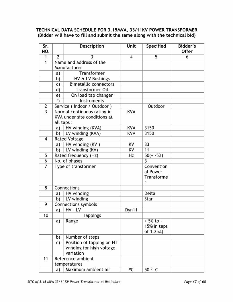
SITC of 3.15 MVA 33/11 KV Power Transformer at IIM Indore Page 47 of 68
TECHNICAL DATA SCHEDULE FOR 3.15MVA, 33/11KV POWER TRANSFORMER (Bidder will have to fill and submit the same along with the technical bid)
Sr. NO.
Description Unit Specified Bidder’s Offer
1 2 3 4 5 6
1 Name and address of the Manufacturer
a) Transformer
b) HV & LV Bushings
c) Bimetallic connectors
d) Transformer Oil
e) On load tap changer
f) Instruments
2 Service ( Indoor / Outdoor ) Outdoor
3 Normal continuous rating in KVA under site conditions at all taps :
KVA
a) HV winding (KVA) KVA 3150
b) LV winding (KVA) KVA 3150
4 Rated Voltage
a) HV winding (KV ) KV 33
b) LV winding (KV) KV 11
5 Rated frequency (Hz) Hz 50(+ -5%)
6 No. of phases 3
7 Type of transformer Conventional Power Transformer
8 Connections
a) HV winding Delta
b) LV winding Star
9 Connections symbols
a) HV – LV Dyn11
10 Tappings
a) Range + 5% to - 15%(in teps of 1.25%)
b) Number of steps
c) Position of tapping on HT winding for high voltage variation
11 Reference ambient temperatures
a) Maximum ambient air ⁰C 50 ⁰ C

SITC of 3.15 MVA 33/11 KV Power Transformer at IIM Indore Page 48 of 68
Sr. NO.
Description Unit Specified Bidder’s Offer
temperature (⁰C)
b) Maximum daily average ambient temperature
(⁰C)
⁰C 35 ⁰ C
c) Minimum ambient air
temperature (⁰C) ⁰C 10 ⁰ C
d) Maximum yearly weighted average ambient temperature
(⁰C)
⁰C 35 ⁰ C
12 Maximum temperature rise over ambient temperature
a) In oil by thermometer
(⁰C) ⁰ C 35 ⁰C
b) In winding by resistance
measurement (⁰C) ⁰ C 40 ⁰C
c) Limit for hot spot temperature for which the transformer is
designed (⁰C)
⁰ C 90 ⁰C (as per Is 2026)
d) Type and details of winding hot spot temperature detector
(⁰C)
⁰ C WTI with 150 mm dia dial
type instrument .temp. sensing element
image coil , auxiliary CT, 2 nos
of contacts of high winding
temperature alaram and trip,
calibration devices.
e) Temperature gradient between windings and oil
(⁰C)
⁰C

SITC of 3.15 MVA 33/11 KV Power Transformer at IIM Indore Page 49 of 68
Sr. NO.
Description Unit Specified Bidder’s Offer
f) Type of maximum winding temperature
indicator (⁰C)
Same as clause No-
12(d)
13 Voltage to earth for which the star point will be insulated
KV
14 Cooling type ONAN
15 Losses
a) Fixed (Iron ) losses of 3 phase Transformer (KW ) at rated voltage & rated frequency
KW 3.6 kW (Max)
b) Load losses at rated current at principal Tap
at 75⁰C (KW )
KW 18.5 kW (Max)
16 Max. Current density in winding at rated current for normal tap position
a) HV winding (Amps/ sq.mm.)
A/mm2
2.5 ( Amps/ sq.mm)
b) LV winding (Amps / sq.mm.)
A/mm2
2.5 ( Amps/ sq.mm)
17 Impedance voltage at rated current , frequency and at
75⁰C expressed as percentage of rated voltage at :-
a) Principal (normal) tap (%)
%
6.25% + 10%
Tolerance
b) Highest tap (%)
%
c) Lowest tap (%)
%
18 Reactance at rated current & frequency as percentage of rated voltage at:
a) Principal (normal) tap
%

SITC of 3.15 MVA 33/11 KV Power Transformer at IIM Indore Page 50 of 68
Sr. NO.
Description Unit Specified Bidder’s Offer
b) Highest Tap
%
c) Lowest Tap
%
19 Resistance at 75ºC
a) H.V. winding at normal tap position
b) L.V. winding
c) Resistance voltage drop at 75ºC winding temperature expressed as percent of rated voltage (%)
i) Principal/ normal tap %
ii) Highest tap
%
iii) Lowest tap
%
20 Capacitance on open circuit conditions
1800 pF(Approximately)
21 Insulation level
a) Separate source power frequency voltage withstand
i) HV winding (KV rms)
KV rms
70
ii) LV winding (KV rms)
KV rms
28
b) Induced over voltage withstand
i) HV winding (KV rms)
KV rms
--- Double Voltage & Double

SITC of 3.15 MVA 33/11 KV Power Transformer at IIM Indore Page 51 of 68
Sr. NO.
Description Unit Specified Bidder’s Offer
Frequency -
ii) LV winding (KV rms)
KV rms
--- Double Voltage &
Double Frequency
-
c) Full wave lightning impulse withstand voltage
i) HV winding (KV peak)
KV peak
ii) LV winding (KV peak)
KV peak
d) Power frequency high voltage tests
i) Test voltage for one minute withstand test on
high voltage windings
KV rms
ii) Test voltage for one minute withstand test on
low voltage windings
KV rms
iii) Test voltage for one minute withstand test on
neutral end of low voltage
KV rms
e) Lightning impulse withstand tests
i) Impulse test on high voltage winding 1.2/50 μ sec full wave withstand
(KV peak)
KV peak
ii) Impulse test on low voltage winding 1.2/50 μ sec full wave withstand
KV peak

SITC of 3.15 MVA 33/11 KV Power Transformer at IIM Indore Page 52 of 68
Sr. NO.
Description Unit Specified Bidder’s Offer
(KV peak)
iii) Wave form for impulse test
KV peak
22 No load current, no load loss, no load power factor at
normal ratio and frequency (Amp/ KW/ P.F.)
Amp/ KW/ P.F
a) 10 percent of rated voltage
Will be furnished by Bidders
Offer
b) 25 percent of rated voltage
c) 50 percent of rated voltage
d) 85 percent of rated voltage
e) 100 percent of rated voltage
f) 105 percent of rated voltage
g) 110 percent of rated voltage
h) 112.5 percent of rated voltage
i) 115 percent of rated voltage
j) 120 percent of rated voltage
k) 125 percent of rated

SITC of 3.15 MVA 33/11 KV Power Transformer at IIM Indore Page 53 of 68
Sr. NO.
Description Unit Specified Bidder’s Offer
voltage
23 Efficiency at 75ºC at unity power factor
a) Full load
%
b) 75% load
%
c) 50% load
%
d) 25% load
%
24 a) The minimum % of load at which the transformer will run at maximum efficiency (%)
%
b) Maximum efficiency of the transformer
%
25 Regulation at full load at 75ºC
a) At unity power factor (%)
%
b) At 0.8 power factor (lagging) (%)
%
26 Core data
a) Grade of core material used
CRGO HIB, M3 or better
b) Thickness of core plate lamination (mm)
mm
≤ 0.23 mm for M3 and ≤ 0.27mm for CRIB
c) Whether core laminations are of cold rolled grain oriented
CRGO HIB, M3 or better

SITC of 3.15 MVA 33/11 KV Power Transformer at IIM Indore Page 54 of 68
Sr. NO.
Description Unit Specified Bidder’s Offer
d) Details of oil ducts in core
i) Whether in the plane & at right angle to the plane of winding
ii) Across the plane of lamination
e) i) Insulation of core lamination
ii) Insulation of core plates
iii) Type of core joints
27 Flux density
a) Designed maximum flux density at normal tap at rated voltage and rated frequency
Tesla
1.5 Tesla
b) Operating continuous flux density(Tesla)
Tesla
1.5 Tesla
i) at normal tap Tesla
ii) at maximum tap Tesla
iii) at minimum tap Tesla
c) Designed maximum operating flux density which the transformer can withstand for one minute at normal tap(Tesla)
Tesla 1.5 Tesla for all Tap
d) Designed maximum operating flux density which the transformer can withstand for five seconds at normal tap(Tesla)
Tesla

SITC of 3.15 MVA 33/11 KV Power Transformer at IIM Indore Page 55 of 68
Sr. NO.
Description Unit Specified Bidder’s Offer
28 Inter-Tap insulation
a) Extent of extreme end turns reinforcement
b) Extent of end turns reinforcement
c) Extent of turn adjacent to tapping reinforced
d) Test voltage for 10 seconds 50Hz inter- turn insulation test on (a)
e) Test voltage for 10 seconds 50Hz inter- turn insulation test on (b)
f) Test voltage for 10 seconds 50Hz inter- turn insulation test on (c)
29 Windings:
a) Material
b) Type of windings:
i) HV windings
ii) LV windings
c) Insulation of HV windings
d) Insulation of LV windings
e) Insulation between HV & LV windings
30 Transformer Tank
a) Material
b) Thickness
- Top mm 10 mm
- Sides mm 10 mm
- Bottom mm 12 mm
c) Details of painting (inner / outer surface)
31 Dimensions of 3 phase transformers:
a) Max. Height to top of bushings (mm)
mm
b) Over-all length (mm) mm
c) Over-all breadth (mm) mm
32 Weight data of transformer components : (Tolerance + 5%

SITC of 3.15 MVA 33/11 KV Power Transformer at IIM Indore Page 56 of 68
Sr. NO.
Description Unit Specified Bidder’s Offer
) ( approximate values not allowed )
a) Core excluding clamping (Kg)
Kg
b) Core with clamping (Kg)
Kg
c) HV winding insulated conductor (Kg)
Kg
d) LV winding Insulated conductor (Kg)
Kg
e) Coils with insulation (Kg.)
Kg
f) Core and windings (Kg)
Kg
g) Weight of steel (Kg)
Kg
h) Fittings and accessories (Kg)
Kg
i) Oil required for first filling including 10% extra
Ltr/ Kg
1. Oil in main tank ( Ltrs) Ltr
2. Oil in the conservator (Ltrs)
Ltr
3. Oil in the radiators ( Ltrs )
Ltr
4. Oil in the OLTC (Ltrs ) Ltr
5. Overall total quantity of oil with 10%
ltr/Kg
j) 1. Transportation weight excluding
Kg
2. Shipping details
i) Weight of heaviest Kg
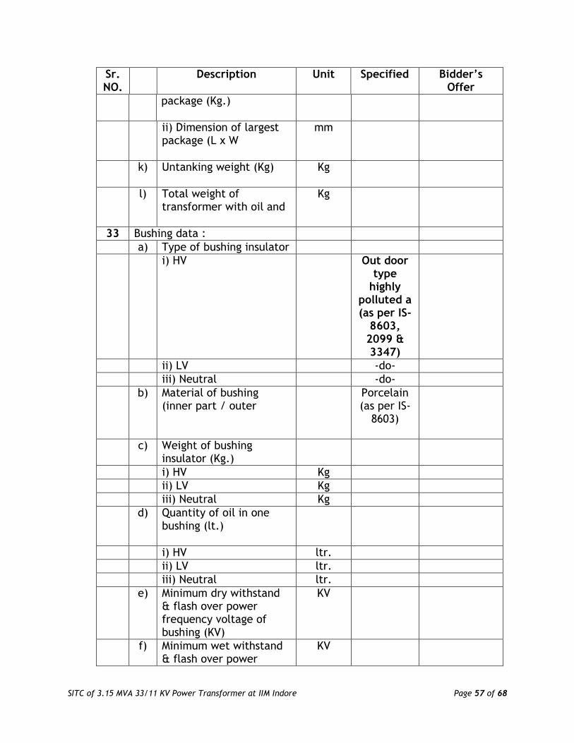
SITC of 3.15 MVA 33/11 KV Power Transformer at IIM Indore Page 57 of 68
Sr. NO.
Description Unit Specified Bidder’s Offer
package (Kg.)
ii) Dimension of largest package (L x W
mm
k) Untanking weight (Kg)
Kg
l) Total weight of transformer with oil and
Kg
33 Bushing data :
a) Type of bushing insulator
i) HV
Out door type
highly polluted a (as per IS-
8603, 2099 & 3347)
ii) LV -do-
iii) Neutral -do-
b) Material of bushing (inner part / outer
Porcelain (as per IS-
8603)
c) Weight of bushing insulator (Kg.)
i) HV Kg
ii) LV Kg
iii) Neutral Kg
d) Quantity of oil in one bushing (lt.)
i) HV ltr.
ii) LV ltr.
iii) Neutral ltr.
e) Minimum dry withstand & flash over power frequency voltage of bushing (KV)
KV
f) Minimum wet withstand & flash over power
KV

SITC of 3.15 MVA 33/11 KV Power Transformer at IIM Indore Page 58 of 68
Sr. NO.
Description Unit Specified Bidder’s Offer
frequency voltage of bushing (KV)
g) Minimum withstand & flashover impulse level (KV)
V
h) Voltage rating (KV)
i) HV KV
ii) LV KV
iii) Neutral KV
i) Current rating (Amps.)
i) HV Amp
ii) LV Amp
iii) Neutral Amp
j) Thermal Short Time current & Duration
Sec 2 sec
i) HV KA
ii) LV KA
iii) Neutral KA
k) Rated Dynamic current & its duration
i) HV KA
ii) LV KA
iii) Neutral KA
l) Cantilever with stand loading
m) Clearance in oil
- phase to phase (mm)
i) HV mm
ii) LV mm
iii) Neutral mm
- phase to earth (mm)
i) HV mm
ii) LV mm
iii) Neutral mm
n) Creepage distance in oil & air (mm)
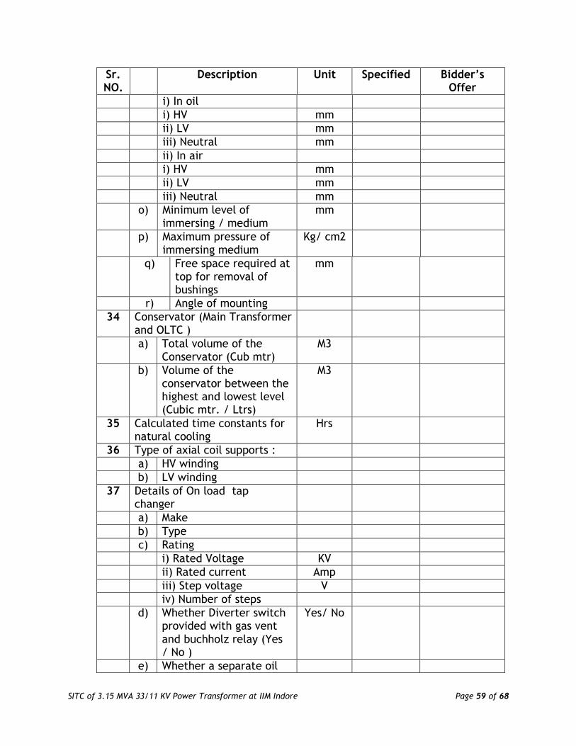
SITC of 3.15 MVA 33/11 KV Power Transformer at IIM Indore Page 59 of 68
Sr. NO.
Description Unit Specified Bidder’s Offer
i) In oil
i) HV mm
ii) LV mm
iii) Neutral mm
ii) In air
i) HV mm
ii) LV mm
iii) Neutral mm
o) Minimum level of immersing / medium
mm
p) Maximum pressure of immersing medium
Kg/ cm2
q) Free space required at top for removal of bushings
mm
r) Angle of mounting
34 Conservator (Main Transformer and OLTC )
a) Total volume of the Conservator (Cub mtr)
M3
b) Volume of the conservator between the highest and lowest level (Cubic mtr. / Ltrs)
M3
35 Calculated time constants for natural cooling
Hrs
36 Type of axial coil supports :
a) HV winding
b) LV winding
37 Details of On load tap changer
a) Make
b) Type
c) Rating
i) Rated Voltage KV
ii) Rated current Amp
iii) Step voltage V
iv) Number of steps
d) Whether Diverter switch provided with gas vent and buchholz relay (Yes / No )
Yes/ No
e) Whether a separate oil

SITC of 3.15 MVA 33/11 KV Power Transformer at IIM Indore Page 60 of 68
Sr. NO.
Description Unit Specified Bidder’s Offer
surge relay with trip contracts provided (Yes / No)
f) Whether Remote control panel provided with Control scheme for simultaneous operation of Tap changer when transformers running in Parallel and independent
g) Details of motor device unit housed in kiosk mounted on tap changer
h) Pressure relief valve
38 Bimetallic connectors: HV / LV
a) Normal current rating (A) Amp
b) Short time current rating (A)
Amp
c) Tensile strength (Kg)
d) Maximum temperature limit
e) Dimensional sketch enclosed indicating tolerances (Yes/No)
f) Minimum clearance (mm)
- Phase to phase mm
- Phase to Earth mm
39 CORE ASSEMBLY :-
a) Core diameter (mm ) mm
b) Core window height (mm )
mm
c) Core leg centre (mm ) mm
d) Gross core cross – sectional area (m2)
M2
e) Total height of core (mm )
mm
f) Details of top end frame
g) Details of Bottom end frame
h) Details of clamp plate (material, thickness, insulation)
i) Total core weight (Kg ) Kg

SITC of 3.15 MVA 33/11 KV Power Transformer at IIM Indore Page 61 of 68
Sr. NO.
Description Unit Specified Bidder’s Offer
j) Core loss, basing on core loss graph at operating flux density (rated voltage and rated frequency ) ( KW )
W/Kg
k) Core stacking factor
l) Net core area (Sq.m) M2
m) Margin towards corner joints, cross- fluxing, dielectric loss (KW)
KW
n) Total core loss at rated voltage and rated frequency (KW )
KW
o) Describe location / method of core grounding
p) Details of core- belting
i) Material , grade and type
ii) Width mm
iii) Thickness mm
iv) Fixing method
40 DETAILS OF WINDING
a) Type of winding
b) Material of the winding conductor
c) Maximum current density of windings at rated current and conductor area ( HV / LV )
Electrolytic Copper
c) Maximum current density of windings at rated current and conductor area ( HV / LV )
A/mm2
2.5 Amps /mm2 ( at all taps)
d) Whether windings are pre-shrunk ?
e) Whether adjustable coil clamps
f) Whether steel rings are used for the windings ? If so, whether these are split ?
g) Whether electrostatic

SITC of 3.15 MVA 33/11 KV Power Transformer at IIM Indore Page 62 of 68
Sr. NO.
Description Unit Specified Bidder’s Offer
shields are provided to obtain uniform voltage distribution in the windings ?
h) Winding Insulation ( Type & Class )
i) Insulating material , used for
i) H.V winding
ii) LV winding
iii) Tapping connection
j) Insulating material used between
i) L.V and H.V winding
ii) Core & L.V winding
k) H.V to H.V winding between phases
l) Type of axial supports
i) H.V winding
ii) L.V winding
m) Type of radial supports
i) H.V winding
ii) L.V winding
n) Maximum allowable torque on
o) Clamping ring details
i) Thickness of ring mm mm
ii) Diameter of ring mm mm
iii) No. & size of pressure screw
p) Bare conductor size (mm2)
i) HV mm2
ii) LV mm2
w) Inside diameter (mm )
i) HV mm
ii) LV mm
x) Outside diameter (mm )
i) HV mm
ii) LV mm
y) Axial height after shrinkage (mm )
i) HV mm
ii) LV mm

SITC of 3.15 MVA 33/11 KV Power Transformer at IIM Indore Page 63 of 68
Sr. NO.
Description Unit Specified Bidder’s Offer
z) D.C Resistance
i) L.V winding at 750 C (Ohms )
Ohm
ii) H.V winding at normal tap at 750 C (Ohms )
Ohm
iii) H.V winding at highest tap at 750 C (Ohms )
Ohm
iv) H.V winding at lowest tap at 750 C (Ohms )
Ohm
v) Total I2R losses at 750 C for normal tap (KW )
KW
vi) Total I2R losses at 750 C for highest tap (KW )
KW
vii) Total I2R losses at 750 C for lowest tap (KW )
KW
viii)
Stray losses including eddy current losses in winding at 750 C ( KW )
KW
a) Normal tap position KW
b) Highest tap position KW
c) Lowest tap position KW
d) Any special measures, taken to reduce eddy current losses and stray losses. Mention in details
ix) Load losses at 750 C (I2 R + Stray )
a) Normal tap position (KW )
KW
b) Highest tap position (KW)
KW
c) Lowest tap position (KW )
KW
x) Details of special arrangement, provided
to improve surge voltage distribution in the
windings.
41 DETAILS OF TANK :

SITC of 3.15 MVA 33/11 KV Power Transformer at IIM Indore Page 64 of 68
Sr. NO.
Description Unit Specified Bidder’s Offer
a) Material of Transformer tank
b) Type of tank
c) Thickness of sheet (No approximate value to be mentioned)
i) Sides (mm) mm
ii) Bottom (mm ) mm
iii) Cover (mm ) mm
iv ) Radiators (mm) mm
d) Inside dimensions of main tank (No
approximation in dimensions to be used )
i) Length (mm) mm
ii) Breadth (mm) mm
iii) Height (mm ) mm
e) Outside dimensions of main tank (No approximation in dimensions to be used )
i) Length (mm) mm
ii) Breadth (mm) mm
iii) Height (mm ) mm
f) Vacuum recommended for hot oil circulation (torr / mm of Hg)
Kg/ cm2
g) Vacuum to be maintained during oil filling in transformer tank (torr / mm of Hg)
Kg/ cm2
h) Vacuum to which the tank can be subjected without distortion ((torr / mm of
Kg/ cm2
i) No. of bi-directional wheels provided
j) Track gauge required for the wheels

SITC of 3.15 MVA 33/11 KV Power Transformer at IIM Indore Page 65 of 68
Sr. NO.
Description Unit Specified Bidder’s Offer
i) Transverse axis mm
ii) Longitudinal axis mm
k) Type and make of pressure relief device and minimum pressure at which it operates
42 CONSERVATOR :-
a) Thickness of sheet (mm)
mm
b) Size (Dia x length ) (mm)
mm
c) Total volume (Litres) Ltrs
d) Volume between the highest and lowest visible oil levels (Litres)
Ltrs

SITC of 3.15 MVA 33/11 KV Power Transformer at IIM Indore Page 66 of 68
LIST OF APPROVED MAKE/MATERIALS
S.No. Material Manufacturer/Brand Name
1 HV Bushing with metal Parts CJI/JP/AP/Genesis (Porcelain Type)
2 LV Bushing with metal Parts CJI/JP/AP/Genesis (Porcelain Type)
3 Additional Neutral Bushing with Metal Parts
CJI/JP/AP/Genesis (Porcelain Type)
4 Oil Temperature Indicator Precimeasure / perfect control
5 Winding Temperature indicator Precimeasure / perfect control
6 Magnetic Oil Level Guage Atvus / I & C / Sukrut / P & F / Precemeasure
7 Buchholz Relay Atvus / Prayog/ I & C / P & F / Yogya
8 Oil Surge Relay (Applicable for OLTC Only)
Atvus / Reputed
9 Radiator Valves Sunrise / Sarvidaya / Atvus / Petson / P & F / Reputed
10 Radiators Sanman / Darshal / Ronak / Minar / SPI Industries / TRAFO / P.E. Engineers /Laxmark
11 Silica gel breather (flange) Yogya / Press N Forge / I & C
12 Bottom Drain cum filter valve Elems / Atam / Newman / Mudit Enterprise / Reputed
13 Top Filter Valve Elems / Atam / Newman / Mudit Enterprise / Reputed
14 Shut off valve Elems / Atam / Newman / Mudit Enterprise / Reputed
15 1 No. SOV for OSR Elems / Atam / Newman / Mudit Enterprise / Reputed
16 OLTC CTR / OLG
17 Transformer Oil Savita / Apar / Raj oil
18 Transformer make BHEL / CG / ABB/ Voltamp / Tesla / Kirloskar

SITC of 3.15 MVA 33/11 KV Power Transformer at IIM Indore Page 67 of 68
Annexure-1 Indian Institute of Management Indore
Part- II: Financial Bid
Ref: Tender Notice No. IIMI/Project/09/2017/43 File No. 353
Name of Work: “Design, Manufacture, Supply, Installation, Testing & Commissioning of 3.15 MVA, 33/11kV power transformer at Utility-I of IIM, Indore”
Sl. No.
Item Description Units Quantity Unit
Rate Total Amount
Total Amount in Words
1
Design, Manufacture, Supply, delivery & unloading at site 3 phase, 50 Hz, 3150 KVA, 33/11 KV, delta/star connected, copper wound oil filled ONAN, outdoor type, power transformer having On load tap changing switch with tapping range from +5% to -15% in steps of 1.25% each + RTCC + AVR and other accessories/fittings as per IS:2026 and other relevant IS complete with first filling of oil including Installation, terminations of HT Cable on both sides (HT & LT side of the transformer), Control wiring with the terminals in the marshalling box , On load Tap changer , earthing connections at the power transformer side, testing & commissioning complete as required. No load losses - 3.6 KW & load losses at 75 degrees Celsius – 18.5 KW, impedance 6.25% complete as per technical specification of the tender and as per the direction of Engineer-in-Charge. Transformer Approved Makes: BHEL/CG/ABB/
Voltamp/Tesla/Kirloskar (Scope of work also includes the following as per detailed hereunder :)
Nos 1.00

SITC of 3.15 MVA 33/11 KV Power Transformer at IIM Indore Page 68 of 68
a . Taking out the existing transformer and shifting of the same to the outside of switchyard including opening the LT & HT side power terminations complete as required and as directed by the Engineer-in-Charge. b. Necessary statuary approvals from the Electrical Safety Department & any other department for replacement of the old transformer & installation, testing & commissioning of the new power transformer
Total Amount (in Rs.):
Total Amount in words:
Name, Signature, Designation & Seal
______________________________
Date ______________________________
Name of Bidder Firm ______________________________
Contact Person ______________________________
Contact Number ______________________________
Email Address ______________________________