| HAO WANATHI MOVIE DLA OLI AI MOMO MALT
103
| HAO WANATHI MOVIE DLA OLI AI MOMO MALT US009970266B2 ( 12 ) United States Patent Marx et al . ( 10 ) Patent No .: US 9 , 970 , 266 B2 ( 45 ) Date of Patent : May 15 , 2018 ( 54 ) METHODS AND SYSTEMS FOR IMPROVED DRILLING OPERATIONS USING REAL - TIME AND HISTORICAL DRILLING DATA ( 2013 . 01 ) ; E21B 47 / 00 ( 2013 . 01 ); E21B 49 / 00 ( 2013 . 01 ) ; GO6N 5 / 02 ( 2013 . 01 ); GO6N 77005 ( 2013 . 01 ) ( 58 ) Field of Classification Search ??? . ........ .. . .. .. .. E21B 44 / 00 ; E21B 44 / 02 USPC . . .. .. 175 / 24 , 27 , 50 ; 702 /9 See application file for complete search history . @ . . . . . . . . . . . ( 71 ) Applicant : Resource Energy Solutions Inc . , Calgary ( CA ) @ ( 56 ) References Cited ( 72 ) Inventors : Trent Marx , Calgary ( CA ) ; Gary William Reid , Black Diamond ( CA ); Henry Leung , Calgary ( CA ); Xiaoxiang Liu , Calgary ( CA ) @ ( * ) Notice : Subject to any disclaimer , the term of this patent is extended or adjusted under 35 U .S .C . 154 (b ) by 378 days . U .S . PATENT DOCUMENTS 6 , 109 , 368 A * 8/ 2000 Goldman . . . . . . . . . . . . . E21B 12 / 02 175 / 39 6 , 206 , 108 B1 * 3 / 2001 MacDonald . . . . . . . . .. . E21B 44 / 00 175 / 24 ( Continued ) Primary Examiner — David J Bagnell Assistant Examiner — Michael A Goodwin ( 74 ) Attorney , Agent , or Firm — HEER LAW ; Christopher D . Heer ( 21 ) Appl . No .: 14 / 676 , 901 ( 22 ) Filed : Apr . 2 , 2015 ( 65 ) Prior Publication Data US 2015 / 0218914 A1 Aug . 6, 2015 ( 63 ) Related U .S . Application Data Continuation of application No . 13 / 665 , 202 , filed on Oct . 31 , 2012 , now Pat . No . 9, 022 , 140 . ( 51 ) Int . Cl . E21B 44 / 00 ( 2006 . 01 ) E21B 41 / 00 ( 2006 . 01 ) E21B 49 / 00 ( 2006 . 01 ) E21B 12 / 02 ( 2006 . 01 ) E21B 7700 ( 2006 . 01 ) E21B 47 / 00 ( 2012 . 01 ) GOON 5 / 02 ( 2006 . 01 ) GOON 7700 ( 2006 . 01 ) U . S . CI . CPC .. .... ... ... E21B 41 / 0092 ( 2013 . 01 ); E21B 7700 ( 2013 . 01 ) ; E21B 12 / 02 ( 2013 . 01 ); E21B 44 / 00 ( 57 ) ABSTRACT Methods and systems are described for improved drilling operations through the use of real - time drilling data to predict bit wear , lithology , pore pressure , a rotating friction coefficient , permeability , and cost in real - time and to adjust drilling parameters in real - time based on the predictions . The real - time lithology prediction is made by processing the real - time drilling data through a multilayer neural network . The real - time bit wear prediction is made by using the real - time drilling data to predict a bit efficiency factor and to detect changes in the bit efficiency factor over time . These predictions may be used to adjust drilling parameters in the drilling operation in real - time , subject to override by the operator . The methods and systems may also include deter mining various downhole hydraulics parameters and a rotary friction factor . Historical data may be used in combination with real - time data to provide expert system assistance and to identify safety concerns . ( 52 ) 20 Claims , 77 Drawing Sheets Historical Database 309 301 - Lithology Porosiy 311 303 . 1 302 . 1 312 Permeability ROP 332 313 -- - Water saturazon Analogous we ! ! 1 ) -- 302 . 2 Historical drilingi parameters & operations data ANNONSER Historical drilling parameters operations dsia - . . . 302 . 1 Analogous wel ! 2 303 .2 Analogous well N 316 314 Bit wear Volume 4335 Trend Fusion : - - ! Mud parameters Engine BHA | Pore pressure 315 RPM 333 334 Filter cake WOS 318 Historical drilling : parameters & operations data pressure 317 331 / Pump 328 330 320 - - 303 . I 10 - - - Expert Dscision Engine emeletion Flags and control operations Well on drilling 201 325 , aculated sve Sensors Real - t: ne criting parameters Data inputs - - - - - - - + Esticated values Adjusied real - time drilling parameters 101 uss Predicted Prediction - - - - - - + kowirits 329 Engine 7 320 327
-
Upload
khangminh22 -
Category
Documents
-
view
0 -
download
0
Transcript of | HAO WANATHI MOVIE DLA OLI AI MOMO MALT
| HAO WANATHI MOVIE DLA OLI AI MOMO MALT US009970266B2
( 12 ) United States Patent Marx et al .
( 10 ) Patent No . : US 9 , 970 , 266 B2 ( 45 ) Date of Patent : May 15 , 2018
( 54 ) METHODS AND SYSTEMS FOR IMPROVED DRILLING OPERATIONS USING REAL - TIME AND HISTORICAL DRILLING DATA
( 2013 . 01 ) ; E21B 47 / 00 ( 2013 . 01 ) ; E21B 49 / 00 ( 2013 . 01 ) ; GO6N 5 / 02 ( 2013 . 01 ) ; GO6N 77005
( 2013 . 01 ) ( 58 ) Field of Classification Search
??? . . . . . . . . . . . . . . . . . . E21B 44 / 00 ; E21B 44 / 02 USPC . . . . . . 175 / 24 , 27 , 50 ; 702 / 9 See application file for complete search history .
@ . . . . . . . . . . . ( 71 ) Applicant : Resource Energy Solutions Inc . , Calgary ( CA )
@ ( 56 ) References Cited ( 72 ) Inventors : Trent Marx , Calgary ( CA ) ; Gary William Reid , Black Diamond ( CA ) ; Henry Leung , Calgary ( CA ) ; Xiaoxiang Liu , Calgary ( CA )
@ ( * ) Notice : Subject to any disclaimer , the term of this patent is extended or adjusted under 35 U . S . C . 154 ( b ) by 378 days .
U . S . PATENT DOCUMENTS 6 , 109 , 368 A * 8 / 2000 Goldman . . . . . . . . . . . . . E21B 12 / 02
175 / 39 6 , 206 , 108 B1 * 3 / 2001 MacDonald . . . . . . . . . . . E21B 44 / 00
175 / 24 ( Continued )
Primary Examiner — David J Bagnell Assistant Examiner — Michael A Goodwin ( 74 ) Attorney , Agent , or Firm — HEER LAW ; Christopher D . Heer
( 21 ) Appl . No . : 14 / 676 , 901 ( 22 ) Filed : Apr . 2 , 2015 ( 65 ) Prior Publication Data
US 2015 / 0218914 A1 Aug . 6 , 2015
( 63 ) Related U . S . Application Data
Continuation of application No . 13 / 665 , 202 , filed on Oct . 31 , 2012 , now Pat . No . 9 , 022 , 140 .
( 51 ) Int . Cl . E21B 44 / 00 ( 2006 . 01 ) E21B 41 / 00 ( 2006 . 01 ) E21B 49 / 00 ( 2006 . 01 ) E21B 12 / 02 ( 2006 . 01 ) E21B 7700 ( 2006 . 01 ) E21B 47 / 00 ( 2012 . 01 ) GOON 5 / 02 ( 2006 . 01 ) GOON 7700 ( 2006 . 01 ) U . S . CI . CPC . . . . . . . . . . . . E21B 41 / 0092 ( 2013 . 01 ) ; E21B 7700
( 2013 . 01 ) ; E21B 12 / 02 ( 2013 . 01 ) ; E21B 44 / 00
( 57 ) ABSTRACT Methods and systems are described for improved drilling operations through the use of real - time drilling data to predict bit wear , lithology , pore pressure , a rotating friction coefficient , permeability , and cost in real - time and to adjust drilling parameters in real - time based on the predictions . The real - time lithology prediction is made by processing the real - time drilling data through a multilayer neural network . The real - time bit wear prediction is made by using the real - time drilling data to predict a bit efficiency factor and to detect changes in the bit efficiency factor over time . These predictions may be used to adjust drilling parameters in the drilling operation in real - time , subject to override by the operator . The methods and systems may also include deter mining various downhole hydraulics parameters and a rotary friction factor . Historical data may be used in combination with real - time data to provide expert system assistance and to identify safety concerns . ( 52 )
20 Claims , 77 Drawing Sheets
Historical Database 309 301 - Lithology Porosiy 311 303 . 1
302 . 1 312 Permeability ROP 332 313 - - - Water saturazon Analogous we ! ! 1 ) - -
302 . 2
Historical drilingi parameters & operations data
ANNONSER Historical drilling parameters operations dsia
- . . .
302 . 1 Analogous wel ! 2
303 . 2 Analogous well N
316
314 Bit wear Volume 4335
Trend Fusion : - - ! Mud parameters Engine BHA | Pore pressure
315 RPM
333 334 Filter cake WOS 318
Historical drilling : parameters & operations data
pressure 317 331 / Pump 328 330
320 - - 303 . I 10 - - -
Expert Dscision Engine emeletion Flags and
control operations Well on drilling
201 325 , aculated sve
Sensors Real - t : ne criting
parameters
Data inputs - - - - - - - + Esticated values Adjusied real - time
drilling parameters
101 uss Predicted Prediction
- - - - - - + kowirits
329 Engine 7 320
327

US 9 , 970 , 266 B2 Page 2
( 56 ) References Cited U . S . PATENT DOCUMENTS
6 , 424 , 919 B1 * 7 / 2002 Moran . . . . . . . . . . . . . . . . E21B 44 / 00 702 / 6
2008 / 0289877 Al * 11 / 2008 Nikolakis - Mouchas · E21B 7 / 04 175 / 57
2009 / 0234623 A1 * 9 / 2009 Germain . . . . . . . . . . . . . . . E21B 41 / 00 703 / 6
* cited by examiner
FIG . la
U . S . Patent
302 . 1
302 . 2
302 . n
320
May 15 , 2018
Analogous well 1 Analogous well 2
Analogous well n
F309
101
Well in drilling
Sheet 1 of 77
Historical database
ris
OO ,
Sensors
Rigsite network
106
103
DFA server software
US 9 , 970 , 266 B2
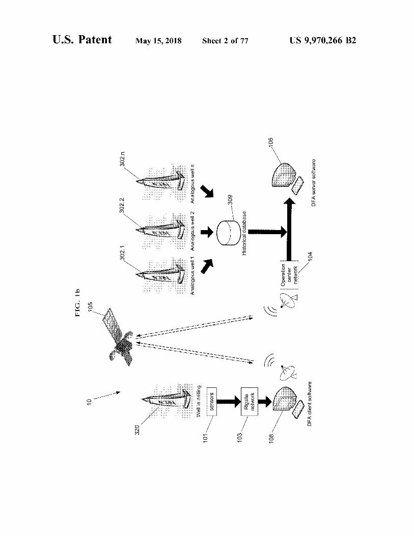
FIG .
b
U . S . Patent
10
105
302 . 1
302 . 2
302 . n
320
May 15 , 2018
Analogous well1 Analogous well 2
Analogous welln
Well in drilling
= s * * * * * w * * * w we he sh?w we we = vs web
101
sensors
Sheet 2 of 77
309
103 ?
Historical database
Rigsite network
??? (
108 ?
| SG
A06
Operation center network
DFA client software
104
DFA server software
US 9 , 970 , 266 B2
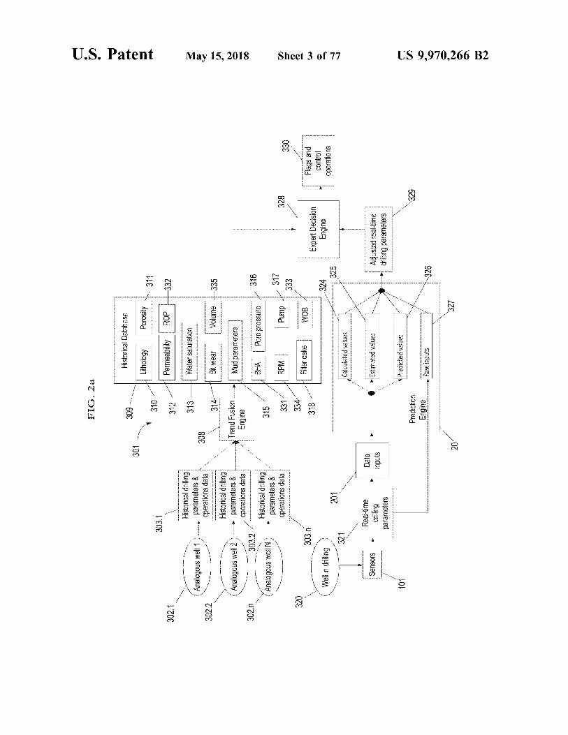
FIG . 2a
U . S . Patent
Historical Database
309
301
Lithology Porosity 311
310
303 . 1
302 , 1
Permeability | ROP
312
4332
313
Water saturation
Analogous well 1
Historical drilling parameters & operations data
308
302 . 2
314 -
1
Bit wear
Volume 4 - 335
May 15 , 2018
Analogous well 2 . . . .
Historical drilling parameters & operations data
Trend Fusion Engine
Mud parameters
302 . n
303 . 2
316
BHA
Pore pressure
Analogous well N ) -
Historical drilling parameters & operations data
315 331
RPM
Pump -
328
333
330
320
334
Filter cake
303 . 2
WOB
318
Expert Decision Engine
Flags and control operations
Sheet 3 of 77
- 324
Well in drilling
201
325
321
Calculated values
- Sensors
Real - time driling parameters Data inputs
Estimated values
Adjusted real - time drilling parameters
101
Predicted values
Prediction Engine Raw inputs
US 9 , 970 , 266 B2
20
U . S . Patent May 15 , 2018 Sheet 4 of 77 US 9 , 970 , 266 B2
FIG . 2b 324 3241
Calculated values Hydrostatic pressure ECD Annular circulation pressure loss
2074 3243 3244
- 3245 3246 325
BHP Volume Water saturation
- 2053 Estimated values Pore pressure 2075 112075 Porosity Permeability Filter cake
- 2076 - 3254 2076 3254 326 Predicted values
Lithology prediction Bit wear prediction - 2057
- 2056
327 Raw inputs
ROP Torque WOB
- 2032 - 2073 2033 3273 3275 RPM
Pump pressure Mud parameters Differential pressure
3276 - 3277
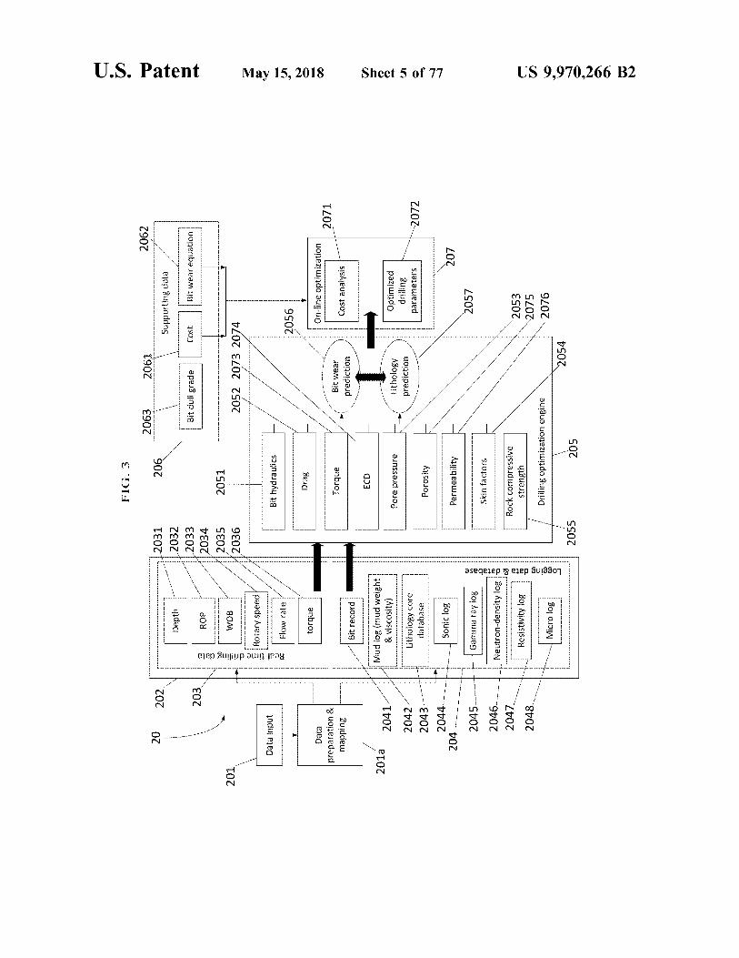
FIG . 3
2063
2061
2062
20
U . S . Patent
206
Supporting data
Depth
Bit dull grade
Cost
Bit wear equation
2031 2032 2033 2034 2035 2036
ROP
2051
201
WOB Real - time drilling data
2052 2073 2074
Rotary speed
Data input
Bit hydraulics
Flow rate
2056
May 15 , 2018
Drag
torque
On - line optimization
Data preparation & mapping
2071
Torque
Bit wear prediction
Cost analysis
Bit record
ECD
2011
Mud log ( mud weight & viscosity )
. . . . .
Pore pressure
Lithology prediction
2041 2042 2043 2044
Optimized drilling parameters
Sheet 5 of 77
Lithology core database
2072
Porosity
Sonic log
204 . . .
Permeability
207
2057
Gamma ray log
Skin factors
2045 2046 2047 2048
Neutron - density log
Logging data & database
Resistivity log
Rock compressive strength
2053 2075 2076
Drilling optimization engine
Micro log
2054
2055
205
US 9 , 970 , 266 B2

FIG , 4
U . S . Patent
30
resample
P ( xly )
Mode 1
May 15 , 2018
T ; W
Mode 1 wins
p ( x - 11 - 2 )
Mode i
Mode 2
T ; W ,
Select the winning mode
Sheet 6 of 77
TW
Mode n
US 9 , 970 , 266 B2

FIG . 5
U . S . Patent
- 404
- 410
401
Estimate of BEF at t - 1
Estimated PDF of the model variable at t
May 15 , 2018
402
Covariance estimate of BEF at t - 1
Computation of the mean of the mode
variable at t
Particle filter
403
Estimated PDF of the model variable at t - 1
405
Sheet 7 of 77
407
BEF prediction
408
40 40
Estimate of BEF att
Kalman filter
wwwwwwwwwwwwwwwwwwwwwwwwwwwwwwwwwwww wwwwwwwwwwwwww
409
Covariance estimate of BEF att
US 9 , 970 , 266 B2
406
US 9 , 970 , 266 B2
uogoipeld leaM YOOL Ouiseejou S $ €
9
* *
wwwwwwwwwwwwwwwwwww
wwwwwwwwwww 19971997
wwwwwwwwwww
wwwwwwwwwww www
* * * * * * * *
. . .
.
. * . * .
. * . * . * . . . . .
. * . * . . . * . * *
* * . * . * . * . . * . * . . * . * . * . * . * . . * . * . * * . . . * . * . * .
.
. .
.
. * . * . . * * . * * * . * * * . * * . * . * * . * * *
. .
* * * * . * . * . . * * * * * * * * * * * * * * * * * * * * * * * * * * * * * * * * *
*
* * * * * *
* * * * * * * * * * * *
* *
OOZ€
*
* * * * * *
* # 44444444 . " * * + * + 444444 * * * W * 444444444444
4 4444
* * * * * * * * * * * * * * * * * * * * * * * * * * * * * * * * * * * * * * * * * * * * * * * * * * * * * * * * * * * * * * * * * * * * * * * * * * * * * * * * * * * * * * * * / * * * * * * * * * * * * * * * * * * * * * * * * * * *
*
*
*
*
001€
* * * * * * * * * * * * *
. - . - . - . - . * * * . - . - . - * * - - - - * * - - * * * - . - . • * * * - . - . - * * * * * - . - . - ; * * * * * * * * * * . - . . * * . * * . * . 2 . . * . * . * . * - V
.
- ???????
??
???? ? ? ? - ? - ? ? ?
??
??? ?? ? ? -
? ?????
?? ? 7 ? ; - - :
????
? ? ? - :
? ?
- - - - - - . - - ? ? ? ? - - ? ? ? ?
. . . . . . . .
. . . .
. . . . .
000€
* * * * *
Er . 5
*
* * *
*
*
* * *
* * * * * *
* * *
* *
*
*
* *
* * * * *
* *
* *
* *
* * * * *
* * * * * * * * * *
*
* * *
* *
* * * * * *
*
* * * * * * *
*
*
* * *
Y
4
* » * *
*
*
*
*
* * * *
* * *
*
* *
* * *
* * * * * * *
*
0062
.
. * . . * . . *
- - - -
Sheet 8 of 77
. .
* * * * * * * *
* * * * * * * * * * * * * * * * * * * * * * * * * * * * * * * * * * * * * * * * * *
- * * - - - * * * * * * * * * * * * * - - * * * * *
* * * *
* * * * * *
* * * * * * * * * * *
* * * * * *
* * * * * * * *
*
* * * *
* * * * *
* * * * * * * * * * * * * * * * * * * * * * * * *
* * * * * * * * * * * * * * * * * * *
* * * *
-
ortamenti WWW . WWW
- - - - - - - - -
Depth ( m )
WW .
. * . * * * . * * . * * . * * * .
* *
* *
* *
*
* * *
* * * *
*
* *
* * *
* * * * * * * * * *
* * * *
*
* *
* *
- - - -
tepooiind VOL Sinoy unieron ÞEZ8 : ( w ) ino udad VOZZ : ( W ) uluded
ElSan ?d1 puoweia perjun Bew DIOON
* * * * *
suvarsis
* *
res
* * *
* * * * * *
* *
* * * * * * * * * * *
* * *
* * *
* *
Wii
0092 - - -
W *
May 15 , 2018
W . . . - - - - - - - -
" . . * . *
* *
*
. * . * . * . * * * . * . * . * * * . * * * . * . * . * * * . * .
* . *
* . . * . * * * . * . * . * * * * * . . * . * * * * * * * * * * * * * * * * * * * * * * * * * * * * * * * * * * * *
0097
* * *
1424
* i
iiiiiiiii i
iiiiii * * * * * * * * * * * * * * * * * * * * * * * * * * * *
* * * *
0007
* * *
een pgpergipeid DJOOB ) Jeemia
. . . . . . . .
. . . . . . . . . . . .
. .
. . ,
00€7 v4444444444444444444444444444444444444444444444444444444444444444444444444444444444444444444444444444444444444444444444444444444444444444444444444444444444444
U . S . Patent
9 O1
600kw 600M 600 . 2 . . . 600 . 1uria
610kW Dineren 0102 0101 . • * * .
Winter *
* * * * * * * *
Neuron FIG . 7 WUUUUUUUUUUUUUUUUUUUUUUUUUUUUUUUUUU ???????????????????????????????????????????? : 608 FO )
* * * * * * * * * * * * * * * * * * * * * * * * * * * * * * * * * * * * * * * * * * * * * * * * * * * * * * * * * * * * * * * * * * * * * * * * * * * * * * * * * * * * * * * * * * * * * * * * * * * * * * * * * * * * * * * * * * * * * * * * *
www .
.
US 9 , 970 , 266 B2 Sheet 9 of 77 May 15 , 2018 U . S . Patent
U . S . Patent May 15 , 2018 Sheet 10 of 77 US 9 , 970 , 266 B2
62 { - 60 622 60 623 630
- 630 . - 643
?? ??? A ? " " " "
60
630 60 630 620 610630 620 510 605 630 620 610 / - 605 640 620 60 6041 641 620 _ 604 642 60 620 _ 60460
630
* [ ]
? ? ?? ? 1 G . ?
* -
* 3 / 4
* - -
* * * * - - -
* -
* * -
???? ?? - - - - - -
63 70 S -
604 605
09 d - 009 % % 603p4 8

840
voe ythology Prediceo * *
* 2017 * wwwwwwwwwwwwwwwwwwwwwwwwwwwwwwwwwwwwwww Wild log wwwwwwwwwwwwwwwwwwwwwwwww asurements Owhola mochanics ???????????????????????????????? ???? ???? ???? ???? ???? ???? ???? ???? ???? ?????
*
nework Mudlayer model YYYYYYYYYYYYYYYYYYYYYYYYYYYYYYYYYYYYYYYYYYYYYYYYYYYYYYYYY 810 * - * - * - * - * - * - * - * - * - * - * - * - * - * - * - * - * - - * - * - * - * - * - * - * - * - * - * - * - * - * - * - * " "
: :
: : : : : : : : : valdation Data Pre - processing Www tttttttt : : : : : : : :
: :
: : : : : : : : : FIG . 9
: : : : : : : : :
Rock contined compressive strength wwwwwwwwwww Farmston dnlab ty coatican wwwwwwwwwwwwwwwwwwwwwwwwwwwwwww : : : : : : : :
Oyunic driling response Rock confinedformation shear strength
: : : : : : : : : Smoothing Data VVVVV : : : : : : : : : :
: : : : : :
w
1
unit tracion Featre - - - - - - - - - - - - - - - - - - -
220
US 9 , 970 , 266 B2 Sheet 11 of 77 May 15 , 2018 atent
U . S . Patent May 15 , 2018 Sheet 12 of 77 US 9 , 970 , 266 B2
FIG . 10
1002
1001
Legend : Three lithology types : shale ( dark gray ) , sandstone ( medium gray ) , siltstone ( light gray )

U . S . Patent May 15 , 2018 Sheet 13 of 77 US 9 , 970 , 266 B2
FIG . 11a Sigma - log
2300 -
-
-
-
-
-
-
-
2400 - - - - - - - - - - - - - - - - - -
-
-
-
-
-
2500 - - - - - - - - - - -
2701
2600 - - - | - - - - - - - - - - - - -
-
-
-
-
-
-
-
-
170 AL - - - - - - - - - - - - - - -
DEPTH ( m ) ?????????? - - - TIILIXI L - - - - - - - - - -
2900 - - - - - - - - - - - -
-
-
-
-
-
-
3000 = =
-
-
-
-
-
-
-
-
-
-
3100 - - - - - - - - - - - - - - - - - - - -
-
-
-
-
-
-
3200 0 . 5
U . S . Patent May 15 , 2018 Sheet 14 of 77 US 9 , 970 , 266 B2
FIG . 11b D - Exponent
2300
2400 * * * * * * * * * * * * * * * *
ACORD 2702 2500 Troy * * * WWW WWW * * *
A
2600 * * * * * * H otels with * * * * * * * * * Y
ok
DEPTH ( m )
REA LEGRA 00 hores Yo * * * * * * * * * * * * punt
2800 NAREX en el x * * * * * * * * *
o 2900 B e * * * *
s
Ray RESER 3000 * * * * * * * * * * * * L
3100 * * * * * < * than ones como um x y
SVARESE 32004 * W ho
O 0 . 5 1 1 . 5
U . S . Patent May 15 , 2018 Sheet 15 of 77 US 9 , 970 , 266 B2
FIG . 110 Pore Pressure Gradient ( ppg ) 2300 wiwiririwwwwwwwwwwwwwwwwwwwwwwwwwwwwwwwwwwwwwwwwwwwwwwwwwwwwwwwwins
wwwwwwwwwwwwwwwwwww wwwwwwwwwwwwwwww
Wh
2500
2703 2600 > > ' " * " * * * * * * * * . * . . * . * * * * * * * * *
Sigma - log DEPTH ( m )
2800 D - exponent * * *
? ? ? ? ? ? ?
o ? ? ?
? ?
? ? ? ? ? ? ? ppi . ' . ' . ' . ' . ' . ' . ' . ' . ' . ' . ' . . . . . . . we
3000
later 3100
3200 wwwmni

SO wwwwww
3000 MM * * * * * * * * * * * * * * * * * * * * * * * * * * * * * * * * * * * * * * * * * * * * * * * * * * * * * * * * * * * * * * * * * * * * * * * * * * * * * * * * * * * * * *
2000 * *
* *
* * * * 44444444444444444444 * * *
DEPTH ( m ) * *
* * * * * * * * 2017 iiriwwiini 1500 * *
* * *
* *
* * * * * * *
wwwwwwwww4 ^ * *
*
* *
* * *
* * *
wwwwwwwwwwwwwwwwwwwwwwww * * * * * * * * * * * 1000 V * 2801
* * * bum sum o jueuodxa - a * * * * * * * * * * *
* * * *
wwwwwwwwwwwwwwwwwwwwwwwwwwwwwwwwwwwwwwwwwwwwwwwwwwwww * * *
*
iirivirisinin 500 * * * * * *
* *
W * * * swiswisswers
* * * *
*
D - Exponent FIG . 12a
US 9 , 970 , 266 B2 Sheet 16 of 77 May 15 , 2018 U . S . Patent

US 9 , 970 , 266 B2
20 15
IIIIIIIIIIIIIIIIIIIIIIIIIIII T . 1
7 . . . . FF177 . . . . .
17
* * *
* * * *
*
*
*
* *
277 . . . . . X . XFF
. . . X . FFF
. .
. X
000000000000000
wwwwwwwwwwwwwwww wwwww
* * * * * * * * * *
Pore pressure gradient ( ppg ) FIG . 12b
10
Sheet 17 of 77
penyamundan mahnya 5
. . ANY7 7 . 7 . 2 .
OX
- - - - - - - - - - - - - - - - - - - - - - - - - - - - - - - - - - - - - - - - - - - - - - - - - - - - - - - - - - - - - - - -
- - - - - - - - - - - - - - - - - - - - - - - - - - - - - - - - - - - - - - - - - - - - - - - - - - - - - - - - - - -
May 15 , 2018
500
000
0097
000€
( uu ) Hidad
U . S . Patent
2802
U . S . Patent May 15 , 2018 Sheet 18 of 77 US 9 , 970 , 266 B2
FIG . 120 PP estimation ( psi ) *
- - POS?n Voews - - - SISALue puel
POS31 wwwxxxXA22 ZAL LLLLLLLLLZELWOOLWAYYYTWOWWWWWWY 47 . 1
* * .
*
* * .
- 2803 p
0001 11797 .
* * *
* *
*
*
* * *
a * * *
*
* *
*
1500 DEPTH ( m )
1 .
000C
WYYY . "
0097 9 * . 7 . 1 * *
sonte termining their
000€ gay
000Z 4000 0009
U . S . Patent May 15 , 2018 Sheet 19 of 77 US 9 , 970 , 266 B2
FIG . 13a D - Exponent
???????????????????
% ? ? ?? ????
????? ?? ?
???? + + + +
% 3 ? ? ? ? ? ? ? ? ? ? ? ? ? ? ? ? + +
2014 ???
???????????????????????????????????????????????????????????????????????????????
{ ???? ?
? *
% { tal ) Flag
%
??? *
* *
* *
' ' ' ' ' ' ' ' ' ' ' ' ' ' ' ???? ? ?? ??
? ???????????????????????????????????????????????????????????? %
??????
U . S . Patent May 15 , 2018 Sheet 20 of 77 US 9 , 970 , 266 B2
FIG . 13b Pore pressure gradient ( ppg ) i m
500
2902 . . ^ n nnn
5 K . RAAH . ? DEPTH ( m )
e
ay herinner here to buy hermany and S
? >
2000 WWW - * * 4w dk
2500 SKER ARS
Wwwwwva 3000 w aww . www xRRY
0 5 1 10 15 1 20
U . S . Patent May 15 , 2018 Sheet 21 of 77 US 9 , 970 , 266 B2
FIG . 130 PP estimation ( psi ) UN
- - - Estimation result
Trend analysis resut
* * * * *
*
* *
* *
2903 1000
1500 DEPTH ( m )
2000 .
2500 . .
3000 TAR 2000 4000 6000 8000

U . S . Patent May 15 , 2018 Sheet 22 of 77 US 9 , 970 , 266 B2
FIG . 14a D - Exponent
+ + + + *
* * * * /
+
*
* * *
+ /
+
* * * * * * *
+
1
4
*
* * * * * * * * * * 500 * * . * * . * . 3001 * *
* *
* * * D - exponent o Line - fitting
1000 . . . . . . . . . . . . . . . . . . . . . . . . . * . * . * . * . * . * . * * 4 . 4 . 4 . 4 . 4 . . . 4 . 4 . 4 . 4 . 4 . 4 . 4 . * . * . . . . . . . . . . . . . . . . . . * . * . * . * * . . * . * . * * *
14444444444444 WWW 1 . 11 . 171 . 177 . 17 www wwwwwwwwwwwwwwww DEPTH ( m )
9 . 444444444444
*
* *
2000
* * * * * * * * * * * * * * * * * * *
wwwwwwwww
wwwwwwwwwwwwwwwwwwwwwwwwwwwwwwwwwwwwwwwwwwwwwwwww www * * * * * * *
* * *
* * *
* * *
3000 * * * * * * * * * * * * * * * * * * * * * * * * * * * * * * * * * * * *
1 . 5 2
U . S . Patent May 15 , 2018 Sheet 23 of 77 US 9 , 970 , 266 B2
40
Pore pressure gradient ( ppg )
+ + + + + + +
3002 DOS A
0001
22 *
wir777JJer177JJJT2272e72272XJ127XJJIT : 274 22
DEPTH ( m ) d OOGCOOOOOOO000 popodoOOOOOOOOOOOOOOOOOOOOOossssconosco ASOSDOSS 7 . 1 . V . S . AT
FK
W WWWW * of turlama hamah Anusmatwa w large 172272XJ2272ee7723 o
2000 go
wwwwwwwwwwwwwwwww www
w
+
3000 wwwwwwwwwwwwwwwwwwww 5 10 15 20
U . S . Patent May 15 , 2018 Sheet 24 of 77 US 9 , 970 , 266 B2
FIG . 140 t i 1 i * * *
D RAR * - - - Estimation result * *
Trend analysis result
500 A ria T . E . . . . MAAT T . T . E . R . . 1 . 2 . MAAFx ' x ' XT TO TO
TFF
1 . . . T .
A .
F T2272222272UWJver272Zvc1277 . 1 . .
3003 1000 1000 7
. 7 . . . .
Fer22772Jerrrr2272JJsecera . . .
.
.
. . .
.
.
2
3
1500 *
l ' 2124 DEPTH ( m ) 272JWS ixk + + 421
27 JJS * + + + * - W
2W * *
2000 Inv2222
were recommen 2500 * * * * * * * * * . . . C . X2
wowowowowo
3000
0 2000 4000 6000 8000
U . S . Patent May 15 , 2018 Sheet 25 of 77 US 9 , 970 , 266 B2
FIG . 15a PP ( Well # 1 ) ( psi )
500 1 .
ADUERELEPE AXEX * 222PPURAI PROASARRU 3101
1000
HOUSELORPIO E GRUA E KREU SAB # 18
DEPTH ( m )
PORARY EYESOARE DEEZER
2000 www . . . www sometimes young 2500
3000 o 5000 10000 15000
- - - - - - Estimation result
Trend analysis result
US 9 , 970 , 266 B2
6000
4
. .
. .
.
. .
. . . . . . . . .
. .
. .
. . . . . . . . . . . . . . . . . . *
* * *
* * * * * * * * *
*
* * * * * * * * * * *
Sheet 26 of 77
4000
PP ( Well # 2 ) ( psi ) FIG . 15b
www im Trend analysis result
e
s reportalen in
- - - - - - Estimation result
2000
notationes ant 1000
1500
2500
30004
May 15 , 2018
DEPTH ( m )
3102
U . S . Patent
U . S . Patent May 15 , 2018 Sheet 27 of 77 US 9 , 970 , 266 B2
FIG . 150 PP ( Well # 3 ) ( psi )
3103500
DEPTH ( m ) lampamenovanie posamenachama te 1500
m
p
0 5000 10000 10000
- - - - - - Estimation result
rew Trend analysis result

U . S . Patent M ay 15 , 2018 Sheet 28 of 77 US 9 , 970 , 266 B2
FIG . 15d Fused PP ( ps ? )
} }
3104 * * * •???
??? ?3 } ??•
DEPTH ( m )
2 { j£ } } * * * * * * * * * * * * * * * * * * * * * *
* * * * * * * * * * * * * * * * * * * * * * *
??? ??•??? *
{ 3 } { 3 } ( jjf } { jyf ?
www me 498 ww
497 - 493
WWW W
: : :
492 496
warmenai 490 499
491 w
* * * * * * * * * * * * * * * * * * * * * * * * * * * * * * * * * * * * * * * * * * * * * * 23 : : : 495 : : : : : :
2 : : : : : :
1 . : : : : :
: : : :
FIG . 15e
US 9 , 970 , 266 B2 Sheet 29 of 77 May 15 , 2018 U . S . Patent
U . S . Patent May 15 , 2018 Sheet 30 of 77 US 9 , 970 , 266 B2
FIG . 16a
APL ( psi ) Sv . VVSYYYAAYYY
500 MWANVYYYAAYANA
3201 YVYYAXYYY AYYY AYYYYYYYYYYYY * * * * . YYYK . . . . . * . * VYY * * * . * .
DEPTH ( m ) MYYYYY - MAYYYYYYYY AYYAA
XXXYYYAAVAN 2000 W * * * * AAYY * * * VYVOLYYTY * * *
Y . Y .
2500 . . . . . . . . FYZATVYYYY AYYYYYYYYY AYY
30000 500 1000
U . S . Patent May 15 , 2018 Sheet 31 of 77 US 9 , 970 , 266 B2
FIG . 16b
ECD ( ppg ) Arvan
YYYAAYYAAYYA 500 YvV * V * 4YV VVKY VYVAS
3202
1000 Se vi i . . * • * •
YAYYYYY MVVVVVAAVVAAVAAVAAVAAVAAVAAYVAAYY . AAVAAVVAAVAAVAVAYY AYVAAVA NNYANNYAY DEPTH ( m )
2000 YWAYWAYWKAKAVYAAN AVVAAVw
2500 * * * * * * * * * *
YAAYYAAYY AYY AYY 90005 10 15
U . S . Patent May 15 , 2018 Sheet 32 of 77 US 9 , 970 , 266 B2
FIG . 160 BHP ( psi )
* *
* WW * * *
W
ww
500 . . VV . AA . VVV A . S . V . SVYAY . V . V . KAYYvev m
i ' wvWW
. * 3203 * *
1000 * * *
*
*
*
* *
DEPTH ( m ) 1500 . * .
*
.
2000 Www . ANVAA S AA # AA . VV . AA
4 . AANVAAWAY
2500 h AWAMW A * * * *
sovo 5000 10000
atent May 15 , 2018 Sheet 33 of 77 US 9 , 970 , 266 B2
FIG . 160
Trip Margin ( psi )
500 SAY AYY AYYAYAYAYYYAAYA
3204 YVVVV * Y * YAYAY . Y YYA YWYYY
* * * ' W .
DEPTH ( m ) '
* *
*
*
2000 WAVAANAA " YAYA
*
* *
V
*
*
*
* 2500 c VYVAAYYYYYYY omments AYYY
YV AV VYY *
www . 1000 0 1000
U . S . Patent May 15 , 2018 Sheet 34 of 77 US 9 , 970 , 266 B2
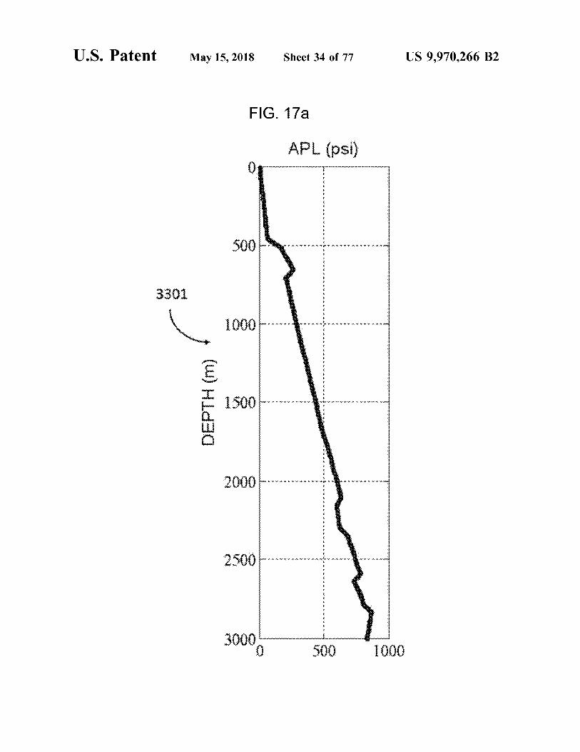
FIG . 17a APL ( psi )
AAYY AYYYAAAYYAAAYY Jessie 500 www . RAYAAN . . YANNYA . VV .
*
*
*
*
*
*
*
*
*
*
* 3301 *
*
*
*
*
*
* 1000 fanove VAAYYYAAYYYAA AW *
*
*
*
*
*
*
*
*
*
*
*
*
*
*
*
*
v
v
DEPTH ( m ) . ! . . . . . . . .
VYA . K . V . V . AA . VV . ARVYYY
YAAYAA .
YAAYYAAYYAAAYYYAAYYY AYY AYYYAAY 2500 NVVA . . . . . * . . . * * * . * . .
DO 500 1000
U . S . Patent May 15 , 2018 Sheet 35 of 77 US 9 , 970 , 266 B2
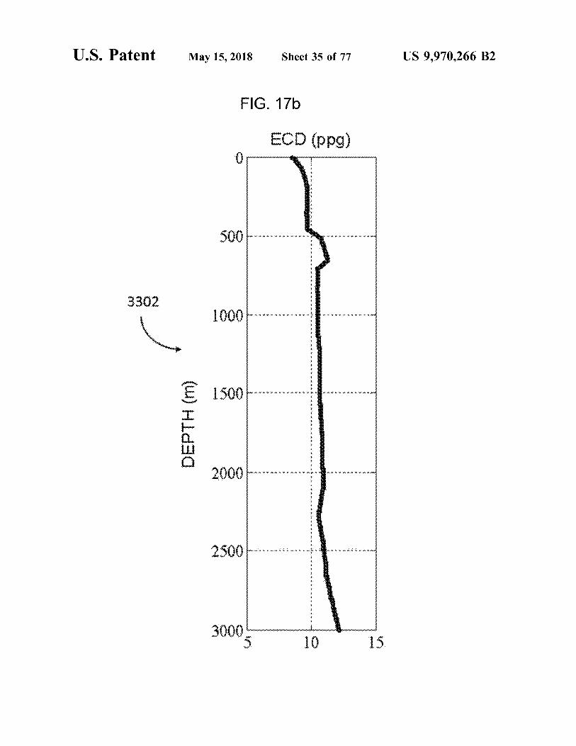
FIG . 176
ECD ( ppg ) SY .
YAYA AvW . 44 W . AA .
Sv . ArYYYAAN
3302 x + x + x + 5 * * * * * * * *
www . YANYASWYAAYYAAAYYYYYvain XYvirwin visivynixvYnm
DEPTH ( m ) ai * * * * * *
WAAVV . AA . AANV AANVAAVAA
AY
* 4 . 4V * *
Y
W
Some or
VASYVYSTYM 3000 5 mwa 10 15
U . S . Patent May 15 , 2018 Sheet 36 of 77 US 9 , 970 , 266 B2
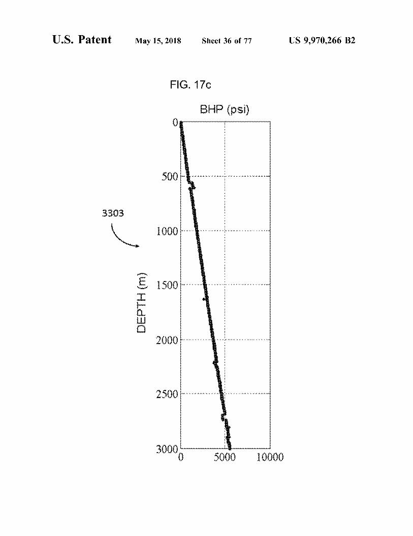
FIG . 170 BHP ( psi )
. . . .
.
. . .
. . .
. .
. . . . +
SWAAVAVAAVAA
- - - - - - -
- -
-
- - - -
3303 . .
.
.
.
SYYSYYYYYYYYYYYYY
7 7 . . . . * * . - * . . . * *
- *
. .
DEPTH ( m ) . . .
.
.
. .
2 . . . . * * * . .
+ "
. . . .
.
- - -
- -
.
.
. . . . . . . . . . . . . . ' ' 2500 * * * * * * * * * * * * * * * * * * * * * * *
30000 5000 10000

U . S . Patent May 15 , 2018 Sheet 37 of 77 US 9 , 970 , 266 B2
FIG . 170 Trip Margin ( psi )
wwwwwwwwwwwwwwwwwwwwwwwwwwwwwwww ANWAAVV * AAYV AWWAALWYA
wwwwwwwwwwwwwwwwwwwwwwww 3304
YA + YAWAVAAYYYAAYYA VYA KVKY 1000 * * * * . * * V * * * * * * * * * * V * * *
wwwwwwwwwwwwwwwwwwwwwwwww wwwwwwwwwwwwwwwwwwwwww OWYM * * Y * * * * * * * * * DEPTH ( m )
wwwwwwwwwwwwwwwwwwwwwwwwwwwwwwwwwwwwwwwwwwwwwwwwwwwwwwwwwwwwwwwwwwwwwwwwwwwwwwwwww *
*
*
*
*
WWA AWWA UWA
HAYVAAYYAYYAYAAYYA WAAVA *
*
*
*
*
*
2500 AAYYAAYYAAAW AVAA ' YA
30 . 90000 3000 1000

U . S . Patent May 15 , 2018 Sheet 38 of 77 US 9 , 970 , 266 B2
FIG . 18a APL ( psi )
500 WAAVAAVAV . AA . VVAAVYA AVM
3401
1000 . . . VVAAVAA MAAVV . MAYWANY W
DEPTH ( m ) v r . - 1 7 . v . A * * * . . .
2000 * * * * * * *
2500 = ' . . r - * * * * * * - - * *
do 500 1000
U . S . Patent May 15 , 2018 Sheet 39 of 77 US 9 , 970 , 266 B2
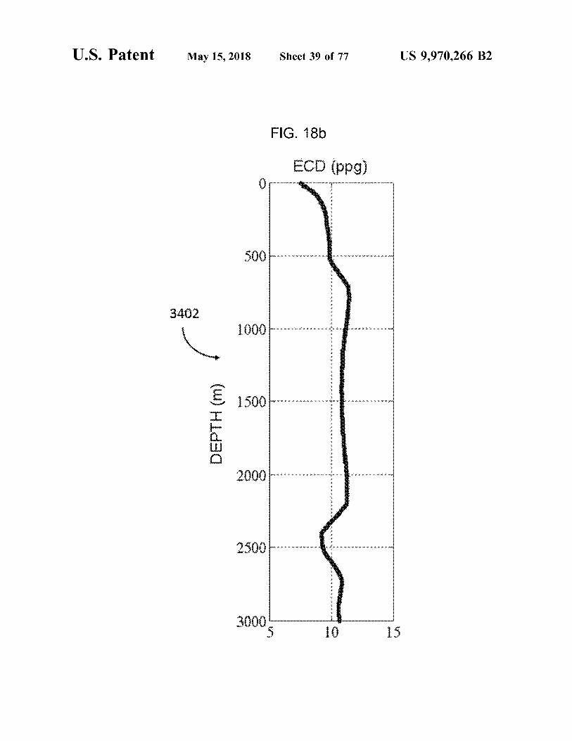
FIG . 18b ECD ( ppg )
YYYY AMV
A . SYYvvvvvv . AYYvvvvvvY24 AM
3402 . VVVVY * * MYYYYYYYY 1 Mvvvvy . W Yivitamin
VYRA * YV + + + + * + - YYV . ' + + * * * * * YYY
* *
*
DEPTH ( m ) *
* * *
* *
* *
* *
*
* sebagai - . - . - * - - - - * *
v 4 *
v v
v
v v
v
t
* * * YYYYYYYYY A rvvvvvvv - AAS
mmm . . . . vvv
0005 nennende 10 15
U . S . Patent _ May15 , 2018 Sheet 40 of 77 US 9 , 970 , 266 B2
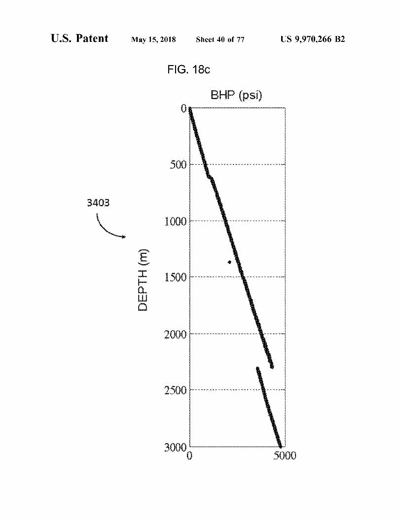
FIG . 18c BHP ( psi )
???? ?
S3j 3 ? + : A ?? , ? ? ? » . . • ? ? ? ? ,
???? ?? ???
??? ??? ? ? ?
* . ??? ' * * : ? ? ? : * . • • * * ? ? * : • * * . : • • ?
?
s : 8• - • • • • • • • • . : • • • • • • • : . : • • . . … 4• • • •
DEPTH ( n ) ?????????????? * : : * : . ?? . ? ? ? ? ?? ? . . & * . ' . ?? ? : ? ? ?? ? . .
? ' ? ? ? ? ? ? ??? ? ? ? ? ? ? ? - ? ? ? ? ? ? !
? } }
3404
U . S . Patent
DEPTH ( m )
ebent things
2500
i
May 15 , 2018
1000
* * * *
-
•
-
* * * * •
WYYYYYYYYYY .
FIG . 18d
*
* 4 *
AYY AYYYY AYY 4
-
*
-
0
? ?
?
?
? ? ?
?
? ?
?
?
? ?
?
?
? ?
?
? ?
?
? ? ?
?
? ?
?
?
? ?
?
?
?
.
.
. . .
.
.
.
. . . .
. .
. .
YAYAYAYAYAYAYYAAVAS
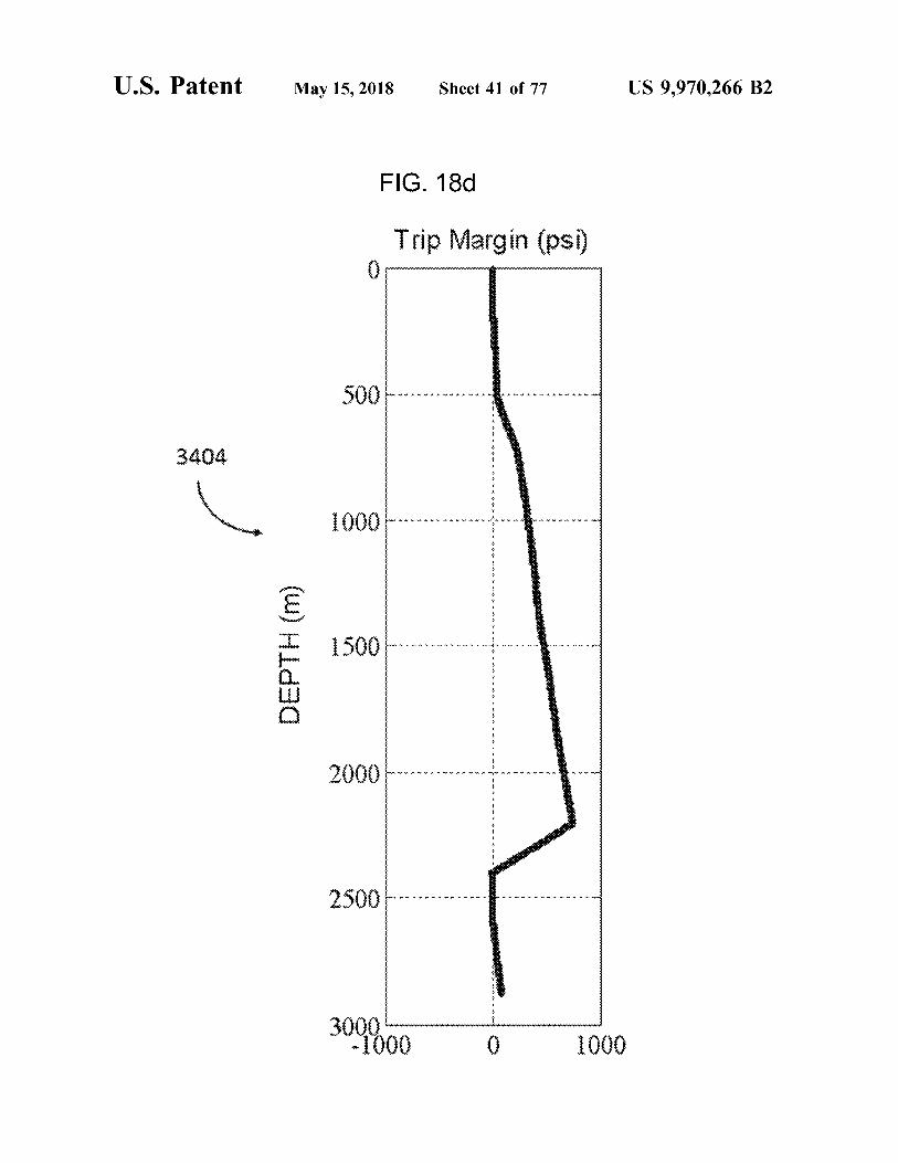
Trip Margin ( psi )
Sheet 41 of 77
* , •
* * * YMAS
* * * * *
* -
* *
* * AYAW
*
- -
* *
* * * * * * * * * * * * * * * * * * * * * * * * * * * * *
* *
* *
* *
* *
* *
* *
* *
* *
* *
1000
Wwwwwwwwwwwwwwwwwwwwwwwwwwww w
www
US 9 , 970 , 266 B2
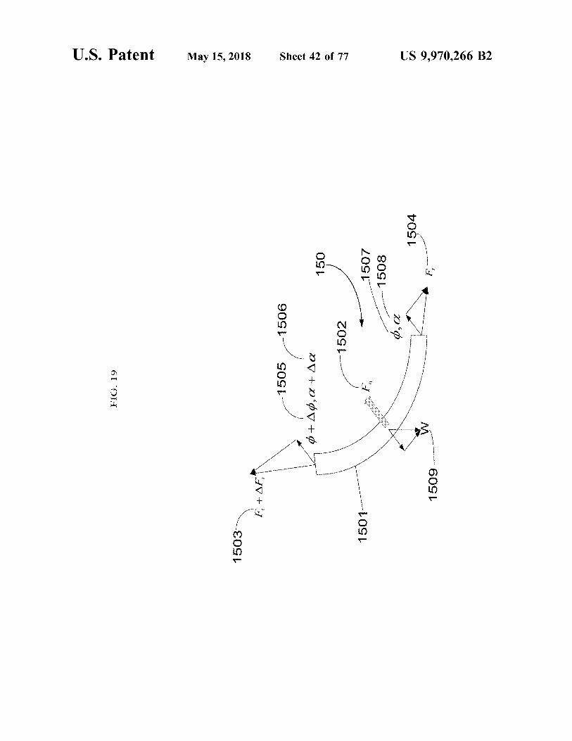
FIG . 19
U . S . Patent May 15 , 2018
1503
F + AFT
- 1505
- 1506
0 + 40 , a + Aa
150
Sheet 42 of 77
- 1502
1501
1507 - - 1508
1504
1509
F .
US 9 , 970 , 266 B2
U . S . Patent May 15 , 2018 Sheet 43 of 77 US 9 , 970 , 266 B2
FIG . 20 , 2200
????????????????????????????
*
* * * * * '
' '
'
'
'
' '
' ' '
'
'
' ' '
'
'
'
'
'
' ' '
' 2400 ' '
'
'
'
'
'
'
' '
'
'
'
'
' ' ' 1601 '
'
2500 * * * * * * * * * * * * X 2
1 . 1 . JUX
2600
Depthim ) . . . . . . . . . . . . . . . . . . . . .
3227 . 7 . V . X
2
7 . V . X .
277 . . . .
2800
. RRYYYYYYYYYYYYYYYYYYYYYYYYYxxxxxxxxxxxxxxxxxxxxxxxxxxxxxx xx . 222222 0067 * * * * * * * * * * * * * * * *
??????? sex <
????????????????? 3100 . 7 . 1 . 7
?
?
0008 2000 4000 6000 Torque ( Nm ) w W
*
U . S . Patent M ay 15 , 2018 Sheet 44 of 77 US 9 , 970 , 266 B2
FIG . 21 { 3 ??????? ? ? ?
? ??
} ??r
3602 ????? 5• • • • + t - • • • + + • • • •? + + - ??? E????tr
st??tt?rr
?
- Cerythfrm ? r ; ? ?
-
{ ????????????????????? ??• • # #
? ? ???? ???? ???? ????
}
* * C g
U . S . Patent May 15 , 2018 Sheet 45 of 77 US 9 , 970 , 266 B2
FIG . 22
2300
2400
2500 . ' ' ' ' ' ' wx
1603 2600 YEVDEK
2700 Depthom ) Depthm )
2800 KEPIFREIFTER THIRT
2900
3000
3100
0 . 5 Rotating friction factor
US 9 , 970 , 266 B2
30
T . 127 . 10
. 107 . 127 . 12
JY WYWYTAUS
TV .
V7 - 71TrenverwecvecvenXNNS
verururwerver
* * *
* * * *
* * * * * * * . ! ! . . . ! . . "
. .
. .
. .
. .
. . . .
. - . -
. - . - " * . . * - » * . . * . * . . * . * . * . - * - * - * . 4 . 4 . 4 . 4 . 4 . 4 . 4 . 4 . 4 . 4
Sheet 46 of 77
20 10 Neutron porosity ( % ) 0
25 -
FIG . 23
31 . 03 .
.
V
May 15 , 2018
* * * * ISTUSSUU
- 10 1
3290
3280
3270
3240
3230
Measured depth ( m )
1701
U . S . Patent
U . S . Patent May 15 , 2018 Sheet 47 of 77 US 9 , 970 , 266 B2
FIG . 24a 3290
3280 1702
Measured depth ( m )
Any
3230 Permeability ( log md ) Permea
US 9 , 970 , 266 B2
: . ' . ' . ' . ' . ' . ' . ' . ' . ' . . ' . . . . . . . . .
. . . . . . . . .
. . . . . . ' . ' . ' . ' . ' . ' . ' . ' . ' . ' . ' . ' . ' . ' . ' . ' . ' . ' . ' . ' . ' . ' . ' . ' . ' . ' . ' . ' . ' . ' . ' . ' . ' . ' . ' . ' . ' . ' . ' . ' . ' . ' . ' . ' . ' . ' . ' . ' . ' . ' . ' . ' . ' . ' . ' . ' . ' . ' . ' . ' . ' . ' . ' . ' . ' . ' . ' . ' . ' . ' . ' . ' . ' . ' . ' . ' . ' . . ' .
. . .
.
1 . 1 : . : . : . : . : . : . : . : . : . : . : . : . : . : . : . : . : . : . : . : . : . : . : . : . : . : . : . : . : . : . : . : . : . : .
. : : . : . : . . : . : . : . : . : . : . : . : . : . : . : . : . : . : . : . : . : . : . : . : . : . : . . : . : . : . : . : . : . : . : . : .
. : . : .
. : . : . : . :
Triiiiiii
. . . .
!
! !
* *
*
*
*
*
. .
irrininccrrrrrrrrrrrrrrrrr
Sheet 48 of 77
AMWWWNS 20xd INOM . .
May 15 , 2018
TOSE
atent
9 7 * OIL
U . S . Patent May 15 , 2018 Sheet 49 of 77 US 9 , 970 , 266 B2
??????????
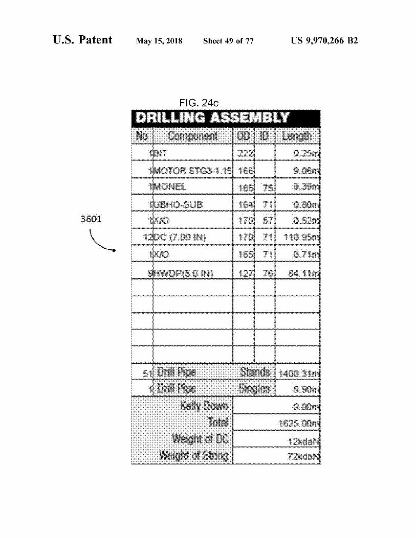
FIG . 24c DRILLING ASSEMBLY No Component OD 0 Length
222 0 . 25m MOTOR STG3 - 1 . 15 166 9 . 06m IMONEL 165 75 9 . 39m TUBHO - SUB 164 71 0 . com
170 571 0 . 52m 120c ( 7 . 00 IN ) 170 711 110 . 95m
165 71 0 . 71m SHWDPI5 . 0 IN ) . 11271 76 84 . 11m
* * * * * * * * * * * * * * * * * * * * * * * * * * * * * * * * * * * *
3601 - - -
- .
. . - - : - -
- . - . - . - . - .
- . - . - . - .
-
-
- - - -
- -
-
- - - -
-
-
-
-
-
-
-
-
-
V
- -
5l Drill Pipe 1 Drill Pipe
Kelly low Total
Weight of DC Weight of String
Stands 1400 . 31m Singles 8 . 90m
0 . 00m 1625 . 00m
12xdan 7daN
U . S . Patent May 15 , 2018 Sheet 50 of 77 US 9 , 970 , 266 B2
heiminimiinimumiminiminim
xxxxxxxxxxxxxx 0
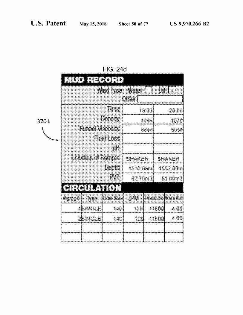
FIG . 24d MUD RECORD
Mud Type Water 0 Other
Time 18 : 00 Density 1065
Funnel Viscosity 685 Fluid Loss
20 : 00 1070 60s
www
Location of Sample SHAKER SHAKER Depth 1510 . 69m 1552 . 00m PVT 62 . 70m ) 61 . 00m3
CIRCULATION Pumpe Type Unter Size SPM Pressure House
SINGLE 1401 120 11500 4 . 00 SINGLE 140 120 11500 4 . 00 YYYYYYYYYYYYYYYYYYYYYYYYYYYYYYYYYYYYYYYYYYYYYYYYYYYYYY
. . . . . . . . . . . . . . . . hooooooooooooo
U . S . Patent
FIG . 24e
May 15 , 2018
:
:
:
:
3801
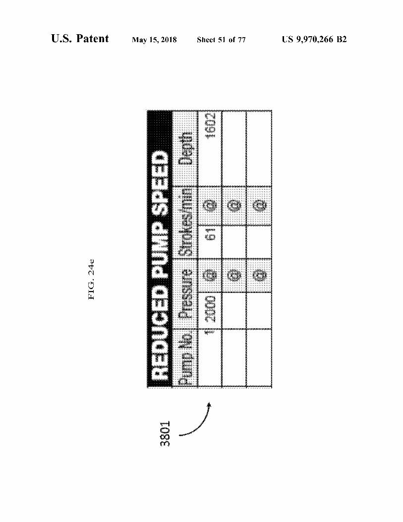
REDUCED PUMP SPEED Pump No . Pressure Strokes / min Depth 2000 @ 61 @ 1602
Sheet 51 of 77
WWW
US 9 , 970 , 266 B2
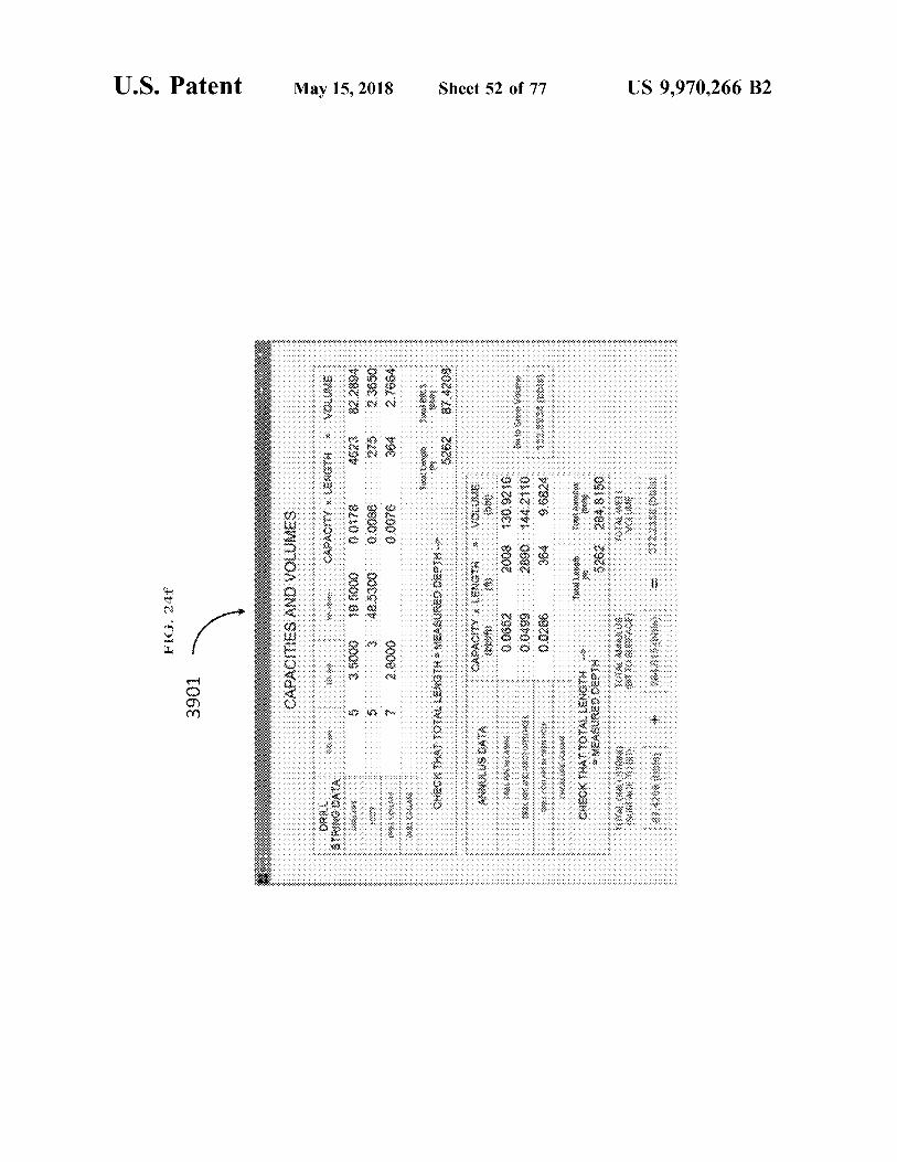
FIG . 24f
U . S . Patent
3901 CAPACITIES AND VOLUMES
CAPACITY X LENGTH * VOLUME
SIS
OKTA
0 . 0178
May 15 , 2018
$ 623
* * * * * * * * * * * * * * * * * * * * * * * * * * * * * * * * * * * * * * * * * * * * * * * * * * * * * * * * * * * * * * * * * * * * * * * * * * * * * *
82 . 2894
0 . 0076
Swim
CHECK THAOYAL WOMXGASURCOS WW US OK
CAPACITY LENGTH * VOUS
Oo
0 . 0662 2008 130 . 9216 0 . 0499 2890 144 , 2110 0 . 0266 304 9 . 6824
Sheet 52 of 77
WWW
33333333333333333333333 * * * * * * * * * * * * * *
. . . . . . . . . . . . . . . . . . . . . . . . . . . . . .
smontox
CHECKM67 101KL LENGTH WEASURES OU WA
US 9 , 970 , 266 B2
US 9 , 970 , 266 B2
{ { 3ds ) Bian Alarksos
S & 838
038
aus
fuss ) area
78 Msikiti wa Ko
BXOBS ja QI BBK
32XS 38
MU
0918737
COZY28
Sonous 26MS 618
{ s } 99 ) Pro dund
( SQ ) Burst OEMS 48
soxqus 18
{ $ iga ) ?wro
is uc
zdo USB
* SH?
een bus # 40 .
Sheet 53 of 77
0002
wds og
1007
39
Was Oy
( um ) au
HQUS 3s
{ wiss army BUEIXO MOS
# BAONS mous 08
wag
da es
May 15 , 2018
soxons vous
Assige oso 0380
( sica ) ovino Sous ou
???
zen dute ON deild Pos
$ 800 Oxassiga manteng duma
BIV NOULVINOHO MOIS P038i que pest
exeo sam nedo .
BVZ OH
U . S . Patent
U . S . Patent May 15 , 2018 Sheet 54 of 77 US 9 , 970 , 266 B2
FIG . 24h 4101 -
Saiad Bacard Siapa SICH Sonu PIT GAIN PT GAIN
( exbits )
MAT : V Sixx Ofestips Casio IVO .
from AKO Lea Testo Weigh to
Max H Weight loss
Reisen Rex Wag tags : ????? , 97N , Miako Weigte sux3 ) Caxing WVO , Veski
WS Marisa Wniot look
70 . 8 *
Asowie Argickx Grimm
2008 SSSSSSS Sosirisirisirisirisis
Casing visits s Catex Fero sexcess
Men ) Afswaste i who Frostwo ( 2
S000
UV from KEN wekis Vogt ( 993 )
U . S . Patent May 15 , 2018 Sheet 55 of 77 US 9 , 970 , 266 B2
FIG . 24i 4201 en
KES RS Cast : BOB Box
M okslo XOXOXO XXX
3 . 00
A s week * * exe
BOXXX .
CMS kodex 304
COMME Svi XXX
1 . 41 BASES Boris Kas WS
SOXXOLX CVWW svou
US 9 , 970 , 266 B2
www omnes BOLLY
* * * * * * * . * .
5328 4 sep 16 . Hoonel . com all oid male secoure el sol colocaual _ call
Hamari T
ris
Sheet 56 of 77
LIT
tutmals zusammenges
ellung . .
S
winn
on * W
May 15 , 2018
Lee
97 9
8 99
les
* * * * * * * * *
* * *
* * *
4202
U . S . Patent
FIG . 241
US 9 , 970 , 266 B2
* * * * * * * * * * * * * * *
* 19 .
sk . * *
* * * * * * *
* * * * * * * * *
• * * * * * * * * * * *
Sheet 57 of 77
COM
1115
. . . en . .
* * * * * *
l
.
Www .
* * * * * * * * *
* * * * *
* * * *
*
* * * * * * * * * *
* *
XX X
* * * *
*
* * *
* * * * * *
* * * * * * * * * * * * *
*
* * * * * * * * * *
* * * * * * * * * * * *
* * * * * * * * *
May 15 , 2018
1
* * * * * * * *
- * * *
* * *
* *
*
1 COCK
U . S . Patent
17 DI
US 9 , 970 , 266 B2
?? 1 ?
- ???? ?? ??? ?????? ?
Sheet 58 of 77
?? ????
?
????????? ?
??
May 15 , 2018
??? - - - - - - ???? ????? ???? ????? ??
?
8
?
???? ?
? . ?
•
treesee sheepetite . .
4204
U . S . Patent
FIG . 241

U . S . Patent
FIG . 25
4300
4301
May 15 , 2018
Muda
real time ? -
4304
4305
4306
4307
4308
4309
CAXXXXXXXXXXXXXXXXXXXXXXXXXX
4302 4302 ' I
_
YEYEVA
Visually check tank for input fluid , whole mud , water , oil . . .
Potential Blowout or need to release pressure ( burb in the well )
<
threshold ?
Stop pump
Establish volume gain and why
Flow check
Follow established procedure DO .
4303
Sheet 59 of 77
ETLENZENTRIERER 22222222222222222
weis
Stop pump stop pump
File Flow check
pro come la persone
Visually check tank for input fluid , whole mud , water , oil . . .
Establish volume loss and why
Potential loss in circulation
Follow established procedure
- rarter :
4304
4305
4306
4307
4310
4311
US 9 , 970 , 266 B2
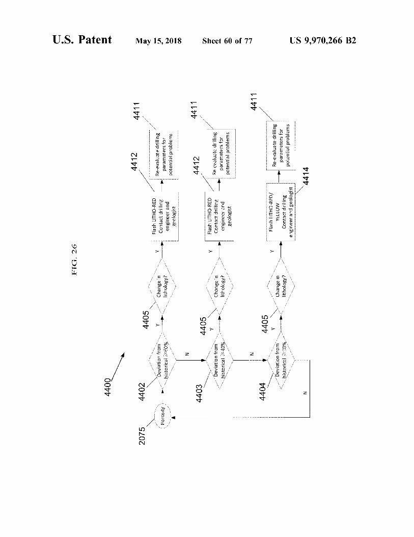
FIG . 26
U . S . Patent
4400
4412
4411
2075
4402
*
*
* * *
Y
MY
Deviation from historical > 60 %
Porosity )
Change in lithology ?
Flash LITHO - RED Contact drilling engineer and geologist
Re - evaluate drilling parameters for potential problems
May 15 , 2018
4411
4403
4412
4405
Y
Deviation from
Y
Change in lithology ?
historical > 40 %
Flash LITHO - RED Contact drilling engineer and geologist
Re - evaluate drilling parameters for potential problems
-
Sheet 60 of 77
-
-
4411
4404
4405 V
Deviation from historical 20 %
Change in lithology ?
Flash LITHO - RED / YELLOW Contact drilling engineer and geologist
Re - evaluate drilling parameters for potential problems
N
4414
US 9 , 970 , 266 B2
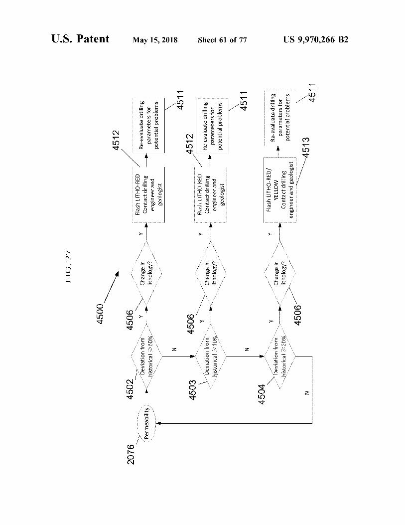
FIG . 27
U . S . Patent
4500
4512
2076
4506 Y
- -
-
4502
Deviation from historical > 60 %
- - Permeability
Change in lithology ?
Flash LITHO - RED Contact drilling engineer and geologist
Re - evaluate drilling parameters for potential problems
May 15 , 2018
4511
4506
4512
. .
4503 Deviation from historical > 40 %
Y
-
. .
- -
Change in lithology ?
Flash LITHO - RED Contact drilling engineer and geologist
Re - evaluate drilling parameters for potential problems
Sheet 61 of 77
4511
4504
Deviation from historical 220 %
Change in lithology ?
Flash LITHO - RED / YELLOW Contact drilling engineer and geologist
Re - evaluate drilling parameters for potential problems
4506
- 4513
4511
US 9 , 970 , 266 B2
U . S . Patent
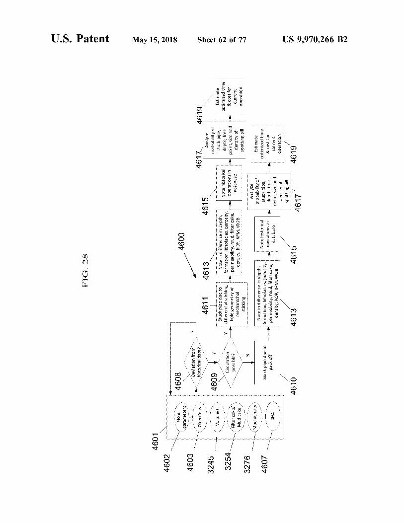
FIG . 28
4601 4602
May 15 , 2018
Hole parameters ,
4608
4600
4603
N
Deviation from historical data ?
Directions
4619
4611
4613
4615
3245
4609
Y
Volumes
4617 Analyze probability of stuck pipe ,
Note historical
depth , free
operations in
point , size and
database
density of spotting pill
3254
Stuck pipe due to differential sticking , hole geometry or mechanichal sticking
Note in difference in depth , formation , lithofacies , porosity , permeability , mud , filter cake , density , ROP , RPM , WOB
Circulation possible ?
Sheet 62 of 77
Estimate optimized time & cost for current operation
Filter cake / Mud cake
3276
N .
Mud density )
4607
- -
- - - -
Stuck pipe due to pack off
Note in difference in depth , formation , lithofacies , porosity , permeability , mud , filter cake , density , ROP , RPM , WOB
Note historical operations in database
Analyze probability of stuck pipe , depth , free point , size and density of spotting pill
Estimate optimized time & cost for current operation
BHA
4610
4613
4615
4619
4617
US 9 , 970 , 266 B2
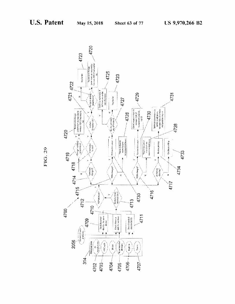
FIG . 29
U . S . Patent
4700
4719
4720
2056
4721 4722
4745 4714
4718
!
change in dB
Y
Review and change [ ages as ?? ( ?? to maintain ROP , if not trip for hit
parameters ?
- 4723
Current bit wear recictio :
N
Trio for bit
4712 4712
314
4709
Formation changca ?
Historical data
Is formation harder ?
4710
Is a harc formation
Wenge in Urilling parameters ?
4720
May 15 , 2018
Review and darge parameters as required lv mantax ROP , Cruip to : Dit
"
?
.
. . . . . .
4702 4703
bit a2 ?zer ,
g
NOP decrease
Check historical data for the same bit
Condove awareness of it hours are vider Tankefacturer
140 % code
- 4725
Y
. Ni
KPM chargedr
a
Review the season
o
Do Dierges make
Et size
any offerencer
Trip for bir
Check issonca data for rur time
- - ' Devation from
historicaidata ?
- 4723
4704 4705 4706 aboro Recommended Bithoux
Trip bit if close to marutx1 : 02r Commenced hours :
- - 4727
- 4728
Depth
Check historical data for bit ?
Sheet 63 of 77
- _ - _ - _ A
4713 4730
WOB changed ?
Time in
Review the reason
4729 p??ze past to : ncrease ROP , it increase not possible , trio bit
4707
4711
N
.
Trio bit li cose to manuacturer jecommended hours
4730
4716
Drilisting vibrating ?
Review geology
Optintre carameters to nize ya?? , increase ROP , f increase noi possible , trip ixit
NL
Continue drilling
4717
4731
4728 4728
4731
4734 4733
US 9 , 970 , 266 B2
U . S . Patent
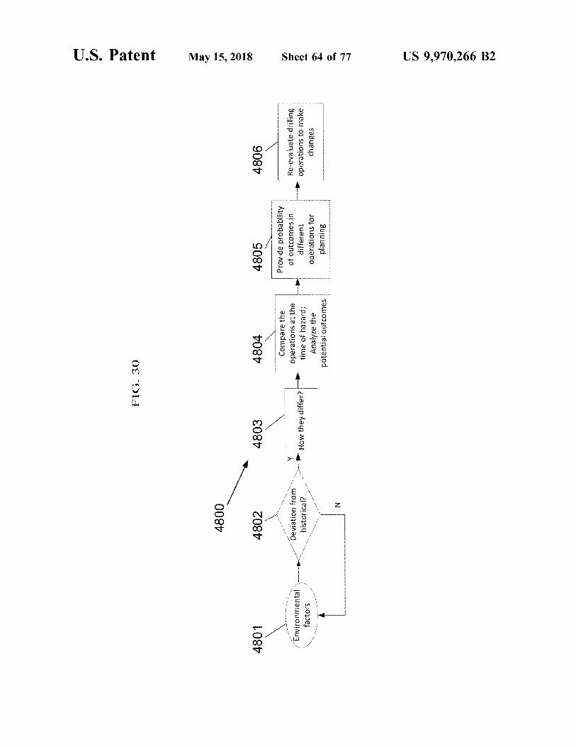
FIG . 30
4800
May 15 , 2018
4801
4802
4803
4804
4805
4806
Y
Environmental factors
Deviation from historical ?
How they differ ?
Compare the operations at the time of hazard ; Analyze the potential outcomes
Estamos tramos Provide probability of outcomes in different operations for planning
Re - evaluate drilling operations to make changes
. .
- -
* * *
*
Sheet 64 of 77 US 9 , 970 , 266 B2
atent May 15 , 2018 Sheet 65 of 77 US 9 , 970 , 266 B2
17 . Tiitiiiiiiiiiiiiiiiiiiiiiiiii 1 . , . , 7 .
WW im
5004 EWON M
WWW . Emas
.
.
. . .
.
wi . .
irriririririi WWWWWWWWWWWWWWWWWWWWWWWWWWWWWwwwwwwwwwwwwwwwwwwwwwwww 2005 *
*
* * * * * * * * * ???? ?? ? ??? ?????? ?? ?????? ?? ?? ???? ??? ? ? ? ?????? ?? ????? ?? ???? ?? ??? ?? ????? ? ???? vllllll
FIG . 31 5001
5002
U . S . Patent May 15 , 2018 Sheet 66 of 77 US 9 , 970 , 266 B2
. . . .
. . . .
. . . .
. . . .
- ? - ? - ? - ? - ? - ? - ? - ? - ? - ? - ? - ? - ? - ? - ?
. .
* * *
FIG . 32
* * *
* * * * * * * * * * * *
* * * * *
* * * * * * * * * * * * * * *
5100 * * *
*
*
* * * *
* *
WWWWWWWWWWWWWWWWWWWWWWWWWWWWWWWWWWWWWWWWWWWWWWWWWWWWWWWWWWW
US 9 , 970 , 266 B2
* * * * * * * * * * * * * * * * * * * * * * * * * * * * *
* *
*
+
, - . *
WW
. .
. . .
.
.
. . .
.
.
. ,
VINNYTY * * *
Siirr Y
+ 4 . 4
" . '
.
.
. . . .
vo . "
. * *
. .
*
.
.
.
* * .
. * .
*
. . .
. .
. * *
.
*
2
.
7
. 1
.
1
Sheet 67 of 77
.
*
* * * *
* * * *
.
. .
.
. . . . .
.
. . . .
1 .
ri ' yin
. .
.
.
,
Www
. * . * . * .
* . * . * . * * . * * * . .
* * * * :
. '
.
.
* *
* +
* * * *
*
May 15 , 2018
* * * * * *
0OZS
CE OL
U . S . Patent
US 9 , 970 , 266 B2
* * * * * * * * *
* * * *
wwwwwwww wwwww * *
+ + + +
. .
.
S
.
.
.
* * * * *
.
>
.
WWWWWWWWWWWWWWWWWWW
.
.
. .
.
. .
. : . . ' + ' + +
. . ' '
' '
. ' . ' . '
.
. . .
.
. .
.
Sheet 68 of 77
: : * * * * * * * * * * * * * * *
YAY ,
.
. . ^
"
.
11 .
.
. . '
11
* * * * * * * *
* * * * * * * . . . .
* *
* * , +
May 15 , 2018
3 . * *
ooow .
W
* * * * * * *
00ES
U . S . Patent
VE DI
U . S . Patent May 15 , 2018 Sheet 69 of 77 US 9 , 970 , 266 B2
FIG . 35
WWW
* * * * * *
*
5400 . .
. .
US 9 , 970 , 266 B2
111 , 11 , ' i
111 ' . yinni
- . - . - . -
. -
. - . .
- .
- . -
.
.
. .
, , "
. .
.
.
. . .
. . . . . . . . . . . . . . . . . . . . . . . . . . . . . . . . . . . . . . . . . . . . . . . . . . . . . . . . . . . . . . . . . . . . . . . . . .
" . . * * * * * *
* *
*
* * * *
1
.
. . .
. .
' . . '
- . .
Sheet 70 of 77
www
'
' '
1
4 . 4 .
1
"
. . kin
. .
. . . . .
ren . . . ' yin
'
* * * *
May 15 , 2018
um
WWWWWWWWWWWW * * * *
* * * * * * *
* * * * * *
* * * * * * * * * * * * * *
xx
* * * * *
5500
U . S . Patent
FIG . 36

US 9 , 970 , 266 B2
* *
*
: : : :
: : : :
: :
. . .
. . . .
.
. .
.
. .
.
.
. .
.
.
' '
* * * * * * * * * *
.
. ' '
. .
.
' .
7 : 11
-
11 -
1 . . 1
*
*
*
* *
Sheet 71 of 77
* . * . * . * . * . * 1 7V
Sli
. . . . . . . . . .
. .
. .
. . ' .
.
. ' ' ' .
' . ' . ' . .
' . '
. . . ' '
, 1 . . . - . .
. . .
. .
. .
" ' . ' . . . ' .
.
. ' .
'
. ' . ' .
'
' .
. '
1 . 1 .
ini . . . . . . .
.
Www
May 15 , 2018
W
*
: : : : : : : : : : : : : : : : : : : : : : :
0098
U . S . Patent
LE ON
U . S . Patent May 15 , 2018 Sheet 72 of 77 US 9 , 970 , 266 B2
WWW M W
* * *
FIG . 38
BAMOK OMX Suondo
WOW MX
5700 myx XXXXX
U . S . Patent May 15 , 2018 Sheet 73 of 77 US 9 , 970 , 266 B2
* . * . * . * . * . * . * . * . * * . * . * . * . * . . * . * . * . * . * . * . * . * . * . * . * . * . * * *
XX X
WWW * MMM Xxx * * * * * * * * * * *
* * * * *
* www
W
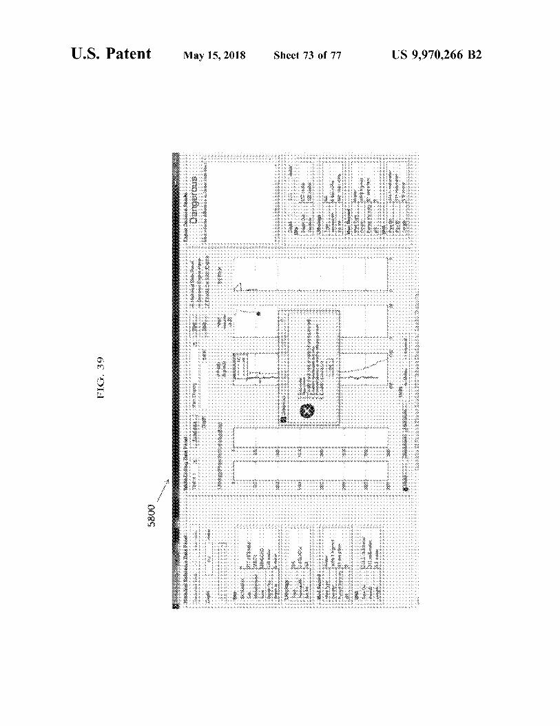
wwwww FIG . 39 Www ,
5800 : : : : : : : : : : : : : : : : : : : : : : :
999
* * * wy w
* * * 0065
* * * * WWWWWWWMX * * * * * * *
*
* * * * * *
*
* * * * * * *
* * * WWWWWWWWWWWW * KA 081 } $ 300 * *
* ?? WMA ?? " ??
"
. . . . . . . . *
.
* * * * * * * * * *
. . . . .
???? .
" ???? WWW ???? . . . . ??
FIG . 40 * * * * * *
*
?????? 4 *
*
- * *
-
- - ' ' ' ' ' ' ' ' ' ' ' ' ' ' ' ' ' ' ' ' ' ' ' ' ' ' ' ' ' ' ' ' ' ' ' ' ' ' ' ' ' '
1
-
- ???? *
. - . ' . ' . ' . ' . ' . ' . ' . ' . ' . ' . ' . ' . ' . ' . ' . ' . ' . ' . ' . ' . ' . ' . ' . ' . ' . ' . ' . ' . ' . ' . ' . ' . ' . ' . ' . ' . ' . ' , WWWXWW . wimwxx
$ 003anuna * * S . . ' . ' . ' . ' . ' . ' . ' . ' . ' . ' . ' . ' . ' . ' . ' . ' . ' . ' . '
MW
wwwwwwwwwwwwww w wwwwwwwwwwwwwwwwwwwww . . . ' . ' . ' . ' . ' . ' . ' . . ' . ' . ' . ' . ' . ' . ' . ' . ' . ' . ' . ' . ' . ' . ' . ' . ' . ' . ' . ' . ' . ' . ' . ' . ' . ' .
US 9 , 970 , 266 B2 Sheet 74 of 77 May 15 , 2018 U . S . Patent

US 9 , 970 , 266 B2
*
. . .
. . . . . . .
. .
.
. : : .
. . . :
WWW WW * w
Sheet 75 of 77
W
* * * * * ii ww www
.
May 15 , 2018
ovom
* * * inistrimin
6000
U . S . Patent
FIG . 41
. . . .
. . . . . . 4
, , , , , Www , , , , , , , , , , , , ,
My 1 . 1 . 1 . 1 . 1 . 1 . 1 . 1 . 1 . 1 . 1 . 1 . 1 . 1 . 1 . 1 . 1 . 1 . 1 .
0019 Salapedia
*
* * * * * * * * * * *
* * * *
* * * * * *
*
*
* * *
FIG , 42 * * * * - * - * - * - * - * * *
www . . . . * * * * *
* * * * * * * wa
* * * * * * * * * *
M
? ??? ??? ??? ??? ??? ??? ? ??? ? ? ?
2 . . *
so Situdoune ki MMM *
. . - . . - . - . - . - . - . - . - . - . - . - . - . - . - . - . - . - . :
* *
. . . . . . . . . . . . . . . . . * * * * * * * * * * * * * * * * * * * * * * * * * * *
. . ' ' ' ' ' ' ' ' ' ' ' ' ' ' ' ' ' ' ' ' ' ' ' ' ' ' ' ' ' ' ' ' ' ' ' ' ' ' ' ' ' ' ' ' ' ' ' ' ' ' ' ' ' ' ' ' ' ' ' ' ' ' ' ' ' ' ' ' ' ' ' ' ' . ' . ' . ' . ' . ' . '
US 9 , 970 , 266 B2 Sheet 76 of 77 May 15 , 2018 U . S . Patent
1 . 1 . 1 . 1 . 1 . 1 . 1 . 1 . 1 . 1 . 1 . 4 . 4 . 4 . 4 . 4 . 4 . 4 . 4 . 4 . 4 . 4 . 4 . 4 . 4 . 4 . 4 . 4 . 4 . 4 . . 4 . 4 . 4 . 4 . 4 . 4 . 4 . 4 . 4 . 4 . 4 . 4 . 4 . 4 . 4 . 4 . 4 . 4 . 4 . 4 . 4 . 4 . 4 . 4 . 4 . 4 . 4 . 4 . 4 . 4 . 4 . 4 . 4 . 4 . 4 . 4 . 4 . 4 . 4 . 4 . 4 . 4 . 4 . 4 . 4 . . . . . . . . . . . . . . 4414171 M
www : : :
U
M
. .
* * . WWW ME *
. *
*
. 249
*
* * * * . * . . * *
* *
.
* * W
* 6200 * * * * * * * * * % 22 22 * * *
* * * *
wwwwww '
. . . 1 . . .
.
:
FIG . 43
1
. . .
.
V 19
' ' ' ' ' ' . ' . ' . ' . ' . ' . ' . ' . ' . ' . ' . ' . ' .
. ' '
.
1 .
17 .
* . * * * . * . * . * . * . * . * . * . * . * . . * . . . * . . * . . * . . . * . . * . .
. * . * . . . . . . . . . . . . . . . . .
* * * * * * * * * * * WWWWWW * * * *
. . . . .
* * * *
: : : . . . . . . . .
w *
* 1 . 1 . 1 . 1 . 1 . 1 . 1 . 1 . 1 . 1 . 1 . 1 . 1 . 1 . 1 . 1 . 1 . 1 . 4 .
11111111111111111 ' . ' . ' . ' . ' . ' . ' . ' . ' . ' . 1 . 1 . 1 . 1 . 1111111
US 9 , 970 , 266 B2 Sheet 77 of 77 May 15 , 2018 U . S . Patent
US 9 , 970 , 266 B2
tion .
METHODS AND SYSTEMS FOR IMPROVED and historical drilling data . This may include using mea DRILLING OPERATIONS USING surements obtained using measurement - while - drilling tech
REAL - TIME AND HISTORICAL DRILLING nology to make a real - time bit wear prediction , lithology DATA prediction , pore pressure estimation , rotating friction esti
5 mation , permeability estimation , and cost estimation . These CROSS - REFERENCE TO RELATED APPLICATIONS predictions may be used to optimize weight on bit and bit
rotation speed in an aim to obtain a maximized drilling rate This application is a continuation of application Ser . No . and a minimized drilling cost . An expert decision engine
13 / 665 , 202 , filed Oct . 31 , 2012 , now pending . The patent may also be provided to guide the operator or user to avoid application identified above is incorporated herein by refer safety concerns while drilling . ence in its entirety to provide continuity of disclosure . According to an aspect of the present invention , there is
provided a method of drilling a formation , comprising : FIELD OF THE INVENTION acquiring real - time drilling data ; acquiring a bit wear equa
tion ; determining a real - time bit wear prediction by using the The present invention relates to drilling operations , and 15 real - time drilling data to predict a bit efficiency factor and to more particularly , to methods and systems for improved drilling operations through the use of real - time and historical detect changes in the bit efficiency factor over time ; deter drilling data . mining a real - time lithology prediction by processing the
real - time drilling data through a multilayer neural network ; BACKGROUND OF THE INVENTION 20 and adjusting the drilling parameters for the drilling opera
tion in real - time based on the real - time bit wear prediction Historically , drilling operations rely on " after - the - fact " and the real - time lithology prediction .
analysis to determine lithology , as well as other parameters . According to a further aspect of the present invention , For example , in order to determine lithology , drill bit cut there is provided a drilling system including a drilling fusion tings are physically analyzed at the surface by the well site , 25 prediction engine for predicting bit wear and lithology in geologist , or to be certain of a formations ' lithology , physi real - time for use in determining drilling parameters in a cal parameters and geological facies , 30 feet core sections or drilling operation , the drilling system comprising : one or sidewall cores are taken and analyzed at the surface . In each of the above methods , samples must be physically removed more sensors for sensing data at a rig during a drilling from the formation and returned to the surface for evalua operation ; a computer system including a drilling fusion
30 prediction engine for predicting bit wear and lithology in In order to provide real - time operational data , in - situ tools real - time , the drilling fusion prediction engine configured to
are used . The most popular is spectral analysis of the receive the sensed data , the drilling fusion prediction engine formation being drilled . Spectral analysis involves the inter - including a software module for predicting lithology in pretation of spectra obtained from the formation drilled real - time by processing the sensed data through a multilayer using logging tools including a passive gamma ray detector 35 neural network , the drilling fusion prediction engine includ and a neutron induced gamma ray log . In the latter tool , a ing a software module for determining a real - time bit wear neutron source is placed alongside the formation and peri - prediction by using the real - time drilling data to predict a bit odically emits bursts of high energy neutrons to excite the efficiency factor and to detect changes in the bit efficiency atoms in the formation . A detector records the number of factor over time ; and a communication network for trans counts of returning gamma rays and segregates them accord - 40 mitting the sensed data to the drilling fusion prediction ing to their energies . The major drawback of this method is engine . the recorded neutron induced gamma ray spectrums which According to a further aspect of the present invention , are contaminated by significant background noise due to there is provided a computer program product , the computer Compton scattering . Hence , spectral analysis cannot deter program product comprising : a storage medium configured mine lithology as precisely as coring - based techniques . 45 to store computer readable instructions ; the computer read
Measurement - while - drilling is a type of well logging that able instructions including instructions for , acquiring real incorporates downhole tools providing real - time informa - time drilling data ; acquiring cost data and a bit wear equa tion to help with steering the bit . These tools typically tion ; determining a real - time bit wear prediction by using the include sensors for measuring downhole temperature and real - time drilling data to predict a bit efficiency factor and to pressure , azimuth and inclination , drilling mechanics infor - 50 detect changes in the bit efficiency factor over time ; deter mation ( e . g . torque , weight - on - bit , rotary speed , etc . ) and a mining a real - time lithology prediction by processing the resistivity to determine the presence of hydrocarbons and real - time drilling data through a multilayer neural network ; water . and adjusting the drilling parameters for the drilling opera
As the hole drilling operation progresses , a drill bit tion in real - time based on the real - time bit wear prediction gradually degrades until it breaks . Replacing a drill bit after 55 and the real - time lithology prediction . it breaks can be costly because of debris left in the hole that Other aspects and features according to the present appli will need to be cleaned out . At the same time , deciding to cation will become apparent to those ordinarily skilled in the pull the bit early results in lower bit utilization , increased art upon review of the following description of embodiments operating costs , and lower productivity due to frequent bit of the invention in conjunction with the accompanying changes . 60 figures .
Accordingly , there remains a need for improvements in the art . BRIEF DESCRIPTION OF THE DRAWINGS
BRIEF SUMMARY OF THE INVENTION Reference will now be made to the accompanying draw 65 ings which show , by way of example , embodiments of the
The present application is directed generally to methods invention , and how they may be carried into effect , and in and systems for improved drilling operations using real - time which :
US 9 , 970 , 266 B2
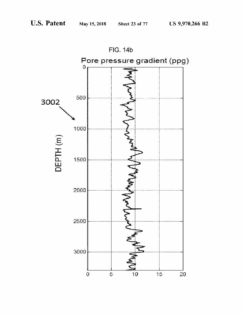
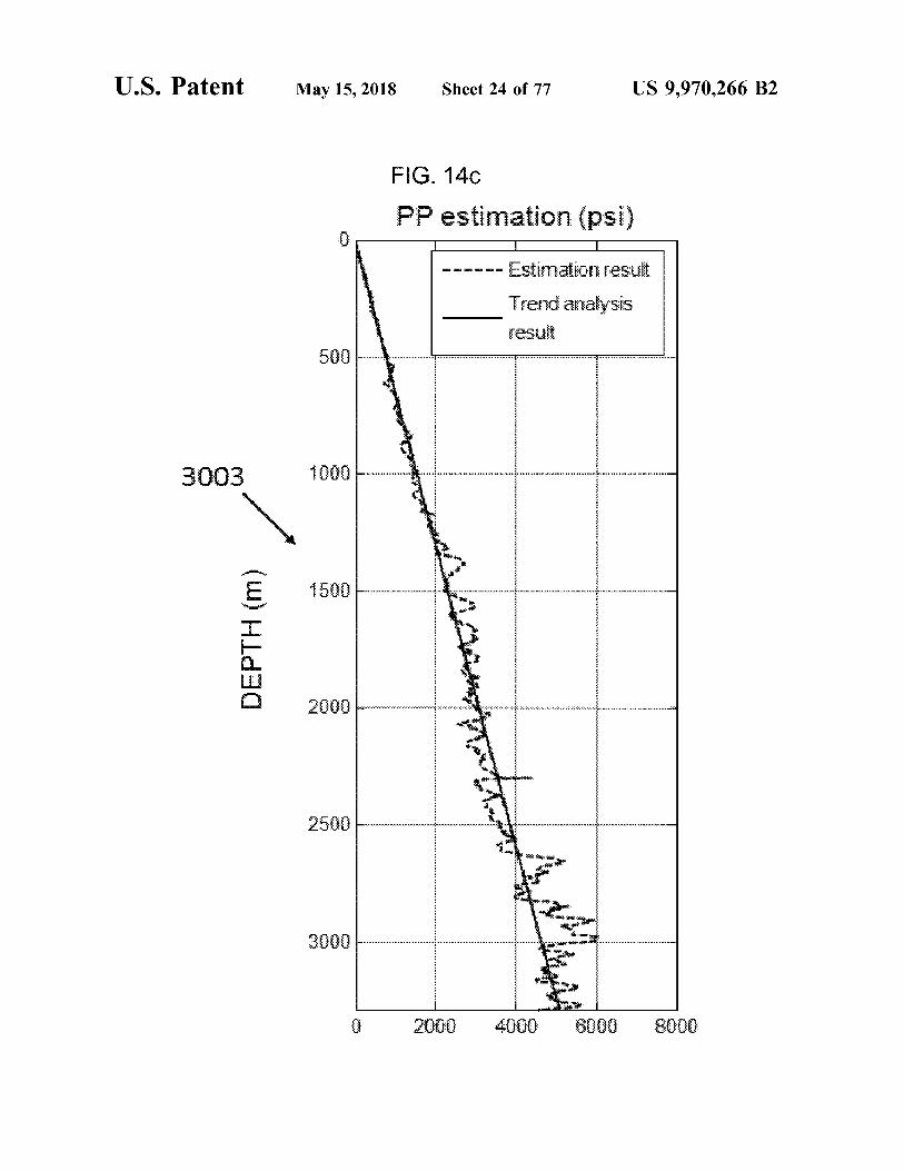
FIG . 1a shows the system architecture of a drilling system FIG . 14b shows pore pressure results for Well # 3 accord employing the drilling fusion software in a standalone ing to an embodiment of the present invention ; arrangement according to an embodiment of the present FIG . 14c shows a pore pressure ( PP ) estimation by linear invention ; regression for Well # 3 according to an embodiment of the
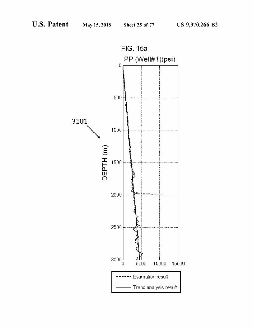
FIG . 1b shows the system architecture of a drilling system 5 present invention ; employing the drilling fusion software in a client - server FIG . 15a shows a trend fusion results of pore pressure arrangement according to an embodiment of the present estimation from Well # 1 according to an embodiment of the invention ; present invention ;
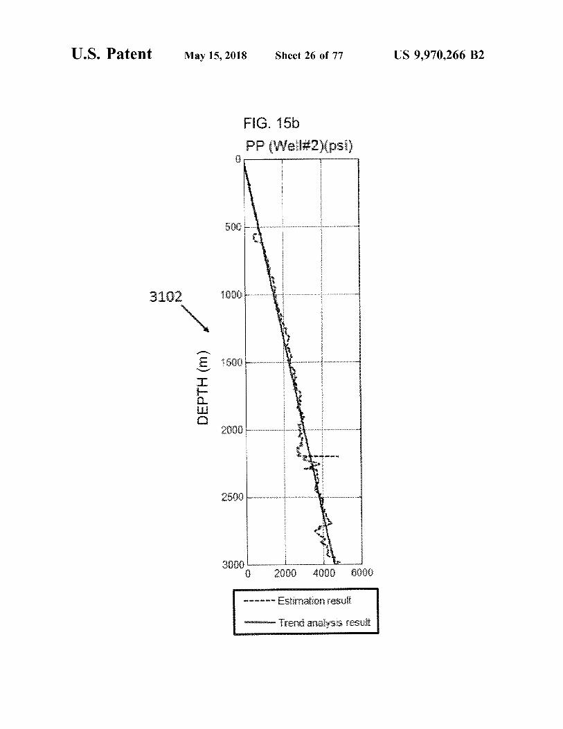
FIG . 2a is a flow diagram of the overall architecture of the FIG . 15 shows a trend fusion results of pore pressure drilling fusion engine according to an embodiment of the 10 estimation from Well # 2 according to an embodiment of the present invention ; present invention ;
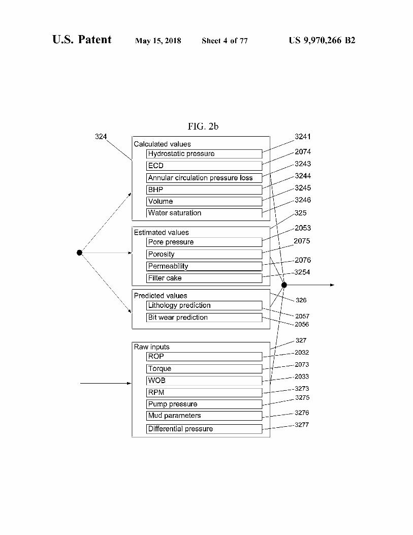
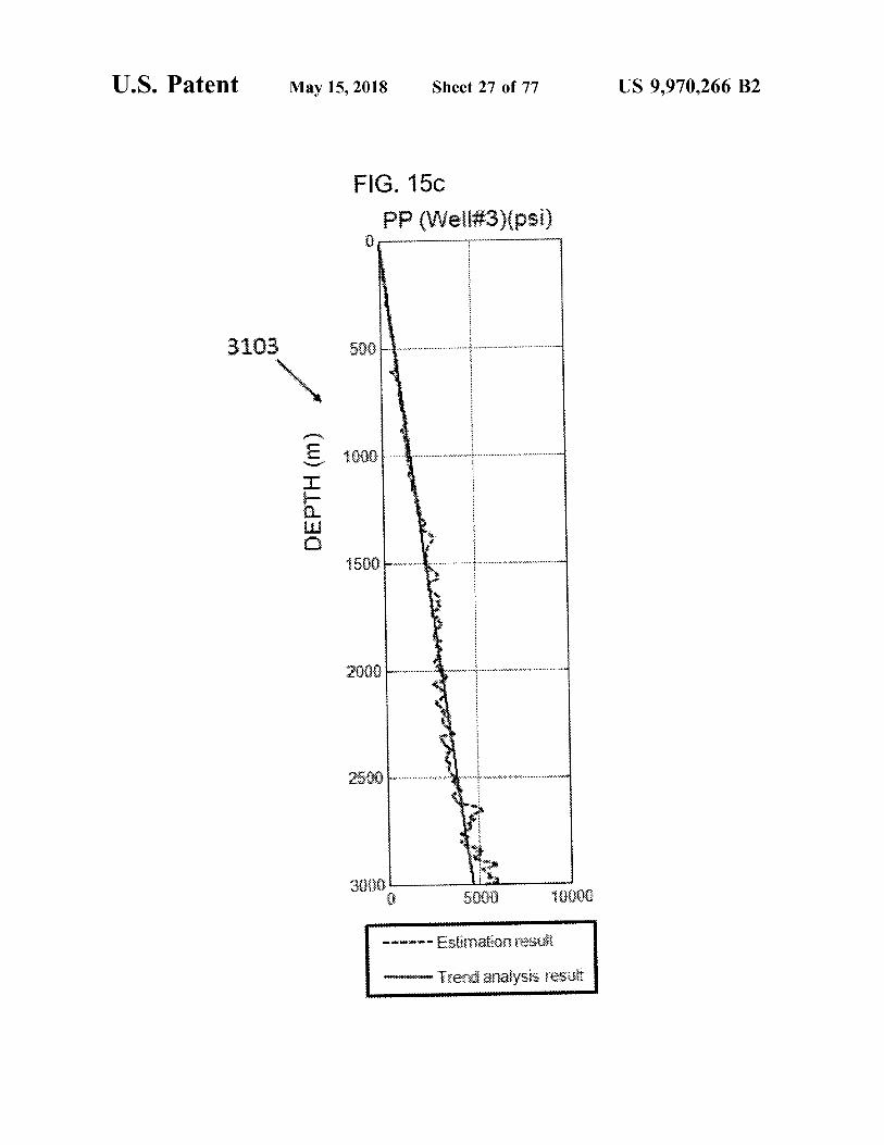
FIG . 2b shows the calculated values , estimated values , FIG . 15c shows a trend fusion results of pore pressure predicted values and raw inputs of the prediction engine estimation from Well # 3 according to an embodiment of the shown in FIG . 2a according to an embodiment the present present invention ; invention ; 15 FIG . 15d shows an optimized pore pressure estimation
FIG . 3 is a flow chart of the prediction engine according obtained from integration of the trend fusion results of pore to an embodiment of the present invention ; pressure estimation from Well # 1 , Well # 2 , and Well # 3
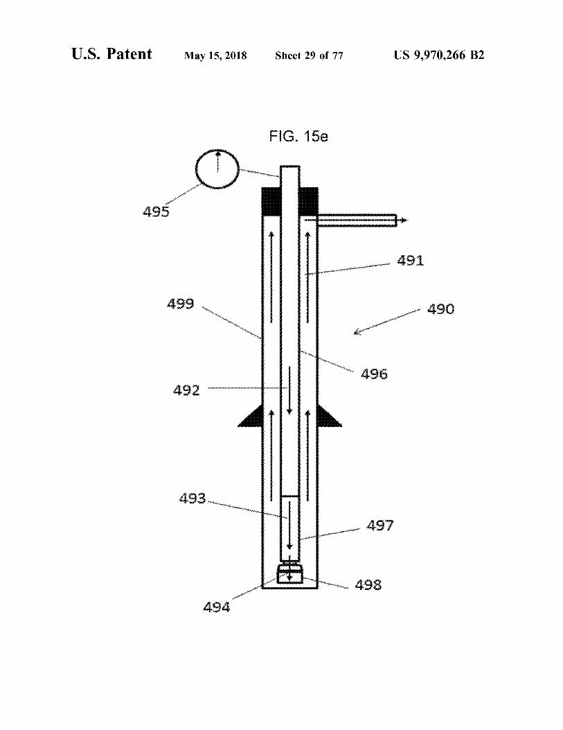
FIG . 4 is a schematic representation of mode selection according to an embodiment of the present invention ; used in the prediction engine according to an embodiment of FIG . 15e shows pressure losses in the circulating system the present invention ; 20 according to an embodiment of the present invention ;
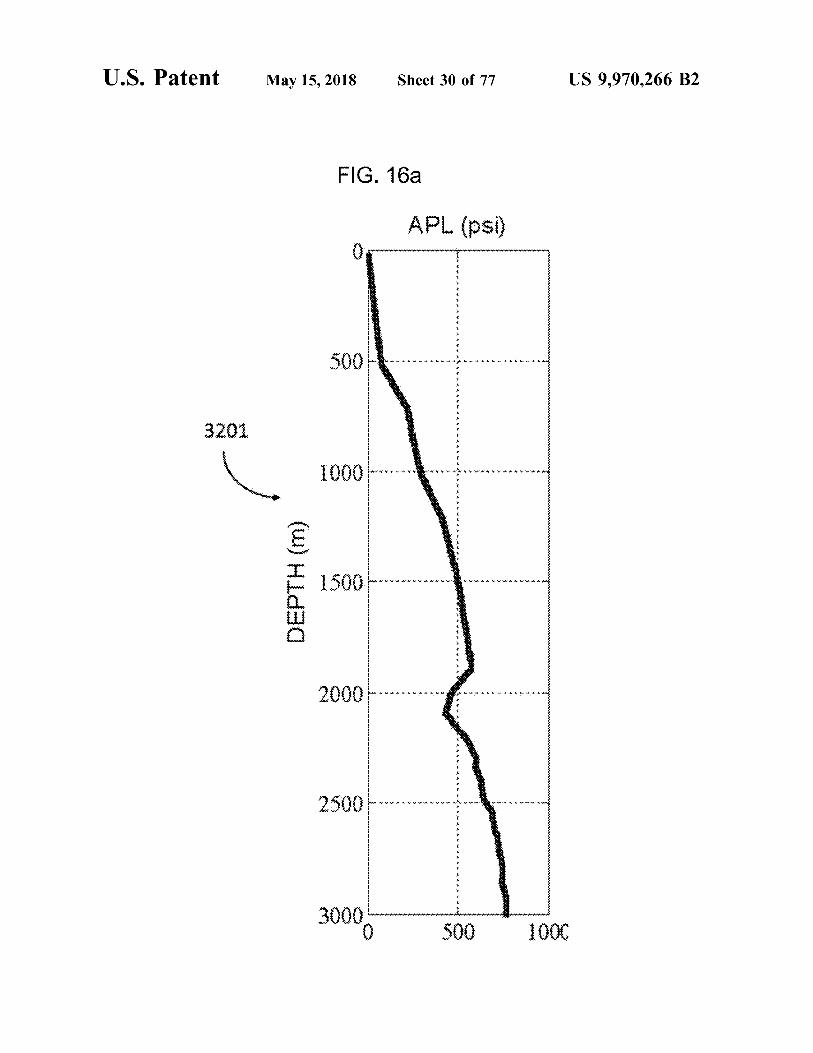
FIG . 5 is a block diagram of bit wear prediction according FIG . 16a shows a calculated annular pressure loss ( APL ) to an embodiment of the present invention ; for Well # 1 according to an embodiment of the present
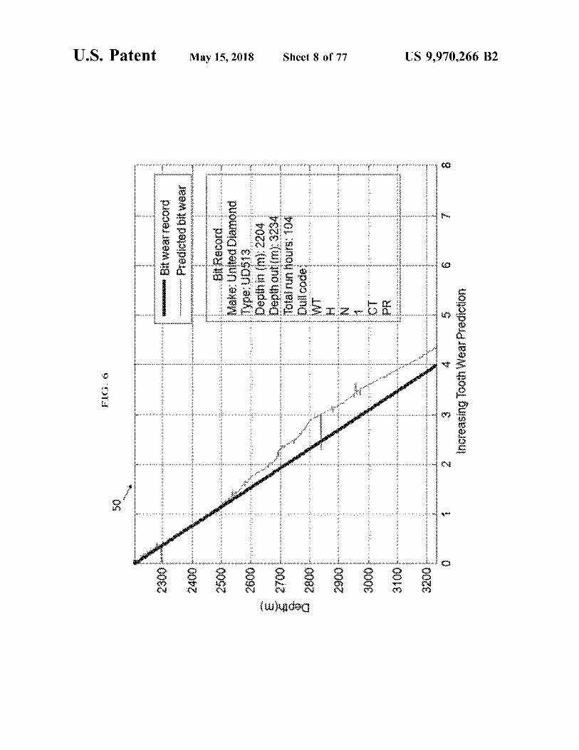
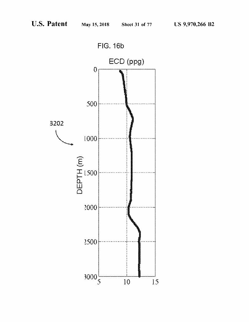
FIG . 6 is a graphical diagram depicting the bit wear i nvention ; prediction results for bit # 7 from Well # 2 according to an FIG . 16b shows a calculated equivalent circulatory den embodiment of the present invention ; 25 sity ( ECD ) for Well # 1 according to an embodiment of the
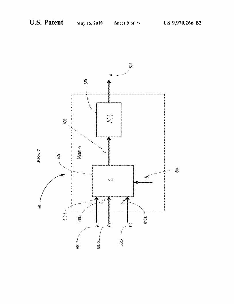
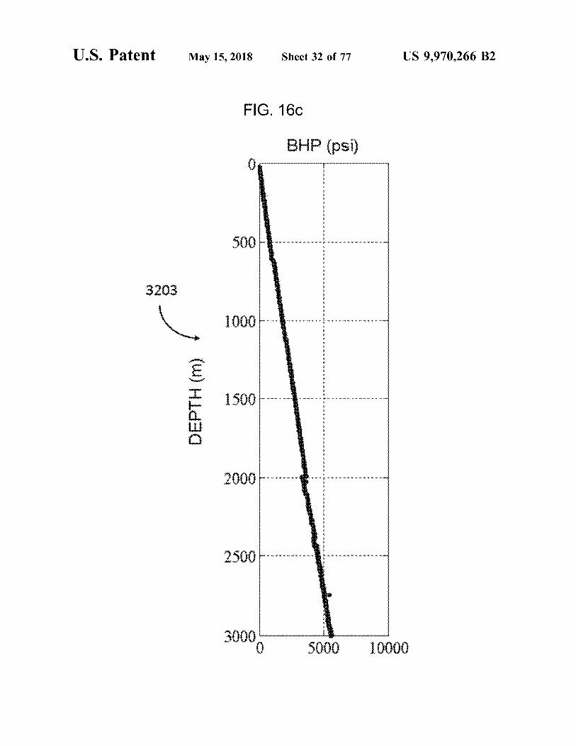
FIG . 7 is a block diagram of a neuron according to an present invention ; embodiment of the present invention ; FIG . 16c shows a bottom hole pressure ( BHP ) for Well # 1
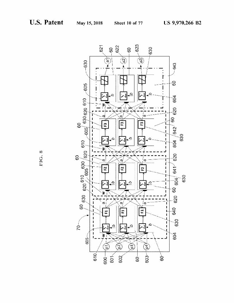
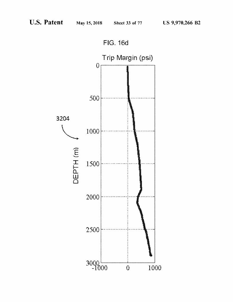
FIG . 8 is a schematic diagram depicting a multilayer according to an embodiment of the present invention ; neural network for lithology determination according to an FIG . 16d shows a calculated trip margin for Well # 1 embodiment of the present invention ; 30 according to an embodiment of the present invention ;
FIG . 9 is a flow chart of a processing subsystem for FIG . 17a shows a calculated annular pressure loss ( APL ) real - time lithology prediction according to an embodiment for Well # 2 according to an embodiment of the present of the present invention ; invention ;
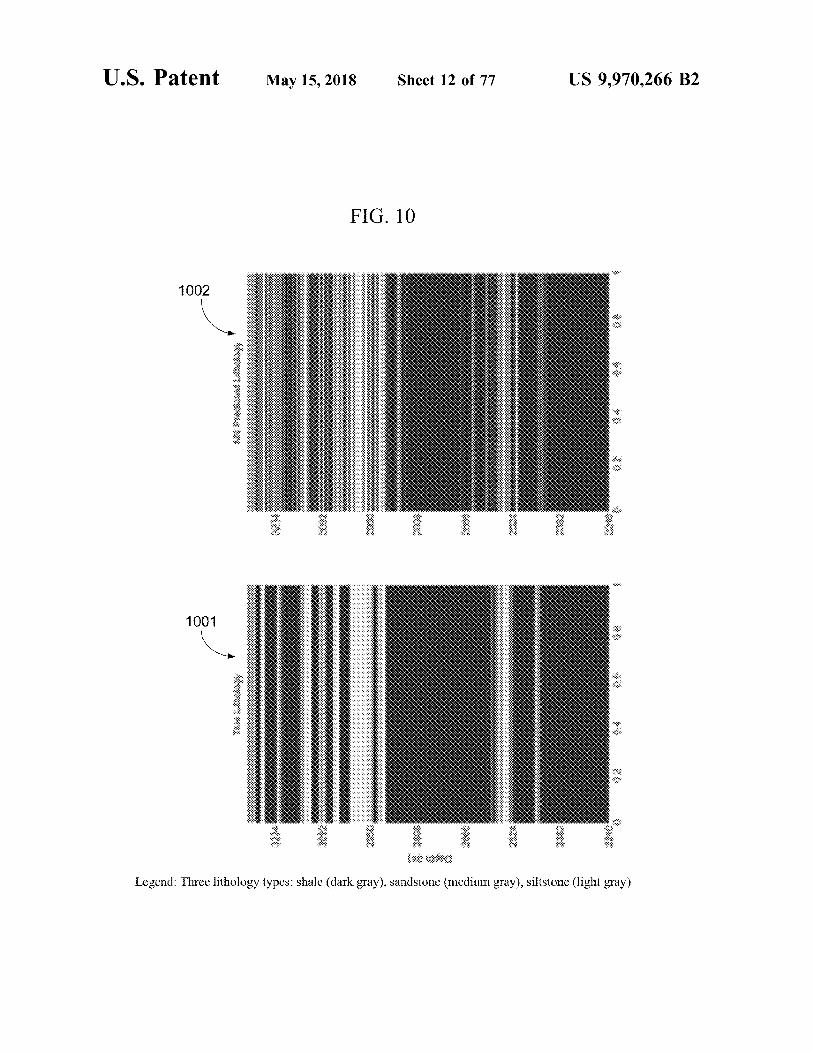
FIG . 10 is a screen shot of the user interface during neural FIG . 176 shows a calculated equivalent circulatory den network training for Well # 2 according to an embodiment of 35 sity ( ECD ) for Well # 2 according to an embodiment of the the present invention ; present invention ;
FIG . 11a shows an intermediate Sigmalog calculations for FIG . 17c shows a bottom hole pressure ( BHP ) for Well # 2 the formation pore pressure gradient ( lbm / gal ) estimation according to an embodiment of the present invention ; results for Well # 1 within depth 2300 m - 3200 m according FIG . 17d shows a calculated trip margin for Well # 2 to an embodiment of the present invention ; 40 according to an embodiment of the present invention ;
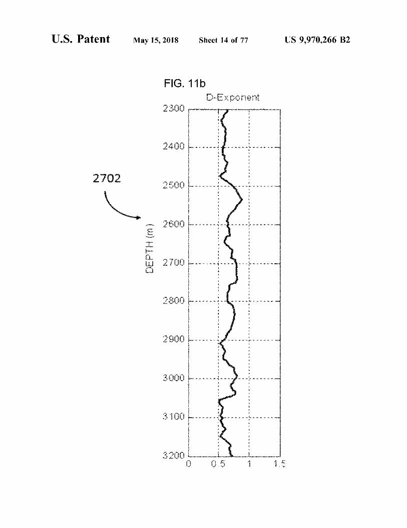
FIG . 11b shows an intermediate d - exponent calculations FIG . 18a shows a calculated annular pressure loss ( APL ) for the formation pore pressure gradient ( lbm / gal ) estimation for Well # 3 according to an embodiment of the present results for Well # 1 within depth 2300 m - 3200 m according invention ; to an embodiment of the present invention ; FIG . 18b shows a calculated equivalent circulatory den
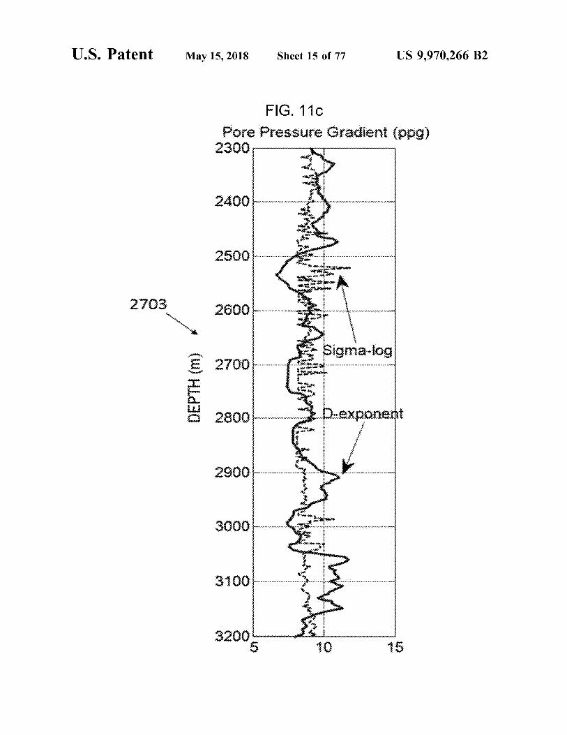
FIG . 11c shows a formation pore pressure gradient ( lbm / 45 sity ( ECD ) for Well # 3 according to an embodiment of the gal ) estimation results using d - exponent and Sigmalog present invention ; approaches for Well # 1 within depth 2300 m - 3200 m accord FIG . 18c shows a bottom hole pressure ( BHP ) for Well # 3 ing to an embodiment of the present invention ; according to an embodiment of the present invention ;
FIG . 12a shows a D - exponent pore pressure estimation FIG . 18d shows a calculated trip margin for Well # 3 results for Well # 1 according to an embodiment of the 50 according to an embodiment of the present invention ; present invention ; FIG . 19 is a diagram depicting a force balance on a drill
FIG . 12b shows a pore pressure results for Well # 1 string element according to an embodiment of the present according to an embodiment of the present invention ; invention ;
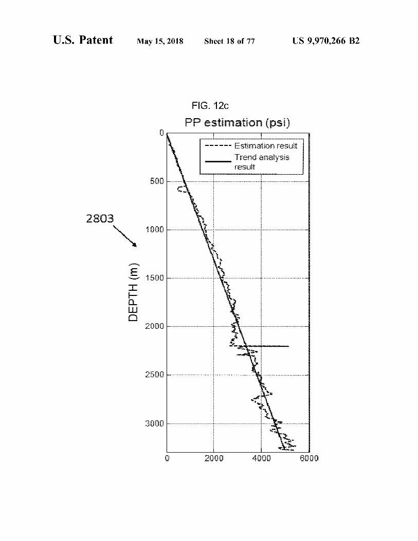
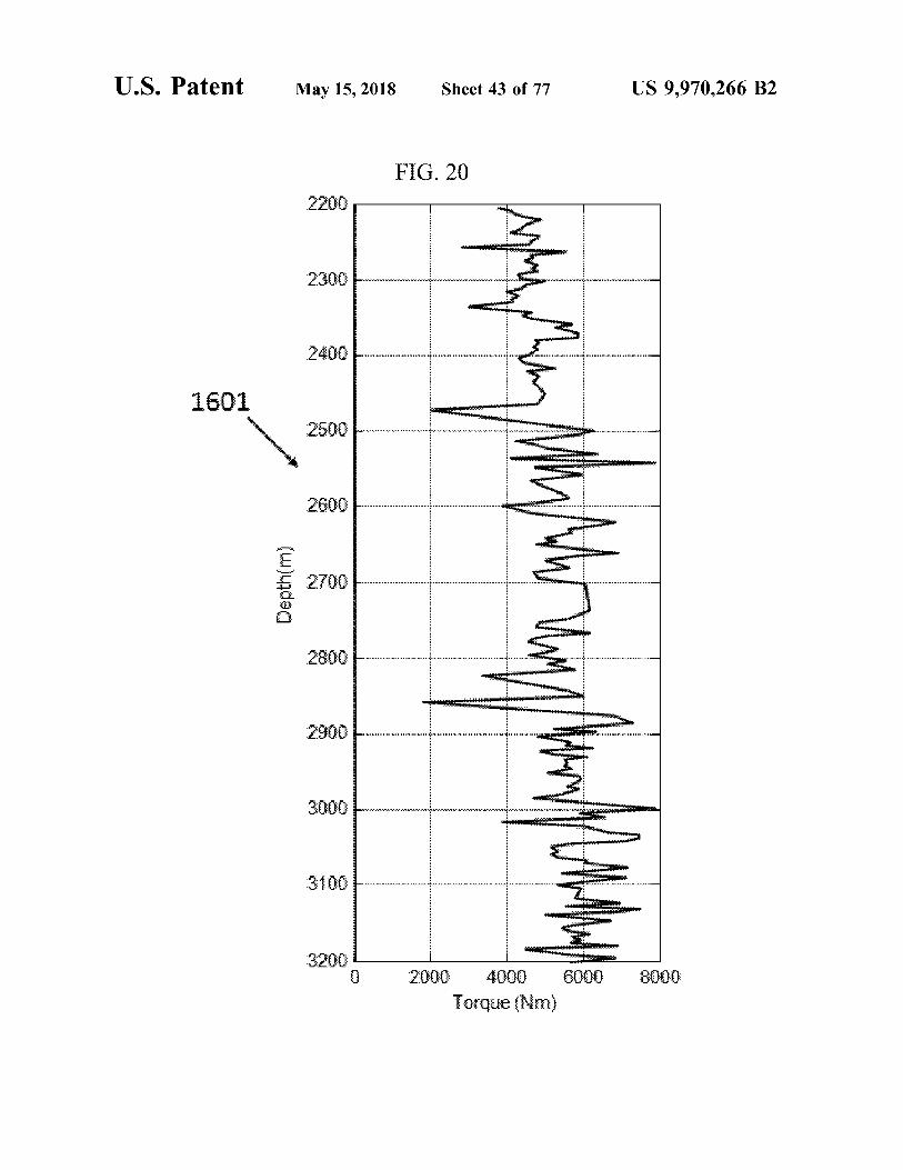
FIG . 12c shows a pore pressure ( PP ) estimation by linear FIG . 20 is a diagram depicting measured real - time drilling regression for Well # 1 according to an embodiment of the 55 torque for Well # 2 according to an embodiment of the present invention ; present invention ;
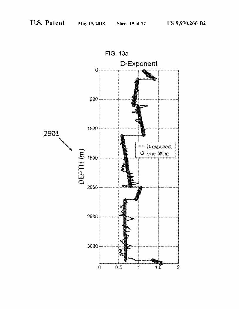
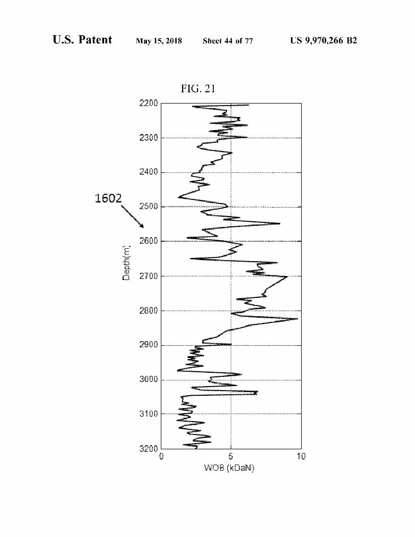
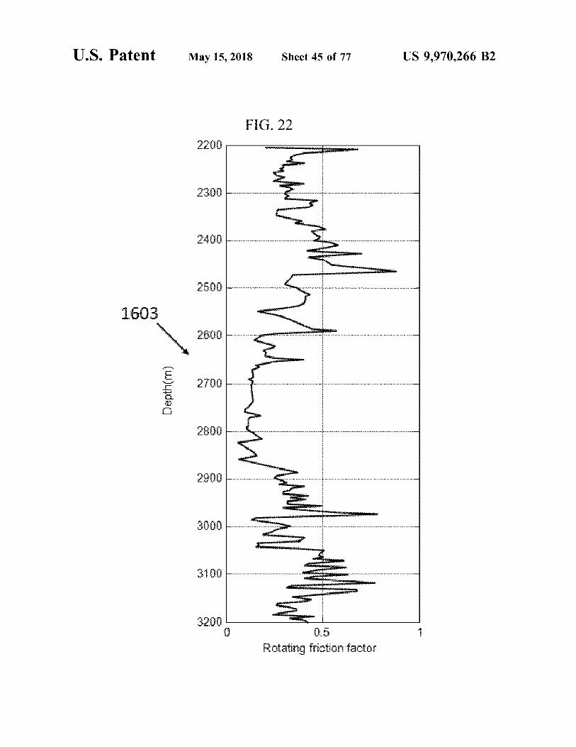
FIG . 13a shows a D - exponent pore pressure estimation FIG . 21 is a diagram depicting WOB data for Well # 2 results for Well # 2 according to an embodiment of the according to an embodiment of the present invention ; present invention ; FIG . 22 is a diagram depicting estimated rotating friction
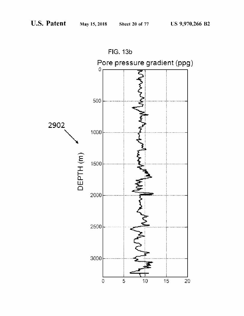
FIG . 13b shows a pore pressure results for Well # 2 60 factor for Well # 2 according to an embodiment of the present according to an embodiment of the present invention ; invention ;
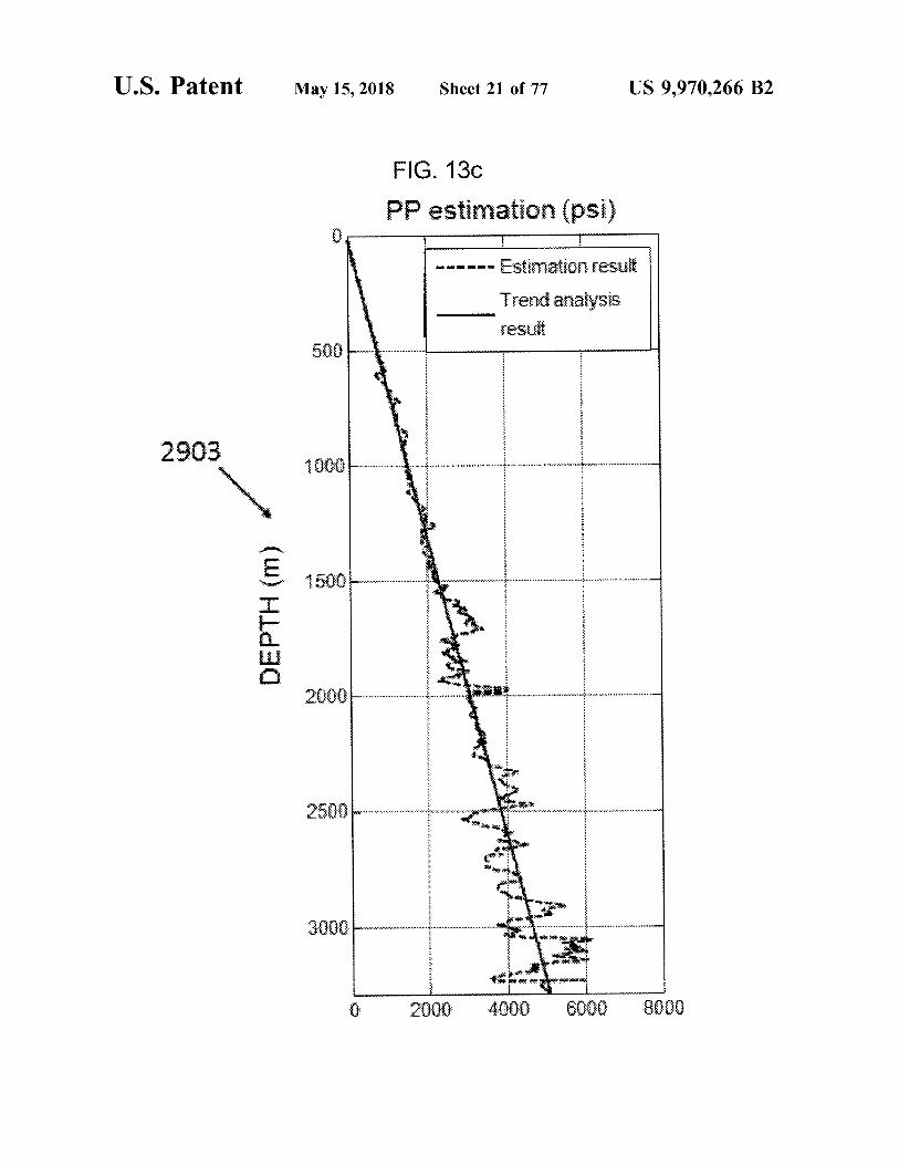
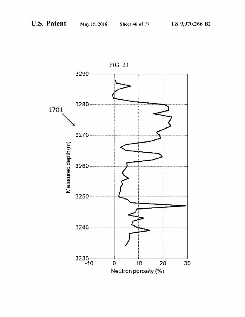
FIG . 13c shows a pore pressure ( PP ) estimation by linear FIG . 23 is a diagram depicting measured neutron porosity regression for Well # 2 according to an embodiment of the for an interval of Well # 2 according to an embodiment of the present invention ; present invention ;
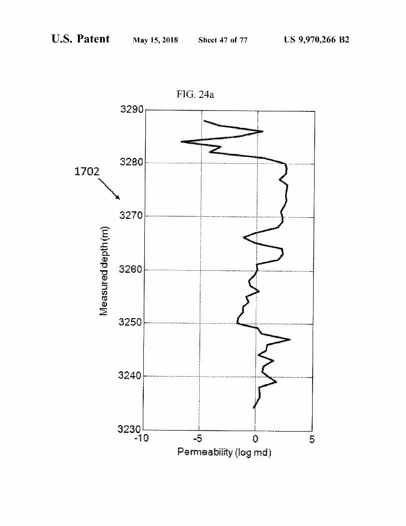
FIG . 14a shows a D - exponent pore pressure estimation 65 FIG . 24a is a diagram depicting estimated permeability results for Well # 3 according to an embodiment of the for an interval of Well # 2 according to an embodiment of the present invention ; present invention ;
US 9 , 970 , 266 B2
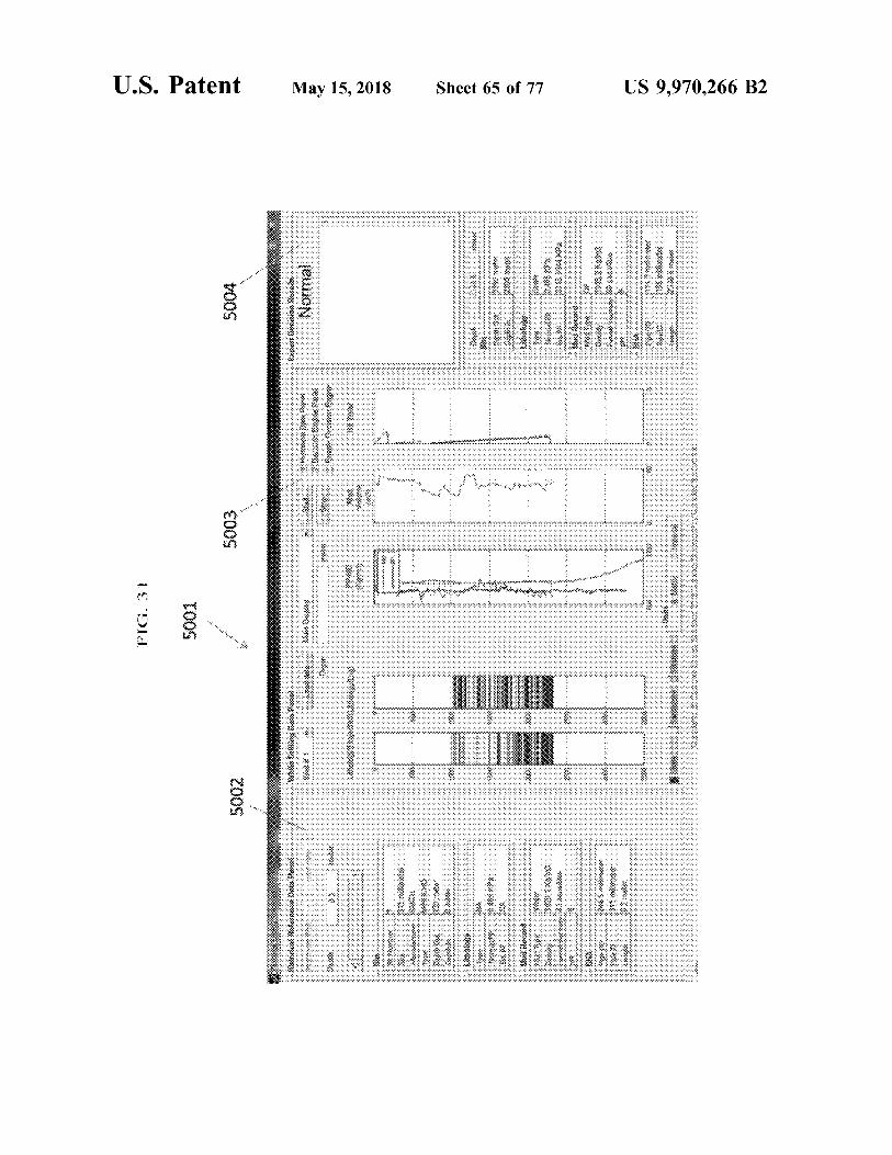
buen
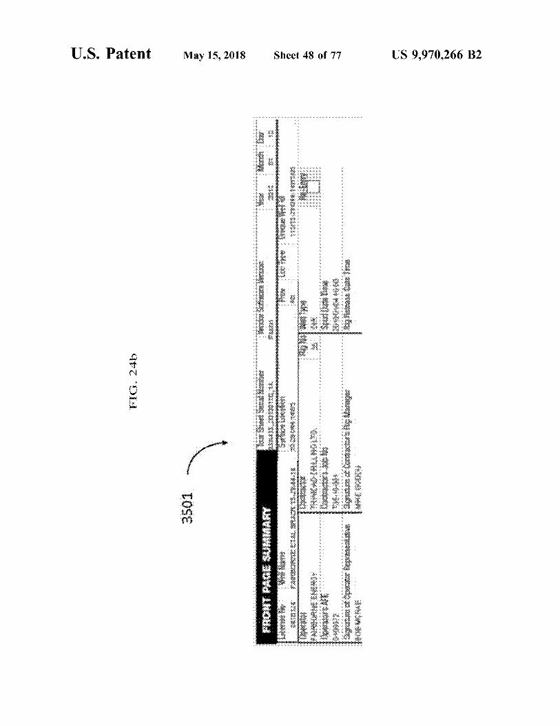
FIG . 24b shows a front page summary of the tour sheet for FIG . 39 shows an expert decision engine prompt for a Well # 1 according to an embodiment of the present inven - mud volume issue for Well # 1 according to an embodiment tion ; of the present invention ;
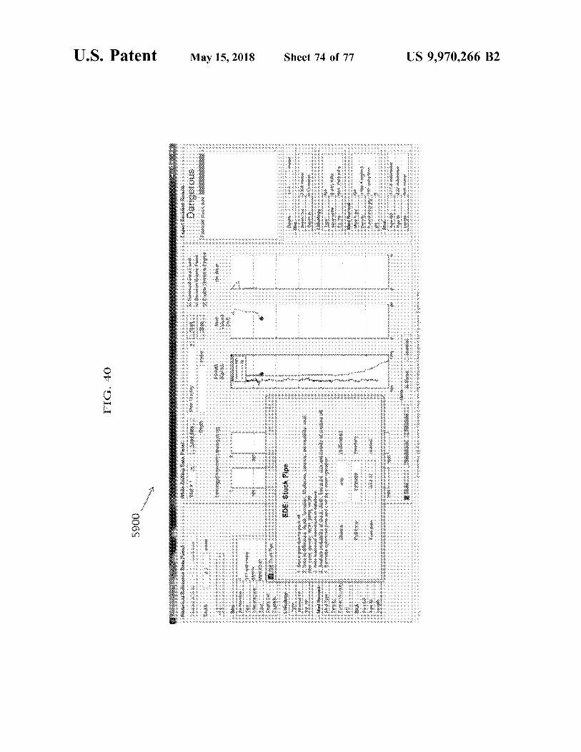
FIG . 24c shows a portion of the tour sheet of Well # 1 FIG . 40 shows an expert decision engine prompt for relating to the drilling assembly according to an embodiment 5 potential stuck pipe due to mud density and mud volume for of the present invention ; Well # 1 according to an embodiment of the present inven
FIG . 24d shows a portion of the tour sheet of Well # 1 tion ; relating to the mud record and circulation according to an FIG . 41 shows an expert decision engine prompt for a embodiment of the present invention ; mud volume issue for Well # 2 according to an embodiment
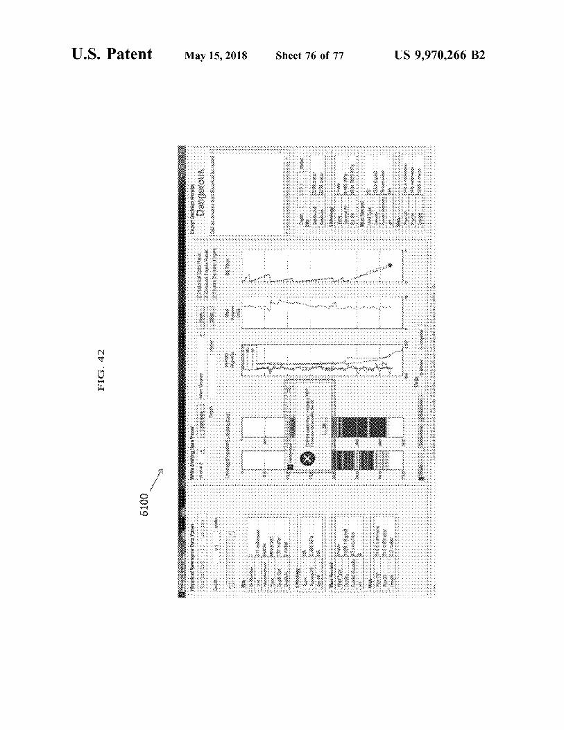
FIG . 24e shows a portion of the tour sheet of Well # 1 " of the present invention ; relating to reduced pump speed according to an embodiment FIG . 42 shows an expert decision engine prompt for bit of the present invention ; wear for Well # 2 according to an embodiment of the present
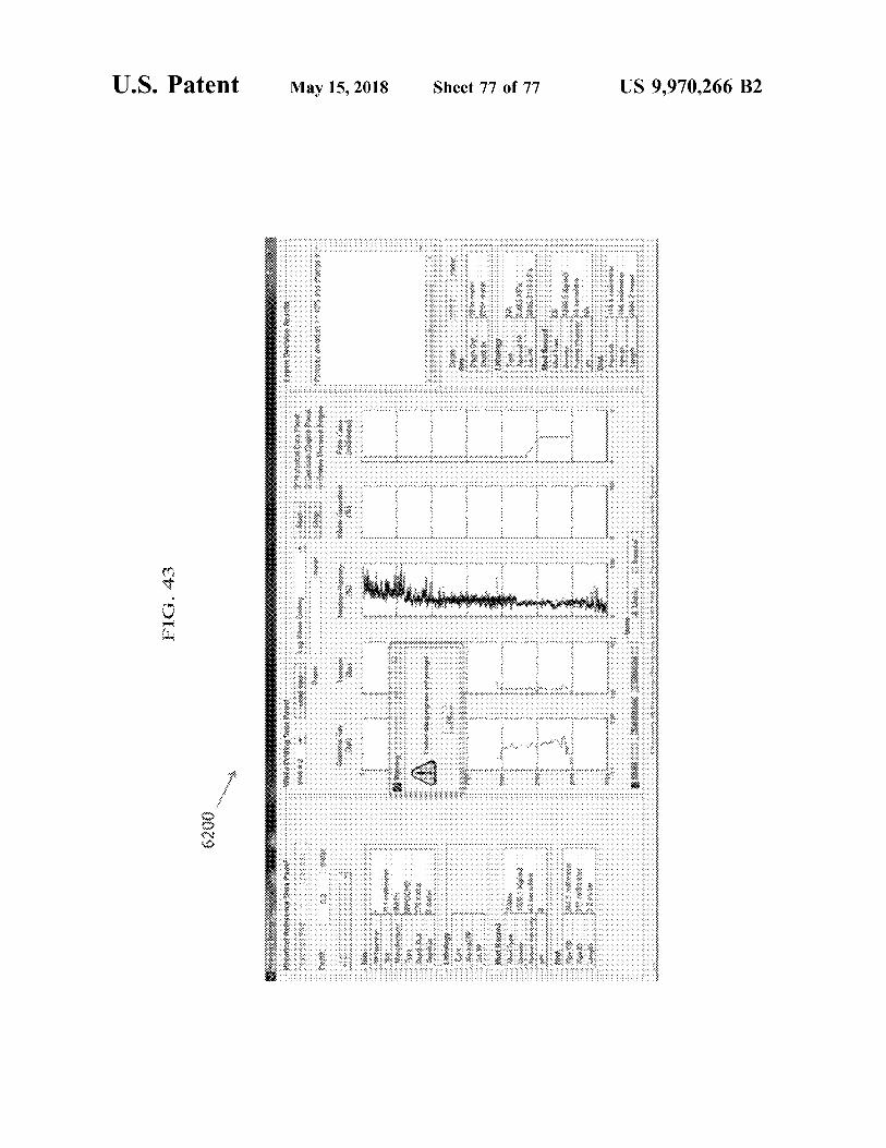
FIG . 24f shows calculations displayed to the user for kill invention ; and sheet # 1 according to an embodiment of the present inven - 15 FIG . 43 shows an expert decision engine prompt for a tion ; porosity issue for Well # 2 according to an embodiment of the
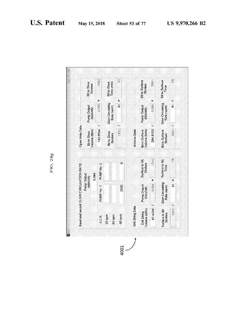
FIG . 24g shows calculations displayed to the user for kill present invention . sheet # 2 according to an embodiment of the present inven Like reference numerals indicate like or corresponding tion ; elements in the drawings .
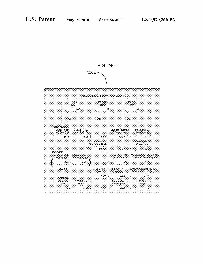
FIG . 24h shows calculations displayed to the user for kill 20 sheet # 3 according to an embodiment of the present inven DETAILED DESCRIPTION OF THE tion ; EMBODIMENTS
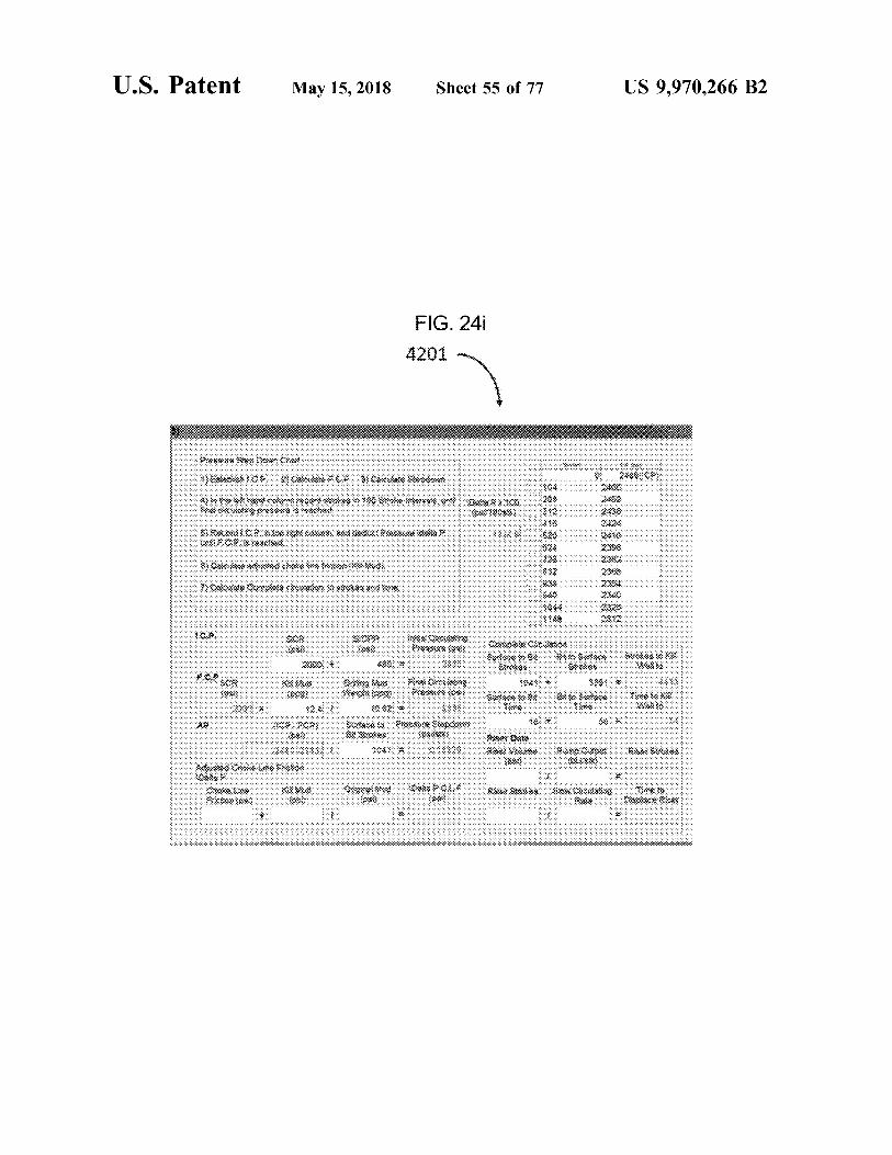
FIG . 24i shows calculations displayed to the user for kill sheet # 4 according to an embodiment of the present inven Embodiments of the present invention are generally tion ; 25 directed to methods and systems for improved drilling
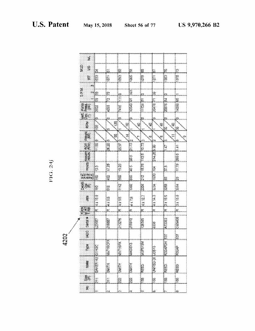
FIG . 24j shows a copy of the bit record of Well # 1 operations using real - time and historical drilling data . according to an embodiment of the present invention ; Embodiments of the invention may be used by any
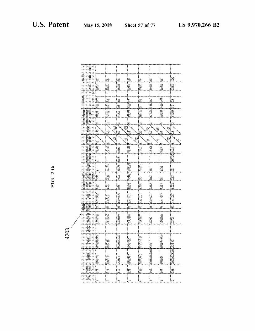
FIG . 24k shows a copy of the bit record of Well # 2 ny of the hit record of Well + 2 persons or entities which control or conduct drilling opera according to an embodiment of the present invention ; tions , such as oil and gas exploration and production com
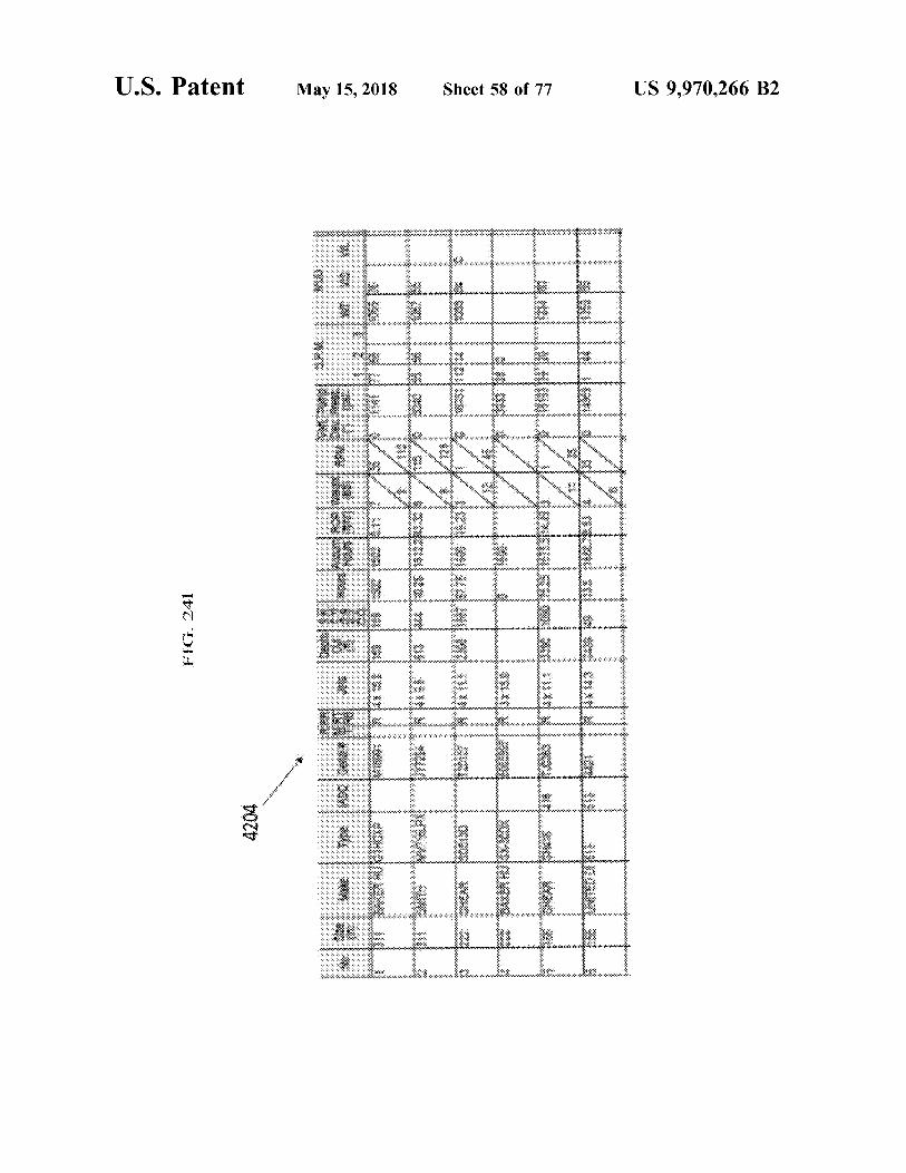
FIG . 241 shows a copy of the bit record of Well # 3 30 P Well # 3 30 panies and oil and gas service companies or mining explo according to an embodiment of the present invention ; ration companies , mining coring companies and mining
service companies . FIG . 25 shows a decision tree of the expert decision According to embodiments of the present invention , the engine relating to mud volume according to an embodiment method , system and computer program product , when of the present invention ; 35 deployed , may identify and predict geological and drilling FIG . 26 shows a decision tree of the expert decision events ahead of the drill bit , such that the user ' s drilling engine relating to porosity according to an embodiment of system may more precisely steer the wellbore while rotating
the present invention ; the drill string or when using the mud motor to increase rate FIG . 27 shows a decision tree of the expert decision of penetration ( ROP ) and reduce drilling cost . In this regard ,
engine relating to permeability according to an embodiment 40 the present invention may incorporate the steps detailed of the present invention ; below for bit wear prediction , lithology prediction , pore
FIG . 28 shows a decision tree of the expert decision pressure estimation , rotating friction coefficient estimation , engine relating to the concern of a stuck pipe according to permeability estimation , and cost estimation using the real an embodiment of the present invention ; time data collected by a variety of sensors , including logging
FIG . 29 shows a decision tree of the expert decision 45 tools , deployed at the well site . These predictions provide engine relating to bit wear according to an embodiment of real - time estimates of the geological formation ahead of the the present invention ; drill bit which allow adjustment of drilling parameters as
FIG . 30 shows a decision tree of the expert decision well as the drill bit itself which may reduce time and risk , engine relating to environmental concerns according to an and therefore cost , in drilling operations . These real - time embodiment of the present invention ; 50 predictions fused with trends determined from the historical
FIG . 31 shows a graphical user interface ( GUI ) with three geological knowledge base of the region may also permit panels according to an embodiment of the present invention ; use of an expert system engine as described below to warn
FIG . 32 shows a main display of the GUI according to an of safety hazards or other issues of concern to the operator embodiment of the present invention ; while drilling . By recognizing unsafe conditions in the
FIG . 33 shows a MWD display of the GUI in metric units 55 wellbore before they cause serious consequences , the pres according to an embodiment of the present invention ; ent invention may increase safety for well site personnel and
FIG . 34 shows a MWD display of the GUI in imperial may reduce or eliminate adverse impacts on the environ units according to an embodiment of the present invention ; ment .
FIG . 35 shows a hydrostatic pressure display of the GUI According to an embodiment , there is a drilling fusion according to an embodiment of the present invention ; 60 engine ( DFE ) which may integrate drilling data in real - time
FIG . 36 shows a dynamic pressure display of the GUI from a rig site to inform adjustments to drilling parameters according to an embodiment of the present invention ; to improve the results of drilling operations ( also referred to
FIG . 37 shows a logging - while - drilling ( LWD ) display of as “ optimization ” ) . This may include specific techniques the GUI according to an embodiment of the present inven - that enable real - time drilling optimization : bit wear predic
65 tion , lithology prediction , pore pressure estimation , rotating FIG . 38 shows a kill sheet display of the GUI according friction coefficient estimation , permeability estimation , and
to an embodiment of the present invention ; cost estimation .
tion ;
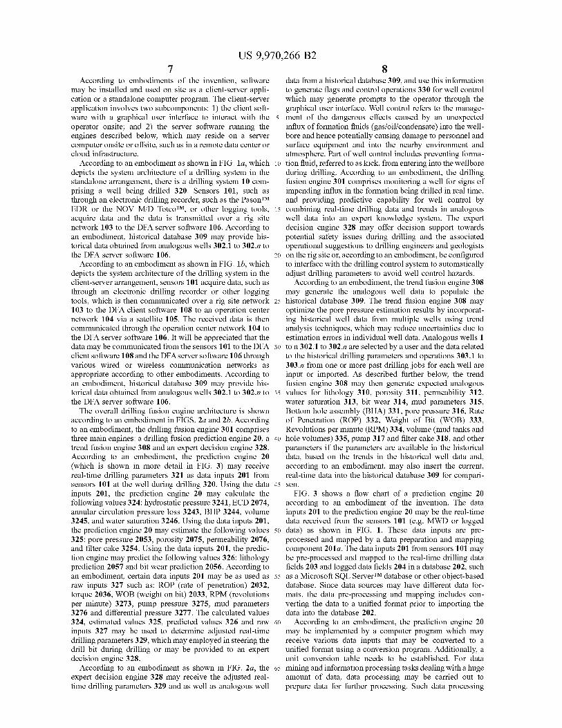
US 9 , 970 , 266 B2
According to embodiments of the invention , software data from a historical database 309 , and use this information may be installed and used on site as a client - server appli to generate flags and control operations 330 for well control cation or a standalone computer program . The client - server which may generate prompts to the operator through the application involves two subcomponents : 1 ) the client soft graphical user interface . Well control refers to the manage ware with a graphical user interface to interact with the 5 ment of the dangerous effects caused by an unexpected operator onsite ; and 2 ) the server software running the influx of formation fluids ( gas / oil / condensate ) into the well engines described below , which may reside on a server bore and hence potentially causing damage to personnel and computer onsite or offsite , such as in a remote data center or surface equipment and into the nearby environment and cloud infrastructure . atmosphere . Part of well control includes preventing forma
According to an embodiment as shown in FIG . la , which 10 tion fluid , referred to as kick , from entering into the wellbore depicts the system architecture of a drilling system in the during drilling . According to an embodiment , the drilling standalone arrangement , there is a drilling system 10 com - fusion engine 301 comprises monitoring a well for signs of prising a well being drilled 320 . Sensors 101 , such as impending influx in the formation being drilled in real time , through an electronic drilling recorder , such as the PasonTM and providing predictive capability for well control by EDR or the NOV M / D TotcoTM , or other logging tools , 15 combining real - time drilling data and trends in analogous acquire data and the data is transmitted over a rig site well data into an expert knowledge system . The expert network 103 to the DFA server software 106 . According to decision engine 328 may offer decision support towards an embodiment , historical database 309 may provide his - potential safety issues during drilling and the associated torical data obtained from analogous wells 302 . 1 to 302 . n to operational suggestions to drilling engineers and geologists the DFA server software 106 . 20 on the rig site or , according to an embodiment , be configured
According to an embodiment as shown in FIG . 1b , which to interface with the drilling control system to automatically depicts the system architecture of the drilling system in the adjust drilling parameters to avoid well control hazards . client - server arrangement , sensors 101 acquire data , such as According to an embodiment , the trend fusion engine 308 through an electronic drilling recorder or other logging may generate the analogous well data to populate the tools , which is then communicated over a rig site network 25 historical database 309 . The trend fusion engine 308 may 103 to the DFA client software 108 to an operation center optimize the pore pressure estimation results by incorporat network 104 via a satellite 105 . The received data is then ing historical well data from multiple wells using trend communicated through the operation center network 104 to analysis techniques , which may reduce uncertainties due to the DFA server software 106 . It will be appreciated that the estimation errors in individual well data . Analogous wells 1 data may be communicated from the sensors 101 to the DFA 30 to n 302 . 1 to 302 . n are selected by a user and the data related client software 108 and the DFA server software 106 through to the historical drilling parameters and operations 303 . 1 to various wired or wireless communication networks as 303 . n from one or more past drilling jobs for each well are appropriate according to other embodiments . According to input or imported . As described further below , the trend an embodiment , historical database 309 may provide his fusion engine 308 may then generate expected analogous torical data obtained from analogous wells 302 . 1 to 302 . n to 35 values for lithology 310 , porosity 311 , permeability 312 , the DFA server software 106 . water saturation 313 , bit wear 314 , mud parameters 315 ,
The overall drilling fusion engine architecture is shown Bottom hole assembly ( BHA ) 331 , pore pressure 316 , Rate according to an embodiment in FIGS . 2a and 2b . According of Penetration ( ROP ) 332 , Weight of Bit ( WOB ) 333 , to an embodiment , the drilling fusion engine 301 comprises Revolutions per minute ( RPM ) 334 , volume ( mud tanks and three main engines : a drilling fusion prediction engine 20 , a 40 hole volumes ) 335 , pump 317 and filter cake 318 , and other trend fusion engine 308 and an expert decision engine 328 . parameters if the parameters are available in the historical According to an embodiment , the prediction engine 20 data , based on the trends in the historical well data and , ( which is shown in more detail in FIG . 3 ) may receive according to an embodiment , may also insert the current , real - time drilling parameters 321 as data inputs 201 from real - time data into the historical database 309 for compari sensors 101 at the well during drilling 320 . Using the data 45 son . inputs 201 , the prediction engine 20 may calculate the FIG . 3 shows a flow chart of a prediction engine 20 following values 324 : hydrostatic pressure 3241 , ECD 2074 , according to an embodiment of the invention . The data annular circulation pressure loss 3243 , BHP 3244 , volume inputs 201 to the prediction engine 20 may be the real - time 3245 , and water saturation 3246 . Using the data inputs 201 , data received from the sensors 101 ( e . g . MWD or logged the prediction engine 20 may estimate the following values 50 data ) as shown in FIG . 1 . These data inputs are pre 325 : pore pressure 2053 , porosity 2075 , permeability 2076 , processed and mapped by a data preparation and mapping and filter cake 3254 . Using the data inputs 201 , the predic component 201a . The data inputs 201 from sensors 101 may tion engine may predict the following values 326 : lithology be pre - processed and mapped to the real - time drilling data prediction 2057 and bit wear prediction 2056 . According to fields 203 and logged data fields 204 in a database 202 , such an embodiment , certain data inputs 201 may be as used as 55 as a Microsoft SQL ServerTM database or other object - based raw inputs 327 such as : ROP ( rate of penetration ) 2032 , database . Since data sources may have different data for torque 2036 , WOB ( weight on bit ) 2033 , RPM ( revolutions mats , the data pre - processing and mapping includes con per minute ) 3273 , pump pressure 3275 , mud parameters verting the data to a unified format prior to importing the 3276 and differential pressure 3277 . The calculated values data into the database 202 . 324 , estimated values 325 , predicted values 326 and raw 60 According to an embodiment , the prediction engine 20 inputs 327 may be used to determine adjusted real - time may be implemented by a computer program which may drilling parameters 329 , which may employed in steering the receive various data inputs that may be converted to a drill bit during drilling or may be provided to an expert unified format using a conversion program . Additionally , a decision engine 328 . unit conversion table needs to be established . For data
According to an embodiment as shown in FIG . 2a , the 65 mining and information processing tasks dealing with a huge expert decision engine 328 may receive the adjusted real amount of data , data processing may be carried out to time drilling parameters 329 and as well as analogous well prepare data for further processing . Such data processing

US 9 , 970 , 266 B2 10
tasks may include operations to replace missing data with facies , laboratory generated permeability , and fluid type default values , and to correct incorrect data inputs , for associated with the formations cored . The sonic log 2044 example , through time - based interpolation and to address may include formation lithology as derived from calcula non - registered multiple data sources , for example , through tions of sonic wave returns , sonic or interval transit times , aligning the data with the same sampling rate or representing 5 possible fracture size and orientations . The gamma ray log the same context . These data processing tasks may then 2045 may include a measurement of gamma radiation : output time or depth aligned data . According to an embodi gamma ray , as shown in Table 5 , below , according to an ment , this data may then also be fed into a data smoothing function to remove measurement noise in order to improve embodiment . The neutron density log 2046 may include lithology prediction accuracy . One such data smoothing 10 measurements of caliper , compensated neutron porosity , function is to use a moving average filtering technique . compensated neutron porosity dolomite / limestone / sand According to an embodiment , a depth - weighted smoother stone matrix , photo electric cross section , bulk density , with a 1 - meter window ( e . g . the depth point has 0 . 2 m temperature , density porosity , and total gas , as shown in sampling frequency , 1 meter window corresponds to 5 data Table 5 , below , according to an embodiment . The resistivity points ) . The weight assigned to each data point in each 15 log 2047 may include measurements of shallow induction , window is inversely proportional to the depth interval medium induction , deep induction , and spontaneous poten between it and the current point . For example , where the tial , as shown in Table 5 , below , according to an embodi input of the smoother is the raw MWD data , x , the smoother ment . The micro log 2048 may include measurements of output y will be
micro normal and micro inverse , as shown in Table 5 , below , y ( 0 ) = x ( 0 ) according to an embodiment . As discussed elsewhere in this
description , embodiments of the invention may operate in y ( 1 ) = ( x ( 0 ) + x ( 1 ) ) / 2 the absence of some or many of these parameters , if they are y ( 2 ) = ( x ( 0 ) + x ( 1 ) + x ( 2 ) ) / 3 not available . Additional data , including other captured or
25 logged data parameters , however , may improve the accuracy y ( 3 ) = ( x ( 0 ) + x ( 1 ) + x ( 2 ) + x ( 3 ) ) / 4 of the predictions made by the prediction engine 20 and the
recommendations of the expert system engine 328 . y ( 4 ) = ( x ( 0 ) + x ( 1 ) + x ( 2 ) + x ( 3 ) + x ( 4 ) ) / 5 The real - time drilling data 203 and the logged data 204
may be used to calculate the drilling bits hydraulics 2051 , y ( 5 ) = ( x ( 1 ) + x ( 2 ) + x ( 3 ) + x ( 4 ) + x ( 5 ) ) / 5 30 the drag 2052 and torque 2073 , the ECD 2074 & pore
pressure 2053 , the porosity 2075 , permeability 2076 and skin factors 2054 , rock compressive strength 2055 , bit wear
where x ( 0 ) denotes the first data point available for smooth prediction 2056 and lithology prediction 2057 . For example , ing operation . The starting point of averaging for the current the mud log 2042 and bit record 2041 may be used in 35 output is found in the fifth data ahead in this case . porosity 2075 and permeability 2076 estimation , and skin
Since the purpose of smoothing is to reduce the measure - factor estimation 2054 . ment noise while still preserving the underlying jumps or The real - time drilling data 203 and logged data 204 may trends of the data , verification needs to be done by testing on be used by the drilling optimization engine 205 to generate the real drilling data . According to an embodiment , 1 meteran optimized drilling parameters , i . e . those adjustments made ( 5 points ) windows were appropriate in that it did not erase to current drilling parameters intended to improve drilling the trends but reduced the overall noise significantly . results . According to an embodiment , supporting data 206 , As discussed above , according to an embodiment , the which may comprise bit dull grade 2063 , cost information
database 202 may include pre - processed and mapped real - 2061 , i . e . the cost of the bit , and a bit wear equation 2062 time drilling data 203 and logged data 204 . The real - time 45 may be used to assist with optimizing drilling parameters drilling data 203 may include one or more data inputs with respect to bit wear replacement . Manufacturers of relating to depth 2031 , Rate of Penetration ( ROP ) 2032 , drilling software such as WellmanTM may provide support Weight On Bit ( WOB ) 2033 , rotary speed 2034 , flow rate ing data 206 such as bit dull grade for each bit run and cost 2035 , and torque 2036 , as shown in Table 1 , below , accord information . Bit manufacturer data may include equations ing to an embodiment . The logged data 204 may include data 50 and parameters to determine the bit tooth wear for the inputs from a bit record 2041 , mud log 2042 , lithology core specific bit used in drilling . According to an embodiment , database 2043 , sonic log 2044 , gamma ray log 2045 , neutron the supporting data 206 from the manufacturer may be density log 2046 , resistivity log 2047 , and micro log 2048 . imported into the computer program . The supporting data The bit record 2041 may include a record of every bit run may then be used for the online optimization 207 of bit wear during an analogous drilling operation including bit size , prediction and drilling costs analysis for generating the IADC name and type , depth in and out , time in the hole , optimized drilling parameters 2072 and cost analysis 2071 . WOB , RPM , bit gauge , bit tooth wear , bearing wear , and According to an embodiment , the lithology prediction total time in the hole , as shown in Tables 3 and 4 , below , 2057 may use neural networks to construct a non - linear map according to an embodiment . The mud log 2042 may includes between the mechanical drilling data and the lithology types . mud weight , mud viscosity , filter cake thickness , chemical The output of lithology types may be determined by the usage , mud properties , information found on a daily drilling training data . Training data may be obtained from analogous report , and solids content , as shown in Table 2 , below , wells . The input of the training process may be a vector of according to an embodiment . The lithology core database features extracted from the training data , and the output may 2043 may include data relating to the formation geology 65 be a vector of target lithology description . For example , if such as depth , lithology type , permeability , porosity , water we have three lithology types ( sandstone , siltstone and saturation , core length and core size , gross and net returns , shale ) , the target output vector may be represented by
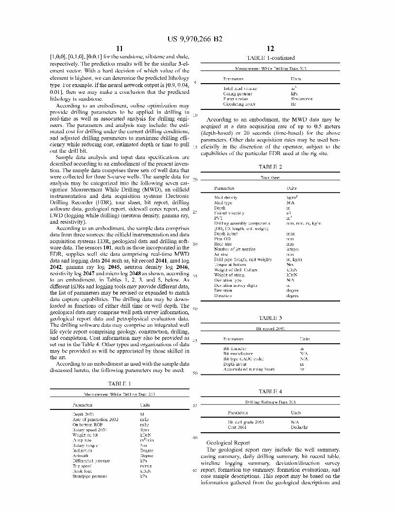
m3
US 9 , 970 , 266 B2 12
[ 1 , 0 , 0 ] , [ 0 , 1 , 0 ] , [ 0 , 0 , 1 ] for the sandstone , siltstone and shale , TABLE 1 - continued respectively . The prediction results will be the similar 3 - el ement vector . With a hard decision of which value of the Measurement - While - Drilling Data 203 element is highest , we can determine the predicted lithology Parameters Units type . For example , if the neural network output is [ 0 . 9 , 0 . 04 , Total mud volume 0 . 01 ] , then we may make a conclusion that the predicted Casing pressure kPa lithology is sandstone . Pump strokes Strokes / min
According to an embodiment , online optimization may Circulating hours Hr provide drilling parameters to be applied in drilling in 10 real - time as well as associated analysis for drilling engi According to an embodiment , the MWD data may be neers . The parameters and analysis may include : the esti acquired at a data acquisition rate of up to 0 . 5 meters mated cost for drilling under the current drilling conditions , ( depth - based ) or 20 seconds ( time - based ) for the above and adjusted drilling parameters to maximize drilling effi parameters . Other data acquisition rates may be used ben ciency while reducing cost , estimated depth or time to pull 15 eficially in the discretion of the operator . subject to the out the drill bit . capabilities of the particular EDR used at the rig site . Sample data analysis and input data specifications are described according to an embodiment of the present inven TABLE 2 tion . The sample data comprises three sets of well data that were collected for three S - curve wells . The sample data for 3 Tour sheet Tour sheet analysis may be categorized into the following seven cat egories : Measurement While Drilling ( MWD ) , an oilfield Parameters Units instrumentation and data acquisition systems Electronic Mud density kg / m3 Drilling Recorder ( EDR ) , tour sheet , bit report , drilling Mud type N / A
software data , geological report , sidewall cores report , and 25 Depth Funnel viscosity LWD ( logging while drilling ) ( neutron density , gamma ray , P?? and resistivity ) . Drilling assembly components mm , mm , m , kg / m
According to an embodiment , the sample data comprises ( OD , ID , length , unit weight ) data from three sources : the oilfield instrumentation and data Depth in / out
Pipe OD acquisition systems EDR , geological data and drilling soft - 20 Hole size ware data . The sensors 101 , such as those incorporated in the Number of jet nozzles integer EDR , supplies well site data comprising real - time MWD Jet size data and logging data 204 such as , bit record 2041 , mud log Drill pipe ( length , unit weight ) m , kg / m
Torque at bottom Nm 2042 , gamma ray log 2045 , neutron density log 2046 , Weight of Drill Collars kDaN resistivity log 2047 and micro log 2048 as shown , according 38 Weight of string kDaN to an embodiment , in Tables 1 , 2 , 3 , and 5 , below . As Deviation type N / A different EDRs and logging tools may provide different data , Deviation survey depth
Deviation the list of parameters may be revised or expanded to match degree Direction degree data capture capabilities . The drilling data may be down
loaded as functions of either drill time or well depth . The geological data may comprise well path survey information , geological report data and petrophysical evaluation data . TABLE 3 The drilling software data may comprise an integrated well Bit record 2041 life cycle report comprising geology , construction , drilling , and completion . Cost information may also be provided as a Parameters Units set out in the Table 4 . Other types and organizations of data
Bit diameter may be provided as will be appreciated by those skilled in Bit manufacture N / A the art . Bit type ( IADC code ) N / A
According to an embodiment as used with the sample data Depth in / out discussed herein , the following parameters may be used : Accumulated running hours
m s / l m3
m / m mm
mm WO
mm
m
m hr
50
TABLE 1 TABLE 4 Measurement - While - Drilling Data 203
Drilling Software Data 206 Parameters Units 55
Parameters Units Bit dull grade 2063 Cost 2061
N / A Dollar / hr
60
Depth 2031 Rate of penetration 2032 On bottom ROP Rotary speed 2034 Weight on bit Pump rate Rotary torque Inclination Azimuth Differential pressure Trip speed Hook load Standpipe pressure
M m / hr m / hr Rpm kDaN m3 / min Nm Degree Degree kPa m / min kDaN kPa
Geological Report The geological report may include the well summary ,
casing summary , daily drilling summary , bit record table , wireline logging summary , deviation / direction survey
65 report , formation top summary , formation evaluations , and core sample descriptions . This report may be based on the information gathered from the geological descriptions and
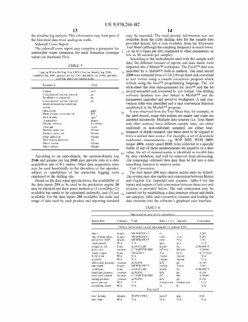
US 9 , 970 , 266 B2 13 14
mm
pu pu
kgm3
the wireline log analysis . This information may form part of may be recorded . The mud density information was not the historical data from analogous wells . available from the EDR drilling data for the sample data
Sidewall Cores Report provided herein , but it was available from the Electronic The sidewall cores report may comprise a parameter for Tour Sheet ( although the sampling frequency is much lower ,
irreducible water saturation for each formation ( average 5 5 i . e . up to 6 times per day , compared to other parameters , as low as 20 seconds per sample ) . value ) ( in fractional ( % ) ) . According to the embodiment used with the sample well data , the different formats of reports and data sheets were TABLE 5 imported into a MatlabTM workspace . The ExcelTM data was
Logging - While - Drilling Data LWD ( Neutron density log 2046 , 10 imported by a MatlabTM built - in method . The mud record resistivity log 2047 , gamma ray log 2045 and micro log 2048 ) and other 2200 was extracted from a ETS 3 . 0 tour sheet and converted
wire line electrical logging tools . to text format using a custom conversion program which written using the JavaTM programming language . The . xsl
Parameters Units style - sheet file was reprogrammed for JavaTM and the bit Caliper record extracted and converted to . csv format . The drilling Compensated neutron porosity pu software database was also linked to MatlabTM and the Borehole size corrected Compensated neutron porosity parameters imported and saved to workspace . A unit con dolomite / limestone / sandstone version table was identified and a unit conversion function matrix established in the MatlabTM program . Gamma ray gapi It was observed from the Tour Sheet that , for example , in Photo electric cross section B / E the mud record , some data entries are empty and some are Bulk density Temperature degree inputted incorrectly . Multiple data sources ( i . e . Tour Sheet Density porosity Fractional and other sources ) have different sample rates , are either Total gas Units uniformly or non - uniformly sampled , are either time Shallow induction 25 stamped or depth - stamped , and these need to be aligned to Medium induction Deep induction form a unified data source . For example , a set of downhole Spontaneous potential mv mechanics measurements , e . g . ROP 2032 , WOB 2033 , Micro normal Ohmm torque 2036 , rotary speed 2035 , were collected at a specific Micro inverse Ohmm depth . If any of these measurements are negative or a zero
30 value , the set of measurements is identified as invalid data According to an embodiment , the neutron - density log by data validation , and will be removed from processing .
2046 and gamma ray log 2045 may provide data at a data The remaining validated data may then be fed into a data acquisition rate of 0 . 1 meters . Other data acquisition rates smoothing function to remove noise . may be used beneficially in the discretion of the operator , Unit Conversion subject to capabilities of the particular logging tools 35 . The data inputs 201 may employ metric units by default . The data inputs 201 may employ metric uni employed at the drilling site . The system may also enable unit conversion between Metric Based on the data input specifications , the availability of and English ( i . e . imperial ) unit systems . Table 6 for the
the data inputs 201 to be used in the prediction engine 20 inputs and outputs of unit conversion between these two unit may be checked and their status marked as ( 1 ) available , ( 2 ) systems is provided below . The unit conversion may be available but needs to be calculated indirectly , and ( 3 ) not an carried out by establishing a data structure whose sub - fields available . For the data inputs 201 available , the units and are category , field , and conversion constant and loading the range of data used by each product and reporting standard data structure into the software ' s graphical user interface .
TABLE 6
Ohmm Ohmm Ohmm
Inputs and outputs of unit conversion
Parameters Category Field Metric ( I . S . ) Imperial Conversion Oilfield instrumentation and data acquisition systems EDR
m ft / hr ft / hr rpm
depth length rate of penetration length on bottom ROP length rotary speed N / A weight on bit force pump rate volume rotary torque force Inclination N / A azimuth N / A differential pressure pressure trip speed length hook load force standpipe pressure pressure total mud volume volume casing pressure pressure pump strokes N / A circulating hours N / A
METER2FEET METER2FEET m / hr METER2FEET m / hr N / A rpm KDAN2LBF kDaN CUBMETER2BBL m / min NM2LBFT Nm N / A degree N / A degree KPA2PSI kPa METER2FEET m / min KDAN2LBF kDaN KPA2PSI kPa CUBMETER2BBL KPA2PSI kPa N / A strokes / min N / A hr
Tour sheet
lbf bbl / min lb ft degree degree psi ft / min lbf
3 . 281 3 . 281 3 . 281 N / A
2248 . 08943 6 . 28981 0 . 7375621 N / A N / A
0 . 145 3 . 281
2248 . 08943 0 . 145 6 . 28981 0 . 145
N / A NA
m3 psi bbl psi strokes / min hr
mud density mud type son ensure density
N / A KGPM32PPG N / A the persone kg / m²
NA ppg N / A
0 . 01 N / A
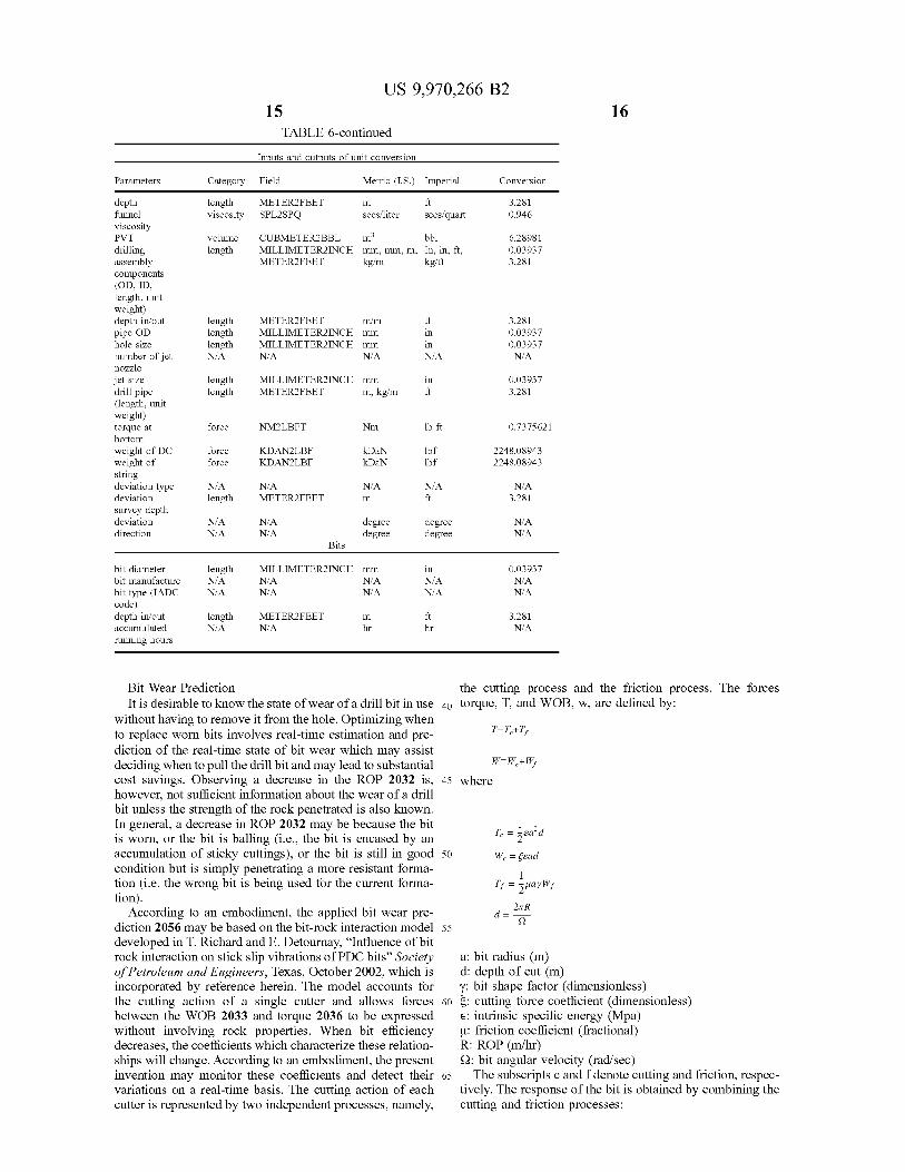
US 9 , 970 , 266 B2 15
TABLE 6 - continued Inputs and outputs of unit conversion
Parameters Category Field Metric ( I . S . ) Imperial Conversion m length
viscosity METER2FEET SPL2SPO
ft secs / quart secs / quart 3 : 28 3 . 281
0 . 946 secs / liter
m3 volume length
CUBMETER2BBL bbl MILLIMETER2INCH MILLIMETERZINCH mm , mm , m . In , in METER2FEET kg / m kg / ft m . mm m . tion , in ft .
6 . 28981 0 . 03937 3 . 281
length length length N / A
METER2FEET m / m MILLIMETER2INCH mm MILLIMETER2INCH mm N / A N / A
in 3 . 281 0 . 03937 0 . 03937
N / A in N / A
depth funnel viscosity P?? drilling assembly components ( OD , ID , length , unit weight ) depth in / out pipe OD hole size number of jet nozzle jet size drill pipe ( length , unit weight ) torque at bottom weight of DC weight of string deviation type deviation survey depth deviation direction
length length
MILLIMETER2INCH mm METER2FEET m , kg / m um kem 0 . 03937
3 . 281 3997 force NM2LBFT Nm lb ft 0 . 7375621
lbf force force
KDAN2LBF KDAN2LBF KDAN kDaN
kDaN lbf 2248 . 08943 2248 . 08943 lbf
N / A N / A N / A length
N / A METER2FEET
N / A 3 . 281 m ft
N / A N / A
N / A N / A
degree degree
degree degree
N / A N / A
Bits
in length N / A N / A
MILLIMETER2INCH mm N / A N / A N / A N / A
N / A N / A
0 . 03937 N / A N / A
bit diameter bit manufacture bit type ( IADC code ) depth in / out accumulated running hours
length ?? length METER2FEET
N / A METER2FEET m m fi 3 . 281 N / A
Te = pead 1
Bit Wear Prediction the cutting process and the friction process . The forces It is desirable to know the state of wear of a drill bit in use 40 torque , T , and WOB , w , are defined by :
without having to remove it from the hole . Optimizing when to replace worn bits involves real - time estimation and pre T = T + T ; diction of the real - time state of bit wear which may assist deciding when to pull the drill bit and may lead to substantial W = Wc + W , cost savings . Observing a decrease in the ROP 2032 is , 45 where however , not sufficient information about the wear of a drill bit unless the strength of the rock penetrated is also known . In general , a decrease in ROP 2032 may be because the bit is worn , or the bit is balling ( i . e . , the bit is encased by an accumulation of sticky cuttings ) , or the bit is still in good 50 We = fead condition but is simply penetrating a more resistant forma tion ( i . e . the wrong bit is being used for the current forma Is = quayWf tion ) .
According to an embodiment , the applied bit wear pre diction 2056 may be based on the bit - rock interaction model 55 developed in T . Richard and E . Detournay , “ Influence of bit rock interaction on stick slip vibrations of PDC bits ” Society a : bit radius ( m ) of Petroleum and Engineers , Texas , October 2002 , which is d : depth of cut ( m ) incorporated by reference herein . The model accounts for y : bit shape factor ( dimensionless ) the cutting action of a single cutter and allows forces 60 E : cutting force coefficient ( dimensionless ) between the WOB 2033 and torque 2036 to be expressed E : intrinsic specific energy ( Mpa ) without involving rock properties . When bit efficiency u : friction coefficient ( fractional ) decreases , the coefficients which characterize these relation R : ROP ( m / hr ) ships will change . According to an embodiment , the present 2 : bit angular velocity ( rad / sec ) invention may monitor these coefficients and detect their 65 The subscripts c and f denote cutting and friction , respec variations on a real - time basis . The cutting action of each tively . The response of the bit is obtained by combining the cutter is represented by two independent processes , namely , cutting and friction processes :
27 R de
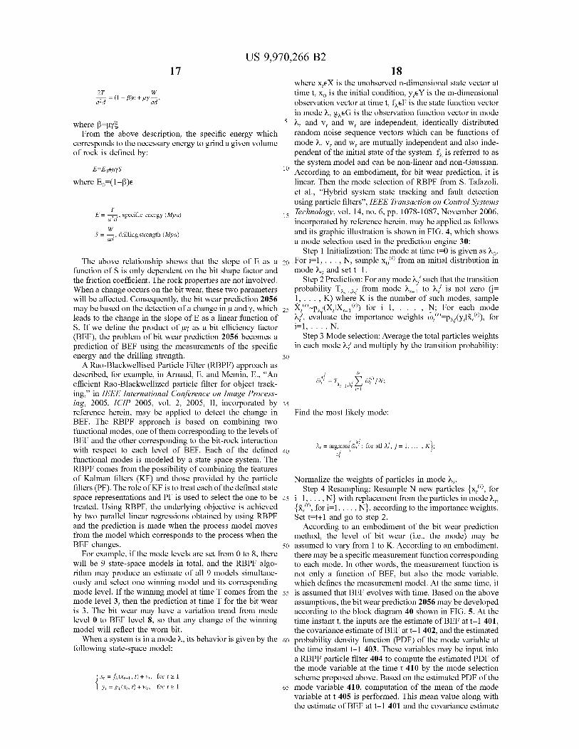
27 azd = a .
10
W in
30 30
US 9 , 970 , 266 B2 17 18
where xeX is the unobserved n - dimensional state vector at W time t , X , is the initial condition , y EY is the m - dimensional 5 = ( 1 - B ) ? + uyi ald observation vector at time t , feF is the state function vector
in mode à , gaeG is the observation function vector in mode where B = uys 5 1 , and V , and w are independent , identically distributed
From the above description , the specific energy which random noise sequence vectors which can be functions of corresponds to the necessary energy to grind a given volume mode à . V , and we are mutually independent and also inde of rock is defined by : pendent of the initial state of the system . f , is referred to as
the system model and can be non - linear and non - Gaussian . E = Eo + uys According to an embodiment , for bit wear prediction , it is where E . = ( 1 - B ) linear . Then the mode selection of RBPF from S . Tafazoli ,
et al . , “ Hybrid system state tracking and fault detection using particle filters " , IEEE Transaction on Control Systems
E = 27 , specific energy ( Mpa ) Technology , vol . 14 , no . 6 , pp . 1078 - 1087 , November 2006 , 15 incorporated by reference herein , may be applied as follows
drilling strength ( Mpa ) and its graphic illustration is shown in FIG . 4 , which shows a mode selection used in the prediction engine 30 :
Step 1 Initialization : The mode at time t = 0 is given as 1o . The above relationship shows that the slope of E as a 20 For i = 1 , . . . , N , sample x . ) from an initial distribution in
function of S is only dependent on the bit shape factor and mode no and set t = 1 . the friction coefficient . The rock properties are not involved . Step 2 Prediction : For any mode , such that the transition When a change occurs on the bit wear , these two parameters probability Thi from mode åt - i to is not zero ( j = will be affected . Consequently , the bit wear prediction 2056 1 , . . . , K ) where K is the number of such modes , sample may be based on the detection of a change in u and y , which 25 X " - p2 . ( XIX - 1 ) ) for i = 1 , . . . , N ; For each mode leads to the change in the slope of E as a linear function of y , evaluate the importance weights w , " = p , ( y , lx , ' ) , for S . If we define the product of uy as a bit efficiency factor i = 1 , . . . , N . ( BEF ) , the problem of bit wear prediction 2056 becomes a Step 3 Mode selection : Average the total particles weights prediction of BEF using the measurements of the specific in each mode , and multiply by the transition probability : energy and the drilling strength .
A Rao - Blackwellised Particle Filter ( RBPF ) approach as described , for example , in Arnaud , E . and Memin , E . , “ An efficient Rao - Blackwellized particle filter for object track ing , ” in IEEE International Conference on Image Process ing , 2005 . ICIP 2005 , vol . 2 , 2005 , II , incorporated by 35 reference herein , may be applied to detect the change in Find the most likely mode : BEF . The RBPF approach is based on combining two functional modes , one of them corresponding to the levels of BEF and the other corresponding to the bit - rock interaction with respect to each level of BEF . Each of the defined 40 = argmax : for all 1 , j = 1 , . . . , K } ; functional modes is modeled by a state space system . The RBPF comes from the possibility of combining the features of Kalman filters ( KF ) and those provided by the particle Normalize the weights of particles in mode àx filters ( PF ) . The role of KF is to treat each of the defined state Step 4 Resampling : Resample N new particles ( x , " ) , for space representations and PF is used to select the one to be 45 i = 1 , . . . , N } with replacement from the particles in modez , treated . Using RBPF , the underlying objective is achieved { ã , ) , for i = 1 , . . . , N } , according to the importance weights . by two parallel linear regressions obtained by using RBPF Set t = + 1 and go to step 2 . and the prediction is made when the process model moves According to an embodiment of the bit wear prediction from the model which corresponds to the process when the method , the level of bit wear ( i . e . , the mode ) may be BEF changes . 50 assumed to vary from 1 to K . According to an embodiment ,
For example , if the mode levels are set from 0 to 8 , there there may be a specific measurement function corresponding will be 9 state - space models in total , and the RBPF algo - to each mode . In other words , the measurement function is rithm may produce an estimate of all 9 models simultane - not only a function of BEF , but also the mode variable , ously and select one winning model and its corresponding which defines the measurement model . At the same time , it mode level . If the winning model at time T comes from the 55 is assumed that BEF evolves with time . Based on the above mode level 3 , then the prediction at time T for the bit wear assumptions , the bit wear prediction 2056 may be developed is 3 . The bit wear may have a variation trend from mode according to the block diagram 40 shown in FIG . 5 . At the level 0 to BEF level 8 , so that any change of the winning time instant t , the inputs are the estimate of BEF at t - 1 401 , model will reflect the worn bit . the covariance estimate of BEF at t - 1 402 , and the estimated
When a system is in a mode à , its behavior is given by the 60 probability density function ( PDF ) of the mode variable at following state - space model : the time instant t - 1 403 . These variables may be input into
a RBPF particle filter 404 to compute the estimated PDF of the mode variable at the time t 410 by the mode selection
S X = fi ( x : - 1 , 1 ) + V? , for 121 scheme proposed above . Based on the estimated PDF of the 1 yr = 82 ( xx , 1 ) + W , for 1 z 1 65 mode variable 410 , computation of the mean of the mode
variable at t 405 is performed . This mean value along with the estimate of BEF at t - 1 401 and the covariance estimate
W = TL 1 - T 5 W / N ; = T - 1 - 1 , 47 El
It
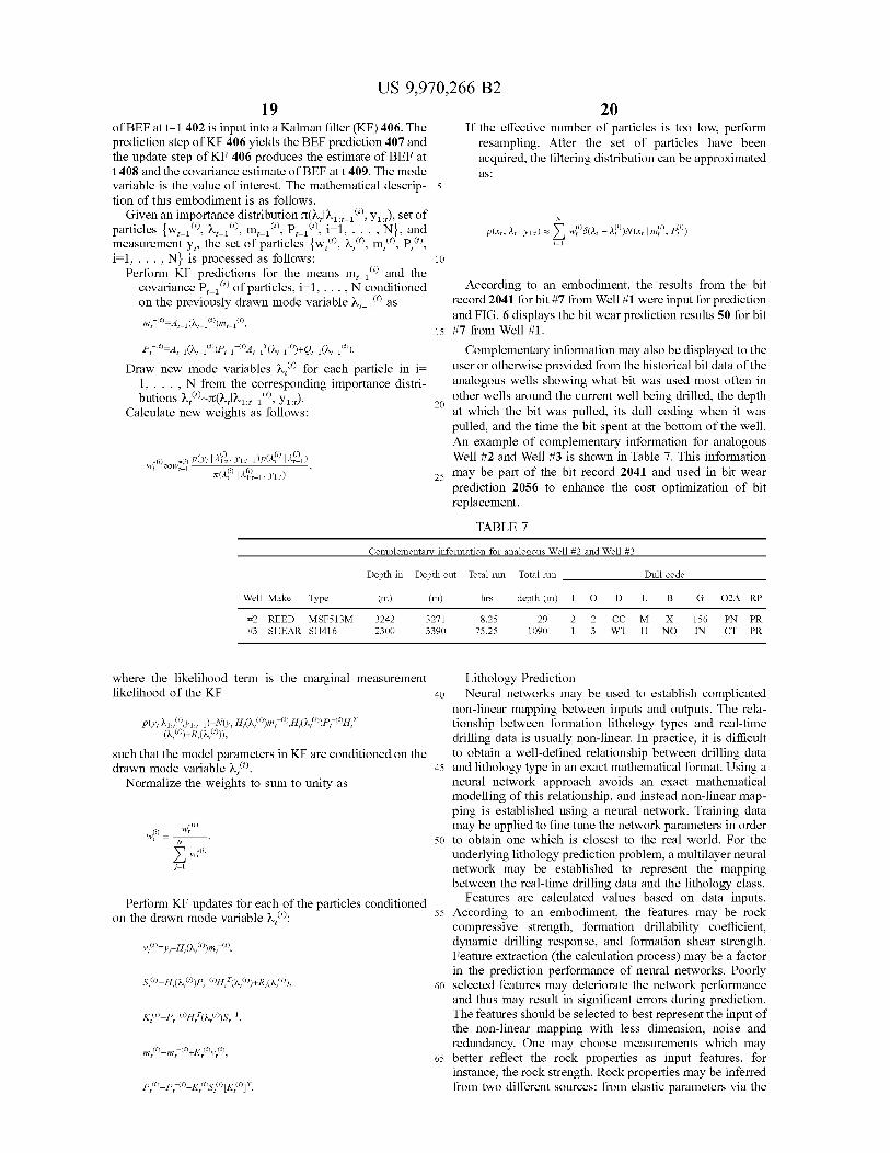
US 9 , 970 , 266 B2 19 20
of BEF at t - 1 402 is input into a Kalman filter ( KF ) 406 . The If the effective number of particles is too low , perform prediction step of KF 406 yields the BEF prediction 407 and resampling . After the set of particles have been the update step of KF 406 produces the estimate of BEF at acquired , the filtering distribution can be approximated t 408 and the covariance estimate of BEF at t 409 . The mode as : variable is the value of interest . The mathematical descrip - 5 tion of this embodiment is as follows . Given an importance distribution day 1 : 7 - 10 ) , y1 : 1 ) , set of
particles { Wx - 1 ) , az - 1 ) , m , - 1 ) , P - 1 " ) , i = 1 , . . . , N , and p ( X1 , 11 | y1 : 1 ) = 0 [ - 2 ( xz | mº ) , p ) measurement y? , the set of particles { w , " ) , ) , m . ) , P . ) , i = 1 , . . . , N } is processed as follows :
Perform KF predictions for the means mi - 1 ( ) and the covariance P _ ( ) of particles , i = 1 , . . . , N conditioned According to an embodiment , the results from the bit on the previously drawn mode variable àz _ 1 " ) as record 2041 for bit # 7 from Well # 1 were input for prediction m , ( * ) = A _ 1 ( Qx _ 1 ) _ 1 " , and FIG . 6 displays the bit wear prediction results 50 for bit
15 # 7 from Well # 1 . P , ( * ) = 4 1 ( dvx - 1 ) P - 1 ° Ag _ 1 " ( 0 - 1 ) + Qs - 1 ( - 1 " ) . Complementary information may also be displayed to the
Draw new mode variables ( ) for each particle in i = user or otherwise provided from the historical bit data of the 1 , . . . , N from the corresponding importance distri analogous wells showing what bit was used most often in butions à ; " ) ( a , là1 : - 16 " ) , y? : t ) . other wells around the current well being drilled , the depth
Calculate new weights as follows : at which the bit was pulled , its dull coding when it was pulled , and the time the bit spent at the bottom of the well . An example of complementary information for analogous Well # 2 and Well # 3 is shown in Table 7 . This information
7 ( 10 | 1927 - 1 , Yu : ) may be part of the bit record 2041 and used in bit wear prediction 2056 to enhance the cost optimization of bit replacement .
20
w + l ) cow + 6 ) Ply : 12 % ? ? , Y1 : 1 - 1 ) ( A | 1721 ) 25
TABLE 7 Complementary information for analogous Well # 2 and Well # 3 Depth in Depth out Total run Total run Dull code
Well Make Type ( m ) ( m ) hrs depth ( m ) 1 0 D L B G 02A RP # 2 REED MSF513M # 3 SHEAR SH416
3242 2300
3271 3390
8 . 25 75 . 25
292 10901
2 CCM 3 WT H
X NO
156 IN
PN PR CT PR
w , ( ) WO ) - w
where the likelihood term is the marginal measurement Lithology Prediction likelihood of the KF 40 Neural networks may be used to establish complicated
non - linear mapping between inputs and outputs . The rela p ( y ; 121 : " ) , 91 : 7 - 1 ) = N ( y , \ H , ( ) m , ( * ) , H , ( 2 , ( 0 ) ) P , ( * HT tionship between formation lithology types and real - time
( _ ) ) + R , ( a , 0 ) ) ) , drilling data is usually non - linear . In practice , it is difficult such that the model parameters in KF are conditioned on the to obtain a well - defined relationship between drilling data drawn mode variable 2 , 9 ) . 45 and lithology type in an exact mathematical format . Using a
Normalize the weights to sum to unity as neural network approach avoids an exact mathematical modelling of this relationship , and instead non - linear map ping is established using a neural network . Training data may be applied to fine tune the network parameters in order
50 to obtain one which is closest to the real world . For the underlying lithology prediction problem , a multilayer neural network may be established to represent the mapping between the real - time drilling data and the lithology class .
Perform KF updates for each of the particles conditioned Features are calculated values based on data inputs . 55 According to an embodiment , the features may be rock on the drawn mode variable 2 , ? ) : compressive strength , formation drillability coefficient ,
dynamic drilling response , and formation shear strength . V " = y - H , ( , ) ) m , - ( i ) , Feature extraction ( the calculation process ) may be a factor in the prediction performance of neural networks . Poorly
$ { " = H , ( 2 , * ) P , - 607 , 5 ( ( + R , ( 2 , 4 " ) , 60 selected features may deteriorate the network performance and thus may result in significant errors during prediction .
KO = P ; ( * H ( 109 S : - 1 , The features should be selected to best represent the input of the non - linear mapping with less dimension , noise and redundancy . One may choose measurements which may m , * ) = m , ( * ) + K ( 1 ) , ( ) , 65 better reflect the rock properties as input features , for instance , the rock strength . Rock properties may be inferred
PL @ = P , ( 9 - K®S ( " [ K , ) ? from two different sources : from elastic parameters via the
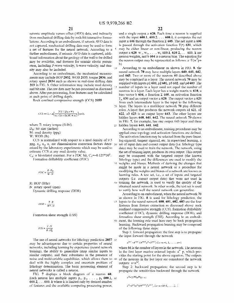
b )
CCS = Cb * In } _ 36T / ( Dp * W ) a1 * [ az * In ( M ) + az ] } ( psi ) ,
US 9 , 970 , 266 B2 21
seismic amplitude versus offset ( AVO ) data , and indirectly and a single output a 620 . Each time a neuron is supplied from mechanical drilling data by rock - bit interactive formu - with the input 600 . 1 , 600 . 2 , . . . 600 . k , it computes the net lations . According to an embodiment , if seismic AVO data is input n 606 through the function 605 . The net input n 606 not captured , mechanical drilling data may be used to form is passed through the activation function FO 630 , which a set of features for the neural network . According to a 5 may be either linear or non - linear , producing the neuron further embodiment , if seismic AVO data is captured , addi output a 620 . W1 , W2 , . . . , W? 610 . 1 , 610 . 2 , . . . 610 . k are tional information about the geology of the well to be drilled neuron weights , and b 604 is a neuron bias . The equation for may be available , and features for seismic elastic param the neuron output may be represented as follows : a = F ( w + p + eters , including P - wave velocity , S - wave velocity , and den sity may also be included . 10 According to an embodiment as shown in FIG . 8 , the
neural network 70 may have multiple layers 640 , 641 , 642 , According to an embodiment , the mechanical measure and 643 . Two or more of the neurons 60 described above ments may include ROP 2032 , WOB 2033 , torque 2036 , and may be combined in a layer . The neural network 70 may be rotary speed 2034 such as shown in real - time drilling data 203 in FIG . 3 . Other information may include mud density supplied with inputs p1 600 , p2 601 , p3 602 , and p4 603 . The
15 number of inputs in a layer need not equal the number of and bit size . The raw data may be pre - processed as discussed neurons in a layer . Each layer has a weight matrix w 610 , a above . After pre - processing , four features may be calculated bias vector b 604 , a function E 605 , an activation function at each point of drilling depth . F , 630 and an output vector a 620 . The output vector a 620 Rock confined compressive strength ( CCS ) 2055 from each intermediate layer is the input to the following 20 layer . The layers in a multilayer network 70 play different
roles . A layer that produces the network outputs al 621 , a2 622 , a3 623 is an output layer 643 . The other layers are hidden layers 640 , 641 , 642 . The neural network 70 shown in FIG . 7 , for example , has one output 643 layer and three
where T : rotary torque ( ft - lbf ) 25 hidden layers 640 , 641 , 642 . DB : bit size ( inches ) According to an embodiment , training procedures may be M : mud density ( ppg ) applied once topology and activation functions are defined . W : WOB ( lb ) The activation function may be selected from the pure linear , CCS is normalized with respect to a mud density of 9 . 5 log - sigmoid , tangent sigmoid , etc . In supervised learning , a
ppg . az , az , az are dimensionless correction factors deter - 30 set of input data and correct output data ( i . e . lithology type mined by the laboratory experiments which may be used to data ) may be used to train the network . The network , using estimate CCS at any mud density value . the set of training input , produces its own output . This output Cz : a bit - related constant . For a PDC bit , Co = - 0 . 125 * 10 % . may be compared with the targeted output ( the known
Formation drillability coefficient ( FDC ) lithology type ) and the differences are used to modify the weights and biases . Methods of deriving the changes that might be made in a neural network or a procedure for
R . DB modifying the weights and biases of a network are known as W . N learning rules . A test set , i . e . , a set of inputs and targeted
outputs ( i . e . correct output data ) that were not used in R : ROP ( ft / hr ) 40 training the network , is used to verify the quality of the N : rotary speed ( rpm ) obtained neural network . In other words , the test set is used Dynamic drilling response ( DDR ) to verify how well the neural network can generalize .
According to an embodiment , when the neural network 70 as shown in FIG . 8 is used for lithology prediction , the
T . R 45 inputs to the neural network 600 , 601 , 602 , 603 are the four W2 . N features from feature extraction as discussed above : rock
confined compressive strength ( CCS ) , formation drillability Formation shear strength ( FSS ) coefficient ( FDC ) , dynamic drilling response ( DDR ) , and
formation shear strength ( FSS ) . According to an embodi 50 ment , the learning rule used here may be back propagation
learning . Backward propagation learning may be composed T : N of the following three steps : R . DE Step 1 : forward propagation : the first step is to propagate the input forward through the network
The use of neural networks for lithology prediction 2057 55 may be advantageous due to certain properties of neural am + 1 = Fm + 1 ( Wm + 19 " + bm + I ) for m = 0 , 1 , . . . , m - 1 networks , including learning by experience ( neural network where M is the number of layers in the network . The neurons training ) , the ability to generalize ( map similar inputs to in the first layer receive external inputs : a ' = p , which pro similar outputs ) , and their robustness in the presence of vides the starting point for the above equation . The outputs noise and multivariable capabilities , which allows them to 60 of the neurons in the last layer are considered the network deal with the highly complex and uncertain problem of outputs : a = am . lithology determination . The basic processing element of Step 2 : backward propagation : the second step is to neural networks is called a neuron . propagate the sensitivities backward through the network
FIG . 7 displays a block diagram of a neuron 60 . Each neuron has multiple inputs P1 , P2 , . . . , Pk 600 . 1 , 65 ?M = 2PM ( 92M ) ( t – a ) 600 . 2 , . . . 600 . k where k is limited only by desired number of features and the available computing processing power , m = FM ( 1 ) ( Wm + 1 ) 7m + 1 , for m = M - 1 , . . . , 2 , 1
FDC =
DDR =
FSS =
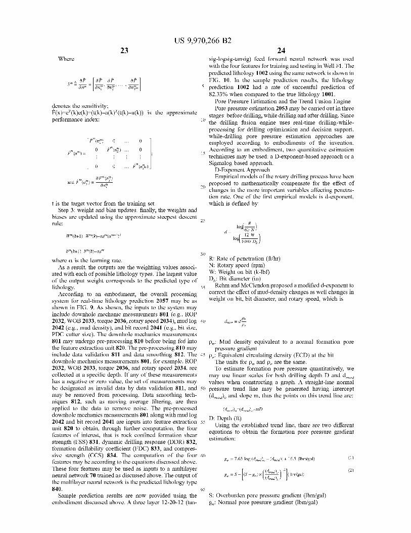
US 9 , 970 , 266 B2 23 US 9 , 970 , 266 B2 23 24
o
Where sig - logsig - tansig ) feed forward neural network was used with the four features for training and testing in Well # 1 . The predicted lithology 1002 using the same network is shown in
A OF [ of OF OF ] FIG . 10 . In the sample prediction results , the lithology su Fanm = | ann anm . . . One on 5 prediction 1002 had a rate of successful prediction of
82 . 33 % when compared to the true lithology 1001 . Pore Pressure Estimation and the Trend Fusion Engine denotes the sensitivity ; Pore pressure estimation 2053 may be carried out in three F ( x ) = e + ( k ) e ( k ) = ( t ( k ) - a ( k ) + ( t ( k ) - a ( k ) ) is the approximate stages : before drilling , while drilling and after drilling . Since performance index ; the drilling fusion engine uses real - time drilling - while
processing for drilling optimization and decision support , while - drilling pore pressure estimation approaches are
[ i " ( n ? " ) 0 . 0 employed according to embodiments of the invention . O : " ( n ) . . . 0 * * " ( n " ) = 1 According to an embodiment , two quantitative estimation
techniques may be used : a D - exponent - based approach or a T O O . . . Fe ( pre ) ] Sigmalog based approach .
D - Exponent Approach Empirical models of the rotary drilling process have been
proposed to mathematically compensate for the effect of changes in the more important variables affecting penetra tion rate . One of the first empirical models is d - exponent ,
t is the target vector from the training set . which is defined by : Step 3 : weight and bias updates : finally , the weights and
biases are updated using the approximate steepest descente rule :
O
.
. . .
O
and is " ( " ) - OF " ( 11 ) and i " ( n ! " ) = only
loglan N d = 60 N )
12 W WM ( k + 1 ) = Wm ( k ) - asMam - 1 ) 1000 DJ
30 b " ( k + 1 ) = b } " ( k ) - as where a is the learning rate . R : Rate of penetration ( ft / hr )
As a result , the outputs are the weighting values associ N : Rotary speed ( rpm ) ated with each of possible lithology types . The largest value W : Weight on bit ( k - lbf ) of the output weight corresponds to the predicted type of Do : Bit diameter ( in ) lithology . 35 Rehm and McClendon proposed a modified d - exponent to
According to an embodiment . the overall processing correct the effect of mud - density changes as well changes in system for real - time lithology prediction 2057 may be as weight on bit , bit diameter , and rotary speed , which is shown in FIG . 9 . As shown , the inputs to the system may include downhole mechanic measurements 801 ( e . g . , ROP 2032 , WOB 2033 , torque 2036 , rotary speed 2034 ) , mud log 40 dmod = d 2042 ( e . g . , mud density ) , and bit record 2041 ( e . g . , bit size , PDC cutter size ) . The downhole mechanics measurements 801 may undergo pre - processing 810 before being fed into Pn : Mud density equivalent to a normal formation pore the feature extraction unit 820 . The pre - processing 810 may pressure gradient include data validation 811 and data smoothing 812 . The 45 pc : Equivalent circulating density ( ECD ) at the bit downhole mechanics measurements 801 , for example , ROP The units for p , and pare the same . 2032 , WOB 2033 , torque 2036 , and rotary speed 2034 , are To estimate formation pore pressure quantitatively , we collected at a specific depth . If any of these measurements may use linear scales for both drilling depth D and dmod has a negative or zero value , the set of measurements may values when constructing a graph . A straight - line normal be designated as invalid data by data validation 811 , and 50 pressure trend line may be generated having intercept may be removed from processing . Data smoothing tech - ( d ) , and slope m , thus the points on this trend line are : niques 812 , such as moving average filtering , are then applied to the data to remove noise . The pre - processed ( dmod ) n = admod ) . + mD downhole mechanics measurements 801 along with mud log 2042 and bit record 2041 are inputs into feature extraction 55 D : Depth ( ft )
Using the established trend line , there are two different unit 820 to obtain , through further computation , the four equations to obtain the formation pore pressure gradient features of interest , that is rock confined formation shear estimation : strength ( FSS ) 831 , dynamic drilling response ( DDR ) 832 , formation drillability coefficient ( FDC ) 833 , and compres sive strength ( CCS ) 834 . The computation of the four 60 & p = 7 . 65 log [ ( dmod ) n - ( dmod ) ] + 16 . 5 ( lbm / gal ) features may be according to the equations discussed above . These four features may be used as inputs to a multilayer neural network 70 trained as discussed above . The output of the multilayer neural network is the predicted lithology type 840 . 65
Sample prediction results are now provided using the S : Overburden pore pressure gradient ( lbm / gal ) embodiment discussed above . A three layer 12 - 20 - 12 ( tan gn : Normal pore pressure gradient ( lbm / gal )
@
@ 8p = s = f ( s = xwx ( Homem " abnyga )
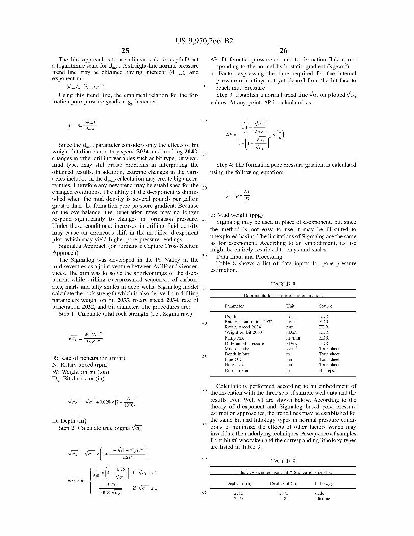
26 US 9 , 970 , 266 B2
25 The third approach is to use a linear scale for depth D but AP : Differential pressure of mud to formation fluid corre
a logarithmic scale for det . A straight - line normal pressure sponding to the normal hydrostatic gradient ( kg / cm² ) trend line may be obtained having intercept ( dmod ) . and n : Factor expressing the time required for the internal exponent m : pressure of cuttings not yet cleared from the bit face to
( dmod ) n = ( dmod ) . em 5 reach mud pressure Using this trend line , the empirical relation for the for Step 3 : Establish a normal trend line Vo , on plotted Vo .
mation pore pressure gradient gp becomes : values . At any point , AP is calculated as :
10 ( dmod ) n 8p = & n dimod 21 - Vor )
APE | Vol x ( 1 ) 12 *
1 - 6 - You Since the dmod parameter considers only the effects of bit weight , bit diameter , rotary speed 2034 , and mud log 2042 , 15 changes in other drilling variables such as bit type , bit wear , mud type , may still create problems in interpreting the Step 4 : The formation pore pressure gradient is calculated obtained results . In addition , extreme changes in the vari - using the following equation : ables included in the dmod calculation may create big uncer tainties . Therefore any new trend may be established for the changed conditions . The utility of the d - exponent is dimin ished when the mud density is several pounds per gallon greater than the formation pore pressure gradient . Because of the overbalance , the penetration rates may no longer p : Mud weight ( ppg ) respond significantly to changes in formation pressure . , # : 25 Sigmalog may be used in place of d - exponent , but since Under these conditions , increases in drilling fluid density the method is not easy to use it may be ill - suited to may cause an erroneous shift in the modified d - exponent plot , which may yield higher pore pressure readings . unexplored basins . The limitations of Sigmalog are the same
as for d - exponent . According to an embodiment , its use Sigmalog Approach ( or Formation Capture Cross Section Approach ) might be entirely restricted to clays and shales .
30 Data Input and Processing The Sigmalog was developed in the Po Valley in the Table 8 shows a list of data inputs for pore pressure mid - seventies as a joint venture between AGIP and Geoser estimation . vices . The aim was to solve the shortcomings of the d - ex ponent while drilling overpressured sequences of carbon ates , marls and silty shales in deep wells . Sigmalog model 26 TABLE 8 calculate the rock strength which is also derive from drilling Data inputs for pore pressure estimation . parameters weight on bit 2033 , rotary speed 2034 , rate of penetration 2032 , and bit diameter . The procedures are : Parameter Unit Source
Step 1 : Calculate total rock strength ( i . e . , Sigma raw ) Depth Rate of penetration 2032 m / hr EDR Rotary speed 2034 rpm
W0 . 5 N0 . 25 Weight on bit 2033 kDaN - EDR
Vo = DyR0 . 25 Pump rate m \ / min EDR Differential pressure kDaN EDR Mud density Tour sheet Depth in / out Tour sheet R : Rate of penetration ( m / hr ) Pipe OD Tour sheet
N : Rotary speed ( rpm ) Hole size Tour sheet W : Weight on bit ( ton ) Bit diameter in Bit report
Do : Bit diameter ( in ) Calculations performed according to an embodiment of
the invention with the three sets of sample well data and the voi = Vo , + 0 . 028 x ( 7 - Dom results from Well # 1 are shown below . According to the
theory of d - exponent and Sigmalog based pore pressure estimation approaches , the trend lines may be established for
D : Depth ( m ) the same bit and lithology types in normal pressure condi Step 2 : Calculate true Sigma vo . tions to minimize the effects of other factors which may
invalidate the underlying techniques . A sequence of samples from bit # 6 was taken and the corresponding lithology types are listed in Table 9 .
m EDR 40
EDR
kg / m3 m
45 mm mm
vo . = Voq x { 1 + 1 - Vente a Ps ) 60 TABLE 9 1 1 1 0 . 75
> 1 Lithology samples from bit # 6 at various depths . where 165 * l4 - o ) ir Voi31 6404 where n = Depth in ( m ) Depth out ( m ) Lithology 3 . 25 - 640x Voy if Vor si
2205 2375
2375 2385 2385
shale siltstone
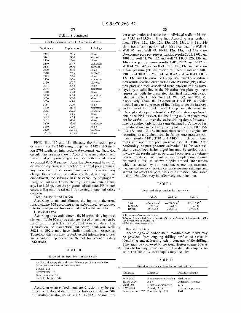
25
US 9 , 970 , 266 B2 27 28
TABLE 9 - continued the uncertainties and noise from individual wells in histori cal 303 . 1 to 303 . 3n drilling data . According to an embodi
Lithology samples from bit # 6 at various depths . ment , FIGS . 12a , 126 , 12c , 13a , 136 , 13c , 14a , 146 , 14c Depth in ( m ) Depth out ( m ) Lithology show trend fusion performed on historical data for Well # 1 ,
Well # 2 , and Well # 3 . FIGS . 12a , 13a , and 14a show 2385 2445 shale D - exponent pore pressure estimation results 2801 , 2901 , and 2445 2450 siltstone 3001 for Well # 1 , Well # 2 , and Well # 3 . FIGS . 12b , 13b , and 2450 2460 shale 14b show pore pressure results 2802 , 2902 , and 3002 for 2460 2475 sandstone 2475 2500 siltstone Well # 1 , Well # 2 , and Well # 3 . FIGS . 12c , 13c , and 14c show 2500 2510 shale 10 a pore pressure ( PP ) estimation by linear regression 2803 , 2510 2515 siltstone 2903 , and 3003 for Well # 1 , Well # 2 , and Well # 3 . FIGS . 2515 2920 shale 2920 2930 12c , 13c , and 14c show the D - exponent based pore estima sandstone 2930 2937 siltstone tion results ( dashed curve in the Pore Pressure ( PP ) estima 2937 2946 shale tion plot ) and their associated trend analysis results ( over 2946 3010 sandstone 15 layed by a solid line in the PP estimation plot ) by linear 3010 3040 shale regression ( with the associated statistical parameters tabu 3040 3054 sandstone 3054 3070 shale lated in Table 11 ) for Well # 1 , Well # 2 , and Well # 3 , 3070 3084 siltstone respectively . Since the D - exponent based PP estimation 3084 3100 shale method may use a process of line fitting to get the intercept 3100 3115 sandstone 20 and slope of the trend line of D - exponent , the estimated 3115 3125 siltstone intercept and slope feeds into the PP estimation equation to 3125 3165 shale obtain the PP . However , the line fitting on D - exponent may 3165 3175 siltstone 3175 3200 shale not be carried out over the entire drilling depth . Instead , it 3200 3210 sandstone may be applied only for the same drilling bit . A line of best 3210 3220 shale fit is also shown in the D - exponent plot . FIG . 15a , FIG . 15b , 3220 3231 . 5 siltstone FIG . 15c , and FIG . 15d illustrate the trend fusion engine 308 3231 . 5 3235 . 5 shale according to an embodiment in fusing pore pressure esti
mation results 3101 , 3102 and 3103 from three different FIGS . 11a , 116 and 11c illustrate the formation pore wells into optimized pore pressure estimate 3104 . After
estimation results 2703 using d - exponent 2702 and Sigma performing the pore pressure estimation 316 for each well log 2701 methods . Intermediate d - exponent and Sigmalog 30 site , a centralized fusion algorithm may be carried out to calculations are also shown . According to an embodiment , integrate the results into an optimized pore pressure estima the normal pore pressure gradient used in the calculation is tion with reduced uncertainties . For example , pore pressure a constant 0 . 4650 psi / feet . Since the D - exponent based PP estimated in Well # 1 shows a spike around 2000 meters estimation equation is a function of normal pore pressure , which is caused by bit transition , where the measured any variation of the normal pore pressure gradient may 35 mechanical sensors provide certain erroneous readings and
should not affect the pore pressure estimation . After trend change the real - time estimation results . According to an fusion , this effect may be effectively smoothed out . embodiment , the software has the capability of program ming the mud weight to watch if it gets to a predefined value , TABLE 11 say , 1 or 1 . 25 pp , over the programmed / estimated PP . In such cases , a flag may be raised thus averting a potential safety 40 Trend analysis parameters for three wells concern .
Trend Analysis and Fusion Well # 1 Well # 2 Well # 3
According to an embodiment , the inputs to the trend SSE 1 . 7631 % 10 % 1 . 0003 x 10 2 097 x 10° fusion engine 308 according to an embodiment are grouped R - Square 0 . 9463 0 . 9670 0 . 9426 into two categories : historical data and real - time data . RMSE 351 . 9952 267 . 2016 383 . 3287
Historical Data According to an embodiment , the historical data inputs as SSE : the sum of squares due to error
R - Square : R - square is defined as the ratio of the sum of squares of the regression ( SSR ) shown in Table 10 may be estimates based on mining nearby and the total sum of squares ( SST ) historical drilling well sites ( i . e . , analogous well data ) . This RMSE : root mean square error is based on the assumption that nearby analogous wells 50 302 . 1 to 302 . n may have similar geological properties . Real - Time Data Therefore , this data may provide useful information to new According to an embodiment , real - time data inputs may wells and drilling operations thereof for potential safety be provided from ongoing drilling profiles to assist in indications . identifying and addressing safety concerns while drilling .
They may be conveyed to the trend fusion engine 308 as 55 inputs to find any deviations from the static data inputs . As TABLE 10 set out in Table 12 , these inputs may include :
Historical data input from analogous wells TABLE 12 Predicted lithology ( from the NN lithology prediction tool ) 310
Estimated pore pressure ( gradient ) 316 60 Real - time data inputs from the well being drilled Porosity 311
Permeability 312 Mechanics Lithology Dynamic Pressure Water saturation 313 Predicted bit wear 314 ROP 2032 Pore pressure estimation Mud weight
Torque 2036 2053 Differential pressure WOB 2033 Lithofacies estimation 3277
According to an embodiment , trend fusion may be per - 65 RPM 3273 Porosity 2075 Hydrostatic pressure formed on historical data from the historical database 309 Pump pressure 3275 Permeability 2076 3241 from multiple analogous wells 302 . 1 to 302 . 3n to minimize
45
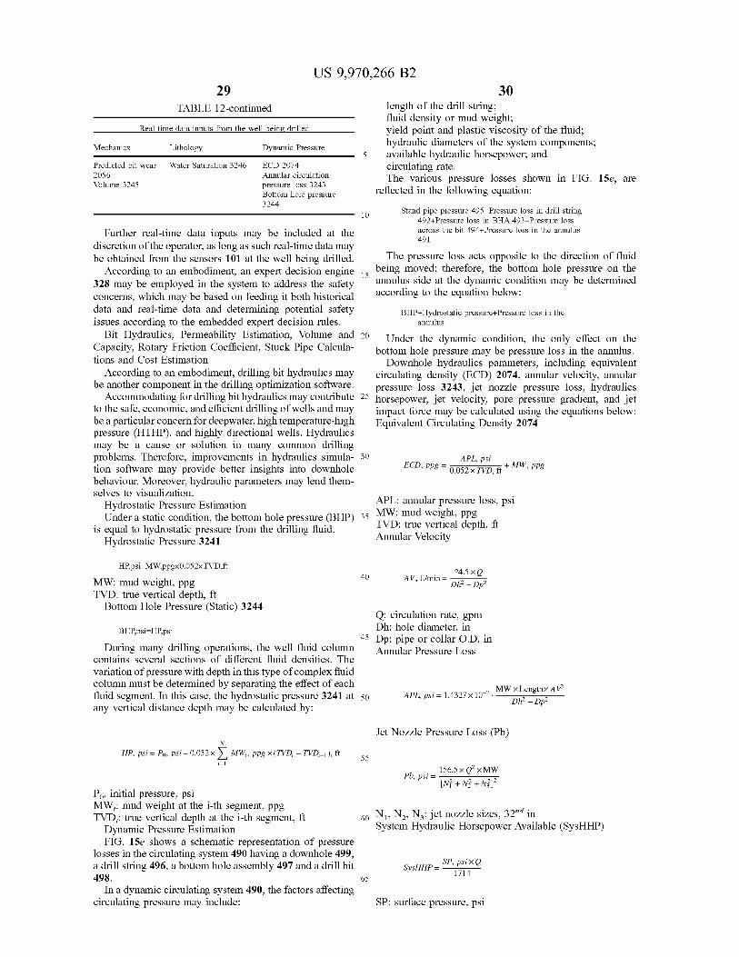
US 9 , 970 , 266 B2 29 30
Dy
- 10 10
TABLE 12 - continued length of the drill string ; fluid density or mud weight ;
Real - time data inputs from the well being drilled yield point and plastic viscosity of the fluid ; Mechanics hydraulic diameters of the system components ; Lithology ic Pressure available hydraulic horsepower ; and Predicted bit wear Water Saturation 3246 ECD 2074 circulating rate . 2056 Annular circulation The various pressure losses shown in FIG . 15e , are Volume 3245 pressure loss 3243
Bottom hole pressure reflected in the following equation : 3244
Stand pipe pressure 495 = Pressure loss in drill string 492 + Pressure loss in BHA 493 + Pressure loss
Further real - time data inputs may be included at the across the bit 494 + Pressure loss in the annulus 491 discretion of the operator , as long as such real - time data may
be obtained from the sensors 101 at the well being drilled . The pressure loss acts opposite to the direction of fluid According to an embodiment , an expert decision engine is being moved ; therefore , the bottom hole pressure on the
328 may be employed in the system to address the safety annulus side at the dynamic condition may be determined concerns , which may be based on feeding it both historical according to the equation below : data and real - time data and determining potential safety BHP = Hydrostatic pressure + Pressure loss in the issues according to the embedded expert decision rules . annulus
Bit Hydraulics , Permeability Estimation , Volume and 20 n? and 20 Under the dynamic condition , the only effect on the Under the dynamics Capacity , Rotary Friction Coefficient , Stuck Pipe Calcula - bottom hole pressure may be pressure loss in the annulus . tions and Cost Estimation Downhole hydraulics parameters , including equivalent
According to an embodiment , drilling bit hydraulics may circulating density ( ECD ) 2074 , annular velocity , annular be another component in the drilling optimization software . pressure loss 3243 , jet nozzle pressure loss , hydraulics
Accommodating for drilling bit hydraulics may contribute 25 horsepower , jet velocity , pore pressure gradient , and jet to the safe , economic , and efficient drilling of wells and may impact force may be calculated using the equations below : be a particular concern for deepwater , high temperature - high Equivalent Circulating Density 2074 pressure ( HTHP ) , and highly directional wells . Hydraulics may be a cause or solution in many common drilling problems . Therefore , improvements in hydraulics simula - 30 APL , psi tion software may provide better insights into downhole behaviour . Moreover , hydraulic parameters may lend them selves to visualization .
Hydrostatic Pressure Estimation APL : annular pressure loss , psi Under a static condition , the bottom hole pressure ( BHP ) 35 MW : mud weight , ppg TVD : true vertical depth , ft is equal to hydrostatic pressure from the drilling fluid . Hydrostatic Pressure 3241 Annular Velocity
ECD , ppg = 0 , 052 TVD , ft 0 . 052 x TVD ft + MW , ppg
HP , psi = MW , ppg < 0 . 052xTVD , ft 24 . 5 XQ 40 40 AV , ft / min = = MW : mud weight , ppg Dh ? – Dp2 TVD : true vertical depth , ft
Bottom Hole Pressure ( Static ) 3244 Q : circulation rate , gpm BHP , psi = HP , psi Dh : hole diameter , in
45 Dp : pipe or collar O . D , in During many drilling operations , the well fluid column Annular Pressure Loss
contains several sections of different fluid densities . The variation of pressure with depth in this type of complex fluid column must be determined by separating the effect of each 22410 - 7 MW x Lengthx AV2 fluid segment . In this case , the hydrostatic pressure 3241 at 50 APL psi = 1 . 4327 x 10 - 7 . Dh ? – Dp2 any vertical distance depth may be calculated by :
Jet Nozzle Pressure Loss ( Pb )
55 HP , psi = Po , psi + 0 . 052xM W , ppg X ( TVD ; – TVD ; - 1 ) , ft . 156 . 5 x Q2xMW Pb , psi =
[ N + N + N3 ] Po , initial pressure , psi MW : mud weight at the i - th segment , ppg TVD ; : true vertical depth at the i - th segment , ft 60 N , N2 , Nz : jet nozzle sizes , 32nd in Dynamic Pressure Estimation System Hydraulic Horsepower Available ( SysHHP ) FIG . 15e shows a schematic representation of pressure
losses in the circulating system 490 having a downhole 499 , a drill string 496 , a bottom hole assembly 497 and a drill bit SP , psixQ SysHHP =
1714 498 . In a dynamic circulating system 490 , the factors affecting
circulating pressure may include : SP : surface pressure , psi
65
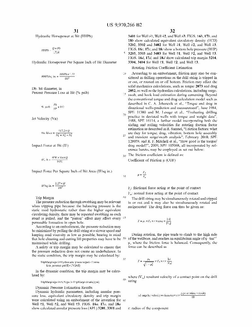
US 9 , 970 , 266 B2 31 32
Hydraulic Horsepower at Bit ( HHPb )
HHPb - ex Pb HHPb = 1714 1714
Hydraulic Horsepower Per Square Inch of Bit Diameter
HHPbx 1 . 27 HHPb / sq in . = D62
Db : bit diameter , in Percent Pressure Loss at Bit ( % psib )
3401 for Well # 1 , Well # 2 , and Well # 3 . FIGS . 16b , 17b , and 18b show calculated equivalent circulatory density ( ECD ) 3202 , 3302 and 3402 for Well # 1 , Well # 2 , and Well # 3 . FIGS . 160 , 17c , and 18c show a bottom hole pressure ( BHP )
5 3203 , 3303 and 3403 for Well # 1 , Well # 2 , and Well # 3 . FIGS . 160 , 17d , and 18d show calculated trip margin 3204 , 3304 , 3404 for Well # 1 , Well # 2 , and Well # 3 .
Rotating Friction Coefficient Estimation 10 According to an embodiment , friction may also be con
sidered in drilling operations as the drill string is tripped in or out , or rotated on or off bottom . Friction may affect the solid mechanics calculations , such as torque 2073 and drag 2052 , as well as the hydraulics calculations , including surge ,
15 swab , and hook load estimation during cementing . Beyond the conventional torque and drag calculation model such as described in C . A . Johancsik et al . , " Torque and drag in directional wells - prediction and measurement ” , June 1984 , SPE 11380 and M . Lesage et al . , “ Evaluating drilling
20 practice in deviated wells with torque and weight data " , 1988 , SPE 16114 , a further model incorporating both the sliding and rolling velocities for rotating friction factor estimation as described in R . Samuel , “ Friction factors : what are they for torque , drag , vibration , bottom hole assembly and transient surge / swarb analysis ” , February 2010 , SPE 128059 , and R . F . Mitchell et al . , " How good is the torque / drag model ? ” , 2009 , SPE 105068 , all incorporated by ref erence herein , may be employed as set out below :
30 The friction coefficient is defined as : Coefficient of Friction u ( COF )
?? % psib = 50x100
Jet Velocity ( Vn )
417 . 2xQ Vn , f / sec = N + N + N3 2
Impact Force at Bit ( IF )
MW XVnxo IF , 1b = 1930
Impact Force Per Square Inch of Bit Area ( IF / sq in . ) 35 = Dh2
16 Vrs
| 1 . 27x F IF / sq in . = = F ; frictional force acting at the point of contact
Fm : normal force acting at the point of contact Trip Margin 40 The drill string may be simultaneously rotated and tripped The pressure reduction through swabbing may be relevant in or out and it may also be simultaneously rotated and
when tripping pipe because : the balancing pressure is the reciprocated . The drag force can thus be given as : static mud hydrostatic rather than the higher equivalent circulating density , there may be repeated swabbing as each stand is pulled , and the “ piston ” effect may affect every 45
T = 4 , XFX X FX cose X permeable formation in open hole . According to an embodiment , the pressure reduction may
be minimized by pulling the drill string at a slower speed and keeping mud viscosity as low as possible , bearing in mind During rotation , the pipe tends to climb to the high side that hole cleaning and cutting lift properties may have to be 50 of the wellbore , and reaches an equilibrium angle of q = tan - 1 maintained while drilling . u , where the friction force is balanced . Consequently , the
A safety or trip margin may be calculated to ensure that force can be described as the pressure reduction does not create an underbalance . In the static condition , the trip margin may be calculated by :
Hy ve TripMargin ( psi ) = Hydrostatic pressure ( psi ) – Forma tion pressure psi / ft ) xTVD ( ft ) V1 + uz
In the dynamic condition , the trip margin may be calcu lated by : where IV sl resultant velocity of a contact point on the drill
TripMargin ( psi ) = APL ( psi ) + Trip Margin ( static ) ( psi ) Dynamic Pressure Estimation Results Dynamic hydraulic parameters , including annular pres pipe rotation velocity
sure loss , equivalent circulatory density and trip margin \ w angular velocity = diameterX AX ! were calculated using an embodiment of the invention for 65 Well # 1 , Well # 2 , and Well # 3 . FIGS . 16a , 17a , and 18a show calculated annular pressure loss ( APL ) 3201 , 3301 and r : radius of the component
od by : 55 = = XF , XrX | V , 75
60 string
60
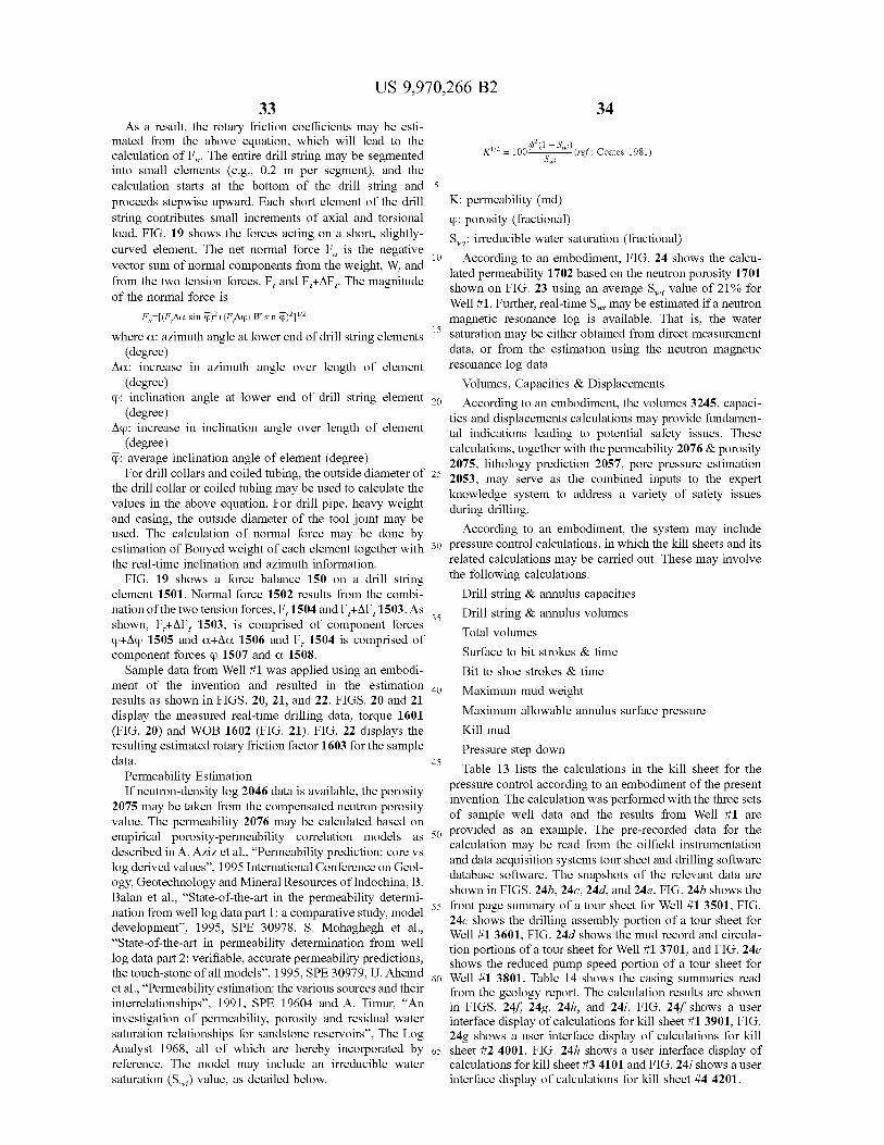
33
K1 / 2 = 100€ - ( 1 – Swi ) , Swi
15
US 9 , 970 , 266 B2 34
As a result , the rotary friction coefficients may be esti mated from the above equation , which will lead to the calculation of Fn . The entire drill string may be segmented 1 - ( ref : Coates 1981 ) into small elements ( e . g . , 0 . 2 m per segment ) , and the calculation starts at the bottom of the drill string and 5 proceeds stepwise upward . Each short element of the drill K : permeability ( md ) string contributes small increments of axial and torsional q : porosity ( fractional ) load . FIG . 19 shows the forces acting on a short , slightly Slightly - Swii irreducible water saturation ( fractional ) curved element . The net normal force Fn is the negative | 10 According to an embodiment , FIG . 24 shows the calcu vector sum of normal components from the weight , W , and lated permeability 1702 based on the neutron porosity 1701 from the two tension forces , F , and F , + AF7 . The magnitude shown on FIG . 23 using an average Swi value of 21 % for of the normal force is Well # 1 . Further , real - time Swi may be estimated if a neutron
Fr = [ ( FAQ sin q ) + ( FAQ + W sin 02 ] 1 2 magnetic resonance log is available . That is , the water where a : azimuth angle at lower end of drill string elements saturation may be either obtained from direct measurement
( degree ) data , or from the estimation using the neutron magnetic Aca : increase in azimuth angle over length of element resonance log data .
( degree ) Volumes , Capacities & Displacements Q : inclination angle at lower end of drill string element 20 According to an embodiment , the volumes 3245 . capaci
( degree ) ties and displacements calculations may provide fundamen Aq : increase in inclination angle over length of element tal indications leading to potential safety issues . These ( degree ) calculations , together with the permeability 2076 & porosity Q : average inclination angle of element ( degree ) 2075 , lithology prediction 2057 , pore pressure estimation For drill collars and coiled tubing , the outside diameter of 25 203 2053 , may serve as the combined inputs to the expert the drill collar or coiled tubing may be used to calculate the knowledge system to address a variety of safety issues values in the above equation . For drill pipe , heavy weight during drilling . and casing , the outside diameter of the tool joint may be According to an embodiment , the system may include used . The calculation of normal force may be done by estimation of Bouyed weight of each element together with 30 pressure control calculations , in which the kill sheets and its the real - time inclination and azimuth information . related calculations may be carried out . These may involve
FIG . 19 shows a force balance 150 on a drill string the following calculations : element 1501 . Normal force 1502 results from the combi Drill string & annulus capacities nation of the two tension forces , F , 1504 and F , + AF , 1503 . As Drill string & annulus volumes shown , F , + AF , 1503 , is comprised of component forces Total volumes Q + AQ 1505 and a + Aa 1506 and F , 1504 is comprised of component forces o 1507 and a 1508 . Surface to bit strokes & time
Sample data from Well # 1 was applied using an embodi Bit to shoe strokes & time ment of the invention and resulted in the estimation 40 Maximum mud weight results as shown in FIGS . 20 , 21 , and 22 . FIGS . 20 and 21 display the measured real - time drilling data , torque 1601 Maximum allowable annulus surface pressure ( FIG . 20 ) and WOB 1602 ( FIG . 21 ) . FIG . 22 displays the Kill mud resulting estimated rotary friction factor 1603 for the sample Pressure step down data . 45 Table 13 lists the calculations in the kill sheet for the Permeability Estimation
If neutron - density log 2046 data is available , the porosity pressure control according to an embodiment of the present invention . The calculation was performed with the three sets 2075 may be taken from the compensated neutron porosity
value . The permeability 2076 may be calculated based on of sample well data and the results from Well # 1 are empirical porosity - permeability correlation models as 50 50 provided as an example . The pre - recorded data for the described in A . Aziz et al . , “ Permeability prediction : core vs calculation may be read from the oilfield instrumentation
and data acquisition systems tour sheet and drilling software log derived values ” , 1995 International Conference on Geol database software . The snapshots of the relevant data are ogy , Geotechnology and Mineral Resources of Indochina , B . shown in FIGS . 246 , 240 , 24d , and 24e . FIG . 24b shows the Balan et al . , “ State - of - the - art in the permeability determi nation from well log data part 1 : a comparative study , model - 55 front page summary of a tour sheet for Well # 1 3501 , FIG .
24c shows the drilling assembly portion of a tour sheet for development ” , 1995 , SPE 30978 , S . Mohaghegh et al . , Well # 1 3601 , FIG . 24d shows the mud record and circula “ State - of - the - art in permeability determination from well tion portions of a tour sheet for Well # 1 3701 , and FIG . 24e log data part 2 : verifiable , accurate permeability predictions , shows the reduced pump speed portion of a tour sheet for the touch - stone of all models ” , 1995 , SPE 30979 , U . Ahemd · Abend 60 Well # 1 3801 . Table 14 shows the casing summaries read et al . , “ Permeability estimation : the various sources and their from the geology report . The calculation results are shown interrelationships ” , 1991 , SPE 19604 and A . Timur , “ An in FIGS . 248 , 249 , 24h , and 24i . FIG . 24f shows a user investigation of permeability , porosity and residual water interface display of calculations for kill sheet # 1 3901 , FIG . saturation relationships for sandstone reservoirs ” , The Log 24g shows a user interface display of calculations for kill Analyst 1968 , all of which are hereby incorporated by 65 sheet # 2 4001 , FIG . 24h shows a user interface display of reference . The model may include an irreducible water calculations for kill sheet # 3 4101 and FIG . 24i shows a user saturation ( Swi ) value , as detailed below . interface display of calculations for kill sheet # 4 4201 .
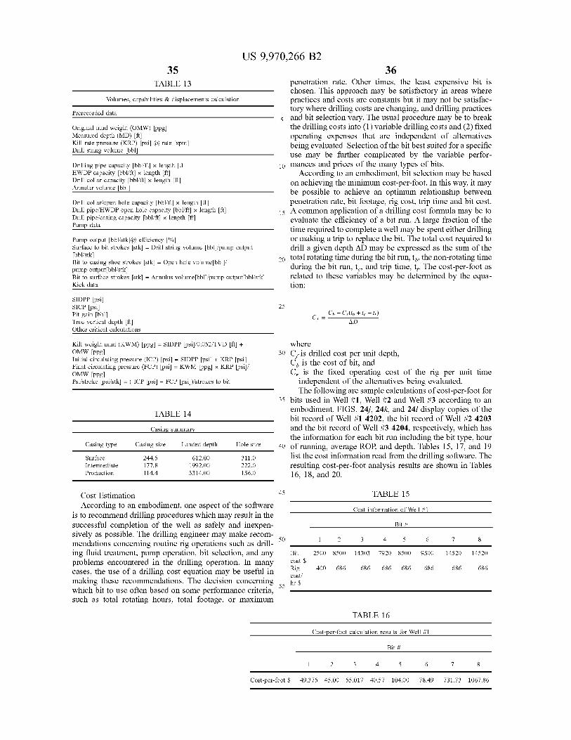
35 US 9 , 970 , 266 B2
36 TABLE 13 penetration rate . Other times , the least expensive bit is
chosen . This approach may be satisfactory in areas where Volumes , capabilities & displacements calculation practices and costs are constants but it may not be satisfac
tory where drilling costs are changing , and drilling practices Prerecorded data 5 and bit selection vary . The usual procedure may be to break Original mud weight ( OMW ) [ ppg ] the drilling costs into ( 1 ) variable drilling costs and ( 2 ) fixed Measured depth ( MD ) [ ft ] operating expenses that are independent of alternatives Kill rate pressure ( KRP ) [ psi ] @ rate [ spm ] being evaluated . Selection of the bit best suited for a specific Drill string volume [ bbl ] use may be further complicated by the variable perfor Drilling pipe capacity [ bbl / ft ] x length [ ft ] 10 mances and prices of the many types of bits . HWDP capacity [ bbl / ft ] x length [ ft ] According to an embodiment , bit selection may be based Drill collar capacity [ bbl / ft ] < length [ ft ] on achieving the minimum cost - per - foot . In this way , it may Annular volume [ bbl ] be possible to achieve an optimum relationship between Drill collar / open hole capacity [ bbl / ft ] < length [ ft ] penetration rate , bit footage , rig cost , trip time and bit cost . Drill pipe / HWDP open hole capacity [ bbl / ft ] x length [ ft ] 15 A common application of a drilling cost formula may be to Drill pipe / casing capacity [ bbl / ft ] < length [ ft ] evaluate the efficiency of a bit run . A large fraction of the Pump data time required to complete a well may be spent either drilling Pump output [ bbl / stk ] @ efficiency [ % ] or making a trip to replace the bit . The total cost required to Surface to bit strokes [ stk ] = Drill string volume [ bbl ] / pump output drill a given depth AD may be expressed as the sum of the [ bbl / stk ] 20 total rotating time during the bit run , th , the non - rotating time Bit to casing shoe strokes [ stk ] = Open hole volume [ bbl ] / during the bit run , t . , and trip time , ty . The cost - per - foot as pump output [ bbl / stk ] Bit to surface strokes [ stk ] = Annulus volume [ bbl ] / pump output [ bbl / stk ] related to these variables may be determined by the equa Kick data tion :
25 SIDPP [ psi ] SICP [ psi ] Pit gain [ bbl ] True vertical depth [ ft ] Other critical calculations
Ch + Cr ( tb + 1c + ) Cp = AD
Kill weight mud ( KWM ) ( ppg ] = SIDPP [ psi ] / 0 . 052 / TVD [ ft ] + OMW [ ppg ] Initial circulating pressure ( ICP ) [ psi ] = SIDPP [ psi ] + KRP [ psi ] Final circulating pressure ( FCP ) [ psi ] = KWM ( ppg ] ~ KRP [ psi ] / OMW [ ppg ] Psi / stroke [ psi / stk ] = ( ICP [ psi ] - FCP [ psi ] ) / strokes to bit
TABLE 14 TABLE 14
where 30 Cf is drilled cost per unit depth ,
C ) is the cost of bit , and C , is the fixed operating cost of the rig per unit time independent of the alternatives being evaluated . The following are sample calculations of cost - per - foot for
35 bits used in Well # 1 , Well # 2 and Well # 3 according to an embodiment . FIGS . 247 , 24k , and 241 display copies of the bit record of Well # 1 4202 , the bit record of Well # 2 4203 and the bit record of Well # 3 4204 , respectively , which has the information for each bit run including the bit type , hour
40 of running , average ROP , and depth . Tables 15 , 17 , and 19 list the cost information read from the drilling software . The resulting cost - per - foot analysis results are shown in Tables 16 , 18 , and 20 .
Casing summary
Casing type Casing size Landed depth Hole size
Surface Intermediate Production
244 . 5 177 . 8 114 . 4
612 . 00 1992 . 00 3314 . 00
311 . 0 222 . 0 156 . 0
TABLE 15 Cost information of Well # 1
Bit #
Cost Estimation 45 According to an embodiment , one aspect of the software
is to recommend drilling procedures which may result in the successful completion of the well as safely and inexpen sively as possible . The drilling engineer may make recom mendations concerning routine rig operations such as drill ing fluid treatment , pump operation , bit selection , and any Bit problems encountered in the drilling operation . In many Rig cases , the use of a drilling cost equation may be useful in making these recommendations . The decision concerning sehr $ which bit to use often based on some performance criteria , such as total rotating hours , total footage , or maximum
1 2 2500 8500
3 14303
4 5 7920 8500
6 7 950014520
8 14520
cost $ 400 686 686 686 686 686 686 686
cost /
TABLE 16
Cost - per - foot calculation results for Well # 1
Bit # Bit #
1 2 3 4 5 6 7 8 Cost - per - foot $ 49 . 375 45 . 00 55 . 017 40 . 57 104 . 00 78 . 49 731 . 73 1067 . 86
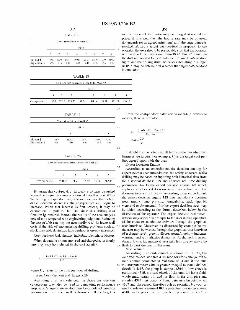
37 TABLE 17
Cost information of Well # 2
US 9 , 970 , 266 B2 38
met or exceeded , the motor may be charged at normal list price ; if it is not , then the hourly rate may be adjusted downwards ( to an agreed minimum ) until the target figure is reached . Before a target cost - per - foot is proposed to the operator , the user should be reasonably sure that the operator
6 7 8 will be able to achieve a minimum ROP . This ROP may be
9500 4000 9500 the drill rate needed to meet both the proposed cost - per - foot 646 646 646 figure and the pricing structure . After calculating this target
ROP , it may be determined whether the target cost - per - foot is attainable .
Bit #
1 2 3 4 5 Bit cost $ Rig cost / hr $
1450 8130 2450 645 646 646
15920 646
9500 646
TABLE 18
Cost - per - foot calculation results for Well # 2
Bit #
1 2 3 55 . 8 57 . 15 103 . 75
4 54 . 74
5 6 194 . 1957 . 78
7 321 . 71
8 160 . 13 Cost - per - foot $
TABLE 19 From the cost - per - foot calculations including downhole motors , there is provided :
Cost information of Well # 3
Bit # Bit # 25 th = 23 4
Cf . AD - Cb - Cylte + 1 ; ) Cr + Cm 5
AD Bit cost $ Rig cost / hr $
850
668 11500 686
16870 686
10900 686
9500
686 ROP =
30
35
It should also be noted that all terms in the preceding two TABLE 20 formulas are targets . For example , Cf is the target cost - per
foot agreed upon with the user . Cost - per - foot calculation results for Well # 3 Expert Decision Engine Bit # Bit # 35 According to an embodiment , the decision making for
expert system recommendations for safety concerns while drilling may be based on inputting both historical data from
Cost - per - foot $ 5941 . 93 41 . 74 45 . 68 57 . 36 382 . 88 the historical database 309 and adjusted real - time drilling parameters 329 to the expert decision engine 328 which applies a set of expert decision rules in accordance with the By using this cost - per - foot formula , a bit may be pulled decision trees set out below . According to an embodiment , when it no longer becomes economical to drill with it . When
the drilling time - per - foot begins to increase , and the footage the expert decision engine 328 may include six decision drilled - per - time decreases , the cost - per - foot will begin to trees : mud volume , porosity , permeability , stuck pipe , bit increase When that increase is first noticed it may be 45 wear and environmental . Further expert decision trees may economical to pull the bit . But since this drilling cost be added according to the format described below in the function ignores risk factors , the results of the cost analysis discretion of the operator . The expert decision recommen may also be tempered with engineering judgment . Reducing dations may appear as prompts to the user during operation the cost of a bit run may not necessarily result in lower well of the client or standalone software through the graphical costs if the risk of encountering drilling problems such as 50 user interface . Moreover , as discussed by example below , stuck pipe , hole deviation , hole washout is greatly increased . the user may be warned through the graphical user interface
of a danger level : green indicates normal , yellow indicates Cost - Per - Foot Calculations Including Downhole Motors warning , and red indicates dangerous . At the yellow or red When downhole motors are used and charged at an hourly danger levels , the graphical user interface display may also
rate , they may be included in the cost equation : 55 flash to alert the user of the issue . Mud Volume According to an embodiment as shown in FIG . 25 , the
C Cb + Cylth + 1c + 1 ) + Cmith mud volume decision tree 4300 monitors for a change of the mud volume parameter in real time 4302 and if the mud
60 volume parameter 4301 is greater or equal to than a defined where Cm refers to the cost per hour of drilling threshold 4303 , the pump is stopped 4304 , a flow check is
performed 4305 , a visual check of the tank for input fluid , Target Cost - Per - Foot and Target ROP whole mud , water , oil , and for flow in the drill pipe and According to an embodiment , the above cost - per - foot annulus 4306 may occur , volume gain may be established
calculations may also be used in generating performance 65 4307 and the reason therefor such as potential blowout or proposals . A target cost - per - foot may be calculated based on need to release pressure 4308 or potential loss in circulation information from offset well performance . If the target is 4310 , and a procedure in regards of potential blowout or
AD
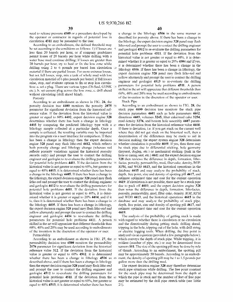
39 US 9 , 970 , 266 B2
40 need to release pressure 4309 or a procedure developed by a change in the lithology 4506 in the same manner as the operator or contractor in regards of potential loss in described for porosity above . If there has been a change in circulation 4311 may be presented to the user . the lithology , the expert decision engine 328 panel may flash
According to an embodiment , the defined threshold may litho - red and prompt the user to contact the drilling engineer be set according to the conditions as follows : 1 ) if losses are 5 and geologist 4512 to re - evaluate the drilling parameters for less than 20 barrels per hour , or if company guidelines potential hole problems 4511 . If the deviation from the permit losses of 20 barrels per hour while drilling with a historical value is not greater or equal to 40 % , it is deter water base mud continue drilling ; if losses are greater than mined whether it is greater or equal to 20 % 4504 and if yes , 20 barrels per hour , try to heal or fix the loss zone while it is determined whether there has been a change in the drilling using 2 to 6 pounds per barrel loss circulation 10 lithology 4506 . If there has been a change in lithology , the material if there are partial losses . For more extreme losses , expert decision engine 328 panel may flash litho - red and but not full losses , stop , mix a tank of whole mud with lost yellow alternately and prompt the user to contact the drilling circulation material of 6 plus pounds per barrel ; if full losses engineer and geologist 4513 to re - evaluate the drilling arise , stop , and evaluate options to fix or stop loss circula tion : a . set a plug . There are various types ( Di - Seal . GUNK 15 parameters for potential hole problems 4511 . A person etc . ) , b . set cement plug across the loss zone , c . drill ahead skilled in the art will appreciate that different thresholds than without circulating ( drill ahead blind ) . 60 % , 40 % and 20 % may be used according to embodiments
Porosity of the invention in the discretion of the operator or user . According to an embodiment as shown in FIG . 26 , the Stuck Pipe
porosity decision tree 4400 monitors the porosity 2075 20 According to an embodiment as shown in FIG . 28 , the parameter for significant deviation from the historical ref - stuck pipe 4600 decision tree monitors the stuck pipe erence value . If the deviation from the historical value is decision parameters 4601 such as hole parameters 4602 , greater or equal to 60 % 4402 , expert decision engine 328 directions 4603 , volumes 3245 , filter cake / mud cake 3254 , determines whether there has been a change in lithology mud density 3276 , and bottom hole assembly 4607 param 4405 by comparing the predicted lithology type with a 25 eters for deviation from the historical reference value 4608 . lithology sample collected at a particular depth . Once a If there is deviation , i . e . if you get stuck on the current well sample is collected , the resulting variable may be imported where they did not get stuck on the historical well , then a into the program via a user interface for comparison . If there determination of the differences may be made to aid in has been a change in lithology then the expert decision decision making ; the expert system engine 328 determines engine 328 panel may flash litho - red 4412 , which reflects 30 whether circulation is possible 4609 . If yes , then there may both porosity change and lithology change ( whereas red be stuck pipe due to differential sticking , hole geometry reflects porosity variations against the historical porosity ( keyseat , dogleg , etc . ) or mechanical sticking ( junk in the records only ) and prompt the user to contact the drilling hole or casing seat , etc . ) 4611 and the expert decision engine engineer and geologist to re - evaluate the drilling parameters 328 then reviews the difference in depth , formation , litho for potential hole problems 4411 . If the deviation from the 35 facies , porosity , permeability , mud , filter cake , density , ROP , historical value is not greater or equal to 60 % , but greater or RPM , and WOB 4613 , and the historical operations in the equal to 40 % 4403 , it is determined whether there has been database 4615 and may analyze the probability of stuck , a change in the lithology 4405 . If there has been a change in depth , free point , size and density of spotting pill 4617 , and the lithology , the expert decision engine 328 panel may flash estimate optimized time and cost for the current operation litho - red and prompt the user to contact the drilling engineer 40 4619 . If circulation is not possible , there may be a stuck pipe and geologist 4412 to re - evaluate the drilling parameters for due to pack off 4610 , and the expert decision engine 328 potential hole problems 4411 . If the deviation from the then notes the difference in depth , formation , lithofacies , historical value is not greater or equal to 40 % , it is deter - porosity , permeability , mud , filter cake , density , ROP , RPM mined whether it is greater or equal to 20 % 4404 , and if it and WOB 4613 , and the historical operations 4615 in the is , then it is determined whether there has been a change in 45 database and may analyze the probability of stuck pipe , the lithology 4405 . If there has been a change in lithology , depth , free point , size and density of spotting pill 4617 , and the expert decision engine 328 panel may flash litho - red and estimate optimized time and cost for the current operation yellow alternately and prompt the user to contact the drilling 4619 . engineer and geologist 4414 to re - evaluate the drilling The analysis of the probability of getting stuck is made parameters for potential hole problems 4411 . A person 50 with regard to whether there is circulation or no circulation skilled in the art will appreciate that different thresholds than and the directionality during getting stuck : drilling ahead , 60 % , 40 % and 20 % may be used according to embodiments tripping in the hole , tripping out of the hole , with drill string of the invention in the discretion of the operator or user . or electric logging tools . When drilling , the free point is
Permeability analyzed via an equation ( provided a few paragraphs below ) , According to an embodiment as shown in FIG . 27 , the 55 which conveys the depth of stuck pipe . While tripping , it is
permeability decision tree 4500 monitors the permeability evident ( number of pipe , etc . ) or may be determined from 2076 parameter for significant deviation from the historical sensors 101 . The size of the spotting pill may be done by rule reference value 312 . If the deviation from the historical of thumb . According to an embodiment , the spotting pill value is greater or equal to 60 % 4502 , it is determined may be approximately 50 barrels . According to an embodi whether there has been a change in lithology 4506 as 60 ment , the density of spotting pill may be 1 to 1 . 5 pounds per described above , and if there has been a change in lithology gallon more than the drilling mud . then the expert decision engine 328 panel may flash litho - red The expert decision engine 328 may therefore determine and prompt the user to contact the drilling engineer and stuck pipe situations while drilling . The free point constant geologist 4512 to re - evaluate the drilling parameters for for the stuck pipe may be determined from the depth at potential hole problems 4511 . If the deviation from the 65 which the pipe is stuck and the number of feet of free pipe historical value is not greater or equal to 60 % , but greater or may be estimated by the drill pipe stretch table ( see Table equal to 40 % 4503 , it is determined whether there has been 21 ) .
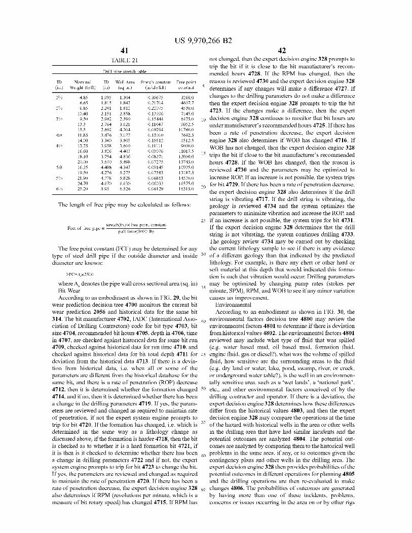
10 . 40 0 . 15444
0 . 09294 0 . 13000 4 . 0
5 . 0
5122
6 / 8 16315 . 0 20
US 9 , 970 , 266 B2 41
TABLE 21 not changed , then the expert decision engine 328 prompts to trip the bit if it is close to the bit manufacturer ' s recom Drill pipe stretch table mended hours 4728 . If the RPM has changed , then the
ID Nominal ID Wall Area Stretch constant Free point reason is reviewed 4730 and the expert decision engine 328 ( in . ) Weight ( lb / ft ) ( in ) ( sq in . ) ( in / klb / kft ) constant determines if any changes will make a difference 4727 . If determines if any changes will make a difference 4727 . If
23 / 8 4 . 85 1 . 995 1 . 304 0 . 30675 3260 . 0 changes to the drilling parameters do not make a difference 6 . 65 1 . 815 1 . 843 0 . 21704 4607 . 7 then the expert decision engine 328 prompts to trip the bit
27 / 8 6 . 85 2 . 241 1 . 812 0 . 22075 4530 . 0 4723 . If the changes make a difference , then the expert 2 . 151 2 . 858 0 . 13996 7145 . 0 3112 9 . 50 2 . 992 2 . 590 6475 . 0 10 decision engine 328 continues to monitor that bit hours are
13 . 3 2 . 764 3 . 621 0 . 11047 9052 . 5 under manufacturer ' s recommended hours 4725 . If there has 15 . 5 2 . 602 4 . 304 10760 . 0 11 . 85 3 . 476 3 . 077 been a rate of penetration decrease , the expert decision 7692 . 5 14 . 00 3 . 340 3 . 805 0 . 10512 9512 . 5 engine 328 also determines if WOB has changed 4716 . If
4112 13 . 75 3 . 958 3 . 600 0 . 11111 9000 . 0 WOB has not changed , then the expert decision engine 328 16 . 60 3 . 826 4 . 407 0 . 09076 11017 . 5 18 . 10 3 . 754 4 . 836 0 . 08271 12090 . 0 15 trips the bit if close to the bit manufacturer ' s recommended 20 . 00 3 . 640 5 . 498 0 . 07275 13745 . 0 hours 4728 . If the WOB has changed , then the reason is 16 . 25 4 . 408 4 . 347 0 . 09145 10935 . 0 reviewed 4730 and the parameters may be optimized to 19 . 50 4 . 276 5 . 275 0 . 07583 13187 . 5 21 . 90 4 . 778 5 . 828 0 . 06863 14570 . 0 increase ROP . If an increase is not possible , the system trips 24 . 70 4 . 670 6 . 630 0 . 06033 16575 . 0 30 for bit 4729 . If there has been a rate of penetration decrease , 25 . 20 5 . 95 6 . 526 0 . 06129 the expert decision engine 328 also determines if the drill
string is vibrating 4717 . If the drill string is vibrating , the The length of free pipe may be calculated as follows : geology is reviewed 4734 and the system optimizes the
parameters to minimize vibration and increase the ROP , and 25 if an increase is not possible , the system trips for bit 4731 . stretch ( in . ) x free point constant Feet of free pipe = ? If the expert decision engine 328 determines that the drill pull force ( 1000 lb ) string is not vibrating , the system continues drilling 4733 .
The geology review 4734 may be carried out by checking The free point constant ( FCF ) may be determined for any the current lithology sample to see if there is any evidence
type of steel drill pipe if the outside diameter and inside 30 of a different geology than that indicated by the predicted diameter are known : lithology . For example , is there any chert or other hard or
soft material at this depth that would indicated this forma FPC - A 2500 tion is such that vibration would occur . Drilling parameters
where A , denotes the pipe wall cross sectional area ( sq . in ) may be optimized by changing pump rates ( stokes per Bit Wear minute , SPM ) , RPM , and WOB to see if any minor variation According to an embodiment as shown in FIG . 29 , the bit causes an improvement .
wear prediction decision tree 4700 monitors the current bit Environmental wear prediction 2056 and historical data for the same bit According to an embodiment as shown in FIG . 30 , the 314 . The bit manufacturer 4702 , IADC ( International Asso - an environmental factors decision tree 4800 may review the ciation of Drilling Contractors ) code for bit type 4703 , bit environmental factors 4801 to determine if there is deviation size 4704 , recommended bit hours 4705 , depth in 4706 , time from historical values 4802 . The environmental factors 4801 in 4707 , are checked against historical data for same bit run reviewed may include what type of fluid that was spilled 4709 , checked against historical data for run time 4710 , and ( e . g . water based mud , oil based mud , formation fluid , checked against historical data for bit total depth 4711 for 45 engine fluid , gas or diesel ? ) , what was the volume of spilled deviation from the historical data 4713 . If there is a devia - fluid , how sensitive are the surrounding areas to the fluid tion from historical data , i . e . when all or some of the ( e . g . dry land or water , lake , pond , swamp , river , or creek , parameters are different from the historical database for the or underground water table ? ) , is the well in an environmen same bit , and there is a rate of penetration ( ROP ) decrease tally sensitive area , such as a ' wet lands ' , a ‘ national park ” , 4712 , then it is determined whether the formation changed 50 etc . , and other environmental factors conceived of by the 4714 , and if no , then it is determined whether there has been drilling contractor and operator . If there is a deviation , the a change in the drilling parameters 4719 . If yes , the param expert decision engine 328 determines how these differences eters are reviewed and changed as required to maintain rate differ from the historical values 4803 , and then the expert of penetration , if not the expert system engine prompts to decision engine 328 may compare the operations at the time trip for bit 4720 . If the formation has changed , i . e . which is of the hazard with historical wells in the area or other wells determined in the same way as a lithology change as in the drilling area that have had similar incidents and the discussed above , if the formation is harder 4718 , then the bit potential outcomes are analyzed 4804 . The potential out is checked as to whether it is a hard formation bit 4721 , if comes are analyzed by comparing them to the historical well it is then is it checked to determine whether there has been problems in the same area , if any , or to outcomes given the a change in drilling parameters 4722 and if not , the expert contingency plans and other wells in the drilling area . The system engine prompts to trip for bit 4723 to change the bit . expert decision engine 328 then provides probabilities of the If yes , the parameters are reviewed and changed as required potential outcomes in different operations for planning 4805 to maintain the rate of penetration 4720 . If there has been a and the drilling operations are then re - evaluated to make rate of penetration decrease , the expert decision engine 328 65 changes 4806 . The probabilities of outcomes are generated also determines if RPM ( revolutions per minute , which is a by having more than one of these incidents , problems , measure of bit rotary speed ) has changed 4715 . If RPM has concerns or issues occurring in the area on or by other rigs
WO