| HAO WAKAT I AKITOA UT MAULA HOMMITT
124
| HAO WAKAT I AKITOA UT MAULA HOMMITT US009878096B2 ( 12 ) United States Patent Roy et al . ( 10 ) Patent No . : US 9 , 878 , 096 B2 (45) Date of Patent : Jan . 30 , 2018 ( 54 ) GENERATION OF TARGET GLUCOSE VALUES FOR A CLOSED - LOOP OPERATING MODE OF AN INSULIN INFUSION SYSTEM ( 58 ) Field of Classification Search None See application file for complete search history . ( 56 ) References Cited ( 71 ) Applicant : MEDTRONIC MINIMED , INC ., Northridge , CA ( US ) U . S . PATENT DOCUMENTS 3 , 631 , 847 A 4 , 212 , 738 A 1/ 1972 Hobbs , II 7 / 1980 Henne ( Continued ) ( 72 ) Inventors : Anirban Roy , Calabasas , CA ( US ); Desmond Barry Keenan , Hollywood , CA ( US ); John J . Mastrototaro , Los Angeles , CA ( US ) ; Benyamin Grosman , North Hollywood , CA ( US ); Neha J . Parikh , West Hills , CA ( US ) FOREIGN PATENT DOCUMENTS CN CN 1859943 A 11 / 2006 1973768 A 6 / 2007 ( Continued ) ( 73 ) Assignee : MEDTRONIC MINIMED , INC . , Northridge , CA ( US ) ( * ) Notice : OTHER PUBLICATIONS Subject to any disclaimer , the term of this patent is extended or adjusted under 35 U .S . C . 154 (b ) by 72 days . ( 21 ) Appl . No .: 13 / 966 , 101 Marchetti et al : “ A feedforward - feedback glucose control strategy for type 1 diabetes mellitus ” , Journal of Process Control , Oxford , GB , vol . 18 , No . 2 , Oct . 24 , 2007 ( Oct . 24 , 2007 ), pp . 149 - 162 , XP022455375 , ISSN : 0959 - 1524 , DOI : 10 . 1016 / J . JPROCONT . 2007 . 07 . 008 * chapter 3 : equations ( 1) -(4 ) ; chapter 7 : “ Feedforward feedback control ” * . ( Continued ) ( 22 ) Filed : Aug . 13 , 2013 ( 65 ) Prior Publication Data US 2014 / 0066886 A1 Mar . 6, 2014 Primary Examiner — Valerie Lubin ( 74 ) Attorney , Agent , or Firm — Lorenz & Kopf , LLC Related U . S . Application Data ( 63 ) Continuation - in - part of application No . 13 / 870 , 902 , filed on Apr . 25 , 2013 , and a continuation - in - part of ( Continued ) ( 51 ) Int . Cl . G060 50 / 00 ( 2012 . 01 ) A61M 5 / 172 ( 2006 . 01 ) ( Continued ) ( 52 ) U .S. CI . CPC .. ..... A61M 5 / 1723 ( 2013 . 01 ); A61B 5 / 14532 ( 2013 . 01 ); A61B 5 / 4839 ( 2013 . 01 ) ; ( Continued ) ( 57 ) ABSTRACT A controller for an insulin infusion device includes at least one processor device and at least one memory element that cooperate to provide a processor - implemented closed - loop start - up module . The start - up module is operated to initiate a closed - loop mode of the infusion device and to obtain a most recent sensor glucose value for the user . The start - up module also calculates a difference between the most recent sensor glucose value and a target glucose setpoint value . When the difference is less than or equal to a threshold value , the closed - loop insulin infusion rate is adjusted over time , based on a fixed final target glucose value that is derived from the target glucose setpoint value . When the difference is greater than the threshold , the infusion rate is ( Continued ) 718 INSULIN EFFECT W 0. 0065 00060 - 0 . 0055 0. 0050 0. 0045 - 0. 0040 00035 0 . 0030 0 . 0025 0 . 0020 www * * * * WCASTLE we w * 715 INSULIN EFFECT ( U / min ) . . . . . . . . UTREC 000157 0. 0010 w H ww . w* 0 . 00054 ww ws an SOLO 00000 - 00005 TIME ( I )
-
Upload
khangminh22 -
Category
Documents
-
view
0 -
download
0
Transcript of | HAO WAKAT I AKITOA UT MAULA HOMMITT
| HAO WAKAT I AKITOA UT MAULA HOMMITT US009878096B2
( 12 ) United States Patent Roy et al .
( 10 ) Patent No . : US 9 , 878 , 096 B2 ( 45 ) Date of Patent : Jan . 30 , 2018
( 54 ) GENERATION OF TARGET GLUCOSE VALUES FOR A CLOSED - LOOP OPERATING MODE OF AN INSULIN INFUSION SYSTEM
( 58 ) Field of Classification Search None See application file for complete search history .
( 56 ) References Cited ( 71 ) Applicant : MEDTRONIC MINIMED , INC . , Northridge , CA ( US ) U . S . PATENT DOCUMENTS
3 , 631 , 847 A 4 , 212 , 738 A
1 / 1972 Hobbs , II 7 / 1980 Henne
( Continued )
( 72 ) Inventors : Anirban Roy , Calabasas , CA ( US ) ; Desmond Barry Keenan , Hollywood , CA ( US ) ; John J . Mastrototaro , Los Angeles , CA ( US ) ; Benyamin Grosman , North Hollywood , CA ( US ) ; Neha J . Parikh , West Hills , CA ( US )
FOREIGN PATENT DOCUMENTS CN CN
1859943 A 11 / 2006 1973768 A 6 / 2007
( Continued ) ( 73 ) Assignee : MEDTRONIC MINIMED , INC . , Northridge , CA ( US )
( * ) Notice : OTHER PUBLICATIONS Subject to any disclaimer , the term of this patent is extended or adjusted under 35 U . S . C . 154 ( b ) by 72 days .
( 21 ) Appl . No . : 13 / 966 , 101
Marchetti et al : “ A feedforward - feedback glucose control strategy for type 1 diabetes mellitus ” , Journal of Process Control , Oxford , GB , vol . 18 , No . 2 , Oct . 24 , 2007 ( Oct . 24 , 2007 ) , pp . 149 - 162 , XP022455375 , ISSN : 0959 - 1524 , DOI : 10 . 1016 / J . JPROCONT . 2007 . 07 . 008 * chapter 3 : equations ( 1 ) - ( 4 ) ; chapter 7 : “ Feedforward feedback control ” * .
( Continued ) ( 22 ) Filed : Aug . 13 , 2013
( 65 ) Prior Publication Data US 2014 / 0066886 A1 Mar . 6 , 2014 Primary Examiner — Valerie Lubin
( 74 ) Attorney , Agent , or Firm — Lorenz & Kopf , LLC
Related U . S . Application Data ( 63 ) Continuation - in - part of application No . 13 / 870 , 902 ,
filed on Apr . 25 , 2013 , and a continuation - in - part of ( Continued )
( 51 ) Int . Cl . G060 50 / 00 ( 2012 . 01 ) A61M 5 / 172 ( 2006 . 01 )
( Continued ) ( 52 ) U . S . CI .
CPC . . . . . . . A61M 5 / 1723 ( 2013 . 01 ) ; A61B 5 / 14532 ( 2013 . 01 ) ; A61B 5 / 4839 ( 2013 . 01 ) ; ( Continued )
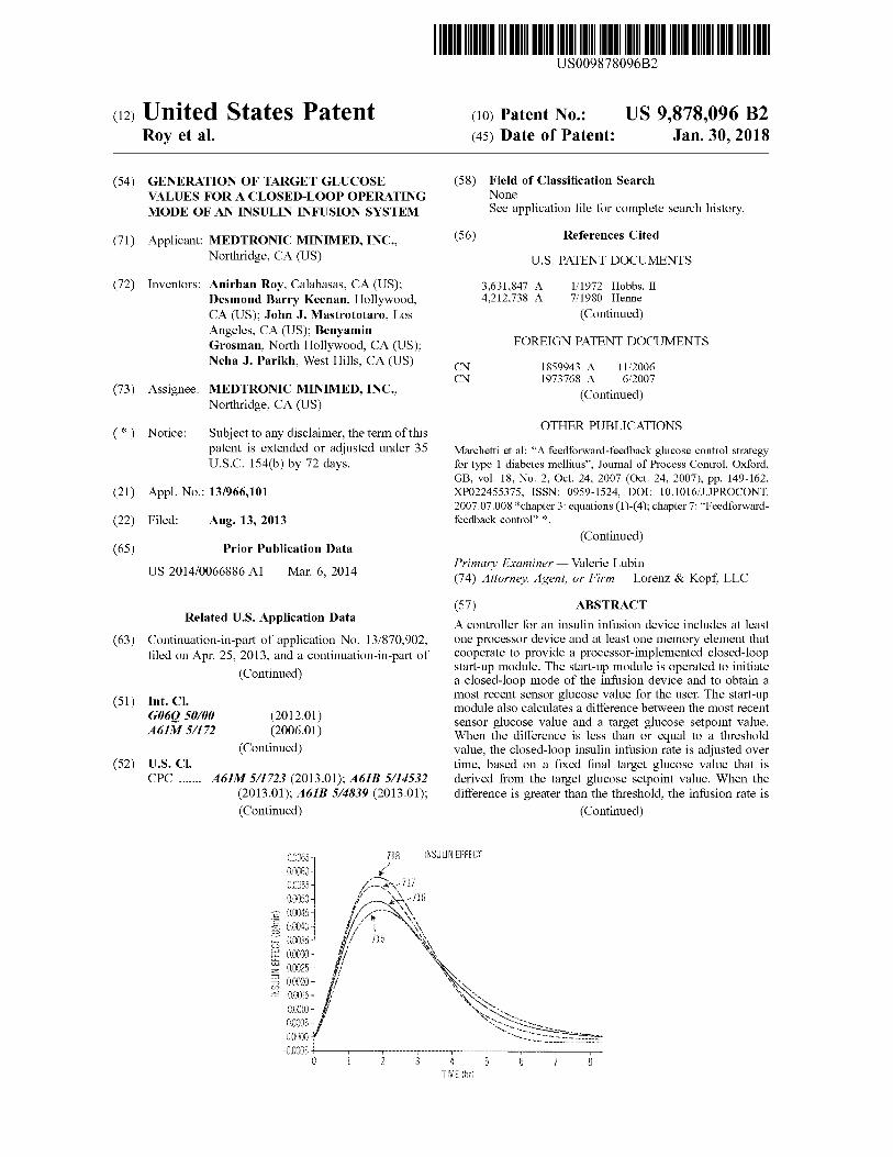
( 57 ) ABSTRACT A controller for an insulin infusion device includes at least one processor device and at least one memory element that cooperate to provide a processor - implemented closed - loop start - up module . The start - up module is operated to initiate a closed - loop mode of the infusion device and to obtain a most recent sensor glucose value for the user . The start - up module also calculates a difference between the most recent sensor glucose value and a target glucose setpoint value . When the difference is less than or equal to a threshold value , the closed - loop insulin infusion rate is adjusted over time , based on a fixed final target glucose value that is derived from the target glucose setpoint value . When the difference is greater than the threshold , the infusion rate is
( Continued )
718 INSULIN EFFECT
W
0 . 0065 00060 - 0 . 0055 0 . 0050 0 . 0045 - 0 . 0040 00035 0 . 0030 0 . 0025 0 . 0020
www * * * * WCASTLE we w *
715 INSULIN EFFECT ( U / min ) . . . . . . . .
UTREC 000157 0 . 0010 w
H ww . w * 0 . 00054 ww ws an SOLO 00000
- 00005
TIME ( I )
US 9 , 878 , 096 B2 Page 2
adjusted over time , based on a dynamic final target glucose value that decreases over time toward the target glucose setpoint value .
10 Claims , 60 Drawing Sheets
Related U . S . Application Data application No . 13 / 870 , 907 , filed on Apr . 25 , 2013 , and a continuation - in - part of application No . 13 / 870 , 910 , filed on Apr . 25 , 2013 .
( 60 ) Provisional application No . 61 / 694 , 950 , filed on Aug . 30 , 2012 , provisional application No . 61 / 694 , 961 , filed on Aug . 30 , 2012 , provisional application No . 61 / 812 , 874 , filed on Apr . 17 , 2013 .
( 51 ) Int . CI . G06F 19 / 00 ( 2011 . 01 ) A61B 5 / 145 ( 2006 . 01 ) A61B 5 / 00 ( 2006 . 01 )
( 52 ) U . S . CI . CPC . . . . . . . . GO6F 19 / 345 ( 2013 . 01 ) ; G06F 19 / 3412
( 2013 . 01 ) ; G06F 19 / 3468 ( 2013 . 01 )
( 56 ) References Cited U . S . PATENT DOCUMENTS
4 , 270 , 532 A 4 , 282 , 872 A 4 , 373 , 527 A 4 , 395 , 259 A 4 , 433 , 072 A 4 , 443 , 218 A 4 , 494 , 950 A 4 , 533 , 346 A 4 , 542 , 532 A 4 , 550 , 731 A 4 , 559 , 037 A 4 , 562 , 751 A 4 , 573 , 994 A 4 , 671 , 288 A 4 , 678 , 408 A 4 , 685 , 903 A 4 , 731 , 051 A 4 , 731 , 726 A 4 , 755 , 173 A 4 , 781 , 798 A 4 , 803 , 625 A 4 , 809 , 697 A 4 , 826 , 810 A 4 , 871 , 351 A 4 , 898 , 578 A 5 , 003 , 298 A 5 , 011 , 468 A 5 , 019 , 974 A 5 , 050 , 612 A 5 , 078 , 683 A 5 , 080 , 653 A 5 , 097 , 122 A 5 , 100 , 380 A 5 , 101 , 814 A 5 , 108 , 819 A 5 , 153 , 827 A 5 , 165 , 407 A 5 , 247 , 434 A 5 , 262 , 035 A 5 , 262 , 305 A 5 , 264 , 104 A 5 , 264 , 105 A 5 , 284 , 140 A
6 / 1981 Franetzki et al . 8 / 1981 Franetzki et al . 2 / 1983 Fischell 7 / 1983 Prestele et al . 2 / 1984 Pusineri et al . 4 / 1984 DeCant , Jr . et al . 1 / 1985 Fischell 8 / 1985 Cosgrove , Jr . et al . 9 / 1985 McQuilkin 11 / 1985 Batina et al . 12 / 1985 Franetzki et al .
1 / 1986 Nason et al . 3 / 1986 Fischell et al . 6 / 1987 Gough 7 / 1987 Nason et al . 8 / 1987 Cable et al . 3 / 1988 Fischell 3 / 1988 Allen , III 7 / 1988 Konopka et al .
11 / 1988 Gough 2 / 1989 Fu et al . 3 / 1989 Causey , III et al . 5 / 1989 Aoki
10 / 1989 Feingold 2 / 1990 Rubalcaba , Jr . 3 / 1991 Havel 4 / 1991 Lundquist et al . 5 / 1991 Beckers 9 / 1991 Matsumura 1 / 1992 Sancoff et al 1 / 1992 Voss et al . 3 / 1992 Colman et al . 3 / 1992 Epstein et al . 4 / 1992 Palti 4 / 1992 Heller et al .
10 / 1992 Coutre et al . 11 / 1992 Wilson et al .
9 / 1993 Peterson et al . 11 / 1993 Gregg et al . 11 / 1993 Heller et al . 11 / 1993 Gregg et al . 11 / 1993 Gregg et al . 2 / 1994 Allen et al .
5 , 299 , 571 A 5 , 307 , 263 A 5 , 317 , 506 A 5 , 320 , 725 A 5 , 322 , 063 A 5 , 338 , 157 A 5 , 339 , 821 A 5 , 341 , 291 A 5 , 350 , 411 A 5 , 356 , 786 A 5 , 357 , 427 A 5 , 368 , 562 A 5 . 370 . 622 A 5 , 371 , 687 A 5 , 376 , 070 A 5 , 390 , 671 A 5 , 391 , 250 A 5 , 403 , 700 A 5 , 411 , 647 A 5 , 482 , 473 A 5 , 485 , 408 A 5 , 497 , 772 A 5 , 505 , 709 A 5 , 543 , 326 A 5 , 569 , 186 A 5 , 569 , 187 A 5 , 573 , 506 A 5 , 582 , 593 A 5 , 586 , 553 A 5 , 593 , 390 A 5 , 593 , 852 A 5 , 594 , 638 A 5 , 609 , 060 A 5 , 626 , 144 A 5 , 630 , 710 A 5 , 643 , 212 A 5 , 660 , 163 A 5 , 660 , 176 A 5 , 665 , 065 A 5 , 665 , 222 A 5 , 685 , 844 A 5 , 687 , 734 A 5 , 704 , 366 A 5 , 750 , 926 A 5 , 754 , 111 A 5 , 764 , 159 A 5 , 772 , 635 A 5 , 779 , 665 A 5 , 788 , 669 A 5 , 791 , 344 A 5 , 800 , 420 A 5 , 807 , 315 A 5 , 807 , 336 A 5 , 814 , 015 A 5 , 822 , 715 A 5 , 832 , 448 A 5 , 840 , 020 A 5 , 861 , 018 A 5 , 868 , 669 A 5 , 871 , 465 A 5 , 879 , 163 A 5 , 885 , 245 A 5 , 897 , 493 A 5 , 899 , 855 A 5 , 904 , 708 A 5 , 913 , 310 A 5 , 917 , 346 A 5 , 918 , 603 A 5 , 925 , 021 A 5 , 933 , 136 A 5 , 935 , 099 A 5 , 940 , 801 A 5 , 951 , 521 A 5 , 954 , 643 A 5 , 956 , 501 A 5 , 960 , 403 A 5 , 965 , 380 A 5 , 972 , 199 A 5 , 978 , 236 A
4 / 1994 Mastrototaro 4 / 1994 Brown 5 / 1994 Coutre et al . 6 / 1994 Gregg et al . 6 / 1994 Allen et al . 8 / 1994 Blomquist 8 / 1994 Fujimoto 8 / 1994 Roizen et al . 9 / 1994 Ryan et al .
10 / 1994 Heller et al . 10 / 1994 Langen et al . 11 / 1994 Blomquist et al . 12 / 1994 Livingston et al . 12 / 1994 Holmes , II et al . 12 / 1994 Purvis et al . 2 / 1995 Lord et al . 2 / 1995 Cheney , II et al . 4 / 1995 Heller et al . 5 / 1995 Johnson et al . 1 / 1996 Lord et al . 1 / 1996 Blomquist 3 / 1996 Schulman et al . 4 / 1996 Funderburk et al . 8 / 1996 Heller et al .
10 / 1996 Lord et al . 10 / 1996 Kaiser 11 / 1996 Vasko 12 / 1996 Hultman 12 / 1996 Halili et al .
1 / 1997 Castellano et al . 1 / 1997 Heller et al . 1 / 1997 Iliff 3 / 1997 Dent 5 / 1997 Tacklind et al . 5 / 1997 Tune et al . 7 / 1997 Coutre et al . 8 / 1997 Schulman et al . 8 / 1997 Iliff 9 / 1997 Colman et al . 9 / 1997 Heller et al .
11 / 1997 Marttila 11 / 1997 Dempsey et al .
1 / 1998 Tacklind et al . 5 / 1998 Schulman et al . 5 / 1998 Garcia 6 / 1998 Neftel 6 / 1998 Dastur et al . 7 / 1998 Mastrototaro et al . 8 / 1998 Peterson 8 / 1998 Schulman et al . 9 / 1998 Gross et al . 9 / 1998 Van Antwerp et al . 9 / 1998 Russo et al . 9 / 1998 Gargano et al .
10 / 1998 Worthington et al . 11 / 1998 Brown 11 / 1998 Heinonen et al . 1 / 1999 Feierbach et al . 2 / 1999 Iliff 2 / 1999 Vasko 3 / 1999 Brown et al . 3 / 1999 Lynch et al . 4 / 1999 Brown 5 / 1999 Brown 5 / 1999 Goedeke 6 / 1999 Brown 6 / 1999 Gord 7 / 1999 Brown 7 / 1999 Castellano et al . 8 / 1999 Brown 8 / 1999 Peterson et al . 8 / 1999 Brown 9 / 1999 Mastrototaro et al . 9 / 1999 Van Antwerp et al . 9 / 1999 Brown 9 / 1999 Brown
10 / 1999 Heller et al . 10 / 1999 Heller et al . 11 / 1999 Faberman et al .
VVV
US 9 , 878 , 096 B2 Page 3
( 56 ) References Cited U . S . PATENT DOCUMENTS
5 , 997 , 476 A 12 / 1999 Brown 5 , 999 , 848 A 12 / 1999 Gord et al . 5 , 999 , 849 A 12 / 1999 Gord et al . 6 , 009 , 339 A 12 / 1999 Bentsen et al . 6 , 011 , 984 A 1 / 2000 Van Antwerp et al . 6 , 032 , 119 A 2 / 2000 Brown et al . 6 , 043 , 437 A 3 / 2000 Schulman et al . 6 , 081 , 736 A 6 / 2000 Colvin et al . 6 , 083 , 710 A 7 / 2000 Heller et al . 6 , 088 , 608 A 7 / 2000 Schulman et al . 6 , 101 , 478 A 8 / 2000 Brown 6 , 103 , 033 A 8 / 2000 Say et al . 6 , 119 , 028 A 9 / 2000 Schulman et al . 6 , 120 , 676 A 9 / 2000 Heller et al . 6 , 121 , 009 A 9 / 2000 Heller et al . 6 , 134 , 461 A 10 / 2000 Say et al . 6 , 143 , 164 A 11 / 2000 Heller et al . 6 , 162 , 611 A 12 / 2000 Heller et al . 6 , 175 , 752 B1 1 / 2001 Say et al . 6 , 183 , 412 B1 . 2 / 2001 Benkowski et al . 6 , 246 , 992 B1 6 / 2001 Brown 6 , 254 , 586 B1 7 / 2001 Mann et al . 6 , 259 , 937 B1 7 / 2001 Schulman et al . 6 , 329 , 161 B1 . 12 / 2001 Heller et al . 6 , 368 , 141 B1 4 / 2002 Van Antwerp et al . 6 , 408 , 330 31 6 / 2002 DeLaHuerga 6 , 418 , 332 B1 7 / 2002 Mastrototaro et al .
B1 7 / 2002 Mastrototaro et al . 6 , 461 , 331 B1 10 / 2002 Van Antwerp 6 , 472 , 122 B1 10 / 2002 Schulman et al . 6 , 484 , 045 B1 11 / 2002 Holker et al . 6 , 484 , 046 B1 11 / 2002 Say et al . 6 , 503 , 381 B11 / 2003 Gotoh et al . 6 , 514 , 718 B2 2 / 2003 Heller et al . 6 , 544 , 173 B2 4 / 2003 West et al . 6 , 553 , 263 B1 4 / 2003 Meadows et al . 6 , 554 , 798 B1 4 / 2003 Mann et al . 6 , 558 , 320 B1 5 / 2003 Causey , III et al . 6 , 558 , 351 B1 5 / 2003 Steil et al . 6 , 560 , 741 B1 5 / 2003 Gerety et al . 6 , 565 , 509 B1 5 / 2003 Say et al . 6 , 579 , 690 B1 6 / 2003 Bonnecaze et al . 6 , 591 , 125 B1 7 / 2003 Buse et al . 6 , 592 , 745 B1 7 / 2003 Feldman et al . 6 , 605 , 200 B1 8 / 2003 Mao et al . 6 , 605 , 201 B1 8 / 2003 Mao et al . 6 , 607 , 658 B1 8 / 2003 Heller et al . 6 , 616 , 819 B1 9 / 2003 Liamos et al . 6 , 618 , 934 B1 9 / 2003 Feldman et al . 6 , 623 , 501 B2 9 / 2003 Heller et al . 6 , 641 , 533 B2 11 / 2003 Causey , III et al . 6 , 654 , 625 B1 11 / 2003 Say et al . 6 , 659 , 980 B2 12 / 2003 Moberg et al . 6 , 671 , 554 B2 12 / 2003 Gibson et al . 6 , 676 , 816 B2 1 / 2004 Mao et al . 6 , 689 , 265 B2 2 / 2004 Heller et al . 6 , 728 , 576 B2 4 / 2004 Thompson et al . 6 , 733 , 471 B1 5 / 2004 Ericson et al . 6 , 734 , 162 B2 5 / 2004 Van Antwerp et al . 6 , 746 , 582 B2 6 / 2004 Heller et al . 6 , 747 , 556 B2 6 / 2004 Medema et al . 6 , 749 , 740 B2 6 / 2004 Liamos et al . 6 , 752 , 787 B16 / 2004 Causey , III et al . 6 , 809 , 653 B1 10 / 2004 Mann et al . 6 , 881 , 551 B2 4 / 2005 Heller et al . 6 , 892 , 085 B2 5 / 2005 McIvor et al . 6 , 893 , 545 B2 5 / 2005 Gotoh et al . 6 , 895 , 263 B2 5 / 2005 Shin et al . 6 , 916 , 159 B2 7 / 2005 Rush et al . 6 , 932 , 584 B2 8 / 2005 Gray et al . 6 , 932 , 894 B2 8 / 2005 Mao et al . 6 , 942 , 518 B2 9 / 2005 Liamos et al . 7 , 153 , 263 B2 12 / 2006 Carter et al . 7 , 153 , 289 B2 12 / 2006 Vasko 7 , 396 , 330 B2 7 / 2008 Banet et al .
7 , 500 , 949 B2 3 / 2009 Gottlieb et al . 8 , 542 , 202 B29 / 2013 Zhuang et al .
2001 / 0044731 Al 11 / 2001 Coffman et al . 2002 / 0013518 A1 1 / 2002 West et al . 2002 / 0055857 A1 5 / 2002 Mault et al . 2002 / 0082665 Al 6 / 2002 Haller et al . 2002 / 0137997 A1 9 / 2002 Mastrototaro et al . 2002 / 0161288 Al 10 / 2002 Shin et al . 2003 / 0060765 A1 3 / 2003 Campbell et al . 2003 / 0078560 A1 4 / 2003 Miller et al . 2003 / 0088166 A1 5 / 2003 Say et al . 2003 / 0144581 Al 7 / 2003 Conn et al . 2003 / 0152823 Al 8 / 2003 Heller 2003 / 0176183 Al 9 / 2003 Drucker et al . 2003 / 0188427 Al 10 / 2003 Say et al . 2003 / 0199744 A 10 / 2003 Buse et al . 2003 / 0208113 A1 11 / 2003 Mault et al . 2003 / 0220552 Al 11 / 2003 Reghabi et al . 2004 / 0061232 Al 4 / 2004 Shah et al . 2004 / 0061234 Al 4 / 2004 Shah et al . 2004 / 0064133 A1 4 / 2004 Miller et al . 2004 / 0064156 A1 4 / 2004 Shah et al . 2004 / 0073095 A1 4 / 2004 Causey , III et al . 2004 / 0074785 A1 4 / 2004 Holker et al . 2004 / 0093167 A1 5 / 2004 Braig et al . 2004 / 0097796 Al 5 / 2004 Berman et al . 2004 / 0102683 Al 5 / 2004 Khanuja et al . 2004 / 0111017 Al 6 / 2004 Say et al . 2004 / 0122353 Al 6 / 2004 Shahmirian et al . 2004 / 0152622 A1 8 / 2004 Keith et al . 2004 / 0167465 Al 8 / 2004 Mihai et al . 2004 / 0263354 Al 12 / 2004 Mann et al . 2005 / 0004439 Al 1 / 2005 Shin et al . 2005 / 0038331 A1 2 / 2005 Silaski et al . 2005 / 0038680 A1 2 / 2005 McMahon et al . 2005 / 0154271 A1 7 / 2005 Rasdal et al . 2005 / 0192557 A1 9 / 2005 Brauker et al . 2006 / 0229694 Al 10 / 2006 Schulman et al . 2006 / 0238333 Al 10 / 2006 Welch et al . 2006 / 0293571 AL 12 / 2006 Bao et al . 2007 / 0088521 A1 4 / 2007 Shmueli et al . 2007 / 0135866 A1 6 / 2007 Baker et al . 2007 / 0173761 A1 7 / 2007 Kanderian , Jr . et al . 2007 / 0179671 A1 8 / 2007 Arimatsu et al . 2007 / 0276279 Al 11 / 2007 Echauz et al . 2008 / 0154503 A1 6 / 2008 Wittenber et al . 2008 / 0228056 A1 9 / 2008 Blomquist et al . 2008 / 0269723 Al 10 / 2008 Mastrototaro et al . 2009 / 0081951 Al 3 / 2009 Erdmann et al . 2009 / 0082635 Al 3 / 2009 Baldus et al . 2009 / 0112478 A1 4 / 2009 Mueller , Jr . et al . 2010 / 0017141 A1 1 / 2010 Campbell et al . 2010 / 0057041 Al 3 / 2010 Hayter 2010 / 0121314 A1 5 / 2010 Iobbi 2010 / 0185175 A1 7 / 2010 Kamen et al . 2010 / 0262117 A1 10 / 2010 Magni et al . 2011 / 0028279 AL 2 / 2011 Chen 2011 / 0106011 A1 5 / 2011 Cinar et al . 2011 / 0208155 A1 8 / 2011 Palerm et al . 2011 / 0208156 A1 * 8 / 2011 Doyle , III . . . . . . . . . . A61B 5 / 14532
604 / 504 2011 / 0237917 AL 9 / 2011 Roy et al . 2011 / 0313390 Al 12 / 2011 Roy et al . 2012 / 0103835 Al 5 / 2012 Liang et al .
FOREIGN PATENT DOCUMENTS
CN CN CN CN CN CN DE EP
101675438 A 102056645 A 102334113 A 102369032 A 102576375 A 102946923 A 4329229 0319268 0806738 0880936 1338295 1631036 A2
3 / 2010 5 / 2011 1 / 2012 3 / 2012 7 / 2012 2 / 2013 3 / 1995
11 / 1988 11 / 1997 12 / 1998 8 / 2003 3 / 2006
EP EP EP EP
US 9 , 878 , 096 B2 Page 4
( 56 ) References Cited FOREIGN PATENT DOCUMENTS
GEE JP WO WO WO WO WO WO WO WO WO WO WO WO WO WO WO WO WO WO WO WO WO WO WO WO WO WO WO
2218831 2006510467 A 2007516814 A 2010512945 A 2010519623 A 2010521222 A 2012502693 A
WO 96 / 20745 WO 96 / 36389 WO 96 / 37246 AL WO 97 / 21456 WO 98 / 20439 WO 98 / 24358 WO 98 / 42407 WO 98 / 49659 WO 98 / 59487 WO 99 / 08183 WO 99 / 10801 WO 99 / 18532 WO 99 / 22236 W09929230 A1 WO 00 / 10628 WO0010628 A2 WO 00 / 19887 WO0018449 A2 W00019887 A1 WO 00 / 48112 W00078210 Al
WO 02 / 058537 A2 WO 03 / 001329 WO 03 / 094090
WO 2005 / 065538 A2 WO2011162970 AL WO2012 / 058694 A2
11 / 1989 3 / 2006 6 / 2007 4 / 2010 6 / 2010 6 / 2010 2 / 2012 7 / 1996
11 / 1996 11 / 1996 6 / 1997 5 / 1998 6 / 1998 10 / 1998 11 / 1998 12 / 1998
2 / 1999 3 / 1999 4 / 1999 5 / 1999 6 / 1999 3 / 2000 3 / 2000 4 / 2000 4 / 2000 4 / 2000 8 / 2000
12 / 2000 8 / 2002 1 / 2003
11 / 2003 7 / 2005
12 / 2011 5 / 2012 WO WOZVI
Arthur C . Guyton , Insulin , Glucagon , and Diabetes Mellitus , Text book of Medical Physiology , Eighth Edition , 1991 , Chapter 78 , pp . 855 - 867 , W . B . Saunders Company . Antonios E . Panteleon , et al . , Evaluation of the Effect of Gain on the Meal Response of an Automated Closed - Loop Insulin Delivery System , Diabetes , Jul . 2006 , pp . 1995 - 2000 , vol . 55 . Garry M . Steil , et al . , Feasibility of Automating Insulin Delivery for the Treatment of Type 1 Diabetes , Diabetes , Dec . 2006 , pp . 3344 3350 , vol . 55 . Stuart A . Weinzimer , et al . , Fully Automated Closed - Loop Insulin Delivery Versus Semiautomated Hybrid Control in Pediatric Patients With Type I Diabetes Using an Artificial Pancreas , Diabetes Care , May 2008 , pp . 934 - 939 , vol . 31 . Gary M . Steil , et al . , Metabolic Modelling and the Closed - Loop Insulin Delivery Problem , Diabetes Research and Clinical Practice , 2006 , pp . S183 - S186 , vol . 74 . PCT Search Report ( PCT / US02 / 03299 ) , Oct . 31 , 2002 , Medtronic Minimed , Inc . ( Animas Corporation , 1999 ) . Animas . . . bringing new life to insulin therapy . Bode B W , et al . ( 1996 ) . Reduction in Severe Hypoglycemia with Long - Term Continuous Subcutaneous Insulin Infusion in Type I Diabetes . Diabetes Care , vol . 19 , No . 4 , 324 - 327 . Boland E ( 1998 ) . Teens Pumping it Up ! Insulin Pump Therapy Guide for Adolescents . 2nd Edition . Brackenridge B P ( 1992 ) . Carbohydrate Gram Counting a Key to Accurate Mealtime Boluses in Intensive Diabetes Therapy . Practical Diabetology , vol . 11 , No . 2 , pp . 22 - 28 . Brackenridge , B P et al . ( 1995 ) . Counting Carbohydrates How to Zero in on Good Control . MiniMed Technologies Inc . Farkas - Hirsch R et al . ( 1994 ) . Continuous Subcutaneous Insulin Infusion : A Review of the Past and Its Implementation for the Future . Diabetes Spectrum From Research to Practice , vol . 7 , No . 2 , pp . 80 - 84 , 136 - 138 . Hirsch I B et al . ( 1990 ) . Intensive Insulin Therapy for Treatment of Type I Diabetes . Diabetes Care , vol . 13 , No . 12 , pp . 1265 - 1283 . Kulkarni K et al . ( 1999 ) . Carbohydrate Counting a Primer for Insulin Pump Users to Zero in on Good Control . Mini Med Inc . Marcus AO et al . ( 1996 ) . Insulin Pump Therapy Acceptable Alternative to Injection Therapy . Postgraduate Medicine , vol . 99 , No . 3 , pp . 125 - 142 . Reed J et al . ( 1996 ) . Voice of the Diabetic , vol . 11 , No . 3 , pp . 1 - 38 . Skyler JS ( 1989 ) . Continuous Subcutaneous Insulin Infusion [ CSII ] With External Devices : Current Status . Update in Drug Delivery Systems , Chapter 13 , pp . 163 - 183 . Futura Publishing Company . Skyler J S et al . ( 1995 ) . The Insulin Pump Therapy Book Insights from the Experts . MiniMed Technologies . Strowig S M ( 1993 ) . Initiation and Management of Insulin Pump Therapy . The Diabetes Educator , vol . 19 , No . 1 , pp . 50 - 60 . Walsh J , et al . ( 1989 ) . Pumping Insulin : The Art of Using an Insulin Pump . Published by MiniMed Technologies . ( Intensive Diabetes Management , 1995 ) . Insulin Infusion Pump Therapy . pp . 66 - 78 . Disetronic My ChoiceTM D - TRONTM Insulin Pump Reference Manual . ( no date ) . Disetronic H - TRON® plus Quick Start Manual . ( no date ) . Disetronic My Choice H - TRONplus Insulin Pump Reference Manual . ( no date ) . Disetronic H - TRON®plus Reference Manual . ( no date ) . ( MiniMed , 1996 ) . The MiniMed 506 . 7 pages . Retrieved on Sep . 16 , 2003 from the World Wide Web : http : / / web . archive . org / web / 19961111054527 / www . minimed . com / files / 506 _ pic . htm . ( MiniMed , 1997 ) . MiniMed 507 Specifications . 2 pages . Retrieved on Sep . 16 , 2003 from the World Wide Web : http : / / webarchive . org web / 19970124234841 / www . mininned . com / files / mmn075 . htm . ( MiniMed , 1996 ) . FAQ : The Practical Things . . . pp . 1 - 4 . Retrieved on Sep . 16 , 2003 from the World Wide Web : http : / / web . archive . org / web / 19961111054546 / www . mininned . com / files / faq _ pract . htm . ( MiniMed , 1997 ) . Wanted : a Few Good Belt Clips ! 1 page . Retrieved on Sep . 16 , 2003 from the World Wide Web : http : / / web . archive . org / web / 19970124234559 / www . mininned . com / files / mmn002 . htm .
OTHER PUBLICATIONS Patek S D et al : “ Modular Closed - Loop Control of Diabetes ” , IEEE Transactions on Biomedical Engineering , IEEE Service Center , Piscataway , NJ , USA , vol . 59 , No . 11 , Apr . 3 , 2012 ( Apr . 3 , 2012 ) , pp . 2986 - 2999 , XP011490242 , ISSN : 0018 - 9294 , DOI : 10 . 1109 / TBME . 2012 . 2192930 * section III . A and III . B . 1 - III . B . 2 ( pp . 2988 2990 ) * . C . Choleua , et al . , Calibration of a Subcutaneous Amperometric Glucose Sensor Part 1 Effect of Measurement Uncertainties on the Determination of Sensor Sensitivity and Background Current , Aug . 1 , 2002 , pp . 641 - 646 , vol . 17 , Issue No . 8 . Gianni Marchetti , et al . , An Improved PID Switching Control Strategy for Type 1 Diabetes , Mar . 1 , 2008 , pp . 857 - 865 , vol . 35 , Isue No . 3 . Garry M . Steil , et al . , The Effect of Insulin Feedback on Closed Loop Glucose Control , Journal of Clinical Endocrinology & Metabolism , May 1 , 2011 , pp . 1402 - 1408 , vol . 96 , Issue No . 5 . Mikhail Loutseiko , et al . , Closed - Loop insulin Delivery Utilizing Pole Placement to Compensate for Delays in Subcutaneous Insulin Delivery . Journal of Diabetes Science and Technology , Nov . 1 , 2011 , pp . 1342 - 1351 , vol . 5 , Issue No . 6 . 4 Roman Hovorka , et al . , Nonlinear Model Predictive Control of Glucose Concentration in Subjects With Type 1 Diabetes , Physi ological Measurement , 2004 , pp . 905 - 920 , vol . 25 . Greet Van Den Berghe G . et al . , Intensive Insulin Therapy in Critically Ill Patients , The New England Journal of Medicine , Nov . 8 , 2001 , pp . 1359 - 1367 , vol . 345 , No . 19 . M . Kollind , et al . , Insulin clearance during hypoglycemia in patients with insulin - dependent diabetes mellitus , Norm Metab Res , Jul . 1991 , pp . 333 - 335 . Steven E . Khan , et al . , Quantification of the Relationship Between Insulin Sensitivity and Beta - Cell Function in Human Subjects . Evidence for a Hyperbolic Function , Diabetes , Nov . 1993 , pp . 1663 - 1672 , vol . 42 .
US 9 , 878 , 096 B2 Page 5
( 56 ) References Cited
OTHER PUBLICATIONS
( MiniMed Technologies , 1994 ) . MiniMed 506 Insulin Pump User ' s Guide . ( MiniMed Technologies , 1994 ) . MiniMedTM Dosage Calculator Initial Meal Bolus Guidelines / MiniMedTM Dosage Calculator Initial Basal Rate Guidelines Percentage Method . 4 pages . ( MiniMed , 1996 ) . MiniMedTM 507 Insulin Pump User ' s Guide . ( MiniMed , 1997 ) . MiniMedTM 507 Insulin Pump User ' s Guide . ( MiniMed , 1998 ) . MiniMed 507C Insulin Pump User ' s Guide . ( MiniMed International , 1998 ) . MiniMed 507C Insulin Pump for those who appreciate the difference . ( MiniMed Inc . , 1999 ) . MiniMed 508 Flipchart Guide to Insulin Pump Therapy ( MiniMed Inc . , 1999 ) . Insulin Pump Comparison / Pump Therapy Will Change Your Life . ( MiniMed , 2000 ) . MiniMed® 508 User ' s Guide . ( MiniMed Inc . , 2000 ) . MiniMed® Now [ I ] Can Meal Bolus Cal culator / Mini Med® Now [ I ] Can Correction Bolus Calculator . ( MiniMed Inc . , 2000 ) . Now [ I ] Can MiniMed Pump Therapy . ( MiniMed Inc . , 2000 ) . Now [ I ] Can MiniMed Diabetes Manage ment . ( Medtronic MiniMed , 2002 ) . The 508 Insulin Pump a Tradition of Excellence . ( Medtronic MiniMed , 2002 ) . Medtronic MiniMed Meal Bolus Calculator and Correction Bolus Calculator . International Version . Abel , P . , et al . , “ Experience with an implantable glucose sensor as a prerequiste of an artificial beta cell , ” Biomed . Biochim . Acta 43 ( 1984 ) 5 , pp . 577 - 584 . Bindra , Dilbir S . , et al . , “ Design and in Vitro Studies of a Needle Type Glucose Sensor for a Subcutaneous Monitoring , ” American Chemistry Society , 1991 , 63 , pp . 1692 - 1696 . Boguslavsky , Leonid , et al . , “ Applications of redox polymers in biosensors , " Sold State Ionics 60 , 1993 , pp . 189 - 197 . Geise , Robert J . , et al . , “ Electropolymerized 1 , 3 - diaminobenzene for the construction of a 1 , 1 ' - dimethylferrocene mediated glucose biosensor , ” Analytica Chimica Acta , 281 , 1993 , pp . 467 - 473 . Gernet , S . , et al . , " A Planar Glucose Enzyme Electrode , ” Sensors and Actuators , 17 , 1989 , pp . 537 - 540 . Gernet , S . , et al . , “ Fabrication and Characterization of a Planar Electromechanical Cell and its Application as a Glucose Sensor , " Sensors and Actuators , 18 , 1989 , pp . 59 - 70 . Gorton , L . , et al . , “ Amperometric Biosensors Based on an Apparent Direct Electron Transfer Between Electrodes and Immobilized Peroxiases , ” Analyst , Aug . 1991 , vol . 117 , pp . 1235 - 1241 . Gorton , L . , et al . , “ Amperometric Glucose Sensors Based on Immobilized Glucose - Oxidizing Enymes and Chemically Modified Electrodes , ” Analytica Chimica Acta , 249 , 1991 , pp . 43 - 54 . Gough , D . A . , et al . , " Two - Dimensional Enzyme Electrode Sensor for Glucose , ” Analytical Chemistry , vol . 57 , No . 5 , 1985 , pp . 2351 - 2357 . Gregg , Brian A . , et al . , “ Cross - Linked Redox Gels Containing Glucose Oxidase for Amperometric Biosensor Applications , ” Ana lytical Chemistry , 62 , pp . 258 - 263 . Gregg , Brian A . , et al . , “ Redox Polymer Films Containing Enzymes . 1 . A Redox - Conducting Epoxy Cement : Synthesis , Characteriza tion , and Electrocatalytic Oxidation of Hydroquinone , ” The Journal of Physical Chemistry , vol . 95 , No . 15 , 1991 , pp . 5970 - 5975 . Hashiguchi , Yasuhiro , MD , et al . , “ Development of a Miniaturized Glucose Monitoring System by Combining a Needle - Type Glucose Sensor With Microdialysis Sampling Method , ” Diabetes Care , vol . 17 , No . 5 , May 1994 , pp . 387 - 389 . Heller , Adam , “ Electrical Wiring of Redox Enzymes , ” Acc . Chem . Res . , vol . 23 , No . 5 , May 1990 , pp . 128 - 134 . Jobst , Gerhard , et al . , “ Thin - Film Microbiosensors for Glucose Lactate Monitoring , ” Analytical Chemistry , vol . 68 , No . 18 , Sep . 15 , 1996 , pp . 3173 - 3179 . Johnson , K . W . , et al . , “ In vivo evaluation of an electroenzymatic glucose sensor implanted in subcutaneous tissue , ” Biosensors & Bioelectronics , 7 , 1992 , pp . 709 - 714 .
Jönsson , G . , et al . , “ An Electromechanical Sensor for Hydrogen Peroxide Based on Peroxidase Adsorbed on a Spectrographic Graphite Electrode , ” Electroanalysis , 1989 , pp . 465 - 468 . Kanapieniene , J . J . , et al . , “ Miniature Glucose Biosensor with Extended Linearity , ” Sensors and Actuators , B . 10 , 1992 , pp . 37 - 40 . Kawamori , Ryuzo , et al . , “ Perfect Normalization of Excessive Glucagon Responses to Intraveneous Arginine in Human Diabetes Mellitus With the Artificial Beta - Cell , ” Diabetes vol . 29 , Sep . 1980 , pp . 762 - 765 . Kimura , J . , et al . , “ An Immobilized Enzyme Membrane Fabrication Method , " Biosensors 4 , 1988 , pp . 41 - 52 . Koudelka , M . , et al . , “ In - vivo Behaviour of Hypodermically Implanted Microfabricated Glucose Sensors , " Biosensors & Bioelectronics 6 , 1991 , pp . 31 - 36 . Koudelka , M . , et al . , “ Planar Amperometric Enzyme - Based Glucose Microelectrode , ” Sensors & Actuators , 18 , 1989 , pp . 157 - 165 . Mastrototaro , John J . , et al . , “ An electroenzymatic glucose sensor fabricated on a flexible substrate , ” Sensors & Actuators , B . 5 , 1991 , pp . 139 - 144 . Mastrototaro , John J . , et al . , “ An Electroenzymatic Sensor Capable of 72 Hour Continuous Monitoring of Subcutaneous Glucose , " 14th Annual International Diabetes Federation Congress , Washington D . C . , Jun . 23 - 28 , 1991 . McKean , Brian D . , et al . , “ A Telemetry - Instrumentation System for Chronically Implanted Glucose and Oxygen Sensors , ” IEEE Trans actions on Biomedical Engineering , Vo . 35 , No . 7 , Jul . 1988 , pp . 526 - 532 . Monroe , D . , “ Novel Implantable Glucose Sensors , ” ACL , Dec . 1989 , pp . 8 - 16 . Morff , Robert J . , et al . , “ Microfabrication of Reproducible , Eco nomical , Electroenzymatic Glucose Sensors , ” Annuaal International Conference of teh IEEE Engineering in Medicine and Biology Society , Vo . 12 , No . 2 , 1990 , pp . 483 - 484 . Moussy , Francis , et al . , “ Performance of Subcutaneously Implanted Needle - Type Glucose Sensors Employing a Novel Trilayer Coat ing , ” Analytical Chemistry , vol . 65 , No . 15 , Aug . 1 , 1993 , pp . 2072 - 2077 . Nakamoto , S . , et al . , “ A Lift - Off Method for Patterning Enzyme Immobilized Membranes in Multi - Biosensors , ” Sensors and Actua tors 13 , 1988 , pp . 165 - 172 . Nishida , Kenro , et al . , “ Clinical applications of teh wearable artifi cal endocrine pancreas with the newly designed needle - type glucose sensor , ” Elsevier Sciences B . V . , 1994 , pp . 353 - 358 . Nishida , Kenro , et al . , “ Development of a ferrocene - mediated needle - type glucose sensor covereed with newly designd biocompatible membrane , 2 - methacryloyloxyethylphosphorylcholine - co - n - butyl nethacrylate , " Medical Progress Through Technology , vol . 21 , 1995 , pp . 91 - 103 . Poitout , V . , et al . , " A glucose monitoring system for on line estimation oin man of blood glucose concentration using a minia turized glucose sensor implanted in the subcutaneous tissue adn a wearable control unit , " Diabetologia , vol . 36 , 1991 , pp . 658 - 663 . Reach , G . , " A Method for Evaluating in vivo the Functional Characteristics of Glucose Sensors , ” Biosensors 2 , 1986 , pp . 211 220 . Shaw , G . W . , et al . , “ In vitro testing of a simply constructed , highly stable glucose sensor suitable for implantation in diabetic patients , " Biosensors & Bioelectronics 6 , 1991 , pp . 401 - 406 . Shichiri , M . , “ A Needle - Type Glucose Sensor - A Valuable Tool Not Only for a Self - Blood Glucose Monitoring but for a Wearable Artithcal Pancreas , ” Life Support Systems Proceedings , XI Annual Meeting Esao , Alpbach - Innsbruck , Austria , Sep . 1984 , pp . 7 - 9 . Shichiri , Motoaki , et al . , " An artificial endocrine pancreas prob lems awaiting solution for long - term clinical applications of a glucose sensor , ” Frontiers Med . Biol . Engng . , 1991 , vol . 3 , No . 4 , pp . 283 - 292 . Shichiri , Motoaki , et al . , “ Closed - Loop Glycemic Control with a Wearable Artificial Endocrine Pancreas — Variations in Daily Insulin Requirements to Glycemic Response , ” Diabetes , vol . 33 , Dec . 1984 , pp . 1200 - 1202 .
US 9 , 878 , 096 B2 Page 6
( 56 ) References Cited OTHER PUBLICATIONS
Shichiri , Motoaki , et al . , “ Glycaemic Control in a Pacreatectomized Dogs with a Wearable Artificial Endocrine Pancreas , ” Diabetologia , vol . 24 , 1983 , pp . 179 - 184 . Shichiri , M . , et al . , “ In Vivo Characteristics of Needle - Type Glucose Sensor — Measurements of Subcutaneous Glucose Concentrations in Human Volunteers , " Hormone and Metabolic Research , Supple ment Series vol . No . 20 , 1988 , pp . 17 - 20 . Shichiri , M . , et al . , “ Membrane design for extending the long - life of an implantable glucose sensor , " Diab . Nutr . Metab . , vol . 2 , No . 4 , 1989 , pp . 309 - 313 . Shichiri , Motoaki , et al . , “ Normalization of the Paradoxic Secretion of Glucagon in Diabetes Who Were Controlled by the Artificial Beta Cell , ” Diabetes , vol . 28 , Apr . 1979 , pp . 272 - 275 Shichiri , Motoaki , et al . , “ Telemetry Glucose Monitoring Device with Needle - Type Glucose Sensor : A useful Tool for Blood Glucose Monitoring in Diabetic Individuals , ” Diabetes Care , vol . 9 , No . 3 , May - Jun . 1986 , pp . 298 - 301 . Shichiri , Motoaki , et al . , “ Wearable Artificial Endocrine Pancreas with Needle - Type Glucose Sensor , " The Lancet , Nov . 20 , 1982 , pp . 1129 - 1131 . Shichiri , Motoaki , et al . , “ The Wearable Artificial Endocrine Pan creas with a Needle - Type Glucose Sensor : Perfect Glycemic Con trol in Ambulatory Diabetes , ” Acta Paediatr Jpn 1984 , vol . 26 , pp . 359 - 370 . Shinkai , Seiji , “ Molecular Recognitiion of Mono - and Di - saccha rides by Phenylboronic Acids in Solvent Extraction and as a Monolayer , ” J . Chem . Soc . , Chem . Commun . , 1991 , pp . 1039 - 1041 . Shults , Mark C . , “ A Telemetry - Instrumentation System for Moni toring Multiple Subcutaneously Implanted Glucose Sensors , ” IEEE Transactions on Biomedical Engineering , vol . 41 , No . 10 , Oct . 1994 , pp . 937 - 942
Sternberg , Robert , et al . , “ Study and Development of Multilayer Needle - type Enzyme - based Glucose Microsensors , " Biosensors , vol . 4 , 1988 , pp . 27 - 40 . Tamiya , E . , et al . , “ Micro Glucose Sensors using Electron Mediators Immobilized on a Polypyrrole - Modified Electrode , ” Sensors and Actuators , vol . 18 , 1989 , pp . 297 - 307 . Tsukagoshi , Kazuhiko , et al . , “ Specific Complexation with Mono and Disaccharides that can be Detected by Circular Dichroism , ” J . Org . Chem . , vol . 56 , 1991 , pp . 4089 - 4091 . Urban , G . , et al . , “ Miniaturized multi - enzyme biosensors integrated with pH sensors on flexible polymer carriers for in vivo applcia tions , ” Biosensors & Bioelectronics , vol . 7 , 1992 , pp . 733 - 739 . Ubran , G . , et al . , “ Miniaturized thin - film biosensors using cova lently immobilized glucose oxidase , ” Biosensors & Bioelectronics , vol . 6 , 1991 , pp . 555 - 562 . Velho , G . , et al . , “ In vivo calibration of a subcutaneous glucose sensor for determination of subcutaneous glucose kinetics , ” Diab . Nutr . Metab . , vol . 3 , 1988 , pp . 227 - 233 . Wang , Joseph , et al . , “ Needle - Type Dual Microsensor for the Simultaneous Monitoring of Glucose and Insulin , " Analytical Chemistry , vol . 73 , 2001 , pp . 844 - 847 . Yamasaki , Yoshimitsu , et al . , “ Direct Measurement of Whole Blood Glucose by a Needle - Type Sensor , ” Clinics Chimica Acta , vol . 93 , 1989 , pp . 93 - 98 . Yokoyama , K . , “ Integrated Biosensor for Glucose and Galactose , ” Analytica Chimica Acta , vol . 218 , 1989 , pp . 137 - 142 . Satish K . Garg , MD , et al . , “ Glucose Outcomes with the In - Home Use of a Hybrid Closed - Loop Insulin Delivery System in Adoles cents and Adults with Type 1 Diabetes , " Diabetes Technology & Therapeutics , 2017 , pp . 155 - 163 , vol . 19 , No . 3 , Mary Ann Liebert , Inc .
* cited by examiner
atent
COMMANDS
INSULIN
www . mmmmmmmmmmm
CONTROLLER
INSULIN DELIVERY SYSTEM
Jan . 30 , 2018
www . weeeeeeeeeeeeeeeeeeeeeeeeeeeeee
Lovetweeeeeeeeeeeeee . WENEVENCENEWSweeeeee
LPLEVILIPPITTER ?
SENSOR SIGNAL
BLOOD GLUCOSE LEVEL
GLUCOSE SENSOR SYSTEM ??
Sheet 1 of 60
ooooooooooooooooooooooooooooooooooooooood FG . 1
US 9 . 878 , 096 B2
US 9 , 878 , 096 B2
Want * *
den som du *
* Nur
* # mo * * Mpt
TT 13 m
ut
no
le
34
m
. * w
6 . *
or
*
x * * *
« next
*
Sheet 2 of 60
nume cu nos
nem morrerá nos y
Com veu
-
az to 11 " "
" "
)
\ " Em
-
.
' n
wa 1
R
N 1
* * ont
1
the civoodoo
NANT 17
Orain
w
w w
ba na
*
N
K
*
non to *
med
Men samen a per set
* *
*
vo Y she or as
X
* *
V YA
H I VO
why
no
ono 23
22
23
ED
* T
0
R
Wolky
e Via
*
FIG . 2
k
nowe www com a
man hoor wa wimbo
oooo w
best * na
.
On bu
k
un
en
KEO Y por
-
wawwwxvo * w * DE SET
the Love WP W
buon er mw
Www XR r .
V
A
O
D
Jan . 30 , 2018
*
26 - 28 mwand
30 -
we
DT DER
E
•
W
e
ou
in
* * can
U . S . Patent
US 9 , 878 , 096 B2
E ' 01
og menntunan
6€
EE LE
bb
.
Feb .
. . the
.
Waschterfon AKKARALAR Print
TE
HALLS T
mint
Pintit
ar
KLIKK ( 9 ) MM
m
IA Who W
WY
wwothousePINTXUR
DE
67
hon
Sheet 3 of 60
1700INOO DNOD NOISIUNI €
wwwmaster harmele
mama 8Z
??????? JULEEEEEEEEEEEEEEEEEEEEEEEEEEEEEEEEEEEEEEEEEEE ???????
Jan . 30 , 2018
7
FETTE DELILIELEZELENIEEEEE - KIELELELEZIEL
Die hemen hemma wwwwwwwwwwwwwwamen Peter PA
kwen ELEELELEGE <
nn mimin
n
19EEIN
LEE LEE LEELEELEEEEEEEEEEEEEEEEE ????????????????????? ???? ?????? - ? ??????
( e ) ( e )
PD
werrrrrrrrrrrrrrrrrrrrrrrrr
U . S . Patent
haurant
U . S . Patent Jan . 30 , 2018 Sheet 4 of 60 US 9 , 878 , 096 B2
ARADANDARAAAAAAA
? ? ? ? ? ? ? ? ? ? ? ? ? ? ? ? ? ? ? ? ? ? ? ? ?
?????????????
ANUNLARNI OU when w w wwwwwwwwand
wewno TELEEEESEELEY UDELELSER SEX
MIMA xatana 60 Quran ho
oran 4
tw TOP
( m . Donec non 66 0 * * 0 0 0 0
* HO 0 0 0 0 0 ooOo 000 med et
0 0
QO
AA OOOOO 0 0
0 0 www 0
0 0 0 0 0 0
" ULTIMA ALLTIDELIAIIRITTI M
TE EDITIRARLILIELIVER ILIKI DITERIMIDEX WOW REF Roja 0
0950 HG . 4
40 CNT KOO ooooooooo 0 0 0
Www
FIG . 3
U . S . Patent Jan . 30 , 2018 Sheet 5 of 60 US 9 , 878 , 096 B2
LI rmy 0 TIDER e
0
e un po So vo o T TTTTTTTTTTTTTTTTTT
come T MARIE REF e o
TIT TTTTTTTTTTTT 142 1
artment mett The 42
layan WRK
40 CNT 42
FIG . 4
U . S . Patent Jan . 30 , 2018 Sheet 6 of 60 US 9 , 878 , 096 B2
m … …
NVINN rrrrrrrr NNNNNNNISH THINEMAN , HHHHHHHHHHHHHHHHHHHHHHHHHHHHHHHHHHHHHHHHHHHHHHHHHHHHHHHHHHHHHHHHHHHHHHHHHH4
HTTERCELLE PHILLEHENHAHAPHILLERIEEE
4 1 , 544 )
MMMMMMMMMMMMMMA wwws Arr
MENTENNHERMANIMMMMMMMMM InsionPSYNTHIN E SSIONSITY HANNERANSYSTERNESS ,
SONORMANNESENSONNEWS
ANNER M ANNERENEWS MAMAHA MMENTRAVENU
HTTPH M NNNNNNNNNNNNNNNNNNNNNNNNNNNNNNNNNNNNNNNNNNNNNNNNNNNNNNNNNNNNNNNN one6S?? OP FFFFFFFFF ing
WEETLETTERNEY E MMMMMMMMMMMMMMMMMMMM
FIG . 5 HAMAHA hkwan
U . S . Patent Jan . 30 , 2018 Sheet 7 of 60 US 9 , 878 , 096 B2
C11 w
UVUVI M
www WWW wwwww
medyo naman
FIG . 6
U . S . Patent Jan . 30 , 2018 Sheet 8 of 60 US 9 , 878 , 096 B2
potent HLTER + + + + + + +
+ + +
+ + + + + + + +
+
OV + 66 Bisit
wwwwww LIIIIIIIII EEEEE un FIG . 7
jasa sig DOROOOOO Isig 1111111111111111 EEEEEEE 0101111113 11113 IEEE 4440A 2492414 + + 4 4 4 4 4 4 4 4 4 * * * * * * * * * * * * * * * * * 14444444444444
a
CNT Vcnt Anim CNT nnnnn mmmmmm M MMMMMMMMMYYY
LOM * P FOTO Azoto JOIKOTA STOKOROZAICO dorur
ent
Isig Rs <
U , S , Patent Jan . 30 , 2018 Sheet 9 Of 60 US 9 , 878 , 096 B2
INFUSION PUMP ??
1
1
1
1
1
1
1 d 1
1 ? ????? 1
1
1
1
1
1
1
1
1 FILTER CALIBRATOR CONTROLLER ???
fi
??? ? ?? ?
?
CONTROLLER FILTER CALIBRATOR 36
R FILTER CALIBRATOR CONTROLLER
???? ???????? ?????? 6
? 38 PRFf FR CONTROLLER
?????? ??? * ;
???
FILTER CALIBRATOR
Fid . 8
U . S . Patent
wo
mad
kw
PREFERRED ALTERNATIVE , EMBODIMENT ,
FIG . 8 ( a )
FIG . 8 ( b )
TELEMETERED
TELEMETERED
CHARACTERISTIC
CHARACTERISTIC MONITOR INFUSION MONITOR
TRANSMITTER PUMP | TRANSMITTER PUMP
Jan . 30 , 2018
ALTERNATIVE ,
ALTERNATIVE ,
FIG . 8 ( c )
FIG . 8 ( d )
TELEMETERED
TELEMETERED
CHARACTERISTIC
CHARACTERISTIC MONITOR INFUSION I MONITOR SUPPLEMENTAL INFUSION TRANSMITTER PUMP | TRANSMITTER DEVICE
Awwwwwwwwwwwwwwwwwwwwwwwww
NOISIUNI
( 151111111111111111111111111111111111111111111111111111111111111111111111111110111111111111111111111
LLLLLLLLLLLLLLL
CAM
COMPONENTS PRE - FILTERS FILTERS CALIBRATOR CONTROLLER
d } { } { } ?
* XXX
XXX
XX
Sheet 10 of 60
FIG . 9
US 9 , 878 , 096 B2
atent Jan . 30 , 2018 Sheet 11 of 60 US 9 , 878 , 096 B2
WE W WA KK KK w w w w w w w w w w w w has been wa pon LL Lined nonno Landard W K ANN w w w w w w wwwwwww ca
68 wwwwwwwwwwwwww www
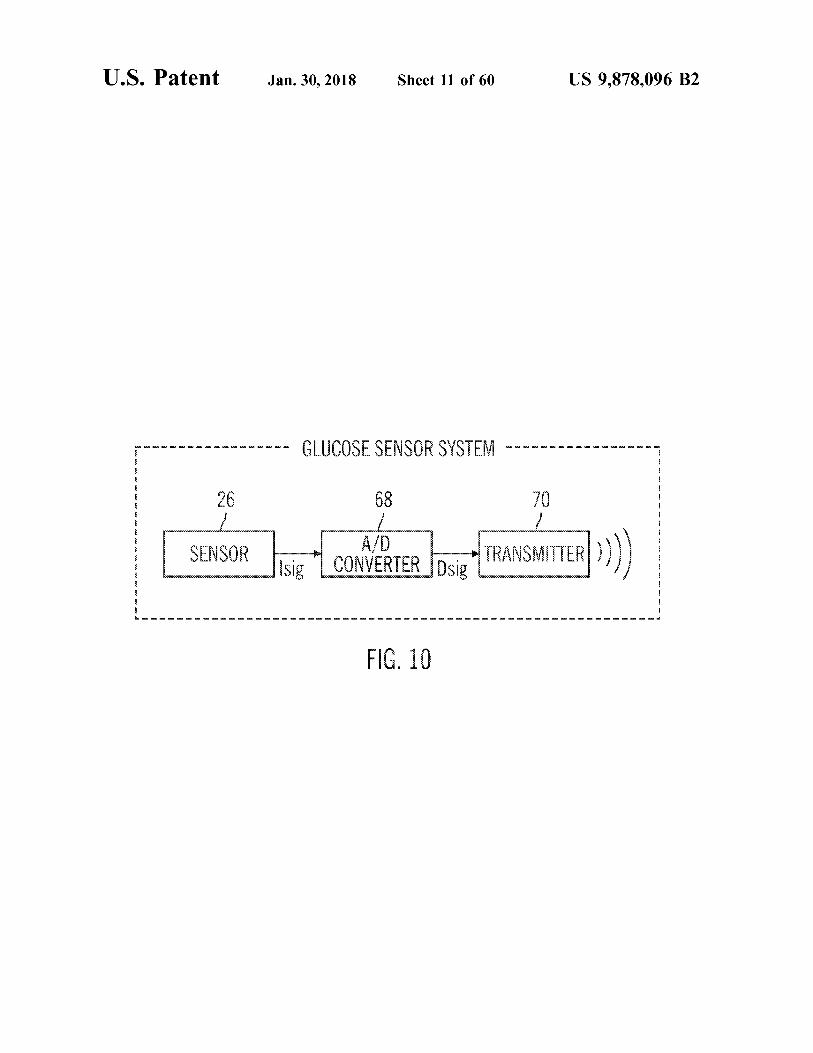
A / Drot - TRANSMITTER ) ) ) ) A / D CONVERTER Dsig SENSOR ) sig
YYYYYYYYYWWWWWWWWW W WWW9999999999999999
L I V S D D D D D D D D D D . . . D D
FIG . 10
smmmmmmmmmmmmmmmmmmmmmmmmmmmmmmmmmmmmmmmmmmmmmmmmmmmmmmmmm wwwwwwwwwwwwwwwww wwwwwwwwwww
wwwwwwwwwwwwwwwww
w
US 9 , 878 , 096 B2
EINNOO
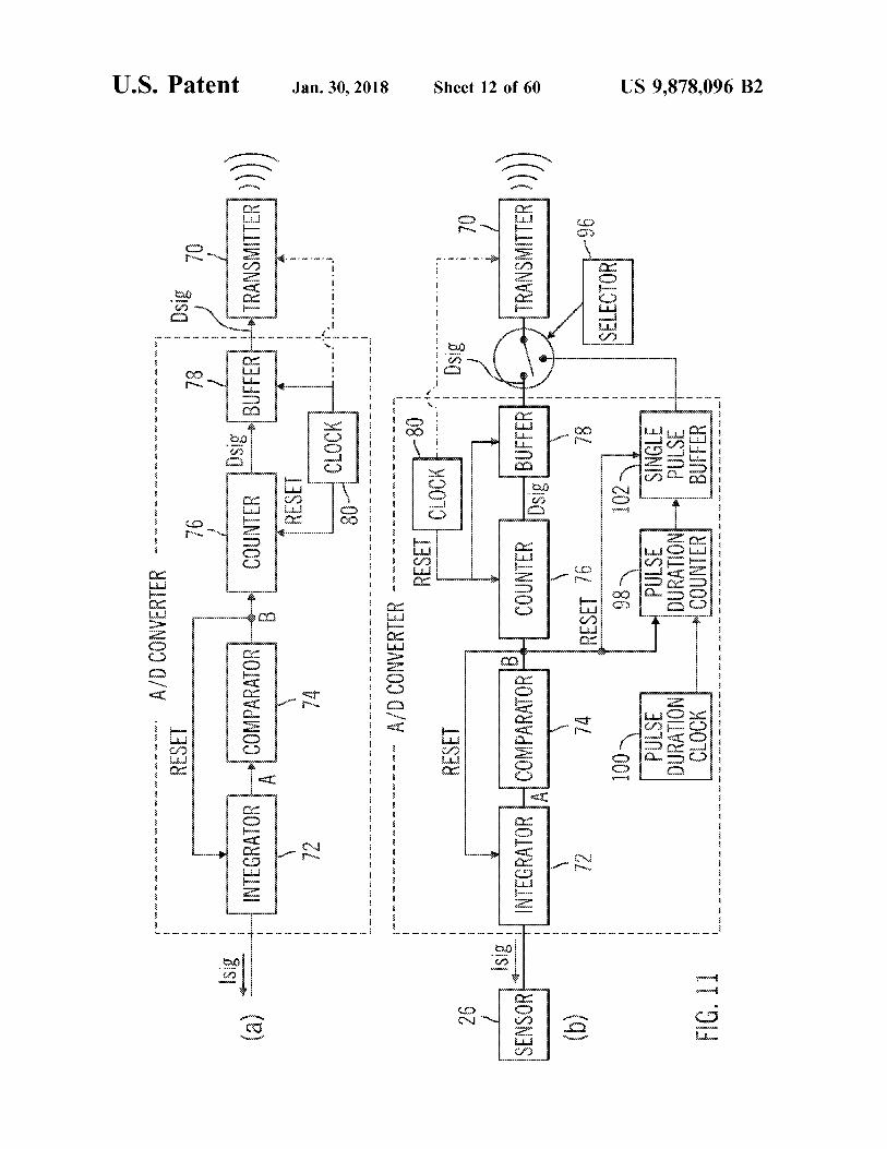
FIG . 11
70073 .
??? ?????
*
4018 3S7nd | 379NIS
. .
??? ??? ??
DURATION PULSE 98
DURATION PULSE L
wwwwww
?? ??
102 wwwt
001
40103735 96 - 1
?? ??? ??? ??? ?
wwwwwwwwwwwwwwwwwwwwwwwwwwwwwwwwww
92 1383
1
?? ?
wwwwwwwwwwwwwwwwwwwwwww ?? .
wwwwwww
wwwwwwwwwwwwwwwwwwwww wwwwwwwwwwwwwwwwwwwwww wwwwwwwwwwwwwwww wwwwww
?
w
? ??
BUFFER
COUNTER
INTEGRATOR H COMPARATOR www
NOSNOS mmnnnnnn
?? ??? ?
Isig
wwwwwwwww
wwwwwww 1
Sheet 12 of 60
??? ?
70
??
norinnennnnnnnnnnnnnnnnnnnnnnnnnnnnnnnnnnnnnnnnnnnnnnnnnnnnnnnnnnnnnnn 90000000
S ]
??? ??? ??
1383
5 . K
wwwwwwwwwwwwwwwwwwwwww
w
a
wakiwa wa - www
- K
WK I WK I WA
YYYYYYY
M0070 ES3 - - - - - - - - -
?
Ww
?
?
?
u
?
?
KK
KK ?
?
?
?
?
?
?
?
?
?
?
IPJANOO O / V - - - - - - - ?
?
?? ?? ?? ?
?
? ???
? ?? ??
?? ??
?
? ???
??
W
"
"
"
"
"
"
"
"
"
"
"
"
"
"
"
"
"
"
"
"
"
"
"
"
"
"
"
"
"
"
"
"
"
"
?
Jan . 30 , 2018
- LE - -
BE
www . mim
?? ?? ????? ??? ?? ???
VL
CLOCK RESET
COUNTER USB . BUFFER
wwwwwwwwwwwwwwwwwww wwwwww
WWWWWWWWWWWWWWW
wwwwwwwwwwwwwwwww wwwwwwwwwwwwwwwwww
w O
WWW
w
TRANSM
LINK
Awwwwwwwwwwwwwwwwwwwwwwwwwwwwww
COMPARATOR INTEGRATOR ???
( a ) =
W
MAK
w
Isig
* *
*
w w w w
70
78
wwwwwwwwwwwwwwwwwwwwwwwwwwwwwww
DS18
U . S . Patent
w
13938
w X w
wwwwwwwwwwwwwwwwwwwwwwwwwwww A / D CONVERTER
Wwwwwwwwwwwwwwwwwwwwwwwwwwwwww
U . S . Patent Jan . 30 , 2018 Sheet 13 of 60 US 9 , 878 , 096 B2
84 _ movt - V +
WERKEN
KERK KRKA COUNTER w COUNTED ???
www 390 886 ww wwwwwwwwwwwwwwwwwwwwwwwwwwwwwwwwwwwwww V namannanna Andres Sam anom L TITIE SEILLE
nanen
wwwwwwwwww wwwwwwwwwwwwwwwwwwwwwwww wwwwwwwwwwwwwwwwwwwwwwwww
kan manda ww rannalta wwwwwwwwwwwwwwwwwwwwwwwwwwwwwwww 1 1
- - - 100mV * * * * . . WM u JARRAINAK wwwwwwwww ononnnnnnnnnnn
wwwwwwwwwwwwww
Se
poate FIG . 12 Eena pacecook
atent Jan . 30 , 2018 Sheet 14 of 60 US 9 , 878 , 096 B2
116 yourses por su 112
1100 annnnnaannnnnnnnnnnnnnaaannnnn grond pronnant ???? wwwwwwwww
COUNTER XXXXXXXX
Land que bonnnnnnnnnnnnooonnnnn Dsig vicing om f Q Vref ,
Sun e mon mtu wwwwwwwwwww wwww w w w w mmm wwwwwwwwww w www pune ? 1 dawane
WAN
w
w w w w w w w w w w w w w w w w w w w w w w w w 1 yousee
uns @ bonnnnnnnnnnnnnnnnnn
FIG . 13
U . S . Patent Jan . 30 , 2018 Sheet 15 of 60 US 9 , 878 , 096 B2
210 212 C " ! 212
www
que D " po
?
quiring 210 51 1 o 1843 Isig 220 nnnnnnnnnnnnnn 221 |
LESSE UUUUU SI que
San e wan COUNTER Dsig counter Dok , www
wy * w Www * * w ww mo
nnnnnnnnnnnnn & ? ? ? ? ? ? ? ? ? ? ???? ? ? ?? wie ww ww www mm wwwwww
?????????
TTTTTTT www © - Urzs
YYYYYYYYYYYYYYYYYYYYYYYYYYYYYYYYYYYYYYYY WWWWWWWWWWW
FIG . 14 fooooooo
U . S . Patent Jan . 30 , 2018 Sheet 16 of 60 US 9 , 878 , 096 B2
304 306 312
nnnnn 310 312 WA / DLEDsi? , BUFFER - TRANSMITTER ( ) )
wwwww Vsio VOLTAGE Dsig ??? 0000000000 www www o ooooooooooooooooooooooooo RAN w
E ( 14141414
CONVERTER MEASUREMENT
TRIGGER 302 * * * WWW . AE www .
CLOCK WY www . m . m . . . wwwwwwwww
boss
308
FIG . 15
US 9 , 878 , 096 B2
91 911
2
2
-
m
m
2
2
2
1
2
.
m
m
.
.
*
*
*
*
*
*
*
24 .
m
m
m
m
m
m
2
T
E
.
E
m
2
2
2
m
2
2
2
2
2
2
2
2
2
2
2
2
2
2
2
2
? ?
W
Sheet 17 of 60 ?
*
* *
*
* *
*
*
*
* *
* *
*
*
*
* *
* *
* *
* *
* *
* *
* *
?
0ISU
? ??? ???
( o anumang BUNSNYA wwww
11
19172 - 3dd
DOSNGS JEBANOO | DIS ! !
O / V
91
M
KKKKKKKKKKKKKKKKES
?
w w w w w w w w w wWw wWww
GawAAAAAAAAAAAKKAAKAKKARA H
A
YARIKAKARRAKKAKKAR
WARAKAT WARAKARAALAKKARA
BAKARARA A
?? ??? ?? ?
OZ
200
00V
89
? ?
Jan . 30 , 2018 ?? ??? ??? ?
wwwwwwmmmmmmmmmmmmmmmmmmmmmmmmm - - - - - WJISAS XOSNIS 3S03N19 www
www www mmmmmmmmmmmmmmm www ww www mmmmmm
U . S . Patent
US 9 . 878 , 096 B2
LLCOM G - 9 -
11 - 10
WWWu
!
Z
BreewareeWeCheetweetweeeeNew Benerienwronomatherene and
weamweatewareetGetternetweetwee e eeeeeeeeeeee
00000000000000000 - - - - - - - - +
m mm mm mm mm mm mm mm er mr mm mm mm mm mm mm mr mr mm mm mm mm m n wer wer mm mm mm mm n we we wer mr mm mm mm mm v w mm mm mm mm mm me we we we w
?
- - - - - - - - - - -
A . ?
- - - - - - - - - + - +
He we we wuw4w4we we we wu we w
-
… … … . . . … … … .
en we w / w v w two - w1 We wrWu Wu W + M1WHwrwtw . mum twi
PHPWu Wu W 1MHP P P *
+ + +
Sheet 18 of 60
????
+ + + + + * * *
?n
* * * * *
li
* *
mm n www we mm " " " " my www mm me or www mm n … www www mm " " m www www my m my www mm m n wu
* * *
Jan . 30 , 2018
* * * * * * * * * * * * * * * * * *
food “ you
U . S . Patent
U . S . Patent Jan . 30 , 2018 Sheet 19 of 60 US 9 , 878 , 096 B2
30
25
20
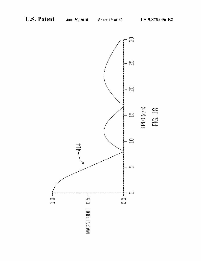
15 FREQ ( c / h ) FIG . 18
10 put
- 414
co
ö + 00
ful MAGNITUDE 0 . 5 -
U . S . Patent Jan . 30 , 2018 Sheet 20 of 60 US 9 , 878 , 096 B2
* *
+ + +
??? W * Load ? ? ???? ???? 11
'
+
, - 50 - apple +
+
app -
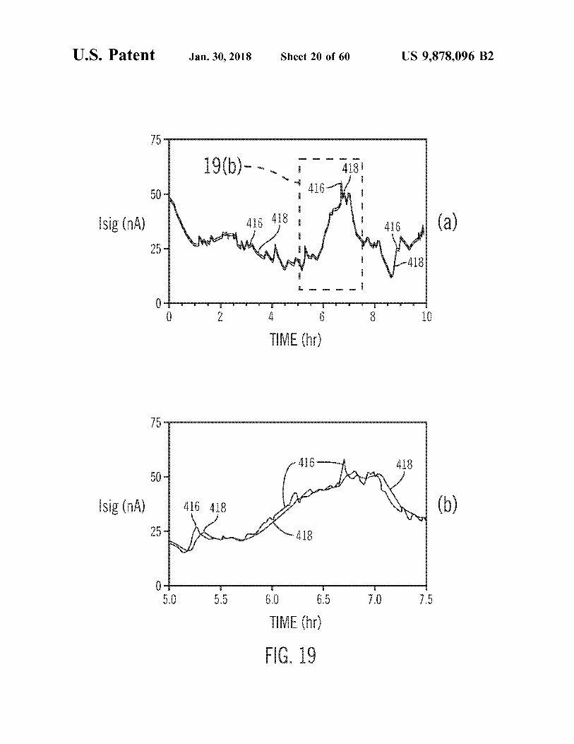
+ Isig ( nA ) ? apan tween 416 ( a ) + ww
* ???????? ???????? ??? ?
+ 5 ???? w I + - 418 +
?ce
??? ???? + ??? ???? ???
?ease & apossessmooooooo Cooocooooooooooooocese . . . . . . . . . ? 2 10 4 TIME ( hr )
'
+ + + + + + + + + + + + +
: : : : : : : : : : : : :
s = = = =
= = =
50 ???? * *
- - - - 416 418 ??? * Isig ( nA )
251 418 ???
- - -
5 . 0 5 . 5 7 . 0 7 . 5 6 . 0 6 . 5 TIVE ( hr )
FIG . 19 4 %
U . S . Patent Jan . 30 , 2018 Sheet 21 of 60 US 9 . 878 , 096 B2
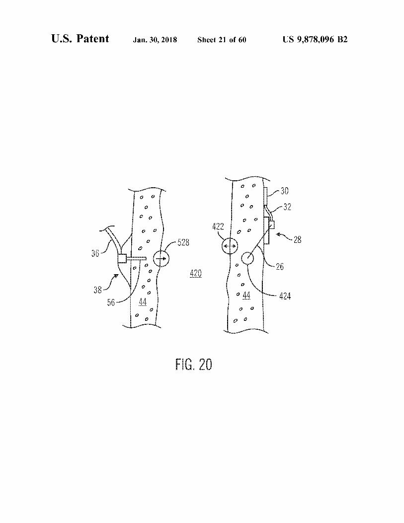
?? ? ? ?
? ?
28 ?
? ?
? air25
ss ? ? % “ ?
| 56 44 ?
FIG . 20

U . S . Patent Jan . 30 , 2018 Sheet 22 of 60 US 9 , 878 , 096 B2
40
30
426 20 FREQ ( c / h ) FIG . 21
10 your
0
e ä com o pa
MAGNITUDE
U . S . Patent Jan . 30 , 2018 Sheet 23 of 60 US 9 , 878 , 096 B2
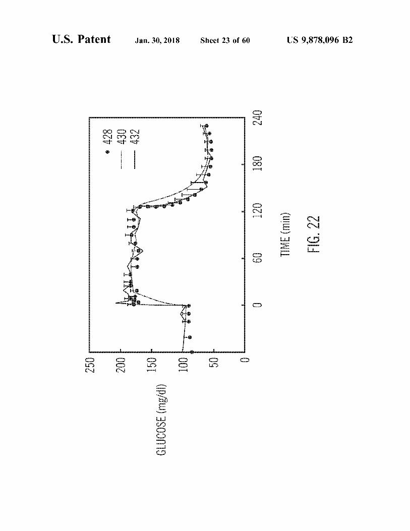
??????????????????????????????????????????????????????????????????????????????????????????????????????????????? 072 428 0€ + 432
081
02
TIME ( min ) FIG . 22
Ville * 09
Wspoow wwwwwwvoorboo 0
ng pangunan
se to yung pus
GLUCOSE ( mg / dl )
US 9 , 878 , 096 B2
ET 01 ( UW ) 3NIL 09
02
06
08
0
OE 00 - 070
WWWWWWWWWWWWWWW
wwwwwwwwww w
Morong wwwwwwwwwwwwwwww
T
D omomorooomomom moman drama o
WW 00 E 0212
TTiTunes Wu toc foarte puternity4449 POP
Sheet 24 of 60
FOR 1
OYLLIL
w
Www
400€ ( 7 / joud ) NOOSNI
009
WWWWWWWWWW
TOI .
as EQ
Will t62Z
Wwwwwww
well
WW €821 0001
Jan . 30 , 2018
( 9661 987 - 81761 30 S3139VO IHV130 ) SdWV70 IB0A79430AH cana : 006
+ + +
+ + + + +
+
+ + +
+
+ +
+ +
+ +
+ + +
+
+ + +
+
+ + + +
+
+ + + +
+
+ + +
+ + + + +
+
+
+
+ + +
+ + + + +
+ + + +
+ + + +
+ + +
+
+ + + 4
+ + + +
+ + + +
U . S . Patent
( e )
( WW ) 979
9V
90 + 99 = °9
nnnnnnnnnnnnnnnnnnnnnnnnnnnnnnnnnnnnnnnnnnnnnnnnnnnnnnnnnnnnnnnnnnnnnn

U . S . Patent Jan . 30 , 2018 sheet 25 of 60 US 9 , 878 , 096 B2
- - - - UllA - - - - - - - - - - - - - - | Anuvvva
| ( 2 ) G . ??
)
{
)
{ } } , ?
440 442
FIG . 24
U . S . Patent Jan . 30 , 2018 Sheet 26 of 60 US 9 , 878 , 096 B2
PLASMA INSULIN LEVEL 200 wwwwwwwwwww
pueece hannah bonnen manunumura IV EEEEEE
Y * * 444 ? legnt ( a ) So WU w TIME ( min ) inn
GLUCOSE UPTAKE RATE 3 in
I 448 20 - 450 ( mg / min per kg FFM ) with handari verstanden
701 pann wwwwwwwwwwwwwwwwwwwwwwww w
FIG . 25
U . S . Patent
12
20
22
wwwwwwwwwwwwwwwwwwwwwwwwwwwwwwwwwwwwww KTr ?
? ??? ?? ?
34
.
porn 24
LEVEDOSEVICOSE
? ?
BODY
24
INSULIN DELIVERY
COMMAND I INSULIN INSULINI SUB INSULIN PUMP
CUTANEOUS TISSUE ??
+ Y PRESENT T Jox HKH
Jan . 30 , 2018
?? ?? ??? ??? ??
DESIRED BASAL BLOOD GLUCOSE
GLUCOSE LEVEL
LEVEL G - ERROR
PRESENT ADJUSTED BLOOD GLUCOSE ESTIMATE CORRECTION PRESENT
454 - ALGORITHMS
BLOOD GLUCOSE ESTIMATE
?? ??? ??? ??? *
BLOOD STREAM
me wa
wwwwwwwwwwwwwwwwwwwwwwwwwwwwwwwwwwwwwwwwwwwwwwwwwwwwwwwwwwwww
?????? ??????????????
- 452
mo w
nnnnnnnnnnnnnnn
E
Sheet 27 of 60
*
BLOOD GLUCOSE LEVEL
KU KA
1
mon 16
RR
n
26
X X
Serie A
X
FILTER FILTER
ISF GLUCOSE LEVEL
SENSOR SIGNAL SIONALE SENSOR
SUB CUTANEOUS TISSUE
CALIBRATION
??????????
w
na na na na
a
na na n
na na na
na na na
na
F
FIG . 26
US 9 , 878 , 096 B2
U . S . Patent Jan . 30 , 2018 Sheet 28 of 60 US 9 , 878 , 096 B2
wing
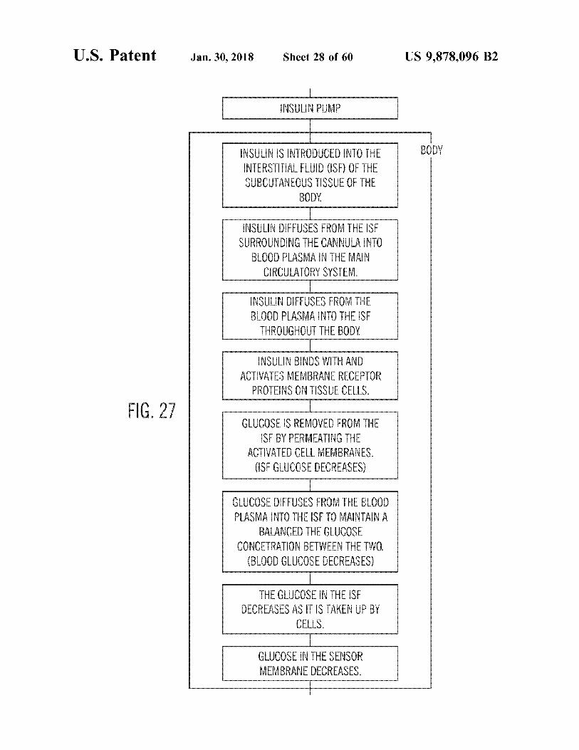
BODY INSULIN IS INTRODUCED INTO THE INTERSTITIAL FLUID ( ISF ) OF THE SUBCUTANEOUS TISSUE OF THE
BODY w En < < S INSULIN DIFFUSES FROM THE ISF
SURROUNDING THE CANNULA INTO BLOOD PLASMA IN THE MAIN
CIRCULATORY SYSTEM . 19
www INSULIN DIFFUSES FROM THE BLOOD PLASMA INTO THE ISF
THROUGHOUT THE BODY . wwwwwwwwww
INSULIN BINDS WITH AND ACTIVATES MEMBRANE RECEPTOR
PROTEINS ON TISSUE CELLS . w
FIG . 27 GLUCOSE IS REMOVED FROM THE
ISF BY PERMEATING THE ACTIVATED CELL MEMBRANES . ( ISF GLUCOSE DECREASES )
1 GLUCOSE DIFFUSES FROM THE BLOOD PLASMA INTO THE ISF TO MAINTAIN A
BALANCED THE GLUCOSE CONCETRATION BETWEEN THE TWO .
( BLOOD GLUCOSE DECREASES )
THE GLUCOSE IN THE ISF DECREASES AS IT IS TAKEN UP BY
CELLS .
GLUCOSE IN THE SENSOR MEMBRANE DECREASES
URLEKKERNEL LLLLL ??????????
wwwwwwwwwwwwwwwwwwwwwwwwwwwwwwwwwwwwwwwwwwwwwwwwwwwwwwwwwwwwwwwww
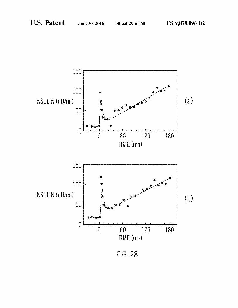
U . S . Patent Jan . 30 , 2018 Sheet 29 of 60 US 9 , 878 , 096 B2
11111111 150 0
W
100 INSULIN ( uU / ml )
50 wwwww mo wwwww 0 wwwwwwwwwwwwwwwwwwwwwwwwwwwwwwwwwwwwwwwwwwwwwwwwwwww w
0 was shownload Lundholmshawddwn which O 180 60 120
TIME ( mn )
150 Wwwwwwwwwwwwwwwwwwwwwwwwwwwwwwwwwwwwwwwwww
100 wwwww KO mi www con normal wwwwwwwwwwwwwwwwwwwwwwwwwwwwwwwwwwwwwwwwwwwwwwwwwwwwwwwwwwwwww AR www MYYYY them to the curre tourname
50
?????????S??ww??????????????????????????s?? : ??????????????????????s?????????????? ?????????Sw???????? 09 180 120 TIME ( mn )
FIG . 28
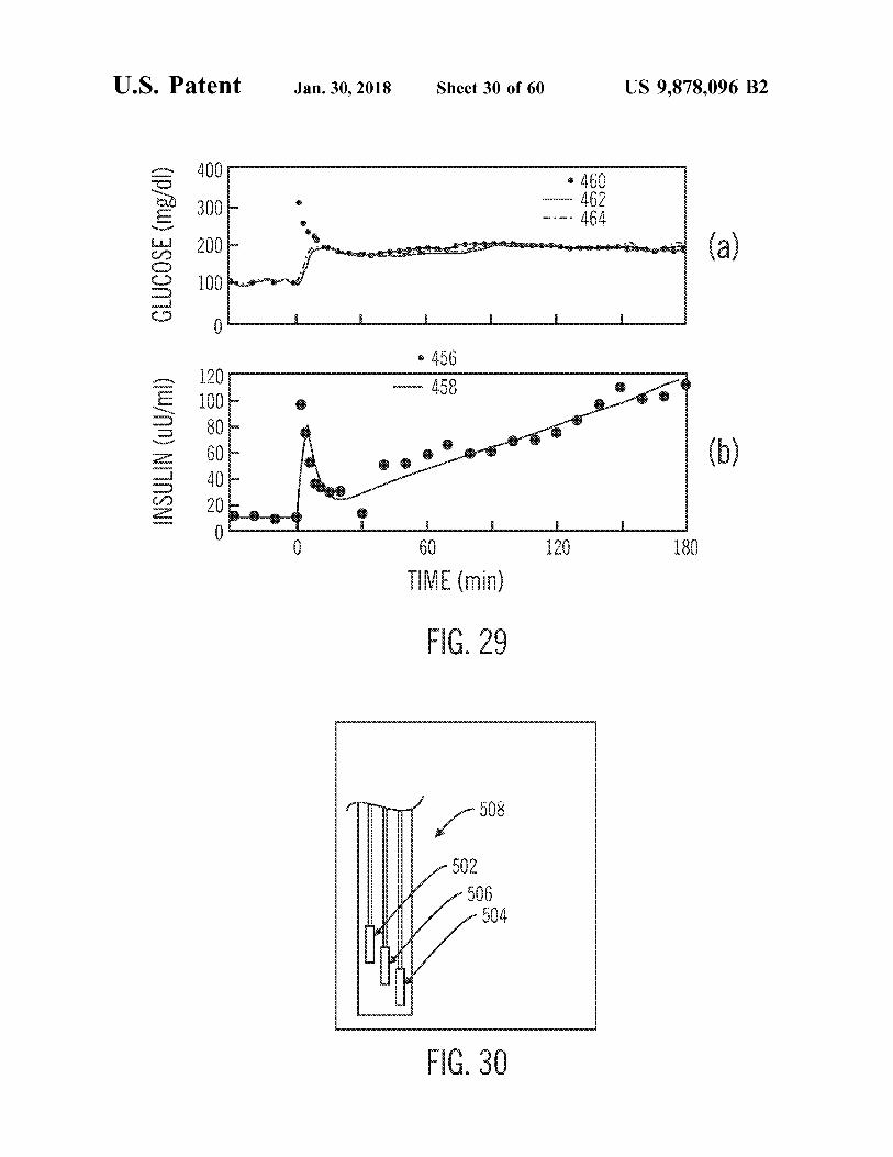
U . S . Patent Jan . 30 , 2018 Sheet 30 of 60 US 9 , 878 , 096 B2
&
- $ 460 462 464 w WW - CO GLUCOSE ( mg / dl )
lang pinsan habang mga hayo
??????
TI • 456 * 456 458
mom
mom
INSULIN ( uU / ml ) 9 . 83 MMMM Debono Perasaan
om 60 081 TIME ( min )
FIG . 29
wwwwwwwwwwwwwwwwwwwwwwwwwwwwwwwwwwwwwwwww wwwwwwwwwwwwwwwwwwwwwwwwwwwwwww
809
502 nnnnnnnnnnnnnnnnnnnnnnnnnnnnnnnnnnnnnnnnnnnn YYYYYYYYYYYYYYYYYYYYYYYYYYYYYYYYYYYYYYYYYYYYYYYYYYYYYYYYYYYYYYYYYYYYYYYYYYYYYYYYYY 506 mm 504
FIG . 30
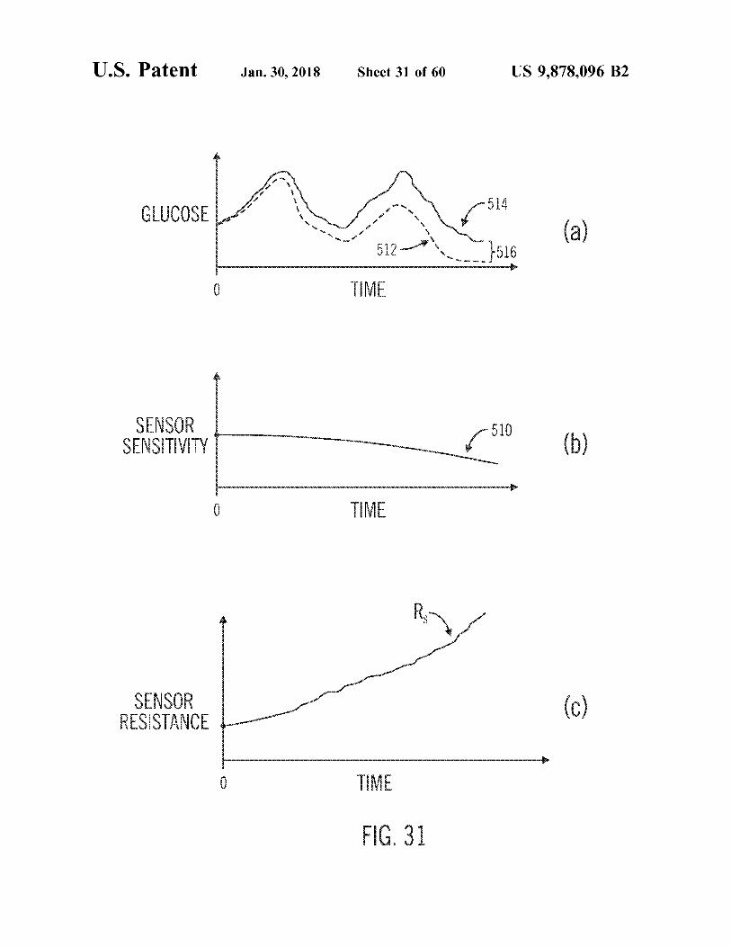
cou wow . . . U . S . Patent Jan . 30 , 2018 Sheet 31 of 60 US 9 , 878 , 096 B2
w we GLUCOSE 5 man 3 one anon 514 '
where you ( a ) want two w to remem
ou 2 512 - TIME
1516 wowo wwwwwwwwwwwwwwwwwwwwwwwwwwwww w wwwwwwwwwwwwwwwwwwwwwwwwwwwwwwwwwwwwww A
0 DOOD wwww
SENSOR SENSITIVITY KKKKKKKKKKKKKKKKK 5 1 750 ( b )
TIME wwwww SA
SENSOR RESISTANCE wwwwwwwwwwwwwww
TIME wwwww . .
FIG . 31 wwww . www
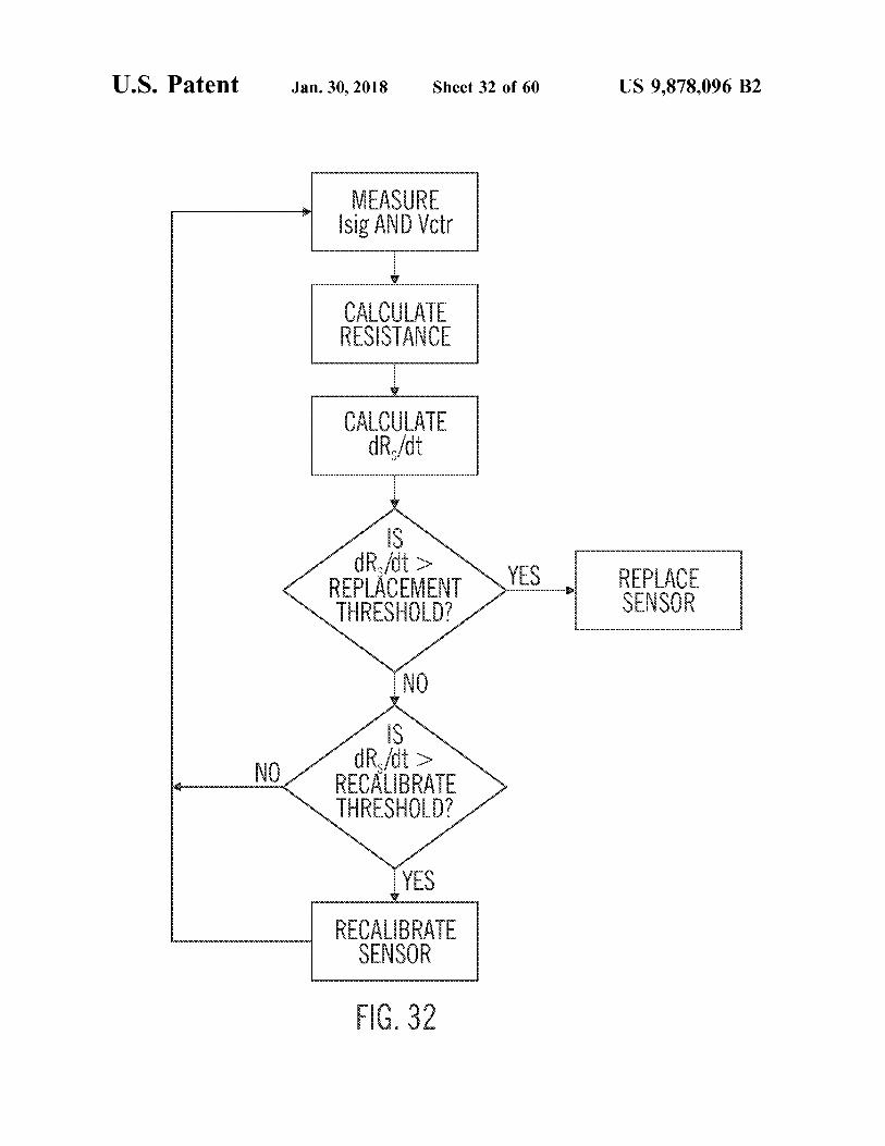
U . S . Patent Jan . 30 , 2018 Sheet 32 of 60 US 9 , 878 , 096 B2
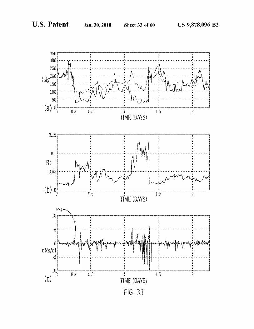
MEASURE Isig AND Vctr Su
1111111111111111111111100011
CALCULATE RESISTANCE
CALCULATE dRs / dt CALCULATE
wwwwwwwwwwwwwwwwww wwwwwwwwwwwwwwww
dr . / dt > mx REPLACEMENT wy YES REPLACE
SENSOR THRESHOLD ?
yang
m
dR / dt > RECALIBRATE THRESHOLD ?
SU
mohona
YES RECALIBRATE
SENSOR
FIG . 32 000000000
U . S . Patent Jan . 30 , 2018 Sheet 33 of 60 US 9 , 878 , 096 B2
1 Un 1
ANWM www . m . mum - ma - en - Nuu NM - mewanununun . ~ . . . . . . . . . . . . - Nu veu
.
n aw Namune . nn . va nimeanna =
n apótkinnan H
x wonly A WEFNINI W rare - - - a - o - - 1 - - - - - 3 n r . = - = = va x isip 50 H den x
) 1
* . . I . . VO . . . . . & . x - - - - - - - 1
x
1001 creamy H
Anunn M A nimanim AMNA - - - - :
50 . . . ton nn rnr rnrnnr mm On FT - Yar CENE - - - - - - NA
air min kant nnnnnn Nunua ( a ) 0 . 3 0 . 5 1 . 5
E MA A
eo *
. -
. -
.
AWNIANA WAAMAAN N A v Yanmaruddin n - Menina MNMNMANNYA YAMNMADAN Aumen YAYAYAANONY .
.
-
0 . 05 v Au . wo MAMA LUKU ANME M . - NM 6MAJAN - - Avv - WMA WA WADAU
.
AY Waarom gorongan orary 111101111111111111111111111111111111111111111111111111111111111111111111011111111111111111111111111111111111111111111111111111111111111111111111111111111111111111111111111111111111111111111111511101111111111111111111111
0 . 5 2 TIME ( DAYS ) dary E
524 o 10 .
.
?
? vnnMNY ?
?
?
A ?
V
* myn na n nmn - * - * - * - - - - - - - - - - - - - - - - - - - - - * u * - - * - * u * - - - - X X u X ? w 60min B
V .
V
.
.
.
Eino ns nizomninminen ws .
A
WA MARE Thymppanimpala Wallmanstand topmaguntunan ANIMA
dRs / dt YAYAN En - 51 . . - IOI . . OTO IO . . cocosos OIOIO TO I J - IO 3 OF 3 x 1 . 1 . 1 E O O E . * . . . ULISEEREELTE to . EO EO IO
ANGOLO KALIMINIANATANAKA - -
- NNYAYA - - AW * vau -
- -
-
-
0 . 3 0 . 5 1 . 5 w
TIME ( DAYS ) FIG . 33
U . S . Patent Jan . 30 , 2018 Sheet 34 of 60 US 9 , 878 , 096 B2
maanan
WRK JOUW MORE
Ww w wwwwwwwwwww
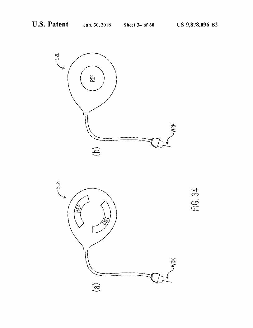
- 518 FIG . 34
WurWWWWWW UWONO mon . UUWWE WWwwwwwwwwww
J . S . Paten atent Jan . 30 , 2018 Sheet 35 of 60 US 9 , 878 , 096 B2
mamma
TIME w
wwww
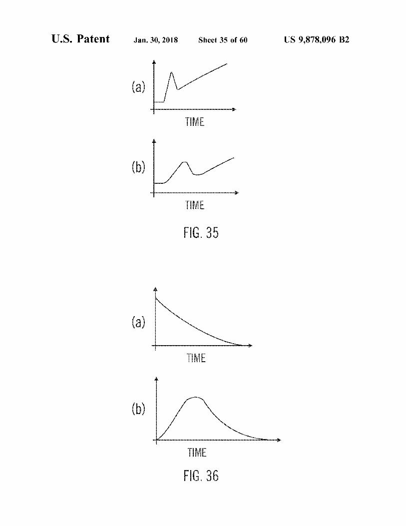
FIG . 35
hond ??
www = Xin
WE modocool
WYYYYYYYYYYY YYY
furnim Lund
FIG . 36
Ande GLUCOSE LEVEL
U . S . Patent
12
- 20
DESIRED ERROR
wwwwwwwwwwwwwwwwwwwwwwwwwwww BODY 24
34
2
wwwwww
LEX
MP INSUUN INSULIN
SUB
wa
PID
wwwwwwwwwwwwwwwwwwwwww
INSULIN
mo
w
Jan . 30 , 2018
w
wwww
CUTANEOUS TISSUE
BASAL
522
BLOOD GLUCOSE
POST
LEVEL G
CONTROLLERU LEAD / LAG PUMP
PRESENT
COMPENSATOR
ADJUSTED " BLOOD GLUCOSE
L?DERIVATIVEL
COMPENSATED
ESTIMATE
FILTER INSULIN
INSULIN
DELIVERY
DELIVERY
- 452 COMMAND
COMMAND
CORRECTION 454 ALGORITHMS
BLOOD GLUCOSE
26
ESTIMATE
SENSOR FILTER SIGNAL
SENSOR
CALIBRATION
BLOOD STREAM wwwwwwwwwwwwwwwwwwwwwwwwwwwwwwwwwwwwwwwwwwwwwwwwwwwwwwwwwwwwwwww
un the W
PRESENT
ow * *
Sheet 36 of 60
EEN
BLOOD GLUCOSE LEVEL 18 .
por 16
w X X
nnnnnnaannnnnnnnnnnnnnnonnnnnnnnnnnn
X
2 SF GLUCOSE LEVEL
nnnnnnnnnnnnnnnnnnnn
X
11 +
+ + + +
TITLE
SUB CUTANEOUS TISSUE
27 - 11 - 09 - 2017
RE m
1
m
m
m
m
m
m
m
m
m
m
m
m
m
m
mm mm m
m
m
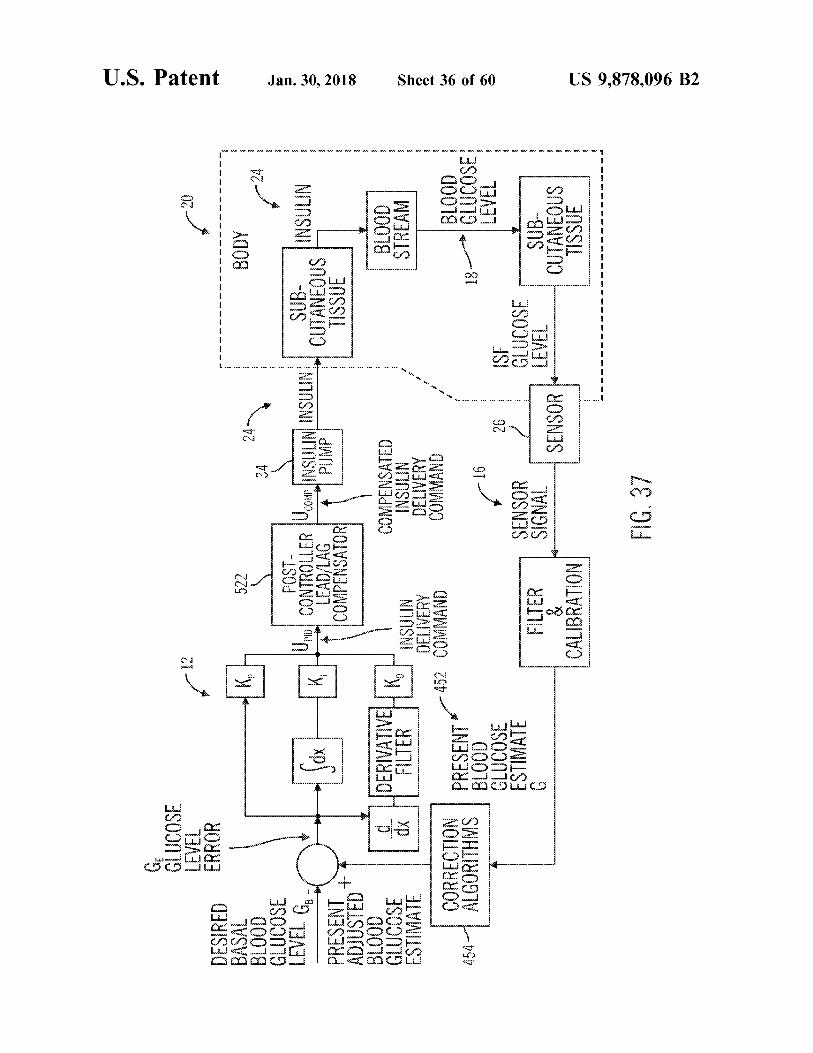
FIG . 37
US 9 , 878 , 096 B2
U . S . Patent Jan . 30 , 2018 Sheet 37 of 60 US 9 , 878 , 096 B2
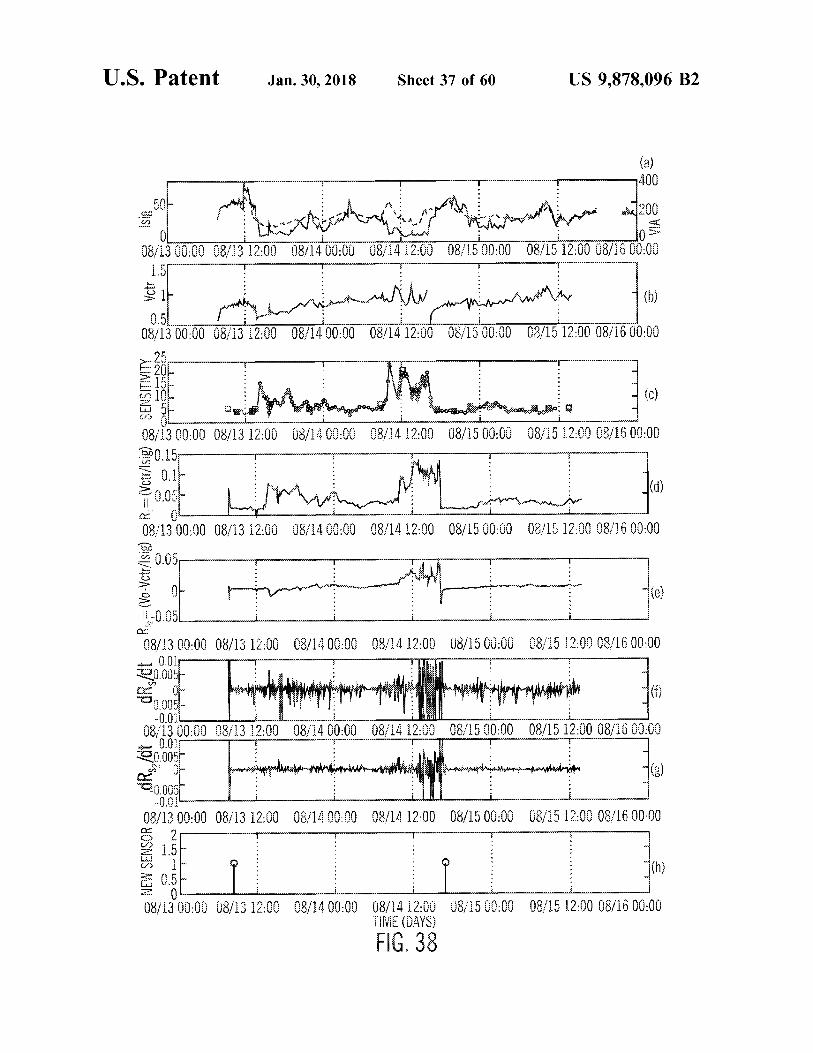
( a ) - 7400
Soukrot LESEN sig in to the chosen fin me : 200 08 / 13 00 : 00 08 / 13 12 : 00 08 / 14 00 08 / 14 12 : 00 08 / 15 00 : 00 08 / 15 12 : 00 08 / 16 00 : 00
Vctr m Immand ?? ?? ??? ???? 1
o
08 / 13 00 : 00 08 / 13 12 : 00 08 / 14 00 : 00 08 / 14 12 : 00 08 / 15 00 : 00 4 1 08 / 15 12 : 00 08 / 16 00 : 00 1 Lv
P
.
- 1
- lastlauskas - .
E - SENSITIVITY . Potput -
. .
esiden Daniel 08 / 14 00 : 00 08 / 14 12 : 00 08 / 15 00 : 00 08 / 15 12 : 00 08 / 16 00 : 00
R = ( Vctr / \ sig )
08 / 13 00 : 00 08 / 13 12 : 00 300 . 15
0 . 14 0 . 054
08 / 13 00 : 00 08 / 13 12 : 00
on . .
Jogging resepi
10 / 30 08 / 14 00 : 00 08 / 14 12 : 00 4 1 2 08 / 15 00 : 00 08 / 15 12 : 00 08 / 16 00 : 00 JO1312
( Vo - Vetr / lsig )
Of gomming enden wird soon innenw :
O plan
1 . - 0 . 05L 08 / 13 00 . 00 08 / 13 12 : 00 08 / 14 00 : 00 08 / 14 12 : 00 08 / 15 00 : 00 08 / 15 12 : 00 08 / 16 00 : 00
$ 0 . 01 20 . 005
O mpatnya mana mana mert kinner www www 0 . 005 - 0 . 01L
08 / 13 00 : 00 08 / 13 12 : 00 08 / 14 00 : 00 08 / 14 12 : 00 20 . 005 che of intensiapupakantokian toda la intentant mor
08 / 15 00 : 00 08 / 15 12 : 00 08 / 16 00 : 00 skool 0 . 011
tini mabas naptim tatlong agune honetan argithin @ 0 . 005 - 0 . 01
08 / 13 00 : 00 08 / 13 12 : 00 08 / 1400 : 00 08 / 14 12 : 00 08 / 15 00 : 00 08 / 15 12 : 00 08 / 16 00 : 00 om
in 11 - NEW SENSOR saved F
?? ? ? ???? . RRRRR . . . . .
F
F
3 0 . 51 E -
-
O
08 / 13 00 : 00 08 / 13 12 : 00 08 / 14 00 : 00 08 / 15 00 : 00 08 / 15 12 : 00 08 / 16 00 : 00 8 5 08 / 14 12 : 00 TIME ( DAYS )
1
FIG . 38

atent Jan . 30 , 2018 Sheet 38 of 60 US 9 , 878 , 096 B2
s
PID CONTROLLER ( ARTIFICAL BETA - CELL
COMMANDS SUBCUTANEOUS
INSULIN COMPENSATION
COMPENSATED COMMANDS
SUBCUTANEOUS INSULIN DELIVERY SYSTEM
PROCESSED GLUCOSE VALUES
INSULIN
SENSOR COMPENSATION , CALIBRATION , AND FILTERS 6 = = = = = RAW GLUCOSE
SENSOR VALVES GLUCOSE SENSOR
SENSOR READINGS BODY
FIG . 39A
PID CONTROLLER ( ARTIFICAL - COMMANDS BETA - CELL )
W INSULIN DELIVERY SYSTEM
INSULIN BODY 3 - 52 PROCESSED GLUCOSE VALUES
BLOOD
EXTRAPOLATION AND
FIR FILTER RAW GLUCOSE SENSOR VALVES
AUTO BLOOD WITHDRAWL AND GLUCOSE DETERMINATION
FIG . 39B
U . S . Patent Jan . 30 , 2018 Sheet 39 of 60 US 9 , 878 , 096 B2
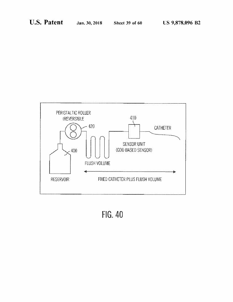
410 PERISTALTIC ROLLER
( REVERSIBLE 420 CATHETER
SENSOR UNIT ( GOD BASED SENSOR )
FLUSH VOLUME
STUTT WASILI
TO RESERVOIR Lind F finna 6 .
FIG . 40 ???????? oogoo
U . S . Patent Jan . 30 , 2018 Sheet 40 of 60 US 9 , 878 , 096 B2
- morgenomgan - -
- -
- -
- - -
-
- -
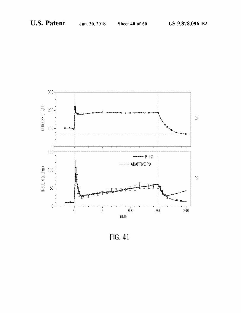
g membang m enghangamoto mother GLUCOSE ( mg / dl ) OBSAKURA gangan - - - - - - - - - - - - - - - - - - - - - - - - - - - - - - - - - - - - - - - - - - - - - - - - - - - - - - - - - - - - - - - - - - - - - - - - - - - - - - - - - . - - .
m aupun gongano
wanyama wapyappannage wysymywanpreganjanju prawujunjunjung
w P - I - D programmaganganny ver con un som ADAPTIVE PD formning ocodon a
( w / m ) NIUOSNI e
yang cocoques courbon pes Program pangungunny me en ondernemine on Kon wo su ws
O farnagaranagannwaganna hamampasan peranang garage www . npranna gampanan menangan perempuan ang
60100260 - 240 TIME
60 100 160 240
FIG . 41
U . S . Pater atent
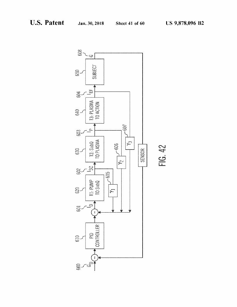
693
650
690 610 601 620 692 630
pod PID Lob11 : PUMP ' sc / 12 : Sub @
640 694 13 : PLASMA | EF
sc
PID CONTROLLER
T1 : PUMP TO SubQ
T2 : SubQ TO PLASMA
Jan . 30 , 2018
SUBJECT
TO ACTION
605
- 606
2 1606 wwwwwwwwwwwwwww
607
13
Sheet 41 of 60
SENSOR FIG . 42
US 9 , 878 , 096 B2
U . S . Patent Jan . 30 , 2018 Sheet 42 of 60 US 9 , 878 , 096 B2
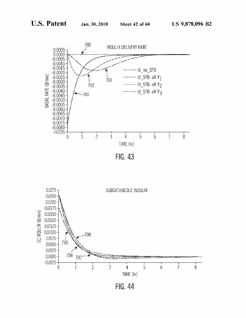
700 L DVD .
www wwwwwwwwwwwwwwwwwwwwwwwwwwwwwwwwww wapn .
0 . 0005 0 . 0000
- 0 . 0005 - 0 . 0010 rov
* * * w
- 0 . 0015 bomboniere um V 703
- ~ ~ - ld no SFB - Id _ SFB : all Y1
- - - - - Id _ SFB : all 12 Id _ SFB : all 13
702 BASAL RATE ( U / min )
701
- 0 . 0020 - 0 . 0020 - 0 . 0025
5 - 0 . 00304 - 0 . 0030 - 0 . 0035 1 - 0 . 0040 - - 0 . 0045 - 0 . 0050 - 0 . 0055 - 0 . 0060 - 0 . 0065 - 0 . 0070 - 0 . 0075 - 0 . 0080 - 0 . 0085 for
Suntem omni
KANUNCIONARE wy www
TIME ( hr ) mm E
FIG . 43
SUBCATANEOUS INSULIN
SC INSULIN ( U / min )
00275 0 . 0250 0 . 0200 0 . 00175 000150 - 0 . 00150 0 . 00125 000100 00075 0 . 0050 0 . 0025 0 . 0000 - 0 . 0025 l
706 707 W O Sommet KT WOVU U www
yowwwwwww wwwwwww my
TIME ( hr )
FIG . 44
U . S . Patent Jan . 30 , 2018 Sheet 43 of 60 US 9 , 878 , 096 B2
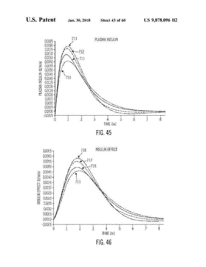
3 A S
www - 712 u fox
- - - - -
711 1 1 - - - - TO M T
* * * *
PLASMA INSULIN ( U / min )
0 . 0085 , 00080 0 . 0075 00070 0 . 0065
= 0 . 0060 00055 0 . 0050 - 0 . 0045 - 0 . 0040 0 . 0035 00030 0 . 0025 0 . 0020 - 1 0 . 0015 - 1 0 . 0010 - 0 . 0005 - 0 . 0000 - 0 . 0005
P3 30 SOODS * * * *
* * *
* * * * *
og Warga *
A MO My www w D W www . de
mume www wWw wWY GOVOR w
TIME ( hr ) E
FIG . 45
73 T orn 1 "
717 1 so 716
* m
utri 715
INSULIN EFFECT (
Unin )
1 .
0 . 00657 0 . 0060 0 . 0055 0 . 0050 0 . 0045 0 . 0040 0 . 0035 00030 - 00025 0 . 0020 0 . 0015 0 . 0010 - 0 . 0005 - 0 . 0000 - 0 . 0005
* * *
*
B s
om ww ws at the tran * Show K REVELL o s w ww 900 W
howy www wwwwww och
wwwwww
TIME ( hr ) FIG . 46
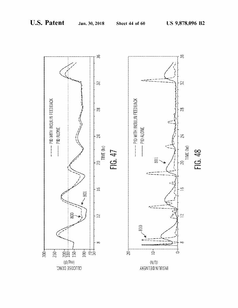
FIG . 48
US 9 , 878 , 096 B2
TIME ( hr )
9€
32
28
24
16
un
yang dipanggan
* * * zo een
co
pletin
moze e
L ann
w
Waling
w MDM
.
w
Bewe
w
meww
wa wewe
w
1
o ayw wow
que
www
( U / h ) INSULIN DELIVERY
w
von
w w
w
w w
OV
PID ALONE - - - - - - PID WITH INSULIN FEEDBACK
018
!
Li .
Sheet 44 of 60
FIG . 47 TIME ( hr )
36
32
82
24
91
ZI
pannnnnnnnnnnnnnnnnnnnnnnnnnnnnnnnnnh
nnnnnnnnnnnnnnnnnnnnnnnnnnnnnnnnnnnnnnnnnnnnnnnni whananananananananana annnnnnnnnnnnnnnnnnnnnnnnnn
wannnnnnnnnnnnnnnnnnnnn
Jan . 30 , 2018
- - - -
-
-
-
-
-
-
-
-
-
-
-
-
-
-
-
-
-
-
-
-
-
-
-
-
-
-
-
-
-
-
-
-
-
-
-
-
-
-
-
- -
-
-
-
-
-
-
- -
- -
-
-
-
-
-
- -
-
-
-
-
-
-
-
- -
-
108
rankin oman payment
CE
W
800
DLA
SS ( p : / 8 )
-
-
-
-
- - -
-
4
:
. . . -
GLUCOSE CONC .
-
-
- -
PID ALONE ma cow . com PID WITH INSULIN FEEDBACK SS33
U . S . Patent
ONTHON
U . S . Patent Jan . 30 , 2018 Sheet 45 of 60 US 9 , 878 , 096 B2
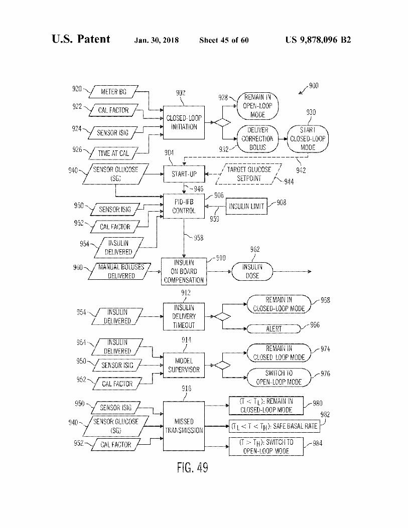
METER BG 902 928 www
REMAIN IN OPEN - LOOP MODE CAL FACTOR
CLOSED - LOOP INITIATION 924 - g 2 SENSOR ISIG SENSOR ISIG | - DELIVER
CORRECTION - BOLUS
START CLOSED - LOOP
MODE 932 TIME AT CAL 904 mwww ww mw wwwm wwwmmwwwwwwwwww
940 - SENSOR GLUCOSE TARGET GLUCOSE for mer comes 942 START - UP - - - met hac ( SG ) SETPOINT _ 944 - - - - - - -
1946 1906
950 so y 500167 - e 908 ASUNUI * * PID - IFB CONTROL SENSOR ISIG INSULIN LIMIT
* 959 952 CAL FACTORA 1958 INSULIN
DELIVERED INSULIN MANUAL BOLUSES 7 . ON BOARD DELIVERED COMPENSATION
962 - 910 was your presente nostre 960 INSULIN
DOSE
912 E NTTT : 968
CLOSED - LOOP MODE 954 INSULIN DELIVERED -
INSULIN DELIVERY TIMEOUT
E www E / ALERTV 966 954 914 INSULIN
DELIVERED - 974 REMAIN IN CLOSED - LOOP MODE
SENSOR ISIG MODEL SUPERVISOR SWITCH TO
OPEN - LOOP MODE 1 976
CAL FACTOR 916 916 SENSOR ISIG
O MISSED TRANSMISSION
SENSOR GLUCOSE ( SG )
CAL FACTOR
( T < TD ) : REMAIN IN CLOSED - LOOP MODE 982
( TL < T < TH ) : SAFE BASAL RATE ( T > TH ) : SWITCH TO 1 984 OPEN - LOOP MODE
punem
952 -
FIG . 49

U . S . Patent Jan . 30 , 2018 Sheet 46 of 60 US 9 , 878 , 096 B2
INSULIN INFUSION 1 DEVICE CONTROL
1000
SYSTEM CHECK ( SENSOR CALIBRATION )
- 1002
. EEEE REMAIN IN OPEN - LOOP - 1006 MODE
1004 OKTO man NO TNITIATE CLOSED - LOOP MODE ?
YES START CLOSED - LOOP MODE 070 7 1008 w
CALCULATE THE FINAL TARGET GLUCOSE VALUE : Final Target
1 mond
1 CALCULATE THE UNCOMPENSATED 1 - 1012 INSULIN INFUSION RATE : PIDRatein
1014 COMPENSATE FOR INSULIN ON BOARD
AND CALCULATE THE ADJUSTED INSULIN INFUSION RATE :
AdjustedRate ( n )
1 O 1 4
USE AdjustedRate ( n ) TO CONTROL THE INSULIN INFUSION DEVICE AND REGULATE DELIVERY OF INSULIN
1 pat
ULA www www
1018 END YES - 1020 * CLOSED - LOOP MODE SWITCH TO OPEN - LOOP
MODE ws
NO 1022
NEXT SAMPLING TIME NO
E
TYES
FIG . 50
U . S . Patent Jan . 30 , 2018 Sheet 47 of 60 US 9 , 878 , 096 B2
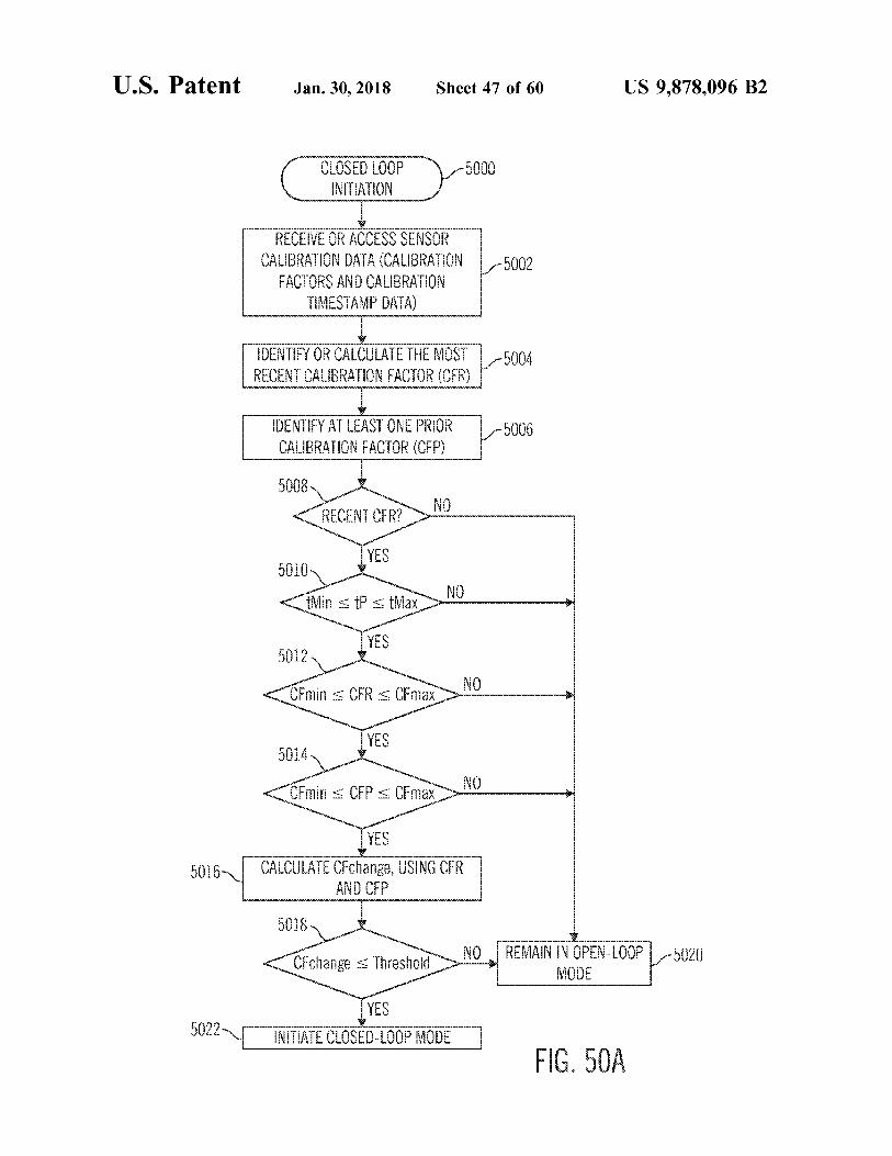
CLOSED LOOP INITIATION
- 5000
??? E E - - 5002
RECEIVE OR ACCESS SENSOR CALIBRATION DATA ( CALIBRATION
FACTORS AND CALIBRATION TIMESTAMP DATA ) ITVE
IDENTIFY OR CALCULATE THE MOST L - 5004 RECENT CALIBRATION FACTOR ( CFR )
IDENTIFY AT LEAST ONE PRIOR CALIBRATION FACTOR ( CFP )
15006
5008 NO RECENT CFR ?
5010 , YES tMin < P tMax
YES 5012 CFmin < CFR < OFmax
5014 5014 YES < Emin CFP < CFmax 10
YES 1 6 CALCULATE CFchange , USING CFR
AND CFP www
5018 < CFchange < Threshold NO REMAIN IN OPEN - LOOP - 5020
MODE
YES
5022 INITIATE CLOSED - LOOP MODE ] FIG . 50A
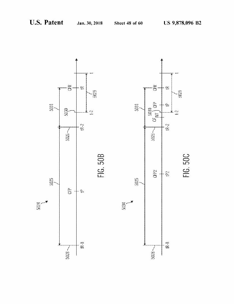
5024
U . S . Patent
5025
5031
mawawwwwwwwwwwwwwwwwwwwwwyour resummannummewennen
www
1
5028
5026
5030
e to
IR - 8
tR - 2
R
1 - 2
Jan . 30 , 2018
5029
FIG . 50B
5034
Sheet 48 of 60
5025
5031 5030
5028
5026 5026 -
CFP2 CFP2
5030 Y CENT CFP CFR FILI tR - 2 | P . t - 2 1 - 2 ha
5029
tR - 8
tP2 FIG . 50C
US 9 , 878 , 096 B2
atent Jan . 30 , 2018 Sheet 49 of 60 US 9 , 878 , 096 B2
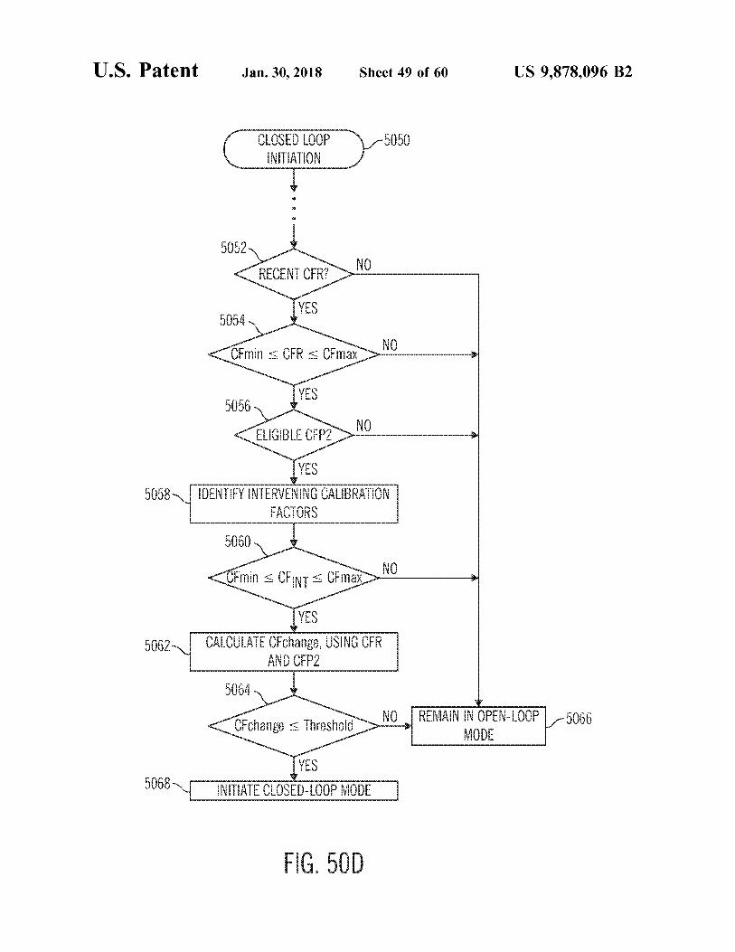
5050 CLOSED LOOP INITIATION
5052 < RECENT CER ? CAT NO
YES 5054 < CFmin < CFR < CFmax NO
YES 5056 ELIGIBLE CFP2 NO
5058 LS from Water E CALIBRAT FACTORS
5060
CFmin s CFINT CFmax "
YES 5062 CALCULATE CFchange , USING CFR
AND CFP2
5064
CFchange s Threshold NO REMAIN IN OPEN - LOOP MODE
- 5066
YES INITIATE CLOSED - LOOP MODE QUO
w
FIG . 50D
U . S . Patent Jan . 30 , 2018 Sheet 50 of 60 US 9 , 878 , 096 B2
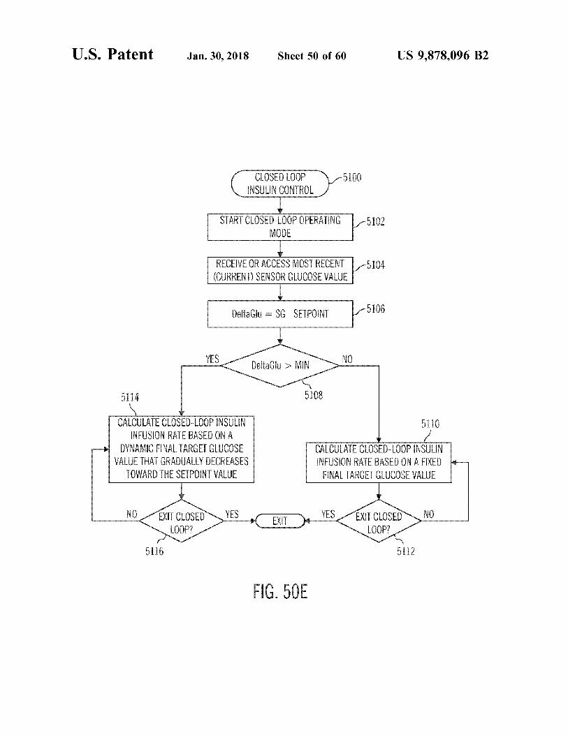
CLOSED LOOP INSULIN CONTROL
15100
START CLOSED - LOOP OPERATING 1 - 5102 MODE
5
5104 5 RECEIVE OR ACCESS MOST RECENT ( CURRENT ) SENSOR GLUCOSE VALUE
1
DeltaGlu - SG - SETPOINT 5106
wwwwww DeltaGlu > MIN
yord proved 5108 nininnnnnnnnnnnnnnnn 1 1 CALCULATE CLOSED - LOOP INSULIN INFUSION RATE BASED ON A
DYNAMIC FINAL TARGET GLUCOSE VALUE THAT GRADUALLY DECREASES
TOWARD THE SETPOINT VALUE nnnnnnnnn
CALCULATE CLOSED - LOOP INSULIN INFUSION RATE BASED ON A FIXED FINAL TARGET GLUCOSE VALUE
L SI !
NO EXIT CLOSED LOOP ?
YES e yim EXIT YES EXIT CLOSEDNO 200P ? LOOP ?
5 1 1 5 yoni pen ! 2
FIG . 50E
U . S . Patent Jan . 30 , 2018 Sheet 51 of 60 US 9 , 878 , 096 B2
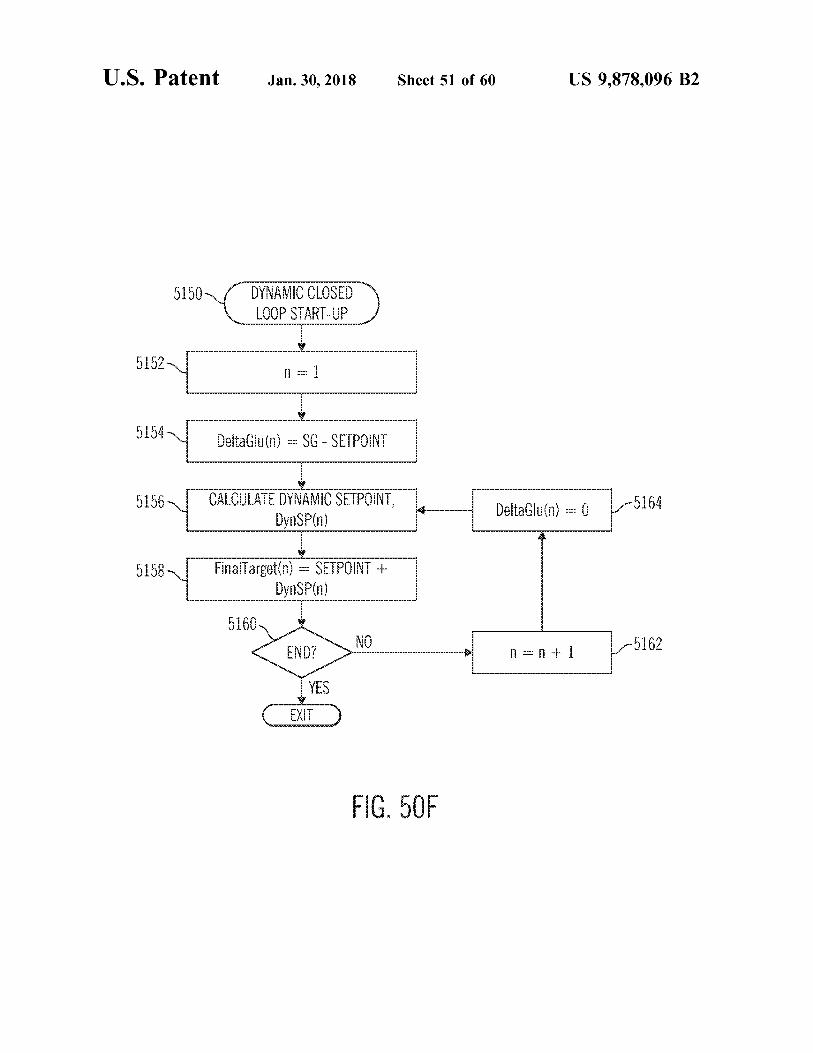
5150 DYNAMIC CLOSED LOOP START - UP
5152 51522 LO 5 n = 1 = 5 1 5 4 DeltaGlu ( n ) = SG - SETPOINT
5 5 HLVUL LEEEE MT HU hawl w DeltaGlu ( n ) = 5 164 DynSPín )
5 1 5 E Final Target ( n ) = SETPOINT + DynSPín )
5160 ENDONO 5 1 6 END ? n = n41
EXIT
FIG . 50F
U . S . Patent Jan . 30 , 2018 Sheet 52 of 60 US 9 , 878 , 096 B2
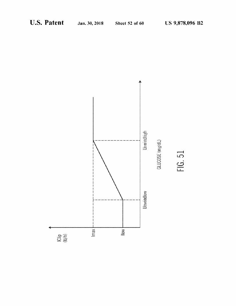
w
GED ) LED DE D G D Yo ypu MUO wwww
GLUCOSE ( mg / dL )
wwwwwwwwwwwwwwwww FIG . 51
mun
wwwwwwww MOPUIMUD imax - - - . . .
MOLL ös
U . S . Patent Jan . 30 , 2018 Sheet 53 of 60 US 9 , 878 , 096 B2
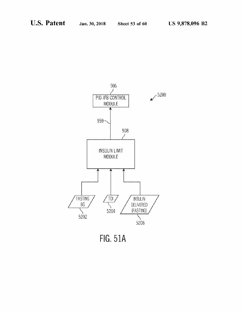
906 5200 PID - IFB CONTROL
MODULE
959 908
INSULIN LIMIT MODULE
FASTING BG
INSULIN DELIVERED FASTING 5204 5204 / ( FASTING ) 5202 5206
boodboooc FIG . 51A xoooooooo
atent Jan . 30 , 2018 Sheet 54 of 60 US 9 , 878 , 096 B2
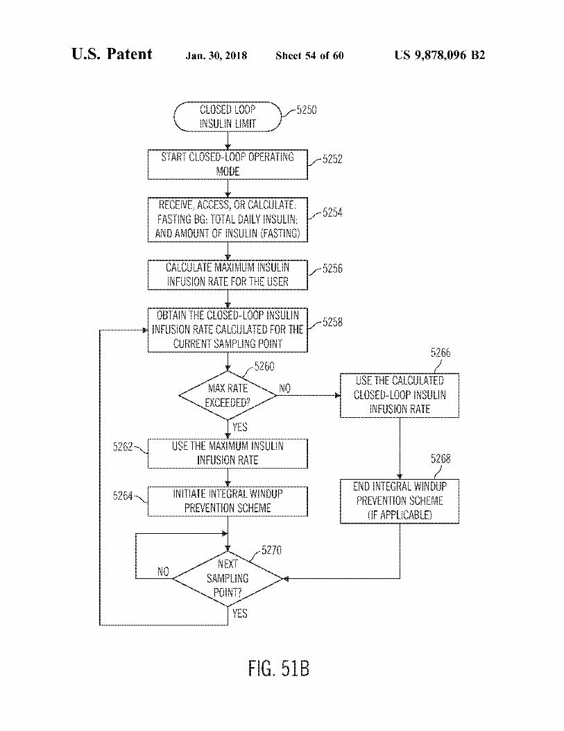
CLOSED LOOP 5250 N VEEEE w
START CLOSED - LOOP OPERATING MODE
5252
PP pen VU , RECEVE , ACCESS , OR CALCULATE : 1
FASTING BG ; TOTAL DAILY INSULIN ; 5 2 5 w
F ARKIT ANIVWII ??? AIVAT
CALCULATE MAXIMUM INSULIN INFUSION RATE FOR THE USER
15256 IRINA
TART : 11L www OBTAIN THE CLOSED - LOOP INSULIN NFUSION RATE CALCULATED FOR THE - 5258 T . . 1
m L . WPRTO ANA
5266 5260
1 MAX RATE EXCEEDED ?
NO USE THE CALCULATED CLOSED - LOOP INSULIN
INFUSION RATE S
wwwwwwwwwwwwwwwww
52621 YES
USE THE MAXIMUM INSULIN INFUSION RATE 5268
INITIADA E UR BEEE .
5264 5264 INITIATE INTEGRAL WINDUP www wwwww E DOLVEN E
( IF APPLICABLE ) 444444444444444444444444444444
5270 NO NEXT
SAMPLING POINT ?
TYES
FIG . 51B
U . S . Patent
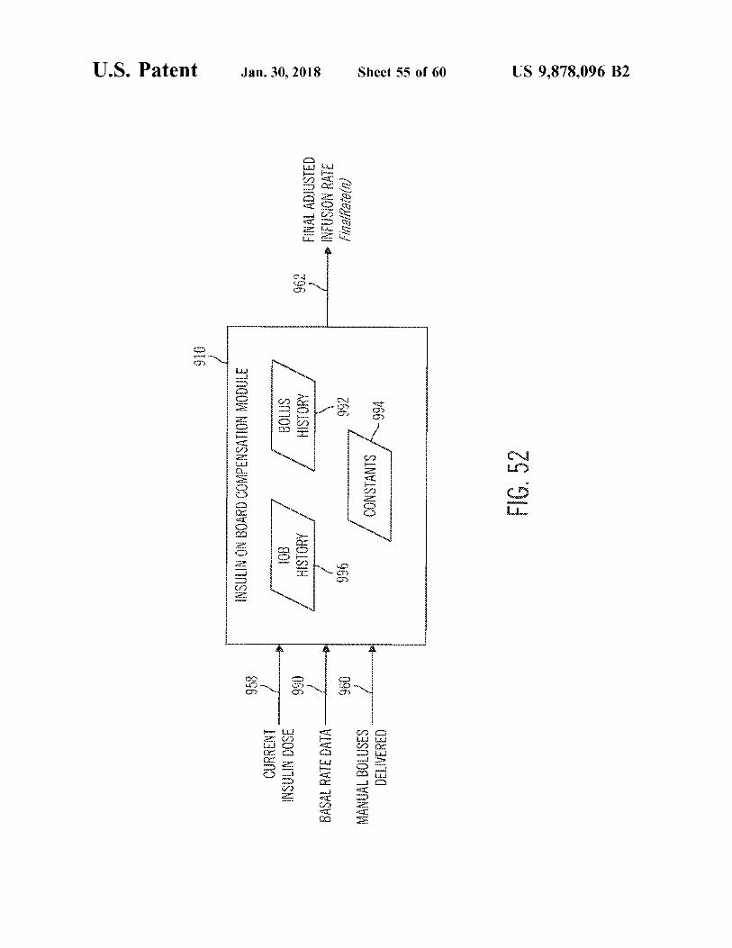
910
INSULIN ON BOARD COMPENSATION MODULE
958
CURRENT INSULIN DOSE
10B HISTORY
990
BOLUS HISTORY
Jan . 30 , 2018
962
BASAL RATE DATA
FINAL ADJUSTED INFUSION RATE FinalRatein )
960
996
992
MANUAL BOLUSES DELIVERED
CONSTANTS 994
Sheet 55 of 60
FIG . 52
US 9 , 878 , 096 B2
U . S . Patent Jan . 30 , 2018 Sheet 56 of 60 US 9 , 878 , 096 B2
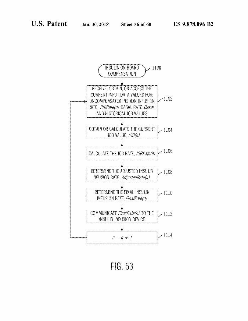
www www INSULIN ON BOARD COMPENSATION
1100 1 1
RECEIVE , OBTAIN , OR ACCESS THE E AAN mann A VALUE
1102 certum UNCOMPENSATED INSULIN INFUSION RATE , PIDRate ( 11 ) , BASAL RATE , Basal ;
AND HISTORICAL IOB VALUES
K !
LILA OBTAIN OR CALCULATE THE CURRENT IOB VALUE , OB ( )
1104 4
????? CULATE CALCULATE THE IOB RATE , IOBRate ( n ) 1 LVUL 3
DETERMINE THE ADJUSTED INSULIN 1 - 1108 INFUSION RATE , AdjustedRate ( n )
1 1 mm
DETERMINE THE FINAL INSULIN INFUSION RATE , FinalRate ( n )
1 - 1110 1 1
COMMUNICATE FinalRate ( n ) TO THE 1112 praat panel 2 TITTY
1 1 1 4 1 = 1 1
FIG . 53
U . S . Patent Jan . 30 , 2018 Sheet 57 of 60 US 9 , 878 , 096 B2
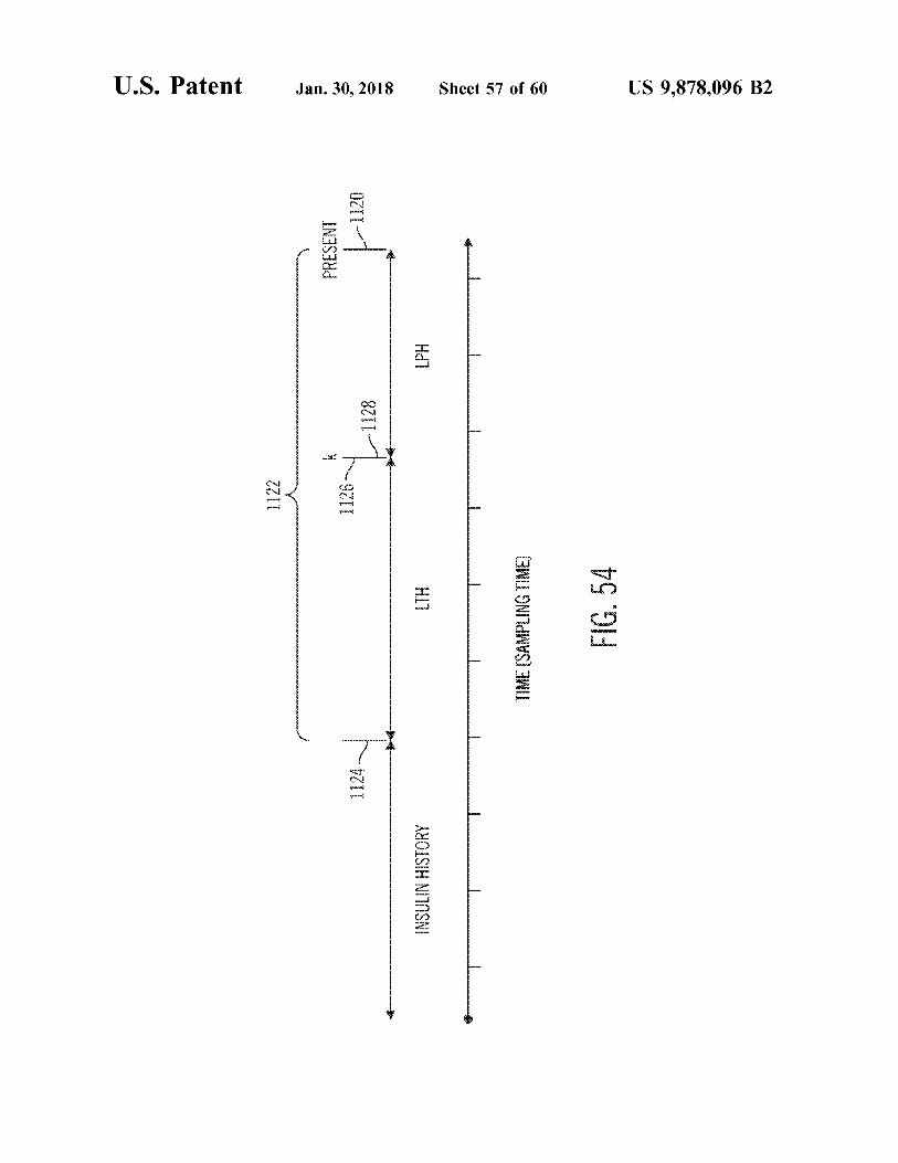
- 1120
PRESENT Hd7
L - 1128
1122 1126 A
weer
HU )
wannnnnnnnnnnnAAAAAAAAAAAAAAAAAAAAAAAaaannnnnnnnnnnn ME ISAMPLING FIG . 54
1124
INSULIN HISTORY ?
U . S . Patent Jan . 30 , 2018 Sheet 58 of 60 US 9 , 878 , 096 B2
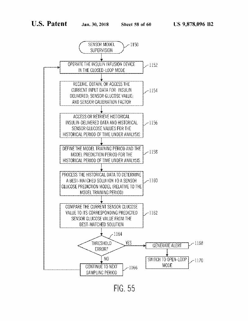
SENSOR MODEL SUPERVISION
1150
n LY Vt 1 OPERATE THE INSULIN INFUSION DEVICE
IN THE CLOSED - LOOP MODE 1152 1 S 5 ! 1
RECEIVE , OBTAIN , OR ACCESS THE CURRENT INPUT DATA FOR : INSULIN 1154 1 w E E ang E AND SENSOR CALIBRATION FACTOR
EEEEE mm E - 1156 1 1 6 ACCESS OR RETRIEVE HISTORICAL
INSULIN - DELIVERED DATA AND HISTORICAL SENSOR GLUCOSE VALUES FOR THE
HISTORICAL PERIOD OF TIME UNDER ANALYSIS A
1158 1 1 DEFINE THE MODEL TRAINING PERIOD AND THE MODEL PREDICTION PERIOD FOR THE
HISTORICAL PERIOD OF TIME UNDER ANALYSIS
6
wwwwwwwwwwwwwwwwwww
L .
1160 PROCESS THE HISTORICAL DATA TO DETERMINE
A BEST - MATCHED SOLUTION TO A SENSOR GLUCOSE PREDICTION MODEL ( RELATIVE TO THE
MODEL TRAINING PERIOD ) wwwwwwwwwwwwwwwwwwwwwwwwwwwwwwwwwwwwwwwww
1 - 1162 1 1 COMPARE THE CURRENT SENSOR GLUCOSE VALUE TO ITS CORRESPONDING PREDICTED
SENSOR GLUCOSE VALUE FROM THE BEST - MATCHED SOLUTION
6
1 1164 THRESHOLD ERROR ?
YES GENERATE ALERT 7 1 1168 EC
- 1170 SWITCH TO OPEN - LOOP MODE CONTINUE TO NEXT 1
SAMPLING PERIOD 1166
FIG . 55
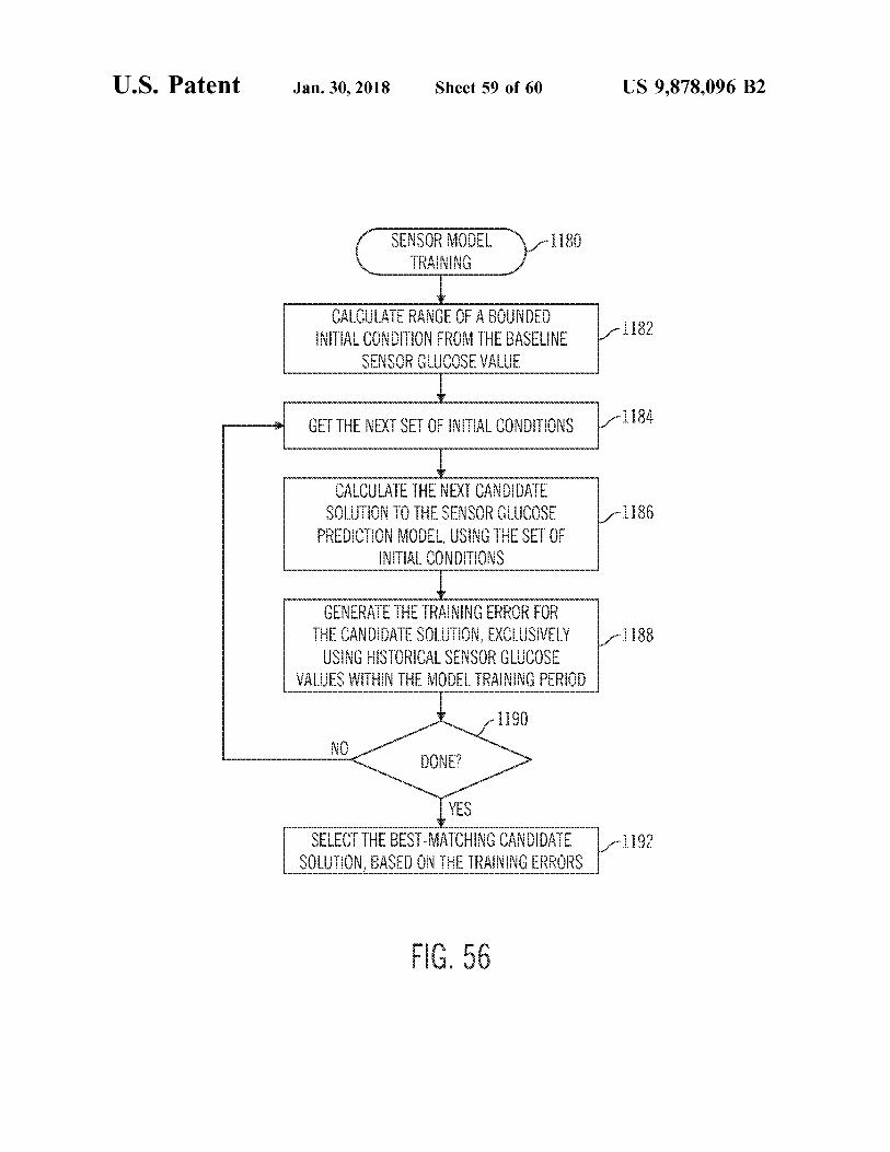
U . S . Patent Jan . 30 , 2018 Sheet 59 of 60 US 9 , 878 , 096 B2
SENSOR MODEL TRAINING
1180
1182 1 1 IT : A
CALCULATE RANGE OF A BOUNDED INITIAL CONDITION FROM THE BASELINE
SENSOR GLUCOSE VALUE SHO
yerel ??? GET THE NEXT SET OF INITIAL CONDITIONS
- 1186 CALCULATE THE NEXT CANDIDATE
SOLUTION TO THE SENSOR GLUCOSE PREDICTION MODEL , USING THE SET OF
INITIAL CONDITIONS
BEEEEEEEEEEEEEEEEEEEEEE 1188 GENERATE THE TRAINING ERROR FOR
THE CANDIDATE SOLUTION , EXCLUSIVELY USING HISTORICAL SENSOR GLUCOSE
VALUES WITHIN THE MODEL TRAINING PERIOD
EEEEEEEEEEEEEEEEE pon * * *
NO DONE ?
YES SELECT THE BEST - MATCHING CANDIDATE
SOLUTION , BASED ON THE TRAINING ERRORS
FIG . 56
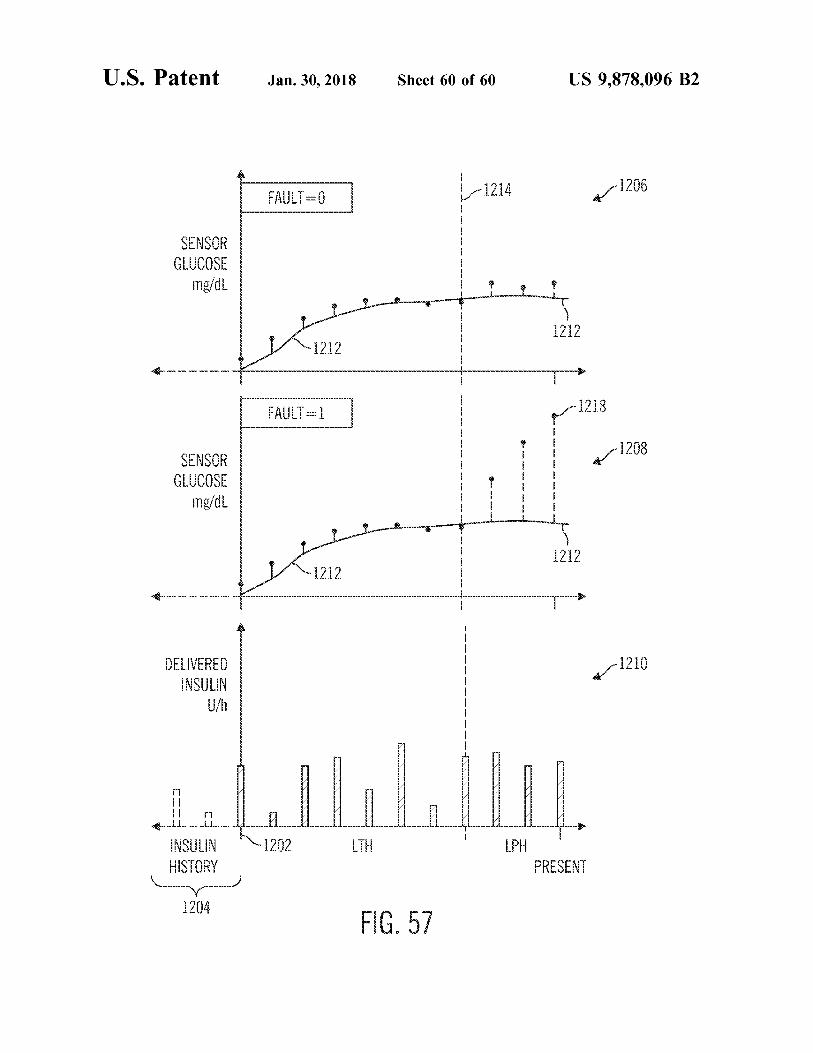
U . S . Patent Jan . 30 , 2018 Sheet 60 of 60 US 9 , 878 , 096 B2
pa frank A 4 1206 FAULT = 1
SENSOR GLUCOSE mg / dL fenn ann an ww ww when an uw won ann ann an uw wongan ma
1212 1 1212
m wwwmm 7
FAULT = 1 8176
SOZI SENSOR GLUCOSE mg / dL
Oh
wann mann ww ww ws and more on ann ann an uw woon aan ww ww nan w wwwwwwwwwwwwwww w
wannnnnnnnnnnnnnnnnnn mn pound N
1212 1
w
w
w
w fangen ? 1210 w
w INSULIN w wannnnnnnnnnnnnnnnnnnnnnnnnnnnnnnnnnnnnnnnnnnnnnnn w fun w
w
w
* * Arsinnnnninneninsennnnnnnn mom wwwwwwwwwww UUUUUUUUUUUUUUUU * winnen ow
1202 LTH d ! Hd ] N INSULIN HISTORY PRESENT
1204 FIG . 57
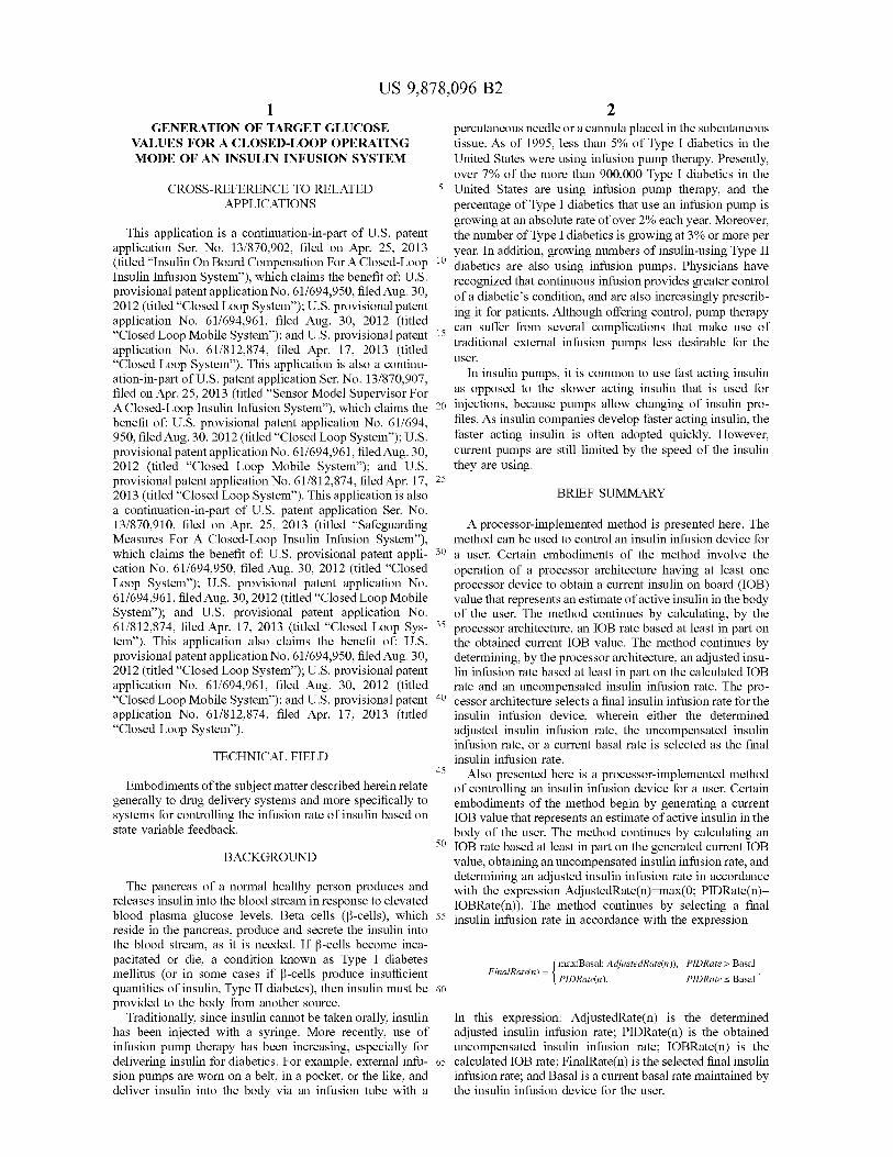
US 9 , 878 , 096 B2
GENERATION OF TARGET GLUCOSE percutaneous needle or a cannula placed in the subcutaneous VALUES FOR A CLOSED - LOOP OPERATING tissue . As of 1995 , less than 5 % of Type I diabetics in the MODE OF AN INSULIN INFUSION SYSTEM United States were using infusion pump therapy . Presently ,
over 7 % of the more than 900 , 000 Type I diabetics in the CROSS - REFERENCE TO RELATED 5 United States are using infusion pump therapy , and the
APPLICATIONS percentage of Type I diabetics that use an infusion pump is growing at an absolute rate of over 2 % each year . Moreover ,
This application is a continuation - in - part of U . S . patent the number of Type I diabetics is growing at 3 % or more per application Ser . No . 13 / 870 , 902 , filed on Apr . 25 , 2013 year . In addition , growing numbers of insulin - using Type II ( titled “ Insulin On Board Compensation For A Closed - Loop 10 diabetics are also using infusion pumps . Physicians have Insulin Infusion System " ) , which claims the benefit of : U . S . recognized that continuous infusion provides greater control provisional patent application No . 61 / 694 , 950 , filed Aug . 30 , of a diabetic ' s condition , and are also increasingly prescrib 2012 ( titled “ Closed Loop System ” ) ; U . S . provisional patent ing it for patients . Although offering control , pump therapy application No . 61 / 694 , 961 , filed Aug . 30 , 2012 ( titled can suffer from several complications that make use of " Closed Loop Mobile System ” ) ; and U . S . provisional patent 15 traditional external infusion pumps less desirable for the application No . 61 / 812 , 874 , filed Apr . 17 , 2013 ( titled " Closed Loop System " ) . This application is also a continu user . ation - in - part of U . S . patent application Ser . No . 13 / 870 , 907 , In insulin pumps , it is common to use fast acting insulin filed on Apr . 25 , 2013 ( titled “ Sensor Model Supervisor For as opposed to the slower acting insulin that is used for A Closed - Loop Insulin Infusion System ” ) , which claims the 20 injections , because pumps allow changing of insulin pro benefit of : U . S . provisional patent application No . 61 / 694 , files . As insulin companies develop faster acting insulin , the 950 , filed Aug . 30 , 2012 ( titled “ Closed Loop System ” ) ; U . S . faster acting insulin is often adopted quickly . However , provisional patent application No . 61 / 694 , 961 , filed Aug . 30 , current pumps are still limited by the speed of the insulin 2012 ( titled “ Closed Loop Mobile System " ) ; and U . S . they are using . provisional patent application No . 61 / 812 , 874 , filed Apr . 17 , 25 2013 ( titled " Closed Loop System ” ) . This application is also BRIEF SUMMARY a continuation - in - part of U . S . patent application Ser . No . 13 / 870 , 910 , filed on Apr . 25 , 2013 ( titled “ Safeguarding A processor - implemented method is presented here . The Measures For A Closed - Loop Insulin Infusion System ” ) , method can be used to control an insulin infusion device for which claims the benefit of : U . S . provisional patent appli - 30 a user . Certain embodiments of the method involve the cation No . 61 / 694 , 950 , filed Aug . 30 , 2012 ( titled “ Closed operation of a processor architecture having at least one Loop System " ) ; U . S . provisional patent application No . processor device to obtain a current insulin on board ( IOB ) 61 / 694 , 961 , filed Aug . 30 , 2012 ( titled “ Closed Loop Mobile value that represents an estimate of active insulin in the body System ” ) ; and U . S . provisional patent application No . of the user . The method continues by calculating , by the 61 / 812 , 874 , filed Apr . 17 , 2013 ( titled “ Closed Loop Sys - 35 processor architecture , an IOB rate based at least in part on tem ” ) . This application also claims the benefit of : U . S . the obtained current IOB value . The method continues by provisional patent application No . 61 / 694 , 950 , filed Aug . 30 , determining , by the processor architecture , an adjusted insu 2012 ( titled “ Closed Loop System " ) ; U . S . provisional patent lin infusion rate based at least in part on the calculated IOB application No . 61 / 694 , 961 , filed Aug . 30 , 2012 ( titled rate and an uncompensated insulin infusion rate . The pro “ Closed Loop Mobile System ” ) ; and U . S . provisional patent 40 cessor architecture selects a final insulin infusion rate for the application No . 61 / 812 , 874 , filed Apr . 17 , 2013 ( titled insulin infusion device , wherein either the determined “ Closed Loop System ” ) . adjusted insulin infusion rate , the uncompensated insulin
infusion rate , or a current basal rate is selected as the final TECHNICAL FIELD insulin infusion rate . 45 A Also presented here is a processor - implemented method
Embodiments of the subject matter described herein relate of controlling an insulin infusion device for a user . Certain generally to drug delivery systems and more specifically to embodiments of the method begin by generating a current systems for controlling the infusion rate of insulin based on IOB value that represents an estimate of active insulin in the state variable feedback . body of the user . The method continues by calculating an
30 IOB rate based at least in part on the generated current IOB BACKGROUND value , obtaining an uncompensated insulin infusion rate , and determining an adjusted insulin infusion rate in accordance The pancreas of a normal healthy person produces and with the expression AdjustedRate ( n ) = max ( 0 ; PIDRate ( n )
releases insulin into the blood stream in response to elevated IOBRate ( n ) ) . The method continues by selecting a final blood plasma glucose levels . Beta cells ( B - cells ) , which 55 insulin infusion rate in accordance with the expression reside in the pancreas , produce and secrete the insulin into the blood stream , as it is needed . If B - cells become inca pacitated or die , a condition known as Type I diabetes ( max ( Basal ; AdjustedRate ( n ) ) , PIDRate > Basal mellitus ( or in some cases if B - cells produce insufficient FinalRate ( n ) = {
| PIDRate ( n ) , PIDRate < Basal quantities of insulin , Type II diabetes ) , then insulin must be 60 provided to the body from another source .
Traditionally , since insulin cannot be taken orally , insulin In this expression : AdjustedRate ( n ) is the determined has been injected with a syringe . More recently , use of adjusted insulin infusion rate ; PIDRate ( n ) is the obtained infusion pump therapy has been increasing , especially for uncompensated insulin infusion rate ; IOBRate ( n ) is the delivering insulin for diabetics . For example , external infu - 65 calculated IOB rate ; FinalRate ( n ) is the selected final insulin sion pumps are worn on a belt , in a pocket , or the like , and infusion rate ; and Basal is a current basal rate maintained by deliver insulin into the body via an infusion tube with a the insulin infusion device for the user .
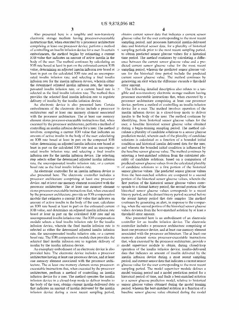
US 9 , 878 , 096 B2
Also presented here is a tangible and non - transitory obtains current sensor data that indicates a current sensor electronic storage medium having processor - executable glucose value for the user corresponding to the most recent instructions that , when executed by a processor architecture sampling period , and processes historical insulin - delivered comprising at least one processor device , perform a method data and historical sensor data , for a plurality of historical of controlling an insulin infusion device for a user . In certain 5 sampling periods prior to the most recent sampling period , embodiments , the method begins by estimating a current to obtain predicted sensor glucose values for a historical IOB value that indicates an amount of active insulin in the time period . The method continues by calculating a differ body of the user . The method continues by calculating an ence between the current sensor glucose value and a pre IOB rate based at least in part on the estimated current IOB dicted current sensor glucose value for the most recent value , determining an adjusted insulin infusion rate based at 10 sampling period , wherein the predicted sensor glucose val least in part on the calculated IOB rate and an uncompen - ues for the historical time period include the predicted sated insulin infusion rate , and selecting a final insulin current sensor glucose value . The method continues by infusion rate for the insulin infusion device , wherein either generating an alert when the difference exceeds a threshold the determined adjusted insulin infusion rate , the uncom - error amount . pensated insulin infusion rate , or a current basal rate is 15 The following detailed description also relates to a tan selected as the final insulin infusion rate . The method then gible and non - transitory electronic storage medium having provides the selected final insulin infusion rate to regulate processor executable instructions that , when executed by a delivery of insulin by the insulin infusion device . processor architecture comprising at least one processor An electronic device is also presented here . Certain device , perform a method of controlling an insulin infusion
embodiments of the electronic device include a processor 20 device for a user . The method involves operation of the architecture and at least one memory element associated insulin infusion device in a closed - loop mode to deliver with the processor architecture . The at least one memory insulin to the body of the user . The method continues by element stores processor - executable instructions that , when identifying , from historical sensor glucose values for the executed by the processor architecture , perform a method of user , a baseline historical sensor glucose value obtained controlling an insulin infusion device for a user . The method 25 during a begin - training sampling period . The method cal involves : computing a current IOB value that indicates an culates a plurality of candidate solutions to a sensor glucose amount of active insulin in the body of the user ; calculating prediction model , wherein each of the plurality of candidate an IOB rate based at least in part on the computed IOB solutions is calculated as a function of a bounded initial value ; determining an adjusted insulin infusion rate based at condition and historical insulin delivered data for the user , least in part on the calculated IOB rate and an uncompen - 30 and wherein the bounded initial condition is influenced by sated insulin infusion rate ; and selecting a final insulin the baseline sensor glucose value . The method continues by infusion rate for the insulin infusion device . The selecting selecting a best - matched solution from the calculated plu step selects either the determined adjusted insulin infusion rality of candidate solutions , based on a comparison of rate , the uncompensated insulin infusion rate , or a current predicted sensor glucose values from the calculated plurality basal rate as the final insulin infusion rate . 35 of candidate solutions to a first portion of the historical
An electronic controller for an insulin infusion device is sensor glucose values . The predicted sensor glucose values also presented here . The electronic controller includes a from the best - matched solution are compared to a second processor architecture comprising at least one processor portion of the historical sensor glucose values , wherein the device , and at least one memory element associated with the first portion of the historical sensor glucose values corre processor architecture . The at least one memory element 40 sponds to a distant history period , the second portion of the stores processor - executable instructions that , when executed historical sensor glucose values corresponds to a recent by the processor architecture , provide an IOB compensation history period , and the distant history period occurred before module that estimates a current IOB value that indicates an the recent history period that data samples . The method amount of active insulin in the body of the user , calculates continues by generating an alert , in response to the compar an IOB rate based at least in part on the estimated current 45 ing , when the second portion of the historical sensor glucose IOB value , and determines an adjusted insulin infusion rate values deviates from the best - matched solution by at least a based at least in part on the calculated IOB rate and an threshold error amount . uncompensated insulin infusion rate . The IOB compensation Also presented here is an embodiment of an electronic module selects a final insulin infusion rate for the insulin controller for an insulin infusion device . The electronic infusion device , wherein the final insulin infusion rate is 50 controller includes a processor architecture comprising at selected as either the determined adjusted insulin infusion least one processor device , and at least one memory element rate , the uncompensated insulin infusion rate , or a current associated with the processor architecture . The at least one basal rate . The IOB compensation module then provides the memory element stores processor - executable instructions selected final insulin infusion rate to regulate delivery of that , when executed by the processor architecture , provide a insulin by the insulin infusion device . 55 model supervisor module to obtain , during closed - loop An exemplary embodiment of an electronic device is also operation of the insulin infusion device , insulin - delivered
provided here . The electronic device includes a processor data that indicates an amount of insulin delivered by the architecture having at least one processor device , and at least insulin infusion device during a most recent sampling one memory element associated with the processor archi - period , and current sensor data that indicates a current sensor tecture . The at least one memory element stores processor - 60 glucose value for the user corresponding to the most recent executable instructions that , when executed by the processor sampling period . The model supervisor module defines a architecture , perform a method of controlling an insulin model training period and a model prediction period for a infusion device for a user . The method operates the insulin historical period of time , and finds a best - matched solution infusion device in a closed - loop mode to deliver insulin to to a sensor glucose prediction model , relative to historical the body of the user , obtains current insulin - delivered data 65 sensor glucose values obtained during the model training that indicates an amount of insulin delivered by the insulin period , wherein the best - matched solution is a function of a infusion device during a most recent sampling period , baseline sensor glucose value obtained during the model
US 9 , 878 , 096 B2
training period , and is a function of historical insulin finding a best - matched solution to a sensor glucose predic delivered data for the user obtained during the historical tion model , relative to historical sensor glucose values period of time . The model supervisor module compares at obtained during the model training period , wherein the least one predicted sensor glucose value from the best - best - matched solution is a function of a baseline sensor matched solution to at least one historical sensor glucose 5 glucose value obtained during the model training period , and value corresponding only to the model prediction period , is a function of historical insulin - delivered data for the user and generates an alert , in response to the comparing , when obtained during the historical period of time . The method the at least one historical sensor glucose value deviates from continues by comparing at least one predicted sensor glu the at least one predicted sensor glucose value by at least a cose value from the best - matched solution to at least one threshold error amount . 10 historical sensor glucose value corresponding only to the
Also included below is a detailed description of a pro - model prediction period . An alert is generated , in response cessor - implemented method of controlling an insulin infu - to the comparing , when the at least one historical sensor sion device for a user . The method may begin by operating glucose value deviates from the at least one predicted sensor the insulin infusion device in a closed - loop mode to deliver glucose value by at least a threshold error amount . insulin to the body of the user . The method continues by 15 Additional processor - implemented methods of control obtaining current insulin - delivered data that indicates an ling an insulin infusion device are also presented below . For amount of insulin delivered by the insulin infusion device example , one method involves operating a processor archi during a most recent sampling period , obtaining current tecture having at least one processor device to obtain sensor sensor data that indicates a current sensor glucose value for calibration data for a continuous glucose sensor that gener the user corresponding to the most recent sampling period , 20 ates a sensor variable indicative of blood glucose of the user . and processing historical insulin - delivered data and histori - This method continues by identifying a most recent calibra cal sensor data , for a plurality of historical sampling periods tion factor from the sensor calibration data , the most recent prior to the most recent sampling period , to obtain predicted calibration factor representing a first conversion value appli sensor glucose values for a historical time period . The cable to convert a first value of the sensor variable to a first method then calculates a difference between the current 25 blood glucose value . This method also identifies a prior sensor glucose value and a predicted current sensor glucose calibration factor from the sensor calibration data , the prior value for the most recent sampling period , wherein the calibration factor representing a second conversion value predicted sensor glucose values for the historical time period applicable to convert a second value of the sensor variable include the predicted current sensor glucose value . An alert to a second blood glucose value , and the prior calibration is generated when the difference exceeds a threshold error 30 factor corresponding to an earlier time relative to the most amount . recent calibration factor . The method regulates entry into a
Also included below is a detailed description of a pro closed - loop operating mode of the insulin infusion device , cessor - implemented method of controlling an insulin infu - based on the most recent calibration factor and the prior sion device for a user . The method may begin by operating calibration factor . the insulin infusion device in a closed - loop mode to deliver 35 Also provided is a tangible and non - transitory electronic insulin to the body of the user . The method continues by storage medium having processor - executable instructions identifying , from historical sensor glucose values for the that , when executed by a processor architecture , perform an user , a baseline historical sensor glucose value obtained exemplary embodiment of a method of controlling an insulin during a begin - training sampling period . Next , a plurality of infusion device for a user , the method including : obtaining candidate solutions to a sensor glucose prediction model is 40 sensor calibration data for a continuous glucose sensor that calculated , wherein each of the plurality of candidate solu generates a sensor variable indicative of blood glucose of the tions is calculated as a function of a bounded initial condi - user ; identifying a most recent calibration factor from the tion and historical insulin delivered data for the user , and sensor calibration data , the most recent calibration factor wherein the bounded initial condition is influenced by the representing a first conversion value applicable to convert a baseline sensor glucose value . The method continues by 45 first value of the sensor variable to a first blood glucose selecting a best - matched solution from the calculated plu - value ; identifying a prior calibration factor from the sensor rality of candidate solutions , based on a comparison of calibration data , the prior calibration factor representing a predicted sensor glucose values from the calculated plurality second conversion value applicable to convert a second of candidate solutions to a first portion of the historical value of the sensor variable to a second blood glucose value , sensor glucose values . At least one predicted sensor glucose 50 and the prior calibration factor corresponding to an earlier value from the best - matched solution is compared to a time relative to the most recent calibration factor ; and second portion of the historical sensor glucose values , regulating entry into a closed - loop operating mode of the wherein the first portion of the historical sensor glucose insulin infusion device , based on the most recent calibration values corresponds to a distant history period , the second factor and the prior calibration factor . portion of the historical sensor glucose values corresponds 55 An embodiment of an electronic device is also presented to a recent history period , and the distant history period here . The electronic device includes : a processor architec occurred before the recent history period that data samples . ture having at least one processor device ; and at least one An alert is generated , in response to the comparing , when the memory element associated with the processor architecture . second portion of the historical sensor glucose values devi - The memory element stores processor - executable instruc ates from the best - matched solution by at least a threshold 60 tions that , when executed by the processor architecture , error amount . perform a method of controlling an insulin infusion device
Another embodiment of a processor - implemented method for a user . The method involves : obtaining sensor calibration of controlling an insulin infusion device for a user is also data for a continuous glucose sensor that generates a sensor presented below . The method involves operating the insulin variable indicative of blood glucose of the user ; identifying infusion device in a closed - loop mode to deliver insulin to 65 a most recent calibration factor from the sensor calibration the body of the user , defining a model training period and a data , the most recent calibration factor representing a first model prediction period for a historical period of time , and conversion value applicable to convert a first value of the
US 9 , 878 , 096 B2
sensor variable to a first blood glucose value ; identifying a dynamic final target glucose value that decreases over time prior calibration factor from the sensor calibration data , the toward the target glucose setpoint value . prior calibration factor representing a second conversion Another exemplary embodiment of an electronic device is value applicable to convert a second value of the sensor also presented here . The electronic device includes a pro variable to a second blood glucose value , and the prior 5 cessor architecture and at least one memory element asso calibration factor corresponding to an earlier time relative to ciated with the processor architecture . The at least one the most recent calibration factor ; and regulating entry into memory element stores processor - executable instructions
a closed - loop operating mode of the insulin infusion device , that , when executed by the processor architecture , perform based on the most recent calibration factor and the prior a method of controlling an insulin infusion device for a user .
10 The method initiates a closed - loop operating mode of the calibration factor . insulin infusion device and , in response to initiating the Also provided is an embodiment of an electronic control closed - loop operating mode , obtains a most recent sensor ler for an insulin infusion device . The electronic controller glucose value for the user . The method continues by calcu includes : a processor architecture having at least one pro lating a difference between the most recent sensor glucose cessor device ; and at least one memory element associated 15 value and a target glucose setpoint value . When the calcu with the processor architecture , the at least one memory lated difference is less than or equal to a minimum threshold element storing processor - executable instructions that , when value , the method adjusts a closed - loop insulin infusion rate executed by the processor architecture , provide a closed over time , based on a fixed final target glucose value that is loop initiation module . The initiation module is configured derived from the target glucose setpoint value . When the to : obtain a most recent calibration factor for a continuous 20 calculated difference is greater than the minimum threshold glucose sensor that generates a sensor variable indicative of value , the method adjusts the closed - loop insulin infusion blood glucose of a user , the most recent calibration factor rate over time , based on a dynamic final target glucose value representing a first conversion value applicable to convert a that decreases over time toward the target glucose setpoint first value of the sensor variable to a first blood glucose value . value ; obtain a prior calibration factor for the continuous 25 Another exemplary embodiment of an electronic control glucose sensor , the prior calibration factor representing a ler for an insulin infusion device is also provided here . The second conversion value applicable to convert a second electronic controller includes : a processor architecture ; and value of the sensor variable to a second blood glucose value ; at least one memory element associated with the processor obtain calibration timestamp data for the most recent cali - architecture , the at least one memory element storing pro bration factor and the prior calibration factor ; and regulate 30 cessor - executable instructions that , when executed by the entry into a closed - loop operating mode of the insulin processor architecture , provide a closed - loop start - up mod infusion device , based on the most recent calibration factor , ule . The start - up module is configured to : initiate a closed the prior calibration factor , and the calibration timestamp loop operating mode of the insulin infusion device ; in data . response to initiating the closed - loop operating mode , obtain
Another embodiment of a processor - implemented method 35 a most recent sensor glucose value for the user ; and calculate of controlling an insulin infusion device for a user is also a difference between the most recent sensor glucose value provided . This method involves : operating a processor and a target glucose setpoint value . When the calculated architecture to initiate a closed - loop operating mode of the difference is less than or equal to a minimum threshold insulin infusion device ; in response to initiating the closed value , the start - up module adjusts a closed - loop insulin loop operating mode , obtaining a most recent sensor glucose 40 infusion rate over time , based on a fixed final target glucose value for the user ; and calculating a difference between the value that is derived from the target glucose setpoint value . most recent sensor glucose value and a target glucose When the calculated difference is greater than the minimum setpoint value . When the calculated difference is less than or threshold value , the start - up module adjusts the closed - loop equal to a minimum threshold value , the method adjusts a insulin infusion rate over time , based on a dynamic final closed - loop insulin infusion rate over time , based on a fixed 45 target glucose value that decreases over time toward the final target glucose value that is derived from the target target glucose setpoint value . glucose setpoint value . In contrast , when the calculated Yet another processor - implemented method of controlling difference is greater than the minimum threshold value , the an insulin infusion device for a user is presented here . The method adjusts the closed - loop insulin infusion rate over method calculates a maximum insulin infusion rate for the time , based on a dynamic final target glucose value that 50 user based on a fasting blood glucose value associated with decreases over time toward the target glucose setpoint value . the user , a total daily insulin value associated with the user ,
Also presented here is a tangible and non - transitory and fasting insulin delivery data that is indicative of insulin electronic storage medium having processor - executable delivered to the user during a fasting period . The maximum instructions that , when executed by a processor architecture , insulin infusion rate is applicable during a period of closed perform a method of controlling an insulin infusion device 55 loop operation of the insulin infusion device . The method for a user . The method involves : initiating a closed - loop continues by obtaining a first closed - loop insulin infusion operating mode of the insulin infusion device ; in response to rate for the user , wherein the first closed - loop insulin infu initiating the closed - loop operating mode , obtaining a most sion rate is obtained for a current sampling point during the recent sensor glucose value for the user ; and calculating a period of closed - loop operation . The method provides a difference between the most recent sensor glucose value and 60 second closed - loop insulin infusion rate for the user when a target glucose setpoint value . When the calculated differ - the obtained first closed - loop insulin infusion rate is greater ence is less than or equal to a minimum threshold value , a than the calculated maximum insulin infusion rate , wherein closed - loop insulin infusion rate is adjusted over time , based the second closed - loop insulin infusion rate is less than the on a fixed final target glucose value that is derived from the first closed - loop insulin infusion rate . target glucose setpoint value . When the calculated difference 65 Also provided is a tangible and non - transitory electronic is greater than the minimum threshold value , the closed - loop storage medium having processor - executable instructions insulin infusion rate is adjusted over time , based on a that , when executed by a processor architecture , perform a
US 9 , 878 , 096 B2 10
method of controlling an insulin infusion device for a user . claimed subject matter , nor is it intended to be used as an aid The method involves : calculating a maximum insulin infu - in determining the scope of the claimed subject matter . sion rate for the user based on a fasting blood glucose value associated with the user , a total daily insulin value associated BRIEF DESCRIPTION OF THE DRAWINGS with the user , and fasting insulin delivery data that is 5 indicative of insulin delivered to the user during a fasting A more complete understanding of the subject matter may period , wherein the maximum insulin infusion rate is appli be derived by referring to the detailed description and claims cable during a period of closed - loop operation of the insulin when considered in conjunction with the following figures ,
wherein like reference numbers refer to similar elements infusion device . The method obtains a first closed - loop 10 throughout the figures . insulin infusion rate for the user , wherein the first closed FIG . 1 is a block diagram of a closed loop glucose control loop insulin infusion rate is obtained for a current sampling system in accordance with an embodiment of the present point during the period of closed - loop operation . The invention . method continues by providing a second closed - loop insulin FIG . 2 is a front view of closed loop hardware located on infusion rate for the user when the obtained first closed - loop 15 a body in accordance with an embodiment of the present insulin infusion rate is greater than the calculated maximum insulin infusion rate , wherein the second closed - loop insulin FIG . 3A is a perspective view of a glucose sensor system infusion rate is less than the first closed - loop insulin infusion for use in an embodiment of the present invention . rate . FIG . 3B is a side cross - sectional view of the glucose
An additional embodiment of an electronic device is also 20 sensor system of FIG . 3A . presented here . The electronic device includes : a processor FIG . 3C is a perspective view of a sensor set of the architecture having at least one processor device ; and at least glucose sensor system of FIG . 3A for use in an embodiment one memory element associated with the processor archi - of the present invention . tecture , the at least one memory element storing processor FIG . 3D is a side cross - sectional view of the sensor set of executable instructions that , when executed by the processor 25 FIG . 3C . architecture , perform a method of controlling an insulin FIG . 4 is a cross sectional view of a sensing end of the infusion device for a user . The method involves : calculating sensor of FIG . 3D . a maximum insulin infusion rate for the user based on a FIG . 5 is a top view of an infusion device with a reservoir fasting blood glucose value associated with the user , a total door in the open position , for use in an embodiment of the daily insulin value associated with the user , and fasting 30 present invention . insulin delivery data that is indicative of insulin delivered to FIG . 6 is a side view of an infusion set with the insertion the user during a fasting period , wherein the maximum needle pulled out , for use in an embodiment of the present insulin infusion rate is applicable during a period of closed - invention . loop operation of the insulin infusion device ; obtaining a FIG . 7 is a circuit diagram of a sensor and its power first closed - loop insulin infusion rate for the user , wherein 35 supply in accordance with an embodiment of the present the first closed - loop insulin infusion rate is obtained for a invention . current sampling point during the period of closed - loop FIG . 8A is a diagram of a single device and its compo operation , and providing a second closed - loop insulin infu - nents in accordance with an embodiment of the present sion rate for the user when the obtained first closed - loop invention . insulin infusion rate is greater than the calculated maximum 40 FIG . 8B is a diagram of two devices and their components insulin infusion rate , wherein the second closed - loop insulin in accordance with an embodiment of the present invention . infusion rate is less than the first closed - loop insulin infusion FIG . 8C is another diagram of two devices and their
components in accordance with an embodiment of the Another embodiment of an electronic controller for an present invention .
insulin infusion device is also provided . The electronic 45 FIG . 8D is a diagram of three devices and their compo controller includes : a processor architecture having at least nents in accordance with an embodiment of the present one processor device ; and at least one memory element invention . associated with the processor architecture , the at least one FIG . 9 is a table listing the devices of FIGS . 8A - D and memory element storing processor - executable instructions their components . that , when executed by the processor architecture , provide a 50 FIG . 10 is a block diagram of the glucose sensor system closed - loop insulin limit module . The closed - loop insulin of FIG . 3A . limit module is configured to : obtain a fasting blood glucose FIG . 11A is a detailed block diagram of an A / D converter value associated with the user , the fasting blood glucose for the glucose sensor system of FIG . 10 in accordance with value corresponding to a fasting period for the user ; obtain an embodiment of the present invention . a total daily insulin value associated with the user ; obtain 55 FIG . 11B is a detailed block diagram of the A / D converter fasting insulin delivery data that is indicative of insulin for the glucose sensor system of FIG . 10 with a pulse delivered to the user during the fasting period ; and calculate duration output selection option in accordance with an a maximum insulin infusion rate for the user based on the embodiment of the present invention . obtained fasting blood glucose value , the obtained total daily FIG . 12 is a circuit diagram of an I - F A / D converter of insulin value , and the obtained fasting insulin delivery data , 60 FIG . 10 accompanied by charts of node signals in accor wherein the maximum insulin infusion rate is applicable dance with an embodiment of the present invention . during a period of closed - loop operation of the insulin FIG . 13 is another circuit diagram of an I - F A / D converter infusion device . of FIG . 10 accompanied by charts of node signals in
This summary is provided to introduce a selection of accordance with an embodiment of the present invention . concepts in a simplified form that are further described 65 FIG . 14 is still another circuit diagram of an I - F A / D below in the detailed description . This summary is not converter of FIG . 10 accompanied by charts of node signals intended to identify key features or essential features of the in accordance with an embodiment of the present invention .
rate .
US 9 , 878 , 096 B2
FIG . 15 is a circuit diagram of an I - V A / D converter of FIG . 30 is a top view of an end of a multi - sensor for FIG . 10 in accordance with an embodiment of the present measuring both glucose concentration and pH in accordance invention . with an embodiment of the present invention .
FIG . 16 is a block diagram of the glucose sensor system FIG . 31A is a representative drawing of blood glucose of FIG . 10 with a pre - filter and a filter in accordance with an 5 compared to sensor measured blood glucose over time in embodiment of the present invention . accordance with an embodiment of the present invention .
FIG . 17 is a chart of an example of a pre - filter of FIG . 16 FIG . 31B is a representative drawing of sensor sensitivity and its effects on digital sensor values Dsig in accordance over the same period of time as FIG . 31A in accordance with with an embodiment of the present invention . an embodiment of the present invention .
FIG . 18 is frequency response chart for a filter of FIG . 16 10 FIG . 31C is a representative drawing of sensor resistance in accordance with an embodiment of the present invention over the same period of time as FIG . 31A in accordance with
FIG . 19A is a plot of a filtered and an unfiltered sensor an embodiment of the present invention . signal over time in accordance with an embodiment of the FIG . 32 is a block diagram using the derivative of sensor present invention . resistance to determine when to recalibrate or replace the
FIG . 19B is close up of a section of the plot of FIG . 19A 15 sensor in accordance with an embodiment of the present in accordance with an embodiment of the present invention . invention .
FIG . 20 is a cross - sectional view of a sensor set and an FIG . 33A is a plot of an analog sensor signal Isig over infusion set attached to the body in accordance with an time in accordance with an embodiment of the present embodiment of the present invention . invention .
FIG . 21 is a frequency response chart of a time delay 20 FIG . 33B is a plot of sensor resistance over the same correcting Weiner filter in accordance with an embodiment period of time as FIG . 32A in accordance with an embodi of the present invention . ment of the present invention .
FIG . 22 is a plot of a digital sensor values Dsig before and FIG . 33C is a plot of the derivative of the sensor resistance after time delay correction compared to actual glucose of FIG . 32B in accordance with an embodiment of the measurements over time in accordance with an embodiment 25 present invention . of the present invention . FIG . 34A is a bottom view of a telemetered characteristic
FIG . 23A is a diagram of a glucose clamp ( glucose level monitor in accordance with an embodiment of the present with respect to time ) . invention .
FIG . 23B is a plot of insulin concentration in a normal FIG . 34B is a bottom view of a different telemetered glucose tolerant ( NGT ) individual in response to various 30 characteristic monitor in accordance with an embodiment of magnitudes of glucose clamps of FIG . 23A . the present invention .
FIG . 24A is a diagram of a glucose clamp . FIG . 35A is a drawing of a blood plasma insulin response FIG . 24B is a diagram of a proportional insulin response to a glucose clamp in a normal glucose tolerant ( NGT )
to the glucose clamp of FIG . 24A in accordance with an individual in accordance with an embodiment of the present embodiment of the present invention . 35 invention .
FIG . 24C is a diagram of an integral insulin response to FIG . 35B is a drawing of the blood plasma insulin the glucose clamp of FIG . 24A in accordance with an response of FIG . 35A when delayed due to insulin being embodiment of the present invention . delivered to the subcutaneous tissue instead of directly into
FIG . 24D is a diagram of a derivative insulin response to the blood stream in accordance with an embodiment of the the glucose clamp of FIG . 24A in accordance with an 40 present invention . embodiment of the present invention . FIG . 36A is a drawing of blood plasma insulin concen
FIG . 24E is a diagram of a combined proportional , tration over time after an insulin bolus is delivered directly integral , and derivative insulin response to the glucose into the blood stream in accordance with an embodiment of clamp of FIG . 24A in accordance with an embodiment of the the present invention . present invention . 45 FIG . 36B is a drawing of a blood plasma insulin concen
FIG . 25A is a plot of insulin responses to a glucose clamp tration over time after an insulin bolus is delivered into the for exercise trained and normal individuals . subcutaneous tissue in accordance with an embodiment of
FIG . 25B is a bar chart of glucose uptake rates for exercise the present invention . trained and normal individuals . FIG . 37 is a block diagram of the closed loop system of
FIG . 26 is a block diagram of a closed loop system to 50 FIG . 26 with the addition of a post - controller compensator control blood glucose levels through insulin infusion based and a derivative filter in accordance with an embodiment of on glucose level feedback in accordance with an embodi - the present invention . ment of the present invention . FIG . 38 A is a plot of sensor signal measurements and Via
FIG . 27 is a detailed block diagram of the portion of the measurements with respect to time in accordance with an control loop of FIG . 26 that is in the body in accordance with 55 embodiment of the present invention . an embodiment of the present invention . FIG . 38B is a plot of a measured counter electrode voltage
FIGS . 28A and 28B are plots of measured insulin Vent with respect to time in accordance with an embodiment responses of two different normal glucose tolerant ( NGT ) of the present invention . individuals to a glucose clamp for use with an embodiment FIG . 38C is a plot of calculated sensor sensitivity with of the present invention . 60 respect to time in accordance with an embodiment of the
FIG . 29A is a plot of two different glucose sensor outputs present invention . compared to glucose meter readings during a glucose clamp FIG . 38D is a plot of a calculation of sensor resistance Rs , in accordance with an embodiment of the present invention . with respect to time in accordance with an embodiment of
FIG . 29B is a plot of actual insulin concentration in blood the present invention . compared to a controller commanded insulin concentration 65 FIG . 38E is a plot of another calculation of sensor in response to the glucose clamp of FIG . 29 A in accordance resistance Rs , with respect to time in accordance with an with an embodiment of the present invention . embodiment of the present invention .
an
13 US 9 , 878 , 096 B2
14 FIG . 38F is a plot of the derivative of sensor resistance FIG . 50F is a flow chart that illustrates an exemplary
Rs , of FIG . 38D with respect to time in accordance with an embodiment of a dynamic closed - loop start - up process for embodiment of the present invention . an insulin infusion device .
FIG . 38G is a plot of the derivative of the sensor resis - FIG . 51 is a graph of integral clip value versus sensor tance Rs , of FIG . 38E with respect to time in accordance 5 glucose levels . with an embodiment of the present invention . FIG . 51A is a block diagram that schematically illustrates
FIG . 38H is a plot of when sensors were replaced with an exemplary embodiment of an insulin limit module . respect to time in accordance with an embodiment of the FIG . 51B is a flow chart that illustrates an exemplary present invention . embodiment of a closed - loop insulin limit process .
FIGS . 39A and 39B are a block diagrams of a closed loop op 10 FIG . 52 is a block diagram that schematically illustrates glucose control system in accordance with embodiments of an exemplary embodiment of an insulin on board ( IOB ) the present invention . compensation module .
FIG . 53 is a flow chart that illustrates an exemplary FIG . 40 is a block diagram of auto blood withdrawal and embodiment of an IOB compensation process . return in accordance with an embodiment of the present 15 le present 15 FIG . 54 is a diagram that depicts certain time events invention . associated with the operation of a model supervisor module . FIG . 41A is a plot actual blood glucose concentration in FIG . 55 is a flow chart that illustrates an exemplary
accordance with an embodiment of the present invention . embodiment of a sensor model supervision process . FIG . 41B is a plot of actual insulin concentration in blood FIG . 56 is a flow chart that illustrates an exemplary
compared to a controller commanded insulin concentration 20 embodiment of a sensor model training process , which may in response to the blood glucose in FIG . 41A in accordance be performed in conjunction with the sensor model super with an embodiment of the present invention . vision process depicted in FIG . 55 .
FIG . 42 illustrates a control feedback block diagram of FIG . 57 is a diagram that illustrates two exemplary fault state variable feedback and in accordance with an embodi conditions that can be detected by the model supervisor ment of the present invention . 25 module .
FIG . 43 is a plot of basal insulin delivery rate over time using different control gains in accordance with embodi DETAILED DESCRIPTION ments of the present invention .
FIG . 44 is a plot of subcutaneous insulin over time using The following detailed description is merely illustrative in different control gains in accordance with embodiments of 30 F 30 nature and is not intended to limit the embodiments of the the present invention . subject matter or the application and uses of such embodi
ments . As used herein , the word " exemplary " means " serv FIG . 45 is a plot of plasma insulin over time using ing as an example , instance , or illustration . ” Any implemen different control gains in accordance with embodiments of tation described herein as exemplary is not necessarily to be the present invention . 35 construed as preferred or advantageous over other imple FIG . 46 is a plot of insulin effect over time using different mentations . Furthermore , there is no intention to be bound control gains in accordance with embodiments of the present by any expressed or implied theory presented in the preced
invention . ing technical field , background , brief summary or the fol FIG . 47 is a plot of simulated glucose concentration over l owing detailed description .
time using a PID controller with state variable feedback and 40 Techniques and technologies may be described herein in a PID controller without state variable feedback in accor - terms of functional and / or logical block components , and dance with embodiments of the present invention . with reference to symbolic representations of operations ,
FIG . 48 is a plot of simulated insulin delivery over time processing tasks , and functions that may be performed by using a PID controller with state variable feedback and a various computing components or devices . Such operations , PID controller without state variable feedback in accordance 45 tasks , and functions are sometimes referred to as being with embodiments of the present invention . computer - executed , computerized , software - implemented ,
FIG . 49 is a block diagram that illustrates processing or computer - implemented . It should be appreciated that the modules and algorithms of an exemplary embodiment of a various block components shown in the figures may be closed - loop system controller . realized by any number of hardware , software , and / or firm
FIG . 50 is a flow chart that illustrates an exemplary 50 ware components configured to perform the specified func embodiment of a control process for an insulin infusion tions . For example , an embodiment of a system or a com device . ponent may employ various integrated circuit components ,
FIG . 50A is a flow chart that illustrates an exemplary e . g . , memory elements , digital signal processing elements , embodiment of a closed - loop initiation process for an insulin logic elements , look - up tables , or the like , which may carry infusion device . 55 out a variety of functions under the control of one or more
FIG . 50B is an exemplary timeline diagram that illustrates microprocessors or other control devices . the temporal relationships for sensor calibration factors When implemented in software or firmware , various processed by a closed - loop initiation module . elements of the systems described herein are essentially the
FIG . 50C is another exemplary timeline diagram that code segments or instructions that perform the various tasks . illustrates the temporal relationships for sensor calibration 60 The program or code segments can be stored in any tangible factors processed by a closed - loop initiation module . and non - transitory processor - readable medium . The “ pro
FIG . 50D is a flow chart that illustrates another exemplary cessor - readable medium ” or “ machine - readable medium ” embodiment of a closed - loop initiation process for an insulin may include any medium that can store or transfer informa infusion device . tion . Examples of the processor - readable medium include an
FIG . 50E is a flow chart that illustrates an exemplary 65 electronic circuit , a semiconductor memory device , a ROM , embodiment of a closed - loop insulin control process for an a flash memory , an erasable ROM ( EROM ) , a floppy dis insulin infusion device . kette , a CD - ROM , an optical disk , a hard disk , or the like .
US 9 , 878 , 096 B2 16
The various tasks performed in connection with a process includes infusion electrical components to activate an infu described herein may be performed by software , hardware , sion motor according to the commands 22 , an infusion firmware , or any combination thereof . It should be appre - communication system to receive the commands 22 from the ciated that a described process may include any number of controller 12 , and an infusion device housing to hold the additional or alternative tasks , the tasks shown in a particular 5 infusion device . figure need not be performed in the illustrated order , and a In preferred embodiments , the controller 12 is housed in described process may be incorporated into a more compre - the infusion device housing and the infusion communication hensive procedure or process having additional functionality system is an electrical trace or a wire that carries the not described in detail herein . Moreover , one or more of the commands 22 from the controller 12 to the infusion device . tasks shown in the figures could be omitted from an embodi - 10 In alternative embodiments , the controller 12 is housed in ment of a described process as long as the intended overall the sensor system housing and the sensor communication functionality remains intact . system is an electrical trace or a wire that carries the sensor
As shown in the drawings for purposes of illustration , the signal 16 from the sensor electrical components to the invention is embodied in a closed loop infusion system for controller electrical components . In other alternative regulating the rate of fluid infusion into a body of a user 15 embodiments , the controller 12 has its own housing or is based on feedback from an analyte concentration measure - included in a supplemental device . In another alternative ment taken from the body . In particular embodiments , the embodiment , the controller is located with the infusion invention is embodied in a control system for regulating the device and the sensor system all within one housing . In rate of insulin infusion into the body of a user based on a further alternative embodiments , the sensor , controller , and / glucose concentration measurement taken from the body . In 20 or infusion communication systems may utilize a cable , a preferred embodiments , the system is designed to model a wire , fiber optic lines , RF , IR , or ultrasonic transmitters and pancreatic beta cell ( B - cell ) . In other words , the system receivers , or the like instead of the electrical traces . controls an infusion device to release insulin into a body of System Overview a user in a similar concentration profile as would be created Preferred embodiments of the invention include a sensor by fully functioning human B - cells when responding to 25 26 , a sensor set 28 , a telemetered characteristic monitor 30 , changes in blood glucose concentrations in the body . a sensor cable 32 , an infusion device 34 , an infusion tube 36 ,
Thus , the system simulates the body ' s natural insulin and an infusion set 38 , all worn on the body 20 of a user , as response to blood glucose levels and not only makes efficient shown in FIG . 2 . The telemetered characteristic monitor 30 use of insulin , but also accounts for other bodily functions includes a monitor housing 31 that supports a printed circuit as well since insulin has both metabolic and mitogenic 30 board 33 , batteries 35 , antenna ( not shown ) , and a sensor effects . However , the algorithms must model the B - cells cable connector ( not shown ) , as seen in FIGS . 3A and 3B . closely , since algorithms that are designed to minimize A sensing end 40 of the sensor 26 has exposed electrodes 42 glucose excursions in the body , without regard for how and is inserted through skin 46 into a subcutaneous tissue 44 much insulin is delivered , may cause excessive weight gain , of a user ' s body 20 , as shown in FIGS . 3D and 4 . The hypertension , and atherosclerosis . In preferred embodiments 35 electrodes 42 are in contact with interstitial fluid ( ISF ) that of the present invention , the system is intended to emulate is present throughout the subcutaneous tissue 44 . The sensor the in vivo insulin secretion pattern and to adjust this pattern 26 is held in place by the sensor set 28 , which is adhesively consistent with the in vivo B - cell adaptation experienced by secured to the user ' s skin 46 , as shown in FIGS . 3C and 3D . normal healthy individuals . The in vivo B - cell response in The sensor set 28 provides for a connector end 27 of the subjects with normal glucose tolerance ( NGT ) , with widely 40 sensor 26 to connect to a first end 29 of the sensor cable 32 . varying insulin sensitivity ( S , ) , is the optimal insulin A second end 37 of the sensor cable 32 connects to the response for the maintenance of glucose homeostasis . monitor housing 31 . The batteries 35 included in the monitor
Preferred embodiments include a glucose sensor system housing 31 provide power for the sensor 26 and electrical 10 , a controller 12 and an insulin delivery system 14 , as components 39 on the printed circuit board 33 . The electrical shown in FIG . 1 . The glucose sensor system 10 generates a 45 components 39 sample the sensor signal 16 and store digital sensor signal 16 representative of blood glucose levels 18 in sensor values ( Dsig ) in a memory and then periodically the body 20 , and provides the sensor signal 16 to the transmit the digital sensor values Dsig from the memory to controller 12 . The controller 12 receives the sensor signal 16 the controller 12 , which is included in the infusion device . and generates commands 22 that are communicated to the The controller 12 processes the digital sensor values Dsig insulin delivery system 14 . The insulin delivery system 14 50 and generates commands 22 for the infusion device 34 . receives the commands 22 and infuses insulin 24 into the Preferably , the infusion device 34 responds to the commands body 20 in response to the commands 22 . 22 and actuates a plunger 48 that forces insulin 24 out of a
Generally , the glucose sensor system 10 includes a glu - reservoir 50 located inside the infusion device 34 , as shown cose sensor , sensor electrical components to provide power in FIG . 5 . In particular embodiments , a connector tip 54 of to the sensor and generate the sensor signal 16 , a sensor 55 the reservoir 50 extends through the infusion device housing communication system to carry the sensor signal 16 to the 52 and a first end 51 of the infusion tube 36 is attached to controller 12 , and a sensor system housing for the electrical the connector tip 54 . A second end 53 of the infusion tube components and the sensor communication system . 36 connects to the infusion set 38 . Insulin 24 is forced
Typically , the controller 12 includes controller electrical through the infusion tube 36 into the infusion set 38 and into components and software to generate commands for the 60 the body 20 . The infusion set 38 is adhesively attached to the insulin delivery system 14 based on the sensor signal 16 , and user ' s skin 46 , as shown in FIG . 6 . As part of the infusion a controller communication system to receive the sensor set 38 , a cannula 56 extends through the skin 46 and signal 16 and carry commands to the insulin delivery system terminates in the subcutaneous tissue 44 completing fluid 14 . communication between the reservoir 50 and the subcuta Generally , the insulin delivery system 14 includes an 65 neous tissue 44 of the user ' s body 20 .
infusion device and an infusion tube to infuse insulin 24 into In alternative embodiments , the closed - loop system can the body 20 . In particular embodiments , the infusion device be a part of a hospital - based glucose management system .
17 US 9 , 878 , 096 B2
18 Given that insulin therapy during intensive care has been In other modifications to the system , a manual blood shown to dramatically improve wound healing , reduce blood glucose / intravenous insulin infusion system can be used stream infections , renal failure , and polyneuropathy mortal where frequent manual entry of blood glucose values from ity , irrespective of whether subjects previously had diabetes a standard blood glucose meter ( e . g . , YSI , Beckman , etc . ) ( See Van den Berghe G . et al . , NEJM 345 : 1359 - 67 , 2001 , 5 and extrapolate the values at more frequent intervals ( pref which is incorporated by reference herein ) , the present erably 1 min ) to create a surrogate signal for calculating invention can be used in this hospital setting to control the IV - insulin infusion . Alternatively , a sensor blood glucose / blood glucose level of a patient in intensive care . In these intravenous insulin infusion system can use a continuous alternative embodiments , since an intravenous ( IV ) hookup glucose sensor ( e . g . , vascular , subcutaneous , etc . ) for fre is typically implanted into a patient ' s arm while the patient quent blood glucose determination . Moreover , the insulin is in an intensive care setting ( e . g . , ICU ) , a closed loop infusion can be administered subcutaneously rather than glucose control can be established which piggy - backs off the intravenously in any one of the previous examples according existing IV connection . Thus , in a hospital based system , IV to the controller described below . catheters which are directly connected to a patient vascular 16 In still further alternative embodiments , the system com system for purposes of quickly delivering IV fluids , can also p onents may be combined in a smaller or greater number of be used to facilitate blood sampling and direct infusion of devices and / or the functions of each device may be allocated substances ( e . g . , insulin , anticoagulants ) into the intra - vas - differently to suit the needs of the user . cular space . Moreover , glucose sensors may be inserted Controller through the IV line to give real - time glucose levels from the 20 Once the hardware for a closed loop system is configured , blood stream . Therefore , depending on the type of hospital such as in the preferred embodiments described above , the based system , the alternative embodiments would not nec effects of the hardware on a human body are determined by essarily need the described system components such as the the controller . In preferred embodiments , the controller 12 is sensor 26 , the sensor set 28 , the telemetered characteristic designed to model a pancreatic beta cell ( B - cell ) . In other monitor 30 , the sensor cable 32 , the infusion tube 36 , and the 25 words , the controller 12 commands the infusion device 34 to infusion set 38 as described in the preferred embodiments . release insulin 24 into the body 20 at a rate that causes the Instead , standard blood glucose meters or vascular glucose insulin concentration in the blood to follow a similar con sensors as described in provisional application entitled centration profile as would be caused by fully functioning “ Multi - lumen Catheter , " filed Sep . 27 , 2002 , Ser . No . human ß - cells responding to blood glucose concentrations in 60 / 414 , 248 , which is incorporated herein in its entirety by 30 the body 20 . In further embodiments , a “ semi - closed - loop " reference , can be used to provide the blood glucose values system may be used , in which the user is prompted to to the infusion pump control and the existing IV connection confirm insulin delivery before any insulin is actually deliv can be used to administer the insulin to the patient . ered .
It is important to appreciate that numerous combinations controller that simulates the body ' s natural insulin of devices in the hospital - based system can be used with the 35 response to blood glucose levels not only makes efficient use closed loop controller of the present invention . For example , of insulin but also accounts for other bodily functions as well as described in FIG . 39B compared to the preferred system since insulin has both metabolic and mitogenic effects . in FIG . 39A , an auto blood glucose / intravenous insulin Controller algorithms that are designed to minimize glucose infusion system can automatically withdraw and analyze excursions in the body without regard for how much insulin blood for glucose concentration at fixed intervals ( preferably 40 is delivered may cause excessive weight gain , hypertension , 5 - 20 minutes ) , extrapolate the blood glucose values at a and atherosclerosis . In preferred embodiments , of the pres more frequent interval ( preferably 1 minute ) , and use the ent invention , the controller 12 is intended to emulate the in extrapolated signal for calculating an IV - insulin infusion vivo insulin secretion pattern and to adjust this pattern to be according to the controller described below . The modified consistent with in vivo B - cell adaptation . The in vivo B - cell auto blood glucose / intravenous insulin infusion system 45 response in subjects with normal glucose tolerance ( NGT ) , would eliminate the need for subcutaneous sensor compen - with widely varying insulin sensitivity ( S ) , is the optimal sation and subcutaneous insulin compensation ( as described insulin response for the maintenance of glucose homeosta with regards to the lead - lag compensator below ) . The auto - sis . matic withdrawal of blood , and subsequent glucose deter - The B - Cell and PID Control mination can be accomplished with existing technology ( e . g . 50 Generally , the in vivo B - cell response to changes in VIA or Biostator like blood glucose analyzer ) or by the glucose is characterized by “ first ” and “ second ” phase system described in FIG . 40 . The system in FIG . 40 uses a insulin responses . This biphasic insulin response is clearly peristaltic pump 420 to withdraw blood across an ampero seen during hyperglycemic clamps applied to NGT subjects , metric sensor 410 ( the same technology as used in sensor 26 ) as shown in FIG . 23B . During a hyperglycemic clamp the and then return the blood with added flush ( 0 . 5 to 1 . 0 ml ) 55 glucose level is rapidly increased from a basal level G , to a from the reservoir 400 . The flush can consist of any makeup new higher level Gc and then held constant at the higher of saline , heparin , glucose solution and / or the like . If the level Gr as shown in FIG . 23A . The magnitude of the blood samples are obtained at intervals longer than 1 minute increase in glucose ( AG ) affects the insulin response . Four but less than 20 minutes , the blood glucose determinations insulin response curves are shown for four different glucose can be extrapolated on a minute - to - minute basis with 60 clamp levels in FIG . 23B . extrapolation based on the present ( n ) and previous values The biphasic insulin response of a B - cell can be modeled ( n - 1 ) to work with the logic of the controller as described in using components of a proportional , plus integral , plus detail below . For blood samples obtained at intervals greater derivative ( PID ) controller . A PID controller is selected than 20 minutes , a zero - order - hold would be used for the since PID algorithms are stable for a wide variety of extrapolation . Based on these blood glucose values , the 65 non - medical dynamic systems , and PID algorithms have infusion device can administer insulin based on the closed been found to be stable over widely varying disturbances loop controller described in greater detail below . and changes in system dynamics .
1s
US 9 , 878 , 096 B2 20
The insulin response of B - cells during a hyperglycemic infusion of insulin increases the percentage of glucose that clamp is diagrammed in FIGS . 24A - E using the components is taken up by the body . Infusing a large amount of insulin of a PID controller to model the B - cell . A proportional to increase the percentage of glucose uptake while the component Up and a derivative component U , of the PID glucose concentration is high results in an efficient use of controller may be combined to represent a first phase insulin 5 insulin . Conversely , infusing a large amount of insulin while response 440 , which lasts several minutes . An integral the glucose concentration is low results in using a large component U , of the PID controller represents a second amount of insulin to remove a relatively small amount of phase insulin response 442 , which is a steady increase in glucose . In other words , a larger percentage of a big number insulin release under hyperglycemic clamp conditions . The is more than a larger percentage of a small number . The magnitude of each component ' s contribution to the insulin 10 infusion of less total insulin helps to avoid development of response is described by the following equations : insulin resistance in the user . As well , first - phase insulin is
Proportional Component Response : thought to result in an early suppression of hepatic glucose output . Up = Kp ( G - GB ) Insulin sensitivity is not fixed and can change dramati
Integral Component Response : cally in a body depending on the amount of exercise by the body . In one study , for example , insulin responses in highly U ; = K / ( G - GB ) dt + Ip , and exercise - trained individuals ( individuals who trained more
Derivative Component Response : than 5 days a week ) were compared to the insulin responses in subjects with normal glucose tolerance ( NGT ) during a
20 hyperglycemic clamp . The insulin response in exercise dG
Un = KD trained individuals 444 was about one - half of the insulin response of the NGT subjects 446 , as shown in FIG . 25A . But the glucose uptake rate for each of the individuals
Where ( exercise - trained 448 or normal 450 ) was virtually identical , U is the proportional component of the command sent to 25 as shown in FIG . 25B . Thus , it can be speculated that the
the insulin delivery system , exercise - trained individuals have twice the insulin sensitiv U , is the integral component of the command sent to the ity and half of the insulin response leading to the same
insulin delivery system , glucose uptake as the NGT individuals . Not only is the first U , is the derivative component of the command sent to phase insulin response 440 reduced due to the effects of
the insulin delivery system , 30 exercise , but the second phase insulin response 442 has also Ky is a proportional gain coefficient , been shown to adjust to insulin sensitivity , as can be seen in K , is an integral gain coefficient , FIG . 25A . K , is a derivative gain coefficient , In preferred embodiments , a closed loop control system G is a present blood glucose level , may be used for delivering insulin to a body to compensate GR is a desired basal glucose level , 35 for B - cells that perform inadequately . There is a desired t is the time that has passed since the last sensor calibra basal blood glucose level Gg for each body . The difference
tion , between the desired basal blood glucose level GR and an to is the time of the last sensor calibration , and estimate of the present blood glucose level G is the glucose IR is a basal insulin concentration at to , or can also be level error Gg that must be corrected . The glucose level error
described as U ( to ) . 40 Ge is provided as an input to the controller 12 , as shown in The combination of the PID components that model the FIG . 26 .
two phases of insulin response by a B - cell is shown in FIG . If the glucose level error Ge is positive ( meaning that the 24E as it responds to the hyperglycemic clamp of FIG . 24A . present estimate of the blood glucose level G is higher than FIG . 24E shows that the magnitude of the first phase the desired basal blood glucose level GR ) then the controller response 440 is driven by the derivative and proportional 45 12 generates an insulin delivery command 22 to drive the gains , K , and Kp . And the magnitude of the second phase infusion device 34 to provide insulin 24 to the body 20 . In response 442 is driven by the integral gain K , . terms of the control loop , glucose is considered to be
The components of the PID controller can also be positive , and therefore insulin is negative . The sensor 26 expressed in its discrete form : senses the ISF glucose level and generates a sensor signal
Proportional Component Response : 50 16 . The sensor signal 16 is filtered and calibrated to create an estimate of the present blood glucose level 452 . In
Pcon " = Kp ( SG ) - G9p ) particular embodiments , the estimate of the present blood Integral Component Response : glucose level G is adjusted with correction algorithms 454
before it is compared to the desired basal blood glucose level Icon " = Iconº 4 + KASG | - - Gsp ) ; Iconº = 1 , 55 GR to calculate a new glucose level error Gg to start the loop
Derivative Component Response : again . If the glucose level error Gris negative ( meaning that the Don ” - KpdGdt ” present estimate of the blood glucose level is lower than the
Where Kp , K , and K , are the proportional , integral , and desired basal blood glucose level GB ) then the controller 12 derivative gain coefficients , SG , and dGdt , are the filtered 60 reduces or stops the insulin delivery depending on whether sensor glucose and derivative respectively , and the super - the integral component response of the glucose error G , is script n refers to discrete time . still positive . An acute insulin response is essential for preventing wide If the glucose level error GE is zero , ( meaning that the
postprandial glycemic excursions . Generally , an early insu - present estimate of the blood glucose level is equal to the lin response to a sudden increase in glucose level results in 65 desired basal blood glucose level GB ) then the controller 12 less total insulin being needed to bring the glucose level may or may not issue commands to infuse insulin depending back to a desired basal glucose level . This is because the on the derivative component ( whether the glucose level is
21 US 9 , 878 , 096 B2
22 raising or falling ) and the integral component ( how long and ing B - cells . The first step in determining a set of controller by how much glucose level has been above or below the gains is to take periodic measurements of blood glucose and basal blood glucose level GB ) . In " semi - closed loop ” blood insulin concentrations from the group of NGT indi embodiments , the user is prompted before the controller 12 viduals . Second , each individual in the group is subjected to issues the commands to infuse insulin . The prompts may be 5 a hyperglycemic clamp , while continuing to periodically displayed to the user on a display , sounded to the user , or measure and record the blood glucose and blood insulin otherwise provide an indication to the user that the system concentrations . Third , a least squares curve fit is applied to is ready to deliver insulin , for example a vibration or other the recorded blood insulin concentrations measured over tactile indication . In addition , the amount of insulin to be time for each individual . The result is a set of curves delivered may be displayed , with or without other informa - 10 representing the insulin responses to the hyperglycemic tion , such as the total amount infused for the day or the clamp for each individual of the group . Fourth , the curves potential effect on the user ' s blood glucose level by the are used to calculate the controller gains Kp , K , and K . , for insulin delivery . In response , the user may indicate that the each individual . And finally , the proportional gains from insulin should or should not be delivered , for example by
each of the individuals are averaged together to obtain an selecting a button , key , or other input . In further embodi - 15 e ments , there must be at least two keystrokes so that insulin average proportional gain , Kp , to be used in a controller 12 . is not delivered by accident . Similarly , the integral gains , K , , and the derivative gains ,
To more clearly understand the effects that the body has Kp , are averaged to obtain an average integral gain , K , and on the control loop , a more detailed description of the of the an average derivative gain , Ky , for the controller 12 . Alter physiological effects that insulin has on the glucose concen - 20 natively , other statistical values may be used instead of tration in the interstitial fluid ( ISF ) is needed . In preferred averages such as , maximums , minimums , the high or low embodiments , the infusion device 34 delivers insulin one , two or three sigma standard deviation values , or the through the cannula 56 of the infusion set 38 into the ISF of like . The gains calculated for various individuals in a group the subcutaneous tissue 44 of the body 20 . And the insulin may be filtered to remove anomalous data points before 24 diffuses from the local ISE surrounding the cannula into 25 statistically calculating the gains to be used in a controller . the blood plasma and then spreads throughout the body 20 In an example , a least squares curve - fitting method is used in the main circulatory system , as described in the block to generate representative insulin response curves from two diagram of FIG . 27 . The insulin then diffuses from the blood fasted individuals in a group , as shown in FIGS . 28A and B . plasma into the interstitial fluid ISF substantially throughout Then the controller gains were calculated from the insulin the entire body . The insulin 24 binds with and activates 30 response curves of the two representative individuals and are membrane receptor proteins on cells of body tissues . This shown in Table 1 . When calculating the controller gains , the facilitates glucose permeation into the activated cells . In this insulin clearance rate ( k ) , was assumed to be 10 ( ml of way , the tissues of the body 20 take up the glucose from the insulin ) / min / kg . of body weight ) . The insulin clearance rate ISF . As the ISF glucose level decreases , glucose diffuses k is the rate that insulin is taken out of the blood stream in from the blood plasma into the ISF to maintain glucose 35 ao se 35 a body . Finally , the average value for each type of gain is concentration equilibrium . Finally , the glucose in the ISF calculated using the measurements from the group , as shown
in Table 1 . permeates the sensor membrane and affects the sensor signal 16 .
?? ??
In addition , insulin has direct and indirect effects on liver TABLE 1 glucose production . Increased insulin concentration 40 PID Controller Gains Calculated From The Insulin decreases liver glucose production . Therefore , acute and Response Curves Of Two NGT Individuals immediate insulin response not only helps the body to efficiently take up glucose but also substantially stops the Proportional Gain , Integral Gain , Derivative Gain ,
Individuals K ] liver from adding to the glucose in the blood stream . In alternative embodiments , insulin is delivered more directly 45 a 0 . 000406 0 . 005650 0 . 052672 into the blood stream instead of into the interstitial fluid , 0 . 000723 0 . 003397 0 . 040403
0 . 000564 Average 0 . 004523 0 . 046537 such as delivery into veins , arteries , the peritoneal cavity , or the like . And therefore , any time delay associated with moving the insulin from the interstitial fluid into the blood The controller gains may be expressed in various units plasma is diminished . In other alternative embodiments , the 50 and / or may be modified by conversion factors depending on glucose sensor is in contact with blood or body fluids other preferences for British or S . I . Units , floating - point or integer than interstitial fluid , or the glucose sensor is outside of the software implementation , the software memory available , or body and measures glucose through a non - invasive means . the like . The set of units for the controller gains in Table 1 The embodiments that use alternative glucose sensors may is : have shorter or longer delays between the blood glucose 55 Kp : ( mU of insulin ) / min / ( Kg of body weight ) per ( mg of level and the measured blood glucose level . glucose ) / ( dl of plasma ) ;
Selecting Controller Gains K ; : ( mU of insulin ) / min / ( Kg of body weight ) per ( mg of In preferred embodiments , the controller gains Kp , Kj , glucose ) / ( dl of plasma ) min . ; and
and Kp , are selected so that the commands from the con - Kp : ( mU of insulin ) / min / ( Kg of body weight ) per ( mg of troller 12 cause the infusion device 34 to release insulin 24 60 glucose ) / ( dl of plasma ) / min . into the body 20 at a rate , that causes the insulin concen - In alternative embodiments , other curve fitting methods tration in the blood to follow a similar concentration profile , are used to generate the insulin response curves from the as would be caused by fully functioning human B - cells measurements of blood insulin concentrations . responding to blood glucose concentrations in the body . In An estimate of an insulin clearance rate ( k ) , the individu preferred embodiments , the gains may be selected by 65 al ' s body weight ( W ) , and the insulin sensitivity S , are observing the insulin response of several normal glucose needed to calculate the controller gains from the insulin tolerant ( NGT ) individuals , with healthy normally function response curves for each NGT individual . The insulin clear
US 9 , 878 , 096 B2 23 24
ance rate ( k ) is generally proportional to body weight and is from a particular individual ) by the individual ' s body well documented in literature . The individual ' s insulin sen - weight . The insulin clearance constant A , is generally the sitivity S , may be measured using an intravenous glucose same for all humans , except under extenuating circum tolerance test , a hyperinsulinemic clamp , or in the case of a stances such as after an individual has contracted HIV , other diabetic , comparing the individual ' s daily insulin require - 5 metabolic affecting diseases , or the like . ment to their daily carbohydrate intake . The disposition index ( DI ) for a human given a change in
In particular embodiments , two parameters , the insulin glucose concentration is available from information pre sensitivity S , and the insulin clearance rate k , are measured sented in the article “ Quantification of the relationship for each individual . In other embodiments , the insulin clear between insulin sensitivity and beta - cell function in human ance rate k is estimated from literature given the individual ' s 10 body weight . In other particular embodiments , longer or subjects . Evidence for a hyperbolic function ” , written by
Khan S E et al . , published in Diabetes , 1993 November ; shorter insulin clearance times are used . In still other 42 ( 11 ) : 1663 - 72 . embodiments , all of the parameters are estimated . In addi tional embodiments , one or more parameters are measured , Both the disposition index DI and the insulin clearance while at least one parameter is estimated from literature . 15 ! 5 rate k may be measured directly from tests . The disposition
index DI may be calculated given the first phase insulin In other alternative embodiments , the controller gains are calculated using a group of individuals with similar body response measured form a glucose clamp test and the types . For example , the insulin response to a hyperglycemic individual ' s insulin sensitivity measured from an insulin
sensitivity test . The insulin clearance rate k may be mea clamp may be measured for several tall , thin , NGT , males in sured from an insulin clearance test . The glucose clamp test order to calculate the controller insulin response gains for 20 each individual in the group . Then the gains are statistically and the insulin clearance test are described in the above combined to generate a set of representative controller gains mentioned articles and are well known in the art . The insulin for tall , thin , NGT , males . The same could be done for other sensitivity S , may be measured using an intravenous glucose groups such as , but not limited to , short , heavy , NGT , tolerance test or a hyperinsulinemic clamp test .
Given these observations , then the following parameters females ; medium height , medium weight , highly exercised 25 trained , females ; average height and weight 10 year olds ; or may be measured from an NGT individual ' s insulin the like . Then the controller gains are selected for each response to a glucose clamp : a desired first phase insulin individual user based on the group that best represents them . response Q1 , the ratio of Ky to Ky , and the ratio of Ky to K . In further alternative embodiments , controller gains are Then the derivative gain K , may be calculated from the first uniquely selected for each individual user . In particular 30 P ar 30 phase insulin response ql using the constants k and DI . And embodiments , the controller gains for a user are selected finally K , and K , may be calculated using the ratios of K ,
to K , and K , to K , . based on measurements of insulin sensitivity , insulin clear The first phase insulin response q1 may be observed in a ing time , insulin appearance time , insulin concentration , NGT individual as the area under the insulin response curve body weight , body fat percentage , body metabolism , or other body characteristics such as pregnancy , age , heart 35 25 during approximately the first 10 minutes of a glucose conditions , or the like . clamp . The increase in the glucose concentration during the
glucose clamp is AG = G - GB ) , where G is equal to Gc , the In other alternative embodiments , the controller gains are estimated as a function of a user ' s body weight W and glucose concentration during the clamp , and Go is the basal
glucose concentration before the clamp . insulin sensitivity S , . A series of observations are used to The importance of the first phase insulin response q1 has justify this method . The first observation is that the control - 40 ler gains are proportional to each other . In other words , small been emphasized by studies indicating that , in subjects with changes in glucose concentration cause a small derivative normal glucose tolerance ( NGT ) , the product of first phase response U , , a small proportional response Up and a small insulin response Q1 and insulin sensitivity ( Sy ) is a constant
known as the disposition index , DI = q1S ; . Therefore , integral response U ; . And larger changes in glucose concen tration cause a proportionally larger derivative response U ) , 45 a proportionally larger proportional Up response and a proportionally larger integral response U , , as shown in FIG . 23B . Changes in the glucose concentration proportionally affect all three components of the controller response UPID : The second observation is that the first phase insulin 50 For a different AG there is a different ol and therefore a response ( 1 ) is proportional to the derivative gain K ) . And different DI . But , the ratio DI / AG is substantially constant the third observation is that two constants may be readily even for different individuals with different insulin sensi obtained from information in published literature or may be tivities . measured from a cross - section of the general population . The insulin sensitivity S , is defined as the percentage of The two constants are the insulin clearance rate ( k ) for a 55 the glucose concentration that the body tissues will take up human given a body weight and the disposition index ( DI ) for a given amount of insulin . The B - cell naturally adapts to for a human given a change in glucose concentration . changes in insulin sensitivity by adjusting the amount of
While there are multiple sources for the information insulin it secretes during the first phase insulin response ql . needed to calculate the insulin clearance rate k , one source This suggests that the body naturally seeks an optimal level is the article " Insulin clearance during hypoglycemia in 60 of glucose tolerance . A controller that mimics this charac patients with insulin - dependent diabetes mellitus ” , written teristic of the B - cell more accurately simulates the body ' s by Kollind M et al . , published in Horm Metab Res , 1991 natural insulin response . July ; 23 ( 7 ) : 333 - 5 . The insulin clearance rate k is obtained The instantaneous insulin response ( RI ) may be calculated from the insulin infused divided by the steady state plasma given the insulin clearance rate ( k ) and the first phase insulin insulin concentration . An insulin clearance constant Aj 65 response Q1 , RI = kol . which is independent of an individual ' s body weight , may be The insulin clearance rate k is proportional to body weight obtained by dividing the insulin clearance rate k ( measured ( W ) , therefore substituting a proportional constant Az and
DI $ 1 = Si
US 9 , 878 , 096 B2 25 26
DI
1
Kp = S , AG
Q = ADI Q = AG
KD = 52
the user ' s body weight W for k and replacing ol with the approximates the actual insulin appearance in the NGT ratio of DI over S , yields the following equation : individual , as shown in FIG . 29B . The insulin concentration
measured from periodic blood samples 456 taken from the individual during the test are represented by dots in FIG .
5 29B . The output from the mathematical model simulating R ; = AkW the insulin response commanded by the controller is shown as a solid line 458 in FIG . 29B .
The instantaneous insulin response R , may also be Three different devices were used to measure the indi expressed as the product of the derivative gain K , and the v idual ' s blood glucose during the study . Blood glucose
10 change in glucose concentration AG , R = KJAG . meter readings 460 from periodic blood samples taken from Setting the two equations for R , equal to each other and the individual are represented by the dots in FIG . 29A . Two
solving for Kp yields , MiniMed sensors ( such as those described in the section entitled “ sensor ” , below ) were placed in the individual ' s subcutaneous tissue , and the sensor readings 462 , 464 are
W ADI shown as lines in FIG . 29A . The sensor readings 462 , 464 are slightly delayed compared to the meter readings 460 . The delay is most likely due to the delay between blood
As mentioned above , DIAG and Ar are constants avail glucose and interstitial fluid ( ISF ) glucose and can be able or calculated from data in published literature . Com - 20 substantially corrected through the use of a filter if needed . bining the constants into a single constant , Q , In this study , the delay was not corrected by a filter and did
not significantly affect the controller ' s ability to command an insulin response that matches the natural response of the NGT individual . This study indicates that the PID insulin
25 response controller model is a good minimal model of insulin secretion that captures the biphasic response of
yields an equation for the derivative gain K , that is a healthy ß - cells . Correction of the delay is only expected to function of the user ' s body weight W and the user ' s insulin increase the accuracy of the model . sensitivity S Fuzzy Logic to Select Between Multiple Sets of Control
30 ler Gains In preferred embodiments , one set of controller gains is
used for a particular individual . In alternative embodiments , more than one set of controller gains is used , and fuzzy logic is used to select between sets of controller gains and to
35 determine when to change from one set of controller gains Once the derivative gain K , is calculated , the propor to another . In particular alternative embodiments , the con tional and integral gains are calculated using ratios . The ratio troller gains are different if the glucose level is above or of K , Kp can be set to the dominant time constant for insulin below the desired glucose basal level . In other alternative action , ranging from 10 - 60 minutes , but more typically embodiments , the controller gains are different if the glucose 20 - 40 minutes and preferably 30 minutes . For example , an ple , 40 level is increasing or decreasing . A justification for different calculating Kp given K , using a time constant of 30 minutes , sets of gains comes from physiological studies that indicate yields the following relationship : that B - cells turn off faster than they turn on . In still other alternative embodiments , the controller gains are different depending on whether the glucose level is above or below
45 the desired glucose basal level and whether the glucose level is increasing or decreasing , which results in four sets of controller gains . In additional alternative embodiments , the
In a similar fashion , the ratio of KJ K , can be set to the controller gains change depending on the magnitude of the average ratio measured from a population of NGT individu - hypoglycemic excursion . In other words , the controller gains als . And K , can be calculated from Kp . 50 for small changes in glucose are different than those for large
In particular embodiments , the user enters their body changes in glucose . weight W and insulin sensitivity S , into the device that Self - Tuning Controller Gains contains the controller . Then the controller gains are auto - Further embodiments may include a controller that self matically calculated and used by the controller . In alternative tunes one or more the gains , Kp , K7 , K , to accommodate embodiments , an individual enters the user ' s body weight W 55 changes in insulin sensitivity . In particular embodiments , and insulin sensitivity S , into a device and the device previous measurements of glucose levels are compared to provides the information to the controller to calculate the the desired basal glucose level GB . For example , the desired gains . basal glucose level GR is subtracted from the previous
A study was conducted to confirm that the insulin glucose level measurements . Then any negative values , response for an individual could be reproduced using the 60 within a predefined time window , are summed ( in essence glucose sensor as an input . In the study , glucose and insulin integrating the glucose level measurements that were below measurements were taken while a hyperglycemic clamp was the basal glucose level GR ) . If the resulting sum is greater applied to a NGT individual . The glucose level measure than a pre - selected hypoglycemic integral threshold , then ments , shown in FIG . 29A , were used as the inputs to a the controller gains are increased by a factor ( 1 + a ) . Con mathematical model created to simulate a PID insulin 65 versely , if the integral of the glucose level measurements response controller . The insulin dosing commanded by the that were measured above the basal glucose level GR within controller in response to the glucose clamp very closely the predefined time window is greater than a pre - selected
KD KD = 30 = Kp =
Kp 30
US 9 , 878 , 096 B2 27 28
di
hyperglycemic integral threshold , then the controller gains To estimate subcutaneous insulin concentration , plasma are decreased by a factor ( 1 - a ) . insulin concentration , and insulin effect , the following equa
In particular embodiments , the predefined time window tions may be used : over which the glucose concentration integrals are evaluated is generally 24 hours , and the controller gains are adjusted if needed at the end of each predefined time window . In . = Q ( Ip - Isc ) alternative embodiments , the integrals of the glucose level measurements are continuously calculated over a moving Afp = az ( isc - Ip ) window of time , and if either integral exceeds a threshold , 10 the gains are immediately adjusted . In particular embodi dleF = 23 ( lp – lep ) ments , the moving time window is one hour , and the time window may be restarted whenever the gains are adjusted . In other alternative embodiments , the time window is longer Wherein Isc is the estimate of normalized insulin con or shorter depending on the sensor accuracy , the rate at 15 centration in the subcutaneous space , Ip is the estimate of which an individual ' s insulin sensitivity changes , the com - normalized insulin concentration in the plasma , IEF is the putational capabilities of the hardware , or the like . estimate of insulin effect on glucose , ay is the rate constant
In particular embodiments , the adjustment amount ( a ) is between insulin delivery and the subcutaneous insulin com 0 . 01 . In alternative embodiments , the adjustment amount a , partment , az is the rate constant between subcutaneous is greater or smaller depending on the sensor accuracy , the racy , the 20 insulin and plasma compartments , az is the rate constant rate at which an individual ' s insulin sensitivity changes , the between the plasma compartment and the insulin effect . I , rate at which the sensor sensitivity S , changes , or the like . In is the delivered insulin , which can be a function of the three still other alternative embodiments , the adjustment amount state variables ( Isc , lp , and leF ) . a is made larger or smaller depending on the amount that the 25 In particular embodiments , an open loop fixed base rate integral of the measured glucose levels exceeds a threshold . plus user requested bolus would result in the bolus being In this way , the gains are adjusted by greater amounts if the increased a certain amount and the basal rate subsequently measured glucose level G is significantly deviating from the decreased the same amount in accordance to the following desired blood glucose level GR and less if the measured formula : glucose level G is closer to the desired blood glucose level 30 GB . In additional alternative embodiments , the controller 1p ' = ( 1 + 91 + Y2 + 93 ) ] p - Y?Isc - Y2lp - y3ler employs a Kalman filter . Wherein l , is the user requested basal ( U / h ) plus bolus
State Variable Feedback ( U ) profile and I ' is the state feedback adjusted profiles . While the primary signal determining the B - cell ' s insulin 35 Note that for a given kinetic excursion the total amount of
response is glucose , there also exists a putative effect of insulin requested ( area under curve of ID ) and delivered insulin per se to inhibit insulin secretion . This effect may be ( area under curve of I , ' ) is identical . Here , Yu , Ys , and y , are directly related to the concentration of insulin in plasma state - feedback gains ( scalars ) . Careful choice of these gains ( IP ( t ) ) , or mediated through some signal proportional to the pump to correct its delivery rate to compensate for delays insulin effect ( IEFF ( t ) ) . The B - cell can likely directly sense sense 40 associated with the dispersion of insulin from the bolus
injection into the subcutaneous layer of the patient , to the these signals ( i . e . , directly sense insulin concentration and plasma , and to its actual insulin effect / action on the body . secondary signals proportional to insulin effect such as free Thus , by estimating how much insulin from a bolus is in the fatty acid ) . Feedback from these intermediary signals is subcutaneous layer , the plasma , or is actually acting on the analogous to what is known as state variable feedback ; that 45 patient ' s glucose level ( state variables Isc , Ip and IEF ) , it is is feedback , whereby the variable being controlled ( glucose possible to optimize delivery of insulin over time to the in this case ) is used together with feedback of each inter patient . Using state feedback the bolus is increased by an mediary signal that affects the variable insulin concentra - amount ( 1 + 4 , + y + y ) that is gradually taken away from tion in plasma and interstitial fluid ) . With this type of future insulin delivery ( - Y Isc - Y21p - Y3IEF ) . As a result , the feedback , undesirable slow kinetic process can be made to apparent insulin pharmokinetic curve appears faster . This is appear much faster than they are . For example , if ß - cell akin to developing a faster acting insulin , but it is achieved insulin secretion were inhibited by a signal proportional to algorithmically by rearranging the distribution of the insulin
delivery per unit bolus by delivering more upfront and insulin concentration in the interstitial fluid where it acts , the removing the extra amount at a later time . The three gains delay between plasma and interstitial insulin could be made 55 can be chosen to move the time delays ( 1 / 01 , 1 / az , and 1 / az ) to appear to be shorter . For the artificial closed - loop algo to any arbitrary locations . In control theory , this is known as rithm , or for " semi - closed - loop ” algorithms , this beneficial pole placement . effect can be achieved by using " state observers ” ( math State feedback can be used in open loop and closed loop ematical equations that predict the insulin concentration in 50 insulin delivery algorithms and with “ semi - closed - loop " various parts of the body knowing the history of past insulin 60 delivery algorithms . State feedback can be used in conjunc delivery ) . In “ semi - closed loop ” algorithms , the algorithms tion with a Proportional - Integral - Derivative ( PID ) or any are the same as for closed loop algorithms but there is a user other type of closed loop controller . Y? is the feedback gain confirmation step before any insulin is actually adminis - multiplied to ISG , Y2 is the feedback gain multiplied to Ip , and tered . By using state variable feedback , it is possible to make 65 Y3 is the feedback gain multiplied to IEF : the insulin in an insulin pump act faster than the insulin The physical state space form directly taken from the actually is . equations above is :
011
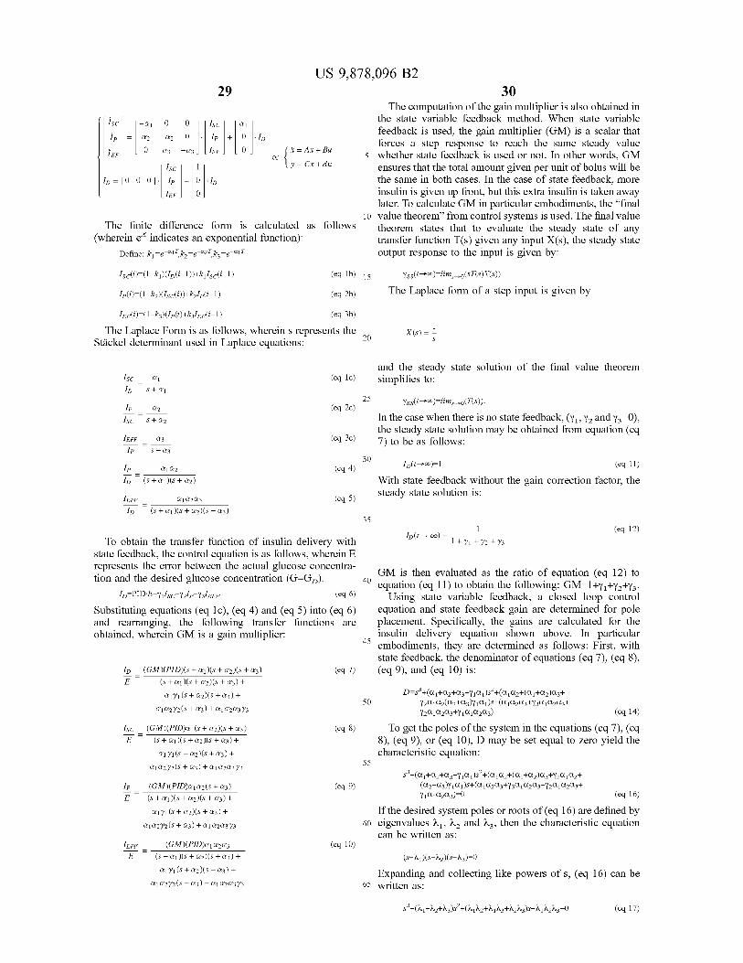
US 9 , 878 , 096 B2 30
?sc ] [ - Q1 0 0 1 [ sc ] fail ?p = az - & 2 0 1p + O ld
llef ] lo ?3 – 23 ] [ lef ] [ 0 ] ( * = Ax + Bu or 1 y = Cx + du
Ip = [ 0 0 0 ] . Ip + 0 . IEF ] [ o ]
The computation of the gain multiplier is also obtained in the state variable feedback method . When state variable feedback is used , the gain multiplier ( GM ) is a scalar that forces a step response to reach the same steady value
5 whether state feedback is used or not . In other words , GM ensures that the total amount given per unit of bolus will be the same in both cases . In the case of state feedback , more insulin is given up front , but this extra insulin is taken away later . To calculate GM in particular embodiments , the " final
10 value theorem ” from control systems is used . The final value theorem states that to evaluate the steady state of any transfer function T ( s ) given any input X ( s ) , the steady state output response to the input is given by :
The finite difference form is calculated as follows ( wherein e indicates an exponential function ) :
Define : k , = e - ajtkn = e - a27 , kz = e - aj7
Isc ( i ) = ( 1 - ki ) ( Id ( i - 1 ) ) + k? Iscli - 1 ) ( eq 1b ) 15 ( eg 2b )
Yss ( t - > 0 ) = lims - > ( $ T ( s ) X ( s ) ) The Laplace form of a step input is given by Ip ( i ) = ( 1 - kz ) ( Isc ( i ) ) + kulp ( i - 1 )
lef ( i ) = ( 1 - kz ) ( Ip ( i ) + kz / ef ( i - 1 ) ( eq 3b ) The Laplace Form is as follows , wherein s represents the
Stäckel determinant used in Laplace equations : X ( S ) =
and the steady state solution of the final value theorem simplifies to : a 1 ( eq 1c ) —
S + a 1 25 25
a2 @
sc s + 02 is stage TERE - 5 4
Yss ( t - > 0 ) = lims - > ( T ( s ) ) . In the case when there is no state feedback , ( Y? , Y2 and Y3 = 0 ) , the steady state solution may be obtained from equation ( eq 7 ) to be as follows : 23 ( eq 3c )
S + 03 30
( eq 4 ) sis
35 1
45
30 IpQ1 Q2 Id ( t > ) = 1 ( eq 11 ) Q1 Q2 Id ( s + Qi ) ( s + a2 ) With state feedback without the gain correction factor , the JEFF _ ? 1 & 2 & 3 ( eg 5 ) steady state solution is : lo ( s + Q1 ) ( s + Q2 ) ( s + 63 )
35 ( eq 12 ) Id ( t To obtain the transfer function of insulin delivery with ) = 1 1 + y1 + y2 + 73
state feedback , the control equation is as follows , wherein E represents the error between the actual glucose concentra tion and the desired glucose concentration ( G - GD ) : 40 GM is then evaluated as the ratio of equation ( eq 12 ) to
40 equation ( eq 11 ) to obtain the following : GM = 1 + Ya + Ya + Y3 . Id = PID - E - Y? / sc - Y2lp - Y3EFF ( eq6 ) Using state variable feedback , a closed loop control
Substituting equations ( eq 1c ) , ( eq 4 ) and ( eq 5 ) into ( eq 6 ) equation and state feedback gain are determined for pole and rearranging , the following transfer functions are placement . Specifically , the gains are calculated for the obtained , wherein GM is a gain multiplier : insulin delivery equation shown above . In particular
embodiments , they are determined as follows : First , with state feedback , the denominator of equations ( eq 7 ) , ( eq 8 ) ,
lo ( GM ) ( PID ) ( s + Q1 ) ( s + 2 ) ( s + 23 ) ( eq 7 ) ( eq 9 ) , and ( eq 10 ) is : ( s + 1 ) ( s + 2 ) ( s + 3 ) + Q1Y1 ( s + @ 2 ) ( s + 3 ) + D = s } + ( Q1 + Qz + Q3 + Y1Q1 ) s - + Q , Qz + ( Qz + az ) azt
Y2Q1Qz ( Qz + az ) YiQ1s + Q1Q2Q3 + Y3QjQ2Q3 + Q ] @ 272 ( s + 3 ) + Q1 Q2 & 3 73 Y2QjQ2Q3 + Y1QjQ223 ) ( eq 14 ) ( GM ) ( PID ) Q1 ( + @ 2 ) ( 8 + 23 ) ( eq 8 ) To get the poles of the system in the equations ( eq 7 ) , ( eq
( s + Qu ) ( s + Q2 ) ( s + Q3 ) + 8 ) , ( eq 9 ) , or ( eq 10 ) , D may be set equal to zero yield the Q1Y1 ( s + Q2 ) ( s + 23 ) + characteristic equation :
Q1 Q272 ( s + 3 ) + Q1 Q20373 se + , + Qz + Az + y , Q1 ) s + ( a , Qz + ( Q , + ay ) az + Y20 , 22 + ( GM ) ( PID ) Q1 Q2 ( 5 + 3 ) ( eq 9 ) ( Qz + Az ) Y1Q1 ) s + Q1Q2Qz + Y3QjQ2Q3 + Y2QjQ2Q3 +
E ( S + Q ) ( + « 2 ) ( s + 3 ) + YlQjQ2Q3 ) = 0 ( eq 16 ) Q171 ( s + @ 2 ) ( s + « 3 ) + If the desired system poles or roots of ( eq 16 ) are defined by
Q ] @ 272 ( s + @ 3 ) + Q1 Q2Q3Y3 60 eigenvalues 21 , 22 and 23 , then the characteristic equation can be written as :
1EFF _ ( GM ) ( PID ) & 10203 ( eq 10 ) ( s + Q1 ) ( s + Q2 ) ( s + Q3 ) + ( s - 11 ) ( s - 12 ) ( - 3 ) = 0 Q171 ( s + @ 2 ) ( s + 3 ) + Expanding and collecting like powers of s , ( eq 16 ) can be
Q1 Q272 ( s + 3 ) + Q1 Q20373 65 written as :
F =
50 50
55
lp =
ge3 - ( 1 + 2 + h3 ) s ' + ( 2 , 12 + yNz + Azhz ) s - házhz = 0 ( eq 17 )

31
( 1 + x Y1 = Q1
Y3 =
- -
a 1
US 9 , 878 , 096 B2 32
Setting the coefficients of like powers of s equal to each time interval Ti , the amount of insulin actually going into other we have the system of equations : action or the effective insulin compartment from the insulin
in the plasma is calculated to provide IFF 604 . That value Q , + Qz + Q3 + Y102 = - ( 1 + 2 + 3 ) ( eq 18 ) will be multiplied ( or otherwise factored by ) Y3 607 and 5 subtracted from the output of the PID controller to determine Q1Qz + Q1Qz + d2Q3 + Y2Q1Qz + Y1Q1 ( Qz + Q3 ) = 112th 13 +
23 ( eq 19 ) an improved desired insulin value based on the effective insulin . The insulin actually delivered to the subject 650 will
C10203 + y3010203 + 2010203 + Yidja2 ( eq 20 ) then change the blood glucose G of the user 608 , which will This results in three equations and three unknowns , Y1 , Y2 then be measured by the sensor 660 and compared to the
and Va . Therefore , the unknown gains can be solved for in 10 desired glucose ou . FIGS . 43 - 46 show graphs with the effect of state feed terms of the desired poles à1 , 92 , a3 , and system time back . FIG . 43 shows the effect on the basal insulin delivery constants , a , a , and az . These formulas enable us to control
the desired pharmacokinetics of insulin as it appears in the rate achieved using the algorithm described above . A bolus different compartments : is given at time zero . Line 700 shows the insulin delivery
when no state feedback is used . This line would be the same as a regular delivery of an insulin bolus and is indicated as 0 . 0000 , because it does not change the amount of basal rate - ( 11 + 12 + 13 + Q1 + Q2 + 3 ) being delivered . The other three lines illustrate the change in insulin delivery rate over time when all of the state feedback
1112 + 11 13 + 1213 – QjQ2 – QjQ3 + Q283 + 20 is placed in one of the gains Yu , Y , or Yz . As can be seen , if ( 11 + 12 + 13 + Q1 + Q2 + « 3 ) ( Q2 + Q3 ) all the state feedback is placed in the gain 11 ( for the Y2 = aja2 subcutaneous layer ) , the basal insulin delivery rate 701 ( in 1142 + 1113 + 1213 – QjQ 2 – QjQ3 – Q2 & 3 + relation to the standard basal rate ) starts out low and
- AA2A3 ( A1 + 2 + + + 32 + 03 ) ( a2 + 23 ) gradually moves to a limit of zero , or the rate without state feedback , as steady state is reached . If all of the state Q1 Q203 Q1 Q2 feedback is placed in the gain Y2 ( for the plasma layer ) , the
( 11 + 12 + 13 + Q1 + a2 + Q3 ) , basal insulin delivery rate 702 starts at zero , dips lower , and then gradually returns up to a limit of zero as steady state is reached . If all of the state feedback is placed in the gain ya
Thus , through the above calculations , the gains can be 30 ( for the insulin action / effect ) , the basal insulin delivery rate calculated and used in the control equation for insulin 703 starts at zero , dips lower , but more slowly than for the delivery of : all y delivery rate , and then gradually returns up to a limit
of zero as steady state is reached . In all cases , the total 15 = PID - E - Y? / sc - Y21p - Y3 / EF delivery of insulin is the same .
PID is the output of a PID controller of any other closed 35 FIG . 44 shows the effect of state feedback per unit bolus loop ( or “ semi - closed - loop " ) controller . The gains are gen - on the subcutaneous insulin . In other words , a bolus of erally calculated just once , but could be calculated more insulin is given to a patient at time zero and the figure shows often if desired . The control equation may be calculated on the rate in which the amount of insulin in the subcutaneous a repeated basis , after predetermined periods of time or layer , from that bolus , decreases to zero . Line 705 shows the continuously . For example , and without limitation , it may be 40 amount of insulin in the subcutaneous layer over time with calculated every five , ten , thirty or sixty minutes . Just the no state feedback . Line 706 shows the amount of insulin in state variable portion ( YiIsc - Y21p - Y3IEF ) may be updated or the subcutaneous layer over time when all of the state the entire equation may be updated . By updating the control feedback is placed in gain y , . Line 707 shows the amount of equation , it is possible to continually improve the delivery of insulin in the subcutaneous layer over time when all of the insulin to the patient . 45 state feedback is placed in gain Y . Line 708 shows the
A control feedback block diagram of an embodiment of a amount of insulin in the subcutaneous layer over time when pump using state variable feedback is shown in FIG . 42 . As all of the state feedback is placed in gain Ya . shown , the desired glucose Go 600 of the patient is entered FIG . 45 shows the effect of state feedback per unit bolus into the PID Controller 610 . The output of the PID controller on the plasma insulin . In other words , a bolus of insulin is is an insulin delivery valuel , 601 . The block then calculates 50 given to a patient at time zero and the figure shows the rate how much insulin should actually be delivered to the patient in which the amount of insulin in the plasma layer , from that as a bolus in addition to the insulin delivery value and how bolus , increases from zero ( there is a slight delay from much should be taken away from the basal rate , as discussed injecting insulin to when the insulin moves into the plasma above . At each discrete time interval , Ti , ( T1 620 , T2 630 , from the subcutaneous layer ) , reaches its peak and then and T3 640 ) , the amount of insulin that has entered into the 55 returns to zero . Line 710 shows the amount of insulin in the subcutaneous layer from the pump is calculated to provide plasma over time with no state feedback . Line 711 shows the Is 602 . That value will be multiplied ( or otherwise factored amount of insulin in the plasma over time when all of the by ) Y 605 and subtracted from the output of the PID state feedback is placed in gain Y . Line 712 shows the controller to provide an improved desired insulin value amount of insulin in the plasma over time when all of the based on the subcutaneous insulin concentration ( with the 60 state feedback is placed in gain Y . Line 713 shows the other calculations following ) . At each discrete time interval amount of insulin in the plasma over time when all of the Ti , the amount of insulin that has entered into the plasma state feedback is placed in gain Yz . from the subcutaneous compartment is calculated to provide FIG . 46 shows the effect of state feedback per unit bolus 1 , 603 . That value will be multiplied ( or otherwise factored on the insulin effect . In other words , a bolus of insulin is by ) Y2 606 and subtracted from the output of the PID 65 given to a patient at time zero and the figure shows the rate controller to determine an improved desired insulin value in which the amount of insulin from that bolus creates the based on the plasma insulin concentration . At each discrete insulin effect on the body , starting at zero ( there is a delay

33 US 9 , 878 , 096 B2
34 from the injection of insulin into the subcutaneous layer and ever , the current realization of the artificial B - cell has TLEAK through the plasma to the insulin effect ) , rising to its as a user input . U , can also be expressed in discrete form by maximum point , and decreasing to zero . Line 715 shows the standard methods . insulin effect over time with no state feedback . Line 716 Post - Controller ( Lead / Lag ) Compensator shows the insulin effect over time when all of the state 5 state 5 In preferred embodiments , commands are issued from the
controller without regard to where in the body the insulin feedback is placed in gain Y? . Line 717 shows the insulin delivery system will infuse the insulin . In essence , the effect over time when all of the state feedback is placed in assumption is that the insulin is either delivered directly into gain Yz . Line 718 shows the insulin effect over time when all the blood stream for immediate use by the body , or that any of the state feedback is placed in gain Yz . time delays caused by delivering the insulin somewhere in
FIGS . 47 and 48 compare insulin state variable feedback the body other than the blood stream can be compensated for used in conjunction with a PID closed loop controller as by adjusting Kp , K , and K , . In this case , the commands opposed to use of a PID closed loop controller alone ( with generally model a B - cell insulin secretion profile , an no insulin state variable feedback ) . FIG . 47 shows the example of which is shown in FIG . 35A . And since the simulated glucose concentration of a patient over time . 15 B - cells secrete insulin directly into the blood stream , the Meals are given at 8 , 13 , 18 , 22 , and 32 hours . The glucose B - cell insulin secretion profile is the intended blood plasma concentration using the PID with insulin state feedback is insulin concentration profile . However , an insulin delivery shown as line 800 . The glucose concentration using the PID delay may distort the intended blood plasma insulin con without insulin state feedback is shown as line 801 . With centration profile , as shown in FIG . 35B . The insulin deliv glucose concentrations , it is always preferable to keep a on ery delay is the amount of time between the instant that the patient ' s concentrations from being too high or too low , so command is given to the insulin delivery system to infuse
insulin and the time that insulin reaches the blood plasma . the more that the closed loop program can avoid high and low values , the better . As can be seen in FIG . 47 , as time An insulin delivery delay may be caused by a diffusion
delay , represented by a circle with an arrow 528 in FIG . 20 , goes on , the glucose concentration using the PID with which is the time required for insulin that has been infused insulin state feedback improves over time ( versus the glu - 25 into a tissue to diffuse into the blood stream . Other con cose concentration using the PID without insulin state tributors to insulin delivery delay may include , time for the feedback ) in that it varies less as time goes on , keeping the les less as time goes on , keeping the delivery system to deliver the insulin to the body after patient with a more steady glucose level that will greatly receiving a command to infuse insulin , time for the insulin reduce hyper - and hypoglycemic events . FIG . 48 shows 20 to spread throughout the circulatory system once it has average simulated insulin delivery profiles from the same entered the blood stream , and / or by other mechanical or system as FIG . 47 . Line 810 represents the insulin delivery physiological causes . In addition , the body clears insulin using the PID with insulin state feedback . Line 811 repre even while an insulin dose is being delivered from the sents the insulin delivery using the PID without insulin state insulin delivery system into the body . Since insulin is feedback . As can be seen , the insulin delivery using the PID of continuously cleared from the blood plasma by the body , an with insulin state feedback contains more spikes and dips , insulin dose that is delivered to the blood plasma too slowly resulting from the state feedback . or is delayed is at least partially , if not significantly , cleared Modifying the PID Controller to Incorporate an Integrator before the entire insulin dose fully reaches the blood plasma .
Leak And therefore , the insulin concentration profile in the blood In preferred embodiments , the PID control response was so plasma never achieves the same peak ( nor follows the same
described with constant gain components , K , K , K , profile ) it would have achieved if there were no delay . Given Although the preferred control response guarantees zero an insulin dose delivered all at once into the blood plasma steady - state error ( i . e . , steady state glucose minus a desired at time zero , the insulin concentration in the blood plasma is basal glucose ( GR ) = 0 ) , inherently , the integral component raised virtually instantaneously ( not shown ) and then would U = KS ( G - GR ) dt + U , ( t . ) destabilizes feedback control 45 decrease exponentially over time as the body clears ( uses or because there is no temporal wind down of the insulin filters out ) the insulin , as shown in FIG . 36A per equation : response while the integral component models the increase in the insulin response . Without any correction , the integral component has a tendency to over - estimate the increase in the insulin response . Since a small difference between steady - state glucose and Go is typically acceptable in insulin response control , an alternative modeling of the integral where : component can incorporate an integrator leak to reduce the Cp is the concentration of insulin in the blood plasma , magnitude of the destabilizing effect . Specifically , changes 1 . is a mass of the insulin dose delivered directly to the is a mass of in U ( t ) can be described by a term proportional to the error 55 11 of 55 blood plasma at time zero , in glucose and a term that leaks in proportion to the V , is a volume of the blood plasma in the body , magnitude of U , . This can be expressed in the formula : Pi is a reciprocal time constant for insulin clearance , and
t is the time that has passed since the delivery of the insulin dose directly into the blood plasma .
K ( G - GB ) – KLEAK UM 60 The time constant for insulin clearance P , may be calcu lated using the following equation :
OpePu ,
dU dt
P =
with initial condition U / { t . ) . The parameter Klear is the reciprocal time constant of the
rate of leaking ( TLEAK in min = 1 / KLEAK ) , where TLEAK is a 65 tuning parameter that can be set based on empirical data , and be tied with the other gain components Kp , Kj , Kp . How
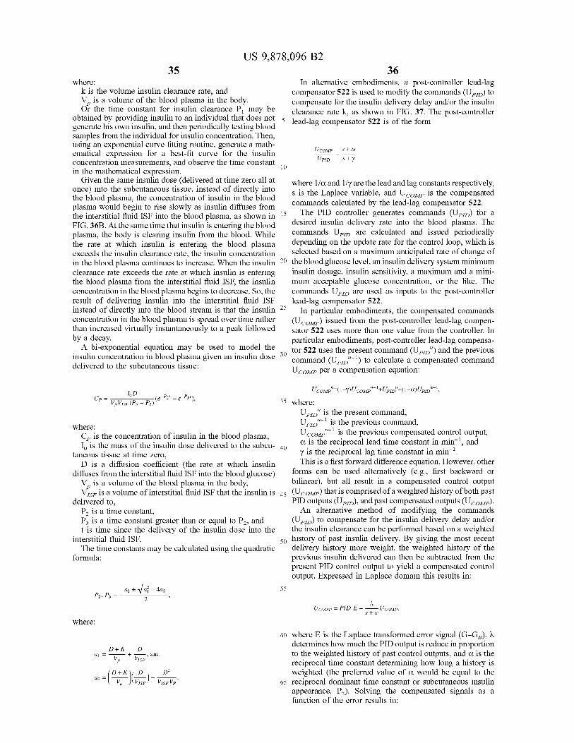
35
= UPD
US 9 , 878 , 096 B2 36
where : In alternative embodiments , a post - controller lead - lag k is the volume insulin clearance rate , and compensator 522 is used to modify the commands ( UPD ) to V , is a volume of the blood plasma in the body . compensate for the insulin delivery delay and / or the insulin Or the time constant for insulin clearance P , may be clearance rate k , as shown in FIG . 37 . The post - controller obtained by providing insulin to an individual that does not 5 lead 5 lead - lag compensator 522 is of the form generate his own insulin , and then periodically testing blood
samples from the individual for insulin concentration . Then , using an exponential curve fitting routine , generate a math UCOMP S + Q ematical expression for a best - fit curve for the insulin
S + y concentration measurements , and observe the time constant 10 in the mathematical expression . Given the same insulin dose ( delivered at time zero all at where 1 / a and 1 / y are the lead and lag constants respectively , once ) into the subcutaneous tissue , instead of directly into s is the Laplace variable , and UCOmp is the compensated the blood plasma , the concentration of insulin in the blood
plasma would begin to rise slowly as insulin diffuses from commands calculated by the lead - lag compensator 522 . the interstitial fluid ISF into the blood plasma , as shown in 15 in 15 The PID controller generates commands ( UPID ) for a FIG . 36B . At the same time that insulin is entering the blood desired insulin delivery rate into the blood plasma . The plasma , the body is clearing insulin from the blood . While commands UpId are calculated and issued periodically the rate at which insulin is entering the blood plasma depending on the update rate for the control loop , which is exceeds the insulin clearance rate , the insulin concentration selected based on a maximum anticipated rate of change of in the blood plasma continues to increase . When the insulin 20 the blood glucose level , an insulin delivery system minimum clearance rate exceeds the rate at which insulin is entering insulin dosage , insulin sensitivity , a maximum and a mini the blood plasma from the interstitial fluid ISF , the insulin mum acceptable glucose concentration , or the like . The concentration in the blood plasma begins to decrease . So , the commands Up are used as inputs to the post - controller result of delivering insulin into the interstitial fluid ISF lead - lag compensator 522 . instead of directly into the blood stream is that the insulin 25 In particular embodiments , the compensated commands concentration in the blood plasma is spread over time rather ( U COMP ) issued from the post - controller lead - lag compen than increased virtually instantaneously to a peak followed sator 522 uses more than one value from the controller . In by a decay . particular embodiments , post - controller lead - lag compensa A bi - exponential equation may be used to model the tor 522 uses the present command ( UPID " ) and the previous insulin concentration in blood plasma given an insulin dose 30 command ( UPID " - ? ) to calculate a compensated command delivered to the subcutaneous tissue : UCOMP per a compensation equation :
Cp = VPVISE Vp VisF ( Pz - P . ( e P2 ? – e - P31 ) ToD U COMP " = ( 1 - y ) U comp ” - I + UpId " + ( 1 - a ) Up " - 4 ,
35 where : Upid " is the present command , UPID " - 1 is the previous command , where :
Cp is the concentration of insulin in the blood plasma , UCOMP " - ? is the previous compensated control output , I . is the mass of the insulin dose delivered to the subcu - 40 a is the reciprocal lead time constant in min - , and
taneous tissue at time zero , y is the reciprocal lag time constant in min - ? . D is a diffusion coefficient ( the rate at which insulin This is a first forward difference equation . However , other
diffuses from the interstitial fluid ISF into the blood glucose ) id ISE into the blood glucose ) forms can be used alternatively ( e . g . , first backward or V , is a volume of the blood plasma in the body , bilinear ) , but all result in a compensated control output Vise is a volume of interstitial fluid ISF that the insulin is 45 ( UCOMP ) that is comprised of a weighted history of both past
delivered to , PID outputs ( UPD ) , and past compensated outputs ( UCOUP ) . P , is a time constant , An alternative method of modifying the commands Pz is a time constant greater than or equal to P , and ( UPD ) to compensate for the insulin delivery delay and / or t is time since the delivery of the insulin dose into the the insulin clearance can be performed based on a weighted
interstitial fluid ISF . 50 history of past insulin delivery . By giving the most recent The time constants may be calculated using the quadratic delivery history more weight , the weighted history of the
formula : previous insulin delivered can then be subtracted from the present PID control output to yield a compensated control output . Expressed in Laplace domain this results in :
55 Ps , Ps = _ 4 ? Vai – 400 UComp = PID E - -
Star U COMP
where :
D + K D di = Vp + vise and
60 where E is the Laplace transformed error signal ( G - GB ) , à determines how much the PID output is reduce in proportion to the weighted history of past control outputs , and a is the reciprocal time constant determining how long a history is weighted ( the preferred value of a would be equal to the
65 reciprocal dominant time constant or subcutaneous insulin appearance , P2 ) . Solving the compensated signals as a function of the error results in :
D + KD do = as = ( 4 - vi VO VISE VirVD
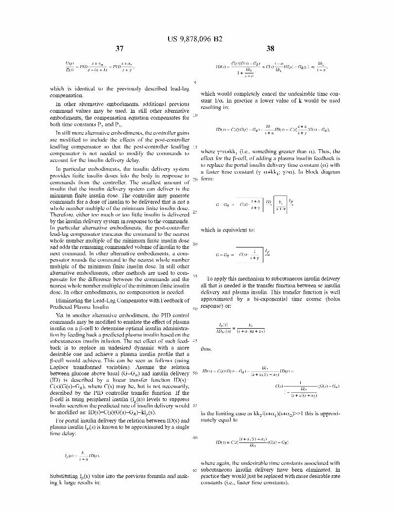
US 9 , 878 , 096 B2 37 38
US ) s ) - GB ) S + Ow S + Q kk? - = PID Staw
- = PID S + ( a + 2 )
ID ( s ) - ( ) ( G ( S ) - GB ) kkj C ( s ) - GB ) ; 1 <
E ( S ) Sty kk1 Sta 1 + Sta
5
ID ( S ) = C ( S ( G ( s ) – GB ) – 5k1 , 1D ( s ) = C ( $ ) * * * ( G ( s ) – GB ) , S + a
f 20 form :
S + Q 0 - 40 - A S +
lp
which is identical to the previously described lead - lag compensation . which would completely cancel the undesirable time con
stant lla . In practice a lower value of k would be used In other alternative embodiments , additional previous resulting in : command values may be used . In still other alternative embodiments , the compensation equation compensates for both time constants P2 and Pz .
In still more alternative embodiments , the controller gains S + y
are modified to include the effects of the post - controller lead / lag compensator so that the post - controller lead / lag 15 compensator is not needed to modify the commands to where y = a + kki ( i . e . , something greater than a ) . Thus , the account for the insulin delivery delay . effect for the B - cell , of adding a plasma insulin feedback is
to replace the portal insulin delivery time constant ( a ) with In particular embodiments , the insulin delivery system a faster time constant ( y = a + kk? ; y > a ) . In block diagram provides finite insulin doses into the body in response to commands from the controller . The smallest amount of insulin that the insulin delivery system can deliver is the minimum finite insulin dose . The controller may generate commands for a dose of insulin to be delivered that is not a G - GB ? C ( s ) . whole number multiple of the minimum finite insulin dose . Sty
Therefore , either too much or too little insulin is delivered by the insulin delivery system in response to the commands . In particular alternative embodiments , the post - controller which is equivalent to : lead - lag compensator truncates the command to the nearest whole number multiple of the minimum finite insulin dose and adds the remaining commanded volume of insulin to the next command . In other alternative embodiments , a com G - GB ? C ( s ) . Sty pensator rounds the command to the nearest whole number multiple of the minimum finite insulin dose . In still other alternative embodiments , other methods are used to com pensate for the difference between the commands and the ~ To apply this mechanism to subcutaneous insulin delivery nearest whole number multiple of the minimum finite insulin all that is needed is the transfer function between sc insulin dose . In other embodiments , no compensation is needed . delivery and plasma insulin . This transfer function is well
Eliminating the Lead - Lag Compensator with Feedback of approximated by a bi - exponential time course ( bolus Predicted Plasma Insulin 40 response ) or :
Yet in another alternative embodiment , the PID control commands may be modified to emulate the effect of plasma Ip ( s ) insulin on a B - cell to determine optimal insulin administra IDsc ( s ) ( s + Qi ) ( s + Q2 ) tion by feeding back a predicted plasma insulin based on the subcutaneous insulin infusion . The net effect of such feed - 45 back is to replace an undesired dynamic with a more desirable one and achieve a plasma insulin profile that a B - cell would achieve . This can be seen as follows ( using Laplace transformed variables ) . Assume the relation Lumikk2 between glucose above basal ( G - GD ) and insulin delivery 50 D ( S ) = C ( s ) ( G ( s ) – GB ) - Tour . You - ID ( s ) = B ( s + a 1 ) ( s + az ) ' D ( S ) = ( ID ) is described by a linear transfer function ID ( S ) = C ( s ) ( G ( S ) - GB ) , where C ( s ) may be , but is not necessarily , C ( s ) — described by the PID controller transfer function . If the * ( s + a ) ( s + x2 ) B - cell is using peripheral insulin ( 1 , ( s ) ) levels to suppress insulin secretion the predicted rate of insulin delivery would 55 be modified as : ID ( s ) = C ( s ) ( G ( s ) - GB ) - kl , ( s ) . in the limiting case as kk / ( s + a ) ( s + d2 ) > > 1 this is approxi
For portal insulin delivery the relation between ID ( s ) and mately equal to plasma insulin 1 ( s ) is known to be approximated by a single time delay :
60
thus ,
kk2
kk _ ( G ( s ) – GB ) 1 +
( s + Qi ) ( s + Q2 ) G ( s ) - GB ) ID ( s ) = C ( s ) - kk2
1063 ) = 54 10 ( 5 ) Sta
Substituting 1 , ( s ) value into the previous formula and mak ing k large results in :
where again , the undesirable time constants associated with 65 subcutaneous insulin delivery have been eliminated . In
practice they would just be replaced with more desirable rate constants ( i . e . , faster time constants ) .

39
Y ( SG ) = 0 + ( 1 - You
and
US 9 , 878 , 096 B2 40
Correction of Hypoglycemic Excursion Around ~ 200 all stable or falling sensor glucose signals . The clipping limit Minutes ( Wind - Down ) represents an absolute threshold , similar to the human coun
Previous modeling of ß - cells using a PID controller gave ter regulatory response . excellent predictability of the “ first ” and “ second ” phase However , other approaches that may emulate the B - cell insulin responses during prolonged periods of increased 5 more accurately include the use of piecewise continuous glucose appearance . However , if the periods of increased functions . For example , the following function allows for glucose appearance is followed by a rapid decrease in progressive clipping to be tuned : glucose appearance , the PID controller would not be able to correctly predict the wind down of the insulin response to lower glucose levels . FIG . 41B illustrates the insulin 10 response to the blood glucose level of FIG . 41A based on the clinical data ( shown as data points ) , the PID modeling if ( SG = T? mg / dl AND CO2 > yKp ( SP - 60 ) ) then ( shown as a solid line ) , and correction of the PID for the hypoglycemic excursion ( shown as a dashed line ) . 100 = yKp ( SP - 60 )
In preferred embodiments , the hypoglycemic excursion is 15 corrected by modifying the PID controller to a PD control with Adaptive Proportional Gain ( or Bilinear PID control This equation introduces two additional tuning parameters ler ) , which is modified form of the original PID equations . ( Yo and T? ) and starts to check the integrator output at a As described previously , the discrete PID algorithm is as higher threshold . For example , if yo = 5 and T , = 100 mg / dl , follows : 20 the integrator output would be clipped to 4 K260 if glucose
Proportional Component Response : fell to 90 mg / dl , 3 Kp60 if glucose fell to 80 mg / dl and so forth until glucose reached 60 where it would be clipped at Pcon " = Kp ( SGM - Gsp ) , Kp60 . Other functions than that proposed in the above Integral Component Response : equation ( e . g . functions based on the rate of fall of glucose ,
Icon " = Icon " - I + K _ ( SG / - Gsp ) ; } conº = 15 , 25 or percent decrease in Icon ) may alternatively be used . System Configurations The following sections provide exemplary , but not limit
ing , illustrations of components that can be utilized with the Derivative Component Response : controller described above . Various changes in components , Dcon " = KpdGdt , 30 layout of various components , combinations of elements , or
the like may be made without departing from the scope of where Kp , Kj , and Ky are the proportional , integral , and the embodiments of the invention . derivative gain coefficients , SG , and dGdt , are the filtered Before it is provided as an input to the controller 12 , the sensor glucose and derivative respectively , and the super sensor signal 16 is generally subjected to signal conditioning script n refers to discrete time . 35 such as pre - filtering , filtering , calibrating , or the like . Com In the Bilinear PID controller , the proportional gain K , is ponents such as a pre - filter , one or more filters , a calibrator based on the integrated error term . The magnitude of each and the controller 12 may be split up or physically located component ' s contribution to the insulin response is together , and may be included with a telemetered charac described by the following equations : teristic monitor transmitter 30 , the infusion device 34 , or a Pcon " = Kp " ( SGM - INT ) 40 supplemental device . In preferred embodiments , the pre
filter , filters and the calibrator are included as part of the Dcon " = KydGdt telemetered characteristic monitor transmitter 30 , and the
controller 12 is included with the infusion device 34 , as Kp " = Kpn - 1 + K _ ( SG , ” - Gsp ) , where Kpº = Kpo shown in FIG . 8B . In alternative embodiments , the pre - filter
Where the proportional gain now integrates at rate K ( initial 45 is included with the telemetered characteristic monitor trans value Kn ) and the proportional component is related to an mitter 30 and the filter and calibrator are included with the intercept value ( INT ) where ( INT < Gsp ) . The modified for controller 12 in the infusion device , as shown in FIG . 8C . In mulation can be seen to fit the hypoglycemic glucose other alternative embodiments , the pre - filter may be excursion without systematic error as the adaptive PD line included with the telemetered characteristic monitor trans shown as a dashed line in FIG . 39 . 50 mitter 30 , while the filter and calibrator are included in the
In additional embodiments , the Bilinear PID controller supplemental device 41 , and the controller is included in the can also incorporate an integrator leak by modifying the infusion device , as shown in FIG . 8D . To illustrate the formula to multiply the previous Kp with a value such as a various embodiments in another way , FIG . 9 shows a table as follows : of the groupings of components ( pre - filter , filters , calibrator ,
55 and controller ) in various devices ( telemetered characteristic Kp " = aKp - ' + K / ( SG - Gsp ) , where Q = 0 . 99 monitor transmitter , supplemental device , and infusion
An alternative method of correcting the hypoglycemic device ) from FIGS . 8A - D . In other alternative embodiments , glucose excursion can be performed by integrator clip into a supplemental device contains some of ( or all of ) the the PID control . PID controllers generally have integrator components . reset rules that prevent excessive “ winding ” and such a rule 60 In preferred embodiments , the sensor system generates a can be used to correct the hypoglycemic glucose excursion . message that includes information based on the sensor signal For example , the integrator can be clipped as follows : such as digital sensor values , pre - filtered digital sensor
values , filtered digital sensor values , calibrated digital sensor If ( SGs60 mg / dl AND Icon " - I > Kp ( SP - 60 ) ) then values , commands , or the like . The message may include
Icona - = Kp ( SP - 60 ) 65 other types of information as well such as a serial number , This equation resets the integrator such that if the sensor an ID code , a check value , values for other sensed param glucose falls below 60 mg / dl the insulin delivery is zero for eters , diagnostic signals , other signals , or the like . In par
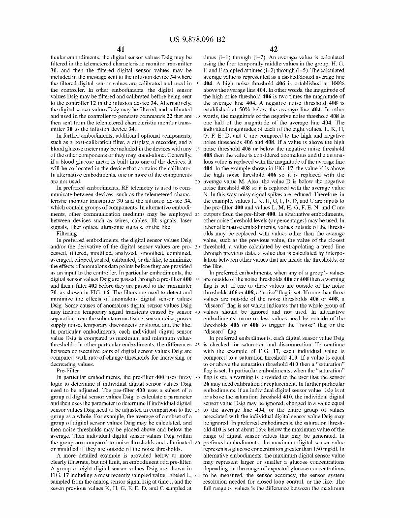
US 9 , 878 , 096 B2 42
ticular embodiments , the digital sensor values Dsig may be times ( i - 1 ) through ( 1 - 7 ) . An average value is calculated filtered in the telemetered characteristic monitor transmitter using the four temporally middle values in the group , H , G , 30 , and then the filtered digital sensor values may be F , and E sampled at times ( i - 2 ) through ( i – 5 ) . The calculated included in the message sent to the infusion device 34 where average value is represented as a dashed / dotted average line the filtered digital sensor values are calibrated and used in 5 404 . A high noise threshold 406 is established at 100 % the controller . In other embodiments , the digital sensor above the average line 404 . In other words , the magnitude of values Dsig may be filtered and calibrated before being sent the high noise threshold 406 is two times the magnitude of to the controller 12 in the infusion device 34 . Alternatively , the average line 404 . A negative noise threshold 408 is the digital sensor values Dsig may be filtered , and calibrated established at 50 % below the average line 404 . In other and used in the controller to generate commands 22 that are 10 words , the magnitude of the negative noise threshold 408 is then sent from the telemetered characteristic monitor trans one half of the magnitude of the average line 404 . The mitter 30 to the infusion device 34 . individual magnitudes of each of the eight values , L , K , H ,
In further embodiments , additional optional components , G , F , E , D , and C are compared to the high and negative such as a post - calibration filter , a display , a recorder , and a noise thresholds 406 and 408 . If a value is above the high blood glucose meter may be included in the devices with any 15 noise threshold 406 or below the negative noise threshold of the other components or they may stand - alone . Generally , 408 then the value is considered anomalous and the anoma if a blood glucose meter is built into one of the devices , it lous value is replaced with the magnitude of the average line will be co - located in the device that contains the calibrator . 404 . In the example shown in FIG . 17 , the value K is above In alternative embodiments , one or more of the components the high noise threshold 406 so it is replaced with the are not used . 20 average value M . Also , the value D is below the negative
In preferred embodiments , RF telemetry is used to com - noise threshold 408 so it is replaced with the average value municate between devices , such as the telemetered charac - N . In this way noisy signal spikes are reduced . Therefore , in teristic monitor transmitter 30 and the infusion device 34 , the example , values L , K , H , G , F , E , D , and C are inputs to which contain groups of components . In alternative embodi - the pre - filter 400 and values L , M , H , G , F , E , N , and C are ments , other communication mediums may be employed 25 outputs from the pre - filter 400 . In alternative embodiments , between devices such as wires , cables , IR signals , laser other noise threshold levels ( or percentages ) may be used . In signals , fiber optics , ultrasonic signals , or the like . other alternative embodiments , values outside of the thresh
Filtering olds may be replaced with values other than the average In preferred embodiments , the digital sensor values Dsig value , such as the previous value , the value of the closest
and / or the derivative of the digital sensor values are pro - 30 threshold , a value calculated by extrapolating a trend line cessed , filtered , modified , analyzed , smoothed , combined , through previous data , a value that is calculated by interpo averaged , clipped , scaled , calibrated , or the like , to minimize lation between other values that are inside the thresholds , or the effects of anomalous data points before they are provided the like . as an input to the controller . In particular embodiments , the In preferred embodiments , when any of a group ' s values digital sensor values Dsig are passed through a pre - filter 400 35 are outside of the noise thresholds 406 or 408 then a warning and then a filter 402 before they are passed to the transmitter flag is set . If one to three values are outside of the noise 70 , as shown in FIG . 16 . The filters are used to detect and thresholds 406 or 408 , a " noise " flag is set . If more than three minimize the effects of anomalous digital sensor values values are outside of the noise thresholds 406 or 408 , a Dsig . Some causes of anomalous digital sensor values Dsig “ discard ” flag is set which indicates that the whole group of may include temporary signal transients caused by sensor 40 values should be ignored and not used . In alternative separation from the subcutaneous tissue , sensor noise , power embodiments , more or less values need be outside of the supply noise , temporary disconnects or shorts , and the like . thresholds 406 or 408 to trigger the “ noise ” flag or the In particular embodiments , each individual digital sensor “ discard ” flag . value Dsig is compared to maximum and minimum value In preferred embodiments , each digital sensor value Dsig thresholds . In other particular embodiments , the differences 45 is checked for saturation and disconnection . To continue between consecutive pairs of digital sensor values Dsig are with the example of FIG . 17 , each individual value is compared with rate - of - change - thresholds for increasing or compared to a saturation threshold 410 . If a value is equal decreasing values . to or above the saturation threshold 410 then a “ saturation "
Pre - Filter flag is set . In particular embodiments , when the “ saturation ” In particular embodiments , the pre - filter 400 uses fuzzy 50 flag is set , a warning is provided to the user that the sensor
logic to determine if individual digital sensor values Dsig 26 may need calibration or replacement . In further particular need to be adjusted . The pre - filter 400 uses a subset of a embodiments , if an individual digital sensor value Dsig is at group of digital sensor values Dsig to calculate a parameter or above the saturation threshold 410 , the individual digital and then uses the parameter to determine if individual digital sensor value Dsig may be ignored , changed to a value equal sensor values Dsig need to be adjusted in comparison to the 55 to the average line 404 , or the entire group of values group as a whole . For example , the average of a subset of a associated with the individual digital sensor value Dsig may group of digital sensor values Dsig may be calculated , and be ignored . In preferred embodiments , the saturation thresh then noise thresholds may be placed above and below the old 410 is set at about 16 % below the maximum value of the average . Then individual digital sensor values Dsig within range of digital sensor values that may be generated . In the group are compared to noise thresholds and eliminated 60 preferred embodiments , the maximum digital sensor value or modified if they are outside of the noise thresholds . represents a glucose concentration greater than 150 mg / dl . In
A more detailed example is provided below to more alternative embodiments , the maximum digital sensor value clearly illustrate , but not limit , an embodiment of a pre - filter . may represent larger or smaller a glucose concentrations A group of eight digital sensor values Dsig are shown in depending on the range of expected glucose concentrations FIG . 17 including a most recently sampled value , labeled L , 65 to be measured , the sensor accuracy , the sensor system sampled from the analog sensor signal Isig at time i , and the resolution needed for closed loop control , or the like . The seven previous values K , H , G , F , E , D , and C sampled at full range of values is the difference between the maximum
US 9 , 878 , 096 B2 43 44
and the minimum digital sensor value that may be generated the sensor ' s response time , or the like . In alternative Higher or lower saturation threshold levels may be used embodiments , filters with other frequency responses may be depending on an expected signal range of the sensor , sensor used to eliminate other noise frequencies depending on the noise , sensor gains , or the like . type of sensor , noise from the power supply or other
Similarly , in preferred embodiments , if a digital signal 5 electronics , the sensor ' s interaction with the body , the effects value Dsig is below a disconnect threshold 412 , then a of body motion on the sensor signal , or the like . In still other " disconnect ” flag is set indicating to a user that the sensor is alternative embodiments , the filter is an infinite impulse not properly connected to the power supply and that the response ( IIR ) filter . power supply or sensor may need replacement or recalibra - In alternative embodiments , other methods are used to tion . In further particular embodiments , if a digital sensor 10 pre - filter the digital sensor values Dsig such as rate - of value Dsig is below the disconnect threshold 412 , the change thresholds , rate - of - change squared thresholds , noise individual value may be ignored , changed to a value equal thresholds about a least squares fit line rather than about the to the average line 404 , or the entire group of values average of a subset of a group ' s values , higher or lower noise associated with the individual digital sensor value Dsig may threshold lines , or the like . be ignored . In preferred embodiments , the disconnect 15 Delay Compensation Filter threshold 410 is set at about 20 % of the full range of values . Aside from noise reduction , a filter may be used to Higher or lower disconnect threshold levels may be used compensate for time delays . Ideally , a sensor would provide depending on an expected signal range of the sensor , sensor a real time , noise - free measurement of a parameter that a system noise , sensor gains , or the like . control system is intended to control , such as a blood
In alternative embodiments , other methods are used to 20 glucose measurement . However , realistically there are pre - filter the digital sensor values Dsig such as rate - of - physiological , chemical , electrical , and algorithmic sources change thresholds , rate - of - change squared thresholds , noise of time delays that cause the sensor measurement to lag thresholds about a least squares fit line rather than about the behind the present value of blood glucose . average of a subset of a group ' s values , higher or lower noise A physiological delay 422 is due to the time required for threshold lines , or the like . 25 glucose to move between blood plasma 420 and interstitial
Noise Filter fluid ( ISF ) . The delay is represented by the circled double After the digital sensor values Dsig are evaluated , and if headed arrow 422 in FIG . 20 . Generally , as discussed above ,
necessary , modified by the pre - filter 400 , the digital sensor the sensor 26 is inserted into the subcutaneous tissue 44 of values Dsig are passed to the filter 402 . The filter 402 may the body 20 and the electrodes 42 near the tip of the sensor be used to reduce noise in particular frequency bands . 30 40 are in contact with interstitial fluid ( ISF ) . But the desired Generally the body ' s blood glucose level 18 changes rela - parameter to be measured is the concentration of blood tively slowly compared to a rate at which digital sensor glucose . Glucose is carried throughout the body in blood values Dsig are collected . Therefore , high frequency signal plasma 420 . Through the process of diffusion , glucose components are typically noise , and a low pass filter may be moves from the blood plasma 420 into the ISF of the used to improve the signal to noise ratio . 35 subcutaneous tissue 44 and vice versa . As the blood glucose
In preferred embodiments , the filter 402 is a finite impulse level 18 changes so does the glucose level in the ISF . But the response ( FIR ) filter used to reduce noise . In particular glucose level in the ISF lags behind the blood glucose level embodiments , the FIR filter is a 7th order filter tuned with 18 due to the time required for the body to achieve glucose a pass band for frequencies from zero to 3 cycles per hour concentration equilibrium between the blood plasma 420 ( c / hr ) and a stop band for frequencies greater than about 6 40 and the ISF . Studies show the glucose lag times between c / hr , as shown in an example frequency response curve 414 blood plasma 420 and ISF vary between 0 to 30 minutes . in FIG . 18 . However , typically FIR filters tuned with a pass Some parameters that may affect the glucose lag time band for frequencies from zero up to between about 2 c / hr between blood plasma 420 and ISF are the individual ' s and 5 c / hr and a stop band beginning at 1 . 2 to three times the metabolism , the current blood glucose level , whether the selected pass band frequency will sufficiently reduce noise 45 glucose level is rising , or falling , or the like . while passing the sensor signal . In particular embodiments , A chemical reaction delay 424 is introduced by the sensor FIR filters tuned with a pass band for frequencies from zero response time , represented by the circle 424 surrounding the up to between about 2 c / hr and 10 c / hr and a stop band tip of the sensor 26 in FIG . 20 . The sensor electrodes 42 are beginning at 1 . 2 to three times the selected pass band coated with protective membranes that keep the electrodes frequency will sufficiently reduce noise . In the 7th order 50 42 wetted with ISF , attenuate the glucose concentration , and filter , unique weighting factors are applied to each of eight reduce glucose concentration fluctuations on the electrode digital sensor values Dsig . The digital sensor values Dsig surface . As glucose levels change , the protective membranes include the most recently sampled value and the seven slow the rate of glucose exchange between the ISF and the previous values . The effects of a low pass filter on a digital electrode surface . In addition , there is a chemical reaction sensor values collected at one minute intervals is shown in 55 delay simply due to the reaction time for glucose to react FIGS . 19A and B . An unfiltered sensor signal curve 416 of with glucose oxidase GOX to generate hydrogen peroxide , digital sensor values is contrasted with a curve of the same and the reaction time for a secondary reaction , the reduction signal after the effects of a 7th order FIR filter 418 . The of hydrogen peroxide to water , oxygen and free electrons . filtered signal curve 418 is delayed and the peaks are There is also a processing delay as the analog sensor smoother compared to the unfiltered sensor signal curve 60 signal Isig is converted to digital sensor values Dsig . In 416 . In other particular embodiments , higher or lower order preferred embodiments , the analog sensor signal Isig is filters may be used . In still other particular embodiments , integrated over one - minute intervals and then converted to a filter weighting coefficients may be applied to digital sensor number of counts . In essence an A / D conversion time results values Dsig collected at time intervals shorter or longer than in an average delay of 30 seconds . In particular embodi one minute depending on the desired sensor sample rate 65 ments , the one - minute values are averaged into 5 - minute based on the body ' s physiology , the computational capabili - values before they are sent to the controller . The resulting ties of the telemetered characteristic monitor transmitter 30 , average delay is two and one half minutes . In alternative
US 9 , 878 , 096 B2 45 46
embodiments , longer or shorter integration times are used Dsig , which results in digital derivative sensor values resulting in longer or shorter delay times . In other embodi ( dDsig / dt ) . The digital derivative sensor values dDsig / dt are ments the analog sensor signal current Isig is continuously passed through a FIR filter . In particular embodiments , the converted to an analog voltage Vsig and a A / D converter derivative filter is at least a 7th order FIR filter tuned to samples the voltage Vsig every 10 seconds . Then six 10 - sec - 5 remove high frequency noise . In alternative embodiments , ond values are pre - filtered and averaged to create a one - higher or lower order filters may be used and the filters may minute value . Finally , five 1 - minute values are filtered and be tuned to remove various frequencies of noise . In other then averaged creating a five - minute value resulting in an alternative embodiments , a derivative is taken from the average delay of two and one half minutes . Other embodi - glucose level error G values and then passed through a ments use other electrical components or other sampling 10 derivative filter 526 , as shown in FIG . 37 . In further alter rates and result in other delay periods . native embodiments , a derivative is taken of an analog
Filters also introduce a delay due to the time required to sensor signal Isig and a hardware filter is used to remove acquire a sufficient number of digital sensor values Dsig to noise . operate the filter . Higher order filters , by definition , require Calibration more digital sensor values Dsig . Aside from the most recent 15 In preferred embodiments , after filtering , the digital sen digital sensor value Dsig , FIR filters use a number of sor values Dsig are calibrated with respect to one or more previous values equal to the order of the filter . For example , glucose reference values . The glucose reference values are a 7th order filter uses 8 digital sensor values Dsig . There is entered into the calibrator and compared to the digital sensor a time interval between each digital sensor value Dsig . To values Dsig . The calibrator applies a calibration algorithm to continue with the example , if the time interval between 20 convert the digital sensor values Dsig , which are typically in digital sensor values Dsig is one minute , then the oldest counts into blood glucose values . In particular embodiments , digital sensor value Dsig used in a 7th order FIR filter would the calibration method is of the type described in U . S . patent be seven minutes old . Therefore , the average time delay for application Ser . No . 09 / 511 , 580 , filed on Feb . 23 , 2000 , all of the values used in the filter is three and a half minutes . entitled “ GLUCOSE MONITOR CALIBRATION METH However , if the weighting factors associated with each of the 25 ODS ” , which is incorporated by reference herein . In par values are not equal then the time delay may be longer or ticular embodiments , the calibrator is included as part of the shorter than three and one half minutes depending on the infusion device 34 and the glucose reference values are effects of the coefficients . entered by the user into the infusion device 34 . In other
Preferred embodiments of the invention include a FIR embodiments , the glucose reference values are entered into filter that compensates for both the various time delays , of 30 the telemetered characteristic monitor transmitter 30 and the up to about 30 minutes as discussed above , and high calibrator calibrates the digital sensor values Dsig and frequency noise , greater than about 10 c / hr also discussed transmits calibrated digital sensor values to the infusion above . Particular embodiments employ a 7th order Weiner device 34 . In further embodiments , the glucose reference type FIR filter . The coefficients for the filter are selected to values are entered into a supplemental device where the correct for time lags while simultaneously reducing high 35 calibration is executed . In alternative embodiments , a blood frequency noise . An example of a frequency response curve glucose meter is in communication with the infusion device 426 is shown in FIG . 21 . The example frequency response 34 , telemetered characteristic monitor transmitter 30 or curve 416 is generated for a Weiner filter with a pass band supplemental device so that glucose reference values may be for frequencies from zero up to about 8 c / hr and a stop band transmitted directly into the device that the blood glucose for frequencies greater than about 15 c / hr for a sensor with 40 meter is in communication with . In additional alternative a sensitivity of about 20 °A / 100 mg / dl . A study conducted embodiments , the blood glucose meter is part of the infusion with sensors in dogs demonstrates that a FIR filter may be device 34 , telemetered characteristic monitor transmitter 30 used to compensate for time delays . During the study a filter or supplemental device such as that shown in U . S . patent was used to compensate for a time delay of about 12 application Ser . No . 09 / 334 , 996 , filed on Jun . 17 , 1999 , minutes . The results , presented in FIG . 22 , show dots 428 45 entitled “ CHARACTERISTIC MONITOR WITH A CHAR representing actual blood plasma glucose levels measured ACTERISTIC METER AND METHOD OF USING THE with a blood glucose meter , a broken line 430 representing SAME ” , which is incorporated by reference herein . sensor measurements without delay compensation , and a In preferred embodiments , to obtain blood glucose refer solid line 432 representing sensor measurements with delay e nce values , one or more blood samples are extracted from compensation . The sensor in the test was abnormally low in 50 the body 20 , and a common , over - the - counter , blood glucose sensitivity . Studies with average sensitivity sensors in meter is used to measure the blood plasma glucose concen humans are indicating a time delay of about 3 to 10 minutes tration of the samples . Then a digital sensor value Dsig is is more normal . Other filter coefficients and other orders of compared to the blood glucose measurement from the meter filters may be used to compensate for the time delay and / or and a mathematical correction is applied to convert the noise . 55 digital sensor values Dsig to blood glucose values . In
In alternative embodiments , other types of filters may be alternative embodiments , a solution of a known glucose used as long as they remove a sufficient portion of the noise concentration is introduced into the subcutaneous tissue from the sensor signal . In other alternative embodiments , no surrounding the sensor 26 by using methods and apparatus time compensation is used if the rate of change in the blood such as described in U . S . patent application Ser . No . 09 / 395 , glucose level is slow compared to the time delay . For 60 530 , filed on Sep . 14 , 1999 , entitled “ METHOD AND KIT example , a five - minute delay between blood plasma glucose FOR SUPPLYING A FLUID TO A SUBCUTANEOUS and a sensor measurement does not have to be corrected for PLACEMENT SITE ” , which is incorporated by reference a closed loop glucose control system to function . herein , or by using injection , infusion , jet pressure , intro
Derivative Filter duction through a lumen , or the like . A digital sensor value Further embodiments may include a filter to remove noise 65 Dsig is collected while the sensor 26 is bathed in the solution
from the derivative of the sensor signal before the controller of known glucose concentration . A mathematical formula uses it . A derivative is taken from the digital sensor values such as a factor , an offset , an equation , or the like , is derived
47 US 9 , 878 , 096 B2
48 to convert the digital sensor value Dsig to the known glucose When the capacitor voltage ( A ' ) is discharged to Vrefl , concentration . The mathematical formula is then applied to the comparator output ( B ' ) returns to low , thus forming a subsequent digital sensors values Dsig to obtain blood pulse . The low comparator output ( B ' ) opens the reset switch glucose values . In alternative embodiments , the digital sen - 84 allowing the capacitor 82 to begin charging again . sor values Dsig are calibrated before filtering . In additional 5 Virtually simultaneously , the low comparator output ( B ' ) alternative embodiments , the digital sensor values Dsig are also triggers the reference voltage switch 88 to open and the calibrated after pre - filtering and before filtering . In other inverter output ( C ' ) triggers reference voltage switch 90 to alternative embodiments , the sensors are calibrated before close resulting in changing the comparator reference voltage they are used in the body or do not require calibration at all . from VrefL back to VrefH .
. 10 I to F , Single Reversible Capacitor Sensor Signal Processing Systems In alternative embodiments , two or more integrator Before filtering and calibrating , generally the sensor sig switches are used to control the polarity of one or more nal is processed to convert the sensor signal from a raw form capacitors . A particular embodiment is shown in FIG . 13 . into a form acceptable for use in the filters and / or calibrator . Generally , only one of the two integrator - switches 110 and In preferred embodiments , as shown in FIG . 10 , an analog 15 . 112 is closed and the of an analog 15 112 is closed and the other integrator switch is open . When sensor signal Isig is digitally quantified through an A / D the first integrator switch 110 is closed , the second integrator converter 68 resulting in digital sensor values Dsig that are switch 112 is open and an integrator Op - Amp 114 sums the transmitted by a transmitter 70 from the telemetered char - analog sensor signal Isig current by charging a capacitor 116 acteristic monitor transmitter 30 to another device . In par - until the capacitor voltage ( A " ) achieves a high reference ticular embodiments , the analog sensor signal Isig is an 20 voltage ( VrefH ) . The comparator 120 compares the integra analog current value that is converted to a digital sensor tor output ( A " ) to the reference voltage VrefH . And when the value Dsig in the form of a digital frequency measurement , capacitor voltage ( A " ) reaches VrefH , the comparator output as shown in FIG . 11 ( a ) . The general circuit includes an ( B " ) shifts from low to high , initiating a pulse . integrator 72 , a comparator 74 , a counter 76 , a buffer 78 , a The high comparator output ( B " ) pulse causes the capaci clock 80 and the transmitter 70 . The integrator 72 generates 25 tor polarity to reverse using the following method . The high a substantially ramped voltage signal ( A ) , and the instanta comparator output ( B " ) triggers the second integrator switch neous slope of the ramped voltage signal is proportional to 112 to close while virtually simultaneously the inverter 118 the magnitude of the instantaneous analog sensor signal Isig . inverts the comparator output ( B " ) . And the low inverter The comparator 74 converts the ramped voltage signal ( A ) output ( C " ) pulse triggers the first integrator switch 110 to from the integrator 72 into square wave pulses ( B ) . Each 30 open . Once the capacitor ' s polarity is reversed , the capacitor pulse from the comparator 74 increments the counter 76 and 116 discharges at a rate proportional to the analog sensor also resets the integrator 72 . The clock 80 periodically signal Isig . The high comparator output ( B " ) pulse also triggers the buffer 78 to store the present value from the triggers the reference voltage of the comparator to change counter 76 and then resets the counter 76 . The values stored form VrefH the low reference voltage ( VrefL ) . When the in the buffer 78 are the digital sensor values Dsig . The clock 35 capacitor voltage ( A " ) is discharged to VrefL , the compara 80 may also periodically signal the transmitter 70 to send a tor output ( B " ) returns to low . The low comparator output value from the buffer 78 . In preferred embodiments , the ( B " ) opens the second integrator switch 112 and virtually clock period is one minute . However , in alternative embodi - simultaneously the high inverter output ( C " ) closes the first ments , the clock period may be adjusted based on how often integrator switch 110 allowing the capacitor 116 to begin measurements are needed , sensor signal noise , sensor sen - 40 charging again . The low comparator output ( B " ) also trig sitivity , required measurement resolution , the type of signal gers the comparator reference voltage to change from VrefL to be transmitted , or the like . In alternative embodiments , a back to VrefH . buffer is not used . An advantage of this embodiment is that sensor signal
A / D Converters errors , which may be created due to capacitor discharge Various A / D converter designs may be used in embodi - 45 time , are reduced since the magnitude of the analog sensor
ments of the present invention . The following examples are signal Isig drives both the charging and the discharging rates illustrative , and not limiting , since other A / D converters may of the capacitor 116 . be used . I to F , Dual Capacitor
I to F ( Current to Frequency ( Counts ) ) , Single Capacitor , In further alternative embodiments , more than one capaci Quick Discharge 50 tor is used such that as one capacitor is charging , at a rate
In preferred embodiments , the integrator 72 consists of a proportional to the magnitude of the analog sensor signal first Op - Amp 92 and a capacitor 82 , shown in FIG . 12 . The Isig , another capacitor is discharging . An example of this integrator 72 sums the analog sensor signal Isig current by embodiment is shown in FIG . 14 . A series of three switches charging the capacitor 82 until the capacitor voltage ( A ' ) are used for each capacitor . A first group of switches 210 is achieves a high reference voltage ( VrefH ) . The capacitor 55 controlled by a latch voltage C ' " , and a second group of voltage ( A ' ) is measured at the output of the first Op - Amp switches 212 are controlled by voltage D ' " , which is the 92 . A second Op - Amp 94 is used as a comparator . When the inverse of C ' " . Substantially , only one group of switches is capacitor voltage ( A ' ) reaches VrefH , the comparator output closed at a time . When the first group of switches 210 is ( B ' ) changes from low to high . The high comparator output closed , the voltage across a first capacitor 216 increases at ( B ' ) closes a reset switch 84 that discharges the capacitor 82 60 a rate proportional to the analog sensor signal Isig until the through a voltage source ( V + ) . The high comparator output integrator voltage ( A ' ' ) at the output of Op - Amp 214 ( B ' ) also triggers a reference voltage switch 88 to close , achieves a reference voltage ( Vref ) . At the same time one of while substantially simultaneously an inverter 86 inverts the the switches shorts the circuit across a second capacitor 222 comparator output ( B ' ) . And the inverter output ( C ' ) triggers causing it to discharge . A comparator 220 compares the a reference voltage switch 90 to open . The result is that the 65 integrator output ( A " " ) to the reference voltage Vref . And reference voltage of the comparator is changed from VrefH when the integrator output ( A ' " ' ) reaches Vref , the compara to the low reference voltage ( VrefL ) . tor output ( B ' ' ) generates a pulse . The comparator output
US 9 , 878 , 096 B2 49 50
pulse increments a counter 76 , and triggers the latch output single pulse buffer 102 when triggered by the reset signal . voltage C ' " from a latch 221 to toggle from a low voltage to When an individual selects the single pulse output , the a high voltage . The change in the latch voltage C " " causes the transmitter 70 transmits the values from the single pulse second group of switches 212 to close and the first group of buffer 102 . The pulse duration clock 100 period must be switches 210 to open . One of the switches from the second 5 sufficiently shorter than the period between individual pulse group of switches 212 shorts the circuit across the first edges from the comparator 74 given a high analog sensor capacitor 216 causing it to discharge . At the same time the signal Isig to have sufficient resolution to quantify different voltage across the second capacitor 222 increases at a rate pulse durations from the comparator 74 . proportional to the analog sensor signal Isig until the inte I to V ( Current to Voltage ) , Voltage A / D grator voltage ( A™ ) at the output of Op - Amp 214 achieves 10 Alternative methods may be used to convert the analog a reference voltage ( Vref ) . Again , the comparator 220 com sensor signal Isig from an analog current signal to a digital pares the integrator output ( A " ) to the reference voltage Vref . And when the integrator output ( A " ' ' ) reaches Vref , the voltage signal . The analog sensor signal Isig is converted to
an analog voltage Vsig using an Op Amp 302 and a resistor comparator output ( B ' " ) generates a pulse . The comparator output pulse increments the counter 76 , and triggers the latch 15 » 304 , as shown in FIG . 15 . And then periodically a clock 308 output voltage C " " to toggle from a high voltage to a low triggers an A / D converter 306 to take a sample value from voltage , which causes the switches to return to their initial the analog voltage Vsig and convert it to a digital signal position with the first group of switches 210 closed and the representing the magnitude of the voltage . The output values second group of switches 212 to open . of the A / D converter 306 are digital sensor values Dsig . The
In summary , as the blood glucose level 18 increases , the 20 digital sensor values Dsig are sent to a buffer 310 and then analog sensor signal Isig increases , which causes the voltage to the transmitter 70 . In particular embodiments , the resistor coming out of the integrator 72 to ramp up faster to the high 304 may be adjusted to scale the Vsig to use a significant reference voltage VrefH , which causes the comparator 74 to portion of the range of the voltage A / D converter 306 generate pulses more often , which adds counts to the counter d epending on the sensor sensitivity , the maximum glucose 76 faster . Therefore , higher blood glucose levels generate 25 concentration to be measured , the desired resolution from more counts per minute . the voltage A / D converter 306 , or the like .
The charge storage capacity for the capacitors used in the In alternative embodiments , a buffer 310 is not needed integrator 72 , and the reference voltages VrefH , and VrefL and the digital sensor values Dsig are sent from the A / D are selected such that the count resolution for counts col - converter directly to the transmitter 70 . In other alternative lected in a one - minute period at a glucose level of 200 mg / dl 30 embodiments , the digital sensor values Dsig are processed , represents a blood glucose measurement error of less than 1 filtered , modified , analyzed , smoothed , combined , averaged , mg / dl . In particular embodiments , VrefH is 1 . 1 volts and clipped , scaled , calibrated , or the like , before being sent to VrefL is 0 . 1 volts . Higher or lower reference voltages may the transmitter 70 . In preferred embodiments , the clock 308 be selected based on the magnitude of the analog sensor triggers a measurement every 10 seconds . In alternative signal Isig , the capacity of the capacitors , and the desired 35 embodiments , the clock 308 runs faster or slower triggering measurement resolution . The source voltage V + is set to a measurements more or less frequently depending on how voltage sufficiently high to discharge one or more capacitors quickly the blood glucose level can change , the sensor quickly enough that the discharge times do not significantly sensitivity , how often new measurements are needed to reduce the number of counts per minute at a blood glucose control the delivery system 14 , or the like . level of 200 mg / dl . 40 Finally , in other alternative embodiments , other sensor
Pulse Duration Output Feature signals from other types of sensors , as discussed in the In preferred embodiments , the transmitter 70 transmits the section “ Sensor and Sensor Set ” below , are converted to
digital sensor values Dsig from the buffer 78 whenever digital sensor values Dsig if necessary before transmitting triggered by the clock 80 . However , in particular embodi - the digital sensor values Dsig to another device . ments , the user or another individual may use a selector 96 45 Additional Controller Inputs to choose other outputs to be transmitted from the transmit - Generally , the proportional plus , integral plus , derivative ter 70 , as shown in FIG . 11B . In preferred embodiments , the ( PID ) insulin response controller uses only glucose ( digital selector 96 is in the form of a menu displayed on a screen sensor values Dsig ) as an input . Conversely , in a normally that is accessed by the user or another individual by using glucose tolerant human body , healthy B - cells benefit from buttons on the surface of the telemetered characteristic 50 additional inputs such as neural stimulation , gut hormone monitor transmitter 30 . In other embodiments , a dial selec - stimulation , changes in free fatty acid ( FFA ) and protein tor , dedicated buttons , a touch screen , a signal transmitted to stimulation etc . Thus in other alternative embodiments , the the telemetered characteristic monitor transmitter 30 , or the PID controller , as discussed above , can be augmented with like , may be used . Signals that may be selected to be one or more additional inputs . In particular alternative transmitted , other than the digital sensor values Dsig , 55 embodiments , the user may manually input supplemental include , but are not limited to , a single pulse duration , digital information such as a start of a meal , an anticipated carbo sensor values before pre - filtering , digital sensor values after hydrate content of the meal , a start of a sleep cycle , an pre - filtering but before filtering , digital sensor values after anticipated sleep duration , a start of an exercise period , an filtering , or the like . anticipated exercise duration , an exercise intensity estima
In particular embodiments , a pulse duration counter 98 60 tion , or the like . Then , a model predictive control feature counts clock pulses from a pulse duration clock 100 until the assists the controller to use the supplemental information to pulse duration counter 98 is reset by a rising or falling edge anticipate changes in glucose concentration and modify the of a pulse from the comparator 74 , as shown in FIG . 11B . output commands accordingly . For example , in a NGT The accumulated count at the time that the pulse duration individual , neural stimulation triggers the B - cells to begin to counter 98 is reset represents the pulse duration for a portion 65 secrete insulin into the blood stream before a meal begins , of a single pulse from the comparator 74 . The accumulated which is well before the blood glucose concentration begins count from the pulse duration counter 98 is stored in the to rise . So , in alternative embodiments , the user can tell the
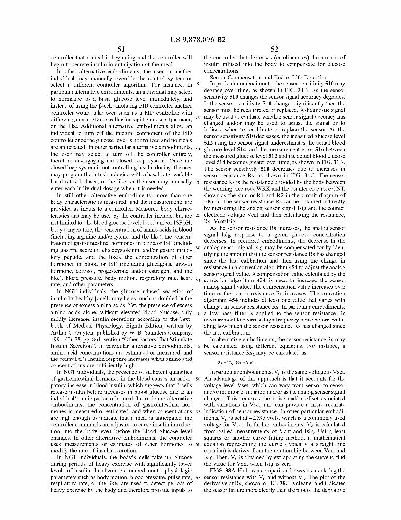
52 US 9 , 878 , 096 B2
51 controller that a meal is beginning and the controller will the controller that decreases ( or eliminates ) the amount of begin to secrete insulin in anticipation of the meal . insulin infused into the body to compensate for glucose
In other alternative embodiments , the user or another concentrations . individual may manually override the control system or Sensor Compensation and End - of - Life Detection select a different controller algorithm . For instance , in 5 In particular embodiments , the sensor sensitivity 510 may particular alternative embodiments , an individual may select degrade over time , as shown in FIG . 31B . As the sensor to normalize to a basal glucose level immediately , and sensitivity 510 changes the sensor signal accuracy degrades .
instead of using the B - cell emulating PID controller another If the sensor sensitivity 510 changes significantly then the sensor must be recalibrated or replaced . A diagnostic signal controller would take over such as a PID controller with
different gains , a PD controller for rapid glucose adjustment , 10 may be used to evaluate whether sensor signal accuracy has or the like . Additional alternative embodiments allow an changed and / or may be used to adjust the signal or to
indicate when to recalibrate or replace the sensor . As the individual to turn off the integral component of the PID sensor sensitivity 510 decreases , the measured glucose level controller once the glucose level is normalized and no meals 512 using the sensor signal underestimates the actual blood are anticipated . In other particular alternative embodiments , bodiments , 15 glucose level 514 , and the measurement error 516 between the user may select to turn off the controller entirely , the measured glucose level 512 and the actual blood glucose therefore disengaging the closed loop system . Once the level 514 becomes greater over time , as shown in FIG . 31A . closed loop system is not controlling insulin dosing , the user The sensor sensitivity 510 decreases due to increases in may program the infusion device with a basal rate , variable sensor resistance Rs , as shown in FIG . 31C . The sensor basal rates , boluses , or the like , or the user may manually 20 resistance Rs is the resistance provided by the body between enter each individual dosage when it is needed . the working electrode WRK and the counter electrode CNT ,
In still other alternative embodiments , more than one shown as the sum or R1 and R2 in the circuit diagram of body characteristic is measured , and the measurements are FIG . 7 . The sensor resistance Rs can be obtained indirectly provided as inputs to a controller . Measured body charac by measuring the analog sensor signal Isig and the counter teristics that may be used by the controller include , but are 25 electrode voltage Vent and then calculating the resistance , not limited to , the blood glucose level , blood and / or ISF PH , body temperature , the concentration of amino acids in blood As the sensor resistance Rs increases , the analog sensor ( including arginine and / or lysine , and the like ) , the concen signal Isig response to a given glucose concentration
tration of gastrointestinal hormones in blood or ISF ( includ decreases . In preferred embodiments , the decrease in the ing gastrin , secretin , cholecystokinin , and / or gastro inhibi - 30 analog sensor signal Isig may be compensated for by iden
tifying the amount that the sensor resistance Rs has changed tory peptide , and the like ) , the concentration of other hormones in blood or ISF ( including glucagons , growth since the last calibration and then using the change in
resistance in a correction algorithm 454 to adjust the analog hormone , cortisol , progesterone and / or estrogen , and the sensor signal value . A compensation value calculated by the like ) , blood pressure , body motion , respiratory rate , heart 35 correction algorithm 454 is used to increase the sensor rate , and other parameters . analog signal value . The compensation value increases over
In NGT individuals , the glucose - induced secretion of time as the sensor resistance Rs increases . The correction insulin by healthy ß - cells may be as much as doubled in the algorithm 454 includes at least one value that varies with presence of excess amino acids . Yet , the presence of excess changes in sensor resistance Rs . In particular embodiments , amino acids alone , without elevated blood glucose , only 40 a low pass filter is applied to the sensor resistance Rs mildly increases insulin secretions according to the Text - measurement to decrease high frequency noise before evalu book of Medical Physiology , Eighth Edition , written by ating how much the sensor resistance Rs has changed since Arthur C . Guyton , published by W . B . Saunders Company , the last calibration . 1991 , Ch . 78 , pg . 861 , section “ Other Factors That Stimulate In alternative embodiments , the sensor resistance Rs may Insulin Secretion " . In particular alternative embodiments , 45 be calculated using different equations . For instance , a amino acid concentrations are estimated or measured , and sensor resistance Rs2 may be calculated as : the controller ' s insulin response increases when amino acid concentrations are sufficiently high . Rsz = ( V - Vent / Isig )
In NGT individuals , the presence of sufficient quantities In particular embodiments , V . is the same voltage as Vset . of gastrointestinal hormones in the blood causes an antici - 50 An advantage of this approach is that it accounts for the patory increase in blood insulin , which suggests that B - cells voltage level Vset , which can vary from sensor to sensor release insulin before increases in blood glucose due to an and / or monitor to monitor , and / or as the analog sensor signal individual ' s anticipation of a meal . In particular alternative changes . This removes the noise and / or offset associated embodiments , the concentration of gastrointestinal hor - with variations in Vset , and can provide a more accurate mones is measured or estimated , and when concentrations 55 indication of sensor resistance . In other particular embodi are high enough to indicate that a meal is anticipated , the ments , V , is set at - 0 . 535 volts , which is a commonly used controller commands are adjusted to cause insulin introduc - voltage for Vset . In further embodiments , V , is calculated tion into the body even before the blood glucose level from paired measurements of Vent and Isig . Using least changes . In other alternative embodiments , the controller squares or another curve fitting method , a mathematical uses measurements or estimates of other hormones to 60 equation representing the curve ( typically a straight line modify the rate of insulin secretion . equation ) is derived from the relationship between Vcnt and
In NGT individuals , the body ' s cells take up glucose Isig . Then , Vo is obtained by extrapolating the curve to find during periods of heavy exercise with significantly lower the value for Vcnt when Isig is zero . levels of insulin . In alternative embodiments , physiologic FIGS . 38A - H show a comparison between calculating the parameters such as body motion , blood pressure , pulse rate , 65 sensor resistance with V , and without Vo . The plot of the respiratory rate , or the like , are used to detect periods of derivative of Rs , shown in FIG . 38G is cleaner and indicates heavy exercise by the body and therefore provide inputs to the sensor failure more clearly than the plot of the derivative
54 US 9 , 878 , 096 B2
53 of Rs shown in FIG . 38F . Hence sensor resistance Rs , may pH Controller Input be used instead of , or in conjunction with , sensor resistance In alternative embodiments , the controller uses measure Rs described above . ments of both the interstitial fluid ( ISF ) glucose level and a
In preferred embodiments , the sensor is recalibrated or local pH in the ISF surrounding the sensor to generate replaced when the change in the sensor resistance Rs since 5 commands for the infusion device . In particular alternative the last calibration exceeds a threshold , or the rate of change embodiments , a single multi - sensor 508 located in the of the sensor resistance dRs / dt exceeds another threshold . In subcutaneous tissue is used to measure both the glucose particular embodiments , the rate of change of the sensor level and the pH . The tip of the multi - sensor 508 that is resistance dRs / dt may be compared to two thresholds as placed into the subcutaneous tissue with three electrodes is shown in FIG . 32 . If dRs / dt exceeds a " replacement ” thresh - 10 shown in FIG . 30 . The working electrode 502 is plated with old then a warning is provided to the user to replace the platinum black and coated with glucose oxidase ( GOX ) . The sensor . If dRs / dt exceeds a “ recalibrate ” threshold then a reference electrode 506 is coated with silver - silver chloride . warning is provided to the user to recalibrate the sensor . And the counter electrode 504 is coated with iridium oxide
In an example shown in FIGS . 33A - C , the analog sensor ( Ir Ox ) . The analog sensor signal Isig is generated at the signal Isig decreases dramatically at approximately 0 . 3 days , 15 working electrode 502 due to the reaction between glucose as seen in FIG . 33A . Given only the analog sensor signal oxidase GOX and the ISF glucose as described with the Isig , the user would believe that the decrease in the analog preferred sensor embodiment . In this alternative embodi sensor signal Isig is due to a decrease in blood glucose . But ment however , as glucose in the ISF reacts with the glucose in reality the drop in the analog sensor signal Isig is due to oxidase GOX on the working electrode and gluconic acid is a sudden change in sensor sensitivity . The sensor resistance 20 generated , the local pH in the ISF surrounding the sensor Rs , shown in FIG . 33A increases as the analog sensor signal decreases , which changes the potential of the iridium oxide Isig drops at about 0 . 3 days . The derivative of the sensor on the counter electrode 504 , with respect to the reference resistance dRs / dt , shown in FIG . 33C , clearly shows a spike electrode REF . So , as the pH decreases , the voltage at the 522 at about 0 . 3 days when the analog sensor signal Isig counter electrode 504 increases . Therefore , as the glucose dropped . The spike 522 in the change in sensor resistance 25 concentration increases , the local pH decreases , which dRs / dt indicates a sensor anomaly rather than a realistic drop causes the counter electrode voltage to increase . So , the in blood glucose . If a threshold were placed at + / - 4 on the glucose concentration may be estimated based on the coun dRs / dt , the user would have received a warning to replace ter electrode voltage . The counter electrode voltage estimate the sensor at about 0 . 3 days . As seen in FIG . 33A , the sensor of glucose concentration can be compared to the estimate of was not replaced until about 1 . 4 days . The analog sensor 30 glucose level from the analog sensor signal Isig . The two signal Isig was under estimating the true glucose level from estimates of the glucose level may be combined by a about 0 . 3 days until the sensor was replaced at about 1 . 4 weighted average or one estimate may simply be used as a days . check to verify that the other sensing method is functioning
In particular embodiments , the amount of time dt over properly . For example , if the difference between the two which the derivative of the sensor resistance Rs is taken is 35 estimates is 10 % for a period of time and then suddenly the the entire time since the last calibration . In other embodi - difference increased to 50 % , a warning would be issued ments , the amount of time dt over which the derivative is indicating to the user that the sensor may need to be replaced taken is fixed , for example over the last hour , 90 minutes , 2 or recalibrated . hours , or the like . In additional alternative embodiments , the pH level near
In alternative embodiments , the sensor is recalibrated or 40 the sensor may be used to detect infection . By tracking replaced when the integral of the sensor resistance Rs over trends in the pH over time , a dramatic change in pH may be a predetermined time window ( Rs d / dt ) exceeds a prede - used to identify that an infection has developed in proximity termined resistance integral threshold . An advantage to this to the sensor . A warning is used to notify the user to replace approach is that it tends to filter out potential noise that could the sensor . be encountered from a signal that includes occasional 45 The pH sensor may be used in other embodiments . When spikes , sudden variations in voltage levels , or the like . insulin is not available to assist the body to use glucose , the Preferably , the integral of the sensor resistance Rs is calcu - body shifts to consuming fat for energy . As the body shifts lated over a time window ( such as 15 minutes , or the like ) from using glucose to using almost exclusively fat for based on Rs measurements obtained at set rates ( such as 1 energy , concentrations of keto acids ( acetoacetic acid and minute , 5 minutes , or the like ) during the time window . In 50 B - hydroxybutyric acid ) increase from about 1 mEq / liter to as alternative embodiments , the time windows may be longer high as 10 mEq / liter . In particular alternative embodiments , or shorter and different sampling rates may be used , with the the pH level is measured to detect increases in keto acids in selection being dependent on noise , response of the system , the body . In embodiments of the present invention , a warn sampling rate used in the controller , or the like . In further ing is provided to the user when the ISF pH level is too low . embodiments , the time windows and sampling rates may 55 A side effect of the increased of keto acid concentrations change over time , such as when approaching the end of the is that sodium is drawn from the body ' s extra cellular fluid expected sensor life , or as the equations indicate that the to combine with the acids so that the body can excrete the sensor is degrading , or the like . acids . This leads to increased quantities of hydrogen ions ,
Like above , multiple thresholds may be used . For which greatly increases the acidosis . Severe cases lead to instance , if JRs d / dt exceeds a “ replacement " threshold then 60 rapid deep breathing , acidotic coma and even death . In other a warning is provided to the user to replace the sensor . And alternative embodiments , an ion - selective electrode ( ISE ) is if JRs d / dt exceeds a “ recalibrate ” threshold then a warning used to detect changes in sodium concentration . A special is provided to the user to recalibrate the sensor . In further membrane is used to coat the ISE so that it only senses alternative embodiments , the counter electrode voltage Vent changes in sodium concentration . In particular alternative is used to evaluate other characteristics such as , sensor 65 embodiments , the ISE is a fourth electrode added to the accuracy , sensor bio - fouling , sensor function , sensor voltage glucose sensor . In another alternative embodiment , a three operating range , sensor attachment , or the like . electrode system is used with a silver - silver chloride refer
55 US 9 , 878 , 096 B2
56 ence electrode REF , an Ir Ox counter electrode CNT , and a erably , the working electrode WRK is plated with platinum sodium ion - selective ( Na ISE ) working electrode WRK . black and coated with glucose oxidase ( GOX ) , the reference While pH measurements , end - of - life measurements , hor electrode REF is coated with silver - silver chloride , and the
mone measurements , or the like , add inputs to the controller counter electrode is plated with platinum black . The voltage that can significantly affect the accuracy of insulin delivery , 5 at the working electrode WRK is generally held to ground , the basic input to the controller is generally a glucose and the voltage at the reference electrode REF is substan measurement . The glucose measurement is provided by the tially held at a set voltage Vset . Vset is between 300 and 700 sensor system . And once the controller uses the glucose mV , and preferably to about 535 mV . measurement to generate commands , the delivery system The most prominent reaction stimulated by the voltage executes the commands . The following is a detailed descrip - 10 difference between the electrodes is the reduction of glucose tion of several apparatus embodiments for the sensor system as it first reacts with GOX to generate gluconic acid and and the delivery system . hydrogen peroxide ( H2O2 ) . Then the H2O2 is reduced to
Sensor System water ( H2O ) and ( 0 ) at the surface of the working electrode The sensor system provides the glucose measurements WRK . The O - draws a positive charge from the sensor
used by the controller . The sensor system includes a sensor , 15 electrical components , thus repelling an electron and caus a sensor set to hold the sensor if needed , a telemetered ing an electrical current flow . This results in the analog characteristic monitor transmitter , and a cable if needed to current signal Isig being proportional to the concentration of carry power and / or the sensor signal between the sensor and glucose in the ISF that is in contact with the sensor elec the telemetered characteristic monitor transmitter . trodes 42 . The analog current signal Isig flows from the
Sensor and Sensor Set 20 working electrode WRK , to the counter electrode CNT , In preferred embodiments , the glucose sensor system 10 typically through a filter and back to the low rail of an
includes a thin film electrochemical sensor such as the type op - amp 66 . An input to the op - amp 66 is the set voltage Vset . disclosed in U . S . Pat . No . 5 , 391 , 250 , entitled “ METHOD The output of the op - amp 66 adjusts the counter voltage OF FABRICATING THIN FILM SENSORS ” ; U . S . patent Vent at the counter electrode CNT as Isig changes with application Ser . No . 09 / 502 , 204 , filed on Feb . 10 , 2000 , 25 glucose concentration . The voltage at the working electrode entitled “ IMPROVED ANALYTE SENSOR AND WRK is generally held to ground , the voltage at the refer METHOD OF MAKING THE SAME ” ; or other typical thin ence electrode REF is generally equal to Vset , and the film sensors such as described in commonly assigned U . S . voltage Vent at the counter electrode CNT varies as needed . Pat . Nos . 5 , 390 , 671 ; 5 , 482 , 473 ; and 5 , 586 , 553 which are In alternative embodiments , more than one sensor is used incorporated by reference herein . See also U . S . Pat . No . 30 to measure blood glucose . In particular embodiments , redun 5 , 299 , 571 . dant sensors are used . The user is notified when a sensor fails
The glucose sensor system 10 also includes a sensor set 28 by the telemetered characteristic monitor transmitter elec to support the sensor 26 such as described in U . S . Pat . No . tronics . An indicator may also inform the user of which 5 , 586 , 553 , entitled “ TRANSCUTANEOUS SENSOR sensors are still functioning and / or the number of sensors INSERTION SET ” ( published as PCT Application WO 35 still functioning . In other particular embodiments , sensor 96 / 25088 ) ; and U . S . Pat . No . 5 , 954 , 643 , entitled “ INSER signals are combined through averaging or other means . If TION SET FOR A TRANSCUTANEOUS SENSOR ” ( pub - the difference between the sensor signals exceeds a thresh lished as PCT Application WO 98 / 56293 ) ; and U . S . Pat . No . old then the user is warned to recalibrate or replace at least 5 , 951 , 521 , entitled “ A SUBCUTANEOUS IMPLANT - one sensor . In other alternative embodiments , more than one ABLE SENSOR SET HAVING . THE CAPABILITY TO 40 glucose sensor is used , and the glucose sensors are not of the REMOVE OR DELIVER FLUIDS TO AN INSERTION same design . For example , an internal glucose sensor and an SITE ” , which are incorporated by reference herein . external glucose sensor may be used to measure blood
In preferred embodiments , the sensor 26 is inserted glucose at the same time . through the user ' s skin 46 using an insertion needle 58 , In alternative embodiments , other continuous blood glu which is removed and disposed of once the sensor is 45 cose sensors and sensor sets may be used . In particular positioned in the subcutaneous tissue 44 . The insertion alternative embodiments , the sensor system is a micro needle 58 has a sharpened tip 59 and an open slot 60 to hold needle analyte sampling device such as described in U . S . the sensor during insertion into the skin 46 , as shown in patent application Ser . No . 09 / 460 , 121 , filed on Dec . 13 , FIGS . 3C and D and FIG . 4 . Further description of the 1999 , entitled “ INSERTION SET WITH MICROPIERC needle 58 and the sensor set 28 are found in U . S . Pat . No . 50 ING MEMBERS AND METHODS OF USING THE 5 , 586 , 553 , entitled “ TRANSCUTANEOUS SENSOR SAME ” , incorporated by reference herein , or an internal INSERTION SET ” ( published as PCT Application WO glucose sensor as described in U . S . Pat . Nos . 5 , 497 , 772 ; 96 / 25088 ) ; and U . S . Pat . No . 5 , 954 , 643 , entitled “ INSER 5 , 660 , 163 ; 5 , 791 , 344 ; and 5 , 569 , 186 , and / or a glucose sen TION SET FOR A TRANSCUTANEOUS SENSOR ” ( pub - sor that uses florescence such as described in U . S . Pat . No . lished as PCT Application WO 98 / 5629 ) , which are incor - 55 6 , 011 , 984 all of which are incorporated by reference herein . porated by reference herein . In other alternative embodiments , the sensor system uses
In preferred embodiments , the sensor 26 has three elec other sensing technologies such as described in Patent trodes 42 that are exposed to the interstitial fluid ( ISF ) in the Cooperation Treaty publication No . WO 99 / 29230 , light subcutaneous tissue 44 as shown in FIGS . 3D and 4 . A beams , conductivity , jet sampling , micro dialysis , micro working electrode WRK , a reference electrode REF and a 60 poration , ultra sonic sampling , reverse iontophoresis , or the counter electrode CNT are used to form a circuit , as shown like . In still other alternative embodiments , only the working in FIG . 7 . When an appropriate voltage is supplied across the electrode WRK is located in the subcutaneous tissue and in working electrode WRK and the reference electrode REF , contact with the ISF , and the counter CNT and reference the ISF provides impedance ( R1 and R2 ) between the REF electrodes are located external to the body and in electrodes 42 . And an analog current signal Isig flows from 65 contact with the skin . In particular embodiments , the counter the working electrode WRK through the body ( R1 and R2 , electrode CNT and the reference electrode REF are located which sum to Rs ) and to the counter electrode CNT . Pref - on the surface of a monitor housing 518 and are held to the
olud
57 US 9 , 878 , 096 B2
58 skin as part of the telemetered characteristic monitor , as 09 / 334 , 858 , filed on Jun . 17 , 1999 , entitled “ EXTERNAL shown in FIG . 34A . In other particular embodiments , the INFUSION DEVICE WITH REMOTE PROGRAMMING , counter electrode CNT and the reference electrode REF are BOLUS ESTIMATOR AND / OR VIBRATION CAPABILI held to the skin using other devices such as running a wire TIES ” ( published as PCT application WO 00 / 10628 ) , which to the electrodes and taping the electrodes to the skin , 5 are herein incorporated by reference . In alternative embodi incorporating the electrodes on the underside of a watch ments , automated implantable medication infusion devices , touching the skin , or the like . In more alternative embodi - as generally described in U . S . Pat . Nos . 4 , 373 , 527 and ments , more than one working electrode WRK is placed into 4 , 573 , 994 , are used , which are incorporated by reference the subcutaneous tissue for redundancy . In additional alter - herein . native embodiments , a counter electrode is not used , a 10 Insulin reference electrode REF is located outside of the body in In preferred embodiments , the infusion device reservoir contact with the skin , and one or more working electrodes 50 contains HUMALOG® lispro insulin to be infused into WRK are located in the ISF . An example of this embodiment the body 20 . Alternatively , other forms of insulin may be implemented by locating the reference electrode REF on a used such as HUMALIN® , human insulin , bovine insulin , monitor housing 520 is shown in FIG . 34B . In other embodi - 15 porcine insulin , analogs , or other insulins such as insulin ments , ISF is harvested from the body of an individual and types described in U . S . Pat . No . 5 , 807 , 315 , entitled flowed over an external sensor that is not implanted in the “ METHOD AND COMPOSITIONS FOR THE DELIV body . ERY OF MONOMERIC PROTEINS ” , and U . S . Patent
Sensor Cable Application Ser . No . 60 / 177 , 897 , filed on Jan . 24 , 2000 , In preferred embodiments , the sensor cable 32 is of the 20 entitled “ MIXED BUFFER SYSTEM FOR STABILIZING
type described in U . S . patent application Ser . No . 60 / 121 , POLYPEPTIDE FORMULATIONS ” , which are incorpo 656 , filed on Feb . 25 , 1999 , entitled “ TEST PLUG AND rated by reference herein , or the like . In further alternative CABLE FOR A GLUCOSE MONITOR ” , which is incor embodiments , other components are added to the insulin porated by reference herein . In other embodiments , other such as polypeptides described in U . S . patent application cables may be used such as shielded , low noise cables for 25 Ser . No . 09 / 334 , 676 , filed on Jun . 25 , 1999 , entitled “ MUL carrying nA currents , fiber optic cables , or the like . In TIPLE AGENT DIABETES THERAPY ” , small molecule alternative embodiments , a short cable may be used or the insulin mimetic materials such as described in U . S . patent sensor may be directly connected to a device without the application Ser . No . 09 / 566 , 877 , filed on May 8 , 2000 , need of a cable . entitled “ DEVICE AND METHOD FOR INFUSION OF
Telemetered Characteristic Monitor Transmitter 30 SMALL MOLECULE INSULIN MIMETIC MATERI In preferred embodiments , the telemetered characteristic ALS ” , both of which are incorporated by reference herein ,
monitor transmitter 30 is of the type described in U . S . patent or the like . application Ser . No . 09 / 465 , 715 , filed on Dec . 17 , 1999 , Infusion Tube entitled “ TELEMETERED CHARACTERISTIC MONI - In preferred embodiments , an infusion tube 36 is used to TOR SYSTEM AND METHOD OF USING THE SAME ” 35 carry the insulin 24 from the infusion device 34 to the ( published as PCT Application WO 00 / 19887 and entitled , infusion set 38 . In alternative embodiments , the infusion “ TELEMETERED CHARACTERISTIC MONITOR SYS - tube carries the insulin 24 from infusion device 34 directly TEM ” ) , which is incorporated by reference herein , and is into the body 20 . In further alternative embodiments , no connected to the sensor set 28 as shown in FIGS . 3A and B . infusion tube is needed , for example if the infusion device
In alternative embodiments , the sensor cable 32 is con - 40 is attached directly to the skin and the insulin 24 flows from nected directly to the infusion device housing , as shown in the infusion device , through a cannula or needle directly into FIG . 8A , which eliminates the need for a telemetered the body . In other alternative embodiments , the infusion characteristic monitor transmitter 30 . The infusion device device is internal to the body and an infusion tube may or contains a power supply and electrical components to oper - may not be used to carry insulin away from the infusion ate the sensor 26 and store sensor signal values . 45 device location .
In other alternative embodiments , the telemetered char - Infusion Set acteristic monitor transmitter includes a receiver to receive In preferred embodiments , the infusion set 38 is of the updates or requests for additional sensor data or to receive type described in U . S . Pat . No . 4 , 755 , 173 , entitled “ SOFT a confirmation ( a hand - shake signal ) indicating that infor - CANNULA SUBCUTANEOUS INJECTION SET ” , which mation has been received correctly . Specifically , if the 50 is incorporated by reference herein . In alternative embodi telemetered characteristic monitor transmitter does not ments , other infusion sets , such described in U . S . Pat . Nos . receive a confirmation signal from the infusion device , then 4 , 373 , 527 and 4 , 573 , 994 , are used , which are incorporated it re - sends the information . In particular alternative embodi - by reference herein . In alternative embodiments , other infu ments , the infusion device anticipates receiving blood glu - sion sets , such as the Rapid set from Disetronic , the Silhou cose values or other information on a periodic basis . If the 55 ette from MiniMed , or the like , may be used . In further expected information is not supplied when required , the alternative embodiments , no infusion set is required , for infusion device sends a “ wake - up ” signal to the telemetered example if the infusion device is an internal infusion device characteristic monitor transmitter to cause it to re - send the or if the infusion device is attached directly to the skin . information . Configurations with Supplemental Devices
Insulin Delivery System 60 In further alternative embodiments , the pre - filter , filters , Infusion Device calibrator and / or controller 12 are located in a supplemental Once a sensor signal 16 is received and processed through device that is in communication with both the telemetered
the controller 12 , commands 22 are generated to operate the characteristic monitor transmitter 30 and the infusion device infusion device 34 . In preferred embodiments , semi - auto 34 . Examples of supplemental devices include , a hand held mated medication infusion devices of the external type are 65 personal digital assistant such as described in U . S . patent used , as generally described in U . S . Pat . Nos . 4 , 562 , 751 ; application Ser . No . 09 / 487 , 423 , filed on Jan . 20 , 2000 , 4 , 678 , 408 ; 4 , 685 , 903 ; and U . S . patent application Ser . No . entitled “ HANDHELD PERSONAL DATA ASSISTANT
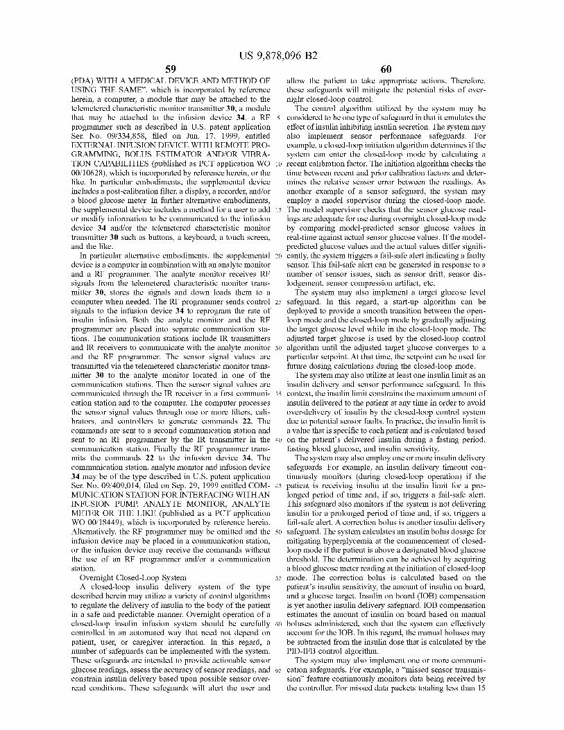
59 US 9 , 878 , 096 B2
60 ( PDA ) WITH A MEDICAL DEVICE AND METHOD OF allow the patient to take appropriate actions . Therefore , USING THE SAME ” , which is incorporated by reference these safeguards will mitigate the potential risks of over herein , a computer , a module that may be attached to the night closed - loop control . telemetered characteristic monitor transmitter 30 , a module The control algorithm utilized by the system may be that may be attached to the infusion device 34 , a RF 5 considered to be one type of safeguard in that it emulates the programmer such as described in U . S . patent application effect of insulin inhibiting insulin secretion . The system may Ser . No . 09 / 334 , 858 , filed on Jun . 17 , 1999 , entitled also implement sensor performance safeguards . For EXTERNAL INFUSION DEVICE WITH REMOTE PRO example , a closed - loop initiation algorithm determines if the GRAMMING , BOLUS ESTIMATOR AND / OR VIBRA - system can enter the closed - loop mode by calculating a TION CAPABILITIES ( published as PCT application WO 10 recent calibration factor . The initiation algorithm checks the 00 / 10628 ) , which is incorporated by reference herein , or the time between recent and prior calibration factors and deter like . In particular embodiments , the supplemental device mines the relative sensor error between the readings . As includes a post - calibration filter , a display , a recorder , and / or another example of a sensor safeguard , the system may a blood glucose meter . In further alternative embodiments , employ a model supervisor during the closed - loop mode . the supplemental device includes a method for a user to add 15 The model supervisor checks that the sensor glucose read or modify information to be communicated to the infusion ings are adequate for use during overnight closed - loop mode device 34 and / or the telemetered characteristic monitor by comparing model - predicted sensor glucose values in transmitter 30 such as buttons , a keyboard , a touch screen , real - time against actual sensor glucose values . If the model and the like . predicted glucose values and the actual values differ signifi
In particular alternative embodiments , the supplemental 20 cantly , the system triggers a fail - safe alert indicating a faulty device is a computer in combination with an analyte monitor sensor . This fail - safe alert can be generated in response to a and a RF programmer . The analyte monitor receives RF number of sensor issues , such as sensor drift , sensor dis signals from the telemetered characteristic monitor trans - lodgement , sensor compression artifact , etc . mitter 30 , stores the signals and down loads them to a The system may also implement a target glucose level computer when needed . The RF programmer sends control 25 safeguard . In this regard , a start - up algorithm can be signals to the infusion device 34 to reprogram the rate of deployed to provide a smooth transition between the open insulin infusion . Both the analyte monitor and the RF loop mode and the closed - loop mode by gradually adjusting programmer are placed into separate communication sta - the target glucose level while in the closed - loop mode . The tions . The communication stations include IR transmitters adjusted target glucose is used by the closed - loop control and IR receivers to communicate with the analyte monitor 30 algorithm until the adjusted target glucose converges to a and the RF programmer . The sensor signal values are particular setpoint . At that time , the setpoint can be used for transmitted via the telemetered characteristic monitor trans future dosing calculations during the closed - loop mode . mitter 30 to the analyte monitor located in one of the The system may also utilize at least one insulin limit as an communication stations . Then the sensor signal values are insulin delivery and sensor performance safeguard . In this communicated through the IR receiver in a first communi - 35 context , the insulin limit constrains the maximum amount of cation station and to the computer . The computer processes insulin delivered to the patient at any time in order to avoid the sensor signal values through one or more filters , cali - over - delivery of insulin by the closed - loop control system brators , and controllers to generate commands 22 . The due to potential sensor faults . In practice , the insulin limit is commands are sent to a second communication station and a value that is specific to each patient and is calculated based sent to an RF programmer by the IR transmitter in the 40 on the patient ' s delivered insulin during a fasting period , communication station . Finally the RF programmer trans - fasting blood glucose , and insulin sensitivity . mits the commands 22 to the infusion device 34 . The The system may also employ one or more insulin delivery communication station , analyte monitor and infusion device safeguards . For example , an insulin delivery timeout con 34 may be of the type described in U . S . patent application tinuously monitors ( during closed - loop operation ) if the Ser . No . 09 / 409 , 014 , filed on Sep . 29 , 1999 entitled COM - 45 patient is receiving insulin at the insulin limit for a pro MUNICATION STATION FOR INTERFACING WITH AN longed period of time and , if so , triggers a fail - safe alert . INFUSION PUMP , ANALYTE MONITOR , ANALYTE This safeguard also monitors if the system is not delivering METER OR THE LIKE ( published as a PCT application insulin for a prolonged period of time and , if so , triggers a WO 00 / 18449 ) , which is incorporated by reference herein . fail - safe alert . A correction bolus is another insulin delivery Alternatively , the RF programmer may be omitted and the 50 safeguard . The system calculates an insulin bolus dosage for infusion device may be placed in a communication station , mitigating hyperglycemia at the commencement of closed or the infusion device may receive the commands without loop mode if the patient is above a designated blood glucose the use of an RF programmer and / or a communication threshold . The determination can be achieved by acquiring station . a blood glucose meter reading at the initiation of closed - loop
Overnight Closed - Loop System 55 mode . The correction bolus is calculated based on the A closed - loop insulin delivery system of the type patient ' s insulin sensitivity , the amount of insulin on board ,
described herein may utilize a variety of control algorithms and a glucose target . Insulin on board ( IOB ) compensation to regulate the delivery of insulin to the body of the patient is yet another insulin delivery safeguard . IOB compensation in a safe and predictable manner . Overnight operation of a estimates the amount of insulin on board based on manual closed - loop insulin infusion system should be carefully 60 boluses administered , such that the system can effectively controlled in an automated way that need not depend on account for the IOB . In this regard , the manual boluses may patient , user , or caregiver interaction . In this regard , a be subtracted from the insulin dose that is calculated by the number of safeguards can be implemented with the system . PID - IFB control algorithm . These safeguards are intended to provide actionable sensor The system may also implement one or more communi glucose readings , assess the accuracy of sensor readings , and 65 cation safeguards . For example , a “ missed sensor transmis constrain insulin delivery based upon possible sensor over - sion ” feature continuously monitors data being received by read conditions . These safeguards will alert the user and the controller . For missed data packets totaling less than 15
US 9 , 878 , 096 B2 62
minutes of operating time , the system remains in closed communication protocol that is usually incompatible with loop mode . During this time , however , the system continues the mobile computing device ) . to calculate the insulin dose using the closed loop control In other embodiments , the functionality of the glucose algorithm based on the last valid sensor glucose value . For sensor system 10 could be integrated into the insulin deliv missed data packets totaling 15 - 60 minutes , the safeguard 5 ery system 14 , perhaps as an interchangeable disposable will switch to a pre - programmed safe basal rate , defined as module that attaches to the housing of the insulin delivery half the patient ' s night time basal rate . If the controller starts system 14 . In yet other embodiments , the functionality of the
receiving data packets during the safe basal rate timeframe , controller 12 could be incorporated into the insulin delivery the system will again switch to the closed - loop mode . For system 14 such that a separate and distinct controller device
10 need not be carried by the patient . Indeed , the control missed data packets totaling more than 60 minutes , the software utilized by the controller 12 can be ported for system will switch to the open - loop mode where it will installation in an insulin infusion pump , a pump monitor deliver a pre - programmed basal rate ( which may be set by device , or the like to implement the functionality of the a caregiver ) . controller 12 in those devices if so desired . In further The exemplary closed - loop control algorithms , method - 15 embodiments , a single hardware device platform could be
ologies , and techniques described in more detail below may suitably designed to accommodate the functionality of the be based around a PID control algorithm of the type pre - insulin delivery system 14 , the glucose sensor system 10 , sented in the preceding sections of this disclosure . In certain and the controller 12 . These and other possible implemen embodiments , the closed - loop control algorithms utilize a tations are contemplated by this disclosure , and the particu PID insulin feedback ( PID - IFB ) control algorithm . More 20 lar manner in which the closed - loop system is configured specifically , the PID - IFB control algorithm cooperates with and deployed is not intended to limit or otherwise restrict the other algorithms , processes , and controls that represent scope or application of the closed - loop control techniques additional safeguards that may apply during overnight use described herein . ( and / or during other periods of use ) . These additional safe Although not shown in FIG . 1 , the closed - loop system guards may include , without limitation : the use of an “ Insu - 25 may include or cooperate with a conventional blood glucose lin Limits ” parameter ; a closed - loop initiation circuit that is meter ( e . g . , a finger stick device ) that provides measured BG based on glucose sensor calibration ; an insulin on board values to the controller 12 and / or to the insulin delivery ( IOB ) compensation algorithm ; monitoring missed trans system 14 , such that the glucose sensor system 10 can be missions ; and monitoring sensor glucose against predicted calibrated . In certain embodiments , the measured BG values sensor glucose . 30 are sent to the insulin delivery system 14 , which in turn
In practice , optimal or desired settings for the Insulin sends the BG value , sensor calibration factor , and calibration Limits parameter should be determined . In this regard , the time to the controller 12 . The controller 12 can process and Insulin Limits parameter serves as an input to the controller analyze the received information to determine whether or logic for each patient , and it imposes an upper limit to the not the system can enter the closed - loop operating mode . In insulin delivery rate as an additional safety feature to avoid 35 this regard , the controller 12 may check to ensure that the over - delivery of insulin by the controller due to potential calibration of the glucose sensor system 10 is within an sensor error . In certain embodiments , the Insulin Limits acceptable range before allowing the system to enter the parameter is calculated from an amount of insulin delivered closed - loop mode . to the patient during a designated fasting period , a fasting After entering the closed - loop mode , the insulin delivery blood glucose value of the patient , and the patient ' s insulin 40 system 14 sends sensor glucose ( SG ) values , sensor Isig sensitivity . values , calibration factors , " insulin delivered " values , and
Referring again to FIG . 1 , a closed - loop system generally other data as needed to the controller 12 in accordance with includes a glucose sensor system 10 , a controller 12 , and an a predetermined schedule , e . g . , at five minute intervals . The insulin delivery system 14 . Although FIG . 1 depicts these controller 12 determines the desired insulin dose based on primary elements as separate blocks , embodiments of the 45 the closed - loop algorithm to maintain the patient at a target system may combine two or more of the illustrated blocks glucose setpoint , and communicates suitable control data into a single physical component . For example , an investi and instructions to the insulin delivery system 14 . The gational test configuration of the closed - loop system may insulin delivery system 14 responds to deliver the insulin include a traditional patient - worn infusion pump ( corre - dose specified by the controller 12 to the user . sponding to the insulin delivery system 14 ) , a conventional 50 FIG . 49 is a block diagram that illustrates processing continuous glucose sensor / transmitter assembly ( corre - modules and algorithms of an exemplary embodiment of a sponding to the glucose sensor system 10 ) , and a mobile closed - loop system controller 900 , and FIG . 50 is a flow computing device with a suitably written software applica - chart that illustrates an exemplary embodiment of a control tion installed thereon ( corresponding to the controller 12 ) . process 1000 that may be performed at least in part by the The mobile computing device may be , for example : a 55 controller 900 to control the insulin delivery system 14 . The smartphone ; a tablet computer ; a netbook computer ; a digital controller 12 shown in FIG . 1 may be configured in accor media player ; a handheld video game device ; or the like . It dance with that shown in FIG . 49 . FIG . 49 schematically should be appreciated that the desired closed - loop control depicts certain inputs and outputs of the controller 900 , functionality can be carried out by way of one or more where the parallelograms represent the inputs , the ovals computer - executable programs or applications designed to 60 represent the outputs , and the rectangles represent the vari run on the mobile computing device . An investigational test ous functional modules of the controller 900 . In the context configuration may also include a translator device that of this description , a " functional module ” may be any serves as a data communication interface between the process , technique , method , algorithm , computer - executable mobile computing device ( which may utilize standard wire - program logic , or the like . In this regard , the controller 900 less data communication technologies such as the Wi - Fi or 65 could be realized as any electronic device having a processor BLUETOOTH data communication protocol ) and the glu - architecture with at least one processor device , and at least cose sensor system 10 ( which may use a proprietary data one memory element that is cooperatively associated with
64 US 9 , 878 , 096 B2
63 the processor architecture . The processor architecture is The illustrated embodiment of the closed - loop initiation suitably configured to execute processor - executable instruc module 902 receives at least the following items as inputs : tions stored in the at least one memory element such that the a meter ( measured ) BG value 920 ; at least one sensor controller 900 can perform the various control operations calibration factor 922 ( i . e . , calibration measurements , cali and methods described in detail herein . Although FIG . 49 5 bration data , etc . ) ; the sensor Isig value 924 ; and timestamp conveniently depicts a number of separate functional mod - data 926 that indicates the calibration time associated with ules , it should be appreciated that the overall functionality the BG value 920 and the sensor calibration factor 922 . and configuration of the controller 900 may be alternatively Some or all of this input data may be provided directly or arranged , and that the functions , operations , and tasks indirectly by the insulin delivery system 14 ( see FIG . 1 ) , a described herein may be performed by one or more of the 10 translator device , a monitor device , or any device in the modules as needed . closed - loop system . This description assumes that a new
The host electronic device that implements the controller sensor calibration factor 922 and new timestamp data 926 is 900 may be realized as a monitor device for an insulin generated for each measured BG value 920 , wherein the infusion device , where the monitor device and the insulin sensor calibration factor 922 is associated with the calibra infusion device are two physically distinct hardware 15 tion of the glucose sensor system 10 ( see FIG . 1 ) that is devices . In another embodiment of the system , the host being used to monitor the patient . In particular , the sensor electronic device that implements the controller 900 may be calibration factor may be based on the meter BG value 920 realized as a portable wireless device , where the portable and the corresponding sensor Isig value 924 . wireless device and the insulin infusion device are two The closed - loop initiation module 902 analyzes the input physically distinct hardware devices . The portable wireless 20 data ( both current values and historical values ) to determine device in this context may be , without limitation : a mobile whether or not the system is allowed to enter into the telephone device ; a tablet computer device ; a laptop com closed - loop mode . For example , the closed - loop initiation puter device ; a portable video game device ; a digital media module 902 may : check the period between two consecutive player device ; a portable medical device ; or the like . In yet calibration timestamp values , compare recent and prior other system embodiments , the host electronic device and 25 calibration factor values ; and the like . The " outputs ” of the the insulin infusion device are physically and functionally closed - loop initiation module 902 correspond to two oper integrated into a single hardware device . In such embodi ating modes of the system . More specifically , the closed ments , the insulin infusion device will include the function - loop initiation module 902 controls whether the system ality of the controller 900 as presented here . remains operating in the open - loop mode 928 or whether the
Certain embodiments of the controller 900 include a 30 system starts the closed - loop mode 930 . plurality of cooperating functional modules that are Referring to FIG . 50 , if the closed - loop mode is not designed and configured to determine the insulin dose to be permitted ( the “ No ” branch of query task 1004 ) , then the delivered to keep the patient at the target glucose setpoint control process 1000 operates the system such that it during an overnight closed - loop operating mode . In this remains in the open - loop mode ( task 1006 ) . On the other regard , the illustrated embodiment of the controller 900 may 35 hand , if the closed - loop mode is permitted ( the “ Yes ” branch include the following functional modules , without limita - of query task 1004 ) , then the control process 1000 can tion : a closed - loop initiation module 902 ; a start - up module initiate and start the closed - loop mode in an appropriate 904 ; a proportional integral derivative insulin feedback manner ( task 1008 ) . Referring again to FIG . 49 , a correction ( PID - IFB ) control module 906 ; an insulin limit module 908 ; bolus 932 can be calculated and delivered ( if needed ) to an insulin on board ( IOB ) compensation module 910 ; an 40 mitigate hyperglycemia at the commencement of the closed insulin delivery timeout module 912 , a model supervisor loop mode . This correction bolus 932 serves as an additional module 914 ; and a missed transmission module 916 . safeguard to achieve a target blood glucose level if a
Referring to FIG . 50 , the control process 1000 may begin measured meter reading is greater than a threshold value . If at any time when it is desired to enter the closed - loop the control process 1000 determines that a correction bolus operating mode . Accordingly , the control process 1000 may 45 is required , then an appropriate insulin dose instruction is begin in response to a user - initiated command , automati - generated for execution by the insulin delivery system at the cally in response to the detection of operating conditions that outset of the closed - loop mode . are usually indicative of closed - loop operation ( e . g . , sleep - Referring to FIG . 49 , the start - up module 904 may be ing ) , or the like . Certain embodiments of the control process called in response to a determination that the system can 1000 may begin with one or more system checks ( task 1002 ) 50 proceed to the closed - loop operating mode . Once the system to confirm whether or not the system is allowed to enter the is in the closed - loop mode , the controller retrieves historical closed - loop operating mode . This particular example data that can be processed and used as described in more employs a sensor calibration check before allowing the detail below . In certain embodiments , for example , the system to proceed to the closed - loop mode . Referring to controller obtains data for the last 24 hours ( from the insulin FIG . 49 , the closed - loop initiation module 902 may be 55 delivery system , from a monitor , or the like ) . Thereafter , the involved during task 1002 . controller retrieves data packets once every sampling period
In some embodiments , the closed - loop initiation module to obtain , without limitation : sensor glucose ( SG ) values ; 902 may consider certain sensor performance criteria that sensor Isig values ; sensor calibration factors ; information prevents closed - loop initiation . Such criteria may include , related to the amount of insulin delivered ; information without limitation : ( 1 ) during start - up when the calibration 60 related to manual boluses delivered ; and sensor calibration is not stable ; ( 2 ) when the sensor sensitivity changes sig factors . As explained in more detail below , the received nificantly ; ( 3 ) when sensors may be calibrated with a poten - information can be used in the various safeguards , and to tially invalid meter reading thereby changing the sensor determine the final insulin dose . sensitivity significantly ; ( 4 ) any other situation that could The start - up module 904 receives sensor glucose ( SG ) cause a mismatch between the sensor and meter for a 65 values 940 as an input , and the functionality of the start - up number of most recent calibrations spaced over a designated module 904 may be initiated in response to the start of the period of time ( e . g . , the two most recent calibrations ) . closed - loop mode 930 ( this trigger mechanism is repre
US 9 , 878 , 096 B2 65 66
sented by the dashed arrow 942 in FIG . 49 ) . The SG values be received by the PID - IFB control module 906 in an 940 may be provided directly by the glucose sensor system ongoing manner as they become available , e . g . , in five 10 or indirectly via the insulin delivery system 14 , a trans - minute intervals or in accordance with any desired schedule . lator device , or any device in the closed - loop system ( see The insulin delivered 954 is a parameter or value that FIG . 1 ) . This description assumes that SG values 940 are 5 indicates the amount of insulin that has been delivered to the received by the start - up module 904 in an ongoing manner patient by the insulin delivery system . Thus , the insulin as they become available . The start - up module 904 may also delivered 954 may indicate recent boluses ( typically by utilize a target glucose setpoint value 944 , which may be Units ) delivered over a period of time . In certain implemen internally maintained , generated , and / or provided by the tations , the insulin delivered 954 corresponds to the amount controller 900 . For the implementation presented here , the 10 of insulin delivered in the last sampling time , which may be , target glucose setpoint value 944 represents a fixed ( con without limitation : one minute ; five minutes ; thirty seconds ; stant ) value that the user can specify ( FIG . 49 depicts the or any designated sampling time . The insulin delivered 954 target glucose setpoint value 944 in dashed lines to indicate may also indicate the amount of insulin delivered by the that the value is a user - specified parameter rather than a delivery system as basal or boluses in any defined period of functional module or data received by the system ) . 15 time in the past ( e . g . , the last N hours ) or the amount of
In certain embodiments , the start - up module 904 calcu - insulin delivered by the system in the last sampling cycle . In lates a final target glucose value 946 , which serves as an practice , the PID - IFB control module 906 ( and the IOB input to the PID - IFB control module 906 . The final target compensation module 910 ) may be “ initialized ” to collect glucose value 946 enables the system to make a smoother and save historical values for the insulin delivered 954 as transition between open - loop and closed - loop modes ( by 20 needed . Thereafter , the insulin delivered 954 can simply gradually adjusting the final target glucose value 946 ) . The indicate an amount of insulin administered by the system start - up module 904 may utilize the target glucose setpoint during the last sampling time period if by a bolus or basal value 944 to calculate the final target glucose value 946 . In channels . this regard , the start - up module 904 elevates the final target As mentioned above , the PID - IFB control module 906 glucose value 946 to the same level as the sensor glucose 25 may utilize the upper insulin limit 959 , which is a patient value at the start of the closed - loop mode , provided the specific parameter . In certain embodiments , the upper insu sensor glucose is above a certain threshold . As time pro lin limit 959 may be entered by the user , a caregiver , or the gresses , the final target glucose value 946 gradually like . Alternatively , the insulin limit module 908 may be decreases back to the target glucose setpoint value 944 responsible for calculating or otherwise managing the upper ( usually in approximately two hours ) . Referring to FIG . 50 , 30 insulin limit 959 if so desired . The upper insulin limit 959 the control process 1000 calculates the final target glucose imposes an upper limit to the insulin delivery rate as an value ( task 1010 ) and continues by calculating an uncom - additional safety feature to avoid over - delivery of insulin by pensated insulin infusion rate , PIDRate ( n ) , based at least in the controller 900 due to potential sensor error . Thus , if the part on the final target glucose value ( task 1012 ) . For this PID - IFB control module 906 recommends a dose higher example , the start - up module 904 may be involved during 35 than the insulin limit 959 , the insulin limit 959 will be task 1010 , and the PID - IFB control module 906 may be utilized to constrain the insulin delivered to the insulin limit involved during task 1012 . value . In addition , implementation of the insulin limit 959
As an additional safeguard , the insulin limit module 908 will “ freeze ” the integral component of the PID to its cooperates with the PID - IFB control module 906 to provide previous value to prevent integral windup , which can cause an upper insulin limit that is calculated based on the patient ' s 40 continuous integrating of the glucose error until it reaches insulin intake during a designated fasting period , the maximum values . In certain embodiments , the upper insulin patient ' s fasting blood glucose , and the patient ' s insulin limit 959 has a default value set at five times the patient ' s sensitivity . This insulin limit imposes an upper limit to the basal rate . Hence , if the maximum value is reached , the insulin delivery rate to avoid over - delivery of insulin by the PID - IFB control algorithm will be fairly aggressive in system due to potential sensor error . 45 calculating an insulin dose . Accordingly , to minimize inte
The PID - IFB control module 906 may be configured to gral windup , the insulin limit 959 is fed back to the PID - IFB carry out the control processes described in more detail control module 906 ( as depicted in FIG . 49 ) for use in the above with reference to FIGS . 1 - 48 . In some embodiments next insulin dose calculation . the PID - IFB control module 906 receives at least the fol The PID - IFB control module 906 operates as described lowing items as inputs : the SG value 940 ( which may be 50 previously to calculate a current insulin dose 958 as an used to calculate a rate of change value that indicates the rate output value ( the current insulin dose 958 is also referred to of change of the SG value ) ; the current sensor Isig value herein as the uncompensated insulin infusion rate , PIDRate 950 ; the current sensor calibration factor 952 , and an amount ( n ) ) . In practice , the current insulin dose 958 is typically of insulin delivered 954 . As shown in FIG . 49 , the PID - IFB expressed as an infusion rate ( Units / Hour ) . In the context of control module 906 may also receive an insulin limit 959 55 this description , the current insulin dose 958 may represent ( e . g . , a maximum insulin infusion rate ) for the user , as a closed - loop infusion rate that has already been subjected to calculated by the insulin limit module 908 . The inputs to the limiting by the insulin limit module 908 , and which may be PID - IFB control module 906 may be provided directly or subjected to further adjustment or compensation by the IOB indirectly by the insulin delivery system 14 , the glucose compensation module 910 . Thus , the output of the insulin sensor system 10 , a translator device , a monitor device , 60 limit module 908 ( the upper insulin limit 959 ) represents a and / or any device in the closed - loop system ( see FIG . 1 ) . potentially limited insulin dose to be provided by the PID The PID - IFB control module 906 is suitably configured to IFB control module 906 — if no limit is imposed , then the calculate the insulin infusion rate based on the current and insulin limit 959 has no effect on the output of the PID - IFB past SG values 940 , the SG rate of change , the sensor Isig control module 906 ; otherwise , the current insulin dose 958 value 950 , the sensor calibration factor 952 , the final target 65 will be the same as the upper insulin limit 959 . Referring glucose value 946 , and the insulin delivered 954 in order to again to FIG . 50 , the control process 1000 may compensate achieve euglycemia . These ( and possibly other ) values may for the insulin " on board ” the patient by calculating an
US 9 , 878 , 096 B2 68
adjusted insulin infusion rate , AdjustedRate ( n ) , based at time is exceeded , the system will trigger a fail - safe alert 966 . least in part on the uncompensated insulin infusion rate ( task Otherwise , the system remains in the closed - loop operating 1014 ) . For this example , the IOB compensation module 910 mode 968 . may be involved during task 1014 . Referring back to FIG . 49 , the model supervisor module
The IOB compensation module 910 receives at least the 5 914 receives at least the following as inputs : the insulin following items as inputs : the current insulin dose 958 ; and delivered 954 ; sensor Isig values 950 ; and one or more information regarding manual boluses delivered 960 . The sensor calibration factors 952 . The inputs to the model manual boluses delivered 960 may be provided directly or supervisor module 914 may be provided directly or indi
rectly by the insulin delivery system 14 , the glucose sensor indirectly by the insulin delivery system 14 , a translator device , a monitor device , and / or any device in the closed 10 system 10 , a translator device , a monitor device , and / or any
device in the closed - loop system ( see FIG . 1 ) . The model loop system ( see FIG . 1 ) . This description assumes that the supervisor module 914 is suitably designed and configured manual boluses delivered 960 is received by the IOB com to estimate the user ' s glucose concentration in real time ( or pensation module 910 in an ongoing manner as it becomes substantially real time ) based on the insulin delivered 954 , available , e . g . , in five minute intervals or in accordance with th 15 the sensor Isig values 950 , and the sensor calibration factors any desired schedule . The IOB compensation module 910 is 952 . The sensor calibration factors 952 used by the model suitably configured to estimate insulin on board based on supervisor module 914 are equal to the sensor calibration manual boluses delivered , before or during closed - loop factors 922 used by the closed - loop initiation module 902 . operation , in order to compensate the final infusion rate to That said , the closed - loop initiation module 902 utilizes the help avoid over - delivery of insulin by the controller 900 . 20 sensor calibration factors 922 at one particular time , whereas Accordingly , the output of the IOB compensation module the model supervisor module 914 considers the sensor 910 may be a final insulin dose 962 expressed as a final calibration factors 952 in an ongoing and continuous manner infusion rate ( Units / Hour ) . The final insulin dose 962 is also during operation in the closed - loop mode . Should the referred to herein as the adjusted insulin infusion rate , model - predicted glucose and the sensor glucose values differ AdjustedRate ( n ) . 25 significantly , the system will exit closed loop mode . Accord
Referring to FIG . 50 , the control process 1000 uses the ingly , the model supervisor module 914 regulates whether adjusted insulin infusion rate , AdjustedRate ( n ) , to control the system remains in the closed - loop mode 974 or switches the insulin infusion device , which in turn regulates the to the open - loop mode 976 . delivery of insulin to the body of the user ( task 1016 ) . In The missed transmission module 916 is suitably config
certain embodiments , the adjusted insulin infusion rate is 30 ured to monitor the following , without limitation : the sensor communicated to the insulin infusion device in an appro Isig values 950 ; the SG values 940 ; and the sensor calibra
tion factors 952 . More particularly , the missed transmission priate manner ( such as wireless data communication ) . The module 916 continuously monitors to check whether the control process 1000 may continue as described above in an system is receiving data packets that convey the necessary iterative and ongoing manner to monitor the condition of the n of the 35 information and input values . For missed data packets user and deliver insulin as needed without user involvement . totaling less than a lower threshold of time ( e . g . , 15 min That said , if the control process 1000 determines that the utes ) , the system remains in the closed - loop mode , as closed - loop operating mode should be terminated ( the Yes " indicated by block 980 in FIG . 49 . During this time , the branch of query task 1018 ) , then the control process 1000 system will continue to calculate the insulin dose using the causes the system to switch back to the open - loop mode 40 closed - loop control methodology based on the last valid ( task 1020 ) . The closed - loop mode may be ended in sensor glucose value . For missed data packets totaling a time response to a user - initiated command , automatically in longer than the lower threshold and shorter than an upper response to the detection of operating conditions that are threshold of time ( e . g . , 60 minutes ) , the missed transmission usually indicative of open - loop operation , or the like . module 916 will switch the system to a pre - programmed
If query task 1018 determines that the closed - loop mode 45 safe basal rate , as indicated by block 982 in FIG . 49 . In should continue ( the " No " branch of query task 1018 ) , then certain embodiments , this safe basal rate is defined as half the control process 1000 may check whether it is time to the patient ' s overnight basal rate , and this parameter may be perform another iteration of the control routine . In other programmed by a caregiver or physician . If the missed words , the control process 1000 may check for the next transmission module 916 starts receiving data packets while sampling time ( query task 1022 ) . If it is time for the next 50 the safe basal rate is being administered , the system will iteration , then the control process 1000 may return to task switch back to the closed - loop mode . For missed data 1010 and repeat the computations with the next set of data packets totaling more than the upper threshold of time , the values . For example , the next iteration of the control routine system will switch to the open - loop mode , as indicated by may obtain and process the current values of some or all of block 984 in FIG . 49 . At this point , the system will be the following parameters , without limitation : the SG value 55 controlled to deliver a pre - programmed open - loop overnight 940 ; the SG rate of change ; the sensor Isig value 924 ; the basal rate . amount of insulin delivered 954 ; and the manual boluses To summarize , the controller 900 determines whether to delivered 960 . This allows the control process 1000 to adjust enter into the closed - loop mode in response to at least the the final insulin infusion rate in an ongoing manner in recent meter BG values 920 , the sensor calibration factors accordance with a predetermined schedule , a designated 60 922 , and the calibration timestamp data 926 . The controller sampling rate , or the like . 900 utilizes the closed - loop initiation module 902 to check
The insulin delivery timeout module 912 monitors if the if the sensor calibration time between the last two calibration patient is receiving continuous delivery of insulin at the values is within an acceptable range , and whether any maximum insulin limit or the minimum allowable infusion change between the two calibration values ( recent and prior of zero Units / Hour for a time specified by the controller . 65 value ) is acceptable . If so , the controller 900 will switch the Accordingly , the insulin delivery timeout module 912 may system into the closed - loop mode . Once the system is in the receive the insulin delivered 954 as an input . If the specified closed - loop mode , the controller 900 will periodically
sa