Insertion of 275 kV Network in Jawa Bali System-jakarta Area Case Study
7
Procedia Technology 11 (2013) 250 – 256 2212-0173 © 2013 The Authors. Published by Elsevier Ltd. Selection and peer-review under responsibility of the Faculty of Information Science & Technology, Universiti Kebangsaan Malaysia. doi:10.1016/j.protcy.2013.12.188 The 4th International Conference on Electrical Engineering and Informatics (ICEEI 2013) Insertion of 275 kV Network in Jawa Bali System - Jakarta Area Case Study Yenni Tarid a,b *, Marwah Cahyono a,b , Koji Yamashita c , Muhammad Nurdin b , Nanang Hariyanto b a PT PLN (Persero), Jakarta, Indonesia b Institut Teknologi Bandung, Jalan Ganesha No. 10, Bandung 40132, Indonesia c Central Research Institute of Electric Power Industry (CRIEPI), 2-11-1 Iwadokita Komae-shi Tokyo, Japan Abstract High short-circuit current and voltage excursion are two major great concerns for an electricity provider in Indonesia, named PLN. These two problems are mainly remarkable in Jakarta area, i.e., the central load of Jawa Bali system. In order to achieve both decrease in the short-circuit current and increase in the voltage level, Insertion of the intermediate 275 kV networks together with the change in the 150 kV networks from loop structure to radial structure is examined with several scenarios. Genetic Algorithm multi-objective optimization technique is also applied for selecting the 275/150 kV transformer reactance in terms of the aforementioned two requirements. The performance of each scenario is verified using the short circuit index, the voltage index and the number of installed 275 kV transmission lines and transformers. Three subsystems in Jakarta area which are Bekasi, Gandul and Kembangan are selected, because these subsystems include most of the issues related to the short-circuit current and the voltage level. The selected scenario successfully reduces the short-circuit currents and increases the voltage level in 150 kV system. Keywords: short-circuit current, voltage level, radial configuration, intermediate voltage class. * Corresponding author. E-mail address: [email protected] Available online at www.sciencedirect.com © 2013 The Authors. Published by Elsevier Ltd. Selection and peer-review under responsibility of the Faculty of Information Science & Technology, Universiti Kebangsaan Malaysia. ScienceDirect
Transcript of Insertion of 275 kV Network in Jawa Bali System-jakarta Area Case Study
Procedia Technology 11 ( 2013 ) 250 – 256
2212-0173 © 2013 The Authors. Published by Elsevier Ltd.Selection and peer-review under responsibility of the Faculty of Information Science & Technology, Universiti Kebangsaan Malaysia.doi: 10.1016/j.protcy.2013.12.188
The 4th International Conference on Electrical Engineering and Informatics (ICEEI 2013)
Insertion of 275 kV Network in Jawa Bali System - Jakarta Area Case Study
Yenni Tarida,b*, Marwah Cahyonoa,b, Koji Yamashitac, Muhammad Nurdinb, Nanang Hariyantob
aPT PLN (Persero), Jakarta, Indonesia
bInstitut Teknologi Bandung, Jalan Ganesha No. 10, Bandung 40132, Indonesia cCentral Research Institute of Electric Power Industry (CRIEPI), 2-11-1 Iwadokita Komae-shi Tokyo, Japan
Abstract
High short-circuit current and voltage excursion are two major great concerns for an electricity provider in Indonesia, named PLN. These two problems are mainly remarkable in Jakarta area, i.e., the central load of Jawa Bali system. In order to achieve both decrease in the short-circuit current and increase in the voltage level, Insertion of the intermediate 275 kV networks together with the change in the 150 kV networks from loop structure to radial structure is examined with several scenarios. Genetic Algorithm multi-objective optimization technique is also applied for selecting the 275/150 kV transformer reactance in terms of the aforementioned two requirements. The performance of each scenario is verified using the short circuit index, the voltage index and the number of installed 275 kV transmission lines and transformers. Three subsystems in Jakarta area which are Bekasi, Gandul and Kembangan are selected, because these subsystems include most of the issues related to the short-circuit current and the voltage level. The selected scenario successfully reduces the short-circuit currents and increases the voltage level in 150 kV system. © 2013 The Authors. Published by Elsevier B.V. Selection and peer-review under responsibility of the Faculty of Information Science and Technology, Universiti Kebangsaan Malaysia.
Keywords: short-circuit current, voltage level, radial configuration, intermediate voltage class.
* Corresponding author.
E-mail address: [email protected]
Available online at www.sciencedirect.com
© 2013 The Authors. Published by Elsevier Ltd.Selection and peer-review under responsibility of the Faculty of Information Science & Technology, Universiti Kebangsaan Malaysia.
ScienceDirect
251 Yenni Tarid et al. / Procedia Technology 11 ( 2013 ) 250 – 256
1. Introduction
One of the greatest concerns for the power system operator or utilities is increase in short-circuit current at substations in transmission system. There is a risk that short-circuit current can exceed the permissible current level of circuit breakers (CBs) and some other related equipment. This risk has been emerged as system expansion as a result of demand growth, installation of power plant, and system interconnection. Very high short-circuit current can damage the system equipments such as generator, transmission line and transformer [1].
This condition can be mitigated by limited the short-circuit current when the fault occurs. The methods for short-circuit current reduction is divided to active and non-active methods. Active methods lead to increase in losses in system otherwise non-active methods haven’t used widely because of their cost, complexity, and operation current. Some methods for limiting short-circuit current are; bus splitting (separate the system), open network loops (radial configuration), increase percentage impedance of transformer, utilize fault current limiter (using mechanical switch, fuses and semiconductor) and introduce interconnections at a higher voltage class, both with ac and dc [1-4]. A study case in Kuwait shows that constructing new higher voltage network and permanent splitting on the lower voltage network is the effective solution for reduction of short-circuit current to acceptable level in that area [4]. However applying of short-circuit current reduction may increase of active and reactive power losses, decrease of reliability and flexibility and degradation of voltage stability. In other words, reduction of short-circuit currents will give negative impact on voltage stability [1,5].
Similar challenge was faced by PLN as an electricity provider in Indonesia. In order to meet with the power supply relative to the growing load, the rate of which is around 9% per year, PLN has installed additional power plants, substations and even transmission lines. Such reinforcement has led to the increasing of short-circuit current which could eventually exceed the permissible current level of CBs. Short-circuit current at several 150 kV class substations is quite high, especially in Jakarta metropolitan area. PLN has taken countermeasures based on system reconfiguration against the increasing of short-circuit current, such as splitting bus, change in connecting point of subsystems, and applying series reactor. However, short circuit levels in several substations are still quite high.
The other countermeasures for reducing short-circuit current are by increasing the voltage level and radial configuration. Currently voltage levels in Java Bali system are 500 kV, 150 kV and 70 kV. The short-circuit current which exceeds the permissible current level of CBs is remarkable in 150 kV. In this study inserting intermediate voltage 275 kV network together with radial configuration in 150 kV network is proposed.
Beside the high short-circuit current problem, PLN is also challenged by voltage issue. In Jakarta area, voltage excursion was occurred in day time which is peak load time of this area. Insertion of 275 kV network may also increase the voltage level. As known higher voltage level of transmission lines give higher Surge Impedance Loading (SIL) which may increase power transfer and decrease reactive power absorption [6].
However insert intermediate voltage network leads to adding a reactance of 275/150 kV transformers, which may cause decrease in the voltage level. Therefore proper location of inserting 275 kV network needed to be evaluated due to two purposes which are decrease short circuit current as well as increase voltage level.
Bekasi, Gandul and Kembangan subsystems are examined for this study because these subsystems includes most of the aspects which have to be considered such as high short-circuit current and large voltage drop in some substations.
2. Methodology
Determining location of 275 kV networks is trial and error process with consideration 275kV substations are installed on outgoing of IBT 500 kV and outgoing of power plant which have high short-circuit current. Radial configuration on 150 kV network is applied to a condition which all power plants in those subsystems operate. In order to avoid overloaded transmission lines and transformers, the number of installed facilities is determined using power flow calculations under minimum and maximum generation conditions.
The ranking of scenarios is determined in terms of three aspects, i.e., the short-circuit current reduction, the voltage level improvement and the cost for 275 kV facilities. The short-circuit current and the voltage level are evaluated using the following performance indices [7].
252 Yenni Tarid et al. / Procedia Technology 11 ( 2013 ) 250 – 256
Short-circuit level index
(1)
Voltage level index
(2)
Where = Short circuit current on bus i (kA) = Voltage on bus i (kV)
= Existing CBs breaking capacity on bus i (kA) = Rated voltage on bus i (kV) n = Number of buses = Maximum rated voltage on bus i (kV) = Minimum rated voltage on bus i (kV)
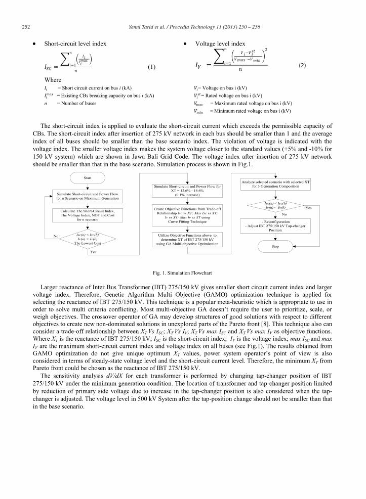
The short-circuit index is applied to evaluate the short-circuit current which exceeds the permissible capacity of CBs. The short-circuit index after insertion of 275 kV network in each bus should be smaller than 1 and the average index of all buses should be smaller than the base scenario index. The violation of voltage is indicated with the voltage index. The smaller voltage index makes the system voltage closer to the standard values (+5% and -10% for 150 kV system) which are shown in Jawa Bali Grid Code. The voltage index after insertion of 275 kV network should be smaller than that in the base scenario. Simulation process is shown in Fig.1.
Start
Simulate Short-circuit and Power Flowfor n Scenario on Maximum Generation
Calculate The Short-Circuit Index,The Voltage Index, NOF and Cost
for n scenario
Isc(n) < Isc(b)Iv(n) < Iv(b)
The Lowest Cost
Simulate Short-circuit and Power Flow forXT = 12.6% - 14.6%
(0.1% increase)
Create Objective Functions from Trade-offRelationship Isc vs XT; Max Isc vs XT;
Iv vs XT; Max Iv vs XT usingCurve Fitting Technique
Utilize Objective Functions above todetermine XT of IBT 275/150 kV
using GA Multi-objective Optimization
Analyze selected scenario with selected XTfor 3 Generation Composition
Isc(n) < Isc(b)Iv(n) < Iv(b)
- Reconfiguration- Adjust IBT 275/150 kV Tap-changer
Position
StopYes
No
Yes
No
Fig. 1. Simulation Flowchart
Larger reactance of Inter Bus Transformer (IBT) 275/150 kV gives smaller short circuit current index and larger voltage index. Therefore, Genetic Algorithm Multi Objective (GAMO) optimization technique is applied for selecting the reactance of IBT 275/150 kV. This technique is a popular meta-heuristic which is appropriate to use in order to solve multi criteria conflicting. Most multi-objective GA doesn’t require the user to prioritize, scale, or weigh objectives. The crossover operator of GA may develop structures of good solutions with respect to different objectives to create new non-dominated solutions in unexplored parts of the Pareto front [8]. This technique also can consider a trade-off relationship between XT Vs ISC; XT Vs IV; XT Vs max ISC and XT Vs max IV as objective functions. Where XT is the reactance of IBT 275/150 kV; ISC is the short-circuit index; IV is the voltage index; max ISC and max IV are the maximum short-circuit current index and voltage index on all buses (see Fig.1). The results obtained from GAMO optimization do not give unique optimum XT values, power system operator’s point of view is also considered in terms of steady-state voltage level and the short-circuit current level. Therefore, the minimum XT from Pareto front could be chosen as the reactance of IBT 275/150 kV.
The sensitivity analysis dV/dX for each transformer is performed by changing tap-changer position of IBT 275/150 kV under the minimum generation condition. The location of transformer and tap-changer position limited by reduction of primary side voltage due to increase in the tap-changer position is also considered when the tap-changer is adjusted. The voltage level in 500 kV System after the tap-position change should not be smaller than that in the base scenario.

253 Yenni Tarid et al. / Procedia Technology 11 ( 2013 ) 250 – 256
The selected scenario is compared with the base scenario and scenario 1 under three different generation conditions; maximum, minimum and average generation conditions. Note that the base scenario is an existing condition and without insertion of 275 kV network. Scenario 1 is applied to radial configuration in 150 kV network without inserting 275 kV network. Other scenarios use insertion of 275 kV network together with radial configuration on 150 kV network.
3. Case Study
Subsystems Priok-Bekasi, Gandul-Muarakarang, and Kembangan are located in Jakarta and Banten area. In normal condition, these subsystems are separated each other for the purpose of reduction of the short-circuit current. In spite of the separated subsystems, the short-circuit current in some substations are still high and some of them are greater than the permissible current level of CBs as shown in Fig.2. In general, the high short-circuit current occurs on power plant substations, the outlet of power plant such as Priok, Pelumpang, Muarakarang, Durikosambi and the outlet of Inter Bus Transformer (IBT) 500/150 kV such as Bekasi and Gandul.
Another issue in those three subsystems is the voltage level which is lower than the standard limit. This occurs on some substations in Jakarta and Banten area mainly during the day time including the peak load time of this area.
Fig. 2 Short-Circuit Current Profile
4. Simulation Results
Simulation results for each scenario are evaluated in terms of the short-circuit current index, the voltage index and the cost shown in Table.1. Scenarios 5 and 8 give smaller ISC and IV compared with those in base scenario. Scenario 8 gives the lower cost.
Table 1. Performance Indices and Cost
Scenario Short-Circuit Current Index
Voltage Index Cost*)
Base 0.7593 0.1106 - 1 0.6905 0.1377 - 2 0.5489 0.1268 793 3 0.4913 0.1622 1267 4 0.6020 0.0841 623 5 0.5622 0.0958 630 6 0.5696 0.1254 723 7 0.5468 0.1160 762 8 0.5524 0.0912 569
*)The cost for 500 kV class facilities are used for that for 275 kV facilities. The objective functions which are obtained using a curve fitting technique as follows
0102030405060
Shor
t -ci
rcui
t Cur
rent
(kA)
SubstationsPermissible Capacity of CBs Short-circuit Current (kA)
254 Yenni Tarid et al. / Procedia Technology 11 ( 2013 ) 250 – 256
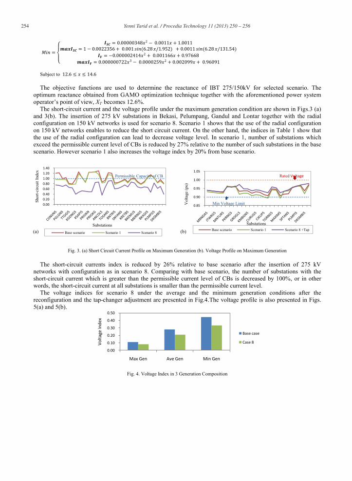
Subject to The objective functions are used to determine the reactance of IBT 275/150kV for selected scenario. The
optimum reactance obtained from GAMO optimization technique together with the aforementioned power system operator’s point of view, XT becomes 12.6%.
The short-circuit current and the voltage profile under the maximum generation condition are shown in Figs.3 (a) and 3(b). The insertion of 275 kV substations in Bekasi, Pelumpang, Gandul and Lontar together with the radial configuration on 150 kV networks is used for scenario 8. Scenario 1 shows that the use of the radial configuration on 150 kV networks enables to reduce the short circuit current. On the other hand, the indices in Table 1 show that the use of the radial configuration can lead to decrease voltage level. In scenario 1, number of substations which exceed the permissible current level of CBs is reduced by 27% relative to the number of such substations in the base scenario. However scenario 1 also increases the voltage index by 20% from base scenario.
Fig. 3. (a) Short Circuit Current Profile on Maximum Generation (b). Voltage Profile on Maximum Generation
The short-circuit currents index is reduced by 26% relative to base scenario after the insertion of 275 kV networks with configuration as in scenario 8. Comparing with base scenario, the number of substations with the short-circuit current which is greater than the permissible current level of CBs is decreased by 100%, or in other words, the short-circuit current at all substations is smaller than the permissible current level.
The voltage indices for scenario 8 under the average and the minimum generation conditions after the reconfiguration and the tap-changer adjustment are presented in Fig.4.The voltage profile is also presented in Figs. 5(a) and 5(b).
Fig. 4. Voltage Index in 3 Generation Composition
0.000.200.400.600.801.001.201.40
Shor
t-circ
uit I
ndex
Substations
Base scenario Scenario 1 Scenario 8
Permissible Capacity of CB
0.85
0.90
0.95
1.00
1.05
Vol
tage
(pu)
SubstationsBase scenario Scenario 1 Scenario 8 +Tap
Rated Voltage
Min Voltage Limit
0.00
0.10
0.20
0.30
0.40
0.50
Max Gen Ave Gen Min Gen
Volta
ge In
dex
Base case
Case 8
(a) (b)
255 Yenni Tarid et al. / Procedia Technology 11 ( 2013 ) 250 – 256
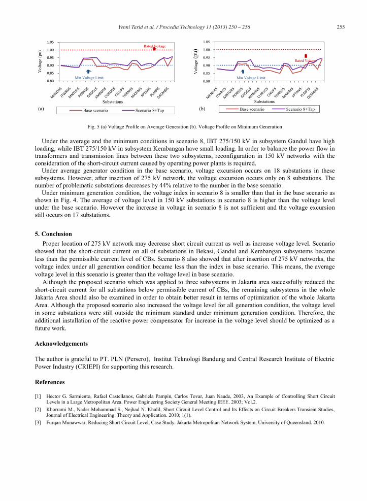
Fig. 5 (a) Voltage Profile on Average Generation (b). Voltage Profile on Minimum Generation
Under the average and the minimum conditions in scenario 8, IBT 275/150 kV in subsystem Gandul have high loading, while IBT 275/150 kV in subsystem Kembangan have small loading. In order to balance the power flow in transformers and transmission lines between these two subsystems, reconfiguration in 150 kV networks with the consideration of the short-circuit current caused by operating power plants is required.
Under average generator condition in the base scenario, voltage excursion occurs on 18 substations in these subsystems. However, after insertion of 275 kV network, the voltage excursion occurs only on 8 substations. The number of problematic substations decreases by 44% relative to the number in the base scenario.
Under minimum generation condition, the voltage index in scenario 8 is smaller than that in the base scenario as shown in Fig. 4. The average of voltage level in 150 kV substations in scenario 8 is higher than the voltage level under the base scenario. However the increase in voltage in scenario 8 is not sufficient and the voltage excursion still occurs on 17 substations.
5. Conclusion Proper location of 275 kV network may decrease short circuit current as well as increase voltage level. Scenario
showed that the short-circuit current on all of substations in Bekasi, Gandul and Kembangan subsystems became less than the permissible current level of CBs. Scenario 8 also showed that after insertion of 275 kV networks, the voltage index under all generation condition became less than the index in base scenario. This means, the average voltage level in this scenario is greater than the voltage level in base scenario.
Although the proposed scenario which was applied to three subsystems in Jakarta area successfully reduced the short-circuit current for all substations below permissible current of CBs, the remaining subsystems in the whole Jakarta Area should also be examined in order to obtain better result in terms of optimization of the whole Jakarta Area. Although the proposed scenario also increased the voltage level for all generation condition, the voltage level in some substations were still outside the minimum standard under minimum generation condition. Therefore, the additional installation of the reactive power compensator for increase in the voltage level should be optimized as a future work.
Acknowledgements
The author is grateful to PT. PLN (Persero), Institut Teknologi Bandung and Central Research Institute of Electric Power Industry (CRIEPI) for supporting this research.
References
[1] Hector G. Sarmiento, Rafael Castellanos, Gabriela Pampin, Carlos Tovar, Juan Naude, 2003, An Example of Controlling Short Circuit Levels in a Large Metropolitan Area. Power Engineering Society General Meeting IEEE. 2003; Vol.2.
[2] Khorrami M., Nader Mohammad S., Nejhad N. Khalil, Short Circuit Level Control and Its Effects on Circuit Breakers Transient Studies, Journal of Electrical Engineering: Theory and Application. 2010; 1(1).
[3] Furqan Munawwar, Reducing Short Circuit Level, Case Study: Jakarta Metropolitan Network System, University of Queensland. 2010.
0.80
0.85
0.90
0.95
1.00
1.05V
olta
ge (p
u)
Substations
Base scenario Scenario 8+Tap
Rated Voltage
Min Voltage Limit0.80
0.85
0.90
0.95
1.00
1.05
Vol
tage
(pu)
Substations
Base scenario Scenario 8+Tap
Rated Voltage
Min Voltage Limit
(a) (b)

256 Yenni Tarid et al. / Procedia Technology 11 ( 2013 ) 250 – 256
[4] Mahmoud Gilany, Wael Al-Haswi, Reducing the Short Circuit Levels in Kuwait Transmission Network (A Case Study), World Academy of Science, Engineering and Technology 29. www.waset.org/journals/waset/v29/v29-96.pdf . 2009.
[5] Andrew J., An Overview of Transmission Fault Current Limiter. IEEE Power Division Colloquium on Fault Current Limiters: A Look at Tommorrow. 1995.
[6] Praba Kundur, Power System Stability and Control. Mc Graw Hill, United State of America. 2004. [7] Wood Allen J., Wollenberg Bruce F., Power Generation Operation, and Control, Second Edition, John Wiley & Sons, Inc. 1996. [8] Abdullah Konak, David W. Coit, Alice E. Smith. Multiobjective Optimization Using Genetic Algorithms: A Tutorial. Reliability
Engineering & System Safety DOI:10.1016/j.ress. 2005. p.992-1007.