


Bahasa
Halaman
Hukum

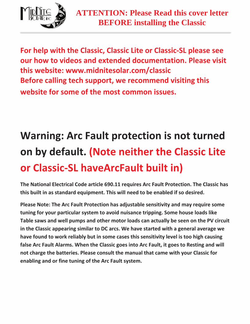
ATTENTION: Please Read this cover letter BEFORE installing the Classic
For help with the Classic, Classic Lite or Classic-SL please see our how to videos and extended documentation. Please visit this website: www.midnitesolar.com/classic Before calling tech support, we recommend visiting this website for some of the most common issues.
Warning: Arc Fault protection is not turned on by default. (Note neither the Classic Lite or Classic-SL haveArcFault built in) The National Electrical Code article 690.11 requires Arc Fault Protection. The Classic has this built in as standard equipment. This will need to be enabled if so desired.
Please Note: The Arc Fault Protection has adjustable sensitivity and may require some tuning for your particular system to avoid nuisance tripping. Some house loads like Table saws and well pumps and other motor loads can actually be seen on the PV circuit in the Classic appearing similar to DC arcs. We have started with a general average we have found to work reliably but in some cases this sensitivity level is too high causing false Arc Fault Alarms. When the Classic goes into Arc Fault, it goes to Resting and will not charge the batteries. Please consult the manual that came with your Classic for enabling and or fine tuning of the Arc Fault system.

2 | P a g e 1 0 - 0 0 1 - 1 R E V : H
DANGER OF DEATH TO YOUR CLASSIC
When the Classic is used with Wind or Hydro a Clipper type device will most likely be needed to protect against over voltage. A battery based diversion load WILL NOT keep the Classic safe from over voltage. High input voltage is recorded and over voltage is not covered under warranty.
Never hook a Pump or other load to the Input side of the Classic. If a Load must be hooked to the input side of the classic the load and Classic need to have blocking diodes on them.
Never Parallel 2 Classics onto one PV array. If 2 Classics have to be paralleled for wind or hydro (NOT SOLAR) there must be blocking diodes on each Classic.
For Larger systems with Large inverters and or multiple inverters (like the Radian or XW+ for example) it is important to use appropriate sized cables and bus bars or damage to the inverters or charge controllers can occur. Take a single XW+ E-Panel for example it has a positive bus bar for Charge controller battery side connections. This bus bar is sufficient for 2 charge controllers so if you needed 3 or more then you need to look at the best way to handle the amperage. A Dual Radian for example is actually 4 separate inverters. Proper size cables become very important as well as large enough battery banks. Most manufacturers of Battery based inverters recommend 100AH of battery per KW of solar modules. (Please consult the inverter manufacturer for assistance with cable sizing etc.)

3 | P a g e 1 0 - 0 0 1 - 1 R E V : H
Standard ClassicThis Manual covers models Classic 150, 200& 250
Este manuel también está disponible en Español. La versión en Español puede encontrar se en nuestra pagina web en la ficha Documentos y hagaclicen Manuales.
4 | P a g e 1 0 - 0 0 1 - 1 R E V : H
UL 1741, Safety for Inverters, Converters, Controllers and Interconnection System Equipment for Use With Distributed Energy Resources, Second Edition, May 7, 1999 with revisions through January 28, 2010 and CAN/CSA C22.2 No. 107.1: 2001/09/01 Ed: 3 (R2006)
5 | P a g e 1 0 - 0 0 1 - 1 R E V : H
Contents Scope ............................................................................................................................................................................. 7
Introduction ................................................................................................................................................................. 7
How to KILL Your Batteries ..................................................................................................................................... 9
Classic Power Curves ................................................................................................................................................ 10
Unpacking the Classic ............................................................................................................................................... 12
Removing and installing the front cover on the Classic ........................................................................................ 13
Mounting the Classic ................................................................................................................................................ 14
.............................................................................................................................................. 15
.......................................................................................................................................................... 15
................................................................................................................................................................................. 15
..................................................................................................................................................... 16
“Follow-ME” Charging coordination ..................................................................................................................... 16
Battery Temperature Sensor Installation ............................................................................................................... 19
Chassis Grounding .................................................................................................................................................... 21
............................................................................................................................................ 21
DC GFP (Ground Fault Protection) ........................................................................................................................ 22
......................................................................................................................................................... 23
Wiring the Classic ..................................................................................................................................................... 23
.......................................................................................................................................... 26
Over Current Protection and Wire Size Requirements ........................................................................................ 26
......................................................................................................................................................... 26
.......................................................................................................................................... 27
....................................................................................................................................... 27
..................................................................................................................... 27
....................................................................................................................... 28
Equalization Manual and Auto ................................................................................................................................ 29
.......................................................................................................................................................... 29
.............................................................................................................................................................. 29
Standard Classic programming ............................................................................................................................... 30
............................................................................................................... 30
..................................................................................................................... 30
................................................................................................................................................................ 30
....................................................................................................................................................... 30
..................................................................................................... 31
........................................................................................................................................................... 31

6 | P a g e 1 0 - 0 0 1 - 1 R E V : H
.............................................................................................................. 31
....................................................................................................................... 32
................................................................................................................................. 32
...................................................................................................... 34
....................................................................................................................................... 34
....................................................................................................................... 35
.................................................................................................................................................... 39
............................................................................................................................. 40
.......................................................................................................................... 41
............................................................................................................. 42
.................................................................................................................... 42
............................................................................................................................................... 44
................................................................................................... 44
......................................................................................... 44
................................................................................................................................................................. 45
...................................................................................................................................... 46
.................................................................................................................................................. 46
.......................................................................................................................... 49
Uploading New Firmware to the Classic ................................................................................................................. 51
Connecting the Classic to the Internet .................................................................................................................... 54
.............................................................................................................................................................. 54
......................................................................................................................... 55
............................................................................................................................................................. 56
......................................................................................................................................................... 57
Positive Ground systems ........................................................................................................................................... 57
Troubleshooting / FAQs ........................................................................................................................................... 58
Electrical Specifications ............................................................................................................................................ 66
Specifications Mechanical ........................................................................................................................................ 67
Default Battery charge set points ............................................................................................................................. 68
Optional accessories .................................................................................................................................................. 68
Regulatory Approval ................................................................................................................................................ 68
Warranty.................................................................................................................................................................... 69
Appendix .............................................................................................................................. 69
............................................................................................................................................ 74
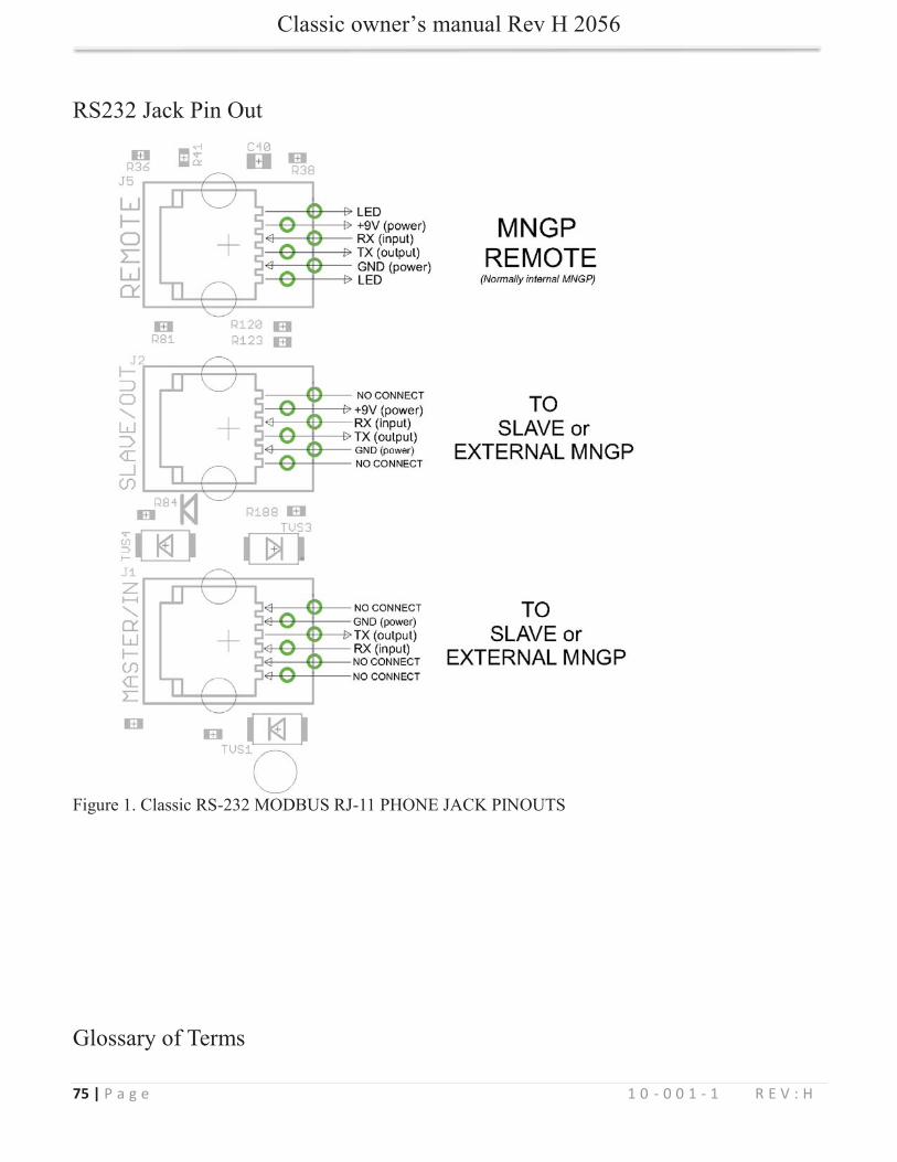
................................................................................................................................................ 75
7 | P a g e 1 0 - 0 0 1 - 1 R E V : H
Scope
Introduction
Classic 150, Classic 200 and the Classic 250
WARNING
CAUTION
unless superseded by local or national codes

8 | P a g e 1 0 - 0 0 1 - 1 R E V : H
never
.
For routine, user-approved maintenance:
Standards and Requirements
DC and Battery-Related Installation Requirements:
WARNING PERSONAL PRECAUTIONS DURING INSTALLATIONWARNING BATTERIES PRESENT RISK OF
ELECTRICAL SHOCK, BURN FROM HIGH SHORT CIRCUIT CURRENT, FIRE OR EXPLOSION FROM VENTED GASES. FOLLOW PROPER PRECAUTIONS.
9 | P a g e 1 0 - 0 0 1 - 1 R E V : H
How to KILL Your Batteries
10 | P a g e 1 0 - 0 0 1 - 1 R E V : H
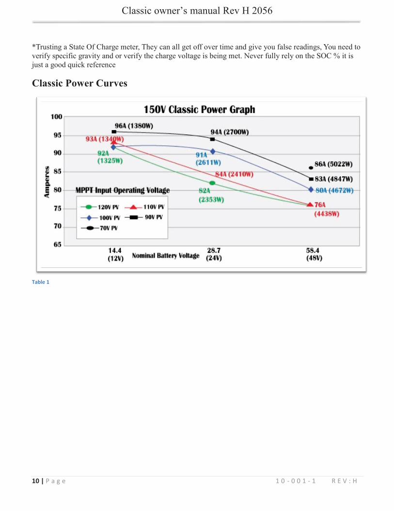
Classic Power Curves
Table 1
11 | P a g e 1 0 - 0 0 1 - 1 R E V : H
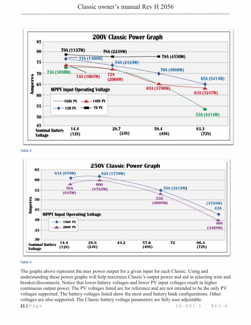
Table 2
Table 3
12 | P a g e 1 0 - 0 0 1 - 1 R E V : H
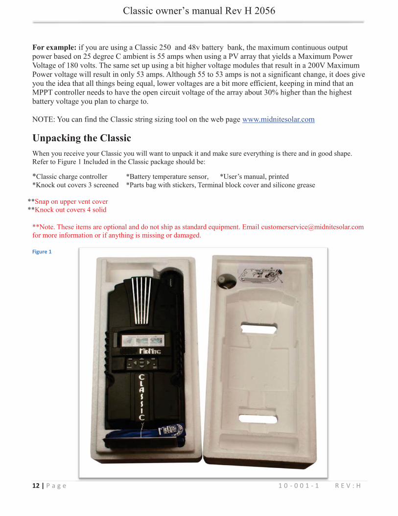
For example:
Unpacking the Classic
Figure 1
13 | P a g e 1 0 - 0 0 1 - 1 R E V : H
eeeeee 11111111 0 -000000 -0 - 0 00 00 00 00 00 00 00 0 1 -111111 -1 - 11111111
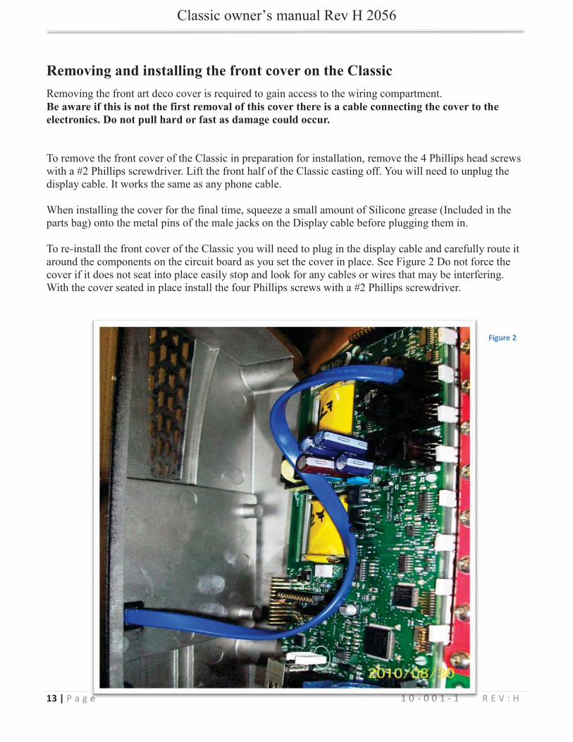
Removing and installing the front cover on the Classic
Be aware if this is not the first removal of this cover there is a cable connecting the cover to the electronics. Do not pull hard or fast as damage could occur.
Figure 2
14 | P a g e 1 0 - 0 0 1 - 1 R E V : H
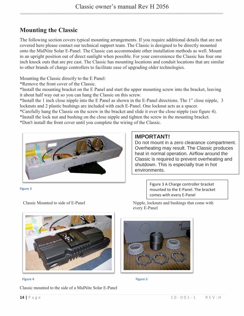
Mounting the Classic
Figure 3
Figure 4 Figure 5
Figure 3 A Charge controller bracket mounted to the E-Panel. The bracket comes with every E-Panel
IMPORTANT!Do not mount in a zero clearance compartment. Overheating may result. The Classic produces heat in normal operation. Airflow around the Classic is required to prevent overheating andshutdown. This is especially true in hotenvironments.
15 | P a g e 1 0 - 0 0 1 - 1 R E V : H
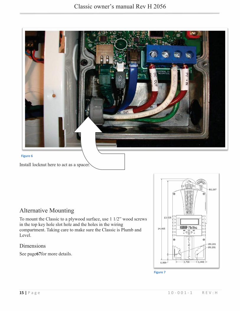
Figure 6
67
Figure 7

16 | P a g e 1 0 - 0 0 1 - 1 R E V : H
Battery Temperature Compensation
. T-Comp
“Follow-ME” Charging coordination
Figure 8Figure 9
17 | P a g e 1 0 - 0 0 1 - 1 R E V : H
Ground Fault sharing
Naming the Classic
18 | P a g e 1 0 - 0 0 1 - 1 R E V : H
Addressing the Classics
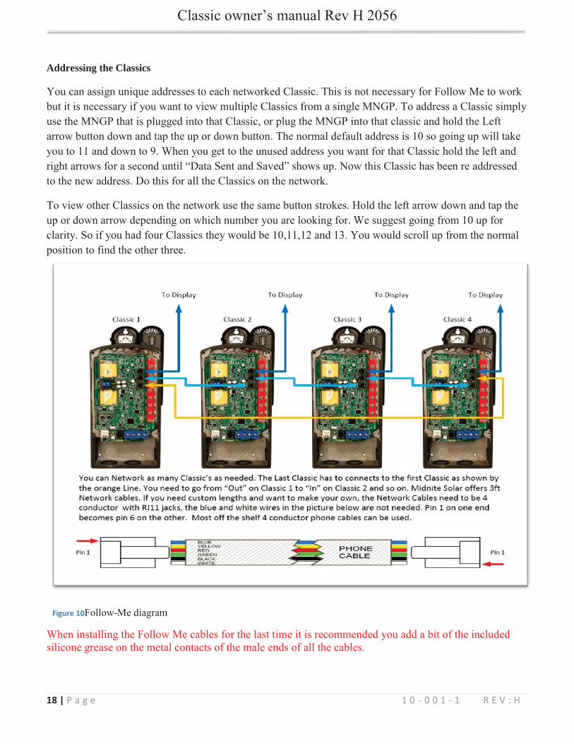
Figure 10
19 | P a g e 1 0 - 0 0 1 - 1 R E V : H
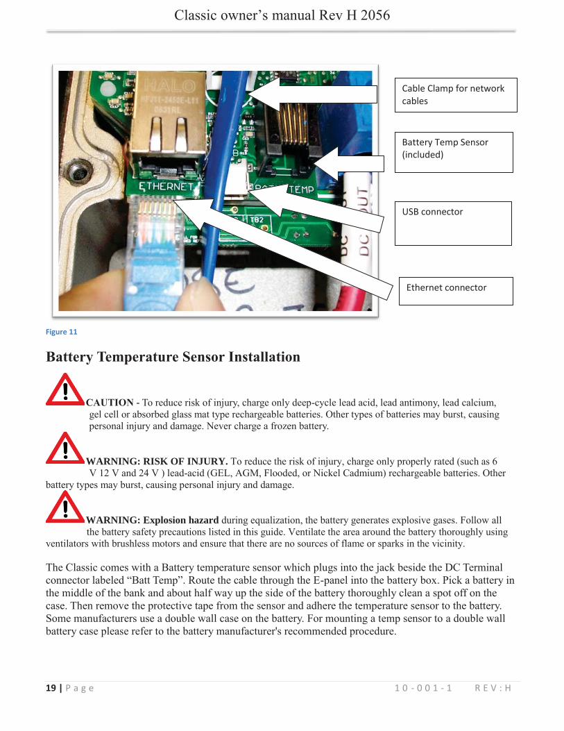
Figure 11
Battery Temperature Sensor Installation
CAUTION -
WARNING: RISK OF INJURY.
WARNING: Explosion hazard
Battery Temp Sensor (included)
Cable Clamp for network cables
USB connector
Ethernet connector
20 | P a g e 1 0 - 0 0 1 - 1 R E V : H
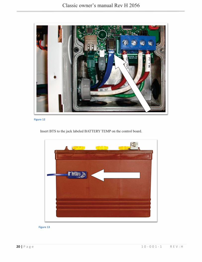
Figure 12
Figure 13
21 | P a g e 1 0 - 0 0 1 - 1 R E V : H
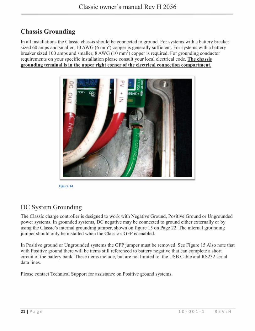
Chassis Grounding
The chassis grounding terminal is in the upper right corner of the electrical connection compartment.
Figure 14
22 | P a g e 1 0 - 0 0 1 - 1 R E V : H
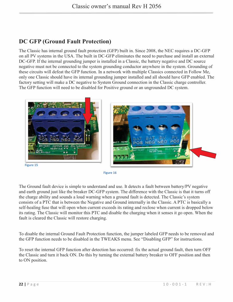
DC GFP (Ground Fault Protection)
Figure 16
Figure 15
23 | P a g e 1 0 - 0 0 1 - 1 R E V : H
Wiring the Classic
WARNING: Shock hazard.
The Classic should be wired by a qualified professional and needs to meet all applicable electrical codes.
24 | P a g e 1 0 - 0 0 1 - 1 R E V : H
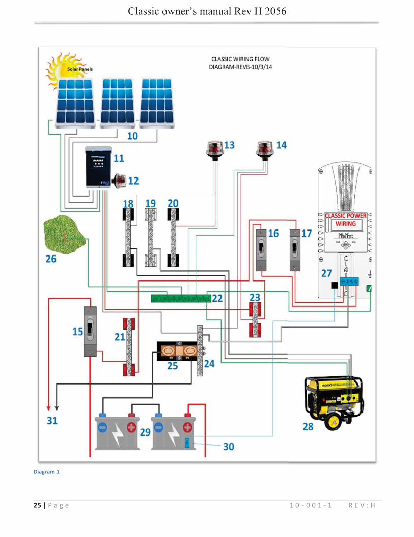
25 | P a g e 1 0 - 0 0 1 - 1 R E V : H
Diagram 1
26 | P a g e 1 0 - 0 0 1 - 1 R E V : H
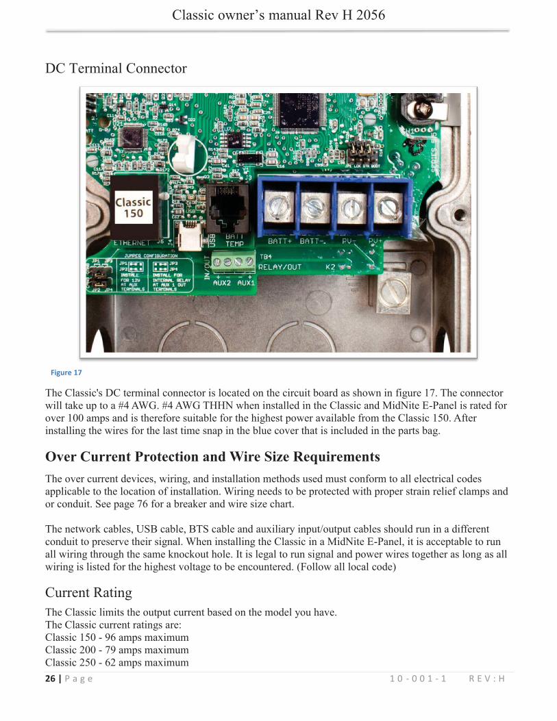
Figure 17
Over Current Protection and Wire Size Requirements
27 | P a g e 1 0 - 0 0 1 - 1 R E V : H
www.midnitesolar.com
28 | P a g e 1 0 - 0 0 1 - 1 R E V : H
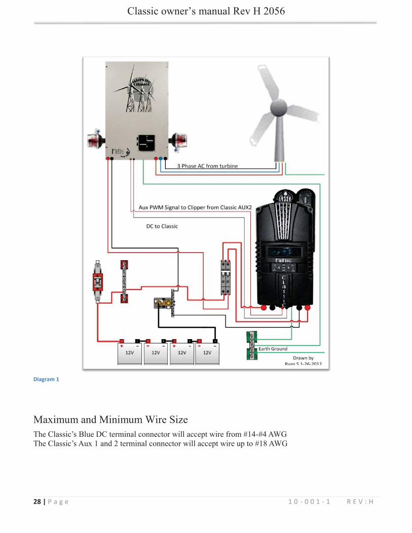
Diagram 1
29 | P a g e 1 0 - 0 0 1 - 1 R E V : H
Equalization Manual and Auto
Manual EQ
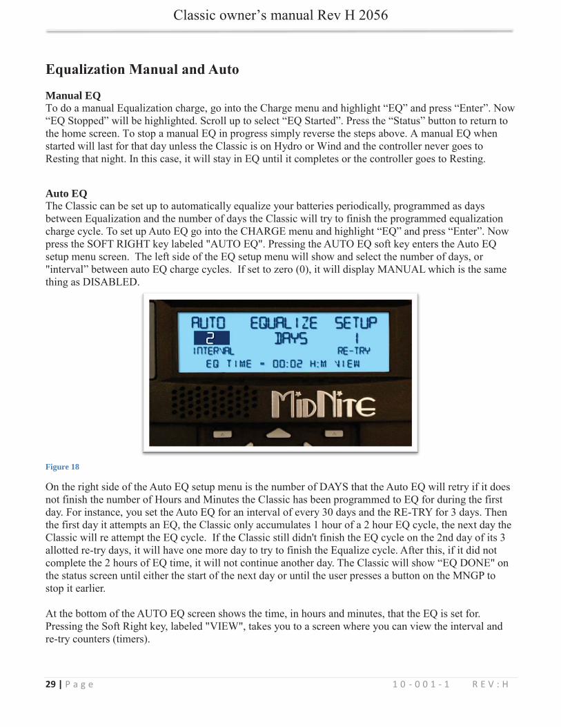
Auto EQ
Figure 18
30 | P a g e 1 0 - 0 0 1 - 1 R E V : H
Standard Classic programming
Float Absorb Float
not

31 | P a g e 1 0 - 0 0 1 - 1 R E V : H
Mode is Off
OFF
Rick Mode
32 | P a g e 1 0 - 0 0 1 - 1 R E V : H
Blinky
LED 1
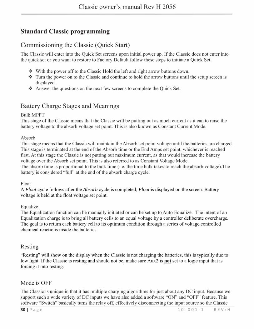
Battery voltage adjust
Battery voltage offset
Displayed battery voltage
Input voltage adjust
Input voltage offset
Displayed Input voltage Screenshot 1
33 | P a g e 1 0 - 0 0 1 - 1 R E V : H
34 | P a g e 1 0 - 0 0 1 - 1 R E V : H
Wind
For more information consult the videos found at www.midnitesolar.com
35 | P a g e 1 0 - 0 0 1 - 1 R E V : H
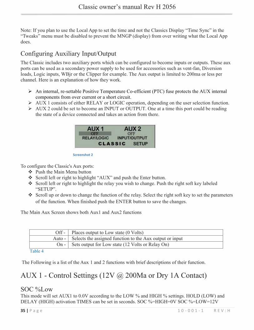
Screenshot 2

36 | P a g e 1 0 - 0 0 1 - 1 R E V : H
37 | P a g e 1 0 - 0 0 1 - 1 R E V : H
38 | P a g e 1 0 - 0 0 1 - 1 R E V : H
39 | P a g e 1 0 - 0 0 1 - 1 R E V : H
40 | P a g e 1 0 - 0 0 1 - 1 R E V : H
41 | P a g e 1 0 - 0 0 1 - 1 R E V : H
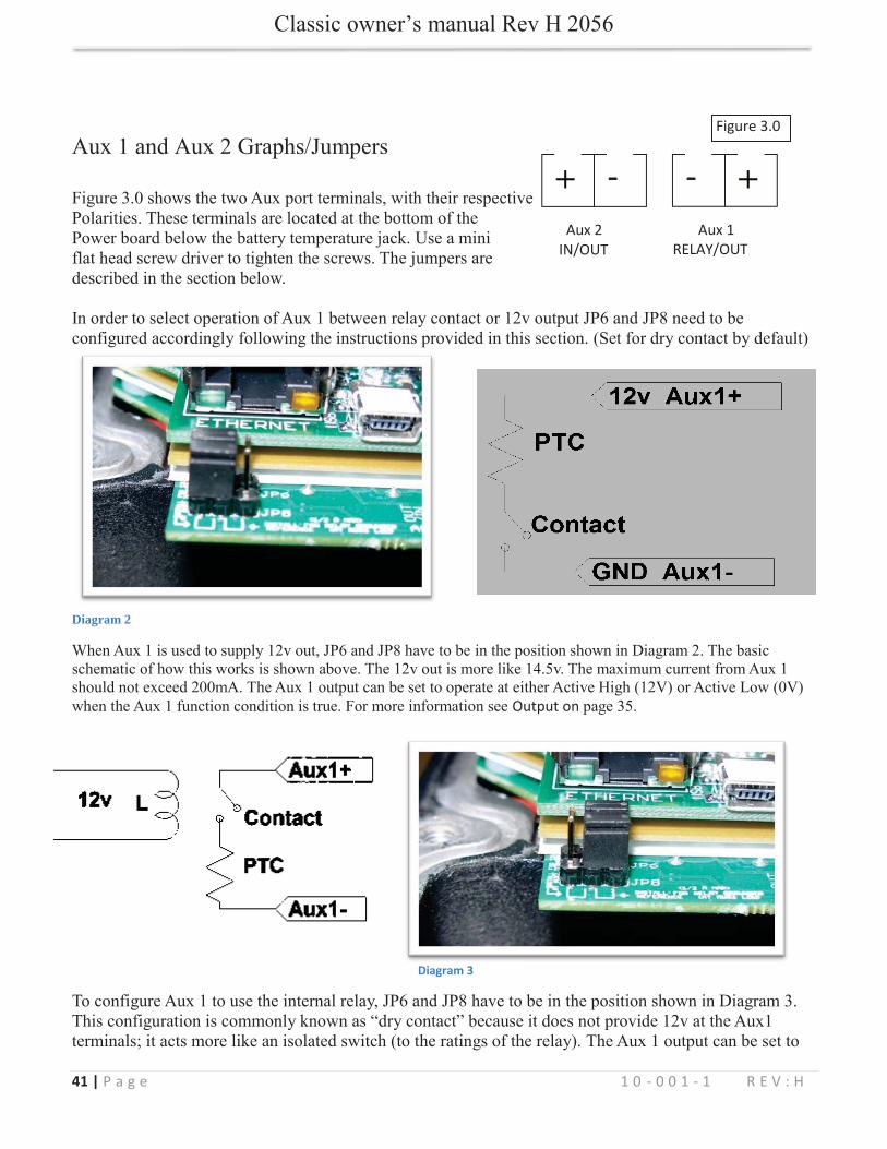
Aux 2 IN/OUT
- - Aux 1 RELAY/OUT
Diagram 2
Output on
Figure 3.0
Diagram 3
42 | P a g e 1 0 - 0 0 1 - 1 R E V : H
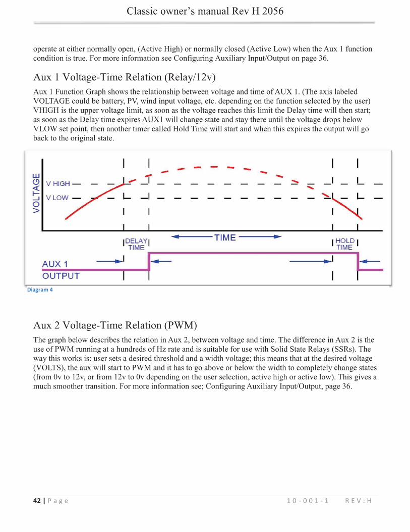
Diagram 4
43 | P a g e 1 0 - 0 0 1 - 1 R E V : H
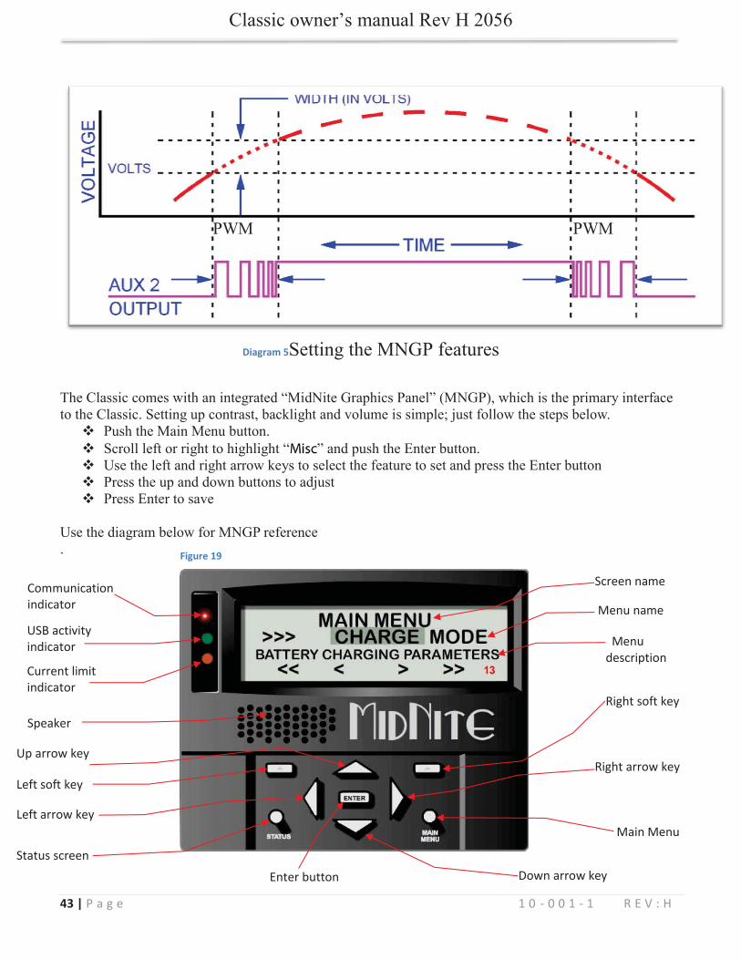
Diagram 5
Left arrow key
Up arrow key
Current limit indicator
USB activity indicator
Down arrow key
Main Menu
Right arrow key
Right soft key
Left soft key
Status screen
Enter button
Speaker
Communication indicator
Menu description
Screen name
Menu name
Figure 19

44 | P a g e 1 0 - 0 0 1 - 1 R E V : H
Figure 20
45 | P a g e 1 0 - 0 0 1 - 1 R E V : H
45454545454545454545 ||||||||| P aP aP aP aP aP aP aP aP aP aP aP aP aP aa g eg eg eg eg eg eg eg eg eg eg eg eg egg
MODE:TIME:
SENSITIVITY:
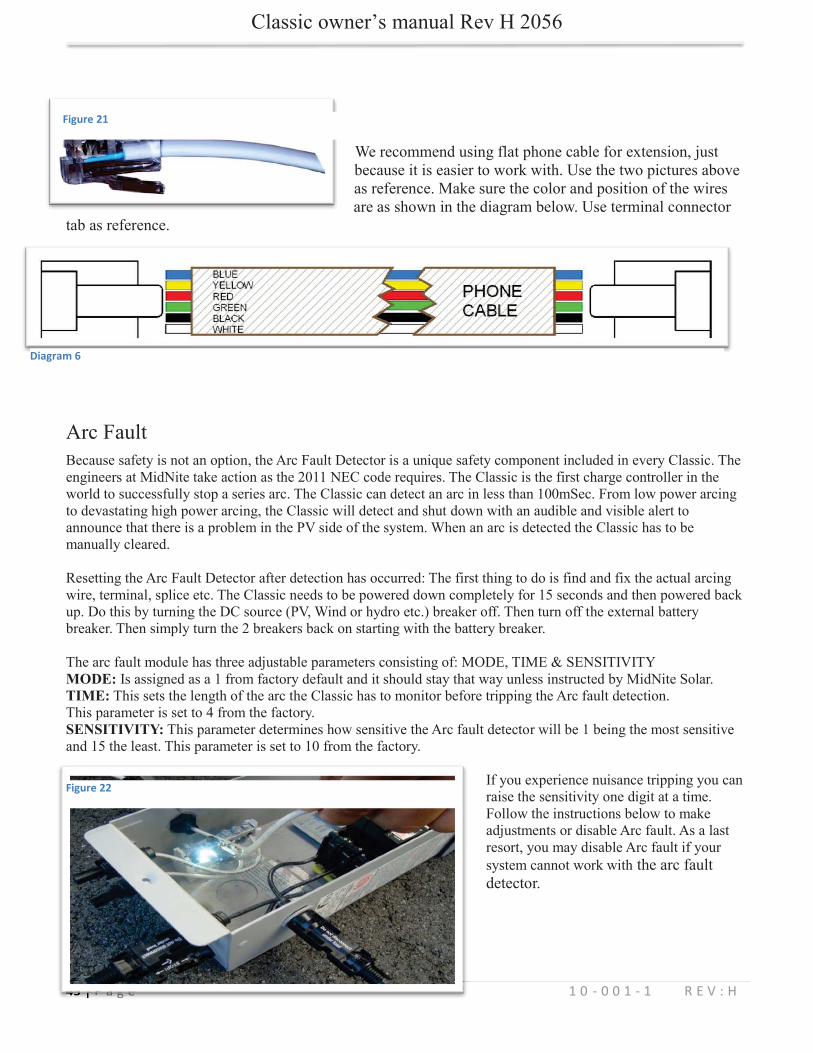
Figure 21
Diagram 6
Figure 22
46 | P a g e 1 0 - 0 0 1 - 1 R E V : H
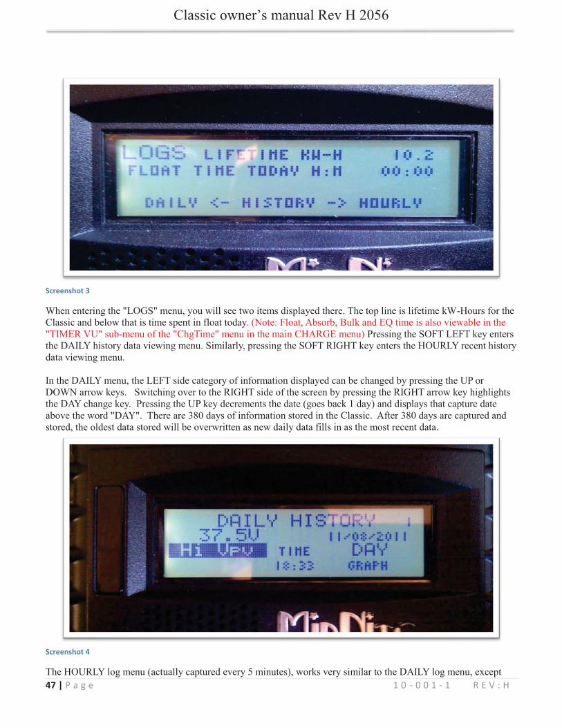
DAILY HISTORY
HOURLY HISTORY
47 | P a g e 1 0 - 0 0 1 - 1 R E V : H
Screenshot 3
Screenshot 4
48 | P a g e 1 0 - 0 0 1 - 1 R E V : H
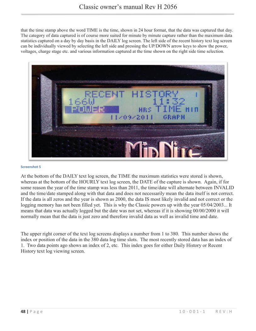
Screenshot 5
49 | P a g e 1 0 - 0 0 1 - 1 R E V : H
50 | P a g e 1 0 - 0 0 1 - 1 R E V : H
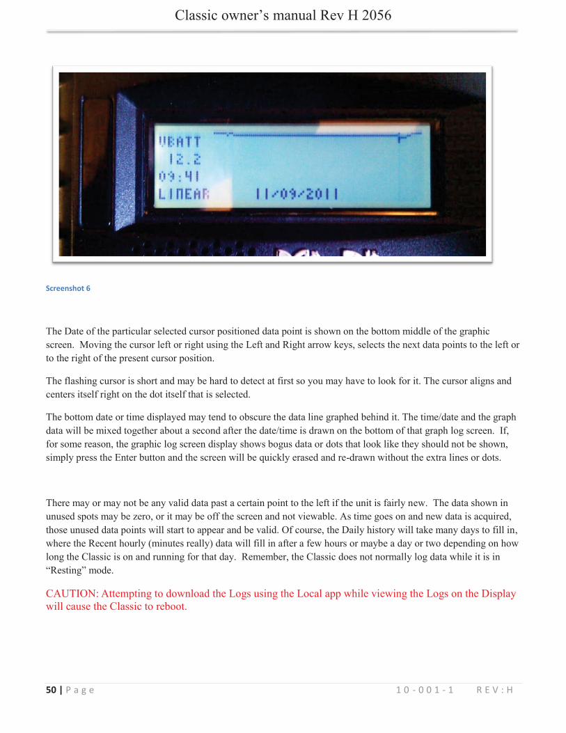
Screenshot 6

51 | P a g e 1 0 - 0 0 1 - 1 R E V : H
Uploading New Firmware to the Classic
WARNING! The Classic's USB port is NOT isolated from battery negative. This is typically only an issue on positive ground systems or systems with a tripped ground fault protection device. Care must be taken that a computer connected to the Classic's USB port is either isolated from ground and the Classic's negative or that the computer's USB negative is common with the Classic's negative and ground.
WARNING! You cannot turn a Classic 150 into a Classic 200 for example using new software, the internal components are also different.
Figure 23
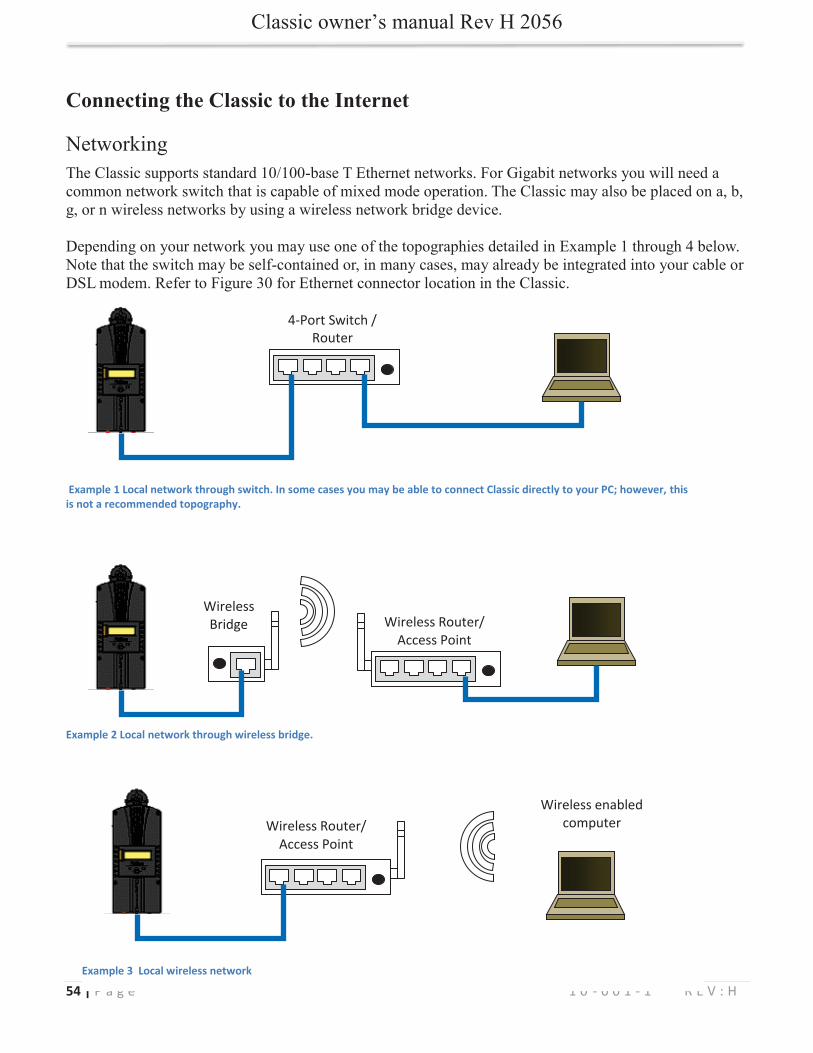
1.
52 | P a g e 1 0 - 0 0 1 - 1 R E V : H
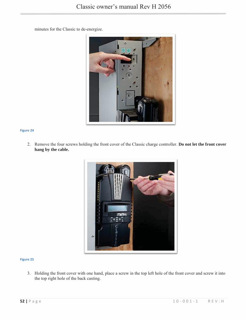
Figure 24
Do not let the front cover hang by the cable.
Figure 25
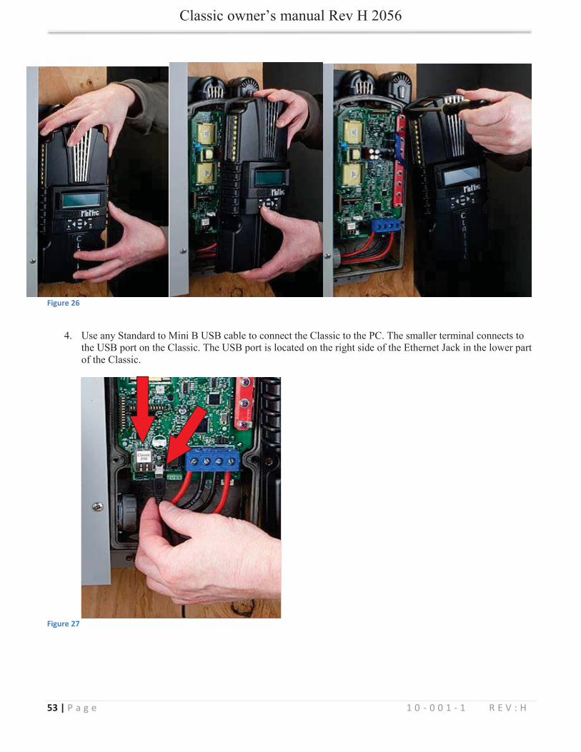
53 | P a g e 1 0 - 0 0 1 - 1 R E V : H
Figure 26
Figure 27
54 | P a g e 1 0 - 0 0 1 - 1 R E V : H
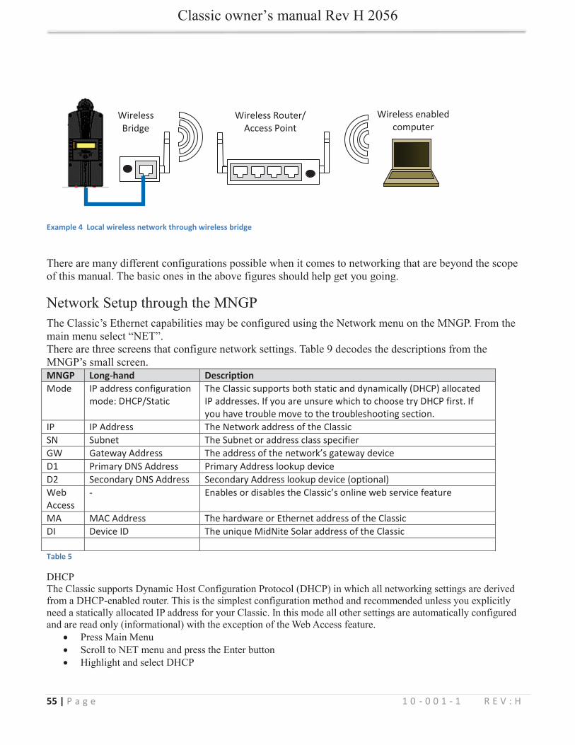
Connecting the Classic to the Internet
4-Port Switch / Router
Example 1 Local network through switch. In some cases you may be able to connect Classic directly to your PC; however, this is not a recommended topography.
Wireless Router/ Access Point
Wireless Bridge
Wireless Router/ Access Point
Wireless enabled computer
Example 3 Local wireless network
Example 2 Local network through wireless bridge.
55 | P a g e 1 0 - 0 0 1 - 1 R E V : H
MNGP Long-hand Description Mode IP address configuration
mode: DHCP/Static The Classic supports both static and dynamically (DHCP) allocated IP addresses. If you are unsure which to choose try DHCP first. If you have trouble move to the troubleshooting section.
IP IP Address The Network address of the Classic SN Subnet The Subnet or address class specifier GW Gateway Address The address of the network’s gateway device D1 Primary DNS Address Primary Address lookup device D2 Secondary DNS Address Secondary Address lookup device (optional) Web Access
- Enables or disables the Classic’s online web service feature
MA MAC Address The hardware or Ethernet address of the Classic DI Device ID The unique MidNite Solar address of the Classic Table 5
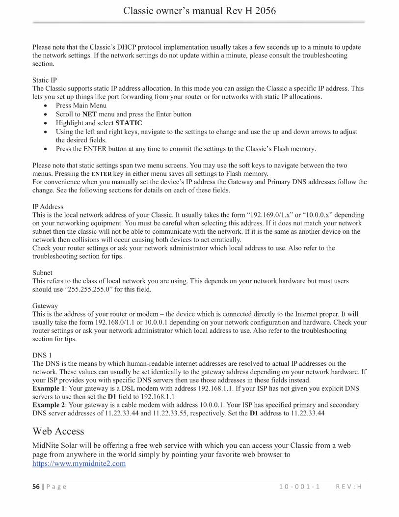
Wireless enabled computer
Wireless Router/ Access Point
Wireless Bridge
Example 4 Local wireless network through wireless bridge
56 | P a g e 1 0 - 0 0 1 - 1 R E V : H
NETSTATIC
ENTER
Example 1D1
Example 2D1
57 | P a g e 1 0 - 0 0 1 - 1 R E V : H
Press Main Menu Scroll to NET menu and press the Enter button Using the soft keys, navigate to the ADVANCED menu (NET→NEXT→ADVANCED) The Web Access option should be highlighted. Use the up/down keys to enable or disable the feature. After saving the change you will need to reboot the Classic by removing PV power and Battery power with the 2 disconnects and waiting for the screen to go dark. Wait 30 seconds and re apply PV and Battery power.
Web Access ENABLED
MA DI
DI
Positive Ground systems
.
IMPORTANT: Do not connect both positive battery and positive PV input to ground. One or the other positive (normally battery +) but not both, otherwise, the Classic input and output will be shorted.

58 | P a g e 1 0 - 0 0 1 - 1 R E V : H
HyperVOC ™
Note 1. HyperVOCNote 2.
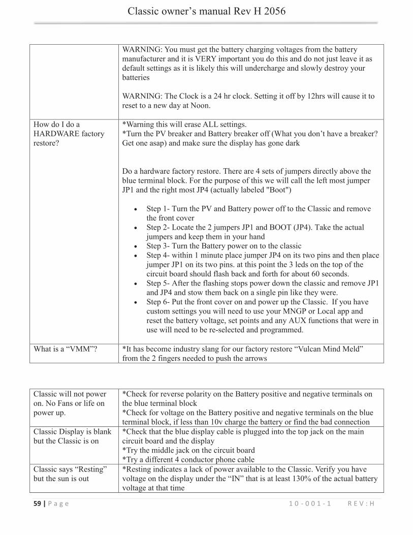
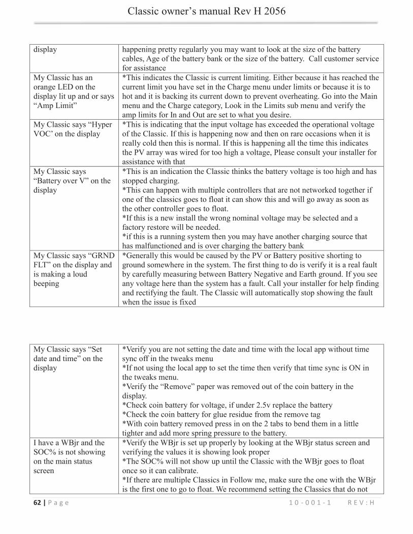
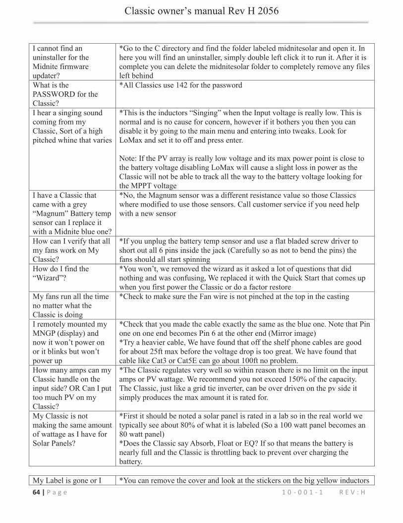
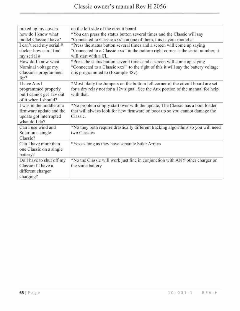
Troubleshooting / FAQs
59 | P a g e 1 0 - 0 0 1 - 1 R E V : H

60 | P a g e 1 0 - 0 0 1 - 1 R E V : H

61 | P a g e 1 0 - 0 0 1 - 1 R E V : H
62 | P a g e 1 0 - 0 0 1 - 1 R E V : H

63 | P a g e 1 0 - 0 0 1 - 1 R E V : H
64 | P a g e 1 0 - 0 0 1 - 1 R E V : H
65 | P a g e 1 0 - 0 0 1 - 1 R E V : H
66 | P a g e 1 0 - 0 0 1 - 1 R E V : H
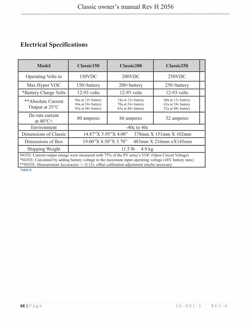
Electrical Specifications
Model Classic150 Classic200 Classic250
Table 6
67 | P a g e 1 0 - 0 0 1 - 1 R E V : H
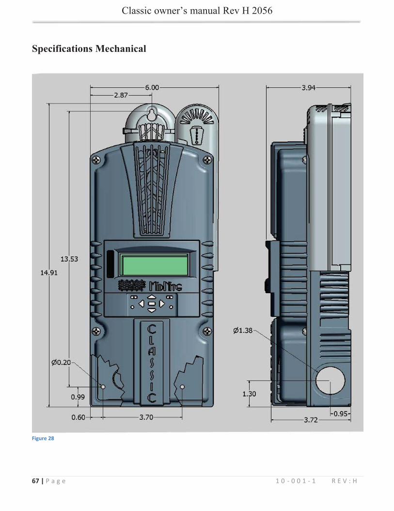
Specifications Mechanical
Figure 28
68 | P a g e 1 0 - 0 0 1 - 1 R E V : H
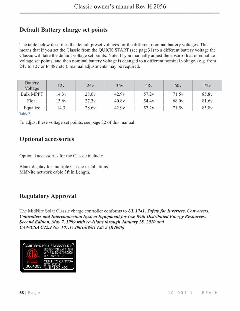
Default Battery charge set points
Table 7
Optional accessories
Regulatory Approval
UL 1741, Safety for Inverters, Converters, Controllers and Interconnection System Equipment for Use With Distributed Energy Resources, Second Edition, May 7, 1999 with revisions through January 28, 2010 and CAN/CSA C22.2 No. 107.1: 2001/09/01 Ed: 3 (R2006)

69 | P a g e 1 0 - 0 0 1 - 1 R E V : H
Warranty
Appendix
Table 8
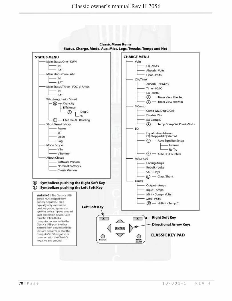
70 | P a g e 1 0 - 0 0 1 - 1 R E V : H
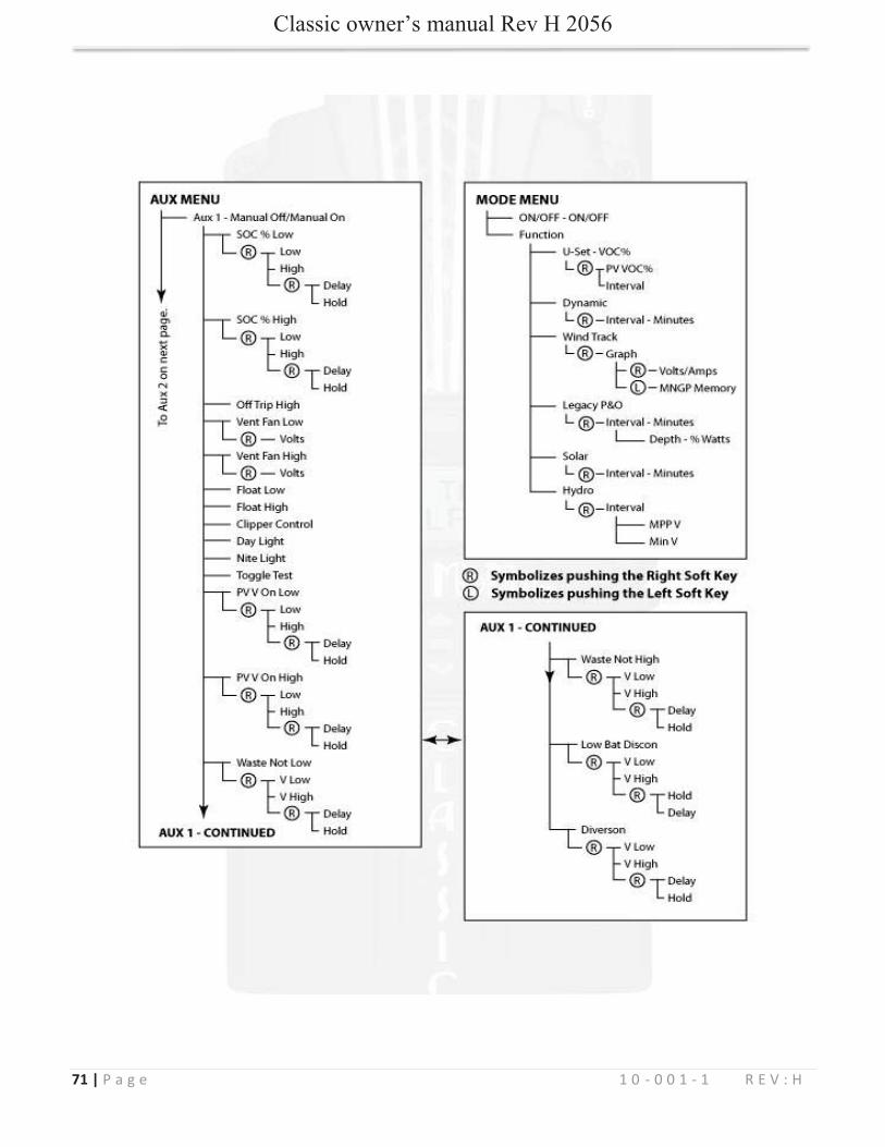
71 | P a g e 1 0 - 0 0 1 - 1 R E V : H
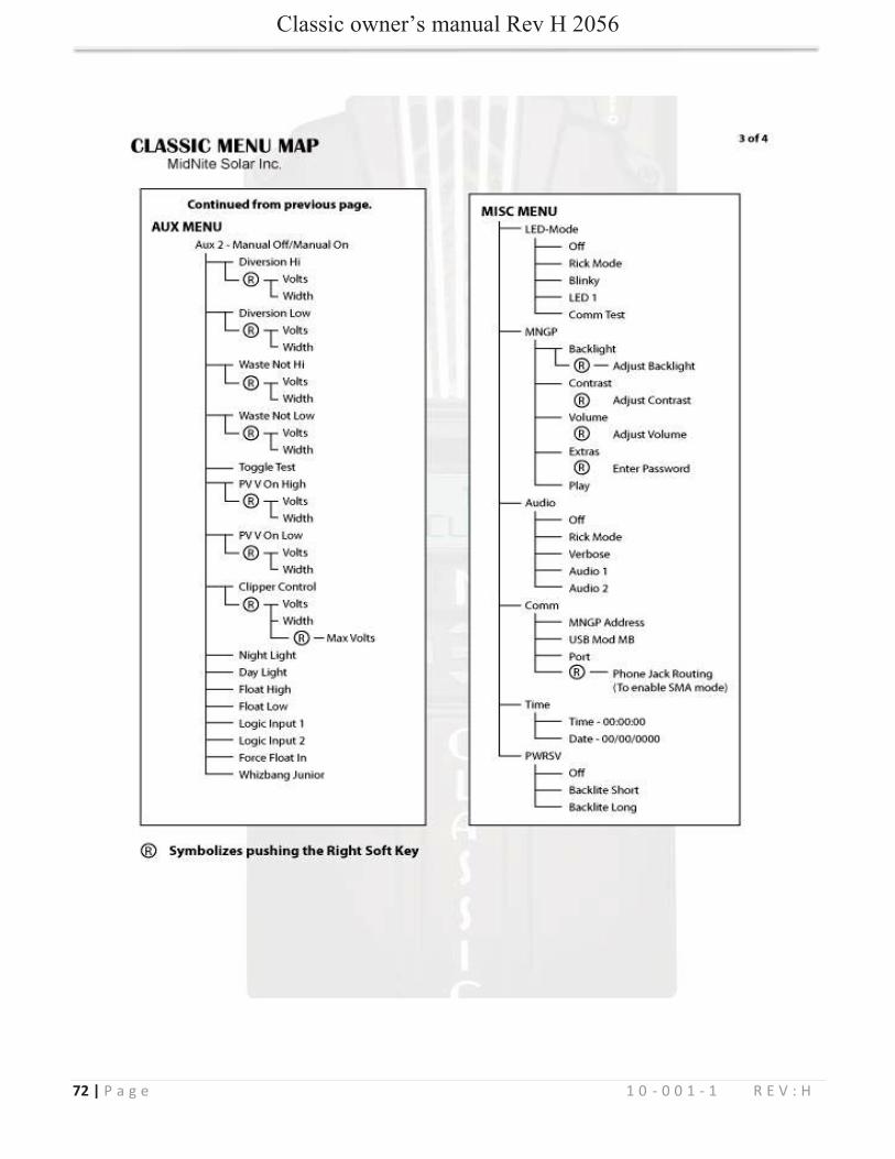
72 | P a g e 1 0 - 0 0 1 - 1 R E V : H
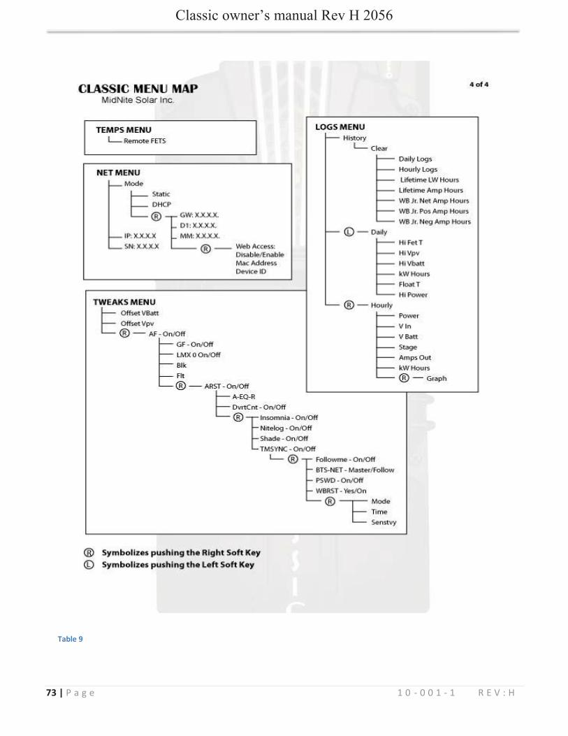
73 | P a g e 1 0 - 0 0 1 - 1 R E V : H
Table 9

74 | P a g e 1 0 - 0 0 1 - 1 R E V : H
75 | P a g e 1 0 - 0 0 1 - 1 R E V : H

76 | P a g e 1 0 - 0 0 1 - 1 R E V : H
Absorb
A-EQ-R
AF
Arc Adjust
A-RST
Aux
BLK
Bulk MPPT
Comm
DvrtCnt
Equalize
EQ MPPT -
Float
Float MPPT
FLT
GF
Got Comm
Insomnia
LED-MODE
LMX
77 | P a g e 1 0 - 0 0 1 - 1 R E V : H
Local App
MNGP
Mode
Mod Bus
My MidNite
NiteLog
PV Shading
Pwr Save
Resting
Shade
T-Comp
Tweaks
VBatt
VOC
Vpv
Web Access
Top Related
Copyright © 2022 FDOKUMEN

