


Bahasa
Halaman
Hukum

User Manual
ACM7000 Remote Site Gateway ACM7000-L Resilience Gateway IM7200 Infrastructure Manager CM7100 Console Servers
Version 4.12.0 2021-10

2
Safety Follow the safety precautions below when installing and operating the console server:
• Do not remove the metal covers. There are no operator serviceable components inside. Opening or removing the cover may expose you to dangerous voltage which may cause fire or electric shock. Refer all service to Opengear qualified personnel.
• To avoid electric shock the power cord protective grounding conductor must be connected through to ground.
• Always pull on the plug, not the cable, when disconnecting the power cord from the socket.
Do not connect or disconnect the console server during an electrical storm. Also use a surge suppressor or UPS to protect the equipment from transients.
FCC Warning Statement This device complies with Part 15 of the FCC rules. Operation of this device is subject to the following conditions: (1) This device may not cause harmful interference, and (2) this device must accept any interference that may cause undesired operation.
Proper back-up systems and necessary safety devices should be utilized to protect against injury, death or property damage due to system failure. Such protection is the responsibility of the user. This console server device is not approved for use as a life-support or medical system.
Any changes or modifications made to this console server device without the explicit approval or consent of Opengear will void Opengear of any liability or responsibility of injury or loss caused by any malfunction.
This equipment is for indoor use and all the communication wirings are limited to inside of the building.

User Manual
Copyright ©Opengear Inc. 2021. All Rights Reserved.
Information in this document is subject to change without notice and does not represent a commitment on the part of Opengear. Opengear provides this document “as is,” without warranty of any kind, expressed or implied, including, but not limited to, the implied warranties of fitness or merchantability for a particular purpose.
Opengear may make improvements and/or changes in this manual or in the product(s) and/or the program(s) described in this manual at any time. This product could include technical inaccuracies or typographical errors. Changes are periodically made to the information herein; these changes may be incorporated in new editions of the publication.

4
TABLE OF CONTENTS
1. THIS MANUAL ............................................................................................................................................... 6
1.1 TYPES OF USERS .............................................................................................................................................................................. 6 1.2 MANAGEMENT CONSOLE .............................................................................................................................................................. 6 1.3 MORE INFORMATION ..................................................................................................................................................................... 7
2. SYSTEM CONFIGURATION ............................................................................................................................ 8
2.1 MANAGEMENT CONSOLE CONNECTION ...................................................................................................................................... 8 2.2 ADMINISTRATOR SET UP ............................................................................................................................................................ 10 2.3 NETWORK CONFIGURATION ....................................................................................................................................................... 12 2.4 SERVICE ACCESS AND BRUTE FORCE PROTECTION ................................................................................................................... 15 2.5 COMMUNICATIONS SOFTWARE.................................................................................................................................................. 19 2.6 MANAGEMENT NETWORK CONFIGURATION ............................................................................................................................ 20
3. SERIAL PORT, HOST, DEVICE & USER CONFIGURATION ............................................................................. 29
3.1 CONFIGURE SERIAL PORTS .......................................................................................................................................................... 29 3.2 ADD AND EDIT USERS ................................................................................................................................................................. 39 3.3 AUTHENTICATION ........................................................................................................................................................................ 43 3.4 NETWORK HOSTS ........................................................................................................................................................................ 43 3.5 TRUSTED NETWORKS .................................................................................................................................................................. 44 3.6 SERIAL PORT CASCADING ............................................................................................................................................................ 46 3.7 SERIAL PORT REDIRECTION (PORTSHARE) .................................................................................................... 50 3.8 MANAGED DEVICES ..................................................................................................................................................................... 51 3.9 IPSEC VPN ............................................................................................................................................ 52 3.10 OPENVPN ............................................................................................................................................. 55 3.11 PPTP VPN ............................................................................................................................................ 63 3.12 CALL HOME .................................................................................................................................................................................. 68 3.13 IP PASSTHROUGH ........................................................................................................................................................................ 71 3.14 CONFIGURATION OVER DHCP (ZTP) .......................................................................................................... 73 3.15 ENROLLMENT INTO LIGHTHOUSE ............................................................................................................................................... 75
4. FIREWALL, FAILOVER & OOB ACCESS ......................................................................................................... 76
4.1 DIALUP MODEM CONNECTION .................................................................................................................................................. 76 4.2 OOB DIAL-IN ACCESS ................................................................................................................................................................. 76 4.3 DIAL-OUT ACCESS ....................................................................................................................................................................... 79 4.4 OOB BROADBAND ETHERNET ACCESS ...................................................................................................................................... 83 4.5 BROADBAND ETHERNET FAILOVER ............................................................................................................................................ 83 4.6 CELLULAR MODEM CONNECTION .............................................................................................................................................. 84 4.7 CELLULAR OPERATION ................................................................................................................................................................ 93 4.8 FIREWALL & FORWARDING ........................................................................................................................................................ 96
5. SSH TUNNELS & SDT CONNECTOR ............................................................................................................ 105
5.1 CONFIGURING FOR SSH TUNNELING TO HOSTS .................................................................................................................... 106 5.2 SDT CONNECTOR CLIENT CONFIGURATION ........................................................................................................................... 106 5.3 SDT CONNECTOR TO MANAGEMENT CONSOLE ................................................................................................................... 115 5.4 SDT CONNECTOR: TELNET OR SSH CONNECT TO SERIALLY ATTACHED DEVICES ........................................................................... 115 5.5 USING SDT CONNECTOR FOR OUT-OF-BAND CONNECTION TO THE GATEWAY .................................................................. 117 5.6 IMPORTING (AND EXPORTING) PREFERENCES ........................................................................................................................ 118 5.7 SDT CONNECTOR PUBLIC KEY AUTHENTICATION ................................................................................................................. 119 5.8 SETTING UP SDT FOR REMOTE DESKTOP ACCESS ................................................................................................................. 120 5.9 SDT SSH TUNNEL FOR VNC ................................................................................................................... 121 5.10 USING SDT TO IP CONNECT TO HOSTS THAT ARE SERIALLY ATTACHED TO THE GATEWAY ................................................. 123 5.11 SSH TUNNELING USING OTHER SSH CLIENTS (E.G. PUTTY) ........................................................................... 127

User Manual
6. ALERTS, AUTO-RESPONSE & LOGGING ..................................................................................................... 129
6.1 CONFIGURE AUTO-RESPONSE ................................................................................................................................................. 129 6.2 CHECK CONDITIONS.................................................................................................................................................................. 131 6.3 TRIGGER ACTIONS .................................................................................................................................................................... 142 6.4 RESOLVE ACTIONS .................................................................................................................................................................... 145 6.5 CONFIGURE SMTP, SMS, SNMP AND/OR NAGIOS SERVICE FOR ALERT NOTIFICATIONS .......................................................... 145 6.6 LOGGING ................................................................................................................................................................................... 150
7. POWER, ENVIRONMENT & DIGITAL I/O ................................................................................................... 153
7.1 REMOTE POWER CONTROL (RPC) ............................................................................................................ 153 7.2 UNINTERRUPTIBLE POWER SUPPLY(UPS) CONTROL ............................................................................................................ 158 7.3 ENVIRONMENTAL MONITORING ............................................................................................................................................. 167 7.4 DIGITAL I/O PORTS .................................................................................................................................................................. 172
8. AUTHENTICATION ..................................................................................................................................... 175
8.1 AUTHENTICATION CONFIGURATION ....................................................................................................................................... 175 8.2 PAM (PLUGGABLE AUTHENTICATION MODULES)........................................................................................ 188 8.3 SSL CERTIFICATE ....................................................................................................................................................................... 189 8.4 ADDING OPENGEAR CUSTOM ATTRIBUTES ............................................................................................................................. 192
9. NAGIOS INTEGRATION .............................................................................................................................. 193
9.1 NAGIOS OVERVIEW .................................................................................................................................................................. 193 9.2 CONFIGURING NAGIOS DISTRIBUTED MONITORING .............................................................................................................. 194 9.3 ADVANCED DISTRIBUTED MONITORING CONFIGURATION ................................................................................................... 199
10. SYSTEM MANAGEMENT ....................................................................................................................... 207
10.1 SYSTEM ADMINISTRATION AND RESET ................................................................................................................................... 207 10.2 UPGRADE FIRMWARE ............................................................................................................................................................... 208 10.3 CONFIGURE DATE AND TIME ................................................................................................................................................... 208 10.4 CONFIGURATION BACKUP ........................................................................................................................................................ 210 10.5 DELAYED CONFIGURATION COMMIT ...................................................................................................................................... 212 10.6 FIPS MODE ............................................................................................................................................................................... 213
11. STATUS REPORTS ................................................................................................................................. 214
11.1 PORT ACCESS AND ACTIVE USERS........................................................................................................................................... 214 11.2 STATISTICS ................................................................................................................................................................................. 215 11.3 SUPPORT REPORTS ................................................................................................................................................................... 215 11.4 SYSLOG ...................................................................................................................................................................................... 216 11.5 DASHBOARD .............................................................................................................................................................................. 218
12. MANAGEMENT ..................................................................................................................................... 221
12.1 DEVICE MANAGEMENT ............................................................................................................................................................ 221 12.2 PORT AND HOST LOGS ............................................................................................................................................................. 222 12.3 TERMINAL CONNECTION .......................................................................................................................................................... 222 12.4 POWER MANAGEMENT ........................................................................................................................................................... 224
13. APPENDIX A: HARDWARE SPECIFICATION .......................................................................................... 225
14. APPENDIX B: SAFETY & CERTIFICATIONS ............................................................................................. 227
15. APPENDIX C: CONNECTIVITY, TCP PORTS & SERIAL I/O ...................................................................... 228
16. APPENDIX E: TERMINOLOGY ............................................................................................................... 234
17. END USER LICENSE AGREEMENTS ........................................................................................................ 239
18. APPENDIX G: SERVICE & STANDARD WARRANTY ............................................................................... 245
1. THIS MANUAL
This User Manual explains installing, operating, and managing Opengear console servers. This manual assumes you are familiar with the Internet and IP networks, HTTP, FTP, basic security operations, and your organization’s internal network.
1.1 Types of users The console server supports two classes of users:
• Administrators who have unlimited configuration and management privileges over the console server and connected devices as well as all services and ports to control all the serial connected devices and network connected devices (hosts). Administrators are set up as members of the admin user group. An administrator can access and control the console server using the config utility, the Linux command line or the browser-based Management Console.
• Users who have been set up by an administrator with limits of their access and control authority. Users have a limited view of the Management Console and can only access authorized configured devices and review port logs. These users are set up as members of one or more of the pre- configured user groups such as PPTPD, dialin, FTP, pmshell, users, or user groups the administrator may have created. They are only authorized to perform specified controls on specific connected devices. Users, when authorized, can access and control serial or network connected devices using specified services (e.g. Telnet, HHTPS, RDP, IPMI, Serial over LAN, Power Control).
Remote users are users who are not on the same LAN segment as the console server. A remote user may be on the road connecting to managed devices over the public Internet, an administrator in another office connecting to the console server over the enterprise VPN, or in the same room or the same office but connected on a separate VLAN to the console server.
1.2 Management Console The Opengear Management Console allows you to configure and monitor the features of your Opengear console server. The Management Console runs in a browser and provides a view of the console server and all connected devices.
Administrators can use the Management Console to configure and manage the console server, users, ports, hosts, power devices, and associated logs and alerts. Non-admin users can use the Management Console with limited menu access to control select devices, review their logs, and access them using the built-in Web terminal.
The console server runs an embedded Linux operating system, and can be configured at the command line. You can get command line access by cellular / dial-in, directly connecting to the console server’s serial console/modem port, or by using SSH or Telnet to connect to the console server over the LAN (or connecting with PPTP, IPsec or OpenVPN).

User Manual
For command line interface (CLI) commands and advanced instructions, download the Opengear CLI and Scripting Reference.pdf from http://ftp.opengear.com/download/manual/current/.
1.3 More information For more information, consult:
• Opengear Products Web Site: See https://opengear.com/products. To get the most up-to-date information on what’s included with your console server, visit the What’s included section for your particular product.
• Quick Start Guide: To get the Quick Start Guide for your device see https://opengear.com/support/documentation/.
• Opengear Knowledge Base: Visit https://opengear.zendesk.com to access technical how-to articles, tech tips, FAQs, and important notifications.
• Opengear CLI and Scripting Reference: http://ftp.opengear.com/download/manual/current/ Opengear CLI and Scripting Reference.pdf.
8
Chapter 2: System Configuration
2. SYSTEM CONFIGURATION
This chapter provides step-by-step instructions for the initial configuration of your console server and connecting it to the Management or Operational LAN. The steps are:
Activate the Management Console.
Change the administrator password.
Set the IP address console server’s principal LAN port.
Select the services to be enabled and access privileges.
This chapter also discusses the communications software tools that an administrator may use to access the console server, and the configuration of the additional LAN ports.
2.1 Management Console Connection Your console server comes configured with a default IP Address 192.168.0.1 and subnet mask 255.255.255.0.
For initial configuration, we recommend that you connect a computer directly to the console. If you do choose to connect your LAN before completing the initial setup steps, make sure that:
• There are no other devices on the LAN with an address of 192.168.0.1. • The console server and the computer are on the same LAN segment, with no interposed router
appliances.
2.1.1 Connected computer set up To configure the console server with a browser, the connected computer should have an IP address in the same range as the console server (for example, 192.168.0.100):
• To configure the IP Address of your Linux or Unix computer, run ifconfig.
• For Windows PCs:
1. Click Start > Settings > Control Panel and double click Network Connections.
2. Right click on Local Area Connection and select Properties.
3. Select Internet Protocol (TCP/IP) and click Properties.
4. Select Use the following IP address and enter the following details:
o IP address: 192.168.0.100
o Subnet mask: 255.255.255.0
5. If you want to retain your existing IP settings for this network connection, click Advanced and Add the above as a secondary IP connection.
2.1.2 Browser connection
Open a browser on the connected PC / workstation and enter https://192.168.0.1.
Log in with:
Username> root Password> default

The Welcome screen lists initial installation configuration steps. These steps are:
Change default administration password (Serial & Network > User & Groups page. See Chapter 2.2)
Configure the local network settings (System > IP page. See Chapter 2.3)
Configure console server features:
•
•
Configure serial ports settings (Serial & Network > Serial Port page. See Chapter 3)
Configure user port access (Serial & Network > Users & Groups page. See Chapter 3)
User Manual
The first time you log in, you are required to change the root password. Click Submit.
To complete the change, enter the new password again. Click Submit.
The Welcome screen appears.

10
Chapter 2: System Configuration
If your system has a cellular modem you will be given the steps to configure the cellular router features:
• Configure the cellular modem connection (System > Dial page. See Chapter 4)
• Allow forwarding to the cellular destination network (System > Firewall page. See Chapter 4)
• Enable IP masquerading for cellular connection (System > Firewall page. See Chapter 4)
After completing each of the above steps, you can return to the configuration list by clicking the Opengear logo in the top left corner of the screen.
NOTE If you are not able to connect to the Management Console at 192.168.0.1 or if the default Username / Password are not accepted, reset your console server (See Chapter 10).
2.2 Administrator Set Up
2.2.1 Change default root System Password You are required to change the root password when you first log in to the device. You can change the this password at any time.
1. Click Serial & Network > Users & Groups or, on the Welcome screen, click Change default
administration password.
2. Scroll down and locate the root user entry under Users and click Edit.
3. Enter the new password in the Password and Confirm fields.
NOTE Checking Save Password across firmware erases saves the password so it does not get erased when the firmware is reset. If this password is lost, the device will need to be firmware recovered.
4. Click Apply. Log in with the new password
2.2.2 Set up a new administrator Create a new user with administrative privileges and log in as this user for administration functions, rather than using root.

User Manual
1. Click Serial & Network > Users & Groups. Scroll to the bottom of the page and click the Add User button.
2. Enter a Username.
3. In the Groups section, check the admin box.
4. Enter a password in the Password and Confirm fields.
5. You can also add SSH Authorized Keys and choose to Disable Password Authentication for this user.
6. Additional options for this user can be set on this page including Dial-in Options, Accessible
Hosts, Accessible Ports, and Accessible RPC Outlets.
7. Click the Apply button at the bottom of the screen to create this new user.
2.2.3 Add System Name, System Description, and MOTD

Chapter 2: System Configuration
12
1. Select System > Administration.
2. Enter a System Name and System Description for the console server to give it a unique ID and make it easier to identify. System Name can contain from 1 to 64 alphanumeric characters and the special characters underscore (_), minus (-), and period (.). System Description can contain up to 254 characters.
3. The MOTD Banner can be used to display a message of the day text to users. It appears on the
upper left of the screen below the Opengear logo.
4. Click Apply.
2.3 Network Configuration Enter an IP address for the principal Ethernet (LAN/Network/Network1) port on the console server or enable its DHCP client to automatically obtain an IP address from a DHCP server. By default, the console server has its DHCP client enabled and automatically accepts any network IP address assigned by a DHCP server on your network. In this initial state, the console server will respond to both its default Static address 192.168.0.1 and its DHCP address.
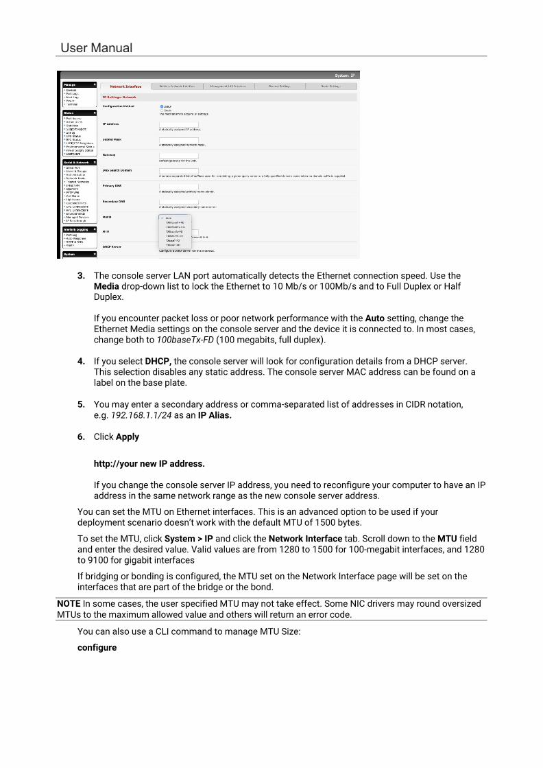
1. Click System > IP and click the Network Interface tab.
2. Choose either DHCP or Static for the Configuration Method.
If you choose Static, enter the IP Address, Subnet Mask, Gateway and DNS server details. This selection disables the DHCP client.
User Manual
3. The console server LAN port automatically detects the Ethernet connection speed. Use the Media drop-down list to lock the Ethernet to 10 Mb/s or 100Mb/s and to Full Duplex or Half Duplex.
If you encounter packet loss or poor network performance with the Auto setting, change the Ethernet Media settings on the console server and the device it is connected to. In most cases, change both to 100baseTx-FD (100 megabits, full duplex).
4. If you select DHCP, the console server will look for configuration details from a DHCP server.
This selection disables any static address. The console server MAC address can be found on a label on the base plate.
5. You may enter a secondary address or comma-separated list of addresses in CIDR notation,
e.g. 192.168.1.1/24 as an IP Alias.
6. Click Apply
http://your new IP address.
If you change the console server IP address, you need to reconfigure your computer to have an IP address in the same network range as the new console server address.
You can set the MTU on Ethernet interfaces. This is an advanced option to be used if your deployment scenario doesn’t work with the default MTU of 1500 bytes.
To set the MTU, click System > IP and click the Network Interface tab. Scroll down to the MTU field and enter the desired value. Valid values are from 1280 to 1500 for 100-megabit interfaces, and 1280 to 9100 for gigabit interfaces
If bridging or bonding is configured, the MTU set on the Network Interface page will be set on the interfaces that are part of the bridge or the bond.
NOTE In some cases, the user specified MTU may not take effect. Some NIC drivers may round oversized MTUs to the maximum allowed value and others will return an error code.
You can also use a CLI command to manage MTU Size:
configure

Chapter 2: System Configuration
14
# config -s config.interfaces.wan.mtu=1380
check
# config -g config.interfaces.wan config.interfaces.wan.address 192.168.2.24 config.interfaces.wan.ddns.provider none config.interfaces.wan.gateway 192.168.2.1 config.interfaces.wan.ipv6.mode stateless config.interfaces.wan.media Auto config.interfaces.wan.mode static config.interfaces.wan.mtu 1380 config.interfaces.wan.netmask 255.255.255.0
2.3.1 IPv6 configuration The console server Ethernet interfaces support IPv4 by default. They can be configured for IPv6 operation:
1. Click System > IP. Click the General Settings tab and check Enable IPv6. If desired, click the
Disable IPv6 for Cellular checkbox.
2. Configure the IPv6 parameters on each interface page.
IPv6 can be configured for either Automatic mode, which will use SLAAC or DHCPv6 to configure addresses, routes, and DNS, or Static mode, which allows the address information to be manually entered.
2.3.2 Dynamic DNS (DDNS) configuration With Dynamic DNS (DDNS), a console server whose IP address is dynamically assigned can be located using a fixed host or domain name.
Create an account with the supported DDNS service provider of your choice. When you set up your DDNS account, you choose a username, password, and hostname that you will use as the DNS name. DDNS service providers let you choose a hostname URL and set an initial IP address to correspond to that hostname URL.
To enable and configure DDNS on any of the Ethernet or cellular network connections on the console
User Manual
server:
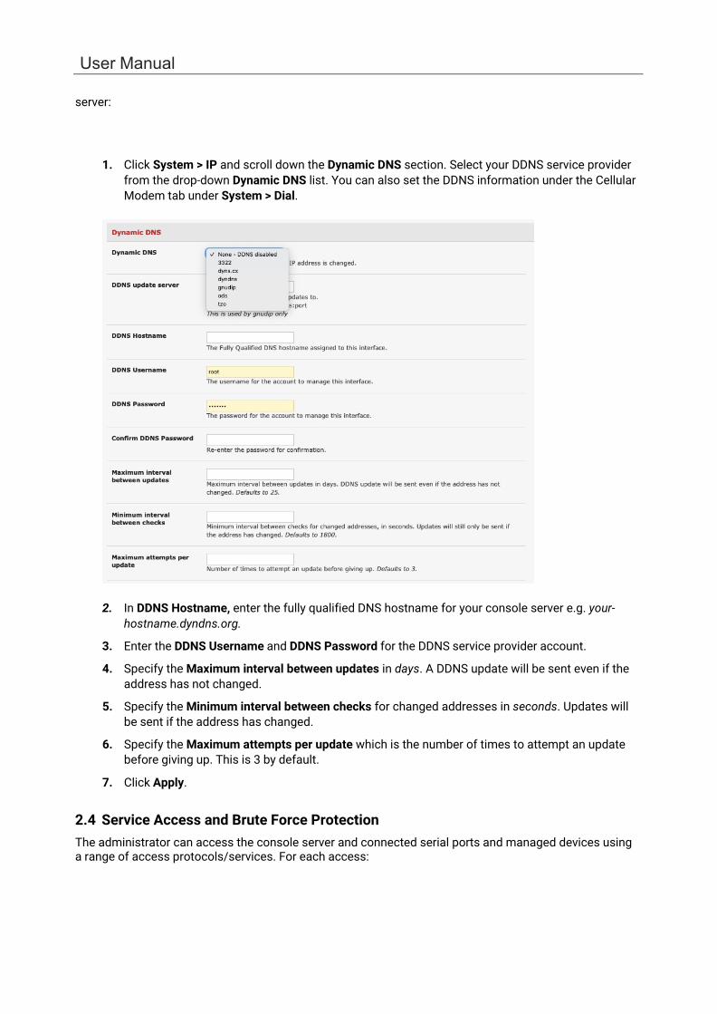
1. Click System > IP and scroll down the Dynamic DNS section. Select your DDNS service provider from the drop-down Dynamic DNS list. You can also set the DDNS information under the Cellular Modem tab under System > Dial.
2. In DDNS Hostname, enter the fully qualified DNS hostname for your console server e.g. your-
hostname.dyndns.org.
3. Enter the DDNS Username and DDNS Password for the DDNS service provider account.
4. Specify the Maximum interval between updates in days. A DDNS update will be sent even if the address has not changed.
5. Specify the Minimum interval between checks for changed addresses in seconds. Updates will be sent if the address has changed.
6. Specify the Maximum attempts per update which is the number of times to attempt an update before giving up. This is 3 by default.
7. Click Apply.
2.4 Service Access and Brute Force Protection The administrator can access the console server and connected serial ports and managed devices using a range of access protocols/services. For each access:

Chapter 2: System Configuration
16
• The service must first be configured and enabled to run on the console server. • Access through the firewall must be enabled for each network connection.
To enable and configure a service:
1. Click System > Services and click the Service Settings tab.
2. Enable and configure basic services:
HTTP By default, HTTP service is running and cannot be fully disabled. By default, HTTP
access is disabled on all interfaces. We recommend this access remain disabled if the console server is accessed remotely over the Internet.
Alternate HTTP lets you to configure an alternate HTTP port to listen on. The HTTP service will continue listening on TCP port 80 for CMS and SDT Connector communications but will be inaccessible through the firewall.
HTTPS By default, HTTPS service is running and enabled on all network interfaces. It is
recommended that only HTTPS access be used if the console server is to be managed over any public network. This ensures administrators have secure browser access to all the menus on the console server. It also allows appropriately configured users secure browser access to selected Manage menus.
The HTTPS service can be disabled or reenabled by checking HTTPS Web Management and an alternate port specified (default port is 443).
Telnet By default the Telnet service is running but disabled on all network interfaces.
Telnet can be used to give an administrator access to the system command line shell. This service may be useful for local administrator and the user access to selected serial consoles. We recommended that you disable this service if the console server is remotely administered.
The Enable Telnet command shell checkbox will enable or disable the Telnet service. An alternate Telnet port to listen on can be specified in Alternate Telnet Port (default port is 23).
User Manual
SSH This service provides secure SSH access to the console server and attached devices – and by default the SSH service is running and enabled on all interfaces. It is recommended you choose SSH as the protocol where an administrator connects to the console server over the Internet or any other public network. This will provide authenticated communications between the SSH client program on the remote computer and the SSH sever in the console server. For more information on SSH configuration See Chapter 8 - Authentication.
The Enable SSH command shell checkbox will enable or disable this service. An alternate SSH port to listen on can be specified in SSH command shell port (default port is 22).
3. Enable and configure other services:
TFTP/FTP If a USB flash card or internal flash is detected on an console server, checking Enable
TFTP (FTP) service enables this service and set up default tftp and ftp server on the USB flash. These servers are used to store config files, maintain access and transaction logs etc. Files transferred using tftp and ftp will be stored under /var/mnt/storage.usb/tftpboot/ (or /var/mnt/storage.nvlog/tftpboot/ on ACM7000- series devices). Unchecking Enable TFTP (FTP) service will disable the TFTP (FTP) service.
DNS Relay Checking Enable DNS Server/Relay enables the DNS relay feature so clients can be
configured with the console server's IP for their DNS server setting, and the console server will forward the DNS queries to the real DNS server.
Web Terminal Checking Enable Web Terminal allows web browser access to the system
command line shell via Manage > Terminal.
4. Specify alternate port numbers for Raw TCP, direct Telnet/SSH and unauthenticated Telnet/SSH services. The console server uses specific ranges for the TCP/IP ports for the various access services that users can use to access devices attached to serial ports (as covered in Chapter 3 – Configure Serial Ports). The administrator can set alternate ranges for these services and these secondary ports will be used in addition to the defaults.
The default TCP/IP base port address for Telnet access is 2000, and the range for Telnet is IP Address: Port (2000 + serial port #) i.e. 2001 – 2048. If an administrator were to set 8000 as a secondary base for Telnet, serial port #2 on the console server can be Telnet accessed at IP Address:2002 and at IP Address:8002. The default base for SSH is 3000; for Raw TCP is 4000; and for RFC2217 it is 5000
5. Other services can be enabled and configured from this menu by selecting Click here to
configure:
Nagios Access to the Nagios NRPE monitoring daemons
NUT Access to the NUT UPS monitoring daemon
SNMP Enables netsnmp in the console server. SNMP is disabled by default
NTP
6. Click Apply. A confirmation message appears: Message Changes to configuration succeeded
The Services Access settings can be set to allow or block access. This specifies which enabled services administrators can use over each network interface to connect to the console server and through the console server to attached serial and network connected devices.

Chapter 2: System Configuration
18
1. Select the Service Access tab on the System > Services page.
2. This displays the enabled services for the console server’s network interfaces. Depending on the
particular console server model the interfaces displayed may include:
• Network interface (for the principal Ethernet connection)
• Management LAN / OOB Failover (second Ethernet connections)
• Dialout /Cellular (V90 and 3G modem)
• Dial-in (internal or external V90 modem)
• Wi-Fi (802.11 wireless)
• VPN (IPsec or Open VPN connection over any network interface)
3. Check/uncheck for each network which service access is to be enabled /disabled
The Respond to ICMP echoes (i.e. ping) service access options that can be configured at this stage. This allows the console server to respond to incoming ICMP echo requests. Ping is enabled by default. For increased security, you should disable this service when you complete initial configuration
You can allow serial port devices to be accessed from nominated network interfaces using Raw TCP, direct Telnet/SSH, unauthenticated Telnet/SSH services, etc.
4. Click Apply
Web Management Settings
The Enable HSTS checkbox enables strict HTTP strict transport security. HSTS mode means that a Strict- Transport-Security header should be sent over HTTPS transport. A compliant web browser remembers this header, and when asked to contact the same host over HTTP (plain) it will automatically switch to

User Manual
HTTPS before attempting HTTP, as long as the browser has accessed the secure site once and seen the S-T-S header.
Brute Force Protection
Brute force protection (Micro Fail2ban) temporarily blocks source IPs that show malicious signs, such as too many password failures. This may help when the device’s network services are exposed to an untrusted network such as the public WAN and scripted attacks or software worms are attempting to guess (brute force) user credentials and gain unauthorized access.
Brute Force Protection may be enabled for the listed services. By default, once protection is enabled 3 or more failed connection attempts within 60 seconds from a specific source IP trigger it to be banned from connecting for a configurable time period. Attempt limit and Ban timeout may be customized. Active Bans are also listed and may be refreshed by reloading the page.
NOTE When running on an untrusted network, consider using a variety of strategies are used to lock down remote access. This includes SSH public key authentication, VPN, and Firewall Rules to allowlist remote access from trusted source networks only. See the Opengear Knowledge Base for details.
2.5 Communications Software You have configured access protocols for the administrator client to use when connecting to the console server. User clients also use these protocols when accessing console server serial attached devices and network attached hosts. You need communications software tools set up on the administrator and user client’s computer. Opengear provides the SDT Connector as the recommended client software tool. You may use other tools such as PuTTY and SSHTerm.
SDT Connector is a lightweight tool that enables users to securely access the Console server and various computers, network devices, and appliances that are serially or network connected to the console server.
Chapter 2: System Configuration
20
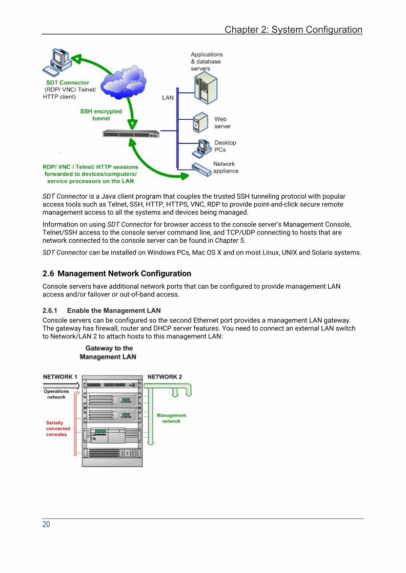
SDT Connector is a Java client program that couples the trusted SSH tunneling protocol with popular access tools such as Telnet, SSH, HTTP, HTTPS, VNC, RDP to provide point-and-click secure remote management access to all the systems and devices being managed.
Information on using SDT Connector for browser access to the console server’s Management Console, Telnet/SSH access to the console server command line, and TCP/UDP connecting to hosts that are network connected to the console server can be found in Chapter 5.
SDT Connector can be installed on Windows PCs, Mac OS X and on most Linux, UNIX and Solaris systems.
2.6 Management Network Configuration Console servers have additional network ports that can be configured to provide management LAN access and/or failover or out-of-band access.
2.6.1 Enable the Management LAN Console servers can be configured so the second Ethernet port provides a management LAN gateway. The gateway has firewall, router and DHCP server features. You need to connect an external LAN switch to Network/LAN 2 to attach hosts to this management LAN:
User Manual
NOTE The second Ethernet port can be configured as either a Management LAN gateway port or as an OOB/Failover port. Ensure you did not allocate NET2 as the Failover Interface when you configured the principal Network connection on the System > IP menu.
To configure the Management LAN gateway:
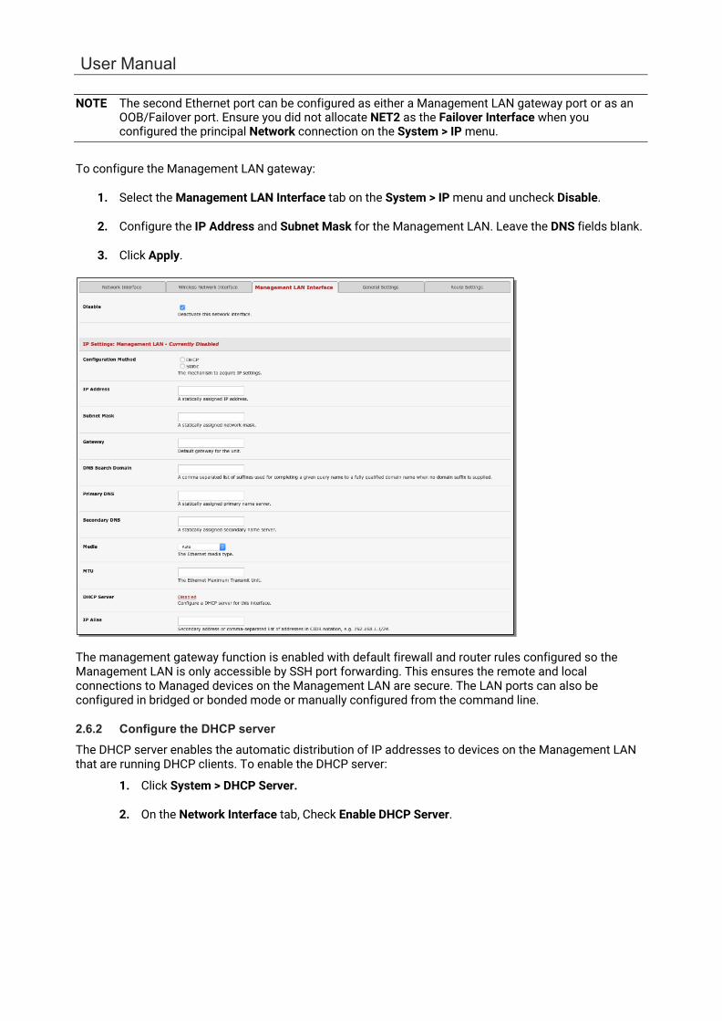
1. Select the Management LAN Interface tab on the System > IP menu and uncheck Disable.
2. Configure the IP Address and Subnet Mask for the Management LAN. Leave the DNS fields blank.
3. Click Apply.
The management gateway function is enabled with default firewall and router rules configured so the Management LAN is only accessible by SSH port forwarding. This ensures the remote and local connections to Managed devices on the Management LAN are secure. The LAN ports can also be configured in bridged or bonded mode or manually configured from the command line.
2.6.2 Configure the DHCP server The DHCP server enables the automatic distribution of IP addresses to devices on the Management LAN that are running DHCP clients. To enable the DHCP server:
1. Click System > DHCP Server.
2. On the Network Interface tab, Check Enable DHCP Server.

Chapter 2: System Configuration
22
3. Enter the Gateway address to be issued to the DHCP clients. If this field is left blank, the console server’s IP address is used.
4. Enter the Primary DNS and Secondary DNS address to issue the DHCP clients. If this field is left blank, console server’s IP address is used.
5. Optionally enter a Domain Name suffix to issue DHCP clients.
6. Enter the Default Lease time and Maximum Lease time in seconds. This is the amount of time that a dynamically assigned IP address is valid before the client must request it again.
7. Click Apply
The DHCP server issues IP addresses from specified address pools:
1. Click Add in the Dynamic Address Allocation Pools field.
2. Enter the DHCP Pool Start Address and End Address.
3. Click Apply.
The DHCP server also supports pre-assigning IP addresses to be allocated to specific MAC addresses and reserving IP addresses to be used by connected hosts with fixed IP addresses. To reserve an IP address for a particular host:
1. Click Add in the Reserved Addresses field
User Manual
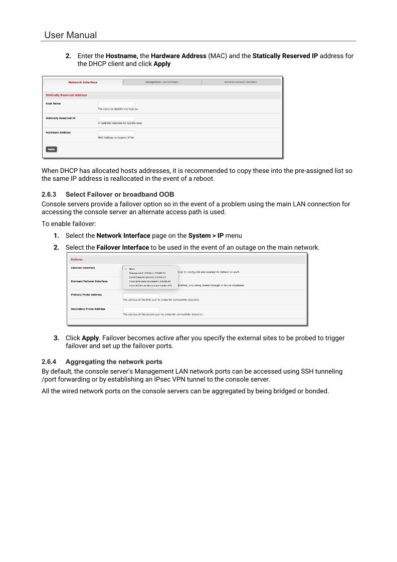
2. Enter the Hostname, the Hardware Address (MAC) and the Statically Reserved IP address for the DHCP client and click Apply
When DHCP has allocated hosts addresses, it is recommended to copy these into the pre-assigned list so the same IP address is reallocated in the event of a reboot.
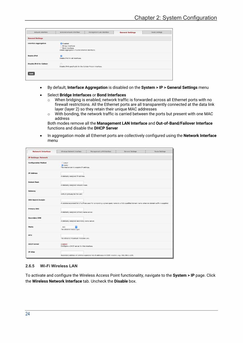
2.6.3 Select Failover or broadband OOB Console servers provide a failover option so in the event of a problem using the main LAN connection for accessing the console server an alternate access path is used.
To enable failover:
1. Select the Network Interface page on the System > IP menu
2. Select the Failover Interface to be used in the event of an outage on the main network.
3. Click Apply. Failover becomes active after you specify the external sites to be probed to trigger failover and set up the failover ports.
2.6.4 Aggregating the network ports By default, the console server's Management LAN network ports can be accessed using SSH tunneling /port forwarding or by establishing an IPsec VPN tunnel to the console server.
All the wired network ports on the console servers can be aggregated by being bridged or bonded.
Chapter 2: System Configuration
24
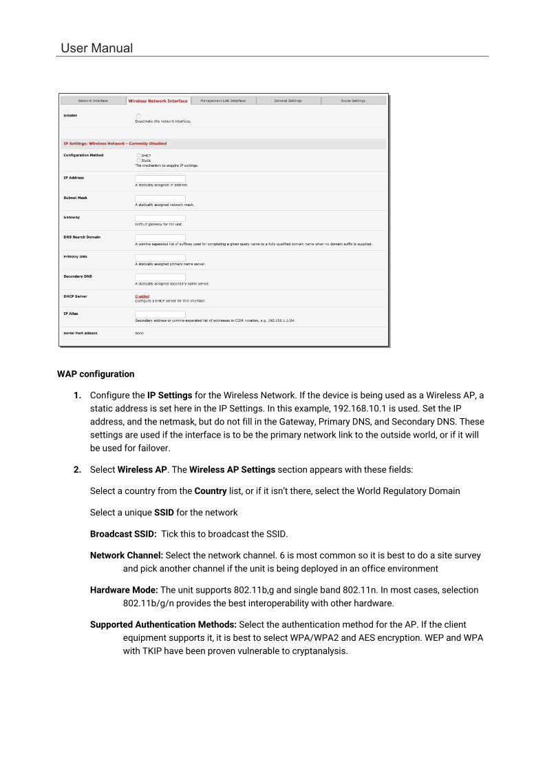
• By default, Interface Aggregation is disabled on the System > IP > General Settings menu
• Select Bridge Interfaces or Bond Interfaces o When bridging is enabled, network traffic is forwarded across all Ethernet ports with no
firewall restrictions. All the Ethernet ports are all transparently connected at the data link layer (layer 2) so they retain their unique MAC addresses
o With bonding, the network traffic is carried between the ports but present with one MAC address
Both modes remove all the Management LAN Interface and Out-of-Band/Failover Interface functions and disable the DHCP Server
• In aggregation mode all Ethernet ports are collectively configured using the Network Interface menu
2.6.5 Wi-Fi Wireless LAN
To activate and configure the Wireless Access Point functionality, navigate to the System > IP page. Click the Wireless Network Interface tab. Uncheck the Disable box.
User Manual
WAP configuration
1. Configure the IP Settings for the Wireless Network. If the device is being used as a Wireless AP, a static address is set here in the IP Settings. In this example, 192.168.10.1 is used. Set the IP address, and the netmask, but do not fill in the Gateway, Primary DNS, and Secondary DNS. These settings are used if the interface is to be the primary network link to the outside world, or if it will be used for failover.
2. Select Wireless AP. The Wireless AP Settings section appears with these fields:
Select a country from the Country list, or if it isn’t there, select the World Regulatory Domain
Select a unique SSID for the network
Broadcast SSID: Tick this to broadcast the SSID.
Network Channel: Select the network channel. 6 is most common so it is best to do a site survey and pick another channel if the unit is being deployed in an office environment
Hardware Mode: The unit supports 802.11b,g and single band 802.11n. In most cases, selection 802.11b/g/n provides the best interoperability with other hardware.
Supported Authentication Methods: Select the authentication method for the AP. If the client equipment supports it, it is best to select WPA/WPA2 and AES encryption. WEP and WPA with TKIP have been proven vulnerable to cryptanalysis.

Chapter 2: System Configuration
26
If WEP is selected:
• WEP Mode: Select Open System or Shared System. Open System is more secure than Shared, due to the way encryption keys are used.
• WEP Key Length: Select the WEP key length. 128-bit keys offer more security but are not supported on all devices. WEP Keys must be entered in Hexadecimal.
• WEP Key 1-4: Up to 4 WEP keys can be used on a single network.
• Default Transmit Key: This selects the default transmit key for the network
If WPA/WPA2 is selected:
• WPA/WPA2 Encryption Methods: Select one or both of TKIP or AES for encrypting WPA/WPA2 connections. AES is more secure and required for the AP to advertise itself as 802.11n if that hardware mode is selected
• WPA Password: The password that clients use to connect to the AP.
3. Once the Wireless AP Settings have been filled out, click Apply. Wait for the page to refresh.
The next step is to set up a DHCP server for the wireless clients. Click the link next to DHCP Server in the IP settings section, or go to System > DHCP Server page. More information on configuring DHCP can be found in Chapter 2.6.
The Wireless screen on the Status > Statistics page shows the list of clients that are connected to the WAP
Wireless Client configuration
1. Select Wireless Client in the Wireless Settings section - which makes the Wireless Client Settings section visible. Select DHCP or Static for the Configuration Method
o For Static, enter the new IP Address, Subnet Mask, Gateway and DNS server details. This selection disables the DHCP client
o For DHCP, the device looks for configuration details from a DHCP server on your management LAN. This selection disables any static address. The device MAC address can be found on a label on the base plate

User Manual
2. The wireless LAN when enabled in client mode operates as the main network connection to the device so failover is available. Use Failover Interface to select the device to failover to in case of wireless outage and specify Probe Addresses of the peers to probed for connectivity detection
3. Configure the Wireless Client to select the local wireless network which serves as the main network connection to the console server.
o Select the Country the device is to operate in
o Enter the appropriate SSID (Set Service Identifier) of the wireless access point to connect to
o Select the Wireless Network Type where Infrastructure is used to connect to an access point and Ad-hoc to connect to a computer
o Select the Wireless Security mode of the wireless network (WEP, WPA etc.) and enter the required Key / Authentication / Encryption settings
NOTE The Wireless Network Interface screen in Status > Statistics displays all locally accessible wireless LANs (with SSID and Encryption/Authentication settings). You can also use this screen to confirm you have connected to the selected access point.
2.6.6 Static routes Static routes provide a very quick way to route data from one subnet to different subnet. You can hard code a path that tells the console server/router to get to a certain subnet using a certain path. This may be useful for accessing various subnets at a remote site when using the cellular OOB connection.

Chapter 2: System Configuration
28
To add to the static route to the route table of the System:
1. Select the Route Settings tab on the System > IP General Settings menu.
2. Click New Route
3. Enter a Route Name for the route.
4. In the Destination Network/Host field, enter the IP address of the destination network/host that the route provides access to.
5. Enter a value in the Destination netmask field that identifies the destination network or host. Any number between 0 and 32. A subnet mask of 32 identifies a host route.
6. Enter Route Gateway with the IP address of a router that will routes packets to the destination network. This may be left blank.
7. Select the Interface to use to reach the destination, may be left as None.
8. Enter a value in the Metric field that represents the metric of this connection. Use any number equal to or greater than 0. This only has to be set if two or more routes conflict or have overlapping targets.
9. Click Apply.
NOTE The route details page provides a list of network interfaces and modems to which a route can be bound. In the case of a modem, the route will be attached to any dialup session established via that device. A route can be specified with a gateway, an interface or both. If the specified interface is not active, routes configured for that interface will not be active.
User Manual
3. SERIAL PORT, HOST, DEVICE & USER CONFIGURATION
The console server enables access and control of serially-attached devices and network-attached devices (hosts). The administrator must configure access privileges for each of these devices and specify the services that can be used to control the devices. The administrator can also set up new users and specify each user’s individual access and control privileges.
This chapter covers each of the steps in configuring network connected and serially attached devices:
• Serial Ports – setting up protocols used serially connected devices
• Users & Groups – setting up users and defining the access permissions for each of these users
• Authentication – this is covered in more detail in Chapter 8
• Network Hosts – configuring access to local network connected computers or appliances (hosts)
• Configuring Trusted Networks - nominate IP addresses that trusted users access from
• Cascading and Redirection of Serial Console Ports
• Connecting to power (UPS, PDU, and IPMI) and environmental monitoring (EMD) devices
• Serial Port Redirection – using the PortShare windows and Linux clients
• Managed Devices - presents a consolidated view of all the connections
• IPSec – enabling VPN connection
• OpenVPN
• PPTP
3.1 Configure Serial Ports The first step in configuring a serial port is to set the Common Settings such as the protocols and the RS232 parameters that are to be used for the data connection to that port (e.g. baud rate).
Select what mode the port is to operate in. Each port can be set to support one of these operating modes:
• Disabled mode is the default, the serial port is inactive

30
Chapter 3: Serial Port, Device and User Configuration
• Console server mode enables general access to serial console port on the serially attached devices
• Device mode sets the serial port up to communicate with an intelligent serial controlled PDU, UPS or Environmental Monitor Devices (EMD)
• SDT mode enables graphical console access (with RDP, VNC, HTTPS etc.) to hosts that are serially connected
• Terminal Server mode sets the serial port to await an incoming terminal login session
• Serial Bridge mode enables the transparent interconnection of two serial port devices over a network
1. Select Serial & Network > Serial Port to display serial port details
2. By default, each serial port is set in Console server mode. Click Edit next to the port to be reconfigured. Or click Edit Multiple Ports and select which ports you wish to configure as a group.
3. When you have reconfigured the common settings and the mode for each port, set up any remote syslog (see the following sections for specific information). Click Apply
4. If the console server has been configured with distributed Nagios monitoring enabled, use
Nagios Settings options to enable nominated services on the Host to be monitored
3.1.1 Common Settings There are a number of common settings that can be set for each serial port. These are independent of the mode in which the port is being used. These serial port parameters must be set so they match the serial port parameters on the device you attach to that port:

User Manual
• Type in a label for the port
• Select the appropriate Baud Rate, Parity, Data Bits, Stop Bits and Flow Control for each port
• Set the Port Pinout. This menu item appears for IM7200 ports where pin-out for each RJ45 serial port can be set as either X2 (Cisco Straight) or X1 (Cisco Rolled)
• Set the DTR mode. This allows you to choose if DTR is always asserted or only asserted when
there is an active user session
• Before proceeding with further serial port configuration, you should connect the ports to the serial devices they will be controlling and ensure they have matching settings
3.1.2 Console Server Mode
Select Console server Mode to enable remote management access to the serial console that is attached to this serial port:
Logging Level This specifies the level of information to be logged and monitored.

32
Chapter 3: Serial Port, Device and User Configuration
Level 0: Disable logging (default)
Level 1: Log LOGIN, LOGOUT and SIGNAL events
Level 2: Log LOGIN, LOGOUT, SIGNAL, TXDATA and RXDATA events
Level 3: Log LOGIN, LOGOUT, SIGNAL and RXDATA events
Level 4: Log LOGIN, LOGOUT, SIGNAL and TXDATA events
Input/RXDATA is data received by the Opengear device from the connected serial device, and output/TXDATA is data sent by the Opengear device (e.g. typed by the user) to the connected serial device.
Device consoles typically echo back characters as they are typed so TXDATA typed by a user is subsequently received as RXDATA, displayed on their terminal.
NOTE: After prompting for a password, the connected device sends * characters to prevent the password from being displayed.
Telnet When the Telnet service is enabled on the console server, a Telnet client on a user’s computer can
connect to a serial device attached to this serial port on the console server. Because Telnet communications are unencrypted, this protocol is only recommended for local or VPN tunneled connections.
If the remote communications are being tunneled with SDT Connector, Telnet can be used for securely accessing these attached devices.
NOTE In console server mode, users can use SDT Connector to set up secure Telnet connections that are SSH tunneled from their client computers to the serial port on the console server. SDT Connector can be installed on Windows PCs and most Linux platforms and it enables secure Telnet connections to be selected with point-and-click.
To use SDT Connector to access consoles on the console server serial ports, configure SDT Connector with the console server as a gateway, and as a host, and enable Telnet service on Port (2000 + serial port #) i.e. 2001–2048.
You can also use standard communications packages like PuTTY to set a direct Telnet or SSH connection to the serial ports.
NOTE In Console server mode, when you connect to a serial port you connect via pmshell. To generate a BREAK on the serial port, type the character sequence ~b. If you’re doing this over OpenSSH type ~~b.
SSH It is recommended that you use SSH as the protocol when users connect to the console server (or connect through the console server to the attached serial consoles) over the Internet or any other public network.
For SSH access to the consoles on devices attached to the console server serial ports, you can use SDT Connector. Configure SDT Connector with the console server as a gateway, and as a host, and enable SSH service on Port (3000 + serial port #) i.e. 3001-3048.
You can also use common communications packages, like PuTTY or SSHTerm to SSH connect to port address IP Address _ Port (3000 + serial port #) i.e. 3001–3048
SSH connections can be configured using the standard SSH port 22. The serial port being accessed is identified by appending a descriptor to the username. This syntax supports:
<username>:<portXX>
<username>:<port label>
User Manual
<username>:<ttySX>
<username>:<serial>
For a user named chris to access serial port 2, when setting up the SSHTerm or the PuTTY SSH client, instead of typing username = chris and ssh port = 3002, the alternate is to type username = chris:port02 (or username = chris:ttyS1) and ssh port = 22.
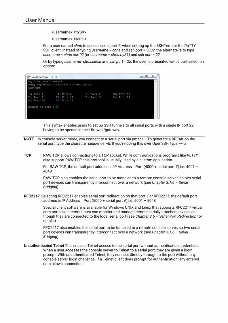
Or by typing username=chris:serial and ssh port = 22, the user is presented with a port selection option:
This syntax enables users to set up SSH tunnels to all serial ports with a single IP port 22 having to be opened in their firewall/gateway
NOTE In console server mode, you connect to a serial port via pmshell. To generate a BREAK on the serial port, type the character sequence ~b. If you’re doing this over OpenSSH, type ~~b.
TCP RAW TCP allows connections to a TCP socket. While communications programs like PuTTY also support RAW TCP, this protocol is usually used by a custom application
For RAW TCP, the default port address is IP Address _ Port (4000 + serial port #) i.e. 4001 – 4048
RAW TCP also enables the serial port to be tunneled to a remote console server, so two serial port devices can transparently interconnect over a network (see Chapter 3.1.6 – Serial Bridging)
RFC2217 Selecting RFC2217 enables serial port redirection on that port. For RFC2217, the default port
address is IP Address _ Port (5000 + serial port #) i.e. 5001 – 5048
Special client software is available for Windows UNIX and Linux that supports RFC2217 virtual com ports, so a remote host can monitor and manage remote serially attached devices as though they are connected to the local serial port (see Chapter 3.6 – Serial Port Redirection for details)
RFC2217 also enables the serial port to be tunneled to a remote console server, so two serial port devices can transparently interconnect over a network (see Chapter 3.1.6 – Serial Bridging)
Unauthenticated Telnet This enables Telnet access to the serial port without authentication credentials.
When a user accesses the console server to Telnet to a serial port, they are given a login prompt. With unauthenticated Telnet, they connect directly through to the port without any console server login challenge. If a Telnet client does prompt for authentication, any entered data allows connection.
34
Chapter 3: Serial Port, Device and User Configuration
This mode is used with an external system (such as conserver) managing user authentication and access privileges at the serial device level.
Logging into a device connected to the console server may require authentication.
For Unauthenticated Telnet the default port address is IP Address _ Port (6000 + serial port #) i.e. 6001 – 6048
Unauthenticated SSH This enables SSH access to the serial port without authentication credentials. When
a user accesses the console server to Telnet to a serial port, they are given a login prompt. With unauthenticated SSH they connect directly through to the port without any console server login challenge.
This mode is used when you have another system managing user authentication and access privileges at the serial device level but wish to encrypt the session across the network.
Logging into a device connected to the console server may require authentication.
For Unauthenticated Telnet the default port address is IP Address _ Port (7000 + serial port #) i.e. 7001 – 7048
The <username>: method of port access (as described in the above SSH section) always requires authentication.
Web Terminal This enables web browser access to the serial port via Manage > Devices: Serial using the
Management Console's built in AJAX terminal. Web Terminal connects as the currently authenticated Management Console user and does not re-authenticate. See section 12.3 for more details.
IP Alias Enable access to the serial port using a specific IP address, specified in CIDR format. Each
serial port can be assigned one or more IP aliases, configured on a per-network-interface basis. A serial port can, for example, be made accessible at both 192.168.0.148 (as part of the internal network) and 10.10.10.148 (as part of the Management LAN). It is also possible to make a serial port available on two IP addresses on the same network (for example, 192.168.0.148 and 192.168.0.248).
These IP addresses can only be used to access the specific serial port, accessible using the standard protocol TCP port numbers of the console server services. For example, SSH on serial port 3 would be accessible on port 22 of a serial port IP alias (whereas on the console server’s primary address it is available on port 2003).
This feature can also be configured via the multiple port edit page. In this case the IP addresses are applied sequentially, with the first selected port getting the IP entered and subsequent ones getting incremented, with numbers being skipped for any unselected ports. For example, if ports 2, 3 and 5 are selected and the IP alias 10.0.0.1/24 is entered for the Network Interface, the following addresses are assigned:
Port 2: 10.0.0.1/24
Port 3: 10.0.0.2/24
Port 5: 10.0.0.4/24
IP Aliases also support IPv6 alias addresses. The only difference is that addresses are hexadecimal numbers, so port 10 may correspond to an address ending in A, and 11 to one ending in B, rather than 10 or 11 as per IPv4.
User Manual
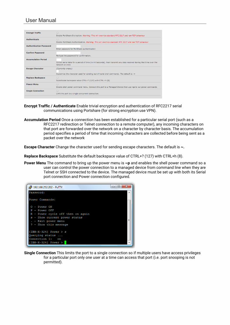
Encrypt Traffic / Authenticate Enable trivial encryption and authentication of RFC2217 serial communications using Portshare (for strong encryption use VPN).
Accumulation Period Once a connection has been established for a particular serial port (such as a
RFC2217 redirection or Telnet connection to a remote computer), any incoming characters on that port are forwarded over the network on a character by character basis. The accumulation period specifies a period of time that incoming characters are collected before being sent as a packet over the network
Escape Character Change the character used for sending escape characters. The default is ~.
Replace Backspace Substitute the default backspace value of CTRL+? (127) with CTRL+h (8).
Power Menu The command to bring up the power menu is ~p and enables the shell power command so a user can control the power connection to a managed device from command line when they are Telnet or SSH connected to the device. The managed device must be set up with both its Serial port connection and Power connection configured.
Single Connection This limits the port to a single connection so if multiple users have access privileges for a particular port only one user at a time can access that port (i.e. port snooping is not permitted).

36
Chapter 3: Serial Port, Device and User Configuration
3.1.3 SDT Mode This setting allows port forwarding of RDP, VNC, HTPP, HTTPS, SSH, Telnet, and other LAN protocols to computers that are locally connected to the console server by their serial COM port. Such port forwarding requires a PPP link to be set up over this serial port.
For configuration details See Chapter 5.
3.1.4 Device (RPC, UPS, Environmental) Mode This mode configures the selected serial port to communicate with a serial controlled Uninterruptable Power Supply (UPS), Remote Power Controller / Power Distribution Units (RPC) or Environmental Monitoring Device (Environmental)
1. Select the desired Device Type (UPS, RPC, or Environmental)
2. Proceed to the appropriate device configuration page (Serial & Network > UPS Connections, RPC Connection or Environmental) as detailed in Chapter 7.
3.1.5 Terminal Server Mode
• Select Terminal Server Mode and the Terminal Type (vt220, vt102, vt100, Linux or ANSI) to enable a getty on the selected serial port
The getty configures the port and wait for a connection to be made. An active connection on a serial device is indicated by the raised Data Carrier Detect (DCD) pin on the serial device. When a connection is detected, the getty program issues a login: prompt, and invokes the login program to handle the system login.
NOTE Selecting Terminal Server mode disables Port Manager for that serial port, so data is no longer logged for alerts etc.
User Manual
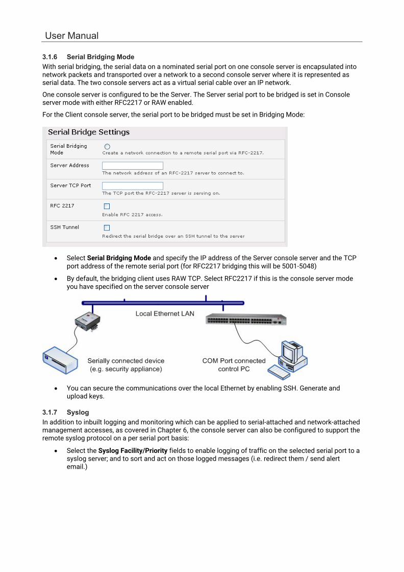
3.1.6 Serial Bridging Mode With serial bridging, the serial data on a nominated serial port on one console server is encapsulated into network packets and transported over a network to a second console server where it is represented as serial data. The two console servers act as a virtual serial cable over an IP network.
One console server is configured to be the Server. The Server serial port to be bridged is set in Console server mode with either RFC2217 or RAW enabled.
For the Client console server, the serial port to be bridged must be set in Bridging Mode:
• Select Serial Bridging Mode and specify the IP address of the Server console server and the TCP port address of the remote serial port (for RFC2217 bridging this will be 5001-5048)
• By default, the bridging client uses RAW TCP. Select RFC2217 if this is the console server mode you have specified on the server console server
• You can secure the communications over the local Ethernet by enabling SSH. Generate and upload keys.
3.1.7 Syslog In addition to inbuilt logging and monitoring which can be applied to serial-attached and network-attached management accesses, as covered in Chapter 6, the console server can also be configured to support the remote syslog protocol on a per serial port basis:
• Select the Syslog Facility/Priority fields to enable logging of traffic on the selected serial port to a syslog server; and to sort and act on those logged messages (i.e. redirect them / send alert email.)
Chapter 3: Serial Port, Device and User Configuration
38
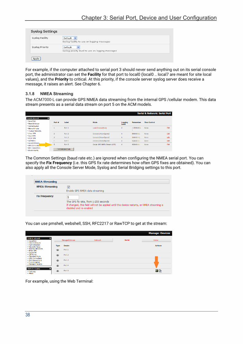
For example, if the computer attached to serial port 3 should never send anything out on its serial console port, the administrator can set the Facility for that port to local0 (local0 .. local7 are meant for site local values), and the Priority to critical. At this priority, if the console server syslog server does receive a message, it raises an alert. See Chapter 6.
3.1.8 NMEA Streaming The ACM7000-L can provide GPS NMEA data streaming from the internal GPS /cellular modem. This data stream presents as a serial data stream on port 5 on the ACM models.
The Common Settings (baud rate etc.) are ignored when configuring the NMEA serial port. You can specify the Fix Frequency (i.e. this GPS fix rate determines how often GPS fixes are obtained). You can also apply all the Console Server Mode, Syslog and Serial Bridging settings to this port.
You can use pmshell, webshell, SSH, RFC2217 or RawTCP to get at the stream:
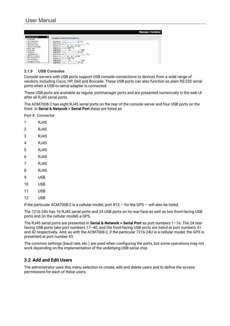
For example, using the Web Terminal:
User Manual
3.1.9 USB Consoles Console servers with USB ports support USB console connections to devices from a wide range of vendors, including Cisco, HP, Dell and Brocade. These USB ports can also function as plain RS-232 serial ports when a USB-to-serial adapter is connected.
These USB ports are available as regular portmanager ports and are presented numerically in the web UI after all RJ45 serial ports.
The ACM7008-2 has eight RJ45 serial ports on the rear of the console server and four USB ports on the front. In Serial & Network > Serial Port these are listed as
Port # Connector
1 RJ45
2 RJ45
3 RJ45
4 RJ45
5 RJ45
6 RJ45
7 RJ45
8 RJ45
9 USB
10 USB
11 USB
12 USB
If the particular ACM7008-2 is a cellular model, port #13 — for the GPS — will also be listed.
The 7216-24U has 16 RJ45 serial ports and 24 USB ports on its rear-face as well as two front-facing USB ports and (in the cellular model) a GPS.
The RJ45 serial ports are presented in Serial & Network > Serial Port as port numbers 1–16. The 24 rear- facing USB ports take port numbers 17–40, and the front-facing USB ports are listed at port numbers 41 and 42 respectively. And, as with the ACM7008-2, if the particular 7216-24U is a cellular model, the GPS is presented at port number 43.
The common settings (baud rate, etc.) are used when configuring the ports, but some operations may not work depending on the implementation of the underlying USB serial chip.
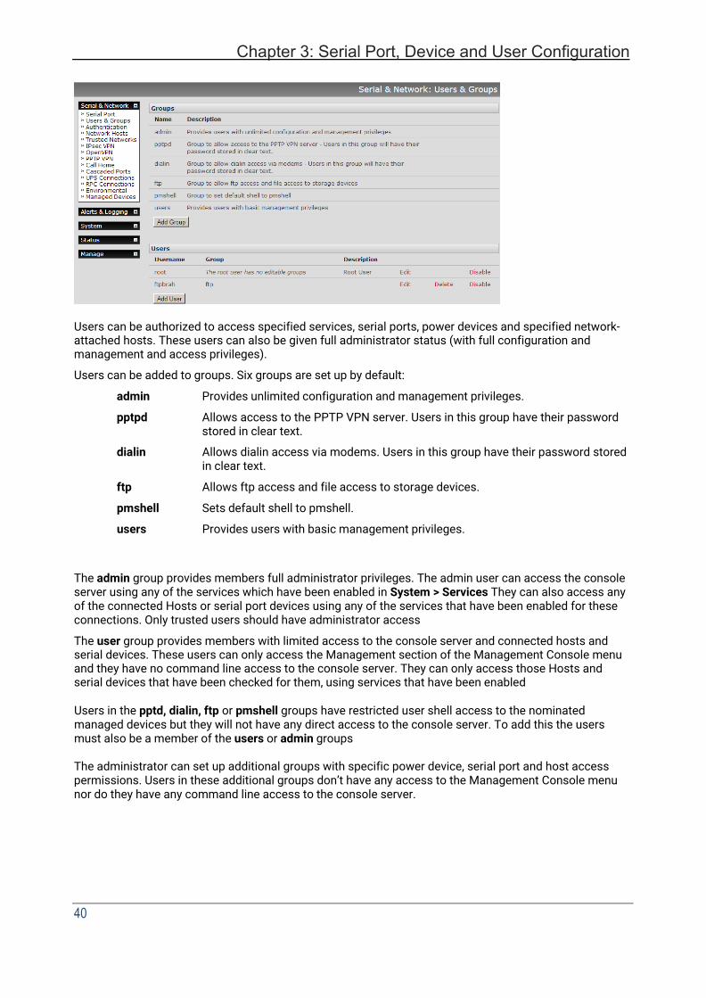
3.2 Add and Edit Users The administrator uses this menu selection to create, edit and delete users and to define the access permissions for each of these users.
Chapter 3: Serial Port, Device and User Configuration
40
Users can be authorized to access specified services, serial ports, power devices and specified network- attached hosts. These users can also be given full administrator status (with full configuration and management and access privileges).
Users can be added to groups. Six groups are set up by default:
admin Provides unlimited configuration and management privileges.
pptpd Allows access to the PPTP VPN server. Users in this group have their password stored in clear text.
dialin Allows dialin access via modems. Users in this group have their password stored in clear text.
ftp Allows ftp access and file access to storage devices.
pmshell Sets default shell to pmshell.
users Provides users with basic management privileges.
The admin group provides members full administrator privileges. The admin user can access the console server using any of the services which have been enabled in System > Services They can also access any of the connected Hosts or serial port devices using any of the services that have been enabled for these connections. Only trusted users should have administrator access
The user group provides members with limited access to the console server and connected hosts and serial devices. These users can only access the Management section of the Management Console menu and they have no command line access to the console server. They can only access those Hosts and serial devices that have been checked for them, using services that have been enabled
Users in the pptd, dialin, ftp or pmshell groups have restricted user shell access to the nominated managed devices but they will not have any direct access to the console server. To add this the users must also be a member of the users or admin groups
The administrator can set up additional groups with specific power device, serial port and host access permissions. Users in these additional groups don’t have any access to the Management Console menu nor do they have any command line access to the console server.
User Manual
The administrator can set up users with specific power device, serial port and host access permissions who are not a member of any groups. These users don’t have any access to the Management Console menu nor command line access to the console server.
For convenience, the SDT Connector Retrieve Hosts function retrieves and auto-configures checked serial ports and checked hosts only, even for admin group users.
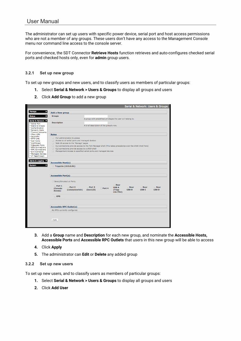
3.2.1 Set up new group
To set up new groups and new users, and to classify users as members of particular groups:
1. Select Serial & Network > Users & Groups to display all groups and users
2. Click Add Group to add a new group
3. Add a Group name and Description for each new group, and nominate the Accessible Hosts,
Accessible Ports and Accessible RPC Outlets that users in this new group will be able to access
4. Click Apply
5. The administrator can Edit or Delete any added group
3.2.2 Set up new users
To set up new users, and to classify users as members of particular groups:
1. Select Serial & Network > Users & Groups to display all groups and users
2. Click Add User

Chapter 3: Serial Port, Device and User Configuration
42
3. Add a Username for each new user. You may also include information related to the user (e.g.
contact details) in the Description field. The user Name can contain from 1 to 127 alphanumeric characters and the characters "-" "_" and ".".
4. Specify which Groups you wish the user to be a member of
5. Add a confirmed Password for each new user. All characters are allowed.
6. SSH pass-key authentication can be used. Paste the public keys of authorized public/private keypairs for this user in the Authorized SSH Keys field
7. Check Disable Password Authentication to only allow public key authentication for this user
when using SSH
8. Check Enable Dial-Back in the Dial-in Options menu to allow an out-going dial-back connection to be triggered by logging into this port. Enter the Dial-Back Phone Number with the phone number to call-back when user logs in
9. Check Accessible Hosts and/or Accessible Ports to nominate the serial ports and network
connected hosts you wish the user to have access privileges to
10. If there are configured RPCs, check Accessible RPC Outlets to specify which outlets the user is able to control (i.e. Power On/Off)
11. Click Apply.
The new user will be able to access the accessible Network Devices, Ports and RPC Outlets. If the user is a group member, they can also access any other device/port/outlet accessible to the group

User Manual
There are no limits on the number of users you can set up or the number of users per serial port or host. Multiple users can control/monitor the one port or host. There are no limits on the number of groups and each user can be a member of a number of groups. A user does not have to be a member of any groups, but if the user is a member of the default user group, they will not be able to use the Management Console to manage ports.
While there are no limits, the time to re-configure increases as the number and complexity increases. We recommend the aggregate number of users and groups be kept under 250.
The administrator can also edit the access settings for any existing users:
• Select Serial & Network > Users & Groups and click Edit to modify the user access privileges • Click Delete to remove the user • Click Disable to temporarily block access privileges
3.3 Authentication See Chapter 8 for authentication configuration details.
3.4 Network Hosts To monitor and remotely access a locally networked computer or device (referred to as a Host) you must identify the Host and specify the TCP or UDP ports/services used to control that Host:
1. Selecting Serial & Network > Network Hosts presents all the network connected Hosts that have been enabled for access, and the related access TCP ports/services
2. Click Add Host to enable access to a new Host (or select Edit to update the settings for existing Host)
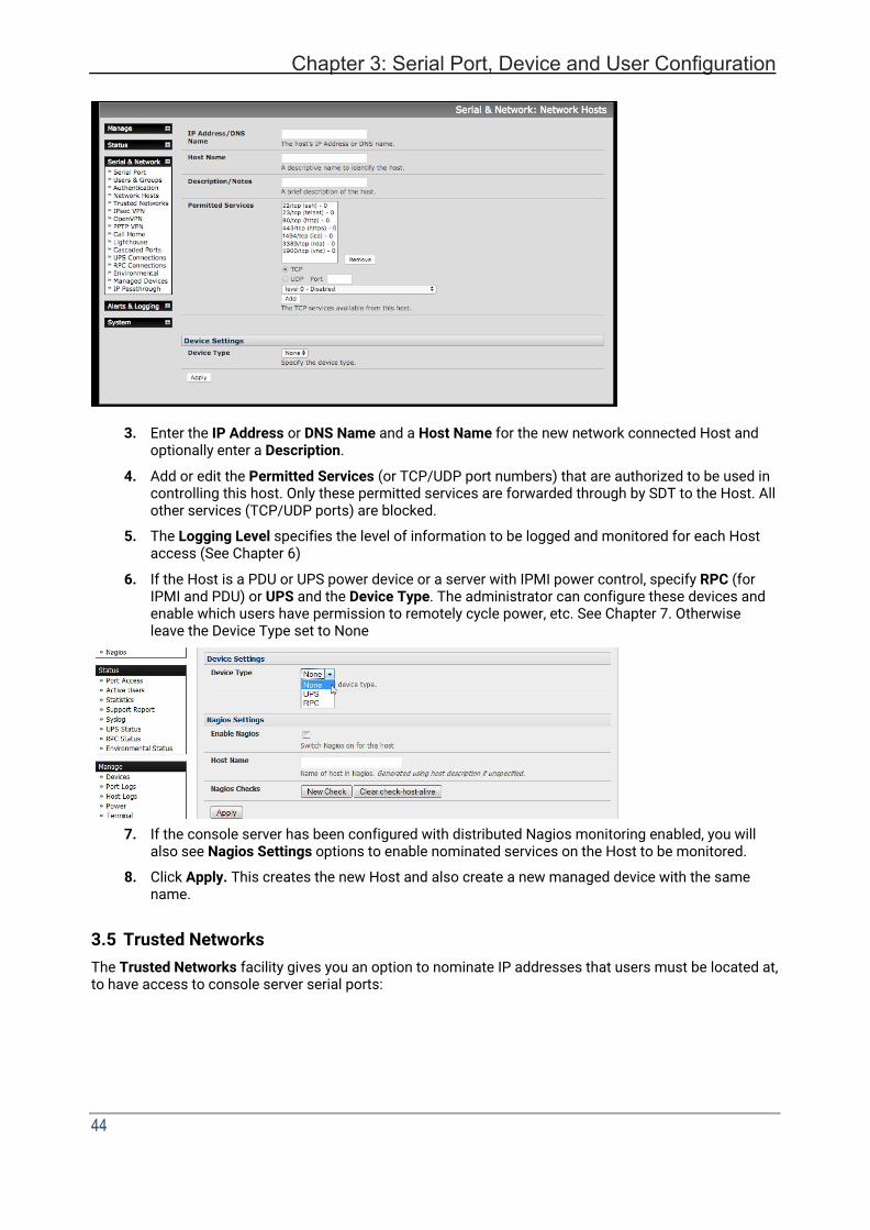
Chapter 3: Serial Port, Device and User Configuration
44
3. Enter the IP Address or DNS Name and a Host Name for the new network connected Host and optionally enter a Description.
4. Add or edit the Permitted Services (or TCP/UDP port numbers) that are authorized to be used in controlling this host. Only these permitted services are forwarded through by SDT to the Host. All other services (TCP/UDP ports) are blocked.
5. The Logging Level specifies the level of information to be logged and monitored for each Host access (See Chapter 6)
6. If the Host is a PDU or UPS power device or a server with IPMI power control, specify RPC (for IPMI and PDU) or UPS and the Device Type. The administrator can configure these devices and enable which users have permission to remotely cycle power, etc. See Chapter 7. Otherwise leave the Device Type set to None
7. If the console server has been configured with distributed Nagios monitoring enabled, you will also see Nagios Settings options to enable nominated services on the Host to be monitored.
8. Click Apply. This creates the new Host and also create a new managed device with the same name.
3.5 Trusted Networks The Trusted Networks facility gives you an option to nominate IP addresses that users must be located at, to have access to console server serial ports:
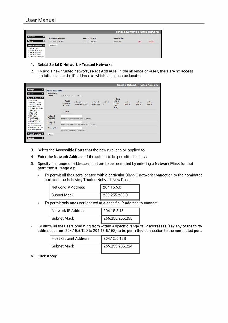
User Manual
1. Select Serial & Network > Trusted Networks
2. To add a new trusted network, select Add Rule. In the absence of Rules, there are no access limitations as to the IP address at which users can be located.
3. Select the Accessible Ports that the new rule is to be applied to
4. Enter the Network Address of the subnet to be permitted access
5. Specify the range of addresses that are to be permitted by entering a Network Mask for that permitted IP range e.g.
• To permit all the users located with a particular Class C network connection to the nominated port, add the following Trusted Network New Rule:
Network IP Address 204.15.5.0
Subnet Mask 255.255.255.0
• To permit only one user located at a specific IP address to connect:
Network IP Address 204.15.5.13
Subnet Mask 255.255.255.255
• To allow all the users operating from within a specific range of IP addresses (say any of the thirty addresses from 204.15.5.129 to 204.15.5.158) to be permitted connection to the nominated port:
Host /Subnet Address 204.15.5.128
Subnet Mask 255.255.255.224
6. Click Apply
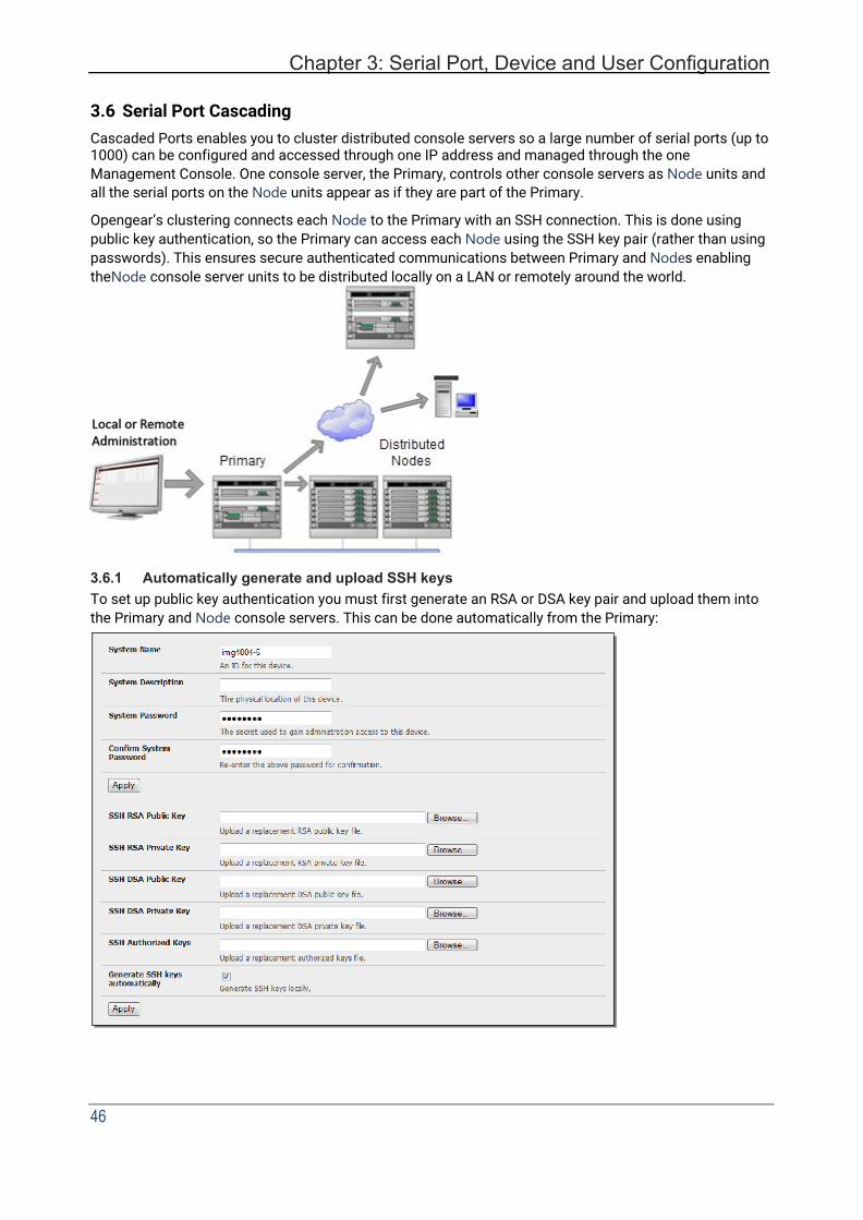
Chapter 3: Serial Port, Device and User Configuration
46
3.6 Serial Port Cascading Cascaded Ports enables you to cluster distributed console servers so a large number of serial ports (up to 1000) can be configured and accessed through one IP address and managed through the one Management Console. One console server, the Primary, controls other console servers as Node units and all the serial ports on the Node units appear as if they are part of the Primary.
Opengear’s clustering connects each Node to the Primary with an SSH connection. This is done using public key authentication, so the Primary can access each Node using the SSH key pair (rather than using passwords). This ensures secure authenticated communications between Primary and Nodes enabling the Node console server units to be distributed locally on a LAN or remotely around the world.
3.6.1 Automatically generate and upload SSH keys To set up public key authentication you must first generate an RSA or DSA key pair and upload them into the Primary and Node console servers. This can be done automatically from the Primary:

User Manual
1. Select System > Administration on Primary’s Management Console
2. Check Generate SSH keys automatically.
3. Click Apply
Next you must select whether to generate keys using RSA and/or DSA (if unsure, select only RSA). Generating each set of keys require two minutes and the new keys destroy old keys of that type. While the new generation is underway, functions relying on SSH keys (e.g. cascading) may stop functioning until they are updated with the new set of keys. To generate keys:
1. Check boxes for the keys you wish to generate.
2. Click Apply
3. Once the new keys have been generated, click the link Click here to return. The keys are uploaded
to the Primary and connected Nodes.
3.6.2 Manually generate and upload SSH keys Alternately if you have an RSA or DSA key pair you can upload them to the Primary and Node console servers.
To upload the key public and private key pair to the Primary console server:
1. Select System > Administration on the Primary’s Management Console
2. Browse to the location you have stored RSA (or DSA) Public Key and upload it to SSH RSA (DSA) Public Key
3. Browse to the stored RSA (or DSA) Private Key and upload it to SSH RSA (DSA) Private Key
4. Click Apply
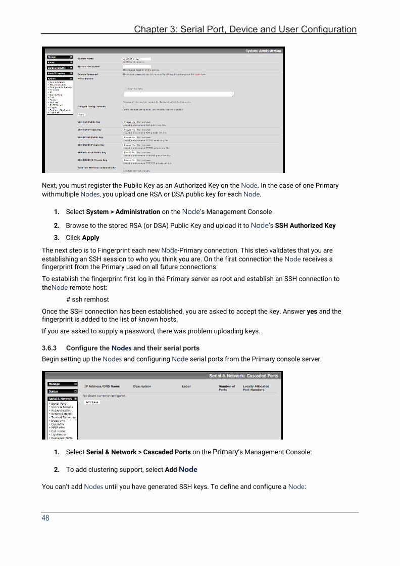
Chapter 3: Serial Port, Device and User Configuration
48
Next, you must register the Public Key as an Authorized Key on the Node. In the case of one Primary with multiple Nodes, you upload one RSA or DSA public key for each Node.
1. Select System > Administration on the Node’s Management Console
2. Browse to the stored RSA (or DSA) Public Key and upload it to Node’s SSH Authorized Key
3. Click Apply
The next step is to Fingerprint each new Node-Primary connection. This step validates that you are establishing an SSH session to who you think you are. On the first connection the Node receives a fingerprint from the Primary used on all future connections:
To establish the fingerprint first log in the Primary server as root and establish an SSH connection to the Node remote host:
# ssh remhost
Once the SSH connection has been established, you are asked to accept the key. Answer yes and the fingerprint is added to the list of known hosts.
If you are asked to supply a password, there was problem uploading keys.
3.6.3 Configure the Nodes and their serial ports Begin setting up the Nodes and configuring Node serial ports from the Primary console server:
1. Select Serial & Network > Cascaded Ports on the Primary’s Management Console:
2. To add clustering support, select Add Node
You can’t add Nodes until you have generated SSH keys. To define and configure a Node:

User Manual
1. Enter the remote IP Address or DNS Name for the Node console server
2. Enter a brief Description and a short Label for the Node
3. Enter the full number of serial ports on the Node unit in Number of Ports
4. Click Apply. This establishes the SSH tunnel between the Primary and the new Node
The Serial & Network > Cascaded Ports menu displays all the nodes and the port numbers that have been allocated on the Primary. If the Primary console server has 16 ports of its own, ports 1-16 are pre-allocated to the Primary, so the first node added is assigned port number 17 onwards.
Once you have added all the Node console servers, the Node serial ports and the connected devices are configurable and accessible from the Primary’s Management Console menu and accessible through the Primary’s IP address.
1. Select the appropriate Serial & Network > Serial Port and Edit to configure the serial ports on the Node.
2. Select the appropriate Serial & Network > Users & Groups to add new users with access privileges
to the Node serial ports (or to extend existing users access privileges).
3. Select the appropriate Serial & Network > Trusted Networks to specify network addresses that can access nominated node serial ports.
4. Select the appropriate Alerts & Logging > Alerts to configure Node port Connection, State Change or Pattern Match alerts. The configuration changes made on the Primary are propagated out to all the nodes when you click Apply.
3.6.4 Managing Nodes The Primary is in control of the Node serial ports. For example, if change a user access privileges or edit any serial port setting on the Primary, the updated configuration files are sent out to each Node in parallel. Each Node makes changes to their local configurations (and only makes changes that relate to its particular serial ports).
You can use the local Node Management Console to change the settings on any node serial port (such as alter the baud rates). These changes are overwritten next time the Primary sends out a configuration file update.
While the Primary is in control of all node serial port related functions, it is not primary over the node network host connections or over the Node Console Server system.
Node functions such as IP, SMTP & SNMP Settings, Date &Time, DHCP server must be managed by accessing each node directly and these functions are not over written when configuration changes are propagated from the Primary. The Node’s Network Host and IPMI settings must be configured at each node.

Chapter 3: Serial Port, Device and User Configuration
50
The Primary’s Management Console provides a consolidated view of the settings for its own and the entire Node’s serial ports. The Primary does not provide a fully consolidated view. For example, if you want to find out who is logged in to cascaded serial ports from the primary, you’ll see that Status > Active Users only displays those users active on the Primary’s ports, so you may need to write custom scripts to provide this view.
3.7 Serial Port Redirection (PortShare) Opengear’s Port Share software delivers the virtual serial port technology your Windows and Linux applications need to open remote serial ports and read the data from serial devices that are connected to your console server.
PortShare is supplied free with each console server and you are licensed to install PortShare on one or more computers for accessing any serial device connected to a console server port.
PortShare for Windows
The portshare_setup.exe can be downloaded from the ftp site. See the PortShare User Manual and Quick Start for details on installation and operation.
PortShare for Linux
The PortShare driver for Linux maps the console server serial port to a host try port. Opengear has released the portshare-serial-client as an open source utility for Linux, AIX, HPUX, SCO, Solaris and UnixWare. This utility can be downloaded from the ftp site.
This PortShare serial port redirector allows you to use a serial device connected to the remote console server as if it were connected to your local serial port. The portshare-serial-client creates a pseudo tty port, connects the serial application to the pseudo tty port, receives data from the pseudo tty port, transmits it to the console server through network and receives data from the console server through network and transmits it to the pseudo-tty port.
The .tar file can be downloaded from the ftp site. See the PortShare User Manual and Quick Start for details on installation and operation.

User Manual
3.8 Managed Devices The Managed Devices page presents a consolidated view of all the connections to a device that can be accessed and monitored through the console server. To view the connections to the devices, select Serial & Network > Managed Devices
This screen displays all the managed devices with their Description/Notes and lists of all the configured Connections:
• Serial Port # (if serially connected) or • USB (if USB connected) • IP Address (if network connected) • Power PDU/outlet details (if applicable) and any UPS connections
Devices such as servers may have more than one power connection (e.g. dual power supplied) and more than one network connection (e.g. for BMC/service processor).
All users can view these managed device connections by selecting Manage > Devices. Administrators can also edit and add/delete these managed devices and their connections.
To edit an existing device and add a new connection:
1. Select Edit on the Serial & Network > Managed Devices and click Add Connection
2. Select the connection type for the new connection (Serial, Network Host, UPS or RPC) and select the connection from the presented list of configured unallocated hosts/ports/outlets
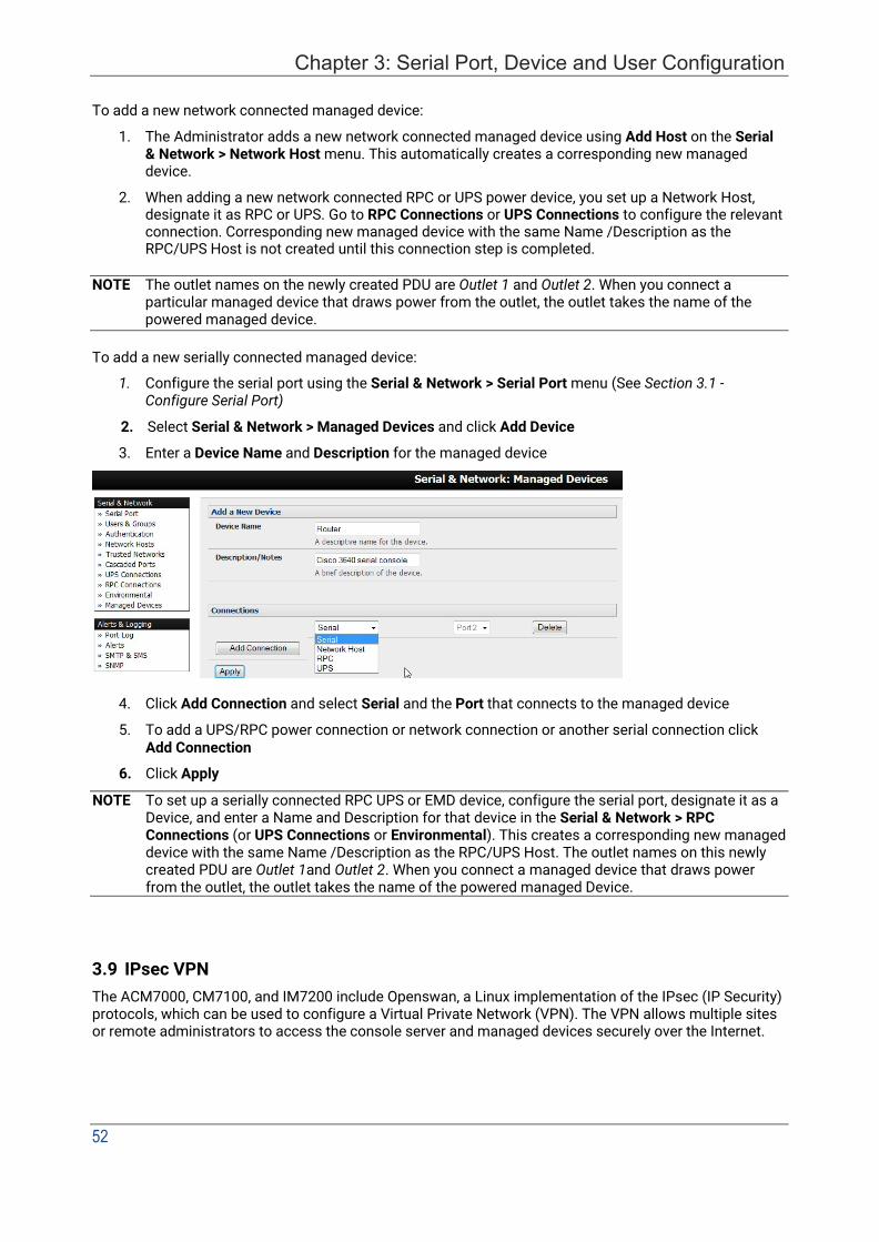
52
Chapter 3: Serial Port, Device and User Configuration
To add a new network connected managed device:
1. The Administrator adds a new network connected managed device using Add Host on the Serial & Network > Network Host menu. This automatically creates a corresponding new managed device.
2. When adding a new network connected RPC or UPS power device, you set up a Network Host, designate it as RPC or UPS. Go to RPC Connections or UPS Connections to configure the relevant connection. Corresponding new managed device with the same Name /Description as the RPC/UPS Host is not created until this connection step is completed.
NOTE The outlet names on the newly created PDU are Outlet 1 and Outlet 2. When you connect a particular managed device that draws power from the outlet, the outlet takes the name of the powered managed device.
To add a new serially connected managed device:
1. Configure the serial port using the Serial & Network > Serial Port menu (See Section 3.1 - Configure Serial Port)
2. Select Serial & Network > Managed Devices and click Add Device
3. Enter a Device Name and Description for the managed device
4. Click Add Connection and select Serial and the Port that connects to the managed device
5. To add a UPS/RPC power connection or network connection or another serial connection click Add Connection
6. Click Apply
NOTE To set up a serially connected RPC UPS or EMD device, configure the serial port, designate it as a Device, and enter a Name and Description for that device in the Serial & Network > RPC Connections (or UPS Connections or Environmental). This creates a corresponding new managed device with the same Name /Description as the RPC/UPS Host. The outlet names on this newly created PDU are Outlet 1and Outlet 2. When you connect a managed device that draws power from the outlet, the outlet takes the name of the powered managed Device.
3.9 IPsec VPN The ACM7000, CM7100, and IM7200 include Openswan, a Linux implementation of the IPsec (IP Security) protocols, which can be used to configure a Virtual Private Network (VPN). The VPN allows multiple sites or remote administrators to access the console server and managed devices securely over the Internet.
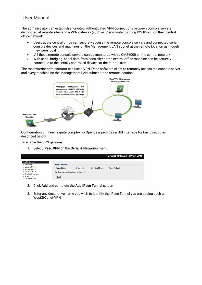
User Manual
The administrator can establish encrypted authenticated VPN connections between console servers distributed at remote sites and a VPN gateway (such as Cisco router running IOS IPsec) on their central office network:
• Users at the central office can securely access the remote console servers and connected serial console devices and machines on the Management LAN subnet at the remote location as though they were local
• All these remote console servers can be monitored with a CMS6000 on the central network • With serial bridging, serial data from controller at the central office machine can be securely
connected to the serially controlled devices at the remote sites
The road warrior administrator can use a VPN IPsec software client to remotely access the console server and every machine on the Management LAN subnet at the remote location
Configuration of IPsec is quite complex so Opengear provides a GUI interface for basic set up as described below.
To enable the VPN gateway:
1. Select IPsec VPN on the Serial & Networks menu
2. Click Add and complete the Add IPsec Tunnel screen
3. Enter any descriptive name you wish to identify the IPsec Tunnel you are adding such as WestStOutlet-VPN
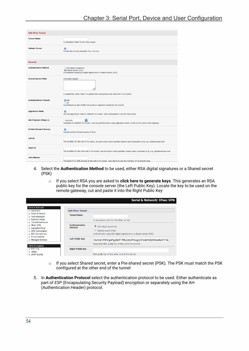
Chapter 3: Serial Port, Device and User Configuration
54
4. Select the Authentication Method to be used, either RSA digital signatures or a Shared secret (PSK)
o If you select RSA you are asked to click here to generate keys. This generates an RSA public key for the console server (the Left Public Key). Locate the key to be used on the remote gateway, cut and paste it into the Right Public Key
o If you select Shared secret, enter a Pre-shared secret (PSK). The PSK must match the PSK
configured at the other end of the tunnel
5. In Authentication Protocol select the authentication protocol to be used. Either authenticate as part of ESP (Encapsulating Security Payload) encryption or separately using the AH (Authentication Header) protocol.

User Manual
6. Enter a Left ID and Right ID. This is the identifier that the Local host/gateway and remote host/gateway use for IPsec negotiation and authentication. Each ID must include an @ and can include a fully qualified domain name ( e.g. [email protected])
7. Enter the public IP or DNS address of this Opengear VPN gateway as the Left Address. You can
leave this blank to use the interface of the default route
8. In Right Address enter the public IP or DNS address of the remote end of the tunnel (only if the remote end has a static or dyndns address). Otherwise leave this blank
9. If the Opengear VPN gateway is serving as a VPN gateway to a local subnet (e.g. the console
server has a Management LAN configured) enter the private subnet details in Left Subnet. Use the CIDR notation (where the IP address number is followed by a slash and the number of ‘one’ bits in the binary notation of the netmask). For example, 192.168.0.0/24 indicates an IP address where the first 24 bits are used as the network address. This is the same as 255.255.255.0. If the VPN access is only to the console server and to its attached serial console devices, leave Left Subnet blank
10. If there is a VPN gateway at the remote end, enter the private subnet details in Right Subnet. Use
the CIDR notation and leave blank if there is only a remote host
11. Select Initiate Tunnel if the tunnel connection is to be initiated from the Left console server end. This can only be initiated from the VPN gateway (Left) if the remote end is configured with a static (or dyndns) IP address
12. Click Apply to save changes
NOTE Configuration details set up on the console server (referred to as the Left or Local host) must match the set up entered when configuring the Remote (Right) host/gateway or software client. See http://www.opengear.com/faq.html for details on configuring these remote ends
3.10 OpenVPN The ACM7000, CM7100, and IM7200 with firmware V3.2 and later include OpenVPN. OpenVPN uses the OpenSSL library for encryption, authentication, and certification, which means it uses SSL/TSL (Secure Socket Layer/Transport Layer Security) for key exchange and can encrypt both data and control channels. Using OpenVPN allows for the building of cross-platform, point-to-point VPNs using either X.509 PKI (Public Key Infrastructure) or custom configuration files.
OpenVPN allows secure tunneling of data through a single TCP/UDP port over an unsecured network, thus providing secure access to multiple sites and secure remote administration to a console server over the Internet.
OpenVPN also allows the use of Dynamic IP addresses by both the server and client thus providing client mobility. For example, an OpenVPN tunnel may be established between a roaming windows client and an Opengear console server within a data center.
Configuration of OpenVPN can be complex so Opengear provides a GUI interface for basic set up as described below. More detailed information is available at http://www.openvpn.net
3.10.1 Enable the OpenVPN
1. Select OpenVPN on the Serial & Networks menu

Chapter 3: Serial Port, Device and User Configuration
56
2. Click Add and complete the Add OpenVPN Tunnel screen
3. Enter any descriptive name you wish to identify the OpenVPN Tunnel you are adding, for example NorthStOutlet-VPN
4. Select the authentication method to be used. To authenticate using certificates select PKI (X.509 Certificates) or select Custom Configuration to upload custom configuration files. Custom configurations must be stored in /etc/config.
NOTE If you select PKI, establish: Separate certificate (also known as a public key). This Certificate File is a *.crt file type Private Key for the server and each client. This Private Key File is a *.key file type Primary Certificate Authority (CA) certificate and key which is used to sign each of the server
and client certificates. This Root CA Certificate is a *.crt file type For a server, you may also need dh1024.pem (Diffie Hellman parameters). See http://openvpn.net/easyrsa.html for a guide to basic RSA key management. For alternative authentication methods see http://openvpn.net/index.php/documentation/howto.html#auth.
5. Select the Device Driver to be used, either Tun-IP or Tap-Ethernet. The TUN (network tunnel) and TAP (network tap) drivers are virtual network drivers that support IP tunneling and Ethernet tunneling, respectively. TUN and TAP are part of the Linux kernel.
6. Select either UDP or TCP as the Protocol. UDP is the default and preferred protocol for OpenVPN.
7. Check or uncheck the Compression button to enable or disable compression.
8. In Tunnel Mode, nominate whether this is the Client or Server end of the tunnel. When running as a server, the console server supports multiple clients connecting to the VPN server over the same port.

User Manual
3.10.2 Configure as Server or Client
1. Complete the Client Details or Server Details depending on the Tunnel Mode selected.
o If Client has been selected, the Primary Server Address is the address of the OpenVPN Server.
o If Server has been selected, enter the IP Pool Network address and the IP Pool Network mask for the IP Pool. The network defined by the IP Pool Network address/mask is used to provide the addresses for connecting clients.
2. Click Apply to save changes
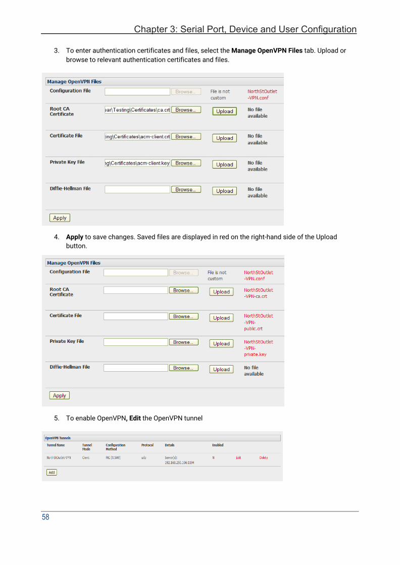
Chapter 3: Serial Port, Device and User Configuration
58
3. To enter authentication certificates and files, select the Manage OpenVPN Files tab. Upload or
browse to relevant authentication certificates and files.
4. Apply to save changes. Saved files are displayed in red on the right-hand side of the Upload button.
5. To enable OpenVPN, Edit the OpenVPN tunnel

User Manual
6. Check the Enabled button.
7. Apply to save changes
NOTE Make sure that the console server system time is correct when working with OpenVPN to avoid authentication issues.
8. Select Statistics on the Status menu to verify that the tunnel is operational.
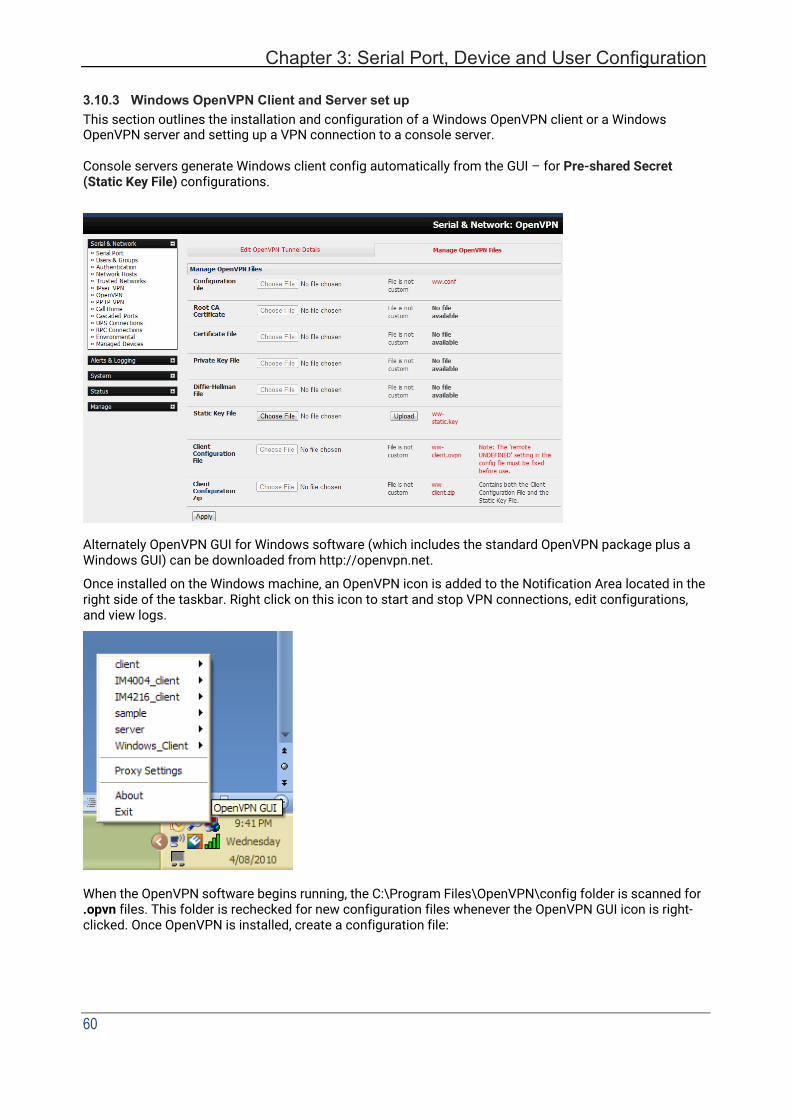
Chapter 3: Serial Port, Device and User Configuration
60
3.10.3 Windows OpenVPN Client and Server set up This section outlines the installation and configuration of a Windows OpenVPN client or a Windows OpenVPN server and setting up a VPN connection to a console server.
Console servers generate Windows client config automatically from the GUI – for Pre-shared Secret (Static Key File) configurations.
Alternately OpenVPN GUI for Windows software (which includes the standard OpenVPN package plus a Windows GUI) can be downloaded from http://openvpn.net.
Once installed on the Windows machine, an OpenVPN icon is added to the Notification Area located in the right side of the taskbar. Right click on this icon to start and stop VPN connections, edit configurations, and view logs.
When the OpenVPN software begins running, the C:\Program Files\OpenVPN\config folder is scanned for .opvn files. This folder is rechecked for new configuration files whenever the OpenVPN GUI icon is right- clicked. Once OpenVPN is installed, create a configuration file:

User Manual
Using a text editor, create an xxxx.ovpn file and save in C:\Program Files\OpenVPN\config. For example, C:\Program Files\OpenVPN\config\client.ovpn
An example of an OpenVPN Windows client configuration file is shown below:
# description: IM4216_client client proto udp verb 3 dev tun remote 192.168.250.152 port 1194 ca c:\\openvpnkeys\\ca.crt cert c:\\openvpnkeys\\client.crt key c:\\openvpnkeys\\client.key nobind persist-key persist-tun comp-lzo
An example of an OpenVPN Windows Server configuration file is shown below:
server 10.100.10.0 255.255.255.0 port 1194 keepalive 10 120 proto udp mssfix 1400 persist-key persist-tun dev tun ca c:\\openvpnkeys\\ca.crt cert c:\\openvpnkeys\\server.crt key c:\\openvpnkeys\\server.key dh c:\\openvpnkeys\\dh.pem comp-lzo verb 1 syslog IM4216_OpenVPN_Server
The Windows client/server configuration file options are:
Options Description #description: This is a comment describing the configuration.
Comment lines start with‘#’ and are ignored by OpenVPN. Client server
Specify whether this will be a client or server configuration file. In the server configuration file, define the IP address pool and netmask. For example, server 10.100.10.0 255.255.255.0
proto udp proto tcp
Set the protocol to UDP or TCP. The client and server must use the same settings.
mssfix <max. size> Mssfix sets the maximum size of the packet. This is only useful for UDP if problems occur.
verb <level> Set log file verbosity level. Log verbosity level can be set from 0 (minimum) to 15 (maximum). For example, 0 = silent except for fatal errors 3 = medium output, good for general usage 5 = helps with debugging connection problems 9 = verbose, excellent for troubleshooting
dev tun dev tap
Select ‘dev tun’ to create a routed IP tunnel or ‘dev tap’ to create an Ethernet tunnel. The client and server must use the same settings.
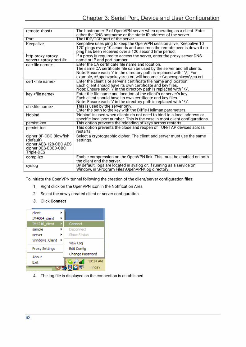
Chapter 3: Serial Port, Device and User Configuration
62
remote <host> The hostname/IP of OpenVPN server when operating as a client. Enter either the DNS hostname or the static IP address of the server.
Port The UDP/TCP port of the server. Keepalive Keepalive uses ping to keep the OpenVPN session alive. 'Keepalive 10
120' pings every 10 seconds and assumes the remote peer is down if no ping has been received over a 120 second time period.
http-proxy <proxy server> <proxy port #>
If a proxy is required to access the server, enter the proxy server DNS name or IP and port number.
ca <file name> Enter the CA certificate file name and location. The same CA certificate file can be used by the server and all clients. Note: Ensure each ‘\’ in the directory path is replaced with ‘ \\’. For example, c:\openvpnkeys\ca.crt will become c:\\openvpnkeys\\ca.crt
cert <file name> Enter the client’s or server’s certificate file name and location. Each client should have its own certificate and key files. Note: Ensure each ‘\’ in the directory path is replaced with ‘ \\’.
key <file name> Enter the file name and location of the client’s or server’s key. Each client should have its own certificate and key files. Note: Ensure each ‘\’ in the directory path is replaced with ‘ \\’.
dh <file name> This is used by the server only. Enter the path to the key with the Diffie-Hellman parameters.
Nobind ‘Nobind’ is used when clients do not need to bind to a local address or specific local port number. This is the case in most client configurations.
persist-key This option prevents the reloading of keys across restarts. persist-tun This option prevents the close and reopen of TUN/TAP devices across
restarts. cipher BF-CBC Blowfish (default) cipher AES-128-CBC AES cipher DES-EDE3-CBC Triple-DES
Select a cryptographic cipher. The client and server must use the same settings.
comp-lzo Enable compression on the OpenVPN link. This must be enabled on both the client and the server.
syslog By default, logs are located in syslog or, if running as a service on Window, in \Program Files\OpenVPN\log directory.
To initiate the OpenVPN tunnel following the creation of the client/server configuration files:
1. Right click on the OpenVPN icon in the Notification Area
2. Select the newly created client or server configuration.
3. Click Connect
4. The log file is displayed as the connection is established
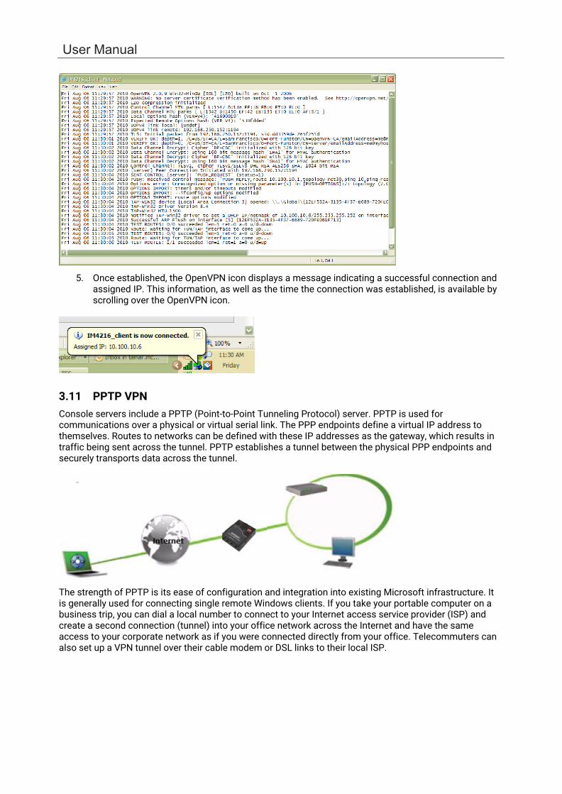
User Manual
5. Once established, the OpenVPN icon displays a message indicating a successful connection and assigned IP. This information, as well as the time the connection was established, is available by scrolling over the OpenVPN icon.
3.11 PPTP VPN Console servers include a PPTP (Point-to-Point Tunneling Protocol) server. PPTP is used for communications over a physical or virtual serial link. The PPP endpoints define a virtual IP address to themselves. Routes to networks can be defined with these IP addresses as the gateway, which results in traffic being sent across the tunnel. PPTP establishes a tunnel between the physical PPP endpoints and securely transports data across the tunnel.
The strength of PPTP is its ease of configuration and integration into existing Microsoft infrastructure. It is generally used for connecting single remote Windows clients. If you take your portable computer on a business trip, you can dial a local number to connect to your Internet access service provider (ISP) and create a second connection (tunnel) into your office network across the Internet and have the same access to your corporate network as if you were connected directly from your office. Telecommuters can also set up a VPN tunnel over their cable modem or DSL links to their local ISP.
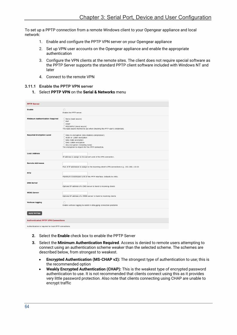
Chapter 3: Serial Port, Device and User Configuration
64
To set up a PPTP connection from a remote Windows client to your Opengear appliance and local network:
1. Enable and configure the PPTP VPN server on your Opengear appliance
2. Set up VPN user accounts on the Opengear appliance and enable the appropriate authentication
3. Configure the VPN clients at the remote sites. The client does not require special software as the PPTP Server supports the standard PPTP client software included with Windows NT and later
4. Connect to the remote VPN
3.11.1 Enable the PPTP VPN server 1. Select PPTP VPN on the Serial & Networks menu
2. Select the Enable check box to enable the PPTP Server
3. Select the Minimum Authentication Required. Access is denied to remote users attempting to connect using an authentication scheme weaker than the selected scheme. The schemes are described below, from strongest to weakest.
• Encrypted Authentication (MS-CHAP v2): The strongest type of authentication to use; this is the recommended option
• Weakly Encrypted Authentication (CHAP): This is the weakest type of encrypted password authentication to use. It is not recommended that clients connect using this as it provides very little password protection. Also note that clients connecting using CHAP are unable to encrypt traffic
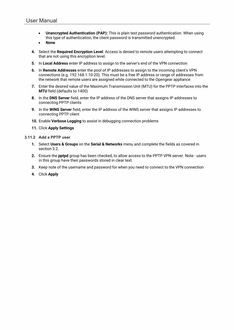
User Manual
• Unencrypted Authentication (PAP): This is plain text password authentication. When using this type of authentication, the client password is transmitted unencrypted.
• None
4. Select the Required Encryption Level. Access is denied to remote users attempting to connect that are not using this encryption level.
5. In Local Address enter IP address to assign to the server's end of the VPN connection
6. In Remote Addresses enter the pool of IP addresses to assign to the incoming client's VPN connections (e.g. 192.168.1.10-20). This must be a free IP address or range of addresses from the network that remote users are assigned while connected to the Opengear appliance
7. Enter the desired value of the Maximum Transmission Unit (MTU) for the PPTP interfaces into the MTU field (defaults to 1400)
8. In the DNS Server field, enter the IP address of the DNS server that assigns IP addresses to connecting PPTP clients
9. In the WINS Server field, enter the IP address of the WINS server that assigns IP addresses to connecting PPTP client
10. Enable Verbose Logging to assist in debugging connection problems
11. Click Apply Settings
3.11.2 Add a PPTP user 1. Select Users & Groups on the Serial & Networks menu and complete the fields as covered in
section 3.2.
2. Ensure the pptpd group has been checked, to allow access to the PPTP VPN server. Note - users in this group have their passwords stored in clear text.
3. Keep note of the username and password for when you need to connect to the VPN connection
4. Click Apply

Chapter 3: Serial Port, Device and User Configuration
66
3.11.3 Set up a remote PPTP client Ensure the remote VPN client PC has Internet connectivity. To create a VPN connection across the Internet, you must set up two networking connections. One connection is for the ISP, and the other connection is for the VPN tunnel to the Opengear appliance.
NOTE This procedure sets up a PPTP client in the Windows 7 Professional operating system. The steps may vary slightly depending on your network access or if you are using an alternate version of Windows. More detailed instructions are available from the Microsoft web site.
1. Login to your Windows client with administrator privileges
2. From the Network & Sharing Center on the Control Panel select Network Connections and create a new connection
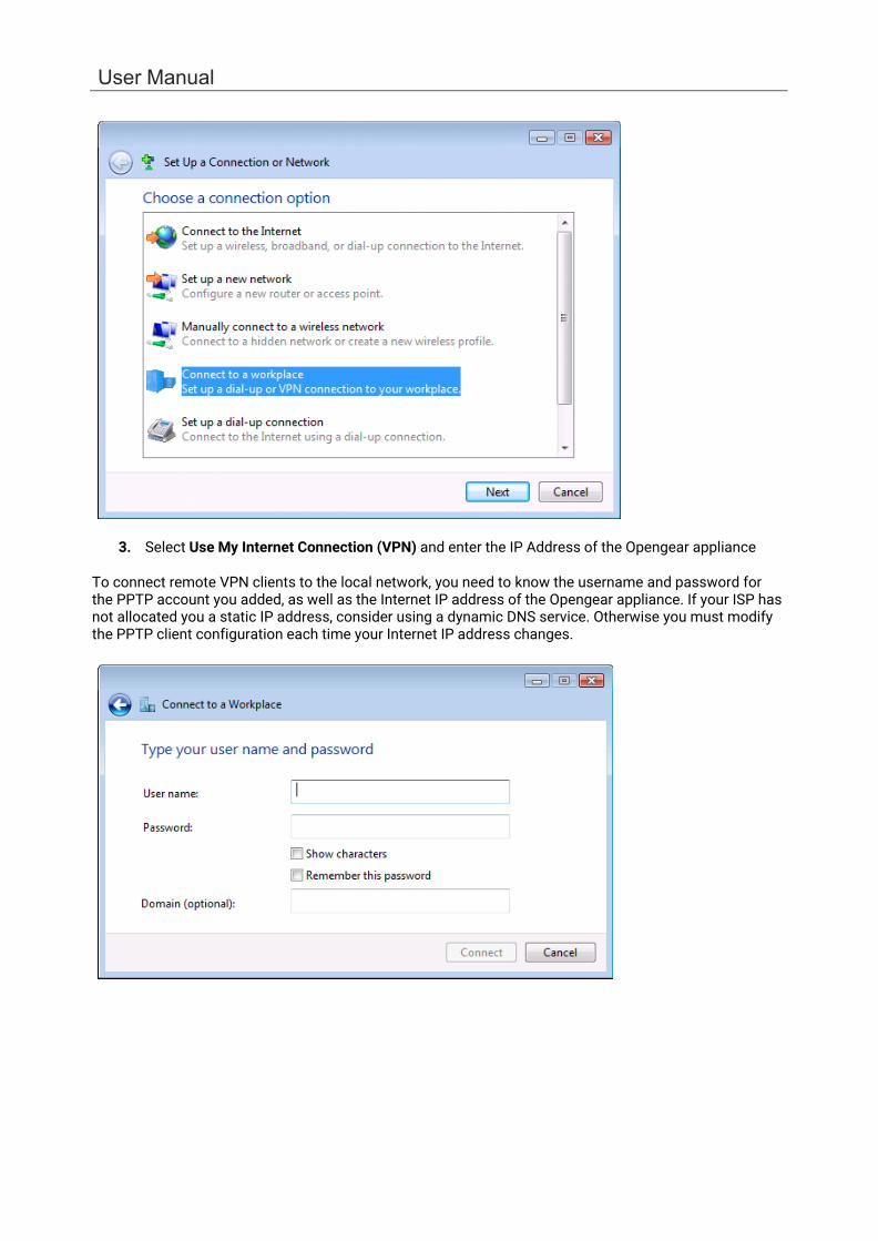
User Manual
3. Select Use My Internet Connection (VPN) and enter the IP Address of the Opengear appliance
To connect remote VPN clients to the local network, you need to know the username and password for the PPTP account you added, as well as the Internet IP address of the Opengear appliance. If your ISP has not allocated you a static IP address, consider using a dynamic DNS service. Otherwise you must modify the PPTP client configuration each time your Internet IP address changes.

Chapter 3: Serial Port, Device and User Configuration
68
3.12 Call Home All console servers include the Call Home feature which initiates the setup of a secure SSH tunnel from the console server to a centralized Lighthouse VM, Lighthouse Standard, Lighthouse Enterprise, CMS6100 or VCMS server (referred to as CMS). The console server registers as a candidate on the CMS. Once accepted there it becomes a Managed Console Server.
The CMS monitors the Managed Console Server and administrators can access the remote Managed Console Server through the CMS. This access is available even when the remote console server is behind a third-party firewall or has a private non-routable IP addresses.
NOTE CMS maintains public key authenticated SSH connections to each of its Managed Console Servers. These connections are used for monitoring, commanding and accessing the Managed Console Servers and the managed devices connected to the Managed Console Server.
To manage Local Console Servers, or console servers that are reachable from the CMS, the SSH connections are initiated by CMS.
To manage Remote Console Servers, or console servers that are firewalled, not routable, or otherwise unreachable from the CMS, the SSH connections are initiated by the Managed Console Server via an initial Call Home connection.
This ensures secure, authenticated communications and enables Managed Console Servers units to be distributed locally on a LAN, or remotely around the world.
3.12.1 Set up Call Home candidate To set up the console server as a Call Home management candidate on the CMS:
1. Select Call Home on the Serial & Network menu
2. If you have not already generated or uploaded an SSH key pair for this console server, do
so before proceeding
3. Click Add
4. Enter the IP address or DNS name (e.g. the dynamic DNS address) of the CMS
5. Enter the Password that you configured on the CMS as the Call Home Password
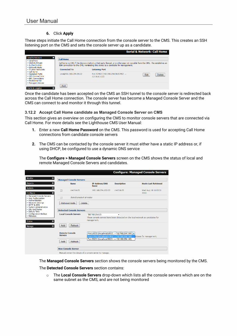
User Manual
6. Click Apply
These steps initiate the Call Home connection from the console server to the CMS. This creates an SSH listening port on the CMS and sets the console server up as a candidate.
Once the candidate has been accepted on the CMS an SSH tunnel to the console server is redirected back across the Call Home connection. The console server has become a Managed Console Server and the CMS can connect to and monitor it through this tunnel.
3.12.2 Accept Call Home candidate as Managed Console Server on CMS This section gives an overview on configuring the CMS to monitor console servers that are connected via Call Home. For more details see the Lighthouse CMS User Manual:
1. Enter a new Call Home Password on the CMS. This password is used for accepting Call Home connections from candidate console servers
2. The CMS can be contacted by the console server it must either have a static IP address or, if
using DHCP, be configured to use a dynamic DNS service
The Configure > Managed Console Servers screen on the CMS shows the status of local and remote Managed Console Servers and candidates.
The Managed Console Servers section shows the console servers being monitored by the CMS.
The Detected Console Servers section contains:
o The Local Console Servers drop-down which lists all the console servers which are on the same subnet as the CMS, and are not being monitored
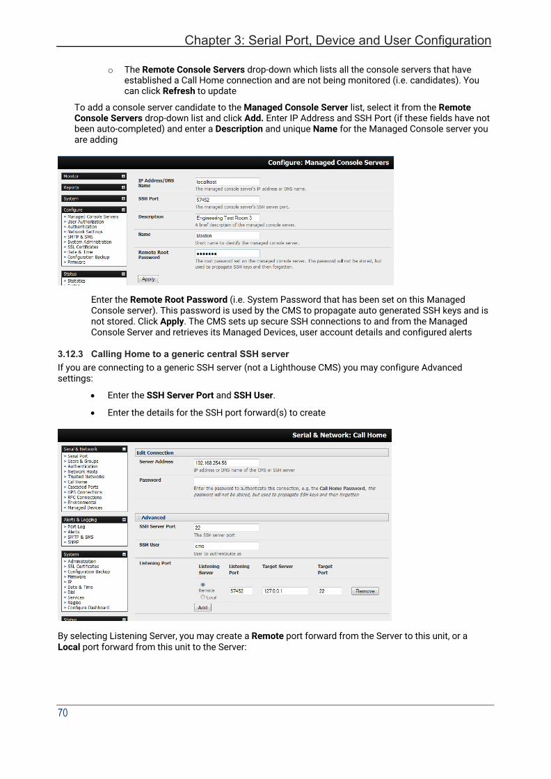
Chapter 3: Serial Port, Device and User Configuration
70
o The Remote Console Servers drop-down which lists all the console servers that have
established a Call Home connection and are not being monitored (i.e. candidates). You can click Refresh to update
To add a console server candidate to the Managed Console Server list, select it from the Remote Console Servers drop-down list and click Add. Enter IP Address and SSH Port (if these fields have not been auto-completed) and enter a Description and unique Name for the Managed Console server you are adding
Enter the Remote Root Password (i.e. System Password that has been set on this Managed Console server). This password is used by the CMS to propagate auto generated SSH keys and is not stored. Click Apply. The CMS sets up secure SSH connections to and from the Managed Console Server and retrieves its Managed Devices, user account details and configured alerts
3.12.3 Calling Home to a generic central SSH server If you are connecting to a generic SSH server (not a Lighthouse CMS) you may configure Advanced settings:
• Enter the SSH Server Port and SSH User.
• Enter the details for the SSH port forward(s) to create
By selecting Listening Server, you may create a Remote port forward from the Server to this unit, or a Local port forward from this unit to the Server:

User Manual
• Specify a Listening Port to forward from, leave this field blank to allocate an unused port
• Enter the Target Server and Target Port that will be the recipient of forwarded connections
3.13 IP Passthrough IP Passthrough is used to make a modem connection (e.g. the internal cellular modem) appear like a regular Ethernet connection to a third-party downstream router, allowing the downstream router to use the modem connection as a primary or backup WAN interface.
The Opengear device provides the modem IP address and DNS details to the downstream device over DHCP and passes network traffic to and from the modem and router.
While IP Passthrough turns an Opengear into a modem-to-Ethernet half bridge, some layer 4 services (HTTP/HTTPS/SSH) may be terminated at the Opengear (Service Intercepts). Also, services running on the Opengear can initiate outbound cellular connections independent of the downstream router.
This allows the Opengear to continue to be used for out-of-band management and alerting and also be managed via Lighthouse, while in IP Passthrough mode.
3.13.1 Downstream Router Setup To use failover connectivity on the downstream router (aka Failover to Cellular or F2C), it must have two or more WAN interfaces.
NOTE Failover in IP Passthrough context is performed by the downstream router, and the built-in out-of- band failover logic on the Opengear is not available while in IP Passthrough mode.
Connect an Ethernet WAN interface on the downstream router to the Opengear’s Network Interface or Management LAN port with an Ethernet cable.
Configure this interface on the downstream router to receive its network settings via DHCP. If failover is required, configure the downstream router for failover between its primary interface and the Ethernet port connected to the Opengear.
3.13.2 IP Passthrough Pre-Configuration Prerequisite steps to enable IP Passthrough are:
1. Configure the Network Interface and where applicable Management LAN interfaces with static
network settings.
• Click Serial & Network > IP.
• For Network Interface and where applicable Management LAN, select Static for the Configuration Method and enter the network settings (see the section entitled Network Configuration for detailed instructions).
• For the interface connected to the downstream router, you may choose any dedicated private network – this network only exists between the Opengear and downstream router and is not normally accessible.
• For the other interface, configure it as you would per normal on the local network.
• For both interfaces, leave Gateway blank.
2. Configure the modem in Always On Out-of-band mode.

Chapter 3: Serial Port, Device and User Configuration
72
• For a cellular connection, click System > Dial: Internal Cellular Modem.
• Select Enable Dial-Out and enter carrier details such as APN (see section Cellular Modem Connection for detailed instructions).
3.13.3 IP Passthrough Configuration To configure IP Passthrough:
• Click Serial & Network > IP Passthrough and check Enable.
• Select the Opengear Modem to use for upstream connectivity.
• Optionally, enter the MAC Address of downstream router’s connected interface. If MAC address is not specified, the Opengear will passthrough to the first downstream device requesting a DHCP address.
• Select the Opengear Ethernet Interface to use for connectivity to the downstream router.
• Click Apply.
3.13.4 Service Intercepts These allow the Opengear to continue to provide services, for example, for out-of-band management when in IP Passthrough mode. Connections to the modem address on the specified intercept port(s) are handled by the Opengear rather than passed through to the downstream router.
• For the required service of HTTP, HTTPS or SSH, check Enable
• Optionally modify the Intercept Port to an alternate port (e.g. 8443 for HTTPS), this is useful if you want to continue to allow the downstream router to remain accessible via its regular port.
3.13.5 IP Passthrough Status Refresh the page to view the Status section. It displays the modem’s External IP Address being passed through, the Internal MAC Address of the downstream router (only populated when the downstream router accepts the DHCP lease), and the overall running status of the IP Passthrough service.
You may be alerted to the failover status of the downstream router by configuring a Routed Data Usage Check under Alerts & Logging > Auto-Response.
3.13.6 Caveats Some downstream routers may be incompatible with the gateway route. This can happen when IP Passthrough is bridging a 3G cellular network where the gateway address is a point-to-point destination address and no subnet information is available. The Opengear sends a DHCP netmask of 255.255.255.255. Devices normally construe this as a single host route on the interface, but some older downstream devices may have issues.
User Manual
Intercepts for local services will not work if the Opengear is using a default route other than the modem. Also, they will not work unless the service is enabled and access to the service is enabled (see System > Services, under the Service Access tab find Dialout/Cellular).
Outbound connections originating from Opengear to remote services are supported (e.g. sending SMTP email alerts, SNMP traps, getting NTP time, IPSec tunnels). There is a small risk of connection failure should both the Opengear and the downstream device try to access the same UDP or TCP port on the same remote host at the same time when they have randomly chosen the same originating local port number.
3.14 Configuration over DHCP (ZTP) Opengear devices can be provisioned during their initial boot from a DHCPv4 or DHCPv6 server using config-over-DHCP. Provisioning on untrusted networks can be facilitated by providing keys on a USB flash drive.
The ZTP functionality can also be used to perform a firmware upgrade on initial connection to the network, or to enroll into a Lighthouse 5 instance.
Preparation
The typical steps for configuration over a trusted network are:
1. Configure a same-model Opengear device.
2. Save its configuration as an Opengear backup (.opg) file.
3. Select System > Configuration Backup > Remote Backup.
4. Click Save Backup.
A backup configuration file — model-name_iso-format-date_config.opg — is downloaded from the Opengear device to the local system.
You can save the configuration as an xml file:
1. Select System > Configuration Backup > XML Configuration. An editable field containing the configuration file in XML format appears.
2. Click into the field to make it active.
3. If you are running any browser on Windows or Linux, right-click and choose Select All from the contextual menu or press Control-A. Right-click and choose Copy from the contextual menu or press Control-C.
4. If you are using any browser on macOS, choose Edit > Select All or press Command-A. Choose Edit > Copy or press Command-C.
5. In your preferred text-editor, create a new empty document, paste the copied data into the empty document and save the file. Whatever file-name you choose, it must include the .xml filename suffix.
6. Copy the saved .opg or .xml file to a public-facing directory on a file server serving at least one of the following protocols: HTTPS, HTTP, FTP or TFTP. (Only HTTPS can be used if the connection between the file server and a to-be-configured Opengear device travels over an untrusted network.).
7. Configure your DHCP server to include a ‘vendor specific’ option for Opengear devices. (This will be done in a DHCP server-specific way.) The vendor specific option should be set to a string containing the URL of the published .opg or .xml file in the step above. The option string must not exceed 250 characters and it must end in either .opg or .xml.
Chapter 3: Serial Port, Device and User Configuration
74
8. Connect a new Opengear device, either factory-reset or Config-Erased, to the network and
apply power. It may take up to 5 minutes for the device to reboot itself.
Example ISC DHCP (dhcpd) server configuration
The following is an example DHCP server configuration fragment for serving an .opg configuration image via the ISC DHCP server, dhcpd:
option space opengear code width 1 length width 1; option opengear.config-url code 1 = text;
class "opengear-config-over-dhcp-test" { match if option vendor-class-identifier ~~ "^Opengear/"; vendor-option-space opengear; option opengear.config-url "https://example.com/opg/${class}.opg";
}
This setup can be modified to upgrade the configuration image using the opengear.image-url option, and providing a URI to the firmware image.
Setup when the LAN is untrusted
If the connection between the file server and a to-be-configured Opengear device includes an untrusted network, a two-handed approach can mitigate the issue.
NOTE This approach introduces two physical steps where trust can be difficult, if not impossible, to establish completely. First, the custody chain from the creation of the data-carrying USB flash drive to its deployment. Second, the hands connecting the USB flash drive to the Opengear device.
• Generate an X.509 certificate for the Opengear device.
• Concatenate the certificate and its private key into a single file named client.pem.
• Copy client.pem onto a USB flash drive.
• Set up an HTTPS server such that access to the .opg or .xml file is restricted to clients that can provide the X.509 client certificate generated above.
• Put a copy of the CA cert that signed the HTTP server’s certificate — ca-bundle.crt — onto the USB flash drive bearing client.pem.
• Insert the USB flash drive into the Opengear device before attaching power or network.
• Continue the procedure from ‘Copy the saved .opg or .xml file to a public-facing directory on a file server’ above using the HTTPS protocol between the client and server.
Prepare a USB drive and create the X.509 certificate and private key
• Generate the CA certificate so the client and server Certificate Signing Requests (CSRs) can be signed.
# cp /etc/ssl/openssl.cnf . # mkdir -p exampleCA/newcerts # echo 00 > exampleCA/serial # echo 00 > exampleCA/crlnumber # touch exampleCA/index.txt # openssl genrsa -out ca.key 8192 # openssl req -new -x509 -days 3650 -key ca.key -out demoCA/cacert.pem \ -subj /CN=ExampleCA
# cp demoCA/cacert.pem ca-bundle.crt
This procedure generates a certificate called ExampleCA but any allowed certificate name can be used. Also, this procedure uses openssl ca. If your organization has an enterprise-wide, secure CA generation process, that should be used instead.
User Manual
• Generate the server certificate.
# openssl genrsa -out server.key 4096 # openssl req -new -key server.key -out server.csr -subj /CN=demo.example.com # openssl ca -days 365 -in server.csr -out server.crt \
-keyfile ca.key -policy policy_anything -batch -notext
NOTE The hostname or IP address must be the same string used in the serving URL. In the example above, the hostname is demo.example.com.
• Generate the client certificate.
# openssl genrsa -out client.key 4096 # openssl req -new -key client.key -out client.csr -subj /CN=ExampleClient # openssl ca -days 365 -in client.csr -out client.crt \
-keyfile ca.key -policy policy_anything -batch -notext # cat client.key client.crt > client.pem
• Format a USB flash drive as a single FAT32 volume.
• Move the client.pem and ca-bundle.crt files onto the flash drive’s root directory.
Debugging ZTP issues Use the ZTP log feature to debug ZTP issues. While the device is attempting to perform ZTP operations, log information is written to /tmp/ztp.log on the device.
The following is an example of the log file from a successful ZTP run.
# cat /tmp/ztp.log Wed Dec 13 22:22:17 UTC 2017 [5127 notice] odhcp6c.eth0: restoring config via DHCP Wed Dec 13 22:22:17 UTC 2017 [5127 notice] odhcp6c.eth0: waiting 10s for network to settle Wed Dec 13 22:22:27 UTC 2017 [5127 notice] odhcp6c.eth0: NTP skipped: no server Wed Dec 13 22:22:27 UTC 2017 [5127 info] odhcp6c.eth0: vendorspec.1 = 'http://[fd07:2218:1350:44::1]/tftpboot/config.sh' Wed Dec 13 22:22:27 UTC 2017 [5127 info] odhcp6c.eth0: vendorspec.2 (n/a) Wed Dec 13 22:22:27 UTC 2017 [5127 info] odhcp6c.eth0: vendorspec.3 (n/a) Wed Dec 13 22:22:27 UTC 2017 [5127 info] odhcp6c.eth0: vendorspec.4 (n/a) Wed Dec 13 22:22:27 UTC 2017 [5127 info] odhcp6c.eth0: vendorspec.5 (n/a) Wed Dec 13 22:22:28 UTC 2017 [5127 info] odhcp6c.eth0: vendorspec.6 (n/a) Wed Dec 13 22:22:28 UTC 2017 [5127 info] odhcp6c.eth0: no firmware to download (vendorspec.2) backup-url: trying http://[fd07:2218:1350:44::1]/tftpboot/config.sh ... backup-url: forcing wan config mode to DHCP backup-url: setting hostname to acm7004-0013c601ce97 backup-url: load succeeded Wed Dec 13 22:22:36 UTC 2017 [5127 notice] odhcp6c.eth0: successful config load Wed Dec 13 22:22:36 UTC 2017 [5127 info] odhcp6c.eth0: no lighthouse configuration (vendorspec.3/4/5/6) Wed Dec 13 22:22:36 UTC 2017 [5127 notice] odhcp6c.eth0: provisioning completed, not rebooting
Errors are recorded in this log.
3.15 Enrollment into Lighthouse Use Enrollment into Lighthouse to enroll Opengear devices into a Lighthouse instance, providing centralized access to console ports, and allowing central configuration of the Opengear devices.
See the Lighthouse User Guide for instructions for enrolling Opengear devices into Lighthouse.
Chapter 3: Serial Port, Device and User Configuration
76
4. FIREWALL, FAILOVER & OOB ACCESS
The console server has a number of out-of-band access capabilities and transparent fail-over features, to ensure high availability. If there’s difficulty in accessing the console server through the main network path, all console server models provide out-of-band (OOB) access and administrators can access it and its Managed Devices from a remote location.
• All console server models support serially attaching an external dial-up modem and configuring dial-in OOB access. Some models with USB ports support attaching an external USB modem. Some models also come standard with an internal modem. These modems can also be configured for dial-in OOB access.
• All console server models with an internal or externally attached modem can be configured for out-dial to be permanently connected.
• The console server models can also be configured for transparent out-dial failover. In the event of a disruption in the principal management network, an external dial-up ppp connection is automatically established.
• These console server models can also be accessed out-of-band using an alternate broadband link and also offer transparent broadband failover.
• Models with an internal cellular modem can be configured for OOB cellular access or for cellular transparent failover or can be configured as a cellular router.
4.1 Dialup Modem Connection To enable dial-in or dial-out you must first ensure there is a modem attached to the console server.
• Models with an internal modem allow OOB dial-in access. These models display an Internal Modem Port tab under System > Dial (as well as the Serial DB9 Port tab).
• Other models also support external USB modems. The USB modem is autodetected and an External USB Modem Port tab will show under System > Dial as well as the Serial Console tab. All console server models support an external modem (any brand) attached via a serial cable to the console/modem port for OOB dial-in access.
• The serial ports on the ACM7000 are by default all configured as RJ serial console server ports. Port 1 can be configured to be the Local Console/Modem port.
4.2 OOB Dial-In Access Once a modem has been attached to the console server you can configure the console server for dial-in PPP access. The console server waits for an incoming connection from a dial-in at remote site. Next the remote client dial-in software needs to be configured to establish the connection between an administrator’s client modem to the dial in modem on the console server.
4.2.1 Configure Dial-In PPP Enable PPP access on the internal or externally attached modem:
1. Select the System > Dial menu option and the Internal Modem or Serial Port tab.
2. Select the Baud Rate and Flow Control that will communicate with the modem.
By default, the modem port is set with software flow control and the baud rate is set at: - 115200 baud for external modems connected to the local console port on CM7100 and
IM7200 console servers.

User Manual
- 9600 baud for the internal modem or external USB modem and for external modems connected to the Console serial ports which have been reassigned for dial-in access (on ACM7000).
We recommend Serial Settings of 38400 baud with Hardware Flow Control for OOB dial-in.
3. Check the Enable Dial-In radio button.
4. In the Remote Address field, enter the IP address to be assigned to the dial-in client. You can select any address for the Remote IP Address. It must be in the same network range as the Local IP Address (e.g. 200.100.1.12 and 200.100.1.67).
5. In the Local Address field enter the IP address for the Dial-In PPP Server. This is the IP address used by the remote client to access console server once the modem connection is established. You can select any address for the Local IP Address but it must be in the same network range as the Remote IP Address.
6. The Default Route option enables the dialed PPP connection to become the default route for the console server.
7. The Custom Modem Initialization option allows a custom AT string modem initialization string to be entered (e.g. AT&C1&D3&K3).

78
Chapter 4: Firewall, Failover & OOB Access
12. Select the Authentication Type required. Access is denied to remote users attempting to connect using an authentication scheme weaker than the selected scheme. The schemes are described below, from strongest to weakest.
• Encrypted Authentication (MS-CHAP v2): The strongest type of authentication to use; this is the recommended option.
• Weakly Encrypted Authentication (CHAP): This is the weakest type of encrypted password authentication to use. It is not recommended that clients connect using this as it provides very little password protection. Also note that clients connecting using CHAP are unable to encrypt traffic.
• Unencrypted Authentication (PAP): This is plain text password authentication. When using this type of authentication, the client password is transmitted unencrypted.
• None.
User Manual
13. Select the Required Encryption Level. Access is denied to remote users attempting to connect not using this encryption level.
NOTE The firmware supports multiple dial-in users, who are setup with dialin group membership. The username and password to be used for the dial-in PPP link and any dial-back phone numbers are configured when the user is set up.
4.2.2 Using SDT Connector client Administrators can use their SDT Connector client to set up secure OOB dial-in access to remote console servers. The SDT Connector Java client software provides point-and-click secure remote access. OOB access uses an alternate path for connecting to the console server to that used for regular data traffic.
Starting an OOB connection in SDT Connector may be achieved by initiating a dial up connection or adding an alternate route to the console server. SDT Connector allows for maximum flexibility is this regard, by allowing you to provide your own scripts or commands for starting and stopping the OOB connection.
4.2.3 Set up Windows XP or later client
1. Open Network Connections in Control Panel and click the New Connection Wizard.
2. Select Connect to the Internet and click Next.
3. On the Getting Ready screen select Set up my connection manually and click Next.
4. On the Internet Connection screen select Connect using a dial-up modem and click Next.
5. Enter a Connection Name (any name you choose) and the dial-up Phone number that will connect thru to the console server modem.
6. Enter the PPP Username and Password for have set up for the console server.
4.2.4 Set up earlier Windows clients For Windows 2000, the PPP client set up procedure is the same as above, except you get to the Dial- Up Networking Folder by clicking the Start button and selecting Settings. Click Network and Dial-up Connections and click Make New Connection.
For Windows 98, double click My Computer on the Desktop, open Dial-Up Networking and double click Make New Connection and proceed as above.
4.2.5 Set up Linux clients The online tutorial http://www.yolinux.com/TUTORIALS/LinuxTutorialPPP.html presents a selection of methods for establishing a dial up PPP connection.
For all PPP clients: Set the PPP link up with TCP/IP as the only protocol enabled Specify that the Server will assign IP address and do DNS Do not set up the console server PPP link as the default for Internet connection
4.3 Dial-Out Access The internal or externally attached modem on the console server can be set up in Failover mode where a dial-out connection is only established in event of a ping failure, or with the dial-out connection always on, or network control via RFC2217 Port.

Chapter 4: Firewall, Failover & OOB Access
80
The console server attempts to re-establish the connection in the event of a disruption in the dial-out connection.
4.3.1 Always-on dial-out The console server modem can be configured for out-dial to be always on, with a permanent external dial- up ppp connection.
• Select the System > Dial menu option and check Enable Dial-Out to allow outgoing modem
communications.
• Select the Baud Rate and Flow Control that will communicate with the modem.
• In the Dial-Out Settings - Always On Out-of-Band field enter the access details for the remote PPP server to be called.
Override DNS is available for PPP Devices such as modems. Override DNS allows the use of alternate DNS servers from those provided by your ISP. For example, an alternative DNS may be required for OpenDNS used for content filtering.
To enable Override DNS, check the Override returned DNS Servers box. Enter the IP of the DNS servers into the spaces provided.
4.3.2 Failover dial-out The ACM7000, CM7100, and IM7200 can be configured so a dial-out PPP connection is automatically set up in the event of a disruption in the principal management network.
NOTE SSH and HTTPS access is enabled on the failover connection so an administrator can SSH or HTTPS connect to the console server and fix the problem.
1. When configuring the principal network connection in System > IP specify the Failover Interface used when a fault is detected with Network / Network1 (eth0). This can be either Internal Modem

User Manual
or the Serial Console if you are using an external modem on the Console port or USB Modem if you are using a USB modem on an ACM7000.
2. Specify the Probe Addresses of two sites (the Primary and Secondary) that the console server is
to ping to determine if Network / Network1 is operational.
3. Select the System > Dial menu option and the port to be configured (Serial Console or Internal Modem Port).
4. Select the Baud Rate and Flow Control that will communicate with the modem.
5. Check the Enable Dial-Out Access box and enter the access details for the remote PPP server to be called.
Override DNS is available for PPP Devices such as modems. Override DNS allows the use of alternate DNS servers from those provided by your ISP. For example, an alternative DNS may be required for OpenDNS used for content filtering.
To enable Override DNS, check the Override returned DNS Servers box. Enter the IP of the DNS servers into the spaces provided.
Chapter 4: Firewall, Failover & OOB Access
82
NOTE By default, the console server supports automatic failure-recovery back to the original state prior to failover. The console server continually pings probe addresses while in original and failover states. The original state is automatically set as a priority and reestablished following three successful pings of the probe addresses during failover. The failover state is removed once the original state has been re-established.
4.3.3 Enable modem control via network
Choose this option to control the internal modem via RFC2217. This option allows control from Lighthouse.

User Manual
4.4 OOB Broadband Ethernet Access The ACM7000, CM7100, and IM7200 have a second Ethernet port (NET2 on the CM7100 and ACM7000,) that can be configured for alternate and OOB (out-of-band) broadband access. With two active broadband access paths to these console servers, in the event you are unable to access through the primary management network (LAN1, Network or Network1) you can access it through the alternate broadband path.
On the System > IP menu select Management LAN Interface (CM7100, IM7200) and configure the IP Address, Subnet Mask, Gateway and DNS with the access settings that relate to the alternate link.
Ensure when configuring the principal Network Interface connection, the Failover Interface is set to None.
4.5 Broadband Ethernet Failover The second Ethernet port can also be configured for failover to ensure transparent high availability.
1. When configuring the principal network connection, specify Management LAN Interface as
the Failover Interface to be used when a fault has been detected with Network Interface.
2. Specify the Probe Addresses of two sites (the Primary and Secondary) that the console server is to ping to determine if Network Interface is operational.
Then on the Management LAN Interface (CM7100 or IM7200) configure the IP Address, Subnet Mask, and Gateway. The Management LAN Interface address must be unique, although it is permissible for it to be in the same subnet as the Network Interface.

Chapter 4: Firewall, Failover & OOB Access
84
In this mode, Management LAN Interface is available as the transparent back-up port to Network Interface for accessing the management network. Management LAN Interface takes over the work of Network Interface in the event Network Interface becomes unavailable.
NOTE SSH and HTTPS access is enabled on the failover connection so an administrator can connect to the console server and fix the problem.
By default, the console server supports automatic failure-recovery back to the original state prior to failover (V3.1.0 firmware and later). The console server continually pings probe addresses whilst in original and failover states. The original state is set as a priority and reestablished following three successful pings of the probe addresses during failover. The failover state is removed once the original state has been re-established.
4.6 Cellular Modem Connection Some models support internal cellular modems. These modems first need to be installed and set up to validate they can connect to the carrier network They can be configured for operation in Always- on cellular router or OOB mode or in Failover mode.
4.6.1 Connecting to a GSM HSUPA/UMTS carrier network -G models have an internal GSM modem that connects to any major GSM carrier globally.
1. Select Internal Cellular Modem panel on the System > Dial menu.
2. Check Enable Dial-Out Settings.

User Manual
NOTE Your 3G carrier may have provided you with details for configuring the connection including APN (Access Point Name), Pin Code (optional PIN code which may be required to unlock the SIM card), Phone Number (the sequence to dial to establish the connection, defaults to *99***1#), Username / Password (optional) and Dial string (optional AT commands). In general, you only need to enter your provider’s APN and leave the other fields blank.
3. Enter the carrier’s APN e.g. for AT&T (USA) enter i2gold, for T-Mobile (USA) enter epc.tmobile.com, for InterNode (Aust) enter internode and for Telstra (Aust) enter telstra.internet
4. If the SIM Card is configured with a PIN Code, unlock the card by entering the PIN Code. If the PIN
Code is entered incorrectly three times, the PUK Code is required to unlock the Card.
You may also need to set Override DNS to use alternate DNS servers from those provided by your carrier.
5. To enable Override DNS, check the Override returned DNS Servers box. Enter the IP of the DNS servers into the spaces provided.
Chapter 4: Firewall, Failover & OOB Access
86
6. Check Apply to establish a radio connection with your cellular carrier.
4.6.2 Connecting to a CDMA EV-DO carrier network -GV and -GS models have an internal CDMA modem. Both connect to the Verizon network in North America.
After creating an account with the CDMA carrier some carriers require an additional step to provision the Internal Cellular Modem, referred to as Provisioning.
User Manual
OTASP Activation:
Before this can be achieved you need both a working account and an activated device in that the Opengear's ESN (Electronic Serial Number) needs to be registered with an appropriate plan on your Carriers account.
1. Select Internal Cellular Modem panel on the System > Dial menu.
2. A particular phone number needs to be dialed to complete OTASP e.g. Verizon uses *22899, Telus uses *22886.
3. Click Activate to initiate the OTASP call. The process is successful if no errors are displayed and you no longer see the CDMA Modem Activation form. If OTASP is unsuccessful you can consult the System Logs for clues to what went wrong at Status > Syslog.
4. When OTASP has completed, enable the Internal Cellular Modem by entering the carriers phone number (which defaults to #777) and clicking Apply.
5. The Cellular statistics page on Status > Statistics displays the current state of the modem.
6. OTASP success results in a valid phone number placed in the NAM Profile Account MDN field.
Manual Activation: Some carriers may not support OTASP in which case it may be necessary to manually provision the modem.
1. Select Internal Cellular Modem panel on the System > Dial menu.
Chapter 4: Firewall, Failover & OOB Access
88
2. Enter the MSL, MDN and MSID values. These are specific to your carrier and for manual activation, find out which values your carrier uses in each field. For example, Verizon has used an MSL of 000000 and the phone number assigned to the Opengear device as both the MDN and MSID with no spaces or hyphens, e.g. 5551231234 for 555-123-1234.
3. Click Activate. If no errors occur, the new values appear in the NAM Profile at the Cellular
page on Status > Statistics.
4. Navigate to the Internal Cellular Modem tab on System > Dial. To connect to your carrier’s 3G
network, enter the appropriate phone number (usually #777) and a Username and Password if directed to by your account/plan documentation.
5. Select Enable.
6. Click Apply to initiate the Always On Out-of-Band connection.
4.6.3 Connecting to a 4G LTE carrier network -LV, -LA and -LR models have an internal modem that connect to any major 4G LTE carrier globally.
1. Before powering on, you must install the SIM card provided by your cellular carrier, and attach the
external antenna.
2. Select Internal Cellular Modem panel on the System > Dial menu.
3. Check Enable Dial-Out Settings.

User Manual
4. Enter the carrier’s APN.
5. If the SIM Card is configured with a PIN Code, unlock the Card by entering the PIN Code.
You may also need to set Override DNS to use alternate DNS servers from those provided by your carrier.
6. To enable Override DNS, check the Override returned DNS Servers box. Enter the IP of the DNS servers into the spaces provided.
7. Check Apply. A radio connection is established with your cellular carrier
4.6.4 Verifying the cellular connection
Out-of-band access is enabled by default so the cellular modem connection should be on.
• Verify the connection status from the Status > Statistics
o Select the Cellular tab and under Service Availability verify Mode is set to Online
o Select Failover& Out-of-Band and the Connection Status reads Connected

Chapter 4: Firewall, Failover & OOB Access
90
o You can check your allocated IP address
• Measure the received signal strength from the Cellular Statistics page on the Status > Statistics screen. This displays the current state of the cellular modem including the Received Signal Strength Indicator (RSSI). The best throughput comes from placing the device in an area with the highest RSSI.
-100 dbm or less = Unacceptable coverage -99 dbm to –90 dbm = Weak Coverage -89 dbm to – 70 dbm = Medium to High Coverage -69 dbm or greater = Strong Coverage
You can also see the connection status from the LEDs on top of the device.
4.6.5 Cellular modem watchdog Select Enable Dial-Out on the System > Dial menu under Internal Cellular Modem to configure a cellular modem watchdog service. This service periodically pings a configurable IP address. If a threshold number of consecutive attempts fail, the service reboots the unit to force a clean restart of the modem and its services to work around any carrier issues.
4.6.6 Dual SIM failover
Some console server models allow you to insert two SIM cards so you can connect to two carrier networks. The dual SIM failover feature allows the cell modem to selectively failover to the secondary SIM when communications over the primary SIM fails.
User Manual
To configure dual SIM failover, you need to:
1. Choose which of the SIMs is to be the Primary. The other SIM will be the secondary/failover. It is recommended that an explicit slot is chosen, rather than leaving it on Automatic. Select Internal Cellular Modem panel on the System > Dial menu nominate which slot (Top or Bottom) contains the Primary.
2. Check Enable SIM Failover
3. Specify how the device will Failback from the failover SIM to the Primary SIM. There are two options:
o On Disconnect failbacks to the Primary SIM only after the connection on the failover SIM has failed its ping test.
o On Timeout failbacks to the Primary SIM after the connection on the failover SIM has been up for the timeout period. The timeout period is either the default value of 600 seconds or the number of seconds you have specified in the Failback Timeout field.
4. Configure each SIM connection with as much information to make a successful connection given
sufficient signal strength from the cell service provider.
5. Enter a Failback Test IP address for each SIM. This IP address is used to ping test the status of the cell modem connection and to determine if SIM failover or failback is to take place.
Configuring DDNS and the Modem Watchdog are optional. DDNS, when configured, is applied to the cell modem dial out connection regardless of which SIM is in use. Dual SIM failover is for dial out connections only.
4.6.7 Automatic SIM Slot Detection
If a single SIM card is used in a Dual SIM slot product, the console server selects that slot. If both slots are populated, the bottom SIM slot is used.

Chapter 4: Firewall, Failover & OOB Access
92
4.6.8 Multi-carrier cellular support
Some cellular carriers require the console server’s cellular modem to be programmed with carrier-specific firmware to operate on their network. Some console server models are equipped with a reprogrammable cellular modem, allowing them to operate on more than one cellular network.
Changes to the cellular modem firmware are unaffected by Opengear firmware upgrades or factory erase/configuration reset operations.
To switch carriers using the UI:
1. For devices with multi-carrier capability, the System > Dial > Internal Cellular Modem tab
provides control over which carrier's firmware is installed on the modem.
2. Select the desired carrier and click the Change Carrier button to program the modem’s flash with the carrier-specific firmware image(s).
3. The flashing process takes several minutes during which the cellular modem is unavailable.
During this time, the page refreshes with status information. Upon successful completion, the page displays the message Cellular Firmware carrier change completed.
Multi-carrier capable models ship with cellular modem firmware for each supported carrier pre-loaded onto internal non-volatile or USB storage. Periodically, new cellular modem firmware becomes available and is published on the Opengear download site.
To download and apply new cellular firmware using the UI:
1. For devices with multi-carrier capability, the System > Firmware page shows a second section
with local cellular firmware image status and a button to start the firmware update process.
2. The Cellular Firmware Status indicates the date of the last firmware download, and a cryptographic fingerprint that can be used to verify the local files' integrity against the fingerprint published in the Opengear Knowledge Base site.
3. Click the Check for Update button to step through the upgrade process. This process contacts
the remote server (ftp.opengear.com) and displays an update summary.
4. The update summary indicates the local and remote fingerprints for comparison, without altering any of the local files. The Advanced section, when expanded, shows a full list of files to be downloaded or deleted, along with their SHA1 hashes. Temporary files downloaded during the initial Check for Updates check may be listed as files to copy into place, as they do not have to be re-downloaded.

User Manual
5. Click Download and Apply to start the update. The modem is only flashed if new firmware is available for the selected carrier. You can click Cancel to reject the update.
6. During the download/apply, an interstitial screen is displayed, showing upgrading cellular modem
firmware. When completed, the System > Firmware page displays the status of the firmware update.
7. To automate this operation, enable the Automatic Cellular Modem Firmware Check and Upgrade
option. This allows the user to schedule these checks on a daily, weekly, or monthly schedule, and specify the time of day the check runs. If new firmware is found, the device downloads and applies it.
4.7 Cellular Operation When set up as a console server the 3G cellular modem can be set up to connect to the carrier in either:
Chapter 4: Firewall, Failover & OOB Access
94
• Cellular router mode. In this case the dial-out connection to the carrier cellular network is always
on, and IP traffic is routed between the cellular connected network and the console server’s local network ports.
• OOB mode. As above in this mode the dial-out connection to the carrier cellular network is always on - awaiting any incoming access (from a remote site wanting to access to the console server or attached serial consoles/network hosts).
• Failover mode. In this case a dial-out cellular connection is only established in event of a ping failure.
• Circuit Switched Data (CSD) mode. In this dial-in mode the cellular modem can receive incoming calls from remote modems who dial a special Data Terminating number. This is a 3G mode only.
4.7.1 OOB access set up In this mode the dial-out connection to the carrier cellular network is always on, awaiting any incoming traffic. By default, the only traffic enabled are incoming SSH access to the console server and its serial ports and incoming HTTPS access to the console server. There is a low level of keep alive and management traffic going over the cellular network. Generally, the status reports and alerts from the site can be carried over the main network.
This mode is used for out of band access to remote sites. This OOB mode is the default for IM7200 appliances with internal cellular modems. Out-of-Band access is enabled by default and the cellular modem connection is always on.
To be accessed, the console server needs to have a Public IP address and it must not have SSH access firewalled.
Almost all carriers offer corporate mobile data service/plans with a Public IP address. These plans often have a service fee attached.
• If you have a static Public IP address plan you can also try accessing the console server using the Public IP Address provided by the carrier. By default, only HTTPS and SSH access is enabled on the OOB connection. You can browse to the console server, but you cannot ping it
• If you have a dynamic Public IP address plan, a DDNS service needs to be configured to enable the remote administrator to initiate incoming access. Once this is done you can try accessing the console server using the allocated domain name.
Most providers offer a consumer grade service which provides dynamic Private IP address assignments to 3G devices. This IP address is not visible across the Internet, but it is adequate for home and general business use.
• With this service, the Failover & Out-of-Band tab on the Status > Statistics shows that your carrier
has allocated you a Private IP Address (i.e. in the range 10.0.0.0 – 10.255.255.255, 172.16.0.0 – 172.31.255.255 or 192.168.0.0 – 192.168.255.255).
User Manual
• For inbound OOB connection with this service, use Call Home with a Lighthouse/VCMS/CMS6110 or set up a VPN.
In out of band access mode the internal cellular modem stays connected. The alternative is to set up Failover mode on the console server as detailed in the next section.
4.7.2 Cellular failover setup In this mode, the appliance continually pings nominated probe addresses over the main network connection. In the event of ping failure, it dials out and sets up a dial-out PPP over the cellular modem and access is switched to this network connection. When the main network connection is restored, access is switched back.
This dial-out cellular connection is established in event of disruption to the main network. The cellular connection remains idle and is only activated in event of a ping failure. This standby mode can suit remote sites with expensive power or cellular traffic costs.
Once you have set up a carrier connection, the cellular modem can be configured for failover.
This tells the cellular connection to remain idle in a low power state. If the primary and secondary probe addresses are not available, it brings up the cellular connection and connects back to the cellular carrier.
1. Navigate back to the Network Interface on the System >IP menu specify Internal Cellular
modem (cell modem 01) as the Failover Interface to be used when a fault has been detected.
2. Specify the Probe Addresses of two sites (the Primary and Secondary) that the console server is to ping to determine if the principal network is operational.
3. In event of a failure of the principal network the 3G network connection is activated as the access path to the console server and managed devices. Only HTTPS and SSH access is enabled on the failover connection (which should enable an administrator to connect and fix the problem).
NOTE By default, the console server supports automatic failure-recovery back to the original state prior
to failover. The console server continually pings probe addresses while in original and failover states. The original state is reestablished after three successful pings of the probe addresses during failover. The failover state is removed once the original state has been re-established.
You can check the connection status by selecting the Cellular panel on the Status > Statistics menu.

96
Chapter 4: Firewall, Failover & OOB Access
The Operational Status changes as the cellular modem finds a channel and connects to the network.
The Failover & Out-of-Band screen displays information relating to a configured Failover/OOB interface and the status of that connection. The IP Address of the Failover / OOB interface is be presented in the Failover & Out-of-Band screen when the Failover/OOB interface is triggered.
4.7.3 Cellular routing Once you have configured carrier connection, the cellular modem can be configured to route traffic through the console server. This requires setting up forwarding and masquerading as detailed in Chapter 4.8.
4.7.4 Cellular CSD dial-in setup Once you have configured carrier connection, the cellular modem can be configured to receive Circuit Switched Data (CSD) calls, a legacy form of data transmission developed for the TDMA based mobile phone systems like GSM.
NOTE CSD is provided selectively by carriers and it is important you receive a Data Terminating number as part of the mobile service your carrier provides. This is the number which external modems call to access the console server.
1. Select the Cellular Modem panel on the System > Dial menu.
2. Check Enable Dial-In and configure the Dial-In Settings.
4.8 Firewall & Forwarding Opengear console servers have basic routing, NAT (Network Address Translation), packet filtering and port forwarding support on all network interfaces.
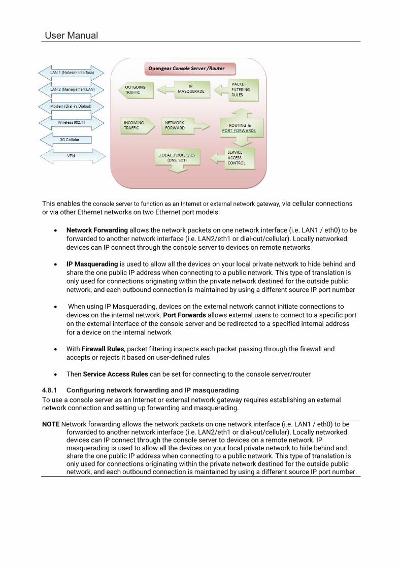
User Manual
This enables the console server to function as an Internet or external network gateway, via cellular connections or via other Ethernet networks on two Ethernet port models:
• Network Forwarding allows the network packets on one network interface (i.e. LAN1 / eth0) to be
forwarded to another network interface (i.e. LAN2/eth1 or dial-out/cellular). Locally networked devices can IP connect through the console server to devices on remote networks
• IP Masquerading is used to allow all the devices on your local private network to hide behind and
share the one public IP address when connecting to a public network. This type of translation is only used for connections originating within the private network destined for the outside public network, and each outbound connection is maintained by using a different source IP port number
• When using IP Masquerading, devices on the external network cannot initiate connections to
devices on the internal network. Port Forwards allows external users to connect to a specific port on the external interface of the console server and be redirected to a specified internal address for a device on the internal network
• With Firewall Rules, packet filtering inspects each packet passing through the firewall and
accepts or rejects it based on user-defined rules
• Then Service Access Rules can be set for connecting to the console server/router
4.8.1 Configuring network forwarding and IP masquerading To use a console server as an Internet or external network gateway requires establishing an external network connection and setting up forwarding and masquerading.
NOTE Network forwarding allows the network packets on one network interface (i.e. LAN1 / eth0) to be forwarded to another network interface (i.e. LAN2/eth1 or dial-out/cellular). Locally networked devices can IP connect through the console server to devices on a remote network. IP masquerading is used to allow all the devices on your local private network to hide behind and share the one public IP address when connecting to a public network. This type of translation is only used for connections originating within the private network destined for the outside public network, and each outbound connection is maintained by using a different source IP port number.

Chapter 4: Firewall, Failover & OOB Access
98
Console servers are configured so that they will not route traffic between networks. To use the console server as an Internet or external network gateway, forwarding must be enabled so that traffic can be routed from the internal network to the Internet/external network:
1. Navigate to the System > Firewall page, and click on the Forwarding & Masquerading tab
2. Find the Source Network to be routed, and tick the relevant Destination Network to enable Forwarding
IP Masquerading is required if the console server is routing to the Internet or if the external network being routed to does not have routing information about the internal network behind the console server.
IP Masquerading performs Source Network Address Translation (SNAT) on outgoing packets, to make them appear like they've come from the console server (rather than devices on the internal network). When response packets come back devices on the external network, the console server translates the packet address back to the internal IP, so that it is routed correctly. This allows the console server to provide full outgoing connectivity for internal devices using a single IP Address on the external network.
By default, IP Masquerading is disabled for all networks. To enable masquerading:
1. Select Forwarding & Masquerading panel on the System > Firewall menu.
2. Check Enable IP Masquerading (SNAT) on the network interfaces where masquerading is enabled.
This masquerading would be applied to any interface that is connecting with a public network such as the Internet.

User Manual
4.8.2 Configuring client devices Client devices on the local network must be configured with Gateway and DNS settings. This can be done statically on each device or using DHCP (on IM and ACM models).
Manual Configuration:
Manually set a static gateway address (being the address of the console server) and set the DNS server address to be the same as used on the external network i.e. if the console server is acting as an internet gateway or a cellular router. Use the ISP provided DNS server address.
DHCP Configuration (IM/ACM families only):
1. Navigate to the System > IP page
2. Click the tab of the interface connected to the internal network. To use DHCP, a static address must be set. Check that the static IP and subnet mask fields are set.
3. Click on the Disabled link next to DHCP Server which brings up the System > DHCP Server page.

Chapter 4: Firewall, Failover & OOB Access
100
4. Check Enable DHCP Server.
5. To configure the DHCP server, tick the Use interface address as gateway check box.
6. Set the DNS server address to be the same as used on the external network, i.e. if the console server is acting as an internet gateway or a cellular router. Use the ISP provided DNS server address.
7. Enter the Default Lease time and Maximum Lease time in seconds. The lease time is the time that a dynamically assigned IP address is valid before the client must request it again.
8. Click Apply.
The DHCP server sequentially issues IP addresses from a specified address pool(s):
1. Click Add in the Dynamic Address Allocation Pools field.
2. Enter the DHCP Pool Start Address and End Address.
3. Click Apply.
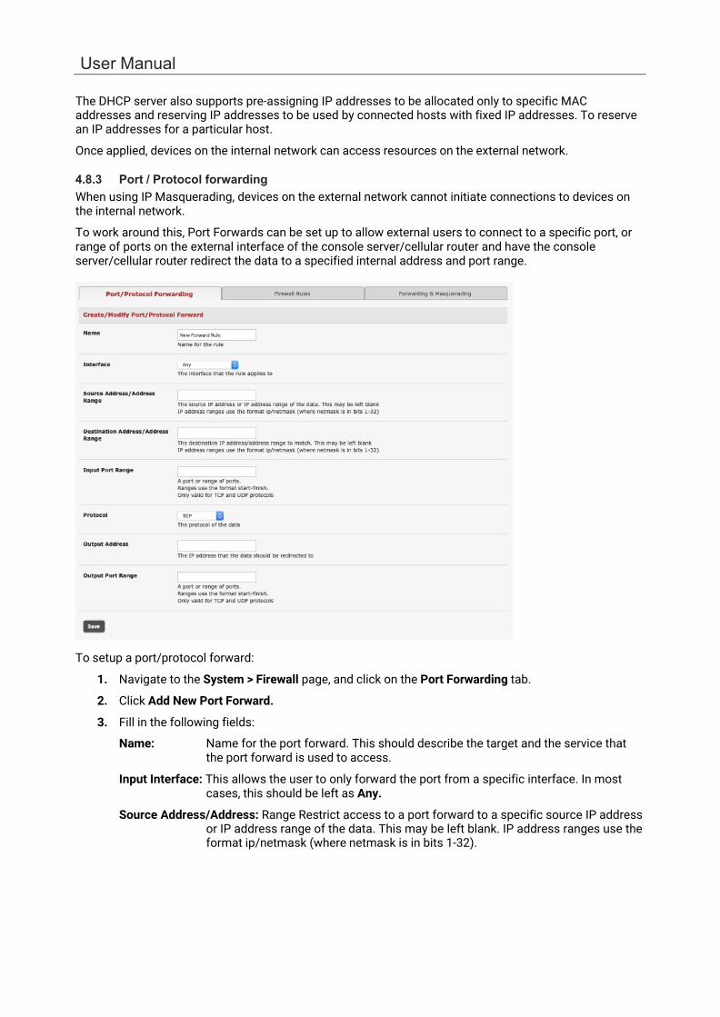
User Manual
The DHCP server also supports pre-assigning IP addresses to be allocated only to specific MAC addresses and reserving IP addresses to be used by connected hosts with fixed IP addresses. To reserve an IP addresses for a particular host.
Once applied, devices on the internal network can access resources on the external network.
4.8.3 Port / Protocol forwarding When using IP Masquerading, devices on the external network cannot initiate connections to devices on the internal network.
To work around this, Port Forwards can be set up to allow external users to connect to a specific port, or range of ports on the external interface of the console server/cellular router and have the console server/cellular router redirect the data to a specified internal address and port range.
To setup a port/protocol forward:
1. Navigate to the System > Firewall page, and click on the Port Forwarding tab.
2. Click Add New Port Forward.
3. Fill in the following fields:
Name: Name for the port forward. This should describe the target and the service that the port forward is used to access.
Input Interface: This allows the user to only forward the port from a specific interface. In most cases, this should be left as Any.
Source Address/Address: Range Restrict access to a port forward to a specific source IP address or IP address range of the data. This may be left blank. IP address ranges use the format ip/netmask (where netmask is in bits 1-32).

Chapter 4: Firewall, Failover & OOB Access
102
Destination Address/Address Range: The destination IP address/address range to match. This
may be left blank IP address ranges use the format ip/netmask (where netmask is in bits 1-32).
Input Port Range: The range of ports to forward to the destination IP. These will be the port(s) specified when accessing the port forward. These ports need not be the same as the output port range.
Protocol: The protocol of the data being forwarded. The options are TCP, UDP, TCP and UDP, ICMP, ESP, GRE, or Any.
Output Address: The target of the port forward. This is an address on the internal network where packets sent to the Input Interface on the input port range are sent.
Output Port Range: The port or range of ports that the packets will be redirected to on the Output Address. Ranges use the format start-finish. Only valid for TCP and UDP protocols.
For example, to forward port 8443 to an internal HTTPS server on 192.168.10.2, the following settings would be used:
Input Interface: Any
Input Port Range: 8443
Protocol: TCP
Output Address: 192.168.10.2
Output Port Range: 443
4.8.4 Firewall rules Firewall rules can be used to block or allow traffic through an interface based on port number, the source and/or destination IP address (range), the direction (ingress or egress) and the protocol. This can be used to allow custom on-box services, or block traffic based on policy.
To setup a firewall rule:
1. Navigate to the System > Firewall page, and click on the Firewall Rules tab.
2. Click New Firewall Rule
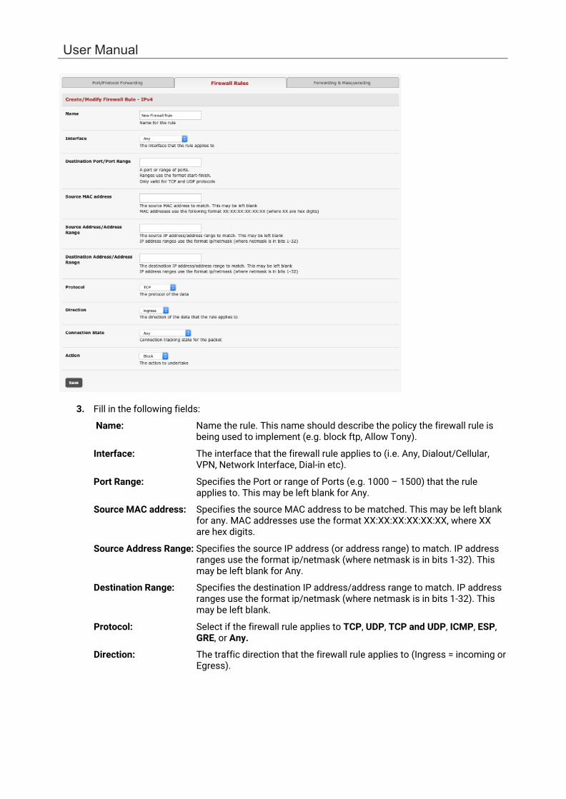
User Manual
3. Fill in the following fields:
Name: Name the rule. This name should describe the policy the firewall rule is being used to implement (e.g. block ftp, Allow Tony).
Interface: The interface that the firewall rule applies to (i.e. Any, Dialout/Cellular, VPN, Network Interface, Dial-in etc).
Port Range: Specifies the Port or range of Ports (e.g. 1000 – 1500) that the rule applies to. This may be left blank for Any.
Source MAC address: Specifies the source MAC address to be matched. This may be left blank for any. MAC addresses use the format XX:XX:XX:XX:XX:XX, where XX are hex digits.
Source Address Range: Specifies the source IP address (or address range) to match. IP address ranges use the format ip/netmask (where netmask is in bits 1-32). This may be left blank for Any.
Destination Range: Specifies the destination IP address/address range to match. IP address ranges use the format ip/netmask (where netmask is in bits 1-32). This may be left blank.
Protocol: Select if the firewall rule applies to TCP, UDP, TCP and UDP, ICMP, ESP, GRE, or Any.
Direction: The traffic direction that the firewall rule applies to (Ingress = incoming or Egress).

Chapter 4: Firewall, Failover & OOB Access
104
Connection State: The state of connections that the firewall rule applies to (Any,
Related/Established, or New). This can be used to only allow established connections out an interface.
Action: The action (Accept or Block) that applies to the packets detected that match the Interface+ Port Range+ Source/destination Address Range+ Protocol+ Direction.
For example, to block all SSH traffic from leaving Dialout Interface, the following settings can be used:
Interface: Dialout/Cellular
Port Range: 22
Protocol: TCP
Direction: Egress
Action: Block
The firewall rules are processed in a set order from top to bottom. For example, with the following rules, all traffic coming in over the Network Interface is blocked except when it comes from two nominated IP addresses (SysAdmin and Tony):
To allow all incoming traffic on all interfaces from the SysAdmin:
To allow all incoming traffic from Tony:
To block all incoming traffic from the Network Interface:
Interface Any Any Network Interface
Port Range Any Any Any
Source MAC Any Any Any
Source IP IP address of SysAdmin IP address of Tony Any
Destination IP Any Any Any
Protocol TCP TCP TCP
Direction Ingress Ingress Ingress
Action Accept Accept Block
If the Rule Order above is changed so the Block Everyone Else rule is second on the list, the traffic coming in over the Network Interface from Tony would be blocked.

5. SSH TUNNELS & SDT CONNECTOR
NOTE As of Release 4.11 the SDT Connector is no longer supported; this change will affect all tasks in this section which involve the SDT Connector.
Each Opengear console server has an embedded SSH server and uses SSH tunneling so remote users can securely connect through the console server to managed devices - using text-based console tools (such as SSH, Telnet, SoL) or graphical tools (like VNC, RDP, HTTPS, HTTP, X11, VMware, DRAC, iLO).
The managed devices being accessed can be located on the same local network as the console server or they can be attached to the console server via a serial port. The remote user connects to the console server thru an SSH tunnel via dial-up, wireless or ISDN modem; a broadband Internet connection; the enterprise VPN network or the local network:
To set up the secure SSH tunnel from the Client PC to the console server, you must install and launch SSH client software on the user’s PC. Opengear recommends you use the SDT Connector client software that is supplied with the console server for this. SDT Connector is easy to install and auto-configure and it provides all your users with point-and-click access to all the systems and devices in the secure network.
SDT Connector sets up a secure SSH tunnel from the client to the selected console server, establishes a port forward connection to the target network connected host or serial connected device, and executes the client application that is used in communicating with the host.
Topics in this chapter:
Configuring the console server for SSH tunneled access to network attached hosts and setting up permitted Services and user access.
Setting up the SDT Connector client with gateway, host, service and client application details and making connections between the Client PC and hosts connected to the console server.
Using SDT Connector to browser access the Management Console.
Using SDT Connector to Telnet or SSH connect to devices that are serially attached to the console server.
Using SDT Connector for out of band access.
Automatic importing and exporting of configurations.
Configuring Public Key Authentication.
Setting up an SDT Secure Tunnel for Remote Desktop.
Setting up an SDT Secure Tunnel for VNC.
Using SDT to IP connect to hosts that are serially attached to the console server.

106
Chapter 6: Alerts, Auto-Response & Logging
5.1 Configuring for SSH Tunneling to Hosts To set up the console server for SSH tunneled access a network attached host, add the new host and the permitted services using the Serial & Network > Network Hosts menu as detailed in Network Hosts. Only these permitted services are forwarded through by SSH to the host. All other services (TCP/UDP ports) are blocked.
Some of the TCP Ports used by SDT in the console server:
22 SSH (All SDT Tunneled connections) 23 Telnet on local LAN (forwarded inside tunnel) 80 HTTP on local LAN (forwarded inside tunnel) 3389 RDP on local LAN (forwarded inside tunnel) 5900 VNC on local LAN (forwarded inside tunnel) 73XX RDP over serial from local LAN – where XX is the serial port number (i.e. 7301to 7348 on
a 48 port console server) 79XX VNC over serial from local LAN – where XX is the serial port number
Add new users using Serial & Network > Users & Groups menu as detailed in Network Hosts. Users can be authorized to access the console server ports and specified network-attached hosts. To simplify configuration, an administrator can first set up groups with group access permissions, users can be classified as members of particular groups.
5.2 SDT Connector Client Configuration The SDT Connector client works with all Opengear console servers. Each of these remote console servers have an embedded OpenSSH based server which can be configured to port forward connections from the SDT Connector client to hosts on their local network as detailed in the previous chapter. The SDT Connector can also be pre-configured with the access tools and applications that are available to run when access to a particular host has been established.
SDT Connector can connect to the console server using an alternate OOB access. It can also access the console server and access devices connected to serial ports on the console server.
To operate SDT Connector, add new gateways to the client software by entering the access details for each console server and let the client auto-configure with all host and serial port connections from each console server. Point-and-click to connect to the Hosts and serial devices.
Or you can add network connected hosts and configure new services to be used in accessing the console server and the hosts and configure clients to run on the PC that uses the service to connect to the hosts.
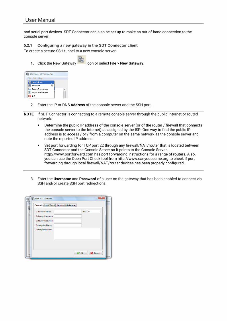
User Manual
and serial port devices. SDT Connector can also be set up to make an out-of-band connection to the console server.
5.2.1 Configuring a new gateway in the SDT Connector client To create a secure SSH tunnel to a new console server:
1. Click the New Gateway icon or select File > New Gateway.
2. Enter the IP or DNS Address of the console server and the SSH port.
NOTE If SDT Connector is connecting to a remote console server through the public Internet or routed network:
Determine the public IP address of the console server (or of the router / firewall that connects the console server to the Internet) as assigned by the ISP. One way to find the public IP address is to access / or / from a computer on the same network as the console server and note the reported IP address.
Set port forwarding for TCP port 22 through any firewall/NAT/router that is located between SDT Connector and the Console Server so it points to the Console Server. http://www.portforward.com has port forwarding instructions for a range of routers. Also, you can use the Open Port Check tool from http://www.canyouseeme.org to check if port forwarding through local firewall/NAT/router devices has been properly configured.
3. Enter the Username and Password of a user on the gateway that has been enabled to connect via SSH and/or create SSH port redirections.

108
Chapter 6: Alerts, Auto-Response & Logging
4. Optionally, enter a Descriptive Name to display instead of the IP or DNS address, and NOTEs or a
Description of this gateway (such as its site location or anything special about its network configuration).
5. Click OK. An icon for the new gateway appears in the SDT Connector home page.
NOTE For an SDT Connector user to access a console server and access specific hosts or serial devices connected to that console server, that user must first be setup on the console server, and must be authorized to access the specific ports / hosts. Only these permitted services are forwarded through by SSH to the Host. All other services (TCP/UDP ports) are blocked.
5.2.2 Auto-configure SDT Connector client with the user’s access privileges Each user on the console server has an access profile which has been configured with those specific connected hosts and serial port devices the user has authority to access, and a specific set of the enabled services for each of these. This configuration can be auto-uploaded into the SDT Connector client:
Click on the new gateway icon and select Retrieve Hosts. This will:
Configure access to network connected Hosts that the user is authorized to access and set up (for each of these Hosts) the services (e.g. HTTPS, IPMI2.0) and the related IP ports being redirected.
Configure access to the console server (this is shown as a Local Services host)
Configure access with the enabled services for the serial port devices connected to the console server.

User Manual
NOTE The Retrieve Hosts function auto-configures all classes of user (i.e. they can be members of user or admin or some other group or no group). SDT Connector will not auto-configure the root.
5.2.3 Make an SDT connection through the gateway to a host Point at the host to be accessed and click on the service to be used in accessing that host. The SSH tunnel to the gateway is established, the appropriate ports redirected through to the host, and the appropriate local client application is launched pointing at the local endpoint of the redirection:
NOTE The SDT Connector client can be configured with unlimited number of Gateways. Each Gateway can be configured to port forward to an unlimited number of locally networked Hosts. There is no limit on the number of SDT Connector clients who can be configured to access the one Gateway. Nor are there limits on the number of Host connections that an SDT Connector client can concurrently have open through the one Gateway tunnel.
5.2.4 Manually adding hosts to the SDT Connector gateway For each gateway, you can specify the network connected hosts to be accessed through that console server; and for each host, specify the services used in communicating with the host.
1. Select the newly added gateway and click the Host icon to create a host to be accessible via this gateway. Or select File > New Host.
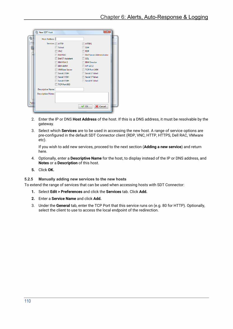
Chapter 6: Alerts, Auto-Response & Logging
110
2. Enter the IP or DNS Host Address of the host. If this is a DNS address, it must be resolvable by the
gateway.
3. Select which Services are to be used in accessing the new host. A range of service options are pre-configured in the default SDT Connector client (RDP, VNC, HTTP, HTTPS, Dell RAC, VMware etc).
If you wish to add new services, proceed to the next section (Adding a new service) and return here.
4. Optionally, enter a Descriptive Name for the host, to display instead of the IP or DNS address, and Notes or a Description of this host.
5. Click OK.
5.2.5 Manually adding new services to the new hosts To extend the range of services that can be used when accessing hosts with SDT Connector:
1. Select Edit > Preferences and click the Services tab. Click Add.
2. Enter a Service Name and click Add.
3. Under the General tab, enter the TCP Port that this service runs on (e.g. 80 for HTTP). Optionally, select the client to use to access the local endpoint of the redirection.

User Manual
4. Select which Client application is associated with the new service. A range of client application options are pre-configured in the default SDT Connector (RDP client, VNC client, HTTP browser, HTTPS browser, Telnet client etc). If you wish to add new client applications to this range, proceed to the next section (Adding a new client) and return here.
5. Click OK, and Close
A service consists of a single SSH port redirection and a local client to access it. It may consist of several redirections, some or all of with clients associated with them.
An example is the Dell RAC service. The first redirection is for the HTTPS connection to the RAC server - it has a client associated with it (web browser) that is launched upon clicking the button for this service.
The second redirection is for the VNC service that the user may choose to later launch from the RAC web console. It loads in a Java client served through the web browser, so it does not need a local client associated with it.
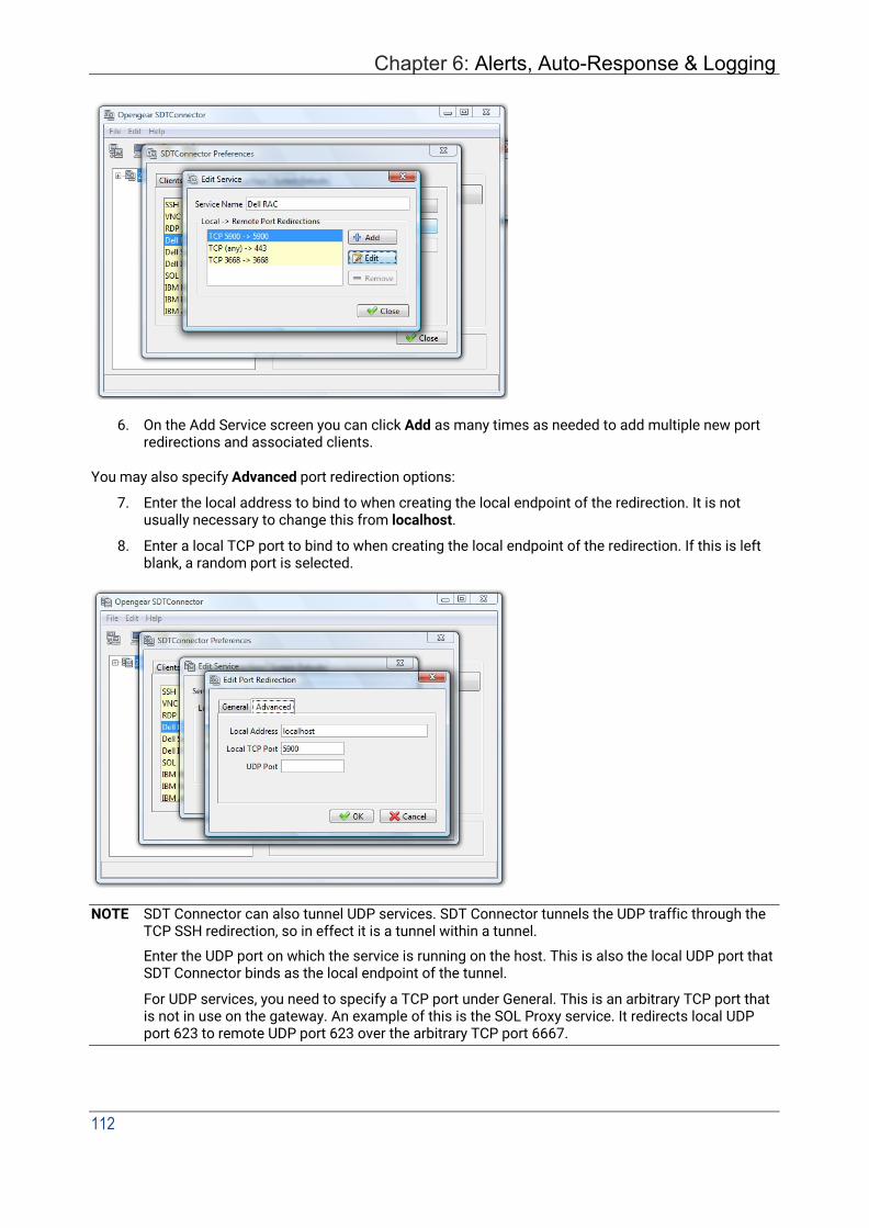
Chapter 6: Alerts, Auto-Response & Logging
112
6. On the Add Service screen you can click Add as many times as needed to add multiple new port redirections and associated clients.
You may also specify Advanced port redirection options:
7. Enter the local address to bind to when creating the local endpoint of the redirection. It is not usually necessary to change this from localhost.
8. Enter a local TCP port to bind to when creating the local endpoint of the redirection. If this is left blank, a random port is selected.
NOTE SDT Connector can also tunnel UDP services. SDT Connector tunnels the UDP traffic through the TCP SSH redirection, so in effect it is a tunnel within a tunnel.
Enter the UDP port on which the service is running on the host. This is also the local UDP port that SDT Connector binds as the local endpoint of the tunnel.
For UDP services, you need to specify a TCP port under General. This is an arbitrary TCP port that is not in use on the gateway. An example of this is the SOL Proxy service. It redirects local UDP port 623 to remote UDP port 623 over the arbitrary TCP port 6667.

User Manual
5.2.6 Adding a client program to be started for the new service Clients are local applications that may be launched when a related service is clicked. To add to the pool of client programs:
1. Select Edit > Preferences and click the Client tab. Click Add.
2. Enter a Name for the client. Enter the Path to the executable file for the client (or click Browse to locate the executable).
3. Enter a Command Line associated with launching the client application. SDT Connector launches a client using command line arguments to point it at the local endpoint of the redirection. There are three special keywords for specifying the command line format. When launching the client, SDT Connector substitutes these keywords with the appropriate values:
%path% is path to the executable file, i.e. the previous field.
%host% is the local address to which the local endpoint of the redirection is bound, i.e. the Local Address field for the Service redirection Advanced options.
%port% is the local port to which the local endpoint of the redirection is bound, i.e. the Local TCP Port field for the Service redirection Advanced options. If this port is unspecified (i.e. Any), the appropriate randomly selected port is substituted.
For example, SDT Connector is preconfigured for Windows installations with a HTTP service client that connects with whichever local browser the local Windows user has configured as the default. Otherwise the default browser used is Firefox:

Chapter 6: Alerts, Auto-Response & Logging
114
Some clients are launched in a command line or terminal window. The Telnet client is an example of this so the Path to client executable file is telnet and the Command line format for client executable is cmd /c start %path% %host% %port% :
4. Click OK.
5.2.7 Dial-in configuration If the client PC is dialing into Local/Console port on the console server, here is how to set up a dial-in PPP link:
1. Configure the console server for dial-in access following the steps in the Configuring for Dial-In PPP Access section in Chapter 4.
2. Set up the PPP client software at the remote user PC following the Set up the remote Client section in Chapter 4.
Once you have a dial-in PPP connection established, you can set up the secure SSH tunnel from the remote Client PC to the console server.
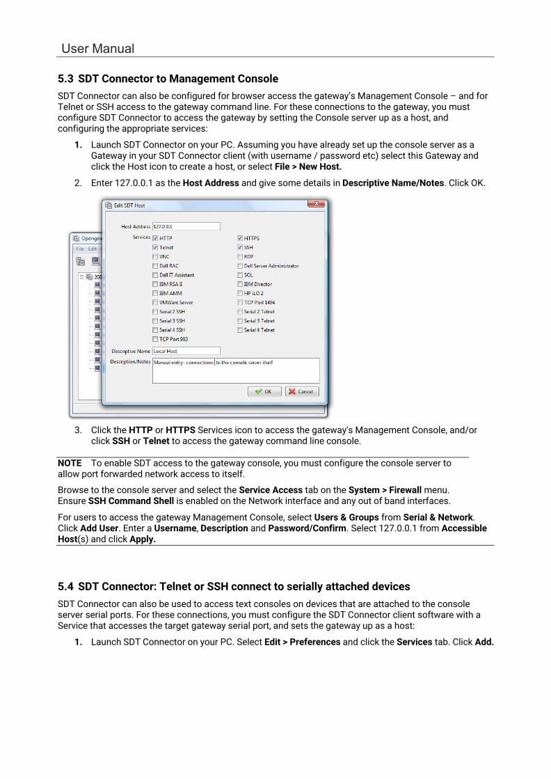
User Manual
5.3 SDT Connector to Management Console SDT Connector can also be configured for browser access the gateway’s Management Console – and for Telnet or SSH access to the gateway command line. For these connections to the gateway, you must configure SDT Connector to access the gateway by setting the Console server up as a host, and configuring the appropriate services:
1. Launch SDT Connector on your PC. Assuming you have already set up the console server as a Gateway in your SDT Connector client (with username / password etc) select this Gateway and click the Host icon to create a host, or select File > New Host.
2. Enter 127.0.0.1 as the Host Address and give some details in Descriptive Name/Notes. Click OK.
3. Click the HTTP or HTTPS Services icon to access the gateway's Management Console, and/or click SSH or Telnet to access the gateway command line console.
NOTE To enable SDT access to the gateway console, you must configure the console server to allow port forwarded network access to itself.
Browse to the console server and select the Service Access tab on the System > Firewall menu. Ensure SSH Command Shell is enabled on the Network interface and any out of band interfaces.
For users to access the gateway Management Console, select Users & Groups from Serial & Network. Click Add User. Enter a Username, Description and Password/Confirm. Select 127.0.0.1 from Accessible Host(s) and click Apply.
\
5.4 SDT Connector: Telnet or SSH connect to serially attached devices SDT Connector can also be used to access text consoles on devices that are attached to the console server serial ports. For these connections, you must configure the SDT Connector client software with a Service that accesses the target gateway serial port, and sets the gateway up as a host:
1. Launch SDT Connector on your PC. Select Edit > Preferences and click the Services tab. Click Add.
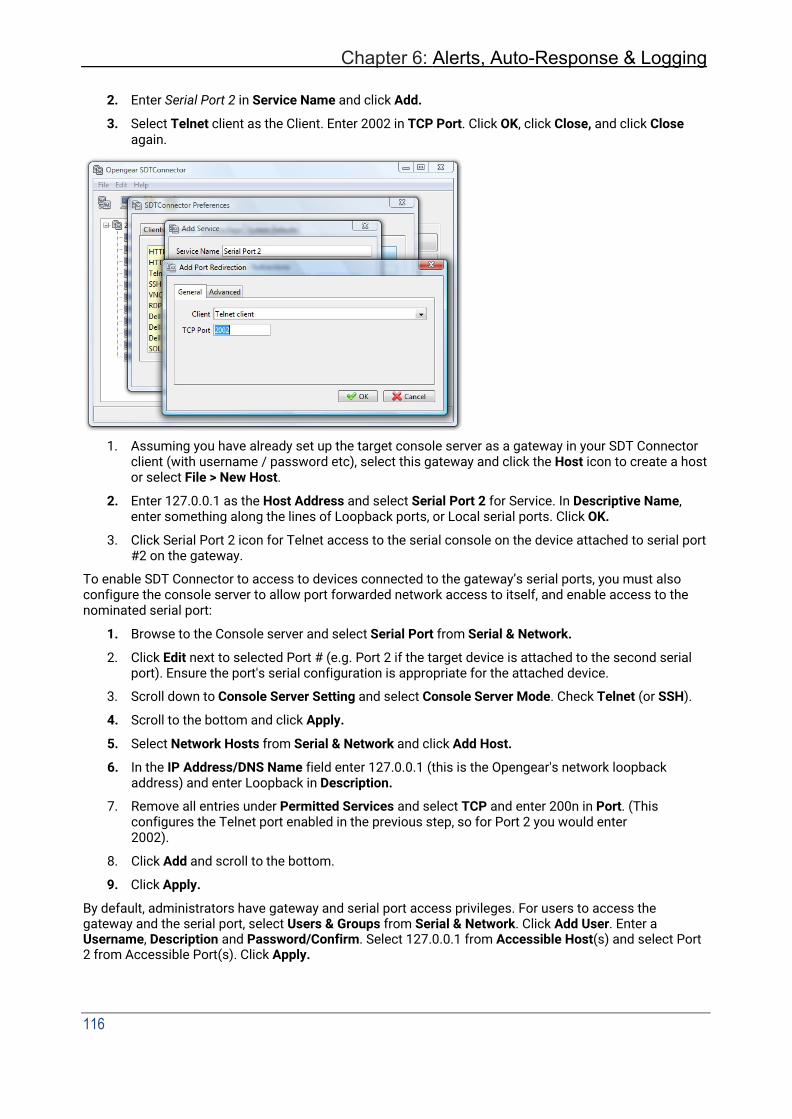
Chapter 6: Alerts, Auto-Response & Logging
116
2. Enter Serial Port 2 in Service Name and click Add.
3. Select Telnet client as the Client. Enter 2002 in TCP Port. Click OK, click Close, and click Close again.
1. Assuming you have already set up the target console server as a gateway in your SDT Connector client (with username / password etc), select this gateway and click the Host icon to create a host or select File > New Host.
2. Enter 127.0.0.1 as the Host Address and select Serial Port 2 for Service. In Descriptive Name, enter something along the lines of Loopback ports, or Local serial ports. Click OK.
3. Click Serial Port 2 icon for Telnet access to the serial console on the device attached to serial port #2 on the gateway.
To enable SDT Connector to access to devices connected to the gateway’s serial ports, you must also configure the console server to allow port forwarded network access to itself, and enable access to the nominated serial port:
1. Browse to the Console server and select Serial Port from Serial & Network.
2. Click Edit next to selected Port # (e.g. Port 2 if the target device is attached to the second serial port). Ensure the port's serial configuration is appropriate for the attached device.
3. Scroll down to Console Server Setting and select Console Server Mode. Check Telnet (or SSH).
4. Scroll to the bottom and click Apply.
5. Select Network Hosts from Serial & Network and click Add Host.
6. In the IP Address/DNS Name field enter 127.0.0.1 (this is the Opengear's network loopback address) and enter Loopback in Description.
7. Remove all entries under Permitted Services and select TCP and enter 200n in Port. (This configures the Telnet port enabled in the previous step, so for Port 2 you would enter 2002).
8. Click Add and scroll to the bottom.
9. Click Apply.
By default, administrators have gateway and serial port access privileges. For users to access the gateway and the serial port, select Users & Groups from Serial & Network. Click Add User. Enter a Username, Description and Password/Confirm. Select 127.0.0.1 from Accessible Host(s) and select Port 2 from Accessible Port(s). Click Apply.

User Manual
5.5 Using SDT Connector for out-of-band connection to the gateway SDT Connector can also be set up to connect to the console server (gateway) out-of-band (OOB). OOB access uses an alternate path for connecting to the gateway to that used for regular data traffic. OOB access is useful for when the primary link into the gateway is unavailable or unreliable.
A gateway's primary link is a broadband Internet connection or Internet connection via a LAN or VPN, and the secondary out-of-band connectivity is provided by a dial-up or wireless modem attached to the gateway. Out-of-band access enables you to access the hosts and serial devices on the network, diagnose any connectivity issues, and restore the gateway's primary link.
In SDT Connector, OOB access is configured by providing the secondary IP address of the gateway and telling SDT Connector how to start and stop the OOB connection. Starting an OOB connection may be achieved by initiating a dial up connection or adding an alternate route to the gateway. SDT Connector allows for maximum flexibility is this regard, by allowing you to provide your own scripts or commands for starting and stopping the OOB connection.
To configure SDT Connector for OOB access:
1. When adding a new gateway or editing an existing gateway select the Out Of Band tab.
2. Enter the secondary, OOB IP address of the gateway (e.g. the IP address it is accessible using when dialed in directly). You also may modify the gateway's SSH port if it's not using the default of 22.
3. Enter the command or path to a script to start the OOB connection in Start Command.
To initiate a pre-configured dial-up connection under Windows, use the following Start Command:
cmd /c start "Starting Out of Band Connection" /wait /min rasdial network_connection login password.
where network_connection is the name of the network connection as displayed in Control Panel > Network Connections, login is the dial-in username, and password is the dial-in password for the connection.
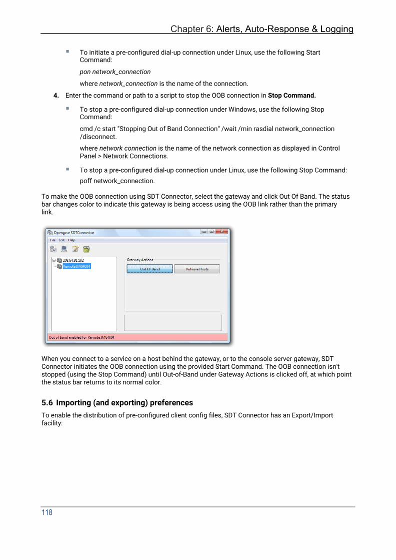
Chapter 6: Alerts, Auto-Response & Logging
118
To initiate a pre-configured dial-up connection under Linux, use the following Start Command:
pon network_connection
where network_connection is the name of the connection.
4. Enter the command or path to a script to stop the OOB connection in Stop Command.
To stop a pre-configured dial-up connection under Windows, use the following Stop Command:
cmd /c start "Stopping Out of Band Connection" /wait /min rasdial network_connection /disconnect.
where network connection is the name of the network connection as displayed in Control Panel > Network Connections.
To stop a pre-configured dial-up connection under Linux, use the following Stop Command: poff network_connection.
To make the OOB connection using SDT Connector, select the gateway and click Out Of Band. The status bar changes color to indicate this gateway is being access using the OOB link rather than the primary link.
When you connect to a service on a host behind the gateway, or to the console server gateway, SDT Connector initiates the OOB connection using the provided Start Command. The OOB connection isn't stopped (using the Stop Command) until Out-of-Band under Gateway Actions is clicked off, at which point the status bar returns to its normal color.
5.6 Importing (and exporting) preferences To enable the distribution of pre-configured client config files, SDT Connector has an Export/Import facility:
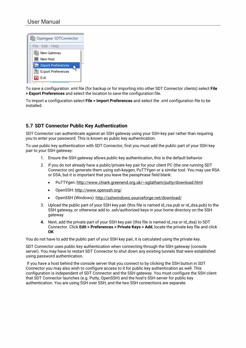
User Manual
To save a configuration .xml file (for backup or for importing into other SDT Connector clients) select File > Export Preferences and select the location to save the configuration file.
To import a configuration select File > Import Preferences and select the .xml configuration file to be installed.
5.7 SDT Connector Public Key Authentication SDT Connector can authenticate against an SSH gateway using your SSH key pair rather than requiring you to enter your password. This is known as public key authentication.
To use public key authentication with SDT Connector, first you must add the public part of your SSH key pair to your SSH gateway:
1. Ensure the SSH gateway allows public key authentication, this is the default behavior
2. If you do not already have a public/private key pair for your client PC (the one running SDT Connector on) generate them using ssh-keygen, PuTTYgen or a similar tool. You may use RSA or DSA, but it is important that you leave the passphrase field blank:
• PuTTYgen: http://www.chiark.greenend.org.uk/~sgtatham/putty/download.html
• OpenSSH: http://www.openssh.org/
• OpenSSH (Windows): http://sshwindows.sourceforge.net/download/
3. Upload the public part of your SSH key pair (this file is named id_rsa.pub or id_dsa.pub) to the SSH gateway, or otherwise add to .ssh/authorized keys in your home directory on the SSH gateway
4. Next, add the private part of your SSH key pair (this file is named id_rsa or id_dsa) to SDT Connector. Click Edit > Preferences > Private Keys > Add, locate the private key file and click OK
You do not have to add the public part of your SSH key pair, it is calculated using the private key.
SDT Connector uses public key authentication when connecting through the SSH gateway (console server). You may have to restart SDT Connector to shut down any existing tunnels that were established using password authentication.
If you have a host behind the console server that you connect to by clicking the SSH button in SDT Connector you may also wish to configure access to it for public key authentication as well. This configuration is independent of SDT Connector and the SSH gateway. You must configure the SSH client that SDT Connector launches (e.g. Putty, OpenSSH) and the host's SSH server for public key authentication. You are using SSH over SSH, and the two SSH connections are separate.

Chapter 6: Alerts, Auto-Response & Logging
120
5.8 Setting up SDT for Remote Desktop access Microsoft’s Remote Desktop Protocol (RDP) enables the system manager to securely access and manages remote Windows computers – to reconfigure applications and user profiles, upgrade the server’s operating system, reboot the machine etc. Opengear’s Secure Tunneling uses SSH tunneling, so this RDP traffic is securely transferred through an authenticated and encrypted tunnel.
SDT with RDP also allows remote users to connect to Windows XP and later computers and to Windows 2000 Terminal Servers; and to have access to all of the applications, files, and network resources (with full graphical interface as though they were in front of the computer screen at work). To set up a secure Remote Desktop connection you must enable Remote Desktop on the target Windows computer that is to be accessed and configure the RPD client software on the client PC.
5.8.1 Enable Remote Desktop on the target Windows computer to be accessed To enable Remote Desktop on the Windows computer being accessed:
1. Open System in the Control Panel and click the Remote tab
2. Check Allow users to connect remotely to this computer.
3. Click Select Remote Users.
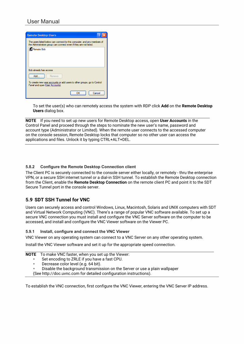
User Manual
To set the user(s) who can remotely access the system with RDP click Add on the Remote Desktop Users dialog box.
NOTE If you need to set up new users for Remote Desktop access, open User Accounts in the Control Panel and proceed through the steps to nominate the new user’s name, password and account type (Administrator or Limited). When the remote user connects to the accessed computer on the console session, Remote Desktop locks that computer so no other user can access the applications and files. Unlock it by typing CTRL+ALT+DEL.
5.8.2 Configure the Remote Desktop Connection client The Client PC is securely connected to the console server either locally, or remotely - thru the enterprise VPN, or a secure SSH internet tunnel or a dial-in SSH tunnel. To establish the Remote Desktop connection from the Client, enable the Remote Desktop Connection on the remote client PC and point it to the SDT Secure Tunnel port in the console server.
5.9 SDT SSH Tunnel for VNC Users can securely access and control Windows, Linux, Macintosh, Solaris and UNIX computers with SDT and Virtual Network Computing (VNC). There’s a range of popular VNC software available. To set up a secure VNC connection you must install and configure the VNC Server software on the computer to be accessed, and install and configure the VNC Viewer software on the Viewer PC.
5.9.1 Install, configure and connect the VNC Viewer VNC Viewer on any operating system can connect to a VNC Server on any other operating system.
Install the VNC Viewer software and set it up for the appropriate speed connection.
NOTE To make VNC faster, when you set up the Viewer: Set encoding to ZRLE if you have a fast CPU. Decrease color level (e.g. 64 bit). Disable the background transmission on the Server or use a plain wallpaper (See http://doc.uvnc.com for detailed configuration instructions).
To establish the VNC connection, first configure the VNC Viewer, entering the VNC Server IP address.

Chapter 6: Alerts, Auto-Response & Logging
122
• When the Viewer PC is connected to the console server thru an SSH tunnel (over the public
Internet, or a dial-in connection, or private network connection), enter localhost (or 127.0.0.1) as the IP VNC Server IP address; and the source port you entered when setting SSH tunneling /port forwarding, e.g. :1234.
• When the Viewer PC is connected to the console server (i.e. locally or remotely through a VPN or dial-in connection); and the VNC Host computer is serially connected to the console server; enter the IP address of the console server unit with the TCP port that the SDT tunnel uses. The TCP port is 7900 plus the physical serial port number (i.e. 7901 to 7948, so all traffic directed to port 79xx on the console server is tunneled thru to port 5900 on the PPP connection on serial Port xx) e.g. for a Windows Viewer PC using UltraVNC connecting to a VNC Server which is attached to Port 1 on a console server located 192.168.0.1
You can establish the VNC connection by activating the VNC Viewer software on the Viewer PC and entering the password.
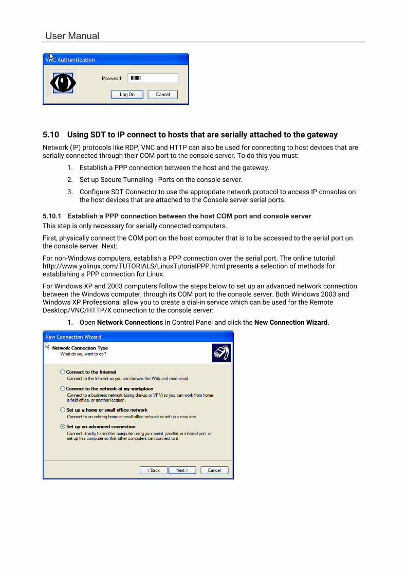
User Manual
5.10 Using SDT to IP connect to hosts that are serially attached to the gateway Network (IP) protocols like RDP, VNC and HTTP can also be used for connecting to host devices that are serially connected through their COM port to the console server. To do this you must:
1. Establish a PPP connection between the host and the gateway.
2. Set up Secure Tunneling - Ports on the console server.
3. Configure SDT Connector to use the appropriate network protocol to access IP consoles on the host devices that are attached to the Console server serial ports.
5.10.1 Establish a PPP connection between the host COM port and console server This step is only necessary for serially connected computers.
First, physically connect the COM port on the host computer that is to be accessed to the serial port on the console server. Next:
For non-Windows computers, establish a PPP connection over the serial port. The online tutorial http://www.yolinux.com/TUTORIALS/LinuxTutorialPPP.html presents a selection of methods for establishing a PPP connection for Linux.
For Windows XP and 2003 computers follow the steps below to set up an advanced network connection between the Windows computer, through its COM port to the console server. Both Windows 2003 and Windows XP Professional allow you to create a dial-in service which can be used for the Remote Desktop/VNC/HTTP/X connection to the console server:
1. Open Network Connections in Control Panel and click the New Connection Wizard.
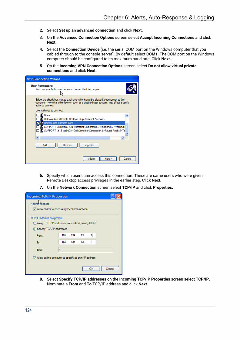
Chapter 6: Alerts, Auto-Response & Logging
124
2. Select Set up an advanced connection and click Next.
3. On the Advanced Connection Options screen select Accept Incoming Connections and click Next.
4. Select the Connection Device (i.e. the serial COM port on the Windows computer that you cabled through to the console server). By default select COM1. The COM port on the Windows computer should be configured to its maximum baud rate. Click Next.
5. On the Incoming VPN Connection Options screen select Do not allow virtual private connections and click Next.
6. Specify which users can access this connection. These are same users who were given Remote Desktop access privileges in the earlier step. Click Next.
7. On the Network Connection screen select TCP/IP and click Properties.
8. Select Specify TCP/IP addresses on the Incoming TCP/IP Properties screen select TCP/IP. Nominate a From and To TCP/IP address and click Next.
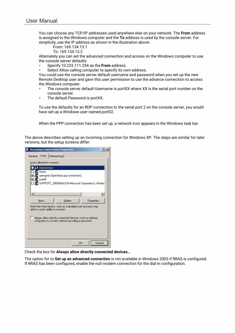
User Manual
You can choose any TCP/IP addresses used anywhere else on your network. The From address is assigned to the Windows computer and the To address is used by the console server. For simplicity, use the IP address as shown in the illustration above:
From: 169.134.13.1 To: 169.134.13.2
Alternately you can set the advanced connection and access on the Windows computer to use the console server defaults: Specify 10.233.111.254 as the From address. Select Allow calling computer to specify its own address. You could use the console server default username and password when you set up the new Remote Desktop user and gave this user permission to use the advance connection to access the Windows computer: The console server default Username is portXX where XX is the serial port number on the
console server. The default Password is portXX.
To use the defaults for an RDP connection to the serial port 2 on the console server, you would have set up a Windows user named port02.
When the PPP connection has been set up, a network icon appears in the Windows task bar.
The above describes setting up an incoming connection for Windows XP. The steps are similar for later versions, but the setup screens differ:
Check the box for Always allow directly connected devices...
The option for to Set up an advanced connection is not available in Windows 2003 if RRAS is configured. If RRAS has been configured, enable the null modem connection for the dial-in configuration.
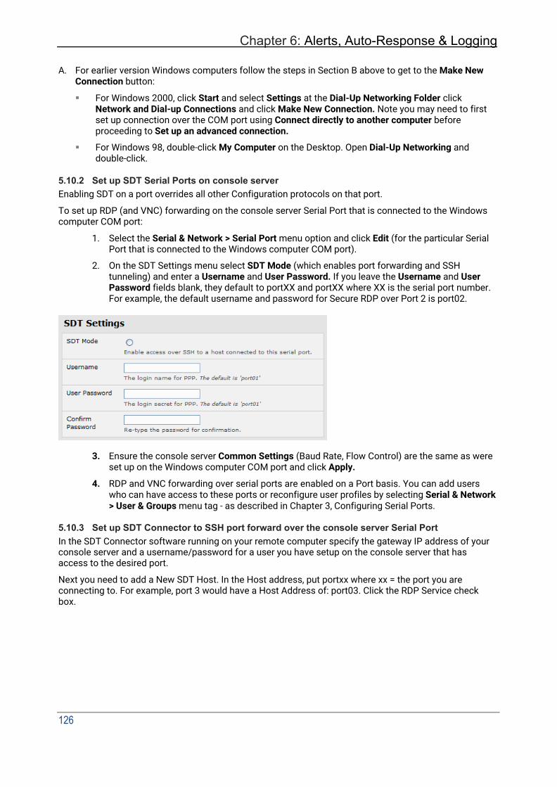
Chapter 6: Alerts, Auto-Response & Logging
126
A. For earlier version Windows computers follow the steps in Section B above to get to the Make New
Connection button:
For Windows 2000, click Start and select Settings at the Dial-Up Networking Folder click Network and Dial-up Connections and click Make New Connection. Note you may need to first set up connection over the COM port using Connect directly to another computer before proceeding to Set up an advanced connection.
For Windows 98, double-click My Computer on the Desktop. Open Dial-Up Networking and double-click.
5.10.2 Set up SDT Serial Ports on console server Enabling SDT on a port overrides all other Configuration protocols on that port.
To set up RDP (and VNC) forwarding on the console server Serial Port that is connected to the Windows computer COM port:
1. Select the Serial & Network > Serial Port menu option and click Edit (for the particular Serial Port that is connected to the Windows computer COM port).
2. On the SDT Settings menu select SDT Mode (which enables port forwarding and SSH tunneling) and enter a Username and User Password. If you leave the Username and User Password fields blank, they default to portXX and portXX where XX is the serial port number. For example, the default username and password for Secure RDP over Port 2 is port02.
3. Ensure the console server Common Settings (Baud Rate, Flow Control) are the same as were
set up on the Windows computer COM port and click Apply.
4. RDP and VNC forwarding over serial ports are enabled on a Port basis. You can add users who can have access to these ports or reconfigure user profiles by selecting Serial & Network > User & Groups menu tag - as described in Chapter 3, Configuring Serial Ports.
5.10.3 Set up SDT Connector to SSH port forward over the console server Serial Port In the SDT Connector software running on your remote computer specify the gateway IP address of your console server and a username/password for a user you have setup on the console server that has access to the desired port.
Next you need to add a New SDT Host. In the Host address, put portxx where xx = the port you are connecting to. For example, port 3 would have a Host Address of: port03. Click the RDP Service check box.

User Manual
5.11 SSH Tunneling using other SSH clients (e.g. PuTTY) We recommend you use the SDT Connector client software that is supplied with the console server. There are also commercial and free SSH client programs that can also provide the secure SSH connections to the console servers and secure tunnels to connected devices.
Here is an example of the establishment of an SSH tunneled connection to a network connected device using the PuTTY client software:
1. In the Session menu enter the IP address of the console server in the Host Name or IP
address field.
• For dial-in connections, this IP address is the Local Address that you assigned to the console server when you set it up as the Dial-In PPP Server.
• For Internet (or local/VPN connections) connections this is the public IP address of the console server.
2. Select the SSH Protocol. The Port is set to 22.
3. Go to the SSH > Tunnels menu and in Add new forwarded port enter any high unused port number for the Source port e.g. 54321.
4. Set the Destination: IP details.
• If your destination device is network connected to the console server and you are connecting using RDP, set the Destination as < managed device IP address/DNS Name>:3389 e.g. if when setting up the managed device as Network Host on the console server you specified its IP address to be 192.168.253.1 (or its DNS Name is accounts.myco.intranet.com), specify the Destination as 192.168.523.1:3389 (or accounts.myco.intranet.com:3389 ). Only devices which have been configured as networked Hosts can be accessed using SSH tunneling (except by the root user who can tunnel to any IP address the console server can route to.

Chapter 6: Alerts, Auto-Response & Logging
128
• If your destination computer is serially connected to the console server, set the Destination as <port label>:3389 e.g. if the Label you specified on the serial port on the console server is win2k3, specify the remote host as win2k3:3389 . Alternative you can set the Destination as portXX:3389 where XX is the SDT enabled serial port number e.g. if port 4 is on the console server is to carry the RDP traffic, specify port04:3389.
5. Select Local and click the Add button.
6. Click Open to SSH connect the Client PC to the console server. You are prompted for the Username/Password for the console server user.
If you are connecting as a user in the users group, you can only SSH tunnel to Hosts and Serial Ports where you have access permissions.
If you are connecting as an administrator, you can connect to any configured Host or Serial
Ports (which has SDT enabled).
To set up the secure SSH tunnel for a HTTP browser connection to the managed device specify port 80 (rather than port 3389 as used for RDP) in the Destination IP address.
To set up the secure SSH tunnel from the Client (Viewer) PC to the console server for VNC follow the steps above. When configuring the VNC port redirection, specify port 5900 in the Destination IP address.

User Manual
6. ALERTS, AUTO-RESPONSE & LOGGING
This chapter describes the automated response, alert generation and logging features of the console server.
With Auto-Response the console server monitors selected serial ports, logins, the power status and environmental monitors and probes for Check Condition triggers. The console server initiates a sequence of actions in response to these triggers. To configure Auto-Response:
1. Set the general parameters.
2. Select and configure the Check Conditions, the conditions that trigger the response.
3. Specify the Trigger Actions, the sequence of actions initiated in event of the trigger condition.
4. Specify the Resolve Actions, the actions performed when trigger conditions have been resolved.
Console servers can maintain log records of all access and communications with the console server and with the attached serial devices. A log of all system activity is also maintained as is a history of the status of any attached environmental monitors.
Some models can also log access and communications with network attached hosts and maintain a history of the UPS and PDU power status.
If port logs are to be maintained on a remote server, the access path to this location need to be configured Activate and set the desired levels of logging for each serial and/or network port and/or power and environment UPS.
6.1 Configure Auto-Response With the Auto-Response facility, a sequence of Trigger Actions is initiated in the event of a specified trigger condition (Check Condition). Subsequent Resolve Actions can also be performed when the trigger condition has been resolved.
To configure, set the general parameters that apply to all Auto-Responses:
• Check Log Events on Alerts & Logging > Auto-Response to enable logging all Auto-Response activities.
• Check Delay after Boot to set any general delay to be applied after console server system boot, before processing events.
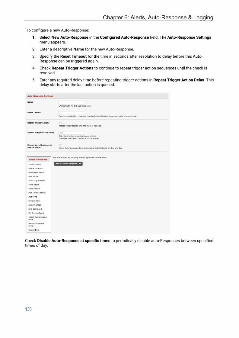
Chapter 6: Alerts, Auto-Response & Logging
130
To configure a new Auto-Response:
1. Select New Auto-Response in the Configured Auto-Response field. The Auto-Response Settings menu appears.
2. Enter a descriptive Name for the new Auto-Response.
3. Specify the Reset Timeout for the time in seconds after resolution to delay before this Auto- Response can be triggered again.
4. Check Repeat Trigger Actions to continue to repeat trigger action sequences until the check is resolved.
5. Enter any required delay time before repeating trigger actions in Repeat Trigger Action Delay. This delay starts after the last action is queued.
Check Disable Auto-Response at specific times to periodically disable auto-Responses between specified times of day.

User Manual
6.2 Check Conditions To configure the condition that triggers the Auto-Response:
Click on the Check Condition type (e.g. Environmental, UPS Status or ICMP ping) to be configured as the trigger for this new Auto-Response in the Auto-Response Settings menu.
6.2.1 Environmental Before configuring Environmental Checks as the trigger in Auto-Response, configure the Temp and/or Humidity sensors on your attached EMD.
To configure Humidity or Temperature levels as the trigger event:
1. Click on the Environmental as the Check Condition.

Chapter 6: Alerts, Auto-Response & Logging
132
2. In the Environmental Check menu, select the Environmental Sensor to be checked for the trigger.
3. Specify the Trigger value (in °C / °F for Temp and % for Humidity) that the check measurement must exceed or drop below to trigger the AutoResponse.
4. Select Comparison type as being Above Trigger Value or Below Trigger Value to trigger.
5. Specify any Hysteresis factor that is to be applied to environmental measurements (e.g. if an Auto-Response is set up with a trigger event of a temp reading above 49°C with a Hysteresis of 4, the trigger condition won’t be resolved until the temp reading is below 45°C).
6. Check Save Auto-Response.
6.2.2 Alarms and Digital Inputs Before configuring Alarms / Digital Inputs checks in Auto-Response you first must configure the sensor/DIO that is to be attached to your EMD.
To set the status of any attached Smoke or Water sensors or digital inputs as the trigger event:
1. Click on Alarms / Digital Inputs as the Check Condition.
2. In the Alarms / Digital Inputs Check menu, select the Alarm/Digital IO Pin that triggers the Auto-Response.
3. Select Trigger on Change to trigger when alarm signal changes, or select to trigger when the alarm signal state changes to either a Trigger Value of Open (0) or Closed (1).
4. Check Save Auto-Response.
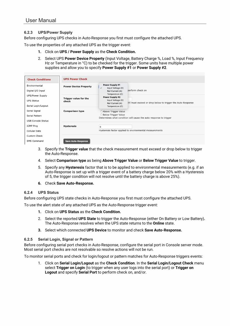
User Manual
6.2.3 UPS/Power Supply Before configuring UPS checks in Auto-Response you first must configure the attached UPS.
To use the properties of any attached UPS as the trigger event:
1. Click on UPS / Power Supply as the Check Condition.
2. Select UPS Power Device Property (Input Voltage, Battery Charge %, Load %, Input Frequency Hz or Temperature in °C) to be checked for the trigger. Some units have multiple power supplies and allow you to specify Power Supply #1 or Power Supply #2.
3. Specify the Trigger value that the check measurement must exceed or drop below to trigger the Auto-Response.
4. Select Comparison type as being Above Trigger Value or Below Trigger Value to trigger.
5. Specify any Hysteresis factor that is to be applied to environmental measurements (e.g. if an Auto-Response is set up with a trigger event of a battery charge below 20% with a Hysteresis of 5, the trigger condition will not resolve until the battery charge is above 25%).
6. Check Save Auto-Response.
6.2.4 UPS Status Before configuring UPS state checks in Auto-Response you first must configure the attached UPS.
To use the alert state of any attached UPS as the Auto-Response trigger event:
1. Click on UPS Status as the Check Condition.
2. Select the reported UPS State to trigger the Auto-Response (either On Battery or Low Battery). The Auto-Response resolves when the UPS state returns to the Online state.
3. Select which connected UPS Device to monitor and check Save Auto-Response.
6.2.5 Serial Login, Signal or Pattern Before configuring serial port checks in Auto-Response, configure the serial port in Console server mode. Most serial port checks are not resolvable so resolve actions will not be run.
To monitor serial ports and check for login/logout or pattern matches for Auto-Response triggers events:
1. Click on Serial Login/Logout as the Check Condition. In the Serial Login/Logout Check menu select Trigger on Login (to trigger when any user logs into the serial port) or Trigger on Logout and specify Serial Port to perform check on, and/or.

Chapter 6: Alerts, Auto-Response & Logging
134
2. Click on Serial Signal as the Check Condition. In the Serial Signal Check menu select the Signal (CTS, DCD, DSR) to trigger on, the Trigger condition (either on serial signal change, or check level) and specify Serial Port to perform check on, and/or.
3. Click on Serial Pattern as the Check Condition. In the Serial Pattern Check menu select the PCRE pattern to trigger on and the serial line (TX or RX) and Serial Port to pattern check on.
With Serial Pattern, you can check the Disconnect Immediately box to disconnect all users from the serial being monitored in event of a successful pattern match.
NOTE For devices with a cellular modem with GPS enabled, the GPS is displayed as an additional port and can be monitored for trigger events.
4. Check Save Auto-Response.
6.2.6 USB Console Status USB port labels in the Web interface match the USB port labels printed on a console server with two exceptions. Some console servers include pairs of USB ports without printed labels. In this case, the Web interface denotes them as either Upper or Lower. The Web interface lists them by their physical relationship to each other.
Some console servers have four USB ports. A few of these have ports labeled 1-4 even though the Web interface denotes them as USB ports A-D.
USB console status checks are not resolvable. Trigger actions run but Resolve actions do not.
To monitor USB ports:
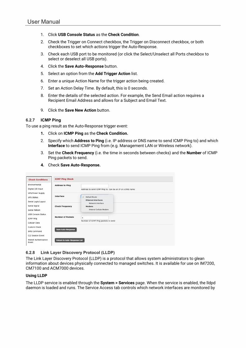
User Manual
1. Click USB Console Status as the Check Condition.
2. Check the Trigger on Connect checkbox, the Trigger on Disconnect checkbox, or both checkboxes to set which actions trigger the Auto-Response.
3. Check each USB port to be monitored (or click the Select/Unselect all Ports checkbox to select or deselect all USB ports).
4. Click the Save Auto-Response button.
5. Select an option from the Add Trigger Action list.
6. Enter a unique Action Name for the trigger action being created.
7. Set an Action Delay Time. By default, this is 0 seconds.
8. Enter the details of the selected action. For example, the Send Email action requires a Recipient Email Address and allows for a Subject and Email Text.
9. Click the Save New Action button.
6.2.7 ICMP Ping To use a ping result as the Auto-Response trigger event:
1. Click on ICMP Ping as the Check Condition.
2. Specify which Address to Ping (i.e. IP address or DNS name to send ICMP Ping to) and which Interface to send ICMP Ping from (e.g. Management LAN or Wireless network).
3. Set the Check Frequency (i.e. the time in seconds between checks) and the Number of ICMP Ping packets to send.
4. Check Save Auto-Response.
6.2.8 Link Layer Discovery Protocol (LLDP) The Link Layer Discovery Protocol (LLDP) is a protocol that allows system administrators to glean information about devices physically connected to managed switches. It is available for use on IM7200, CM7100 and ACM7000 devices.
Using LLDP
The LLDP service is enabled through the System > Services page. When the service is enabled, the lldpd daemon is loaded and runs. The Service Access tab controls which network interfaces are monitored by
Chapter 6: Alerts, Auto-Response & Logging
136
the lldpd daemon. LLDPd is also configured by default to broadcast CDP packets, and monitor both LLDP and CDP neighbours.
When LLDP is granted access to an interface, it uses that interface even if the interface has been disabled via System > IP.
LLDP neighbors are visible through the Status > LLDP Neighbors page. This page shows neighbors heard, and also indicates the information that the console manager is sending.
NOTE LLDP service can be granted access to non-ethernet interfaces (for example, G3, G4 and PSTN dial-up interfaces), but it currently ignores non-ethernet interfaces.
Customising LLDP
The lldpcli shell client interacts with and configures the running LLDP service.
Persistent custom configuration changes can be added to the system through configuration files placed in /etc/config/lldpd.d/. Custom configuration files — which must have filenames ending with .conf — is read and executed by lldpcli when the LLDP service starts.
NOTE On Opengear hardware:
• The /etc/ directory is read-only. Most default configuration files otherwise stored in /etc/ are in /etc/config/, which is writeable.
• The default lldpd configuration file — lldpd.conf — is stored in /etc/config/. It is not a safe location to store custom configuration details. There are circumstances in which this file is regenerated automatically, in which customizations will be lost.
• The etc/config/lldpd.d/ directory, which is writable and is created on first boot, is safe to write to. Any Custom LLDP configurations must be stored as *.conf files in this directory.
Security
When enabled, LLDP frames issued by an Opengear Console Manager reveals sensitive information such as hostname and firmware version.
LLDP frames are not passed through by 802.3ab compliant switches, and Opengear Console Managers have the LLDP service disabled by default.
Documentation
Both lldpd and lldpcli have standard man pages but, because of space concerns, these man pages are not shipped with Opengear hardware.
Both man pages are available on the lldpd project web-site:
man lldpd.
man lldpcli.
6.2.9 Cellular Data Before configuring cellular data checks in Auto-Response the internal cellular modem must be configured and detected by the console server.
This check monitors the aggregate data traffic inbound and outbound through the cellular modem as an Auto-Response trigger event.
Click on Cellular Data as the Check Condition

User Manual
6.2.10 Custom Check This check allows users to run a nominated custom script with nominated arguments whose return value is used as an Auto-Response trigger event:
1. Click on Custom Check as the Check Condition
2. Create an executable trigger check script file e.g. /etc/config/test.sh
#!/bin/sh logger "A test script" logger Argument1 = $1 logger Argument2 = $2 logger Argument3 = $3 logger Argument4 = $4 if [ -f /etc/config/customscript.0 ]; then
rm /etc/config/customscript.0 exit 7
fi touch /etc/config/customscript.0 exit 1
See online FAQ for a sample web page html check and other script file templates.
3. Enter the Script Executable file name (e.g. /etc/config/test.sh).
4. Set the Check Frequency (i.e. the time in seconds between re-running the script) and the Script Timeout (i.e. the maximum run-time for the script).
5. Specify the Successful Return Code. An Auto-Response is triggered if the return code from the script is not this value.
6. Enter Arguments that are to be passed to the script (e.g. with a web page html check script, these Arguments might specify the web page address/DNS and user logins).
7. Check Save Auto-Response.

Chapter 6: Alerts, Auto-Response & Logging
138
6.2.11 SMS Command The SMS command trigger condition can only be set if there is an internal cellular modem.
An incoming SMS command from a nominated caller can trigger an Auto-Response:
1. Click on SMS Command as the Check Condition.
2. Specify which Phone Number (in international format) of the phone sending the SMS message. For multiple trusted SMS sources separate the numbers with a comma.
3. Set the Incoming Message Pattern (PCRE regular expression) to match to create trigger event.
`
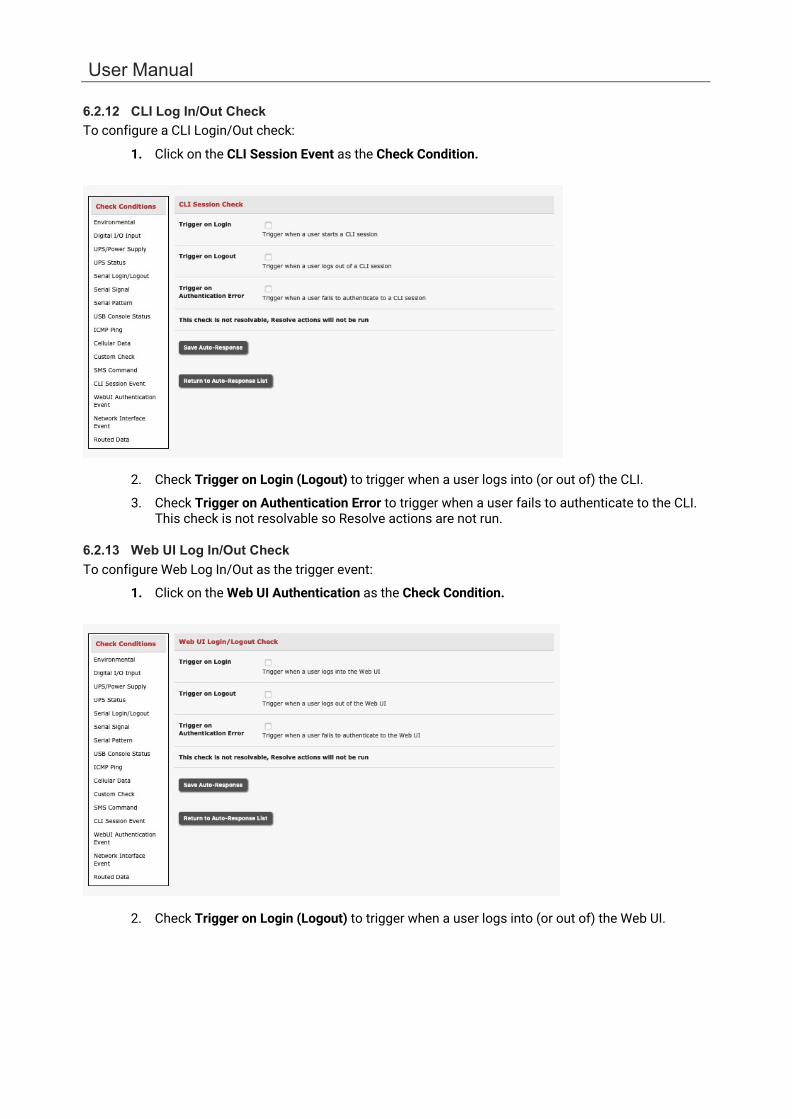
User Manual
6.2.12 CLI Log In/Out Check To configure a CLI Login/Out check:
1. Click on the CLI Session Event as the Check Condition.
2. Check Trigger on Login (Logout) to trigger when a user logs into (or out of) the CLI.
3. Check Trigger on Authentication Error to trigger when a user fails to authenticate to the CLI. This check is not resolvable so Resolve actions are not run.
6.2.13 Web UI Log In/Out Check To configure Web Log In/Out as the trigger event:
1. Click on the Web UI Authentication as the Check Condition.
2. Check Trigger on Login (Logout) to trigger when a user logs into (or out of) the Web UI.
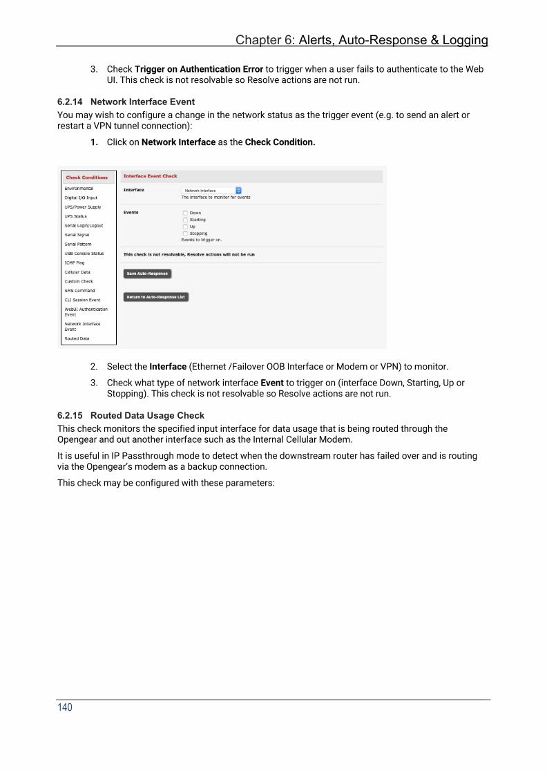
Chapter 6: Alerts, Auto-Response & Logging
140
3. Check Trigger on Authentication Error to trigger when a user fails to authenticate to the Web
UI. This check is not resolvable so Resolve actions are not run.
6.2.14 Network Interface Event You may wish to configure a change in the network status as the trigger event (e.g. to send an alert or restart a VPN tunnel connection):
1. Click on Network Interface as the Check Condition.
2. Select the Interface (Ethernet /Failover OOB Interface or Modem or VPN) to monitor.
3. Check what type of network interface Event to trigger on (interface Down, Starting, Up or Stopping). This check is not resolvable so Resolve actions are not run.
6.2.15 Routed Data Usage Check This check monitors the specified input interface for data usage that is being routed through the Opengear and out another interface such as the Internal Cellular Modem.
It is useful in IP Passthrough mode to detect when the downstream router has failed over and is routing via the Opengear’s modem as a backup connection.
This check may be configured with these parameters:

User Manual
• The Opengear’s incoming Interface to monitor.
• An optional Source MAC/IP Address, to monitor traffic from a host.
• Data Limit threshold, the Auto-Response triggers when this is reached in the specified Time Period.
• The Auto-Response resolves if no matching data is routed for the Resolve Period.

Chapter 6: Alerts, Auto-Response & Logging
142
6.3 Trigger Actions To configure the sequence of actions to take in the event of the trigger condition:
1. For a nominated Auto-Response with a defined Check Condition, click on Add Trigger Action to select the action type to take. Configure the selected action as detailed in the following sections.
2. Action Delay Time specifies how many seconds after the Auto-Response trigger event to wait before performing the action. You can add follow-on actions to create a sequence of actions taken in the event of the trigger condition.
3. To edit or delete an existing action, click the Modify (or Delete) icon in the Scheduled Trigger Action table.
A message text can be sent with Email, SMS and Nagios actions. This configurable message can include selected values:
$AR_TRIGGER_VAL: the trigger value for the check e.g. for UPS Status, it could be onbatt or battlow.
$AR_VAL: the value returned by the check e.g. for ups status, it could be online/onbatt/battlow.
$AR_CHECK_DEV: the device name of the device being checked e.g. for Alarm, the alarm name.
$TIMESTAMP: the current timestamp.
$HOSTNAME: the hostname of the console server.
The default message text is: $TIMESTAMP: This action was run - Check details: value $AR_VAL vs trigger value $AR_TRIGGER_VAL.
6.3.1 Send Email
1. Click on Send Email as the Add Trigger Action. Enter a unique Action Name and set the
Action Delay Time.

User Manual
2. Specify the Recipient Email Address to send this email to and the Subject of the email. For multiple recipients you can enter comma separated addresses.
3. Edit the Email Text message to send and click Save New Action.
An SMS alert can also be sent via an SMTP (email) gateway. Enter the Recipient Email Address in the format specified by the gateway provider (e.g. for T-Mobile it is phonenumber @tmomail.net).
6.3.2 Send SMS An SMS alert can only be sent if there is an internal cellular modem.
1. Click on Send SMS as the Add Trigger Action. Enter a unique Action Name and set the Action
Delay Time.
2. Specify the Phone number that the SMS will be sent to in international format (without the +).
3. Edit the Message Text to send and click Save New Action.
NOTE SMS alerts can also be sent via a SMTP SMS gateway as described above.
6.3.3 Perform RPC Action
1. Click on Perform RPC Action as the Add Trigger Action. Enter a unique Action Name and set the Action Delay Time.
2. Select a power Outlet and specify the Action to perform (power on, off, or cycle).
3. Click Save New Action.

144
Chapter 6: Alerts, Auto-Response & Logging
6.3.4 Run Custom Script
1. Click on Run Custom Script as the Add Trigger Action. Enter a unique Action Name and set
the Action Delay Time.
2. Create a script file to execute when this action is triggered and enter the Script Executable file name e.g. /etc/config/action.sh.
3. Set the Script Timeout (i.e. the maximum run-time for the script). Leave as 0 for unlimited.
4. Enter any Arguments to pass to the script and click Save New Action.
6.3.5 Send SNMP Trap
Click on Send SNMP Trap as the Add Trigger Action. Enter a unique Action Name and set the Action Delay Time.
The SNMP Trap actions are valid for Serial, WebUI & CLI Login, Environmental, UPS and Cellular data triggers.
6.3.6 Send Nagios Event
1. Click on Send Nagios Event as the Add Trigger Action. Enter a unique Action Name and set the Action Delay Time.
2. Edit the Nagios Event Message text to display on the Nagios status screen for the service.
3. Specify the Nagios Event State (OK, Warning, Critical or Unknown) to return to Nagios for this service.
4. Click Save New Action.
NOTE To notify the central Nagios server of Alerts, NSCA must be enabled under System > Nagios and Nagios must be enabled for each applicable host or port.
6.3.7 Perform Interface Action 1. Click on Perform Interface Action as the Add Trigger Action. Enter a unique Action Name and
set the Action Delay Time.
2. Select the Interface (Modem or VPN service) and the Action (Start or Stop Interface) to take. You can start an IPsec VPN service in response to an incoming SMS or set up an OpenVPN tunnel whenever your Opengear device fails over to use the cellular connection.
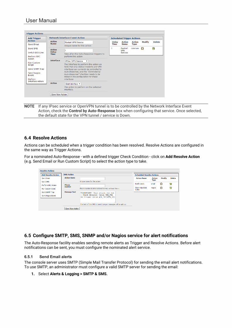
User Manual
NOTE If any IPsec service or OpenVPN tunnel is to be controlled by the Network Interface Event Action, check the Control by Auto-Response box when configuring that service. Once selected, the default state for the VPN tunnel / service is Down.
6.4 Resolve Actions Actions can be scheduled when a trigger condition has been resolved. Resolve Actions are configured in the same way as Trigger Actions.
For a nominated Auto-Response - with a defined trigger Check Condition - click on Add Resolve Action (e.g. Send Email or Run Custom Script) to select the action type to take.
6.5 Configure SMTP, SMS, SNMP and/or Nagios service for alert notifications The Auto-Response facility enables sending remote alerts as Trigger and Resolve Actions. Before alert notifications can be sent, you must configure the nominated alert service.
6.5.1 Send Email alerts The console server uses SMTP (Simple Mail Transfer Protocol) for sending the email alert notifications. To use SMTP, an administrator must configure a valid SMTP server for sending the email:
1. Select Alerts & Logging > SMTP & SMS.
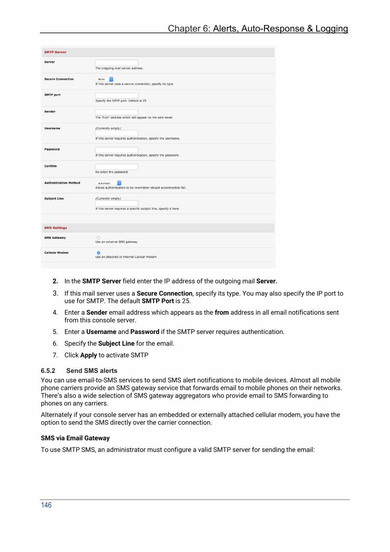
Chapter 6: Alerts, Auto-Response & Logging
146
2. In the SMTP Server field enter the IP address of the outgoing mail Server.
3. If this mail server uses a Secure Connection, specify its type. You may also specify the IP port to use for SMTP. The default SMTP Port is 25.
4. Enter a Sender email address which appears as the from address in all email notifications sent from this console server.
5. Enter a Username and Password if the SMTP server requires authentication.
6. Specify the Subject Line for the email.
7. Click Apply to activate SMTP
6.5.2 Send SMS alerts You can use email-to-SMS services to send SMS alert notifications to mobile devices. Almost all mobile phone carriers provide an SMS gateway service that forwards email to mobile phones on their networks. There’s also a wide selection of SMS gateway aggregators who provide email to SMS forwarding to phones on any carriers.
Alternately if your console server has an embedded or externally attached cellular modem, you have the option to send the SMS directly over the carrier connection.
SMS via Email Gateway
To use SMTP SMS, an administrator must configure a valid SMTP server for sending the email:
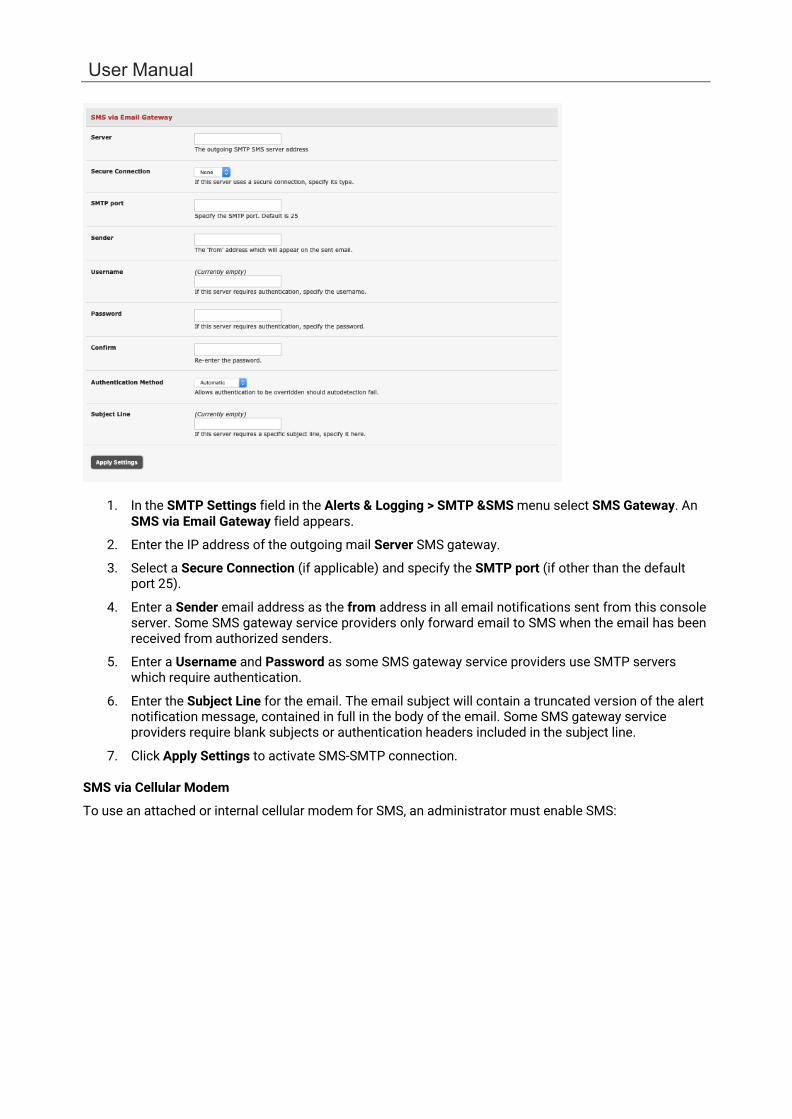
User Manual
1. In the SMTP Settings field in the Alerts & Logging > SMTP &SMS menu select SMS Gateway. An SMS via Email Gateway field appears.
2. Enter the IP address of the outgoing mail Server SMS gateway.
3. Select a Secure Connection (if applicable) and specify the SMTP port (if other than the default port 25).
4. Enter a Sender email address as the from address in all email notifications sent from this console server. Some SMS gateway service providers only forward email to SMS when the email has been received from authorized senders.
5. Enter a Username and Password as some SMS gateway service providers use SMTP servers which require authentication.
6. Enter the Subject Line for the email. The email subject will contain a truncated version of the alert notification message, contained in full in the body of the email. Some SMS gateway service providers require blank subjects or authentication headers included in the subject line.
7. Click Apply Settings to activate SMS-SMTP connection.
SMS via Cellular Modem
To use an attached or internal cellular modem for SMS, an administrator must enable SMS:
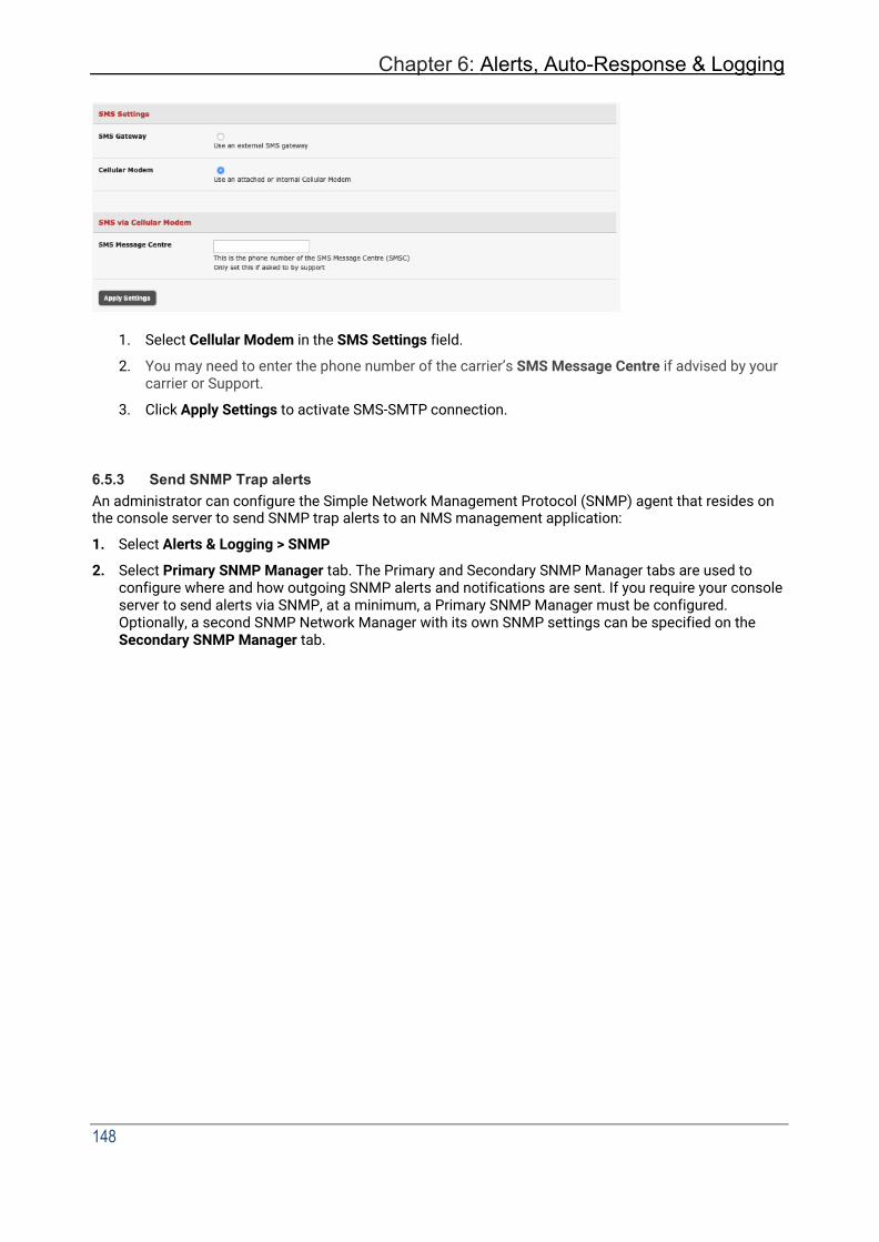
Chapter 6: Alerts, Auto-Response & Logging
148
1. Select Cellular Modem in the SMS Settings field.
2. You may need to enter the phone number of the carrier’s SMS Message Centre if advised by your carrier or Support.
3. Click Apply Settings to activate SMS-SMTP connection.
6.5.3 Send SNMP Trap alerts An administrator can configure the Simple Network Management Protocol (SNMP) agent that resides on the console server to send SNMP trap alerts to an NMS management application:
1. Select Alerts & Logging > SNMP
2. Select Primary SNMP Manager tab. The Primary and Secondary SNMP Manager tabs are used to configure where and how outgoing SNMP alerts and notifications are sent. If you require your console server to send alerts via SNMP, at a minimum, a Primary SNMP Manager must be configured. Optionally, a second SNMP Network Manager with its own SNMP settings can be specified on the Secondary SNMP Manager tab.
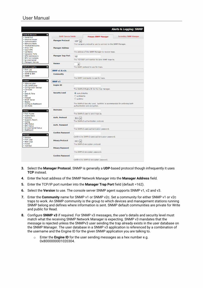
User Manual
3. Select the Manager Protocol. SNMP is generally a UDP-based protocol though infrequently it uses TCP instead.
4. Enter the host address of the SNMP Network Manager into the Manager Address field.
5. Enter the TCP/IP port number into the Manager Trap Port field (default =162).
6. Select the Version to use. The console server SNMP agent supports SNMP v1, v2 and v3.
7. Enter the Community name for SNMP v1 or SNMP v2c. Set a community for either SNMP v1 or v2c traps to work. An SNMP community is the group to which devices and management stations running SNMP belong and defines where information is sent. SNMP default communities are private for Write and public for Read.
8. Configure SNMP v3 if required. For SNMP v3 messages, the user’s details and security level must match what the receiving SNMP Network Manager is expecting. SNMP v3 mandates that the message is rejected unless the SNMPv3 user sending the trap already exists in the user database on the SNMP Manager. The user database in a SNMP v3 application is referenced by a combination of the username and the Engine ID for the given SNMP application you are talking to.
o Enter the Engine ID for the user sending messages as a hex number e.g. 0x8000000001020304.
Chapter 6: Alerts, Auto-Response & Logging
150
o Specify the Security Level. The level of security has to be compatible with the settings of the remote SNMP Network Manager.
noAuthNoPriv No authentication or encryption.
authNoPriv Authentication only. An authentication protocol (SHA or MD5) and password is required.
authPriv Uses both authentication and encryption. This is the highest level
of security and requires an encryption protocol (DES or AES) and password in addition to the authentication protocol and password.
o Complete the Username. This is the Security Name of the SNMPv3 user sending the
message. This field is mandatory and must be completed when configuring the console server for SNMPv3.
o An Authentication Protocol (SHA or MD5) and Authentication Password must be given for a Security Level of either authNoPriv or authPriv. The password must contain at least 8 characters.
o A Privacy Protocol (DES or AES) must be specified for the authPriv level of security used as the encryption algorithm. AES is recommended for stronger security. A password of at least 8 characters must be provided for encryption to work.
9. Click Apply.
6.5.4 Send Nagios Event alerts To notify the central Nagios server of Alerts, NSCA must be enabled under System > Nagios and Nagios must be enabled for each applicable host or port under Serial & Network > Network Hosts or Serial & Network > Serial Ports.
NOTE In Lighthouse, you can check the Nagios alert option. On the trigger condition (for matched patterns, logins, power events and signal changes) an NSCA check warning result is sent to the central Nagios server. This condition is displayed on the Nagios status screen and triggers a notification, which can cause the Nagios central server to send out an email or an SMS, page, etc.
6.6 Logging The console server can maintain log records of auto-response events and log records of all access and communications events (with the console server and with the attached serial, network and power devices).
A log of all system activity is also maintained by default, as is a history of the status of any attached environmental monitors.
6.6.1 Log storage Before activating any Event, Serial, Network or UPS logging, you must specify where to save those logs. These records are stored off-server or in the ACM/IM gateway USB flash memory.
Select the Alerts & Logging > Port Log menu option and specify the Server Type and the details to enable log server access.
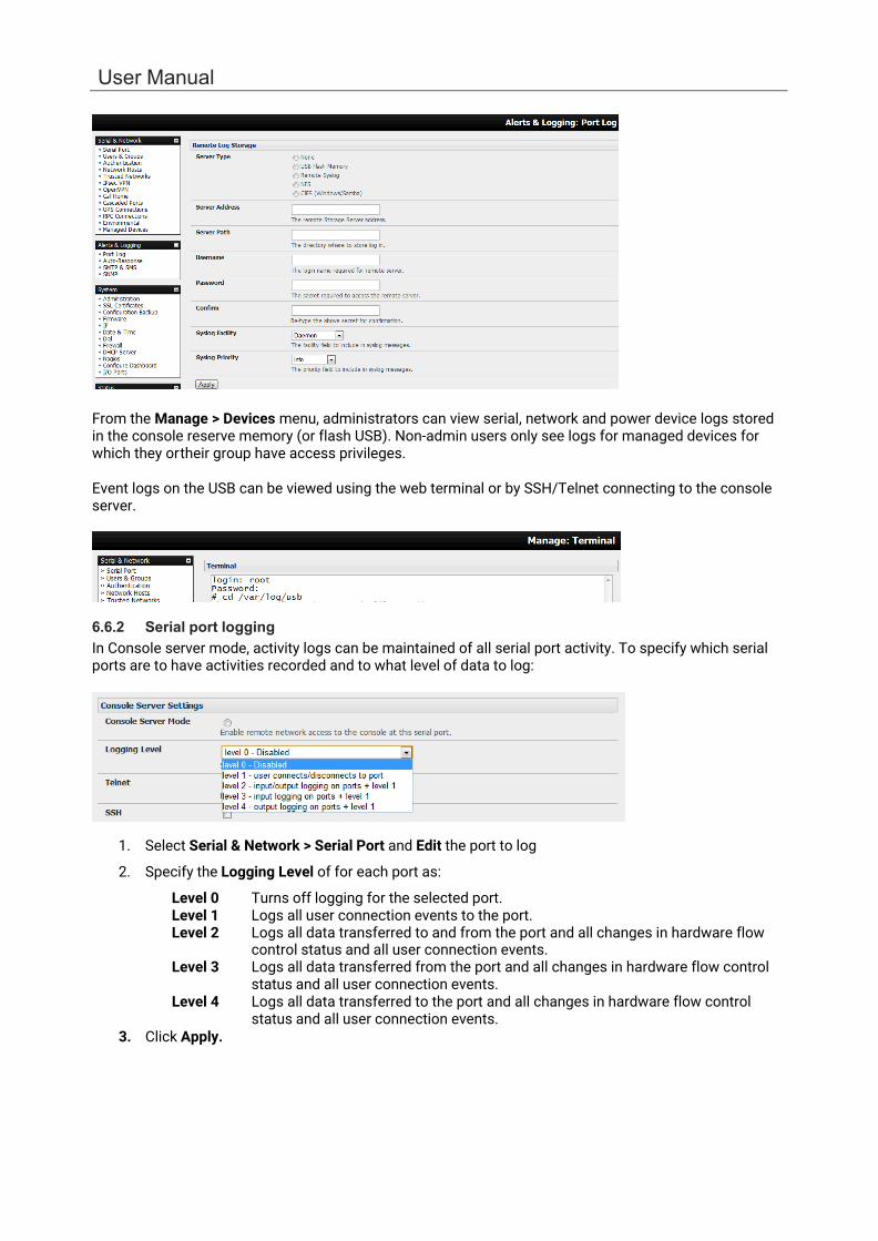
User Manual
From the Manage > Devices menu, administrators can view serial, network and power device logs stored in the console reserve memory (or flash USB). Non-admin users only see logs for managed devices for which they or their group have access privileges.
Event logs on the USB can be viewed using the web terminal or by SSH/Telnet connecting to the console server.
6.6.2 Serial port logging In Console server mode, activity logs can be maintained of all serial port activity. To specify which serial ports are to have activities recorded and to what level of data to log:
1. Select Serial & Network > Serial Port and Edit the port to log
2. Specify the Logging Level of for each port as:
Level 0 Turns off logging for the selected port. Level 1 Logs all user connection events to the port. Level 2 Logs all data transferred to and from the port and all changes in hardware flow
control status and all user connection events. Level 3 Logs all data transferred from the port and all changes in hardware flow control
status and all user connection events. Level 4 Logs all data transferred to the port and all changes in hardware flow control
status and all user connection events. 3. Click Apply.
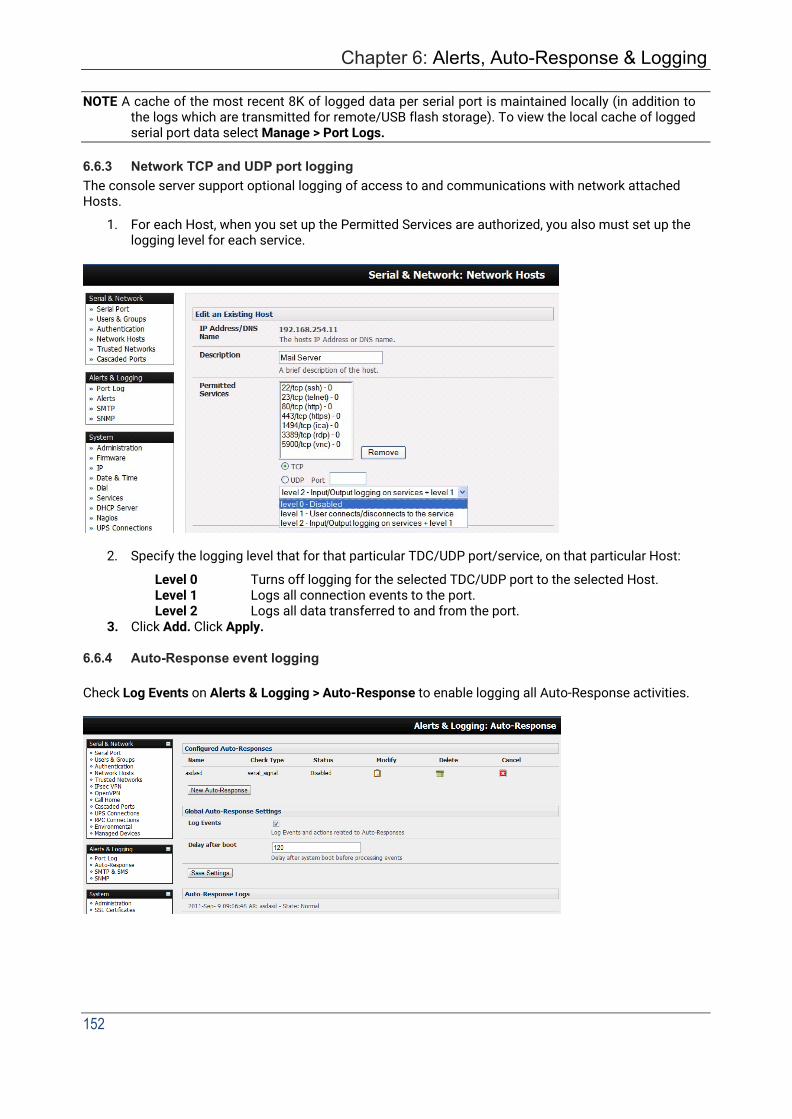
Chapter 6: Alerts, Auto-Response & Logging
152
NOTE A cache of the most recent 8K of logged data per serial port is maintained locally (in addition to the logs which are transmitted for remote/USB flash storage). To view the local cache of logged serial port data select Manage > Port Logs.
6.6.3 Network TCP and UDP port logging The console server support optional logging of access to and communications with network attached Hosts.
1. For each Host, when you set up the Permitted Services are authorized, you also must set up the logging level for each service.
2. Specify the logging level that for that particular TDC/UDP port/service, on that particular Host:
Level 0 Turns off logging for the selected TDC/UDP port to the selected Host. Level 1 Logs all connection events to the port. Level 2 Logs all data transferred to and from the port.
3. Click Add. Click Apply.
6.6.4 Auto-Response event logging
Check Log Events on Alerts & Logging > Auto-Response to enable logging all Auto-Response activities.
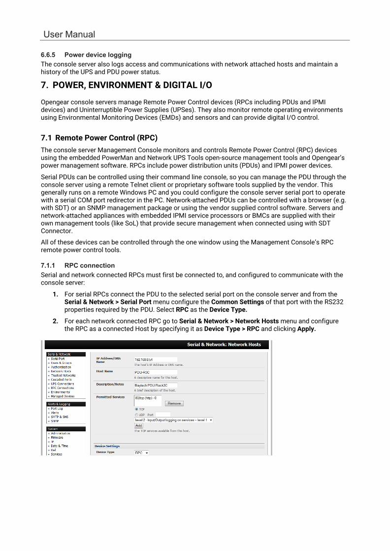
User Manual
6.6.5 Power device logging The console server also logs access and communications with network attached hosts and maintain a history of the UPS and PDU power status.
7. POWER, ENVIRONMENT & DIGITAL I/O
Opengear console servers manage Remote Power Control devices (RPCs including PDUs and IPMI devices) and Uninterruptible Power Supplies (UPSes). They also monitor remote operating environments using Environmental Monitoring Devices (EMDs) and sensors and can provide digital I/O control.
7.1 Remote Power Control (RPC) The console server Management Console monitors and controls Remote Power Control (RPC) devices using the embedded PowerMan and Network UPS Tools open-source management tools and Opengear’s power management software. RPCs include power distribution units (PDUs) and IPMI power devices.
Serial PDUs can be controlled using their command line console, so you can manage the PDU through the console server using a remote Telnet client or proprietary software tools supplied by the vendor. This generally runs on a remote Windows PC and you could configure the console server serial port to operate with a serial COM port redirector in the PC. Network-attached PDUs can be controlled with a browser (e.g. with SDT) or an SNMP management package or using the vendor supplied control software. Servers and network-attached appliances with embedded IPMI service processors or BMCs are supplied with their own management tools (like SoL) that provide secure management when connected using with SDT Connector.
All of these devices can be controlled through the one window using the Management Console’s RPC remote power control tools.
7.1.1 RPC connection Serial and network connected RPCs must first be connected to, and configured to communicate with the console server:
1. For serial RPCs connect the PDU to the selected serial port on the console server and from the Serial & Network > Serial Port menu configure the Common Settings of that port with the RS232 properties required by the PDU. Select RPC as the Device Type.
2. For each network connected RPC go to Serial & Network > Network Hosts menu and configure the RPC as a connected Host by specifying it as Device Type > RPC and clicking Apply.
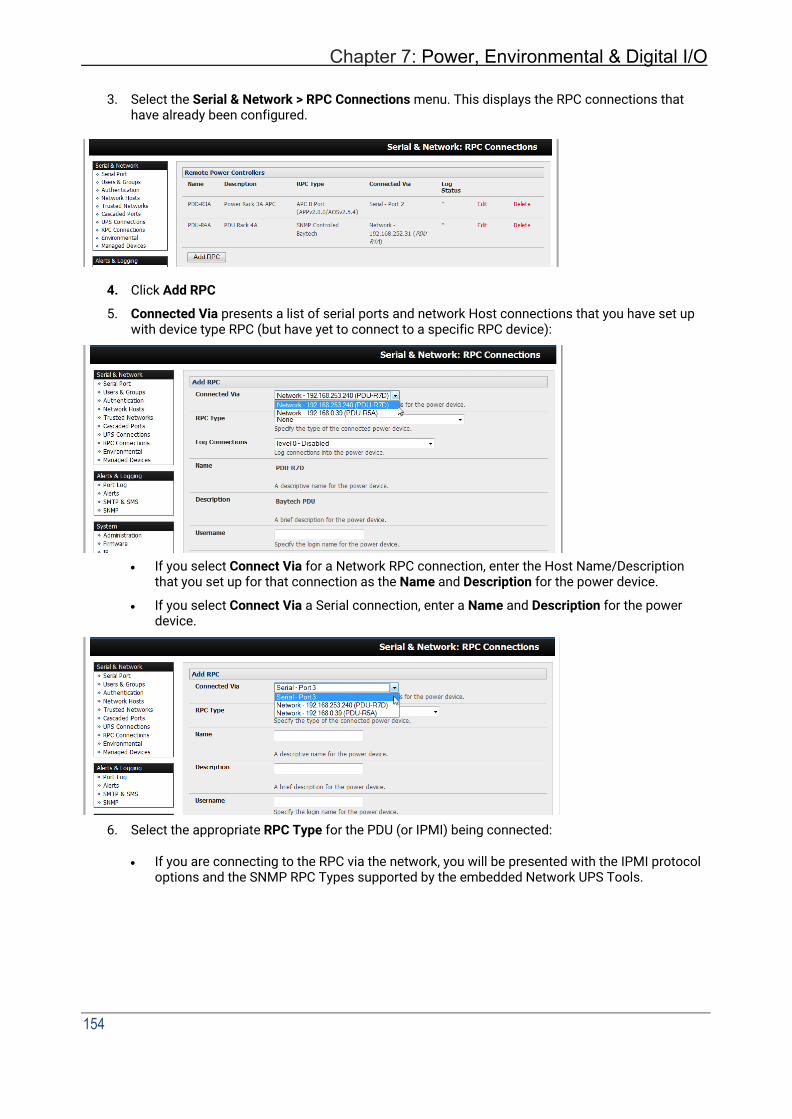
154
Chapter 7: Power, Environmental & Digital I/O
3. Select the Serial & Network > RPC Connections menu. This displays the RPC connections that have already been configured.
4. Click Add RPC
5. Connected Via presents a list of serial ports and network Host connections that you have set up with device type RPC (but have yet to connect to a specific RPC device):
• If you select Connect Via for a Network RPC connection, enter the Host Name/Description that you set up for that connection as the Name and Description for the power device.
• If you select Connect Via a Serial connection, enter a Name and Description for the power device.
6. Select the appropriate RPC Type for the PDU (or IPMI) being connected:
• If you are connecting to the RPC via the network, you will be presented with the IPMI protocol options and the SNMP RPC Types supported by the embedded Network UPS Tools.

User Manual
• If you are connecting to the RPC by a serial port, you will be presented with all the serial RPC types supported by the embedded PowerMan and Opengear’s power manager:
7. Enter the Username and Password used to login into the RPC. These login credentials are not
related the users and access privileges you configured in Serial & Networks > Users & Groups.
8. If you selected SNMP protocol, enter the SNMP v1 or v2c Community for Read/Write access. By default, this is private.
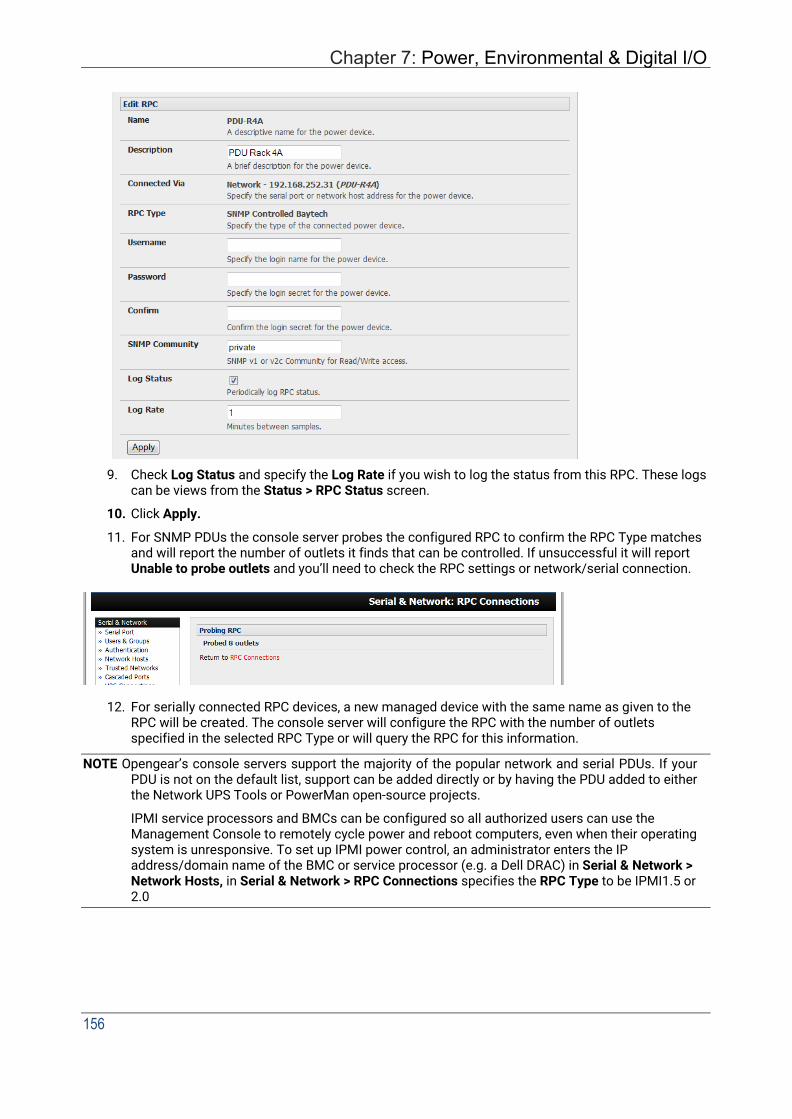
Chapter 7: Power, Environmental & Digital I/O
156
9. Check Log Status and specify the Log Rate if you wish to log the status from this RPC. These logs can be views from the Status > RPC Status screen.
10. Click Apply.
11. For SNMP PDUs the console server probes the configured RPC to confirm the RPC Type matches and will report the number of outlets it finds that can be controlled. If unsuccessful it will report Unable to probe outlets and you’ll need to check the RPC settings or network/serial connection.
12. For serially connected RPC devices, a new managed device with the same name as given to the RPC will be created. The console server will configure the RPC with the number of outlets specified in the selected RPC Type or will query the RPC for this information.
NOTE Opengear’s console servers support the majority of the popular network and serial PDUs. If your PDU is not on the default list, support can be added directly or by having the PDU added to either the Network UPS Tools or PowerMan open-source projects.
IPMI service processors and BMCs can be configured so all authorized users can use the Management Console to remotely cycle power and reboot computers, even when their operating system is unresponsive. To set up IPMI power control, an administrator enters the IP address/domain name of the BMC or service processor (e.g. a Dell DRAC) in Serial & Network > Network Hosts, in Serial & Network > RPC Connections specifies the RPC Type to be IPMI1.5 or 2.0

User Manual
7.1.2 RPC access privileges and alerts Set PDU and IPMI alerts using Alerts & Logging > Alerts. You can also assign which user can access and control which particular outlet on each RPC using Serial & Network > Users & Groups.
7.1.3 User power management The Power Manager enables users to access and control the configured serial and network attached PDU power strips, and servers with embedded IPMI service processors or BMCs:
Select the Manage > Power and the particular Target power device to be controlled (and the Outlet to be controlled if the RPC supports outlet level control)
The outlet status is displayed. Initiate the desired Action to be taken by selecting the appropriate icon:
Turn ON
Turn OFF
Cycle
Status
You will be presented with icons for those operations that are supported by the Target you have selected.
7.1.4 RPC status You can monitor the current status of your network and serially connected PDUs and IPMI RPCs.
1. Select the Status > RPC Status menu and a table with the summary status of all connected RPC hardware will be displayed.

Chapter 7: Power, Environmental & Digital I/O
158
2. Click on View Log or select the RPCLogs menu and you will be presented with a table of the history and detailed graphical information on the selected RPC.
3. Click Manage to query or control the individual power outlet. This will take you to the Manage > Power screen.
7.2 Uninterruptible Power Supply(UPS) Control All Opengear console servers can be configured to manage locally and remotely connected UPS hardware using Network UPS Tools.
Network UPS Tools (NUT) is a group of open-source programs that provide a common interface for monitoring and administering UPS hardware; and ensuring safe shutdowns of the systems which are connected. NUT is built on a networked model with a layered scheme of drivers, server and clients.
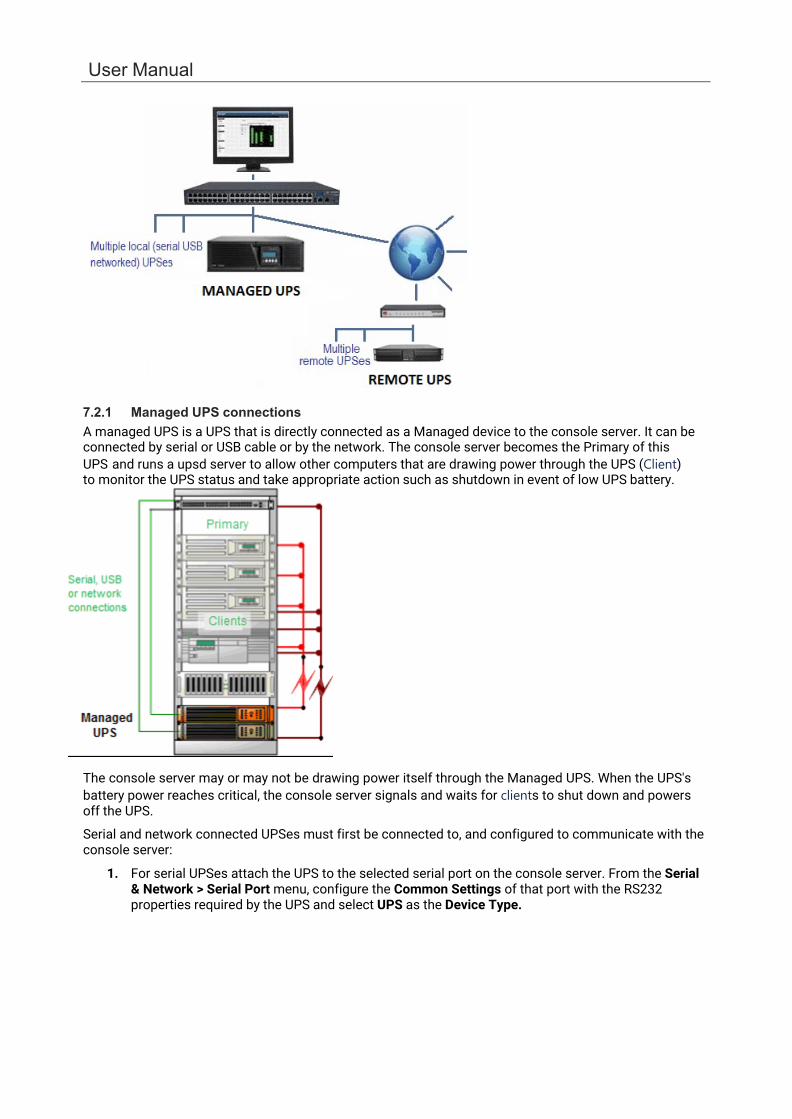
User Manual
7.2.1 Managed UPS connections A managed UPS is a UPS that is directly connected as a Managed device to the console server. It can be connected by serial or USB cable or by the network. The console server becomes the Primary of this UPS and runs a upsd server to allow other computers that are drawing power through the UPS (Client) to monitor the UPS status and take appropriate action such as shutdown in event of low UPS battery.
The console server may or may not be drawing power itself through the Managed UPS. When the UPS's battery power reaches critical, the console server signals and waits for clients to shut down and powers off the UPS.
Serial and network connected UPSes must first be connected to, and configured to communicate with the console server:
1. For serial UPSes attach the UPS to the selected serial port on the console server. From the Serial & Network > Serial Port menu, configure the Common Settings of that port with the RS232 properties required by the UPS and select UPS as the Device Type.

Chapter 7: Power, Environmental & Digital I/O
160
2. For each network connected UPS, go to Serial & Network > Network Hosts menu and configure
the UPS as a connected Host by specifying it as Device Type > UPS and clicking Apply.
No such configuration is required for USB connected UPS hardware.
3. Select the Serial & Network > UPS Connections menu. The Managed UPSes section will display all the UPS connections that have already been configured.
4. Click Add Managed UPS.
5. Select if the UPS will be Connected Via USB or over pre-configured serial port or via
SNMP/HTTP/HTTPS over the preconfigured network Host connection.

User Manual
6. When you select a network UPS connection, the corresponding Host Name/Description that you set up for that connection will be entered as the Name and Description for the power device. Alternately if you selected to Connect Via a USB or serial connection, enter a Name and Description for the power device (and these details will also be used to create a new managed device entry for the serial/USB connected UPS devices).
7. Enter the login details. This Username and Password is used by Clients of this UPS (i.e. other computers that are drawing power through this UPS) to connect to the console server to monitor the UPS status so they can shut themselves down when battery power is low. Monitoring will be performed using the upsmon client running on the Client server.
NOTE These login credentials are not related the users and access privileges you will have configured in Serial & Networks > Users & Groups.
8. Select the action to take when UPS battery power becomes critical i.e. Shut down the UPS (or Shut down all Managed UPSes) or Run until failure.
NOTE The shutdown script /etc/scripts/ups-shutdown can be customized so, in the event of a critical power failure (when the UPS battery runs out) you can perform program the console server to perform last gasp actions using before power is lost. See online FAQ for details. It is easier to perform last gasp actions by triggering Auto-Response on the UPS hitting batt or lowbatt.
9. If you have more than one UPS and need to shut down in order, specify the Shutdown Order for this UPS. This is a whole positive number, or -1. 0s are shut down first, then 1s, 2s, etc. -1s are not shut down at all. Defaults to 0.
10. Select the Driver that will be used to communicate with the UPS.
11. Click New Options in Driver Options if you need to set driver-specific options for your selected
NUT driver and hardware combination.
12. Check Log Status and specify the Log Rate (minutes between samples) if you wish the status
from this UPS to be logged. These logs can be viewed from the Status > UPS Status screen.
13. If you have enabled Nagios services, an option for Nagios monitoring appears. Check Enable Nagios to enable this UPS to be monitored using Nagios central management.
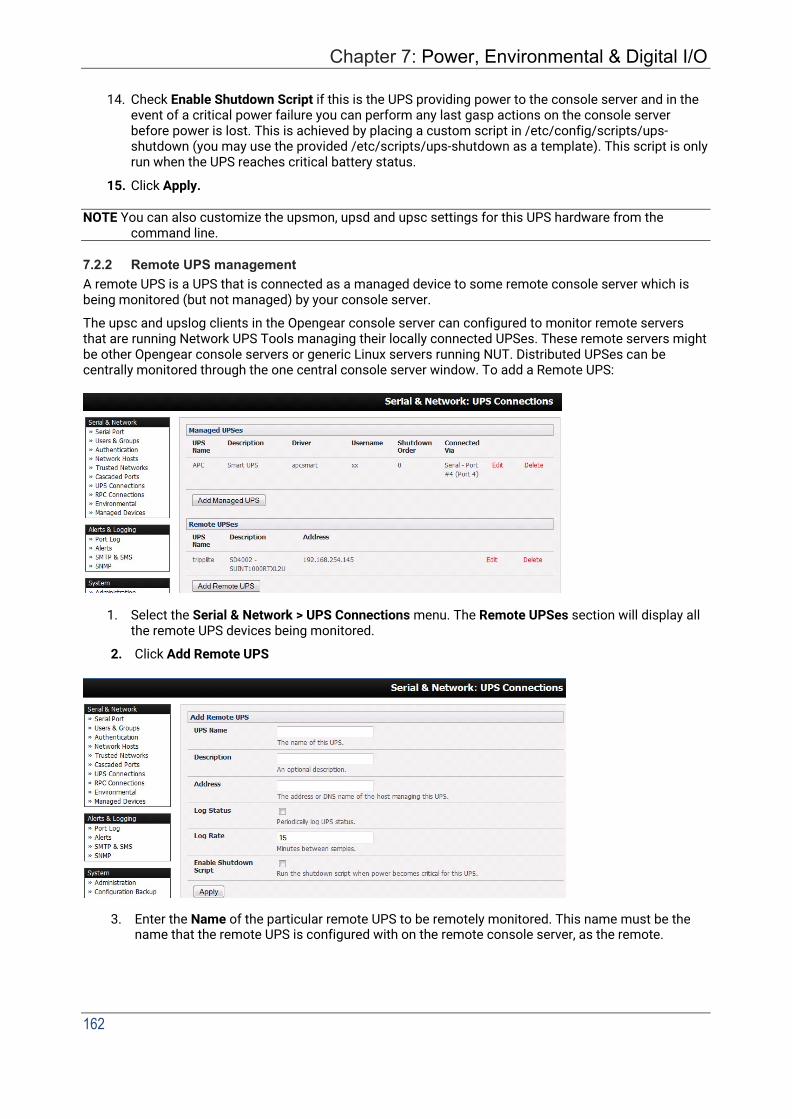
162
Chapter 7: Power, Environmental & Digital I/O
14. Check Enable Shutdown Script if this is the UPS providing power to the console server and in the
event of a critical power failure you can perform any last gasp actions on the console server before power is lost. This is achieved by placing a custom script in /etc/config/scripts/ups- shutdown (you may use the provided /etc/scripts/ups-shutdown as a template). This script is only run when the UPS reaches critical battery status.
15. Click Apply.
NOTE You can also customize the upsmon, upsd and upsc settings for this UPS hardware from the command line.
7.2.2 Remote UPS management A remote UPS is a UPS that is connected as a managed device to some remote console server which is being monitored (but not managed) by your console server.
The upsc and upslog clients in the Opengear console server can configured to monitor remote servers that are running Network UPS Tools managing their locally connected UPSes. These remote servers might be other Opengear console servers or generic Linux servers running NUT. Distributed UPSes can be centrally monitored through the one central console server window. To add a Remote UPS:
1. Select the Serial & Network > UPS Connections menu. The Remote UPSes section will display all the remote UPS devices being monitored.
2. Click Add Remote UPS
3. Enter the Name of the particular remote UPS to be remotely monitored. This name must be the name that the remote UPS is configured with on the remote console server, as the remote.

User Manual
console server may have multiple UPSes attached that it is managing locally with NUT. Optionally enter a Description.
4. Enter the IP Address or DNS name of the remote console server* that is managing the remote UPS. (*This may be another Opengear console server or it may be a generic Linux server running Network UPS Tools).
5. Check Log Status and specify the Log Rate (minutes between samples) if you wish the status from this UPS to be logged. These logs can be viewed from the Status > UPS Status screen.
6. Check Enable Shutdown Script if this remote UPS is the UPS providing power to the console server. In the event the UPS reaches critical battery status the custom script in /etc/config/scripts/ups-shutdown is run enabling you to perform any last gasp actions.
7. Click Apply.
7.2.3 Controlling UPS powered computers One of the advantages of having a Managed UPS is that you can configure computers that draw power through that UPS to be shut down gracefully in the event of UPS problems.
For Linux computers this can be done by setting up upsmon on each computer and directing them to monitor the console server that is managing their UPS. This will set the conditions that will be used to initiate a power down of the computer. Non-critical servers may be powered down some second after the UPS starts running on battery, whereas more critical servers may not be shut down until a low battery warning is received.
An example upsmon.conf entry might look like:
MONITOR [email protected] 1 username password Client.
• managedups is the UPS Name of the Managed UPS.
• 192.168.0.1 is the IP address of the Opengear console server.
• 1 indicates the server has a single power supply attached to this UPS.
• username is the Username of the Managed UPS.
• password is the Password of the Manager UPS.
There are NUT monitoring clients available for Windows computers (WinNUT).
If you have an RPC (PDU) it is also possible to shut down UPS powered computers and other equipment without them having a client running (e.g. communications and surveillance gear). Set up a UPS alert and using this to trigger a script which control a PDU to shut off the power.
7.2.4 UPS alerts You can set UPS alerts using Alerts & Logging > Alerts.
7.2.5 UPS status You can monitor the current status of your network, serially or USB connected Managed UPSes and any configured Remote UPSes.
1. Select the Status > UPS Status menu and a table with the summary status of all connected UPS hardware will be displayed.

Chapter 7: Power, Environmental & Digital I/O
164
2. Click on any particular UPS System name in the table. A more detailed graphical information on the select UPS System appears.
3. Click on any particular All Data for any UPS System in the table for more status and configuration information on the select UPS System.
4. Select UPS Logs. The log table of the load, battery charge level, temperature and other status
information from all the Managed and Monitored UPS systems appears. This information will be

User Manual
logged for all UPSes which were configured with Log Status checked. The information is also presented graphically.
7.2.6 Overview of Network UPS Tools (NUT) NUT is built on a networked model with a layered scheme of drivers, server and clients. NUT can be configured using the Management Console as described above, or you can configure the tools and manage the UPSes from the command line. This section provides an overview of NUT. You can find full documentation at http://www.networkupstools.org/documentation.
NUT is built on a networked model with a layered scheme of drivers, server and clients:
The driver programs talk to the UPS equipment and run on the same host as the NUT network server (upsd). Drivers are provided for a wide assortment of equipment from most of the popular UPS vendors and understand the language of each UPS. They communicate to serial, USB and SNMP network connected UPS hardware and map the communications back to a compatibility layer. This means both an expensive smart protocol UPS and a power strip model can be handled transparently.
Chapter 7: Power, Environmental & Digital I/O
166
The NUT network server program upsd is responsible for passing status data from the drivers to
the client programs via the network. upsd can cache the status from multiple UPSes and serve this status data to many clients. upsd also contains access control features to limit the abilities of the clients (e.g. so only authorized hosts may monitor or control the UPS hardware).
There are a number of NUT clients that connect to upsd to check on the status of the UPS
hardware and perform tasks based on the status. These clients can run on the same host as the NUT server or they can communicate with the NUT server over the network (enabling them to monitor any UPS anywhere):
The upsc client provides a quick way to poll the status of a UPS server. It can be used
inside shell scripts and other programs that need UPS data but don't want to include the full interface.
The upsmon client enables servers that draw power through the UPS to shutdown gracefully when the battery power reaches critical.
There are also logging clients (upslog) and third-party interface clients (Big Sister, Cacti, Nagios, Windows and more).
The latest release of NUT (2.4) also controls PDU systems. It can do this either natively using
SNMP or through a binding to Powerman (open source software from Livermore Labs that also is embedded in Opengear console servers).
These NUT clients and servers all are embedded in each Opengear console server (with a Management Console presentation layer added) … and they also are run remotely on distributed console servers and other remote NUT monitoring systems. This layered distributed NUT architecture enables:
Multiple manufacturer support: NUT can monitor UPS models from 79 different manufacturers - and PDUs from a growing number of vendors - with a unified interface.
Multiple architecture support: NUT can manage serial and USB connected UPS models with the same common interface. Network connected USB and PDU equipment can also be monitored using SNMP.
Multiple clients monitoring the one UPS: Multiple systems may monitor a single UPS using only their network connections and there's a wide selection of client programs which support monitoring UPS hardware via NUT (Big Sister, Cacti, Nagios and more).
Central management of multiple NUT servers: A central NUT client can monitor multiple NUT servers that may be distributed throughout the data center, across a campus or around the world.
NUT supports the more complex power architectures found in data centers, communications centers and distributed office environments where many UPSes from many vendors power many systems with many clients - and each of the larger UPSes power multiple devices - and many of these devices are in turn dual powered.
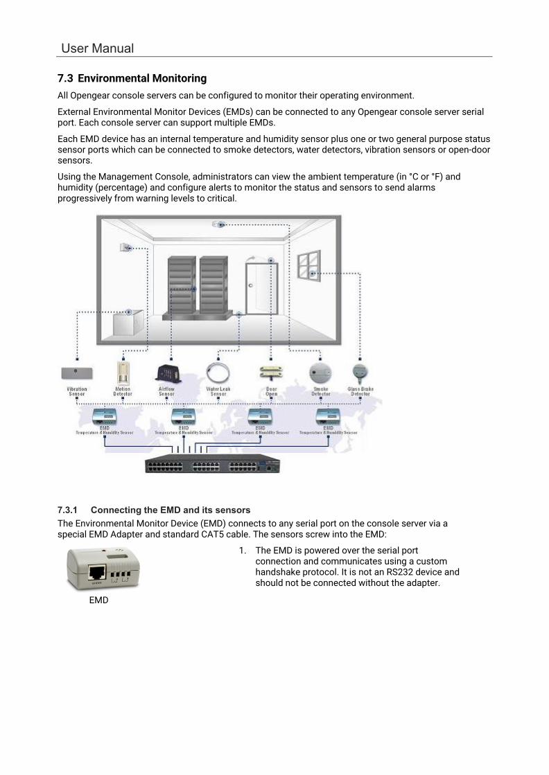
User Manual
7.3 Environmental Monitoring All Opengear console servers can be configured to monitor their operating environment.
External Environmental Monitor Devices (EMDs) can be connected to any Opengear console server serial port. Each console server can support multiple EMDs.
Each EMD device has an internal temperature and humidity sensor plus one or two general purpose status sensor ports which can be connected to smoke detectors, water detectors, vibration sensors or open-door sensors.
Using the Management Console, administrators can view the ambient temperature (in °C or °F) and humidity (percentage) and configure alerts to monitor the status and sensors to send alarms progressively from warning levels to critical.
7.3.1 Connecting the EMD and its sensors The Environmental Monitor Device (EMD) connects to any serial port on the console server via a special EMD Adapter and standard CAT5 cable. The sensors screw into the EMD:
1. The EMD is powered over the serial port connection and communicates using a custom handshake protocol. It is not an RS232 device and should not be connected without the adapter.
EMD

168
Chapter 7: Power, Environmental & Digital I/O
EMD Adapter
EMD sensor
2. Plug the male RJ plug on the EMD Adapter into the EMD. Connect the Adapter to the console server serial port using the provided UTP cable. If the 6-foot (2 meter) UTP cable provided with the EMD is not long enough it can be replaced with a standard Cat5 UTP cable up to 33 feet (10 meters) in length.
3. Screw the bare wires on any smoke detector, water detector, vibration sensor, open-door sensor or general purpose open/close status sensors into the terminals on the EMD.
NOTE You can attach two sensors onto the terminals on EMDs that are connected to console servers with Opengear Classic pinouts. Console servers with -01 and -02 pinouts only support attaching a single sensor to each EMD.
The EMD can only be used with an Opengear console server and cannot be connected to standard RS232 serial ports on other appliances.
1. Select Environmental as the Device Type in the Serial & Network > Serial Port menu for the port to which the EMD is to be attached. No particular Common Settings are required.
2. Click Apply.
7.3.2 Connecting sensors to ACM7000s
ACM7000 models ship with an in-built, black, spring cage I/O connector block for attaching environmental sensors and digital I/O devices.
ACM7000 models have dedicated I/O (DIO1 & DIO2) and output only pins (OUT1 & OUT2), the later having inverting outputs with higher voltage/current transistor.
1. To confirm the direction and state configurations for these ports you can select the System > I/O Ports menu and a table with the summary status of the four digital I/O ports will be displayed. I/O Port1 = DIO1 or SENSOR1, I/O Port2 = DIO2 or SENSOR2, I/O Port3 = SENSOR3 and I/O Port4 = SENSOR 4).
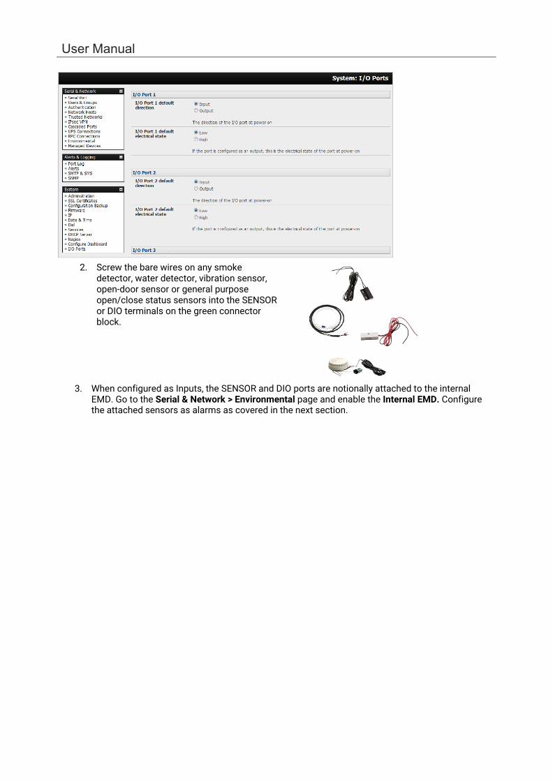
User Manual
2. Screw the bare wires on any smoke
detector, water detector, vibration sensor, open-door sensor or general purpose open/close status sensors into the SENSOR or DIO terminals on the green connector block.
3. When configured as Inputs, the SENSOR and DIO ports are notionally attached to the internal EMD. Go to the Serial & Network > Environmental page and enable the Internal EMD. Configure the attached sensors as alarms as covered in the next section.
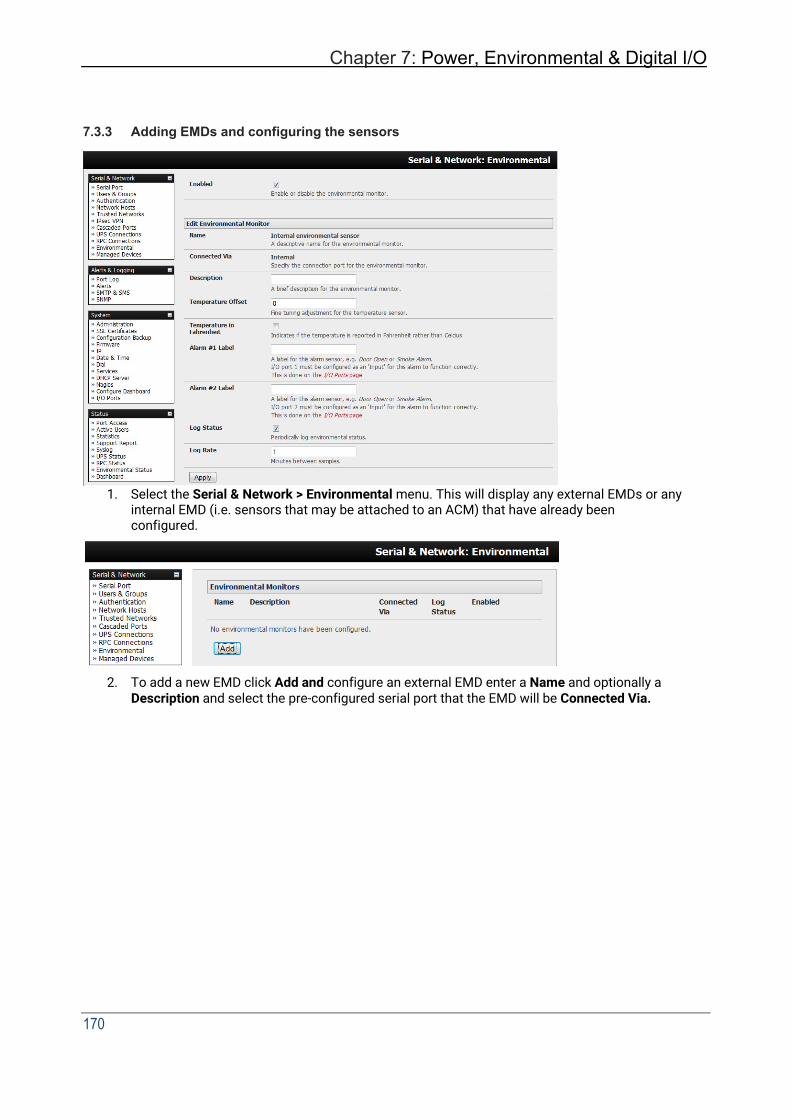
Chapter 7: Power, Environmental & Digital I/O
170
7.3.3 Adding EMDs and configuring the sensors
1. Select the Serial & Network > Environmental menu. This will display any external EMDs or any internal EMD (i.e. sensors that may be attached to an ACM) that have already been configured.
2. To add a new EMD click Add and configure an external EMD enter a Name and optionally a
Description and select the pre-configured serial port that the EMD will be Connected Via.
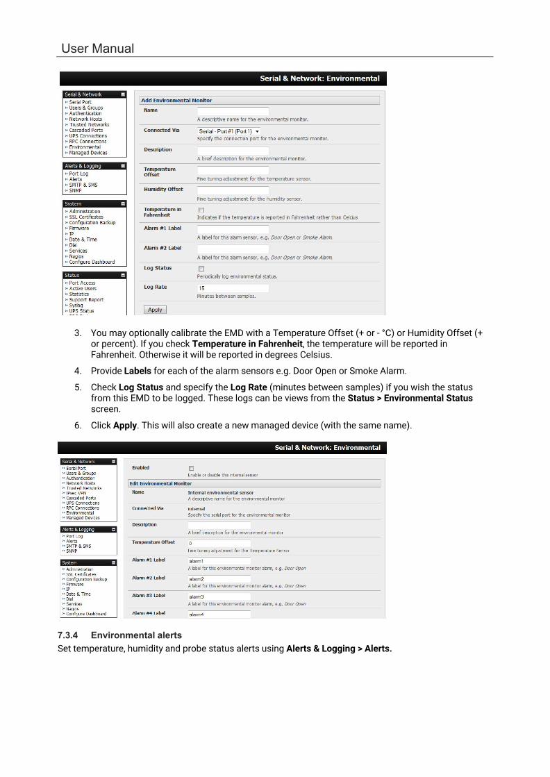
User Manual
3. You may optionally calibrate the EMD with a Temperature Offset (+ or - °C) or Humidity Offset (+ or percent). If you check Temperature in Fahrenheit, the temperature will be reported in Fahrenheit. Otherwise it will be reported in degrees Celsius.
4. Provide Labels for each of the alarm sensors e.g. Door Open or Smoke Alarm.
5. Check Log Status and specify the Log Rate (minutes between samples) if you wish the status from this EMD to be logged. These logs can be views from the Status > Environmental Status screen.
6. Click Apply. This will also create a new managed device (with the same name).
7.3.4 Environmental alerts Set temperature, humidity and probe status alerts using Alerts & Logging > Alerts.

Chapter 7: Power, Environmental & Digital I/O
172
7.3.5 Environmental status You can monitor the current status of all any configured external EMDs and their sensors, and any internal or directly attached sensors.
1. Select the Status > Environmental Status menu and a table with the summary status of all connected EMD hardware will be displayed.
2. Click on View Log or select the Environmental Logs menu. A table and graphical plot of the log history of the select EMD appears.
7.4 Digital I/O Ports
ACM7000 models ship with an in-built, black, spring cage I/O connector block for attaching environmental sensors and digital I/O devices.
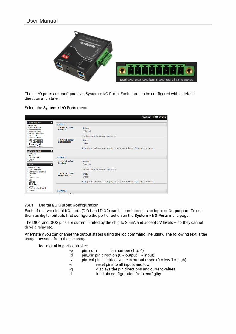
User Manual
These I/O ports are configured via System > I/O Ports. Each port can be configured with a default direction and state.
Select the System > I/O Ports menu.
7.4.1 Digital I/O Output Configuration Each of the two digital I/O ports (DIO1 and DIO2) can be configured as an Input or Output port. To use them as digital outputs first configure the port direction on the System > I/O Ports menu page.
The DIO1 and DIO2 pins are current limited by the chip to 20mA and accept 5V levels – so they cannot drive a relay etc.
Alternately you can change the output states using the ioc command line utility. The following text is the usage message from the ioc usage:
ioc: digital io-port controller: -p pin_num pin number (1 to 4) -d pin_dir pin direction (0 = output 1 = input) -v pin_val pin electrical value in output mode (0 = low 1 = high) -r reset pins to all inputs and low -g displays the pin directions and current values -l load pin configuration from configlity

Chapter 7: Power, Environmental & Digital I/O
174
For example, to set pin 1 to a low output, type:
ioc -p 1 -d 0 -v 0
To pulse one of these outputs, use a script like the following: ioc -p 1 -d 0 -v 1 sleep 1 ioc -p 1 -d 0 -v 0 This will set the output high for 1 second, return it to low (assuming the initial state is low).
7.4.2 Digital I/O Input Configuration When either of the two digital I/O (DIO1 & DIO2) outlets is configured as an Input on the System > I/O Ports, it can be used to monitor the current status of any attached sensor.
When configured as inputs (and this is the factory default) these first two ports are notionally attached to an internal EMD. To configure them as alarms, go to the Environmental page and edit and enable the Internal EMD.
The low voltage circuits in DIO1 and DIO2 should not be wired to voltages greater than 5V DC.
These input ports can be monitored using the ioc command line utility (as detailed in the previous section).
7.4.3 High Voltage Outputs OUT1 and OUT2 (internally DIO3 & DIO4) outlets are wired as high voltage outputs. The way these outputs are expected to be used is to pull a power connected line to ground (i.e. the OUT1 and OUT2 transistors are open collector).
The I/O port header includes a 12v reference line (VIN) which can be used to detect the line state change.
For example, to light a 12v LED using the high voltage outputs, connect the positive leg of the LED to the 12v reference, and the negative leg to output pin 4. Due to the way that the I/O port is connected internally, the output has to be set high to pull the output to ground.
The following command will switch on the led:
ioc -p 4 -d 0 -v 1
OUT1 and OUT2 transistors can operate with a supply of >5V to <= 30V @100mA. This means to drive a relay circuit you must guarantee it doesn't provide more than 100mA when set to 1.
7.4.4 DIO SNMP status There is a SNMP status table (with V3.9 and later) which reports on the status of the digital IO ports. The table OID is OG-STATUSv2-MIB::ogEmdDioTable. Performing an snmpwalk on this table on a console server with DIO produces something like (will vary depending on device status):
$ snmpwalk -v2c -c public -M $MIBSDIR -m ALL t5:161 1.3.6.1.4.1.25049.16.5 OG-STATUS-MIB::ogDioStatusName.1 = STRING: DIO 1 OG-STATUS-MIB::ogDioStatusName.2 = STRING: DIO 2 OG-STATUS-MIB::ogDioStatusName.3 = STRING: DIO 3 OG-STATUS-MIB::ogDioStatusName.4 = STRING: DIO 4 OG-STATUS-MIB::ogDioStatusType.1 = INTEGER: ttlInputOutput(0) OG-STATUS-MIB::ogDioStatusType.2 = INTEGER: ttlInputOutput(0) OG-STATUS-MIB::ogDioStatusType.3 = INTEGER: highVoltageOutput(1) OG-STATUS-MIB::ogDioStatusType.4 = INTEGER: highVoltageOutput(1) OG-STATUS-MIB::ogDioStatusDirection.1 = INTEGER: input(1) OG-STATUS-MIB::ogDioStatusDirection.2 = INTEGER: input(1) OG-STATUS-MIB::ogDioStatusDirection.3 = INTEGER: input(1)
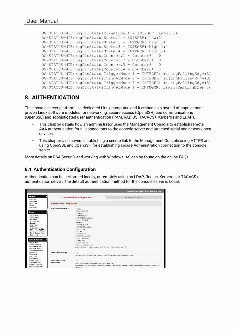
User Manual
OG-STATUS-MIB::ogDioStatusDirection.4 = INTEGER: input(1) OG-STATUS-MIB::ogDioStatusState.1 = INTEGER: low(0) OG-STATUS-MIB::ogDioStatusState.2 = INTEGER: high(1) OG-STATUS-MIB::ogDioStatusState.3 = INTEGER: high(1) OG-STATUS-MIB::ogDioStatusState.4 = INTEGER: high(1) OG-STATUS-MIB::ogDioStatusCounter.1 = Counter64: 0 OG-STATUS-MIB::ogDioStatusCounter.2 = Counter64: 0 OG-STATUS-MIB::ogDioStatusCounter.3 = Counter64: 0 OG-STATUS-MIB::ogDioStatusCounter.4 = Counter64: 0 OG-STATUS-MIB::ogDioStatusTriggerMode.1 = INTEGER: risingFallingEdge(3) OG-STATUS-MIB::ogDioStatusTriggerMode.2 = INTEGER: risingFallingEdge(3) OG-STATUS-MIB::ogDioStatusTriggerMode.3 = INTEGER: risingFallingEdge(3) OG-STATUS-MIB::ogDioStatusTriggerMode.4 = INTEGER: risingFallingEdge(3)
8. AUTHENTICATION
The console server platform is a dedicated Linux computer, and it embodies a myriad of popular and proven Linux software modules for networking, secure access (OpenSSH) and communications (OpenSSL) and sophisticated user authentication (PAM, RADIUS, TACACS+, Kerberos and LDAP).
This chapter details how an administrator uses the Management Console to establish remote AAA authentication for all connections to the console server and attached serial and network host devices.
This chapter also covers establishing a secure link to the Management Console using HTTPS and using OpenSSL and OpenSSH for establishing secure Administration connection to the console server.
More details on RSA SecurID and working with Windows IAS can be found on the online FAQs.
8.1 Authentication Configuration Authentication can be performed locally, or remotely using an LDAP, Radius, Kerberos or TACACS+ authentication server. The default authentication method for the console server is Local.

Chapter 8: Authentication
176
Any authentication method that is configured will be used for authentication of any user who attempts to log in through Telnet, SSH or the Web Manager to the console server and any connected serial port or network host devices.
The console server can be configured to the default (Local) or an alternate authentication method (TACACS, RADIUS, LDAP or Kerberos) with the option of a selected order in which local and remote authentication is to be used:
Local TACACS /RADIUS/LDAP/Kerberos: Tries local authentication first, falling back to remote if local fails.
TACACS /RADIUS/LDAP/Kerberos Local: Tries remote authentication first, falling back to local if remote fails.
TACACS /RADIUS/LDAP/Kerberos Down Local: Tries remote authentication first, falling back to local if the remote authentication returns an error condition (e.g. the remote authentication server is down or inaccessible).
8.1.1 Local authentication
1. Select Serial & Network > Authentication and check Local.
2. Click Apply.
8.1.2 TACACS authentication Perform the following procedure to configure the TACACS+ authentication method to be used whenever the console server or any of its serial ports or hosts is accessed:
1. Select Serial & Network > Authentication and check TACAS, LocalTACACS, TACACSLocal or TACACSDownLocal.
2. Enter the Server Address (IP or host name) of the remote Authentication/Authorization server.
Multiple remote servers may be specified in a comma separated list. Each server is tried in succession.

User Manual
3. Session accounting is on by default. If session accounting information is not wanted, check the Disable Accounting checkbox. (One reason for not wanting session accounting: if the authentication server does not respond to accounting requests, said request may introduce a delay when logging in.)
4. In addition to multiple remote servers you can also enter for separate lists of Authentication/Authorization servers and Accounting servers. If no Accounting servers are specified, the Authentication/Authorization servers are used instead.
5. Enter and confirm the Server Password. Select the method to be used to authenticate to the server (defaults to PAP). To use DES encrypted passwords, select Login.
6. If required enter the TACACS Group Membership Attribute that is to be used to indicate group memberships (defaults to groupname#n).
7. If required, specify TACACS Service to authenticate with. This determines which set of attributes are returned by the server (defaults to raccess ).
8. If required, check Default Admin Privileges to give all TACAS+ authenticated users admin privileges. Use Remote Groups must also be ticked for these privileges to be granted.
9. The TACACS Privilege Level feature only applies to TACACS remote authentication. When Ignore Privilege Level is enabled, the priv-lvl setting for all of the users defined on the TACACS AAA server will be ignored.
NOTE An Opengear device interprets a user with a TACACS priv-lvl of 12 or above as an admin user. There is a special case where a user with a priv-lvl of 15 is also given access to all configured serial ports. When the Ignore Privilege Level option is enabled (i.e. checked in the UI) there are no escalations of privileges based on the priv-lvl value from the TACACS server.
Also note that if the only thing configured for one or more TACACS users is the priv-lvl (e.g. no specific port access or group memberships set), enabling this feature will revoke access to the console server for those users as the they won't be a member of any groups, even if the Retrieve Remote groups option in the Authentication menu is enabled.
10. Click Apply. TACAS+ remote authentication is used for all user access to console server and serially or network attached devices
TACACS+ The Terminal Access Controller Access Control System (TACACS+) security protocol is a recent protocol developed by Cisco. It provides detailed accounting information and flexible administrative control over the authentication and authorization processes. TACACS+ allows for a single access control server (the TACACS+ daemon) to provide authentication, authorization, and accounting services independently. Each service can be tied into its own database to take advantage of other services available on that server or on the network, depending on the capabilities of the daemon.
8.1.3 RADIUS authentication
NOTE: PAP or MS-CHAPv2 authentication is supported from release 4.12.0. MS-CHAPv2 is the default for new configurations, however, devices with existing RADIUS configuration will remain configured for PAP when upgrading from an earlier version.
Perform the following procedure to configure the RADIUS authentication method to be used whenever the console server or any of its serial ports or hosts is accessed:
1. Select Serial & Network > Authentication and check RADIUS or LocalRADIUS or RADIUSLocal or RADIUSDownLocal.
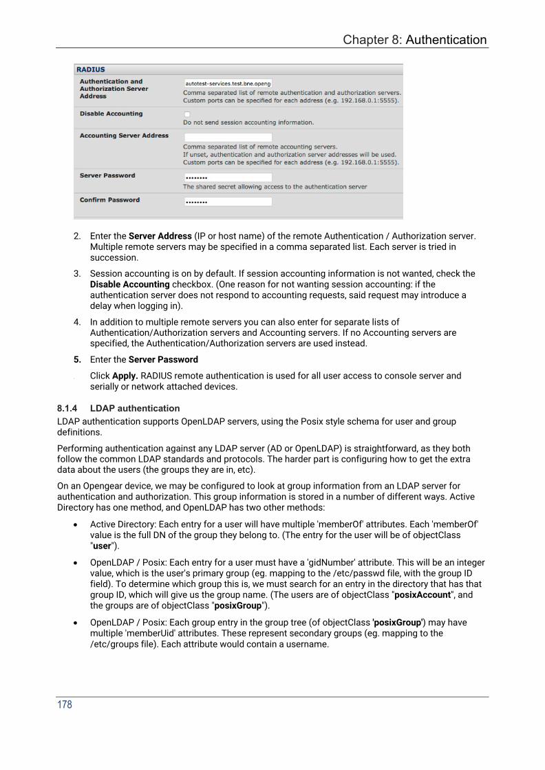
Chapter 8: Authentication
178
2. Enter the Server Address (IP or host name) of the remote Authentication / Authorization server. Multiple remote servers may be specified in a comma separated list. Each server is tried in succession.
3. Session accounting is on by default. If session accounting information is not wanted, check the Disable Accounting checkbox. (One reason for not wanting session accounting: if the authentication server does not respond to accounting requests, said request may introduce a delay when logging in).
4. In addition to multiple remote servers you can also enter for separate lists of Authentication/Authorization servers and Accounting servers. If no Accounting servers are specified, the Authentication/Authorization servers are used instead.
5. Enter the Server Password
6. Click Apply. RADIUS remote authentication is used for all user access to console server and serially or network attached devices.
8.1.4 LDAP authentication LDAP authentication supports OpenLDAP servers, using the Posix style schema for user and group definitions.
Performing authentication against any LDAP server (AD or OpenLDAP) is straightforward, as they both follow the common LDAP standards and protocols. The harder part is configuring how to get the extra data about the users (the groups they are in, etc).
On an Opengear device, we may be configured to look at group information from an LDAP server for authentication and authorization. This group information is stored in a number of different ways. Active Directory has one method, and OpenLDAP has two other methods:
• Active Directory: Each entry for a user will have multiple 'memberOf' attributes. Each 'memberOf' value is the full DN of the group they belong to. (The entry for the user will be of objectClass "user").
• OpenLDAP / Posix: Each entry for a user must have a 'gidNumber' attribute. This will be an integer value, which is the user's primary group (eg. mapping to the /etc/passwd file, with the group ID field). To determine which group this is, we must search for an entry in the directory that has that group ID, which will give us the group name. (The users are of objectClass "posixAccount", and the groups are of objectClass "posixGroup").
• OpenLDAP / Posix: Each group entry in the group tree (of objectClass 'posixGroup') may have multiple 'memberUid' attributes. These represent secondary groups (eg. mapping to the /etc/groups file). Each attribute would contain a username.
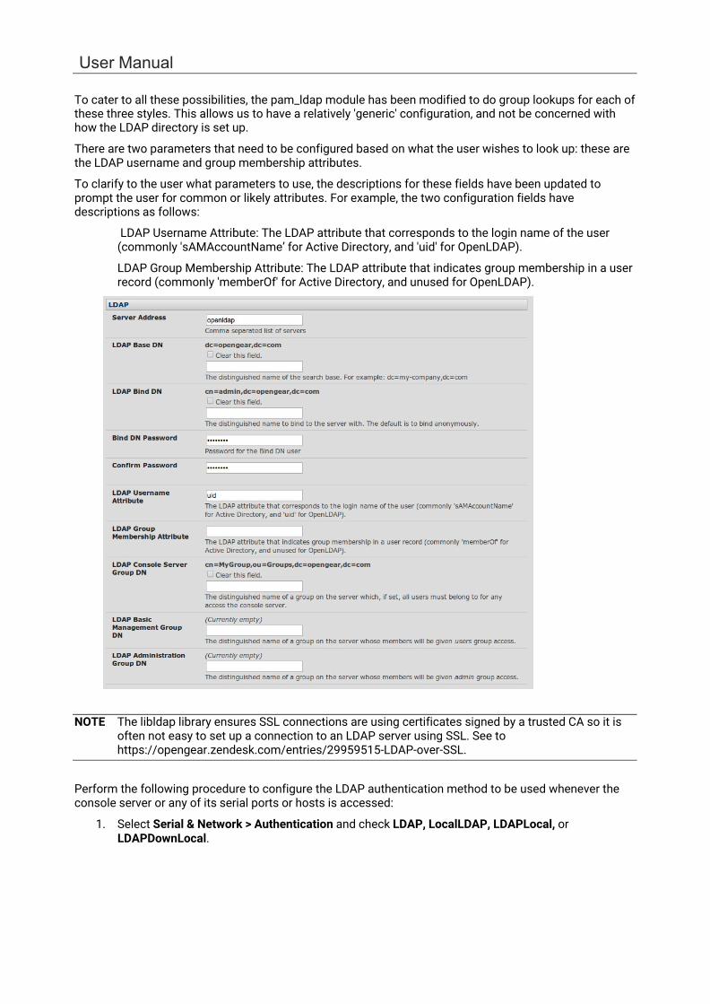
User Manual
To cater to all these possibilities, the pam_ldap module has been modified to do group lookups for each of these three styles. This allows us to have a relatively 'generic' configuration, and not be concerned with how the LDAP directory is set up.
There are two parameters that need to be configured based on what the user wishes to look up: these are the LDAP username and group membership attributes.
To clarify to the user what parameters to use, the descriptions for these fields have been updated to prompt the user for common or likely attributes. For example, the two configuration fields have descriptions as follows:
LDAP Username Attribute: The LDAP attribute that corresponds to the login name of the user (commonly 'sAMAccountName’ for Active Directory, and 'uid' for OpenLDAP).
LDAP Group Membership Attribute: The LDAP attribute that indicates group membership in a user record (commonly 'memberOf' for Active Directory, and unused for OpenLDAP).
NOTE The libldap library ensures SSL connections are using certificates signed by a trusted CA so it is often not easy to set up a connection to an LDAP server using SSL. See to https://opengear.zendesk.com/entries/29959515-LDAP-over-SSL.
Perform the following procedure to configure the LDAP authentication method to be used whenever the console server or any of its serial ports or hosts is accessed:
1. Select Serial & Network > Authentication and check LDAP, LocalLDAP, LDAPLocal, or LDAPDownLocal.
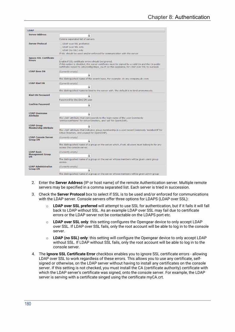
Chapter 8: Authentication
180
2. Enter the Server Address (IP or host name) of the remote Authentication server. Multiple remote servers may be specified in a comma separated list. Each server is tried in succession.
3. Check the Server Protocol box to select if SSL is to be used and/or enforced for communications with the LDAP server. Console servers offer three options for LDAPS (LDAP over SSL):
o LDAP over SSL preferred will attempt to use SSL for authentication, but if it fails it will fall back to LDAP without SSL. As an example LDAP over SSL may fail due to certificate errors or the LDAP server not be contactable on the LDAPS port etc.
o LDAP over SSL only: this setting configures the Opengear device to only accept LDAP over SSL. If LDAP over SSL fails, only the root account will be able to log in to the console server.
o LDAP (no SSL) only: this setting will configure the Opengear device to only accept LDAP without SSL. If LDAP without SSL fails, only the root account will be able to log in to the console server.
4. The Ignore SSL Certificate Error checkbox enables you to ignore SSL certificate errors - allowing LDAP over SSL to work regardless of these errors. This allows you to use any certificate, self- signed or otherwise, on the LDAP server without having to install any certificates on the console server. If this setting is not checked, you must install the CA (certificate authority) certificate with which the LDAP server's certificate was signed, onto the console server. For example, the LDAP server is serving with a certificate singed using the certificate myCA.crt.
User Manual
NOTE The certificate needs to be in CRT format and myCA.crt needs to be installed onto console server at /etc/config/ldaps_ca.crt. Also the file name must be ldaps_ca.crt. You need to copy the file to this location and file name manually using 'scp' or the like e.g.
scp /local/path/to/myCA.c rt root@console_server:/etc/config/ldaps_ca.crt
5. Enter the Server Password.
6. Click Apply. LDAP remote authentication is used for all user access to console server and serially
or network attached devices.
8.1.5 RADIUS/TACACS user configuration Users may be added to the local console server appliance. If they are not added and they log in via remote AAA, a user will be added for them. This user will not show up in the Opengear configurators unless they are specifically added, at which point they are transformed into a local user. The newly added user must authenticate off of the remote AAA server and will have no access if it is down.
If a local user logs in, they may be authenticated / authorized from the remote AAA server, depending on the chosen priority of the remote AAA. A local user's authorization is the union of local and remote privileges.
Example 1:
User Tim is locally added and has access to ports 1 and 2. He is also defined on a remote TACACS server, which says he has access to ports 3 and 4. Tim may log in with either his local or TACACS password and will have access to ports 1 through 4. If TACACS is down, he will need to use his local password, and will only be able to access ports 1 and 2.
Example 2:
User Lynn is only defined on the TACACS server, which says she has access to ports 5 and 6. When she attempts to log in a new user will be created for him, and she will be able to access ports 5 and 6. If the TACACS server is down she will have no access.
Example 3:
User Paul is defined on a RADIUS server only. He has access to all serial ports and network hosts.
Example 4:
User Don is locally defined on an appliance using RADIUS for AAA. Even if Don is also defined on the RADIUS server he will only have access to those serial ports and network hosts he has been authorized to use on the appliance.
If a no local AAA option is selected, root will be authenticated locally.
Remote users may be added to the admin group via either RADIUS or TACACS. Users may have a set of authorizations set on the remote TACACS server. Users automatically added by RADIUS will have authorization for all resources, whereas those added locally will need their authorizations specified.
LDAP has not been modified and needs locally defined users.
8.1.6 Group support with remote authentication All console servers allow remote authentication via RADIUS, LDAP and TACACS+. RADIUS and LDAP can provide additional restrictions on user access based on group information or membership. For example, with remote group support, users can belong to a local group that has been setup to have restricted access to serial ports, network hosts and managed devices.
Remote authentication with group support works by matching a local group name with a remote group name provided by the authentication service. If the list of remote group names returned by the
Chapter 8: Authentication
182
authentication service matches any local group names, the user is given permissions as configured in the local groups.
To enable group support to be used by remote authentication services:
1. Select Serial & Network > Authentication.
2. Select the relevant Authentication Method.
3. Check the Use Remote Groups button.
8.1.7 Remote groups with RADIUS authentication
1. Enter the RADIUS Authentication and Authorization Server Address and Server Password.
2. Click Apply.
3. Edit the Radius user’s file to include group information and restart the Radius server.
When using RADIUS authentication, group names are provided to the console server using the Framed-Filter-Id attribute. This is a standard RADIUS attribute and may be used by other devices that authenticate via RADIUS.
To interoperate with other devices using this field, the group names can be added to the end of any existing content in the attribute, in the following format:
:group_name=testgroup1,users:
The above example sets the remote user as a member of testgroup1 and users if groups with those names exist on the console server. Any groups which do not exist on the console server are ignored.
User Manual
When setting the Framed-Filter-Id, the system may also remove the leading colon for an empty field. To work around this, add some dummy text to the start of the string. For example:
dummy:group_name=testgroup1,users:
• If no group is specified for a user, for example AmandaJones, the user will have no user Interface and serial port access but limited console access.
• Default groups available on the console server include ‘admin’ for administrator access and ‘users’ for general user access.
TomFraser
AmandaJones
FredWhite
JanetLong
Cleartext-Password := ”FraTom70”
Framed-Filter-Id=”:group_name=admin:”
Cleartext-Password := ”JonAma83”
Cleartext-Password := ”WhiFre62”
Framed-Filter-Id=”:group_name=testgroup1,users:”
Cleartext-Password := ”LonJan57”
Framed-Filter-Id=”:group_name=admin:”
• Additional local groups such as testgroup1 can be added via Users & Groups > Serial & Network.
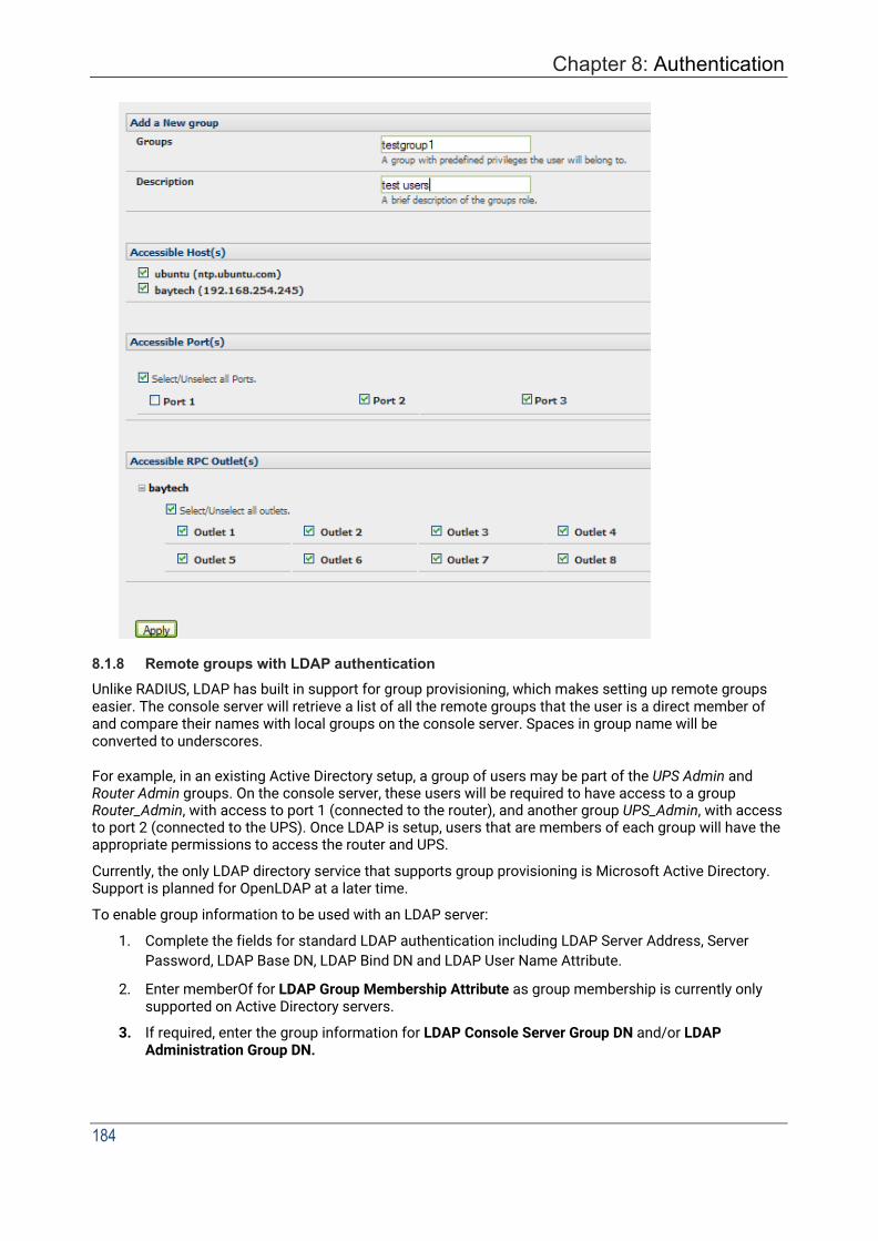
Chapter 8: Authentication
184
8.1.8 Remote groups with LDAP authentication Unlike RADIUS, LDAP has built in support for group provisioning, which makes setting up remote groups easier. The console server will retrieve a list of all the remote groups that the user is a direct member of and compare their names with local groups on the console server. Spaces in group name will be converted to underscores.
For example, in an existing Active Directory setup, a group of users may be part of the UPS Admin and Router Admin groups. On the console server, these users will be required to have access to a group Router_Admin, with access to port 1 (connected to the router), and another group UPS_Admin, with access to port 2 (connected to the UPS). Once LDAP is setup, users that are members of each group will have the appropriate permissions to access the router and UPS.
Currently, the only LDAP directory service that supports group provisioning is Microsoft Active Directory. Support is planned for OpenLDAP at a later time.
To enable group information to be used with an LDAP server:
1. Complete the fields for standard LDAP authentication including LDAP Server Address, Server Password, LDAP Base DN, LDAP Bind DN and LDAP User Name Attribute.
2. Enter memberOf for LDAP Group Membership Attribute as group membership is currently only supported on Active Directory servers.
3. If required, enter the group information for LDAP Console Server Group DN and/or LDAP Administration Group DN.

User Manual
A user must be a member of the LDAP Console Server Group DN group in order to gain access to the console and user interface. For example, the user must be a member of MyGroup on the Active Server to gain access to the console server.
Additionally, a user must be a member of the LDAP Administration Group DN in order to gain administrator access to the console server. For example, the user must be a member of AdminGroup on the Active Server to receive administration privileges on the console server.
4. Click Apply.
5. Ensure the LDAP service is operational and group names are correct within the Active Directory.
NOTE When you are using remote groups with LDAP remote auth, you need to have corresponding local groups on the console server BUT where the LDAP group names can contain upper case and space characters the local group name on the console server must be all lower case and the spaces replaced with underscrores. For example, a remote group on the LDAP server may be My Ldap Access Group needs a corresponding local group on the console server called my_ldap_access_group. The local group on the console server must specify what the group member is granted access to for any group membership to be effective.

Chapter 8: Authentication
186
8.1.9 Remote groups with TACACS+ authentication
When using TACACS+ authentication, there are two ways to grant a remotely authenticated user privileges. The first is to set the priv-lvl and port attributes of the raccess service to 12, discussed further in section 8.2. Also, group names can be provided to the console server using the groupname custom attribute of the raccess service.
An example Linux tac-plus config snippet might look like:
user = myuser { service = raccess {
groupname="users" groupname1="routers" groupname2="dracs"
} }
You may also specify multiple groups in one comma-delimited, e.g. groupname="users,routers,dracs" but be aware that the maximum length of the attribute value string is 255 characters.
To use an attribute name other than groupname, set Authentication > TACACS+ > TACACS Group Membership Attribute.

User Manual
8.1.10 Idle timeout You can specify amount of time in minutes the console server waits before it terminates an idle SSH, pmshell or web connection.
Select Serial & Network > Authentication.
• Web Management Session Timeout specifies the browser console session idle timeout in minutes. The default setting is 20 minutes.
• CLI Management Session Timeout specifies the SSH console session idle timeout in minutes. The default setting is to never expire.
• Console Server Session Timeout specifies the pmshell serial console server session idle timeout in minutes. The default setting is to never expire.
8.1.11 Kerberos authentication The Kerberos authentication can be used with UNIX and Windows (Active Directory) Kerberos servers. This form of authentication does not provide group information, so a local user with the same username must be created, and permissions set.
NOTE Kerberos is sensitive to time differences between the Key Distribution Center (KDC) authentication server and the client device. Make sure that NTP is enabled, and the time zone is set correctly on the console server.
When authenticating against Active Directory, the Kerberos Realm will be the domain name, and the Primary KDC will be the address of the primary domain controller.
8.1.12 Authentication testing The Authentication Testing tab enables the connection to the remote authentication server to be tested.
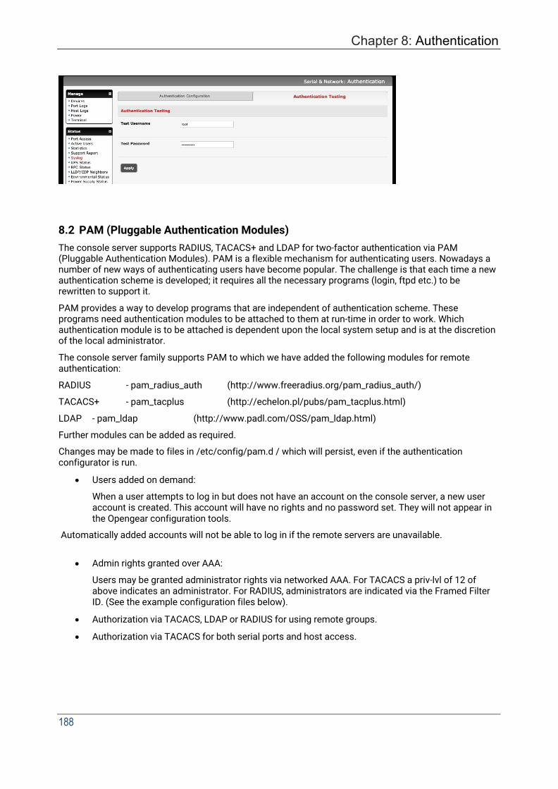
Chapter 8: Authentication
188
8.2 PAM (Pluggable Authentication Modules) The console server supports RADIUS, TACACS+ and LDAP for two-factor authentication via PAM (Pluggable Authentication Modules). PAM is a flexible mechanism for authenticating users. Nowadays a number of new ways of authenticating users have become popular. The challenge is that each time a new authentication scheme is developed; it requires all the necessary programs (login, ftpd etc.) to be rewritten to support it.
PAM provides a way to develop programs that are independent of authentication scheme. These programs need authentication modules to be attached to them at run-time in order to work. Which authentication module is to be attached is dependent upon the local system setup and is at the discretion of the local administrator.
The console server family supports PAM to which we have added the following modules for remote authentication:
RADIUS - pam_radius_auth (http://www.freeradius.org/pam_radius_auth/)
TACACS+ - pam_tacplus (http://echelon.pl/pubs/pam_tacplus.html)
LDAP - pam_ldap (http://www.padl.com/OSS/pam_ldap.html)
Further modules can be added as required.
Changes may be made to files in /etc/config/pam.d / which will persist, even if the authentication configurator is run.
• Users added on demand:
When a user attempts to log in but does not have an account on the console server, a new user account is created. This account will have no rights and no password set. They will not appear in the Opengear configuration tools.
Automatically added accounts will not be able to log in if the remote servers are unavailable.
• Admin rights granted over AAA:
Users may be granted administrator rights via networked AAA. For TACACS a priv-lvl of 12 of above indicates an administrator. For RADIUS, administrators are indicated via the Framed Filter ID. (See the example configuration files below).
• Authorization via TACACS, LDAP or RADIUS for using remote groups.
• Authorization via TACACS for both serial ports and host access.
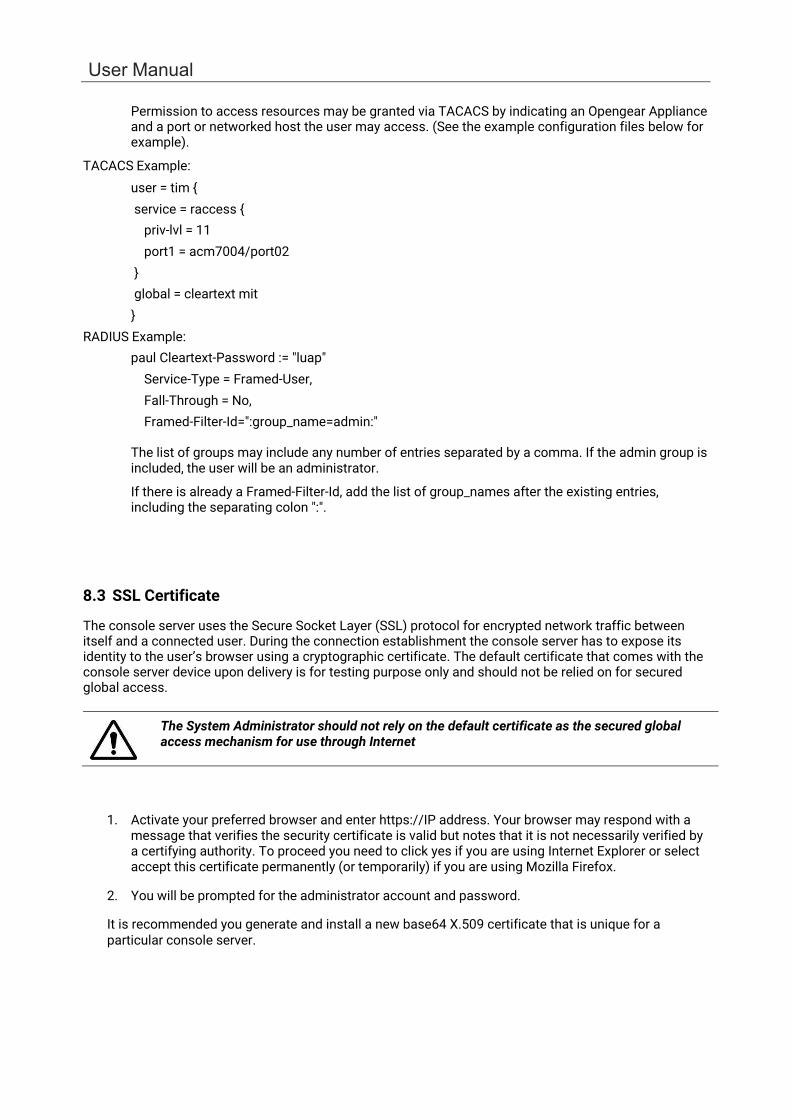
User Manual
Permission to access resources may be granted via TACACS by indicating an Opengear Appliance and a port or networked host the user may access. (See the example configuration files below for example).
TACACS Example: user = tim { service = raccess {
priv-lvl = 11 port1 = acm7004/port02
} global = cleartext mit }
RADIUS Example: paul Cleartext-Password := "luap"
Service-Type = Framed-User, Fall-Through = No, Framed-Filter-Id=":group_name=admin:"
The list of groups may include any number of entries separated by a comma. If the admin group is included, the user will be an administrator.
If there is already a Framed-Filter-Id, add the list of group_names after the existing entries, including the separating colon ":".
8.3 SSL Certificate
The console server uses the Secure Socket Layer (SSL) protocol for encrypted network traffic between itself and a connected user. During the connection establishment the console server has to expose its identity to the user’s browser using a cryptographic certificate. The default certificate that comes with the console server device upon delivery is for testing purpose only and should not be relied on for secured global access.
The System Administrator should not rely on the default certificate as the secured global access mechanism for use through Internet
1. Activate your preferred browser and enter https://IP address. Your browser may respond with a message that verifies the security certificate is valid but notes that it is not necessarily verified by a certifying authority. To proceed you need to click yes if you are using Internet Explorer or select accept this certificate permanently (or temporarily) if you are using Mozilla Firefox.
2. You will be prompted for the administrator account and password.
It is recommended you generate and install a new base64 X.509 certificate that is unique for a particular console server.

Chapter 8: Authentication
190
To do this the console server must be enabled to generate a new cryptographic key and the associated Certificate Signing Request (CSR) that needs to be certified by a Certification Authority (CA). A certification authority verifies that you are the person who you claim you are and signs and issues a SSL certificate to you. To create and install an SSL certificate for the console server:
1. Select System > SSL Certificate and fill out the fields as explained below:
• Common name This is the network name of the console server once it is installed in the network (usually the fully qualified domain name). It is identical to the name that is used to access the console server with a web browser (without the http:// prefix). In case the name given here and the actual network name differ, the browser will pop up a security warning when the console server is accessed using HTTPS.
• Organizational Unit This field is used for specifying to which department within an organization the console server belongs.
• Organization The name of the organization to which the console server belongs.
• Locality/City The city where the organization is located.
• State/Province The state or province where the organization is located.
• Country The country where the organization is located. This is the two-letter ISO code, e.g. DE for Germany, or US for the USA. (Note: the country code has to be entered in CAPITAL LETTERS).
• Email The email address of a contact person that is responsible for the console server and its security.
• Challenge Password Some certification authorities require a challenge password to authorize later changes on the certificate (e.g. revocation of the certificate). The minimal length of this password is 4 characters.
• Confirm Challenge Password Confirmation of the Challenge Password.

User Manual
• Key length This is the length of the generated key in bits. 1024 Bits are supposed to be sufficient for most cases. Longer keys may result in slower response time of the console server during connection establishment.
• Subject Alternative Names set one or more Subject Alternative Name certificate entries to allow for multi-homing the device.
NOTE: Set the Common Name of the device as a Subject Alternative Name when the CSR is generated as some Chrome and Firefox versions will give warnings if this is not done.
2. Once this is done, click on the button Generate CSR which will initiate the Certificate Signing Request generation. The CSR can be downloaded to your administration machine with the Download button.
3. Send the saved CSR string to a Certification Authority (CA). for certification. You will get the new certificate from the CA after a more or less complicated traditional authentication process (depending on the CA).
4. Upload the certificate to the console server using the Upload button as shown below.
After completing these steps, the console server has its own certificate that is used for identifying the console server to its users.

8.4 Adding Opengear custom attributes
You can use an Opengear Vendor Specific Attribute when specifying group mappings via RADIUS. Opengear has an IANA enterprise number of 25049 with our own vendor specific attributes under that enterprise number.
Create a file called /etc/freeradius/$VERSION/dictionary.opengear containing:
VENDOR Opengear 25049 BEGIN-VENDOR Opengear ATTRIBUTE Opengear-MappedGroups 1 string END-VENDOR Opengear
Edit /etc/freeradius/$VERSION/dictionary to include that file:
$INCLUDE dictionary.opengear
Add the following “update reply {}” block to /etc/freeradius/$VERSION/sites-enabled/default inside the “authorize {}” section at the end. (
NOTE the ‘&' before 'Opengear’ should not be there in some older versions of freeradius eg. 2.1.12
authorize { ... ... ...
update reply { &Opengear-MappedGroups = "group1,group2,group3"
} }
Check if configuration is correct and restart the server.
sudo freeradius –CX sudo service freeradius restart

User Manual
9. NAGIOS INTEGRATION
Nagios is a powerful, highly extensible open-source tool for monitoring network hosts and services. The core Nagios software package is installed the central Nagios server.
Console servers operate in conjunction with a central/upstream Nagios server to provide distributing monitoring of attached network hosts and serial devices. They embed the NSCA (Nagios Service Checks Acceptor) and NRPE (Nagios Remote Plug-in Executor) add-ons – this allows them to communicate with the central Nagios server, eliminating the need for a dedicated Client Nagios server at remote sites.
The console server products all support distributed monitoring. Even if distributed monitoring is not required, the Console servers can be deployed locally alongside the Nagios monitoring host server, to provide additional diagnostics and points of access to managed devices.
NOTE If you have an existing Nagios deployment, you may wish to use the console server gateways in a
distributed monitoring server capacity only. If this case and you are already familiar with Nagios, skip ahead to section 9.3.
9.1 Nagios Overview Nagios provides central monitoring of the hosts and services in your distributed network. Nagios is freely downloadable, open source software. This section offers a quick background of Nagios and its capabilities. A complete overview, FAQ and comprehensive documentation are available at: http://www.nagios.org
Nagios forms the core of many leading commercial system management solutions such as GroundWork: http://www.groundworkopensource.com.
Nagios provides an outstanding network monitoring system. With Nagios you can:
Display tables showing the status of each monitored server and network service in real time.
Use a wide range of freely available plug-ins to make detailed checks of specific services – e.g. check that a database can validate requests and return real data.
Display warnings and send warning e-mails, pager or SMS alerts when a service failure or degradation is detected.
Assign contact groups who are responsible for specific services in specific time frames.
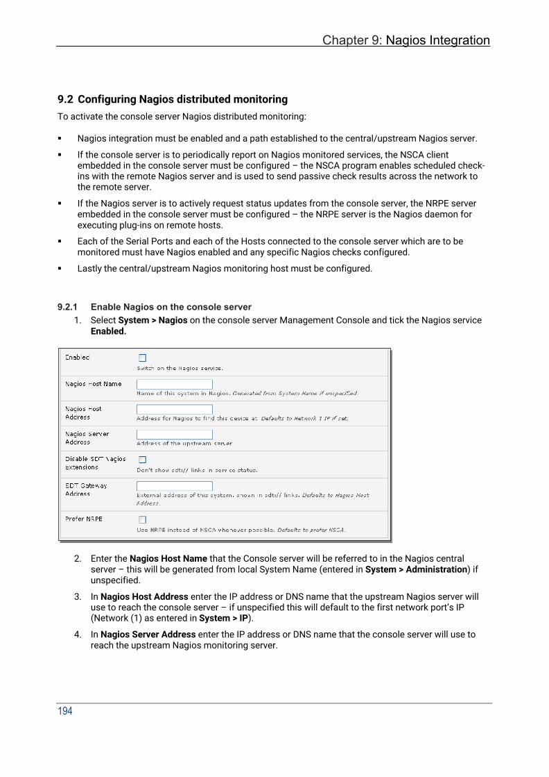
Chapter 9: Nagios Integration
194
9.2 Configuring Nagios distributed monitoring To activate the console server Nagios distributed monitoring:
Nagios integration must be enabled and a path established to the central/upstream Nagios server.
If the console server is to periodically report on Nagios monitored services, the NSCA client embedded in the console server must be configured – the NSCA program enables scheduled check- ins with the remote Nagios server and is used to send passive check results across the network to the remote server.
If the Nagios server is to actively request status updates from the console server, the NRPE server embedded in the console server must be configured – the NRPE server is the Nagios daemon for executing plug-ins on remote hosts.
Each of the Serial Ports and each of the Hosts connected to the console server which are to be monitored must have Nagios enabled and any specific Nagios checks configured.
Lastly the central/upstream Nagios monitoring host must be configured.
9.2.1 Enable Nagios on the console server 1. Select System > Nagios on the console server Management Console and tick the Nagios service
Enabled.
2. Enter the Nagios Host Name that the Console server will be referred to in the Nagios central
server – this will be generated from local System Name (entered in System > Administration) if unspecified.
3. In Nagios Host Address enter the IP address or DNS name that the upstream Nagios server will use to reach the console server – if unspecified this will default to the first network port’s IP (Network (1) as entered in System > IP).
4. In Nagios Server Address enter the IP address or DNS name that the console server will use to reach the upstream Nagios monitoring server.

195
5. Check the Disable SDT Nagios Extensions option if you wish to disable the SDT Connector integration with your Nagios server at the head end – this would only be checked if you want to run a vanilla Nagios monitoring.
6. If not, enter the IP address or DNS name the SDT Nagios clients will use to reach the console server in SDT Gateway Address.
7. When NRPE and NSCA are both enabled, NSCA is preferred method for communicating with the upstream Nagios server – check Prefer NRPE to use NRPE whenever possible (i.e. for all communication except for alerts).
9.2.2 Enable NRPE monitoring
Enabling NRPE allows you to execute plug-ins (such as check_tcp and check_ping) on the remote Console server to monitor serial or network attached remote servers. This will offload CPU load from the upstream Nagios monitoring machine which is especially valuable if you are monitoring hundreds or thousands of hosts. To enable NRPE:
1. Select System > Nagios and check NRPE Enabled.
2. Enter the details the user connection to the upstream Nagios monitoring server and see the sample Nagios configuration example below for details of configuring specific NRPE checks.
The console server accepts a connection between the upstream Nagios monitoring server and the NRPE server with SSL encryption, without SSL, or tunneled through SSH. The security for the connection is configured at the Nagios server.

Chapter 9: Nagios Integration
196
9.2.3 Enable NSCA monitoring
NSCA is the mechanism that allows you to send passive check results from the remote console server to the Nagios daemon running on the monitoring server. To enable NSCA:
1. Select System > Nagios and check NSCA Enabled.
2. Select the Encryption from the drop-down list and enter a Secret password and specify a check Interval.
3. See the sample Nagios configuration section below for some examples of configuring specific NSCA checks.
9.2.4 Configure selected Serial Ports for Nagios monitoring The individual Serial Ports connected to the console server to be monitored must be configured for Nagios checks. To enable Nagios to monitor on a device connected to the console server serial port:
1. Select Serial & Network > Serial Port and click Edit on the serial Port # to be monitored.
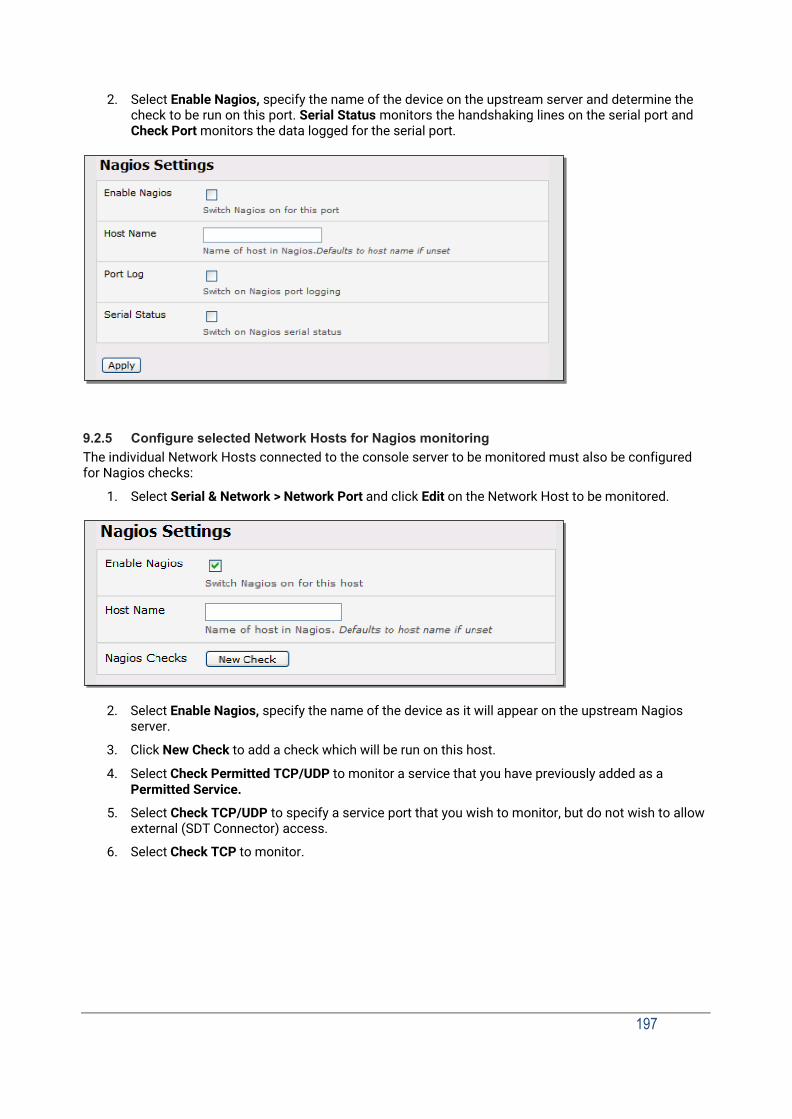
197
2. Select Enable Nagios, specify the name of the device on the upstream server and determine the check to be run on this port. Serial Status monitors the handshaking lines on the serial port and Check Port monitors the data logged for the serial port.
9.2.5 Configure selected Network Hosts for Nagios monitoring The individual Network Hosts connected to the console server to be monitored must also be configured for Nagios checks:
1. Select Serial & Network > Network Port and click Edit on the Network Host to be monitored.
2. Select Enable Nagios, specify the name of the device as it will appear on the upstream Nagios
server.
3. Click New Check to add a check which will be run on this host.
4. Select Check Permitted TCP/UDP to monitor a service that you have previously added as a Permitted Service.
5. Select Check TCP/UDP to specify a service port that you wish to monitor, but do not wish to allow external (SDT Connector) access.
6. Select Check TCP to monitor.
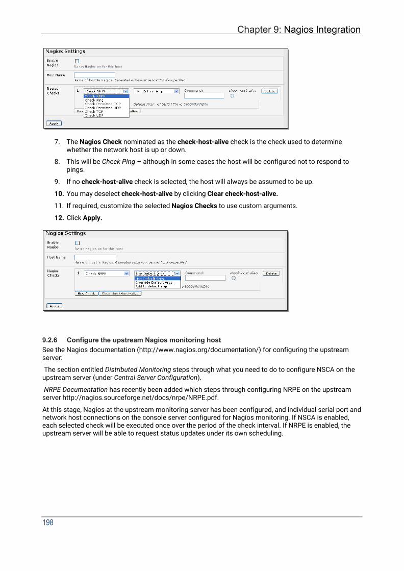
Chapter 9: Nagios Integration
198
7. The Nagios Check nominated as the check-host-alive check is the check used to determine whether the network host is up or down.
8. This will be Check Ping – although in some cases the host will be configured not to respond to pings.
9. If no check-host-alive check is selected, the host will always be assumed to be up.
10. You may deselect check-host-alive by clicking Clear check-host-alive.
11. If required, customize the selected Nagios Checks to use custom arguments.
12. Click Apply.
9.2.6 Configure the upstream Nagios monitoring host See the Nagios documentation (http://www.nagios.org/documentation/) for configuring the upstream server:
The section entitled Distributed Monitoring steps through what you need to do to configure NSCA on the upstream server (under Central Server Configuration).
NRPE Documentation has recently been added which steps through configuring NRPE on the upstream server http://nagios.sourceforge.net/docs/nrpe/NRPE.pdf.
At this stage, Nagios at the upstream monitoring server has been configured, and individual serial port and network host connections on the console server configured for Nagios monitoring. If NSCA is enabled, each selected check will be executed once over the period of the check interval. If NRPE is enabled, the upstream server will be able to request status updates under its own scheduling.
199
9.3 Advanced Distributed Monitoring Configuration
9.3.1 Sample Nagios configuration An example configuration for Nagios is listed below. It shows how to set up a remote Console server to monitor a single host, with both network and serial connections. For each check it has two configurations, one each for NRPE and NSCA. In practice, these would be combined into a single check which used NSCA as a primary method, falling back to NRPE if a check was late – for details see the Nagios documentation http://www.nagios.org/documentation/ on Service and Host Freshness Checks.
; Host definitions ; ; Opengear Console server define host{
use generic-host host_name opengear alias Console server address 192.168.254.147 }
; Managed Host define host{
use generic-host host_name server alias server address 192.168.254.227 }
; NRPE daemon on gateway define command {
command_name check_nrpe_daemon command_line $USER1$/check_nrpe -H 192.168.254.147 -p 5666 }
define service {
service_description NRPE Daemon host_name opengear use generic-service check_command check_nrpe_daemon }
; Serial Status define command {
command_name check_serial_status command_line $USER1$/check_nrpe -H 192.168.254.147 -p 5666 -c
check_serial_$HOSTNAME$ }
define service {
service_description Serial Status host_name server use generic-service check_command check_serial_status }
define service {
service_description serial-signals-server host_name server

Chapter 9: Nagios Integration
200
use generic-service check_command check_serial_status active_checks_enabled 0 passive_checks_enabled 1 }
define servicedependency{
name opengear_nrpe_daemon_dep host_name opengear dependent_host_name server dependent_service_description Serial Status service_description NRPE Daemon execution_failure_criteria w,u,c }
; Port Log define command{
command_name check_port_log command_line $USER1$/check_nrpe -H 192.168.254.147 -p 5666 -c
port_log_$HOSTNAME$ }
define service {
service_description Port Log host_name server use generic-service check_command check_port_log }
define service {
service_description port-log-server host_name server use generic-service check_command check_port_log active_checks_enabled 0 passive_checks_enabled 1 }
define servicedependency{
name opengear_nrpe_daemon_dep host_name opengear dependent_host_name server dependent_service_description Port Log service_description NRPE Daemon execution_failure_criteria w,u,c }
; Ping define command{
command_name check_ping_via_opengear command_line $USER1$/check_nrpe -H 192.168.254.147 -p 5666 -c
host_ping_$HOSTNAME$ }
define service {
service_description Host Ping host_name server

201
use generic-service check_command check_ping_via_opengear }
define service {
service_description host-ping-server host_name server use generic-service check_command check_ping_via_opengear active_checks_enabled 0 passive_checks_enabled 1 }
define servicedependency{
name opengear_nrpe_daemon_dep host_name opengear dependent_host_name server dependent_service_description Host Ping service_description NRPE Daemon execution_failure_criteria w,u,c }
; SSH Port define command{
command_name check_conn_via_opengear command_line $USER1$/check_nrpe -H 192.168.254.147 -p 5666 -c
host_$HOSTNAME$_$ARG1$_$ARG2$ }
define service {
service_description SSH Port host_name server use generic-service check_command check_conn_via_opengear!tcp!22 }
define service {
service_description host-port-tcp-22-server ; host-port-<protocol>-<port>-<host>
host_name server use generic-service check_command check_conn_via_opengear!tcp!22 active_checks_enabled 0 passive_checks_enabled 1 }
define servicedependency{
name opengear_nrpe_daemon_dep host_name opengear dependent_host_name server dependent_service_description SSH Port service_description NRPE Daemon execution_failure_criteria w,u,c }

Chapter 9: Nagios Integration
202
9.3.2 Basic Nagios plug-ins Plug-ins are compiled executables or scripts that can be scheduled to be run on the console server to check the status of a connected host or service. This status is communicated to the upstream Nagios server which uses the results to monitor the current status of the distributed network. Each console server is preconfigured with a selection of the checks that are part of the Nagios plug-ins package:
check_tcp and check_udp are used to check open ports on network hosts .
.check_ping is used to check network host availability.
check_nrpe used to execute arbitrary plug-ins in other devices.
Each console server is preconfigured with two checks:
check_serial_signals used to monitor the handshaking lines on the serial ports.
check_port_log used to monitor the data logged for a serial port.
9.3.3 Additional plug-ins Additional Nagios plug-ins (listed below) are available for all the CM7100 or IM7200 products:
check_apt check_by_ssh check_clamd check_dig check_dns check_dummy check_fping check_ftp check_game check_hpjd check_http check_imap check_jabber check_ldap check_load check_mrtg check_mrtgtraf check_nagios check_nntp check_nntps check_nt check_ntp check_nwstat check_overcr check_ping check_pop check_procs check_real check_simap check_smtp check_snmp check_spop check_ssh check_ssmtp check_swap check_tcp check_time

203
check_udp check_ups check_users
These plug-ins from the Nagios plug-ins package can be downloaded from ftp.opengear.com.
There also are bash scripts which can be downloaded and run (primarily check_log.sh).
To configure additional checks the downloaded plug-in program must be saved in the tftp addins directory on the USB flash and the downloaded text plug-in file saved in /etc/config.
To enable these new additional checks you select Serial & Network > Network Port, Edit the Network Host to be monitored, and select New Checks. The additional check option will have been included in the updated Nagios Checks list, and you can again customize the arguments.
If you need other plug-ins to be loaded into the CM7100 or IM7200 firmware:
If the plug-in in a Perl script, it must be rewritten as the console server does not support Perl. However, if you do require Perl support, make a feature request to [email protected].
Individual compiled programs may be generated using gcc for ARM. Contact [email protected] for details.
9.3.4 Number of supported devices The number of devices that can be supported by any particular console server is a function of the number of checks being made, and how often they are performed. Access method will also play a part. The table below shows the performance of three of the console server models (1/2 port, 8 port and 16/48 port) tabulating:
Time No encryption 3DES SSH tunnel
NSCA for single check ~ ½ second ~ ½ second ~ ½ second
NSCA for 100 sequential checks 100 seconds 100 seconds 100 seconds
NSCA for 10 sequential checks, batched upload
1 ½ seconds 2 seconds 1 second
NSCA for 100 sequential checks, batched upload
7 seconds 11 seconds 6 seconds
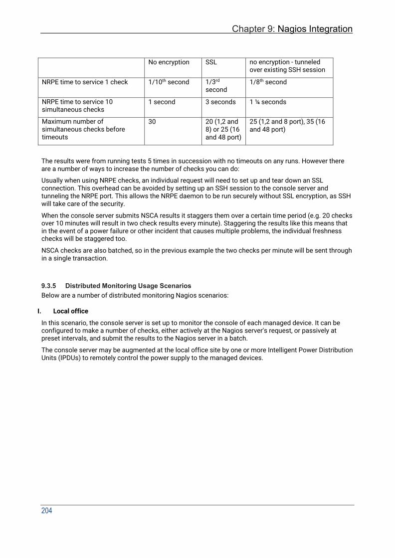
Chapter 9: Nagios Integration
204
No encryption SSL no encryption - tunneled over existing SSH session
NRPE time to service 1 check 1/10th second 1/3rd second
1/8th second
NRPE time to service 10 simultaneous checks
1 second 3 seconds 1 ¼ seconds
Maximum number of simultaneous checks before timeouts
30 20 (1,2 and 8) or 25 (16 and 48 port)
25 (1,2 and 8 port), 35 (16 and 48 port)
The results were from running tests 5 times in succession with no timeouts on any runs. However there are a number of ways to increase the number of checks you can do:
Usually when using NRPE checks, an individual request will need to set up and tear down an SSL connection. This overhead can be avoided by setting up an SSH session to the console server and tunneling the NRPE port. This allows the NRPE daemon to be run securely without SSL encryption, as SSH will take care of the security.
When the console server submits NSCA results it staggers them over a certain time period (e.g. 20 checks over 10 minutes will result in two check results every minute). Staggering the results like this means that in the event of a power failure or other incident that causes multiple problems, the individual freshness checks will be staggered too.
NSCA checks are also batched, so in the previous example the two checks per minute will be sent through in a single transaction.
9.3.5 Distributed Monitoring Usage Scenarios Below are a number of distributed monitoring Nagios scenarios:
I. Local office
In this scenario, the console server is set up to monitor the console of each managed device. It can be configured to make a number of checks, either actively at the Nagios server's request, or passively at preset intervals, and submit the results to the Nagios server in a batch.
The console server may be augmented at the local office site by one or more Intelligent Power Distribution Units (IPDUs) to remotely control the power supply to the managed devices.
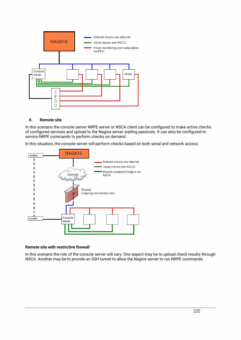
205
II. Remote site
In this scenario the console server NRPE server or NSCA client can be configured to make active checks of configured services and upload to the Nagios server waiting passively. It can also be configured to service NRPE commands to perform checks on demand.
In this situation, the console server will perform checks based on both serial and network access.
Remote site with restrictive firewall
In this scenario the role of the console server will vary. One aspect may be to upload check results through NSCA. Another may be to provide an SSH tunnel to allow the Nagios server to run NRPE commands.
Chapter 9: Nagios Integration
206
Remote site with no network access
In this scenario the console server allows dial-in access for the Nagios server. Periodically, the Nagios server establishes a connection to the console server and execute any NRPE commands before dropping the connection.
207
10. SYSTEM MANAGEMENT
This chapter describes how an administrator can perform a range of general console server system administration and configuration tasks such as:
Applying Soft and Hard Resets to the gateway.
Re-flashing the Firmware.
Configuring the Date, Time and NTP.
Setting up Backup of the configuration files.
Delayed configuration commits.
Configuring the console server in FIPS mode.
10.1 System Administration and Reset Administrators can reboot or reset the gateway to default settings.
To perform a soft reset, select Reboot in the System > Administration menu and clicking Apply
The console server reboots with all settings (e.g. the assigned network IP address) preserved. This soft reset disconnects all users and ends any SSH sessions that had been established.
A soft reset will also occur when you switch OFF power from the console server and switch the power back ON. However, if you cycle the power and the unit is writing to flash you could corrupt or lose data, so the software reboot is the safer option.
To perform a hard erase (hard reset), with the unit ON, push the Erase button on the rear panel twice with a ball point pen or bent paper clip.
This resets the console server back to its factory default settings and clears the console server’s stored configuration information (i.e. the IP address will be reset to 192.168.0.1). You will be prompted to log in and must enter the default administration username and password:
Username: root
Password: default You will then be required to change the root password.
To complete the change, you will enter the new password again.

Chapter 10: System Management
208
10.2 Upgrade Firmware Before upgrading you should ascertain if you are already running the most current firmware in your Opengear device. Your Opengear device will not allow you to upgrade to the same or an earlier version.
The Firmware version is displayed in the header of each page. Status > Support Report also reports the Firmware Version.
1. Download the latest firmware image http://ftp.opengear.com/download/release/current/.
2. Save the downloaded file on a system on the same subnet as the Opengear device.
3. Download and read the Release Notes file for the latest information.
4. To up-load the firmware image file, select System > Firmware.
5. Specify the address and name of the downloaded Firmware Upgrade File, or Browse the local subnet and locate the downloaded file.
6. Click Apply and the Opengear device will undertake a soft reboot and commence upgrading the firmware. This process will take several minutes.
7. After the firmware upgrade has completed, click here to return to the Management Console. Your Opengear device will have retained all its pre-upgrade configuration information.
10.3 Configure Date and Time
It is important to set the local Date and Time in your Opengear appliance as soon as it is configured. Features such as Syslog and NFS logging use the system time for time-stamping log entries, while certificate generation depends on a correct Timestamp to check the validity period of the certificate.
Your Opengear appliance can synchronize its system time with a remote Network Time Protocol (NTP) server. NTP uses Coordinated Universal Time (UTC) for all time synchronizations so it is not affected by different time zones.

209
You need to specify your local time zone so the system clock shows correct local time. Set your appropriate region/locality in the Time Zone selection box and click Set Timezone.
NOTE Time Zone can also be set to UTC which replaced Greenwich Mean Time as the World standard for time in 1986.
Configuring NTP ensures the Opengear appliance clock is kept accurate (once Internet connection has been established).
1. Select the Enable NTP checkbox in the Network Time Protocol section of the System > Date &
Time page.
2. Enter the IP address of the remote NTP Server.
3. If your external NTP server requires authentication, you need to specify the NTP Authentication Key and the Key Index to use when authenticating with the NTP server.
4. Click Apply NTP Settings.

Chapter 10: System Management
210
If remote NTP is not used, the time can be set manually:
1. Enter the Year, Month, Day, Hour and Minute using the Date and Time selection boxes.
2. Check Set Time.
NOTE All Opengear appliances have an internal battery-backed hardware clock. When the time and date is set through the management console or retrieved from an NTP server, the hardware clock of the Opengear appliance is automatically updated. The hardware clock uses a battery to allow the current time and date to be maintained across reboots or when the appliance has been powered down for longer periods of time.
NOTE With the NTP peering model, the Opengear appliance can share its time information with other devices connected to it, so all devices can be time synchronized. To do this, tick Enable NTP on the Time and Date page, and ensure that the appropriate networks are selected on the Service Access page.
10.4 Configuration Backup It is recommended that you back up the console server configuration whenever you make significant changes, such as adding new users or managed devices, before performing a firmware upgrade.
1. Select the System > Configuration Backup menu option or click the icon.
211
With all console servers you can save the backup file remotely on your PC and you can restore configurations from remote locations:
2. Click Save Backup in the Remote Configuration Backup menu.
3. The config backup file (System Name_date_config.opg) is downloaded to your PC and saved in the location you nominate.
To restore a remote backup:
1. Click Browse in the Remote Configuration Backup menu and select the Backup File you wish to
restore.
2. Click Restore and click OK. This will overwrite all the current configuration settings in your console server.
With some console servers, you can save the backup file locally onto the USB storage. Your console server must support USB and you must have an internal or external USB flash drive installed.
To backup and restore using USB:
1. Ensure the USB flash is the only USB device attached to the console server.
2. Select the Local Backup tab and click here to proceed. This will set a Volume Label on the USB storage device. This preparation step is only necessary the first time and will not affect any other information you have saved onto the USB storage device. We recommend that you back up any critical data from the USB storage device before using it with your console server. If there are multiple USB devices installed, a warning to remove them appears.
3. To back up to the USB enter a brief Description of the backup in the Local Backup menu and select Save Backup.
4. The Local Backup menu will display all the configuration backup files you have stored onto the USB flash.
5. To restore a backup from the USB, select Restore on the particular backup you wish to restore and click Apply.
Chapter 10: System Management
212
After saving a local configuration backup, you may choose to use it as the alternate default configuration. When the console server is reset to factory defaults, it will load your alternate default configuration instead of its factory settings:
To set an alternate default configuration, check Load On Erase and click Apply.
NOTE Before selecting Load On Erase, ensure you have tested your alternate default configuration by clicking Restore.
If for some reason your alternate default configuration causes the console server to become unbootable recover your unit to factory settings using the following steps:
• If the configuration is stored on an external USB storage device, unplug the storage device and reset to factory defaults as per section 10.1.
• If the configuration is stored on an internal USB storage device reset to factory defaults using a prepared USB storage device:
o The USB storage device must be formatted with a Windows FAT32/VFAT file system on the first partition or the entire disk, most USB thumb drives are already formatted this way.
o The file system must have the volume label: OPG_DEFAULT. o Insert this USB storage device into an external USB port on the console server and
reset to factory defaults as per section 10.1.
After recovering your console server, ensure the problematic configuration is no longer selected for Load On Erase.
10.5 Delayed Configuration Commit This mode allows the grouping or queuing of configuration changes and the simultaneous application of these changes to a device. For example, changes to authentication methods or user accounts may be grouped and run once to minimize system downtime. To enable:
1. Check the Delayed Config Commits button under System > Administration.
2. Click Apply.
The Commit Config icon is displayed in top right-hand corner of the screen between the Backup and Log Out icons.
To queue and run configuration changes:
1. Apply all the required changes to the configuration e.g. modify user accounts, amend authentication method, enable OpenVPN tunnel or modify system time.
2. Click the Commit Config button. This will generate the System > Commit Configuration screen displaying all the configurators to be run.
3. Click Apply to run all the configurators in the queue or click Cancel if you wish to discard all the delayed configuration changes.
NOTE All the queued configuration changes will be lost if Cancel is selected..
To disable the Delayed Configuration Commits mode:
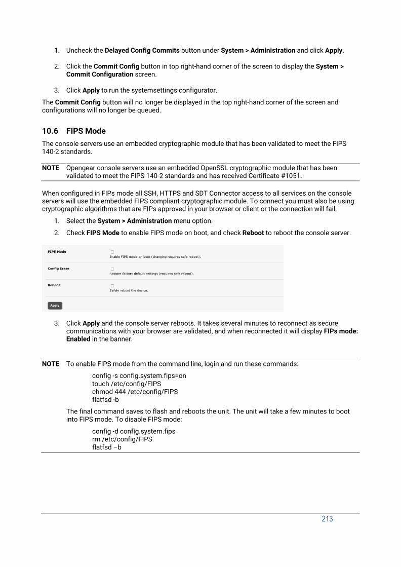
213
1. Uncheck the Delayed Config Commits button under System > Administration and click Apply.
2. Click the Commit Config button in top right-hand corner of the screen to display the System > Commit Configuration screen.
3. Click Apply to run the systemsettings configurator.
The Commit Config button will no longer be displayed in the top right-hand corner of the screen and configurations will no longer be queued.
10.6 FIPS Mode The console servers use an embedded cryptographic module that has been validated to meet the FIPS 140-2 standards.
NOTE Opengear console servers use an embedded OpenSSL cryptographic module that has been validated to meet the FIPS 140-2 standards and has received Certificate #1051.
When configured in FIPs mode all SSH, HTTPS and SDT Connector access to all services on the console servers will use the embedded FIPS compliant cryptographic module. To connect you must also be using cryptographic algorithms that are FIPs approved in your browser or client or the connection will fail.
1. Select the System > Administration menu option.
2. Check FIPS Mode to enable FIPS mode on boot, and check Reboot to reboot the console server.
3. Click Apply and the console server reboots. It takes several minutes to reconnect as secure
communications with your browser are validated, and when reconnected it will display FIPs mode: Enabled in the banner.
NOTE To enable FIPS mode from the command line, login and run these commands:
config -s config.system.fips=on touch /etc/config/FIPS chmod 444 /etc/config/FIPS flatfsd -b
The final command saves to flash and reboots the unit. The unit will take a few minutes to boot into FIPS mode. To disable FIPS mode:
config -d config.system.fips rm /etc/config/FIPS flatfsd –b

Chapter 12: Management
214
11. STATUS REPORTS
This chapter describes the dashboard feature and the status reports that are available:
Port Access and Active Users
Statistics
Support Reports
Syslog
Dashboard
11.1 Port Access and Active Users Administrators can see which users have access privileges with which serial ports. Select the Status > Port Access.
Administrators can also see the current status of users who have active sessions on those ports. Select the Status > Active Users.
The Status > Active Users menu enables administrators to selectively terminate serial sessions. Connection types Telnet, SSH, raw TCP and unauthenticated Telnet can be disconnected. You cannot disconnect an RFC2217 session.
The root user, any user in the admin group, and port-level administrators can access the Active Users page, which shows a snapshot of the connected sessions, at the time indicated by the timestamp.

215
displayed at the top of the page. This page shows the local console ports and not any cascaded ports, or in the case of port admins, the ports they have permission to administer.
There are Disconnect Sessions buttons along the right-hand side of the table listing active users. These buttons disconnect all sessions from the Port they correspond to. If the port is not set up in Console server mode, the user will see a pop up error informing them that they need to configure the port as Console server mode before they can connect and disconnect.
After the buttons have been pressed, the selected sessions will be disconnected, and the number of disconnect sessions will be displayed to the user.
To allow more detailed control of who to disconnect, there is a table at the bottom of the page with drop- down lists for all connected users and all connected ports that allow the user to choose who do disconnect. If you wish to disconnect the user tester from all ports, choose tester in the user’s box, and All ports in the Ports box and hit the Disconnect Sessions button.
NOTE You can also disconnect serial sessions from the command line using the --disconnect option with the pmusers command.
11.2 Statistics The Statistics report provides a snapshot of the status, current traffic and other activities and operations of your console server. Select Status > Statistics.
Detailed statistics reports can be found by selecting the various submenus.
11.3 Support Reports The Support Report provides useful status information that will assist the Opengear technical support team to solve any problems you may experience with your console server.
If you do experience a problem and have to contact support, ensure you include the Support Report with your email support request. The Support Report should be generated when the issue is occurring and attached in plain text format.
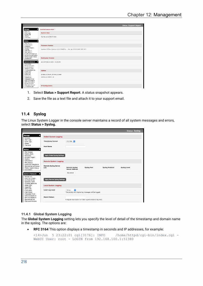
Chapter 12: Management
216
1. Select Status > Support Report. A status snapshot appears.
2. Save the file as a text file and attach it to your support email.
11.4 Syslog The Linux System Logger in the console server maintains a record of all system messages and errors, select Status > Syslog.
11.4.1 Global System Logging The Global System Logging setting lets you specify the level of detail of the timestamp and domain name in the syslog. The options are:
• RFC 3164 This option displays a timestamp in seconds and IP addresses, for example:
<14>Jun 5 23:22:01 cgi[3176]: INFO /home/httpd/cgi-bin/index.cgi - WebUI User: root - LOGIN from 192.168.100.1:51380

217
• RFC 3339 This option displays a timestamp in milliseconds as well as fully qualified domain names (FQDN), for example:
<46>2019-06-05T23:25:52.547326-04:00 syslog: [origin software="rsyslogd" swVersion="8.33.0" x-pid="3492" x- info="http://www.rsyslog.com"] start
11.4.2 Syslog Server Address and Port The syslog record can be redirected to a remote Syslog Server. Enter the remote Syslog Server Address and Syslog Server Port details and click Apply.
11.4.3 Power State Changes in Syslog Power state changes are captured in the syslog for:
• All DDC devices.
• IM72xx DDC or rev6a AC models (IM7200-DAC devices manufactured after April 16, 2019) with power monitoring capabilities.
Voltage transitions from about 0 to about 10-13 will emit syslog("PSU xxx power up").
Voltage transitions from about 12 to < 9 for over a period of time (for example 5 to 10 seconds) will emit syslog("PSU xxx power down")..
When both PSU #1 and #2 are on, the syslog reports it. For example: <14>May 7 16:57:37 psmon[2508]: INFO psmon - Internal Voltage[PSU #1] status
OPERATIONAL, value 12.025001
<14>May 7 16:57:37 psmon[2508]: INFO psmon - Internal Voltage[PSU #2] status
OPERATIONAL, value 12.050000
If PSU #1 is turned off, the syslog reports it. For example: <14>May 7 16:59:08 psmon[2508]: INFO psmon - Internal Voltage[PSU #1]
status LOW, value 8.100000
If PSU #1 is turned on again, the syslog captures that. For example:
<14>May 7 16:59:23 psmon[2508]: INFO psmon - Internal Voltage[PSU #1]
status OPERATIONAL, value 12.025001
11.4.4 Syslog Match Pattern To make it easier to find information in the local Syslog file, a pattern matching filter tool is provided.
Specify the Match Pattern that is to be searched for (e.g. the search for mount is shown below) and click Apply. The Syslog will be represented with those entries that include the specified pattern.
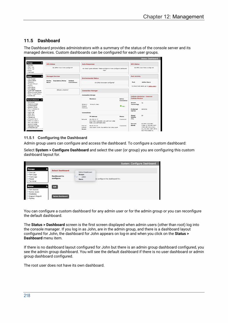
Chapter 12: Management
218
11.5 Dashboard The Dashboard provides administrators with a summary of the status of the console server and its managed devices. Custom dashboards can be configured for each user groups.
11.5.1 Configuring the Dashboard Admin group users can configure and access the dashboard. To configure a custom dashboard:
Select System > Configure Dashboard and select the user (or group) you are configuring this custom dashboard layout for.
You can configure a custom dashboard for any admin user or for the admin group or you can reconfigure the default dashboard.
The Status > Dashboard screen is the first screen displayed when admin users (other than root) log into the console manager. If you log in as John, are in the admin group, and there is a dashboard layout configured for John, the dashboard for John appears on log-in and when you click on the Status > Dashboard menu item.
If there is no dashboard layout configured for John but there is an admin group dashboard configured, you see the admin group dashboard. You will see the default dashboard if there is no user dashboard or admin group dashboard configured.
The root user does not have its own dashboard.
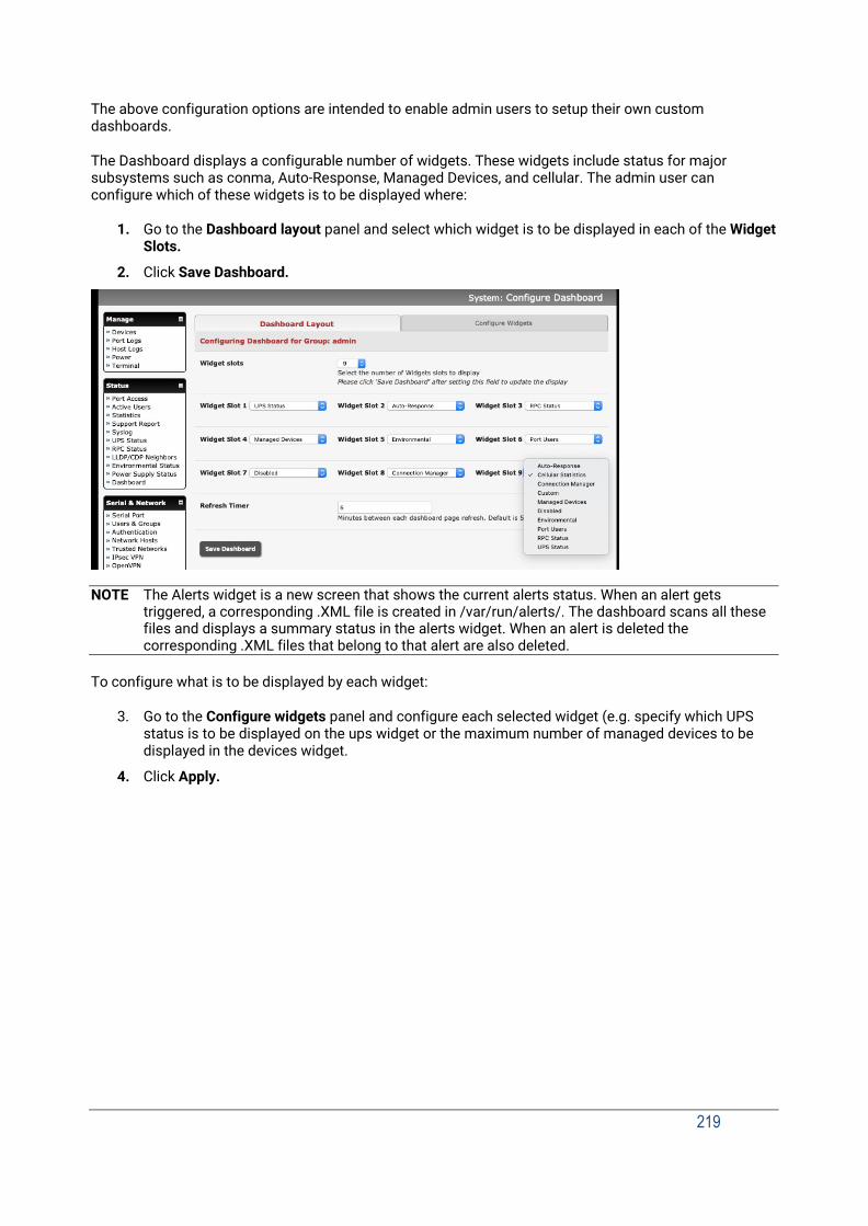
219
The above configuration options are intended to enable admin users to setup their own custom dashboards.
The Dashboard displays a configurable number of widgets. These widgets include status for major subsystems such as conma, Auto-Response, Managed Devices, and cellular. The admin user can configure which of these widgets is to be displayed where:
1. Go to the Dashboard layout panel and select which widget is to be displayed in each of the Widget
Slots.
2. Click Save Dashboard.
NOTE The Alerts widget is a new screen that shows the current alerts status. When an alert gets triggered, a corresponding .XML file is created in /var/run/alerts/. The dashboard scans all these files and displays a summary status in the alerts widget. When an alert is deleted the corresponding .XML files that belong to that alert are also deleted.
To configure what is to be displayed by each widget:
3. Go to the Configure widgets panel and configure each selected widget (e.g. specify which UPS status is to be displayed on the ups widget or the maximum number of managed devices to be displayed in the devices widget.
4. Click Apply.
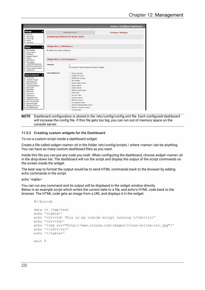
Chapter 12: Management
220
NOTE Dashboard configuration is stored in the /etc/config/config.xml file. Each configured dashboard will increase the config file. If this file gets too big, you can run out of memory space on the console server.
11.5.2 Creating custom widgets for the Dashboard To run a custom script inside a dashboard widget:
Create a file called widget-<name>.sh in the folder /etc/config/scripts / where <name> can be anything. You can have as many custom dashboard files as you want.
Inside this file you can put any code you wish. When configuring the dashboard, choose widget-<name>.sh in the drop-down list. The dashboard will run the script and display the output of the script commands on the screen inside the widget.
The best way to format the output would be to send HTML commands back to the browser by adding echo commands in the script:
echo '<table>'
You can run any command and its output will be displayed in the widget window directly. Below is an example script which writes the current date to a file, and echo's HTML code back to the browser. The HTML code gets an image from a URL and displays it in the widget.
#!/bin/sh
date >> /tmp/test echo '<table>' echo '<tr><td> This is my custom script running </td></tr>' echo '<tr><td>' echo '<img src="http://www.vinras.com/images/linux-online-inc.jpg">' echo '</td></tr>' echo '</table>'
exit 0

221
12. MANAGEMENT
The console server has a small number of Manage reports and tools that are available to all users:
Access and control authorized devices.
View serial port logs and host logs for those devices.
Use SSH or the Web Terminal to access serially attached consoles.
Control of power devices (where authorized).
All other Management Console menu items are only available to administrators.
12.1 Device Management To display managed devices and their grouped serial, network and power connections:
Select Manage > Devices or click the Manage Devices icon in the top right of the UI.
Admin-group users are presented with a list of all configured managed devices and their constituent connections, user-group users only see the Managed Devices for each Related Connection where they have been permitted access.
The Status column displays the current status for each Related Connection with links to detailed status.
The links in the Actions column are used to control the managed device.
Administrators will see all configured managed devices. Non-admin users will see the managed devices they or their group have been given access privileges for.
Select the Serial tab for an ungrouped view of permitted serial port connections for the current user.

Chapter 12: Management
222
The Signals column displays the current state of the serial pins.
NOTE To use the Connect: via SSH links, your computer’s operating system must recognize the ssh:/ / URI scheme and have a protocol handler configured (e.g. an SSH client like SecureCRT).
12.2 Port and Host Logs Users can view and download logs of data transferred to and from connected devices.
1. Select Manage > Port Logs and the serial Port # to be displayed.
2. To display Host logs select Manage > Host Logs and Host to be displayed.
This will display logs stored locally on the console server memory or USB flash.
12.3 Terminal Connection There are two methods available for accessing the console server command line and devices attached to the console server serial ports, directly from a web browser:
• The Web Terminal service uses AJAX to enable the web browser to connect to the console server using HTTP or HTTPS, as a terminal - without the need for additional client installation on the user's PC.
• The SDT Connector service launches a pre-installed SDT Connector client on the user's PC to establish secure SSH access and uses pre-installed client software on the client PC to connect to the console server.
Web browser access is available to users who are a member of the admin or users’ groups.
12.3.1 Web Terminal The AJAX based Web Terminal service may be used to access the console server command line or attached serial devices.
NOTE Any communication using the Web Terminal service using HTTP is unencrypted and not secure. The Web Terminal connects to the command line or serial device using the same protocol that is being used to browse to the Opengear Management Console, i.e. if you are browsing using an https:/ / URL (this is the default), the Web Terminal connects using HTTPS.
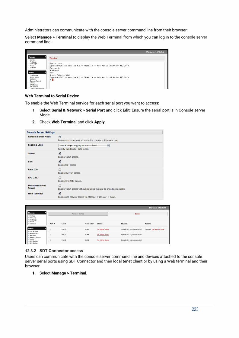
223
Administrators can communicate with the console server command line from their browser:
Select Manage > Terminal to display the Web Terminal from which you can log in to the console server command line.
Web Terminal to Serial Device
To enable the Web Terminal service for each serial port you want to access:
1. Select Serial & Network > Serial Port and click Edit. Ensure the serial port is in Console server Mode.
2. Check Web Terminal and click Apply.
12.3.2 SDT Connector access Users can communicate with the console server command line and devices attached to the console server serial ports using SDT Connector and their local tenet client or by using a Web terminal and their browser.
1. Select Manage > Terminal.
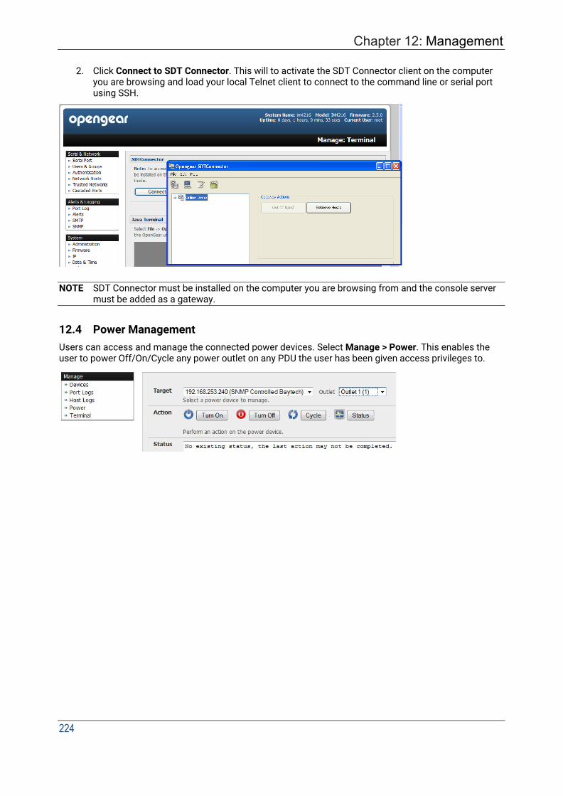
Chapter 12: Management
224
2. Click Connect to SDT Connector. This will to activate the SDT Connector client on the computer you are browsing and load your local Telnet client to connect to the command line or serial port using SSH.
NOTE SDT Connector must be installed on the computer you are browsing from and the console server
must be added as a gateway.
12.4 Power Management Users can access and manage the connected power devices. Select Manage > Power. This enables the user to power Off/On/Cycle any power outlet on any PDU the user has been given access privileges to.
225
13. APPENDIX A: Hardware Specification
FEATURE VALUE Dimensions ACM7004, ACM7004-2-L(V/A/R/MA/MV/MCR/MCT): 5 1/8 x
4 3/4 x 1 3/8 in (13 x 12 x 3.5 cm) IM7216/32/48: 17 x 10 x 1.75 in (44 x 25.4 x 4.5 cm) CM7116/32/48: 17 x 6.9 x 1.75 in (44 x 17 x 4.5 cm)
Weight ACM7004, ACM7004-2-L(V/A/R/MA/MV/MCR/MCT): 0.6kg (1.3 lbs) IM7216/32/48: 4.5 kg (10 lbs) CM7116/32/48: 4 kg (9 lbs)
Ambient operating temperature
5°C to 50°C (41°F to 122°F) Higher for -I models
Non-operating storage temp -30°C to +60°C (-20°F to +140°F) Humidity 5% to 90% Power IM7200, CM7100: DAC have dual socket 100-240V AC
DDC models dual +/- 36V to 72V DC Power consumption of IM7216-24E – 40W CM7100: SAC models – single socket universal 100-240V AC ACM7000: 110-240V AC to 12V DC external power adapter
Power Consumption All less than 30W CPU IM7200: 1GHz ARM SoC (Marvell 88F6283)
CM7100: 800MHz ARM SoC (Marvell 88F6W11) ACM7000: 800MHz ARM SoC (Marvell 88F6W11) Others: Micrel KS8695P controller
Memory ACM7004, ACM7004-2-L(V/A/R/MA/MV/MCR/MCT): 254MB SDRAM, 256MB + 4GB Flash IM7216/32/48: 256MB SDRAM, 64MB + 16 GB Flash CM7116/32/48: 256MB SDRAM, 32MB + 4GB Flash
USB ports ACM7004, ACM7004-2-L(V/A/R/MA/MV/MCR/MCT): 4 external USB2.0 IM7216/32/48: 2 external USB3.0 CM7116/32/48: 2 external USB2.0
Serial Connectors ACM7004, ACM7004-2-L(V/A/R/MA/MV/MCR/MCT): 4 RJ- 45 RS-232 serial ports IM7216-2: 16 RJ-45 RS-232 serial ports ** IM7232-2: 32 RJ-45 RS-232 serial ports ** IM7248-2: 48 RJ-45 RS-232 serial ports** CM7116-2: 16 RJ-45 RS-232 serial ports ** CM7132-2: 32 RJ-45 RS-232 serial ports ** CM7148-2: 48 RJ-45 RS-232 serial ports ** * models also have 1 DB-9 RS-232 console / modem serial port ** models also have 1 RJ45 console port
Serial Baud Rates RJ45 ports - 50 to 230,400bps DB9 port - 2400 to 115,200 bps
Ethernet Connectors IM7216/32/48: Two 10/100/1000 GbE copper or SFP fiber ports
ACM7004, ACM7004-2-L(V/A/R/MA/MV/MCR/MCT): Two 10/100/1000 GbE ports
CM7116/32/48: Two 10/100/1000 GbE ports

Connectivity, TCP Ports & Serial I/O
226
IM7216/32/48: Two 10/100/1000 GbE ports
Cellular Modem Frequency Resilience Gateway
ACM7000-L Cellular Modem LTE UMTS/HSDPA
HSUPA/HSPA CDMA GSM EGSM DCS PCS
ACM700x-x-LMR
Sierra MC7304
2100 MHz 1800 MHz 2600 MHz 900 MHz (Band 1, 3, 8, 20) 800 MHz (Band 7)
2100 MHz 1900 MHz 850 MHz 900 MHz (Band 1, 2, 5, 8)
850 MHz
900 MHz
1800 MHz
1900 MHz
ACM700x-x-LMP
Sierra MC7430
2100 MHz 1800 MHz 850 MHz 2600 MHz 900 MHz 850 MHz 1500 MHz 700 MHz 2600 MHz 1900 MHz 2300 MHz 2500 MHz
2100 MHz 850 MHz 800 MHz 900 MHz 1700 MHz TD-SCDMA 1880 – 1920 MHz
ACM700x-x-LMA ACM700x-x-LMV ACM700x-x-LMCR ACM700x-x-LMCT
Sierra MC7354
1900 MHz 1700/2100 MHz 850 MHz 700 MHz (LTE Band 2, 4, 5, 13, 17, 25)
2100 MHz 1900 MHz AWS 1700/2100 MHz 850 MHz 900 MHz
Cellular – 800 MHz PCS – 1900 MHz Secondary – 800 MHz
Infrastructure Manager IM7200
Cellular Modem LTE UMTS/HSDPA
HSUPA/HSPA CDMA GSM EGSM DCS PCS
IM72xx-2-LR
Sierra MC7304
2100 MHz 1800 MHz 2600 MHz 900 MHz (Band 1, 3, 8, 20) 800 MHz (Band 7)
2100 MHz 1900 MHz 850 MHz 900 MHz (Band 1, 2, 5, 8)
850 MHz
900 MHz
1800 MHz
1900 MHz
IM72xx-2-LR
Sierra MC7455 (mPCIE) - NA and EU
2100 MHz 1900 MHz 1800 MHz 1700 MHz 850 MHz 2600 MHz 900 MHz 700 MHz (lower) 700 MHz (upper) 800 MHz 1900 MHz 850 MHz (ext) 700 MHz (SDL supplemental down-link) 2300 MHz 2500 MHz (TDD Time Division Duplex)
2100 MHz 1900 MHz 1800 MHz 1700 MHz 850MHz 900 MHz

227
IM72xx-2-LMP
Sierra MC7430
2100 MHz 1800 MHz 850 MHz 2600 MHz 900 MHz 850 MHz 1500 MHz 700 MHz 2600 MHz 1900 MHz 2300 MHz 2500 MHz
2100 MHz 850 MHz 800 MHz 900 MHz 1700 MHz TD-SCDMA 1880 – 1920 MHz
IM72xx-2-LMA IM72xx-2-LMV IM72xx-2-LMCB IM72xx-2-LMCR IM72xx-2-LMCT
Sierra MC7354
1900 MHz 1700/2100 MHz 850 MHz 700 MHz (LTE Band 2, 4, 5, 13, 17, 25)
2100 MHz 1900 MHz AWS 1700/2100 MHz 850 MHz 900 MHz
Cellular – 800 MHz PCS – 1900 MHz Secondary – 800 MHz
Band Frequency (Tx) Frequency (Rx) Band 1 1920-1980 MHz 2110-2170 MHz Band 5 824-849 MHz 869-894 MHz Band 6 830-840 MHz 875-885 MHz

Connectivity, TCP Ports & Serial I/O
228
Band 8 880-915 MHz 925-960 MHz Band 9 1749.9-1784.9 MHz 1844.9-1879.9 MHz Band 19 830-845 MHz 875-890 MHz
14. APPENDIX B: Safety & Certifications
Follow the safety precautions below when installing and operating the console server:
- Do not remove the metal covers. There are no operator serviceable components inside. Opening or removing the cover may expose you to dangerous voltage which may cause fire or electric shock. Refer all service to Opengear qualified personnel.
- To avoid electric shock the power cord protective grounding conductor must be connected
through to ground.
- Always pull on the plug, not the cable, when disconnecting the power cord from the socket.
Do not connect or disconnect the console server during an electrical storm. It is recommended you use a surge suppressor or UPS to protect the equipment from transients.
FCC Warning Statement This device complies with Part 15 of the FCC rules. Operation of this device is subject to the following conditions: (1) This device may not cause harmful interference, and (2) this device must accept any interference that may cause undesired operation.
WEEE Statement
The symbol on the product or its packaging indicates that this product must not be disposed of with your other household waste. Instead, it is your responsibility to dispose of your waste equipment by handing it over to a designated collection point for the recycling of waste electrical and electronic equipment. The separate collection and recycling of your waste equipment at the time of disposal will help conserve natural resources and ensure that it is recycled in a manner that protects human health and the environment. For more information about where you can drop off your waste for recycling, please contact your local authority, or where you purchased your product.
Mexico Certification for IM7232-2-DAC-LMV
IFETEL number: RTIOPIM19-0374
La operación de este equipo está sujeta a las siguientes dos condiciones: (1) es posible que este equipo o dispositivo no cause interferencia perjudicial y (2) este equipo o dispositivo debe aceptar cualquier interferencia, incluyendo la que pueda causar su operación no deseada.


Connectivity, TCP Ports & Serial I/O
228
15. APPENDIX C: Connectivity, TCP Ports & Serial I/O
Pin-out standards exist for both DB9 and DB25 connectors. There are not pin-out standards for serial connectivity using RJ45 connectors. Most console servers and serially managed servers / router / switches / power devices have adopted their own unique pin-out, so custom connectors and cables may be required to interconnect your console server.
Serial Port Pinout
Opengear's console servers come with 1 to 48 serial connectors (notated SERIAL or SERIAL PORTS) for the RS232 serial ports:
• The RJ45 serial ports are located on the rear panel of the rack mount IM7200 and CM7100
• The CM7100 and ACM7000 models have Cisco Straight serial pinouts on its RJ45 connectors
• The IM7200 has software selectable Cisco Straight or Cisco Rolled RJ45
Cisco Straight RJ45 pinout (option -X2)
Straight through RJ-45 cable to equipment such as Cisco, Juniper, SUN, and more...
Opengear Classic (X0) RJ45 pinout
This is the same RJ45 pinout as the Avocent /Equinox brand console server:
PIN SIGNAL DEFINITION DIRECTION 1 CTS Clear To Send Input 2 DSR Data Set Ready Input 3 RXD Receive Data Input 4 GND Signal Ground NA 5 GND Signal Ground NA 6 TXD Transmit Data Output 7 DTR Data Terminal Ready Output 8 RTS Request To Send Output
PIN SIGNAL DEFINITION DIRECTION 1 RTS Request To Send Output 2 DSR Data Set Ready Input 3 DCD Data Carrier Detect Input 4 RXD Receive Data Input 5 TXD Transmit DataCTS Output 6 GND Signal Ground NA 7 DTR Data Terminal Ready Output 8 CTS Clear To Send Input
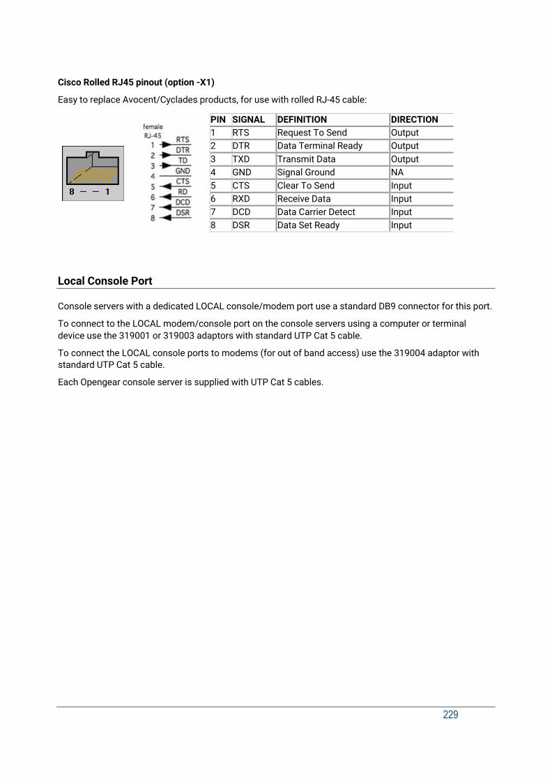
229
Cisco Rolled RJ45 pinout (option -X1)
Easy to replace Avocent/Cyclades products, for use with rolled RJ-45 cable:
Local Console Port
Console servers with a dedicated LOCAL console/modem port use a standard DB9 connector for this port.
To connect to the LOCAL modem/console port on the console servers using a computer or terminal device use the 319001 or 319003 adaptors with standard UTP Cat 5 cable.
To connect the LOCAL console ports to modems (for out of band access) use the 319004 adaptor with standard UTP Cat 5 cable.
Each Opengear console server is supplied with UTP Cat 5 cables.
PIN SIGNAL DEFINITION DIRECTION 1 RTS Request To Send Output 2 DTR Data Terminal Ready Output 3 TXD Transmit Data Output 4 GND Signal Ground NA 5 CTS Clear To Send Input 6 RXD Receive Data Input 7 DCD Data Carrier Detect Input 8 DSR Data Set Ready Input

Connectivity, TCP Ports & Serial I/O
230
RS232 Standard Pinouts
The RS232 pinout standards for the DB9 (and DB25) connectors are tabled below:
DB25 SIGNAL DB9 DEFINITION 1 Protective Ground 2 TXD 3 Transmitted Data 3 RXD 2 Received Data 4 RTS 7 Request To Send 5 CTS 8 Clear To Send 6 DSR 6 Data Set Ready 7 GND 5 Signal Ground 8 CD 1 Received Line Signal Detector 9 Reserved for data set testing 10 Reserved for data set testing 11 Unassigned 12 SCF Secondary Rcvd Line Signal Detector 13 SCB Secondary Clear to Send 14 SBA Secondary Transmitted Data 15 DB Transmission Signal Timing 16 SBB Secondary Received Data 17 DD Receiver Signal Element Timing 18 Unassigned 19 SCA Secondary Request to Send 20 DTR 4 Data Terminal Ready 21 CG Signal Quality Detector 22 9 Ring Indicator 23 CH/CI Data Signal Rate Selector 24 DA Transmit Signal Element Timing 25 Unassigned
FEMALE MALE
25 pin DB25
9 pin DB9
8 pin RJ45
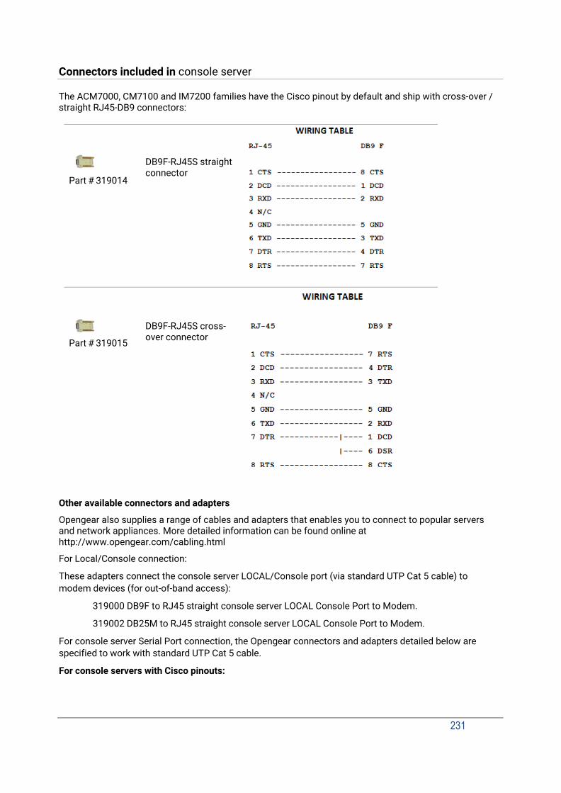
231
Connectors included in console server
The ACM7000, CM7100 and IM7200 families have the Cisco pinout by default and ship with cross-over / straight RJ45-DB9 connectors:
Part # 319014
Part # 319015
DB9F-RJ45S straight connector
DB9F-RJ45S cross- over connector
Other available connectors and adapters
Opengear also supplies a range of cables and adapters that enables you to connect to popular servers and network appliances. More detailed information can be found online at http://www.opengear.com/cabling.html
For Local/Console connection:
These adapters connect the console server LOCAL/Console port (via standard UTP Cat 5 cable) to modem devices (for out-of-band access):
319000 DB9F to RJ45 straight console server LOCAL Console Port to Modem.
319002 DB25M to RJ45 straight console server LOCAL Console Port to Modem.
For console server Serial Port connection, the Opengear connectors and adapters detailed below are specified to work with standard UTP Cat 5 cable.
For console servers with Cisco pinouts:

Connectivity, TCP Ports & Serial I/O
232
319014 DB9F to RJ45 straight Console server with Cisco pinout to IP Power and other serial device.
319015 DB9F to RJ45 crossover DCE adapter - Console server with Cisco pinout to X86 and other.
319016 DB9M to RJ45 straight DTE adapter - Console server w Cisco pinout to Netscreen and Dell.
319004 DB9M to RJ45 straight DTE adapter - Console server OOB modem connection.
For console servers with Opengear Classic pinouts:
319000 DB9F to RJ45 straight Console server with Opengear classic pinout to IP Power and other serial device.
319001 DB9F to RJ45 crossover DCE adapter - Console server with Opengear classic pinout to X86 and other.
319002 DB25M to RJ45 straight DTE adapter for console server with Opengear classic pinout.
319003 DB25M to RJ45 crossover DCE adapter - Console server with Opengear classic pinout to Sun and other.
319004 DB9M to RJ45 straight DTE adapter - Console server with Opengear classic pinout to Netscreen and Dell; and OOB modem connection.
319005 DB25F to RJ45 crossover DCE adapter - Console server with Opengear classic pinout to Cisco 7200 AUX.
440016 5ft Cat5 RJ-45 to RJ-45 cables.
Extension cables
449016 RJ-45 plug to RJ-45 jack adapter for console server with Opengear classic pinout to Cisco console (and to Netscreen with reversing cable).
449017 RJ-45 plug to RJ-45 jack adapter for console server with Opengear classic pinout to Rackable Systems console.
TCP/UDP Port Numbers
Port numbers are divided into three ranges: Well Known Ports (0 through 1023), Registered Ports (1024 through 49151), and Dynamic and/or Private Ports (49152 through 65535).
Well Known Ports are assigned by IANA, and on most systems can only be used by system processes or programs executed by privileged users. The table below lists some of the well-known port numbers. For more details, please visit the IANA website: http://www.iana.org/assignments/port-numbers.
Port Number Protocol TCP/UDP
21 FTP (File Transfer Protocol) TCP 22 SSH (Secure Shell) TCP 23 Telnet TCP 25 SMTP (Simple Mail Transfer Protocol) TCP 37 Time TCP, UCP

233
39 RLP (Resource Location Protocol) UDP 49 TACACS, TACACS+ UDP 53 DNS UDP 67 BOOTP server UDP 68 BOOTP client UDP v69 TFTP UDP 70 Gopher TCP 79 Finger TCP 80 HTTP TCP 110 POP3 TCP 119 NNTP (Network News Transfer Protocol) TCP 161/162 SNMP UDP 443 HTTPS TCP
Terminology
234
16. APPENDIX E: TERMINOLOGY
TERM MEANING AES The Advanced Encryption Standard (AES) is a new block cipher standard to
replace DES, developed by NIST, the US National Institute of Standards and Technology. AES ciphers use a 128-bit block and 128-, 192-, or 256-bit keys. The larger block size helps resist birthday attacks while the large key size prevents brute force attacks.
APN Access Point Name (APN) is used by carriers to identify an IP packet data network that a mobile data user wants to communicate with and the type of wireless service.
Authentication Authentication is the technique by which a process verifies that its communication partner is who it is supposed to be and not an imposter. Authentication confirms that data is sent to the intended recipient and assures the recipient that the data originated from the expected sender and has not been altered on route.
BIOS Basic Input/Output System is the built-in software in a computer that are executed on startup (boot) and that determine what the computer can do without accessing programs from a disk. On PCs, the BIOS contains all the code required to control the keyboard, display screen, disk drives, serial communications, and a number of miscellaneous functions.
Bonding Ethernet Bonding or Failover is the ability to detect communication failure transparently, and switch from one LAN connection to another.
BOOTP Bootstrap Protocol. A protocol that allows a network user to automatically receive an IP address and have an operating system boot without user interaction. BOOTP is the basis for the more advanced DHCP.
Certificates A digitally signed statement that contains information about an entity and the entity's public key, thus binding these two pieces of information together. A certificate is issued by a trusted organization (or entity) called a Certification Authority (CA) after the CA has verified that the entity is who it says it is.
Certificate
Authority
A Certificate Authority is a trusted third party, which certifies public keys belong to their claimed owners. It allows users to trust that a given public key is the one they wish to use, either to send a private message to its owner or to verify the signature on a message sent by that owner.
Certificate
Revocation List
A list of certificates that have been revoked by the CA before they expired. This may be necessary if the private key certificate has been compromised or if the holder of the certificate is to be denied the ability to establish a connection to the console server.
CHAP Challenge-Handshake Authentication Protocol (CHAP) is used to verify a user's name and password for PPP Internet connections. It is more secure than PAP, the other main authentication protocol.
MS-CHAPv2 MS-CHAPv2 can be used for remote authentication over SSH and GUI based login. MS-CHAPv2 is the default for new configurations.

235
DES The Data Encryption Standard is a block cipher with 64-bit blocks and a 56- bit key.
DHCP Dynamic Host Configuration Protocol. A communications protocol that assigns IP addresses to computers when they are connected to the network.
DNS Domain Name System that allocates Internet domain names and translates them into IP addresses. A domain name is a meaningful and easy to remember name for an IP address.
DUN Dial Up Networking.
Encryption The technique for converting a readable message (plaintext) into random material (ciphertext) which cannot be read if intercepted. The proper decryption key is required to read the message.
Ethernet A physical layer protocol based upon IEEE standards.
Firewall A network gateway device that protects a private network from users on other networks. A firewall is installed to allow users on an intranet access to the public Internet without allowing public Internet users access to the intranet.
Gateway A machine that provides a route (or pathway) to the outside world.
Hub A network device that allows more than one computer to be connected as a LAN, usually using UTP cabling.
Internet A worldwide system of computer networks - a public, cooperative, and self- sustaining network of networks accessible to hundreds of millions of people worldwide. The Internet uses the TCP/IP set of protocols.
Intranet A private TCP/IP network within an enterprise.
IPMI Intelligent Platform Management Interface (IPMI) is a set of common interfaces to a computer system which system administrators can use to monitor system health and manage the system. The IPMI standard defines the protocols for interfacing with a service processor embedded into a server platform.
Key lifetimes The length of time before keys are renegotiated.
LAN Local Area Network.
LDAP The Lightweight Directory Access Protocol (LDAP) is a protocol used to access information stored in an LDAP server. It is based on the X.500 standard but is simpler and more readily adapted to meet custom needs. The core LDAP specifications are defined in RFCs.
LED Light-Emitting Diode.
MAC address Every piece of Ethernet hardware has a unique number assigned to it called a MAC address. The MAC address is used by the local Internet router in order

Terminology
236
to direct console server traffic to it. It is a 48-bit number written as a series
of 6 hexadecimal octets, e.g. 00:d0:cf:00:5b:da. Each console server has its MAC address printed on a label underneath the device.
MSCHAP Microsoft Challenge Handshake Authentication Protocol (MSCHAP) is authentication for PPP connections between a computer using a Microsoft Windows operating system and a network access server. It is more secure than PAP or CHAP and also supports data encryption.
NAT Network Address Translation. The translation of an IP address used on one network to an IP address on another network. Masquerading is one particular form of NAT.
Net mask The way that computers know which part of a TCP/IP address refers to the network and which part refers to the host range.
NFS Network File System is a protocol that allows file sharing across a network. Users can view, store, and update files on a remote computer.
NTP Network Time Protocol (NTP) used to synchronize clock times in a network of computers.
Out-of-Band Management
Out-of-Band (OOB) management is any management done over channels and interfaces that are separate from those used for user/customer data. Examples would include a serial console interface or a network interface connected to a dedicated management network that is not used to carry customer traffic, or to a BMC/service processor. Any management done over the same channels and interfaces used for user/customer data is In Band.
PAP Password Authentication Protocol (PAP) is the usual method of user authentication used on the internet: sending a username and password to a server where they are compared with a table of authorized users. Whilst most common, PAP is the least secure of the authentication options.
PPP Point-to-Point Protocol. A networking protocol for establishing links between two peers.
RADIUS The Remote Authentication Dial-In User Service (RADIUS) protocol was developed by Livingston Enterprises as an access server authentication and accounting protocol. The RADIUS server can support a variety of methods to authenticate a user. When it is provided with the username and original password given by the user, it can support PPP, PAP or CHAP, UNIX login, and other authentication mechanisms.
Router A network device that moves packets of data. A router differs from hubs and switches because it is intelligent and can route packets to their final destination.
SIM Subscriber Identity Module (SIM) card stores unique serial numbers and security authentication used to identify a subscriber on mobile telephony devices.
SMASH Systems Management Architecture for Server Hardware is a standards- based protocols aimed at increasing productivity of the management of a

237
data center. The SMASH Command Line Protocol (SMASH CLP) specification provides an intuitive interface to heterogeneous servers independent of machine state, operating system or OS state, system topology or access method. It is a standard method for local and remote management of server hardware using out-of-band communication.
SMTP Simple Mail Transfer Protocol. Console server includes, SMTPclient, a minimal SMTP client that takes an email message body and passes it on to a SMTP server (default is the MTA on the local host).
SOL Serial Over LAN (SOL) enables servers to transparently redirect the serial character stream from the baseboard universal asynchronous receiver/transmitter (UART) to and from the remote-client system over a LAN. With SOL support and BIOS redirection (to serial) remote managers can view the BIOS/POST output during power on, and reconfigured.
SSH Secure Shell is secure transport protocol based on public-key cryptography.
SSL Secure Sockets Layer is a protocol that provides authentication and encryption services between a web server and a web browser.
TACACS+ The Terminal Access Controller Access Control System (TACACS+) security protocol is a more recent protocol developed by Cisco. It provides detailed accounting information and flexible administrative control over the authentication and authorization processes. TACACS+ allows for a single access control server (the TACACS+ daemon) to provide authentication, authorization, and accounting services independently. Each service can be tied into its own database to take advantage of other services available on that server or on the network, depending on the capabilities of the daemon. There is a draft RFC detailing this protocol.
TCP/IP Transmission Control Protocol/Internet Protocol. The basic protocol for Internet communication.
TCP/IP address Internet addressing method that uses the form nnn.nnn.nnn.nnn.
Telnet Terminal protocol that provides an easy-to-use method of creating terminal connections to a network.
UDP User Datagram Protocol.
UTC Coordinated Universal Time.
UTP Unshielded Twisted Pair cabling. A type of Ethernet cable that can operate up to 100Mb/s. Also known as Category 5 or CAT 5.
VNC Virtual Network Computing (VNC) is a desktop protocol to remotely control another computer. It transmits the keyboard presses and mouse clicks from one computer to another relaying the screen updates back in the other direction over a network.

Terminology
238
VPN Virtual Private Network (VPN) is a network that uses a public
telecommunication infrastructure and Internet to provide remote offices or individual users with secure access to their organization's network.
WAN Wide Area Network.
WINS Windows Internet Naming Service (WINS) manages the association of workstation names and locations with IP addresses.

239
17. END USER LICENSE AGREEMENTS
READ BEFORE USING THE ACCOMPANYING SOFTWARE YOU SHOULD CAREFULLY READ THE FOLLOWING TERMS AND CONDITIONS BEFORE USING THE ACCOMPANYING SOFTWARE, THE USE OF WHICH IS LICENSED FOR USE ONLY AS SET FORTH BELOW. IF YOU DO NOT AGREE TO THE TERMS AND CONDITIONS OF THIS AGREEMENT, DO NOT USE THE SOFTWARE. IF YOU USE ANY PART OF THE SOFTWARE, SUCH USE WILL INDICATE THAT YOU ACCEPT THESE TERMS.
You have acquired a product that includes Opengear (“Opengear”) proprietary software and/or proprietary software licensed to Opengear. This Opengear End User License Agreement (“EULA”) is a legal agreement between you (either an individual or a single entity) and Opengear for the installed software product of Opengear origin, as well as associated media, printed materials, and “online” or electronic documentation (“Software”). By installing, copying, downloading, accessing, or otherwise using the Software, you agree to be bound by the terms of this EULA. If you do not agree to the terms of this EULA, Opengear is not willing to license the Software to you. In such event, do not use or install the Software. If you have purchased the Software, promptly return the Software and all accompanying materials with proof of purchase for a refund.
Products with separate end user license agreements that may be provided along with the Software are licensed to you under the terms of those separate end user license agreements.
LICENSE GRANT. Subject to the terms and conditions of this EULA, Opengear grants you a nonexclusive right and license to install and use the Software on a single CPU, provided that, (1) you may not rent, lease, sell, sublicense or lend the Software; (2) you may not reverse engineer, decompile, disassemble or modify the Software, except and only to the extent that such activity is expressly permitted by applicable law notwithstanding this limitation; and (3) you may not transfer rights under this EULA unless such transfer is part of a permanent sale or transfer of the Product, you transfer at the same time all copies of the Software to the same party or destroy such materials not transferred, and the recipient agrees to this EULA.
No license is granted in any of the Software’s proprietary source code. This license does not grant you any rights to patents, copyright, trade secrets, trademarks or any other rights with respect to the Software.
You may make a reasonable number of copies of the electronic documentation accompanying the Software for each Software license you acquire, provided that, you must reproduce and include all copyright notices and any other proprietary rights notices appearing on the electronic documentation. Opengear reserves all rights not expressly granted herein.
INTELLECTUAL PROPERTY RIGHTS. The Software is protected by copyright laws, international copyright treaties, and other intellectual property laws and treaties. Opengear and its suppliers retain all ownership of, and intellectual property rights in (including copyright), the Software components and all copies thereof, provided however, that (1) certain components of the Software, including SDT Connector, are components licensed under the GNU General Public License Version 2, which Opengear supports, and (2) the SDT Connector includes code from JSch, a pure Java implementation of SSH2 which is licensed under BSD style license. Copies of these licenses are detailed below and Opengear will provide source code for any of the components of the Software licensed under the GNU General Public License upon request.
EXPORT RESTRICTIONS. You agree that you will not export or re-export the Software, any part thereof, or any process or service that is the direct product of the Software in violation of any applicable laws or regulations of the United States or the country in which you obtained them.
U.S. GOVERNMENT RESTRICTED RIGHTS. The Software and related documentation are provided with Restricted Rights. Use, duplication, or disclosure by the Government is subject to restrictions set forth in subparagraph (c) (1) (ii) of the Rights in Technical Data and Computer Software clause at DFARS 252.227-7013 or subparagraphs (c) (1) and (2) of the Commercial Computer Software – Restricted Rights at 48 C.F.R. 52.227-19, as applicable, or any successor regulations.
TERM AND TERMINATION. This EULA is effective until terminated. The EULA terminates immediately if you fail to comply with any term or condition. In such an event, you must destroy all copies of the Software. You may also terminate this EULA at any time by destroying the Software.
GOVERNING LAW AND ATTORNEY’S FEES. This EULA is governed by the laws of the State of Utah, USA, excluding its conflict of law rules. You agree that the United Nations Convention on Contracts for the International Sale of Goods is hereby excluded in its entirety and does not apply to this EULA. If you acquired this Software in a country outside of the United States, that country’s laws may apply. In any action or suit to enforce any right or remedy under this EULA

License Agreement
240
or to interpret any provision of this EULA, the prevailing party will be entitled to recover its costs, including reasonable attorneys’ fees.
ENTIRE AGREEMENT. This EULA constitutes the entire agreement between you and Opengear with respect to the Software, and supersedes all other agreements or representations, whether written or oral. The terms of this EULA can only be modified by express written consent of both parties. If any part of this EULA is held to be unenforceable as written, it will be enforced to the maximum extent allowed by applicable law, and will not affect the enforceability of any other part.
Should you have any questions concerning this EULA, or if you desire to contact Opengear for any reason, please contact the Opengear representative serving your company.
THE FOLLOWING DISCLAIMER OF WARRANTY AND LIMITATION OF LIABILITY IS INCORPORATED INTO THIS EULA BY REFERENCE. THE SOFTWARE IS NOT FAULT TOLERANT. YOU HAVE INDEPENDENTLY DETERMINED HOW TO USE THE SOFTWARE IN THE DEVICE, AND OPENGEAR HAS RELIED UPON YOU TO CONDUCT SUFFICIENT TESTING TO DETERMINE THAT THE SOFTWARE IS SUITABLE FOR SUCH USE.
LIMITED WARRANTY Opengear warrants the media containing the Software for a period of ninety (90) days from the date of original purchase from Opengear or its authorized retailer. Proof of date of purchase will be required. Any updates to the Software provided by Opengear (which may be provided by Opengear at its sole discretion) shall be governed by the terms of this EULA. In the event the product fails to perform as warranted, Opengear’s sole obligation shall be, at Opengear’s discretion, to refund the purchase price paid by you for the Software on the defective media, or to replace the Software on new media. Opengear makes no warranty or representation that its Software will meet your requirements, will work in combination with any hardware or application software products provided by third parties, that the operation of the software products will be uninterrupted or error free, or that all defects in the Software will be corrected.
OPENGEAR DISCLAIMS ANY AND ALL OTHER WARRANTIES, WHETHER EXPRESS OR IMPLIED, INCLUDING WITHOUT LIMITATION, ANY IMPLIED WARRANTIES OF MERCHANTABILITY OR FITNESS FOR A PARTICULAR PURPOSE. OTHER THAN AS STATED HEREIN, THE ENTIRE RISK AS TO SATISFACTORY QUALITY, PERFORMANCE, ACCURACY, AND EFFORT IS WITH YOU. ALSO, THERE IS NO WARRANTY AGAINST INTERFERENCE WITH YOUR ENJOYMENT OF THE SOFTWARE OR AGAINST INFRINGEMENT. IF YOU HAVE RECEIVED ANY WARRANTIES REGARDING THE DEVICE OR THE SOFTWARE, THOSE WARRANTIES DO NOT ORIGINATE FROM, AND ARE NOT BINDING ON, OPENGEAR.
NO LIABILITY FOR CERTAIN DAMAGES. EXCEPT AS PROHIBITED BY LAW, OPENGEAR SHALL HAVE NO LIABILITY FOR COSTS, LOSS, DAMAGES OR LOST OPPORTUNITY OF ANY TYPE WHATSOEVER, INCLUDING BUT NOT LIMITED TO, LOST OR ANTICIPATED PROFITS, LOSS OF USE, LOSS OF DATA, OR ANY INCIDENTAL, EXEMPLARY SPECIAL OR CONSEQUENTIAL DAMAGES, WHETHER UNDER CONTRACT, TORT, WARRANTY OR OTHERWISE ARISING FROM OR IN CONNECTION WITH THIS EULA OR THE USE OR PERFORMANCE OF THE SOFTWARE. IN NO EVENT SHALL OPENGEAR BE LIABLE FOR ANY AMOUNT IN EXCESS OF THE LICENSE FEE PAID TO OPENGEAR UNDER THIS EULA. SOME STATES AND COUNTRIES DO NOT ALLOW THE LIMITATION OR EXCLUSION OF LIABILITY FOR INCIDENTAL OR CONSEQUENTIAL DAMAGES, SO THIS LIMITATION MAY NOT APPLY TO YOU.
JSch License SDT Connector includes code from JSch, a pure Java implementation of SSH2. JSch is licensed under BSD style license and it is:
Copyright (c) 2002, 2003, 2004 Atsuhiko Yamanaka, JCraft,Inc. All rights reserved.
Redistribution and use in source and binary forms, with or without modification, are permitted provided that the following conditions are met:
1. Redistributions of source code must retain the above copyright notice, this list of conditions and the following
disclaimer.
2. Redistributions in binary form must reproduce the above copyright notice, this list of conditions and the following disclaimer in the documentation and/or other materials provided with the distribution.
3. The names of the authors may not be used to endorse or promote products derived from this software without
specific prior written permission.

241
THIS SOFTWARE IS PROVIDED ``AS IS'' AND ANY EXPRESSED OR IMPLIED WARRANTIES, INCLUDING, BUT NOT LIMITED TO, THE IMPLIED WARRANTIES OF MERCHANTABILITY AND FITNESS FOR A PARTICULAR PURPOSE ARE DISCLAIMED. IN NO EVENT SHALL JCRAFT, INC. OR ANY CONTRIBUTORS TO THIS SOFTWARE BE LIABLE FOR ANY DIRECT, INDIRECT, INCIDENTAL, SPECIAL, EXEMPLARY, OR CONSEQUENTIAL DAMAGES (INCLUDING, BUT NOT LIMITED TO, PROCUREMENT OF SUBSTITUTE GOODS OR SERVICES; LOSS OF USE, DATA, OR PROFITS; OR BUSINESS INTERRUPTION) HOWEVER CAUSED AND ON ANY THEORY OF LIABILITY, WHETHER IN CONTRACT, STRICT LIABILITY, OR TORT (INCLUDING NEGLIGENCE OR OTHERWISE) ARISING IN ANY WAY OUT OF THE USE OF THIS SOFTWARE, EVEN IF ADVISED OF THE POSSIBILITY OF SUCH DAMAGE.
GNU GENERAL PUBLIC LICENSE Version 2, June 1991
Copyright (C) 1989, 1991 Free Software Foundation, Inc. 51 Franklin Street, Fifth Floor, Boston, MA 02110-1301, USA
Everyone is permitted to copy and distribute verbatim copies of this license document, but changing it is not allowed.
GNU GENERAL PUBLIC LICENSE TERMS AND CONDITIONS FOR COPYING, DISTRIBUTION AND MODIFICATION
0. This License applies to any program or other work which contains a notice placed by the copyright holder saying it may be distributed under the terms of this General Public License. The "Program", below, refers to any such program or work, and a "work based on the Program" means either the Program or any derivative work under copyright law: that is to say, a work containing the Program or a portion of it, either verbatim or with modifications and/or translated into another language. (Hereinafter, translation is included without limitation in the term "modification".) Each licensee is addressed as "you".
Activities other than copying, distribution and modification are not covered by this License; they are outside its scope. The act of running the Program is not restricted, and the output from the Program is covered only if its contents constitute a work based on the Program (independent of having been made by running the Program). Whether that is true depends on what the Program does.
1. You may copy and distribute verbatim copies of the Program's source code as you receive it, in any medium, provided that you conspicuously and appropriately publish on each copy an appropriate copyright notice and disclaimer of warranty; keep intact all the notices that refer to this License and to the absence of any warranty; and give any other recipients of the Program a copy of this License along with the Program.
You may charge a fee for the physical act of transferring a copy, and you may at your option offer warranty protection in exchange for a fee.
2. You may modify your copy or copies of the Program or any portion of it, thus forming a work based on the Program, and copy and distribute such modifications or work under the terms of Section 1 above, provided that you also meet all of these conditions:
a) You must cause the modified files to carry prominent notices stating that you changed the files and the date of
any change.
b) You must cause any work that you distribute or publish, that in whole or in part contains or is derived from the Program or any part thereof, to be licensed as a whole at no charge to all third parties under the terms of this License.
c) If the modified program normally reads commands interactively when run, you must cause it, when started running
for such interactive use in the most ordinary way, to print or display an announcement including an appropriate copyright notice and a notice that there is no warranty (or else, saying that you provide a warranty) and that users may redistribute the program under these conditions, and telling the user how to view a copy of this License. (Exception: if

License Agreement
242
the Program itself is interactive but does not normally print such an announcement, your work based on the Program is not required to print an announcement.)
These requirements apply to the modified work as a whole. If identifiable sections of that work are not derived from the Program, and can be reasonably considered independent and separate works in themselves, then this License, and its terms, do not apply to those sections when you distribute them as separate works. But when you distribute the same sections as part of a whole which is a work based on the Program, the distribution of the whole must be on the terms of this License, whose permissions for other licensees extend to the entire whole, and thus to each and every part regardless of who wrote it.
Thus, it is not the intent of this section to claim rights or contest your rights to work written entirely by you; rather, the intent is to exercise the right to control the distribution of derivative or collective works based on the Program.
In addition, mere aggregation of another work not based on the Program with the Program (or with a work based on the Program) on a volume of a storage or distribution medium does not bring the other work under the scope of this License.
3. You may copy and distribute the Program (or a work based on it, under Section 2) in object code or executable form under the terms of Sections 1 and 2 above provided that you also do one of the following:
a) Accompany it with the complete corresponding machine-readable source code, which must be distributed under
the terms of Sections 1 and 2 above on a medium customarily used for software interchange; or,
b) Accompany it with a written offer, valid for at least three years, to give any third party, for a charge no more than your cost of physically performing source distribution, a complete machine-readable copy of the corresponding source code, to be distributed under the terms of Sections 1 and 2 above on a medium customarily used for software interchange; or,
c) Accompany it with the information you received as to the offer to distribute corresponding source code. (This
alternative is allowed only for noncommercial distribution and only if you received the program in object code or executable form with such an offer, in accord with Subsection b above.)
The source code for a work means the preferred form of the work for making modifications to it. For an executable work, complete source code means all the source code for all modules it contains, plus any associated interface definition files, plus the scripts used to control compilation and installation of the executable. However, as a special exception, the source code distributed need not include anything that is normally distributed (in either source or binary form) with the major components (compiler, kernel, and so on) of the operating system on which the executable runs, unless that component itself accompanies the executable.
If distribution of executable or object code is made by offering access to copy from a designated place, then offering equivalent access to copy the source code from the same place counts as distribution of the source code, even though third parties are not compelled to copy the source along with the object code.
4. You may not copy, modify, sublicense, or distribute the Program except as expressly provided under this License. Any attempt otherwise to copy, modify, sublicense or distribute the Program is void, and will automatically terminate your rights under this License. However, parties who have received copies, or rights, from you under this License will not have their licenses terminated so long as such parties remain in full compliance.
5. You are not required to accept this License, since you have not signed it. However, nothing else grants you permission to modify or distribute the Program or its derivative works. These actions are prohibited by law if you do not accept this License. Therefore, by modifying or distributing the Program (or any work based on the Program), you indicate your acceptance of this License to do so, and all its terms and conditions for copying, distributing or modifying the Program or works based on it.
6. Each time you redistribute the Program (or any work based on the Program), the recipient automatically receives a license from the original licensor to copy, distribute or modify the Program subject to these terms and conditions. You may not impose any further restrictions on the recipients' exercise of the rights granted herein. You are not responsible for enforcing compliance by third parties to this License.
7. If, as a consequence of a court judgment or allegation of patent infringement or for any other reason (not limited to patent issues), conditions are imposed on you (whether by court order, agreement or otherwise) that contradict the

243
conditions of this License, they do not excuse you from the conditions of this License. If you cannot distribute so as to satisfy simultaneously your obligations under this License and any other pertinent obligations, then as a consequence you may not distribute the Program at all. For example, if a patent license would not permit royalty-free redistribution of the Program by all those who receive copies directly or indirectly through you, then the only way you could satisfy both it and this License would be to refrain entirely from distribution of the Program.
If any portion of this section is held invalid or unenforceable under any particular circumstance, the balance of the section is intended to apply and the section as a whole is intended to apply in other circumstances.
It is not the purpose of this section to induce you to infringe any patents or other property right claims or to contest validity of any such claims; this section has the sole purpose of protecting the integrity of the free software distribution system, which is implemented by public license practices. Many people have made generous contributions to the wide range of software distributed through that system in reliance on consistent application of that system; it is up to the author/donor to decide if he or she is willing to distribute software through any other system and a licensee cannot impose that choice.
This section is intended to make thoroughly clear what is believed to be a consequence of the rest of this License.
8. If the distribution and/or use of the Program is restricted in certain countries either by patents or by copyrighted interfaces, the original copyright holder who places the Program under this License may add an explicit geographical distribution limitation excluding those countries, so that distribution is permitted only in or among countries not thus excluded. In such case, this License incorporates the limitation as if written in the body of this License.
9. The Free Software Foundation may publish revised and/or new versions of the General Public License from time to time. Such new versions will be similar in spirit to the present version, but may differ in detail to address new problems or concerns.
Each version is given a distinguishing version number. If the Program specifies a version number of this License which applies to it and "any later version", you have the option of following the terms and conditions either of that version or of any later version published by the Free Software Foundation. If the Program does not specify a version number of this License, you may choose any version ever published by the Free Software Foundation.
10. If you wish to incorporate parts of the Program into other free programs whose distribution conditions are different, write to the author to ask for permission. For software which is copyrighted by the Free Software Foundation, write to the Free Software Foundation; we sometimes make exceptions for this. Our decision will be guided by the two goals of preserving the free status of all derivatives of our free software and of promoting the sharing and reuse of software generally.
NO WARRANTY
11. BECAUSE THE PROGRAM IS LICENSED FREE OF CHARGE, THERE IS NO WARRANTY FOR THE PROGRAM, TO THE EXTENT PERMITTED BY APPLICABLE LAW. EXCEPT WHEN OTHERWISE STATED IN WRITING THE COPYRIGHT HOLDERS AND/OR OTHER PARTIES PROVIDE THE PROGRAM "AS IS" WITHOUT WARRANTY OF ANY KIND, EITHER EXPRESSED OR IMPLIED, INCLUDING, BUT NOT LIMITED TO, THE IMPLIED WARRANTIES OF MERCHANTABILITY AND FITNESS FOR A PARTICULAR PURPOSE. THE ENTIRE RISK AS TO THE QUALITY AND PERFORMANCE OF THE PROGRAM IS WITH YOU. SHOULD THE PROGRAM PROVE DEFECTIVE, YOU ASSUME THE COST OF ALL NECESSARY SERVICING, REPAIR OR CORRECTION.
12. IN NO EVENT UNLESS REQUIRED BY APPLICABLE LAW OR AGREED TO IN WRITING WILL ANY COPYRIGHT HOLDER, OR ANY OTHER PARTY WHO MAY MODIFY AND/OR REDISTRIBUTE THE PROGRAM AS PERMITTED ABOVE, BE LIABLE TO YOU FOR DAMAGES, INCLUDING ANY GENERAL, SPECIAL, INCIDENTAL OR CONSEQUENTIAL DAMAGES ARISING OUT OF THE USE OR INABILITY TO USE THE PROGRAM (INCLUDING BUT NOT LIMITED TO LOSS OF DATA OR DATA BEING RENDERED INACCURATE OR LOSSES SUSTAINED BY YOU OR THIRD PARTIES OR A FAILURE OF THE PROGRAM TO OPERATE WITH ANY OTHER PROGRAMS), EVEN IF SUCH HOLDER OR OTHER PARTY HAS BEEN ADVISED OF THE POSSIBILITY OF SUCH DAMAGES.

License Agreement
244
END OF TERMS AND CONDITIONS
Wireless Driver License
The Opengear firmware includes 802.11 driver code which is used in various console server models. This code is:
Copyright (c) 2007, Ralink Technology Corporation All rights reserved.
Redistribution and use in binary form, without modification, are permitted provided that the following conditions are met:
- Redistributions must reproduce the above copyright notice and the following disclaimer in the documentation and/or other materials provided with the distribution
- Neither the name of Ralink Technology Corporation nor the names of its suppliers may be used to endorse or promote products derived from this software without specific prior written permission
- No reverse engineering, decompilation, or disassembly of this software is permitted
Ralink Technology Corporation grants a world-wide, royalty-free, non-exclusive license under patents it now or hereafter owns or controls to make, have made, use, import, offer to sell and sell ("Utilize") this software, but solely to the extent that any such patent is necessary to Utilize the software alone, or in combination with an operating system licensed under an approved Open Source license as listed by the Open Source Initiative at http://opensource.org/licenses. The patent license shall not apply to any other combinations which include this software. No hardware per se is licensed hereunder.
DISCLAIMER. THIS SOFTWARE IS PROVIDED BY THE COPYRIGHT HOLDERS AND CONTRIBUTORS "AS IS" AND ANY EXPRESS OR IMPLIED WARRANTIES, INCLUDING, BUT NOT LIMITED TO, THE IMPLIED WARRANTIES OF MERCHANTABILITY AND FITNESS FOR A PARTICULAR PURPOSE ARE DISCLAIMED. IN NO EVENT SHALL THE COPYRIGHT OWNER OR CONTRIBUTORS BE LIABLE FOR ANY DIRECT, INDIRECT, INCIDENTAL, SPECIAL, EXEMPLARY, OR CONSEQUENTIAL DAMAGES (INCLUDING, BUT NOT LIMITED TO, PROCUREMENT OF SUBSTITUTE GOODS OR SERVICES; LOSS OF USE, DATA, OR PROFITS; OR BUSINESS INTERRUPTION) HOWEVER CAUSED AND ON ANY THEORY OF LIABILITY, WHETHER IN CONTRACT, STRICT LIABILITY, OR TORT (INCLUDING NEGLIGENCE OR OTHERWISE) ARISING IN ANY WAY OUT OF THE USE OF THIS SOFTWARE, EVEN IF ADVISED OF THE POSSIBILITY OF SUCH
245
18. APPENDIX G: SERVICE & STANDARD WARRANTY
STANDARD WARRANTY
Opengear, Inc., its parent, affiliates and subsidiaries, (collectively, "Opengear") warrant your Opengear product to be in good working order and to be free from defects in workmanship and material (except in those cases where the materials are supplied by the Purchaser) under normal and proper use and service for the period of four (4) years from the date of original purchase from an Authorized Opengear reseller. In the event that this product fails to meet this warranty within the applicable warranty period, and provided that Opengear confirms the specified defects, Purchaser's sole remedy is to have Opengear, in Opengear's sole discretion, repair or replace such product at the place of manufacture, at no additional charge other than the cost of freight of the defective product to and from the Purchaser. Repair parts and replacement products will be provided on an exchange basis and will be either new or reconditioned. Opengear will retain, as its property, all replaced parts and products. Notwithstanding the foregoing, this hardware warranty does not include service to replace or repair damage to the product resulting from accident, disaster, abuse, misuse, electrical stress, negligence, any non- Opengear modification of the product except as provided or explicitly recommended by Opengear, or other cause not arising out of defects in material or workmanship. This hardware warranty also does not include service to replace or repair damage to the product if the serial number or seal or any part thereof has been altered, defaced or removed. If Opengear does not find the product to be defective, the Purchaser will be invoiced for said inspection and testing at Opengear's then current rates, regardless of whether the product is under warranty.
RMA RETURN PROCEDURE
If this product requires service during the applicable warranty period, a Return Materials Authorization (RMA) number must first be obtained from Opengear. Product that is returned to Opengear for service or repair without an RMA number will be returned to the sender unexamined. Product should be returned, freight prepaid, in its original or equivalent packaging, to:
Opengear Service Center Suite A, 630 West 9560 South Sandy, Utah 84070
Proof of purchase date must accompany the returned product and the Purchaser shall agree to insure the product or assume the risk of loss of damage in transit. Contact Opengear by emailing [email protected] for further information.
TECHNICAL SUPPORT
Purchaser is entitled to thirty (30) days free telephone support and twelve (12) months free e-mail support (worldwide) from date of purchase provided that the Purchaser first register their product(s) with Opengear by filling in the on-line form http://www.opengear.com/product-registration.html.
Direct telephone, help-desk and e-mail support is available from 9:00 AM to 5:00 PM, Mountain Time. http://www.opengear.com/support
Opengear's standard warranty includes free access to Opengear's Knowledge Base as well as any application notes, white papers and other on-line resources that may become available from time to time.
Opengear reserves the right to discontinue all support for products that are no longer covered by warranty.

246
Service & Warranty
LIMITATION OF LIABILITY
No action, regardless of form, arising from this warranty may be brought by either party more than two (2) years after the cause of action has occurred. Purchaser expressly agrees that Opengear's liability, if any, shall be limited solely to the replacement or repair of the product in accordance with the warranties specifically and expressly set forth herein. The remedies of the Purchaser are the exclusive and sole remedies available, and, in the event of a breach or repudiation of any provision of this agreement by Opengear, the Purchaser shall not be entitled to receive any incidental damages as that term is defined in Section 2-715 of the Uniform Commercial Code. Opengear waives the benefit of any rule that disclaimer of warranty shall be construed against Opengear and agrees that such disclaimers herein shall be construed liberally in favor of Opengear.
THE FOREGOING WARRANTIES ARE THE SOLE ANDEXCLUSIVE WARRANTIES GIVEN IN CONNECTION WITH THE PRODUCT AND THE HARDWARE. OPENGEAR DISCLAIMS ALL OTHER WARRANTIES, EXPRESS OR IMPLIED, INCLUDING WITHOUT LIMITATION, ANY WARRANTIES AS TO THE SUITABILITY OR MERCHANTABILITY OR FITNESS FOR ANY PARTICULAR PURPOSE AND NONINFRINGEMENT OF THIRD PARTY RIGHTS. OPENGEAR DOES NOT PROMISE THAT THE PRODUCT IS ERROR-FREE OR WILL OPERATE WITHOUT INTERRUPTION. IN NO EVENT SHALL OPENGEAR BE LIABLE FOR ANY LOST OR ANTICIPATED PROFITS, OR ANY INCIDENTAL, EXEMPLARY, SPECIAL OR CONSEQUENTIAL DAMAGES, REGARDLESS OF WHETHER OPENGEAR WAS ADVISED OF THE POSSIBILITY OF SUCH DAMAGES.
Copyright © 2022 FDOKUMEN

