


Bahasa
Halaman
Hukum


Trapped fields greater than 7 T in a 12mm square stack of commercialhigh-temperature superconducting tapeA. Patel, K. Filar, V. I. Nizhankovskii, S. C. Hopkins, and B. A. Glowacki Citation: Appl. Phys. Lett. 102, 102601 (2013); doi: 10.1063/1.4795016 View online: http://dx.doi.org/10.1063/1.4795016 View Table of Contents: http://apl.aip.org/resource/1/APPLAB/v102/i10 Published by the American Institute of Physics. Related ArticlesFormation and upper critical fields of the two distinct A15 phases in the subelements of powder-in-tube Nb3Snwires Appl. Phys. Lett. 102, 012601 (2013) Development of 10 kA high temperature superconducting power cable for railway systems J. Appl. Phys. 111, 063910 (2012) Enhancement of superconducting properties in FeSe wires using a quenching technique J. Appl. Phys. 111, 013912 (2012) High transport critical current densities in textured Fe-sheathed Sr1−xKxFe2As2+Sn superconducting tapes Appl. Phys. Lett. 99, 242506 (2011) Low noise measurement system for determination of the critical currents in superconducting tapes by a pulsemethod Rev. Sci. Instrum. 82, 114701 (2011) Additional information on Appl. Phys. Lett.Journal Homepage: http://apl.aip.org/ Journal Information: http://apl.aip.org/about/about_the_journal Top downloads: http://apl.aip.org/features/most_downloaded Information for Authors: http://apl.aip.org/authors
Trapped fields greater than 7 T in a 12 mm square stack of commercialhigh-temperature superconducting tape
A. Patel,1,a) K. Filar,2 V. I. Nizhankovskii,2 S. C. Hopkins,1 and B. A. Glowacki1,3,4
1Department of Materials Science and Metallurgy, University of Cambridge, Pembroke Street,Cambridge CB2 3QZ, United Kingdom2International Laboratory of High Magnetic Fields and Low Temperatures, Gajowicka 95,53-421 Wrocław, Poland3Department of Physics and Energy, University of Limerick, Plassey, Ireland4Institute of Power Engineering, August�owka 6, 02-981 Warsaw, Poland
(Received 14 January 2013; accepted 26 February 2013; published online 11 March 2013)
Superconducting bulks can be magnetized to act as powerful permanent magnets; however, for
high trapped fields at temperatures below 77 K, bulks have poor thermal stability and are limited
by low mechanical strength. The trapped fields reported in this paper are between two stacks of
commercial high-temperature superconducting tape each with 120 layers, magnetized by field
cooling. 7.34 T was trapped at approximately 4.2 K, the highest field ever achieved for such a
sample. The trapped field also continued to increase below 20 K showing high thermal stability,
largely due to the silver over-layer which effectively dissipates heat. VC 2013 American Institute ofPhysics. [http://dx.doi.org/10.1063/1.4795016]
There is no technology which can currently provide as
compact a source of high magnetic field as magnetized super-
conducting bulks. When using the field cooling method of
magnetization, fields over 17 T have been trapped between
two 26.5 mm diameter YBa2Cu3O7�x (YBCO) bulks.1
However, a significant problem with existing bulks is thermal
instability below 30 K (Refs. 2 and 3) which makes it impossi-
ble or impractical to exploit the large Jc (critical current den-
sity) values which exist at low temperatures. Additionally, for
very high trapped fields, existing superconducting bulks
require external mechanical reinforcement due to the poor me-
chanical strength of bulk (RE)Ba2Cu3O7�x ((RE)BCO), where
RE stands for a rare-earth element) which is a ceramic. A
stack of (RE)BCO coated conductor tapes is fundamentally
mechanically strong due to the metallic substrate supporting
the superconducting layer and therefore seems a natural
choice for trapping very high fields. Although field cooling is
not necessarily the most practical method of magnetization, it
is essential for determining the maximum possible field that a
superconductor can trap, which is the purpose of this study.
Pulsed magnetization, which is more practical, has already
been used to magnetize a similar stack of tapes4 and this paper
includes an important comparison of the trapped field results
for each method, giving a complete picture of what the new
samples tested are capable of.
The potential of a stack of (RE)BCO tapes to be used as
trapped field magnets in applications is very significant.
Such samples have relatively uniform Jc compared to bulks,
resulting in predictable performance. There is no fundamen-
tal restriction in preventing larger sized samples and some
leading manufacturers currently produce 40 mm wide tape
with no degradation in Jc when scaling width. Tape this wide
has already been used to create annuli that have been field
cooled at 77 K for magnetic resonance applications.5 Finally,
the cost of superconducting tapes is steadily and predictably
falling making the technology attractive for engineering
applications.
Fig. 1(a) shows the geometry of the stack of tapes sam-
ple. The layers were compressed as shown in Fig. 1(b) with
good mating between each layer. The superconducting tape
used to create the stack was produced by SuperPower, Inc. to
specification SP12050 AP ((Y,Gd)1þxBa2Cu3O7�d with
7.5% Zr added) and a rated Ic of 240 A (at 77 K and in self-
field). Fig. 1(c) schematically shows the cross-section of the
12 mm wide (RE)BCO tape that was cut into 12 mm lengths
to give square pieces. The cutting does not cause any signifi-
cant damage to the superconducting properties of the
(RE)BCO layer.4 The volume fractions of the compressed
tape stack can be seen in Table I. Remarkably, the supercon-
ducting (RE)BCO contributes less than 2% of the overall
volume, whereas the substrate made of HastelloyVR
C-276
(Hastelloy) accounts for 87% of the volume.
In order to understand the difference in thermal behavior
between the (RE)BCO tape stack and a (RE)BCO bulk, the
thermal properties of the constituent materials have been
listed in Table II. While the heat capacities of silver,
Hastelloy, and YBCO all have a similar range of values, the
thermal conductivity of the silver over-layer stands out, being
over an order of magnitude higher than Hastelloy and
(RE)BCO. When considering tensile strength, it is clear that
Hastelloy is considerably stronger than bulk YBCO and it is a
specification of SuperPower tape that 550 MPa of stress can
be applied with less than 5% reduction in Ic.6 This high
strength should be able to support extraordinarily high mag-
netic pressure in the (RE)BCO superconducting layer. The
magnetic pressure in MPa inside a saturated bulk is given by3
r � 0:30 B02; (1)
where B0 is the maximum field in the sample, approximately
the same as the field trapped between two samples magne-
tized together like in this study. If higher fields are applieda)Electronic mail: [email protected].
0003-6951/2013/102(10)/102601/5/$30.00 VC 2013 American Institute of Physics102, 102601-1
APPLIED PHYSICS LETTERS 102, 102601 (2013)
than strictly needed to saturate the sample (as is often the
case), then the magnetic stresses can be significantly higher
than given by Eq. (1). The 550 MPa limit for the Hastelloy
substrate corresponds to a maximum trapped field of 42.8 T,
which suggests that there is no real mechanical limit to trap-
ping high fields in a stack of tapes, as other factors would
prevent ever reaching such a high value.
The tensile strength of bulks is often quoted as being
higher than 30 MPa but these values are typically for small test
samples (�3 mm). However, the fracture strength (�30 MPa)
defined for larger samples is limited by micro-cracks and the
weakest part of the whole bulk. Although reinforced YBCO
samples can survive the magnetic pressures of high trapped
field, the external reinforcement in the form of a steel ring or
composite fiber adds complexity and increases the sample
diameter. Even then, they can fracture during magnetization or
subsequently, during demagnetization.13 Stacks of YBCO tape
are not expected to fracture like this due to the Hastelloy sub-
strate and its volume fraction.
The magnet used for field cooling the samples was a
15 T Oxford Instruments superconducting magnet. The field
cooling procedure involved ramping the field of the magnet
up to the desired applied field whilst holding the sample
at 100 K to ensure it is non-superconducting ((RE)BCO
Tc� 92 K), cooling the sample down to the desired field
cooling temperature whilst holding the applied field constant,
and finally ramping the applied field down slowly to zero,
leaving a trapped field in the sample. The sample was in a
sealed insert filled with helium gas. The insert was cooled
directly with liquid helium so that the sample was cooled via
the helium gas. The temperature of the sample was con-
trolled using a heater mounted close to the sample. A central
cryogenic Hall probe (type Arepoc LHP-MP) was used to
measure the trapped field, with another Toshiba Hall probe
used to determine whether the sample was saturated or not
by measuring off-centre trapped field.
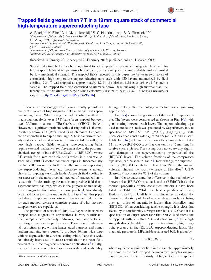
The results for the field trapped in the double stack of
tapes for different field cooling temperatures are shown in
Fig. 2. The graph shows clearly the significant increase in
field that can be trapped if field cooling below 77.4 K. The
lower off-center field shows that the sample was saturated.
No damage was observed in any of the tape layers after
the tests. The ramp rates used for the applied field were
higher for higher temperatures (0.5 T min�1 for 77.4 K and
0.34 T min�1 for 60 K) and lower when approaching 4.2 K
(0.15 T min�1 for 20 K and 13 K, with the rate reduced to
0.07 T min�1 for the last 1 T of the 13 K ramp). The lower
ramp rates required for the 20 K and 13 K temperature stages
meant that the field cooling took approximately 1 h given
that the applied field was 8.5 T in both cases. The trapped
field for 4.2 K was not strictly achieved using field cooling.
To begin with, a zero field cooling test was performed with a
high ramp rate (0.25 T min�1) to separately test how flux
penetrated the sample. Interestingly, the high ramp rate
caused flux to penetrate in a series of sudden global flux
jumps. As a result of this instability, at the maximum 14 T
applied, the central field in the sample was 10.7 T and there-
fore the stack was saturated. This behavior shows that even
though a stack of tapes may be more thermally stable at low
temperatures, even this type of sample will suffer from
FIG. 1. (a) Schematic of the double (RE)BCO tape stack used for the field
cooling experiment. (b) 120 of the square tape layers compressed to form a
tape stack. (c) Components of the 12 mm wide SuperPower superconducting
tape from which 12 mm lengths were cut.
TABLE I. Parameters and volume fraction for each compressed 120 layer
stack of tapes used in the experiment.
Parameter
120 layer (RE)
BCO tape stack
Sample height (mm) 6.9
Density (kg m�3) 8380
(RE)BCO volume fraction 1.7%
Hastelloy volume fraction 87.0%
Silver volume fraction 5.2%
Stacking space fraction 6.1%
TABLE II. Properties of Hastelloy C-276 substrate, silver over-layer and bulk YBCO at cryogenic temperatures. A range of values is given for 10–77.4 K
where there is a known temperature dependence.
Parameter Hastelloy Silver over-layer Bulk YBCO
Density (kg m�3) 88907 10 490 59003
Thermal conductivity (W m�1 K�1) 3–7.57 �500–15008–10 6–20 ab-plane, 1–4 c-axis11
Heat capacity (J kg�1 K�1) 2–2007 2–1558 �1–20011
Tensile strength (MPa) 670–760 (yield)12 �60 (yield)8 �30 (fracture)3
102601-2 Patel et al. Appl. Phys. Lett. 102, 102601 (2013)
global flux jumps near 4.2 K if the applied field changes too
quickly. Given the saturated state of the sample at the end of
the increasing field ramp, the field could be ramped back
down to zero to effectively achieve field cooling, and indeed
the state achieved at the end should be the same as if
field cooling was performed with the same decreasing
applied field. During the ramp down in field, a ramp rate of
0.12 T min�1 was used from 8 T. On several occasions, an
increase in temperature was observed and the ramp was tem-
porarily halted until the temperature recovered, and on the
final occasion the liquid helium level (which was very low)
was increased. This suggests that even a stack of tapes can
suffer some instability if cooling power is insufficient. After
this re-fill, full stability was restored and the ramp continued
without interruption. The maximum measured temperature
rise was 2.5 K but, as the thermometer was not in close con-
tact with the samples (but thermally connected by a brass
mount), the warming would be higher inside the sample
itself. The field cooling temperature should, therefore, only
be considered as approximately 4.2 K.
When individual flux jumps occur in a superconductor
they generate a small amount of heat which leads to a local
temperature rise, if the heat cannot be conducted away
quickly enough and/or the heat capacity is too low, then the
temperature rise can be big enough to lead to a global flux
jump (large scale de-pinning and flow of flux). This occurs
as the local temperature spike leads to a decrease in Jc and
hence de-pinning of neighboring flux lines and an avalanche
effect. A global flux jump corresponds to a sudden measura-
ble drop in the trapped field, including complete collapse,
which is often observed in bulk superconductors for high
fields and low temperatures. Therefore, flux jumps have a
significantly limiting effect for bulks below 20–30 K, result-
ing in a decrease in trapped field when field cooling below
these temperatures.2,3 A unique feature of the results for a
stack of tapes is a continuous increase in trapped field as
temperature decreases all the way down to 4.2 K. The
trapped field of 7.34 T is the highest field reported to have
been trapped in a stack of superconducting tapes or thin
films. Although the value is not as high as many bulk
samples,1,13,14 it is remarkable given the small size of the
stack (12 mm square), commercially availability of the tape,
and its “average” Ic value.
A detailed description of flux jumping in bulk supercon-
ductors which have high fields trapped in them has already
been developed.15 However, the description of trapped field
stability in a stack of tapes is more complex and the so called
adiabatic approach—in which locally generated heat from a
flux jump is assumed to take a very long time to diffuse
through the sample—cannot be used. The fundamental dif-
ferences between the two cases can be highlighted by consid-
ering the simple case of a stack of tapes which forms a
composite bulk and a plain bulk, both with the same overall
engineering Jc. This means that the actual Jc in the thin
films of the tape stack is much higher than that of the plain
bulk (the Jc of the tapes tested is �2 MAcm�2 compared to
�30 kAcm�2 for a typical bulk at 77 K (Ref. 3)) and should,
therefore, have a correspondingly higher instantaneous tem-
perature rise due to a flux jump if both samples have the
same overall trapped field. Based on the values presented in
Table II, one can also simplify by assuming the heat capacity
of all parts of the stack of tapes is the same as the plain bulk.
The key differences are then clearer: the total heat generated
per unit volume should be the same in both cases, but for the
stack of tapes, all the heat is being generated in very thin
superconducting layers which, therefore, have a very high
power density. However, unlike the plain bulk, this heat is
almost all conducted away by the upper silver layer with its
high thermal conductivity and the lower Hastelloy layer with
its large thickness. The high thermal conductivity of the sil-
ver layer allows efficient internal cooling of the sample via
conduction of heat to the outer sample surfaces. It appears
that despite the heat energy density being much higher for
the superconductor in the stack of tapes, the fast removal of
heat into a non-superconducting metallic layer suppresses
flux instability in the superconductor better than if the heat
generation was spread out over a larger superconducting
region of low thermal conductivity. The stability provided
by the silver layer is analogous to low temperature multi-
filamentary wires in which the non-superconducting metallic
matrix prevents a quench by the fast removal of local heat
from the superconducting filaments.16
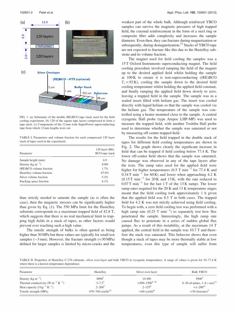
Flux creep was measured for the trapped fields up to
5 min after field cooling as shown in Fig. 3. The decay in the
trapped field was expected to be logarithmic, as is typically
the case for bulks.3 However, for the time window observed,
the creep rate seems to be slightly faster than logarithmic
as the curves in Fig. 3 are not linear. It is difficult to say why
the decay is not completely logarithmic as flux creep meas-
urements can be complicated by a number of factors,17 but
given how short the time window is, it is clear that measure-
ments for a hour or more are needed to get a better picture of
the exact form of the decay. Another interesting feature is the
strong decrease in the flux creep rate as temperature
decreases. The temperature dependence of creep rate is not
generally linear or monotonic but can exhibit a field depend-
ent peak.3,17 It is difficult to make a direct comparison of the
creep rates to values for (RE)BCO bulks as the few studies
that exist in the literature measure decay in magnetization
rather than central field; however, it appears that for the time
FIG. 2. Trapped field between two 120 layer tape stacks using the field cool-
ing method at various temperatures. The increase in field as temperature
decreases is approximately linear, reaching a maximum at the center of
7.34 T at 4.2 K.
102601-3 Patel et al. Appl. Phys. Lett. 102, 102601 (2013)
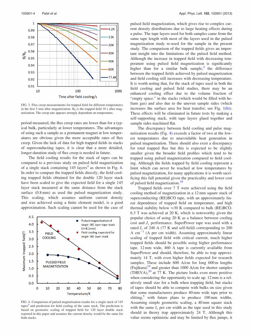
period measured, the flux creep rates are lower than for a typ-
ical bulk, particularly at lower temperatures. The advantages
of using such a sample as a permanent magnet at low temper-
atures are obvious given the more acceptable rates of flux
creep. Given the lack of data for high trapped fields in stacks
of superconducting tapes, it is clear that a more detailed,
longer-duration study of flux creep is needed in future.
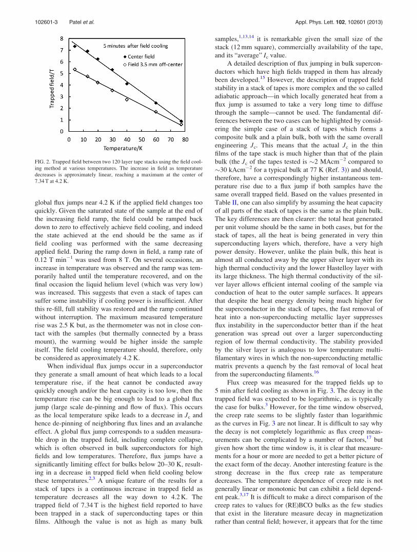
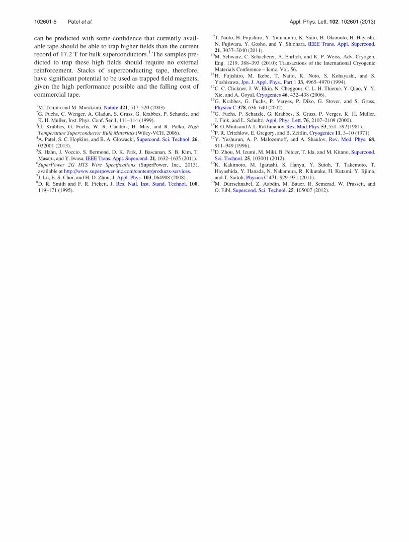
The field cooling results for the stack of tapes can be
compared to a previous study on pulsed field magnetization
of a single stack containing 145 layers4 as shown in Fig. 4.
In order to compare the trapped fields directly, the field cool-
ing trapped fields obtained for the double 120 layer stack
have been scaled to give the expected field for a single 145
layer stack measured at the same distance from the stack
surface (0.8 mm) as used the pulsed magnetization study.
This scaling, which assumes uniform current density
and was achieved using a finite element model, is a good
approximation. Such scaling cannot be used for the case of
pulsed field magnetization, which gives rise to complex cur-
rent density distributions due to large heating effects during
a pulse. The tape layers used for both samples came from the
same tape length with most of the layers used in the pulsed
magnetization study re-used for the sample in the present
study. The comparison of the trapped fields gives an impor-
tant insight into the limitations of the pulsed field method.
Although the increase in trapped field with decreasing tem-
perature using pulsed field magnetization is significantly
higher than for a similar bulk sample,4 the difference
between the trapped fields achieved by pulsed magnetization
and field cooling still increases with decreasing temperature.
It is worth noting that, for the stack of tapes used in both the
field cooling and pulsed field studies, there may be an
enhanced cooling effect due to the volume fraction of
“empty space.” in the stacks (which would be filled with he-
lium gas) and also due to the uneven sample sides (which
increases the surface area for heat transfer; see Fig. 1(b)).
These effects will be eliminated in future tests by making a
self-supporting stack, with tape layers glued together and
sample sides machined flat.
The discrepancy between field cooling and pulse mag-
netization results (Fig. 4) exceeds a factor of two at the low-
est temperatures due to unavoidable heat generation in
pulsed magnetization. There should also exist a discrepancy
for total trapped flux but this is expected to be slightly
smaller given the broader field profiles which tend to be
trapped using pulsed magnetization compared to field cool-
ing. Although the fields trapped by field cooling represent a
limit which can never be reached at low temperatures by
pulsed magnetization, for many applications it is worth sacri-
ficing this full potential given the practicality and lower cost
of pulsed field magnetization.18
Trapped fields over 7 T were achieved using the field
cooling method of magnetization in a 12 mm square stack of
superconducting (RE)BCO tape, with an approximately lin-
ear dependence of trapped field on temperature, and high
thermal stability below �30 K compared to bulk (RE)BCO.
6.3 T was achieved at 20 K, which is noteworthy given the
popular choice of using 20 K as a balance between cooling
cost and Jc performance. SuperPower tape was used with a
rated Ic of 240 A (77 K and self-field) corresponding to 200
A cm�1 (A per cm width). Assuming approximately linear
scaling of trapped field with critical current, much higher
trapped fields should be possible using higher performance
tape. 12 mm wide, 460 A tape is currently available from
SuperPower and should, therefore, be able to trap approxi-
mately 14 T, with even higher fields expected for research
samples. These include 600 A/cm for long 600 m lengths
(Fujikura)19 and greater than 1000 A/cm for shorter samples
(THEVA),20 at 77 K. The picture looks even more positive
when considering the opportunity to scale up. 12 mm is a rel-
atively small size for a bulk when trapping field, but stacks
of tapes should be able to compete with bulks on size given
that some manufacturers produce 40 mm wide tape prior to
slitting,5 with future plans to produce 100 mm widths.
Assuming simple geometric scaling, a 40 mm square stack
with the same Ic per cm width as the tape used in this study
should in theory trap approximately 24 T. Although this
value seems optimistic and may be limited by flux jumps, it
FIG. 3. Flux creep measurements for trapped field for different temperatures
in the first 5 min after magnetization. B0 is the trapped field 10 s after mag-
netization. The creep rate appears strongly dependent on temperature.
FIG. 4. Comparison of pulsed magnetization results for a single stack of 145
tapes4 and prediction for field cooling of the same stack. The prediction is
based on geometric scaling of trapped field for 120 layer double stack
reported in this paper and assumes the current density would be the same for
both stacks.
102601-4 Patel et al. Appl. Phys. Lett. 102, 102601 (2013)
can be predicted with some confidence that currently avail-
able tape should be able to trap higher fields than the current
record of 17.2 T for bulk superconductors.1 The samples pre-
dicted to trap these high fields should require no external
reinforcement. Stacks of superconducting tape, therefore,
have significant potential to be used as trapped field magnets,
given the high performance possible and the falling cost of
commercial tape.
1M. Tomita and M. Murakami, Nature 421, 517–520 (2003).2G. Fuchs, C. Wenger, A. Gladun, S. Gruss, G. Krabbes, P. Schatzle, and
K. H. Muller, Inst. Phys. Conf. Ser 1, 111–114 (1999).3G. Krabbes, G. Fuchs, W. R. Canders, H. May, and R. Palka, HighTemperature Superconductor Bulk Materials (Wiley-VCH, 2006).
4A. Patel, S. C. Hopkins, and B. A. Glowacki, Supercond. Sci. Technol. 26,
032001 (2013).5S. Hahn, J. Voccio, S. Bermond, D. K. Park, J. Bascunan, S. B. Kim, T.
Masaru, and Y. Iwasa, IEEE Trans. Appl. Supercond. 21, 1632–1635 (2011).6SuperPower 2G HTS Wire Specifications (SuperPower, Inc., 2013),
available at http://www.superpower-inc.com/content/products-services.7J. Lu, E. S. Choi, and H. D. Zhou, J. Appl. Phys. 103, 064908 (2008).8D. R. Smith and F. R. Fickett, J. Res. Natl. Inst. Stand. Technol. 100,
119–171 (1995).
9T. Naito, H. Fujishiro, Y. Yamamura, K. Saito, H. Okamoto, H. Hayashi,
N. Fujiwara, Y. Gosho, and Y. Shiohara, IEEE Trans. Appl. Supercond.
21, 3037–3040 (2011).10M. Schwarz, C. Schacherer, A. Ehrlich, and K. P. Weiss, Adv. Cryogen.
Eng. 1219, 388–393 (2010); Transactions of the International Cryogenic
Materials Conference – Icmc, Vol. 56.11H. Fujishiro, M. Ikebe, T. Naito, K. Noto, S. Kohayashi, and S.
Yoshizawa, Jpn. J. Appl. Phys., Part 1 33, 4965–4970 (1994).12C. C. Clickner, J. W. Ekin, N. Cheggour, C. L. H. Thieme, Y. Qiao, Y. Y.
Xie, and A. Goyal, Cryogenics 46, 432–438 (2006).13G. Krabbes, G. Fuchs, P. Verges, P. Diko, G. Stover, and S. Gruss,
Physica C 378, 636–640 (2002).14G. Fuchs, P. Schatzle, G. Krabbes, S. Gruss, P. Verges, K. H. Muller,
J. Fink, and L. Schultz, Appl. Phys. Lett. 76, 2107–2109 (2000).15R.G.MintsandA.L.Rakhmanov,Rev.Mod.Phys.53,551–592(1981).16P. R. Critchlow, E. Gregory, and B. Zeitlin, Cryogenics 11, 3–10 (1971).17Y. Yeshurun, A. P. Malozemoff, and A. Shaulov, Rev. Mod. Phys. 68,
911–949 (1996).18D. Zhou, M. Izumi, M. Miki, B. Felder, T. Ida, and M. Kitano, Supercond.
Sci. Technol. 25, 103001 (2012).19K. Kakimoto, M. Igarashi, S. Hanyu, Y. Sutoh, T. Takemoto, T.
Hayashida, Y. Hanada, N. Nakamura, R. Kikutake, H. Kutami, Y. Iijima,
and T. Saitoh, Physica C 471, 929–931 (2011).20M. D€urrschnabel, Z. Aabdin, M. Bauer, R. Semerad, W. Prusseit, and
O. Eibl, Supercond. Sci. Technol. 25, 105007 (2012).
102601-5 Patel et al. Appl. Phys. Lett. 102, 102601 (2013)
Copyright © 2022 FDOKUMEN

