


Bahasa
Halaman
Hukum

University of Huddersfield Repository
Johnson Anthony and Unver Ertu
The Conceptual Design of a Kinetic Energy Storage Device to Store 20 KWh of Energy
Original Citation
Johnson Anthony and Unver Ertu (2011) The Conceptual Design of a Kinetic Energy Storage Device to Store 20 KWh of Energy Research Report University of Huddersfield Confidential Feasibility Report Huddersfield UK (Unpublished)
This version is available at httpeprintshudacuk13812
The University Repository is a digital collection of the research output of theUniversity available on Open Access Copyright and Moral Rights for the itemson this site are retained by the individual author andor other copyright ownersUsers may access full items free of charge copies of full text items generallycan be reproduced displayed or performed and given to third parties in anyformat or medium for personal research or study educational or not-for-profitpurposes without prior permission or charge provided
bull The authors title and full bibliographic details is credited in any copybull A hyperlink andor URL is included for the original metadata page andbull The content is not changed in any way
For more information including our policy and submission procedure pleasecontact the Repository Team at Emailboxhudacuk
httpeprintshudacuk
1
Report On Behalf of
ESP
The Conceptual Design of a
Kinetic Energy Storage Device To Store 20 KWh of Energy
by
Anthony Johnson BSc(Hons) MIMechE CEng
School of Computing and Engineering Mechanical Engineering
Ertu Unver PhD MSc PG Cert BSc (Hons) School of Art Design and Architecture 3D Digital amp Product Design
Dates Phase 1 9May2011 Completion and presentation of stage 1 page 1 to 22 Phase 2 on-going research page 23 to 45)
This report is strictly confidential and owned by ESP and University of Huddersfield It may not be published in full or in part without the consent of the Authors and ESP Energy Storage ltd
2
Contents (Phase 1) Contact Details 3 Introduction 4 Conceptual Design Exploration 5 Target Specification and Requirements 6 Design Considerations and Decisions 7 Rim Type 7 Disc Type Flywheel 10 Primary Bearing System 12 Secondary Bearing System 13 Containment 13 Motor Generator Set 14 Control Equipment 14 Machine Monitoring 15 Magnetic Drive Coupling 15 Electrical Aspects Design and Analysis 15 Conclusions and Recommendations 16 References 18 Appendix-1 19-22
3
Contents (Phase 2) Stage 2 of the Flywheel project 23 Additional team members joining to the research team 23 Design Evolution from Concept 1 24 Design Concept 2 Evolving to Concepts 3 and 4 25 Concept 5 30 Concept 6 32 Conclusion and further plan 36 Appendix 2 37-43
4
Contact details ESP Storage Products Limited details
Contact Person Terry Idle CEO ESP Energy Storage Products Limited
Tel 07506 553663 email terryidleespim ESP is a company registered in England and Wales (7392042) Registered Offices Horley Green House Horley Green Road Claremont Halifax England HX3 6AS
University staff contacts Dr Ertu Unver Senior Lecturer Tel 01484483848 Email eunverhudacuk University of Huddersfield School of Art Design and Architecture Huddersfield HD1 3DH MA 3D Digital Design course leader 3D Subject Area - BABSc Product Transport Web sites wwwhuddersfield3dcouk wwwhudacuk
Anthony Johnson BSc (Hons) MIMechE CEng
Email adjohnsonhudacuk Web www1719designcom Mobile 07800 947196
University of Huddersfield School of Computing and Engineering Queensgate Huddersfield HD1 3DH
5
Introduction This conceptual design was commissioned by ESP with the express intention of creating a viable concept for a Kinetic Energy Storage Device (KESD) in the form of a flywheel system The intention is to glean energy from the national grid when electricity is very low cost and return it to the national grid when energy is more expensive As an example one kWh of energy bought in the early morning when demand is low costs approximately pound20 If this could be stored until a high demand period say early evening the cost would be approximately pound250 per kWh If several KESDrsquos could be run there would be potential of making a great deal of money On a national basis several thousand KESDrsquos could reduce the necessity for so many power stations KESDrsquos could also store solar power and wind power to be used when demand for power is high Summary This report presents two conceptual styles of Kinetic Energy Storage Devices as outlined as follows
Cylindrical rim type flywheel system
Solid disc type flywheel system The general specifications are listed as follows
Rim Type Rotor Disc Type Rotor
Style Hollow cylinder Solid cylinder
Outer Diameter (mm) 600 600
Inner diameter (mm) 450 na
Rotor depth (mm) 1000 500
Material steel steel
Density (kgm3) 7500 7500
Rotor mass (kg) 930 1060
Angular velocity (Revmin) 18000 18000
Surface speed (ms) 565 565
Energy (Joules) 74200000 84800000
Energy (KWh) 2061 2355
Power (KW) 573 654
1 Tonne mass lift (m) 8150 8152
Containment (Primary) Steel casing Steel casing
Containment (Secondary)
Concrete lined Pit
Concrete lined Pit
Bearing system radial Magnetic Levitation
Magnetic Levitation
Bearing System (secondary)
Rolling element Brgs
Rolling element Brgs
Motor Generator Drive coupling Magnetic Magnetic Chamber Type Vacuum Vacuum
6
Conceptual Design Exploration A great deal of research was applied to the project in order to gain an overview of the technology involved with flywheel design The most useful of the references are listed in the reference section pp17 Several basic styles of flywheel solutions were examined before the final concepts were selected At the initial briefing solutions were aired as possible concepts as follows
Toroidal flywheel system supported on bearings at the rim
Containment system using a secondary rotor to absorb the energy from a bursting flywheel
Toroidal Flywheel A schematic can be seen in figure 1 This rotor system is supported on magnetic levitation bearings at the rim The motor generator system is also sited at the rim Though the system is sound in principle investigations revealed certain practical difficulties The design would incorporate a solid (or multiple disc) rotor where the windings would be built into the stationary casing The high surface speeds at the periphery would use eddy currents which are known to be only 70 efficient Furthermore magnetic levitation would be difficult to control and expensive to apply at the larger peripheral diameter
CoilsRim
Figure 1 Schematic of a Toroidal Rotor This solution was discarded due to its elevated expense and lead time in developing the system Containment System Using a Secondary Rotor This is quite a feasible solution to the problem of absorbing the energy of a bursting rotor It represents one of the three generally accepted containment systems and is often used for containment for flywheels used in vehicles aeroplanes etc It was considered for use in the current concept and would certainly work Its main drawback however is its increased complexity and subsequent extra cost The current concept is ground based and therefore can use a static passive containment system where weight (mass) is not a problem the solution was therefore discarded in favour of a less expensive containment system
7
The initial approach was to design the system using standard technology with the minimal new technological development It was hoped that this would keep costs down and make manufacturing relatively simple The target specification is outlined below Target Specification and Requirements Research The research revealed that high speed burst was a large problem If the flywheel system disintegrated there would be large pieces of material possessing massive amounts of energy being thrown around Essentially the device would have enough energy to be equivalent to a large bomb if not contained properly Many variations of flywheel have been designed Some of the major research in this area has been in flywheel construction When a flywheel bursts the main danger is from the high velocity chunks of material Much research is being applied to the design of rotors in fibre reinforced resin When these burst they disintegrate into fibrous elements which do not possess any great mass Target Specification The initial target specification was defined through initial research combined with the original specification from ESP Envelope size 1m3 Power rating 20 to 50KWh Efficiency gt 75 Power degradation over 24hrs lt 10 Calendar life 10 years Max sound power level 63dBA Low speed approx 20k revmin Design Approach The analysis shown on the spreadsheets in the appendix was iterated several times for each style of flywheel until optimum sizes were found The analysis revealed some enormous parameters which needed to be carefully considered in the design Furthermore the parameters focussed the design in particular directions An example of this is the surface speed parameter of 565ms This is almost twice the speed of sound and demands some means of reducing the turbulence and noise within the enclosure The progress of the design became an iterative approach where parameters such as diameter mass speed etc were varied until a reasonable output emerged It was difficult to decide on the most appropriate type of flywheel rim type or disc type so a concept of both versions has been proposed
8
Design Considerations and Decisions Flywheel Design Rim Type The rim type flywheel takes the form of a large rotating cylinder The main advantage is that many of the elements which allow the spin eg bearings can be built inside the cylinder creating a more compact overall unit Stresses in the cylinder can be considered to be hoop stresses only rather than radial and hoop stresses as with a solid flywheel Careful consideration needs to be applied to the link between shaft and flywheel since this would be subjected to some high stresses Finite element stress analysis would be used to verify strength The parameters selected for the rim type flywheel are as follows in table 1 The rim type flywheel concept can be seen in figure 2 Table 1 Rim-type Flywheel Concept Specification
Rim Type Rotor
Style Hollow cylinder
Outer Diameter (mm) 600
Inner diameter (mm) 450
Rotor depth (mm) 1000
Material steel
Density (kgm3) 7500
Rotor mass (kg) 930
Angular velocity (Revmin) 18000
Surface speed (ms) 565
Energy (Joules) 74200000
Energy (KWh) 2061
Power (KW) 573
1 Tonne mass lift (m) 8150
Containment (Primary) Steel casing
Containment (Secondary) Concrete lined
Pit
Bearing system radial Magnetic Levitation
Bearing System (secondary) Rolling element
Brgs
Motor Generator Drive coupling Magnetic
Chamber Type Vacuum
9
Figure 2 Proposed Rim Type Flywheel
SHAFT
CASING
UPPER FLANGE
TOP CAP
FLYWHEEL
FLYWHEEL SHAFT SUPPORT
FLYWHEEL SHAFT SUPPORT
RADIAL MAG LEV BEARING
RADIAL MAG LEV BEARING
UPPER AUXILIARY ROLLING
ELEMENT BEARING
BEARING CAP
AXIAL SUPPORT MAG LEV BEARING
LOWER AUXILIARY SUPPORT BEARING
BEARING CAP
SEAL
LOWER CAP
CASING BASE
UPPER CASING FLANGE
SEAL
1260
1000
Oslash600
Oslash464
20
Oslash912
Oslash330
Oslash135
1877
NON-FERROUS PLATE
597
MAGNETIC DRIVE HALF
MAGNETIC DRIVE HALF
MOTOR GENERATOR
FLYWHEEL
AND
HOUSING
UPPER BEARING
LOWER BEARING
MOTOR GEN STATOR
MOTOR GEN ROTOR
MOTOR GEN SHAFT
Oslash440
Oslash640
HOLLOW ROTOR FLYWHEEL SYSTEM
10
Disc Type Flywheel The disc type flywheel takes the form of a solid steel cylinder of dimensions Diameter 600mm x 500mm long Though this is physically smaller than the rim type flywheel the overall package including the casing and motorgenerator set is a little longer This is because the bearings have to be set above and below the rotor rather than inside as with the rim type rotor Radial and hoop stresses are important considerations Hoop stresses are a maximum at the outer rim but radial stresses are a maximum near the centre of the cylinder Consideration therefore is needed when fitting the rotor to the shaft since extra stresses near the centre should be avoided The concept uses a particular method of fixing to the shaft which is hoped will prove to be successful Careful stress analysis needs to be done to ensure that this method or any other selected method will be satisfactory The parameters selected for the disc type flywheel are as follows in table 2 The disc type flywheel concept can be seen in figure 3 Table 2 Disc Type Rotor Specification
Disc Type Rotor
Style Solid cylinder
Outer Diameter (mm) 600
Inner diameter (mm) na
Rotor depth (mm) 500
Material steel
Density (kgm3) 7500
Rotor mass (kg) 1060
Angular velocity (Revmin) 18000
Surface speed (ms) 565
Energy (Joules) 84800000
Energy (KWh) 2355
Power (KW) 654
1 Tonne mass lift (m) 8152
Containment (Primary) Steel casing
Containment (Secondary) Concrete lined Pit
Bearing system radial Magnetic Levitation
Bearing System (secondary) Rolling element
Brgs
Motor Generator Drive coupling Magnetic
Chamber Type Vacuum
11
Figure 3 Proposed Disc Type Flywheel
CASING
UPPER FLANGE
TOP CAP
RADIAL MAG LEV BEARING
UPPER AUXILIARY ROLLING
ELEMENT BEARING
BEARING CAP
AXIAL SUPPORT MAG LEV BEARING
UPPER CASING FLANGE
SEAL
NON-FERROUS PLATE
597
MAGNETIC DRIVE HALF
MAGNETIC DRIVE HALF
MOTOR
GENERATOR
UPPER BEARING
LOWER BEARING
MOTOR GEN STATOR
MOTOR GEN ROTOR
MOTOR GEN SHAFT
Oslash440
Oslash6402028
SHAFT
RADIAL MAG LEV BEARING
LOWER AUXILIARY SUPPORT BEARING
BEARING CAP
SEAL
LOWER CAP
CASING BASE
Oslash912
Oslash330
Oslash740
5001300
Oslash600FIXED SHAFT FLANGE
PRECISION HEADED PIN
REMOVABLE FLANGE
LOCK COLLAR
PRECISION HEADED PIN
FLYWHEEL
SOLID ROTOR FLYWHEEL SYSTEM
12
Primary Bearing System The bearing system is required to hold the rotor in place whilst allowing rotation around 20000 revmin with the minimal frictional resistance Several options were considered Magnetic levitation bearings Rolling element bearings Gas film bearings Fluid film bearings (journal) Gas film bearings require a pressurised gas to be constantly pumped between the shaft and bearing In a vacuum environment this would be inappropriate and the option was discarded Fluid film bearings are essentially oil filled Upon rotation of the journal (shaft) the oil is pulled into the contactsupport area and acts as a cushion Frictional resistance is low but a constant flow of fluid is required requiring shaft seals within the vacuum chamber It was thought that the frictional resistance applied by the seals would create too much drag and reduce efficiency There may also be a problem with heat generation within the fluid at high speeds Magnetic levitation bearings are frictionless and can operate within a vacuum environment Their major disadvantage is that they require a control system and that the magnetic coils require power Research shows however that many KESDrsquos use magnetic levitation as a primary bearing system It was discovered that SKF could produce the magnetic levitation bearings required and also have experience in producing motor generator equipment which could operate at these high speeds SKF provided some very useful data which was used directly in the concept designs They gave approximate sizes of bearing units and suggested how the layout should be applied Beacon power is a company in the United states for which SKF have previously designed such bearings Please see their web site wwwbeaconpowercom A typical radial Magnetic Levitation Bearing can be seen in figure 4 Figure 4 Typical Radial Magnetic Levitation Bearing
13
The axial bearings should be sited at the top of the housing The magnetic flux applied is attractive allowing the rotor to hang from the bearing This arrangement can be seen in both figures 2 and figure 3 Secondary Bearing System It is evident from the research and from advice given by SKF that there needs to be a secondary bearing back-up system This is necessary should power fail to the magnetic levitation bearings SKF recommended high speed ball bearings for this particular role These bearings would function as radial and axial bearings Figure 5 shows typical ball bearings The application can be seen in the concept designs in figures 2 and 3
Figure 5 Typical Ball Bearings Containment The containment system has to be applied to two aspects of the design containment of the vacuum and containment of a bursting flywheel There are several approaches to containment of a bursting flywheel
Brute force approach using heavy-walled pressure vessels
Spinning ring which soaks up the energy of the impacting flywheel debris
Energy absorbing liner The soft catch approach The containment system requires design effort to be applied When the flywheel is at running speed a great deal of energy is contained This energy is enough to vertically lift a 1 tonne mass 81 km Put another way there is energy contained in the flywheel equivalent to 18kg (40lbs) of TNT Generally it is thought that a combined approach might be the way forward This would entail a light casing to contain the vacuum and a heavier casing such as a concrete perhaps below ground vessel to contain any flywheel burst This chamber might also incorporate some form of soft catch energy absorbing system which could take the form of sand or pea gravel filled chambers which break thus allowing the contents to infiltrate the chamber when a burst occurs The current concept uses segmental sand bags set inside the concrete basin If the bursting flywheel breaches the vacuum casing the sand bags will disintegrate allowing the sand to absorb the debris The concrete casing will act as final resort containment Please see figure 6 for a 3D impression of the containment Many current flywheels merely incorporate the brute force approach where a heavy casing is combined with a vacuum chamber In the case of a burst a great deal of
14
energy needs to be contained so any such casing needs to be very firm and should be mounted on heavy foundations Figure 6 Impression of the Segmental Sandbag and Concrete Containment System Motor Generator Set The motor Generator set drives the flywheel up to speed during energy input and converts rotational energy into electrical energy during energy extraction Due to the high speeds this is quite a special arrangement and requires specialist design attention SKF are able to provide the design expertise and design a suitable MG set to suit the specific design needs of the project Typical components can be seen in figure 7
Figure 7 Typical Motor Generator Components Control Equipment The magnetic levitation bearings could become unstable unless constantly monitored and controlled The service incorporates appropriate matching and supply of monitoring and control equipment Figures 8 and 9 show typical control and monitoring devices
15
Figures 8 and 9 Typical Control and Monitoring Devices Machine Monitoring Within the package SKF also offer machine monitoring software which takes input from several sensors to relay the information to a monitoring station This information could include rotational speed out of balance detection temperature energy input efficiency energy extraction efficiency etc
Figure 10 Machine monitoring Software Magnetic Drive Coupling The modular design of the KESD separates the motorgenerator from the vacuum chamber of the flywheel Normal engineering practice would incorporate lip seals to contain the vacuum but the seals would be in contact with the shaft causing frictional resistance and heat generation Ceramic seals would be required The better solution would be to use a magnetic drive coupling This is a non-contacting coupling which transfers magnetic flux through a non-magnetic membrane thus allowing drive to be applied between the two halves of the coupling One half would be situated inside the vacuum chamber the other half inside the motor generator chamber A typical magnetic drive coupling can be seen in figure 11
Figure 11 Typical Magnetic Drive Coupling
16
Electrical Aspects Design and Analysis SKF are the current specialist source of magnetic levitation bearings There are other companies who can offer this service however SKF have been the most informative and helpful They not only offer a full manufacture and design service but they also offer all the ancillary equipment needed to operate and maintain the system Elements for the system are listed as follows
Design and manufacture service for magnetic levitation bearings
Radial magnetic levitation bearings
Axial magnetic levitation bearings
Control system for magnetic levitation bearings
Machine monitoring system
Design and manufacture service for motor generator set
Control system for the motor generator set Incorporated in the total package is a high performance finite element predictive analysis tool for magnetic levitation applications Conclusions and Recommendations The proposed designs show the format of both a rim type flywheel system and also a solid (disc type) flywheel system The sizes of the rotors are generally correct though other aspects of the design are approximate It should be noted however that during the process of conversion from concept to detailed manufacturable units many of the details may change There are many technical design details which require careful consideration such as methods of balancing the rotors and stress analysis of the rotors and frame Below is a basic list of work to be accomplished before a flywheel system can be manufactured Further Work Required to Progress the Project
Finite element stress analysis vacuum chamber
MagLev radial bearing design
MagLev axial bearing design
Control system for magnetic levitation bearings
Machine monitoring system
Design and manufacture of motor generator set
Control system for the motor generator set
Stress analysis of rotors for burst limitation
Fluid flow analysis within the chamber
Vacuum pump and equipment selection
Rolling element bearing design and selection
Vacuum Casing design
Explosion containment system design
Foundations design
Selection of materials There are two concepts put forward each with its own advantages and disadvantages There needs to be a selection of either version so that detailed work can commence
17
Both concept designs fit most of the initial criteria During the detail design process some of these may need to change to accommodate more precise constraints for use or perhaps to accommodate physical parameters thrown up by the development process The concept specifications are as follows in table 3 Industrial Concept The KESD system has been designed for an industrial application where banks of KESDrsquos can be housed The appendix shows several 3D pictures which indicate scale and the probable industrial setting The soft-catch and concrete containment system is also shown Table 3 Concept Specifications for the ESP Kinetic Energy Storage Device
Rim Type Rotor Disc Type Rotor
Style Hollow cylinder Solid cylinder
Outer Diameter (mm) 600 600
Inner Diameter (mm) 450 na
Rotor depth (mm) 1000 500
Material steel steel
Density (kgm3) 7500 7500
Rotor Mass (kg) 930 1060
Angular velocity (Revmin) 18000 18000
Surface Speed (ms) 565 565
Energy (Joules) 74200000 84800000
Energy (kWh) 2061 2355
Power (kW) 573 654
1 Tonne mass lift (m) 8150 8152
Containment (Primary) Steel casing Steel casing
Containment (Secondary) Concrete lined Pit Concrete lined Pit
Bearing System Radial Magnetic Levitation Magnetic Levitation
Bearing System (secondary) Rolling element
Bearings Rolling element
Bearings
Motor Generator Drive Coupling Magnetic Magnetic
Chamber Type Vacuum Vacuum
18
Rotor Selection There is little to choose between the two types of rotor The list of differing parameters is as follows Rim Type Disc Type - Lower mass 930kg - Higher mass 1060kg - Height overall 1877mm - Overall height 2028mm - Energy 2061 kWh - Energy 2355 kWh - Power 573 kW - Power 654 kW - Stresses in rim only - Radial and Hoop stresses present (Less prone to burst)
bull Design and manufacturing will present a similar level of difficulty bull Balancing relatively easier with the rim-type flywheel due to increased length bull Cost implications will be similar for each type
19
References
Many references were consulted These were a mixture of both technical papers and company data The following is a list of the most useful references
SKF Website wwwskfcom
Beacon Power wwwbeaconpowercom
Flywheel Energy Storage System California Energy Commission 2004
Compact Flywheel Energy Storage System Koyo Seiko Company
Flywheel Energy Storage Riello-UPS wwwriello-Upscouk
Flywheel energy and Power Storage Systems Boland Bernhoff and Leijon 2004
Energy Storage Flywheel System with SMB and PMB and its Performances Mitsuda Komori Subkhan and Inoue 2009
Designing Safer Flywheels Steven Ashley Test devices inc wwwtestdevicescom
Murakami m (2007) japan Title design of an energy storage flywheel system using permanent magnet bearing and superconducting magnetic bearings
Seong-yeol yoo (2009) korea Title design of magnetically levitated rotors in a large flywheel
Werfel (2008) Germany (german e-on) Title 250kW Flywheel with HTS Magnetic Bearing for Industrial use
Bjorn Bolund (2005) sweden Title Flywheel energy and power storage systems
Read T Doucette (2011) OXFORD Engineering Science department UK 201011 Title A comparison of high speed flywheels batteries and ultracapasitors and the bases of cost and fuel
T H Sung (2011) Korea Title Flywheel energy storage system with a horizontal axle mounted on high Tc superconductor bearings
20
Appendix -1
a) Flywheel Characteristics Iteration Spreadsheets Flywheel Characteristics Disc Type Rotor
Note Speed of Sound = 3432ms
Dia Radius Depth Density Volume mass Ang Vel Ang Vel Surface Moment KE KE Power 1 tonne Rim
m m m kgm^3 m^3 kg RPM radsec Speed of Inertia Joules KWh KW Mass lift Stress
Ms kgm^2 m Nm^2
020 010 080 750000 003 18852 3000000 314200 31420 094 4652751 129 036 251584 4056795
030 015 070 750000 005 37115 2000000 209467 31420 418 9160103 254 071 251584 4056795
030 015 070 750000 005 37115 3000000 314200 47130 418 20610232 573 159 566064 9127789
040 020 070 750000 009 65982 2000000 209467 41893 1320 28950450 804 223 447261 7212080
050 025 070 750000 014 103097 2000000 209467 52367 3222 70679810 1963 545 698845 11268876
060 030 070 750000 020 148460 2000000 209467 62840 6681 146561653 4071 1131 1006337 16227181
060 030 060 750000 017 127251 2000000 209467 62840 5726 125624274 3490 969 1006337 16227181
060 030 050 750000 014 106043 2000000 209467 62840 4772 104686895 2908 808 1006337 16227181
060 030 040 750000 011 84834 2000000 209467 62840 3818 83749516 2326 646 1006337 16227181
070 035 030 750000 012 86601 2000000 209467 73313 5304 116367238 3232 898 1369736 22086996
070 035 020 750000 008 57734 2000000 209467 73313 3536 77578159 2155 599 1369736 22086996
080 040 020 750000 010 75408 2000000 209467 83787 6033 132344914 3676 1021 1789043 28848322
000 750000 000 000 000 000 000 0 000 000 DIV0 0
050 025 035 750000 007 51548 3000000 314200 78550 1611 79514786 2209 614 1572401 25354970
060 030 020 750000 006 42417 3000000 314200 94260 1909 94218206 2617 727 2264258 36511157
000 750000 000 000 000 000 000 0 000 000 DIV0 0
070 035 021 750000 008 60621 2000000 209467 73313 3713 81457067 2263 629 1369736 22086996
060 030 021 750000 006 44538 2000000 209467 62840 2004 43968496 1221 339 1006337 16227181
050 025 020 750000 004 29456 3000000 314200 78550 921 45437020 1262 351 1572401 25354970
000 750000 000 000 000 000 000 0 000 000 DIV0 0
000 750000 000 000 000 000 000 0 000 000 DIV0 0
060 030 050 750000 014 106043 1800000 188520 56556 4772 84796385 2355 654 815133 13144017
060 030 050 750000 014 106043 1200000 125680 37704 4772 37687282 1047 291 362281 5841785 Flywheel Characteristics Rim Type Rotor
Note Speed of Sound = 3432ms
Ou
ter
Dia
(m)
Ou
ter
Rad
(m)
Inn
er
Dia
(m
)
Inn
er
Rad
(m)
De
pth
(m
)
De
nsi
ty
(kg
m^
3)
Vo
lum
e
(m^
3)
mas
s (k
g)
An
g V
el
(Re
vm
in)
An
g V
el
Surf
ace
Spe
ed
(m
s)
Mo
me
nt
of
Ine
rtia
kgm
^2
KE
(Jo
ule
s)
KE
(KW
h)
Po
we
r (K
W)
1 t
on
ne
Mas
s
Lift
(m
)
Rim
Str
ess
(Nm
^2
)050 025 012 006 080 750000 015 111038 15000 1571 39275 3470 42819848 1189 330 393100 6338743
06 030 015 008 05 750000 013 99415 18000 1885 56556 4474 79496611 2208 613 815133 13144017
06 030 015 008 04 750000 011 79532 18000 1885 56556 3579 63597289 1767 491 815133 13144017
06 030 015 008 03 750000 008 59649 18000 1885 56556 2684 47697967 1325 368 815133 13144017
05 025 015 008 07 750000 013 93818 18000 1885 47130 2932 52098088 1447 402 566064 9127789
04 020 015 008 08 750000 009 64804 18000 1885 37704 1296 23031117 640 178 362281 5841785
05 025 015 008 06 750000 011 80416 18000 1885 47130 2513 44655504 1240 345 566064 9127789
05 025 015 008 065 750000 012 87117 18000 1885 47130 2722 48376796 1344 373 566064 9127789
055 028 022 011 07 750000 014 104788 18000 1885 51843 3962 70409363 1956 543 684938 11044625
06 030 022 011 05 750000 012 91786 18000 1885 56556 4130 73395982 2039 566 815133 13144017
06 030 045 023 1 750000 012 92787 18000 1885 56556 4175 74196837 2061 573 815133 13144017
21
b) Concept Renderings Figure 12 Single containment basin showing lid and control cabinet Figure 13 Impression of the industrial Application (Lids removed) Figure 14 Impression showing the Soft-Catch Segmental Sand Bags
22
Figure 15 Impression Showing Scale Figure 16 Renderings of the Proposed KESD (Hollow Flywheel Version)
Figure 17 Renderings of the Proposed KESD (Solid Flywheel Version)
23
Phase 2 Stage 2 of the Flywheel project (9May2011 till now)
The crucial elements to a successful design were considered to be the bearings radial and axial and the rotor stresses Once these elements were finalised then the rest of the KESD could be designed to suit Use of Bearings was investigated whilst finite element analysis was performed on the proposed rotor designs this is where other specialist team members included in the research team Additional team members joining to the research team Dr Simon Barrans (SMB) Specialism Stress Analyst Duties Analyse the stresses in the rotor and define materials rotor speeds and rotor shape according to safe stressing Mark Dales (MD) Specialism High current Electrical Engineer Duties Specify the motor Generator equipment and designprocure all other electrical elements Prof Rakesh Mishra (RM) Specialism Thermo-fluid behaviour and CFD techniques Duties Analyse the air flow around the rotor and determine the fluid drag Design Evolution from Concept 1 Concept 1 explained in phase 1 was devised after extensive research of current models and practices It was discovered that the original application of capturing cheap energy and selling it back to the grid at a higher cost is very feasible Furthermore peak demand smoothing is possible and indeed is the very reason for the building of several large flywheel installations throughout the world The kinetic storage of electrical energy possesses other benefits to emerging industries such as the electric car industry Here recharging stations will be required and may possibly have kinetic energy storage The conclusion is therefore that research revealed a very viable market which is demanding some form of energy storage Kinetic Energy Storage devices could easily fill that demand Concept stage 1 was effectively a feasibility study of current technologies and the possibility of using these technologies to create a kinetic energy storage device (KESD) A feasibility report was presented to the board of ESP Ltd who then agreed to the project progressing to the phase 2 The main thrust of the design was that it should follow standard engineering techniques in order to Reduce time to market Reduce the development time Reduce development costs Ensure low cost manufacture Ensure sustainability issues were minimised
24
Bearings Up to the point of the presentation in May 2011 of the feasibility report the team had been liaising with SKF who had been very helpful in providing guidance for the magnetic-levitation bearings used in Concept 1 The bearings needed development though SKF had previously provided similar bearings to the Beacon Project which is a similar facility based in California As soon as SKF understood the need for development work they lost interest saying they were overstretched and could not pursue the project Another company Mecos of Switzerland was approached who could provide the necessary magnetic levitation units They were very enthusiastic but required pound100000 to be deposited before development could begin This clearly excluded them from the development Two other companies were approached with no success Stress Analysis Whilst the bearing search was being conducted SMB had been pursuing the stress analysis on the rotor and reported that a high carbon steel rotor with a speed of 18000 revmin would burst long before it reached the operation speed The data below in table 3 shows the rotor size possibilities related to material stress Table 3 Rotor Size Possibilities for Solid Rotors at 7000 revmin The table above indicates the radius of the flywheel and the stress that flywheel would see in service The moment of inertia and the height of the rotor are important since they are essential properties in the storage of kinetic energy In general a larger Inertia value will store a larger value of kinetic energy but an increase in speed will increase the kinetic energy storage capacity in terms of speed squared Basic Equation for Kinetic Energy is as follows
KE = 1 I2 2 Where I = Moment of Inertia (kgm2)
= Angular velocity (radsec) It can be seen from the first line of table 3 that a rotor of radius 04m (800mm diameter) with a height of 0913m (913mm) will have a moment of inertia of
Ou
ter
Rad
ius
Ro
(m
)
Radial Stress(MNm2) at centre
Mo
men
t o
f in
erti
ah
eigh
t
Hei
ght
(m)
req
uir
ed t
o
give
re
qu
ired
en
ergy
at
rate
d s
pee
d
Is design possible
04 2686726 3016E+02 0913 Y
045 3400387 4831E+02 0570 Y
05 4198009 7363E+02 0374 Y
25
3016 x 10-2 kgm2 Importantly the radial stress in the rotor is 26867 MNm2 which is approximately half of the envisaged ultimate tensile strength of the rotor material medium carbon steel This will give a safety factor of slightly under 20 The conclusion from this analysis is that the original target of 18000 revmin for a solid rotor cannot be achieved using steel or one of its alloys The analysis shows that the speed needs to be substantially reduced to a maximum of 7000 revmin Design Concept 2 Evolving to Concepts 3 and 4 The revelation that the rotor stresses had forced the angular velocity down to 7000 revmin from 18000 revmin helped to continue the theme of using standard engineering components and techniques since high speed radial rolling element bearings could now be considered and separate thrust bearings The negative side to reducing the speed was that the rotor mass had to be increased to approximately 3 tonnes in order to increase the moment of inertia The reduction in speed also meant that expensive active magnetic-levitation bearings could be discarded though it seemed reasonable to support the 3 tonnes mass of the vertical axially mounted rotor on permanent magnet thrust bearings Figure 15 shows the concept Figure 15 Concept 2 Solid Rotor with Permanent Magnet Bearings and Hybrid Ceramic Radial Bearings
UPPER FLANGE
TOP CAP
BEARING CAP
UPPER CASING FLANGE
SEAL
NON-FERROUS PLATE
597 MAGNETIC DRIVE HALF
MAGNETIC DRIVE HALF
MOTOR
GENERATOR
UPPER BEARING
LOWER BEARING
MOTOR GEN STATOR
MOTOR GEN ROTOR
MOTOR GEN SHAFT
Oslash440
Oslash640
UPPER FLANGE
UPPER HIGH SPEED ROLLING
ELEMENT BEARING
GOOD SLIDING FIT ON
OUTER RACE
UPPER CASING FLANGE
SEAL
ROTOR
AXIAL SUPPORT PASSIVE
REPULSING MAGNETS (ROTOR)
AXIAL SUPPORT PASSIVE
REPULSING MAGNETS (BASE)
CASING
LOWER HIGH SPEED
ROLLING ELEMENT BEARING
GOOD SLIDING FIT ON
OUTER RACE
1880
1218
Oslash900
26
Radial Bearings Several bearing companies were contacted with a specification for radial bearings of 7000 Revmin 100mm bore Radial loads of 15KN Radial loads were evaluated by calculating the residual out-of-balance as directed by ISO 19401 Balancing Quality Requirements for Rigid Rotors Bearing loads were then calculated for a particular bearing diameter Bearing companies contacted were as follows Barden UK (Part of the Schaeffler group) SKF Luton NSK UK Each company suggested that the duty could be accommodated using a hybrid bearing of ceramic ball bearings and a high alloy steel race In order to increase long life several lubrication strategies were suggested
Grease packed
Oil lubrication (automatic injection)
A five year maintenance plan
Live wear monitoring Uniformly Stressed Rotor Results During the search for appropriate bearings SMB was conducting stress analysis on the rotor The start point for the analysis was the solid rotor in Concept 2 with a speed of 7000 revmin The necessity to increase moment of inertia and reduce the radial stresses which were so high near the rotor axis drove the rotor shape to that of a rim-type flywheel Concept 3 shows the KESD with the new shape rotor See figure 16
27
Figure 16 Concept 3 KESD Showing Rim Type Flywheel as a Uniformly Stressed Rotor
UPPER FLANGE
TOP CAP
UPPER HIGH SPEED ROLLING
ELEMENT BEARING
GOOD SLIDING FIT ON
OUTER RACE
BEARING CAP
UPPER CASING FLANGE
SEAL
NON-FERROUS PLATE
597
MAGNETIC DRIVE HALF
MAGNETIC DRIVE HALF
MOTOR
GENERATOR
UPPER BEARING
LOWER BEARING
MOTOR GEN STATOR
MOTOR GEN ROTOR
MOTOR GEN SHAFT
Oslash440
Oslash640
ROTOR
AXIAL SUPPORT PASSIVE
REPULSING MAGNETS (ROTOR)
AXIAL SUPPORT PASSIVE
REPULSING MAGNETS (BASE)
CASING
LOWER HIGH SPEED
ROLLING ELEMENT BEARING
GOOD SLIDING FIT ON
OUTER RACE
1692
1030
28
Figure 17 Concept 4 Inboard Configuration of Permanent Magnet Thrust Bearing Permanent Magnet Thrust Bearings Since the axis of the rotor was vertical it seemed reasonable to support the 3 tonnes axial load on a separate thrust bearing The obvious choice was to use rolling element thrust bearings but it was considered that other low friction axial bearing alternatives should be investigated Air bearings were considered but since the unit was destined to run in a vacuum the continual leakage of air from the bearings in to the vacuum chamber would destroy the vacuum Air bearings were therefore ruled out of the design
UPPER HIGH SPEED ROLLING
ELEMENT BEARING
GOOD SLIDING FIT ON
OUTER RACE
BEARING CAP
UPPER CASING FLANGE
SEAL
EXTERNAL RADIAL MAGNETIC DRIVE HALF
INTERNAL RADIAL MAGNETIC DRIVE HALF
MOTOR
GENERATOR
UPPER HIGH SPEED BEARING
LOWER BEARING
MOTOR GEN STATOR
MOTOR GEN ROTOR
MOTOR GEN SHAFT
Oslash440
Oslash640
ROTOR
AXIAL SUPPORT PASSIVE
REPULSING MAGNETS (ROTOR)
AXIAL SUPPORT PASSIVE
REPULSING MAGNETS (BASE)
CASING
LOWER HIGH SPEED
ROLLING ELEMENT BEARING
GOOD SLIDING FIT ON
OUTER RACE
1030
702
1733
Oslash1212
Oslash400
Oslash180
Oslash110
Oslash900
700
29
The company that ESP Ltd had proposed as manufacturers JPS Ltd based in the Wirral suggested permanent magnet thrust bearings as axial thrust bearings They had previously conducted some ad-hoc experiments but had no real data to offer Manufacturers of permanent magnets were contacted to ascertain strengths costs etc Research was also conducted as to best methods of application and installation of permanent magnets High strength magnets are manufactured from neodymium Since the rotor was to be supported by permanent magnets the flywheel rim edges were proposed as bearing points Consideration was given to the shape of the magnets Cylindrical magnets were an obvious choice but research showed that heat would be generated as rotor mounted magnets passed over base mounted magnets It soon became clear that specially shaped magnets would be required to reduce the number of ldquoedgesrdquo within the magnetic flux and hence reduce the generated heat Manufacturing shaped magnets offered several options The thrust bearing could be applied as in Concept 3 figure 16 or perhaps as in Concept 4 see figure 17 This particular configuration was devised after a quote from Best Solution Consultancy Ltd who quoted a repulsing magnet outer diameter of 540mm and an inner diameter of 160mm with a magnet thickness of 40mm The material would be neodymium rare earth This high strength high cost sintered magnet offered several benefits
Reasonable gap between thrust plates of approximately 5mm
Able to support 3 tonne mass
Zero friction (no Contact)
Zero maintenance There were however several negatives
Very High cost (approx pound28000 per bearing)
Requirement to magnetise at the assembly site
Requirement for mechanical handling equipment to enable unpacking and assembly (due to inherent attractive forces)
High cost of ancillary equipment Due to the high cost of the magnetic bearing material and the anticipated high cost of the handling equipment and other ancillary equipment it was decided that though an exceedingly viable technical option the costs were prohibitive The use of permanent magnet thrust bearings was discarded in favour of more traditional bearings such as rolling element thrust bearings
30
Concept 5 The specification for the rotor was as follows
Rotor mass 3000kg
Rotor speed 7000 revmin
Vertical axis Investigations into rolling element thrust bearings quickly revealed that even hybrid ceramic bearings would be hard pressed to support 3000kg running at 7000 revmin A quote from one of the bearing manufacturers SKF UK Ltd suggested that such a bearing would match their ACDHC super precision angular contact hybrid bearing (ceramic balls) This would need to be lubricated with an oil-air (spray) system Unfortunately this bearing system would only have a predicted life of 284 hours This was the best bearing SKF could offer Other companies offered similar bearings They suggested that the heavy load and the rotation speed were the main problems It was evident that the rotor required redesigning to fulfil the design brief of storing 20KWh but with a much lower mass and a lower speed Since the uniformly stressed rotor was essentially a rim type rotor analysis was conducted for a rim type flywheel with a spoke and shaft system to be added later within the stress analysis exercise Revisiting the basic Kinetic Energy equation it was discovered that there were several variables which could be manipulated as follows
KE = 1 I2 2 Where I = Moment of Inertia (kgm2)
= Angular velocity (radsec) But I = mk2 Where m = mass (kg) and k = radius of gyration (m) giving
KE = 1 mk22 2 Or
KE = 1 m(R2 + R1)22
2 (2)2 Where R1 = outer radius (m) R2 = inner radius (m)
31
From analysis of basic flywheel characteristics see appendix the kinetic energy to deliver 20KWh is 725MJ For analysis purposes this value was fixed as well as the aim of a notional 1500kg for the rotor mass The four variables were therefore R1 = outer radius (m) R2 = inner radius (m) Rotor depth (m)
= angular velocity (radsec)
A spreadsheet tool was used to vary the parameters which are shown in table 4 below Table 4 Spreadsheet Analysis tool to Vary Flywheel Parameters
During the iteration process the outer diameter was fixed and the depth and the inner radius was varied The angular velocity was also varied to achieve the kinetic energy value of approximately 73MJ The rotor of 22m OD 20m ID 03m depth emerged as an excellent choice having a mass of only 1485kg and a KE of 788MJ The rotor of 20m OD 17m ID 025m depth was a little heavier at 1635kg but was smaller in outer diameter This was desirable since a smaller outer diameter would mean an overall smaller unit In comparison there is not much to choose between either of the rotors The rotor of 18m OD 16m ID 04m depth emerged as the best of the 18 diameter rotors but was lacking in the value of kinetic energy storage at only KE of 579MJ This size of rotor was clearly inferior to the 20m and 22m diameter rotors
Ou
ter
Dia
(m
)
Ou
ter
Rad
(m
)
Inn
er D
ia (
m)
Inn
er R
ad (
m)
De
pth
(m
)
De
nsi
ty
(kg
m^3
)
Vo
lum
e (
m^3
)
mas
s (k
g)
An
g V
el
(Re
vm
in)
An
g V
el
(rad
sec
)
Surf
ace
Spee
d
(ms
)
Mo
me
nt
of
Iner
tia
kgm
^2
KE
(Jo
ule
s)
KE
(KW
h)
18 090 14 070 02 7500 020 1508 4000 419 377 611 53599690 1489
18 090 15 075 025 7500 019 1458 4000 419 377 591 51820013 1439
18 090 16 080 04 7500 021 1602 4000 419 377 649 56949671 1582
2 100 16 080 02 7500 023 1697 3000 314 314 848 41874758 1163
2 100 16 080 025 7500 028 2121 3000 314 314 1060 52343448 1454
2 100 17 085 025 7500 022 1635 4000 419 419 817 71729910 1992
2 100 175 088 03 7500 022 1657 4000 419 419 828 72699233 2019
2 100 18 090 036 7500 021 1612 4000 419 419 806 70721814 1964
22 110 18 090 02 7500 025 1885 3000 314 346 1141 56298286 1564
22 110 19 095 025 7500 024 1812 3000 314 346 1096 54099134 1503
22 110 2 100 03 7500 020 1485 4000 419 461 898 78817600 2189
32
Shown in figure 18 is the rim type rotor which was used to base the analysis whose results are displayed in table 4 Please note that for analysis purposes the spokes and shaft have been omitted being relatively insignificant compared to the rim of the rotor Figure 18 Rim of Flywheel as Calculated for 20m Device Figure 19 Concept 5 Rim Type Flywheel
Concept 5 is shown in Figure 19 The rotor has a diameter of 20 m and is hollow to reduce weight and hence bearing load It was intended that the hollow halves of the rotor would be machined separately and joined using industrial adhesive The key turned in to the joint at the rim would key the two halves and allow them to expand radially as one component when rotating at speed Concept 6 Intensive stress analysis revealed that the use of normally available engineering materials provided severe restrictions on the shape speed and size of the flywheel Furthermore the variables hitherto used were complicated to juggle to obtain the
LOWER HIGH SPEED
ROLLING ELEMENT BEARING
GOOD SLIDING FIT ON
OUTER RACE
UPPER FLANGE
TOP CAP
UPPER HIGH SPEED ROLLING
ELEMENT BEARING
GOOD SLIDING FIT ON
OUTER RACE
UPPER CASING FLANGE
SEAL
NON-FERROUS PLATE
ROTOR
CASING
BEARING CAP
NON-FERROUS PLATE
597
MAGNETIC DRIVE HALF
MAGNETIC DRIVE HALF
MOTOR
GENERATOR
UPPER BEARING
LOWER BEARING
MOTOR GEN STATOR
MOTOR GEN ROTOR
MOTOR GEN SHAFT
Oslash440
Oslash640
ROLLING ELEMENT CERAMIC
THRUST BEARING
Oslash2000
12
83
Oslash2500
33
correct rotor format Research revealed that energy density was a comparative parameter that would give the optimum energy capacity for various rotor shapes Energy Density Further research [16] led the design in the direction of using ldquoEnergy Densityrdquo as a useful factor in identifying the most appropriate flywheel shape as explained below Energy density is essentially the value of energy in Joules per kg mass of rotor Energy Density = joules Kg
KE = 1 x I x 2 helliphelliphelliphelliphelliphelliphelliphelliphellip1
2
KE = m x r2 x 2 helliphelliphelliphelliphelliphelliphelliphelliphellip2
2 where KE = Kinetic Energy (Joules)
I = polar 2nd moment of Inertia (kgm2) I = m x r2 m = mass (kg) r = mean radius (m)
= angular velocity (radsec)
From equation 2 it can be seen that a reduction in angular velocity must be
compensated by an increase in radius r Another parameter which is useful to consider is that of ldquoenergy densityrdquo and is shown below From equation 2
KE = m x r2 x 2 helliphelliphelliphelliphelliphelliphelliphelliphellip2
2 Divide both sides by mass m
KE = m x r2 x 2 helliphelliphelliphelliphelliphelliphelliphelliphellip3
m m 2 giving
KE = r2 x 2 helliphelliphelliphelliphelliphelliphelliphelliphellip4
m 2 or Energy Density This parameter allows comparison between flywheel shapes The new task then was to arrange the flywheel shape to give a large value of energy (Joules) for each kg of rotor mass
34
The use of Energy Density quickly showed that the best shape for a rotor system was not a rim type flywheel or a cylindrical flywheel but a tapered rotor section as shown in figure 20 Figure 20 Concept 6 Tapered disc
Stress analysis revealed that the major stresses were radial and imposed high stresses near the shaft Essentially centrifugal forces tend to pull the flywheel material away from the shaft
Figure 21 Finite Element Stress Analyses Showing a Small Disc Segment by Dr Simon Barrans The diagram shown in figure 21 shows a small disc segment rotated at 500radsec (4776 revmin) The disc shows stresses 237MNm2 in the blue area at the outside of the disc and 463 MNm2 at the centre Should high strength materials be used these stresses are not particularly excessive and show clearly where the highest stresses are likely to occur which is towards the centre where the disc joins the shaft The next step was to attach the disc to the shaft in order to determine stresses at the joint of the disc and the shaft The analytical diagram is shown in figure 22 Figure 22 Analytical Segment Showing High Stress at Discshaft Junction by Dr Simon Barrans
LOWER HIGH SPEED
ROLLING ELEMENT BEARING
GOOD SLIDING FIT ON
OUTER RACE
ROTOR
ROLLING ELEMENT CERAMIC
THRUST BEARING
Oslash2000
Small segment analysed
Plain disc stress not uniform
Disc is not infinite
Full disc moment of inertia 484 kgm2
Disc outer diameter 24m
Central thickness 100mm
Edge load applied to give uniform stress
Fillet radius generates significant stress raiser
Disc Diameter 09m
35
The concept 6 design emerged as a constant stress device which took the form of a tapered cross section fatter nearer the shaft and tapering to the outside edge The surface however has been curved to enable constant stress across the section The whole concept can be seen in figure 23 Concept 6 parameters are as follows Outer radius 10 m Outer Diameter 20 m Thickness on central axis 110 mm (plus stub shafts to mate with the bearings) Thickness on outer rim 35 mm Mass 12 to 15 tonnes Speed 3650 to 4000 rpm Energy storage 40 to 54 MJ Figure 23 Concept 6 Uniformly Stressed Rotor Design
Bearing Selection Various bearing manufacturers were contacted requesting quotations and a specification of bearing Since the bearings required were off standard and therefore required specialist selection procedures the bearing companies were relied upon to specify bearings which could contend with the following parameters Working speed 4000 revmin Test speed 7000revmin Rotor mass 2000kg Life 10 years HB Bearings LTD of Honley West Yorkshire are specialist bearing manufacturers They declined to quote a price since the bearings could be purchased off the shelf from some of the large bearing manufacturing companies as is outlined below They did however assist greatly in specifying bearing types as follows Radial Bearings
UPPER FLANGE
TOP CAP
UPPER HIGH SPEED ROLLING
ELEMENT BEARING
GOOD SLIDING FIT ON
OUTER RACE
UPPER CASING FLANGE
SEAL
NON-FERROUS PLATE
ROTOR
CASING
BEARING CAP
NON-FERROUS PLATE
59
7
MAGNETIC DRIVE HALF
MAGNETIC DRIVE HALF
MOTOR
GENERATOR
UPPER BEARING
LOWER BEARING
MOTOR GEN STATOR
MOTOR GEN ROTOR
MOTOR GEN SHAFT
Oslash440
Oslash640
ROLLING ELEMENT CERAMIC
THRUST BEARING
Oslash2000
12
83
Oslash2500
LOWER HIGH SPEED
ROLLING ELEMENT BEARING
GOOD SLIDING FIT ON
OUTER RACE
36
Hybrid type angular contact bearing at 15deg - 25deg angle of contact
Oslash 100mm x Oslash 150mm x 24mm
To P4 run out and dimensional tolerances
Obtainable as sealed or not sealed
Commercially available bearing from SKF FAG NSKRHP Thrust Bearing This posed a challenge with the high running speed required since a bearing of a similar size to the radial bearings would not have the thrust capability to operate at the required speed To be able to run at the required speed a smaller bearing needs to be considered This would reduce the linear speed of the balls within the bearing The specification suggested follows
Hybrid type ball bearing at
Oslash 50mm x Oslash 70mm x 14mm single row ball thrust bearing
Load ratings of Ca 27 KN and Coa 75KN
Working speeds of 4300 revmin maximum
Test speed 6300 revmin limiting speed Further research and engineering analysis have been currently carried out b Engineering staff especially vacuum fluid dynamics air resistance stability friction and vibration and noise Conclusion and further plan In this report an overview of advanced flywheel feasibility study is presented in the phase one This report covered the literature review competitive products on the market and the concept development of two alternative products with basic calculations After presenting this report in May 2011 to ESP directors and managers the team visited manufacturing facility of ESP near Liverpool and ESP decided to fund the development of two prototypes and raise further funding which is handled by the Research amp Enterprise Centre of the University The team then continued to further engineering design calculation manufacturing details optimisation cost of off the shelf external parts design and detailing of the new parts to be built And further discussion taken place with the manufacturers of the standard parts This process was very useful as it revealed that due to the required final cost of the KESD set by ESP ltd further design changes was necessary as the companies initially approached could not deliver the required spec parts therefore further calculation and design iterations required At this point team also extended to include Dr Simon Barrans who calculated stress on the rotor and material specification Then Mark Dales from Electrical Engineering started on electric motor generator specification which is still on going Also Prof Rakesh Mishra agreed and will be calculating and advising on the rotor air frictions who specialise on Thermo-fluid behaviour and CFD techniques when the final decision is made The next phase of the project is to start purchasing off the shelf parts an also manufacturing and testing which we require to use manufacturing facilities of ESP The research team appreciate Dr Simon Barrans (SMB) on the his expert advice on the analysis of the stresses in the rotor materials shape and specifications so far
37
Appendix 2 Flywheel Characteristics Iteration Spreadsheets Flywheel Characteristics Disc Type Rotor
Note Speed of Sound = 3432ms
Dia Radius Depth Density Volume mass Ang Vel Ang Vel Surface Moment KE KE Power 1 tonne Rim
m m m kgm^3 m^3 kg RPM radsec Speed of Inertia Joules KWh KW Mass lift Stress
Ms kgm^2 m Nm^2
020 010 080 750000 003 18852 3000000 314200 31420 094 4652751 129 036 251584 4056795
030 015 070 750000 005 37115 2000000 209467 31420 418 9160103 254 071 251584 4056795
030 015 070 750000 005 37115 3000000 314200 47130 418 20610232 573 159 566064 9127789
040 020 070 750000 009 65982 2000000 209467 41893 1320 28950450 804 223 447261 7212080
050 025 070 750000 014 103097 2000000 209467 52367 3222 70679810 1963 545 698845 11268876
060 030 070 750000 020 148460 2000000 209467 62840 6681 146561653 4071 1131 1006337 16227181
060 030 060 750000 017 127251 2000000 209467 62840 5726 125624274 3490 969 1006337 16227181
060 030 050 750000 014 106043 2000000 209467 62840 4772 104686895 2908 808 1006337 16227181
060 030 040 750000 011 84834 2000000 209467 62840 3818 83749516 2326 646 1006337 16227181
070 035 030 750000 012 86601 2000000 209467 73313 5304 116367238 3232 898 1369736 22086996
070 035 020 750000 008 57734 2000000 209467 73313 3536 77578159 2155 599 1369736 22086996
080 040 020 750000 010 75408 2000000 209467 83787 6033 132344914 3676 1021 1789043 28848322
000 750000 000 000 000 000 000 0 000 000 DIV0 0
050 025 035 750000 007 51548 3000000 314200 78550 1611 79514786 2209 614 1572401 25354970
060 030 020 750000 006 42417 3000000 314200 94260 1909 94218206 2617 727 2264258 36511157
000 750000 000 000 000 000 000 0 000 000 DIV0 0
070 035 021 750000 008 60621 2000000 209467 73313 3713 81457067 2263 629 1369736 22086996
060 030 021 750000 006 44538 2000000 209467 62840 2004 43968496 1221 339 1006337 16227181
050 025 020 750000 004 29456 3000000 314200 78550 921 45437020 1262 351 1572401 25354970
000 750000 000 000 000 000 000 0 000 000 DIV0 0
000 750000 000 000 000 000 000 0 000 000 DIV0 0
060 030 050 750000 014 106043 1800000 188520 56556 4772 84796385 2355 654 815133 13144017
060 030 050 750000 014 106043 1200000 125680 37704 4772 37687282 1047 291 362281 5841785 Flywheel Characteristics Rim Type Rotor
Note Speed of Sound = 3432ms
Ou
ter
Dia
(m)
Ou
ter
Rad
(m)
Inn
er
Dia
(m
)
Inn
er
Rad
(m)
De
pth
(m
)
De
nsi
ty
(kg
m^
3)
Vo
lum
e
(m^
3)
mas
s (k
g)
An
g V
el
(Re
vm
in)
An
g V
el
Surf
ace
Spe
ed
(m
s)
Mo
me
nt
of
Ine
rtia
kgm
^2
KE
(Jo
ule
s)
KE
(KW
h)
Po
we
r (K
W)
1 t
on
ne
Mas
s
Lift
(m
)
Rim
Str
ess
(Nm
^2
)050 025 012 006 080 750000 015 111038 15000 1571 39275 3470 42819848 1189 330 393100 6338743
06 030 015 008 05 750000 013 99415 18000 1885 56556 4474 79496611 2208 613 815133 13144017
06 030 015 008 04 750000 011 79532 18000 1885 56556 3579 63597289 1767 491 815133 13144017
06 030 015 008 03 750000 008 59649 18000 1885 56556 2684 47697967 1325 368 815133 13144017
05 025 015 008 07 750000 013 93818 18000 1885 47130 2932 52098088 1447 402 566064 9127789
04 020 015 008 08 750000 009 64804 18000 1885 37704 1296 23031117 640 178 362281 5841785
05 025 015 008 06 750000 011 80416 18000 1885 47130 2513 44655504 1240 345 566064 9127789
05 025 015 008 065 750000 012 87117 18000 1885 47130 2722 48376796 1344 373 566064 9127789
055 028 022 011 07 750000 014 104788 18000 1885 51843 3962 70409363 1956 543 684938 11044625
06 030 022 011 05 750000 012 91786 18000 1885 56556 4130 73395982 2039 566 815133 13144017
06 030 045 023 1 750000 012 92787 18000 1885 56556 4175 74196837 2061 573 815133 13144017
38
From ISO19401 Uper = 9549 x G x W (gmm) N Where G = Balance Grade G63 W = Rotor Mass 3000kg N = Service Speed 7000revmin Uper = 9549 x 63 x 3000 = 25782 gmm 7000 Find Centrifugal Force First Find Eccentric Mass Uper = 25782 grm Radius of Bearing = 55mm Uper = emass x radius emass = Uper__ = 25782 = 470grm or 047kg radius 55 Find Centrifugal Force
Fc = m x 2 x r
Where m = rotor mass of 3000kg
= angular velocity = 7000 x 2 x = 733 radsec
60 R = bearing radius = 55mm or 0055m Fc = 3000 x 7332 x 0055 = 13890 N or equivalent mass = 1416kg And is the radial force applied to the bearing
Determination of Residual Unbalance Forces From Balancing Grades
Grade Rotor Angular Rotor Bearing Residual Residual Centrifugal Centrifugal
Speed Velocity Mass Radius Unbalance Eccentric Force Equiv Load
mass at Brg at Brg
RevMin radsec Kg mm g-mm kg N kg
63 7000 733 3000 55 257823 047 138576 14126
25 7000 733 3000 55 102311 019 54990 5606
63 4000 419 1635 55 245899 045 43156 4399
39
Determination of Energy Storage Efficiency
Determination of Drag due to Skin Friction
Determination of Drag due to Bearing Friction
Determination of Retardation and Efficiency Determination of Drag due to Skin Friction The general drag force equation shown below was used
Fdrag = 1 x x v2 x A x CD
2 Where
= gas density (kgm3)
V = velocity (ms) A = Cross sectional Area (m2) CD = Drag coefficient (dimensionless) The drag coefficient was determined from the following equation after determining the Reynolds Number for the conditions These calculations can be seen in the appendix page xxx CD = 133(Re)-12 per side Ref [19] Where Re = Reynolds Number
Re = VL
Where
= fluid density (kgm3)
V = average velocity (ms) L = Travelled length of fluid (hydraulic Diameter) (m)
= dynamic viscosity (Nsm2)
Parameters from speed of sound analysis Pressure = 200mbar
air = 12 x 02 = 024kgm3
Find Dynamic Viscosity
Viscosity at 1000 mbar = 1827 Pa s
Viscosity at 200mbar = 1827 x 10-3 x 02 = = 3654 x 10-3 Pa s
Find L (travelled fluid length) Normally for a pipe but the equivalent diameter can be calculated from the Hydraulic Diameter as follows DH = 4A
40
P Where A = cross sectional Area (m2) P = whetted surface distance (m) Average thickness = 90mm at 448mm = average radius of disc Cross Sectional Area = average thickness x average radius CSA = 0073 x 094 = 00686 m2 Find Whetted Length P Length of surface area of section Shaft = 01 x 2 = 02 Surface = 094 x 2 = 188 Circumference = 0036 2116 m Find Hydraulic Diameter DH DH = 4A = 4 x 00686 = 013m P 2116 Find Average Velocity Average occurs at average radius = r_ = 10_ = 10 x 0707 = 0707m (2)12 (2)12 Find Average Velocity V From tabulated data Velocity at circumference = 420ms at 4000revmin Velocity Mean = V = 420 x 0707 = 300ms Find Reynolds Number
Re = VL = 024 x 300 x 013 = 2561
3654 x 10-3
10
01
00
1000
11
0
36
AVERAGE RADIUS
RA = RADIUS X 0707
ROTOR CROSS SECTION
940
73
707
41
Find Skin Friction Coefficient CD CD = 133(Re)-12 per side Ref [19] CD = 133(2561)-12 x 2 = 00525 Find Drag Force
Fdrag = 1 x x v2 x A x CD
2 Fdrag = 1 x 024 x 3002 x 00686 x 00525 = 3889N Average force at average radius 2 Find Average Torque Due to Skin Friction T = force x radius T = 3889 x 0707 = 275Nm Determination of Drag due to Bearing Friction The rolling element bearings are hybrid bearings with ceramic balls Their equivalent coefficient of friction is rated at 10 of that of a standard rolling element bearing Since standard rolling element bearings typically have a coefficient of friction of 001 the coefficient of friction of ceramic hybrid bearings can be considered to be 0001 General Data Mass of rotor 1500kg Rotational speed 4000revmin Radial Bearings Effective diameter 110mm Radial force (N) 1571N (gleaned from balancing forces for a rigid rotor)
Coefficient of friction 0001 ()
Thrust Bearings 147KN (weight of rotor) Effective diameter 60mm Axial force (N) 1571N
Coefficient of friction 0001 ()
Find Friction Force FR Radial Bearings NB 2 Bearings
FR = N
FR = 2 x 0001 x 1571 = 3142N
42
Find Resisting Torque (Radial) T = force x radius T = 3142 x 0055 = 0173Nm Thrust Bearings NB 2 bearings sharing the load Load = 147KN Each bearing will sustain 735KN Load
FR = N
FR = 2 x 0001 x 735 x 103 = 147N Find Resisting Torque (Axial) T = force x radius T = 147 x 003 = 0441Nm Total Torque TT = Skin Friction + radial bearing + axial Bearing TT = 275 + 0173 + 0441 = 28114 Nm Determine Deceleration From Newtonrsquos second law I = 825kgm2 from data tool
T = I x
= T = 28114 = 0034ms2 retardation
I 825 The value of the resistance from fluid friction is significantly higher than the resistance from the bearings Bearings contribute little to the inefficiencies whereas the skin friction is comparatively large
Determine the Angular Velocity after 1 hour of Deceleration 1
Initial Angular Velocity 0 = 419 radsec
43
Time 1 hour t = 3600 seconds
Deceleration = 0034ms2
From
1 - 0 + t
0 = 1 - ( x t) = 419 - (0034 x 3600) = 297 radsec = 2832revmin
Determine Efficiency Efficiency = change in speed = 4000 - 2832 = 0292 or 292 speed reduction original speed 4000 A loss of efficiency of 292 in 1 hour is unacceptable In 3 hours the rotor would have almost stopped rotating Since the fluid friction is the largest contributor there must be a further reduction in the skin friction FULLY STRESSED DISK DESIGN
bull Concept Vary the cross section of the disk so that the stress due to rotation remains constant across the radius
bull For a solid disk theory gives the height as
bull Theoretical disk should have an infinite outer radius bull thickness tapers down to zero
bull Practical disks will have a finite outer radius bull where the thickness is finite
bull For a disk of this shape the moment of inertia is given by
2
Contents (Phase 1) Contact Details 3 Introduction 4 Conceptual Design Exploration 5 Target Specification and Requirements 6 Design Considerations and Decisions 7 Rim Type 7 Disc Type Flywheel 10 Primary Bearing System 12 Secondary Bearing System 13 Containment 13 Motor Generator Set 14 Control Equipment 14 Machine Monitoring 15 Magnetic Drive Coupling 15 Electrical Aspects Design and Analysis 15 Conclusions and Recommendations 16 References 18 Appendix-1 19-22
3
Contents (Phase 2) Stage 2 of the Flywheel project 23 Additional team members joining to the research team 23 Design Evolution from Concept 1 24 Design Concept 2 Evolving to Concepts 3 and 4 25 Concept 5 30 Concept 6 32 Conclusion and further plan 36 Appendix 2 37-43
4
Contact details ESP Storage Products Limited details
Contact Person Terry Idle CEO ESP Energy Storage Products Limited
Tel 07506 553663 email terryidleespim ESP is a company registered in England and Wales (7392042) Registered Offices Horley Green House Horley Green Road Claremont Halifax England HX3 6AS
University staff contacts Dr Ertu Unver Senior Lecturer Tel 01484483848 Email eunverhudacuk University of Huddersfield School of Art Design and Architecture Huddersfield HD1 3DH MA 3D Digital Design course leader 3D Subject Area - BABSc Product Transport Web sites wwwhuddersfield3dcouk wwwhudacuk
Anthony Johnson BSc (Hons) MIMechE CEng
Email adjohnsonhudacuk Web www1719designcom Mobile 07800 947196
University of Huddersfield School of Computing and Engineering Queensgate Huddersfield HD1 3DH
5
Introduction This conceptual design was commissioned by ESP with the express intention of creating a viable concept for a Kinetic Energy Storage Device (KESD) in the form of a flywheel system The intention is to glean energy from the national grid when electricity is very low cost and return it to the national grid when energy is more expensive As an example one kWh of energy bought in the early morning when demand is low costs approximately pound20 If this could be stored until a high demand period say early evening the cost would be approximately pound250 per kWh If several KESDrsquos could be run there would be potential of making a great deal of money On a national basis several thousand KESDrsquos could reduce the necessity for so many power stations KESDrsquos could also store solar power and wind power to be used when demand for power is high Summary This report presents two conceptual styles of Kinetic Energy Storage Devices as outlined as follows
Cylindrical rim type flywheel system
Solid disc type flywheel system The general specifications are listed as follows
Rim Type Rotor Disc Type Rotor
Style Hollow cylinder Solid cylinder
Outer Diameter (mm) 600 600
Inner diameter (mm) 450 na
Rotor depth (mm) 1000 500
Material steel steel
Density (kgm3) 7500 7500
Rotor mass (kg) 930 1060
Angular velocity (Revmin) 18000 18000
Surface speed (ms) 565 565
Energy (Joules) 74200000 84800000
Energy (KWh) 2061 2355
Power (KW) 573 654
1 Tonne mass lift (m) 8150 8152
Containment (Primary) Steel casing Steel casing
Containment (Secondary)
Concrete lined Pit
Concrete lined Pit
Bearing system radial Magnetic Levitation
Magnetic Levitation
Bearing System (secondary)
Rolling element Brgs
Rolling element Brgs
Motor Generator Drive coupling Magnetic Magnetic Chamber Type Vacuum Vacuum
6
Conceptual Design Exploration A great deal of research was applied to the project in order to gain an overview of the technology involved with flywheel design The most useful of the references are listed in the reference section pp17 Several basic styles of flywheel solutions were examined before the final concepts were selected At the initial briefing solutions were aired as possible concepts as follows
Toroidal flywheel system supported on bearings at the rim
Containment system using a secondary rotor to absorb the energy from a bursting flywheel
Toroidal Flywheel A schematic can be seen in figure 1 This rotor system is supported on magnetic levitation bearings at the rim The motor generator system is also sited at the rim Though the system is sound in principle investigations revealed certain practical difficulties The design would incorporate a solid (or multiple disc) rotor where the windings would be built into the stationary casing The high surface speeds at the periphery would use eddy currents which are known to be only 70 efficient Furthermore magnetic levitation would be difficult to control and expensive to apply at the larger peripheral diameter
CoilsRim
Figure 1 Schematic of a Toroidal Rotor This solution was discarded due to its elevated expense and lead time in developing the system Containment System Using a Secondary Rotor This is quite a feasible solution to the problem of absorbing the energy of a bursting rotor It represents one of the three generally accepted containment systems and is often used for containment for flywheels used in vehicles aeroplanes etc It was considered for use in the current concept and would certainly work Its main drawback however is its increased complexity and subsequent extra cost The current concept is ground based and therefore can use a static passive containment system where weight (mass) is not a problem the solution was therefore discarded in favour of a less expensive containment system
7
The initial approach was to design the system using standard technology with the minimal new technological development It was hoped that this would keep costs down and make manufacturing relatively simple The target specification is outlined below Target Specification and Requirements Research The research revealed that high speed burst was a large problem If the flywheel system disintegrated there would be large pieces of material possessing massive amounts of energy being thrown around Essentially the device would have enough energy to be equivalent to a large bomb if not contained properly Many variations of flywheel have been designed Some of the major research in this area has been in flywheel construction When a flywheel bursts the main danger is from the high velocity chunks of material Much research is being applied to the design of rotors in fibre reinforced resin When these burst they disintegrate into fibrous elements which do not possess any great mass Target Specification The initial target specification was defined through initial research combined with the original specification from ESP Envelope size 1m3 Power rating 20 to 50KWh Efficiency gt 75 Power degradation over 24hrs lt 10 Calendar life 10 years Max sound power level 63dBA Low speed approx 20k revmin Design Approach The analysis shown on the spreadsheets in the appendix was iterated several times for each style of flywheel until optimum sizes were found The analysis revealed some enormous parameters which needed to be carefully considered in the design Furthermore the parameters focussed the design in particular directions An example of this is the surface speed parameter of 565ms This is almost twice the speed of sound and demands some means of reducing the turbulence and noise within the enclosure The progress of the design became an iterative approach where parameters such as diameter mass speed etc were varied until a reasonable output emerged It was difficult to decide on the most appropriate type of flywheel rim type or disc type so a concept of both versions has been proposed
8
Design Considerations and Decisions Flywheel Design Rim Type The rim type flywheel takes the form of a large rotating cylinder The main advantage is that many of the elements which allow the spin eg bearings can be built inside the cylinder creating a more compact overall unit Stresses in the cylinder can be considered to be hoop stresses only rather than radial and hoop stresses as with a solid flywheel Careful consideration needs to be applied to the link between shaft and flywheel since this would be subjected to some high stresses Finite element stress analysis would be used to verify strength The parameters selected for the rim type flywheel are as follows in table 1 The rim type flywheel concept can be seen in figure 2 Table 1 Rim-type Flywheel Concept Specification
Rim Type Rotor
Style Hollow cylinder
Outer Diameter (mm) 600
Inner diameter (mm) 450
Rotor depth (mm) 1000
Material steel
Density (kgm3) 7500
Rotor mass (kg) 930
Angular velocity (Revmin) 18000
Surface speed (ms) 565
Energy (Joules) 74200000
Energy (KWh) 2061
Power (KW) 573
1 Tonne mass lift (m) 8150
Containment (Primary) Steel casing
Containment (Secondary) Concrete lined
Pit
Bearing system radial Magnetic Levitation
Bearing System (secondary) Rolling element
Brgs
Motor Generator Drive coupling Magnetic
Chamber Type Vacuum
9
Figure 2 Proposed Rim Type Flywheel
SHAFT
CASING
UPPER FLANGE
TOP CAP
FLYWHEEL
FLYWHEEL SHAFT SUPPORT
FLYWHEEL SHAFT SUPPORT
RADIAL MAG LEV BEARING
RADIAL MAG LEV BEARING
UPPER AUXILIARY ROLLING
ELEMENT BEARING
BEARING CAP
AXIAL SUPPORT MAG LEV BEARING
LOWER AUXILIARY SUPPORT BEARING
BEARING CAP
SEAL
LOWER CAP
CASING BASE
UPPER CASING FLANGE
SEAL
1260
1000
Oslash600
Oslash464
20
Oslash912
Oslash330
Oslash135
1877
NON-FERROUS PLATE
597
MAGNETIC DRIVE HALF
MAGNETIC DRIVE HALF
MOTOR GENERATOR
FLYWHEEL
AND
HOUSING
UPPER BEARING
LOWER BEARING
MOTOR GEN STATOR
MOTOR GEN ROTOR
MOTOR GEN SHAFT
Oslash440
Oslash640
HOLLOW ROTOR FLYWHEEL SYSTEM
10
Disc Type Flywheel The disc type flywheel takes the form of a solid steel cylinder of dimensions Diameter 600mm x 500mm long Though this is physically smaller than the rim type flywheel the overall package including the casing and motorgenerator set is a little longer This is because the bearings have to be set above and below the rotor rather than inside as with the rim type rotor Radial and hoop stresses are important considerations Hoop stresses are a maximum at the outer rim but radial stresses are a maximum near the centre of the cylinder Consideration therefore is needed when fitting the rotor to the shaft since extra stresses near the centre should be avoided The concept uses a particular method of fixing to the shaft which is hoped will prove to be successful Careful stress analysis needs to be done to ensure that this method or any other selected method will be satisfactory The parameters selected for the disc type flywheel are as follows in table 2 The disc type flywheel concept can be seen in figure 3 Table 2 Disc Type Rotor Specification
Disc Type Rotor
Style Solid cylinder
Outer Diameter (mm) 600
Inner diameter (mm) na
Rotor depth (mm) 500
Material steel
Density (kgm3) 7500
Rotor mass (kg) 1060
Angular velocity (Revmin) 18000
Surface speed (ms) 565
Energy (Joules) 84800000
Energy (KWh) 2355
Power (KW) 654
1 Tonne mass lift (m) 8152
Containment (Primary) Steel casing
Containment (Secondary) Concrete lined Pit
Bearing system radial Magnetic Levitation
Bearing System (secondary) Rolling element
Brgs
Motor Generator Drive coupling Magnetic
Chamber Type Vacuum
11
Figure 3 Proposed Disc Type Flywheel
CASING
UPPER FLANGE
TOP CAP
RADIAL MAG LEV BEARING
UPPER AUXILIARY ROLLING
ELEMENT BEARING
BEARING CAP
AXIAL SUPPORT MAG LEV BEARING
UPPER CASING FLANGE
SEAL
NON-FERROUS PLATE
597
MAGNETIC DRIVE HALF
MAGNETIC DRIVE HALF
MOTOR
GENERATOR
UPPER BEARING
LOWER BEARING
MOTOR GEN STATOR
MOTOR GEN ROTOR
MOTOR GEN SHAFT
Oslash440
Oslash6402028
SHAFT
RADIAL MAG LEV BEARING
LOWER AUXILIARY SUPPORT BEARING
BEARING CAP
SEAL
LOWER CAP
CASING BASE
Oslash912
Oslash330
Oslash740
5001300
Oslash600FIXED SHAFT FLANGE
PRECISION HEADED PIN
REMOVABLE FLANGE
LOCK COLLAR
PRECISION HEADED PIN
FLYWHEEL
SOLID ROTOR FLYWHEEL SYSTEM
12
Primary Bearing System The bearing system is required to hold the rotor in place whilst allowing rotation around 20000 revmin with the minimal frictional resistance Several options were considered Magnetic levitation bearings Rolling element bearings Gas film bearings Fluid film bearings (journal) Gas film bearings require a pressurised gas to be constantly pumped between the shaft and bearing In a vacuum environment this would be inappropriate and the option was discarded Fluid film bearings are essentially oil filled Upon rotation of the journal (shaft) the oil is pulled into the contactsupport area and acts as a cushion Frictional resistance is low but a constant flow of fluid is required requiring shaft seals within the vacuum chamber It was thought that the frictional resistance applied by the seals would create too much drag and reduce efficiency There may also be a problem with heat generation within the fluid at high speeds Magnetic levitation bearings are frictionless and can operate within a vacuum environment Their major disadvantage is that they require a control system and that the magnetic coils require power Research shows however that many KESDrsquos use magnetic levitation as a primary bearing system It was discovered that SKF could produce the magnetic levitation bearings required and also have experience in producing motor generator equipment which could operate at these high speeds SKF provided some very useful data which was used directly in the concept designs They gave approximate sizes of bearing units and suggested how the layout should be applied Beacon power is a company in the United states for which SKF have previously designed such bearings Please see their web site wwwbeaconpowercom A typical radial Magnetic Levitation Bearing can be seen in figure 4 Figure 4 Typical Radial Magnetic Levitation Bearing
13
The axial bearings should be sited at the top of the housing The magnetic flux applied is attractive allowing the rotor to hang from the bearing This arrangement can be seen in both figures 2 and figure 3 Secondary Bearing System It is evident from the research and from advice given by SKF that there needs to be a secondary bearing back-up system This is necessary should power fail to the magnetic levitation bearings SKF recommended high speed ball bearings for this particular role These bearings would function as radial and axial bearings Figure 5 shows typical ball bearings The application can be seen in the concept designs in figures 2 and 3
Figure 5 Typical Ball Bearings Containment The containment system has to be applied to two aspects of the design containment of the vacuum and containment of a bursting flywheel There are several approaches to containment of a bursting flywheel
Brute force approach using heavy-walled pressure vessels
Spinning ring which soaks up the energy of the impacting flywheel debris
Energy absorbing liner The soft catch approach The containment system requires design effort to be applied When the flywheel is at running speed a great deal of energy is contained This energy is enough to vertically lift a 1 tonne mass 81 km Put another way there is energy contained in the flywheel equivalent to 18kg (40lbs) of TNT Generally it is thought that a combined approach might be the way forward This would entail a light casing to contain the vacuum and a heavier casing such as a concrete perhaps below ground vessel to contain any flywheel burst This chamber might also incorporate some form of soft catch energy absorbing system which could take the form of sand or pea gravel filled chambers which break thus allowing the contents to infiltrate the chamber when a burst occurs The current concept uses segmental sand bags set inside the concrete basin If the bursting flywheel breaches the vacuum casing the sand bags will disintegrate allowing the sand to absorb the debris The concrete casing will act as final resort containment Please see figure 6 for a 3D impression of the containment Many current flywheels merely incorporate the brute force approach where a heavy casing is combined with a vacuum chamber In the case of a burst a great deal of
14
energy needs to be contained so any such casing needs to be very firm and should be mounted on heavy foundations Figure 6 Impression of the Segmental Sandbag and Concrete Containment System Motor Generator Set The motor Generator set drives the flywheel up to speed during energy input and converts rotational energy into electrical energy during energy extraction Due to the high speeds this is quite a special arrangement and requires specialist design attention SKF are able to provide the design expertise and design a suitable MG set to suit the specific design needs of the project Typical components can be seen in figure 7
Figure 7 Typical Motor Generator Components Control Equipment The magnetic levitation bearings could become unstable unless constantly monitored and controlled The service incorporates appropriate matching and supply of monitoring and control equipment Figures 8 and 9 show typical control and monitoring devices
15
Figures 8 and 9 Typical Control and Monitoring Devices Machine Monitoring Within the package SKF also offer machine monitoring software which takes input from several sensors to relay the information to a monitoring station This information could include rotational speed out of balance detection temperature energy input efficiency energy extraction efficiency etc
Figure 10 Machine monitoring Software Magnetic Drive Coupling The modular design of the KESD separates the motorgenerator from the vacuum chamber of the flywheel Normal engineering practice would incorporate lip seals to contain the vacuum but the seals would be in contact with the shaft causing frictional resistance and heat generation Ceramic seals would be required The better solution would be to use a magnetic drive coupling This is a non-contacting coupling which transfers magnetic flux through a non-magnetic membrane thus allowing drive to be applied between the two halves of the coupling One half would be situated inside the vacuum chamber the other half inside the motor generator chamber A typical magnetic drive coupling can be seen in figure 11
Figure 11 Typical Magnetic Drive Coupling
16
Electrical Aspects Design and Analysis SKF are the current specialist source of magnetic levitation bearings There are other companies who can offer this service however SKF have been the most informative and helpful They not only offer a full manufacture and design service but they also offer all the ancillary equipment needed to operate and maintain the system Elements for the system are listed as follows
Design and manufacture service for magnetic levitation bearings
Radial magnetic levitation bearings
Axial magnetic levitation bearings
Control system for magnetic levitation bearings
Machine monitoring system
Design and manufacture service for motor generator set
Control system for the motor generator set Incorporated in the total package is a high performance finite element predictive analysis tool for magnetic levitation applications Conclusions and Recommendations The proposed designs show the format of both a rim type flywheel system and also a solid (disc type) flywheel system The sizes of the rotors are generally correct though other aspects of the design are approximate It should be noted however that during the process of conversion from concept to detailed manufacturable units many of the details may change There are many technical design details which require careful consideration such as methods of balancing the rotors and stress analysis of the rotors and frame Below is a basic list of work to be accomplished before a flywheel system can be manufactured Further Work Required to Progress the Project
Finite element stress analysis vacuum chamber
MagLev radial bearing design
MagLev axial bearing design
Control system for magnetic levitation bearings
Machine monitoring system
Design and manufacture of motor generator set
Control system for the motor generator set
Stress analysis of rotors for burst limitation
Fluid flow analysis within the chamber
Vacuum pump and equipment selection
Rolling element bearing design and selection
Vacuum Casing design
Explosion containment system design
Foundations design
Selection of materials There are two concepts put forward each with its own advantages and disadvantages There needs to be a selection of either version so that detailed work can commence
17
Both concept designs fit most of the initial criteria During the detail design process some of these may need to change to accommodate more precise constraints for use or perhaps to accommodate physical parameters thrown up by the development process The concept specifications are as follows in table 3 Industrial Concept The KESD system has been designed for an industrial application where banks of KESDrsquos can be housed The appendix shows several 3D pictures which indicate scale and the probable industrial setting The soft-catch and concrete containment system is also shown Table 3 Concept Specifications for the ESP Kinetic Energy Storage Device
Rim Type Rotor Disc Type Rotor
Style Hollow cylinder Solid cylinder
Outer Diameter (mm) 600 600
Inner Diameter (mm) 450 na
Rotor depth (mm) 1000 500
Material steel steel
Density (kgm3) 7500 7500
Rotor Mass (kg) 930 1060
Angular velocity (Revmin) 18000 18000
Surface Speed (ms) 565 565
Energy (Joules) 74200000 84800000
Energy (kWh) 2061 2355
Power (kW) 573 654
1 Tonne mass lift (m) 8150 8152
Containment (Primary) Steel casing Steel casing
Containment (Secondary) Concrete lined Pit Concrete lined Pit
Bearing System Radial Magnetic Levitation Magnetic Levitation
Bearing System (secondary) Rolling element
Bearings Rolling element
Bearings
Motor Generator Drive Coupling Magnetic Magnetic
Chamber Type Vacuum Vacuum
18
Rotor Selection There is little to choose between the two types of rotor The list of differing parameters is as follows Rim Type Disc Type - Lower mass 930kg - Higher mass 1060kg - Height overall 1877mm - Overall height 2028mm - Energy 2061 kWh - Energy 2355 kWh - Power 573 kW - Power 654 kW - Stresses in rim only - Radial and Hoop stresses present (Less prone to burst)
bull Design and manufacturing will present a similar level of difficulty bull Balancing relatively easier with the rim-type flywheel due to increased length bull Cost implications will be similar for each type
19
References
Many references were consulted These were a mixture of both technical papers and company data The following is a list of the most useful references
SKF Website wwwskfcom
Beacon Power wwwbeaconpowercom
Flywheel Energy Storage System California Energy Commission 2004
Compact Flywheel Energy Storage System Koyo Seiko Company
Flywheel Energy Storage Riello-UPS wwwriello-Upscouk
Flywheel energy and Power Storage Systems Boland Bernhoff and Leijon 2004
Energy Storage Flywheel System with SMB and PMB and its Performances Mitsuda Komori Subkhan and Inoue 2009
Designing Safer Flywheels Steven Ashley Test devices inc wwwtestdevicescom
Murakami m (2007) japan Title design of an energy storage flywheel system using permanent magnet bearing and superconducting magnetic bearings
Seong-yeol yoo (2009) korea Title design of magnetically levitated rotors in a large flywheel
Werfel (2008) Germany (german e-on) Title 250kW Flywheel with HTS Magnetic Bearing for Industrial use
Bjorn Bolund (2005) sweden Title Flywheel energy and power storage systems
Read T Doucette (2011) OXFORD Engineering Science department UK 201011 Title A comparison of high speed flywheels batteries and ultracapasitors and the bases of cost and fuel
T H Sung (2011) Korea Title Flywheel energy storage system with a horizontal axle mounted on high Tc superconductor bearings
20
Appendix -1
a) Flywheel Characteristics Iteration Spreadsheets Flywheel Characteristics Disc Type Rotor
Note Speed of Sound = 3432ms
Dia Radius Depth Density Volume mass Ang Vel Ang Vel Surface Moment KE KE Power 1 tonne Rim
m m m kgm^3 m^3 kg RPM radsec Speed of Inertia Joules KWh KW Mass lift Stress
Ms kgm^2 m Nm^2
020 010 080 750000 003 18852 3000000 314200 31420 094 4652751 129 036 251584 4056795
030 015 070 750000 005 37115 2000000 209467 31420 418 9160103 254 071 251584 4056795
030 015 070 750000 005 37115 3000000 314200 47130 418 20610232 573 159 566064 9127789
040 020 070 750000 009 65982 2000000 209467 41893 1320 28950450 804 223 447261 7212080
050 025 070 750000 014 103097 2000000 209467 52367 3222 70679810 1963 545 698845 11268876
060 030 070 750000 020 148460 2000000 209467 62840 6681 146561653 4071 1131 1006337 16227181
060 030 060 750000 017 127251 2000000 209467 62840 5726 125624274 3490 969 1006337 16227181
060 030 050 750000 014 106043 2000000 209467 62840 4772 104686895 2908 808 1006337 16227181
060 030 040 750000 011 84834 2000000 209467 62840 3818 83749516 2326 646 1006337 16227181
070 035 030 750000 012 86601 2000000 209467 73313 5304 116367238 3232 898 1369736 22086996
070 035 020 750000 008 57734 2000000 209467 73313 3536 77578159 2155 599 1369736 22086996
080 040 020 750000 010 75408 2000000 209467 83787 6033 132344914 3676 1021 1789043 28848322
000 750000 000 000 000 000 000 0 000 000 DIV0 0
050 025 035 750000 007 51548 3000000 314200 78550 1611 79514786 2209 614 1572401 25354970
060 030 020 750000 006 42417 3000000 314200 94260 1909 94218206 2617 727 2264258 36511157
000 750000 000 000 000 000 000 0 000 000 DIV0 0
070 035 021 750000 008 60621 2000000 209467 73313 3713 81457067 2263 629 1369736 22086996
060 030 021 750000 006 44538 2000000 209467 62840 2004 43968496 1221 339 1006337 16227181
050 025 020 750000 004 29456 3000000 314200 78550 921 45437020 1262 351 1572401 25354970
000 750000 000 000 000 000 000 0 000 000 DIV0 0
000 750000 000 000 000 000 000 0 000 000 DIV0 0
060 030 050 750000 014 106043 1800000 188520 56556 4772 84796385 2355 654 815133 13144017
060 030 050 750000 014 106043 1200000 125680 37704 4772 37687282 1047 291 362281 5841785 Flywheel Characteristics Rim Type Rotor
Note Speed of Sound = 3432ms
Ou
ter
Dia
(m)
Ou
ter
Rad
(m)
Inn
er
Dia
(m
)
Inn
er
Rad
(m)
De
pth
(m
)
De
nsi
ty
(kg
m^
3)
Vo
lum
e
(m^
3)
mas
s (k
g)
An
g V
el
(Re
vm
in)
An
g V
el
Surf
ace
Spe
ed
(m
s)
Mo
me
nt
of
Ine
rtia
kgm
^2
KE
(Jo
ule
s)
KE
(KW
h)
Po
we
r (K
W)
1 t
on
ne
Mas
s
Lift
(m
)
Rim
Str
ess
(Nm
^2
)050 025 012 006 080 750000 015 111038 15000 1571 39275 3470 42819848 1189 330 393100 6338743
06 030 015 008 05 750000 013 99415 18000 1885 56556 4474 79496611 2208 613 815133 13144017
06 030 015 008 04 750000 011 79532 18000 1885 56556 3579 63597289 1767 491 815133 13144017
06 030 015 008 03 750000 008 59649 18000 1885 56556 2684 47697967 1325 368 815133 13144017
05 025 015 008 07 750000 013 93818 18000 1885 47130 2932 52098088 1447 402 566064 9127789
04 020 015 008 08 750000 009 64804 18000 1885 37704 1296 23031117 640 178 362281 5841785
05 025 015 008 06 750000 011 80416 18000 1885 47130 2513 44655504 1240 345 566064 9127789
05 025 015 008 065 750000 012 87117 18000 1885 47130 2722 48376796 1344 373 566064 9127789
055 028 022 011 07 750000 014 104788 18000 1885 51843 3962 70409363 1956 543 684938 11044625
06 030 022 011 05 750000 012 91786 18000 1885 56556 4130 73395982 2039 566 815133 13144017
06 030 045 023 1 750000 012 92787 18000 1885 56556 4175 74196837 2061 573 815133 13144017
21
b) Concept Renderings Figure 12 Single containment basin showing lid and control cabinet Figure 13 Impression of the industrial Application (Lids removed) Figure 14 Impression showing the Soft-Catch Segmental Sand Bags
22
Figure 15 Impression Showing Scale Figure 16 Renderings of the Proposed KESD (Hollow Flywheel Version)
Figure 17 Renderings of the Proposed KESD (Solid Flywheel Version)
23
Phase 2 Stage 2 of the Flywheel project (9May2011 till now)
The crucial elements to a successful design were considered to be the bearings radial and axial and the rotor stresses Once these elements were finalised then the rest of the KESD could be designed to suit Use of Bearings was investigated whilst finite element analysis was performed on the proposed rotor designs this is where other specialist team members included in the research team Additional team members joining to the research team Dr Simon Barrans (SMB) Specialism Stress Analyst Duties Analyse the stresses in the rotor and define materials rotor speeds and rotor shape according to safe stressing Mark Dales (MD) Specialism High current Electrical Engineer Duties Specify the motor Generator equipment and designprocure all other electrical elements Prof Rakesh Mishra (RM) Specialism Thermo-fluid behaviour and CFD techniques Duties Analyse the air flow around the rotor and determine the fluid drag Design Evolution from Concept 1 Concept 1 explained in phase 1 was devised after extensive research of current models and practices It was discovered that the original application of capturing cheap energy and selling it back to the grid at a higher cost is very feasible Furthermore peak demand smoothing is possible and indeed is the very reason for the building of several large flywheel installations throughout the world The kinetic storage of electrical energy possesses other benefits to emerging industries such as the electric car industry Here recharging stations will be required and may possibly have kinetic energy storage The conclusion is therefore that research revealed a very viable market which is demanding some form of energy storage Kinetic Energy Storage devices could easily fill that demand Concept stage 1 was effectively a feasibility study of current technologies and the possibility of using these technologies to create a kinetic energy storage device (KESD) A feasibility report was presented to the board of ESP Ltd who then agreed to the project progressing to the phase 2 The main thrust of the design was that it should follow standard engineering techniques in order to Reduce time to market Reduce the development time Reduce development costs Ensure low cost manufacture Ensure sustainability issues were minimised
24
Bearings Up to the point of the presentation in May 2011 of the feasibility report the team had been liaising with SKF who had been very helpful in providing guidance for the magnetic-levitation bearings used in Concept 1 The bearings needed development though SKF had previously provided similar bearings to the Beacon Project which is a similar facility based in California As soon as SKF understood the need for development work they lost interest saying they were overstretched and could not pursue the project Another company Mecos of Switzerland was approached who could provide the necessary magnetic levitation units They were very enthusiastic but required pound100000 to be deposited before development could begin This clearly excluded them from the development Two other companies were approached with no success Stress Analysis Whilst the bearing search was being conducted SMB had been pursuing the stress analysis on the rotor and reported that a high carbon steel rotor with a speed of 18000 revmin would burst long before it reached the operation speed The data below in table 3 shows the rotor size possibilities related to material stress Table 3 Rotor Size Possibilities for Solid Rotors at 7000 revmin The table above indicates the radius of the flywheel and the stress that flywheel would see in service The moment of inertia and the height of the rotor are important since they are essential properties in the storage of kinetic energy In general a larger Inertia value will store a larger value of kinetic energy but an increase in speed will increase the kinetic energy storage capacity in terms of speed squared Basic Equation for Kinetic Energy is as follows
KE = 1 I2 2 Where I = Moment of Inertia (kgm2)
= Angular velocity (radsec) It can be seen from the first line of table 3 that a rotor of radius 04m (800mm diameter) with a height of 0913m (913mm) will have a moment of inertia of
Ou
ter
Rad
ius
Ro
(m
)
Radial Stress(MNm2) at centre
Mo
men
t o
f in
erti
ah
eigh
t
Hei
ght
(m)
req
uir
ed t
o
give
re
qu
ired
en
ergy
at
rate
d s
pee
d
Is design possible
04 2686726 3016E+02 0913 Y
045 3400387 4831E+02 0570 Y
05 4198009 7363E+02 0374 Y
25
3016 x 10-2 kgm2 Importantly the radial stress in the rotor is 26867 MNm2 which is approximately half of the envisaged ultimate tensile strength of the rotor material medium carbon steel This will give a safety factor of slightly under 20 The conclusion from this analysis is that the original target of 18000 revmin for a solid rotor cannot be achieved using steel or one of its alloys The analysis shows that the speed needs to be substantially reduced to a maximum of 7000 revmin Design Concept 2 Evolving to Concepts 3 and 4 The revelation that the rotor stresses had forced the angular velocity down to 7000 revmin from 18000 revmin helped to continue the theme of using standard engineering components and techniques since high speed radial rolling element bearings could now be considered and separate thrust bearings The negative side to reducing the speed was that the rotor mass had to be increased to approximately 3 tonnes in order to increase the moment of inertia The reduction in speed also meant that expensive active magnetic-levitation bearings could be discarded though it seemed reasonable to support the 3 tonnes mass of the vertical axially mounted rotor on permanent magnet thrust bearings Figure 15 shows the concept Figure 15 Concept 2 Solid Rotor with Permanent Magnet Bearings and Hybrid Ceramic Radial Bearings
UPPER FLANGE
TOP CAP
BEARING CAP
UPPER CASING FLANGE
SEAL
NON-FERROUS PLATE
597 MAGNETIC DRIVE HALF
MAGNETIC DRIVE HALF
MOTOR
GENERATOR
UPPER BEARING
LOWER BEARING
MOTOR GEN STATOR
MOTOR GEN ROTOR
MOTOR GEN SHAFT
Oslash440
Oslash640
UPPER FLANGE
UPPER HIGH SPEED ROLLING
ELEMENT BEARING
GOOD SLIDING FIT ON
OUTER RACE
UPPER CASING FLANGE
SEAL
ROTOR
AXIAL SUPPORT PASSIVE
REPULSING MAGNETS (ROTOR)
AXIAL SUPPORT PASSIVE
REPULSING MAGNETS (BASE)
CASING
LOWER HIGH SPEED
ROLLING ELEMENT BEARING
GOOD SLIDING FIT ON
OUTER RACE
1880
1218
Oslash900
26
Radial Bearings Several bearing companies were contacted with a specification for radial bearings of 7000 Revmin 100mm bore Radial loads of 15KN Radial loads were evaluated by calculating the residual out-of-balance as directed by ISO 19401 Balancing Quality Requirements for Rigid Rotors Bearing loads were then calculated for a particular bearing diameter Bearing companies contacted were as follows Barden UK (Part of the Schaeffler group) SKF Luton NSK UK Each company suggested that the duty could be accommodated using a hybrid bearing of ceramic ball bearings and a high alloy steel race In order to increase long life several lubrication strategies were suggested
Grease packed
Oil lubrication (automatic injection)
A five year maintenance plan
Live wear monitoring Uniformly Stressed Rotor Results During the search for appropriate bearings SMB was conducting stress analysis on the rotor The start point for the analysis was the solid rotor in Concept 2 with a speed of 7000 revmin The necessity to increase moment of inertia and reduce the radial stresses which were so high near the rotor axis drove the rotor shape to that of a rim-type flywheel Concept 3 shows the KESD with the new shape rotor See figure 16
27
Figure 16 Concept 3 KESD Showing Rim Type Flywheel as a Uniformly Stressed Rotor
UPPER FLANGE
TOP CAP
UPPER HIGH SPEED ROLLING
ELEMENT BEARING
GOOD SLIDING FIT ON
OUTER RACE
BEARING CAP
UPPER CASING FLANGE
SEAL
NON-FERROUS PLATE
597
MAGNETIC DRIVE HALF
MAGNETIC DRIVE HALF
MOTOR
GENERATOR
UPPER BEARING
LOWER BEARING
MOTOR GEN STATOR
MOTOR GEN ROTOR
MOTOR GEN SHAFT
Oslash440
Oslash640
ROTOR
AXIAL SUPPORT PASSIVE
REPULSING MAGNETS (ROTOR)
AXIAL SUPPORT PASSIVE
REPULSING MAGNETS (BASE)
CASING
LOWER HIGH SPEED
ROLLING ELEMENT BEARING
GOOD SLIDING FIT ON
OUTER RACE
1692
1030
28
Figure 17 Concept 4 Inboard Configuration of Permanent Magnet Thrust Bearing Permanent Magnet Thrust Bearings Since the axis of the rotor was vertical it seemed reasonable to support the 3 tonnes axial load on a separate thrust bearing The obvious choice was to use rolling element thrust bearings but it was considered that other low friction axial bearing alternatives should be investigated Air bearings were considered but since the unit was destined to run in a vacuum the continual leakage of air from the bearings in to the vacuum chamber would destroy the vacuum Air bearings were therefore ruled out of the design
UPPER HIGH SPEED ROLLING
ELEMENT BEARING
GOOD SLIDING FIT ON
OUTER RACE
BEARING CAP
UPPER CASING FLANGE
SEAL
EXTERNAL RADIAL MAGNETIC DRIVE HALF
INTERNAL RADIAL MAGNETIC DRIVE HALF
MOTOR
GENERATOR
UPPER HIGH SPEED BEARING
LOWER BEARING
MOTOR GEN STATOR
MOTOR GEN ROTOR
MOTOR GEN SHAFT
Oslash440
Oslash640
ROTOR
AXIAL SUPPORT PASSIVE
REPULSING MAGNETS (ROTOR)
AXIAL SUPPORT PASSIVE
REPULSING MAGNETS (BASE)
CASING
LOWER HIGH SPEED
ROLLING ELEMENT BEARING
GOOD SLIDING FIT ON
OUTER RACE
1030
702
1733
Oslash1212
Oslash400
Oslash180
Oslash110
Oslash900
700
29
The company that ESP Ltd had proposed as manufacturers JPS Ltd based in the Wirral suggested permanent magnet thrust bearings as axial thrust bearings They had previously conducted some ad-hoc experiments but had no real data to offer Manufacturers of permanent magnets were contacted to ascertain strengths costs etc Research was also conducted as to best methods of application and installation of permanent magnets High strength magnets are manufactured from neodymium Since the rotor was to be supported by permanent magnets the flywheel rim edges were proposed as bearing points Consideration was given to the shape of the magnets Cylindrical magnets were an obvious choice but research showed that heat would be generated as rotor mounted magnets passed over base mounted magnets It soon became clear that specially shaped magnets would be required to reduce the number of ldquoedgesrdquo within the magnetic flux and hence reduce the generated heat Manufacturing shaped magnets offered several options The thrust bearing could be applied as in Concept 3 figure 16 or perhaps as in Concept 4 see figure 17 This particular configuration was devised after a quote from Best Solution Consultancy Ltd who quoted a repulsing magnet outer diameter of 540mm and an inner diameter of 160mm with a magnet thickness of 40mm The material would be neodymium rare earth This high strength high cost sintered magnet offered several benefits
Reasonable gap between thrust plates of approximately 5mm
Able to support 3 tonne mass
Zero friction (no Contact)
Zero maintenance There were however several negatives
Very High cost (approx pound28000 per bearing)
Requirement to magnetise at the assembly site
Requirement for mechanical handling equipment to enable unpacking and assembly (due to inherent attractive forces)
High cost of ancillary equipment Due to the high cost of the magnetic bearing material and the anticipated high cost of the handling equipment and other ancillary equipment it was decided that though an exceedingly viable technical option the costs were prohibitive The use of permanent magnet thrust bearings was discarded in favour of more traditional bearings such as rolling element thrust bearings
30
Concept 5 The specification for the rotor was as follows
Rotor mass 3000kg
Rotor speed 7000 revmin
Vertical axis Investigations into rolling element thrust bearings quickly revealed that even hybrid ceramic bearings would be hard pressed to support 3000kg running at 7000 revmin A quote from one of the bearing manufacturers SKF UK Ltd suggested that such a bearing would match their ACDHC super precision angular contact hybrid bearing (ceramic balls) This would need to be lubricated with an oil-air (spray) system Unfortunately this bearing system would only have a predicted life of 284 hours This was the best bearing SKF could offer Other companies offered similar bearings They suggested that the heavy load and the rotation speed were the main problems It was evident that the rotor required redesigning to fulfil the design brief of storing 20KWh but with a much lower mass and a lower speed Since the uniformly stressed rotor was essentially a rim type rotor analysis was conducted for a rim type flywheel with a spoke and shaft system to be added later within the stress analysis exercise Revisiting the basic Kinetic Energy equation it was discovered that there were several variables which could be manipulated as follows
KE = 1 I2 2 Where I = Moment of Inertia (kgm2)
= Angular velocity (radsec) But I = mk2 Where m = mass (kg) and k = radius of gyration (m) giving
KE = 1 mk22 2 Or
KE = 1 m(R2 + R1)22
2 (2)2 Where R1 = outer radius (m) R2 = inner radius (m)
31
From analysis of basic flywheel characteristics see appendix the kinetic energy to deliver 20KWh is 725MJ For analysis purposes this value was fixed as well as the aim of a notional 1500kg for the rotor mass The four variables were therefore R1 = outer radius (m) R2 = inner radius (m) Rotor depth (m)
= angular velocity (radsec)
A spreadsheet tool was used to vary the parameters which are shown in table 4 below Table 4 Spreadsheet Analysis tool to Vary Flywheel Parameters
During the iteration process the outer diameter was fixed and the depth and the inner radius was varied The angular velocity was also varied to achieve the kinetic energy value of approximately 73MJ The rotor of 22m OD 20m ID 03m depth emerged as an excellent choice having a mass of only 1485kg and a KE of 788MJ The rotor of 20m OD 17m ID 025m depth was a little heavier at 1635kg but was smaller in outer diameter This was desirable since a smaller outer diameter would mean an overall smaller unit In comparison there is not much to choose between either of the rotors The rotor of 18m OD 16m ID 04m depth emerged as the best of the 18 diameter rotors but was lacking in the value of kinetic energy storage at only KE of 579MJ This size of rotor was clearly inferior to the 20m and 22m diameter rotors
Ou
ter
Dia
(m
)
Ou
ter
Rad
(m
)
Inn
er D
ia (
m)
Inn
er R
ad (
m)
De
pth
(m
)
De
nsi
ty
(kg
m^3
)
Vo
lum
e (
m^3
)
mas
s (k
g)
An
g V
el
(Re
vm
in)
An
g V
el
(rad
sec
)
Surf
ace
Spee
d
(ms
)
Mo
me
nt
of
Iner
tia
kgm
^2
KE
(Jo
ule
s)
KE
(KW
h)
18 090 14 070 02 7500 020 1508 4000 419 377 611 53599690 1489
18 090 15 075 025 7500 019 1458 4000 419 377 591 51820013 1439
18 090 16 080 04 7500 021 1602 4000 419 377 649 56949671 1582
2 100 16 080 02 7500 023 1697 3000 314 314 848 41874758 1163
2 100 16 080 025 7500 028 2121 3000 314 314 1060 52343448 1454
2 100 17 085 025 7500 022 1635 4000 419 419 817 71729910 1992
2 100 175 088 03 7500 022 1657 4000 419 419 828 72699233 2019
2 100 18 090 036 7500 021 1612 4000 419 419 806 70721814 1964
22 110 18 090 02 7500 025 1885 3000 314 346 1141 56298286 1564
22 110 19 095 025 7500 024 1812 3000 314 346 1096 54099134 1503
22 110 2 100 03 7500 020 1485 4000 419 461 898 78817600 2189
32
Shown in figure 18 is the rim type rotor which was used to base the analysis whose results are displayed in table 4 Please note that for analysis purposes the spokes and shaft have been omitted being relatively insignificant compared to the rim of the rotor Figure 18 Rim of Flywheel as Calculated for 20m Device Figure 19 Concept 5 Rim Type Flywheel
Concept 5 is shown in Figure 19 The rotor has a diameter of 20 m and is hollow to reduce weight and hence bearing load It was intended that the hollow halves of the rotor would be machined separately and joined using industrial adhesive The key turned in to the joint at the rim would key the two halves and allow them to expand radially as one component when rotating at speed Concept 6 Intensive stress analysis revealed that the use of normally available engineering materials provided severe restrictions on the shape speed and size of the flywheel Furthermore the variables hitherto used were complicated to juggle to obtain the
LOWER HIGH SPEED
ROLLING ELEMENT BEARING
GOOD SLIDING FIT ON
OUTER RACE
UPPER FLANGE
TOP CAP
UPPER HIGH SPEED ROLLING
ELEMENT BEARING
GOOD SLIDING FIT ON
OUTER RACE
UPPER CASING FLANGE
SEAL
NON-FERROUS PLATE
ROTOR
CASING
BEARING CAP
NON-FERROUS PLATE
597
MAGNETIC DRIVE HALF
MAGNETIC DRIVE HALF
MOTOR
GENERATOR
UPPER BEARING
LOWER BEARING
MOTOR GEN STATOR
MOTOR GEN ROTOR
MOTOR GEN SHAFT
Oslash440
Oslash640
ROLLING ELEMENT CERAMIC
THRUST BEARING
Oslash2000
12
83
Oslash2500
33
correct rotor format Research revealed that energy density was a comparative parameter that would give the optimum energy capacity for various rotor shapes Energy Density Further research [16] led the design in the direction of using ldquoEnergy Densityrdquo as a useful factor in identifying the most appropriate flywheel shape as explained below Energy density is essentially the value of energy in Joules per kg mass of rotor Energy Density = joules Kg
KE = 1 x I x 2 helliphelliphelliphelliphelliphelliphelliphelliphellip1
2
KE = m x r2 x 2 helliphelliphelliphelliphelliphelliphelliphelliphellip2
2 where KE = Kinetic Energy (Joules)
I = polar 2nd moment of Inertia (kgm2) I = m x r2 m = mass (kg) r = mean radius (m)
= angular velocity (radsec)
From equation 2 it can be seen that a reduction in angular velocity must be
compensated by an increase in radius r Another parameter which is useful to consider is that of ldquoenergy densityrdquo and is shown below From equation 2
KE = m x r2 x 2 helliphelliphelliphelliphelliphelliphelliphelliphellip2
2 Divide both sides by mass m
KE = m x r2 x 2 helliphelliphelliphelliphelliphelliphelliphelliphellip3
m m 2 giving
KE = r2 x 2 helliphelliphelliphelliphelliphelliphelliphelliphellip4
m 2 or Energy Density This parameter allows comparison between flywheel shapes The new task then was to arrange the flywheel shape to give a large value of energy (Joules) for each kg of rotor mass
34
The use of Energy Density quickly showed that the best shape for a rotor system was not a rim type flywheel or a cylindrical flywheel but a tapered rotor section as shown in figure 20 Figure 20 Concept 6 Tapered disc
Stress analysis revealed that the major stresses were radial and imposed high stresses near the shaft Essentially centrifugal forces tend to pull the flywheel material away from the shaft
Figure 21 Finite Element Stress Analyses Showing a Small Disc Segment by Dr Simon Barrans The diagram shown in figure 21 shows a small disc segment rotated at 500radsec (4776 revmin) The disc shows stresses 237MNm2 in the blue area at the outside of the disc and 463 MNm2 at the centre Should high strength materials be used these stresses are not particularly excessive and show clearly where the highest stresses are likely to occur which is towards the centre where the disc joins the shaft The next step was to attach the disc to the shaft in order to determine stresses at the joint of the disc and the shaft The analytical diagram is shown in figure 22 Figure 22 Analytical Segment Showing High Stress at Discshaft Junction by Dr Simon Barrans
LOWER HIGH SPEED
ROLLING ELEMENT BEARING
GOOD SLIDING FIT ON
OUTER RACE
ROTOR
ROLLING ELEMENT CERAMIC
THRUST BEARING
Oslash2000
Small segment analysed
Plain disc stress not uniform
Disc is not infinite
Full disc moment of inertia 484 kgm2
Disc outer diameter 24m
Central thickness 100mm
Edge load applied to give uniform stress
Fillet radius generates significant stress raiser
Disc Diameter 09m
35
The concept 6 design emerged as a constant stress device which took the form of a tapered cross section fatter nearer the shaft and tapering to the outside edge The surface however has been curved to enable constant stress across the section The whole concept can be seen in figure 23 Concept 6 parameters are as follows Outer radius 10 m Outer Diameter 20 m Thickness on central axis 110 mm (plus stub shafts to mate with the bearings) Thickness on outer rim 35 mm Mass 12 to 15 tonnes Speed 3650 to 4000 rpm Energy storage 40 to 54 MJ Figure 23 Concept 6 Uniformly Stressed Rotor Design
Bearing Selection Various bearing manufacturers were contacted requesting quotations and a specification of bearing Since the bearings required were off standard and therefore required specialist selection procedures the bearing companies were relied upon to specify bearings which could contend with the following parameters Working speed 4000 revmin Test speed 7000revmin Rotor mass 2000kg Life 10 years HB Bearings LTD of Honley West Yorkshire are specialist bearing manufacturers They declined to quote a price since the bearings could be purchased off the shelf from some of the large bearing manufacturing companies as is outlined below They did however assist greatly in specifying bearing types as follows Radial Bearings
UPPER FLANGE
TOP CAP
UPPER HIGH SPEED ROLLING
ELEMENT BEARING
GOOD SLIDING FIT ON
OUTER RACE
UPPER CASING FLANGE
SEAL
NON-FERROUS PLATE
ROTOR
CASING
BEARING CAP
NON-FERROUS PLATE
59
7
MAGNETIC DRIVE HALF
MAGNETIC DRIVE HALF
MOTOR
GENERATOR
UPPER BEARING
LOWER BEARING
MOTOR GEN STATOR
MOTOR GEN ROTOR
MOTOR GEN SHAFT
Oslash440
Oslash640
ROLLING ELEMENT CERAMIC
THRUST BEARING
Oslash2000
12
83
Oslash2500
LOWER HIGH SPEED
ROLLING ELEMENT BEARING
GOOD SLIDING FIT ON
OUTER RACE
36
Hybrid type angular contact bearing at 15deg - 25deg angle of contact
Oslash 100mm x Oslash 150mm x 24mm
To P4 run out and dimensional tolerances
Obtainable as sealed or not sealed
Commercially available bearing from SKF FAG NSKRHP Thrust Bearing This posed a challenge with the high running speed required since a bearing of a similar size to the radial bearings would not have the thrust capability to operate at the required speed To be able to run at the required speed a smaller bearing needs to be considered This would reduce the linear speed of the balls within the bearing The specification suggested follows
Hybrid type ball bearing at
Oslash 50mm x Oslash 70mm x 14mm single row ball thrust bearing
Load ratings of Ca 27 KN and Coa 75KN
Working speeds of 4300 revmin maximum
Test speed 6300 revmin limiting speed Further research and engineering analysis have been currently carried out b Engineering staff especially vacuum fluid dynamics air resistance stability friction and vibration and noise Conclusion and further plan In this report an overview of advanced flywheel feasibility study is presented in the phase one This report covered the literature review competitive products on the market and the concept development of two alternative products with basic calculations After presenting this report in May 2011 to ESP directors and managers the team visited manufacturing facility of ESP near Liverpool and ESP decided to fund the development of two prototypes and raise further funding which is handled by the Research amp Enterprise Centre of the University The team then continued to further engineering design calculation manufacturing details optimisation cost of off the shelf external parts design and detailing of the new parts to be built And further discussion taken place with the manufacturers of the standard parts This process was very useful as it revealed that due to the required final cost of the KESD set by ESP ltd further design changes was necessary as the companies initially approached could not deliver the required spec parts therefore further calculation and design iterations required At this point team also extended to include Dr Simon Barrans who calculated stress on the rotor and material specification Then Mark Dales from Electrical Engineering started on electric motor generator specification which is still on going Also Prof Rakesh Mishra agreed and will be calculating and advising on the rotor air frictions who specialise on Thermo-fluid behaviour and CFD techniques when the final decision is made The next phase of the project is to start purchasing off the shelf parts an also manufacturing and testing which we require to use manufacturing facilities of ESP The research team appreciate Dr Simon Barrans (SMB) on the his expert advice on the analysis of the stresses in the rotor materials shape and specifications so far
37
Appendix 2 Flywheel Characteristics Iteration Spreadsheets Flywheel Characteristics Disc Type Rotor
Note Speed of Sound = 3432ms
Dia Radius Depth Density Volume mass Ang Vel Ang Vel Surface Moment KE KE Power 1 tonne Rim
m m m kgm^3 m^3 kg RPM radsec Speed of Inertia Joules KWh KW Mass lift Stress
Ms kgm^2 m Nm^2
020 010 080 750000 003 18852 3000000 314200 31420 094 4652751 129 036 251584 4056795
030 015 070 750000 005 37115 2000000 209467 31420 418 9160103 254 071 251584 4056795
030 015 070 750000 005 37115 3000000 314200 47130 418 20610232 573 159 566064 9127789
040 020 070 750000 009 65982 2000000 209467 41893 1320 28950450 804 223 447261 7212080
050 025 070 750000 014 103097 2000000 209467 52367 3222 70679810 1963 545 698845 11268876
060 030 070 750000 020 148460 2000000 209467 62840 6681 146561653 4071 1131 1006337 16227181
060 030 060 750000 017 127251 2000000 209467 62840 5726 125624274 3490 969 1006337 16227181
060 030 050 750000 014 106043 2000000 209467 62840 4772 104686895 2908 808 1006337 16227181
060 030 040 750000 011 84834 2000000 209467 62840 3818 83749516 2326 646 1006337 16227181
070 035 030 750000 012 86601 2000000 209467 73313 5304 116367238 3232 898 1369736 22086996
070 035 020 750000 008 57734 2000000 209467 73313 3536 77578159 2155 599 1369736 22086996
080 040 020 750000 010 75408 2000000 209467 83787 6033 132344914 3676 1021 1789043 28848322
000 750000 000 000 000 000 000 0 000 000 DIV0 0
050 025 035 750000 007 51548 3000000 314200 78550 1611 79514786 2209 614 1572401 25354970
060 030 020 750000 006 42417 3000000 314200 94260 1909 94218206 2617 727 2264258 36511157
000 750000 000 000 000 000 000 0 000 000 DIV0 0
070 035 021 750000 008 60621 2000000 209467 73313 3713 81457067 2263 629 1369736 22086996
060 030 021 750000 006 44538 2000000 209467 62840 2004 43968496 1221 339 1006337 16227181
050 025 020 750000 004 29456 3000000 314200 78550 921 45437020 1262 351 1572401 25354970
000 750000 000 000 000 000 000 0 000 000 DIV0 0
000 750000 000 000 000 000 000 0 000 000 DIV0 0
060 030 050 750000 014 106043 1800000 188520 56556 4772 84796385 2355 654 815133 13144017
060 030 050 750000 014 106043 1200000 125680 37704 4772 37687282 1047 291 362281 5841785 Flywheel Characteristics Rim Type Rotor
Note Speed of Sound = 3432ms
Ou
ter
Dia
(m)
Ou
ter
Rad
(m)
Inn
er
Dia
(m
)
Inn
er
Rad
(m)
De
pth
(m
)
De
nsi
ty
(kg
m^
3)
Vo
lum
e
(m^
3)
mas
s (k
g)
An
g V
el
(Re
vm
in)
An
g V
el
Surf
ace
Spe
ed
(m
s)
Mo
me
nt
of
Ine
rtia
kgm
^2
KE
(Jo
ule
s)
KE
(KW
h)
Po
we
r (K
W)
1 t
on
ne
Mas
s
Lift
(m
)
Rim
Str
ess
(Nm
^2
)050 025 012 006 080 750000 015 111038 15000 1571 39275 3470 42819848 1189 330 393100 6338743
06 030 015 008 05 750000 013 99415 18000 1885 56556 4474 79496611 2208 613 815133 13144017
06 030 015 008 04 750000 011 79532 18000 1885 56556 3579 63597289 1767 491 815133 13144017
06 030 015 008 03 750000 008 59649 18000 1885 56556 2684 47697967 1325 368 815133 13144017
05 025 015 008 07 750000 013 93818 18000 1885 47130 2932 52098088 1447 402 566064 9127789
04 020 015 008 08 750000 009 64804 18000 1885 37704 1296 23031117 640 178 362281 5841785
05 025 015 008 06 750000 011 80416 18000 1885 47130 2513 44655504 1240 345 566064 9127789
05 025 015 008 065 750000 012 87117 18000 1885 47130 2722 48376796 1344 373 566064 9127789
055 028 022 011 07 750000 014 104788 18000 1885 51843 3962 70409363 1956 543 684938 11044625
06 030 022 011 05 750000 012 91786 18000 1885 56556 4130 73395982 2039 566 815133 13144017
06 030 045 023 1 750000 012 92787 18000 1885 56556 4175 74196837 2061 573 815133 13144017
38
From ISO19401 Uper = 9549 x G x W (gmm) N Where G = Balance Grade G63 W = Rotor Mass 3000kg N = Service Speed 7000revmin Uper = 9549 x 63 x 3000 = 25782 gmm 7000 Find Centrifugal Force First Find Eccentric Mass Uper = 25782 grm Radius of Bearing = 55mm Uper = emass x radius emass = Uper__ = 25782 = 470grm or 047kg radius 55 Find Centrifugal Force
Fc = m x 2 x r
Where m = rotor mass of 3000kg
= angular velocity = 7000 x 2 x = 733 radsec
60 R = bearing radius = 55mm or 0055m Fc = 3000 x 7332 x 0055 = 13890 N or equivalent mass = 1416kg And is the radial force applied to the bearing
Determination of Residual Unbalance Forces From Balancing Grades
Grade Rotor Angular Rotor Bearing Residual Residual Centrifugal Centrifugal
Speed Velocity Mass Radius Unbalance Eccentric Force Equiv Load
mass at Brg at Brg
RevMin radsec Kg mm g-mm kg N kg
63 7000 733 3000 55 257823 047 138576 14126
25 7000 733 3000 55 102311 019 54990 5606
63 4000 419 1635 55 245899 045 43156 4399
39
Determination of Energy Storage Efficiency
Determination of Drag due to Skin Friction
Determination of Drag due to Bearing Friction
Determination of Retardation and Efficiency Determination of Drag due to Skin Friction The general drag force equation shown below was used
Fdrag = 1 x x v2 x A x CD
2 Where
= gas density (kgm3)
V = velocity (ms) A = Cross sectional Area (m2) CD = Drag coefficient (dimensionless) The drag coefficient was determined from the following equation after determining the Reynolds Number for the conditions These calculations can be seen in the appendix page xxx CD = 133(Re)-12 per side Ref [19] Where Re = Reynolds Number
Re = VL
Where
= fluid density (kgm3)
V = average velocity (ms) L = Travelled length of fluid (hydraulic Diameter) (m)
= dynamic viscosity (Nsm2)
Parameters from speed of sound analysis Pressure = 200mbar
air = 12 x 02 = 024kgm3
Find Dynamic Viscosity
Viscosity at 1000 mbar = 1827 Pa s
Viscosity at 200mbar = 1827 x 10-3 x 02 = = 3654 x 10-3 Pa s
Find L (travelled fluid length) Normally for a pipe but the equivalent diameter can be calculated from the Hydraulic Diameter as follows DH = 4A
40
P Where A = cross sectional Area (m2) P = whetted surface distance (m) Average thickness = 90mm at 448mm = average radius of disc Cross Sectional Area = average thickness x average radius CSA = 0073 x 094 = 00686 m2 Find Whetted Length P Length of surface area of section Shaft = 01 x 2 = 02 Surface = 094 x 2 = 188 Circumference = 0036 2116 m Find Hydraulic Diameter DH DH = 4A = 4 x 00686 = 013m P 2116 Find Average Velocity Average occurs at average radius = r_ = 10_ = 10 x 0707 = 0707m (2)12 (2)12 Find Average Velocity V From tabulated data Velocity at circumference = 420ms at 4000revmin Velocity Mean = V = 420 x 0707 = 300ms Find Reynolds Number
Re = VL = 024 x 300 x 013 = 2561
3654 x 10-3
10
01
00
1000
11
0
36
AVERAGE RADIUS
RA = RADIUS X 0707
ROTOR CROSS SECTION
940
73
707
41
Find Skin Friction Coefficient CD CD = 133(Re)-12 per side Ref [19] CD = 133(2561)-12 x 2 = 00525 Find Drag Force
Fdrag = 1 x x v2 x A x CD
2 Fdrag = 1 x 024 x 3002 x 00686 x 00525 = 3889N Average force at average radius 2 Find Average Torque Due to Skin Friction T = force x radius T = 3889 x 0707 = 275Nm Determination of Drag due to Bearing Friction The rolling element bearings are hybrid bearings with ceramic balls Their equivalent coefficient of friction is rated at 10 of that of a standard rolling element bearing Since standard rolling element bearings typically have a coefficient of friction of 001 the coefficient of friction of ceramic hybrid bearings can be considered to be 0001 General Data Mass of rotor 1500kg Rotational speed 4000revmin Radial Bearings Effective diameter 110mm Radial force (N) 1571N (gleaned from balancing forces for a rigid rotor)
Coefficient of friction 0001 ()
Thrust Bearings 147KN (weight of rotor) Effective diameter 60mm Axial force (N) 1571N
Coefficient of friction 0001 ()
Find Friction Force FR Radial Bearings NB 2 Bearings
FR = N
FR = 2 x 0001 x 1571 = 3142N
42
Find Resisting Torque (Radial) T = force x radius T = 3142 x 0055 = 0173Nm Thrust Bearings NB 2 bearings sharing the load Load = 147KN Each bearing will sustain 735KN Load
FR = N
FR = 2 x 0001 x 735 x 103 = 147N Find Resisting Torque (Axial) T = force x radius T = 147 x 003 = 0441Nm Total Torque TT = Skin Friction + radial bearing + axial Bearing TT = 275 + 0173 + 0441 = 28114 Nm Determine Deceleration From Newtonrsquos second law I = 825kgm2 from data tool
T = I x
= T = 28114 = 0034ms2 retardation
I 825 The value of the resistance from fluid friction is significantly higher than the resistance from the bearings Bearings contribute little to the inefficiencies whereas the skin friction is comparatively large
Determine the Angular Velocity after 1 hour of Deceleration 1
Initial Angular Velocity 0 = 419 radsec
43
Time 1 hour t = 3600 seconds
Deceleration = 0034ms2
From
1 - 0 + t
0 = 1 - ( x t) = 419 - (0034 x 3600) = 297 radsec = 2832revmin
Determine Efficiency Efficiency = change in speed = 4000 - 2832 = 0292 or 292 speed reduction original speed 4000 A loss of efficiency of 292 in 1 hour is unacceptable In 3 hours the rotor would have almost stopped rotating Since the fluid friction is the largest contributor there must be a further reduction in the skin friction FULLY STRESSED DISK DESIGN
bull Concept Vary the cross section of the disk so that the stress due to rotation remains constant across the radius
bull For a solid disk theory gives the height as
bull Theoretical disk should have an infinite outer radius bull thickness tapers down to zero
bull Practical disks will have a finite outer radius bull where the thickness is finite
bull For a disk of this shape the moment of inertia is given by
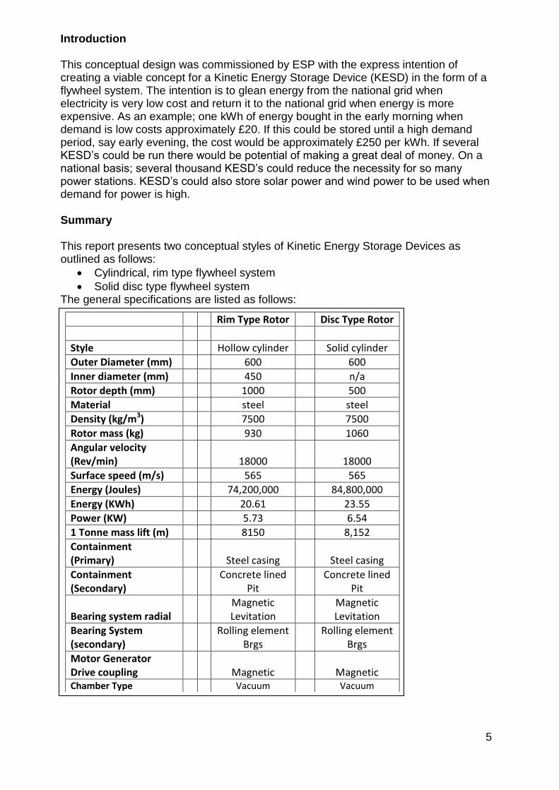
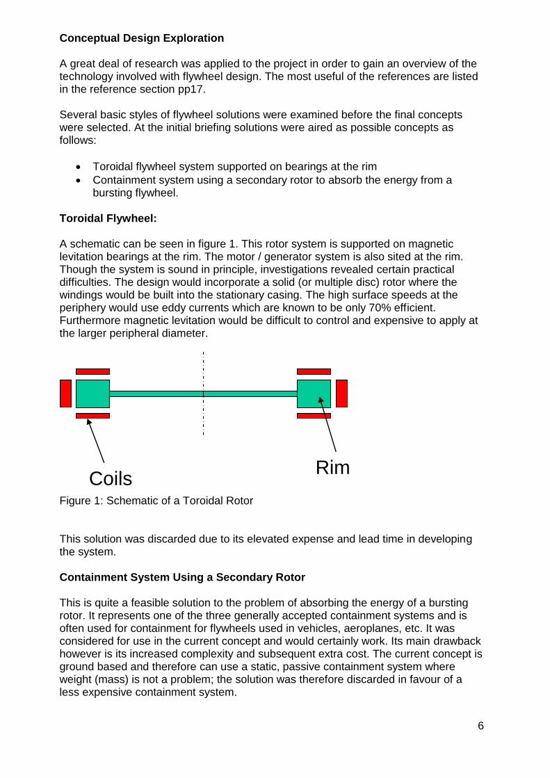
7
The initial approach was to design the system using standard technology with the minimal new technological development It was hoped that this would keep costs down and make manufacturing relatively simple The target specification is outlined below Target Specification and Requirements Research The research revealed that high speed burst was a large problem If the flywheel system disintegrated there would be large pieces of material possessing massive amounts of energy being thrown around Essentially the device would have enough energy to be equivalent to a large bomb if not contained properly Many variations of flywheel have been designed Some of the major research in this area has been in flywheel construction When a flywheel bursts the main danger is from the high velocity chunks of material Much research is being applied to the design of rotors in fibre reinforced resin When these burst they disintegrate into fibrous elements which do not possess any great mass Target Specification The initial target specification was defined through initial research combined with the original specification from ESP Envelope size 1m3 Power rating 20 to 50KWh Efficiency gt 75 Power degradation over 24hrs lt 10 Calendar life 10 years Max sound power level 63dBA Low speed approx 20k revmin Design Approach The analysis shown on the spreadsheets in the appendix was iterated several times for each style of flywheel until optimum sizes were found The analysis revealed some enormous parameters which needed to be carefully considered in the design Furthermore the parameters focussed the design in particular directions An example of this is the surface speed parameter of 565ms This is almost twice the speed of sound and demands some means of reducing the turbulence and noise within the enclosure The progress of the design became an iterative approach where parameters such as diameter mass speed etc were varied until a reasonable output emerged It was difficult to decide on the most appropriate type of flywheel rim type or disc type so a concept of both versions has been proposed
8
Design Considerations and Decisions Flywheel Design Rim Type The rim type flywheel takes the form of a large rotating cylinder The main advantage is that many of the elements which allow the spin eg bearings can be built inside the cylinder creating a more compact overall unit Stresses in the cylinder can be considered to be hoop stresses only rather than radial and hoop stresses as with a solid flywheel Careful consideration needs to be applied to the link between shaft and flywheel since this would be subjected to some high stresses Finite element stress analysis would be used to verify strength The parameters selected for the rim type flywheel are as follows in table 1 The rim type flywheel concept can be seen in figure 2 Table 1 Rim-type Flywheel Concept Specification
Rim Type Rotor
Style Hollow cylinder
Outer Diameter (mm) 600
Inner diameter (mm) 450
Rotor depth (mm) 1000
Material steel
Density (kgm3) 7500
Rotor mass (kg) 930
Angular velocity (Revmin) 18000
Surface speed (ms) 565
Energy (Joules) 74200000
Energy (KWh) 2061
Power (KW) 573
1 Tonne mass lift (m) 8150
Containment (Primary) Steel casing
Containment (Secondary) Concrete lined
Pit
Bearing system radial Magnetic Levitation
Bearing System (secondary) Rolling element
Brgs
Motor Generator Drive coupling Magnetic
Chamber Type Vacuum
9
Figure 2 Proposed Rim Type Flywheel
SHAFT
CASING
UPPER FLANGE
TOP CAP
FLYWHEEL
FLYWHEEL SHAFT SUPPORT
FLYWHEEL SHAFT SUPPORT
RADIAL MAG LEV BEARING
RADIAL MAG LEV BEARING
UPPER AUXILIARY ROLLING
ELEMENT BEARING
BEARING CAP
AXIAL SUPPORT MAG LEV BEARING
LOWER AUXILIARY SUPPORT BEARING
BEARING CAP
SEAL
LOWER CAP
CASING BASE
UPPER CASING FLANGE
SEAL
1260
1000
Oslash600
Oslash464
20
Oslash912
Oslash330
Oslash135
1877
NON-FERROUS PLATE
597
MAGNETIC DRIVE HALF
MAGNETIC DRIVE HALF
MOTOR GENERATOR
FLYWHEEL
AND
HOUSING
UPPER BEARING
LOWER BEARING
MOTOR GEN STATOR
MOTOR GEN ROTOR
MOTOR GEN SHAFT
Oslash440
Oslash640
HOLLOW ROTOR FLYWHEEL SYSTEM
10
Disc Type Flywheel The disc type flywheel takes the form of a solid steel cylinder of dimensions Diameter 600mm x 500mm long Though this is physically smaller than the rim type flywheel the overall package including the casing and motorgenerator set is a little longer This is because the bearings have to be set above and below the rotor rather than inside as with the rim type rotor Radial and hoop stresses are important considerations Hoop stresses are a maximum at the outer rim but radial stresses are a maximum near the centre of the cylinder Consideration therefore is needed when fitting the rotor to the shaft since extra stresses near the centre should be avoided The concept uses a particular method of fixing to the shaft which is hoped will prove to be successful Careful stress analysis needs to be done to ensure that this method or any other selected method will be satisfactory The parameters selected for the disc type flywheel are as follows in table 2 The disc type flywheel concept can be seen in figure 3 Table 2 Disc Type Rotor Specification
Disc Type Rotor
Style Solid cylinder
Outer Diameter (mm) 600
Inner diameter (mm) na
Rotor depth (mm) 500
Material steel
Density (kgm3) 7500
Rotor mass (kg) 1060
Angular velocity (Revmin) 18000
Surface speed (ms) 565
Energy (Joules) 84800000
Energy (KWh) 2355
Power (KW) 654
1 Tonne mass lift (m) 8152
Containment (Primary) Steel casing
Containment (Secondary) Concrete lined Pit
Bearing system radial Magnetic Levitation
Bearing System (secondary) Rolling element
Brgs
Motor Generator Drive coupling Magnetic
Chamber Type Vacuum
11
Figure 3 Proposed Disc Type Flywheel
CASING
UPPER FLANGE
TOP CAP
RADIAL MAG LEV BEARING
UPPER AUXILIARY ROLLING
ELEMENT BEARING
BEARING CAP
AXIAL SUPPORT MAG LEV BEARING
UPPER CASING FLANGE
SEAL
NON-FERROUS PLATE
597
MAGNETIC DRIVE HALF
MAGNETIC DRIVE HALF
MOTOR
GENERATOR
UPPER BEARING
LOWER BEARING
MOTOR GEN STATOR
MOTOR GEN ROTOR
MOTOR GEN SHAFT
Oslash440
Oslash6402028
SHAFT
RADIAL MAG LEV BEARING
LOWER AUXILIARY SUPPORT BEARING
BEARING CAP
SEAL
LOWER CAP
CASING BASE
Oslash912
Oslash330
Oslash740
5001300
Oslash600FIXED SHAFT FLANGE
PRECISION HEADED PIN
REMOVABLE FLANGE
LOCK COLLAR
PRECISION HEADED PIN
FLYWHEEL
SOLID ROTOR FLYWHEEL SYSTEM
12
Primary Bearing System The bearing system is required to hold the rotor in place whilst allowing rotation around 20000 revmin with the minimal frictional resistance Several options were considered Magnetic levitation bearings Rolling element bearings Gas film bearings Fluid film bearings (journal) Gas film bearings require a pressurised gas to be constantly pumped between the shaft and bearing In a vacuum environment this would be inappropriate and the option was discarded Fluid film bearings are essentially oil filled Upon rotation of the journal (shaft) the oil is pulled into the contactsupport area and acts as a cushion Frictional resistance is low but a constant flow of fluid is required requiring shaft seals within the vacuum chamber It was thought that the frictional resistance applied by the seals would create too much drag and reduce efficiency There may also be a problem with heat generation within the fluid at high speeds Magnetic levitation bearings are frictionless and can operate within a vacuum environment Their major disadvantage is that they require a control system and that the magnetic coils require power Research shows however that many KESDrsquos use magnetic levitation as a primary bearing system It was discovered that SKF could produce the magnetic levitation bearings required and also have experience in producing motor generator equipment which could operate at these high speeds SKF provided some very useful data which was used directly in the concept designs They gave approximate sizes of bearing units and suggested how the layout should be applied Beacon power is a company in the United states for which SKF have previously designed such bearings Please see their web site wwwbeaconpowercom A typical radial Magnetic Levitation Bearing can be seen in figure 4 Figure 4 Typical Radial Magnetic Levitation Bearing
13
The axial bearings should be sited at the top of the housing The magnetic flux applied is attractive allowing the rotor to hang from the bearing This arrangement can be seen in both figures 2 and figure 3 Secondary Bearing System It is evident from the research and from advice given by SKF that there needs to be a secondary bearing back-up system This is necessary should power fail to the magnetic levitation bearings SKF recommended high speed ball bearings for this particular role These bearings would function as radial and axial bearings Figure 5 shows typical ball bearings The application can be seen in the concept designs in figures 2 and 3
Figure 5 Typical Ball Bearings Containment The containment system has to be applied to two aspects of the design containment of the vacuum and containment of a bursting flywheel There are several approaches to containment of a bursting flywheel
Brute force approach using heavy-walled pressure vessels
Spinning ring which soaks up the energy of the impacting flywheel debris
Energy absorbing liner The soft catch approach The containment system requires design effort to be applied When the flywheel is at running speed a great deal of energy is contained This energy is enough to vertically lift a 1 tonne mass 81 km Put another way there is energy contained in the flywheel equivalent to 18kg (40lbs) of TNT Generally it is thought that a combined approach might be the way forward This would entail a light casing to contain the vacuum and a heavier casing such as a concrete perhaps below ground vessel to contain any flywheel burst This chamber might also incorporate some form of soft catch energy absorbing system which could take the form of sand or pea gravel filled chambers which break thus allowing the contents to infiltrate the chamber when a burst occurs The current concept uses segmental sand bags set inside the concrete basin If the bursting flywheel breaches the vacuum casing the sand bags will disintegrate allowing the sand to absorb the debris The concrete casing will act as final resort containment Please see figure 6 for a 3D impression of the containment Many current flywheels merely incorporate the brute force approach where a heavy casing is combined with a vacuum chamber In the case of a burst a great deal of
14
energy needs to be contained so any such casing needs to be very firm and should be mounted on heavy foundations Figure 6 Impression of the Segmental Sandbag and Concrete Containment System Motor Generator Set The motor Generator set drives the flywheel up to speed during energy input and converts rotational energy into electrical energy during energy extraction Due to the high speeds this is quite a special arrangement and requires specialist design attention SKF are able to provide the design expertise and design a suitable MG set to suit the specific design needs of the project Typical components can be seen in figure 7
Figure 7 Typical Motor Generator Components Control Equipment The magnetic levitation bearings could become unstable unless constantly monitored and controlled The service incorporates appropriate matching and supply of monitoring and control equipment Figures 8 and 9 show typical control and monitoring devices
15
Figures 8 and 9 Typical Control and Monitoring Devices Machine Monitoring Within the package SKF also offer machine monitoring software which takes input from several sensors to relay the information to a monitoring station This information could include rotational speed out of balance detection temperature energy input efficiency energy extraction efficiency etc
Figure 10 Machine monitoring Software Magnetic Drive Coupling The modular design of the KESD separates the motorgenerator from the vacuum chamber of the flywheel Normal engineering practice would incorporate lip seals to contain the vacuum but the seals would be in contact with the shaft causing frictional resistance and heat generation Ceramic seals would be required The better solution would be to use a magnetic drive coupling This is a non-contacting coupling which transfers magnetic flux through a non-magnetic membrane thus allowing drive to be applied between the two halves of the coupling One half would be situated inside the vacuum chamber the other half inside the motor generator chamber A typical magnetic drive coupling can be seen in figure 11
Figure 11 Typical Magnetic Drive Coupling
16
Electrical Aspects Design and Analysis SKF are the current specialist source of magnetic levitation bearings There are other companies who can offer this service however SKF have been the most informative and helpful They not only offer a full manufacture and design service but they also offer all the ancillary equipment needed to operate and maintain the system Elements for the system are listed as follows
Design and manufacture service for magnetic levitation bearings
Radial magnetic levitation bearings
Axial magnetic levitation bearings
Control system for magnetic levitation bearings
Machine monitoring system
Design and manufacture service for motor generator set
Control system for the motor generator set Incorporated in the total package is a high performance finite element predictive analysis tool for magnetic levitation applications Conclusions and Recommendations The proposed designs show the format of both a rim type flywheel system and also a solid (disc type) flywheel system The sizes of the rotors are generally correct though other aspects of the design are approximate It should be noted however that during the process of conversion from concept to detailed manufacturable units many of the details may change There are many technical design details which require careful consideration such as methods of balancing the rotors and stress analysis of the rotors and frame Below is a basic list of work to be accomplished before a flywheel system can be manufactured Further Work Required to Progress the Project
Finite element stress analysis vacuum chamber
MagLev radial bearing design
MagLev axial bearing design
Control system for magnetic levitation bearings
Machine monitoring system
Design and manufacture of motor generator set
Control system for the motor generator set
Stress analysis of rotors for burst limitation
Fluid flow analysis within the chamber
Vacuum pump and equipment selection
Rolling element bearing design and selection
Vacuum Casing design
Explosion containment system design
Foundations design
Selection of materials There are two concepts put forward each with its own advantages and disadvantages There needs to be a selection of either version so that detailed work can commence
17
Both concept designs fit most of the initial criteria During the detail design process some of these may need to change to accommodate more precise constraints for use or perhaps to accommodate physical parameters thrown up by the development process The concept specifications are as follows in table 3 Industrial Concept The KESD system has been designed for an industrial application where banks of KESDrsquos can be housed The appendix shows several 3D pictures which indicate scale and the probable industrial setting The soft-catch and concrete containment system is also shown Table 3 Concept Specifications for the ESP Kinetic Energy Storage Device
Rim Type Rotor Disc Type Rotor
Style Hollow cylinder Solid cylinder
Outer Diameter (mm) 600 600
Inner Diameter (mm) 450 na
Rotor depth (mm) 1000 500
Material steel steel
Density (kgm3) 7500 7500
Rotor Mass (kg) 930 1060
Angular velocity (Revmin) 18000 18000
Surface Speed (ms) 565 565
Energy (Joules) 74200000 84800000
Energy (kWh) 2061 2355
Power (kW) 573 654
1 Tonne mass lift (m) 8150 8152
Containment (Primary) Steel casing Steel casing
Containment (Secondary) Concrete lined Pit Concrete lined Pit
Bearing System Radial Magnetic Levitation Magnetic Levitation
Bearing System (secondary) Rolling element
Bearings Rolling element
Bearings
Motor Generator Drive Coupling Magnetic Magnetic
Chamber Type Vacuum Vacuum
18
Rotor Selection There is little to choose between the two types of rotor The list of differing parameters is as follows Rim Type Disc Type - Lower mass 930kg - Higher mass 1060kg - Height overall 1877mm - Overall height 2028mm - Energy 2061 kWh - Energy 2355 kWh - Power 573 kW - Power 654 kW - Stresses in rim only - Radial and Hoop stresses present (Less prone to burst)
bull Design and manufacturing will present a similar level of difficulty bull Balancing relatively easier with the rim-type flywheel due to increased length bull Cost implications will be similar for each type
19
References
Many references were consulted These were a mixture of both technical papers and company data The following is a list of the most useful references
SKF Website wwwskfcom
Beacon Power wwwbeaconpowercom
Flywheel Energy Storage System California Energy Commission 2004
Compact Flywheel Energy Storage System Koyo Seiko Company
Flywheel Energy Storage Riello-UPS wwwriello-Upscouk
Flywheel energy and Power Storage Systems Boland Bernhoff and Leijon 2004
Energy Storage Flywheel System with SMB and PMB and its Performances Mitsuda Komori Subkhan and Inoue 2009
Designing Safer Flywheels Steven Ashley Test devices inc wwwtestdevicescom
Murakami m (2007) japan Title design of an energy storage flywheel system using permanent magnet bearing and superconducting magnetic bearings
Seong-yeol yoo (2009) korea Title design of magnetically levitated rotors in a large flywheel
Werfel (2008) Germany (german e-on) Title 250kW Flywheel with HTS Magnetic Bearing for Industrial use
Bjorn Bolund (2005) sweden Title Flywheel energy and power storage systems
Read T Doucette (2011) OXFORD Engineering Science department UK 201011 Title A comparison of high speed flywheels batteries and ultracapasitors and the bases of cost and fuel
T H Sung (2011) Korea Title Flywheel energy storage system with a horizontal axle mounted on high Tc superconductor bearings
20
Appendix -1
a) Flywheel Characteristics Iteration Spreadsheets Flywheel Characteristics Disc Type Rotor
Note Speed of Sound = 3432ms
Dia Radius Depth Density Volume mass Ang Vel Ang Vel Surface Moment KE KE Power 1 tonne Rim
m m m kgm^3 m^3 kg RPM radsec Speed of Inertia Joules KWh KW Mass lift Stress
Ms kgm^2 m Nm^2
020 010 080 750000 003 18852 3000000 314200 31420 094 4652751 129 036 251584 4056795
030 015 070 750000 005 37115 2000000 209467 31420 418 9160103 254 071 251584 4056795
030 015 070 750000 005 37115 3000000 314200 47130 418 20610232 573 159 566064 9127789
040 020 070 750000 009 65982 2000000 209467 41893 1320 28950450 804 223 447261 7212080
050 025 070 750000 014 103097 2000000 209467 52367 3222 70679810 1963 545 698845 11268876
060 030 070 750000 020 148460 2000000 209467 62840 6681 146561653 4071 1131 1006337 16227181
060 030 060 750000 017 127251 2000000 209467 62840 5726 125624274 3490 969 1006337 16227181
060 030 050 750000 014 106043 2000000 209467 62840 4772 104686895 2908 808 1006337 16227181
060 030 040 750000 011 84834 2000000 209467 62840 3818 83749516 2326 646 1006337 16227181
070 035 030 750000 012 86601 2000000 209467 73313 5304 116367238 3232 898 1369736 22086996
070 035 020 750000 008 57734 2000000 209467 73313 3536 77578159 2155 599 1369736 22086996
080 040 020 750000 010 75408 2000000 209467 83787 6033 132344914 3676 1021 1789043 28848322
000 750000 000 000 000 000 000 0 000 000 DIV0 0
050 025 035 750000 007 51548 3000000 314200 78550 1611 79514786 2209 614 1572401 25354970
060 030 020 750000 006 42417 3000000 314200 94260 1909 94218206 2617 727 2264258 36511157
000 750000 000 000 000 000 000 0 000 000 DIV0 0
070 035 021 750000 008 60621 2000000 209467 73313 3713 81457067 2263 629 1369736 22086996
060 030 021 750000 006 44538 2000000 209467 62840 2004 43968496 1221 339 1006337 16227181
050 025 020 750000 004 29456 3000000 314200 78550 921 45437020 1262 351 1572401 25354970
000 750000 000 000 000 000 000 0 000 000 DIV0 0
000 750000 000 000 000 000 000 0 000 000 DIV0 0
060 030 050 750000 014 106043 1800000 188520 56556 4772 84796385 2355 654 815133 13144017
060 030 050 750000 014 106043 1200000 125680 37704 4772 37687282 1047 291 362281 5841785 Flywheel Characteristics Rim Type Rotor
Note Speed of Sound = 3432ms
Ou
ter
Dia
(m)
Ou
ter
Rad
(m)
Inn
er
Dia
(m
)
Inn
er
Rad
(m)
De
pth
(m
)
De
nsi
ty
(kg
m^
3)
Vo
lum
e
(m^
3)
mas
s (k
g)
An
g V
el
(Re
vm
in)
An
g V
el
Surf
ace
Spe
ed
(m
s)
Mo
me
nt
of
Ine
rtia
kgm
^2
KE
(Jo
ule
s)
KE
(KW
h)
Po
we
r (K
W)
1 t
on
ne
Mas
s
Lift
(m
)
Rim
Str
ess
(Nm
^2
)050 025 012 006 080 750000 015 111038 15000 1571 39275 3470 42819848 1189 330 393100 6338743
06 030 015 008 05 750000 013 99415 18000 1885 56556 4474 79496611 2208 613 815133 13144017
06 030 015 008 04 750000 011 79532 18000 1885 56556 3579 63597289 1767 491 815133 13144017
06 030 015 008 03 750000 008 59649 18000 1885 56556 2684 47697967 1325 368 815133 13144017
05 025 015 008 07 750000 013 93818 18000 1885 47130 2932 52098088 1447 402 566064 9127789
04 020 015 008 08 750000 009 64804 18000 1885 37704 1296 23031117 640 178 362281 5841785
05 025 015 008 06 750000 011 80416 18000 1885 47130 2513 44655504 1240 345 566064 9127789
05 025 015 008 065 750000 012 87117 18000 1885 47130 2722 48376796 1344 373 566064 9127789
055 028 022 011 07 750000 014 104788 18000 1885 51843 3962 70409363 1956 543 684938 11044625
06 030 022 011 05 750000 012 91786 18000 1885 56556 4130 73395982 2039 566 815133 13144017
06 030 045 023 1 750000 012 92787 18000 1885 56556 4175 74196837 2061 573 815133 13144017
21
b) Concept Renderings Figure 12 Single containment basin showing lid and control cabinet Figure 13 Impression of the industrial Application (Lids removed) Figure 14 Impression showing the Soft-Catch Segmental Sand Bags
22
Figure 15 Impression Showing Scale Figure 16 Renderings of the Proposed KESD (Hollow Flywheel Version)
Figure 17 Renderings of the Proposed KESD (Solid Flywheel Version)
23
Phase 2 Stage 2 of the Flywheel project (9May2011 till now)
The crucial elements to a successful design were considered to be the bearings radial and axial and the rotor stresses Once these elements were finalised then the rest of the KESD could be designed to suit Use of Bearings was investigated whilst finite element analysis was performed on the proposed rotor designs this is where other specialist team members included in the research team Additional team members joining to the research team Dr Simon Barrans (SMB) Specialism Stress Analyst Duties Analyse the stresses in the rotor and define materials rotor speeds and rotor shape according to safe stressing Mark Dales (MD) Specialism High current Electrical Engineer Duties Specify the motor Generator equipment and designprocure all other electrical elements Prof Rakesh Mishra (RM) Specialism Thermo-fluid behaviour and CFD techniques Duties Analyse the air flow around the rotor and determine the fluid drag Design Evolution from Concept 1 Concept 1 explained in phase 1 was devised after extensive research of current models and practices It was discovered that the original application of capturing cheap energy and selling it back to the grid at a higher cost is very feasible Furthermore peak demand smoothing is possible and indeed is the very reason for the building of several large flywheel installations throughout the world The kinetic storage of electrical energy possesses other benefits to emerging industries such as the electric car industry Here recharging stations will be required and may possibly have kinetic energy storage The conclusion is therefore that research revealed a very viable market which is demanding some form of energy storage Kinetic Energy Storage devices could easily fill that demand Concept stage 1 was effectively a feasibility study of current technologies and the possibility of using these technologies to create a kinetic energy storage device (KESD) A feasibility report was presented to the board of ESP Ltd who then agreed to the project progressing to the phase 2 The main thrust of the design was that it should follow standard engineering techniques in order to Reduce time to market Reduce the development time Reduce development costs Ensure low cost manufacture Ensure sustainability issues were minimised
24
Bearings Up to the point of the presentation in May 2011 of the feasibility report the team had been liaising with SKF who had been very helpful in providing guidance for the magnetic-levitation bearings used in Concept 1 The bearings needed development though SKF had previously provided similar bearings to the Beacon Project which is a similar facility based in California As soon as SKF understood the need for development work they lost interest saying they were overstretched and could not pursue the project Another company Mecos of Switzerland was approached who could provide the necessary magnetic levitation units They were very enthusiastic but required pound100000 to be deposited before development could begin This clearly excluded them from the development Two other companies were approached with no success Stress Analysis Whilst the bearing search was being conducted SMB had been pursuing the stress analysis on the rotor and reported that a high carbon steel rotor with a speed of 18000 revmin would burst long before it reached the operation speed The data below in table 3 shows the rotor size possibilities related to material stress Table 3 Rotor Size Possibilities for Solid Rotors at 7000 revmin The table above indicates the radius of the flywheel and the stress that flywheel would see in service The moment of inertia and the height of the rotor are important since they are essential properties in the storage of kinetic energy In general a larger Inertia value will store a larger value of kinetic energy but an increase in speed will increase the kinetic energy storage capacity in terms of speed squared Basic Equation for Kinetic Energy is as follows
KE = 1 I2 2 Where I = Moment of Inertia (kgm2)
= Angular velocity (radsec) It can be seen from the first line of table 3 that a rotor of radius 04m (800mm diameter) with a height of 0913m (913mm) will have a moment of inertia of
Ou
ter
Rad
ius
Ro
(m
)
Radial Stress(MNm2) at centre
Mo
men
t o
f in
erti
ah
eigh
t
Hei
ght
(m)
req
uir
ed t
o
give
re
qu
ired
en
ergy
at
rate
d s
pee
d
Is design possible
04 2686726 3016E+02 0913 Y
045 3400387 4831E+02 0570 Y
05 4198009 7363E+02 0374 Y
25
3016 x 10-2 kgm2 Importantly the radial stress in the rotor is 26867 MNm2 which is approximately half of the envisaged ultimate tensile strength of the rotor material medium carbon steel This will give a safety factor of slightly under 20 The conclusion from this analysis is that the original target of 18000 revmin for a solid rotor cannot be achieved using steel or one of its alloys The analysis shows that the speed needs to be substantially reduced to a maximum of 7000 revmin Design Concept 2 Evolving to Concepts 3 and 4 The revelation that the rotor stresses had forced the angular velocity down to 7000 revmin from 18000 revmin helped to continue the theme of using standard engineering components and techniques since high speed radial rolling element bearings could now be considered and separate thrust bearings The negative side to reducing the speed was that the rotor mass had to be increased to approximately 3 tonnes in order to increase the moment of inertia The reduction in speed also meant that expensive active magnetic-levitation bearings could be discarded though it seemed reasonable to support the 3 tonnes mass of the vertical axially mounted rotor on permanent magnet thrust bearings Figure 15 shows the concept Figure 15 Concept 2 Solid Rotor with Permanent Magnet Bearings and Hybrid Ceramic Radial Bearings
UPPER FLANGE
TOP CAP
BEARING CAP
UPPER CASING FLANGE
SEAL
NON-FERROUS PLATE
597 MAGNETIC DRIVE HALF
MAGNETIC DRIVE HALF
MOTOR
GENERATOR
UPPER BEARING
LOWER BEARING
MOTOR GEN STATOR
MOTOR GEN ROTOR
MOTOR GEN SHAFT
Oslash440
Oslash640
UPPER FLANGE
UPPER HIGH SPEED ROLLING
ELEMENT BEARING
GOOD SLIDING FIT ON
OUTER RACE
UPPER CASING FLANGE
SEAL
ROTOR
AXIAL SUPPORT PASSIVE
REPULSING MAGNETS (ROTOR)
AXIAL SUPPORT PASSIVE
REPULSING MAGNETS (BASE)
CASING
LOWER HIGH SPEED
ROLLING ELEMENT BEARING
GOOD SLIDING FIT ON
OUTER RACE
1880
1218
Oslash900
26
Radial Bearings Several bearing companies were contacted with a specification for radial bearings of 7000 Revmin 100mm bore Radial loads of 15KN Radial loads were evaluated by calculating the residual out-of-balance as directed by ISO 19401 Balancing Quality Requirements for Rigid Rotors Bearing loads were then calculated for a particular bearing diameter Bearing companies contacted were as follows Barden UK (Part of the Schaeffler group) SKF Luton NSK UK Each company suggested that the duty could be accommodated using a hybrid bearing of ceramic ball bearings and a high alloy steel race In order to increase long life several lubrication strategies were suggested
Grease packed
Oil lubrication (automatic injection)
A five year maintenance plan
Live wear monitoring Uniformly Stressed Rotor Results During the search for appropriate bearings SMB was conducting stress analysis on the rotor The start point for the analysis was the solid rotor in Concept 2 with a speed of 7000 revmin The necessity to increase moment of inertia and reduce the radial stresses which were so high near the rotor axis drove the rotor shape to that of a rim-type flywheel Concept 3 shows the KESD with the new shape rotor See figure 16
27
Figure 16 Concept 3 KESD Showing Rim Type Flywheel as a Uniformly Stressed Rotor
UPPER FLANGE
TOP CAP
UPPER HIGH SPEED ROLLING
ELEMENT BEARING
GOOD SLIDING FIT ON
OUTER RACE
BEARING CAP
UPPER CASING FLANGE
SEAL
NON-FERROUS PLATE
597
MAGNETIC DRIVE HALF
MAGNETIC DRIVE HALF
MOTOR
GENERATOR
UPPER BEARING
LOWER BEARING
MOTOR GEN STATOR
MOTOR GEN ROTOR
MOTOR GEN SHAFT
Oslash440
Oslash640
ROTOR
AXIAL SUPPORT PASSIVE
REPULSING MAGNETS (ROTOR)
AXIAL SUPPORT PASSIVE
REPULSING MAGNETS (BASE)
CASING
LOWER HIGH SPEED
ROLLING ELEMENT BEARING
GOOD SLIDING FIT ON
OUTER RACE
1692
1030
28
Figure 17 Concept 4 Inboard Configuration of Permanent Magnet Thrust Bearing Permanent Magnet Thrust Bearings Since the axis of the rotor was vertical it seemed reasonable to support the 3 tonnes axial load on a separate thrust bearing The obvious choice was to use rolling element thrust bearings but it was considered that other low friction axial bearing alternatives should be investigated Air bearings were considered but since the unit was destined to run in a vacuum the continual leakage of air from the bearings in to the vacuum chamber would destroy the vacuum Air bearings were therefore ruled out of the design
UPPER HIGH SPEED ROLLING
ELEMENT BEARING
GOOD SLIDING FIT ON
OUTER RACE
BEARING CAP
UPPER CASING FLANGE
SEAL
EXTERNAL RADIAL MAGNETIC DRIVE HALF
INTERNAL RADIAL MAGNETIC DRIVE HALF
MOTOR
GENERATOR
UPPER HIGH SPEED BEARING
LOWER BEARING
MOTOR GEN STATOR
MOTOR GEN ROTOR
MOTOR GEN SHAFT
Oslash440
Oslash640
ROTOR
AXIAL SUPPORT PASSIVE
REPULSING MAGNETS (ROTOR)
AXIAL SUPPORT PASSIVE
REPULSING MAGNETS (BASE)
CASING
LOWER HIGH SPEED
ROLLING ELEMENT BEARING
GOOD SLIDING FIT ON
OUTER RACE
1030
702
1733
Oslash1212
Oslash400
Oslash180
Oslash110
Oslash900
700
29
The company that ESP Ltd had proposed as manufacturers JPS Ltd based in the Wirral suggested permanent magnet thrust bearings as axial thrust bearings They had previously conducted some ad-hoc experiments but had no real data to offer Manufacturers of permanent magnets were contacted to ascertain strengths costs etc Research was also conducted as to best methods of application and installation of permanent magnets High strength magnets are manufactured from neodymium Since the rotor was to be supported by permanent magnets the flywheel rim edges were proposed as bearing points Consideration was given to the shape of the magnets Cylindrical magnets were an obvious choice but research showed that heat would be generated as rotor mounted magnets passed over base mounted magnets It soon became clear that specially shaped magnets would be required to reduce the number of ldquoedgesrdquo within the magnetic flux and hence reduce the generated heat Manufacturing shaped magnets offered several options The thrust bearing could be applied as in Concept 3 figure 16 or perhaps as in Concept 4 see figure 17 This particular configuration was devised after a quote from Best Solution Consultancy Ltd who quoted a repulsing magnet outer diameter of 540mm and an inner diameter of 160mm with a magnet thickness of 40mm The material would be neodymium rare earth This high strength high cost sintered magnet offered several benefits
Reasonable gap between thrust plates of approximately 5mm
Able to support 3 tonne mass
Zero friction (no Contact)
Zero maintenance There were however several negatives
Very High cost (approx pound28000 per bearing)
Requirement to magnetise at the assembly site
Requirement for mechanical handling equipment to enable unpacking and assembly (due to inherent attractive forces)
High cost of ancillary equipment Due to the high cost of the magnetic bearing material and the anticipated high cost of the handling equipment and other ancillary equipment it was decided that though an exceedingly viable technical option the costs were prohibitive The use of permanent magnet thrust bearings was discarded in favour of more traditional bearings such as rolling element thrust bearings
30
Concept 5 The specification for the rotor was as follows
Rotor mass 3000kg
Rotor speed 7000 revmin
Vertical axis Investigations into rolling element thrust bearings quickly revealed that even hybrid ceramic bearings would be hard pressed to support 3000kg running at 7000 revmin A quote from one of the bearing manufacturers SKF UK Ltd suggested that such a bearing would match their ACDHC super precision angular contact hybrid bearing (ceramic balls) This would need to be lubricated with an oil-air (spray) system Unfortunately this bearing system would only have a predicted life of 284 hours This was the best bearing SKF could offer Other companies offered similar bearings They suggested that the heavy load and the rotation speed were the main problems It was evident that the rotor required redesigning to fulfil the design brief of storing 20KWh but with a much lower mass and a lower speed Since the uniformly stressed rotor was essentially a rim type rotor analysis was conducted for a rim type flywheel with a spoke and shaft system to be added later within the stress analysis exercise Revisiting the basic Kinetic Energy equation it was discovered that there were several variables which could be manipulated as follows
KE = 1 I2 2 Where I = Moment of Inertia (kgm2)
= Angular velocity (radsec) But I = mk2 Where m = mass (kg) and k = radius of gyration (m) giving
KE = 1 mk22 2 Or
KE = 1 m(R2 + R1)22
2 (2)2 Where R1 = outer radius (m) R2 = inner radius (m)
31
From analysis of basic flywheel characteristics see appendix the kinetic energy to deliver 20KWh is 725MJ For analysis purposes this value was fixed as well as the aim of a notional 1500kg for the rotor mass The four variables were therefore R1 = outer radius (m) R2 = inner radius (m) Rotor depth (m)
= angular velocity (radsec)
A spreadsheet tool was used to vary the parameters which are shown in table 4 below Table 4 Spreadsheet Analysis tool to Vary Flywheel Parameters
During the iteration process the outer diameter was fixed and the depth and the inner radius was varied The angular velocity was also varied to achieve the kinetic energy value of approximately 73MJ The rotor of 22m OD 20m ID 03m depth emerged as an excellent choice having a mass of only 1485kg and a KE of 788MJ The rotor of 20m OD 17m ID 025m depth was a little heavier at 1635kg but was smaller in outer diameter This was desirable since a smaller outer diameter would mean an overall smaller unit In comparison there is not much to choose between either of the rotors The rotor of 18m OD 16m ID 04m depth emerged as the best of the 18 diameter rotors but was lacking in the value of kinetic energy storage at only KE of 579MJ This size of rotor was clearly inferior to the 20m and 22m diameter rotors
Ou
ter
Dia
(m
)
Ou
ter
Rad
(m
)
Inn
er D
ia (
m)
Inn
er R
ad (
m)
De
pth
(m
)
De
nsi
ty
(kg
m^3
)
Vo
lum
e (
m^3
)
mas
s (k
g)
An
g V
el
(Re
vm
in)
An
g V
el
(rad
sec
)
Surf
ace
Spee
d
(ms
)
Mo
me
nt
of
Iner
tia
kgm
^2
KE
(Jo
ule
s)
KE
(KW
h)
18 090 14 070 02 7500 020 1508 4000 419 377 611 53599690 1489
18 090 15 075 025 7500 019 1458 4000 419 377 591 51820013 1439
18 090 16 080 04 7500 021 1602 4000 419 377 649 56949671 1582
2 100 16 080 02 7500 023 1697 3000 314 314 848 41874758 1163
2 100 16 080 025 7500 028 2121 3000 314 314 1060 52343448 1454
2 100 17 085 025 7500 022 1635 4000 419 419 817 71729910 1992
2 100 175 088 03 7500 022 1657 4000 419 419 828 72699233 2019
2 100 18 090 036 7500 021 1612 4000 419 419 806 70721814 1964
22 110 18 090 02 7500 025 1885 3000 314 346 1141 56298286 1564
22 110 19 095 025 7500 024 1812 3000 314 346 1096 54099134 1503
22 110 2 100 03 7500 020 1485 4000 419 461 898 78817600 2189
32
Shown in figure 18 is the rim type rotor which was used to base the analysis whose results are displayed in table 4 Please note that for analysis purposes the spokes and shaft have been omitted being relatively insignificant compared to the rim of the rotor Figure 18 Rim of Flywheel as Calculated for 20m Device Figure 19 Concept 5 Rim Type Flywheel
Concept 5 is shown in Figure 19 The rotor has a diameter of 20 m and is hollow to reduce weight and hence bearing load It was intended that the hollow halves of the rotor would be machined separately and joined using industrial adhesive The key turned in to the joint at the rim would key the two halves and allow them to expand radially as one component when rotating at speed Concept 6 Intensive stress analysis revealed that the use of normally available engineering materials provided severe restrictions on the shape speed and size of the flywheel Furthermore the variables hitherto used were complicated to juggle to obtain the
LOWER HIGH SPEED
ROLLING ELEMENT BEARING
GOOD SLIDING FIT ON
OUTER RACE
UPPER FLANGE
TOP CAP
UPPER HIGH SPEED ROLLING
ELEMENT BEARING
GOOD SLIDING FIT ON
OUTER RACE
UPPER CASING FLANGE
SEAL
NON-FERROUS PLATE
ROTOR
CASING
BEARING CAP
NON-FERROUS PLATE
597
MAGNETIC DRIVE HALF
MAGNETIC DRIVE HALF
MOTOR
GENERATOR
UPPER BEARING
LOWER BEARING
MOTOR GEN STATOR
MOTOR GEN ROTOR
MOTOR GEN SHAFT
Oslash440
Oslash640
ROLLING ELEMENT CERAMIC
THRUST BEARING
Oslash2000
12
83
Oslash2500
33
correct rotor format Research revealed that energy density was a comparative parameter that would give the optimum energy capacity for various rotor shapes Energy Density Further research [16] led the design in the direction of using ldquoEnergy Densityrdquo as a useful factor in identifying the most appropriate flywheel shape as explained below Energy density is essentially the value of energy in Joules per kg mass of rotor Energy Density = joules Kg
KE = 1 x I x 2 helliphelliphelliphelliphelliphelliphelliphelliphellip1
2
KE = m x r2 x 2 helliphelliphelliphelliphelliphelliphelliphelliphellip2
2 where KE = Kinetic Energy (Joules)
I = polar 2nd moment of Inertia (kgm2) I = m x r2 m = mass (kg) r = mean radius (m)
= angular velocity (radsec)
From equation 2 it can be seen that a reduction in angular velocity must be
compensated by an increase in radius r Another parameter which is useful to consider is that of ldquoenergy densityrdquo and is shown below From equation 2
KE = m x r2 x 2 helliphelliphelliphelliphelliphelliphelliphelliphellip2
2 Divide both sides by mass m
KE = m x r2 x 2 helliphelliphelliphelliphelliphelliphelliphelliphellip3
m m 2 giving
KE = r2 x 2 helliphelliphelliphelliphelliphelliphelliphelliphellip4
m 2 or Energy Density This parameter allows comparison between flywheel shapes The new task then was to arrange the flywheel shape to give a large value of energy (Joules) for each kg of rotor mass
34
The use of Energy Density quickly showed that the best shape for a rotor system was not a rim type flywheel or a cylindrical flywheel but a tapered rotor section as shown in figure 20 Figure 20 Concept 6 Tapered disc
Stress analysis revealed that the major stresses were radial and imposed high stresses near the shaft Essentially centrifugal forces tend to pull the flywheel material away from the shaft
Figure 21 Finite Element Stress Analyses Showing a Small Disc Segment by Dr Simon Barrans The diagram shown in figure 21 shows a small disc segment rotated at 500radsec (4776 revmin) The disc shows stresses 237MNm2 in the blue area at the outside of the disc and 463 MNm2 at the centre Should high strength materials be used these stresses are not particularly excessive and show clearly where the highest stresses are likely to occur which is towards the centre where the disc joins the shaft The next step was to attach the disc to the shaft in order to determine stresses at the joint of the disc and the shaft The analytical diagram is shown in figure 22 Figure 22 Analytical Segment Showing High Stress at Discshaft Junction by Dr Simon Barrans
LOWER HIGH SPEED
ROLLING ELEMENT BEARING
GOOD SLIDING FIT ON
OUTER RACE
ROTOR
ROLLING ELEMENT CERAMIC
THRUST BEARING
Oslash2000
Small segment analysed
Plain disc stress not uniform
Disc is not infinite
Full disc moment of inertia 484 kgm2
Disc outer diameter 24m
Central thickness 100mm
Edge load applied to give uniform stress
Fillet radius generates significant stress raiser
Disc Diameter 09m
35
The concept 6 design emerged as a constant stress device which took the form of a tapered cross section fatter nearer the shaft and tapering to the outside edge The surface however has been curved to enable constant stress across the section The whole concept can be seen in figure 23 Concept 6 parameters are as follows Outer radius 10 m Outer Diameter 20 m Thickness on central axis 110 mm (plus stub shafts to mate with the bearings) Thickness on outer rim 35 mm Mass 12 to 15 tonnes Speed 3650 to 4000 rpm Energy storage 40 to 54 MJ Figure 23 Concept 6 Uniformly Stressed Rotor Design
Bearing Selection Various bearing manufacturers were contacted requesting quotations and a specification of bearing Since the bearings required were off standard and therefore required specialist selection procedures the bearing companies were relied upon to specify bearings which could contend with the following parameters Working speed 4000 revmin Test speed 7000revmin Rotor mass 2000kg Life 10 years HB Bearings LTD of Honley West Yorkshire are specialist bearing manufacturers They declined to quote a price since the bearings could be purchased off the shelf from some of the large bearing manufacturing companies as is outlined below They did however assist greatly in specifying bearing types as follows Radial Bearings
UPPER FLANGE
TOP CAP
UPPER HIGH SPEED ROLLING
ELEMENT BEARING
GOOD SLIDING FIT ON
OUTER RACE
UPPER CASING FLANGE
SEAL
NON-FERROUS PLATE
ROTOR
CASING
BEARING CAP
NON-FERROUS PLATE
59
7
MAGNETIC DRIVE HALF
MAGNETIC DRIVE HALF
MOTOR
GENERATOR
UPPER BEARING
LOWER BEARING
MOTOR GEN STATOR
MOTOR GEN ROTOR
MOTOR GEN SHAFT
Oslash440
Oslash640
ROLLING ELEMENT CERAMIC
THRUST BEARING
Oslash2000
12
83
Oslash2500
LOWER HIGH SPEED
ROLLING ELEMENT BEARING
GOOD SLIDING FIT ON
OUTER RACE
36
Hybrid type angular contact bearing at 15deg - 25deg angle of contact
Oslash 100mm x Oslash 150mm x 24mm
To P4 run out and dimensional tolerances
Obtainable as sealed or not sealed
Commercially available bearing from SKF FAG NSKRHP Thrust Bearing This posed a challenge with the high running speed required since a bearing of a similar size to the radial bearings would not have the thrust capability to operate at the required speed To be able to run at the required speed a smaller bearing needs to be considered This would reduce the linear speed of the balls within the bearing The specification suggested follows
Hybrid type ball bearing at
Oslash 50mm x Oslash 70mm x 14mm single row ball thrust bearing
Load ratings of Ca 27 KN and Coa 75KN
Working speeds of 4300 revmin maximum
Test speed 6300 revmin limiting speed Further research and engineering analysis have been currently carried out b Engineering staff especially vacuum fluid dynamics air resistance stability friction and vibration and noise Conclusion and further plan In this report an overview of advanced flywheel feasibility study is presented in the phase one This report covered the literature review competitive products on the market and the concept development of two alternative products with basic calculations After presenting this report in May 2011 to ESP directors and managers the team visited manufacturing facility of ESP near Liverpool and ESP decided to fund the development of two prototypes and raise further funding which is handled by the Research amp Enterprise Centre of the University The team then continued to further engineering design calculation manufacturing details optimisation cost of off the shelf external parts design and detailing of the new parts to be built And further discussion taken place with the manufacturers of the standard parts This process was very useful as it revealed that due to the required final cost of the KESD set by ESP ltd further design changes was necessary as the companies initially approached could not deliver the required spec parts therefore further calculation and design iterations required At this point team also extended to include Dr Simon Barrans who calculated stress on the rotor and material specification Then Mark Dales from Electrical Engineering started on electric motor generator specification which is still on going Also Prof Rakesh Mishra agreed and will be calculating and advising on the rotor air frictions who specialise on Thermo-fluid behaviour and CFD techniques when the final decision is made The next phase of the project is to start purchasing off the shelf parts an also manufacturing and testing which we require to use manufacturing facilities of ESP The research team appreciate Dr Simon Barrans (SMB) on the his expert advice on the analysis of the stresses in the rotor materials shape and specifications so far
37
Appendix 2 Flywheel Characteristics Iteration Spreadsheets Flywheel Characteristics Disc Type Rotor
Note Speed of Sound = 3432ms
Dia Radius Depth Density Volume mass Ang Vel Ang Vel Surface Moment KE KE Power 1 tonne Rim
m m m kgm^3 m^3 kg RPM radsec Speed of Inertia Joules KWh KW Mass lift Stress
Ms kgm^2 m Nm^2
020 010 080 750000 003 18852 3000000 314200 31420 094 4652751 129 036 251584 4056795
030 015 070 750000 005 37115 2000000 209467 31420 418 9160103 254 071 251584 4056795
030 015 070 750000 005 37115 3000000 314200 47130 418 20610232 573 159 566064 9127789
040 020 070 750000 009 65982 2000000 209467 41893 1320 28950450 804 223 447261 7212080
050 025 070 750000 014 103097 2000000 209467 52367 3222 70679810 1963 545 698845 11268876
060 030 070 750000 020 148460 2000000 209467 62840 6681 146561653 4071 1131 1006337 16227181
060 030 060 750000 017 127251 2000000 209467 62840 5726 125624274 3490 969 1006337 16227181
060 030 050 750000 014 106043 2000000 209467 62840 4772 104686895 2908 808 1006337 16227181
060 030 040 750000 011 84834 2000000 209467 62840 3818 83749516 2326 646 1006337 16227181
070 035 030 750000 012 86601 2000000 209467 73313 5304 116367238 3232 898 1369736 22086996
070 035 020 750000 008 57734 2000000 209467 73313 3536 77578159 2155 599 1369736 22086996
080 040 020 750000 010 75408 2000000 209467 83787 6033 132344914 3676 1021 1789043 28848322
000 750000 000 000 000 000 000 0 000 000 DIV0 0
050 025 035 750000 007 51548 3000000 314200 78550 1611 79514786 2209 614 1572401 25354970
060 030 020 750000 006 42417 3000000 314200 94260 1909 94218206 2617 727 2264258 36511157
000 750000 000 000 000 000 000 0 000 000 DIV0 0
070 035 021 750000 008 60621 2000000 209467 73313 3713 81457067 2263 629 1369736 22086996
060 030 021 750000 006 44538 2000000 209467 62840 2004 43968496 1221 339 1006337 16227181
050 025 020 750000 004 29456 3000000 314200 78550 921 45437020 1262 351 1572401 25354970
000 750000 000 000 000 000 000 0 000 000 DIV0 0
000 750000 000 000 000 000 000 0 000 000 DIV0 0
060 030 050 750000 014 106043 1800000 188520 56556 4772 84796385 2355 654 815133 13144017
060 030 050 750000 014 106043 1200000 125680 37704 4772 37687282 1047 291 362281 5841785 Flywheel Characteristics Rim Type Rotor
Note Speed of Sound = 3432ms
Ou
ter
Dia
(m)
Ou
ter
Rad
(m)
Inn
er
Dia
(m
)
Inn
er
Rad
(m)
De
pth
(m
)
De
nsi
ty
(kg
m^
3)
Vo
lum
e
(m^
3)
mas
s (k
g)
An
g V
el
(Re
vm
in)
An
g V
el
Surf
ace
Spe
ed
(m
s)
Mo
me
nt
of
Ine
rtia
kgm
^2
KE
(Jo
ule
s)
KE
(KW
h)
Po
we
r (K
W)
1 t
on
ne
Mas
s
Lift
(m
)
Rim
Str
ess
(Nm
^2
)050 025 012 006 080 750000 015 111038 15000 1571 39275 3470 42819848 1189 330 393100 6338743
06 030 015 008 05 750000 013 99415 18000 1885 56556 4474 79496611 2208 613 815133 13144017
06 030 015 008 04 750000 011 79532 18000 1885 56556 3579 63597289 1767 491 815133 13144017
06 030 015 008 03 750000 008 59649 18000 1885 56556 2684 47697967 1325 368 815133 13144017
05 025 015 008 07 750000 013 93818 18000 1885 47130 2932 52098088 1447 402 566064 9127789
04 020 015 008 08 750000 009 64804 18000 1885 37704 1296 23031117 640 178 362281 5841785
05 025 015 008 06 750000 011 80416 18000 1885 47130 2513 44655504 1240 345 566064 9127789
05 025 015 008 065 750000 012 87117 18000 1885 47130 2722 48376796 1344 373 566064 9127789
055 028 022 011 07 750000 014 104788 18000 1885 51843 3962 70409363 1956 543 684938 11044625
06 030 022 011 05 750000 012 91786 18000 1885 56556 4130 73395982 2039 566 815133 13144017
06 030 045 023 1 750000 012 92787 18000 1885 56556 4175 74196837 2061 573 815133 13144017
38
From ISO19401 Uper = 9549 x G x W (gmm) N Where G = Balance Grade G63 W = Rotor Mass 3000kg N = Service Speed 7000revmin Uper = 9549 x 63 x 3000 = 25782 gmm 7000 Find Centrifugal Force First Find Eccentric Mass Uper = 25782 grm Radius of Bearing = 55mm Uper = emass x radius emass = Uper__ = 25782 = 470grm or 047kg radius 55 Find Centrifugal Force
Fc = m x 2 x r
Where m = rotor mass of 3000kg
= angular velocity = 7000 x 2 x = 733 radsec
60 R = bearing radius = 55mm or 0055m Fc = 3000 x 7332 x 0055 = 13890 N or equivalent mass = 1416kg And is the radial force applied to the bearing
Determination of Residual Unbalance Forces From Balancing Grades
Grade Rotor Angular Rotor Bearing Residual Residual Centrifugal Centrifugal
Speed Velocity Mass Radius Unbalance Eccentric Force Equiv Load
mass at Brg at Brg
RevMin radsec Kg mm g-mm kg N kg
63 7000 733 3000 55 257823 047 138576 14126
25 7000 733 3000 55 102311 019 54990 5606
63 4000 419 1635 55 245899 045 43156 4399
39
Determination of Energy Storage Efficiency
Determination of Drag due to Skin Friction
Determination of Drag due to Bearing Friction
Determination of Retardation and Efficiency Determination of Drag due to Skin Friction The general drag force equation shown below was used
Fdrag = 1 x x v2 x A x CD
2 Where
= gas density (kgm3)
V = velocity (ms) A = Cross sectional Area (m2) CD = Drag coefficient (dimensionless) The drag coefficient was determined from the following equation after determining the Reynolds Number for the conditions These calculations can be seen in the appendix page xxx CD = 133(Re)-12 per side Ref [19] Where Re = Reynolds Number
Re = VL
Where
= fluid density (kgm3)
V = average velocity (ms) L = Travelled length of fluid (hydraulic Diameter) (m)
= dynamic viscosity (Nsm2)
Parameters from speed of sound analysis Pressure = 200mbar
air = 12 x 02 = 024kgm3
Find Dynamic Viscosity
Viscosity at 1000 mbar = 1827 Pa s
Viscosity at 200mbar = 1827 x 10-3 x 02 = = 3654 x 10-3 Pa s
Find L (travelled fluid length) Normally for a pipe but the equivalent diameter can be calculated from the Hydraulic Diameter as follows DH = 4A
40
P Where A = cross sectional Area (m2) P = whetted surface distance (m) Average thickness = 90mm at 448mm = average radius of disc Cross Sectional Area = average thickness x average radius CSA = 0073 x 094 = 00686 m2 Find Whetted Length P Length of surface area of section Shaft = 01 x 2 = 02 Surface = 094 x 2 = 188 Circumference = 0036 2116 m Find Hydraulic Diameter DH DH = 4A = 4 x 00686 = 013m P 2116 Find Average Velocity Average occurs at average radius = r_ = 10_ = 10 x 0707 = 0707m (2)12 (2)12 Find Average Velocity V From tabulated data Velocity at circumference = 420ms at 4000revmin Velocity Mean = V = 420 x 0707 = 300ms Find Reynolds Number
Re = VL = 024 x 300 x 013 = 2561
3654 x 10-3
10
01
00
1000
11
0
36
AVERAGE RADIUS
RA = RADIUS X 0707
ROTOR CROSS SECTION
940
73
707
41
Find Skin Friction Coefficient CD CD = 133(Re)-12 per side Ref [19] CD = 133(2561)-12 x 2 = 00525 Find Drag Force
Fdrag = 1 x x v2 x A x CD
2 Fdrag = 1 x 024 x 3002 x 00686 x 00525 = 3889N Average force at average radius 2 Find Average Torque Due to Skin Friction T = force x radius T = 3889 x 0707 = 275Nm Determination of Drag due to Bearing Friction The rolling element bearings are hybrid bearings with ceramic balls Their equivalent coefficient of friction is rated at 10 of that of a standard rolling element bearing Since standard rolling element bearings typically have a coefficient of friction of 001 the coefficient of friction of ceramic hybrid bearings can be considered to be 0001 General Data Mass of rotor 1500kg Rotational speed 4000revmin Radial Bearings Effective diameter 110mm Radial force (N) 1571N (gleaned from balancing forces for a rigid rotor)
Coefficient of friction 0001 ()
Thrust Bearings 147KN (weight of rotor) Effective diameter 60mm Axial force (N) 1571N
Coefficient of friction 0001 ()
Find Friction Force FR Radial Bearings NB 2 Bearings
FR = N
FR = 2 x 0001 x 1571 = 3142N
42
Find Resisting Torque (Radial) T = force x radius T = 3142 x 0055 = 0173Nm Thrust Bearings NB 2 bearings sharing the load Load = 147KN Each bearing will sustain 735KN Load
FR = N
FR = 2 x 0001 x 735 x 103 = 147N Find Resisting Torque (Axial) T = force x radius T = 147 x 003 = 0441Nm Total Torque TT = Skin Friction + radial bearing + axial Bearing TT = 275 + 0173 + 0441 = 28114 Nm Determine Deceleration From Newtonrsquos second law I = 825kgm2 from data tool
T = I x
= T = 28114 = 0034ms2 retardation
I 825 The value of the resistance from fluid friction is significantly higher than the resistance from the bearings Bearings contribute little to the inefficiencies whereas the skin friction is comparatively large
Determine the Angular Velocity after 1 hour of Deceleration 1
Initial Angular Velocity 0 = 419 radsec
43
Time 1 hour t = 3600 seconds
Deceleration = 0034ms2
From
1 - 0 + t
0 = 1 - ( x t) = 419 - (0034 x 3600) = 297 radsec = 2832revmin
Determine Efficiency Efficiency = change in speed = 4000 - 2832 = 0292 or 292 speed reduction original speed 4000 A loss of efficiency of 292 in 1 hour is unacceptable In 3 hours the rotor would have almost stopped rotating Since the fluid friction is the largest contributor there must be a further reduction in the skin friction FULLY STRESSED DISK DESIGN
bull Concept Vary the cross section of the disk so that the stress due to rotation remains constant across the radius
bull For a solid disk theory gives the height as
bull Theoretical disk should have an infinite outer radius bull thickness tapers down to zero
bull Practical disks will have a finite outer radius bull where the thickness is finite
bull For a disk of this shape the moment of inertia is given by
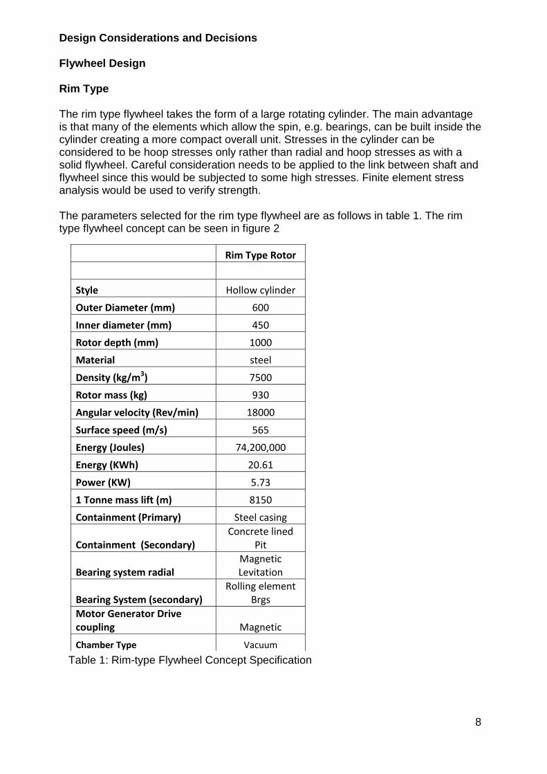
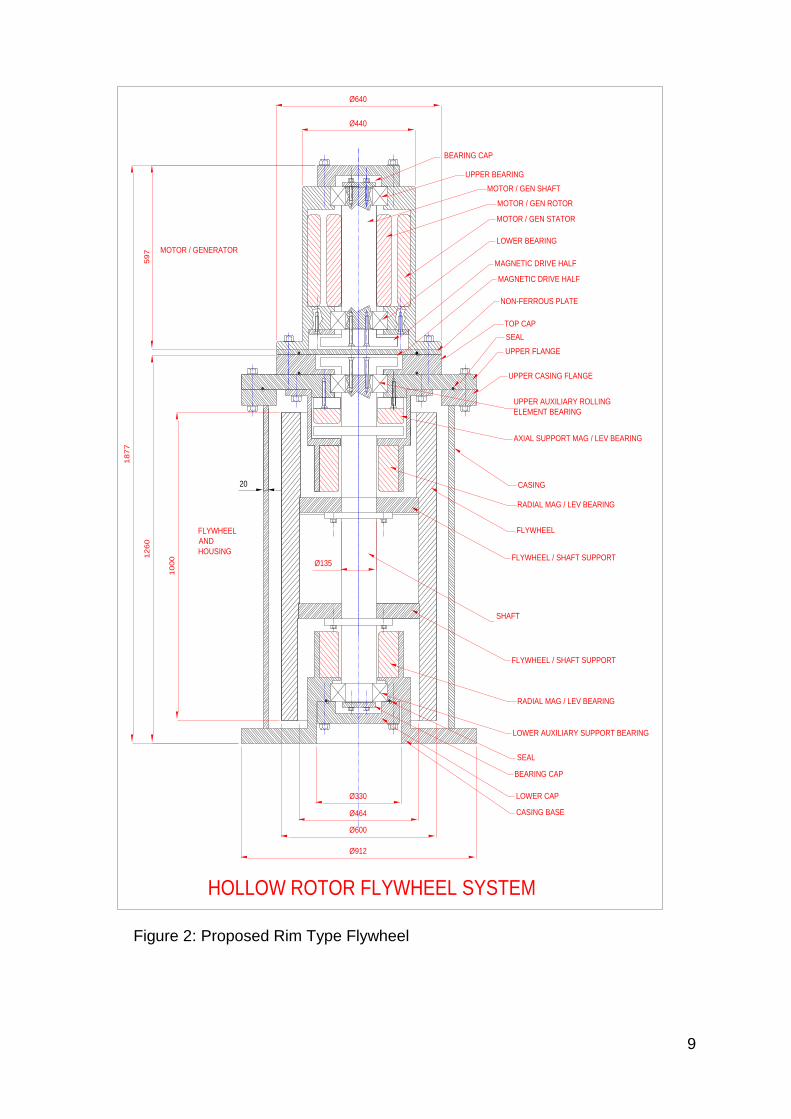
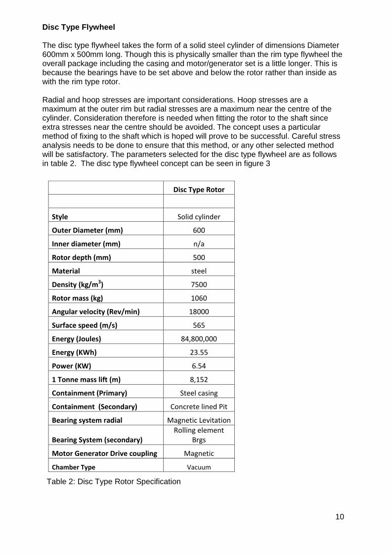
10
Disc Type Flywheel The disc type flywheel takes the form of a solid steel cylinder of dimensions Diameter 600mm x 500mm long Though this is physically smaller than the rim type flywheel the overall package including the casing and motorgenerator set is a little longer This is because the bearings have to be set above and below the rotor rather than inside as with the rim type rotor Radial and hoop stresses are important considerations Hoop stresses are a maximum at the outer rim but radial stresses are a maximum near the centre of the cylinder Consideration therefore is needed when fitting the rotor to the shaft since extra stresses near the centre should be avoided The concept uses a particular method of fixing to the shaft which is hoped will prove to be successful Careful stress analysis needs to be done to ensure that this method or any other selected method will be satisfactory The parameters selected for the disc type flywheel are as follows in table 2 The disc type flywheel concept can be seen in figure 3 Table 2 Disc Type Rotor Specification
Disc Type Rotor
Style Solid cylinder
Outer Diameter (mm) 600
Inner diameter (mm) na
Rotor depth (mm) 500
Material steel
Density (kgm3) 7500
Rotor mass (kg) 1060
Angular velocity (Revmin) 18000
Surface speed (ms) 565
Energy (Joules) 84800000
Energy (KWh) 2355
Power (KW) 654
1 Tonne mass lift (m) 8152
Containment (Primary) Steel casing
Containment (Secondary) Concrete lined Pit
Bearing system radial Magnetic Levitation
Bearing System (secondary) Rolling element
Brgs
Motor Generator Drive coupling Magnetic
Chamber Type Vacuum
11
Figure 3 Proposed Disc Type Flywheel
CASING
UPPER FLANGE
TOP CAP
RADIAL MAG LEV BEARING
UPPER AUXILIARY ROLLING
ELEMENT BEARING
BEARING CAP
AXIAL SUPPORT MAG LEV BEARING
UPPER CASING FLANGE
SEAL
NON-FERROUS PLATE
597
MAGNETIC DRIVE HALF
MAGNETIC DRIVE HALF
MOTOR
GENERATOR
UPPER BEARING
LOWER BEARING
MOTOR GEN STATOR
MOTOR GEN ROTOR
MOTOR GEN SHAFT
Oslash440
Oslash6402028
SHAFT
RADIAL MAG LEV BEARING
LOWER AUXILIARY SUPPORT BEARING
BEARING CAP
SEAL
LOWER CAP
CASING BASE
Oslash912
Oslash330
Oslash740
5001300
Oslash600FIXED SHAFT FLANGE
PRECISION HEADED PIN
REMOVABLE FLANGE
LOCK COLLAR
PRECISION HEADED PIN
FLYWHEEL
SOLID ROTOR FLYWHEEL SYSTEM
12
Primary Bearing System The bearing system is required to hold the rotor in place whilst allowing rotation around 20000 revmin with the minimal frictional resistance Several options were considered Magnetic levitation bearings Rolling element bearings Gas film bearings Fluid film bearings (journal) Gas film bearings require a pressurised gas to be constantly pumped between the shaft and bearing In a vacuum environment this would be inappropriate and the option was discarded Fluid film bearings are essentially oil filled Upon rotation of the journal (shaft) the oil is pulled into the contactsupport area and acts as a cushion Frictional resistance is low but a constant flow of fluid is required requiring shaft seals within the vacuum chamber It was thought that the frictional resistance applied by the seals would create too much drag and reduce efficiency There may also be a problem with heat generation within the fluid at high speeds Magnetic levitation bearings are frictionless and can operate within a vacuum environment Their major disadvantage is that they require a control system and that the magnetic coils require power Research shows however that many KESDrsquos use magnetic levitation as a primary bearing system It was discovered that SKF could produce the magnetic levitation bearings required and also have experience in producing motor generator equipment which could operate at these high speeds SKF provided some very useful data which was used directly in the concept designs They gave approximate sizes of bearing units and suggested how the layout should be applied Beacon power is a company in the United states for which SKF have previously designed such bearings Please see their web site wwwbeaconpowercom A typical radial Magnetic Levitation Bearing can be seen in figure 4 Figure 4 Typical Radial Magnetic Levitation Bearing
13
The axial bearings should be sited at the top of the housing The magnetic flux applied is attractive allowing the rotor to hang from the bearing This arrangement can be seen in both figures 2 and figure 3 Secondary Bearing System It is evident from the research and from advice given by SKF that there needs to be a secondary bearing back-up system This is necessary should power fail to the magnetic levitation bearings SKF recommended high speed ball bearings for this particular role These bearings would function as radial and axial bearings Figure 5 shows typical ball bearings The application can be seen in the concept designs in figures 2 and 3
Figure 5 Typical Ball Bearings Containment The containment system has to be applied to two aspects of the design containment of the vacuum and containment of a bursting flywheel There are several approaches to containment of a bursting flywheel
Brute force approach using heavy-walled pressure vessels
Spinning ring which soaks up the energy of the impacting flywheel debris
Energy absorbing liner The soft catch approach The containment system requires design effort to be applied When the flywheel is at running speed a great deal of energy is contained This energy is enough to vertically lift a 1 tonne mass 81 km Put another way there is energy contained in the flywheel equivalent to 18kg (40lbs) of TNT Generally it is thought that a combined approach might be the way forward This would entail a light casing to contain the vacuum and a heavier casing such as a concrete perhaps below ground vessel to contain any flywheel burst This chamber might also incorporate some form of soft catch energy absorbing system which could take the form of sand or pea gravel filled chambers which break thus allowing the contents to infiltrate the chamber when a burst occurs The current concept uses segmental sand bags set inside the concrete basin If the bursting flywheel breaches the vacuum casing the sand bags will disintegrate allowing the sand to absorb the debris The concrete casing will act as final resort containment Please see figure 6 for a 3D impression of the containment Many current flywheels merely incorporate the brute force approach where a heavy casing is combined with a vacuum chamber In the case of a burst a great deal of
14
energy needs to be contained so any such casing needs to be very firm and should be mounted on heavy foundations Figure 6 Impression of the Segmental Sandbag and Concrete Containment System Motor Generator Set The motor Generator set drives the flywheel up to speed during energy input and converts rotational energy into electrical energy during energy extraction Due to the high speeds this is quite a special arrangement and requires specialist design attention SKF are able to provide the design expertise and design a suitable MG set to suit the specific design needs of the project Typical components can be seen in figure 7
Figure 7 Typical Motor Generator Components Control Equipment The magnetic levitation bearings could become unstable unless constantly monitored and controlled The service incorporates appropriate matching and supply of monitoring and control equipment Figures 8 and 9 show typical control and monitoring devices
15
Figures 8 and 9 Typical Control and Monitoring Devices Machine Monitoring Within the package SKF also offer machine monitoring software which takes input from several sensors to relay the information to a monitoring station This information could include rotational speed out of balance detection temperature energy input efficiency energy extraction efficiency etc
Figure 10 Machine monitoring Software Magnetic Drive Coupling The modular design of the KESD separates the motorgenerator from the vacuum chamber of the flywheel Normal engineering practice would incorporate lip seals to contain the vacuum but the seals would be in contact with the shaft causing frictional resistance and heat generation Ceramic seals would be required The better solution would be to use a magnetic drive coupling This is a non-contacting coupling which transfers magnetic flux through a non-magnetic membrane thus allowing drive to be applied between the two halves of the coupling One half would be situated inside the vacuum chamber the other half inside the motor generator chamber A typical magnetic drive coupling can be seen in figure 11
Figure 11 Typical Magnetic Drive Coupling
16
Electrical Aspects Design and Analysis SKF are the current specialist source of magnetic levitation bearings There are other companies who can offer this service however SKF have been the most informative and helpful They not only offer a full manufacture and design service but they also offer all the ancillary equipment needed to operate and maintain the system Elements for the system are listed as follows
Design and manufacture service for magnetic levitation bearings
Radial magnetic levitation bearings
Axial magnetic levitation bearings
Control system for magnetic levitation bearings
Machine monitoring system
Design and manufacture service for motor generator set
Control system for the motor generator set Incorporated in the total package is a high performance finite element predictive analysis tool for magnetic levitation applications Conclusions and Recommendations The proposed designs show the format of both a rim type flywheel system and also a solid (disc type) flywheel system The sizes of the rotors are generally correct though other aspects of the design are approximate It should be noted however that during the process of conversion from concept to detailed manufacturable units many of the details may change There are many technical design details which require careful consideration such as methods of balancing the rotors and stress analysis of the rotors and frame Below is a basic list of work to be accomplished before a flywheel system can be manufactured Further Work Required to Progress the Project
Finite element stress analysis vacuum chamber
MagLev radial bearing design
MagLev axial bearing design
Control system for magnetic levitation bearings
Machine monitoring system
Design and manufacture of motor generator set
Control system for the motor generator set
Stress analysis of rotors for burst limitation
Fluid flow analysis within the chamber
Vacuum pump and equipment selection
Rolling element bearing design and selection
Vacuum Casing design
Explosion containment system design
Foundations design
Selection of materials There are two concepts put forward each with its own advantages and disadvantages There needs to be a selection of either version so that detailed work can commence
17
Both concept designs fit most of the initial criteria During the detail design process some of these may need to change to accommodate more precise constraints for use or perhaps to accommodate physical parameters thrown up by the development process The concept specifications are as follows in table 3 Industrial Concept The KESD system has been designed for an industrial application where banks of KESDrsquos can be housed The appendix shows several 3D pictures which indicate scale and the probable industrial setting The soft-catch and concrete containment system is also shown Table 3 Concept Specifications for the ESP Kinetic Energy Storage Device
Rim Type Rotor Disc Type Rotor
Style Hollow cylinder Solid cylinder
Outer Diameter (mm) 600 600
Inner Diameter (mm) 450 na
Rotor depth (mm) 1000 500
Material steel steel
Density (kgm3) 7500 7500
Rotor Mass (kg) 930 1060
Angular velocity (Revmin) 18000 18000
Surface Speed (ms) 565 565
Energy (Joules) 74200000 84800000
Energy (kWh) 2061 2355
Power (kW) 573 654
1 Tonne mass lift (m) 8150 8152
Containment (Primary) Steel casing Steel casing
Containment (Secondary) Concrete lined Pit Concrete lined Pit
Bearing System Radial Magnetic Levitation Magnetic Levitation
Bearing System (secondary) Rolling element
Bearings Rolling element
Bearings
Motor Generator Drive Coupling Magnetic Magnetic
Chamber Type Vacuum Vacuum
18
Rotor Selection There is little to choose between the two types of rotor The list of differing parameters is as follows Rim Type Disc Type - Lower mass 930kg - Higher mass 1060kg - Height overall 1877mm - Overall height 2028mm - Energy 2061 kWh - Energy 2355 kWh - Power 573 kW - Power 654 kW - Stresses in rim only - Radial and Hoop stresses present (Less prone to burst)
bull Design and manufacturing will present a similar level of difficulty bull Balancing relatively easier with the rim-type flywheel due to increased length bull Cost implications will be similar for each type
19
References
Many references were consulted These were a mixture of both technical papers and company data The following is a list of the most useful references
SKF Website wwwskfcom
Beacon Power wwwbeaconpowercom
Flywheel Energy Storage System California Energy Commission 2004
Compact Flywheel Energy Storage System Koyo Seiko Company
Flywheel Energy Storage Riello-UPS wwwriello-Upscouk
Flywheel energy and Power Storage Systems Boland Bernhoff and Leijon 2004
Energy Storage Flywheel System with SMB and PMB and its Performances Mitsuda Komori Subkhan and Inoue 2009
Designing Safer Flywheels Steven Ashley Test devices inc wwwtestdevicescom
Murakami m (2007) japan Title design of an energy storage flywheel system using permanent magnet bearing and superconducting magnetic bearings
Seong-yeol yoo (2009) korea Title design of magnetically levitated rotors in a large flywheel
Werfel (2008) Germany (german e-on) Title 250kW Flywheel with HTS Magnetic Bearing for Industrial use
Bjorn Bolund (2005) sweden Title Flywheel energy and power storage systems
Read T Doucette (2011) OXFORD Engineering Science department UK 201011 Title A comparison of high speed flywheels batteries and ultracapasitors and the bases of cost and fuel
T H Sung (2011) Korea Title Flywheel energy storage system with a horizontal axle mounted on high Tc superconductor bearings
20
Appendix -1
a) Flywheel Characteristics Iteration Spreadsheets Flywheel Characteristics Disc Type Rotor
Note Speed of Sound = 3432ms
Dia Radius Depth Density Volume mass Ang Vel Ang Vel Surface Moment KE KE Power 1 tonne Rim
m m m kgm^3 m^3 kg RPM radsec Speed of Inertia Joules KWh KW Mass lift Stress
Ms kgm^2 m Nm^2
020 010 080 750000 003 18852 3000000 314200 31420 094 4652751 129 036 251584 4056795
030 015 070 750000 005 37115 2000000 209467 31420 418 9160103 254 071 251584 4056795
030 015 070 750000 005 37115 3000000 314200 47130 418 20610232 573 159 566064 9127789
040 020 070 750000 009 65982 2000000 209467 41893 1320 28950450 804 223 447261 7212080
050 025 070 750000 014 103097 2000000 209467 52367 3222 70679810 1963 545 698845 11268876
060 030 070 750000 020 148460 2000000 209467 62840 6681 146561653 4071 1131 1006337 16227181
060 030 060 750000 017 127251 2000000 209467 62840 5726 125624274 3490 969 1006337 16227181
060 030 050 750000 014 106043 2000000 209467 62840 4772 104686895 2908 808 1006337 16227181
060 030 040 750000 011 84834 2000000 209467 62840 3818 83749516 2326 646 1006337 16227181
070 035 030 750000 012 86601 2000000 209467 73313 5304 116367238 3232 898 1369736 22086996
070 035 020 750000 008 57734 2000000 209467 73313 3536 77578159 2155 599 1369736 22086996
080 040 020 750000 010 75408 2000000 209467 83787 6033 132344914 3676 1021 1789043 28848322
000 750000 000 000 000 000 000 0 000 000 DIV0 0
050 025 035 750000 007 51548 3000000 314200 78550 1611 79514786 2209 614 1572401 25354970
060 030 020 750000 006 42417 3000000 314200 94260 1909 94218206 2617 727 2264258 36511157
000 750000 000 000 000 000 000 0 000 000 DIV0 0
070 035 021 750000 008 60621 2000000 209467 73313 3713 81457067 2263 629 1369736 22086996
060 030 021 750000 006 44538 2000000 209467 62840 2004 43968496 1221 339 1006337 16227181
050 025 020 750000 004 29456 3000000 314200 78550 921 45437020 1262 351 1572401 25354970
000 750000 000 000 000 000 000 0 000 000 DIV0 0
000 750000 000 000 000 000 000 0 000 000 DIV0 0
060 030 050 750000 014 106043 1800000 188520 56556 4772 84796385 2355 654 815133 13144017
060 030 050 750000 014 106043 1200000 125680 37704 4772 37687282 1047 291 362281 5841785 Flywheel Characteristics Rim Type Rotor
Note Speed of Sound = 3432ms
Ou
ter
Dia
(m)
Ou
ter
Rad
(m)
Inn
er
Dia
(m
)
Inn
er
Rad
(m)
De
pth
(m
)
De
nsi
ty
(kg
m^
3)
Vo
lum
e
(m^
3)
mas
s (k
g)
An
g V
el
(Re
vm
in)
An
g V
el
Surf
ace
Spe
ed
(m
s)
Mo
me
nt
of
Ine
rtia
kgm
^2
KE
(Jo
ule
s)
KE
(KW
h)
Po
we
r (K
W)
1 t
on
ne
Mas
s
Lift
(m
)
Rim
Str
ess
(Nm
^2
)050 025 012 006 080 750000 015 111038 15000 1571 39275 3470 42819848 1189 330 393100 6338743
06 030 015 008 05 750000 013 99415 18000 1885 56556 4474 79496611 2208 613 815133 13144017
06 030 015 008 04 750000 011 79532 18000 1885 56556 3579 63597289 1767 491 815133 13144017
06 030 015 008 03 750000 008 59649 18000 1885 56556 2684 47697967 1325 368 815133 13144017
05 025 015 008 07 750000 013 93818 18000 1885 47130 2932 52098088 1447 402 566064 9127789
04 020 015 008 08 750000 009 64804 18000 1885 37704 1296 23031117 640 178 362281 5841785
05 025 015 008 06 750000 011 80416 18000 1885 47130 2513 44655504 1240 345 566064 9127789
05 025 015 008 065 750000 012 87117 18000 1885 47130 2722 48376796 1344 373 566064 9127789
055 028 022 011 07 750000 014 104788 18000 1885 51843 3962 70409363 1956 543 684938 11044625
06 030 022 011 05 750000 012 91786 18000 1885 56556 4130 73395982 2039 566 815133 13144017
06 030 045 023 1 750000 012 92787 18000 1885 56556 4175 74196837 2061 573 815133 13144017
21
b) Concept Renderings Figure 12 Single containment basin showing lid and control cabinet Figure 13 Impression of the industrial Application (Lids removed) Figure 14 Impression showing the Soft-Catch Segmental Sand Bags
22
Figure 15 Impression Showing Scale Figure 16 Renderings of the Proposed KESD (Hollow Flywheel Version)
Figure 17 Renderings of the Proposed KESD (Solid Flywheel Version)
23
Phase 2 Stage 2 of the Flywheel project (9May2011 till now)
The crucial elements to a successful design were considered to be the bearings radial and axial and the rotor stresses Once these elements were finalised then the rest of the KESD could be designed to suit Use of Bearings was investigated whilst finite element analysis was performed on the proposed rotor designs this is where other specialist team members included in the research team Additional team members joining to the research team Dr Simon Barrans (SMB) Specialism Stress Analyst Duties Analyse the stresses in the rotor and define materials rotor speeds and rotor shape according to safe stressing Mark Dales (MD) Specialism High current Electrical Engineer Duties Specify the motor Generator equipment and designprocure all other electrical elements Prof Rakesh Mishra (RM) Specialism Thermo-fluid behaviour and CFD techniques Duties Analyse the air flow around the rotor and determine the fluid drag Design Evolution from Concept 1 Concept 1 explained in phase 1 was devised after extensive research of current models and practices It was discovered that the original application of capturing cheap energy and selling it back to the grid at a higher cost is very feasible Furthermore peak demand smoothing is possible and indeed is the very reason for the building of several large flywheel installations throughout the world The kinetic storage of electrical energy possesses other benefits to emerging industries such as the electric car industry Here recharging stations will be required and may possibly have kinetic energy storage The conclusion is therefore that research revealed a very viable market which is demanding some form of energy storage Kinetic Energy Storage devices could easily fill that demand Concept stage 1 was effectively a feasibility study of current technologies and the possibility of using these technologies to create a kinetic energy storage device (KESD) A feasibility report was presented to the board of ESP Ltd who then agreed to the project progressing to the phase 2 The main thrust of the design was that it should follow standard engineering techniques in order to Reduce time to market Reduce the development time Reduce development costs Ensure low cost manufacture Ensure sustainability issues were minimised
24
Bearings Up to the point of the presentation in May 2011 of the feasibility report the team had been liaising with SKF who had been very helpful in providing guidance for the magnetic-levitation bearings used in Concept 1 The bearings needed development though SKF had previously provided similar bearings to the Beacon Project which is a similar facility based in California As soon as SKF understood the need for development work they lost interest saying they were overstretched and could not pursue the project Another company Mecos of Switzerland was approached who could provide the necessary magnetic levitation units They were very enthusiastic but required pound100000 to be deposited before development could begin This clearly excluded them from the development Two other companies were approached with no success Stress Analysis Whilst the bearing search was being conducted SMB had been pursuing the stress analysis on the rotor and reported that a high carbon steel rotor with a speed of 18000 revmin would burst long before it reached the operation speed The data below in table 3 shows the rotor size possibilities related to material stress Table 3 Rotor Size Possibilities for Solid Rotors at 7000 revmin The table above indicates the radius of the flywheel and the stress that flywheel would see in service The moment of inertia and the height of the rotor are important since they are essential properties in the storage of kinetic energy In general a larger Inertia value will store a larger value of kinetic energy but an increase in speed will increase the kinetic energy storage capacity in terms of speed squared Basic Equation for Kinetic Energy is as follows
KE = 1 I2 2 Where I = Moment of Inertia (kgm2)
= Angular velocity (radsec) It can be seen from the first line of table 3 that a rotor of radius 04m (800mm diameter) with a height of 0913m (913mm) will have a moment of inertia of
Ou
ter
Rad
ius
Ro
(m
)
Radial Stress(MNm2) at centre
Mo
men
t o
f in
erti
ah
eigh
t
Hei
ght
(m)
req
uir
ed t
o
give
re
qu
ired
en
ergy
at
rate
d s
pee
d
Is design possible
04 2686726 3016E+02 0913 Y
045 3400387 4831E+02 0570 Y
05 4198009 7363E+02 0374 Y
25
3016 x 10-2 kgm2 Importantly the radial stress in the rotor is 26867 MNm2 which is approximately half of the envisaged ultimate tensile strength of the rotor material medium carbon steel This will give a safety factor of slightly under 20 The conclusion from this analysis is that the original target of 18000 revmin for a solid rotor cannot be achieved using steel or one of its alloys The analysis shows that the speed needs to be substantially reduced to a maximum of 7000 revmin Design Concept 2 Evolving to Concepts 3 and 4 The revelation that the rotor stresses had forced the angular velocity down to 7000 revmin from 18000 revmin helped to continue the theme of using standard engineering components and techniques since high speed radial rolling element bearings could now be considered and separate thrust bearings The negative side to reducing the speed was that the rotor mass had to be increased to approximately 3 tonnes in order to increase the moment of inertia The reduction in speed also meant that expensive active magnetic-levitation bearings could be discarded though it seemed reasonable to support the 3 tonnes mass of the vertical axially mounted rotor on permanent magnet thrust bearings Figure 15 shows the concept Figure 15 Concept 2 Solid Rotor with Permanent Magnet Bearings and Hybrid Ceramic Radial Bearings
UPPER FLANGE
TOP CAP
BEARING CAP
UPPER CASING FLANGE
SEAL
NON-FERROUS PLATE
597 MAGNETIC DRIVE HALF
MAGNETIC DRIVE HALF
MOTOR
GENERATOR
UPPER BEARING
LOWER BEARING
MOTOR GEN STATOR
MOTOR GEN ROTOR
MOTOR GEN SHAFT
Oslash440
Oslash640
UPPER FLANGE
UPPER HIGH SPEED ROLLING
ELEMENT BEARING
GOOD SLIDING FIT ON
OUTER RACE
UPPER CASING FLANGE
SEAL
ROTOR
AXIAL SUPPORT PASSIVE
REPULSING MAGNETS (ROTOR)
AXIAL SUPPORT PASSIVE
REPULSING MAGNETS (BASE)
CASING
LOWER HIGH SPEED
ROLLING ELEMENT BEARING
GOOD SLIDING FIT ON
OUTER RACE
1880
1218
Oslash900
26
Radial Bearings Several bearing companies were contacted with a specification for radial bearings of 7000 Revmin 100mm bore Radial loads of 15KN Radial loads were evaluated by calculating the residual out-of-balance as directed by ISO 19401 Balancing Quality Requirements for Rigid Rotors Bearing loads were then calculated for a particular bearing diameter Bearing companies contacted were as follows Barden UK (Part of the Schaeffler group) SKF Luton NSK UK Each company suggested that the duty could be accommodated using a hybrid bearing of ceramic ball bearings and a high alloy steel race In order to increase long life several lubrication strategies were suggested
Grease packed
Oil lubrication (automatic injection)
A five year maintenance plan
Live wear monitoring Uniformly Stressed Rotor Results During the search for appropriate bearings SMB was conducting stress analysis on the rotor The start point for the analysis was the solid rotor in Concept 2 with a speed of 7000 revmin The necessity to increase moment of inertia and reduce the radial stresses which were so high near the rotor axis drove the rotor shape to that of a rim-type flywheel Concept 3 shows the KESD with the new shape rotor See figure 16
27
Figure 16 Concept 3 KESD Showing Rim Type Flywheel as a Uniformly Stressed Rotor
UPPER FLANGE
TOP CAP
UPPER HIGH SPEED ROLLING
ELEMENT BEARING
GOOD SLIDING FIT ON
OUTER RACE
BEARING CAP
UPPER CASING FLANGE
SEAL
NON-FERROUS PLATE
597
MAGNETIC DRIVE HALF
MAGNETIC DRIVE HALF
MOTOR
GENERATOR
UPPER BEARING
LOWER BEARING
MOTOR GEN STATOR
MOTOR GEN ROTOR
MOTOR GEN SHAFT
Oslash440
Oslash640
ROTOR
AXIAL SUPPORT PASSIVE
REPULSING MAGNETS (ROTOR)
AXIAL SUPPORT PASSIVE
REPULSING MAGNETS (BASE)
CASING
LOWER HIGH SPEED
ROLLING ELEMENT BEARING
GOOD SLIDING FIT ON
OUTER RACE
1692
1030
28
Figure 17 Concept 4 Inboard Configuration of Permanent Magnet Thrust Bearing Permanent Magnet Thrust Bearings Since the axis of the rotor was vertical it seemed reasonable to support the 3 tonnes axial load on a separate thrust bearing The obvious choice was to use rolling element thrust bearings but it was considered that other low friction axial bearing alternatives should be investigated Air bearings were considered but since the unit was destined to run in a vacuum the continual leakage of air from the bearings in to the vacuum chamber would destroy the vacuum Air bearings were therefore ruled out of the design
UPPER HIGH SPEED ROLLING
ELEMENT BEARING
GOOD SLIDING FIT ON
OUTER RACE
BEARING CAP
UPPER CASING FLANGE
SEAL
EXTERNAL RADIAL MAGNETIC DRIVE HALF
INTERNAL RADIAL MAGNETIC DRIVE HALF
MOTOR
GENERATOR
UPPER HIGH SPEED BEARING
LOWER BEARING
MOTOR GEN STATOR
MOTOR GEN ROTOR
MOTOR GEN SHAFT
Oslash440
Oslash640
ROTOR
AXIAL SUPPORT PASSIVE
REPULSING MAGNETS (ROTOR)
AXIAL SUPPORT PASSIVE
REPULSING MAGNETS (BASE)
CASING
LOWER HIGH SPEED
ROLLING ELEMENT BEARING
GOOD SLIDING FIT ON
OUTER RACE
1030
702
1733
Oslash1212
Oslash400
Oslash180
Oslash110
Oslash900
700
29
The company that ESP Ltd had proposed as manufacturers JPS Ltd based in the Wirral suggested permanent magnet thrust bearings as axial thrust bearings They had previously conducted some ad-hoc experiments but had no real data to offer Manufacturers of permanent magnets were contacted to ascertain strengths costs etc Research was also conducted as to best methods of application and installation of permanent magnets High strength magnets are manufactured from neodymium Since the rotor was to be supported by permanent magnets the flywheel rim edges were proposed as bearing points Consideration was given to the shape of the magnets Cylindrical magnets were an obvious choice but research showed that heat would be generated as rotor mounted magnets passed over base mounted magnets It soon became clear that specially shaped magnets would be required to reduce the number of ldquoedgesrdquo within the magnetic flux and hence reduce the generated heat Manufacturing shaped magnets offered several options The thrust bearing could be applied as in Concept 3 figure 16 or perhaps as in Concept 4 see figure 17 This particular configuration was devised after a quote from Best Solution Consultancy Ltd who quoted a repulsing magnet outer diameter of 540mm and an inner diameter of 160mm with a magnet thickness of 40mm The material would be neodymium rare earth This high strength high cost sintered magnet offered several benefits
Reasonable gap between thrust plates of approximately 5mm
Able to support 3 tonne mass
Zero friction (no Contact)
Zero maintenance There were however several negatives
Very High cost (approx pound28000 per bearing)
Requirement to magnetise at the assembly site
Requirement for mechanical handling equipment to enable unpacking and assembly (due to inherent attractive forces)
High cost of ancillary equipment Due to the high cost of the magnetic bearing material and the anticipated high cost of the handling equipment and other ancillary equipment it was decided that though an exceedingly viable technical option the costs were prohibitive The use of permanent magnet thrust bearings was discarded in favour of more traditional bearings such as rolling element thrust bearings
30
Concept 5 The specification for the rotor was as follows
Rotor mass 3000kg
Rotor speed 7000 revmin
Vertical axis Investigations into rolling element thrust bearings quickly revealed that even hybrid ceramic bearings would be hard pressed to support 3000kg running at 7000 revmin A quote from one of the bearing manufacturers SKF UK Ltd suggested that such a bearing would match their ACDHC super precision angular contact hybrid bearing (ceramic balls) This would need to be lubricated with an oil-air (spray) system Unfortunately this bearing system would only have a predicted life of 284 hours This was the best bearing SKF could offer Other companies offered similar bearings They suggested that the heavy load and the rotation speed were the main problems It was evident that the rotor required redesigning to fulfil the design brief of storing 20KWh but with a much lower mass and a lower speed Since the uniformly stressed rotor was essentially a rim type rotor analysis was conducted for a rim type flywheel with a spoke and shaft system to be added later within the stress analysis exercise Revisiting the basic Kinetic Energy equation it was discovered that there were several variables which could be manipulated as follows
KE = 1 I2 2 Where I = Moment of Inertia (kgm2)
= Angular velocity (radsec) But I = mk2 Where m = mass (kg) and k = radius of gyration (m) giving
KE = 1 mk22 2 Or
KE = 1 m(R2 + R1)22
2 (2)2 Where R1 = outer radius (m) R2 = inner radius (m)
31
From analysis of basic flywheel characteristics see appendix the kinetic energy to deliver 20KWh is 725MJ For analysis purposes this value was fixed as well as the aim of a notional 1500kg for the rotor mass The four variables were therefore R1 = outer radius (m) R2 = inner radius (m) Rotor depth (m)
= angular velocity (radsec)
A spreadsheet tool was used to vary the parameters which are shown in table 4 below Table 4 Spreadsheet Analysis tool to Vary Flywheel Parameters
During the iteration process the outer diameter was fixed and the depth and the inner radius was varied The angular velocity was also varied to achieve the kinetic energy value of approximately 73MJ The rotor of 22m OD 20m ID 03m depth emerged as an excellent choice having a mass of only 1485kg and a KE of 788MJ The rotor of 20m OD 17m ID 025m depth was a little heavier at 1635kg but was smaller in outer diameter This was desirable since a smaller outer diameter would mean an overall smaller unit In comparison there is not much to choose between either of the rotors The rotor of 18m OD 16m ID 04m depth emerged as the best of the 18 diameter rotors but was lacking in the value of kinetic energy storage at only KE of 579MJ This size of rotor was clearly inferior to the 20m and 22m diameter rotors
Ou
ter
Dia
(m
)
Ou
ter
Rad
(m
)
Inn
er D
ia (
m)
Inn
er R
ad (
m)
De
pth
(m
)
De
nsi
ty
(kg
m^3
)
Vo
lum
e (
m^3
)
mas
s (k
g)
An
g V
el
(Re
vm
in)
An
g V
el
(rad
sec
)
Surf
ace
Spee
d
(ms
)
Mo
me
nt
of
Iner
tia
kgm
^2
KE
(Jo
ule
s)
KE
(KW
h)
18 090 14 070 02 7500 020 1508 4000 419 377 611 53599690 1489
18 090 15 075 025 7500 019 1458 4000 419 377 591 51820013 1439
18 090 16 080 04 7500 021 1602 4000 419 377 649 56949671 1582
2 100 16 080 02 7500 023 1697 3000 314 314 848 41874758 1163
2 100 16 080 025 7500 028 2121 3000 314 314 1060 52343448 1454
2 100 17 085 025 7500 022 1635 4000 419 419 817 71729910 1992
2 100 175 088 03 7500 022 1657 4000 419 419 828 72699233 2019
2 100 18 090 036 7500 021 1612 4000 419 419 806 70721814 1964
22 110 18 090 02 7500 025 1885 3000 314 346 1141 56298286 1564
22 110 19 095 025 7500 024 1812 3000 314 346 1096 54099134 1503
22 110 2 100 03 7500 020 1485 4000 419 461 898 78817600 2189
32
Shown in figure 18 is the rim type rotor which was used to base the analysis whose results are displayed in table 4 Please note that for analysis purposes the spokes and shaft have been omitted being relatively insignificant compared to the rim of the rotor Figure 18 Rim of Flywheel as Calculated for 20m Device Figure 19 Concept 5 Rim Type Flywheel
Concept 5 is shown in Figure 19 The rotor has a diameter of 20 m and is hollow to reduce weight and hence bearing load It was intended that the hollow halves of the rotor would be machined separately and joined using industrial adhesive The key turned in to the joint at the rim would key the two halves and allow them to expand radially as one component when rotating at speed Concept 6 Intensive stress analysis revealed that the use of normally available engineering materials provided severe restrictions on the shape speed and size of the flywheel Furthermore the variables hitherto used were complicated to juggle to obtain the
LOWER HIGH SPEED
ROLLING ELEMENT BEARING
GOOD SLIDING FIT ON
OUTER RACE
UPPER FLANGE
TOP CAP
UPPER HIGH SPEED ROLLING
ELEMENT BEARING
GOOD SLIDING FIT ON
OUTER RACE
UPPER CASING FLANGE
SEAL
NON-FERROUS PLATE
ROTOR
CASING
BEARING CAP
NON-FERROUS PLATE
597
MAGNETIC DRIVE HALF
MAGNETIC DRIVE HALF
MOTOR
GENERATOR
UPPER BEARING
LOWER BEARING
MOTOR GEN STATOR
MOTOR GEN ROTOR
MOTOR GEN SHAFT
Oslash440
Oslash640
ROLLING ELEMENT CERAMIC
THRUST BEARING
Oslash2000
12
83
Oslash2500
33
correct rotor format Research revealed that energy density was a comparative parameter that would give the optimum energy capacity for various rotor shapes Energy Density Further research [16] led the design in the direction of using ldquoEnergy Densityrdquo as a useful factor in identifying the most appropriate flywheel shape as explained below Energy density is essentially the value of energy in Joules per kg mass of rotor Energy Density = joules Kg
KE = 1 x I x 2 helliphelliphelliphelliphelliphelliphelliphelliphellip1
2
KE = m x r2 x 2 helliphelliphelliphelliphelliphelliphelliphelliphellip2
2 where KE = Kinetic Energy (Joules)
I = polar 2nd moment of Inertia (kgm2) I = m x r2 m = mass (kg) r = mean radius (m)
= angular velocity (radsec)
From equation 2 it can be seen that a reduction in angular velocity must be
compensated by an increase in radius r Another parameter which is useful to consider is that of ldquoenergy densityrdquo and is shown below From equation 2
KE = m x r2 x 2 helliphelliphelliphelliphelliphelliphelliphelliphellip2
2 Divide both sides by mass m
KE = m x r2 x 2 helliphelliphelliphelliphelliphelliphelliphelliphellip3
m m 2 giving
KE = r2 x 2 helliphelliphelliphelliphelliphelliphelliphelliphellip4
m 2 or Energy Density This parameter allows comparison between flywheel shapes The new task then was to arrange the flywheel shape to give a large value of energy (Joules) for each kg of rotor mass
34
The use of Energy Density quickly showed that the best shape for a rotor system was not a rim type flywheel or a cylindrical flywheel but a tapered rotor section as shown in figure 20 Figure 20 Concept 6 Tapered disc
Stress analysis revealed that the major stresses were radial and imposed high stresses near the shaft Essentially centrifugal forces tend to pull the flywheel material away from the shaft
Figure 21 Finite Element Stress Analyses Showing a Small Disc Segment by Dr Simon Barrans The diagram shown in figure 21 shows a small disc segment rotated at 500radsec (4776 revmin) The disc shows stresses 237MNm2 in the blue area at the outside of the disc and 463 MNm2 at the centre Should high strength materials be used these stresses are not particularly excessive and show clearly where the highest stresses are likely to occur which is towards the centre where the disc joins the shaft The next step was to attach the disc to the shaft in order to determine stresses at the joint of the disc and the shaft The analytical diagram is shown in figure 22 Figure 22 Analytical Segment Showing High Stress at Discshaft Junction by Dr Simon Barrans
LOWER HIGH SPEED
ROLLING ELEMENT BEARING
GOOD SLIDING FIT ON
OUTER RACE
ROTOR
ROLLING ELEMENT CERAMIC
THRUST BEARING
Oslash2000
Small segment analysed
Plain disc stress not uniform
Disc is not infinite
Full disc moment of inertia 484 kgm2
Disc outer diameter 24m
Central thickness 100mm
Edge load applied to give uniform stress
Fillet radius generates significant stress raiser
Disc Diameter 09m
35
The concept 6 design emerged as a constant stress device which took the form of a tapered cross section fatter nearer the shaft and tapering to the outside edge The surface however has been curved to enable constant stress across the section The whole concept can be seen in figure 23 Concept 6 parameters are as follows Outer radius 10 m Outer Diameter 20 m Thickness on central axis 110 mm (plus stub shafts to mate with the bearings) Thickness on outer rim 35 mm Mass 12 to 15 tonnes Speed 3650 to 4000 rpm Energy storage 40 to 54 MJ Figure 23 Concept 6 Uniformly Stressed Rotor Design
Bearing Selection Various bearing manufacturers were contacted requesting quotations and a specification of bearing Since the bearings required were off standard and therefore required specialist selection procedures the bearing companies were relied upon to specify bearings which could contend with the following parameters Working speed 4000 revmin Test speed 7000revmin Rotor mass 2000kg Life 10 years HB Bearings LTD of Honley West Yorkshire are specialist bearing manufacturers They declined to quote a price since the bearings could be purchased off the shelf from some of the large bearing manufacturing companies as is outlined below They did however assist greatly in specifying bearing types as follows Radial Bearings
UPPER FLANGE
TOP CAP
UPPER HIGH SPEED ROLLING
ELEMENT BEARING
GOOD SLIDING FIT ON
OUTER RACE
UPPER CASING FLANGE
SEAL
NON-FERROUS PLATE
ROTOR
CASING
BEARING CAP
NON-FERROUS PLATE
59
7
MAGNETIC DRIVE HALF
MAGNETIC DRIVE HALF
MOTOR
GENERATOR
UPPER BEARING
LOWER BEARING
MOTOR GEN STATOR
MOTOR GEN ROTOR
MOTOR GEN SHAFT
Oslash440
Oslash640
ROLLING ELEMENT CERAMIC
THRUST BEARING
Oslash2000
12
83
Oslash2500
LOWER HIGH SPEED
ROLLING ELEMENT BEARING
GOOD SLIDING FIT ON
OUTER RACE
36
Hybrid type angular contact bearing at 15deg - 25deg angle of contact
Oslash 100mm x Oslash 150mm x 24mm
To P4 run out and dimensional tolerances
Obtainable as sealed or not sealed
Commercially available bearing from SKF FAG NSKRHP Thrust Bearing This posed a challenge with the high running speed required since a bearing of a similar size to the radial bearings would not have the thrust capability to operate at the required speed To be able to run at the required speed a smaller bearing needs to be considered This would reduce the linear speed of the balls within the bearing The specification suggested follows
Hybrid type ball bearing at
Oslash 50mm x Oslash 70mm x 14mm single row ball thrust bearing
Load ratings of Ca 27 KN and Coa 75KN
Working speeds of 4300 revmin maximum
Test speed 6300 revmin limiting speed Further research and engineering analysis have been currently carried out b Engineering staff especially vacuum fluid dynamics air resistance stability friction and vibration and noise Conclusion and further plan In this report an overview of advanced flywheel feasibility study is presented in the phase one This report covered the literature review competitive products on the market and the concept development of two alternative products with basic calculations After presenting this report in May 2011 to ESP directors and managers the team visited manufacturing facility of ESP near Liverpool and ESP decided to fund the development of two prototypes and raise further funding which is handled by the Research amp Enterprise Centre of the University The team then continued to further engineering design calculation manufacturing details optimisation cost of off the shelf external parts design and detailing of the new parts to be built And further discussion taken place with the manufacturers of the standard parts This process was very useful as it revealed that due to the required final cost of the KESD set by ESP ltd further design changes was necessary as the companies initially approached could not deliver the required spec parts therefore further calculation and design iterations required At this point team also extended to include Dr Simon Barrans who calculated stress on the rotor and material specification Then Mark Dales from Electrical Engineering started on electric motor generator specification which is still on going Also Prof Rakesh Mishra agreed and will be calculating and advising on the rotor air frictions who specialise on Thermo-fluid behaviour and CFD techniques when the final decision is made The next phase of the project is to start purchasing off the shelf parts an also manufacturing and testing which we require to use manufacturing facilities of ESP The research team appreciate Dr Simon Barrans (SMB) on the his expert advice on the analysis of the stresses in the rotor materials shape and specifications so far
37
Appendix 2 Flywheel Characteristics Iteration Spreadsheets Flywheel Characteristics Disc Type Rotor
Note Speed of Sound = 3432ms
Dia Radius Depth Density Volume mass Ang Vel Ang Vel Surface Moment KE KE Power 1 tonne Rim
m m m kgm^3 m^3 kg RPM radsec Speed of Inertia Joules KWh KW Mass lift Stress
Ms kgm^2 m Nm^2
020 010 080 750000 003 18852 3000000 314200 31420 094 4652751 129 036 251584 4056795
030 015 070 750000 005 37115 2000000 209467 31420 418 9160103 254 071 251584 4056795
030 015 070 750000 005 37115 3000000 314200 47130 418 20610232 573 159 566064 9127789
040 020 070 750000 009 65982 2000000 209467 41893 1320 28950450 804 223 447261 7212080
050 025 070 750000 014 103097 2000000 209467 52367 3222 70679810 1963 545 698845 11268876
060 030 070 750000 020 148460 2000000 209467 62840 6681 146561653 4071 1131 1006337 16227181
060 030 060 750000 017 127251 2000000 209467 62840 5726 125624274 3490 969 1006337 16227181
060 030 050 750000 014 106043 2000000 209467 62840 4772 104686895 2908 808 1006337 16227181
060 030 040 750000 011 84834 2000000 209467 62840 3818 83749516 2326 646 1006337 16227181
070 035 030 750000 012 86601 2000000 209467 73313 5304 116367238 3232 898 1369736 22086996
070 035 020 750000 008 57734 2000000 209467 73313 3536 77578159 2155 599 1369736 22086996
080 040 020 750000 010 75408 2000000 209467 83787 6033 132344914 3676 1021 1789043 28848322
000 750000 000 000 000 000 000 0 000 000 DIV0 0
050 025 035 750000 007 51548 3000000 314200 78550 1611 79514786 2209 614 1572401 25354970
060 030 020 750000 006 42417 3000000 314200 94260 1909 94218206 2617 727 2264258 36511157
000 750000 000 000 000 000 000 0 000 000 DIV0 0
070 035 021 750000 008 60621 2000000 209467 73313 3713 81457067 2263 629 1369736 22086996
060 030 021 750000 006 44538 2000000 209467 62840 2004 43968496 1221 339 1006337 16227181
050 025 020 750000 004 29456 3000000 314200 78550 921 45437020 1262 351 1572401 25354970
000 750000 000 000 000 000 000 0 000 000 DIV0 0
000 750000 000 000 000 000 000 0 000 000 DIV0 0
060 030 050 750000 014 106043 1800000 188520 56556 4772 84796385 2355 654 815133 13144017
060 030 050 750000 014 106043 1200000 125680 37704 4772 37687282 1047 291 362281 5841785 Flywheel Characteristics Rim Type Rotor
Note Speed of Sound = 3432ms
Ou
ter
Dia
(m)
Ou
ter
Rad
(m)
Inn
er
Dia
(m
)
Inn
er
Rad
(m)
De
pth
(m
)
De
nsi
ty
(kg
m^
3)
Vo
lum
e
(m^
3)
mas
s (k
g)
An
g V
el
(Re
vm
in)
An
g V
el
Surf
ace
Spe
ed
(m
s)
Mo
me
nt
of
Ine
rtia
kgm
^2
KE
(Jo
ule
s)
KE
(KW
h)
Po
we
r (K
W)
1 t
on
ne
Mas
s
Lift
(m
)
Rim
Str
ess
(Nm
^2
)050 025 012 006 080 750000 015 111038 15000 1571 39275 3470 42819848 1189 330 393100 6338743
06 030 015 008 05 750000 013 99415 18000 1885 56556 4474 79496611 2208 613 815133 13144017
06 030 015 008 04 750000 011 79532 18000 1885 56556 3579 63597289 1767 491 815133 13144017
06 030 015 008 03 750000 008 59649 18000 1885 56556 2684 47697967 1325 368 815133 13144017
05 025 015 008 07 750000 013 93818 18000 1885 47130 2932 52098088 1447 402 566064 9127789
04 020 015 008 08 750000 009 64804 18000 1885 37704 1296 23031117 640 178 362281 5841785
05 025 015 008 06 750000 011 80416 18000 1885 47130 2513 44655504 1240 345 566064 9127789
05 025 015 008 065 750000 012 87117 18000 1885 47130 2722 48376796 1344 373 566064 9127789
055 028 022 011 07 750000 014 104788 18000 1885 51843 3962 70409363 1956 543 684938 11044625
06 030 022 011 05 750000 012 91786 18000 1885 56556 4130 73395982 2039 566 815133 13144017
06 030 045 023 1 750000 012 92787 18000 1885 56556 4175 74196837 2061 573 815133 13144017
38
From ISO19401 Uper = 9549 x G x W (gmm) N Where G = Balance Grade G63 W = Rotor Mass 3000kg N = Service Speed 7000revmin Uper = 9549 x 63 x 3000 = 25782 gmm 7000 Find Centrifugal Force First Find Eccentric Mass Uper = 25782 grm Radius of Bearing = 55mm Uper = emass x radius emass = Uper__ = 25782 = 470grm or 047kg radius 55 Find Centrifugal Force
Fc = m x 2 x r
Where m = rotor mass of 3000kg
= angular velocity = 7000 x 2 x = 733 radsec
60 R = bearing radius = 55mm or 0055m Fc = 3000 x 7332 x 0055 = 13890 N or equivalent mass = 1416kg And is the radial force applied to the bearing
Determination of Residual Unbalance Forces From Balancing Grades
Grade Rotor Angular Rotor Bearing Residual Residual Centrifugal Centrifugal
Speed Velocity Mass Radius Unbalance Eccentric Force Equiv Load
mass at Brg at Brg
RevMin radsec Kg mm g-mm kg N kg
63 7000 733 3000 55 257823 047 138576 14126
25 7000 733 3000 55 102311 019 54990 5606
63 4000 419 1635 55 245899 045 43156 4399
39
Determination of Energy Storage Efficiency
Determination of Drag due to Skin Friction
Determination of Drag due to Bearing Friction
Determination of Retardation and Efficiency Determination of Drag due to Skin Friction The general drag force equation shown below was used
Fdrag = 1 x x v2 x A x CD
2 Where
= gas density (kgm3)
V = velocity (ms) A = Cross sectional Area (m2) CD = Drag coefficient (dimensionless) The drag coefficient was determined from the following equation after determining the Reynolds Number for the conditions These calculations can be seen in the appendix page xxx CD = 133(Re)-12 per side Ref [19] Where Re = Reynolds Number
Re = VL
Where
= fluid density (kgm3)
V = average velocity (ms) L = Travelled length of fluid (hydraulic Diameter) (m)
= dynamic viscosity (Nsm2)
Parameters from speed of sound analysis Pressure = 200mbar
air = 12 x 02 = 024kgm3
Find Dynamic Viscosity
Viscosity at 1000 mbar = 1827 Pa s
Viscosity at 200mbar = 1827 x 10-3 x 02 = = 3654 x 10-3 Pa s
Find L (travelled fluid length) Normally for a pipe but the equivalent diameter can be calculated from the Hydraulic Diameter as follows DH = 4A
40
P Where A = cross sectional Area (m2) P = whetted surface distance (m) Average thickness = 90mm at 448mm = average radius of disc Cross Sectional Area = average thickness x average radius CSA = 0073 x 094 = 00686 m2 Find Whetted Length P Length of surface area of section Shaft = 01 x 2 = 02 Surface = 094 x 2 = 188 Circumference = 0036 2116 m Find Hydraulic Diameter DH DH = 4A = 4 x 00686 = 013m P 2116 Find Average Velocity Average occurs at average radius = r_ = 10_ = 10 x 0707 = 0707m (2)12 (2)12 Find Average Velocity V From tabulated data Velocity at circumference = 420ms at 4000revmin Velocity Mean = V = 420 x 0707 = 300ms Find Reynolds Number
Re = VL = 024 x 300 x 013 = 2561
3654 x 10-3
10
01
00
1000
11
0
36
AVERAGE RADIUS
RA = RADIUS X 0707
ROTOR CROSS SECTION
940
73
707
41
Find Skin Friction Coefficient CD CD = 133(Re)-12 per side Ref [19] CD = 133(2561)-12 x 2 = 00525 Find Drag Force
Fdrag = 1 x x v2 x A x CD
2 Fdrag = 1 x 024 x 3002 x 00686 x 00525 = 3889N Average force at average radius 2 Find Average Torque Due to Skin Friction T = force x radius T = 3889 x 0707 = 275Nm Determination of Drag due to Bearing Friction The rolling element bearings are hybrid bearings with ceramic balls Their equivalent coefficient of friction is rated at 10 of that of a standard rolling element bearing Since standard rolling element bearings typically have a coefficient of friction of 001 the coefficient of friction of ceramic hybrid bearings can be considered to be 0001 General Data Mass of rotor 1500kg Rotational speed 4000revmin Radial Bearings Effective diameter 110mm Radial force (N) 1571N (gleaned from balancing forces for a rigid rotor)
Coefficient of friction 0001 ()
Thrust Bearings 147KN (weight of rotor) Effective diameter 60mm Axial force (N) 1571N
Coefficient of friction 0001 ()
Find Friction Force FR Radial Bearings NB 2 Bearings
FR = N
FR = 2 x 0001 x 1571 = 3142N
42
Find Resisting Torque (Radial) T = force x radius T = 3142 x 0055 = 0173Nm Thrust Bearings NB 2 bearings sharing the load Load = 147KN Each bearing will sustain 735KN Load
FR = N
FR = 2 x 0001 x 735 x 103 = 147N Find Resisting Torque (Axial) T = force x radius T = 147 x 003 = 0441Nm Total Torque TT = Skin Friction + radial bearing + axial Bearing TT = 275 + 0173 + 0441 = 28114 Nm Determine Deceleration From Newtonrsquos second law I = 825kgm2 from data tool
T = I x
= T = 28114 = 0034ms2 retardation
I 825 The value of the resistance from fluid friction is significantly higher than the resistance from the bearings Bearings contribute little to the inefficiencies whereas the skin friction is comparatively large
Determine the Angular Velocity after 1 hour of Deceleration 1
Initial Angular Velocity 0 = 419 radsec
43
Time 1 hour t = 3600 seconds
Deceleration = 0034ms2
From
1 - 0 + t
0 = 1 - ( x t) = 419 - (0034 x 3600) = 297 radsec = 2832revmin
Determine Efficiency Efficiency = change in speed = 4000 - 2832 = 0292 or 292 speed reduction original speed 4000 A loss of efficiency of 292 in 1 hour is unacceptable In 3 hours the rotor would have almost stopped rotating Since the fluid friction is the largest contributor there must be a further reduction in the skin friction FULLY STRESSED DISK DESIGN
bull Concept Vary the cross section of the disk so that the stress due to rotation remains constant across the radius
bull For a solid disk theory gives the height as
bull Theoretical disk should have an infinite outer radius bull thickness tapers down to zero
bull Practical disks will have a finite outer radius bull where the thickness is finite
bull For a disk of this shape the moment of inertia is given by
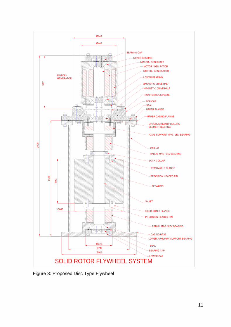
11
Figure 3 Proposed Disc Type Flywheel
CASING
UPPER FLANGE
TOP CAP
RADIAL MAG LEV BEARING
UPPER AUXILIARY ROLLING
ELEMENT BEARING
BEARING CAP
AXIAL SUPPORT MAG LEV BEARING
UPPER CASING FLANGE
SEAL
NON-FERROUS PLATE
597
MAGNETIC DRIVE HALF
MAGNETIC DRIVE HALF
MOTOR
GENERATOR
UPPER BEARING
LOWER BEARING
MOTOR GEN STATOR
MOTOR GEN ROTOR
MOTOR GEN SHAFT
Oslash440
Oslash6402028
SHAFT
RADIAL MAG LEV BEARING
LOWER AUXILIARY SUPPORT BEARING
BEARING CAP
SEAL
LOWER CAP
CASING BASE
Oslash912
Oslash330
Oslash740
5001300
Oslash600FIXED SHAFT FLANGE
PRECISION HEADED PIN
REMOVABLE FLANGE
LOCK COLLAR
PRECISION HEADED PIN
FLYWHEEL
SOLID ROTOR FLYWHEEL SYSTEM
12
Primary Bearing System The bearing system is required to hold the rotor in place whilst allowing rotation around 20000 revmin with the minimal frictional resistance Several options were considered Magnetic levitation bearings Rolling element bearings Gas film bearings Fluid film bearings (journal) Gas film bearings require a pressurised gas to be constantly pumped between the shaft and bearing In a vacuum environment this would be inappropriate and the option was discarded Fluid film bearings are essentially oil filled Upon rotation of the journal (shaft) the oil is pulled into the contactsupport area and acts as a cushion Frictional resistance is low but a constant flow of fluid is required requiring shaft seals within the vacuum chamber It was thought that the frictional resistance applied by the seals would create too much drag and reduce efficiency There may also be a problem with heat generation within the fluid at high speeds Magnetic levitation bearings are frictionless and can operate within a vacuum environment Their major disadvantage is that they require a control system and that the magnetic coils require power Research shows however that many KESDrsquos use magnetic levitation as a primary bearing system It was discovered that SKF could produce the magnetic levitation bearings required and also have experience in producing motor generator equipment which could operate at these high speeds SKF provided some very useful data which was used directly in the concept designs They gave approximate sizes of bearing units and suggested how the layout should be applied Beacon power is a company in the United states for which SKF have previously designed such bearings Please see their web site wwwbeaconpowercom A typical radial Magnetic Levitation Bearing can be seen in figure 4 Figure 4 Typical Radial Magnetic Levitation Bearing
13
The axial bearings should be sited at the top of the housing The magnetic flux applied is attractive allowing the rotor to hang from the bearing This arrangement can be seen in both figures 2 and figure 3 Secondary Bearing System It is evident from the research and from advice given by SKF that there needs to be a secondary bearing back-up system This is necessary should power fail to the magnetic levitation bearings SKF recommended high speed ball bearings for this particular role These bearings would function as radial and axial bearings Figure 5 shows typical ball bearings The application can be seen in the concept designs in figures 2 and 3
Figure 5 Typical Ball Bearings Containment The containment system has to be applied to two aspects of the design containment of the vacuum and containment of a bursting flywheel There are several approaches to containment of a bursting flywheel
Brute force approach using heavy-walled pressure vessels
Spinning ring which soaks up the energy of the impacting flywheel debris
Energy absorbing liner The soft catch approach The containment system requires design effort to be applied When the flywheel is at running speed a great deal of energy is contained This energy is enough to vertically lift a 1 tonne mass 81 km Put another way there is energy contained in the flywheel equivalent to 18kg (40lbs) of TNT Generally it is thought that a combined approach might be the way forward This would entail a light casing to contain the vacuum and a heavier casing such as a concrete perhaps below ground vessel to contain any flywheel burst This chamber might also incorporate some form of soft catch energy absorbing system which could take the form of sand or pea gravel filled chambers which break thus allowing the contents to infiltrate the chamber when a burst occurs The current concept uses segmental sand bags set inside the concrete basin If the bursting flywheel breaches the vacuum casing the sand bags will disintegrate allowing the sand to absorb the debris The concrete casing will act as final resort containment Please see figure 6 for a 3D impression of the containment Many current flywheels merely incorporate the brute force approach where a heavy casing is combined with a vacuum chamber In the case of a burst a great deal of
14
energy needs to be contained so any such casing needs to be very firm and should be mounted on heavy foundations Figure 6 Impression of the Segmental Sandbag and Concrete Containment System Motor Generator Set The motor Generator set drives the flywheel up to speed during energy input and converts rotational energy into electrical energy during energy extraction Due to the high speeds this is quite a special arrangement and requires specialist design attention SKF are able to provide the design expertise and design a suitable MG set to suit the specific design needs of the project Typical components can be seen in figure 7
Figure 7 Typical Motor Generator Components Control Equipment The magnetic levitation bearings could become unstable unless constantly monitored and controlled The service incorporates appropriate matching and supply of monitoring and control equipment Figures 8 and 9 show typical control and monitoring devices
15
Figures 8 and 9 Typical Control and Monitoring Devices Machine Monitoring Within the package SKF also offer machine monitoring software which takes input from several sensors to relay the information to a monitoring station This information could include rotational speed out of balance detection temperature energy input efficiency energy extraction efficiency etc
Figure 10 Machine monitoring Software Magnetic Drive Coupling The modular design of the KESD separates the motorgenerator from the vacuum chamber of the flywheel Normal engineering practice would incorporate lip seals to contain the vacuum but the seals would be in contact with the shaft causing frictional resistance and heat generation Ceramic seals would be required The better solution would be to use a magnetic drive coupling This is a non-contacting coupling which transfers magnetic flux through a non-magnetic membrane thus allowing drive to be applied between the two halves of the coupling One half would be situated inside the vacuum chamber the other half inside the motor generator chamber A typical magnetic drive coupling can be seen in figure 11
Figure 11 Typical Magnetic Drive Coupling
16
Electrical Aspects Design and Analysis SKF are the current specialist source of magnetic levitation bearings There are other companies who can offer this service however SKF have been the most informative and helpful They not only offer a full manufacture and design service but they also offer all the ancillary equipment needed to operate and maintain the system Elements for the system are listed as follows
Design and manufacture service for magnetic levitation bearings
Radial magnetic levitation bearings
Axial magnetic levitation bearings
Control system for magnetic levitation bearings
Machine monitoring system
Design and manufacture service for motor generator set
Control system for the motor generator set Incorporated in the total package is a high performance finite element predictive analysis tool for magnetic levitation applications Conclusions and Recommendations The proposed designs show the format of both a rim type flywheel system and also a solid (disc type) flywheel system The sizes of the rotors are generally correct though other aspects of the design are approximate It should be noted however that during the process of conversion from concept to detailed manufacturable units many of the details may change There are many technical design details which require careful consideration such as methods of balancing the rotors and stress analysis of the rotors and frame Below is a basic list of work to be accomplished before a flywheel system can be manufactured Further Work Required to Progress the Project
Finite element stress analysis vacuum chamber
MagLev radial bearing design
MagLev axial bearing design
Control system for magnetic levitation bearings
Machine monitoring system
Design and manufacture of motor generator set
Control system for the motor generator set
Stress analysis of rotors for burst limitation
Fluid flow analysis within the chamber
Vacuum pump and equipment selection
Rolling element bearing design and selection
Vacuum Casing design
Explosion containment system design
Foundations design
Selection of materials There are two concepts put forward each with its own advantages and disadvantages There needs to be a selection of either version so that detailed work can commence
17
Both concept designs fit most of the initial criteria During the detail design process some of these may need to change to accommodate more precise constraints for use or perhaps to accommodate physical parameters thrown up by the development process The concept specifications are as follows in table 3 Industrial Concept The KESD system has been designed for an industrial application where banks of KESDrsquos can be housed The appendix shows several 3D pictures which indicate scale and the probable industrial setting The soft-catch and concrete containment system is also shown Table 3 Concept Specifications for the ESP Kinetic Energy Storage Device
Rim Type Rotor Disc Type Rotor
Style Hollow cylinder Solid cylinder
Outer Diameter (mm) 600 600
Inner Diameter (mm) 450 na
Rotor depth (mm) 1000 500
Material steel steel
Density (kgm3) 7500 7500
Rotor Mass (kg) 930 1060
Angular velocity (Revmin) 18000 18000
Surface Speed (ms) 565 565
Energy (Joules) 74200000 84800000
Energy (kWh) 2061 2355
Power (kW) 573 654
1 Tonne mass lift (m) 8150 8152
Containment (Primary) Steel casing Steel casing
Containment (Secondary) Concrete lined Pit Concrete lined Pit
Bearing System Radial Magnetic Levitation Magnetic Levitation
Bearing System (secondary) Rolling element
Bearings Rolling element
Bearings
Motor Generator Drive Coupling Magnetic Magnetic
Chamber Type Vacuum Vacuum
18
Rotor Selection There is little to choose between the two types of rotor The list of differing parameters is as follows Rim Type Disc Type - Lower mass 930kg - Higher mass 1060kg - Height overall 1877mm - Overall height 2028mm - Energy 2061 kWh - Energy 2355 kWh - Power 573 kW - Power 654 kW - Stresses in rim only - Radial and Hoop stresses present (Less prone to burst)
bull Design and manufacturing will present a similar level of difficulty bull Balancing relatively easier with the rim-type flywheel due to increased length bull Cost implications will be similar for each type
19
References
Many references were consulted These were a mixture of both technical papers and company data The following is a list of the most useful references
SKF Website wwwskfcom
Beacon Power wwwbeaconpowercom
Flywheel Energy Storage System California Energy Commission 2004
Compact Flywheel Energy Storage System Koyo Seiko Company
Flywheel Energy Storage Riello-UPS wwwriello-Upscouk
Flywheel energy and Power Storage Systems Boland Bernhoff and Leijon 2004
Energy Storage Flywheel System with SMB and PMB and its Performances Mitsuda Komori Subkhan and Inoue 2009
Designing Safer Flywheels Steven Ashley Test devices inc wwwtestdevicescom
Murakami m (2007) japan Title design of an energy storage flywheel system using permanent magnet bearing and superconducting magnetic bearings
Seong-yeol yoo (2009) korea Title design of magnetically levitated rotors in a large flywheel
Werfel (2008) Germany (german e-on) Title 250kW Flywheel with HTS Magnetic Bearing for Industrial use
Bjorn Bolund (2005) sweden Title Flywheel energy and power storage systems
Read T Doucette (2011) OXFORD Engineering Science department UK 201011 Title A comparison of high speed flywheels batteries and ultracapasitors and the bases of cost and fuel
T H Sung (2011) Korea Title Flywheel energy storage system with a horizontal axle mounted on high Tc superconductor bearings
20
Appendix -1
a) Flywheel Characteristics Iteration Spreadsheets Flywheel Characteristics Disc Type Rotor
Note Speed of Sound = 3432ms
Dia Radius Depth Density Volume mass Ang Vel Ang Vel Surface Moment KE KE Power 1 tonne Rim
m m m kgm^3 m^3 kg RPM radsec Speed of Inertia Joules KWh KW Mass lift Stress
Ms kgm^2 m Nm^2
020 010 080 750000 003 18852 3000000 314200 31420 094 4652751 129 036 251584 4056795
030 015 070 750000 005 37115 2000000 209467 31420 418 9160103 254 071 251584 4056795
030 015 070 750000 005 37115 3000000 314200 47130 418 20610232 573 159 566064 9127789
040 020 070 750000 009 65982 2000000 209467 41893 1320 28950450 804 223 447261 7212080
050 025 070 750000 014 103097 2000000 209467 52367 3222 70679810 1963 545 698845 11268876
060 030 070 750000 020 148460 2000000 209467 62840 6681 146561653 4071 1131 1006337 16227181
060 030 060 750000 017 127251 2000000 209467 62840 5726 125624274 3490 969 1006337 16227181
060 030 050 750000 014 106043 2000000 209467 62840 4772 104686895 2908 808 1006337 16227181
060 030 040 750000 011 84834 2000000 209467 62840 3818 83749516 2326 646 1006337 16227181
070 035 030 750000 012 86601 2000000 209467 73313 5304 116367238 3232 898 1369736 22086996
070 035 020 750000 008 57734 2000000 209467 73313 3536 77578159 2155 599 1369736 22086996
080 040 020 750000 010 75408 2000000 209467 83787 6033 132344914 3676 1021 1789043 28848322
000 750000 000 000 000 000 000 0 000 000 DIV0 0
050 025 035 750000 007 51548 3000000 314200 78550 1611 79514786 2209 614 1572401 25354970
060 030 020 750000 006 42417 3000000 314200 94260 1909 94218206 2617 727 2264258 36511157
000 750000 000 000 000 000 000 0 000 000 DIV0 0
070 035 021 750000 008 60621 2000000 209467 73313 3713 81457067 2263 629 1369736 22086996
060 030 021 750000 006 44538 2000000 209467 62840 2004 43968496 1221 339 1006337 16227181
050 025 020 750000 004 29456 3000000 314200 78550 921 45437020 1262 351 1572401 25354970
000 750000 000 000 000 000 000 0 000 000 DIV0 0
000 750000 000 000 000 000 000 0 000 000 DIV0 0
060 030 050 750000 014 106043 1800000 188520 56556 4772 84796385 2355 654 815133 13144017
060 030 050 750000 014 106043 1200000 125680 37704 4772 37687282 1047 291 362281 5841785 Flywheel Characteristics Rim Type Rotor
Note Speed of Sound = 3432ms
Ou
ter
Dia
(m)
Ou
ter
Rad
(m)
Inn
er
Dia
(m
)
Inn
er
Rad
(m)
De
pth
(m
)
De
nsi
ty
(kg
m^
3)
Vo
lum
e
(m^
3)
mas
s (k
g)
An
g V
el
(Re
vm
in)
An
g V
el
Surf
ace
Spe
ed
(m
s)
Mo
me
nt
of
Ine
rtia
kgm
^2
KE
(Jo
ule
s)
KE
(KW
h)
Po
we
r (K
W)
1 t
on
ne
Mas
s
Lift
(m
)
Rim
Str
ess
(Nm
^2
)050 025 012 006 080 750000 015 111038 15000 1571 39275 3470 42819848 1189 330 393100 6338743
06 030 015 008 05 750000 013 99415 18000 1885 56556 4474 79496611 2208 613 815133 13144017
06 030 015 008 04 750000 011 79532 18000 1885 56556 3579 63597289 1767 491 815133 13144017
06 030 015 008 03 750000 008 59649 18000 1885 56556 2684 47697967 1325 368 815133 13144017
05 025 015 008 07 750000 013 93818 18000 1885 47130 2932 52098088 1447 402 566064 9127789
04 020 015 008 08 750000 009 64804 18000 1885 37704 1296 23031117 640 178 362281 5841785
05 025 015 008 06 750000 011 80416 18000 1885 47130 2513 44655504 1240 345 566064 9127789
05 025 015 008 065 750000 012 87117 18000 1885 47130 2722 48376796 1344 373 566064 9127789
055 028 022 011 07 750000 014 104788 18000 1885 51843 3962 70409363 1956 543 684938 11044625
06 030 022 011 05 750000 012 91786 18000 1885 56556 4130 73395982 2039 566 815133 13144017
06 030 045 023 1 750000 012 92787 18000 1885 56556 4175 74196837 2061 573 815133 13144017
21
b) Concept Renderings Figure 12 Single containment basin showing lid and control cabinet Figure 13 Impression of the industrial Application (Lids removed) Figure 14 Impression showing the Soft-Catch Segmental Sand Bags
22
Figure 15 Impression Showing Scale Figure 16 Renderings of the Proposed KESD (Hollow Flywheel Version)
Figure 17 Renderings of the Proposed KESD (Solid Flywheel Version)
23
Phase 2 Stage 2 of the Flywheel project (9May2011 till now)
The crucial elements to a successful design were considered to be the bearings radial and axial and the rotor stresses Once these elements were finalised then the rest of the KESD could be designed to suit Use of Bearings was investigated whilst finite element analysis was performed on the proposed rotor designs this is where other specialist team members included in the research team Additional team members joining to the research team Dr Simon Barrans (SMB) Specialism Stress Analyst Duties Analyse the stresses in the rotor and define materials rotor speeds and rotor shape according to safe stressing Mark Dales (MD) Specialism High current Electrical Engineer Duties Specify the motor Generator equipment and designprocure all other electrical elements Prof Rakesh Mishra (RM) Specialism Thermo-fluid behaviour and CFD techniques Duties Analyse the air flow around the rotor and determine the fluid drag Design Evolution from Concept 1 Concept 1 explained in phase 1 was devised after extensive research of current models and practices It was discovered that the original application of capturing cheap energy and selling it back to the grid at a higher cost is very feasible Furthermore peak demand smoothing is possible and indeed is the very reason for the building of several large flywheel installations throughout the world The kinetic storage of electrical energy possesses other benefits to emerging industries such as the electric car industry Here recharging stations will be required and may possibly have kinetic energy storage The conclusion is therefore that research revealed a very viable market which is demanding some form of energy storage Kinetic Energy Storage devices could easily fill that demand Concept stage 1 was effectively a feasibility study of current technologies and the possibility of using these technologies to create a kinetic energy storage device (KESD) A feasibility report was presented to the board of ESP Ltd who then agreed to the project progressing to the phase 2 The main thrust of the design was that it should follow standard engineering techniques in order to Reduce time to market Reduce the development time Reduce development costs Ensure low cost manufacture Ensure sustainability issues were minimised
24
Bearings Up to the point of the presentation in May 2011 of the feasibility report the team had been liaising with SKF who had been very helpful in providing guidance for the magnetic-levitation bearings used in Concept 1 The bearings needed development though SKF had previously provided similar bearings to the Beacon Project which is a similar facility based in California As soon as SKF understood the need for development work they lost interest saying they were overstretched and could not pursue the project Another company Mecos of Switzerland was approached who could provide the necessary magnetic levitation units They were very enthusiastic but required pound100000 to be deposited before development could begin This clearly excluded them from the development Two other companies were approached with no success Stress Analysis Whilst the bearing search was being conducted SMB had been pursuing the stress analysis on the rotor and reported that a high carbon steel rotor with a speed of 18000 revmin would burst long before it reached the operation speed The data below in table 3 shows the rotor size possibilities related to material stress Table 3 Rotor Size Possibilities for Solid Rotors at 7000 revmin The table above indicates the radius of the flywheel and the stress that flywheel would see in service The moment of inertia and the height of the rotor are important since they are essential properties in the storage of kinetic energy In general a larger Inertia value will store a larger value of kinetic energy but an increase in speed will increase the kinetic energy storage capacity in terms of speed squared Basic Equation for Kinetic Energy is as follows
KE = 1 I2 2 Where I = Moment of Inertia (kgm2)
= Angular velocity (radsec) It can be seen from the first line of table 3 that a rotor of radius 04m (800mm diameter) with a height of 0913m (913mm) will have a moment of inertia of
Ou
ter
Rad
ius
Ro
(m
)
Radial Stress(MNm2) at centre
Mo
men
t o
f in
erti
ah
eigh
t
Hei
ght
(m)
req
uir
ed t
o
give
re
qu
ired
en
ergy
at
rate
d s
pee
d
Is design possible
04 2686726 3016E+02 0913 Y
045 3400387 4831E+02 0570 Y
05 4198009 7363E+02 0374 Y
25
3016 x 10-2 kgm2 Importantly the radial stress in the rotor is 26867 MNm2 which is approximately half of the envisaged ultimate tensile strength of the rotor material medium carbon steel This will give a safety factor of slightly under 20 The conclusion from this analysis is that the original target of 18000 revmin for a solid rotor cannot be achieved using steel or one of its alloys The analysis shows that the speed needs to be substantially reduced to a maximum of 7000 revmin Design Concept 2 Evolving to Concepts 3 and 4 The revelation that the rotor stresses had forced the angular velocity down to 7000 revmin from 18000 revmin helped to continue the theme of using standard engineering components and techniques since high speed radial rolling element bearings could now be considered and separate thrust bearings The negative side to reducing the speed was that the rotor mass had to be increased to approximately 3 tonnes in order to increase the moment of inertia The reduction in speed also meant that expensive active magnetic-levitation bearings could be discarded though it seemed reasonable to support the 3 tonnes mass of the vertical axially mounted rotor on permanent magnet thrust bearings Figure 15 shows the concept Figure 15 Concept 2 Solid Rotor with Permanent Magnet Bearings and Hybrid Ceramic Radial Bearings
UPPER FLANGE
TOP CAP
BEARING CAP
UPPER CASING FLANGE
SEAL
NON-FERROUS PLATE
597 MAGNETIC DRIVE HALF
MAGNETIC DRIVE HALF
MOTOR
GENERATOR
UPPER BEARING
LOWER BEARING
MOTOR GEN STATOR
MOTOR GEN ROTOR
MOTOR GEN SHAFT
Oslash440
Oslash640
UPPER FLANGE
UPPER HIGH SPEED ROLLING
ELEMENT BEARING
GOOD SLIDING FIT ON
OUTER RACE
UPPER CASING FLANGE
SEAL
ROTOR
AXIAL SUPPORT PASSIVE
REPULSING MAGNETS (ROTOR)
AXIAL SUPPORT PASSIVE
REPULSING MAGNETS (BASE)
CASING
LOWER HIGH SPEED
ROLLING ELEMENT BEARING
GOOD SLIDING FIT ON
OUTER RACE
1880
1218
Oslash900
26
Radial Bearings Several bearing companies were contacted with a specification for radial bearings of 7000 Revmin 100mm bore Radial loads of 15KN Radial loads were evaluated by calculating the residual out-of-balance as directed by ISO 19401 Balancing Quality Requirements for Rigid Rotors Bearing loads were then calculated for a particular bearing diameter Bearing companies contacted were as follows Barden UK (Part of the Schaeffler group) SKF Luton NSK UK Each company suggested that the duty could be accommodated using a hybrid bearing of ceramic ball bearings and a high alloy steel race In order to increase long life several lubrication strategies were suggested
Grease packed
Oil lubrication (automatic injection)
A five year maintenance plan
Live wear monitoring Uniformly Stressed Rotor Results During the search for appropriate bearings SMB was conducting stress analysis on the rotor The start point for the analysis was the solid rotor in Concept 2 with a speed of 7000 revmin The necessity to increase moment of inertia and reduce the radial stresses which were so high near the rotor axis drove the rotor shape to that of a rim-type flywheel Concept 3 shows the KESD with the new shape rotor See figure 16
27
Figure 16 Concept 3 KESD Showing Rim Type Flywheel as a Uniformly Stressed Rotor
UPPER FLANGE
TOP CAP
UPPER HIGH SPEED ROLLING
ELEMENT BEARING
GOOD SLIDING FIT ON
OUTER RACE
BEARING CAP
UPPER CASING FLANGE
SEAL
NON-FERROUS PLATE
597
MAGNETIC DRIVE HALF
MAGNETIC DRIVE HALF
MOTOR
GENERATOR
UPPER BEARING
LOWER BEARING
MOTOR GEN STATOR
MOTOR GEN ROTOR
MOTOR GEN SHAFT
Oslash440
Oslash640
ROTOR
AXIAL SUPPORT PASSIVE
REPULSING MAGNETS (ROTOR)
AXIAL SUPPORT PASSIVE
REPULSING MAGNETS (BASE)
CASING
LOWER HIGH SPEED
ROLLING ELEMENT BEARING
GOOD SLIDING FIT ON
OUTER RACE
1692
1030
28
Figure 17 Concept 4 Inboard Configuration of Permanent Magnet Thrust Bearing Permanent Magnet Thrust Bearings Since the axis of the rotor was vertical it seemed reasonable to support the 3 tonnes axial load on a separate thrust bearing The obvious choice was to use rolling element thrust bearings but it was considered that other low friction axial bearing alternatives should be investigated Air bearings were considered but since the unit was destined to run in a vacuum the continual leakage of air from the bearings in to the vacuum chamber would destroy the vacuum Air bearings were therefore ruled out of the design
UPPER HIGH SPEED ROLLING
ELEMENT BEARING
GOOD SLIDING FIT ON
OUTER RACE
BEARING CAP
UPPER CASING FLANGE
SEAL
EXTERNAL RADIAL MAGNETIC DRIVE HALF
INTERNAL RADIAL MAGNETIC DRIVE HALF
MOTOR
GENERATOR
UPPER HIGH SPEED BEARING
LOWER BEARING
MOTOR GEN STATOR
MOTOR GEN ROTOR
MOTOR GEN SHAFT
Oslash440
Oslash640
ROTOR
AXIAL SUPPORT PASSIVE
REPULSING MAGNETS (ROTOR)
AXIAL SUPPORT PASSIVE
REPULSING MAGNETS (BASE)
CASING
LOWER HIGH SPEED
ROLLING ELEMENT BEARING
GOOD SLIDING FIT ON
OUTER RACE
1030
702
1733
Oslash1212
Oslash400
Oslash180
Oslash110
Oslash900
700
29
The company that ESP Ltd had proposed as manufacturers JPS Ltd based in the Wirral suggested permanent magnet thrust bearings as axial thrust bearings They had previously conducted some ad-hoc experiments but had no real data to offer Manufacturers of permanent magnets were contacted to ascertain strengths costs etc Research was also conducted as to best methods of application and installation of permanent magnets High strength magnets are manufactured from neodymium Since the rotor was to be supported by permanent magnets the flywheel rim edges were proposed as bearing points Consideration was given to the shape of the magnets Cylindrical magnets were an obvious choice but research showed that heat would be generated as rotor mounted magnets passed over base mounted magnets It soon became clear that specially shaped magnets would be required to reduce the number of ldquoedgesrdquo within the magnetic flux and hence reduce the generated heat Manufacturing shaped magnets offered several options The thrust bearing could be applied as in Concept 3 figure 16 or perhaps as in Concept 4 see figure 17 This particular configuration was devised after a quote from Best Solution Consultancy Ltd who quoted a repulsing magnet outer diameter of 540mm and an inner diameter of 160mm with a magnet thickness of 40mm The material would be neodymium rare earth This high strength high cost sintered magnet offered several benefits
Reasonable gap between thrust plates of approximately 5mm
Able to support 3 tonne mass
Zero friction (no Contact)
Zero maintenance There were however several negatives
Very High cost (approx pound28000 per bearing)
Requirement to magnetise at the assembly site
Requirement for mechanical handling equipment to enable unpacking and assembly (due to inherent attractive forces)
High cost of ancillary equipment Due to the high cost of the magnetic bearing material and the anticipated high cost of the handling equipment and other ancillary equipment it was decided that though an exceedingly viable technical option the costs were prohibitive The use of permanent magnet thrust bearings was discarded in favour of more traditional bearings such as rolling element thrust bearings
30
Concept 5 The specification for the rotor was as follows
Rotor mass 3000kg
Rotor speed 7000 revmin
Vertical axis Investigations into rolling element thrust bearings quickly revealed that even hybrid ceramic bearings would be hard pressed to support 3000kg running at 7000 revmin A quote from one of the bearing manufacturers SKF UK Ltd suggested that such a bearing would match their ACDHC super precision angular contact hybrid bearing (ceramic balls) This would need to be lubricated with an oil-air (spray) system Unfortunately this bearing system would only have a predicted life of 284 hours This was the best bearing SKF could offer Other companies offered similar bearings They suggested that the heavy load and the rotation speed were the main problems It was evident that the rotor required redesigning to fulfil the design brief of storing 20KWh but with a much lower mass and a lower speed Since the uniformly stressed rotor was essentially a rim type rotor analysis was conducted for a rim type flywheel with a spoke and shaft system to be added later within the stress analysis exercise Revisiting the basic Kinetic Energy equation it was discovered that there were several variables which could be manipulated as follows
KE = 1 I2 2 Where I = Moment of Inertia (kgm2)
= Angular velocity (radsec) But I = mk2 Where m = mass (kg) and k = radius of gyration (m) giving
KE = 1 mk22 2 Or
KE = 1 m(R2 + R1)22
2 (2)2 Where R1 = outer radius (m) R2 = inner radius (m)
31
From analysis of basic flywheel characteristics see appendix the kinetic energy to deliver 20KWh is 725MJ For analysis purposes this value was fixed as well as the aim of a notional 1500kg for the rotor mass The four variables were therefore R1 = outer radius (m) R2 = inner radius (m) Rotor depth (m)
= angular velocity (radsec)
A spreadsheet tool was used to vary the parameters which are shown in table 4 below Table 4 Spreadsheet Analysis tool to Vary Flywheel Parameters
During the iteration process the outer diameter was fixed and the depth and the inner radius was varied The angular velocity was also varied to achieve the kinetic energy value of approximately 73MJ The rotor of 22m OD 20m ID 03m depth emerged as an excellent choice having a mass of only 1485kg and a KE of 788MJ The rotor of 20m OD 17m ID 025m depth was a little heavier at 1635kg but was smaller in outer diameter This was desirable since a smaller outer diameter would mean an overall smaller unit In comparison there is not much to choose between either of the rotors The rotor of 18m OD 16m ID 04m depth emerged as the best of the 18 diameter rotors but was lacking in the value of kinetic energy storage at only KE of 579MJ This size of rotor was clearly inferior to the 20m and 22m diameter rotors
Ou
ter
Dia
(m
)
Ou
ter
Rad
(m
)
Inn
er D
ia (
m)
Inn
er R
ad (
m)
De
pth
(m
)
De
nsi
ty
(kg
m^3
)
Vo
lum
e (
m^3
)
mas
s (k
g)
An
g V
el
(Re
vm
in)
An
g V
el
(rad
sec
)
Surf
ace
Spee
d
(ms
)
Mo
me
nt
of
Iner
tia
kgm
^2
KE
(Jo
ule
s)
KE
(KW
h)
18 090 14 070 02 7500 020 1508 4000 419 377 611 53599690 1489
18 090 15 075 025 7500 019 1458 4000 419 377 591 51820013 1439
18 090 16 080 04 7500 021 1602 4000 419 377 649 56949671 1582
2 100 16 080 02 7500 023 1697 3000 314 314 848 41874758 1163
2 100 16 080 025 7500 028 2121 3000 314 314 1060 52343448 1454
2 100 17 085 025 7500 022 1635 4000 419 419 817 71729910 1992
2 100 175 088 03 7500 022 1657 4000 419 419 828 72699233 2019
2 100 18 090 036 7500 021 1612 4000 419 419 806 70721814 1964
22 110 18 090 02 7500 025 1885 3000 314 346 1141 56298286 1564
22 110 19 095 025 7500 024 1812 3000 314 346 1096 54099134 1503
22 110 2 100 03 7500 020 1485 4000 419 461 898 78817600 2189
32
Shown in figure 18 is the rim type rotor which was used to base the analysis whose results are displayed in table 4 Please note that for analysis purposes the spokes and shaft have been omitted being relatively insignificant compared to the rim of the rotor Figure 18 Rim of Flywheel as Calculated for 20m Device Figure 19 Concept 5 Rim Type Flywheel
Concept 5 is shown in Figure 19 The rotor has a diameter of 20 m and is hollow to reduce weight and hence bearing load It was intended that the hollow halves of the rotor would be machined separately and joined using industrial adhesive The key turned in to the joint at the rim would key the two halves and allow them to expand radially as one component when rotating at speed Concept 6 Intensive stress analysis revealed that the use of normally available engineering materials provided severe restrictions on the shape speed and size of the flywheel Furthermore the variables hitherto used were complicated to juggle to obtain the
LOWER HIGH SPEED
ROLLING ELEMENT BEARING
GOOD SLIDING FIT ON
OUTER RACE
UPPER FLANGE
TOP CAP
UPPER HIGH SPEED ROLLING
ELEMENT BEARING
GOOD SLIDING FIT ON
OUTER RACE
UPPER CASING FLANGE
SEAL
NON-FERROUS PLATE
ROTOR
CASING
BEARING CAP
NON-FERROUS PLATE
597
MAGNETIC DRIVE HALF
MAGNETIC DRIVE HALF
MOTOR
GENERATOR
UPPER BEARING
LOWER BEARING
MOTOR GEN STATOR
MOTOR GEN ROTOR
MOTOR GEN SHAFT
Oslash440
Oslash640
ROLLING ELEMENT CERAMIC
THRUST BEARING
Oslash2000
12
83
Oslash2500
33
correct rotor format Research revealed that energy density was a comparative parameter that would give the optimum energy capacity for various rotor shapes Energy Density Further research [16] led the design in the direction of using ldquoEnergy Densityrdquo as a useful factor in identifying the most appropriate flywheel shape as explained below Energy density is essentially the value of energy in Joules per kg mass of rotor Energy Density = joules Kg
KE = 1 x I x 2 helliphelliphelliphelliphelliphelliphelliphelliphellip1
2
KE = m x r2 x 2 helliphelliphelliphelliphelliphelliphelliphelliphellip2
2 where KE = Kinetic Energy (Joules)
I = polar 2nd moment of Inertia (kgm2) I = m x r2 m = mass (kg) r = mean radius (m)
= angular velocity (radsec)
From equation 2 it can be seen that a reduction in angular velocity must be
compensated by an increase in radius r Another parameter which is useful to consider is that of ldquoenergy densityrdquo and is shown below From equation 2
KE = m x r2 x 2 helliphelliphelliphelliphelliphelliphelliphelliphellip2
2 Divide both sides by mass m
KE = m x r2 x 2 helliphelliphelliphelliphelliphelliphelliphelliphellip3
m m 2 giving
KE = r2 x 2 helliphelliphelliphelliphelliphelliphelliphelliphellip4
m 2 or Energy Density This parameter allows comparison between flywheel shapes The new task then was to arrange the flywheel shape to give a large value of energy (Joules) for each kg of rotor mass
34
The use of Energy Density quickly showed that the best shape for a rotor system was not a rim type flywheel or a cylindrical flywheel but a tapered rotor section as shown in figure 20 Figure 20 Concept 6 Tapered disc
Stress analysis revealed that the major stresses were radial and imposed high stresses near the shaft Essentially centrifugal forces tend to pull the flywheel material away from the shaft
Figure 21 Finite Element Stress Analyses Showing a Small Disc Segment by Dr Simon Barrans The diagram shown in figure 21 shows a small disc segment rotated at 500radsec (4776 revmin) The disc shows stresses 237MNm2 in the blue area at the outside of the disc and 463 MNm2 at the centre Should high strength materials be used these stresses are not particularly excessive and show clearly where the highest stresses are likely to occur which is towards the centre where the disc joins the shaft The next step was to attach the disc to the shaft in order to determine stresses at the joint of the disc and the shaft The analytical diagram is shown in figure 22 Figure 22 Analytical Segment Showing High Stress at Discshaft Junction by Dr Simon Barrans
LOWER HIGH SPEED
ROLLING ELEMENT BEARING
GOOD SLIDING FIT ON
OUTER RACE
ROTOR
ROLLING ELEMENT CERAMIC
THRUST BEARING
Oslash2000
Small segment analysed
Plain disc stress not uniform
Disc is not infinite
Full disc moment of inertia 484 kgm2
Disc outer diameter 24m
Central thickness 100mm
Edge load applied to give uniform stress
Fillet radius generates significant stress raiser
Disc Diameter 09m
35
The concept 6 design emerged as a constant stress device which took the form of a tapered cross section fatter nearer the shaft and tapering to the outside edge The surface however has been curved to enable constant stress across the section The whole concept can be seen in figure 23 Concept 6 parameters are as follows Outer radius 10 m Outer Diameter 20 m Thickness on central axis 110 mm (plus stub shafts to mate with the bearings) Thickness on outer rim 35 mm Mass 12 to 15 tonnes Speed 3650 to 4000 rpm Energy storage 40 to 54 MJ Figure 23 Concept 6 Uniformly Stressed Rotor Design
Bearing Selection Various bearing manufacturers were contacted requesting quotations and a specification of bearing Since the bearings required were off standard and therefore required specialist selection procedures the bearing companies were relied upon to specify bearings which could contend with the following parameters Working speed 4000 revmin Test speed 7000revmin Rotor mass 2000kg Life 10 years HB Bearings LTD of Honley West Yorkshire are specialist bearing manufacturers They declined to quote a price since the bearings could be purchased off the shelf from some of the large bearing manufacturing companies as is outlined below They did however assist greatly in specifying bearing types as follows Radial Bearings
UPPER FLANGE
TOP CAP
UPPER HIGH SPEED ROLLING
ELEMENT BEARING
GOOD SLIDING FIT ON
OUTER RACE
UPPER CASING FLANGE
SEAL
NON-FERROUS PLATE
ROTOR
CASING
BEARING CAP
NON-FERROUS PLATE
59
7
MAGNETIC DRIVE HALF
MAGNETIC DRIVE HALF
MOTOR
GENERATOR
UPPER BEARING
LOWER BEARING
MOTOR GEN STATOR
MOTOR GEN ROTOR
MOTOR GEN SHAFT
Oslash440
Oslash640
ROLLING ELEMENT CERAMIC
THRUST BEARING
Oslash2000
12
83
Oslash2500
LOWER HIGH SPEED
ROLLING ELEMENT BEARING
GOOD SLIDING FIT ON
OUTER RACE
36
Hybrid type angular contact bearing at 15deg - 25deg angle of contact
Oslash 100mm x Oslash 150mm x 24mm
To P4 run out and dimensional tolerances
Obtainable as sealed or not sealed
Commercially available bearing from SKF FAG NSKRHP Thrust Bearing This posed a challenge with the high running speed required since a bearing of a similar size to the radial bearings would not have the thrust capability to operate at the required speed To be able to run at the required speed a smaller bearing needs to be considered This would reduce the linear speed of the balls within the bearing The specification suggested follows
Hybrid type ball bearing at
Oslash 50mm x Oslash 70mm x 14mm single row ball thrust bearing
Load ratings of Ca 27 KN and Coa 75KN
Working speeds of 4300 revmin maximum
Test speed 6300 revmin limiting speed Further research and engineering analysis have been currently carried out b Engineering staff especially vacuum fluid dynamics air resistance stability friction and vibration and noise Conclusion and further plan In this report an overview of advanced flywheel feasibility study is presented in the phase one This report covered the literature review competitive products on the market and the concept development of two alternative products with basic calculations After presenting this report in May 2011 to ESP directors and managers the team visited manufacturing facility of ESP near Liverpool and ESP decided to fund the development of two prototypes and raise further funding which is handled by the Research amp Enterprise Centre of the University The team then continued to further engineering design calculation manufacturing details optimisation cost of off the shelf external parts design and detailing of the new parts to be built And further discussion taken place with the manufacturers of the standard parts This process was very useful as it revealed that due to the required final cost of the KESD set by ESP ltd further design changes was necessary as the companies initially approached could not deliver the required spec parts therefore further calculation and design iterations required At this point team also extended to include Dr Simon Barrans who calculated stress on the rotor and material specification Then Mark Dales from Electrical Engineering started on electric motor generator specification which is still on going Also Prof Rakesh Mishra agreed and will be calculating and advising on the rotor air frictions who specialise on Thermo-fluid behaviour and CFD techniques when the final decision is made The next phase of the project is to start purchasing off the shelf parts an also manufacturing and testing which we require to use manufacturing facilities of ESP The research team appreciate Dr Simon Barrans (SMB) on the his expert advice on the analysis of the stresses in the rotor materials shape and specifications so far
37
Appendix 2 Flywheel Characteristics Iteration Spreadsheets Flywheel Characteristics Disc Type Rotor
Note Speed of Sound = 3432ms
Dia Radius Depth Density Volume mass Ang Vel Ang Vel Surface Moment KE KE Power 1 tonne Rim
m m m kgm^3 m^3 kg RPM radsec Speed of Inertia Joules KWh KW Mass lift Stress
Ms kgm^2 m Nm^2
020 010 080 750000 003 18852 3000000 314200 31420 094 4652751 129 036 251584 4056795
030 015 070 750000 005 37115 2000000 209467 31420 418 9160103 254 071 251584 4056795
030 015 070 750000 005 37115 3000000 314200 47130 418 20610232 573 159 566064 9127789
040 020 070 750000 009 65982 2000000 209467 41893 1320 28950450 804 223 447261 7212080
050 025 070 750000 014 103097 2000000 209467 52367 3222 70679810 1963 545 698845 11268876
060 030 070 750000 020 148460 2000000 209467 62840 6681 146561653 4071 1131 1006337 16227181
060 030 060 750000 017 127251 2000000 209467 62840 5726 125624274 3490 969 1006337 16227181
060 030 050 750000 014 106043 2000000 209467 62840 4772 104686895 2908 808 1006337 16227181
060 030 040 750000 011 84834 2000000 209467 62840 3818 83749516 2326 646 1006337 16227181
070 035 030 750000 012 86601 2000000 209467 73313 5304 116367238 3232 898 1369736 22086996
070 035 020 750000 008 57734 2000000 209467 73313 3536 77578159 2155 599 1369736 22086996
080 040 020 750000 010 75408 2000000 209467 83787 6033 132344914 3676 1021 1789043 28848322
000 750000 000 000 000 000 000 0 000 000 DIV0 0
050 025 035 750000 007 51548 3000000 314200 78550 1611 79514786 2209 614 1572401 25354970
060 030 020 750000 006 42417 3000000 314200 94260 1909 94218206 2617 727 2264258 36511157
000 750000 000 000 000 000 000 0 000 000 DIV0 0
070 035 021 750000 008 60621 2000000 209467 73313 3713 81457067 2263 629 1369736 22086996
060 030 021 750000 006 44538 2000000 209467 62840 2004 43968496 1221 339 1006337 16227181
050 025 020 750000 004 29456 3000000 314200 78550 921 45437020 1262 351 1572401 25354970
000 750000 000 000 000 000 000 0 000 000 DIV0 0
000 750000 000 000 000 000 000 0 000 000 DIV0 0
060 030 050 750000 014 106043 1800000 188520 56556 4772 84796385 2355 654 815133 13144017
060 030 050 750000 014 106043 1200000 125680 37704 4772 37687282 1047 291 362281 5841785 Flywheel Characteristics Rim Type Rotor
Note Speed of Sound = 3432ms
Ou
ter
Dia
(m)
Ou
ter
Rad
(m)
Inn
er
Dia
(m
)
Inn
er
Rad
(m)
De
pth
(m
)
De
nsi
ty
(kg
m^
3)
Vo
lum
e
(m^
3)
mas
s (k
g)
An
g V
el
(Re
vm
in)
An
g V
el
Surf
ace
Spe
ed
(m
s)
Mo
me
nt
of
Ine
rtia
kgm
^2
KE
(Jo
ule
s)
KE
(KW
h)
Po
we
r (K
W)
1 t
on
ne
Mas
s
Lift
(m
)
Rim
Str
ess
(Nm
^2
)050 025 012 006 080 750000 015 111038 15000 1571 39275 3470 42819848 1189 330 393100 6338743
06 030 015 008 05 750000 013 99415 18000 1885 56556 4474 79496611 2208 613 815133 13144017
06 030 015 008 04 750000 011 79532 18000 1885 56556 3579 63597289 1767 491 815133 13144017
06 030 015 008 03 750000 008 59649 18000 1885 56556 2684 47697967 1325 368 815133 13144017
05 025 015 008 07 750000 013 93818 18000 1885 47130 2932 52098088 1447 402 566064 9127789
04 020 015 008 08 750000 009 64804 18000 1885 37704 1296 23031117 640 178 362281 5841785
05 025 015 008 06 750000 011 80416 18000 1885 47130 2513 44655504 1240 345 566064 9127789
05 025 015 008 065 750000 012 87117 18000 1885 47130 2722 48376796 1344 373 566064 9127789
055 028 022 011 07 750000 014 104788 18000 1885 51843 3962 70409363 1956 543 684938 11044625
06 030 022 011 05 750000 012 91786 18000 1885 56556 4130 73395982 2039 566 815133 13144017
06 030 045 023 1 750000 012 92787 18000 1885 56556 4175 74196837 2061 573 815133 13144017
38
From ISO19401 Uper = 9549 x G x W (gmm) N Where G = Balance Grade G63 W = Rotor Mass 3000kg N = Service Speed 7000revmin Uper = 9549 x 63 x 3000 = 25782 gmm 7000 Find Centrifugal Force First Find Eccentric Mass Uper = 25782 grm Radius of Bearing = 55mm Uper = emass x radius emass = Uper__ = 25782 = 470grm or 047kg radius 55 Find Centrifugal Force
Fc = m x 2 x r
Where m = rotor mass of 3000kg
= angular velocity = 7000 x 2 x = 733 radsec
60 R = bearing radius = 55mm or 0055m Fc = 3000 x 7332 x 0055 = 13890 N or equivalent mass = 1416kg And is the radial force applied to the bearing
Determination of Residual Unbalance Forces From Balancing Grades
Grade Rotor Angular Rotor Bearing Residual Residual Centrifugal Centrifugal
Speed Velocity Mass Radius Unbalance Eccentric Force Equiv Load
mass at Brg at Brg
RevMin radsec Kg mm g-mm kg N kg
63 7000 733 3000 55 257823 047 138576 14126
25 7000 733 3000 55 102311 019 54990 5606
63 4000 419 1635 55 245899 045 43156 4399
39
Determination of Energy Storage Efficiency
Determination of Drag due to Skin Friction
Determination of Drag due to Bearing Friction
Determination of Retardation and Efficiency Determination of Drag due to Skin Friction The general drag force equation shown below was used
Fdrag = 1 x x v2 x A x CD
2 Where
= gas density (kgm3)
V = velocity (ms) A = Cross sectional Area (m2) CD = Drag coefficient (dimensionless) The drag coefficient was determined from the following equation after determining the Reynolds Number for the conditions These calculations can be seen in the appendix page xxx CD = 133(Re)-12 per side Ref [19] Where Re = Reynolds Number
Re = VL
Where
= fluid density (kgm3)
V = average velocity (ms) L = Travelled length of fluid (hydraulic Diameter) (m)
= dynamic viscosity (Nsm2)
Parameters from speed of sound analysis Pressure = 200mbar
air = 12 x 02 = 024kgm3
Find Dynamic Viscosity
Viscosity at 1000 mbar = 1827 Pa s
Viscosity at 200mbar = 1827 x 10-3 x 02 = = 3654 x 10-3 Pa s
Find L (travelled fluid length) Normally for a pipe but the equivalent diameter can be calculated from the Hydraulic Diameter as follows DH = 4A
40
P Where A = cross sectional Area (m2) P = whetted surface distance (m) Average thickness = 90mm at 448mm = average radius of disc Cross Sectional Area = average thickness x average radius CSA = 0073 x 094 = 00686 m2 Find Whetted Length P Length of surface area of section Shaft = 01 x 2 = 02 Surface = 094 x 2 = 188 Circumference = 0036 2116 m Find Hydraulic Diameter DH DH = 4A = 4 x 00686 = 013m P 2116 Find Average Velocity Average occurs at average radius = r_ = 10_ = 10 x 0707 = 0707m (2)12 (2)12 Find Average Velocity V From tabulated data Velocity at circumference = 420ms at 4000revmin Velocity Mean = V = 420 x 0707 = 300ms Find Reynolds Number
Re = VL = 024 x 300 x 013 = 2561
3654 x 10-3
10
01
00
1000
11
0
36
AVERAGE RADIUS
RA = RADIUS X 0707
ROTOR CROSS SECTION
940
73
707
41
Find Skin Friction Coefficient CD CD = 133(Re)-12 per side Ref [19] CD = 133(2561)-12 x 2 = 00525 Find Drag Force
Fdrag = 1 x x v2 x A x CD
2 Fdrag = 1 x 024 x 3002 x 00686 x 00525 = 3889N Average force at average radius 2 Find Average Torque Due to Skin Friction T = force x radius T = 3889 x 0707 = 275Nm Determination of Drag due to Bearing Friction The rolling element bearings are hybrid bearings with ceramic balls Their equivalent coefficient of friction is rated at 10 of that of a standard rolling element bearing Since standard rolling element bearings typically have a coefficient of friction of 001 the coefficient of friction of ceramic hybrid bearings can be considered to be 0001 General Data Mass of rotor 1500kg Rotational speed 4000revmin Radial Bearings Effective diameter 110mm Radial force (N) 1571N (gleaned from balancing forces for a rigid rotor)
Coefficient of friction 0001 ()
Thrust Bearings 147KN (weight of rotor) Effective diameter 60mm Axial force (N) 1571N
Coefficient of friction 0001 ()
Find Friction Force FR Radial Bearings NB 2 Bearings
FR = N
FR = 2 x 0001 x 1571 = 3142N
42
Find Resisting Torque (Radial) T = force x radius T = 3142 x 0055 = 0173Nm Thrust Bearings NB 2 bearings sharing the load Load = 147KN Each bearing will sustain 735KN Load
FR = N
FR = 2 x 0001 x 735 x 103 = 147N Find Resisting Torque (Axial) T = force x radius T = 147 x 003 = 0441Nm Total Torque TT = Skin Friction + radial bearing + axial Bearing TT = 275 + 0173 + 0441 = 28114 Nm Determine Deceleration From Newtonrsquos second law I = 825kgm2 from data tool
T = I x
= T = 28114 = 0034ms2 retardation
I 825 The value of the resistance from fluid friction is significantly higher than the resistance from the bearings Bearings contribute little to the inefficiencies whereas the skin friction is comparatively large
Determine the Angular Velocity after 1 hour of Deceleration 1
Initial Angular Velocity 0 = 419 radsec
43
Time 1 hour t = 3600 seconds
Deceleration = 0034ms2
From
1 - 0 + t
0 = 1 - ( x t) = 419 - (0034 x 3600) = 297 radsec = 2832revmin
Determine Efficiency Efficiency = change in speed = 4000 - 2832 = 0292 or 292 speed reduction original speed 4000 A loss of efficiency of 292 in 1 hour is unacceptable In 3 hours the rotor would have almost stopped rotating Since the fluid friction is the largest contributor there must be a further reduction in the skin friction FULLY STRESSED DISK DESIGN
bull Concept Vary the cross section of the disk so that the stress due to rotation remains constant across the radius
bull For a solid disk theory gives the height as
bull Theoretical disk should have an infinite outer radius bull thickness tapers down to zero
bull Practical disks will have a finite outer radius bull where the thickness is finite
bull For a disk of this shape the moment of inertia is given by

12
Primary Bearing System The bearing system is required to hold the rotor in place whilst allowing rotation around 20000 revmin with the minimal frictional resistance Several options were considered Magnetic levitation bearings Rolling element bearings Gas film bearings Fluid film bearings (journal) Gas film bearings require a pressurised gas to be constantly pumped between the shaft and bearing In a vacuum environment this would be inappropriate and the option was discarded Fluid film bearings are essentially oil filled Upon rotation of the journal (shaft) the oil is pulled into the contactsupport area and acts as a cushion Frictional resistance is low but a constant flow of fluid is required requiring shaft seals within the vacuum chamber It was thought that the frictional resistance applied by the seals would create too much drag and reduce efficiency There may also be a problem with heat generation within the fluid at high speeds Magnetic levitation bearings are frictionless and can operate within a vacuum environment Their major disadvantage is that they require a control system and that the magnetic coils require power Research shows however that many KESDrsquos use magnetic levitation as a primary bearing system It was discovered that SKF could produce the magnetic levitation bearings required and also have experience in producing motor generator equipment which could operate at these high speeds SKF provided some very useful data which was used directly in the concept designs They gave approximate sizes of bearing units and suggested how the layout should be applied Beacon power is a company in the United states for which SKF have previously designed such bearings Please see their web site wwwbeaconpowercom A typical radial Magnetic Levitation Bearing can be seen in figure 4 Figure 4 Typical Radial Magnetic Levitation Bearing
13
The axial bearings should be sited at the top of the housing The magnetic flux applied is attractive allowing the rotor to hang from the bearing This arrangement can be seen in both figures 2 and figure 3 Secondary Bearing System It is evident from the research and from advice given by SKF that there needs to be a secondary bearing back-up system This is necessary should power fail to the magnetic levitation bearings SKF recommended high speed ball bearings for this particular role These bearings would function as radial and axial bearings Figure 5 shows typical ball bearings The application can be seen in the concept designs in figures 2 and 3
Figure 5 Typical Ball Bearings Containment The containment system has to be applied to two aspects of the design containment of the vacuum and containment of a bursting flywheel There are several approaches to containment of a bursting flywheel
Brute force approach using heavy-walled pressure vessels
Spinning ring which soaks up the energy of the impacting flywheel debris
Energy absorbing liner The soft catch approach The containment system requires design effort to be applied When the flywheel is at running speed a great deal of energy is contained This energy is enough to vertically lift a 1 tonne mass 81 km Put another way there is energy contained in the flywheel equivalent to 18kg (40lbs) of TNT Generally it is thought that a combined approach might be the way forward This would entail a light casing to contain the vacuum and a heavier casing such as a concrete perhaps below ground vessel to contain any flywheel burst This chamber might also incorporate some form of soft catch energy absorbing system which could take the form of sand or pea gravel filled chambers which break thus allowing the contents to infiltrate the chamber when a burst occurs The current concept uses segmental sand bags set inside the concrete basin If the bursting flywheel breaches the vacuum casing the sand bags will disintegrate allowing the sand to absorb the debris The concrete casing will act as final resort containment Please see figure 6 for a 3D impression of the containment Many current flywheels merely incorporate the brute force approach where a heavy casing is combined with a vacuum chamber In the case of a burst a great deal of
14
energy needs to be contained so any such casing needs to be very firm and should be mounted on heavy foundations Figure 6 Impression of the Segmental Sandbag and Concrete Containment System Motor Generator Set The motor Generator set drives the flywheel up to speed during energy input and converts rotational energy into electrical energy during energy extraction Due to the high speeds this is quite a special arrangement and requires specialist design attention SKF are able to provide the design expertise and design a suitable MG set to suit the specific design needs of the project Typical components can be seen in figure 7
Figure 7 Typical Motor Generator Components Control Equipment The magnetic levitation bearings could become unstable unless constantly monitored and controlled The service incorporates appropriate matching and supply of monitoring and control equipment Figures 8 and 9 show typical control and monitoring devices
15
Figures 8 and 9 Typical Control and Monitoring Devices Machine Monitoring Within the package SKF also offer machine monitoring software which takes input from several sensors to relay the information to a monitoring station This information could include rotational speed out of balance detection temperature energy input efficiency energy extraction efficiency etc
Figure 10 Machine monitoring Software Magnetic Drive Coupling The modular design of the KESD separates the motorgenerator from the vacuum chamber of the flywheel Normal engineering practice would incorporate lip seals to contain the vacuum but the seals would be in contact with the shaft causing frictional resistance and heat generation Ceramic seals would be required The better solution would be to use a magnetic drive coupling This is a non-contacting coupling which transfers magnetic flux through a non-magnetic membrane thus allowing drive to be applied between the two halves of the coupling One half would be situated inside the vacuum chamber the other half inside the motor generator chamber A typical magnetic drive coupling can be seen in figure 11
Figure 11 Typical Magnetic Drive Coupling
16
Electrical Aspects Design and Analysis SKF are the current specialist source of magnetic levitation bearings There are other companies who can offer this service however SKF have been the most informative and helpful They not only offer a full manufacture and design service but they also offer all the ancillary equipment needed to operate and maintain the system Elements for the system are listed as follows
Design and manufacture service for magnetic levitation bearings
Radial magnetic levitation bearings
Axial magnetic levitation bearings
Control system for magnetic levitation bearings
Machine monitoring system
Design and manufacture service for motor generator set
Control system for the motor generator set Incorporated in the total package is a high performance finite element predictive analysis tool for magnetic levitation applications Conclusions and Recommendations The proposed designs show the format of both a rim type flywheel system and also a solid (disc type) flywheel system The sizes of the rotors are generally correct though other aspects of the design are approximate It should be noted however that during the process of conversion from concept to detailed manufacturable units many of the details may change There are many technical design details which require careful consideration such as methods of balancing the rotors and stress analysis of the rotors and frame Below is a basic list of work to be accomplished before a flywheel system can be manufactured Further Work Required to Progress the Project
Finite element stress analysis vacuum chamber
MagLev radial bearing design
MagLev axial bearing design
Control system for magnetic levitation bearings
Machine monitoring system
Design and manufacture of motor generator set
Control system for the motor generator set
Stress analysis of rotors for burst limitation
Fluid flow analysis within the chamber
Vacuum pump and equipment selection
Rolling element bearing design and selection
Vacuum Casing design
Explosion containment system design
Foundations design
Selection of materials There are two concepts put forward each with its own advantages and disadvantages There needs to be a selection of either version so that detailed work can commence
17
Both concept designs fit most of the initial criteria During the detail design process some of these may need to change to accommodate more precise constraints for use or perhaps to accommodate physical parameters thrown up by the development process The concept specifications are as follows in table 3 Industrial Concept The KESD system has been designed for an industrial application where banks of KESDrsquos can be housed The appendix shows several 3D pictures which indicate scale and the probable industrial setting The soft-catch and concrete containment system is also shown Table 3 Concept Specifications for the ESP Kinetic Energy Storage Device
Rim Type Rotor Disc Type Rotor
Style Hollow cylinder Solid cylinder
Outer Diameter (mm) 600 600
Inner Diameter (mm) 450 na
Rotor depth (mm) 1000 500
Material steel steel
Density (kgm3) 7500 7500
Rotor Mass (kg) 930 1060
Angular velocity (Revmin) 18000 18000
Surface Speed (ms) 565 565
Energy (Joules) 74200000 84800000
Energy (kWh) 2061 2355
Power (kW) 573 654
1 Tonne mass lift (m) 8150 8152
Containment (Primary) Steel casing Steel casing
Containment (Secondary) Concrete lined Pit Concrete lined Pit
Bearing System Radial Magnetic Levitation Magnetic Levitation
Bearing System (secondary) Rolling element
Bearings Rolling element
Bearings
Motor Generator Drive Coupling Magnetic Magnetic
Chamber Type Vacuum Vacuum
18
Rotor Selection There is little to choose between the two types of rotor The list of differing parameters is as follows Rim Type Disc Type - Lower mass 930kg - Higher mass 1060kg - Height overall 1877mm - Overall height 2028mm - Energy 2061 kWh - Energy 2355 kWh - Power 573 kW - Power 654 kW - Stresses in rim only - Radial and Hoop stresses present (Less prone to burst)
bull Design and manufacturing will present a similar level of difficulty bull Balancing relatively easier with the rim-type flywheel due to increased length bull Cost implications will be similar for each type
19
References
Many references were consulted These were a mixture of both technical papers and company data The following is a list of the most useful references
SKF Website wwwskfcom
Beacon Power wwwbeaconpowercom
Flywheel Energy Storage System California Energy Commission 2004
Compact Flywheel Energy Storage System Koyo Seiko Company
Flywheel Energy Storage Riello-UPS wwwriello-Upscouk
Flywheel energy and Power Storage Systems Boland Bernhoff and Leijon 2004
Energy Storage Flywheel System with SMB and PMB and its Performances Mitsuda Komori Subkhan and Inoue 2009
Designing Safer Flywheels Steven Ashley Test devices inc wwwtestdevicescom
Murakami m (2007) japan Title design of an energy storage flywheel system using permanent magnet bearing and superconducting magnetic bearings
Seong-yeol yoo (2009) korea Title design of magnetically levitated rotors in a large flywheel
Werfel (2008) Germany (german e-on) Title 250kW Flywheel with HTS Magnetic Bearing for Industrial use
Bjorn Bolund (2005) sweden Title Flywheel energy and power storage systems
Read T Doucette (2011) OXFORD Engineering Science department UK 201011 Title A comparison of high speed flywheels batteries and ultracapasitors and the bases of cost and fuel
T H Sung (2011) Korea Title Flywheel energy storage system with a horizontal axle mounted on high Tc superconductor bearings
20
Appendix -1
a) Flywheel Characteristics Iteration Spreadsheets Flywheel Characteristics Disc Type Rotor
Note Speed of Sound = 3432ms
Dia Radius Depth Density Volume mass Ang Vel Ang Vel Surface Moment KE KE Power 1 tonne Rim
m m m kgm^3 m^3 kg RPM radsec Speed of Inertia Joules KWh KW Mass lift Stress
Ms kgm^2 m Nm^2
020 010 080 750000 003 18852 3000000 314200 31420 094 4652751 129 036 251584 4056795
030 015 070 750000 005 37115 2000000 209467 31420 418 9160103 254 071 251584 4056795
030 015 070 750000 005 37115 3000000 314200 47130 418 20610232 573 159 566064 9127789
040 020 070 750000 009 65982 2000000 209467 41893 1320 28950450 804 223 447261 7212080
050 025 070 750000 014 103097 2000000 209467 52367 3222 70679810 1963 545 698845 11268876
060 030 070 750000 020 148460 2000000 209467 62840 6681 146561653 4071 1131 1006337 16227181
060 030 060 750000 017 127251 2000000 209467 62840 5726 125624274 3490 969 1006337 16227181
060 030 050 750000 014 106043 2000000 209467 62840 4772 104686895 2908 808 1006337 16227181
060 030 040 750000 011 84834 2000000 209467 62840 3818 83749516 2326 646 1006337 16227181
070 035 030 750000 012 86601 2000000 209467 73313 5304 116367238 3232 898 1369736 22086996
070 035 020 750000 008 57734 2000000 209467 73313 3536 77578159 2155 599 1369736 22086996
080 040 020 750000 010 75408 2000000 209467 83787 6033 132344914 3676 1021 1789043 28848322
000 750000 000 000 000 000 000 0 000 000 DIV0 0
050 025 035 750000 007 51548 3000000 314200 78550 1611 79514786 2209 614 1572401 25354970
060 030 020 750000 006 42417 3000000 314200 94260 1909 94218206 2617 727 2264258 36511157
000 750000 000 000 000 000 000 0 000 000 DIV0 0
070 035 021 750000 008 60621 2000000 209467 73313 3713 81457067 2263 629 1369736 22086996
060 030 021 750000 006 44538 2000000 209467 62840 2004 43968496 1221 339 1006337 16227181
050 025 020 750000 004 29456 3000000 314200 78550 921 45437020 1262 351 1572401 25354970
000 750000 000 000 000 000 000 0 000 000 DIV0 0
000 750000 000 000 000 000 000 0 000 000 DIV0 0
060 030 050 750000 014 106043 1800000 188520 56556 4772 84796385 2355 654 815133 13144017
060 030 050 750000 014 106043 1200000 125680 37704 4772 37687282 1047 291 362281 5841785 Flywheel Characteristics Rim Type Rotor
Note Speed of Sound = 3432ms
Ou
ter
Dia
(m)
Ou
ter
Rad
(m)
Inn
er
Dia
(m
)
Inn
er
Rad
(m)
De
pth
(m
)
De
nsi
ty
(kg
m^
3)
Vo
lum
e
(m^
3)
mas
s (k
g)
An
g V
el
(Re
vm
in)
An
g V
el
Surf
ace
Spe
ed
(m
s)
Mo
me
nt
of
Ine
rtia
kgm
^2
KE
(Jo
ule
s)
KE
(KW
h)
Po
we
r (K
W)
1 t
on
ne
Mas
s
Lift
(m
)
Rim
Str
ess
(Nm
^2
)050 025 012 006 080 750000 015 111038 15000 1571 39275 3470 42819848 1189 330 393100 6338743
06 030 015 008 05 750000 013 99415 18000 1885 56556 4474 79496611 2208 613 815133 13144017
06 030 015 008 04 750000 011 79532 18000 1885 56556 3579 63597289 1767 491 815133 13144017
06 030 015 008 03 750000 008 59649 18000 1885 56556 2684 47697967 1325 368 815133 13144017
05 025 015 008 07 750000 013 93818 18000 1885 47130 2932 52098088 1447 402 566064 9127789
04 020 015 008 08 750000 009 64804 18000 1885 37704 1296 23031117 640 178 362281 5841785
05 025 015 008 06 750000 011 80416 18000 1885 47130 2513 44655504 1240 345 566064 9127789
05 025 015 008 065 750000 012 87117 18000 1885 47130 2722 48376796 1344 373 566064 9127789
055 028 022 011 07 750000 014 104788 18000 1885 51843 3962 70409363 1956 543 684938 11044625
06 030 022 011 05 750000 012 91786 18000 1885 56556 4130 73395982 2039 566 815133 13144017
06 030 045 023 1 750000 012 92787 18000 1885 56556 4175 74196837 2061 573 815133 13144017
21
b) Concept Renderings Figure 12 Single containment basin showing lid and control cabinet Figure 13 Impression of the industrial Application (Lids removed) Figure 14 Impression showing the Soft-Catch Segmental Sand Bags
22
Figure 15 Impression Showing Scale Figure 16 Renderings of the Proposed KESD (Hollow Flywheel Version)
Figure 17 Renderings of the Proposed KESD (Solid Flywheel Version)
23
Phase 2 Stage 2 of the Flywheel project (9May2011 till now)
The crucial elements to a successful design were considered to be the bearings radial and axial and the rotor stresses Once these elements were finalised then the rest of the KESD could be designed to suit Use of Bearings was investigated whilst finite element analysis was performed on the proposed rotor designs this is where other specialist team members included in the research team Additional team members joining to the research team Dr Simon Barrans (SMB) Specialism Stress Analyst Duties Analyse the stresses in the rotor and define materials rotor speeds and rotor shape according to safe stressing Mark Dales (MD) Specialism High current Electrical Engineer Duties Specify the motor Generator equipment and designprocure all other electrical elements Prof Rakesh Mishra (RM) Specialism Thermo-fluid behaviour and CFD techniques Duties Analyse the air flow around the rotor and determine the fluid drag Design Evolution from Concept 1 Concept 1 explained in phase 1 was devised after extensive research of current models and practices It was discovered that the original application of capturing cheap energy and selling it back to the grid at a higher cost is very feasible Furthermore peak demand smoothing is possible and indeed is the very reason for the building of several large flywheel installations throughout the world The kinetic storage of electrical energy possesses other benefits to emerging industries such as the electric car industry Here recharging stations will be required and may possibly have kinetic energy storage The conclusion is therefore that research revealed a very viable market which is demanding some form of energy storage Kinetic Energy Storage devices could easily fill that demand Concept stage 1 was effectively a feasibility study of current technologies and the possibility of using these technologies to create a kinetic energy storage device (KESD) A feasibility report was presented to the board of ESP Ltd who then agreed to the project progressing to the phase 2 The main thrust of the design was that it should follow standard engineering techniques in order to Reduce time to market Reduce the development time Reduce development costs Ensure low cost manufacture Ensure sustainability issues were minimised
24
Bearings Up to the point of the presentation in May 2011 of the feasibility report the team had been liaising with SKF who had been very helpful in providing guidance for the magnetic-levitation bearings used in Concept 1 The bearings needed development though SKF had previously provided similar bearings to the Beacon Project which is a similar facility based in California As soon as SKF understood the need for development work they lost interest saying they were overstretched and could not pursue the project Another company Mecos of Switzerland was approached who could provide the necessary magnetic levitation units They were very enthusiastic but required pound100000 to be deposited before development could begin This clearly excluded them from the development Two other companies were approached with no success Stress Analysis Whilst the bearing search was being conducted SMB had been pursuing the stress analysis on the rotor and reported that a high carbon steel rotor with a speed of 18000 revmin would burst long before it reached the operation speed The data below in table 3 shows the rotor size possibilities related to material stress Table 3 Rotor Size Possibilities for Solid Rotors at 7000 revmin The table above indicates the radius of the flywheel and the stress that flywheel would see in service The moment of inertia and the height of the rotor are important since they are essential properties in the storage of kinetic energy In general a larger Inertia value will store a larger value of kinetic energy but an increase in speed will increase the kinetic energy storage capacity in terms of speed squared Basic Equation for Kinetic Energy is as follows
KE = 1 I2 2 Where I = Moment of Inertia (kgm2)
= Angular velocity (radsec) It can be seen from the first line of table 3 that a rotor of radius 04m (800mm diameter) with a height of 0913m (913mm) will have a moment of inertia of
Ou
ter
Rad
ius
Ro
(m
)
Radial Stress(MNm2) at centre
Mo
men
t o
f in
erti
ah
eigh
t
Hei
ght
(m)
req
uir
ed t
o
give
re
qu
ired
en
ergy
at
rate
d s
pee
d
Is design possible
04 2686726 3016E+02 0913 Y
045 3400387 4831E+02 0570 Y
05 4198009 7363E+02 0374 Y
25
3016 x 10-2 kgm2 Importantly the radial stress in the rotor is 26867 MNm2 which is approximately half of the envisaged ultimate tensile strength of the rotor material medium carbon steel This will give a safety factor of slightly under 20 The conclusion from this analysis is that the original target of 18000 revmin for a solid rotor cannot be achieved using steel or one of its alloys The analysis shows that the speed needs to be substantially reduced to a maximum of 7000 revmin Design Concept 2 Evolving to Concepts 3 and 4 The revelation that the rotor stresses had forced the angular velocity down to 7000 revmin from 18000 revmin helped to continue the theme of using standard engineering components and techniques since high speed radial rolling element bearings could now be considered and separate thrust bearings The negative side to reducing the speed was that the rotor mass had to be increased to approximately 3 tonnes in order to increase the moment of inertia The reduction in speed also meant that expensive active magnetic-levitation bearings could be discarded though it seemed reasonable to support the 3 tonnes mass of the vertical axially mounted rotor on permanent magnet thrust bearings Figure 15 shows the concept Figure 15 Concept 2 Solid Rotor with Permanent Magnet Bearings and Hybrid Ceramic Radial Bearings
UPPER FLANGE
TOP CAP
BEARING CAP
UPPER CASING FLANGE
SEAL
NON-FERROUS PLATE
597 MAGNETIC DRIVE HALF
MAGNETIC DRIVE HALF
MOTOR
GENERATOR
UPPER BEARING
LOWER BEARING
MOTOR GEN STATOR
MOTOR GEN ROTOR
MOTOR GEN SHAFT
Oslash440
Oslash640
UPPER FLANGE
UPPER HIGH SPEED ROLLING
ELEMENT BEARING
GOOD SLIDING FIT ON
OUTER RACE
UPPER CASING FLANGE
SEAL
ROTOR
AXIAL SUPPORT PASSIVE
REPULSING MAGNETS (ROTOR)
AXIAL SUPPORT PASSIVE
REPULSING MAGNETS (BASE)
CASING
LOWER HIGH SPEED
ROLLING ELEMENT BEARING
GOOD SLIDING FIT ON
OUTER RACE
1880
1218
Oslash900
26
Radial Bearings Several bearing companies were contacted with a specification for radial bearings of 7000 Revmin 100mm bore Radial loads of 15KN Radial loads were evaluated by calculating the residual out-of-balance as directed by ISO 19401 Balancing Quality Requirements for Rigid Rotors Bearing loads were then calculated for a particular bearing diameter Bearing companies contacted were as follows Barden UK (Part of the Schaeffler group) SKF Luton NSK UK Each company suggested that the duty could be accommodated using a hybrid bearing of ceramic ball bearings and a high alloy steel race In order to increase long life several lubrication strategies were suggested
Grease packed
Oil lubrication (automatic injection)
A five year maintenance plan
Live wear monitoring Uniformly Stressed Rotor Results During the search for appropriate bearings SMB was conducting stress analysis on the rotor The start point for the analysis was the solid rotor in Concept 2 with a speed of 7000 revmin The necessity to increase moment of inertia and reduce the radial stresses which were so high near the rotor axis drove the rotor shape to that of a rim-type flywheel Concept 3 shows the KESD with the new shape rotor See figure 16
27
Figure 16 Concept 3 KESD Showing Rim Type Flywheel as a Uniformly Stressed Rotor
UPPER FLANGE
TOP CAP
UPPER HIGH SPEED ROLLING
ELEMENT BEARING
GOOD SLIDING FIT ON
OUTER RACE
BEARING CAP
UPPER CASING FLANGE
SEAL
NON-FERROUS PLATE
597
MAGNETIC DRIVE HALF
MAGNETIC DRIVE HALF
MOTOR
GENERATOR
UPPER BEARING
LOWER BEARING
MOTOR GEN STATOR
MOTOR GEN ROTOR
MOTOR GEN SHAFT
Oslash440
Oslash640
ROTOR
AXIAL SUPPORT PASSIVE
REPULSING MAGNETS (ROTOR)
AXIAL SUPPORT PASSIVE
REPULSING MAGNETS (BASE)
CASING
LOWER HIGH SPEED
ROLLING ELEMENT BEARING
GOOD SLIDING FIT ON
OUTER RACE
1692
1030
28
Figure 17 Concept 4 Inboard Configuration of Permanent Magnet Thrust Bearing Permanent Magnet Thrust Bearings Since the axis of the rotor was vertical it seemed reasonable to support the 3 tonnes axial load on a separate thrust bearing The obvious choice was to use rolling element thrust bearings but it was considered that other low friction axial bearing alternatives should be investigated Air bearings were considered but since the unit was destined to run in a vacuum the continual leakage of air from the bearings in to the vacuum chamber would destroy the vacuum Air bearings were therefore ruled out of the design
UPPER HIGH SPEED ROLLING
ELEMENT BEARING
GOOD SLIDING FIT ON
OUTER RACE
BEARING CAP
UPPER CASING FLANGE
SEAL
EXTERNAL RADIAL MAGNETIC DRIVE HALF
INTERNAL RADIAL MAGNETIC DRIVE HALF
MOTOR
GENERATOR
UPPER HIGH SPEED BEARING
LOWER BEARING
MOTOR GEN STATOR
MOTOR GEN ROTOR
MOTOR GEN SHAFT
Oslash440
Oslash640
ROTOR
AXIAL SUPPORT PASSIVE
REPULSING MAGNETS (ROTOR)
AXIAL SUPPORT PASSIVE
REPULSING MAGNETS (BASE)
CASING
LOWER HIGH SPEED
ROLLING ELEMENT BEARING
GOOD SLIDING FIT ON
OUTER RACE
1030
702
1733
Oslash1212
Oslash400
Oslash180
Oslash110
Oslash900
700
29
The company that ESP Ltd had proposed as manufacturers JPS Ltd based in the Wirral suggested permanent magnet thrust bearings as axial thrust bearings They had previously conducted some ad-hoc experiments but had no real data to offer Manufacturers of permanent magnets were contacted to ascertain strengths costs etc Research was also conducted as to best methods of application and installation of permanent magnets High strength magnets are manufactured from neodymium Since the rotor was to be supported by permanent magnets the flywheel rim edges were proposed as bearing points Consideration was given to the shape of the magnets Cylindrical magnets were an obvious choice but research showed that heat would be generated as rotor mounted magnets passed over base mounted magnets It soon became clear that specially shaped magnets would be required to reduce the number of ldquoedgesrdquo within the magnetic flux and hence reduce the generated heat Manufacturing shaped magnets offered several options The thrust bearing could be applied as in Concept 3 figure 16 or perhaps as in Concept 4 see figure 17 This particular configuration was devised after a quote from Best Solution Consultancy Ltd who quoted a repulsing magnet outer diameter of 540mm and an inner diameter of 160mm with a magnet thickness of 40mm The material would be neodymium rare earth This high strength high cost sintered magnet offered several benefits
Reasonable gap between thrust plates of approximately 5mm
Able to support 3 tonne mass
Zero friction (no Contact)
Zero maintenance There were however several negatives
Very High cost (approx pound28000 per bearing)
Requirement to magnetise at the assembly site
Requirement for mechanical handling equipment to enable unpacking and assembly (due to inherent attractive forces)
High cost of ancillary equipment Due to the high cost of the magnetic bearing material and the anticipated high cost of the handling equipment and other ancillary equipment it was decided that though an exceedingly viable technical option the costs were prohibitive The use of permanent magnet thrust bearings was discarded in favour of more traditional bearings such as rolling element thrust bearings
30
Concept 5 The specification for the rotor was as follows
Rotor mass 3000kg
Rotor speed 7000 revmin
Vertical axis Investigations into rolling element thrust bearings quickly revealed that even hybrid ceramic bearings would be hard pressed to support 3000kg running at 7000 revmin A quote from one of the bearing manufacturers SKF UK Ltd suggested that such a bearing would match their ACDHC super precision angular contact hybrid bearing (ceramic balls) This would need to be lubricated with an oil-air (spray) system Unfortunately this bearing system would only have a predicted life of 284 hours This was the best bearing SKF could offer Other companies offered similar bearings They suggested that the heavy load and the rotation speed were the main problems It was evident that the rotor required redesigning to fulfil the design brief of storing 20KWh but with a much lower mass and a lower speed Since the uniformly stressed rotor was essentially a rim type rotor analysis was conducted for a rim type flywheel with a spoke and shaft system to be added later within the stress analysis exercise Revisiting the basic Kinetic Energy equation it was discovered that there were several variables which could be manipulated as follows
KE = 1 I2 2 Where I = Moment of Inertia (kgm2)
= Angular velocity (radsec) But I = mk2 Where m = mass (kg) and k = radius of gyration (m) giving
KE = 1 mk22 2 Or
KE = 1 m(R2 + R1)22
2 (2)2 Where R1 = outer radius (m) R2 = inner radius (m)
31
From analysis of basic flywheel characteristics see appendix the kinetic energy to deliver 20KWh is 725MJ For analysis purposes this value was fixed as well as the aim of a notional 1500kg for the rotor mass The four variables were therefore R1 = outer radius (m) R2 = inner radius (m) Rotor depth (m)
= angular velocity (radsec)
A spreadsheet tool was used to vary the parameters which are shown in table 4 below Table 4 Spreadsheet Analysis tool to Vary Flywheel Parameters
During the iteration process the outer diameter was fixed and the depth and the inner radius was varied The angular velocity was also varied to achieve the kinetic energy value of approximately 73MJ The rotor of 22m OD 20m ID 03m depth emerged as an excellent choice having a mass of only 1485kg and a KE of 788MJ The rotor of 20m OD 17m ID 025m depth was a little heavier at 1635kg but was smaller in outer diameter This was desirable since a smaller outer diameter would mean an overall smaller unit In comparison there is not much to choose between either of the rotors The rotor of 18m OD 16m ID 04m depth emerged as the best of the 18 diameter rotors but was lacking in the value of kinetic energy storage at only KE of 579MJ This size of rotor was clearly inferior to the 20m and 22m diameter rotors
Ou
ter
Dia
(m
)
Ou
ter
Rad
(m
)
Inn
er D
ia (
m)
Inn
er R
ad (
m)
De
pth
(m
)
De
nsi
ty
(kg
m^3
)
Vo
lum
e (
m^3
)
mas
s (k
g)
An
g V
el
(Re
vm
in)
An
g V
el
(rad
sec
)
Surf
ace
Spee
d
(ms
)
Mo
me
nt
of
Iner
tia
kgm
^2
KE
(Jo
ule
s)
KE
(KW
h)
18 090 14 070 02 7500 020 1508 4000 419 377 611 53599690 1489
18 090 15 075 025 7500 019 1458 4000 419 377 591 51820013 1439
18 090 16 080 04 7500 021 1602 4000 419 377 649 56949671 1582
2 100 16 080 02 7500 023 1697 3000 314 314 848 41874758 1163
2 100 16 080 025 7500 028 2121 3000 314 314 1060 52343448 1454
2 100 17 085 025 7500 022 1635 4000 419 419 817 71729910 1992
2 100 175 088 03 7500 022 1657 4000 419 419 828 72699233 2019
2 100 18 090 036 7500 021 1612 4000 419 419 806 70721814 1964
22 110 18 090 02 7500 025 1885 3000 314 346 1141 56298286 1564
22 110 19 095 025 7500 024 1812 3000 314 346 1096 54099134 1503
22 110 2 100 03 7500 020 1485 4000 419 461 898 78817600 2189
32
Shown in figure 18 is the rim type rotor which was used to base the analysis whose results are displayed in table 4 Please note that for analysis purposes the spokes and shaft have been omitted being relatively insignificant compared to the rim of the rotor Figure 18 Rim of Flywheel as Calculated for 20m Device Figure 19 Concept 5 Rim Type Flywheel
Concept 5 is shown in Figure 19 The rotor has a diameter of 20 m and is hollow to reduce weight and hence bearing load It was intended that the hollow halves of the rotor would be machined separately and joined using industrial adhesive The key turned in to the joint at the rim would key the two halves and allow them to expand radially as one component when rotating at speed Concept 6 Intensive stress analysis revealed that the use of normally available engineering materials provided severe restrictions on the shape speed and size of the flywheel Furthermore the variables hitherto used were complicated to juggle to obtain the
LOWER HIGH SPEED
ROLLING ELEMENT BEARING
GOOD SLIDING FIT ON
OUTER RACE
UPPER FLANGE
TOP CAP
UPPER HIGH SPEED ROLLING
ELEMENT BEARING
GOOD SLIDING FIT ON
OUTER RACE
UPPER CASING FLANGE
SEAL
NON-FERROUS PLATE
ROTOR
CASING
BEARING CAP
NON-FERROUS PLATE
597
MAGNETIC DRIVE HALF
MAGNETIC DRIVE HALF
MOTOR
GENERATOR
UPPER BEARING
LOWER BEARING
MOTOR GEN STATOR
MOTOR GEN ROTOR
MOTOR GEN SHAFT
Oslash440
Oslash640
ROLLING ELEMENT CERAMIC
THRUST BEARING
Oslash2000
12
83
Oslash2500
33
correct rotor format Research revealed that energy density was a comparative parameter that would give the optimum energy capacity for various rotor shapes Energy Density Further research [16] led the design in the direction of using ldquoEnergy Densityrdquo as a useful factor in identifying the most appropriate flywheel shape as explained below Energy density is essentially the value of energy in Joules per kg mass of rotor Energy Density = joules Kg
KE = 1 x I x 2 helliphelliphelliphelliphelliphelliphelliphelliphellip1
2
KE = m x r2 x 2 helliphelliphelliphelliphelliphelliphelliphelliphellip2
2 where KE = Kinetic Energy (Joules)
I = polar 2nd moment of Inertia (kgm2) I = m x r2 m = mass (kg) r = mean radius (m)
= angular velocity (radsec)
From equation 2 it can be seen that a reduction in angular velocity must be
compensated by an increase in radius r Another parameter which is useful to consider is that of ldquoenergy densityrdquo and is shown below From equation 2
KE = m x r2 x 2 helliphelliphelliphelliphelliphelliphelliphelliphellip2
2 Divide both sides by mass m
KE = m x r2 x 2 helliphelliphelliphelliphelliphelliphelliphelliphellip3
m m 2 giving
KE = r2 x 2 helliphelliphelliphelliphelliphelliphelliphelliphellip4
m 2 or Energy Density This parameter allows comparison between flywheel shapes The new task then was to arrange the flywheel shape to give a large value of energy (Joules) for each kg of rotor mass
34
The use of Energy Density quickly showed that the best shape for a rotor system was not a rim type flywheel or a cylindrical flywheel but a tapered rotor section as shown in figure 20 Figure 20 Concept 6 Tapered disc
Stress analysis revealed that the major stresses were radial and imposed high stresses near the shaft Essentially centrifugal forces tend to pull the flywheel material away from the shaft
Figure 21 Finite Element Stress Analyses Showing a Small Disc Segment by Dr Simon Barrans The diagram shown in figure 21 shows a small disc segment rotated at 500radsec (4776 revmin) The disc shows stresses 237MNm2 in the blue area at the outside of the disc and 463 MNm2 at the centre Should high strength materials be used these stresses are not particularly excessive and show clearly where the highest stresses are likely to occur which is towards the centre where the disc joins the shaft The next step was to attach the disc to the shaft in order to determine stresses at the joint of the disc and the shaft The analytical diagram is shown in figure 22 Figure 22 Analytical Segment Showing High Stress at Discshaft Junction by Dr Simon Barrans
LOWER HIGH SPEED
ROLLING ELEMENT BEARING
GOOD SLIDING FIT ON
OUTER RACE
ROTOR
ROLLING ELEMENT CERAMIC
THRUST BEARING
Oslash2000
Small segment analysed
Plain disc stress not uniform
Disc is not infinite
Full disc moment of inertia 484 kgm2
Disc outer diameter 24m
Central thickness 100mm
Edge load applied to give uniform stress
Fillet radius generates significant stress raiser
Disc Diameter 09m
35
The concept 6 design emerged as a constant stress device which took the form of a tapered cross section fatter nearer the shaft and tapering to the outside edge The surface however has been curved to enable constant stress across the section The whole concept can be seen in figure 23 Concept 6 parameters are as follows Outer radius 10 m Outer Diameter 20 m Thickness on central axis 110 mm (plus stub shafts to mate with the bearings) Thickness on outer rim 35 mm Mass 12 to 15 tonnes Speed 3650 to 4000 rpm Energy storage 40 to 54 MJ Figure 23 Concept 6 Uniformly Stressed Rotor Design
Bearing Selection Various bearing manufacturers were contacted requesting quotations and a specification of bearing Since the bearings required were off standard and therefore required specialist selection procedures the bearing companies were relied upon to specify bearings which could contend with the following parameters Working speed 4000 revmin Test speed 7000revmin Rotor mass 2000kg Life 10 years HB Bearings LTD of Honley West Yorkshire are specialist bearing manufacturers They declined to quote a price since the bearings could be purchased off the shelf from some of the large bearing manufacturing companies as is outlined below They did however assist greatly in specifying bearing types as follows Radial Bearings
UPPER FLANGE
TOP CAP
UPPER HIGH SPEED ROLLING
ELEMENT BEARING
GOOD SLIDING FIT ON
OUTER RACE
UPPER CASING FLANGE
SEAL
NON-FERROUS PLATE
ROTOR
CASING
BEARING CAP
NON-FERROUS PLATE
59
7
MAGNETIC DRIVE HALF
MAGNETIC DRIVE HALF
MOTOR
GENERATOR
UPPER BEARING
LOWER BEARING
MOTOR GEN STATOR
MOTOR GEN ROTOR
MOTOR GEN SHAFT
Oslash440
Oslash640
ROLLING ELEMENT CERAMIC
THRUST BEARING
Oslash2000
12
83
Oslash2500
LOWER HIGH SPEED
ROLLING ELEMENT BEARING
GOOD SLIDING FIT ON
OUTER RACE
36
Hybrid type angular contact bearing at 15deg - 25deg angle of contact
Oslash 100mm x Oslash 150mm x 24mm
To P4 run out and dimensional tolerances
Obtainable as sealed or not sealed
Commercially available bearing from SKF FAG NSKRHP Thrust Bearing This posed a challenge with the high running speed required since a bearing of a similar size to the radial bearings would not have the thrust capability to operate at the required speed To be able to run at the required speed a smaller bearing needs to be considered This would reduce the linear speed of the balls within the bearing The specification suggested follows
Hybrid type ball bearing at
Oslash 50mm x Oslash 70mm x 14mm single row ball thrust bearing
Load ratings of Ca 27 KN and Coa 75KN
Working speeds of 4300 revmin maximum
Test speed 6300 revmin limiting speed Further research and engineering analysis have been currently carried out b Engineering staff especially vacuum fluid dynamics air resistance stability friction and vibration and noise Conclusion and further plan In this report an overview of advanced flywheel feasibility study is presented in the phase one This report covered the literature review competitive products on the market and the concept development of two alternative products with basic calculations After presenting this report in May 2011 to ESP directors and managers the team visited manufacturing facility of ESP near Liverpool and ESP decided to fund the development of two prototypes and raise further funding which is handled by the Research amp Enterprise Centre of the University The team then continued to further engineering design calculation manufacturing details optimisation cost of off the shelf external parts design and detailing of the new parts to be built And further discussion taken place with the manufacturers of the standard parts This process was very useful as it revealed that due to the required final cost of the KESD set by ESP ltd further design changes was necessary as the companies initially approached could not deliver the required spec parts therefore further calculation and design iterations required At this point team also extended to include Dr Simon Barrans who calculated stress on the rotor and material specification Then Mark Dales from Electrical Engineering started on electric motor generator specification which is still on going Also Prof Rakesh Mishra agreed and will be calculating and advising on the rotor air frictions who specialise on Thermo-fluid behaviour and CFD techniques when the final decision is made The next phase of the project is to start purchasing off the shelf parts an also manufacturing and testing which we require to use manufacturing facilities of ESP The research team appreciate Dr Simon Barrans (SMB) on the his expert advice on the analysis of the stresses in the rotor materials shape and specifications so far
37
Appendix 2 Flywheel Characteristics Iteration Spreadsheets Flywheel Characteristics Disc Type Rotor
Note Speed of Sound = 3432ms
Dia Radius Depth Density Volume mass Ang Vel Ang Vel Surface Moment KE KE Power 1 tonne Rim
m m m kgm^3 m^3 kg RPM radsec Speed of Inertia Joules KWh KW Mass lift Stress
Ms kgm^2 m Nm^2
020 010 080 750000 003 18852 3000000 314200 31420 094 4652751 129 036 251584 4056795
030 015 070 750000 005 37115 2000000 209467 31420 418 9160103 254 071 251584 4056795
030 015 070 750000 005 37115 3000000 314200 47130 418 20610232 573 159 566064 9127789
040 020 070 750000 009 65982 2000000 209467 41893 1320 28950450 804 223 447261 7212080
050 025 070 750000 014 103097 2000000 209467 52367 3222 70679810 1963 545 698845 11268876
060 030 070 750000 020 148460 2000000 209467 62840 6681 146561653 4071 1131 1006337 16227181
060 030 060 750000 017 127251 2000000 209467 62840 5726 125624274 3490 969 1006337 16227181
060 030 050 750000 014 106043 2000000 209467 62840 4772 104686895 2908 808 1006337 16227181
060 030 040 750000 011 84834 2000000 209467 62840 3818 83749516 2326 646 1006337 16227181
070 035 030 750000 012 86601 2000000 209467 73313 5304 116367238 3232 898 1369736 22086996
070 035 020 750000 008 57734 2000000 209467 73313 3536 77578159 2155 599 1369736 22086996
080 040 020 750000 010 75408 2000000 209467 83787 6033 132344914 3676 1021 1789043 28848322
000 750000 000 000 000 000 000 0 000 000 DIV0 0
050 025 035 750000 007 51548 3000000 314200 78550 1611 79514786 2209 614 1572401 25354970
060 030 020 750000 006 42417 3000000 314200 94260 1909 94218206 2617 727 2264258 36511157
000 750000 000 000 000 000 000 0 000 000 DIV0 0
070 035 021 750000 008 60621 2000000 209467 73313 3713 81457067 2263 629 1369736 22086996
060 030 021 750000 006 44538 2000000 209467 62840 2004 43968496 1221 339 1006337 16227181
050 025 020 750000 004 29456 3000000 314200 78550 921 45437020 1262 351 1572401 25354970
000 750000 000 000 000 000 000 0 000 000 DIV0 0
000 750000 000 000 000 000 000 0 000 000 DIV0 0
060 030 050 750000 014 106043 1800000 188520 56556 4772 84796385 2355 654 815133 13144017
060 030 050 750000 014 106043 1200000 125680 37704 4772 37687282 1047 291 362281 5841785 Flywheel Characteristics Rim Type Rotor
Note Speed of Sound = 3432ms
Ou
ter
Dia
(m)
Ou
ter
Rad
(m)
Inn
er
Dia
(m
)
Inn
er
Rad
(m)
De
pth
(m
)
De
nsi
ty
(kg
m^
3)
Vo
lum
e
(m^
3)
mas
s (k
g)
An
g V
el
(Re
vm
in)
An
g V
el
Surf
ace
Spe
ed
(m
s)
Mo
me
nt
of
Ine
rtia
kgm
^2
KE
(Jo
ule
s)
KE
(KW
h)
Po
we
r (K
W)
1 t
on
ne
Mas
s
Lift
(m
)
Rim
Str
ess
(Nm
^2
)050 025 012 006 080 750000 015 111038 15000 1571 39275 3470 42819848 1189 330 393100 6338743
06 030 015 008 05 750000 013 99415 18000 1885 56556 4474 79496611 2208 613 815133 13144017
06 030 015 008 04 750000 011 79532 18000 1885 56556 3579 63597289 1767 491 815133 13144017
06 030 015 008 03 750000 008 59649 18000 1885 56556 2684 47697967 1325 368 815133 13144017
05 025 015 008 07 750000 013 93818 18000 1885 47130 2932 52098088 1447 402 566064 9127789
04 020 015 008 08 750000 009 64804 18000 1885 37704 1296 23031117 640 178 362281 5841785
05 025 015 008 06 750000 011 80416 18000 1885 47130 2513 44655504 1240 345 566064 9127789
05 025 015 008 065 750000 012 87117 18000 1885 47130 2722 48376796 1344 373 566064 9127789
055 028 022 011 07 750000 014 104788 18000 1885 51843 3962 70409363 1956 543 684938 11044625
06 030 022 011 05 750000 012 91786 18000 1885 56556 4130 73395982 2039 566 815133 13144017
06 030 045 023 1 750000 012 92787 18000 1885 56556 4175 74196837 2061 573 815133 13144017
38
From ISO19401 Uper = 9549 x G x W (gmm) N Where G = Balance Grade G63 W = Rotor Mass 3000kg N = Service Speed 7000revmin Uper = 9549 x 63 x 3000 = 25782 gmm 7000 Find Centrifugal Force First Find Eccentric Mass Uper = 25782 grm Radius of Bearing = 55mm Uper = emass x radius emass = Uper__ = 25782 = 470grm or 047kg radius 55 Find Centrifugal Force
Fc = m x 2 x r
Where m = rotor mass of 3000kg
= angular velocity = 7000 x 2 x = 733 radsec
60 R = bearing radius = 55mm or 0055m Fc = 3000 x 7332 x 0055 = 13890 N or equivalent mass = 1416kg And is the radial force applied to the bearing
Determination of Residual Unbalance Forces From Balancing Grades
Grade Rotor Angular Rotor Bearing Residual Residual Centrifugal Centrifugal
Speed Velocity Mass Radius Unbalance Eccentric Force Equiv Load
mass at Brg at Brg
RevMin radsec Kg mm g-mm kg N kg
63 7000 733 3000 55 257823 047 138576 14126
25 7000 733 3000 55 102311 019 54990 5606
63 4000 419 1635 55 245899 045 43156 4399
39
Determination of Energy Storage Efficiency
Determination of Drag due to Skin Friction
Determination of Drag due to Bearing Friction
Determination of Retardation and Efficiency Determination of Drag due to Skin Friction The general drag force equation shown below was used
Fdrag = 1 x x v2 x A x CD
2 Where
= gas density (kgm3)
V = velocity (ms) A = Cross sectional Area (m2) CD = Drag coefficient (dimensionless) The drag coefficient was determined from the following equation after determining the Reynolds Number for the conditions These calculations can be seen in the appendix page xxx CD = 133(Re)-12 per side Ref [19] Where Re = Reynolds Number
Re = VL
Where
= fluid density (kgm3)
V = average velocity (ms) L = Travelled length of fluid (hydraulic Diameter) (m)
= dynamic viscosity (Nsm2)
Parameters from speed of sound analysis Pressure = 200mbar
air = 12 x 02 = 024kgm3
Find Dynamic Viscosity
Viscosity at 1000 mbar = 1827 Pa s
Viscosity at 200mbar = 1827 x 10-3 x 02 = = 3654 x 10-3 Pa s
Find L (travelled fluid length) Normally for a pipe but the equivalent diameter can be calculated from the Hydraulic Diameter as follows DH = 4A
40
P Where A = cross sectional Area (m2) P = whetted surface distance (m) Average thickness = 90mm at 448mm = average radius of disc Cross Sectional Area = average thickness x average radius CSA = 0073 x 094 = 00686 m2 Find Whetted Length P Length of surface area of section Shaft = 01 x 2 = 02 Surface = 094 x 2 = 188 Circumference = 0036 2116 m Find Hydraulic Diameter DH DH = 4A = 4 x 00686 = 013m P 2116 Find Average Velocity Average occurs at average radius = r_ = 10_ = 10 x 0707 = 0707m (2)12 (2)12 Find Average Velocity V From tabulated data Velocity at circumference = 420ms at 4000revmin Velocity Mean = V = 420 x 0707 = 300ms Find Reynolds Number
Re = VL = 024 x 300 x 013 = 2561
3654 x 10-3
10
01
00
1000
11
0
36
AVERAGE RADIUS
RA = RADIUS X 0707
ROTOR CROSS SECTION
940
73
707
41
Find Skin Friction Coefficient CD CD = 133(Re)-12 per side Ref [19] CD = 133(2561)-12 x 2 = 00525 Find Drag Force
Fdrag = 1 x x v2 x A x CD
2 Fdrag = 1 x 024 x 3002 x 00686 x 00525 = 3889N Average force at average radius 2 Find Average Torque Due to Skin Friction T = force x radius T = 3889 x 0707 = 275Nm Determination of Drag due to Bearing Friction The rolling element bearings are hybrid bearings with ceramic balls Their equivalent coefficient of friction is rated at 10 of that of a standard rolling element bearing Since standard rolling element bearings typically have a coefficient of friction of 001 the coefficient of friction of ceramic hybrid bearings can be considered to be 0001 General Data Mass of rotor 1500kg Rotational speed 4000revmin Radial Bearings Effective diameter 110mm Radial force (N) 1571N (gleaned from balancing forces for a rigid rotor)
Coefficient of friction 0001 ()
Thrust Bearings 147KN (weight of rotor) Effective diameter 60mm Axial force (N) 1571N
Coefficient of friction 0001 ()
Find Friction Force FR Radial Bearings NB 2 Bearings
FR = N
FR = 2 x 0001 x 1571 = 3142N
42
Find Resisting Torque (Radial) T = force x radius T = 3142 x 0055 = 0173Nm Thrust Bearings NB 2 bearings sharing the load Load = 147KN Each bearing will sustain 735KN Load
FR = N
FR = 2 x 0001 x 735 x 103 = 147N Find Resisting Torque (Axial) T = force x radius T = 147 x 003 = 0441Nm Total Torque TT = Skin Friction + radial bearing + axial Bearing TT = 275 + 0173 + 0441 = 28114 Nm Determine Deceleration From Newtonrsquos second law I = 825kgm2 from data tool
T = I x
= T = 28114 = 0034ms2 retardation
I 825 The value of the resistance from fluid friction is significantly higher than the resistance from the bearings Bearings contribute little to the inefficiencies whereas the skin friction is comparatively large
Determine the Angular Velocity after 1 hour of Deceleration 1
Initial Angular Velocity 0 = 419 radsec
43
Time 1 hour t = 3600 seconds
Deceleration = 0034ms2
From
1 - 0 + t
0 = 1 - ( x t) = 419 - (0034 x 3600) = 297 radsec = 2832revmin
Determine Efficiency Efficiency = change in speed = 4000 - 2832 = 0292 or 292 speed reduction original speed 4000 A loss of efficiency of 292 in 1 hour is unacceptable In 3 hours the rotor would have almost stopped rotating Since the fluid friction is the largest contributor there must be a further reduction in the skin friction FULLY STRESSED DISK DESIGN
bull Concept Vary the cross section of the disk so that the stress due to rotation remains constant across the radius
bull For a solid disk theory gives the height as
bull Theoretical disk should have an infinite outer radius bull thickness tapers down to zero
bull Practical disks will have a finite outer radius bull where the thickness is finite
bull For a disk of this shape the moment of inertia is given by
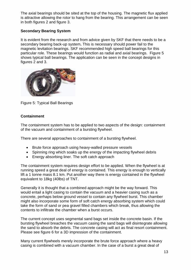
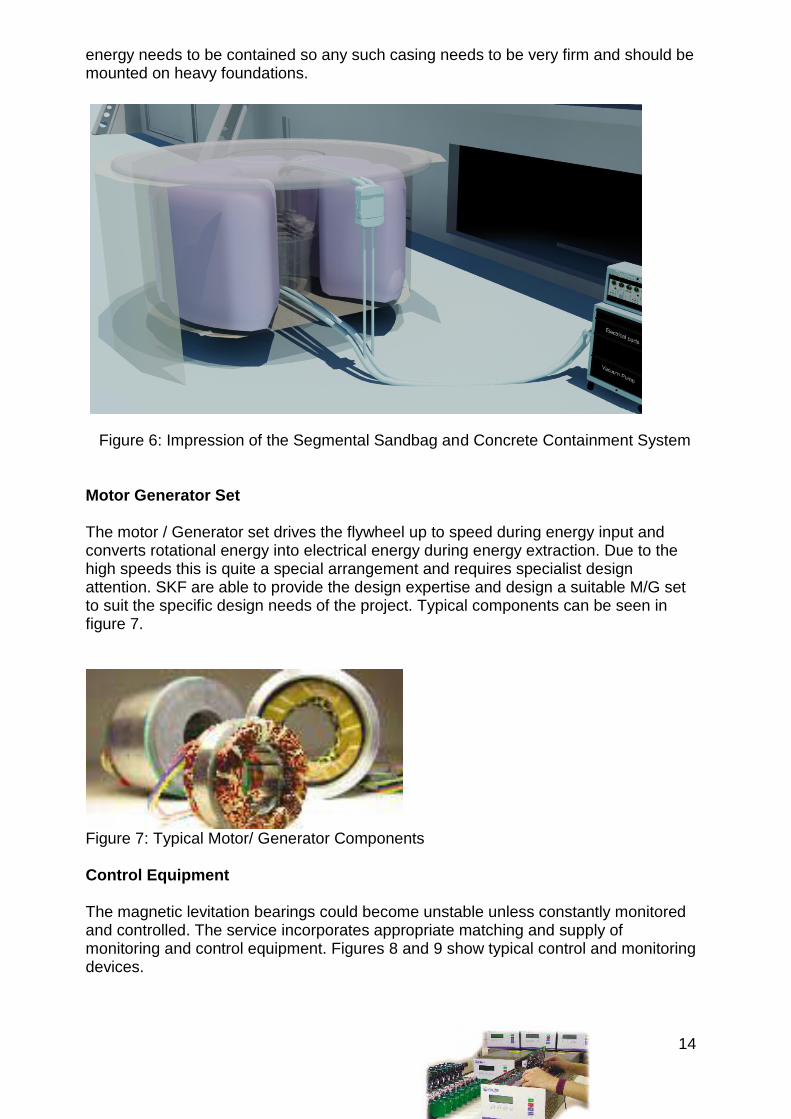
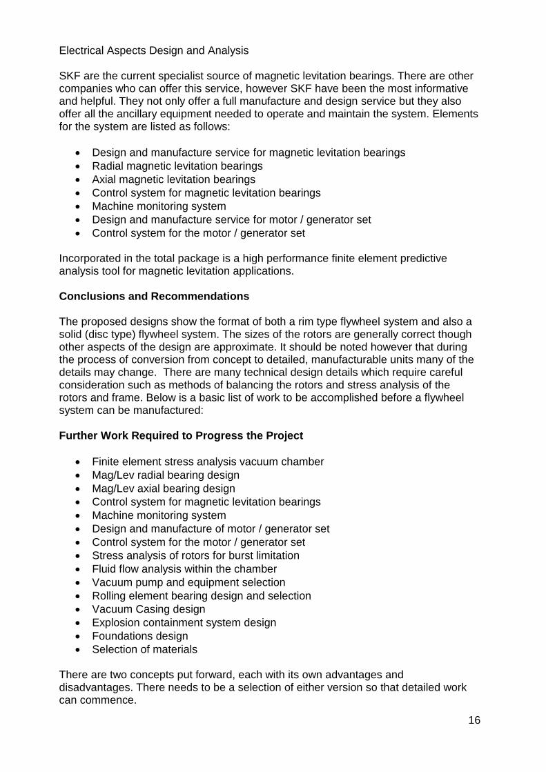
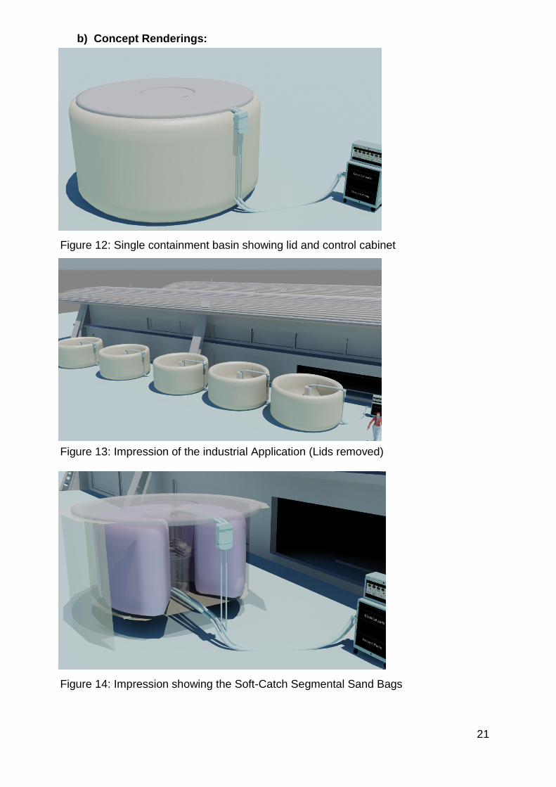
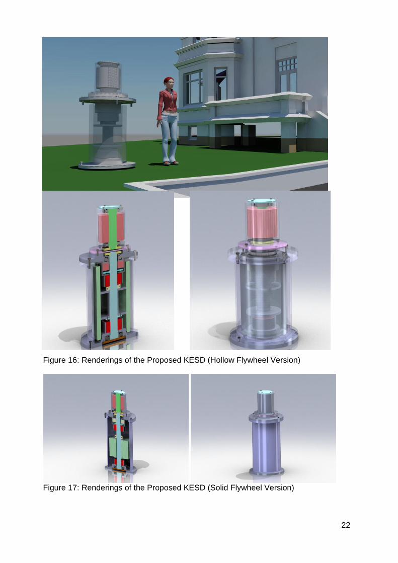
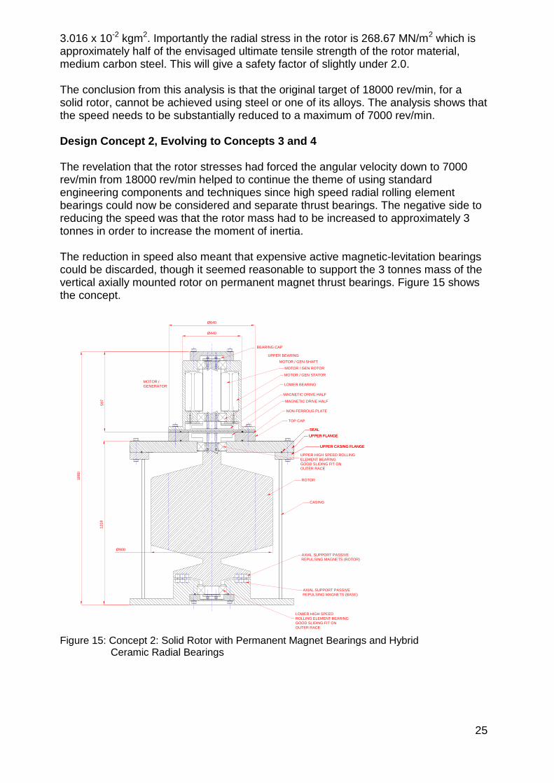
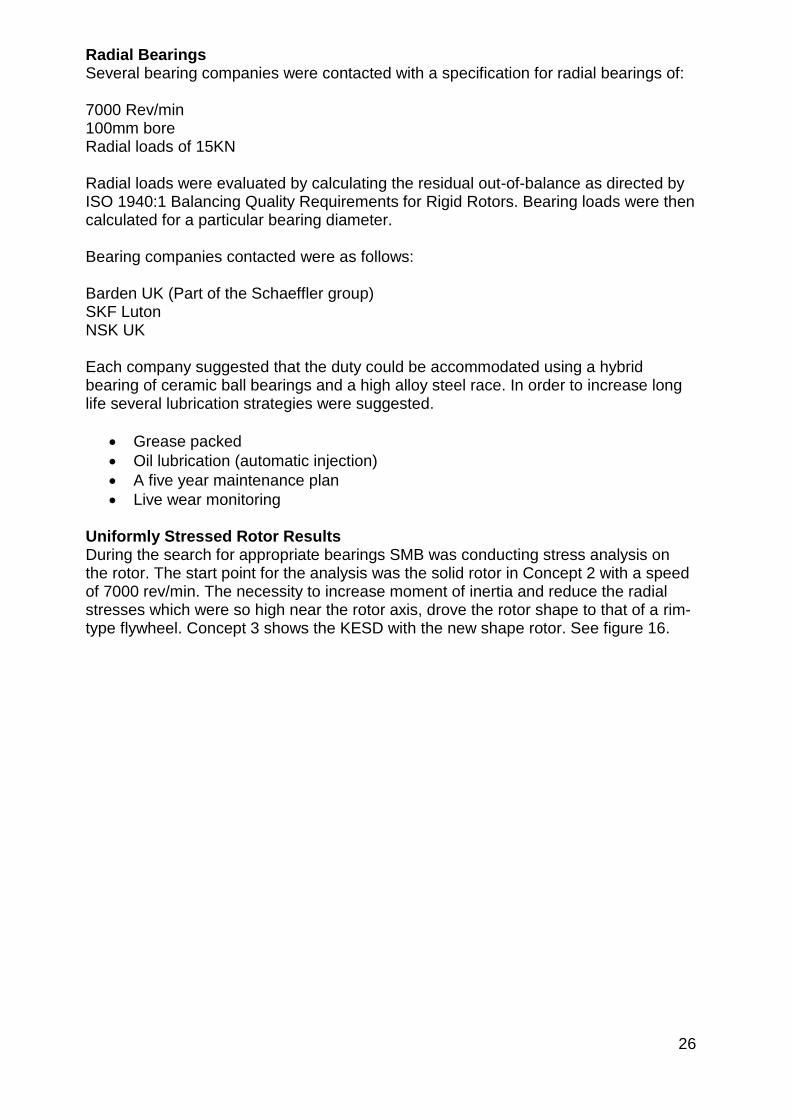
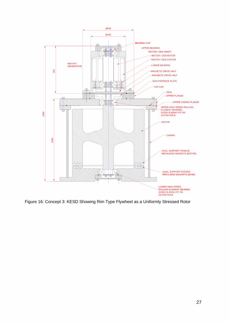
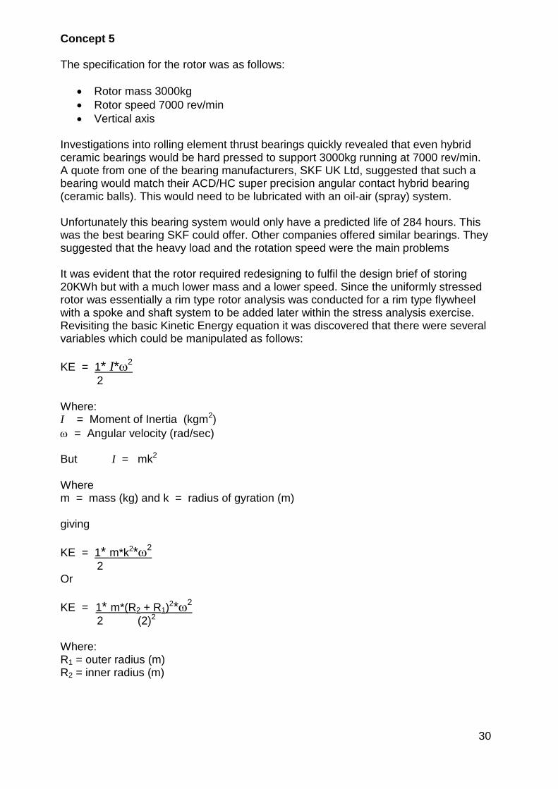
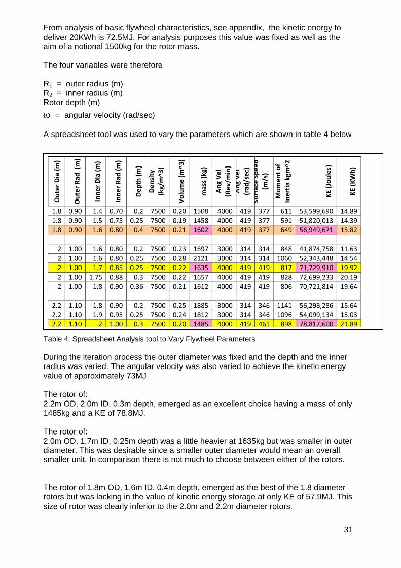
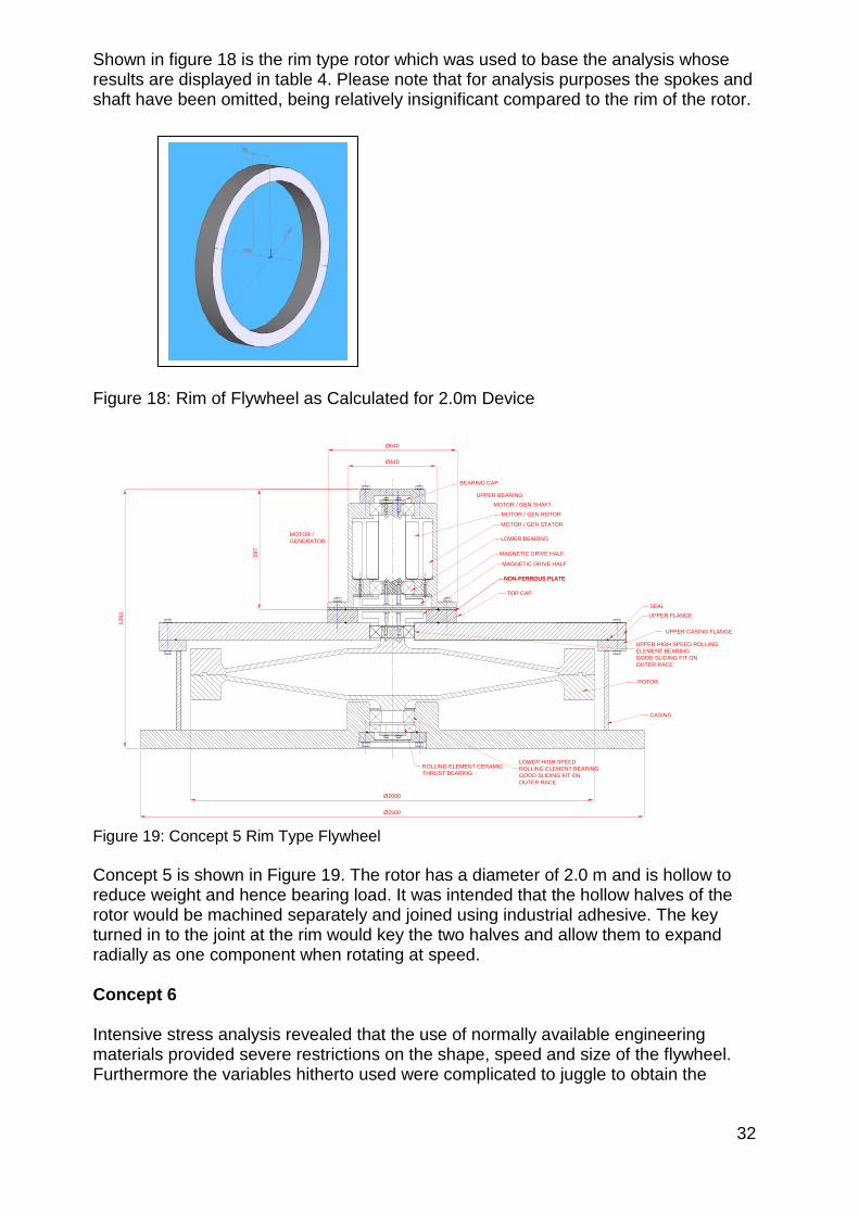
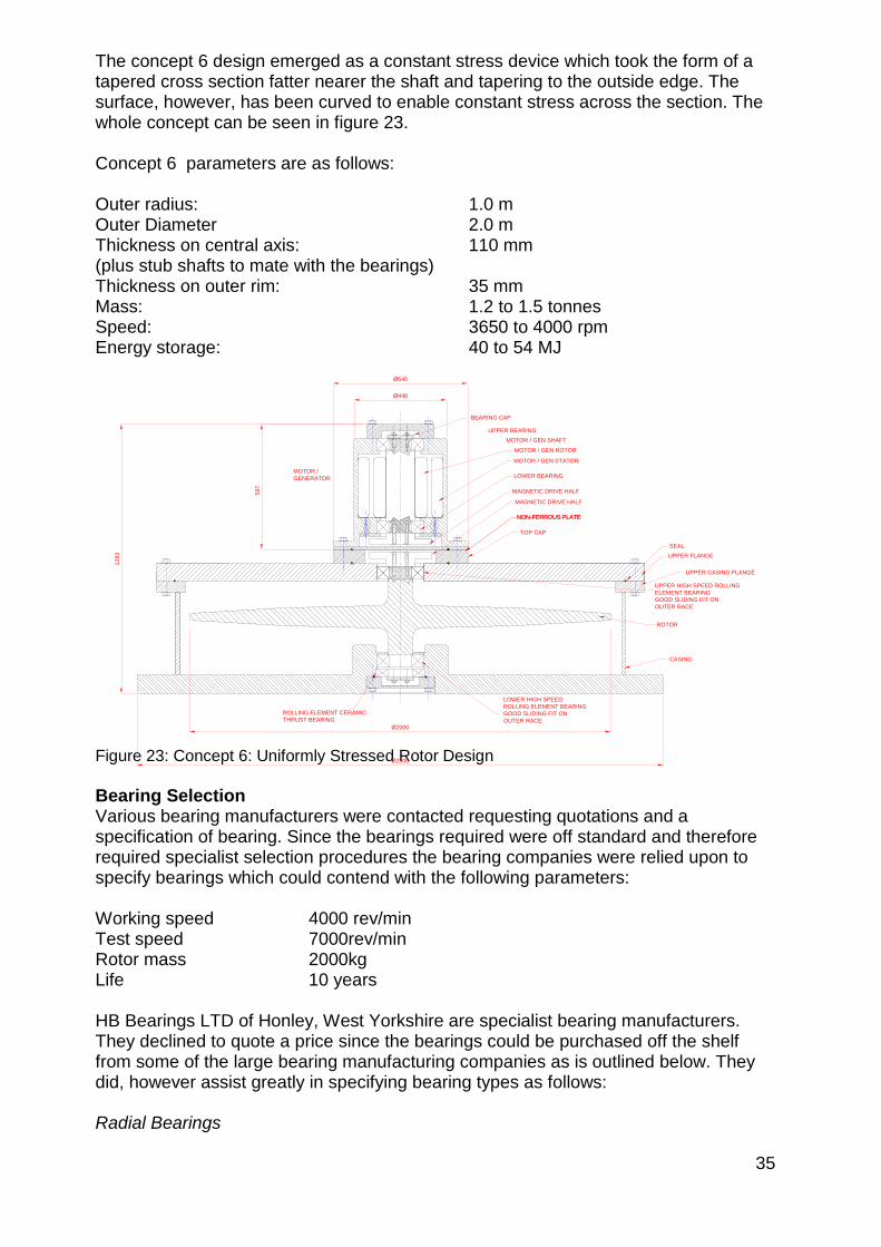
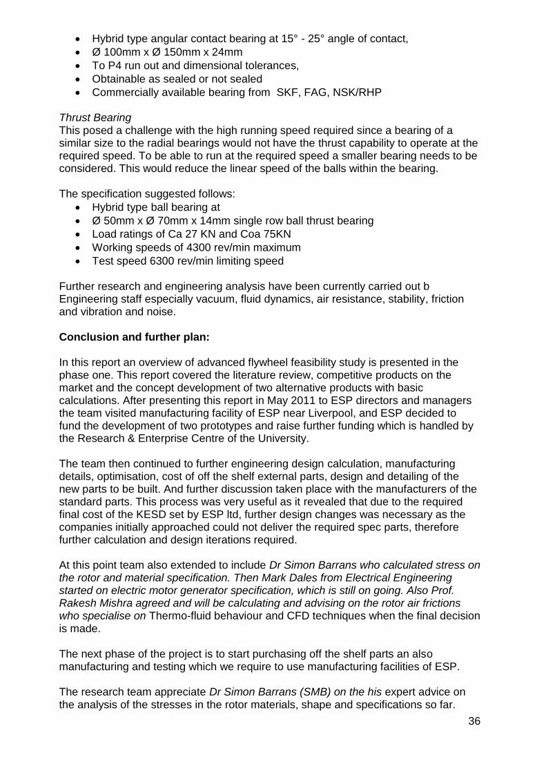
36
Hybrid type angular contact bearing at 15deg - 25deg angle of contact
Oslash 100mm x Oslash 150mm x 24mm
To P4 run out and dimensional tolerances
Obtainable as sealed or not sealed
Commercially available bearing from SKF FAG NSKRHP Thrust Bearing This posed a challenge with the high running speed required since a bearing of a similar size to the radial bearings would not have the thrust capability to operate at the required speed To be able to run at the required speed a smaller bearing needs to be considered This would reduce the linear speed of the balls within the bearing The specification suggested follows
Hybrid type ball bearing at
Oslash 50mm x Oslash 70mm x 14mm single row ball thrust bearing
Load ratings of Ca 27 KN and Coa 75KN
Working speeds of 4300 revmin maximum
Test speed 6300 revmin limiting speed Further research and engineering analysis have been currently carried out b Engineering staff especially vacuum fluid dynamics air resistance stability friction and vibration and noise Conclusion and further plan In this report an overview of advanced flywheel feasibility study is presented in the phase one This report covered the literature review competitive products on the market and the concept development of two alternative products with basic calculations After presenting this report in May 2011 to ESP directors and managers the team visited manufacturing facility of ESP near Liverpool and ESP decided to fund the development of two prototypes and raise further funding which is handled by the Research amp Enterprise Centre of the University The team then continued to further engineering design calculation manufacturing details optimisation cost of off the shelf external parts design and detailing of the new parts to be built And further discussion taken place with the manufacturers of the standard parts This process was very useful as it revealed that due to the required final cost of the KESD set by ESP ltd further design changes was necessary as the companies initially approached could not deliver the required spec parts therefore further calculation and design iterations required At this point team also extended to include Dr Simon Barrans who calculated stress on the rotor and material specification Then Mark Dales from Electrical Engineering started on electric motor generator specification which is still on going Also Prof Rakesh Mishra agreed and will be calculating and advising on the rotor air frictions who specialise on Thermo-fluid behaviour and CFD techniques when the final decision is made The next phase of the project is to start purchasing off the shelf parts an also manufacturing and testing which we require to use manufacturing facilities of ESP The research team appreciate Dr Simon Barrans (SMB) on the his expert advice on the analysis of the stresses in the rotor materials shape and specifications so far
37
Appendix 2 Flywheel Characteristics Iteration Spreadsheets Flywheel Characteristics Disc Type Rotor
Note Speed of Sound = 3432ms
Dia Radius Depth Density Volume mass Ang Vel Ang Vel Surface Moment KE KE Power 1 tonne Rim
m m m kgm^3 m^3 kg RPM radsec Speed of Inertia Joules KWh KW Mass lift Stress
Ms kgm^2 m Nm^2
020 010 080 750000 003 18852 3000000 314200 31420 094 4652751 129 036 251584 4056795
030 015 070 750000 005 37115 2000000 209467 31420 418 9160103 254 071 251584 4056795
030 015 070 750000 005 37115 3000000 314200 47130 418 20610232 573 159 566064 9127789
040 020 070 750000 009 65982 2000000 209467 41893 1320 28950450 804 223 447261 7212080
050 025 070 750000 014 103097 2000000 209467 52367 3222 70679810 1963 545 698845 11268876
060 030 070 750000 020 148460 2000000 209467 62840 6681 146561653 4071 1131 1006337 16227181
060 030 060 750000 017 127251 2000000 209467 62840 5726 125624274 3490 969 1006337 16227181
060 030 050 750000 014 106043 2000000 209467 62840 4772 104686895 2908 808 1006337 16227181
060 030 040 750000 011 84834 2000000 209467 62840 3818 83749516 2326 646 1006337 16227181
070 035 030 750000 012 86601 2000000 209467 73313 5304 116367238 3232 898 1369736 22086996
070 035 020 750000 008 57734 2000000 209467 73313 3536 77578159 2155 599 1369736 22086996
080 040 020 750000 010 75408 2000000 209467 83787 6033 132344914 3676 1021 1789043 28848322
000 750000 000 000 000 000 000 0 000 000 DIV0 0
050 025 035 750000 007 51548 3000000 314200 78550 1611 79514786 2209 614 1572401 25354970
060 030 020 750000 006 42417 3000000 314200 94260 1909 94218206 2617 727 2264258 36511157
000 750000 000 000 000 000 000 0 000 000 DIV0 0
070 035 021 750000 008 60621 2000000 209467 73313 3713 81457067 2263 629 1369736 22086996
060 030 021 750000 006 44538 2000000 209467 62840 2004 43968496 1221 339 1006337 16227181
050 025 020 750000 004 29456 3000000 314200 78550 921 45437020 1262 351 1572401 25354970
000 750000 000 000 000 000 000 0 000 000 DIV0 0
000 750000 000 000 000 000 000 0 000 000 DIV0 0
060 030 050 750000 014 106043 1800000 188520 56556 4772 84796385 2355 654 815133 13144017
060 030 050 750000 014 106043 1200000 125680 37704 4772 37687282 1047 291 362281 5841785 Flywheel Characteristics Rim Type Rotor
Note Speed of Sound = 3432ms
Ou
ter
Dia
(m)
Ou
ter
Rad
(m)
Inn
er
Dia
(m
)
Inn
er
Rad
(m)
De
pth
(m
)
De
nsi
ty
(kg
m^
3)
Vo
lum
e
(m^
3)
mas
s (k
g)
An
g V
el
(Re
vm
in)
An
g V
el
Surf
ace
Spe
ed
(m
s)
Mo
me
nt
of
Ine
rtia
kgm
^2
KE
(Jo
ule
s)
KE
(KW
h)
Po
we
r (K
W)
1 t
on
ne
Mas
s
Lift
(m
)
Rim
Str
ess
(Nm
^2
)050 025 012 006 080 750000 015 111038 15000 1571 39275 3470 42819848 1189 330 393100 6338743
06 030 015 008 05 750000 013 99415 18000 1885 56556 4474 79496611 2208 613 815133 13144017
06 030 015 008 04 750000 011 79532 18000 1885 56556 3579 63597289 1767 491 815133 13144017
06 030 015 008 03 750000 008 59649 18000 1885 56556 2684 47697967 1325 368 815133 13144017
05 025 015 008 07 750000 013 93818 18000 1885 47130 2932 52098088 1447 402 566064 9127789
04 020 015 008 08 750000 009 64804 18000 1885 37704 1296 23031117 640 178 362281 5841785
05 025 015 008 06 750000 011 80416 18000 1885 47130 2513 44655504 1240 345 566064 9127789
05 025 015 008 065 750000 012 87117 18000 1885 47130 2722 48376796 1344 373 566064 9127789
055 028 022 011 07 750000 014 104788 18000 1885 51843 3962 70409363 1956 543 684938 11044625
06 030 022 011 05 750000 012 91786 18000 1885 56556 4130 73395982 2039 566 815133 13144017
06 030 045 023 1 750000 012 92787 18000 1885 56556 4175 74196837 2061 573 815133 13144017
38
From ISO19401 Uper = 9549 x G x W (gmm) N Where G = Balance Grade G63 W = Rotor Mass 3000kg N = Service Speed 7000revmin Uper = 9549 x 63 x 3000 = 25782 gmm 7000 Find Centrifugal Force First Find Eccentric Mass Uper = 25782 grm Radius of Bearing = 55mm Uper = emass x radius emass = Uper__ = 25782 = 470grm or 047kg radius 55 Find Centrifugal Force
Fc = m x 2 x r
Where m = rotor mass of 3000kg
= angular velocity = 7000 x 2 x = 733 radsec
60 R = bearing radius = 55mm or 0055m Fc = 3000 x 7332 x 0055 = 13890 N or equivalent mass = 1416kg And is the radial force applied to the bearing
Determination of Residual Unbalance Forces From Balancing Grades
Grade Rotor Angular Rotor Bearing Residual Residual Centrifugal Centrifugal
Speed Velocity Mass Radius Unbalance Eccentric Force Equiv Load
mass at Brg at Brg
RevMin radsec Kg mm g-mm kg N kg
63 7000 733 3000 55 257823 047 138576 14126
25 7000 733 3000 55 102311 019 54990 5606
63 4000 419 1635 55 245899 045 43156 4399
39
Determination of Energy Storage Efficiency
Determination of Drag due to Skin Friction
Determination of Drag due to Bearing Friction
Determination of Retardation and Efficiency Determination of Drag due to Skin Friction The general drag force equation shown below was used
Fdrag = 1 x x v2 x A x CD
2 Where
= gas density (kgm3)
V = velocity (ms) A = Cross sectional Area (m2) CD = Drag coefficient (dimensionless) The drag coefficient was determined from the following equation after determining the Reynolds Number for the conditions These calculations can be seen in the appendix page xxx CD = 133(Re)-12 per side Ref [19] Where Re = Reynolds Number
Re = VL
Where
= fluid density (kgm3)
V = average velocity (ms) L = Travelled length of fluid (hydraulic Diameter) (m)
= dynamic viscosity (Nsm2)
Parameters from speed of sound analysis Pressure = 200mbar
air = 12 x 02 = 024kgm3
Find Dynamic Viscosity
Viscosity at 1000 mbar = 1827 Pa s
Viscosity at 200mbar = 1827 x 10-3 x 02 = = 3654 x 10-3 Pa s
Find L (travelled fluid length) Normally for a pipe but the equivalent diameter can be calculated from the Hydraulic Diameter as follows DH = 4A
40
P Where A = cross sectional Area (m2) P = whetted surface distance (m) Average thickness = 90mm at 448mm = average radius of disc Cross Sectional Area = average thickness x average radius CSA = 0073 x 094 = 00686 m2 Find Whetted Length P Length of surface area of section Shaft = 01 x 2 = 02 Surface = 094 x 2 = 188 Circumference = 0036 2116 m Find Hydraulic Diameter DH DH = 4A = 4 x 00686 = 013m P 2116 Find Average Velocity Average occurs at average radius = r_ = 10_ = 10 x 0707 = 0707m (2)12 (2)12 Find Average Velocity V From tabulated data Velocity at circumference = 420ms at 4000revmin Velocity Mean = V = 420 x 0707 = 300ms Find Reynolds Number
Re = VL = 024 x 300 x 013 = 2561
3654 x 10-3
10
01
00
1000
11
0
36
AVERAGE RADIUS
RA = RADIUS X 0707
ROTOR CROSS SECTION
940
73
707
41
Find Skin Friction Coefficient CD CD = 133(Re)-12 per side Ref [19] CD = 133(2561)-12 x 2 = 00525 Find Drag Force
Fdrag = 1 x x v2 x A x CD
2 Fdrag = 1 x 024 x 3002 x 00686 x 00525 = 3889N Average force at average radius 2 Find Average Torque Due to Skin Friction T = force x radius T = 3889 x 0707 = 275Nm Determination of Drag due to Bearing Friction The rolling element bearings are hybrid bearings with ceramic balls Their equivalent coefficient of friction is rated at 10 of that of a standard rolling element bearing Since standard rolling element bearings typically have a coefficient of friction of 001 the coefficient of friction of ceramic hybrid bearings can be considered to be 0001 General Data Mass of rotor 1500kg Rotational speed 4000revmin Radial Bearings Effective diameter 110mm Radial force (N) 1571N (gleaned from balancing forces for a rigid rotor)
Coefficient of friction 0001 ()
Thrust Bearings 147KN (weight of rotor) Effective diameter 60mm Axial force (N) 1571N
Coefficient of friction 0001 ()
Find Friction Force FR Radial Bearings NB 2 Bearings
FR = N
FR = 2 x 0001 x 1571 = 3142N
42
Find Resisting Torque (Radial) T = force x radius T = 3142 x 0055 = 0173Nm Thrust Bearings NB 2 bearings sharing the load Load = 147KN Each bearing will sustain 735KN Load
FR = N
FR = 2 x 0001 x 735 x 103 = 147N Find Resisting Torque (Axial) T = force x radius T = 147 x 003 = 0441Nm Total Torque TT = Skin Friction + radial bearing + axial Bearing TT = 275 + 0173 + 0441 = 28114 Nm Determine Deceleration From Newtonrsquos second law I = 825kgm2 from data tool
T = I x
= T = 28114 = 0034ms2 retardation
I 825 The value of the resistance from fluid friction is significantly higher than the resistance from the bearings Bearings contribute little to the inefficiencies whereas the skin friction is comparatively large
Determine the Angular Velocity after 1 hour of Deceleration 1
Initial Angular Velocity 0 = 419 radsec
43
Time 1 hour t = 3600 seconds
Deceleration = 0034ms2
From
1 - 0 + t
0 = 1 - ( x t) = 419 - (0034 x 3600) = 297 radsec = 2832revmin
Determine Efficiency Efficiency = change in speed = 4000 - 2832 = 0292 or 292 speed reduction original speed 4000 A loss of efficiency of 292 in 1 hour is unacceptable In 3 hours the rotor would have almost stopped rotating Since the fluid friction is the largest contributor there must be a further reduction in the skin friction FULLY STRESSED DISK DESIGN
bull Concept Vary the cross section of the disk so that the stress due to rotation remains constant across the radius
bull For a solid disk theory gives the height as
bull Theoretical disk should have an infinite outer radius bull thickness tapers down to zero
bull Practical disks will have a finite outer radius bull where the thickness is finite
bull For a disk of this shape the moment of inertia is given by
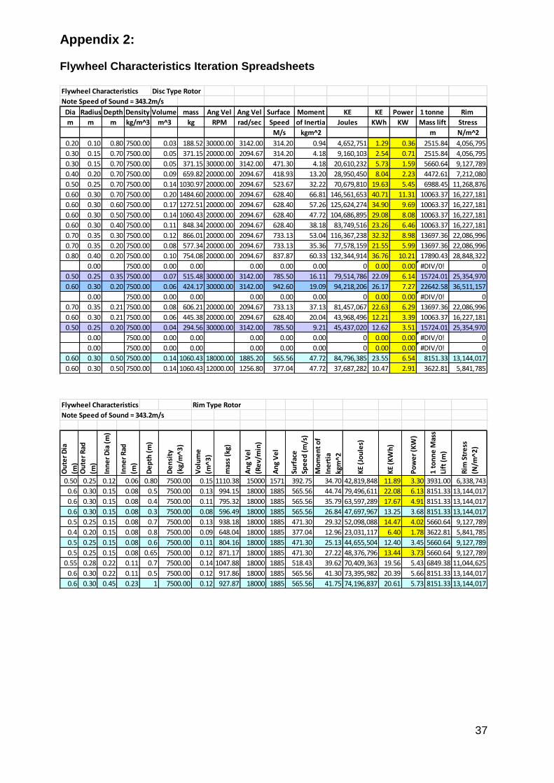
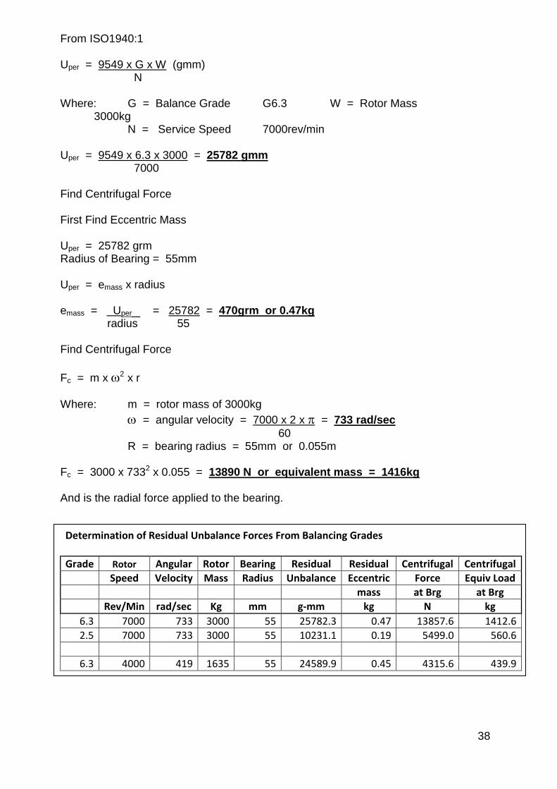
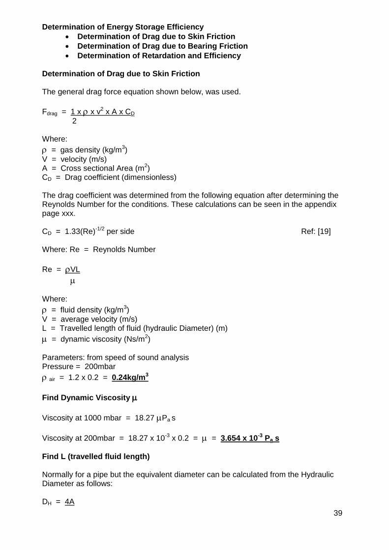
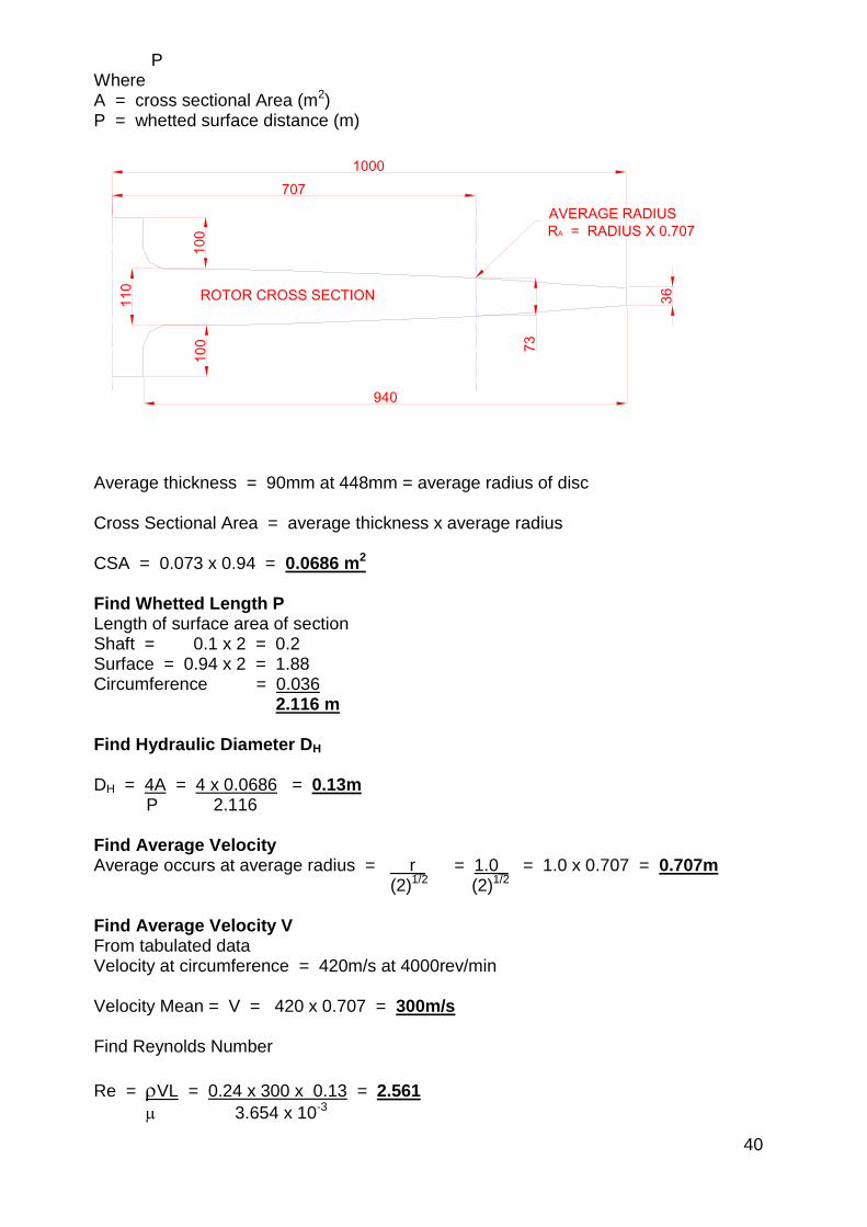
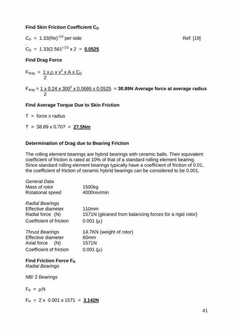
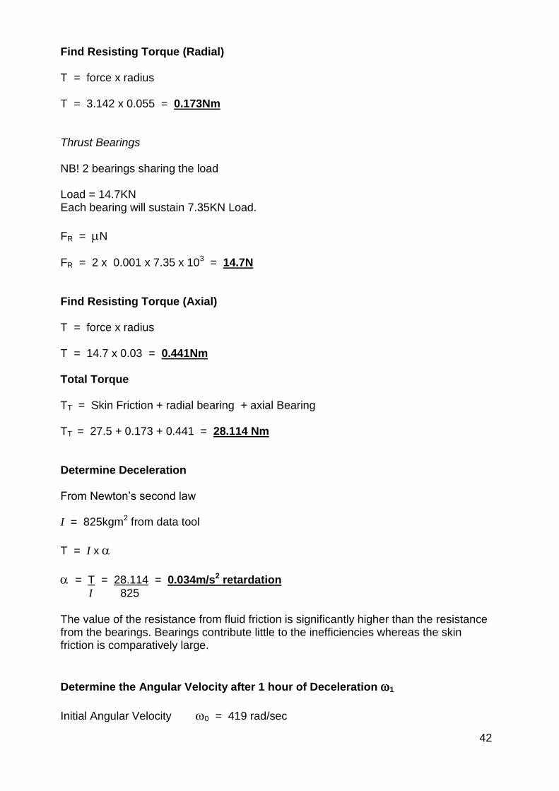
Top Related
Copyright © 2022 FDOKUMEN

