


Bahasa
Halaman
Hukum


The flowmeter for smallest flow rates with an ultra-compact transmitter
Application
• The measuring principle is virtually independent of pressure,density, temperature and viscosity
• For the smallest flow quantities and demanding hygienicapplications
Device properties• Integrated temperature measurement• Sensor housing made of stainless steel (3-A, EHEDG)• Wetted materials CIP/SIP cleanable• Robust, ultra-compact transmitter housing• Highest degree of protection: IP69K• Local display available
Your benefits
• Flexible installation concept – numerous hygienic processconnections
• Energy-saving flow measurement – no pressure loss due tocross-section constriction
• Maintenance-free – no moving parts• Space‐saving transmitter – full functionality on smallest
footprint• Time‐saving local operation without additional software and
hardware – integrated web server• Integrated verification – Heartbeat Technology™
Products Solutions Services
Technical InformationProline Promag H 100Electromagnetic flowmeter
TI01101D/06/EN/05.1771361932

Proline Promag H 100
2 Endress+Hauser
Table of contents
Document information . . . . . . . . . . . . . . . . . . . . . . . 4Symbols used . . . . . . . . . . . . . . . . . . . . . . . . . . . . . . . . 4
Function and system design . . . . . . . . . . . . . . . . . . . 4Measuring principle . . . . . . . . . . . . . . . . . . . . . . . . . . . . 4Measuring system . . . . . . . . . . . . . . . . . . . . . . . . . . . . . 6Equipment architecture . . . . . . . . . . . . . . . . . . . . . . . . . 7Safety . . . . . . . . . . . . . . . . . . . . . . . . . . . . . . . . . . . . . 7
Input . . . . . . . . . . . . . . . . . . . . . . . . . . . . . . . . . . . . . 7Measured variable . . . . . . . . . . . . . . . . . . . . . . . . . . . . . 7Measuring range . . . . . . . . . . . . . . . . . . . . . . . . . . . . . . 7Operable flow range . . . . . . . . . . . . . . . . . . . . . . . . . . . 9Input signal . . . . . . . . . . . . . . . . . . . . . . . . . . . . . . . . . 9
Output . . . . . . . . . . . . . . . . . . . . . . . . . . . . . . . . . . . 9Output signal . . . . . . . . . . . . . . . . . . . . . . . . . . . . . . . . 9Signal on alarm . . . . . . . . . . . . . . . . . . . . . . . . . . . . . . 11Low flow cut off . . . . . . . . . . . . . . . . . . . . . . . . . . . . . 12Galvanic isolation . . . . . . . . . . . . . . . . . . . . . . . . . . . . 12Protocol-specific data . . . . . . . . . . . . . . . . . . . . . . . . . . 12
Power supply . . . . . . . . . . . . . . . . . . . . . . . . . . . . . 20Terminal assignment . . . . . . . . . . . . . . . . . . . . . . . . . . 20Pin assignment, device plug . . . . . . . . . . . . . . . . . . . . . . 25Supply voltage . . . . . . . . . . . . . . . . . . . . . . . . . . . . . . 27Power consumption . . . . . . . . . . . . . . . . . . . . . . . . . . . 28Current consumption . . . . . . . . . . . . . . . . . . . . . . . . . . 28Power supply failure . . . . . . . . . . . . . . . . . . . . . . . . . . 28Electrical connection . . . . . . . . . . . . . . . . . . . . . . . . . . 28Potential equalization . . . . . . . . . . . . . . . . . . . . . . . . . 32Terminals . . . . . . . . . . . . . . . . . . . . . . . . . . . . . . . . . 33Cable entries . . . . . . . . . . . . . . . . . . . . . . . . . . . . . . . 33Cable specification . . . . . . . . . . . . . . . . . . . . . . . . . . . . 34
Performance characteristics . . . . . . . . . . . . . . . . . . 35Reference operating conditions . . . . . . . . . . . . . . . . . . . 35Maximum measured error . . . . . . . . . . . . . . . . . . . . . . . 35Repeatability . . . . . . . . . . . . . . . . . . . . . . . . . . . . . . . 36Temperature measurement response time . . . . . . . . . . . . 36Influence of ambient temperature . . . . . . . . . . . . . . . . . 36
Installation . . . . . . . . . . . . . . . . . . . . . . . . . . . . . . . 36Mounting location . . . . . . . . . . . . . . . . . . . . . . . . . . . . 36Orientation . . . . . . . . . . . . . . . . . . . . . . . . . . . . . . . . 37Inlet and outlet runs . . . . . . . . . . . . . . . . . . . . . . . . . . 38Adapters . . . . . . . . . . . . . . . . . . . . . . . . . . . . . . . . . . 38
Environment . . . . . . . . . . . . . . . . . . . . . . . . . . . . . . 39Ambient temperature range . . . . . . . . . . . . . . . . . . . . . 39Storage temperature . . . . . . . . . . . . . . . . . . . . . . . . . . 40Degree of protection . . . . . . . . . . . . . . . . . . . . . . . . . . 40Shock resistance . . . . . . . . . . . . . . . . . . . . . . . . . . . . . 40Vibration resistance . . . . . . . . . . . . . . . . . . . . . . . . . . . 40Mechanical load . . . . . . . . . . . . . . . . . . . . . . . . . . . . . 40Interior cleaning . . . . . . . . . . . . . . . . . . . . . . . . . . . . . 40Electromagnetic compatibility (EMC) . . . . . . . . . . . . . . . 40
Process . . . . . . . . . . . . . . . . . . . . . . . . . . . . . . . . . . 40Medium temperature range . . . . . . . . . . . . . . . . . . . . . . 40Conductivity . . . . . . . . . . . . . . . . . . . . . . . . . . . . . . . . 41Pressure-temperature ratings . . . . . . . . . . . . . . . . . . . . 41Pressure tightness . . . . . . . . . . . . . . . . . . . . . . . . . . . . 47Flow limit . . . . . . . . . . . . . . . . . . . . . . . . . . . . . . . . . 47Pressure loss . . . . . . . . . . . . . . . . . . . . . . . . . . . . . . . 47System pressure . . . . . . . . . . . . . . . . . . . . . . . . . . . . . 47Vibrations . . . . . . . . . . . . . . . . . . . . . . . . . . . . . . . . . 47
Mechanical construction . . . . . . . . . . . . . . . . . . . . 48Dimensions in SI units . . . . . . . . . . . . . . . . . . . . . . . . . 48Dimensions in US units . . . . . . . . . . . . . . . . . . . . . . . . . 67Weight . . . . . . . . . . . . . . . . . . . . . . . . . . . . . . . . . . . 81Measuring tube specification . . . . . . . . . . . . . . . . . . . . . 81Materials . . . . . . . . . . . . . . . . . . . . . . . . . . . . . . . . . . 82Fitted electrodes . . . . . . . . . . . . . . . . . . . . . . . . . . . . . 83Process connections . . . . . . . . . . . . . . . . . . . . . . . . . . . 83Surface roughness . . . . . . . . . . . . . . . . . . . . . . . . . . . . 84
Operability . . . . . . . . . . . . . . . . . . . . . . . . . . . . . . . 84Operating concept . . . . . . . . . . . . . . . . . . . . . . . . . . . . 84Local display . . . . . . . . . . . . . . . . . . . . . . . . . . . . . . . . 84Remote operation . . . . . . . . . . . . . . . . . . . . . . . . . . . . 85Service interface . . . . . . . . . . . . . . . . . . . . . . . . . . . . . 86
Certificates and approvals . . . . . . . . . . . . . . . . . . . 89CE mark . . . . . . . . . . . . . . . . . . . . . . . . . . . . . . . . . . . 89C-Tick symbol . . . . . . . . . . . . . . . . . . . . . . . . . . . . . . . 89Ex approval . . . . . . . . . . . . . . . . . . . . . . . . . . . . . . . . 89Sanitary compatibility . . . . . . . . . . . . . . . . . . . . . . . . . 90Functional safety . . . . . . . . . . . . . . . . . . . . . . . . . . . . . 90HART certification . . . . . . . . . . . . . . . . . . . . . . . . . . . . 90Certification PROFIBUS . . . . . . . . . . . . . . . . . . . . . . . . . 90Modbus RS485 certification . . . . . . . . . . . . . . . . . . . . . 90EtherNet/IP certification . . . . . . . . . . . . . . . . . . . . . . . . 90Certification PROFINET . . . . . . . . . . . . . . . . . . . . . . . . 90Additional certification . . . . . . . . . . . . . . . . . . . . . . . . . 90Pressure Equipment Directive . . . . . . . . . . . . . . . . . . . . 91Other standards and guidelines . . . . . . . . . . . . . . . . . . . 91
Ordering information . . . . . . . . . . . . . . . . . . . . . . . 91
Application packages . . . . . . . . . . . . . . . . . . . . . . . 92Cleaning . . . . . . . . . . . . . . . . . . . . . . . . . . . . . . . . . . 92Heartbeat Technology . . . . . . . . . . . . . . . . . . . . . . . . . 92
Accessories . . . . . . . . . . . . . . . . . . . . . . . . . . . . . . . 92Device-specific accessories . . . . . . . . . . . . . . . . . . . . . . 92Communication-specific accessories . . . . . . . . . . . . . . . . 93Service-specific accessories . . . . . . . . . . . . . . . . . . . . . . 93System components . . . . . . . . . . . . . . . . . . . . . . . . . . . 94
Supplementary documentation . . . . . . . . . . . . . . . 94Standard documentation . . . . . . . . . . . . . . . . . . . . . . . . 94Supplementary device-dependent documentation . . . . . . . 95

Proline Promag H 100
Endress+Hauser 3
Registered trademarks . . . . . . . . . . . . . . . . . . . . . . 95

Proline Promag H 100
4 Endress+Hauser
Document information
Symbols used Electrical symbols
Symbol Meaning Symbol Meaning
Direct current Alternating current
Direct current and alternating current Ground connectionA grounded terminal which, as far asthe operator is concerned, isgrounded via a grounding system.
Protective ground connectionA terminal which must be connectedto ground prior to establishing anyother connections.
Equipotential connectionA connection that has to be connectedto the plant grounding system: Thismay be a potential equalization lineor a star grounding system dependingon national or company codes ofpractice.
Symbols for certain types of information
Symbol Meaning
PermittedProcedures, processes or actions that are permitted.
PreferredProcedures, processes or actions that are preferred.
ForbiddenProcedures, processes or actions that are forbidden.
TipIndicates additional information.
Reference to documentation
Reference to page
Reference to graphic
Visual inspection
Symbols in graphics
Symbol Meaning Symbol Meaning
1, 2, 3,... Item numbers , …, Series of steps
A, B, C, ... Views A-A, B-B, C-C, ... Sections
-Hazardous area . Safe area (non-hazardous area)
Flow direction
Function and system design
Measuring principle Following Faraday's law of magnetic induction, a voltage is induced in a conductor moving through amagnetic field.

Proline Promag H 100
Endress+Hauser 5
I
L
B
I
Ue
v
A0017035
Ue Induced voltageB Magnetic induction (magnetic field)L Electrode spacingI Currentv Flow velocity
In the electromagnetic measuring principle, the flowing medium is the moving conductor. Thevoltage induced (Ue) is proportional to the flow velocity (v) and is supplied to the amplifier by meansof two measuring electrodes. The flow volume (Q) is calculated via the pipe cross-section (A). The DCmagnetic field is created through a switched direct current of alternating polarity.
Formulae for calculation• Induced voltage Ue = B · L · v• Volume flow Q = A · v

Proline Promag H 100
6 Endress+Hauser
Measuring system The device consists of a transmitter and a sensor.
The device is available as a compact version:The transmitter and sensor form a mechanical unit.
Transmitter
Promag 100 Device versions and materials:• Compact, aluminum coated:
Aluminum, AlSi10Mg, coated• Compact, hygienic, stainless:
Hygienic version, stainless steel 1.4301 (304)• Ultra-compact, hygienic, stainless:
Hygienic version, stainless steel 1.4301 (304)
Configuration:• Via operating tools (e.g. FieldCare)• Additionally for device version with local display:
Via Web browser (e.g. Microsoft Internet Explorer)• Also for device version with 4-20 mA HART, pulse/frequency/switch
output:Via Web browser (e.g. Microsoft Internet Explorer)
• Also for device version with EtherNet/IP output:– Via Web browser (e.g. Microsoft Internet Explorer)– Via Add-on Profile Level 3 for automation system from Rockwell
Automation– Via Electronic Data Sheet (EDS)
• Also for device version with PROFINET output:– Via Web browser (e.g. Microsoft Internet Explorer)– Via device master file (GSD)
A0016693
A0016694
A0016695
Sensor
Promag H Nominal diameter range: DN 2 to 150 (1/12 to 6")
Materials:• Sensor housing: stainless steel, 1.4301 (304)• Measuring tubes: stainless steel, 1.4301 (304)• Liner: PFA• Electrodes: stainless steel, 1.4435 (316L); Alloy C22, 2.4602 (UNS
N06022); tantalum; platinum (only up to DN 25 (1"))• Process connections: stainless steel, 1.4404 (F316L); PVDF; PVC
adhesive sleeve• Seals:
– DN 2 to 25 (1/12 to 1"): O-ring seal (EPDM, FKM, Kalrez), asepticmolded seal (EPDM, FKM, silicone)
– DN 40 to 150 (1 ½ to 6"): aseptic molded seal (EPDM, FKM, silicone)• Grounding rings: stainless steel, 1.4435 (316L); Alloy C22, 2.4602
(UNS N06022); tantalum
A0019897
A0019898

Proline Promag H 100
Endress+Hauser 7
Equipment architecture
2 3
6
7
8
4
1
5
A0021560
1 Possibilities for integrating measuring devices into a system
1 Control system (e.g. PLC)2 EtherNet/IP3 PROFIBUS DP4 PROFINET5 Modbus RS4856 4-20 mA HART, pulse/frequency/switch output7 Non-hazardous area8 Non-hazardous area and Zone 2/Div. 2
Safety IT security
We only provide a warranty if the device is installed and used as described in the OperatingInstructions. The device is equipped with security mechanisms to protect it against any inadvertentchanges to the device settings.
IT security measures in line with operators' security standards and designed to provide additionalprotection for the device and device data transfer must be implemented by the operators themselves.
Input
Measured variable Direct measured variables
• Volume flow (proportional to induced voltage)• Temperature (DN 15 to 150 (½ to 6"))• Electrical conductivity
Calculated measured variables
• Mass flow• Corrected volume flow• Corrected electrical conductivity
Measuring range Typically v = 0.01 to 10 m/s (0.03 to 33 ft/s) with the specified accuracy
Electrical conductivity: ≥ 5 μS/cm for liquids in general

Proline Promag H 100
8 Endress+Hauser
Flow characteristic values in SI units
Nominaldiameter
Recommendedflow Factory settings
min./max. full scale value(v ~ 0.3/10 m/s)
Current output full scalevalue 1)
(v ~ 2.5 m/s)
Pulse value 1)
(~ 2 pulse/s)Low flow cut off(v ~ 0.04 m/s)
[mm] [in] [dm3/min] [dm3/min] [dm3] [dm3/min]
2 1/12 0.06 to 1.8 0.5 0.005 0.01
4 1/8 0.25 to 7 2 0.025 0.05
8 3/8 1 to 30 8 0.1 0.1
15 ½ 4 to 100 25 0.2 0.5
25 1 9 to 300 75 0.5 1
40 1 ½ 25 to 700 200 1.5 3
50 2 35 to 1 100 300 2.5 5
65 – 60 to 2 000 500 5 8
80 3 90 to 3 000 750 5 12
100 4 145 to 4 700 1200 10 20
125 5 220 to 7 500 1850 15 30
150 6 20 to 600 m3/h 150 m3/h 0.03 m3 2.5 m3/h
1) HART only
Flow characteristic values in US units
Nominaldiameter
Recommendedflow Factory settings
min./max. full scale value(v ~ 0.3/10 m/s)
Current output full scalevalue 1)
(v ~ 2.5 m/s)
Pulse value 1)
(~ 2 pulse/s)Low flow cut off(v ~ 0.04 m/s)
[in] [mm] [gal/min] [gal/min] [gal] [gal/min]
1/12 2 0.015 to 0.5 0.1 0.001 0.002
1/8 4 0.07 to 2 0.5 0.005 0.008
3/8 8 0.25 to 8 2 0.02 0.025
½ 15 1 to 27 6 0.05 0.1
1 25 2.5 to 80 18 0.2 0.25
1 ½ 40 7 to 190 50 0.5 0.75
2 50 10 to 300 75 0.5 1.25
3 80 24 to 800 200 2 2.5
4 100 40 to 1 250 300 2 4
5 125 60 to 1 950 450 5 7
6 150 90 to 2 650 600 5 12
1) HART only
To calculate the measuring range, use the Applicator sizing tool → 93
Recommended measuring range
"Flow limit" section → 47

Proline Promag H 100
Endress+Hauser 9
Operable flow range Over 1000 : 1
Input signal External measured values
To increase the accuracy of certain measured variables or to calculate the corrected volume flow, theautomation system can continuously write different measured values to the measuring device:• Operating pressure to increase accuracy (Endress+Hauser recommends the use of a pressure
measuring device for absolute pressure, e.g. Cerabar M or Cerabar S)• Medium temperature to increase accuracy (e.g. iTEMP)• Reference density for calculating the corrected volume flow
Various pressure transmitters and temperature measuring devices can be ordered from Endress+Hauser: see "Accessories" section → 94
It is recommended to read in external measured values to calculate the following measured variables:Corrected volume flow
HART protocol
The measured values are written from the automation system to the measuring device via the HARTprotocol. The pressure transmitter must support the following protocol-specific functions:• HART protocol• Burst mode
Digital communication
The measured values can be written from the automation system to the measuring via:• PROFIBUS DP• Modbus RS485• EtherNet/IP• PROFINET
Output
Output signal Current output
Current output 4-20 mA HART (active)
Maximum output values • DC 24 V (no flow)• 22.5 mA
Load 0 to 700 Ω
Resolution 0.38 µA
Damping Adjustable: 0.07 to 999 s
Assignable measuredvariables
• Volume flow• Mass flow• Corrected volume flow• Flow velocity• Conductivity• Corrected conductivity• Electronic temperature
Pulse/frequency/switch output
Function Can be set to pulse, frequency or switch output
Version Passive, open collector
Maximum input values • DC 30 V• 25 mA
Voltage drop For 25 mA: ≤ DC 2 V
Pulse output

Proline Promag H 100
10 Endress+Hauser
Pulse width Adjustable: 0.05 to 2 000 ms
Maximum pulse rate 10 000 Impulse/s
Pulse value Adjustable
Assignable measuredvariables
• Volume flow• Mass flow• Corrected volume flow
Frequency output
Output frequency Adjustable: 0 to 10 000 Hz
Damping Adjustable: 0 to 999 s
Pulse/pause ratio 1:1
Assignable measuredvariables
• Volume flow• Mass flow• Corrected volume flow• Flow velocity• Conductivity• Corrected conductivity• Temperature• Electronic temperature
Switch output
Switching behavior Binary, conductive or non-conductive
Switching delay Adjustable: 0 to 100 s
Number of switchingcycles
Unlimited
Assignable functions • Off• On• Diagnostic behavior• Limit value:
– Off– Volume flow– Mass flow– Corrected volume flow– Flow velocity– Conductivity– Corrected conductivity– Totalizer 1-3– Temperature– Electronic temperature
• Flow direction monitoring• Status
– Empty pipe detection– Low flow cut off
PROFIBUS DP
Signal encoding NRZ code
Data transfer 9.6 kBaud…12 MBaud
Modbus RS485
Physical interface In accordance with EIA/TIA-485-A standard
Terminating resistor Integrated, can be activated via DIP switch on the transmitter electronics module
EtherNet/IP
Standards In accordance with IEEE 802.3

Proline Promag H 100
Endress+Hauser 11
PROFINET
Standards In accordance with IEEE 802.3
Signal on alarm Depending on the interface, failure information is displayed as follows:
Current output
4-20 mA
Failure mode Choose from:• 4 to 20 mA in accordance with NAMUR recommendation NE 43• 4 to 20 mA in accordance with US• Min. value: 3.59 mA• Max. value: 22.5 mA• Freely definable value between: 3.59 to 22.5 mA• Actual value• Last valid value
HART
Device diagnostics Device condition can be read out via HART Command 48
Pulse/frequency/switch output
Pulse output
Failure mode Choose from:• Actual value• No pulses
Frequency output
Failure mode Choose from:• Actual value• 0 Hz• Defined value: 0 to 12 500 Hz
Switch output
Failure mode Choose from:• Current status• Open• Closed
PROFIBUS DP
Status and alarmmessages
Diagnostics in accordance with PROFIBUS PA Profile 3.02
Modbus RS485
Failure mode Choose from:• NaN value instead of current value• Last valid value
EtherNet/IP
Device diagnostics Device condition can be read out in Input Assembly
Proline Promag H 100
12 Endress+Hauser
PROFINET
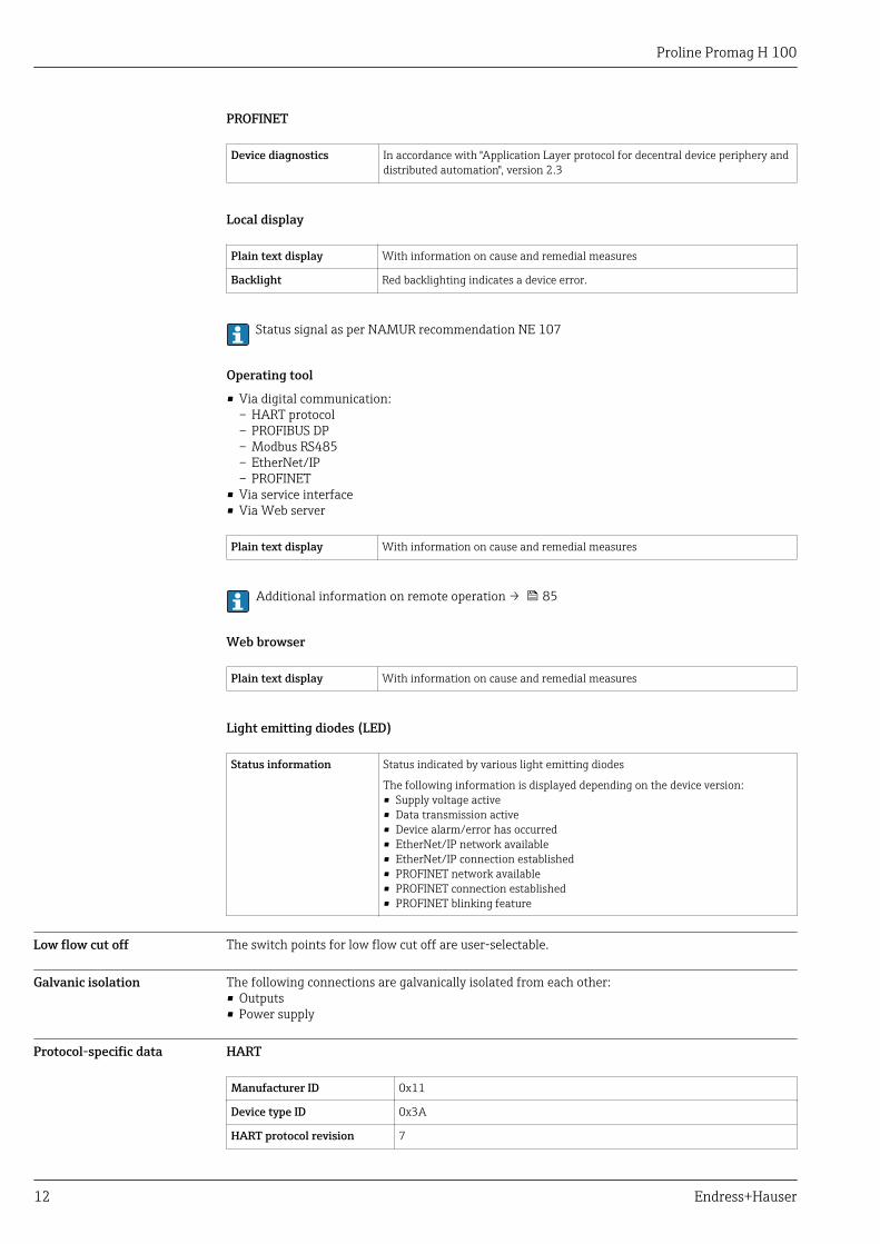
Device diagnostics In accordance with "Application Layer protocol for decentral device periphery anddistributed automation", version 2.3
Local display
Plain text display With information on cause and remedial measures
Backlight Red backlighting indicates a device error.
Status signal as per NAMUR recommendation NE 107
Operating tool
• Via digital communication:– HART protocol– PROFIBUS DP– Modbus RS485– EtherNet/IP– PROFINET
• Via service interface• Via Web server
Plain text display With information on cause and remedial measures
Additional information on remote operation → 85
Web browser
Plain text display With information on cause and remedial measures
Light emitting diodes (LED)
Status information Status indicated by various light emitting diodes
The following information is displayed depending on the device version:• Supply voltage active• Data transmission active• Device alarm/error has occurred• EtherNet/IP network available• EtherNet/IP connection established• PROFINET network available• PROFINET connection established• PROFINET blinking feature
Low flow cut off The switch points for low flow cut off are user-selectable.
Galvanic isolation The following connections are galvanically isolated from each other:• Outputs• Power supply
Protocol-specific data HART
Manufacturer ID 0x11
Device type ID 0x3A
HART protocol revision 7

Proline Promag H 100
Endress+Hauser 13
Device description files(DTM, DD)
Information and files under:www.endress.com
HART load Min. 250 Ω
Dynamic variables Read out the dynamic variables: HART command 3The measured variables can be freely assigned to the dynamic variables.
Measured variables for PV (primary dynamic variable)• Off• Volume flow• Mass flow• Corrected volume flow• Flow velocity• Corrected conductivity• Temperature• Electronic temperature
Measured variables for SV, TV, QV (secondary, tertiary and quaternarydynamic variable)• Volume flow• Mass flow• Corrected volume flow• Flow velocity• Corrected conductivity• Temperature• Electronic temperature• Totalizer 1• Totalizer 2• Totalizer 3
Device variables Read out the device variables: HART command 9The device variables are permanently assigned.
A maximum of 8 device variables can be transmitted:• 0 = volume flow• 1 = mass flow• 2 = corrected volume flow• 3 = flow velocity• 4 = conductivity• 5 = corrected conductivity• 6 = temperature• 7 = electronic temperature• 8 = totalizer 1• 9 = totalizer 2• 10 = totalizer 3
PROFIBUS DP
Manufacturer ID 0x11
Ident number 0x1561
Profile version 3.02
Device description files (GSD,DTM, DD)
Information and files under:• www.endress.com
On the product page for the device: Documents/Software → Device drivers• www.profibus.org

Proline Promag H 100
14 Endress+Hauser
Output values(from measuring device toautomation system)
Analog input 1 to 4• Volume flow• Mass flow• Corrected volume flow• Flow velocity• Conductivity• Corrected conductivity• Temperature• Electronic temperature
Digital input 1 to 2• Empty pipe detection• Low flow cut off• Verification status
Totalizer 1 to 3• Volume flow• Mass flow• Corrected volume flow
Input values(from automation system tomeasuring device)
Analog output 1 to 2 (fixed assignment)• External temperature• External density
Digital output 1 to 2 (fixed assignment)• Digital output 1: switch positive zero return on/off• Digital output 2: start verification
Totalizer 1 to 3• Totalize• Reset and hold• Preset and hold• Stop• Operating mode configuration:
– Net flow total– Forward flow total– Reverse flow total
Supported functions • Identification & MaintenanceSimplest device identification on the part of the control system andnameplate
• PROFIBUS upload/downloadReading and writing parameters is up to ten times faster with PROFIBUSupload/download
• Condensed statusSimplest and self-explanatory diagnostic information by categorizingdiagnostic messages that occur
Configuration of the deviceaddress
• DIP switches on the I/O electronics module• Via operating tools (e.g. FieldCare)
Modbus RS485
Protocol Modbus Applications Protocol Specification V1.1
Device type Slave
Slave address range 1 to 247
Broadcast address range 0
Function codes • 03: Read holding register• 04: Read input register• 06: Write single registers• 08: Diagnostics• 16: Write multiple registers• 23: Read/write multiple registers
Broadcast messages Supported by the following function codes:• 06: Write single registers• 16: Write multiple registers• 23: Read/write multiple registers
Proline Promag H 100
Endress+Hauser 15
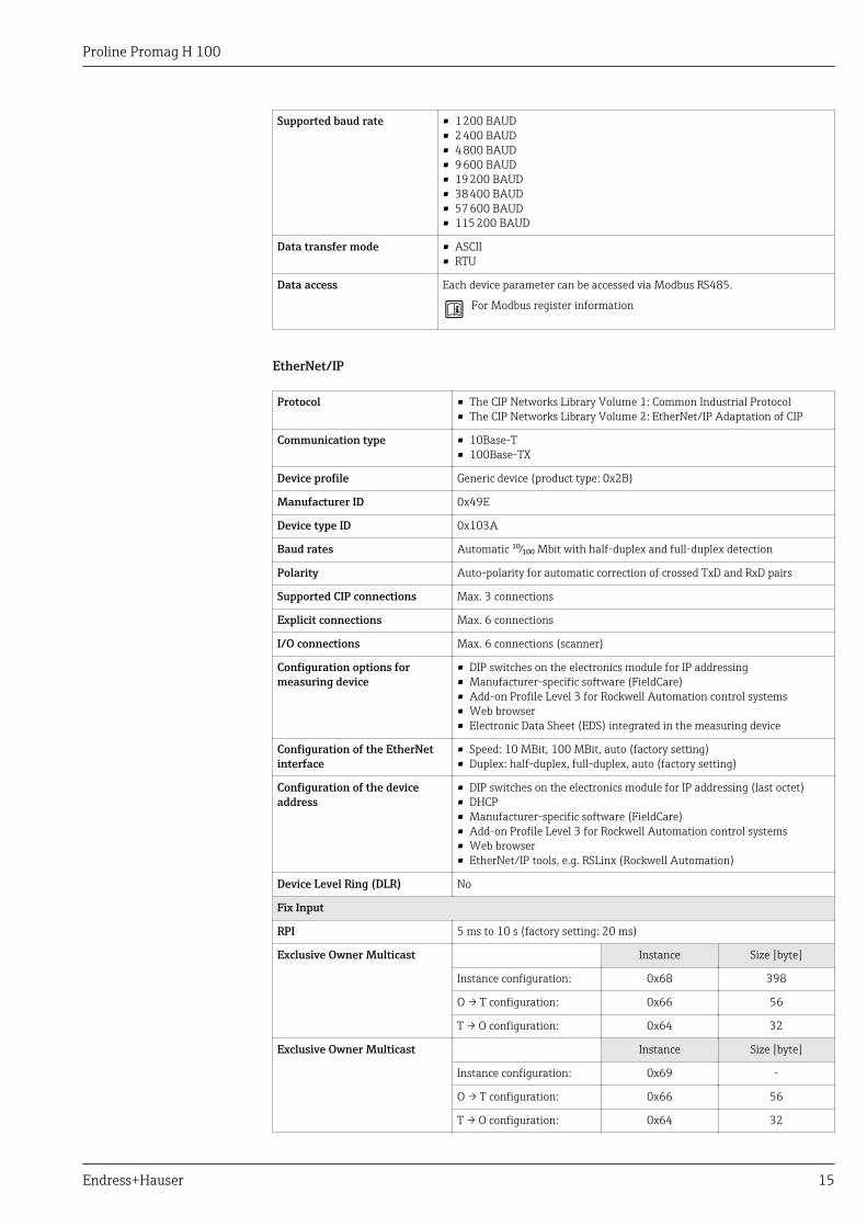
Supported baud rate • 1 200 BAUD• 2 400 BAUD• 4 800 BAUD• 9 600 BAUD• 19 200 BAUD• 38 400 BAUD• 57 600 BAUD• 115 200 BAUD
Data transfer mode • ASCII• RTU
Data access Each device parameter can be accessed via Modbus RS485.
For Modbus register information
EtherNet/IP
Protocol • The CIP Networks Library Volume 1: Common Industrial Protocol• The CIP Networks Library Volume 2: EtherNet/IP Adaptation of CIP
Communication type • 10Base-T• 100Base-TX
Device profile Generic device (product type: 0x2B)
Manufacturer ID 0x49E
Device type ID 0x103A
Baud rates Automatic ¹⁰⁄₁₀₀ Mbit with half-duplex and full-duplex detection
Polarity Auto-polarity for automatic correction of crossed TxD and RxD pairs
Supported CIP connections Max. 3 connections
Explicit connections Max. 6 connections
I/O connections Max. 6 connections (scanner)
Configuration options formeasuring device
• DIP switches on the electronics module for IP addressing• Manufacturer-specific software (FieldCare)• Add-on Profile Level 3 for Rockwell Automation control systems• Web browser• Electronic Data Sheet (EDS) integrated in the measuring device
Configuration of the EtherNetinterface
• Speed: 10 MBit, 100 MBit, auto (factory setting)• Duplex: half-duplex, full-duplex, auto (factory setting)
Configuration of the deviceaddress
• DIP switches on the electronics module for IP addressing (last octet)• DHCP• Manufacturer-specific software (FieldCare)• Add-on Profile Level 3 for Rockwell Automation control systems• Web browser• EtherNet/IP tools, e.g. RSLinx (Rockwell Automation)
Device Level Ring (DLR) No
Fix Input
RPI 5 ms to 10 s (factory setting: 20 ms)
Exclusive Owner Multicast Instance Size [byte]
Instance configuration: 0x68 398
O → T configuration: 0x66 56
T → O configuration: 0x64 32
Exclusive Owner Multicast Instance Size [byte]
Instance configuration: 0x69 -
O → T configuration: 0x66 56
T → O configuration: 0x64 32
Proline Promag H 100
16 Endress+Hauser
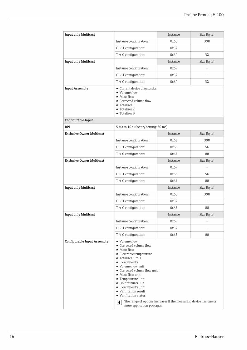
Input only Multicast Instance Size [byte]
Instance configuration: 0x68 398
O → T configuration: 0xC7 -
T → O configuration: 0x64 32
Input only Multicast Instance Size [byte]
Instance configuration: 0x69 -
O → T configuration: 0xC7 -
T → O configuration: 0x64 32
Input Assembly • Current device diagnostics• Volume flow• Mass flow• Corrected volume flow• Totalizer 1• Totalizer 2• Totalizer 3
Configurable Input
RPI 5 ms to 10 s (factory setting: 20 ms)
Exclusive Owner Multicast Instance Size [byte]
Instance configuration: 0x68 398
O → T configuration: 0x66 56
T → O configuration: 0x65 88
Exclusive Owner Multicast Instance Size [byte]
Instance configuration: 0x69 -
O → T configuration: 0x66 56
T → O configuration: 0x65 88
Input only Multicast Instance Size [byte]
Instance configuration: 0x68 398
O → T configuration: 0xC7 -
T → O configuration: 0x65 88
Input only Multicast Instance Size [byte]
Instance configuration: 0x69 -
O → T configuration: 0xC7 -
T → O configuration: 0x65 88
Configurable Input Assembly • Volume flow• Corrected volume flow• Mass flow• Electronic temperature• Totalizer 1 to 3• Flow velocity• Volume flow unit• Corrected volume flow unit• Mass flow unit• Temperature unit• Unit totalizer 1-3• Flow velocity unit• Verification result• Verification status
The range of options increases if the measuring device has one ormore application packages.
Proline Promag H 100
Endress+Hauser 17
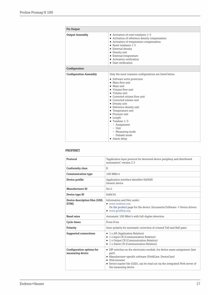
Fix Output
Output Assembly • Activation of reset totalizers 1-3• Activation of reference density compensation• Activation of temperature compensation• Reset totalizers 1-3• External density• Density unit• External temperature• Activation verification• Start verification
Configuration
Configuration Assembly Only the most common configurations are listed below.
• Software write protection• Mass flow unit• Mass unit• Volume flow unit• Volume unit• Corrected volume flow unit• Corrected volume unit• Density unit• Reference density unit• Temperature unit• Pressure unit• Length• Totalizer 1-3:
– Assignment– Unit– Measuring mode– Failsafe mode
• Alarm delay
PROFINET
Protocol "Application layer protocol for decentral device periphery and distributedautomation", version 2.3
Conformity class B
Communication type 100 MBit/s
Device profile Application interface identifier 0xF600Generic device
Manufacturer ID 0x11
Device type ID 0x843A
Device description files (GSD,DTM)
Information and files under:• www.endress.com
On the product page for the device: Documents/Software → Device drivers• www.profibus.org
Baud rates Automatic 100 Mbit/s with full-duplex detection
Cycle times From 8 ms
Polarity Auto-polarity for automatic correction of crossed TxD and RxD pairs
Supported connections • 1 x AR (Application Relation)• 1 x Input CR (Communication Relation)• 1 x Output CR (Communication Relation)• 1 x Alarm CR (Communication Relation)
Configuration options formeasuring device
• DIP switches on the electronics module, for device name assignment (lastpart)
• Manufacturer-specific software (FieldCare, DeviceCare)• Web browser• Device master file (GSD), can be read out via the integrated Web server of
the measuring device

Proline Promag H 100
18 Endress+Hauser
Configuration of the devicename
• DIP switches on the electronics module, for device name assignment (lastpart)
• DCP protocol
Output values(from measuring device toautomation system)
Analog Input module (slot 1 to 10)• Volume flow• Mass flow• Corrected volume flow• Flow velocity• Conductivity• Corrected conductivity• Temperature• Electronic temperature
Discrete Input module (slot 1 to 10)• Empty pipe detection• Low flow cut off
Diagnostics Input module (slot 1 to 10)• Last diagnostics• Current diagnosis
Totalizer 1 to 3 (slot 11 to 13)• Volume flow• Mass flow• Corrected volume flow
Heartbeat Verification module (fixed assignment)Verification status (slot 17)
Input values(from automation system tomeasuring device)
Analog Output module (fixed assignment)• External density (slot 14)• External temperature (slot 15)
Discrete Output module (fixed assignment)Activate/deactivate positive zero return (slot 16)
Totalizer 1 to 3 (slot 11 to 13)• Totalize• Reset and hold• Preset and hold• Stop• Operating mode configuration:
– Net flow total– Forward flow total– Reverse flow total
Heartbeat Verification module (fixed assignment)Start verification (slot 17)
Supported functions • Identification & MaintenanceSimple device identification via:– Control system– Nameplate
• Measured value statusThe process variables are communicated with a measured value status
• Blinking feature via the onsite display for simple device identification andassignment
Administration of software options
Input/output value Process variable Category Slot
Output value Mass flow Process variable 1…10
Volume flow
Corrected volume flow
Temperature
Conductivity
Corrected conductivity
Electronic temperature
Flow velocity

Proline Promag H 100
Endress+Hauser 19
Input/output value Process variable Category Slot
Current device diagnostics
Previous device diagnostics
Input/output value Totalizer Totalizer 11…13
Input value External density Process monitoring 14
External temperature 15
Flow override 16
Verification status Heartbeat Verification 1) 17
1) Only available with the "Heartbeat" application package.
Startup configuration
Startup configuration(NSU)
If startup configuration is enabled, the configuration of the most importantdevice parameters is taken from the automation system and used.
The following configuration is taken from the automation system:• Management
– Software revision– Write protection
• System units– Mass flow– Mass– Volume flow– Volume– Corrected volume flow– Corrected volume– Density– Temperature– Conductivity
• Sensor adjustment• Process param.
– Damping (flow, conductivity, temperature)– Flow override– Filter options
• Low flow cut off– Assign process variable– Switch-on/switch-off point– Pressure shock suppression
• Empty pipe detection– Assign process variable– Limit values– Response time
• External compensation– Temperature source– Density source– Density value
• Diagnostic settings• Diagnostic behavior for diverse diagnostic information
Proline Promag H 100
20 Endress+Hauser
Power supply
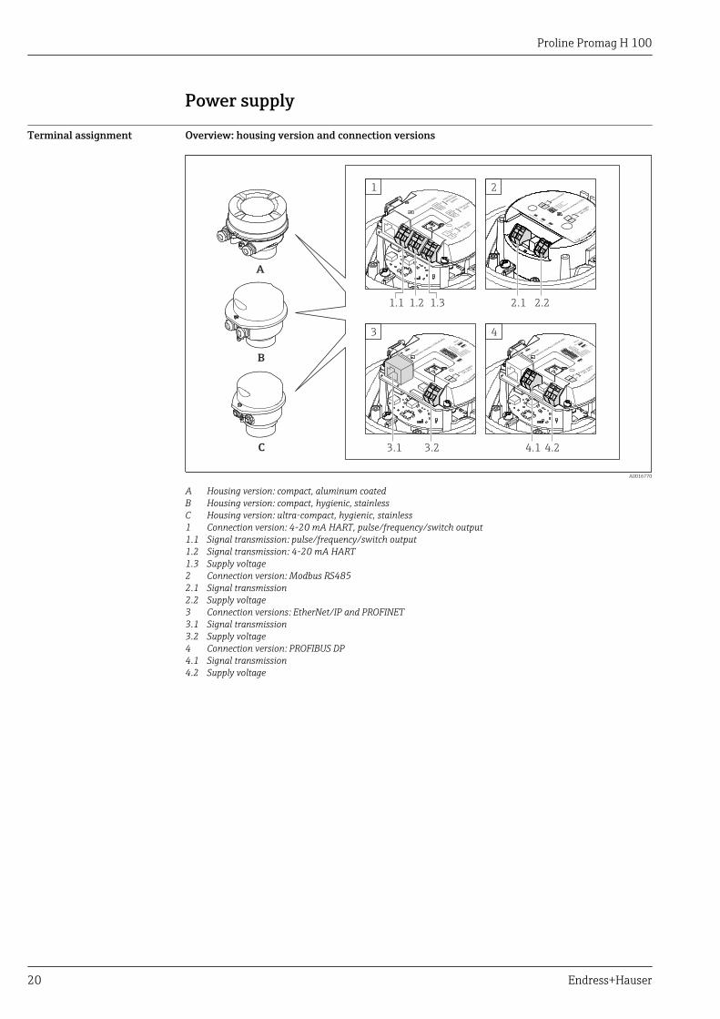
Terminal assignment Overview: housing version and connection versions
A
B
C
2
2.1 2.2
3
3.1 3.2
1
1.1 1.2 1.3
4
4.24.1
A0016770
A Housing version: compact, aluminum coatedB Housing version: compact, hygienic, stainlessC Housing version: ultra-compact, hygienic, stainless1 Connection version: 4-20 mA HART, pulse/frequency/switch output1.1 Signal transmission: pulse/frequency/switch output1.2 Signal transmission: 4-20 mA HART1.3 Supply voltage2 Connection version: Modbus RS4852.1 Signal transmission2.2 Supply voltage3 Connection versions: EtherNet/IP and PROFINET3.1 Signal transmission3.2 Supply voltage4 Connection version: PROFIBUS DP4.1 Signal transmission4.2 Supply voltage

Proline Promag H 100
Endress+Hauser 21
Transmitter
Connection version 4-20 mA HART with pulse/frequency/switch output
Order code for "Output", option B
Depending on the housing version, the transmitters can be ordered with terminals or device plugs.
Order code for"Housing"
Connection methods availablePossible options for order code
"Electrical connection"Outputs Powersupply
OptionsA, B
Terminals Terminals • Option A: coupling M20x1• Option B: thread M20x1• Option C: thread G ½"• Option D: thread NPT ½"
OptionsA, B
Device plugs→ 25
Terminals • Option L: plug M12x1 + thread NPT ½"• Option N: plug M12x1 + coupling M20• Option P: plug M12x1 + thread G ½"• Option U: plug M12x1 + thread M20
OptionsA, B, C
Device plugs→ 25
Device plugs→ 25
Option Q: 2 x plug M12x1
Order code for "Housing":• Option A: compact, coated aluminum• Option B: compact, hygienic, stainless• Option C ultra-compact, hygienic, stainless
L
L
26
27
+_
24
25
1
2
+_
+_ 1
2
3
A0016888
2 Terminal assignment 4-20 mA HART with pulse/frequency/switch output
1 Power supply: DC 24 V2 Output 1: 4-20 mA HART (active)3 Output 2: pulse/frequency/switch output (passive)
Order code for"Output"
Terminal number
Power supply Output 1 Output 2
2 (L-) 1 (L+) 27 (–) 26 (+) 25 (–) 24 (+)
Option B DC 24 V 4-20 mA HART (active) Pulse/frequency/switchoutput (passive)
Order code for "Output":Option B: 4-20 mA HART with pulse/frequency/switch output

Proline Promag H 100
22 Endress+Hauser
PROFIBUS DP connection version
For use in the non-hazardous area and Zone 2/Div. 2.
Order code for "Output", option L
Depending on the housing version, the transmitters can be ordered with terminals or device plugs.
Order code for"Housing"
Connection methods availablePossible options for order code
"Electrical connection"Output Powersupply
OptionsA, B
Terminals Terminals • Option A: coupling M20x1• Option B: thread M20x1• Option C: thread G ½"• Option D: thread NPT ½"
OptionsA, B
Device plugs→ 25
Terminals • Option L: plug M12x1 + thread NPT ½"• Option N: plug M12x1 + coupling M20• Option P: plug M12x1 + thread G ½"• Option U: plug M12x1 + thread M20
OptionsA, B, C
Device plugs→ 25
Device plugs→ 25
Option Q: 2 x plug M12x1
Order code for "Housing":• Option A: compact, coated aluminum• Option B: compact, hygienic, stainless• Option C ultra-compact, hygienic, stainless
L
L
26
27
B
A
1
2
+_ 1
2
A0022716
3 PROFIBUS DP terminal assignment
1 Power supply: DC 24 V2 PROFIBUS DP
Order code for"Output"
Terminal number
Power supply Output
2 (L-) 1 (L+) 26 (RxD/TxD-P) 27 (RxD/TxD-N)
Option L DC 24 V B A
Order code for "Output":Option L: PROFIBUS DP, for use in non-hazardous areas and Zone 2/div. 2
Proline Promag H 100
Endress+Hauser 23
Modbus RS485 connection version
Order code for "Output", option M
Depending on the housing version, the transmitters can be ordered with terminals or device plugs.
Order code for"Housing"
Connection methods availablePossible options for order code
"Electrical connection"Output Powersupply
OptionsA, B
Terminals Terminals • Option A: coupling M20x1• Option B: thread M20x1• Option C: thread G ½"• Option D: thread NPT ½"
OptionsA, B
Device plugs→ 25
Terminals • Option L: plug M12x1 + thread NPT ½"• Option N: plug M12x1 + coupling M20• Option P: plug M12x1 + thread G ½"• Option U: plug M12x1 + thread M20
OptionsA, B, C
Device plugs→ 25
Device plugs→ 25
Option Q: 2 x plug M12x1
Order code for "Housing":• Option A: compact, coated aluminum• Option B: compact, hygienic, stainless• Option C ultra-compact, hygienic, stainless
L
L
26
27 A
B
1
2
+_ 1
2
A0019528
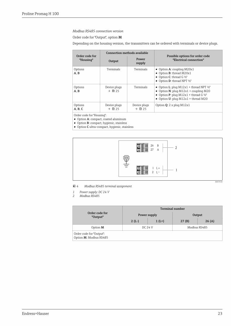
4 Modbus RS485 terminal assignment
1 Power supply: DC 24 V2 Modbus RS485
Order code for"Output"
Terminal number
Power supply Output
2 (L-) 1 (L+) 27 (B) 26 (A)
Option M DC 24 V Modbus RS485
Order code for "Output":Option M: Modbus RS485

Proline Promag H 100
24 Endress+Hauser
EtherNet/IP connection version
Order code for "Output", option N
Depending on the housing version, the transmitters can be ordered with terminals or device plugs.
Order code for"Housing"
Connection methods availablePossible options for order code
"Electrical connection"Output Powersupply
OptionsA, B
Device plugs→ 25
Terminals • Option L: plug M12x1 + thread NPT ½"• Option N: plug M12x1 + coupling M20• Option P: plug M12x1 + thread G ½"• Option U: plug M12x1 + thread M20
OptionsA, B, C
Device plugs→ 25
Device plugs→ 25
Option Q: 2 x plug M12x1
Order code for "Housing":• Option A: compact, coated aluminum• Option C ultra-compact, hygienic, stainless
L
L
1
2
+_ 1
2
A0017054
5 EtherNet/IP terminal assignment
1 Power supply: DC 24 V2 EtherNet/IP
Order code for"Output"
Terminal number
Power supply Output
2 (L-) 1 (L+) Device plug M12x1
Option N DC 24 V EtherNet/IP
Order code for "Output":Option N: EtherNet/IP

Proline Promag H 100
Endress+Hauser 25
PROFINET connection version
Order code for "Output", option R
Depending on the housing version, the transmitters can be ordered with terminals or device plugs.
Order code for"Housing"
Connection methods availablePossible options for order code
"Electrical connection"Output Powersupply
OptionsA, B
Device plugs→ 25
Terminals • Option L: plug M12x1 + thread NPT ½"• Option N: plug M12x1 + coupling M20• Option P: plug M12x1 + thread G ½"• Option U: plug M12x1 + thread M20
OptionsA, B, C
Device plugs→ 25
Device plugs→ 25
Option Q: 2 x plug M12x1
Order code for "Housing":• Option A: compact, coated aluminum• Option C ultra-compact, hygienic, stainless
L
L
1
2
+_ 1
2
A0017054
6 PROFINET terminal assignment
1 Power supply: DC 24 V2 PROFINET
Order code for"Output"
Terminal number
Power supply Output
2 (L-) 1 (L+) Device plug M12x1
Option R DC 24 V PROFINET
Order code for "Output":Option R: PROFINET
Pin assignment, device plug Order codes for the M12x1 connectors, see the "Order code for electrical connection" column:• 4-20 mA HART, pulse/frequency/switch output → 21• PROFIBUS DP→ 22• Modbus RS485 → 23• EtherNet/IP → 24• PROFINET→ 25

Proline Promag H 100
26 Endress+Hauser
Supply voltage
For all connection versions (device side)
1
2
4
3
5
A0016809
Pin Assignment
1 L+ DC 24 V
2 Not assigned
3 Not assigned
4 L- DC 24 V
5 Grounding/shielding
Coding Plug/socket
A Plug
The following is recommended as a socket:• Binder, series 763, part no. 79 3440 35 05• Alternatively: Phoenix part no. 1669767 SAC-5P-M12MS
– With the order code for "Output", option B: 4-20 mA HART, pulse/frequency/switch output– With the order code for "Output", option N: EtherNet/IP
• When using the device in a hazardous location: Use a suitably certified socket.
4-20 mA HART with pulse/frequency/switch output
Device plug for signal transmission (device side)
3
2
4
1
5
A0016810
Pin Assignment
1 + 4-20 mA HART (active)
2 - 4-20 mA HART (active)
3 + Pulse/frequency/switch output (passive)
4 - Pulse/frequency/switch output (passive)
5 Grounding/shielding
Coding Plug/socket
A Socket
• Recommended plug: Binder, series 763, part no. 79 3439 12 05• When using the device in a hazardous location, use a suitably certified plug.
PROFIBUS DP
For use in the non-hazardous area and Zone 2/Div. 2.
Device plug for signal transmission (device side)
3
2
4
1
5
A0016811
Pin Assignment
1 Not assigned
2 A PROFIBUS DP
3 Not assigned
4 B PROFIBUS DP
5 Grounding/shielding
Coding Plug/socket
B Socket
• Recommended plug: Binder, series 763, part no. 79 4449 20 05• When using the device in a hazardous location, use a suitably certified plug.

Proline Promag H 100
Endress+Hauser 27
MODBUS RS485
Device plug for signal transmission (device side)
3
2
4
1
5
A0016811
Pin Assignment
1 Not assigned
2 A Modbus RS485
3 Not assigned
4 B Modbus RS485
5 Grounding/shielding
Coding Plug/socket
B Socket
• Recommended plug: Binder, series 763, part no. 79 4449 20 05• When using the device in a hazardous location, use a suitably certified plug.
EtherNet/IP
Device plug for signal transmission (device side)
3
2
4
1
A0016812
Pin Assignment
1 + Tx
2 + Rx
3 - Tx
4 - Rx
Coding Plug/socket
D Socket
Recommended plug:• Binder, series 763, part no. 99 3729 810 04• Phoenix, part no. 1543223 SACC-M12MSD-4Q• When using the device in a hazardous location, use a suitably certified plug.
PROFINET
Device plug for signal transmission (device side)
3
2
4
1
A0016812
Pin Assignment
1 + TD +
2 + RD +
3 - TD –
4 - RD –
Coding Plug/socket
D Socket
Recommended plug:• Binder, series 763, part no. 99 3729 810 04• Phoenix, part no. 1543223 SACC-M12MSD-4Q• When using the device in a hazardous location, use a suitably certified plug.
Supply voltage The power unit must be tested to ensure it meets safety requirements (e.g. PELV, SELV).
Transmitter
For device version with all communication types: DC 20 to 30 V
Proline Promag H 100
28 Endress+Hauser
Power consumption Transmitter
Order code for "Output" MaximumPower consumption
Option B: 4-20 mA HART with pulse/frequency/switch output 3.5 W
Option L: PROFIBUS DP 3.5 W
Option M: Modbus RS485 3.5 W
Option N: EtherNet/IP 3.5 W
Option R: PROFINET 3.5 W
Current consumption Transmitter
Order code for "Output" MaximumCurrent consumption
Maximumswitch-on current
Option B: 4-20mA HART, pul./freq./switch output 145 mA 18 A (< 0.125 ms)
Option L: PROFIBUS DP 145 mA 18 A (< 0.125 ms)
Option M: Modbus RS485 90 mA 10 A (< 0.8 ms)
Option N: EtherNet/IP 145 mA 18 A (< 0.125 ms)
Option R: PROFINET 145 mA 18 A (< 0.125 ms)
Power supply failure • Totalizers stop at the last value measured.• Depending on the device version, the configuration is retained in the device memory or in the
plug-in memory (HistoROM DAT).• Configuration is retained in the plug-in memory (HistoROM DAT).• Error messages (incl. total operated hours) are stored.
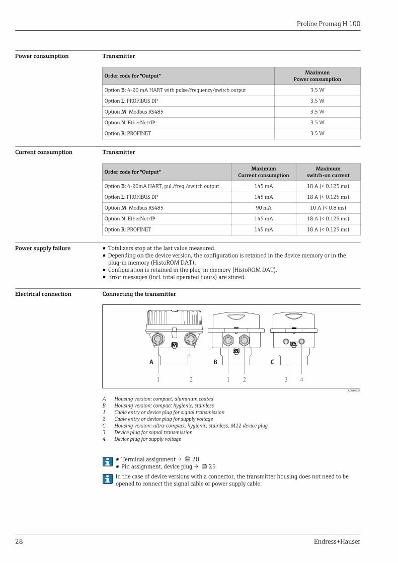
Electrical connection Connecting the transmitter
1 2 1 2 3 4
A B C
A0016924
A Housing version: compact, aluminum coatedB Housing version: compact hygienic, stainless1 Cable entry or device plug for signal transmission2 Cable entry or device plug for supply voltageC Housing version: ultra-compact, hygienic, stainless, M12 device plug3 Device plug for signal transmission4 Device plug for supply voltage
• Terminal assignment → 20• Pin assignment, device plug → 25In the case of device versions with a connector, the transmitter housing does not need to beopened to connect the signal cable or power supply cable.

Proline Promag H 100
Endress+Hauser 29
Connection examples
Current output 4-20 mA HART
4
4...20 mA
+
–
5
21 3
6
+
_
A0016800
7 Connection example for 4-20 mA HART current output (active)
1 Automation system with current input (e.g. PLC)2 Cable shield, observe cable specifications3 Connection for HART operating devices4 Resistor for HART communication (≥ 250 Ω): observe maximum load5 Analog display unit: observe maximum load6 Transmitter
Pulse/frequency output
1
+
_
12345
2
+
–
+–
3
A0016801
8 Connection example for pulse/frequency output (passive)
1 Automation system with pulse/frequency input (e.g. PLC)2 Power supply3 Transmitter: observe input values → 9
Switch output
1
+_
+
_
2
+
_ 3
A0016802
9 Connection example for switch output (passive)
1 Automation system with switch input (e.g. PLC)2 Power supply3 Transmitter: observe input values

Proline Promag H 100
30 Endress+Hauser
PROFIBUS DP
21
A
B
A
B
A
B
3
3
A0021429
10 Connection example for PROFIBUS DP, non-hazardous area and Zone 2/Div. 2
1 Control system (e.g. PLC)2 Cable shield: the cable shield must be grounded at both ends to comply with EMC requirements; observe cable
specifications3 Transmitter
If baud rates > 1.5 MBaud an EMC cable entry must be used and the cable shield must continueas far as the terminal wherever possible.
Modbus RS485
21
A
B
A
B
A
B
3
4
4
A0016803
11 Connection example for Modbus RS485, non-hazardous area and Zone 2/Div. 2
1 Control system (e.g. PLC)2 Cable shield: the cable shield must be grounded at both ends to comply with EMC requirements; observe cable
specifications3 Distribution box4 Transmitter

Proline Promag H 100
Endress+Hauser 31
EtherNet/IP
1 2 4
5
5
3
A0016805
12 Connection example for EtherNet/IP
1 Control system (e.g. PLC)2 Ethernet switch3 Observe cable specifications4 Device plug5 Transmitter
PROFINET
1 2 4
5
5
3
A0016805
13 Connecting cable for PROFINET
1 Control system (e.g. PLC)2 Ethernet switch3 Observe cable specifications4 Connector5 Transmitter
HART input
2
4...20 mA
3 41
+
-5
+
-
6
A0019828
14 Connection example for HART input (burst mode) via current output (active)
1 Cable shield, observe cable specifications2 Resistor for HART communication (≥ 250 Ω): observe maximum load3 Connection for HART operating devices4 Analog display unit5 Transmitter6 Sensor for external measured variable

Proline Promag H 100
32 Endress+Hauser
3
4...20 mA
4 521
+
-6
4...20 mA
+
-7
3 4 52
+
--+
A0019830
15 Connection example for HART input (master mode) via current output (active)
1 Automation system with current input (e.g. PLC).Prerequisite: automation system with HART version 6, HART commands 113 and 114 can be processed.
2 Cable shield, observe cable specifications3 Resistor for HART communication (≥ 250 Ω): observe maximum load4 Connection for HART operating devices5 Analog display unit6 Transmitter7 Sensor for external measured variable
Potential equalization Requirements
Please consider the following to ensure correct measurement:• Same electrical potential for the fluid and sensor• Company-internal grounding concepts• Pipe material and grounding
For devices intended for use in hazardous locations, please observe the guidelines in the Exdocumentation (XA).
Connection example, standard scenario
Metal process connections
Potential equalization is generally via the metal process connections that are in contact with themedium and mounted directly on the sensor. Therefore there is generally no need for additionalpotential equalization measures.
Connection example in special situations
Plastic process connections
In the case of plastic process connections, additional grounding rings or process connections with anintegrated grounding electrode must be used to ensure potential matching between the sensor andthe fluid. If there is no potential matching, this can affect the measuring accuracy or cause thedestruction of the sensor as a result of the electrochemical decomposition of the electrodes.
Note the following when using grounding rings:• Depending on the option ordered, plastic disks are used instead of grounding rings on some
process connections. These plastic disks only act as "spacers" and do not have any potentialmatching function. Furthermore, they also perform a significant sealing function at the sensor/connection interface. Therefore, in the case of process connections without metal grounding rings,these plastic disks/seals should never be removed and should always be installed!
• Grounding rings can be ordered separately as an accessory from Endress+Hauser . When orderingmake sure that the grounding rings are compatible with the material used for the electrodes, asotherwise there is the danger that the electrodes could be destroyed by electrochemical corrosion!
• Grounding rings, including seals, are mounted inside the process connections. Therefore theinstallation length is not affected.

Proline Promag H 100
Endress+Hauser 33
Potential equalization via additional grounding ring
1
3 2
4
2
A0002651
1 Hexagonal-headed bolts of process connection2 O-ring seals3 Plastic disk (spacer) or grounding ring4 Sensor
Potential equalization via grounding electrodes on process connection
2 1
3
4
A0017293
1 Hexagonal-headed bolts of process connection2 Integrated grounding electrodes3 O-ring seal4 Sensor
Terminals TransmitterSpring terminals for wire cross-sections0.5 to 2.5 mm2 (20 to 14 AWG)
Cable entries • Cable gland: M20 × 1.5 with cable 6 to 12 mm (0.24 to 0.47 in)• Thread for cable entry:
– NPT ½"– G ½"– M20

Proline Promag H 100
34 Endress+Hauser
Cable specification Permitted temperature range
• –40 °C (–40 °F) to +80 °C (+176 °F)• Minimum requirement: cable temperature range ≥ ambient temperature +20 K
Power supply cable
Standard installation cable is sufficient.
Signal cable
Current output
For 4-20 mA HART: Shielded cable recommended. Observe grounding concept of the plant.
Pulse/frequency/switch output
Standard installation cable is sufficient.
PROFIBUS DP
The IEC 61158 standard specifies two types of cable (A and B) for the bus line which can be used forevery transmission rate. Cable type A is recommended.
Cable type A
Characteristic impedance 135 to 165 Ω at a measuring frequency of 3 to 20 MHz
Cable capacitance <30 pF/m
Wire cross-section >0.34 mm2 (22 AWG)
Cable type Twisted pairs
Loop resistance ≤110 Ω/km
Signal damping Max. 9 dB over the entire length of the cable cross-section
Shield Copper braided shielding or braided shielding with foil shield. When groundingthe cable shield, observe the grounding concept of the plant.
Modbus RS485
The EIA/TIA-485 standard specifies two types of cable (A and B) for the bus line which can be usedfor every transmission rate. Cable type A is recommended.
Cable type A
Characteristic impedance 135 to 165 Ω at a measuring frequency of 3 to 20 MHz
Cable capacitance <30 pF/m
Wire cross-section >0.34 mm2 (22 AWG)
Cable type Twisted pairs
Loop resistance ≤110 Ω/km
Signal damping Max. 9 dB over the entire length of the cable cross-section
Shield Copper braided shielding or braided shielding with foil shield. When groundingthe cable shield, observe the grounding concept of the plant.
EtherNet/IP
The standard ANSI/TIA/EIA-568-B.2 Annex specifies CAT 5 as the minimum category for a cableused for EtherNet/IP. CAT 5e and CAT 6 are recommended.
For more information on planning and installing EtherNet/IP networks, please refer to the"Media Planning and Installation Manual. EtherNet/IP" of ODVA Organization
Proline Promag H 100
Endress+Hauser 35
PROFINET
Standard IEC 61156-6 specifies CAT 5 as the minimum category for a cable used for PROFINET. CAT5e and CAT 6 are recommended.
For more information on planning and installing PROFINET networks, see: "PROFINET Cablingand Interconnection Technology", Guideline for PROFINET
Performance characteristics
Reference operatingconditions
In accordance with DIN EN 29104• Medium temperature: +28 ± 2 °C (+82 ± 4 °F)• Ambient temperature: +22 ± 2 °C (+72 ± 4 °F)• Warm-up period: 30 minInstallation• Inlet run > 10 × DN• Outlet run > 5 × DN• Sensor and transmitter grounded.• The sensor is centered in the pipe.
To calculate the measuring range, use the Applicator sizing tool → 93
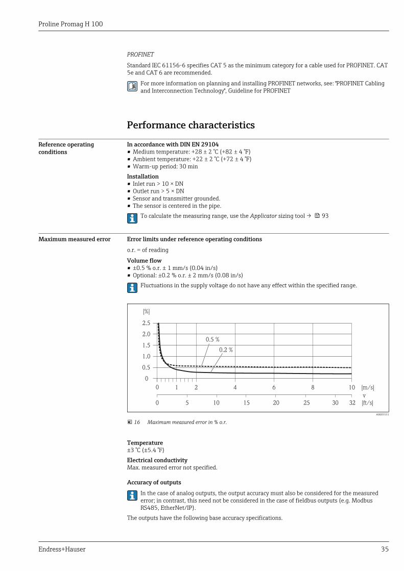
Maximum measured error Error limits under reference operating conditions
o.r. = of reading
Volume flow• ±0.5 % o.r. ± 1 mm/s (0.04 in/s)• Optional: ±0.2 % o.r. ± 2 mm/s (0.08 in/s)
Fluctuations in the supply voltage do not have any effect within the specified range.
2.5
[%]
2.0
1.5
1.0
0.5
0
0.2 %
0.5 %
0 1 2 4 6 8 10 [m/s]
v
5 10 15 20 25 30 32 [ft/s]0
A0005531
16 Maximum measured error in % o.r.
Temperature±3 °C (±5.4 °F)Electrical conductivityMax. measured error not specified.
Accuracy of outputs
In the case of analog outputs, the output accuracy must also be considered for the measurederror; in contrast, this need not be considered in the case of fieldbus outputs (e.g. ModbusRS485, EtherNet/IP).
The outputs have the following base accuracy specifications.

Proline Promag H 100
36 Endress+Hauser
Current output
Accuracy Max. ±5 µA
Pulse/frequency output
o.r. = of reading
Accuracy Max. ±50 ppm o.r. (across the entire ambient temperature range)
Repeatability o.r. = of reading
Volume flowMax. ±0.1 % o.r. ± 0.5 mm/s (0.02 in/s)Temperature±0.5 °C (±0.9 °F)Electrical conductivityMax. ±5 % o.r.
Temperature measurementresponse time
T90 < 15 s
Influence of ambienttemperature
Current output
o.r. = of reading
Temperature coefficient Max. ±0.005% o.r./°C
Pulse/frequency output
Temperature coefficient No additional effect. Included in accuracy.
InstallationNo special measures such as supports are necessary. External forces are absorbed by the constructionof the device.
Mounting location
h
A0023343
Preferably install the sensor in an ascending pipe, and ensure a sufficient distance to the next pipeelbow: h ≥ 2 × DN
To prevent measuring errors arising from accumulation of gas bubbles in the measuring tube, avoidthe following mounting locations in the pipe:• Highest point of a pipeline.• Directly upstream of a free pipe outlet in a down pipe.
Proline Promag H 100
Endress+Hauser 37
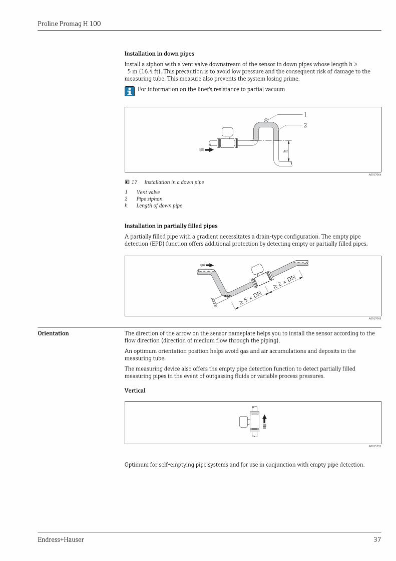
Installation in down pipes
Install a siphon with a vent valve downstream of the sensor in down pipes whose length h ≥ 5 m (16.4 ft). This precaution is to avoid low pressure and the consequent risk of damage to themeasuring tube. This measure also prevents the system losing prime.
For information on the liner's resistance to partial vacuum
h
2
1
A0017064
17 Installation in a down pipe
1 Vent valve2 Pipe siphonh Length of down pipe
Installation in partially filled pipes
A partially filled pipe with a gradient necessitates a drain-type configuration. The empty pipedetection (EPD) function offers additional protection by detecting empty or partially filled pipes.
³5 ×
DN
³2 ×
DN
A0017063
Orientation The direction of the arrow on the sensor nameplate helps you to install the sensor according to theflow direction (direction of medium flow through the piping).
An optimum orientation position helps avoid gas and air accumulations and deposits in themeasuring tube.
The measuring device also offers the empty pipe detection function to detect partially filledmeasuring pipes in the event of outgassing fluids or variable process pressures.
Vertical
A0015591
Optimum for self-emptying pipe systems and for use in conjunction with empty pipe detection.

Proline Promag H 100
38 Endress+Hauser
Horizontal
1
22
A0019602
1 EPD electrode for empty pipe detection2 Measuring electrodes for signal detection
• The measuring electrode plane must be horizontal. This prevents brief insulation of the twomeasuring electrodes by entrained air bubbles.
• Empty pipe detection only works if the transmitter housing is pointing upwards as otherwisethere is no guarantee that the empty pipe detection function will actually respond to apartially filled or empty measuring tube.
Inlet and outlet runs If possible, install the sensor upstream from fittings such as valves, T-pieces or elbows.
Observe the following inlet and outlet runs to comply with accuracy specifications:
5 × DN≥ 2 × DN≥
A0016275
Adapters Suitable adapters to DIN EN 545 (double-flange reducers) can be used to install the sensor in larger-diameter pipes. The resultant increase in the rate of flow improves measuring accuracy with veryslow-moving fluids.
The nomogram shown here can be used to calculate the pressure loss caused by reducers andexpanders:• Calculate the ratio of the diameters d/D.• From the nomogram read off the pressure loss as a function of flow velocity (downstream from
the reduction) and the d/D ratio.The nomogram only applies to liquids with a viscosity similar to that of water.

Proline Promag H 100
Endress+Hauser 39
100
10
0.5d / D
[mbar]
0.6 0.7 0.8 0.9
1 m/s
2 m/s
3 m/s
4 m/s
5 m/s
6 m/s
7 m/s
8 m/s
1
Dd
max. 8°
A0016359
Environment
Ambient temperature range Transmitter –40 to +60 °C (–40 to +140 °F)
Local display –20 to +60 °C (–4 to +140 °F), the readability of the display may beimpaired at temperatures outside the temperature range.
Sensor –40 to +60 °C (–40 to +140 °F)
Liner Do not exceed or fall below the permitted temperature range of the liner .
If operating outdoors:• Install the measuring device in a shady location.• Avoid direct sunlight, particularly in warm climatic regions.• Avoid direct exposure to weather conditions.
Temperature tables
The following interdependencies between the permitted ambient and fluid temperatures apply whenoperating the device in hazardous areas:
Ex nA, CCSAUS NI
SI units
Ta[°C]
T6[85 °C]
T5[100 °C]
T4[135 °C]
T3[200 °C]
T2[300 °C]
T1[450 °C]
30 50 95 130 150 150 150
50 – 95 130 150 150 150
60 – 95 110 110 110 110

Proline Promag H 100
40 Endress+Hauser
US units
Ta[°F]
T6[185 °F]
T5[212 °F]
T4[275 °F]
T3[392 °F]
T2[572 °F]
T1[842 °F]
86 122 203 266 302 302 302
122 – 203 266 302 302 302
140 – 203 230 230 230 230
Storage temperature The storage temperature corresponds to the operating temperature range of the measuringtransmitter and the appropriate measuring sensors.→ 39
• Protect the measuring device against direct sunlight during storage in order to avoid unacceptablyhigh surface temperatures.
• Select a storage location where moisture cannot collect in the measuring device as fungus orbacteria infestation can damage the liner.
• If protection caps or protective covers are mounted these should never be removed beforeinstalling the measuring device.
Degree of protection Transmitter and sensor• As standard: IP66/67, type 4X enclosure• With the order code for "Sensor options", option CM: IP69K can also be ordered• When housing is open: IP20, type 1 enclosure• Display module: IP20, type 1 enclosure
Shock resistance As per IEC/EN 60068-2-31
Vibration resistance Acceleration up to 2 g based on IEC 60068-2-6
Mechanical load • Protect the transmitter housing against mechanical effects, such as shock or impact.• Never use the transmitter housing as a ladder or climbing aid.
Interior cleaning • Cleaning in place (CIP)• Sterilization in place (SIP)
Electromagneticcompatibility (EMC)
• Depends on the communication protocol:– HART, PROFIBUS DP, Modbus RS485, EtherNet/IP:
As per IEC/EN 61326 and NAMUR Recommendation 21 (NE 21)– PROFINET: as per IEC/EN 61326
• Complies with emission limits for industry as per EN 55011 (Class A)• Device version with PROFIBUS DP: Complies with emission limits for industry as per EN 50170
Volume 2, IEC 61784The following applies for PROFIBUS DP: If baud rates > 1.5 MBaud, an EMC cable entry must beused and the cable shield must continue as far as the terminal wherever possible.For details, refer to the Declaration of Conformity.
Process
Medium temperature range –20 to +150 °C (–4 to +302 °F)

Proline Promag H 100
Endress+Hauser 41
PFA
0
0
0
0
-20-40
-40
20
20
40100
60140[°F] [°C]
40 60 80 100
100
120 140 160
200 300
180
360
-20
-40-40
TA
TF
[°F]
[°C]
1
A0019805
TA Ambient temperature range
TF Medium temperature
1 Harsh environment and IP68 only up to +130 °C (+266 °F)
Conductivity ≥ 5 μS/cm for liquids in general
Pressure-temperatureratings
The following graphics contain material load diagrams (reference curves) for different processconnections in relation to the medium temperature.
Process connections with O-ring seal, DN 2 to 25 (1/12 to 1")
Process connection: weld-in nipple according to DIN EN ISO 1127, ODT/SMS, ISO 2037; couplingaccording to ISO 228 / DIN 2999, NPT
25
35
30
40
[bar][psi]
-40 -20 0 20 40 60 80 100120140160180 [°C]
360 [°F]0-40 100 200 300
400
500
600
PN40
A0021191-EN
18 Process connection material: stainless steel, 1.4404 (F316L)

Proline Promag H 100
42 Endress+Hauser
Process connection: flange according to EN 1092-1 (DIN 2501), adhesive sleeve
25
35
30
40
[bar][psi]
-40 -20 0 20 40 60 80 100120140160180 [°C]
360 [°F]0-40 100 200 300
400
500
600
PN40
A0021191-EN
19 Process connection material: stainless steel, 1.4404 (F316L)
0
5
10
15
20
[bar][psi]
-60 -40 -20 0 20 40 60 80 100120140160180 [°C]
360 [°F]0-40 100 200 300
200
100
300
0
PN16
A0021230-EN
20 Process connection material: PVDF
0
5
10
15
20
[bar][psi]
-60 -40 -20 0 20 40 60 80 100120140160180 [°C]
360 [°F]0-40 100 200 300
200
100
300
0
PN16
A0021231-EN
21 Process connection material: PVC-U

Proline Promag H 100
Endress+Hauser 43
Process connection: flange according to ASME B16.5
0
5
15
10
20
[bar][psi]
-40 -20 0 20 40 60 80 100120140160180 [°C]
360 [°F]0-40 100 200 300
100
200
300
0
Cl150
A0021192-EN
22 Process connection material: stainless steel, 1.4404 (F316L)
0
5
15
10
20
[bar][psi]
-40 -20 0 20 40 60 80 100120140160180 [°C]
360 [°F]0-40 100 200 300
100
200
300
0
Cl150
A0021232-EN
23 Process connection material: PVDF
Process connection: flange according to JIS B2220
0
5
15
10
20
[bar][psi]
-40 -20 0 20 40 60 80 100120140160180 [°C]
360 [°F]0-40 100 200 300
100
200
300
25
0
20K
A0021193-EN
24 Process connection material: stainless steel, 1.4404 (F316L)

Proline Promag H 100
44 Endress+Hauser
0
5
15
10
20
[bar][psi]
-40 -20 0 20 40 60 80 100120140160180 [°C]
360 [°F]0-40 100 200 300
100
200
300
25
0
10K
A0021233-EN
25 Process connection material: PVDF
Process connections with aseptic molded seal, DN 2 to 25 (1/12 to 1")
Process connection: weld-in nipple according to EN 10357 (DIN 11850), ASME BPE, ISO 2037; Clampaccording to ISO 2852, DIN 32676, L14 AM7; coupling according to SC DIN 11851, DIN 11864-1,SMS 1145; flange according to DIN 11864-2
PN16
[bar]
-60 -40 -20 0 20 40 60 80 100120140160180 [°C]
0
5
15
10
20
25
[psi]
360 [°F]0-40 100 200 300
100
200
300
0
A0021190-EN
26 Process connection material: stainless steel, 1.4404 (F316L)
Process connections with aseptic molded seal, DN 40 to 150 (1 ½ to 6")
Process connection: coupling according to SMS 1145
PN16
[bar]
-60 -40 -20 0 20 40 60 80 100120140160180 [°C]
0
5
15
10
20
25
[psi]
360 [°F]0-40 100 200 300
100
200
300
0
A0021190-EN
27 Process connection material: stainless steel, 1.4404 (F316L)

Proline Promag H 100
Endress+Hauser 45
Process connection: weld-in nipple according to EN 10357 (DIN 11850); coupling according toSC DIN 11851
0
5
10
15
20
25
35
30
40
[bar][psi]
-40 -20 0 20 40 60 80 100 140 180 [°C]
360 [°F]0-40 100 200 300
200
100
400
300
500
600
0
120 160
PN40:DN40 (1½")
PN25:DN50...100(2...4")
PN16:DN125...150(5...6")
A0021195-EN
28 Process connection material: stainless steel, 1.4404 (F316L)
Process connection: weld-in nipple according to ASME BPE
0
5
10
15
20
25
35
30
40
[bar][psi]
-40 -20 0 20 40 60 80 100 140 180 [°C]
360 [°F]0-40 100 200 300
200
100
400
300
500
600
0
120 160
PN40:DN40 (1½ )"
PN25:DN50...100(2 )...4"
PN16:DN150 (6")
A0021196-EN

Proline Promag H 100
46 Endress+Hauser
Process connection: weld-in nipple according to ISO 2037
0
5
10
15
20
25
35
30
40
[bar][psi]
-40 -20 0 20 40 60 80 100 140 180 [°C]
360 [°F]0-40 100 200 300
200
100
400
300
500
600
0
120 160
PN40:DN40 (1½")
PN25:DN50...100(2...4")
PN16:DN125...150(5...6")
A0021195-EN
29 Process connection material: stainless steel, 1.4404 (F316L)
Process connection: Clamp according to ISO 2852, DIN 32676, L14 AM7
PN16:DN 1 ½ )40...100( ...4"
0
5
10
15
20
[bar][psi]
-60 -40 -20 0 20 40 60 80 100 140 180 [°C]
360 [°F]0-40 100 200 300
200
100
300
0
PN10:DN125...150(5...6")
120 160
A0021197-EN
30 Process connection material: stainless steel, 1.4404 (F316L)
Process connection: coupling according to DIN 11864-1, ISO 2853
20
25
35
30
40
[bar][psi]
-40 -20 0 20 40 60 80 100 140 180 [°C]
360 [°F]0-40 100 200 300
400
300
500
600
120 160
PN40:DN40 (1½")
PN25:DN50...100(2...4")
A0021194-EN
31 Process connection material: stainless steel, 1.4404 (F316L)

Proline Promag H 100
Endress+Hauser 47
Process connection: flange according to DIN 11864-2
0
5
10
15
20
25
30
[bar][psi]
-40 -20 0 20 40 60 80 100 140 180 [°C]
360 [°F]0-40 100 200 300
200
100
400
300
0
PN25: )DN40 (1½"
120 160
PN16:DN50...100( )2...4"
PN10:DN125...150( )5...6"
A0021198-EN
32 Process connection material: stainless steel, 1.4404 (F316L)
Pressure tightness Liner: PFA
Nominal diameter Limit values for absolute pressure in [mbar] ([psi]) for fluid temperatures:
[mm] [in] +25 °C(+77 °F)
+80 °C(+176 °F)
+100 °C(+212 °F)
+130 °C(+266 °F)
+150 °C(+302 °F)
2 to 150 ¹⁄₁₂ to 6 0 (0) 0 (0) 0 (0) 0 (0) 0 (0)
Flow limit The diameter of the pipe and the flow rate determine the nominal diameter of the sensor. Theoptimum flow velocity is between 2 to 3 m/s (6.56 to 9.84 ft/s). Also match the velocity of flow (v)to the physical properties of the fluid:• v < 2 m/s (6.56 ft/s): For low conductivity values• v > 2 m/s (6.56 ft/s): For media that produce buildup (z.B. milk with high fat content)
A necessary increase in the flow velocity can be achieved by reducing the sensor nominaldiameter.For an overview of the full scale values for the measuring range, see the "Measuring range"section → 7
Pressure loss • No pressure loss occurs as of nominal diameter DN 8 (3/8") if the sensor is installed in a pipe withthe same nominal diameter.
• Pressure losses for configurations incorporating adapters according to DIN EN 545 → 38
System pressure
A0015594
Never install the sensor on the pump suction side in order to avoid the risk of low pressure, and thusdamage to the liner.
Furthermore, install pulse dampers if reciprocating, diaphragm or peristaltic pumps are used.
• For information on the liner's resistance to partial vacuum → 47• For information on the shock resistance of the measuring system → 40• For information on the vibration resistance of the measuring system → 40
Vibrations In the event of very strong vibrations, the pipe and sensor must be supported and fixed.
• For information on the shock resistance of the measuring system → 40• For information on the vibration resistance of the measuring system → 40

Proline Promag H 100
48 Endress+Hauser
L
A0016266
33 Measures to avoid device vibrations (L > 10 m (33 ft))
Mechanical construction
Dimensions in SI units Compact version
Order code for "Housing", option A "Compact, coated aluminum"
L
E
DC
B
F
H
di
Q
A
G
A0019463
DN A B C D E 1) F G 1) H L 2) Q di
[mm] [mm] [mm] [mm] [mm] [mm] [mm] [mm] [mm] [mm] [mm] [mm]
2 136 147.5 93.5 54 179 55 234 43 86 4 ×M6 2.25
4 136 147.5 93.5 54 179 55 234 43 86 4 ×M6 4.5
8 136 147.5 93.5 54 179 55 234 43 86 4 ×M6 9
15 136 147.5 93.5 54 179 55 234 43 86 4 ×M6 16
25 136 147.5 93.5 54 179 55 234 56 86 4 ×M6 26
1) If using a display, order code for "Display; Operation", option B: values + 28 mm2) Total length (L) depends on the process connections.

Proline Promag H 100
Endress+Hauser 49
L
E
DC
B
F
H
Q
A
G
di
A0019468
DN A B C D E 1) F G 1) H L 2) Q di
[mm] [mm] [mm] [mm] [mm] [mm] [mm] [mm] [mm] [mm] [mm] [mm]
40 136 147.5 93.5 54 179.3 53.3 232.6 107 140 4 ×M8 34.8
50 136 147.5 93.5 54 185.8 59.8 245.6 120 140 4 ×M8 47.5
65 136 147.5 93.5 54 195.6 69.6 265.2 135 140 6 ×M8 60.2
80 136 147.5 93.5 54 199.8 73.8 273.6 148 140 6 ×M8 72.9
100 136 147.5 93.5 54 212.8 86.8 299.6 174 140 6 ×M8 97.4
125 136 147.5 93.5 54 228.8 102.8 331.6 206 200 6 ×M10 120.0
150 136 147.5 93.5 54 242.8 116.8 359.6 234 200 6 ×M10 146.9
1) If using a display, order code for "Display; Operation", option B: values + 28 mm2) Total length (L) depends on the process connections.
Order code for "Housing", option B "Compact hygienic, stainless"
L
E
DC
B
F
H
di
Q
A
G
A0019464

Proline Promag H 100
50 Endress+Hauser
DN A B C D E 1) F G 1) H L 2) Q di
[mm] [mm] [mm] [mm] [mm] [mm] [mm] [mm] [mm] [mm] [mm] [mm]
2 133.5 136.8 78 58.8 173 55 228 43 86 4 ×M6 2.25
4 133.5 136.8 78 58.8 173 55 228 43 86 4 ×M6 4.5
8 133.5 136.8 78 58.8 173 55 228 43 86 4 ×M6 9
15 133.5 136.8 78 58.8 173 55 228 43 86 4 ×M6 16
25 133.5 136.8 78 58.8 173 55 220 56 86 4 ×M6 26
1) If using a display, order code for "Display; Operation", option B: values + 14 mm2) Total length (L) depends on the process connections.
A
DC
B
L
EF
H
di
Q
G
A0019470
DN A B C D E 1) F G 1) H L 2) Q di
[mm] [mm] [mm] [mm] [mm] [mm] [mm] [mm] [mm] [mm] [mm] [mm]
40 133.5 136.8 78 58.8 173.3 53.3 226.6 107 140 4 ×M8 34.8
50 133.5 136.8 78 58.8 179.8 59.8 239.6 120 140 4 ×M8 47.5
65 133.5 136.8 78 58.8 189.6 69.6 259.2 135 140 6 ×M8 60.2
80 133.5 136.8 78 58.8 193.8 73.8 267.6 148 140 6 ×M8 72.9
100 133.5 136.8 78 58.8 206.8 86.8 293.6 174 140 6 ×M8 97.4
125 133.5 136.8 78 58.8 222.8 102.8 325.6 206 200 6 ×M10 120.0
150 133.5 136.8 78 58.8 236.8 116.8 353.6 234 200 6 ×M10 146.9
1) If using a display, order code for "Display; Operation", option B: values + 14 mm2) Total length (L) depends on the process connections.

Proline Promag H 100
Endress+Hauser 51
Order code for "Housing", option C "Ultra-compact hygienic, stainless"
L
E
DC
B
F
H
di
Q
A
G
A0019466
DN A B C D E 1) F G 1) H L 2) Q di
[mm] [mm] [mm] [mm] [mm] [mm] [mm] [mm] [mm] [mm] [mm] [mm]
2 111.4 123.6 67.7 55.9 173 55 228 43 86 4 ×M6 2.25
4 111.4 123.6 67.7 55.9 173 55 228 43 86 4 ×M6 4.5
8 111.4 123.6 67.7 55.9 173 55 228 43 86 4 ×M6 9
15 111.4 123.6 67.7 55.9 173 55 228 43 86 4 ×M6 16
25 111.4 123.6 67.7 55.9 173 55 228 56 86 4 ×M6 26
1) If using a display, order code for "Display; Operation", option B: values + 14 mm2) Total length (L) depends on the process connections.
A
DC
B
L
EF
H
di
Q G
A0019471
DN A B C D E 1) F G 1) H L 2) Q di
[mm] [mm] [mm] [mm] [mm] [mm] [mm] [mm] [mm] [mm] [mm] [mm]
40 111.4 123.6 67.7 55.9 173.3 53.3 226.6 107 140 4 ×M8 34.8
50 111.4 123.6 67.7 55.9 179.8 59.8 239.6 120 140 4 ×M8 47.5
65 111.4 123.6 67.7 55.9 189.6 69.6 259.2 135 140 6 ×M8 60.2

Proline Promag H 100
52 Endress+Hauser
DN A B C D E 1) F G 1) H L 2) Q di
[mm] [mm] [mm] [mm] [mm] [mm] [mm] [mm] [mm] [mm] [mm] [mm]
80 111.4 123.6 67.7 55.9 193.8 73.8 267.6 148 140 6 ×M8 72.9
100 111.4 123.6 67.7 55.9 206.8 86.8 293.6 174 140 6 ×M8 97.4
125 111.4 123.6 67.7 55.9 222.8 102.8 325.6 206 200 6 ×M10 120.0
150 111.4 123.6 67.7 55.9 236.8 116.8 353.6 234 200 6 ×M10 146.9
1) If using a display, order code for "Display; Operation", option B: values + 14 mm2) Total length (L) depends on the process connections.
Sensor flange connection
G
F
K
H
E
Z
Z Z-Z
L
A B D
M
C
B/2
B/2
E–
2
E–
2
A0017657
34 Front view without process connections
DN A B C D E F G H K L M
[mm] [mm] [mm] [mm] [mm] [mm] [mm] [mm] [mm] [mm] [mm] [mm]
2 62 41.6 34 9 24 42 43 8.5 6 4 M6
4 62 41.6 34 9 24 42 43 8.5 6 4 M6
8 62 41.6 34 9 24 42 43 8.5 6 4 M6
15 62 41.6 34 16 24 42 43 8.5 6 4 M6
25 72 50.2 44 26 29 55 56 8.5 6 4 M6

Proline Promag H 100
Endress+Hauser 53
F
E
G
H
Z–Z
D C B A
Z
K
Z
L
A0005528
35 Front view without process connections
DN A B C D E F G H K L
90° ±0.5° 60° ±0.5°
[mm] [mm] [mm] [mm] [mm] [mm] [mm] [mm] [mm] Tapped holes
40 99.7 85.8 71.0 48.3 34.8 M8 12 17 4 –
50 112.7 98.8 83.5 60.3 47.5 M8 12 17 4 –
65 127.7 114.8 100.0 76.1 60.2 M8 12 17 – 6
80 140.7 133.5 114.0 88.9 72.9 M8 12 17 – 6
100 166.7 159.5 141.0 114.3 97.4 M8 12 17 – 6
125 198.7 191.5 171.0 139.7 120.0 M10 15 20 – 6
150 226.7 219.5 200.0 168.3 146.9 M10 15 20 – 6
Flanges
Flanges with aseptic molded seal
C
D
A B E
XX
L
A0015627
36 Detail X: Asymmetrical process connection; the part shown in gray is provided by the supplier.

Proline Promag H 100
54 Endress+Hauser
Flange DIN 11864-2, aseptic female, Form A1.4404 (316L)Order code for "Process connection", option DES
DN[mm]
Suitable for pipe EN 10357 (DIN 11850)[mm]
A[mm]
B[mm]
C[mm]
D[mm]
E[mm]
L[mm]
2 to 8 13 × 1.5 (DN 10) 54 37 4 × 9 10 10 183
15 19 × 1.5 (DN 15) 59 42 4 × 9 10 16 183
25 29 × 1.5 (DN 25) 70 53 4 × 9 10 26 183
Surface roughness: Ra ≤ 0.8 µm, optional ≤ 0.38 µmPlease note the internal diameters of the measuring tube and process connection (E) when cleaning with pigs.
Flange DIN 11864-2, aseptic flange, Form A1.4404 (316L)Order code for "Process connection", option DES
DN[mm]
Suitable for pipe EN 10357 (DIN 11850)[mm]
A[mm]
B[mm]
C[mm]
D[mm]
E[mm]
L[mm]
40 41 × 1.5 82 65 4 × 9 10 38 246
50 53 × 1.5 94 77 4 × 9 10 50 246
65 70 × 2 113 95 4 × 9 10 66 246
80 85 × 2 133 112 4 × 9 10 81 270
100 104 × 2 159 137 4 × 9 10 100 278
125 129 × 2 183 161 4 × 9 10 125 362
150 154 × 2 213 188 4 × 9 10 150 362
Surface roughness: Ra ≤ 0.8 µm, optional ≤ 0.38 µmPlease note the internal diameters of the measuring tube and process connection (E) when cleaning with pigs.
Flanges with O-ring seal
C
D
A B E
L
A0015621
Flange according to EN 1092-1 (DIN 2501), Form B: PN 401.4404 (316L)Order code for "Process connection", option D5S
DN[mm]
A[mm]
B[mm]
C[mm]
D[mm]
E[mm]
L[mm]
2 to 8 1) 95 65 4 × 14 16 17.3 198.4
15 95 65 4 × 14 16 17.3 198.4
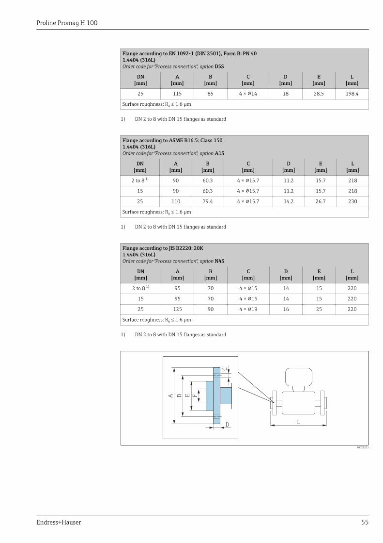
Proline Promag H 100
Endress+Hauser 55
Flange according to EN 1092-1 (DIN 2501), Form B: PN 401.4404 (316L)Order code for "Process connection", option D5S
DN[mm]
A[mm]
B[mm]
C[mm]
D[mm]
E[mm]
L[mm]
25 115 85 4 × 14 18 28.5 198.4
Surface roughness: Ra ≤ 1.6 µm
1) DN 2 to 8 with DN 15 flanges as standard
Flange according to ASME B16.5: Class 1501.4404 (316L)Order code for "Process connection", option A1S
DN[mm]
A[mm]
B[mm]
C[mm]
D[mm]
E[mm]
L[mm]
2 to 8 1) 90 60.3 4 × 15.7 11.2 15.7 218
15 90 60.3 4 × 15.7 11.2 15.7 218
25 110 79.4 4 × 15.7 14.2 26.7 230
Surface roughness: Ra ≤ 1.6 µm
1) DN 2 to 8 with DN 15 flanges as standard
Flange according to JIS B2220: 20K1.4404 (316L)Order code for "Process connection", option N4S
DN[mm]
A[mm]
B[mm]
C[mm]
D[mm]
E[mm]
L[mm]
2 to 8 1) 95 70 4 × 15 14 15 220
15 95 70 4 × 15 14 15 220
25 125 90 4 × 19 16 25 220
Surface roughness: Ra ≤ 1.6 µm
1) DN 2 to 8 with DN 15 flanges as standard
L
C
D
A B FE
A0022221

Proline Promag H 100
56 Endress+Hauser
Lap joint flange according to EN 1092-1 (DIN 2501): PN 16PVDFOrder code for "Process connection", option D3P
DN[mm]
A[mm]
B[mm]
C[mm]
D[mm]
E[mm]
F[mm]
L[mm]
2 to 8 1) 95 65 4 x 14 14.5 45 17.3 200
15 95 65 4 x 14 14.5 45 17.3 200
25 115 85 4 x 14 16.5 68 28.5 200
Surface roughness: Ra ≤ 1.6 µmThe required grounding rings can be ordered as accessories (order code: DK5HR-****).
1) DN 2 to 8 with DN 15 flanges as standard
Lap joint flange with grounding electrode according to EN 1092-1 (DIN 2501): PN 16PVDFOrder code for "Process connection", option D4P
DN[mm]
A[mm]
B[mm]
C[mm]
D[mm]
E[mm]
F[mm]
L[mm]
2 to 8 1) 95 65 4 x 14 14.5 45 17.3 200
15 95 65 4 x 14 14.5 45 17.3 200
25 115 85 4 x 14 16.5 68 28.5 200
Surface roughness: Ra ≤ 1.6 µmGrounding rings are not necessary.
1) DN 2 to 8 with DN 15 flanges as standard
Lap joint flange according to ASME B16.5: Class 150PVDFOrder code for "Process connection", option A1P
DN[mm]
A[mm]
B[mm]
C[mm]
D[mm]
E[mm]
F[mm]
L[mm]
2 to 8 1) 90 60.3 4 × 15.7 15 35.1 15.7 200
15 90 60.3 4 × 15.7 15 35.1 15.7 200
25 110 79.4 4 × 15.7 16 50.8 26.7 200
Surface roughness: Ra ≤ 1.6 µmThe required grounding rings can be ordered as accessories (order code: DK5HR-****).
1) DN 2 to 8 with DN 15 flanges as standard
Lap joint flange with grounding electrode according to ASME B16.5: Class 150PVDFOrder code for "Process connection", option A4P
DN[mm]
A[mm]
B[mm]
C[mm]
D[mm]
E[mm]
F[mm]
L[mm]
2 to 8 1) 90 60.3 4 × 15.7 15 35.1 15.7 200
15 90 60.3 4 × 15.7 15 35.1 15.7 200
25 110 79.4 4 × 15.7 16 50.8 26.7 200
Surface roughness: Ra ≤ 1.6 µmGrounding rings are not necessary.
1) DN 2 to 8 with DN 15 flanges as standard

Proline Promag H 100
Endress+Hauser 57
Lap joint flange according to JIS B2220: 10KPVDFOrder code for "Process connection", option N3P
DN[mm]
A[mm]
B[mm]
C[mm]
D[mm]
E[mm]
F[mm]
L[mm]
2 to 8 1) 95 70 4 × 15.7 15 35.1 15 200
15 95 70 4 × 15.7 15 35.1 15 200
25 125 90 4 × 15.7 16 50.8 19 200
Surface roughness: Ra ≤ 1.6 µmThe required grounding rings can be ordered as accessories (order code: DK5HR-****).
1) DN 2 to 8 with DN 15 flanges as standard
Lap joint flange with grounding electrode according to JIS B2220: 10KPVDFOrder code for "Process connection", option N4P
DN[mm]
A[mm]
B[mm]
C[mm]
D[mm]
E[mm]
F[mm]
L[mm]
2 to 8 1) 95 70 4 × 15.7 15 35.1 15 200
15 95 70 4 × 15.7 15 35.1 15 200
25 125 90 4 × 15.7 16 50.8 19 200
Surface roughness: Ra ≤ 1.6 µmGrounding rings are not necessary.
1) DN 2 to 8 with DN 15 flanges as standard
Welding nipple
Welding nipple with aseptic molded seal
L
A B
A0027510
Welding nipple according to EN 10357 (DIN 11850)1.4404 (316L)Order code for "Process connection", option DAS
DN[mm]
Suitable for pipe EN 10357 (DIN 11850)[mm]
A[mm]
B[mm]
L[mm]
2 to 8 13 × 1.5 13 10 132.6
15 19 × 1.5 19 16 132.6
25 29 × 1.5 29 26 132.6
40 41 × 1.5 41 38 220
50 53 × 1.5 53 50 220
65 70 × 2 70 66 220
80 85 × 2 85 81 220

Proline Promag H 100
58 Endress+Hauser
Welding nipple according to EN 10357 (DIN 11850)1.4404 (316L)Order code for "Process connection", option DAS
DN[mm]
Suitable for pipe EN 10357 (DIN 11850)[mm]
A[mm]
B[mm]
L[mm]
100 104 × 2 104 100 220
125 129 × 2 129 125 300
150 154 × 2 154 150 300
Surface roughness: Ra ≤ 0.8 µm, optional ≤ 0.38 µmPlease note the internal diameters of the measuring tube and process connection (B) when cleaning with pigs.
Welding nipple according to ISO 20371.4404 (316L)Order code for "Process connection", option IAS
DN[mm]
Suitable for pipe ISO 2037[mm]
A[mm]
B[mm]
L[mm]
2 to 8 12.7 × 1.65 12 10 118.2
15 19.05 × 1.65 18 16 118.2
25 25.4 × 1.60 25 22.6 118.2
40 38 × 1.2 38 35.6 220
50 51 × 1.2 51 48.6 220
65 63.5 × 1.6 63.5 60.3 220
80 76.1 × 1.6 76.1 72.9 220
100 101.6 × 2 101.6 97.6 220
125 139.7 × 2 139.7 135.7 380
150 168.3 × 2.6 168.3 163.1 380
Surface roughness: Ra ≤ 0.8 µm, optional ≤ 0.38 µmPlease note the internal diameters of the measuring tube and process connection (B) when cleaning with pigs.
Welding nipple according to ASME BPE1.4404 (316L)Order code for "Process connection", option AAS
DN[mm]
Suitable for pipe ASME BPE[mm]
A[mm]
B[mm]
L[mm]
2 to 8 12.7 × 1.65 12.7 9 118.2
15 19.1 × 1.65 19.1 16 118.2
25 25.4 × 1.65 25.4 22.6 118.2
40 38.1 × 1.65 38.1 34.8 220
50 50.8 × 1.65 50.8 47.5 220
65 63.5 × 1.65 63.5 60.2 220
80 76.2 × 1.65 76.2 72.9 220
100 101.6 × 1.65 101.6 97.4 220
150 152.4 × 2.77 149.9 149.9 300
Surface roughness: Ra ≤ 0.8 µm, optional ≤ 0.38 µmPlease note the internal diameters of the measuring tube and process connection (B) when cleaning with pigs.

Proline Promag H 100
Endress+Hauser 59
Welding nipple with O-ring seal
L
A B
A0027510
Welding nipple according to ODT/SMS1.4404 (316L)Order code for "Process connection", option A2S
DN[mm]
Suitable for pipe ODT/SMS[mm]
A[mm]
B[mm]
L[mm]
2 to 8 13.5 × 2.30 13.5 9 126.6
15 21.3 × 2.65 21.3 16 126.6
25 33.7 × 3.25 33.7 27.2 126.6
Surface roughness: Ra ≤ 1.6 µm
Welding nipple according to DIN EN ISO 11271.4404 (316L)Order code for "Process connection", option D1S
DN[mm]
Suitable for pipe DIN EN ISO 1127[mm]
A[mm]
B[mm]
L[mm]
2 to 8 13.5 × 1.6 13.5 10.3 126.6
15 21.3 × 1.6 21.3 18.1 126.6
25 33.7 × 2.0 33.7 29.7 126.6
Surface roughness: Ra ≤ 1.6 µm
Welding nipple according to ISO 20371.4404 (316L)Order code for "Process connection", option I1S
DN[mm]
Suitable for pipe ISO 2037[mm]
A[mm]
B[mm]
L[mm]
2 to 8 13.5 × 2.3 13.5 9 126.6
15 21.3 × 2.65 21.3 16 126.6
25 33.7 × 3.25 33.7 27.2 126.6
Surface roughness: Ra ≤ 1.6 µm

Proline Promag H 100
60 Endress+Hauser
Clamp connections
Clamp connections with aseptic molded seal
L
A B
A0015625
Clamp according to DIN 326761.4404 (316L)Order code for "Process connection", option DBS
DN[mm]
Suitable for pipe EN 10357 (DIN 11850)[mm]
A[mm]
B[mm]
L[mm]
2 to 8 14 × 2 (DN 10) 34 10 168
15 20 × 2 (DN 15) 34 16 168
25 30 × 2 (DN 25) 50.5 26 175
40 41 × 1.5 50.5 38 220
50 53 × 1.5 64 50 220
65 70 × 2 91 66 220
80 85 × 2 106 81 220
100 104 × 2 119 100 220
125 129 × 2 155 125 300
150 154 × 2 183 150 300
Surface roughness: Ra ≤ 0.8 µm, optional ≤ 0.38 µmPlease note the internal diameters of the measuring tube and process connection (B) when cleaning with pigs.
Tri-Clamp1.4404 (316L)Order code for "Process connection", option FAS
DN[mm]
Suitable for pipe as per ASME BPE[mm]
A[mm]
B[mm]
L[mm]
2 to 8 12.7 × 1.65 25 9.4 143
15 19.1 × 1.65 25 15.8 143
25 25.4 × 1.65 50.4 22.1 143
40 38.1 × 1.65 50.4 34.8 220
50 50.8 × 1.65 63.9 47.5 220
65 63.5 × 1.65 77.4 60.2 220
80 76.2 × 1.65 90.9 72.9 220
100 101.6 × 2.11 118.9 97.4 220
150 152.4 × 2.77 166.9 146.9 300
Surface roughness: Ra ≤ 0.8 µm, optional ≤ 0.38 µmPlease note the internal diameters of the measuring tube and process connection (B) when cleaning with pigs.

Proline Promag H 100
Endress+Hauser 61
Clamp according to ISO 2852, Fig. 21.4404 (316L)Order code for "Process connection", option IBS
DN[mm]
Suitable for pipe ISO 2037[mm]
A[mm]
B[mm]
L[mm]
25 24.5 × 1.65 50.5 22.6 174.6
40 38 × 1.6 50.5 35.6 220
50 51 × 1.6 64 48.6 220
65 63.5 × 1.6 77.5 60.3 220
80 76.1 × 1.6 91 72.9 220
100 101.6 × 2 119 97.6 220
125 139.7 × 2 155 135.7 300
150 168.3 × 2.6 183 163.1 300
Surface roughness: Ra ≤ 0.8 µm, optional ≤ 0.38 µmPlease note the internal diameters of the measuring tube and process connection (B) when cleaning with pigs.
Cable glands
Threaded adapter with aseptic molded seal
L
A B
A0027509
Coupling SC DIN 11851, threaded adapter1.4404 (316L)Order code for "Process connection", option DCS
DN[mm]
Suitable for pipe EN 10357 (DIN 11850)[mm]
A[mm/in]
B[mm]
L[mm]
2 to 8 12 × 1 (DN 10) Rd 28 × ¹⁄₈ 10 174
15 18 × 1.5 (ODT ¾") Rd 34 × ¹⁄₈ 16 174
25 28 × 1 or 28×1.5 Rd 52 × ¹⁄₆ 26 190
40 41 × 1.5 Rd 65 × 1/6 38 260
50 53 × 1.5 Rd 78 × 1/6 50 260
65 70 × 2 Rd 95 × 1/6 66 270
80 85 × 2 Rd 110 × 1/4 81 280
100 104 × 2 Rd 130 × 1/4 100 290
125 129 × 2 Rd 160 × 1/4 125 380
150 154 × 2 Rd 160 × 1/4 150 390
Surface roughness: Ra ≤ 0.8 µm, optional ≤ 0.38 µmPlease note the internal diameters of the measuring tube and process connection (B) when cleaning with pigs.

Proline Promag H 100
62 Endress+Hauser
Coupling DIN 11864-1, aseptic threaded hygienic connection, Form A1.4404 (316L)Order code for "Process connection", option DDS
DN[mm]
Suitable for pipe EN 10357 (DIN 11850)[mm]
A[mm/in]
B[mm]
L[mm]
2 to 8 Pipe 13 × 1.5 (DN 10) Rd 28 × ¹⁄₈ 10 170
15 Pipe 19 × 1.5 Rd 34 × ¹⁄₈ 16 170
25 Pipe 29 × 1.5 Rd 52 × ¹⁄₆ 26 184
40 41 × 1.5 Rd 65 × 1/6 38 256
50 53 × 1.5 Rd 78 × 1/6 50 256
65 70 × 2 Rd 95 × 1/6 66 266
80 85 × 2 Rd 110 × 1/4 81 276
100 104 × 2 Rd 130 × 1/4 100 286
Surface roughness: Ra ≤ 0.8 µm, optional ≤ 0.38 µmPlease note the internal diameters of the measuring tube and process connection (B) when cleaning with pigs.
Coupling ISO 2853, threaded adapter1.4404 (316L)Order code for "Process connection", option ICS
DN[mm]
Suitable for pipe ISO 2037[mm]
DNClamp ISO 2853
[mm]
A[mm/in]
B[mm]
L[mm]
40 38 × 1.6 38 Tr 50.5 × 3.175 35.6 256
50 51 × 1.6 51 Tr 64 × 3.175 48.6 256
65 63.5 × 1.6 63.5 Tr 77.5 × 3.175 60.3 266
80 76.1 × 1.6 76.1 Tr 91 × 3.175 72.9 276
100 101.6 × 2 101.6 Tr 118 × 3.175 97.6 286
Surface roughness: Ra ≤ 0.8 µm, optional ≤ 0.38 µmPlease note the internal diameters of the measuring tube and process connection (B) when cleaning with pigs.
Coupling SMS 1145, threaded adapter1.4404 (316L)Order code for "Process connection", option SAS
DN[mm]
Suitable for pipe ODT[mm]
DNSMS 1145
[mm]
A[mm/in]
B[mm]
L[mm]
25 1 25 Rd40 × ¹⁄₆ 22.6 147.6
40 38.1 × 1.65 38 Rd 60 × 1/6" 34.8 256
50 50.8 × 1.65 51 Rd 70 × 1/6" 47.5 256
65 63.5 × 1.65 63.5 Rd 85 × 1/6" 60.2 266
80 76.2 × 1.65 76 Rd 98 × 1/6" 72.6 276
100 101.6 × 1.65 101.6 Rd 132 × 1/6" 97.4 286
Surface roughness: Ra ≤ 0.8 µm, optional ≤ 0.38 µmPlease note the internal diameters of the measuring tube and process connection (B) when cleaning with pigs.

Proline Promag H 100
Endress+Hauser 63
Threaded adapter with O-ring seal
L
A B
A0027509
External thread according to ISO 228/DIN 29991.4404 (316L)Order code for "Process connection", option I2S
DN[mm]
A[mm/in]
B[mm]
L[mm]
2 to 8 R 10.1 × 3/8 10 166
15 R 13.2 × ½ 16 166
25 R 16.5 × 1 25 170
Surface roughness: Ra ≤ 1.6 µm
Internal thread according to ISO 228/DIN 29991.4404 (316L)Order code for "Process connection", option I3S
DN[mm]
A[mm/in]
B[mm]
L[mm]
2 to 8 Rp 13 × 3/8 9 176
15 Rp 14 × ½ 16 176
25 Rp 17 × 1 27.2 188
Surface roughness: Ra ≤ 1.6 µm
Hose adapter
Hose adapter with O-ring seal
L
A
A0027511

Proline Promag H 100
64 Endress+Hauser
Hose adapter1.4404 (316L)Order code for "Process connection", options O1S, O2S, O3S
DN[mm]
Suitable for internal diameter[mm]
A[mm]
L[mm]
2 to 8 13 10 184
15 16 12.6 184
25 19 16 184
Surface roughness: Ra ≤ 1.6 µm
Adhesive sleeves
Adhesive sleeves with O-ring seal
L
A B
A0027510
Adhesive sleevePVCOrder code for "Process connection", options O1V, O2V
DN[mm]
Suitable for pipe[mm] / [in]
A[mm]
B[mm]
L[mm]
2 to 8 20 × 2 (DIN 8062) 27 20.2 163
15 ½ 27.3 21.5 163
25 20 × 2 (DIN 8062) 27 20.2 142
Surface roughness: Ra ≤ 1.6 µmThe required grounding rings can be ordered as accessories (order code: DK5HR-****).

Proline Promag H 100
Endress+Hauser 65
Mountings sets
Wall mounting kit
A
B
E
F
D
C
4 x M5
A0005537
A B C Ø D E F
[mm] [mm] [mm] [mm] [mm] [mm]
137 110 120 7 125 88
Accessories
Spacer
Ø D
2
Ø D
1
L
Ø d
i
A0017294
Order code: DK5HB-****
DN di D1 D2 L
[mm] [mm] [mm] [mm] [mm]
80 72.9 140.7 141 30
100 97.4 166.7 162 30

Proline Promag H 100
66 Endress+Hauser
Clamp connections with aseptic molded seal available for order
L
A B
A0015625
Tri-Clamp1.4404 (316L)Order code: DKH**-HF**
DN[mm]
Suitable for pipe in accordance with ASME BPE (reduction)[mm]
A[mm]
B[mm]
L[mm]
15 Pipe ODT 1 50.4 22.1 143
Surface roughness: Ra ≤ 0.8 µm, optional ≤ 0.38 µmPlease note the internal diameters of the measuring tube and process connection (B) when cleaning with pigs.
Threaded glands with O-ring seal available for order
L
A B
A0027509
External thread1.4404 (316L)Order code: DKH**-GD**
DN[mm]
Suitable for NPT internal thread[in]
A[mm/in]
B[mm]
L[mm]
2 to 8 NPT 3/8 R 15.5 × 3/8 10 186
15 NPT ½ R 20 × ½ 16 186
25 NPT 1 R 25 × 1 25 196
Surface roughness: Ra ≤ 1.6 µm
Internal thread1.4404 (316L)Order code: DKH**-GC**
DN[mm]
Suitable for NPT external thread[in]
A[mm/in]
B[mm]
L[mm]
2 to 8 NPT 3/8 R 13 × 3/8 8.9 176
15 NPT ½ R 14 × ½ 16 176
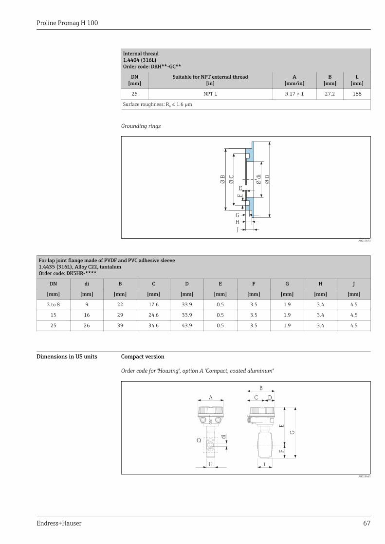
Proline Promag H 100
Endress+Hauser 67
Internal thread1.4404 (316L)Order code: DKH**-GC**
DN[mm]
Suitable for NPT external thread[in]
A[mm/in]
B[mm]
L[mm]
25 NPT 1 R 17 × 1 27.2 188
Surface roughness: Ra ≤ 1.6 µm
Grounding rings
Ø C
Ø d
i
Ø B
Ø D
0.5E
F
G
H
J
A0017673
For lap joint flange made of PVDF and PVC adhesive sleeve1.4435 (316L), Alloy C22, tantalumOrder code: DK5HR-****
DN di B C D E F G H J
[mm] [mm] [mm] [mm] [mm] [mm] [mm] [mm] [mm] [mm]
2 to 8 9 22 17.6 33.9 0.5 3.5 1.9 3.4 4.5
15 16 29 24.6 33.9 0.5 3.5 1.9 3.4 4.5
25 26 39 34.6 43.9 0.5 3.5 1.9 3.4 4.5
Dimensions in US units Compact version
Order code for "Housing", option A "Compact, coated aluminum"
L
E
DC
B
F
H
di
Q
A
G
A0019463

Proline Promag H 100
68 Endress+Hauser
DN A B C D E 1) F G H L 2) Q di
[in] [in] [in] [in] [in] [in] [in] [in] [in] [in] [mm] [in]
1/12 5.35 5.81 3.68 2.13 7.05 2.17 9.21 1.69 3.39 4 ×M6 0.09
1/8 5.35 5.81 3.68 2.13 7.05 2.17 9.21 1.69 3.39 4 ×M6 0.18
3/8 5.35 5.81 3.68 2.13 7.05 2.17 9.21 1.69 3.39 4 ×M6 0.35
½ 5.35 5.81 3.68 2.13 7.05 2.17 9.21 1.69 3.39 4 ×M6 0.63
1 5.35 5.81 3.68 2.13 7.05 2.17 9.21 2.20 3.39 4 ×M6 1.02
1) If using a display, order code for "Display; Operation", option B: values + 1.1 in2) Total length (L) depends on the process connections.
L
E
DC
B
F
H
Q
A
G
di
A0019468
DN A B C D E 1) F G H L 2) Q di
[in] [in] [in] [in] [in] [in] [in] [in] [in] [in] [mm] [in]
1 ½ 5.35 5.81 3.68 2.13 7.06 2.10 9.16 4.21 5.51 4 ×M8 1.37
2 5.35 5.81 3.68 2.13 7.31 2.35 9.67 4.72 5.51 4 ×M8 1.87
3 5.35 5.81 3.68 2.13 7.87 2.91 10.80 5.83 5.51 6 ×M8 2.87
4 5.35 5.81 3.68 2.13 8.38 3.42 11.80 6.85 5.51 6 ×M8 3.83
5 5.35 5.81 3.68 2.13 9.01 4.05 13.10 8.11 7.87 6 ×M10 4.72
6 5.35 5.81 3.68 2.13 9.56 4.60 14.20 9.21 7.87 6 ×M10 5.78
1) If using a display, order code for "Display; Operation", option B: values + 1.1 in2) Total length (L) depends on the process connections.

Proline Promag H 100
Endress+Hauser 69
Order code for "Housing", option B "Compact hygienic, stainless"
L
E
DC
B
F
H
di
Q
A
G
A0019464
DN A B C D E 1) F G H L 2) Q di
[in] [in] [in] [in] [in] [in] [in] [in] [in] [in] [mm] [in]
1/12 5.26 5.39 3.07 2.31 6.81 2.17 8.98 1.69 3.39 4 ×M6 0.09
1/8 5.26 5.39 3.07 2.31 6.81 2.17 8.98 1.69 3.39 4 ×M6 0.18
3/8 5.26 5.39 3.07 2.31 6.81 2.17 8.98 1.69 3.39 4 ×M6 0.35
½ 5.26 5.39 3.07 2.31 6.81 2.17 8.98 1.69 3.39 4 ×M6 0.63
1 5.26 5.39 3.07 2.31 6.81 2.17 8.98 2.20 3.39 4 ×M6 1.02
1) If using a display, order code for "Display; Operation", option B: values + 1.1 in2) Total length (L) depends on the process connections.
A
DC
B
L
EF
H
di
Q
G
A0019470
DN A B C D E 1) F G H L 2) Q di
[in] [in] [in] [in] [in] [in] [in] [in] [in] [in] [mm] [in]
1 ½ 5.26 5.39 3.07 2.31 6.82 2.10 8.92 4.21 5.51 4 ×M8 1.37
2 5.26 5.39 3.07 2.31 7.08 2.35 9.43 4.72 5.51 4 ×M8 1.87
3 5.26 5.39 3.07 2.31 7.63 2.91 10.5 5.83 5.51 6 ×M8 2.87

Proline Promag H 100
70 Endress+Hauser
DN A B C D E 1) F G H L 2) Q di
[in] [in] [in] [in] [in] [in] [in] [in] [in] [in] [mm] [in]
4 5.26 5.39 3.07 2.31 8.14 3.42 11.60 6.85 5.51 6 ×M8 3.83
5 5.26 5.39 3.07 2.31 8.77 4.05 12.80 8.11 7.87 6 ×M10 4.72
6 5.26 5.39 3.07 2.31 9.32 4.60 13.90 9.21 7.87 6 ×M10 5.78
1) If using a display, order code for "Display; Operation", option B: values + 1.1 in2) Total length (L) depends on the process connections.
Order code for "Housing", option C "Ultra-compact hygienic, stainless"
L
E
DC
B
F
H
di
Q
A
G
A0019466
DN A B C D E 1) F G H L 2) Q di
[in] [in] [in] [in] [in] [in] [in] [in] [in] [in] [mm] [in]
1/12 4.39 4.87 2.67 2.20 6.81 2.17 8.98 1.69 3.39 4 ×M6 0.09
1/8 4.39 4.87 2.67 2.20 6.81 2.17 8.98 1.69 3.39 4 ×M6 0.18
3/8 4.39 4.87 2.67 2.20 6.81 2.17 8.98 1.69 3.39 4 ×M6 0.35
½ 4.39 4.87 2.67 2.20 6.81 2.17 8.98 1.69 3.39 4 ×M6 0.63
1 4.39 4.87 2.67 2.20 6.81 2.17 8.98 2.20 3.39 4 ×M6 1.02
1) If using a display, order code for "Display; Operation", option B: values + 1.1 in2) Total length (L) depends on the process connections.

Proline Promag H 100
Endress+Hauser 71
A
DC
B
L
EF
H
di
Q G
A0019471
DN A B C D E 1) F G H L 2) Q di
[in] [in] [in] [in] [in] [in] [in] [in] [in] [in] [mm] [in]
1 ½ 4.39 4.87 2.67 2.20 6.82 2.10 8.92 4.21 5.51 4 ×M8 1.37
2 4.39 4.87 2.67 2.20 7.08 2.35 9.43 4.72 5.51 4 ×M8 1.87
3 4.39 4.87 2.67 2.20 7.63 2.91 10.50 5.83 5.51 6 ×M8 2.87
4 4.39 4.87 2.67 2.20 8.14 3.42 11.60 6.85 5.51 6 ×M8 3.83
5 4.39 4.87 2.67 2.20 8.77 4.05 12.80 8.11 7.87 6 ×M10 4.72
6 4.39 4.87 2.67 2.20 9.32 4.60 13.90 9.21 7.87 6 ×M10 5.78
1) If using a display, order code for "Display; Operation", option B: values + 1.1 in2) Total length (L) depends on the process connections.
Sensor flange connection
G
F
K
H
E
Z
Z Z-Z
L
A B D
M
C
B/2
B/2
E–
2
E–
2
A0017657
37 Front view without process connections

Proline Promag H 100
72 Endress+Hauser
DN A B C D E F G H K L M
[in] [in] [in] [in] [in] [in] [in] [in] [in] [in] [in] [mm]
1/12 2.44 1.64 1.34 0.35 0.94 1.65 1.69 0.33 0.24 0.16 M6
1/8 2.44 1.64 1.34 0.35 0.94 1.65 1.69 0.33 0.24 0.16 M6
3/8 2.44 1.64 1.34 0.35 0.94 1.65 1.69 0.33 0.24 0.16 M6
½ 2.44 1.64 1.34 0.63 0.94 1.65 1.69 0.33 0.24 0.16 M6
1 2.83 1.98 1.73 0.89 1.14 2.17 2.20 0.33 0.24 0.16 M6
F
E
G
H
Z–Z
D C B A
Z
K
Z
L
A0005528
38 Front view without process connections
DN A B C D E F G H K L
90° ±0.5° 60° ±0.5°
[in] [in] [in] [in] [in] [in] [mm] [in] [in] Tapped holes
1 ½ 3.93 3.38 2.80 1.90 1.37 M8 0.47 0.67 4 –
2 4.44 3.89 3.29 2.37 1.87 M8 0.47 0.67 4 –
3 5.54 5.26 4.49 3.50 2.87 M8 0.47 0.67 – 6
4 6.56 6.28 5.55 4.50 3.83 M8 0.47 0.67 – 6
5 7.82 7.54 6.73 5.50 4.72 M10 0.59 0.79 – 6
6 8.93 8.64 7.87 6.63 5.78 M10 0.59 0.79 – 6
Flanges
Flanges with O-ring seal
C
D
A B E
L
A0015621
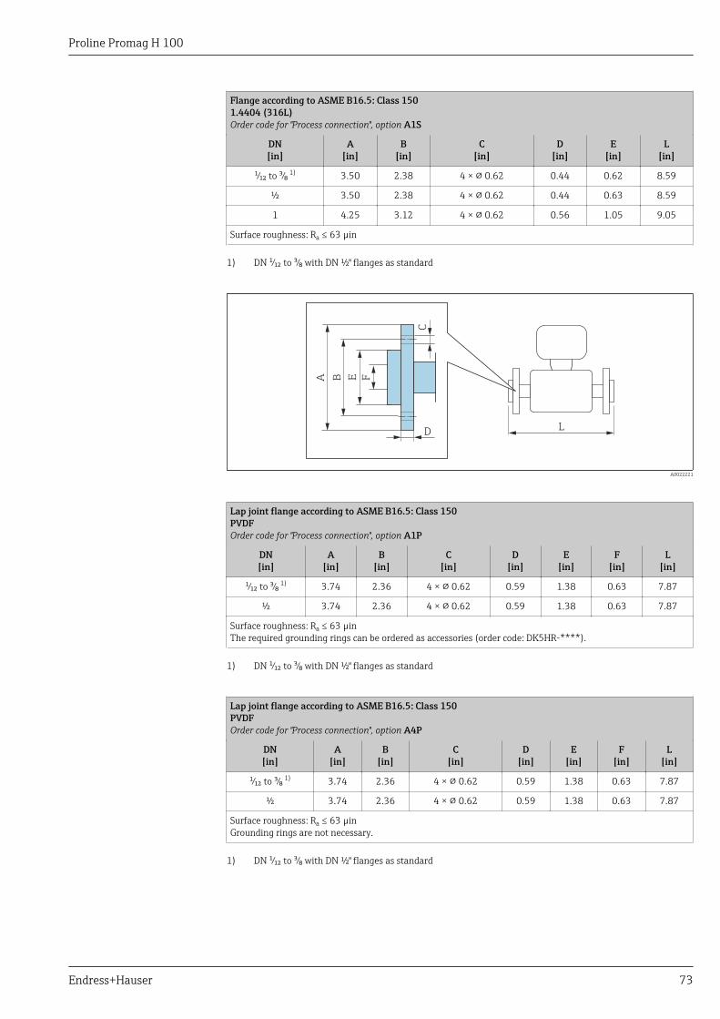
Proline Promag H 100
Endress+Hauser 73
Flange according to ASME B16.5: Class 1501.4404 (316L)Order code for "Process connection", option A1S
DN[in]
A[in]
B[in]
C[in]
D[in]
E[in]
L[in]
¹⁄₁₂ to ³⁄₈ 1) 3.50 2.38 4 × 0.62 0.44 0.62 8.59
½ 3.50 2.38 4 × 0.62 0.44 0.63 8.59
1 4.25 3.12 4 × 0.62 0.56 1.05 9.05
Surface roughness: Ra ≤ 63 µin
1) DN ¹⁄₁₂ to ³⁄₈ with DN ½" flanges as standard
LC
D
A B FE
A0022221
Lap joint flange according to ASME B16.5: Class 150PVDFOrder code for "Process connection", option A1P
DN[in]
A[in]
B[in]
C[in]
D[in]
E[in]
F[in]
L[in]
¹⁄₁₂ to ³⁄₈ 1) 3.74 2.36 4 × 0.62 0.59 1.38 0.63 7.87
½ 3.74 2.36 4 × 0.62 0.59 1.38 0.63 7.87
Surface roughness: Ra ≤ 63 µinThe required grounding rings can be ordered as accessories (order code: DK5HR-****).
1) DN ¹⁄₁₂ to ³⁄₈ with DN ½" flanges as standard
Lap joint flange according to ASME B16.5: Class 150PVDFOrder code for "Process connection", option A4P
DN[in]
A[in]
B[in]
C[in]
D[in]
E[in]
F[in]
L[in]
¹⁄₁₂ to ³⁄₈ 1) 3.74 2.36 4 × 0.62 0.59 1.38 0.63 7.87
½ 3.74 2.36 4 × 0.62 0.59 1.38 0.63 7.87
Surface roughness: Ra ≤ 63 µinGrounding rings are not necessary.
1) DN ¹⁄₁₂ to ³⁄₈ with DN ½" flanges as standard

Proline Promag H 100
74 Endress+Hauser
Welding nipple
Welding nipple with aseptic molded seal
L
A B
A0027510
Welding nipple according to ISO 20371.4404 (316L)Order code for "Process connection", option IAS
DN[in]
Suitable for pipe ISO 2037[in]
A[in]
B[in]
L[in]
¹⁄₁₂ to ³⁄₈ 0.50 × 0.06 0.47 0.39 4.65
½ 0.75 × 0.06 0.71 0.63 4.65
1 1.00 × 0.06 0.98 0.89 4.65
1 ½ 1.50 × 0.05 1.50 1.40 8.66
2 2.00 × 0.05 2.01 1.91 8.66
3 3.00 × 0.06 3.00 2.87 8.66
4 2.50 × 0.08 4.00 3.84 8.66
5 4.00 × 0.08 5.50 5.34 15.00
6 6.63 × 0.10 6.63 6.42 15.00
Surface roughness: Ra ≤ 31.5 µin, optional ≤ 15 µinPlease note the internal diameters of the measuring tube and process connection (B) when cleaning with pigs.
Welding nipple according to ASME BPE1.4404 (316L)Order code for "Process connection", option AAS
DN[in]
Suitable for pipe ASME BPE[in]
A[in]
B[in]
L[in]
¹⁄₁₂ to ³⁄₈ 0.50 × 0.06 0.50 0.35 4.65
½ 0.75 × 0.06 0.75 0.63 4.65
1 1.00 × 0.06 1.00 0.89 4.65
1 ½ 1.50 × 0.06 1.50 1.37 8.66
2 2.00 × 0.06 2.00 1.87 8.66
3 3.00 × 0.06 3.00 2.87 8.66
4 4.00 × 0.08 4.00 3.83 8.66
6 6.00 × 0.11 6.00 5.90 11.80
Surface roughness: Ra ≤ 31.5 µin, optional ≤ 15 µinPlease note the internal diameters of the measuring tube and process connection (B) when cleaning with pigs.

Proline Promag H 100
Endress+Hauser 75
Welding nipple with O-ring seal
L
A B
A0027510
Welding nipple according to ODT/SMS1.4404 (316L)Order code for "Process connection", option A2S
DN[in]
Suitable for pipe ODT/SMS[in]
A[in]
B[in]
L[in]
¹⁄₁₂ to ³⁄₈ 0.53 × 0.09 0.53 0.35 4.99
½ 0.84 × 0.10 0.84 0.63 4.99
Surface roughness: Ra ≤ 63 µin
Clamp connections
Clamp connections with aseptic molded seal
L
A B
A0015625
Tri-Clamp1.4404 (316L)Order code for "Process connection", option FAS
DN[in]
Suitable for pipe as per ASME BPE[in]
A[in]
B[in]
L[in]
¹⁄₁₂ to ³⁄₈ ½ 1 0.37 5.63
½ ¾ 25 0.62 5.63
1 1 2 0.87 5.63
1 ½ 1.50 × 0.06 1.98 1.37 8.66
2 2.00 × 0.06 2.52 1.87 8.66
3 3.00 × 0.06 3.58 2.87 8.66
4 4.00 × 0.08 4.68 3.83 8.66
6 6.00 × 0.11 6.57 5.90 11.80
Surface roughness: Ra ≤ 31.5 µin, optional ≤ 15 µinPlease note the internal diameters of the measuring tube and process connection (B) when cleaning with pigs.

Proline Promag H 100
76 Endress+Hauser
Clamp according to ISO 2852, Fig. 21.4404 (316L)Order code for "Process connection", option IBS
DN[in]
Suitable for pipe ISO 2037[in]
DNClamp ISO 2852
[in]
A[in]
B[in]
L[in]
1 0.96 × 0.06 1 2.00 0.89 6.87
1 ½ 1.50 × 0.06 1.50 1.99 1.40 8.66
2 2.00 × 0.06 2.01 2.52 1.91 8.66
3 3.00 × 0.06 3.00 3.58 2.87 8.66
4 2.50 × 0.08 4.00 4.69 3.84 8.66
5 4.00 × 0.08 5.50 6.10 5.34 11.80
6 6.63 × 0.10 6.63 7.20 6.42 11.80
Surface roughness: Ra ≤ 31.5 µin, optional ≤ 15 µinPlease note the internal diameters of the measuring tube and process connection (B) when cleaning with pigs.
Cable glands
Threaded adapter with aseptic molded seal
L
A B
A0027509
Coupling SC DIN 11851, threaded adapter1.4404 (316L)Order code for "Process connection", option DCS
DN[in]
Suitable for pipe EN 10357 (DIN 11850)[in]
A[in]
B[in]
L[in]
½ Pipe ODT ¾ Rd0.05 × 0.13 0.63 6.85
1 ½ 1.65 × 0.06 Rd 2.56 × 1/6 1.50 10.20
2 2.13 × 0.06 Rd 3.07 × 1/6 1.97 10.20
3 3.35 × 0.08 Rd 4.33 × 1/4 3.19 11.00
4 4.09 × 0.08 Rd 5.12 × 1/4 3.94 11.40
5 5.08 × 0.08 Rd 6.30 × 1/4 4.92 15.00
6 6.06 × 0.08 Rd 6.30 × 1/4 5.91 15.40
Surface roughness: Ra ≤ 31.5 µin, optional ≤ 15 µinPlease note the internal diameters of the measuring tube and process connection (B) when cleaning with pigs.

Proline Promag H 100
Endress+Hauser 77
Coupling ISO 2853, threaded adapter1.4404 (316L)Order code for "Process connection", option ICS
DN[in]
Suitable for pipe EN 10357 (DIN 11850)[in]
DNClamp ISO 2853
[in]
A[in]
B[in]
L[in]
1 ½ 1.50 × 0.06 1.50 Tr 2.00 × 0.13 1.40 10.80
2 2.00 × 0.06 2.01 Tr 2.52 × 0.13 1.91 10.80
3 3.00 × 0.06 3.00 Tr 3.58 × 0.13 2.87 10.90
4 2.50 × 0.08 4.00 Tr 4.65 × 0.13 3.84 11.30
Surface roughness: Ra ≤ 31.5 µin, optional ≤ 15 µinPlease note the internal diameters of the measuring tube and process connection (B) when cleaning with pigs.
Coupling SMS 1145, threaded adapter1.4404 (316L)Order code for "Process connection", option SAS
DN[in]
Suitable for pipe ODT[in]
DNSMS 1145
[in]
A[in]
B[in]
L[in]
1 1 1 Rd1.57 × 0.17 0.89 5.81
1 ½ 1.50 × 0.06 1.50 Rd 2.36 × 1/6 1.37 10.10
2 2.00 × 0.06 2.00 Rd 2.76 × 1/6 1.87 10.10
3 3.00 × 0.06 3.00 Rd 3.86 × 1/6 2.86 10.90
4 4.00 × 0.08 4.00 Rd 5.20 × 1/6 3.83 11.30
Surface roughness: Ra ≤ 31.5 µin, optional ≤ 15 µinPlease note the internal diameters of the measuring tube and process connection (B) when cleaning with pigs.
Threaded adapter with O-ring seal
L
A B
A0027509
External thread according to ISO 228/DIN 29991.4404 (316L)Order code for "Process connection", option I2S
DN[in]
Suitable for internal thread ISO 228 / DIN 2999[in]
A[in]
B[in]
L[in]
¹⁄₁₂ to ³⁄₈ R 3/8 Rd 0.40 × 3/8 0.39 6.53
½ R ½ Rd 0.52 × ½ 0.63 6.53
1 R 1 Rd 0.66 × 1 0.98 6.69
Surface roughness: Ra ≤ 63 µin

Proline Promag H 100
78 Endress+Hauser
Internal thread according to ISO 228/DIN 29991.4404 (316L)Order code for "Process connection", option I3S
DN[in]
Suitable for external thread ISO 228 / DIN 2999[in]
A[in]
B[in]
L[in]
¹⁄₁₂ to ³⁄₈ Rp 3/8 Rd 0.51 × 3/8 0.35 6.93
½ Rp ½ Rd 0.55 × ½ 0.63 6.93
1 Rp 1 Rd 0.67 × 1 1.07 7.41
Surface roughness: Ra ≤ 63 µin
Adhesive sleeves
Adhesive sleeves with O-ring seal
L
A B
A0027510
Adhesive sleevePVCOrder code for "Process connection", options O1V, O2V
DN[in]
Suitable for pipe[in]
A[in]
B[in]
L[in]
¹⁄₁₂ to ³⁄₈ ½ 1.07 0.85 6.43
Surface roughness: Ra ≤ 63 µinThe required grounding rings can be ordered as accessories (order code: DK5HR-****).
Mountings sets
Wall mounting kit
A
B
E
F
D
C
4 x M5
A0005537

Proline Promag H 100
Endress+Hauser 79
A B C Ø D E F
[in] [in] [in] [in] [in] [in]
5.39 4.33 4.72 0.28 4.92 3.46
Accessories
Spacer
Ø D
2
Ø D
1
L
Ø d
i
A0017294
Order code: DK5HB-****
DN di D1 D2 L
[in] [in] [in] [in] [in]
3 2.87 5.54 5.55 1.30
4 3.83 6.56 6.38 1.30
Clamp connections with aseptic molded seal available for order
L
A B
A0015625
39 Hygienic clamp adapter connection suitable for pipes with connection according to ASME BPE (reduction)
Tri-Clamp1.4404 (316L)Order code: DKH**-HF**
DN[in]
Suitable for pipe in accordance with ASME BPE (reduction)[in]
A[in]
B[in]
L[in]
½ Pipe ODT 1 2 0.87 5.63
Surface roughness: Ra ≤ 31.5 µin, optional ≤ 15 µinPlease note the internal diameters of the measuring tube and process connection (B) when cleaning with pigs.
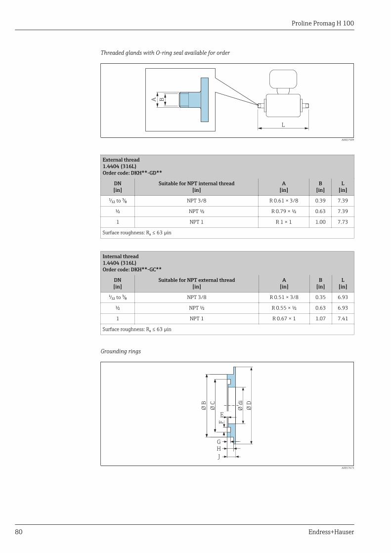
Proline Promag H 100
80 Endress+Hauser
Threaded glands with O-ring seal available for order
L
A B
A0027509
External thread1.4404 (316L)Order code: DKH**-GD**
DN[in]
Suitable for NPT internal thread[in]
A[in]
B[in]
L[in]
¹⁄₁₂ to ³⁄₈ NPT 3/8 R 0.61 × 3/8 0.39 7.39
½ NPT ½ R 0.79 × ½ 0.63 7.39
1 NPT 1 R 1 × 1 1.00 7.73
Surface roughness: Ra ≤ 63 µin
Internal thread1.4404 (316L)Order code: DKH**-GC**
DN[in]
Suitable for NPT external thread[in]
A[in]
B[in]
L[in]
¹⁄₁₂ to ³⁄₈ NPT 3/8 R 0.51 × 3/8 0.35 6.93
½ NPT ½ R 0.55 × ½ 0.63 6.93
1 NPT 1 R 0.67 × 1 1.07 7.41
Surface roughness: Ra ≤ 63 µin
Grounding rings
Ø C
Ø d
i
Ø B
Ø D
0.5E
F
G
H
J
A0017673

Proline Promag H 100
Endress+Hauser 81
For lap joint flange made of PVDF and PVC adhesive sleeve1.4435 (316L), Alloy C22, tantalumOrder code: DK5HR-****
DN di B C D E F G H J
[in] [in] [in] [in] [in] [in] [in] [in] [in] [in]
¹⁄₁₂ to ³⁄₈ 0.35 0.87 0.69 1.33 0.02 0.14 0.07 0.13 0.18
½ 0.63 1.14 0.97 1.33 0.02 0.14 0.07 0.13 0.18
1 0.89 1.44 1.23 1.73 0.02 0.14 0.07 0.13 0.18
Weight All values (weight exclusive of packaging material) refer to devices for standard pressure ratings.Weight specifications including transmitter: order code for "Housing", option A "Compact, aluminumcoated".Different values due to different transmitter versions:
Compact version
• Including the transmitter• Weight specifications apply to standard pressure ratings and without packaging material.
Nominal diameter Weight
[mm] [in] [kg] [lbs]
2 1/12 2.00 4.41
4 1/8 2.00 4.41
8 3/8 2.00 4.41
15 ½ 1.90 4.19
25 1 2.80 6.17
40 1 ½ 4.10 9.04
50 2 4.60 10.1
65 – 5.40 11.9
80 3 6.00 13.2
100 4 7.30 16.1
125 5 12.7 28.0
150 6 15.1 33.3
Measuring tube specification Nominal diameter Pressure rating 1) Process connection internal diameter
EN (DIN) PFA
[mm] [in] [bar] [mm] [in]
2 1/12 PN 16/40 2.25 0.09
4 1/8 PN 16/40 4.5 0.18
8 3/8 PN 16/40 9.0 0.35
15 ½ PN 16/40 16.0 0.63
– 1 PN 16/40 22.6 0.89
25 – PN 16/40 26.0 1.02
40 1 ½ PN 16/25/40 35.3 1.39
50 2 PN 16/25 48.1 1.89
65 – PN 16/25 59.9 2.36
80 3 PN 16/25 72.6 2.86
100 4 PN 16/25 97.5 3.84

Proline Promag H 100
82 Endress+Hauser
Nominal diameter Pressure rating 1) Process connection internal diameter
EN (DIN) PFA
[mm] [in] [bar] [mm] [in]
125 5 PN 10/16 120.0 4.72
150 6 PN 10/16 146.5 5.77
1) Depending on process connection and seals used
Materials Transmitter housing
• Order code for "Housing", option A "Compact, aluminum coated":Aluminum, AlSi10Mg, coated
• Order code for "Housing", option B "Compact, hygienic, stainless":Hygienic version, stainless steel 1.4301 (304)
• Order code for "Housing", option C "Ultra-compact, hygienic, stainless":Hygienic version, stainless steel 1.4301 (304)
• Window material for optional local display (→ 84):– For order code for "Housing", option A: glass– For order code for "Housing", option B and C: plastic
Cable entries/cable glands
1
2
3
A0020640
40 Possible cable entries/cable glands
1 Female thread M20 × 1.52 Cable gland M20 × 1.53 Adapter for cable entry with internal thread G ½" or NPT ½"
Order code for "Housing", option A "Compact, coated aluminum"
The various cable entries are suitable for hazardous and non-hazardous areas.
Cable entry/cable gland Material
Cable gland M20 × 1.5 Nickel-plated brass
Adapter for cable entry with internal thread G ½"
Adapter for cable entry with internal thread NPT ½"
Order code for "Housing", option B "Compact, hygienic, stainless"
The various cable entries are suitable for hazardous and non-hazardous areas.
Cable entry/cable gland Material
Cable gland M20 × 1.5 Stainless steel, 1.4404 (316L)
Adapter for cable entry with internal thread G ½"
Adapter for cable entry with internal thread NPT ½"

Proline Promag H 100
Endress+Hauser 83
Device plug
Electrical connection Material
Plug M12x1 • Socket: Stainless steel, 1.4404 (316L)• Contact housing: Polyamide• Contacts: Gold-plated brass
Sensor housing
Stainless steel 1.4301 (304)
Measuring tubes
Stainless steel 1.4301 (304)
Liner
PFA (USP Class VI, FDA 21 CFR 177.1550, 3A)
Process connections
• Stainless steel, 1.4404 (F316L)• PVDF• PVC adhesive sleeve
Electrodes
• Standard: 1.4435 (316L)• Optional: Alloy C22, tantalum, platinum (only up to DN 25 (1"))
Seals
• O-ring seal, DN 2 to 25 (1/12 to 1"): EPDM, FKM, Kalrez• Aseptic molded seal, DN 2 to 150 (1/12 to 6"): EPDM 1), FKM, silicone 1)
Accessories
Grounding rings
• Standard: 1.4435 (316L)• Optional: Alloy C22, tantalum
Wall mounting kit
Stainless steel 1.4301 (304)
Spacer
1.4435 (F316L)
Fitted electrodes • 2 measuring electrodes for signal detection• 1 empty pipe detection electrode for empty pipe detection/temperature measurement (only DN 15
to 150 (½ to 6"))
Process connections With O-ring seal:• Welding nipple (DIN EN ISO 1127, ODT/SMS, ISO 2037)• Flange (EN (DIN), ASME, JIS)• Flange from PVDF (EN (DIN), ASME, JIS)• External thread• Internal thread• Hose connection• PVC adhesive sleeve
1) USP Class VI, FDA 21 CFR 177.2600, 3A

Proline Promag H 100
84 Endress+Hauser
With aseptic molded seal:• Welding nipple (EN 10357 (DIN 11850), ASME BPE, ISO 2037)• Clamp (ISO 2852, ISO 2853, DIN 32676, L14 AM7)• Coupling (DIN 11851, DIN 11864-1, ISO 2853, SMS 1145)• Flange DIN 11864-2
For information on the different materials used in the process connections → 83
Surface roughness Stainless steel electrodes, 1.4435 (316L); Alloy C22, 2.4602 (UNS N06022); platinum; tantalum:≤ 0.3 to 0.5 µm (11.8 to 19.7 µin)(All data relate to parts in contact with fluid)Liner with PFA:≤ 0.4 µm (15.7 µin)(All data relate to parts in contact with fluid)Stainless steel process connections:• With O-ring seal: ≤ 1.6 µm (63 µin)• With aseptic seal: ≤ 0.8 µm (31.5 µin)
Optional: ≤ 0.38 µm (15 µin)(All data relate to parts in contact with fluid)
Operability
Operating concept Operator-oriented menu structure for user-specific tasks• Commissioning• Operation• Diagnostics• Expert levelQuick and safe commissioning• Individual menus for applications• Menu guidance with brief explanations of the individual parameter functionsReliable operation• Operation in the following languages:
– Via "FieldCare" operating tool:English, German, French, Spanish, Italian, Chinese, Japanese
– Via integrated Web browser (only available for device versions with HART, PROFIBUS DP,PROFINET and EtherNet/IP):English, German, French, Spanish, Italian, Dutch, Portuguese, Polish, Russian, Turkish, Chinese,Japanese, Bahasa (Indonesian), Vietnamese, Czech, Swedish, Korean
• Uniform operating philosophy applied to operating tools and Web browser• If replacing the electronic module, transfer the device configuration via the plug-in memory
(HistoROM DAT) which contains the process and measuring device data and the event logbook. Noneed to reconfigure.For devices with Modbus RS485, the data recovery function is implemented without the plug-inmemory (HistoROM DAT).
Efficient diagnostics increase measurement availability• Troubleshooting measures can be called up via the operating tools and Web browser• Diverse simulation options• Status indicated by several light emitting diodes (LEDs) on the electronic module in the housing
compartment
Local display A local display is only available for device versions with the following communication protocols:HART, PROFIBUS-DP, PROFINET, EtherNet/IP
The local display is only available with the following device order code:Order code for "Display; Operation", option B: 4-line; lit, via communication

Proline Promag H 100
Endress+Hauser 85
Display element• 4-line liquid crystal display with 16 characters per line.• White background lighting; switches to red in event of device errors.• Format for displaying measured variables and status variables can be individually configured.• Permitted ambient temperature for the display: –20 to +60 °C (–4 to +140 °F). The readability of
the display may be impaired at temperatures outside the temperature range.
Remote operation Via HART protocol
This communication interface is available in device versions with a HART output.
1 2 3 5
74 6
A0016948
41 Options for remote operation via HART protocol
1 Control system (e.g. PLC)2 Field Communicator 4753 Computer with operating tool (e.g. FieldCare, AMS Device Manager, SIMATIC PDM)4 Commubox FXA195 (USB)5 Field Xpert SFX350 or SFX3706 VIATOR Bluetooth modem with connecting cable7 Transmitter
Via PROFIBUS DP network
This communication interface is available in device versions with PROFIBUS DP.
1 2
3
444
A0020903
42 Options for remote operation via PROFIBUS DP network
1 Automation system2 Computer with PROFIBUS network card3 PROFIBUS DP network4 Measuring device
Via Ethernet-based fieldbus
This communication interface is available in device versions with EtherNet/IP.

Proline Promag H 100
86 Endress+Hauser
4
21 3
5 5 5
A0016961
43 Options for remote operation via Ethernet-based fieldbus
1 Control system, e.g. "RSLogix" (Rockwell Automation)2 Workstation for measuring device operation: with Add-on Profile Level 3 for "RSLogix 5000" (Rockwell
Automation) or with Electronic Data Sheet (EDS)3 Computer with Web browser (e.g. Internet Explorer) for accessing the integrated device Web server or with
"FieldCare" operating tool with COM DTM "CDI Communication TCP/IP"4 Ethernet switch5 Measuring device
Via PROFINET network
This communication interface is available in device versions with PROFINET.
3
1 2
4 4 4
A0026545
44 Options for remote operation via PROFINET network
1 Automation system, e.g. Simatic S7 (Siemens)2 Computer with Web browser (e.g. Internet Explorer) for accessing the integrated device Web server or with
"FieldCare" operating tool with COM DTM "CDI Communication TCP/IP"3 Switch, e.g. Scalance X204 (Siemens)4 Measuring device
Service interface Via service interface (CDI-RJ45)
This communication interface is present in the following device version:• Order code for "Output", option B: 4-20 mA HART, pulse/frequency/switch output• Order code for "Output", option L: PROFIBUS DP• Order code for "Output", option N: EtherNet/IP• Order code for "Output", option R: PROFINET

Proline Promag H 100
Endress+Hauser 87
HART
1
2
3
A0016926
45 Connection for the order code for "Output", option B: 4-20 mA HART, pulse/frequency/switch output
1 Service interface (CDI -RJ45) of the measuring device with access to the integrated Web server2 Computer with Web browser (e.g. Internet Explorer) for accessing the integrated device Web server or with
"FieldCare" operating tool with COM DTM "CDI Communication TCP/IP"3 Standard Ethernet connecting cable with RJ45 plug
PROFIBUS DP
1
2
3
A0021270
46 Connection for order code for "Output", option L: PROFIBUS DP
1 Service interface (CDI -RJ45) of the measuring device with access to the integrated Web server2 Computer with Web browser (e.g. Internet Explorer) for accessing the integrated device Web server or with
"FieldCare" operating tool with COM DTM "CDI Communication TCP/IP"3 Standard Ethernet connecting cable with RJ45 plug

Proline Promag H 100
88 Endress+Hauser
EtherNet/IP
1
2
3
A0016940
47 Connection for order code for "Output", option N: EtherNet/IP
1 Service interface (CDI -RJ45) and EtherNet/IP interface of the measuring device with access to the integratedWeb server
2 Computer with Web browser (e.g. Internet Explorer) for accessing the integrated device Web server or with"FieldCare" operating tool with COM DTM "CDI Communication TCP/IP"
3 Standard Ethernet connecting cable with RJ45 plug
PROFINET
1
2
3
A0016940
48 Connection for order code for "Output", option R: PROFINET
1 Service interface (CDI -RJ45) and PROFINET interface of the measuring device with access to the integratedWeb server
2 Computer with Web browser (e.g. Internet Explorer) for accessing the integrated device Web server or with"FieldCare" operating tool with COM DTM "CDI Communication TCP/IP"
3 Standard Ethernet connecting cable with RJ45 plug
Via service interface (CDI)
This communication interface is present in the following device version:Order code for "Output", option M: Modbus RS485

Proline Promag H 100
Endress+Hauser 89
Modbus RS485
12
3
A0016925
1 Service interface (CDI) of the measuring device2 Commubox FXA2913 Computer with "FieldCare" operating tool with COM DTM "CDI Communication FXA291"
Certificates and approvals
CE mark The measuring system is in conformity with the statutory requirements of the applicable ECDirectives. These are listed in the corresponding EC Declaration of Conformity along with thestandards applied.
Endress+Hauser confirms successful testing of the device by affixing to it the CE mark.
C-Tick symbol The measuring system meets the EMC requirements of the "Australian Communications and MediaAuthority (ACMA)".
Ex approval The measuring device is certified for use in hazardous areas and the relevant safety instructions areprovided in the separate "Safety Instructions" (XA) document. Reference is made to this document onthe nameplate.
The separate Ex documentation (XA) containing all the relevant explosion protection data isavailable from your Endress+Hauser sales center.
ATEX, IECEx
Currently, the following versions for use in hazardous areas are available:
Ex nA
Category Type of protection
II3G Ex nA IIC T6-T1 Gc
cCSAus
Currently, the following versions for use in hazardous areas are available:
NI
Category Type of protection
Class I Division 2 Groups ABCD NI (Non-incendive version), NIFW parameter 1)
1) Entity and NIFW parameter according to Control Drawings
INMETRO
Currently, the following versions for use in hazardous areas are available:

Proline Promag H 100
90 Endress+Hauser
…
Category Type of protection
… …
NEPSI
Currently, the following versions for use in hazardous areas are available:
…
Category Type of protection
… …
Sanitary compatibility • 3A approval and EHEDG-certified• Seals → FDA-compliant (apart from Kalrez seals)
Functional safety The measuring device can be used for flow monitoring systems (min., max., range) up to SIL 2(single-channel architecture) and SIL 3 (multichannel architecture with homogeneous redundancy)and is independently evaluated and certified by the TÜV in accordance with IEC 61508.
The following types of monitoring in safety equipment are possible:Volume flow
Functional Safety Manual with information on the SIL device
HART certification HART interface
The measuring device is certified and registered by the FieldComm Group. The measuring systemmeets all the requirements of the following specifications:• Certified according to HART 7• The device can also be operated with certified devices of other manufacturers (interoperability)
Certification PROFIBUS PROFIBUS interface
The measuring device is certified and registered by the PROFIBUS User Organization (PNO). Themeasuring system meets all the requirements of the following specifications:• Certified in accordance with PROFIBUS PA Profile 3.02• The device can also be operated with certified devices of other manufacturers (interoperability)
Modbus RS485 certification The measuring device meets all the requirements of the MODBUS/TCP conformity test and has the"MODBUS/TCP Conformance Test Policy, Version 2.0". The measuring device has successfully passedall the test procedures carried out and is certified by the “MODBUS/TCP Conformance TestLaboratory” of the University of Michigan.
EtherNet/IP certification The measuring device is certified and registered by the ODVA (Open Device Vendor Association).The measuring system meets all the requirements of the following specifications:• Certified in accordance with the ODVA Conformance Test• EtherNet/IP Performance Test• EtherNet/IP PlugFest compliance• The device can also be operated with certified devices of other manufacturers (interoperability)
Certification PROFINET PROFINET interface
The measuring device is certified and registered by the PNO (PROFIBUS User Organization ). Themeasuring system meets all the requirements of the following specifications:• Certified according to:
– Test specification for PROFINET devices– PROFINET Security Level 1 – Net load test
• The device can also be operated with certified devices of other manufacturers (interoperability)
Additional certification PWIS-free
PWIS = paint-wetting impairment substances

Proline Promag H 100
Endress+Hauser 91
PWIS-free pending.
For more information on PWIS-free certification, see "Test specification" document TS01028D
Pressure EquipmentDirective
The devices can be ordered with or without a PED approval. If a device with a PED approval isrequired, this must be explicitly stated in the order. For devices with nominal diameters less than orequal to DN 25 (1"), this is neither possible nor necessary.
• With the PED/G1/x (x = category) marking on the sensor nameplate, Endress+Hauser confirmscompliance with the "Essential Safety Requirements" specified in Annex I of the PressureEquipment Directive 97/23/EC.
• Devices bearing this marking (PED) are suitable for the following types of medium:Media in Group 1 and 2 with a vapor pressure greater than, or smaller and equalto0.5 bar (7.3 psi)
• Devices not bearing this marking (PED) are designed and manufactured according to goodengineering practice. They meet the requirements of Art.3 Section 3 of the Pressure EquipmentDirective 97/23/EC. The range of application is indicated in tables 6 to 9 in Annex II of thePressure Equipment Directive.
Other standards andguidelines
• EN 60529Degrees of protection provided by enclosures (IP code)
• EN 61010-1Safety requirements for electrical equipment for measurement, control and laboratory use -general requirements
• IEC/EN 61326Emission in accordance with Class A requirements. Electromagnetic compatibility (EMCrequirements).
• NAMUR NE 21Electromagnetic compatibility (EMC) of industrial process and laboratory control equipment
• NAMUR NE 32Data retention in the event of a power failure in field and control instruments withmicroprocessors
• NAMUR NE 43Standardization of the signal level for the breakdown information of digital transmitters withanalog output signal.
• NAMUR NE 53Software of field devices and signal-processing devices with digital electronics
• NAMUR NE 105Specifications for integrating fieldbus devices in engineering tools for field devices
• NAMUR NE 107Self-monitoring and diagnosis of field devices
• NAMUR NE 131Requirements for field devices for standard applications
Ordering informationDetailed ordering information is available from the following sources:• In the Product Configurator on the Endress+Hauser website: www.endress.com → Select your
country → Products → Select measuring technology, software or components → Select the product(picklists: measurement method, product family etc.) → Device support (right-hand column):Configure the selected product → The Product Configurator for the selected product opens.
• From your Endress+Hauser Sales Center: www.addresses.endress.comProduct Configurator - the tool for individual product configuration• Up-to-the-minute configuration data• Depending on the device: Direct input of measuring point-specific information such as
measuring range or operating language• Automatic verification of exclusion criteria• Automatic creation of the order code and its breakdown in PDF or Excel output format• Ability to order directly in the Endress+Hauser Online Shop

Proline Promag H 100
92 Endress+Hauser
Application packagesMany different application packages are available to enhance the functionality of the device. Suchpackages might be needed to address safety aspects or specific application requirements.
The application packages can be ordered with the device or subsequently from Endress+Hauser.Detailed information on the order code in question is available from your local Endress+Hauser salescenter or on the product page of the Endress+Hauser website: www.endress.com.
Cleaning Package Description
Electrode cleaning circuit(ECC)
The electrode cleaning circuit (ECC) function has been developed to have a solutionfor applications where magnetite (Fe3O4) deposits frequently occur (e.g. hotwater). Since magnetite is highly conductive this build up leads to measuring errorsand ultimately to the loss of signal. The application package is designed to AVOIDbuild up of highly conductive matter and thin layers (typical of magnetite).
Heartbeat Technology Package Description
Heartbeat Verification+Monitoring
Heartbeat MonitoringContinuously supplies data, which are characteristic of the measuring principle, toan external condition monitoring system for the purpose of preventivemaintenance or process analysis. These data enable the operator to:• Draw conclusions - using these data and other information - about the impact
process influences (such as corrosion, abrasion, buildup etc.) have on themeasuring performance over time.
• Schedule servicing in time.• Monitor the process or product quality, e.g. gas pockets.
Heartbeat VerificationMeets the requirement for traceable verification to DIN ISO 9001:2008 Chapter7.6 a) "Control of monitoring and measuring equipment".• Functional testing in the installed state without interrupting the process.• Traceable verification results on request, including a report.• Simple testing process via local operation or other operating interfaces.• Clear measuring point assessment (pass/fail) with high test coverage within the
framework of manufacturer specifications.• Extension of calibration intervals according to operator's risk assessment.
AccessoriesVarious accessories, which can be ordered with the device or subsequently from Endress+Hauser, areavailable for the device. Detailed information on the order code in question is available from yourlocal Endress+Hauser sales center or on the product page of the Endress+Hauser website:www.endress.com.
Device-specific accessories For the transmitter
Accessories Description
For the sensor
Accessories Description
Adapter set Adapter connections for installing Promag H instead of a Promag 30/33 A orPromag 30/33 H (DN 25) device.
Consists of:• 2 process connections• Screws• Seals
Seal set For the regular replacement of seals for the sensor.
Spacer If replacing a DN 80/100 sensor in an existing installation, a spacer is needed if thenew sensor is shorter.
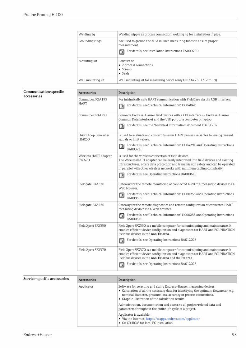
Proline Promag H 100
Endress+Hauser 93
Welding jig Welding nipple as process connection: welding jig for installation in pipe.
Grounding rings Are used to ground the fluid in lined measuring tubes to ensure propermeasurement.
For details, see Installation Instructions EA00070D
Mounting kit Consists of:• 2 process connections• Screws• Seals
Wall mounting kit Wall mounting kit for measuring device (only DN 2 to 25 (1/12 to 1"))
Communication-specificaccessories
Accessories Description
Commubox FXA195HART
For intrinsically safe HART communication with FieldCare via the USB interface.
For details, see "Technical Information" TI00404F
Commubox FXA291 Connects Endress+Hauser field devices with a CDI interface (= Endress+HauserCommon Data Interface) and the USB port of a computer or laptop.
For details, see the "Technical Information" document TI405C/07
HART Loop ConverterHMX50
Is used to evaluate and convert dynamic HART process variables to analog currentsignals or limit values.
For details, see "Technical Information" TI00429F and Operating InstructionsBA00371F
Wireless HART adapterSWA70
Is used for the wireless connection of field devices.The WirelessHART adapter can be easily integrated into field devices and existinginfrastructures, offers data protection and transmission safety and can be operatedin parallel with other wireless networks with minimum cabling complexity.
For details, see Operating Instructions BA00061S
Fieldgate FXA320 Gateway for the remote monitoring of connected 4-20 mA measuring devices via aWeb browser.
For details, see "Technical Information" TI00025S and Operating InstructionsBA00053S
Fieldgate FXA520 Gateway for the remote diagnostics and remote configuration of connected HARTmeasuring devices via a Web browser.
For details, see "Technical Information" TI00025S and Operating InstructionsBA00051S
Field Xpert SFX350 Field Xpert SFX350 is a mobile computer for commissioning and maintenance. Itenables efficient device configuration and diagnostics for HART and FOUNDATIONFieldbus devices in the non-Ex area.
For details, see Operating Instructions BA01202S
Field Xpert SFX370 Field Xpert SFX370 is a mobile computer for commissioning and maintenance. Itenables efficient device configuration and diagnostics for HART and FOUNDATIONFieldbus devices in the non-Ex area and the Ex area.
For details, see Operating Instructions BA01202S
Service-specific accessories Accessories Description
Applicator Software for selecting and sizing Endress+Hauser measuring devices:• Calculation of all the necessary data for identifying the optimum flowmeter: e.g.
nominal diameter, pressure loss, accuracy or process connections.• Graphic illustration of the calculation results
Administration, documentation and access to all project-related data andparameters throughout the entire life cycle of a project.
Applicator is available:• Via the Internet: https://wapps.endress.com/applicator• On CD-ROM for local PC installation.

Proline Promag H 100
94 Endress+Hauser
W@M Life cycle management for your plantW@M supports you with a wide range of software applications over the entireprocess: from planning and procurement, to the installation, commissioning andoperation of the measuring devices. All the relevant device information, such asthe device status, spare parts and device-specific documentation, is available forevery device over the entire life cycle.The application already contains the data of your Endress+Hauser device. Endress+Hauser also takes care of maintaining and updating the data records.
W@M is available:• Via the Internet: www.endress.com/lifecyclemanagement• On CD-ROM for local PC installation.
FieldCare FDT-based plant asset management tool from Endress+Hauser.It can configure all smart field units in your system and helps you manage them. Byusing the status information, it is also a simple but effective way of checking theirstatus and condition.
For details, see Operating Instructions BA00027S and BA00059S
DeviceCare Tool for connecting and configuring Endress+Hauser field devices.
For details, see Innovation brochure IN01047S
Commubox FXA291 Connects Endress+Hauser field devices with a CDI interface (= Endress+HauserCommon Data Interface) and the USB port of a computer or laptop.
For details, see "Technical Information" TI00405C
System components Accessories Description
Memograph M graphicdisplay recorder
The Memograph M graphic display recorder provides information on all relevantmeasured variables. Measured values are recorded correctly, limit values aremonitored and measuring points analyzed. The data are stored in the 256 MBinternal memory and also on a SD card or USB stick.
For details, see "Technical Information" TI00133R and Operating InstructionsBA00247R
Supplementary documentationFor an overview of the scope of the associated Technical Documentation, refer to the following:• The W@M Device Viewer : Enter the serial number from the nameplate
(www.endress.com/deviceviewer)• The Endress+Hauser Operations App: Enter the serial number from the nameplate or scan the
2-D matrix code (QR code) on the nameplate.
Standard documentation Brief Operating Instructions
Brief Operating Instructions containing all the important information for standardcommissioning is enclosed with the device.
Operating Instructions
Measuringdevice
Documentation code
HART PROFIBUS DP Modbus RS485 EtherNet/IP PROFINET
Promag H 100 BA01171D BA01237D BA01175D BA01173D BA01421D
Description of device parameters
Measuring device Documentation code
HART PROFIBUS DP Modbus RS485 EtherNet/IP PROFINET
Promag 100 GP01038D GP01039D GP01040D GP01041D GP01042D

Proline Promag H 100
Endress+Hauser 95
Supplementary device-dependent documentation
Safety Instructions
Contents Documentation code
ATEX/IECEx Ex nA XA01090D
Special Documentation
Contents Documentation code
Modbus RS485 Register Information SD01148D
Heartbeat Technology SD01149D
Installation Instructions
Contents Documentation code
Installation Instructions for spare part sets Specified for each individual accessory
Registered trademarksHART®
Registered trademark of the HART Communication Foundation, Austin, USA
PROFIBUS®
Registered trademark of the PROFIBUS User Organization, Karlsruhe, Germany
Modbus®
Registered trademark of SCHNEIDER AUTOMATION, INC.
EtherNet/IPTM
Trademark of ODVA, Inc.
PROFINET®
Registered trademark of the PROFIBUS User Organization, Karlsruhe, Germany
Microsoft®
Registered trademark of the Microsoft Corporation, Redmond, Washington, USA
Applicator®, FieldCare®, DeviceCare ®, Field XpertTM, HistoROM®, Heartbeat TechnologyTM
Registered or registration-pending trademarks of the Endress+Hauser Group

www.addresses.endress.com
Top Related
Copyright © 2022 FDOKUMEN

