


Bahasa
Halaman
Hukum


Study on the fluid-structure interactionof flexible printed circuit board motherboard
in personal computer casingsWei Chiat Leong, Mohd Zulkifly Abdullah, Chu Yee Khor and Dadan Ramdan
School of Mechanical Engineering, Universiti Sains Malaysia, Nibong Tebal, Penang, Malaysia
AbstractPurpose – The flexible printed circuit board (FPCB) can be an alternative to the rigid printed circuit board because of its excellent flexibility, twistability,and light weight. Using FPCB to construct personal computer (PC) motherboard is still rare. Therefore, the present study aims to investigate the fluid-structure interaction (FSI) behaviors of the newly proposed FPCB motherboard under fan-flow condition in the PC casings.Design/methodology/approach – The deflection and stress induced, which are usually ignored in the traditional rigid motherboard, are the mainconcern in the current FPCB motherboard studies. Only a few studies have been conducted on the effect of inlet locations, effect of inlet sizes, effect ofmulti-inlets, and effect of a two-fan system. These numerical analyses are performed using the fluid flow solver FLUENT and the structural solverABAQUS; they are real-time online coupled by Mesh-based Parallel Code Coupling Interface (MpCCI).Findings – A smaller inlet size can cause higher deflection and stress fluctuations, but the fluctuations can be reduced by incorporating the multi-inletsdesign. In addition, the inlet locations and two-fan system can prominently affect the magnitudes of the deflection and stress induced.Practical implications – The current study provides better understanding and allows designers to be aware of the FSI phenomenon when dealingwith the FPCB motherboard. Although the present study primarily focuses on the motherboard, the findings could also contribute valuable informationfor other FPCB applications.Originality/value – The present study extends the FSI investigation from the previous novel approach of FPCB motherboard, and uniquely exploresthe behaviors of the FPCB motherboard inside different PC casings.
Keywords Fluid-structure interaction, FPCB motherboard, PC casings, Deflection, Stress, Computers, Circuits
Paper type Research paper
1. Introduction
The flexible printed circuit board (FPCB) can be an alternative
to the rigid printed circuit board. It has been proven
advantageous in several applications because of its excellent
flexibility, twistability, and lightweight. Over the years, FPCBs
have been widely used in numerous electronic devices, but their
application as a personal computer (PC) motherboard is still
rare. Compared with those by traditional rigid PCB, the
deflection and stress induced by the FPCB in the fan-flow
condition are far more prominent; hence, this issue is very
crucial in FPCB in terms of reliability. Many researchers have
focused on this area. A review of previous works, which builds a
background for the current study, is presented as follows.Azar and Russell (1990) experimentally studied the flow
distribution on a circuit pack. They found that the flow in
electronic enclosures is highly 3D. A similar study was reported
by Lee and Mahalingam (1993), who used a computational fluid
dynamics (CFD) tool to evaluate the velocity and temperature
fields of airflow in a computer system enclosure. Dealing with the
component-PCB heat transfer, Rodgers and his co-workers
(Eveloy et al., 2000; Rodgers et al., 2003a, b) performed
numerical and experimental works to assess the predictive
accuracy of CFD tools for the thermal analysis of electronic
systems. They also conducted a detailed characterization of the
airflow patterns around PCB-mounted electronic components
using several complimentary flow visualization techniques
(Lohan et al., 2002).Leung et al. (2000) developed a numerical solution to the
steady-state forced convection for air flowing through a
horizontally oriented PCB assembly under laminar flow
conditions. Shankaran and Karimanal (2002) proposed the
“zoom-in modeling” for accurate and time-efficient CFD design
calculations for a populated system cooled by forced airflow.
Leon et al. (2002) used the FLUENT code to obtain the optimal
layout for cooling fins in forced-convection cooling by uniquely
considering both the heat flux and flow resistance. The modeling
of forced convection cooling was also reported by Baelmans et al.
(2003), whoobserved that fan-induced swirling flows are difficult
to predict using standard k-1 turbulence models. Cole et al.
(2003) investigated the aerodynamic and thermal interactions of
ball grid array packages in a real environment. Furthermore,
extensive experiments and modeling of flow and heat transfer in
fan-cooled electronic systems were reported by Grimes et al.
(2001) and Grimes and Davies (2002, 2004a, b). Based on
observation, the flow in the sucking mode is steady, uniform, and
The current issue and full text archive of this journal is available at
www.emeraldinsight.com/1356-5362.htm
Microelectronics International
30/3 (2013) 138–150
q Emerald Group Publishing Limited [ISSN 1356-5362]
[DOI 10.1108/MI-10-2012-0071]
The authors would like to thank Universiti Sains Malaysia (USM),Penang, Malaysia, for the financial support for this research work underthe USM Fellowship scheme.
138
easily predictable using a laminar model, whereas in blowing,
it is unsteady, swirling, and too complex to be predicted by aturbulent model with reasonable accuracy. However, the heat
transfer is enhanced by shifting the fan from exit (sucking) to theinlet (blowing).
For rigid PCB, Leicht and Skipor (Leicht and Skipor, 2000;Skipor and Leicht, 2001) introduced a method to measure the
reliability of mechanical bending fatigue of area array packages.A global/local modeling in PCB mechanical loading wasproposed by Zhu et al. (2001). Using the finite element method
(FEM) model, Shetty et al. (2001) and Shetty and Reinikainen(2003) investigated the durability of CSP interconnects when
assembled on FR4 substrates. Lau et al. (2006) studied plasticballgrid array package assemblies under a three-point bending
condition by experiment and simulation. In addition, Yu et al.(2010) analyzed the full-field dynamic responses of the PCBs at
the product level using digital image correlation technique.Recently, using FEM, Arruda et al. (2009a, b) have studied aflex-rigid PCB (RFPCB) interface to evaluate the cracking
phenomena during thermal cycling. They found that thedevelopment of stress is due to the design of the PCB, and the
non-uniformity is due to the thermal expansion of various parts.Sun et al. (2009) also found, through FE analysis, that there are
some risk places for potential failures, such as the corners of theconnecting part of the RFPCB. Das et al. (2010) were able to
fabricate a biocompatible FPCB on a polydimethylsiloxanesubstrate.
Only a few researchers have focused on the material and
structural characteristics of FPCB. Li and Jiao (2000) studiedthe effects of temperature and aging on the Young’s moduli of
polymeric-based flexible substrates, such as polyethylenenaphthalate, polyester, and polyimide. Experimentally,
Martynenko et al. (2002) further assessed the fatigueresistance and reliability of polyimide-based FPCB.
Barlow et al. (2002) successfully demonstrated the feasibilityand viability of FPCB for miniaturization purpose on integratedpower modules. In addition, Van Driel et al. (2006) predicted
the reliability problem for packages in FPCB end products. Thefatigue behavior of thin Cu foil for FPCB was experimentally
studied by Han et al. (2007). Considering fluid-structureinteraction (FSI), Arruda and Freitas (2007) proposed a
multiphysics model to describe the interaction between FPCBand its surrounding air. Huang et al. (2009) investigated themechanical reliability of a ball grid array mounted on an FPCB
under drop impact and found that stress could be reduced byincreasing solder joints height. In the work of Rizvi et al. (2010),
Ansys v.11 was used to predict damage accumulations in chipresistor solder joints under a range of thermal cycling
conditions. Interestingly, Siegel et al. (2010) were able tofabricate several low-cost flexible electronic circuits on paper
substrates. Suk et al. (2012) also studied various chip-on-filmpackages using two-metal layer FPCB.
Only a few studies on PC motherboards have beeninvestigated. Using CFD modeling, Chang et al. (2001)identified the minimum air flow design for a PC. Pitarresi et al.(2002, 2004) and Yating et al. (2006) addressed the FEM issueon the dynamic responses of a typical PC motherboard. They
locally modeled the large components as simple blocks to avoidexpensive modeling and found that the predictions correlate
well with the experimental measurements. Darveaux et al.(2009) investigated the temperature distribution in a laptopcomputer under various conditions and observed that the
operating temperature range is approximately 558C-808C.
Tari and Yalcin (2010) suggested that placing the CPU,motherboard, and RAM on the back side of the laptop lid couldcool the laptop passively without the aid of a fan. Recently, theauthors (Leong et al., 2012a, 2012b, 2012c) investigated theFSI issues in relevant with the applications of the FPCB as wellas the FPCB motherboard.
The authors’ recent work (Leong et al., 2012b) has studiedthe few physical design issues on the novel approach ofFPCB motherboard. In the study, the deflection and stressconsiderations were found to bevital for the FPCB motherboard.However, the outcomes inside different PC casings are yet to beexplored, which is particularly important for the FPCBmotherboard. Therefore, different from previous studies, thepresent study extends the study to focus on the FSI of the newlyproposed FPCB motherboard in different configurations of PCcasings. Few cases are investigated such as effects of inletlocations, inlet sizes, multi-inlets and two-fan system. These FSIstudies are performed using the fluid flow solver FLUENTandthe structural solver ABAQUS; they are real-time online coupledby mesh-based parallel code coupling interface (MpCCI).
2. Methodology
2.1 Modeling strategy
The present study utilizes the similar FPCB motherboard testvehicle and also similar numerical technique with the authors’recent work (Leong et al., 2012b). The FSI numericalanalyses are performed using the fluid flow solver FLUENT6.3.26 and structural solver ABAQUS/CAE 6.9; they areonline real-time coupled by MpCCI 3.1.0. In the presentstudy, the analysis consumed approximately 30 h per case on acomputer machine with Pentium (R) Dual-Core processorcomputer machine with E6800, 3.33 GHz and 3 GB of RAM.
2.2 Structural modeling
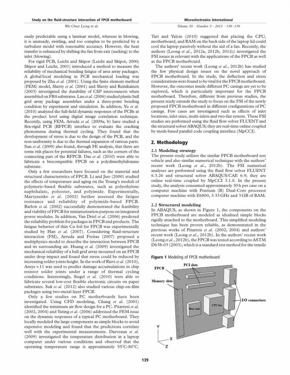
In ABAQUS, as shown in Figure 1, the components on theFPCB motherboard are modeled as idealized simple blocksrigidly attached to the motherboard. This simplified modelingtechnique has been proven reliable, as demonstrated in theprevious works of Pitarresi et al. (2002, 2004) and authors’recent work (Leong et al., 2012b). In the authors’ recent work(Leong et al., 2012b), the FPCB was tested according to ASTMD638-03 (2003), which is a standard test method for the tensile
Figure 1 Modeling of FPCB motherboard
Study on the fluid-structure interaction of FPCB motherboard
Wei Chiat Leong et al.
Microelectronics International
Volume 30 · Number 3 · 2013 · 138–150
139
properties of plastics. The FPCB was purchased from PCB
Universe located in the USA, and the effective elastic modulus
was found to be 5.243 GPa in the linear elastic region. In the
present study, the effective elastic modulus, density, and
dimensions of various components are specified in Table I
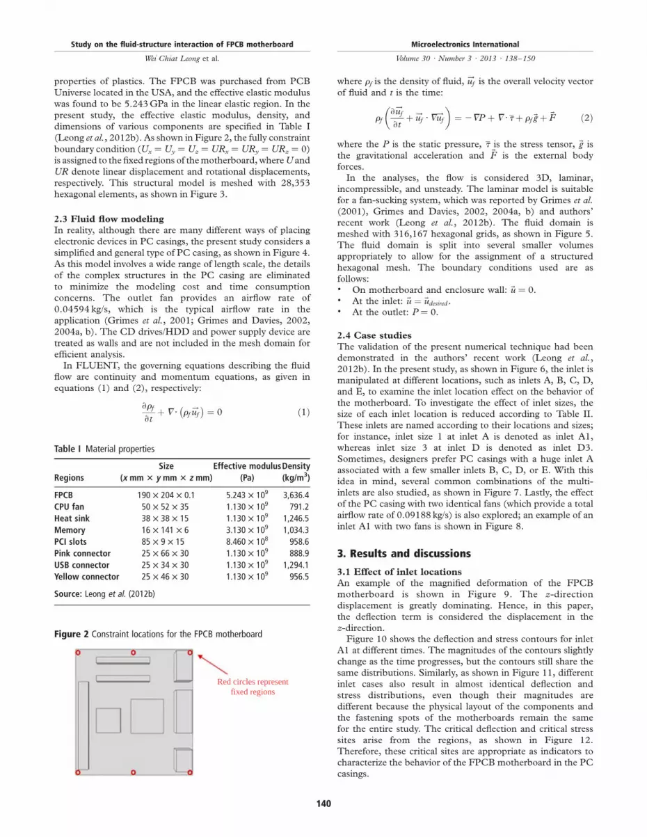
(Leong et al., 2012b). As shown in Figure 2, the fully constraint
boundary condition (Ux ¼ Uy ¼ Uz ¼ URx ¼ URy ¼ URz ¼ 0)
is assigned to the fixed regions of the motherboard, whereU and
UR denote linear displacement and rotational displacements,
respectively. This structural model is meshed with 28,353
hexagonal elements, as shown in Figure 3.
2.3 Fluid flow modeling
In reality, although there are many different ways of placing
electronic devices in PC casings, the present study considers a
simplified and general type of PC casing, as shown in Figure 4.
As this model involves a wide range of length scale, the details
of the complex structures in the PC casing are eliminated
to minimize the modeling cost and time consumption
concerns. The outlet fan provides an airflow rate of
0.04594 kg/s, which is the typical airflow rate in the
application (Grimes et al., 2001; Grimes and Davies, 2002,
2004a, b). The CD drives/HDD and power supply device are
treated as walls and are not included in the mesh domain for
efficient analysis.In FLUENT, the governing equations describing the fluid
flow are continuity and momentum equations, as given in
equations (1) and (2), respectively:
›rf
›tþ 7 · rf
!uf
� �¼ 0 ð1Þ
where rf is the density of fluid,!uf is the overall velocity vector
of fluid and t is the time:
rf›!uf
›tþ !uf ·7
!uf
� �¼ 27P þ 7 · tþ rf ~gþ ~F ð2Þ
where the P is the static pressure, t is the stress tensor, ~g is
the gravitational acceleration and ~F is the external body
forces.In the analyses, the flow is considered 3D, laminar,
incompressible, and unsteady. The laminar model is suitable
for a fan-sucking system, which was reported by Grimes et al.(2001), Grimes and Davies, 2002, 2004a, b) and authors’
recent work (Leong et al., 2012b). The fluid domain is
meshed with 316,167 hexagonal grids, as shown in Figure 5.
The fluid domain is split into several smaller volumes
appropriately to allow for the assignment of a structured
hexagonal mesh. The boundary conditions used are as
follows:. On motherboard and enclosure wall: ~u ¼ 0.. At the inlet: ~u ¼ ~udesired .. At the outlet: P ¼ 0.
2.4 Case studies
The validation of the present numerical technique had been
demonstrated in the authors’ recent work (Leong et al.,2012b). In the present study, as shown in Figure 6, the inlet is
manipulated at different locations, such as inlets A, B, C, D,
and E, to examine the inlet location effect on the behavior of
the motherboard. To investigate the effect of inlet sizes, the
size of each inlet location is reduced according to Table II.
These inlets are named according to their locations and sizes;
for instance, inlet size 1 at inlet A is denoted as inlet A1,
whereas inlet size 3 at inlet D is denoted as inlet D3.
Sometimes, designers prefer PC casings with a huge inlet A
associated with a few smaller inlets B, C, D, or E. With this
idea in mind, several common combinations of the multi-
inlets are also studied, as shown in Figure 7. Lastly, the effect
of the PC casing with two identical fans (which provide a total
airflow rate of 0.09188 kg/s) is also explored; an example of an
inlet A1 with two fans is shown in Figure 8.
3. Results and discussions
3.1 Effect of inlet locations
An example of the magnified deformation of the FPCB
motherboard is shown in Figure 9. The z-direction
displacement is greatly dominating. Hence, in this paper,
the deflection term is considered the displacement in the
z-direction.Figure 10 shows the deflection and stress contours for inlet
A1 at different times. The magnitudes of the contours slightly
change as the time progresses, but the contours still share the
same distributions. Similarly, as shown in Figure 11, different
inlet cases also result in almost identical deflection and
stress distributions, even though their magnitudes are
different because the physical layout of the components and
the fastening spots of the motherboards remain the same
for the entire study. The critical deflection and critical stress
sites arise from the regions, as shown in Figure 12.
Therefore, these critical sites are appropriate as indicators to
characterize the behavior of the FPCB motherboard in the PC
casings.
Figure 2 Constraint locations for the FPCB motherboard
Red circles representfixed regions
Table I Material properties
Regions
Size
(x mm 3 y mm 3 z mm)
Effective modulus
(Pa)
Density
(kg/m3)
FPCB 190 £ 204 £ 0.1 5.243 £ 109 3,636.4
CPU fan 50 £ 52 £ 35 1.130 £ 109 791.2
Heat sink 38 £ 38 £ 15 1.130 £ 109 1,246.5
Memory 16 £ 141 £ 6 3.130 £ 109 1,034.3
PCI slots 85 £ 9 £ 15 8.460 £ 108 958.6
Pink connector 25 £ 66 £ 30 1.130 £ 109 888.9
USB connector 25 £ 34 £ 30 1.130 £ 109 1,294.1
Yellow connector 25 £ 46 £ 30 1.130 £ 109 956.5
Source: Leong et al. (2012b)
Study on the fluid-structure interaction of FPCB motherboard
Wei Chiat Leong et al.
Microelectronics International
Volume 30 · Number 3 · 2013 · 138–150
140

Figure 3 3D meshed model in ABAQUS
Y
X
Z
Figure 4 Modeling of PC casing environment
Figure 5 3D meshed model in FLUENT
Y
XZ
Study on the fluid-structure interaction of FPCB motherboard
Wei Chiat Leong et al.
Microelectronics International
Volume 30 · Number 3 · 2013 · 138–150
141

In the no-flow condition (still air), purely because of the
weight-induced force, the motherboard critical deflection
is obtained at 0.239 mm, and its accompanied critical stress is
1.591 MPa. Figure 13 shows the deflections and stresses at
the respective critical sites in the motherboard for the
different inlet locations. Inlets B1 and C1 significantly induce
deflections and stresses on the motherboard because the flows
entering from the side of the PC casings contain prominent
z-direction velocity, which can easily affect the motherboard.Conversely, for inlets D1 and E1, which also introduceflows from the side of the PC casings, the flow influences arerather small because a portion of the flow directly bypassestowards the near exits. Although the present study is onlyfocused on the FSI aspect, air bypass is generally not desirableunder thermal consideration. Among them, inlet A1 isconsidered moderate in terms of deflection and stressinduced.
3.2 Effect of inlet sizes
The effect of inlet sizes is also studied for each inlets A, B, C, D,and E. The deflections and stresses induced at respective criticalsites in the motherboard for the different inlet sizes at inlet Aare shown in Figure 14. As the inlet size is reduced,the motherboard deflection and stress fluctuationsremarkably increase, increasing tremendously when inletA5 is used. As shown in Figure 15, as the inlet size becomessmaller, the entering airflow velocity increases, subsequentlyinitiating the vigorous flow. Generally, these fluctuations
Figure 6 PC casings with different inlet locations
Fan outlet
Flow inlet
y
xz
Fan outlet Fan outlet
Fan outletFan outlet
y
xz
y
xz
y
xz
y
xz
Flow inletFlow inlet
Flow inletFlow inlet
Inlet D Inlet E
Inlet B
Inlet A
Inlet C
Table II Dimensions of different inlet sizes
Inlet sizes
Horizontal length 3 vertical
length (mm 3 mm)
1 165 £ 130
2 145 £ 110
3 125 £ 90
4 105 £ 70
5 85 £ 50
Study on the fluid-structure interaction of FPCB motherboard
Wei Chiat Leong et al.
Microelectronics International
Volume 30 · Number 3 · 2013 · 138–150
142

are extremely undesirable under the fatigue concern
because they can lead to reliability failure.To explore further in detail the stress fluctuations, which are
simply the differences between the maximum and minimum
values, all inlets are analyzed and plotted in Figure 16. The
responses of the other inlets are also identicalwith thoseof inlet A,
in which a smaller inlet size gives higher stress fluctuation on
the motherboard. Interestingly, the stress fluctuations are
exponentially increased with the reduction of the inlet area. The
stress fluctuations slightly increase when the inlet area decreases
from 214.5 cm2 at the beginning. However, the fluctuation
increments are significantly boosted when the inlet area is further
reduced from 112.5 cm2. Moreover, inlets D3 and E3 are less
affected by the inlet size effect because a large portion of the flow
directly bypasses towards the exits, in agreement with the finding
in Section 3.1.
3.3 Effect of multi-inlets
As a result of the problem on the high fluctuation
phenomenon, which is attributed to the small inlet size as
discussed in Section 3.2, there is a need to investigate the
behavior of a motherboard in multi-inlet PC casings with
Figure 7 PC casings with different multi-inlets
Inlet A1+B3 Inlet A1+C3
Inlet A1+B3+C3 Inlet A1+B3+E3
Flow inlets Flow inlets
y
xz
y
xz
Fan outlet Fan outlet
Fan outlet Fan outlet
y
xz
y
xz
Flow inlets Flow inlets
Figure 8 PC casing with two-fan outlets
Two fanoutlets
Flow inlet
y
xz
Figure 9 Magnified deformation scale of the FPCB motherboard
Significant z-directiondisplacement
Y
ZX
Study on the fluid-structure interaction of FPCB motherboard
Wei Chiat Leong et al.
Microelectronics International
Volume 30 · Number 3 · 2013 · 138–150
143

few small inlets because such PC casings are sometimes
preferred. Figure 17 shows the resultant deflections and
stresses induced at the respective critical sites in the
motherboard for different multi-inlets. Significantly, the
fluctuation phenomenon greatly diminishes when the small
inlet is used in conjunction with other inlets. The reason is
that the entering airflows are now contributed by several
inlets; hence, more inlet area is accessible for the PC
casings. Consequently, the concentrated and vigorous flows at
one small inlet can be prevented. Owing to the samereason, the magnitudes of deflection and stress are also
noticeably reduced when the PC casings switch from a two-
inlet design to a three-inlet design, as clearly shown in the
figure.
3.4 Effect of the two-fan system
Occasionally, the PC casing is installed with two fans to
promote airflow. The values of the deflections and stresses for
different inlets are shown in Figure 18. For inlets A1, B1, and
C1, when the airflow rates are doubled, the magnitudes of the
deflection and stress are unavoidably enlarged, with an
average of 36 and 52 percent, respectively. Despite this
condition, a negligible flow influence exists at inlet E1, which
is again due to the bypass of the flow towards the exit.Surprisingly, inlet D1 is affected to a great extent even though
it is located near the exit. The reason is that the two-fan
system provides a very energetic flow that permits the entering
airflow to travel further and impinge on the motherboard
towards the negative z-direction instead of bypass towards the
exit. This situation also causes the unexpected reductions in
the deflection (260 percent) and stress (235 percent) for
inlet D1.
3.5 Discussion on the FPCB motherboard
Unlike the traditional rigid motherboard, the FSI study is far
more vital for the newly proposed FPCB motherboard under
a fan-flow condition. Based on the studies, the maximum
deflection can reach 0.61 mm, whereas the maximum stress
can be attained at 3.092 MPa. At this juncture, the deflection
has to be taken with utmost care to ensure that the deformed
motherboard does not impose any physical contact among the
components as well as with the other surrounding objects,
especially in miniaturized condition. The existence of the
stress fluctuation is also crucial and undesirable, as extreme
fatigue can lead to the failure of the motherboard. In practice,
the reductions in deflection and stress are always favorable for
enhanced reliability; this issue is particularly important for the
FPCB-based motherboard.Based on the results, the PC casing with inlet A1 is the most
promising for the FPCB motherboard because it offers
moderate magnitudes of deflection and stress induced, and it
does not directly bypass the air. Considering the FSI concern,
the designer is recommended to select a huge inlet and avoid an
inlet size smaller than 112.5 cm2to prevent excessive deflection
and stress fluctuations, which can greatly reduce the reliability
of the motherboard due to fatigue. However, if the designer still
insists on selecting a small inlet, the small inlet should be used in
conjunction with other inlets because more inlets can effectively
reduce the fluctuation phenomenon in the FPCB motherboard.
Although using two fans can greatly increase the airflow rate, the
designer has to be aware and make proper compromises because
the enlargements in deflection (36 percent) and stress
(52 percent) induced are critical for inlets A1, B1, and C1.
However, this issue is not a concern if inlets D1 and E1 are used.
Figure 10 Deflection and stress contours for inlet A1 at different times
1 s 1 s
5 s 5 s
10 s 10 s
Study on the fluid-structure interaction of FPCB motherboard
Wei Chiat Leong et al.
Microelectronics International
Volume 30 · Number 3 · 2013 · 138–150
144

In terms of fan-flow influence, the authors believe that theapplication of the newly proposed FPCB motherboard is feasibleprovided that the deflection and stress issues are carefullyconsidered during the design stage. However, more detailedanalyses on the other influential factors of the mechanical andelectronic aspects have to be carried out before the FPCBmotherboard can finally be used commercially.
4. Conclusions
The present study has explored the behaviors of the newlyproposed FPCB motherboard under a fan-flow condition inthe PC casings. The studies are numerically performedusing FLUENT and ABAQUS; they are real-time onlinecoupled by MpCCI. Inlet A1 is the most promising for theFPCB motherboard system considering the FSI concern.Interestingly, as the inlet size is reduced, the deflection andstress fluctuations of the motherboard are amplified, and the
effect is drastically boosted when the inlet area is further
reduced from 112.5 cm2. However, when the small inlet is
used in conjunction with other inlets, the undesirable
fluctuations are greatly diminished. For inlets A1, B1, and
C1, when the airflow rate is doubled, the magnitudes of
deflection and stress are unavoidably enlarged at around
36 and 52 percent, respectively. However, this issue is not a
concern for inlets D1 and E1. The application of the FPCB
motherboard is considered feasible under the fan-flow
condition. However, more detailed analyses of other
influential factors still have to be carried out. The present
study provides a better understanding and allows designers to
be aware of the FSI phenomenon, not only when dealing with
FPCB motherboard but also other FPCB applications. In the
future, the present study can be further extended to include
thermal stress, electrical circuit and electronic signal
concerns.
Figure 11 Deflection and stress contours for different inlet locations at 10 s
Inlet A1 Inlet A1
Inlet B1 Inlet B1
Inlet C1 Inlet C1
Inlet D1 Inlet D1
Inlet E1 Inlet E1
Study on the fluid-structure interaction of FPCB motherboard
Wei Chiat Leong et al.
Microelectronics International
Volume 30 · Number 3 · 2013 · 138–150
145

Figure 12 Critical deflection and critical stress sites
Figure 13 (a) Critical deflections and (b) critical stresses for differentinlet locations
Time (s)
0 5 10 15 20
Def
lect
ion
(m
m)
0.0
0.1
0.2
0.3
0.4
0.5
Inlet A1Inlet B1Inlet C1Inlet D1Inlet E1
(a)
Time (s)
0 5 10 15 20
von
Mis
es s
tres
s (M
Pa)
0.0
0.5
1.0
1.5
2.0
2.5
Inlet A1Inlet B1Inlet C1Inlet D1Inlet E1
(b)
Figure 14 (a) Critical deflections and (b) critical stresses for differentinlet sizes at inlet A
Time (s)
0 5 10 15 20
Def
lect
ion
(m
m)
–0.1
0.0
0.1
0.2
0.3
0.4
0.5
0.6Inlet A1Inlet A2Inlet A3Inlet A4Inlet A5
(a)
Time (s)
0 5 10 15 20
von
Mis
es s
tres
s (M
Pa)
0.0
0.5
1.5
1.0
2.0
2.5
3.0
Inlet A1Inlet A2Inlet A3Inlet A4Inlet A5
(b)
Study on the fluid-structure interaction of FPCB motherboard
Wei Chiat Leong et al.
Microelectronics International
Volume 30 · Number 3 · 2013 · 138–150
146

Figure 15 Flows for different inlet sizes at inlet A
Inlet A1
Inlet A3
Inlet A5
Study on the fluid-structure interaction of FPCB motherboard
Wei Chiat Leong et al.
Microelectronics International
Volume 30 · Number 3 · 2013 · 138–150
147

References
Arruda, L. and Freitas, G. (2007), “Effect of surrounding air
on board level drop tests of flexible printed circuit boards”,
EuroSime 2007: International Conference on Thermal,Mechanical and Multi-Physics Simulation Experiments inMicroelectronics and Micro-Systems, pp. 1-4.
Arruda, L., Chen, Q. and Quintero, J. (2009a), “Failure
evaluation of flexible-rigid PCBs by thermo-mechanical
simulation”, International Conference on Electronic PackagingTechnology & High Density Packaging, pp. 1201-1205.
Arruda, L., Bonadiman, R., Costa, F. and Reinikainen, T.
(2009b), “Cracking phenomena on flexible-rigid interfaces
in PCBs under thermo cycling load”, Circuit World, Vol. 35
No. 2, pp. 28-32.ASTM D638-03 (2003), Standard Test Method for TensileProperties of Plastics, ASTM, Philadelphia, PA.
Azar, K. and Russell, E.T. (1990), “Effect of component layout
and geometry on the flow distribution in electronics circuit
packs”, Sixth IEEE SEMI-THERMe Symposium, pp. 1-9.Baelmans, M., Meyers, J. and Nevelsteen, K. (2003), “Flow
modeling in air-cooled electronic enclosures”, 19th IEEESEMI-THERM Symposium, pp. 27-34.
Figure 16 Stress fluctuations for different inlet sizes
Inlet area (cm2)
20 40 60 80 100 120 140 160 180 200 220 240
Str
ess
flu
ctu
atio
n (
MP
a)
0.0
0.2
0.4
0.6
0.8
1.0
1.2
1.4
1.6
1.8
2.0
Inlet AInlet BInlet CInlet DInlet E
Size 3
Size 2 Size 1
Size 5
Size 4
Figure 17 (a) Critical deflections and (b) critical stresses for differentmulti-inlets
Time (s)0 5 10 15 20
Def
lect
ion
(m
m)
0.1
0.2
0.3
0.4
0.5Inlet A1+B3Inlet A1+C3Inlet A1+B3+C3Inlet A1+B3+E3
(a)
Time (s)0 5 10 15 20
von
Mis
es s
tres
s (M
Pa)
1.0
1.5
2.0
2.5Inlet A1+B3Inlet A1+C3Inlet A1+B3+C3Inlet A1+B3+E3
(b)
Figure 18 (a) Critical deflections and (b) critical stresses for single-fanand two-fan systems
Inlets
A1 B1 C1 D1 E1
Def
lect
ion
(m
m)
0.0
0.1
0.2
0.3
0.4
0.5
0.6
0.7
Single fanTwo fans
(a)
Inlets
A1 B1 C1 D1 E1
(b)
von
Mis
es s
tres
s (M
Pa)
0.0
0.5
1.0
1.5
2.0
2.5
3.0
3.5
Single fanTwo fans
Study on the fluid-structure interaction of FPCB motherboard
Wei Chiat Leong et al.
Microelectronics International
Volume 30 · Number 3 · 2013 · 138–150
148

Barlow, F., Lostetter, A. and Elshabini, A. (2002), “Low cost
flex substrates for miniaturized electronic assemblies”,
Microelectronics Reliability, Vol. 42, pp. 1091-1099.Chang, J.Y., Yu, C.W. and Webb, R.L. (2001), “Identification
of minimum air flow design for a desktop computer using
CFD modeling”, Journal of Electronic Packaging, Vol. 123,
pp. 225-231.Cole, R., Davies, M. and Punch, J. (2003), “A board level
study of an array of ball grid components – Aerodynamic
and thermal measurements”, Journal of Electronic Packaging,
Vol. 125, pp. 480-489.Darveaux, R., Reichman, C. and Berry, C.J. (2009), “Field
use environment for a FCBGA in a laptop computer
application”, Electronic Components and Technology
Conference, pp. 1234-1239.Das, R.N., Egitto, F.D., Wilson, B., Poliks, M.D. and
Markovich, V.R. (2010), “Development of rigid-flex and
multilayer flex for electronic packaging”, Electronic
Components and Technology Conference, pp. 568-574.Eveloy, V., Lohan, J. and Rodgers, P. (2000), “A benchmark
study of computational fluid dynamics predictive accuracy
for component-printed circuit board heat transfer”, IEEE
Transactions on Components and Packaging Technologies,
Vol. 23 No. 3, pp. 568-577.Grimes, R. and Davies, M. (2002), “The effect of fan
operating point and location on temperature distribution in
electronic systems”, Inter Society Conference on Thermal
Phenomena, pp. 677-684.Grimes, R. and Davies, M. (2004a), “Air flow and heat
transfer in fan cooled electronic systems”, Journal of
Electronic Packaging, Vol. 126, pp. 124-134.Grimes, R. and Davies, M. (2004b), “Optical measurement
of electronic system air flow and temperature distribution”,
Journal of Optics A: Pure and Applied Optics, Vol. 6,
pp. 617-626.Grimes, R., Davies, M., Punch, J., Dalton, T. and Cole, R.
(2001), “Modeling electronic cooling axial fan flows”,
Journal of Electronic Packaging, Vol. 123, pp. 112-119.Han, S., Seo, K., Kim, W., Lee, H., Lee, H., Shin, J. and
Lee, J. (2007), “Fatigue behavior of thin Cu foils for flexible
printed circuit board”, Solid State Phenomena, Vol. 124-126,
pp. 1369-1372.Huang, J., Chen, Q., Xu, L. and Zhang, G.Q. (2009),
“Prediction of drop impact reliability of BGA solder joints
on FPC”, 11th Electronics Packaging Technology Conference,
pp. 663-667.Lau, D., Chan, Y.S., Ricky Lee, S.W., Fu, L., Ye, Y. and Liu, S.
(2006), “Experimental testing and failure prediction
of PBGA package assemblies under 3-point bending
condition through computational stress analysis”, 7th
International Conference on Electronics Packaging Technology,
pp. 1-7.Lee, T. and Mahalingam, M. (1993), “Application of a CFD
tool for system level thermal simulation”, Proceedings of
IEEE 43rd Electronic Components and Technology Conference,
pp. 249-255.Leicht, L. and Skipor, A. (2000), “Mechanical cycling fatigue
of PBGA package interconnects”, Microelectronics Reliability,
Vol. 40, pp. 1129-1133.Leon, O., Mey, G.D. and Dick, E. (2002), “Study of the
optimal layout of cooling fins in forced convection cooling”,
Microelectronics Reliability, Vol. 42, pp. 1101-1111.
Leong, W.C., Abdullah, M.Z. and Abdul Mujeebu, M.
(2012a), “Flow induced deflection and stress on flexible
printed circuit board (FPCB) in fan-cooled electronic
systems: FSI approach”, IEEE Transactions on Components,
Packaging and Manufacturing Technology, Vol. 2 No. 4,
pp. 617-624.Leong, W.C., Abdullah, M.Z. and Khor, C.Y. (2012b),
“Application of flexible printed circuit board (FPCB) in
personal computer motherboards: focusing on mechanical
performance”, Microelectronics Reliability, Vol. 52,
pp. 744-756.Leong, W.C., Abdullah, M.Z., Khor, C.Y. and
Ernest Ong, E.S. (2012c), “Study on the fluid-structure
interaction of flexible printed circuit board electronics in
the flow environment”, IEEE Transactions on Components,
Packaging and Manufacturing Technology, Vol. 2 No. 8,
pp. 1335-1345.Leung, C.W., Chen, S. and Chan, T.L. (2000), “Numerical
simulation of laminar forced convection in an air-cooled
horizontal printed circuit board assembly”, Numerical Heat
Transfer, Part A, Vol. 37, pp. 373-393.Li, R.S. and Jiao, J. (2000), “The effects of temperature and
aging on Young’s moduli of polymeric based flexible
substrate”, The International Journal of Microcircuits and
Electronic Packaging, Vol. 23 No. 4, pp. 456-461.Lohan, J., Eveloy, V. and Rodgers, P. (2002), “Visualization of
forced air flows over a populated printed circuit board and
their impact in convective heat transfer”, Inter Society
Conference on Thermal Phenomena, pp. 501-511.Martynenko, E., Zhou, W., Chudnovsky, A., Li, R.S. and
Poglitsch, L. (2002), “High cycle fatigue resistance and
reliability assessment of flexible printed circuitry”,
Transactions of the ASME, Vol. 124, pp. 254-259.Pitarresi, J., Geng, P., Beltman, W. and Ling, Y. (2002),
“Dynamic modeling and measurement of personal
computer motherboards”, Electronic Components and
Technology Conference, pp. 597-603.Pitarresi, J., Roggerman, B., Chaparala, S. and Geng, P.
(2004), “Mechanical shock testing and modeling of PC
motherboards”, Electronic Components and Technology
Conference, pp. 1047-1054.Rizvi, M.J., Bailey, C. and Lu, H. (2010), “Damage
predictions in a chip resistor solder joint on flexible
circuit board”, Microelectronic Engineering, Vol. 87,
pp. 1889-1895.Rodgers, P.J., Eveloy, V.C. and Davies, M.R.D. (2003a),
“An experimental assessment of numerical predictive
accuracy for electronic component heat transfer in forced
convection – part I: experimental methods and numerical
modeling”, Journal of Electronic Packaging, Vol. 125,
pp. 67-75.Rodgers, P.J., Eveloy, V.C. and Davies, M.R.D. (2003b),
“An experimental assessment of numerical predictive
accuracy for electronic component heat transfer in forced
convection – part II: results and discussion”, Journal of
Electronic Packaging, Vol. 125, pp. 76-83.Shankaran, G.V. and Karimanal, K. (2002), “A multi level
modeling approach with boundary condition import for
system, sub-system or board level thermal
characterization”, 18th IEEE SEMI-THERM Symposium,
pp. 35-41.
Study on the fluid-structure interaction of FPCB motherboard
Wei Chiat Leong et al.
Microelectronics International
Volume 30 · Number 3 · 2013 · 138–150
149

Shetty, S. and Reinikainen, T. (2003), “Three- and four-pointbend testing for electronic packages”, Journal of ElectronicPackaging, Vol. 125, pp. 556-561.
Shetty, S., Lehtinen, V., Dasgupta, A., Halkola, V. andReinikainen, T. (2001), “Fatigue of chip scale packageinterconnects due to cyclic bending”, Journal of ElectronicPackaging, Vol. 123, pp. 302-308.
Siegel, A.C., Phillips, S.T., Dickey, M.D., Lu, N., Suo, Z. andWhitesides, G.M. (2010), “Foldable printed circuit boardson paper substrates”, Advanced Functional Materials,Vol. 20, pp. 28-35.
Skipor, A. and Leicht, L. (2001), “Mechanical bendingfatigue reliability and its application to area arraypackaging”, Electronic Components and TechnologyConference, pp. 606-612.
Suk, K.-L., Choo, K., Kim, S.J., Kim, J.-S. and Paik, K.-W.(2012), “Studies on various chip-on-film (COF) packagesusing ultra fine pitch two-metal layer flexible printedcircuits (two-metal layer FPCs)”, Microelectronics Reliability,Vol. 52 No. 6, pp. 1182-1188.
Sun, H.-b., Shi, M.-Q., Yang, P., Zhong, J., Chen, Q., Xue, T.,Zhao, T., Xu, L. and Salo, A. (2009), “Rigid-flexible printedcircuit structure optimization by simulations”, 10thInternational Conference on Thermal, Mechanical andMultiphysics Simulation Experiment in Micro-Electronics andMicro-Systems, pp. 1-4.
Tari, I. and Yalcin, F.S. (2010), “CFD analyses of a notebookcomputer thermal management system and a proposedpassive cooling alternative”, IEEE Transactions onComponents and Packaging Technologies, Vol. 33 No. 2,pp. 443-452.
Van Driel, W.D., Van der Sluis, O., Yang, D.G., Ubachs, R.,Zenz, C., Aflenzer, G. and Chang, G.Q. (2006),“Reliability modeling for packages in packages in flexibleend-products”, Microelectronics Reliability, Vol. 46,pp. 1880-1885.
Yating, Y., Pingan, D. and Ezhong, G. (2006), “Structuralrobustness study of a computer motherboard”, Proceedingsof the IEEE International Conference on Industrial Technology,pp. 2370-2374.
Yu, D., Kwak, J.B., Park, S. and Lee, J. (2010), “Dynamicresponses of PCB under product-level free drop impact”,Microelectronics Reliability, Vol. 50, pp. 1028-1038.
Zhu, J., Quander, S. and Reinikainen, T. (2001), “Global/localmodeling for PWB mechanical loading”, ElectronicComponents and Technology Conference, pp. 1164-1169.
About the authors
Wei Chiat Leong obtained his Bachelor’s degree in
Mechanical Engineering (First Honours) from Universiti
Sains Malaysia (USM), Malaysia. Currently he is pursuing his
doctoral degree in the field of electronic packaging at USM,
specializing in the area of flexible printed circuit board. He is
an active member of Institution of Engineers Malaysia (IEM),
registering under the Board of Engineers Malaysia (BEM).
His research interests are fluid mechanics, CFD, structural
analysis, FEM, fluid-structure interaction study and
electronic packaging. Wei Chiat Leong is the corresponding
author and can be contacted at: [email protected]
Mohd Zulkifly Abdullah is Professor of Mechanical
Engineering at Universiti Sains Malaysia. He obtained his
Bachelor degree in Mechanical Engineering from University
of Wales, Swansea, UK. His MSc and PhD degrees are from
University of Strathclyde, UK. He has numerous publications
in international journals and conference proceedings. His
areas of research are CFD, heat transfer, and electronic
packaging.
Chu Yee Khor received the Graduate degree in mechanical
engineering and the Master’s degree in computational fluid
dynamics, specializing in integrated circuit packaging from
Universiti Sains Malaysia, Minden, Malaysia, in 2008 and
2010, respectively. He is currently pursuing the PhD degree in
advanced packaging in microelectronics. His current research
interests are electronics packaging, fluid/structure interaction,
fluid mechanics, dynamics, polymer rheology and heat and
mass transfer.
Dadan Ramdan was born in Bandung, Indonesia, in 1964.
He received the BS degree in physics from the Pandjadjaran
University of Bandung, Bandung, and the MSc and MEng
degrees from the Institute Technology of Bandung, Bandung,
and the Toyohashi University of Technology, Toyohashi,
Japan, respectively. He is currently pursuing the PhD degree
with Universiti Sains, Penang, Malaysia. He was previously a
lecturer of mechanical engineering with the Engineering
Faculty, Medan Area University, Medan, Indonesia. His
current research interests include electronic instrumentation,
control systems engineering, and computational flow
dynamics analysis of electronic packaging and casting.
Study on the fluid-structure interaction of FPCB motherboard
Wei Chiat Leong et al.
Microelectronics International
Volume 30 · Number 3 · 2013 · 138–150
150
To purchase reprints of this article please e-mail: [email protected]
Or visit our web site for further details: www.emeraldinsight.com/reprints
Copyright © 2022 FDOKUMEN

