


Bahasa
Halaman
Hukum

APC APPLICATION NOTE #156StruxureWare Data Center Expert v7.2.0
Building Management System Integration
By Kevin Kosko
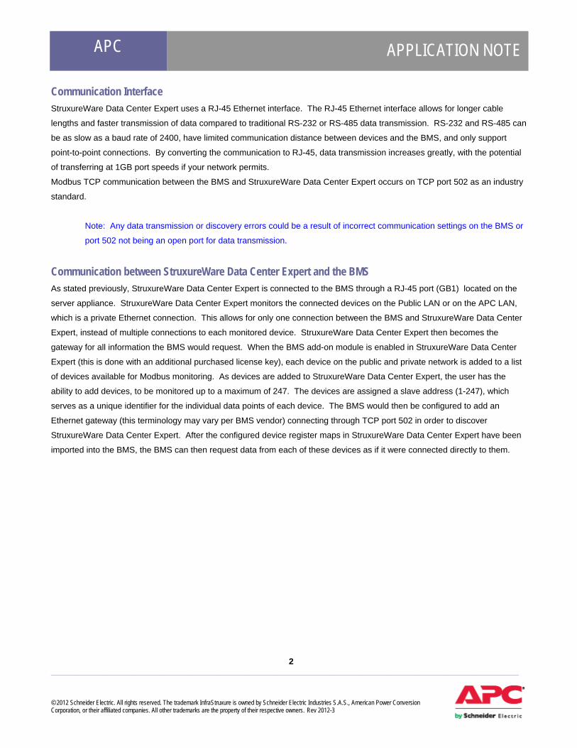
Abstract Building Management Systems (BMS) are implemented in a building's infrastructure to collect data of assorted managed
devices that comprise this infrastructure. Some examples of the devices that the BMS would monitor could include
generators, computer room air conditioners (CRAC), uninterruptible power supply (UPS), power distribution units (PDU), fire
sensors, or building switchgear. The BMS itself is typically a stand-alone computer that contains a software program used to
collect data and a hardware interface used to connect it to the monitored devices. This software program is designed
specifically for each application, as each building infrastructure is unique and the monitoring points may be different for each
device. A master-slave type system exists between the BMS and the connected devices. There is one node (the master node
or BMS) that requests data from one of the "slave" nodes (connected devices) and then translates the responses into readable
data. Slave nodes will not typically transmit data without a request from the master node, and do not communicate with other
slaves.
Modbus Protocol The Modbus protocol is a standard in the buildings industry and is supported by many BMS vendors. Modbus is an application
layer messaging protocol, which provides client/server communication between devices connected on different types of buses
or networks, typically within a building's infrastructure. There are a few different types of the Modbus protocols, which include
Modbus TCP (TCP/IP binary), Modbus (serial ASCII), and Modbus RTU (serial binary). For the discussion in this application
note, StruxureWare Data Center Expert uses the Modbus TCP protocol. Modbus TCP communication is becoming more
common in the industry, because Modbus TCP/IP simply takes the Modbus instruction set and wraps TCP/IP around it.
Implementation costs are exceptionally low and minimum hardware is required, which is why the industry is more and more
adopting Modbus TCP as a standard.
Schneider Electric integrates Modbus TCP over an Ethernet connection for StruxureWare Data Center Expert's
communication with a BMS (e.g. TAC Andover Continuum™ and TAC Vista™, Johnson Controls’ Metasys™, Siemens’
APOGEE™, ALC’s WebCTRL™, etc.). This paper explains the integration of the Schneider Electric StruxureWare Data
Center Expert v7.2.0 server appliance with a Building Management System.
Note: APC and TAC are subsidiaries of Schneider Electric and have tested and integrated StruxureWare Data
Center Expert’s Modbus TCP with T.A.C. Andover Continuum™ and Vista™. The integration of these management
systems provides the ability to correlate the physical infrastructure of the data center “white space” with the
supporting building infrastructure.
1 ____________________________________________________________________________________________________ © 2012 Schneider Electric. All rights reserved. The trademark InfraStruxure is owned by Schneider Electric Industries S.A.S., American Power Conversion Corporation, or their affiliated companies. All other trademarks are the property of their respective owners. Rev 2012-3
APC APPLICATION NOTE
2 ___________________________________________________________________________________________________ © 2012 Schneider Electric. All rights reserved. The trademark InfraStruxure is owned by Schneider Electric Industries S.A.S., American Power Conversion Corporation, or their affiliated companies. All other trademarks are the property of their respective owners. Rev 2012-3
Communication Interface StruxureWare Data Center Expert uses a RJ-45 Ethernet interface. The RJ-45 Ethernet interface allows for longer cable
lengths and faster transmission of data compared to traditional RS-232 or RS-485 data transmission. RS-232 and RS-485 can
be as slow as a baud rate of 2400, have limited communication distance between devices and the BMS, and only support
point-to-point connections. By converting the communication to RJ-45, data transmission increases greatly, with the potential
of transferring at 1GB port speeds if your network permits.
Modbus TCP communication between the BMS and StruxureWare Data Center Expert occurs on TCP port 502 as an industry
standard.
Note: Any data transmission or discovery errors could be a result of incorrect communication settings on the BMS or
port 502 not being an open port for data transmission.
Communication between StruxureWare Data Center Expert and the BMS As stated previously, StruxureWare Data Center Expert is connected to the BMS through a RJ-45 port (GB1) located on the
server appliance. StruxureWare Data Center Expert monitors the connected devices on the Public LAN or on the APC LAN,
which is a private Ethernet connection. This allows for only one connection between the BMS and StruxureWare Data Center
Expert, instead of multiple connections to each monitored device. StruxureWare Data Center Expert then becomes the
gateway for all information the BMS would request. When the BMS add-on module is enabled in StruxureWare Data Center
Expert (this is done with an additional purchased license key), each device on the public and private network is added to a list
of devices available for Modbus monitoring. As devices are added to StruxureWare Data Center Expert, the user has the
ability to add devices, to be monitored up to a maximum of 247. The devices are assigned a slave address (1-247), which
serves as a unique identifier for the individual data points of each device. The BMS would then be configured to add an
Ethernet gateway (this terminology may vary per BMS vendor) connecting through TCP port 502 in order to discover
StruxureWare Data Center Expert. After the configured device register maps in StruxureWare Data Center Expert have been
imported into the BMS, the BMS can then request data from each of these devices as if it were connected directly to them.

APC APPLICATION NOTE
3 ___________________________________________________________________________________________________ © 2012 Schneider Electric. All rights reserved. The trademark InfraStruxure is owned by Schneider Electric Industries S.A.S., American Power Conversion Corporation, or their affiliated companies. All other trademarks are the property of their respective owners. Rev 2012-3
In the current integration of StruxureWare Data Center Expert and BMS systems, there is support for Modbus Function Code
04 (Read Input Registers) The communication between a BMS and connected devices, involves Read Input Registers,
Queries, and Responses. These are explained below:
Read Input Registers
Reads the binary contents of input registers (3X references) in the slave. Broadcast is not supported. The
maximum parameters supported by various controller models are listed below.
Query
The query message specifies the starting register and quantity of registers to be read. Registers are
addressed starting at zero- registers 1 ... 16 are addressed as 0 ... 15.

APC APPLICATION NOTE
4 ___________________________________________________________________________________________________ © 2012 Schneider Electric. All rights reserved. The trademark InfraStruxure is owned by Schneider Electric Industries S.A.S., American Power Conversion Corporation, or their affiliated companies. All other trademarks are the property of their respective owners. Rev 2012-3
Here is an example of a request to read register 31000 from slave device 17:
Field Name Example (Hex) Slave Address 11
Function 04
Starting Address Hi 00
Starting Address Lo 08
Number of Points Hi 00
Number of Points Lo 01
Error Check (LRC or CRC) --
Response The register data in the response message are packed as two bytes per register, with the binary contents
right justified within each byte. For each register, the first byte contains the high-order bits and the second
contains the low-order bits. The response is returned when the data is completely assembled.
Here is an example of a response to the query above:
Field Name Example (Hex) Slave Address 11
Function 04
Byte Count 02
Data Hi (Register 30009) 00
Data Lo (Register 30009) 0A
Error Check (LRC or CRC) --
The contents of register 31009 are shown as the two byte values of 00 0A hex, or 10 decimal.
Floating point numbers Modbus registers contain 16 bits of data. Because Modbus registers do not handle floating point numbers the float is
converted to an integer by multiplying it by 10, 100 or 1000 (depending on the number of decimal places) to preserve the
precision. Thus, in some of the valid responses there will be a note indicating that the response must be divided by 10, 100 or
1000 to yield the correct results.

APC APPLICATION NOTE
5 ___________________________________________________________________________________________________ © 2012 Schneider Electric. All rights reserved. The trademark InfraStruxure is owned by Schneider Electric Industries S.A.S., American Power Conversion Corporation, or their affiliated companies. All other trademarks are the property of their respective owners. Rev 2012-3
StruxureWare Data Center Expert Data Registers StruxureWare Data Center Expert allows the user the flexibility to configure the data registers for each device. The register
range spans from 31000 – 39999 and the amount of Modbus registers vary per device. First you will select the device you
would like to read data from, chose the Slave address and then generate the register map (Figure 1). Once the register map
is created it can then be exported and imported into the BMS (Figure2).
Figure 1

APC APPLICATION NOTE
6 ___________________________________________________________________________________________________ © 2012 Schneider Electric. All rights reserved. The trademark InfraStruxure is owned by Schneider Electric Industries S.A.S., American Power Conversion Corporation, or their affiliated companies. All other trademarks are the property of their respective owners. Rev 2012-3
Figure 2
StruxureWare Data Center Expert Device Alarm Count Register The device alarm count register will always remain 30999 and will display the maximum number of device alarms per device that are active within StruxureWare Data Center Expert. Devices that have unmapped register values will return 0xDEAD as seen below.
Register Description
Modbus Register Register Value(s) Register Value Description
Active Alarm Count 0x30999 0-Max Active Alarm Count
Magic Values 0xDEAD Value refers to an empty or unmapped register

APC APPLICATION NOTE
7 ___________________________________________________________________________________________________ © 2012 Schneider Electric. All rights reserved. The trademark InfraStruxure is owned by Schneider Electric Industries S.A.S., American Power Conversion Corporation, or their affiliated companies. All other trademarks are the property of their respective owners. Rev 2012-3
StruxureWare Data Center Expert Device Status Register The device status register is common to all discovered devices. The Modbus register for the device status will always remain
at 30998 with the register value changing. Below are the following register values for device status:
Register Description
Modbus Register
Register Value(s) Register Value Description
Device Status Register 0x30998 0xFFFD Device discovery phase is in progress
0xFFFE No Status is available for device 0xFFFF Ok state 0x0000 Informational state 0x0001 Device is in warning state 0x0002 Device is in error state 0x0003 Device is in critical state 0x0004 Device is in failure state 0x0005 Device is in maintenance mode
StruxureWare Data Center Expert Device Alarm Codes In the following table are the Alarm codes common to all devices. Each alarm will have two registers per alarm with the registers starting prior to 30998 and based on the number of alarms, you would need to poll two registers for each alarm. For example: If there are 10 devices sensors in an alarm state each with one alarm, you would need to poll 20 registers prior 30998, in order to display the alarm code and the sensor code for the device it corresponds to.
Register Description
Modbus Register
Register Value(s) Register Value Description
Each alarm spans two registers with the first register representing the alarm code and the second representing the corresponding sensor.
0x30998 – (max alarms reported) *2
0xFFFE Device alarm 0xFFFF Exclude (test) alarm
0x0001 Device info alarm 0x0002 Communication lost 0x0003 Threshold violation: too low 0x0004 Threshold violation: too low too long 0x0005 Threshold violation: too high
Alarms are read as a negative offset from the Device Status Register (0x30998) up to Max alarms reported. Alarms are provided in order of severity. A single alarm occupies two registers
0x0006 Threshold violation: too high too long 0x0007 Threshold violation: increase too fast 0x0008 Threshold violation: decrease too fast 0x0009 Threshold violation: state change 0x000A DDF Download Failure 0x000B Capture drive failure 0x000C Remote link failed 0x000D Log on error 0x000E General Device Alarm
0x????
Specific device alarms (see each device alarm table for the Modbus register value and register value description)
APC APPLICATION NOTE
8 ___________________________________________________________________________________________________ © 2012 Schneider Electric. All rights reserved. The trademark InfraStruxure is owned by Schneider Electric Industries S.A.S., American Power Conversion Corporation, or their affiliated companies. All other trademarks are the property of their respective owners. Rev 2012-3
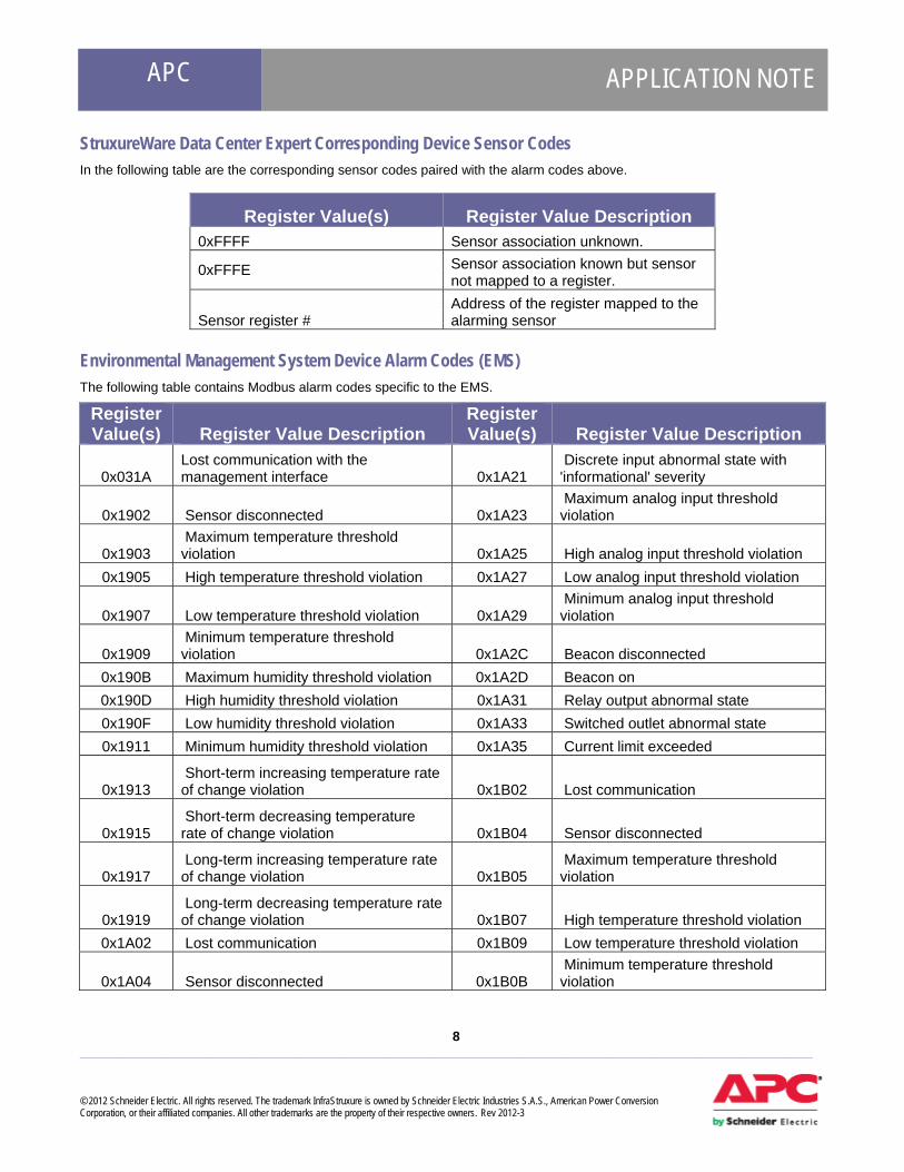
StruxureWare Data Center Expert Corresponding Device Sensor Codes In the following table are the corresponding sensor codes paired with the alarm codes above.
Register Value(s) Register Value Description 0xFFFF Sensor association unknown.
0xFFFE Sensor association known but sensor not mapped to a register.
Sensor register # Address of the register mapped to the alarming sensor
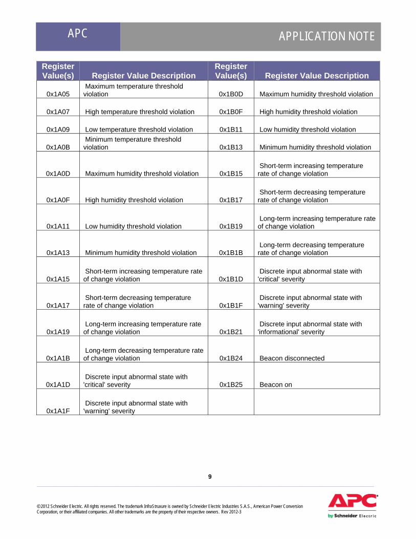
Environmental Management System Device Alarm Codes (EMS) The following table contains Modbus alarm codes specific to the EMS.
Register Value(s) Register Value Description
Register Value(s) Register Value Description
0x031A Lost communication with the management interface 0x1A21
Discrete input abnormal state with 'informational' severity
0x1902 Sensor disconnected 0x1A23 Maximum analog input threshold violation
0x1903 Maximum temperature threshold violation 0x1A25 High analog input threshold violation
0x1905 High temperature threshold violation 0x1A27 Low analog input threshold violation
0x1907 Low temperature threshold violation 0x1A29 Minimum analog input threshold violation
0x1909 Minimum temperature threshold violation 0x1A2C Beacon disconnected
0x190B Maximum humidity threshold violation 0x1A2D Beacon on 0x190D High humidity threshold violation 0x1A31 Relay output abnormal state 0x190F Low humidity threshold violation 0x1A33 Switched outlet abnormal state 0x1911 Minimum humidity threshold violation 0x1A35 Current limit exceeded
0x1913 Short-term increasing temperature rate of change violation 0x1B02 Lost communication
0x1915 Short-term decreasing temperature rate of change violation 0x1B04 Sensor disconnected
0x1917 Long-term increasing temperature rate of change violation 0x1B05
Maximum temperature threshold violation
0x1919 Long-term decreasing temperature rate of change violation 0x1B07 High temperature threshold violation
0x1A02 Lost communication 0x1B09 Low temperature threshold violation
0x1A04 Sensor disconnected 0x1B0B Minimum temperature threshold violation
APC APPLICATION NOTE
9 ___________________________________________________________________________________________________ © 2012 Schneider Electric. All rights reserved. The trademark InfraStruxure is owned by Schneider Electric Industries S.A.S., American Power Conversion Corporation, or their affiliated companies. All other trademarks are the property of their respective owners. Rev 2012-3
Register Value(s) Register Value Description
Register Value(s) Register Value Description
0x1A05 Maximum temperature threshold violation 0x1B0D Maximum humidity threshold violation
0x1A07 High temperature threshold violation 0x1B0F High humidity threshold violation
0x1A09 Low temperature threshold violation 0x1B11 Low humidity threshold violation
0x1A0B Minimum temperature threshold violation 0x1B13 Minimum humidity threshold violation
0x1A0D Maximum humidity threshold violation 0x1B15 Short-term increasing temperature rate of change violation
0x1A0F High humidity threshold violation 0x1B17 Short-term decreasing temperature rate of change violation
0x1A11 Low humidity threshold violation 0x1B19 Long-term increasing temperature rate of change violation
0x1A13 Minimum humidity threshold violation 0x1B1B Long-term decreasing temperature rate of change violation
0x1A15 Short-term increasing temperature rate of change violation 0x1B1D
Discrete input abnormal state with 'critical' severity
0x1A17 Short-term decreasing temperature rate of change violation 0x1B1F
Discrete input abnormal state with 'warning' severity
0x1A19 Long-term increasing temperature rate of change violation 0x1B21
Discrete input abnormal state with 'informational' severity
0x1A1B Long-term decreasing temperature rate of change violation 0x1B24 Beacon disconnected
0x1A1D Discrete input abnormal state with 'critical' severity 0x1B25 Beacon on
0x1A1F Discrete input abnormal state with 'warning' severity

APC APPLICATION NOTE
10 ___________________________________________________________________________________________________ © 2012 Schneider Electric. All rights reserved. The trademark InfraStruxure is owned by Schneider Electric Industries S.A.S., American Power Conversion Corporation, or their affiliated companies. All other trademarks are the property of their respective owners. Rev 2012-3
Environmental Monitoring Unit Device Alarm Codes (EMU) The following table contains Modbus alarm codes specific to the EMU.
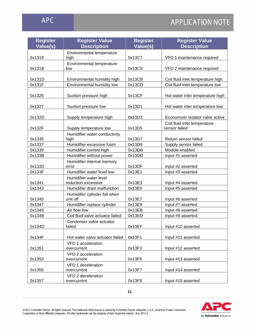
Network Air FM Device Alarm Codes The following table contains Modbus alarm codes specific to the Network Air FM.
Register Value(s)
Register Value Description
Register Value(s)
Register Value Description
0x1303 Module power on 0x13B9 VFD 1 fault tolerance exceeded
0x1305 Water detected 0x13BB VFD 2 fault tolerance exceeded 0x1307 Fire detected 0x13BD Cooling coil: No fluid flow 0x1309 Smoke detected 0x13BF Condenser: No fluid flow
0x130D Head pressure high 0x13C1 Lost communication with expansion module 1
0x130F Condensate pump failed 0x13C3 Lost communication with expansion module 2
0x1311 Air block interlock open 0x13C5 Lost communication with expansion module 3
Register Value(s)
Register Value Description
Register Value(s)
Register Value Description
0x031A Lost Communication 0x0329
A minimum temperature threshold violation exists for integrated Environmental Monitor Sensor
0x031B
Critical fault on integrated Environmental Monitor input contact 0x031D
A low temperature threshold violation exists for integrated Environmental Monitor Sensor
0x0343
Warning fault on integrated Environmental Monitor input contact 0x031F
A high temperature threshold violation exists for integrated Environmental Monitor Sensor
0x0349
Lost communication to the integrated Environmental Monitor input contact 0x0327
A maximum temperature threshold violation exists for integrated Environmental Monitor Sensor
0x0323
A high humidity threshold violation exists for integrated Environmental Monitor Sensor 0x032D
A minimum humidity threshold violation exists for integrated Environmental Monitor Sensor
0x032B
A maximum humidity threshold violation exists for integrated Environmental Monitor Sensor 0x0321
A low humidity threshold violation exists for integrated Environmental Monitor Sensor
0x0347 Lost Communication
APC APPLICATION NOTE
11 ___________________________________________________________________________________________________ © 2012 Schneider Electric. All rights reserved. The trademark InfraStruxure is owned by Schneider Electric Industries S.A.S., American Power Conversion Corporation, or their affiliated companies. All other trademarks are the property of their respective owners. Rev 2012-3
Register Value(s)
Register Value Description
Register Value(s)
Register Value Description
0x1319 Environmental temperature high 0x13C7 VFD 1 maintenance required
0x131B Environmental temperature low 0x13C9 VFD 2 maintenance required
0x131D Environmental humidity high 0x13CB Coil fluid inlet temperature high 0x131F Environmental humidity low 0x13CD Coil fluid inlet temperature low
0x1325 Suction pressure high 0x13CF Hot water inlet temperature high
0x1327 Suction pressure low 0x13D1 Hot water inlet temperature low
0x132D Supply temperature high 0x13D3 Economizer isolator valve active
0x132F Supply temperature low 0x13D5 Coil fluid inlet temperature sensor failed
0x1335 Humidifier water conductivity high 0x13D7 Return sensor failed
0x1337 Humidifier excessive foam 0x13D9 Supply sensor failed 0x1339 Humidifier current high 0x13DB Module enabled 0x133B Humidifier without power 0x13DD Input #1 asserted
0x133D Humidifier internal memory error 0x13DF Input #2 asserted
0x133F Humidifier water level low 0x13E1 Input #3 asserted
0x1341 Humidifier water level reduction excessive 0x13E3 Input #4 asserted
0x1343 Humidifier drain malfunction 0x13E5 Input #5 asserted
0x1345 Humidifier cylinder full when unit off 0x13E7 Input #6 asserted
0x1347 Humidifier replace cylinder 0x13E9 Input #7 asserted 0x1349 Air flow low 0x13EB Input #8 asserted 0x134B Coil fluid valve actuator failed 0x13ED Input #9 asserted
0x134D Condenser valve actuator failed 0x13EF Input #10 asserted
0x134F Hot water valve actuator failed 0x13F1 Input #11 asserted
0x1351 VFD 1 acceleration overcurrent 0x13F3 Input #12 asserted
0x1353 VFD 2 acceleration overcurrent 0x13F5 Input #13 asserted
0x1355 VFD 1 deceleration overcurrent 0x13F7 Input #14 asserted
0x1357 VFD 2 deceleration overcurrent 0x13F9 Input #15 asserted

APC APPLICATION NOTE
12 ___________________________________________________________________________________________________ © 2012 Schneider Electric. All rights reserved. The trademark InfraStruxure is owned by Schneider Electric Industries S.A.S., American Power Conversion Corporation, or their affiliated companies. All other trademarks are the property of their respective owners. Rev 2012-3
Register Value(s)
Register Value Description
Register Value(s)
Register Value Description
0x1359 VFD 1 steady operation overcurrent 0x13FB Input #16 asserted
0x135B VFD 2 steady operation overcurrent 0x13FD
Remote sensor at address 3 removed
0x135D VFD 1 steady operation overvoltage 0x13FF
Remote sensor at address 4 removed
0x135F VFD 2 steady operation overvoltage 0x1403
Remote sensor at address 5 removed
0x1361 VFD 1 DC undervoltage 0x1405 Remote sensor at address 6 removed
0x1363 VFD 2 DC undervoltage 0x1407 Remote sensor at address 7 removed
0x1365 VFD 1 power supply open phase 0x1409
Remote sensor at address 8 removed
0x1367 VFD 2 power supply open phase 0x140B
Remote sensor at address 9 removed
0x1369 VFD 1 output wiring error 0x140D Remote sensor at address 10 removed
0x136B VFD 2 output wiring error 0x140F Remote sensor added
0x136D VFD 1 heat sink temperature high 0x1411 Primary sensors failed
0x136F VFD 2 heat sink temperature high 0x1413 Secondary Sensors failed
0x1371 VFD 1 motor 1 overload 0x1415 Secondary sensors active 0x1373 VFD 2 motor 1 overload 0x1417 System is offline 0x1375 VFD 1 overload 0x1419 System failure 0x1377 VFD 2 overload 0x141B Backup system online
0x1379 VFD 1 acceleration overvoltage 0x141D System power off
0x137B VFD 2 acceleration overvoltage 0x141F System is load sharing
0x137D VFD 1 deceleration overvoltage 0x1421 Backup system unavailable
0x137F VFD 2 deceleration overvoltage 0x1423 System smoke detected
0x1381 VFD 1 external thermal sensor temperature high 0x1425 System fire detected
0x1383 VFD 2 external thermal sensor temperature high 0x1427 Group fatal smoke alarm
0x1385 VFD 1 braking resistor overheated 0x1429 Group fatal fire alarm
0x1387 VFD 2 braking resistor temperature high 0x142B System communication lost

APC APPLICATION NOTE
13 ___________________________________________________________________________________________________ © 2012 Schneider Electric. All rights reserved. The trademark InfraStruxure is owned by Schneider Electric Industries S.A.S., American Power Conversion Corporation, or their affiliated companies. All other trademarks are the property of their respective owners. Rev 2012-3
Register Value(s)
Register Value Description
Register Value(s)
Register Value Description
0x1389 VFD 1 motor 2 overload 0x142D Group configuration invalid 0x138B VFD 2 motor 2 overload 0x142F Group configuration conflict 0x138D VFD 1 memory error 0x1431 Module firmware mismatch 0x138F VFD 2 memory error 0x1433 System firmware mismatch
0x1391 VFD 1 keypad transmission error 0x1435 Module download failure
0x1393 VFD 2 keypad transmission error 0x1437 VFD 1 mains failure
0x1395 VFD 1 CPU error 0x1439 VFD 2 mains failure 0x1397 VFD 2 CPU error 0x143B VFD 1 overvoltage
0x1399 VFD 1 option communication error 0x143D VFD 2 overvoltage
0x139B VFD 2 option communication error 0x143F VFD 1 inverter overload
0x139D VFD 1 option error 0x1441 VFD 2 inverter overload 0x139F VFD 2 option error 0x1443 VFD 1 motor failure 0x13A1 VFD 1 drive startup error 0x1445 VFD 2 motor failure 0x13A3 VFD 2 drive startup error 0x1447 VFD 1 power card fail
0x13A5 VFD 1 RS485 communication error 0x1449 VFD 2 power card fail
0x13A7 VFD 2 RS485 communication error 0x14AF Mains A failure
0x13A9 Air filter clogged 0x14B1 Mains B failure
0x13AB Compressor 1 maintenance required 0x14B3 Humidifier RS-485 failure
0x13AD Compressor 2 maintenance required 0x14B5 Persistent low suction pressure
0x13AF Heater maintenance required 0x14FB
The NMC firmware is older than the corresponding device firmware
0x13B1 Humidifier maintenance required 0x14FD
The NMC firmware is newer than the corresponding device firmware
0x13B3 Blower 1 maintenance required 0x14FF
The StruxureWare Data Center Expert server is still able to communicate with the NMC, but the NMC cannot communicate with the device
0x13B5 Blower 2 maintenance required 0x13B7
Humidifier fault tolerance exceeded
APC APPLICATION NOTE
14 ___________________________________________________________________________________________________ © 2012 Schneider Electric. All rights reserved. The trademark InfraStruxure is owned by Schneider Electric Industries S.A.S., American Power Conversion Corporation, or their affiliated companies. All other trademarks are the property of their respective owners. Rev 2012-3
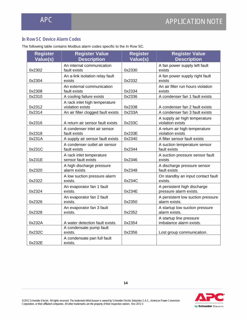
In Row SC Device Alarm Codes The following table contains Modbus alarm codes specific to the In Row SC.
Register Value(s)
Register Value Description
Register Value(s)
Register Value Description
0x2302 An internal communication fault exists 0x2330
A fan power supply left fault exists
0x2304 An a-link isolation relay fault exists 0x2332
A fan power supply right fault exists
0x2308 An external communication fault exists 0x2334
An air filter run hours violation exists
0x2310 A cooling failure exists 0x2336 A condenser fan 1 fault exists
0x2312 A rack inlet high temperature violation exists 0x2338 A condenser fan 2 fault exists
0x2314 An air filter clogged fault exists 0x233A A condenser fan 3 fault exists
0x2316 A return air sensor fault exists 0x233C A supply air high temperature violation exists
0x2318 A condenser inlet air sensor fault exists 0x233E
A return air high temperature violation exists
0x231A A supply air sensor fault exists 0x2340 A filter sensor fault exists
0x231C A condenser outlet air sensor fault exists 0x2344
A suction temperature sensor fault exists
0x231E A rack inlet temperature sensor fault exists 0x2346
A suction pressure sensor fault exists
0x2320 A high discharge pressure alarm exists 0x2348
A discharge pressure sensor fault exists
0x2322 A low suction pressure alarm exists. 0x234C
On standby an input contact fault exists.
0x2324 An evaporator fan 1 fault exists. 0x234E
A persistent high discharge pressure alarm exists.
0x2326 An evaporator fan 2 fault exists. 0x2350
A persistent low suction pressure alarm exists.
0x2328 An evaporator fan 3 fault exists. 0x2352
A startup low suction pressure alarm exists.
0x232A A water detection fault exists. 0x2354 A startup line pressure imbalance alarm exists.
0x232C A condensate pump fault exists. 0x2356 Lost group communication.
0x232E A condensate pan full fault exists.

APC APPLICATION NOTE
15 ___________________________________________________________________________________________________ © 2012 Schneider Electric. All rights reserved. The trademark InfraStruxure is owned by Schneider Electric Industries S.A.S., American Power Conversion Corporation, or their affiliated companies. All other trademarks are the property of their respective owners. Rev 2012-3
In Row RP Device Alarm Codes The following table contains Modbus alarm codes specific to the In Row RP.
Register Value(s)
Register Value Description
Register Value(s)
Register Value Description
0x2C02 An internal communication fault exists. 0x2C4A
A suction temperature sensor fault exists.
0x2C04 An A-link isolation relay fault exists. 0x2C4C
A suction pressure sensor fault exists.
0x2C08 An external communication fault exists. 0x2C4E
A discharge pressure sensor fault exists.
0x2C10 A cooling failure exists. 0x2C50 On standby an input contact fault exists.
0x2C12 A rack inlet high temperature violation exists. 0x2C52
A persistent high discharge pressure alarm exists.
0x2C14 An air filter clogged fault exists. 0x2C54
A persistent low suction pressure alarm exists.
0x2C16 An upper return air sensor fault exists. 0x2C5C
An outside heat exchanger fault exists.
0x2C1A A lower return air sensor fault exists. 0x2C60
A factory configuration not completed alarm exists.
0x2C1C An upper supply air sensor fault exists. 0x2C62
A liquid refrigerant sensor fault exists.
0x2C1E A middle supply air sensor fault exists. 0x2C64
An excessive compressor cycling alarm exists.
0x2C20 A lower supply air sensor fault exists. 0x2C66
A no backup units available alarm exists.
0x2C22 A rack inlet temperature sensor fault exists. 0x2C38 A condensate pump fault exists.
0x2C24 A condensor fluid actuator fault exists. 0x2C3A
A condensate pan full fault exists.
0x2C26 A high discharge pressure alarm exists. 0x2C3C
An upper fan power supply fault exists.
0x2C28 A low suction pressure alarm exists. 0x2C3E
A lower fan power supply fault exists.
0x2C2A An evaporator fan 1 fault exists. 0x2C40
An air filter run hours violation exists.
0x2C2C An evaporator fan 2 fault exists. 0x2C42 Lost group communication.
0x2C2E An evaporator fan 3 fault exists. 0x2C44
A supply air high temperature violation exists.
0x2C30 An evaporator fan 4 fault exists. 0x2C46
A return air high temperature violation exists.
0x2C32 An evaporator fan 5 fault exists. 0x2C48 A filter sensor fault exists.
0x2C34 An evaporator fan 6 fault 0x2C36 A water detection fault exists.
APC APPLICATION NOTE
16 ___________________________________________________________________________________________________ © 2012 Schneider Electric. All rights reserved. The trademark InfraStruxure is owned by Schneider Electric Industries S.A.S., American Power Conversion Corporation, or their affiliated companies. All other trademarks are the property of their respective owners. Rev 2012-3
Register Value(s)
Register Value Description
Register Value(s)
Register Value Description
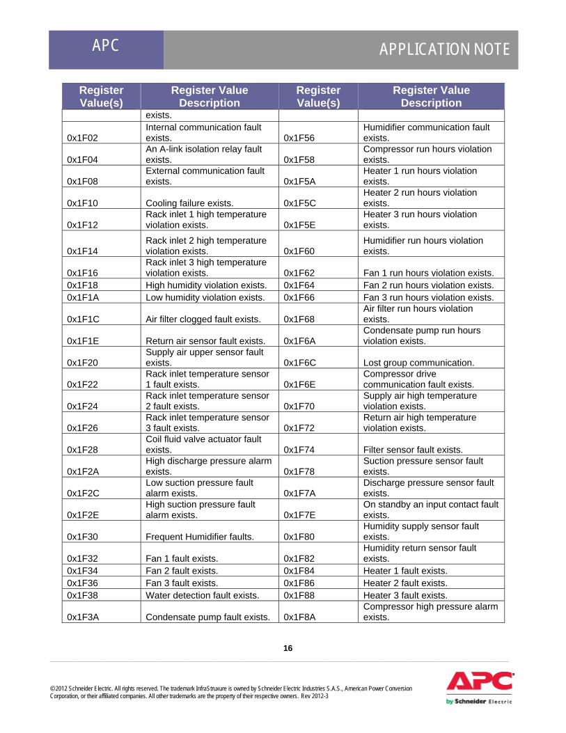
exists.
0x1F02 Internal communication fault exists. 0x1F56
Humidifier communication fault exists.
0x1F04 An A-link isolation relay fault exists. 0x1F58
Compressor run hours violation exists.
0x1F08 External communication fault exists. 0x1F5A
Heater 1 run hours violation exists.
0x1F10 Cooling failure exists. 0x1F5C Heater 2 run hours violation exists.
0x1F12 Rack inlet 1 high temperature violation exists. 0x1F5E
Heater 3 run hours violation exists.
0x1F14 Rack inlet 2 high temperature violation exists. 0x1F60
Humidifier run hours violation exists.
0x1F16 Rack inlet 3 high temperature violation exists. 0x1F62 Fan 1 run hours violation exists.
0x1F18 High humidity violation exists. 0x1F64 Fan 2 run hours violation exists. 0x1F1A Low humidity violation exists. 0x1F66 Fan 3 run hours violation exists.
0x1F1C Air filter clogged fault exists. 0x1F68 Air filter run hours violation exists.
0x1F1E Return air sensor fault exists. 0x1F6A Condensate pump run hours violation exists.
0x1F20 Supply air upper sensor fault exists. 0x1F6C Lost group communication.
0x1F22 Rack inlet temperature sensor 1 fault exists. 0x1F6E
Compressor drive communication fault exists.
0x1F24 Rack inlet temperature sensor 2 fault exists. 0x1F70
Supply air high temperature violation exists.
0x1F26 Rack inlet temperature sensor 3 fault exists. 0x1F72
Return air high temperature violation exists.
0x1F28 Coil fluid valve actuator fault exists. 0x1F74 Filter sensor fault exists.
0x1F2A High discharge pressure alarm exists. 0x1F78
Suction pressure sensor fault exists.
0x1F2C Low suction pressure fault alarm exists. 0x1F7A
Discharge pressure sensor fault exists.
0x1F2E High suction pressure fault alarm exists. 0x1F7E
On standby an input contact fault exists.
0x1F30 Frequent Humidifier faults. 0x1F80 Humidity supply sensor fault exists.
0x1F32 Fan 1 fault exists. 0x1F82 Humidity return sensor fault exists.
0x1F34 Fan 2 fault exists. 0x1F84 Heater 1 fault exists. 0x1F36 Fan 3 fault exists. 0x1F86 Heater 2 fault exists. 0x1F38 Water detection fault exists. 0x1F88 Heater 3 fault exists.
0x1F3A Condensate pump fault exists. 0x1F8A Compressor high pressure alarm exists.
APC APPLICATION NOTE
17 ___________________________________________________________________________________________________ © 2012 Schneider Electric. All rights reserved. The trademark InfraStruxure is owned by Schneider Electric Industries S.A.S., American Power Conversion Corporation, or their affiliated companies. All other trademarks are the property of their respective owners. Rev 2012-3
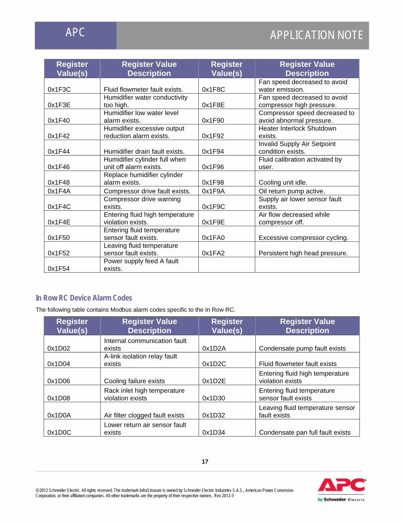
Register Value(s)
Register Value Description
Register Value(s)
Register Value Description
0x1F3C Fluid flowmeter fault exists. 0x1F8C Fan speed decreased to avoid water emission.
0x1F3E Humidifier water conductivity too high. 0x1F8E
Fan speed decreased to avoid compressor high pressure.
0x1F40 Humidifier low water level alarm exists. 0x1F90
Compressor speed decreased to avoid abnormal pressure.
0x1F42 Humidifier excessive output reduction alarm exists. 0x1F92
Heater Interlock Shutdown exists.
0x1F44 Humidifier drain fault exists. 0x1F94 Invalid Supply Air Setpoint condition exists.
0x1F46 Humidifier cylinder full when unit off alarm exists. 0x1F96
Fluid calibration activated by user.
0x1F48 Replace humidifier cylinder alarm exists. 0x1F98 Cooling unit idle.
0x1F4A Compressor drive fault exists. 0x1F9A Oil return pump active.
0x1F4C Compressor drive warning exists. 0x1F9C
Supply air lower sensor fault exists.
0x1F4E Entering fluid high temperature violation exists. 0x1F9E
Air flow decreased while compressor off.
0x1F50 Entering fluid temperature sensor fault exists. 0x1FA0 Excessive compressor cycling.
0x1F52 Leaving fluid temperature sensor fault exists. 0x1FA2 Persistent high head pressure.
0x1F54 Power supply feed A fault exists.
In Row RC Device Alarm Codes The following table contains Modbus alarm codes specific to the In Row RC.
Register Value(s)
Register Value Description
Register Value(s)
Register Value Description
0x1D02 Internal communication fault exists 0x1D2A Condensate pump fault exists
0x1D04 A-link isolation relay fault exists 0x1D2C Fluid flowmeter fault exists
0x1D06 Cooling failure exists 0x1D2E Entering fluid high temperature violation exists
0x1D08 Rack inlet high temperature violation exists 0x1D30
Entering fluid temperature sensor fault exists
0x1D0A Air filter clogged fault exists 0x1D32 Leaving fluid temperature sensor fault exists
0x1D0C Lower return air sensor fault exists 0x1D34 Condensate pan full fault exists

APC APPLICATION NOTE
18 ___________________________________________________________________________________________________ © 2012 Schneider Electric. All rights reserved. The trademark InfraStruxure is owned by Schneider Electric Industries S.A.S., American Power Conversion Corporation, or their affiliated companies. All other trademarks are the property of their respective owners. Rev 2012-3
Register Value(s)
Register Value Description
Register Value(s)
Register Value Description
0x1D0E Upper return air sensor fault exists 0x1D36 Power source A failure exists
0x1D10 Lower supply air sensor fault exists 0x1D38 Power source B failure exists
0x1D12 Upper supply air sensor fault exists 0x1D3A Fan power supply left fault exists
0x1D14 Rack inlet temperature sensor fault exists 0x1D3C
Fan power supply right fault exists
0x1D16 Coil fluid valve actuator fault exists 0x1D3E Air filter run hours violation exists
0x1D18 Fan 1 fault exists 0x1D42 On standby input contact fault exists
0x1D1A Fan 2 fault exists 0x1D44 Supply air high temperature violation exists
0x1D1C Fan 3 fault exists 0x1D46 Return air high temperature violation exists
0x1D1E Fan 4 fault exists 0x1D48 Group communication lost 0x1D20 Fan 5 fault exists 0x1D4A Filter sensor fault exists
0x1D22 Fan 6 fault exists 0x1D4E Fluid calibration activated by user.
0x1D24 Fan 7 fault exists 0x1D52 External communication fault exists
0x1D26 Fan 8 fault exists 0x1D28 Water detection fault exists
Air Removal Unit (ARU) Device Alarm Codes The following table contains Modbus alarm codes specific to the ARU.
Register Value(s)
Register Value Description
Register Value(s)
Register Value Description
0x1201 Internal communication fault exists. 0x1206
The overall operation of the fan has exceeded the runhour threshold
0x1202 Exhaust temperature cannot be maintained (critical). 0x1207 No redundant AC input present.
0x1203 Exhaust temperature violates the override setpoint. 0x1208
Controller firmware update timed out.
0x1204 Fan failure exists. 0x1209 Firmware upgrade of ARU controller has ended in a failure.
0x1205 Fan speed (rpm) fault detected. 0x120A
The data version of the ARU controller is incompatible with the data version of the Network Management Interface.

APC APPLICATION NOTE
19 ___________________________________________________________________________________________________ © 2012 Schneider Electric. All rights reserved. The trademark InfraStruxure is owned by Schneider Electric Industries S.A.S., American Power Conversion Corporation, or their affiliated companies. All other trademarks are the property of their respective owners. Rev 2012-3
Stultz Chiller Device Alarm Codes The following table contains Modbus alarm codes specific to Stultz Chillers.
Register Value(s)
Register Value Description
Register Value(s)
Register Value Description
0x3002 Lost Communication 0x3076 Sensor 14 is returning invalid values.
0x3004 No description available. 0x3078 Sensor 15 is returning invalid values.
0x3006 No description available. 0x307A Sensor 16 is returning invalid values.
0x3008 No description available. 0x307C Sensor 17 is returning invalid values.
0x300A A common alarm exists. 0x307E Sensor 18 is returning invalid values.
0x300C Unit requires maintenance. 0x3080 Sensor 19 is returning invalid values.
0x300E A/C Fan 1 has stopped spinning. 0x3082
Sensor 20 is returning invalid values.
0x3010 A/C Fan 2 has stopped spinning. 0x3084
Sensor 21 is returning invalid values.
0x3012 A/C Fan 3 has stopped spinning. 0x3086
Compressor 1 overload protection is active.
0x3014 A high pressure alarm exists in circuit 1. 0x3088
Compressor 2 overload protection is active.
0x3016 A high pressure alarm exists in circuit 2. 0x308A
A low pressure alarm exists in circuit 1.
0x3018 Water has been detected. 0x308C A low pressure alarm exists in circuit 2.
0x301A A phase failure has occurred. 0x308E Electrical re-heat stage 1 is overheated.
0x301C Fire/Smoke has been detected. 0x3090
Electrical re-heat stage 2 is overheated.
0x301E A return air high temperature violation exists. 0x3092
Electrical re-heat stage 3 is overheated.
0x3020 A return air high humidity violation exists. 0x3094
Electrical re-heat stage 4 is overheated.
0x3022 A supply air high temperature violation exists. 0x3096
An alarm condition exists in Dry Cooler 1.
0x3024 A supply air high humidity violation exists. 0x3098
An alarm condition exists in Dry Cooler 2.
0x3026 A water high temperature violation exists. 0x309A
An alarm condition exists in Dry Cooler 3.
0x3028 A return air low temperature violation exists. 0x309C
An alarm condition exists in Dry Cooler 4.
APC APPLICATION NOTE
20 ___________________________________________________________________________________________________ © 2012 Schneider Electric. All rights reserved. The trademark InfraStruxure is owned by Schneider Electric Industries S.A.S., American Power Conversion Corporation, or their affiliated companies. All other trademarks are the property of their respective owners. Rev 2012-3
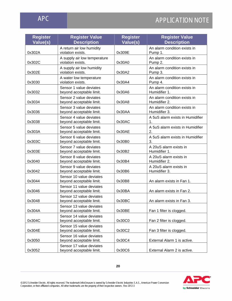
Register Value(s)
Register Value Description
Register Value(s)
Register Value Description
0x302A A return air low humidity violation exists. 0x309E
An alarm condition exists in Pump 1.
0x302C A supply air low temperature violation exists. 0x30A0
An alarm condition exists in Pump 2.
0x302E A supply air low humidity violation exists. 0x30A2
An alarm condition exists in Pump 3.
0x3030 A water low temperature violation exists. 0x30A4
An alarm condition exists in Pump 4.
0x3032 Sensor 1 value deviates beyond acceptable limit. 0x30A6
An alarm condition exists in Humidifier 1.
0x3034 Sensor 2 value deviates beyond acceptable limit. 0x30A8
An alarm condition exists in Humidifier 2.
0x3036 Sensor 3 value deviates beyond acceptable limit. 0x30AA
An alarm condition exists in Humidifier 3.
0x3038 Sensor 4 value deviates beyond acceptable limit. 0x30AC
A 5uS alarm exists in Humidifier 1.
0x303A Sensor 5 value deviates beyond acceptable limit. 0x30AE
A 5uS alarm exists in Humidifier 2.
0x303C Sensor 6 value deviates beyond acceptable limit. 0x30B0
A 5uS alarm exists in Humidifier 3.
0x303E Sensor 7 value deviates beyond acceptable limit. 0x30B2
A 20uS alarm exists in Humidifier 1.
0x3040 Sensor 8 value deviates beyond acceptable limit. 0x30B4
A 20uS alarm exists in Humidifier 2.
0x3042 Sensor 9 value deviates beyond acceptable limit. 0x30B6
A 20uS alarm exists in Humidifier 3.
0x3044 Sensor 10 value deviates beyond acceptable limit. 0x30B8 An alarm exists in Fan 1.
0x3046 Sensor 11 value deviates beyond acceptable limit. 0x30BA An alarm exists in Fan 2.
0x3048 Sensor 12 value deviates beyond acceptable limit. 0x30BC An alarm exists in Fan 3.
0x304A Sensor 13 value deviates beyond acceptable limit. 0x30BE Fan 1 filter is clogged.
0x304C Sensor 14 value deviates beyond acceptable limit. 0x30C0 Fan 2 filter is clogged.
0x304E Sensor 15 value deviates beyond acceptable limit. 0x30C2 Fan 3 filter is clogged.
0x3050 Sensor 16 value deviates beyond acceptable limit. 0x30C4 External Alarm 1 is active.
0x3052 Sensor 17 value deviates beyond acceptable limit. 0x30C6 External Alarm 2 is active.

APC APPLICATION NOTE
21 ___________________________________________________________________________________________________ © 2012 Schneider Electric. All rights reserved. The trademark InfraStruxure is owned by Schneider Electric Industries S.A.S., American Power Conversion Corporation, or their affiliated companies. All other trademarks are the property of their respective owners. Rev 2012-3
Register Value(s)
Register Value Description
Register Value(s)
Register Value Description
0x3054 Sensor 18 value deviates beyond acceptable limit. 0x30C8 External Alarm 3 is active.
0x3056 Sensor 19 value deviates beyond acceptable limit. 0x30CA External Alarm 4 is active.
0x3058 Sensor 20 value deviates beyond acceptable limit. 0x30CC External Alarm 5 is active.
0x305A Sensor 21 value deviates beyond acceptable limit. 0x30CE External Alarm 6 is active.
0x305C Sensor 1 is returning invalid values. 0x30D0 External Alarm 7 is active.
0x305E Sensor 2 is returning invalid values. 0x30D2 External Alarm 8 is active.
0x3060 Sensor 3 is returning invalid values. 0x30D4 External Alarm 9 is active.
0x3062 Sensor 4 is returning invalid values. 0x30D6 External Alarm 10 is active.
0x3064 Sensor 5 is returning invalid values. 0x30D8 A Hot Gas Re-Heat alarm exists.
0x3066 Sensor 6 is returning invalid values. 0x30DA
A circuit 1 electronic expansion valve pressure sensor error condition exists.
0x3068 Sensor 7 is returning invalid values. 0x30DC
A circuit 1 electronic expansion valve temperature sensor error condition exists.
0x306A Sensor 8 is returning invalid values. 0x30DE
A circuit 1 electronic expansion valve stepper motor error condition exists.
0x306C Sensor 9 is returning invalid values. 0x30E0
A circuit 2 electronic expansion valve pressure sensor error condition exists.
0x306E Sensor 10 is returning invalid values. 0x30E2
A circuit 2 electronic expansion valve temperature sensor error condition exists.
0x3070 Sensor 11 is returning invalid values. 0x30E4
A circuit 2 electronic expansion valve stepper motor error condition exists.
0x3072 Sensor 12 is returning invalid values. 0x30E6 A freeze alarm is active.
0x3074 Sensor 13 is returning invalid values. 0x30E8 A dehumidifier alarm is active.

APC APPLICATION NOTE
22 ___________________________________________________________________________________________________ © 2012 Schneider Electric. All rights reserved. The trademark InfraStruxure is owned by Schneider Electric Industries S.A.S., American Power Conversion Corporation, or their affiliated companies. All other trademarks are the property of their respective owners. Rev 2012-3
Power Generation Automatic Transfer Switch (ATS) Device Alarm Codes The following table contains Modbus alarm codes specific to the ATS.
Register Value(s) Register Value Description
Register Value(s)
Register Value Description
0x1714 The output voltage on phase has fallen below the low voltage threshold. 0x17D3
The generator failed to stop. After de-assertion of the Engine Start signal the quality of Source 2 continued to be seen as good.
0x1716 The output voltage on phase has risen above the high voltage threshold. 0x17C7
InfraStruxure ATS is not in automatic mode.
0x1724 The output current on phase has fallen below the low current threshold. 0x17C2
The device's Emergency Power Off (EPO) circuit is tripped.
0x1726 The output current on phase has risen above the high current threshold. 0x17C1
The device's Emergency Power Off (EPO) circuit has been switched back to the test position.
0x1760 The ATS output frequency is outside the range. 0x174E The initiated test has failed.
0x17C4 There is an internal communication error in the device. 0x1780
User input contact on the device is in an abnormal state.
0x17C6
A data incompatibility exists within the device. This is typically the result of mismatches between firmware revisions of the transfer switch controller and the Network Management interface. 0x1781
User input contact on the device is in an abnormal state.
0x17D1 The ATS cannot communicate with the generator. 0x1782
User input contact on the device is in an abnormal state.
0x17D7 The ATS could not read these registers from the generator 0x1783
User input contact on the device is in an abnormal state.
0x1704
The ATS has transferred to neutral position. In this position neither Source 1 nor Source 2 is selected and the ATS will have no output voltage. The ATS is now running in mode. 0x17D4
The state of the generator's Remote Start input and the ATS's Engine Start output do not match. This indicates something wrong in the Engine Start wiring which must be corrected. This condition may prevent the generator from being started when needed.
APC APPLICATION NOTE
23 ___________________________________________________________________________________________________ © 2012 Schneider Electric. All rights reserved. The trademark InfraStruxure is owned by Schneider Electric Industries S.A.S., American Power Conversion Corporation, or their affiliated companies. All other trademarks are the property of their respective owners. Rev 2012-3
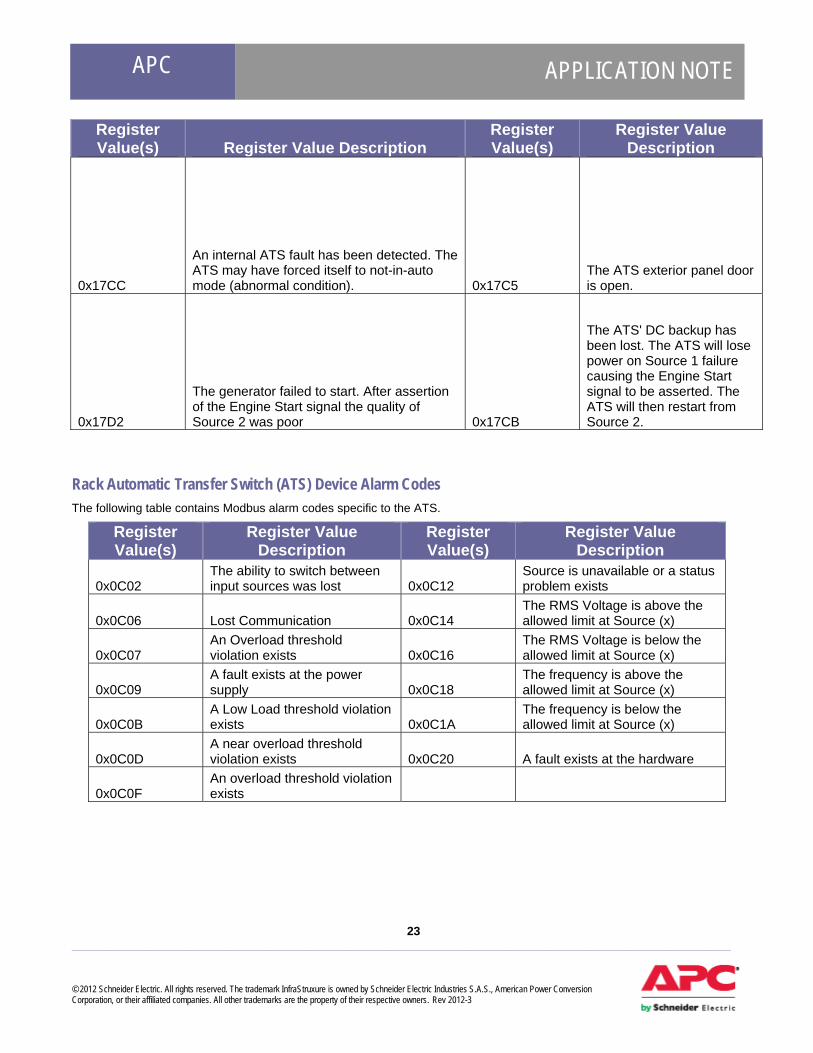
Register Value(s) Register Value Description
Register Value(s)
Register Value Description
0x17CC
An internal ATS fault has been detected. The ATS may have forced itself to not-in-auto mode (abnormal condition). 0x17C5
The ATS exterior panel door is open.
0x17D2
The generator failed to start. After assertion of the Engine Start signal the quality of Source 2 was poor 0x17CB
The ATS' DC backup has been lost. The ATS will lose power on Source 1 failure causing the Engine Start signal to be asserted. The ATS will then restart from Source 2.
Rack Automatic Transfer Switch (ATS) Device Alarm Codes The following table contains Modbus alarm codes specific to the ATS.
Register Value(s)
Register Value Description
Register Value(s)
Register Value Description
0x0C02 The ability to switch between input sources was lost 0x0C12
Source is unavailable or a status problem exists
0x0C06 Lost Communication 0x0C14 The RMS Voltage is above the allowed limit at Source (x)
0x0C07 An Overload threshold violation exists 0x0C16
The RMS Voltage is below the allowed limit at Source (x)
0x0C09 A fault exists at the power supply 0x0C18
The frequency is above the allowed limit at Source (x)
0x0C0B A Low Load threshold violation exists 0x0C1A
The frequency is below the allowed limit at Source (x)
0x0C0D A near overload threshold violation exists 0x0C20 A fault exists at the hardware
0x0C0F An overload threshold violation exists
APC APPLICATION NOTE
24 ___________________________________________________________________________________________________ © 2012 Schneider Electric. All rights reserved. The trademark InfraStruxure is owned by Schneider Electric Industries S.A.S., American Power Conversion Corporation, or their affiliated companies. All other trademarks are the property of their respective owners. Rev 2012-3
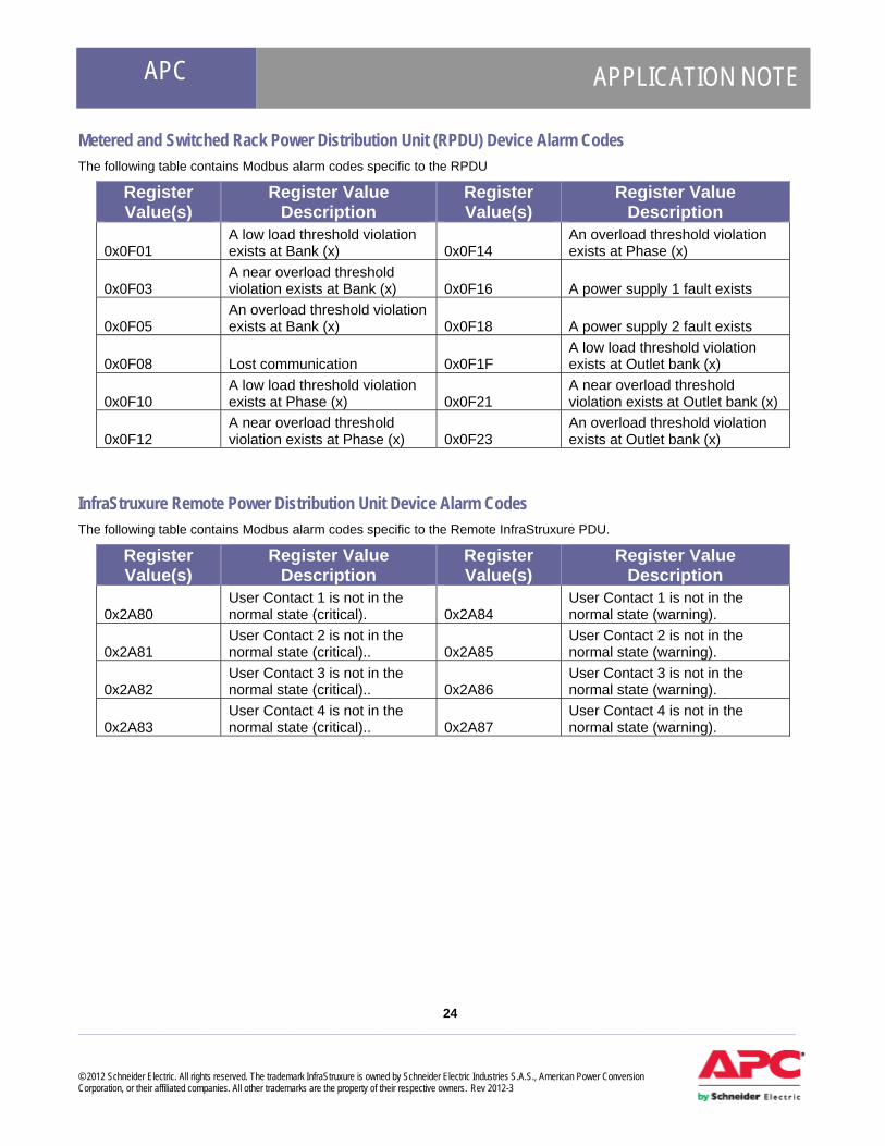
Metered and Switched Rack Power Distribution Unit (RPDU) Device Alarm Codes The following table contains Modbus alarm codes specific to the RPDU
Register Value(s)
Register Value Description
Register Value(s)
Register Value Description
0x0F01 A low load threshold violation exists at Bank (x) 0x0F14
An overload threshold violation exists at Phase (x)
0x0F03 A near overload threshold violation exists at Bank (x) 0x0F16 A power supply 1 fault exists
0x0F05 An overload threshold violation exists at Bank (x) 0x0F18 A power supply 2 fault exists
0x0F08 Lost communication 0x0F1F A low load threshold violation exists at Outlet bank (x)
0x0F10 A low load threshold violation exists at Phase (x) 0x0F21
A near overload threshold violation exists at Outlet bank (x)
0x0F12 A near overload threshold violation exists at Phase (x) 0x0F23
An overload threshold violation exists at Outlet bank (x)
InfraStruxure Remote Power Distribution Unit Device Alarm Codes The following table contains Modbus alarm codes specific to the Remote InfraStruxure PDU.
Register Value(s)
Register Value Description
Register Value(s)
Register Value Description
0x2A80 User Contact 1 is not in the normal state (critical). 0x2A84
User Contact 1 is not in the normal state (warning).
0x2A81 User Contact 2 is not in the normal state (critical).. 0x2A85
User Contact 2 is not in the normal state (warning).
0x2A82 User Contact 3 is not in the normal state (critical).. 0x2A86
User Contact 3 is not in the normal state (warning).
0x2A83 User Contact 4 is not in the normal state (critical).. 0x2A87
User Contact 4 is not in the normal state (warning).
APC APPLICATION NOTE
25 ___________________________________________________________________________________________________ © 2012 Schneider Electric. All rights reserved. The trademark InfraStruxure is owned by Schneider Electric Industries S.A.S., American Power Conversion Corporation, or their affiliated companies. All other trademarks are the property of their respective owners. Rev 2012-3
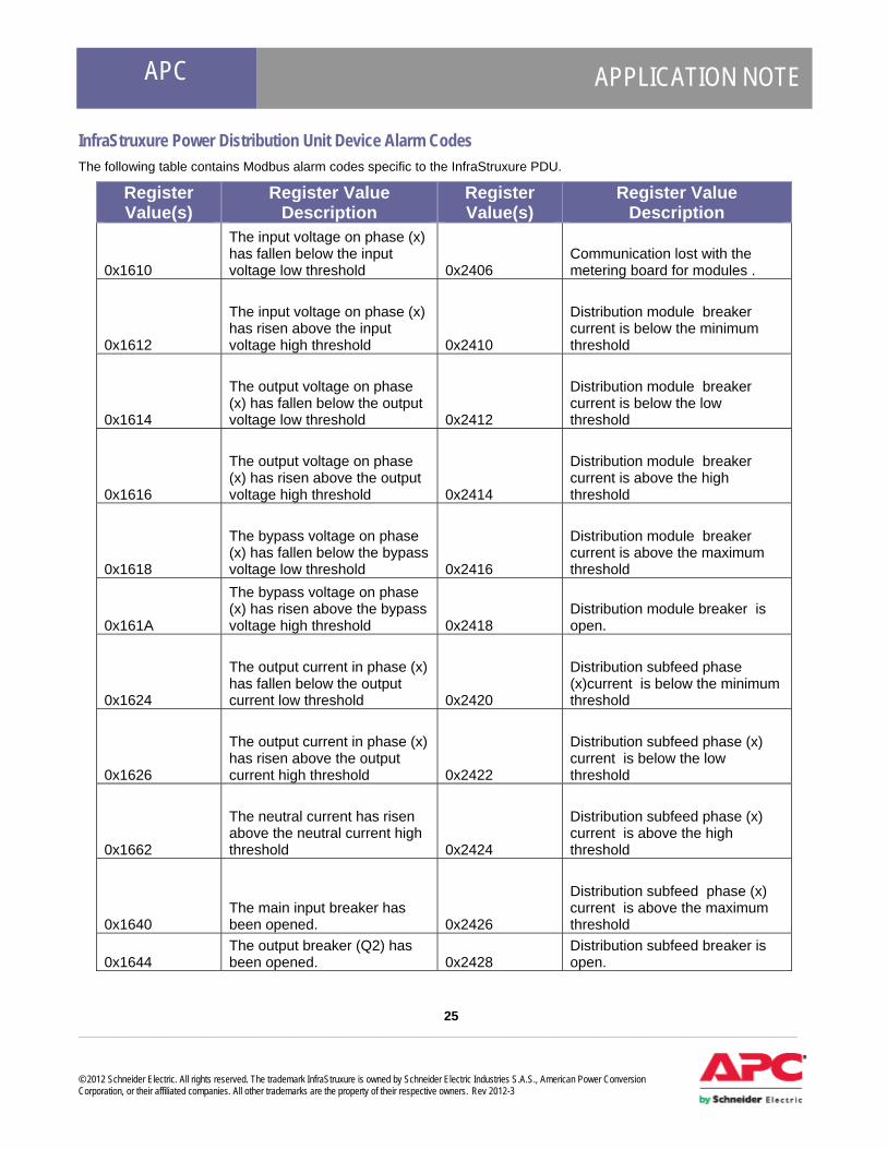
InfraStruxure Power Distribution Unit Device Alarm Codes The following table contains Modbus alarm codes specific to the InfraStruxure PDU.
Register Value(s)
Register Value Description
Register Value(s)
Register Value Description
0x1610
The input voltage on phase (x) has fallen below the input voltage low threshold 0x2406
Communication lost with the metering board for modules .
0x1612
The input voltage on phase (x) has risen above the input voltage high threshold 0x2410
Distribution module breaker current is below the minimum threshold
0x1614
The output voltage on phase (x) has fallen below the output voltage low threshold 0x2412
Distribution module breaker current is below the low threshold
0x1616
The output voltage on phase (x) has risen above the output voltage high threshold 0x2414
Distribution module breaker current is above the high threshold
0x1618
The bypass voltage on phase (x) has fallen below the bypass voltage low threshold 0x2416
Distribution module breaker current is above the maximum threshold
0x161A
The bypass voltage on phase (x) has risen above the bypass voltage high threshold 0x2418
Distribution module breaker is open.
0x1624
The output current in phase (x) has fallen below the output current low threshold 0x2420
Distribution subfeed phase (x)current is below the minimum threshold
0x1626
The output current in phase (x) has risen above the output current high threshold 0x2422
Distribution subfeed phase (x) current is below the low threshold
0x1662
The neutral current has risen above the neutral current high threshold 0x2424
Distribution subfeed phase (x) current is above the high threshold
0x1640 The main input breaker has been opened. 0x2426
Distribution subfeed phase (x) current is above the maximum threshold
0x1644 The output breaker (Q2) has been opened. 0x2428
Distribution subfeed breaker is open.
APC APPLICATION NOTE
26 ___________________________________________________________________________________________________ © 2012 Schneider Electric. All rights reserved. The trademark InfraStruxure is owned by Schneider Electric Industries S.A.S., American Power Conversion Corporation, or their affiliated companies. All other trademarks are the property of their respective owners. Rev 2012-3
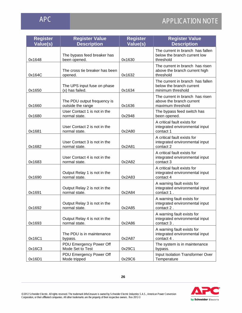
Register Value(s)
Register Value Description
Register Value(s)
Register Value Description
0x1648 The bypass feed breaker has been opened. 0x1630
The current in branch has fallen below the branch current low threshold
0x164C The cross tie breaker has been opened. 0x1632
The current in branch has risen above the branch current high threshold
0x1650 The UPS input fuse on phase (x) has failed. 0x1634
The current in branch has fallen below the branch current minimum threshold
0x1660 The PDU output frequency is outside the range 0x1636
The current in branch has risen above the branch current maximum threshold
0x1680 User Contact 1 is not in the normal state. 0x2948
The bypass feed switch has been opened.
0x1681 User Contact 2 is not in the normal state. 0x2A80
A critical fault exists for integrated environmental input contact 1
0x1682 User Contact 3 is not in the normal state. 0x2A81
A critical fault exists for integrated environmental input contact 2
0x1683 User Contact 4 is not in the normal state. 0x2A82
A critical fault exists for integrated environmental input contact 3
0x1690 Output Relay 1 is not in the normal state. 0x2A83
A critical fault exists for integrated environmental input contact 4
0x1691 Output Relay 2 is not in the normal state. 0x2A84
A warning fault exists for integrated environmental input contact 1 .
0x1692 Output Relay 3 is not in the normal state. 0x2A85
A warning fault exists for integrated environmental input contact 2 .
0x1693 Output Relay 4 is not in the normal state. 0x2A86
A warning fault exists for integrated environmental input contact 3 .
0x16C1 The PDU is in maintenance bypass. 0x2A87
A warning fault exists for integrated environmental input contact 4 .
0x16C3 PDU Emergency Power Off Mode Set to Test 0x29C1
The system is in maintenance bypass.
0x16D1 PDU Emergency Power Off Mode tripped 0x29C6
Input Isolation Transformer Over Temperature

APC APPLICATION NOTE
27 ___________________________________________________________________________________________________ © 2012 Schneider Electric. All rights reserved. The trademark InfraStruxure is owned by Schneider Electric Industries S.A.S., American Power Conversion Corporation, or their affiliated companies. All other trademarks are the property of their respective owners. Rev 2012-3
Register Value(s)
Register Value Description
Register Value(s)
Register Value Description
0x16C4 PDU Internal Communication Failure 0x29C8 Transformer Cooling Fan Failure
0x16CC
The data version of the PDU controller is incompatible with the data version of the Network Management Interface. 0x29CA System Mode Alarm
0x16C6
PDU Input Isolation Transformer Over Temperature 0x16CA PDU System Mode Alarm
0x16C8 PDU Cooling Fan Failure
Silcon UPS Device Alarm Codes The following table contains Modbus alarm codes specific to the Silcon UPS.
Register Value(s)
Register Value Description
Register Value(s)
Register Value Description
0x0102 Lost communication. 0x3A1F A weak battery exists.
0x0103 The load exceeds 100% of rated capacity. 0x3A23
The system is locked in operational mode.
0x0107
The battery power is too low to support the load; if power fails the UPS will be shut down immediately. 0x3A25
A RAM1 memory write fault exists.
0x0109 On battery power in response to an input power problem. 0x3A27 A memory write fault exists.
0x010F
The battery power is too low to continue to support the load; the UPS will shut down if input power does not return to normal soon. 0x3A29
Lost communication with the VQ bypass.
0x0114 The output power is turned off. 0x3A2B Lost communication with the VQ output.
0x011B In bypass in response to an internal hardware fault. 0x3A2D
Lost communication with the DMU.
0x011D
In bypass in response to the bypass switch at the UPS typically for maintenance. 0x3A2F
Lost communication with the controller.
0x0125
A graceful shutdown process is being used to shut down the load equipment before the UPS turns off. 0x3A31
Lost communication with the parallel interface (IF).

APC APPLICATION NOTE
28 ___________________________________________________________________________________________________ © 2012 Schneider Electric. All rights reserved. The trademark InfraStruxure is owned by Schneider Electric Industries S.A.S., American Power Conversion Corporation, or their affiliated companies. All other trademarks are the property of their respective owners. Rev 2012-3
Register Value(s)
Register Value Description
Register Value(s)
Register Value Description
0x012C
The internal battery temperature exceeds the critical threshold. 0x3A33
An external shutdown was accepted.
0x0148 Lost communication while the UPS was on battery. 0x3A35
A direct current (DC) capacitor charge fault exists.
0x0207 A battery fault exists. 0x3A37 Lost communication with the VQ Mains.
0x020F
An input voltage or frequency problem prevents switching to bypass mode. 0x3A39
A bypass synchronization fault exists.
0x0217 In bypass in response to an overload. 0x3A3B A charge fault exists.
0x022B The output voltage is outside its defined limits. 0x3A3D
The SII auxiliary input is activated.
0x022D A phase synchronization fault exists. 0x3A41 A blown inverter fuse exists.
0x022F The battery is not installed properly. 0x3A43 A blown rectifier fuse exists.
0x0231
The battery voltage exceeds the nominal battery voltage rating. 0x3A45 An auxiliary 1 fault exists.
0x3A01 The peak current limiter is active. 0x3A5B
A high temperature charger magnetic fault exists.
0x3A03 A bypass power supply fault exists. 0x3A5F A battery monitor warning exists.
0x3A05 The delta current limiter is active. 0x3A61 A battery monitor alarm exists.
0x3A07 A fan fault exists. 0x3A69 A TSM 1/2/3 temperature shutdown exists.
0x3A09 A high direct current (DC) warning exists. 0x3A6B
A charger 0/30 temperature warning exists.
0x3A0B An inverter voltage fault exists. 0x3A6D A charger 0/30 temperature shutdown exists.
0x3A0D A parallel synchronization fault exists. 0x3A6F A high output voltage exists.
0x3A0F A second power supply fault exists. 0x3A71
An SSW temperature over 90 fault exists.
0x3A11 An internal power supply fault exists. 0x3A75
A low current fault exists for the AC capacitors.
0x3A1B A static bypass switch high temperature exists. 0x3A79
The advanced battery management is not installed.

APC APPLICATION NOTE
29 ___________________________________________________________________________________________________ © 2012 Schneider Electric. All rights reserved. The trademark InfraStruxure is owned by Schneider Electric Industries S.A.S., American Power Conversion Corporation, or their affiliated companies. All other trademarks are the property of their respective owners. Rev 2012-3
Register Value(s)
Register Value Description
Register Value(s)
Register Value Description
0x3A1D The battery temperature exceeds the critical threshold.
Symmetra Three Phase UPS Device Alarm Codes The following table contains Modbus alarm codes specific to the Symmetra Three Phase UPS.
Register Value(s)
Register Value Description
Register Value(s)
Register Value Description
0x0102 Lost Communication. 0x0223 No power modules detected as installed.
0x0103 The load exceeds 100% of rated capacity. 0x0225
An input voltage or frequency problem occurred while on bypass turning off the UPS.
0x0106
The UPS failed its diagnostic self-test due to either an overload or poor battery health. 0x0227
A runtime alarm threshold violation exists.
0x0107
The battery power is too low to support the load; if power fails the UPS will be shut down immediately. 0x0229
An extended run frame fault exists.
0x0109 On battery power in response to an input power problem. 0x022B
The output voltage is not within its defined limits.
0x010F
The battery power is too low to continue to support the load; the UPS will shut down if input power does not return to normal soon. 0x022D
A phase synchronization fault exists.
0x0114 The output power is turned off. 0x022F No batteries detected as installed.
0x0115
Turned off for a defined period of time in response to a software command or off while waiting for input power to return to normal. 0x0231
The battery voltage exceeds the Nominal Battery Voltage rating.
0x0119 At least one faulty battery exists. 0x0235 A site wiring fault exists.
0x011C
In bypass in response to the UPS front-panel or a user-initiated software command typically for maintenance. 0x0237 The backfeed relay is open.

APC APPLICATION NOTE
30 ___________________________________________________________________________________________________ © 2012 Schneider Electric. All rights reserved. The trademark InfraStruxure is owned by Schneider Electric Industries S.A.S., American Power Conversion Corporation, or their affiliated companies. All other trademarks are the property of their respective owners. Rev 2012-3
Register Value(s)
Register Value Description
Register Value(s)
Register Value Description
0x0125
A graceful shutdown process is being used to shut down the load equipment before the UPS turns off. 0x2601
A maintenance bypass fault exists.
0x012A A battery charger fault exists. 0x2603 A high isolation transformer temperature exists.
0x012C
The internal battery temperature exceeds the critical threshold. 0x2605
The external DC disconnect switch is open.
0x0148 Lost communication while the UPS was on battery. 0x2607
A system power supply card fault exists.
0x0201 A power module fault exists. 0x2609 A battery monitor card fault exists.
0x0203 A main intelligence module fault exists. 0x260B
The battery monitor card was removed.
0x0205 A redundant intelligence module fault exists. 0x260D
An XR communication card fault exists.
0x0207 A battery fault exists. 0x260F
The external run frame (XR) communication card was removed.
0x0209 A load (kVA) alarm threshold violation exists. 0x2611
An external switch gear communication card fault exists.
0x020B Lost power module redundancy. 0x2613
The external switch gear communication card was removed.
0x020D A redundancy alarm threshold violation exists. 0x2615
The internal DC disconnect switch is open.
0x020F
An input voltage or frequency problem prevents switching to bypass mode. 0x2617
A static bypass switch module fault exists.
0x0211 The bypass relay is stuck in its bypass position. 0x2619
The system ID card was removed.
0x0213 The bypass relay is stuck in its online position. 0x261B
A system identification card fault exists.
0x0215 In bypass in response to an internal hardware fault. 0x261D
In bypass in response to switchgear or UPS static switch.
0x0217 In bypass in response to an overload. 0x261F
The static bypass switch module was removed.
0x0219 In bypass for maintenance. 0x2621 A system start-up configuration fault exists.
0x021B The input circuit breaker is open. 0x2623
The battery charger is shutdown externally.
APC APPLICATION NOTE
31 ___________________________________________________________________________________________________ © 2012 Schneider Electric. All rights reserved. The trademark InfraStruxure is owned by Schneider Electric Industries S.A.S., American Power Conversion Corporation, or their affiliated companies. All other trademarks are the property of their respective owners. Rev 2012-3
Register Value(s)
Register Value Description
Register Value(s)
Register Value Description
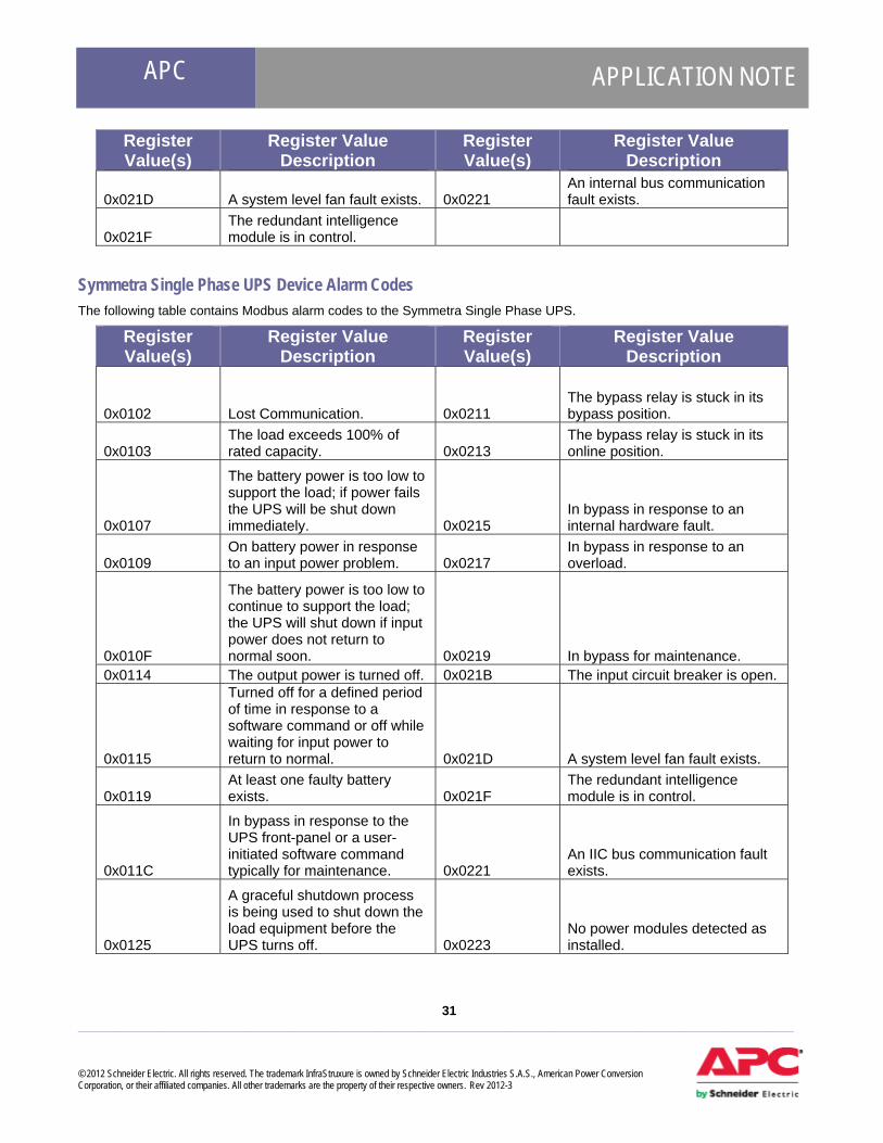
0x021D A system level fan fault exists. 0x0221 An internal bus communication fault exists.
0x021F The redundant intelligence module is in control.
Symmetra Single Phase UPS Device Alarm Codes The following table contains Modbus alarm codes to the Symmetra Single Phase UPS.
Register Value(s)
Register Value Description
Register Value(s)
Register Value Description
0x0102 Lost Communication. 0x0211 The bypass relay is stuck in its bypass position.
0x0103 The load exceeds 100% of rated capacity. 0x0213
The bypass relay is stuck in its online position.
0x0107
The battery power is too low to support the load; if power fails the UPS will be shut down immediately. 0x0215
In bypass in response to an internal hardware fault.
0x0109 On battery power in response to an input power problem. 0x0217
In bypass in response to an overload.
0x010F
The battery power is too low to continue to support the load; the UPS will shut down if input power does not return to normal soon. 0x0219 In bypass for maintenance.
0x0114 The output power is turned off. 0x021B The input circuit breaker is open.
0x0115
Turned off for a defined period of time in response to a software command or off while waiting for input power to return to normal. 0x021D A system level fan fault exists.
0x0119 At least one faulty battery exists. 0x021F
The redundant intelligence module is in control.
0x011C
In bypass in response to the UPS front-panel or a user-initiated software command typically for maintenance. 0x0221
An IIC bus communication fault exists.
0x0125
A graceful shutdown process is being used to shut down the load equipment before the UPS turns off. 0x0223
No power modules detected as installed.
APC APPLICATION NOTE
32 ___________________________________________________________________________________________________ © 2012 Schneider Electric. All rights reserved. The trademark InfraStruxure is owned by Schneider Electric Industries S.A.S., American Power Conversion Corporation, or their affiliated companies. All other trademarks are the property of their respective owners. Rev 2012-3
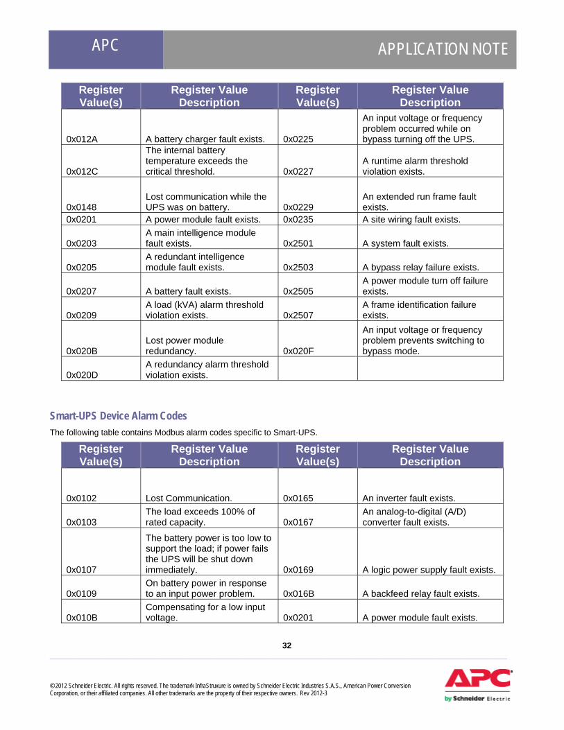
Register Value(s)
Register Value Description
Register Value(s)
Register Value Description
0x012A A battery charger fault exists. 0x0225
An input voltage or frequency problem occurred while on bypass turning off the UPS.
0x012C
The internal battery temperature exceeds the critical threshold. 0x0227
A runtime alarm threshold violation exists.
0x0148 Lost communication while the UPS was on battery. 0x0229
An extended run frame fault exists.
0x0201 A power module fault exists. 0x0235 A site wiring fault exists.
0x0203 A main intelligence module fault exists. 0x2501 A system fault exists.
0x0205 A redundant intelligence module fault exists. 0x2503 A bypass relay failure exists.
0x0207 A battery fault exists. 0x2505 A power module turn off failure exists.
0x0209 A load (kVA) alarm threshold violation exists. 0x2507
A frame identification failure exists.
0x020B Lost power module redundancy. 0x020F
An input voltage or frequency problem prevents switching to bypass mode.
0x020D A redundancy alarm threshold violation exists.
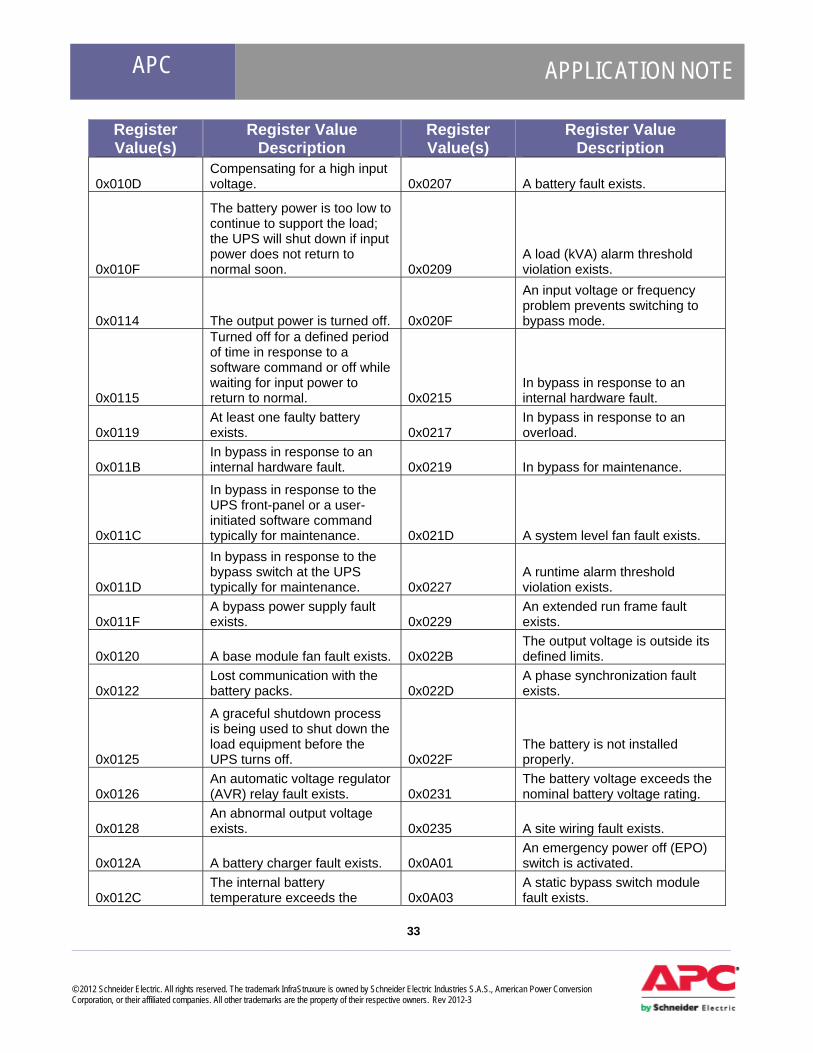
Smart-UPS Device Alarm Codes The following table contains Modbus alarm codes specific to Smart-UPS.
Register Value(s)
Register Value Description
Register Value(s)
Register Value Description
0x0102 Lost Communication. 0x0165 An inverter fault exists.
0x0103 The load exceeds 100% of rated capacity. 0x0167
An analog-to-digital (A/D) converter fault exists.
0x0107
The battery power is too low to support the load; if power fails the UPS will be shut down immediately. 0x0169 A logic power supply fault exists.
0x0109 On battery power in response to an input power problem. 0x016B A backfeed relay fault exists.
0x010B Compensating for a low input voltage. 0x0201 A power module fault exists.
APC APPLICATION NOTE
33 ___________________________________________________________________________________________________ © 2012 Schneider Electric. All rights reserved. The trademark InfraStruxure is owned by Schneider Electric Industries S.A.S., American Power Conversion Corporation, or their affiliated companies. All other trademarks are the property of their respective owners. Rev 2012-3
Register Value(s)
Register Value Description
Register Value(s)
Register Value Description
0x010D Compensating for a high input voltage. 0x0207 A battery fault exists.
0x010F
The battery power is too low to continue to support the load; the UPS will shut down if input power does not return to normal soon. 0x0209
A load (kVA) alarm threshold violation exists.
0x0114 The output power is turned off. 0x020F
An input voltage or frequency problem prevents switching to bypass mode.
0x0115
Turned off for a defined period of time in response to a software command or off while waiting for input power to return to normal. 0x0215
In bypass in response to an internal hardware fault.
0x0119 At least one faulty battery exists. 0x0217
In bypass in response to an overload.
0x011B In bypass in response to an internal hardware fault. 0x0219 In bypass for maintenance.
0x011C
In bypass in response to the UPS front-panel or a user-initiated software command typically for maintenance. 0x021D A system level fan fault exists.
0x011D
In bypass in response to the bypass switch at the UPS typically for maintenance. 0x0227
A runtime alarm threshold violation exists.
0x011F A bypass power supply fault exists. 0x0229
An extended run frame fault exists.
0x0120 A base module fan fault exists. 0x022B The output voltage is outside its defined limits.
0x0122 Lost communication with the battery packs. 0x022D
A phase synchronization fault exists.
0x0125
A graceful shutdown process is being used to shut down the load equipment before the UPS turns off. 0x022F
The battery is not installed properly.
0x0126 An automatic voltage regulator (AVR) relay fault exists. 0x0231
The battery voltage exceeds the nominal battery voltage rating.
0x0128 An abnormal output voltage exists. 0x0235 A site wiring fault exists.
0x012A A battery charger fault exists. 0x0A01 An emergency power off (EPO) switch is activated.
0x012C The internal battery temperature exceeds the 0x0A03
A static bypass switch module fault exists.

APC APPLICATION NOTE
34 ___________________________________________________________________________________________________ © 2012 Schneider Electric. All rights reserved. The trademark InfraStruxure is owned by Schneider Electric Industries S.A.S., American Power Conversion Corporation, or their affiliated companies. All other trademarks are the property of their respective owners. Rev 2012-3
Register Value(s)
Register Value Description
Register Value(s)
Register Value Description
critical threshold.
0x012F The battery is not installed properly. 0x0A05
A system start up configuration fault exists.
0x0138 An inverter DC imbalance exists. 0x0A07
A power supply unit (PSU) fault exists.
0x013B An electronics unit fan fault exists. 0x0A09 A weak battery exists.
0x013E A main relay fault exists. 0x0A0B A high battery temperature exists.
0x0140 A bypass relay fault exists. 0x0A0D An internal mechanical bypass exists.
0x0148 Lost communication while the UPS was on battery. 0x0A0F Lost parallel redundancy.
0x0150 A power factor correction input relay fault exists. 0x0A11
A parallel bus communication fault exists on cable 1.
0x0152 The internal UPS temperature exceeds the critical threshold. 0x0A13
A parallel bus communication fault exists on cable 2.
0x0154
The battery voltage exceeds the nominal battery voltage rating. 0x0A15
An auxiliary bus communication fault exists.
0x0156 An EEPROM fault exists. 0x0A17 A parallel bus termination fault exists on cable 1.
0x0159 A fault exists at the battery temperature sensor. 0x0A19
A parallel bus termination fault exists on cable 2.
0x015B A battery bus soft start fault exists. 0x0A1B
An auxiliary bus termination fault exists.
0x015D The output has a short-circuit. 0x0A1D A no master present fault exists in the parallel system.
0x015F An output relay fault exists. 0x0A1F An overload exists on a parallel unit.
0x0161 A power factor correction fault exists. 0x0A21
A parallel configuration fault exists.
0x0163 A DC bus overvoltage exists.
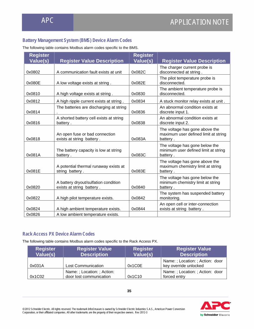
APC APPLICATION NOTE
35 ___________________________________________________________________________________________________ © 2012 Schneider Electric. All rights reserved. The trademark InfraStruxure is owned by Schneider Electric Industries S.A.S., American Power Conversion Corporation, or their affiliated companies. All other trademarks are the property of their respective owners. Rev 2012-3
Battery Management System (BMS) Device Alarm Codes The following table contains Modbus alarm codes specific to the BMS.
Register Value(s) Register Value Description
Register Value(s) Register Value Description
0x0802 A communication fault exists at unit 0x082C The charger current probe is disconnected at string .
0x080E A low voltage exists at string . 0x082E The pilot temperature probe is disconnected.
0x0810 A high voltage exists at string . 0x0830 The ambient temperature probe is disconnected.
0x0812 A high ripple current exists at string . 0x0834 A stuck monitor relay exists at unit .
0x0814 The batteries are discharging at string . 0x0836
An abnormal condition exists at discrete input 1.
0x0816 A shorted battery cell exists at string battery . 0x0838
An abnormal condition exists at discrete input 2.
0x0818 An open fuse or bad connection exists at string battery . 0x083A
The voltage has gone above the maximum user defined limit at string battery .
0x081A The battery capacity is low at string battery . 0x083C
The voltage has gone below the minimum user defined limit at string battery .
0x081E A potential thermal runaway exists at string battery . 0x083E
The voltage has gone above the maximum chemistry limit at string battery .
0x0820 A battery dryout/sulfation condition exists at string battery . 0x0840
The voltage has gone below the minimum chemistry limit at string battery .
0x0822 A high pilot temperature exists. 0x0842 The system has suspended battery monitoring.
0x0824 A high ambient temperature exists. 0x0844 An open cell or inter-connection exists at string battery .
0x0826 A low ambient temperature exists. Rack Access PX Device Alarm Codes The following table contains Modbus alarm codes specific to the Rack Access PX.
Register Value(s)
Register Value Description
Register Value(s)
Register Value Description
0x031A Lost Communication 0x1C0E Name: ; Location: ; Action: door key override unlocked
0x1C02 Name: ; Location: ; Action: door lost communication 0x1C10
Name: ; Location: ; Action: door forced entry
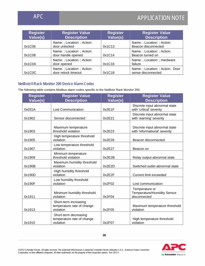
APC APPLICATION NOTE
36 ___________________________________________________________________________________________________ © 2012 Schneider Electric. All rights reserved. The trademark InfraStruxure is owned by Schneider Electric Industries S.A.S., American Power Conversion Corporation, or their affiliated companies. All other trademarks are the property of their respective owners. Rev 2012-3
Register Value(s)
Register Value Description
Register Value(s)
Register Value Description
0x1C06 Name: ; Location: ; Action: door unlocked 0x1C13
Name: ; Location: ; Action: Beacon disconnected
0x1C08 Name: ; Location: ; Action: door handle opened 0x1C14
Name: ; Location: ; Action: Beacon turned on
0x1C0A Name: ; Location: ; Action: door opened 0x1C16
Name: ; Location: ; Hardware failure
0x1C0C Name: ; Location: ; Action: door relock timeout 0x1C18
Name: ; Location: ; Action: Door sense disconnected
NetBotz® Rack Monitor 200 Device Alarm Codes The following table contains Modbus alarm codes specific to the NetBotz Rack Monitor 200.
Register Value(s)
Register Value Description
Register Value(s)
Register Value Description
0x031A Lost Communication 0x2E1F Discrete input abnormal state with 'critical' severity
0x1902 Sensor disconnected 0x2E21 Discrete input abnormal state with 'warning' severity
0x1903 Maximum temperature threshold violation 0x2E23
Discrete input abnormal state with 'informational' severity
0x1905 High temperature threshold violation 0x2E26 Beacon disconnected
0x1907 Low temperature threshold violation 0x2E27 Beacon on
0x1909 Minimum temperature threshold violation 0x2E2B Relay output abnormal state
0x190B Maximum humidity threshold violation 0x2E2D Switched outlet abnormal state
0x190D High humidity threshold violation 0x2E2F Current limit exceeded
0x190F Low humidity threshold violation 0x2F02 Lost communication
0x1911 Minimum humidity threshold violation 0x2F04
Temperature or Temperature/Humidity Sensor disconnected
0x1913
Short-term increasing temperature rate of change violation 0x2F05
Maximum temperature threshold violation
0x1915
Short-term decreasing temperature rate of change violation 0x2F07
High temperature threshold violation
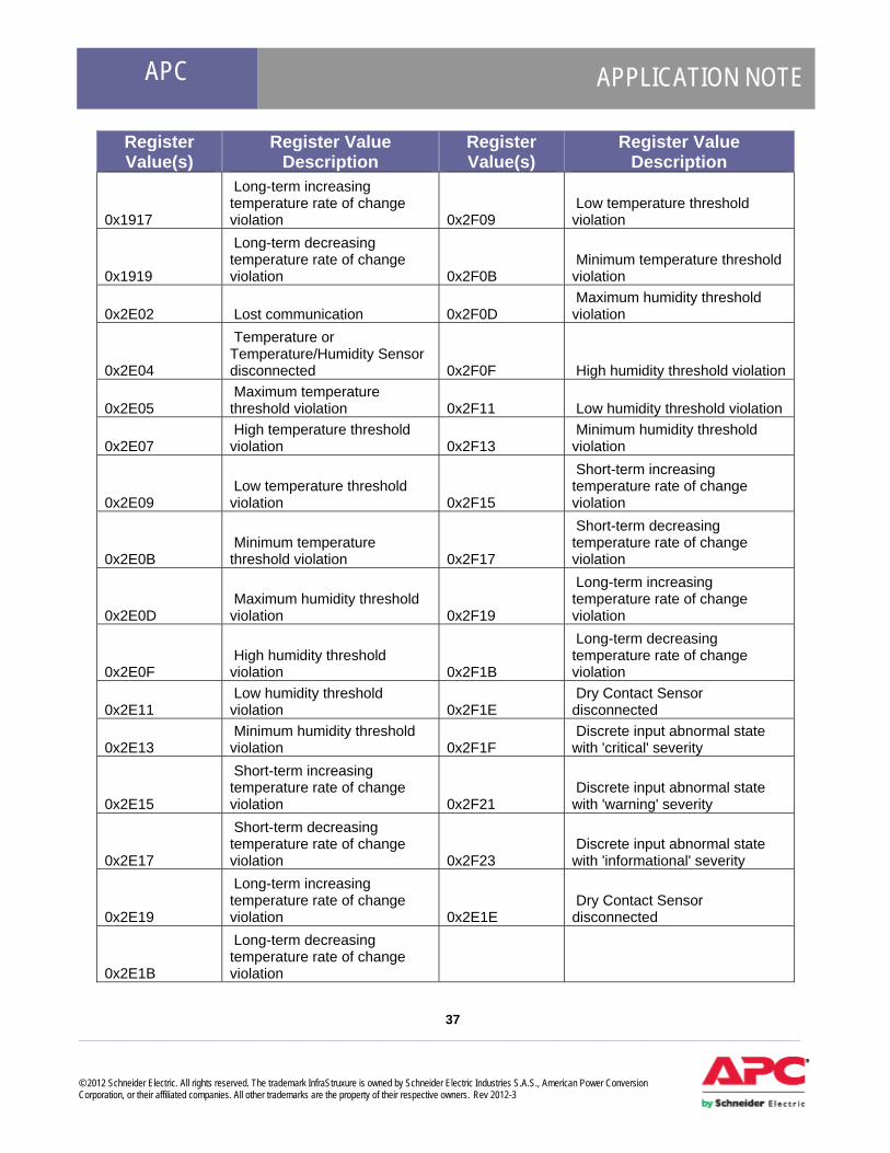
APC APPLICATION NOTE
37 ___________________________________________________________________________________________________ © 2012 Schneider Electric. All rights reserved. The trademark InfraStruxure is owned by Schneider Electric Industries S.A.S., American Power Conversion Corporation, or their affiliated companies. All other trademarks are the property of their respective owners. Rev 2012-3
Register Value(s)
Register Value Description
Register Value(s)
Register Value Description
0x1917
Long-term increasing temperature rate of change violation 0x2F09
Low temperature threshold violation
0x1919
Long-term decreasing temperature rate of change violation 0x2F0B
Minimum temperature threshold violation
0x2E02 Lost communication 0x2F0D Maximum humidity threshold violation
0x2E04
Temperature or Temperature/Humidity Sensor disconnected 0x2F0F High humidity threshold violation
0x2E05 Maximum temperature threshold violation 0x2F11 Low humidity threshold violation
0x2E07 High temperature threshold violation 0x2F13
Minimum humidity threshold violation
0x2E09 Low temperature threshold violation 0x2F15
Short-term increasing temperature rate of change violation
0x2E0B Minimum temperature threshold violation 0x2F17
Short-term decreasing temperature rate of change violation
0x2E0D Maximum humidity threshold violation 0x2F19
Long-term increasing temperature rate of change violation
0x2E0F High humidity threshold violation 0x2F1B
Long-term decreasing temperature rate of change violation
0x2E11 Low humidity threshold violation 0x2F1E
Dry Contact Sensor disconnected
0x2E13 Minimum humidity threshold violation 0x2F1F
Discrete input abnormal state with 'critical' severity
0x2E15
Short-term increasing temperature rate of change violation 0x2F21
Discrete input abnormal state with 'warning' severity
0x2E17
Short-term decreasing temperature rate of change violation 0x2F23
Discrete input abnormal state with 'informational' severity
0x2E19
Long-term increasing temperature rate of change violation 0x2E1E
Dry Contact Sensor disconnected
0x2E1B
Long-term decreasing temperature rate of change violation

38 ___________________________________________________________________________________________________ © 2012 Schneider Electric. All rights reserved. The trademark InfraStruxure is owned by Schneider Electric Industries S.A.S., American Power Conversion Corporation, or their affiliated companies. All other trademarks are the property of their respective owners. Rev 2012-3
APC APPLICATION NOTE
Conclusion StruxureWare Data Center Expert is designed to communicate with a Building Management System through the Modbus TCP
protocol, using port 502. The Modbus TCP protocol is a standard in the industry and is supported by almost all BMS vendors.
All monitored devices are connected to the StruxureWare Data Center Expert server through the Public LAN or the APC LAN,
which is a private Ethernet connection. StruxureWare Data Center Expert then becomes the gateway for all information the
BMS would request.
StruxureWare Data Center Expert Server Appliance The StruxureWare Data Center Expert server appliance provides centralized management for all APC and non APC SNMP
Physical Infrastructure devices, and can forward this information via the included Modbus port to a BMS such as T.A.C.
Continuum™ and Vista™.
Note: StruxureWare Data Center Expert Modbus support primarily provides monitoring capability only, not control.
Schneider Electric highly recommends anyone considering Modbus integration to consider using StruxureWare Data Center
Expert since its Modbus support spans the majority of the APC product range as well as non-APC SNMP discovered devices,
and provides many features that are complementary to T.A.C. Continuum™ and Vista™. If control is required for UPS's, etc.,
see the following links for information on how to integrate directly with each individual device.
APC UPS Building Management System Integration Card This card can be used with all APC UPS’s except Symmetra Megawatt which includes its own built-in Modbus support. Product information including manuals: http://www.apc.com/products/resource/include/techspec_index.cfm?base_sku=AP9622
APC Battery Management System Modbus Register Map Manuals and Modbus register map: http://www.apcc.com/resource/include/techspec_index.cfm?base_sku=AP9921X&tab=documentation
APC InfraStruxure InRow RC Modbus Register Map Manuals and Modbus register map: http://www.apcc.com/prod_docs/results.cfm?DocType=User%20Manual&Query_Type=3&Value=339
APC Symmetra Megawatt Modbus Register Map Manuals: http://www.apcc.com/prod_docs/results.cfm?class=user&product=185
References • www.modbus.org
Copyright © 2022 FDOKUMEN

