


Bahasa
Halaman
Hukum


Chamberlain GmbH
Alfred-Nobel-Strasse 4
66793 Saarwellingen
Germany
www.liftmaster.eu
®
Engineered and designed by The Chamberlain Group, Inc, USA
Rolling Garage Door Opener
LM650EVGB
LM650EVGBSA
LM850EVGBSA
LM950EVGBSA
Installation and Operating Instructions
Keep these instructions
for future reference

IMPORTANTChain reduction assemblies that may interfere with the safe and proper operation of the LM950EV must be removed.
All Hand chains must be removed prior to fitting the LM950EV.
DO NOT use extension poles with the LM950EV.
The LM950EV can be used on windlocked doors based on the following conditions:- door is professionally installed, correctly sprung and maintained to manufacturer’s instruction- door size up to 18m²- product is only operated in normal conditions, not during adverse wind conditions
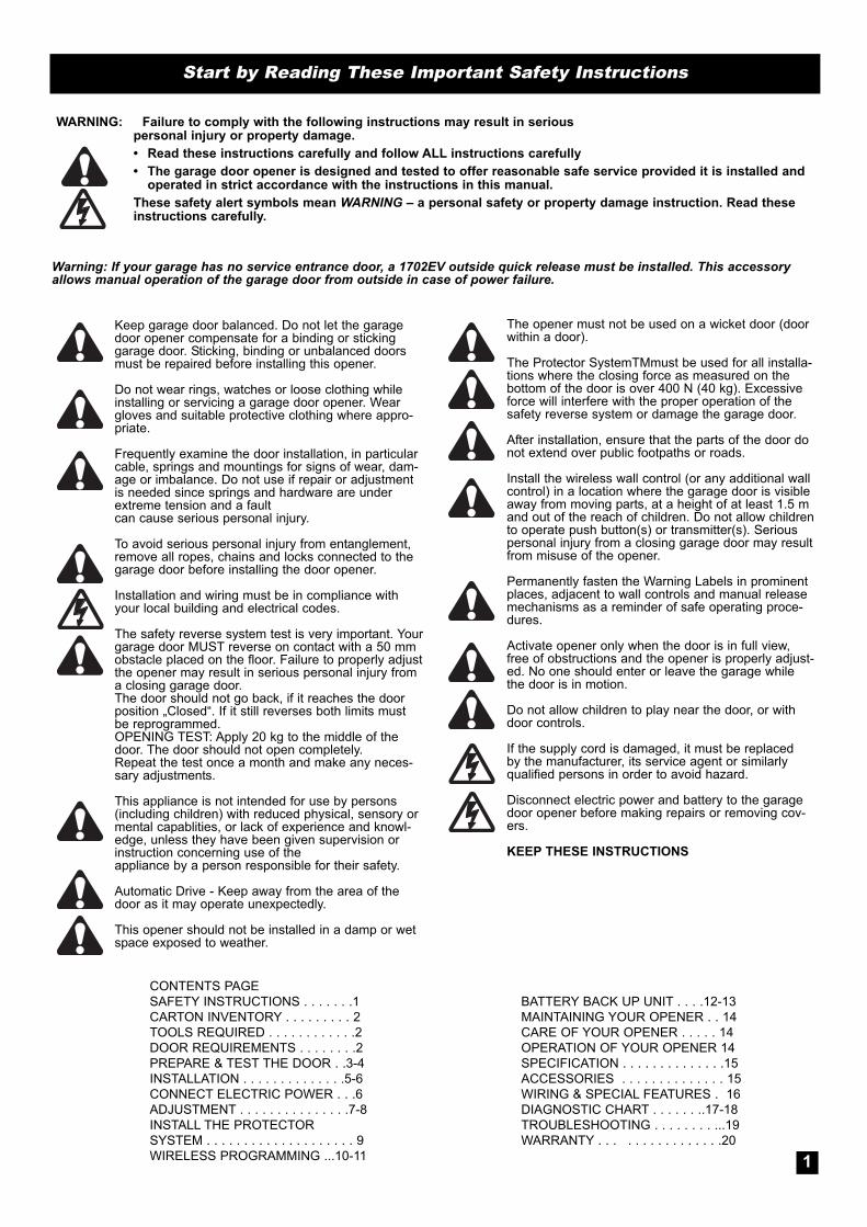
WARNING: Failure to comply with the following instructions may result in serious personal injury or property damage.
• Read these instructions carefully and follow ALL instructions carefully
• The garage door opener is designed and tested to offer reasonable safe service provided it is installed andoperated in strict accordance with the instructions in this manual.
These safety alert symbols mean WARNING – a personal safety or property damage instruction. Read theseinstructions carefully.
Warning: If your garage has no service entrance door, a 1702EV outside quick release must be installed. This accessoryallows manual operation of the garage door from outside in case of power failure.
Keep garage door balanced. Do not let the garagedoor opener compensate for a binding or stickinggarage door. Sticking, binding or unbalanced doorsmust be repaired before installing this opener.
Do not wear rings, watches or loose clothing whileinstalling or servicing a garage door opener. Weargloves and suitable protective clothing where appro-priate.
Frequently examine the door installation, in particularcable, springs and mountings for signs of wear, dam-age or imbalance. Do not use if repair or adjustmentis needed since springs and hardware are underextreme tension and a faultcan cause serious personal injury.
To avoid serious personal injury from entanglement,remove all ropes, chains and locks connected to thegarage door before installing the door opener.
Installation and wiring must be in compliance withyour local building and electrical codes.
The safety reverse system test is very important. Yourgarage door MUST reverse on contact with a 50 mmobstacle placed on the floor. Failure to properly adjustthe opener may result in serious personal injury froma closing garage door. The door should not go back, if it reaches the doorposition „Closed“. If it still reverses both limits mustbe reprogrammed.OPENING TEST: Apply 20 kg to the middle of thedoor. The door should not open completely.Repeat the test once a month and make any neces-sary adjustments.
This appliance is not intended for use by persons(including children) with reduced physical, sensory ormental capablities, or lack of experience and knowl-edge, unless they have been given supervision orinstruction concerning use of theappliance by a person responsible for their safety.
Automatic Drive - Keep away from the area of thedoor as it may operate unexpectedly.
This opener should not be installed in a damp or wetspace exposed to weather.
Start by Reading These Important Safety Instructions
CONTENTS PAGE
SAFETY INSTRUCTIONS . . . . . . .1
CARTON INVENTORY . . . . . . . . . 2
TOOLS REQUIRED . . . . . . . . . . . .2
DOOR REQUIREMENTS . . . . . . . .2
PREPARE & TEST THE DOOR . .3-4
INSTALLATION . . . . . . . . . . . . . .5-6
CONNECT ELECTRIC POWER . . .6
ADJUSTMENT . . . . . . . . . . . . . . .7-8
INSTALL THE PROTECTOR
SYSTEM . . . . . . . . . . . . . . . . . . . . 9
WIRELESS PROGRAMMING ...10-11
BATTERY BACK UP UNIT . . . .12-13
MAINTAINING YOUR OPENER . . 14
CARE OF YOUR OPENER . . . . . 14
OPERATION OF YOUR OPENER 14
SPECIFICATION . . . . . . . . . . . . . .15
ACCESSORIES . . . . . . . . . . . . . . 15
WIRING & SPECIAL FEATURES . 16
DIAGNOSTIC CHART . . . . . . ..17-18
TROUBLESHOOTING . . . . . . . . ...19
WARRANTY . . . . . . . . . . . . . . . .20
The opener must not be used on a wicket door (doorwithin a door).
The Protector SystemTMmust be used for all installa-tions where the closing force as measured on thebottom of the door is over 400 N (40 kg). Excessiveforce will interfere with the proper operation of thesafety reverse system or damage the garage door.
After installation, ensure that the parts of the door donot extend over public footpaths or roads.
Install the wireless wall control (or any additional wallcontrol) in a location where the garage door is visibleaway from moving parts, at a height of at least 1.5 mand out of the reach of children. Do not allow childrento operate push button(s) or transmitter(s). Seriouspersonal injury from a closing garage door may resultfrom misuse of the opener.
Permanently fasten the Warning Labels in prominentplaces, adjacent to wall controls and manual releasemechanisms as a reminder of safe operating proce-dures.
Activate opener only when the door is in full view,free of obstructions and the opener is properly adjust-ed. No one should enter or leave the garage whilethe door is in motion.
Do not allow children to play near the door, or withdoor controls.
If the supply cord is damaged, it must be replacedby the manufacturer, its service agent or similarlyqualified persons in order to avoid hazard.
Disconnect electric power and battery to the garagedoor opener before making repairs or removing cov-ers.
KEEP THESE INSTRUCTIONS
1

13 mm, 10 mm, 8 mm
5.5 mm11
CARTON INVENTORY1. Instruction manual (this document)
2. Stop collar
3. Clamp bracket
4. Release handle, cord and risk of entrapment card
5. Transmitters (2)
6. Wireless wall button (LM650EVGB only)
7. Hardware bag
8. Clamp plate
9. Warning label and risk of entrapment label
10. Opener
11. Extension poles (2) (LM650EVGB only)
1 2 TOOLS REQUIRED1. Ladder
2. Adjustable wrench for U-bolts already installed
on the door
3. 8 mm socket, 10 mm socket and 13 mm extended
socket and socket wrench
4. 300 mm socket extension (for minimum side-room
installations)
5. Drill and 5.5 mm drill bit
6. Philips-head screwdriver
7. Marker pen
8. Door stand or similar device to safely support door
(not shown)
DOOR REQUIREMENTSThe maximum allowable door height is 4.5 m with a maximum curtain area of 16.5 m²* (LM650EV) & 18 m²*
(LM850EV) (door height in metres multiplied by the width in metres). The door must be spring balanced. *The
Protector System™ (IR Beams) must be installed if the force at the edge of the closing door exceeds 400 N (40 kg).
For LM950EV the maximum allowable door height is 5.5m (light commercial door) with a maximum curtain area of
25m² (door height in metres multiplied by the width in metres). The door must be of continuous corrugated sheet con-
struction, spring balanced & of a mass not exceeding 250kg. Door axle diameter must not exceed 35mm.
Ensure that there is at least 45 mm from the edge of the curtain to the edge of the bracket. If the roller door drum is
on the edge of the curtain or is a smaller diameter, additional clearance may be required. If the drum is more than 60
mm from the curtain edge or of a smaller diameter, an extension pole kit may be required (section 10).
Different drum and bracket types may result in the minimum side room clearance not being possible and
extension poles being required. Ensure there is a power point near the opener.
3
2
95 mm
95 mm
Minimum distance fromedge of curtain to edge ofdoor bracket 45 mm
Independentclamping method
Direct clampingmethod

Non opener side Opener side
S AFE TY CHE CK !Is the stop collar
installed?YES: proceed to the next
step
NO: install the stop collarbefore proceeding
TESTING THE DOOR
Complete the following test to ensure your door is well
balanced, and not sticking or binding:
• Disable all locks and remove any ropes connected to the
garage door.
• Lift the door to about halfway and then release it.
The door should remain spring balanced.
• Raise and lower the door to determine if there are any
sticking or binding points (20 kg is the absolute maximum
allowable to raise or lower the door in any position).
• If your door does not hold in place or the door binds or
sticks, call a qualified door technician before installing the
opener.
4
INSTALLING THE STOP COLLAR
• Install the stop collar on the opposite end to where
the opener is to be installed.
• Fit the stop collar hard against the boss of the door drum.
Ensure the U-bolt holding the door shaft to the door
bracket is tightly secured.
5
INSTALLING THE WEIGHT BAR (optional)
• Place the weight in the centre of the door (as shown).
• Use a pencil to mark the two hole positions.
• If the door curtain does not have a handle you will need
to drill two 5.5 mm holes through the two marked
positions, then place the weight bar on the inside of the
door.
• Use the bolts, washers and nuts (provided) to
fasten the weight bar in place.
NOTE: If the door has a lifting handle, remove the handle,
nuts & bolts. Place weight bar over the handle holes,
insert extended bolts through the weight bar & fasten handle back in place.
6
3

Free curtain Ballooning Add fasteners here
Door closed Door can belifted
Door secure
Release cable
Rope
Manual releasewarning label
Release handle
Overhand knot
DOWN Arrowbutton
UP Arrowbutton
Learnbutton
Learn Limitsbutton
Pull downFIRMLY
click
THE RELEASE HANDLE & CORD
• Thread one end of the rope through the hole in the top of the red
release handle so that “NOTICE” reads right side up as shown.
• Secure with an overhand knot at least 25 mm from the end of
the rope to prevent slipping.
• Thread the other end of the rope through the loop of the manual
release cable.
• Adjust rope length so the handle (when installed) will be no higher
than 1.8 m above the floor. Secure with an overhand knot. If the
door is greater than 2.5 m in height the release cord extension kit
accessory is required.
NOTE: Final adjustment of handle height should be completed after
the opener is installed. If it is necessary to cut the rope, heat seal
the cut end to prevent unravelling (refer section 16).
7
OPERATING THE MANUAL RELEASE
To disengage the opener
Pull the release cord down firmly, (opener will make a clicking noise).
To re-engage the opener
Pull the release cord down firmly, (opener will make a clicking noise).
Disable all locks and remove any ropes connected to the garage door.
Take care when operating the manual release as an open door may fall rapidly due to weak or broken
8
PINNING THE DOOR
Note: A ballooning door may delay the safety reversal
response and can compromise garage door security.
• To remedy any ballooning place self tapping metal screws
or rivets where the curtain leaves the roll. Secure these
through the curtain into the drum wheel at each end of the roll.
• After determining the correct fastener location as shown, lift
the door approximately half a turn from the closed position
to allow access for drilling.
9
Disable all locks and remove any ropes connected to the garage door.
Take care when operating the manual release as an open door may fall rapidly due to weak or
broken springs, or being out of balance.
4

LEFT(handing must bechanged during limitsetting, section 13)
RIGHT(factorydefaultsetting)
Inside garage looking out
Release cable
Rope
Manual ReleaseWarning Label
Release handle
Overhand knot
Extension pole
Reinforcing Brace
Drive Leg
ATTACHING EXTENSION POLES
(IF REQUIRED)
(LM650EV / LM850EV ONLY)
Optional accessory for model LM850EV
• Align the extension pole holes with the drive legs.
• Insert the extension poles into the drive leg and fix in
place using screws provided.
• Slide the reinforcing brace over the poles and fix in
place using the screws provided.
10
Reinforcing brace must be used.
Use extension pole kit part number 001B6449-1
LEFT / RIGHT HAND INSTALLATION11
5

Door stand
Rope
Door stand
Rope
Tighten to25-28 Nm
INSTALLATION PROCEDURE)
NOTE: The opener can be installed on either side
of the door. The following instructions are for
RIGHT HAND INSTALLATIONS (as illustrated i.e.
inside the garage looking out). For left hand
installations, reverse the instruction terminology
(eg LEFT for RIGHT etc).
Preparation:
• Place the opener in manual release mode (refer section 8).
• Open the roller door fully. For safety, tie a rope around
the door.
• Ensure the door axle U-BOLT and door mounting bracket
on the left hand side (non opener side) are securely fastened.
• Support the door with a door stand or similar device to safely
support the door.
• Mark the position of the door shaft on the right hand door
bracket (for reassembly purposes).
• While the door is supported, remove the right hand axle
U-Bolt and door mounting bracket from the wall.
Install the opener:
• Slide the opener over the door axle and engage the drive
legs into the door drum wheel, either side of a spoke.
Extensions may be necessary (refer section 10).
• Refit the door mounting bracket to the wall. If the door bracket
needs to be relocated due to opener width, refer section 3.
• Clamp the opener on the door axle and door bracket in the
marked position using the clamp assembly supplied
(tighten to 25 – 28 Nm).
• If side room exceeds 95mm clamp independently to the door
axle as illustrated in section 3.
• Remove all ropes and the support stand.
• Check the operation of the door in manual mode by raising
and lowering by hand. It should operate smoothly without
sticking or binding. The disengage handle should already
be attached less than 1.8m
above the floor (refer section 7).
Connect the power:
• Position the power cable away from the door curtain
and any moving parts.
• Plug the opener into a nearby power point and turn ON.
• The opener courtesy LEDs should turn ON.
• The opener must now be programmed for:-
• DOOR TRAVEL LIMITS (Section 13)
• RIGHT OR LEFT HAND OPERATION (Section 13)
• FORCE SETTING (Section 14)
12
Do not allow people to walk under or
around the door during the installation
process as serious injury can occur.
6
Press and holduntilFLASHINGLED
Press & release to acceptselected hand.
If required: Use DOWN button to adjust
Press and hold to drivedoor up to open
Press and hold to drivedoor down to closed
If required: Use UP button to adjust
Activate door to open
Close the door to test limits
OrangeLED ON &Courtesy LEDSon Dim
Motor will make a click &FULL BRIGHT courtesyLEDs will turn on
Right bankwill light up
(IF REQUIRED)To changepress and holduntil correctbank lights up
Left bankwill light upfor Left handinstallation
Click
Press & release to set theUP limit
Press & release to set theDOWN limit
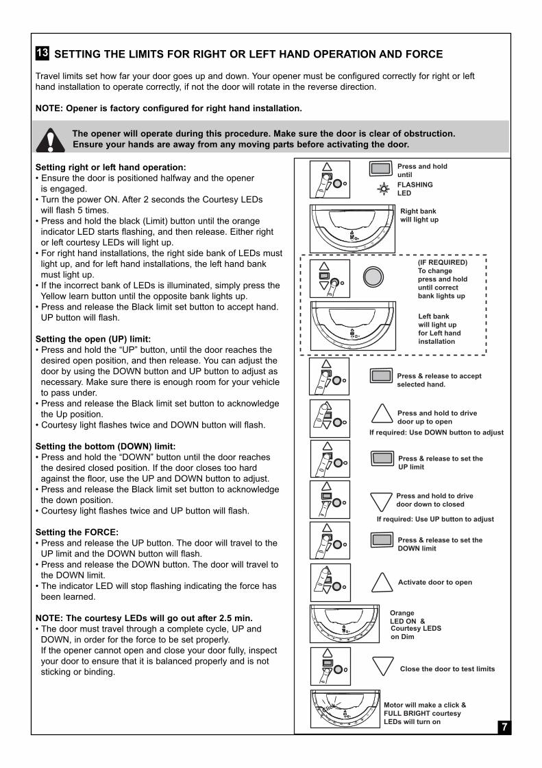
SETTING THE LIMITS FOR RIGHT OR LEFT HAND OPERATION AND FORCE
Travel limits set how far your door goes up and down. Your opener must be configured correctly for right or left
hand installation to operate correctly, if not the door will rotate in the reverse direction.
NOTE: Opener is factory configured for right hand installation.
Setting right or left hand operation:
• Ensure the door is positioned halfway and the opener
is engaged.
• Turn the power ON. After 2 seconds the Courtesy LEDs
will flash 5 times.
• Press and hold the black (Limit) button until the orange
indicator LED starts flashing, and then release. Either right
or left courtesy LEDs will light up.
• For right hand installations, the right side bank of LEDs must
light up, and for left hand installations, the left hand bank
must light up.
• If the incorrect bank of LEDs is illuminated, simply press the
Yellow learn button until the opposite bank lights up.
• Press and release the Black limit set button to accept hand.
UP button will flash.
Setting the open (UP) limit:
• Press and hold the “UP” button, until the door reaches the
desired open position, and then release. You can adjust the
door by using the DOWN button and UP button to adjust as
necessary. Make sure there is enough room for your vehicle
to pass under.
• Press and release the Black limit set button to acknowledge
the Up position.
• Courtesy light flashes twice and DOWN button will flash.
Setting the bottom (DOWN) limit:
• Press and hold the “DOWN” button until the door reaches
the desired closed position. If the door closes too hard
against the floor, use the UP and DOWN button to adjust.
• Press and release the Black limit set button to acknowledge
the down position.
• Courtesy light flashes twice and UP button will flash.
Setting the FORCE:
• Press and release the UP button. The door will travel to the
UP limit and the DOWN button will flash.
• Press and release the DOWN button. The door will travel to
the DOWN limit.
• The indicator LED will stop flashing indicating the force has
been learned.
NOTE: The courtesy LEDs will go out after 2.5 min.
• The door must travel through a complete cycle, UP and
DOWN, in order for the force to be set properly.
If the opener cannot open and close your door fully, inspect
your door to ensure that it is balanced properly and is not
sticking or binding.
13
The opener will operate during this procedure. Make sure the door is clear of obstruction.
Ensure your hands are away from any moving parts before activating the door.
7

Wall control, orwireless push buttonno less than 1.5 m
Handle should beless than 1.8 m
<1.8
m
>1.5
m
50 mm
50 mm test obstacle
TESTING THE SAFETY REVERSE SYSTEM
Operate the door in the down direction. The door must
reverse upon contact with the obstacle. If the door
stops on the obstacle, remove obstacle and repeat
limit and force setting (refer section 13).
Repeat test of the safety reverse system.
14
The safety reverse system test is important.
The garage door must reverse on contact
with a 50 mm obstacle laid flat on the floor.
Failure to properly adjust the opener may result in
serious personal injury from a closing garage door.
FIXING WARNING LABELS
Once you have completed your installation and successfully
carried out the safety reverse system test (outlined above),
install the warning labels provided with your opener as shown.
The risk of entrapment label must be installed adjacent
to the release handle at a height of less than1.8 m
from the floor.
The WARNING label must be installed in a prominent
place near any fixed control.
Any fixed wall control or wireless door control must be mounted
at a height of no less than 1.5 m out of the reach of children.
Ensure the manual release instruction card is attached to the
rope as detailed in section 7.
Read the safety instructions (page 1) for further
details concerning safety.
15
8
STANDARD INSTALLATION COMPLETE

12V
DC
SilentDrive MR850EVO ONLY
Up
Down
YellowLearnButton
BlackLearnButton
INSTALL THE PROTECTOR SYSTEM™ (IR BEAMS) OPTIONAL ACCESSORY
NOTE: This accessory must be used for all
installations where the closing force as measured
on the bottom of the door is over 400 N (40 kg).
After the opener has been installed and adjusted, the
Protector System™ accessory can be installed.
Instructions are included with this accessory.
The Protector System™ provides an additional measure
of safety against a small child or animal being trapped
under a garage door. It uses an infrared beam, which
when broken by an obstruction, causes a closing door
to open and prevents an open door from closing and is
strongly recommended for homeowners with young children.
NOTE: The opener will automatically detect the Protector
SystemTM when it is installed andoperating for 5 minutes
(during this time the beams must remain unobstructed).
The opener will not close unless the beams are aligned.
Timer to close feature (TTC)
The Timer-to-close feature allows the door to automatically close after a specified time period. Prior to the door
closing, the garage door opener lights flash for 8 seconds before the door begins to close.
If the door encounters an obstruction while closing, the opener will make a second attempt to close the door.
If an obstruction occurs on the second attempt, the garage door opener will open, stop and WILL NOT close until
the obstruction has been cleared and the opener has been operated again.
NOTE: The Protector SystemTM MUST be installed and operating for 5 minutes to enable this feature.
Installing and adjusting:
• Turn the opener off
• Install the Protector SystemTM using the brackets, wires and instructions provided with the product. Twist the
two white (only) wires together and terminate them into the white (2) terminal. Twist the two white/black wires
together and terminate them into the grey (3) terminal.
• Turn the opener on
With the door at the down limit, press and hold DOWN
arrow until orange LED starts blinking.
Yellow LEARN button is used to cycle through the TTC settings:
1 x long blink = TTC OFF
1 x short blink = TTC 1 min
2 x short blink = TTC 5 min
3 x short blink = TTC 10 min
Press black rectangle button to set and exit.
16
Auto close is NOT recommended for households with young children.
Door may operate unexpectedly, therefore do not allow anything to stay in the path of the door.
SAFETY FIRST!
Whilst Chamberlain have engineered safety features into your garage door opener, we urge you to con
sider fitting IR Beams to your new garage door opener. In many countries these devices are compulsory
to assist in preventing serious injury or property damage. For your own peace of mind and the safety of
others please install this inexpensive safety device.
9
LM950EV/ LM850EV ONLY

Press LEARN
LED will FLASH
TO ADD Transmitters / Wireles s wall button
P res s and hold down the des iredB utton.
P res s LEAR N for 9 s econds
TO DE LE TE ALL R EMOTE S
LED on WILL TUR N ON
After 9 s econds all remotesare deleted and LED will goout.
R eleas e LR N button whenCourtes y LEDsflashes once
or
INSTALLING YOUR WIRELESS WALL BUTTON
To install:
• Carefully pry open the device and locate the two screws for
mounting.
• Attach to the wall using the two screws and wall anchors
provided if mounting to a plaster wall. If using a recessed wall
box do not use anchors.
NOTE: Do not overtighten screws.
NOTE: The wall control supplied with your opener should be
pre-programmed by the factory.
If adding a new wall control, program into the opener before
mounting the unit as detailed in section 18.
17
Disconnect power to the opener whilst installing
this accessory to prevent accidental activation.
Locate minimum 1.5 m above the floor.
WIRELESS PROGRAMING (OPTIONAL ACCESSORIES)
NOTE: Transmitter(s) and wall button supplied with your opener are factory programmed.
NOTE: If adding an installed wall control
you will need a second person to press and hold
the desired button. If not installed, program the
wall button into the opener before mounting.
ADDING transmitters using the LRN “LEARN”
button
• Press and hold down the button you wish to program
to the opener.
• The orange LED on the opener will flash to indicate
it is receiving signal from the transmitter.
• Press and release the “LRN” button.
• The courtesy LEDs will flash once.
• Ensure the door is clear of obstruction, then test the
transmitter.
Deleting ALL transmitter codes
NOTE: This deletes all transmitters and codes
• Press and hold the LRN learn button until the orange
indicator light goes out (approximately 9 sec).
18
Activate the opener only when the door is in full view, free of obstruction and properly adjusted.
No one should enter or leave garage whilst the door is in motion. Do not allow children to operate
push button(s) or transmitter(s). Do not allow children to play near the door.
Fix any wall control at a height of at least 1.5 m and within sight of the door but away from any
moving parts.
10
+
3
2
3
2

2
3
4
3
Press and releasethe yellowlearn button
Enter a 4-digitP IN of yourchoice? ? ? ?_ _ _ _
Press and holdthe enter buttonOpener light bulbsblink
After the lightsblink release theENTER button
1 Locatethe yellowlearn button
KEYLESS DEVICE PROGRAMMING (OPTIONAL ACCESSORIES )
To install:
Wireless KeypadTo set the keyless entry PIN:
1. Locate the Yellow Learn button on the garage door opener.
2. Press and release the Yellow Learn button on the garage
door opener. The LED will light.
3. Enter a 4-digit personal identification number (PIN) of your
choice on the keypad.
4. Press and hold the ENTER button. Check to see if the
opener light blinks. Release the ENTER button after the l
ight bulb blinks.
To change an existing keyless entry PIN:
1. Enter the existing programmed PIN that you want to change.
2. Press and hold the # button until the light bulb blinks twice.
3. Enter the new 4-digit PIN of your choice, then press the
ENTER button. The light bulb will blink once.
4. To test, enter the new PIN, then press the ENTER button.
The garage door opener will activate.
19
Activate the opener only when the door is in full view,
free of obstruction and properly adjusted.
No one should enter or leave garage whilst the door is
in motion. Do not allow children to operate push
button(s) or transmitter(s). Do not allow children to
play near the door.
11

Battery BackupUnit (BBU)
BATTERY BACKUP UNIT (OPTIONAL ACCESSORY LM950EV/ LM850EV ONLY )20
To prevent possible SERIOUS INJURY or DEATH
from electrocution, disconnect ALL electric and
battery power BEFORE performing ANY service
or maintenance.
1. Installation instructions for mounting the BBU.
After the opener has been installed, position the BBU
next to the opener on a structural support (joist) within
BBUTs cord length.
Attach the BBU to the support by using the wall or
ceiling mount holes on either side of the BBU and the
1” (25mm) screws (provided).
2. Connect the BBU to the Opener.
Disconnect the opener from the electrical outlet.
Connect the BBU cord into the connector on the
bottom of the opener (see picture below). Connect the
opener into the electrical outlet.
Turn the power ON. After 2 seconds the Courtesy
LEDs will flash 5 times.
After 20 seconds, the green diagnostic LED (see
picture next page) will begin to flash indicating the
BBU is charging.
IMPORTANT NOTE: Installation of the BBU when
permanent electrical power is not available (such as a
new construction and the electricity is not installed)
may damage the battery.
Unplug the BBU after testing to prevent damage.
OPERATING INSTRUCTIONS
1. Test the installed BBU with the opener.
To test the BBU, disconnect the opener power cord
from the electrical power outlet.
A solid orange LED indicates the BBU is operating
on battery power.
A flashing orange LED indicates the BBU is
operating on battery power and that the battery
charge is low.
To test the BBU is functioning properly, open and
close the garage door.
Re-connect the opener power cord back into the
electrical outlet.
Verify that the green LED is flashing on the opener
(indicates that the BBU is now charging).
Test completed.
2. Charge the battery.
Allow the battery 24 to 48 hours to fully charge
before using the BBU system.
A fully charged BBU supplies 12V DC to the opener
for one to two days of normal operation during an
electrical power outage. If the battery voltage drops
too low, the battery will disconnect and the opener
will no longer operate under battery power.
After the electrical power has been restored, the
battery will recharge within 48 hours. Under normal
usage the battery will last 3 to 5 years.
To obtain maximum battery life and prevent damage,
disconnect the battery backup when the opener is
not in use for an extended period of time.
NOTE: Door operation may be limited until the
battery is fully charged.
12

Diagnostic LED(SilentDrive MR850EVO)
"-" NEGATIVE LABEL
"+" POSITIVE LABEL
15AMP FUSE
"+" POSITIVE TERMINAL
"-" NEGATIVE TERMINAL
BATTERY TO BE PLACED INTOTHE HOUSING WITH THETERMINALS AS SHOWN
RETAINING BRACKET
BATTERY BACKUP UNIT (OPTIONAL ACCESSORY LM950EV/ LM850EV ONLY)
CONTINUED
Battery Backup Unit (BBU) Diagnostics
GREEN LED:
All systems are normal.
• A solid LED light indicates the battery is fully charged.
• A solid LED light indicates the battery is fully charged.
NOTE: Battery does not have to be fully charged to
operate the motor unit.
ORANGE LED:
The motor unit has lost power and is operating off the
BBU.
• A solid LED indicates the opener is activating the
door and is operating off the BBU.
• A flashing LED indicates the battery is low.
• Once the power is restored the BBU will recharge.
is indicated by a flashing green LED.
RED LED:
An error has been detected and the BBU will
automatically shut off. The BBU will attempt to restart
by reconnecting to the battery. If the error is still
present it will shut itself off again. This process will
repeat every 5 minutes or until the error has been
resolved. This is used to prevent further draining of
the battery.
• If a red LED remains on when the power is restored
please call for service.
Replace Battery
• Unplug the BBU from the opener and remove the
screws holding the BBU to the wall.
• Remove the battery retaining bracket.
• Withdraw the battery from the housing and
disconnect the terminals.
• Reinstall the new battery in the reverse process,
taking care to connect the positive and negative
terminals correctly.
• Reconnect the BBU to the opener as in step 2 of
the previous page.
21
13

OPERATION OF YOUR OPENER
Your opener can be activated by any of the following
devices:
• The ACTIVATION button
Press the button until door starts to move.
• The Outside keyswitch or keyless entry system (if you
have installed any of these accessories).
• The Transmitter or Wireless Wall Control
Hold the push button down until the door starts to move.
When the opener is activated by transmitter,
ACTIVATION button or wall control:
• If open, the door will close. If closed, the door will
open.
• If closing, the door will stop.
• If opening, the door will stop (allowing space for entry
and exit of pets and for fresh air).
• If the door has been stopped in a partially open or
closed position, it will reverse direction.
Obstruction behaviour:
• If an obstruction is encountered while closing, the door
will reverse.
• If an obstruction is encountered while opening, the
door will reverse and stop.
• The optional Protector System™ uses an invisible
beam which, when broken by an obstruction, causes a
closing door to open and prevents an open door from
closing. It is STRONGLY RECOMMENDED for home-
owners with young children.
Opening the door manually:
The door can be opened manually by pulling the
release cord down firmly.
To re-engage the door, pull the release cord down firmly.
The opener light will turn on:
• when opener is initially plugged in;
• when the power is briefly interrupted;
• when the opener is activated.
• when IR Beams are triggered with the door in the
Open position. (the light turns off automatically after
2-1/2 minutes.)
CARE OF YOUR OPENERWhen properly installed, your opener will operate with
minimal maintenance. The opener does not require
additional lubrication.
Limit and Force Settings: These settings must be
checked and properly set when the opener is installed.
Weather conditions may cause some minor changes in
the door operation, requiring some re-adjustments, par-
ticularly during the first year of operation. Refer to limit
and force setting in, section 13.
Follow the instructions carefully and repeat the
safety reverse test after any adjustment.
Transmitter: Additional transmitters can be purchased at
any time. Refer to Accessories. Any new transmitters
must be programmed into the opener.
Transmitter battery: If transmission range
decreases, replace the battery.
Door should be fully closed if possible.
Weak or broken springs could allow an open
door to fall rapidly. Property damage or serious
personal injury could result.
MAINTENANCE OF YOUR OPENEROnce a Month:
• Repeat safety reverse test.
Make any necessary adjustments (section 13).
• Manually operate door. If it is unbalanced or binding,
call for professional garage door service.
• Check to be sure door opens and closes fully.
Set limits and/or force if necessary.
SPECIAL NOTE: Chamberlain strongly recommends
that the Protector SystemTM be installed on all
garage door openers.
14

1 2 3 4
8
5
7
6
ACCESSORIES22
1. Model 128EV 2 Channel wireless wall button
2. Model TX4UNI 4 Channel mini transmitter
3. Model 747EV Keyless entry system
4. Model 760EV Outside keyswitch
5. Model 1702EV Outside quick release
6. Model 770/771/772
The Protector SystemTM (IR Beams)
7. Model 475M-12 V (battery backup) -
(LM850EV/ LM950EV only)
8. Extension poles
(optional accessory for LM650EV/LM850EV)
15
SPECIFICATIONS LM950EVGBSAInput Voltage: 220-240 VAC, 50/60 Hz, 110 W
Rated Load: 40 Nm
Max.Pull Force: 1300 N @ �300 mmStandby Power: <1 Watt
Drive: DC gearmotor permanent
lubrication
Max. Drum Rotations: 4 1/2
Memory Registers: 64
Operating Frequency: 433.30/433.92/434.54 MHz
SPECIFICATIONS LM850EVGBSAInput Voltage: 220-240 VAC, 50/60 Hz, 170 W
Rated Load: 32 Nm
Max.Pull Force: 550 N @ �300 mmStandby Power: <1 Watt
Drive: DC gearmotor permanent
lubrication
Max. Drum Rotations: 4 1/2
Memory Registers: 64
Operating Frequency: 433.30/433.92/434.54 MHz
SPECIFICATIONS LM650EVGBInput Voltage: 230-240 VAC, 50 Hz, 110 W
Rated Load: 25 Nm
Max.Pull Force: 500 N @ �300 mmStandby Power: <1 Watt
Drive: DC gearmotor permanent
lubrication
Max. Drum Rotations: 4 1/2
Memory Registers: 64
Operating Frequency: 433.30/433.92/434.54 MHz
SPECIFICATIONS LM650EVGBSAInput Voltage: 220-240 VAC, 50/60 Hz, 110 W
Rated Load: 25 Nm
Max.Pull Force: 500 N @ �300 mmStandby Power: <1 Watt
Drive: DC gearmotor permanent
lubrication
Max. Drum Rotations: 4 1/2
Memory Registers: 64
Operating Frequency: 433.30/433.92/434.54 MHz

1
3
2
12V
DC
SilentDrive MR850EVO ONLY
SPECIAL FEATURES - Information for Service Personnel (OPTIONAL ACCESSORIES)
1. 12 VDC power output for external devices - (LM950EV/ LM850EV only)
2. The Protector SystemTM IR Beams
3. Standby Power Unit (battery backup) - (LM950EV/ LM850EV only)
24
16
LM850EV /
LM950EV ONLY
TYPICAL WIRING DIAGRAM LM950EV/ LM850EV/ LM650EV -
Information for Service Personnel
23
rxwhite/blackwhite
white/blackwhite
12 vdcgnd
ExternalDevice
Keyswitch orpush button
com
no
12V
DC
LM950EV/ LM850EV ONLY

DIA
GN
OST
ICU
PD
OW
NSY
MPT
OM
POSS
IBLE
CAU
SEPO
SSIB
LER
ESO
LUTO
NC
OD
EAR
RO
WAR
RO
W1-
11
FLAS
H1
FLAS
HTh
ega
rage
door
open
erw
illTh
eP
rote
ctor
Sys
tem
isno
tC
heck
the
Pro
tect
orS
yste
mis
notc
lose
and
the
light
sw
illfla
shin
stal
led,
conn
ecte
d,or
inst
alle
dan
dal
igne
dco
rrect
ly,
wire
sm
aybe
cut
both
LED
sar
eO
Nw
ithno
obst
ruct
ion
betw
een
the
beam
s.
1-2
1FL
ASH
2FL
ASH
ESTh
ega
rage
door
open
erw
illTh
eP
rote
ctor
Sys
tem
wire
Che
ckth
eP
rote
ctor
Syst
emis
notc
lose
and
the
light
sw
illsh
orte
dor
reve
rsed
inst
alle
dan
dal
igne
dco
rrect
ly,
flash
both
LED
sar
eO
Nw
ithno
obst
ruct
ion
betw
een
the
beam
s.
1-3
1FL
ASH
3FL
ASH
ESW
allm
ount
eddo
orco
ntro
lTh
ew
ires
fort
hedo
orco
ntro
lC
heck
the
door
cont
rolw
iring
isw
illno
tfun
ctio
nar
esh
orte
dor
the
door
corre
ctco
ntro
lis
faul
ty
1-4
1FL
ASH
4FL
ASH
ESTh
ega
rage
door
open
erw
illM
isal
igne
dor
obst
ruct
edC
heck
the
Pro
tect
orS
yste
mis
notc
lose
the
door
and
the
Pro
tect
orS
yste
min
stal
led
and
alig
ned
corr
ectly
,lig
hts
flash
both
LED
sar
eO
Nw
ithno
obst
ruct
ion
betw
een
the
beam
s.1-
51
FLAS
H5
FLAS
HES
The
gara
gedo
orop
ener
clic
ksIn
tern
alfa
ult
Con
tact
serv
ice
cent
rebu
tno
mov
emen
tTh
eop
ener
runs
appr
oxim
atel
yC
omm
unic
atio
ner
rort
oC
onta
ctse
rvic
ece
ntre
150-
200
mm
and
stop
san
d/or
reve
rses
trave
lmod
ule
Your
gara
gedo
orop
ener
ispr
ogra
mm
edfo
rsel
f-dia
gnos
ticca
pabi
litie
s.Th
eU
Pan
dD
OW
Nar
row
son
the
gara
gedo
orop
ener
flash
the
diag
nost
icco
des.
DIAGNOSTICCHART
TM TMTM
TM TM
TM
2-1
2FL
ASH
ES1
FLAS
HTh
ega
rage
door
open
erw
illno
tP
CB
mem
ory
corr
upt
Res
etop
ener
bytu
rnin
gth
em
ains
OFF
for2
0se
cond
sR
etes
tOpe
ner
oper
ate
2-2
2FL
ASH
ES2
FLAS
HES
The
gara
gedo
orop
ener
will
not
Res
etop
ener
bytu
rnin
gth
em
ains
OFF
for2
0se
cond
sR
etes
tOpe
ner
oper
ate
2-3
2FL
ASH
ES3
FLAS
HES
The
gara
gedo
orop
ener
will
not
oper
ate
inba
ttery
mod
eR
echa
rge
batte
ryR
eset
open
erby
turn
ing
the
mai
nsO
FFfo
r20
seco
nds
Con
tact
cust
omer
serv
ice
PC
BV
olta
gete
stfa
ilure
Bat
tery
failu
re-i
ffitt
ed
17

DIA
GN
OST
ICU
PD
OW
NSY
MPT
OM
POSS
IBLE
CAU
SEPO
SSIB
LER
ESO
LUTO
NC
OD
EAR
RO
WAR
RO
W
3-3
3FL
ASH
ES3
FLAS
HES
The
gara
gedo
orop
ener
fails
toBa
ttery
LED
flash
ing
gree
n,R
echa
rge
Bat
tery
,con
tact
oper
ate
and
the
batte
ryLE
Dis
char
ging
circ
uits
tops
and
star
tsse
rvic
ece
ntre
.co
nsta
ntly
flash
ing
gree
nto
drai
nca
usin
gba
ttery
char
ging
stat
us
4-1
4FL
ASH
ES1
FLAS
HD
oori
scl
osin
g,st
ops
and
Obs
truct
ion,
bind
ing
orst
icki
ngR
emov
eob
stru
ctio
n,se
rvic
edo
or.
reve
rses
door
4-2
4FL
ASH
ES2
FLAS
HES
The
door
sto p
sw
hile
open
ing
Obs
truct
ion,
bind
ing
orst
icki
ngR
emov
eob
stru
ctio
n,se
rvic
edo
or.
forn
oap
pare
ntre
ason
door
4-3
4FL
ASH
ES3
FLAS
HES
The
door
reve
rses
forn
oO
bstru
ctio
n,bi
ndin
gor
stic
king
Res
etlim
its&
forc
e ,se
rvic
edo
or.
appa
rent
reas
onor
afte
rtou
chin
gdo
orth
eflo
or
4-4
4FL
ASH
ES4
FLAS
HES
The
door
reve
rses
forn
oap
pare
ntO
bstru
ctio
n,bi
ndin
gor
stic
king
Res
etlim
its&
forc
e,se
rvic
edo
or.
reas
onor
afte
rtou
chin
gth
eflo
ordo
or
4-5
4FL
ASH
ES5
FLAS
HES
The
open
erru
nsap
prox
imat
ely
Com
mun
icat
ion
erro
rto
trave
l15
0-20
0m
man
dst
ops
and/
orre
vers
esm
odul
eR
eset
limits
&fo
rce
cont
act
serv
ice
cent
re
4-6
4FL
ASH
ES6
FLAS
HES
The
door
reve
rses
forn
oa p
pare
ntS
afet
yse
nsor
sw
ere
tem
pora
rily
Rem
ove
obst
ruct
ion,
orre
alig
nre
ason
whi
letra
vellin
gdo
wn
obst
ruct
edor
mis
alig
ned
sens
ors
My
gara
gedo
orop
ener
light
(s)w
illno
ttur
nof
fwhe
nth
edo
oris
open
:Th
ega
rage
door
open
eris
equi
pped
with
afe
atur
eth
attu
rns
the
light
onw
hen
the
safe
tyre
vers
ing
sens
ors
have
been
obst
ruct
ed.I
fsta
ying
onco
ntin
ually
-Con
tact
Cus
tom
erS
ervi
ceC
entre
.
*Rep
rogr
amth
ere
mot
eco
ntro
l.*I
fthe
rem
ote
cont
rolw
illst
illno
tact
ivat
eth
edo
orch
eck
the
diag
nost
icco
des
toen
sure
the
gara
gedo
orop
ener
isw
orki
ngpr
oper
ly.
My
neig
hbou
r'sre
mot
eco
ntro
lope
nsm
yga
rage
door
:*E
nsur
eth
ean
tenn
aw
ireis
hang
ing
dow
nfro
mth
ega
rage
door
open
er.
Era
seth
em
emor
yfro
myo
urga
rage
door
open
eran
dre
prog
ram
the
rem
ote
con t
rol(s
).
Thes
ear
ead
ditio
nalt
roub
lesh
ootin
gis
sues
that
will
nots
how
upin
the
diag
nost
icco
des:
My
rem
ote
cont
rolw
illno
tact
ivat
eth
edo
or:
2-4
2FL
ASH
ES4
FLAS
HES
The
gara
gedo
orop
ener
will
not
oper
ate
byre
mot
eco
ntro
lsP
CB
radi
ore
ceiv
erfa
ilure
Res
etop
ener
bytu
rnin
gm
ains
OFF
for2
0se
cond
s,re
code
trans
mitt
ers
2-5
2FL
ASH
ES5
FLAS
HES
The
gara
gedo
orop
ener
will
not
oper
ate
PC
Bpo
ssib
lein
tern
alfa
ilure
Res
etop
ener
bytu
rnin
gm
ains
OFF
for2
0se
cond
s,re
test
open
er.
18

TROUBLESHOOTING1. The opener will not operate from either the
ACTIVATION button or the transmitters :• Does the opener have electric power? Plug a lamp into
the outlet. If it does not work, check the fuse box.• Have you disabled all door locks? Review installation
instruction warnings on page 1.• Is there a build-up of ice or snow under the door? The
door may be frozen to the ground. Remove anyrestriction.
• The garage door spring may be broken. Have itreplaced.
2. Opener operates from the transmitter, but notfrom the wired wall control terminals:
• Are the wiring connections correct?
3. The door operates from the ACTIVATION buttonbut not from the wireless wall control ortransmitter:
• Program the opener to match the transmitter code.(Refer to section 18). Repeat with all transmitters.
4. The transmitter has short range:• Change the location of the transmitter in your car.• Check to be sure the antenna on the bottom of the
opener extends fully downward.• Some installations may have shorter range due to a
metal door, foil backed insulation, or metal garagesiding.
5. The garage door opens and closes by itself:• Be sure that all transmitter push buttons are off.• If the wired wall control terminals are installed, remove
the bell wire from the wired wall control terminals andoperate from the ACTIVATION button or transmitter . Ifthis solves the problem, the wired wall control is faulty(replace), or there is an intermittent short on the wirebetween the wired wall control and the opener.
• Clear memory and re-program all wireless wallcontrols and transmitters.
6. The door reverses and stops before openingcompletely:
• Is something obstructing the door? Is it out of balance,or are the springs broken? Remove the obstruction orrepair the door.
7. The door reverses for no apparent reason andopener lights blink 10 times after reversing:
• Check the Protector SystemTM (IR Beams), ifinstalled. Correct alignment if the red light on the beamis solid.
8. The door opens but will not close or reverseswhile closing:
• Is something obstructing the door? Pull the manualrelease handle. Operate the door manually. If it isunbalanced or binding, call a trained door systemstechnician.
• Clear any ice or snow from the garage floor area wherethe door closes.
• Repeat the limit and force setting in section 13.Repeat safety reverse test after adjustments.
9. The opener strains to operate door:• The door may be out of balance or the springs may
be broken. Close the door and use the manualrelease to disconnect the door. Open and close thedoor manually. A properly balanced door will stay inany point of travel while being supported entirely byits springs. If it does not, disconnect the opener and call a trained door systems technician.
10. The opener motor hums briefly, then will notwork:
• Check that the door is not in manual release mode(refer section 8).
• The garage door springs may be broken. See above.• If the problem occurs on the first operation of the
opener, door may be locked. Disable any door locks.
11. The opener will not operate due to powerfailure:
• Use the manual release handle to disconnect thedoor. The door can be opened and closed manually.When power is restored, re-engage the opener (refersection 8).
• If a Battery Back up Unit is connected, the openershould be able to operate up to 20 times withoutpower.
19
B. P. KelkhoffManager, Regulatory Affairs Chamberlain GmbHAlred-Nobel-Str. 4D-66793 Saarwellingen September 2014
Declaration of Incorporation
The listed automatic garage door opener correspondsto the applicable sections of the standards EN 55014-1(2006), EN 55014-2 (2008), EN 61000-3-2:2006, EN61000-3-3:2008, EN 62233 (2008), EN 300220-1, EN300220-2, EN 301 489-1 (v1.9.2), EN 301 489-3(v1.4.1), EN 60335-1 (2002), EN 60335-2-95 (2004) inaccordance with the provisions and all amendments tothe European Directives 2004/108/EC, 2006/95/EC,2006/42/EC and 1999/5/EG.
Models: LM650EVGB, LM850EVGBSA, LM950EVGBSA
S./N.: ....................................xxxxx000001 - xxxxx99999
Manufacturer....................................Chamberlain GmbH
Alfred-Nobel-Str. 4D-66793 Saarwellingen
All technical archive data for the opener and the associ-ated accessories are kept safe by Chamberlain GmbHand will be provided to the authorities on request ifrequired.

آل التعليمات واتبعها بحرص• .اقرأ
تادانسلاو والزنبرآات الكابل ةصاخو متكرر بشكل الباب ترآيب افحص الباب تستخدم ال. االتزان عدم أو التلف أو االهتراء عالمات عن اثحب
تحت تقع الباب وعتاد زنبرآات أن حيث تعديل أو تصليح إلى احتاج إذا .بالغة إصابات حدوث في خطأ أي يتسبب وقد شديد ضغط
باب يرتد أن يجب. جدا مهما لألمان العكسي النظام اختبار يعتبر. األرضية على موضوعا مم 40 ارتفاعه عائق مالمسة عند الجراج
إصابات صحيح بشكل الباب فتح جهاز ضبط في الفشل عن ينتج قد أي بعمل وقم شهر آل مرة االختبار آرر. إغالقه جراء بالغة
.ضرورية تعديالت
ذلك في بما( األشخاص لبق من الستخدامه اصصخم ليس الجهاز هذا أو الحسية أو الجسمانية القدرات في نقص لديهم الذين) األطفال مسؤول بالغ شخص قام إذا إال والدراية، الخبرة تنقصهم أو العقلية،
.الجهاز استخدام آيفية عن إرشادهم أو عليهم باإلشراف سالمتهم عن
أنه حيث الباب بها يوجد التي المساحة عن اديعب تبثي - اآللي لغشملا .مفاجئ بشكل يعمل قد
آامل بشكل ايئرم الباب يكون عندما فقط الباب فتح جهاز لغش. صحيح بشكل ضبطه تم الباب فتح جهاز وأن العوائق من لاخو
وضع في الباب يكون عندما الجراج دحأ يغادر أو يدخل أال يجب .الحرآة
من بالقرب أو بالباب مكحتلا بأجهزة باللعب لألطفال تسمح ال
.الباب
قبل الجراج باب فتح جهاز عن والبطارية الكهربائي التيار افصل .األغطية إزالة أو إصالحات أي إجراء
التعليمات بهذه احتفظ
اليدوي التحرير تشغيل
الباب فتح جهاز لتحرير .)طقطقة صوت الباب فتح جهاز سيصدر( بشدة، أسفل إلى التحرير حبل اجذب
الباب فتح جهاز تشغيل إلعادة ).طقطقة صوت الباب فتح جهاز سيصدر( بشدة، أسفل إلى التحرير حبل اجذب
.الجراج بباب متصلة حبال أي وإزالة األقفال آافة بتعطيل قم أو الزنبرآات في آسر أو ضعف بسبب بسرعة يسقط قد المفتوح الباب أن حيث اليدوي الفتح نظام تشغيل عند الحذر توخي يرجى .متوازن غير الباب يكون
اليسرى أو اليمنى الجهة لتشغيل والقوة الحدود إعداد ليعمل اليسرى أو اليمنى الجهة في الترآيب ألجل صحيح بشكل الباب فتح جهاز تكوين يتم أن يجب. أسفل إلى ونزوله أعلى إلى الباب ارتفاع مدى الباب أشواط حدود نيعت
.المعاآس االتجاه في الباب سيدور صحيح بشكل ترآيبه يتم لم إذا صحيح، بشكل
في اقبسمالهادئ المشغلالصامت لغشملا فتح جهاز تكوين تم: مالحظة .اليمنى الجهة على لترآيبه المصنع
.الباب تشغيل قبل متحرآة أجزاء أي عن بعيدة يديك أن تأآد. العقبات من لاخ الباب مسار أن تأآد. اإلجراء هذا أثناء الباب فتح جهاز سيعمل
:اليسرى أو اليمنى الجهة على التشغيل عملية إعداد .تشغيل وضع في الباب فتح جهاز وأن المسافة منتصف في الباب أن تأآد 5 عدد LED لمبات ستومض ثانيتين، مرور بعد. التيار مصدر بتشغيل قم
.مرات الصمام يبدأ حتى األسود) الحدود تعيين( زر على الضغط في واستمر اضغط
ررح ثم الوميض، في البرتقالي اللون ذو (LED) للضوء الباعث الثنائي .اليمنى أو اليسرى LED لمبات من أي ستومض. الزر
LED لمبات صف يضيء أن يجب اليمنى، الجهة على للترآيب بالنسبة أن يجب اليسرى، الجهة على للترآيب وبالنسبة اليمين، إلى الموجود .اليسار إلى الموجود LED لمبات صف يضيء
أصفر" تعلم" زر على اضغط ببساطة الخطأ، LED لمبات صف أضاء إذا .المقابل LED لمبات صف يضيء حتى اللون
. المطلوبة الجهة لقبول اللون أسود الحدود تعيين زر ررحو اضغط ."أعلى" زر سيومض

):األعلى( الفتح حد إعداد موضع إلى الباب يصل حتى" أعلى" زر على الضغط في واستمر اضغط
" أسفل" زر باستخدام الباب تعديل تستطيع. الزر ررح ثم المطلوب، الفتح من مرآبتك لمرور آافية مساحة هناك أن تأآد. الحاجة حسب" أعلى" وزر
.الباب أسفل .العلوي الموضع لتحديد اللون أسود الحدود تعيين زر ررحو اضغط ."أسفل" زر وسيومض مرتين الباب فتح أضواء تومض
):أسفل( السفلي الحد إعداد موضع إلى الباب يصل حتى" أسفل" زر على الضغط في واستمر اضغط
األرضية، على بقوة يغلق الباب آان إذا. الزر ررح ثم المطلوب، اإلغالق .للتعديل" أسفل"و" أعلى" زر استخدم
.السفلي الموضع لتحديد اللون أسود الحدود تعيين زر ررحو اضغط ."أعلى" زر وسيومض مرتين الباب فتح أضواء تومض
:القوة إعداد العلوي الحد إلى ادوعص الباب سيتحرك". أعلى" زر ررحو اضغط
."أسفل" زر وسيومض الحد إلى األرضية تجاه الوزن الباب سيتحرك". أسفل" زر ررحو اضغط
.السفلي .القوة حد ملعت أنه احضوم الوميض عن LED الضوء مؤشر سيتوقف
.دقيقة 2.5 مرور بعد الباب بفتح الخاصة LED أضواء ستختفي: مالحظة يتم حتى أسفل، وإلى أعلى إلى آاملة، دورة خالل الباب يتحرك أن يجب
إغالق أو فتح يستطيع ال الباب فتح جهاز آان إذا. صحيح بشكل القوة ضبط غير وأنه صحيح بشكل متوازن أنه للتأآد بابك افحص آامل، بشكل بابك
.اروشحم أو اقلاع
لألمان العكسي النظام اختبار
باب يرتد أن يجب. امهم لألمان العكسي النظام اختبار يعتبر على اعوضوم مم 40 ارتفاعه عائق مالمسة عند الجراج
.األرضية صحيح بشكل الباب فتح جهاز ضبط في الفشل عن ينتج قد
.إغالقه ءارج بالغة إصابات
الباب يرتد أن يجب. أسفل إلى النزول اتجاه في الباب لغش بعائق، االصطدام عند الباب توقف إذا. بعائق االصطدام عند الصعود أشواط حدود تعيين إعدادات وآرر العائق أزل
.)13 القسم راجع( القوة وإعدادات والنزول .لألمان العكسي النظام اختبار ررآ

)اختيارية ملحقات( الالسلكي برمجة
.المصنع في الباب فتح جهاز مع توريده يتم الذي الجدار فوق المثبت والزر اإلرسال أجهزة/جهاز برمجة تم :مالحظة
يغادر أو يدخل أال يجب. صحيح بشكل ضبطه وتم العوائق من لاخو آامل بشكل ايئرم الباب يكون عندما فقط الباب فتح جهاز لغش ال. اإلرسال أجهزة/جهاز أو التشغيل أزرار/زر على بالضغط لألطفال تسمح ال. الحرآة وضع في الباب يكون عندما الجراج دحأ
.الباب من ابيرق باللعب لألطفال تسمح
.متحرآة أجزاء أي عن اديعب لكن منها مرأى على الباب يكون بحيث األقل على متر 1.5 ارتفاع على ةجداري تحكم أجهزة أي بآر
ترآيب جهاز التحكم الجداري :مالحظة آنت ستضيف آان . سوف تحتاج إلى شخص آخر ليضغط ويمسك بالزر المطلوبإذا إذا ترآيبه جمرب زر الحائط في جهاز فتح الباب قبل ،اتبثم .غير
).LEARN" (ملعت"أجهزة إرسال باستخدام زر إضافة
.الذي ترغب في برمجته لجهاز فتح الباباضغط واستمر في الضغط على الزر • .ستومض أضواء جهاز فتح الباب برتقالية اللون لتوضح أنها تصلها إشارة من جهاز اإلرسال• ررحو زر • .)LRN" (ملعت"اضغط .مرة واحدة LEDستومض لمبات فتح الباب • لاخ من العقبات، ثم اختبر جهاز اإلرسال• .تأآد أن مسار الباب
رموز جهاز اإلرسال آلمسح آافة أجهزة اإلرسال والرموز :مالحظة هذا سيؤدي إلى حذف يرجى مالحظة أن
حتى يختفي ضوء "تعلم"اضغط مع االستمرار في الضغط على زر
ابيرقت 9يستغرق ذلك (المؤشر ذو اللون البرتقالي ).ثوان
الباب فتح جهاز تشغيل
:تستطيع تشغيل جهاز فتح الباب بأي من الطرق التالية مكحت جهاز فتح الباب• "أسفل"و "أعلى"أزرار : لوحة دعب• استمر في الضغط على الزر حتى يبدأ : جهاز إرسال التحكم عن
الحرآة .الباب في آنت قد (مفتاح التبديل الخارجي أو نظام الدخول عديم المفاتيح • إذا
هذه الملحقات بترآيب أي من ).قمت جهاز اإلرسال أو لوحة التحكم الجدارية الالسلكية •
الحرآة .استمر في الضغط على الزر حتى يبدأ الباب في
.عندما يكون جهاز فتح الباب قيد التشغيل آان ا• قلغيسإذا ،احوتفم ،اقلغم سيفتح. لباب آان الباب .إذا آان الباب جاري إغالقه فسيتوقف• .إذا آان الباب جاري فتحه، سيتوقف • بحيث يترك مسافة تسمح (إذا
).بدخول الحيوانات األليفة والهواء المتجدد،ايئزج سيعكس • افقوتم في وضع مفتوح أو مغلق آان آان الباب إذا
.االتجاه

:سلوك الباب عندما يواجهه عائق
اتجاهه• .إذا اعترض مسار الباب عائق أثناء اإلغالق، سيعكس اتجاهه ويتوقف• .إذا اعترض مسار الباب عائق أثناء الفتح، سيعكس االختياري شعاع ) Protector System™(يستخدم نظام الحماية •
الجاري إغالقه غير مرئي، عندما يكسره عائق، يتسبب في فتح البابألصحاب المنازل يوصى به بشدة. ومنع الباب المفتوح من اإلغالق
.الذين لديهم أطفال صغار
قد. ذلك أمكن إن آامل بشكل اقلغم الباب يكون أن يجب الباب بسقوط الضعيفة أو المكسورة الزنبرآات تسمح
شخصية إصابات أو ضرر ذلك عن ينتج قد. بسرعة .بالغة
:ايودي الباب فتح
أسفل إلى التحرير حبل سحب خالل من ايودي الباب فتح يمكن .بشدة التحرير حبل اسحب الباب، تشغيل إلعادة .بشدة
.الباب فتح جهاز أضواء تضيء سوف
الصوم بالمقبس في األساس؛ عندما يكون جهاز فتح الباب عندما يكون جهاز فتح الباب متقطع؛• .عندما يكون جهاز فتح الباب قيد التشغيل• . تضيء مع الباب في موضع الفتح) تحت الحمراء( IRعندما تكون أشعة • ايئاقلت بعد نصف دقيقة ( .)دقيقتين -ينطفئ الضوء
الباب فتح بجهاز العناية. عندما يتم تثبيته، سوف يوفر لك جهاز فتح الباب أدنى حد من الصيانة
.ال يحتاج جهاز فتح الباب إلى تشحيم إضافي
هذه اإلعدادات : والقوةإعدادات حدود أشواط الباب يجب فحص ترآيب جهاز فتح الباب قد تسبب الظروف . وتعيينها بشكل صحيح عند
اضعب من الجوية بعض التغيرات الطفيفة في تشغيل الباب، تحتاج إلى اصوصخو خالل السنة األولى من التشغيل راجع . إعادة الضبط،
.13إعدادات حدود أشواط الباب والقوة في القسم وآرر اختبار األمان العكسي بعد إجراء أي ا تبع التعليمات بحرص
.تعديل
. تستطيع شراء جهاز اإلرسال إضافية في أي وقت: جهاز اإلرساليجب أن يتم برمجة أي أجهزة إرسال جديدة في جهاز . راجع الملحقات
.فتح الباب
لق مدى اإلرسال، استبدل البطارية: بطارية جهاز اإلرسال .إذا

ن ابيا
صخي
تشل
تي
لذاص ا
خيتش
الات
انيمك
ل إألج
ك اج
جرب
باتح
ز فجها
جة رم
ت بتم
.هم
أسض
ومث ت
حي"
لىأع
" "و
فلأس
"ج
جراال
ابح ب
فتهاز
جلى
عودة
وجالم
صيةخي
تش ال
وزرم
ال سب
ح.
صيخي
تش ال
مزالر
هم
س"
لىأع
" هم
س"
فلأس
" ض
عرال
مل
حتالم
ب سب
ال
ملحت
المل
لحا
1-1 حدة
واضة
وم
حدة وا
ضةوم
ح
يفتال
ج جرا
الاب
ح ب فت
هازج
ضوم
ء تضوا
األو
ة
مايلح
م اظا
ب نرآي
ت م يت
لمPr
otec
tor S
yste
mTM
ك سال
األن
كود ت
ق و ه أ
صيلتو
و أ
عةطو
مق
ة ماي
لحا م
ظاب ن
رآيم ت
ه تأن
أآدت
Prot
ecto
r Sy
stem
TM
ن وأ
ح،حي
صل
شكه ب
ذاتحا
ط مضب
وت
مباا ل
آلتLE
D
ن بي
اتعقب
ي د أ
وجت ال
ويئة
ضم
عةألش
ا.
1-2 حدة
واضة
وم
انضت
وم
ح يفت
ال ج
جرا ال
ابح ب
فتهاز
جض
ومء ت
ضوااأل
و
ة ماي
لحم ا
ظاي ن
فق
رصجد
يوPr
otec
tor S
yste
mTM
و
أس
عكا ان
أنه
ة ماي
لحم ا
ظاب ن
رآيم ت
ه تأن
أآدت
Prot
ecto
r Sy
stem
TM
ن وأ
ح،حي
صل
شكب ه
ذاتحا
ط مضب
وت
مباا ل
آلتLE
D
ن بي
اتعقب
ي د أ
وجال ت
ويئة
ضم
عةألش
ا.
1-3 حدة
واضة
وم
3 ات
ضوم
ت
مثب ال
ابالب
ي ف م
حكالت
ز جها
مل يع
ال دار
لجى ا
عل
ز جها
ك سال
ي أ ف
قرص
جد يو
طأ خ
بهأنه
و ب أ
لباي ا
ف م حك
الت
حةحي
صب
لباا ي
م فحك
التز
جهات
يالص
تون
د أتأآ
1-4 حدة
واضة
وم
4 ات
ضوم
قلغيال
ج جرا
الاب
ح ب فت
هازج
ضوم
ء تضوا
األ و
ابالب
ام
نظاة
حاذط م
ضبتم
م يل
ة ماي
لحا
Prot
ecto
r Sy
stem
TM
ه ض
تراع
و أ
ئقعا
ة ماي
لحم ا
ظاب ن
رآيم ت
ه تأن
أآدت
Prot
ecto
r Sy
stem
TM
ن وأ
ح،حي
صل
شكب ه
ذاتحا
ط مضب
وت
مباا ل
آلتLE
D
ن بي
اتعقب
ي د أ
وجال ت
ويئة
ضم
عةألش
ا.
1-5 حدة
واضة
وم
5 ات
ضوم
ج
جرا ال
ابح ب
فتهاز
جي
ردص ت صو
"يك
آل "
جد تو
ال ن
ولكة
حرآ
ج
جرا ال
ابح ب
فتهاز
جمل
يعفة
سالم
150
-20
0
ابيرقتمم
وف
وقويت
/هه
جاات
سعك
و يأ
لياخ
أ دخط
ي أ ف
خطرآة
لحة ا
حدبو
ل صا
التا
مةخد
الرآز
بمل
صات
مةخد
الرآز
بمل
صات
2-1 ان
ضتوم
حدة
واضة
وم
مل يع
الاج
جر ال
ابح ب
فتهاز
ج
ة وني
ترإللك
اةحوللارة
ذاآة
وعطب
الم)
PCB
(فة
تال
ر تيا
الصل
ق فري
طعن
ب لبا
ح ا فت
هاز ج
يلشغ
د تأع
دة لم
سيرئي
ال20
ة اني
ثاب الب
ح فت
هاز ج
بارخت
د اأع
2-2
انضت
وم
انضت
وم
مل يع
الاج
جر ال
ابح ب
فتهاز
ج
ة لتي
فور
تبااخ
ل فش
PCB
ر
تيا ال
صلق ف
ري ط
عنب
لباح ا
فتهاز
جيل
شغد ت
أعدة
لمسي
رئيال
20 ة
انيث
اب الب
ح فت
هاز ج
بارخت
د اأع
2-3
انضت
وم
3 ات
ضوم
ل
عمال ي
ج جرا
الاب
ح ب فت
هازج
ريةطا
البل ب
شغيالت
ع ض
وفي
ة
ريطا
البي
ل ففش
– تم
ذا إ
بهارآي
ت
ريةطا
البن
شحعد
أ
ر تيا
الصل
ق فري
طعن
ب لبا
ح ا فت
هاز ج
يلشغ
د تأع
دة لم
سيرئي
ال20
نيةثا
الء
عم ال
مةخد
ل بص
ات

صيخي
تش ال
مزالر
هم
س"
لىأع
" هم
س"
فلأس
" ض
عرال
مل
حتالم
ب سب
ال
ملحت
المل
لحا
2-4 ان
ضتوم
4
اتض
وم
ل عم
ال يج
جرا ال
ابح ب
فتهاز
جن
عكم
تح ال
زةجه
ة أسط
بوا دعب
ا حولل ةل
تقبمس
ي ف ل
فشعة
بومط
النية
رولكت
اإل)
PCB
(كي
سللال
ا
ل ص
ق فري
ط عن
ب لبا
ا ح فت
هاز ج
يلشغ
د تأع
دة لم
سيرئي
اليار
الت20
ز رمي
د تأع
ثم ة،
انيث
سالإلر
ة اهز
أج
2-5 ان
ضتوم
5
اتض
وم
مل يع
الاج
جر ال
ابح ب
فت هاز
ج
لا حول ةي
ل فحتم
ي مخل
داشل
فعة
بومط
النية
رولكت
اإل)
PCB
( ل
صق ف
ريط
عنب
لباا ح
فتهاز
جيل
شغد ت
أعدة
لمسي
رئي ال
يارالت
20 ر
تبااخ
عد م أ
، ثنية
ثااب
البح
فتهاز
ج.
3-3 3
اتض
وم
3 ات
ضوم
ل
عمال
فيب
لباح ا
فت هاز
جشل
فة
لمبء
ضيوت
LED
ة
صخا
الرار
ستم با
ضرأخ
انولية
طارالب
ب
ن للو
بارية
طاالب
بة لم
ضوم
تن
شحال
رة دا
فوق
وتتر
ضألخ
اة
حال
ةببسمك
هالست
االي
أ فتبد
ورية
طاالب
ص نق
مةخد
الرآز
بمل
صوات
ية طار
البن
شحعد
أ.
4-1 4
اتض
وم
حدة وا
ضةوم
س
عكوي
ف وق
ويتق
يغلب
لباا
ههجا
ات
ه ض
تر يع
أولق
عان
كود ي
ب قلبا
ااروشحمن
كود ي
و قق أ
عائ
ابللب
نة صيا
ء جرا
بإوقم
ق عائ
الزل
أ.
4-2 4
اتض
وم
انضت
وم
ب لبا
ف اوق
يتب
سبح ل
لفتء ا
ثناأ
هرظا
ر غي
ه
ضتر
يع أو
لقعا
ن كو
د يب ق
لباا
وشحم ارن
كوي د
ق و ق أ
عائ
ابللب
نة صيا
ء جرا
بإوقم
ق عائ
الزل
أ.
4-3 4
اتض
وم
3 ات
ضوم
و
ر أظاه
ب سب
ن دو
ب بلبا
د ارت
يضية
ألرة ا
مسمال
عد ب
ه
ضتر
يع أو
لقعا
ن كو
د يب ق
لباا
اروشحمن
كود ي
و قق أ
عائ
راءإج
م بوق
ق عائ
الزل
أ
ابللب
نة صيا
.
4-4 4
اتض
وم
4 ات
ضوم
و
ر أظاه
ب سب
ن دو
ب بلبا
د ارت
يضية
ألرة ا
مسمال
عد ب
ه
ضتر
يع أو
لقعا
ن كو
د يب ق
لباا
وشحم ارن
كوي د
و قق أ
عائ
ة يان
صء
جرا بإ
وقموة
الق و
ودحد
الين
تعيعد
أاب
للب.
4-5 4
اتض
وم
5 ات
ضوم
ج
جرا ال
ابح ب
فتهاز
جمل
يعفة
سالم
150
-20
0
ابيرقتمم
وف
وقويت
/هه
جا ات
سعك
و يأ
رآةلح
ة احد
بول
صاالت
ي اأ ف
خط
مةخد
الرآز
بمل
صوات
وة الق
وود
حد ال
ينتعي
عد أ
4-6 4
اتض
وم
6 ات
ضوم
ر
ظاهب
سبن
دوب ب
لباد ا
رتي
فلأس
ى إل
ولهنز
ء ثنا
أ
ها ض
تريع
انألم
ت اعرا
تشمس
تم م ي
ا لنه
و أت أ
ؤقق م
عائتها
اذامح
اة حاذ
ء مجرا
د إأع
و ق أ
عائال
زلأ
اتعر
تشمس
ال
صيةخي
تش ال
وزرم
الفي
ر ظه
ن تا ل
نهث أ
حيها
لولوح
ية ضاف
اإلل
شاآالم
ض بع
يكإل
: اب
البل
شغي بت
وم يق
الدعبن
عكم
تح ال
هازج
: *
دعبن
عكم
تح ال
هاز ج
جةرم
د بعد
أ.
*ز
موالر
ص فح
، ااب
البل
شغيع ت
طيست
ال يل
يزاال
دعبن
عكم
تح ال
هاز ج
انا آ
إذز
جهان
د أتأآ
للصية
خيتش
السب
منال
شكل ب
عمج ي
جرا ال
ابح ب
فت.
*اج
جر ال
ابح ب
فتهاز
جمن
ى تدل
ي يوائ
الهك
سلن
د أتأآ
.
ء ضو
)واء
ضأ
(احوتفمب
لبان ا
كوا ي
دمعن
ئ طف
تن ال
ابالب
ح فت
هازج
:ما
عندئ
ضء ت
ضوااأل
ل جع
ة تصي
خا ب
دوزمب
لباح ا
فتهاز
جن
ألماة ل
سيعك
الات
عرتش
مس ال
ضتر
يعئق
عا .
ة شكل
المذه
هرت
ستما ا
إذ-
الءعم
المة
خدز
مرآل ب
صات
. جي
جراب
باتح
يف ني
يرا ج
حد بأ
صخا
الب دعن
عكم
تح ال
هازج
: ز
جهاجة
رمد ب
أع و
اججر
الاب
ب ح فت
هازج
رةذاآ
ح مس
ا)
زةجه
أ (
دعبن
عكم
تحال
.

114A4712C 2014, all rights reserved
حل المشكالت :يعمل من خالل زر التشغيل أو أجهزة اإلرسالجهاز فتح الباب ال .1آهربي في منفذ • آهربي؟ أدخل قابس مصباح هل جهاز فتح الباب به تيار
ققحت من صندوق الصهيرة . التيار ).الفيوز(إذا لم يعمل، الترآيب في • آافة أقفال الباب؟ راجع تحذيرات تعليمات هل قمت بتعطيل
.1صفحة تراآمات من• الثلج أو الجليد تحت الباب؟ قد يكون الباب عالق في هل يوجد
.أزل أي عوائق. األرضيةزنبرآات الباب مكسورة• .استبدلها. قد تكون يعمل جهاز فتح الباب بواسطة جهاز اإلرسال ولكن ال يعمل من .2
:نهايات التحكم السلكية الجدارية هل توصيالت األسالك صحيحة؟• زر التشغيل ولكن ال يعمل من لوحة التحكم الالسلكية يعمل الباب بواسطة .3
:الجدارية أو جهاز اإلرسال). 18راجع قسم . (برمج جهاز فتح الباب ليتوافق مع رمز جهاز اإلرسال•
آل أجهزة اإلرسال .آرر باستخدام :جهاز اإلرسال مداه قصير .4 .قم بتغيير موقع جهاز اإلرسال في سيارتك• ي الموجود في أسفل جهاز فتح الباب يمتد إلى أسفل بشكل تحقق أن الهوائ•
.آاملمداها قصير وذلك بسبب وجود باب معدني أو عازل • الترآيبات بعض
.معدم من ورق القصدير أو جوانب الجراج المعدنية :يفتح باب الجراج ويغلق لوحده .5آافة أزرار جهازة اإلرسال في وضع إيقاف• .تأآد أن ترآيبها، قم بإزالة سلك الجرس • آانت نهايات التحكم السلكية الجدارية قد تم إذا
لغشو بواسطة زر أو التشغيلمن أطراف لوحة التحكم السلكية الجدارية هذا اإلجراء المشكلة، إذن لوحة التحكم . بواسطة جهاز اإلرسال إذا حل
تقطيع أو قصر في ، أو يوجد)يرجى استبدالها(السلكية الجدارية بها عطل .السلك فيما بين لوحة التحكم السلكية الجدارية وجهاز فتح الباب
آافة أجهزة التحكم الالسلكية الجدارية • الذاآرة وأعد برمجة أفرغ .وأجهزة اإلرسال
آامل .6 :يرتد الباب ويتوقف قبل أن يفتح بشكل هل الباب غير متوازن أو • هناك شيء يعترض طريق الباب؟ هناك هل
.زنبرآات مكسورة؟ أزل العائق أو أصلح البابظاهر وتومض أضواء جهاز فتح الباب .7 10يرتد الباب بدون سبب
:مرات بعد االرتدادمستشعرات السالمة ) ( Protector SystemTM(تحقق من نظام الحماية • ترآيبه)ةيئوضلا آان قد تم آان الضوء األحمر . ، إذا في ححص المحاذاة إذا
.الحزمة ال يومض :الباب يفتح لكنه ال يغلق أو يرتد أثناء اإلغالق .8هناك شيء يعترض طريق الباب؟ اسحب مقبض التحرير اليدوي• . هل
ايودي آان غير متوازن أو محشور، اتصل بمتخصص في . شغل الباب إذا .أنظمة األبواب
.فيها البابأزل أي ثلج أو جليد من منطقة باب الجراج التي يغلق •
آرر اختبار . 13آرر إعدادات حدود أشواط الباب والقوة في القسم •
.األمان العكسي بعد عمل التعديالتادوهجم لتشغيل الباب .9 :جهاز فتح الباب يبذل زنبرآات الباب مكسورة• أغلق . قد يكون الباب غير متوازن أو قد تكون
ايودي. البابالباب واستخدم التحرير اليدوي لفصل إن . افتح وأغلق الباب حرآته بينما يكون الباب المتوازن بشكل صحيح سيقف في أي نقطة أثناء
زنبرآاته آان غير ذلك، افصل جهاز فتح . اموعدم بالكامل بواسطة إذا .الباب واتصل بمتخصص في أنظمة األبواب
:يصدر المحرك صوت طنين قصير ثم ال يعمل .10 ).8راجع القسم (تأآد أن الباب ليس في وضع التحرير اليدوي • زنبرآات الباب مكسورة• .انظر أعاله. قد تكون إذا حدثت المشكلة في أول عملية تشغيل لجهاز فتح الباب، قد يكون الباب •
.قم بتعطيل أي أقفال بالباب. الوفقم :ال يعمل جهاز فتح الباب بسبب انقطاع التيار .11ايودي. تخدم مقبض التحرير اليدوي لفصل الباباس• . يمكن فتح وإغالق الباب
).8راجع القسم (عند عودة التيار، أعد تشغيل جهاز فتح الباب إذا تم توصيل وحدة بطارية احتياطية، فينبغي أن يعمل جهاز فتح الباب حتى •
.مرة بدون الحاجة إلى تيار 20
Top Related
Copyright © 2022 FDOKUMEN

