


Bahasa
Halaman
Hukum

J Intell Robot SystDOI 10.1007/s10846-009-9391-1
Real-Time Warning System for Driver DrowsinessDetection Using Visual Information
Marco Javier Flores · José María Armingol ·Arturo de la Escalera
Received: 3 November 2008 / Accepted: 18 November 2009© Springer Science + Business Media B.V. 2009
Abstract Traffic accidents due to human errors cause many deaths and injuriesaround the world. To help in reducing this fatality, in this research, a new modulefor Advanced Driver Assistance System (ADAS) for automatic driver drowsinessdetection based on visual information and Artificial Intelligence is presented. Theaim of this system is to locate, to track and to analyze the face and the eyes tocompute a drowsiness index, working under varying light conditions and in real time.Examples of different images of drivers taken in a real vehicle are shown to validatethe algorithm.
Keywords Driver’s drowsiness · Neural networks · Support vector machine ·Gabor filter · Artificial intelligence · ADAS · Computer vision
1 Introduction
ADAS is part of the active safety systems that interact much more with drivers tohelp them avoid traffic accidents, indeed, its goal is to contribute in the reduction oftraffic accidents, by using new technologies; that is, incorporating new systems forincreasing vehicle security, and at the same time, decreasing the danger situations
M. J. Flores · J. M. Armingol (B) · A. de la EscaleraIntelligent Systems Laboratory, Universidad Carlos III de Madrid,C/. Butarque 15, 28991, Leganés, Madrid, Spaine-mail: [email protected]: www.uc3m.es/islab
M. J. Florese-mail: [email protected]: www.uc3m.es/islab
A. de la Escalerae-mail: [email protected]: www.uc3m.es/islab
J Intell Robot Syst
that may arise during driving, due to human errors. In this scenario, vehicularsecurity research is focused on driver analysis, in this particular case; drowsiness anddistraction are studied more intensely [4].
Drowsiness appears in situations of stress and fatigue in an unexpected andinopportune way, and it may be produced by sleep disorders, certain type ofmedications, and even, boredom situations, for example, driving for a long time.In this sense, sleepiness sensation diminishes the level of vigilance, and it producesdanger situations and increases the probability that an accident occurs.
It has been estimated that drowsiness causes between 10% and 20% of trafficaccidents with dead [31] and injured drivers [11], whereas the trucking industry shows57% of fatal truck accidents for this fatality [2, 22]. Fletcher et al. in [12] goes furtherand has mentioned that 30% of all traffic accidents have been caused by drowsinessand Brandt et al. [4] presents statistics in which 20% of all accidents are caused byfatigue and inattention. In USA drowsiness is responsible for 100,000 traffic accidentswhose costs are about $12,000 million [28]. In Germany, one of four traffic accidentshave their origin in drowsiness, in England 20% off all traffic accidents are producedby drowsiness [16] and in Australia 1,500 million dollars has been spent on thisfatality [24].
In this context, it is important to use new technologies to design and to buildsystems that will monitor drivers, and measure their level of attention throughout thewhole driving process. Fortunately, people in a state of drowsiness produce severalvisual cues that can be detected on the human face, they are:
• Yawn frequency,• Eye-blinking frequency,• Eye-gaze movement,• Head movement and,• Facial expressions.
Taking advantage of these visual characteristics, computer vision is the feasible andappropriate technology to treat this problem. This article presents the drowsinessdetection system of the IVVI (Intelligent Vehicle based Visual on Information)vehicle [1]. The goal of this system is to estimate driver drowsiness automaticallyand to prevent drivers falling asleep while driving.
The organization of the paper is as follows. Section 2 presents an extended stateof the art divided by light conditions. Section 3 introduces the proposed method thatconsists of face and eye detection, face and eye tracking and the drowsiness indexbased on support vector machine. Finally, in section 4 results and conclusions areshown.
2 Related Work
To increase the traffic security and to reduce the number of traffic accidents,numerous universities, research centers, automotive companies (Toyota, DaimlerChrysler, Mitsubishi, etc.) and governments (Europe Union, etc.) are contributingin the development of ADAS for driver analysis [2], using different technologies. Inthis sense, the use of visual information to know the driver’s drowsiness state andunderstand his/her behavior is an active research field.
J Intell Robot Syst
This problem requires the recognition of human behavior when in a state ofsleepiness through the analysis of the eyes and the face (head). This is a difficult task,even for humans because there are many factors involved, for instance, changingillumination conditions and a variety of possible face poses. Taking into account theillumination, the state of the art has been divided in two parts; one is the systemsthat work with natural daylight; another is the systems which work with the help ofillumination systems based on near infrared (NIR) illumination.
2.1 Systems with Daylight Illumination
To analyze driver drowsiness several systems have been built in recent years. Theyusually require simplifying the problem to work partially or under special environ-ments, for example, D’Orazio et al. [10] has proposed an eye detection algorithm thatsearches for the eyes in the whole image assuming that the iris is always darker thanthe sclera and based on the Hough transform for circles and geometrical constraintsthe eyes candidates are located, next, they are passed to a neural network that classifybetween eyes and non-eyes. This system is able to classify the eyes as being in anopen or closed state. The main limitations of this algorithm are: it is applicable onlywhen the eyes are visible in the image, and it is not robust at changing illumination.Horng et al. [17] has shown a system that uses a skin color model over HSI spacefor face detection, edge information for eye localization and dynamical templatematching for eye tracking. Using eyeball color information, it identifies the eye stateand computes the driver’s state, i.e., asleep or alert; if the eyes are closed over afive consecutive frames, the driver is dozing. Brandt et al. [4] has shown a systemthat monitors driver fatigue and inattention. For this task, he uses the Viola & Jones(VJ) method [34] to detect the driver’s face. Using the optical flow algorithm overeyes and head this system is able to compute the driver state. Tian and Qin in [31]have built a system for verifying the driver’s eye state. Their system uses Cb and Crcomponents of the YCbCr color space; with vertical projection function this systemlocalizes the face region and with horizontal projection function it localizes the eyeregion. Once the eyes are localized the system computes eye state using a complexityfunction. Dong and Wu [11] have presented a system for driver fatigue detection,which uses a skin color model based on bivariate Normal distribution and Cb andCr components of the YCbCr color space. After localizing the eyes, it computes thefatigue index utilizing the eyelid distance to classify open eyes and closed eyes; ifthe eyes are closed over five consecutives frames, the driver is regarded as dozing,alike to the Horng’s work. Branzan et al. [5] also presents a system for drowsinessmonitoring using template matching to analysis the eye state.
2.2 Systems with Infrared Illumination
In this case, due to night-time light conditions, Ji et al. [21] and Ji and Yang [22]has presented a drowsiness detection system based on NIR illumination and stereovision. This system localizes the eye position by using image differences based onthe bright pupil effect. Afterwards, this system computes the blind eyelid frequencyand eye gaze to build two drowsiness indices: PERCLOS (percentage of eye closureover time) [28] and AECS (average eye closure speed). Bergasa et al. [2] alsohas developed a non-intrusive system using infrared light illumination, this system

J Intell Robot Syst
computes driver vigilance level using a finite state automata (FSM) [3] with six eyestates that computes several indices, among them, PERCLOS; also, this system isable to detect inattention through face pose analysis. Another work using this typeof illumination is presented by Grace [14] for measuring slow eyelid closure. Systemsusing NIR illumination work well under stable lighting conditions [2, 9]; however,this is a shortcoming for applications in real vehicles, where the light is changing allthe time. In this scenario, if the spectral pupils disappear, then it will be difficult todetect the eyes.
3 System Design to Drowsiness Detection
This paper presents a system to detect the driver’s drowsiness that works on grayscaleimages. The scheme of the system is shown in Fig. 1 in which six modules arepresented:
• Face detection• Eye detection• Face tracking• Eye tracking• Drowsiness detection and• Distraction detection
Each one of these parts will be explained in the following subsections.
3.1 Face Detection
To localize the face, this system uses the VJ object detector which is a machinelearning approach for visual object detection. It uses three important aspects to makean efficient object detector based on the integral image, AdaBoost technique andcascade classifier [34]. Each one of these elements is important for processing the
Face detection
Success?
Eye detection
No
Eye state
Drowsiness?
Capture image
No
YesYes
Yes
No
Initialize
Success?
Face and Eye Tracking
Face analysis
Distraction?
Activate alarm
Yes
Activate alarm
Fig. 1 Algorithm scheme
J Intell Robot Syst
images efficiently and in near real-time with 90% of correct detection. A furtherimportant aspect of this method is its robustness under changing light conditions.However, in spite of the above-mentioned features, its principal disadvantage is thatit cannot extrapolate and does not work appropriately when the face is not in frontof the camera axis. Such would be the case when the driver moves his/her head;however, this shortcoming will be analyzed later on.
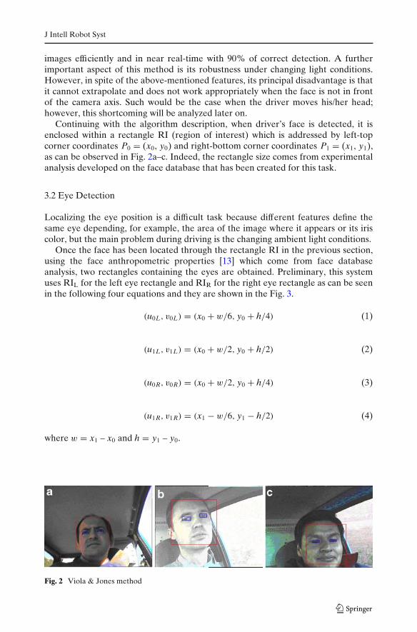
Continuing with the algorithm description, when driver’s face is detected, it isenclosed within a rectangle RI (region of interest) which is addressed by left-topcorner coordinates P0 = (x0, y0) and right-bottom corner coordinates P1 = (x1, y1),as can be observed in Fig. 2a–c. Indeed, the rectangle size comes from experimentalanalysis developed on the face database that has been created for this task.
3.2 Eye Detection
Localizing the eye position is a difficult task because different features define thesame eye depending, for example, the area of the image where it appears or its iriscolor, but the main problem during driving is the changing ambient light conditions.
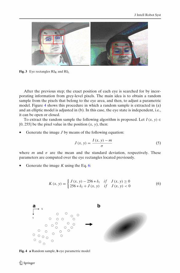
Once the face has been located through the rectangle RI in the previous section,using the face anthropometric properties [13] which come from face databaseanalysis, two rectangles containing the eyes are obtained. Preliminary, this systemuses RIL for the left eye rectangle and RIR for the right eye rectangle as can be seenin the following four equations and they are shown in the Fig. 3.
(u0L, v0L) = (x0 + w/6, y0 + h/4) (1)
(u1L, v1L) = (x0 + w/2, y0 + h/2) (2)
(u0R, v0R) = (x0 + w/2, y0 + h/4) (3)
(u1R, v1R) = (x1 − w/6, y1 − h/2) (4)
where w = x1 – x0 and h = y1 – y0.
Fig. 2 Viola & Jones method
J Intell Robot Syst
Fig. 3 Eye rectangles RIR and RIL
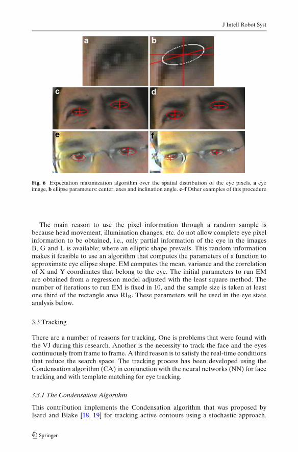
After the previous step; the exact position of each eye is searched for by incor-porating information from grey-level pixels. The main idea is to obtain a randomsample from the pixels that belong to the eye area, and then, to adjust a parametricmodel. Figure 4 shows this procedure in which a random sample is extracted in (a)and an elliptic model is adjusted in (b). In this case, the eye state is independent, i.e.,it can be open or closed.
To extract the random sample the following algorithm is proposed. Let I (x, y) ∈[0, 255] be the pixel value in the position (x, y), then:
• Generate the image J by means of the following equation:
J (x, y) = I (x, y) − mσ
(5)
where m and σ are the mean and the standard deviation, respectively. Theseparameters are computed over the eye rectangles located previously.
• Generate the image K using the Eq. 6:
K (x, y) ={
J (x, y) − 256 ∗ δ1 i f J (x, y) ≥ 0256 ∗ δ2 + J (x, y) i f J (x, y) < 0
(6)
Fig. 4 a Random sample, b eye parametric model

J Intell Robot Syst
where δ1 =max (0, ceil (J (x, y) /256)−1), δ2 =max (1, ceil (|J (x, y)| /256)) and ceil(x)is the function that returns the smallest integer larger than x.
• Obtain the binary image, B, from image K through the Eq. 7, namely,
B (x, y) ={
255 i f K (x, y) ≥ κ
0 other case(7)
where κ is computed by Ostu’s method [29] which is used to compute an automaticthreshold, Fig. 5b.
• Compute the gradient image, G, using the Sobel horizontal (Sx) and vertical (Sy)edge operator followed by an image contrast enhancement [20], Fig. 5c.
Sx =⎡⎣−1 0 1
−2 0 2−1 0 1
⎤⎦ , Sy = −ST
x (8)
• Compute the logarithm image [35], L, with the objective to enhance the iris pixelsthat are the central part of the eye, Fig. 5d.
L (x, y) = log (1 + I (x, y)) (9)
Starting from the pixels that have been extracted from the images B, G andL; it is possible to obtain the random sample previously mentioned. This samplepresents an ellipse shape and an elliptic model has been adjusted over this by usingthe expectation maximization algorithm (EM) [26]. The ellipse center has beengiven special attention, because, it allows the exact position of the eye center to beobtained. The ellipse axes determine the width and height of the eyes. The result isshown in Fig. 6b.
Fig. 5 Eye location through RL and RR, a grayscale image, b binary image (B), c gradient image(G), and d logarithm image (L)
J Intell Robot Syst
Fig. 6 Expectation maximization algorithm over the spatial distribution of the eye pixels, a eyeimage, b ellipse parameters: center, axes and inclination angle. c–f Other examples of this procedure
The main reason to use the pixel information through a random sample isbecause head movement, illumination changes, etc. do not allow complete eye pixelinformation to be obtained, i.e., only partial information of the eye in the imagesB, G and L is available; where an elliptic shape prevails. This random informationmakes it feasible to use an algorithm that computes the parameters of a function toapproximate eye ellipse shape. EM computes the mean, variance and the correlationof X and Y coordinates that belong to the eye. The initial parameters to run EMare obtained from a regression model adjusted with the least square method. Thenumber of iterations to run EM is fixed in 10, and the sample size is taken at leastone third of the rectangle area RIR. These parameters will be used in the eye stateanalysis below.
3.3 Tracking
There are a number of reasons for tracking. One is problems that were found withthe VJ during this research. Another is the necessity to track the face and the eyescontinuously from frame to frame. A third reason is to satisfy the real-time conditionsthat reduce the search space. The tracking process has been developed using theCondensation algorithm (CA) in conjunction with the neural networks (NN) for facetracking and with template matching for eye tracking.
3.3.1 The Condensation Algorithm
This contribution implements the Condensation algorithm that was proposed byIsard and Blake [18, 19] for tracking active contours using a stochastic approach.
J Intell Robot Syst
CA combines factored sampling (Monte-Carlo sampling method) with a dynamicalmodel that is governed through the state Eq. 10.
Xt = f (Xt−1, ξt) (10)
where Xt is the state at instant t, f (·) is an nonlinear equation and depends on aprevious state plus a white noise. The goal is to estimate the state vector Xt withthe help of system observation which are the realization of the stochastic process Zt
governed by the measurement equation:
Zt = h (Xt, ηt) (11)
where Zt is the measure system at time t, h(·) is another nonlinear equation thatlinks the present state plus a white noise. The processes ξ t and ηt are each onewhite noise and are independent of each other. Also, these processes in general arenon-Gaussian and multi-modal. It must be pointed out that Xt is an unobservableunderlying stochastic process.
3.3.2 Neural Networks
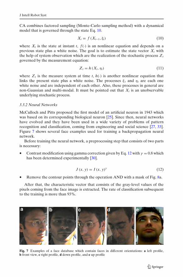
McCulloch and Pitts proposed the first model of an artificial neuron in 1943 whichwas based on its corresponding biological neuron [25]. Since then, neural networkshave evolved and they have been used in a wide variety of problems of patternrecognition and classification, coming from engineering and social science [27, 33].Figure 7 shows several face examples used for training a backpropagation neuralnetwork.
Before training the neural network, a preprocessing step that consists of two partsis necessary:
• Contrast modification using gamma correction given by Eq. 12 with γ = 0.8 whichhas been determined experimentally [30].
J (x, y) = I (x, y)γ (12)
• Remove the contour points through the operation AND with a mask of Fig. 8a.
After that, the characteristic vector that consists of the gray-level values of thepixels coming from the face image is extracted. The rate of classification subsequentto the training is more than 93%.
Fig. 7 Examples of a face database which contain faces in different orientations: a left profile,b front view, c right profile, d down profile, and e up profile
J Intell Robot Syst
Fig. 8 Mask for face training and its result
3.3.3 Face Tracking
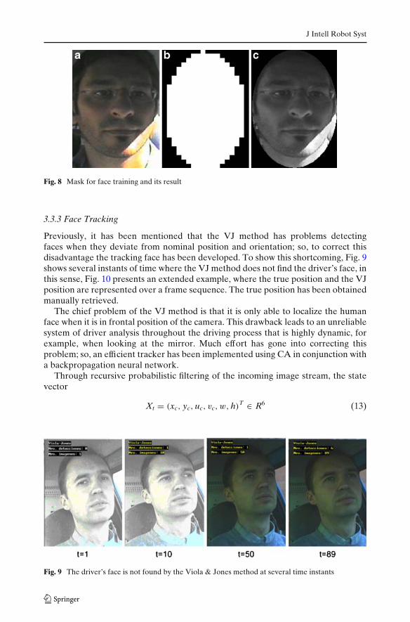
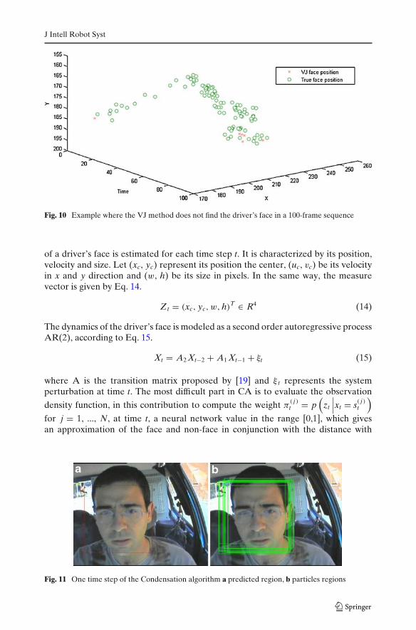
Previously, it has been mentioned that the VJ method has problems detectingfaces when they deviate from nominal position and orientation; so, to correct thisdisadvantage the tracking face has been developed. To show this shortcoming, Fig. 9shows several instants of time where the VJ method does not find the driver’s face, inthis sense, Fig. 10 presents an extended example, where the true position and the VJposition are represented over a frame sequence. The true position has been obtainedmanually retrieved.
The chief problem of the VJ method is that it is only able to localize the humanface when it is in frontal position of the camera. This drawback leads to an unreliablesystem of driver analysis throughout the driving process that is highly dynamic, forexample, when looking at the mirror. Much effort has gone into correcting thisproblem; so, an efficient tracker has been implemented using CA in conjunction witha backpropagation neural network.
Through recursive probabilistic filtering of the incoming image stream, the statevector
Xt = (xc, yc, uc, vc, w, h)T ∈ R6 (13)
Fig. 9 The driver’s face is not found by the Viola & Jones method at several time instants
J Intell Robot Syst
Fig. 10 Example where the VJ method does not find the driver’s face in a 100-frame sequence
of a driver’s face is estimated for each time step t. It is characterized by its position,velocity and size. Let (xc, yc) represent its position the center, (uc, vc) be its velocityin x and y direction and (w, h) be its size in pixels. In the same way, the measurevector is given by Eq. 14.
Zt = (xc, yc, w, h)T ∈ R4 (14)
The dynamics of the driver’s face is modeled as a second order autoregressive processAR(2), according to Eq. 15.
Xt = A2 Xt−2 + A1 Xt−1 + ξt (15)
where A is the transition matrix proposed by [19] and ξ t represents the systemperturbation at time t. The most difficult part in CA is to evaluate the observation
density function, in this contribution to compute the weight π( j )t = p
(zt
∣∣∣xt = s( j )t
)for j = 1, ..., N, at time t, a neural network value in the range [0,1], which givesan approximation of the face and non-face in conjunction with the distance with
Fig. 11 One time step of the Condensation algorithm a predicted region, b particles regions
J Intell Robot Syst
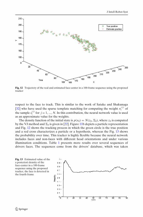
Fig. 12 Trajectory of the real and estimated face-center in a 100-frame sequence using the proposedtracker
respect to the face to track. This is similar to the work of Satake and Shakunaga[32] who have used the sparse template matching for computing the weight π
( j )t of
the sample s( j )t for j = 1, ..., N. In this contribution, the neural network value is used
as an approximate value for the weights.The density function of the initial state is p(x0) = N(z0, 0), where z0 is computed
by the VJ method and 0 is given in [22]. Figure 11b depicts a particle representationand Fig. 12 shows the tracking process in which the green circle is the true positionand a red cross characterizes a particle or a hypothesis, whereas the Fig. 13 showsthe probability over time. This tracker is highly flexible because the neural networkincludes faces and non-faces with different head orientations and under variousillumination conditions. Table 1 presents more results over several sequences ofdrivers faces. The sequences come from the drivers’ database, which was taken
Fig. 13 Estimated value of thea posteriori density of theface-center in a 100-framesequence using the proposedtracker, the face is detected inthe fourth frame

J Intell Robot Syst
Table 1 Result of facetracking
Driver Total frames Tracking failure Correct rate (%)
D1 960 60 93.75D2 900 22 97.55D3 500 45 91.00D4 330 15 95.45D5 1400 50 96.42
to develop these experiments. The true position of the faces has been obtainedmanually retrieved.
3.3.4 Eye Tracking
For this task, the state of the eye is characterized by its position and velocity over theimage. Let (x, y) represent the eye pixel position at time t and (u, v) be its velocity attime t in x and y directions, respectively. The state vector at time t can, therefore, berepresented by Eq. 16.
Xt = (x, y, u, v)T ∈ R4 (16)
The transition model is given by Eq. 17 which is a first autoregressive modelAR(1).
Xt = AXt−1 + ξt (17)
The evaluation of the observation density function is developed by a templatematching strategy [32] that was truncated to reduce the false detection. CA isinitialized when the eyes are detected with the method from the previous section plusa white noise and it is similar to the case of face tracking. Figure 14 depicts the eye
Fig. 14 Trajectory of the real and estimated eyes-center in a 100-frame sequence

J Intell Robot Syst
Fig. 15 Estimated value of the a posteriori density of the eye-center in a 100-frame for right and lefteyes, the eyes are detected in the four frame
trajectory tracking and Fig. 15 shows the compute values of the a posteriori densityfunction of each eye, both on a sequence of 100 images, whereas Table 2 shows theeye tracking results that has been developed in several sequences of images.
3.4 Eye State Detection
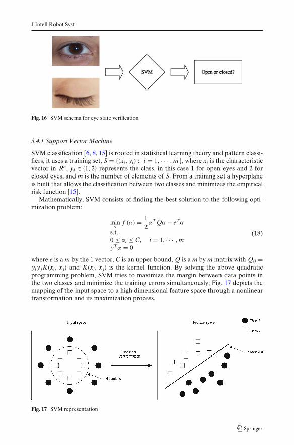
To identify drowsiness through eye analysis it is necessary to know its state: openor closed, through the time and develop an analysis over time, i.e., to measure thetime that has been spent in each state. Classification of the open and closed stateis complex due to the changing shape of the eye, among other factors, the changingposition and the rotating of the face, and variations of twinkling and illumination. Allthis makes it difficult to analyze eye in a reliable manner. For the problems that havebeen exposed a supervised classification method has been used for this challengingtask, in this case, a support vector machine (SVM). Figure 16 presents the schemaproposed for eye state verification.
Table 2 Result of eye tracking Driver Total frames Tracking failure Correct rate (%)
D1 960 20 97.91D2 900 30 96.60D3 500 8 98.40D4 330 14 95.75D5 1400 90 93.57
J Intell Robot Syst
Fig. 16 SVM schema for eye state verification
3.4.1 Support Vector Machine
SVM classification [6, 8, 15] is rooted in statistical learning theory and pattern classi-fiers, it uses a training set, S = {(xi, yi) : i = 1, · · · , m }, where xi is the characteristicvector in Rn, yi ∈ {1, 2} represents the class, in this case 1 for open eyes and 2 forclosed eyes, and m is the number of elements of S. From a training set a hyperplaneis built that allows the classification between two classes and minimizes the empiricalrisk function [15].
Mathematically, SVM consists of finding the best solution to the following opti-mization problem:
minα
f (α) = 1
2αT Qα − eTα
s.t.0 ≤ αi ≤ C, i = 1, · · · , myTα = 0
(18)
where e is a m by the 1 vector, C is an upper bound, Q is a m by m matrix with Qij =yi y jK(xi, x j) and K(xi, x j) is the kernel function. By solving the above quadraticprogramming problem, SVM tries to maximize the margin between data points inthe two classes and minimize the training errors simultaneously; Fig. 17 depicts themapping of the input space to a high dimensional feature space through a nonlineartransformation and its maximization process.
Fig. 17 SVM representation

J Intell Robot Syst
3.4.2 Eye Characteristic Extraction Using Gabor Filter
The Gabor filter was used by Daugman for image analysis, changing the orientationand scale [9, 23]. Indeed, they are multi-scale and multi-orientation kernels. They canbe defined by Eq. 19 that is a complex function.
g (x, y, θ, φ) = exp
(− x2 + y2
σ 2
)exp (i2πθ (x cos (φ) + y sin (φ))) (19)
where θ and φ are the scale and orientation parameters, σ is the standard deviation ofthe Gaussian kernel that depends upon the spatial frequency to measured, i.e. θ . Theresponse of the Gabor filter to an image is obtained by a 2D convolution operation.Let I(x, y) denote the image and G(x, y, θ , φ) denote the response of a Gabor filterwith scale θ and orientation φ to an image at point (x, y) on the image plane. G(·) isobtained by (20).
G (x, y, θ, φ) =∫∫
I (p, q) g (x − p, y − q, θ, φ) dpdq (20)
Some combinations of scales and orientations are more robust for the classificationbetween open eye and closed eye. Indeed, three scales, four orientations have beenused to generate Fig. 18, they are {1,2,3} and {0, π /4, π /2, 3π /4} that were obtainedexperimentally over an image of size 30 by 20.
Once the response of a Gabor filter is obtained, the eye characteristic vector isextracted by a sub-window procedure described by Chen and Kubo [7] and denoted
Fig. 18 Gabor filter for θ = {0,1,2} and φ = {0, π /4, π /2, 3π /4}
J Intell Robot Syst
Fig. 19 Sub-window imagesfrom the Gabor filter
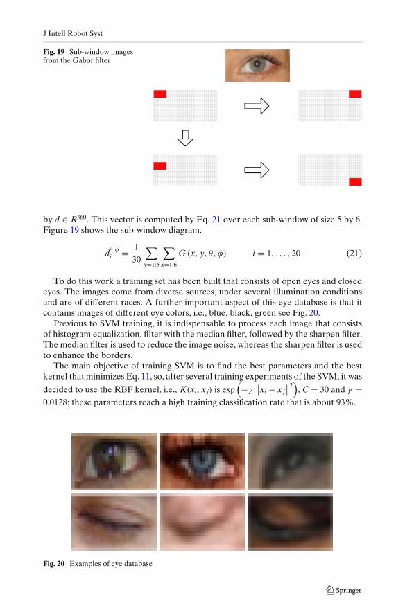
by d ∈ R360. This vector is computed by Eq. 21 over each sub-window of size 5 by 6.Figure 19 shows the sub-window diagram.
dθ,φ
i = 1
30
∑y=1:5
∑x=1:6
G (x, y, θ, φ) i = 1, . . . , 20 (21)
To do this work a training set has been built that consists of open eyes and closedeyes. The images come from diverse sources, under several illumination conditionsand are of different races. A further important aspect of this eye database is that itcontains images of different eye colors, i.e., blue, black, green see Fig. 20.
Previous to SVM training, it is indispensable to process each image that consistsof histogram equalization, filter with the median filter, followed by the sharpen filter.The median filter is used to reduce the image noise, whereas the sharpen filter is usedto enhance the borders.
The main objective of training SVM is to find the best parameters and the bestkernel that minimizes Eq. 11, so, after several training experiments of the SVM, it was
decided to use the RBF kernel, i.e., K(xi, x j) is exp(−γ
∥∥xi − x j∥∥2
), C = 30 and γ =
0.0128; these parameters reach a high training classification rate that is about 93%.
Fig. 20 Examples of eye database
J Intell Robot Syst
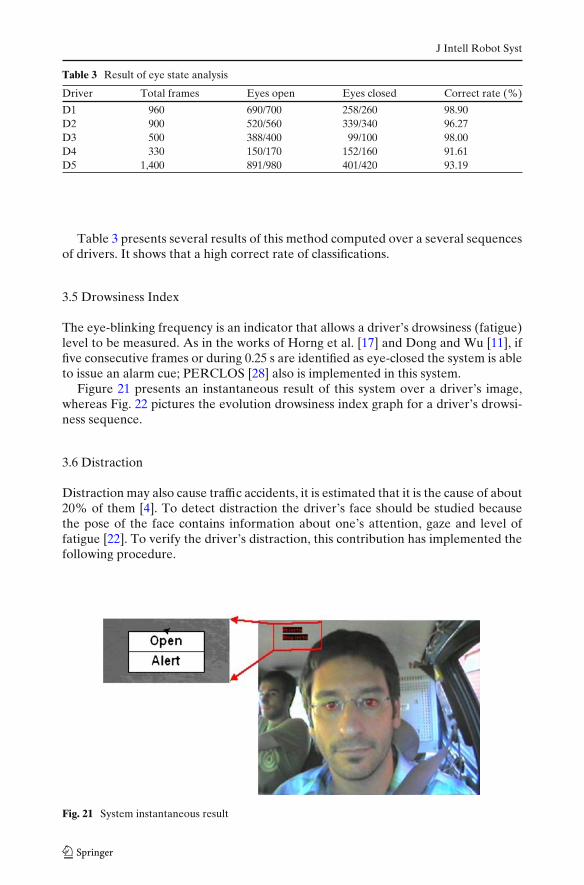
Table 3 Result of eye state analysis
Driver Total frames Eyes open Eyes closed Correct rate (%)
D1 960 690/700 258/260 98.90D2 900 520/560 339/340 96.27D3 500 388/400 99/100 98.00D4 330 150/170 152/160 91.61D5 1,400 891/980 401/420 93.19
Table 3 presents several results of this method computed over a several sequencesof drivers. It shows that a high correct rate of classifications.
3.5 Drowsiness Index
The eye-blinking frequency is an indicator that allows a driver’s drowsiness (fatigue)level to be measured. As in the works of Horng et al. [17] and Dong and Wu [11], iffive consecutive frames or during 0.25 s are identified as eye-closed the system is ableto issue an alarm cue; PERCLOS [28] also is implemented in this system.
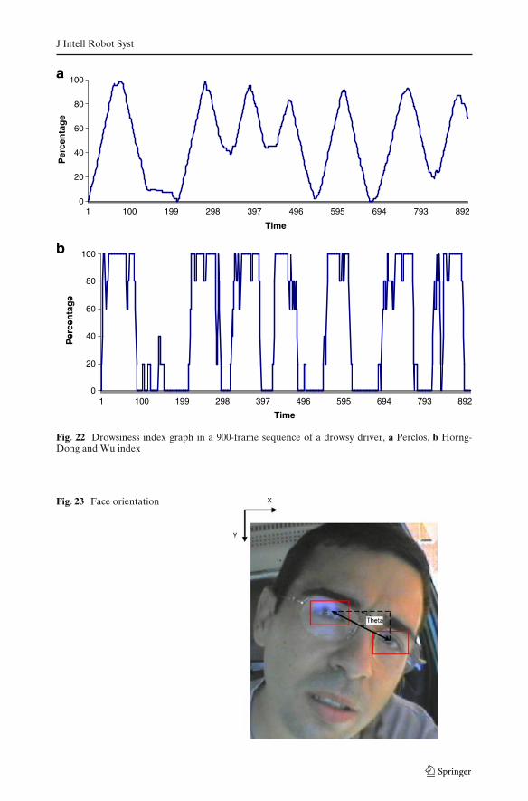
Figure 21 presents an instantaneous result of this system over a driver’s image,whereas Fig. 22 pictures the evolution drowsiness index graph for a driver’s drowsi-ness sequence.
3.6 Distraction
Distraction may also cause traffic accidents, it is estimated that it is the cause of about20% of them [4]. To detect distraction the driver’s face should be studied becausethe pose of the face contains information about one’s attention, gaze and level offatigue [22]. To verify the driver’s distraction, this contribution has implemented thefollowing procedure.
Fig. 21 System instantaneous result
J Intell Robot Syst
0
20
40
60
80
100
1 100 199 298 397 496 595 694 793 892
Time
Per
cen
tag
e
0
20
40
60
80
100
1 100 199 298 397 496 595 694 793 892
Time
Per
cen
tag
ea
b
Fig. 22 Drowsiness index graph in a 900-frame sequence of a drowsy driver, a Perclos, b Horng-Dong and Wu index
Fig. 23 Face orientation
J Intell Robot Syst
Ang
le
Time
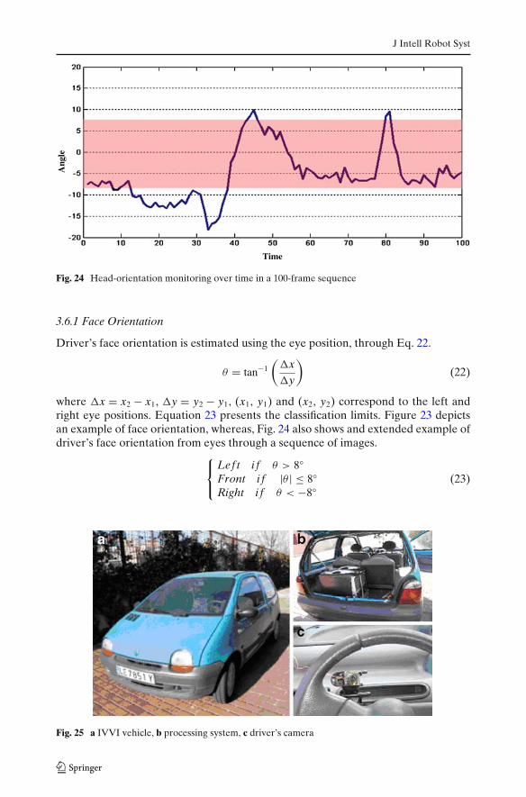
Fig. 24 Head-orientation monitoring over time in a 100-frame sequence
3.6.1 Face Orientation
Driver’s face orientation is estimated using the eye position, through Eq. 22.
θ = tan−1
( x y
)(22)
where x = x2 − x1, y = y2 − y1, (x1, y1) and (x2, y2) correspond to the left andright eye positions. Equation 23 presents the classification limits. Figure 23 depictsan example of face orientation, whereas, Fig. 24 also shows and extended example ofdriver’s face orientation from eyes through a sequence of images.⎧⎨
⎩Lef t i f θ > 8◦Front i f |θ | ≤ 8◦Right i f θ < −8◦
(23)
Fig. 25 a IVVI vehicle, b processing system, c driver’s camera

J Intell Robot Syst
Fig. 26 Different stages of the proposed algorithm on several instants of time, driving conditionsand different drivers
3.6.2 Head Tilt
The above method has a problem when using a monocular camera, so, to correctthis drawback, this contribution implements a head-tilt based on neural networks.Let us remember that the driver’s face database is made up of examples of faces infive orientations, so, the face is passed to neural networks to know its orientation,especially for the up and down cases. If the system detect that the face position is notfrontal, an alarm cue is issued to alert the driver of a danger situation.
4 Conclusions
In this paper, a research project to develop a non-intrusive driver’s drowsinesssystem based on Computer Vision and Artificial Intelligence has been presented.This system uses advanced technologies for analyzing and monitoring drivers eyestate in real-time and in real driving conditions. Based on the results presentedon Tables 1, 2 and 3, the proposed algorithm for face tracking, eye detectionand eye tracking is robust and accurate under varying light, external illuminationsinterference, vibrations, changing background and facial orientations.
To acquire data to use while developing and testing the algorithms, several driverswere recruited; they were exposed to a variety of difficult situations commonlyencountered on the roadway. This guarantees and confirms that these experimentshave proven robustness and efficiency in real traffic scenes. The images were taken
J Intell Robot Syst
with the camera inside the IVVI vehicle, Fig. 25c. IVVI is an experimental platformused to develop the driver assistance systems in real driving conditions. It is aRenault Twingo vehicle, Fig. 25a, equipped with a processing system, Fig. 25b, whichprocesses the information comes from the cameras. Finally, Fig. 26 shows an examplethat validates this system.
For future work, the objective will be to reduce the percentage error, i.e., to reducethe false alarms; for this, extra experiments will be developed, using additionaldrivers and incorporating new modules.
Acknowledgements This work was supported in part by the Spanish Government through theCICYT projects VISVIA (Grant TRA2007-67786-C02-02) and POCIMA (Grand TRA2007-67374-C02-01).
References
1. Armingol, J.M., de la Escalera, A., Hilario, C., Collado, J., Carrasco, J., Flores, M., Pastor, J.,Rodriguez, F.: IVVI: intelligent vehicle based on visual information. Robot. Auton. Syst. 55,904–916 (2007). doi:10.1016/j.robot.2007.09.004
2. Bergasa, L., Nuevo, J., Sotelo, M., Vazquez, M.: Real time system for monitoring driver vigilance.In: IEEE Intelligent Vehicles Symposium, Parma, 14–17 June 2004
3. Brookshear, J.G.: Theory of Computation: Formal Languages, Automata and Complexity.Addison Wesley Iberoamericana, Reading (1993)
4. Brandt, T., Stemmer, R., Mertsching, B., Rakotomirainy, A.: Affordable visual driver monitoringsystem for fatigue and monotony. IEEE Int. Conf. Syst. Man Cybern. 7, 6451–6456 (2004)
5. Branzan, A., Widsten, B., Wang, T., Lan, J., Mah, J.: A computer vision-based system for real-time detection of sleep onset in fatigued drivers. In: IEEE Intelligent Vehicles Symposium,pp. 25–30 (2008)
6. Chang, C., Lin, C.: LIBSVM: a library for support vector machine (2001). www.csie.ntu.edu.tw/∼cjlin/libsvm
7. Chen, Y.W., Kubo, K.: A robust eye detection and tracking technique using Gabor filters.In: Third International Conference on Intelligent Information Hiding and Multimedia SignalProcessing, IEEE, vol. 1, pp. 109–112 (2007)
8. Cristianini, N., Shawe-Taylor, J.: An Introduction to Support Vector Machines and other Kernel-Based Learning Methods. Cambridge University Press, Cambridge (2000)
9. Daugman, J.G.: Uncertainty relation for resolution in space, spatial frequency and orientationoptimized by two-dimensional cortial filters. J. Opt. Soc. Am. 2(7), 1160–1169 (1985)
10. D’Orazio, T., Leo, M., Distante, A.: Eye detection in faces images for a driver vigilante system.IEEE Intelligent Vehicles Symposium University of Parma, Italy, 14–17 June (2004)
11. Dong, W., Wu, X.: Driver fatigue detection based on the distance of eyelid. In: IEEE Int.Workshop VLSI Design & Video Tech., Suzhou, China (2005)
12. Fletcher, L., Petersson, L., Zelinsky, A.: Driver assistance systems based on vision in and out ofvehicles. In: IEEE Proceedings of Intelligent Vehicles Symposium, pp. 322–327 (2003)
13. Gejgus, P., Sparka, M.: Face Tracking in Color Video Sequences. The Association for ComputingMachinery Inc., New York (2003)
14. Grace, R.: Drowsy driver monitor and warning system. International Driving Symposium onHuman Factors in Driver Assessment, Training and Vehicle Design (2001)
15. Guyon, I., Gunn, S., Nikravesh, M., Zadeh, L.A.: Feature Extraction: Foundations and Applica-tions. Springer, Berlin (2006)
16. Hagenmeyer, L.: Development of a multimodal, universal human–machine-interface forhypovigilance-management-systems. Ph.D. thesis, University of Stuttgart (2007)
17. Horng, W., Chen, C., Chang, Y.: Driver fatigue detection based on eye tracking and dynamictemplate matching. In: Proceedings of the IEEE International Conference on Networking,Sensing & Control (2004)
18. Isard, M., Blake, A.: Condensation: conditional density propagation for visual tracking. Int. J.Comput. Vis. 29(1), 5–28 (1998). doi:10.1023/A:1008078328650
J Intell Robot Syst
19. Isard, M.A.: Visual motion analysis by probabilistic propagation of conditional density. Ph.D.thesis, Oxford University (1998)
20. Jafar, I., Ying, H.: A new method for image contrast enhancement based on automatic specifica-tion of local histograms. IJCSNS Int. J. Computer Sci. Netw. Secur. 7(7), 1–10 (2007)
21. Ji, Q., Zhu, Z., Lan, P.: Real time nonintrusive monitoring and prediction of driver fatigue. IEEETrans. Veh. Technol. 53(4), 1052–1068 (2004). doi:10.1109/TVT.2004.830974
22. Ji, Q., Yang, X.: Real-time eye, gaze, and face pose tracking for monitoring driver vigilance.Real-Time Imaging 8, 357–377 (2002)
23. Liu, C.: Gabor-based kernel PCA with fractional power polynomial models for face recognition.IEEE Trans. Pattern Anal. Mach. Intell. 26(5), 572–581 (2004)
24. Longhurst G.: Understanding Driver Visual Behaviour. Seeing Machine Pty Limited, Acton(2002)
25. Looney, C.G.: Pattern Recognition Using Neural Networks, Theory and Algorithms forEngineers and Scientists. Oxford University Press, Oxford (1997)
26. McLachlan, G.J.: The EM Algorithm and Extensions. Wiley, New York (1997)27. Mujtaba I.M.: Application of Neural Networks and Other Learning Technologies in Process
Engineering. Imperial College Press, London (2001)28. NHTSA: evaluation of techniques for ocular measurement as an index of fatigue and the ba-
sis for alertness management. Final report DOT HS 808762, National Highway Traffic SafetyAdministration, Virginia 22161, USA (1998)
29. Otsu, N.: A threshold selection method from gray-level histograms. IEEE Trans. Syst. ManCybern. 9, 62–66 (1979). doi:10.1109/TSMC.1979.4310076
30. Parker, J.R.: Practical Computer Vision Using C. Wiley, New York (1994)31. Tian, Z., Qin, H.: Real-time driver’s eye state detection. In: IEEE International Conference on
Vehicular Electronics and Safety, pp. 285–289 (2005)32. Satake, J., Shakunaga, T.: Multiple target tracking by appearance-based condensation tracker
using structure information. In: Proceedings of the 17th International Conference on PatterRecognition (ICPR’04), vol. 3, pp. 294–297 (2004)
33. Swingler, K.: Applying Neural Networks: A Practical Guide. Academic, New York (1996)34. Viola, P., Jones, M.: Rapid object detection using a boosted cascade of simple features. In:
Conference on Computer Vision and Pattern Recognition (2001)35. Wu, Y., Liu, H., Zha, H.: A new method of detecting human eyelids based on deformable
templates. In: IEEE International Conference on Systems, Man and Cybernetics, pp. 604–609(2004)
Copyright © 2022 FDOKUMEN

