


Bahasa
Halaman
Hukum


Pneumatic CylindersComposite, round line repairable and disposable, and NFPA square interchangeable
PNEUMATIC VALVESAND MOTION CONTROL2, 3, AND 4-WAY VALVES, AVAILABLE WITH ELECTRIC, MANUAL,
MECHANICAL, AND PNEUMATIC ACTUATORS. MINIATURE TO FULL SIZE VALVES.

About ARO®ARO® is a worldwide manufacturer of fluid management products that are skillfully engineered to deliver performance and serviceability, allowing success to flow freely in our customers’ busi-nesses. That’s why ARO® is fluid intelligence—the smart choice in fluid management products for industrial operations.
With over an 85-year legacy of premier product performance and service excellence, ARO® provides fluid management equipment for customers and industries around the globe. ARO® has the right product to meet our customers’ specific needs. We offer air-operated diaphragm pumps, piston pumps and packages, filters, regulators, and lubricators (FRLs), lubrication equipment, and pneumatic valves and cylinders.
ARO’s Fluid Power Products Keep the Unknown In CheckThe smallest things pose the biggest threats to your facility. Air particle contaminates, improper pressure levels, lack of safety switches, and more can cause major damage to equipment and employees. Too often than not, plant managers are unaware of these threats until suddenly an essential tool doesn’t work or their facility is shut down and they lose major time diagnos-ing the issue. ARO® builds the quality products to keep you from getting too familiar with the unknown. ARO® valves, cylinders, logic controls, and filters/regulators/lubricators (FRLs) make it easy to manage the small stuff. ARO® products are expertly engineered to protect your equip-ment and your employees from unscheduled downtime, premature breakdown, and injury risks. And because they integrate perfectly together, building a complete system for full protection is a breeze.
Our robust valve offering is broad and deepWe have a valve for almost every solenoid, manual and mechanical application. In the rare case we don’t have it, we can expertly modify or customize our standard product to meet your application needs. ARO® can provide customized pneumatic control solutions to meet the needs of large customers and OEMs
The performance you deserve. The reliability you expectARO® has always delivered on a promise of performance, and valves are no excep-tion. Built with the rugged reliability to handle heavy duty and dirty applications while offering excellent flow rates, our valves can control cylinder movement and machine sequence, operate pumps, and more with top-of-the-line efficiency.
[email protected] • (800) 495-0276 / Pneumatic Valves • AROzone.com 1
z Valves Actuator Styles Page Manual Max Air .............................................36, 39, 40, 59 50 Series ............................................................. 32 E Series................................................................ 42 K Series ............................................................... 48 200 Series ........................................................... 56 460 Series ........................................................... 61
Mechanical Maxair ...........................................................40, 59 50 Series ............................................................. 32 E Series................................................................ 42 100 Series ........................................................... 58 200 Series ........................................................... 56 400 Series ........................................................... 60
Pilot Max Air ................................................................ 13 50 Series ............................................................. 32 E Series................................................................ 42 K Series ............................................................... 48 H Series ............................................................... 52 200 Series ........................................................... 56 Alpha ................................................................... 18
Solenoid Max Air ..........................................................13, 30 Sierra .................................................................... 4 Alpha ................................................................... 18 CAT ..................................................................... 24 E Series................................................................ 42 H Series ............................................................... 52 K Series ............................................................... 48 Premair ................................................................ 28
z Accessories and Specialty Valves 24130 Button Bleeder ....................................... 62 24135 Button Bleeder ....................................... 62 9600 Pilot Bleeder ............................................. 62 EV-30-A Quick Exhaust ..................................... 62 PR10 Single Pulse Relay .................................... 62 SV10-C Shuttle .................................................. 63 SV20-C Shuttle ................................................... 63 20370 Micro Switches ....................................... 63 20467 Micro Switches ....................................... 63 20311-X Breather.............................................. 64 20312-X Muffler ............................................... 64 20313-X Speed Control .................................... 64 20308-X Exhaust Silencer ................................. 64 600 3-Way Sleeve ............................................. 65 Coils and Connectors ..................................69, 70 Tubing, Fittings and Connectors ......................... 95 Flow Controls ......................................... 66, 67, 68 Air Pneumatic Logic Controls Specifications ...................................................... 73 Two -Hand Anit-Tie-Down ................................. 74 Flex-6 Accessory Units........................................ 75 Flex-6 Controls ................................................... 78 Logic Elements .................................................... 81 Indicators ............................................................ 88 Enclosures ........................................................... 91 Counters .............................................................. 92 Liquid Level Sensors ........................................... 93 Fittings ................................................................ 95 Panell Mounted Valves .................................89, 90
Repair Kits Repair Kits .....................................................72, 73
Table of Contents

2 AROzone.com • Pneumatic Valves / (800) 495-0276 • [email protected]
z Descriptions Sierra Series Compact 2-position, 4-way valves that are lightweight, yet durable. 15mm or 18mm wide. Body ported or
sub-base mounted. Single and double solenoids available. M5 (10-32) and 1/8” ports.
MaxAir Series 2, 3 and 4-way air solenoid, pilot and hand lever valves feature excellent flow in a compact, lightweight package.
Alpha Series High flow, 2-and-3-position, 4-way valves that are compact in size with many features. The family includes:
Body Threaded, Stacking, Bar Manifold and Assembled Manifold. Single and double solenoids, or pilot actuators are available. 1/8”, 1/4” and 3/8” ports.
Cat Series Small, 3-way solenoid valves. Perfect for small bore, single acting cylinders and electric to air interfacing applications.
Body ported for stand alone applications, stacking or base manifold. Available as normally open or normally closed. 1/8” and 1/4” ports.
50 Series 3-way and 4-way body ported valves. Six manual, mechanical and pilot actuator styles available. 1/8” ports.
E-Series 3-way and 4-way body ported valves. Nine manual, mechanical, pilot and solenoid actuator styles available. 1/4” ports.
K-Series Manual, Pilot and Solenoid, heavy duty 4-way valves. Available as body ported. Seven actuator styles available.
Manual: 3/8” and 1/2” ports. Solenoid and Pilots: 3/8”, 1/2”, 3/4” and 1” ports.
H-Series High flow 3-and-4-way function Poppet valves. Available in solenoid, pilot and bleed actuators. 1/4”, 3/8” & 1/2” ports.
Premair™ 3 & 4-way direct acting solenoid valve. Rugged construction & lightweight, stand alone & stacking. Available in 1/8” ports.
z Accessories Accessory Valves • 100 Series - 3-way N.C., miniature limit valves. • 200 Series - 3-way limit valve-ideal for sensing devices such as cylinders, slides & gates. • 400 Series - Heavy duty 3-way limit valves, 4 actuator arms available. • 460 Series - 3-way palm button valves. • The 200, 400 and 460 are multipurpose valves, plumb N.O., N.C., diverter, & selector. • In line and right angle flow controls, in line needle & check valves.
Valve Accessories and Special Valves • Bleed valves: manual button and pilot operated. • Quick exhaust valves for enhancing cylinder speed. • One shot pulse valve to convert continuous air supply to a momentary output. • Shuttle valves operate as a check when two inlets are required. • Micro switch converts pneumatic signal into an electric signal. • Exhaust mufflers, exhaust speed controls, breather vents.
Pneumatic Logic Controls • Two-hand anti-tie-down unit for monitoring operators hands during work cycle. • Pneumatic pulse and delay timers for use in simple valve circuitry. • Pneumatic counters.
Pneumatic Valves

[email protected] • (800) 495-0276 / Pneumatic Valves • AROzone.com 3
Selection Charts
z Product line size range - body style solenoid valves
z Product line size range - manifold/stacking solenoid valves
z Product line size range - body style manual/mechanical
Valve Series (Page No.)
10-32Port Size
1/8”Port Size
1/4”Port Size
3/8”Port Size
1/2”Port Size
3/4”Port Size
1”Port Size
Sierra(PG 4-12)
9 SCFM (0.25 Cv)
30 SCFM (0.70 Cv)
Premair(PG 28,29)
10 SCFM (0.144 Cv)
Maxair(PG 13-17)
26 SCFM (0.70 Cv)
61 SCFM (1.65 Cv)
150 SCFM(1.70 Cv)
Alpha(PG 18-23)
30 SCFM (0.90 Cv)
50 SCFM (1.50 Cv)
61 SCFM (0.70 Cv)
E(PG 42-47)
26 SCFM (0.70 Cv)
H(PG 52,55)
55 SCFM (1.51Cv)
81 SCFM (2.27 Cv)
85 SCFM (2.40 Cv)
K(PG 48-51)
83 SCFM (2.30 Cv)
90 SCFM (2.57 Cv)
270 SCFM (7.54 Cv)
280 SCFM (7.80 Cv)
Sierra(PG 4-12)
9 SCFM (0.25 Cv)
30 SCFM (0.70 Cv)
Premair(PG 28,29)
10 SCFM (0.14 Cv)
Maxair(PG 13-17)
26 SCFM (0.70 Cv)
61 SCFM (1.65 Cv)
150 SCFM (1.75 Cv)
Alpha(PG 16-23)
43 SCFM (1.32 Cv)
54 SCFM (1.60 Cv)
54 SCFM (1.60 Cv)
57 SCFM (1.75 Cv)
Cat(PG 24-27)
1.8 SCFM (0.048 Cv)
2.2 SCFM (0.0.62 Cv)
Valve Series (Page No.)
5/32”Push to Connect
1/8”Port Size
1/4”Port Size
3/8”Port Size
1/2”Port Size
3/4”Port Size
1”Port Size
200(PG 56-57)
4 SCFM (0.104 Cv)
7.5 SCFM (0.195 Cv)
400(PG 60-61)
4 SCFM (0.104 Cv)
7.5 SCFM (0.195 Cv)
50(PG 32-35)
16 SCFM (0.43 Cv)
Maxair(PG 36-40)
8 SCFM (0.70 Cv)
26 SCFM (1.14 Cv)
E(PG 42-47)
26 SCFM (0.70 Cv)
K (PG 48-51)83 SCFM (2.30 Cv)
90 SCFM (2.57 Cv)

4 AROzone.com • Pneumatic Valves / (800) 495-0276 • [email protected]
Ultra-Compact Valve DesignAt only 15 mm wide, Sierra 15 is the one compact valve that’s going to fit your valve location requirements – with room to spare.
Durable Body ConstructionSierra’s body features bar stock aluminum construction, producing a light weight, yet durable valve.
Body-Ported: • 2-position single and double solenoid models. • Two wiring options: Lead Wire and Plug-In. • Available in 120V AC, 24V DC or 12V DC. • Body-Ported valves can be mounted on low profile manifold
to simplify installation when using multiple valves.
Base Mounted: • 2-position single and double solenoid models. • Standard 2-, 4-, 6-, 8-, 10-, 12- and 16 stations. • Stand-alone subbase (for 1-station) with M5 (10-32) or 1/8” NPT(F)
ports. • Two wiring options: Lead Wire and Plug-In and three voltage options 120V AC, 24V DC or 12V DC.
One-Touch Manual Valve Override (Standard)Mechanical valve override is nonlocking spring return push with tool.
Wiring and Voltage OptionsLead-Wire Style: Valve lead wires come stripped and preattached to the coil (NEMA 4). All models are available in either 120V AC, 24V DC. 12V DC Available on plug in only.
Manifold OptionsManifolds are available in 2, 4, 6, 8, 10, 12 and 16-station configurations. Sierra manifolds are available with 1/8” NPT(F) ports. Sierra Valves and Manifolds are sold separately.
Stand-alone sub-bases available in M5 (10-32) or 1/8” NPT, for use with manifold mount valves only.
z FeaturesAt Last. A Miniature Valve with Maximum Range. Superior flow capacity, an unrivaled array of “real-world” design features and options, a valve body that is both ultra-compact and lightweight—yet exceptionally durable—this is Sierra 15, the miniature valve with the maximum range.
Sierra Valves on SML51N-04 Low Profile Manifold
Sierra 15
z Performance Specifications
Pressure Range: 22 to 115 PSI (0.8 M pa)
Shift Pressures: 22 PSI Single or Double-Solenoid
Flow: 9 SCFM, .25 Cv
Operating Medium: Compressed Air
Lubrication: None Required
Cycle Rate: 120 Cycles Per Minute
Temperature Rating: 0° to 122°F (-17° to 50°C)
Signal Response Time 14 ms
Rated Voltage: 120V AC, 24V DC and 12V DC
Current Ratings: 120V AC = 16 mA in-rush; 11 mA holding 12V DC & 24V DC = 67 mA
Power Consumption: 2.1/1.8 VA 1.9 W
Base Mounted Sierra Valves on a SMH51N-04 Manifold
Sierra Body-Ported Valve with Lead Wire

[email protected] • (800) 495-0276 / Pneumatic Valves • AROzone.com 5
z Ordering - Body Ported
Double Solenoid (Plug-In Model)
Single Solenoid (Lead Wire)
z Low Profile Manifold
A
PR1
B
R2
NOTE: Low Profile Manifolds are for use with Body Ported Valves only. One gasket and two screws are provided per station.
Position 1 2 3 4 5
Example: S5 X S M X - 1
Position 1
Sierra Valve Size
Position 2
Number of Coils
Positon 3
Valve Style Positon 4Body Style
Positon 5Coil Style / Voltage
S5 15 mm S Single Solenoid, Spring Return
D Double Solenoid
S Standard Solenoid Operator
M M5 (10-32) A Lead Wire, 120V ACB Lead Wire, 24V DCC Plug-In, 120V ACD Plug-In, 24V DCF Plug-In, 12V DC
A, B NEMA 4 RatingC, D & F NEMA 2 Rating
Position 1 2
Example: SML51N - XX
Position 1
Sierra Manifold
Position 2
Number of Stations
15mm valve low profile manifold with 1/8” Supply and Exhaust Ports
02 2 Stations 04 4 Stations 06 6 Stations 08 8 Stations
Part Number Description
119892-33 120 VAC Plug-In
119892-39 24 VDC Plug-In
119892-38 12 VDC Plug-In
119893-33 120 VAC Lead Wire
119893-39 24 VDC Lead Wire
z Replacement Coils
6 AROzone.com • Pneumatic Valves / (800) 495-0276 • [email protected]
A
PR1
B
R2
Manifold Close-Up
Sierra Valve on 1/8" Stand-alone Subbase
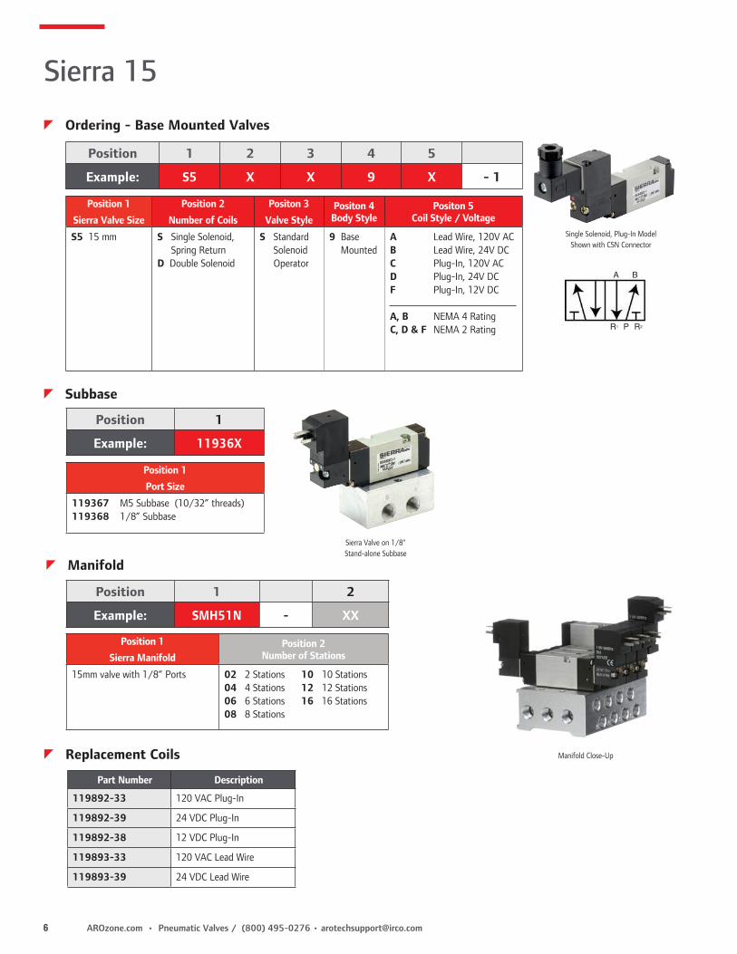
Single Solenoid, Plug-In ModelShown with CSN Connector
Sierra 15
z Ordering - Base Mounted Valves
z Subbase
Position 1 2 3 4 5
Example: S5 X X 9 X - 1
Position 1
Sierra Valve Size
Position 2
Number of Coils
Positon 3
Valve Style Positon 4Body Style
Positon 5Coil Style / Voltage
S5 15 mm S Single Solenoid, Spring Return
D Double Solenoid
S Standard Solenoid Operator
9 Base Mounted
A Lead Wire, 120V ACB Lead Wire, 24V DCC Plug-In, 120V ACD Plug-In, 24V DCF Plug-In, 12V DC
A, B NEMA 4 RatingC, D & F NEMA 2 Rating
Position 1
Example: 11936X
Position 1
Port Size
119367 M5 Subbase (10/32” threads)119368 1/8” Subbase
Part Number Description
119892-33 120 VAC Plug-In
119892-39 24 VDC Plug-In
119892-38 12 VDC Plug-In
119893-33 120 VAC Lead Wire
119893-39 24 VDC Lead Wire
z Replacement Coils
z Manifold
Position 1 2
Example: SMH51N - XX
Position 1
Sierra ManifoldPosition 2
Number of Stations
15mm valve with 1/8” Ports 02 2 Stations 10 10 Stations 04 4 Stations 12 12 Stations 06 6 Stations 16 16 Stations 08 8 Stations

[email protected] • (800) 495-0276 / Pneumatic Valves • AROzone.com 7
[email protected] • (800) 495-0276 / Pneumatic Valves • AROzone.com 9
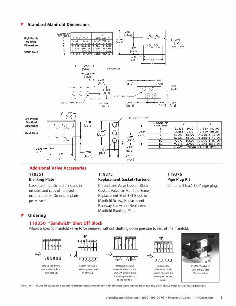
119351 Blanking PlateGasketted metallic plate installs in minutes and caps off unused manifold ports. Order one plate per valve station.
119375 Replacement Gasket/FastenerKit contains Valve Gasket, Block Gasket, Valve-to-Manifold Screw, Replacement Shut-Off Block to Manifold Screw, Replacement Raceway Screw and Replacement Manifold Blanking Plate.
119376Pipe Plug KitContains 3 (ea.) 1/8” pipe plugs.
Additional Valve Accessories
z Ordering
One Solenoid Valve needs to be replaced
during set-up.
Loosen the valve’s retaining screws and
ift off valve.
Removing the valve automatically causes the Shut-Off Block to close the valve ports leading
to the manifold.
Replacing the valve automatically
reopens the ports and reenergizes the new
valve.
IMPORTANT: The Shut-off Block option is intended for machine setup convenience only. When performing routine maintenance on machinery, always observe proper lock-out/ tag-out procedures.
119350 “Sandwich” Shut Off BlockAllows a specific manifold valve to be removed without shutting down pressure to rest of the manifold.
119350 “Sandwich” Shut-off Block for Manifold Valves
z Standard Manifold Dimensions
High Profile Manifold
Dimensions
SMH51N-X
Low Profile Manifold
Dimensions
SML51N-X

10 AROzone.com • Pneumatic Valves / (800) 495-0276 • [email protected]
z Performance Specifications
Sierra 18
z FeaturesSierra® 18 (1/8” Ports) 4-Way, Compact Air Valves18mm Wide Body and 1/8” Ports Fill The Bill Between Mini and Medium Flow ValvesLarger than its 15mm Sierra
counterpart yet smaller than the
Alpha® valve, the Sierra 18 is the perfect fit for valve applications that require a compact, 4-way valve with plenty of options and features. The new Sierra 18 valves are equally ideal where fast signal response (18ms avg.) with moderate flow (.5 Cv, 3-position, .7 Cv 2-position) is required.
2 Styles Available: Choose Between Body-Threaded or Manifold - Mounted:The Sierra 18 is a body - threaded valve that can be directly plumbed or mounted to a low profile manifold. The Sierra 18 is also available as a true manifold valve. Where there’s a need for multiple valves in tight spots, especially in machine design operations, the Sierra 18 is the compact valve with complete flexibility and delivery.
3-Position Spool Function Provides Wider Application Flexibility:Sierra 18 offers three distinct, 3-position spool configurations for a wide variety of applications:
• All ports blocked in center • Cylinder ports open to exhaust in center, supply blocked • Cylinder ports pressurized in center, exhaust ports blocked
Solenoid Coils and Connectors Provide Quick, Clean Connections:Coils are Class F rated for 100% duty cycle applications at 122° F ( 50° C) . AC or DC coils can be interchanged on the same solenoid stem. Each Solenoid connector acts as its own junction box, with molded connectors and gaskets to protect electrical connections. Design meets NEMA-4 classifications.
One - Touch Manual Override (Standard):Sierra 18 contains a mechanical valve non-locking override.
Manifolds Available in 2, 4, 6, 8, 10, and 16-Station Configurations.
Pressure Range: 115 PSI (7.8 bar)
Shift Pressure: 22 PSI
Flow: 30 SCFM .7 Cv (2-Position Valves)21 SCFM .5 Cv (3-Position Valves)
Operating Medium: Compressed Air
Cycle Rate: 120 Cycles Per Minute
Temp. Rating: 0° to 122° F ( -17° to 50° C)
Lubrication: None Required
Signal Response TIme: 17ms (AC), 22ms (DC)
RatedVoltage
Power ConsumptionIn-rush Holding
Current DrawIn-rush Holding
20 VAC 3.1 VA 2.2 VA 26 mA 18 mA
12 VDC 1.9 W 1.9 W 154 mA 154 mA
24 VDC 2.0 W 2.0 W 85 mA 85 mA
[email protected] • (800) 495-0276 / Pneumatic Valves • AROzone.com 11
CHL6-120
CHW6
CSN6
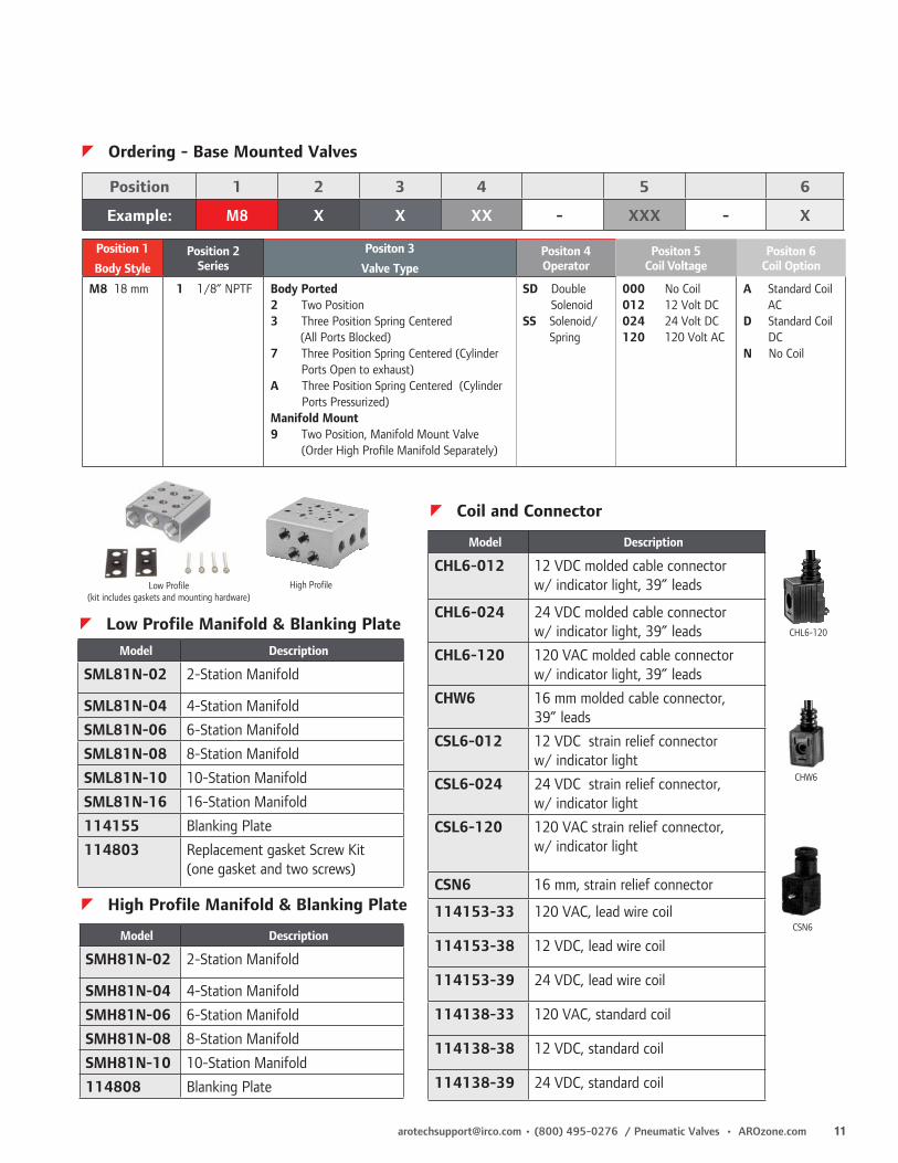
z Ordering - Base Mounted Valves
Position 1 2 3 4 5 6
Example: M8 X X XX -- XXX - X
Model Description
SML81N-02 2-Station Manifold
SML81N-04 4-Station Manifold
SML81N-06 6-Station Manifold
SML81N-08 8-Station Manifold
SML81N-10 10-Station Manifold
SML81N-16 16-Station Manifold
114155 Blanking Plate
114803 Replacement gasket Screw Kit(one gasket and two screws)
z Low Profile Manifold & Blanking Plate
Model Description
SMH81N-02 2-Station Manifold
SMH81N-04 4-Station Manifold
SMH81N-06 6-Station Manifold
SMH81N-08 8-Station Manifold
SMH81N-10 10-Station Manifold
114808 Blanking Plate
z High Profile Manifold & Blanking Plate
Model Description
CHL6-012 12 VDC molded cable connector w/ indicator light, 39” leads
CHL6-024 24 VDC molded cable connector w/ indicator light, 39” leads
CHL6-120 120 VAC molded cable connector w/ indicator light, 39” leads
CHW6 16 mm molded cable connector, 39” leads
CSL6-012 12 VDC strain relief connector w/ indicator light
CSL6-024 24 VDC strain relief connector, w/ indicator light
CSL6-120 120 VAC strain relief connector, w/ indicator light
CSN6 16 mm, strain relief connector
114153-33 120 VAC, lead wire coil
114153-38 12 VDC, lead wire coil
114153-39 24 VDC, lead wire coil
114138-33 120 VAC, standard coil
114138-38 12 VDC, standard coil
114138-39 24 VDC, standard coil
z Coil and Connector
Low Profile (kit includes gaskets and mounting hardware)
High Profile
Position 1
Body StylePosition 2
SeriesPositon 3
Valve Type Positon 4Operator
Positon 5Coil Voltage
Positon 6Coil Option
M8 18 mm 1 1/8” NPTF Body Ported 2 Two Position3 Three Position Spring Centered (All Ports Blocked)7 Three Position Spring Centered (Cylinder
Ports Open to exhaust)A Three Position Spring Centered (Cylinder
Ports Pressurized)Manifold Mount9 Two Position, Manifold Mount Valve
(Order High Profile Manifold Separately)
SD Double Solenoid
SS Solenoid/Spring
000 No Coil012 12 Volt DC024 24 Volt DC120 120 Volt AC
A Standard Coil AC
D Standard Coil DC
N No Coil

12 AROzone.com • Pneumatic Valves / (800) 495-0276 • [email protected]
M819SS-XXX-X M819SD-XXX-X
M812SD-XXX-XM813SD-XXX-X
M812SS-XXX-X
.510
.531
.710
.531.531
4.29
1.38
.669
.124 (2 PL)
.124 (2 PL)
5.98 (2-Position) 6.33(3-Position)
2.28
.18 Hole Dia.(4 places)
A
.79
B
.955 A B2-Station 2.24 1.854-Station 3.74 3.356-Station 5.24 4.848-Station 6.73 6.3410-Station 8.23 7.84
C D2-Station 2.56 2.09 4-Station 4.06 3.59 6-Station 5.56 5.08 8-Station 7.05 6.58 10-Station 8.55 8.08
1/4”NPT
1/8”NPT
31.8
60.5
C
D
18.6
Sierra 18
z Low Profile Manifold Dimensions
z High Profile Manifold Dimensions
[email protected] • (800) 495-0276 / Pneumatic Valves • AROzone.com 13
MaxAir
z Features
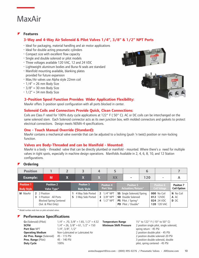
• Ideal for packaging, material handling and air motor applications • Ideal for double acting pneumatic cylinders • Compact size with excellent flow capacity • Single and double solenoid or pilot models • Three voltages available 120 VAC, 12 and 24 VDC • Lightweight aluminum bodies and Buna-N seals are standard • Manifold mounting available, blanking plates
provided for future expansion • Max/Air valves use Alpha style 22mm coil • 1/4” = 26 mm Body Size • 3/8” = 30 mm Body Size • 1/2” = 34 mm Body Size
3-Way and 4-Way Air Solenoid & Pilot Valves 1/4”, 3/8” & 1/2” NPT Ports
Cv (Solenoid) (Pilot) 1/4” = .70, 3/8” = 1.65, 1/2” = 4.32SCFM 1/4” = 26, 3/8” = 61, 1/2” = 150Port Size NPT 1/4”, 3/8”, 1/2”Operating Medium Non-Lubricated or Lubricated AirAir Pres. Range (Solenoid) 45 - 115 PSIPres. Range (Pilot) 45 - 140 PSIDuty Cycle 100%
Temperature Range 15° to 122° F (-10° to 50° C)Minimum Shift Pressure 2 position single pilot, single solenoid,
spring return - 45 PSI 2 position double pilot - 45 PSI 2 position double solenoid-20 PSI 3 position double solenoid, double
pilot, spring centered - 45 PSI
3-Position Spool Function Provides Wider Application Flexibility:MaxAir offers 3-position spool configuration with all ports blocked in center.
Solenoid Coils and Connectors Provide Quick, Clean Connections:Coils are Class F rated for 100% duty cycle applications at 122° F ( 50° C). AC or DC coils can be interchanged on the same solenoid stem. Each Solenoid connector acts as its own junction box, with molded connectors and gaskets to protect electrical connections. Design meets NEMA-4 specifications.
One - Touch Manual Override (Standard):MaxAir contains a mechanical valve override that can be adjusted to a locking (push ‘n twist) position or non-locking function.
Valves are Body-Threaded and can be Manifold - Mounted:MaxAir is a body - threaded valve that can be directly plumbed or manifold - mounted. Where there’s a need for multiple valves in tight spots, especially in machine design operations. Manifolds Available in 2, 4, 6, 8, 10, and 12 Station configurations.
z Performance Specifications
* Model number ends here on pilot activated valves.
z Ordering
Position 1 2 3 4 5 6 7
Example: M X X X XX - 120 - A
Position 1
Body Style
Position 2
Valve Type*
Positon 3
Body StylePositon 4Port Size
Positon 5Actuation/Return*
Positon 6Coil Volage
Positon 7Coil Option
M MaxAir 2 2 Position3 3 Position All Ports
Blocked Spring Centered (Sol. & Pilot Only)
1 4 Way Side Ported5 3 Way Side Ported
2 1/4” NPT3 3/8” NPT4 1/2” NPT
SS Single Solenoid/SpringSD Double SolenoidPS Pilot / Spring*PD Pilot / Double*
000 No Coil012 12VDC024 24 VDC120 120 VAC
N No CoilA ACD DC

14 AROzone.com • Pneumatic Valves / (800) 495-0276 • [email protected]
M26MB Fits 1/4” (26 mm) manifolds
M30MB Fits 3/8” (30 mm) manifolds
M34MB Fits 1/2” (34 mm) manifolds
Blanking Plate Kit
No. of 1/4” NPT 3/8” NPT 1/2” NPT Stations Ports Ports Ports
2 M26M02-02 M30M03-02 M34M04-02 4 M26M02-04 M30M03-04 M34M04-04 6 M26M02-06 M30M03-06 M34M04-06 8 M26M02-08 M30M03-08 M34M04-08 10 M26M02-10 M30M03-10 M34M04-10
Manifold KitsKits include: manifold, seals
and valve attaching hardware
.169 Hole Dia.(4 places)
A
C
B
1/4” 3/8”
1/2”
MaxAir
z Ordering - Manifold
z Dimensions
CHW CBW CSN, CSL-XXX CDN, CDWCDL-XXXX
012 = 12 VDC/VAC 024 = 24 VDC/VAC 120 = 120 VDC/VAC
22mmConnector Model Description
CHW Straight connector with cable (36”) located on topCBW Straight connector with cable (36”) located on backCHL-XXX Straight connector (36”) with indicator light located on back.CSN Strain relief, without indicator light or cable.CSL-XXX Strain relief, with indicator light located on the back.CDN 1/2” conduit without light or lead wireCDW 1/2” conduit without light, 18” lead wireCDL-XXX 1/2” conduit with light, 18” lead wire
CHL-XXX
Voltage (-XXX)
1/4” 3/8” 1/2” Stations A B C A B C A B C 2 3.189 2.638 0.866 3.661 3.031 1.063 4.134 3.346 1.181 4 5.315 4.764 0.866 6.101 5.471 1.063 6.890 6.102 1.181 6 7.441 6.890 0.866 8.541 7.911 1.063 9.646 8.858 1.181 8 9.567 9.016 0.866 10.981 10.351 1.063 12.402 11.614 1.181 10 11.693 11.142 0.866 13.421 12.791 1.063 15.158 14.370 1.181

[email protected] • (800) 495-0276 / Pneumatic Valves • AROzone.com 15
MaxAir
M212SSM252SS*
M213SSM253SS*
M214SSM254SS*
z Dimensions - Solenoid
* Dimensions are the same for 3-way and 4-way valves

16 AROzone.com • Pneumatic Valves / (800) 495-0276 • [email protected]
M212PS, M252PS*
M213PS, M253PS*
M214PS, M254PS*
* Dimensions are the same for 3-way and 4-way valves
z Dimensions - Pilot
MaxAir

[email protected] • (800) 495-0276 / Pneumatic Valves • AROzone.com 17
M212PDM312PD
M214PDM314PD
M212SDM312SD
M213SDM313SD
M214SDM314SD
M213PDM313PD
MaxAir
z Dimensions - Solenoid
z Dimensions - Pilot

18 AROzone.com • Pneumatic Valves / (800) 495-0276 • [email protected]
Body Ported ValvesCompact, space saving design. Perfect for stand alone and remote valve applications. Ports have ISO identification. Sizes include 1/8”, 1/4” and 3/8” NPT .
Stacking ValvesThe lowest cost method of ganging valves, because it eliminates the manifold. Flip out design. Loosen the end plate cap screws to swing the valve up and out. No need to disassemble entire stack to replace one valve. Bodies stack on 1” centers. Circuits can be designed and mounted in a compact area. When stacked, ALPHA becomes a 4-way, 4-ported valve. 3/8” common end plate ports with 1/4” working ports in the valve body.
Subbase ValvesReplace valves easily! Simply remove three screws, lift off valve and replace. Math made simple! Add or subtract manifolds by removing an end plate and changing the valve stack as needed. No tie rods to make changing manifold lengths difficult. Port sizes of 1/4” and 1/2” with ISO port identifications. Subbase Valves use the same electrical coils and connectors as the ALPHA Body Ported Valve. Both End Plates can be used for common supplies and exhaust in high flow applications.
“Thin” Manifold ValvesThin, 1” width means more valves in less space. Faster assembly than stacking style valves. 2, 4, 6, 8, and 10 station manifolds are available. Use optional blanking plates for odd-numbered stations. 1/4” (NPT) models, with 3/8” supply or exhaust ports. Speed controls install directly into manifold, cutting set-up time.
Versatile Design• Available in Body Ported, Subbase,
Stacking and “Thin” configurations• Alpha can be ordered as a 2-position
or 3-position valve• 5-Year Warranty• Valve Body, End Plate and Manifold
material is zinc
Superb Performance• ALPHA’s bonded, precision ground spool
resists wear and provides excellent shift response
• Large air passages result in high flow characteristics. Listings detail Cv factor and maximum flow rates
Numerous Control Options• Control the valve one of 5 ways:
Solenoid/Spring, Solenoid/Solenoid, Solenoid/Pilot, Pilot/Spring or Pilot/Pilot
• External solenoid supply allows operation for vacuum service and low pressure applications (Use kit No. 119306)
• Coils are cURus listed
Pressure Range: Vacuum to 150 psi (10.2 bar)Operating Medium: Compressed Air or inert gasLubrication: None RequiredFiltration: 40 Micron recommendedCycle Rate: 600 Cycles Per MinuteTemperature Rating: 0° to 180°F (-17° to 82°C)Shift Pressures: 50 psi (3.4 bar) 2-Position Single Solenoid
or Single Pilot, Spring Return. 20 psi (1.4 bar) 2-position double pilot or double solenoid. 60 psi (4.0 bar) 3-Position Double Solenoid or Double Pilot, Spring Centered.Signal Response Time: Double Pilot Actuator: 14 ms Double Solenoid: 20 ms Single Pilot (Pilot On) 19 ms Single Pilot (Pilot Off) 26 ms Single Solenoid (Energized) 22 ms Single Solenoid (De-energized) 27 ms
Flow:Body Ported 2-position 1/8” Ports = .9 Cv, 30 SCFM 2-position 1/4” Ports = 1.5 Cv, 50 SCFM 2-position 3/8” Ports = 1.7 Cv, 61 SCFM 3-position 1/8” Ports = .8 Cv, 27 SCFM 3-position 1/4” Ports = 1.4 Cv, 45 SCFM 3-position 3/8” Ports = 1.7 Cv, 61 SCFMSubbase Valves: 1/8” Ports = 1.3Cv, 43 SCFM 1/4” Ports = 1.6 Cv, 54 SCFM 3/8” Ports = 1.6 Cv, 54 SCFM 1/2” Ports = 1.75 Cv, 57 SCFMStacking Valves: 2-position 1/8” Ports = 1.32 Cv, 43 SCFM 2-position 1/4” Ports = 1.9 Cv, 63 SCFM 3-position 1/8” Ports = 1.2 Cv, 39 SCFM 3-position 1/4” Ports = 1.7 Cv, 57 SCFM“Thin” Valves: 1/4” Ports = 1.2 Cv, 39 SCFM
Alpha
z Features
z Performance Specifications

[email protected] • (800) 495-0276 / Pneumatic Valves • AROzone.com 19
Body Ported Valve: A212SS-120-A “2” 2-Position Valve, Urethane Spool “1” 4-Way Body Ported Valve “2” 1/4” NPTF Ports “SS” Actuator-Solenoid, Return-Spring “120-A” 120 Volt Coil, AC Current
“Thin” Valve: A449PS “4” 2-Position Valve, Viton Spool “4” 4-Way Alpha “Thin” Valve “9” 9 No NPTF Ports “PS” Actuator-Pilot, Return-Spring
“Thin” Manifold: 118605-4“11860X-X” Basic Manifold “5” 1/4” NPT Ports“-4” 4-StationsManifold information on Page 21
119306 External Supply Conversion Kit, Page 21. Use when supply pressure is under 50 PSI or vacuum is used.
4-Way, 2-Position 4-Way, 3-Position, all ports blocked in neutral
4-Way, 3-Position, cylinder ports open, inlet port blocked
Alpha
z Ordering
Position 1 2 3 4 5 6 7
Example: A X X X XX - XXX - X
Position 1
Body Style
Position 2
Valve Spool Type
Positon 3
Body StylePositon 4Port Size
Positon 5Actuation/Return*
Positon 6Coil Volage
Positon 7Current Type
A Alpha 2 2-Position, Urethane3 3-Position, Urethane8 3-Position, Viton
(3 and 8 are Spring Centered, all ports blocked in neutral. Available only with PD or SD Actuators)
4 2-Position, Viton7 3-Position, Urethane9 3-Position, Viton (7 & 9 are Spring Centered,
inlet ports blocked (cylinder ports open) in neutral. Available only with PD or SD Actuators)
1 4-Way, Body Ported Valves
2 4-Way, Stacking Valves Order End Plates
from menu on Page 20. Order Mounting Brackets from Page 20.
3 4-Way, Subbase Mounted Valves Order Subbase
Manifolds from menu on Page 21.
4 4-Way, Alpha Thin Valves Order Alpha Thin
Manifolds and Speed Control Kits from menus on Page 21.
1 1/8” NPTF (Available on Body Ported valves only)
2 1/4” NPTF (Available on Body Ported or Stacking Valves)
3 3/8” NPTF (#3 available on Body Ported Valves only)
9 NONE (#9 used on Subbase or Alpha Thin Valves)
*PS Pilot/Spring*PD Pilot/Pilot SS Solenoid/Spring SD Solenoid/
Solenoid SP Solenoid/Pilot
* Numbering ends here if a non-solenoid (PS or PD) valve is being selected.
000 No coil 024 24V AC/DC120 120V AC012 12V AC/DC 240 240V AC
A ACD DCN No CoilL Low Watt** **(DC Only, 115 PSI Max.)
If coil option A, D or L is selected, a coil connector must be ordered. See Pg. 69 for coil & connector information. (Low Watt coils work only on valves with low watt option)
z Ordering Examples
20 AROzone.com • Pneumatic Valves / (800) 495-0276 • [email protected]
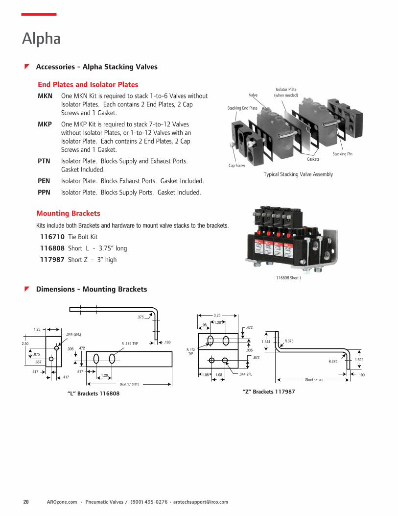
MKN One MKN Kit is required to stack 1-to-6 Valves without Isolator Plates. Each contains 2 End Plates, 2 Cap Screws and 1 Gasket.
MKP One MKP Kit is required to stack 7-to-12 Valves without Isolator Plates, or 1-to-12 Valves with an Isolator Plate. Each contains 2 End Plates, 2 Cap Screws and 1 Gasket.
PTN Isolator Plate. Blocks Supply and Exhaust Ports. Gasket Included.
PEN Isolator Plate. Blocks Exhaust Ports. Gasket Included.
PPN Isolator Plate. Blocks Supply Ports. Gasket Included.
Valve
Stacking End Plate
Gaskets
Isolator Plate(when needed)
Stacking Pin
Cap Screw
Typical Stacking Valve Assembly
Kits include both Brackets and hardware to mount valve stacks to the brackets.
116710 Tie Bolt Kit
116808 Short L - 3.75” long
117987 Short Z - 3” high
3.25
.981.28
.472
.335
.672
.344 2PL
R.375
1.522R.375
.190
1.544
Short “Z” 3.0
1.08 1.08
R. 172TYP
“Z” Brackets 117987
1.25
.875
2.50
.417.417
.306 .472R .172 TYP
.344 (2PL)
.375
.190
.687
.8171.28
Short “L” 3.815
“L” Brackets 116808
116808 Short L
End Plates and Isolator Plates
Mounting Brackets
Alpha
z Dimensions - Mounting Brackets
z Accessories - Alpha Stacking Valves

[email protected] • (800) 495-0276 / Pneumatic Valves • AROzone.com 21
116464 Solenoid Breather Vent 10-32 Thread Size. 119306 External Solenoid Supply Plug Kit Changes ALPHA valves from internal to external
solenoid air source. Step #1: Remove all air supply sources, remove
sealing plug. Figure 1. Step #2: Install separator plug by threading plug into
valve body with a flat-head screwdriver. Figure 2.
Step #3: Connect the external pilot air supply to the valve with an 1/8” NPT connector.
3/16” Allen Wrench Flat-Head Screwdriver
Cover Plate
Valve Body
ThreadM4-.7Figure 1 Figure 2
Sealing PlugSeparator Plug
Breather Vent, External Supply Plug
Alpha Thin Manifolds
Alpha Thin Speed ControlsControl speed directly from the manifold. Kits allow you to control only the cylinder direction needed.
118618 Includes both 119230 (Port #2) and 119231 (Port #4) control kits.
118612 Station blanking kit.
11860X-X ALPHA Thin Manifold Stack
118618 Speed Control Kit
Subbase Valve Manifolds & End Plates
Alpha
z Accessories
z Alpha "Thin" Valves
Manifold and End Plate Kits
Port Size Manifold Kit End Plate Kit 1/4” 115455-1 116916-1 1/2” 116899-1 116926-1
• Manifold Kits are required when ordering Sub-base valves.• One End Plate Kit is needed for each valve stack.• Manifold Kits include the Manifold, one Gasket and two Screws.• End Plate Kits include two End Plates, one Gasket and two Screws.
z Sub-base Valves
Position 1 2
Example: 118605 - X
Position 1
Port SizePosition 2
Number of Stations
1/4” NPT 2 2 Station 4 4 Station 6 6 Station 8 8 Station 10 10 Station

22 AROzone.com • Pneumatic Valves / (800) 495-0276 • [email protected]
1/8” and 1/4” Body Ported
Stacking Valves
3 31/32(100.8)
2 15/16(74.6) 1 15/32
(37.3)
Mounting Hole for No 10 Screw, 3PL
1 13/16(46)
3 1/4(82.6)
2 15/16 (74.1)
“4” PORT(CYL)
1/212.7
1/212.7
7/8(22.2)
3/419.1
1 1/2 (38.1)
31/32
1 15/1649.2
7/822.2
1 15/32(37.3)
“2” Port (CYL)
Pilot Port 2PL 1/8”NPTF
Mounting Hole for No 10 Screw, 3PL
7/16” (11.1)5
1 3
1 13/16(46)
13/16(20.6)
1/2(12.7)
1 Port Inlet5 Port Exhaust 3 Port Exhaust
7/8(22.2)
3/8” Body Ported Valves
2 7/16(6.19)17/32
(30.9)11/32(26.2)
21/32(21.4) 1/2” (12.7)
“3” Port (EXH)“5” Port (EXH)
”1” Port (INLET)
5 3
4 2
1
2 Port (Cyl)
13/16 (20.7)
1/2 (13.0)
4 Port (Cyl)
Mounting Hole
Pilot Port, 2PL,1/8” NPTF
7/8(22.2)
1 7/32(31.7) 2 7/16
(56.0)
2 15/16(74.6)
1 15/32’(37.3)
1 3/16(30.1)
3 5/8(92.2)
2 1/32(56.0)
1
2
3
4
5
3 31/32(100.6)
3(75.8)
1 1/2(37.9)
Mounting Hole, 1/4” Screw
1(25.4)
1(25.4)
Pilot Ports1/8” NPTF
12/2(12.7)
12/2(12.7)
External Solenoid Supply1/8” NPTF
4 Port (Cyl.)
1 X (NO. OF VALVES) + 1(25.4) (25.4)
(25.4)
7/8(22.2)
7/8(22.2)
(38.1)
1 X (NO. OF VALVES) + 1 1/2
2 Port (Cyl.)
3 7/8(98.4)
2 7/16 (61.9)
1 5/16 (33.3)
1 21/32(42.1)
17/32(13.5)
1 5/32(29.4)
MTG SLOT FOR5/16 SCREW
INLET PORT 3/8 NPTF
EXHAUST PORT 3/8 NPTF
2 7/16(61.9)
3 31/32(100.8)
3 1/4(82.6)
1 25/32(45.2)
Alpha
z Dimensions Dimensions given in Inches and (Millimeters)

[email protected] • (800) 495-0276 / Pneumatic Valves • AROzone.com 23
Subbase Valves with 1/4” Cylinder Ports
Subbase Valves with 1/2” Cylinder Ports
Thin Manifolds with 1/4” Cylinder Ports
.94
.53
1.87
3.76
MTG HOLE .281 (2PL)“2” Port (Cyl.)
“4” Port (Cyl.)
5.18
2.0
1.1
2.2
3.07
4.11
MTG HOLE .281 (2PL)
“5” Exhaust Port“3” Exhaust Port
“1”Inlet Port
1.26.88
“2” Port (Cyl.)“4” Port (Cyl.)
2.23
4.12
5.54
2.5
2
CYLINDER PORT
MTG. HOLE.281 DIA.(4 PL.)
5.66
4.13
.28
.28
4
2
1.00
.44
1.582.01
1.0TYP
4
2
4
2
4
A
No. ofStations A 2 3.57 4 5.57 6 7.57 8 9.57 10 11.57
“3” Exhaust Port
“5” Exhaust Port
“1” Inlet Port
MTG. HOLE.281 (2 PL.)
4.73
3.69
2.52
1.26
1.91
3.44
.951.511.25
4.0
.99.28
.19
.66 MAX(OPTIONAL SPEED
CONTROL)
2.82
Alpha
z Dimensions Dimensions given in Inches and (Millimeters)

24 AROzone.com • Pneumatic Valves / (800) 495-0276 • [email protected]
Valve Performance Features• Cat Series Valves are available as single station units, bar manifold or
assembled as a stack. • Cat Series valves are suitable for air or inert gas.• Plugging the exhaust port allows single station valves to be plumbed
as 2-way valves.• Cat Series valves are available with a variety of coil options. See Pg. 69.
• Class F coils are rated for 100% duty cycle.
Cat Series Valve Features and Benefits• Quick change coil can be easily interchanged or replaced.
Simply remove the top nut, slide off the coil and replace it with a new coil.• The coil accepts DIN-style connectors, or automotive spade type
connections. This helps reduce installation time and provides a secure electrical hook-up. See page 69.
• When mounted individually, the coil can be rotated to face one of four ways. As a stack, the coils can be mounted in two directions.
Pressure Range: 0 to 115 PSI Low Watt
Pressure Range: 0 to 150 PSI (10.4 bar)
Temperature Rating: 0° to 122°F (-17° to 50°C)
Flow:
1/8” Individual, Bar Manifold and Stacking Valves:
CAT33P: Cv = .062 (2.2 SCFM), Seat Orifice .051, Stem .070
CAT33S: Cv = .048 (1.8 SCFM), Seat Orifice .051, Stem .070
CAT44P: Cv = .056 (2.0 SCFM), Seat Orifice .039, Stem .051
CATXXB: Cv = .062 (2.2 SCFM), Seat Orifice .051, Stem .070
Operating Medium: Compressed Air
Response Time: 5 - 9 ms
Performance Data, Ordering Menus and Dimensional Data for High-Flow CAT Valves are found on page 26.
Three Valve CAT Series Stack
Single CAT Series Valve
High Flow Cat Valve
Six-Station Cat Valve Bar Manifold
Cat Series
z Features
z Performance Specifications

[email protected] • (800) 495-0276 / Pneumatic Valves • AROzone.com 25
Code Voltage Current000-N Valve with No Coil 012-A 12 Volt AC012-D 12 Volt DC024-A 24 Volt AC
Model Number Port Size Valve Function Body StyleCAT33P-XXX-X 1/8” Non-Passing PortedCAT33S-XXX-X 1/8” Non-Passing StackableCAT44P-XXX-X 1/8” Passing Ported
Coil Options (for above model numbers) To stack CAT Series valves, tie-rod mounting kits are required. Order kits separately from the menu below.
13
2
13
2
13
2
13
2
31
2
31
2Normally Non-Passing
13
2
13
2
13
2
13
2
31
2
31
2Normally Passing
If coil option A or D is selected, a coil connector must be ordered. See Pg. 69 for coil & connector information.
1/8” Individual and Stacking Valves
* Available on CAT33P-XXX-L and CAT33S-XXX-L only.
Cat Series
CAT44P CAT33P CAT33S Body Ported, Body Ported Stacking Normally Passing Normally Non-Passing Normally Non Passing
3.12(79.4)
1.62 (41.3)
1/8” NPTF
.87(22.2)
.875(22.2)
.35(19.1)
1/8 NPTF Ports (2)
.14 (3.6)
1.0(25.4)
.391(9.9)
#8-32 Mtg Holes (2)
.594 (15.1) #8-32 Mtg Holes (2).875
(22.2)
2.43(61.9)
1.0(25.4)
.475(12.1)
1.62 (41.3)
.87(22.2) 1/8 NPTF
Ports (2)
.14 (3.6)
.391(9.9)
#8-32 Mtg Holes (2)
.594 (15.1)
#10-32 Thread
#10-32 Thread
.725(18.4)
.875(22.2)
1.0(25.4)
.391(9.9)
.875(22.2)
.594(15.1)
.394(10)
1.625(41.3)
2.68(68.2)
.451(11.5)
1/8 NPTF Ports (2)
.141(3.6)
.407(10.3)
z Dimensions Dimensions given in Inches and (Millimeters)
CAT Series Valve Stack and116345-X Stacking Kit
Exhaust Plug Stacking Tie-Rod Kits59632-1 (10-32 Thread) 116345-2 2 Valve StackPlugs exhaust port to convert normally 116345-3 3 Valve Stacknon-passing 3-way valve to 2-way. 116345-4 4 Valve Stack 116345-5 5 Valve Stack 116345-6 6 Valve Stack Tie-Rod Kits include tie rods, nuts, o-rings and a plug.
z Accessories
NOTE: To make a normally passing 3-way valve to a 2-way valve requires a DC plug.
z Ordering
Code Voltage Current 024-D 24 Volt DC120-A 120 Volt AC240-A 240 Volt AC*012-L 12 Volt Low Watt DC*024-L 24 Volt Low Watt DC

26 AROzone.com • Pneumatic Valves / (800) 495-0276 • [email protected]
High Flow Cat Valve
1/4-18 NPT Ports
1/4-18 NPT Ports
1.000
1.250
1.287
3.547
(4.137 -N.O. Model)
1.500
2.152
.25
1.000
.394
#10 - 32 x .250DP Mounting Holes
#10 - 32Internal THD
To stack CAT Series valves, tie-rod mounting kits are required. Order kits separately from the menu below.
13
2
13
2
13
2
13
2
31
2
31
2Normally Non-Passing
13
2
13
2
13
2
13
2
31
2
31
2Normally Passing
Pressure Range: 0 to 150 PSITemperature Rating: 0° to 122° FOperating Medium: Compressed AirHigh-Flow Valves: CAT66P: Cv = .2 (6.9 SCFM) CAT77S: Cv = .2 (6.9 SCFM) CAT88P: Cv = .2 (6.9 SCFM)
High Flow Cat Valve
Connector CDW-30 30-mm connector with wire.CSN-30 30-mm connector, strain relief.CHW-30 30-mm connector, molded cable.119690-XX See Page 69 for Coil information.
Stacking Tie-Rod Kits119698-2 (2 Stations)119698-3 (3 Stations)119698-4 (4 Stations)119698-5 (5 Stations)119698-6 (6 Stations)119698-7 (7 Stations)
Cat Series
012-D 12 Volt DC120-A 120 Volt AC024-D 24 Volt DC000-N No Coil*012-L Low Watt DC*024-L Low Watt DC
Model Number Port Size Valve Function Body StyleCAT66P-XXX-X* 1/4” Normally Closed PortedCAT77S-XXX-X* 1/4” Normally Closed StackingCAT88P-XXX-X* 1/4” Normally Open Ported
Coil Voltage* (for above model numbers)
High Flow Cat Valves
* Available on normally closed valves only.
z Ordering
z Performance Specifications
z Dimensions z Accessories
High Flow Tie-Rod Kits

[email protected] • (800) 495-0276 / Pneumatic Valves • AROzone.com 27
Six-Station Cat Valve Bar Manifold
1/8 - 27 NPTFInlet Ports
.451
.4071.609
1/8 - 27 NPTF Ports
3.275
.877 .725
.5001.000
1.000 Between Stations
.190 Mtg Holes
Cat Valve Bar Manifold
Cat Series
Position 1 2
Example: CATXXB - XXX-X
Position 1Number of Stations
Position 2
Coil Options
02 07 1203 08 1304 09 1405 10 1506 11 16
Code Voltage Current000-N Valve with No Coil012-A 12 Volt AC012-D 12 Volt DC024-A 24 Volt AC024-D 24 Volt DC
Code Voltage Current120-A 120 Volt AC120-D 120 Volt DC240-A 240 Volt AC012-L 12 Volt Low Watt DC024-L 24 Volt Low Watt DC
Cat Valve Bar Manifold
z Ordering
See Page 69 for Connectors and other Coil options.
z Dimensions Dimensions given in Inches and (Millimeters)

28 AROzone.com • Pneumatic Valves / (800) 495-0276 • [email protected]
Model Description
P114400 END PLATE FOR 3-WAY OR 4-WAY VALVE STACK114806 MOUNTING BRACKET FOR INLINE VALVES114807 ISOLATOR PLUG KIT FOR STACKING VALVESCSN-MICRO CONNECTOR, STRAIN RELIEFP251SS-012-D 3-WAY BODY PORTED, LEAD WIRE, 12 DCP251SS-012-E 3-WAY BODY PORTED, PLUG-IN, 12 DCP251SS-024-D 3-WAY BODY PORTED, LEAD WIRE, 24 DCP251SS-024-E 3-WAY BODY PORTED, PLUG-IN, 24 DCP251SS-120-A 3-WAY BODY PORTED, LEAD WIRE, 120 ACP251SS-120-B 3-WAY BODY PORTED, PLUG-IN, 120 ACP261SS-012-D 3-WAY STACKING, LEAD WIRE, 12 DCP261SS-012-E 3-WAY STACKING, PLUG-IN, 12 DCP261SS-024-D 3-WAY STACKING, LEAD WIRE, 24 DCP261SS-024-E 3-WAY STACKING, PLUG-IN, 24 DCP261SS-120-A 3-WAY STACKING, LEAD WIRE, 120 ACP261SS-120-B 3-WAY STACKING, PLUG-IN, 120 ACP211SS-012-D 4-WAY BODY PORTED, LEAD WIRE, 12 DCP211SS-012-E 4-WAY BODY PORTED, PLUG-IN, 12 DCP211SS-024-D 4-WAY BODY PORTED, LEAD WIRE, 24 DCP211SS-024-E 4-WAY BODY PORTED, PLUG-IN, 24 DCP211SS-120-A 4-WAY BODY PORTED, LEAD WIRE, 120 ACP211SS-120-B 4-WAY BODY PORTED, PLUG-IN, 120 ACP211SC-012-D 4-WAY BODY PORTED W/SPEED CONTROL, LEAD WIRE, 12 DCP211SC-012-E 4-WAY BODY PORTED W/SPEED CONTROL, PLUG-IN, 12 DCP211SC-024-D 4-WAY BODY PORTED W/SPEED CONTROL, LEAD WIRE, 24 DCP211SC-024-E 4-WAY BODY PORTED W/SPEED CONTROL, PLUG-IN, 24 DCP211SC-120-A 4-WAY BODY PORTED W/SPEED CONTROL, LEAD WIRE, 120 ACP211SC-120-B 4-WAY BODY PORTED W/SPEED CONTROL, PLUG-IN, 120 ACP221SS-012-D 4-WAY STACKING, LEAD WIRE, 12 DCP221SS-012-E 4-WAY STACKING, PLUG-IN, 12 DCP221SS-024-D 4-WAY STACKING, LEAD WIRE, 24 DCP221SS-024-E 4-WAY STACKING, PLUG-IN, 24 DCP221SS-120-A 4-WAY STACKING, LEAD WIRE, 120 ACP221SS-120-B 4-WAY STACKING, PLUG-IN, 120 ACP221SC-012-D 4-WAY STACKING W/SPEED CONTROL, LEAD WIRE, 12 DCP221SC-012-E 4-WAY STACKING W/SPEED CONTROL, PLUG-IN, 12 DCP221SC-024-D 4-WAY STACKING W/SPEED CONTROL, LEAD WIRE, 24 DCP221SC-024-E 4-WAY STACKING W/SPEED CONTROL, PLUG-IN, 24 DCP221SC-120-A 4-WAY STACKING W/SPEED CONTROL, LEAD WIRE, 120 ACP221SC-120-B 4-WAY STACKING W/SPEED CONTROL, PLUG-IN, 120 AC
3-Way Body Ported
4-Way Body Ported 4-Way Body Portedwith Speed Controls
3-Way and 4-Way Stacking Valves
z Ordering
Premair
Miniature 3-Way and 4-Way Valves
CSN-MICRO ConnectorPlug-in DIN type connector conforms to Industrial Micro Type C. Order separately.
114807 Isolator Plug KitKit consists of two plugs. Plugs can be used on stacking valves to convert 4-ways to 3-ways, or 3-ways to 2-ways. Also can be used to provide multiple pressures to a valve stack.
114806 Mounting BracketKit is designed for use with both 3-Way and 4-Way valves. Kit consists of a bracket, two #6-32 screws, and two nuts.
P114400 End Plate KitKit consists of two end plates, two o-rings, and two bolts. One kit required for each valve stack. Can be used for 3-Way or 4-Way valves, or any combination of valves.

[email protected] • (800) 495-0276 / Pneumatic Valves • AROzone.com 29
Port Size-NPT 1/8” NPTMedia Air or Inert GasOperating Pressure 3-Way, 0 to 125 PSI 4-Way, Vac to 125 PSIAmbient Temperature Range 32 to 125 F (0 to 50 C)Cv Factor .144Coil Rated Voltage 120VAC (50/60Hz); 12, 24 VDCAllowable Voltage Fluctuation + or - 10% of Rated VoltageCoil Insulation Type Class B Rated, 100% Duty CyclePower Consumption DC 4.5 WattsElectrical Entry 24” Lead Wire (22 AWG) Plug-In DIN Connector (Industrial Micro Type C)Manual Override Yes, Top of Coil, Non-LockingMaterials Seals; Buna-N, Coil: Acetal Body; Aluminum, Brass and StainlessResponse Time (On/Off) .012/.010 (DC), .012/.020 (AC) Sec.Max. Cycle Rate 2700 (DC), 1875 (AC)SCFM @ 100 PSIG >10Leak Rate (Max. Allowed) 4cc/Min. @ 100 PSIGLubrication None Required, Factory Pre-LubedWeight 3-Way; .26 lbs (116g) 4-Way; .28 lbs. (128g)
3-Way Valves• Quick Response• Direct Acting/Single Solenoid• Non-Locking Manual Override• Continuous Duty Coil• 1/8” NPT• 2-Position/Spring Return• Can be used as a Diverter or Selector Valve
4-Way Valves• Quick Response• Can be used in a variety of 2-, 3-, and 4-Way functions• Direct Acting/Single Solenoid• Non-Locking Manual Override• Continuous duty Coil• 1/8” NPT• 2-Position/Spring Return• Optional Built-In Dual Flow Controls
4-WayBody
Ported
3-WayBody
Ported
Stacking Valves
z Dimensions
Premair
z Performance Specifications

30 AROzone.com • Pneumatic Valves / (800) 495-0276 • [email protected]
NOTE: Connector is to be ordered separately. See page 69 for ordering information.* Vacuum operation only available with TB011B-X, TB022B-X and TB034B-X.
MaxAir
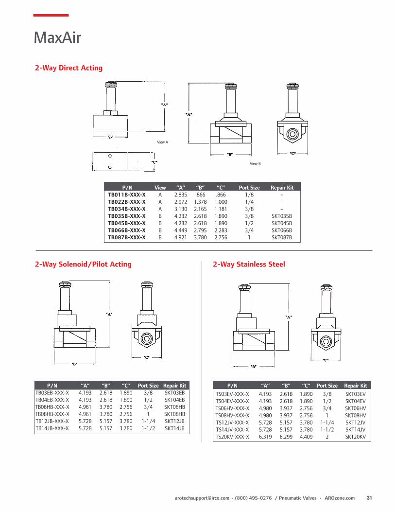
2-Way Direct Acting Solenoid Valves• Valves are direct acting, normally closed for fast response and are excellent
for low operating pressure applications• Die-cast brass body, stainless steel stem and buna-n diaphragm provide excellent durability• Suitable for use with water, air, lightweight oil, liquid gas and vacuum*• Available with 12 VDC, 24 VDC & 120VAC coils
z Ordering (Replace XXX-X with voltage requirement)000-N No Coil012-D 12 VDC024-D 24 VDC024-A 24 VAC120-A 120 VAC
z Performance SpecificationsTemperature Range: 0˚ - 180˚ FDuty Cycle: 100%Power Consumption: 22 VAResponse Time: 30 ms 50 ms
2-Way Solenoid/Pilot Acting Valves• Valves are internally piloted, normally closed & are excellent for high flow applications• Die-cast brass body, stainless steel stem and buna-n diaphragm provide
excellent durability• Suitable for use with water, air, lightweight oil and liquid gas• Available with 12 VDC, 24 VDC and 120VAC coils
2-Way Stainless Steel Solenoid/Pilot Acting Valves• Valves are internally piloted, normally closed and are excellent for high flow applications• #304 stainless steel body, stainless steel stem and viton diaphragm
provide excellent durability• Suitable for use with beverage dispensing, water, air, lightweight oil, liquid gas
and most chemical liquids• Available with 12 VDC, 24 VDC & 120VAC coils
Model No. Port Size Orifice Cv SCFM Pressure Range (PSI)
2-Way Direct Acting Solenoid Valves
TB011B-XXX-X 1/8" NPT 3/64" (1.2mm) 0.1 3 AC = 120, DC = 100
TB022B-XXX-X 1/4" NPT 3/32" (2.3 mm) 0.18 5 AC = 120, DC = 100
TB034B-XXX-X 3/8" NPT 5/16" (8.0 mm) 1.0 28 AC = 140, DC = 100
TB035B-XXX-X 3/8" NPT 33/64" (13 mm) 4.5 126 AC = 120, DC = 100
TB045B-XXX-X 1/2" NPT 33/64" (13 mm) 4.5 126 AC = 120, DC = 100
TB066B-XXX-X 3/4" NPT 25/32" (20 mm) 8.6 240 AC = 120, DC = 85
TB087B-XXX-X 1" NPT 1" (25 mm) 11 308 AC = 100, DC = 70
2-Way Solenoid/Pilot Acting Valves
TB03EB-XXX-X 3/8" NPT 33/64" (13 mm) 4.5 126 10-150
TB04EB-XXX-X 1/2" NPT 33/64" (13 mm) 4.5 126 10-150
TB06HB-XXX-X 3/4" NPT 1" (25 mm) 12 336 10-150
TB08HB-XXX-X 1" NPT 1" (25 mm) 12 336 10-150
TB12JB-XXX-X 1-1/4" NPT 1-1/2" (38 mm) 22 615 10-150
TB14JB-XXX-X 1-1/2" NPT 1-1/2" (38 mm) 22 615 10-150
2-Way Stainless Steel Solenoid/Pilot Acting Valves
TS03EV-XXX-X 3/8" NPT 33/64" (13 mm) 4.5 126 10-150
TS04EV-XXX-X 1/2" NPT 33/64" (13 mm) 4.5 126 10-150
TS06HV-XXX-X 3/4" NPT 1" (25 mm) 12 336 10-150
TS08HV-XXX-X 1" NPT 1" (25 mm) 12 336 10-150
TS12JV-XXX-X 1-1/4" NPT 1-1/2" (38 mm) 22 615 10-150
TS14JV-XXX-X 1-1/2" NPT 1-1/2" (38 mm) 30 839 10-150
TS20KV-XXX-X 2" NPT 2" (50 mm) 48 1343 10-150
TB034B-120-A
TB04EB-120-A
TB066B-120-A
TS04EV-120-A
[email protected] • (800) 495-0276 / Pneumatic Valves • AROzone.com 31
MaxAir
z Ordering (Replace XXX-X with voltage requirement)
2-Way Direct Acting
2-Way Solenoid/Pilot Acting 2-Way Stainless Steel
View A
View B
P/N View “A” “B” “C” Port Size Repair Kit TB011B-XXX-X A 2.835 .866 .866 1/8 – TB022B-XXX-X A 2.972 1.378 1.000 1/4 – TB034B-XXX-X A 3.130 2.165 1.181 3/8 – TB035B-XXX-X B 4.232 2.618 1.890 3/8 SKT035B TB045B-XXX-X B 4.232 2.618 1.890 1/2 SKT045B TB066B-XXX-X B 4.449 2.795 2.283 3/4 SKT066B TB087B-XXX-X B 4.921 3.780 2.756 1 SKT087B
P/N “A” “B” “C” Port Size Repair Kit TB03EB-XXX-X 4.193 2.618 1.890 3/8 SKT03EB TB04EB-XXX-X 4.193 2.618 1.890 1/2 SKT04EB TB06HB-XXX-X 4.961 3.780 2.756 3/4 SKT06HB TB08HB-XXX-X 4.961 3.780 2.756 1 SKT08HB TB12JB-XXX-X 5.728 5.157 3.780 1-1/4 SKT12JB TB14JB-XXX-X 5.728 5.157 3.780 1-1/2 SKT14JB
P/N “A” “B” “C” Port Size Repair Kit TS03EV-XXX-X 4.193 2.618 1.890 3/8 SKT03EV TS04EV-XXX-X 4.193 2.618 1.890 1/2 SKT04EV TS06HV-XXX-X 4.980 3.937 2.756 3/4 SKT06HV TS08HV-XXX-X 4.980 3.937 2.756 1 SKT08HV TS12JV-XXX-X 5.728 5.157 3.780 1-1/4 SKT12JV TS14JV-XXX-X 5.728 5.157 3.780 1-1/2 SKT14JV TS20KV-XXX-X 6.319 6.299 4.409 2 SKT20KV

32 AROzone.com • Pneumatic Valves / (800) 495-0276 • [email protected]
Hand Lever
Palm Button
Roller Cam
Cam Stem
Pilot
• Numerous Styles and Options - 3-Way or 4-Way Configurations• Six Actuator Styles. Hand Lever Cam Stem Palm Button Pilot Roller Cam Manual Bleed• Compact Size provides greater design flexibility• Perfect for low to moderate flow applications requiring
manual or mechanical valve operation
Aluminum Body 50 Series Valves feature an extruded aluminum body for less porosity, greater durability and lighter weight.Body Threaded PortsPort threads are 1/8” NPTFBuna N Seals The standard spool seals are Buna N. For high temperature applications, Viton seals are available. Consult the factory for ordering information.Sturdy Valve Spools Spools are steel on mechanical and manually actuated valves. Pilot and bleed actuator valves feature aluminum spools.
50 Series 3-Way & 4-Way Valves
Comprehensive Valve Design
Manual Bleed
50 Series
z Features

[email protected] • (800) 495-0276 / Pneumatic Valves • AROzone.com 33
Optional Palm ButtonsCode Description13111 Plastic, Black119243 Metal, Plain119244 Metal, Red119245 Metal, GreenMP3651-7 Plastic, RedFor 32 or 41 Actuators
3-Way and 4-Way Valves
3-Way 4-Way
50 Series
z Ordering
Pressure Range: 20-150 PSI Max. 50-150 PSI Max. (Manual Bleed Actuator)Flow: 16 SCFM Cv Factor: .43 CvTemperature Rating: -10° to 180°F (-23° to 82°C)Minimum Pilot Pressure: 30 PSI (2.1 Bar) Pilot Return 60 PSI (4.2 Bar) Pilot Actuator/Spring Return ValvesLubrication: Valves use O-ring seals. For maximum performance and
life expectancy, standard air line lubrication should be used.
z Performance Specifications
*Available only with Palm Button Actuators (02, 12, 21, 32, 41)
Position 1 2 3 4
Example: 50 X X - XX
Position 1
Series
Position 2
Valve Function
Positon 3
Body StylePositon 4
Actuation/Return
50 50 Series 3 3-Way4 4-Way
0 1/8” Side Ports1* 1/8” Side Ports
with panel mounting
Code Actuator/Return01 Hand Lever/Spring10 Hand Lever/Manual20 Hand Lever/Pilot02 Palm Button/Spring12 Palm Button/Manual21 Palm Button/Pilot32 Palm w/o Button/Manual41 Palm w/o Button/Pilot
Code Actuator/Return05 Roller Cam/Spring06 Cam Stem/Spring24 Cam Stem/Pilot07 Pilot/Spring35 Pilot/Pilot33 Manual Bleed/Manual Bleed

34 AROzone.com • Pneumatic Valves / (800) 495-0276 • [email protected]
Basic 3-Way Valve
2.0(50.8)
3/8(9.5)
1(25.4)
“2” Port (Cylinder)
1 1/2(39.1)
3/16(4.8)
3/16(4.8)
MTG. HOLES.199 (5.1) Dia.
“1” Port (Inlet)
“3” Port (Exhaust)1 3/8(34.9)
5/8(15.9)
3/4”(19.1)
Hand Lever Valves5030-01, 5030-10 5030-20
3 13/16(96.8)
1.25(31.8)
1 1/4
1/8-27 NPTF
3 15/32(88.1)
7/32(5.6)
21/32(16.7)3 29/32
(99.2)
1” (25.4) 1” (25.4)
5040-201/8-27 NPTF
21/32(16.7)4 13/32
(111.9)
1” (25.4)
5040-01, 5040-10
3 31/32(100.8)
7/32(5.6)
1” (25.4)
2.5(63.5)
3/8(9.5)
“2” Port (Cylinder)
“4” Port (Cylinder)
1 1/2(39.1)
3/16(4.8)
1 9/16(39.7)
MTG. HOLES.199 (5.1) Dia.
“5” Port (Exhaust) 5/8(15.9)
1 7/8(47.6)
1 1/4“1” Port (Inlet)
3/4”(19.1)
“3” Port (Exhaust)
Palm Button Valves
5031-XX, 5041-XX
1 3/4(28.6)
5/16(7.9)
1 1/8(28.6)
5040-02, -12, -32
3 27/32(97.4)
7/32(5.6)
5030-02, -12, -32
3 11/32(84.9)
7/32(5.6)
5040-21, -41
21/32(16.7)4 9/32
(108.7)
1/8-27 NPTF
5030-21, -41
21/32(16.7)3 25/32
(96.0)
1/8-27 NPTF
3/4-16 UNF-2A
7/8(22.2)
1 3/4(44.5)
2”(50.8)
Can be mounted up to 5/16” thickness.
7/16-20 Threads
Basic 4-Way Valve
Roller Cam Valves5030-05
5/16(7.9)
3/16(4.8)
7/16(11.1)
1 1/2(38.1)
3 23/32(94.5)
4 7/32(107.2)
Steel Roller
7/32(5.6)
7/32(5.6)
1” (25.4)
1” (25.4)
5040-05
50 Series
z Dimensions Dimensions given in Inches and (Millimeters)

[email protected] • (800) 495-0276 / Pneumatic Valves • AROzone.com 35
5/16(7.9)
7/16(11.1)
9/16(14.3)
Cam Stem Valves
7/32(5.6)
5030-065030-24 5040-24
3 9/32(83.3)
5040-06
Pilot Valves
5040-07
21/32(16.7)
1/8-27NPTF
5030-07 3 5/16(86.1)21/32
(16.7)
21/32(16.7)
1/8-27 NPTF
3 5/16(86.1)
5030-35
5040-35
1/8-27 NPTF
21/32(16.7)
21/32(16.7)
3 13/16(96.8)
3 13/16(96.8)
21/32(16.7)
1 5/16(33.3)
4 5/8(117.5)
5 1/8(130.2)
21/32(16.7)
1 5/16(33.3)
21/32(16.7)
1 5/16(33.3)
Manual Bleed Valves
5030-33
5040-33
Cam Stem Valves
Pilot Valves
Manual Bleed Valves
50 Series
2 25/32(70.6)

36 AROzone.com • Pneumatic Valves / (800) 495-0276 • [email protected]
• Light weight aluminum bodies and Buna-N seals are standard• Ideal for packaging, material handling and air motor applications.• Hand levers available with lever parallel or perpendicular to valve body.• Parallel lever can be manifold mounted. See pg. 14 for manifold ordering information.• 1/4” perpendicular hand lever valves can be panel mounted.
3-Way and 4-Way Hand Lever Valves 1/4” and 3/8” NPT Ports
Panel Mounting is standard on1/4” NPT Perpendicular Valves
z Features
Cv (Lever) 1/4” = .70, 3/8” = 1.14Operating Medium Non-lubricated or lubricated airPressure Range 20 -140 PSITemperature Range 15° to 122°F (-10° to 50°C)Port Size NPT 1/4”, 3/8”Filtration 40 micron recommended
z Performance Specifications
MaxAir
z Ordering
Model Description
Levers Perpendicular to BodyM212LM 1/4”, 4-Way, 2-Position, Lever/ManualM212LS 1/4”, 4-Way, 2-Position, Lever/SpringM312LS 1/4”, 4-Way, 3-Position, All Ports BlockedM213LS 3/8”, 4-Way, 2-Position, Lever/SpringM213LM 3/8”, 4-Way, 2-Position, Lever/ManualM252LM 1/4”, 3-Way, 2-Position, Lever/ManualM252LS 1/4”, 3-Way, 2-Position, Lever/SpringLevers Parallel to BodyM212LM-R 1/4”, 4-Way, 2-Position, Lever/Manual M212LS-R 1/4”, 4-Way, 2-Position, Lever/Spring
z Replacement AccessoriesModel Description114420 Black Knob114421 Red Knob114418 Boot for 1/4” Valve114419 Boot for 3/8” Valve114822 Lever
Perpendicular Lever / Manual Return
Parallel Levers
Perpendicular Lever / Springl Return

[email protected] • (800) 495-0276 / Pneumatic Valves • AROzone.com 37
M213LM M212LS
M213LS
M212LM
M312LS
.144
.144
0.169 (2 PL)
.528
1.181
1.024
0.169 (2 PL)
.394
.906
0.169 (2 PL)
.528
1.181
1.181 1.02
.138
0.169 (2 PL)
.394
.906
.138
1.181
MaxAir
z Dimensions
4-Way Hand Lever (Perpendicular)

38 AROzone.com • Pneumatic Valves / (800) 495-0276 • [email protected]
4-Way Hand Lever (Parallel)
3-Way Hand Lever (Perpendicular)
MaxAir
z Dimensions
[email protected] • (800) 495-0276 / Pneumatic Valves • AROzone.com 39
Foot Pedal Valve Shown with Guard
M252FS Foot Pedal Valve
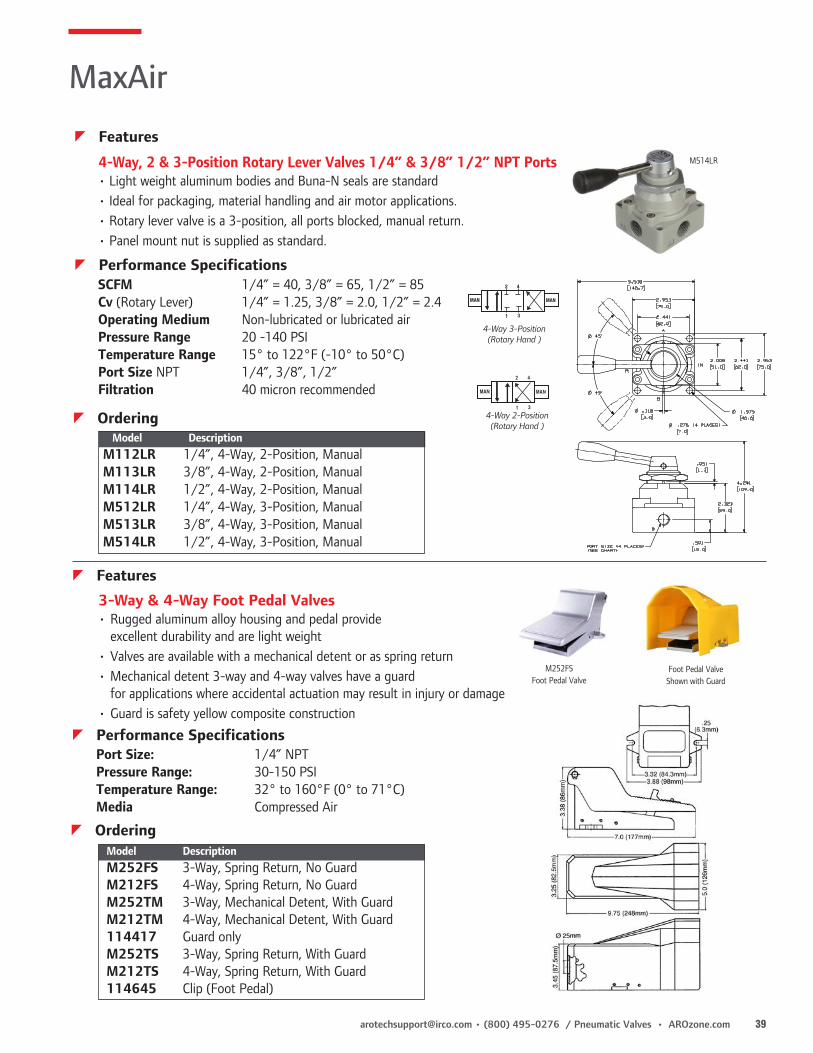
3-Way & 4-Way Foot Pedal Valves• Rugged aluminum alloy housing and pedal provide
excellent durability and are light weight• Valves are available with a mechanical detent or as spring return• Mechanical detent 3-way and 4-way valves have a guard
for applications where accidental actuation may result in injury or damage• Guard is safety yellow composite construction
M514LR4-Way, 2 & 3-Position Rotary Lever Valves 1/4” & 3/8” 1/2” NPT Ports• Light weight aluminum bodies and Buna-N seals are standard• Ideal for packaging, material handling and air motor applications.• Rotary lever valve is a 3-position, all ports blocked, manual return.• Panel mount nut is supplied as standard.
4-Way 3-Position (Rotary Hand )
MAN MAN
42
1 3
4-Way 2-Position(Rotary Hand )
MAN MAN
42
1 3
MaxAir
z Features
Port Size: 1/4” NPTPressure Range: 30-150 PSITemperature Range: 32° to 160°F (0° to 71°C)Media Compressed Air
z Performance Specifications
Model DescriptionM252FS 3-Way, Spring Return, No GuardM212FS 4-Way, Spring Return, No GuardM252TM 3-Way, Mechanical Detent, With GuardM212TM 4-Way, Mechanical Detent, With Guard114417 Guard onlyM252TS 3-Way, Spring Return, With GuardM212TS 4-Way, Spring Return, With Guard114645 Clip (Foot Pedal)
z Ordering
z Features
SCFM 1/4” = 40, 3/8” = 65, 1/2” = 85Cv (Rotary Lever) 1/4” = 1.25, 3/8” = 2.0, 1/2” = 2.4Operating Medium Non-lubricated or lubricated airPressure Range 20 -140 PSITemperature Range 15° to 122°F (-10° to 50°C)Port Size NPT 1/4”, 3/8”, 1/2”Filtration 40 micron recommendedescripti
z Performance Specifications
z OrderingModel Description
M112LR 1/4”, 4-Way, 2-Position, ManualM113LR 3/8”, 4-Way, 2-Position, ManualM114LR 1/2”, 4-Way, 2-Position, ManualM512LR 1/4”, 4-Way, 3-Position, ManualM513LR 3/8”, 4-Way, 3-Position, ManualM514LR 1/2”, 4-Way, 3-Position, Manual
40 AROzone.com • Pneumatic Valves / (800) 495-0276 • [email protected]
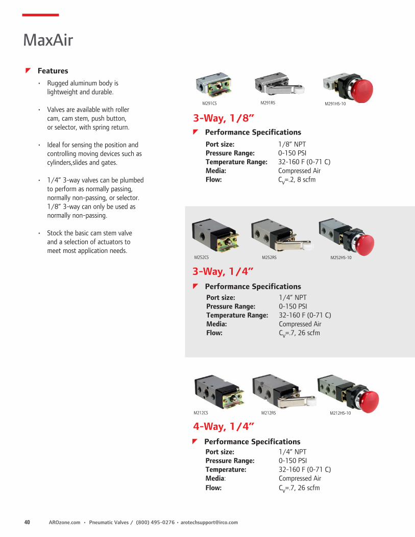
M291CS M291RS M291HS-10
• Rugged aluminum body is lightweight and durable.
• Valves are available with roller cam, cam stem, push button,
or selector, with spring return.
• Ideal for sensing the position and controlling moving devices such as
cylinders,slides and gates.
• 1/4” 3-way valves can be plumbed to perform as normally passing,
normally non-passing, or selector. 1/8” 3-way can only be used as normally non-passing.
• Stock the basic cam stem valve and a selection of actuators to
meet most application needs.
Port size: 1/8” NPTPressure Range: 0-150 PSITemperature Range: 32-160 F (0-71 C)Media: Compressed AirFlow: Cv=.2, 8 scfm
3-Way, 1/4”
4-Way, 1/4”
3-Way, 1/8”
M252CS M252RS M252HS-10
M212CS M212RS M212HS-10
MaxAir
z Performance Specifications
Port size: 1/4” NPTPressure Range: 0-150 PSITemperature Range: 32-160 F (0-71 C)Media: Compressed AirFlow: Cv=.7, 26 scfm
z Performance Specifications
z Features
Port size: 1/4” NPTPressure Range: 0-150 PSITemperature: 32-160 F (0-71 C)Media: Compressed AirFlow: Cv=.7, 26 scfm
z Performance Specifications

[email protected] • (800) 495-0276 / Pneumatic Valves • AROzone.com 41
M291HS-15 M291HS-11 M291HS-13 M291LS-10 M291LS-11 M291LS-10-2
M252HS-15 M252HS-11 M252HS-13 M252LS-10 M252LS-11
M212HS-15 M212HS-11 M212HS-13 M212LS-10 M212LS-11
MaxAir
Complete Models Basic Valves M291HS-17 3-Way, Standard Palm Button, Spring Return (Green)M291HS-10 3-Way, Standard Palm Button, Spring Return (Red)M291HS-15 3-Way, Palm Button w/Detent, Spring ReturnM291HS-11 3-Way, Palm without Guard, Spring ReturnM291HS-13 3-Way, Palm w/Guard, Spring ReturnM291LS-10 3-Way, Standard Selector, ManualM291LS-11 3-Way, Long Knob Selector, ManualM291RS 3-Way, Roller Lever, Spring ReturnM291CS Basic Valve, 3-Way, Cam Stem, Spring Return M291LS-10-2 3-Way, Two Valve Kit (Both valves actuate at same time)
Actuators Only114597-10 Standard Palm Button Actuator (Red)114597-11 Palm Button without Guard (Red)114597-13 Palm Button w/Guard (Red)114597-15 Palm Button w/Detent (e-stop) (Red)114598-10 Standard Knob (Black)114598-11 Long Knob (Black)114599 Roller Lever114597-17 Standard Palm Button Actuator (Green)
z Ordering - 3-Way, 1/8" NPT
Actuators Only114597-10 Standard Palm Button Actuator (Red)114597-11 Palm Button without Guard (Red)114597-13 Palm Button w/Guard (Red)114597-15 Palm Button w/Detent (e-stop) (Red)114598-10 Standard Knob (Black)114598-11 Long Knob (Black)114599 Roller Lever114597-17 Standard Palm Button Actuator (Green)
Complete Models M252HS-17 3-Way, Standard Palm Button, Spring Return (Green)M252HS-10 3-Way, Standard Palm Button, Spring Return (Red) M252HS-15 3-Way, Palm Button w/Detent M252HS-11 3-Way, Palm without Guard, Spring ReturnM252HS-13 3-Way, Palm w/Guard, Spring ReturnM252LS-10 3-Way, Standard Selector, ManualM252LS-11 3-Way, Long Knob Selector, ManualM252RS 3-Way, Roller Lever, Spring ReturnM252CS Basic Valve, 3-Way, Cam Stem, Spring Return
z Ordering - 3-Way, 1/4" NPT
Complete Models M212HS-17 4-Way, Standard Palm Button, Spring Return (Green)M212HS-10 4-Way, Standard Palm Button, Spring Return (Red) M212HS-15 4-Way, Palm Button w/Detent, Spring Return M212HS-11 4-Way, Palm without Guard, Spring ReturnM212HS-13 4-Way, Palm w/Guard, Spring ReturnM212LS-10 4-Way, Standard Selector, ManualM212LS-11 4-Way, Long Knob Selector, ManualM212RS 4-Way, Roller Lever, Spring ReturnM212CS Basic Valve, 4-Way, Cam Stem, Spring Return
Actuators Only114597-10 Standard Palm Button Actuator (Red)114597-11 Palm Button without Guard (Red)114597-13 Palm Button w/Guard (Red)114597-15 Palm Button w/Detent (e-stop) (Red)114598-10 Standard Knob (Black)114598-11 Long Knob (Black)114599 Roller Lever114597-17 Standard Palm Button Actuator (Green)
z Ordering - 4-Way, 1/4" NPT

42 AROzone.com • Pneumatic Valves / (800) 495-0276 • [email protected]
Several Styles and Options • 3-Way or 4-Way Configurations. 2-and 3-position configurations.
Numerous Actuator Styles Manual Mechanical Electric Pneumatic Hand Lever Cam Stem Single Solenoid Pilot Palm Button Roller Cam Double Solenoid Bleed Pedal Treadle
Many Performance Features • Buna-N spool seals are standard. Viton seals are available for high temperature
applications. Consult the factory for ordering information. • The E Series Valve has a low profile. An extruded aluminum body provides excellent
durability and lighter weight. • An External Solenoid Supply Port allows service in low pressure applications.
This requires a #116153 plug Kit. See Page 47 for operation and ordering information.
Solenoid Override • Manual locking override is standard on solenoid models. Turn override to operate. • Solenoid override is a convenient means to set-up and trouble shoot circuits.
Air pressure at the solenoid exhaust will also override the solenoid.Coils
Hand Lever
Treadle
Pedal
Palm Button
Bleed
Solenoids
Roller Cam
Cam Stem
3-Way and 4-Way Valves
E Series
z Features
z Performance SpecificationsFlow: 26 SCFMCv Factor: .70 CvTemperature Ratings: -10° to 180° F (-23° to 82° C)Weight: Solenoid Valves 1.8 to 3.4 oz. (.82 to 1.5 g) Non-Solenoid Valves .7 to 1.3 oz (.32 to .6 g)Lubrication: Valves use O-ring seals. For maximum performance and life expectancy, standard air line lubrication should be used.
Pressure Range Minimum Pilot Pressure
PSI (Bar) PSI (Bar)
Manual Actuators
Manual, Spring, and Spring Centered Returns 20 -150 (1.4 - 10.2)
Mechanical Actuators
Manual, Spring, and Spring Centered Returns 20 -150 (1.4 - 10.2)
Electric Actuators
Spring Return 30-150 (2-10.2)
Spring Centered Return 35-150 (2.4-10.2)
Solenoid Return 20-150 (1.4-10.2)
Pneumatic Actuators
Pilot/Spring Return 20-150 (1.4-10.2) 30 (2)
Pilot/Spring Centered 20-150 (1.4-10.2) 35 (2.4)
Pilot/Pilot Return 20-150 (1.4-10.2) 15 (1)
Bleed/Spring Return 20-150 (1.4-10.2)
Bleed/Bleed 20-150 (1.4-10.2)
Pilot

[email protected] • (800) 495-0276 / Pneumatic Valves • AROzone.com 43
4-Way, 2-Position 4-Way, 3-Position all ports blocked
4-Way, 3-Position inlet ports blocked, cylinder ports open
4-Way, 2-Position Bleed Valve
3-Way
For use with WM, WP or WS Actuators.
13111 Plastic, Black119243 Metal, Plain119244 Metal, Red119245 Metal, GreenMP3651-7 Plastic, Red
Recommended for applications where accidental actuation may result in damage or injury. Model 20965-1 is designed to comply with ANSI No. B11.1-1971 specifications and OSHA regulations.
20965-1 Pedal Guard with Flapper20965-2 Pedal Guard without Flapper
20965-1
6.5 (165.1)
5 (127)
Pedal Protector Flap.406 DIA. MTG. HOLES
12.25 (311.2)11/25 (285.8)
3/4” (19.1MM)
7(177.8)
Palm Buttons
Foot Pedal Guards
NOTE: Not for use with treadle actuator
E Series
z Ordering
z Accessories
Position 1 2 3 4 5 6 7
Example: E X X 2 XX - XXX - X
Position 1
Body Style
Position 2
Valve Type
Positon 3
Body StylePositon 4Port Size
Positon 5Actuation/Return*
Positon 6Coil Volage
Positon 7Current Type
E E Series 1 2 Position Detent
2 2 Position
3 3 Position Spring Centered
5 3 Position Detent (3 & 5, all ports blocked)
6 3 Position Detent (inlet ports blocked, cylinder ports open)
7 3 Position Spring Centered (6 & 7, inlet ports blocked, cylinder ports open)
1 4 Way Side Ported
4* 4 Way Bottom Ported
5 3 Way Side Ported
* Solenoid and Pilot Models only.
2 1/4” NPT
BD Bleed DoubleBS Bleed/SpringCS Cam Stem/SpringUS Cam Stem/Spring, 1/4” Spool travel, 3-way valve only.RS Roller Cam/SpringHM Palm/ManualHP Palm/PilotHS Palm/SpringWM Palm w/o Button/ManualWP Palm w/o Button/PilotWS Palm w/o Button/SpringLM Hand Lever/ManualLP Hand Lever/PilotLS Hand Lever/SpringPD Pilot/DoublePS Pilot/SpringSD Double SolenoidSN Solenoid/Spring-N.O.SS Solenoid/SpringFP Pedal/PilotFS Pedal/SpringTM Treadle/ManualTS Treadle/Spring* Numbering ends here if a non-solenoid valveis being selected.
000 No coil 024 24V AC/DC120 120V AC012 12V AC/DC 240 240V AC
Required only when ordering Solenoid Valves.
A ACD DCN No Coil
Required only on Solenoid Valves
If coil option A, D or L is selected, a coil connector must be ordered. See Pg. 69 for coil & connector information.

44 AROzone.com • Pneumatic Valves / (800) 495-0276 • [email protected]
3 7/8”(98.4)
1 11/32(34.1)
5 7/32(132.6)
4 3/16(106.4)
6 7/32(158.0)
4 11/32(110.3)
1/2(11.7)
1” (25.4)1” (25.4)
1” (25.4)
1” (25.4)
1” (25.4)
1” (25.4)
3 Way Valves 4 Way Valves
1 3/8(34.9)
1 3/8(34.9)
11/32(8.7)
1/8-27 NPTF
1/8-27 NPTF
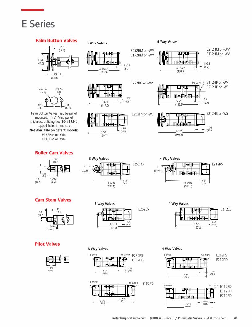
E252LS E212LS
E252LME152LM
E252LP
E212LP
6 5/16(160.3)
5 3/16(131.8)
5 11/32(135.7)
1” (25.4)
1 15/32(37.3)
11/32(8.7)
1/2(12.7)
E312LSE712LS
E212LME112LME512LME612LM
Hand Lever Valves
5 13/32(137.3)
3/32(2.4)
2”(50.8)
3 Way Valves 4 Way Valves
9 9/32(235.7)
10 9/32(261.1)
1 3/8(34.9)
1 3/8(34.9)
4”(101.6)
4”(101.6)
E252FS E212FS
Pedal
2 1/2(63.5)
3 1/2(88.9)
1’ (25.4)
1/2(12.7)
1/2(12.7)
2 3/4(69.9)
1 1/4(31.8)
1 1/4(31.8)
1 3/4(44.8)
3/4(19.1)
2 1/4(57.2)
1’ (25.4)
“4” Port (Cyl.)
“5” Port (Exh.)
“1” Port (Inlet)
“3” Port (Exh.)
MTG Holes - .257 (6.5) Dia
“2” Port (Cyl.)
Basic 3-Way Valve Basic 4-Way Valve
E Series
z Dimensions Dimensions given in Inches and (Millimeters)
[email protected] • (800) 495-0276 / Pneumatic Valves • AROzone.com 45
1 3/4(44.5)
1 5/8(41.3)
1/2”(12.7)
3 Way Valves 4 Way Valves
4 15/32(113.5)
11/32(8.7)
1/2(12.7)
1/2(12.7)
1/8-27 NPTF
4 5/8(117.5)
5 5/8(142.9)
6 1/2(165.1)
1 3/8(34.9)5 1/2
(139.7)
E252HM or -WME152HM or -WM
E252HP or -WP
E212HM or -WME112HM or -WM
E112HP or -WPE212HP or -WP
E212HS or -WSE252HS or -WS
11/32(8.7)5 15/32
(138.9)
1 3/8(34.9)
9/16 DIA.(14.3)
9/16(14.3)
9/16(14.3)
7/32 DIA.(5.6)
Palm Button Valves may be panel mounted. 1/8” Max. panel
thickness utilizing two 10-24 UNC tapped holes in end cap
Not Available on detent models:E152HM or -WME112HM or -WM
Palm Button Valves
3 Way Valves 4 Way ValvesE252RS E212RS
3 Way Valves 4 Way Valves
1/2(12.7)
1/2(12.7)
1 9/16(39.7)
3/16(4.8)
1(25.4)
1(25.4)
1 3/8(34.9)
1 3/8(34.9)5 7/16
(138.1)6 7/16(163.5)
1/2(12.7)
1/2(12.7)
1 5/16(33.9)
1 3/8(34.9)5 3/16
(131.8)
1 3/8(34.9)6 3/16
(157.2)
E252CS E212CS
Roller Cam Valves
Cam Stem Valves
3 Way Valves 4 Way Valves
E252PSE252PD
E212PSE212PD
E152PD
1 3/8(34.9) 5 1/4
(133.4)
6 7/16(163.5)
1 3/8(34.9)
1/8-27NPTF 1/8-27NPTF
2 9/16(65.1)
1/8-27NPTF 1/8-27NPTF
1/8-27NPTF
1/8-27NPTF 1/8-27NPTF
1/8-27NPTF
1 3/8(34.9)6 1/4
(158.8)
7 7/16(188.9)
2 9/16(65.1)
E112PDE312PDE712PD
Pilot Valves
E Series

46 AROzone.com • Pneumatic Valves / (800) 495-0276 • [email protected]
Treadle Valves
4 5/8(117.5)
5 1/2(139.7)
8”(203.3)
1/8(3.2)
3 Way Valves 4 Way Valves
8 11/32(211.9)
2 3/4(69.9)
E252TM
11/32(8.7)
11/32(8.7)
9 11/32(237.3)
10 15/32(265.9)
2 3/4(69.9)
2 3/4(69.9)
E212TM
E312TSE712TS
1 15/32(37.3)
Bleed Valves3 Way Valves 4 Way Valves
2 1/4(57.2)
6 1/8(155.6)
7”(177.8)
1 3/8(34.9)
2 1/4(57.2)
1 3/8(34.9)
7 1/8(181.0)
8”(203.2)
2 1/4(57.2)
E252BS E212BS
E212BDE252BD
Solenoid Valves
1 3/8(34.9)
3 1/4(82.5)
1 3/8(34.9)
3/8(9.5)
1 7/16(36.5)
Ext Solenoid Supply
Manual Override
1 7/16(36.5)
3 1/4(82.5)
MANUAL OVERRIDE
3/8(9.5)
3 Way Valves
2 15/32(62.7)
2 15/16(74.6)
Ext. Solenoid Supply
1/8-27 NPTF3/4
(19.1)
1/4(6.3)
2”(50.8)
1 3/8(34.9)
1(25.4)
E252SN-XXX-X E252SS-XXX-X
4 Way Valves
E212SS-XXX-X2”
(50.8)1/4(6.3)
5 7/32(132.6)
2 15/32(62.7)
2 15/16(74.6)
Ext. Sol. Supply
11/32 (8.7)
1” (25.4)
3/419.1
Mtg. Hole .203 Dia.
2 15/32(62.7)
3/419.1
Mtg. Hole .203 Dia.
2 15/16(74.6)
6 1/4 158.8
2” (50.8)
1/4 (6.3)
1 3/8 (34.9)
1” (25.4)
E212SD-XXX-X
2 9/16 (65.2)
7 7/16 (188.9)
3/419.1
Mtg. Hole .203 Dia.
2” (50.8)1/4 (6.3)
1 3/8 (34.9)
E312SD-XXX-X E712SD-XXX-X
E Series
z Dimensions Dimensions given in Inches and (Millimeters)

[email protected] • (800) 495-0276 / Pneumatic Valves • AROzone.com 47
PIPEPLUG
INTERNALAIR SUPPLY
SOLENOID VALVEW/INTERNAL SOLENOID SUPPLYFROM VALVE BODY AS SHIPPED
TUBEFITTING
#116153 PLUG
CONVERTED SOLENOID VALVE W/EXTERNAL SOLENOID SUPPLY CONNECTION
EXTERNAL AIR SUPPLY
PIPEPLUG
INTERNALAIR SUPPLY
SOLENOID VALVEW/INTERNAL SOLENOID SUPPLYFROM VALVE BODY AS SHIPPED
TUBEFITTING
#116153 PLUG
CONVERTED SOLENOID VALVE W/EXTERNAL SOLENOID SUPPLY CONNECTION
EXTERNAL AIR SUPPLY
116153 Plug KitKit needed for low pressure applications requiring an external Solenoid Supply Pressure. To use, remove and discard the standard pipe plug in the solenoid base. Thread the Plug/O-ring assembly into the threaded port. This blocks the internal supply connection. Finish by connecting an external air supply to the 1/8 NPTF port.
z Accessories
E Series

48 AROzone.com • Pneumatic Valves / (800) 495-0276 • [email protected]
K Series
Several Styles and Options • 5-Port, 4-Way, 2 and 3-position directional control valves.
Numerous Actuator Styles
Manual Electric Pneumatic Hand Lever Single Solenoid Pilot Palm Button Double Solenoid Bleed Pedal Treadle
z Features
Comprehensive Valve DesignAluminum BodySand cast aluminum body provides a rugged, reliable valve.
Buna N Seals Standard seals are Buna N, for extended valve life. Viton seals are available for high temperature applications. Consult factory for ordering information.
Sturdy Spools K-Series valves have an aluminum spool. This slides in a hard anodized Teflon non-stick aluminum sleeve (3/8” or 1/2” models) The sleeves are brass on 3/4” or 1” models.
Standard Solenoid Override Feature3/8” and 1/2” models only.
External Solenoid External Solenoid supply port enables valve operation for vacuum service or low pressure operations. For proper supply connection, consult factory. (Remove end cap and rotate gasket 90° for remote solenoid supply.)
Hand Lever
Treadle
Pedal
Pilot
Solenoids
Bleed

[email protected] • (800) 495-0276 / Pneumatic Valves • AROzone.com 49
1 3
2
1
4
5 3
2
1
4
5 3
2
1
4 2
5 3
2
1
4
5 3
2
2-Position
1 3
2
1
4
5 3
2
1
4
5 3
2
1
4 2
5 3
2
1
4
5 3
2
3-Position, inlet ports blocked
1 3
2
1
4
5 3
2
1
4
5 3
2
1
4 2
5 3
2
1
4
5 3
2
3-Position, inlet blocked, cylinder ports open
z Ordering
Position 1 2 3 4 5 6 7
Example: K X 1 X XX - XXX - X
Position 1
Body Style
Position 2
Valve Type
Positon 3
Body StylePositon 4Port Size
Positon 5Actuation/Return*
Positon 6Coil Volage
Positon 7Current Type
K K Series 2 2 Position 3 3 Position Spring
Centered5 3 Position Detent
(3 & 5, all ports blocked in neutral)
6 3 Position Detent (inlet ports blocked, cylinder ports open in neutral)
7 3 Position Spring Centered (6 & 7, inlet ports blocked, cylinder ports open in neutral)
1 4 Way Side Ported
3 3/8” NPT4 1/2” NPT6 3/4” NPT8 1” NPT
BD Bleed/BleedBS Bleed/Spring*FP Pedal/Pilot*FS Pedal/Spring**HS Palm/Spring*LM Hand Lever/Manual*LS Hand Lever/SpringPD Pilot/PilotPS Pilot/SpringSD Solenoid/SolenoidSS Solenoid/Spring*TM Treadle/Manual*FP, FS, LM, LS & TS available in 3/8” and 1/2” port sizes only. Numbering ends here if a Non-Solenoid valve is being selected.
**HS available in 3/8” port size only.
000 No coil 012 12V AC or DC 024 24V AC or DC120 120V AC or DC240 240V AC only
Required only when ordering Solenoid Valves.
A ACD DCN No Coil
Required only on Solenoid Valves
If coil option A or D is selected, a coil connector must be ordered. See Pg. 69 for coil & connector information.
K Series
z Performance SpecificationsTemperature Ratings: -10° to 180° F (-23° to 82° C)Lubrication: Valves use O-ring seals. For maximum performance and life
expectancy, standard air line lubrication should be used.Flow & Cv Factor:
Pressure Range Minimum Pilot Pressure
PSI (Bar) PSI (Bar)
Manual Actuators
Manual, Spring, and Pilot 0-150 (0-10.4) 20 (1.4)
Mechanical Actuators
Manual, Spring, and Pilot 0-150 (0-10.4) 20 (1.4)
Electric Actuators
Spring Return 50-150 (3.5-10.4)
Spring Centered Return 60-150 (4.1-10.4)
Solenoid Return 20-150 (1.4-10.4)
Pneumatic Actuators
Pilot/Spring Return 0-150 (0-10.4 50 (3.5)
Pilot/Spring Centered 0-150 (0-10.4 60 (4.1)
Pilot/Pilot Return 50-150 (3.5-10.4) 20 (1.4)
Bleed/Spring Return 50-150 (3.5-10.4)
Bleed/Bleed 20-150 (1.4-10.4)
Port Size Flow Cv Factor
3/8” 83 SCFM 2.30
1/2” 90 SCFM 2.57
3/4” 270 SCFM 7.54
1” 280 SCFM 7.80
20965-X Foot Pedal Guards, for use with Pedal Style valves.
See Pg. 43 (bottom) for details.

50 AROzone.com • Pneumatic Valves / (800) 495-0276 • [email protected]
Top Dimension = 3/8” and 1/2” PortsBottom Dimensions = 3/4” and 1” Ports
1 1/4 (31.8)1 3/4 (44.5)
5 (127.0)8 3/8 (212.7)
1/8-27 NPTF1/4-18 NPTF
K2XXPSK2XXPDK3XXPDK7XXPD
K21XBSK21XBD
7/8(22.2)
1/8-27 NPTF1/4-18 NPTF
1 1/4 (31.9)1 3/4 (257.2) 6 3/4 (171.5)
10 1/8 (257.2)
5 7/8 (149.2)9 1/4 (235.0)
1
53
1.193
1.75
6.255
1.75
6.2551.193
“5” Port Exhaust “4” Port Output“2” Port Output
“3” Port Exhaust
“1” Port Inlet
1 1/16(27.0)
1(25.4)
1/2 (12.7)11/16 (17.5)
11/16(17.5)
1(25.4)
1 1/4(31.8)
2(50.8)
3 1/2(88.9)4 7/16(112.7)
2 3/32(53.2)
2 11/16(68.3)
3(76.2)3 3/4(95.3)
2 9/16 (65.1)3 1/2 (88.9)
1 3/16 (46.0)2 1/2 (63.5)
3 7/16 (87.3)5 5/8 (142.9)
4 (101.6)7 (177.8)
Mtg. Hole9/32 (7.1)
13/32 (10.3)
1.5 (38.1)3 (76.2)
3/4 (19.1)1 1/2 (38.1)
Basic Valves
Pilot and Bleed Valves
Palm Valves
z Dimensions Dimensions given in Inches and (Millimeters)
K Series
K213HS
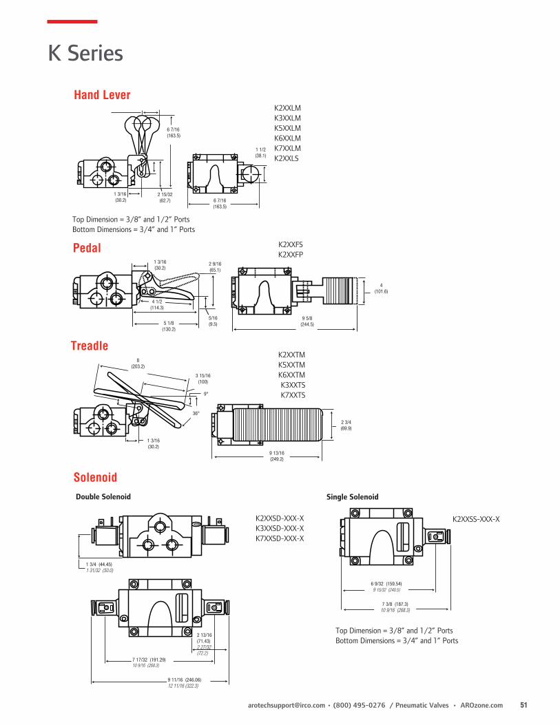
[email protected] • (800) 495-0276 / Pneumatic Valves • AROzone.com 51
Hand Lever
6 7/16(163.5)
1 1/2(38.1)
6 7/16 (163.5)
1 3/16 (30.2)
2 15/32(62.7)
Top Dimension = 3/8” and 1/2” PortsBottom Dimensions = 3/4” and 1” Ports
K2XXLMK3XXLMK5XXLMK6XXLMK7XXLMK2XXLS
Pedal K2XXFSK2XXFP
4(101.6)
9 5/8(244.5)5 1/8
(130.2)
4 1/2(114.3)
1 3/16(30.2)
2 9/16(65.1)
5/16(9.5)
K Series
Treadle
9 13/16(249.2)
1 3/16(30.2)
2 3/4(69.9)
8(203.2)
3 15/16(100)
9°
36°
K2XXTMK5XXTMK6XXTMK3XXTSK7XXTS
Top Dimension = 3/8” and 1/2” Ports Bottom Dimensions = 3/4” and 1” Ports
K2XXSD-XXX-X K3XXSD-XXX-X K7XXSD-XXX-X
1 3/4 (44.45)1 31/32 (50.0)
7 17/32 (191.29)10 9/16 (268.3)
9 11/16 (246.06)12 11/16 (322.3)
2 13/16 (71.43)2 27/32 (72.2)
K2XXSS-XXX-X
SolenoidDouble Solenoid Single Solenoid
6 9/32 (159.54)9 15/32 (240.5)
7 3/8 (187.3)10 9/16 (268.3)

52 AROzone.com • Pneumatic Valves / (800) 495-0276 • [email protected]
3-Way Pilot
4-Way Solenoid
Pilot Bleed
4-Way Pilot
3-Way Solenoid
Manual Bleed
Comprehensive Valve DesignDurable Valve Body Valve body is die-cast Zinc, with a zinc chromate coating for added corrosion resistance in harsh environments.
Superior Performance Large, unrestricted air passages produce high flow and fast response times.
Superior Design 3-Way valves feature a single poppet. 4-Way valves have two simultaneously driven poppets to provide the 4-way function.
H Series
Several Styles and Options • H-Series Valves feature high-flow and fast response. • 3-Way and 4-Way 2-position Poppet Valves • Override is not available with “H” Series Valves
Numerous Actuator Styles
Electric Pneumatic 3-Way Solenoid 3-Way Pilot 4-Way Solenoid 4-Way Pilot 4-Way Pilot Bleed 4-Way Manual Bleed
z Features
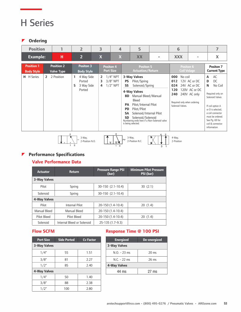
[email protected] • (800) 495-0276 / Pneumatic Valves • AROzone.com 53
3-Way, 2-Position N.C.
4-Way, 2-Position
13
243-Way, 2-Position N.O.
13
2
13
2
13
2
13
2
31
2
31
2
z Ordering
H Series
Position 1 2 3 4 5 6 7
Example: H 2 X X XX - XXX - X
Position 1
Body Style
Position 2
Valve Type
Positon 3
Body StylePositon 4Port Size
Positon 5Actuation/Return
Positon 6Coil Volage
Positon 7Current Type
H H Series 2 2 Position 1 4 Way Side Ported
5 3 Way Side Ported
2 1/4” NPT 3 3/8” NPT4 1/2” NPT
3-Way Valves PS Pilot/Spring SS Solenoid/Spring
4-Way Valves BD Manual Bleed/Manual Bleed PA Pilot/Internal Pilot PD Pilot/Pilot SA Solenoid/Internal Pilot SD Solenoid/SolenoidNumbering ends here if a Non-Solenoid valve is being selected.
000 No coil 012 12V AC or DC 024 24V AC or DC120 120V AC or DC240 240V AC only
Required only when ordering Solenoid Valves.
A ACD DCN No Coil
Required only on Solenoid Valves
If coil option A or D is selected, a coil connector must be ordered. See Pg. 69 for coil & connector information.
z Performance Specifications
Actuator Return Pressure Range PSI (bar)
Minimum Pilot Pressure PSI (bar)
3-Way Valves
Pilot Spring 30-150 (2.1-10.4) 30 (2.1)
Solenoid Spring 30-150 (2.1-10.4)
4-Way Valves
Pilot Internal Pilot 20-150 (1.4-10.4) 20 (1.4)
Manual Bleed Manual Bleed 20-150 (1.4-10.4)
Pilot Bleed Pilot Bleed 20-150 (1.4-10.4) 20 (1.4)
Solenoid Internal Bleed or Solenoid 25-135 (1.7-9.3)
Valve Performance Data
Port Size Side Ported Cv Factor
3-Way Valves
1/4” 55 1.51
3/8” 81 2.27
1/2” 85 2.40
4-Way Valves
1/4” 50 1.40
3/8” 88 2.38
1/2” 100 2.80
Flow SCFM
Energized De-energized
3-Way Valves
N.O. - 23 ms 20 ms
N.C. - 22 ms 26 ms
4-Way Valves
44 ms 27 ms
Response Time @ 100 PSI

54 AROzone.com • Pneumatic Valves / (800) 495-0276 • [email protected]
Inlet N.O.
2 3/32 (53.2)
5/8 (15.9)
2 7/32 (56)
1/2 (12.7)
1 3/4 (44.5)
2 7/8 (73)
Inlet N.O.
Inlet N.C.
1 55/64 (47.2)
19/32 (15.1)
2 13/64 (56.0)
1 9/64 (29.0)
7/32 Mtg Holes
Inlet N.C.
2 3/32 (53.2)
11/64 (4.4)
11/64 (4.4)
1/4” and 3/8” Side Port
4 1/2 (114.3)
3 7/8 (98.4)
4 1/2 (114.3)
2 15/16 (74.5)
2 5/32 (54.8)
5/32 (4.0)
5/8 (15.9)
2 1/8 (54.0)
1 11/16 (42.9)
2 5/32 (54.8)
1/4” and 3/8” Side Port
5/16 (7.9)
Exhaust
9/32 Mtg. Holes
Outlet 1
Outlet 2
Inlet
15/64 (6.0)
21/64 (8.3)
1 1/2 (38.1)
3 7/8 (98.4)
5 1/4 (133.4)5 1/4 (133.4)
2 1/2 (63.5)
11/16 (17.5)
5/32 (4.0)
2 1/8 (54.0)
1 11/16 (42.9)
1/2” Side Port
Outlet 1
Outlet 2
1 1/2 (38.1)
ExhaustInlet
2 1/2 (63.5)
7/16 (11.1)
2 31/32 (75.4)
9/32 Mtg Holes
55/64
11/32 (87) 22/32 (18.3)
Inlet N.O. Inlet N.C.
Inlet N.C.
Inlet N.O.
7/32 Mtg. Holes1 1/32 (26.2)
1/2 (12.7)1/2” Side Port
2 5/8 (66.3)
2 7/8 (73.0)
1 3/4 (44.5)
1 3/4
1
3 3/16 (82.0)
1/8-27 NPTF Pilot
11/16 (17.5)
1 1/64 (25.8)
1 55/64 (47.2)
2 5/8 (66.7)
19/32 (15.1)
2 7/8 (73.0)
21/32
3-Way Basic Valves
4-Way Basic Valves
H Series
z Dimensions Dimensions given in Inches and (Millimeters)

[email protected] • (800) 495-0276 / Pneumatic Valves • AROzone.com 55
Bleed Valves
4-Way Manual Bleed 4-Way Pilot BleedH21XBD H21XPD13/16
(20.3)
Outlet
2 1/8 (54.0)
1 11/16 (42.9)
3 7/8 (98.4)
2 3/16 (55.6)
1 1/2 (38.1)
1 1/2 (38.1)
5/32 (4.0) 1“
2 1/8 (54.0)
11/32 (8.7)
1 3/4 (44.5)
1 1/8 (28.6)
3 7/8 (98.4)
1 1/2 (38.1)
1 1/2 (38.1)
1 11/16 (42.9)5/32
(4.0) 1”
4-Way Double Solenoid 3-Way Single SolenoidH21XSD-XXX-X H25XSS-XXX-X
4-Way Single SolenoidH21XSA-XXX-X
1 15/16 (49.2)
3 7/8 (98.4)
1 7/16 (36.5)
1 1/2 (38.1)
1 15/16 (49.2)
3 7/8 (98.4)
1 7/16 (36.5)
1 15/16 (49.2)
1 7/8 (36.5)
1 7/16 (36.5)
1 1/2 (38.1)
Pilot Valves
3-Way Pilot 4-Way Pilot1/8-27 NPTF Pilot Port 1 1/32
(26.2)
Inlet N.O.
1 3/4 (44.5) 1 3/4
(44.5)
1/2 (12.7)
Inlet N.C.
1 7/8 (47.6)
1 (25.4)
5 32 (4.0)
1 (25.4)
1/8-27 NPTF Pilot Port 2 1/8
(54.0)Outlet
1 1/16 (42.9) 1 1/2
(38.1)
3 7/8 (98.4)
2 3/16 (55.6)
3 3/4 (95.3)
H25XPS H21XPA
H Series
z Dimensions Dimensions given in Inches and (Millimeters)
Solenoid Valves
1 3/4 (44.5)
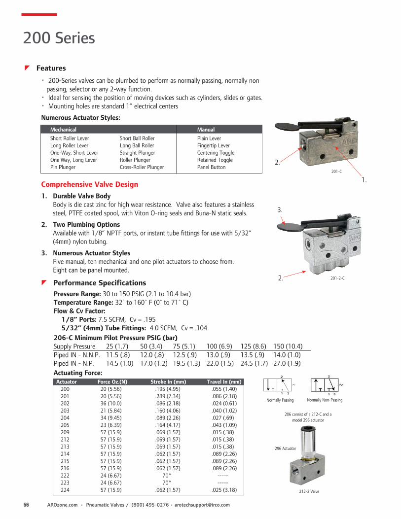
56 AROzone.com • Pneumatic Valves / (800) 495-0276 • [email protected]
Pressure Range: 30 to 150 PSIG (2.1 to 10.4 bar) Temperature Range: 32˚ to 160˚ F (0˚ to 71˚ C) Flow & Cv Factor: 1/8” Ports: 7.5 SCFM, Cv = .195 5/32” (4mm) Tube Fittings: 4.0 SCFM, Cv = .104206-C Minimum Pilot Pressure PSIG (bar)Supply Pressure 25 (1.7) 50 (3.4) 75 (5.1) 100 (6.9) 125 (8.6) 150 (10.4)Piped IN - N.N.P. 11.5 (.8) 12.0 (.8) 12.5 (.9) 13.0 (.9) 13.5 (.9) 14.0 (1.0)Piped IN - N.P. 14.5 (1.0) 17.0 (1.2) 19.5 (1.3) 22.0 (1.5) 24.5 (1.7) 27.0 (1.9)
• 200-Series valves can be plumbed to perform as normally passing, normally non passing, selector or any 2-way function.• Ideal for sensing the position of moving devices such as cylinders, slides or gates.• Mounting holes are standard 1” electrical centers
Numerous Actuator Styles:
Mechanical Manual Short Roller Lever Short Ball Roller Plain Lever Long Roller Lever Long Ball Roller Fingertip Lever One-Way, Short Lever Straight Plunger Centering Toggle One Way, Long Lever Roller Plunger Retained Toggle Pin Plunger Cross-Roller Plunger Panel Button
Comprehensive Valve Design1. Durable Valve Body Body is die cast zinc for high wear resistance. Valve also features a stainless
steel, PTFE coated spool, with Viton O-ring seals and Buna-N static seals.
2. Two Plumbing Options Available with 1/8” NPTF ports, or instant tube fittings for use with 5/32”
(4mm) nylon tubing.
3. Numerous Actuator Styles Five manual, ten mechanical and one pilot actuators to choose from.
Eight can be panel mounted.
2.
1.201-C
2.
3.
201-2-C
13
2
13
2
13
2
13
2
31
2
31
2
Normally Passing Normally Non-Passing
296 Actuator
212-2 Valve
206 consist of a 212-C and a model 296 actuator
200 Series
z Features
z Performance Specifications
Actuating Force:Actuator Force Oz.(N) Stroke In (mm) Travel In (mm) 200 20 (5.56) .195 (4.95) .055 (1.40) 201 20 (5.56) .289 (7.34) .086 (2.18) 202 36 (10.0) .086 (2.18) .024 (0.61) 203 21 (5.84) .160 (4.06) .040 (1.02) 204 34 (9.45) .089 (2.26) .027 (.69) 205 23 (6.39) .164 (4.17) .043 (1.09) 209 57 (15.9) .069 (1.57) .015 (.38) 212 57 (15.9) .069 (1.57) .015 (.38) 213 57 (15.9) .069 (1.57) .015 (.38) 214 57 (15.9) .062 (1.57) .089 (2.26) 215 57 (15.9) .062 (1.57) .089 (2.26) 216 57 (15.9) .062 (1.57) .089 (2.26) 222 24 (6.67) 70° ----- 223 24 (6.67) 70° ----- 224 57 (15.9) .062 (1.57) .025 (3.18)

[email protected] • (800) 495-0276 / Pneumatic Valves • AROzone.com 57
200 Series
Basic Valves
15/16 (23.8)
11/16 (17.5)
1” (25.4)
2 1/32 (51.6)
5/32 (4.0)
200-C
1/8” NPT Ports 5/32” Tubing Ports
1 3/4 (44.5)1/2
(12.7)
1/4 (6.4)
1 (25.4)
Mtg. for #8 Screw (2)11/32 (8.7)
13/32 (10.3)
1 3/8 (34.9)
7/64 (2.8)
11/16 (17.5)
1 3/4 (44.5)1/2
(12.7)1/4 (6.4)
1 (25.4)
Mtg. for #8 Screw (2)47/64 (18.7)
9/32 (7.1)25/32 (19.8)
1 7/32 (31)
1, IN-NC (non-passing)
3, IN-NO (passing)2, Out
2 15/32 (62.7)
201-C
5/32 (4.0)
1 11/64(29.8)
203-C
5/32 (4.0)1 7/16
(36.5)
1 57/64 (48.0)
Roller 3/8” Dia.x 21/64
204-C
5/32 (4.0)
1 51/64 (45.6)
1 1/32 (26.2)Roller 3/8” Dia.x 21/64
205-C
5/32 (4.0)
1 7/8 (47.6)
1 27/32 (48.6)Roller 3/8” Dia.x 21/64
215-C
1 15/64 (31.4)
15/32-32 Threads
9/16 HEX. x 3/32 Thick
Nut (4)
Roller 3/8” Dia.x 21/64
216-C
1 15/64 (31.4)
15/32-32 Threads39/64
(15.5)
Roller 3/8” Dia.x 21/64
222-C
1 19/64 (32.9)
15/32-32 Threads
9/16 HEX. x 3/32 Thick
Nut (2)
Panel Nut 19/32 Dia.
x 1/16
30° Any Direction
223-C
1 1/4 (31.8)
15/32-32 Threads
9/16 HEX. x 3/32 Thick
Nut (2)
Panel Nut 19/32 Dia.
x 1/16
70° Rotation
224-C
1 19/64 (32.9)
7/8 (22.2) Dia.
15/32-32 Threads
9/16 HEX. x 3/32 Thick
Nut (2)
Panel Nut 19/32 Dia.
x 1/16
209-C
15/16 (23.7)
46/64 (17.1)
1/8 Dia (3.8)
212-C
29/64 (11.5)
23/64 (9.1)
Ball 11/32 Dia.
15/32-32 Threads
213-C
11/16 (17.5)
Ball 11/32 Dia.
15/32-32 Threads
9/16 HEX. x 3/32 Thick
Nut (4)
214-C
13/16(20.6)
5/16 (7.9)15/32-32 Threads
9/16 HEX. x 3/32 Thick
Nut (4)
206-C
2 5/32(54.8)
1 3/8(34.9)
1/8 NPTF
.15/32-32 THD.
202-C
5/32 (4.0)1 23/64
(34.5)
1 5/64 (27.4)
Roller 3/8” Dia.x 21/64
• Use on 212-C ball roller limit valve.• For use in low pilot pressure applications.• Maximum pilot pressure is 100 psig (6.9 bar)• 1/8” NPTF air inlet ports.• Aluminum-alloy construction with low friction Buna-N cup seal.• Order Model 20368 and 212-C Aro ball roller limit valve separately.
Low-Pressure Pilot Actuator Switch
20368
z Dimensions Dimensions given in Inches and (Millimeters)
Position 1 2 3
Example: 2 XX - X
Position 1
Series
Position 2
Actuator TypePosition 3Port Type
2 200 Series 00 Plain Lever01 Fingertip Lever02 Short Roller Lever03 Long Roller Lever04 One-Way, Short Lever05 One Way, Long Lever06 Pilot Actuated09 Pin Plunger
12 Short Ball Roller 13 Long Ball Roller 14 Straight Plunger 15 Roller Plunger 16 Cross-Roller Plunger 22 Centering Toggle 23 Retained Toggle 24 Panel Button
C 1/8” NPTF Ports2-C 5/32” Tubing Ports
Supply Pressure
Minimum Pilot Pressure PSIG (bar)
25 (1.7) 50 (3.5) 75 (5.2) 100 (6.9)
125 (8.6)
150 (10.4)
Piped IN-N.N.P. 5.5 (0.4) 6.0 (0.4) 6.5 (0.4) 7.0 (0.5) 7.5 (0.5) 8.0 (0.6)
Piped IN-N.P. 5.5 (0.4) 6.0 (0.4) 6.5 (0.4) 7.0 (0.5) 7.5 (0.5) 8.0 (0.6)
z Ordering

58 AROzone.com • Pneumatic Valves / (800) 495-0276 • [email protected]
.299 (7.6)
Roller .5 Dia. x .323
Roller .5 Dia. x .323
2.4 (60.9)
.5 (12.7)
.5 (12.7)
.5 (12.7)
.125 (3.2)
.125 (3.2)
.125 (3.2)
.125
.125
.15 (3.8)
.125 (3.2)
.170 Dia.
.170 Dia..170 Dia.
1.2 (30.5)
1.2 (30.5)
1.2 (30.5)1.02 (25.9)
1.02 (25.9)
1.02 (25.9)
.421 (10.7).421 (10.7)
.421
.824 (20.9)
.7 (17.8)
1.8 (45.7)
1.35 (34.3)
.185 (4.7)
1.5 (38.1)
.94 (23.9)
.56
.63 (16)
.46 (11.7)
103-2-A
105-2-A
109-2-A
Pressure Range: 0 to 150 PSIG (0 to 10.4 bar)Temperature Range: -10° to 180° F (-23° to 82° C)Flow & Cv Factor: 3.4 SCFM at 100 PSIG (7 bar) input 85 PSI (5.8 bar) output. Cv = .09Actuating Force: Travel Operation:Straight Plunger: Straight Plunger:52 oz. at 100 PSIG .03125” (.8mm) to actuate(14.46 N at 7 bar) .109375” (2.8mm) totalLevers: Levers:25 oz. at 100 PSIG .0625” (1.6mm) to actuate(6.95 N at 7 bar) .21875” (5.5mm) total
Miniature Control Valves
Normally Non-Passing
100 Series
z Features
• Ball Poppet valve provides fast response.• Slotted Mounting holes for easy placement and adjustment.• 100 Series Mini Valves are non-passing, non-lube limit valves.• 33% glass reinforced polyester body is strong, lightweight
and corrosion resistant.• Available with 5/32” tube fittings. Both ports are on one side
for ease of plumbing and maintenance.• Seals are Buna-N, Stainless Steel Spring, Brass Plunger and Delrin Roller.
z Performance Specifications
z Dimensions Dimensions given in Inches and (Millimeters)
z Ordering
Model No. Port Size Actuator Type
103-2-A 5/32” Tube Roller Lever
105-2-A 5/32” Tube 90° Roller Lever
109-2-A 5/32” Tube Straight Plunger

[email protected] • (800) 495-0276 / Pneumatic Valves • AROzone.com 59
M211HS 4-Way, Push Button, Spring Return** M251HS 3-Way, Push button, Spring Return**
z Dimensions Dimensions given in Inches and (Millimeters)
M251LS 3-Way, Toggle, Maintained
M251RS 3-Way, Roller, Spring Return
M211LS 4-Way, Toggle, Maintained
M211RS 4-Way, Roller, Spring Return
• Rugged aluminum alloy body is lightweight and durable.• 3-way valves can be plumbed to perform as normally passing, normally non-passing, or selector.
MaxAir 3-Way & 4-Way, 1/8” Manual & Mechanical Valves
** Accessories can be mounted on push button valves for additional actuating styles
z Features
MaxAir
Port size: 1/8” NPTPressure Range: 0-150 PSITemp. Range: 32˚-160˚ F (0˚-71˚C)Media: Compressed AirFlow: 3-Way = 7 scfm 4-Way = 9 scfm
Attachments for use on M251HS & M211HS Valves104484 One-way roller lever 104485 Ball plunger attachment 104486* Air pilot attachment 104487 Finger button attachmentM251PS 3-Way M211PS 4-Way
z Performance Specifications z Accessories
M211PSM251PS
* Air pilot attachment can be ordered with valve

60 AROzone.com • Pneumatic Valves / (800) 495-0276 • [email protected]
Travel to open ports approx 10°
Travel to open ports approx 10°
Travel to fully shift approx 25°
Travel to fully shift approx 25°
Max. travel approx 45°
Rest Position
5/16 (7.9) Dia. Hole
1 1/2 (38.1)
3/4 Dia. x 9/32 Nylon
(19.1) x (7.1)
3/4 Dia. x 91/4 Steel (19.1) x (6.4)
Max. travel approx 45°
400 Series
• Plumb 400 Series valves as normally passing, normally non-passing, selector or any 2-way valve function. • Ports available with either 1/8” NPTF threads or 5/32” tube fittings. • Four actuator options: Nylon Roller, Steel Roller, Rod Lever or
Adjustable Roller Lever. Actuators must be ordered separately. See menu below.• Operating head may be adjusted to any of four positions.• Outer case protects working parts from dirt.
Pressure Range: 30 to 150 PSIG (2.1 to 10.4 bar)Temperature Range: 32˚ to 160˚ F (0˚ to 71˚ C)Flow & Cv Factor: 1/8” Ports 7.5 SCFM, Cv = .195 5/32” (4mm) Tube Fittings 4.0 SCFM, Cv = .104Actuator Force: 447 - 1.6 lbs. 448 - 1.6 lbs. 449 - 0.5 lbs. 450 - 0.8 lbs.Actuating Torque: 2.4 in. lbs.119605 Side Plate Cover-used to cover body cavities.
13
2
13
2
13
2
13
2
31
2
31
2
Normally Non-Passing
Normally Passing
13
2
13
2
13
2
13
2
31
2
31
2
Valves1/8” Ports Tube Fittings Valve Action 400-A 400-1-A One Way, Clockwise 401-A 401-1-A One Way, Counterclockwise 402-A 402-1-A Clockwise & Counterclockwise
3/4 Dia. x 9/32 Nylon
(19.1) x (7.1)
1 3/16 (30.2) Min. 3 (76.2) Max.
5 1/8 (130.2)
1/2 (12.7)5/16 (7.9)
Dia. Hole
5/16 (7.9)
2 9/16 (65.1)
1 5/16 (33.3)
3 27/32 (97.6)
3/4 (19.1)
.201” dia.
1 (25.4)
1 3/16 (30.2)
19/64 (7.5)
1 5/32 (29.4)
13/32
1 3/4 (44.5)
400-A
447
448449
450
3-Way Limit Valves
400 Series
z Features
z Performance Specifications
z Ordering
ActuatorsCode Description447 Nylon Roller448 Steel Roller449 Rod Lever450 Adjustable Roller
z Dimensions Dimensions given in Inches and (Millimeters)

[email protected] • (800) 495-0276 / Pneumatic Valves • AROzone.com 61
460 Series
Palm Button Control Valves
Normally Passing
Normally Non-Passing
460-X 461-X with 20975 Guard
• Plumb each to perform as normally passing, normally non-passing, selector or any 2-way valve function. • Ports available with either 1/8” NPTF threads or 5/32” tube fittings. • 2 1/2” Buttons (63.5mm) are available in four colors. If needed, order 20975 guard separately.• 460-5 and 461-5 models use buttons that are threaded on rather than pushed on, making them more tamper resistant.
2 1/4 (57.2) Dia
2 13/32 (61.1)
1 5/32 (29.4)
1 (25.4)
1 15/32 (37.3)
5/64 (2.0) Stroke
19/64 (7.5)
2 3/4 (69.9)
35/64 (13.9)
1 13/64 (30.6)
2 13/32 (61.1)
35/64 (13.9)
1 13/64 (30.6)
.201 Dia Holes
5/8 (15.9)
1 1/4 (31.8)
Max. Panel Thickness3/16” (4.8)
3/4 (19.1)
1/4 (6.4)
1/2 (12.7)
3/8 (9.5) Dia Holes (2) Button Removal Access Hole460 w/20975 Guard only.
17/32 (13.5) Dia.
5/32 (4.0) Dia.
Panel Mtg. Drilling Layout
13
2
13
2
13
2
13
2
31
2
31
213
2
13
2
13
2
13
2
31
2
31
2
461-5 with 119244 Button
z Features
460 Series
z Ordering
z Dimensions Dimensions given in Inches and (Millimeters)
z Performance SpecificationsPressure Range: 30 to 150 PSIG (2.1 to 10.4 bar)Temperature Range: 32˚ to 160˚ F (0˚ to 71˚ C)Flow & Cv Factor: 1/8” Ports 7.5 SCFM, Cv = .195 5/32” (4mm) 4.0 SCFM, Cv = .104 Tube FittingsActuator Force: 3 lbs.
Position 1 2 3
Example: 46 X - X
Position 1
Series
Position 2
Port TypeePosition 3
Button Color
46 460 Series 0 1/8” NPT1 5/32” Tubing
1 Black2 Red3 Green4 Yellow5 Valve W/O Button
(Order button for 7/16”-20 TH’d separately)
z Accessories
20975 Button Guard † 13111 Plastic, Black
*20973-1 Black Button †119243 Metal, Plain
*20973-2 Red Button †119244 Metal, Red
*20973-3 Green Button †119245 Metal, Green
*20973-4 Yellow Button †MP3651-7 Plastic, Red
* Tolerance ring 20972 must be ordered with accessory buttons. (Replacement buttons for -1, -2, -3, -4 options only.)
† (Buttons for -5 models only)

62 AROzone.com • Pneumatic Valves / (800) 495-0276 • [email protected]
Button Bleeders• Provides remote control of bleeder pilot-operated valves.• Reduces air pressure on valve, so valve can shift.• Mounting blocks provide remote location of bleeder valve.• 1/8” NPT thread. Maximum operating pressure of 150 PSIG (10.4 bar)
Pilot Bleeder Valve - 9600• Similar to button bleeder valves, but operated by a pressure signal.• 1/8” NPT threads. Operating Pressures 20-150 PSIG (1.4 - 10.4 bar)
Quick Exhaust Valves• Provides quick dump of exhaust at cylinder.• Eliminates need for large diameter piping or selector valves.• Die cast aluminum body.
Single Pulse Relay Valve - PR10• Converts continuous inlet supply to a momentary pressure pulse.• Ideal where input signal remains pressurized, but output must go
“off” after performing its task.• Locate PR10 as close to pilot port of valve as possible.
2413524130
EV30-A
PR10
9600
Bleeder, Quick Exhaust, Relay Valves
z Features
5/8 (15.9)
5/8 (15.9)
1 1/4 Sq.
1 1/4 Sq.
13/16 (20.6)
7/8 (22.2)
7/8 (22.2)
3/16 (4.8)
7/8 (22.2)
3/16 (4.8)
1/8-27 NPTF 17/16 Dia. Mtg. Hole
3/16 (4.8)
5/8 (15.9)
A
C
B
A B C1-7/16 (36.5) 1-23/32 (43.7) 1-1/2 (38.1)2-1/8 (54.0) 2-7/32 (56.4) 2-1/1 (52.4)2-1/8 (54.0) 2-7/32 (56.4) 2-1/1 (52.4)3-1/8 (79.4) 3-1/2 (88.9) 4-1/32 (102.4)3-1/8 (79.4) 3-1/2 (88.9) 4-1/32 (102.4)
1 49/64(44.9)
13/16 (20.6)
3/8 (9.5)
5/8 (15.9)
1/8-27 NPTF, 2 pl.
23/32 (18.3)
1 3/8 (34.9)
13/16 (20.6)
31/32 (24.6)
31/64 (12.3)
Output (A)
Input (P)
2 1/2 (63.5)
1 7/32 (31.0)
3/8 (9.5)
13/64 Dia. Mtg. Hole, 2 pl.
Button Bleeders Quick Exhaust Valves Single Pulse Relay Valve - PR10
z Dimensions Dimensions given in Inches and (Millimeters)
Single PulseRelay Valve - PR10Quick Exhaust ValvesButton Bleeders
z Performance Specifications and Ordering
Model Number Description 24130 1/2” (12.7) Dia. Head 24135 1 1/8” (28.6) Dia. Head
Model Inlet Cyl. Exh Pres RangeNumber Port Port Port PSI (bar) EV 125 1/8" 1/8" 1/4" 1-125 (.07-8.6)EV 250 1/4" 1/4" 3/8" 1-125 (.07-8.6)EV 375 3/8" 3/8" 3/8" 1-125 (.07-8.6)EV 30-A 1/2" 1/2" 3/4" 5-125 (.35-8.6)EV 35-A 3/4" 3/4" 3/4" 5-125 (.35-8.6)
Supply PSIG Pulse Reset Press. (bar) Duration Time 50 (3.5) 125ms 300 ms 75 (5.2) 110ms 300 ms 100 (6.9) 105ms 300 ms 125 (8.6) 100ms 300 ms
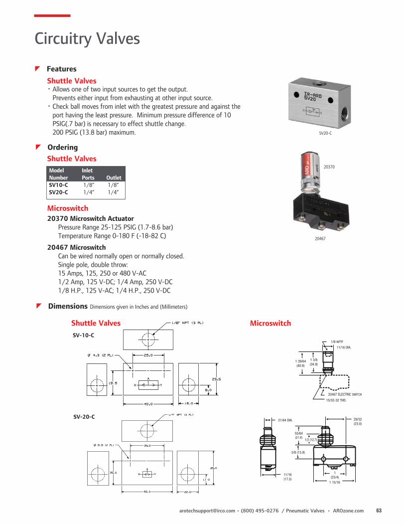
[email protected] • (800) 495-0276 / Pneumatic Valves • AROzone.com 63
Shuttle Valves
Microswitch
• Allows one of two input sources to get the output. Prevents either input from exhausting at other input source.
• Check ball moves from inlet with the greatest pressure and against the port having the least pressure. Minimum pressure difference of 10
PSIG(.7 bar) is necessary to effect shuttle change. 200 PSIG (13.8 bar) maximum.
Model InletNumber Ports OutletSV10-C 1/8” 1/8”SV20-C 1/4” 1/4”
20370 Microswitch Actuator Pressure Range 25-125 PSIG (1.7-8.6 bar) Temperature Range 0-180 F (-18-82 C)
20467 Microswitch Can be wired normally open or normally closed. Single pole, double throw: 15 Amps, 125, 250 or 480 V-AC 1/2 Amp, 125 V-DC; 1/4 Amp, 250 V-DC 1/8 H.P., 125 V-AC; 1/4 H.P., 250 V-DC
20370
20467
SV20-C
29/32 (23.0)
55/64 (21.8)
5/8 (15.9)
1 15/16
11/16 (17.5)
21/64 DIA.
1(25/4)
1/2 (12.7)
1/8-NPTF
20467 ELECTRIC SWITCH
15/32-32 THD.
11/16 DIA.
1 3/8 (34.9)
1 39/64 (40.9)
Shuttle Valves
MicroswitchShuttle ValvesSV-10-C
SV-20-C
z Features
Circuitry Valves
z Ordering
z Dimensions Dimensions given in Inches and (Millimeters)

64 AROzone.com • Pneumatic Valves / (800) 495-0276 • [email protected]
20311-X
20312-X
20313-X
20308-X
Breather Vents• Use on valves and single acting cylinders to prevent dirt from entering ports
open to atmosphere. Other uses are for vacuum relief or pressure equalization on gear boxes, reservoirs and air tanks.
• 40 micron filtration. Selection based on thread size.• Nickel plated steel body.
Muffler• Use on valve exhaust ports.• Sintered bronze construction. Air muffler and exhaust diffuser.• 40 micron nominal filtration; sound deadening qualities with low pressure drop.• Nickel plated steel body.
Speed Controls• Controls air flow on exhaust ports of air valves.• Change cylinder operating speed by adjusting screw. Secure with lock nut.
Silencer• Reduces noise of air powered motors and valves.• For high SCFM applications. High flow, low back pressure with no build up.• 300 PSI Max.
Circuitry Valves
z Features
Model Port Length Number Size In. (mm) Hex
20311-1 1/8” 7/16 (11.1) 7/16 20311-2 1/4” 5/8 (15.9) 9/16 20311-3 3/8” 3/4 (19.1) 11/16 20311-4 1/2” 7/8 (22.2) 7/8 20311-6 3/4” 1 (25.4) 1-1/16 20311-8 1” 1-5/16 (33.3) 1-5/16
Model Port Length Number Size In. (mm) Hex
116464 10-32 23/32 (18.2) 5/16 20312-1 1/8” 1 1/8 (28.6) 7/16 20312-2 1/4” 1 3/8 (34.9) 9/16 20312-3 3/8” 1 1/2 (38.1) 11/16 20312-4 1/2” 1 7/8 (47.6) 7/8 20312-6 3/4” 2 1/4 (57.2) 11/16 20312-8 1” 1 7/8 (73.0) 1 5/16
Model Ports Diameter Length
20308-1 1/8” 13/16 2-1/820308-2 1/4” 13/16 2-1/420308-3 3/8” 1-1/4 3-7/1620308-4 1/2” 1-1/4 3-9/1620308-6 3/4” 2 5-3/820308-8 1” 2 5-1/2
Breather Vents
Muffler
Speed Controls
Silencer
z Ordering
Model Port Length Length Number Size Closed Open In. (mm)
20313-1 1/8” 1 3/8 (34.9) 2 (50.8) 20313-2 1/4” 1 9/16 (39.7) 2 3/16 (55.6) 20313-3 3/8” 1 7/8 (47.6) 2 13/16 (71.4) 20313-4 1/2” 2 1/4 (57.2) 3 5/16 (84.1) 20313-6 3/4” 2 3/4 (69.9) 3 13/16 (96.8) 20313-8 1” 3 1/4 (82.6) 4 5/8 (117.5)

[email protected] • (800) 495-0276 / Pneumatic Valves • AROzone.com 65
600-X
Maximum Pressure: 200 PSI (13.8 bar)Temperature Range: -25° - 200°F (-32° - 93°C)
Model Port 10 PSI Pressure Drop (SCFM)Number Size 100 PSI 80 PSI
600-1 1/8” 16 14.5 600-2 1/4” 40 36 600-3 3/8” 65 59 600-4 1/2” 140 127
3-Way Sleeve Valve• Provides low-cost on-off control of single-acting spring
return cylinders.• Use in both ports of double-acting cylinders to isolate
from circuit.
Circuitry Valves
z Features
z Performance Specifications and Ordering

66 AROzone.com • Pneumatic Valves / (800) 495-0276 • [email protected]
• 360° swivel eases tube alignment. Preapplied thread sealant.• Choose threaded or instant tube fitting inlets; slotted or knob
flow adjustment.• Sturdy components include nickel-plated brass body, black anodized
aluminum swivel, Buna-N seals and a stainless steel spring.• Ready for installation on all ARO and competitive cylinders.• Consult factory for BSP size models.
SLOTTED ADJUST
KNOB ADJUST
C
E
F
A
B
AC
EMax. F
D
H
J
G
I
K
K
J
I
G
H
Flow Controls
z Features
z Ordering
Port “C” “D” “E” “F” “G” “H” “I” “J” “K” Size inches inches inches inches inches inches inches inches inches “A” & “B” (mm) (mm) (mm) (mm) (mm) (mm) (mm) (mm) (mm) 10/32 5/16 1/8 27/64 53/64 27/64 11/32 7/16 37/64 53/64 (8) (3.2) (11) (21) (11) (9) (11) (14.7) (21.1)
1/8 1/2 0 25/32 1-17/64 19/32 19/32 33/64 47/64 1-3/64 (13) 0 (19.8) (32) (15) (15) (13) (18.5) (26.7)
1/4 43/64 0 1-1/64 1-39/64 3/4 3/4 23/32 7/8 1-19/64 (17) 0 (25.8) (41) (19) (19) (18) (22.5) (32.9)
3/8 7/8 0 1-9/64 1-27/32 29/32 29/32 29/32 1-1/8 1-39/64 (22) 0 (29) (47) (23) (23) (23) (28.5) 41
1/2 1-1/16 0 1-27/64 2-9/32 1-7/64 1-7/64 63/64 1-7/32 1-53/64 (27) 0 (36) (58) (28) (28) (25) (31) (46.3)
1/8 33/64 0 25/32 1-7/8 19/32 19/32 33/64 47/64 1-3/64 (13) 0 (19.8) (47.5) (15) (15) (13) (18.5) (26.7)
1/4 43/64 0 1-1/64 2-9/32 3/4 3/4 45/64 57/64 1-19/64 (17) 0 (25.8) (58) (19) (19) (18) (22.5) (32.9)
3/8 7/8 0 1-9/64 2-37/64 29/32 29/32 29/32 1-1/8 1-39/64 (22) 0 (29) (65.5) (23) (23) (23) (28.5) (41)
1/2 1-1/16 0 1-27/64 3-5/32 1-7/64 1-7/64 63/64 1-7/32 1-53/64 (27) 0 (36) (80) (28) (28) (25) (31) (46.3)
KN
OB A
DJUS
T SL
OTTE
D AD
JUST
z Dimensions Dimensions given in Inches and (Millimeters)
Operating Pressure: 15-150 PSI (1-10 bar)Operating Temperature: -32°F - 158°F
z Performance Specifications
Slotted Adjust Knob Adjust
119307-XXXMale x Female thd
119309-XXXMale thd x fitting
119308-XXXMale x Female thd
119310-XXXMale thd x fitting
XXX Male x Female XXX Male x Tubing XXX Male x Female XXX Male x Tubing
103 10-32x10-32 103 10-32 x 5/32” 125 1/8” x 1/8” NPT 120 1/8” x 5/32”
125 1/8” x 1/8” NPT 120 1/8” x 5/32” 250 1/4” x 1/4” NPT 125 1/8” x 1/4
250 1/4” x 1/4” NPT 125 1/8” x 1/4” 375 3/8” x 3/8” NPT 250 1/4” x 1/4”
375 3/8” x 3/8” NPT 250 1/4” x 1/4” 500 1/2” x 1/2” NPT 255 1/4” x 3/8”
500 1/2” x 1/2” NPT 255 1/4” x 3/8” 375 3/8” x 3/8”
375 3/8” x 3/8”
119307-375 119307-250 119309-125 119309-103 119308-125

[email protected] • (800) 495-0276 / Pneumatic Valves • AROzone.com 67
• Four Stage, tapered needle design provides infinite control settings.• Composite body is tough and corrosion resistant.• Color-coded micrometer & calibrated adjustment knob provide instant reference points for repeat settings. Press red locking ring down prevents adjustment.
Tamper resistant wire supplied in package.• Units are threaded for easy remote panel mounting. Order panel nuts below.• Needle Valve is available with stainless steel needle & inserts. Order 104104-NS2.
A B C D E F Port* inches inches inches inches inches inches Model NPT(F) (mm) (mm) Min. Max. (mm) (mm) (mm)
01 1/8-27 15/16 1-11/32 2-33/64 2-53/64 15/16 1-29/32 1-20 (23.8) (34.1) (63.9) (71.6) (23.8) (48.4) UNEF-2A
02 1/4-18 15/16 1-11/32 2-33/64 2-53/64 15/16 1-29/32 1-20 (23.8) (34.1) (63.9) (71.6) (23.8) (48.4) UNEF-2A
03 3/8-18 1-5/16 1-11/16 3-23/64 3-55/64 1-5/16 2-27/32 1-3/16-18 (33.3) (42.9) (85.3) (97.8) (33.3) (72.2) UNEF-2A
04 1/2-14 1-5/16 1-11/16 3-23/64 3-55/64 1-5/16 2-27/32 1-3/16-18 (33.3) (42.9) (85.3) (97.8) (33.3) (72.2) UNEF-2A
06 3/4-14 1-9/16 2 3-43/64 4-11/64 1-9/16 3 1-3/16-18 (39.7) (50.8) (93.3) (105.7) (39.7) (76.2) UNEF-2A
AB
D
E
F
AB
C
D
E
F
Tamper Resistant Lock Ring
Locked
Unlocked
In-Line, CompositeNeedleFlowCheck
Flow Controls
z Features
z OrderingPosition 1 2 3
Example: 104104 - X XX
Position 1
Series
Position 2
Valve TypePosition 3Port Size
104104 C Check ValveF Flow ControlN Needle Valve
01 1/8-27 NTF SAE Short02 1/4-18 NTF SAE Short03 3/8-18 NTF SAE Short04 1/2-14 NTF SAE Short06 3/4-14 NTF SAE ShortS2* 1/4-18 NTF SAE Short
Stainless Steel inserts & stem* Available on needle valve only.
Operating Pressure: 200 PSI (13.8 bar) Operating Temperature: 0° - 200°F (-18° - 93°C)Flow: 100 PSI Inlet
z Performance Specifications
z Dimensions Dimensions given in Inches and (Millimeters)
Panel Port Mounting Nuts Size
104096 1/8” & 1/4” 104094 3/8”, 1/2” & 3/4”
F01C01 N01
Check Valve
Flow and Needle Valve

68 AROzone.com • Pneumatic Valves / (800) 495-0276 • [email protected]
CPXX-B* Check ValveFXX-BK Flow Control
NXX-BK Needle Valve
• High Pressure (up to 2000 PSI) flow control for either pneumatic or hydraulic applications.
• Heavy-duty brass construction provides good corrosion resistance.• Valve bodies, needle housings, locknuts and plugs are
machined from brass stock.• Cracking Pressure CP10 - 1-1/2 PSI CP20 - 1-1/2 PSI
In-Line, Brass
Flow Controls
z Features
Replace the “XX” with valve number corresponding to port size desired.Example: F10-BK Flow Control Valve 1/8” Ports
In-Line, Brass
z Ordering
ModelValve No.
(XX)NPTFPort
PDHex E L G
FXX-BKNXX-BKCPXX-B*
10 1/8 11/16 1-1/4 1-1/2 9/32
20 1/4 7/8 1-1/4 2 5/16
25 3/8 1-1/16 1-3/8 2-1/4 11/32
30 1/2 1-5/16 1-3/8 2-21/32 3/8
35 3/4 1-5/8 1-7/8 3 15/32
CPXX-B
FXX-BKNXX-BK
E max
D
L
P
L
P
D
L
P
In-Line, Brass
z Dimensions Dimensions given in Inches and (Millimeters)
E max
D
F20-BK
CP20-B N10-BK
* available in 1/8" and 1/4" only

[email protected] • (800) 495-0276 / Pneumatic Valves • AROzone.com 69
115046-XX 116218-XX 116647-XX115064-XX 119690-XX
Coils
Coils Connectors
• Coils are Class F rated for 100% duty cycle (311°F/155°C) applications.• AC and DC coils are interchangeable on the same solenoid stem.• Low “inrush” and “holding” current keeps heat rise to a minimum. This maximizes coil life and reduces power consumption.
Code / Voltage 31 = 12V AC 33 = 120V AC 35 = 240V AC
Code / Voltage 38 = 24V AC or 12V DC
(22mm Coils only) 39 = 24V DC
(Replace XX on model number with coil voltage required.)
115046-XX Cable Coil (NEMA 4, 22mm) 10’ AWG UL-listed elastomer cable. No solenoid connector needed.
115064-XX Low Watt Coil (DC only) (NEMA 4, 22mm) Low DIN coil. DC only, for use with 3-prong connectors.
12 and 24V DC only. Used only on valves ordered as low wattage.
116218-XX Standard Coil cURus listed (NEMA 4, 22mm) AC or DC DIN coil for use with 3-prong connectors.
116647-XX Coil with Molded Leads cURus listed (NEMA 4, 22mm) AC or DC lead wire coil with 18” molded leads. No solenoid
connector needed.
*119690-XX Oversize (NEMA 4, 30 mm) High Flow Cat Valve and 2-way Valve coil.
Available in -32, -33, -35, -38 and -39 voltages
117345-XX ATEX - NEC/CEC: Class I & II, Div 1 & 2, Group A-D - ATEX: Zone 1&2, 21&22* NOTE: -38 option is 12 VDC only on 30mm coils. 24 VAC is not available See Page 70 for Voltage Operating Ranges and Voltage Ratings.
CBWCHW CHL-XXX CDN, CDWCDL-XXX
CSNCSL-XXX
CDW-30 CSN-30 CHW-30
22-mm Connectors:(Replace XXX with voltage and type from chart below)
CHW Straight connector with cable (36”) located on top.
CBW Straight connector with cable (36”) located on back.
CHL-XXX Straight connector (36”) with indicator light located on back.
CSN Strain Relief, without indicator light or cable.CSL-XXX Strain Relief with indicator light located on back.CDN 1/2” Conduit without lights or lead wires.CDW 1/2” Conduit without lights, 18” lead wires.CDL-XXX 1/2” Conduit with light and 18” lead wires.30-mm Connectors:Use with High Flow Cat & intrinsically safe Genesis ValvesCDW-30 Connector with wire.CSN-30 Connector, strain relief.CHW-30 Connector, molded cable.
Voltage XXX)012 = 12V AC/DC024 = 24V AC/DC
120 = 120V AC240 = 240V AC/DC
114772-XX (30mm wide)
Connectors• Protect electrical connections from humidity and moisture.
Meet NEMA 4 classifications• Each is it’s own junction box, eliminating need to wire
solenoid to another box.
Hazardous Location CoilCoils are CSA certified and meet the requirements for use in hazardous locations.Environmental Code: Division 1, Class I, II, III, Group A-GFM Certification: 3006713Electrical Entry: 1/2” - 14 NPT-1 w/24” Lead Wires
Class “H” rated, 100% duty cycle Available in 120V AC & 24V DC only
z Features
Solenoid Accessories
z Ordering
119416 Side exhaust coil nut.
117345-XX ATEX

70 AROzone.com • Pneumatic Valves / (800) 495-0276 • [email protected]
Voltage Operating Ranges Coil Voltage Operating Range +10% Ratings AC DC 12 11-13 11-13 24 22-26 22-26 120 108-132 108-132 240 216-264 -- 380 342-418 --
22 mm Coil Current (Amps) Watts 12 DC 0.38 5.4 24 DC 0.20 5.4 120 DC 0.04 5.4 12, 24 DC .05 1.1
22 mm Coil Voltage Ratings Coil 50/60 Hz 50/60 Hz Voltage Current (Amps) Volt-Amps, Rating Inrush Holding Inrush Holding
12AC .70/.63 .50/.42 8.4/7.5 6.0/5.0 24AC .46/.40 .36/.27 11.0/9.4 8.4/6.5 120AC .09/.08 .07/.05 11.0/9.4 8.4/6.5 240AC .05/.04 .04/.03 11.0/9.4 8.4/6.5 380AC .03/.026 .024/.019 11.4/9.9 9.1/6.9
Coils
1 3/4(44.5)1 1/8
(28.6)
13/16(20.6)
3/4(19.1)
1 7/32(31.0)
15/16 (23.8)
1/2nps
3/4 (19.1)
1 1/4(31.5)
7/16(11.0)
36" (94.4)
3/4 (19.1)
1 1/16 (27.0)
1 1/16 (27.0)
3/4 (19.1)
13/16(20.6)
13/16(20.6)
10mm Dia. 1 7/32
(31.0)
1 19/32(40.5)1 1/8
(28.6)
.25 Dia.Cable
7/32
CSN 22 mm Strain Relief
1 3/4(44.5)1 1/8
(28.6)
13/16(20.6)
3/4(19.1)
1 7/32(31.0)
15/16 (23.8)
1/2nps
3/4 (19.1)
1 1/4(31.5)
7/16(11.0)
36" (94.4)
3/4 (19.1)
1 1/16 (27.0)
1 1/16 (27.0)
3/4 (19.1)
13/16(20.6)
13/16(20.6)
10mm Dia. 1 7/32
(31.0)
1 19/32(40.5)1 1/8
(28.6)
.25 Dia.Cable
7/32
1 3/4(44.5)1 1/8
(28.6)
13/16(20.6)
3/4(19.1)
1 7/32(31.0)
15/16 (23.8)
1/2nps
3/4 (19.1)
1 1/4(31.5)
7/16(11.0)
36" (94.4)
3/4 (19.1)
1 1/16 (27.0)
1 1/16 (27.0)
3/4 (19.1)
13/16(20.6)
13/16(20.6)
10mm Dia. 1 7/32
(31.0)
1 19/32(40.5)1 1/8
(28.6)
.25 Dia.Cable
7/32Straight Connectors
1 3/4(44.5)1 1/8
(28.6)
13/16(20.6)
3/4(19.1)
1 7/32(31.0)
15/16 (23.8)
1/2nps
3/4 (19.1)
1 1/4(31.5)
7/16(11.0)
36" (94.4)
3/4 (19.1)
1 1/16 (27.0)
1 1/16 (27.0)
3/4 (19.1)
13/16(20.6)
13/16(20.6)
10mm Dia. 1 7/32
(31.0)
1 19/32(40.5)1 1/8
(28.6)
.25 Dia.Cable
7/32
1/2” Conduit Connector
CDW-30.812 (20.6)
1.10 (27.94)
1.12(28.44)
1.654 (42.01)1.063 (27.0)
CHW-30
1.10 (27.94)
1.10(27.94)
1.59 (40.38)
.965(24.5)
CSN-30 30 mm Strain Relief
1.12(28.4)
1.10(27.94)
.81 (20.5)
1.06(26.92)
1.654(42.01)
30 mm Coil Voltage Ratings Coil 50/60 Hz 50/60 Hz Voltage Current (Amps) Volt-Amps, Rating Inrush Holding Inrush Holding
24AC -- -- 23 20 120AC -- -- 23 20 120AC (Hazardous Duty) 11.5 8.5
30 mm Coil Current (Amps) Watts 12 DC 0. - 62 15 24 DC 0.62 15 24 DC (Hazardous Duty) 5
Connectors
Solenoid Accessories
z Performance Specifications
z Dimensions Dimensions given in Inches and (Millimeters)

[email protected] • (800) 495-0276 / Pneumatic Valves • AROzone.com 71
Alpha Valves MaxAir Valves
Valve Model Kit Number
All 2-Position, Spring Return, Urethane 118597-2All 2-Position, Pilot or Solenoid Return, Urethane 118597-12All 2-Position, Spring Return, Viton 118598-4All 2-Position, Pilot or Solenoid Return, Viton 118598-143-Position, Closed, Urethane 118597-33-Position, Open, Urethane 118597-73-Position, Closed, Viton 118598-83-Position, Open, Viton 118598-9
Sierra Valves
Model Number Repair Kit
All Sierra Model 15 MQ3620M812SS-XXX-X RKM812-SSM812SD-XXX-X RKM812-SDM813SD-XXX-X RKM813-SD
50-Series Valves
Model Number Repair Kit
All Models 7000
E-Series Valves
Model Repair Kit
E112HM 116772E112LM 116772E112PD 116773E152HM 116772E152LM 116772E152PD 116773E212BS 116772E212BD 116773E212CA 116772E212CS 116772E212CP 116772E212FA 116772E212FP 116772E212FS 116772E212HA 116772E212HM 116772E212HP 116772E212HS 116772E212JS 116702
Model Repair Kit
E212JD 116702E212KD-XXX-X 116702E212KS-XXX-X 116702E212LA 116772E212LM 116772E212LP 116772E212LS 116772E212PA 116772E212PD 116773E212PE 116772E212PS 116772E212RA 116772E212RP 116772E212RS 116772E212SA-XXX-X 116772E212SD-XXX-X 116773E212SP-XXX-X 116773E212SS-XXX-X 116772E212TM 116772
Model Repair Kit
E252BD 116773E252BS 116772E252CA 116772E252CS 116772E252CP 116772E252FA 116772E252FP 116772E252FS 116772E252GA 116772E252GS 116772E252HA 116772E252HM 116772E252HP 116772E252HS 116772E252JS 116702E252JD 116702E252KS-XXX-X 116702E252LA 116772E252LM 116772
Model Repair Kit
E252LP 116772E252LS 116772E252PA 116772E252PD 116773 E252PE 116772E252PS 116772E252RA 116772E252RP 116772E252RS 116772E252SA-XXX-X 116772E252SN-XXX-X 116772E252SP-XXX-X 116773E252SS-XXX-X 116772E252TM 116772E252UA 116772E252US 116772E312LS 116773E312PD 116773E312TS 116773
Model Repair Kit
E712LS 116773E312SD-XXX 116773E512LM 116772E612LM 116772E712SD-XXX-X 116773Solenoid OperatorE212KD-XXX-X 116575E212KS-XXX-X 116573E212SA-XXX-X 116573E212SP-XXX-X 116573E212SD-XXX-X 116575E212SS-XXX-X 116573E252KS-XXX-X 116573E252SA-XXX-X 116573E252SN-XXX-X 116573E252SP-XXX-X 116573E252SS-XXX-X 116573E312SD-XXX-X 116575E712SD-XXX-X 116575
Model Repair Kit
M212LM RKM212-LMM212-LS RKM212-LMM212PD RKM212-PDM212PS RKM212-PSM212SD-XXX-X RKM212-SDM212SS-XXX-X RKM212-SSM252SS-XXX-X RKM212-SSM213LM RKM213-LMM213LS RKM213-LSM213PD RKM213-PDM213PS RKM213-PSM213SD-XXX-X RKM213-SDM213SS-XXX-X RKM213-SSM214-PD RKM214-PDM214PS RKM214-PSM214SD-XXX-X RKM214-SDM214SS-XXX-X RKM214-SSM2X2FS 114645M2X2TM 114645M312PD RKM312-PDM312SD-XXX-X RKM312-SDM313PD RKM313-PDM313SD-XXX-X RKM313-SDM314PD RKM314-PDM314SD-XXX-X RKM314-SD
Repair Kits
z Ordering

72 AROzone.com • Pneumatic Valves / (800) 495-0276 • [email protected]
H-Series
Model Repair Kit
H212BD 7103H212PA 7103H212PD 7103H212SA-XXX-X 7103H212SD-XXX-X 7103H213BD 7103H213PA 7103H213PD 7103H213SA-XXX-X 7103H213SD-XXX-X 7103H214BD 7103H214PA 7103
Model Repair Kit
H214PD 7103H214SA-XXX-X 7103H214SD-XXX-X 7103H242BD 7103H242PA 7103H242PD 7103H242SA-XXX-X 7103H242SD-XXX-X 7103H243BD 7103H243PA 7103H243PD 7103H243SA-XXX-X 7103
Model Repair Kit
H243SD-XXX-X 7103H252PS 7102H252SS-XXX-X 7102H253PS 7102H253SS-XXX-X 7102H254PS 7102H254SS-XXX-X 7102H282PS 7102H282SS-XXX-X 7102H283PS 7102H283SS-XXX-X 7102 – –
Model Repair Kit
SOLENOID OPERATORH212SA-XXX-X 116572H212SD-XXX-X 116574H213SA-XXX-X 116572H213SD-XXX-X 116574H214SA-XXX-X 116572H214SD-XXX-X 116574H242SA-XXX-X 116572H242SD-XXX-X 116574H243SA-XXX-X 116572H243SD-XXX-X 116574H252SS-XXX-X 116572H253SS-XXX-X 116572H254SS-XXX-X 116572H282SS-XXX-X 116572
K-Series
Repair Kits
z Ordering
Model Repair KitK213BS 7006K213FP 7006K213FS 7006K213HS 7006K213LM 7006K213LS 7006K213PD 7006K213PS 7006K213RS 7008K213SD-XXX-X 7006K213SS-XXX-X 7006K213TM 7006K214BS 7006K214BD 7006K214FP 7006K214FS 7006K214LM 7006K214LS 7006K214PS 7006K214PD 7006K214RS 7008K214SD-XXX-X 7006K214SS-XXX-X 7006K214TM 7006K216BD 7010K216BS 7010K216PD 7010K216PS 7010K216RS 7012K216SD-XXX-X 7010K216SS-XXX-X 7010K218BD 7010K218BS 7010K218PD 7010K218PS 7010K218RS 7012K218SD-XXX-X 7010K218SS-XXX-X 7010K233BD 7006K233BS 7006K233FP 7006K233FS 7006K233LM 7006K233LS 7006
Model Repair KitK233PD 7006K233PS 7006K233RS 7008K233SD-XXX-X 7006K233SS-XXX-X 7006K233TM 7006K234BD 7006K234BS 7006K234FP 7006K234FS 7006K234LM 7006K234LS 7006K234PD 7006K234PS 7006K234RS 7008K234SD-XXX-X 7006K234SS-XXX-X 7006K234TM 7006K236BD 7010K236BS 7010K236PD 7010K236PS 7010K236RS 7012K236SD-XXX-X 7010K236SS-XXX-X 7010K238BS 7010K238BD 7010K238PD 7010K238PS 7010K238RS 7012K238SD-XXX-X 7010K238SS-XXX-X 7010K243BD 7006K243BS 7006K243FP 7006K243FS 7006K243LM 7006K243LS 7006K243PD 7006K243PS 7006K243RS 7008K243SD-XXX-X 7006K243SS-XXX-X 7006K243TM 7006
Model Repair KitK244BD 7006K244BS 7006K244FP 7006K244FS 7006K244LM 7006K244LS 7006K244PD 7006K244PS 7006K244RS 7008K244SD-XXX-X 7006K244SS-XXX-X 7006K244TM 7006K246BD 7010K246BS 7010K246PD 7010K246PS 7010K246RS 7012K246SD-XXX-X 7010K246SS-XXX-X 7010K248BD 7010K248BS 7010K248PD 7010K248PS 7010K248RS 7012K248SD-XXX-X 7010K248SS-XXX-X 7010K313LS 7006K313PD 7006K313TS 7006K314LS 7006K314PD 7006K314SD-XXX-X 7006K314TS 7006K316PD 7010K316SD-XXX-X 7010K318PD 7010K318SD-XXX-X 7010K333LS 7006K333PD 7006K333SD-XXX-X 7006K333TS 7006K334LS 7006K334PD 7006K334SD-XXX-X 7006
Model Repair KitK314BD 7006K334TS 7006K336PD 7010K336SD-XXX-X 7010K338PD 7010K338SD-XXX-X 7010K343LS 7006K343PD 7006K343SD-XXX-X 7006K343TS 7006K344LS 7006K344PD 7006K344SD-XXX-X 7006K344TS 7006K346PD 7010K346SD-XXX-X 7010K348PD 7010K348SD-XXX-X 7010K513LM 7007K513TM 7007K514LM 7007K514TM 7007K533LM 7007K533TM 7007K534LM 7007K534TM 7007K543LM 7007K543TM 7007K544LM 7007K544TM 7007K613LM 7007K613TM 7007K614LM 7007K614TM 7007K633LM 7007K633TM 7007K634LM 7007K634TM 7007K643LM 7007K643TM 7007K644LM 7007K644TM 7007K713LS 7006K713PD 7006
Model Repair KitK713SD-XXX-X 7006K713TS 7006K714LS 7006K714PD 7006K714SD-XXX-X 7006K714TS 7006K716PD 7010K716SD-XXX-X 7010K718PD 7010K718SD-XXX-X 7010K733PD 7006K733LS 7006K733SD-XXX-X 7006K733TS 7006K734PD 7006K734LS 7006K734SD-XXX-X 7006K734TS 7006K736PD 7010K736SD-XXX-X 7010K738PD 7010K738SD-XXX-X 7010K743LS 7006K743SD-XXX-X 7006K743TS 7006K744LS 7006K744PD 7006K744SD-XXX-X 7006K744TS 7006K746PD 7010K746SD-XXX-X 7010K748PD 7010K748SD-XXX-X 7010SOLENOID OPERATORK213SD-XXX-X 116578K213SS-XXX-X 116578K214SD-XXX-X 116578K214SS-XXX-X 116578K216SD-XXX-X 116579K216SS-XXX-X 116579K218SD-XXX-X 116579K218SS-XXX-X 116579K233SD-XXX-X 116578K233SS-XXX-X 116578
Model Repair KitSOLENOID OPERATOR CONT.K234SD-XXX-X 116578K234SS-XXX-X 116578K236SD-XXX-X 116579K236SS-XXX-X 116579K238SD-XXX-X 116579K238SS-XXX-X 116579K243SD-XXX-X 116578K243SS-XXX-X 116578K244SD-XXX-X 116578K244SS-XXX-X 116578K246SD-XXX-X 116579K246SS-XXX-X 116579K248SD-XXX-X 116579K248SS-XXX-X 116579K313SD-XXX-X 116578K314SD-XXX-X 116578K316SD-XXX-X 116579K318SD-XXX-X 116579K333SD-XXX-X 116578K334SD-XXX-X 116578K336SD-XXX-X 116579K338SD-XXX-X 116579K343SD-XXX-X 116578K344SD-XXX-X 116578K346SD-XXX-X 116579K348SD-XXX-X 116579K713SD-XXX-X 116578K714SD-XXX-X 116578K716SD-XXX-X 116579K718SD-XXX-X 116579K733SD-XXX-X 116578K734SD-XXX-X 116578K736SD-XXX-X 116579K738SD-XXX-X 116579K743SD-XXX-X 116578K744SD-XXX-X 116578K746SD-XXX-X 116579K748SD-XXX-X 116579

[email protected] • (800) 495-0276 / Pneumatic Valves • AROzone.com 73
Individual Elements
Circuit Board Construction
Function Base Assembly Back Tubulation
Elements: Elements are miniature diaphragm operated poppet valves designed to perform specific functions. This includes “Or,” “And,” “Not,” plus various “Memory” and “Delay” functions. Elements are designed so response times, shift ratios, flow and exhaust capacities are closely matched and all are compatible in a total system. This compatibility simplifies circuit design.
Circuit Board Construction: Aro’s patented circuit board construction uses a gasket and two metal plates to create a custom air manifold. Interconnections between the elements are cut into the gasket (module) and sealed between the metal plates. The result is a completely interconnected circuit without tubing or fittings. Two gasket modules are used for more complex circuits. Circuit Boards produce a smaller circuit package at lower cost; increased tamper resistance; and provide a clean, neat assembly.
Function Base Assembly Method: A Function Base can be used when circuits require four or less elements. This consists of a gasket module, a thin metal plate and a porting strip. Interconnections between the elements are cut into the module. The porting strip has 1/8” NPTF ports, eliminating the need for porting blocks. This method can be mounted on any flat surface; it provides a neat, durable assembly; and it increases tamper resistance.
Back Tubulation Construction: This method uses a thin metal plate (base plate) and porting blocks for each element. Each block has built in fittings for 5/32” (4mm) tubing. Element interconnections are made by connecting tubes to these fittings. Back tubulation is often used for “bread boarding” new circuits, air circuit training and if circuits are frequently changed.
Air Supply PreparationRecommended Filtration: Filter air with a 40 micron filter or better. Additional screens in the base of timing function elements and amplifiers prevent large particles from entering the element.
Recommended Lubrication: None required for individual elements, or for circuits including timing functions or amplifiers.
Moisture: All metal parts are chromate plated to resist corrosion from moisture and many chemicals. A dry air supply is recommended for maximum repeatability of timing and sensing functions.
Operating Air:Operating Pressure: 30-125 PSI (2-9 bar). Two-hand anti-tie-down devices require 50-125 PSI (3.5-9 bar).
Shift Pressures:Snap-Acting Elements (And, Not, Inhibitor, S/R -- Mem, Delay and Pulse) shift when the pilot pressure exceeds 70% of the supply. They return when pilot pressure is less than 40% (Inhibitor 5%) of the supply.
Non-Snap-Acting Elements (Or -- Flip-Flop) have a shift pressure of 50% of supply pressure.
Flow & Cv Factors: Dependent on specific elements and flow paths. Flow = 9.3-16.2 SCFM, Cv = .14-.28
Identification:Symbols: Each element has a symbol based on the National Standard for diagramming moving part logic control (attached method).
Port Identification: Letters cast into the cover and base of each element correspond to input and output designations.
Mounting: Elements have 5/8” (15.9mm) bolt extensions. All mounting hardware and seals are provided with each element.
Test Ports: Many elements have 1/8” NPT ports connected to the “C” (output) port. These can be used as optional output ports, or as test ports.
Anticipated Life:Element Life: APLC elements have proven extremely durable, operating many millions of cycles, or several years, without failure. If needed, repair kits or parts are available for most elements.
Aro Pneumatic Logic Control Overviewz Features
APLC
z Performance Specifications

74 AROzone.com • Pneumatic Valves / (800) 495-0276 • [email protected]
• Ideal for machines where position of operator’s hands must be monitored.• Actuate and hold both air valve buttons concurrently to maintain an
output air signal. If either push button is released, the output air signal is exhausted,
indicating the operator’s hands are no longer in position.• Operating Pressures: 50-125 PSI (3.5-8.6 bar). Designed to comply with
OSHA regulations.
Warning: These provide only the anti-tie down logic function and are not stroke limiting devices. On machines with full revolution clutches and/or where repeat cycles can occur, approved safety and/or single stroke devices must be used in conjunction with the anti-tie down units.
59191 Base Mounted• Element has three 1/8” NPTF ports on top. 2 inputs, 1 output.• Element is base mounted. See page 101 for additional information
Elements
Packages
59809
4-3/8(111.1 mm)
3-5/8(92.1 mm)
4-3/8(111.1 mm)
10(254 mm)
4-3/8(111.1mm)
3-5/8(92.1mm)
3-5/8(92.1mm)
10(254 mm)
4-3/8(111.1 mm)
2(50.8 mm)
2-1/2(50.8 mm)
4-1/2(114.3 mm)
1/4(6.4 mm)
59191
59808
4-1/4(108 mm)
10(254 mm)
2(50.8 mm)
6(152.4 mm)
2(50.8 mm)
1-3/16(30.2 mm)
2(50.8 mm)
59808• Includes two enclosures with green push button valves separated by a
length of flexible conduit. External supply and output to machine is made by 5/32” (4mm) instant tube fittings.
• Comes assembled with all internal connections ready to install on machine.
• Palm Buttons are 30” center to center.
59809• Green push buttons located on opposite ends of a single enclosure.
External supply and output to machine is made by 5/32” (4mm) instant tube fittings.
• Comes assembled with all internal connections ready to install on machine.
59003-842• Unassembled package.• Includes 59191 anti-tie-down block, two 461-3 palm buttons
with 20975 guards, 10 feet of 5/32” tubing and fittings for 59191.• Customer can custom fit components to machine.
59003-842 CONTROL ASM. 59756*4 (3) BOW FITTINGS FOR 5/32” TUBING
10’ of 5/32” Tubing
59191 LOGIC CONTROL ASM.
APLC - 2 Hand Anti-Tie-Down
z Features
2 Hand Anti-tie down (ATD)

[email protected] • (800) 495-0276 / Pneumatic Valves • AROzone.com 75
59860 Signal Standardizer• Converts an input signal of any duration into a timed output signal.• Built in 4-way function in which two output signals are provided;
one normally on, the other normally off.• Can be used for 3-way and 4-way valves of all types including single and
double pilot-operated models.• Timing Range is 0.1 to 3 seconds. Longer with use of an accumulator.
Each additional cu. in. of space added will give an extra 8 seconds of timing.
• Use filtered, dry, non-lubricated air. 50-125 psi (3.5-8.6 bar)• See page 79 for additional information.
59861 Oscillator Circuit• Use in applications involving cycling and oscillating valves and cylinders for manufacturing and testing; as well as, pumping, sorting and painting.• Has two dial timers so both phases can be adjusted independently.• Can be used for all types of 3-way and 4-way valves.• Recommended Timing Range of .1 to 3 seconds. Longer when using an accumulator. Each additional cu. in. of space added will give an extra 8
seconds of timing.• See page 79 for additional information.NOTE: For set-up or trouble-shooting, time delay functions can be adjusted far beyond their recommended range; however, if their normal operating time is longer than 3 seconds, additional volume should be connected to the port marked “Acu” (to the right of the adjustment dial). Each cubic inch additional volume connected to this port will increase the maximum range of the time delay by 8 seconds. A pressure gauge tee’d into the accumulator port can be very valuable as a visual aid when adjusting timers with extended ranges.
59917 Binary Flip-Flop• With supply on, output one or output two will be on and the other off. • Pressurizing the trigger port switches the outputs between on and off.NOTE: All Flex-6 units have 10/32” ports.
59914 “OR” Element• Connects two inputs to one output. The output will be on when either,
or both, inputs are on.59913 “AND” Element• Connects two inputs to one output. The output will be on when both
inputs are on.
Operating Press: 30-150 PSIG (2-10 bar)Operating Temp: 32°-160°F (0°-71°C)Ports: #10-32 threads Shuttle/Poppet: Buna NBody Material: Acetal Resin Inserts: AluminumFlow: “OR” = 4 SCFM, “AND” = 3.2 SCFM Cv: “OR” = .11, “AND” = .09
In Line Logic Elements
59860
59861
59917
59914 59913
13/64 (5.2mm)MTG HOLE 4 PL
4-1/8(105 mm)
1/4(64 mm)
4-1/2(114.3 mm)
2-1/16(54.4 mm)
11/16 (17.4)
#10-32 Ports
2-1/2(63.5 mm)
2-1/8(54 mm)
Dimensions for Base Mounted Units Ports are 10/32 Threads
4-1/2(114.3 mm)
1/4(64 mm)
2-1/2(63.5 mm)
2 (50.4)
#10-32 Ports
APLC - Specialty Circut Blocks*
z Accessories
* See page 79 for sample application circuits
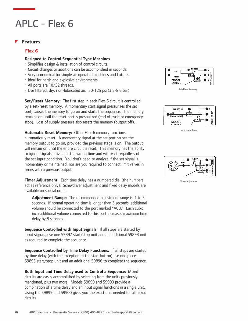
76 AROzone.com • Pneumatic Valves / (800) 495-0276 • [email protected]
Designed to Control Sequential Type Machines• Simplifies design & installation of control circuits.• Circuit changes or additions can be accomplished in seconds.• Very economical for simple air operated machines and fixtures.• Ideal for harsh and explosive environments.• All ports are 10/32 threads.• Use filtered, dry, non-lubricated air. 50-125 psi (3.5-8.6 bar)
Set/Reset Memory: The first step in each Flex-6 circuit is controlled by a set/reset memory. A momentary start signal pressurizes the set port, causes the memory to go on and starts the sequence. The memory remains on until the reset port is pressurized (end of cycle or emergency stop). Loss of supply pressure also resets the memory (output off).
Automatic Reset Memory: Other Flex-6 memory functions automatically reset. A momentary signal at the set port causes the memory output to go on, provided the previous stage is on. The output will remain on until the entire circuit is reset. This memory has the ability to ignore signals arriving at the wrong time and will reset regardless of the set input condition. You don’t need to analyze if the set signal is momentary or maintained, nor are you required to connect limit valves in series with a previous output.
Timer Adjustment: Each time delay has a numbered dial (the numbers act as reference only). Screwdriver adjustment and fixed delay models are available on special order.
Adjustment Range: The recommended adjustment range is .1 to 3 seconds. If normal operating time is longer than 3 seconds, additional volume should be connected to the port marked “ACU.” Each cubic inch additional volume connected to this port increases maximum time delay by 8 seconds.
Sequence Controlled with Input Signals: If all steps are started by input signals, use one 59897 start/stop unit and an additional 59898 unit as required to complete the sequence.
Sequence Controlled by Time Delay Functions: If all steps are started by time delay (with the exception of the start button) use one piece 59895 start/stop unit and an additional 59896 to complete the sequence.
Both Input and Time Delay used to Control a Sequence: Mixed circuits are easily accomplished by selecting from the units previously mentioned, plus two more. Models 59899 and 59900 provide a combination of a time delay and an input signal functions in a single unit. Using the 59899 and 59900 gives you the exact unit needed for all mixed circuits.
Set/Reset Memory
Automatic Reset
Timer Adjustment
Flex 6
APLC - Flex 6
z Features

[email protected] • (800) 495-0276 / Pneumatic Valves • AROzone.com 77
Steps to Connecting Flex-6 Units
STEP 1
MAINTAINED SUPPLY
LAST SUPPLY OUT PORT REMAINS PLUGGED.
STEP 2
Remove and retain Plug for later use.
STEP 3
STEP 4
STEP 5
STEP 6
1. Arrange the units in the order and sequence they are used (steps 1 and 2 top, 3 and 4 next, etc.).
2. Connect a maintained supply to the “supply in” port of the first unit. Then connect the “supply out” of the first unit to the “supply in” of the second unit. Connect subsequent units in this manner. The last “supply out” port will remain plugged.
Limit Valves
Start
LV-1
LV-2
3. Connect the set input signals. The start signal and all other input signals are connected to the set ports of the units they will start.
4. Connect and “program” the outputs. Each unit has three ports on the right side marked “A,” “B,” and “C.” The “C” port is the output and is connected to the pilot valve or other device causing action for each stage. The “C” output signal can be removed by a signal (maintained) to the “A” port. The “B” ports are used to provide this maintained signal.
Example: Cylinder 1 extends in step 1 and retracts in step 4. The “C” port of step 1 is connected to a spring return pilot valve which extends the cylinder. The “B” port of step 4 is connected to the “A” port of step 1. This accomplishes the retract function.NOTE: Once these connections have been made, plug all “B” and “C” ports not used. “A” ports not used remain open.
Supply
Cylinder
4
1
Remove plug and connect to “A” port to remove “C.”
To Cylinder 2 Pilot (Etc.)
First Unit
The Last Step of the Sequence is to RESET the Circuit
All Ports are 10/32
5. Connect the reset signal from the last step in sequence to the port marked “reset” in the first. This signal resets the circuit, making it ready to start a new cycle.
APLC - Flex 6
z Set-up

78 AROzone.com • Pneumatic Valves / (800) 495-0276 • [email protected]
59919-1
59895 S/R Mem-Delay ModelThe first unit in a Flex-6 circuit when step two is a delay function. The first output is caused by the start input signal. The second output is caused by a time delay following the first output. Flex 6 Dimensional Data is located on Pg. 86.
59896 Double DelayUsed as the second unit, or later, in circuits when two time delay functions are needed. The first output is caused by a time delay after the supply signal is applied. The second output is caused by a time delay following the first output.Flex 6 Dimensional Data is located on Pg. 86.
59897 S/R Mem-Auto Mem ModelThe first unit in Flex-6 circuits when step two is an input signal. The first output is caused by the start input signal. The second output is caused by a second input signal.Flex 6 Dimensional Data is located on Pg. 86.
59898 Double Auto Mem ModelUsed as the second unit, or later, in circuits when two input signals are available. Both outputs are caused by their respective inputs and both are controlled by automatic reset memory functions.Flex 6 Dimensional Data is located on Pg. 86.
59899 Auto Mem-Delay ModelUsed as the second unit, or later, in Flex-6 circuits when an input signal and a delay function are required. The first output is caused by an input signal. The second output is caused by a time delay following the first output.Flex 6 Dimensional Data is located on Pg. 86.
59900 Delay-Auto Mem ModelUsed as the second unit, or later, in circuits when a delay and an input signal are required. The first output is caused by delay function after the supply signal is applied. The second output is caused by an input signal.Flex 6 Dimensional Data is located on Pg. 86.
59919-1 Cycle Repeat CircuitCycle Repeat Circuit provides continuous recycling of a control circuit started by a momentary start signal, end of cycle stop — momentary input, single cycle operation, emergency stop and an adjustable dwell between cycles.Add to any Flex-6 circuit so it cycles continuously. Flex 6 Dimensional Data is located on Pg. 86.See page 102 for additional information.
59896
59897
59898
59900
59895
59899
Flex 6 Individual Units
APLC - Flex 6
z Features

[email protected] • (800) 495-0276 / Pneumatic Valves • AROzone.com 79
Other Six Element Assemblies
Two-Hand Ant-Tie-Down Model 59191The two-hand anti-tie-down is used to insure that both push buttons have been actuated before the cycle will start. When the anti-tie-down is used, both buttons must be actuated concurrently to create an output signal. Once either push button is released, the output signal goes off. Both push buttons must then be released and reactuated to start again.
The first drawing shows a two-hand anti-tie-down added to the start of a Flex-6 circuit.
The second drawing shows a more complex circuit which is used to insure that the operator hold both buttons until cylinder 1 is fully extended. Once cylinder 1 is extended and actuates limit valve 1, the push buttons can be released and the machine will continue its automatic cycle.
The Signal Standardizer Model 59860The 59860 signal standardizer (or signal shaper) can be used to convert a signal of any duration to outputs of a predetermined time period.
When the start signal is received, the cylinder will extend for the period of time adjusted on the timer. Then the cylinder will retract. The start input signal can be shorter or longer than the output signal(s)* without affecting the timing function.
The Oscillator Circuit Model 59861When a signal is received at the input of the oscillator circuit output T1 will come on. After an adjustable period of time (adjustable at timer T1 output T1 will go off and output T2 will go on.* After another adjustable period of time (adjustable at T2) output will go off and output T1 will go on. This will continue as long as the input remains on.* Outputs not used can be plugged. Small cylinders can be ported directly to these outputs.
Four other six element assemblies are available. These units are sometimes used with Flex-6 circuits and in other cases provide a complete function in themselves.
APLC - Specialty Assemblies
z Features
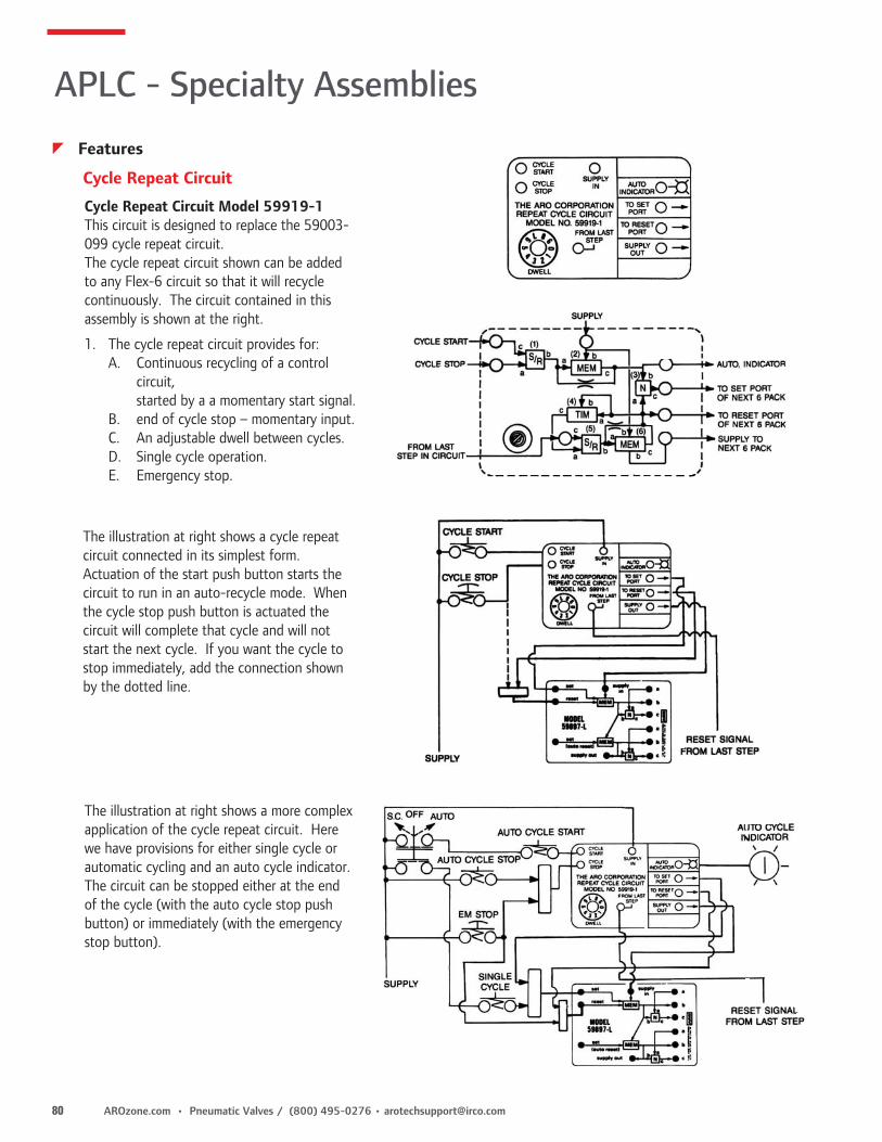
80 AROzone.com • Pneumatic Valves / (800) 495-0276 • [email protected]
Cycle Repeat Circuit
Cycle Repeat Circuit Model 59919-1 This circuit is designed to replace the 59003-099 cycle repeat circuit.The cycle repeat circuit shown can be added to any Flex-6 circuit so that it will recycle continuously. The circuit contained in this assembly is shown at the right.
1. The cycle repeat circuit provides for: A. Continuous recycling of a control
circuit, started by a a momentary start signal.
B. end of cycle stop – momentary input. C. An adjustable dwell between cycles. D. Single cycle operation. E. Emergency stop.
The illustration at right shows a cycle repeat circuit connected in its simplest form. Actuation of the start push button starts the circuit to run in an auto-recycle mode. When the cycle stop push button is actuated the circuit will complete that cycle and will not start the next cycle. If you want the cycle to stop immediately, add the connection shown by the dotted line.
The illustration at right shows a more complex application of the cycle repeat circuit. Here we have provisions for either single cycle or automatic cycling and an auto cycle indicator. The circuit can be stopped either at the end of the cycle (with the auto cycle stop push button) or immediately (with the emergency stop button).
APLC - Specialty Assemblies
z Features

[email protected] • (800) 495-0276 / Pneumatic Valves • AROzone.com 81
59010 “OR” Element59023 “OR” Element on 1/8” Base• Combines two air signals so either can produce an output.• Output port C is pressurized when either input port A or B is pressurized “on”.Dimensions: 1 1/4” sq. x 1” (31.8mm sq. x 25.4mm) Response Times: Input to Output Milliseconds “A” on to “C” on 7.5 “B” on to “C” on 759111 “AND” Element59124 “AND” Element on 1/8” Base• Combines two signals so both must be on to create an output.• Output port C is pressurized only when both inputs A & B are pressurized “on”.• Limit inlet pressures to 60-100 PSI• Shift occurs when pressures exceed 60% of total and return when pressures fall below 50%.Dimensions: 1 1/4” Sq. x 1 21/32” (31.8mm sq. x 42.1mm) Response Times: Input to Output Milliseconds “A” on to “C” on 8 “A” off to “C” off 9.559112 “NOT” Element59125 “NOT” Element on 1/8” Base• Combines two signals so that one (“B”) must be on, and the other (“A”) must be off to create an output.• Output C is pressurized only when input B is pressurized and input A is off.• Limit inlet pressures to 60-100 PSI • Shift occurs when pressures exceed 60% of total and return when pressures fall below 50%.Dimensions: 1 1/4” Sq. x 1 21/32” (31.8mm sq. x 42.1mm)Response Times: Input to Output Milliseconds “A” on to “C” off 8.5 “A” off to “C” on 959800 Inhibitor Element59912 Inhibitor Assembly on 1/8” Base• Functions as NOT element except pressure at A must drop below 5% of supply before element will reset, regaining output at C.• Useful in detecting air cylinder motions where limit valves cannot be applied.Response Times: Input to Output Milliseconds A on to C off 15 A off to C on 2559181 Set-Reset (S-R) Gate and 59113 Memory Models59185 Set-Reset (S-R) Gate and Memory Assembly on 1/8” Base• The elements work together to perform a memory function.• With constant supply at B of MEM and B of S-R connected to A of MEM, a momentary pressure signal at C of S-R will cause C of MEM to pressurize. C of MEM will remain pressurized until a pressure signal to A of S-R is received.• The MEMORY is pneumatically retained. If supply is removed (B MEM off), output C will go off & remain off until a new set signal is received.• The reset signal (“A” of S-R) is snap-action function and can be connected to a TIMER element to create a delayed reset function.Dimensions: 1 1/4” sq. x 1 21/32” (31.8mm x 42.1mm)Minimum Time: Signal Milliseconds To SET 17 To RESET 19
59010
59111
59112
59181 59113
59800
Individual Elements
APLC - Elements
Truth table
Truth table
Truth table

82 AROzone.com • Pneumatic Valves / (800) 495-0276 • [email protected]
59892”FLIP FLOP” Model• A memory type element, Flip-Flop converts momentary signals received at the set and reset ports into maintained corresponding outputs.• A set signal at A shifts the Flip-Flop to C port on and resets D to off. A reset signal at F shifts the Flip-Flop to D on and C off.• If set or reset signals are maintained, later signals of equal pressure to the opposite input will not alter the output condition.• The Flip-Flop has six ports and requires two element spaces. A Set Input D Reset Output B Supply E Supply C Set Output F Reset Input• 59892 has two top ports (10-32) for C and D outputs.• Shift pressure is 50% of supply pressure. Dimensions: 2 1/2” x 1 7/32” (63.5mm x 36.5mm)
Delay Elements• Combine an AND and a TIMER function.• With supply present at B, output will be pressurized (C on) a predetermined amount of time after input A is pressurized. Time can be fixed or adjustable.• Reset time (time signal at “A” must be off between cycles) is 100 milliseconds.• Timing ranges for individual elements cannot be increased. For longer delays, a base mounted assembly is needed.
Delay Timing In Functions1. With the input off, the output will also be off.2. The timing function starts when the input goes on.3. When the timing is complete, the output goes on.4. Output goes off immediately when input is removed.
Screwdriver Adjustable Delay Units• ±4% timing accuracy. Individual Element Base Mounted Elements (1/8” Base) 59121 Timing Range: .08 to 4.5 seconds 59158 Timing Range: .08 to 4.5 seconds 59879 Timing Range: 4.1 to 24.5 seconds
Dial Adjustable Delay Units• ±4% timing accuracy. Individual Element Base Mounted Elements (1/8” Base) 59156 Timing Range .08 to 4.5 seconds 59160 Timing Range: .08 to 4.5 seconds
59166-4 Fixed Delays• Not adjustable. Order model for desired time.Dimensions: 1 1/4” sq x 2 3/4” (31.8mm sq. x 69.9mm) Model Milliseconds 59166-4 445 ± 40Dimensions for Base Assemblies are on page 87.
Flip-Flop
Delay Elements & Assemblies
Output (C)
Input (A) 59879
APLC - Elements
z Features
Approximate Response Time
Input to Output Milliseconds
A on to C on 11 F on to D on 11
59892
59121
59156
59166-4
59158

[email protected] • (800) 495-0276 / Pneumatic Valves • AROzone.com 83
Pulse Elements• Combine a NOT and a TIMER function.• These perform TIMING-IN inverted or PULSE functions, depending on connections to supply port B.
For TIMING-IN INVERTED function: With port B pressurized, C port remains on untilport A is pressurized. When A is pressurized, C will go OFF after a predetermined amount of time.
PULSE function: When A & B are connected together, output C is normally off.If inputs are applied to A & B, output C goes on. C remains on for timer period, thengoes off and remains off until inputs are removed and reapplied. Reset time is 100 milliseconds. The predetermined amount of time can be fixed or adjustable.
1. With input off, the output will also be off.2. Output goes on & timing starts when input comes on.3. When timing is completed, output goes off.4. Remove & reapply input to get second output. NOTE: Input must be longer than output for full times signal. If not possible, see momentary timers.
Screw Adjustable Pulse Timers• ±4% timing accuracy. Individual Element Base Mounted Elements (1/8” Base) 59120 Timing Range: .08 to 4.5 seconds 59157 Timing Range: .08 to 4.5 seconds
Dial Adjustable Pulse Timers Individual Element Base Mounted Elements (1/8” Base) 59155 Timing Range: .08 to 4.5 seconds 59159 Timing Range: .08 to 4.5 seconds 59875 Timing Range: 3.0 to 14.5 seconds59165-4 Fixed Pulse• Not adjustable, order model for time desired; ±10% timing accuracy.Dimensions: 1 1/4” sq x 2 3/4” (31.8mm sq. x 69.9mm) Model Milliseconds 59165-4 445 ± 40
59114 Differentiator• A non-adjustable pulse element.• With A blocked, signal at B will produce an output at C of 80 to 130 milliseconds. Output can be lengthened by connecting a 59117 Accumulator to port A.• Reset time is 110 milliseconds.Dimensions: 1 1/4” sq. x 1 3/4” (31.8mm sq. x 44.5mm)
Dimensions for Base Assemblies are on page 87.
Pulse Elements & Assemblies
59155
59165-4
59157
Input (A)
Output (C)
59881 / 59882
Input (A)
Output (C)
59874 / 59875
59114
59120
APLC - Elements
z Features

84 AROzone.com • Pneumatic Valves / (800) 495-0276 • [email protected]
59117 Accumulator• Used with timing elements to extend timing range. C port is connected to output of timing element. Volume is approximately 1 cu. in. (16.4 cm3). Dimensions: 1 1/4” sq. x 2 1/16” (31.8mm sq. x 52.4mm)
TIMERS are used in conjunction with snap-acting 59111 AND, 59112 NOT, 59181 S-R GATE or 59800 INHIBITOR to perform special functions not offered in one complete element.• Overall height of circuit board can be reduced by using these combinations rather than elements which combine these functions.• Timing periods can exceed 4.5 seconds when using with 59117 Accumulators.• Time can be fixed or adjustable, depending on element selected.59115 Screw Adjustable Timer• Connected to A of snap-acting AND or NOT element, these timing ranges can be accomplished. Dimensions: 1 1/4” sq. x 2 7/64” (31.8mm sq. x 53.6mm)
59116 Dial Adjustable Timer• Connected to A of snap-acting element, these timing ranges can be accomplished. Dimensions: 1 1/4” sq. x 3 5/16” (31.8mm sq. x 84.1mm)
• Can be mounted in inlet or outlet ports of any element to reduce flow and/or increase response time.
• Fits into O-Ring cavity of element base.
Model Orifice Size Inches (mm)
59671-1 .0135 (.343)
Timer Elements
Accumulator
Fixed Orifice plates and Port Plug
59117
59116
59115
59671-X
APLC - Elements
z Features
Number of 59117 Timing Range Timer Accumulators ±4% Seconds
59116 0 1.4 to 4.559116 1 3.0 to 14.559116 2 4.6 to 24.559116 3 6.2 to 34.559116 4 7.8 to 44.5
Number of 59117 Timing Range Timer Accumulators ±4% Seconds
59115 0 .08 to 4.559115 1 .14 to 14.559115 2 .20 to 24.559115 3 .26 to 34.559115 4 .32 to 44.5

[email protected] • (800) 495-0276 / Pneumatic Valves • AROzone.com 85
NOT Amplifier
AND Amplifier59175 “AND” Amplifier• The amplifier converts low pressure signals such as those used in liquid level
sensing, to high pressure signals compatible with other APLC elements.• Performs AND function except when output at C is greater than input A1.• Inputs A & B must be interconnected externally of the element.• Output C is on only when A1 receives a low pressure signal and inputs A & B are pressurized. Output at C equals pressure at inputs A & B.• Shift pressure depends on element ordered and adjusted setting.• Sensitivity adjustment screw allows adjustment of shift point within adjustable range.Dimensions: 1/4” sq. x 3” (31.8mm sq. x 76.2mm)
59176 NOT Amplifier• The element converts low pressure signals such as those used in liquid level sensing, to high pressure signals compatible with other APLC elements.• Performs NOT function with exception when C output is greater than input of A1.• Input A & B ports must be interconnected externally of element.• Output C is on only when low pressure at A1 is off. C output equals pressure at A & B.• Shift pressure depends on element ordered and adjusted setting.• Sensitivity adjustment screw allows adjustment of shift point within adjustable range.
Dimensions: 1 1/4” sq. x 3” (31.8mm sq. x 76.2mm)
59175-X
59176-X
OPERATING CHARACTERISTICS(SET FOR MIN. SIGNAL OPERATION)
SUPPLY PRESSURE - PSIG
A SI
GNAL
PRE
SSUR
E PS
IG
59176-2
59176-1
Minimum Pressure to Switch
Pressure at Which Element
Will Reset
25
0
1
2
3
50 75 100 125 150
OPERATING CHARACTERISTICS(SET FOR MIN. SIGNAL OPERATION)
SUPPLY PRESSURE - PSIG
A SI
GNAL
PRE
SSUR
E PS
IG
59175-2
59175-1
Minimum Pressure to
Switch Element
Pressure at Which Element
Will Reset
25
0
1
2
3
50 75 100 125 150
APLC - Elements
z Features
Individual Approximate Response Time Adjustable A1 Pressure Range PSIG Element Input to Output Milliseconds when A and B = 50 PSIG (3.4bar)
59176-1 A1 on to C off 10 .24 to 1.5 (0.11 to .07)59176-2 A1 off to C on 10 1.5 to 15 (0.7 to 1.0)
Element on Approximate Response Time Adjustable A1 Pressure Range PSIGBase Assys. Input to Output Milliseconds when A and B = 50 PSIG (3.4bar)
59162-2 A1 off to C on 10 1.5 to 15 (0.7 to 1.0)
Dimensions for Base Assemblies are on page 87.
Individual Approximate Response Time Adjustable A1 Pressure Range PSIG Element Input to Output Milliseconds when A and B = 50 PSIG (3.4bar)
59175-1 A1 on to C on 10 .24 to 1.5 (0.11 to .07)59175-2 A1 off to C off 10 1.5 to 15 (0.7 to 1.0)
Element on Approximate Response Time Adjustable A1 Pressure Range PSIGBase Assys. Input to Output Milliseconds when A and B = 50 PSIG (3.4bar)
59161-1 A1 on to C on 10 .24 to 1.5 (0.11 to 0.7)59161-2 A1 off to C off 10 1.5 to 15 (0.7 to 1.0)

86 AROzone.com • Pneumatic Valves / (800) 495-0276 • [email protected]
59109
Special Purpose Elements
Porting Block59109 Porting Block• Provides three instant tube fittings. One each to A, B or C ports of elements.• One porting block required for each element.
Dimensions for Base Assemblies are on page 87.
59089
59890
59891
59089 Two to Three-Way Converter• Used to convert a two-way (bleed signal) to a three-way (pressure-exhaust) signal.• With supply B pressurized, C will be pressurized if A is not blocked. When A port is blocked, C will go off.
Dimensions: 1 1/4” sq. x 1 21/23” (31.8mm sq. x 42.1mm)
Approximate Response Time With 6” (152mm) 5/32” (4mm) Add Milliseconds for Input to Output Tubing to A---Milliseconds each Foot more Tubing A open to C on 14 5.5 A blocked to C off 70 32.5 Start up B to C pulse 90 33.5
59890 Vibrator Element59866 Vibrator on 1/8” Base• With input B on, C output will come on and go off in a constant timed pattern until the input is removed.• The on and off times are not independently adjustable.• Adjustment timing range: .08 to 4.5 seconds. Output off equals 80% of on setting.• C port must also be connected to the A input port on element.
Dimensions: 1 1/4” sq x 2 3/4” (31.8mm sq. x 69.9mm)
59891 Air to Electric Interface Device• Normally open, single throw, single pole pressure switch.• Mount to top of C port of standard element.
Dimensions: 1 7/16” dia. x 2 1/4” Wire is 22AWG
Model Supply Output Connections Response Time
59891 30-150 PSI 5 Amps Max 1/8-27 NPT On - 1 ms Off - 4 ms
APLC - Elements
z Features

[email protected] • (800) 495-0276 / Pneumatic Valves • AROzone.com 87
Mounting Equipment
Base Assembly Method
59200-XX
59201-XX
59595-88
59062Base Assembly
58023 Split Bit1/4” Hex Shank Bit used to build
function base assemblies
APLC - Accessories
z Features
• Simple logic functions requiring up to four elements can be mounted using the function base assembly method.• Interconnections between elements are made in a module below the elements. External connections are made via the 1/8” NPTF ports on
the porting blocks.Model Base Assembly # of Ports Components
59387 1-Element 3 Base, Washer & nuts.59061 2-Elements 6 Base, Cover plate,59062 3-Elements 8 module, pipe plugs,59063 4-Elements 10 nuts and washers.
59200-XX Base Plate• Contains two mounting holes and three porting holes for each element.• Surface is metallic grit etched and plated to resist corrosion.
59595-88 Module Gasket• Corresponding circuit pattern of layout sheet is printed on module. Air channels are then cut into gasket for air passage.
59201-XX Cover Plate• Used in conjunction with 59200 base plate to retain 59595 module.• Contains only the mounting holes required by elements.• Surface is metallic grit etched and plated to resist corrosion.
Model Dimensions in Inches (Millimeters) Element CoverageBase Plate59200-24 5/64 x 3 21/64 x 5 53/64 (2 x 85 x 148) 2 x 459200-44 5/64 x 5 53/64 x 5 53/64 (2 x 148 x 148) 4 x 459200-66 5/64 x 8 21/64 x 8 21/64 (2 x 212 x 212) 6 x 6Module Gasket59595-88 1/16 x 10 45/64 x 10 45/64 (2 x 272 x 272) 8 x 8Cover Plate59201-24 5/32 x 3 21/64 x 5 53/64 (4 x 85 x 148) 2 x 459201-44 5/32 x 5 53/64 x 5 53/64 (4 x 148 x 148) 4 x 459201-66 5/32 x 8 21/64 x 8 21/64 (4 x 212 x 212) 6 x 6
z Dimensions Dimensions given in Inches and (Millimeters)

88 AROzone.com • Pneumatic Valves / (800) 495-0276 • [email protected]
Multiple Snap Indicator
Panel Mounted Miniature Control Valves
• Bright sleeve within indicator extends to indicate pressurized condition. Sleeve retracts when pressure is removed.
• Snap-in design for installation into 11/16” (17.5mm) hole.
Pressure Range: 30-150 PSI (2.1-10.4 bar)59812-1 Red Indicator 1/8” Ports59812-3 Green Indicator 1/8” Ports
Element Test Indicators• Used to indicate an output pressure signal from an element.• Thread into test port of “OR”, “AND” or “MEM” elements.
24130 Press to test indicator.
59812-X
.048 - .125 Panel Thickness
1/8-27 NPTF Port
1-1/2
1/2
59812-X Dimensional Data
9/16 Square for legend plate (2 places)
Panel thickness(3/64 min. to 1/8 max.)
Panel thickness(3/64 min. to 1/8 max.)
11/16 Each Additional Control Valve
9/16
1-3/4
1-1/21/21-7/8
2-1/4
11/16
2-7/8
59724-X Legend Sheets
24130
Valve mounts into back of Control
unit
APLC
z Features
• Uses basic 200 Series 3-way valves.• Valves are available with push button or rocker type selectors.• Order legend sheets separately.
3-Way Control Valve Assembly1/8” Ports Tube Fittings Actuation Port Models Models Type Designation
59804 59804-1 Rocker 3-in, Passing (Maintained) 2-Output
59724-X Legend SheetsSelf-adhesive. They fit into recesses of valves and indicators.
Model Color
59724-1 Black59724-2 White59724-3 Green59724-4 Red
z Dimensions and Mounting Information

[email protected] • (800) 495-0276 / Pneumatic Valves • AROzone.com 89
Valve Kit
Operator
Push Button Assembly
Legend Plate
59067-10
59067-11
59067-12
59067-13
59067-15
59067-16
59067-17
59067-18
1-1/2(38.1 mm)
1-5/8(41.3 mm)
1-5/32(29.4 mm)
3/16(4.8 mm)
1/16 To 1/4(1.6 mm To 6.4mm)
1-13/32(35.7 mm)
• Can be plumbed normally passing, non-passing, selector or any two-way function.• Eight button styles. Oil tight, all metal construction. • Fifteen legends available.• Uses basic 200 Series 3-way valves. • Can activate one or two control valves.• Order Valve Kits, Operators, and Legend Plates separately.• Kits shipped unassembled.
*Inserts included: (Yellow, White, Green Orange, Black, Blue, Red)
APLC
z Features
z Performance Specifications
Pressure Range: 30 to 150 PSIG (2.1 to 10.4 bar) Temperature Range: 32˚ to 160˚ F (0˚ to 71˚ C) Flow & Cv Factor: 1/8” Ports, 7.5 SCFM Cv = .195 5/32” (4mm) Tube Fittings, 4.0 SCFM Cv = .104
Valve Kits Ordering Menu1/8” Ports Tube Fittings # of Valves
59064 59064-1 1 59065 59065-1 2
Push Button Operators Push Button Legend Plates Model Description Model Plate Marking
59067-10 1 3/8” (35mm) Red Button 59068-14 Emergency Stop59067-11* Without Guard 59068-15 Start59067-12* Extended Guard 59068-30 Blank59067-13* Full Guard 59068-33 Down 59067-15 1 3/8” (35mm) Red Button 59068-34 Up Push/Pull Action 59068-42 Reset59067-16 2-1/4” (57mm) Red Button 59067-17 2-1/4” (57mm) Green Button 59067-18 Momentary, universal, dual function push button
1-7/32(31 mm)

90 AROzone.com • Pneumatic Valves / (800) 495-0276 • [email protected]
• Can be plumbed normally passing, non-passing, selector or any two-way function.• Eight button styles. Oil tight, all metal construction. • Fifteen legends available.• Uses basic 200 Series 3-way valves. • Can activate one or two control valves.• Order Valve Kits, Operators, and Legend Plates separately.• Kits shipped unassembled.
Valve Kit
Operator
Selector Assembly
Legend Plate
59066-10
59066-11
59066-133
APLC
z Features
z Performance SpecificationsPressure Range: 30 to 150 PSIG (2.1 to 10.4 bar) Temperature Range: 32˚ to 160˚ F (0˚ to 71˚ C) Flow & Cv Factor: 1/8” Ports, 7.5 SCFM Cv = .195 5/32” (4mm) Tube Fittings, 4.0 SCFM Cv = .104
Valve Kits Ordering Menu1/8” Ports Tube Fittings # of Valves
59064 59064-1 1 59065 59065-1 2
Selector Operators Selector Legend Plates Model Description Model Plate Marking
2-Position Maintained 2 Position59066-10 Standard Knob 59068-22 Off-On59066-11 Gloved Hand Knob 59068-24 Open-Close59066-133 Key Operated
3-Position Maintained 3 Position 59066-16 Standard Knob 59068-30 Blank59066-17 Gloved Hand Knob 59068-77 Man-Off-Auto59066-191 Key Operated
3-Position Spring Return 59066-20 Standard Knob 59066-21 Gloved Hand Knob

[email protected] • (800) 495-0276 / Pneumatic Valves • AROzone.com 91
Control Enclosures
58027• Accepts single push button, selector or palm button valves.• Standard 1/2” and 3/4” conduit knock-outs at top and bottom
Dimensions: 4 3/8” x 4 3/8” x 3 5/8” (111.1mm x 111.1mm x 82.1mm)
59361• Accepts four push button, selector or palm button valves.• Standard 1/2” and 3/4” conduit knock-outs at top and bottom.• Includes grommets, screws, washers and nuts for installation.
Dimensions: 4 3/8” x 10” x 3 5/8” (111.1mm x 254mm x 82.1mm)
59792• Accepts single push button, selector or palm button valves.• Standard 1/2” and 3/4” conduit knock-outs at top and bottom.• Additional space provided for circuitry.
Dimensions: 4 3/8” x 10” x 3 5/8” (111.1mm x 254mm x 82.1mm)
59097-6 Hinged Mounting Plates• Accepts 6 x 6 element circuit boards.• Provides mounting and swing-out of circuit boards.• Requires 5/8” (15.9mm) clearance for circuit boards, 2 3/8” (60mm) for back tubulation.
Circuit Bds Elements Dimensions 59097-6 6 x 6 9 1/2” x 10” (241 x 254mm)
59097-659792
4-3/8(111.1 mm)
3-5/8(82.1 mm)
10(254 mm)
2-1/2(63.5 mm)
TYP
4-3/8(111.1 mm)
3-5/8(82.1 mm)
4-3/8(111.1 mm)
4-1/4(108 mm)
10(254 mm)
2(50.8 mm)
6(152.4 mm)
2(50.8 mm)
1-3/16(30.2 mm)
2(50.8 mm)
4-1/4(108 mm)
10(254 mm)
2(50.8 mm)
6(152.4 mm)
2(50.8 mm)
1-3/16(30.2 mm)
2(50.8 mm)
59361
58027
APLC
z Features

92 AROzone.com • Pneumatic Valves / (800) 495-0276 • [email protected]
59095-4
59801
2-3/32(53 mm)
1/2(13 mm)
2-5/8(67 mm)
2-1/32(52 mm)
1-37/64(40 mm)
1-1/4(32 mm)
2-13/64(56 mm)
59802
2-1/64(51 mm)
2-1/64(51 mm)
2-5/8(67 mm)
1/8(3 mm)
2-13/64(56 mm)
3-5/32(80 mm) 2-31/64
(63 mm)
2(50.8 mm)
4-1/2(114.3 mm)
APLC
z Features
Pneumatic Counters
Totalizing Counters/Manual Reset59095-4 Knob Reset/Base Mount• Counter advances one digit each time a pneumatic pulse
is received. • 600 counts/minute maximum.
z Performance SpecificationsOperating Pressure: 30 to 125 PSIG (2 to 10 bar) Operating Temperature: 32° to 160°F (0° to 71°C)Minimum Signal Duration: Pressure Signal 0.05 sec. Ports: 1/8” NPT
Totalizing Counter/Manual or Pressure Reset59801 Panel Mount• 6-digit readout. Records up to 1500 counts/minute• Can be reset using reset button or pneumatic signal.
z Performance SpecificationsOperating Pressure: 30 to 115 PSIG (2 to 8 bar) Operating Temperature: 32° to 140°F (0° to 60°C)Minimum Signal Duration: Pressure Signal .008 sec. Exhaust Signal .010 sec. Reset Signal .150 sec.Ports: 5/32” (4mm) Tube Fittings
Predetermined Counter/Manual or Pressure Reset59802 Panel Mount• 5-digit readout.• Each pneumatic pulse decreases predetermined number by one until zero is reached. An output signal is then provided.• Counter is reset to predetermined number by the reset button or a pneumatic signal.
z Performance SpecificationsOperating Pressure: 30 to 115 PSIG (2 to 8 bar) Operating Temperature: 32° to 140°F (0° to 60°C)Minimum Signal Duration: Pressure Signal .008 sec. Exhaust Signal .012 sec. Reset Signal .180 sec.Ports: 5/32” (4mm) Tube FittingsFlow: 4.5 SCFM (2.1 dm3/s)Port Designation: P (3) Supply, A (4) Output, Z (1) Count, Y (2) Reset
2(50.8 mm)

[email protected] • (800) 495-0276 / Pneumatic Valves • AROzone.com 93
Liquid
Sample Circuit Illustration
Manual Selector Valve
Supply
Pump Air Inlet
To Input Port
From Output Port
3-way Pilot Valve (size to match pump requirements)
ONOFF
Liquid Level Sensor• Sensors produce a pneumatic output signal as fluid levels in an unpressurized vessel rise or fall past predetermined levels. Will accurately sense almost any fluid.• Supply pressure range: 30 to 150 psig. Range recommended for quickest response is 50 to 100 psig.• When on, the output is the same pressure as that supplied to the air inlet. When off, the output is connected to atmosphere through an internal exhaust port. This insures a sharp on-off signal from the sensor.• Units supplied with 25’ of flexible 1/4” tubing.
59916-1 High Level Sensor• Provides an output signal when sensing tube is blocked by a liquid.
59916-2 Low Level Sensor• Provides an output signal when sensing tube is not blocked by a liquid. 59916-X
How to set-up your Liquid Level SensorLiquid level sensors are supplied with a 25’ length of ¼” diameter flexible nylon tubing. This tubing attaches to the sensing port (a ¼” tubing bulk-head fitting located in the bottom of the panel near the regulator adjustment). This is a quick disconnect type fitting; simply push the tubing firmly into the fitting until it locks.
Next, cut the tubing to length and/or attach to the final sensing probe. Install the sensor probe with the open end pointing downward and located at or just below (0 to 2½”, depending on type of liquid and design of probe) the level where the operating signal should occur. In some cases, you may use the flexible tubing itself as the sensing probe. In other cases, you may want to use a length of pipe or rigid tubing as a final sensing probe so that it is easier to mount and adjust to the proper depth. The sensor probe will vary with the nature of the fluid being sensed. In all cases, it will need to be chemically and temperature compatible. For water fluids, the open end of the supplied tubing is adequate. For fluids of greater viscosity, you may want to increase the diameter of the opening for greater sensitivity.
When the liquid level sensor drops below the sensing tube and the manual selector valve is in the ON position the pump will run.
The pump will shut down when the manual selector valve is selected OFF, or when the fluid is above the sensing tube.
Maintain Liquid Level
APLC
z Features

94 AROzone.com • Pneumatic Valves / (800) 495-0276 • [email protected]
Removal of Ground Water
Low and High Sensors
Low level and high level sensors keep the liquid level between the two sensing points
Liquid
Supply
Pump Air Inlet
To Input Port
From Output Port
To Input Port
From Output Port
3-way Double Pilot Valve (size to match pump requirements)
Manual Selector ValveONOFF
3-way Pilot Valve Spring Return (size to match pump requirements)
Supply
To Input Port
From Output Port
When the water is sensed by the liquid level sensor the pump starts
The pump will shut down when the manual selector valve is selected OFF, or when the fluid is below the sensing tube.
Input
Ground water or well
Output
Pump Air Inlet
APLC

[email protected] • (800) 495-0276 / Pneumatic Valves • AROzone.com 95
Pneumatic Sensing Components
Tubing, Fittings & Connectors
Flex-6 Accessories
59807 Amplifier• Designed to amplify low pressure signals from
sensors.• Actuates at signal pressures as low as one to
four inches (249 to 995 Pa) of water.
1-3/8(34.9 mm)
1-3/8(34.9 mm)
1-1/4(31.8 mm)
1/4(6.4 mm) 1/4
(6.4 mm)7/8
(22.2 mm)
OUT 10-32 UNFIN 10-32 UNF
3/16 MTG HOLES(4.8 mm)
10-32 UNFCONTROL
59807
Maximum Working Pressure Vacuum to 250 PSI (17 bar)Temperature Range - +5˚F to 160˚F (-15˚F to 71˚C)Tubing Material: Nylon II
Male Connector Tube Size NPT 59474-4 5/32 1/8 59474-56 1/4 1/8 59474-156 1/4 1/4 59474-256 1/4 3/8
Male Elbow Tube Size NPT 59756-103 5/32 #10-3259756-4 5/32 1/859756-56 1/4 1/859756-156 1/4 1/4
Union Tube Size 59759-4 5/32 59759-56 1/4
Male Branch Tee Tube Size NPT 59757-4 5/32 1/8 59757-56 1/4 1/8 59757-156 1/4 1/4
Union Elbow Tube Size 59760-4 5/32 59760-56 1/4
Union Tee Tube Size 59761-4 5/32 59761-56 1/4
Union Bulkhead Tube Size 59762-4 5/32 59762-56 1/4
Reducer Tube Male Tube Size NPT 59765-56 1/4 5/32
Plug Tube Size 59463-4 5/32 59463-56 1/4
Tubing (100’ rolls) Tube Size 59690-4 5/32
Expander Tube Male Tube Size NPT 59765-4 5/32 1/4
59634 Cross Junction10-32 Thread
59632-1 Plug10-32 Thread
59629 Adapter1/8” to 10-32 Thread
59636 Bulkhead Fitting10-32 x 10-32 Thread
5963X-100 Flexible Tubing59630-100: 1/16” ID.59631-100: 1/8” ID.
59908 Nipple10-32 x 10-32 Thread
59764-4 Male Connector10-32 Thread x 5/32” Tube
59903 Swivel Connector
5990X Push On Connector59905: 10-32 NPT x 1/16” Tube59906: 10-32 NPT x 1/8” Tube
APLC
z Features
Y-Connector Tube Size 59482 5/32

96 AROzone.com • Pneumatic Valves / (800) 495-0276 • [email protected]
By utilizing a modular lockout valve the user can close off the downstream air supply for maintenance and pressure isolation. Units are threaded for direct plumbing or can be installed in the modular arrangement.
Use of modular threaded pipe adapters allow for ease of service by allowing a unit to be quickly removed from the air line. Adapters can be used to pipe different thread sizes in the plumbing setup.
The ARO soft-start valve allows system pressure to build gradually, protecting downstream equipment and creating a safer start-up condition.
Optional filter life indicator works off of pressure differential to show a visible alert when the filter needs replacement.
A T-bracket wall mount is standard on all combo units.
See our accessories catalog or go to our Web site for the complete selection of accessories for your application.
Pressure switch104415
Mounting brackets104409
Replacement parts104338
Refurb kits104302
A panel nut is standard on all individual ARO-Flo regulators and piggybacks. Must be ordered separately on combination units.
The settable gauge fan is a visual reference that allows the user to display the specific pressure range that is needed for their application.
z Spares and Accessories
Air Systems Components
z Features
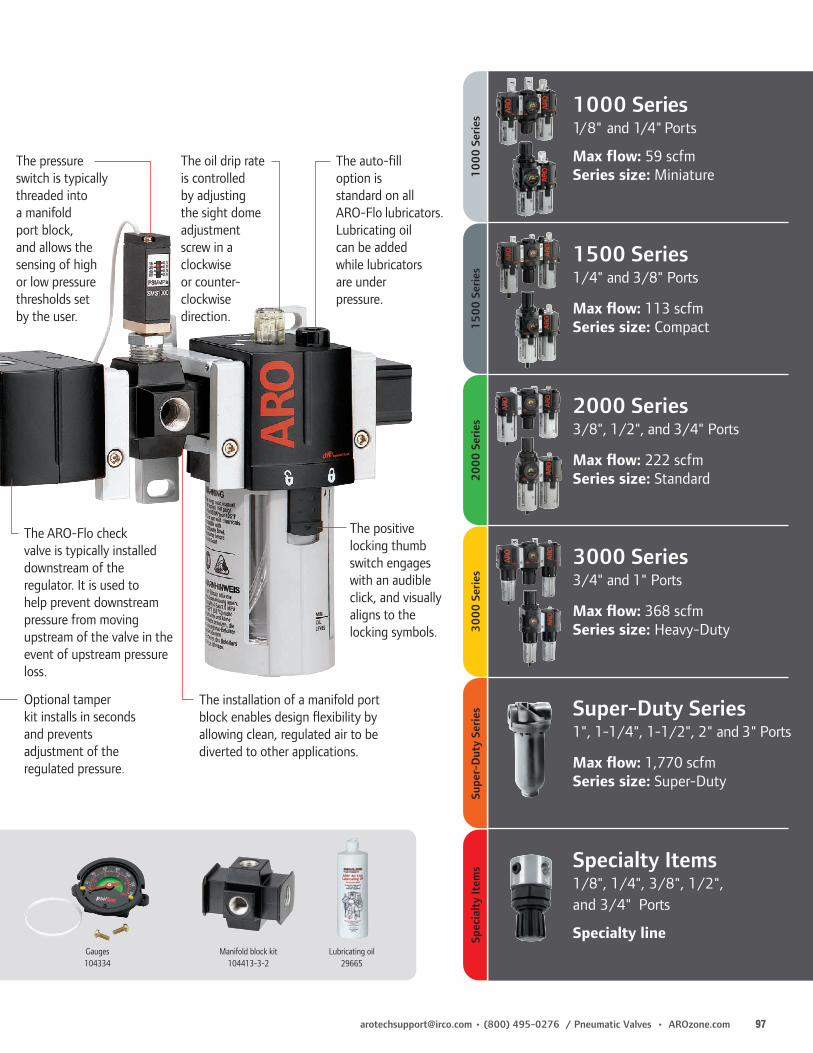
[email protected] • (800) 495-0276 / Pneumatic Valves • AROzone.com 97
The installation of a manifold port block enables design flexibility by allowing clean, regulated air to be diverted to other applications.
The pressure switch is typically threaded into a manifold port block, and allows the sensing of high or low pressure thresholds set by the user.
The positive locking thumb switch engages with an audible click, and visually aligns to the locking symbols.
The auto-fill option is standard on all ARO-Flo lubricators. Lubricating oil can be added while lubricators are under pressure.
1000 Series1/8" and 1/4" Ports
Max flow: 59 scfmSeries size: Miniature
1500 Series1/4" and 3/8" Ports
Max flow: 113 scfmSeries size: Compact
2000 Series3/8", 1/2", and 3/4" Ports
Max flow: 222 scfmSeries size: Standard
3000 Series3/4" and 1" Ports
Max flow: 368 scfmSeries size: Heavy-Duty
Super-Duty Series1", 1-1/4", 1-1/2", 2" and 3" Ports
Max flow: 1,770 scfmSeries size: Super-Duty
Specialty Items1/8", 1/4", 3/8", 1/2", and 3/4" Ports
Specialty line
1000
Ser
ies
1500
Ser
ies
2000
Ser
ies
3000
Ser
ies
Supe
r-D
uty
Serie
sSp
ecia
lty
Item
s
Lubricating oil29665
Manifold block kit104413-3-2
Gauges104334
The oil drip rate is controlled by adjusting the sight dome adjustment screw in a clockwise or counter-clockwise direction.
The ARO-Flo check valve is typically installed downstream of the regulator. It is used to help prevent downstream pressure from moving upstream of the valve in the event of upstream pressure loss.
Optional tamper kit installs in seconds and prevents adjustment of the regulated pressure.

98 AROzone.com • Pneumatic Valves / (800) 495-0276 • [email protected]
Air Systems Components
z Overview
Combinations
Piggyback Filters / RegulatorsLubricators
RegulatorsAir line regulators provide controlled, consistent air pressure as required for specific pneumatic equipment connected to the air system. All ARO-Flo regulators are offered with a standard adjustment range of 0 – 140 psig (0 – 9.6 barg). Alternative spring ranges are offered for easy conversion to suit different requirements. Non-relieving regulators are offered for applications where the venting of downstream overpressure is undesirable.
ARO-Flo mist-type lubricators help ensure that pneumatic devices receive the required lubrication to maintain peak performance, reduce wear, and prolong service life. They are designed to provide the correct amount of oil required for most general applications in a pneumatic system, delivering a constant ratio of oil to air flow. Precise oil feed adjustment sets the proper oil drip rate. Lubricators should be installed close to the downstream application to ensure effective distribution of oil.
Filter-regulators, or “piggybacks,” combine the functions of both a filter and regulator. Piggybacks are compact and most effective when space is a constraint. Piggybacks can be ordered with different filter elements and can be modified with different springs, depending on the filtration and air regulating requirements.
Filters, regulators, lubricators, and piggybacks can be combined together to form combinations. They are typically strung together in the F+R+L arrangement (three-piece combo) and F/R+L (two-piece combo) arrangement, although other configurations are also used depending on application needs. ARO-Flo combination FRLs are easily assembled using modular spacer kits. Panel nuts not included with units. Must be ordered separately.
Filters
ARO-Flo compressed air filters are designed to remove airborne solid and liquid contaminants. Filters can be ordered with different elements, including coalescing models which are capable of removing oil aerosols and particles down to 0.3 micron. Standard filters are sold with 5-micron elements; 40-micron elements can be purchased and installed separately.

[email protected] • (800) 495-0276 / Pneumatic Valves • AROzone.com 99
z Selection
Air Systems Components
When selecting an FRL or individual filter, regulator and lubricator units, the air consumption of the tools or equipment to be serviced should be correlated with the flow capacity of the FRL. ARO Filters, Regulators and Lubricators are designed to flow in excess of that indicated in the maximum recommended flow table shown below. This table gives recommended flows for pipe sizes at listed pressures and should be used as a guide in sizing piping and equipment for compressed air systems.
The filter, regulator and lubricator should be installed in the order shown in the illustration below. If a coalescing filter is required, it should be installed downstream from a standard filter. Individual take-off lines to the FRL and air tool or equipment should be from the top of the compressed air line. Make sure that air flow markings are followed for proper flow direction through the FRL units.
To trap and expel water, sludge and other contaninants which may collect on the bottom of the air line, a drip leg drain should be used. Drip leg drains should be installed at low points in the piping system and at the far end of the distribution
Maximum recommended air flow (scfm) thru ANSI standard weight Schedule 40 pipe
AppliedPressure
PSIG
Nominal Standard Pipe Size — Inches
1/8" 1/4" 3/8" 1/2" 3/4" 1" 1-1/4" 1-1/2" 2" 2-1/2" 3"
5 0.5 1.2 2.7 4.9 6.6 13 27 40 80 135 240
10 0.8 1.7 3.9 7.7 11.0 21 44 64 125 200 370
20 1.3 3.0 6.6 13.0 18.5 35 75 110 215 350 600
40 2.5 5.5 12.0 23.0 34.0 62 135 200 385 640 1100
60 3.5 8.0 18.0 34.0 50.0 93 195 290 560 900 1600
80 4.7 10.5 23.0 44.0 65.0 120 255 380 720 1200 2100
100 5.8 13.0 29.0 54.0 80.0 150 315 470 900 1450 2600
150 8.6 20.0 41.0 80.0 115 220 460 680 1350 2200 3900
200 11.5 26.0 58.0 108.0 155.0 290 620 910 1750 2800 5000
250 14.5 33.0 73.0 135.0 200 370 770 1150 2200 3500 6100
Pressure Drop (∆P) per 100 ft. of Pipe Pipe Size — Inches
10% of Applied Pressure 1/8, 1/4, 3/8, 1/2
5% of Applied Pressure 3/4, 1, 1-1/4, 1-1/2, 2, 2-1/2, 3
The flow values in the chart above are based upon a pressure drop ( ∆P) as set forth in the following schedule:
Compressed AirFilter Lubricator
Shut-offvalve
Pneumatic tool
2000 Series lockout valve Drip leg
drain
Regulator
z Installation

100 AROzone.com • Pneumatic Valves / (800) 495-0276 • [email protected]
Some oils used in air compressors contain chemicals harmful to Buna-N seals, if not adequately filtered at the compressor. The most common of these oils, in addition to other harmful material, are listed below.
COMPRESSOR OILS COMPRESSOR OILS OTHER MATERIALS
Cellulube No. 150 & 220 Phrano Garlock No. 98403 (Polyurethane)Haskel No. 568-023 Pydraul AC Parco No. 3106 (Neoprene)Hougton & Co. Oil No. 1120, Sears Regular Motor Oil Some Loctite CompoundsNo. 1130, No. 1055 Sinclair Oil “Lily White” Stillman No. SR269-75 Houtosafe 1000 Skydrol (Polyurethane)
Kano Kroil Tenneco Anderol No. 495 Stillman No. SR513-70 (Neoprene)Keyston Penetrating Oil No. 2 & No. 500 Oils
Marvel Mystery Oil
CAUTION: Compounded oils containing graphite and fillers are not recommended for use with cylinders.
Harmful Compressor Oils & Other Materials
The following are hazards or unsafe practices which could result in severe personal injury, death or substantial property damage. Heed the following. Use safeguards. Insure that provisions are made to prevent the valve from being accidentally operated (actuated.)
Hazardous Air Pressure. Shut off, disconnect and relieve any trapped air pressure from system before performing service or maintenance.
Hazardous Voltage. Do not attempt any service without disconnecting all electrical supply sources.
Do not use the valve as a safety device or to operate or control the operation of full revolution clutch systems or brake systems on power presses or similar equipment. These valves are not intended for such applications. Do not subject the valve to any condition that exceeds the limits set forth in the specifications for a particular valve model. Keep all hoses, electrical wiring, fittings and connections in good working condition. Damaged air pressure hoses, electrical wiring, or connections, could cause accidental valve operation (actuation). Only allow qualified technicians to install or maintain the valve system. It is necessary to have a through understanding of the operation and application of all valves being used in a particular system and how they interact with the other components of the system.
AIR PRESSURE: Limited to 200 psig (14 bar) FILTRATION: 40 Micron. Proper moisture removal and filtration of contaminates will promote good service life and operation. Install an air regulator to control the operating pressure, insure smooth operation and conserve energy.
LUBRICATION: All valve components have been lubricated at the factory and can be operated without additional air line lubrication. Minimal lubrication may extend the life of the valve. 50 Series, E-Series and K-Series Valves use o-ring seals. For maximum performance and life expectancy, standard air line lubrication should be used. If air line cylinders or other air line devices, used in conjunction with ARO® valve, require lubrication, be sure the lubricating oils used are compatible with the valve seals and are of sufficient viscosity to assure adequate lubrication. ARO® recommends an oil lubricant with a viscosity of 100-200 SUS at 100° F and an airline point above 200° F.
NOTICE: The use of compound oils containing graphite filters, extremely low viscosities an other non-fluid lubricants is not recommended.
RECOMMENDED: ARO® 29665 air line lubricator oil is available in one quart containers.
To obtain information or to receive technical literature for specific valves: contact ARO Customer Service at (800) 495-0276 or contact your nearest Aro distributor. Refer to the Service Kit Director for Valves and Cylinders form #9326-M, available from Aro. Selected parts are provided in kit form. The ARO Parts List/Service Instructions contain Repair Kit information and complete Service Parts information and are available upon request. Order Manuals as shown. The following Operator’s Manuals are available.
Operator’s Manual Part Number
ALPHA SERIES 119999-015CAT SERIES 119999-036E SERIES 119999-034GENESIS SERIES 119999-021H SERIES 119999-037K SERIES 119999-03550 SERIES 119999-045
Air & Lubrication Requirement Warning
General Information
Warnings and General Information
z Warnings

[email protected] • (800) 495-0276 / Pneumatic Valves • AROzone.com 101
Ingersoll Rand/ARO® warrants to the user purchaser of the ARO® products depicted in this catalog that the products be free of defects in material and workmanship for a period of five (5) years from the date of purchase.
ARO® will repair or replace, at its election, any product which is found upon its inspection to be defective during the period prescribed above. The product must be shipped prepaid to ARO® factory or ARO® Customer Service Center together with proof of purchase.
This warranty does not apply to failures or defects occurring as a result of abuse, misuse, negligent repairs, corrosion, erosion and normal wear and tear.
THIS WARRANTY IS IN LIEU OF ALL OTHER WARRANTIES (EXCEPT TITLE), EXPRESSED OR IMPLIED, AND THERE ARE NO WARRANTY OF MERCHANTABILITY OR FITNESS FOR PARTICULAR PURPOSE IS INTENDED OR MADE .
THE REMEDIES OF THE USER PURCHASER SET FORTH UNDER THE WARRANTY OUTLINED ABOVE ARE EXCLUSIVE AND THE TOTAL LIABILITY OF ARO WITH RESPECT TO THIS TRANSACTION, WHETHER BASED ON CONTRACT, WARRANTY, NEGLIGENCE, INDEMNITY, STRICT LIABILITY OR OTHERWISE SHALL NOT EXCEED THE PURCHASE PRICE OF THE PRODUCT.
ARO® SHALL IN NO EVENT BE LIABLE TO THE USER PURCHASER FOR ANY CONSEQUENTIAL, INCIDENTAL, INDIRECT, SPECIAL OR PUNITIVE DAMAGES ARISING OUT OF THIS TRANSACTION, OR ANY BREACH THEREOF, WHETHER OR NOT SUCH LOSS OR DAMAGE IS BASED ON CONTRACT, WARRANTY, NEGLIGENCE, INDEMNITY, STRICT LIABILITY OR OTHERWISE.
z 5 Year Warranty
Warranty

102 AROzone.com • Pneumatic Valves / (800) 495-0276 • [email protected]
Numerical Index
103-X .........................58105-X .........................58109-X .........................582XX-X .........................57400-X .........................60401-X .........................60402-X .........................60447 .............................60448 .............................60449 .............................60450 .............................6046X-X .........................61600-X .........................655030-XX .....................325040-XX .....................327000 ...........................717006 ...........................727007 ...........................727008 ...........................727010 ...........................727012 ...........................727102 ...........................727103 ...........................729600 ...........................6213111 ............33, 43, 6120308-X .....................6420311-X .....................6420312-X .....................6420313-X .....................6420368 .........................5720370 .........................6320467 .........................6320965-X .............. 43, 4920973-X .....................6120975 .........................6124130 .................. 62, 8824135 .........................6258023 .........................8758027 .........................9159010 .........................8159023 .........................8159003-842 .................7459061 .........................8759062 .........................8759063 .........................8759064-X .............. 89, 9059065-X .............. 89, 9059066-XX ...................9059067-XX ...................8959068-XX ............ 89, 9059089 .........................8659095-1 .....................9259097-6 .....................9159109 .........................8659111 .........................8159112 .........................8159114 .........................8359115 .........................8459116 .........................8459117 .........................8459124 .........................8159120 .........................8359121 .........................8259125 .........................8159155 .........................83
59156 .........................8259157 .........................8359158 .........................8259159 .........................8359160 .........................8259161-X .....................8559162-2 .....................8559165-4 .....................8359166-4 .....................8259175-X .....................8559176-X .....................8559181 .........................8159185 .........................8159191 .................. 74, 7959200-X .....................8759201-X .....................8759361 .........................9159387 .........................8759463-X .....................9559474-XXX ................9559482 .........................9559595-88 ...................8759629 .........................955963X-100 .................9559632-1 .............. 25, 9559634 .........................9559636 .........................9559671-1 .....................8459690-4 .....................9559724-X .....................8859756-XXX ................9559757-XXX ................9559759-XX ...................9559760-XX ...................9559761-XX ...................9559762-XX ...................9559764-4 .....................9559765-XX ...................9559792 .........................9159800 .........................8159801 .........................9259802 .........................9259804-X .....................8859807 .........................9559808 .........................7459809 .........................7459812-X .....................8859860 .................. 75, 7959861 .................. 75, 7959866 .........................8659875 .........................8359879 .........................8259890 .........................8659891 .........................8659892 .........................8259895 .........................7859896 .........................7859897 .........................7859898 .........................7859899 .........................7859900 .........................7859903 .........................9559905 .........................9559906 .........................9559908 .........................95
59912 .........................8159913 .........................7559914 .........................7559916-X .....................9359917 .........................7559919-1 .....................78104094 .......................67104096 .......................67104104-XXX ..............67104484 .......................59104485 .......................59104486 .......................59104487 .......................59114155 .......................11114417 .......................39114418 .......................36114419 .......................36114420 .......................36114421 .......................36114597-XX.................41114598-XX.................41114599 .......................41114803 .......................11114806 .......................28114807 .......................28114808 .......................11114822 .......................36114138-XX.................11114153-XX.................11114645 ................ 39, 71114772-XX.................69115046-XX.................69115064-XX.................69115455-1 ...................21116153 .......................47116218-XX.................69116345-X ...................25116464 ................ 21, 64116572 .......................72116573 .......................71116574 .......................72116575 .......................71116578 .......................72116579 .......................72116647-XX.................69116702 .......................71116710 .......................20116772 .......................71116773 .......................71116808 .......................20116899-1 ...................21116916-1 ...................21116926-1 ...................21117345-XX.................69117987 .......................20118597-XX.................71118598-XX.................7111860X-X ...................21118612 .......................21118618 .......................21119243 ..........33, 43, 61119244 ..........33, 43, 61119245 ..........33, 43, 61119306 ................ 19, 21119307-XXX ..............66
119308-XXX ..............66119309-XXX ..............66119310-XXX ..............66119350 .........................9119351 .........................9119367 .........................6119638 .........................6119375 .........................9119376 .........................9119416 .......................69119690-XX.......... 26, 69119698-X ...................26119892-XX...............5, 6119893-XX...............5, 6AXXXXX-XXX-X ..........19CATXXX-XXX-X ....24-27CBW ..................... 14, 69CDN ..................... 14, 69CDL-XXX.............. 14, 69CDW ..................... 14, 69CDW-30 ............... 26, 69CHL-XXX ............. 14, 69CHL6-XXX ..................11CHW..................... 14, 69CHW6 .........................11CHW-30 ............... 26, 69CPXX-B .......................68CSL-XXX .............. 14, 69CSL6-XXX ...................11CSN ...................... 14, 69CSN6 ...........................11CSN-30 ................ 26, 69CSN-MICRO ................28EXXXXX-XXX-X ..........42EV 30-A ......................62EV 35-A ......................62EV 125 ........................62EV 250 ........................62EV 375 ........................62FXX-BK .......................68HXXXXX-XXX-X ..........52KXXXXX-XXX-X ..........48MKN ...........................20MKP ............................20M11XLR .....................39M2XXXX . 36, 39, 41, 59M21XXX-XXX-X .........13M211PS ......................59M251PS ......................59M26M02-XX ..............14M30M03-XX ..............14M34M04-XX ..............14M51XLR .....................39M81XXX-XXX-X .........11MP3651-7 .....33, 43, 61MQ3620 .....................71MXXMB ......................14MXXX-XX-XXX-X .......13NXX-BK .....................68P114400 ....................28P2X1-XXX-X ...............28PEN .............................20PPN ............................20PTN.............................20PR10 ...........................62
RKM21X-XX ...............71RKM31X-XX ...............71RKM81X-XX ...............71S5XSMX-1 ....................5S5XX9X-1 .....................6SML51N-XX .................5SMH51N-XX .................6SMH81N-XX ...............11SML81N-XX ...............11SV10-C .......................63SV20-C .......................63TBXXX-XXX-X ......30-31TSXXXX-XXX-XX ........30SK-T0XXB ...................31SK-T1XXB ...................31
Number Page Number Page Number Page Number Page Number Page

[email protected] • (800) 495-0276 / Pneumatic Valves • AROzone.com 103

ARO® is a brand of Ingersoll Rand. Ingersoll Rand (NYSE:IR) advances the quality of life by creating comfortable, sustainable and efficient environments. Our people and our family of brands—including Club Car®, Ingersoll Rand®, Thermo King® and Trane®—work together to enhance the quality and comfort of air in homes and buildings; transport and protect food and perishables; and increase industrial productivity and efficiency. We are a $14 billion global business committed to a world of sustainable progress and enduring results. For more information, visit www.ingersollrand.com.
©2014 Ingersoll Rand IRITS-0214-049 EN 0419
[email protected] youtube.com/aropumps (800) 495-0276www.AROzone.com
Distributed by:
We are committed to using environmentally conscious print practices
Top Related
Copyright © 2022 FDOKUMEN

