


Bahasa
Halaman
Hukum

Micro Programmable Controller CPM2CA--92
Micro Programmable Controller
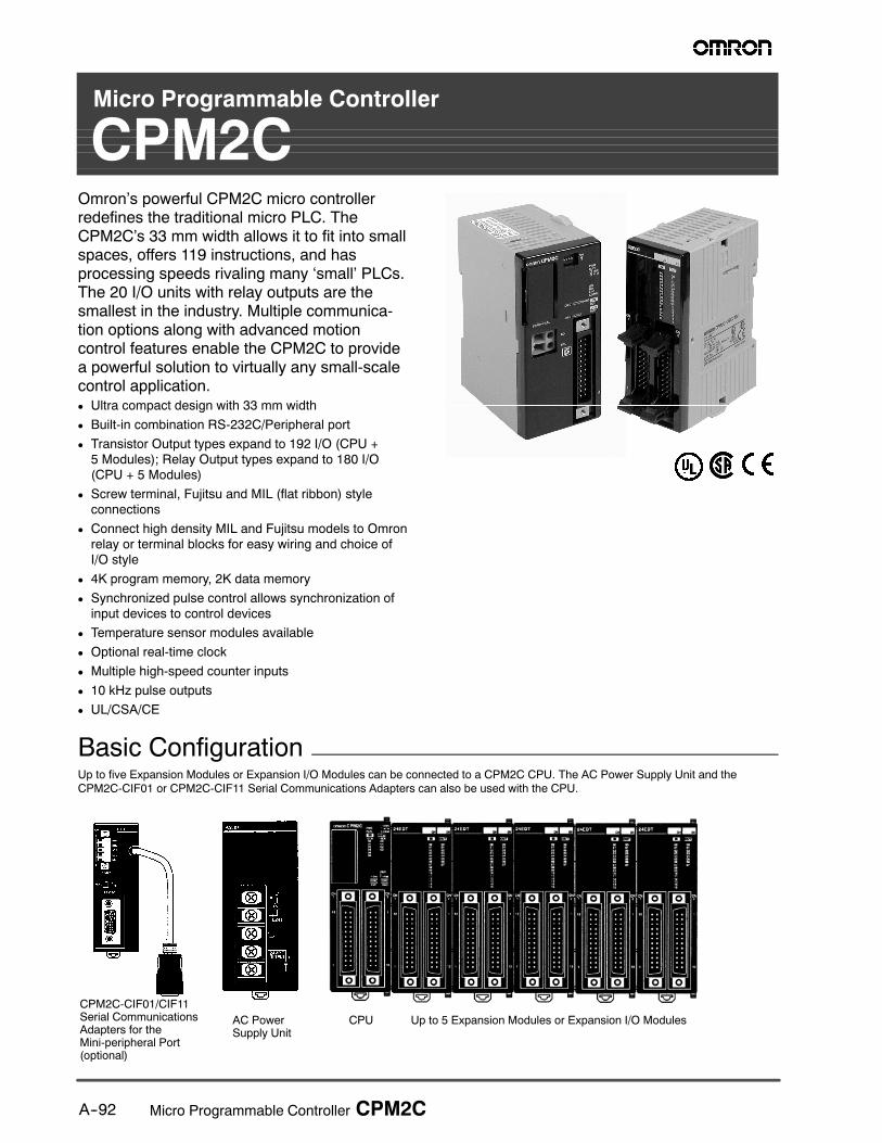
CPM2COmron’s powerful CPM2C micro controllerredefines the traditional micro PLC. TheCPM2C’s 33 mm width allows it to fit into smallspaces, offers 119 instructions, and hasprocessing speeds rivaling many ‘small’ PLCs.The 20 I/O units with relay outputs are thesmallest in the industry. Multiple communica-tion options along with advanced motioncontrol features enable the CPM2C to providea powerful solution to virtually any small-scalecontrol application.D Ultra compact design with 33 mm width
D Built-in combination RS-232C/Peripheral port
D Transistor Output types expand to 192 I/O (CPU +5 Modules); Relay Output types expand to 180 I/O(CPU + 5 Modules)
D Screw terminal, Fujitsu and MIL (flat ribbon) styleconnections
D Connect high density MIL and Fujitsu models to Omronrelay or terminal blocks for easy wiring and choice ofI/O style
D 4K program memory, 2K data memory
D Synchronized pulse control allows synchronization ofinput devices to control devices
D Temperature sensor modules available
D Optional real-time clock
D Multiple high-speed counter inputs
D 10 kHz pulse outputs
D UL/CSA/CE
Basic ConfigurationUp to five Expansion Modules or Expansion I/O Modules can be connected to a CPM2C CPU. The AC Power Supply Unit and the
CPM2C-CIF01 or CPM2C-CIF11 Serial Communications Adapters can also be used with the CPU.
CPU Up to 5 Expansion Modules or Expansion I/O ModulesAC PowerSupply Unit
CPM2C-CIF01/CIF11Serial CommunicationsAdapters for theMini-peripheral Port(optional)

A--93Micro Programmable Controller CPM2C
Ordering Information
J PART NUMBER NOMENCLATURE
CPM2C-jjjjj-j1 2 3 4 65
1. Number of I/O
2. RTC = C1No RTC = C
3. Input Power
4. PNP = T1NPN = T
5. Relay = RMIL = MConnector = C
6. Power Supply
J CPU MODULES WITH 10 I/O POINTS
Stock Note: Shaded models are normally stocked.
Description CPU module Inputs Outputs Clock Part number
CPU with RelayOutputs viaTerminal Block
10 I/O points(6 inputs,4 outputs)
I/O terminal block 6 inputs(24 VDC)
4 relay outputs No CPM2C-10CDR-D
Terminal Block 4 outputs)
Yes CPM2C-10C1DR-D
CPU withTransistor
I/Oconnector
2 Fujitsuconnectors
6 inputs(24 VDC)
4 transistoroutputs (sinking)
No CPM2C-10CDTC-DTransistorOutputs via
connector connectors (24 VDC) outputs (sinking)Yes CPM2C-10C1DTC-DOutputs via
Fujitsu-compatibleConnector
4 transistoroutputs (sourcing)
No CPM2C-10CDT1C-DConnector outputs (sourcing)
Yes CPM2C-10C1DT1C-D
CPU withTransistor Outputs
2 MILconnectors
6 inputs(24 VDC)
4 transistoroutputs (sinking)
No CPM2C-10CDTM-DTransistor Outputsvia MIL Connector
connectors (24 VDC) outputs (sinking)Yes CPM2C-10C1DTM-Dvia MIL Connector
4 transistoroutputs (sourcing)
No CPM2C-10CDT1M-Doutputs (sourcing)
Yes CPM2C-10C1DT1M-D
J CPU MODULES WITH 20 I/O POINTS
Stock Note: Shaded models are normally stocked.
Description CPU module Inputs Outputs Clock Part number
CPU with RelayOutputs viaTerminal Block
20 I/O points(12 inputs,8 outputs)
I/O terminal block 12 inputs(24 VDC)
8 relay outputs No CPM2C-20CDR-D
Terminal Block 8 outputs)
Yes CPM2C-20C1DR-D
CPU withTransistor
I/Oconnector
2 Fujitsuconnectors
12 inputs(24 VDC)
8 transistoroutputs (sinking)
No CPM2C-20CDTC-DTransistorOutputs via
connector connectors (24 VDC) outputs (sinking)Yes CPM2C-20C1DTC-DOutputs via
Fujitsu-compatibleConnector
8 transistoroutputs (sourcing)
No CPM2C-20CDT1C-DConnector outputs (sourcing)
Yes CPM2C-20C1DT1C-D
CPU withTransistor Outputs
2 MILconnectors
12 inputs(24 VDC)
8 transistoroutputs (sinking)
No CPM2C-20CDTM-DTransistor Outputsvia MIL Connector
connectors (24 VDC) outputs (sinking)Yes CPM2C-20C1DTM-Dvia MIL Connector
8 transistoroutputs (sourcing)
No CPM2C-20CDT1M-Doutputs (sourcing)
Yes CPM2C-20C1DT1M-D
A--94 Micro Programmable Controller CPM2C
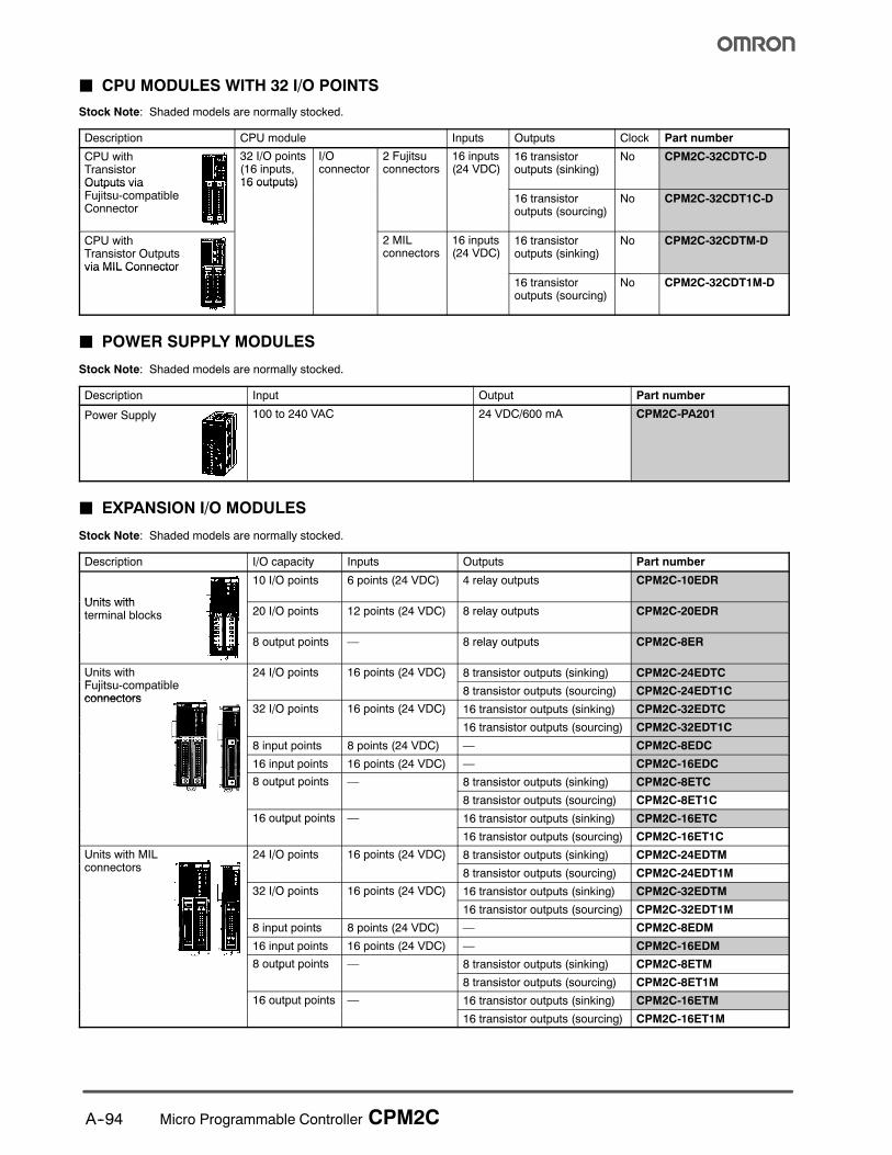
J CPU MODULES WITH 32 I/O POINTS
Stock Note: Shaded models are normally stocked.
Description CPU module Inputs Outputs Clock Part number
CPU withTransistorOutputs via
32 I/O points(16 inputs,16 outputs)
I/Oconnector
2 Fujitsuconnectors
16 inputs(24 VDC)
16 transistoroutputs (sinking)
No CPM2C-32CDTC-D
Outputs viaFujitsu-compatibleConnector
16 outputs)
16 transistoroutputs (sourcing)
No CPM2C-32CDT1C-D
CPU withTransistor Outputsvia MIL Connector
2 MILconnectors
16 inputs(24 VDC)
16 transistoroutputs (sinking)
No CPM2C-32CDTM-D
via MIL Connector
16 transistoroutputs (sourcing)
No CPM2C-32CDT1M-D
J POWER SUPPLY MODULES
Stock Note: Shaded models are normally stocked.
Description Input Output Part number
Power Supply 100 to 240 VAC 24 VDC/600 mA CPM2C-PA201
J EXPANSION I/O MODULES
Stock Note: Shaded models are normally stocked.
Description I/O capacity Inputs Outputs Part number
Units with
10 I/O points 6 points (24 VDC) 4 relay outputs CPM2C-10EDR
Units withterminal blocks 20 I/O points 12 points (24 VDC) 8 relay outputs CPM2C-20EDR
8 output points — 8 relay outputs CPM2C-8ER
Units withF jit tibl
24 I/O points 16 points (24 VDC) 8 transistor outputs (sinking) CPM2C-24EDTCFujitsu-compatibleconnectors
/ p p ( )
8 transistor outputs (sourcing) CPM2C-24EDT1Cconnectors
32 I/O points 16 points (24 VDC) 16 transistor outputs (sinking) CPM2C-32EDTC/ p p ( )
16 transistor outputs (sourcing) CPM2C-32EDT1C
8 input points 8 points (24 VDC) — CPM2C-8EDC
16 input points 16 points (24 VDC) — CPM2C-16EDC
8 output points — 8 transistor outputs (sinking) CPM2C-8ETCp p
8 transistor outputs (sourcing) CPM2C-8ET1C
16 output points — 16 transistor outputs (sinking) CPM2C-16ETCp p
16 transistor outputs (sourcing) CPM2C-16ET1C
Units with MILt
24 I/O points 16 points (24 VDC) 8 transistor outputs (sinking) CPM2C-24EDTMconnectors
/ p p ( )
8 transistor outputs (sourcing) CPM2C-24EDT1M
32 I/O points 16 points (24 VDC) 16 transistor outputs (sinking) CPM2C-32EDTM/ p p ( )
16 transistor outputs (sourcing) CPM2C-32EDT1M
8 input points 8 points (24 VDC) — CPM2C-8EDM
16 input points 16 points (24 VDC) — CPM2C-16EDM
8 output points — 8 transistor outputs (sinking) CPM2C-8ETMp p
8 transistor outputs (sourcing) CPM2C-8ET1M
16 output points — 16 transistor outputs (sinking) CPM2C-16ETMp p
16 transistor outputs (sourcing) CPM2C-16ET1M
A--95Micro Programmable Controller CPM2C
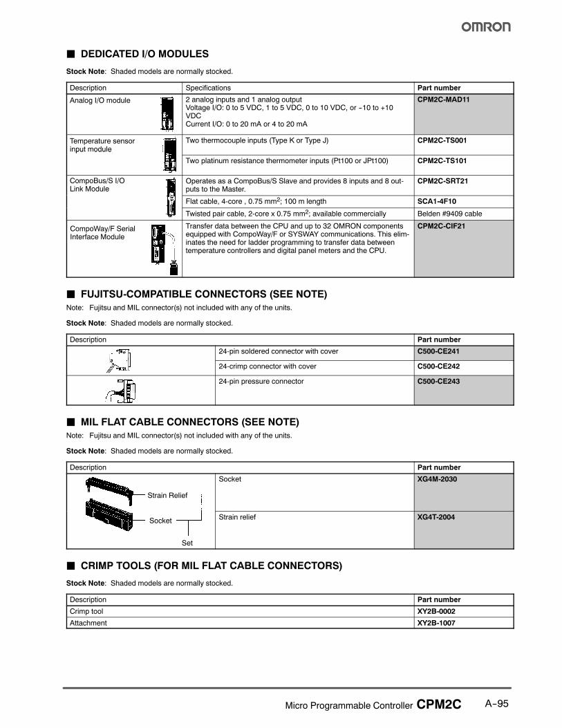
J DEDICATED I/O MODULES
Stock Note: Shaded models are normally stocked.
Description Specifications Part number
Analog I/O module 2 analog inputs and 1 analog outputVoltage I/O: 0 to 5 VDC, 1 to 5 VDC, 0 to 10 VDC, or --10 to +10VDCCurrent I/O: 0 to 20 mA or 4 to 20 mA
CPM2C-MAD11
Temperature sensorinput module
Two thermocouple inputs (Type K or Type J) CPM2C-TS001
pu odu e
Two platinum resistance thermometer inputs (Pt100 or JPt100) CPM2C-TS101
CompoBus/S I/OLink Module
Operates as a CompoBus/S Slave and provides 8 inputs and 8 out-puts to the Master.
CPM2C-SRT21
Flat cable, 4-core , 0.75 mm2; 100 m length SCA1-4F10
Twisted pair cable, 2-core x 0.75 mm2; available commercially Belden #9409 cable
CompoWay/F SerialInterface Module
Transfer data between the CPU and up to 32 OMRON componentsequipped with CompoWay/F or SYSWAY communications. This elim-inates the need for ladder programming to transfer data betweentemperature controllers and digital panel meters and the CPU.
CPM2C-CIF21
J FUJITSU-COMPATIBLE CONNECTORS (SEE NOTE)
Note: Fujitsu and MIL connector(s) not included with any of the units.
Stock Note: Shaded models are normally stocked.
Description Part number
24-pin soldered connector with cover C500-CE241
24-crimp connector with cover C500-CE242
24-pin pressure connector C500-CE243
J MIL FLAT CABLE CONNECTORS (SEE NOTE)
Note: Fujitsu and MIL connector(s) not included with any of the units.
Stock Note: Shaded models are normally stocked.
Description Part number
Strain Relief
Socket XG4M-2030
Socket
Set
Strain relief XG4T-2004
J CRIMP TOOLS (FOR MIL FLAT CABLE CONNECTORS)
Stock Note: Shaded models are normally stocked.
Description Part number
Crimp tool XY2B-0002
Attachment XY2B-1007
A--96 Micro Programmable Controller CPM2C
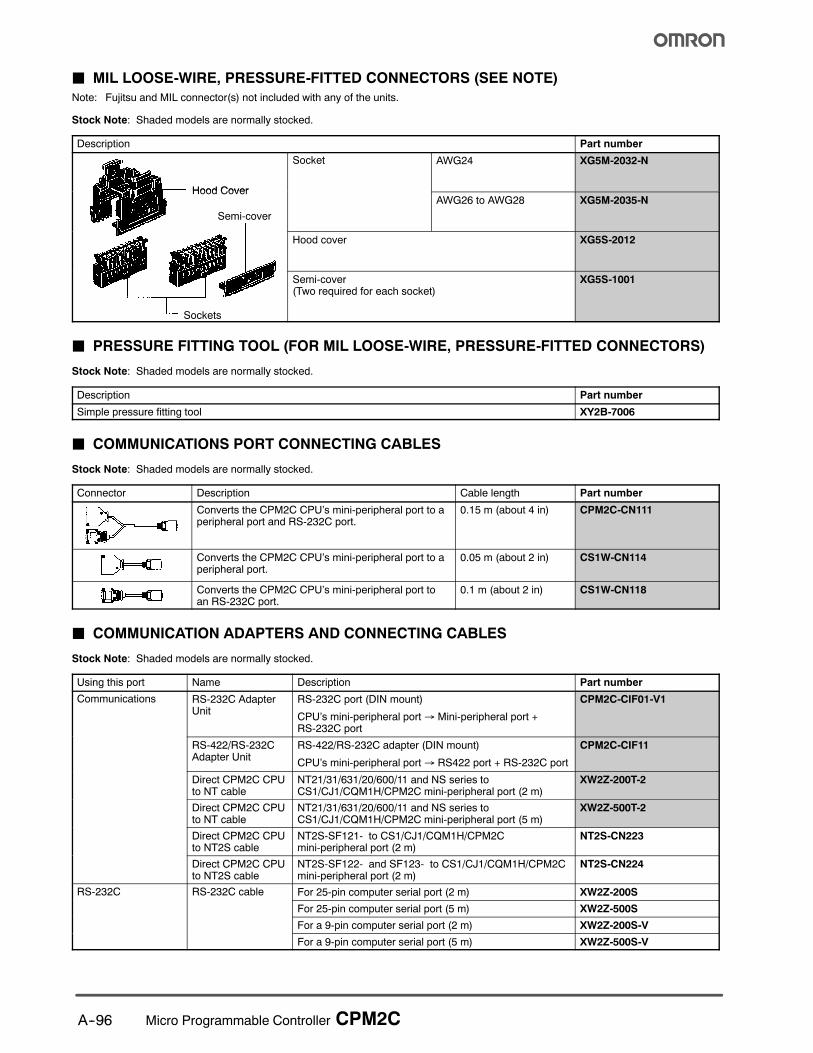
J MIL LOOSE-WIRE, PRESSURE-FITTED CONNECTORS (SEE NOTE)
Note: Fujitsu and MIL connector(s) not included with any of the units.
Stock Note: Shaded models are normally stocked.
Description Part number
Hood Cover
Socket AWG24 XG5M-2032-N
Hood Cover
Semi-cover
AWG26 to AWG28 XG5M-2035-N
Hood cover XG5S-2012
Sockets
Semi-cover(Two required for each socket)
XG5S-1001
J PRESSURE FITTING TOOL (FOR MIL LOOSE-WIRE, PRESSURE-FITTED CONNECTORS)
Stock Note: Shaded models are normally stocked.
Description Part number
Simple pressure fitting tool XY2B-7006
J COMMUNICATIONS PORT CONNECTING CABLES
Stock Note: Shaded models are normally stocked.
Connector Description Cable length Part number
Converts the CPM2C CPU’s mini-peripheral port to aperipheral port and RS-232C port.
0.15 m (about 4 in) CPM2C-CN111
Converts the CPM2C CPU’s mini-peripheral port to aperipheral port.
0.05 m (about 2 in) CS1W-CN114
Converts the CPM2C CPU’s mini-peripheral port toan RS-232C port.
0.1 m (about 2 in) CS1W-CN118
J COMMUNICATION ADAPTERS AND CONNECTING CABLES
Stock Note: Shaded models are normally stocked.
Using this port Name Description Part number
Communications RS-232C AdapterUnit
RS-232C port (DIN mount)
CPU’s mini-peripheral port→ Mini-peripheral port +RS-232C port
CPM2C-CIF01-V1
RS-422/RS-232CAdapter Unit
RS-422/RS-232C adapter (DIN mount)
CPU’s mini-peripheral port→ RS422 port + RS-232C port
CPM2C-CIF11
Direct CPM2C CPUto NT cable
NT21/31/631/20/600/11 and NS series toCS1/CJ1/CQM1H/CPM2C mini-peripheral port (2 m)
XW2Z-200T-2
Direct CPM2C CPUto NT cable
NT21/31/631/20/600/11 and NS series toCS1/CJ1/CQM1H/CPM2C mini-peripheral port (5 m)
XW2Z-500T-2
Direct CPM2C CPUto NT2S cable
NT2S-SF121- to CS1/CJ1/CQM1H/CPM2Cmini-peripheral port (2 m)
NT2S-CN223
Direct CPM2C CPUto NT2S cable
NT2S-SF122- and SF123- to CS1/CJ1/CQM1H/CPM2Cmini-peripheral port (2 m)
NT2S-CN224
RS-232C RS-232C cable For 25-pin computer serial port (2 m) XW2Z-200S
For 25-pin computer serial port (5 m) XW2Z-500S
For a 9-pin computer serial port (2 m) XW2Z-200S-V
For a 9-pin computer serial port (5 m) XW2Z-500S-V
A--97Micro Programmable Controller CPM2C
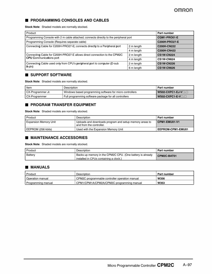
J PROGRAMMING CONSOLES AND CABLES
Stock Note: Shaded models are normally stocked.
Product Part number
Programming Console with 2 m cable attached; connects directly to the peripheral port CQM1-PRO01-E
Programming Console (Requires separate cable) C200H-PRO27-E
Connecting Cable for C200H-PRO27-E; connects directly to a Peripheral port 2 m length C200H-CN222g ; y p p
4 m length C200H-CN422
Connecting Cable for C200H-PRO27-E allows direct connection to the CPM2CCPU C i ti t
2 m length CS1W-CN224gCPU Communications port
4 m length CS1W-CN624
Connecting Cable used only from CPU’s peripheral port to computer (D-sub9 i )
2 m length CS1W-CN226g y p p p p (9-pin)
6 m length CS1W-CN626
J SUPPORT SOFTWARE
Stock Note: Shaded models are normally stocked.
Item Description Part number
CX-Programmer Jr. Windows based programming software for micro controllers WS02-CXPC1-EJ-Vj.j
CX-Programmer Full programming software package for all controllers WS02-CXPC1-E-Vj.j
J PROGRAM TRANSFER EQUIPMENT
Stock Note: Shaded models are normally stocked.
Product Description Part number
Expansion Memory Unit Uploads and downloads program and setup memory areas toand from the controller.
CPM1-EMU01-V1
EEPROM (256 kbits) Used with the Expansion Memory Unit EEPROM-CPM1-EMU01
J MAINTENANCE ACCESSORIES
Stock Note: Shaded models are normally stocked.
Product Description Part number
Battery Backs up memory in the CPM2C CPU. (One battery is already
installed in CPUs containing a clock.)CPM2C-BAT01
J MANUALS
Product Description Part number
Operation manual CPM2C programmable controller operation manual W356
Programming manual CPM1/CPM1A/CPM2A/CPM2C programming manual W353

A--98 Micro Programmable Controller CPM2C
Specifications
J GENERAL SPECIFICATIONS FOR CPU AND EXPANSION UNITS
Item CPUs with 10/20 I/O points CPUs with32 I/O points tran-
Expansion I/O Units andExpansion Units
Relay outputs Transistor outputs32 I/O points tran-sistor outputs
Expansion Units
Supply voltage 24 VDC
Operating voltagerange
20.4 to 26.4 VDC
Power consumption(See Note)
CPM2C-10CjDR-j: 4 WCPM2C-10CjDTjC-D: 3 WCPM2C-10CjDTjM-D: 3 WCPM2C-20CjDR-j: 4 WCPM2C-20CjDTjC-D: 3 WCPM2C-20CjDTjM-D: 3 WCPM2C-32CDTjC-D: 3 WCPM2C-32CDTjM-D: 3 W
Note: The above values for CPU power consumption include
the power consumption for Programming Consoles and
Communications Adapter Units (CIFjj).
CPM2C-10EDR: 1 WCPM2C-20EDR: 2 WCPM2C-8ER: 2 WCPM2C-24EDTC: 1 WCPM2C-24EDT1C 1 WCPM2C-32EDTC: 1 WCPM2C-32EDT1C 1 WCPM2C-8EDC: 1 WCPM2C-16EDC: 1 WCPM2C-8ETC: 1 WCPM2C-8ET1C: 1 WCPM2C-16ETC: 1 WCPM2C-16ET1C: 1 WCPM2C-24EDTM: 1 WCPM2C-24EDT1M: 1 WCPM2C-32EDTM: 1 WCPM2C-32EDT1M: 1 WCPM2C-8EDM: 1 WCPM2C-16EDM: 1 WCPM2C-8ETM: 1 WCPM2C-8ET1M: 1 WCPM2C-16ETM: 1 WCPM2C-16ET1M: 1 WCPM2C-MAD11: 3.5 WCPM2C-TS001: 1.5 WCPM2C-TS101: 1.5 WCPM2C-SRT21: 1 WCPM2C-CIF21: 1 W
Inrush current 25 A max.
Insulation resistance 20 MΩ min. (at 500 VDC) between insulated circuits
Dielectric strength 2,300 VAC for 1 min (between insulated circuits)
Noise immunity Conforms to IEC61000-4-4; 2 kV (power lines)
Vibration resistance 10 to 57 Hz, 0.075-mm double amplitude, 57 to 150 Hz, acceleration: 9.8 m/s2 in X, Y, and Z directions for 80minutes each (Time coefficient; 8 minutes × coefficient factor 10 = total time 80 minutes)
Shock resistance 147 m/s2 three times each in X, Y, and Z directions
Ambient temperature Operating: 0° to 55°C (32° to 131°F)Storage: --20° to 75°C (--4° to 167°F) except for the battery
Humidity 10% to 90% (with no condensation)
Atmosphere Must be free from corrosive gas
Power interrupt time 2 ms min.
Weight 10 I/O: 200 g max.20 I/O: 250 g max.
200 g max. 200 g max. 8 and 16 inputs: 150 g8 and 16 transistor outputs 150 g8 relay outputs 200 g10 I/O (relay outputs) 200 g24 I/O (transistor outputs) 200 g32 I/O (transistor outputs) 200 gPeripheral/RS-232C Adapter 150 gRS-422/RS-232C Adapter 150 gAC power supply unit 250 gAnalog I/O, Temperature units 200 gCompoBus/S unit 150 g
Note: When calculating the total power consumption, it is necessary to include the power consumption of Programming Consoles,
RS-232C Adapters and other devices.
A--99Micro Programmable Controller CPM2C
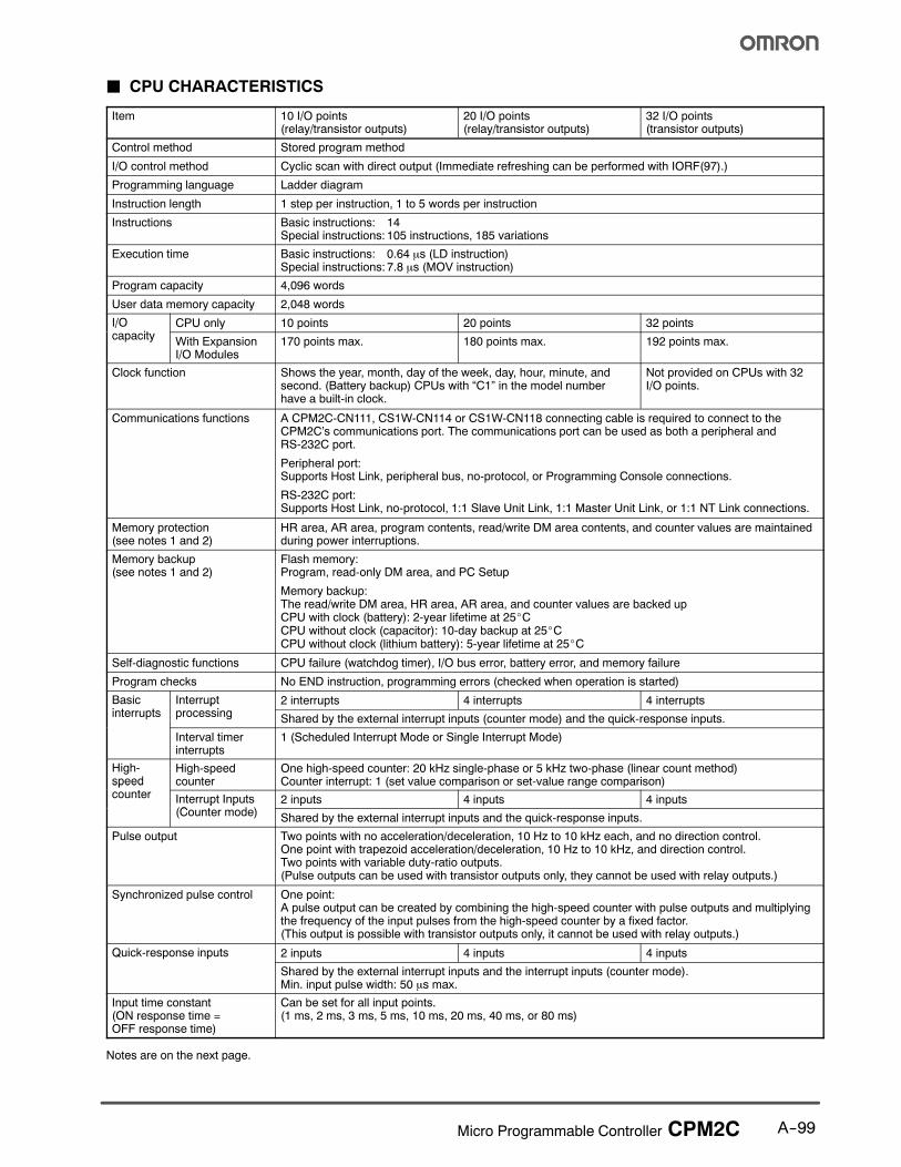
J CPU CHARACTERISTICS
Item 10 I/O points(relay/transistor outputs)
20 I/O points(relay/transistor outputs)
32 I/O points(transistor outputs)
Control method Stored program method
I/O control method Cyclic scan with direct output (Immediate refreshing can be performed with IORF(97).)
Programming language Ladder diagram
Instruction length 1 step per instruction, 1 to 5 words per instruction
Instructions Basic instructions: 14Special instructions: 105 instructions, 185 variations
Execution time Basic instructions: 0.64 µs (LD instruction)Special instructions: 7.8 µs (MOV instruction)
Program capacity 4,096 words
User data memory capacity 2,048 words
I/Oit
CPU only 10 points 20 points 32 points/capacity
With ExpansionI/O Modules
170 points max. 180 points max. 192 points max.
Clock function Shows the year, month, day of the week, day, hour, minute, andsecond. (Battery backup) CPUs with “C1” in the model numberhave a built-in clock.
Not provided on CPUs with 32I/O points.
Communications functions A CPM2C-CN111, CS1W-CN114 or CS1W-CN118 connecting cable is required to connect to theCPM2C’s communications port. The communications port can be used as both a peripheral andRS-232C port.
Peripheral port:Supports Host Link, peripheral bus, no-protocol, or Programming Console connections.
RS-232C port:Supports Host Link, no-protocol, 1:1 Slave Unit Link, 1:1 Master Unit Link, or 1:1 NT Link connections.
Memory protection(see notes 1 and 2)
HR area, AR area, program contents, read/write DM area contents, and counter values are maintainedduring power interruptions.
Memory backup(see notes 1 and 2)
Flash memory:Program, read-only DM area, and PC Setup
Memory backup:The read/write DM area, HR area, AR area, and counter values are backed upCPU with clock (battery): 2-year lifetime at 25_CCPU without clock (capacitor): 10-day backup at 25_CCPU without clock (lithium battery): 5-year lifetime at 25_C
Self-diagnostic functions CPU failure (watchdog timer), I/O bus error, battery error, and memory failure
Program checks No END instruction, programming errors (checked when operation is started)
Basici t t
Interrupti
2 interrupts 4 interrupts 4 interruptsinterrupts
pprocessing
Shared by the external interrupt inputs (counter mode) and the quick-response inputs.
Interval timerinterrupts
1 (Scheduled Interrupt Mode or Single Interrupt Mode)
High-speed
High-speedcounter
One high-speed counter: 20 kHz single-phase or 5 kHz two-phase (linear count method)Counter interrupt: 1 (set value comparison or set-value range comparison)speed
counter Interrupt Inputs(C t d )
2 inputs 4 inputs 4 inputsp p(Counter mode)
Shared by the external interrupt inputs and the quick-response inputs.
Pulse output Two points with no acceleration/deceleration, 10 Hz to 10 kHz each, and no direction control.One point with trapezoid acceleration/deceleration, 10 Hz to 10 kHz, and direction control.Two points with variable duty-ratio outputs.(Pulse outputs can be used with transistor outputs only, they cannot be used with relay outputs.)
Synchronized pulse control One point:A pulse output can be created by combining the high-speed counter with pulse outputs and multiplyingthe frequency of the input pulses from the high-speed counter by a fixed factor.(This output is possible with transistor outputs only, it cannot be used with relay outputs.)
Quick-response inputs 2 inputs 4 inputs 4 inputsQ p p
Shared by the external interrupt inputs and the interrupt inputs (counter mode).Min. input pulse width: 50 µs max.
Input time constant(ON response time =OFF response time)
Can be set for all input points.(1 ms, 2 ms, 3 ms, 5 ms, 10 ms, 20 ms, 40 ms, or 80 ms)
Notes are on the next page.

A--100 Micro Programmable Controller CPM2C
CPU Characteristics table notes:
Note: 1. The DM area, HR area, AR area, and counter values are backed up. If the backup battery or capacitor is discharged, the con-
tents of these ares will be lost and the data values will revert to the defaults.
2. The contents of the program area, read-only DM area (DM 6144 to DM 6599), and PC setup (DM 6600 to DM 6655) are stored
in flash memory. The contents of these areas will be read from flash memory the next time the power is turned ON, even if the
backup battery or capacitor is discharged.
When data has been changed in any of these areas, write the new values to flash memory by switching the CMP2C to MON-ITOR or RUN mode, or by turning the power OFF and then ON again.
J I/O ALLOCATION
Input bits IR 00000 to IR 00915 (Words not used for input bits can be used for work bits.)
Output bits IR 01000 to IR 01915 (Words not used for output bits can be used for work bits.)
Work bits 928 bits: IR 02000 to IR 04915 (Words IR 020 to IR 049) andIR 20000 to IR 22715 (Words IR 200 to IR 227)
Special bits (SR area) 448 bits: SR 22800 to SR 25515
Temporary bits (TR area) 8 bits (TR0 to TR7)
Holding bits (HR area) 320 bits: HR 0000 to HR 1915 (Words HR 00 to HR 19)
Auxiliary bits (AR area) 384 bits: AR 0000 to AR 2315 (Words AR 00 to AR 23)
Link bits (LR area) 256 bits: LR 0000 to LR 1515 (Words LR 00 to LR 15)
Timers/Counters 256 timers/counters (TIM/CNT 000 to TIM/CNT 255)
1-ms timers: TMHH(—)10-ms timers: TIMH(15)100-ms timers: TIM1-s/10-s timers: TIML(—)Decrementing counters: CNTReversible counters: CNTR(12)
Data memory Read/Write: 2,048 words (DM 0000 to DM 2047)*Read-only: 456 words (DM 6144 to DM 6599)PC Setup: 56 words (DM 6600 to DM 6655)
*The Error Log is contained in DM 2000 to DM 2021.
A--101Micro Programmable Controller CPM2C
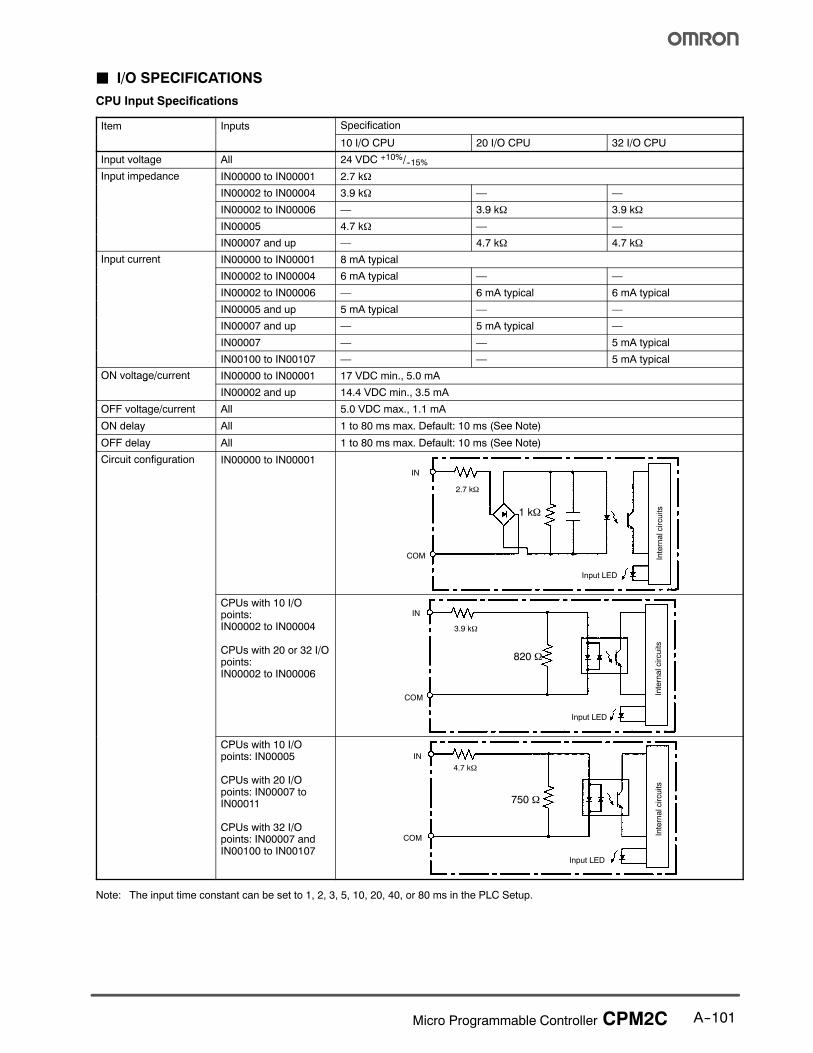
J I/O SPECIFICATIONS
CPU Input Specifications
Item Inputs Specificationp
10 I/O CPU 20 I/O CPU 32 I/O CPU
Input voltage All 24 VDC +10%/--15%
Input impedance IN00000 to IN00001 2.7 kΩp p
IN00002 to IN00004 3.9 kΩ — —
IN00002 to IN00006 — 3.9 kΩ 3.9 kΩ
IN00005 4.7 kΩ — —
IN00007 and up — 4.7 kΩ 4.7 kΩ
Input current IN00000 to IN00001 8 mA typicalp
IN00002 to IN00004 6 mA typical — —
IN00002 to IN00006 — 6 mA typical 6 mA typical
IN00005 and up 5 mA typical — —
IN00007 and up — 5 mA typical —
IN00007 — — 5 mA typical
IN00100 to IN00107 — — 5 mA typical
ON voltage/current IN00000 to IN00001 17 VDC min., 5.0 mAg /
IN00002 and up 14.4 VDC min., 3.5 mA
OFF voltage/current All 5.0 VDC max., 1.1 mA
ON delay All 1 to 80 ms max. Default: 10 ms (See Note)
OFF delay All 1 to 80 ms max. Default: 10 ms (See Note)
Circuit configuration IN00000 to IN00001
1 kΩ
IN
COM
2.7 kΩ
Input LED
Internalcircuits
CPUs with 10 I/Opoints:IN00002 to IN00004
CPUs with 20 or 32 I/Opoints:IN00002 to IN00006
820 Ω
IN
COM
3.9 kΩ
Input LED
Internalcircuits
CPUs with 10 I/Opoints: IN00005
CPUs with 20 I/Opoints: IN00007 toIN00011
CPUs with 32 I/Opoints: IN00007 andIN00100 to IN00107
750 Ω
IN
COM
4.7 kΩ
Input LED
Internalcircuits
Note: The input time constant can be set to 1, 2, 3, 5, 10, 20, 40, or 80 ms in the PLC Setup.
A--102 Micro Programmable Controller CPM2C
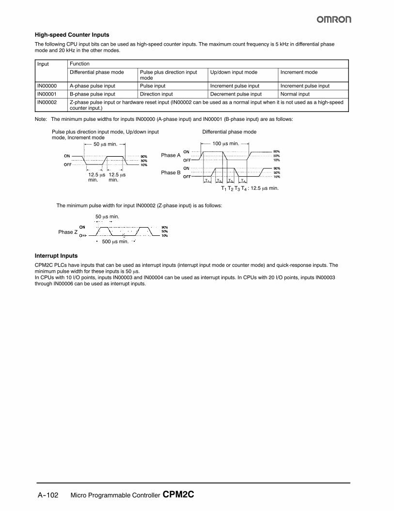
High-speed Counter Inputs
The following CPU input bits can be used as high-speed counter inputs. The maximum count frequency is 5 kHz in differential phase
mode and 20 kHz in the other modes.
Input Functionp
Differential phase mode Pulse plus direction inputmode
Up/down input mode Increment mode
IN00000 A-phase pulse input Pulse input Increment pulse input Increment pulse input
IN00001 B-phase pulse input Direction input Decrement pulse input Normal input
IN00002 Z-phase pulse input or hardware reset input (IN00002 can be used as a normal input when it is not used as a high-speedcounter input.)
Note: The minimum pulse widths for inputs IN00000 (A-phase input) and IN00001 (B-phase input) are as follows:
100 µs min.
T1 T2 T3 T4 : 12.5 µs min.
Phase A
Phase B
50 µs min.
12.5 µsmin.
Pulse plus direction input mode, Up/down inputmode, Increment mode
Differential phase mode
12.5 µsmin. T1 T2 T3 T4
50 µs min.
500 µs min.
Phase Z
The minimum pulse width for input IN00002 (Z-phase input) is as follows:
Interrupt Inputs
CPM2C PLCs have inputs that can be used as interrupt inputs (interrupt input mode or counter mode) and quick-response inputs. The
minimum pulse width for these inputs is 50 µs.In CPUs with 10 I/O points, inputs IN00003 and IN00004 can be used as interrupt inputs. In CPUs with 20 I/O points, inputs IN00003through IN00006 can be used as interrupt inputs.

A--103Micro Programmable Controller CPM2C
J EXPANSION I/O MODULE INPUT SPECIFICATIONS
Item Specification
Input voltage 24 VDC +10%/--15%
Input impedance 4.7 kΩ
Input current 5 mA typical
ON voltage 14.4 VDC min., 3.5 mA
OFF voltage 5.0 VDC max., 1.1 mA
ON delay 1 to 80 ms max. Default: 10 ms (See note.)
OFF delay 1 to 80 ms max. Default: 10 ms (See note.)
Circuit configuration
750 Ω
IN
COM
4.7 kΩ
Input LED
Internalcircuits
Note: The input time constant can be set to 1, 2, 3, 5, 10, 20, 40, or 80 ms in the PLC Setup.
J CPM2C OUTPUT SPECIFICATIONS (CPUs AND EXPANSION I/O MODULES)
Relay Output
Item Specification
Max. switching capacity 2 A, 250 VAC (cosφ = 1)2 A, 24 VDC (4 A/common)
Min. switching capacity 10 mA, 5 VDC
Service life of relay Electrical: 150,000 operations (30-VDC resistive load)100,000 operations (240-VAC inductive load, cosφ = 0.4)
Mechanical: 20,000,000 operations
ON delay 15 ms max.
OFF delay 15 ms max.
Circuit configurationOutput LED
Internalcircuits
COM
OUT
COM
OUT

A--104 Micro Programmable Controller CPM2C
J TRANSISTOR OUTPUTS (NPN OR PNP)
For CPUs and Expansion I/O Modules
Item Specification
Max. switching capacity CPUs with 10 or 20 I/O points:OUT01000 to OUT01007: 40 mA/4.5 VDC to 300 mA/20.4 VDC, 300 mA (20.4 VDC to 26.4 VDC)
CPUs with 32 I/O points:OUT01000 to OUT01007: 40 mA/4.5 VDC to 300 mA/20.4 VDC, 300 mA (20.4 VDC to 26.4 VDC)OUT01100 to OUT01107: 40 mA/4.5 VDC to 100 mA/20.4 VDC, 100 mA (20.4 VDC to 26.4 VDC)
Expansion I/O Modules:OUT01j00 to OUT01j07: 40 mA/4.5 VDC to 300 mA/20.4 VDC, 300 mA (20.4 VDC to 26.4 VDC)OUT01j08 to OUT01j15: 40 mA/4.5 VDC to 100 mA/20.4 VDC, 100 mA (20.4 VDC to 26.4 VDC)
Note: When using OUT01000 or OUT01001 as a pulse output, connect a dummy resistor as required to
bring the load current between 10 and 150 mA. If the load current is below 10 mA, the ON/OFF
response time will be longer and high-speed pulses will not be output.
The transistor will heat if used at 150 mA or higher, possibly damaging elements.
Min. switching capacity 0.5 mA
Max. inrush current 0.9 A for 10 ms (charging and discharging waveform)
Leakage current 0.1 mA max.
Residual voltage 0.8 V max.
ON delay OUT01000 and OUT01001: 20 µs max.OUT01002 and up: 0.1 ms max.
OFF delay OUT01000 and OUT01001: 40 µs max. for 10 to 300 mA0.1 ms max. for 0.5 to 10 mA
OUT01002 and up: 1 ms max.
Fuse 1 fuse for each 2 outputs (The fuse cannot be replaced by the user.)
Circuit configuration NPN Outputs
COM (--)
PNP Outputs
Output LED
OUT
OUT
24 VDC
0 VDC
Output LED
OUT
OUT
COM (+)
Internalcircuits
Internalcircuits
A--105Micro Programmable Controller CPM2C
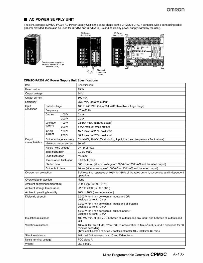
J AC POWER SUPPLY UNIT
The slim, compact CPM2C-PA201 AC Power Supply Unit is the same shape as the CPM2C’s CPU. It connects with a connecting cable
(23 cm) provided. It can also be used for CPM1A and CPM2A CPUs and as display power supply (wired by the user).
AC PowerSupply Unit
AC PowerSupply Unit
Attachedconnecting
cable
Service power supply forexternal devices such as
sensors (24 V).
CPM2C-PA201 AC Power Supply Unit Specifications
Item Specification
Rated output 15 W
Output voltage 24 V
Output current 600 mA
Efficiency 75% min. (at rated output)
Inputditi
Rated voltage 100 to 240 VAC (85 to 264 VAC allowable voltage range)pconditions
Frequency 47 to 63 Hz
Current 100 V 0.4 A
200 V 0.2 A
Leakaget
100 V 0.5 mA max. (at rated output)gcurrent
200 V 1 mA max. (at rated output)
Inrusht
100 V 15 A max. (at 25°C cold start)current
200 V 30 A max. (at 25°C cold start)
Outputh t i ti
Output voltage accuracy 5%/--10%, 10%/--15% (including input, load, and temperature fluctuations)pcharacteristics
Minimum output current 30 mA
Ripple noise voltage 2% (p-p) max.
Input fluctuation 0.75% max.
Load fluctuation 4% max.
Temperature fluctuation 0.05%/°C max.
Startup time 300 ms max. (at input voltage of 100 VAC or 200 VAC and the rated output)
Output hold time 10 ms (at input voltage of 100 VAC or 200 VAC and the rated output)
Overcurrent protection Self-resetting, operates at 105% to 335% of the rated current, suspended and independentoperation
Overvoltage protection None
Ambient operating temperature 0° to 55°C (32° to 131°F)
Ambient storage temperature --20° to 70°C (--4° to 158°F)
Ambient operating humidity 10% to 90% (no condensation)
Dielectric strength 2,000 V for 1 min between all inputs and GRLeakage current: 10 mA
3,000 V for 1 min between all inputs and all outputsLeakage current: 10 mA
1,000 V for 1 min between all outputs and GRLeakage current: 10 mA
Insulation resistance 100 MΩ min. at 500 VDC between all outputs and any input, and between all outputs andGR
Vibration resistance 10 to 57 Hz, amplitude, 57 to 150 Hz, acceleration: 9.8 m/s2 in X, Y, and Z directions for 80minutes according(Time coefficient: 8 minutes × coefficient factor 10 = total time 80 min.)
Shock resistance 147 m/s2 3 times each in X, Y, and Z directions
Noise terminal voltage FCC class A
Weight 250 g max.
A--106 Micro Programmable Controller CPM2C
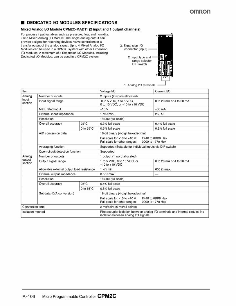
J DEDICATED I/O MODULES SPECIFICATIONS
Mixed Analog I/O Module CPM2C-MAD11 (2 input and 1 output channels)
For process input variables such as pressure, flow, and humidity,
use a Mixed Analog I/O Module. The single analog output canprovide a signal for recording devices, valve controllers or a
transfer output of the analog signal. Up to 4 Mixed Analog I/O
Modules can be used in a CPM2C system with other Expansion
I/O Modules. A maximum of 5 Expansion I/O Modules, including
Dedicated I/O Modules, can be used in a CPM2C system.
3. Expansion I/Oconnector (input)
2. Input type andrange selectorDIP switch
1. Analog I/O terminals
Item Voltage I/O Current I/O
Analogi t
Number of inputs 2 inputs (2 words allocated)ginputsection
Input signal range 0 to 5 VDC, 1 to 5 VDC,0 to 10 VDC, or --10 to +10 VDC
0 to 20 mA or 4 to 20 mA
Max. rated input ±15 V ±30 mA
External input impedance 1 MΩ min. 250 Ω
Resolution 1/6000 (full scale)
Overall accuracy 25°C 0.3% full scale 0.4% full scaley
0 to 55°C 0.6% full scale 0.8% full scale
A/D conversion data 16-bit binary (4-digit hexadecimal)
Full scale for --10 to +10 V: F448 to 0BB8 HexFull scale for other ranges: 0000 to 1770 Hex
Averaging function Supported (Settable for individual inputs via DIP switch)
Open-circuit detection function Supported
Analogt t
Number of outputs 1 output (1 word allocated)goutputsection
Output signal range 1 to 5 VDC, 0 to 10 VDC, or--10 to +10 VDC
0 to 20 mA or 4 to 20 mA
Allowable external output load resistance 1 kΩ min. 600 Ω max.
External output impedance 0.5 Ω max. —
Resolution 1/6000 (full scale)
Overall accuracy 25°C 0.4% full scaley
0 to 55°C 0.8% full scale
Set data (D/A conversion) 16-bit binary (4-digit hexadecimal)
Full scale for --10 to +10 V: F448 to 0BB8 HexFull scale for other ranges: 0000 to 1770 Hex
Conversion time 2 ms/point (6 ms/all points)
Isolation method Photocoupler isolation between analog I/O terminals and internal circuits. Noisolation between analog I/O signals.
A--107Micro Programmable Controller CPM2C
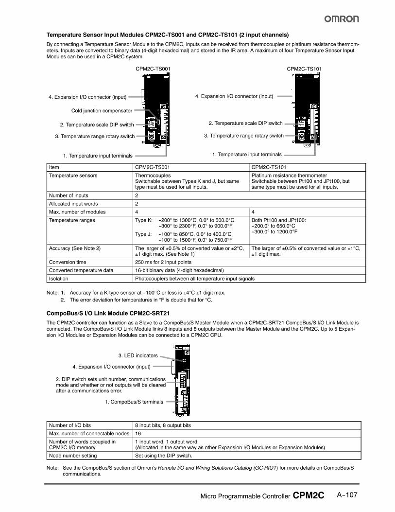
Temperature Sensor Input Modules CPM2C-TS001 and CPM2C-TS101 (2 input channels)
By connecting a Temperature Sensor Module to the CPM2C, inputs can be received from thermocouples or platinum resistance thermom-
eters. Inputs are converted to binary data (4-digit hexadecimal) and stored in the IR area. A maximum of four Temperature Sensor InputModules can be used in a CPM2C system.
1. Temperature input terminals
3. Temperature range rotary switch
2. Temperature scale DIP switch
Cold junction compensator
4. Expansion I/O connector (input)
CPM2C-TS001
1. Temperature input terminals
4. Expansion I/O connector (input)
CPM2C-TS101
3. Temperature range rotary switch
2. Temperature scale DIP switch
Item CPM2C-TS001 CPM2C-TS101
Temperature sensors ThermocouplesSwitchable between Types K and J, but sametype must be used for all inputs.
Platinum resistance thermometerSwitchable between Pt100 and JPt100, butsame type must be used for all inputs.
Number of inputs 2
Allocated input words 2
Max. number of modules 4 4
Temperature ranges Type K: --200° to 1300°C, 0.0° to 500.0°C--300° to 2300°F, 0.0° to 900.0°F
Type J: --100° to 850°C, 0.0° to 400.0°C--100° to 1500°F, 0.0° to 750.0°F
Both Pt100 and JPt100:--200.0° to 650.0°C--300.0° to 1200.0°F
Accuracy (See Note 2) The larger of ±0.5% of converted value or ±2°C,±1 digit max. (See Note 1)
The larger of ±0.5% of converted value or ±1°C,±1 digit max.
Conversion time 250 ms for 2 input points
Converted temperature data 16-bit binary data (4-digit hexadecimal)
Isolation Photocouplers between all temperature input signals
Note: 1. Accuracy for a K-type sensor at --100°C or less is ±4°C ±1 digit max.2. The error deviation for temperatures in °F is double that for °C.
CompoBus/S I/O Link Module CPM2C-SRT21
The CPM2C controller can function as a Slave to a CompoBus/S Master Module when a CPM2C-SRT21 CompoBus/S I/O Link Module isconnected. The CompoBus/S I/O Link Module links 8 inputs and 8 outputs between the Master Module and the CPM2C. Up to 5 Expan-
sion I/O Modules or Expansion Modules can be connected to a CPM2C CPU.
1. CompoBus/S terminals
2. DIP switch sets unit number, communicationsmode and whether or not outputs will be clearedafter a communications error.
4. Expansion I/O connector (input)
3. LED indicators
Number of I/O bits 8 input bits, 8 output bits
Max. number of connectable nodes 16
Number of words occupied inCPM2C I/O memory
1 input word, 1 output word(Allocated in the same way as other Expansion I/O Modules or Expansion Modules)
Node number setting Set using the DIP switch.
Note: See the CompoBus/S section of Omron’s Remote I/O and Wiring Solutions Catalog (GC RIO1) for more details on CompoBus/Scommunications.

A--108 Micro Programmable Controller CPM2C
J SERIAL COMMUNICATIONS MODULES
CPM2C-CIF01-V1Mini-peripheral/RS-232C Adapter Unit
CPM2C-CIF01-V1
Mini-peripheralconnector
RS-232C port(D-sub 9-pinconnector)
Communicationsconnector
CPM2CCPU
CPM2C-CIF11RS-422/RS-232C Adapter Unit
CPM2C-CIF11
RS-422 port(terminal block)
RS-232C port(D-sub 9-pinconnector)
CPM2CCPU
Communicationsconnector
Internal Configuration
CPM2C-CIF01-V1 CPM2C CPU
Mini-peripheralport(CMOS/RS-232C)
RS-232Cport(RS-232C)
CMOS level→RS-232Cconversion
Mini-peripheral port(CMOS level)
RS-232C port(RS-232C)
CMOS level
CPM2C-CIF11 CPM2C CPU
RS-422 port
RS-232C port
CMOS level→RS-422conversion
Mini-peripheral port(CMOS level)
RS-232C port
Note: When using the CS1W-CN226/CN626 Connecting Cable
for personal computer connection, turn ON the switch.
Note: A Programming Console cannot be connected to the
RS-422 port.
CPM2C-CIF01-V1/CIF11 Specifications
Item Specification
CPM2C-CIF01-V1 CPM2C-CIF11
Upper port Signalconversion
Outputs signals from the CPU’s CMOS interfacewithout conversion, or converts CMOS level(CPU side) to RS-232C (connected device side).
Converts CMOS level (CPU side) toRS-422 (connected device side).RS-422 (externally connected device) insulatedusing DC/DC converter or photocoupler.
Function Host Link, peripheral bus, no-protocol, or Pro-gramming Console connections.
Host Link, peripheral bus, or no-protocol connec-tions.
Lower port Signalconversion
Outputs signals from the CPU’s CMOS interfacewithout conversion.
Outputs signals from the CPU’s CMOS interfacewithout conversion.
Function Host Link, no-protocol, 1:1 Link, or 1:1 NT Linkconnections.
Host Link, no-protocol, 1:1 Link, or 1:1 NT Link con-nections.
Power supply Power supplied from CPU.
Current consumption 0.3 A max. at 5 V
Weight 150 g max.
Note: Neither the CPM2C-CIF01-V1 nor the CPM2C-CIF11 can be used with any PC other than the CPM2C. A CPM2C-CIF11 or
another CPM2C-CIF01-V1 cannot be connected to the CPM2C if a CPM2C-CIF01-V1 is already connected to it.
A--109Micro Programmable Controller CPM2C
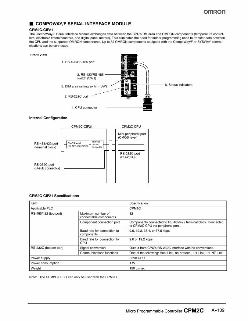
J COMPOWAY/F SERIAL INTERFACE MODULE
CPM2C-CIF21The CompoWay/F Serial Interface Module exchanges data between the CPU’s DM area and OMRON components (temperature control-
lers, electronic timers/counters, and digital panel meters). This eliminates the need for ladder programming used to transfer data between
the CPU and the supported OMRON components. Up to 32 OMRON components equipped with the CompoWay/F or SYSWAY commu-
nications can be connected.
Front View
1. RS-422/RS-485 port
3. RS-422/RS-485switch (SW1)
5. DIM area setting switch (SW2)
2. RS-232C port
6. Status indicators
4. CPU connector
Internal Configuration
CPM2C-CIF21 CPM2C CPU
RS-485/422 port(terminal block)
RS-232C port(D-sub connector)
CMOS levelRS-422 conversion
Mini-peripheral port(CMOS level)
RS-232C port(RS-232C)
Internalmicro-computer
CPM2C-CIF21 Specifications
Item Specification
Applicable PLC CPM2C
RS-485/422 (top port) Maximum number ofconnectable components
32
Component connection port Components connected to RS-485/422 terminal block. Connectedto CPM2C CPU via peripheral port.
Baud rate for connection tocomponents
9.6, 19.2, 38.4, or 57.6 kbps
Baud rate for connection toCPU
9.6 or 19.2 kbps
RS-232C (bottom port) Signal conversion Output from CPU’s RS-232C interface with no conversions.( p )
Communications functions One of the following: Host Link, no-protocol, 1:1 Link, 1:1 NT Link
Power supply From CPU
Power consumption 1 W
Weight 150 g max.
Note: The CPM2C-CIF21 can only be used with the CPM2C.
A--110 Micro Programmable Controller CPM2C
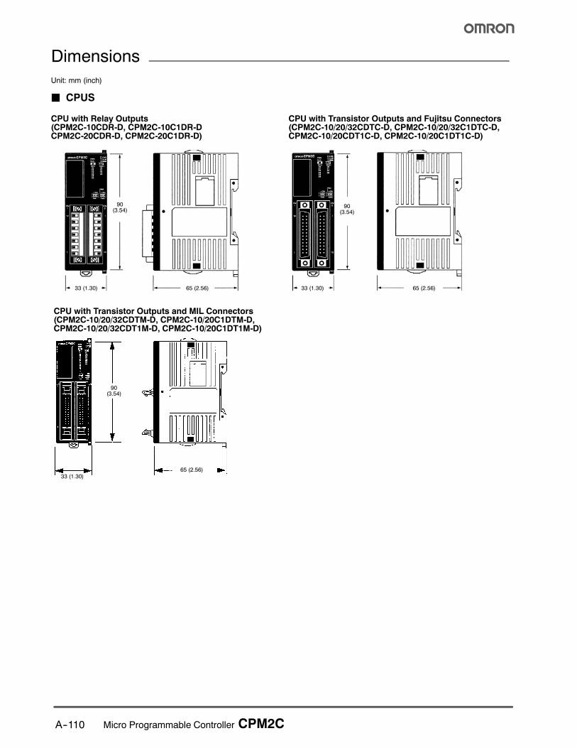
Dimensions
Unit: mm (inch)
J CPUS
CPU with Relay Outputs(CPM2C-10CDR-D, CPM2C-10C1DR-DCPM2C-20CDR-D, CPM2C-20C1DR-D)
CPU with Transistor Outputs and Fujitsu Connectors(CPM2C-10/20/32CDTC-D, CPM2C-10/20/32C1DTC-D,CPM2C-10/20CDT1C-D, CPM2C-10/20C1DT1C-D)
90(3.54)
90(3.54)
33 (1.30) 33 (1.30)65 (2.56) 65 (2.56)
CPU with Transistor Outputs and MIL Connectors(CPM2C-10/20/32CDTM-D, CPM2C-10/20C1DTM-D,CPM2C-10/20/32CDT1M-D, CPM2C-10/20C1DT1M-D)
33 (1.30)
90(3.54)
65 (2.56)
A--111Micro Programmable Controller CPM2C
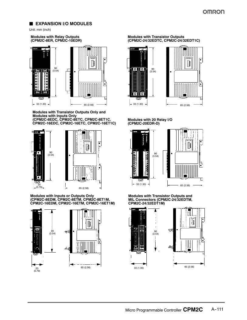
J EXPANSION I/O MODULES
Unit: mm (inch)
Modules with Relay Outputs(CPM2C-8ER, CPM2C-10EDR)
Modules with Transistor Outputs(CPM2C-24/32EDTC, CPM2C-24/32EDT1C)
Modules with Transistor Outputs Only andModules with Inputs Only(CPM2C-8EDC, CPM2C-8ETC, CPM2C-8ET1C,CPM2C-16EDC, CPM2C-16ETC, CPM2C-16ET1C)
90(3.54)
90(3.54)
33 (1.30) 33 (1.30)65 (2.56) 65 (2.56)
90(3.54)
65 (2.56)
20(0.79)
Modules with 20 Relay I/O(CPM2C-20EDR-D)
90(3.54)
33 (1.30)65 (2.56)
Modules with Inputs or Outputs Only(CPM2C-8EDM, CPM2C-8ETM, CPM2C-8ET1M,CPM2C-16EDM, CPM2C-16ETM, CPM2C-16ET1M)
90(3.54)
65 (2.56)20(0.79)
33 (1.30)65 (2.56)
Modules with Transistor Outputs andMIL Connectors (CPM2C-24/32EDTM,CPM2C-24/32EDT1M)
90(3.54)
A--112 Micro Programmable Controller CPM2C
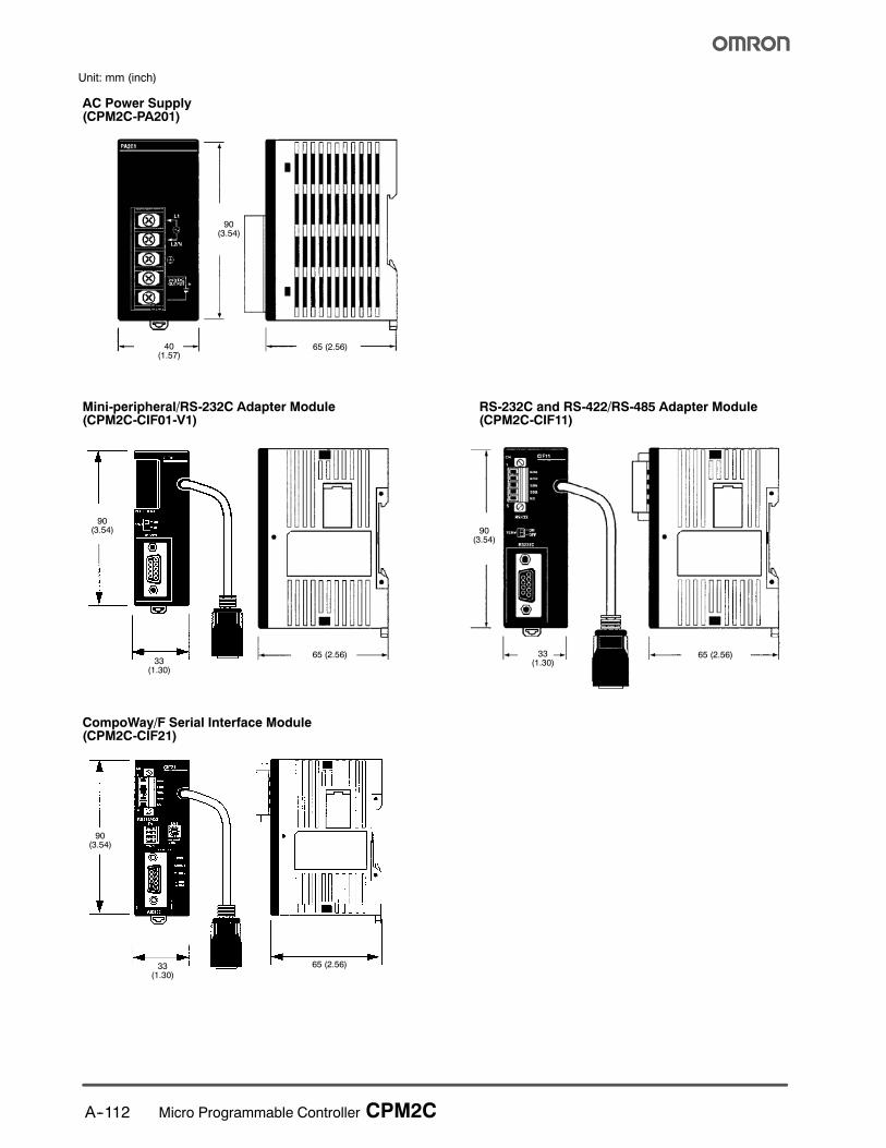
Unit: mm (inch)
AC Power Supply(CPM2C-PA201)
Mini-peripheral/RS-232C Adapter Module(CPM2C-CIF01-V1)
RS-232C and RS-422/RS-485 Adapter Module(CPM2C-CIF11)
90(3.54)
90(3.54)
33 (1.30)
40(1.57)
65 (2.56)
90(3.54)
65 (2.56)33
(1.30)
65 (2.56)33(1.30)
CompoWay/F Serial Interface Module(CPM2C-CIF21)
65 (2.56)33(1.30)
90(3.54)
A--113Micro Programmable Controller CPM2C
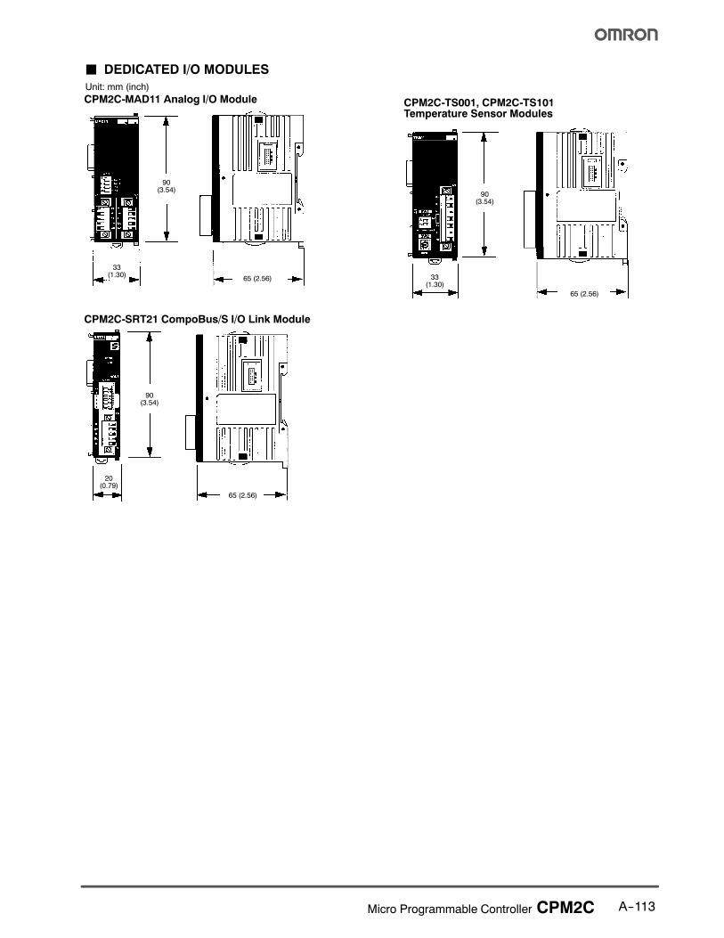
J DEDICATED I/O MODULES
Unit: mm (inch)
CPM2C-MAD11 Analog I/O Module
90(3.54)
65 (2.56)
33(1.30)
CPM2C-TS001, CPM2C-TS101Temperature Sensor Modules
90(3.54)
65 (2.56)
33(1.30)
90(3.54)
65 (2.56)
20(0.79)
CPM2C-SRT21 CompoBus/S I/O Link Module

A--114 Micro Programmable Controller CPM2C
J CPM2C MODULES WITH CONNECTORS ATTACHEDUnit: mm (inch)
Modules with Relay Outputs Modules with Transistor Outputs(Using pressure connectors)
Modules with Transistor Outputs(Using soldered connectors)
104 (4.09) 111 (4.37)
74 (2.91)
104 (4.09)
Units with Transistor Outputsand MIL Connectors
78 (3.07)
104 (4.09)

A--115Micro Programmable Controller CPM2C
Functions
The CPM2C programmable controllers offer a variety of features
in a compact Unit, including synchronized pulse control, interruptinputs, pulse outputs, and a clock function. The CPM2C CPU can
handle a broad range of machine control applications and it is
small enough to be incorporated as the control unit in almost any
free-standing machine.
The full complement of communications functions lets you
communicate with personal computers, other OMRON PLCs, andOMRON Programmable Terminals. These communications
capabilities allow the user to design a low-cost, effective control
system.
The communications port can be used si-multaneously as two ports: Mini-peripheraland RS-232C. The mini-peripheral port sup-ports Programming Devices, Host Link, andno-protocol communications. The RS-232Cport supports Host Link, no-protocol (serial),1:1 Link, and 1:1 NT Link communications.
CPUs with 10 I/O points (relay or transistoroutputs) and 20 or 32 I/O points (transistoroutputs only) are available. Expansion I/OUnits can be connected to increase capacity to192 I/O points.
J TIME-PROPORTIONAL CONTROL
The CPM2C performs simple-to-program, time-proportional
control using up to four Analog I/O modules (maximum 8 analoginputs and 4 analog outputs) and the PID and PWM expansion
instructions. These instructions set the parameters for PID
control and a pulse output with variable duty ratio. For increased
reliability, an open-circuit detection function can be used with the
1 to 5 VDC and 4 to 20 mA analog input settings.
For temperature monitoring applications, CPM2C accepts up to 8
inputs (two per module) from Temperature Sensor Input modules.The PID instruction can manipulate the input from either
thermocouple or platinum resistance thermometer sensors.
J DISTRIBUTED I/O CONTROL
Omron’s CompoBus/S I/O Link provides distributed CPU control
based on a “PLC + compact PLC” configuration which provides
improvements over distributed control based on “PLC + remote
I/O” configurations. The distributed CPU control makes
equipment module, so designs can be standardized, specialneeds can be addressed and modules can be replaced easily in
the event of breakdown without affecting the main CPU.
MasterPLC
CompoBus/SMaster Module
CPM2C(Slave)
CompoBus/SI/O Link Module
CompoBus/S
Distributed CPU control
J BUILT-IN MOTOR CONTROL CAPABILITY
Synchronized Pulse Control(Transistor Output Models Only)
Synchronized pulse control provides an easy way to synchronize
the operation of a peripheral piece of equipment with the main
equipment. The output pulse frequency can be controlled as
some multiple of the input pulse frequency, allowing the speed ofa peripheral piece of equipment (such as a supply conveyor) to
be synchronized with the speed of the main piece of equipment.
Encoder
CPM2C
Motor
Pulses are output as a fixed multiple of the input frequency.
3G3HV Drive
A--116 Micro Programmable Controller CPM2C
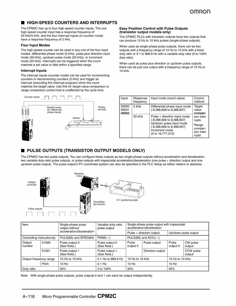
J HIGH-SPEED COUNTERS AND INTERRUPTS
The CPM2C has up to four high-speed counter inputs. The one
high-speed counter input has a response frequency of20 kHz/5 kHz, and the four interrupt inputs (in counter mode)
have a response frequency of 2 kHz.
Four Input Modes
The high-speed counter can be used in any one of the four input
modes: differential phase mode (5 kHz), pulse plus direction inputmode (20 kHz), up/down pulse mode (20 kHz), or increment
mode (20 kHz). Interrupts can be triggered when the count
matches a set value or falls within a specified range.
Interrupt Inputs
The interrupt inputs (counter mode) can be used for incrementing
counters or decrementing counters (2 kHz) and trigger aninterrupt (executing the interrupt program) when the count
matches the target value. Use this for target-value comparison or
range comparison control that is unaffected by the cycle time.
Easy Position Control with Pulse Outputs(transistor output models only)
The CPM2C PLCs with transistor outputs have two outputs that
can produce 10 Hz to 10 kHz pulses (single-phase outputs).
When used as single-phase pulse outputs, there can be two
outputs with a frequency range of 10 Hz to 10 kHz with a fixed
duty ratio or 0.1 to 999.9 Hz with a variable duty ratio (0 to 100%
duty ratio).
When used as pulse plus direction or up/down pulse outputs,
there can be just one output with a frequency range of 10 Hz to
10 kHz.
Counter inputs
Resets inputs(for differentialphase inputs)
Sensor
Rotaryencoder
Input Responsefrequency
Input mode (count value) Controlmethod
000000000100002
5 kHz Differential phase input mode(-8,388,608 to 8,388,607)
Targetvaluecompari-00002
20 kHz Pulse + direction input mode(-8,388,608 to 8,388,607)Up/down pulse input mode(-8,388,608 to 8,388,607)Increment mode(0 to 16,777,215)
compari-son inter-rupts
Rangecompari-son inter-rupts
J PULSE OUTPUTS (TRANSISTOR OUTPUT MODELS ONLY)
The CPM2C has two pulse outputs. You can configure these outputs as two single-phase outputs without acceleration and deceleration,
two variable duty-ratio pulse outputs, or pulse outputs with trapezoidal acceleration/deceleration (one pulse + direction output and one
up/down pulse output). The pulse output’s PV coordinate system can also be specified in the PLC Setup as either relative or absolute.
Steppingmotor
Pulse outputs
CPM2Ccontroller
X-Y positioning tableSmartStepServodriver
Item Single-phase pulseoutput without
l i /d l i
Variable duty-ratiopulse output
Single-phase pulse output with trapezoidalacceleration/decelerationoutput t out
acceleration/decelerationpu se output
Pulse + direction output Up/down pulse output
Controlling instruction(s) PULS(65) and SPED(64) PWM(----) PULS(65) and ACC(----)
Outputnumber
01000 Pulse output 0(See Note.)
Pulse output 0(See Note.)
Pulseoutput 0
Pulse output Pulseoutput 0
CW pulseoutputu be
01001 Pulse output 1(See Note.)
Pulse output 1(See Note.)
ou pu 0
Direction output
ou pu 0
CCW pulseoutput
Output frequency range 10 Hz to 10 kHz 0.1 Hz to 999.9 Hz 10 Hz to 10 kHz 10 Hz to 10 kHz
Pitch 10 Hz 0.1 Hz 10 Hz 10 Hz
Duty ratio 50% 0 to 100% 50% 50%
Note: With single-phase pulse outputs, pulse outputs 0 and 1 can each be output independently.
A--117Micro Programmable Controller CPM2C
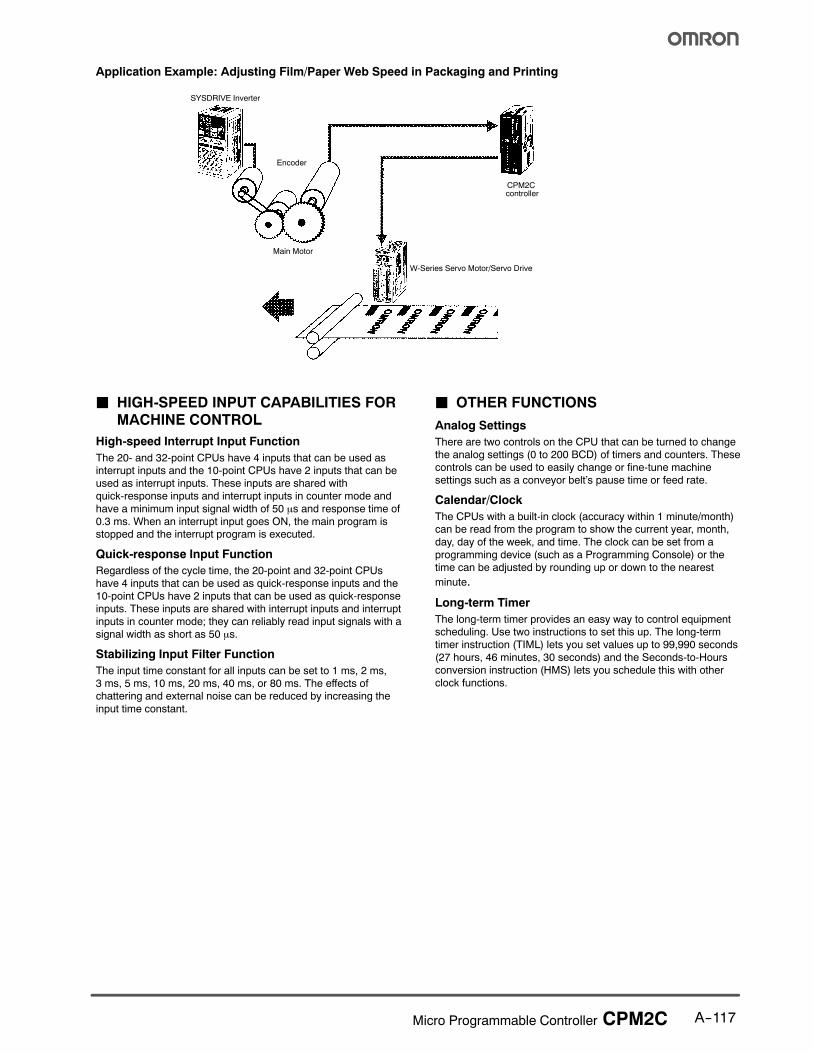
Application Example: Adjusting Film/Paper Web Speed in Packaging and Printing
CPM2Ccontroller
Main Motor
Encoder
SYSDRIVE Inverter
W-Series Servo Motor/Servo Drive
J HIGH-SPEED INPUT CAPABILITIES FORMACHINE CONTROL
High-speed Interrupt Input Function
The 20- and 32-point CPUs have 4 inputs that can be used asinterrupt inputs and the 10-point CPUs have 2 inputs that can be
used as interrupt inputs. These inputs are shared with
quick-response inputs and interrupt inputs in counter mode and
have a minimum input signal width of 50 µs and response time of0.3 ms. When an interrupt input goes ON, the main program isstopped and the interrupt program is executed.
Quick-response Input Function
Regardless of the cycle time, the 20-point and 32-point CPUs
have 4 inputs that can be used as quick-response inputs and the
10-point CPUs have 2 inputs that can be used as quick-responseinputs. These inputs are shared with interrupt inputs and interrupt
inputs in counter mode; they can reliably read input signals with a
signal width as short as 50 µs.
Stabilizing Input Filter Function
The input time constant for all inputs can be set to 1 ms, 2 ms,
3 ms, 5 ms, 10 ms, 20 ms, 40 ms, or 80 ms. The effects ofchattering and external noise can be reduced by increasing the
input time constant.
J OTHER FUNCTIONS
Analog Settings
There are two controls on the CPU that can be turned to changethe analog settings (0 to 200 BCD) of timers and counters. These
controls can be used to easily change or fine-tune machine
settings such as a conveyor belt’s pause time or feed rate.
Calendar/Clock
The CPUs with a built-in clock (accuracy within 1 minute/month)can be read from the program to show the current year, month,
day, day of the week, and time. The clock can be set from a
programming device (such as a Programming Console) or the
time can be adjusted by rounding up or down to the nearest
minute.
Long-term Timer
The long-term timer provides an easy way to control equipmentscheduling. Use two instructions to set this up. The long-term
timer instruction (TIML) lets you set values up to 99,990 seconds
(27 hours, 46 minutes, 30 seconds) and the Seconds-to-Hours
conversion instruction (HMS) lets you schedule this with other
clock functions.
A--118 Micro Programmable Controller CPM2C
Communications
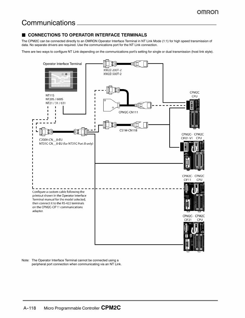
J CONNECTIONS TO OPERATOR INTERFACE TERMINALS
The CPM2C can be connected directly to an OMRON Operator Interface Terminal in NT Link Mode (1:1) for high speed transmission of
data. No separate drivers are required. Use the communications port for the NT Link connection.
There are two ways to configure NT Link depending on the communications port’s setting for single or dual transmission (host link style).
Note: The Operator Interface Terminal cannot be connected using a
peripheral port connection when communicating via an NT Link.
A--119Micro Programmable Controller CPM2C
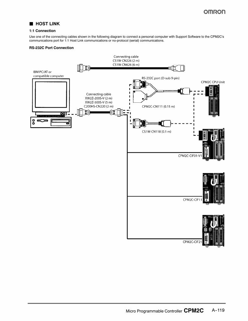
J HOST LINK
1:1 Connection
Use one of the connecting cables shown in the following diagram to connect a personal computer with Support Software to the CPM2C’scommunications port for 1:1 Host Link communications or no-protocol (serial) communications.
RS-232C Port Connection
A--120 Micro Programmable Controller CPM2C
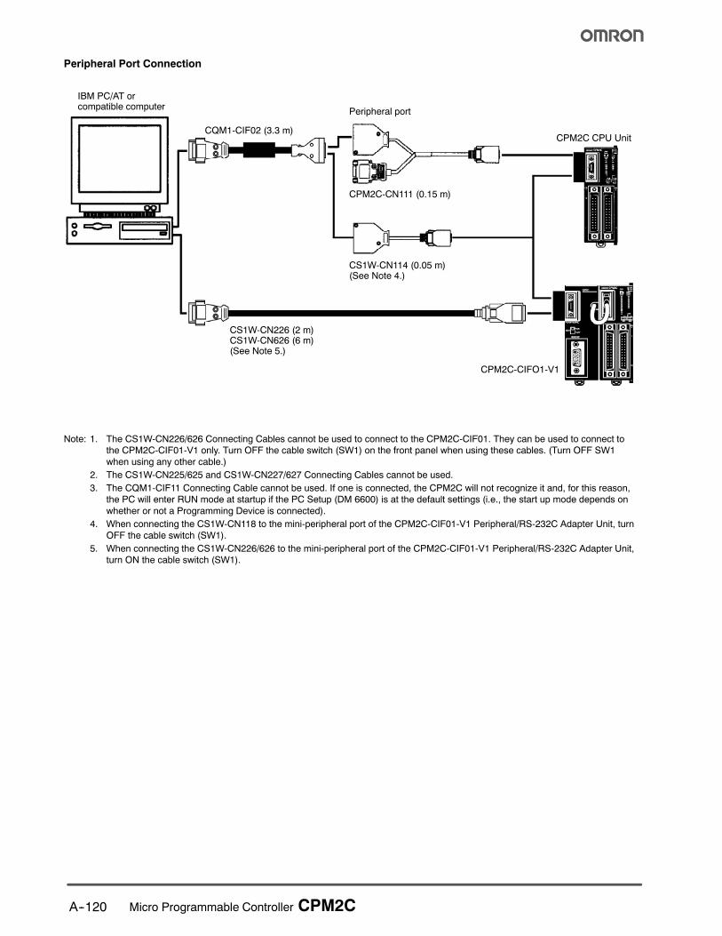
Peripheral Port Connection
IBM PC/AT orcompatible computer
CQM1-CIF02 (3.3 m)
CS1W-CN226 (2 m)CS1W-CN626 (6 m)(See Note 5.)
CS1W-CN114 (0.05 m)(See Note 4.)
CPM2C-CN111 (0.15 m)
Peripheral port
CPM2C CPU Unit
CPM2C-CIFO1-V1
Note: 1. The CS1W-CN226/626 Connecting Cables cannot be used to connect to the CPM2C-CIF01. They can be used to connect to
the CPM2C-CIF01-V1 only. Turn OFF the cable switch (SW1) on the front panel when using these cables. (Turn OFF SW1
when using any other cable.)
2. The CS1W-CN225/625 and CS1W-CN227/627 Connecting Cables cannot be used.
3. The CQM1-CIF11 Connecting Cable cannot be used. If one is connected, the CPM2C will not recognize it and, for this reason,
the PC will enter RUN mode at startup if the PC Setup (DM 6600) is at the default settings (i.e., the start up mode depends on
whether or not a Programming Device is connected).
4. When connecting the CS1W-CN118 to the mini-peripheral port of the CPM2C-CIF01-V1 Peripheral/RS-232C Adapter Unit, turn
OFF the cable switch (SW1).
5. When connecting the CS1W-CN226/626 to the mini-peripheral port of the CPM2C-CIF01-V1 Peripheral/RS-232C Adapter Unit,
turn ON the cable switch (SW1).

A--121Micro Programmable Controller CPM2C
1:N Connection
Up to 32 OMRON PLCs, including CPM2C PLCs, can be connected to a host computer.
IBM PC/AT orcompatiblecomputerwithRS-422/RS-485
Connecting Cable
XW2Z-200S-V (2 m)XW2Z-500S-V (5 m)C200HS-CN220 (2 m)
NT-AL001 (requires +5 V)(See notes 1 and 2.)RS-422 (Total length: 500 m max.)
When using the portas a peripheral port
CPM2C-CIF11 CPM2C-CIF11 CPM2C-CIF11
CPM2C CPU CPM2C CPU CPM2C CPU
CPM2CCPU
CPM2CCPUCPM2C CPUCPM2C CPU
NT-AL001(See note 1.)
NT-AL001(See note 1.)
NT-AL001(See note 1.)
NT-AL001(See note 1.)
When usingthe port asan RS-232Cport
RS-232C port XW2Z-200T-1 (2 m)XW2Z-200T-1 (2 m) XW2Z-200T-1 (2 m)
RS-232C port
CSW1-CN118Connecting cable(0.1 m)
RS-232C port
CSW1-CN111Connecting cable(0.15 m)
CPM2C-CIF01-V1
CPM2C-CIF21
Up to 32 PLCs
XW2Z-200T-1 (2 m)
Note: 1. The NT-AL001 must be supplied externally with 5 VDC. When an NT-AL001 is connected to a CPM2C PC, pin 6 of the
CPM2C’s RS-232C port supplies +5 VDC and an external power supply is not necessary.
2. Be sure that the power supply requirements of the CPU, Expansion Modules, and Expansion I/O Modules do not exceed the
available capacity. Only three Expansion I/O Modules and Expansion Modules can be connected when the NT-AL001 Adapter
is connected to the RS-232C port.
A--122 Micro Programmable Controller CPM2C
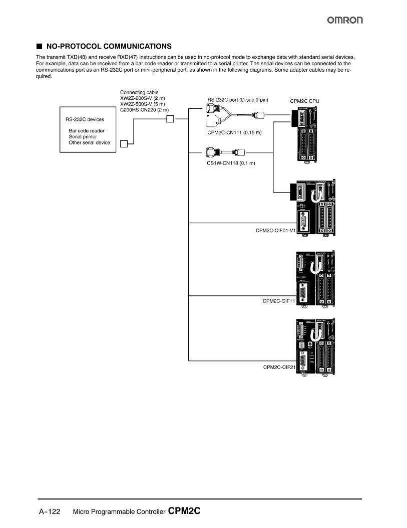
J NO-PROTOCOL COMMUNICATIONS
The transmit TXD(48) and receive RXD(47) instructions can be used in no-protocol mode to exchange data with standard serial devices.
For example, data can be received from a bar code reader or transmitted to a serial printer. The serial devices can be connected to the
communications port as an RS-232C port or mini-peripheral port, as shown in the following diagrams. Some adapter cables may be re-
quired.
A--123Micro Programmable Controller CPM2C
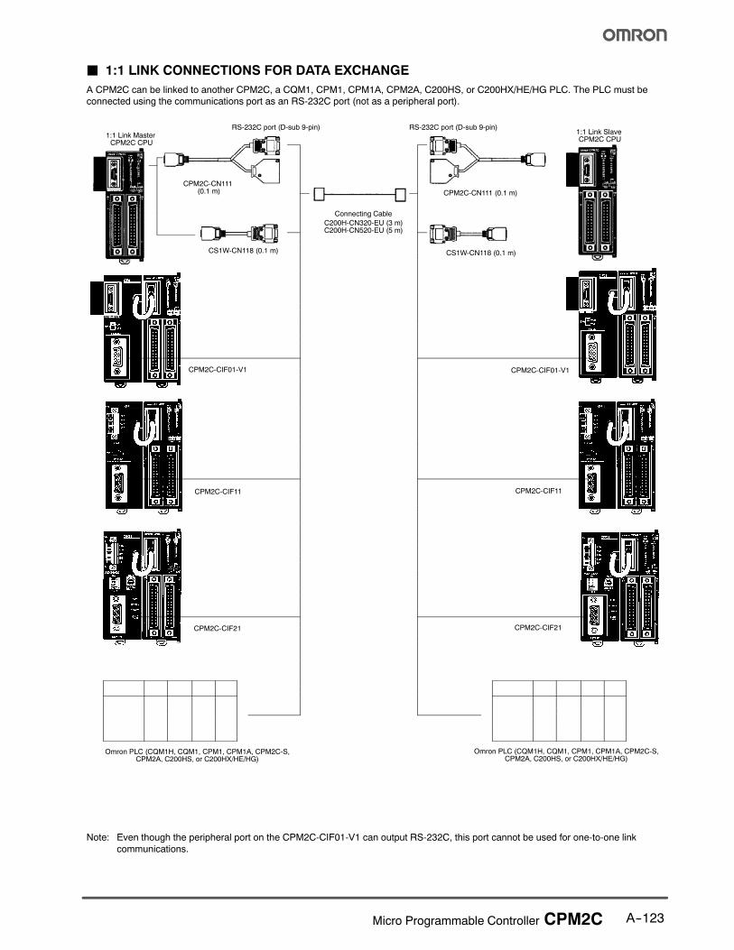
J 1:1 LINK CONNECTIONS FOR DATA EXCHANGE
A CPM2C can be linked to another CPM2C, a CQM1, CPM1, CPM1A, CPM2A, C200HS, or C200HX/HE/HG PLC. The PLC must be
connected using the communications port as an RS-232C port (not as a peripheral port).
CPM2C-CN111(0.1 m)
CS1W-CN118 (0.1 m) CS1W-CN118 (0.1 m)
1:1 Link MasterCPM2C CPU
Connecting Cable
C200H-CN320-EU (3 m)C200H-CN520-EU (5 m)
RS-232C port (D-sub 9-pin)
CPM2C-CN111 (0.1 m)
RS-232C port (D-sub 9-pin)1:1 Link SlaveCPM2C CPU
Omron PLC (CQM1H, CQM1, CPM1, CPM1A, CPM2C-S,CPM2A, C200HS, or C200HX/HE/HG)
Omron PLC (CQM1H, CQM1, CPM1, CPM1A, CPM2C-S,CPM2A, C200HS, or C200HX/HE/HG)
CPM2C-CIF01-V1
CPM2C-CIF11
CPM2C-CIF01-V1
CPM2C-CIF11
CPM2C-CIF21 CPM2C-CIF21
Note: Even though the peripheral port on the CPM2C-CIF01-V1 can output RS-232C, this port cannot be used for one-to-one link
communications.
A--124 Micro Programmable Controller CPM2C
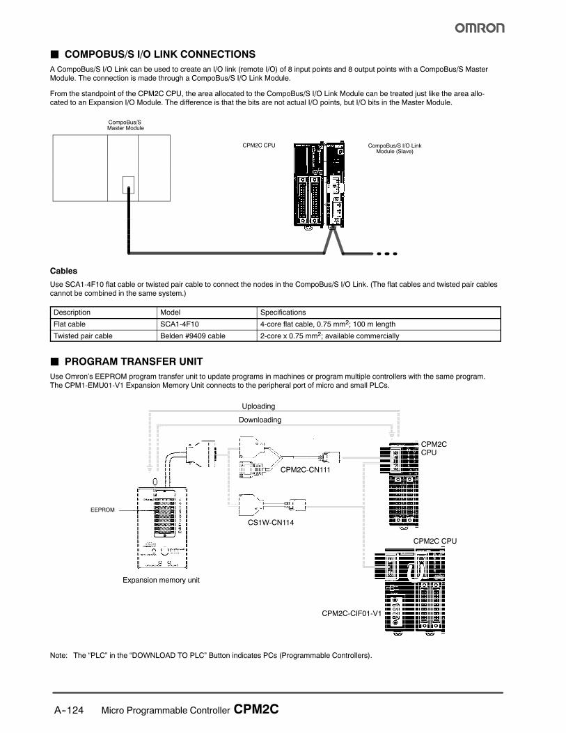
J COMPOBUS/S I/O LINK CONNECTIONS
A CompoBus/S I/O Link can be used to create an I/O link (remote I/O) of 8 input points and 8 output points with a CompoBus/S Master
Module. The connection is made through a CompoBus/S I/O Link Module.
From the standpoint of the CPM2C CPU, the area allocated to the CompoBus/S I/O Link Module can be treated just like the area allo-cated to an Expansion I/O Module. The difference is that the bits are not actual I/O points, but I/O bits in the Master Module.
CPM2C CPU
CompoBus/SMaster Module
CompoBus/S I/O LinkModule (Slave)
Cables
Use SCA1-4F10 flat cable or twisted pair cable to connect the nodes in the CompoBus/S I/O Link. (The flat cables and twisted pair cables
cannot be combined in the same system.)
Description Model Specifications
Flat cable SCA1-4F10 4-core flat cable, 0.75 mm2; 100 m length
Twisted pair cable Belden #9409 cable 2-core x 0.75 mm2; available commercially
J PROGRAM TRANSFER UNIT
Use Omron’s EEPROM program transfer unit to update programs in machines or program multiple controllers with the same program.
The CPM1-EMU01-V1 Expansion Memory Unit connects to the peripheral port of micro and small PLCs.
Expansion memory unit
Uploading
EEPROM
CPM2C-CN111
CS1W-CN114
CPM2CCPU
CPM2C CPU
CPM2C-CIF01-V1
Downloading
Note: The “PLC” in the “DOWNLOAD TO PLC” Button indicates PCs (Programmable Controllers).
! ! "! # # ! $ %& ''(% %%) * + !! #
! %) % *
, - ( ! ! # * ! . !% # + *
/ 011 %2 $# # * % % ! %
## !%# # 3 " $
4 . . ! # . ! ! 3 % % !! ! # !! $ ! . ! ! # . % %*
5 67 * % ! # 3 # 7* 8 ! % $ $* !"% ! ! %* * # %
9 ( & %) * .
: 6 ;) % % # % ! 38 ! !!8 % ! % ! ! % ! ! 8 3 #
1 - # < . % = % % % % * #
# * $% 6* "
% ! 8 $ * !# $ %*
- # 8 $
. ( % *
$% # % ,1 "% % # $
> &.# > + .# $% 8 # % . % ! . % '&''&?;@&A>??AB??&?&&A7A!&C?&? 7;'7&-!*<AA"7A6?7A$&;&A!;&?(DA*7'"7B ? 67A& 6? ?7(<'? <?& 6 D& $-*<B&?(@A>'&-$&D7'A&D-&&?;7A&-DD&$- >7'' <7*'B ;&& D& ?&E<7?&;&A 6 D&7?7A&A-&-<& % . % % $ " * ? + %" % * % % # "$! + ! * 3 $# # % % ! ! . $ + $ ! ! %) "!% ! ? %* % # % % % % %% $% !! % % # # ! # ! % %#
, - '&&''&?D''A*&'7*'&6?&(7'!7A-7"?&( ? (A&E<&A7' -;$&! ' 6 ?67 ? ?"-<(7A?(;;&?(7''7AAB>B(AA&(&->7DD&$-!>D&D&?<(D('7;7*&-7A(A?(!>??AB!A&$'7$&A(&??7('7*7'7B 6 ! # % . # $%
/ 7 * ! % ! ! ! . + . !# "! * + $> !* . % . % $ *
2 ( % $ .# * A" * ! .# % * $ " ! * % #
4; ># A % . % * # % % * + % * $!"#% # % # %7# # #!## # * # # !
%< % % "! % $ * + $* + 3 ! # % $% % $ % ! ! ! . % # % .# % $! % % $= ! ##
! % & !% ! !#
! 3 ! !# ! 3 !%) #
! 3 8 8% # % % $
A&F&?<&D&?-<(6?A'7(7A7AF'F7A$&?7<?7@'76&??&?B>7D<&A<?7A$DD&B&;>D'&D*&&A-&7$A&---?&D&?7@!A-DD& &''&?+ ?-<( 7 ?&?'B ?&- A- 7A''&- 6?D&7A&A-&-<&>7D7AD&F&?''&E<7;&A?B&;
% % % + "% $! 3
, - # # % 7 + ! " 3 %) +>''%
/ ( % % # 7" % % ! D # ! " $% > %! % % . %8 + # $
2 & % 8 % # % # ! % ! !
$%"=GG<"=GGG ("=GG
Cat. No. R301-E3-01 2/04 Specifications subject to change without notice Printed in USA
! "#992; # !;*2F9
$%&'&&$&(
( -# %!7'415,
$)$*)+,,6< 3 =
,,((&&)&&
- ./ 012
111# # 3H/- 2.2"/4#
!56 ## !%11,:,5# !%11,25
Copyright © 2022 FDOKUMEN

