


Bahasa
Halaman
Hukum


PIPING MATERIAL SPECIFICATION
TOTAL
SHEETS 48
DOCUMENT NO VCS PL PI PMS 001
PIPING MATERIAL SPECIFICATION
3 07.09.2018 RE-ISSUED AS STANDARD CM MC AD
2 17.02.2018 RE-ISSUED AS STANDARD MD MC AD
1 05.08.2017 RE-ISSUED AS STANDARD CM MC AD
0 05.08.2017 ISSUED AS STANDARD AS SM AD
REV DATE DESCRIPTION PREP CHK APPR

PIPING MATERIAL SPECIFICATION
PIPING MATERIAL SPECIFICATION
Document No. Rev
VCS-PL-PI-PMS-001 3
Page 2 of 48
TABLE OF CONTENTS
1.0 INTRODUCTION 2.0 CODES AND STANDARDS 3.0 MATERIAL SPECIFICATIONS 4.0 CLASS DESIGNATION CODES 5.0 PIPELINE 6.0 PIPES 7.0 FITTINGS 8.0 BENDS 9.0 FLANGES 10.0 GASKETS 11.0 BOLTING AND THREADS 12.0 THREAD SEALANT 13.0 VALVES
14.0 QUICK OPENING END CLOSURE 15.0 HYDROTESTING VENTS AND DRAINS 16.0 PIPELINE SPECIALITY ITEMS 17.0 INSULATING GASKET, SLEEVE AND WASHER 18.0 CHARPY V-NOTCH TEST

PIPING MATERIAL SPECIFICATION
PIPING MATERIAL SPECIFICATION
Document No. Rev
VCS-PL-PI-PMS-001 3
Page 3 of 48
1.0 INTRODUCTION
This specification cover minimum requirements for the material specification for
pipe, fittings, flanges, line blinds, bolts, gaskets, and valves that shall be used for
natural gas pipeline and associated facilities in accordance with ASME B31.8,
OISD-226 and PNGRB guideline
This specification also defines, by piping class for each listed service, and defines
the pressure/temperature limitations within which they may be used.
This specification shall be read in conjunction with various codes and standards as
applicable.
2.0 CODES AND STANDARDS
2.1 Pipeline and pipeline terminal facilities envisaged as part of this project shall be
designed and engineered primarily in accordance with the provisions of the latest
edition of the following codes:
(i) ASME B 31.8 - Gas transmissions and Distribution Piping System
(ii) ASME B 31.3 - Chemical Plant and Petroleum Refinery Piping
(iii) OISD Standard 226 - Natural Gas transmission Pipelines.
(iv) PNGRB - Petroleum & Natural Gas Regulatory Board
2.2 All codes, standards and specifications referred herein shall be the latest edition of
such documents.
2.3 For sake of brevity the initials of the society to which the codes are referred may be
omitted in the specifications, for example, B16.5 is a code referring to ASME A106 is a
code referring to ASTM.
2.4 In addition to this PMS, various piping and pipeline materials shall also be applicable.
3.0 MATERIAL SPECIFICATIONS
Individual piping class has been generally designed to cover a set of service operating
within pressure-temperature consideration as per ASME B16.5/ B16.34 or part of it.
Deviations of material from class specifications may occur due to specific design
conditions and/or availability. These deviations are permissible if they equal or better
the individual class requirements and shall be subjected to approval on case-to-case
basis.

PIPING MATERIAL SPECIFICATION
PIPING MATERIAL SPECIFICATION
Document No. Rev
VCS-PL-PI-PMS-001 3
Page 4 of 48
4.0 CLASS DESIGNATION CODE
The piping class designation shall generally consist of three digits made up of a letter,
number & letter e.g. 15HC, 15HLT , 30HC, 30 HLT, 60HC etc. as follows:
First two numerals letter indicates ASME class rating, e.g.,
15 - 150 Class
30 - 300 Class
60 - 600 Class
The first alphabet indicates differences in the specifications within the same class
rating and material, e.g. H stands for Hydrocarbon, etc.
The last letter indicates type of material, e.g.,
C - Carbon steel
S - Stainless Steel
LT- LTCS
5.0 PIPELINE
5.1 Line pipe material grade and wall thickness details are indicated in PMS.
6.0 PIPES
6.1 Carbon steel pipe shall be made by open hearth, electric furnace or basic oxygen
process only. The steel used shall be fully killed and made with fine grain structure.
The grade and wall thickness of various sizes of pipes shall be as per piping material
specification for the applicable class.
6.2 Pipe dimensions shall be in accordance with ASME B 36.10 for carbon steel ASTM
standard pipes & API 5L for carbon steel API 5L grade pipes.
6.3 All pipe threads shall conform to American Standard taper as per ASME B 1.20.1 NPT,
unless otherwise specified.
6.4 For butt weld end, bevel shall be in accordance with API specification 5L or ASME
B16.25 as applicable.
7.0 FITTINGS
7.1 Fully killed carbon steel shall be used in the manufacture of fittings. The fitting shall
have carbon equivalent not exceeding 0.45, based on check analysis.
7.2 Threaded joints, if used, shall conform to American Standard taper as per ASME
B1.20.1 NPT.

PIPING MATERIAL SPECIFICATION
PIPING MATERIAL SPECIFICATION
Document No. Rev
VCS-PL-PI-PMS-001 3
Page 5 of 48
7.3 Dimensions of socket welded/screwed fittings shall conform to ASME B 16.11. Swage
shall be as per BS 3799.
7.4 Dimensions of steel butt welded fittings shall be as per ASME B 16.9.
7.5 Bore of socket welded fittings shall suit outside diameter (OD) of pipe and its
thickness.
7.6 Butt welding ends shall conform to API specification 5L or ASME B 16.25 as
applicable. In case of difference in thickness of matching ends, requirements of ASME
B 31.4 shall apply.
7.7 Integrally reinforced forged branch fittings such as Sockolet, Weldolet etc. shall be as
per MSS-SP-97. Fittings not covered in ASME B16.9 and MSS-SP-97 shall conform to
manufacturer’s standard.
7.8 Fittings thickness tolerances shall match pipe thickness tolerance.
8.0 BENDS
8.1 Unless otherwise specified for process piping, elbow of radius R = 1.5 D shall only be
used.
8.2 In order to accommodate changes in vertical and horizontal alignment in piggable
section of pipeline, Elastic bends/ Cold field bends/ Hot formed long radius bends shall
be used.
D = Specified Outside Diameter
Long Radius Bend shall be used only when indicated in AFC drawing.
8.3 Miters shall not be used.
9.0 FLANGES
9.1 Pressure Temperature rating of flanges shall conform to B16.5/ MSS-SP44/ B16.47
Series A, as applicable.
9.2 Dimensions of flanges shall be in accordance with B16.5/ MSS-SP44/ B16.47 Series A,
as applicable.
9.3 Neck of weld neck (WN) flanges shall suit pipe bore and thickness.
9.4 Bore of socket welded (SW) flanges shall suit pipe O.D. and its thickness.
9.5 Threads for screwed flanges, if used, shall conform to American Standard taper as per
ASME B 1.20.1 NPT.

PIPING MATERIAL SPECIFICATION
PIPING MATERIAL SPECIFICATION
Document No. Rev
VCS-PL-PI-PMS-001 3
Page 6 of 48
9.6 Sizes for blind flanges shall be indicated by nominal pipe size.
9.7 Unless specified otherwise in Piping Material Specification the flange face finish shall
be as per ASME B16.5.
9.8 Butt welding ends of WN flanges shall conform to ASME B 16.25.
9.9 Spectacle blind/spacer & blinds shall be in accordance with ASME B 16.48/
manufacturer’s standard.
10.0 GASKETS
10.1 Spiral wound metallic gasket with Graphite filled winding with SS304 inner ring and CS
outer ring and shall conform to ASME B 16.20/ API 601.
10.2 Spiral wound gasket shall be self-aligning type.
11.0 BOLTING & THREADS
11.1 Nuts for stud bolts shall be American Standard Hexagon Heavy Series and double
chamfered.
11.2 Dimension and tolerances for stud bolts and nuts shall be as per ASME B 18.2.1 and
18.2.2 with full threading to ASME B 1.1 Class 2A thread for bolts and Class 2B for
nuts. Diameter and length of stud bolts shall be as per ASME B 16.5/ASME B16.47
with full threading.
11.3 Threads for nuts shall be as per ASME B 1.1 as follows,
Nuts for stud bolts dia ¼" to 1" : UNC-2B
Nuts for stud bolts dia 1⅛" to 3¼" : 8UN-2B
11.4 Threads for stud bolts shall be as per ASME B 1.1, as follows:
Stud bolts dia ¼" to 1" : UNC-2A
Stud bolts dia 1⅛" to 3¼" : 8UN-2A
11.5 Threads for threaded pipe, fitting, flanges and valve shall be in accordance with B
1.20.1 taper threads, unless specified otherwise.
11.6 Heads of jack screws shall be heavy hexagonal type. Jack screw end shall be rounded.
Stud bolts shall be fully threaded with two hexagonal nuts.
12.0 THREAD SEALANT
12.1 Threaded joints shall be made with 1" wide PTFE jointing tape.

PIPING MATERIAL SPECIFICATION
PIPING MATERIAL SPECIFICATION
Document No. Rev
VCS-PL-PI-PMS-001 3
Page 7 of 48
13.0 VALVES
13.1 Valve ends shall be as per valve data sheets for various piping class.
13.2 Sectionalizing valves, Block valves and other isolation valves installed on the main
pipeline shall be ball valves with butt welding ends. All inline isolation valves on the
mainline (pipeline) shall be full bore valves to allow smooth passage of cleaning as well
as intelligent pigs.
13.3 All buried valves shall be provided with stem extension, sealant, vent/drain and shall
have butt welded ends as per relevant specification/ data sheet.
13.4 Flange dimensions and face finish of flanged end valves shall conform to clause 9.0 of
this specification.
13.5 Butt welding ends of Butt Welded valves shall conform to ASME B 16.25.
13.6 Face to face and end to end dimensions shall conform to applicable standards.
13.7 Valves shall conform to following standards unless specified otherwise in piping
material specification for various piping class.
Flanged/Socket Welded end valves (1½" and below)
Design STD. for Process lines
Gate Valves : API 602
Globe Valves : BS EN ISO 15761
Check Valves : BS EN ISO 15761
Ball Valves : BS EN ISO 17292
Plug Valves : BS 5353
Flanged/Butt Welded end valves (2" and above)
Design STD. for Process Lines
Gate Valves : API 6D
Globe Valves : BS 1873
Check Valves : API 6D
Ball Valves : API 6D
Plug Valves : API 6D
13.8 All manual operated valves shall be provided with wrench / hand wheel or gear operator as specified here in below.
13.8.1 Gate Valves
For ANSI class 150 and 300 -Hand wheel operated for size ≤ 12" NB.
Gear operated for size ≥ 14" NB.

PIPING MATERIAL SPECIFICATION
PIPING MATERIAL SPECIFICATION
Document No. Rev
VCS-PL-PI-PMS-001 3
Page 8 of 48
For ANSI class 600 -Hand wheel operated for size ≤ 10" NB.
Gear operated for size ≥ 12" NB.
13.8.2 Globe Valves
For ANSI class 150, 300, 600 and 900 -Hand Wheel operated for all size
13.8.3 Ball valves & Plug Valves
For all ANSI class - Wrench operated for size ≤ 4" NB.
Gear operated for size ≥ 6" NB.
13.8.4 Actuated Valves
Actuated valves shall be as per P & IDs. The actuator shall have provision for remote
operation as per P & IDs. All Actuated valves shall have additional provision of hand
wheel operation.
14.0 QUICK OPENING END CLOSURE
Quick opening end closure to be installed on scraper traps shall be designed in
accordance with Section VIII of ASME Boiler and Pressure Vessel Code and equipped
with safety locking devices in compliance with Section VIII, division 1, UG-35.2 of
ASME Boiler and Pressure Vessel Code.
15.0 HYDROTESTING VENTS AND DRAINS
In terminal piping, high point vents and low point drains required for the purpose of
hydro testing shall be of size 0.75". These vents & drains shall consist of gate valves
with blind flange assembly.
16.0 PIPELINE SPECIATLITY ITEMS
Pipeline specialty items viz. scraper traps, flow tees, insulating joints, LR bends etc.
shall be as per data sheets and specification.
For Mainline Items, corrosion allowance shall be as per data sheet
.
17.0 INSULATING GASKET, SLEEVE AND WASHER
The insulating gasket shall consist of a PTFE (Teflon) spring-energized face seal, or an
elastomeric O-ring, seated in an isolating laminate, which shall be permanently bonded
to a high strength metal gasket core. Due to this unique pressure activated sealing
mechanism, the gasket requires far less bolt stress to seal than any other gasket. The
gasket inner diameter shall be exactly matched to the flange bore to eliminate turbulent
flow and flange face erosion/ corrosion. The seal elements shall be replaceable in the
reusable gasket retainer. The core of gasket shall be made of annealed 316 stainless
steel or other metals including duplex and Inconel etc.
PIPING MATERIAL SPECIFICATION
PIPING MATERIAL SPECIFICATION
Document No. Rev
VCS-PL-PI-PMS-001 3
Page 9 of 48
Insulating gasket shall include the following applications,
Flange isolation in conjunction with cathodic protection.
Isolation between dissimilar metals to prevent galvanic corrosion.
Mating mismatched ring-joint to raised –face flanges.
Eliminate fluid trap corrosion between ring-joint (RTJ) flanges where high
concentrations of Co2, H2S and other aggressive hydrocarbon media are present.
Eliminate turbulence and flow induced erosion between ring-joint (RTJ) flanges.
Protect against coating impingement on coated flange faces.
To seal between flanges subjected to vibration/ cavitation.
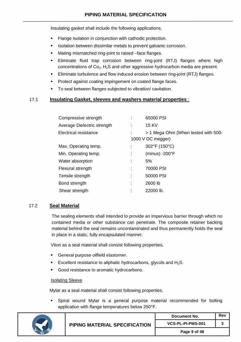
17.1 Insulating Gasket, sleeves and washers material properties :
Compressive strength : 65000 PSI
Average Dielectric strength : 15 KV
Electrical resistance : > 1 Mega Ohm (When tested with 500-
1000 V DC megger)
Max. Operating temp. : 302°F (150°C)
Min. Operating temp. : (minus) -200°F
Water absorption : 5%
Flexural strength : 70000 PSI
Tensile strength : 50000 PSI
Bond strength : 2600 lb
Shear strength : 22000 lb.
17.2 Seal Material
The sealing elements shall intended to provide an impervious barrier through which no
contained media or other substance can penetrate. The composite retainer backing
material behind the seal remains uncontaminated and thus permanently holds the seal
in place in a static, fully encapsulated manner.
Viton as a seal material shall consist following properties,
General purpose oilfield elastomer.
Excellent resistance to aliphatic hydrocarbons, glycols and H2S.
Good resistance to aromatic hydrocarbons.
Isolating Sleeve
Mylar as a seal material shall consist following properties,
Spiral wound Mylar is a general purpose material recommended for bolting
application with flange temperatures below 250°F.

PIPING MATERIAL SPECIFICATION
PIPING MATERIAL SPECIFICATION
Document No. Rev
VCS-PL-PI-PMS-001 3
Page 10 of 48
Material shall be fair resistance to crushing, cracking, breaking and thread pinch.
Isolating washer: 1/8” (0.125) Thick washer
Steel Washer: ZPS standard – Zinc plated steel washers.
Butt weld (BW) ends of the insulating assembly shall be protected by metallic or high
impact plastic bevel protectors.
The dimensions of insulating components (gaskets, sleeves and washers) shall be as
indicated in Data Sheet. The insulating gasket and washers shall have adequate
compressive strength to permit proper tightening of flange bolts for leak proof joint.
The insulating material shall be suitable for pressure and temperature indicated in
Data Sheet under connecting pipeline details and shall be resistant to the fluid to be
handled through the pipeline.
I.D. and O.D. of insulating washers shall be designed to fit over insulating sleeves and
within spot faces on flanges.
After the hydrostatic test, insulating flange assembly shall be tested with air at 5
kg/cm2 for 10 minutes. The tightness shall be checked by immersion or with a frothing
agent. No leakage shall be accepted.
Insulating gasket, sleeve and washer after the field hydrostatic test shall be tested for
dielectric integrity at 5000 V A.C., 50 Hz for one minute and the leakage current
before and after shall be equal. Testing time, voltage and leakage shall be recorded
and certified. The test shall be carried out in dry conditions.
18.0 CHARPY V-NOTCH TEST
All piping material like valves, fittings, flanges bolting etc. shall be Charpy impact
tested. Charpy V-notch impact tests are required for the base metal weld metal and
heat-affected zone (HAZ)

PIPING MATERIAL SPECIFICATION
PIPING MATERIAL SPECIFICATION
Document No. Rev
VCS-PL-PI-PMS-001 3
Page 11 of 48
PIPING MATERIAL SPECIFICATION INDEX
Sr. No.
Piping
Class Rating C. A.
Spl.
Reqt.
Basic
Material Service Remarks
1 15HC 150 1.5 NON IBR CARBON
STEEL
NON-CORROSIVE PROCESS-FLAMMABLE /NONFLAMMABLE, NON
LETHAL- HYDROCARBONS
Page 12
of 48
2 15HLT 150 1.5 LOW TEMPER ATURE SERVICE
CARBON
STEEL
NON-CORROSIVE PROCESS-FLAMMABLE /NON-FLAMMABLE, NON
LETHAL- HYDROCARBONS
Page 17
of 48
3 30HC 300 1.5 NON IBR CARBON STEEL
NON-CORROSIVE PROCESS-FLAMMABLE / NONFLAMMABLE, NON
LETHAL- HYDROCARBONS
Page 22 of 48
4 30HLT 300 1.5 LOW TEMPER ATURE SERVICE
CARBON STEEL
FIRE WATER (ABOVE GROUND / UNDER
GROUND)
Page 28 of 48
5 60HC 600 1.5 NON IBR CARBON STEEL
NON-CORROSIVE PROCESS-FLAMMABLE / NONFLAMMABLE, NON
LETHAL- HYDROCARBONS
Page 32 of 48
6 60HLT 600 1.5 LOW TEMPER ATURE SERVICE
CARBON STEEL
NON-CORROSIVE PROCESS-FLAMMABLE / NON-FLAMMABLE, NON
LETHAL- HYDROCARBONS
Page 38 of 48
7 15FW 150 1.5 NON IBR CARBON STEEL
FIRE WATER (ABOVE GROUND / UNDER
GROUND)
Page 44 of 48

PIPING MATERIAL SPECIFICATION (15HC)
PIPING MATERIAL SPECIFICATION
Document No. Rev
VCS-PL-PI-PMS-001 3
Page 12 of 48
PIPE CLASS : 15HC
RATING : 150
BASE MATERIAL : Carbon Steel
CORROSION ALLOWANCE : 1.5 MM
SPECIAL REQUIREMENT : Non IBR
TEMPERATURE (Deg. C) AND PRESSURE ( Kg/Sq. cm g ) RATINGS
SERVICE
Natural Gas, Utilities (water, inst. air, plant air, nitrogen, carbon dioxide)
NOTES
1. All vents and drains shall be provided with gate valve with blind flange
assembly unless otherwise indicated in P&ID.
2. NDT of welds shall be as follows:
Radiography : All butt welds 100%
MPI : Socket welds 100%
3. Piping design as per ASME B 31.8, OISD 226 & PNGRB Guidelines
4. Charpy V notch test and hardness test shall be conducted for pipes, fittings and flanges at (-)
29°C.
5. All branch connections including vent, drain, pressure and temperature connection shall be
as per branch connection table.
6. For valves, refer valve data sheets.
ITEM SIZE DESCRIPTION
Maintainence
joints ALL Flanged, to be kept minimum
Pipe joints 1.5" & BELOW SW coupling
2.0" & ABOVE Butt welded
Drains ON LINES <= 1.5" Refer std. SD-PI-019
ON LINES >= 2.0" As per P&ID or 0.75". Refer std. SD-PI-018
Vents ON LINES <= 1.5" Refer std. SD-PI-019
ON LINES >= 2.0" As per P&ID or 0.75". Refer std. SD-PI-018
Temp. Connection 1.5" Flanged, installation as per std. SD-PI-014 & 015, except
skin temperature measurement.
Press. Connection 0.75" SW nipple with Plug/ Ball Valve to spec. as per Refer std.
SD-PI-011, 012 & 013
TEMP -29 38 93 149 204 260 316 343 371
PRESS 20.03 20.03 18.28 16.17 14.06 11.95 9.84 8.78 7.73

PIPING MATERIAL SPECIFICATION (15HC)
PIPING MATERIAL SPECIFICATION
Document No. Rev
VCS-PL-PI-PMS-001 3
Page 13 of 48
BRANCH TABLE
T
24
T T
20
T T T
18
B
T T T T
16
R
T T T T T
14
A
T T T T T T
12
N
T T T T T T T
10
C
T T T T T T T W
8
H
T T T T T T W W W
6
T T T W W W W W W W
4
P
T T T W W W W W W W W
3
I
T T T W W W W W W W W W
2
P
T T T T S S S S S S S S S
1.5
E
T T T S S S S S S S S S S S
1
T T T T S S S S S S S S S S S
0.75
T T T T S S S S S S S S S S S S 0.50
0.05 0.75 1 1.5 2 3 4 6 8 10 12 14 16 18 20 24
R U N P I P E
CODE DESCRIPTION
T TEES W WELDOLETS S SOCKOLETS

PIPING MATERIAL SPECIFICATION (15HC)
PIPING MATERIAL SPECIFICATION
Document No. Rev
VCS-PL-PI-PMS-001 3
Page 14 of 48
Item
Lower Size
(Inch)
Upper Size
(Inch)
Sch./
Thk. Dmn. STD Material (Charpy) Description
Pipe Group
PIPE 00.500 00.750 S160 B-36.10 ASTM A 106 GR.B PE, SEAMLESS
PIPE 01.000 01.500 XS B-36.10 ASTM A 106 GR.B PE, SEAMLESS
PIPE 02.000 02.000 XS B-36.10 ASTM A 106 GR.B
(Charpy) BE, SEAMLESS
PIPE 03.000 24.000 STD B-36.10 ASTM A 106 GR.B
(Charpy) BE, SEAMLESS
NIPPLE 00.500 01.500 M B-36.10 ASTM A 106 GR.B PBE, SEAMLESS
Flange Group
FLNG.SW 00.500 01.500 M B-16.5 ASTM A 105 150, RF/125AARH
FLNG.WN 2.000 24.000 M B-16.5 ASTM A 105 (Charpy) 150, RF/ 125AARH
FLNG.BLIND 00.500 01.500 B-16.5 ASTM A 105 150, RF/ 125AARH
FLNG.BLIND 00.500 24.000 B-16.5 ASTM A 105 (Charpy) 150, RF/ 125AARH
FLNG.FIG.8 00.500 08.000 ASME
B16.48 ASTM A 105 (Charpy) 150, FF/ 125AARH
SPCR&BLND 10.000 24.000 ASME B16.48
ASTM A 105 (Charpy) 150, FF/ 125AARH
Fitting Group
ELBOW.90 00.500 01.500 B-16.11 ASTM A 105 SW, 6000
ELBOW.90 02.000 26.000 M B-16.9 ASTM A 234 GR.WPB
(Charpy) BW, 1.5D
ELBOW.45 00.500 01.500 B-16.11 ASTM A 105 SW, 6000
ELBOW.45 02.000 26.000 M B-16.9 ASTM A 234 GR.WPB
(Charpy) BW, 1.5D
T.EQUAL 00.500 01.500 B-16.11 ASTM A 105 SW, 6000
T.EQUAL 02.000 26.000 M B-16.9 ASTM A 234 GR.WPB
(Charpy) BW
T.RED 00.500 01.500 B-16.11 ASTM A 105 SW, 6000
T.RED 02.000 26.000 M, M B-16.9 ASTM A 234 GR.WPB
(Charpy) BW
REDUC. CONC
02.000 26.000 M, M B-16.9 ASTM A 234 GR.WPB (Charpy)
BW

PIPING MATERIAL SPECIFICATION (15HC)
PIPING MATERIAL SPECIFICATION
Document No. Rev
VCS-PL-PI-PMS-001 3
Page 15 of 48
Item
Lower Size
(Inch)
Upper Size
(Inch)
Sch./
Thk. Dmn. STD Material (Charpy) Description
REDUC. ECC
02.000 26.000 M, M B-16.9 ASTM A 234 GR.WPB (Charpy)
BW
SWAGE. CONC
00.500 03.000 M, M BS-3799 ASTM A 105 (Charpy) PBE
SWAGE.ECC 00.500 03.000 M, M BS-3799 ASTM A 105 (Charpy) PBE
CAP 00.500 00.750 B-16.11 ASTM A 105 SCRF, 6000
CAP 01.000 01.500 B-16.11 ASTM A 105 SCRF, 3000
CAP 02.000 18.000 M B-16.9 ASTM A 234 GR.WPB (Charpy)
BW
PLUG 00.500 00.750 B-16.11 ASTM A 105 SCRM, 6000
O'let
WELDOLET 02.000 06.000 M,
S160 MSS-SP97 ASTM A 105 (Charpy) BW
SOCKOLET 00.500 00.750 MSS-SP97 ASTM A 105 SCRF, 6000
SOCKOLET 01.000 01.500 MSS-SP97 ASTM A 105 SW, 3000
Valves
VLV.GLOBE 00.250 01.500 BS EN
1SO 15761
BODY-ASTM A 105,TRIM-
STELLITED,STEM- 13%CR STEEL
SW, 800, 3000,
B-16.11
VLV.GLOBE 02.000 18.000 BS-1873 BODY-ASTM A 216
GR.WCB,TRIM- 13% CR.STEEL
FLGD, 150, B-16.5, RF/125AARH
VLV.CHECK 00.250 01.500 BS EN
1SO 15761 BODY-ASTM A
105,TRIM- STELLITED
SW, 800, 3000,
B-16.11
VLV.CHECK 02.000 26.000 API-6D BODY-ASTM A 216
GR.WCB,TRIM- 13% CR.STEEL
FLGD, 150,
B-16.5, RF/125AARH
VLV.BALL 00.500 01.500 BS EN
1SO 17292
BODY-ASTM A 105,TRIM-13%
CR.STEEL, SEAT- RPTFE
SW, 150,
B-16.5, RF/125AARH
VLV.BALL 02.000 30.000 API-6D
BODY-ASTM A216 GR.WCB,TRIM/BA LL
SEAT-(AISI 4140
+ 0.003"ENP)/AISI 410
FLGD, 150,
B-16.5, RF/125AARH
VLV.BALL 02.000 18.000 API-6D
BODY-ASTM A 216 GR.WCB, TRIM- BALL,
SEAT-(AISI 4140 + 0.003"ENP) / AISI 410
BW, 150,
B-16.25

PIPING MATERIAL SPECIFICATION (15HC)
PIPING MATERIAL SPECIFICATION
Document No. Rev
VCS-PL-PI-PMS-001 3
Page 16 of 48
Item
Lower Size
(Inch)
Upper Size
(Inch)
Sch./
Thk. Dmn. STD Material (Charpy) Description
VLV.PLUG 00.500 01.500 BS-5353
BODY-ASTM A 105,PLUG - A105 +
0.003" ENP
SW, 800, 3000,
B-16.11,
Bolt Group
BOLT.STUD 00.500 48.000 B-18.2 BOLT:A193 GR.B7, NUT:A194 GR.2H
Gasket Group
GASKET 00.500 24.000 B-16.20-
ANSI B16.5
SP.WND
METTALIC WITH GRAPHITEFILLER
SPIRAL, 150
GASKET 26.000 48.000 B-16.20-
ANSI B16.47A
SP.WND
METTALIC WITH GRAPHITEFILLER
SPIRAL, 150

PIPING MATERIAL SPECIFICATION (15HLT)
PIPING MATERIAL SPECIFICATION
Document No. Rev
VCS-PL-PI-PMS-001 3
Page 17 of 48
PIPE CLASS : 15HLT
RATING : 150
BASE MATERIAL : Carbon Steel
CORROSION ALLOWANCE : 1.5 MM
SPECIAL REQUIREMENT : Low Temperature Service
TEMPERATURE (Deg. C) AND PRESSURE ( Kg/Sq. cm g ) RATINGS
SERVICE
Natural Gas, Utilities (water, inst. air, plant air, nitrogen, carbon dioxide)
NOTES
1. All vents and drains shall be provided with gate valve with blind flange assembly unless
otherwise indicated in P&ID.
2. NDT of welds shall be as follows:
Radiography : All butt welds 100%
MPI : Socket welds 100%
3. Piping design as per ASME B 31.8 , OISD 226 & PNGRB Guidelines
4. Charpy V notch test and hardness test shall be conducted for pipes, fittings and flanges at (-)
45°C.
5. All branch connections including vent, drain, pressure and temperature connection shall be
as per branch connection table.
6. For valves, refer valve data sheets.
ITEM SIZE DESCRIPTION
Maintenance
joints ALL Flanged, to be kept minimum
Pipe joints 1.5" & BELOW SW coupling
2.0" & ABOVE Butt welded
Drains ON LINES <= 1.5" Refer std. SD-PI-019
ON LINES >= 2.0" As per P&ID or 0.75". Refer std. SD-PI-018
Vents ON LINES <= 1.5" Refer std. SD-PI-019
ON LINES >= 2.0" As per P&ID or 0.75". Refer std. SD-PI-018
Temp. Connection 1.5" Flanged, installation as per std. SD-PI-014 & 015, except
skin temperature measurement.
Press. Connection 0.75" SW nipple with Plug/ Ball Valve to spec. as per Refer std.
SD-PI-011, 012 & 013
TEMP -45 38 93
PRESS 18.63 18.63 17.57

PIPING MATERIAL SPECIFICATION (15HLT)
PIPING MATERIAL SPECIFICATION
Document No. Rev
VCS-PL-PI-PMS-001 3
Page 18 of 48
BRANCH TABLE
T
6
BR
AN
CH
PIP
E
T T
4
T T T
3
T T T W
2
T T T T S
1.5
T T T S S S
1
T T T T S S S
0.75
T T T T S S S S 0.50
0.05 0.75 1 1.5 2 3 4 6
RUN PIPE
CODE DESCRIPTION
T TEES W WELDOLETS
S SOCKOLETS

PIPING MATERIAL SPECIFICATION (15HLT)
PIPING MATERIAL SPECIFICATION
Document No. Rev
VCS-PL-PI-PMS-001 3
Page 19 of 48
Item
Lower Size
(Inch)
Upper Size
(Inch)
Sch./
Thk. Dmn. STD Material (Charpy) Description
Pipe Group
PIPE 00.500 00.750 S160 B-36.10 ASTM A 333 GR.6 PE, SEAMLESS
PIPE 01.000 01.500 XS B-36.10 ASTM A 333 GR.6 PE, SEAMLESS
PIPE 02.000 02.000 XS B-36.10 ASTM A 333 GR.6 BE, SEAMLESS
PIPE 03.000 06.000 STD B-36.10 ASTM A 333 GR.6 BE, SEAMLESS
NIPPLE 00.500 01.500 M B-36.10 ASTM A 333 GR.6 PBE, SEAMLESS
Flange Group
FLNG.WN 00.500 06.00 M B-16.5 ASTM A 350
GR.LF2 150, RF/125AARH
FLNG.BLIND 00.500 06.00 B-16.5 ASTM A 350
GR.LF2 150, RF/125AARH
FLNG.FIG.8 00.500 06.00 ASME
B16.48
ASTM A 350
GR.LF2 150, FF/ 125AARH
Fitting Group
ELBOW.90 00.500 00.75 B-16.11 ASTM A 350
GR.LF2 SW, 6000
ELBOW.90 01.000 01.500 B-16.11 ASTM A 350
GR.LF2 SW, 3000
ELBOW.90 02.000 6.000 M B-16.9 ASTM A 420
GR.WPL6 BW, 1.5D
ELBOW.45 00.500 00.75 B-16.11 ASTM A 350
GR.LF2 SW, 6000
ELBOW.45 01.000 01.500 B-16.11 ASTM A 350
GR.LF2 SW, 3000
ELBOW.45 02.000 6.000 M B-16.9 ASTM A 420
GR.WPL6 BW, 1.5D
T.EQUAL 00.500 00.75 B-16.11 ASTM A 350
GR.LF2 SW, 6000
T.EQUAL 01.000 01.500 B-16.11 ASTM A 350
GR.LF2 SW, 3000

PIPING MATERIAL SPECIFICATION (15HLT)
PIPING MATERIAL SPECIFICATION
Document No. Rev
VCS-PL-PI-PMS-001 3
Page 20 of 48
Item
Lower Size
(Inch)
Upper Size
(Inch)
Sch./
Thk. Dmn. STD Material (Charpy) Description
T.EQUAL 02.000 6.000 M B-16.9 ASTM A 420
GR.WPL6 BW
T.RED 00.500 00.75 B-16.11 ASTM A 350
GR.LF2 SW, 6000
T.RED 01.000 01.500 B-16.11 ASTM A 350
GR.LF2 SW, 3000
T.RED 02.000 6.000 M, M B-16.9 ASTM A 420
GR.WPL6 BW
REDUC. CONC
02.000 6.000 M, M B-16.9 ASTM A 420
GR.WPL6
BW
REDUC. ECC
02.000 6.000 M, M B-16.9 ASTM A 420
GR.WPL6
BW
SWAGE. CONC
00.500 03.000 M, M BS-3799 ASTM A 350
GR.LF2
PBE
SWAGE.ECC 00.500 03.000 M, M BS-3799 ASTM A 350
GR.LF2
PBE
CAP 00.500 01.500 B-16.11 ASTM A 350
GR.LF2
SCRF, 3000
CAP 02.000 6.000 M B-16.9 ASTM A 420
GR.WPL6
BW
PLUG 00.500 01.500 B-16.11 ASTM A 350
GR.LF2
SCRM, 3000
COUPLING
FULL 00.500 00.75 B-16.11
ASTM A 350
GR.LF2 SW, 6000
COUPLING
FULL 01.000 01.500 B-16.11
ASTM A 350
GR.LF2 SW, 3000
COUPLING
HALF 00.500 00.75 B-16.11
ASTM A 350
GR.LF2 SW, 6000
COUPLING
HALF 01.000 01.500 B-16.11
ASTM A 350
GR.LF2 SW, 3000
O'let
WELDOLET 02.000 06.000 M, XXS MSS-SP97 ASTM A 350
GR.LF2 BW
SOCKOLET 00.500 00.750 MSS-SP97 ASTM A 350
GR.LF2 SW, 6000
SOCKOLET 01.000 01.500 MSS-SP97 ASTM A 350 SW, 3000

PIPING MATERIAL SPECIFICATION (15HLT)
PIPING MATERIAL SPECIFICATION
Document No. Rev
VCS-PL-PI-PMS-001 3
Page 21 of 48
Item
Lower Size
(Inch)
Upper Size
(Inch)
Sch./
Thk. Dmn. STD Material (Charpy) Description
GR.LF2
Valves
VLV.GLOBE 00.50 01.500 BS EN
1SO 15761
BODY-ASTM A 350
GR.LF2,TRIMSTELLITED,
STEMSS304
SW, 800, 3000,
B-16.11
VLV.CHECK 00.50 01.500 BS EN
1SO 15761
BODY-ASTM A 350
GR.LF2,TRIMSTELLITED
SW, 800, 3000,
B-16.11
VLV.BALL 00.500 01.500 BS EN
1SO 17292
BODY-ASTM A352
GR.LCB / ASTM
A350 GR.LF2
CL.1,TRIM-BODY
SEAT-RPTFE
SW, 800, 3000,
B-16.11
VLV.BALL 02.000 6.000 API-6D
BODY-ASTM A352
GR.LCB / ASTM
A350 GR.LF2
CL.1,TRIM-BODY
SEAT-RPTFE
FLGD, 150,
B-16.5, RF/125AARH
VLV.BALL 02.000 6.000 API-6D
BODY-ASTM A352
GR.LCB / ASTM
A350 GR.LF2
CL.1,TRIM-BODY
SEAT-RPTFE
BW, 150,
B-16.25
Bolt Group
BOLT.STUD 00.500 6.000 B-18.2 BOLT:A320 GR.L7,
NUT:A194 GR.4
Gasket Group
GASKET 00.500 6.000 B-16.20-
ANSI B16.5
SP.WND SS316+ GRAFOIL SPIRAL, 150

PIPING MATERIAL SPECIFICATION (30HC)
PIPING MATERIAL SPECIFICATION
Document No. Rev
VCS-PL-PI-PMS-001 3
Page 22 of 48
PIPE CLASS : 30HC
RATING : 300
BASE MATERIAL : Carbon Steel
CORROSION ALLOWANCE : 1.5 MM
SPECIAL REQUIREMENT : Non IBR
TEMPERATURE (Deg. C) AND PRESSURE (Kg/Sq. cm g ) RATINGS
TEMP -29 38 93 149 204 260 316 343
PRESS 52.02 52.02 47.45 46.05 44.64 42.18 38.66 37.61
SERVICE
Natural Gas, Utilities (water, inst. air, plant air, nitrogen, carbon dioxide)
NOTES
1. All vents and drains shall be provided with gate valve with blind flange
assembly unless otherwise indicated in P&ID
2. NDT of welds shall be as follows:
Radiography : All butt welds 100%
MPI : Socket welds 100%
3. Piping design as per ASME B 31.8 , OISD 226 & PNGRB Guidelines
4. Charpy V notch test and hardness test shall be conducted for pipes, fittings and flanges
at (-) 29°C.
5. Corrosion allowance of 1.5 mm has been considered for terminal piping.
6. All branch connections including vent, drain, pressure and temperature connection shall
be as per branch connection table.
7. For valves, refer valve data sheets as enclosed.
8. Design factor 0.5.
9. Ball Valve to be used in main pipeline shall have butt welded ends.
ITEM SIZE DESCRIPTION
Maintenance Joints all Flanged, to be kept minimum
Pipe joints 1.5" & below SW coupling
2.0" & above Butt welded
Drains on lines <= 1.5" Refer std. SD-PI-019
on lines >= 2.0" As per P&ID or 0.75". Refer std. SD-PI-018
Vents on lines <= 1.5" Refer std. SD-PI-019
on lines >= 2.0" As per P&ID or 0.75". Refer std. SD-PI-018
Temp. Connection 1.5" Flanged, installation as per std. SD-PI-014 & 015, except
skin temperature measurement.
Press. Connection 0.75" SW nipple with Plug/ Ball Valve to spec. as per Refer std.
SD-PI-011, 012 & 013

PIPING MATERIAL SPECIFICATION (30HC)
PIPING MATERIAL SPECIFICATION
Document No. Rev
VCS-PL-PI-PMS-001 3
Page 23 of 48
BRANCH TABLE
T 42
T T 36
T T T 32
T T T T 30
T T T T T 24
T T T T T T 20
T T T T T T T 18 B
T T T T T T T T 16 R
T T T T T T T T T 14 A
T T T T T T T T T T 12 N
T T T T T T T T T T T 10 C
T T T T T T T W W W W W 8 H
T T T T T T W W W W W W W 6
T T T T W W W W W W W W W W 4 P
T T T W W W W W W W W W W W W 3 I
T T T W W W W W W W W W W W W W 2 P
T T T T S S S S S S S S S S S S S 1.5 E
T T T S S S S S S S S S S S S S S S 1
T T T T S S S S S S S S S S S S S S S 0.75
T T T T S S S S S S S S S S S S S S S S 0.50
0.05 0.75 1 1.5 2 3 4 6 8 10 12 14 16 18 20 24 30 32 36 42
R U N P I P E
CODE DESCRIPTION
T TEES W WELDOLETS S SOCKOLETS

PIPING MATERIAL SPECIFICATION (30HC)
PIPING MATERIAL SPECIFICATION
Document No. Rev
VCS-PL-PI-PMS-001 3
Page 24 of 48
Item
Lower Size
(Inch)
Upper Size
(Inch)
Sch./
Thk. Dmn. STD Material (Charpy) Description
PIPE GROUP
PIPE 00.500 00.750 S160 B-36.10 ASTM A 106 GR.B PE, SEAMLESS
PIPE 01.000 01.500 XS B-36.10 ASTM A 106 GR.B PE, SEAMLESS
PIPE 02.000 02.000 XS B-36.10 ASTM A 106 GR.B
(CHARPY) BE, SEAMLESS
PIPE 03.000 03.000 STD B-36.10 ASTM A 106 GR.B
(CHARPY) BE, SEAMLESS
PIPE 04.000 06.000 XS B-36.10 ASTM A 106 GR.B
(CHARPY) BE, SEAMLESS
PIPE 08.000 08.000 6.4 API 5L API 5L GR.X 52/60 PSL 2,
(CHARPY) BE, SEAMLESS
PIPE 10.000 10.000 6.4 API 5L API 5L GR.X 52/60 PSL 2,
(CHARPY) BE, SEAMLESS
PIPE 12.000 16.000 7.1 API 5L API 5L GR.X 52/60 PSL 2,
(CHARPY) BE, SEAMLESS
PIPE 18.000 18.000 7.9 / 7.1 API 5L API 5L GR.X 52/60 PSL 2,
(CHARPY) BE, SAW
PIPE 20.000 20.000 8.7 / 7.9 API 5L API 5L GR.X 52/60 PSL 2,
(CHARPY) BE, SAW
PIPE 24.000 24.000 10.3 / 9.5
API 5L API 5L GR.X 52/60 PSL 2,
(CHARPY) BE, SAW
NIPPLE 00.500 01.500 M B-36.10 ASTM A 106 GR.B PBE, SEAMLESS
FLANGE GROUP
FLNG.SW 00.500 01.500 M B-16.5 ASTM A 105 300, RF/125AARH
FLNG.WN 02.000 16.000 M B-16.5 ASTM A 105 (CHARPY) 300, RF/125AARH
FLNG.WN 18.000 24.000 M B-16.5 ASTM A 694 GR.F- 52/60
(CHARPY) 300, RF/125AARH
FLNG.WN 26.000 30.000 M B-16.47-A ASTM A 694 GR.F- 52/60
(CHARPY) 300, RF/125AARH
FLNG.BLIND 00.500 01.500 B-16.5 ASTM A 105 300, RF/125AARH
FLNG.BLIND 02.000 24.000 B-16.5 ASTM A 105 (CHARPY) 300, RF/125AARH
FLNG.BLIND 26.000 30.000 B-16.47-A ASTM A 105 (CHARPY) 300, RF/125AARH
FLNG.FIG.8 00.500 01.500 ASME- B
16.48 ASTM A 105 300, FF/125AARH
FLNG.FIG.8 02.000 08.000 ASME- B
16.48 ASTM A 105 (CHARPY) 300, FF/125AARH

PIPING MATERIAL SPECIFICATION (30HC)
PIPING MATERIAL SPECIFICATION
Document No. Rev
VCS-PL-PI-PMS-001 3
Page 25 of 48
Item
Lower Size
(Inch)
Upper Size
(Inch)
Sch./
Thk. Dmn. STD Material (Charpy) Description
SPCR&BLND 10.000 24.000 ASME- B
16.48 ASTM A 105 (CHARPY) 300, FF/125AARH
FITTING GROUP
ELBOW.90 00.500 00.750 B-16.11 ASTM A 105 SW, 6000
ELBOW.90 01.000 01.500 B-16.11 ASTM A 105 SW, 3000
ELBOW.90 02.000 16.000 M B-16.9 ASTM A 234 GR.WPB
(CHARPY) BW, 1.5D
ELBOW.90 18.000 30.000 M MSS-SP75 MSS SP-75 GR.WPHY-
52/60 BW, 1.5D
ELBOW.45 00.500 00.750 B-16.11 ASTM A 105 SW, 6000
ELBOW.45 01.000 01.500 B-16.11 ASTM A 105 SW, 3000
ELBOW.45 02.000 16.000 M B-16.9 ASTM A 234 GR.WPB
(CHARPY) BW, 1.5D
ELBOW.45 18.000 30.000 M MSS-SP75 MSS SP-75 GR.WPHY-
52/60 BW, 1.5D
T.EQUAL 00.500 00.750 B-16.11 ASTM A 105 SW, 6000
T.EQUAL 01.000 01.500 B-16.11 ASTM A 105 SW, 3000
T.EQUAL 02.000 16.000 M B-16.9 ASTM A 234 GR.WPB
(CHARPY) BW
T.EQUAL 18.000 30.000 M MSS-SP75 MSS SP-75 GR.WPHY-
52/60 BW
T.RED 00.500 00.750 B-16.11 ASTM A 105 SW, 6000
T.RED 01.000 01.500 B-16.11 ASTM A 105 SW, 3000
T.RED 02.000 16.000 M, M B-16.9 ASTM A 234 GR.WPB
(CHARPY) BW
T.RED 18.000 30.000 M, M MSS-SP75 MSS SP-75 GR.WPHY-
52/60 BW
REDUC.
CONC 02.000 16.000 M, M B-16.9
ASTM A 234 GR.WPB
(CHARPY) BW
REDUC.
CONC 18.000 30.000 M, M MSS-SP75
MSS SP-75 GR.WPHY-
52/60 BW
REDUC.
ECC 02.000 16.000 M, M B-16.9
ASTM A 234 GR.WPB
(CHARPY) BW
REDUC.
ECC 18.000 30.000 M, M MSS-SP75
MSS SP-75 GR.WPHY-
52/60 BW
SWAGE.
CONC 00.500 03.000 M, M BS-3799 ASTM A 105 (CHARPY) PBE

PIPING MATERIAL SPECIFICATION (30HC)
PIPING MATERIAL SPECIFICATION
Document No. Rev
VCS-PL-PI-PMS-001 3
Page 26 of 48
Item
Lower Size
(Inch)
Upper Size
(Inch)
Sch./
Thk. Dmn. STD Material (Charpy) Description
SWAGE.
ECC 00.500 03.000 M, M BS-3799 ASTM A 105 (CHARPY) PBE
CAP 00.500 00.750 B-16.11 ASTM A 105 SCRF, 6000
CAP 01.000 01.500 B-16.11 ASTM A 105 SCRF, 3000
CAP 02.000 16.000 M B-16.9 ASTM A 234 GR.WPB
(CHARPY) BW
CAP 18.000 30.000 M MSS-SP75 MSS SP-75 GR.WPHY-
52/60 BW
PLUG 00.500 00.750 B-16.11 ASTM A 105 SCRM, 6000
PLUG 01.000 01.500 B-16.11 ASTM A 105 SCRM, 3000
CPLNG.FULL 00.500 00.750 B-16.11 ASTM A 105 SW, 6000
CPLNG.FULL 01.000 01.500 B-16.11 ASTM A 105 SW, 3000
CPLNG.HALF 00.500 00.750 B-16.11 ASTM A 105 SW, 6000
CPLNG.HALF 01.000 01.500 B-16.11 ASTM A 105 SW, 3000
CPLNG.LH 00.500 00.750 B-16.11 ASTM A 105 SW, 6000
CPLNG.LH 01.000 01.500 B-16.11 ASTM A 105 SW, 3000
CPLNG.RED 00.500 00.750 B-16.11 ASTM A 105 SW, 6000
CPLNG.RED 01.000 01.500 B-16.11 ASTM A 105 SW, 3000
O'let
SOCKOLET 00.500 00.750 MSS-SP97 ASTM A 105 SW, 6000
SOCKOLET 01.000 01.500 MSS-SP97 ASTM A 105 SW, 3000
WELDOLET 02.000 08.000 M,
XXS MSS-SP97 ASTM A 105 (CHARPY) BW
VALVE GROUP
VLV.GATE 00.500 01.500 API-602
BODY-ASTM A 105,TRIM-
STELLITED,STEM- 13%
CR.STEEL
SW, 600, 3000,
B-16.11
VLV.GLOBE 00.500 01.500 BS EN 1SO
15761
BODY-ASTM A 105,TRIM-
STELLITED,STEM- 13%
CR STEEL
SW, 600, 3000,
B-16.11
VLV.GLOBE 02.000 12.000 BS 1873
BODY-ASTM A 216
GR.WCB, TRIM-
13% CR.STEEL
FLGD, 300, B-16.5,
RF/125AARH
VLV.CHECK 00.500 01.500 BS EN 1SO 15761
BODY-ASTM A 105,
TRIM- STELLITED
SW, 600, 3000,
B-16.11

PIPING MATERIAL SPECIFICATION (30HC)
PIPING MATERIAL SPECIFICATION
Document No. Rev
VCS-PL-PI-PMS-001 3
Page 27 of 48
Item
Lower Size
(Inch)
Upper Size
(Inch)
Sch./
Thk. Dmn. STD Material (Charpy) Description
VLV.BALL 00.500 01.500 BS EN 1SO
17292
BODY-ASTM A 105,
TRIM-BODY SEAT -
RPTFE
SW, 600,
B-16.5,
RF/125AARH
VLV.BALL 02.000 24.000 API-6D
BODY-ASTM A 216
GR.WCC/A234
GR.WPC,TRIM:SEAT:
AISI4140+0.003
"ENP/AISI410
FLGD, 300,
B-16.5,
RF/125AARH
VLV.BALL 26.000 30.000 API-6D
BODY-ASTM A 216
GR.WCC/A234 GR.
WPC,TRIM: SEAT:
AISI4140 + 0.003"ENP/ AISI 4140
FLGD, 300,
B-16.47 A,
RF/125AARH
VLV.BALL 02.000 30.000 M API-6D
BODY-ASTM A 216
GR.WCC/A234 GR.
WPC,TRIM: SEAT : AISI
4140+0.003"ENP/AISI 410
BW, 300, B-16.25
VLV.PLUG 00.500 01.500 BS-5353 BODY-ASTM A 105,PLUG-
A105 +0.003" ENP
SW, 600, 3000,
B-16.11
VLV.PLUG 02.000 24.000 API-6D
BODY- A 216GR.
WCB,PLUG: A216
GR.WCB + 0.003" ENP
FLGD, 300,
B-16.5,
RF/125AARH
VLV.PLUG 02.000 02.000 M API-6D
BODY-ASTM A 216
GR.WCB,PLUG: A216
GR.WCB + 0.003"ENP
BW, 300, B-16.25
BOLT GROUP
BOLT.STUD 00.500 30.000 B-18.2 BOLT:A193 GR.B7,
NUT:A194 GR.2H
GASKET
GASKET 00.500 24.000 B-16.20-
ANSI B16.5
SP.WND
METTALIC WITH GRAPHITEFILLER
SPIRAL, 300
GASKET 26.000 30.000 B-16.20-
ANSI
B16.47A
SP.WND
METTALIC WITH GRAPHITEFILLER
SPIRAL, 300

PIPING MATERIAL SPECIFICATION (30HLT)
PIPING MATERIAL SPECIFICATION
Document No. Rev
VCS-PL-PI-PMS-001 3
Page 28 of 48
PIPE CLASS : 30HLT
RATING : 300
BASE MATERIAL : Carbon Steel
CORROSION ALLOWANCE : 1.5 MM
SPECIAL REQUIREMENT : Low Temperature Service
TEMPERATURE (Deg. C) AND PRESSURE (Kg/Sq. cm g) RATINGS
SERVICE
Natural Gas, Utilities (water, inst. air, plant air, nitrogen, carbon dioxide)
NOTES
a. All vents and drains shall be provided with gate valve with blind flange assembly unless
otherwise indicated in P&ID.
b. Piping design as per ASME B 31.8 , OISD 226 & PNGRB Guidelines
c. Flanged end shall be as per ASME B 16.5 for valve upto 24" (excluding 22"), for 22" as
per MSS-SP-44.
d. Impact testing is required at (-45) Deg C.
e. NDT of welds within terminal shall be as follows:
Radiography : All Butt welds 100% MPI : Socket welds 100%
ITEM SIZE DESCRIPTION
Maintenance Joints all Flanged, to be kept minimum
Pipe joints 1.5" & below SW coupling
2.0" & above Butt welded
Drains on lines <= 1.5" Refer std. SD-PI-019
on lines >= 2.0" As per P&ID or 0.75". Refer std. SD-PI-018
Vents on lines <= 1.5" Refer std. SD-PI-019
on lines >= 2.0" As per P&ID or 0.75". Refer std. SD-PI-018
Temp.conn 1.5" Flanged, installation as per std. SD-PI-014 & 015, except
skin temperature measurement.
Press.conn 0.75" SW nipple with Plug/ Ball Valve to spec. as per Refer std.
SD-PI-011, 012 & 013
TEMP -45 38 93 120 149 204
PRESS 48.86 48.86 46.05 45.54 44.99 43.59

PIPING MATERIAL SPECIFICATION (30HLT)
PIPING MATERIAL SPECIFICATION
Document No. Rev
VCS-PL-PI-PMS-001 3
Page 29 of 48
BRANCH TABLE
T 16
T T 14 B
T T T 12 R
T T T T 10 A
T T T T T 8 N
T T T T T T 6 C
T T T T W W W 4 H
T T T W W W W W 3
T T T W W W W W W 2 P
T T T T S S S S S S 1.5 I
T T T S S S S S S S S 1 P
T T T T S S S S S S S S 0.75 E
T T T T S S S S S S S S S 0.50
0.05 0.75 1 1.5 2 3 4 6 8 10 12 14 16
R U N P I P E
CODE DESCRIPTION
T TEES W WELDOLETS S SOCKOLETS
PIPING MATERIAL SPECIFICATION (30HLT)
PIPING MATERIAL SPECIFICATION
Document No. Rev
VCS-PL-PI-PMS-001 3
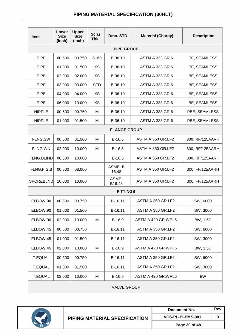
Page 30 of 48
Item
Lower Size
(Inch)
Upper Size
(Inch)
Sch./
Thk. Dmn. STD Material (Charpy) Description
PIPE GROUP
PIPE 00.500 00.750 S160 B-36.10 ASTM A 333 GR.6 PE, SEAMLESS
PIPE 01.000 01.500 XS B-36.10 ASTM A 333 GR.6 PE, SEAMLESS
PIPE 02.000 02.000 XS B-36.10 ASTM A 333 GR.6 BE, SEAMLESS
PIPE 03.000 03.000 STD B-36.10 ASTM A 333 GR.6 BE, SEAMLESS
PIPE 04.000 04.000 XS B-36.10 ASTM A 333 GR.6 BE, SEAMLESS
PIPE 06.000 10.000 XS B-36.10 ASTM A 333 GR.6 BE, SEAMLESS
NIPPLE 00.500 00.750 M B-36.10 ASTM A 333 GR.6 PBE, SEAMLESS
NIPPLE 01.000 01.500 M B-36.10 ASTM A 333 GR.6 PBE, SEAMLESS
FLANGE GROUP
FLNG.SW 00.500 01.500 M B-16.5 ASTM A 350 GR.LF2 300, RF/125AARH
FLNG.WN 02.000 10.000 M B-16.5 ASTM A 350 GR.LF2 300, RF/125AARH
FLNG.BLIND 00.500 10.000 B-16.5 ASTM A 350 GR.LF2 300, RF/125AARH
FLNG.FIG.8 00.500 08.000 ASME- B
16.48 ASTM A 350 GR.LF2 300, FF/125AARH
SPCR&BLND 10.000 10.000 ASME-
B16.48 ASTM A 350 GR.LF2 300, FF/125AARH
FITTINGS
ELBOW.90 00.500 00.750 B-16.11 ASTM A 350 GR.LF2 SW, 6000
ELBOW.90 01.000 01.500 B-16.11 ASTM A 350 GR.LF2 SW, 3000
ELBOW.90 02.000 10.000 M B-16.9 ASTM A 420 GR.WPL6 BW, 1.5D
ELBOW.45 00.500 00.750 B-16.11 ASTM A 350 GR.LF2 SW, 6000
ELBOW.45 01.000 01.500 B-16.11 ASTM A 350 GR.LF2 SW, 3000
ELBOW.45 02.000 10.000 M B-16.9 ASTM A 420 GR.WPL6 BW, 1.5D
T.EQUAL 00.500 00.750 B-16.11 ASTM A 350 GR.LF2 SW, 6000
T.EQUAL 01.000 01.500 B-16.11 ASTM A 350 GR.LF2 SW, 3000
T.EQUAL 02.000 10.000 M B-16.9 ASTM A 420 GR.WPL6 BW
VALVE GROUP

PIPING MATERIAL SPECIFICATION (30HLT)
PIPING MATERIAL SPECIFICATION
Document No. Rev
VCS-PL-PI-PMS-001 3
Page 31 of 48
VLV.GATE 00.500 01.500 API-602
BODY-ASTM A 350
GR.LF2,TRIM-
STELLITED,STEM- SS 304
SW, 600, 3000, B-
16.11
VLV.GLOBE 00.500 01.500 BS EN ISO 15761
BODY-ASTM A 350
GR.LF2,TRIM-
STELLITED,STEM- SS304
SW, 600, 3000, B-
16.11
VLV.CHECK 00.500 01.500 BS EN ISO
15761
BODY-ASTM A 350
GR.LF2,TRIM- STELLITED SW, 600, 3000, B-
16.11
VLV.PLUG 00.500 01.500 BS-5353
BODY-ASTM A 350
GR.LF2,PLUG: A350
GR.LF2 + 0.003" ENP
SW, 600, 3000, B-
16.11
VLV.PLUG 02.000 10.000 API-6D
BODY-ASTM A 352
GR.LCB / A350
GR.LF2,STEM-SS
304/SS316
FLGD, 300, B-
16.5,
RF/125AARH
VLV.PLUG 02.000 10.000 API-6D
BODY-ASTM A 352
GR.LCB/ ASTM
A350GR.LF2,TRIM- SS
304/ SS316
BW, 300, B-16.25
BOLT & GASKET
BOLT.STUD 00.500 10.000 B-18.2 BOLT:A320 GR.L7,
NUT:A194 GR.4
GASKET 00.500 10.000 B-16.20-
ANSI B16.5
SP.WND
METTALIC WITH
GRAPHITEFILLER
SPIRAL, 300

PIPING MATERIAL SPECIFICATION (60HC)
PIPING MATERIAL SPECIFICATION
Document No. Rev
VCS-PL-PI-PMS-001 3
Page 32 of 48
PIPE CLASS : 60HC
RATING : 600
BASE MATERIAL : Carbon Steel
CORROSION ALLOWANCE : 1.5 MM
SPECIAL REQUIREMENT : Non IBR
TEMPERATURE (Deg. C) AND PRESSURE (Kg/Sq. cm g ) RATINGS
TEMP -29 38 93 149 204 260 316 343
PRESS 104.05 104.05 94.91 92.45 89.29 84.36 79.68 75.58
SERVICE
Natural Gas, Utilities (water, inst. air, plant air, nitrogen, carbon dioxide).
NOTES
1. All vents and drains for hydrotest shall be provided with gate valve with blind flange
assembly unless otherwise indicated in P&ID
2. NDT of welds shall be as follows:
Radiography : All butt welds 100%
MPI : Socket welds 100%
3. Piping design as per ASME B 31.8 , OISD 226 & PNGRB Guidelines
4. Charpy V notch test and hardness test shall be conducted for pipes, fittings and flanges
at (-) 29°C.
5. Corrosion allowance of 1.5 mm has been considered for terminal piping.
6. All branch connections including vent, drain, pressure and temperature connection shall
be as per branch connection table.
7. For valves, refer valve data sheets as enclosed.
8. Design factor 0.5
9. Ball Valve to be used in main pipeline shall have butt welded ends.
ITEM SIZE DESCRIPTION
Maintenance Joints all Flanged, to be kept minimum
Pipe joints 1.5" & below SW coupling
2.0" & above Butt welded
Drains on lines <= 1.5" Refer std. SD-PI-019
on lines >= 2.0" As per P&ID or 0.75". Refer std. SD-PI-018
Vents on lines <= 1.5" Refer std. SD-PI-019
on lines >= 2.0" As per P&ID or 0.75". . Refer std. SD-PI-018
Temp. Connection 1.5" Flanged, installation as per std. SD-PI-014 & 015, except
skin temperature measurement.
Press. Connection 0.75" SW nipple with Plug/ Ball Valve to spec. as per Refer std.
SD-PI-011, 012 & 013

PIPING MATERIAL SPECIFICATION (60HC)
PIPING MATERIAL SPECIFICATION
Document No. Rev
VCS-PL-PI-PMS-001 3
Page 33 of 48
BRANCH TABLE
T 42
T T 36
T T T 32
T T T T 30
T T T T T 24
T T T T T T 20
T T T T T T T 18 B
T T T T T T T T 16 R
T T T T T T T T T 14 A
T T T T T T T T T T 12 N
T T T T T T T T T T T 10 C
T T T T T T T W W W W W 8 H
T T T T T T W W W W W W W 6
T T T T W W W W W W W W W W 4 P
T T T W W W W W W W W W W W W 3 I
T T T W W W W W W W W W W W W W 2 P
T T T T S S S S S S S S S S S S S 1.5 E
T T T S S S S S S S S S S S S S S S 1
T T T T S S S S S S S S S S S S S S S 0.75
T T T T S S S S S S S S S S S S S S S S 0.50
0.05 0.75 1 1.5 2 3 4 6 8 10 12 14 16 18 20 24 30 32 36 42
R U N P I P E
CODE DESCRIPTION
T TEES W WELDOLETS S SOCKOLETS

PIPING MATERIAL SPECIFICATION (60HC)
PIPING MATERIAL SPECIFICATION
Document No. Rev
VCS-PL-PI-PMS-001 3
Page 34 of 48
Item
Lower Size
(Inch)
Upper Size
(Inch)
Sch./
Thk. Dmn. STD Material (Charpy) Description
PIPE GROUP
PIPE 00.500 00.750 S160 B-36.10 ASTM A 106 GR.B PE, SEAMLESS
PIPE 01.000 01.500 XS B-36.10 ASTM A 106 GR.B PE, SEAMLESS
PIPE 02.000 02.000 XS B-36.10 ASTM A 106 GR.B
(CHARPY) BE, SEAMLESS
PIPE 03.000 03.000 STD B-36.10 ASTM A 106 GR.B
(CHARPY) BE, SEAMLESS
PIPE 04.000 06.000 XS B-36.10 ASTM A 106 GR.B
(CHARPY) BE, SEAMLESS
PIPE 08.000 08.000 7.9/ 7.1 API 5L API 5L GR.X- 52/60 PSL2,
(CHARPY) BE, SEAMLESS
PIPE 10.000 10.000 8.7/ 7.8 API 5L API 5L GR.X- 52/60 PSL2,
(CHARPY) BE, SEAMLESS
PIPE 12.000 12.000 10.3/ 8.7
API 5L API 5L GR.X- 52/60 PSL2,
(CHARPY) BE, SEAMLESS
PIPE 14.000 14.000 11.1/ 9.5
API 5L API 5L GR.X- 52/60 PSL2,
(CHARPY) BE, SEAMLESS
PIPE 16.000 16.000 12.7/ 11.1
API 5L API 5L GR.X- 52/60 PSL2,
(CHARPY) BE, SAW
PIPE 18.000 18.000 14.3/ 11.9
API 5L API 5L GR.X- 52/60 PSL2,
(CHARPY) BE, SAW
PIPE 20.000 20.000 15.9/
14.3 API 5L
API 5L GR.X- 52/60 PSL2,
(CHARPY) BE, SAW
PIPE 24.000 24.000 17.5/
15.9 API 5L
API 5L GR.X- 52/60 PSL2,
(CHARPY) BE, SAW
NIPPLE 00.500 01.500 M B-36.10 ASTM A 106 GR.B PBE, SEAMLESS
FLANGE GROUP
FLNG.SW 00.500 01.500 M B-16.5 ASTM A 105 600, RF/125AARH
FLNG.WN 02.000 16.000 M B-16.5 ASTM A 105 (CHARPY) 600, RF/125AARH
FLNG.WN 18.000 24.000 M B-16.5 ASTM A 694 GR.F- 52/60
(CHARPY) 600, RF/125AARH
FLNG.WN 26.000 30.000 M B-16.47-A ASTM A 694 GR.F- 52/60
(CHARPY) 600, RF/125AARH
FLNG.BLIND 00.500 01.500 B-16.5 ASTM A 105 600, RF/125AARH
FLNG.BLIND 02.000 24.000 B-16.5 ASTM A 105 (CHARPY) 600, RF/125AARH
FLNG.BLIND 26.000 30.000 B-16.47-A ASTM A 105 (CHARPY) 600, RF/125AARH
FLNG.FIG.8 00.500 01.500 ASME- B
16.48 ASTM A 105 600, FF/125AARH

PIPING MATERIAL SPECIFICATION (60HC)
PIPING MATERIAL SPECIFICATION
Document No. Rev
VCS-PL-PI-PMS-001 3
Page 35 of 48
Item
Lower Size
(Inch)
Upper Size
(Inch)
Sch./
Thk. Dmn. STD Material (Charpy) Description
FLNG.FIG.8 02.000 08.000 ASME- B
16.48 ASTM A 105 (CHARPY) 600, FF/125AARH
SPCR&BLND 10.000 24.000 ASME- B
16.48 ASTM A 105 (CHARPY) 600, FF/125AARH
FITTING GROUP
ELBOW.90 00.500 00.750 B-16.11 ASTM A 105 SW, 6000
ELBOW.90 01.000 01.500 B-16.11 ASTM A 105 SW, 3000
ELBOW.90 02.000 16.000 M B-16.9 ASTM A 234 GR.WPB
(CHARPY) BW, 1.5D
ELBOW.90 18.000 30.000 M MSS-SP75 MSS SP-75 GR.WPHY-52 BW, 1.5D
ELBOW.45 00.500 00.750 B-16.11 ASTM A 105 SW, 6000
ELBOW.45 01.000 01.500 B-16.11 ASTM A 105 SW, 3000
ELBOW.45 02.000 16.000 M B-16.9 ASTM A 234 GR.WPB
(CHARPY) BW, 1.5D
ELBOW.45 18.000 30.000 M MSS-SP75 MSS SP-75 GR.WPHY- 52 BW, 1.5D
T.EQUAL 00.500 00.750 B-16.11 ASTM A 105 SW, 6000
T.EQUAL 01.000 01.500 B-16.11 ASTM A 105 SW, 3000
T.EQUAL 02.000 16.000 M B-16.9 ASTM A 234 GR.WPB
(CHARPY) BW
T.EQUAL 18.000 30.000 M MSS-SP75 MSS SP-75 GR.WPHY-52 BW
T.RED 00.500 00.750 B-16.11 ASTM A 105 SW, 6000
T.RED 01.000 01.500 B-16.11 ASTM A 105 SW, 3000
T.RED 02.000 16.000 M, M B-16.9 ASTM A 234 GR.WPB
(CHARPY) BW
T.RED 18.000 30.000 M, M MSS-SP75 MSS SP-75 GR.WPHY-52 BW
REDUC.
CONC 02.000 16.000 M, M B-16.9
ASTM A 234 GR.WPB
(CHARPY) BW
REDUC.
CONC 18.000 30.000 M, M MSS-SP75 MSS SP-75 GR.WPHY-52 BW
REDUC.
ECC 02.000 16.000 M, M B-16.9
ASTM A 234 GR.WPB
(CHARPY) BW
REDUC.
ECC 18.000 30.000 M, M MSS-SP75 MSS SP-75 GR.WPHY-52 BW
SWAGE.
CONC 00.500 03.000 M, M BS-3799 ASTM A 105 (CHARPY) PBE

PIPING MATERIAL SPECIFICATION (60HC)
PIPING MATERIAL SPECIFICATION
Document No. Rev
VCS-PL-PI-PMS-001 3
Page 36 of 48
Item
Lower Size
(Inch)
Upper Size
(Inch)
Sch./
Thk. Dmn. STD Material (Charpy) Description
SWAGE.
ECC 00.500 03.000 M, M BS-3799 ASTM A 105 (CHARPY) PBE
CAP 00.500 00.750 B-16.11 ASTM A 105 SCRF, 6000
CAP 01.000 01.500 B-16.11 ASTM A 105 SCRF, 3000
CAP 02.000 16.000 M B-16.9 ASTM A 234 GR.WPB
(CHARPY) BW
CAP 18.000 30.000 M MSS-SP75 MSS SP-75 GR.WPHY-52 BW
PLUG 00.500 00.750 B-16.11 ASTM A 105 SCRM, 6000
PLUG 01.000 01.500 B-16.11 ASTM A 105 SCRM, 3000
CPLNG.FULL 00.500 00.750 B-16.11 ASTM A 105 SW, 6000
CPLNG.FULL 01.000 01.500 B-16.11 ASTM A 105 SW, 3000
CPLNG.HALF 00.500 00.750 B-16.11 ASTM A 105 SW, 6000
CPLNG.HALF 01.000 01.500 B-16.11 ASTM A 105 SW, 3000
CPLNG.LH 00.500 00.750 B-16.11 ASTM A 105 SW, 6000
CPLNG.LH 01.000 01.500 B-16.11 ASTM A 105 SW, 3000
CPLNG.RED 00.500 00.750 B-16.11 ASTM A 105 SW, 6000
CPLNG.RED 01.000 01.500 B-16.11 ASTM A 105 SW, 3000
O'let
SOCKOLET 00.500 00.750 MSS-SP97 ASTM A 105 SW, 6000
SOCKOLET 01.000 01.500 MSS-SP97 ASTM A 105 SW, 3000
WELDOLET 02.000 08.000 M,
XXS MSS-SP97 ASTM A 105 (CHARPY) BW
VALVE GROUP
VLV.GATE 00.500 01.500 API-602
BODY-ASTM A 105,TRIM-
STELLITED,STEM- 13%
CR.STEEL
SW, 800, 3000,
B-16.11
VLV.GLOBE 00.500 01.500 BS EN 1SO
15761
BODY-ASTM A 105,TRIM-
STELLITED,STEM- 13%
CR STEEL
SW, 800, 3000,
B-16.11
VLV.GLOBE 02.000 12.000 BS 1873
BODY-ASTM A 216
GR.WCB, TRIM-
13% CR.STEEL
FLGD, 600, B-16.5,
RF/125AARH
VLV.CHECK 00.500 01.500 BS EN 1SO
15761
BODY-ASTM A 105,
TRIM- STELLITED
SW, 800, 3000,
B-16.11

PIPING MATERIAL SPECIFICATION (60HC)
PIPING MATERIAL SPECIFICATION
Document No. Rev
VCS-PL-PI-PMS-001 3
Page 37 of 48
Item
Lower Size
(Inch)
Upper Size
(Inch)
Sch./
Thk. Dmn. STD Material (Charpy) Description
VLV.BALL 00.500 01.500 BS EN 1SO
17292
BODY-ASTM A 105,
TRIM-BODY SEAT -
RPTFE
SW, 600,
B-16.5,
RF/125AARH
VLV.BALL 02.000 24.000 API-6D
BODY-ASTM A 216
GR.WCC/A234
GR.WPC,TRIM:SEAT:
AISI4140+0.003
"ENP/AISI410
FLGD, 600,
B-16.5,
RF/125AARH
VLV.BALL 26.000 30.000 API-6D
BODY-ASTM A 216
GR.WCC/A234 GR.
WPC,TRIM: SEAT:
AISI4140 + 0.003"ENP/ AISI 410
FLGD, 600,
B-16.47 A,
RF/125AARH
VLV.BALL 02.000 30.000 M API-6D
BODY-ASTM A 216
GR.WCC/A234 GR.
WPC,TRIM: SEAT : AISI
4140+0.003"ENP/AISI 410
BW, 600, B-16.25
VLV.PLUG 00.500 01.500 BS-5353 BODY-ASTM A 105,PLUG-
A105 +0.003" ENP
SW, 800, 3000,
B-16.11
VLV.PLUG 02.000 24.000 API-6D
BODY- A 216GR.
WCB,PLUG: A216
GR.WCB + 0.003" ENP
FLGD, 600,
B-16.5,
RF/125AARH
VLV.PLUG 02.000 02.000 M API-6D
BODY-ASTM A 216
GR.WCB,PLUG: A216
GR.WCB + 0.003"ENP
BW, 600, B-16.25
BOLT GROUP
BOLT.STUD 00.500 30.000 B-18.2 BOLT:A193 GR.B7,
NUT:A194 GR.2H
GASKET
GASKET 00.500 24.000 B-16.20-
ANSI B16.5
SP.WND
METTALIC WITH GRAPHITEFILLER
SPIRAL, 600
GASKET 26.000 30.000 B-16.20-
ANSI
B16.47A
SP.WND
METTALIC WITH GRAPHITEFILLER
SPIRAL, 600

PIPING MATERIAL SPECIFICATION (60HLT)
PIPING MATERIAL SPECIFICATION
Document No. Rev
VCS-PL-PI-PMS-001 3
Page 38 of 48
PIPE CLASS : 60HLT
RATING : 600
BASE MATERIAL : Carbon Steel
CORROSION ALLOWANCE : 1.5 MM
SPECIAL REQUIREMENT : Low Temperature Services
TEMPERATURE (Deg. C) AND PRESSURE (Kg/Sq. cm g ) RATINGS
TEMP -45 38 93 120
PRESS 98.07 98.07 92.79 91.27
SERVICE
Natural Gas, Utilities (water, inst. air, plant air, nitrogen, carbon dioxide)
NOTES
1. All vents and drains for hydro test shall be provided with gate valve with blind flange
assembly unless otherwise indicated in P&ID
2. NDT of welds shall be as follows:
Radiography : All butt welds 100%
MPI : Socket welds 100%
3. Piping design as per ASME B 31.8 , OISD 226 & PNGRB Guidelines
4. Charpy V notch test and hardness test shall be conducted for pipes, fittings and flanges
at (-) 45°C.
5. Corrosion allowance of 1.5 mm has been considered for terminal piping.
6. All branch connections including vent, drain, pressure and temperature connection shall
be as per branch connection table.
7. For valves, refer valve data sheets as enclosed.
8. Design factor 0.5
9. Ball Valve to be used in main pipeline shall have butt welded ends.
ITEM SIZE DESCRIPTION
Maintenance Joints all Flanged, to be kept minimum
Pipe joints 1.5" & below SW coupling
2.0" & above Butt welded
Drains on lines <= 1.5" Refer std. SD-PI-019
on lines >= 2.0" As per P&ID or 0.75". Refer std. SD-PI-018
Vents on lines <= 1.5" Refer std. SD-PI-019
on lines >= 2.0" As per P&ID or 0.75". . Refer std. SD-PI-018
Temp. Connection 1.5" Flanged, installation as per std. SD-PI-014 & 015, except
skin temperature measurement.
Press. Connection 0.75" SW nipple with Plug/ Ball Valve to spec. as per Refer std.
SD-PI-011, 012 & 013

PIPING MATERIAL SPECIFICATION (60HLT)
PIPING MATERIAL SPECIFICATION
Document No. Rev
VCS-PL-PI-PMS-001 3
Page 39 of 48
BRANCH TABLE
T
6
BR
AN
CH
PIP
E
T T
4
T T T
3
T T T W
2
T T T T S
1.5
T T T S S S
1
T T T T S S S
0.75
T T T T S S S S 0.50
0.05 0.75 1 1.5 2 3 4 6
RUN PIPE
CODE DESCRIPTION
T TEES W WELDOLETS S SOCKOLETS

PIPING MATERIAL SPECIFICATION (60HLT)
PIPING MATERIAL SPECIFICATION
Document No. Rev
VCS-PL-PI-PMS-001 3
Page 40 of 48
Item
Lower Size
(Inch)
Upper Size
(Inch)
Sch./
Thk. Dmn. STD Material (Charpy) Description
PIPE GROUP
PIPE 00.500 00.750 S160 B-36.10 ASTM A 333 GR.6 PE, SEAMLESS
PIPE 01.000 01.500 XS B-36.10 ASTM A 333 GR.6 PE, SEAMLESS
PIPE 02.000 06.000 XS B-36.10 ASTM A 333 GR.6 BE, SEAMLESS
NIPPLE 00.500 01.500 M B-36.10 ASTM A 333 GR.6 PBE, SEAMLESS
FLANGE GROUP
FLNG.SW 00.500 01.500 M B-16.5 ASTM A 350 GR.LF2 600, RF/125AARH
FLNG.WN 02.000 06.000 M B-16.5 ASTM A 350 GR.LF2 600, RF/125AARH
FLNG.BLIND 00.500 06.000 B-16.5 ASTM A 350 GR.LF2 600, RF/125AARH
FLNG.FIG.8 00.500 06.000 ASME- B
16.48 ASTM A 350 GR.LF2 600, FF/125AARH
FITTING GROUP
ELBOW.90 00.500 00.75 B-16.11 ASTM A 350
GR.LF2 SW, 6000
ELBOW.90 01.000 01.500 B-16.11 ASTM A 350
GR.LF2 SW, 3000
ELBOW.90 02.000 6.000 M B-16.9 ASTM A 420
GR.WPL6 BW, 1.5D
ELBOW.45 00.500 00.75 B-16.11 ASTM A 350
GR.LF2 SW, 6000
ELBOW.45 01.000 01.500 B-16.11 ASTM A 350
GR.LF2 SW, 3000
ELBOW.45 02.000 6.000 M B-16.9 ASTM A 420
GR.WPL6 BW, 1.5D
T.EQUAL 00.500 00.75 B-16.11 ASTM A 350
GR.LF2 SW, 6000
T.EQUAL 01.000 01.500 B-16.11 ASTM A 350
GR.LF2 SW, 3000
T.EQUAL 02.000 6.000 M B-16.9 ASTM A 420
GR.WPL6 BW
T.RED 00.500 00.75 B-16.11 ASTM A 350
GR.LF2 SW, 6000
T.RED 01.000 01.500 B-16.11 ASTM A 350
GR.LF2 SW, 3000

PIPING MATERIAL SPECIFICATION (60HLT)
PIPING MATERIAL SPECIFICATION
Document No. Rev
VCS-PL-PI-PMS-001 3
Page 41 of 48
Item
Lower Size
(Inch)
Upper Size
(Inch)
Sch./
Thk. Dmn. STD Material (Charpy) Description
T.RED 02.000 6.000 M, M B-16.9 ASTM A 420
GR.WPL6 BW
REDUC. CONC
02.000 6.000 M, M B-16.9 ASTM A 420
GR.WPL6
BW
REDUC. ECC
02.000 6.000 M, M B-16.9 ASTM A 420
GR.WPL6
BW
SWAGE. CONC
00.500 03.000 M, M BS-3799 ASTM A 350
GR.LF2
PBE
SWAGE.ECC 00.500 03.000 M, M BS-3799 ASTM A 350
GR.LF2
PBE
CAP 00.500 01.500 B-16.11 ASTM A 350
GR.LF2
SCRF, 3000
CAP 02.000 6.000 M B-16.9 ASTM A 420
GR.WPL6
BW
PLUG 00.500 01.500 B-16.11 ASTM A 350
GR.LF2
SCRM, 3000
COUPLING
FULL 00.500 00.75 B-16.11 ASTM A 350
GR.LF2 SW, 6000
COUPLING
FULL 01.000 01.500 B-16.11
ASTM A 350
GR.LF2 SW, 3000
COUPLING
FULL 00.500 01.500 B-16.11
ASTM A 350
GR.LF2 SCRF, 3000
COUPLING
HALF 00.500 00.75 B-16.11
ASTM A 350
GR.LF2 SW, 6000
COUPLING
HALF 01.000 01.500 B-16.11
ASTM A 350
GR.LF2 SW, 3000
COUPLING
HALF 00.500 01.500 B-16.11
ASTM A 350
GR.LF2 SCRF, 3000
O'let
WELDOLET 02.000 04.000 M, XXS MSS-SP97 ASTM A 350
GR.LF2 BW
SOCKOLET 00.500 00.750 MSS-SP97 ASTM A 350
GR.LF2 SW, 6000
SOCKOLET 01.000 01.500 MSS-SP97 ASTM A 350
GR.LF2
SW, 3000

PIPING MATERIAL SPECIFICATION (60HLT)
PIPING MATERIAL SPECIFICATION
Document No. Rev
VCS-PL-PI-PMS-001 3
Page 42 of 48
Item
Lower Size
(Inch)
Upper Size
(Inch)
Sch./
Thk. Dmn. STD Material (Charpy) Description
VALVE GROUP
VLV.GATE 00.50 01.500 API 602
BODY-ASTM A 350
GR.LF2,TRIMSTELLITED,
STEM-SS 304
SW, 800, 3000,
B-16.11
VLV.GLOBE 00.50 01.500 BS EN 1SO
15761
BODY-ASTM A 350
GR.LF2,TRIMSTELLITED,
STEM-SS304
SW, 800, 3000,
B-16.11
VLV.CHECK 00.50 01.500 BS EN 1SO
15761
BODY-ASTM A 350
GR.LF2,TRIM-STELLITED
SW, 800, 3000,
B-16.11
VLV.BALL 00.500 01.500 BS EN 1SO
17292
BODY-ASTM A352
GR.LCB / ASTM
A350 GR.LF2
CL.1,TRIM-BODY
SEAT-RPTFE
SW, 800, 3000,
B-16.11
VLV.BALL 02.000 6.000 API-6D
BODY-ASTM A 352
GR.LCB / A
350GR.LF2,TRIM:
SEAT: SS 304, SS316
FLGD, 600,
B-16.5, RF/125AARH
VLV.BALL 02.000 6.000 API-6D
BODY-ASTM A 352
GR.LCB / A
350GR.LF2,TRIM:
SEAT: SS 304, SS316
BW, 600,
B-16.25
VLV.PLUG 00.500 01.500 BS-5353
BODY-ASTM A 350
GR.LF2,PLUG:
A350 GR.LF2 +
0.003" ENP
SW, 800, 3000,
B-16.11
VLV.PLUG 02.000 06.000 API-6D
BODY-ASTM A 352
GR.LCB / A350
GR.LF2,STEM-SS
304/SS316
FLGD, 600,
B-16.5,
RF/125AARH
VLV.PLUG 02.000 06.000 M API-6D
BODY-ASTM A 352
GR.LCB / A350
GR.LF2,STEM-SS
304/SS316
BW, 600, B-16.25

PIPING MATERIAL SPECIFICATION (60HLT)
PIPING MATERIAL SPECIFICATION
Document No. Rev
VCS-PL-PI-PMS-001 3
Page 43 of 48
Item
Lower Size
(Inch)
Upper Size
(Inch)
Sch./
Thk. Dmn. STD Material (Charpy) Description
BOLT GROUP
BOLT.STUD 00.500 06.000 B-18.2 BOLT:A320 GR.L7,
NUT:A194 GR.4
GASKET
GASKET 00.500 6.000 B-16.20-
ANSI B16.5
SP.WND SS316+
GRAFOIL SPIRAL, 600

PIPING MATERIAL SPECIFICATION (15FW)
PIPING MATERIAL SPECIFICATION
Document No. Rev
VCS-PL-PI-PMS-001 3
Page 44 of 48
PIPE CLASS 15FW RATING 150 BASE MATERIAL CARBON STEEL CORROSION ALLOWANCE 1.5 MM SPECIAL REQUIREMENT NON IBR
TEMPERATURE (Deg. C) AND PRESSURE (Kg/Sq. cm g) RATINGS
TEMP 0 38 50 65
PRESS 18.9 18.9 18.9 18.9
SERVICE: FIRE WATER (ABOVE GROUND / UNDER GROUND)
NOTES 1.0 All vents and drains shall be provided with gate valve with blind flange assembly unless
otherwise indicated in P&ID. 2.0 Forgings are acceptable in Lieu of Plate material. 3.0 Sizes given in PMS are nominal bore for O.D. of IS 3589 pipes refer ANSI B36.10. 4.0 Butterfly Valves shall be lugged wafer type up to 24" and double flanged body for sizes
beyond 24". 5.0 Pipe thicknesses are job specific based on the soil properties of job site and depth of top
of pipe of 1.5m. No live load has been considered for calculation of pipe thickness. Live loads wherever expected shall be suitably taken care of.
6.0 NDT of welds shall be as follows: Radiography : All Butt welds 10% MPI : Socket welds 10%
SPECIAL NOTES
ITEM SIZE DESCRIPTION A.CODE
MAINTENANCE JOINTS
ALL FLANGED, TO BE KEPT MINIMUM
PIPE JOINTS 1.5" & BELOW SW COUPLING
2.0" & ABOVE BUTT WELDED
DRAINS ON LINES <= 1.5" Refer std. SD-PI-019
ON LINES >= 2.0" As per P&ID or 0.75". Refer std. SD-PI-018
VENTS ON LINES <= 1.5" Refer std. SD-PI-019
ON LINES >= 2.0" As per P&ID or 0.75". Refer std. SD-PI-018
TEMP.CONN 1.5" Flanged, installation as per std. SD-PI-014 & 015, except skin temperature measurement.
PRESS.CONN 0.75" SW nipple with Plug/ Ball Valve to spec. as per Refer std.SD-PI-011, 012 & 013

PIPING MATERIAL SPECIFICATION (15FW)
PIPING MATERIAL SPECIFICATION
Document No. Rev
VCS-PL-PI-PMS-001 3
Page 45 of 48
CODE DESCRIPTION
F SADDLE FUSED JT T TEES H H. COUPLING W WELDOLETS P PIPE TO PIPE I INSTRUMENT TEE R REINFORCED X Refer Notes S SOCKOLETS L SWEEPOLET
BRANCH TABLE
B
R
T
14
A
T R
12
N
T R R
10
C
T R R R
8
H
T P R R R
6
T R P R R R
4
P
T P R P R R R
3
I
T P P R P R R R
2
P
T T H H H H H H H
1.5
E
T T H H H H H H H H
1
T T T H H H H H H H H
0.75
T T T T H H H H H H H H
0.50
0.05 0.75 1 1.5 2 3 4 6 8 10 12 14
R U N
P I P E

PIPING MATERIAL SPECIFICATION (15FW)
PIPING MATERIAL SPECIFICATION
Document No. Rev
VCS-PL-PI-PMS-001 3
Page 46 of 48
Item Type
Lower Size
(Inch)
Upper Size
(Inch)
Sch/ Thk
Dmn. STD Material Description
Pipe Group
PIPE 00.500 01.500 HVY IS-1239-I IS-1239 (BLACK) PE, C.WELDED
PIPE 02.000 06.000 HVY IS-1239-I IS-1239 (BLACK) BE, C.WELDED
PIPE 08.000 12.000 6.0 IS-3589 IS-3589 GR.410 BE, WELDED
PIPE 14.000 14.000 8.0 IS-3589 IS-3589 GR.410 BE, WELDED
NIPPLE 00.500 01.500 HVY VCS 'STD IS-1239 (BLACK) PBE, C.WELDED
Flange Group
FLNG.SW 00.500 01.500 M B-16.5 ASTM A 105 150, RF/125AARH
FLNG.SO 02.000 14.000 B-16.5 ASTM A 105 150, RF/125AARH
FLNG.BLIND 00.500 14.000 B-16.5 ASTM A 105 150, RF/125AARH
FLNG.FIG.8 00.500 08.000 ASME- B16.48 ASTM A 105 150, FF/125AARH
SPCR&BLND 10.000 14.000 ASME- B16.48 ASTM A 105 150, FF/125AARH
Fitting Group
ELBOW.90 00.500 01.500 B-16.11 ASTM A 105 SW, 3000
ELBOW.90 02.000 06.000 STD B-16.9 ASTM A 234
GR.WPB BW, 1.5D
ELBOW.90 08.000 14.000 M B-16.9 ASTM A 234 GR.WPB-W
BW, 1.5D
ELBOW.45 00.500 01.500 B-16.11 ASTM A 105 SW, 3000
ELBOW.45 02.000 06.000 STD B-16.9 ASTM A 234
GR.WPB BW, 1.5D
ELBOW.45 08.000 14.000 M B-16.9 ASTM A 234 GR.WPB-W
BW, 1.5D
T.EQUAL 00.500 01.500 B-16.11 ASTM A 105 SW, 3000
T.EQUAL 02.000 06.000 STD B-16.9 ASTM A 234
GR.WPB BW
T.EQUAL 08.000 14.000 M B-16.9 ASTM A 234 GR.WPB-W
BW
T.RED 00.500 01.500 B-16.11 ASTM A 105 SW, 3000
T.RED 02.000 06.000 STD, STD
B-16.9 ASTM A 234
GR.WPB BW
T.RED 08.000 14.000 M, M B-16.9 ASTM A 234 GR.WPB-W
BW

PIPING MATERIAL SPECIFICATION (15FW)
PIPING MATERIAL SPECIFICATION
Document No. Rev
VCS-PL-PI-PMS-001 3
Page 47 of 48
Item Type
Lower Size
(Inch)
Upper Size
(Inch)
Sch/ Thk
Dmn. STD Material Description
Fitting Group
REDUC.CONC 02.000 06.000 STD, STD
B-16.9 ASTM A 234 GR.WPB BW
REDUC.CONC 08.000 14.000 M, M B-16.9 ASTM A 234 GR.WPB-W BW
REDUC.ECC 02.000 06.000 STD, STD
B-16.9 ASTM A 234GR.WPB BW
REDUC.ECC 08.000 14.000 M, M B-16.9 ASTM A 234 GR.WPB-W BW
SWAGE.CONC 00.500 03.000 M, M BS-3799 ASTM A 105 PBE
SWAGE.ECC 00.500 03.000 M, M BS-3799 ASTM A 105 PBE
CAP 00.500 01.500 B-16.11 ASTM A 105 SCRF, 3000
CAP 02.000 06.000 STD B-16.9 ASTM A 234 GR.WPB BW
CAP 08.000 14.000 M B-16.9 ASTM A 234 GR.WPB BW
CPLNG.FULL 00.500 01.500 B-16.11 ASTM A 105 SW, 3000
CPLNG.HALF 00.500 01.500 B-16.11 ASTM A 105 SW, 3000
CPLNG.LH 00.500 01.500 B-16.11 ASTM A 105 SW, 3000
CPLNG.RED 00.500 01.500 B-16.11 ASTM A 105 SW, 3000
SOCKOLET 00.500 01.500 MSS-SP97 ASTM A 105 SW, 3000
UNION 00.500 01.500 BS-3799 ASTM A 105 SW, 3000
Valves Group
VLV.GATE 00.500 01.500 API-602 BODY-ASTM A 105,TRIM-
STELLITED,STEM-13%CR.STEEL
SW, 800, 3000, B-16.11.
VLV.GATE 02.000 24.000 API-600 BODY-ASTM A 216
GR.WCB,TRIM- 13% CR.STEEL
FLGD, 150, B-16.5, RF/125AARH.
VLV.GLOBE 00.500 01.500 BS-5352 BODY-ASTM A
105,TRIM- STELLITED,STEM-
13%CR STEEL
SW, 800, 3000, B-16.11.
VLV.GLOBE 02.000 16.000 BS-1873 BODY-ASTM A 216
GR.WCB,TRIM- 13% CR.STEEL
FLGD, 150, B-16.5, RF/125AARH.
VLV.CHECK 00.500 01.500 BS-5352 BODY-ASTM A
105,TRIM- STELLITED SW, 800, 3000, B-
16.11.
VLV.CHECK 02.000 24.000 BS 1868 BODY-ASTM A 216
GR.WCB,TRIM- 13% CR.STEEL
FLGD, 150, B-16.5, RF/125AARH.
PIPING MATERIAL SPECIFICATION (15FW)
PIPING MATERIAL SPECIFICATION
Document No. Rev
VCS-PL-PI-PMS-001 3
Page 48 of 48
Item Type
Lower Size
(Inch)
Upper Size
(Inch) Sch/ Thk Dmn. STD Material Description
Valves Group
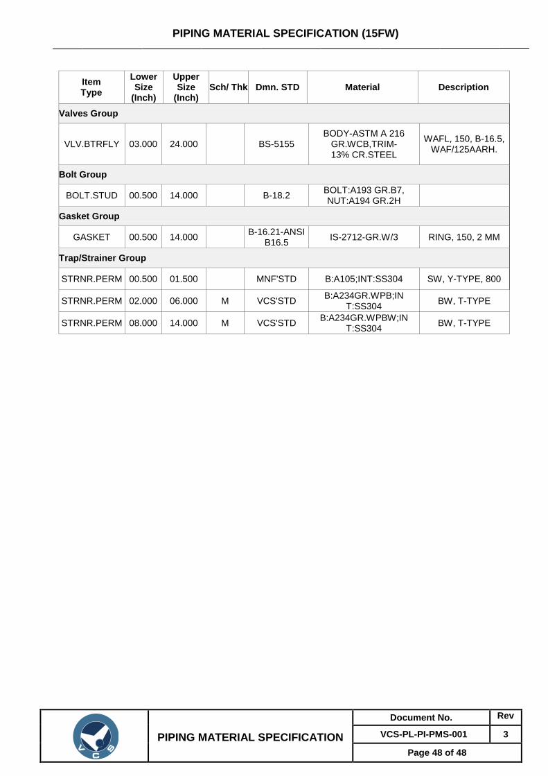
VLV.BTRFLY 03.000 24.000 BS-5155 BODY-ASTM A 216
GR.WCB,TRIM- 13% CR.STEEL
WAFL, 150, B-16.5, WAF/125AARH.
Bolt Group
BOLT.STUD 00.500 14.000 B-18.2 BOLT:A193 GR.B7, NUT:A194 GR.2H
Gasket Group
GASKET 00.500 14.000 B-16.21-ANSI
B16.5 IS-2712-GR.W/3 RING, 150, 2 MM
Trap/Strainer Group
STRNR.PERM 00.500 01.500 MNF'STD B:A105;INT:SS304 SW, Y-TYPE, 800
STRNR.PERM 02.000 06.000 M VCS'STD B:A234GR.WPB;IN
T:SS304 BW, T-TYPE
STRNR.PERM 08.000 14.000 M VCS'STD B:A234GR.WPBW;IN
T:SS304 BW, T-TYPE
Copyright © 2022 FDOKUMEN

