


Bahasa
Halaman
Hukum


ARTICLE IN PRESS
0143-8166/$ - se
doi:10.1016/j.op
�CorrespondE-mail addr
Optics and Lasers in Engineering 46 (2008) 117–123
www.elsevier.com/locate/optlaseng
Optical image encryption using fractional Fourier transform and chaos
Narendra Singh, Aloka Sinha�
Department of Physics, Indian Institute of Technology Delhi, Hauz Khas, New Delhi 110016, India
Received 26 June 2007; received in revised form 3 September 2007; accepted 7 September 2007
Available online 24 October 2007
Abstract
We propose a new method for image encryption using fractional Fourier transform and chaos theory. Random phase masks are
generated using iterative chaos functions. The input image is combined with the first random phase mask at the object plane and is then
transformed using the fractional Fourier transform. After the first fractional Fourier transform, the second random phase mask, again
generated by using the chaos functions, is used at the fractional plane. The second fractional Fourier transform operation is then carried
out to obtain the encrypted image. Three types of chaos functions have been used: the logistic map, the tent map and the Kaplan–Yorke
map. The mean square error and the signal-to-noise ratio between the decrypted image and the input image for the correct order and the
incorrect order of the fractional Fourier transform have been calculated. The computer simulations are presented to verify the validity of
the proposed technique.
r 2007 Published by Elsevier Ltd.
Keywords: Image encryption/decryption; Fractional Fourier transform; Logistic map; Tent map; Kaplan–Yorke map; Mean square error/signal-to-noise
ratio
1. Introduction
Information security is one of the important issues in thepresent information age where there is a phenomenalincrease in the rate at which information is beingdisseminated. Image security is an important part ofinformation security for applications in engineering,industrial and medical processes. Optical encryptionmethods play a very important role in image securitysystems. In real time applications, fast computing andparallelism of optics are very useful. There are severalparameters in optics such as wavelength, phase, polariza-tion, etc. by which information can be hidden more securely[1]. A number of optical image encryption systems havebeen proposed. Double random phase encoding methodusing Fourier transform was proposed by Refregier andJavidi [2] in which the primary image is encrypted tostationary white noise. In this method, two random phasemasks are used in the input and the Fourier plane. Phase ofthese random phase masks are uniformly distributed in the
e front matter r 2007 Published by Elsevier Ltd.
tlaseng.2007.09.001
ing author. Tel.: +9111 2659 6003.
ess: [email protected] (A. Sinha).
interval [0, 2p]. A double random phase optical encryptionsystem that uses a binary key code has also been proposed[3]. Recently, the vulnerability of the double random phaseencoding method against chosen-ciphertext attacks hasbeen demonstrated [4]. Simulated annealing based heuristicalgorithm has also been used to decrypt the image with lowerror [5]. An image encryption method based on stochasticgeometric moire has been recently proposed [6]. A novelmethod of multiple image encryption and watermarkingbased on the idea of double phase encoding and wave fieldsuperposition has been proposed [7]. A method formultiplexing of encrypted data by using polarized lighthas also been proposed. The encryption process is based ondouble random pure-phase enciphering method [8].A lensless optical security system based on computergenerated phase only mask has been proposed in whichthe masks are located at determined positions alongthe direction of propagation so as to decrypt the targetimage [9]. Optical image encryption techniques havebeen proposed using fractional Fourier transform (FRT)[10–16]. Lohmann and co-workers [17,18] defined the FRTusing the Wigner distribution function. General opticalimplementations of FRT have also been proposed [19].

ARTICLE IN PRESS
Fig. 1. Encryption process using chaos function.
N. Singh, A. Sinha / Optics and Lasers in Engineering 46 (2008) 117–123118
Garcia et al. [20] proposed the method for calculation ofthe FRT using the fast Fourier transform algorithm.Optical encryption technique using cascaded extendedFRT has also been proposed [21]. Recently, chaos basedencryption methods have been proposed [22,23]. Suzukiand Imai [24] have proposed a chaos based securecommunication system using optical resonators. Chaosfunctions are extremely sensitive to their initial conditions[25–27] In optical image encryption techniques, the imageis encrypted using random phase masks and the wholerandom phase mask has to be sent to the receiver side todecrypt the original image. Thus, the security of the data inthese methods becomes less. In this paper, we propose anew method for image encryption using FRT and chaos.The image to be encrypted is FRT two times and therandom phase masks generated using chaos functions areplaced in the intermediate planes. Three chaos functionshave been used to generate the chaotic random phasemasks (CRPM). These functions are logistic map, tent mapand Kaplan–Yorke map. The comparison of the meansquare errors (MSE) and signal-to-noise ratio (SNR)between the decrypted image and the input image forcorrect order of FRT and incorrect order of FRT usingthese chaos functions have been done.
2. The fractional Fourier transform
The FRT is a generalization of the ordinary Fouriertransform. For a transformable function f(x), the FRT oforder p is defined as [11,18]:
f pðxpÞ ¼ F pff ðxÞgðxpÞ ¼
Z þ1�1
f ðxÞKpðx; xpÞdx, (1)
The kernel is given by
Kpðx;xpÞ ¼exp½�iðpf=4� f=2Þ�ffiffiffiffiffiffiffiffiffiffiffiffiffiffiffi
j sin jjp exp½ipðx2 cot f
� 2xxp cscfþ x2p cot fÞ�; 0ojpjo2,
¼ dðx� xpÞ; p ¼ 0,
¼ dðxþ xpÞ; p ¼ �2. ð2Þ
where f=p(p/2), f ¼ sgnðsin fÞ. p is the order of the FRT.Fp expresses the FRT of order ‘p’, x and xp are thecoordinates in the input domain and output pth fractionaldomain, respectively. For p=1, the FRT is equivalent tothe ordinary Fourier transform. The fourth order of theFRT is equivalent to the original function. The FRT is alinear transform. The FRT is additive in indices, i.e.Fp1fFp2ff ðxÞgg ¼ F p1þp2
ff ðxÞg.
3. Chaos functions
Chaos functions have been used mainly to develop themathematical models of non-linear systems. There areseveral interesting properties of the chaos functions [25].These functions generate iterative values which are
completely random in nature but limited between bounds.Convergence of the iterative values after any value ofiterations can never be seen. Chaos functions have extremesensitivity to the initial conditions. Three chaos functionshave been used for our study. The first chaos function usedfor our study is the logistic map [25–27] and is defined as:
f ðxÞ ¼ p � x � ð1� xÞ. (3)
This function is bounded for 0opo4 and can be written inthe iterative form as:
xnþ1 ¼ p � xn � ð1� xnÞ. (4)
with ‘x0’ as the initial value. This is also known as the seedvalue for the chaos function. The second chaos functionused for our study is the tent map [25–27] and is defined as:
f ðxÞ ¼ a � x for 0pxp0:5, (5)
f ðxÞ ¼ að1� xÞ for 0:5pxp1. (6)
This function is bounded for 0oap2 and can be written inthe iterative form as:
xnþ1 ¼ a � xn for 0px0p0:5, (7)
xnþ1 ¼ að1� xnÞ for 0:5px0p1, (8)
with ‘x0’ as the initial value. The third chaos function usedfor our study is the Kaplan–Yorke map [25–27] and isdefined as:
f ðxÞ ¼ a � x �mod 1, (9)
f ðyÞ ¼ byþ cosð4pxÞ. (10)
This is bounded for 0pap2 and 0pbp1 and can bewritten in the iterative form as:
xnþ1 ¼ a � xn �mod 1, (11)
ynþ1 ¼ byn þ cosð4pxnÞ, (12)
with ‘x0’ as the initial value. These chaos functions are usedto generate random phase masks. Logistic map and tentmap are one-dimensional chaos functions and the Kaplan–Yorke map is a two-dimensional chaos function. For thetwo-dimensional chaos function, two seed values arerequired to generate the CRPM.
4. Proposed technique
The proposed encryption and decryption technique isbased on the FRT and chaos. The proposed encryptionand decryption processes are shown in Figs. 1 and 2,

ARTICLE IN PRESSN. Singh, A. Sinha / Optics and Lasers in Engineering 46 (2008) 117–123 119
respectively. The FRT is performed two times and therandom phase masks generated by using the chaosfunctions are introduced at the intermediate planes. Letf(x) denotes the original image to be encrypted. Althoughthe images are two-dimensional, we follow a one-dimen-sional representation for convenience. The input image ismultiplied by the first CRPM represented by the phasefunction exp[ipC1(x)], where C1(x) is the random numbersequence generated by the chaos function. The first FRToperation of order p1 is performed over this to give us:
Fp1ff ðxÞ exp½ipC1ðxÞ�g, (13)
where ‘p1’ is the fractional order of the first FRT. Thisdistribution is encoded by the second CRPM which ismathematically expressed as the phase function of thesecond CRPM exp[ipC2(x2)] together, where C2(x2) is thesecond chaotic function obtained by using a different seedvalue. Then it goes into the second FRT operation. Thedistribution at the output plane is given by
gðxÞ ¼ Fp2fF p1ff ðxÞ exp½ipC1ðxÞ�g exp½ipC2ðxÞ�g, (14)
where ‘p2’ is the fractional order of the second FRToperation. The decryption process is the inverse of theencryption process. The first inverse FRT (FRT of order�p2) operation is performed over g(x) and then multipliedby the conjugate of the second CRPM. On the outputobtained, the second inverse FRT (FRT of order �p1) isperformed over it and then multiplied by the conjugateof the first CRPM. The decrypted image is then obtained.
Fig. 2. Decryption process using chaos function.
Fig. 3. Proposed optical implement
The decryption process is expressed as:
f ðxÞ ¼ F�p1fF�p2fgðxÞg exp½�ipC2ðxÞ�g exp½�ipC1ðxÞ�.
(15)
The proposed encryption technique can be opticallyimplemented by using the single-lens Lohmann’s config-uration for optical implementation of FRT [17]. Theoptical implementation of the encryption and the decryp-tion technique are shown in Figs. 3 and 4, respectively.Spatial light modulators (SLM1 and SLM2) are located inthe input plane and the fractional Fourier plane, respec-tively. In the encryption process, the original image isdisplayed along with the first CRPM using SLM1 in theencryption process. The second CRPM is displayed usingSLM2. The CCD camera is placed at the output plane torecord the encrypted image. The decryption configurationis the reverse of the encryption configuration. Theencrypted image is taken as input image and the conjugateof the second CRPM and the first CRPM are displayed onSLM1 and SLM2, respectively. The retrieved image isdirectly detected by the CCD camera.
5. Results and discussions
Numerical simulations have been performed on aMatlab platform to verify the validity of the proposed
ation of the encryption process.
Fig. 4. Proposed optical implementation of the decryption process.

ARTICLE IN PRESSN. Singh, A. Sinha / Optics and Lasers in Engineering 46 (2008) 117–123120
technique. The original image is the picture of Lena of100� 100 pixels as shown in Fig. 5. Three chaos functionshave been used to generate the CRPM. These functions arelogistic map, tent map and Kaplan–Yorke map. Eachchaos function is used to generate two CRPM’s withdifferent seed values. The two CRPM’s using logistic map,are generated by using Eq. (4) with the seed valuesx ¼ 0.241 for the first CRPM and x ¼ 0.341 for the secondCRPM and are shown in Fig. 6(a) and (b), respectively.The two CRPM’s using the tent map are generated using
Fig. 5. The input image.
Fig. 6. The CRPM (a) for x ¼ 0.241 using logistic function, (b) for x ¼ 0.341
tent map, (e) for x ¼ 0.2, y ¼ 0.3 using Kaplan–Yorke map and (f) for x ¼ 0
Eq. (8) with the seed values x ¼ 0.61 for the first CRPMand x ¼ 0.62 for the second CRPM and are shown inFig. 6(c) and (d), respectively. The two CRPM’s usingKaplan–Yorke map are generated using Eqs. (11) and (12)with the seed values x=0.2 and y=0.3 for the first CRPMand x=0.2005 and y=0.3005 for the second CRPM andare shown in Fig. 6(e) and (f), respectively. Kaplan–Yorkemap is a two-dimensional chaos function. Hence, it needstwo seed values for each CRPM.The fractional orders of FRT for the first FRT system
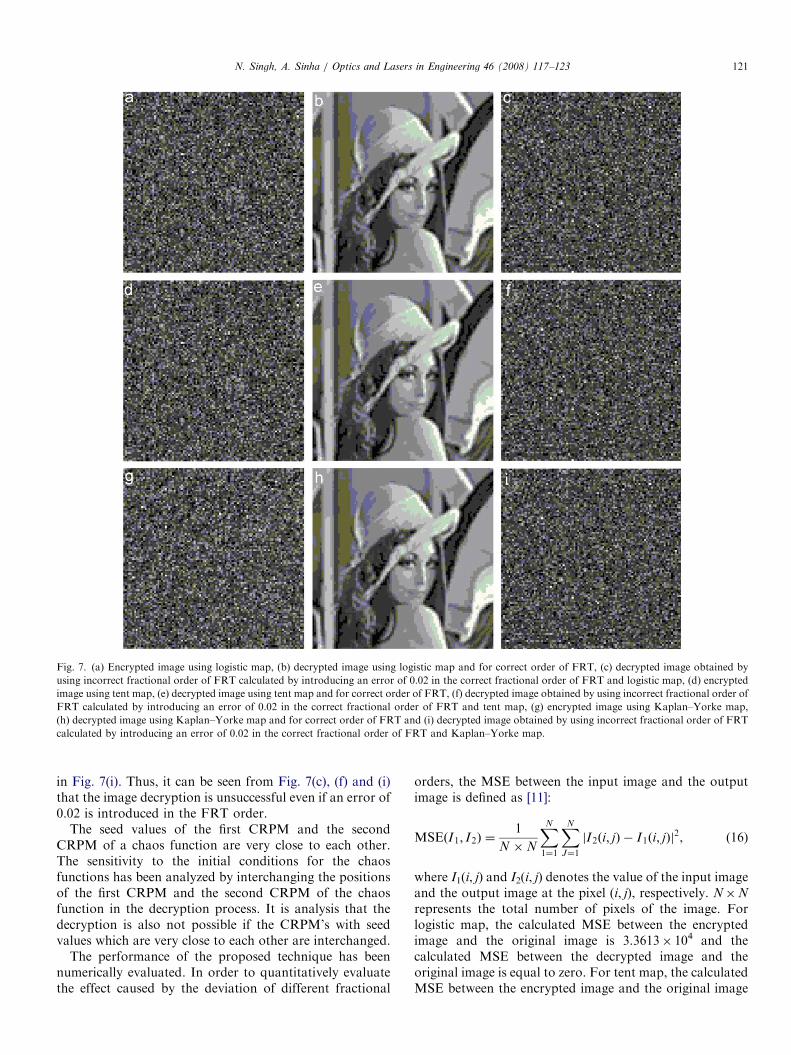
and the second FRT system are (0.75, 0.9) and (1.25, 1.1),respectively. The incorrect fractional orders of FRT usedfor the decryption system are calculated by introducing anerror of 0.02 in both the sets of fractional orders. Theincorrect sets of fractional order of FRT for the first FRTsystem and the second FRT system after introducing theerror are (0.73, 0.88) and (1.23, 1.08), respectively. Theencrypted image and the decrypted image using logisticmap for correct order of FRT are shown in Fig. 7(a) and(b), respectively. The decrypted image obtained by usingincorrect fractional order of FRT calculated by introdu-cing an error of 0.02 in the correct fractional order of FRTand logistic map is shown in Fig. 7(c). The encrypted imageand the decrypted image using tent map for correct orderof FRT are shown in Fig. 7(d) and (e), respectively. Thedecrypted image obtained by using incorrect fractionalorder of FRT calculated by introducing an error of 0.02 inthe correct fractional order of FRT and tent map is shownin Fig. 7(f). The encrypted image and the decrypted imageusing Kaplan–Yorke map for correct order of FRT areshown in Fig. 7(g) and (h), respectively. The decryptedimage obtained by using incorrect fractional order of FRTcalculated by introducing an error of 0.02 in the correctfractional order of FRT and Kaplan–Yorke map is shown
using logistic map, (c) for x ¼ 0.61 using tent map, (d) for x ¼ 0.62 using
.2005, y ¼ 0.3005 using Kaplan–Yorke map.
ARTICLE IN PRESS
Fig. 7. (a) Encrypted image using logistic map, (b) decrypted image using logistic map and for correct order of FRT, (c) decrypted image obtained by
using incorrect fractional order of FRT calculated by introducing an error of 0.02 in the correct fractional order of FRT and logistic map, (d) encrypted
image using tent map, (e) decrypted image using tent map and for correct order of FRT, (f) decrypted image obtained by using incorrect fractional order of
FRT calculated by introducing an error of 0.02 in the correct fractional order of FRT and tent map, (g) encrypted image using Kaplan–Yorke map,
(h) decrypted image using Kaplan–Yorke map and for correct order of FRT and (i) decrypted image obtained by using incorrect fractional order of FRT
calculated by introducing an error of 0.02 in the correct fractional order of FRT and Kaplan–Yorke map.
N. Singh, A. Sinha / Optics and Lasers in Engineering 46 (2008) 117–123 121
in Fig. 7(i). Thus, it can be seen from Fig. 7(c), (f) and (i)that the image decryption is unsuccessful even if an error of0.02 is introduced in the FRT order.
The seed values of the first CRPM and the secondCRPM of a chaos function are very close to each other.The sensitivity to the initial conditions for the chaosfunctions has been analyzed by interchanging the positionsof the first CRPM and the second CRPM of the chaosfunction in the decryption process. It is analysis that thedecryption is also not possible if the CRPM’s with seedvalues which are very close to each other are interchanged.
The performance of the proposed technique has beennumerically evaluated. In order to quantitatively evaluatethe effect caused by the deviation of different fractional
orders, the MSE between the input image and the outputimage is defined as [11]:
MSEðI1; I2Þ ¼1
N �N
XN
1¼1
XN
J¼1
jI2ði; jÞ � I1ði; jÞj2, (16)
where I1(i, j) and I2(i, j) denotes the value of the input imageand the output image at the pixel (i, j), respectively. N�N
represents the total number of pixels of the image. Forlogistic map, the calculated MSE between the encryptedimage and the original image is 3.3613� 104 and thecalculated MSE between the decrypted image and theoriginal image is equal to zero. For tent map, the calculatedMSE between the encrypted image and the original image

ARTICLE IN PRESSN. Singh, A. Sinha / Optics and Lasers in Engineering 46 (2008) 117–123122
is 3.4008� 104 and the calculated MSE between thedecrypted image and the original image is equal to zero.For Kaplan–Yorke map, the calculated MSE between theencrypted image and the original image is 3.3709� 104 andthe calculated MSE between the decrypted image and theoriginal image is equal to zero. These values of MSEs arecalculated for the correct order parameters of FRT used inthe decryption process.
To evaluate the results quantitatively, the SNR has beencalculated. The SNR is defined as [3]:
SNR ¼
Pi;j½I1ði; jÞ�
2
Px;y½I1ði; jÞ � I2ði; jÞ�
2, (17)
where I1(i, j) and I2 (i, j) denotes the value of the inputimage and the output image at the pixel (i, j), respectively.The SNR between the encrypted image and the input imagehas been calculated. The SNR between the decryptedimage and the input image have also been calculated for
Table 1
The calculated values of SNR
Chaos function SNR between encrypted
image and input image
SNR between de
image and input
for correct key
Logistic map 0.5015 3.2556� 1017
Tent map 0.5013 2.1411� 1017
Kalpan–Yorke map 0.4949 5.3451� 1017
Fig. 8. MSE graph showing the MSE between the decrypted image and the i
(a) logistic map, (b) tent map and (c) Kaplan–Yorke map.
correct decryption and incorrect decryption as shown inTable 1. It is seen from the table, the calculated SNRbetween the encrypted image and the input image has avery low value and the calculated SNR between decryptedimage and the input image has a high value for all the threechaos functions in the proposed technique.
6. Robustness of the algorithm to blind decryption
The MSE between the decrypted image and the inputimage is evaluated as a function of different magnitude oferrors in the decrypted fractional orders. To decrypt thedata correctly, it is essential that the CRPM multipliedduring encryption gets canceled which is possible only ifthe key to decrypt the data is multiplied in the fractionaldomain where encoding was done. Thus, any error indecryption order would not cancel the CRPM accruedduring encryption. The plot of the MSE between the
crypted
image
SNR between decrypted image and input image by
introducing the error in fractional order with lowest
deviation 0.02
0.5024
0.4982
0.5078
nput image as a function of order of FRT used for decryption by using:

ARTICLE IN PRESSN. Singh, A. Sinha / Optics and Lasers in Engineering 46 (2008) 117–123 123
decrypted image and the input image using differentmagnitudes of error introduced in both the sets oforder of FRT for the logistic map is shown in Fig. 8(a),for the tent map is shown in Fig. 8(b) and for theKaplan–Yorke map is shown in Fig. 8(c). It is seen fromFig. 8(a)–(c) that an error of 0.02 and above in thefractional order results in sufficiently high MSE betweenthe decrypted—and the original image. It can be seen fromthe calculated SNR, as shown in Table 1, that an error of0.02 in the fractional order results in sufficiently low SNRbetween the decrypted—and the original image. The errorin the fractional order of 0.02 and above will protect thedata when the fractional order is used as a key. In all theMSE calculation and the SNR calculation performed, theresults were averaged over 10 trials. Hence, the fractionalorders serve as a robust key in terms of blind decryption.
7. Conclusions
We have proposed a new idea to encrypt the image usingFRT and chaos. This is the first time, chaos function hasbeen used with an optical transform for image encryption.The logistic map, tent map and Kaplan–Yorke map havealso been used to generate the CRPMs. Two CRPMs fortwo different seeds values have been generated for eachchaos function. Logistic map and tent map are one-dimensional chaos functions. Kaplan–Yorke map is a two-dimensional chaos function. The comparisons of the MSEand the SNR between the decrypted image and the inputimage for these chaos functions have been performed. Thecomparisons of the MSE and the SNR between theencrypted image and the input image for these chaosfunctions have also been performed. Robustness of theparameters of the FRT in terms of blind decryption havebeen evaluated. An error of 0.02 and above in the fractionalorder results in sufficiently high MSE and low SNR betweenthe decrypted image and the input image. The error in thefractional order of 0.02 and above will protect the data whenthe fractional order is used as a key. Hence, the fractionalorder serve as a robust key in terms of blind decryption. Theadvantage of the CRPM based encryption technique is thatonly the initial element called the seed value of the chaosfunction can be used to generate the CRPM for decryption.Thus, there is no need to send the whole phase mask to thereceiver side for decryption. Two-dimensional chaos func-tions have advantage over one-dimensional chaos functions.In two-dimensional chaos function, two seed values areneeded to encrypt and decrypt the image and hence securityof the encrypted image is increased. The Kaplan–Yorke mapis more robust to blind decryption in comparison with thelogistic map and the tent map.
References
[1] Nishchal NK, Joseph J, Singh K. Fully phase-encrypted memory
using cascaded extended fractional Fourier transform. Opt Lasers
Eng 2004;42(2):141–51.
[2] Refregier P, Javidi B. Optical image encryption based on input plane
and Fourier plane random encoding. Opt Lett 1995;20(7):767–9.
[3] Nomura T, Javidi B. Optical encryption system with a binary key
code. Appl Opt 2000;39(26):4783–7.
[4] Carnicer A, Montes-Usategui M, Arcos S, Juvells I. Vulnerability to
chosen-cyphertext attacks of optical encryption schemes based on
double random phase keys. Opt Lett 2005;30(13):1644–6.
[5] Unnikrishnan U, Monaghan DS, Naughton TJ, Sheridan JT. A
known-plaintext heuristic attack on the Fourier plane encryption
algorithm. Opt Exp 2006;14(8):3181–6.
[6] Ragulskis M, Aleksa A, Saunoriene L. Improved algorithm for image
encryption based on stochastic geometric moire and its application.
Opt Commun 2007;273(2):370–8.
[7] He MZ, Cai LZ, Liu Q, Wang XC, Meng XF. Multiple image
encryption and watermarking by random phase matching. Opt
Commun 2005;247(1–3):29–37.
[8] Barrera JF, Henao R, Tebaldi M, Torroba R, Bolognini N.
Multiplexing encrypted data by using polarized light. Opt Commun
2006;260(1):109–12.
[9] Situ G, Zhang J. A lensless optical security system based on
computer-generated phase only masks. Opt Commun 2004;232(1–6):
115–22.
[10] Zhao J, Lu H, Song X, Li J, Ma Y. Optical image encryption based
on multistage fractional Fourier transforms and pixel scrambling
technique. Opt Commun 2005;249(4–6):493–9.
[11] Hennelly BM, Sheridan JT. Image encryption and the fractional
Fourier transform. Optik 2003;114(6):251–65.
[12] Liu S, Yu L, Zhu B. Optical image encryption by cascaded fractional
Fourier transforms with random phase filtering. Opt Commun
2001;187(1–3):57–63.
[13] Zhang Y, Zheng CH, Tanno N. Optical encryption based on iterative
fractional Fourier transform. Opt Commun 2002;202(4–6):277–85.
[14] Zhu B, Liu S. Optical image encryption based on the generalized
fractional convolution operation. Opt Commun 2001;195(5–6):
371–81.
[15] Zhu B, Liu S. Optical image encryption with multistage and
multichannel fractional Fourier-domain filtering. Opt Lett 2001;
26(16):1242–4.
[16] Hennelly BM, Sheridan JT. Optical image encryption by random
shifting in fractional Fourier domains. Opt Lett 2003;28(4):269–71.
[17] Lohmann AW. Image rotation, Wigner rotation, and the fractional
Fourier transform. J Opt Soc Am A 1993;10(10):2181–6.
[18] Ozaktas HM, Zalevsky Z, Kutay MA. The Fractional Fourier
Transform with applications in optics and signal processing. UK:
Wiley; 2001.
[19] Liu S, Xu J, Zhang Y, Chen L, Li C. General optical implementations
of fractional Fourier transforms. Opt Lett 1995;20(9):1053–5.
[20] Garcia J, Mas D, Dorsch RG. Fractional-Fourier-transform
calculation through the fast-Fourier-transform algorithm. Appl Opt
1996;35(35):7013–8.
[21] Nishchal NK, Joseph J, Singh K. Optical encryption using cascaded
extended fractional Fourier transform. Optical Memory & Neural
Networks 2003;12(2):139–45.
[22] Larger L, Goedgebuer J-P. Encryption using chaotic dynamics for
optical telecommunications. CR Phys 2004;5(6):609–11.
[23] Larger L, Goedgebuer J-P, Udaltsov V. Ikeda-based nonlinear
delayed dynamics for application to secure optical transmission
systems using chaos. CR Phys 2004;5(6):669–81.
[24] Suzuki K, Imai Y. Decryption characterstics in message modulation
type chaos secure communication system using optical fiber ring
resonators. Opt Commun 2006;259(1):88–93.
[25] James G. Making a new science. Minerva: Minerva Limited; 1988.
[26] Alligood KT, Sauer TD, Yorke JA. Chaos: an introduction to
dynamical systems. New York: Springer; 2001.
[27] Hilborn RC. Chaos and nonlinear dynamic. 2nd ed. New York:
Oxford University Press; 2000.
Top Related
Copyright © 2022 FDOKUMEN

