


Bahasa
Halaman
Hukum


01. vv
OPERATION GUIDELX100 Vehicle Accessory Interface Kit | 29.03.19
LINVEHICLE ACCESSORY INTERFACE

PAGE 2
| LX100 VEHICLE ACCESSORY INTERFACE KIT OPERATION GUIDE
WHAT IS LINX?

| LX100 VEHICLE ACCESSORY INTERFACE KIT OPERATION GUIDE
PAGE 3
WHAT IS LINX?
INTRODUCING TOTAL CONTROL
LINX is a unique modern controller that declutters the dashboard and centralises the command of vehicle accessories by replacing classic switches, gauges and monitors with one sleek and smart driver interface. Built on an expandable platform, LINX will continue to evolve your on and off road driving experience both now and into the future.
The mobile touchscreen display integrates seamlessly into the vehicle cabin and mounts to a magnetic gimbal that’s installed within easy reach of the driver. This connects to the LINX Controller which is the brains behind the system, and is conveniently installed out-of-sight either underneath the dash or the seat.
STAY IN THE LOOPFor the latest details, updates and list of accessories, head over to:
www.linx.arb.com.au
LINX is a sleek touchscreen interface that enables total control of both new and existing 4X4 Accessories. Gone are the days where the only option for installing aftermarket switches meant drilling multiple holes into the dashboard.
| LX100 VEHICLE ACCESSORY INTERFACE KIT OPERATION GUIDE
PAGE 4
TABLE OF CONTENTSGet to know the basic in’s and out’s of your brand new LINX - the next generation of 4x4 Accessories.
KIT CONTENTS
01. WHAT’S IN THE BOX? p.7
OVERVIEW
02. COMPATIBLE ARB ACCESSORIES p.9
03. OPTIONAL ACCESSORIES p.10
INITIAL SETUP
04. SETTING UP YOUR LINX p.13
05. GETTING STARTED p.14
SWITCHING ON/OFF p.15
UPDATING LINX SOFTWARE p.16
BLUETOOTH PAIRING THE DISPLAY WITH CONTROLLER p.18
OPERATING LINX
06. LINX DISPLAY p.21
07. HOME SCREEN p.22
08. SETTINGS MENUS p.24
QUICK SETTINGS MENU p.24
MAIN SETTINGS MENU p.24
09. LINX USER INTERFACE p.25
LINX DISPLAY SCREENS p.26
10. LINX MAIN ICON SCREEN p.27
ACCESSING EACH MODULE p.28
RETURNING TO LINX MAIN ICON SCREEN p.28
LINX SETTINGS SCREEN p.29
11. UPDATING LINX p.30
MODULES OVERVIEW
12. FRONT AND REAR TRACTION MODULES p.32
CONFIGURING TRACTION MODULES: AIR LOCKER SETUP p.33
13. COMPRESSOR MODULE p.35
SWITCHING ON COMPRESSOR p.35
CONFIGURING COMPRESSOR MODULE p.36
CONFIGURING PRESSURE CONTROL p.36
PRESSURE CONTROL MODE LIST p.38
| LX100 VEHICLE ACCESSORY INTERFACE KIT OPERATION GUIDE
PAGE 5
14. SWITCHBOARD MODULE p.40
CONFIGURING SWITCHBOARD MODULE p.40
RENAMING ACCESSORIES p.41
AUTOMATING ACCESSORIES p.41
LOW BATTERY PROTECTION p.42
SWITCHING ON/OFF AN ACCESSORY p.43
15. BATTERY MODULE p.44
CONFIGURING BATTERY MODULE p.44
RENAMING BATTERIES p.45
LOW VOLTAGE ALARM LEVEL p.45
16. SPEEDOMETER MODULE p.47
CONFIGURING SPEEDOMETER p.47
SETTING SPEED LIMIT WARNING p.48
17. AIR SUSPENSION MODULE p.49
CONFIGURING AIR SUSPENSION p.49
RENAMING MODES p.51
ADJUSTING AIR PRESSURE p.52
18. INCLINOMETER MODULE p.53
CONFIGURING THE INCLINOMETER p.54
19. CLOCK MODULE p.55
20. FRIDGE MODULE p.57
CONNECTING TO THE FRIDGE APP CONNECT MODULE p.57
CONFIGURING A SERIES 2 FRIDGE p.58
COMPLIANCE INFORMATION
21. COMPLIANCE INFORMATION p.61
EUROPE - EU DECLARATION OF CONFORMITY p.61
USA - FCC STATEMENT p.62
ENVIRONMENTAL PROTECTION p.62

PAGE 6
| LX100 VEHICLE ACCESSORY INTERFACE KIT OPERATION GUIDE
KIT CONTENTS
Each and every component to get your new LINX up and running.
BACK TO TABLE OF CONTENTS

| LX100 VEHICLE ACCESSORY INTERFACE KIT OPERATION GUIDE
PAGE 7
01.WHAT’S IN THE BOX?
Congratulations on the purchase of your brand new LINX. Inside the box, you’ll find each of the components required to get the system up and running for your next 4x4 adventure.
NOTES
• The LINX Display 02 was specifically designed to withstand the extremes of heat and cold. It has a metal coupling on the
back to connect it to the magnets on the LINX Display Gimbal Mount .
• The LINX Controller 01 and wiring looms 05 are normally mounted under the dash, however this may vary depending on
the vehicle.
• The DIN rail 06 comes assembled to the back of the LINX controller 01 and is used for securing the unit.
• The USB connection can be used to power and charge the LINX Display, and provide the communications channel between the LINX Controller and LINX Display.
LINX CONTROLLER
LINX DISPLAY
LINX DISPLAY GIMBAL MOUNT
USB CABLE
WIRING LOOMS (x3)
DIN RAIL 180MM01
02
03
04
06
05
03
PAGE 8
| LX100 VEHICLE ACCESSORY INTERFACE KIT OPERATION GUIDE
OVERVIEW
Out of the box, LINX offers total control of six pre-installed modules: Front & Rear Traction, Compressor & Pressure
Control, Battery Monitoring, Speedometer, Air Suspension Control and an Accessory Switchboard.
BACK TO TABLE OF CONTENTS

| LX100 VEHICLE ACCESSORY INTERFACE KIT OPERATION GUIDE
PAGE 9
There’s a range of ARB accessories that can be controlled and monitored by LINX.
ARB DRIVING LIGHTS
ARB offers a large range of LED, HID and Halogen driving lights and light bars to suit your every driving need. Designed to perform in the most extreme conditions, they’ll keep the road ahead brightly lit and the rear visible wherever you go.
AIR LOCKERS
Designed and manufactured in Australia, ARB Air Lockers will enhance the traction of your 4×4 in just about any terrain, whether it’s rock, clay, gravel, sand, snow or mud.
ARB DUAL BATTERY SYSTEMS
Allowing you to power additional accessories without the risk of flattening the main battery, an ARB Dual Battery System also provides peace of mind in the event of a main battery failure.
ARB AIR COMPRESSORS
ARB Air Compressors provide many advantages; including inflating tyres and camping accessories, running air tools, activating Air Lockers and even re-seating a tyre onto a wheel.
02.COMPATIBLE ARB ACCESSORIES
| LX100 VEHICLE ACCESSORY INTERFACE KIT OPERATION GUIDE
PAGE 10
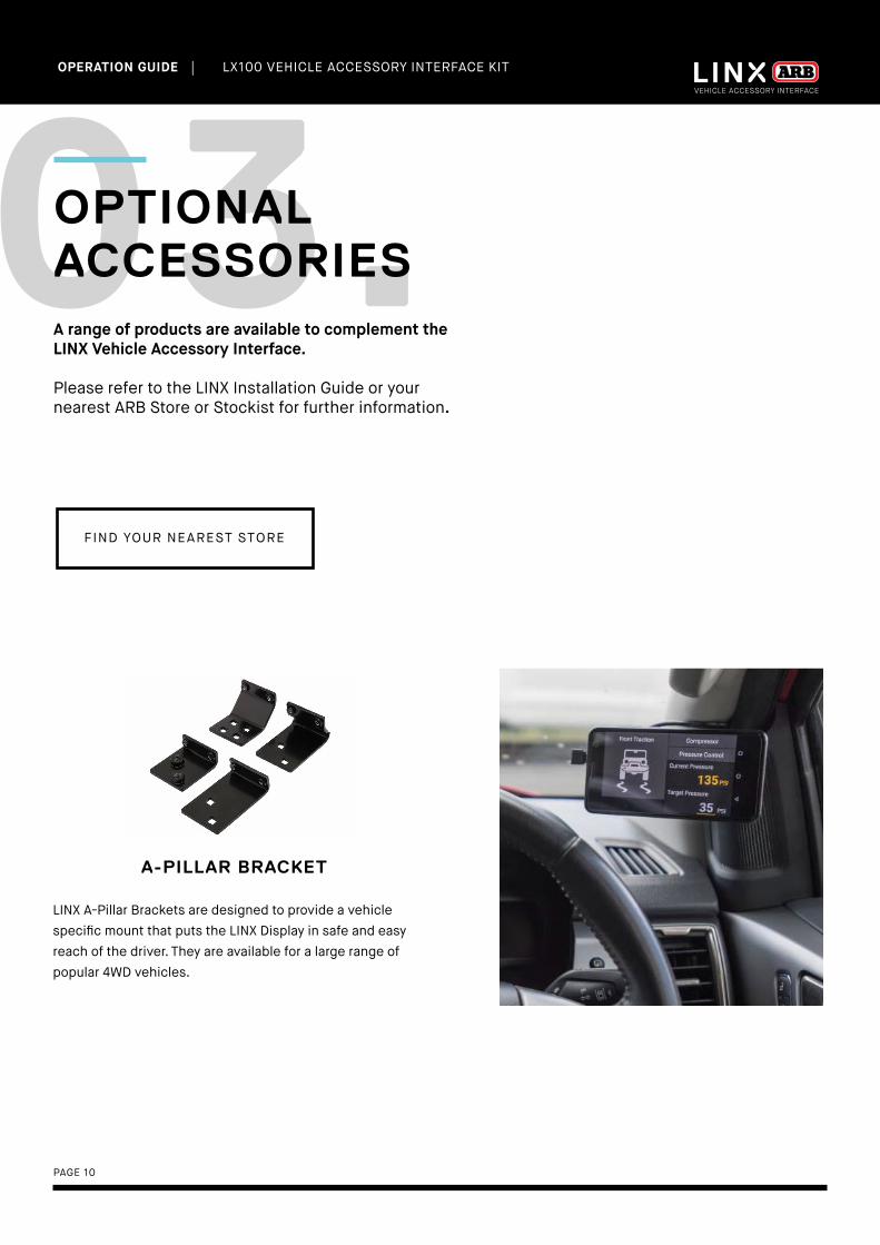
03.OPTIONAL ACCESSORIESA range of products are available to complement the LINX Vehicle Accessory Interface.
Please refer to the LINX Installation Guide or your nearest ARB Store or Stockist for further information.
A-PILLAR BRACKET
LINX A-Pillar Brackets are designed to provide a vehicle specific mount that puts the LINX Display in safe and easy reach of the driver. They are available for a large range of popular 4WD vehicles.
FIND YOUR NEAREST STORE

| LX100 VEHICLE ACCESSORY INTERFACE KIT OPERATION GUIDE
PAGE 11
AIR SUSPENSION ISOLATION KIT(7450109)
Adding an Air Suspension Isolation Kit allows owners with air suspension to take full advantage of LINX’s Air Suspen-sion Module, providing the ability to independently adjust the pressure and ride height in each air bag.
LINX TERMINAL KIT(7450105)
LINX already comes with a packet of terminals, enough to do a complete install. This kit is if you require any extra terminals.
PRESSURE CONTROL KIT(7450107)
Offering ‘set & forget’ simplicity to either tyre inflation or remote control over your air suspension, the optional LINX Pressure Control Kit (coupled with an ARB air compressor) allows you to take full advantage of LINX’s Pressure Control Module.
Note: Separate pressure control kits are required for tyre inflation and air
suspension.
RELAY KIT(180422)
A pre-wired relay base used for connecting accessories that don’t come with a relay in its wiring loom. Most ARB wiring looms already come with a relay.

PAGE 12
| LX100 VEHICLE ACCESSORY INTERFACE KIT OPERATION GUIDE
INITIAL SETUP
BACK TO TABLE OF CONTENTS
It’s time to get your LINX device up and running!

| LX100 VEHICLE ACCESSORY INTERFACE KIT OPERATION GUIDE
PAGE 13
The time taken to connect and configure accessories such as compressor, Air Lockers and driving lights will vary depending on whether the accessory was fitted before or after your next LINX installation. LINX is fully customisable to suit your vehicle, please contact your local ARB distributor to discuss your individual requirements and provide a quote for your installation.
LINX SETUP PROCESS
• Mounting of the LINX Controller.
• Connection of the power loom to the LINX Controller.
• Updating LINX software.
• Connection of 4 input wires from accessory power, parker/low beam headlamps, high beam headlamps and reverse
lamp to the LINX Controller.
• Installation of the LINX Display Gimbal Mount and/or optional vehicle specific LINX A-Pillar Bracket.
• Connection of the USB cable from the LINX Controller or optional USB power source to the LINX Display.
04.SETTING UP YOUR LINX

| LX100 VEHICLE ACCESSORY INTERFACE KIT OPERATION GUIDE
PAGE 14
05.GETTING STARTED
The LINX Display receives power from the LINX Controller via the USB charge cable provided.
The LINX Display’s on-board battery will take around 1 hour to fully charge from flat condition and provide approximately 4 hours of non-connected run time. It is normal practice to leave the display on all the time and connected when in the vehicle. When outside the vehicle, the display communicates with the LINX Controller via a Bluetooth connection up to 10m away.
USB CABLE04
LINX CONTROLLER
LINX DISPLAY GIMBAL MOUNT
LINX DISPLAY03
CLIP ON COVER05 02
01
POWER BUTTON06
VOLUME07
| LX100 VEHICLE ACCESSORY INTERFACE KIT OPERATION GUIDE
PAGE 15
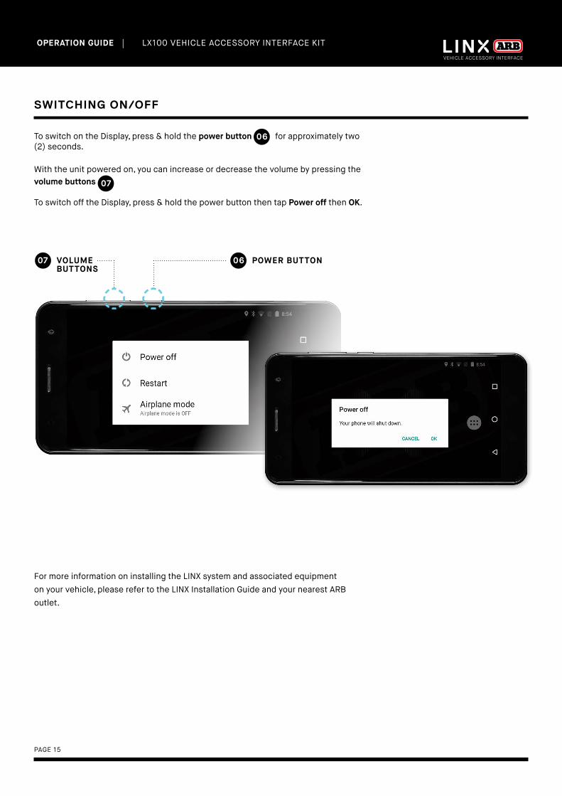
SWITCHING ON/OFF
To switch on the Display, press & hold the power button for approximately two (2) seconds.
With the unit powered on, you can increase or decrease the volume by pressing the volume buttons 07
To switch off the Display, press & hold the power button then tap Power off then OK.
POWER BUTTON06VOLUME BUTTONS
07
For more information on installing the LINX system and associated equipment on your vehicle, please refer to the LINX Installation Guide and your nearest ARB outlet.
06
| LX100 VEHICLE ACCESSORY INTERFACE KIT OPERATION GUIDE
PAGE 16
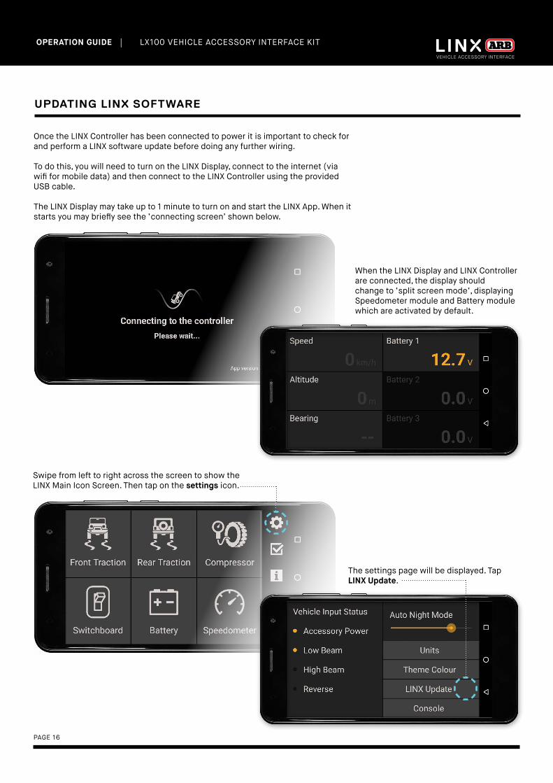
UPDATING LINX SOFTWARE
Once the LINX Controller has been connected to power it is important to check for and perform a LINX software update before doing any further wiring.
To do this, you will need to turn on the LINX Display, connect to the internet (via wifi for mobile data) and then connect to the LINX Controller using the provided USB cable.
The LINX Display may take up to 1 minute to turn on and start the LINX App. When it starts you may briefly see the ‘connecting screen’ shown below.
When the LINX Display and LINX Controller are connected, the display should change to ‘split screen mode’, displaying Speedometer module and Battery module which are activated by default.
Swipe from left to right across the screen to show the LINX Main Icon Screen. Then tap on the settings icon.
The settings page will be displayed. Tap LINX Update.
| LX100 VEHICLE ACCESSORY INTERFACE KIT OPERATION GUIDE
PAGE 17
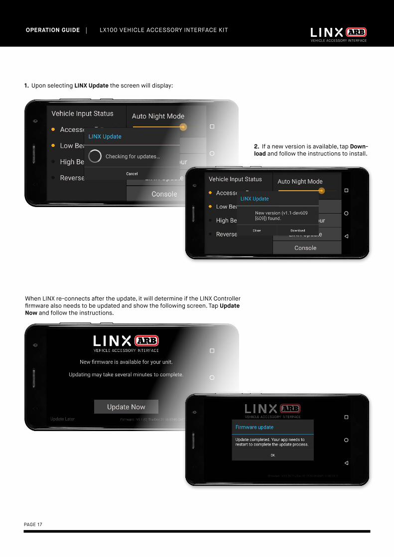
1. Upon selecting LINX Update the screen will display:
2. If a new version is available, tap Down-load and follow the instructions to install.
When LINX re-connects after the update, it will determine if the LINX Controller firmware also needs to be updated and show the following screen. Tap Update Now and follow the instructions.
| LX100 VEHICLE ACCESSORY INTERFACE KIT OPERATION GUIDE
PAGE 18
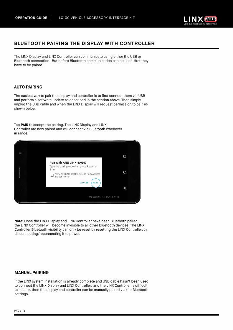
BLUETOOTH PAIRING THE DISPLAY WITH CONTROLLER
AUTO PAIRING
The easiest way to pair the display and controller is to first connect them via USB and perform a software update as described in the section above. Then simply unplug the USB cable and when the LINX Display will request permission to pair, as shown below.
The LINX Display and LINX Controller can communicate using either the USB or Bluetooth connection. But before Bluetooth communication can be used, first they have to be paired.
Tap PAIR to accept the pairing. The LINX Display and LINX Controller are now paired and will connect via Bluetooth whenever in range.
MANUAL PAIRING
If the LINX system installation is already complete and USB cable hasn’t been used to connect the LINX Display and LINX Controller, and the LINX Controller is difficult to access, then the display and controller can be manually paired via the Bluetooth settings.
Note: Once the LINX Display and LINX Controller have been Bluetooth paired, the LINX Controller will become invisible to all other Bluetooth devices. The LINX Controller Bluetooth visibility can only be reset by resetting the LINX Controller, by disconnecting/reconnecting it to power.
| LX100 VEHICLE ACCESSORY INTERFACE KIT OPERATION GUIDE
PAGE 19
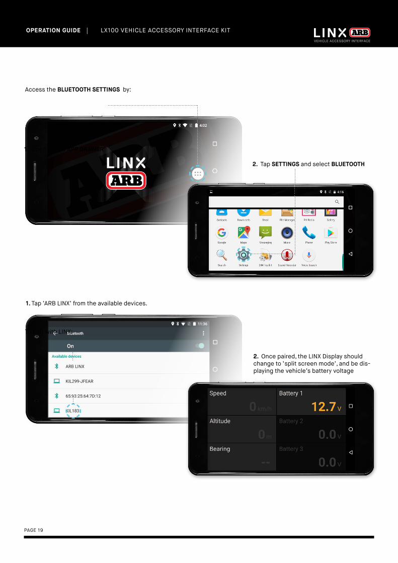
Access the BLUETOOTH SETTINGS by:
2. Tap SETTINGS and select BLUETOOTH
1. Open up the APP DRAWER
2. Once paired, the LINX Display should change to ‘split screen mode’, and be dis-playing the vehicle’s battery voltage
1. Tap ‘ARB LINX’ from the available devices.
To pair with LINX:
PAGE 20
| LX100 VEHICLE ACCESSORY INTERFACE KIT OPERATION GUIDE
OPERATING LINX
Learn how to navigate your LINX device.
BACK TO TABLE OF CONTENTS
| LX100 VEHICLE ACCESSORY INTERFACE KIT OPERATION GUIDE
PAGE 21
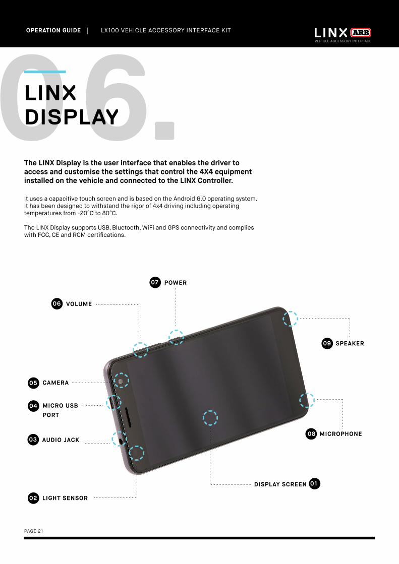
The LINX Display is the user interface that enables the driver to access and customise the settings that control the 4X4 equipment installed on the vehicle and connected to the LINX Controller.
It uses a capacitive touch screen and is based on the Android 6.0 operating system. It has been designed to withstand the rigor of 4x4 driving including operating temperatures from -20°C to 80°C.
The LINX Display supports USB, Bluetooth, WiFi and GPS connectivity and complies with FCC, CE and RCM certifications.
MICROPHONE
DISPLAY SCREEN
08
01
CAMERA05
MICRO USB PORT
04
AUDIO JACK03
LIGHT SENSOR02
VOLUME06
POWER07
SPEAKER09
06.LINX DISPLAY

| LX100 VEHICLE ACCESSORY INTERFACE KIT OPERATION GUIDE
PAGE 22
07.HOME SCREENUpon start-up, the LINX Display shows the ARB LINX home screen and then enters 'split screen mode'.
The status bar contains several icons positioned across the top of the display which indicate the status of the unit. Items which are active/on are bright. Items which are inactive/off are greyed out.
Settings that should remain on all the time include GPS (for the LINX Speedometer module to operate), Bluetooth (for LINX Controller communications when the LINX Display is disconnected from the USB cable) and WiFi as this is used by the LINX Display to communicate with the Internet during LINX updates.
GPS01(on)
BLUETOOTH02(on)
WIFI03(on)
SD CARD(none)
04
BATTERY(full)
05
TIME 06

| LX100 VEHICLE ACCESSORY INTERFACE KIT OPERATION GUIDE
PAGE 23
APP DRAWER10
RECENT 07
NOTES
• Tap Recent 07 to display a list of recently selected Apps. Scroll up/down and tap an item to return to it. To remove an item from the
list tap the X button for that item.
• Tap APP drawer 10 to display all Apps installed on your LINX Display.
• Tap LINX home 08 to return to the LINX home screen.
• Tap Back 09 to return to the previous screen. (When in LINX 'split screen mode', tap and hold to save the current module
view as Favourite. To show the Favourite view at any time, tap Back 09 again.
(Tap twice to return to Home Screen)
LINX HOME 08
BACK09
| LX100 VEHICLE ACCESSORY INTERFACE KIT OPERATION GUIDE
PAGE 24
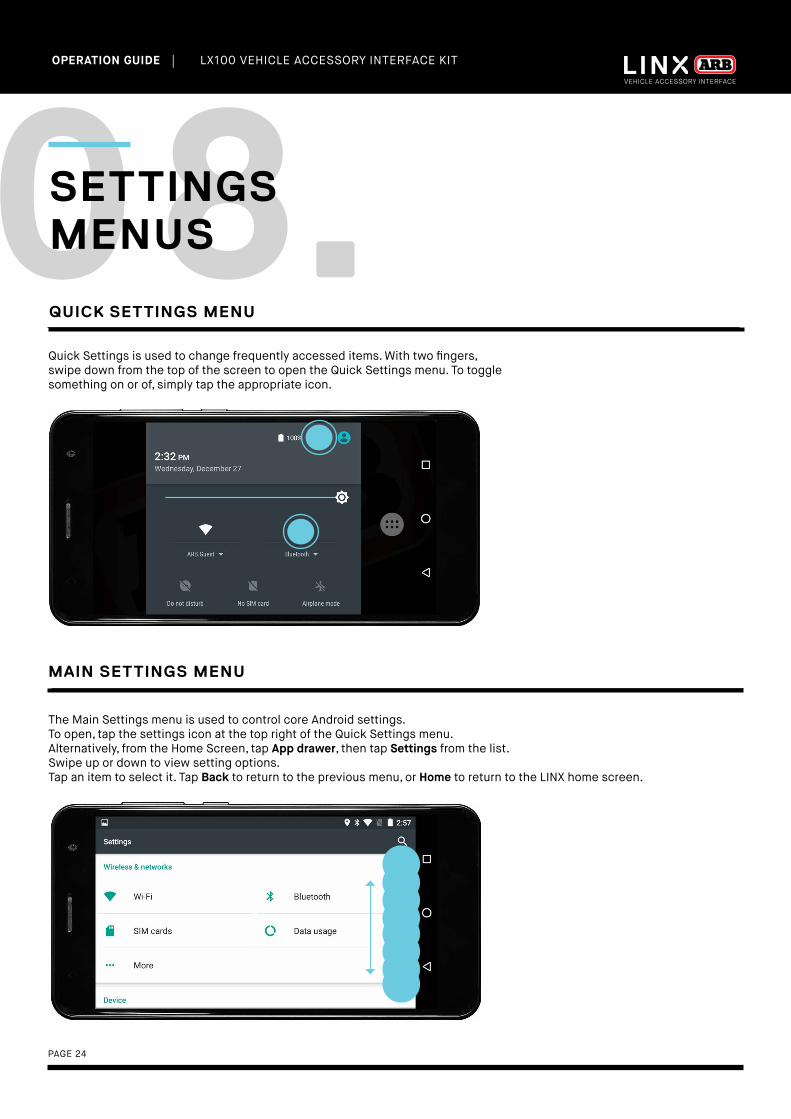
The Main Settings menu is used to control core Android settings.To open, tap the settings icon at the top right of the Quick Settings menu. Alternatively, from the Home Screen, tap App drawer, then tap Settings from the list.Swipe up or down to view setting options.Tap an item to select it. Tap Back to return to the previous menu, or Home to return to the LINX home screen.
QUICK SETTINGS MENU
MAIN SETTINGS MENU
08.SETTINGS MENUS
Quick Settings is used to change frequently accessed items. With two fingers, swipe down from the top of the screen to open the Quick Settings menu. To toggle something on or of, simply tap the appropriate icon.

| LX100 VEHICLE ACCESSORY INTERFACE KIT OPERATION GUIDE
PAGE 25
09.LINX USER INTERFACE
The LINX system offers a Graphical User Interface (GUI) similar to that found on most smart phones and tablets.
In order to fast track your use of the LINX interface, please acquaint yourself with these basic methods of interacting with LINX.
DOUBLE TAP a module to toggle between full / split screen display.
SINGLE TAP a module or button to select it or turn it on/off.
PRESS & HOLD a module to go to its settings menu.
PRESS & HOLD an underlined value or text to edit it.
SWIPE LEFT/RIGHT in 'split screen mode' to return to the LINX Main Icon Screen.
SWIPE UP/DOWN in split screen mode with one finger to scroll to the next Module.
SELECTABLE(but turned off)
SELECTABLE(and turned on)
NON-SELECTABLE(disabled)
BUTTON COLOUR STATUS
AUTOMATION TRIANGLE on a button indicates a LINX automated state of the control.
THEMED COLOURED VALUE is a real-time display, as opposed to a set value.
| LX100 VEHICLE ACCESSORY INTERFACE KIT OPERATION GUIDE
PAGE 26
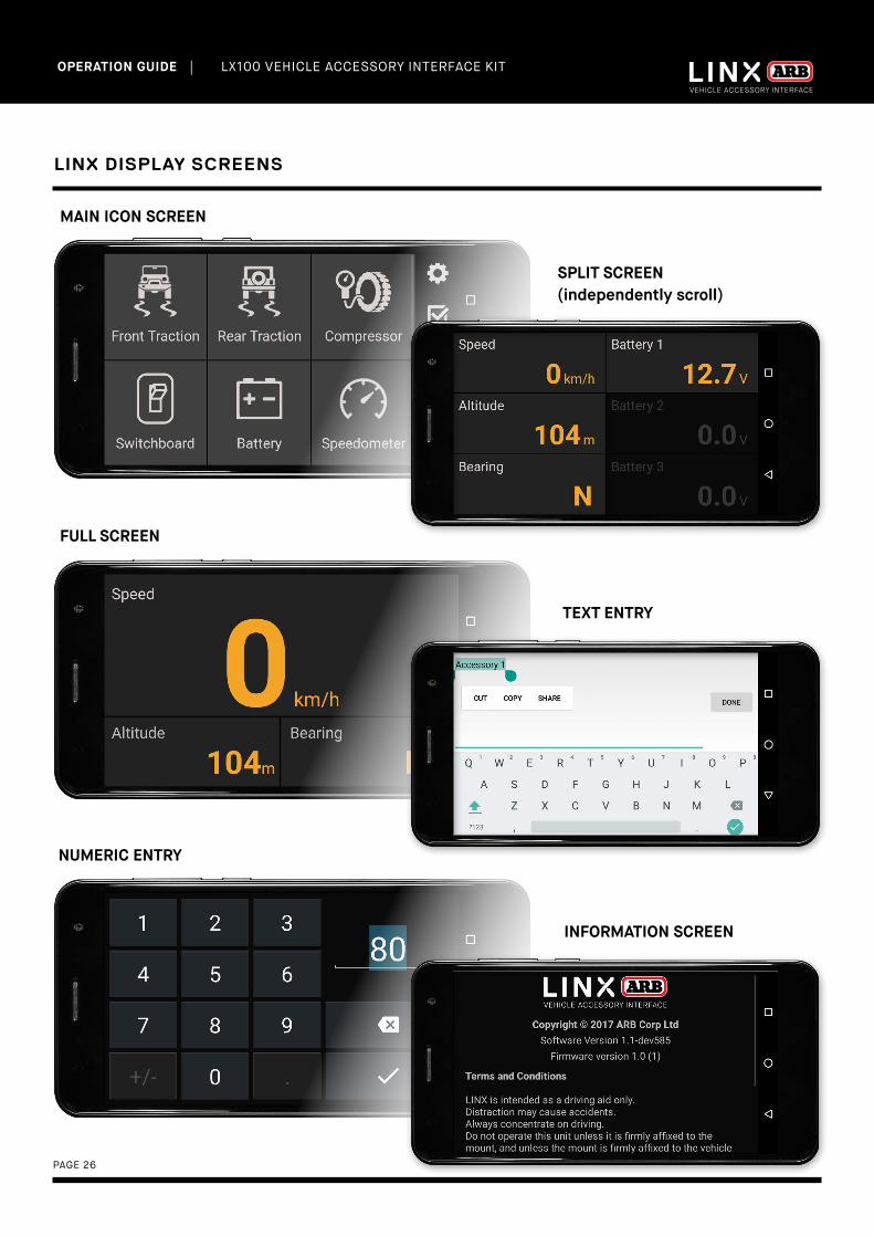
LINX DISPLAY SCREENS
MAIN ICON SCREEN
SPLIT SCREEN (independently scroll)
FULL SCREEN
TEXT ENTRY
NUMERIC ENTRY
INFORMATION SCREEN
| LX100 VEHICLE ACCESSORY INTERFACE KIT OPERATION GUIDE
PAGE 27
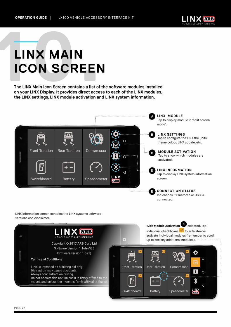
The LINX Main Icon Screen contains a list of the software modules installed on your LINX Display. It provides direct access to each of the LINX modules, the LINX settings, LINX module activation and LINX system information.
LINX MODULEA
LINX INFORMATIOND
LINX SETTINGSB
MODULE ACTIVATIONC
10.LINX MAIN ICON SCREEN
Tap to display module in 'split screen mode'.
Tap to configure the LINX the units, theme colour, LINX update, etc.
Tap to show which modules are activated.
LINX information screen contains the LINX systems software versions and disclaimer.
Tap to display LINX system information screen.
CONNECTION STATUSEIndications if Bluetooth or USB is connected.
With Module Activation C selected. Tap
individual checkboxes to activate/de-activate individual modules (remember to scroll up to see any additional modules).

| LX100 VEHICLE ACCESSORY INTERFACE KIT OPERATION GUIDE
PAGE 28
The LINX Display is supplied with pre-installed software modules. These provide access to modules like: Front and Rear Traction, Compressor, Switchboard (for lights), Battery monitor, Speedometer and Air Suspension.
Scroll down or up to see which modules are installed.
Access to the LINX Main Icon Screen is gained by swiping left or right from 'split screen mode'.
RETURNING TO LINX MAIN ICON SCREEN
ACCESSING EACH MODULE
When a module is selected, the display automatically enters 'split screen mode'. The screen is then divided into two columns. Each screen can then be scrolled vertically independent of the other.
| LX100 VEHICLE ACCESSORY INTERFACE KIT OPERATION GUIDE
PAGE 29
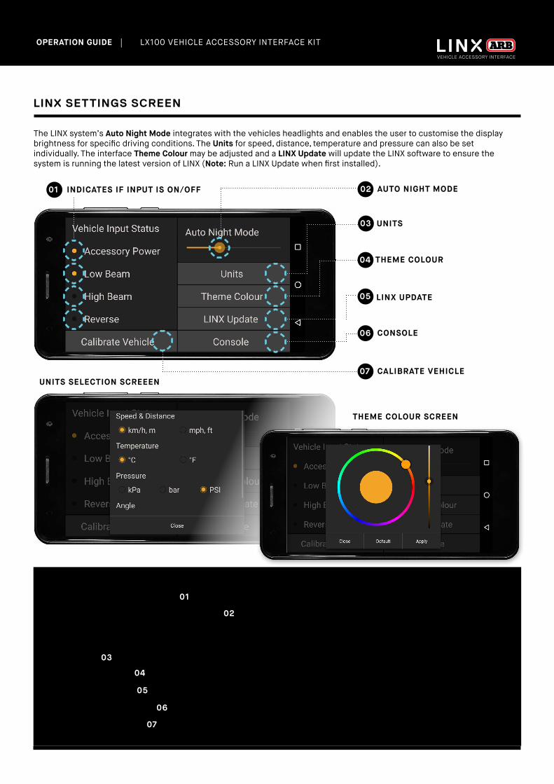
LINX SETTINGS SCREEN
UNITS03
THEME COLOUR04
LINX UPDATE05
The LINX system’s Auto Night Mode integrates with the vehicles headlights and enables the user to customise the display brightness for specific driving conditions. The Units for speed, distance, temperature and pressure can also be set individually. The interface Theme Colour may be adjusted and a LINX Update will update the LINX software to ensure the system is running the latest version of LINX (Note: Run a LINX Update when first installed).
NOTES
• The Vehicle Input Status area 01 will show a coloured dot next to activated input connections on the controller.
• Use the slide control on Auto Night Mode 02 to customise the brightness level of the LINX Display for a specific driving condition. E.g. For night driving you may want to switch your low beam lights on, then adjust the brightness down to a level you want active when the low beam lights are next in operation.
• Tap Units 03 to bring up the units menu and tap the combination of units required.
• Tap Theme Colour 04 . Press and drag or slide to match your vehicle’s instrumentation colours.
• Run a LINX Update 05 to check if you have the latest software build and features on your device.
• Tap the Console button 06 to enter configuration commands.
• Tap Calibrate Vehicle 07 then follow the instructions to calibrate the controllers orientation within the vehicle.
AUTO NIGHT MODE02INDICATES IF INPUT IS ON/OFF01
UNITS SELECTION SCREEEN
THEME COLOUR SCREEN
CONSOLE06
CALIBRATE VEHICLE07

| LX100 VEHICLE ACCESSORY INTERFACE KIT OPERATION GUIDE
PAGE 30
The LINX system can check for new updates whenever connected to the Internet by tapping 'LINX Update'.
11.UPDATING LINX
1. Upon selecting LINX Update the screen will display:
2. If a new version is available, tap Down-load and follow the instructions to install.
When LINX re-connects after the update, it will determine if the LINX Controller firmware also needs to be updated and show the following screen. Tap Update Now and follow the instructions.
PAGE 31
| LX100 VEHICLE ACCESSORY INTERFACE KIT OPERATION GUIDE
MODULES OVERVIEW
When you’re ready to hit the road, accessing each module using LINX is achieved with a simple swipe
across the touchscreen display.
BACK TO TABLE OF CONTENTS

| LX100 VEHICLE ACCESSORY INTERFACE KIT OPERATION GUIDE
PAGE 32
12.FRONT AND REAR TRACTION MODULESThe LINX Front Traction and Rear Traction modules are used to control and setup the Air Lockers installed on your vehicle and when selected will automatically turn on the air compressor where required to engage them.
1. Double tapping the Front Traction (or Rear Traction) mod-ule brings up 'full screen mode' for the Traction module.
2. Now in 'full screen mode'.
To engage the rear Air Locker, simply tap the button once. Tap again to switch off the rear Air Locker.
1. Single tap on Rear Traction.
2. Rear Traction is now engaged/locked.

| LX100 VEHICLE ACCESSORY INTERFACE KIT OPERATION GUIDE
PAGE 33
To enter settings for the Traction modules, press and hold the module. This will show the traction settings page. Simply tap the option you wish to set. Tap again to unset it.
CONFIGURING TRACTION MODULES: AIR LOCKER SETUP
1. Press and hold Front Traction
2. Front Traction settings page. Front Axle Second is selected by default.
The Front Traction module can be setup to operate in two ways: 'front axle second', and 'front independent of rear'.
FRONT AXLE SECOND
'Front axle second' is the default mode in which the LINX system is supplied. It automatically greys-out the Front Traction button making it unselectable until the Rear Traction button is made active. This is a traditional safety feature of Air Lockers that was factory hard wired in conventional installations.

| LX100 VEHICLE ACCESSORY INTERFACE KIT OPERATION GUIDE
PAGE 34
FRONT INDEPENDENT OF REAR
'Front independent of rear' mode is available when Front Axle Second is deselected. It allows the front and/or rear Air Lockers to be switched on or off independently of the other at any time.
EXTERNAL LOCK SWITCH INSTALLED
When External Lock Switch is selected, this allows you to control the Traction mod-ule with an Air Locker dashboard switch. LINX will display the lock / unlock state of the dashboard switch and the LINX Display button will be unselectable.

| LX100 VEHICLE ACCESSORY INTERFACE KIT OPERATION GUIDE
PAGE 35
13.COMPRESSOR MODULE
The LINX Compressor module is used to configure and operate your air compressor. 'Pressure Control' is an optional upgrade that is used in conjunction with the LINX Pressure Control Kit (7450107) to inflate or deflate your tyres to a target pressure.
SWITCHING ON COMPRESSOR
To switch the Compressor on, tap the button once. Tap again to switch it off. Note: Vehicle accessory power must be on before Compressor can be turned on.
1. Single tap on Compressor button.
2. Compressor highlighted indicates it is on.
AND OPTIONAL PRESSURE CONTROL MODULE
The blue automation triangle appears in the top right corner of the Compressor button to indicate that LINX has changed the state of the Compressor, such as the vehicles accessory power turning off, or Front Traction turning on.

| LX100 VEHICLE ACCESSORY INTERFACE KIT OPERATION GUIDE
PAGE 36
CONFIGURING COMPRESSOR MODULE
To configure the Compressor module, press and hold anywhere on the module, this will show the compressor settings page. Tap the option you wish to set. Tap again to unset it.
1. Press and hold anywhere on the Compressor module.
Disable When Engine OFF ensures that the compressor will only run when the engine is on, this prevents any damage to the compressor motor or blown fuses if the battery levels are too low to operate it.
CONFIGURING PRESSURE CONTROL
2. Then set the Maximum System Pressure
1. Tap Pressure Control Installed
To activate the optional Pressure Control feature, tap the Pressure Control Installed button then set the Maximum System Pressure to set the upper limit that can be used when inflating your items.
This must be less than the minimum limit of your compressor’s pressure switch (e.g. For an ARB CO35 100psi pressure switch set it to 65psi, for an ARB 180901 150psi pressure switch set it to 130 psi).
2. Compressor settings page (Disable When Engine OFF is set by default)
| LX100 VEHICLE ACCESSORY INTERFACE KIT OPERATION GUIDE
PAGE 37
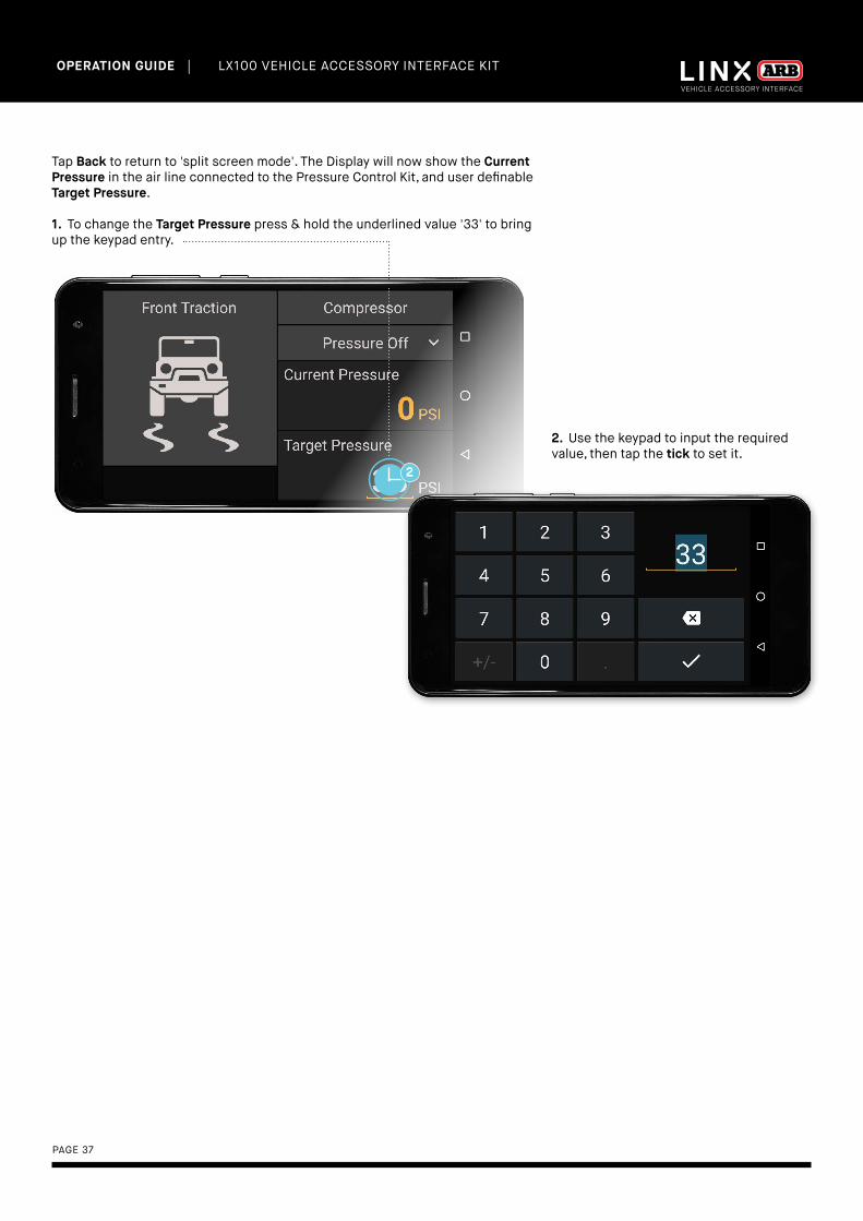
Tap Back to return to 'split screen mode'. The Display will now show the Current Pressure in the air line connected to the Pressure Control Kit, and user definable Target Pressure.
1. To change the Target Pressure press & hold the underlined value '33' to bring up the keypad entry.
2. Use the keypad to input the required value, then tap the tick to set it.

| LX100 VEHICLE ACCESSORY INTERFACE KIT OPERATION GUIDE
PAGE 38
PRESSURE CONTROL MODE LIST
With pressure control installed the Current Pressure and Target Pressure fields are activated along with the Pressure Control Mode list. Tap on the dropdown list to select from the 3 different modes.
PRESSURE CONTROL MODES
Pressure Off means no air flow from the compressor, but residual pressure may still be in the air line.
Pressure Control will turn on the compressor and the Pressure Control Valve will try to inflate/deflate to achieve the Target Pressure to a value less than or equal to the Maximum System Pressure setting.
Pressure Max will turn on the compressor, and open the Pressure Control Valve, thereby opening up a straight connection between the compressor and air line which is useful when using a blow gun on the air line.
Cancel is used to back out of the menu (ie same as tapping the Back button).
1. Tap the 'dropdown list' to view the list of modes.
2. Tap the desired Pressure Control Mode to select it.

| LX100 VEHICLE ACCESSORY INTERFACE KIT OPERATION GUIDE
PAGE 39
NOTES
• Parameters that may be set by the user are shown underlined.
• Theme coloured parameters (e.g. Current Pressure value) are monitored by the system.
• The Maximum System Pressure will automatically override any Target Pressure entered in excess of it.
• Current Pressure is the pressure monitored by the LINX system in whatever is connected to the LINX Pressure
control Kit.
• Target Pressure is the pressure that the user may set to either inflate or deflate their tyres.
• The LINX Display uses Bluetooth to communicate with the LINX Controller and may be disconnected from the USB
cable then removed from the mount and taken outside of the vehicle to monitor and control your tyre pressures
dynamically at the side of your vehicle.
WARNING
Tyre pressures vary by manufacturer, type, vehicle load, speed and driving conditions. Over inflating your tyres can
lead to excessive tread wear and shorten their overall life expectancy. Please consult the tyre manufacturer for the
appropriate pressure settings for your tyres and driving conditions. Always remember to re-inflate your tyres to the
correct pressure immediately upon returning to sealed roads. Failure to do so could seriously affect vehicle handling
and possibly result in tyre failure
| LX100 VEHICLE ACCESSORY INTERFACE KIT OPERATION GUIDE
PAGE 40
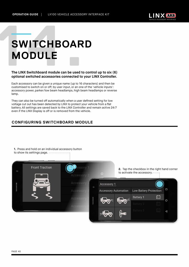
14.SWITCHBOARD MODULE
The LINX Switchboard module can be used to control up to six (6) optional switched accessories connected to your LINX Controller.
Each accessory can be given a unique name (up to 16 characters) and then be customised to switch on or off; by user input, or an one of the 'vehicle inputs': accessory power, parker/low beam headlamps, high beam headlamps or reverse lamp.
They can also be turned off automatically when a user defined setting for low voltage cut out has been detected by LINX to protect your vehicle from a flat battery. All settings are saved back to the LINX Controller and remain active 24/7 even if the LINX Display is off or is removed from the vehicle.
1. Press and hold on an individual accessory button to show its settings page.
CONFIGURING SWITCHBOARD MODULE
2. Tap the checkbox in the right hand corner to activate the accessory.
| LX100 VEHICLE ACCESSORY INTERFACE KIT OPERATION GUIDE
PAGE 41
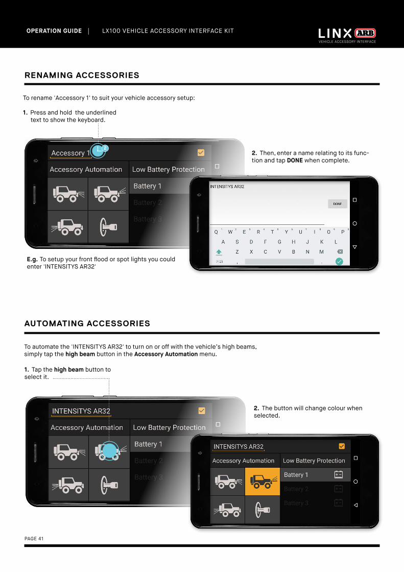
RENAMING ACCESSORIES
To rename 'Accessory 1' to suit your vehicle accessory setup:
1. Press and hold the underlined text to show the keyboard.
E.g. To setup your front flood or spot lights you could enter 'INTENSITYS AR32'
2. Then, enter a name relating to its func-tion and tap DONE when complete.
AUTOMATING ACCESSORIES
1. Tap the high beam button toselect it.
2. The button will change colour when selected.
To automate the 'INTENSITYS AR32' to turn on or off with the vehicle’s high beams, simply tap the high beam button in the Accessory Automation menu.
| LX100 VEHICLE ACCESSORY INTERFACE KIT OPERATION GUIDE
PAGE 42
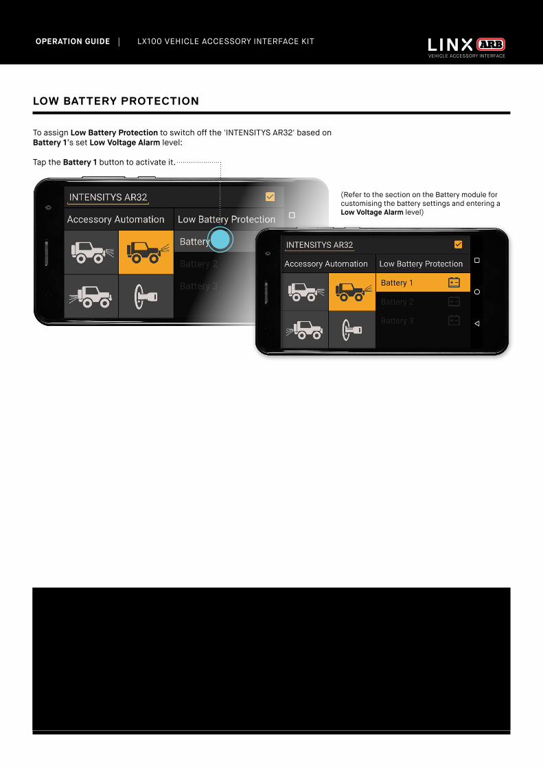
LOW BATTERY PROTECTION
To assign Low Battery Protection to switch off the 'INTENSITYS AR32' based on Battery 1’s set Low Voltage Alarm level:
Tap the Battery 1 button to activate it.
(Refer to the section on the Battery module for customising the battery settings and entering a Low Voltage Alarm level)
NOTES
• In the example shown above, the Low Battery Protection on Battery 1 will ensure that the 'INTENSITYS AR32' are
switched off (even though your high beam lamps are still switched on) once the battery level drops below limit set
by Low Voltage Alarm in the Battery module settings.
• All automation functions are user over-ridable. In the example above, LINX will automate the 'INTENSITYS AR32' to
come on whenever the high beams are activated, but the 'INTENSITYS AR32' can still be switched off by the user at
any time.
| LX100 VEHICLE ACCESSORY INTERFACE KIT OPERATION GUIDE
PAGE 43
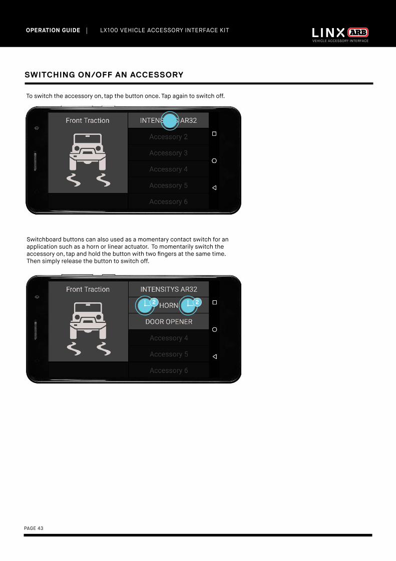
SWITCHING ON/OFF AN ACCESSORY
To switch the accessory on, tap the button once. Tap again to switch off.
Switchboard buttons can also used as a momentary contact switch for an application such as a horn or linear actuator. To momentarily switch the accessory on, tap and hold the button with two fingers at the same time. Then simply release the button to switch off.

| LX100 VEHICLE ACCESSORY INTERFACE KIT OPERATION GUIDE
PAGE 44
15.BATTERY MODULEThe LINX Battery module can be used to monitor and display the charge state of up to three (3) independent batteries simultaneously.
Each battery can be given a unique name (up to 16 characters) and then be configured to operate with your Switchboard accessory via the Switchboard module. (Refer to the section on the Switchboard module for further details).
1. Press and hold Battery 1 to show its settings page.
Note: The greyed-out checkbox indicates that Battery 1 is the battery the LINX Controller is connected to for power. Hence it is active by default and cannot be de-activated.
CONFIGURING BATTERY MODULE
2. Activate each battery by tapping the checkbox in the top right corner.
| LX100 VEHICLE ACCESSORY INTERFACE KIT OPERATION GUIDE
PAGE 45
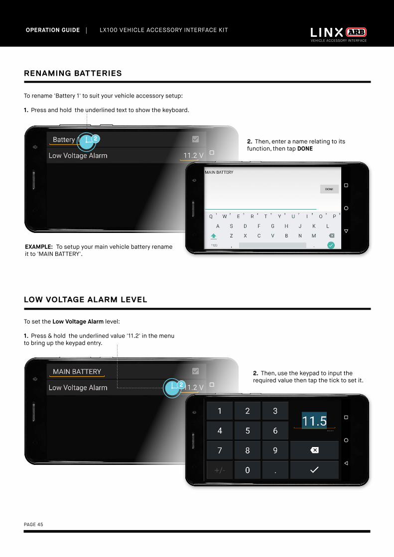
RENAMING BATTERIES
To rename 'Battery 1' to suit your vehicle accessory setup:
1. Press and hold the underlined text to show the keyboard.
2. Then, enter a name relating to its function, then tap DONE
LOW VOLTAGE ALARM LEVEL
To set the Low Voltage Alarm level: 1. Press & hold the underlined value '11.2' in the menu to bring up the keypad entry.
2. Then, use the keypad to input the required value then tap the tick to set it.
EXAMPLE: To setup your main vehicle battery rename it to 'MAIN BATTERY'.

| LX100 VEHICLE ACCESSORY INTERFACE KIT OPERATION GUIDE
PAGE 46
LOW VOLTAGE ALARM
A Low Voltage Alarm when triggered will highlight in RED. For example, Battery 2 (renamed to “AUX BATTERY”) has its Low Voltage Alarm level set to “11.5V” and the batteries actual voltage is 11.4V which now highlights in RED
NOTES
• The maximum setting for Low Voltage Alarm is 15.0V
• Parameters that may be set by the user are shown underlined (e.g. Low Voltage Alarm value).
• Theme coloured parameters (e.g. battery voltage 12.7v) are displayed in real time.
Tap BACK return to Battery module screen.
| LX100 VEHICLE ACCESSORY INTERFACE KIT OPERATION GUIDE
PAGE 47
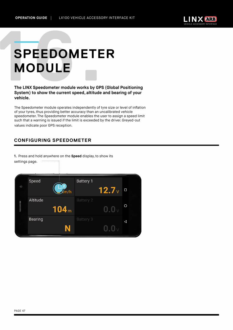
16.SPEEDOMETER MODULEThe LINX Speedometer module works by GPS (Global Positioning System) to show the current speed, altitude and bearing of your vehicle.
The Speedometer module operates independently of tyre size or level of inflation of your tyres, thus providing better accuracy than an uncalibrated vehicle speedometer. The Speedometer module enables the user to assign a speed limit such that a warning is issued if the limit is exceeded by the driver. Greyed-out values indicate poor GPS reception.
1. Press and hold anywhere on the Speed display, to show its settings page.
CONFIGURING SPEEDOMETER

| LX100 VEHICLE ACCESSORY INTERFACE KIT OPERATION GUIDE
PAGE 48
SETTING SPEED LIMIT WARNING
To set the speed limit:
1. Press & hold the underlined value ('0 km/h') next to Speed Limit Warning to bring up the keypad entry.
2. Use the keypad to input the required value, then select the tick to set it.
1. Tap the tick box in the top right corner to activate the Speed Limit Warning.
2. Tap the BACK to return to Speedometer module screen.
LINX will now monitor the vehicles’ speed and let the driver know when the limit has been exceeded by changing the displayed speed colour to RED.
NOTES
• Parameters that may be set by the user are shown underlined (e.g. Speed Limit Warning value).
• Theme coloured parameters (e.g. Altitude, Bearing and Speed) are monitored by the system.
• The GPS in your LINX Display requires good outdoor signal reception from at least three satellites to pinpoint your
location for accuracy of operation. Greyed-out values indicate no GPS reception and are not real time (e.g. When
driving through a tunnel).
| LX100 VEHICLE ACCESSORY INTERFACE KIT OPERATION GUIDE
PAGE 49
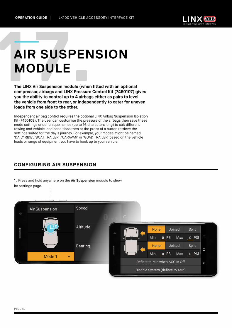
17.AIR SUSPENSION MODULEThe LINX Air Suspension module (when fitted with an optional compressor, airbags and LINX Pressure Control Kit (7450107) gives you the ability to control up to 4 airbags either as pairs to level the vehicle from front to rear, or independently to cater for uneven loads from one side to the other.
Independent air bag control requires the optional LINX Airbag Suspension Isolation Kit (7450109). The user can customise the pressure of the airbags then save these mode settings under unique names (up to 16 characters long) to suit different towing and vehicle load conditions then at the press of a button retrieve the settings suited for the day’s journey. For example, your modes might be named 'DAILY RIDE', 'BOAT TRAILER', 'CARAVAN' or 'QUAD TRAILER' based on the vehicle loads or range of equipment you have to hook up to your vehicle.
1. Press and hold anywhere on the Air Suspension module to show its settings page.
CONFIGURING AIR SUSPENSION
| LX100 VEHICLE ACCESSORY INTERFACE KIT OPERATION GUIDE
PAGE 50
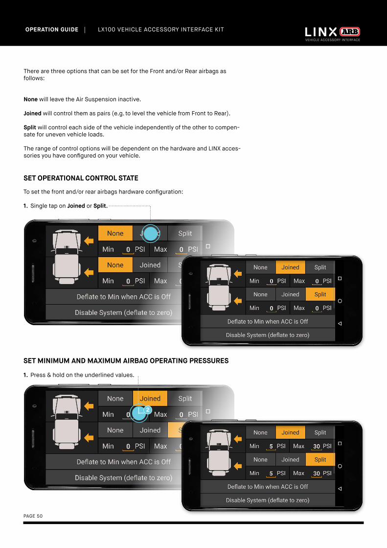
SET OPERATIONAL CONTROL STATE
To set the front and/or rear airbags hardware configuration:
1. Single tap on Joined or Split.
SET MINIMUM AND MAXIMUM AIRBAG OPERATING PRESSURES
1. Press & hold on the underlined values.
There are three options that can be set for the Front and/or Rear airbags as follows:
None will leave the Air Suspension inactive.
Joined will control them as pairs (e.g. to level the vehicle from Front to Rear).
Split will control each side of the vehicle independently of the other to compen-sate for uneven vehicle loads.
The range of control options will be dependent on the hardware and LINX acces-sories you have configured on your vehicle.

| LX100 VEHICLE ACCESSORY INTERFACE KIT OPERATION GUIDE
PAGE 51
2. Change name as required, then tap DONE.
1. Scroll up, then press and hold 'Mode 4'.
2. The screen will return to Air Suspension Module screen.
1. Tap the BACK button to return to Air Suspension module Screen.
RENAMING MODES

| LX100 VEHICLE ACCESSORY INTERFACE KIT OPERATION GUIDE
PAGE 52
ADJUSTING AIR PRESSURE
1. Tap the pressure value of one or more values requiring adjustment (tap near '5PSI'). Tap again to deselect them.
2. Tap the + button to increment and - button to decrement the value.
NOTES
• Parameters on the settings page that may be set by the user are shown underlined (e.g. the values next to Min and
Max, and the mode names).
• Refer to your airbag manufacturer’s datasheet for the recommended Min and Max operating pressures
• Disable System option is normally used by technicians when working on and installing the system.
Tap the value again to deselect it and it will be saved in the current mode such as "DAILY RIDE'.
Select from the different modes by tapping on the drop down menu.
CHANGING MODES

| LX100 VEHICLE ACCESSORY INTERFACE KIT OPERATION GUIDE
PAGE 53
18.INCLINOMETER MODULEThe LINX Inclinometer module monitors and displays the roll and pitch of the vehicle independant of the LINX Display. The inclinometer can be configured to sound and display and alarm to warn you of approaching your vehicle roll or pitch limit.
For the inclinometer to function correctly the vehicle must first be calibrated via the LINX Settings Screen by tapping the Calibrate Vehicle button.
1. Double tapping the Inclinometer (ROLL or PITCH) module brings up 'full screen mode' for the Inclinometer module.
2. Now in 'full screen mode'.
| LX100 VEHICLE ACCESSORY INTERFACE KIT OPERATION GUIDE
PAGE 54
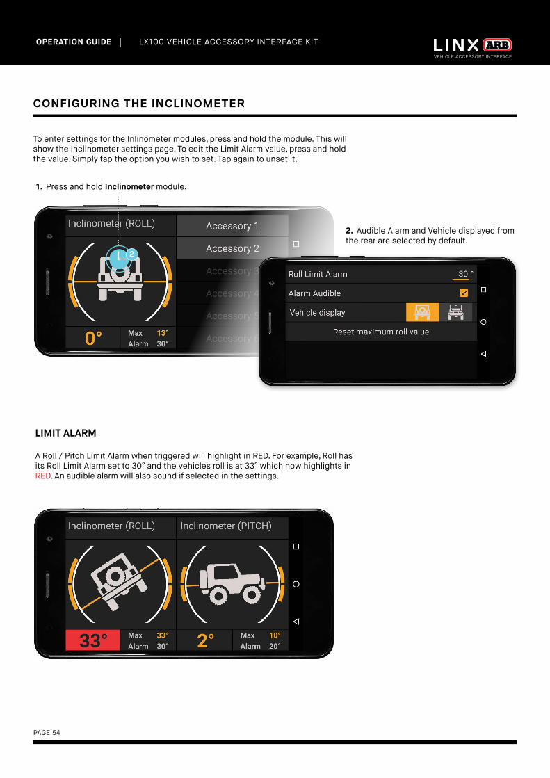
To enter settings for the Inlinometer modules, press and hold the module. This will show the Inclinometer settings page. To edit the Limit Alarm value, press and hold the value. Simply tap the option you wish to set. Tap again to unset it.
CONFIGURING THE INCLINOMETER
1. Press and hold Inclinometer module.
2. Audible Alarm and Vehicle displayed from the rear are selected by default.
LIMIT ALARM
A Roll / Pitch Limit Alarm when triggered will highlight in RED. For example, Roll has its Roll Limit Alarm set to 30° and the vehicles roll is at 33° which now highlights in RED. An audible alarm will also sound if selected in the settings.
| LX100 VEHICLE ACCESSORY INTERFACE KIT OPERATION GUIDE
PAGE 55
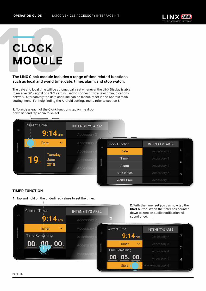
19.CLOCK MODULEThe LINX Clock module includes a range of time related functions such as local and world time, date, timer, alarm, and stop watch.
The date and local time will be automatically set whenever the LINX Display is able to receive GPS signal or a SIM card is used to connect it to a telecommunications network. Alternatively the date and time can be manually set in the Android main setting menu. For help finding the Android settings menu refer to section 8.
1. To access each of the Clock functions tap on the drop down list and tap again to select.
1. Tap and hold on the underlined values to set the timer.
TIMER FUNCTION
2. With the timer set you can now tap the Start button. When the timer has counted down to zero an audile notification will sound once.
| LX100 VEHICLE ACCESSORY INTERFACE KIT OPERATION GUIDE
PAGE 56
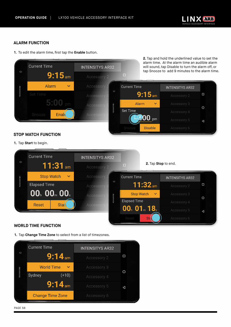
1. To edit the alarm time, first tap the Enable button.
ALARM FUNCTION
2. Tap and hold the underlined value to set the alarm time. At the alarm time an audible alarm will sound, tap Disable to turn the alarm off, or tap Snooze to add 9 minutes to the alarm time.
1. Tap Start to begin.
STOP WATCH FUNCTION
2. Tap Stop to end.
1. Tap Change Time Zone to select from a list of timezones.
WORLD TIME FUNCTION

| LX100 VEHICLE ACCESSORY INTERFACE KIT OPERATION GUIDE
PAGE 57
20.FRIDGE MODULEThe LINX Fridge module can monitor/control a compatible ARB Fridge Freezer that has been fitted with an ARB Fridge App Connect module (ARB #10900041).
When connected to a Series 2 ARB Fridge Freezer the module can be used to monitor and control the Fridge. Series 1 ARB Fridge Freezer manufactured post 2014 allow monitor function only.
1. Tap and hold the Fridge module to enter settings.
2. Tap the Connect to fridge button to search for nearby fridges.
3. Tap to select your fridge from the list. Ensure that the name matches that printed on the underside of the Fridge App Connect module.
4. You will then be asked to enter a security pin code to connect to the fridge, this is also printed on the underside of the Fridge App Connect module.
CONNECTING TO THE FRIDGE APP CONNECT MODULE

| LX100 VEHICLE ACCESSORY INTERFACE KIT OPERATION GUIDE
PAGE 58
If the connected fridge is a series 2 fridge, then you will be able to control the fridge by changing settings such as Battery Protection level, Display Brightness, and set up to 3 temperature mode names and values.If the connected fridge is a series 1 fridge then you will be able to monitor what these settings are on the fridge, but not change them.
2. To change the temperature mode names and values, scroll up then press and hold the underlined text to show the keyboard. Change the name/value as required and then tap DONE.
1. To change the Battery Protection or Display Brightness on the fridge, simply tap your selection.
4. The screen will return to Fridge module screen.
3. Tap the BACK button to return to Fridge module screen.
CONFIGURING A SERIES 2 FRIDGE
| LX100 VEHICLE ACCESSORY INTERFACE KIT OPERATION GUIDE
PAGE 59
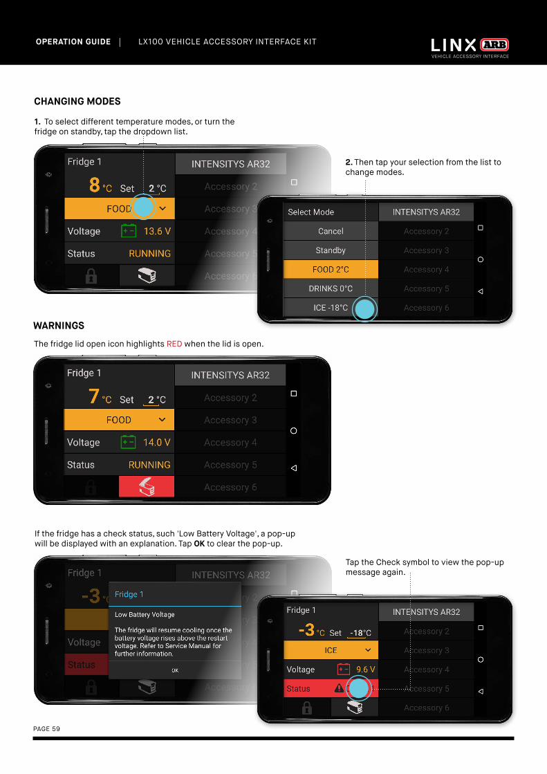
CHANGING MODES
1. To select different temperature modes, or turn the fridge on standby, tap the dropdown list.
2. Then tap your selection from the list to change modes.
WARNINGS
The fridge lid open icon highlights RED when the lid is open.
If the fridge has a check status, such 'Low Battery Voltage', a pop-up will be displayed with an explanation. Tap OK to clear the pop-up.
Tap the Check symbol to view the pop-up message again.

PAGE 60
| LX100 VEHICLE ACCESSORY INTERFACE KIT OPERATION GUIDE
COMPLIANCE INFORMATION
BACK TO TABLE OF CONTENTS
| LX100 VEHICLE ACCESSORY INTERFACE KIT OPERATION GUIDE
PAGE 61
21.COMPLIANCE INFORMATION
EUROPE - EU DECLARATION OF CONFORMITY
This declaration of conformity is issued under the sole responsibility of the manufacturer.
This declaration relates to these products:LINX 1.0
The products are in conformity with the following standards or standardized documents:
ETSI EN 301 489-17 V3.1.1:2017ETSI EN 301 489-1 V2.1.1:2017ETSI EN 300 328 V2.1.1:2016EN 60950-1:2006 + A11:2009 + A1:2010 + A12:2011 + A2:2013IEC 60950-1:2005 (Second Edition) + Am 1:2009 + Am 2:2013
According to the provisions of the directives:
2014/53/EU (Radio Equipment Directive)2014/30/EU (Electromagnetic Compatibility Directive)2014/35/EU (Low Voltage Directive)
Technical file at:ARB Corporation Ltd, 42-44 Garden St, Kilsyth, Victoria, Australia
Signed for and on behalf of ARB Corporation Ltd
Andrew BrownManaging DirectorMelbourne, March 2018
| LX100 VEHICLE ACCESSORY INTERFACE KIT OPERATION GUIDE
PAGE 62
USA - FCC STATEMENT
This device complies with part 15 of the FCC Rules. Operation is subject to the following two conditions: (1) this device may not cause harmful interference, and (2) this device must accept any interference received, including interference that may cause undesired operation.
This equipment has been tested and found to comply with the limits for a Class B digital device, pursuant to part 15 of the FCC Rules. These limits are designed to provide reasonable protection against harmful interference in a residential installation. This equipment generates, uses and can radiate radio frequency energy and, if not installed and used in accordance with the instructions, may cause harmful interference to radio communications. However, there is no guarantee that interference will not occur in a particular installation. If this equipment does cause harmful interference to radio or television reception, which can be determined by turning the equipment off and on, the user is encouraged to try to correct the interference by one or more of the following measures:
• Reorient or relocate the receiving antenna.• Increase the separation between the equipment
and receiver.• Connect the equipment into an outlet on a
circuit different from that to which the receiver is connected.
• Consult the dealer or an experienced radio/TV technician for help.
FCC CAUTIONSChanges or modifications made to this device that are not expressly approved by ARB Corporation Ltd may void the user’s authority to operate the equipment.This device must not be co-located or operated in conjunction with any other antenna or transmitter.
FCC RADIATION EXPOSURE STATEMENTThis equipment complies with FCC radiation exposure limits set forth for an uncontrolled environment. This equipment should be installed and operated with minimum distance of 20 cm between the radiator and your body.
ENVIRONMENTAL PROTECTION
Waste electrical products should not be disposed of with household waste. Please recycle where facilities exist. Check with your local authority or retailer for recycling advice.

ARB STORES
VICTORIA
Bairnsdale (03) 5152 1226
Ballarat (03) 5336 4605
Bendigo (03) 5445 7100
Brighton (03) 9557 1888
Dandenong (03) 9793 0002
Echuca (03) 5480 2600
Geelong (03) 5272 2611
Hoppers Crossing (03) 9749 5905
Keilor Park (03) 9331 7333
Kilsyth (03) 9761 6622
Pakenham (03) 5940 5500
Shepparton (03) 5822 1877
Somerton (03) 9460 9988
Traralgon (03) 5174 9190
SOUTH AUSTRALIA
Elizabeth (08) 8252 1599
Morphett Vale (08) 8186 6101
Regency Park (08) 8244 5001
ACT
Fyshwick (02) 6280 7475
NEW SOUTH WALES
Albury (02) 6021 2477
Artarmon (02) 9438 4484
Broken Hill (08) 8087 9250
Brookvale (02) 8507 3073
Dubbo (02) 6885 5777
Moorebank (02) 9821 3633
Newcastle (02) 4953 9555
Orange (02) 6369 0700
Penrith (02) 4731 1266
Port Macquarie (02) 6581 2500
St Peters (02) 9565 2455
Tamworth (02) 6762 0541
Thornleigh (02) 9980 8855
Wagga Wagga (02) 6925 8777
Wentworthville (02) 9631 7889
WESTERN AUSTRALIA
Canning Vale (02) 9455 4366
Geraldton (08) 9921 8077
Mandurah (08) 9583 3200
Osborne Park (08) 9244 3553
Wangara (08) 9409 5764
Welshpool (08) 9358 3688
NORTHERN TERRITORY
Alice Springs (08) 8953 0572
Darwin (08) 8947 2262
QUEENSLAND
Biggera Waters (07) 5537 8800
Bundaberg (07) 4153 2929
Burleigh Heads (07) 5535 9223
Caboolture (07) 5499 1955
Capalaba (07) 3823 5900
Cairns (07) 4035 3350
Caloundra (07) 5491 4500
Coopers Plains (07) 3277 2020
Jindalee (07) 3715 6400
Nundah (07) 3266 3255
North Lakes (07) 3491 9600
Springwood (07) 3493 3030
Mackay (07) 4998 6888
Maroochydore (07) 5475 4011
Rockhampton (07) 4922 7788
Toowoomba (07) 4632 1122
Townsville (07) 4728 0900
TASMANIA
Burnie (03) 6431 4494
Hobart (03) 6232 2333
Launceston (03) 6331 4190
INTERNATIONAL OFFICES
HEAD OFFICE
ARB 4X4 ACCESSORIES
42-44 Garden Street,
Kilsyth Victoria 3137 Australia
Tel: +61 (03) 9761 6622
Fax: +61 (03) 9761 6807
Email: [email protected]
Web: www.arb.com.au
NORTH AMERICA
720 SW 34th Street
Renton, WA 98057
Tel: +1 (425) 264 1391
Fax: +1 (425) 264 1392
Email: [email protected]
Web: www.arbusa.com
CENTRAL & SOUTH AMERICA
3700 Port Jacksonville Pkwy Suite
#1, Jacksonville FL 32226, USA
Tel: +1 (904) 379 8216
Fax: +1 (904) 813 7197
Email: [email protected]
THAILAND
Building GW1, 300/56,
Moo 1, Tambon Tasit,
Amphur Pluakdaeng,
Rayong, 21140, Thailand
Tel: +66 (0) 38 929 672
Fax: +66 (0) 38 929 676
Email: [email protected]
Web: www.arb.co.th
EUROPE
Na Dlouhém čc.80, DC2,
Ricany - Jažlovic,
251 01, Czech Republic
Tel: +420 323 040 900
Fax: +420 323 040 910
Email: [email protected]
Web: www.arbeurope.com
MIDDLE EAST
ARB Middle East FZE
LIU15, RA07AB05
Jebel Ali Freezone,
North Dubai, United Arab Emirates
Tel: +971 4 880 7005
Email: [email protected]
OTHER REGIONS
Please contact our
Export Department
Tel: +61 3 9761 6622
Email: [email protected]
Top Related
Copyright © 2022 FDOKUMEN

