


Bahasa
Halaman
Hukum


On-Demand Monitoring of Construction Projects
through a Game-Like Hybrid Application of BIM and
Machine Learning
Farzad Pour Rahimiana,b,∗, Saleh Seyedzadehc,d, Stephen Oliverc,d, SergioRodrigueza, Nashwan Dawooda
aSchool of Computing, Engineering & Digital Technologies, Teesside University, TeesValley, Middlesbrough, UK.
bDepartment of Civil and Environmental Engineering (DICeA), University of Florence,Florence, Italy.
cFaculty of Engineering, University of Strathclyde, Glasgow G1 1XW, UK.darbnco, Glasgow, UK.
Abstract
Whilst unavoidable, inspections, progress monitoring, and comparing as-planned with as-built conditions in construction projects do not readily addtangible intrinsic value to the end-users. In large-scale construction projects,the process of monitoring the implementation of every single part of build-ings and reflecting them on the BIM models can become highly labour in-tensive and error-prone, due to the vast amount of data produced in theform of schedules, reports and photo logs. In order to address the men-tioned methodological and technical gap, this paper presents a frameworkand a proof of concept prototype for on-demand automated simulation of con-struction projects, integrating some cutting edge IT solutions, namely imageprocessing, machine learning, BIM and Virtual Reality. This study utilisedthe Unity game engine to integrate data from the original BIM models andthe as-built images, which were processed via various computer vision tech-niques. These methods include object recognition and semantic segmenta-tion for identifying different structural elements through supervised trainingin order to superimpose the real world images on the as-planned model. Theproposed framework leads to an automated update of the 3D virtual environ-ment with states of the construction site. This framework empowers project
∗Email: [email protected]
Preprint submitted to Automation in Construction November 7, 2019

managers and stockholders with an advanced decision-making tool, high-lighting the inconsistencies in an effective manner. This paper contributesto body knowledge by providing a technical exemplar for the integration ofML and image processing approaches with immersive and interactive BIMinterfaces, the algorithms and program codes of which can help replicabilityof these approaches by other scholars.
Keywords: Construction Management, Progress Monitoring, BuildingInformation Modelling, Image Processing, Virtual Reality, Machine learning
1. Introduction
The complexity of the construction projects and the individualistic ap-proach to every building project result in delays and errors. Majority ofconstruction management and monitoring processes are still conducted tra-ditionally with the use of 2D drawings, reports, schedules and photo logs,making the process complicated and inefficient. The impact of Informationand Communication Technology (ICT) integration on progressive improve-ment in the construction is undeniable [1, 2, 3]. Different technologies andsystems have been recently implemented on construction sites to improveproject communication, coordination, planning and monitoring, includingweb-based technologies, cloud computing, Building Information Modelling(BIM), and tracking technologies [4, 5]. These novel applications are usu-ally used in different technological combinations to improve the constructionmonitoring and allow for comparison of the as-planned and as-built mod-els [6]. BIM capabilities are no longer limited to geometry representation(i.e. 3D virtual objects), and enhance many other aspects of constructionprojects, such as information management (through semantically rich mod-els), inbuilt intelligence and analysis (via active knowledge-based systemsand simulation), as well as collaboration and integration (through digitaldata exchange) [7].
BIM has been widely used in construction projects for improving commu-nication among various parties during different phases of design and projectdelivery [8, 9]. However, due to the myriad of issues such as the unpre-dictable pace of works, continually changing site environments, and the needfor constant synchronisations, BIM use has been hindered in the monitoringof construction projects. This is despite the fact that adopting on-demanddata acquisition techniques in conjunction with BIM models to compare the
2

state of the sites with the as-planned models has been suggested by manyresearchers [10, 11, 12, 13], because of the time-consuming and error-pronenature of these activities. Nonetheless, the interoperability between the toolsand systems has been identified as the main obstacle, which is presently hardto overcome [14].
For addressing this methodological and technical gap, this study devel-oped a framework and a proof-of-concept prototype, facilitating bilateralcoordination of information flow between construction sites and the BIMmodels. In this framework, computer vision and machine learning (ML)techniques are proposed to help prepare and compose site photographs withthe as-planned BIM models. The interoperability and integration of thesetechniques are facilitated by the aid of Virtual Reality (VR) game engines,such as the Unity engine. The proposed hybrid application of image process-ing and BIM is expected to enable facilitation of on-demand as-built modelupdate for construction progress tracking. The integration performed in theVR environment (VRE) with the use of a game engine is to enable usersto actively participate in the progress evaluation as well as highlighting andreporting the inconsistencies
This paper first outlines an overview of existing technologies for auto-mated construction monitoring, focusing on image processing and visualisa-tion methods. Then, the proposed framework for integration of BIM, MLand VR is discussed, followed by the details of prototype design, appliedtechniques and algorithms, development strategies, and system architectureof the game like VRE. Finally, the conclusion is presented by wrapping upthe work done thus far and describing future research opportunities for im-provement of the developed system.
2. Related Studies
2.1. Overview of Real-Time Data Collection Technologies
The data collection technologies for construction project monitoring canbe divided into three main categories: a) enhanced information technologies,such as multimedia, emails, voice, and hand-held computing, b) geospatialtechnologies, like Geographic Information System (GIS), Global Position-ing System (GPS), barcoding and Quick Response (QR) coding, Radio Fre-quency Identification (RFID) and Ultra Wide Band (UWB) tags, and c)image-based technologies, including photogrammetry, videogrammetry andlaser scanning [15].
3

GPS and GIS are commonly used automated asset tracking systems,which can be used for the analysis of construction site equipment operations[16]. Location information of the construction elements is used to identifyand track the equipment activity and compile the safety information to im-prove the decision-making and site management processes [17]. When GISis integrated with BIM, it can help construction managers identify the bestspaces for tower cranes and represent the material progress in supply chainmanagement [18].
Barcoding allows for product identification and is considered as one ofthe most cost-effective construction tool monitoring methods. However, itis time-consuming, due to the required reading to the tag proximity, andthere is a restricted quantity of information contained in each barcode label.Barcode technology is also considered to be unreliable as the tags are proneto damage in the harsh construction environment, or can be lost [15]. QR, onthe other hand, provides more information, and it is commonly exploited dueto the increasing popularity of mobile phones and tablets utilisation onsitewith the available QR code reading applications. The implementation of QRcodes has been suggested in conjunction with BIM technology to improvecommunication on-site and to increase health and safety [19].
RFID incorporates the use of radiofrequency waves instead of light waves,allowing for overcoming the distance issue [15]. This technology has widelybeen used in conjunction with BIM for leveraging control and monitoring ofconstruction projects [20] as well as productivity optimisation and improvinghealth and safety [21]. UWB signals can be reliable, even beyond wallsor any other obstruction that may be faced and are known as one of themost accurate systems for distance positioning, monitoring and tracking,consuming considerably low energy [22].
Laser scanning technology allows for 3D object scanning and data collec-tion for existing environments. The data is generally stored in the form ofa 3D point cloud, which can be used for the creation of a digital twin of abuilding [23, 24]. The primary factors that make the scan-to-BIM methodless practical are the required expensive equipment and the time-consumingprocess for data collection and BIM model creation, which itself is error-prone[25]. Although this method is mainly used for documentation and renovationprojects, there is a potentiality for automating construction progress moni-toring, which can be achieved through a combination of 3D point cloud ac-quisition and three-dimensional object recognition to categorise constructionelements and 3D models associated with construction schedule [26]. Fur-
4

ther to laser scanning, light detection and ranging (LiDAR) technology hasbeen proposed for monitoring construction projects by employing roboticsand creating 3D modelling [27].
All these cutting-edge technologies offer several benefits, yet pose spe-cific drawbacks, specifically in supporting monitoring of construction sitesfor inconsistencies [28]. However, capturing site images is still consideredas the easiest and least labour intensive method of gathering informationfrom construction sites [15]. The advent of new photo shooting technologies,such as cheap camera drones and depth image cameras has further facilitatedand promoted the construction scene recording actions. The next section isdedicated to reviewing technologies processing construction site photos formonitoring purposes.
2.2. Machine Learning-Based Image Processing for Construction ProgressMonitoring
ML techniques found their applications in buiding energy filed early on1990’s [29], however, their use in the field of construction monitoring is verynew, and their advantage has not been fully exploited. Automatic image-based modelling techniques for progress monitoring and defects detention hasbeen in the area of interest of many researchers, in both construction andcomputer science domains [30, 31, 32]. Integration of as-built photographswith 4D modelling using time-lapsed photos was proposed for constructionprogress monitoring [33]. Later, the same group [34] suggested an auto-mated monitoring system for employing daily construction images and anIndustry Foundation Classes (IFC) model-based BIM. In their study, visual-isation was achieved through the creation of a 4D as-built model from pointcloud images and performing an image classification for progress detectionand an as-planned model from BIM. This work was then followed by [35],performing an automated comparison of the actual state and planed state ofconstruction through photometric methods, in order to detect discrepanciesand adjustment of the construction schedules.
Kim et al. [36] proposed a methodology based on image processingfor automated update of 4D models via incorporating (Red-Green-Blue)RGB colour image acquisition, in accordance with specific instructions. Theprogress identification was also performed by applying 3D-CAD based imagefilters [37]. Roh et al. [11] integrated as-planned BIM models with as-builtprojects data extracted from the site photographs, which was then overlaid
5
in a 3D walkthrough environment to help estimate the delays in the con-struction progress.
As manually site photography is time-consuming and challenging in somesections, many researchers have suggested the use of Unmanned Aerial Vehi-cles (UAVs) for this purpose [38, 39, 40]. Golparvar-Fard et al. [34] developedan ML method for detection of the ongoing progress of construction. Theyutilised an image data set, including progress and no-progress predefined pho-tos and trained a classification model to be used for prediction of new images.Image classification was also used for the detection of construction materialsand building a BIM model to support automated progress monitoring [41].
It was argued that employing image synthesis methods can help improvethe accuracy of classifiers. Soltani et al. [42] demonstrated the efficiencyof synthetic images in training vision detectors of construction equipment.Rashidi et al. [43] compared three different classification models for mate-rial detection and managed to automatically detect concrete, oriented strandboard and red brick from the still images. Kim and Kim [44] used the his-togram of oriented gradient visual descriptor for training a set of syntheticallycreated images to help facilitate site equipment detection.
2.3. Virtual and Augmented Reality for Construction Project Monitoring
Initially used in the gaming industry, VR applications have long sinceentered the architecture and construction industries, allowing better visu-alisation and simulation of various scenarios [45]. Kim and Kano [46] ad-vocated the superiority of related VR images over the ordinary photographstaken from the construction sites for progress monitoring. It has been arguedthat VR images can provide a realistic location and condition of structureelements comparable to 3D CAD models [47]. VR technologies have widelybeen used for design and construction prototyping by modelling and visu-alising different activates, in order to identify potential risks and optimiseconstruction process [48], also to help effectively manage design alterationsand improve communications with clients[49]. Retik et al. [50] developed ahybrid VR interface integrated with telepresence and video communicationsystems allowing remote construction monitoring.
AR has been getting more attention in the construction industry becauseof its ability to superimpose virtual objects on real world scenes. Severalresearch works have used AR for providing more accurate interactive site vi-sualisation [51], construction worksite planning [52], underground infrastruc-ture planning and maintenance [53], comparison of as-built and as-planned
6

images on construction sites [54], and visualisation of equipment operationand tasks [55]. The effectiveness of using AR tools in supporting decision-making and conveying the sophisticated knowledge to the parties engaged inconstruction has also been overtly advocated [54].
Kopsida and Brilakis [56]proposed a method to enhance inspection andprogress monitoring for interior activities, using HoloLens. The applicationprojected 3D as-planned model on the real-world scene, for identifying in-consistencies with actual construction. Ratajczak et al. [57] integrated ARwith BIM and location-based management system, as a mobile application tofacilitate the progress monitoring and communication of construction projectparties. The app is supported by Tango ready smartphones and displays the3D BIM model overlaid onto as-built images. It also delivers information onconstruction tasks and materials technical data.
2.4. Summary of Progress Monitoring Methods
The various methods used for construction progress monitoring is sum-marised in Table 1, highlighting the limitations and advantages of each.
7
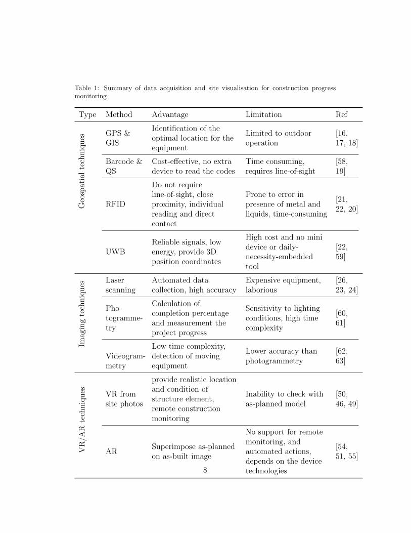
Table 1: Summary of data acquisition and site visualisation for construction progressmonitoring
Type Method Advantage Limitation Ref
Geo
spat
ial
tech
niq
ues
GPS &GIS
Identification of theoptimal location for theequipment
Limited to outdooroperation
[16,17, 18]
Barcode &QS
Cost-effective, no extradevice to read the codes
Time consuming,requires line-of-sight
[58,19]
RFID
Do not requireline-of-sight, closeproximity, individualreading and directcontact
Prone to error inpresence of metal andliquids, time-consuming
[21,22, 20]
UWBReliable signals, lowenergy, provide 3Dposition coordinates
High cost and no minidevice or daily-necessity-embeddedtool
[22,59]
Imag
ing
tech
niq
ues
Laserscanning
Automated datacollection, high accuracy
Expensive equipment,laborious
[26,23, 24]
Pho-togramme-try
Calculation ofcompletion percentageand measurement theproject progress
Sensitivity to lightingconditions, high timecomplexity
[60,61]
Videogram-metry
Low time complexity,detection of movingequipment
Lower accuracy thanphotogrammetry
[62,63]
VR
/AR
tech
niq
ues VR from
site photos
provide realistic locationand condition ofstructure element,remote constructionmonitoring
Inability to check withas-planned model
[50,46, 49]
ARSuperimpose as-plannedon as-built image
No support for remotemonitoring, andautomated actions,depends on the devicetechnologies
[54,51, 55]
8
2.5. Research Gap
Although there have been tools including geospatial and imaging tech-niques to enhance progress tracking of construction projects, these appli-cations are not yet able to effectively identify the inconsistencies betweenas-built and as-planned models. Moreover, there is a need for a decisionsupport system for project monitoring to support effective communicationamong the involved parties. The reviewed literature shows that there hasbeen a great success in employing VR and AR applications for supportingdecision-making at design stages and handling complicated tasks in facilitiesmanagement. However, this great potential has not been fully utilised in theconstruction phase for enhancing project progress monitoring and reporting,mainly due to specific conditions of construction sites which make them dif-ferent from any other environment. It was mentioned that previous studieshave been successful in integrating AR and BIM models to provide a toolfor construction progress inspection. However, these tools heavily rely onthe accuracy of utilised AR tools, and thereby prone to error. On the otherhand, the use of such solutions for proper communications among construc-tion parties requires the presence of contributors on construction sites. Thisissue is one of the main raising challenges in construction management. Theuse of VR to tackle this problem has been very limited as it requires multidis-ciplinary cooperation to realise the interoperability of it with 3D informationmodelling and advanced AI methods.
The framework and prototype presented in this paper aim at integrat-ing ML, artificial intelligence, image processing, VR and BIM technologiesaligned with gamification approaches in order to address this particular re-search gap. Unlike previous attempts that utilised ML and BIM directlyas a means for identifying work progress or diagnosing particular problems,this framework benefited from those technologies for the preparation of aninteractive virtual environment to be manipulated by a game engine. There-fore, this tool allows effective utilisation of these technologies in order tosupport selective examination of various building characteristics at differenttimes and by different people, hence making the system more usable for allprofessionals involved in the project.
3. Project Framework
The core component of the hybrid system described in this article is agame-like VRE, providing integration between ML-based image processing
9
and BIM. As such, the developed system architecture in this study consistsof four major elements: 1) image capturing, 2) image processing, 3) BIMauthoring, and 4) VR game authoring and object linking. Overall, the studyproved the concept that the integration of computer vision, image process-ing, BIM and VR can facilitate the automatic update of a digital model,storage of the data in a standard file format, and display of project progressinformation in a structured manner. This paper posits that this can be usedas an effective tool for communicating with different parties involved in con-struction projects and decision-making.
Despite the fact that laser scanning and photogrammetry are the leadingmethods for collecting special and geometric information, still image photog-raphy method was adopted in this study, as an inexpensive and hassle-freemethod, that has become the industry standard for gathering constructionsite progress information.
Figure 1 demonstrates the schematic diagram of the proposed system ar-chitecture. Interoperability and flawless information exchange were seen as asignificant driver in this research; therefore, Autodesk Naviswork (NWD) fileformat and IFC as standard file format were used throughout this research.First, entities from BIM IFC model links to the unity to create the VR model.From this model, a dataset of synthetic RGB-D images is generated. Then,Neural networks are trained using the created data enriched with real-worlddepth images to create classifier models.
Construction site images were captured every day using a depth camera,then regenerated by copying the same camera settings and location (localisa-tion) within the BIM model. These images were stored in cloud-based stor-age along with the BIM model. ML classification technique, ConvolutionalNeural Network (CNN), was applied to the aforementioned photographs todetect and identify different objects and building components. Image pro-cessing was then utilised to remove unwanted objects from the scenes forfurther clarity.
Recognised and classified elements were linked to the related actionabletasks from the time schedules linked to the BIM model. The extracted de-tails were then overlaid onto the as-planned BIM models for the purpose ofcomparison.
The superimposed construction status data was transferred to the gameengine through scripting or exporting IFC into an Autodesk FilmBoX (FBX)format, then integrated with the virtual environment. This provided thesystem with a higher level of immersion, improved visualisation and enhanced
10
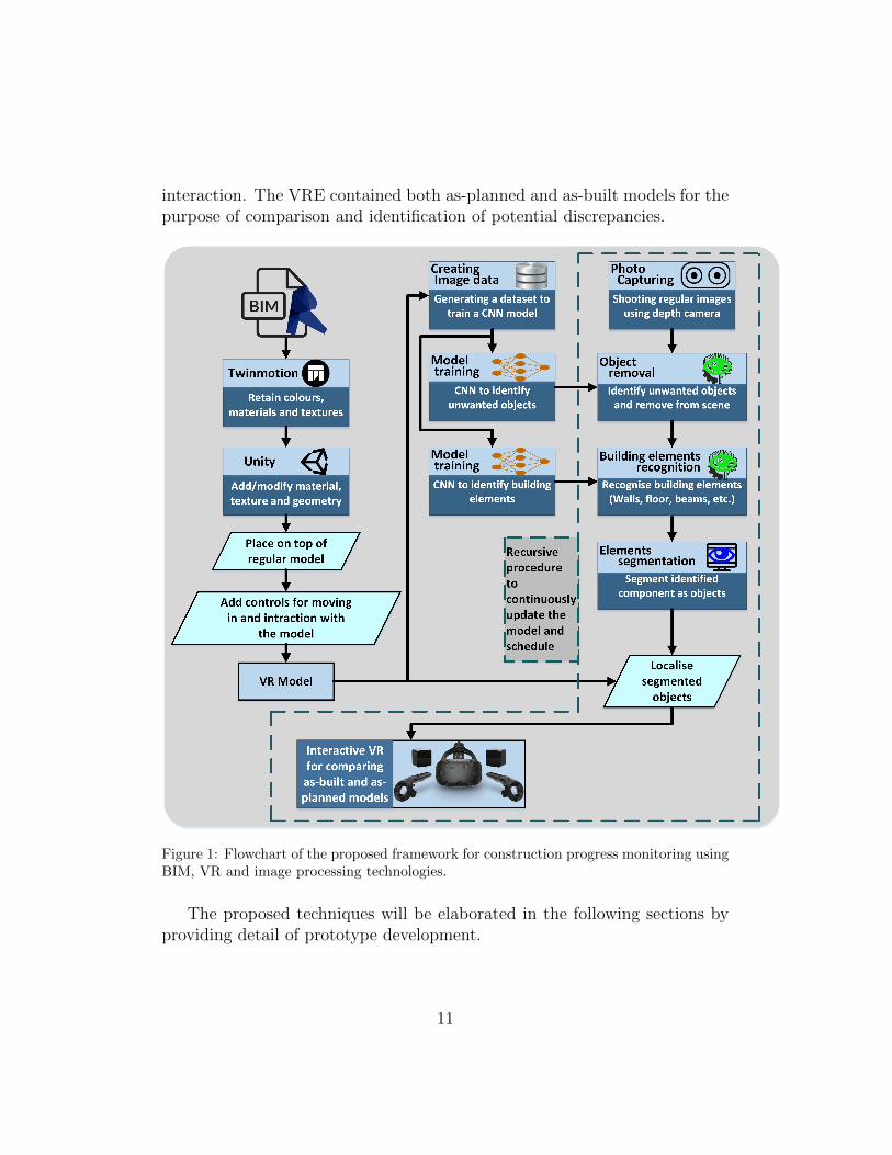
interaction. The VRE contained both as-planned and as-built models for thepurpose of comparison and identification of potential discrepancies.
Figure 1: Flowchart of the proposed framework for construction progress monitoring usingBIM, VR and image processing technologies.
The proposed techniques will be elaborated in the following sections byproviding detail of prototype development.
11
4. Prototype Development
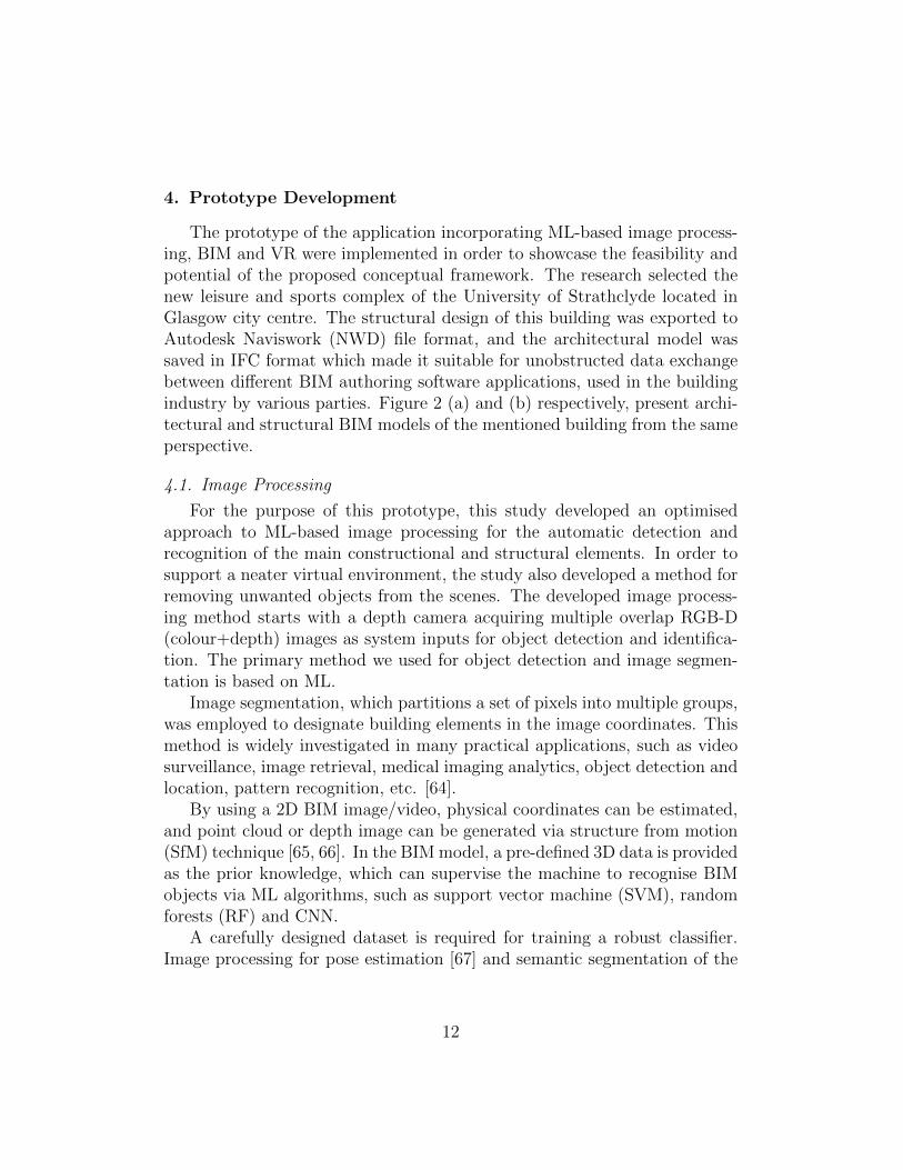
The prototype of the application incorporating ML-based image process-ing, BIM and VR were implemented in order to showcase the feasibility andpotential of the proposed conceptual framework. The research selected thenew leisure and sports complex of the University of Strathclyde located inGlasgow city centre. The structural design of this building was exported toAutodesk Naviswork (NWD) file format, and the architectural model wassaved in IFC format which made it suitable for unobstructed data exchangebetween different BIM authoring software applications, used in the buildingindustry by various parties. Figure 2 (a) and (b) respectively, present archi-tectural and structural BIM models of the mentioned building from the sameperspective.
4.1. Image Processing
For the purpose of this prototype, this study developed an optimisedapproach to ML-based image processing for the automatic detection andrecognition of the main constructional and structural elements. In order tosupport a neater virtual environment, the study also developed a method forremoving unwanted objects from the scenes. The developed image process-ing method starts with a depth camera acquiring multiple overlap RGB-D(colour+depth) images as system inputs for object detection and identifica-tion. The primary method we used for object detection and image segmen-tation is based on ML.
Image segmentation, which partitions a set of pixels into multiple groups,was employed to designate building elements in the image coordinates. Thismethod is widely investigated in many practical applications, such as videosurveillance, image retrieval, medical imaging analytics, object detection andlocation, pattern recognition, etc. [64].
By using a 2D BIM image/video, physical coordinates can be estimated,and point cloud or depth image can be generated via structure from motion(SfM) technique [65, 66]. In the BIM model, a pre-defined 3D data is providedas the prior knowledge, which can supervise the machine to recognise BIMobjects via ML algorithms, such as support vector machine (SVM), randomforests (RF) and CNN.
A carefully designed dataset is required for training a robust classifier.Image processing for pose estimation [67] and semantic segmentation of the
12
(a)
(b)
Figure 2: (a) Architectural and (b) structural BIM models.
13
scene (Song et al., 2017), includes labelling each pixel within the depth im-age with an object associated category to supervise the ML algorithm andlearning the voxel features of the object. In BIM projects, it is a practi-cal approach to use a pre-defined 3D model for simulating depth images invarious viewpoints, thus generating as many labelled depth images as pos-sible for building a dataset prior to the commencement of the constructionwork. The details of generating data for training the network using virtualphotogrammetry are presented in the next section.
Taking daily construction activity planning into consideration, a deepneural network seems a proper option, as it can automatically tune the pa-rameters [68, 69], based on the new given data. Therefore, it can effectivelylearn a new representation of an object along with the progress of a BIMproject instead of retraining a new classifier on a daily basis.
Due to the diverse nature of predictions for semantic segmentation andrecognition of unwanted objects in the construction scenery, training a singlemodel to perform both tasks accurately is rather difficult. Moreover, theutilised dataset for training a model for image segmentation which includessynthetic images does not include those intended objects, such as human ormachinery. As such, this study first applied a separate network for recogni-tion of these objects. This procedure guarantees the precision of both modelsby utilisation of individual training sets. It is possible to train one modelfor both purposes, using a comprehensive dataset. However, preparation ofsuch dataset is very laborious as it requires a graphical mixture of environ-ment and objects, both in the form of synthetic and real images. Moreover,obtaining adequate negative data is another hurdle for creating a recogni-tion model. It should be noted that the negative samples are as valuable aspositive records in training an accurate model that requires identifying thedesired objects precisely as well as rejecting the false detections.
4.1.1. Object removal
Taking photos from a construction site is the first step in creating an as-built model for the purpose of comparison between the current state and theas-planned model. Construction scenes consist of many tools and materials,which are considered as unwanted objects in the construction progress mon-itoring application. Furthermore, the presence of these objects will lead tofaulty detection of construction elements related to the BIM model. Gener-ally, it is not practical to move all these objects while shooting photos. Thisstudy proposed an automated two-stage object removal method in order to
14

address this challenge. The first step was using the supervised object recog-nition technique for identifying unwanted objects, and the second step wasto fill the area of the detected object in a visually plausible way.
Many approaches for filling a part of an image or inpainting have beendeveloped by the previous studies. However, as the images used in the studycontained depth information, it was posited that a suitable region fillingmethod should be able to estimate the depth filling pixels. This study em-ployed an exemplar-based method developed by [70] as a suitable means toaddress this requirement. First, these elements were recognised and seg-mented using the pre-trained CNN, then the boundary of the target regionwas identified, a patch was chosen to be inpainted, and the source area wasqueried to find the best-matching spot via an appropriate error metric. Thisstudy noted that the main advantage of this method over the other inpaintingmethods was its ability to propagate the texture into the target region.
Gupta et al. [71] trained a large CNN on RGB-D images to recogniseobjects and applied a semantic segmentation to infer object masks. For thepurpose of demonstration, this study trained CNN to detect humans in theconstruction scene. For training data, the study selected 3200 positive im-ages [72] and 7500 negative images [72]. Figure 3 shows the detail of themethod for recognition of objects using RGB-D images and presents howRGB-D images make it possible to calculate the depth and average gradi-ents. This detail is then combined with a fast edge detection approach togenerate enhanced outlines. The contours are used to create 2.5D regioncandidates through processing characteristics on the depth and colour im-age. The depth-map is encoded with various channels at each pixel, namelyhorizontal disparity, height over ground, and the angle the pixel’s local sur-face. Then the CNNs which are trained on RGB-d images detect intendedobjects in 2.5D region candidates. Each CNN begins with a set of region pro-posals, and calculate features on them. The box proposals are then classifiedusing a linear support vector machine.
Figure 4 shows the original image and with a depth-map, taken from theconstruction site. Figure 5 presents the output of applying object recognitionwith the trained CNN.
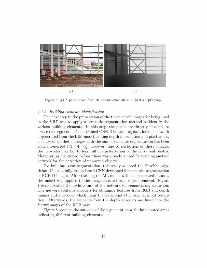
When the unwanted object is recognised, the filtered image is passed tothe object removal procedure to eliminate it from the scene and fill the gapin both RGB and depth space. The outcome of applying this algorithm inFigure 4 is demonstrated in Figure 6. The depth-map of the generated imageis illustrated in Figure 6 (b).
15
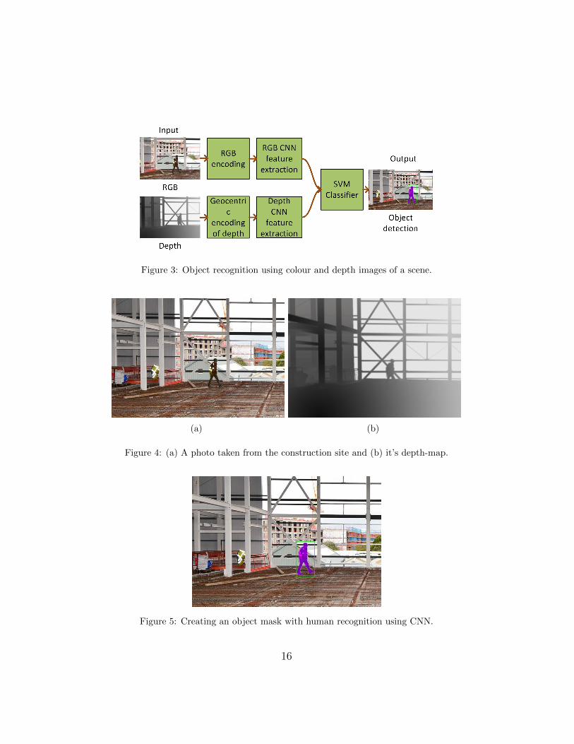
Figure 3: Object recognition using colour and depth images of a scene.
(a) (b)
Figure 4: (a) A photo taken from the construction site and (b) it’s depth-map.
Figure 5: Creating an object mask with human recognition using CNN.
16
(a) (b)
Figure 6: (a) A photo taken from the construction site and (b) it’s depth-map.
4.1.2. Building elements identification
The next step in the preparation of the taken depth images for being usedin the VRE was to apply a semantic segmentation method to identify thevarious building elements. In this step, the pixels are directly labelled, tocreate the segments using a trained CNN. The training data for this networkis generated from the BIM model, adding depth information and pixel labels.The use of synthetic images with the aim of semantic segmentation has beenwidely reported [73, 74, 75], however, due to perfection of those images,the networks may fail to learn all characterisation of the noisy real photos.Moreover, as mentioned before, there was already a need for training anothernetwork for the detection of unwanted objects.
For building scene segmentation, this study adopted the FuseNet algo-rithm [76], as a fully fusion-based CNN developed for semantic segmentationof RGB-D images. After training the ML model with the generated dataset,the model was applied to the image resulted from object removal. Figure7 demonstrates the architecture of the network for semantic segmentation.The network contains encoders for obtaining features from RGB and depthimages and a decoder which maps the feature into the original input resolu-tion. Afterwards, the elements from the depth encoders are fused into thefeature-maps of the RGB part.
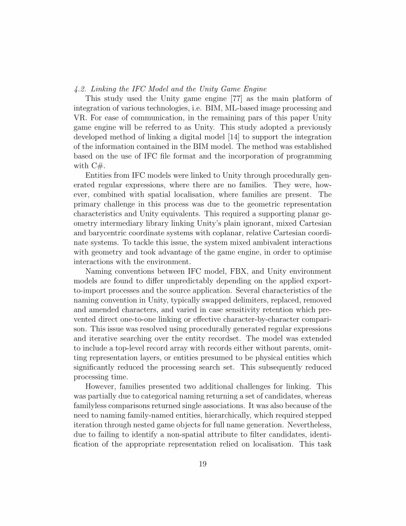
Figure 8 presents the outcome of the segmentation with the coloured areasindicating different building elements.
17
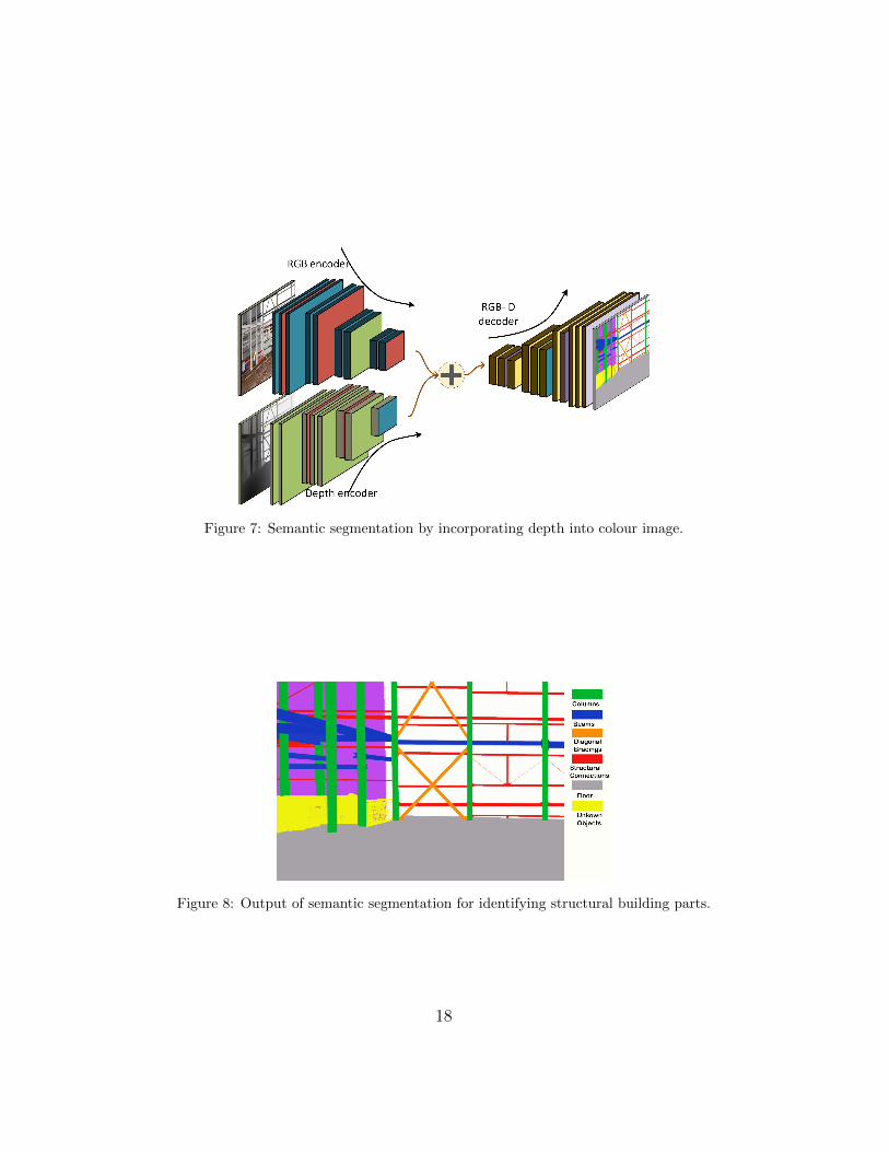
Figure 7: Semantic segmentation by incorporating depth into colour image.
Figure 8: Output of semantic segmentation for identifying structural building parts.
18
4.2. Linking the IFC Model and the Unity Game EngineThis study used the Unity game engine [77] as the main platform of
integration of various technologies, i.e. BIM, ML-based image processing andVR. For ease of communication, in the remaining pars of this paper Unitygame engine will be referred to as Unity. This study adopted a previouslydeveloped method of linking a digital model [14] to support the integrationof the information contained in the BIM model. The method was establishedbased on the use of IFC file format and the incorporation of programmingwith C#.
Entities from IFC models were linked to Unity through procedurally gen-erated regular expressions, where there are no families. They were, how-ever, combined with spatial localisation, where families are present. Theprimary challenge in this process was due to the geometric representationcharacteristics and Unity equivalents. This required a supporting planar ge-ometry intermediary library linking Unity’s plain ignorant, mixed Cartesianand barycentric coordinate systems with coplanar, relative Cartesian coordi-nate systems. To tackle this issue, the system mixed ambivalent interactionswith geometry and took advantage of the game engine, in order to optimiseinteractions with the environment.
Naming conventions between IFC model, FBX, and Unity environmentmodels are found to differ unpredictably depending on the applied export-to-import processes and the source application. Several characteristics of thenaming convention in Unity, typically swapped delimiters, replaced, removedand amended characters, and varied in case sensitivity retention which pre-vented direct one-to-one linking or effective character-by-character compari-son. This issue was resolved using procedurally generated regular expressionsand iterative searching over the entity recordset. The model was extendedto include a top-level record array with records either without parents, omit-ting representation layers, or entities presumed to be physical entities whichsignificantly reduced the processing search set. This subsequently reducedprocessing time.
However, families presented two additional challenges for linking. Thiswas partially due to categorical naming returning a set of candidates, whereasfamilyless comparisons returned single associations. It was also because of theneed to naming family-named entities, hierarchically, which required steppediteration through nested game objects for full name generation. Nevertheless,due to failing to identify a non-spatial attribute to filter candidates, identi-fication of the appropriate representation relied on localisation. This task
19
was achieved by using bounding box centre points, which were generated byUnity during mesh construction and lazily evaluated by the IFC Library.
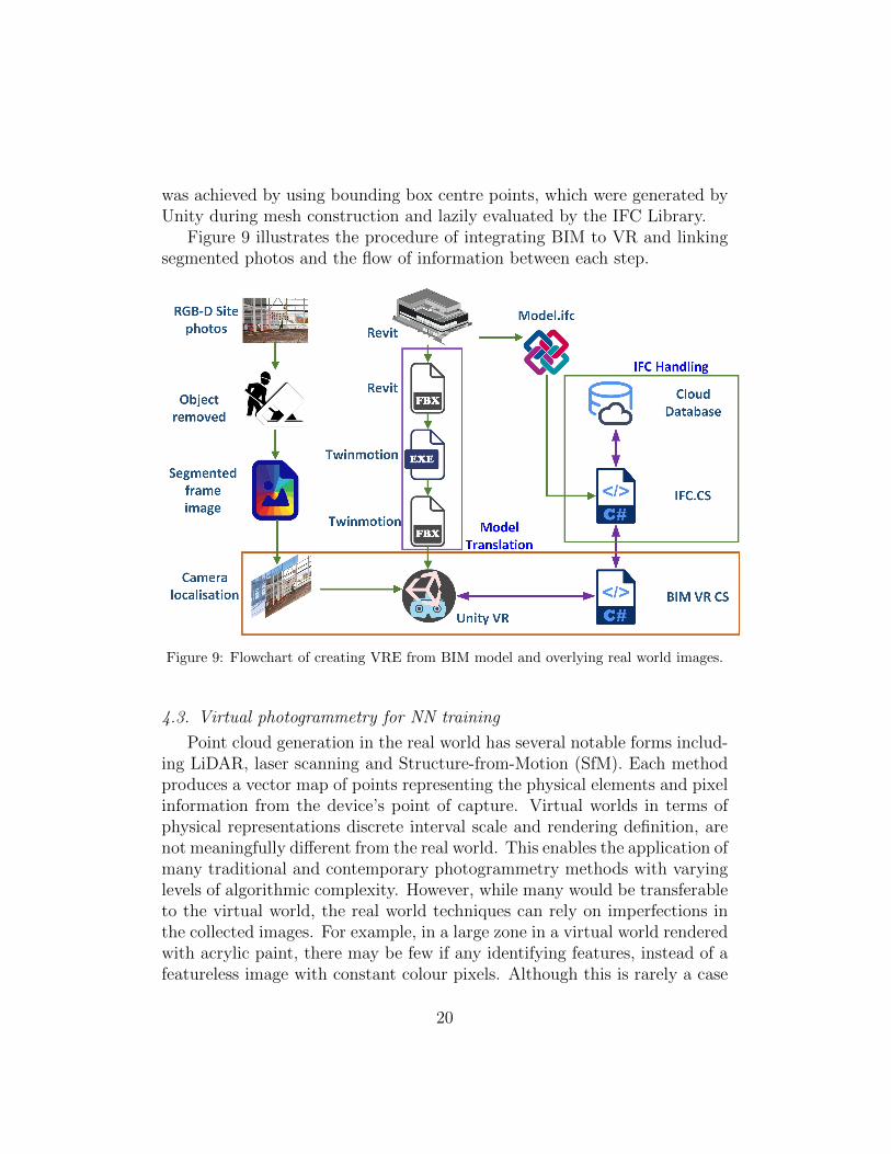
Figure 9 illustrates the procedure of integrating BIM to VR and linkingsegmented photos and the flow of information between each step.
Figure 9: Flowchart of creating VRE from BIM model and overlying real world images.
4.3. Virtual photogrammetry for NN training
Point cloud generation in the real world has several notable forms includ-ing LiDAR, laser scanning and Structure-from-Motion (SfM). Each methodproduces a vector map of points representing the physical elements and pixelinformation from the device’s point of capture. Virtual worlds in terms ofphysical representations discrete interval scale and rendering definition, arenot meaningfully different from the real world. This enables the application ofmany traditional and contemporary photogrammetry methods with varyinglevels of algorithmic complexity. However, while many would be transferableto the virtual world, the real world techniques can rely on imperfections inthe collected images. For example, in a large zone in a virtual world renderedwith acrylic paint, there may be few if any identifying features, instead of afeatureless image with constant colour pixels. Although this is rarely a case
20

in virtual models, a method needs to work with everything or nothing. Thisreduces the potential for SfM. Similarly, implementations of real world toolsin a virtual world are often significantly different from how they function inreality. LiDAR, for example, uses omnidirectional pulses. If this were im-plemented literally in the virtual world, a countable but impractical numberof ray casts would be required which would bring the engine to a halt for along time.
Instead, at point of triggering the function in the virtual world, the trig-gering objects that reside and interrogate a physical object database wouldstep out of the world. For instance, in the case of a game with human agents,rather than raycast in every direction, the script would locate all players inthe database then separate the (x,y) and (z) dimensions. Using the (x,y)boundaries, a simple rectangle would be created around the agent, and anintersection calculation would be carried out for each line until a horizontalintersection occurs; otherwise, the play is ignored. Assuming it is identified,in the next stage, a vertical intersect assertion would be made. The simplestsolution at this point may ray cast only within the boundaries of the box.A more complex solution may use relative coordinate systems and spatialcaching to reduce further the number of cases required. For example, forany given intersect the boundary box method may be applied to infer pointswhich do not merit raycasting.
In order to avoid a complicated algorithm based on existing techniquesused in the real world, this study facilitated virtual photogrammetry usinga simple application of the game engine’s physics component and its cameraclass functionality. Using the Camera class’s camera point to virtual worldcoordinate translation function, each pixel’s relative location in the virtualworld is identified. A raycast is sent from that location, matching the baseorientation of the camera then attempts to intersect with any object witha MeshCollider. Upon successfully hitting an object, a struct is createdcontaining the 2D and 3D coordinate system locations, an extension to thedefault Mesh class which accommodates binding of external data, such as IFCand the triangle on the mesh which was hit. The latter implicitly linking aBarycentric coordinate system to the struct. As mentioned in the planargeometry system, triangular meshes are translated into planar surface sets.This set is already bound with the mesh, and each plane constituents meshtriangles. Each point struct is added to the point cloud dictionary, whichmay then be exported for producing composite images, or helping scalablediscrete reconstruction.
21
The library is susceptible to two issues common with other forms of pho-togrammetry, i.e. nonuniform intervals and point density. However, in con-trast to the real world, the process is reproducible and does not require anadditional journey through the model. At any point, where the cloud lacksintegrity, a camera can be spawned to collect additional data with partiallycontrolled precision. Partial is used here as a caveat for the inherent limita-tions of casting a finite number of times on varying distance surfaces.
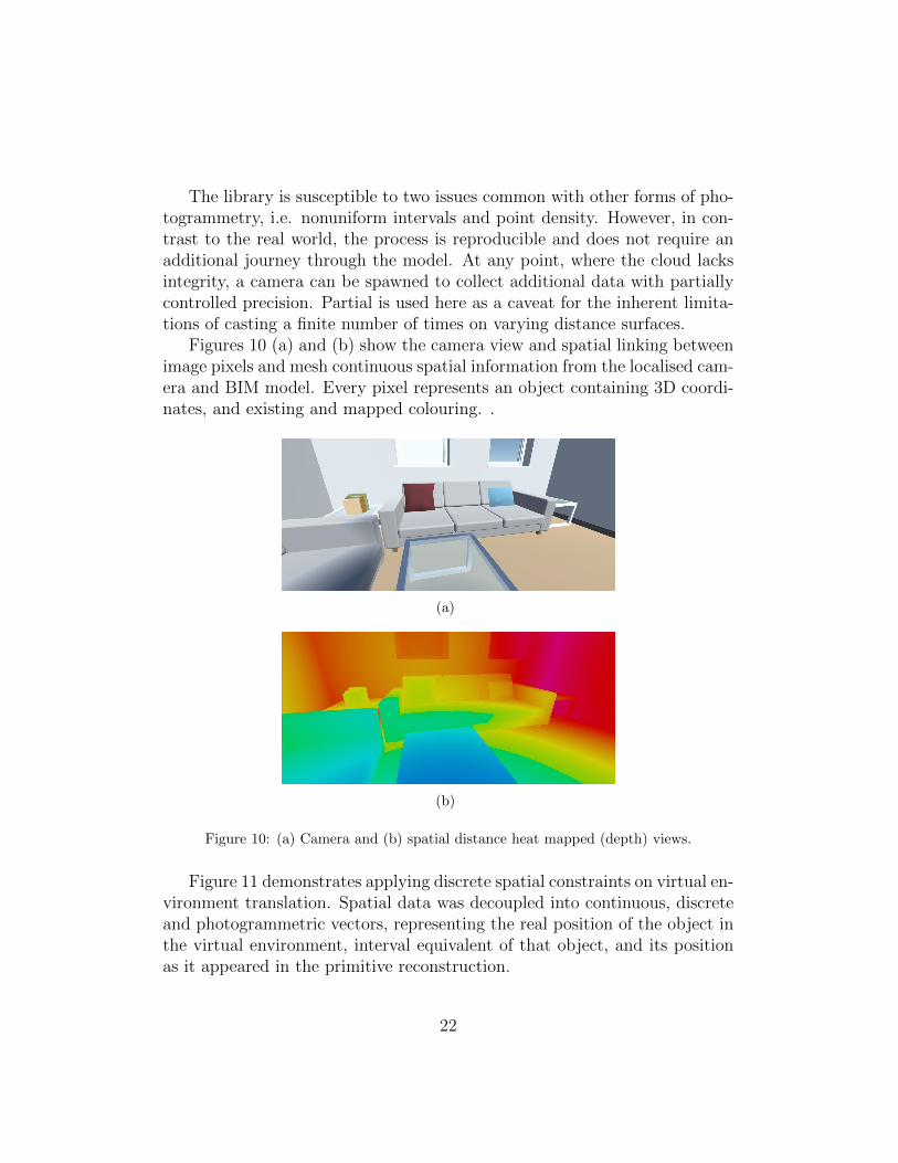
Figures 10 (a) and (b) show the camera view and spatial linking betweenimage pixels and mesh continuous spatial information from the localised cam-era and BIM model. Every pixel represents an object containing 3D coordi-nates, and existing and mapped colouring. .
(a)
(b)
Figure 10: (a) Camera and (b) spatial distance heat mapped (depth) views.
Figure 11 demonstrates applying discrete spatial constraints on virtual en-vironment translation. Spatial data was decoupled into continuous, discreteand photogrammetric vectors, representing the real position of the object inthe virtual environment, interval equivalent of that object, and its positionas it appeared in the primitive reconstruction.
22

Figure 11: Discrete distance Heat-mapped view.
Synthetic image data is collected primarily using the virtual photogram-metry methods demonstrated in images 10 and 11, and procedurally generat-ing random camera locations in spaces or near the objects of interest. Usingthe floor perimeter, the camera location boundaries can be obtained, and thenumber of floor elements can be used as a proxy. Cameras are first spawnedaround human height, enabling initial data collection regarding the currentspace, primarily making ceiling height identification and partially identifyingzone boundaries. Once these have been identified, a camera can store an im-age and use the learned spatial boundaries to choose a new camera locationwithin the space. The virtual photogrammetry and camera movement in thespace can then be iteratively applied to the partial mapping, ceiling heightand farthest surface distance to constrain camera angle.
The virtual photogrammetry is then used to bind pixels to their con-stituent entities in the virtual world, and if bound, to update IFC repre-sentations. Their material, entity type and where relevant, the families areextracted from the IFC schema. This is bound to the raw image data includedUV and ARGB. Pixels are grouped by the entity that they are associatedwith. Entities with pixel adjacencies can have surface poly-boundary pointscheck for coplanarity with surfaces on the other entity. The relationshipsare tested in each imaging set, ensuring most are encaptured. As shown inFigure 12, entities can be turned off such that the surrounding hidden (orpartially hidden) entity surfaces can be mapped. If necessary, this could alsobe used to identify which entities are present in the space, but occluded.
Data is then split into its constituent sets and inserted into a databaseor tracked in an image relations file. The former interrogated via SQL andthe latter parsed into the PixelRelation class of the VP library. Splicing ina localised real-world image now has a truth network for training real-world
23

Figure 12: Category-mapped scene view.
classifiers and segmentation models, where the data in the virtual world isappropriate mostly for producing inference networks. The significance of theformer is that project like ImageNet are massive human endeavours. Peoplemanually segment images and classify objects. Since the virtual world hasalready segmented virtual representations, these can be used to estimateconfidence in classifications. Using depth from the real-world and virtual-world relative scale can be used to refine the expectations. If somethingseems right, but not linked between both, other profiles from virtual imagescan be scaled and compared. If an object is still not identified, a case forpropagating a specialist classifier for that type of object exists. The familyor entity’s related images can then be used to train a model looking for thoseexclusively.
4.4. Integration with the Game Engine
Autodesk Revit viewed and amended the original BIM model of theStrathclyde Sports Centre. The digital model was imported into the Unitygame engine to allow for the development of VR simulation. The Unity gamecreation engine was the primary platform for creating the application, usingthe C# as the main programming language. The IFC BIM model was ex-ported in the FBX file through a TwinMotion plug-in for Revit. The plug-inwas incorporated in the workflow, since the export of the FBX file throughRevit would result in loss of the textures defining the materials during thetransition to Unity. This method allowed flawless export of the BIM modelwith the textures assigned. The use of TwinMotion was proved to be verybeneficial and contributed to achieving a high-quality asset in Unity. Specificoptimisations were made to the BIM model to correct the existing errors inthe geometry. The size of the model caused a sort of issues since the entiremodel and all the objects were rendered at the same time.
24

The HTC Vive was the primary VR headset used for this work. TheVive comes equipped with two controllers, and two wall or tripod mountablescanners that allow the user to move around extensively within their per-sonal real world space. A Windows gaming laptop with an Intel i7 processorand NVidia GTX 1070 graphics card was the machine used to create theapplication.
4.5. Overlaying the Segmented Images
When the virtual environment was built in the Unity engine, the finalstep to complete the monitoring tool was to overlay as-built images over theas-planned model. The elaboration of the method as a set of rules was asfollows:
• Where no high-precision camera location information was known, butthe entities of interest were identified, they may have been highlightedentirely via the Colour property of the primary material. Changingthis property would highlight the desired objects, so that when theuser brought them into view, they would have been able to identifywhether or not they were of interest.
• Where camera location was known, but orientation and field of viewweren’t, faces could be identified via generation of a FaceSet throughthe UnityIFC library, which could create the planes to define the entity.In this case, the script needed to effectively raycast to the centre of theclosest triangle on the largest two faces. Once the face was identified,the barycentric coordinate systems needed to be used to determinewhich triangle is associated with that specific raycast. The trianglepoint list direction which informed the user as to whether the triangleis visible or not rendered. If the triangle is rendered, then the face isthat the user should see; otherwise, the other largest face is that ofinterest. The identified face’s primary material colour would then needto be changed to the highlighting colour.
• Where all the above (including the field of view) were known, the sys-tem would provide an indication of entities which were not entirely inplace. That is not to say the system has definitely identified erroneouslypositioned columns. However, they might have been highlighted, wherea re-measure with a laser distance meter (as Leica Disto) would havebeen worthwhile. There were two options for achieving this goal: 1) by
25

using superimposing the segmented image over an n-dimensional imagecreated with the library designed for this project, or 2) by applying asimilar process for direct raycasting from the superimposed segments.In the case of the former, the screen or secondary camera resolutionneeded to be adjusted to match the metadata on the picture; or if notpossible, up to a proportional scale. It should, however, be noted thatin this case, additional control for pixel scale would have been requiredas well as including buffering the AND failure area to accommodatethe larger pixels. Pixels from each then needed to be first comparedwith an AND operation to identify where expected pixels overlie withthe segmented sections from the image processor.
• Where the AND failed, there was a potential misalignment of the en-tities, and each should have been highlighted appropriately using twodistinctive colours to demonstrate where the segment and virtual facewere out with the boundary of the other.
Figure 13 illustrates the overall proposed procedure for overlaying thesegmented images on the BIM model in the VRE. Figure 14 shows the resultof superimposing the segmented image over BIM model in VR environment,where the columns are selected for the investigation.
Figure 13: Procedure flowchart of overlaying segmented images over BIM model in VRE.
26

Figure 14: Superimposing the columns in the VR environment.
Camera localisation has several meaningful opportunities depending onthe information of entities captured within the view and segmentation. Themethods appropriate for this paper primarily rely on segmentation and BIMlocalisation. Depth segmentation is mostly excluded here, but confidencein its results can surpass the random sampling type method described. Thefollowing describes an idealised (two-sample) instance, however, the principleof RANSAC could be applied in conjunction with it to refine and confirm.
IPS has been reported to be accurate within 300mm which is a signif-icant improvement on GPS, reported to be accurate within 5,000mm. Inrecent years, research has refined the use of fiducial markers, demonstratingaccuracy within 80mm. In each case, the reported accuracy is without thebenefit of verification with segmentation or virtual photogrammetry fromBIM models. With the assumption that a floor is segmented, choosing threepoints on the surface, with two creating a line perpendicular to the camera,forms an isosceles or equilateral triangular hyperplane. Splitting this into atriangle and trapezoid and injecting the z dimension from segmentation willprovide enough data to estimate the shear coefficient. Repeating this processon a second perpendicular triangle will only be consistent, if it falls withina reasonable tolerance, and if the surface is horizontal. Otherwise, it shouldbe possible to estimate the second shear coefficient and then rearrange shearfunctions to determine perpendicular horizontal axis orientation. With theorientation of the surface and shear coefficient, the cameras’ height and ori-entation can be determined. The results may be confirmed by repeating theprocess on the virtual planes associated with the segmented surfaces by usingthe pixel reference to identify the surface.
27
With or without the previous calibration for height and orientation, clas-sified segmentation may aid location inference. Using segmented entities andIPS virtual photogrammetry can be used to search for similar or expectedprofiles. Considering a beam, for example, the orientation can be determinedfrom another hyperplane, this time between the floor and vertical centre pointof the beam, shear coefficient and taking the ratio of the full height and thesecond height of another point along the floor/beam, not the entire length.By repeating the process, the results may be refined. The final stage forthis method is subsampling segmented and virtual properties and applyingRANSAC to make educated guess from what appears to be in both fromsegmentation in both virtual and real worlds.
Another option is using fiducial or natural markers, specifically for lo-calisation of the camera. While natural markers are not necessarily present,anyone taking pictures may throw temporary markers to the floor which, willenable the previous method in conjunction with IPS. Segmentation aided lo-calisation is a matter of confidence in what has been identified. Any markersknown to be on the floor will facilitate the previous method. In either case,if a floor is known, IPS accuracy is enough to start using surface-to-surfaceedge detection connected, noncoplanar surfaces. Localisation is not an exactscience and under normal circumstances is not guaranteed to work. However,with BIM overlaying, the virtual test frame can be moved and the VP can beregenerated. It is not great to say educated guessing can solve the problem,however, it doesn’t matter whether the process is achieved by a single processor it takes a thousand. Localisation doesn’t need to happen in seconds orminutes, it just has to fall within an acceptable tolerance and not requirehuman input.
5. Discussions
Technology-Supported Integration of Real and Virtual Worlds:Bridging the gap between real and virtual-worlds is no longer a matter oftechnological barriers but rather a resource management issue. The toolswhich are necessary to link, translate and fuse mixed reality data exist inisolation. It is down to development teams to figure out how they maybe combined to produce a practical utility under the constraints of fundingand team capacity. Some techniques, such as Drone LiDAR scanning havelong since been established for producing a discrete spatial mapping of thereal world, that can be translated into virtual components. To a lesser ex-
28

tent, some tools such as Tango-enabled mobiles can produce and translatepoint-clouds to coloured 3D meshes in near real-time. Pour Rahimian etal. [14] demonstrated translation between vector and discrete virtual en-vironments and linking Cartesian and Barycentric coordinate systems. Inthis study, bidirectional linking between discrete and vector worlds were ex-tended to incorporate raster representations, ultimately developing a virtualphotogrammetry tool for mixed reality.
ML-Assisted Image Processing: Python’s SciKit-learn contains manyflexible deep learning utilities designed for image classification, object iden-tification and semantic segmentation. Of course, ML and deep learning toolsaren’t without flaw, but through progressive interactive training with re-inforcement, transfer learning and input homogenisation, they can be con-vinced to perform well beyond expectations. Linking virtual and real worlds,however, requires testing, tweaking and reinforcement, which under normalcircumstances, would require significant team involvement which cannot al-ways be consumed in parallel and must be carefully managed.
Paradigm Shift in Project Monitoring: The process of developingand proving solutions for research objectives similar to this study do notneed to rely on the real world initially. Through abstracting the process,there is no reason why individual components from virtual and real worldutilities or data sources cannot be interchangeable. For example, virtualphotogrammetry module for the Unity game engine, which was developedin this study can differ from real photogrammetry only by imperfectionsin the surfaces they may scan. Although virtual models can produce idealsurface maps, there is a little challenge in introducing imperfections. Theidea behind converging realities is that tasks which are constrained by serialtime, equipment allocation and team capacity are not subject to the sameconstraints. If a team has one drone in the real world, they can generate dataspecific to the target building(s) at the rate which the camera is capable ofcapturing UV and point-cloud data. The properties of the building andenvironment are immutable, the weather and lighting are situational, andthe rendering is not controllable by the pilot.
Expedited Data Collection: In contrast, virtual worlds are constrainedonly by the amount of processing time and devices that can be afforded to theproject. Data collection can be automatic and in parallel, and the environ-mental and target features are mutable. The virtual world can be spawnedrandomly with rendering material types, resolution and imperfections uniqueto a given instance; even the target can be sampled from a repository of
29

buildings. Drones in the virtual world don’t need pilots, nor do they havephysical representations meaning more than one can collect data during asingle collection. Unity can be compiled for Linux machines which enablenext-to-nothing cost parallel processing. In short, by the time the real worldpilot has travelled to the site and generated data for a single target, the vir-tual world can produce thousands of data sets from any number of targetswith a flexible selection of the characteristics that are otherwise immutablein the real world.
Converging Realities: The aim of attempting to converging realitiesis to take actions which are applicable to virtual world data applicable todata from the real world by gradually blurring the lines between the two.The real and virtual world renderings are never going to be identical, andtherefore, training models on purely virtual data alone would likely be un-fruitful. However, between readily available rendering material images andFast Style Transfer (FST) CNNs creating a progressive interactive trainingensemble can be made easier. FSTs, as demonstrated by Engstrom [79],learn the common characteristics of a given training image’s artistic style bycomparing it with thousands of images with distinct artistic styles includingworks from historically famous artists. Once a model has been trained, animage can be converted from its raw state to a style-transferred equivalent.
The Virtual Photogrammetry Technique: In this study, rather thanattempting to create a complicated algorithm based on existing techniquesused in the real world, virtual photogrammetry was facilitated using simpleapplication of the game engine’s physics component. Currently constrainedby the screen resolution, not a physical constraint, any given camera is sent arequest to capture what it sees at the time step it receives the request. At theend of the time, step a call back to capture the spatial and physical objectdata. This process is by no means perfect and not implicitly transferable tothe real world, but it lays the foundation of progressing to a practical tool.
Role of Open Standards, Interoperability and Social Psychol-ogy: This research suggested the next disruptive innovation in AEC soft-ware will not be in the form of cutting edge design functionality but ratherby greater consideration for social psychology’s role in effective computer-mediated communication. Pour Rahiumian et al. (2019) in contrast, arguedthat focus should be on interoperability with an emphasis on accommodat-ing immersive virtual environments. This paper proposes an intermediateand demonstrates a collection of tools that partially bridge the gap betweenthese two suggestions. Open standards can facilitate interoperability not
30
only between traditional vector CAD vendors but also packages which arenot directly linked to the construction industry. Pour Rahimian et al. [14],for example, discussed the potential application of their BIM library to re-side outside virtual environments entirely. The library does not presupposethat the interface has any graphical interface to the extent that the modelmay be interrogated without an interfacing script. This project tackles theopposite side of communication problems in accordance to converging real-ities approach, in which linking real and virtual worlds has many objectiveand subjective benefits. Through the ability to mix worlds, the subjectiveperception of proximity between involved parties can be heightened throughinherent increases in media richness while reducing the risk of communicationbreakdown from initially unverifiable conflicts.
Application, Functionality, Impacts and Contributions of theStudy: This paper’s application in data science is yet to be established.However, it has the potential to be its most significant contribution to sci-entific knowledge. The framework and prototype presented in this studyformed methodological and technical foundations for a converging realitiesapproach to self-propagating hierarchical deep learning ensembles and creat-ing an AI network which aims to progressively introduce real world imagesto virtual world datasets, via homogenisation of real and virtual world im-ages. A weakness of that kind of process, however, is its initial attemptsto rationalise the real world. This project is well suited to mitigating thistraction problem. Linking both real and virtual world enables determinis-tic assertion of the presence of equipment and construction features throughspatial comparison of real and virtual photogrammetry data. This serves tosolve two problems. First, where an entity is proven to be present in bothworlds but not identified by an image classifier, additional images from eitherworld may be introduced to its training data or can be used to produce achild branch in the network. Second, the information in the virtual worldis explicitly linked to the virtual entity and therefore, it can be bound topixels in a deterministic manner. In short, this library’s functionality mayreduce the need for difficult segmentation while providing a mechanism forreinforcement and transfer learning.
6. Conclusion
The research presented in this paper addresses the methodological andtechnical gap in the emerging digital analytical tools of machine learning and
31
computer vision and the advanced visualisation media including BIM, andinteractive game-like immersive VR interfaces, in order to leverage automa-tion of construction progress monitoring. To achieve this, the study proposeda framework and developed a proof of concept prototype of a hybrid systemwhich is capable of importing and processing construction site images andintegrating them with the nD building information models within a gamelikeimmersive VRE. It was discussed in lights of the reviewed literature thatdespite the wide adoption of modern technologies in construction progressmonitoring, the use of BIM, as an as-planned constructional model, has notbeen exploited well, due to the interoperability issues among the relevanttechnologies.
Therefore, this study responded to the necessity of a platform that cansupport continuous system update and enable construction managers andclients to effectively compare the building construction (as-built) with as-planned BIM model for the purpose of deficiency detection. The resultingprototype, based around the principles of remote construction project mon-itoring, took advantage of ML and image processing in removing unwantedobjects, recognising and extracting main building characteristics, and over-laying these on the corresponding as-planned nD components. VR technolo-gies, including Unity and HTC Vive, provided a virtual environment to allowbetter user interaction with these elements.
It was argued in the paper that the proposed platform could help con-struction companies to follow the progress of their work and diagnose anydiscrepancy without interrupting the on-site operations. This remote manag-ing tool can also save a great deal of time and provide a more accurate com-parison of constructed parts with the as-planned BIM model. On the otherhand, this powerful virtual environment can be used for presenting the stageof building development to the clients. The facilitated automatic update ofthe model makes it possible to have an on-demand schedule method withoutthe need for sophisticated wireless-enabled devices. One of the main contri-butions of this project was providing a technical exemplar for the integrationof ML and image processing approaches with immersive and interactive BIMinterfaces, the algorithms and program codes of which can help replicabilityof these approaches by other scholars.
The methods of object recognition, image processing and overlying realimages over as-planned BIM model were suggested for completion and demon-stration of the presented prototype. However, different approaches might beadopted in future to achieve better identification and segmentation of the
32
building elements, considering the studied construction site situation anddemands. Moreover, advanced positioning systems can be employed for eas-ier localisation of such components through extracting camera location. Fur-thermore, the prospective photo shooting procedures can be further enhancedby means of contemporary UAVs, which are capable of pre-programmed andautonomous aviation and actions. Hence, the utilisation of advanced smalldrones can automate image acquisition. This is possible through defining ahome point and a route in the virtual environment, then adapting it to thereal-world location and finally transferring the flight plan to the drone via awaypoint path. As most advanced UAVs encompass 360-degree sensors, theyare able to perform safe indoor manoeuvres. The use of these UAVs can alsoreduce health and safety risks and allow for capturing the site images, evenwhen there are works in progress.
Acknowledgement
The authors would like to gratefully acknowledge the generous fund-ing received from Advanced Forming Research Centre (AFRC), under theRoute to Impacts Scheme (grant numbers: R900014-107 & R900021-101)which enabled the team to conduct this study. This work would also notbe feasible without the generous PhD funding for the second author, whichwas co-funded by the Engineering The Future scheme from University ofStrathclyde and the Industry Funded Studentship Agreement with arbncoLtd (Studentship Agreement Number: S170392-101). The authors are alsohighly grateful to the considerable support from arbnco Ltd in both fundingthe third author’s MPhil study and supporting his professional developmentover the last decade. The authors also would like to acknowledge the con-tributions of Dr Andrew Agapiou, Dr Vladimir Stankovic, Frahad Chamo,Minxiang (Jeremy) Ye, Andrew Graham and Kasia Kozlowska from Strath-clyde University, during the initial BIM-VR prototype development stages.Finally, valuable advice received from various managers in AFRC, especiallyDavid Grant is highly appreciated.
References
[1] R. A. Stewart, IT enhanced project information management in con-struction: Pathways to improved performance and strategic compet-itiveness, Automation in Construction 16 (4) (2007) 511–517. doi:
10.1016/j.autcon.2006.09.001.
33

[2] S. J. Kolo, F. P. Rahimian, J. S. Goulding, Offsite manufacturing con-struction: A big opportunity for housing delivery in Nigeria, ProcediaEngineering 85 (2014) 319–327. doi:10.1016/j.proeng.2014.10.557.
[3] F. Pour Rahimian, R. Ibrahim, M. N. Baharudin, Using IT/ICT as anew medium toward implementation of interactive architectural com-munication cultures, in: Proceedings - International Symposium onInformation Technology 2008, ITSim, Vol. 4, IEEE, 2008, pp. 1–11.doi:10.1109/ITSIM.2008.4631984.
[4] E. O. Ibem, S. Laryea, Survey of digital technologies in procurementof construction projects, Automation in Construction 46 (2014) 11–21.doi:10.1016/j.autcon.2014.07.003.
[5] E. J.Adwan, A. Al-Soufi, A Review of ICT Technology In Construc-tion, International Journal of Managing Information Technology 8 (3/4)(2016) 01–21. doi:10.5121/ijmit.2016.8401.
[6] S. Alsafouri, S. K. Ayer, Review of ICT Implementations for Facil-itating Information Flow between Virtual Models and ConstructionProject Sites, Automation in Construction 86 (2018) 176–189. doi:
10.1016/j.autcon.2017.10.005.
[7] N. Gu, V. Singh, K. London, BIM Ecosystem: The Coevolution ofProducts, Processes, and People, in: K. Kensek, D. Noble (Eds.),Building Information Modeling: BIM in Current and Future Prac-tice, no. MAY, John Wiley & Sons, Hoboken, 2014, pp. 197–210.doi:10.1002/9781119174752.ch15.
[8] F. Svalestuen, V. Knotten, O. Lædre, F. Drevland, J. Lohne, UsingBuilding Information Model (Bim) Devices To Improve InformationFlow and Collaboration on Construction Sites, Journal of InformationTechnology in Construction 22 (February) (2017) 204–219.URL http://www.itcon.org/2017/11, Accessed 7th Nov 2019
[9] M. Sheikhkhoshkar, F. Pour Rahimian, M. H. Kaveh, M. R. Hosseini,D. J. Edwards, Automated planning of concrete joint layouts with 4D-BIM, Automation in Construction 107 (2019) 102943. doi:10.1016/j.autcon.2019.102943.
34

[10] J. Teizer, Status quo and open challenges in vision-based sensing andtracking of temporary resources on infrastructure construction sites, Ad-vanced Engineering Informatics 29 (2) (2015) 225–238. doi:10.1016/
j.aei.2015.03.006.
[11] S. Roh, Z. Aziz, F. Pena-Mora, An object-based 3D walk-through modelfor interior construction progress monitoring, Automation in Construc-tion 20 (1) (2011) 66–75. doi:10.1016/j.autcon.2010.07.003.
[12] K. K. Han, M. Golparvar-Fard, Appearance-based material classificationfor monitoring of operation-level construction progress using 4D BIMand site photologs, Automation in Construction 53 (2015) 44–57. arXiv:arXiv:1011.1669v3, doi:10.1016/j.autcon.2015.02.007.
[13] K. K. Han, M. Golparvar-Fard, Potential of big visual data and build-ing information modeling for construction performance analytics: Anexploratory study, Automation in Construction 73 (2017) 184–198.doi:10.1016/j.autcon.2016.11.004.
[14] F. Pour Rahimian, V. Chavdarova, S. Oliver, F. Chamo, OpenBIM-Tango integrated virtual showroom for offsite manufactured productionof self-build housing, Automation in Construction 102 (2019) 1–16. doi:10.1016/j.autcon.2019.02.009.
[15] T. Omar, M. L. Nehdi, Data acquisition technologies for constructionprogress tracking, Automation in Construction 70 (2016) 143–155. doi:10.1016/j.autcon.2016.06.016.
[16] J. Song, C. T. Haas, C. H. Caldas, Tracking the Location of Ma-terials on Construction Job Sites, Journal of Construction Engineer-ing and Management 132 (9) (2006) 911–918. doi:10.1061/(ASCE)
0733-9364(2006)132:9(911).
[17] V. Ptrucean, I. Armeni, M. Nahangi, J. Yeung, I. Brilakis, C. Haas,State of research in automatic as-built modelling, Advanced EngineeringInformatics 29 (2) (2015) 162–171. doi:10.1016/j.aei.2015.01.001.
[18] K. Chen, W. Lu, Y. Peng, S. Rowlinson, G. Q. Huang, Bridging BIM andbuilding: From a literature review to an integrated conceptual frame-work, International Journal of Project Management 33 (6) (2015) 1405–1416. doi:10.1016/j.ijproman.2015.03.006.
35
[19] T. M. Lorenzo, B. Bossi, M. Cassano, D. Todaro, BIM and QR Code. ASynergic Application in Construction Site Management, Procedia Engi-neering 85 (2014) 520–528. doi:10.1016/j.proeng.2014.10.579.
[20] H. Xie, W. Shi, R. R. A. Issa, Using rfid and real-time virtual realitysimulation for optimization in steel construction USING RFID ANDREAL-TIME VIRTUAL REALITY SIMULATION FOR OPTIMIZA-TION IN STEEL CONSTRUCTION, Journal of Information Technol-ogy 16 (September) (2015) 291–308.URL http://www.itcon.org/2011/19, Accessed 7th Nov 2019
[21] E. J. Jaselskis, T. El-Misalami, Implementing radio frequency identifi-cation in the construction process, Journal of Construction Engineer-ing and Management 129 (6) (2003) 680–688. doi:10.1061/(ASCE)
0733-9364(2003)129:6(680).
[22] D. L. Jochen Teizer, M. Sofer, Rapid Automated Monitoring of Con-struction Site Activities Using Ultra-Wideband, in: 24th InternationalSymposium on Automation and Robotics in Construction (ISARC),no. 2, 24th International Symposium on Automation & Robotics in Con-struction, Kochi, 2007, pp. 23–28. doi:10.22260/ISARC2007/0008.
[23] R. Lu, I. Brilakis, Digital twinning of existing reinforced concrete bridgesfrom labelled point clusters, Automation in Construction 105 (2019)102837. doi:10.1016/J.AUTCON.2019.102837.
[24] R. Woodhead, P. Stephenson, D. Morrey, Digital construction: Frompoint solutions to IoT ecosystem, Automation in Construction 93 (2018)35–46. doi:10.1016/J.AUTCON.2018.05.004.
[25] F. Bosche, M. Ahmed, Y. Turkan, C. T. Haas, R. Haas, The value ofintegrating Scan-to-BIM and Scan-vs-BIM techniques for constructionmonitoring using laser scanning and BIM: The case of cylindrical MEPcomponents, Automation in Construction 49 (2015) 201–213. doi:10.
1016/j.autcon.2014.05.014.
[26] Y. Turkan, F. Bosche, C. T. Haas, R. Haas, Automated progress track-ing using 4D schedule and 3D sensing technologies, Automation in Con-struction 22 (2012) 414–421. doi:10.1016/j.autcon.2011.10.003.
36
[27] S. Ladha, R. Singh, Monitoring construction of a structure (jan 2018).URL https://patents.google.com/patent/US20180012125A1/en,Accessed 7th Nov 2019
[28] Z. Asgari, F. P. Rahimian, Advanced Virtual Reality Applications andIntelligent Agents for Construction Process Optimisation and DefectPrevention, Procedia Engineering 196 (2017) 1130–1137. doi:10.1016/j.proeng.2017.08.070.
[29] S. Seyedzadeh, F. P. Rahimian, I. Glesk, M. Roper, Machine learn-ing for estimation of building energy consumption and performance:a review, Visualization in Engineering 6 (1) (2018) 5. doi:10.1186/
s40327-018-0064-7.
[30] J. Seo, S. Han, S. Lee, H. Kim, Computer Vision techniques for construc-tion safety and health monitoring, Advanced Engienering Informatics29 (2) (2015) 239–251. doi:10.1016/j.aei.2015.02.001.
[31] Y. Ham, K. K. Han, J. J. Lin, M. Golparvar-Fard, Visual monitoringof civil infrastructure systems via camera-equipped Unmanned AerialVehicles (UAVs): a review of related works, Visualization in Engineering4 (1) (2016) 1. doi:10.1186/s40327-015-0029-z.
[32] H. Guo, Y. Yu, M. Skitmore, Visualization technology-based construc-tion safety management: A review, Automation in Construction 73(2017) 135–144. doi:10.1016/j.autcon.2016.10.004.
[33] M. Golparvar-Fard, F. Pena-Mora, C. A. Arboleda, S. Lee, Visualizationof Construction Progress Monitoring with 4D Simulation Model Over-laid on Time-Lapsed Photographs, Journal of Computing in Civil Engi-neering 23 (6) (2009) 391–404. doi:10.1061/(ASCE)0887-3801(2009)23:6(391).
[34] M. Golparvar-Fard, F. Pena-Mora, S. Savarese, Automated ProgressMonitoring Using Unordered Daily Construction Photographs and IFC-Based Building Information Models, Journal of Computing in Civil En-gineering 29 (1) (2015) 04014025. doi:10.1061/(ASCE)CP.1943-5487.0000205.
[35] A. Braun, S. Tuttas, A. Borrmann, U. Stilla, A concept for automatedconstruction progress monitoring using BIM-based geometric constraints
37
and photogrammetric point clouds, Journal of Information Technologyin Construction 20 (5) (2015) 68–79.URL http://www.itcon.org/2015/5, Accessed 7th Nov 2019
[36] C. Kim, B. Kim, H. Kim, 4D CAD model updating using imageprocessing-based construction progress monitoring, Automation in Con-struction 35 (2013) 44–52. doi:10.1016/j.autcon.2013.03.005.
[37] Y. Wu, H. Kim, C. Kim, S. H. Han, Object Recognition in Construction-Site Images Using 3D CAD-Based Filtering, Journal of Comput-ing in Civil Engineering 24 (1) (2010) 56–64. doi:10.1061/(ASCE)
0887-3801(2010)24:1(56).
[38] J. J. Lin, K. K. Han, M. Golparvar-Fard, A Framework for Model-DrivenAcquisition and Analytics of Visual Data Using UAVs for AutomatedConstruction Progress Monitoring (ASCE), in: Computing in Civil En-gineering, 2015, pp. 156–164. doi:10.1061/9780784479247.020.
[39] S. Kluckner, J. A. Birchbauer, C. Windisch, C. Hoppe, A. Irschara,A. Wendel, S. Zollmann, G. Reitmayr, H. Bischof, AVSS 2011 demosession: Construction site monitoring from highly-overlapping MAV im-ages, in: 2011 8th IEEE International Conference on Advanced Videoand Signal Based Surveillance, AVSS 2011, IEEE, 2011, pp. 531–532.doi:10.1109/AVSS.2011.6027402.
[40] K. K. Han, J. J. Lin, M. Golparvar-Fard, A Formalism for Utilizationof Autonomous Vision- Based Systems and Integrated Project Modelsfor Construction Progress Monitoring, in: A Formalism for Utilizationof Autonomous Vision- Based Systems and Integrated Project Modelsfor Construction Progress Monitoring, 2015, pp. 128–131.URL https://core.ac.uk/download/pdf/38930727.pdf#page=129,Accessed 7th Nov 2019
[41] A. Dimitrov, M. Golparvar-Fard, Vision-based material recognition forautomated monitoring of construction progress and generating build-ing information modeling from unordered site image collections, Ad-vanced Engineering Informatics 28 (1) (2014) 37–49. doi:10.1016/j.
aei.2013.11.002.
38
[42] M. M. Soltani, Z. Zhu, A. Hammad, Automated annotation for visualrecognition of construction resources using synthetic images, Automa-tion in Construction 62 (2016) 14–23. doi:10.1016/j.autcon.2015.
10.002.
[43] A. Rashidi, M. H. Sigari, M. Maghiar, D. Citrin, An analogy betweenvarious machine-learning techniques for detecting construction materialsin digital images, KSCE Journal of Civil Engineering 20 (4) (2016) 1178–1188. doi:10.1007/s12205-015-0726-0.
[44] H. Kim, H. Kim, 3D reconstruction of a concrete mixer truck for trainingobject detectors, Automation in Construction 88 (2018) 23–30. doi:
10.1016/j.autcon.2017.12.034.
[45] J. Whyte, Virtual Reality and the Built Environment, Routledge, 2002.doi:10.4324/9780080520667.
[46] H. Kim, N. Kano, Comparison of construction photograph and VR im-age in construction progress, Automation in Construction 17 (2) (2008)137–143. doi:10.1016/j.autcon.2006.12.005.
[47] F. Pour Rahimian, T. Arciszewski, J. S. Goulding, Successful educa-tion for AEC professionals: case study of applying immersive game-likevirtual reality interfaces, Visualization in Engineering 2 (1) (2014) 4.doi:10.1186/2213-7459-2-4.
[48] T. Huang, C. W. Kong, H. L. Guo, A. Baldwin, H. Li, A virtual pro-totyping system for simulating construction processes, Automation inConstruction 16 (5) (2007) 1–21. doi:10.1016/j.autcon.2006.09.
007.
[49] H. Li, T. Huang, C. W. Kong, H. L. Guo, A. Baldwin, N. Chan,J. Wong, Integrating design and construction through virtual proto-typing, Automation in Construction 17 (8) (2008) 915–922. doi:
10.1016/j.autcon.2008.02.016.
[50] A. Retik, G. Mair, R. Fryer, D. McGregor, Integrating virtual real-ity and telepresence to remotely monitor construction sites: A ViRTUEproject, in: I. Smith (Ed.), Artificial Intelligence in Structural Engineer-ing. Lecture Notes in Computer Science, Springer, 2006, pp. 459–463.doi:10.1007/bfb0030474.
39
[51] A. H. Behzadan, V. R. Kamat, Georeferenced Registration of Construc-tion Graphics in Mobile Outdoor Augmented Reality, Journal of Com-puting in Civil Engineering 21 (4) (2007) 247–258. doi:10.1061/(ASCE)0887-3801(2007)21:4(247).
[52] X. Wang, Using augmented reality to plan virtual construction worksite,International Journal of Advanced Robotic Systems 4 (4) (2007) 501–512. doi:10.5772/5677.
[53] G. Schall, E. Mendez, E. Kruijff, E. Veas, S. Junghanns, B. Re-itinger, D. Schmalstieg, Handheld Augmented Reality for undergroundinfrastructure visualization, Personal and Ubiquitous Computing 13 (4)(2009) 281–291. doi:10.1007/s00779-008-0204-5.
[54] M. Golparvar-Fard, F. Pena-Mora, C. A. Arboleda, S. Lee, Visualiza-tion of Construction Progress Monitoring with 4D Simulation ModelOverlaid on Time-Lapsed Photographs, in: Journal of Computing inCivil Engineering, Vol. 23, 2009, pp. 391–404. doi:10.1061/(ASCE)
0887-3801(2009)23:6(391).
[55] A. Hammad, Distributed augmented reality for visualising collab-orative construction tasks, Mixed Reality In Architecture, DesignAnd Construction 23 (December) (2009) 171–183. doi:10.1007/
978-1-4020-9088-2_11.
[56] M. Kopsida, I. Brilakis, BIM registration methods for mobile augmentedreality-based inspection, in: eWork and eBusiness in Architecture, En-gineering and Construction - Proceedings of the 11th European Con-ference on Product and Process Modelling, ECPPM 2016, CRC Press,2016, pp. 201–208.
[57] J. Ratajczak, A. Schweigkofler, M. Riedl, D. T. Matt, AugmentedReality Combined with Location-Based Management System to Im-prove the Construction Process, Quality Control and InformationFlow, in: Advances in Informatics and Computing in Civil and Con-struction Engineering, Springer, 2019, pp. 289–296. doi:10.1007/
978-3-030-00220-6.URL http://link.springer.com/10.1007/978-3-030-00220-6, Ac-cessed 7th Nov 2019
40
[58] H. P. Tserng, R. J. Dzeng, Y. C. Lin, S. T. Lin, Mobile constructionsupply chain management using PDA and Bar Codes, Computer-AidedCivil and Infrastructure Engineering 20 (4) (2005) 242–264. doi:10.
1111/j.1467-8667.2005.00391.
[59] Y. K. Cho, J. H. Youn, D. Martinez, Error modeling for an unteth-ered ultra-wideband system for construction indoor asset tracking, Au-tomation in Construction 19 (1) (2010) 43–54. doi:10.1016/j.autcon.2009.08.001.
[60] Z. A. Memon, M. Z. Muhd, M. Mustaffar, An automatic project progressmonintoring model by integrating auto CAD and digital photos, in:Proceedings of the 2005 ASCE International Conference on Computingin Civil Engineering, 2005, pp. 1605–1617.
[61] F. Dai, M. Lu, Assessing the accuracy of applying photogramme-try to take geometric measurements on building products, Journal ofConstruction Engineering and Management 136 (2) (2010) 242–250.doi:10.1061/(ASCE)CO.1943-7862.0000114.
[62] I. Brilakis, H. Fathi, A. Rashidi, Progressive 3D reconstruction of in-frastructure with videogrammetry, Automation in Construction 20 (7)(2011) 884–895. doi:10.1016/j.autcon.2011.03.005.
[63] F. Dai, A. Rashidi, I. Brilakis, P. Vela, Comparison of image-based andtime-of-flight-based technologies for three-dimensional reconstruction ofinfrastructure, Journal of Construction Engineering and Management139 (1) (2013) 69–79. doi:10.1061/(ASCE)CO.1943-7862.0000565.
[64] G. Dong, M. Xie, Color clustering and learning for image segmentationbased on neural networks, IEEE Transactions on Neural Networks 16 (4)(2005) 925–936. doi:10.1109/TNN.2005.849822.
[65] J. L. Schonberger, E. Zheng, M. Pollefeys, J.-M. Frahm, Pixelwise ViewSelection for Unstructured Multi-View Stereo, in: European Confer-ence on Computer Vision (ECCV), Amsterdam, 2016. doi:10.1007/
978-3-319-46487-9_31.
[66] J. L. Schonberger, J.-M. Frahm, Structure-From-Motion Revisited, in:The IEEE Conference on Computer Vision and Pattern Recognition
41

(CVPR), IEEE, Las Vegad, 2016, pp. 5157–5164. doi:10.1109/CVPR.
2016.445.
[67] J. Shotton, R. Girshick, A. Fitzgibbon, T. Sharp, M. Cook, M. Finoc-chio, R. Moore, P. Kohli, A. Criminisi, A. Kipman, A. Blake, Efficienthuman pose estimation from single depth images, IEEE Transactionson Pattern Analysis and Machine Intelligence 35 (12) (2013) 2821–2840.doi:10.1109/TPAMI.2012.241.
[68] S. Seyedzadeh, F. Pour Rahimian, P. Rastogi, I. Glesk, Tuning ma-chine learning models for prediction of building energy loads, Sustain-able Cities and Society 47. doi:10.1016/j.scs.2019.101484.
[69] S. Seyedzadeh, P. Rastogi, F. Pour Rahimian, S. Oliver, I. Glesk, B. Ku-mar, Multi-Objective Optimisation for Tuning Building Heating andCooling Loads Forecasting Models, in: 36th CIB W78 2019 Conference,Newcastle, 2019.URL https://bit.ly/36IWQIs, Accessed 7th Nov 2019
[70] A. Atapour-Abarghouei, T. P. Breckon, Extended Patch Prioritiza-tion for Depth Filling Within Constrained Exemplar-Based RGB-DImage Completion, in: Lecture Notes in Computer Science (includ-ing subseries Lecture Notes in Artificial Intelligence and Lecture Notesin Bioinformatics), Vol. 10882 LNCS, Springer, 2018, pp. 306–314.doi:10.1007/978-3-319-93000-8_35.
[71] S. Gupta, R. Girshick, P. Arbelaez, J. Malik, Learning rich features fromRGB-D images for object detection and segmentation supplementarymaterial, in: Computer Vision - Eccv 2014, Pt Vii, Vol. 8695, Springer,2014, pp. 345–360. doi:10.1007/978-3-319-10584-0_23.
[72] N. Silberman, D. Hoiem, P. Kohli, R. Fergus, Indoor segmentation andsupport inference from RGBD images Lecture Notes in Computer Sci-ence, in: ECCV’12: Proceedings of the 12th European conference onComputer Vision - Volume Part V, Vol. Part V, Springer, 2012, pp.746–760. doi:10.1007/978-3-642-33715-4_54.
[73] J. McCormac, A. Handa, S. Leutenegger, A. J. Davison, SceneNet RGB-D: Can 5M Synthetic Images Beat Generic ImageNet Pre-training on
42

Indoor Segmentation?, in: Proceedings of the IEEE International Con-ference on Computer Vision, Vol. 2017-Octob, 2017, pp. 2697–2706.doi:10.1109/ICCV.2017.292.
[74] C. Panagiotakis, H. Papadakis, E. Grinias, N. Komodakis,P. Fragopoulou, G. Tziritas, Interactive image segmentation based onsynthetic graph coordinates, Pattern Recognition 46 (11) (2013) 2940–2952. doi:10.1016/j.patcog.2013.04.004.
[75] G. Ros, L. Sellart, J. Materzynska, D. Vazquez, A. M. Lopez, The SYN-THIA Dataset: A Large Collection of Synthetic Images for SemanticSegmentation of Urban Scenes, in: Proceedings of the IEEE ComputerSociety Conference on Computer Vision and Pattern Recognition, Vol.2016-Decem, 2016, pp. 3234–3243. doi:10.1109/CVPR.2016.352.
[76] C. Hazirbas, L. Ma, C. Domokos, D. Cremers, FuseNet: Incorporat-ing depth into semantic segmentation via fusion-based CNN architec-ture, in: Lecture Notes in Computer Science (including subseries Lec-ture Notes in Artificial Intelligence and Lecture Notes in Bioinformat-ics), Vol. 10111 LNCS, Springer, 2017, pp. 213–228. doi:10.1007/
978-3-319-54181-5_14.
[77] Unity Technologies, Unity.URL https://unity3d.com/, Accessed 7th Nov 2019
[78] S. Oliver, S. Seyedzadeh, F. Pour Rahimian, B. Kumar, A BIM-centricconvergent realities framework for constructing self-propagating hierar-chical convolutional neural network ensembles, in: Accepted for presen-tation at 19th International Conference on Construction Applications ofVirtual Reality, Bangkok, 2019.
[79] L. Engstrom, Fast Style Transfer in TensorFlow (2016).URL https://github.com/lengstrom/fast-style-transfer, Ac-cessed 7th Nov 2019
43
Copyright © 2022 FDOKUMEN

