


Bahasa
Halaman
Hukum

arX
iv:0
904.
2923
v2 [
quan
t-ph
] 1
9 Ju
l 201
0
Modal, Spectral, and Polarization Entanglement in Guided-Wave Parametric
Down-Conversion
Mohammed F. Saleh,1, ∗ Bahaa E. A. Saleh,1, 2 and Malvin Carl Teich1, 3
1Quantum Photonics Laboratory, Department of Electrical and Computer Engineering, Boston University, Boston, MA 022152Quantum Photonics Laboratory, College of Optics and Photonics (CREOL),
University of Central Florida, Orlando, FL 328163Department of Physics, Boston University, Boston, MA 02215
(Dated: July 20, 2010)
We examine the modal, spectral, and polarization entanglement properties of photon pairs gen-erated in a nonlinear, periodically poled, two-mode waveguide (1-D planar or 2-D circular) vianondegenerate spontaneous parametric down-conversion. Any of the possible degrees of freedom —mode number, frequency, or polarization — can be used to distinguish the down-converted photonswhile the others serve as attributes of entanglement. Distinguishing the down-converted photonsbased on their mode numbers enables us to efficiently generate spectral or polarization entangle-ment that is either narrowband or broadband. On the other hand, when the generated photonsare distinguished by their frequencies in a Type-0 process, modal entanglement turns out to bean efficient alternative to polarization entanglement. Moreover, modal entanglement in Type-IIdown-conversion may be used to generate a doubly entangled state in frequency and polarization.
PACS numbers: 42.65.Wi, 42.65.Lm, 42.50.Dv
I. INTRODUCTION
Photon pairs generated via the nonlinear process ofspontaneous parametric down-conversion (SPDC) canexhibit entanglement in multiple degrees of freedom:spectral, spatial, and polarization [1]. Entanglementarises from the multiple possibilities for satisfying energyand momentum conservation, as required by the para-metric interaction process. Spectral entanglement is ex-hibited equivalently in time or energy [2]; spatial entan-glement may be manifested as entanglement in wavevec-tor direction [3], transverse direction [4], orbital-angular-momentum (OAM) [5], or spatial parity [6, 7]. A properdescription of the quantum state of the photon pair(biphoton) requires a Hilbert space that includes all ofthe pertinent degrees of freedom. One of these degrees offreedom may be arbitrarily chosen to distinguish the twophotons, while the other two are used to describe thestate. The term hyper-entanglement has been used todescribe states defined over multiple degrees of freedom[8].
While the polarization variable is intrinsically binary,spectral and spatial variables are generally continuous.Nevertheless, binary spectral or spatial degrees of free-dom can be extracted by selection of a subspace of di-mension two (a qubit). Examples are frequency selectionby use of narrow spectral filters [9], direction selection byuse of pinholes in the far field [10], and lower-order OAM-mode selection by suppression of higher-order modes [11].Another approach to binarization is based on constrain-ing the parametric process in such a way that only twovalues of the continuous variable are permitted; such
∗Electronic address: [email protected]
configurations include narrowband spectral entanglement[12] and Type-II noncollinear down-conversion in whichonly two directions (as determined by intersecting rings)are permitted [13]. A third approach is to map the largerHilbert space onto a binary space, as in spatial-parity en-tanglement [6, 14].
In this paper, we consider the generation of biphotonsby means of SPDC in a nonlinear waveguide. This con-figuration confines the photons to a single direction ofpropagation and discretizes the spatial degree of free-dom to the waveguide spatial modes. For a two-modewaveguide, the spatial degree of freedom is binary, rep-resenting a modal qubit. The waveguide also supportstwo polarizations (e.g., TE and TM in a one-dimensionalgeometry). Moreover, the spectral distributions of thedown-converted photons may be constrained to yield apair of narrow spectral lines defining a spectral qubit, oralternatively, may be made more flexible so as to gener-ate photon pairs with broad spectral entanglement; theseconditions are achieved by making use of periodic andlinearly chirped poling of the nonlinear medium, respec-tively.
In addition to the advantage of spatial binarization,the two-mode waveguide has the merit of combining ahigher rate of biphoton generation, normally obtained incollinear degenerate bulk SPDC, with the photon sepa-rability generally offered by a noncollinear configuration.Moreover, processing of the generated biphotons for ap-plications in quantum information [15] is often facilitatedby the use of guided-wave devices.
In this paper, we offer a comprehensive theoreticalstudy of the properties and applications of modal, spec-tral, and polarization entanglement of biphotons gener-ated via SPDC in 1-D planar and 2-D circular waveg-uides. In particular, we consider biphotons generatedvia different types of interactions and with the use of a
continuous wave (CW) pump. Prior work in this areahas been limited and has made use of a pulsed, ratherthan CW, pump [16, 17].The paper is organized as follows. In Sec. II, we de-
velop a general theory for SPDC in periodically poledmultimode waveguides. In Sec. III, we determine thewaveguide parameters required to generate modal andspectral or polarization entanglement in 1-D planarwaveguides using either Type-0 or Type-II interactions.A similar study is carried out in Sec. IV for 2-D circu-lar waveguides (optical fibers). Features and applicationsof modal entanglement are considered in Sec. V. Finally,the conclusions are presented in Sec. VI.
II. SPONTANEOUS PARAMETRICDOWN-CONVERSION IN MULTIMODE
WAVEGUIDES
Consider an SPDC process in a multimode waveguide,where a pump wave p is down-converted into a signalwave s and an idler wave i . Using time-dependent per-turbation theory, the two-photon state |Ψ〉 can be writtenas [12]
|Ψ〉 ∼∫∫
drdt d(r)Ep(r, t) E(−)s (r, t) E
(−)i (r, t) |0, 0〉,
(1)where d(r) is the second-order nonlinear-coefficient ten-sor; Ep is the pump electric field at position r and time
t, treated classically and assumed to be undepleted; E(−)q
are the negative-frequency parts of the signal and idlerelectric-field operators (q = s, i) at position r and time t;and |0, 0〉 is the vacuum state of the signal and the idler.For guided waves propagating along the x direction,
the electric-field operator of the signal and idler is writtenas
E(−)q (r, t) =
∫dωq
∑
mq,σq
a†mq,σq(ωq) umq,σq
(ωq, y, z)
× exp[jωqt− jβmq,σq
(ωq)x],
(2)where ωq is the angular frequency; σq and mq are the po-larization and spatial-mode indexes, respectively; βmq,σq
is the propagation constant; umq,σqis the transverse field
profile in the y-z plane; and a†mq,σqis the creation opera-
tor for the wave q. For the classical pump electric field, asimilar expression can be obtained by taking the complexconjugate of Eq. (2) then replacing the creation operatorwith the wave amplitude.Substituting Eq. (2) into Eq. (1), assuming that d(r)
depends only on x, and noting that the integration over tyields the delta function δ (ωp − ωs − ωi), the two-photonstate becomes
|Ψ〉 ∼∫
dωs
∑
m,σ
Φm,σ (ωs) |ωs,ms, σs〉|ωi,mi, σi〉,
(3)
where
Φm,σ (ωs) = Am,σ (ωs)
∫dx d(x) exp [j∆βm,σ (ωs) x] ,
(4)
Am,σ (ωs) =
∫∫dy dz
∏
q= p,s,i
umq,σq(ωq , y , z ) , (5)
ωi = ωp − ωs, m = (ms,mi), σ = (σs, σi), and∆βm,σ (ωs) = βmp,σp
(ωp) − βms,σs(ωs) − βmi,σi
(ωi) isthe phase mismatch. The factor Am,σ represents the spa-tial overlap of the transverse profiles of the interactingmodes. The square-magnitude of Φm,σ (ωs) representsthe SPDC spectrum when the signal and the idler modenumbers arem = (ms,mi) and their polarization indexesare σ = (σs, σi).Since the generated photons are collinear, their direc-
tions cannot be used to distinguish the two photons. Ifthe mode number is used in this capacity, then the two-photon state described in Eq. (3) may be written as
|Ψ〉 ∼∫
dωs
∑
m,σ
Φm,σ (ωs) |ωs, σs〉ms|ωi, σi〉mi
. (6)
Alternatively, using frequency as the identifier, the two-photon state takes the form
|Ψ〉 ∼∫
dωs
∑
m,σ
Φm,σ (ωs) |ms, σs〉ωs|mi, σi〉ωi
. (7)
We may also use polarization as the identifier and writea similar expression for the two-photon state. These ex-pressions for the state are, of course, equivalent.We now derive expressions for the spectral function
Φm,σ for quasi-phase matched (QPM) structures. Suchstructures are designed to phase match a specific type ofinteraction (Type 0 or I or II) via a certain componentof the second-order nonlinear tensor; hence d can be re-placed by its effective value deff . Using electric poling, thenonlinear coefficient is made to alternate between ± deffalong one of the crystal principle axes, say x. The polingperiod can be either uniform or variable. We considerthese two cases in turn.
Uniform Poling. For uniform poling with period Λ 0,the spatial distribution of the nonlinear coefficient canbe represented as a sum of distinct Fourier components,
deff (x) =∑∞
κ=1 dκ exp[−j
∫ x
0dx Kκ (x)
], where dκ =
(2/πκ) |deff | and Kκ (x) = (2πκ/Λ0) represent the ampli-tude and spatial frequency of the κth Fourier component,respectively. Only that Fourier component whose phaseis close to, or equal to, the phase mismatch ∆βm,σ (ωs)will contribute to Φm,σ (ωs). Carrying out the integra-tion in Eq. (4) for a waveguide of length L, we obtain
Φm,σ (ωs) = A′m,σ (ωs) sinc
[∆βm,σ (ωs)L/2π
]
× exp[j∆βm,σ (ωs)L/2
],
(8)
where
∆βm,σ (ωs) = ∆βm,σ (ωs)−2π κ
Λ 0, (9)
A′m,σ (ωs) = (2L/πκ) |deff |Am,σ (ωs), and sinc (θ) =
sin(πθ)/(πθ). From a practical perspective, the pol-ing period is determined by satisfying the quasi-phase-matching condition at a certain frequency ωs, i.e.,
∆βm,σ (ωs) = 0, or ∆βm,σ (ωs) = 2πκ/Λ0.
Linearly Chirped Poling. For linearly chirped polingwith a slowly varying spatial frequency, we can still makeuse of a Fourier series to represent the spatial distributionof the nonlinear coefficient with Kκ (x ) = 2πκ/Λ(x) =2πκ/Λ0 − ζx, where ζ is the chirp parameter [18]. Itis clear that it is the spatial frequency, rather than thespatial period, that is chirped. In this case, Eq. (4) yields
Φm,σ (ωs) = A′′m,σ (ωs) exp
[−j∆β2
m,σ (ωs)
2ζ
]
× [γ (L)− γ (0)] ,
(10)
where A′′m,σ (ωs) = |deff |Am,σ (ωs)
√2j/πζκ2, γ(x) =
erfi{[∆βm,σ(ωs) + ζx]/√−2jζ}, erfi(θ) = −j erf(j θ) and
erf(·) is the error function. In the remainder of this paper,we use κ = 1 to compute the poling periods since thisresults in the strongest nonlinear interaction and polingperiods are not limited by fabrication techniques.
III. MODAL ENTANGLEMENT IN 1-DPLANAR WAVEGUIDES
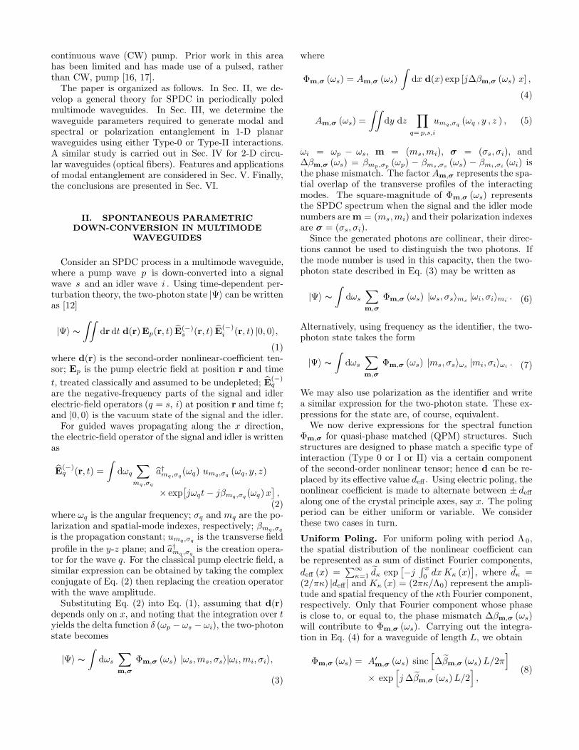
We now consider the generation of entangled photonsvia nondegenerate SPDC in a 1-D planar waveguide. Thestructure comprises a dielectric slab of thickness h andrefractive index n1 embedded in dielectric media withlower refractive index n2, as illustrated in Fig. 1. Thetransverse profile of mode mq inside the slab is [19]
umq,σq(ωq, y , z ) ∝
cos(k(z )mq,σq
(ωq) z), mq = even
sin(k(z )mq,σq (ωq) z
), mq = odd,
(11)while outside the slab it is
umq,σq(ωq, y , z ) ∝ exp
(−γmq,σq
(ωq) z), (12)
where k(z )mq ,σq = (k2mq,σq
− β2mq,σq
)1/2 is the z -component
of the wavevector kmq,σq= n1 ωq/c, γmq,σq
= (β2mq,σq
−k2mq,σq
)1/2, kmq,σq= n2 ωq/c, and c is the velocity of light
in free space. Note that both n1 and n2 are frequency-dependent.Within the slab, the mode transverse profiles are either
even or odd functions. The propagation constants of the
FIG. 1: Sketch of a 1-D planar waveguide. The waveguideis a slab of dielectric medium of thickness h with a uniformrefractive index n1 surrounded by media of lower refractiveindex n2. The inner medium and the outer media are knownas the core and cladding, respectively. The nonlinear coeffi-cient of the core is poled with a period Λ(x); arrows indicatethe poling direction. The poling periods at x = 0 and x = L
are denoted Λ0 and ΛL, respectively.
modes can be determined using the dispersion relation forthe planar waveguide. For the TE wave (o-polarization),
tan2[h
2
√k2mq,σq
− β2mq,σq
− mqπ
2
]=
β2mq,σq
− k2mq,σq
k2mq ,σq− β2
mq, σq
,
(13)whereas for the TM wave (e-polarization), the RHS ofthe above equation must be multiplied by n2
1/n22.
Substituting Eq. (11) into Eqs. (4) and (5), we candetermine the functions Φm,σ (ωs), which in turn deter-mine the quantum state set forth in Eq. (3). We considera two-mode waveguide for which the fundamental mode(mq = 0) is even and the next mode (mq = 1) is odd. Ifthe down-converted photons have different spatial parity,the pump mode must be odd so that the spatial over-lap integral in Eq. (5), which determines Am,σ (ωs) andthence Φm,σ (ωs), does not vanish.We seek to generate an entangled state of the form
|Ψ〉 ∼∫dωs [Φ0,1,σ (ωs) |ωs, 0, σs〉|ωi, 1, σi〉
+Φ1,0,σ (ωs) |ωs, 1, σs〉|ωi, 0, σi〉] ,(14)
i.e., if the signal is in the even mode, the idler mustbe in the odd mode, and vice versa. This requiresthat the phase-matching condition be satisfied for eachof these two possibilities. For a fixed geometry andmaterial parameters, we find a single poling period Λ0
of the nonlinear coefficient at which these conditions,∆β0,1,σ (ωs) = 2π/Λ0 and ∆β1,0,σ (ωs) = 2π/Λ0, aresimultaneously met. We achieve this by plotting the pol-ing period Λ0 as a function of the signal frequency ωs,or as a function of the signal wavelength λs, for each ofthese two conditions, and search for intersections. Theexample shown in Fig. 2 reveals that this may occur at asingle frequency or, when the two curves are tangential,over a broad spectral band. Once the poling period isselected and fixed, we determine if the spectral functionsΦ0,1,σ (ωs) and Φ1,0,σ (ωs) overlap, i.e., have some com-
700 800 900 10006.5
7
7.5
8
8.5
Signal wavelength λs (nm)
Poling
per
iod
Λ0
(µm
)
800 900 1000 11006.5
7
7.5
8
Signal wavelength λs (nm)P
oling
per
iod
Λ0
(µm
)
700 800 900 100018
20
22
24
26
Signal wavelength λs (nm)
Poling
per
iod
Λ0
(µm
)
900 1000 110020
40
60
80
Signal wavelength λs (nm)
Poling
per
iod
Λ0
(µm
)
808 810 81219.26
19.28
19.3
λs (nm)
Λ0
(µm
)(a)
(c)
(b)
(d)
2
2
2
2
1
1
1
1
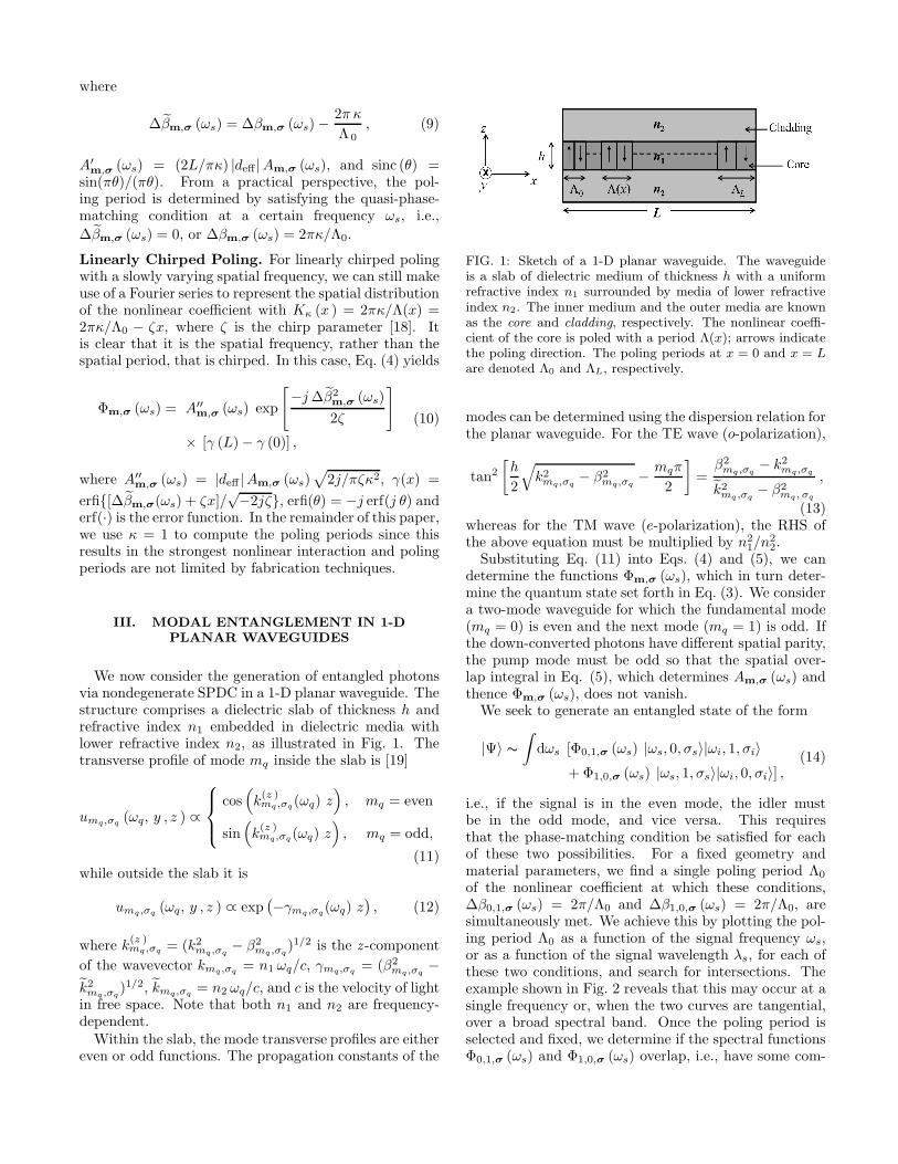
FIG. 2: (Color online). Values of the poling period Λ0 re-quired to satisfy quasi-phase matching as a function of thesignal wavelength λs, for four values of the waveguide thick-ness h. Calculations are presented for a KTP planar waveg-uide with ∆ = 0.05 pumped by a laser whose wavelengthis λp = 532 nm and whose modal structure coincides withmp = 1. The core refractive indexes are determined usingthe Sellmeier equations for KTP. The orange (black) curvesrepresent condition 1 (2), namely that the signal (idler) modenumber ms (mi) is 0 and that the idler (signal) mode num-ber mi (ms) is 1. Dashed lines indicate intersection pointsor ranges. (a) Type-0 (e, e, e) with waveguide thickness h =1.625 µm. (b) Type-0 (e, e, e) with h = 1.49 µm. (c) Type-II(o, e, o) with h = 1.617 µm. The inset shows the behavior ofthe poling period for condition 1 near the intersection point.(d) Type-II (e, o, o) with h = 1.56 µm.
mon spectral band. If they do, then the two-photon stateexhibits entanglement.Example. A laser source with wavelength λp = 532
nm and in mode mp = 1, is used to pump a 1-D peri-odically poled KTP waveguide with fractional refractiveindex change ∆ ≈ 1− n2/n1 = 0.05. The core refractiveindexes along the y and z axes are given by the KTPSellmeier equations [20]
n21,(y) (λ) = 3.45018 +
0.04341
λ2 − 0.04597+
16.98825
λ2 − 39.43799,
n21,(z) (λ) = 4.59423 +
0.06206
λ2 − 0.04763+
110.80672
λ2 − 86.12171,
(15)where λ is the wavelength expressed in µm.The curves in Fig. 2 represent uniform poling-period
values satisfying the quasi-phase-matching conditionsversus the signal wavelength λs, for four different valuesof the waveguide thickness h. The orange (black) curvesrepresent condition 1 (2), namely that the signal (idler)mode number is 0 and the idler (signal) mode numberis 1. In panels (a) and (b), the interactions are Type-0(e, e, e), with |deff | = |d33| = 16.9 pm/V [21]. The in-teractions in panels (c) and (d) are Type-II (o, e, o) andType-II (e, o, o), respectively, with |deff | = |d24| = 3.64pm/V. The notation (· , · , ·) indicates, in consecutive or-der, the polarization of the down-converted photon whosefrequency lies above the degenerate frequency, the down-converted photon whose frequency lies below the degen-erate frequency, and the pump photon.These plots reveal that the two curves can intersect at
a single frequency, as in panels (a) and (c) or, alterna-tively, they can coincide over a broad range of frequen-cies, as in panels (b) and (d). Modal entanglement canbe obtained at any intersection point since the two quasi-phase-matching conditions are simultaneously satisfiedfor the unique poling period determined by the pointof intersection. In panels (a) and (c), h has been cho-sen such that the intersection point between the curvesoccurs near λs = 810 nm so that the down-convertedphoton with the longer wavelength lies in the telecom-munications window near 1550 nm. In panels (b) and(d), h has been chosen such that the two curves are tan-gential over a broad range of wavelengths.We now proceed to study the spectral characteristics
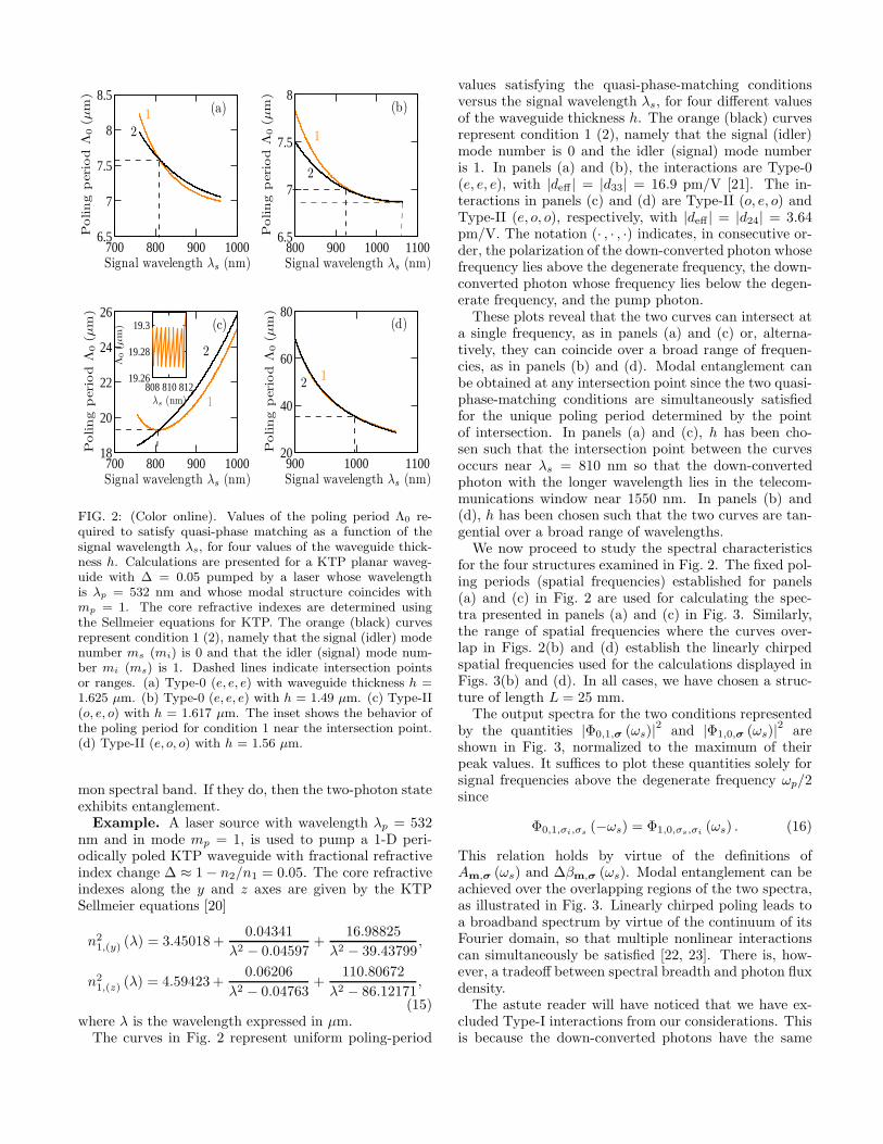
for the four structures examined in Fig. 2. The fixed pol-ing periods (spatial frequencies) established for panels(a) and (c) in Fig. 2 are used for calculating the spec-tra presented in panels (a) and (c) in Fig. 3. Similarly,the range of spatial frequencies where the curves over-lap in Figs. 2(b) and (d) establish the linearly chirpedspatial frequencies used for the calculations displayed inFigs. 3(b) and (d). In all cases, we have chosen a struc-ture of length L = 25 mm.The output spectra for the two conditions represented
by the quantities |Φ0,1,σ (ωs)|2 and |Φ1,0,σ (ωs)|2 areshown in Fig. 3, normalized to the maximum of theirpeak values. It suffices to plot these quantities solely forsignal frequencies above the degenerate frequency ωp/2since
Φ0,1,σi,σs(−ωs) = Φ1,0,σs,σi
(ωs) . (16)
This relation holds by virtue of the definitions ofAm,σ (ωs) and ∆βm,σ (ωs). Modal entanglement can beachieved over the overlapping regions of the two spectra,as illustrated in Fig. 3. Linearly chirped poling leads toa broadband spectrum by virtue of the continuum of itsFourier domain, so that multiple nonlinear interactionscan simultaneously be satisfied [22, 23]. There is, how-ever, a tradeoff between spectral breadth and photon fluxdensity.The astute reader will have noticed that we have ex-
cluded Type-I interactions from our considerations. Thisis because the down-converted photons have the same
900 1000 11000
0.2
0.4
0.6
0.8
1
Signal wavelength λs (nm)|Φ
ms,m
i,σ
s,σ
i|2
809 810 811 8120
0.2
0.4
0.6
0.8
1
Signal wavelength λs (nm)
|Φm
s,m
i,σ
s,σ
i|2
808 810 8120
0.2
0.4
0.6
0.8
1
Signal wavelength λs (nm)
|Φm
s,m
i,σ
s,σ
i|2
800 900 1000 11000
0.2
0.4
0.6
0.8
1
Signal wavelength λs (nm)
|Φm
s,m
i,σ
s,σ
i|2
(a)
(c) (d)
(b)
2
2
2
2
1
1
1
1
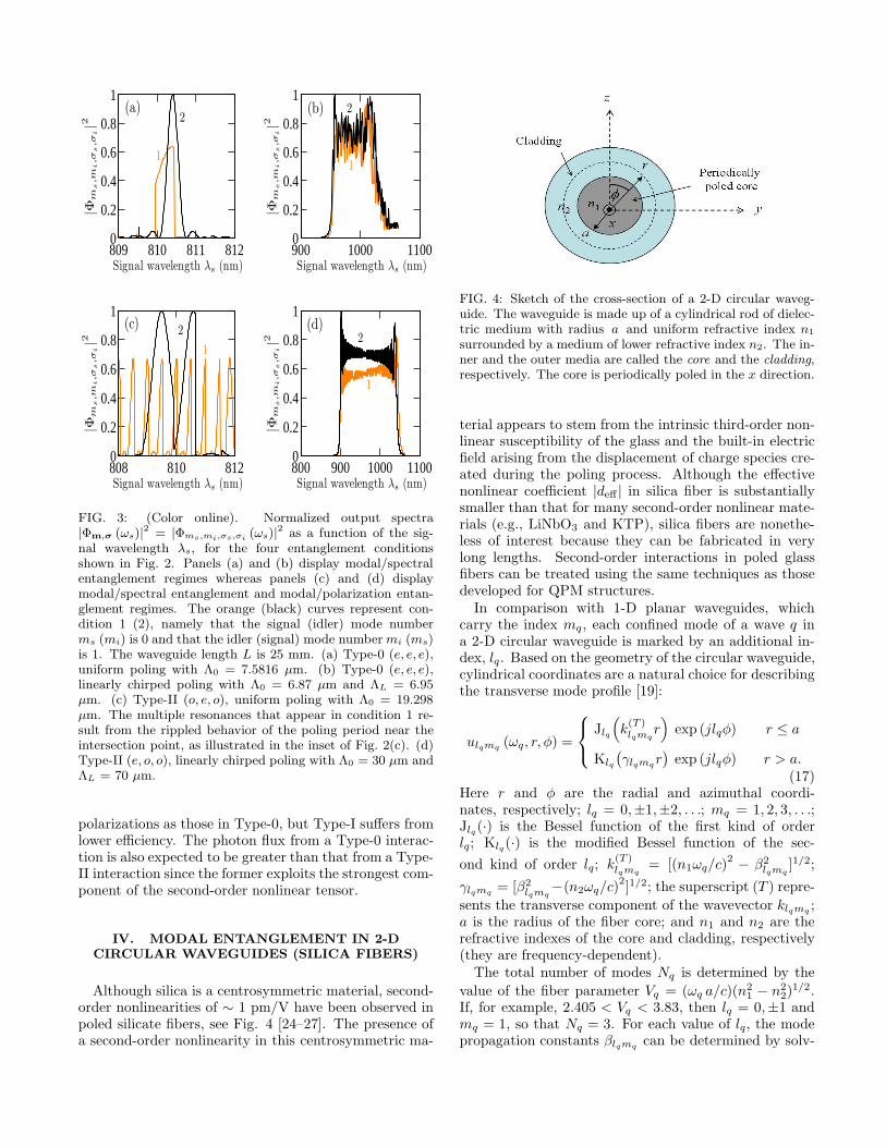
FIG. 3: (Color online). Normalized output spectra|Φm,σ (ωs)|
2 = |Φms,mi,σs,σi(ωs)|
2 as a function of the sig-nal wavelength λs, for the four entanglement conditionsshown in Fig. 2. Panels (a) and (b) display modal/spectralentanglement regimes whereas panels (c) and (d) displaymodal/spectral entanglement and modal/polarization entan-glement regimes. The orange (black) curves represent con-dition 1 (2), namely that the signal (idler) mode numberms (mi) is 0 and that the idler (signal) mode numbermi (ms)is 1. The waveguide length L is 25 mm. (a) Type-0 (e, e, e),uniform poling with Λ0 = 7.5816 µm. (b) Type-0 (e, e, e),linearly chirped poling with Λ0 = 6.87 µm and ΛL = 6.95µm. (c) Type-II (o, e, o), uniform poling with Λ0 = 19.298µm. The multiple resonances that appear in condition 1 re-sult from the rippled behavior of the poling period near theintersection point, as illustrated in the inset of Fig. 2(c). (d)Type-II (e, o, o), linearly chirped poling with Λ0 = 30 µm andΛL = 70 µm.
polarizations as those in Type-0, but Type-I suffers fromlower efficiency. The photon flux from a Type-0 interac-tion is also expected to be greater than that from a Type-II interaction since the former exploits the strongest com-ponent of the second-order nonlinear tensor.
IV. MODAL ENTANGLEMENT IN 2-DCIRCULAR WAVEGUIDES (SILICA FIBERS)
Although silica is a centrosymmetric material, second-order nonlinearities of ∼ 1 pm/V have been observed inpoled silicate fibers, see Fig. 4 [24–27]. The presence ofa second-order nonlinearity in this centrosymmetric ma-
FIG. 4: Sketch of the cross-section of a 2-D circular waveg-uide. The waveguide is made up of a cylindrical rod of dielec-tric medium with radius a and uniform refractive index n1
surrounded by a medium of lower refractive index n2. The in-ner and the outer media are called the core and the cladding,respectively. The core is periodically poled in the x direction.
terial appears to stem from the intrinsic third-order non-linear susceptibility of the glass and the built-in electricfield arising from the displacement of charge species cre-ated during the poling process. Although the effectivenonlinear coefficient |deff | in silica fiber is substantiallysmaller than that for many second-order nonlinear mate-rials (e.g., LiNbO3 and KTP), silica fibers are nonethe-less of interest because they can be fabricated in verylong lengths. Second-order interactions in poled glassfibers can be treated using the same techniques as thosedeveloped for QPM structures.In comparison with 1-D planar waveguides, which
carry the index mq, each confined mode of a wave q ina 2-D circular waveguide is marked by an additional in-dex, lq. Based on the geometry of the circular waveguide,cylindrical coordinates are a natural choice for describingthe transverse mode profile [19]:
ulqmq(ωq, r, φ) =
Jlq
(k(T )lqmq
r)exp (jlqφ) r ≤ a
Klq
(γlqmq
r)exp (jlqφ) r > a.
(17)Here r and φ are the radial and azimuthal coordi-nates, respectively; lq = 0,±1,±2, . . .; mq = 1, 2, 3, . . .;Jlq (·) is the Bessel function of the first kind of orderlq; Klq(·) is the modified Bessel function of the sec-
ond kind of order lq; k(T )lqmq
= [(n1ωq/c)2 − β2
lqmq]1/2;
γlqmq= [β2
lqmq−(n2ωq/c)
2]1/2; the superscript (T ) repre-
sents the transverse component of the wavevector klqmq;
a is the radius of the fiber core; and n1 and n2 are therefractive indexes of the core and cladding, respectively(they are frequency-dependent).The total number of modes Nq is determined by the
value of the fiber parameter Vq = (ωq a/c)(n21 − n2
2)1/2.
If, for example, 2.405 < Vq < 3.83, then lq = 0,±1 andmq = 1, so that Nq = 3. For each value of lq, the modepropagation constants βlqmq
can be determined by solv-
ing the fiber characteristic equation for k(T ) [19],
XJlq±1 (X)
Jlq (X)= ±Y
Klq±1 (Y )
Klq (Y ), (18)
where X = k(T )a and Y = (V 2q − X2)1/2. The values
of k(T ) that satisfy the characteristic equation are k(T )lqmq
.
Using the definitions provided above, we can then deter-mine βlqmq
. The subscript σ has been eliminated in thissection since glass fiber is an isotropic material and thecharacteristic equation is polarization-independent.In 2-D circular waveguides, the two-photon quantum
state is
|Ψ〉 ∼∫
dωs
∑
lm
Φlm (ωs) |ωs, lsms〉|ωi, limi〉, (19)
where lm = (lsms, limi), Φlm (ωs) can be determinedfrom Eq. (4) and the amplitude Alm (ωs) in cylindricalcoordinates is given by
Alm (ωs) =
∫ a
0
dr
∫ 2π
0
dφ r∏
q=p,s,i
ulqmq(ωq, r, φ) . (20)
Substituting Eq. (17) into Eq. (20) and performing theazimuthal integration leads to δ (lp + ls + li), which canbe viewed as a limitation on the transverse profiles of theinteracting modes (similar to that for planar waveguides).Consider nondegenerate SPDC in an optical fiber with
2.405 < Vq < 3.83. We seek to generate photon pairswith the following entangled state:
|Ψ〉 ∼∫
dωs [Φ01,11 (ωs) |ωs, 01〉|ωi, 11〉
+ Φ11,01 (ωs) |ωs, 11〉|ωi, 01〉] ,(21)
signifying that if the signal is in the fundamental mode(lsms = 01), then the idler will be in the first mode(limi = 11), and vice versa. To have nonvanishingAlm (ωs) or Φlm (ωs), the pump mode index lpmp mustbe (−11).Example. A pump source, with wavelength λp = 532
nm and in mode lp mp = −11, is incident on an opticalglass poled fiber with fractional refractive-index change∆ = 0.01. The core refractive index is computed usingthe Sellmeier equation for fused silica [19]
n21 (λ) = 1 +
0.6962λ2
λ2 − (0.06840)2 +
0.4079λ2
λ2 − (0.1162)2
+0.8975λ2
λ2 − (9.8962)2 ,
(22)
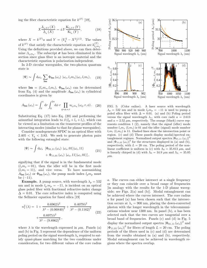
where λ is the wavelength expressed in µm. Panels (a)and (b) in Fig. 5 represent the dependence of the uniformpoling period on the signal wavelength λs required to sat-isfy quasi-phase matching for the two conditions underconsideration, for two different values of the core radius
880 900 920 940 96035
35.5
36
36.5
Signal wavelength λs (nm)
Poling
per
iod
Λ0
(µm
)
900 1000 110034.5
35
35.5
36
Signal wavelength λs (nm)
Poling
per
iod
Λ0
(µm
)
896 898 900 9020
0.2
0.4
0.6
0.8
1
Signal wavelength λs (nm)
|Φl s
ms,l
im
i|2
950 1000 1050 11000
0.2
0.4
0.6
0.8
1
Signal wavelength λs (nm)
|Φl s
ms,l
im
i|2
(a)
(c) (d)
(b)
2
2
2
2
1
11
1
FIG. 5: (Color online). A laser source with wavelengthλp = 532 nm and in mode lpmp = −11 is used to pump apoled silica fiber with ∆ = 0.01. (a) and (b) Poling periodversus the signal wavelength λs, with core radii a = 2.613and a = 2.52 µm, respectively. The orange (black) curve rep-resents condition 1 (2), namely that the signal (idler) modenumber lsms (limi) is 01 and the idler (signal) mode numberlimi (lsms) is 11. Dashed lines show the intersection point orregion. (c) and (d) These panels display modal/spectral en-tanglement regimes. Normalized output spectra |Φ01,11 (ωs)|
2
and |Φ11,01 (ωs)|2 for the structures displayed in (a) and (b),
respectively, with L = 20 cm. The poling period of the non-linear coefficient is uniform in (c) with Λ0 = 35.813 µm, andis linearly chirped in (d) with Λ0 = 34.9 µm and ΛL = 35.05µm.
a. The curves can either intersect at a single frequencyor they can coincide over a broad range of frequencies[in analogy with the results for the 1-D planar waveg-uide; see Figs. 2(a) and (b)]. Modal entanglement canbe achieved where the curves intersect. The core radiusa for panel (a) has been chosen such that the intersec-tion occurs at λs = 900 nm, placing the down-convertedphoton with the longer wavelength in the telecommuni-cations window near 1300 nm. In panel (b), a has beenselected such that the two curves are tangential over abroad band of frequencies. Panels (c) and (d) in Fig. 5
display the normalized output spectra |Φ01,11 (ωs)|2 and
|Φ11,01 (ωs)|2 for fibers of length L = 20 cm. The polingperiods of the fibers used in (c) and (d) are determinedfrom the results obtained in (a) and (b), respectively.Modal entanglement can be achieved in wavelength re-gions where the spectra overlap.
V. FEATURES OF MODAL ENTANGLEMENT
In the previous sections, we have demonstrated that itis possible to obtain modal entanglement in 1-D planarand 2-D circular waveguides. In this section, we discussvarious features and applications of modal entanglement.
Combining the advantages of noncollinear and
collinear-degenerate interactions in bulk crystals.
A noncollinear configuration is often preferred in bulkcrystals because the photon pairs generated by SPDC areeasily separated. This process is typically not efficient,however, since the fraction of the photons that are en-tangled is seriously limited by the intersections betweenthe emission cones. A degenerate-collinear configuration,on the other hand, creates impediments to separating thephoton pairs but offers high efficiency by virtue of the to-tal overlap of the emission cones. In a two-mode waveg-uide with modal entanglement, in contrast, the photonpairs are efficiently generated in the two allowed entan-gled modes and are thus also readily separated by theirmode numbers, i.e, their different transverse-field pro-files. This can be implemented by use of a branchingwaveguide [28].
Device flexibility and compatibility. Using uni-form or linearly chirped poling, we are able to generate ei-ther narrowband or broadband spectral/polarization en-tanglement, as illustrated in Fig. 3. By replacing thebranching waveguide at the device output with a diffrac-tion grating, prism, or polarizing beam splitter (for Type-II), we can obtain binary modal entanglement. Thestructure can then be used as a source of binary andcontinuum entanglement that is expected to be usefulfor applications such as quantum imaging [29–31], quan-tum cryptography [32], quantum teleportation [33], andquantum information [34]. We note that this waveguideconfiguration is compatible with integrated optics, whichcan facilitate its incorporation into a practical system.
Spectral entanglement is typically measured viaa Hong-Ou-Mandel interferometer (HOM) [35]. An ex-periment is conducted by sweeping a temporal delay τinserted between the down-converted photons while mea-suring the coincidence rate of photon counts at a pair ofdetectors placed at the two output ports of the interfer-ometer. The coincidence rate R(τ) is given by
R (τ) = 12 {R0 − Re [R1 (τ)]} (23)
with
R0 =
∫dωs |Φm,σ (ωs)|2 ,
R1 (τ) =
∫dωs
{Φ
m,σ (ωs)Φ∗m,σ (−ωs)
× exp [j (ωp − 2ωs) τ ]} ,
(24)
−20 0 200
0.2
0.4
0.6
0.8
1
Norm
alized
coin
cid
ence
rate
R
−20 0 200.3
0.4
0.5
0.6
0.7
−20 0 200.3
0.4
0.5
0.6
0.7
−20 0 200.3
0.4
0.5
0.6
0.7
−20 0 200
0.2
0.4
0.6
0.8
1
Time delay τ (ps)−20 0 20
0.3
0.4
0.5
0.6
0.7
(a)
(e)(d)
(b) (c)
(f)
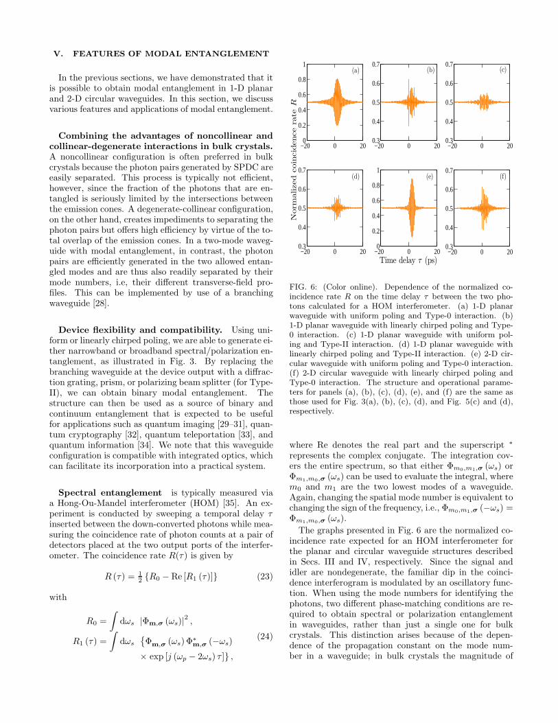
FIG. 6: (Color online). Dependence of the normalized co-incidence rate R on the time delay τ between the two pho-tons calculated for a HOM interferometer. (a) 1-D planarwaveguide with uniform poling and Type-0 interaction. (b)1-D planar waveguide with linearly chirped poling and Type-0 interaction. (c) 1-D planar waveguide with uniform pol-ing and Type-II interaction. (d) 1-D planar waveguide withlinearly chirped poling and Type-II interaction. (e) 2-D cir-cular waveguide with uniform poling and Type-0 interaction.(f) 2-D circular waveguide with linearly chirped poling andType-0 interaction. The structure and operational parame-ters for panels (a), (b), (c), (d), (e), and (f) are the same asthose used for Fig. 3(a), (b), (c), (d), and Fig. 5(c) and (d),respectively.
where Re denotes the real part and the superscript ∗
represents the complex conjugate. The integration cov-ers the entire spectrum, so that either Φm0,m1,σ (ωs) orΦm1,m0,σ (ωs) can be used to evaluate the integral, wherem0 and m1 are the two lowest modes of a waveguide.Again, changing the spatial mode number is equivalent tochanging the sign of the frequency, i.e., Φm0,m1,σ (−ωs) =Φm1,m0,σ (ωs).
The graphs presented in Fig. 6 are the normalized co-incidence rate expected for an HOM interferometer forthe planar and circular waveguide structures describedin Secs. III and IV, respectively. Since the signal andidler are nondegenerate, the familiar dip in the coinci-dence interferogram is modulated by an oscillatory func-tion. When using the mode numbers for identifying thephotons, two different phase-matching conditions are re-quired to obtain spectral or polarization entanglementin waveguides, rather than just a single one for bulkcrystals. This distinction arises because of the depen-dence of the propagation constant on the mode num-ber in a waveguide; in bulk crystals the magnitude of
the wavevector is independent of the direction of prop-
agation. Hence, ∆βm0,m1,σ (ωs) is not exactly equal
to ∆βm0,m1,σ (−ωs), so that Φm,σ (ωs) and Φ∗
m,σ (−ωs)do not perfectly overlap in the complex domain. Thishas several consequences: i) The interference patternshifts about τ = 0 since Φm,σ (ωs)Φ
∗m,σ (−ωs) is a not
purely real. This effect is illustrated in Fig. 6(a) and
(e). ii) The visibility, which is defined as V (τ) =(Rmax −Rmin) / (Rmax +Rmin), where Rmax and Rmin
are the maximum and minimum values of the R (τ), re-spectively, is reduced since R0 is not precisely equal toRmin. This is clearly observable in the Type-II curvesportrayed in Fig. 6(c) and (d). iii) The interfer-ence pattern is ragged, as depicted in Fig. 6(b) and(f). However, reducing the device length will result ina cleaner interference pattern, since the imaginary partof Φm,σ (ωs)Φ
∗m,σ (−ωs) is proportional to the device
length for both uniform and linearly chirped poling.Using Eqs. (8) and (10), we define the entanglement
length Le as the waveguide length for which the phase ofΦm,σ (ωs) Φ
∗m,σ (−ωs) is equal to π. For uniform poling,
we obtain
Le =
∣∣∣∣∣2π
∆βm0,m1,σ (ωs)−∆βm0,m1,σ (−ωs)
∣∣∣∣∣ , (25)
whereas for linearly chirped poling, we have
Le =
∣∣∣∣∣4π2
(Λ−10 − Λ−1
L
)
∆β2m0,m1,σ (ωs)−∆β2
m0,m1,σ (−ωs)
∣∣∣∣∣ . (26)
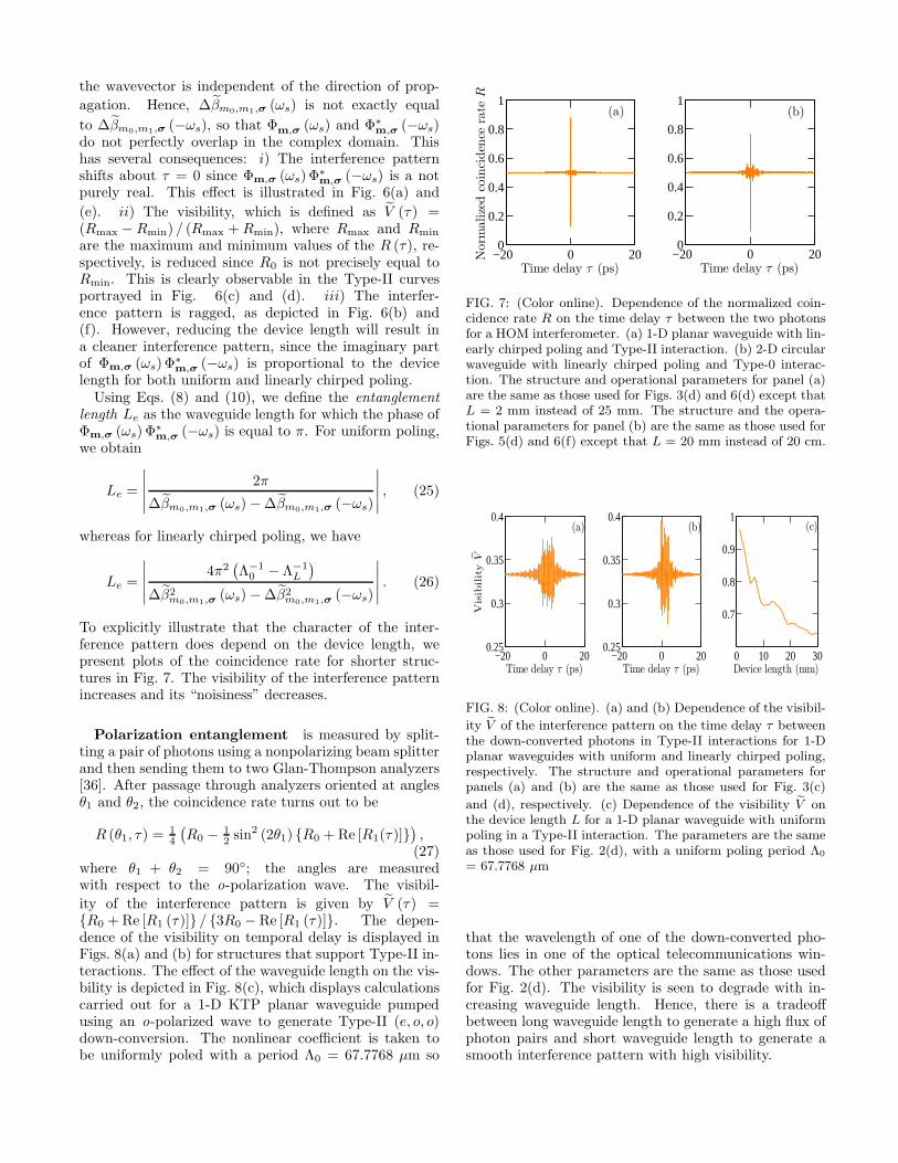
To explicitly illustrate that the character of the inter-ference pattern does depend on the device length, wepresent plots of the coincidence rate for shorter struc-tures in Fig. 7. The visibility of the interference patternincreases and its “noisiness” decreases.
Polarization entanglement is measured by split-ting a pair of photons using a nonpolarizing beam splitterand then sending them to two Glan-Thompson analyzers[36]. After passage through analyzers oriented at anglesθ1 and θ2, the coincidence rate turns out to be
R (θ1, τ) =14
(R0 − 1
2 sin2 (2θ1) {R0 +Re [R1(τ)]}
),(27)
where θ1 + θ2 = 90◦; the angles are measuredwith respect to the o-polarization wave. The visibil-
ity of the interference pattern is given by V (τ) ={R0 +Re [R1 (τ)]} / {3R0 − Re [R1 (τ)]}. The depen-dence of the visibility on temporal delay is displayed inFigs. 8(a) and (b) for structures that support Type-II in-teractions. The effect of the waveguide length on the vis-bility is depicted in Fig. 8(c), which displays calculationscarried out for a 1-D KTP planar waveguide pumpedusing an o-polarized wave to generate Type-II (e, o, o)down-conversion. The nonlinear coefficient is taken tobe uniformly poled with a period Λ0 = 67.7768 µm so
−20 0 200
0.2
0.4
0.6
0.8
1
Time delay τ (ps)
Norm
alize
dco
inci
den
cera
teR
−20 0 200
0.2
0.4
0.6
0.8
1
Time delay τ (ps)
(a) (b)
FIG. 7: (Color online). Dependence of the normalized coin-cidence rate R on the time delay τ between the two photonsfor a HOM interferometer. (a) 1-D planar waveguide with lin-early chirped poling and Type-II interaction. (b) 2-D circularwaveguide with linearly chirped poling and Type-0 interac-tion. The structure and operational parameters for panel (a)are the same as those used for Figs. 3(d) and 6(d) except thatL = 2 mm instead of 25 mm. The structure and the opera-tional parameters for panel (b) are the same as those used forFigs. 5(d) and 6(f) except that L = 20 mm instead of 20 cm.
−20 0 200.25
0.3
0.35
0.4
Time delay τ (ps)
Visib
ility
V
−20 0 200.25
0.3
0.35
0.4
Time delay τ (ps)0 10 20 30
0.7
0.8
0.9
1
Device length (mm)
(a) (b) (c)
FIG. 8: (Color online). (a) and (b) Dependence of the visibil-
ity V of the interference pattern on the time delay τ betweenthe down-converted photons in Type-II interactions for 1-Dplanar waveguides with uniform and linearly chirped poling,respectively. The structure and operational parameters forpanels (a) and (b) are the same as those used for Fig. 3(c)
and (d), respectively. (c) Dependence of the visibility V onthe device length L for a 1-D planar waveguide with uniformpoling in a Type-II interaction. The parameters are the sameas those used for Fig. 2(d), with a uniform poling period Λ0
= 67.7768 µm
that the wavelength of one of the down-converted pho-tons lies in one of the optical telecommunications win-dows. The other parameters are the same as those usedfor Fig. 2(d). The visibility is seen to degrade with in-creasing waveguide length. Hence, there is a tradeoffbetween long waveguide length to generate a high flux ofphoton pairs and short waveguide length to generate asmooth interference pattern with high visibility.
Modal entanglement can be considered as an al-ternative to polarization entanglement. Whereas polar-ization entanglement is restricted to Type-II interactions,modal entanglement has the merit that it can be gener-ated using any type of nonlinear interaction, includingType-0. Indeed, the down-conversion generation rate inType-0 is about one order of magnitude higher than thatin Type-II, since Type-0 utilizes the strongest compo-nent of the second-order nonlinear tensor. Hence, SPDCgenerated via Type-0 modal entanglement in a waveg-uide can serve as an efficient source of binary entangledphotons.
An increase in the overall signal-to-noise ratio
in an infrared biphoton system can be achieved bychoosing the waveguide dimensions such that one of thephotons falls in the visible region while the other lies inthe infrared region. This technique can be useful sincethe visible photon can be efficiently detected with a Siphoton-counting detector while the infrared photon is de-tected with a less efficient InGaAs photon-counting de-tector. The overall signal-to-noise ratio is increased as aconsequence [30, 37].
Generation of a doubly entangled state via
modal entanglement. Although Type-II is less effi-cient than Type-0, this configuration can be exploitedto generate a doubly entangled state in frequency andpolarization [8],
|Ψ〉 ∼ (|ωs, ωi〉+ |ωi, ωs〉 ⊗ |σs, σi〉+ |σi, σs〉) . (28)
This state can be viewed as a combination of Type-II(o, e, o) and Type-II (e, o, o). The photon pairs can beseparated on the basis of their mode number with thehelp of a branching waveguide. Using Eq. (6), four dif-ferent nonlinear processes are required to generate thedoubly entangled state:
|Ψ〉 ∼∫
dωs [Φ0,1,o,e (ωs) |ωs, o〉0|ωi, e〉1+Φ1,0,o,e (ωs) |ωi, e〉0|ωs, o〉1+Φ0,1,e,o (ωs) |ωs, e〉0|ωi, o〉1+Φ1,0,e,o (ωs) |ωi, o〉0|ωs, e〉1] .
(29)
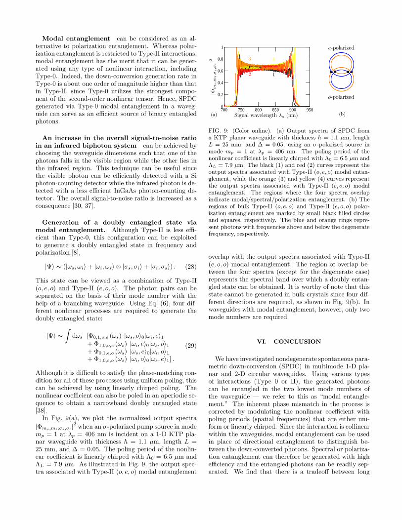
Although it is difficult to satisfy the phase-matching con-dition for all of these processes using uniform poling, thiscan be achieved by using linearly chirped poling. Thenonlinear coefficient can also be poled in an aperiodic se-quence to obtain a narrowband doubly entangled state[38].In Fig. 9(a), we plot the normalized output spectra
|Φms,mi,σs,σi|2 when an o -polarized pump source in mode
mp = 1 at λp = 406 nm is incident on a 1-D KTP pla-nar waveguide with thickness h = 1.1 µm, length L =25 mm, and ∆ = 0.05. The poling period of the nonlin-ear coefficient is linearly chirped with Λ0 = 6.5 µm andΛL = 7.9 µm. As illustrated in Fig. 9, the output spec-tra associated with Type-II (o, e, o) modal entanglement
700 750 800 850 900 9500
0.2
0.4
0.6
0.8
1
Signal wavelength λs (nm)
|Φm
s,m
i,σ
s,σ
i|2
(a)
e-polarized
(b)
o-polarized
2 1
3 4
FIG. 9: (Color online). (a) Output spectra of SPDC froma KTP planar waveguide with thickness h = 1.1 µm, lengthL = 25 mm, and ∆ = 0.05, using an o -polarized source inmode mp = 1 at λp = 406 nm. The poling period of thenonlinear coefficient is linearly chirped with Λ0 = 6.5 µm andΛL = 7.9 µm. The black (1) and red (2) curves represent theoutput spectra associated with Type-II (o, e, o) modal entan-glement, while the orange (3) and yellow (4) curves representthe output spectra associated with Type-II (e, o, o) modalentanglement. The regions where the four spectra overlapindicate modal/spectral/polarization entanglement. (b) Theregions of bulk Type-II (o, e, o) and Type-II (e, o, o) polar-ization entanglement are marked by small black filled circlesand squares, respectively. The blue and orange rings repre-sent photons with frequencies above and below the degeneratefrequency, respectively.
overlap with the output spectra associated with Type-II(e, o, o) modal entanglement. The region of overlap be-tween the four spectra (except for the degenerate case)represents the spectral band over which a doubly entan-gled state can be obtained. It is worthy of note that thisstate cannot be generated in bulk crystals since four dif-ferent directions are required, as shown in Fig. 9(b). Inwaveguides with modal entanglement, however, only twomode numbers are required.
VI. CONCLUSION
We have investigated nondegenerate spontaneous para-metric down-conversion (SPDC) in multimode 1-D pla-nar and 2-D circular waveguides. Using various typesof interactions (Type 0 or II), the generated photonscan be entangled in the two lowest mode numbers ofthe waveguide — we refer to this as “modal entangle-ment.” The inherent phase mismatch in the process iscorrected by modulating the nonlinear coefficient withpoling periods (spatial frequencies) that are either uni-form or linearly chirped. Since the interaction is collinearwithin the waveguides, modal entanglement can be usedin place of directional entanglement to distinguish be-tween the down-converted photons. Spectral or polariza-tion entanglement can therefore be generated with highefficiency and the entangled photons can be readily sep-arated. We find that there is a tradeoff between long
waveguide length to generate a high flux of photon pairsand short waveguide length to generate a smooth inter-ference pattern with high visibility. In Type-0 interac-tions, frequency can be used as a mode identifier ratherthan waveguide mode number, offering the possibility ofusing modal entanglement in place of polarization entan-glement, which requires a Type-II interaction. This is asalutary feature since a Type-0 interaction exploits thestrongest component of the second-order nonlinear ten-sor. The technique can be implemented in any of theoptical telecommunications windows by controlling thewaveguide dimensions. Finally, we have demonstratedthat modal entanglement in a Type-II interaction canbe used to generate a doubly entangled state in fre-
quency and polarization. Drawing on a Hilbert spaceof higher dimensions can offer advantages in quantum-communication protocols and quantum computing.
Acknowledgments
This work was supported by a U.S. Army ResearchOffice (ARO) Multidisciplinary University Research Ini-tiative (MURI) Grant; and by the Bernard M. Gor-don Center for Subsurface Sensing and Imaging Systems(CenSSIS), an NSF Engineering Research Center.
[1] D. N. Klyshko, Photons and Nonlinear Optics (Nauka,Moscow, 1980), chaps. 1 and 6. Translation: Gordon andBreach, New York, 1988.
[2] B. E. A. Saleh, A. F. Abouraddy, A. V. Sergienko, andM. C. Teich, Phys. Rev. A 62, 043816 (2000).
[3] A. Joobeur, B. E. A. Saleh, and M. C. Teich, Phys. Rev.A 50, 3349 (1994).
[4] A. Joobeur, B. E. A. Saleh, T. S. Larchuk, and M. C.Teich, Phys. Rev. A 53, 4360 (1996).
[5] A. Mair, A. Vaziri, G. Weihs, and A. Zeilinger, Nature412, 313 (2001).
[6] A. F. Abouraddy, T. Yarnall, B. E. A. Saleh, and M. C.Teich, Phys. Rev. A 75, 052114 (2007).
[7] T. Yarnall, A. F. Abouraddy, B. E. A. Saleh, and M. C.Teich, Phys. Rev. Lett. 99, 170408 (2007).
[8] J. T. Barreiro, N. K. Langford, N. A. Peters, and P. G.Kwiat, Phys. Rev. Lett. 95, 260501 (2005).
[9] M. Halder, S. Tanzilli, H. de Riedmatten, A. Beveratos,H. Zbinden, and N. Gisin, Phys. Rev. A 71, 042335(2005).
[10] J. G. Rarity and P. R. Tapster, Phys. Rev. Lett. 64, 2495(1990).
[11] S. P. Walborn, S. Padua, and C. H. Monken, Phys. Rev.A 71, 053812 (2005).
[12] M. C. Booth, M. Atature, G. DiGiuseppe, B. E. A. Saleh,A. Sergienko, and M. C. Teich, Phys. Rev. A 66, 023815(2002).
[13] P. G. Kwiat, K. Mattle, H. Weinfurter, A. Zeilinger, A. V.Sergienko, and Y. Shih, Phys. Rev. Lett. 75, 4337 (1995).
[14] T. Yarnall, A. F. Abouraddy, B. E. A. Saleh, and M. C.Teich, Phys. Rev. Lett. 99, 250502 (2007).
[15] C. H. Bennett and P. W. Shor, IEEE Trans. Inform. The-ory 44, 2724 (1998).
[16] K. Banaszek, A. B. URen, and I. A. Walmsley, Opt. Lett26, 1367 (2001).
[17] A. Eckstein and C. Silberhorn, Opt. Lett 33, 1825 (2008).[18] G. Imeshev, M. A. Arbore, M. M. Fejer, A. Galvanauskas,
M. Fermann, and D. Harter, J. Opt. Am. Soc. B 17, 304(2000).
[19] B. E. A. Saleh and M. C. Teich, Fundamentals of Pho-tonics (Wiley, Hoboken, NJ, 2007), 2nd ed.
[20] K. Kato and E. Takaoka, Appl. Opt. 41, 5040 (2002).
[21] R. L. Sutherland, Handbook of Nonlinear Optics (CRCPress, Boca Raton, FL, 2003), 2nd ed.
[22] S. Carrasco, J. P. Torres, L. Torner, A. V. Sergienko,B. E. A. Saleh, and M. C. Teich, Opt. Lett 29, 2429(2004).
[23] M. B. Nasr, S. Carrasco, B. E. A. Saleh, A. V. Sergienko,M. C. Teich, J. P. Torres, L. Torner, D. S. Hum, andM. M. Fejer, Phys. Rev. Lett. 100, 183601 (2008).
[24] H. Nasu, H. Okamoto, K. Kurachi, J. Matsuoka,K. Kamiya, A. Mito, and H. Hosono, J. Opt. Am. Soc.B 12, 644 (1995).
[25] P. G. Kazansky, P. S. J. Russell, and H. Takebe, J. Light-wave Technol. 15, 1484 (1997).
[26] P. G. Kazansky and V. Pruneri, J. Opt. Am. Soc. B 14,3170 (1997).
[27] J. Fage-Pedersen, R. Jacobsen, and M. Kristensen, Opt.Express 13, 8514 (2005).
[28] H. Yajima, Appl. Phys. Lett. 22, 647 (1973).[29] A. F. Abouraddy, B. E. A. Saleh, A. V. Sergienko, and
M. C. Teich, Phys. Rev. Lett. 87, 123602 (2001).[30] A. F. Abouraddy, B. E. A. Saleh, A. V. Sergienko, and
M. C. Teich, J. Opt. Am. Soc. B 19, 1174 (2002).[31] M. B. Nasr, D. P. Goode, N. Nguyen, G. Rong, L. Yang,
B. M. Reinhard, B. E. A. Saleh, and M. C. Teich, Opt.Commun. 282, 1154 (2009).
[32] T. Jennewein, C. Simon, G. Weihs, H. Weinfurter, andA. Zeilinger, Phys. Rev. Lett. 84, 4729 (2000).
[33] C. H. Bennett, G. Brassard, C. Crepeau, R. Jozsa,A. Peres, and W. K. Wootters, Phys. Rev. Lett. 70, 1895(1993).
[34] M. A. Nielsen and I. L. Chuang, Quantum Computationand Quantum Information (Cambridge University Press,Cambridge, UK, 2000).
[35] C. K. Hong, Z. Y. Ou, and L. Mandel, Phys. Rev. Lett.59, 2044 (1987).
[36] Y. H. Shih and C. O. Alley, Phys. Rev. Lett. 61, 2921(1988).
[37] H. G. de Chatellus, A. V. Sergienko, B. E. A. Saleh,M. C. Teich, and G. Di Giuseppe, Opt. Express 14, 10060(2006).
[38] A. Norton and C. de Sterke, Opt. Express 12, 841 (2004).
Top Related
Copyright © 2022 FDOKUMEN

