


Bahasa
Halaman
Hukum

M
IK
a
ARA
KGGMCV
C
1
btgti
1d
Renewable and Sustainable Energy Reviews 15 (2011) 1042–1049
Contents lists available at ScienceDirect
Renewable and Sustainable Energy Reviews
journa l homepage: www.e lsev ier .com/ locate / rser
ine ventilation air methane as a sustainable energy source
zzet Karakurt, Gokhan Aydin, Kerim Aydiner ∗
aradeniz Technical University, Department of Mining Engineering, 61080 Trabzon, Turkey
r t i c l e i n f o
rticle history:eceived 23 June 2010ccepted 12 November 2010
a b s t r a c t
Underground coal mines emitting large quantities of methane to atmosphere is one of the sources ofmethane. Approximately 70% of the methane emitted from coal mines is released as the ventilation
eywords:lobal warmingreenhouse gasesethane
oal minesentilation air
air methane (VAM). Unfortunately, due to the low methane concentration (0.1–1.5%) in ventilation air,its effective utilization is considerably low. However, the global warming potential of methane can bereduced up to 95% by oxidizing the methane. Energy recovery may be possible as the products of oxi-dization. In this study, the existing and developing methods, based on the oxidation of methane, areintroduced with a discussion of the features of the methods of the mitigation and utilization of VAM.The main operational parameters of the methods such as combustion method, technical feasibility andengineering applicability were also discussed.
© 2010 Elsevier Ltd. All rights reserved.
ontents
1. Introduction . . . . . . . . . . . . . . . . . . . . . . . . . . . . . . . . . . . . . . . . . . . . . . . . . . . . . . . . . . . . . . . . . . . . . . . . . . . . . . . . . . . . . . . . . . . . . . . . . . . . . . . . . . . . . . . . . . . . . . . . . . . . . . . . . . . . . . . . 10422. Mitigation and utilization of VAM . . . . . . . . . . . . . . . . . . . . . . . . . . . . . . . . . . . . . . . . . . . . . . . . . . . . . . . . . . . . . . . . . . . . . . . . . . . . . . . . . . . . . . . . . . . . . . . . . . . . . . . . . . . . . . . . . 10433. Methane oxidation mechanisms. . . . . . . . . . . . . . . . . . . . . . . . . . . . . . . . . . . . . . . . . . . . . . . . . . . . . . . . . . . . . . . . . . . . . . . . . . . . . . . . . . . . . . . . . . . . . . . . . . . . . . . . . . . . . . . . . . . 10444. Ancillary uses of ventilation air methane . . . . . . . . . . . . . . . . . . . . . . . . . . . . . . . . . . . . . . . . . . . . . . . . . . . . . . . . . . . . . . . . . . . . . . . . . . . . . . . . . . . . . . . . . . . . . . . . . . . . . . . . . 1044
4.1. Pulverized coal-fired power station. . . . . . . . . . . . . . . . . . . . . . . . . . . . . . . . . . . . . . . . . . . . . . . . . . . . . . . . . . . . . . . . . . . . . . . . . . . . . . . . . . . . . . . . . . . . . . . . . . . . . . . . 10444.2. Hybrid waste/coal/tailings/methane combustion units . . . . . . . . . . . . . . . . . . . . . . . . . . . . . . . . . . . . . . . . . . . . . . . . . . . . . . . . . . . . . . . . . . . . . . . . . . . . . . . . . . . 10454.3. Internal combustion engines . . . . . . . . . . . . . . . . . . . . . . . . . . . . . . . . . . . . . . . . . . . . . . . . . . . . . . . . . . . . . . . . . . . . . . . . . . . . . . . . . . . . . . . . . . . . . . . . . . . . . . . . . . . . . . . 10464.4. Conventional gas turbines . . . . . . . . . . . . . . . . . . . . . . . . . . . . . . . . . . . . . . . . . . . . . . . . . . . . . . . . . . . . . . . . . . . . . . . . . . . . . . . . . . . . . . . . . . . . . . . . . . . . . . . . . . . . . . . . . 1046
5. Principal uses of VAM . . . . . . . . . . . . . . . . . . . . . . . . . . . . . . . . . . . . . . . . . . . . . . . . . . . . . . . . . . . . . . . . . . . . . . . . . . . . . . . . . . . . . . . . . . . . . . . . . . . . . . . . . . . . . . . . . . . . . . . . . . . . . . 10465.1. Thermal flow reversal reactor technology (TFRR) . . . . . . . . . . . . . . . . . . . . . . . . . . . . . . . . . . . . . . . . . . . . . . . . . . . . . . . . . . . . . . . . . . . . . . . . . . . . . . . . . . . . . . . . . 10465.2. Catalytic flow reversal reactor (CFRR) . . . . . . . . . . . . . . . . . . . . . . . . . . . . . . . . . . . . . . . . . . . . . . . . . . . . . . . . . . . . . . . . . . . . . . . . . . . . . . . . . . . . . . . . . . . . . . . . . . . . . 10465.3. Catalytic-monolith reactors (CMR) . . . . . . . . . . . . . . . . . . . . . . . . . . . . . . . . . . . . . . . . . . . . . . . . . . . . . . . . . . . . . . . . . . . . . . . . . . . . . . . . . . . . . . . . . . . . . . . . . . . . . . . . 10475.4. Lean-burn gas turbines . . . . . . . . . . . . . . . . . . . . . . . . . . . . . . . . . . . . . . . . . . . . . . . . . . . . . . . . . . . . . . . . . . . . . . . . . . . . . . . . . . . . . . . . . . . . . . . . . . . . . . . . . . . . . . . . . . . . . 10485.5. Concentrators . . . . . . . . . . . . . . . . . . . . . . . . . . . . . . . . . . . . . . . . . . . . . . . . . . . . . . . . . . . . . . . . . . . . . . . . . . . . . . . . . . . . . . . . . . . . . . . . . . . . . . . . . . . . . . . . . . . . . . . . . . . . . . 1048
6. Conclusions . . . . . . . . . . . . . . . . . . . . . . . . . . . . . . . . . . . . . . . . . . . . . . . . . . . . . . . . . . . . . . . . . . . . . . . . . . . . . . . . . . . . . . . . . . . . . . . . . . . . . . . . . . . . . . . . . . . . . . . . . . . . . . . . . . . . . . . . 1048References . . . . . . . . . . . . . . . . . . . . . . . . . . . . . . . . . . . . . . . . . . . . . . . . . . . . . . . . . . . . . . . . . . . . . . . . . . . . . . . . . . . . . . . . . . . . . . . . . . . . . . . . . . . . . . . . . . . . . . . . . . . . . . . . . . . . . . . . . 1049
. Introduction
Greenhouse gases are released mainly from the activities such asurning of fossil fuels, industrial processes, transportation, agricul-
tors, ecological systems and humans’ life would come into existence[1,2].
Carbon dioxide, methane, nitrogen oxide and chlorofluorocar-
ural facilities and waste management processes. Accumulation ofreenhouse gases in atmosphere has led to the increase of earth’semperature. As a result of the increases in global temperatures,t is expected that important changes affecting socioeconomic sec-
∗ Corresponding author. Tel.: +90 462 377 35 31; fax: +90 462 325 74 05.E-mail address: [email protected] (K. Aydiner).
364-0321/$ – see front matter © 2010 Elsevier Ltd. All rights reserved.oi:10.1016/j.rser.2010.11.030
bons have vital importance on the global warming and the relatedenvironmental problems. Carbon dioxide has solely a rate of 74%in total anthropogenic greenhouse gas emissions. Methane, nitro-gen oxide and high global warming potential gases follow carbon
dioxide (Fig. 1).Methane can trap the heat about 20 times of CO2. In spiteof the fact that methane is the second biggest contributor toanthropogenic greenhouse gas emissions, it affects climate changesat least as carbon dioxide does [5,6]. The variation of non-
I. Karakurt et al. / Renewable and Sustainable
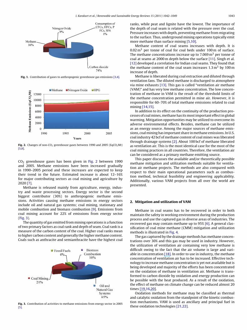
Fig. 1. Contribution of gases to anthropogenic greenhouse gas emissions [3,4].
F[
Caitf2
tbsimc(
omtC
F[
ig. 2. Changes of non-CO2 greenhouse gases between 1990 and 2005 (EqCO2Mt)5,8].
O2 greenhouse gases has been given in Fig. 2 between 1990nd 2005. Methane emissions have been increased graduallyn 1990–2005 period and these increases are expected to keepheir trend in the future. Estimated increase is about 12–16%or major contributing sectors as coal mining and agriculture by020 [7].
Methane is released mainly from agriculture, energy, indus-ry and waste processing sectors. Energy sector is the secondiggest contributor (30%) to anthropogenic methane emis-ions. Activities causing methane emissions in energy sectorsnclude oil and natural gas systems; coal mining, stationary and
obile combustion and biomass combustion [9]. Emissions fromoal mining account for 22% of emissions from energy sectorFig. 3).
The quantity of gas emitted from mining operations is a functionf two primary factors as coal rank and depth of seam. Coal rank is aeasure of the carbon content of the coal. Higher coal ranks mean
o higher carbon content and generally the higher methane content.oals such as anthracite and semianthracite have the highest coal
ig. 3. Contribution of activities to methane emissions from energy sector in 20055].
Energy Reviews 15 (2011) 1042–1049 1043
ranks, while peat and lignite have the lowest. The importance ofthe depth of coal seam is related with the pressure over the coal.Pressure increases with depth, preventing methane from migratingto the surface. Thus, underground mining operations typically emitmore methane than surface mining [5,10].
Methane content of coal seams increases with depth. It is0.02 m3 per tonne of coal for coal beds under 100 m of surface.The methane concentrations increase up to 7.069 m3 per tonne ofcoal at seams at 2000 m depth below the surface [11]. Singh et al.[12] developed a correlation for Indian coal seams. They found thatthe methane content of the coal seam increases 1.3 m3 by 100 mincrease of depth.
Methane is liberated during coal extraction and diluted throughventilation fans. The diluted methane is discharged to atmospherevia mine exhausts [13]. This gas is called “ventilation air methane(VAM)” and has very low methane concentration. The low concen-tration of methane in VAM is the result of the threshold limits ofthe methane concentration permitted in mine air. However, it isresponsible for 60–70% of total methane emissions related to coalmining [14,15].
In addition to its effect on the continuity of the production pro-cesses of coal mines, methane has its most important effect in globalwarming. Mitigation opportunities may be utilized to overcome itsadverse environmental effects. Besides, methane can be utilizedas an energy source. Among the major sources of methane emis-sions, coal mining has important share in methane emissions. In U.S.coal industry 42 bcf of methane content of coal mines was liberatedthrough drainage systems [2]. About 100 bcf of methane liberatedas ventilation air. This is the most identical case for the most of thecoal mining practices in all countries. Therefore, the ventilation aircan be considered as a primary methane emitting source.
This paper discusses the available and/or theoretically possiblemethane mitigation and utilization methods suitable for ventila-tion air methane projects. The methods are also compared withrespect to their main operational parameters such as combus-tion method, technical feasibility and engineering applicability.Additionally, various VAM projects from all over the world arepresented.
2. Mitigation and utilization of VAM
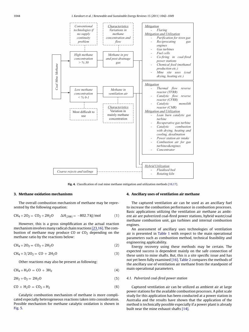
Methane in coal seams has to be recovered in order to bothmaintain the safety in working environment during the productionprocess and use the captured gas in diverse areas of industries. Therecovered gas may contain methane up to 95% [6]. A general clas-sification of coal mine methane (CMM) mitigation and utilizationmethods is illustrated in Fig. 4.
The gas captured by the drainage methods has methane concen-trations over 30% and this gas may be used in industry. However,the utilization of ventilation air containing very low methane isdifficult owing to the fact that the air volume is large and vari-able in concentration [18]. In order to use in industry, the methaneconcentration of ventilation air has to be increased. Effective tech-nology to increase methane concentration is yet not available but isbeing developed and majority of the efforts has been concentratedon the oxidation of methane in ventilation air. Methane is trans-formed to carbon dioxide by oxidation and energy production canbe possible with the heat produced. As a result of the oxidation,the effect of methane on climate change can be reduced almost 20
times [19,16,20].Oxidation methods for methane may be classified as thermaland catalytic oxidation from the standpoint of the kinetic combus-tion mechanisms. VAM is used as ancillary and principal fuel inthese oxidation technologies [21,22].
1044 I. Karakurt et al. / Renewable and Sustainable Energy Reviews 15 (2011) 1042–1049
Mitigation- Thermal flow reverse
reactor (TFRR) - Catalytic flow reverse
reactor (CFRR) - Catalytic monolith
reactor (CMR) Mitigation and Utilization
- Lean burn catalytic gas turbine
- Recuperative gas turbine - Catalytic combustion
with drying, heating and cooling, desalination
- Power station air intake - Combustion air for gas
turbines&engines - Concentrator
CharacteristicsVariations in
methane concentration and
flow
High methane concentration
> % 30
Methane in pre and post-drainage
gas
Low methane concentration
< % 0-1
Hybrid Utilization - Fluidised bed
Conventional technologies if
no supply continuity problem
Most difficult to use
Methane in ventilation air
Mitigation - Flaring
Mitigation and Utilization- Purification for town gas - Reciprocating gas
engines - Gas turbines - Fuel cells - Co-firing in coal-fired
power stations - Chemical feed (methanol
production etc.) - Mine site uses (coal
drying, heating etc.)
Coa
l Min
e M
etha
ne
Coarse rejects and tailings
CharacteristicsVariation in
mainly methane concentration
ne mit
3
s
C
mbm
C
C
C
2
C
cPF
Fig. 4. Classification of coal mine metha
. Methane oxidation mechanisms
The overall combustion mechanism of methane may be repre-ented by the following equation:
H4 + 2O2 = CO2 + 2H2O �H(298) = −802.7 kJ/mol (1)
However, this is a gross simplification as the actual reactionechanism involves many radical chain reactions [23,16]. The com-
ustion of methane may produce CO or CO2 depending on theethane ratio by the reactions below:
H4 + 2O2 = CO2 + 2H2O (2)
H4 + 3/2O2 = CO + 2H2O (3)
Other reactions may also be present as following:
H4 + H2O = CO + 3H2 (4)
H2 + O2 = 2H2O (5)
O + H2O = CO2 + H2 (6)
Catalytic combustion mechanism of methane is more compli-ated especially heterogeneous reactions taken into consideration.ossible mechanism for methane catalytic oxidation is shown inig. 5.
- Rotating kiln
igation and utilization methods [16,17].
4. Ancillary uses of ventilation air methane
The captured ventilation air can be used as an ancillary fuelto increase the combustion performance in combustion processes.Basic applications utilizing the ventilation air methane as ambi-ent air are pulverized coal-fired power stations, hybrid waste/coalmethane combustion unit, gas turbines and internal combustionengines.
An assessment of ancillary uses technologies of ventilationair is presented in Table 1 with respect to the main operationalparameters such as combustion method, technical feasibility andengineering applicability.
Energy recovery using these methods may be certain. Theexpected success is dependent mainly on the safe connection ofthese units to mine shafts. But, this is a site specific issue and hasnot yet been fully examined [16]. Table 2 compares the methods ofthe ancillary use of ventilation air methane from the standpoint ofmain operational parameters.
4.1. Pulverized coal-fired power station
Captured ventilation air can be utilized as ambient air at large
power stations for the available combustion processes. A pilot scalestudy for this application has been conducted at a power station inAustralia and the results have shown that the application of themethod is technically possible especially if a power plant is alreadybuilt near the mine exhaust shafts [14].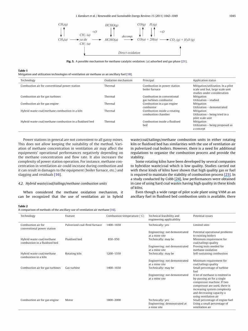
I. Karakurt et al. / Renewable and Sustainable Energy Reviews 15 (2011) 1042–1049 1045
ya da
CH4(g)
CH4(a)CH3
- (a)
CH2- (a)
+O
HCHO(a)
HCHO(g)
decomp.
CO(g) H2(g)
CO(a) + 2H(a) CO2 (g) + H2O (g)
+O
Direct oxidation
Fig. 5. A possible mechanism for methane catalytic oxidation: (a) adsorbed and gas phase [21].
Table 1Mitigation and utilization technologies of ventilation air methane as an ancillary fuel [18].
Technology Oxidation mechanism Principal Application status
Combustion air for conventional power station Thermal Combustion in power stationboiler furnace
Mitigation/utilization. In a pilotscale unit but, large scale unitstudies under consideration
Combustion air for gas turbines Thermal Combustion in conventionalgas turbines combustor
MitigationUtilization – studied
Combustion air for gas engine Thermal Combustion in a gas enginecombustor
MitigationUtilization – demonstrated
Hybrid waste coal/methane combustion in a kiln Thermal Combustion inside a rotatingcombustion chamber
MitigationUtilization – being tried in a
Taetccis
4
c
TA
Hybrid waste coal/methane combustion in a fluidised bed Thermal
Power stations in general are not convenient to all gassy mines.his does not allow keeping the suitability of the method. Vari-tion of methane concentration in ventilation air may affect thequipments’ operational performances negatively depending onhe methane concentration and flow rate. It also increases theomplexity of power station operation. For instance, methane con-entration in ventilation air could increase during combustion andt can result in damages to the equipment (boiler furnace, etc.) andlagging and residuals [16].
.2. Hybrid waste/coal/tailings/methane combustion units
When considered the methane oxidation mechanism, itan be recognized that the use of ventilation air in hybrid
able 2comparison of methods of the ancillary use of ventilation air methane [16].
Technology Feature Combustion tempe
Combustion air forconventional power station
Pulverized coal-fired furnace 1400–1650
Hybrid waste coal/methanecombustion in a fluidised bed
Fluidised bed 850–950
Hybrid waste coal/methanecombustion in a kiln
Rotating kiln 1200–1550
Combustion air for gas turbines Gas turbine 1400–1650
Combustion air for gas engine Motor 1800–2000
pilot scale unitCombustion inside a fluidisedbed
MitigationUtilization – being proposed asa concept
waste/coal/tailings/methane combustion units in either rotatingkiln or fluidised bed has similarities with the use of ventilation airin pulverized coal boilers. However, there is a need for additionalregulations to organize the combustion process and provide thestability.
Some rotating kilns have been developed by several companiesto hybridize waste/coal which is low quality. Studies carried outwith these kinds of kilns have shown that high quality gas or fuelis required to maintain the stability of combustion process [23]. In
a study conducted by Cobb [24], low performances were obtainedin case of using hard coal wastes having high quality in these kindsof kilns.Even though a wide range of pilot scale plant using VAM as anancillary fuel in fluidised bed combustion units is available, there
rature (◦C) Technical feasibility andengineering applicability
Potential issues
Technically: yes Limited sites
Engineering: not demonstratedat a mine site
Potential operational problemsto existing boilers
Technically: may be Minimum requirement forcoal/tailings quality
Engineering: not demonstratedat a mine site
Proving tests needed formethane oxidation
Technically: may be Self-sustaining combustion
Engineering: not demonstratedat a mine site
Minimum requirement forcoal/tailings quality
Technically: may be Small percentage of turbinefuel
Engineering: not demonstratedat a mine site
A lot of methane is emitted inby-passing air for a singlecompressor machine. If twocompressor are used, there isincreasing system complexityand decreasing capacity ousing ventilation air
Technically: yes Small percentage of engine fuelEngineering: demonstrated ata mine site
Using a small percentage ofventilation air
1046 I. Karakurt et al. / Renewable and Sustainable Energy Reviews 15 (2011) 1042–1049
ho
4
tactdooi
4
etatapv
5
cHfaabmd
5.2. Catalytic flow reversal reactor (CFRR)
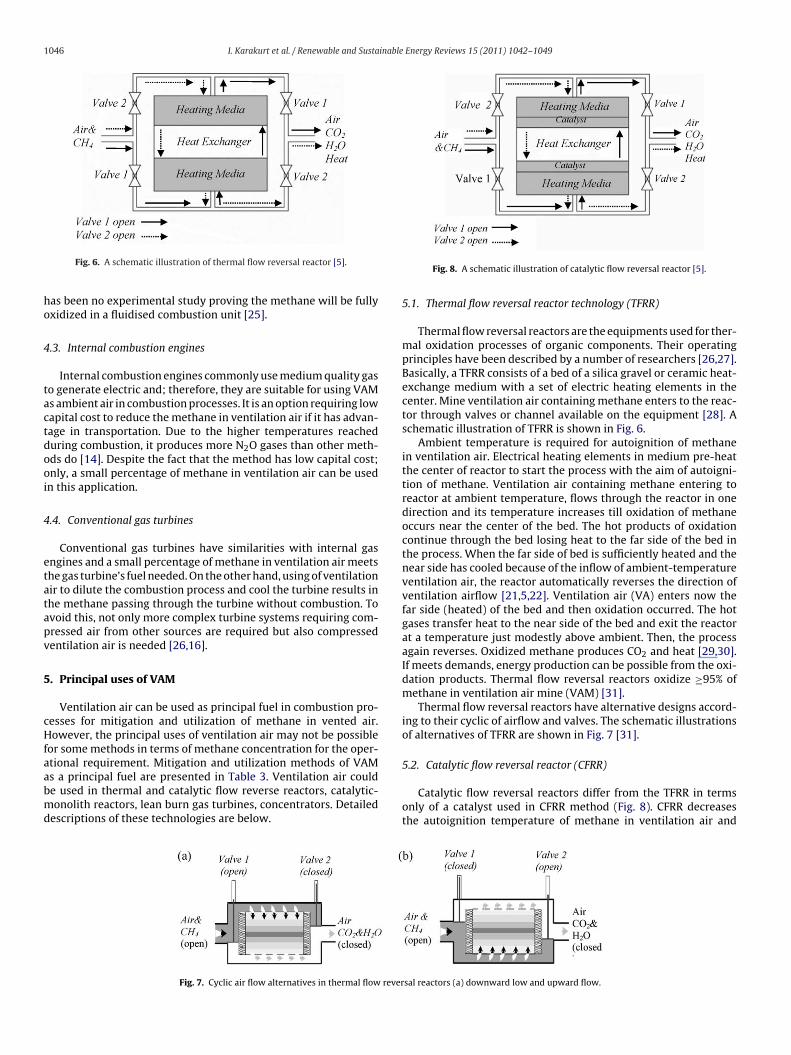
Fig. 6. A schematic illustration of thermal flow reversal reactor [5].
as been no experimental study proving the methane will be fullyxidized in a fluidised combustion unit [25].
.3. Internal combustion engines
Internal combustion engines commonly use medium quality gaso generate electric and; therefore, they are suitable for using VAMs ambient air in combustion processes. It is an option requiring lowapital cost to reduce the methane in ventilation air if it has advan-age in transportation. Due to the higher temperatures reacheduring combustion, it produces more N2O gases than other meth-ds do [14]. Despite the fact that the method has low capital cost;nly, a small percentage of methane in ventilation air can be usedn this application.
.4. Conventional gas turbines
Conventional gas turbines have similarities with internal gasngines and a small percentage of methane in ventilation air meetshe gas turbine’s fuel needed. On the other hand, using of ventilationir to dilute the combustion process and cool the turbine results inhe methane passing through the turbine without combustion. Tovoid this, not only more complex turbine systems requiring com-ressed air from other sources are required but also compressedentilation air is needed [26,16].
. Principal uses of VAM
Ventilation air can be used as principal fuel in combustion pro-esses for mitigation and utilization of methane in vented air.owever, the principal uses of ventilation air may not be possible
or some methods in terms of methane concentration for the oper-tional requirement. Mitigation and utilization methods of VAM
s a principal fuel are presented in Table 3. Ventilation air coulde used in thermal and catalytic flow reverse reactors, catalytic-onolith reactors, lean burn gas turbines, concentrators. Detailedescriptions of these technologies are below.
Fig. 7. Cyclic air flow alternatives in thermal flow rever
Fig. 8. A schematic illustration of catalytic flow reversal reactor [5].
5.1. Thermal flow reversal reactor technology (TFRR)
Thermal flow reversal reactors are the equipments used for ther-mal oxidation processes of organic components. Their operatingprinciples have been described by a number of researchers [26,27].Basically, a TFRR consists of a bed of a silica gravel or ceramic heat-exchange medium with a set of electric heating elements in thecenter. Mine ventilation air containing methane enters to the reac-tor through valves or channel available on the equipment [28]. Aschematic illustration of TFRR is shown in Fig. 6.
Ambient temperature is required for autoignition of methanein ventilation air. Electrical heating elements in medium pre-heatthe center of reactor to start the process with the aim of autoigni-tion of methane. Ventilation air containing methane entering toreactor at ambient temperature, flows through the reactor in onedirection and its temperature increases till oxidation of methaneoccurs near the center of the bed. The hot products of oxidationcontinue through the bed losing heat to the far side of the bed inthe process. When the far side of bed is sufficiently heated and thenear side has cooled because of the inflow of ambient-temperatureventilation air, the reactor automatically reverses the direction ofventilation airflow [21,5,22]. Ventilation air (VA) enters now thefar side (heated) of the bed and then oxidation occurred. The hotgases transfer heat to the near side of the bed and exit the reactorat a temperature just modestly above ambient. Then, the processagain reverses. Oxidized methane produces CO2 and heat [29,30].If meets demands, energy production can be possible from the oxi-dation products. Thermal flow reversal reactors oxidize ≥95% ofmethane in ventilation air mine (VAM) [31].
Thermal flow reversal reactors have alternative designs accord-ing to their cyclic of airflow and valves. The schematic illustrationsof alternatives of TFRR are shown in Fig. 7 [31].
Catalytic flow reversal reactors differ from the TFRR in termsonly of a catalyst used in CFRR method (Fig. 8). CFRR decreasesthe autoignition temperature of methane in ventilation air and
sal reactors (a) downward low and upward flow.
I. Karakurt et al. / Renewable and Sustainable Energy Reviews 15 (2011) 1042–1049 1047
Table 3Mitigation and utilization technologies of ventilation air methane as principal fuel [18].
Technology Oxidation mechanism Principal Application
Thermal flow reverse reactor (TFRR) Thermal Flow reverse reactor with regenerativebed
Mitigation: demonstratedUtilization: not demonstrated yet
Catalytic flow reverse reactor (CFRR) Catalytic Flow reverse reactor with regenerativebed
Mitigation: demonstratedUtilization: not demonstrated yet
Catalytic-monolith combustor Catalytic Monolith reactor with a recuperator Mitigation: demonstratedUtilization: not demonstrated yet
Catalytic lean burn gas turbine Catalytic Gas turbine with a catalytic combustorand recuperator
Mitigation: combustion demonstratedUtilization: being developed in a labscale unit
Recuperative gas turbine Thermal Gas turbine with a recuperativecombustor and recuperator
Mitigation: combustion demonstratedUtilization: demonstrated in a pilot
ulti-sting ad
kOatre
CfCVmauwi
ah
5
amr
Concentrator N/A, adsorption Mus
eeps the durability of system reaction during combustion [32].ver heating or over cooling may be prevented by adding air orir–water mixer to the heat-exchanger [5,33]. These kinds of reac-ors have some advantages such as working at low temperatures,eleasing low amount of N2O (can be omitted), low production andngineering costs, requiring small equipments [34,35].
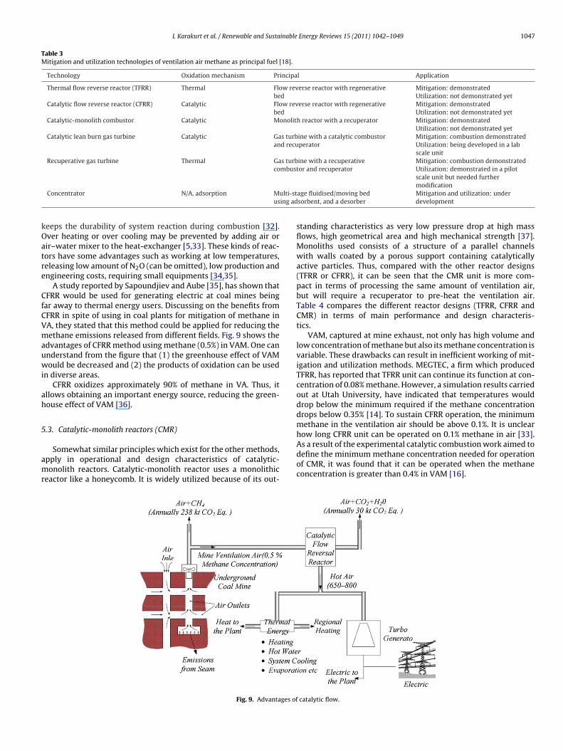
A study reported by Sapoundjiev and Aube [35], has shown thatFRR would be used for generating electric at coal mines being
ar away to thermal energy users. Discussing on the benefits fromFRR in spite of using in coal plants for mitigation of methane inA, they stated that this method could be applied for reducing theethane emissions released from different fields. Fig. 9 shows the
dvantages of CFRR method using methane (0.5%) in VAM. One cannderstand from the figure that (1) the greenhouse effect of VAMould be decreased and (2) the products of oxidation can be used
n diverse areas.CFRR oxidizes approximately 90% of methane in VA. Thus, it
llows obtaining an important energy source, reducing the green-ouse effect of VAM [36].
.3. Catalytic-monolith reactors (CMR)
Somewhat similar principles which exist for the other methods,pply in operational and design characteristics of catalytic-onolith reactors. Catalytic-monolith reactor uses a monolithic
eactor like a honeycomb. It is widely utilized because of its out-
Fig. 9. Advantages of
scale unit but needed furthermodification
age fluidised/moving bedsorbent, and a desorber
Mitigation and utilization: underdevelopment
standing characteristics as very low pressure drop at high massflows, high geometrical area and high mechanical strength [37].Monoliths used consists of a structure of a parallel channelswith walls coated by a porous support containing catalyticallyactive particles. Thus, compared with the other reactor designs(TFRR or CFRR), it can be seen that the CMR unit is more com-pact in terms of processing the same amount of ventilation air,but will require a recuperator to pre-heat the ventilation air.Table 4 compares the different reactor designs (TFRR, CFRR andCMR) in terms of main performance and design characteris-tics.
VAM, captured at mine exhaust, not only has high volume andlow concentration of methane but also its methane concentration isvariable. These drawbacks can result in inefficient working of mit-igation and utilization methods. MEGTEC, a firm which producedTFRR, has reported that TFRR unit can continue its function at con-centration of 0.08% methane. However, a simulation results carriedout at Utah University, have indicated that temperatures woulddrop below the minimum required if the methane concentrationdrops below 0.35% [14]. To sustain CFRR operation, the minimummethane in the ventilation air should be above 0.1%. It is unclearhow long CFRR unit can be operated on 0.1% methane in air [33].
As a result of the experimental catalytic combustion work aimed todefine the minimum methane concentration needed for operationof CMR, it was found that it can be operated when the methaneconcentration is greater than 0.4% in VAM [16].catalytic flow.
1048 I. Karakurt et al. / Renewable and Sustainable Energy Reviews 15 (2011) 1042–1049
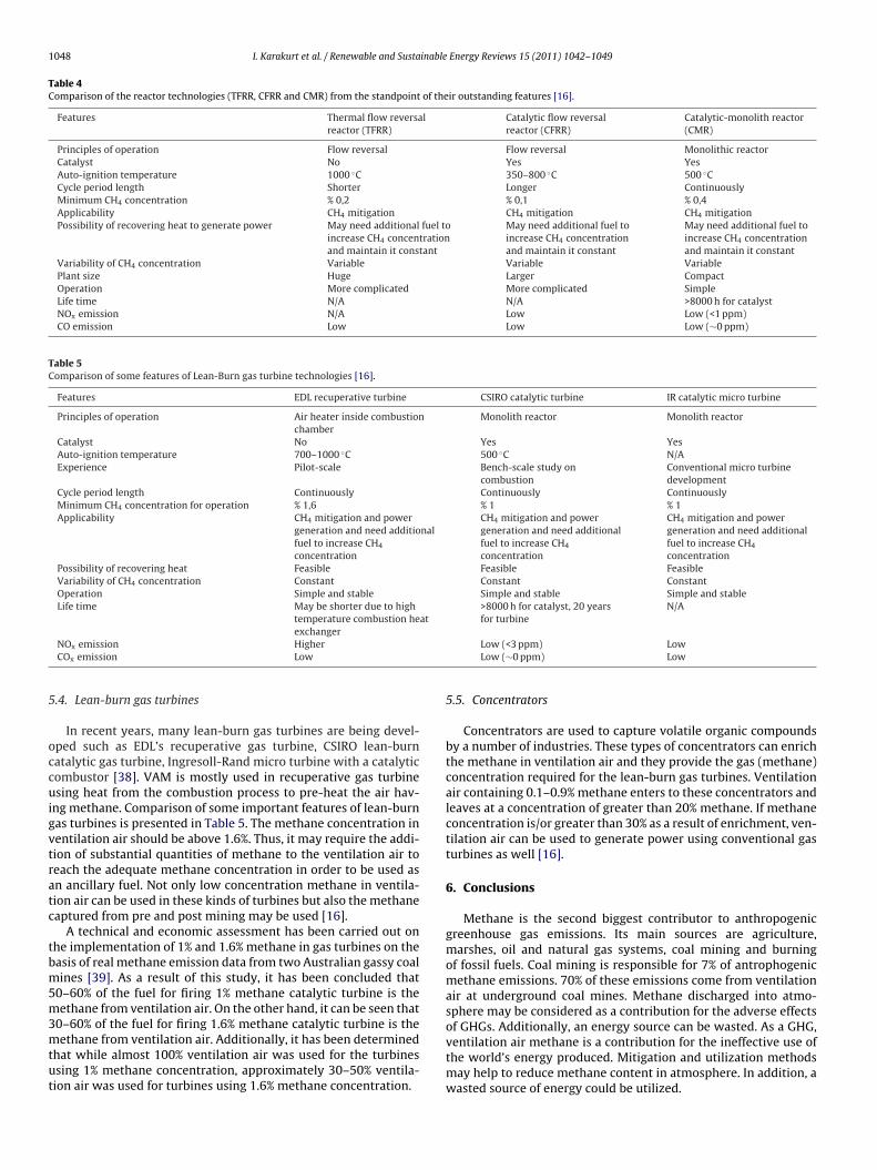
Table 4Comparison of the reactor technologies (TFRR, CFRR and CMR) from the standpoint of their outstanding features [16].
Features Thermal flow reversalreactor (TFRR)
Catalytic flow reversalreactor (CFRR)
Catalytic-monolith reactor(CMR)
Principles of operation Flow reversal Flow reversal Monolithic reactorCatalyst No Yes YesAuto-ignition temperature 1000 ◦C 350–800 ◦C 500 ◦CCycle period length Shorter Longer ContinuouslyMinimum CH4 concentration % 0,2 % 0,1 % 0,4Applicability CH4 mitigation CH4 mitigation CH4 mitigationPossibility of recovering heat to generate power May need additional fuel to
increase CH4 concentrationand maintain it constant
May need additional fuel toincrease CH4 concentrationand maintain it constant
May need additional fuel toincrease CH4 concentrationand maintain it constant
Variability of CH4 concentration Variable Variable VariablePlant size Huge Larger CompactOperation More complicated More complicated SimpleLife time N/A N/A >8000 h for catalystNOx emission N/A Low Low (<1 ppm)CO emission Low Low Low (∼0 ppm)
Table 5Comparison of some features of Lean-Burn gas turbine technologies [16].
Features EDL recuperative turbine CSIRO catalytic turbine IR catalytic micro turbine
Principles of operation Air heater inside combustionchamber
Monolith reactor Monolith reactor
Catalyst No Yes YesAuto-ignition temperature 700–1000 ◦C 500 ◦C N/AExperience Pilot-scale Bench-scale study on
combustionConventional micro turbinedevelopment
Cycle period length Continuously Continuously ContinuouslyMinimum CH4 concentration for operation % 1,6 % 1 % 1Applicability CH4 mitigation and power
generation and need additionalfuel to increase CH4
concentration
CH4 mitigation and powergeneration and need additionalfuel to increase CH4
concentration
CH4 mitigation and powergeneration and need additionalfuel to increase CH4
concentrationPossibility of recovering heat Feasible Feasible FeasibleVariability of CH4 concentration Constant Constant ConstantOperation Simple and stable Simple and stable Simple and stableLife time May be shorter due to high
temperature combustion heat>8000 h for catalyst, 20 yearsfor turbine
N/A
5
occuigvtratc
tbm5m3mtut
exchangerNOx emission HigherCOx emission Low
.4. Lean-burn gas turbines
In recent years, many lean-burn gas turbines are being devel-ped such as EDL’s recuperative gas turbine, CSIRO lean-burnatalytic gas turbine, Ingresoll-Rand micro turbine with a catalyticombustor [38]. VAM is mostly used in recuperative gas turbinesing heat from the combustion process to pre-heat the air hav-
ng methane. Comparison of some important features of lean-burnas turbines is presented in Table 5. The methane concentration inentilation air should be above 1.6%. Thus, it may require the addi-ion of substantial quantities of methane to the ventilation air toeach the adequate methane concentration in order to be used asn ancillary fuel. Not only low concentration methane in ventila-ion air can be used in these kinds of turbines but also the methaneaptured from pre and post mining may be used [16].
A technical and economic assessment has been carried out onhe implementation of 1% and 1.6% methane in gas turbines on theasis of real methane emission data from two Australian gassy coalines [39]. As a result of this study, it has been concluded that
0–60% of the fuel for firing 1% methane catalytic turbine is theethane from ventilation air. On the other hand, it can be seen that
0–60% of the fuel for firing 1.6% methane catalytic turbine is theethane from ventilation air. Additionally, it has been determined
hat while almost 100% ventilation air was used for the turbinessing 1% methane concentration, approximately 30–50% ventila-ion air was used for turbines using 1.6% methane concentration.
Low (<3 ppm) LowLow (∼0 ppm) Low
5.5. Concentrators
Concentrators are used to capture volatile organic compoundsby a number of industries. These types of concentrators can enrichthe methane in ventilation air and they provide the gas (methane)concentration required for the lean-burn gas turbines. Ventilationair containing 0.1–0.9% methane enters to these concentrators andleaves at a concentration of greater than 20% methane. If methaneconcentration is/or greater than 30% as a result of enrichment, ven-tilation air can be used to generate power using conventional gasturbines as well [16].
6. Conclusions
Methane is the second biggest contributor to anthropogenicgreenhouse gas emissions. Its main sources are agriculture,marshes, oil and natural gas systems, coal mining and burningof fossil fuels. Coal mining is responsible for 7% of antrophogenicmethane emissions. 70% of these emissions come from ventilationair at underground coal mines. Methane discharged into atmo-sphere may be considered as a contribution for the adverse effects
of GHGs. Additionally, an energy source can be wasted. As a GHG,ventilation air methane is a contribution for the ineffective use ofthe world’s energy produced. Mitigation and utilization methodsmay help to reduce methane content in atmosphere. In addition, awasted source of energy could be utilized.
inable
mrtda
(
(i
(
(
R
[
[
[
[
[
[
[
[
[
[
[
[
[
[
[
[
[
[
[
[
[
[
[
[
[
[
[
[
fichier.php/codectec/En/1999-13/1999-13e.pdf, accessed at July 15, 2009.[38] US EPA. Coalbed Methane Extra, A publication of the Coalbed Methane Outreach
I. Karakurt et al. / Renewable and Susta
Effective method for mitigation and utilization of ventilation airethane is not yet available but many efforts have been devised in
ecent years. Majority of works has been concentrated on the oxida-ion of methane in ventilation air. The following conclusions can berawn from the analysis of the current technological possibilitiesnd the theoretical bases:
(i) Methane gas captured by drainage methods can be utilizeddepending on the methane concentration. However, it is so dif-ficult to use mine ventilation air since it has high volume andcontains low and variable concentration of methane.
ii) VAM can be used as ancillary and principal fuel in combustionprocesses for the purposes of mitigation and utilization. Ancil-lary uses of ventilation air methane serve mainly in reducing thegreenhouse effect of methane. In principal use, both the energyproduction and the greenhouse effect reducing goals may beachieved.
ii) In case of inadequate methane concentration in ventilation airto meet the demands for the mitigation and utilization pro-cesses, ventilation air should be enriched to increase methaneconcentration. Concentrators are suitable devices for enrich-ment of low methane in ventilation air. After enrichment ifmethane concentration is greater than 30%, it can be possibleto use it for power generation in conventional gas turbines.
iv) The applicability of mitigation and utilization methods for VAMat any mine site depends mainly on site specific conditions. Itis very important to investigate any possible safety issue whenany type of technologies is connected to the mine site (mineexhaust).
v) Globally the effect of methane from underground coal minesvia ventilation air on climate changes could be reduced about95% by using oxidation methods. On the other hand emissionsfrom coal mining could be reduced to 67%.
eferences
[1] Aydın G. Coalbed Methane Use Technologies and Analysis of Methane Emis-sions from Energy Production, Karadeniz Technical University, Graduate Schoolof Natural and Applied Sciences, Master Thesis; 2008. Trabzon [in Turkish].
[2] US EPA. An assessment of the worldwide market potential for oxidizing coalmine ventilation air methane. United States Environmental Protection Agency;2003. July.
[3] Kruger D, Franklin P. The methane to markets partnership: opportunities forcoal mine methane utilization. In: 11th U.S./North American mine ventilationsymposium. 2006.
[4] Karakurt I, Aydın G, Aydıner K. Decreasing options of methane gas releasedfrom coal mines. In: Proceedings of 3rd mining and environmental symposium.2009. p. 165–72.
[5] U.S. EPA. Coalbed Methane Outreach Program (CMOP). U.S. Environmental Pro-tection Agency; 2006, accessed on June 10, 2009.
[6] Aydın G, Karakurt I. The utilization technologies of methane produced fromunderground coal seams, Pamukkale University. Journal of Engineering Sci-ences 2009;15(1):129–36 [in Turkish].
[7] methanetomarkets.org, 2010, Underground Coal Mine Methane Recov-ery and Use Opportunities, http://www.methanetomarkets.org/documents/coal fs eng.pdf, accessed at April 13, 2010.
[8] Aydın G, Karakurt I. The regional analyses of global methane emissions fromenergy sector by different sources. In: Proceedings of 21st international miningcongress and exhibition of Turkey. 2009. p. 629–37.
[9] Aydın G, Karakurt I, Aydıner K. Analysis of global methane emissions related toenergy: 1990–2010. In: Proceedings of 7th energy symposium. 2009. p. 129–43.
10] Karakurt I, Aydın G, Aydıner K. Use of coalbed methane as natural gas. In: 7th
energy symposium. 2009. p. 67–76.11] worldcoal.org, 2010, What is Coal Seam Methane? http://www.worldcoal.org/coal/coal-seam-methane/ accessed at May 20, 2010.
12] Singh AK, Kispotta J, Singh H, Mendhe VA. Indian scenario of coal bed methane.In: Singh TN, Gupta ML, editors. Proc. Int. Symp. on clean coal initiatives. 1999.New Delhi, India, pp.729–737.
[
Energy Reviews 15 (2011) 1042–1049 1049
13] Aydın G, Karakurt I, Aydıner K. Investigating the effects of methane drainageon the operating performances of mines. In: Proceedings of 3rd Balkan miningcongress. 2009. p. 575–83.
14] Carothers P, Deo M. Technical and economic assessment: mitigation of methaneemissions from coal mine ventilation air. In: Coalbed methane outreach pro-gram. 2000.
15] Karakurt I, Aydın G, Aydıner K. The effect of geologic features on methaneemissions at underground coal mines. In: Proceedings of 2nd national workershealth and occupational safety in mining. 2009. p. 151–8.
16] Su S, Andrew J, Beath, Guo H, Mallet C. An assessment of mine methane mitiga-tion and utilization technologies. Progress in Energy and Combustion Science2005;31:123–70.
17] Karakurt I, Aydın G, Aydıner K. Energy production by oxidation of mine venti-lation air. In: Proceedings of 3rd Balkan mining congress. 2009. p. 585–92.
18] Su S, Agnew J. Catalytic combustion of coal mine ventilation air methane. Fuel2006;85:1201–10.
19] You C, Xu X. Utilization of ventilation air methane as a supplementary fuelat a circulating fluidized bed combustion boiler. Environmental Science andTechnology 2008;42:2590–3.
20] Su S, Chen H, Teakle P, Xue S. Characteristics of coal mine ventilation air flows.Journal of Environmental Management 2008;86:44–62.
21] Mallet CW, Su S. Progress in developing ventilation air methane mitigationand utilization technologies. In: 3rd international methane & nitrous oxidemitigation conference. 2003.
22] Carothers P, Schultz LH, Talkington CC. Mitigation of methane emissionsfrom coal mine ventilation air: an update; 2003. http://www.irgltd.com/Resources/Publications/US/2003-05%20Mitigation%20of%20Methane%20Emissions%20from%20Coal%20Mine%20Ventilation%20Air%20Update.pdf.
23] Lee JH, Trimm DL. Catalytic combustion of methane. Fuel Processing Technology1995;42:339–59.
24] Cobb JT. Coal Desulfurization in a Rotary Kiln Combustor, Final Report, March15 July. Pittsburg, USA: BCR National Lab; 1992.
25] Su S, Mallett CW. Investigation into Waste Coal Handling Facilities, CSIROExploration and Mining Report; 2003. Brisbane, August.
26] King B, Traves D. Catalytic flow reversal reactor/gas turbine greenhouse gasemissions reduction technology. In: Atlantic Canada environmental business &Expo. 2000.
27] Danell R, Nunn J, Kallstrand A. Demonstration of MEGTEC Vocsidizer forMethane Utilization, ACARP report; 2002. Brisbane, accessed on May 26, 2009.
28] Sommers JM, Schultz HL. Thermal oxidation of coal mine ventilationair methane. In: 12th US/North American mine ventilation symposium.2008.
29] Ruixiang L, Yongqi L, Zhengqiang G. Methane emission control by thermal oxi-dation in a reverse flow reactor. Bioinformatics and Biomedical Engineering,ICBBE; 2008.
30] Xianzhao H, Ma P, Yu Y, Lin Q, Xin X. The ventilation air methane combus-tion system and its clean development mechanisms analysis; 2008. http://ieeexplore.ieee.org/stamp/stamp.jsp?tp=&arnumber=4535384&isnumber=4534880, accessed at May 17, 2009.
31] Kosmack AD. Capture and use of mine ventilation air methane. In: 2nd annualconference on carbon sequestration. 2003.
32] Marin P, Ordonez S, Diez F. Procedures for heat recovery in the catalytic com-bustion of lean methane–air mixtures in a reverse flow reactor. ChemicalEngineering Journal 2009;147:356–65.
33] Hristo S, Gilles J. Introduction of catalytic flow-reversal reactor technology andits potential in China coal mines. In: 3rd international methane and nitrousoxide mitigation conference. 2003.
34] Gosiewski K, Matros YS, Warmuzinski K, Jaschik M, Tanczyk M. Homogeneousvs. catalytic combustion of lean methane–air mixtures in reverse-flow reactors.Chemical Engineering Science 2008;63:5010–9.
35] Sapoundjiev H, Aube F. Catalytic flow reversal reactor technology: anopportunity for heat recovery and greenhouse gas elimination frommine ventilation air; 1999. http://canmetenergy-canmetenergie.nrcan-rncan.gc.ca/fichier.php/codectec/Fr/1999-51/1999-51e.pdf, accessed at June20, 2009.
36] Climino S, Pirone R, Russo G. Thermal stability of perovskite-based monolithicreactors in the catalytic combustion of methane. Industrial Chemical Research2001;40:80–5.
37] Sapoundjiev H, Aube F, Trottier R. Elimination of dilute methane emis-sions from underground mine and oil and natural gas productionsectors; 1999. http://canmetenergy-canmetenergie.nrcan-rncan.gc.ca/
Program, EPA-430-N-00-04; 2003b, July.39] Su S, Beath AC. Development of ventilation air methane catalytic combus-
tion gas turbine. In: 3rd international methane and nitrous oxide mitigationconference. 2003.
Top Related
Copyright © 2022 FDOKUMEN

