


Bahasa
Halaman
Hukum

Maharashtra State Electricity Distribution Co. Ltd,,ru' Office of the Chief Engineer (Commercial),Lrd. "Prakashgad", Sth Floor, Station Road, Bandra [E), Mumbai - 400 051
Tel,: [P) 2647 47 53, (O) 26+7 4211, Fax : (Oz2) 2647 2366Email: cecor.n4.@mahadiscom,in, Website: www,mahadiscom.cotn
[email protected](A Govt. of Maharashtra Undertaking)
CIN: U40109M H2005SGC153045
CE/Comm/MNRE-RTs-phase-t t/No. lb 0 1 Ilr g Date I s J/.H 202t
COMMERCIAL CTRCU LAR No.- 33L
SUB: lmplementation of MNRE's Phase-ll of Grid Connected Rooftop Solar program inMSEDCL
REF.: (1) MNRE's Letter No. 318/33L/2017-Grid Connected Rooftop Dated:-20.0g.201,9(2) MERC (Grid lnteractive Rooftop Renewable Energy Generating Systems) Regulations,
2019(3) Commercial Circular No. 322 Dated: 22.01,.202A(a) This office tender: MSEDCL/COMM/2o20/pHASE-il RTS/T-o1 Dated: 28.08.2020
1. Preamble
1..1. MNRE declared Phase-ll Rooftop Solar Program for Residential consumers toachieve 4 GW Rooftop Solar in lndia through Residential sector and issuedguidelines for implementation of this program vide ref.O1.
MSEDCL participated in implementation of MNRE's Phase-ll RTS program with atarget capacity of 25 MW and MNRE approved this target on 02.01,.2020.
For implementation of this program in MSEDCL area, tender was floated forexpression of interest of agencies for Design, supply, lnstallation, testing &commissioning of Grid connected Rooftop Solar Photovoltaic Systems inResidential premises, aggregating to 25 MW, including five years warranty &comprehensive maintenance in MSEDCL jurisdiction in the State of Maharashtra.List of Empaneled agencies for the above program is available atwww.mahadiscom.in.
1..2
1.3
The operational guidelines for implementation of MNRE's phase-ll of Grid ConnectedRooftop Solar Program in MSEDCL are as under:
2. Applicability
The program provides for Central Financial Assistance (CFA) for the householdowner and Group Housing Societies to set up Rooftop Solar in theirresidence/residential campus, Accordingly, Residential category consumers(lncluding Group Housing Society/ Residential Welfare Associations) only are eligiblefor CFA under this program under Net-Metering Arrangement as per GIRREGSRegulations 20j.9.
Page I of9
i
/
3.
3.1
3.2
3.3
3.4
3.5
3.6
3.7
IS AS
Central Financial Assistance (CFA)
CFA @ 40 %for caPacitY uP to 3kwP'
CFA @ 40 %for capaclty only for the first 3 kwp and for capacity above 3 kwp
anO upto 10 l(wp, the CFA would be limited lo20%
CFA@20%forGHS/RWAcapacityupto500Kwp(limitedtolOkwpperhouseand total uPto 500 kwP)'
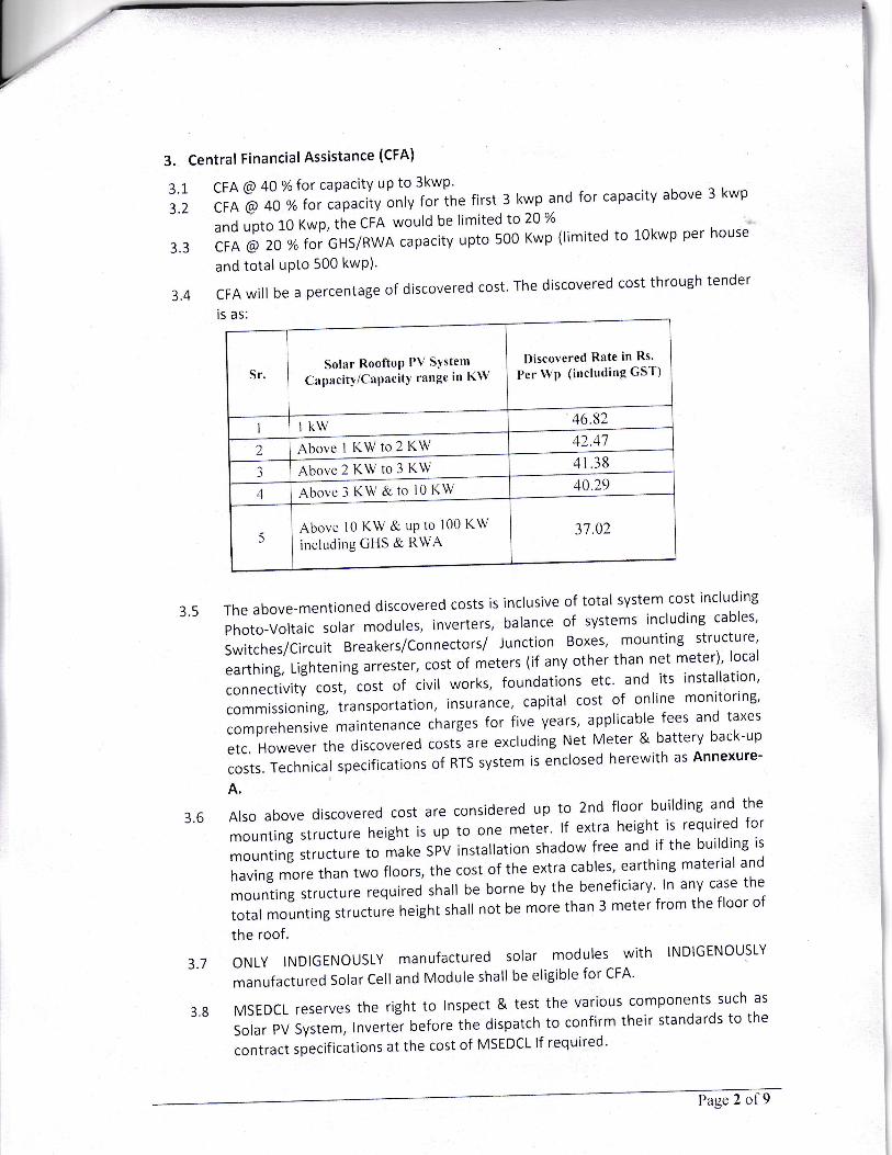
CFAwillbeapercentageofdiscoveredcost'Thediscoveredcostthroughtender
The above-mentioned discovered costs is inclusive of total system cost including
Photo-Voltaicsolarmodules,inverterS,balanceofsystemsincludingcables,Switches/Circuit Breakers/Connectors/ Junction Boxes' mounting structure'
earthing, Llghtening arrester, cost of meters (if any other than net meter)' local
connectivitycost,costofcivilWorks,foundationsetc'anditsinstallation,commissioning,transportation,insurance'capitalcostofonlinemonitoring'comprehensive maintenance charges for five years' applicable fees and taxes
etc. However the discovered costs are excluding Net Meter & battery back-up
costs.TechnicalspecificationsofRTSSystem|senclosedherewithasAnnexure-A.
Alsoabovediscoveredcostareconsideredupto2ndfloorbuildingandthemountingStructureheightisuptoonemeter.lfextraheightisrequiredformounting structure to make sPV installation shadow free and if the building is
having more than two floors, the cost of the extra cables, earthing material and
mounting structure required shall be borne by the beneficiary. In any case the
totalmountingstructureheightshallnotbemorethan3meterfromthefloorofthe roof.
oNLYlNDlGENoUSLYmanufacturedsolarmoduleswithlNDlGENoUSLYmanufactured Solar cell and Module shall be eligible for cFA'
MSEDCLreserveStherighttolnSpect&testthevariousComponentssuchasSolarPVSystem,tnverterbeforethedispatchtoconfirmtheirstandardstothecontract specifications at the cost of MSEDCL lf required'
Discovered Rate in Rs.
I'er Wp (including GST)Solar RooftoP P\/ SYstem
CapacitY/CaPacitY range in KWSr,
46.82lkwI
42.41Above 1 I(W to 2 I(W241 38
Above 2 I(W to 3 KW340,29Above 3 t(W & to l0 KW4
31.02Above l0 l(W & uP to 100 KW
including GHS & RWA5
3.8
Page 2 of9

The pre dispatch inspection/testing of the Solar Cell/Modules & lnverter may be
done at the manufacture's place if required,
MSEDCL reserves the right to do sample inspection checks for the projects
commissioned by the Bidder.
The projects will be inspected for quality at any time during commissioning or
after the completion of the project either by officer(s) from MSEDCL or its
designated agency.
The inspe ction as mentioned above bv MSEDCL's representative shall not
relieve the elled aeencies from ful I resoonsibilitv of comp ne the work
confirmine qualitv of material as per thg technical specitications and
requirement this contract.
3.9 COMPLETION OF CONTRACT:
Unless otherwise terminated under the provisions of any other relevant clause,
this contract shall be deemed to have been completed on the expiry of the
warranty period & Comprehensive Maintenance,
3.10 SERVICE CENTRES
a. Empanelled Agency has to undertake to establish one no. of Service centre
with necessary spare parts and technicians in each selected Zones under
MSEDCL Jurisdiction area.
b. The Service Centre should have adequately trained staff available for repair
and maintenance of Solar PV Systems, lnverters supplied and installed.
c. The service centre should be open for at least 8 hours per day and 6 days
week excluding bank holidays.
d. Empanelled Agencies need to have a dedicated mobile number which should
be readily available during its office hours and an e-mail lD for
correspondence.e. Empanelled Agency shall ensure that necessary spares are always available
with the service centres to provide necessary after sales service to the
beneficiary during the warranty period.
3.11 Resolving Complaints related to defects/ non-working / poor performance ofthe system:
a. For any problem/defect in system, Empanelled Agency shall have toreplace/repair the defect of the system, resolve it and make the system
operative as per the Technical specifications, within 48 (Forty eight)
hours from the receipt of the complaint or receipt ofn otification/Alert/M essage f rom the re mote meteri n g system.
Page 3 of9
While doing repairing or rectification work, the Empanelled Agency's
technician or any person is not authorized to work on MSEDCL's electricline of L1 KV and LT having potential danger of electricity.
c. Penaltv on part of loss of Solar Reneration"The Performance Ratio (PR) of Grid Connected Solar Systems shall be
more than 75% throughout the 5-year warranty & CMC period, and
necessary efforts shall be made by the Bidder to achieve it. The PR shall
be verified by MSEDCL or its authorized designated Agency at any timeand any numbers of times during the 5-year maintenance period
without any prior intimation to the Bidder. The PR shall be measuredon an instantaneous-basis and shall be calculated on the nameplate DC
capacity of the PV system (at STC). Further, the PR shall be calculatedafter cleaning the PV modules and during a time when there is no
shadow being cast on the PV array from objects outside thebeneficiary's/ consu mer's premises."
ln case the PV system fails to meet the minimum instantaneousPerformance Ratio (PR) of 75%, then the empanelled agency shall bepenalized at the rate of Rs, 1,000 per kW for each percentage shortfall inthe PR for each instance of measurement. (For example, if a 3 kW systemmeasures 73%PR during an inspection, then the Bidder shall be penalizedRs. 1,000 per kW per% x 3 kW x(75-73)% = Rs.6,000/-) The Bidder shallbe required to rectify the faults in the PV system within l week of suchfailure, after which, one more inspection shall be carried out to verify therectification. This penalty shall be deducted from the PBG/FD of theBidder, which shall be replenished immediately after such deduction.
LOCATION OF INSTALLATION :
The Grid Connected Solar PV system is required to be installed at variouslocations of Residential consumer's premises who apply for it in the jurisdictionof MSEDCL in the Maharashtra State,
3.13 PACKING AND FORWARDING CHARGES:
The prices shall be inclusive of packing & forwarding charges. The stores should
be strongly and adequately packed to ensure safe arrival at destination. The
materials dispatched from overseas by Air / Shipping should be packed in such away that it can withstand rough handling and possible corrosion due to exposure
to salt laden atmosphere, salt spray or open storage. All packing must be clearly
marked with order Number and consignee's name and address.
b
3.12
Page 4 of 9
3.L4 lnsurance:
The Bidder shall be responsible and take an lnsurance Policy for transit-cum
storage-cum erection for all the materials to cover all risks and liabilities for
supply of materials on site basis, storage of materials at site, erection, testing
and commissioning. The bidder shall also take appropriate insurance during
O&M period.
The Bidder shall also take insurance for Third Party Liability covering loss of
human life, engineers and workmen and also covering the risks of damage to the
third party/material/equipment/properties during execution of the Contract'
Before commencement of the work, the Bidder will ensure that all its employees
and representatives are covered by suitable insurance against any damage, loss,
injury or death arising out of the execution of the work or in carrying out the
Contract. Liquidation, Death, Bankruptcy etc., shall be the responsibility of
bidder.
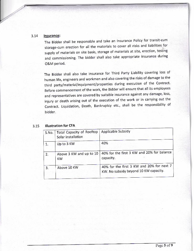
3.1-5 lllustration for CFA
Applicable SubsidYTotal CapacitY of Ro
Solar lnstallation
oftopS.No.
40%7 upto3KW
40% for the first 3 KW and 20% for ba lance
capacity2 Above 3 KW and uP to L0
KW
40% for the first 3 KW and 20%
KW. No subsidy beyond 10 KW capacityfor next 7Above 10 KW3
Page 5 of 9
Name of Region Name of Zone
lKWAbove IKW TO2KW
Above2KWTO
3KW
Above3KWTO
1oKW
Above10KW
TO10oKw
includingGHS &RWA
AllocatedQuantum
AllocatedQuantum
AllocatedQuantum
AllocatedQuantum
AllocatedQuantum
AURANGABADREGION
AURANGABAD ZONE 349 349 115 300 60 1233
LATURZONE LATUR 180 180 90 100 600
NANDED ZONE 160 160 80 100 50 550
KOKANREGION
BHANDUP (U) ZONE 780 780 390 1400 1200 455t
JALGAON ZONE 240 t20 100 40 140
KALYAN ZONE 751 157 3',78 400 250 2542
KOKAN ZONE RATNAGIRI 180 180 90 100 60 610
NASIK ZONE 613 613 306 400 t20 2052
NAGPURREGION
AKOLA ZONE 180 180 90 100 80 630
AMARAVATI ZONE 168 r68 84 100 80 600
CHANDRAPUR ZONE 164 164 82 100 80 591
GONDIA ZONE t20 t20 60 150 60 510
NAGPURZONE 520 520 260 s00 200 2000
BARAMATI ZONE 440 440 220 200 100 1400
KOLHAPUR ZONE 222 222 ll1 100 941
PLTNE ZONE 926 926 463 2t64 970 5450
6000 6000 3000 6500 3500 25000
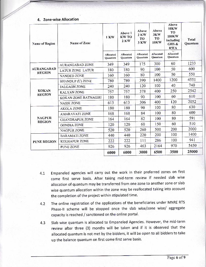
4. Zone-wise Allocation
4.1. Empaneled agencies will carry out the work in their preferred zones on first
come first serve basis. After taking mid-term review if needed slab wise
allocation of quantum may be transferred from one zone to another zone or slab
wise quantum allocation within the zone may be reallocated taking into account
the completion of the project within stipulated time.
The online registration of the applications of the beneficiaries under MNRE RTS
Phase-ll scheme will be stopped once the slab wise/zone wise/ aggregate
capacity is reached / sanctioned on the online portal'
Slab wise quantum is allocated to Empaneled Agencies. However, the mid-term
review after three (3) months will be taken and if it is observed that the
allocated quantum is not met by the bidders, it will be open to all bidders to take
up the balance quantum on first come first serve basis.
4.2
TotalQuantum
4.3
Page 6 of9
50
240
PUNE REGION 286
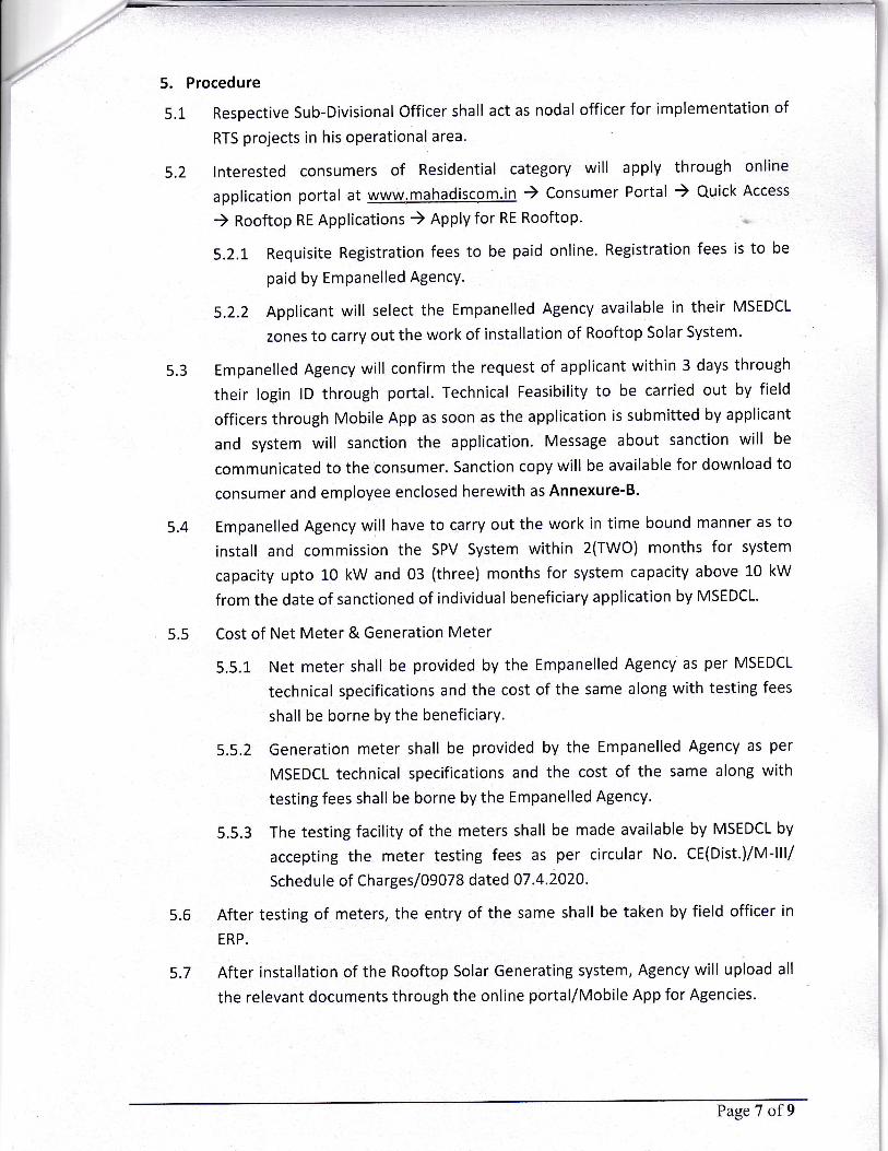
a, 5. Procedure
5.L
5.2
5.3
5.4
5.5
5.6
Respective Sub-Divisional Officer shall act as nodal officer for implementation of
RTS projects in his operational area'
lnterested consumers of Residential category will apply through online
application portal at www.mahadiscom,in ) Consumer Portal ) Quick Access
) Rooftop RE Applications ) Apply for RE Rooftop'
5.2.1. Requisite Registration fees to be paid online. Registration fees is to be
paid by EmPanelled AgencY.
5.2.2 Applicant will select the Empanelled Agency available in their MSEDCL
zones to carry out the work of installation of Rooftop Solar System'
Empanelled Agency will confirm the request of applicant within 3 days through
their login lD through portal. Technical Feasibility to be carried out by field
officers through Mobile App as soon as the application is submitted by applicant
and system will sanction the application. Message about sanction will be
communicated to the consumer. Sanction copy will be available for download to
consumer and employee enclosed herewith as Annexure-B.
Empanelled Agency will have to carry out the work in time bound manner as to
install and commission the SPV System within 2(TWO) months for system
capacity upto 10 kW and 03 (three) months for system capacity above 10 kW
from the date of sanctioned of individual beneficiary application by MSEDCL.
Cost of Net Meter & Generation Meter
5.5.1 Net meter shall be provided by the Empanelled Agency as per MSEDCL
technical specifications and the cost of the same along with testing fees
shall be borne by the beneficiarY'
5.5.2 Generation meter shall be provided by the Empanelled Agency as per
MSEDCL technical specifications and the cost of the same along with
testing fees shall be borne by the Empanelled Agency.
5.5.3 The testing facility of the meters shall be made available by MSEDCL by
accepting the meter testing fees as per circular No. cE(Dist.)/M-lll/
Schedule of Charges /09078 dated 07.4.2020'
After testing of meters, the entry of the same shall be taken by field officer in
ERP.
After installation of the Rooftop Solar Generating system, Agency will upload all
the relevant documents through the online portal/Mobile App for Agencies.
5.7
Page 7 of 9
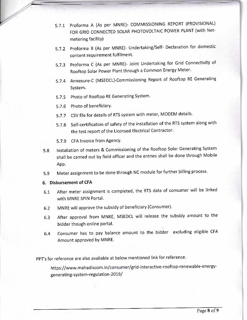
5.7.1. Proforma A (As per MNRE)- COMMISSIONING REPORT (PROVISIONAL)
FOR GRID CONNECTED SOLAR PHOTOVOLTAIC POWER PLANT (With NCt-
metering facilitY)
5.7.2 Proforma B (As per MNRE)- Undertaking/self- Declaration for domestic
content requirement fulfil ment'
5,7,3ProformaC(AsperMNRE)-JointUndertakingforGridConnectivityofRooftop solar Power Plant through a common Energy Meter.
5.7.4 Annexure-c (MSEDCL)-Commissioning Report of Rooftop RE Generating
SYstem.
5.7.5 Photo of Rooftop RE Generating System'
5.7.6 Photo of beneficiarY'
5.7.7 CSV file for details of RTS system with meter, MODEM details'
5.7,g Self-certification of safety of the installation of the RTS system along with
thetestreportoftheLicensedElectricalContractor.
5.7.9 CFA lnvoice from AgencY.
5.g lnstallation of meters & Commissioning of the Rooftop Solar Generating System
shall be carried out by field officer and the entries shall be done through Mobile
App.
5.g Meter assignment to be done through NC module for further billing process.
6. Disbursement of CFA
6.1 After meter assignment is completed, the RTS data of consumer will be linked
with MNRE SPIN Portal'
6.2 MNRE will approve the subsidy of beneficlary (consumer).
6.3 After approval from MNRE, MSEDCL will release the subsidy amount to the
bidder though online Portal'
6.4 Consumer has to pay balance amount to the bidder excluding eligible CFA
Amount aPProved bY MNRE.
ppT's for reference are also available at below mentioned link for reference'
https://www.ma hadiscom.in/consu mer/grid-interactive-rooftop-renewable-energy-
generati ng-system-regu lation-20L9/
Page 8 of9
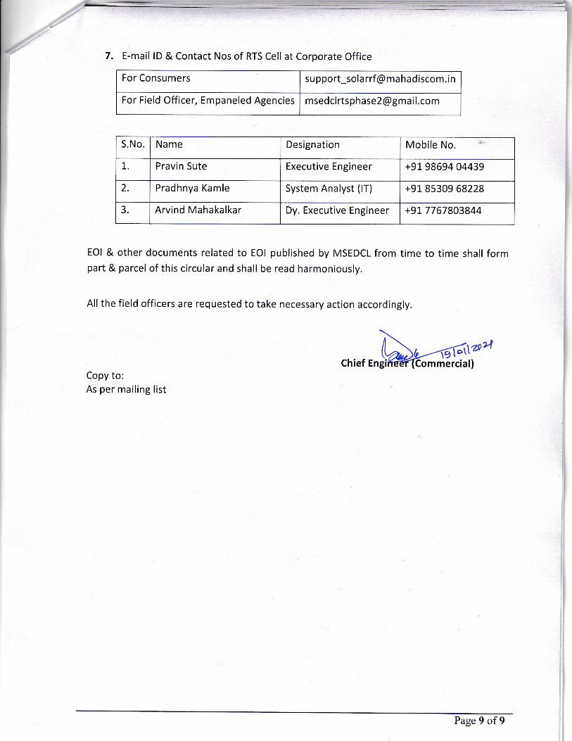
E-mail lD & Contact Nos of RTS Cell at Corporate Office
For Consumers support_sola rrf @ mahadiscom.in
For Field Officer, Empaneled Agencies
S.No Name Designation Mobile No.
Pravin Sute Executive Engineer +91 98694 04439
Pradhnya Kamle System Analyst (lT) +91 85309 68228
3. Arvind Mahakalkar Dy. Executive Engineer +917767803844
EOI & other documents related to EOI published by MSEDCL from time to time shall formpart & parcel of this circular and shall be read harmoniously.
Allthe field officers are requested to take necessary action accordingly.
ChiefCopy to:As per mailing list
Page 9 of9
msedcl rtsphase2 @gma i l.com
1..
2.
a>l
Annexure-A
TECHNICAL SPECIFICATIONS FOR
GRID CONNECTED SPV SYSTEMS
The proposed projects shall be commissioned as per the technical specifications given below.
Any short comings will lead to cancelation of Empanelment as may be decided by MSEDCL and
Competent Authority’s decision will be final and binding on the bidder.
1. DEFINITION: A Grid connected Solar Rooftop Photo Voltaic (SPV) power plant consists of SPV array, Module Mounting Structure, Power Conditioning Unit (PCU) consisting of Maximum Power Point Tracker (MPPT), Inverter, and Controls & Protections, interconnect cables, solar meter, bi-directional energy meter and switches. PV Array is mounted on a suitable structure. Grid connected SPV system is without battery and should be designed with necessary features to supplement the grid power during daytime. Components and parts used in the SPV power plants including the PV modules, metallic structures, cables, junction box, switches, PCUs etc., should confirm to the BIS, IEC, or international specifications, wherever such specifications are available and applicable. Solar PV system shall consist of following equipment/components.
Solar PV modules consisting of required number of Crystalline PV modules.
Grid interactive Power Conditioning Unit with Remote Monitoring System.
Mounting structures.
Junction Boxes.
Earthing and lightening protections.
IR/UV protected PVC Cables, pipes and accessories.
Solar Generator Meter and Bi-directional Energy Meter
a) SOLAR PHOTOVOLTAIC MODULES:
1.1.1 The PV modules and Solar Cell used should be made in India. Necessary documents in this regards must be provided to MSEDCL.
Violation of norms of Domestic Content Requirement (DCR) UNDER Solar PV
projects will lead to penalties and actions as mentioned in office memorandum of
MNRE GOI vide letter no. 283/2018-GRID SOLAR dated 20th February, 2018 as
under:
a) Filing of criminal case under IPC 420 and related Sec. b) Blacklisting of developers for period of 10 years c) Forfeiting of relevant bank guarantee(s) d) Disciplinary case against the Officers of concerned CPSU/ State Govt. e) Any other action, in addition to those above
SPV Modules and Solar Cells must be used for this Scheme shall be
domestically manufactured as per MNRE’s requirement. The Empanelled
Agencies shall require to submit the Self declaration, regarding the Modules and
Solar cells used under this Scheme are “Made in India” in Appendix-3 Proforma-

B. In absence of the ALMM (Approved list of Models & Manufacturers of SPV),
the Empanelled Agencies shall have to submit self-declaration regarding
domestically manufactured Cell and Modules used in the SPV System in this
project. Whenever, the ALMM list published by the MNRE, the Model and
Manufactures of the Module and Cell shall be from the ALMM only used in the
SPV System in this project.
“The PV modules used shall conform to the latest edition of IEC 61215 and IS
14286 (Terrestrial photovoltaic (PV) modules - Design qualification and type
approval). The PV modules shall also conform to IS/ IEC 61730 (Photovoltaic (PV)
module safety qualification: Requirements for construction and testing).”
1.1.2. The PV modules used must qualify to the latest edition of IEC PV module qualification test or equivalent BIS standards Crystalline Silicon Solar Cell Modules IEC 61215 and IS14286, IEC 61853-Part I, IS 16170-Part I for Photovoltaic (PV) module performance testing and energy rating, Irradiance and temperature performance measurements, and power rating, In addition, the modules must conform to IEC61730 Part-2- requirements for construction & Part 2 – requirements for testing, for safety qualification or equivalent IS.
a) For the PV modules to be used in a highly corrosive atmosphere throughout their lifetime, they must qualify to IEC 61701/IS 61701
b) The total solar PV array capacity should not be less than allocated capacity (kWp) and should comprise of solar crystalline modules of minimum 250 Wp. Module capacity less than 250 watts shall not be accepted.
c) Protective devices against surges (SPD) at the PV module shall be provided. Low voltage drop bypass diodes shall be provided.
d) PV modules must be tested and approved by one of the IEC/BIS authorized test
centres. e) The module frame shall be made of corrosion resistant materials,
preferably having anodized aluminium. f) The bidder shall carefully design & accommodate requisite numbers of the
modules to achieve the rated power in his bid. g) The PV Module efficiency should be higher than 15%. h) Other general requirement for the PV modules and sub systems shall be the
following:
i. The rated power of solar PV module shall have maximum tolerance up to
+3%. No negative tolerance in the rated capacity of solar PV module is
allowed.
ii. The peak-power point voltage and the peak-power point current of any
supplied module string (series connected modules) shall not vary by +2%
from the respective arithmetic means for all modules and/or for all
module strings, as the case may be.
iii. The module shall be provided with a junction box with either provision of
external screw terminal connection or sealed type and with arrangements
for provision of by-pass diode. The box shall have hinged, weather proof
lid with captive screws and cable gland entry points or may be of sealed
type and IP-65 rated.
iv. I-V curves at STC shall have to be provided by bidder.
v. Minimum certified PV module efficiency shall be 15% for crystalline. The
temperature co-efficient power of the PV module shall not be less than -
0.50% /°C.
vi. All PV modules should carry a performance warranty of > 90% during the
first 10 years, and >80% during the next 15 years. Further, module shall
have performance warranty of > 97% during the first year of installation.
Degradation of module should not be more than 1 % per annum. MSEDCL
authorized representative will check the efficiency of the system on
random basis.
vii. The PV modules shall be equipped with IP67 or higher protection level
junction box with a minimum of 3 (three) numbers of bypass diodes of
appropriate rating and appropriately sized output power cable of
symmetric length with MC4 or equivalent solar connectors.
1.1.3. Modules deployed must use a RF identification tag. The following information must be mentioned in the RFID used on each module (This can be inside or outside the laminate, but must be able to withstand harsh environmental conditions).
a) Name of the manufacturer of the PV module b) Name of the manufacturer of Solar Cells. c) Month & year of the manufacture (separate for solar cells and modules) d) Country of origin (separately for solar cells and module) e) I-V curve for the module Wattage, Im, Vm and FF for the module f) Unique Serial No and Model No of the module
g) Date and year of obtaining IEC PV module qualification certificate. h) Name of the test lab issuing IEC certificate. i) Other relevant information on traceability of solar cells and module as per
9001 and ISO 14001 1.1.4. Warranties:
a) Material Warranty:
i. Material Warranty is defined as: The manufacturer should warrant the
Solar Module(s) to be free from the defects and/or failures specified below
for a period not less than five (05) years from the date of commissioning.
ii. Defects and/or failures due to manufacturing.
iii. Defects and/or failures due to quality of materials.
iv. Non conformity to specifications due to faulty manufacturing and/or
inspection processes. If the solar Module(s) fails to conform to this
warranty, the manufacturer will repair or replace the solar module(s), at
the Owners sole option.
b) Performance Warranty:
i. The predicted electrical degradation of power generated not exceeding
20% of the minimum rated power over the 25 year period and not more
than 10% after ten years period of the full rated original output.
2. ARRAY STRUCTURE:
a) Supply, installation, erection and acceptance of module mounting structure (MMS) with all necessary accessories, auxiliaries and spare part shall be in the scope of the Empanelled Agency.
b) Hot dip galvanized MS /anodized aluminium mounting structures shall be
used for mounting the modules/ panels/arrays. Each structure should have angle of inclination as per the site conditions and to take maximum insolation. However to accommodate more capacity the angle inclination may be reduced until the plant meets the specified performance ratio requirements. MMS shall be made of hot dip Galvanized steel per ASTM A123. Minimum thickness of HDGI zinc coating should be minimum 80 micron at any point when measured. No averaging is allowed in the measurement of coating thickness. All bolts, nuts, panel mounting clamps fasteners shall be of stainless steel of grade SS 304 and must sustain the adverse climatic conditions.
c) PV array structure shall be designed and positioned such that the PV modules are completely shadow-free solar during generation hours.
3. JUNCTION BOXES (JBs): a) The junction boxes are to be provided in the PV array for termination of
connecting cables. The Junction Boxes (JBs) shall be made of
GRP/FRP/Powder Coated aluminium /cast aluminium alloy with full dust,
water & vermin proof arrangement. All wires/cables must be terminated through cable lugs. The JBs shall be such that input & output termination can be made through suitable cable glands. Suitable markings shall be provided on the busbars for easy identification and cable ferrules will be fitted at the cable termination points for identification.
b) Copper bus bars/terminal blocks housed in the junction box with suitable
termination threads Conforming to IP65 standard and IEC 62208 Hinged door with EPDM rubber gasket to prevent water entry. Single /double compression cable glands.
c) For array junction box/ PV combiner box, Empanelled Agency may also
provide polyamide glands and MC4 Connectors. The rating of the junction box shall be suitable with adequate safety factor to interconnect the Solar PV array.
d) Each Junction Box shall have High quality Suitable capacity Metal Oxide Varistors (MOVs) / SPDs, suitable Reverse Blocking Diodes.
e) Suitable markings shall be provided on the bus bar for easy identification and the cable ferrules must be fitted at the cable termination points for identification.
f) Junction boxes shall be mounted on the MMS such that they are easily accessible and are protected from direct sunlight and harsh weather.
4. DC DISTRIBUTION BOX (DCDB): a) DC Distribution Box (DCDB) to receive the DC output from the PV array field.
b) DC DBs shall be dust & vermin proof conform having IP 65 protection.
c) The bus bars are made of EC grade copper of required size. Suitable capacity MCBs/MCCB shall be provided for controlling the DC power output to the PCU along with necessary surge arrestors.
5. AC DISTRIBUTION BOX (ACDB):
a) AC Distribution Panel Board (DPB) shall control the AC power from PCU/inverter, and should have necessary surge arrestors. Interconnection from ACDB to mains at LT Bus bar while in grid connected mode.
b) All switches and the circuit breakers, connectors should conform to IEC60947:2019, part I, II and III/ IS60947 part I, II and III.
c) The changeover switches, cabling work should be undertaken by the bidder as part of the project.
d) All the Panel’s shall be metal clad, totally enclosed, rigid, floor mounted, air -insulated, cubical type suitable for operation on three phase / single phase,415 or 230 volts, 50 Hz.
e) The panels shall be designed for minimum expected ambient temperature of 50 degree Celsius, 80% humidity and dusty weather.
f) All indoor panels will have protection of IP54 or better. All outdoor panels will have protection of IP65 or better.
g) Should conform to Indian Electricity Act and CEA safety regulations (till last amendment). h) All the 415 AC or 230 volts devices / equipment like bus support insulators, circuit breakers, SPDs, VTs etc., mounted inside the switchgear shall be suitable for continuous operation and satisfactory performance under the following supply conditions.
a. Variation in supply voltage :+/- 10 % b. Variation in supply frequency :+/- 3 Hz
h) The inverter output shall have the necessary rated AC surge arrestors
and MCB/ MCCB. MCB shall be used for currents up to 63 Amperes, and MCCB shall be used for currents greater than 63 Amperes. RCCB shall be used by the Agency if required for successful operation of the PV system.
6. PCU/ARRAY SIZE RATIO:
a) The combined wattage of all inverters should not be less than rated capacity of power plant under STC.
b) Maximum power point tracker shall be integrated in the PCU/Inverter to maximize energy drawn from the array.
7. PCU/Inverter:-
i. Marking: All the Inverters should contain the following clear and indelible Marking Label & Warning Label as per IS 16221 Part II, clause 5. The equipment shall, as a minimum, be permanently marked with:
a) The name or trade mark of the manufacturer or supplier; b) A model number, name or other means to identify the equipment, c) A serial number, code or other marking allowing identification of manufacturing
location and the manufacturing batch or date within a three-month time period.
d) Input voltage, type of voltage (a.c. or d.c.), frequency, and maximum
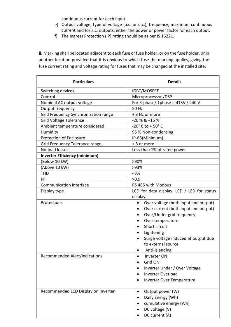
continuous current for each input.
e) Output voltage, type of voltage (a.c. or d.c.), frequency, maximum continuous current and for a.c. outputs, either the power or power factor for each output.
f) The Ingress Protection (IP) rating should be as per IS 16221.
ii. Marking shall be located adjacent to each fuse or fuse holder, or on the fuse holder, or in
another location provided that it is obvious to which fuse the marking applies, giving the
fuse current rating and voltage rating for fuses that may be changed at the installed site.
Particulars Details
Switching devices IGBT/MOSFET
Control Microprocessor /DSP
Nominal AC output voltage For 3-phase/ 1phase :- 415V / 240 V
Output frequency 50 Hz
Grid Frequency Synchronization range + 3 Hz or more
Grid Voltage Tolerance -20 % & +15 %
Ambient temperature considered -20° C to + 50° C
Humidity 95 % Non-condensing
Protection of Enclosure IP-65(Minimum).
Grid Frequency Tolerance range + 3 or more
No-load losses Less than 1% of rated power Inverter Efficiency (minimum)
(Below 10 kW) >90%
(Above 10 kW) >93%
THD <3%
PF >0.9
Communication interface RS 485 with Modbus Display type LCD for data display. LCD / LED for status
display
Protections Over voltage (both input and output)
Over current (both input and output)
Over/Under grid frequency
Over temperature
Short circuit
Lightening
Surge voltage induced at output due to external source
Anti-islanding
Recommended Alert/Indications Inverter ON
Grid ON
Inverter Under / Over Voltage
Inverter Overload
Inverter Over Temperature
Recommended LCD Display on Inverter Output power (W)
Daily Energy (Wh)
cumulative energy (Wh)
DC voltage (V)
DC current (A)
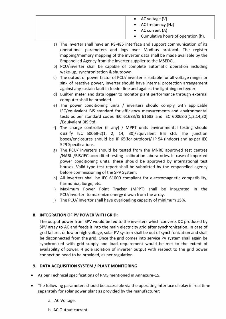
AC voltage (V)
AC frequency (Hz)
AC current (A)
Cumulative hours of operation (h).
a) The inverter shall have an RS-485 interface and support communication of its operational parameters and logs over Modbus protocol. The register mapping/memory mapping of the inverter data shall be made available by the Empanelled Agency from the inverter supplier to the MSEDCL.
b) PCU/inverter shall be capable of complete automatic operation including wake-up, synchronization & shutdown.
c) The output of power factor of PCU/ inverter is suitable for all voltage ranges or sink of reactive power, inverter should have internal protection arrangement against any sustain fault in feeder line and against the lightning on feeder.
d) Built-in meter and data logger to monitor plant performance through external computer shall be provided.
e) The power conditioning units / inverters should comply with applicable IEC/equivalent BIS standard for efficiency measurements and environmental tests as per standard codes IEC 61683/IS 61683 and IEC 60068-2(1,2,14,30) /Equivalent BIS Std.
f) The charge controller (if any) / MPPT units environmental testing should
qualify IEC 60068-2(1, 2, 14, 30)/Equivalent BIS std. The junction boxes/enclosures should be IP 65(for outdoor)/ IP 54 (indoor) and as per IEC 529 Specifications.
g) The PCU/ inverters should be tested from the MNRE approved test centres /NABL /BIS/IEC accredited testing- calibration laboratories. In case of imported power conditioning units, these should be approved by international test houses. Valid type test report shall be submitted by the empanelled agency before commissioning of the SPV System.
h) All inverters shall be IEC 61000 compliant for electromagnetic compatibility, harmonics, Surge, etc.
i) Maximum Power Point Tracker (MPPT) shall be integrated in the PCU/inverter to maximize energy drawn from the array.
j) The PCU/ Invertor shall have overloading capacity of minimum 15%.
8. INTEGRATION OF PV POWER WITH GRID:
The output power from SPV would be fed to the inverters which converts DC produced by SPV array to AC and feeds it into the main electricity grid after synchronization. In case of grid failure, or low or high voltage, solar PV system shall be out of synchronization and shall be disconnected from the grid. Once the grid comes into service PV system shall again be synchronized with grid supply and load requirement would be met to the extent of availability of power. 4 pole isolation of inverter output with respect to the grid power connection need to be provided, as per regulation.
9. DATA ACQUISITION SYSTEM / PLANT MONITORING
As per Technical specifications of RMS mentioned in Annexure-15.
The following parameters should be accessible via the operating interface display in real time separately for solar power plant as provided by the manufacturer:
a. AC Voltage.
b. AC Output current.
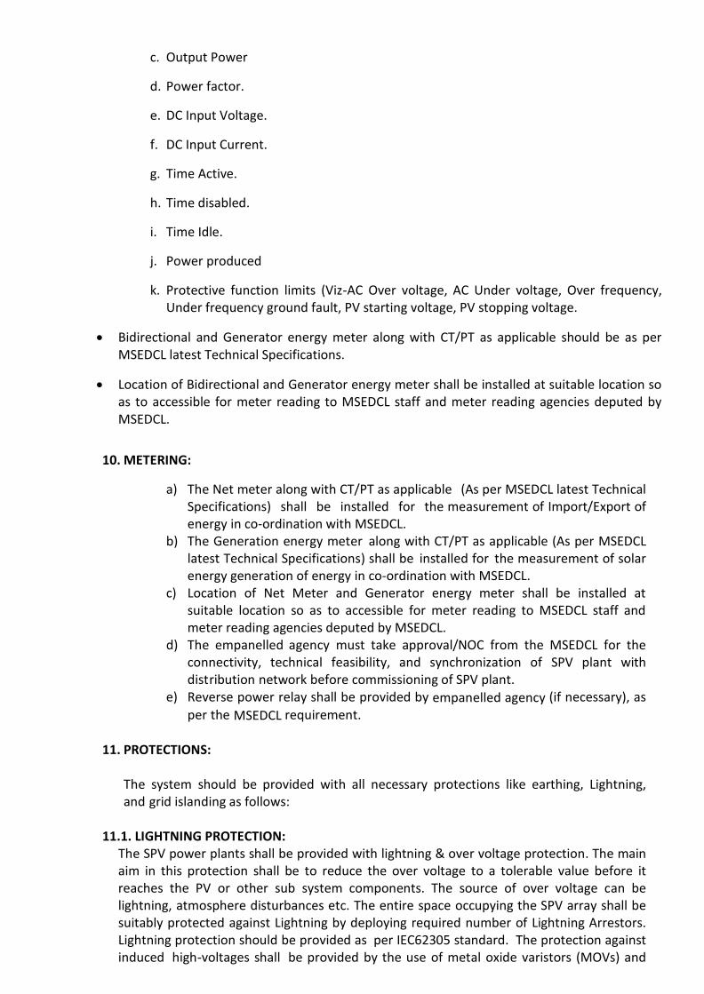
c. Output Power
d. Power factor.
e. DC Input Voltage.
f. DC Input Current.
g. Time Active.
h. Time disabled.
i. Time Idle.
j. Power produced
k. Protective function limits (Viz-AC Over voltage, AC Under voltage, Over frequency, Under frequency ground fault, PV starting voltage, PV stopping voltage.
Bidirectional and Generator energy meter along with CT/PT as applicable should be as per MSEDCL latest Technical Specifications.
Location of Bidirectional and Generator energy meter shall be installed at suitable location so as to accessible for meter reading to MSEDCL staff and meter reading agencies deputed by MSEDCL.
10. METERING:
a) The Net meter along with CT/PT as applicable (As per MSEDCL latest Technical Specifications) shall be installed for the measurement of Import/Export of energy in co-ordination with MSEDCL.
b) The Generation energy meter along with CT/PT as applicable (As per MSEDCL latest Technical Specifications) shall be installed for the measurement of solar energy generation of energy in co-ordination with MSEDCL.
c) Location of Net Meter and Generator energy meter shall be installed at suitable location so as to accessible for meter reading to MSEDCL staff and meter reading agencies deputed by MSEDCL.
d) The empanelled agency must take approval/NOC from the MSEDCL for the connectivity, technical feasibility, and synchronization of SPV plant with distribution network before commissioning of SPV plant.
e) Reverse power relay shall be provided by empanelled agency (if necessary), as
per the MSEDCL requirement.
11. PROTECTIONS: The system should be provided with all necessary protections like earthing, Lightning, and grid islanding as follows:
11.1. LIGHTNING PROTECTION: The SPV power plants shall be provided with lightning & over voltage protection. The main aim in this protection shall be to reduce the over voltage to a tolerable value before it reaches the PV or other sub system components. The source of over voltage can be lightning, atmosphere disturbances etc. The entire space occupying the SPV array shall be suitably protected against Lightning by deploying required number of Lightning Arrestors. Lightning protection should be provided as per IEC62305 standard. The protection against induced high-voltages shall be provided by the use of metal oxide varistors (MOVs) and

suitable earthing such that induced transients find an alternate route to earth.
11.2. SURGE PROTECTION: Internal surge protection shall consist of three MOV type surge-arrestors connected from +ve and –ve terminals to earth (via Y arrangement).
11.3. EARTHING i. Each array structure of the PV yard should be grounded/ earthed properly as per
IS:3043-1987. ii. In addition the lighting arrester/masts should also be earthed inside the array field.
iii. It shall be ensured that all the earthing points are bonded together for AC systems to
make them at the same potential. iv. Earthing for Lightening Arrestors/DC Systems shall be provided separately. v. All the earthings required as per the technical specifications should be maintenance
free earthings.
a) Each array structure of the PV yard, LT power system, earthing grid for switchyard, all electrical equipment, inverter, all junction boxes, etc. shall be grounded properly as per IS 3043-1987. All metal casing/ shielding of the plant shall be thoroughly grounded in accordance with CEA Safety Regulation 2010.
b) Each string/ array and MMS of the plant shall be grounded properly. The array structures are to be connected to earth pits as per IS standards.
c) Necessary provision shall be made for bolted isolating joints of each earthing pit for periodic checking of earth resistance.
d) The complete earthing system shall be mechanically and electrically connected to provide independent return to earth.
e) Earthing bus bar shall be terminated at both ends of the switchgear to suit the connections to outside earthing conductor. All components and the module are required to be earthed individually and are to be looped and connected to the earthing grid.
f) Separate earth pits shall be prepared for equipment body earthing. Lightning arrestor earth pits and equipment earth pit are to be kept separate.
g) Earthing system shall consist of earth grids and electrodes buried in soil in the premises, embedded in concrete inside the buildings/rooms to which all the electrical equipment, metallic structures are connected to have earth continuity for safety reasons.
11.4. GRID ISLANDING:
i. In the event of a power failure on the electric grid, it is required that any independent power-producing inverters attached to the grid turn off immediately. This prevents the DC-to-AC inverters from continuing to feed power into small sections of the grid, known as “islands.” Powered islands present a risk to workers who may expect the area to be unpowered, and they may also damage grid- connected equipment. The Rooftop PV system shall be equipped with Anti islanding features. In addition to disconnection from the grid (due to islanding protection) disconnection due to under and over voltage conditions shall also be provided.
ii. A manual disconnect 4 / 2 pole isolation switch (RCCB may also be used) beside automatic disconnection to grid would have to be provided at utility end to isolate the grid connection by the utility personnel to carry out any maintenance.
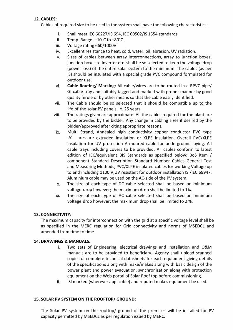
12. CABLES: Cables of required size to be used in the system shall have the following characteristics:
i. Shall meet IEC 60227/IS 694, IEC 60502/IS 1554 standards ii. Temp. Range: –10°C to +80°C.
iii. Voltage rating 660/1000V iv. Excellent resistance to heat, cold, water, oil, abrasion, UV radiation. v. Sizes of cables between array interconnections, array to junction boxes,
junction boxes to Inverter etc. shall be so selected to keep the voltage drop (power loss) of the entire solar system to the minimum. The cables (as per IS) should be insulated with a special grade PVC compound formulated for outdoor use.
vi. Cable Routing/ Marking: All cable/wires are to be routed in a RPVC pipe/ GI cable tray and suitably tagged and marked with proper manner by good quality ferule or by other means so that the cable easily identified.
vii. The Cable should be so selected that it should be compatible up to the life of the solar PV panels i.e. 25 years.
viii. The ratings given are approximate. All the cables required for the plant are to be provided by the bidder. Any change in cabling sizes if desired by the bidder/approved after citing appropriate reasons.
ix. Multi Strand, Annealed high conductivity copper conductor PVC type ‘A’ pressure extruded insulation or XLPE insulation. Overall PVC/XLPE insulation for UV protection Armoured cable for underground laying. All cable trays including covers to be provided. All cables conform to latest edition of IEC/equivalent BIS Standards as specified below: BoS item / component Standard Description Standard Number Cables General Test and Measuring Methods, PVC/XLPE insulated cables for working Voltage up to and including 1100 V,UV resistant for outdoor installation IS /IEC 69947. Aluminium cable may be used on the AC-side of the PV system.
x. The size of each type of DC cable selected shall be based on minimum voltage drop however; the maximum drop shall be limited to 1%.
xi. The size of each type of AC cable selected shall be based on minimum voltage drop however; the maximum drop shall be limited to 2 %.
13. CONNECTIVITY: The maximum capacity for interconnection with the grid at a specific voltage level shall be as specified in the MERC regulation for Grid connectivity and norms of MSEDCL and amended from time to time.
14. DRAWINGS & MANUALS: i. Two sets of Engineering, electrical drawings and Installation and O&M
manuals are to be provided to beneficiary. Agency shall upload scanned copies of complete technical datasheets for each equipment giving details of the specifications along with make/makes along with basic design of the power plant and power evacuation, synchronization along with protection equipment on the Web portal of Solar Roof top before commissioning.
ii. ISI marked (wherever applicable) and reputed makes equipment be used.
15. SOLAR PV SYSTEM ON THE ROOFTOP/ GROUND: The Solar PV system on the rooftop/ ground of the premises will be installed for PV capacity permitted by MSEDCL as per regulation issued by MERC.
16. SAFETY MEASURES: The bidder shall take entire responsibility for electrical safety of the installation(s) including connectivity with the grid and follow all the safety rules & regulations applicable as per Electricity Act, 2003 and CEA Safety Regulation 2010 etc.
17. DOCUMENTATION: Operation & Maintenance manual / user manual shall be supplied along with the each power plant. The manual shall include complete system details such as array lay out, schematic of the system, inverter details, working principle etc. Step by step maintenance and troubleshooting procedures shall be given in the manuals and provided to the beneficiary.
18. SHADOW ANALYSIS: The shadow analysis of each site has to be carried out by Bidder and shall be his responsibility to educate the user to install the system only in shadow free space. Lower performance of the system due to shadow effect shall be the responsibility of the bidder and shall be liable for penalty for lower performance.
19. PERFORMACE RATIO: The Performance Ratio of Grid Connected Systems shall be more than 75% throughout the five year maintenance period, and necessary efforts shall be made to achieve it by the empanelled agency considering CUF (Capacity Utilization factor) to be minimum 15%.
20. TOOLS & TACKLES AND SPARES:
After completion of installation & commissioning of the power plant, necessary tools & tackles are to be provided free of cost by the EoI holder for maintenance purpose. List of tools and tackles to be supplied by the EoI holder for approval of specifications and make from MSEDCL/ owner.
A minimum set of spares shall be maintained in the respective service centers for the entire period of warranty and CMC which upon its use shall be replenished.
21. DANGER BOARDS AND SIGNAGES :
Danger boards should be provided as and where necessary as per IE Act. /IE rules as amended up to date. Three signage shall be provided one each at battery –cum- control room, solar array area and main entry from administrative block. Text of the signage may be finalized in consultation with MSEDCL/ owner.
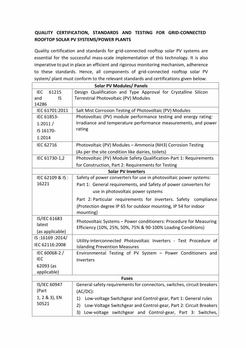
QUALITY CERTIFICATION, STANDARDS AND TESTING FOR GRID-CONNECTED
ROOFTOP SOLAR PV SYSTEMS/POWER PLANTS
Quality certification and standards for grid-connected rooftop solar PV systems are
essential for the successful mass-scale implementation of this technology. It is also
imperative to put in place an efficient and rigorous monitoring mechanism, adherence
to these standards. Hence, all components of grid-connected rooftop solar PV
system/ plant must conform to the relevant standards and certifications given below:
Solar PV Modules/ Panels IEC 61215 and IS 14286
Design Qualification and Type Approval for Crystalline Silicon Terrestrial Photovoltaic (PV) Modules
IEC 61701:2011 Salt Mist Corrosion Testing of Photovoltaic (PV) Modules
IEC 61853-
1:2011 /
IS 16170-
1:2014
Photovoltaic (PV) module performance testing and energy rating: Irradiance and temperature performance measurements, and power rating
IEC 62716 Photovoltaic (PV) Modules – Ammonia (NH3) Corrosion Testing
(As per the site condition like dairies, toilets) IEC 61730-1,2 Photovoltaic (PV) Module Safety Qualification-Part 1: Requirements
for Construction, Part 2: Requirements for Testing
Solar PV Inverters
IEC 62109 & IS : 16221
Safety of power converters for use in photovoltaic power systems:
Part 1: General requirements, and Safety of power converters for
use in photovoltaic power systems
Part 2: Particular requirements for inverters. Safety compliance
(Protection degree IP 65 for outdoor mounting, IP 54 for indoor mounting)
IS/IEC 61683 latest
(as applicable)
Photovoltaic Systems – Power conditioners: Procedure for Measuring Efficiency (10%, 25%, 50%, 75% & 90-100% Loading Conditions)
IS :16169 :2014/
IEC 62116:2008
Utility-interconnected Photovoltaic Inverters - Test Procedure of Islanding Prevention Measures
IEC 60068-2 / IEC
62093 (as applicable)
Environmental Testing of PV System – Power Conditioners and
Inverters
Fuses
IS/IEC 60947 (Part
1, 2 & 3), EN 50521
General safety requirements for connectors, switches, circuit breakers
(AC/DC):
1) Low-voltage Switchgear and Control-gear, Part 1: General rules
2) Low-Voltage Switchgear and Control-gear, Part 2: Circuit Breakers
3) Low-voltage switchgear and Control-gear, Part 3: Switches,

disconnectors switch, disconnectors and fuse-combination units
EN 50521: Connectors for photovoltaic system-Safety requirements
and tests
IEC 60269-6:2010
Low-voltage fuses - Part 6: Supplementary requirements for fuse-links
for the protection of solar photovoltaic energy systems
Solar PV Roof Mounting Structure
IS 2062/IS 4759 Material for the structure mounting
Surge Arrestors
BFC 17-102:2011
Lightening Protection Standard
IEC 60364-5-53/ IS
15086-
5 (SPD)
IEC
61643-
11:2011
Electrical installations of buildings - Part 5-53: Selection and erection
of electrical equipment - Isolation, switching and control
Low-voltage surge protective devices - Part 11: Surge protective
devices connected to low-voltage power systems - Requirements
and test methods
Cables
IEC 60227/IS 694, IEC
60502/IS 1554 (Part 1
& 2)/
IEC69947
(as
applicable)
General test and measuring method for PVC (Polyvinyl chloride)
insulated cables (for working voltages up to and including 1100 V, and
UV resistant for outdoor installation)
BS EN 50618
Electric cables for photovoltaic systems (BT(DE/NOT)258), mainly for
DC Cables
Earthing /Lightning
IEC 62561
Series
(Chemical
earthing) (as
applicable)
IEC 62561-1
Lightning protection system components (LPSC) –
Part 1: Requirements for connection components IEC 62561-2
Lightning protection system components (LPSC) –
Part 2: Requirements for conductors and earth electrodes
IEC 62561-7
Lightning protection system components (LPSC) –
Part 7: Requirements for earthing enhancing compounds
Junction Boxes
IEC 60529 Junction boxes and solar panel terminal boxes shall be of the thermo-
plastic type with IP 65 protection for outdoor use, and IP 54

protection for indoor use
Energy Meters
Testing facility of Net Meters and Generation Meters shall be provided by MSEDCL by accepting the meter testing fees as per circular No. CE(Dist.)/M-III/ Schedule of Charges/ 09078 dated 07.4.2020.
Page 1 of 2
(A Govt. of Maharashtra Undertaking)
CIN: U40109MH2005SGC153645
Maharashtra State Electricity Distribution Co. Ltd
Office Name : <<Sub Div>>/<<Circle Name>>
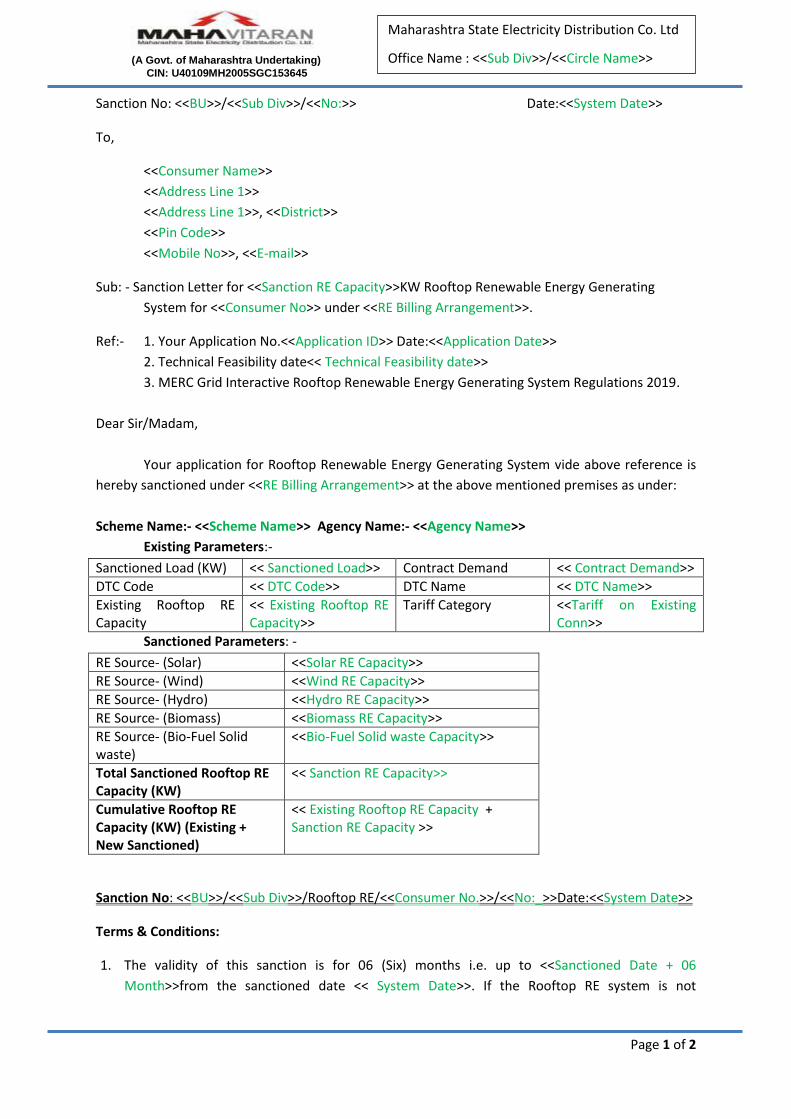
Sanction No: <<BU>>/<<Sub Div>>/<<No:>> Date:<<System Date>>
To,
<<Consumer Name>>
<<Address Line 1>>
<<Address Line 1>>, <<District>>
<<Pin Code>>
<<Mobile No>>, <<E-mail>>
Sub: - Sanction Letter for <<Sanction RE Capacity>>KW Rooftop Renewable Energy Generating
System for <<Consumer No>> under <<RE Billing Arrangement>>.
Ref:- 1. Your Application No.<<Application ID>> Date:<<Application Date>>
2. Technical Feasibility date<< Technical Feasibility date>>
3. MERC Grid Interactive Rooftop Renewable Energy Generating System Regulations 2019.
Dear Sir/Madam,
Your application for Rooftop Renewable Energy Generating System vide above reference is
hereby sanctioned under <<RE Billing Arrangement>> at the above mentioned premises as under:
Scheme Name:- <<Scheme Name>> Agency Name:- <<Agency Name>>
Existing Parameters:-
Sanctioned Load (KW) << Sanctioned Load>> Contract Demand << Contract Demand>>
DTC Code << DTC Code>> DTC Name << DTC Name>>
Existing Rooftop RE Capacity
<< Existing Rooftop RE Capacity>>
Tariff Category <<Tariff on Existing Conn>>
Sanctioned Parameters: -
RE Source- (Solar) <<Solar RE Capacity>>
RE Source- (Wind) <<Wind RE Capacity>>
RE Source- (Hydro) <<Hydro RE Capacity>>
RE Source- (Biomass) <<Biomass RE Capacity>>
RE Source- (Bio-Fuel Solid waste)
<<Bio-Fuel Solid waste Capacity>>
Total Sanctioned Rooftop RE Capacity (KW)
<< Sanction RE Capacity>>
Cumulative Rooftop RE Capacity (KW) (Existing + New Sanctioned)
<< Existing Rooftop RE Capacity + Sanction RE Capacity >>
Sanction No: <<BU>>/<<Sub Div>>/Rooftop RE/<<Consumer No.>>/<<No:_>>Date:<<System Date>>
Terms & Conditions:
1. The validity of this sanction is for 06 (Six) months i.e. up to <<Sanctioned Date + 06
Month>>from the sanctioned date << System Date>>. If the Rooftop RE system is not
Page 2 of 2
(A Govt. of Maharashtra Undertaking)
CIN: U40109MH2005SGC153645
Maharashtra State Electricity Distribution Co. Ltd
Office Name : <<Sub Div>>/<<Circle Name>>
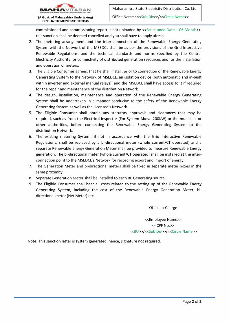
commissioned and commissioning report is not uploaded by <<Sanctioned Date + 06 Month>>,
this sanction shall be deemed cancelled and you shall have to apply afresh.
2. The metering arrangement and the inter-connection of the Renewable Energy Generating
System with the Network of the MSEDCL shall be as per the provisions of the Grid Interactive
Renewable Regulations, and the technical standards and norms specified by the Central
Electricity Authority for connectivity of distributed generation resources and for the installation
and operation of meters.
3. The Eligible Consumer agrees, that he shall install, prior to connection of the Renewable Energy
Generating System to the Network of MSEDCL, an isolation device (both automatic and in-built
within inverter and external manual relays); and the MSEDCL shall have access to it if required
for the repair and maintenance of the distribution Network.
4. The design, installation, maintenance and operation of the Renewable Energy Generating
System shall be undertaken in a manner conducive to the safety of the Renewable Energy
Generating System as well as the Licensee’s Network.
5. The Eligible Consumer shall obtain any statutory approvals and clearances that may be
required, such as from the Electrical Inspector (For System Above 200KW) or the municipal or
other authorities, before connecting the Renewable Energy Generating System to the
distribution Network.
6. The existing metering System, if not in accordance with the Grid Interactive Renewable
Regulations, shall be replaced by a bi-directional meter (whole current/CT operated) and a
separate Renewable Energy Generation Meter shall be provided to measure Renewable Energy
generation. The bi-directional meter (whole current/CT operated) shall be installed at the inter-
connection point to the MSEDCL’s Network for recording export and import of energy.
7. The Generation Meter and bi-directional meters shall be fixed in separate meter boxes in the
same proximity.
8. Separate Generation Meter shall be installed to each RE Generating source.
9. The Eligible Consumer shall bear all costs related to the setting up of the Renewable Energy
Generating System, including the cost of the Renewable Energy Generation Meter, bi-
directional meter (Net Meter) etc.
Office In-Charge
<<Employee Name>>
<<CPF No.>>
<<BU>>/<<Sub Div>>/<<Circle Name>>
Note: This sanction letter is system generated, hence, signature not required.

11/5/2020 Commissioning_Report
https://grouppaybill.mahadiscom.in/PayNCChargesTest/UI/ROOFTOP/CommisioningReport.aspx 1/1
M a h a r a s h t r a S t a t e E l e c t r i c i t yD i s t r i b u t i o n C o . L t d .
Renewable Energy Generating System
Annexure- I(Commissioning Report for RE System)
S No. Particulars As commissioned
1 Name of the Consumer THE CHAIRMAN SHRI NIWAS APPT
2 Consumer Number 170140297421
3 Mobile Number 8578550103
4 E-mail [email protected]
5 Address of InstallationPLOT NO .GP 106,WING-B,NEA G
BLOCK,MIDC,SHAHUNAGAR,CH Aghane 410503
6 RE Arrangement Type Net Metering Arrangement
7 RE Source Wind
8 Sanctioned Capacity(KW) 3
9 Capacity Type Rooftop + Ground
10 Project Model Capex
11 RE installed Capacity(Rooftop)(KW) NA
12 RE installed Capacity(Rooftop + Ground)(KW) 3
13 RE installed Capacity(Ground)(KW) NA
14 Installation date 03-November-2020
15 Solar PV Details
Inverter Capacity(KW) 4
Inverter Make Any Other
No. of Modules 1
Module Capacity(KW) 3
To be uploaded separately:
1. Self-certification of safety of the installation of the RTS system along with the test report of the Licensed Electrical
Contractor (Proforma-A).
2. Electrical Inspector permission if System is above 200 KW. (Mandatory if system is above 200KW only)
3. Third party leasing agreement if Model selected is RESCO.
4. Photograph of the system commissioned.
Signature of Consumer
Date: 05-November-2020 THE CHAIRMAN SHRI NIWAS APPT
COMMISSIONING REPORT (PROVISIONAL) FOR GRID CONNECTED SOLAR
PHOTOVOLTAIC POWER PLANT (with Net-metering facility) Certified that a Grid Connected SPV Power Plant of ………………….. KWp capacity has been installed at the site …………………………………………………………………………………………………………………………………………… ……………………………………………………………………………………………………………………………………………………….. district ……………………………………………. of …………………………………………………………………………………………. which has been installed by M/S …………………………………………………………………………………………………….. on ……………………………………………. The system is as per BIS/MNRE specifications. The system has been checked for its performance on ………………..............with / without installation of bi-directional meter and it is working satisfactorily. The system is suitable for installation of bi-directional and gross energy meters. Signature of the beneficiary Signature of the rep. of supplier With name, seal and date Signature of the P.O./APO With name, date and seal

Undertaking/Self- Declaration for domestic content requirement fulfillment
(On a plain Paper)
This is to certify that M/S [Name of the company empaneled under Phase-II] has installed [Capacity
of RTS system installed in KW] Grid Connected Rooftop Solar PV Power Plant for [Full name of the
beneficiary as per ID Proof] at [Address where the RTS system is installed] under sanction number
[sanction number issued by implementing agency/DISCOM] dated [date on which sanction was
issued by implementing agency/DISCOM ] issued by [Name of the implementing agency/DISCOM]
2. It is hereby undertaken that the PV modules installed for the above-mentioned project are
domestically manufactured using domestic manufactured solar cells. The details of installed PV
Modules are follows:
1. PV Module Capacity: Capacity of the installed PV Module
2. Number of PV Modules: Total number of PV Modules Installed in one project
3. Sr No of PV Module: Serial Number of each PV Module Installed (Add signed and stamped
annexure page with all serial numbers, if number of PV modules is large]
4. PV Module Make: Name of the company who manufactured the installed PV Modules
5. Purchase Order Number: Number of your Purchase Order document issued by emapanled
company to the PV Module manufacturer
6. Purchase Order Date: Date on which Purchase order was issued by empaneled company to
the PV Module Manufacturer
7. Cell manufacturer’s name: Name of the manufacturer of solar cells used in the PV Modules
installed in the project.
8. Cell GST invoice No: Invoice number of the purchase invoice for the Solar Cells
3. The above undertaking is based on the certificate issued by PV Module manufacturer/supplier
while supplying the above mentioned order.
4. I, [Name of the officer signing this document] on behalf of M/S [Name of the company
empaneled under Phase-II] further declare that the information given above is true and correct and
nothing has been concealed therein. If anything is found incorrect at any stage then the due Central
Financial Assistance (CFA) that I have not charged from the consumer can be withheld and
appropriate action may be taken against me and my company for wrong declaration. Supporting
documents and proof of the above information will be provided as and when requested by MNRE.
(Signature With official Seal/stamp)
For M/S [Name of the company empaneled under Phase-II]
Name: [Name of the officer signing this document]
Designation: [Designation of the officer signing this document]
Phone: [Phone Number of the officer/ company]
Email: [Email address of the officer/company]
Enclosed: Certificate issued by PV Module manufacturer/supplier

Format for Joint Undertaking for Grid Connectivity of Rooftop Solar Power Plant
through a Common Energy Meter
(To be furnished on Stamp Paper of appropriate value)
I/We …………………………………………………as Secretary/ Director /Managing
Trusty (in case of trust) of ………………................................. (Name of Society) [Owner],
registered under the Section ........................... of The State/Central Societies Registration
Act having electricity connection under the ambit ………………………… (Name of
distribution company) bearing Customer Account No ………………... [Annexure-I] at
…………………………………..(Address) [Premises] do hereby solemnly affirm and
declare as under:
1) That I am/ We are the legal heir of the above said premises and have entered into a
lease agreement with ………………………………………… (Name of Beneficiary)
for a period of ………… years upto …………………(Date of Termination);
2) We understand that the …………………………………………………..(Name of
State Nodal Agency) has sanctioned Financial Assistance [including assistance from
The Ministry of New and Renewable Energy and Govt. of …………..(Name of the
State)] for installation of Grid Connected Rooftop Solar Photovoltaic Power Plant of
……………. KWp capacity at the above said premises. The Financial Assistance has
been sanctioned in the name of ………………………………(Name of Beneficiary);
3) We, hereby submit our undertaking that the referred Grid Connected Rooftop Solar
Power Plant [RTS] can be connected to the Energy Meter/ Bi-directional Energy Meter
bearing Consumer Account No…………………………... Any benefit availed from the
excess solar energy exported through the Bidirectional Energy Meter to the grid as
per the Net-Metering regulation of Central/State Electricity Regulatory Commission,
can be claimed by ……..…………………………………….. (Name of Beneficiary);
4) It is certified that the Financial Assistance sanctioned by …………………………….
(Name of State Nodal Agency) to …………………………………………… (Name of
Beneficiary) for the installation of referred RTS is not transferred to the Owner;
5) It is stated that following are also connected to the same Energy Meter/ Bi-Directional
Energy Meter bearing Consumer Account No. ……………:
1. ...................................
2. ...................................
3. ...................................
This undertaking is being given for submission to MNRE & ………………………(Name of
the DISCOM) in compliance to the norms set for Grid Connectivity of our Grid Connected
Rooftop Solar Power Plant.
Signature Signature
(____________________________) (____________________________)
Name of the Owner/ Signing Authority Name of Beneficiary
Date:
Place:
Accepted By:
(witness with name, address & signature)
For ................................(1) Signature (____________)
For ................................(2) Signature (_____________)
For .................................(3) Signature (____________)
ANNEXURE-I
Copy of latest electricity bill to be enclosed
2
Solar Rooftop Application Portal
Section 1: Solar Rooftop Application Portal
Solar Rooftop Application Portal MSEDCL
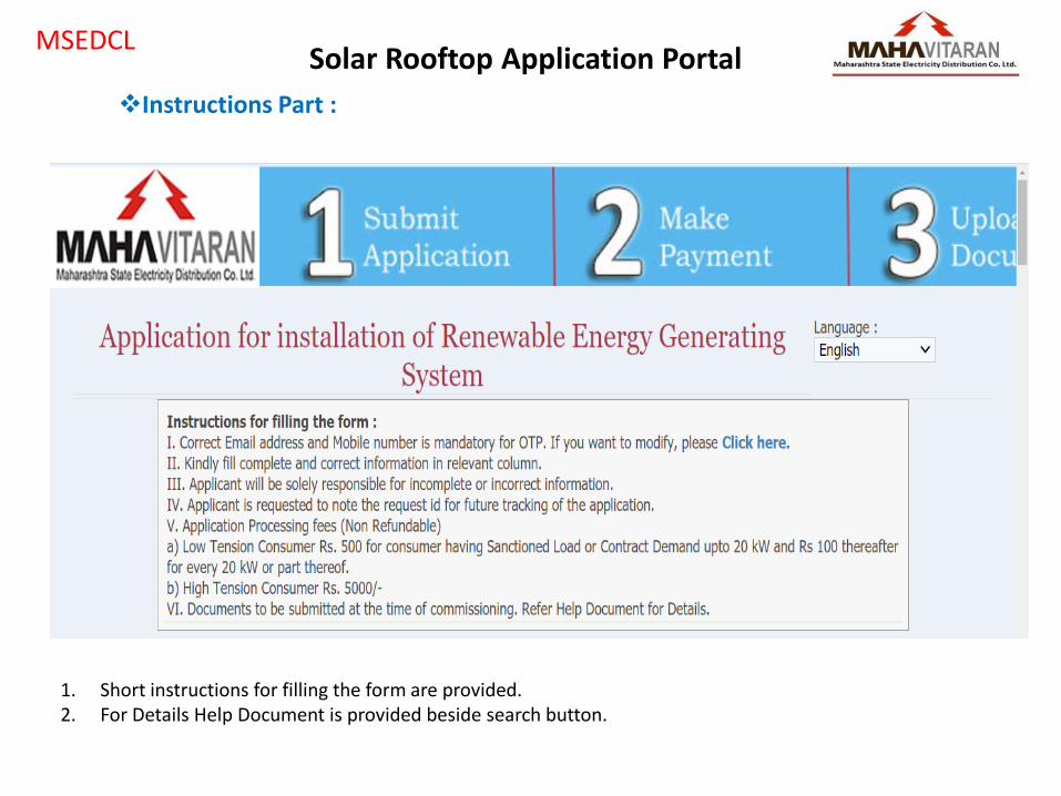
Instructions Part :
1. Short instructions for filling the form are provided. 2. For Details Help Document is provided beside search button.
Solar Rooftop Application Portal MSEDCL
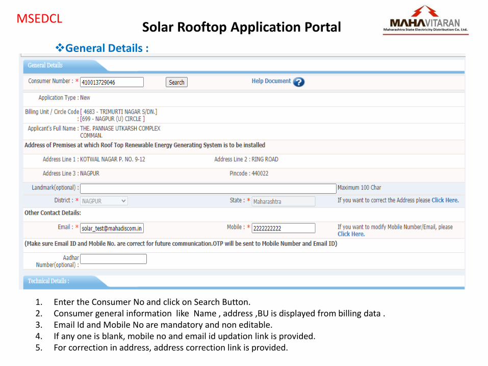
General Details :
1. Enter the Consumer No and click on Search Button. 2. Consumer general information like Name , address ,BU is displayed from billing data . 3. Email Id and Mobile No are mandatory and non editable. 4. If any one is blank, mobile no and email id updation link is provided. 5. For correction in address, address correction link is provided.

Solar Rooftop Application Portal MSEDCL
Technical Details for Subsidize Consumer:
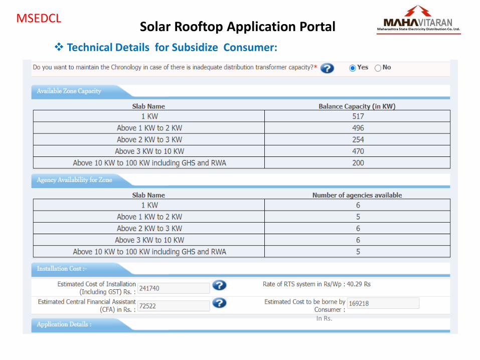
Solar Rooftop Application Portal MSEDCL
Technical Details for Subsidize Consumer:
In Rs.
Solar Rooftop Application Portal MSEDCL
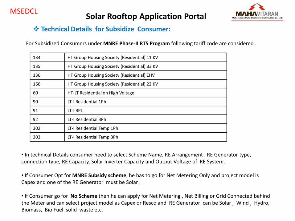
Technical Details for Subsidize Consumer:
For Subsidized Consumers under MNRE Phase-II RTS Program following tariff code are considered .
134 HT Group Housing Society (Residential) 11 KV
135 HT Group Housing Society (Residential) 33 KV
136 HT Group Housing Society (Residential) EHV
166 HT Group Housing Society (Residential) 22 KV
60 HT-LT Residential on High Voltage
90 LT-I Residential 1Ph
91 LT-I BPL
92 LT-I Residential 3Ph
302 LT-I Residential Temp 1Ph
303 LT-I Residential Temp 3Ph
• In technical Details consumer need to select Scheme Name, RE Arrangement , RE Generator type, connection type, RE Capacity, Solar Inverter Capacity and Output Voltage of RE System. • If Consumer Opt for MNRE Subsidy scheme, he has to go for Net Metering Only and project model is Capex and one of the RE Generator must be Solar . • If Consumer go for No Scheme then he can apply for Net Metering , Net Billing or Grid Connected behind the Meter and can select project model as Capex or Resco and RE Generator can be Solar , Wind , Hydro, Biomass, Bio Fuel solid waste etc.

Solar Rooftop Application Portal MSEDCL
Installation Cost and Application Submission for Subsidize Consumer:
• For Subsidy Consumer, as per applied solar RE Capacity, Estimated Installation cost, Subsidy amount(CFA) and cost to be paid are shown. • OTP will generate on Registered Mobile No for verification and application will submit. • Application ID is generated and consumer can pay his Registration Fee. •After application submission, SMS will be sent to consumer containing application Id and Date.

Solar Rooftop Application Portal MSEDCL
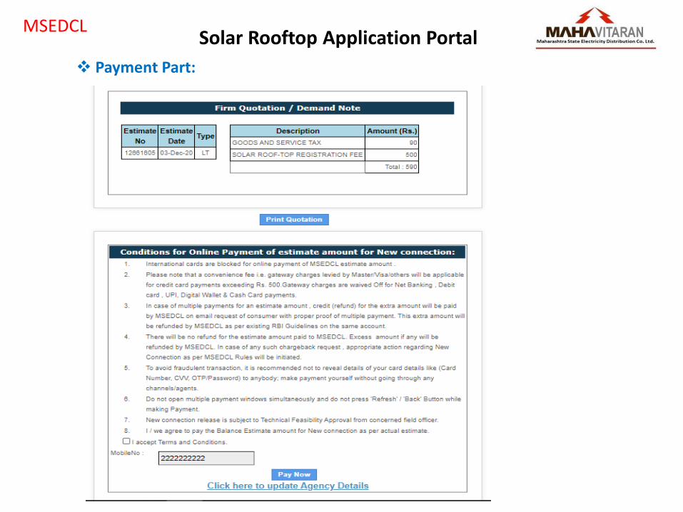
Payment Part:
• After click on Pay Now , Consumer need to provide Application ID • His Application Details will be shown as follow and consumer can make payment on payment Gateway

Solar Rooftop Application Portal MSEDCL
Payment Part:
(In Rs.)
(In Rs.)
(In Rs.)
Solar Rooftop Application Portal MSEDCL
Payment Part:
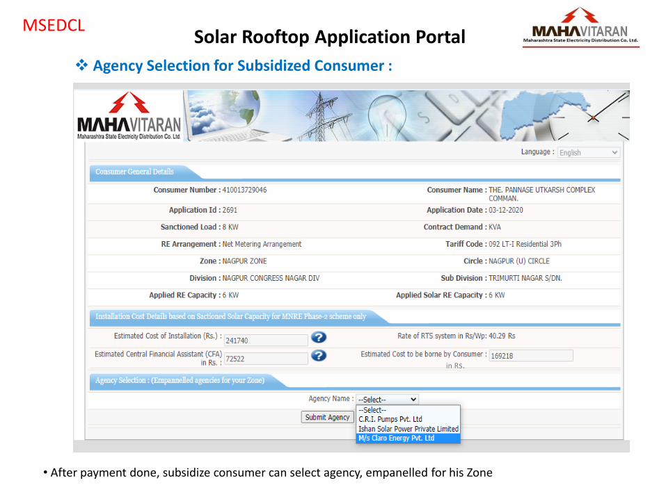
Solar Rooftop Application Portal MSEDCL
Agency Selection for Subsidized Consumer :
• After payment done, subsidize consumer can select agency, empanelled for his Zone
in Rs.
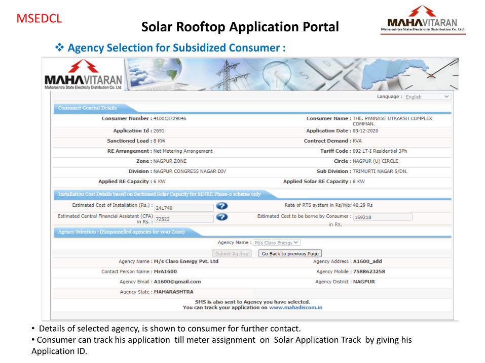
Solar Rooftop Application Portal MSEDCL
Agency Selection for Subsidized Consumer :
• Details of selected agency, is shown to consumer for further contact. • Consumer can track his application till meter assignment on Solar Application Track by giving his Application ID.
in Rs.
14
Solar Rooftop Vendor Portal
Section 2: Solar Rooftop Vendor Portal
https://rts.mahadiscom.in/RoofTopSolar/
Section 2: Solar Rooftop Vendor Portal MSEDCL
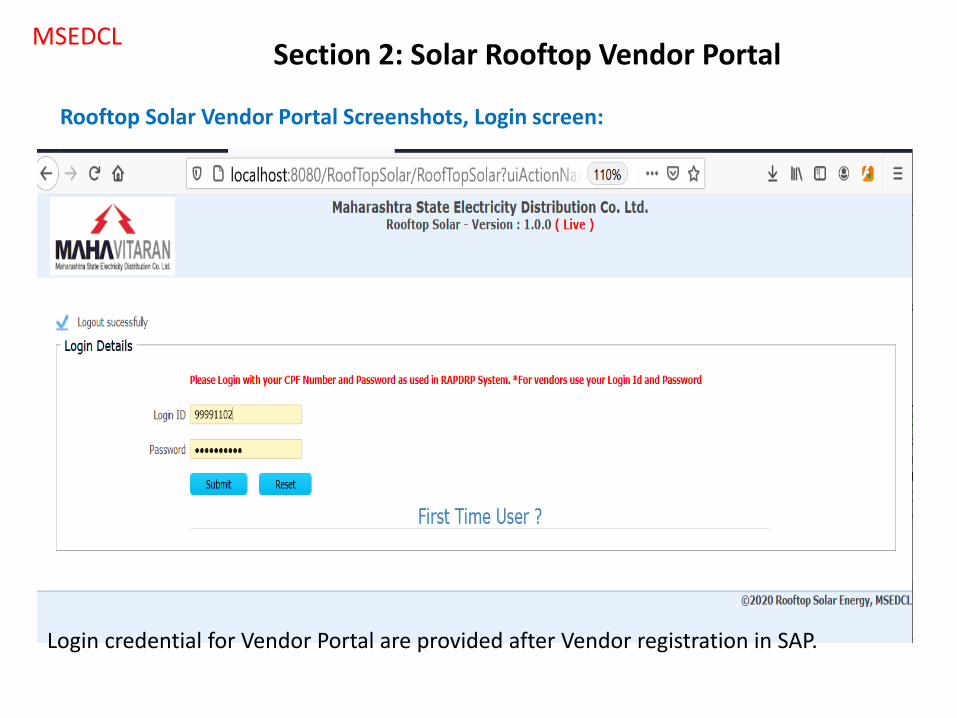
Rooftop Solar Vendor Portal Screenshots, Login screen:
Login credential for Vendor Portal are provided after Vendor registration in SAP.
MSEDCL
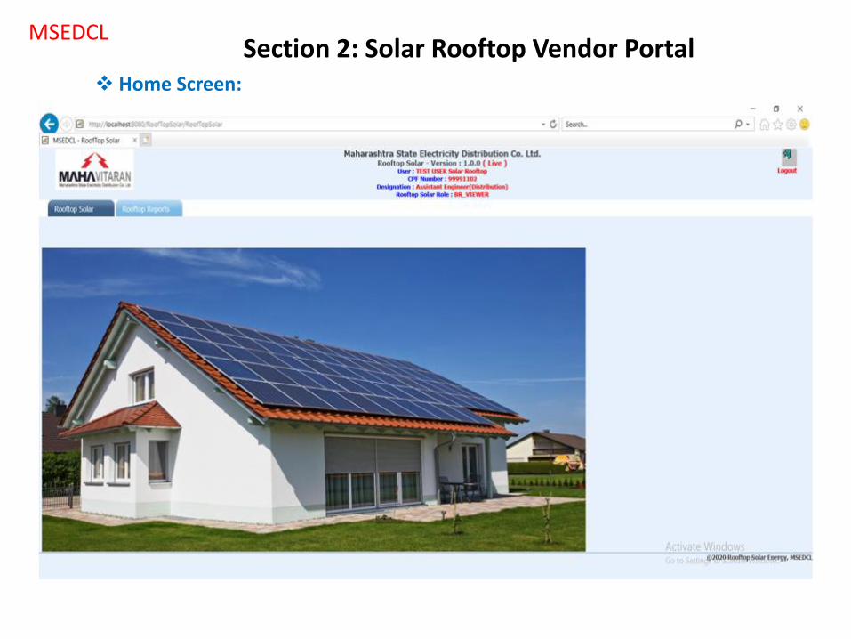
Home Screen:
Section 2: Solar Rooftop Vendor Portal

MSEDCL
Rooftop Solar List:
Section 2: Solar Rooftop Vendor Portal
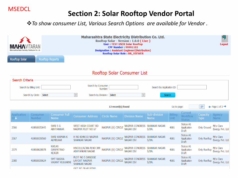
MSEDCL
To show consumer List, Various Search Options are available for Vendor .
Section 2: Solar Rooftop Vendor Portal
MSEDCL
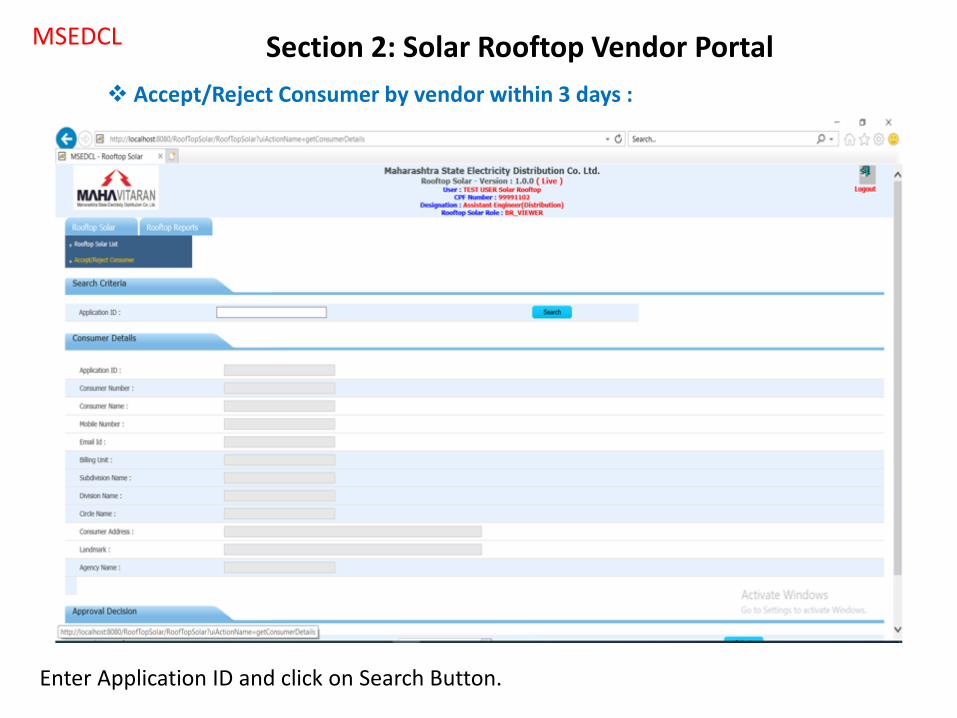
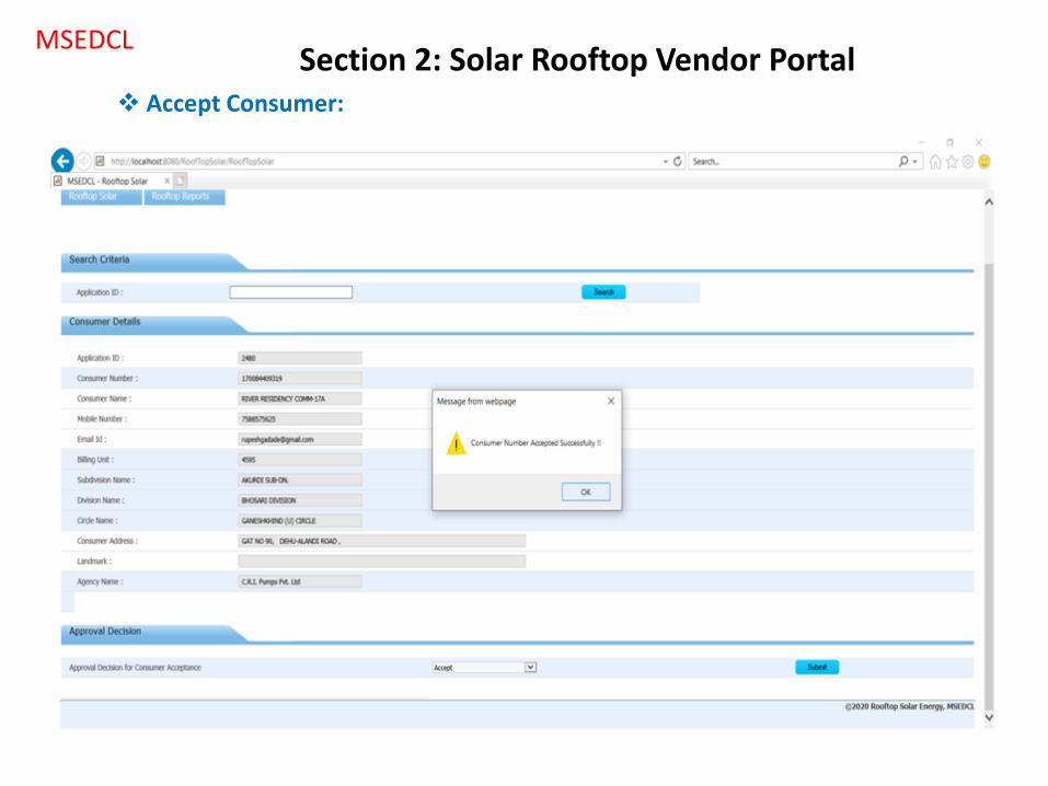
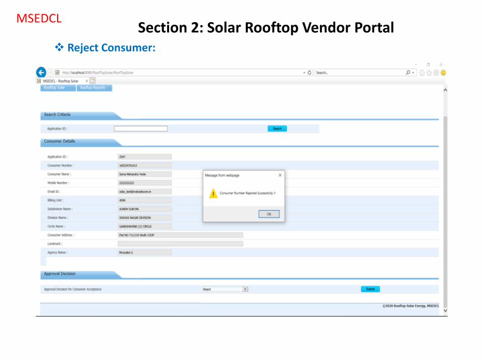
Accept/Reject Consumer by vendor within 3 days :
Enter Application ID and click on Search Button.
Section 2: Solar Rooftop Vendor Portal
MSEDCL
Accept Consumer:
Section 2: Solar Rooftop Vendor Portal
MSEDCL
Reject Consumer:
Section 2: Solar Rooftop Vendor Portal
MSEDCL
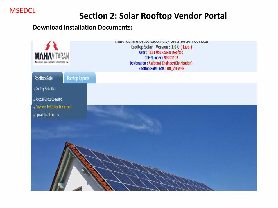
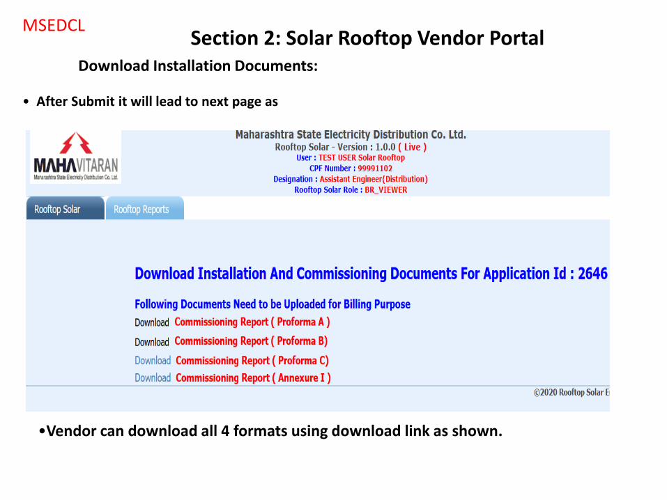
Download Installation Documents:
Section 2: Solar Rooftop Vendor Portal
MSEDCL
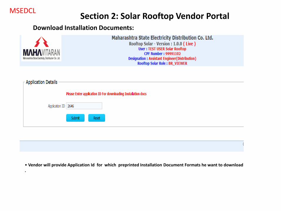
Download Installation Documents:
• Vendor will provide Application Id for which preprinted Installation Document Formats he want to download .
Section 2: Solar Rooftop Vendor Portal
MSEDCL
Download Installation Documents:
•Vendor can download all 4 formats using download link as shown.
• After Submit it will lead to next page as
Section 2: Solar Rooftop Vendor Portal
MSEDCL
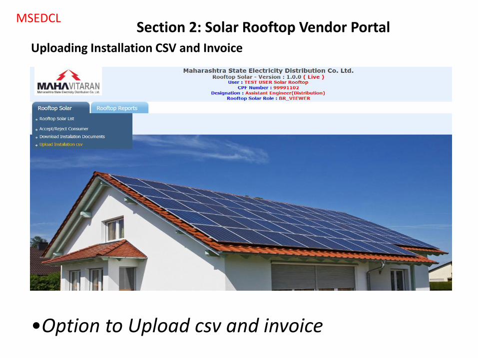
Uploading Installation CSV and Invoice
•Option to Upload csv and invoice
Section 2: Solar Rooftop Vendor Portal
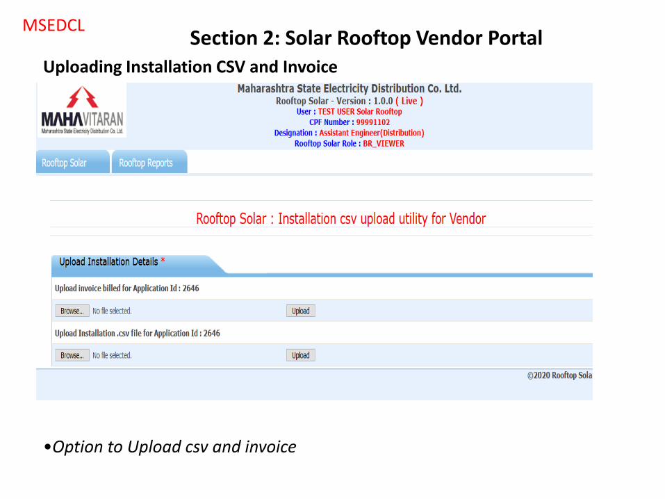
MSEDCL
Uploading Installation CSV and Invoice
•Option to Upload csv and invoice
Section 2: Solar Rooftop Vendor Portal

MSEDCL
Download Consumer List:
Section 2: Solar Rooftop Vendor Portal

MSEDCL
Download Consumer List output:
Section 2: Solar Rooftop Vendor Portal
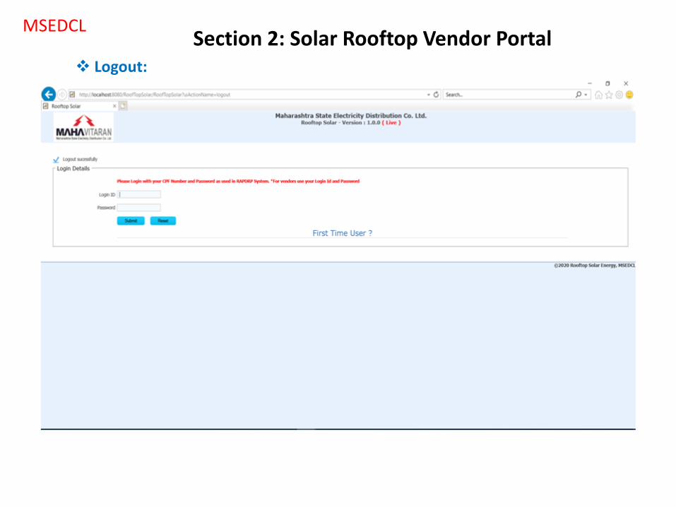
MSEDCL
Logout:
Section 2: Solar Rooftop Vendor Portal
30
TECHNICAL FEASIBILITY – MOBILE APP
Section 3 : TECHNICAL FEASIBILITY – MOBILE APP
[Renewable Energy - Rooftop Solar]
MSEDCL
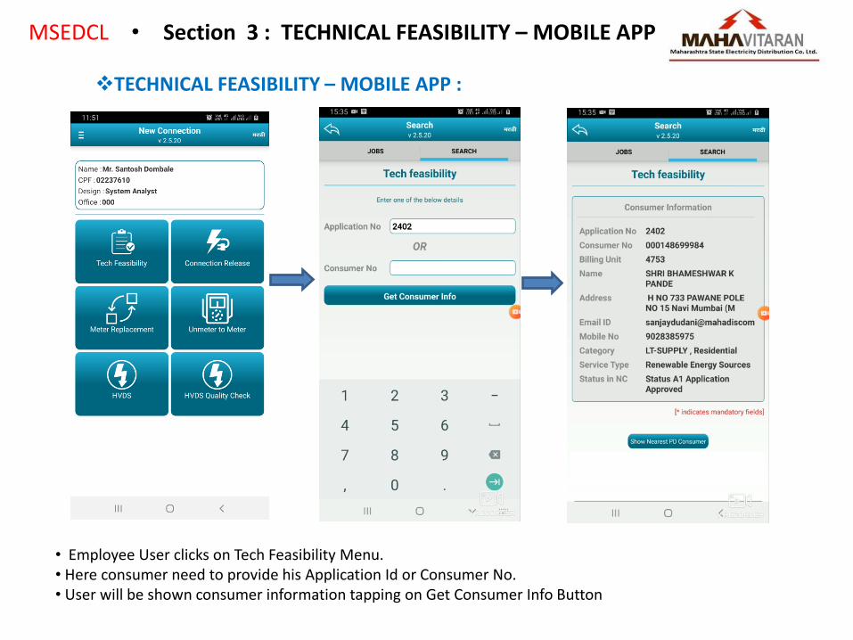
TECHNICAL FEASIBILITY – MOBILE APP :
• Employee User clicks on Tech Feasibility Menu. • Here consumer need to provide his Application Id or Consumer No. • User will be shown consumer information tapping on Get Consumer Info Button
• Section 3 : TECHNICAL FEASIBILITY – MOBILE APP
MSEDCL
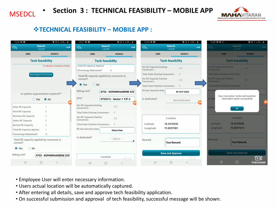
TECHNICAL FEASIBILITY – MOBILE APP :
• Employee User will enter necessary information. • Users actual location will be automatically captured. • After entering all details, save and approve tech feasibility application. • On successful submission and approval of tech feasibility, successful message will be shown.
• Section 3 : TECHNICAL FEASIBILITY – MOBILE APP
33
RENEWABLE ENERGY APP
Section 4 : RE APP FOR VENDOR
[Renewable Energy - Rooftop Solar]
https://empportal.mahadiscom.in/EmpPortal/emp?uiActionName=getMobileAppDownload
34
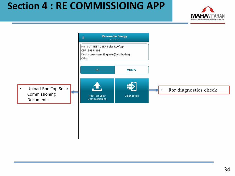
• Upload RoofTop Solar Commissioning Documents
• For diagnostics check
Section 4 : RE COMMISSIOING APP

35
Section 4 : RE COMMISSIOING APP
Upload RoofTop Solar Commissioning Documents
• Choose ‘RoofTop Solar Commissioning' from the main menu. A list with applications to be commissioned will be displayed
• Application can be searched by following 3 options
- Search by Billing Unit
- Search by Application ID
- Search by Consumer Number
• Choose an application from the list
36
Section 4 : RE COMMISSIOING APP
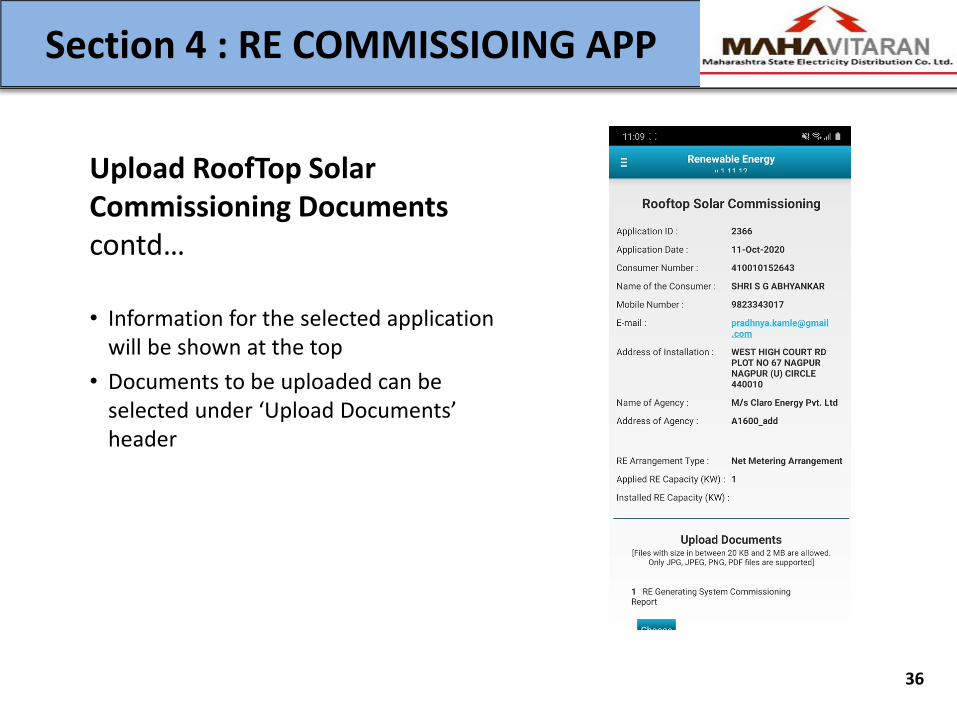
Upload RoofTop Solar Commissioning Documents contd…
• Information for the selected application will be shown at the top
• Documents to be uploaded can be selected under ‘Upload Documents’ header
37
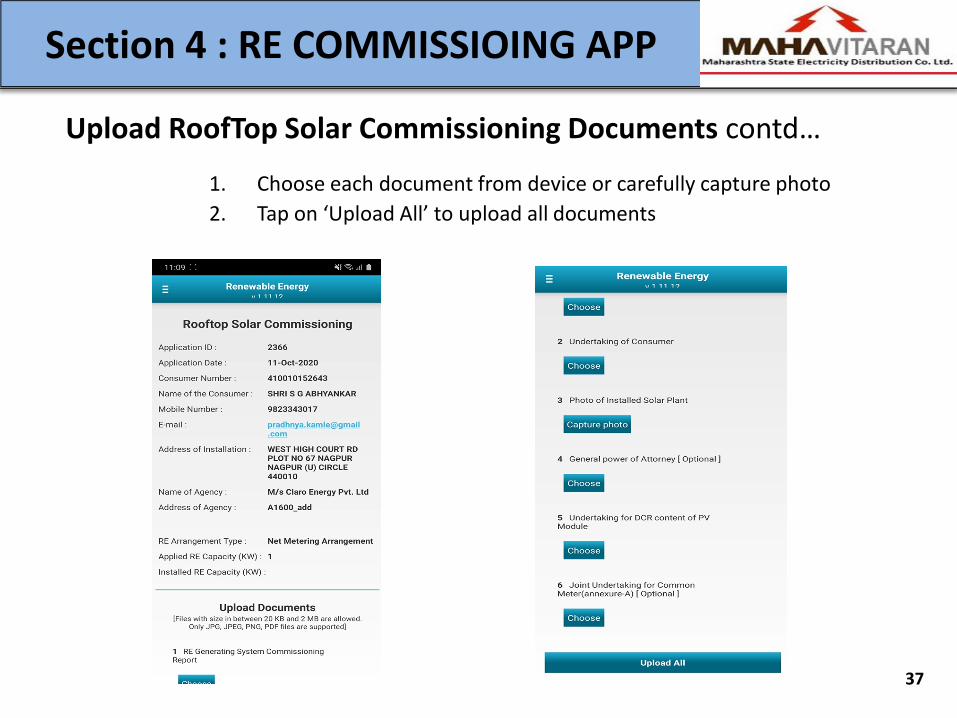
Section 4 : RE COMMISSIOING APP
Upload RoofTop Solar Commissioning Documents contd…
1. Choose each document from device or carefully capture photo
2. Tap on ‘Upload All’ to upload all documents
38
Solar Rooftop Vendor Portal
Section 5 : Solar Rooftop Vendor Portal
(Employee-side Portal Operations )

Section 5 : Solar Rooftop Vendor Portal
(Employee-side Portal Operations ) MSEDCL
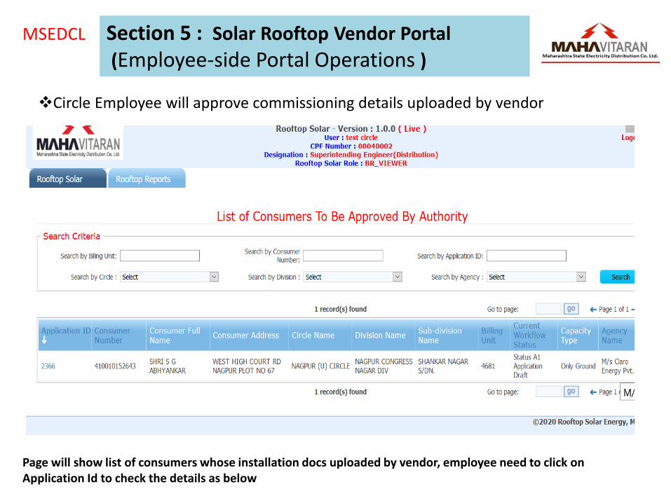
Circle Employee will approve commissioning details uploaded by vendor
MSEDCL
Circle Employee will approve commissioning details uploaded by vendor
Page will show list of consumers whose installation docs uploaded by vendor, employee need to click on Application Id to check the details as below
Section 5 : Solar Rooftop Vendor Portal
(Employee-side Portal Operations )
MSEDCL
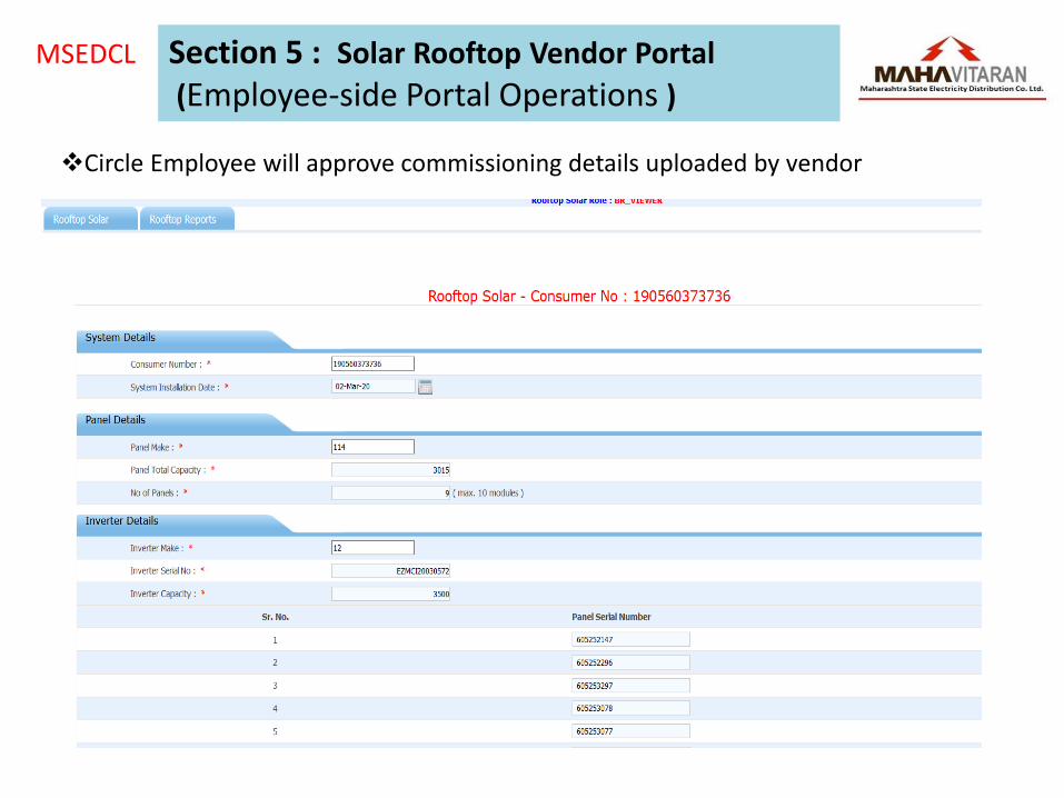
Circle Employee will approve commissioning details uploaded by vendor
Section 5 : Solar Rooftop Vendor Portal
(Employee-side Portal Operations )

MSEDCL
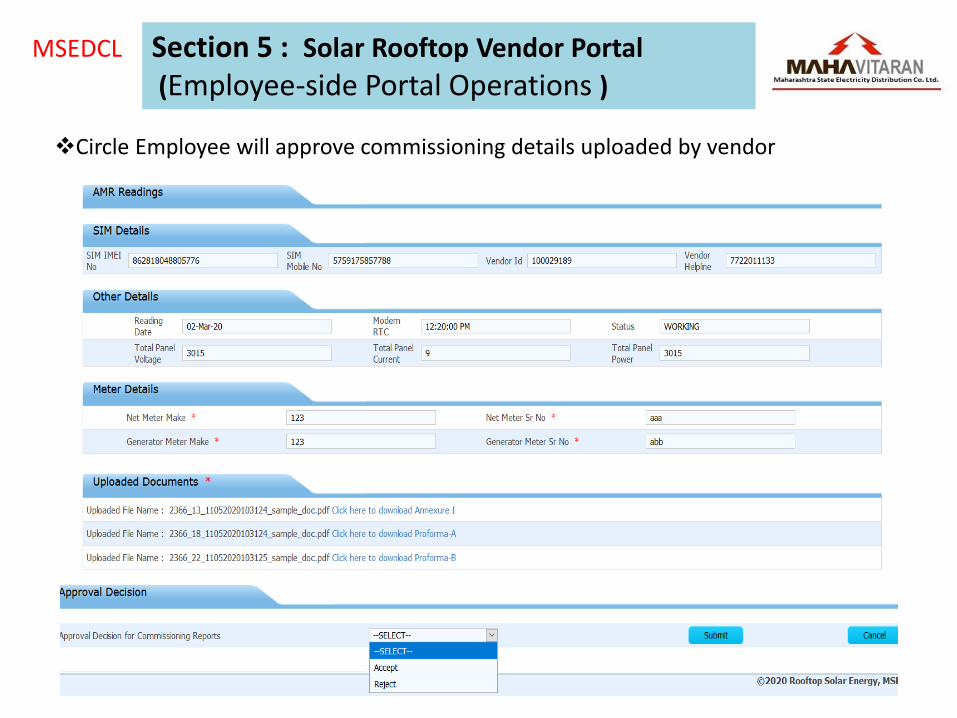
Circle Employee will approve commissioning details uploaded by vendor
Section 5 : Solar Rooftop Vendor Portal
(Employee-side Portal Operations )
MSEDCL
Circle Employee will approve commissioning details uploaded by vendor
Section 5 : Solar Rooftop Vendor Portal
(Employee-side Portal Operations )

44
Solar Rooftop Application Portal
Section 6 : APPLICATION TRACKING
[Renewable Energy - Rooftop Solar]
Solar Rooftop Application Portal MSEDCL
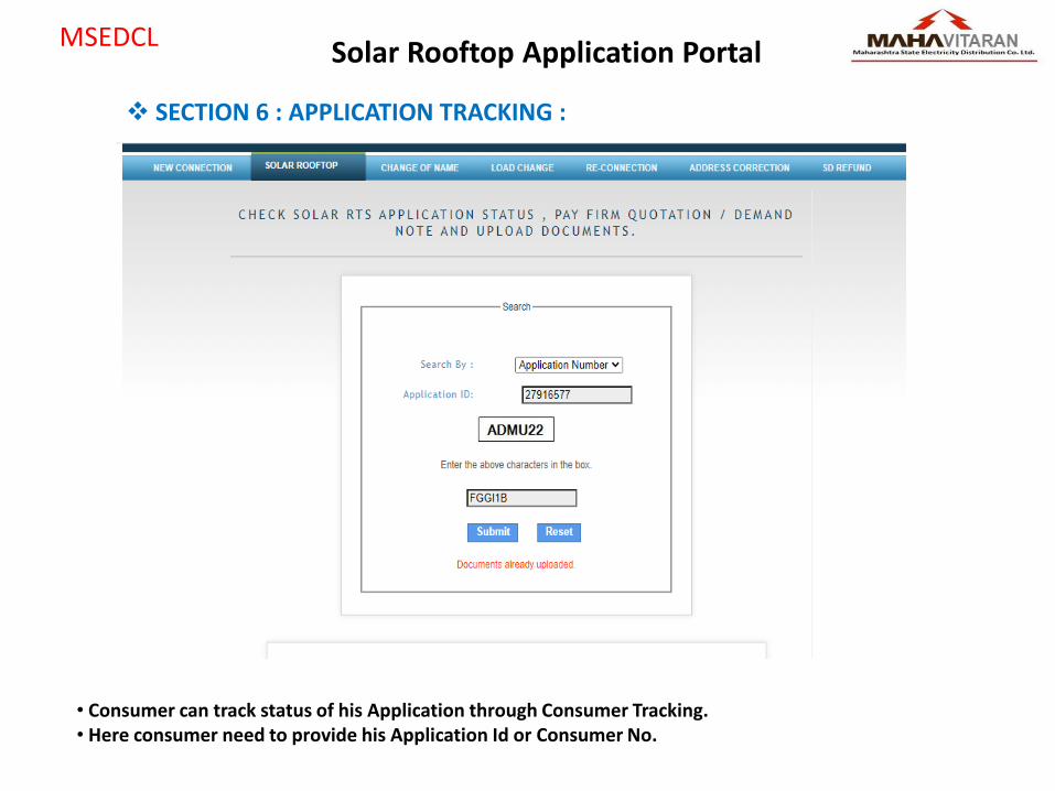
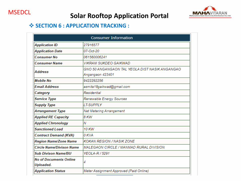
• Consumer can track status of his Application through Consumer Tracking. • Here consumer need to provide his Application Id or Consumer No.
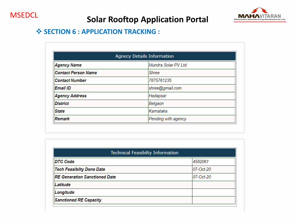
SECTION 6 : APPLICATION TRACKING :
Solar Rooftop Application Portal MSEDCL
SECTION 6 : APPLICATION TRACKING :

Solar Rooftop Application Portal MSEDCL
SECTION 6 : APPLICATION TRACKING :
Solar Rooftop Application Portal MSEDCL
SECTION 6 : APPLICATION TRACKING :

Solar Rooftop Application Portal MSEDCL
SECTION 6 : APPLICATION TRACKING :

Solar Rooftop Application Portal MSEDCL
SECTION 6 : APPLICATION TRACKING :

51
Solar Rooftop Application Portal
Section 7 : Commission Document Upload for Non-Subsidize Consumer

Solar Rooftop Application Portal MSEDCL
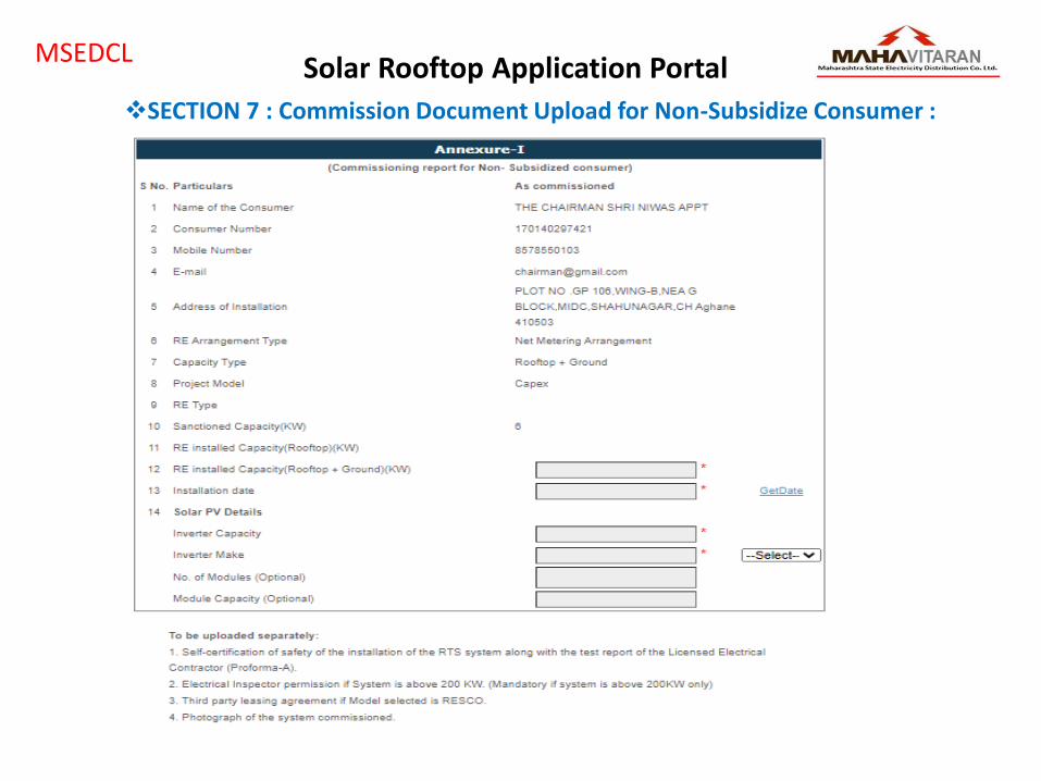
SECTION 7 : Commission Document Upload for Non-Subsidize Consumer :
• After Technical Feasibility, Non-Subsidize consumer can upload his commission report and other documents by Track his Application Link.

Solar Rooftop Application Portal MSEDCL
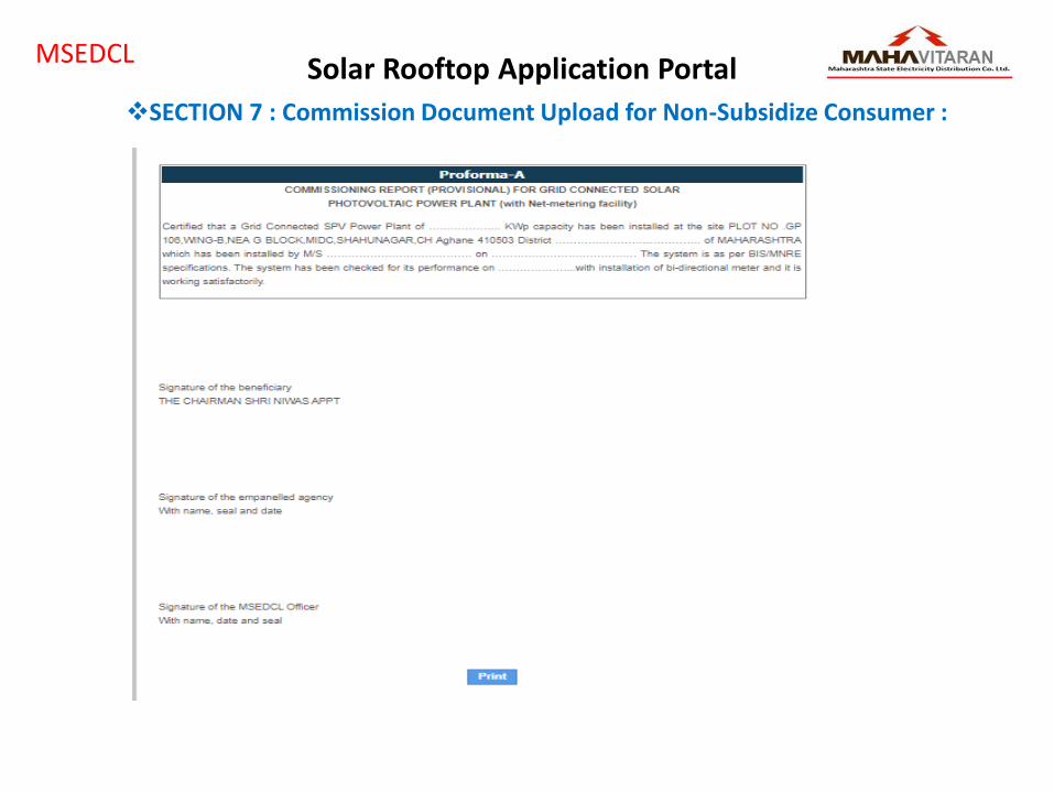
• These are documents required to upload by Non –Subsidize Consumer. • Commission Report and Proforma – A will be downloaded by consumer with pre-printed data. In Commission report consumer need to feed Installation date, installed capacity , inverter Make, capacity and Save it. Then Print the document. Upload duly signed Commission Report and Proforma – A and other documents.
SECTION 7 : Commission Document Upload for Non-Subsidize Consumer :
Solar Rooftop Application Portal MSEDCL
SECTION 7 : Commission Document Upload for Non-Subsidize Consumer :
Solar Rooftop Application Portal MSEDCL
SECTION 7 : Commission Document Upload for Non-Subsidize Consumer :

SMS No. Event To whom Revise SMS text to shorten the Length For Confirmation SMS- 1 After Application Submit CONSUMER "Dear Consumer, RE appln-id <<application ID>> for consumer no << consumer number>> is received. Track status at
www.mahadiscom.in" SMS-2 Agency Selection by Consumer CONSUMER "Dear Consumer, Agency <<Agency Name>>, having Mobile No <<Agency Mobile No>> is selected by you under MNRE Phase-II RTS
scheme for RE appln-id <<application_id>>. Agency will contact you shortly for further process."
SMS-3 Agency Selection by Consumer Agency "Dear <<Agency Name>>, Consumer <<Consumer Name>>, Consumer No <<Consumer No>>, having Mobile No. <<Mobile No>> selected your agency under MNRE Phase-II RTS scheme. You have to submit acceptance/rejection within 3 days through <<Vendor portal Link>>, else considered as accepted."
SMS-4 Agency Selection by Consumer EMPLOYEE "RE appln-id <<application ID>> dated <<Application Date>> of Consumer No. <<Consumer Number>> for <<Total Capacity>> KW, selected agency <<Agency Name>>, Contact No. <<Contact Number of agency>> is initiated for carrying out Joint Technical feasibility."
SMS-5 Agency Reject to Consumer CONSUMER "Dear Consumer, Agency <<Agency Name>> has rejected your request, for RE appln-id <<application ID>>. So please select another agency. <<url to reselect agency>>"
SMS-6 Agency Accept to Consumer CONSUMER "Dear Consumer, Agency <<Agency Name>> has accepted your request, for RE appln-id <<application ID>>. "
SMS07 After Online Payment Done by consumer SDO Application No. <<Application ID>> Dated <<Application Date>> for Rooftop RE Generating system for <<Total Capacity>> KW in r/o Shri/Smt <<Consumer Name>> & <<Consumer Number>> is initiated for carrying out Joint Technical feasibility.
SMS08 Rejection of Tech feasibility through Mobile App.
Consumer "Dear Consumer, RE appln-id <<application ID>> for consumer no << consumer number>> is not feasible due to << Remark for rejection >>"
SMS09 Keep Application in pending Stage if Chronology flag is 'Y' and inadequante Distribution Transformer Capacity
Consumer "Dear Consumer, RE appln-id <<application ID>> for consumer no << consumer number>> will be considered as per application seniority as soon as the distribution transformer capacity is upgraded."
SMS10 Cancel Application if Chronology flag is 'N'and inadequante Distribution transformer capacity
Consumer "Dear Consumer, RE appln-id <<application ID>> for consumer no << consumer number>> is rejected due to Inadequate distribution transformer capacity."
SMS11 Cancel Application if Technical constraints Consumer "Dear Consumer, RE appln-id <<application ID>> for consumer no << consumer number>> is rejected due to technical constraints."
SMS12 When the DTC capacity is augmented Consumer "Dear Consumer, With reference to RE appln-id <<Application ID>> for consumer no << consumer number>> the DTC <<DTC No>> is augmented and your application will be considered for sanction."
SMS13 SDO "The DTC <<DTC No>> is augmented. Please consider RE appln-id <<application ID>> for further processing."
SMS14 Tech feasibility Approved throgh mobile App Consumer "Dear Consumer, RE appln-id <<application ID>> for consumer no << consumer number>> is sanctioned on <<sanction date>> for <<Total capacity>> KWp is valid upto <<Validity Date>>. If commissioning report of RE is not uploaded on or before Validity date,appln will be deemed treated as cancelled and consumer have to re-apply"
SMS15 Reminder Message after 4 months of Sanction Date
Consumer "Reminder : Dear Consumer, RE appln-id <<application ID>> for consumer no << consumer number>> is sanctioned on <<sanction date>> for <<Total capacity>> KWp is valid upto <<Validity Date>>. If commissioning report of RE is not uploaded on or before Validity date,appln will be deemed treated as cancelled and consumer have to re-apply"
SMS16 Auto Cancellation of Application for non- commissioning
Consumer "Dear consumer, RE appln-id <<application ID>> for consumer no << consumer number> is cancelled for non-commissioning up to validity date<<validity Date>>."
SMS17 After commissioning If any technical discrepancy is observed
Consumer "Dear consumer, RE appln-id <<application ID>> for consumer no << consumer number> installation have <<Remark of field officer>> deficiencies. Please rectify the deficiencies within 15 days."
SMS18 After commissioning If any technical discrepancy is observed
Agency "Dear Agency,<<Agency Name >>, RE appln-id <<application ID>> for consumer no << consumer number> have <<Remark of field officer>> deficiencies. Please rectify the deficiencies within 15 days."
SMS19 Tech feasibility Approved throgh mobile App AGENCY "Dear Agency,<<Agency Name >>, RE appln-id <<application ID>> for consumer no << consumer number>> is sanctioned on <<sanction date>> for <<Total capacity>> KWp is valid upto <<Validity Date>>. If commissioning report of RE is not uploaded on or before Validity date,appln will be deemed treated as cancelled and consumer have to re-apply"
SMS20 Rejection of Tech feasibility through Mobile App.
AGENCY "Dear Agency,<<Agency Name >>, RE appln-id <<application ID>> for consumer no << consumer number>> is not feasible due to << Remark for rejection >>"
SMS FOR VARIOUS STAGES

Top Related
Copyright © 2022 FDOKUMEN

