


Bahasa
Halaman
Hukum

Opt Quant Electron (2011) 42:473–485DOI 10.1007/s11082-010-9424-9
Light propagation in 1D photonic crystalswith dissipation
G. V. Morozov · F. Placido
Received: 9 August 2010 / Accepted: 9 November 2010 / Published online: 16 December 2010© Springer Science+Business Media, LLC. 2010
Abstract Light propagation in one-dimensional (1D) photonic crystals with dissipation(including metal layers) is studied analytically. The proper effective refractive indices andextinctions of dissipative layers in case of oblique incidence are introduced. Then, the formal-ism available for nondissipative photonic crystals is modified by replacing the conventionalrefractive indices with effective ones. Propagation in a bilayer dielectric-metallic crystal iscomputed as an example.
Keywords 1D dissipative photonic crystals · Bandgaps · Bragg resonances ·Transfer matrix
1 Introduction
Typical photonic crystals are artificial nondissipative dielectric structures with a periodicmodulation of the real valued refractive index. Due to Bragg reflection, they exhibit band-gaps (even omnidirectional ones in some cases) and, as a result, control the propagation oflight in novel ways, with obvious applications to mirrors, waveguides, and laser cavities.
The real valued refractive index in nondissipative 1D photonic crystals varies alongone direction (chosen as the z-axis for convenience) and, therefore, satisfies the relationn(z) = n(z + d) where d is the length of a period. The analysis of bandgaps in such crystalsis usually done with the aid of the dispersion relation for the Bloch wave number α (or theBloch phase φ = α d), which is derived either from Floquet-Bloch theory (Brillouin 1946;Levin 1948; Morozov et al. 1999; Nusinsky and Hardy 2006), or from the transfer matrixmethod (Yeh et al. 1977; Sprung et al. 1993; Bendickson et al. 1996). The Bloch phase iscomplex, φ = qπ + iφ
′′, q = 1, 2, . . . , in the bandgaps (numbered by the index q) and the
G. V. Morozov (B) · F. PlacidoThin Film Centre, University of the West of Scotland, Paisley PA1 2BE, Scotland, UKe-mail: [email protected]
G. V. Morozov · F. PlacidoThe Scottish Universities Physics Alliance (SUPA), St. Andrews KY16 9SS, UK
123
474 G.V. Morozov, F. Placido
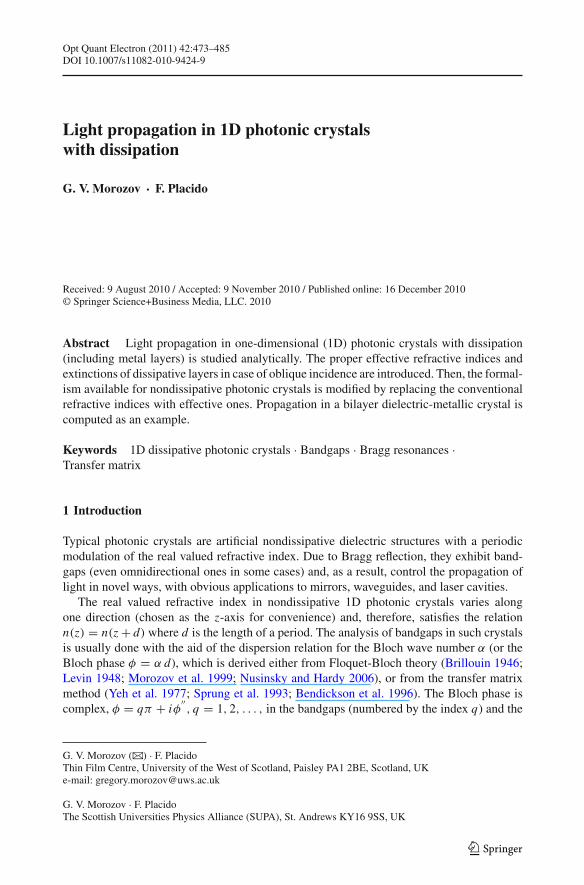
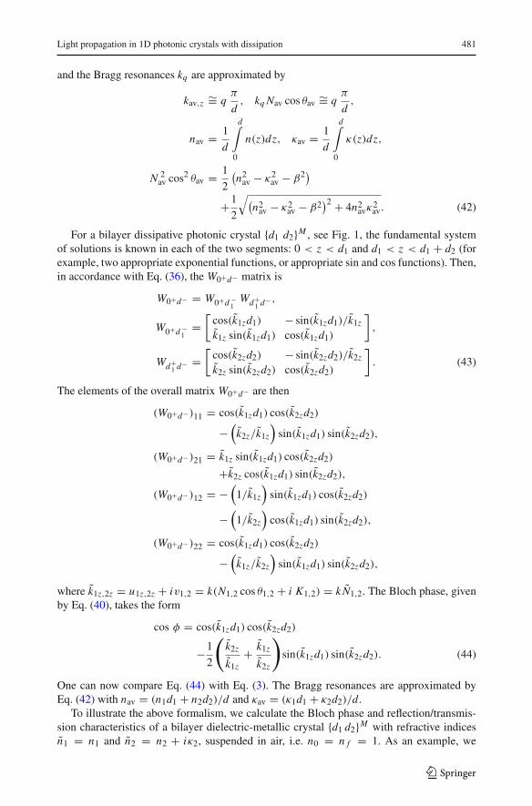
Fig. 1 Bilayer photonic crystal{d1 d2}M , n1 and n2 are thecomplex refractive indices of twohomogeneous absorptivematerials with thicknesses d1 andd2, M is the number of periods
forward Bloch wave P(z) exp(iαz), P(z + d) = P(z) is exponentially damped even in theabsence of real absorption (dissipation). This damping has maxima at the so-called Braggresonances. The bandgaps correspond to wave numbers which satisfy
| cos φ(k)| > 1, or |eiφ(k) + e−iφ(k)| > 2 , (1)
where k = ω/c = 2π/λ is the wavenumber of the impinging wave in vacuum, and the wavenumbers kq corresponding to the Bragg resonances (which are located close to the centresof the bandgaps) are well approximated by
kav,z ∼= qπ
d, kqnav cos θav ∼= q
π
d,
(2)
nav cos θav =√
n2av − n2
0 sin θ20 , nav = 1
d
d∫
0
n(z)dz,
where n0 is the refractive index of the incident medium (n0 = 1 in case of vacuum), θ0 is theangle of incidence.
Typical 1D photonic crystals consist of two alternating dielectric materials (bilayerphotonic crystal), see Fig. 1. Usually, their bandgaps are not large, even in case of highrefractive index contrast between the two materials. A combination of metallic (with strongdissipation) and dielectric layers can significantly increase bandgap widths, while still keep-ing some allowed bands open. The thickness of the metallic layer should be close to or smallerthan the relevant skin depth. Another application of metallic-dielectric photonic crystals is apossible absorption enhancement in comparison to a layer of bulk metal of the same thickness(Yu et al. 2004; Chen et al. 2009).
For a bilayer dielectric photonic crystal {d1 d2}M in Fig. 1, with real refractive indicesn1,2 = n1,2, the dispersion relation for s (TE) polarized light takes the form
cos φ = cos(k1zd1) cos(k2zd2)
−1
2
(k2z
k1z+ k1z
k2z
)sin(k1zd1) sin(k2zd2), (3)
where the above z-components of the wave vectors k1,2 are k1z,2z = kn1,2 cos θ1,2 =k√
n21,2 − n2
0 sin θ20 . The Bragg resonances are approximated by Eq. (2) with nav = (n1d1 +
n2d2)/d .In this paper we modify Eqs. (1)–(3) to include photonic crystals with complex dielectric
permittivities (metallic layers, for example). Further, we show how to define properly thebandgaps of such photonic crystals. The reflection/transmission characteristics of such crys-tals are calculated using the W -form of the transfer matrix, which we also modify to includeabsorptive layers. The results should be of broad interest since despite the existence of several
123
Light propagation in 1D photonic crystals with dissipation 475
numerical procedures, no exact analytical treatment for absorptive photonic crystals in 1Dhas been presented so far. For brevity this paper considers only s polarized light.
2 Inhomogeneous plane waves
We begin with Maxwell’s equations for a nonmagnetic (μ= 1) and charge free (no externalcharges) medium, which in Gaussian units are
curl E = −1
c
∂H∂t
, curl H = 1
c
∂D∂t
,
div D = 0 , div H = 0. (4)
Maxwell’s equations in such a form are equally applicable to both dielectrics and metals,however it is necessary to define the proper relationship between D and E. For a linearisotropic medium this relation takes the form
D(r, t) = E(r, t) +∞∫
0
f (τ ) E(r, t − τ) dτ . (5)
For monochromatic fields of circular frequency ω, one has
E(r, t) = E(r) e−iωt , H(r, t) = H(r) e−iωt , (6)
and, as a result, the relation (5) takes the form
D(r, t) = ε(ω) E(r, t) , (7)
where
ε(ω) = 1 +∞∫
0
f (τ ) eiωτ dτ (8)
is the complex valued (ε = εr + i εi ) and frequency dependent dielectric permittivity ofthe medium. The function ε(ω) is related to the real valued electrostatic permittivity ε andconductivity σ in the low frequency limit, see Ref. Landau et al. (1984), as
ε(ω) → ε ω → 0 dielectrics,
ε(ω) → i 4πσ/ω ω → 0 metals,
ε(ω) → ε + i 4πσ/ω ω → 0 semiconductors. (9)
For monochromatic fields, see Eqs. (6), we seek solutions in the form
E(r) = Ec ei kr, H(r) = Hc ei kr, (10)
where k is the complex wave vector, and Ec and Hc are complex vectors as well. Substituting(10) into (4), we obtain the relations
k × E = ω
cH , k × H = − ω
cε E ,
k · E = 0 , k · H = 0 , (11)
123
476 G.V. Morozov, F. Placido
which are valid both for time-dependent complex fields E(r, t) = Ec ei(kr−ωt) and H(r, t) =Hc ei(kr−ωt) as well as for their complex amplitudes Ec and Hc. Fields of such a form arecalled inhomogeneous plane waves.
An absorbing or dissipative medium can also be modelled with a complex valued,frequency dependent refractive index n(ω) = n(ω) + i κ(ω), introduced as n = √
ε. Then,
n2 − κ2 = εr , 2 nκ = εi , (12)
where n is a real valued refractive index and κ is an extinction coefficient. The complex wavevector k can be decomposed into real (u) and imaginary (v) parts as
k ≡ u + i v ≡ k (N f + i K a), (13)
where k = ω/c = 2π/λ is the wave number in vacuum, f and a are unit normals to theplanes of constant phase and amplitude respectively, and N and K can be interpreted as theeffective refractive index and extinction respectively. Using Eq. (11), it can be shown that
N 2 − K 2 = n2 − κ2, N K f · a = nκ. (14)
For nondissipative media κ = 0, which allows for two possibilities. Firstly, it could simplymean that N = n, K = 0, i.e. u = k n, v = 0, which is the most common situation. Secondly,it may be that f · a = 0, i.e the angle between vectors u and v is 90◦. This case describes,for example, an EM wave in the second medium after total internal reflection on an interfacebetween two nondissipative media.
2.1 Nondissipative/Dissipative interface
Here we consider plane monochromatic optical waves of frequency ω with real wave vectorski
0 ≡ ui0, ki
0 = k n0, incident from a nondissipative medium of index n0 onto a dissipativemedium of index n1 = n1 + iκ1 at an arbitrary angle of incidence θ0, measured from thenormal. The z-axis is chosen to be normal to the interface, and is directed from the mediumn0 to the medium n1 = n1 + iκ1. We further take the plane of incidence, which is the planeof vectors ki
0 and z (z is a unit vector along the z-axis), to be the (z, x) plane. An incidentplane wave in the medium n0 can be written as a superposition of an s (or TE) wave and a p(or TM) wave. As we mentioned in the introduction, we concentrate on s (TE) waves in thispaper.
The incident s wave has its electric vector perpendicular to the plane of incidence, i.e.
Ei0(r, t) = yE i
0 eik(n0 cos θ0 z+βx−ωt), β ≡ n0 sin θ0. (15)
The magnetic vector Hi0 of the incident s wave lies in the (x, z) plane, and ki
0 · Hi0 = 0, i.e.
Hi0 ⊥ ki
0. At the interface the time variation of the secondary field will be the same as that ofthe incident wave primary field. Therefore, Snell’s law is modified to read
ki0 · r = kr
0 · r = kt1 · r, (16)
where the superscripts r and t denote reflected and transmitted wave respectively, while r isan arbitrary point on the interface. Since the refractive index does not vary along the x-axis,all fields depend on the x-coordinate in the same manner. Using these two properties, it ispossible to show that the reflected and transmitted s waves maintain the same direction ofthe electric vector as the incident wave, and the transmitted wave decays in the directionperpendicular to the interface. Hence, their electric fields can be expressed as
123
Light propagation in 1D photonic crystals with dissipation 477
Er0(r, t) = yE r
0 eik (−n0 cos θ0z+β x−ωt),
Et1(r, t) = yE t
1 e−kK1z eik (N1 cos θ1z+β x−ωt), (17)
where E r0 and E t
1 are complex numbers, and
N 21 cos2 θ1 = 1
2
(n2
1 − κ21 − β2)
+1
2
√(n2
1 − κ21 − β2
)2 + 4n21κ
21 ,
N 21 = 1
2
(n2
1 − κ21 + β2)
+1
2
√(n2
1 − κ21 − β2
)2 + 4n21κ
21 ,
K 21 = 1
2
(−n21 + κ2
1 + β2)
+1
2
√(n2
1 − κ21 − β2
)2 + 4n21κ
21 , (18)
in agreement with Refs. Stratton (1941), Born and Wolf (1999), Mahan (1956), Vitela (2004).The magnetic field of the transmitted s wave lies in the (z, x) plane. However, it is not perpen-
dicular to the real part (u t1) of the complex wave vector k
t1. Using the boundary conditions,
in particular, the continuity of the fields Ey and Hx across an interface, we obtain modifiedFresnel formulae for s waves
E r0 = n0 cos θ0 − (N1 cos θ1 + i K1)
n0 cos θ0 + (N1 cos θ1 + i K1)E i
0 ,
E t1 = 2 n0 cos θ0
n0 cos θ0 + (N1 cos θ1 + i K1)E i
0. (19)
2.2 Dissipative/Dissipative interface
Let plane optical waves in a dissipative medium of index n1 = n1 + iκ1 impinge on anotherdissipative medium of index n2 = n2 + iκ2. In general, it is extremely difficult to treat suchan interface properly: see for example Refs. Dupertuis et al. (1994), Chang et al. (2005),Shen et al. (2010). However, to treat an absorbing stratified medium, we need only treat thecase where the electric field of the incident wave is given by
Ei1(r) = yE i
1 e−kK1z eik (N1 cos θ1z+β x), (20)
with β = N1 sin θ1 = n0 sin θ0. This is due to the fact that it is supposed that the incidentoptical wave impinges on the multilayered structure from a nondissipative incident medium(air, for example). In this case, extinction in all layers will be normal to the interface(s). Theelectric fields of reflected and transmitted waves are
Er1(r) = yE r
1 ekK1z eik (−N1 cos θ1z+β x),
Et2(r) = yE t
2 e−kK2z eik (N2 cos θ2z+β x), (21)
123
478 G.V. Morozov, F. Placido
where in order to find N2 cos θ2, N2, and K2 one need only replace the subindex 1 by subindex2 in Eq. (18). The modified Fresnel formulae take the form
E r1 = (N1 cos θ1 + i K1) − (N2 cos θ2 + i K2)
(N1 cos θ1 + i K1) + (N2 cos θ2 + i K2)E i
1,
E t2 = 2 (N1 cos θ1 + i K1)
(N1 cos θ1 + i K1) + (N2 cos θ2 + i K2)E i
1. (22)
Finally, with the aid of Eqs. (13), (14), one should recognize that
n21,2 − β2 = n2
1,2 − κ21,2 + 2 i n1,2 κ1,2 − β2
= N 21,2 cos2 θ1,2 − K 2
1,2 + 2 i N1,2 K1,2
= (N1,2 cos θ1,2 + i K1,2
) 2 ≡ N 21,2, (23)
where in the last line the so-called effective complex valued refractive indices N1,2 aredefined.
3 W -Transfer matrix
Let us now consider a slab with a complex valued refractive index n(z) = n(z)+ iκ(z), occu-pying the region 0 < z < l. The slab is surrounded by a homogeneous dielectric mediumwith a real refractive index n0 on the left and a real refractive index n f on the right. Theelectric fields of s waves can be written
E(r, t) = yE(z) ei(kβx−ωt), (24)
with
E (z) =⎧⎨⎩
A0eik0z z + B0e−ik0z z, z < 0,
AF (z) + BG (z) , 0 < z < l,A f eik f z(z−l) + B f e−ik f z(z−l), z > l,
(25)
where k 0 = k n0, k f = k n f , and the functions F(z), G(z) constitute a fundamental systemof solutions of equation
d2 E(z)
dz2 + k2 N 2(z)E(z) = 0,
N 2(z) = n2(z) − β2 = [N (z) cos θ(z) + i K (z)] 2 , (26)
in the region 0 < z < l.The basic idea of the transfer matrix method is to separate the potential n(z) into the seg-
ments within which a fundamental system of solutions F(z) and G(z) is known. The overalltransfer matrix T relates the solutions on the external edges of a slab as
[A0
B0
]= T
[A f
B f
], T = L−1
0− W0+l− Ll+ . (27)
123
Light propagation in 1D photonic crystals with dissipation 479
The component transfer matrices L and W take the form
L−10− = 1
2
[1 −i/k0z
1 i/k0z
], Ll+ =
[1 1ik f z −ik f z
], (28)
W0+l− =[
F(0+) G(0+)
F′(0+) G
′(0+)
]⎡⎣
G′(l−)w
G(l−)−w
F′(l−)
−wF(l−)
w
⎤⎦ , (29)
where w ≡ F(l−)G′(l−) − G(l−)F
′(l−) is the Wronskian of a second order linear differ-
ential equation with no first derivative term and one can show that
det W0+l− = 1, and det T = k f z
k0z. (30)
If an incident wave Ei0(r, t) = y eik(n0 cos θ0 z+βx−ωt) of unit amplitude impinges on the slab
from the left, i.e. from the region z < 0, the field E(z) in regions outside of the slab can beexpressed as
E (z) ={
eik0z z + r e−ik0z z, z < 0,
t eik f z(z−l), z > l,(31)
where r and t are the amplitude reflection and transmission coefficients. Then, in terms ofthose coefficients, the overall transfer matrix T may be written as
T =(
1t
r#
t#rt
1t#
), (32)
where the superscript # means a standard complex conjugation plus the reversal of all thesigns of the imaginary parts of the complex optical indices (Andre and Jonnard 2008).The amplitude reflection r and transmission t coefficients can be then expressed in terms ofthe W transfer matrix elements as
r = W11 − (k f z/k0z)W22 + i(k f z W12 + W21/k0z)
W11 + (k f z/k0z)W22 + i(k f z W12 − W21/k0z),
t = 2
W11 + (k f z/k0z)W22 + i(k f z W12 − W21/k0z). (33)
The absorptance A can be obtained from
A = 1 − |r |2 − k f z
k0z|t |2. (34)
If the potential n(z) inside the slab can be divided into two regions, within each of whichthe fundamental systems of Eq. (26) are known, then
E(z) = A1 F1(z) + B1G1(z), 0+ < z < a−,
= A2 F2(z) + B2G2(z), a+ < z < l−, (35)
and the matrix W0+l− can be expressed as the product
W0+l− = W0+a− Wa+l− , (36)
123
480 G.V. Morozov, F. Placido
where
W0+a− =[
F1(0+) G1(0+)
F′1(0
+) G′1(0
+)
]⎡⎣
G′1(a
−)
w1
G1(a−)−w1
F′1(a−)
−w1
F1(a−)w1
⎤⎦ ,
Wa+l− =[
F2(a+) G2(a+)
F′2(a
+) G′2(a
+)
] ⎡⎣
G′2(l−)
w2
G2(l−)−w2
F′2(l−)
−w2
F2(l−)w2
⎤⎦ .
4 Absorptive periodic crystal
Now we suppose that the complex refractive index n(z) = n(z) + iκ(z) varies periodically,i.e. n(z) = n(z + d) inside 0 < z < l ≡ Md , where d is the period of the structure and Mis the number of periods. According to Floquet theory, the fundamental system of Eq. (26)with a periodic potential n(z) can be chosen in terms of two Bloch waves, i.e.
E(z) = A P(z) eiφz/d + B Q(z) e−iφz/d ,
P(z + d) = P(z), Q(z + d) = Q(z), (37)
where the Bloch phase φ is complex (φ = α d = φ′ + iφ′′) everywhere (not only in thebandgaps as it was for the real valued refractive index).
With a bit of effort, one can show that for any fundamental system of solutions F(z) andG(z) [not only for the Bloch waves P(z) and Q(z)]
W(qd)+(qd+d)− ≡ W0+d− , q = 0, 1, . . . , M − 1. (38)
But det W0+d− = 1, see Eq. (30), and therefore
W0+l− = ( W0+d−)M
= 1
sin φ
[W0+d− sin Mφ − 1 sin(M − 1)φ
], (39)
where 1 is the unit matrix, φ is the Bloch phase and we note that sin Mφ/ sin φ ≡ UM−1(φ)
is a polynomial function of the trace of the transfer matrix:
cos φ = 1
2
[(W0+d−)11 + (W0+d−)22
]. (40)
We should emphasize that, in accordance with our derivations, Eqs. (39), (40) remain validfor a 1D periodic slab with an arbitrary complex valued refractive index n(z) = n(z + d)
if we use the effective complex refractive indices N (z), as defined in Eq. (23), (26), in allcorresponding expressions [for normal propagation N (z) = n(z) ≡ n(z)+ iκ(z)]. However,a noticeable difference is that cos φ for such an index itself becomes complex valued andEqs. (1), (2) are modified as follows: the bandgaps can be found by demanding that
| [cos φ(k)]| > 1, (41)
123
Light propagation in 1D photonic crystals with dissipation 481
and the Bragg resonances kq are approximated by
kav,z ∼= qπ
d, kq Nav cos θav ∼= q
π
d,
nav = 1
d
d∫
0
n(z)dz, κav = 1
d
d∫
0
κ(z)dz,
N 2av cos2 θav = 1
2
(n2
av − κ2av − β2)
+1
2
√(n2
av − κ2av − β2
)2 + 4n2avκ
2av. (42)
For a bilayer dissipative photonic crystal {d1 d2}M , see Fig. 1, the fundamental systemof solutions is known in each of the two segments: 0 < z < d1 and d1 < z < d1 + d2 (forexample, two appropriate exponential functions, or appropriate sin and cos functions). Then,in accordance with Eq. (36), the W0+d− matrix is
W0+d− = W0+d −1
Wd+1 d− ,
W0+d −1
=[
cos(k1zd1) − sin(k1zd1)/k1z
k1z sin(k1zd1) cos(k1zd1)
],
Wd+1 d− =
[cos(k2zd2) − sin(k2zd2)/k2z
k2z sin(k2zd2) cos(k2zd2)
]. (43)
The elements of the overall matrix W0+d− are then
(W0+d−)11 = cos(k1zd1) cos(k2zd2)
−(
k2z/k1z
)sin(k1zd1) sin(k2zd2),
(W0+d−)21 = k1z sin(k1zd1) cos(k2zd2)
+k2z cos(k1zd1) sin(k2zd2),
(W0+d−)12 = −(
1/k1z
)sin(k1zd1) cos(k2zd2)
−(
1/k2z
)cos(k1zd1) sin(k2zd2),
(W0+d−)22 = cos(k1zd1) cos(k2zd2)
−(
k1z/k2z
)sin(k1zd1) sin(k2zd2),
where k1z,2z = u1z,2z + iv1,2 = k(N1,2 cos θ1,2 + i K1,2) = k N1,2. The Bloch phase, givenby Eq. (40), takes the form
cos φ = cos(k1zd1) cos(k2zd2)
−1
2
(k2z
k1z+ k1z
k2z
)sin(k1zd1) sin(k2zd2). (44)
One can now compare Eq. (44) with Eq. (3). The Bragg resonances are approximated byEq. (42) with nav = (n1d1 + n2d2)/d and κav = (κ1d1 + κ2d2)/d .
To illustrate the above formalism, we calculate the Bloch phase and reflection/transmis-sion characteristics of a bilayer dielectric-metallic crystal {d1 d2}M with refractive indicesn1 = n1 and n2 = n2 + iκ2, suspended in air, i.e. n0 = n f = 1. As an example, we
123
482 G.V. Morozov, F. Placido
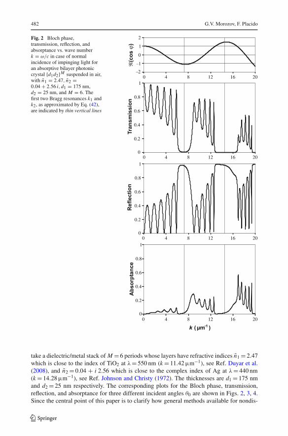
Fig. 2 Bloch phase,transmission, reflection, andabsorptance vs. wave numberk = ω/c in case of normalincidence of impinging light foran absorptive bilayer photoniccrystal {d1d2}M suspended in air,with n1 = 2.47, n2 =0.04 + 2.56 i, d1 = 175 nm,d2 = 25 nm, and M = 6. Thefirst two Bragg resonances k1 andk2, as approximated by Eq. (42),are indicated by thin vertical lines
take a dielectric/metal stack of M = 6 periods whose layers have refractive indices n1 = 2.47which is close to the index of TiO2 at λ= 550 nm (k = 11.42 µm−1), see Ref. Duyar et al.(2008), and n2 = 0.04 + i 2.56 which is close to the complex index of Ag at λ= 440 nm(k = 14.28 µm−1), see Ref. Johnson and Christy (1972). The thicknesses are d1 = 175 nmand d2 = 25 nm respectively. The corresponding plots for the Bloch phase, transmission,reflection, and absorptance for three different incident angles θ0 are shown in Figs. 2, 3, 4.Since the central point of this paper is to clarify how general methods available for nondis-
123
Light propagation in 1D photonic crystals with dissipation 483
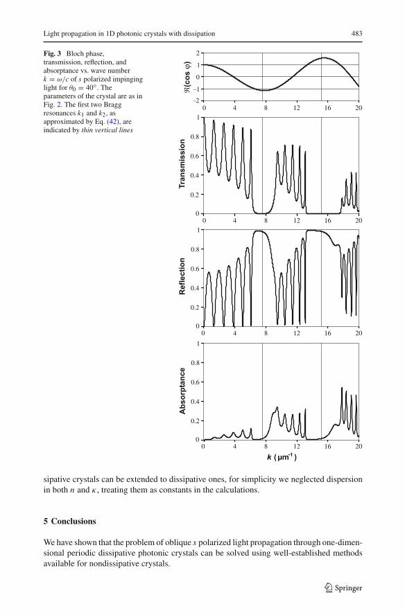
Fig. 3 Bloch phase,transmission, reflection, andabsorptance vs. wave numberk = ω/c of s polarized impinginglight for θ0 = 40◦. Theparameters of the crystal are as inFig. 2. The first two Braggresonances k1 and k2, asapproximated by Eq. (42), areindicated by thin vertical lines
sipative crystals can be extended to dissipative ones, for simplicity we neglected dispersionin both n and κ , treating them as constants in the calculations.
5 Conclusions
We have shown that the problem of oblique s polarized light propagation through one-dimen-sional periodic dissipative photonic crystals can be solved using well-established methodsavailable for nondissipative crystals.
123
484 G.V. Morozov, F. Placido
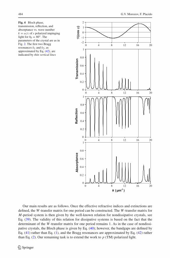
Fig. 4 Bloch phase,transmission, reflection, andabsorptance vs. wave numberk = ω/c of s polarized impinginglight for θ0 = 80◦. Theparameters of the crystal are as inFig. 2. The first two Braggresonances k1 and k2, asapproximated by Eq. (42), areindicated by thin vertical lines
Our main results are as follows. Once the effective refractive indices and extinctions aredefined, the W -transfer matrix for one period can be constructed. The W -transfer matrix forM-period system is then given by the well-known relation for nondissipative crystals, seeEq. (39). The validity of this relation for dissipative systems is based on the fact that thedeterminant of the W -transfer matrix for one period remains 1. As in the case of nondissi-pative crystals, the Bloch phase is given by Eq. (40); however, the bandgaps are defined byEq. (41) rather than Eq. (1), and the Bragg resonances are approximated by Eq. (42) ratherthan Eq. (2). Our remaining task is to extend the work to p (TM) polarized light.
123
Light propagation in 1D photonic crystals with dissipation 485
To use the above theory for most absorptive periodic stacks one must also take intoaccount dispersion of the complex valued refractive indices (Yu et al. 2004; Chen et al. 2009).However, our formalism remains valid without modification if the proper frequency depen-dent values of n and κ are used from the beginning. The only exception is Eq. (42) where theaverage refractive index and extinction must be properly defined.
Acknowledgments We are grateful to Prof. D. W. L. Sprung from McMaster University for his helpfuland contributive suggestions to improve the current manuscript. GVM is grateful to the Royal Society ofEdinburgh for an International Exchange Programme Award P086CHA that made the collaboration withMcMaster possible.
References
Andre, J.M., Jonnard, P.: Stokes reciprocity equations and density of modes for absorbing stratified media.J. Mod. Opt. 56, 1562–1571 (2008)
Bendickson, J.M., Dowling, J.P., Scalora, M.: Analytic expressions for the electromagnetic mode density infinite, one-dimensional, photonic band-gap structures. Phys. Rev. E 53, 4107–4121 (1996)
Born, M., Wolf, E.: Principles of Optic, 7th edn. Cambridge, London (1999)Brillouin, L.: Wave Propagation in Periodic Structures. McGraw-Hill, New York (1946)Chang, P.C.Y., Walker, J.C., Hopcraft, K.I.: Ray tracing in absorbing media. J. Quant. Spectrosc. Radiat.
Transf. 96, 327–341 (2005)Chen, S., Wang, Y., Yao, D., Song, Z.: Absorption enhancement in 1D Ag/Si02 metallic-dielectric photonic
crystals. Opt. Appl. 39, 473–479 (2009)Dupertuis, M.A., Proctor, M., Acklin, B.: Generalization of complex Snell-Descartes and Fresnel laws.
J. Opt. Soc. Am. A 11, 1159–1166 (1994)Duyar, O., Placido, F., Durusoy, H.Z.: Optimization of TiO2 films prepared by reactive electron beam
evaporation of Ti3O5. J. Phys. D Appl. Phys. 41, Article No. 095307 (2008)Johnson, P.B., Christy, R.W.: Optical constants of the noble metals. Phys. Rev. B 6, 4370–4379 (1972)Landau, L.D., Lifshitz, E.M., Pitaevskii, L.P.: Electrodynamics of Continuous Media. 2nd edn. Butterworth-
Heinemann, Oxford (1984)Levin, M.L.: Propagation of a plane electromagnetic wave in a periodic layered medium. Zh. Tekh.
Fiz. 18, 1399–1404 (1948)Mahan, A.I.: Reflection and refraction at oblique incidence on a dielectric-metallic interface as a boundary
value problem in electromagnetic theory. J. Opt. Soc. Am. A 46, 913–914 (1956)Morozov, G.V., Maev, R.G., Drake, G.W.F.: Switching electromagnetic waves by two-layered periodic dielec-
tric structures. Phys. Rev. E 60, 4860–4867 (1999)Nusinsky, I., Hardy, A.A.: Band-gap analysis of one-dimensional photonic crystals and conditions for gap
closing. Phys. Rev. B 73, Article No. 125104 (2006)Shen, J., Yu, H., Lu, J.: Light propagation and reflection-refraction event in absorbing media. Chin. Opt.
Lett. 8, 111–114 (2010)Sprung, D.W.L., Wu, H., Martorell, J.: Scattering by a finite periodic potential. Am. J. Phys. 61, 1118–
1124 (1993)Stratton, J.A.: Electromagnetic Theory. McGraw-Hill, New York (1941)Vitela, J.E.: Electromagnetic waves in dissipative media revisited. Am. J. Phys. 72, 393–403 (2004)Yeh, P., Yariv, A., Hong, C.-S.: Electromagnetic propagation in periodic stratified media: general theory.
J. Opt. Soc. Am. 67, 423–438 (1977)Yu, J., Shen, Y., Liu, X., Fu, R., Zi, J., Zhu, Z.: Absorption in one-dimensional metallic-dielectric photonic
crystals. J. Phys. Condens. Matter 16, L51–L56 (2004)
123
Top Related
Copyright © 2022 FDOKUMEN

