


Bahasa
Halaman
Hukum


K770K770K770K770----KBDKBDKBDKBD MIDI Interface forMIDI Interface forMIDI Interface forMIDI Interface for
Korg 770 / 700S / 900PS KeyboardKorg 770 / 700S / 900PS KeyboardKorg 770 / 700S / 900PS KeyboardKorg 770 / 700S / 900PS Keyboard
Model 8Model 8Model 8Model 8----430430430430 Version 1.0Version 1.0Version 1.0Version 1.0
Installation Manual for Korg 700SInstallation Manual for Korg 700SInstallation Manual for Korg 700SInstallation Manual for Korg 700S
© 2019 CHD Elektroservis© 2019 CHD Elektroservis© 2019 CHD Elektroservis© 2019 CHD Elektroservis
Korg 700S MIDI InterfaceKorg 700S MIDI InterfaceKorg 700S MIDI InterfaceKorg 700S MIDI Interface K770 K770 K770 K770----KBDKBDKBDKBD Installation ManualInstallation ManualInstallation ManualInstallation Manual 8888----430 / v. 1.00430 / v. 1.00430 / v. 1.00430 / v. 1.00
Copyright © 2019 CHD Elektroservis. All rights reserved. No part of this publication may be reproduced in any form without the written permission of CHD Elektroservis.
2222
Contents:Contents:Contents:Contents: 1111 GENERAL INFORMATIONGENERAL INFORMATIONGENERAL INFORMATIONGENERAL INFORMATION ................................................................................................................................ ................................................................................................................................ ............................... ................................................................................................................................................................................................................................. 3333 1.1 MIDI INTERFACE KIT PARTS............................................................................................................................. 3 2222 MIDI INTERFACE INSTALLATIONMIDI INTERFACE INSTALLATIONMIDI INTERFACE INSTALLATIONMIDI INTERFACE INSTALLATION ................................................................................................................................ ............................... ............................................................................................................................................................................................................................................................................................................................. 4444 2.1 OPEN THE INSTRUMENT............................................ ..................................................................................... 4 2.2 DRILLING HOLES FOR MIDI SOCKETS ................................................................................................................ 5 2.3 MIDI SOCKETS MOUNTING .......................................... ............................................................... .................... 6 2.4 DRILLING HOLES FOR BUTTON AND INDICATION LED ......................................................................................... 6 2.5 BUTTON AND INDICATION LED MOUNTING ............................. ............................................................... .......... 7 2.6 POWER SUPPLY CABLE MOUNTING.................................................................................................................. 8 2.7 KEYBOARD CONTROL SIGNALS CABLE MOUNTING ....................................................................................... ...... 9 2.8 THE INTERFACE BOARD MOUNTING ................................... ........................................................................... 10 2.9 INTERFACE ADJUSTMENT ............................................................................................................................. 11 2.10 FINISHING OF THE INSTALLATION.................................................................................................................. 12 3333 INSTALLATION TIPSINSTALLATION TIPSINSTALLATION TIPSINSTALLATION TIPS ................................................................................................................................ ............................... ................................................................................................................................ ................................................................................................................................................................................................................................. ........................ 15151515 3.1 MIDI – THRU/OUT OUTPUT ......................................... ............................................................... .................. 15 3.2 RESET BUTTON AND INDICATION LED ............................................................................................................ 15

Korg 700S MIDI InterfaceKorg 700S MIDI InterfaceKorg 700S MIDI InterfaceKorg 700S MIDI Interface K770 K770 K770 K770----KBDKBDKBDKBD Installation ManualInstallation ManualInstallation ManualInstallation Manual 8888----430 / v. 1.00430 / v. 1.00430 / v. 1.00430 / v. 1.00
Copyright © 2019 CHD Elektroservis. All rights reserved. No part of this publication may be reproduced in any form without the written permission of CHD Elektroservis.
3333
1111 GENERAL INFORMATIONGENERAL INFORMATIONGENERAL INFORMATIONGENERAL INFORMATION
FiguFiguFiguFigure 1.1 re 1.1 re 1.1 re 1.1 –––– Connection to instrument circuits Connection to instrument circuits Connection to instrument circuits Connection to instrument circuits K770-KBD MIDI interface controls VCO and GATE generator of the Korg 700S synthesizer. Simplified block schematics of the interface installation in the instrument shows fig. 1.1. The interface board looks very similarly for Korg 770, 700S, 900PS and M500 but there are a differences in some components. It is recommended to check if you have the correct model. The instrument model identification label on the interface board (see fig. 1.2) specifies the Korg instrument type: K770 is interface for Korg 770, 700S and 900PS, KM500 is interface for Korg M500 Micropreset.
Figure 1.2 Figure 1.2 Figure 1.2 Figure 1.2 –––– Identification labels Identification labels Identification labels Identification labels The interface firmware can be revised. Actual version of the firmware is printed on the identification label on the interface’s processor (see fig. 1.2). It is also possible to read the actual version of firmware from the interface by MIDI System Exclusive message. 1.11.11.11.1 MIDI INTERFACE KIT PARTSMIDI INTERFACE KIT PARTSMIDI INTERFACE KIT PARTSMIDI INTERFACE KIT PARTS
MIDI interface kit contents all necessary parts for installation incl. all support and coupling elements. The delivery also includes both installation and operation manuals in printed form. Please check if the delivery is complete before the installation (see fig. 1.1.1).
Figure 1.1.1 Figure 1.1.1 Figure 1.1.1 Figure 1.1.1 –––– Parts of the interface kit Parts of the interface kit Parts of the interface kit Parts of the interface kit The K770-KBD interface kit delivery contents:
(1) MIDI Interface board (2) 2x DIN-5 socket with cable (3) Bunched cables for power
supply (4) Bunched cables with
button and LED (5) Bunched cables of
keyboard control signals (6) Coupling elements (LED
holder, screws, nuts, washers, insulation tube and tightening strips)
(7) Owner’s and Installation manuals in printed form
Korg 700S MIDI InterfaceKorg 700S MIDI InterfaceKorg 700S MIDI InterfaceKorg 700S MIDI Interface K770 K770 K770 K770----KBDKBDKBDKBD Installation ManualInstallation ManualInstallation ManualInstallation Manual 8888----430 / v. 1.00430 / v. 1.00430 / v. 1.00430 / v. 1.00
Copyright © 2019 CHD Elektroservis. All rights reserved. No part of this publication may be reproduced in any form without the written permission of CHD Elektroservis.
4444
2222 MIDI INTERFACE INSTALLATIONMIDI INTERFACE INSTALLATIONMIDI INTERFACE INSTALLATIONMIDI INTERFACE INSTALLATION
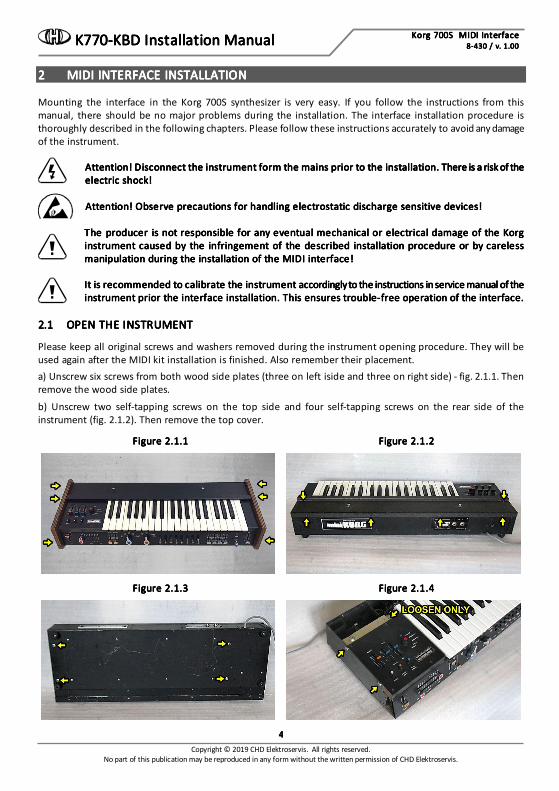
Mounting the interface in the Korg 700S synthesizer is very easy. If you follow the instructions from this manual, there should be no major problems during the installation. The interface installation procedure is thoroughly described in the following chapters. Please follow these instructions accurately to avoid any damage of the instrument.
Attention! Disconnect the instrument form the mains prior to thAttention! Disconnect the instrument form the mains prior to thAttention! Disconnect the instrument form the mains prior to thAttention! Disconnect the instrument form the mains prior to the installation. There is a risk of the e installation. There is a risk of the e installation. There is a risk of the e installation. There is a risk of the electric shock!electric shock!electric shock!electric shock! Attention! Observe precautions for handling electrostatic discharge sensitive devices!Attention! Observe precautions for handling electrostatic discharge sensitive devices!Attention! Observe precautions for handling electrostatic discharge sensitive devices!Attention! Observe precautions for handling electrostatic discharge sensitive devices! The producer is not responsible for any eventual mechanical or electrical damage of the Korg The producer is not responsible for any eventual mechanical or electrical damage of the Korg The producer is not responsible for any eventual mechanical or electrical damage of the Korg The producer is not responsible for any eventual mechanical or electrical damage of the Korg instrument causedinstrument causedinstrument causedinstrument caused by the infringement of the described installation procedure or by careless by the infringement of the described installation procedure or by careless by the infringement of the described installation procedure or by careless by the infringement of the described installation procedure or by careless manipulation during the installation of the MIDI interface!manipulation during the installation of the MIDI interface!manipulation during the installation of the MIDI interface!manipulation during the installation of the MIDI interface!
It is recommended to calibrate the instrument accordingly to the instructions in service manual of the It is recommended to calibrate the instrument accordingly to the instructions in service manual of the It is recommended to calibrate the instrument accordingly to the instructions in service manual of the It is recommended to calibrate the instrument accordingly to the instructions in service manual of the instrument prioinstrument prioinstrument prioinstrument prior the interface installation. This ensures troubler the interface installation. This ensures troubler the interface installation. This ensures troubler the interface installation. This ensures trouble----free operation of the interface.free operation of the interface.free operation of the interface.free operation of the interface.
2.12.12.12.1 OPEN THE INSTRUMENTOPEN THE INSTRUMENTOPEN THE INSTRUMENTOPEN THE INSTRUMENT
Please keep all original screws and washers removed during the instrument opening procedure. They will be used again after the MIDI kit installation is finished. Also remember their placement. a) Unscrew six screws from both wood side plates (three on left iside and three on right side) - fig. 2.1.1. Then remove the wood side plates.
b) Unscrew two self-tapping screws on the top side and four self-tapping screws on the rear side of the instrument (fig. 2.1.2). Then remove the top cover.
Figure 2.1.1Figure 2.1.1Figure 2.1.1Figure 2.1.1 Figure 2.1.2Figure 2.1.2Figure 2.1.2Figure 2.1.2
Figure 2.1.3Figure 2.1.3Figure 2.1.3Figure 2.1.3 Figure 2.1.4Figure 2.1.4Figure 2.1.4Figure 2.1.4
Korg 700S MIDI InterfaceKorg 700S MIDI InterfaceKorg 700S MIDI InterfaceKorg 700S MIDI Interface K770 K770 K770 K770----KBDKBDKBDKBD Installation ManualInstallation ManualInstallation ManualInstallation Manual 8888----430 / v. 1.00430 / v. 1.00430 / v. 1.00430 / v. 1.00
Copyright © 2019 CHD Elektroservis. All rights reserved. No part of this publication may be reproduced in any form without the written permission of CHD Elektroservis.
5555
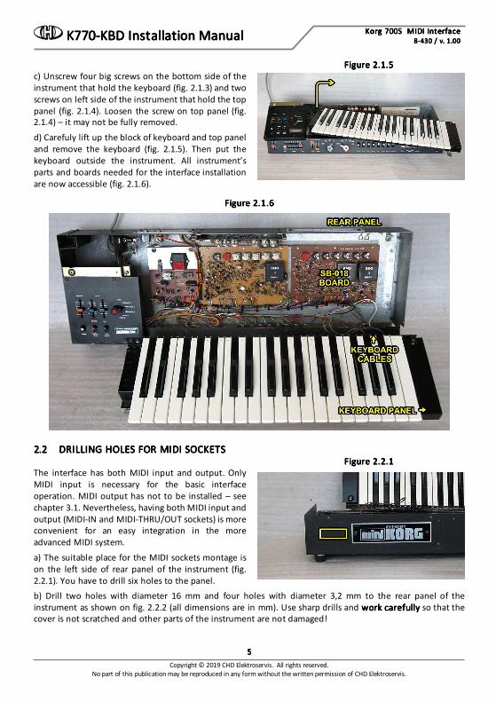
Figure 2.1.5Figure 2.1.5Figure 2.1.5Figure 2.1.5 c) Unscrew four big screws on the bottom side of the instrument that hold the keyboard (fig. 2.1.3) and two screws on left side of the instrument that hold the top panel (fig. 2.1.4). Loosen the screw on top panel (fig. 2.1.4) – it may not be fully removed.
d) Carefuly lift up the block of keyboard and top panel and remove the keyboard (fig. 2.1.5). Then put the keyboard outside the instrument. All instrument’s parts and boards needed for the interface installation are now accessible (fig. 2.1.6).
Figure 2.1.6Figure 2.1.6Figure 2.1.6Figure 2.1.6
2.22.22.22.2 DRILLING HOLES FOR MIDI SOCKETSDRILLING HOLES FOR MIDI SOCKETSDRILLING HOLES FOR MIDI SOCKETSDRILLING HOLES FOR MIDI SOCKETS
Figure 2.2.1Figure 2.2.1Figure 2.2.1Figure 2.2.1 The interface has both MIDI input and output. Only MIDI input is necessary for the basic interface operation. MIDI output has not to be installed – see chapter 3.1. Nevertheless, having both MIDI input and output (MIDI-IN and MIDI-THRU/OUT sockets) is more convenient for an easy integration in the more advanced MIDI system.
a) The suitable place for the MIDI sockets montage is on the left side of rear panel of the instrument (fig. 2.2.1). You have to drill six holes to the panel. b) Drill two holes with diameter 16 mm and four holes with diameter 3,2 mm to the rear panel of the instrument as shown on fig. 2.2.2 (all dimensions are in mm). Use sharp drills and work carefullywork carefullywork carefullywork carefully so that the cover is not scratched and other parts of the instrument are not damaged!

Korg 700S MIDI InterfaceKorg 700S MIDI InterfaceKorg 700S MIDI InterfaceKorg 700S MIDI Interface K770 K770 K770 K770----KBDKBDKBDKBD Installation ManualInstallation ManualInstallation ManualInstallation Manual 8888----430 / v. 1.00430 / v. 1.00430 / v. 1.00430 / v. 1.00
Copyright © 2019 CHD Elektroservis. All rights reserved. No part of this publication may be reproduced in any form without the written permission of CHD Elektroservis.
6666
Figure 2.2.2Figure 2.2.2Figure 2.2.2Figure 2.2.2
c) Clean the edge of the holes with small rasp or tip of bigger drill from both sides of the panel after the holes are drilled. d) Clean all iron sawdust and raspings from the inside of the instrumentsClean all iron sawdust and raspings from the inside of the instrumentsClean all iron sawdust and raspings from the inside of the instrumentsClean all iron sawdust and raspings from the inside of the instruments, they can cause short circuits or serious electrical damage if left inside the instrument. Please clean the instrument carefully! 2.32.32.32.3 MIDI SOCKETS MOUNTINGMIDI SOCKETS MOUNTINGMIDI SOCKETS MOUNTINGMIDI SOCKETS MOUNTING
a) Pull flat connectors of MIDI cables (from the interface accessory) through the holes in the instrument’s rear panel from outer side and insert DIN sockets into the holes (pic. 2.3.1). Both MIDI cables are identical and they can be swapped.
Figure 2.3.1 Figure 2.3.1 Figure 2.3.1 Figure 2.3.1 Figure 2.3.2 Figure 2.3.2 Figure 2.3.2 Figure 2.3.2
b) Fix DIN sockets to the drilled holes using screws, nuts and tooth lock washers from the interface accessory (fig. 2.3.2).
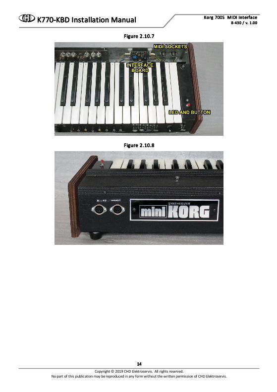
c) It is recommended to label the DIN sockets ("MIDI IN", "MIDI THRU/OUT" for example) with self-adhesive foil glued near the sockets (fig. 2.10.8 in chapter 2.10). 2.42.42.42.4 DRILLING HOLES FOR BUTTON AND INDRILLING HOLES FOR BUTTON AND INDRILLING HOLES FOR BUTTON AND INDRILLING HOLES FOR BUTTON AND INDICATION LEDDICATION LEDDICATION LEDDICATION LED
There are two control elements on the interface - button and bi-color LED. They are not necessary for the interface operation, so they need not to be installed (if you prefer to maintain the vintage status of the instrument) – see chapter 3.2. Nevertheless having both of them installed is more convenient for easier device control.
Korg 700S MIDI InterfaceKorg 700S MIDI InterfaceKorg 700S MIDI InterfaceKorg 700S MIDI Interface K770 K770 K770 K770----KBDKBDKBDKBD Installation ManualInstallation ManualInstallation ManualInstallation Manual 8888----430 / v. 1.00430 / v. 1.00430 / v. 1.00430 / v. 1.00
Copyright © 2019 CHD Elektroservis. All rights reserved. No part of this publication may be reproduced in any form without the written permission of CHD Elektroservis.
7777
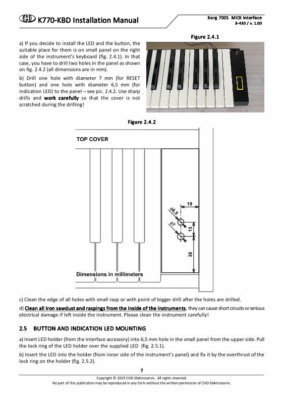
Figure 2.4.1Figure 2.4.1Figure 2.4.1Figure 2.4.1 a) If you decide to install the LED and the button, the suitable place for them is on small panel on the right side of the instrument’s keyboard (fig. 2.4.1). In that case, you have to drill two holes in the panel as shown on fig. 2.4.2 (all dimensions are in mm).
b) Drill one hole with diameter 7 mm (for RESET button) and one hole with diameter 6,5 mm (for indication LED) to the panel – see pic. 2.4.2. Use sharp drills and work carefullywork carefullywork carefullywork carefully so that the cover is not scratched during the drilling!
Figure 2.4.2Figure 2.4.2Figure 2.4.2Figure 2.4.2
c) Clean the edge of all holes with small rasp or with point of bigger drill after the holes are drilled.
d) CleCleCleClean all iron sawdust and raspings from the inside of the instrumentsan all iron sawdust and raspings from the inside of the instrumentsan all iron sawdust and raspings from the inside of the instrumentsan all iron sawdust and raspings from the inside of the instruments, they can cause short circuits or serious electrical damage if left inside the instrument. Please clean the instrument carefully! 2.52.52.52.5 BUTTON AND INDICATION LED MOUNTINGBUTTON AND INDICATION LED MOUNTINGBUTTON AND INDICATION LED MOUNTINGBUTTON AND INDICATION LED MOUNTING
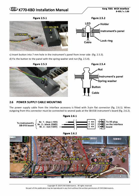
a) Insert LED holder (from the interface accessory) into 6,5 mm hole in the small panel from the upper side. Pull the lock ring of the LED holder over the supplied LED (fig. 2.5.1).
b) Insert the LED into the holder (from inner side of the instrument’s panel) and fix it by the overthrust of the lock ring on the holder (fig. 2.5.2).
Korg 700S MIDI InterfaceKorg 700S MIDI InterfaceKorg 700S MIDI InterfaceKorg 700S MIDI Interface K770 K770 K770 K770----KBDKBDKBDKBD Installation ManualInstallation ManualInstallation ManualInstallation Manual 8888----430 / v. 1.00430 / v. 1.00430 / v. 1.00430 / v. 1.00
Copyright © 2019 CHD Elektroservis. All rights reserved. No part of this publication may be reproduced in any form without the written permission of CHD Elektroservis.
8888
Figure 2.5.1 Figure 2.5.1 Figure 2.5.1 Figure 2.5.1 Figure 2.5.2 Figure 2.5.2 Figure 2.5.2 Figure 2.5.2
c) Insert button into 7 mm hole in the instrument’s panel from inner side (fig. 2.5.3).
d) Fix the button to the panel with the spring washer and nut (fig. 2.5.4).
Figure 2.5.3 Figure 2.5.3 Figure 2.5.3 Figure 2.5.3 Figure 2.5.4 Figure 2.5.4 Figure 2.5.4 Figure 2.5.4
2.62.62.62.6 POWER SUPPLY CABLE MOUNTINGPOWER SUPPLY CABLE MOUNTINGPOWER SUPPLY CABLE MOUNTINGPOWER SUPPLY CABLE MOUNTING
The power supply cable from the interface accessory is fitted with 3-pin flat connector (fig. 2.6.1). Wires outgoing from this connector must be connected to several pads at the SB-018 instrument’s board (fig. 2.6.2).
Figure 2.6.1Figure 2.6.1Figure 2.6.1Figure 2.6.1
To X5 plugon the interfaceboard
Nr. 1 - blue (-10V)Nr. 2 - black (GND)
Nr. 3 - red (+20V)
123
123
To instrument'sSB-018 board
Figure 2.6.2Figure 2.6.2Figure 2.6.2Figure 2.6.2
Korg 700S MIDI InterfaceKorg 700S MIDI InterfaceKorg 700S MIDI InterfaceKorg 700S MIDI Interface K770 K770 K770 K770----KBDKBDKBDKBD Installation ManualInstallation ManualInstallation ManualInstallation Manual 8888----430 / v. 1.00430 / v. 1.00430 / v. 1.00430 / v. 1.00
Copyright © 2019 CHD Elektroservis. All rights reserved. No part of this publication may be reproduced in any form without the written permission of CHD Elektroservis.
9999
a) Solder the red wire Nr. 3 “+20V“ to “9 / +VCC” pad on the instrument’s SB-018 board (fig. 2.6.2). An orange wire of the original bunched cables is already soldered here.
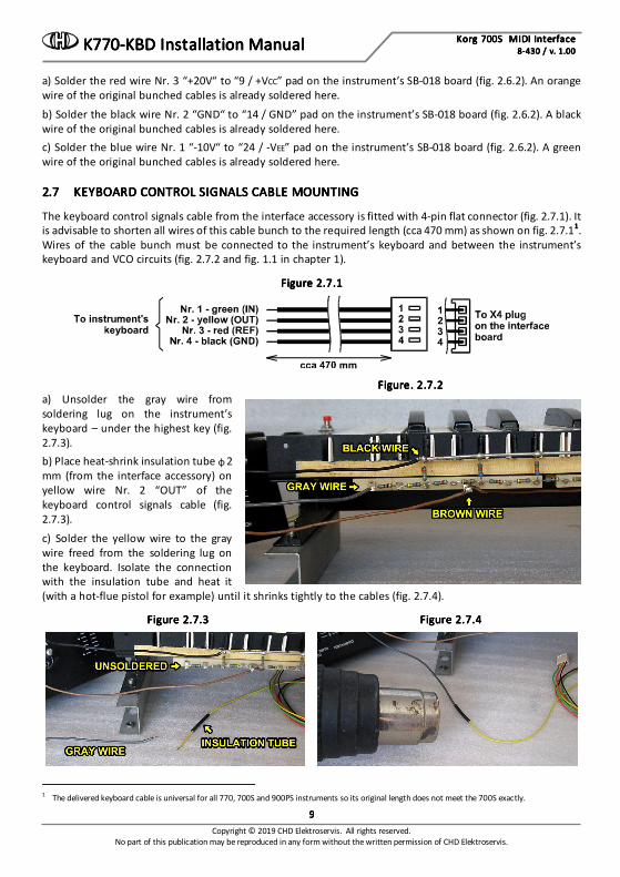
b) Solder the black wire Nr. 2 “GND“ to “14 / GND” pad on the instrument’s SB-018 board (fig. 2.6.2). A black wire of the original bunched cables is already soldered here. c) Solder the blue wire Nr. 1 “-10V“ to “24 / -VEE” pad on the instrument’s SB-018 board (fig. 2.6.2). A green wire of the original bunched cables is already soldered here. 2.72.72.72.7 KEYBOARD CONTROL SIGNALS CABLE MOUNTINGKEYBOARD CONTROL SIGNALS CABLE MOUNTINGKEYBOARD CONTROL SIGNALS CABLE MOUNTINGKEYBOARD CONTROL SIGNALS CABLE MOUNTING
The keyboard control signals cable from the interface accessory is fitted with 4-pin flat connector (fig. 2.7.1). It is advisable to shorten all wires of this cable bunch to the required length (cca 470 mm) as shown on fig. 2.7.11111. Wires of the cable bunch must be connected to the instrument’s keyboard and between the instrument’s keyboard and VCO circuits (fig. 2.7.2 and fig. 1.1 in chapter 1).
Figure 2.7.1Figure 2.7.1Figure 2.7.1Figure 2.7.1
Figure. 2.7.2Figure. 2.7.2Figure. 2.7.2Figure. 2.7.2 a) Unsolder the gray wire from soldering lug on the instrument’s keyboard – under the highest key (fig. 2.7.3). b) Place heat-shrink insulation tube φ 2 mm (from the interface accessory) on yellow wire Nr. 2 “OUT” of the keyboard control signals cable (fig. 2.7.3).
c) Solder the yellow wire to the gray wire freed from the soldering lug on the keyboard. Isolate the connection with the insulation tube and heat it (with a hot-flue pistol for example) until it shrinks tightly to the cables (fig. 2.7.4).
Figure 2.7.3Figure 2.7.3Figure 2.7.3Figure 2.7.3 Figure 2.7.4Figure 2.7.4Figure 2.7.4Figure 2.7.4
1 The delivered keyboard cable is universal for all 770, 700S and 900PS instruments so its original length does not meet the 700S exactly.

Korg 700S MIDI InterfaceKorg 700S MIDI InterfaceKorg 700S MIDI InterfaceKorg 700S MIDI Interface K770 K770 K770 K770----KBDKBDKBDKBD Installation ManualInstallation ManualInstallation ManualInstallation Manual 8888----430 / v. 1.00430 / v. 1.00430 / v. 1.00430 / v. 1.00
Copyright © 2019 CHD Elektroservis. All rights reserved. No part of this publication may be reproduced in any form without the written permission of CHD Elektroservis.
10101010
Figure. 2.7.5Figure. 2.7.5Figure. 2.7.5Figure. 2.7.5 d) Solder green wire Nr. 1 “IN” of the interface cable to the freed soldering lug on the instrument’s keyboard (fig. 2.7.5). e) Solder black wire Nr. 4 “GND“ of the interface cable to thick wire (common bus) of the instrument’s keyboard – to pad where a black wire is already soldered (fig. 2.7.5).
f) Solder red wire Nr. 3 “REF“ of the interface cable to lug on the instrument’s keyboard where a brown wires are already soldered (fig. 2.7.5). 2.82.82.82.8 THE INTERFACE BOARD MOUNTINGTHE INTERFACE BOARD MOUNTINGTHE INTERFACE BOARD MOUNTINGTHE INTERFACE BOARD MOUNTING
a) The interface board will be placed on right side of the rear metal panel of the instrument (fig. 2.8.1). Sometimes a paper label is stuck on the panel. Scrape it off.
Figure 2.8.1Figure 2.8.1Figure 2.8.1Figure 2.8.1 Figure 2.8.2 Figure 2.8.2 Figure 2.8.2 Figure 2.8.2
b) Cleanse the part of rear panel for the interface board placement (fig. 2.8.1). Use a chemical cleaner to remove all dirt and grease.
c) Remove the protective foil form the self-adhesive supports of the interface board (fig. 2.8.2).
Figure 2.8.3Figure 2.8.3Figure 2.8.3Figure 2.8.3 d) Attach the interface board to the instrument’s cover so that the board side with two connectors X4 (“KBD”) and X5 (“PWR”) points to the left as shown on the figure 2.8.3. Than fix the self-adhesive supports by pressing down to the cover.
e) Plug the 3-pin connector of the power supply bunched cables lead from the SB-018 board to X5 (“PWR”) plug head on the interface board. Orientation of the connector is given by the connector lock so it cannot be plugged reversely (fig. 2.8.4). f) Plug 4-pin connector of the bunched cables lead from keyboard to X4 (“KBD”) plug head on the interface board. Orientation of the connector is given by the connector lock again (fig. 2.8.4).

Korg 700S MIDI InterfaceKorg 700S MIDI InterfaceKorg 700S MIDI InterfaceKorg 700S MIDI Interface K770 K770 K770 K770----KBDKBDKBDKBD Installation ManualInstallation ManualInstallation ManualInstallation Manual 8888----430 / v. 1.00430 / v. 1.00430 / v. 1.00430 / v. 1.00
Copyright © 2019 CHD Elektroservis. All rights reserved. No part of this publication may be reproduced in any form without the written permission of CHD Elektroservis.
11111111
Figure 2.8.4Figure 2.8.4Figure 2.8.4Figure 2.8.4 g) Plug two 3-pin connectors of the MIDI cables to X1 (“I”) and X2 (“O”) plug heads on the interface board. Orientation of the connectors is given by the connector lock again but be sure that the connectors are not exchanged: MIDI input must be plugged to X1 head and MIDI output to X2 head (fig. 2.8.4).
h) Plug the 4-pin connector of the button and LED cable to X3 (“CTRL”) plug head on the interface board. Orientation of the connector is given by the connector lock again (fig. 2.8.4). i) Align newly installed cables and fix them together with plastic stripes from the interface accessory (fig. 2.8.5).
Figure 2.8.5Figure 2.8.5Figure 2.8.5Figure 2.8.5
2.92.92.92.9 INTERFACE ADJUSTMENTINTERFACE ADJUSTMENTINTERFACE ADJUSTMENTINTERFACE ADJUSTMENT
Figure 2.9.1Figure 2.9.1Figure 2.9.1Figure 2.9.1 There are two variable resistors on the interface board labeled “OFFSET” and “RANGE” (fig. 2.9.1). They must be adjusted before the interface is used. Adjustment procedure is following2222:
a) Connect MIDI output of your MIDI master keyboard (or PC / sequencer / DAW) to MIDI input of the interface3333.
b) Connect the high level audio output (“OUT-H”) of the instrument to a tuner or to a frequency meter.
c) Set all controllers on the instrument’s panels to a clear sound without any modulation:
2 It is suppossed that the interface is in "Factory Reset" status before the adjustment procedure. If it is not, send the F0 00 20 21 7F 54 50 03 7F 5A F0 00 20 21 7F 54 50 03 7F 5A F0 00 20 21 7F 54 50 03 7F 5A F0 00 20 21 7F 54 50 03 7F 5A
F7 [hex]F7 [hex]F7 [hex]F7 [hex] SysEx message to the intarface first. 3 Set transmit MIDI Channel to number 1 on the master keyboard.
Korg 700S MIDI InterfaceKorg 700S MIDI InterfaceKorg 700S MIDI InterfaceKorg 700S MIDI Interface K770 K770 K770 K770----KBDKBDKBDKBD Installation ManualInstallation ManualInstallation ManualInstallation Manual 8888----430 / v. 1.00430 / v. 1.00430 / v. 1.00430 / v. 1.00
Copyright © 2019 CHD Elektroservis. All rights reserved. No part of this publication may be reproduced in any form without the written permission of CHD Elektroservis.
12121212
Top panel: • EFFECT switch to OFFOFFOFFOFF (upper position) • SUSTAIN LONG switch to OFFOFFOFFOFF (upper position) • TRAVEL VIBRATO switch to OFFOFFOFFOFF (upper position) Front panel: • VOLUME slider to MAXMAXMAXMAX (fully down) • TRAVELER sliders LPF (upper slider) to 10101010 / HPF (lower slider) to 0000 • ATTACK slider to 0000 • PERCUSSION / SINGING slider to 10101010 • SCALE selector to 4’4’4’4’ • MODE selector to TriangleTriangleTriangleTriangle (fully counterclockwise) • EXPAND, BRIGHT, SUSTAIN, BENDER REPEAT, VIBRATO, DEAY VIB., PORTAMENTO switches all to OFFOFFOFFOFF
(upper position) • PITCH slider to middle position Positions of all other controllers on both instrument’s panels are not significant.
d) Plug instrument's power supply cable to a mains socket and switch the instrument on by POWER switch on front panel. Attention Attention Attention Attention ---- work very carefully during whole adjustment procedure work very carefully during whole adjustment procedure work very carefully during whole adjustment procedure work very carefully during whole adjustment procedure ---- there is a risk of electric shock! there is a risk of electric shock! there is a risk of electric shock! there is a risk of electric shock!
e) Now, the interface is in "Stand-by" mode - the interface’s indication LED is off. If not, press the "RESET" button of the interface.
f) Wait a few minutesWait a few minutesWait a few minutesWait a few minutes to stabilize the temperature of all instrument circuits. g) Measure the voltage between pins of the "TP" jumper head (fig. 2.9.1) with a quality digital multimeter. It should be zero volts exactly. If it is not, adjust it with "OFFSET” variable resistor on the interface board (fig. 2.9.1).
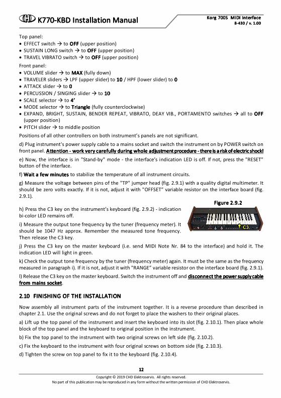
Figure 2.9.2Figure 2.9.2Figure 2.9.2Figure 2.9.2 h) Press the C3 key on the instrument’s keyboard (fig. 2.9.2) - indication bi-color LED remains off.
i) Measure the output tone frequency by the tuner (frequency meter). It should be 1047 Hz approx. Remember the measured tone frequency. Then release the C3 key. j) Press the C3 key on the master keyboard (i.e. send MIDI Note Nr. 84 to the interface) and hold it. The indication LED will light in green. k) Check the output tone frequency by the tuner (frequency meter) again. It must be the same as the frequency measured in paragraph i). If it is not, adjust it with "RANGE” variable resistor on the interface board (fig. 2.9.1). l) Release the C3 key on the master keyboard. Switch the instrument off and disconnect the power supply cable disconnect the power supply cable disconnect the power supply cable disconnect the power supply cable from mains socketfrom mains socketfrom mains socketfrom mains socket. 2.102.102.102.10 FINISHING OF THE INSTALLATIONFINISHING OF THE INSTALLATIONFINISHING OF THE INSTALLATIONFINISHING OF THE INSTALLATION
Now assembly all instrument parts of the instrument together. It is a reverse procedure than described in chapter 2.1. Use the original screws and do not forget to place the washers to their original places.
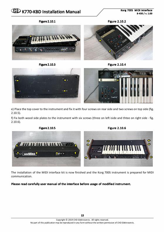
a) Lift up the top panel of the instrument and insert the keyboard into its slot (fig. 2.10.1). Then place whole block of the top panel and the keyboard to original position in the instrument. b) Fix the top panel to the instrument with two original screws on left side (fig. 2.10.2).
c) Fix the keyboard to the instrument with four original screws on bottom side (fig. 2.10.3). d) Tighten the screw on top panel to fix it to the keyboard (fig. 2.10.4).
Korg 700S MIDI InterfaceKorg 700S MIDI InterfaceKorg 700S MIDI InterfaceKorg 700S MIDI Interface K770 K770 K770 K770----KBDKBDKBDKBD Installation ManualInstallation ManualInstallation ManualInstallation Manual 8888----430 / v. 1.00430 / v. 1.00430 / v. 1.00430 / v. 1.00
Copyright © 2019 CHD Elektroservis. All rights reserved. No part of this publication may be reproduced in any form without the written permission of CHD Elektroservis.
13131313
Figure 2.10.1 Figure 2.10.1 Figure 2.10.1 Figure 2.10.1 Figure 2.10.2 Figure 2.10.2 Figure 2.10.2 Figure 2.10.2
Figure 2.10.3 Figure 2.10.3 Figure 2.10.3 Figure 2.10.3 Figure 2.10.4 Figure 2.10.4 Figure 2.10.4 Figure 2.10.4
e) Place the top cover to the instrument and fix it with four screws on rear side and two screws on top side (fig. 2.10.5).
f) Fix both wood side plates to the instrument with six screws (three on left iside and thtee on right side - fig. 2.10.6).
Figure 2.10.5 Figure 2.10.5 Figure 2.10.5 Figure 2.10.5 Figure 2.10.6 Figure 2.10.6 Figure 2.10.6 Figure 2.10.6
The installation of the MIDI interface kit is now finished and the Korg 700S instrument is prepared for MIDI communication. Please read carefully user manual of the interface before usage of modified instrument.Please read carefully user manual of the interface before usage of modified instrument.Please read carefully user manual of the interface before usage of modified instrument.Please read carefully user manual of the interface before usage of modified instrument.
Korg 700S MIDI InterfaceKorg 700S MIDI InterfaceKorg 700S MIDI InterfaceKorg 700S MIDI Interface K770 K770 K770 K770----KBDKBDKBDKBD Installation ManualInstallation ManualInstallation ManualInstallation Manual 8888----430 / v. 1.00430 / v. 1.00430 / v. 1.00430 / v. 1.00
Copyright © 2019 CHD Elektroservis. All rights reserved. No part of this publication may be reproduced in any form without the written permission of CHD Elektroservis.
14141414
FiguFiguFiguFigure 2.10.7re 2.10.7re 2.10.7re 2.10.7
Figure 2.10.8Figure 2.10.8Figure 2.10.8Figure 2.10.8
Korg 700S MIDI InterfaceKorg 700S MIDI InterfaceKorg 700S MIDI InterfaceKorg 700S MIDI Interface K770 K770 K770 K770----KBDKBDKBDKBD Installation ManualInstallation ManualInstallation ManualInstallation Manual 8888----430 / v. 1.00430 / v. 1.00430 / v. 1.00430 / v. 1.00
Copyright © 2019 CHD Elektroservis. All rights reserved. No part of this publication may be reproduced in any form without the written permission of CHD Elektroservis.
15151515
3333 INSTALLATION TIPSINSTALLATION TIPSINSTALLATION TIPSINSTALLATION TIPS 3.13.13.13.1 MIDI MIDI MIDI MIDI –––– THRU/OUT OUTPUT THRU/OUT OUTPUT THRU/OUT OUTPUT THRU/OUT OUTPUT
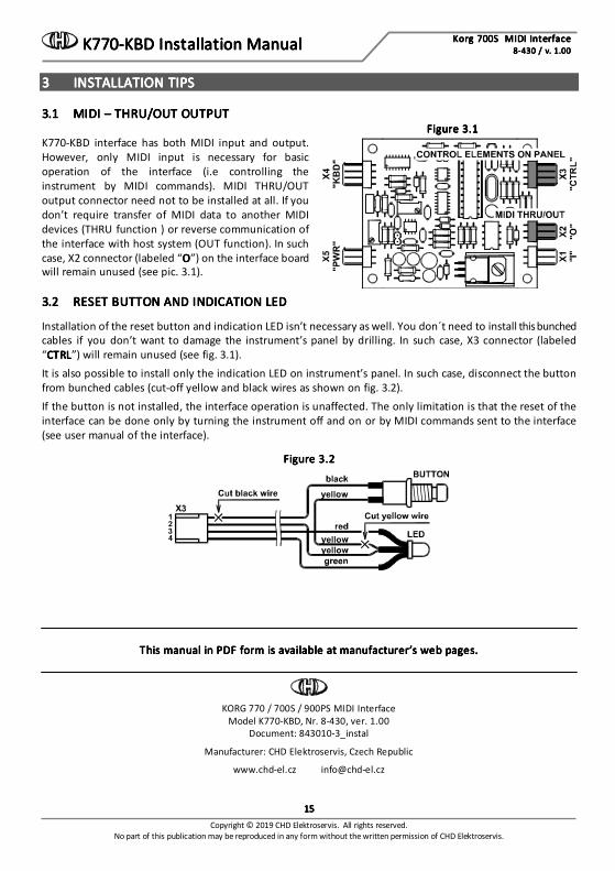
Figure 3.1Figure 3.1Figure 3.1Figure 3.1 K770-KBD interface has both MIDI input and output. However, only MIDI input is necessary for basic operation of the interface (i.e controlling the instrument by MIDI commands). MIDI THRU/OUT output connector need not to be installed at all. If you don’t require transfer of MIDI data to another MIDI devices (THRU function ) or reverse communication of the interface with host system (OUT function). In such case, X2 connector (labeled “OOOO”) on the interface board will remain unused (see pic. 3.1). 3.23.23.23.2 RESET BUTTON AND INDICATION LEDRESET BUTTON AND INDICATION LEDRESET BUTTON AND INDICATION LEDRESET BUTTON AND INDICATION LED
Installation of the reset button and indication LED isn’t necessary as well. You don´t need to install this bunched cables if you don’t want to damage the instrument’s panel by drilling. In such case, X3 connector (labeled “CTRLCTRLCTRLCTRL”) will remain unused (see fig. 3.1). It is also possible to install only the indication LED on instrument’s panel. In such case, disconnect the button from bunched cables (cut-off yellow and black wires as shown on fig. 3.2). If the button is not installed, the interface operation is unaffected. The only limitation is that the reset of the interface can be done only by turning the instrument off and on or by MIDI commands sent to the interface (see user manual of the interface).
Figure 3.2Figure 3.2Figure 3.2Figure 3.2
This manual in PDF form is available at manufacturer’s web pages.This manual in PDF form is available at manufacturer’s web pages.This manual in PDF form is available at manufacturer’s web pages.This manual in PDF form is available at manufacturer’s web pages.
KORG 770 / 700S / 900PS MIDI Interface Model K770-KBD, Nr. 8-430, ver. 1.00
Document: 843010-3_instal
Manufacturer: CHD Elektroservis, Czech Republic
www.chd-el.cz [email protected]

Top Related
Copyright © 2022 FDOKUMEN

