


Bahasa
Halaman
Hukum


ISO 9
GO
CGuid
9001:2008
Spec
OVERNM
IntegConsistidance Di
Specif
RESEAR
Effective
cification fo
Telecom D
MENT
grated ing of Tisplay B
fication
RCH DEMANA
from: 27-1
for Integrat
Directorate, R
OF IND
SPECIF
PassenTrain InfBoards a
No. RD
TELEESIGNS &AK NAG
10-2015
ted Passeng
RDSO/Luckno
DIA, M
FICATI
nger Informatioand PC b
DSO/SP
Issued b
ECOM DI& STAN
GAR, LU
RDSO/S
ger Inform
ow
MINISTR
ION FO
nformon Displbased A
PN/TC-6
by
IRECTORNDARDSUCKNOW
SPN/TC-61/
ation Syste
RY OF
OR
ation Slay Boar
Announc
61/2015,
RATE S ORGANW-22601
/2015
em (IPIS)
Page 1 o
RAILW
Systemrds, Coa
cement S
Rev-4.0
NISATIO1
Rev-4.0
of 62
WAYS
m ach System.
0
ON
ISO 9001:2008 Effective from: 27-10-2015 RDSO/SPN/TC-61/2015 Rev-4.0
Specification for Integrated Passenger Information System (IPIS)
Telecom Directorate, RDSO/Lucknow Page 2 of 62
DOCUMENT DATA SHEET
Specification No: RDSO/SPN/TC-61/2015 Revision 4.0
Title of the document:
Specification for Integrated Passenger Information System consisting of Train information Display boards, Coach Guidance Display board and PC Based Announcement.
Author:
P Lal Joint Director/Telecom-I
Approved by:
Shri D N Tewari Executive Director/Telecom
Abstract:
This document specifies technical specification of Integrated Passenger Information System consisting of Train Indication, Coach Guidance and PC Based Announcement.

ISO 9001:2008 Effective from: 27-10-2015 RDSO/SPN/TC-61/2015 Rev-4.0
Specification for Integrated Passenger Information System (IPIS)
Telecom Directorate, RDSO/Lucknow Page 3 of 62
DOCUMENT CONTROL SHEET
Name Organization Function Level
P.Lal Joint Director/ Telecom-I
RDSO Member Prepare
Shri D.N.Tewari Executive Director/ Telecom
RDSO - Approve
REVISIONS:
Version Chapter/ Annexure
Revision Effective from Month/Year
RDSO/SPN/TC/61/2006 - FIRST ISSUE 2006
RDSO/SPN/TC/61/2006 All Pages 1st Revision September, 2006
RDSO/SPN/TC/61/2007 All Pages 2nd Revision October, 2007
RDSO/SPN/TC/61/2012 All Pages 3rd Revision September, 2012
RDSO/SPN/TC/61/2015 All Pages 4th Revision October, 2015

ISO 9001:2008 Effective from: 27-10-2015 RDSO/SPN/TC-61/2015 Rev-4.0
Specification for Integrated Passenger Information System (IPIS)
Telecom Directorate, RDSO/Lucknow Page 4 of 62
TABLE OF CONTENTS
Sr. No. Name of the Item Page No
1 Scope 6
2 System Description 6
3 System Requirements 6
4 Functional Requirements 9
5 General Requirements 12
6 Software Requirements 16
7 Power Supply 20
8 Tests and Requirements 21
9 Test Procedure 24
10 Quality Assurance 27
11 Marking & Packing 27
12 Information to be supplied by Manufacturer 28
13 Information to be supplied by Purchaser 28
14 Training 29
15 Annexure- A 30
16 Annexure- B 53
17 Annexure- C 57
18 Diagram -1 58
19 Diagram -2 59
20 Diagram -3 & 4 60
21 Diagram -5 61
22 Diagram -6 62
ISO 9001:2008 Effective from: 27-10-2015 RDSO/SPN/TC-61/2015 Rev-4.0
Specification for Integrated Passenger Information System (IPIS)
Telecom Directorate, RDSO/Lucknow Page 5 of 62
I. SUMMARY:
This specification covers the general, functional, technical and performance requirements of Integrated Passenger Information System which includes Display of train information on LED based display board i.e. Single Line, Multiline, At a glance & coach guidance display boards and PC based announcement for train information to passengers.
II. SOURCE:
Draft specification RDSO/ SPN/ TC/ 61/2015 Rev 4.0 has been prepared by RDSO, Lucknow based on feedback provided by Firms/Railway Board/user Railways on the system for better reliability & cost reduction.
III. FOREWORD:
RDSO/ SPN specification is issued as draft specification. This specification is circulated to customers/ Railways and field inspection units for comments.
In the absence of IRS specification, procurement may be made as per RDSO/ SPN specification.
This specification requires the reference to the following specifications:
IRS: S23 Electrical signaling and interlocking equipment
RDSO/SPN/144 The Safety and reliability requirement of electronic signaling equipment
IS:9000 Basic environmental testing procedures for electronic and electrical items
Wherever, reference to any specifications appears in this document, it shall be taken as a reference to the latest version of that specification unless the year of issue of the specification is specifically stated.
For the purpose of this specification, the terminology given in IRS: S23 and RDSO/SPN/144 shall apply.

ISO 9001:2008 Effective from: 27-10-2015 RDSO/SPN/TC-61/2015 Rev-4.0
Specification for Integrated Passenger Information System (IPIS)
Telecom Directorate, RDSO/Lucknow Page 6 of 62
1.0 SCOPE:
1.1 This specification covers the general, functional, technical and performance requirements of Integrated Passenger Information System, which includes Display of train information on LED based display board i.e. Single Line, Multiline, At a glance & coach guidance display boards, LED/LCD Display and PC based announcement system for train information to passengers.
2.0 SYSTEM DESCRIPTION:
2.0 The Integrated Passenger Information System (IPIS) will consist of Central Data Controller (CDC) loaded with software for announcement, Platform Data Controller (PDC), LED/LCD display and display boards of different sizes including Coach Guidance display boards.
2.1 Multiline Display Board to display train Information i.e. Train number, Name, time of arrival/departure and platform number. It will show information of multiple trains at a time. For major stations, there should be separate display boards for arrival & departure, whereas for small way side stations there can be a common display board for displaying arrival & departure information. The multiline display boards will be placed at main entrance/ concourse of the station and platform display boards at suitable places on platforms/ foot-over bridges.
2.2 Platform Display Board to display the information of the train scheduled for arrival/departure from that platform i.e. Train number, Name, time of arrival/departure.
2.3 At-A-Glance Display Board for displaying information of the train arriving/departing from that platform with coach composition.
2.4 Coach Guidance Display Board to indicate position of coach No. scheduled for arrival/departure from that platform for guidance of passengers.
2.5 It should be possible to display train information being displayed on Multiline Display Board on LED/LCD Display placed at different locations of the platform. LED/LCD Display shall be provided in the enquiry offices, waiting rooms or at any suitable place to be decided by the purchaser.
2.6 It should also be possible to network all systems provided at different locations at a station for carrying out operation from a centralized place.
3.0 SYSTEM REQUIREMENT:
3.1 Hardware Requirements: The IPIS shall consists of following units/subsystems:-
a) Central Data Controller (CDC) b) Platform Data Controller (PDC) c) Multiline Display Board d) Platform Display Board e) At-a-glance display Board f) Coach Guidance Display Board g) LED/LCD Display
3.2 Central Data Controller:
3.2.1 The Central Data Controller (CDC) shall consist of two CPUs (PCs) connected through a Central Data Switch (CDS) for data synchronization. One 17” (minimum) Colour LCD/TFT monitor to be connected through a Keyboard-Video-Mouse

ISO 9001:2008 Effective from: 27-10-2015 RDSO/SPN/TC-61/2015 Rev-4.0
Specification for Integrated Passenger Information System (IPIS)
Telecom Directorate, RDSO/Lucknow Page 7 of 62
(KVM) switch. Audio/Video selection device with speaker and microphone shall be provided for live announcement.
3.2.2 The CPU of CDC shall be of reputed make or as specified by purchaser having following minimum configuration:
a) i5 processor or equivalent or higher processor
b) 4 GB or higher RAM
c) HDD: 500 GB or higher SATA
d) Standard I/O Ports (1 Serial and 4 USB)
e) Windows-7 or higher version Operating System (OS)
f) Gigabit Ethernet Port- 10/100/1000 Mbps
g) Audio Input /Output ports
h) Keyboard & Optical Mouse
i) Any industry standard database package like SQL server 2000 or higher.
j) 2GB Graphic Card (If not inbuilt in CPU)
k) Two Video Output Port (VGA/ HDMI/ DVI).One for connecting local monitor and another for connecting LED/LCD Display for displaying Train information.
3.2.3 Both the CPUs of CDC shall be pre-loaded with necessary software for working of Integrated Passenger Information System (IPIS). There shall be continuous data synchronization between both the CPUs connected through a LAN link. At a time only one CPU will work but database of both CPUs shall be updated automatically.
3.2.4 It should be possible to operate CDC from a suitable control center or enquiry office, preferably a dust free or AC environment.
3.2.5 CDC shall be provided with voice recording and playback facility for making live PC based announcement. There shall be provision for one speaker of minimum 5W of reputed make with volume control.
3.2.6 The selection of Audio/ Video (A/V)output for PC based announcement and LED/LCD Display shall be automatic/manual with the help of a suitable Audio & Video selection device from both CPUs of CDC. A/V selection device shall provide properly isolated audio output which can be connected to audio amplifier of public address system. It shall also provide video signal for LED/LCD Display of PIS.
3.2.7 UPS of minimum 1 KVA with minimum 25 minutes battery backup shall be provided for uninterrupted operation of the CDC.
3.2.8 By Pressing “ON” Push button switch provided on CDC cabinet, both the CPUs of CDC (main/standby) should switch ON and automatically run system software. Repeat pressing of the button should switch “OFF” the CDC.
3.2.9 CDC should be switched OFF only after closing all running programs and with proper shut down operation.
3.2.10 Cabinet of the equipment shall be well designed to sustain external vibration due to movement of trains.
3.2.11 System shall be fully equipped with suitable hardware & software to acquire & process updated data of running trains automatically from NTES, COIS Server or from any central server, etc. to display updated train information on various types of

ISO 9001:2008 Effective from: 27-10-2015 RDSO/SPN/TC-61/2015 Rev-4.0
Specification for Integrated Passenger Information System (IPIS)
Telecom Directorate, RDSO/Lucknow Page 8 of 62
display boards, coach guidance systems and announcement on PA system. NTES/any other central server connectivity & protocol shall be provided by concerned Railway.
3.2.12 LCD/LED Monitors of suitable size as specified by the purchaser shall be used for LED/LCD Display for IPIS. LCD/LED Monitors shall be of reputed make or as specified by the purchaser.
3.3.0 Central Data Switch:
3.3.1 The Central Data Switch (CDS) shall provide Ethernet connectivity for data communication between both CPUs of CDC and multiline display board & Platform Data Controllers of the station.
3.3.2 8-port or 12-port Layer 3 switch (as per site requirement) shall be used as Central Data Switch. Switch shall be of CISCO, HP, Juniper, Brocade, Avaya, Extreme etc make or as specified by the purchaser.
3.3.3 Data communication between Central Data Switch to Platform Data Controller and Multiline display board shall be on Ethernet using CAT-6 cable or it should be Optic Fibre cable if distance is more. CAT-6 cable should be compliant with TIA/EIA-568 B or latest standards or latest from reputed make & necessary test certificate shall be produced from CAT-6 cable manufacturer.
3.3.4 Switch should have at least two 10/100 or better Base X SFP ports (fibre ports) for connecting field devices on optic fibre cable and remaining ports shall be Ethernet (copper).
3.3.5 Necessary diagnostic tools shall be provided in CDC for health monitoring of various devices connected to it.
3.4 Platform Data Controller (PDC):
3.4.1 The Platform Data Controllers shall derive Platform display boards and Coach guidance display boards.
3.4.2 The PDC should have two 10/100 or better Base X SFP ports with single mode optical interface for connecting CDC and at least eight Ethernet ports for connecting field display devices.
3.4.3 The Platform Data Controller design should be based on a minimum 32-bit microcontroller. The PDC shall route the data/ instructions coming from the Central Data Controller to the downstream display devices and health/ diagnostics information from the display devices to CDC.
3.4.4 PDC should also have eight serial ports (RS-485) for connecting Coach Guidance Display boards and Platform Display boards (already available on platform). Each serial port shall be capable of deriving minimum 6 coach guidance display boards.
3.4.5 Serial port (RS-485) connection to coach guidance display boards shall be of multi drop type and in case of failure (like power down) of any device, extension of communication link shall not be affected. Also in case of removal of any Display Board for repair it should not affect working of other display Boards.
3.4.6 PDC should be equipped with wireless Zig-Bee module for data connectivity on wireless to connect Platform Display boards and Coach Guidance Display boards in license free band of 2.4 GHz (Optional). Common protocol for data connectivity on Zig-Bee shall be as per Annexure-B.
3.4.7 All the ports shall have LED indications for monitoring the communication status of the connected devices.
ISO 9001:2008 Effective from: 27-10-2015 RDSO/SPN/TC-61/2015 Rev-4.0
Specification for Integrated Passenger Information System (IPIS)
Telecom Directorate, RDSO/Lucknow Page 9 of 62
3.4.8 Necessary Platform Data Controller shall be installed on each platform to cater data connectivity requirement of all the display board.
3.4.9 It should be possible to mount PDC on wall or Platform Display Controller, fiber termination box etc. shall be accommodated in a standard 19” Euro Rack of suitable height.
3.4.10 The PDC shall be IP54 environmental standard compliant to protect it against dust, Rain & other environmental hazards.
3.5 Functional requirements of various types Train Information Display Boards:
3.5.1 Display board shall be of four types, depending on its location.
a) Multiline Display Boards for displaying information of multiple trains.
b) Platform Display Board for displaying information of single train.
c) At-A-Glance Display Board for displaying information of the train arriving/departing from that platform with coach composition
d) Coach Guidance Display Board to indicate position of coach No. scheduled for arrival/departure from that platform for guidance of passengers.
3.5.2 Hardware and software of IPIS of the different vendors shall be interoperable in such a way that:
i. It should be possible to send and display data on display boards of different make and read & set configuration of the display board through wired or wireless media.
ii. The display boards of different make shall be also compatible with other hardware and software of IPIS of different make.
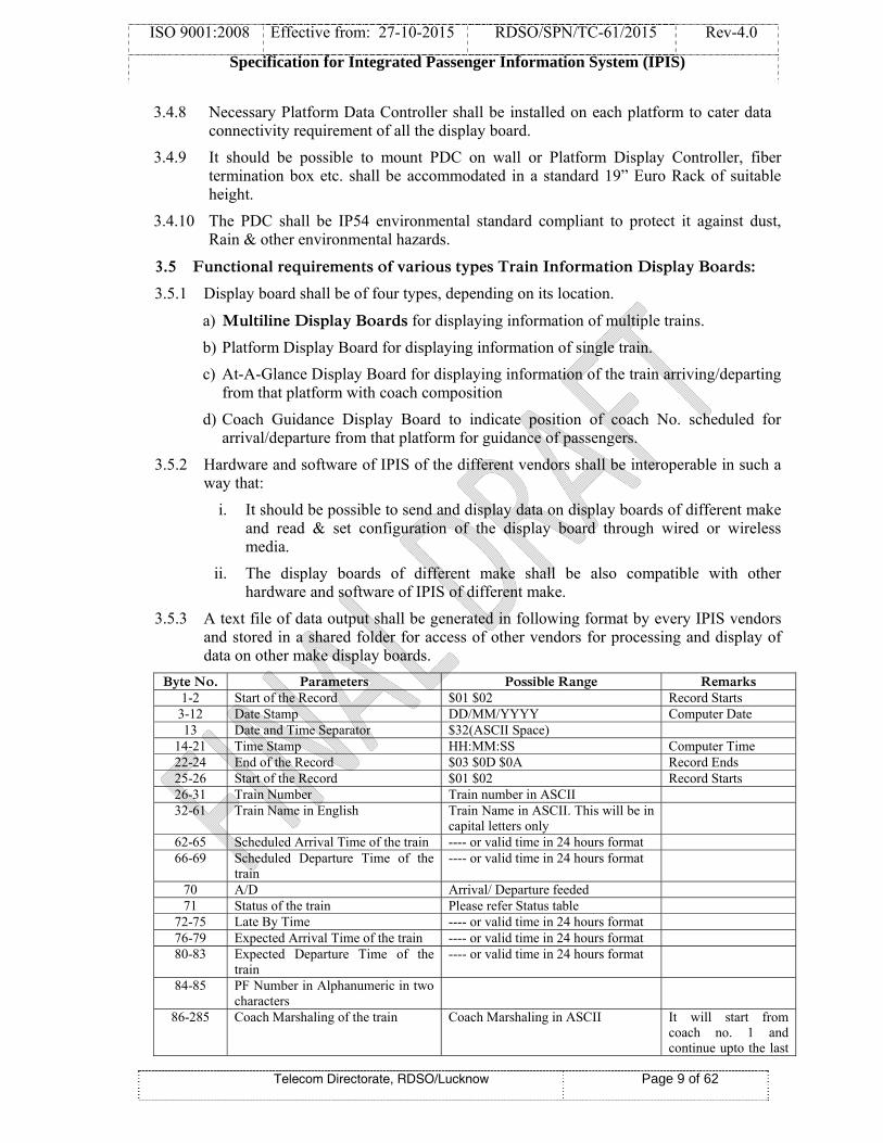
3.5.3 A text file of data output shall be generated in following format by every IPIS vendors and stored in a shared folder for access of other vendors for processing and display of data on other make display boards.
Byte No. Parameters Possible Range Remarks 1-2 Start of the Record $01 $02 Record Starts
3-12 Date Stamp DD/MM/YYYY Computer Date 13 Date and Time Separator $32(ASCII Space)
14-21 Time Stamp HH:MM:SS Computer Time22-24 End of the Record $03 $0D $0A Record Ends25-26 Start of the Record $01 $02 Record Starts26-31 Train Number Train number in ASCII 32-61 Train Name in English Train Name in ASCII. This will be in
capital letters only
62-65 Scheduled Arrival Time of the train ---- or valid time in 24 hours format 66-69 Scheduled Departure Time of the
train ---- or valid time in 24 hours format
70 A/D Arrival/ Departure feeded 71 Status of the train Please refer Status table
72-75 Late By Time ---- or valid time in 24 hours format 76-79 Expected Arrival Time of the train ---- or valid time in 24 hours format 80-83 Expected Departure Time of the
train ---- or valid time in 24 hours format
84-85 PF Number in Alphanumeric in two characters
86-285 Coach Marshaling of the train Coach Marshaling in ASCII It will start from coach no. 1 and continue upto the last
ISO 9001:2008 Effective from: 27-10-2015 RDSO/SPN/TC-61/2015 Rev-4.0
Specification for Integrated Passenger Information System (IPIS)
Telecom Directorate, RDSO/Lucknow Page 10 of 62
coach where every coach position will be separated by ‘,’ (comma) and $FA will mark the end of coach marshaling.
286-288 End of the Record $03 $0D $0A Record Ends… Bytes from 25 to 288 will continue for every train data transferred to the display boards…
3.5.4 It should be possible to read data file generated as text file by other vendors and shall be able to process and display updated information on display boards.
3.5.5 Display Data Controller design should be based on a minimum 32-bit microcontroller having Ethernet port for data transfer.
3.5.6 Multiline display board shall be located at the concourse/ main entrance of the station. Platform display boards shall be placed at the respective platforms. The exact location is to be indicated by the purchaser.
3.5.7 Multiline display board shall be of 2 lines or more and maximum up to 10 lines. Purchaser has to specifically mention the number of lines in each main display board as per site requirement.
3.5.8 At major stations separate multiline display boards for “arrival” and “departure” of trains are to be provided if specified by the purchaser, otherwise a common display board showing information of both “arrival” & “departure” of trains can be provided. However, the software should permit to display either “arrival” or “departure” on both the boards.
3.5.9 Data transfer from CDC to PDC shall be only on Ethernet using standard TCP/IP protocol.
3.5.10 Data transfer from CDC to all type of display boards excepts CGDB should be on Ethernet using standard TCP/IP protocol or on wireless using 2.4 GHz Zig-Bee module in license free band (Optional)
3.5.11 PDC to CGDB it should be either on wired serial interface (RS-485) or on wireless using 2.4 GHz Zig-Bee module in license free band (Optional)
3.5.12 In case, the information is more than the number of lines in display board then information shall be displayed on time slot basis.
3.5.13 The Platform Display board (PFD) shall display the information of a train scheduled for arrival/departure on that platform. If the platform display board is common between two platforms, it can be used to display the train information of trains scheduled on both the platforms alternatively.
3.5.14 Fixed titles on display boards viz. train number, name, expected time, arrival/ departure, platform number shall be screen printed preferably in white/ yellow (or stickered) on the top of first display line on casings in capital letters. The character size of these titles shall be minimum 6 cm height.
3.5.15 It should be possible to display Train information status as late, rescheduled, cancelled, indefinite late, diverted etc.
3.5.16 It should be possible to mount or fix a display board on wall at the platform entry or inside a concourse/main entry of a Railway station.
3.5.17 The information on display boards shall be displayed in English, Hindi and also in a Regional language, if required by the purchaser. The information shall be displayed for

ISO 9001:2008 Effective from: 27-10-2015 RDSO/SPN/TC-61/2015 Rev-4.0
Specification for Integrated Passenger Information System (IPIS)
Telecom Directorate, RDSO/Lucknow Page 11 of 62
a specific period of up to 30 seconds and shall be selectable in steps of 10 seconds from the Central Data Controller.
3.5.18 LEDs with equal fringe and uniform intensity are to be used to manufacture display boards to ensure that the information being displayed is with excellent contrast & without any visible black patches on the display screen and it shall be flicker free.
3.5.19 All display boards shall be constructed using 16X48 LED matrix PCB modules. Fixing of these modules shall be such that easy replacement of PCB module should be possible in case of failure. Such replacement shall not call for removing any other PCBs.
3.5.20 It should be possible to set intensity of display boards by software on time bond basis depending upon day/night conditions. Intensity Mode selection shall be user configurable. It shall be also possible to manually adjust intensity of the display boards through software from CDC in steps of 25%, 50%, 75% and 100%.
3.5.21 ICs used for the display board should be preferably of surface mounted devices (SMD) to ensure high reliability.
3.5.22 Class-D surge protection device shall be provided in CGDB and serial port of PDC for protection of data line against surge as per clause no. 5.7 of RDSO specification no. RDSO/SPN/TC/98/2011 Rev.0. Typical parameters of Class-D surge protection device shall be as under:
i. Max. continuous DC Voltage: 13 V DC ii. Total Nominal discharge current (8/20μs) line-Ground: 5 kA or equivalent for
10/1000 μs pulse. iii. Impulse limiting voltage/ Let through Voltage Line – Line (1kV/μs pulse or 8/20
μs pulse or 10/1000 μs pulse): 40V iv. Impulse limiting voltage/ Let through Voltage Line – Ground (1kV/μs pulse or
8/20 μs pulse or 10/1000 μs pulse): 1000 V v. Nominal load current: 100 mA
3.5.23 The Coach Guidance Display (CGD) Board shall indicate the Coach No./Train No. scheduled to arrive/depart from that platform.
3.5.24 Individual coach display board across the platform should display Train No &. Coach
No. alternatively like GEN, D1, S10, B1, A1, H1 in English and “अना., डी-1, एस-10, बी-1, ए-1, एच-1”etc. in Hindi. The information of Train No/Coach No shall be displayed alternatively at an interval of 10 sec. The information of Train No/Coach No. shall be displayed in Hindi and English alternatively. Time period for display of information should be programmable in step of 10 sec.
3.5.25 Following character sizes shall be used for displaying information on Display boards:
a) Character Size on display board with 16 Rows of LEDs:
For English and Numeric, the character size shall be adjusted to appropriate character width subject to maximum of 16X10 & for Hindi or Regional Language it should be maximum up to 16X14 LED matrix. There should be a gap of min. 16X1 LED matrix between two consecutive characters and 16X3 LED matrix between two consecutive words. However, actual character size may depend on type of font used.
b) Character Size for coach composition data display:
For English, the character size shall be preferably of 7X5 LED matrix. There should be a gap of minimum 8X1 LED matrix between two consecutive characters and 8X3
ISO 9001:2008 Effective from: 27-10-2015 RDSO/SPN/TC-61/2015 Rev-4.0
Specification for Integrated Passenger Information System (IPIS)
Telecom Directorate, RDSO/Lucknow Page 12 of 62
LED matrix between two consecutive words. However, actual character size may depend on type of font used.
3.6.0 GENERAL REQUIREMENTS:
3.6.1 The display systems shall be suitable for working in AC/DC electrified and non-electrified sections. It shall be suitable in all sections including where locomotives thyristor controlled single phase or 3-phase induction motors having haul passenger or freight trains and chopper controlled EMU stocks are operated.
3.6.2 Performance of the system shall not be affected in AC/DC electrified area.
3.6.3 When there is no data to be displayed, it should not display any garbage on the display board. The boards shall have proper built-in recovery mechanism to automatically recover the information in case the processor goes haywire.
3.6.4 Construction of different type of display boards should be modular, such that any defective module (i.e. PCB, connector, cable, power supply unit etc.) can be easily replaced to make the system functional.
3.6.5 LED displays of IPIS of various vendors shall be interoperable. It should be possible to receive & display train information data coming from CDC of other Firm using standard data protocols. From CDC, it should be also possible transfer data to display boards of other make and monitor link status & health of the display devices connected in the system.
3.6.6 It should be possible to have data of Multiline display board on cloud server so that it can be accessed through a web based application on android based smartphones (Optional).
3.6.7 Material used for the printed circuit board (PCB) shall be copper clad glass epoxy of grade FR-4 or equivalent. The PCB thickness shall be minimum 1.6 mm ± 0.1mm.
3.6.8 Conformal coating shall be applied on assembled and tested printed circuit boards to protect them from Humidity, Dust and dirt, Airborne contaminants like smoke and chemical vapors, Conducting particles like metal clips and filings, Accidental short circuit by dropped tools, fasteners etc.
3.6.9 The solder masks (green/black/combination of both) shall be applied on the solder side and component side of the card.
3.6.10 All display boards shall be protected with U.V. stabilized polycarbonate sheet having minimum thickness of 3mm (with tolerance of ± 0.1 mm) for better visibility and protection against dust/Rain.
3.6.11 Only single polycarbonate sheet without any joint should be used to cover all type of display boards however for Multi line display boards of more than two lines can be covered either by a single polycarbonate sheet for complete board or for individual line.
3.6.12 Wiring between different modules should be done with the help of male/female type of connectors. There should not be any requirement of rewiring, re-soldering/de-soldering for replacement of defective module. Proper cable guides shall be provided for fastening of cables and wires.
3.6.13 Suitable ‘Earthing’ point shall be provided for earthing the body of display board. Brass bolt of 6 mm dia shall be provided at appropriate place & suitably marked.
3.6.14 For installation of coach guidance display board on uncovered portion of the platform shall be provided using GI pipe of minimum 3”dia or as specified by purchaser.
3.6.15 Local power supply available on platform may be used for CGDB power supply.

ISO 9001:2008 Effective from: 27-10-2015 RDSO/SPN/TC-61/2015 Rev-4.0
Specification for Integrated Passenger Information System (IPIS)
Telecom Directorate, RDSO/Lucknow Page 13 of 62
3.6.16 Manufacturer shall maintain proper account of LEDs being used. The record shall include various details like source of supply, procurement invoice number & date, quantity, incoming rejection, lot wise consumption etc. which can be verified by the inspecting officials.
3.6.17 LEDs used in LED display units shall be of high performance quality and from reputed manufacturers as stipulated by RDSO. Number of LEDs and their part number shall not be changed without prior approval of RDSO.
3.6.18 The mounting of LEDs on all types of display boards should be such that it should have more horizontal viewing angle. Data sheets from the LED manufacturer shall be submitted to support the parameters of the LEDs used.
3.6.19 Protective grid made of Nylon-66 shall be provided on LED matrix for uniform intensity of the display boards .it should be preferably 16 X16 in size and in black colour.
3.6.20 Cabinet of CDC should be of standard design as per schematic shown in diagram-1 & made of Cold Rolled Closed Annealed (CRCA) sheet of minimum 18 SWG (1.2 mm) thicknesses. It should be powder coated in ivory/gray colour to protect from rust. Shelves of suitable height shall be provided to accommodate the equipment. Proper power supply distribution with plugs & sockets of appropriate capacity and earthing connection point shall be provided on the cabinet. Gland plates shall be provided on the top and bottom panel of cabinet for cable entry.
3.6.21 The cabinet shall have locking arrangement for front and back doors for equipment safety. Front side of the cabinet may have two or three doors. Only keyboard & mouse and/or monitor shall be accessible to operator whereas the other equipments remain in locked condition. Front door of the cabinet shall be of toughened glass/transparent UV polycarbonate sheet.
3.6.22 The housing of various display boards should be made of Cold Rolled Closed Annealed (CRCA) sheet of minimum 18 SWG (1.2 mm) thicknesses & dimension as per table shown in clause 3.7.12.
3.6.23 Both faces of Coach Guidance Display board should have nominal 5º tilt with a tolerance of + 1º from vertical plan downwards for better visibility.
3.6.24 Following information shall be etched/screen printed on the component side of the PCB.
a) Manufacturer’s name
b) PCB name/Part number
c) Component outline (in proximity of the component)
3.6.25 Following information shall be engraved or marked with permanent ink on the PCB
a) Card serial number
b) Month and year of manufacture
3.7.0 General Requirements of Display Boards:
3.7.1 All Display board shall be manufactured using 16 X 48 LED matrix having pitch of 10 + 0.5 mm.
3.7.2 Field format of Single/multiline display board, each line consisting of the LED matrix of 16X336 should be preferably as per following format:

ISO 9
3.7.3
3.7.4
3.7.5
3.7.6
9001:2008
Spec
55
Train No.
5 Digits
44444
Display
4 Field forwith LEinformat
64
Train N
5 Digits
44444
5 At-a-glanLED ma
Display f
It shall be pLED matrixTrain inform
Effective
cification fo
Telecom D
3
AAAA
format of S
rmat of At-D matrix otion to be di
3
No.
s
4
nce display atrix of each
format for a
possible to x of each 16mation & co
from: 27-1
for Integrat
Directorate, R
19
Train
AAAA
Single/multi
-a-glance Df 32X192. Hisplayed.
E
4 D
board shallh 8 x 192.
at a glance D
give Train 6 x 192. Theoach compo
10-2015
ted Passeng
RDSO/Luckno
92
Name
AAAAA
iline display
Display boarHowever, a
53
Expt. Time
Digit + Colon
20:45
l be display
Display Boa
informatione display shosition infor
RDSO/S
ger Inform
ow
3
EXP
y board (16
rd shall be actual forma
n
coach com
ard (32 x 19
n on at a glahall preferabrmation are
SPN/TC-61/
ation Syste
3 45
Expt. Tim
4 Digit + Co
20:45
x 336) shal
preferably at will depe
3 28
A/D
1 Ch
A
mposition inf
92) shall be
ance Displably be as pe to be show
/2015
em (IPIS)
Page 14 o
3 10
me A/D
olon 1
Char
A
ll be as unde
as per folloend on the f
8 3
D
har.
A
formation in
as under:
ay Board aser the follow
wn alternativ
Rev-4.0
of 62
3 22
D PF No
r. 2 Digit
10
er:
owing formfont type an
38
PF No.
2 Digit + 1 Char.
10A
n a four line
a two lineswing formatvely.
o.
t
mat
nd
e
s .
ISO 9001:2008 Effective from: 27-10-2015 RDSO/SPN/TC-61/2015 Rev-4.0
Specification for Integrated Passenger Information System (IPIS)
Telecom Directorate, RDSO/Lucknow Page 15 of 62
3.7.7 CGDB shall be double faced & other can Single or Double Face (as per requirement of purchaser).
3.7.8 Display format for Coach Guidance Display Board:
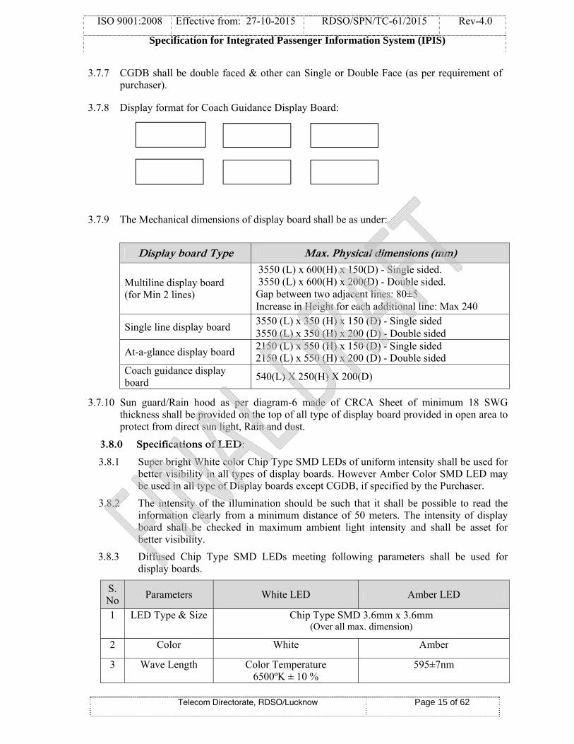
3.7.9 The Mechanical dimensions of display board shall be as under:
Display board Type Max. Physical dimensions (mm)
Multiline display board (for Min 2 lines)
3550 (L) x 600(H) x 150(D) - Single sided. 3550 (L) x 600(H) x 200(D) - Double sided. Gap between two adjacent lines: 80±5 Increase in Height for each additional line: Max 240
Single line display board 3550 (L) x 350 (H) x 150 (D) - Single sided 3550 (L) x 350 (H) x 200 (D) - Double sided
At-a-glance display board 2150 (L) x 550 (H) x 150 (D) - Single sided 2150 (L) x 550 (H) x 200 (D) - Double sided
Coach guidance display board
540(L) X 250(H) X 200(D)
3.7.10 Sun guard/Rain hood as per diagram-6 made of CRCA Sheet of minimum 18 SWG thickness shall be provided on the top of all type of display board provided in open area to protect from direct sun light, Rain and dust.
3.8.0 Specifications of LED:
3.8.1 Super bright White color Chip Type SMD LEDs of uniform intensity shall be used for better visibility in all types of display boards. However Amber Color SMD LED may be used in all type of Display boards except CGDB, if specified by the Purchaser.
3.8.2 The intensity of the illumination should be such that it shall be possible to read the information clearly from a minimum distance of 50 meters. The intensity of display board shall be checked in maximum ambient light intensity and shall be asset for better visibility.
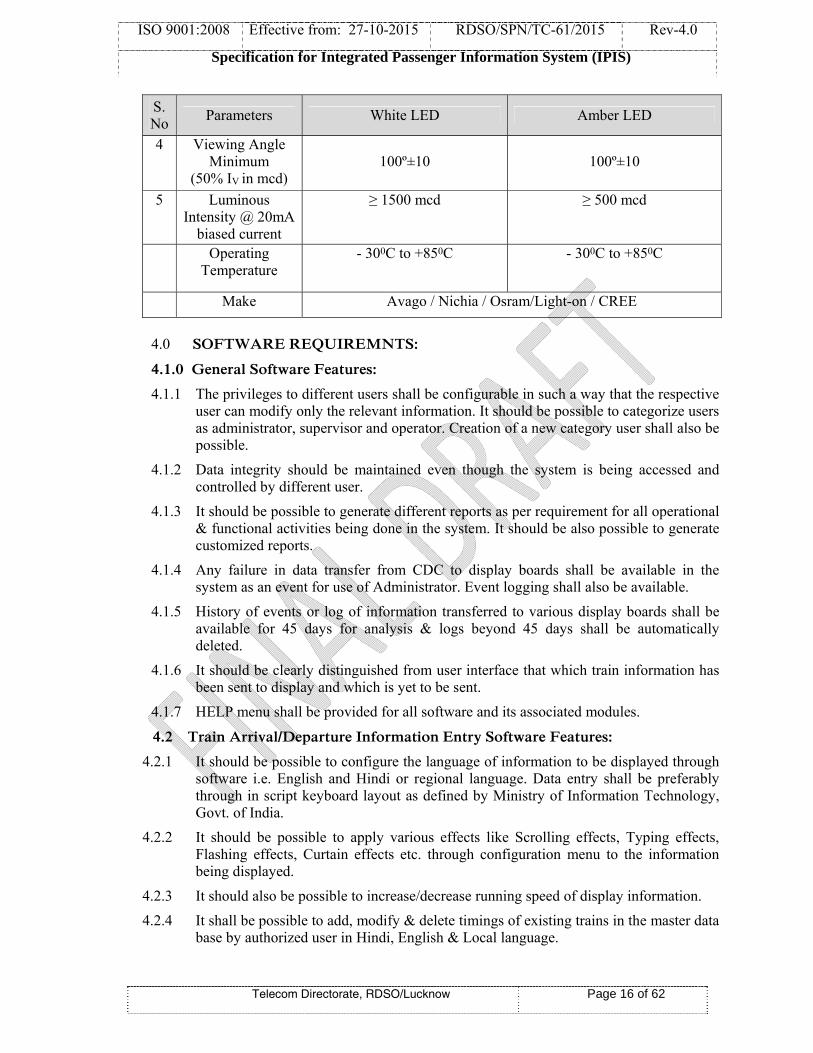
3.8.3 Diffused Chip Type SMD LEDs meeting following parameters shall be used for display boards.
S. No Parameters White LED Amber LED
1
LED Type & Size Chip Type SMD 3.6mm x 3.6mm (Over all max. dimension)
2 Color White Amber
3 Wave Length Color Temperature6500ºK ± 10 %
595±7nm
ISO 9001:2008 Effective from: 27-10-2015 RDSO/SPN/TC-61/2015 Rev-4.0
Specification for Integrated Passenger Information System (IPIS)
Telecom Directorate, RDSO/Lucknow Page 16 of 62
S. No
Parameters White LED Amber LED
4 Viewing Angle Minimum
(50% IV in mcd) 100º±10
100º±10
5 Luminous Intensity @ 20mA
biased current
≥ 1500 mcd ≥ 500 mcd
Operating Temperature
- 300C to +850C - 300C to +850C
Make Avago / Nichia / Osram/Light-on / CREE
4.0 SOFTWARE REQUIREMNTS:
4.1.0 General Software Features:
4.1.1 The privileges to different users shall be configurable in such a way that the respective user can modify only the relevant information. It should be possible to categorize users as administrator, supervisor and operator. Creation of a new category user shall also be possible.
4.1.2 Data integrity should be maintained even though the system is being accessed and controlled by different user.
4.1.3 It should be possible to generate different reports as per requirement for all operational & functional activities being done in the system. It should be also possible to generate customized reports.
4.1.4 Any failure in data transfer from CDC to display boards shall be available in the system as an event for use of Administrator. Event logging shall also be available.
4.1.5 History of events or log of information transferred to various display boards shall be available for 45 days for analysis & logs beyond 45 days shall be automatically deleted.
4.1.6 It should be clearly distinguished from user interface that which train information has been sent to display and which is yet to be sent.
4.1.7 HELP menu shall be provided for all software and its associated modules.
4.2 Train Arrival/Departure Information Entry Software Features:
4.2.1 It should be possible to configure the language of information to be displayed through software i.e. English and Hindi or regional language. Data entry shall be preferably through in script keyboard layout as defined by Ministry of Information Technology, Govt. of India.
4.2.2 It should be possible to apply various effects like Scrolling effects, Typing effects, Flashing effects, Curtain effects etc. through configuration menu to the information being displayed.
4.2.3 It should also be possible to increase/decrease running speed of display information.
4.2.4 It shall be possible to add, modify & delete timings of existing trains in the master data base by authorized user in Hindi, English & Local language.

ISO 9001:2008 Effective from: 27-10-2015 RDSO/SPN/TC-61/2015 Rev-4.0
Specification for Integrated Passenger Information System (IPIS)
Telecom Directorate, RDSO/Lucknow Page 17 of 62
4.2.5 The entry into Master Data Base should be password protected. It should be also possible to add data of new trains. There should be provision to change the password.
4.2.6 The operator should be able to make broadcast message by typing only train number and modification to timing and platform nos.
4.2.7 Mouse click should be used to transfer data from CDC to various Display Boards.
4.2.8 The information to be displayed at various boards shall be selected automatically only by selecting Train No. and platform No.
4.2.9 While deleting or modifying any train entry the software shall prompt the user before data transfer to display boards, so that the information at board always matches with monitor information.
4.2.10 The modified information shall be automatically saved as soon as it is transferred to the display board, so that in case of any failure the information data remains updated.
4.2.11 The Train Arrival/Departure information display system software should be developed on Windows based operating system using standard package
4.2.12 Software should provide pictorial representation of the tasks through ICONS.
4.2.13 Various ICONS shall represent applications which can be used by click of mouse.
4.2.14 Buttons with corresponding pop-up labels shall be available for the user to perform tasks. The user has to just click mouse on the button and the corresponding task shall be completed.
4.2.15 Command Buttons: This button shall be clicked to perform a command.
4.2.16 Check Box shall be used to turn ON/OFF a particular feature.
4.2.17 Data Communication, health status of display boards and data controller shall be available in CDC.
4.2.18 The Software should have provision to receive the data of Train information like train coach position and platform No. from control office or any other designated location. All these data should be integrated for making announcement and display of train arrival/ departure information on display boards and coach guidance system. However, there should be provision to manually enter coach position and platform number.
4.2.19 The software shall have provision to configure the number of lines present in the multiline display board.
4.2.20 If two Trains are merged to form a single Train at a particular station, it should be clearly indicated on display boards by showing No of both Train alternatively and shall be suitable announced on a PA system about the two merged Trains.
4.2.21 Display of train arrival/departure information display boards shall preferably be in the following format.

ISO 9
4.3.0
4.3.1
4.3.2
4.3.3
4.3.4
9001:2008
Spec
i. For
ii. For num
iii. For textdura
0 Softwa
1 The soarrivingdepart and po
2 It shallfrom ccentral
3 On the individplatform
4 Informrespect
Effective
cification fo
Telecom D
example, E
the types “mber is optio
the types “ts containination.
are Feature
ftware shoug or departfrom the stsition of co
l be possiblcentral serv server havi
e correspondual displaym.
mation displt for Coach
from: 27-1
for Integrat
Directorate, R
Expected Tim
“Running Ronal. For th
“Rescheduleng as show
e requirem
uld have preting from thtation, the caches i.e., f
le to acquirever of Coacing informa
nding platfoy boards (do
lay period No. & Trai
10-2015
ted Passeng
RDSO/Luckno
me is taken
Right Time”he rest, it is m
ed”, “Termiabove shal
ment for Co
eloaded infohe station. Wconcerned o
from ENGIN
e & update ch Operatioation of coac
orm the trainouble faced)
shall be prin number.
RDSO/S
ger Inform
ow
n as “05:30 H
”, “Runningmandatory.
inated at” al be display
oach Guid
ormation ofWhen the troperator is NE to GUA
data of coaon Informach composi
n coach po), installed f
rogrammab
SPN/TC-61/
ation Syste
Hrs” & plat
g Late” & “
and “Diverteyed alternat
ance Displ
f coach comrain is likelrequired to
ARD Brake V
aches for Ration Systemition.
sitions detafor display
ble from th
/2015
em (IPIS)
Page 18 o
tform numb
“Reschedule
ed” two septively with
lay Boards
mposition ofly to arrive o enter the Van
Rake formatim (COIS)
ails are dispof each coa
he control c
Rev-4.0
of 62
ber as “02”.
ed”, platfor
parate displaconfigurab
s:
f all the trainat station
train numb
ion of a traor any oth
played on thach across th
console wi
rm
ay ble
ns or er
ain her
he he
th

ISO 9001:2008 Effective from: 27-10-2015 RDSO/SPN/TC-61/2015 Rev-4.0
Specification for Integrated Passenger Information System (IPIS)
Telecom Directorate, RDSO/Lucknow Page 19 of 62
4.3.5 It should be possible to display data on Coach Guidance Display Boards in English & Hindi.
4.3.6 It should be possible to add, modify & delete coach composition of trains in the master database.
4.3.7 The entry into Master Data Base shall be password protected. It shall also be possible to add new trains. The operator shall be able to enter details by typing only train number and modification to coach nos.
4.3.8 While deleting or modifying any train entry on the monitor, the software shall prompt user before transferring data, so that the information at board always matches with monitor information.
4.3.9 The modified information shall be saved as soon as it is transferred to the display board, so that in case of any failure the information remains updated.
4.4.0 FEATURES OF ANNOUNCEMENT SYSTEM:
4.4.1 The system supplied shall be of Windows 7 or higher – GUI based fully programmed for the announcement of all type of passenger carrying trains through key board.
4.4.2 Fixed audio messages shall be recorded in soundproof sound studio and professional female voice with minimum 16 bit sample resolution.
4.4.3 It should be possible to make repeated announcements without affecting other operations. However for making a repeated announcement just by repeated pressing of keys shall not be possible until the initiated announcement is finished successfully or paused by the operator.
4.4.4 The format of the operation for the updating and announcement shall be user friendly.
4.4.5 Software shall be user friendly to the maximum extent so that addition and alterations can be done by the Railway Engineer without the help of suppliers and programmer. For any newly added train, it shall be possible to record a file externally and attached to the train through user interface. The application shall take care of placing the recorded file at appropriate internal application folder.
4.4.6 The system shall have provision to select messages and language to be broadcasted. The announcement shall be fluent and professional enough to avoid unnatural pauses between two pieces of voice clips.
4.4.7 The broadcast messages shall be categorized like courtesy, emergency messages. Recording & playback of new messages shall be possible only from CDC with microphone and speaker provided with CDC using Windows standard sound recording tool.
4.4.8 The entire voice recording shall be done in a sound proof professional studio. All the voice recording shall be of professional grade shall have approval of user railway before using in the systems.
4.4.9 It should be possible to select and play courtesy slogans. There should be provision to play any of the pre-recorded music & same could be started or interrupted by touching a single button.
4.4.10 Mainly there will be three types of announcements one for a train arriving on platform, one for train arrived on platform and one for train departing from platform in English, Hindi & a regional language. It should be possible to update announcement if Platform No./Train No. is changed .

ISO 9001:2008 Effective from: 27-10-2015 RDSO/SPN/TC-61/2015 Rev-4.0
Specification for Integrated Passenger Information System (IPIS)
Telecom Directorate, RDSO/Lucknow Page 20 of 62
4.4.11 Provision shall be made for the operator to send announcement related to train number, platform numbers, and arrival/ departure just by entering the train number, platform number and status in conditions.
i. Late arrival of trains.
ii. Platform No. of arriving/ arrived trains and change in platform No.
iii. Right time arrival of trains.
iv. Departure of trains at scheduled or unscheduled time.
v. Announce/display that trains is arriving/ departing shortly or terminated or
and Current status of the train.
vi. Cancellation of train
vii. Route Diversion of train
viii. Any other message required to be announced/ displayed regarding train
arrival/departure.
4.4.12 Format for online data entry screen for announcement & display of train’s details shall be preferably as per the diagram-3.
5.0 POWER SUPPLY:
5.1 Switch Mode Power Supply (SMPS) modules of standard make of suitable capacity working on AC source of 160V-270 Volts of appropriate current capacity shall be used in all types of display boards and control units. SMPS modules shall be of reputed make like Lambda, Meanwell etc. SMPS modules shall meet following requirements:
i. Suitable DC out-put may be selected depending upon type of display or controller used. The out- put voltage shall be within ±2% of the rated output voltage.
ii. Power supply module shall have input under voltage cut-off of 160VAC±10V & over voltage cut-off of 270V±10V AC.
iii. Power supply module shall have output over voltage cut-off at 5.75V DC
iv. Power supply output Ripple / Noise shall be less than 1% of rated output voltage.
v. Power supply module shall be protected against over/under voltage, short circuit and over load.
5.2 Overall load on power supply units shall not exceed more than 70% of rated capacity.
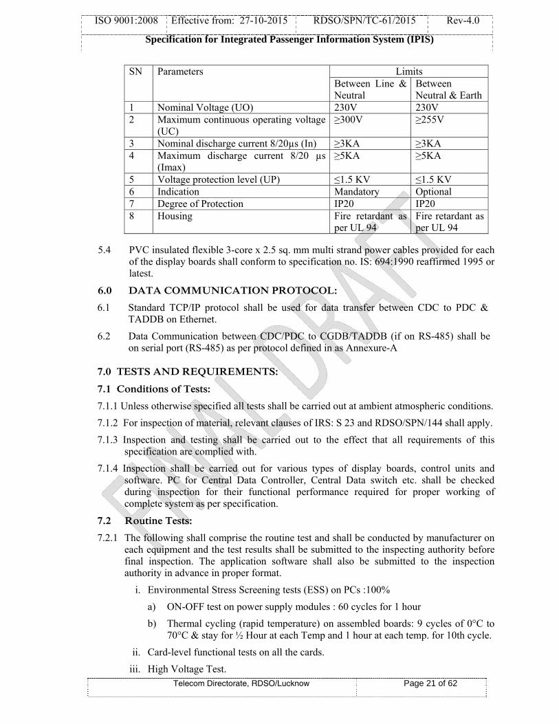
5.3 Suitable Class C surge protection shall be provided at input of the power supply to protect against transient voltages suspected in the power supply source shall be provided. The parameters of Class C protection device shall be as per clause no. 5.9 of specification no. RDSO/SPN/TC/98/2011, Rev.0 or latest. Applicable parameters are given below:-
ISO 9001:2008 Effective from: 27-10-2015 RDSO/SPN/TC-61/2015 Rev-4.0
Specification for Integrated Passenger Information System (IPIS)
Telecom Directorate, RDSO/Lucknow Page 21 of 62
SN Parameters Limits Between Line & Neutral
Between Neutral & Earth
1 Nominal Voltage (UO) 230V 230V 2 Maximum continuous operating voltage
(UC) ≥300V ≥255V
3 Nominal discharge current 8/20µs (In) ≥3KA ≥3KA 4 Maximum discharge current 8/20 µs
(Imax) ≥5KA ≥5KA
5 Voltage protection level (UP) ≤1.5 KV ≤1.5 KV6 Indication Mandatory Optional 7 Degree of Protection IP20 IP20 8 Housing Fire retardant as
per UL 94 Fire retardant as per UL 94
5.4 PVC insulated flexible 3-core x 2.5 sq. mm multi strand power cables provided for each of the display boards shall conform to specification no. IS: 694:1990 reaffirmed 1995 or latest.
6.0 DATA COMMUNICATION PROTOCOL:
6.1 Standard TCP/IP protocol shall be used for data transfer between CDC to PDC & TADDB on Ethernet.
6.2 Data Communication between CDC/PDC to CGDB/TADDB (if on RS-485) shall be on serial port (RS-485) as per protocol defined in as Annexure-A
7.0 TESTS AND REQUIREMENTS:
7.1 Conditions of Tests:
7.1.1 Unless otherwise specified all tests shall be carried out at ambient atmospheric conditions.
7.1.2 For inspection of material, relevant clauses of IRS: S 23 and RDSO/SPN/144 shall apply.
7.1.3 Inspection and testing shall be carried out to the effect that all requirements of this specification are complied with.
7.1.4 Inspection shall be carried out for various types of display boards, control units and software. PC for Central Data Controller, Central Data switch etc. shall be checked during inspection for their functional performance required for proper working of complete system as per specification.
7.2 Routine Tests:
7.2.1 The following shall comprise the routine test and shall be conducted by manufacturer on each equipment and the test results shall be submitted to the inspecting authority before final inspection. The application software shall also be submitted to the inspection authority in advance in proper format.
i. Environmental Stress Screening tests (ESS) on PCs :100%
a) ON-OFF test on power supply modules : 60 cycles for 1 hour
b) Thermal cycling (rapid temperature) on assembled boards: 9 cycles of 0°C to 70°C & stay for ½ Hour at each Temp and 1 hour at each temp. for 10th cycle.
ii. Card-level functional tests on all the cards.
iii. High Voltage Test.

ISO 9001:2008 Effective from: 27-10-2015 RDSO/SPN/TC-61/2015 Rev-4.0
Specification for Integrated Passenger Information System (IPIS)
Telecom Directorate, RDSO/Lucknow Page 22 of 62
iv. Insulation Resistance Tests (Clause 8.2)
v. Visual inspection of complete system
vi. Tests on power supply module
vii. Performance test
viii. System level functional tests.
ix. LED parameter test (Clause 8.7)
7.3 Acceptance Tests:
7.3.1 Following shall constitute the acceptance test which shall be carried out by the inspecting authority for the purpose of acceptance on 20% of the lots (minimum 2 each type of system) offered for inspection by the Firm:
i) High Voltage Test.
ii) Insulation Resistance Tests (Clause 8.2)
iii) Applied High Voltage Test (Clause 8.3)
iv) Visual inspection of complete system.
v) Tests on power supply module.
vi) Performance test
vii) System level functional tests.
viii) LED parameter test (Clause 8.7)
ix) Endurance Test (Clause 8.6.2)
7.3.2 Any other tests shall be carried out as considered necessary by the inspecting authority.
7.4 Type Tests:
7.4.1 For type test, one complete system consisting of all type of display boards shall be subjected to following tests as applicable:
i. Visual inspection (Clause 8.1)
ii. Insulation Resistance Test (Clause 8.2)
iii. Tests on power supply module.
iv. Applied High Voltage Test (Clause 8.3)
v. Environmental/ Climate Tests (Clause 8.4)
vi. Performance Test
vii. Endurance test (Clause 8.6.1)
viii. Card-level functional tests on all the cards.
ix. System level functional tests.
x. Test for interoperability
xi. LED parameter tests (Clause 8.7)
7.4.2 Separate 16x48 three-line single sided display boards with proper enclosure shall be fabricated for carrying out environmental & climatic tests. LED modules, processor cards, driver cards & power supply modules should be taken from multiline/ platform display board/AGDB on which functionality tests were carried out.

ISO 9001:2008 Effective from: 27-10-2015 RDSO/SPN/TC-61/2015 Rev-4.0
Specification for Integrated Passenger Information System (IPIS)
Telecom Directorate, RDSO/Lucknow Page 23 of 62
7.4.3 Following tests are to be carried out as per details given below:
Tests
Prototypes Display Boards Control / Interface
16x48 Three line single sided display board
PFD & AGDB Single/
Double Sided
CGDB
Multi-line PDC
Visual Inspection Yes Yes Yes Yes YesInsulation Resistance test Yes Yes Yes Yes YesApplied high voltage test Yes Yes Yes Yes YesEnvironmental/ Climatic test Yes No Yes No YesPerformance Test Yes Yes Yes Yes YesEndurance test Yes No Yes No YesCard/module functional tests Yes Yes Yes Yes YesSystem Level Functional Tests
Yes Yes Yes Yes Yes
LED parameter test Yes Yes Yes Yes No
7.4.4 Following systems shall be submitted to RDSO after type approval.
i) One number of 16 x 336 single line single sided display board.
ii) Two number of 16 x 48 double sided coach guided display boards (One, on which environmental testing has been conducted & one additional)
iii) One Platform Data Controller on which environmental testing has been conducted.
iv) Two sets of complete software in CD.
7.4.5 Only one complete system shall be type tested for this purpose. The system shall successfully pass all the type tests for proving conformity with this specification. If any one of the equipment fails in any of the type tests, the inspecting authority or his nominee at his discretion, may call for another equipment/ card(s) of the same type and subject it to all tests or the test(s) in which failure occurred. No failure shall be permitted in the repeat test(s).
7.4.6 Total system on which type tests are to be conducted shall consist of:
i. Two CPUs loaded with software, Central Data Switch and all other accessories
ii. One Platform Data Controller
iii. Single Line Platform Display Boards
iv. AGDB
v. One minimum 3-Line single sided Display Board
vi. Four Coach Guidance Display Boards
vii. One LCD/LED TV (minimum 32”) to test LED/LCD Display interface.
viii. Audio Amplifier with speaker
7.4.7 Any other test may be carried out as considered necessary by the inspecting authority.

ISO 9001:2008 Effective from: 27-10-2015 RDSO/SPN/TC-61/2015 Rev-4.0
Specification for Integrated Passenger Information System (IPIS)
Telecom Directorate, RDSO/Lucknow Page 24 of 62
8.0 TEST PROCEDURE:
The test procedure shall be based on the system design. The methodologies to be adopted for various tests shall be decided taking into account the system design/configuration.
8.1 Visual Inspection: Each equipment of the system shall be visually inspected to ensure compliance with
the requirement of clause 3 to 6 of this specification. The visual inspection shall broadly include:
8.1.1 System Level Checking:
i) Constructional details.
ii) Dimensional check.
iii) General workmanship.
iv) Configuration.
v) Mechanical polarization on cards.
8.1.2 Card Level Checking:
i) General track layout.
ii) Quality of soldering and component mounting.
iii) Conformal Coating.
iv) Legend printing.
8.1.3 Module Level Checking:
i) Indications and displays.
ii) Mounting and clamping of connectors.
iii) Proper housing of cards.
8.2 Insulation Resistance Test: - This test shall be carried out –
i. Before the high voltage test
ii. After the high voltage test
iii. After completion of the climatic test
There shall be no appreciable change (value more than 10 Mega ohms and variation within 10%) in the values measured before and after high voltage test. After the completion of climatic test, the values shall not be less than 10 Mega ohms for the equipment at a temperature of 400 C and relative humidity 60%. The measurement shall be made at a potential of 500V DC.
8.3 Applied High Voltage Test: - The equipment shall withstand for one minute without puncture and arcing, a test voltage applied between line terminal and earth as mentioned below:
(i) AC line terminals and earth, test voltage of 1500V AC
(ii) DC line terminals and earth, test voltage of 500V AC
The test voltage shall be alternating of approximately sinusoidal waveform of any frequency between 50 Hz and 100 Hz. Printed circuit cards shall be removed during the test

ISO 9001:2008 Effective from: 27-10-2015 RDSO/SPN/TC-61/2015 Rev-4.0
Specification for Integrated Passenger Information System (IPIS)
Telecom Directorate, RDSO/Lucknow Page 25 of 62
8.4 Environmental/ Climatic Tests:-
8.4.1 The various types of display boards and PDC shall be capable of working in non-air conditioned environment in the field.
8.4.2 The various types of display systems shall meet the following climatic and environmental requirements:
SN TEST REFERENCE1. Change of temp test IS 9000
Part XIV Sect. II
Low temp –10oC ± 3oCHigh temp +70oC ± 2oC
Rate of change in temperature
1oC / min
Duration 3 hrs at each temp. –10oC & +70oC Cycle 3
Condition Fully functional during test
2. Dry heat test IEC-571; IS:9000 Part-III Sect 3
Temp +70oC ± 2oC
Duration 16 hrs
Condition Fully functional during test3. Cold test IS 9000 Part II
Sect. III Temp –10oC ±3oC
Duration 2 hours
Condition Fully functional during test.4. Damp heat test (Cyclic) IS9000 Part V
Sect. 2 Variant 1Upper temp 40oC ±2oC
Humidity 95% (+1%, -5%)
Cycles 6
Condition Fully functional during one hour period towards end of each cycle. Stabilization shall be done at 25o ±3oC
5. Damp heat test (Steady state storage) IS9000 Part IV
Temp 40o ±2oC
Humidity 93% (+2%, -3%)
Severity 4 days
Condition Fully functional during test.

ISO 9001:2008 Effective from: 27-10-2015 RDSO/SPN/TC-61/2015 Rev-4.0
Specification for Integrated Passenger Information System (IPIS)
Telecom Directorate, RDSO/Lucknow Page 26 of 62
6. Salt mist test IS9000 Part XI procedure 3
Mist + Damp heat Procedure 3 (2 hours +22 hours)
Temp 35o ±3oC
Humidity 93% (+2%, -3%)
Hours 22
Cycle 3
Condition After this test, electrical parameters shall be monitored in addition to physical checks.
7. Dust test IS 9000 Part XII Duration 1hour
Condition After this test, electrical parameters shall be monitored in addition to physical checks.
8. Bump test IS 9000 Part VII, Sec. 2 PCBs/Modules/units in packed condition shall be subjected to
bump test as under: No of bumps 1000Peak acceleration 400m/s2
Pulse duration 6msNo of axes 3Condition After this test, electrical parameters shall
be monitored in addition to physical checks.
9. Vibration test QM-333
Up to &including 75Kgs. weight
Over 75Kgs.
Freq. Range 05-350 Hz 5-150 Hz
Amplitude ±6mm constant displacement or 15m/ sec.2
constant acceleration.
±6mm constant displacement or 15m/ sec.2 constant acceleration.
No. of axes 3 3
No of sweep cycle 20 10
Total duration 105 min/axis 105 min/axis
If resonance is observed
10 min at each resonant freq.
10 min at each resonant freq.
Condition After this test, electrical parameters shall be monitored in addition to physical checks.

ISO 9001:2008 Effective from: 27-10-2015 RDSO/SPN/TC-61/2015 Rev-4.0
Specification for Integrated Passenger Information System (IPIS)
Telecom Directorate, RDSO/Lucknow Page 27 of 62
8.5. The equipment shall comply with the requirements as specified in Clauses 3 to 8.
8.6 Endurance Test:
8.6.1 During type test, endurance test shall be conducted for continuous operation which shall be 168 hours at 600C burning for LED without giving any deterioration in light output.
8.6.2 During acceptance test, endurance test shall be conducted on complete system for continuous operation which shall be 48 hours at room temperature burning for LED without giving any deterioration in light output
8.7 LED Parameter Test:
8.7.1 The manufacturer shall submit the LED data sheets at the time of inspection. The parameters of LED shall be tested as per Clause No: 3.8.3 & procedure enclosed as Annexure-C. Samples shall be tested as follows:
i) For type test, 25 nos. of SMD type LEDs shall be tested from the lots used in manufacturing display boards.
ii) For acceptance test, 15 nos. of SMD type LEDs shall be tested from the lots used in manufacturing display boards.
iii) For routine test, one LED from a batch of 1000 LEDs shall be tested. If it fails, then total batch of LEDs shall be tested, of which if more than 1% of LEDs fails, then entire batch of LEDs shall be rejected.
9. QUALITY ASSURANCE:
9.1 All materials & workmanship shall be of good quality.
9.2 Since the quality of the equipment bears a direct relationship to the manufacturing process and the environment under which it is manufactured, the manufacturer shall ensure Quality Assurance Program of adequate standard.
9.3 Validation and system of monitoring of QA procedure shall form a part of type approval. The necessary plants, machineries and testing equipments required for production & quality assurance as per Scheduling of Technical Requirements (STR) shall be available with the manufacturer.
9.4 Firm to submit Bill of Material, its make & rating used in Type Test Sample.
10. MARKING & PACKING:
10.1 The following information shall be clearly marked at a suitable place on each equipment:
i. Name and Address of the manufacturer.
ii. Year of the manufacturer.
iii. Serial number of Equipment
iv. Specification number
v. Wiring diagram of the equipment to be shown on the side of the cover for ready reference.

ISO 9001:2008 Effective from: 27-10-2015 RDSO/SPN/TC-61/2015 Rev-4.0
Specification for Integrated Passenger Information System (IPIS)
Telecom Directorate, RDSO/Lucknow Page 28 of 62
10.2 The equipment and its sub-assemblies shall be packed in thermocole boxes and the empty spaces shall be filled with suitable filling material. Before keeping in the thermocole box, the equipment shall be wrapped with bubble sheet. The equipment shall be finally packed in a wooden case of sufficient strength so that it can withstand bumps and jerks encountered in a road/rail journey.
11. INFORMATION TO BE SUPPLIED BY THE MANUFACTURER: 11.1 The following documents in two sets should be supplied along with the system:
i) Mechanical drawings of each sub system/ rack. ii) Installation and maintenance manual incorporating trouble shooting exercises,
printed cards patterns, software etc. iii) Operating and troubleshooting manual. iv) Pre-commissioning check list.
12. INFORMATION TO BE SUPPLIED BY THE PURCHASER:
The purchaser should clearly indicate details of required items including hardware and software which shall mainly consist of following items as specified by him.
SN Description of the Item Quantity
1. Central Data Controller consisting of CPU with other accessories. One Set
2. Announcement recordings in digital format as per details given by Railways
One set
3. Type of data connectivity between PDC & Display Boards.
wired or wireless
4. Requirement of rain hood/sun guard for display boards to be provided in open area. Nos.
5. Software for announcement system, various types of display boards information management & LED/LCD PIS management
One set with system and one set of soft copy in CD for each station.
6. Central Data Switch One No. 7. Platform Data Controller As specified by purchaser8. Color of LEDs: White or Amber for display
boards other than CGDB. Note: i. Colour of CGDB should be only White.
ii. Unless otherwise specified by purchaser the colour should be white.
White /Amber
9. Multiline Display Boards of required lines (Single or Double sided and number of lines)
As specified by purchaser
10. Platform Display Board: (16x336) Single or double sided
As specified by purchaser
11. At A Glance Display Board: (32x192) Single or double sided
As specified by purchaser
12. Coach Guidance Display Boards As specified by purchaser13. LED/LCD TV As specified by purchaser

ISO 9001:2008 Effective from: 27-10-2015 RDSO/SPN/TC-61/2015 Rev-4.0
Specification for Integrated Passenger Information System (IPIS)
Telecom Directorate, RDSO/Lucknow Page 29 of 62
SN Description of the Item Quantity
15. Data Cable (in meters)(UTP CAT6 or higher grade) As specified by purchaser16. Power Cable and extension boards As specified by purchaser17. Any other items or features required by the
purchaser As specified by purchaser
13. TRAINING:
13.1 Onsite training shall be provided to the Railway staff which shall include complete assembly of the system through the use of various modules, integration of hardware with software and complete operation of the system.
14. DIAGRAMS:
Detailed construction diagrams of Cabinet, Multiline Display Board (single sided & double sided), Platform Display Board (single sided & double sided), Coach Guidance Display Board & Platform Data Controller etc. shall be approved by RDSO before starting manufacturing.

ISO 9001:2008 Effective from: 27-10-2015 RDSO/SPN/TC-61/2015 Rev-4.0
Specification for Integrated Passenger Information System (IPIS)
Telecom Directorate, RDSO/Lucknow Page 30 of 62
Annexure – A
DATA COMMUNICATION PROTOCOL
FOR
INTEGRATED PASSENGER INFORMATION SYSTEM (IPIS)
as per Specification No:
RDSO/SPN/TC-61/2015, Revision- 4.0

ISO 9001:2008 Effective from: 27-10-2015 RDSO/SPN/TC-61/2015 Rev-4.0
Specification for Integrated Passenger Information System (IPIS)
Telecom Directorate, RDSO/Lucknow Page 31 of 62
A.1 Scope:
This document defines networking and data communication protocol for Integrated Passenger Information System as per specification no: RDSO/SPN/TC/61/2015, Revision 4.0. This system consists of train arrival/departure Information display boards and Coach Guidance display boards with PC based Central Data Controller. The entire system data transmission and networking shall be built on Ethernet up to PDC /TADD or on Zig-Bee from PDC to TADD/CGDB & serial communication for PDC to CGDB existing TADD of previous version.
This protocol is applicable only for data transfer on RS-485. Standard TCP/IP protocol shall be used for data transfer to display devices connected on Ethernet.
A.2 Acronyms:
LED - Light Emitting Diode
CDC - Central Data Controller
PDC - Platform Data Controller
TADDB - Train Arrival and Departure Display Board
CGDB - Coach Guidance Display Board
MSB - Most Significant Bit
LSB - Least Significant Bit
CRC - Cyclic Redundancy Check
A.3 Overview:
Passenger information system shall consist of mainly two types of display boards, Train arrival/departure display boards placed at different places of a railway station and Coach Guidance display boards on each platform. The updated Data shall be sent to these display boards from central data controller.
The data to all the systems, both train arrival/departure information & coach composition are disseminated and routed through the network. All Platform Data controller are connected to the CDC through Central Data Switch and placed at suitable location of the platform. Each PDC disseminates data to both TADDB and CGDB on the respective platform.
The architecture and system block diagram can be referred in diagram-1 of specification.
A.4 Systems Description:
A.4.1 Central Data Controller (CDC): CDC provides complete control and data entry for IPIS. The CDC communicates with all systems connected in the network in the defined methods and protocol.
The CDC shall fulfil the following data communication functions.
i. Data send to TADDB & CGDB ii. Get Link Status of PDC,TADDB & CGDB
iii. Set and get the configuration of PDC, TADDB & CGDB iv. Soft Reset of PDC, TADDB & CGDB v. Clear Reset Status of PDC, TADDB & CGDB

ISO 9001:2008 Effective from: 27-10-2015 RDSO/SPN/TC-61/2015 Rev-4.0
Specification for Integrated Passenger Information System (IPIS)
Telecom Directorate, RDSO/Lucknow Page 32 of 62
A.4.1.1 Sending Data to TADDB (If on RS-485)
i) Data shall be divided into packet size of maximum 1 Kilobytes each ii) Each data packet shall have serial number. iii) The last data packet of specific data set shall be indicated. (It shall contain the status of last packet
sent.) iv) It shall identify the success response from the destination system. v) It shall identify the failure response (if any) from the various transmission stages and retransmit.
A.4.1.2 Sending Data to CGDB:
Coach Guidance Display Boards are required to display train number and coach number alternatively in synchronization. In order to achieve this, the following procedure is to be adopted.
i) Initially all the boards shall be stopped with STOP command. ii) Data to the respective boards shall be sent. iii) Then START command shall be sent to all the boards.
A.4.1.3 Get Link Status of TADDB, CGDB:
It shall also get the link status of TADDB and CGDB maintained in respective connected hubs.
A.4.1.4 Set and a Get the Configuration:
i) Set and Get the configuration for TADDB and CGDB: CDC shall send the command to set the display intensity value which can be varied with respect to the ambient light conditions. It shall set the time period for which the sent data is valid for displaying.
Get configuration shall send command to get the both set values of
1) Intensity 2) Data validity time.
ii) Set and Get the configuration for PDC: CDC shall send the command to set the Hub Port configuration table, which shall contain the information of CGDB identification numbers in relation to the port it is connected.
Get command shall get the Hub port configuration table stored in that Hub.
A.4.1.5 Soft Reset:
CDC shall send this command to PDC/TADDB/CGDB to reset itself and clear all the data content.
A.4.1.6 Clear Reset Status:
CDC shall send this command to PDC/TADDB/CGDB to clear reset status after identifying the reset state of it.
A.4.2 Platform Data Controller (PDC):
The PDC is the Data hub for all TADDB and CGDB in each platform. The PDC receives all the data and command packets from CDC and directs to its destination. The port to which the CGDB is connected is determined from the port configuration table. It responds to the command addressed to it. In the event of invalid packet, non-availability of port configuration table, invalid ID etc., the PDC shall report error to CDC.
ISO 9001:2008 Effective from: 27-10-2015 RDSO/SPN/TC-61/2015 Rev-4.0
Specification for Integrated Passenger Information System (IPIS)
Telecom Directorate, RDSO/Lucknow Page 33 of 62
The PDC shall fulfill the following data communication functions:
i) Validate packets. ii) Send packets to the respective port. iii) Send response for packets addressed to it. iv) Report error to PDC in case of any failure. v) Maintain the communication link status of all the systems connected. vi) Send Link status to PDC on request. vii) It shall poll CGDBs at regular intervals for its status. viii) It shall identify start/stop command packet and act on all the CGDBs connected. ix) It shall receive port configuration table from PDC and store in non-volatile memory.
A.4.3 Train Arrival Departure Display Board (TADDB) (if connected on RS-485):
The TADDB shall fulfill the following data communication functions.
i) Validate the packet received. ii) Report error in case of any failure. iii) Send Link status on request. iv) It shall receive configuration from CCU and store in non-volatile memory.
A.4.4 Coach Guidance Display Board (CGDB):
The CGDB shall fulfil the following data communication functions.
i) Validate the packet received. ii) Send response for packets addressed to it. iii) Report error in case of any failure. iv) Send Link status on request. v) It shall receive configuration from CCU and store in non-volatile memory.
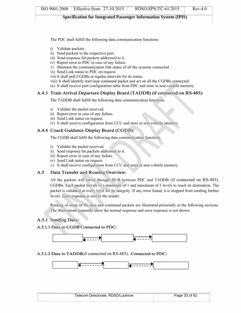
A.5 Data Transfer and Routing Overview:
All the packets will travel through HUB between PDC and TADDB (if connected on RS-485), CGDBs. Each packet travels to a minimum of 1 and maximum of 3 levels to reach its destination. The packet is validated at every level for its integrity. If any error found, it is stopped from sending further levels. Error response is sent to the sender.
Routing of some of the data and command packets are illustrated pictorially in the following sections. The illustrations generally show the normal response and error response is not shown.
A.5.1 Sending Data:
A.5.1.1 Data to CGDB Connected to PDC:
A.5.1.2 Data to TADDB(if connected on RS-485), Connected to PDC:

ISO 9001:2008 Effective from: 27-10-2015 RDSO/SPN/TC-61/2015 Rev-4.0
Specification for Integrated Passenger Information System (IPIS)
Telecom Directorate, RDSO/Lucknow Page 34 of 62
A.5.2 Stop:
A.5.2.1 Stop command to CGDBs Connected to PDC:
Stop is broadcast command. PDC send this command to all CGDB’s connected to it.
A.5.3 Start: A.5.3.1 Start command to CGDB Connected to PDC:
Start is broadcast command. PDC send this command to all CGDB’s connected to it.
A.5.4 Link Check:
A.5.4.1 Link Check Command from PDC to CGDB or TADDB (if connected on RS-485),
A.5.5 Soft Reset:
A.5.5.1 Soft Reset Command from CDC to CGDB:
A.5.6 Clear Reset Status:
A.5.6.1 Clear Reset Command from CDC to PDC:
A.6 Communication Packet Format:
6.1.1 Starting Flags To indicate the start of the packet/frame (2 bytes) (0xAA followed by 0x99)
6.1.2 Format Identifier
1st Byte: 0x00 -> Format identifier not used 1st Byte: 0x01 -> Packet generates response (command packet) 1st Byte: 0x02 -> Packet is for a 422 destination (CGDB) 1st Byte: 0x03 -> Ethernet packet for Ethernet destination 1st Byte: 0x04 to 0x07 for future use 2nd Byte: ‘A’ to ‘Z’ for future use
6.1.3 Length of Packet a) 1 Byte, when Format Identifier is not used. b) 2 Bytes, when Format Identifier is used.
6.1.4 Destination Address Destination unit address (2 bytes) 6.1.5 Source Address Originating unit address (2 bytes)

ISO 9001:2008 Effective from: 27-10-2015 RDSO/SPN/TC-61/2015 Rev-4.0
Specification for Integrated Passenger Information System (IPIS)
Telecom Directorate, RDSO/Lucknow Page 35 of 62
6.1.6 Sequence Number Sequence number of the packets originated (1 byte)
6.1.7 Data bytes Actual data of the packet - Max. 240 Bytes for 1-Byte LOP - Max. 1024 Bytes for 2-Byte LOP
6.1.8 CRC - CRC is 16-bit value. This is calculated as CRC of all the bytes starting from Length MSB to last byte stored in BLOCK 2. CRC-16-CCITT (also known as CRC-CCITT) is used for data integrity. The polynomial of CRC-16 is “x16+x12+x5+1” and its hex value is 1021.
A.6.2 BLOCK-1:
START:
Every command frame will be started with these two identifiers.
The identifiers are
1. $AA
2. $99
Format Identifier
1st Byte: 0x00 -> Format identifier not used 1st Byte: 0x01 -> Packet generates response (command packet) 1st Byte: 0x02 -> Packet is for a 422 destination (CGDB) 1st Byte: 0x03 -> Ethernet packet for Ethernet destination 1st Byte: 0x04 to 0x07 for future use 2nd Byte: A to Z for future use.
LENGTH:
a) 1 Byte, when Format Identifier is not used. b) 2 Bytes, when Format Identifier is used.
The LENGTH is represented either as 8 bit or as 16-bit value. It defines the no. of bytes in between Source MSB and CRC LSB, Including these two.
CONTROL FIELD:
(a) SOURCE (b) DESTINATION (c) SERIAL NUMBER
(a) SOURCE ADDRESS (2 Bytes): This bytes field signifies from where the command is originated. The assigned addresses are explained in destination address.
(b) DESTINATION ADDRESS (2 Bytes): This bytes field signifies “to where” the packet is sent. Most significant byte gives the address of all CDC, PDC and TADDB. Least significant byte gives the address of the CGDB and most significant
ISO 9001:2008 Effective from: 27-10-2015 RDSO/SPN/TC-61/2015 Rev-4.0
Specification for Integrated Passenger Information System (IPIS)
Telecom Directorate, RDSO/Lucknow Page 36 of 62
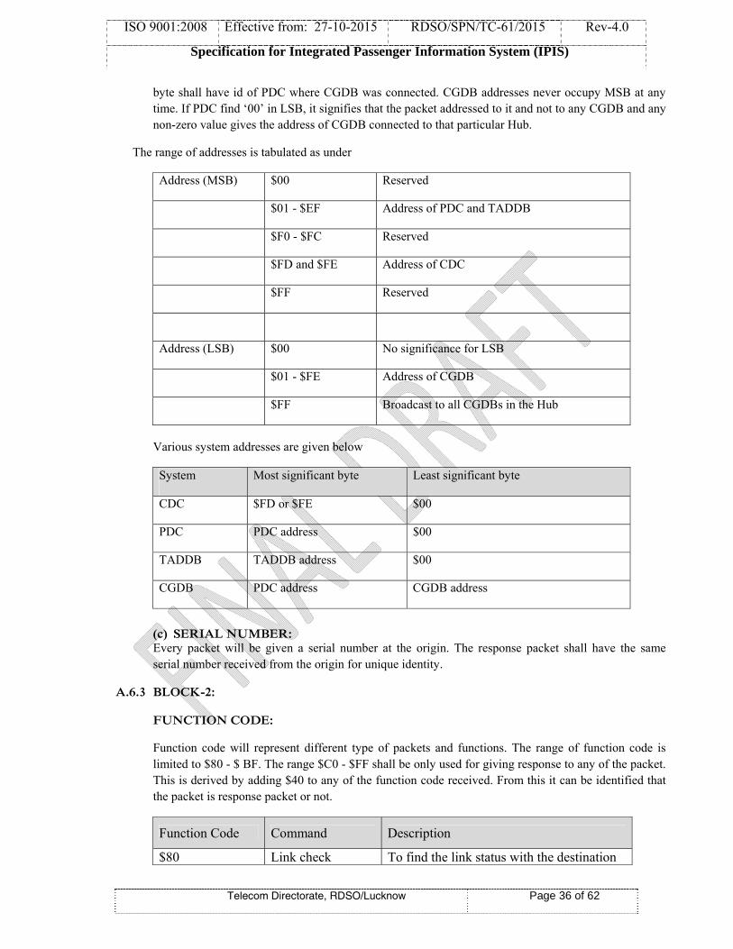
byte shall have id of PDC where CGDB was connected. CGDB addresses never occupy MSB at any time. If PDC find ‘00’ in LSB, it signifies that the packet addressed to it and not to any CGDB and any non-zero value gives the address of CGDB connected to that particular Hub.
The range of addresses is tabulated as under
Address (MSB) $00 Reserved
$01 - $EF Address of PDC and TADDB
$F0 - $FC Reserved
$FD and $FE Address of CDC
$FF Reserved
Address (LSB) $00 No significance for LSB
$01 - $FE Address of CGDB
$FF Broadcast to all CGDBs in the Hub
Various system addresses are given below
System Most significant byte Least significant byte
CDC $FD or $FE $00
PDC PDC address $00
TADDB TADDB address $00
CGDB PDC address CGDB address
(c) SERIAL NUMBER: Every packet will be given a serial number at the origin. The response packet shall have the same
serial number received from the origin for unique identity.
A.6.3 BLOCK-2:
FUNCTION CODE:
Function code will represent different type of packets and functions. The range of function code is limited to $80 - $ BF. The range $C0 - $FF shall be only used for giving response to any of the packet. This is derived by adding $40 to any of the function code received. From this it can be identified that the packet is response packet or not.
Function Code Command Description
$80 Link check To find the link status with the destination
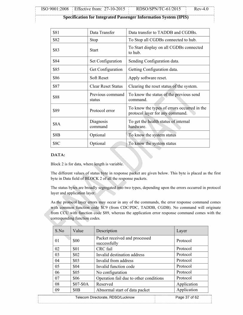
ISO 9001:2008 Effective from: 27-10-2015 RDSO/SPN/TC-61/2015 Rev-4.0
Specification for Integrated Passenger Information System (IPIS)
Telecom Directorate, RDSO/Lucknow Page 37 of 62
$81 Data Transfer Data transfer to TADDB and CGDBs.
$82 Stop To Stop all CGDBs connected to hub.
$83 Start To Start display on all CGDBs connected to hub.
$84 Set Configuration Sending Configuration data.
$85 Get Configuration Getting Configuration data.
$86 Soft Reset Apply software reset.
$87 Clear Reset Status Clearing the reset status of the system.
$88 Previous command status
To know the status of the previous send command.
$89 Protocol error To know the types of errors occurred in the protocol layer for any command.
$8A Diagnosis command
To get the health status of internal hardware.
$8B Optional To know the system status
$8C Optional To know the system status
DATA:
Block 2 is for data, where length is variable.
The different values of status byte in response packet are given below. This byte is placed as the first byte in Data field of BLOCK 2 of all the response packets.
The status bytes are broadly segregated into two types, depending upon the errors occurred in protocol layer and application layer.
As the protocol layer errors may occur in any of the commands, the error response command comes with common function code $C9 (from CDC/PDC, TADDB, CGDB). No command will originate from CCU with function code $89, whereas the application error response command comes with the corresponding function codes.
S.No Value Description Layer
01 $00 Packet received and processed successfully
Protocol
02 $01 CRC fail Protocol 03 $02 Invalid destination address Protocol 04 $03 Invalid from address Protocol 05 $04 Invalid function code Protocol 06 $05 No configuration Protocol 07 $06 Operation fail due to other conditions Protocol 08 $07-$0A Reserved Application 09 $0B Abnormal start of data packet Application

ISO 9001:2008 Effective from: 27-10-2015 RDSO/SPN/TC-61/2015 Rev-4.0
Specification for Integrated Passenger Information System (IPIS)
Telecom Directorate, RDSO/Lucknow Page 38 of 62
TABLE 1.0
A.6.4 BLOCK-3:
CRC:
This CRC is 16-bit value, and it is placed in the Block 3. This is calculated as CRC of all the bytes starting from Length MSB to last byte stored in BLOCK 2. CRC-16-CCITT (also known as CRC-CCITT) is used for data integrity. The polynomial of CRC-16 is “x16+x12+x5+1” and its hex value is 1021.
A.6.5 Link Check Command:
This command will originate from PDC-CGDB/TADDB (if on RS-485).
BLOCK-1
BLOCK-2 Function Code - $80
No Data Bytes
BLOCK-3
A.6.5.1 Response packet from PDC:
BLOCK-1
BLOCK-2 Function Code - $C0
N – Data Bytes
BLOCK-3
Response packet from PDC for a link check command shall have the BLOCK-2 in the under described structure.
First byte of the data shall be $00 for successful execution of the command.
Second byte of the data shall be status of the PDC as described in the Table 2.0.
From third byte onwards, status of all the systems connected to each of the port shall be placed in the following order. This shall cover all the ports of that particular PDC.
Port No – 1 No. of System Ids Id System Status
10 $0C Mismatch in serial number of data packet Application 11 $0D Internal buffer overflow Application 12 $0E Invalid data length Application 13 $1F Invalid data Application 14 $20 Internal write error Application 15 $21 Due to other conditions Application

ISO 9001:2008 Effective from: 27-10-2015 RDSO/SPN/TC-61/2015 Rev-4.0
Specification for Integrated Passenger Information System (IPIS)
Telecom Directorate, RDSO/Lucknow Page 39 of 62
Id System Status .. .. Port No – 2 No. of System Ids Id System Status Id System Status .. .. .. .. Port No – N No. of System Ids Id System Status Id System Status ..
All the ports, each port type connected to CGDB’s in multi drop, and all the system IDs connected through that port along with its status shall be placed.
System status shall be formed as described in table 2.0.
Bit position Significance
b7 1 = System Link ok 0 = System Link not ok
b6 1 = System in Reset State 0 = System in Normal state
b5-b4
00 = System configuration not available 01 = System configuration available 10 = System configuration with default values 11 = Not used
b3-b0 Not used
TABLE 2.0

ISO 9001:2008 Effective from: 27-10-2015 RDSO/SPN/TC-61/2015 Rev-4.0
Specification for Integrated Passenger Information System (IPIS)
Telecom Directorate, RDSO/Lucknow Page 40 of 62
A.6.5.2 Response packet from TADDB/CGDB:
BLOCK-1
BLOCK-2 Function Code - $C0
N – Data Bytes
BLOCK-3
BLOCK-2:
First byte of the data shall be $00 for successful execution of the command.
Second byte of the data shall be status of the TADDB/CGDB as described in the Table 2.0.
A.6.6 Data Transfer Command:
A.6.6.1 Sending Data to TADDB/CGDB:
This command will originate from CCU.
BLOCK-1
BLOCK-2 Function Code - $81
N – Data Bytes
BLOCK-3
Data shall be divided into packet size of maximum 1 Kilobytes each. Each packet shall start with the serial number 00 and continue to $FF. It shall also have the status to indicate that the packet is the last packet of the series or any more to succeed.
Data Packet shall have the following structure for BLOCK-2.
First byte shall indicate the serial number of the data packet. Ranging 00 - $FF.
Second byte shall have continuity status of the data packet.
$00 = No more packet in continuation to this.
$FF = Next packet to arrive in continuation to this.
Bit 0 of Third byte is to indicate whether to consider present data packet as normal or default data packet.
Bit 0 = 0 (Normal data)
Bit 0 = 1 (Default data)
Bit 1 to Bit 7 reserved for future use.
Default data means the data to be displayed on various display boards if no train data is available.

ISO 9001:2008 Effective from: 27-10-2015 RDSO/SPN/TC-61/2015 Rev-4.0
Specification for Integrated Passenger Information System (IPIS)
Telecom Directorate, RDSO/Lucknow Page 41 of 62
Structure of remaining bytes is given in the Display Data Structure section.
A.6.6.2 Response Packet from TADDB/CGDB:
BLOCK-1
BLOCK-2 Function Code - $C1
N – Data Bytes
BLOCK-3 BLOCK-2: Status byte as given in Table 1.0.
A.6.7 Stop Command: This command will originate from CDC.
BLOCK-1
BLOCK-2 Function Code - $82
No Data Bytes
BLOCK-3
This is broadcasting command, so there will be no Response packet.
A.6.8 Start Command: This command will originate from CDC.
BLOCK-1
BLOCK-2 Function Code - $83
No Data Bytes
BLOCK-3
This is broadcasting command, so there will be no Response packet.
A.6.9 Configuration Setting Command:
A.6.9.1 Set Configuration of TADDB/CGDB:
This command will originate from CDC.
BLOCK-1
BLOCK-2 Function Code - $84
N – Data Bytes
BLOCK-3
BLOCK-2:
Different values for the two data bytes available in the data field and their description is given in the following tables.
1st byte:

ISO 9001:2008 Effective from: 27-10-2015 RDSO/SPN/TC-61/2015 Rev-4.0
Specification for Integrated Passenger Information System (IPIS)
Telecom Directorate, RDSO/Lucknow Page 42 of 62
Data byte value Intensity
$00 25% Intensity
$01 50% Intensity
$02 75% Intensity
$03 100% Intensity
2nd byte: It gives the time out value of the data present on the TADDB/CGDB in minutes. Data on TADDB/CGDB will be cleared after this particular time.
A.6.9.2 Response Packet from TADDB/CGDB:
BLOCK-1
BLOCK-2 Function Code - $C4
N – Data Bytes
BLOCK-3
BLOCK-2: Status byte as given in Table 1.0.
A.6.9.3 Set Configuration Command for PDC:
Set configuration command originates from CDC.
BLOCK-1
BLOCK-2 Function Code - $84
N – Data Bytes
BLOCK-3
The values for configuration table are provided in the BLOCK-2 of command packet.
All the ports, each port connected to a single system or CGDB’s in multi drop, and all the system IDs connected through that port shall be formed in the following structure.
Port No – 1 No. of System Ids Id Id Id .. .. Port No – 2 No. of System Ids Id Id Id .. ..

ISO 9001:2008 Effective from: 27-10-2015 RDSO/SPN/TC-61/2015 Rev-4.0
Specification for Integrated Passenger Information System (IPIS)
Telecom Directorate, RDSO/Lucknow Page 43 of 62
Port Type No. of System Ids Id Id Id .. ..
Port number ranges 1 –8
A.6.9.4 Response packet from PDC:
BLOCK-1
BLOCK-2 Function Code - $C4
N – Data Bytes
BLOCK-3
BLOCK-2: Status byte as given in Table 1.0.
A.6.10 Command to Get Configuration:
A.6.9.1 command to Get configuration for PDC /TADDB/CGDB
This command will originate from CDC.
BLOCK-1
BLOCK-2 Function Code - $85
N – Data Bytes
BLOCK-3
A.6.10.2 Response packet from TADDB/CGDB:
BLOCK-1
BLOCK-2 Function Code - $C5
N – Data Bytes
BLOCK-3
BLOCK-2:
First byte of data shall be $00 for successful execution of the command. Second Byte:
Data byte value Description
$01 System configuration available
$02 System configuration with default values
$03 No configuration
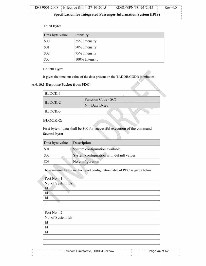
ISO 9001:2008 Effective from: 27-10-2015 RDSO/SPN/TC-61/2015 Rev-4.0
Specification for Integrated Passenger Information System (IPIS)
Telecom Directorate, RDSO/Lucknow Page 44 of 62
Third Byte:
Data byte value Intensity
$00 25% Intensity
$01 50% Intensity
$02 75% Intensity
$03 100% Intensity
Fourth Byte:
It gives the time out value of the data present on the TADDB/CGDB in minutes.
A.6.10.3 Response Packet from PDC:
BLOCK-1
BLOCK-2 Function Code - $C5
N – Data Bytes
BLOCK-3
BLOCK-2:
First byte of data shall be $00 for successful execution of the command Second byte:
Data byte value Description
$01 System configuration available
$02 System configuration with default values
$03 No configuration
The remaining bytes are from port configuration table of PDC as given below:
Port No – 1 No. of System Ids Id Id Id .. .. Port No – 2 No. of System Ids Id Id Id .. ..
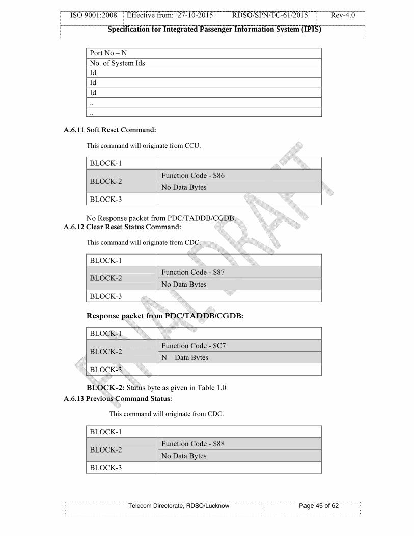
ISO 9001:2008 Effective from: 27-10-2015 RDSO/SPN/TC-61/2015 Rev-4.0
Specification for Integrated Passenger Information System (IPIS)
Telecom Directorate, RDSO/Lucknow Page 45 of 62
Port No – N No. of System Ids Id Id Id .. ..
A.6.11 Soft Reset Command:
This command will originate from CCU.
BLOCK-1
BLOCK-2 Function Code - $86
No Data Bytes
BLOCK-3 No Response packet from PDC/TADDB/CGDB.
A.6.12 Clear Reset Status Command:
This command will originate from CDC.
BLOCK-1
BLOCK-2 Function Code - $87
No Data Bytes
BLOCK-3
Response packet from PDC/TADDB/CGDB:
BLOCK-1
BLOCK-2 Function Code - $C7
N – Data Bytes
BLOCK-3
BLOCK-2: Status byte as given in Table 1.0 A.6.13 Previous Command Status:
This command will originate from CDC.
BLOCK-1
BLOCK-2 Function Code - $88
No Data Bytes
BLOCK-3

ISO 9001:2008 Effective from: 27-10-2015 RDSO/SPN/TC-61/2015 Rev-4.0
Specification for Integrated Passenger Information System (IPIS)
Telecom Directorate, RDSO/Lucknow Page 46 of 62
Response packet from PDC/TADDB/CGDB:
BLOCK-1
BLOCK-2 Function Code - $C8
N – Data Bytes
BLOCK-3
BLOCK-2: 1st byte is the Status byte, as given in Table1.0.
2nd byte indicates whether previous serial number status is available or not.
00 – Status available
FF- Not available
3rd byte gives previous command serial number.
4th byte gives previous function code.
A.6.14 Protocol Error Command:
This command will originate from PDC/TADDB/CGDB.
BLOCK-1
BLOCK-2 Function Code - $C9
N – Data Bytes
BLOCK-3
BLOCK-2: 1st byte is the Status byte (error code), as given in Table1.0.
2nd & 3rd bytes state the record length of received command with protocol error.
4th, 5th, 6th & 7th bytes indicate the source and destination bytes of the received command with protocol error.
8th & 9th bytes indicate the serial number and function code of the received command with protocol error.
A.6.15 Diagnosis Command:
This command will originate from CDC.
BLOCK-1
BLOCK-2 Function Code - $8A
No Data Bytes
BLOCK-3

ISO 9001:2008 Effective from: 27-10-2015 RDSO/SPN/TC-61/2015 Rev-4.0
Specification for Integrated Passenger Information System (IPIS)
Telecom Directorate, RDSO/Lucknow Page 47 of 62
Response packet from PDC/TADDB/CGDB:
BLOCK-1
BLOCK-2 Function Code - $CA
N – Data Bytes
BLOCK-3
BLOCK-2: 1st byte is the Status byte, as given in Table 1.0.
2nd byte is the manufacturer ID.
The values of N data bytes should be produced at the time of RDSO approval, because the hardware design may vary from manufacturer to manufacturer.
A.6.16 Optional Command:
This command shall not be used for display application related activities, it may be used for internal diagnostic test or any similar activities not related with its actual application.
This command will originate from CDC.
BLOCK-1
BLOCK-2 Function Code - $8B / $8C
N – Data Bytes
BLOCK-3
Response packet from PDC/TADDB/CGDB:
BLOCK-1
BLOCK-2 Function Code - $CB
N – Data Bytes
BLOCK-3
BLOCK-2: 1st byte is the Status byte, as given in Table 1.0.
2nd byte is the manufacturer ID.
The values of N data bytes should be produced at the time of RDSO approval, because the design may be vary from manufacturer to manufacturer.
A.7 DISPLAY DATA STRUCTURE:
(SAMPLE PACKET with relevant field properly marked so that there is a single interpretation for this structure.)

ISO 9001:2008 Effective from: 27-10-2015 RDSO/SPN/TC-61/2015 Rev-4.0
Specification for Integrated Passenger Information System (IPIS)
Telecom Directorate, RDSO/Lucknow Page 48 of 62
The TADDB or CGDB is an arrangement of sheet of LED dots (shown in the Figure-1). Along with the display data, some other attributes are also need to be specified. The necessary details are described under. The position where data need to be dumped is specified as a window .The dimension of the window is defined in 4 words. The window specifies the left column, right column, top row and bottom row as its dimension to which it is bounded. The row number starts from the bottom row of the display and increases towards top row. The Column number starts from leftmost and increase towards rightmost column. Pictorial representation of window is given in Figure-2.
To manage variable length of the character data, only the address is stated and the data is set aside in the specified address.
Byte No.
Bit Position Parameter Possible range Remarks
1 – 2 b15 – b0 Window Left column (2 bytes)
Varies with board size MSB first, LSB next
3 – 4 b15 – b0 Window Right column (2 bytes)
Varies with board size MSB first, LSB next
5 – 6 b15 – b0 Window Top Row (2 bytes)
Varies with board size MSB first, LSB next
7 – 8 b15 – b0 Window Bottom Row (2 bytes)
Varies with board size MSB first, LSB next
9
b7 Reverse Video 0 or 1 0 = Normal 1 = Reverse video
b6 – b3 Not used –
b2 – b0 Speed $00 – $04 The dumping speed of the Characters on display board. As per TABLE-1.2
10 b7 – b4 Not used
b3 – b0 Effect code $00 – $08 As per TABLE-1.3
11
b7 – b6 Not used
b5 – b3 Letter size $00 – $05 As per TABLE-1.4
b2 – b0 Gap $00 – $07 Space in between character to character
12 b7 – b0 Delay $00 – $FF No. of seconds the current message shall remain on the display.
13 b15 – b0 Address of Character string
(MSB first, LSB next) Offset Address where the character codes aside. This address is relative to the starting address of display data structure. & the starting address of the display data structure is zero
…
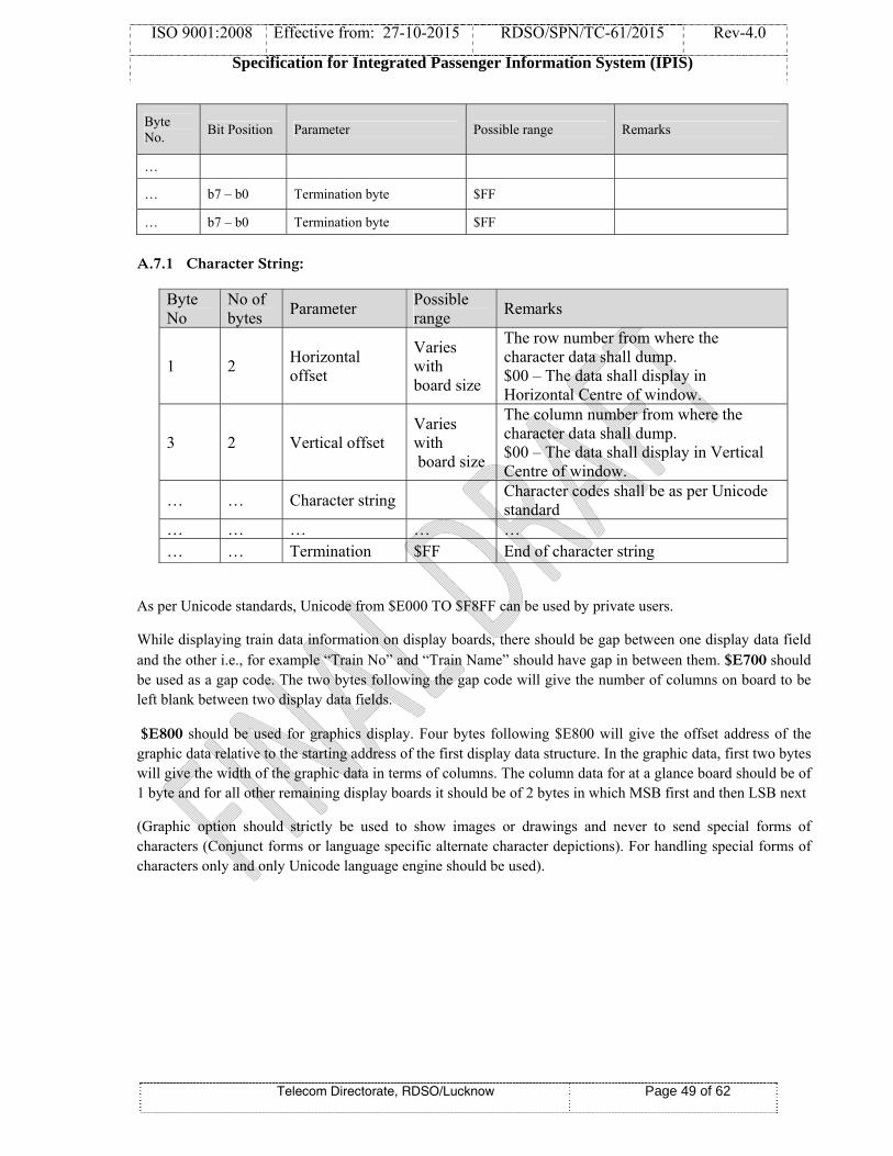
ISO 9001:2008 Effective from: 27-10-2015 RDSO/SPN/TC-61/2015 Rev-4.0
Specification for Integrated Passenger Information System (IPIS)
Telecom Directorate, RDSO/Lucknow Page 49 of 62
Byte No.
Bit Position Parameter Possible range Remarks
…
… b7 – b0 Termination byte $FF
… b7 – b0 Termination byte $FF
A.7.1 Character String:
Byte No
No of bytes
Parameter Possible range
Remarks
1 2 Horizontal offset
Varies with board size
The row number from where the character data shall dump. $00 – The data shall display in Horizontal Centre of window.
3 2 Vertical offset Varies with board size
The column number from where the character data shall dump. $00 – The data shall display in Vertical Centre of window.
… … Character string Character codes shall be as per Unicode standard
… … … … … … … Termination $FF End of character string
As per Unicode standards, Unicode from $E000 TO $F8FF can be used by private users.
While displaying train data information on display boards, there should be gap between one display data field and the other i.e., for example “Train No” and “Train Name” should have gap in between them. $E700 should be used as a gap code. The two bytes following the gap code will give the number of columns on board to be left blank between two display data fields.
$E800 should be used for graphics display. Four bytes following $E800 will give the offset address of the graphic data relative to the starting address of the first display data structure. In the graphic data, first two bytes will give the width of the graphic data in terms of columns. The column data for at a glance board should be of 1 byte and for all other remaining display boards it should be of 2 bytes in which MSB first and then LSB next
(Graphic option should strictly be used to show images or drawings and never to send special forms of characters (Conjunct forms or language specific alternate character depictions). For handling special forms of characters only and only Unicode language engine should be used).

ISO 9
9001:2008
Spec
Effective
cification fo
Telecom D
from: 27-1
for Integrat
Directorate, R
10-2015
ted Passeng
RDSO/Luckno
RDSO/S
ger Inform
ow
SPN/TC-61/
ation Syste
/2015
em (IPIS)
Page 50 o
Rev-4.0
of 62
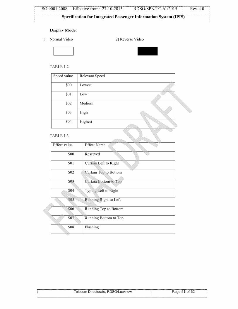
ISO 9001:2008 Effective from: 27-10-2015 RDSO/SPN/TC-61/2015 Rev-4.0
Specification for Integrated Passenger Information System (IPIS)
Telecom Directorate, RDSO/Lucknow Page 51 of 62
Display Mode:
1) Normal Video 2) Reverse Video
TABLE 1.2
Speed value Relevant Speed
$00 Lowest
$01 Low
$02 Medium
$03 High
$04 Highest
TABLE 1.3
Effect value Effect Name
$00 Reserved
$01 Curtain Left to Right
$02 Curtain Top to Bottom
$03 Curtain Bottom to Top
$04 Typing Left to Right
$05 Running Right to Left
$06 Running Top to Bottom
$07 Running Bottom to Top
$08 Flashing

ISO 9001:2008 Effective from: 27-10-2015 RDSO/SPN/TC-61/2015 Rev-4.0
Specification for Integrated Passenger Information System (IPIS)
Telecom Directorate, RDSO/Lucknow Page 52 of 62
TABLE 1.4
Available letter sizes for English language.
Size value Size
$00 7
$01 8
$02 10
$03 12
$04 14
$05 16
Note: Only 16 size font is available for Hindi & other regional languages.
A.8 Communication Speeds:
Between CDC and Central Data switch - 57600 bps
Between PDC and TADDB/CGDB - 19200 bps
Data length - 8 bits
Stop bits - 1 bit
Parity - None
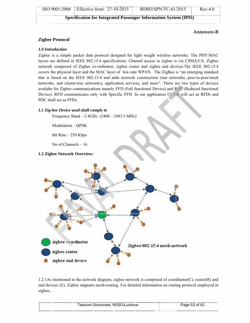
ISO 9
Zigbee
1.0 IntroZigbee ilayers arnetworkcovers ththat is bnetworkavailabeDevice)PDC sha
1.1 Zig-b
1.2 Zigb
1.2.1As end devizigbee, .
9001:2008
Spec
Protocol
oduction is a simple re defined in
k composed he physical lbased on the
ks, and clustee for Zigbee . RFD commall act as FFD
bee Device uFrequency B
Modulation
Bit Rate – 2
No of Chann
bee Network
mentioned iices (E). Zig.
Effective
cification fo
Telecom D
packet data n IEEE 802.of Zigbee clayer and thee IEEE 802er-tree netwcommunicat
municates onDs.
used shall coBand – 2.4GH
– QPSK
50 Kbps
nels – 16
k Overview:
in the networgbee supports
from: 27-1
for Integrat
Directorate, R
protocol de.15.4 specifico-ordinator,e MAC layer.15.4 and ad
works), applictions namelynly with Spe
omply to Hz (2400 – 2
rk diagram, zs mesh-routin
10-2015
ted Passeng
RDSO/Luckno
esigned for lcations. Cha, zigbee rour of low-ratdds networkcation servic
y FFD (Full fecific FFD. I
2483.5 MHz
zigbee netwong. For detai
RDSO/S
ger Inform
ow
light weight annel access uter and zigbte WPAN. Tk constructioces, and morfunctional DIn our appli
z)
ork is compriled informat
SPN/TC-61/
ation Syste
wireless nein zigbee is
bee end devThe ZigBee ion (star netwre”. There aevice) and Rcation CGD
rised of coordtion on routi
/2015
em (IPIS)
Page 53 o
A
etworks. Thes via CSMAvices.The IEEis “an emerg
works, peer-tare two typeRFD (ReduceDB will act a
dinator(C), ring protocol
Rev-4.0
of 62
nnexure-B
e PHY/MACA/CA. Zigbee
EE 802.15.4ging standardto-peer/mesh
es of devicesed functionalas RFDs and
router(R) andemployed in
B
C e 4 d h s l d
d n

ISO 9001:2008 Effective from: 27-10-2015 RDSO/SPN/TC-61/2015 Rev-4.0
Specification for Integrated Passenger Information System (IPIS)
Telecom Directorate, RDSO/Lucknow Page 54 of 62
1.2.2 Coordinator: Always first coordinator need to be installed for establishing Zigbee network service, it starts a new PAN (Personal Area Network), once started other Zigbee components viz. router(R) and End devices(E) can join the network(PAN). . 1.2.3 Router: First router needs to join the network then it can allow other R & E to join the PAN. 1.2.4 End Devices: It cannot allow other devices to join the PAN nor can it assist in routing the data through the network.
1.3 Forming the Zigbee Network
• Coordinator searches for suitable RF channel which is usable and not interfering with Wireless LAN frequencies in use. This is because WLAN also operates in the same 2.4GHz bands. This is done on all the 16 channels. It is also referred as energy scan. • Coordinator starts the network by assigning a PAN ID to the network. Assignment is done in two ways. Manual (pre configured) and dynamic (obtained by checking other PAN IDs of networks already in the operation nearby so that PAN ID does not conflict with other networks). Here Coordinator also assigns network address to itself i.e. 0x0000. • Now coordinator completes its configuration and is ready to accept network joining request queries from routers and end devices who wish to join the PAN.
In addition to above, Coordinator(C) sends broadcast beacon request frame on remaining quiet channel. This is also referred as beacon scan or PAN scan. By this Coordinator receives PAN ID of routers(R) and end devices(E) present nearby. It also comes to know whether R/E allow join or not.
Now R/E can join by sending association request to C. C will respond with association response.
1.4 Joining the Zigbee Network Let us examine how a router or end device joins zigbee network .There are two ways to join a zigbee network viz. MAC association and network re-join. First one is implemented by device underlying MAC layer and second one is implemented by network layer, despite the name may also be used to join a network for the first time. MAC association can be performed between C and R/E or R and E or R and other R. - Let us assume that Coordinator(C) has already established the PAN network. Hence next step for R or E is to find out whether C is allowing joining or not. So they do PAN scan or send beacon request frame. They will join network & form PAN
1.5 Protocol Data Frame Format
As mentioned in the zigbee protocol stack that zigbee MAC layer frame composed of MAC header,MAC
payload and FCS. The diagram below depicts generic mac frame format adopted in zigbee technology at
MAC layer. This part is also referred as MPDU or MAC Protocol Data Unit. This gets embedded into
PPDU(physical PDU) frame of zigbee.
1.6 Generic MAC Frame format
Octets:2 1 0/2 0/2/8 0/2 0/2/8 Variable 2
Frame control
Sequence number
Destination PAN ID
Destination Address
Source PAN ID
Source Address
Frame Payload
FCS
Addressing fields
MHR MAC Payload
MFR

ISO 9001:2008 Effective from: 27-10-2015 RDSO/SPN/TC-61/2015 Rev-4.0
Specification for Integrated Passenger Information System (IPIS)
Telecom Directorate, RDSO/Lucknow Page 55 of 62
Generic MAC layer frame has frame control field of 2 octets. It carries useful information such as frame
type, source and destination addressing modes. Frame type specifies whether the frame is beacon
frame,data frame, ACK of data, MAC command frame etc. The same is outlined 'Frame type subfield'
table below with 3 bits.
1.7 Frame control field
Bits:
0-2 3 4 5 6 7-9 10-11 12-13 14-15
Frame
type
security
enabled
Frame
pending
Ack.
Request
Intra
PAN Reserved
Dest.
Addressing
mode
Reserved
Source
Addressing
mode
1.8 Frame type subfield
Frame type value(b2,b2,b0) Description
000 Beacon frame
001 Data frame
010 Acknowledgement
011 MAC command
100-111 Reserved
As shown below beacon frame carries frame control field and addressing fields along with sequence
number. It is broadcasted to obtain PAN ID of nearby zigbee devices.
1.9 Beacon Frame format
Octets:2 1 4/10 2 variable variable variable 2
Frame
control
sequence
number
Addressing
fields
Superframe
specification
GTS
fields
Pending
address fields
Beacon
payloadFCS
MHR MAC Payload MFR
Once connection is established data frame carry data. The format of data frame is similar to generic mac
frame format and is shown in the table below.
1.10 Data Frame format
Octets:2 1 section 7.2.2.2.1
IEEE 802.15.4 Variable 2
Frame control sequence number Addressing fields Data Payload FCS
MHR MAC Payload MFR
Acknowledgement Frame format

ISO 9001:2008 Effective from: 27-10-2015 RDSO/SPN/TC-61/2015 Rev-4.0
Specification for Integrated Passenger Information System (IPIS)
Telecom Directorate, RDSO/Lucknow Page 56 of 62
Octets:2 1 2
Frame control sequence number FCS
MHR MFR
1.11 MAC command Frame format
Octets:2 1 Section 7.2.2.4.1
IEEE 802.15.41 Variable 2
Frame
control
sequence
number
Addressing
fields
Command Frame
IdentifierCommand Payload FCS
MHR MAC Payload MFR
Zigbee protocol supports different command frames for difference use case as mentioned below in the
table.
1.12 MAC command frames
Command Frame ID Command frame
0x01 Association request(Tx)
0x02 Association response(Rx)
0x03 Disassociation notification(Tx,Rx)
0x04 Data request(Tx)
0x05 PAN ID conflict notification(Tx)
0x06 Orphan notification(Tx)
0x07 Beacon request(Tx)
0x08 coordinator realignment(Rx)
0x09 GTS Request
0x0a-0xFF Reserved
*******

ISO 9
Pro
A-
A.3.1
A.3.2
A.3.3
A.3.4
A.3.5
A.4
A.5
A.5.1
A.5.2
A.5.3
A.5.4
Intensi
9001:2008
Spec
ocedure fo
Measurem
Typical se
Connect t
Bias the L
Adjust thdiffuser to
Place the indicated records m
Rotate thof the vadegrees. Cto half inopposite Lux valurotation in
Calculatio
Disp
Intensity M
Connect t
Bias the L
Adjust th
Use the Cthe patterthe Lux oLED in L
ity of LED
Effective
cification fo
Telecom D
or LED Pa
ment of Vie
etup diagram
the LED un
LED such th
he distance o 10 cm exa
Chromo min the set
maximum Lu
e LED in Halue that wCalculate th
ntensity valudirection fre observed n degrees fr
on of dispe
persion Ang
Measurem
the LED un
LED such th
e distance b
Chromo metrn formed oobserved at Lux.
D (mcd) = 9
from: 27-1
for Integrat
Directorate, R
rameter m
ewing Ang
m is show b
nder test as s
hat the rated
between thactly.
meter or Spectup. Rotate ux. Record
Horizontal (Xas observed
he degrees tue. Record
from the mais half the
rom maxim
ersion Ang
gle= θa + θb
ment of LED
nder test as s
hat the rated
between the
ter or Specton the white
the center
92.9*Lux va
10-2015
ted Passeng
RDSO/Luckno
measuremen
le of LED
below:
shown in th
d current flo
he tip of th
ctrometer tothe LED this value a
X-directiond in the clathe LED wathis value i
aximum intvalue to th
mum Lux val
gle:
b
D:
shown in th
d current flo
e tip of the L
trometer to e board dueof the Patte
alue observe
RDSO/S
ger Inform
ow
nt:
:
he above set
ows in the L
e LED and
o measure thso that theand position
n) to a pointause 4.3.4. as rotated fris as θa (Thtensity valuhe one obselue and reco
he above set
ows in the L
LED and wh
measure the the illuminern on the w
ed.
SPN/TC-61/
ation Syste
t up in a dar
LED under t
d Chromo m
he intensitye chromo mn of LED in
, at which tRecord th
rom the maxheta). Similaue and markerved in theord this valu
up in a dar
LED under t
hite board to
e intensity ination of th
white board
/2015
em (IPIS)
Page 57 o
ANNE
rk room.
test.
meter or Sp
y in Lux in tmeter or Sp
degrees.
the Lux reade position ximum intearly rotate tk the point e center. Caue as θb.
rk room.
test.
o 30 cm exa
in Lux at thhe LED. Thd is the inten
Rev-4.0
of 62
EXURE-C
pectrometer
the position pectrometer
ding is half of LED in
ensity value the LED in
where the alculate the
actly.
he center of he Value of nsity of the
C
f
ff

ISO 9
9001:2008
Spec
Effective
cification fo
Telecom D
from: 27-1
for Integrat
Directorate, R
10-2015
ted Passeng
RDSO/Luckno
RDSO/S
ger Inform
ow
SPN/TC-61/
ation Syste
/2015
em (IPIS)
Page 58 o
Rev-4.0
of 62

ISO 9
9001:2008
Spec
Effective
cification fo
Telecom D
from: 27-1
for Integrat
Directorate, R
10-2015
ted Passeng
RDSO/Luckno
RDSO/S
ger Inform
ow
SPN/TC-61/
ation Syste
/2015
em (IPIS)
Page 59 o
Rev-4.0
of 62

ISO 9
9001:2008
Spec
Effective
cification fo
Telecom D
from: 27-1
for Integrat
Directorate, R
10-2015
ted Passeng
RDSO/Luckno
RDSO/S
ger Inform
ow
SPN/TC-61/
ation Syste
/2015
em (IPIS)
Page 60 o
Rev-4.0
of 62

ISO 9
9001:2008
Spec
Effective
cification fo
Telecom D
from: 27-1
for Integrat
Directorate, R
10-2015
ted Passeng
RDSO/Luckno
RDSO/S
ger Inform
ow
SPN/TC-61/
ation Syste
/2015
em (IPIS)
Page 61 o
Rev-4.0
of 62

ISO 9
9001:2008
Spec
Effective
cification fo
Telecom D
from: 27-1
for Integrat
Directorate, R
10-2015
ted Passeng
RDSO/Luckno
RDSO/S
ger Inform
ow
SPN/TC-61/
ation Syste
/2015
em (IPIS)
Page 62 o
Rev-4.0
of 62
Top Related
Copyright © 2022 FDOKUMEN

