


Bahasa
Halaman
Hukum

In situ measurement of soil moisture: a comparison
of techniques
Jeffrey P. Walker*, Garry R. Willgoose1, Jetse D. Kalma
Department of Civil, Surveying and Environmental Engineering, The University of Newcastle, Callaghan, NSW 2308, Australia
Received 3 December 2002; revised 19 January 2004; accepted 23 January 2004
Abstract
A number of automated techniques for point measurement of soil moisture content have been developed to an operational
level over the past few decades. While each of those techniques have been individually evaluated by the thermogravimetric
(oven drying and weighing) method, typically under laboratory conditions, there have been few studies which have made a
direct comparison between the various techniques, particularly under field conditions. This paper makes an inter-comparison of
the Virribw, Campbell Scientific CS615 reflectometer, Soil Moisture Equipment Corporation TRASEw buriable- and
connector-type time domain reflectometry (TDR) soil moisture sensors, and a comparison of the connector-type TDR sensor
with thermogravimetric measurements for data collected during a 2-year field study. Both qualitative and quantitative
comparisons between the techniques are made, and comparisons made with results from a simple water balance ‘bucket’ model
and a Richards equation based model. It was found that the connector-type TDR sensors produced soil moisture measurements
within the ^2.5% v/v accuracy specification of the manufacturer as compared to thermogravimetric data when using the
manufacturer’s calibration relationship. However, comparisons with the water balance model showed that Virrib and buriable-
type TDR sensors yielded soil moisture changes that exceeded rainfall amounts during infiltration events. It was also found that
the CS615 reflectometer yielded physically impossible soil moisture measurements (greater than the soil porosity) during
periods of saturation. Moreover, the buriable-type TDR measurements of soil moisture content were systematically less than the
Virrib measurements by approximately 10% v/v. In addition to the good agreement with thermogravimetric measurements, the
connector-type TDR soil moisture measurements yielded the best agreement with Richards equation based model predictions of
soil moisture content, with Virrib sensors yielding a poor agreement in the deeper layers. This study suggests that connector-
type TDR sensors give the most accurate measurements of soil moisture content out of the sensor types tested.
q 2004 Elsevier B.V. All rights reserved.
Keywords: Soil moisture; In situ measurement; Techniques; Comparison
1. Introduction
It has long been recognised that reliable, robust and
automated techniques for the measurement of soil
moisture content can be extremely useful, if not
essential, in hydrologic, environmental and agricultural
0022-1694/$ - see front matter q 2004 Elsevier B.V. All rights reserved.
doi:10.1016/j.jhydrol.2004.01.008
Journal of Hydrology 293 (2004) 85–99
www.elsevier.com/locate/jhydrol
1 Present address: School of Geography, The University of Leeds,
Leeds, United Kingdom.
* Corresponding author. Present address: Department of Civil and
Environmental, Environmental Applied Hydrology, The University
of Melbourne, Parkville, Victoria 3010, Australia. Tel.: þ61-
38344-5590; fax: þ61-38344-6215.
E-mail address: [email protected] (J.P. Walker).

applications. Over the last 70 years, this recognition
has fostered the investment of a considerable amount
of ingenuity in developing such techniques. The
standard method of measuring soil moisture content is
the thermogravimetric method, which requires oven
drying of a known volume of soil at 105 8C and
determining the weight loss. This method is time
consuming and destructive to the sampled soil,
meaning that it cannot be used for repetitive
measurements at the same location. However, it is
indispensable as a standard method for calibration and
evaluation purposes.
Among the widely used automated soil moisture
measurement techniques are neutron scattering,
gamma ray attenuation, soil electrical conductivity
(including electrical conductivity probes, electrical
resistance blocks and electromagnetic induction),
tensiometry, hygrometry (including electrical resist-
ance, capacitance, piezoelectric sorption, infra-red
absorption and transmission, dimensionally varying
element, dew point, and psychometric), and soil
dielectric constant (including capacitance and time
domain reflectometry). Reviews on the advantages,
disadvantages, and basis of these measurement
techniques may be found in Wilson, (1971);
Schmugge et al. (1980); Zegelin (1996); Topp (2003).
While there is a wide range of point soil moisture
measurement techniques commercially available for
monitoring of soil moisture content, and each of the
techniques have been evaluated using the standard
thermogravimetric technique, there has been little in
the way of quantitative inter-comparison between the
various techniques, or evaluation under field con-
ditions. This paper compares the soil moisture
measurements obtained with four different soil
moisture sensors during a 2-year field study. A variety
of techniques are used in the evaluation, including
comparison of a single technique with the standard
thermogravimetric method, inter-comparisons
between the techniques, and comparisons with pre-
dictions from generally accepted models.
2. Field data and soil moisture sensors
The field data used in this study are from the
Nerrigundah experimental catchment, located in a
temperate region of eastern Australia. The main
objective of this rangeland experimental catchment
was to enable a soil moisture assimilation study at the
catchment scale. A detailed description of the
experimental catchment and the entire data set is
given in Walker et al. (2001a), so only the pertinent
details are given here.
The Nerrigundah catchment was instrumented to
monitor evapotranspiration, precipitation and soil
moisture from 12 October 1996 to 20 October 1998.
The soil moisture instrumentation, contained within a
1 £ 1 m portion of soil located in an area of negligible
lateral redistribution, consisted of Virribw soil moist-
ure sensors (the mention of trade and company names
is for the benefit of the reader and does not imply an
endorsement of the product), Soil Moisture Equip-
ment Corporation TRASEw buriable- and connector-
type time domain reflectometry (TDR) soil moisture
sensors, and a Campbell Scientific CS615 water
content reflectometer (see Fig. 1). Thermogravimetric
measurements were also made. There were no
instrument failures during the 2-year period.
2.1. Virrib sensors
The Virrib soil moisture sensors consist of two
stainless steel concentric circular rings (electrodes of
diameters 28 and 20 cm). Measurements of soil
moisture content using the Virrib sensors are made
by means of an electro-magnetic wave between these
two electrodes (Komin, Technical Data). The sensor
produces an output between 5 and 55 mA, which
corresponds to a soil moisture content range from 5 to
55% v/v. Soil moisture measurements using the Virrib
sensors are reported to be independent of the soil’s
chemical properties (Komin, Technical Data). Due to
the diameter of the outer electrode and the layer
thickness over which the sensor output responds
(approximately 12 cm when installed horizontally),
the sensor provides average soil moisture measure-
ments for a 20 l volume of soil (Komin, Technical
Data).
A total of five Virrib sensors were installed
horizontally at depths of 10, 15, 20, 30, and 40 cm to
continuously monitor soil moisture throughout the
46 cm soil profile, with measurements logged every
15 min. The minimum depth at which the Virrib sensor
could be installed without having interference from the
air layer above was 10 cm (Komin, Technical Data).
J.P. Walker et al. / Journal of Hydrology 293 (2004) 85–9986

Given the design of the Virrib sensors, installation
required excavation and recompaction of the soil in
which the sensors were placed for measurement of soil
moisture content. To minimise the effects of soil
disturbance, the soil was replaced in the same order
in which it was removed, with as little soil
mixing as possible. Due to the disturbance of the
soil, these sensors are reported to generally
require a few months settling time before
representative soil moisture measurements may be
made (Komin, Technical Data).
2.2. Buriable-type TDR sensors
The buriable-type TDR sensors consist of three
20 cm long waveguides and the TRASE signal unit.
By the TDR technique, measurements of soil moisture
content are made through a relationship with the
velocity of an electromagnetic wave that is passed
along the waveguides, determined by measuring the
time-of-travel. These sensors provide an average soil
moisture measurement over a layer thickness of
approximately 4 cm when installed horizontally,
with a specified accuracy of ^2.5% v/v when used
in typical mineral soils with the manufacturer’s
standard calibration relationship (Soil Moisture
Equipment Corp., 1989). While this technique can
be automated, it was not done in this application.
Periodic measurements of soil moisture using
horizontally installed buriable-type TDR sensors at
depths of 5, 10, 15, 20, 30 and 40 cm were made on a
fortnightly basis, apart from September 1997 when
they were made every 2–3 days. The minimum depth
at which the sensor could be installed without causing
a loss of accuracy was 5 cm (Soil Moisture Equipment
Corp., 1989). As the sensors consist of straight
waveguides, these sensors could be inserted into
undisturbed soil from the side of the excavation.
Therefore, measurements made using these sensors
should not be affected by disturbance to the soil from
excavation to the same extent as the Virrib sensors.
However, the disturbance caused by the actual
insertion of the waveguide into the soil may be
significant for larger waveguide diameters. Rothe et al.
(1997)) have shown that merely pushing the TDR
waveguides into the soil results in a reduction of the
measured soil moisture content of up to 10% v/v, with
the effects being strongest close to saturation. There-
fore, for waveguide diameters greater than 6 mm,
Rothe et al. (1997) suggest that it is necessary to
remove soil prior to waveguide installation by
drilling. The buriable-type TDR sensors have
Fig. 1. (a) Campbel Scientific CS615 water content reflectometer; (b) Virribw soil moisture sensor; (c) Soil Moisture Equipment Corporation
TRASEw buriable- and (d) connector-type TDR soil moisture sensor.
J.P. Walker et al. / Journal of Hydrology 293 (2004) 85–99 87
a waveguide diameter of 3.2 mm. However, due to the
dry state of the soil at the time of installation, the soil
was extremely hard and installation was difficult,
requiring pilot holes to be formed prior to installation
of the sensors. Thus the installation of these types of
sensors could be prone to suffer from gaps between
the soil and the waveguide.
2.3. Connector-type TDR sensors
The connector-type TDR sensors consist of two
stainless steel waveguides of user specified length, a
balun and the TRASE signal unit. These sensors are
reported to have the same area of influence and
accuracy specifications as the buriable-type sensors.
The connector-type TDR sensors consist of two 6 mm
diameter waveguides that are inserted from the soil
surface. Given the design and diameter of these
waveguides, they could be inserted from the surface
into undisturbed soil without pre-forming holes, even
under relatively dry soil conditions.
The vertically inserted connector-type TDR sen-
sors provided an average soil moisture measurement
over depths of 0–5, 0–10, 0–15, 0–20, 0–30, and
0–40 cm, being the length of the waveguides used.
While this technique can be automated, in this
application measurements were made on a fortnightly
basis, apart from September 1997 when they were
made every 2–3 days. These sensors were not
installed until 24 April 1997.
There are upper and lower limitations on the length
of TDR waveguides that may be used. The upper limit
on waveguide length is governed by the strength-of-
arm of the person who inserts the waveguide.
However, a more severe limit to waveguide length
arises from loss of TDR signal in the soil (Zegelin,
1996). To overcome the arm strength limitations,
waveguides of greater than 15 cm length were
inserted by hammering employing a waveguide
insertion tool. The lower limit on waveguide length
is imposed by the accuracy of the time-of-travel
measurement of the TDR device, which is currently of
order 0.1 ns, limiting waveguide length to greater than
5 cm (Zegelin, 1996). However, Zegelin (1996) has
noted that waveguide lengths of 10 cm even have a
reduced accuracy because of this timing limit, and
Soil Moisture Equipment Corp., 1989) warns against
using waveguide lengths of less than 15 cm due to
a loss of accuracy. The impact of shorter waveguides
on measurement accuracy is discussed further in the
section on thermogravimetric measurements.
2.4. Campbell scientific CS615 sensors
The Campbell Scientific CS615 water content
reflectometer consists of two 30 cm long stainless
steel waveguides connected to a printed circuit board,
and measures the soil moisture content using the TDR
technique (Campbell Scientific Inc., 1995). The
CS615 reflectometer is specified to have an accuracy
of ^2.5% v/v when applied to typical mineral soils
using the manufacturer’s standard calibration
relationship. Soils with different dielectric properties
show an error that appears as a constant offset
(Campbell Scientific Inc., 1995). However, both the
accuracy and stability of the sensor are affected by the
soil’s electrical conductivity. With soil electrical
conductivity above 2 dSm21 the sensor output
changes and at electrical conductivity values greater
than 20 dSm21 the sensor output becomes unstable
(Campbell Scientific Inc., 1995). An important
consideration with the CS615 reflectometer is its
strong dependence on soil temperature. To account for
this temperature dependence, a temperature correc-
tion polynomial has been supplied (Campbell Scien-
tific Inc., 1995).
A single CS615 sensor was installed horizontally
into undisturbed soil from the side of an excavation at
a depth of 5 cm, providing a soil moisture measure-
ment over a layer thickness of approximately 4 cm
(Campbell Scientific Inc., 1995). Thermocouples
were installed at depths of 4 and 6 cm to enable the
temperature correction to be made. These measure-
ments were logged every 10 min from 8 May 1997.
The CS615 reflectometer has a waveguide diameter of
3.2 mm (the same as the buriable-type TDR sensors),
but due to the moist state of the soil at the time of
installation, the sensor could be easily installed
without pre-forming holes.
2.5. Thermogravimetric measurements: sensor
calibration
An in-situ calibration of the soil moisture sensor
installations described above could not be performed
without destroying the soil moisture monitoring site.
J.P. Walker et al. / Journal of Hydrology 293 (2004) 85–9988

Hence, evaluation of soil moisture measurements was
performed by making comparisons between the
different soil moisture sensor types, and using a
calibration of the connector-type TDR sensor to give
confidence in those measurements. The calibration of
5, 10 and 15 cm waveguide lengths was evaluated from
thermogravimetric field samples (10 cm diameter soil
sampling ring of 5 cm depth). The calibration of longer
waveguides was not evaluated due to the destructive
nature and labour intensiveness of the testing, and the
number of calibration data values required to make
conclusive statements regarding accuracy, and the
good agreement for the shorter waveguides. In
addition, literature suggests that longer waveguides
should not result in any further loss of accuracy for the
waveguide lengths used. Hence, provided satisfactory
calibration results were obtained for the shorter
waveguides, measurements made with longer wave-
guides should also be of sufficient accuracy.
The comparison of connector-type TDR and
thermogravimetric measurements is given in Fig. 2,
where it can be seen that measurements from the 10
and 15 cm waveguides are in good agreement with
thermogravimetric measurements when using the
manufacturer’s calibration relationship with approxi-
mately the ^2.5% v/v accuracy stated by the
manufacturer. However, the comparison with 5 cm
waveguides may be interpreted in one of three ways:
(i) TDR soil moisture measurements follow a 1:1
relationship with the thermogravimetric measure-
ments but have a very low accuracy, approxi-
mately ^7% v/v. This interpretation requires the
assumption that the lack of spread around the 1:1
line at soil moisture contents below 40% v/v is due
to an insufficiently large sample size.
(ii) There is a non-linear or non-continuous relation-
ship between TDR and thermogravimetric soil
moisture measurements. Using this interpret-
ation, individual relationships may be fitted to
TDR soil moisture measurements above and
below 25% v/v.
(iii) For soil moisture content less than 15% v/v the
TDR method cannot measure soil moisture
content reliably using 5 cm waveguides, with a
variation of 20% v/v in the TDR measurements
for the same thermogravimetric soil moisture
content.
Fig. 2. Comparison of thermogravimetric and connector-type TDR
soil moisture measurements for varying waveguide lengths: (a)
5 cm; (b) 10 cm; and (c) 15 cm.
J.P. Walker et al. / Journal of Hydrology 293 (2004) 85–99 89

A reason to support (iii) is that as soil becomes
drier, the dielectric constant of the soil is reduced,
and hence the velocity of the electromagnetic wave
is increased. The effect of this increase in velocity
would be to make determination of the travel time
along the waveguide more difficult due to the
shortness of the waveguide. Timing errors will also
have a greater influence on the soil moisture content
measurement with shorter waveguides. From this
third interpretation, a linear relationship may be
fitted to TDR measurements above 25% v/v, and
any TDR soil moisture measurements below 25%
v/v regarded as erroneous. Because of the uncer-
tainty associated with 5 cm waveguide measure-
ments, this data is only used in the qualitative
comparison section of this paper.
3. Qualitative comparison of techniques: sensor
intercomparison
An intercomparison of soil moisture as measured
by the various electronic techniques described above
is given in Fig. 3 for depth variation at discrete times,
and Fig. 4 for temporal variation in the near-surface
measurements. Fig. 5a shows an intercomparison of
the temporal variation of soil moisture in the top
40 cm of the soil profile.
The intercomparisons in Fig. 3 show that the
Virrib sensors continually gave soil moisture
measurements that were approximately 10% v/v
higher than the buriable-type TDR sensors, while
the connector-type TDR sensors gave mid-range soil
moisture contents. Moreover, plotting of the soil
moisture profile measurements at discrete times
revealed that the soil moisture measurements did
not yield a smooth variation of soil moisture content
with depth, and that disaggregation of the con-
nector-type TDR measurements for the soil moisture
profile was sometimes difficult (e.g. 1 October), as
small differences in soil moisture measurements
yielded large differences in the layer estimates when
performing the disaggregation. Thus, aggregated
rather than disaggregated comparisons are made in
the remainder of this paper. The non-smooth
variation of soil moisture with depth for Virrib
and buriable-type TDR may be a result of: (i)
inaccurate measurement of soil moisture content by
Fig. 3. Depth comparison of Virrib, CS615, buriable- and
connector-type TDR soil moisture sensor measurements for various
dates.
J.P. Walker et al. / Journal of Hydrology 293 (2004) 85–9990

the sensors; or (ii) physical differences in soil
moisture content with depth as a result of natural
variation in soil properties. The latter is more likely.
The inset of Fig. 4 shows that both the Virrib and
CS615 reflectometer have diurnal variations in the
soil moisture measurements. While the CS615
reflectometer measurements do not exhibit the high
frequency noise present in the Virrib measurements,
which requires filtering before the data can be used,
soil moisture measurements as high as 70% v/v were
recorded. Such high soil moisture measurements were
physically unrealistic for this soil, with a porosity of
approximately 60% v/v. The CS615 reflectometer
measurements indicated higher soil moisture content
Fig. 4. Temporal comparison of soil moisture measurements: Virrib sensor at 10 cm (solid line), CS615 sensor at 5 cm (dashed line), buriable-
type TDR sensor at 5 cm (solid square) and 10 cm (open square), and connector-type TDR for 0-5 cm (solid circle) and 0–10 cm (open circle).
J.P. Walker et al. / Journal of Hydrology 293 (2004) 85–99 91

than Virrib measurements during wet periods and
lower soil moisture content during dry periods. This is
to be expected, with the CS615 reflectometer installed
at a shallower depth. Moreover, the same overall trend
was apparent and there was a reasonable agreement
between CS615 reflectometer and buriable-type TDR
measurements, particularly during the southern hemi-
sphere summer of 1997/98.
It is difficult to draw any general conclusions
regarding the comparison of connector-type TDR
measurements with the other instrument types pre-
sented in Fig. 4, or the overall accuracy of any
particular system from Figs. 3 or 4. However, Fig. 5(a)
shows a generally good agreement between the Virrib
and connector-type TDR measurements of soil
moisture content in the top 40 cm of the soil profile
and a poorer agreement with buriable-type TDR
measurements. Qualitatively similar results were
obtained for comparisons of aggregated soil moisture
over shallower depths. This would suggest that Virrib
and connector-type TDR measurement techniques
were the most accurate of the four techniques tested,
based on the qualitatively similar buriable-type TDR
and CS615 reflectometer soil moisture measurements
at 5 cm depth, and the good agreement of connector-
type TDR and thermogravimetric measurements.
4. Quantitative comparison of techniques: soil
considerations
An investigation into the variability of soil
moisture content over short length scales was
undertaken to see if the differences between Virrib,
buriable- and connector-type TDR soil moisture
measurements were due to actual differences in soil
Fig. 5. (a) Comparison of soil moisture measurements for Virrib (solid circle), buriable- (open circle with dot) and connector-type TDR (open
circle), to a soil depth of 40 cm; (b) Comparison of cumulative change in soil moisture profile storage for Virrib, buriable- and connector-type
TDR, and a bucket water balance model (open square).
J.P. Walker et al. / Journal of Hydrology 293 (2004) 85–9992

moisture as a result of natural variation in soil
properties. For this investigation, transects of soil
moisture were measured with the 15 cm connector-
type TDR waveguides every 0.5 m for a distance of
25 m and every 0.1 m for a distance of 2.5 m, under
saturated and unsaturated conditions. Measurements
were made in a level area near the intensive soil
moisture instrumentation site, with variograms and
autocorrelation relationships determined for each of
the data sets.
Under saturated soil conditions the measurements
reflect the natural variation in soil porosity, whilst the
other measurements reflect the variation in soil
moisture content due to natural variations in
soil properties (such as soil texture), and noise in the
measurement technique. The results from this analysis
indicated a very short correlation length (less than
0.5 m), with the variogram suggesting a nugget effect
due to error in the TDR measurement technique of
between 1 and 3% v/v, which is consistent with the
manufacturer’s specification.
As the large difference between Virrib and
buriable-type TDR soil moisture measurements
could not be explained by a short scale natural
variation in the soil properties, an alternative
explanation was sought. The soil disturbance caused
by installation of the Virrib sensors was considered to
be a contributing factor. Therefore, measurements
were made using 15 and 30 cm connector-type TDR
waveguide lengths in the disturbed soil where the
Virrib sensors were installed, and in the undisturbed
soil near the buriable-type TDR sensors. The soil
moisture measurements in the disturbed soil (31 July
1997) were 38.2 and 37.4% v/v for the 15 and 30 cm
waveguides, respectively, whilst the soil moisture
measurements in the undisturbed soil were 35.9 and
35.6% v/v for the 15 and 30 cm waveguides,
respectively. Soil moisture measurements were
approximately 2% v/v drier in the undisturbed soil
in both instances.
This analysis suggests that some of the difference
between Virrib and buriable-type TDR soil moisture
measurements is attributable to soil disturbance
during installation of the Virrib sensors, even nine
months after installation. However, this does not
account for the entire difference observed, which is
possibly due to gaps between the soil and the buriable-
type TDR waveguides. Any air or fluid filled gaps
around the waveguide due to insertion affect the
ability of the TDR technique to measure the soil
moisture content accurately. The effect of gaps is
reported to be greater for three-rod sensors (i.e.
buriable-type TDR) than two-rod sensors (i.e. con-
nector-type TDR and CS615 reflectometer), and if
the gaps are filled with water rather than air (Knight
et al., 1997).
5. Quantitative comparison of techniques: simple
analysis
Immediately following periods of infiltration (14
February 1997, 22 May 1997 and 28 April 1998), the
soil moisture measurements by the Virrib sensors
indicated systematic increases in soil water storage
greater than those indicated by both the buriable- and
connector-type TDR soil moisture measurements (Fig.
5a). To identify if the Virrib sensors were over-
estimating or if the TDR sensors were under-estimat-
ing the changes in soil moisture content, a comparison
of cumulative change in soil moisture storage based on
the soil moisture measurements was made with a
simple bucket type water balance model (Fig. 5b).
In the simple bucket model, it was assumed there
was no drainage from the bottom of the soil profile, all
rainfall infiltrated up to the maximum soil moisture
storage (porosity £ soil depth), and actual evapotran-
spiration was estimated from the Penman-Monteith
potential evapotranspiration, reduced by a soil
moisture stress index. The soil moisture stress index
used in this study was the average column soil
moisture content divided by the average column
porosity. There was no calibration of the model. Soil
moisture storage calculations were commenced from
installation of the connector-type TDR probes (24
April 1997), and were normalised so that soil moisture
storage estimates were the same for each sensor type
at commencement of calculations. This removed the
systematic bias between Virrib and buriable-type
TDR soil moisture measurements. The results from
this analysis indicate that the Virrib sensors were
over-estimating the changes in soil moisture content,
with connector-type TDR soil moisture measurements
and the crude water balance calculations having a
good agreement for the two major infiltration events
when there was data from all three sensor types.
J.P. Walker et al. / Journal of Hydrology 293 (2004) 85–99 93

Analysis of the buriable-type TDR measurements
indicated close agreement with the changes in soil
water storage from the Virrib sensors.
The other obvious discrepancy between Virrib and
connector-type TDR soil moisture measurements
(Fig. 5a) was the dry down period from July 1997 to
October 1997. During this period, data from the Virrib
sensor showed a consistently wetter estimate of the
soil moisture content. The comparison with water
balance calculations (Fig. 5b) was again best for the
connector-type TDR measurements. The discrepancy
of water balance calculations with measurements
from October 1997 to January 1998 was a result of the
model assumption that all rainfall infiltrated. At lower
soil moisture contents and for heavy rainfall this is not
the case, with infiltration capacities being less than the
rainfall rate. Due to the poor agreement between
connector- and buriable-type TDR data, and the
concern over the installation of buriable-type TDR
sensors resulting in gaps, the buriable-type TDR
measurements are not used further in this paper.
6. Quantitative comparison of techniques: detailed
analysis
This section uses a one-dimensional Richards
equation based soil moisture model (see Walker
et al., 2001b for details) to further explore the
accuracy of Virrib and connector-type TDR soil
moisture data. To allow instrument settling time and
avoid the period of erroneous Virrib soil moisture data
identified above (moisture data suggested that more
rainfall occurred than was recorded by the raingauges
during wetting up periods), the soil moisture model
was calibrated for the 100 day dry down period from
16 June 1997 (Julian day 167) to 24 September 1997
(Julian day 267); approximately eight months after
installation of the Virrib sensors.
6.1. Observed model parameters
Several of the parameters required by the soil
moisture model could be defined directly from field
observations and measurements. Soil layer thicknesses
were set to the observed soil horizon thicknesses with
the exception of the surface layer, which was set to a
thickness of 1 cm. The depression storage parameter
was set at 5 mm, based on measurements of root mean
square surface roughness. Likewise, the saturated
hydraulic conductivity ðKSÞ was estimated from
Guelph permeameter and double ring infiltrometer
measurements. The porosity ðfÞ and residual soil
moisture content ðurÞ for each of the model layers were
estimated from an analysis of the soil moisture
measurements over the entire record of data. These
parameter values are given in Tables 1 and 2.
6.2. Calibrated model parameters
The model parameters requiring calibration were
the van Genuchten parameter n (van Genuchten,
1980), for relating hydraulic conductivity to saturated
hydraulic conductivity, and MGRAD, a maximum
matric head gradient parameter (Walker et al., 2001b)
that is dependent on soil type and used to estimate the
matric head gradient for vertical redistribution of soil
moisture. Calibration of these parameters was per-
formed with the Bayesian non-linear regression
program NLFIT. The NLFIT program suite (Kuczera,
1994) is an interactive optimisation package, employ-
ing the Shuffled Complex Evolution Method
Table 1
Soil parameters for the one-dimensional soil moisture model from calibration to Virrib soil moisture data
Layer Thickness (mm) Horizon Observed Calibrated
KS (mm/h) f (% v/v) ur (% v/v) n MGRAD (mm)
1 10 A1 15 60 6 1.15 432
2 45 A1 15 60 6 1.15 432
3 68 A2 15 46 8 2.42 384
4 112 B1 3 42 12 1.64 389
5 225 B2 0.4 48 18 2.25 32
J.P. Walker et al. / Journal of Hydrology 293 (2004) 85–9994

developed by Duan et al. (1994). The data used for
calibration were the Virrib soil moisture measure-
ments of model layers 3 and 4 (model layers 1 and 2
were too shallow for comparison with soil moisture
measurements and soil moisture measurements of
model layer 5 were not used as a good fit to the data
could not be obtained when using those measure-
ments) and the connector-type TDR measurements of
depth integrated soil moisture over model layers 1–5
(see Table 3 for depth comparisons). The n and
MGRAD parameter values from calibration to the
different data types are given in Tables 1 and 2.
Initial soil moisture values were set to the soil
porosity values, given that calibration commenced
when the soil was saturated. With the soil column
being underlain by a low permeability sandstone, a
zero-moisture flux boundary condition was applied to
the base of the soil column. The surface soil moisture
flux boundary condition was set at a fixed value for
half hour simulation periods. This surface soil
moisture flux was taken as the average of 10 min
measurements of Penman–Monteith potential evapo-
transpiration rate, reduced by the soil stress index,
except for periods during which rainfall was recorded.
During those periods, it was assumed that no
evapotranspiration occurred and that the rainfall
recorded had a uniform rainfall rate over the half
hour period. Ponding greater than the depression
storage depth was instantly disposed of as runoff.
6.3. Calibration to virrib measurements
Parameter values from calibrating to the Virrib
observations (Table 1) gave a very good agreement
between the model predictions and Virrib soil
moisture data (Fig. 6) in model layers 3 and 4
(comparison with layer 4 not shown). However, the
comparison with Virrib soil moisture data in model
layer 5 was very poor from Julian day 200–260. It
was believed that this poor agreement in model layer 5
was a result of poor quality soil moisture data in this
layer, rather than a weakness of the model. Installation
of the Virrib soil moisture sensors required excavation
and recompaction of the soil around the sensors.
Hence, even after eight months the soil may not have
returned to its original state, particularly at greater
depths. In addition, just prior to the calibration period
the Virrib soil moisture sensors over-responded to the
increase in soil moisture content relative to the
amount of rainfall recorded. It was also found that
Table 2
Soil parameters for the one-dimensional soil moisture model from calibration to connector-type TDR soil moisture data (from Walker et al.,
2001b)
Layer Thickness (mm) Horizon Observed Calibrated
KS (mm/h) f (% v/v) ur (% v/v) N MGRAD (mm)
1 10 A1 15 60 6 2.18 23
2 45 A1 15 60 6 2.18 23
3 68 A2 15 46 8 1.34 22
4 112 B1 3 42 12 2.19 50
5 225 B2 0.4 48 18 1.46 275
Table 3
Model and measurement depths used in comparisons
Model Virrib Model Connector
Layers Depth (mm) Sensors Depth (mm) Layers Depth (mm) Waveguide length(s) (mm) Depth (mm)
3 55–123 1 40–160 1–3 0–123 100/150 0–125
4 123–235 2/3 90–260 1–4 0–235 200/300 0–250
5 243–460 4/5 260–460 1–5 0–460 400 0–400
J.P. Walker et al. / Journal of Hydrology 293 (2004) 85–99 95

connector TDR soil moisture measurements did not
agree well with the Virrib soil moisture measurements
during this period, and that connector TDR soil
moisture measurements agreed better with soil
moisture calculations using a simple bucket water
balance model (Fig. 5b).
A comparison of connector-type TDR soil moist-
ure measurements with model predictions from this
Fig. 6. Comparison of Virrib soil moisture measurements (open circles) with the Richards equation based soil moisture model prediction (solid
line): (a) model layer 3 and (b) model layer 5 with calibration to Virrib soil moisture measurements; (c) model layer 3 and (d) model layer 5 with
calibration to connector-type TDR soil moisture measurements.
J.P. Walker et al. / Journal of Hydrology 293 (2004) 85–9996
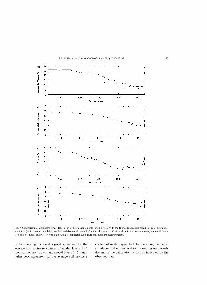
calibration (Fig. 7) found a good agreement for the
average soil moisture content of model layers 1–4
(comparison not shown) and model layers 1–5, but a
rather poor agreement for the average soil moisture
content of model layers 1–3. Furthermore, the model
simulation did not respond to the wetting up towards
the end of the calibration period, as indicated by the
observed data.
Fig. 7. Comparison of connector-type TDR soil moisture measurements (open circles) with the Richards equation based soil moisture model
prediction (solid line): (a) model layers 1–3 and (b) model layers 1–5 with calibration to Virrib soil moisture measurements; (c) model layers
1–3 and (b) model layers 1–5 with calibration to connector-type TDR soil moisture measurements.
J.P. Walker et al. / Journal of Hydrology 293 (2004) 85–99 97

6.4. Calibration to connector TDR measurements
To improve the comparison of model predictions
with the observed connector-type TDR soil moisture
measurements, a calibration was made to the
connector-type TDR soil moisture data. The par-
ameter values from this calibration (Table 2) gave a
very good agreement between model predictions and
the connector-type TDR soil moisture data (Fig. 7) for
model layers 1–3 and 1–4 (comparison not shown),
and an equally good agreement for model layers 1–5
as for the calibration to Virrib soil moisture data. The
model simulation also responded to the wetting up at
the end of the calibration period. In addition, the
MGRAD values from calibration to the connector-
type TDR data increased with depth, rather than
decrease as with the calibration to Virrib soil moisture
data. Increasing MGRAD values with depth agree
better with intuition, as the clay content in the soil
profile increased with depth, and hence the maximum
matric suction gradient should be greater at deeper
depths. The consistent slight over-estimation of soil
moisture storage for the entire soil profile as compared
to the connector-type TDR measurements may be a
result of: (i) the no drainage boundary condition at the
bottom of the soil profile, (ii) an incorrect estimate of
rainfall and/or evapotranspiration, or (iii) a systematic
error in the 40 cm TDR measurement. A joint
calibration to Virrib and connector-type TDR data
and/or use of a gravity drainage boundary condition
was unable to improve the results.
A comparison of the model prediction is made with
the Virrib soil moisture data in Fig. 6. This
comparison shows a good agreement with model
layer 3 and an even better agreement in model layer 5
than for the calibration to Virrib soil moisture data
itself. However, the comparison with model layer 4
(comparison not shown) was slightly degraded. This
analysis provides further support to the accuracy of
connector-type TDR soil moisture measurements over
the Virrib (and other) techniques tested in this paper.
7. Conclusions
This paper found a good agreement between the
Soil Moisture Equipment Corporation TRASEw
connector-type time domain reflectometry (TDR)
and thermogravimetric soil moisture measurements.
However, there were significant differences between
the other electronic soil moisture techniques studied,
which included Virribw soil moisture sensors, a
Campbell Scientific CS615 water content reflect-
ometer, and Soil Moisture Equipment Corporation
TRASE buriable-type TDR soil moisture sensors. The
conclusion drawn from an analysis of these measure-
ments was that the differences in the soil moisture
measurements from the various sensors were the
result of a combination of factors.
Firstly, the installation procedure for the Virrib
sensors involved major disturbance to the soil in
which soil moisture was being measured, thus altering
the physical properties of the soil, and still influencing
the physical moisture content of the soil in compari-
son to the undisturbed soil even nine months after
installation. Secondly, the different sensors use
different measurement techniques and measure the
soil moisture of different size volumes of soil. Thirdly,
any air or fluid filled gaps around the TDR
waveguides due to insertion affect the ability of the
TDR technique to measure the moisture content of the
soil accurately, with the effects being greater for
buriable-type sensors (having three-prong wave-
guides) than the connector-type and CS615 reflect-
ometer sensors (having two-prong waveguides). Thus
the dry soil conditions at time of installation for the
buriable-type TDR sensors may have resulted in poor
installation of the buriable-type TDR sensors, result-
ing in gaps which introduce further errors in the
measurements, especially under wet soil conditions.
Both the Virrib and CS615 reflectometer soil
moisture sensors displayed diurnal variations in soil
moisture content and the Virrib sensors displayed high
frequency noise that required filtering. Moreover,
comparison with a simple water balance ‘bucket’
model showed that measured changes in soil moisture
storage using the Virrib and buriable-type TDR sensors
exceeded the recorded rainfall amounts during infiltra-
tion events. Furthermore, the CS615 reflectometer soil
moisture sensor predicted soil moisture contents that
exceeded the soil porosity during periods of saturation.
While buriable-type TDR sensors yielded system-
atically lower measurements of soil moisture content
in comparison to Virrib measurements, these two
sensor types yielded similar estimates of change
in water storage. Comparison between Virrib and
J.P. Walker et al. / Journal of Hydrology 293 (2004) 85–9998

connector-type TDR measurements of total profile
water storage was generally good, with the exception
of the major infiltration events and towards the end of
the major dry down event. In addition to the good
agreement with thermogravimetric measurements, the
connector-type TDR soil moisture measurements
yielded better agreement with Richards equation
based model predictions of soil moisture than did the
Virrib measurements, providing further evidence that
these sensors yielded the most accurate measurements
of soil moisture content. It was not possible to attain a
good agreement between Richards equation based
model predictions and Virrib measurements of deep
soil moisture content, even with calibration to that
data.
Acknowledgements
This work has been jointly funded by an Australian
Postgraduate Award scholarship and the Hunter Water
Corporation. Andrew Krause and Scott Wooldridge
are acknowledged for their assistance with field work.
John and Margaret Russell are acknowledged for the
use of their land in the monitoring of soil moisture.
References
Campbell Scientific Inc., 1995. Water Content Reflectometer
Instruction Manual, Campbell Scientific Inc., Logan, USA, 8pp.
Duan, Q., Sorooshian, S., Gupta, V.K., 1994. Optimal use of the
SCE-UA global optimization method for calibrating watershed
models. J. Hydrol. 158, 265–284.
Knight, J.H., Ferre, P.A., Rudolph, D.L., Kachanoski, R.G.,
1997. A Numerical analysis of the effects of coatings and
gaps upon relative dielectric permittivity measurement with
time domain reflectometry. Water Resour. Res. 33 (6),
1455–1460.
Kuczera, G., 1994. NLFIT: a Bayesian Non-linear Regression
Program Suite. Department of Civil Engineering and Surveying,
The University of Newcastle, Australia.
Rothe, A., Weis, W., Kreutzer, K., Matthies, D., Hess, U., Ansorge,
B., 1997. Changes in soil structure caused by the installation of
time domain reflectometry probes and their influence on the
measurement of soil moisture. Water Resour. Res. 33 (7),
1585–1593.
Schmugge, T.J., Jackson, T.J., McKim, H.L., 1980. Survey of
methods for soil moisture determination. Water Resour. Res. 16
(6), 961–979.
Soil Moisture Equipment Corp., 1989. Trase System 1 Operating
Instructions. Soil Moisture Equipment Corp., 54.
Topp, G.C., 2003. State of the art of measuring soil water content.
Hydrol. Process. 17, 2993–2996.
van Genuchten, M.T., 1980. A closed-form equation for predicting
the hydraulic conductivity of unsaturated soils. Soil Sci. Soc.
Am. J. 44, 892–898.
Walker, J.P., Willgoose, G.R., Kalma, J.D., 2001a. The nerrigundah
data set: soil moisture patterns, Soil charachteristics and
hydrological flux measurements. Water Resour. Res. 37 (11),
2653–2658.
Walker, J.P., Willgoose, G.R., Kalma, J.D., 2001b. One dimen-
sional soil moisture profile retrieval by assimilation of near-
surface mesaurements: a simplified soil moisture model and
field application. J. Hydromet. 2, 356–373.
Wilson, R. G., 1971. Methods of Measuring Soil Moisture.
Technical Manual Series, The Secretariat, Canadian National
Commission for the International Hydrological Decade, Ottawa,
Canada, 20 pp.
Zegelin, S., 1996. Soil Moisture Measurement, Field Measurement
Techniques in Hydrology-Workshop Notes, Corpus Christi
College, Clayton, pp.C1–C22.
J.P. Walker et al. / Journal of Hydrology 293 (2004) 85–99 99
Top Related
Copyright © 2022 FDOKUMEN

