


Bahasa
Halaman
Hukum

Thin Solid Films 568 (2014) 19–24
Contents lists available at ScienceDirect
Thin Solid Films
j ourna l homepage: www.e lsev ie r .com/ locate / ts f
Structural, optical and mechanical properties of amorphous andcrystalline alumina thin films
Priyanka Nayar a, Atul Khanna a,⁎, D. Kabiraj b, S.R. Abhilash b, Ben D. Beake c, Yannick Losset c, Banghao Chen d
a Department of Physics, Guru Nanak Dev University, Amritsar 143005, Indiab Inter University Accelerator Centre, Aruna Asaf Ali Marg, New Delhi 110067, Indiac Micro Materials Limited, Unit 3, Wrexham Technology Park, Wrexham LL13 7YP, UKd Chemistry & Biochemistry Department, Florida State University, Tallahassee 32306, USA
⁎ Corresponding author. Tel.: +91 183 2258802x3168;E-mail address: [email protected] (A. Khanna).
http://dx.doi.org/10.1016/j.tsf.2014.07.0530040-6090/© 2014 Elsevier B.V. All rights reserved.
a b s t r a c t
a r t i c l e i n f oArticle history:Received 19 June 2013Received in revised form 19 July 2014Accepted 31 July 2014Available online 7 August 2014
Keywords:AluminaThin filmsElectron-beam evaporationThermal stabilityHardnessRefractive index27Al Magic Angle Spinning Nuclear MagneticResonanceAl–O speciation
Thinfilms of amorphous alumina of thickness 350 nmwere deposited on fused silica substrates by electron beamevaporation. Amorphous films were annealed at several temperatures in the range: 400–1130 °C and changes infilm crystallinity, short-range structure, optical andmechanical properties were studied. X-ray diffraction studiesfound that crystallization starts at 800 °C and produces γ and δ-alumina, the latter phase grows with heat treat-ment and the sample was mostly δ and θ-alumina after annealing at 1130 °C. The as-deposited amorphous alu-mina films have low hardness of 5 to 8 GPa, which increases to 11 to 12 GPa in crystalline sample. 27Al MagicAngle Spinning Nuclear Magnetic Resonance was used to study the short-range order of amorphous and crystal-line alumina films and it was found that amorphous alumina film contains AlO5 and AlO4 structural units in theratio of 1:2. The concentration of AlO5was significantly suppressed in crystallinefilm,which contains 48% of Al3+
ions in AlO6, 7% in AlO5 and 45% in AlO4 units.© 2014 Elsevier B.V. All rights reserved.
1. Introduction
Aluminum oxide exists in several crystallographic polymorphsand its thin and thick films are used in wide range of applications in-cluding microelectronics and catalysis, as well as diffusion barrier,thermal barrier and wear resistant coatings for cutting tools [1,2].Metastable phases like γ-alumina find use in catalysis due to theirlarge surface area [3], while the anodic alumina templates are usedfor the synthesis of nanowires [4]. α-Alumina films for cutting toolapplications are deposited by chemical vapor deposition at highsubstrate temperature of 1100 °C [5]. Plasma Assisted ChemicalVapor Deposition decreases the deposition temperature for α-alumina to 560 °C [6], while High Power Impulse MagnetronSputtering forms α-alumina films at ~600 °C [7]. Cr2O3 templateshave been found to reduce substrate temperature to ~280 °C [8].Dual hollow cylindrical magnetrons and mid-frequency AC supply
fax: +91 183 2258820.
(41 kHz) grow crystalline γ-alumina films at a moderate in situ tem-perature of 350 °C [9]. It is well established that other physical vapordeposition techniques such as electron beam evaporation andpulsed laser deposition (PLD) grow amorphous alumina films up toa substrate temperature of at least 600 °C [10]. PLD grows γ-alumina phase at ~800 °C [11–13]. Significant effort has been devot-ed during the last three decades towards developing techniques todeposit crystalline alumina films at lower temperatures. Reactivesputtering has several advantages over other techniques that itcauses ion bombardment of the growing film and provides highenergy that is essential for achieving crystallinity [6,7,14]. Basedon theoretical and experimental work, subplantation has been sug-gested to control the phase formation in alumina thin films [15,16].
It is still not completely understood why aluminum oxide, whichis not a glass former and has not been synthesized in the amorphousform in the bulk, produces amorphous phase even at high substratetemperature of 600 °C by thin film deposition. An important insighthas recently been provided by the 27Al Magic Angle Spinning (MAS)Nuclear Magnetic Resonance (NMR) studies of amorphous and crys-talline alumina films, which revealed that significant fraction of
20 P. Nayar et al. / Thin Solid Films 568 (2014) 19–24
Al3+ ions are in penta-coordination with oxygen ions in amorphousalumina and it is this structural feature i.e. the presence of AlO5
(denoted as [5]Al) that creates disorder and hinders the growth ofcrystalline alumina phase [17,18]. High temperature of ~800 °C isrequired for the transformation of amorphous alumina into γ-phase by the following structural rearrangement reaction:
2 AlO5½ �→ AlO4½ � þ AlO6½ �: ð1Þ
Geometrically speaking, the above reaction mechanism involvesthe formation of edge-sharing octahedral [6]Al from corner sharing[5]Al. Amorphous and molten alumina contain [5]Al and [4]Al in theratio of 1:2 [17–19], γ-alumina has [6]Al and [4]Al in the ratio of 2:1,θ-alumina has [6]Al and [4]Al in the ratio of 1:1, κ-alumina has [6]Aland [4]Al in the ratio of 1:3, while α-alumina contains only [6]Al [20].
High substrate temperatures that are essential to grow crystal-line alumina films by physical vapor deposition techniques are diffi-cult to maintain for long times during deposition since theydeteriorate chamber vacuum. Ideally, we need deposition tech-niques that do not use in situ high substrate heating. Therefore onemethod that has attracted attention for crystallization of amorphousalumina films is post deposition thermal annealing. This is also im-portant from the fundamental point of view as it provides insightsabout the thermal stability and phase transformation properties ofamorphous and metastable crystalline alumina phases. The thermalstability of amorphous and γ-alumina films has been studied by ear-lier researchers [21–23] and again in the recent times [14,24,25].There is some variation in the reported phase transformation prop-erties of alumina films; Eklund et al. found that films containingamorphous or very small amounts of γ-phase show the formationof intermediate θ-phase in the temperature range of 1000 to1100 °C, while highly crystalline γ-alumina films transformdirectly into α-phase [24]. Musil et al. have studied the thermal sta-bility of γ-alumina films grown by reactive magnetron sputteringand shown that γ-alumina films are stable on heat treatment at1000 °C for at least 5 h and that the α-phase grows at ~1050 °C.These authors also found that thin γ-alumina films (thickness~300 nm) were resistant to transformation to α-phase even after 5h of heat treatment at 1100 °C, while thicker films (~1200 nm)transformed readily to α-phase on annealing at 1100 °C for 2 h[25]. Edlmayr et al. studied the thermal stability of alumina films de-posited on Si(100) substrates and iron foils, by bipolar pulsed mag-netron sputtering and reported that amorphous films transform toα-phase at 1150 °C while crystalline γ-alumina films transformedto α-phase at a higher temperature of ~1250 °C [14].
There are few studies on the thermal stability, mechanical andoptical properties of alumina films deposited by electron beamevaporation [26], and it is not known whether their structural trans-formation properties are the same or different from that of reactive-ly sputtered alumina films. The energy of the depositing particlesduring electron beam evaporation is lower than the energy of parti-cles during reactive magnetron sputtering and because the micro-structure and mechanical properties of alumina films dependcritically on the incident particle energy [27], the crystallizationproperties of electron beam and sputter coated alumina may bedifferent.
In this paper we report the effects of heat treatment on the crystalstructure, optical and mechanical properties and the short-range struc-ture (i.e. Al–O speciation) in amorphous and crystalline alumina filmsprepared by electron beam evaporation. Amorphous films of aluminumoxide were grown on the fused silica substrates and subsequentlyannealed at temperatures between 400 °C and 1130 °C for 6 h in air.Films were characterized by grazing incidence X-ray diffraction, UV–visible absorption spectroscopy, and nanoindentation and 27Al MASNMR spectroscopy.
2. Experimental
2.1. Thin film deposition
Aluminum oxide thin films were deposited on fused silicasubstrates by electron beam evaporation of alumina disks (99.5%purity, Carborundum Universal Ltd., Hosur, India). Before deposi-tion, the substrates were ultrasonically cleaned in acetone andethanol. The growth chamber was equipped with a Varian electronbeam gun (maximum power 2 kW) and the target to substrate dis-tance was about 23 cm. The deposition chamber was evacuatedwith a cryopump to a base vacuum of 4 × 10⁻⁶ Pa. The electronbeam gun was switched on, and alumina deposition was carriedout for 52 min. During deposition the chamber pressure was ~3.3 ×10⁻⁵ Pa. The thickness of films was monitored in situ by a quartzcrystal monitor. Average deposition rate was 0.11 nm s−1 and thefinal film thickness was 350 nm.
2.2. Post-deposition annealing
One amorphous film on silica substrate (sample code: S1) wassequentially annealed at 400 °C, 600 °C, 800 °C, 950 °C, 1050 °C and1130 °C. The sample was heat treated at each of these temperaturesfor 6 h in ambient air, and then slowly cooled to room temperature.Sample heating rate was ~20 °C min−1, and after heat treatment, itwas cooled slowly to room temperature at ~200 °C h−1.
2.3. Grazing incidence X-ray diffraction (GIXRD)
XRD measurements were performed on alumina film before andafter each annealing treatment on Bruker D8 Focus X-ray diffractometerin the grazing incidence geometry with Cu-Kα radiation (λ =0.154056 nm). Measurements were done by keeping the incidentangle fixed at 2° and by scanning the scintillation counter detector inthe 2θ range of 10–70°. The X-ray tube was operated at 40 kV and35 mA.
2.4. UV–visible spectroscopy
The optical absorption spectra of as depositedfilm on silica substratebefore and after heat treatment were measured on a Cecil UV–visiblespectrophotometer (model 3055). The refractive indices of as depositedamorphous and crystallized samples were determined by using thefitting procedure based on Sellmeier's dispersion relations [28].
2.5. Nanoindentation
Nanoindentation testing was performed on two samples on silicasubstrate (S1 and S1-1130) using a Micro Materials NanoTest system.Hardness and reduced indentation modulus (Er), were determinedfrom nanoindentation to 0.5–50 mN with a Micro Materials NanoTestsystem. The reduced indentation modulus, Er, is defined as:
1Er
¼1−νs
2� �
Esþ
1−νi2
� �
Eið2Þ
where νs is the Poisson's ratio for the sample, νi, the Poisson's ratio forthe diamond indenter (0.07), Es, the sample elastic modulus and Ei, thediamond elastic modulus.
All indentations were performed with a very sharp Berkovichindenter calibrated against a fused silica reference over a wide depthrange. In all indentations the loading time was 20 s loading, 10 s holdat peak load, 20 s unloading and 60 s for thermal drift correction at90% unloading. All data were corrected for a small (sub-nm) zeropoint correction prior to analysis.
21P. Nayar et al. / Thin Solid Films 568 (2014) 19–24
2.6. 27Al MAS NMR spectroscopy
One amorphous alumina film (sample S1) and heat-treated (crystal-line) alumina film on silica substrate (sample S1-1130) were used for27Al MAS NMR studies. All solid-state NMR experiments were per-formed at room temperature on a Varian 500 MHz spectrometer(11.7 T) at a Larmor frequency of 130.3MHz. Small pieces of amorphousand crystalline thin film sample (with silica substrate) were crushedinto a powder and packed in 4-mm silicon nitride rotors and spun atthe magic angle in a T3 probe at 13 kHz. A short pulse (0.3 μs) wasapplied and the recycle delay is 0.5 s. The data were collected after552,040 scans and the chemical shifts were referenced to 1.0 MAl(NO3)3 at δ = 0 ppm. Empty rotor was run at the same conditionsas control experiments.
3. Results and discussion
3.1. Crystal structure
GIXRDmeasurements were performed on alumina thin films depos-ited on fused silica substrates after each annealing step. Prior to anneal-ing, it was confirmed by XRD that the as-deposited sample wasamorphous. Crystallization of films initiated at 800 °C.
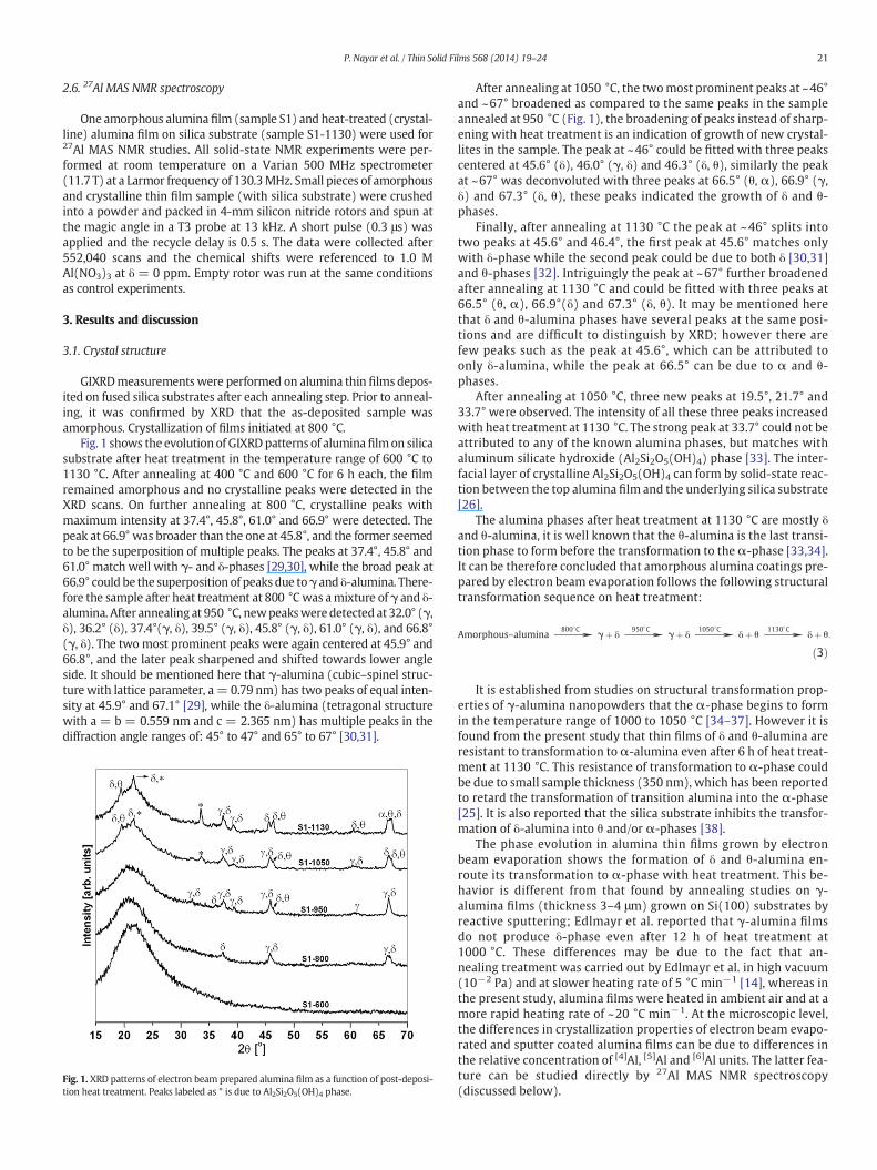
Fig. 1 shows the evolution of GIXRDpatterns of aluminafilmon silicasubstrate after heat treatment in the temperature range of 600 °C to1130 °C. After annealing at 400 °C and 600 °C for 6 h each, the filmremained amorphous and no crystalline peaks were detected in theXRD scans. On further annealing at 800 °C, crystalline peaks withmaximum intensity at 37.4°, 45.8°, 61.0° and 66.9° were detected. Thepeak at 66.9° was broader than the one at 45.8°, and the former seemedto be the superposition of multiple peaks. The peaks at 37.4°, 45.8° and61.0° match well with γ- and δ-phases [29,30], while the broad peak at66.9° could be the superposition of peaks due toγ and δ-alumina. There-fore the sample after heat treatment at 800 °Cwas amixture of γ and δ-alumina. After annealing at 950 °C, newpeakswere detected at 32.0° (γ,δ), 36.2° (δ), 37.4°(γ, δ), 39.5° (γ, δ), 45.8° (γ, δ), 61.0° (γ, δ), and 66.8°(γ, δ). The twomost prominent peaks were again centered at 45.9° and66.8°, and the later peak sharpened and shifted towards lower angleside. It should be mentioned here that γ-alumina (cubic–spinel struc-ture with lattice parameter, a = 0.79 nm) has two peaks of equal inten-sity at 45.9° and 67.1° [29], while the δ-alumina (tetragonal structurewith a = b = 0.559 nm and c = 2.365 nm) has multiple peaks in thediffraction angle ranges of: 45° to 47° and 65° to 67° [30,31].
Fig. 1. XRD patterns of electron beam prepared alumina film as a function of post-deposi-tion heat treatment. Peaks labeled as * is due to Al2Si2O5(OH)4 phase.
After annealing at 1050 °C, the twomost prominent peaks at ~46°and ~67° broadened as compared to the same peaks in the sampleannealed at 950 °C (Fig. 1), the broadening of peaks instead of sharp-ening with heat treatment is an indication of growth of new crystal-lites in the sample. The peak at ~46° could be fitted with three peakscentered at 45.6° (δ), 46.0° (γ, δ) and 46.3° (δ, θ), similarly the peakat ~67° was deconvoluted with three peaks at 66.5° (θ, α), 66.9° (γ,δ) and 67.3° (δ, θ), these peaks indicated the growth of δ and θ-phases.
Finally, after annealing at 1130 °C the peak at ~46° splits intotwo peaks at 45.6° and 46.4°, the first peak at 45.6° matches onlywith δ-phase while the second peak could be due to both δ [30,31]and θ-phases [32]. Intriguingly the peak at ~67° further broadenedafter annealing at 1130 °C and could be fitted with three peaks at66.5° (θ, α), 66.9°(δ) and 67.3° (δ, θ). It may be mentioned herethat δ and θ-alumina phases have several peaks at the same posi-tions and are difficult to distinguish by XRD; however there arefew peaks such as the peak at 45.6°, which can be attributed toonly δ-alumina, while the peak at 66.5° can be due to α and θ-phases.
After annealing at 1050 °C, three new peaks at 19.5°, 21.7° and33.7° were observed. The intensity of all these three peaks increasedwith heat treatment at 1130 °C. The strong peak at 33.7° could not beattributed to any of the known alumina phases, but matches withaluminum silicate hydroxide (Al2Si2O5(OH)4) phase [33]. The inter-facial layer of crystalline Al2Si2O5(OH)4 can form by solid-state reac-tion between the top alumina film and the underlying silica substrate[26].
The alumina phases after heat treatment at 1130 °C are mostly δand θ-alumina, it is well known that the θ-alumina is the last transi-tion phase to form before the transformation to the α-phase [33,34].It can be therefore concluded that amorphous alumina coatings pre-pared by electron beam evaporation follows the following structuraltransformation sequence on heat treatment:
Amorphous–alumina→800�C
γþ δ→950�C
γþ δ→1050�C
δþ θ→1130�C
δþ θ:
ð3Þ
It is established from studies on structural transformation prop-erties of γ-alumina nanopowders that the α-phase begins to formin the temperature range of 1000 to 1050 °C [34–37]. However it isfound from the present study that thin films of δ and θ-alumina areresistant to transformation to α-alumina even after 6 h of heat treat-ment at 1130 °C. This resistance of transformation to α-phase couldbe due to small sample thickness (350 nm), which has been reportedto retard the transformation of transition alumina into the α-phase[25]. It is also reported that the silica substrate inhibits the transfor-mation of δ-alumina into θ and/or α-phases [38].
The phase evolution in alumina thin films grown by electronbeam evaporation shows the formation of δ and θ-alumina en-route its transformation to α-phase with heat treatment. This be-havior is different from that found by annealing studies on γ-alumina films (thickness 3–4 μm) grown on Si(100) substrates byreactive sputtering; Edlmayr et al. reported that γ-alumina filmsdo not produce δ-phase even after 12 h of heat treatment at1000 °C. These differences may be due to the fact that an-nealing treatment was carried out by Edlmayr et al. in high vacuum(10−2 Pa) and at slower heating rate of 5 °C min−1 [14], whereas inthe present study, alumina films were heated in ambient air and at amore rapid heating rate of ~20 °C min−1. At the microscopic level,the differences in crystallization properties of electron beam evapo-rated and sputter coated alumina films can be due to differences inthe relative concentration of [4]Al, [5]Al and [6]Al units. The latter fea-ture can be studied directly by 27Al MAS NMR spectroscopy(discussed below).
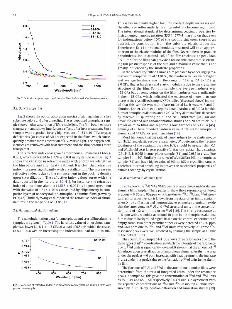
Fig. 2. Optical absorption spectra of alumina films before and after heat-treatment.
22 P. Nayar et al. / Thin Solid Films 568 (2014) 19–24
3.2. Optical properties
Fig. 2 shows the optical absorption spectra of alumina film on silicasubstrate before and after annealing. The as-deposited amorphous sam-ple shows higher absorption of UV–visible light. The film becomesmoretransparent and shows interference effects after heat treatment. Sincesamples were deposited in very high vacuum of 1.33 × 10⁻⁵ Pa, oxygendeficiencies (or excess of Al) are expected in the films, which conse-quently produce more absorption of UV–visible light. The oxygen defi-ciencies are removed with heat treatment and the film becomes moretransparent.
The refractive index of as grown amorphous alumina was 1.666±0.001, which increased to 1.778 ± 0.001 in crystalline sample. Fig. 3shows the variation in refractive index with photon wavelength inthe film before and after heat treatment. It is clear that refractiveindex increases significantly with crystallization. The increase inrefractive index is due to the enhancement in the packing densityupon crystallization. The refractive index values agree with thedata reported in the literature [39–41]. For instance, the refractiveindex of amorphous alumina (1.666 ± 0.001) is in good agreementwith the value of 1.647 ± 0.003 measured by ellipsometry in com-posite layers of nanocrystalline-amorphous alumina films grown byPLD [42]. SimilarlyWang et al. reported the refractive index of alumi-na films in the range of 1.65–1.85 [43].
3.3. Hardness and elastic modulus
The nanoindentation data for amorphous and crystalline aluminasamples are given in Table 1. The hardness value of amorphous sam-ple was lower i.e. 8.1 ± 1.3 GPa at a load of 0.5 mN which decreasesto 5.1 ± 0.8 GPa on increasing the indentation load to 10–50 mN.
Fig. 3. Variation of refractive index, n in amorphous and crystalline alumina films withphoton wavelength.
This is because with higher load the contact depth increases andthe effects of softer underlying silica substrate become significant.The international standard for determining coating properties byinstrumented nanoindentation (ISO 14577-4) has shown that evenfor indentations below 10% of the coating thickness there is anappreciable contribution from the substrate elastic properties.Therefore in Eq. (1) the actual modulus measured will be an approx-imation to the elastic modulus of the film. Nevertheless, in practicenanoindentation to around 10% of the film thickness (a peak load0.5–1 mN for the film) can provide a reasonable compromise ensur-ing full plastic response of the film and a modulus value that is notgreatly influenced by the substrate properties.
In the second, crystalline alumina film prepared by annealing up to amaximum temperature of 1130 °C, the hardness values were higherand average hardness was in the range of 11.6 ± 2.4 to 12.2 ±2.0 GPa. Higher hardness and elastic modulus is due to the crystallinestructure of the film. For this sample the average hardness was~12 GPa but at some points on the film, hardness was significantlyhigher ~15 GPa, which indicated the existence of more than onephase in the crystallized sample. XRD studies (discussed above) indicat-ed that this sample was multiphase material i.e. it was, γ, δ and θ-alumina. Earlier, Chou et al. reported nanohardness of 9 GPa for thinfilms of amorphous alumina and 7.2 GPa for γ-alumina films depositedby reactive RF sputtering on Si and NaCl substrates [44]. Xu andRowcliffe carried out nanoindentation studies on 920 nm thick PVDgrown alumina films and reported a low hardness of 6.1 GPa [45].Edlmayr et al. have reported hardness value of 10 GPa for amorphousalumina and 14 GPa for γ-alumina films [14].
Musil has found that the ratio of nanohardness to the elastic modu-lus (H/Er) and elastic recovery parameter, We, determine the fracturetoughness of the coatings, the ratio H/Er should be greater than 0.1andWe should be as large as possible for fracture resistant hard coatings[27]. H/Er is 0.065 in amorphous sample (S1) and 0.085 in crystallinesample (S1-1130). Similarly the range ofWe is 26% to 30% in amorphoussample (S1) and has a higher value of 39% to 46% in crystalline sample.Therefore thermal annealing improves the mechanical properties ofalumina coatings by crystallization.
3.4. Al speciation in alumina films
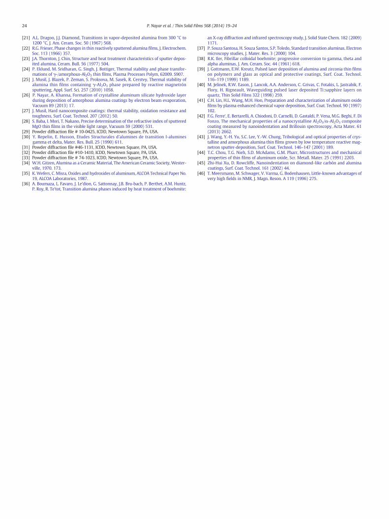
Fig. 4 shows the 27AlMASNMR spectra of amorphous and crystallinealumina film samples. These patterns show three resonances centeredat about−6, 30 and 60 ppm,which are due to [6]Al, [5]Al and [4]Al struc-tural units respectively. It is known from the state-of-art in situ contain-erless X-ray diffraction and neutron studies on molten aluminum oxidethat the latter contains [5]Al and [4]Al structural units in the concentra-tion ratio of 1:2 with little or no [6]Al [19]. The strong resonance at−6 ppmwith a shoulder at around 10 ppm in the amorphous aluminafilm is due to background signal based on the control experiments ofempty rotor. Two other prominent peaks were detected at ~30 ppmand ~60 ppm due to [5]Al and [4]Al units respectively. All three 27Alresonance peaks were well resolved by spinning the sample at 13 kHzin the field of 11.7 T.
The spectrum of sample S1-1130 shows three resonances due to thethree types of Al3+ coordination, inwhich the intensity of the resonancedue to [5]Al units is significantly lowered. It shows that the amount of [5]
Al reduces upon crystallization of amorphous alumina. Further the areaunder the peak at−6 ppm increases with heat treatment, the increasein area under this peak is due to the formation of [6]Al units in the alumi-na film.
The fractions of [5]Al and [4]Al in the amorphous alumina films weredetermined from the ratio of integrated areas under the resonancepeaks in sample S1, this gave the concentration of [5]Al and [4]Al unitsas 35 ± 4% and 65 ± 5% respectively. This result is in agreement withthe reported concentrations of [5]Al and [4]Al in molten alumina mea-sured by in situ X-ray, neutron diffraction and simulation studies [19].
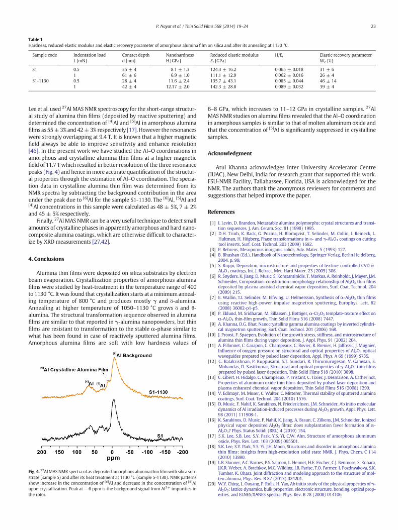
Table 1Hardness, reduced elastic modulus and elastic recovery parameter of amorphous alumina film on silica and after its annealing at 1130 °C.
Sample code Indentation loadL [mN]
Contact depthd [nm]
NanohardnessH [GPa]
Reduced elastic modulusEr [GPa]
H/Er Elastic recovery parameterWe [%]
S1 0.5 35 ± 4 8.1 ± 1.3 124.3 ± 16.2 0.065 ± 0.018 31 ± 61 61 ± 6 6.9 ± 1.0 111.1 ± 12.9 0.062 ± 0.016 26 ± 4
S1-1130 0.5 28 ± 4 11.6 ± 2.4 135.7 ± 43.1 0.085 ± 0.044 46 ± 141 42 ± 4 12.17 ± 2.0 142.3 ± 28.8 0.089 ± 0.032 39 ± 4
23P. Nayar et al. / Thin Solid Films 568 (2014) 19–24
Lee et al. used 27Al MAS NMR spectroscopy for the short-range structur-al study of alumina thin films (deposited by reactive sputtering) anddetermined the concentration of [4]Al and [5]Al in amorphous aluminafilms as 55±3% and 42±3% respectively [17]. However the resonanceswere strongly overlapping at 9.4 T. It is known that a higher magneticfield always be able to improve sensitivity and enhance resolution[46]. In the present work we have studied the Al–O coordinations inamorphous and crystalline alumina thin films at a higher magneticfield of 11.7 Twhich resulted in better resolution of the three resonancepeaks (Fig. 4) and hence inmore accurate quantification of the structur-al properties through the estimation of Al–O coordination. Τhe specia-tion data in crystalline alumina thin film was determined from itsNMR spectra by subtracting the background contribution in the areaunder the peak due to [6]Al for the sample S1-1130. The [6]Al, [5]Al and[4]Al concentrations in this sample were calculated as 48 ± 5%, 7 ± 2%and 45 ± 5% respectively.
Finally, 27AlMAS NMR can be a very useful technique to detect smallamounts of crystalline phases in apparently amorphous and hard nano-composite alumina coatings, which are otherwise difficult to character-ize by XRD measurements [27,42].
4. Conclusions
Alumina thin films were deposited on silica substrates by electronbeam evaporation. Crystallization properties of amorphous aluminafilms were studied by heat-treatment in the temperature range of 400to 1130 °C. It was found that crystallization starts at aminimumanneal-ing temperature of 800 °C and produces mostly γ and δ-alumina.Annealing at higher temperature of 1050–1130 °C grows δ and θ-alumina. The structural transformation sequence observed in aluminafilms are similar to that reported in γ-alumina nanopowders, but thinfilms are resistant to transformation to the stable α-phase similar towhat has been found in case of reactively sputtered alumina films.Amorphous alumina films are soft with low hardness values of
Fig. 4. 27AlMASNMR spectra of as-deposited amorphous alumina thinfilmwith silica sub-strate (sample S) and after its heat treatment at 1130 °C (sample S-1130). NMR patternsshow increase in the concentration of [6]Al and decrease in the concentration of [5]Alupon crystallization. Peak at −6 ppm is the background signal from Al3+ impurities inthe rotor.
6–8 GPa, which increases to 11–12 GPa in crystalline samples. 27AlMAS NMR studies on alumina films revealed that the Al–O coordinationin amorphous samples is similar to that of molten aluminum oxide andthat the concentration of [5]Al is significantly suppressed in crystallinesamples.
Acknowledgment
Atul Khanna acknowledges Inter University Accelerator Centre(IUAC), New Delhi, India for research grant that supported this work.FSU-NMR Facility, Tallahassee, Florida, USA is acknowledged for theNMR. The authors thank the anonymous reviewers for comments andsuggestions that helped improve the paper.
References
[1] I. Levin, D. Brandon, Metastable alumina polymorphs: crystal structures and transi-tion sequences, J. Am. Ceram. Soc. 81 (1998) 1995.
[2] D.H. Trinh, K. Back, G. Pozina, H. Blomqvist, T. Selinder, M. Collin, I. Reineck, L.Hultman, H. Högberg, Phase transformations in κ- and γ-Al2O3 coatings on cuttingtool inserts, Surf. Coat. Technol. 203 (2009) 1682.
[3] P. Behrens, Mesoporous inorganic solids, Adv. Mater. 5 (1993) 127.[4] B. Bhushan (Ed.), Handbook of Nanotechnology, Springer Verlag, Berlin Heidelberg,
2004, p. 99.[5] S. Ruppi, Deposition, microstructure and properties of texture-controlled CVD α-
Al2O3 coatings, Int. J. Refract. Met. Hard Mater. 23 (2005) 306.[6] R. Snyders, K. Jiang, D. Music, S. Konstantinidis, T. Markus, A. Reinholdt, J. Mayer, J.M.
Schneider, Composition–constitution–morphology relationship of Al2O3 thin filmsdeposited by plasma assisted chemical vapor deposition, Surf. Coat. Technol. 204(2009) 215.
[7] E. Wallin, T.I. Selinder, M. Elfwing, U. Helmersson, Synthesis of α-Al2O3 thin filmsusing reactive high-power impulse magnetron sputtering, Europhys. Lett. 82(2008) 36002-p1-p5.
[8] P. Eklund, M. Sridharan, M. Sillassen, J. Bøttiger, α-Cr2O3 template-texture effect onα-Al2O3 thin-film growth, Thin Solid Films 516 (2008) 7447.
[9] A. Khanna, D.G. Bhat, Nanocrystalline gamma alumina coatings by inverted cylindri-cal magnetron sputtering, Surf. Coat. Technol. 201 (2006) 168.
[10] J. Proost, F. Spaepen, Evolution of the growth stress, stiffness, and microstructure ofalumina thin films during vapor deposition, J. Appl. Phys. 91 (2002) 204.
[11] A. Pillonnet, C. Garapon, C. Champeaux, C. Bovier, R. Brenier, H. Jaffrezic, J. Mugnier,Influence of oxygen pressure on structural and optical properties of Al2O3 opticalwaveguides prepared by pulsed laser deposition, Appl. Phys. A 69 (1999) S735.
[12] G. Balakrishnan, P. Kuppusami, S.T. Sundari, R. Thirumurugesan, V. Ganesan, E.Mohandas, D. Sastikumar, Structural and optical properties of γ-Al2O3 thin filmsprepared by pulsed laser deposition, Thin Solid Films 518 (2010) 3898.
[13] C. Cibert, H. Hidalgo, C. Champeaux, P. Tristant, C. Tixier, J. Desmaison, A. Catherinot,Properties of aluminum oxide thin films deposited by pulsed laser deposition andplasma enhanced chemical vapor deposition, Thin Solid Films 516 (2008) 1290.
[14] V. Edlmayr, M. Moser, C. Walter, C. Mitterer, Thermal stability of sputtered aluminacoatings, Surf. Coat. Technol. 204 (2010) 1576.
[15] D. Music, F. Nahif, K. Sarakinos, N. Friederichsen, J.M. Schneider, Ab initio moleculardynamics of Al irradiation-induced processes during Al2O3 growth, Appl. Phys. Lett.98 (2011) 111908-1.
[16] K. Sarakinos, D. Music, F. Nahif, K. Jiang, A. Braun, C. Zilkens, J.M. Schneider, Ionizedphysical vapor deposited Al2O3 films: does subplantation favor formation of α-Al2O3? Phys. Status Solidi (RRL) 4 (2010) 154.
[17] S.K. Lee, S.B. Lee, S.Y. Park, Y.S. Yi, C.W. Ahn, Structure of amorphous aluminumoxide, Phys. Rev. Lett. 103 (2009) 095501.
[18] S.K. Lee, S.Y. Park, Y.S. Yi, J.H. Moon, Structures and disorder in amorphous aluminathin films: insights from high-resolution solid state NMR, J. Phys. Chem. C 114(2010) 13890.
[19] L.B. Skinner, A.C. Barnes, P.S. Salmon, L. Hennet, H.E. Fischer, C.J. Benmore, S. Kohara,J.K.R. Weber, A. Bytchkov, M.C. Wilding, J.B. Parise, T.O. Farmer, I. Pozdnyakova, S.K.Tumber, K. Ohara, Joint diffraction and modeling approach to the structure of mol-ten alumina, Phys. Rev. B 87 (2013) 024201.
[20] W.Y. Ching, L. Ouyang, P. Rulis, H. Yao, Ab initio study of the physical properties of γ-Al2O3: lattice dynamics, bulk properties, electronic structure, bonding, optical prop-erties, and ELNES/XANES spectra, Phys. Rev. B 78 (2008) 014106.
24 P. Nayar et al. / Thin Solid Films 568 (2014) 19–24
[21] A.L. Dragoo, J.J. Diamond, Transitions in vapor-deposited alumina from 300 °C to1200 °C, J. Am. Ceram. Soc. 50 (1967) 568.
[22] R.G. Frieser, Phase changes in thin reactively sputtered alumina films, J. Electrochem.Soc. 113 (1966) 357.
[23] J.A. Thornton, J. Chin, Structure and heat treatment characteristics of sputter depos-ited alumina, Ceram. Bull. 56 (1977) 504.
[24] P. Eklund, M. Sridharan, G. Singh, J. Bottiger, Thermal stability and phase transfor-mations of γ-/amorphous-Al2O3 thin films, Plasma Processes Polym, 62009. S907.
[25] J. Musil, J. Blazek, P. Zeman, S. Proksova, M. Sasek, R. Cerstvy, Thermal stability ofalumina thin films containing γ-Al2O3 phase prepared by reactive magnetrónsputtering, Appl. Surf. Sci. 257 (2010) 1058.
[26] P. Nayar, A. Khanna, Formation of crystalline aluminum silicate hydroxide layerduring deposition of amorphous alumina coatings by electron beam evaporation,Vacuum 89 (2013) 17.
[27] J. Musil, Hard nanocomposite coatings: thermal stability, oxidation resistance andtoughness, Surf. Coat. Technol. 207 (2012) 50.
[28] S. Baba, I. Mori, T. Nakano, Precise determination of the refractive index of sputteredMgO thin films in the visible light range, Vacuum 59 (2000) 531.
[29] Powder diffraction file # 10-0425, ICDD, Newtown Square, PA, USA.[30] Y. Repelin, E. Husson, Etudes Structurales d'alumines de transition I-alumines
gamma et delta, Mater. Res. Bull. 25 (1990) 611.[31] Powder diffraction file #46-1131, ICDD, Newtown Square, PA, USA.[32] Powder diffraction file #10-1410, ICDD, Newtown Square, PA, USA.[33] Powder diffraction file # 74-1023, ICDD, Newtown Square, PA, USA.[34] W.H. Gitzen, Alumina as a CeramicMaterial, The American Ceramic Society,Wester-
ville, 1970. 173.[35] K.Wefers, C. Misra, Oxides and hydroxides of aluminum, ALCOA Technical Paper No.
19, ALCOA Laboratories, 1987.[36] A. Boumaza, L. Favaro, J. Le'dion, G. Sattonnay, J.B. Bru-bach, P. Berthet, A.M. Huntz,
P. Roy, R. Te'tot, Transition alumina phases induced by heat treatment of boehmite:
an X-ray diffraction and infrared spectroscopy study, J. Solid State Chem. 182 (2009)1171.
[37] P. Souza Santosa, H. Souza Santos, S.P. Toledo, Standard transition aluminas. Electronmicroscopy studies, J. Mater. Res. 3 (2000) 104.
[38] R.K. Iler, Fibrillar colloidal boehmite; progressive conversion to gamma, theta andalpha aluminas, J. Am. Ceram. Soc. 44 (1961) 618.
[39] J. Gottmann, E.W. Kreutz, Pulsed laser deposition of alumina and zirconia thin filmson polymers and glass as optical and protective coatings, Surf. Coat. Technol.116–119 (1999) 1189.
[40] M. Jelinek, R.W. Eason, J. Lancok, A.A. Anderson, C. Grivas, C. Fotakis, L. Jastrabik, F.Flory, H. Rigneault, Waveguiding pulsed laser deposited Ti:sapphire layers onquartz, Thin Solid Films 322 (1998) 259.
[41] C.H. Lin, H.L. Wang, M.H. Hon, Preparation and characterization of aluminum oxidefilms by plasma enhanced chemical vapor deposition, Surf. Coat. Technol. 90 (1997)102.
[42] F.G. Ferre', E. Bertarelli, A. Chiodoni, D. Carnelli, D. Gastaldi, P. Vena, M.G. Beghi, F. DiFonzo, The mechanical properties of a nanocrystalline Al2O3/α-Al2O3 compositecoating measured by nanoindentation and Brillouin spectroscopy, Acta Mater. 61(2013) 2662.
[43] J. Wang, Y.-H. Yu, S.C. Lee, Y.-W. Chung, Tribological and optical properties of crys-talline and amorphous alumina thin films grown by low temperature reactive mag-netron sputter-deposition, Surf. Coat. Technol. 146–147 (2001) 189.
[44] T.C. Chou, T.G. Nieh, S.D. McAdams, G.M. Pharr, Microstructures and mechanicalproperties of thin films of aluminum oxide, Scr. Metall. Mater. 25 (1991) 2203.
[45] Zhi-Hui Xu, D. Rowcliffe, Nanoindentation on diamond-like carbón and aluminacoatings, Surf. Coat. Technol. 161 (2002) 44.
[46] T. Meersmann, M. Schwager, V. Varma, G. Bodenhausen, Little-known advantages ofvery high fields in NMR, J. Magn. Reson. A 119 (1996) 275.
Top Related
Copyright © 2022 FDOKUMEN

