


Bahasa
Halaman
Hukum

ICC 600-2020 Standard for Residential Construction in High-Wind Regions American National Standard International Code Council 500 New Jersey Avenue, NW 6th Floor Washington, D.C. 20001
PREFACE Most regions in the United States face windstorm threats. Hurricanes strike the Gulf and Atlantic coastal states one or more times per year, with a single storm capable of causing billions of dollars in damage. On average, 10.1 named storms occur each Atlantic hurricane season, with an average of 5.9 becoming hurricanes and 2.5 becoming major hurricanes (Category 3 or greater). The 2005 Atlantic hurricane season produced a record-breaking 27 28 named tropical storms including a record 15 hurricanes of which 7 were rated as a ‘major hurricane’. Of these, a record four reached Category 5 strength, the highest cate-gorization for hurricanes on the Saffir-Simpson Hurricane Scale. Five of the 15 were major landfall hurricanes causing damage in Cuba, Mexico and the US states of Florida, Alabama, Mississippi, Louisiana and Texas. Currently, the average wind damage to constructed facilities exceeds $3 billion yearly and is rising with accelerated coastal development and the migration of peo-ple to hurricane-prone coastlines. In 2004 and 2005 wind-related damage exceeded $20 billion each year. Much of this damage can be attributed to the inadequate resistance of nonengineered buildings to high winds.
If property damage is to be mitigated in the high-wind regions of this country, increased engineering attention must be given to residential construction. During the 1990s and first half of the 2000s, material associations including wood, masonry and steel, together with academics, product producers, engineers and code officials, were engaged in developing guidelines and standards that applied engineering knowledge and analysis to housing.
The International Code Council legacy standard SSTD 10-99 and its predecessors were the first US standards for high-wind construction of residential structures. The ICC SSTD 10 document was based on the Standard Building Code wind loads and used fastest-mile wind speeds. The SSTD 10 standard was well received by builders and building officials in many parts of the country.
In 2001, both wood and steel associations published construction manuals and standards, respectively, that dealt with high-wind design with their materials. These were based on the ASCE 7 Wind Loads that are now the basis for defining wind loads in the International Building Code (IBC) and the International Residential Code (IRC).
This standard provides a set of specifications that is consistent with the International Building Code and ASCE 7 wind loads, wind speed maps and conventions. See Appendix A for design load assumptions.
The primary focus of the update effort has been to provide a contemporary set of prescriptive requirements that supplement the International Residential Code provisions. The prescriptive requirements contained herein are based on the latest engineering knowledge and are intended to provide minimum requirements to improve structural integrity and improve building envelope performance within the limitations in building geometry, materials and wind climate specified, improving building resiliency.
Currently recognized within the IBC and IRC family of codes, the AWC Wood Frame Construction Manual (WFCM) and the AISI Standard for Cold-Formed Steel Framing – Prescriptive Method for One and Two Family Dwellings (ANSI/AISI S230) are consensus documents that provide design guidance for wood frame and cold-formed steel-framed buildings, respectively. These documents are adopted by reference in Chapter 5 for design of light-framed construction of wood or cold-formed steel.
The committee responsible for developing this standard recognized that a large number of alternatives were available to a de-signer or builder for providing wind resistance. The provisions given are not intended to prevent the use of alternative materi-als or methods permitted by Section 104.11 of the 2015 2021 International Building Code and International Residential Code. Neither the ICC nor any of the reviewers make any representation or warranty of any kind, whether expressed or implied, con-cerning the accuracy, completeness and utility of any information provided in this publication and assumes no liability for use of the information. This information should not be used without obtaining competent advice concerning its suitability for the application under consideration. Anyone using this information assumes all liability arising from its use.
2014 2020 Standard for Residential Construction in High-Wind Regions (ICC 600-2014 2020)
First Printing: December 2014 2020
ISBN: 978-1-60983-569-9
COPYRIGHT © 20142020
by
INTERNATIONAL CODE COUNCIL, INC.
ALL RIGHTS RESERVED. This 2014 2020 Standard for Residential Construction in High-Wind Regions (ICC 600) is a cop-yrighted work owned by the International Code Council, Inc. Without advance written permission from the copyright owner, no part of this book may be reproduced, distributed or transmitted in any form or by any means, including, without limitation, electronic, optical or mechanical means (by way of example, and not limitation, photocopying, or recording by or in an infor-mation storage retrieval system). For information on permission to copy material exceeding fair use, please contact: Publica-tions, 4051 Flossmoor Road, Country Club Hills, IL 60478. Phone 1-888-ICC-SAFE (422-7233).
Trademarks: “ICC,” the “International Code Council” logo and the Standard for Residential Construction in High-Wind Re-gions are trademarks of the International Code Council, Inc.
PRINTED IN THE U.S.A.
American National Standard
Approval of an American National Standard requires verification by ANSI that the requirements for due process, consensus and other criteria for approval have been met by the standards developer.
Consensus is established when in the judgment of the ANSI Board of Standards Review, substantial agreement has been reached by directly and materially affected interests. Substantial agreement means much more than a simple majority, but not necessarily unanimity. Consensus requires that all views and objections be considered, and that a concerted effort be made toward their resolu-tion.
The use of American National Standards is completely voluntary; their existence does not in any respect preclude anyone, whether he or she has approved the standards or not, from manufacturing, marketing, purchasing or using products, processes or procedures not conforming to the standards.
The American National Standards Institute does not develop standards and will in no circumstances give an interpretation of any American National Standard. Moreover, no person shall have the right or authority to issue an interpretation of an American National Standard in the name of the American National Standards Institute. Requests for interpretations should be addressed to the secretariat or sponsor.
CAUTION NOTICE: This American National Standard may be revised or withdrawn at any time. The procedures of the American National Standards Institute require that action be taken periodically to reaffirm, revise or withdraw this standard. Purchasers of American National Standards may receive current information on all standards by calling or writing the American National Standards Institute.

FOREWORD
[The information contained in this foreword is not part of this American National Standard (ANS) and has not been processed in accordance with ANSI’s requirements for an ANS. This foreword may contain material that has not been subjected to public review or a consensus process. In addition, it does not contain requirements necessary for conformance to this standard.]
Introduction
In 2002, upon direction from the International Code Council (ICC) Board of Directors, the ICC Standards Council appointed a consensus committee to write a standard for the design and construction of residential buildings in high-wind regions. The scope of the standard was to specify prescriptive methods to provide wind-resistant designs and construction details for residen-tial buildings constructed in high-wind regions.
Development
This is the second third edition of ICC 600, Standard for Residential Construction in High-Wind Regions. This updated stand-ard was developed by the ICC Consensus Committee on Residential High-Wind Construction (IS-RHW) Multi-Hazard Resili-ency for Residential Construction (IS-MHRRC) that operates under ANSI Approved ICC Consensus Procedures for the Devel-opment of ICC Standards. The consensus process of ICC for promulgating standards is accredited by ANSI. The IS-RHW IS-MHRRC Committee is a balanced committee formed and operated in accordance with ICC rules and procedures.
The meetings of the IS-RHW IS-MHRRC Committee were open to the public and interested individuals and organizations from across the country participated. The technical content of currently published documents on residential construction in high-wind regions, including hurricane-prone regions, was reviewed and considered by the committee. The information from these documents helped form a basis for the regulations provided in ICC 600, but the exact provisions adopted by the commit-tee were determined based on the scope and intent of ICC 600. The requirements of ICC 600 are based on the intent to estab-lish provisions consistent with the scope of the ICC family of codes and standards that are written to adequately protect public health, safety and welfare; provisions that do not necessarily increase construction costs; provisions that do not restrict the use of new materials, products or methods of construction; and provisions that do not give preferential treatment to particular types or classes of materials, products or methods of construction.
Adoption
ICC 600, Standard for Residential Construction in High-Wind Regions, is available for adoption and use by any jurisdiction. Its use within a governmental jurisdiction is intended to be accomplished through adoption by reference in accordance with pro-ceedings establishing the jurisdiction’s laws.
Interpretations
Requests for interpretations on the provisions of ICC 600-2014 2020 should be addressed to: International Code Council, Cen-tral Regional Office, 4051 Flossmoor Road, Country Club Hills, IL 60478.
Maintenance – Submittal of Proposals
All ICC standards are revised as required by ANSI. Proposals for revising this edition are welcome. Please visit the ICC web-site at www.iccsafe.org for the official “Call for Proposals” announcement. A proposal form and instructions can also be down-loaded from www.iccsafe.org.
ICC, its members and those participating in the development of ICC 600-2014 2020 do not accept any liability resulting from compliance or noncompliance with the provisions of ICC 600-2014 2020. ICC does not have the power or authority to police or enforce compliance with the contents of this standard. Only the governmental body that enacts this standard into law has such authority.
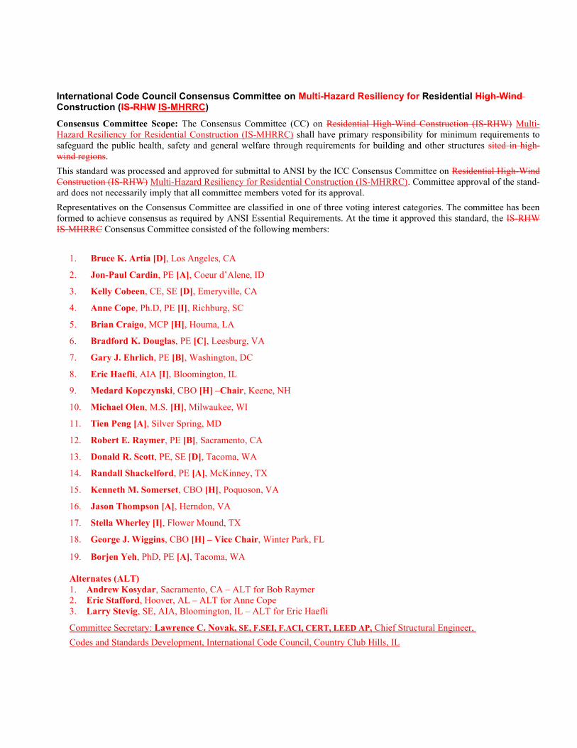
International Code Council Consensus Committee on Multi-Hazard Resiliency for Residential High-Wind Construction (IS-RHW IS-MHRRC)
Consensus Committee Scope: The Consensus Committee (CC) on Residential High-Wind Construction (IS-RHW) Multi-Hazard Resiliency for Residential Construction (IS-MHRRC) shall have primary responsibility for minimum requirements to safeguard the public health, safety and general welfare through requirements for building and other structures sited in high-wind regions.
This standard was processed and approved for submittal to ANSI by the ICC Consensus Committee on Residential High-Wind Construction (IS-RHW) Multi-Hazard Resiliency for Residential Construction (IS-MHRRC). Committee approval of the stand-ard does not necessarily imply that all committee members voted for its approval.
Representatives on the Consensus Committee are classified in one of three voting interest categories. The committee has been formed to achieve consensus as required by ANSI Essential Requirements. At the time it approved this standard, the IS-RHW IS-MHRRC Consensus Committee consisted of the following members:
1. Bruce K. Artia [D], Los Angeles, CA
2. Jon-Paul Cardin, PE [A], Coeur d’Alene, ID
3. Kelly Cobeen, CE, SE [D], Emeryville, CA
4. Anne Cope, Ph.D, PE [I], Richburg, SC
5. Brian Craigo, MCP [H], Houma, LA
6. Bradford K. Douglas, PE [C], Leesburg, VA
7. Gary J. Ehrlich, PE [B], Washington, DC
8. Eric Haefli, AIA [I], Bloomington, IL
9. Medard Kopczynski, CBO [H] –Chair, Keene, NH
10. Michael Olen, M.S. [H], Milwaukee, WI
11. Tien Peng [A], Silver Spring, MD
12. Robert E. Raymer, PE [B], Sacramento, CA
13. Donald R. Scott, PE, SE [D], Tacoma, WA
14. Randall Shackelford, PE [A], McKinney, TX
15. Kenneth M. Somerset, CBO [H], Poquoson, VA
16. Jason Thompson [A], Herndon, VA
17. Stella Wherley [I], Flower Mound, TX
18. George J. Wiggins, CBO [H] – Vice Chair, Winter Park, FL
19. Borjen Yeh, PhD, PE [A], Tacoma, WA Alternates (ALT) 1. Andrew Kosydar, Sacramento, CA – ALT for Bob Raymer 2. Eric Stafford, Hoover, AL – ALT for Anne Cope 3. Larry Stevig, SE, AIA, Bloomington, IL – ALT for Eric Haefli
Committee Secretary: Lawrence C. Novak, SE, F.SEI, F.ACI, CERT, LEED AP, Chief Structural Engineer,
Codes and Standards Development, International Code Council, Country Club Hills, IL
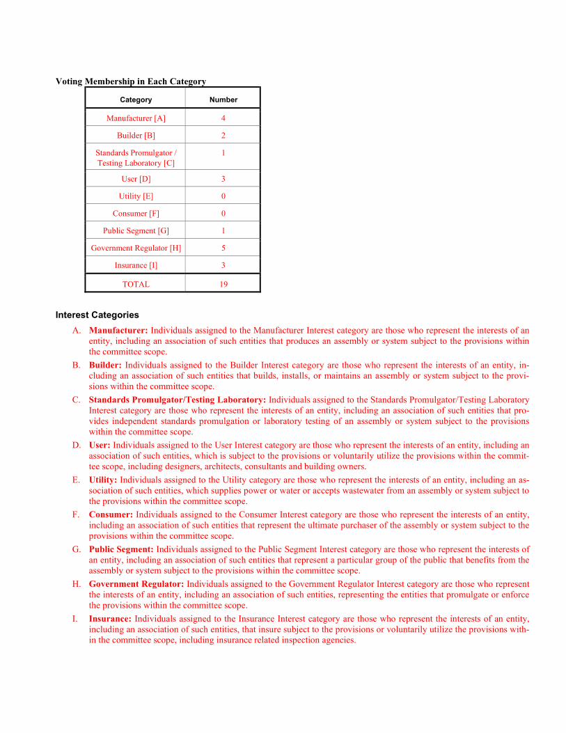
Voting Membership in Each Category
Category Number
Manufacturer [A] 4
Builder [B] 2
Standards Promulgator / Testing Laboratory [C]
1
User [D] 3
Utility [E] 0
Consumer [F] 0
Public Segment [G] 1
Government Regulator [H] 5
Insurance [I] 3
TOTAL 19
Interest Categories
A. Manufacturer: Individuals assigned to the Manufacturer Interest category are those who represent the interests of an entity, including an association of such entities that produces an assembly or system subject to the provisions within the committee scope.
B. Builder: Individuals assigned to the Builder Interest category are those who represent the interests of an entity, in-cluding an association of such entities that builds, installs, or maintains an assembly or system subject to the provi-sions within the committee scope.
C. Standards Promulgator/Testing Laboratory: Individuals assigned to the Standards Promulgator/Testing Laboratory Interest category are those who represent the interests of an entity, including an association of such entities that pro-vides independent standards promulgation or laboratory testing of an assembly or system subject to the provisions within the committee scope.
D. User: Individuals assigned to the User Interest category are those who represent the interests of an entity, including an association of such entities, which is subject to the provisions or voluntarily utilize the provisions within the commit-tee scope, including designers, architects, consultants and building owners.
E. Utility: Individuals assigned to the Utility category are those who represent the interests of an entity, including an as-sociation of such entities, which supplies power or water or accepts wastewater from an assembly or system subject to the provisions within the committee scope.
F. Consumer: Individuals assigned to the Consumer Interest category are those who represent the interests of an entity, including an association of such entities that represent the ultimate purchaser of the assembly or system subject to the provisions within the committee scope.
G. Public Segment: Individuals assigned to the Public Segment Interest category are those who represent the interests of an entity, including an association of such entities that represent a particular group of the public that benefits from the assembly or system subject to the provisions within the committee scope.
H. Government Regulator: Individuals assigned to the Government Regulator Interest category are those who represent the interests of an entity, including an association of such entities, representing the entities that promulgate or enforce the provisions within the committee scope.
I. Insurance: Individuals assigned to the Insurance Interest category are those who represent the interests of an entity, including an association of such entities, that insure subject to the provisions or voluntarily utilize the provisions with-in the committee scope, including insurance related inspection agencies.
General Interest: Individuals assigned to the General Interest category are those who represent the interests of an entity, in-cluding an association of such entities, representing the general public, or entities that promulgate or enforce the provisions within the committee scope. These entities include consumers and government regulatory agencies.
User Interest: Individuals assigned to the User Interest category are those who represent the interests of an entity, includ-ing an association of such entities, which is subject to the provisions or that voluntarily utilizes provisions within the com-mittee scope. These entities include academia, applied research laboratory, building owner, design professional, government nonregulatory agency, insurance company, private inspection agency and product certification/evaluation agency.
Producer Interest: Individuals assigned to the Producer Interest category are those who represent the interests of an entity, including an association of such entities, which produces, installs or maintains a product, assembly or system subject to the provisions within the committee scope. These entities include builder, contractor, distributor, laborer, manufacturer, material association, standards promulgator, testing laboratory and utility.
NOTE — Multiple Interests: Individuals representing entities in more than one of the above interest categories, one of which is a Producer Interest, are assigned to Producer Interest. Individuals representing entities in the General Interest and User Interest categories are assigned to the User Interest.
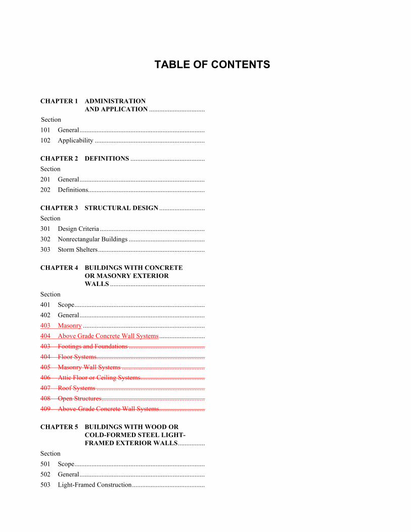
TABLE OF CONTENTS
CHAPTER 1 ADMINISTRATION AND APPLICATION .................................
Section
101 General ..........................................................................
102 Applicability .................................................................
CHAPTER 2 DEFINITIONS ............................................
Section
201 General ..........................................................................
202 Definitions.....................................................................
CHAPTER 3 STRUCTURAL DESIGN ...........................
Section
301 Design Criteria ..............................................................
302 Nonrectangular Buildings .............................................
303 Storm Shelters ...............................................................
CHAPTER 4 BUILDINGS WITH CONCRETE OR MASONRY EXTERIOR WALLS ........................................................
Section
401 Scope .............................................................................
402 General ..........................................................................
403 Masonry ........................................................................
404 Above Grade Concrete Wall Systems ...........................
403 Footings and Foundations .............................................
404 Floor Systems ................................................................
405 Masonry Wall Systems .................................................
406 Attic Floor or Ceiling Systems ......................................
407 Roof Systems ................................................................
408 Open Structures .............................................................
409 Above-Grade Concrete Wall Systems...........................
CHAPTER 5 BUILDINGS WITH WOOD OR COLD-FORMED STEEL LIGHT- FRAMED EXTERIOR WALLS ................
Section
501 Scope .............................................................................
502 General ..........................................................................
503 Light-Framed Construction ...........................................
504 Fasteners and Connectors ..............................................
505 Footings and Foundations .............................................
506 Slab-on-Grade Floor Systems .......................................
507 Special Provisions for Wood Structural Panels Used to Resist Both Shear and Uplift .....................................
508 Open Structures .............................................................
509 Roof Sheathing in Wood Light-Framed Construction .......................................
CHAPTER 6 COMBINED EXTERIOR WALL CONSTRUCTION .........................
Section
601 Scope .............................................................................
602 Light-Frame Second Story Above Concrete,
Masonry or ICF First Story ..........................................
602 Concrete, Masonry or ICF First Story; Wood Frame Second Story .............................
603 Wood Frame Gable End Walls Above Concrete, Masonry or ICF Walls ...................
604 Cold-formed Steel Framing Above Concrete, Masonry or ICF Walls ..............................
CHAPTER 7 ROOF ASSEMBLIES .................................
Section
701 General ..........................................................................
702 Weather Protection ........................................................
703 Materials .......................................................................
704 Requirements for Roof Coverings ................................
CHAPTER 8 FENESTRATION .......................................
Section
801 Scope General ...............................................................
802 Windows, Unit Skylights, Garage Doors, Sliding Glass Doors, Glass Patio Doors and Entry Doors Installed in Wall/Roof Systems ...............................................
803 Windborne Debris .........................................................
CHAPTER 9 EXTERIOR WALL COVERING, FLASHING, AND SOFFIT ........................
Section
901 General ..........................................................................
902 Wall Coverings .............................................................
903 Flashing .........................................................................
904 Soffit .............................................................................
905 Drained Assembly Wall Over Mass Assembly Wall ....

906 Foam Plastic Insulating Sheathing ................................
902 Wood, Hardboard and Wood Structural Panel Siding/Sheathing .............................................
903 Stucco ............................................................................
904 Masonry Veneer ............................................................
905 Aluminum and Vinyl Siding .........................................
906 Exterior Insulation Finish Systems ...............................
907 Fiber Cement Siding .....................................................
908 Metal Veneers ...............................................................
909 Drained Assembly Wall Over Mass Assembly Wall ..........................................................
910 Foam Plastic Insulating Sheathing ................................
CHAPTER 10 REFERENCED STANDARDS ..................
APPENDIX A DESIGN LOAD ASSUMPTIONS .............
APPENDIX B FLOOD-RESISTANT FOUNDATIONS FOR RESIDENTIAL BUILDINGS WITH WOOD OR COLD- FORMED STEEL LIGHT- FRAMED WALLS ......................................
APPENDIX C ICC 600 DESIGN CHECKLIST................
APPENDIX D DIMENSIONS OF STANDARIZED NAILS DESCRIBED BY PENNYWEIGHT SYSTEM .......................

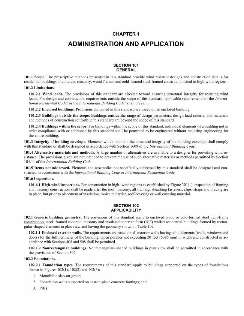
CHAPTER 1
ADMINISTRATION AND APPLICATION
SECTION 101 GENERAL
101.1 Scope. The prescriptive methods presented in this standard provide wind resistant designs and construction details for residential buildings of concrete, masonry, wood-framed and cold-formed steel-framed construction sited in high-wind regions.
101.2 Limitations.
101.2.1 Wind loads. The provisions of this standard are directed toward ensuring structural integrity for resisting wind loads. For design and construction requirements outside the scope of this standard, applicable requirements of the Interna-tional Residential Code® or the International Building Code® shall prevail.
101.2.2 Enclosed buildings. Provisions contained in this standard are based on an enclosed building.
101.2.3 Buildings outside the scope. Buildings outside the range of design parameters, design load criteria, and materials and methods of construction set forth in this standard are beyond the scope of this standard.
101.2.4 Buildings within the scope. For buildings within the scope of this standard, individual elements of a building not in strict compliance with or addressed by this standard shall be permitted to be engineered without requiring engineering for the entire building.
101.3 Integrity of building envelope. Elements which maintain the structural integrity of the building envelope shall comply with this standard or shall be designed in accordance with Section 1609 of the International Building Code.
101.4 Alternative materials and methods. A large number of alternatives are available to a designer for providing wind re-sistance. The provisions given are not intended to prevent the use of such alternative materials or methods permitted by Section 104.11 of the International Building Code.
101.5 Items not addressed. Elements and assemblies not specifically addressed by this standard shall be designed and con-structed in accordance with the International Building Code or International Residential Code.
101.6 Inspections.
101.6.1 High-wind inspections. For construction in high- wind regions as established by Figure 301(1), inspection of framing and masonry construction shall be made after the roof, masonry, all framing, sheathing fasteners, clips, straps and bracing are in place, but prior to placement of insulation, moisture barrier, roof covering or wall covering material.
SECTION 102 APPLICABILITY
102.1 Generic building geometry. The provisions of this standard apply to enclosed wood or cold-formed steel light-frame construction, steel- framed concrete, masonry and insulated concrete form (ICF) walled residential buildings formed by rectan-gular-shaped elements in plan view and having the geometry shown in Table 102.
102.1.1 Enclosed exterior walls. The requirements are based on all exterior walls having solid elements (walls, windows and doors) for the full perimeter of the building. Open porches not exceeding 20 feet (6096 mm) in width and constructed in ac-cordance with Sections 408 and 508 shall be permitted.
102.1.2 Nonrectangular buildings. Nonrectangular- shaped buildings in plan view shall be permitted in accordance with the provisions of Section 302.
102.2 Foundations.
102.2.1 Foundation types. The requirements of this standard apply to buildings supported on the types of foundations shown in Figures 102(1), 102(2) and 102(3):
1. Monolithic slab-on-grade;
2. Foundation walls supported on cast-in-place concrete footings; and
3. Piles.

102.3 Flood-resistant construction. In flood hazard areas, flood-resistant construction shall be in accordance with the Interna-tional Residential Code or ASCE 24. Appendix B of this standard and FEMA P550 provide guidance for flood-resistant foun-dations and prescriptive designs for flood- and wind-resistant foundations for buildings with wood or cold-formed steel light-framed exterior walls.
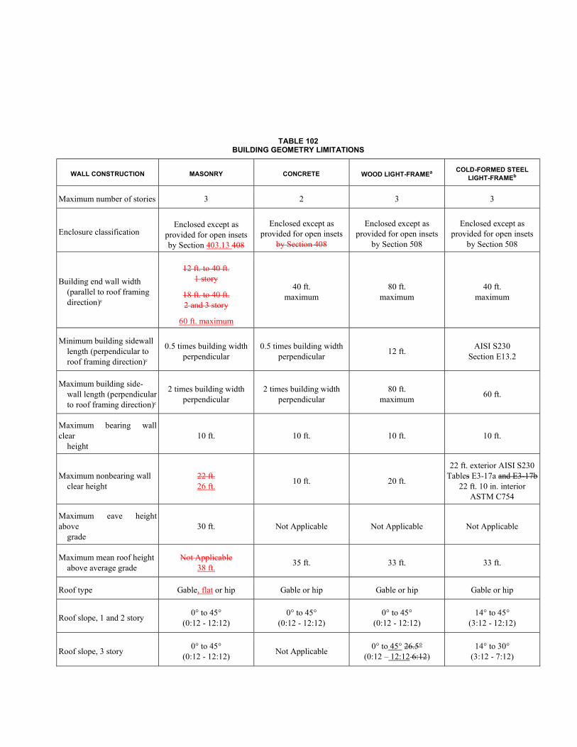
TABLE 102 BUILDING GEOMETRY LIMITATIONS
WALL CONSTRUCTION MASONRY CONCRETE WOOD LIGHT-FRAMEa COLD-FORMED STEEL
LIGHT-FRAMEb
Maximum number of stories 3 2 3 3
Enclosure classification Enclosed except as
provided for open insets by Section 403.13 408
Enclosed except as provided for open insets
by Section 408
Enclosed except as provided for open insets
by Section 508
Enclosed except as provided for open insets
by Section 508
Building end wall width (parallel to roof framing direction)c
12 ft. to 40 ft. 1 story
18 ft. to 40 ft. 2 and 3 story
60 ft. maximum
40 ft. maximum
80 ft. maximum
40 ft. maximum
Minimum building sidewall length (perpendicular to roof framing direction)c
0.5 times building width perpendicular
0.5 times building width perpendicular
12 ft. AISI S230
Section E13.2
Maximum building side- wall length (perpendicular to roof framing direction)c
2 times building width perpendicular
2 times building width perpendicular
80 ft. maximum
60 ft.
Maximum bearing wall clear height
10 ft. 10 ft. 10 ft. 10 ft.
Maximum nonbearing wall clear height
22 ft. 26 ft.
10 ft. 20 ft.
22 ft. exterior AISI S230 Tables E3-17a and E3-17b
22 ft. 10 in. interior ASTM C754
Maximum eave height above grade
30 ft. Not Applicable Not Applicable Not Applicable
Maximum mean roof height above average grade
Not Applicable 38 ft.
35 ft. 33 ft. 33 ft.
Roof type Gable, flat or hip Gable or hip Gable or hip Gable or hip
Roof slope, 1 and 2 story 0° to 45°
(0:12 - 12:12) 0° to 45°
(0:12 - 12:12) 0° to 45°
(0:12 - 12:12) 14° to 45°
(3:12 - 12:12)
Roof slope, 3 story 0° to 45°
(0:12 - 12:12) Not Applicable
0° to 45° 26.5° (0:12 – 12:12 6:12)
14° to 30° (3:12 - 7:12)
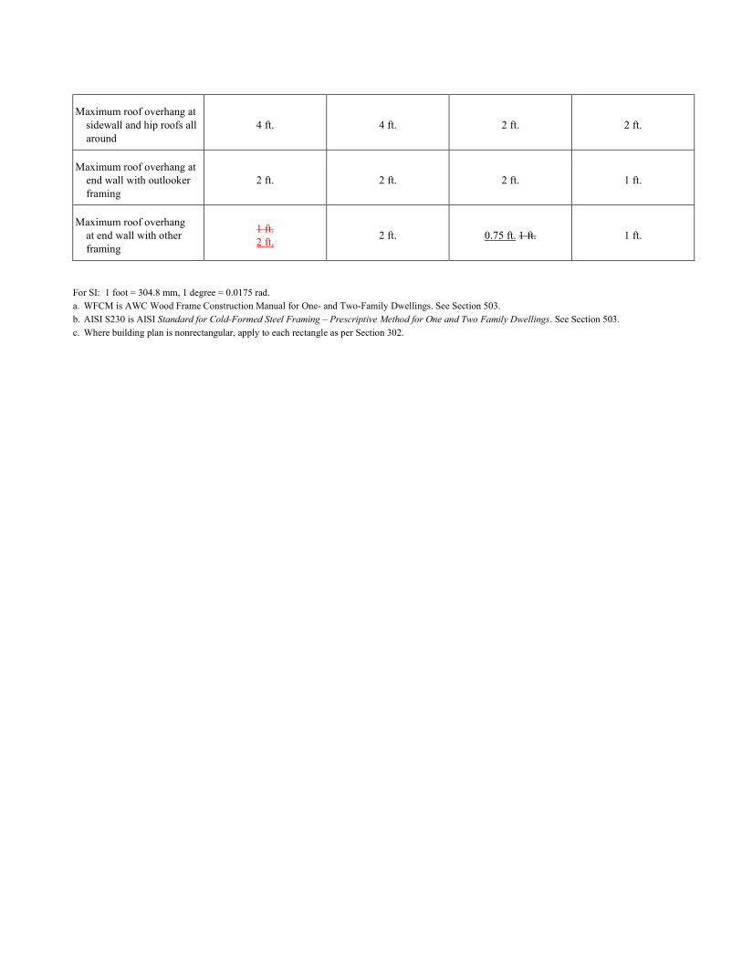
Maximum roof overhang at sidewall and hip roofs all around
4 ft. 4 ft. 2 ft. 2 ft.
Maximum roof overhang at end wall with outlooker framing
2 ft. 2 ft. 2 ft. 1 ft.
Maximum roof overhang at end wall with other framing
1 ft. 2 ft.
2 ft. 0.75 ft. 1 ft. 1 ft.
For SI: 1 foot = 304.8 mm, 1 degree = 0.0175 rad. a. WFCM is AWC Wood Frame Construction Manual for One- and Two-Family Dwellings. See Section 503. b. AISI S230 is AISI Standard for Cold-Formed Steel Framing – Prescriptive Method for One and Two Family Dwellings. See Section 503. c. Where building plan is nonrectangular, apply to each rectangle as per Section 302.
CHAPTER 2
DEFINITIONS
SECTION 201 GENERAL
201.1 General. For the purposes of this standard, the terms listed in Section 202 shall have the indicated meaning.
201.2 Undefined terms. The terms not specifically defined in this standard or in standards referenced herein shall have ordi-narily accepted meaning such as the context implies.
SECTION 202 DEFINITIONS
APPROVED. Approved by the building official or other authority having jurisdiction.
AVERAGE GRADE. A reference plane representing the average of finished ground level adjoining the building at all exterior walls. When the finished ground level slopes away from the exterior walls, the reference plane shall be established by the low-est points within the area between the building and the lot line or between the building and a point 6 feet (1829 mm) from the building, whichever is closer to the building.
BALLOON-FRAME CONSTRUCTION. Construction in which the exterior wall studs extend the full height of the building from foundation plate to rafter plate.
BLOCKED DIAPHRAGM. A diaphragm in which all adjoining panel edges occur over framing or lightweight nailers [usual-ly 2 inches by 4 inches (50.8 mm by 101.6 mm)] or other primary structural supports for the specific purpose of connecting the edges of the panels. This “blocking” is provided to allow connections of panels at all edges for better shear transfer.
BOND BEAM. One or more courses of masonry units grouted solid; cast-in-place concrete; or composite precast/cast-in-place concrete, reinforced with longitudinal reinforcement.
BUILDING LENGTH (L). The dimension of exterior walls perpendicular to the span of roof rafters or trusses [see Figure 202(1)].
BUILDING WIDTH (W). The dimension of exterior walls parallel to the span of roof rafters or trusses [see Figure 202(1)].
CEILING HEIGHT. Nominal distance measured at the sidewall between top of floor and bottom surface of ceiling above that is directly attached to roof/floor framing system [see Figure 202(1)].
CONCRETE COVER, SPECIFIED. The distance from the outer most surface of embedded reinforcement and the closest outer surface of concrete indicated on the construction documents.
CONTINUOUS (REINFORCING STEEL). Refers to lengths of reinforcing steel spliced together to act as a single unit, providing an uninterrupted connection capable of developing the full strength of the bar.
DESIGN WIND SPEED. Design wind speed in miles per hour (3 sec. gust) given in Figure 301(1) or as specified by the building official or other authority having jurisdiction.
DIAPHRAGM. A flat structural unit acting like a deep thin beam.
DRAG STRUT. A structural member that transfers axial loads between adjacent shear-resisting elements. Bond beams, top plates, joists, girders and truss chords may be used as drag struts provided connections at each end of the drag strut are capable of transferring loads (see Section 105).
END WALL. An exterior wall parallel to the primary floor and roof framing direction [see Figure 202(1)].
FACE SHELL. Side wall of a hollow masonry unit.
GROUP II, III, and IV WOOD SPECIES. Classifications of wood species by specific gravity for the purpose of fastening design. Specific gravities of various species are provided in the American Wood Council’s (AWC) National Design Specifica-tion (NDS) for Wood Construction.
Group II Species. Species with a specific gravity of 0.49 or greater (Douglas Fir, Southern Pine, etc.).
Group III Species. Species with a specific gravity of 0.42 or greater and less than 0.49 (Hem Fir, Spruce Pine Fir, etc.).
Group IV Species. Species with a specific gravity less than 0.42 (California Redwood, Western Cedar, etc.).
GROUT. A mixture of cementitious material and aggregate to which water is added to provide desired slump.
Coarse grout. A mixture of Portland cement, sand, pea gravel and water.
Fine grout. A mixture of Portland cement, sand and water.
HEADER. See “Lintel.”
HIGH-WIND REGION. Areas where the ultimate design wind speed equals or exceeds 120 miles per hour (52.8 m/s) or greater.
HURRICANE-PRONE REGIONS. Areas vulnerable to hurricanes, defined as the U.S. Atlantic Ocean and Gulf of Mexico coasts where the ultimate design wind speed, Vult, is greater than 115 miles per hour (51 m/s), and Hawaii, Puerto Rico, Guam, Virgin Islands and America Samoa.
INSULATED CONCRETE FORM (ICF). A concrete forming system using stay-in-place forms of rigid foam plastic insula-tion, a hybrid of cement and foam insulation, a hybrid of cement and wood chips, or other insulating material for constructing cast-in-place concrete walls.
INTERIOR SHEAR WALL. A shear wall located in the interior of the building; i.e., not an end wall or sidewall.
LINTEL. A beam placed over an opening in a wall.
MASONRY. A form of construction composed of concrete masonry units or clay masonry units laid up unit by unit and set in mortar.
MASONRY COVER. Protective covering for reinforcement consisting of masonry units, grout, or mortar or a combination thereof.
MEAN ROOF HEIGHT. The distance from average grade to the average roof elevation [see Figures 102(1), 102(2) and 102(3)].
OVERHANG. Projection of a roof beyond the wall below.
Eave overhang. Projection of a roof beyond the sidewall.
Rake overhang. Projection of a roof beyond the gable end wall.
RUNNING BOND. The placement of masonry units such that head joints in successive courses are horizontally offset at least one quarter of the unit length.
STACK BOND. The placement of masonry units in a bond pattern such that head joints in successive courses are vertically aligned. For the purpose of this standard, requirements for stack bond shall apply to all masonry laid in other than running bond.
SHEAR WALL. A wall or portion of a wall used to resist horizontal forces parallel to the wall (in-plane shear) [see Figure 405(8)].
SHEAR WALL PIER. Portion of a shear wall segment adjacent to and equal in height to the opening with the shortest height on either side of the shear wall segment [see Figure 405(8) 403(7)].
SHEAR WALL SEGMENT or SHEAR SEGMENT. Portion of a shear wall between openings extending between horizon-tal diaphragms and/or floor designed to resist in-plane shear (shear parallel to the wall) [see Figure 405(8) 403(7)].
SIDEWALL. An exterior wall perpendicular to the primary floor and roof framing direction [see Figure 202(1)].
STANDARD 90-DEGREE HOOK. Reinforcing steel which ends in a 90-degree (1.57 rad) bend plus extension beyond the bend [see Figure 409(5)].
STANDARD 180-DEGREE HOOK. Reinforcing steel which ends in a 180-degree (3.14 rad) bend plus a minimum extension beyond the bend [see Figure 409(5)].
STORY. The portion of a building included between the upper surface of a floor and upper surface of the roof or floor above.
ULTIMATE DESIGN WIND SPEED. The three-second gust wind speed in miles per hour (kilometers per second) at 33 feet (10 meters) above ground in Exposure C conditions, as given in Figure 301(1) or as established by the building official or other authority having jurisdiction.
WINDBORNE DEBRIS REGION. Areas within hurricane-prone regions located in accordance with one of the following:
1. Within 1 mile (1.61 km) of the mean high-water line where an Exposure D condition exists upwind at the waterline and the ultimate design wind speed, Vult, is 130 mph (58 m/s) or greater.
2. In areas where the ultimate design wind speed, Vult, is 140 mph (63 m/s) or greater; or Hawaii.

WOOD STRUCTURAL PANEL. A structural panel manufactured in accordance with DOC PS 1 or DOC PS 2 from veneers, wood strands or wafers or a combination of veneer and wood strands or wafers bonded together with waterproof synthetic res-ins or other suitable bonding systems. Examples of wood structural panels are: composite panels, oriented strand board (OSB) and plywood.
WYTHE. Each continuous vertical section of a masonry wall one masonry unit in thickness.

CHAPTER 3
STRUCTURAL DESIGN
SECTION 301 DESIGN CRITERIA
301.1 Wind loads. The loads used in the design of the various structural systems and elements of the buildings are separated into:
1. The overall (or global) forces used in the design of the Main Windforce-Resisting Systems (MWFRS); and
2. Those loads appropriate for the design of fasteners, cladding and elements of the building that must resist the much higher loadings induced over relatively small areas. The latter loads are designated Component and Cladding Loads (C&C).
301.2 Other design loads and assumptions. See Appendix A.
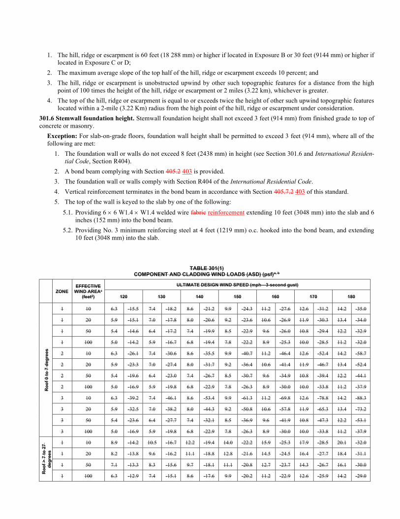
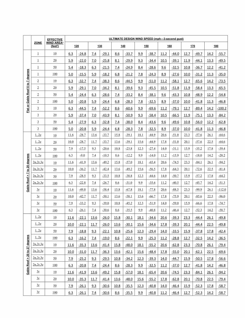
301.3 Ultimate Design design wind speeds. This standard provides prescriptive requirements and other details of construction for buildings sited in areas with ultimate design wind speeds of 120 to 195 180 miles per hour (52.8 to 80.5 m/s). The appropri-ate ultimate design wind speed to be selected for a particular building site shall be determined from Figure 301(1). Where not otherwise provided, design wind pressures for wall coverings, curtain walls, roof coverings, exterior windows, skylights, gar-age doors and exterior doors and other component and cladding elements shall be determined from Table 301(1) or Table 301(2) and adjusted for height and exposure category per Table 301(23).
Unless noted otherwise, the ultimate design wind speeds (Vult) provided in this standard are ultimate design wind speeds (Vult) based on a 700-year mean return period interval. Design loads and pressures obtained from tables are nominal (ASD) design loads.
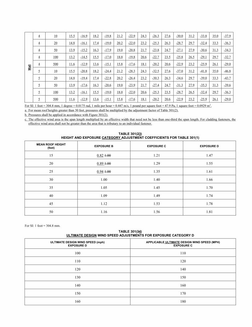
301.3.1 Ultimate Design design wind speeds for Exposure D. Where provisions for Exposure D are not provided, provi-sions for Exposure C are permitted to be used provided the ultimate design wind speeds are adjusted in accordance with Table 301(34).
301.4 Exposure categories. For each wind direction considered, an exposure category that adequately reflects the characteris-tics of ground surface irregularities shall be determined for the site at which the building or structure is to be constructed, in-cluding but not limited to variations in ground surface roughness that arise from natural topography, vegetation, and other con-struction. For any given wind direction, the exposure category in which a specific building or other structure is sited shall be assessed as being Exposure B, C or D as defined in Section 301.4.1, 301.4.2 or 301.4.3.
301.4.1 Exposure B. Urban and suburban areas, wooded areas or other terrain with numerous closely spaced obstructions having the size of single-family dwellings or larger. Use of this exposure category shall be limited to those areas for which terrain representative of Exposure B prevails in the upwind direction for a distance of at least 1,500 feet (460 m).
301.4.2 Exposure C. Open terrain with scattered obstructions, including surface undulations or other irregularities, having heights generally less than 30 feet (9144 mm) extending more than 1,500 feet (457 m) from the building site in any quad-rant. This exposure category shall also apply to any building located within Exposure B-type terrain where the building is di-rectly adjacent to open areas of Exposure C-type terrain in any quadrant for a distance of more than 600 feet (182.9 m). This category includes flat open country, and grasslands. Exposure C shall apply for all cases where Exposure B or D does not apply.
301.4.3 Exposure D. Flat, unobstructed areas exposed to wind flowing over open water, smooth mud flats, salt flats and un-broken ice for a distance of at least 5,000 feet (1,524 m). This exposure category shall apply only to those buildings and other structures exposed to the wind coming from over the unobstructed area water. Exposure D extends downwind from the edge of the unobstructed area inland from the shore line a distance of 600 feet (183 m) or 20 times the height of the building struc-ture, whichever is greater.
301.5 Topographic wind effects. Where required by the authority having jurisdiction, topographic wind effects in accordance with this section shall be considered for buildings located on the top half of isolated hills, ridges or escarpments. Table 301(45) shall be permitted to be used to determine an adjusted ultimate design wind speed. Where the ultimate design wind speed ad-justed for topographic wind effects exceeds the limitations of Section 301.3, the design of the building shall be in accordance with the International Building Code and ASCE 7. Topographic wind effects shall apply to buildings sited where all of the fol-lowing conditions exist:
1. The hill, ridge or escarpment is 60 feet (18 288 mm) or higher if located in Exposure B or 30 feet (9144 mm) or higher if located in Exposure C or D;
2. The maximum average slope of the top half of the hill, ridge or escarpment exceeds 10 percent; and
3. The hill, ridge or escarpment is unobstructed upwind by other such topographic features for a distance from the high point of 100 times the height of the hill, ridge or escarpment or 2 miles (3.22 km), whichever is greater.
4. The top of the hill, ridge or escarpment is equal to or exceeds twice the height of other such upwind topographic features located within a 2-mile (3.22 Km) radius from the high point of the hill, ridge or escarpment under consideration.
301.6 Stemwall foundation height. Stemwall foundation height shall not exceed 3 feet (914 mm) from finished grade to top of concrete or masonry.
Exception: For slab-on-grade floors, foundation wall height shall be permitted to exceed 3 feet (914 mm), where all of the following are met:
1. The foundation wall or walls do not exceed 8 feet (2438 mm) in height (see Section 301.6 and International Residen-tial Code, Section R404).
2. A bond beam complying with Section 405.2 403 is provided.
3. The foundation wall or walls comply with Section R404 of the International Residential Code.
4. Vertical reinforcement terminates in the bond beam in accordance with Section 405.7.2 403 of this standard.
5. The top of the wall is keyed to the slab by one of the following:
5.1. Providing 6 6 W1.4 W1.4 welded wire fabric reinforcement extending 10 feet (3048 mm) into the slab and 6 inches (152 mm) into the bond beam.
5.2. Providing No. 3 minimum reinforcing steel at 4 feet (1219 mm) o.c. hooked into the bond beam, and extending 10 feet (3048 mm) into the slab.
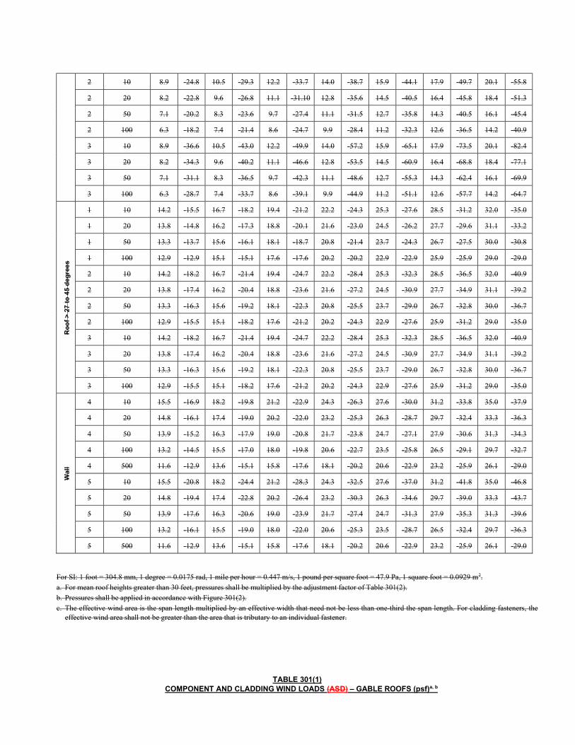
TABLE 301(1) COMPONENT AND CLADDING WIND LOADS (ASD) (psf)a, b
ZONE EFFECTIVE
WIND AREAc
(feet2)
ULTIMATE DESIGN WIND SPEED (mph—3-second gust)
120 130 140 150 160 170 180
Ro
of
0 t
o 7
deg
ree
s
1 10 6.3 -15.5 7.4 -18.2 8.6 -21.2 9.9 -24.3 11.2 -27.6 12.6 -31.2 14.2 -35.0
1 20 5.9 -15.1 7.0 -17.8 8.0 -20.6 9.2 -23.6 10.6 -26.9 11.9 -30.3 13.4 -34.0
1 50 5.4 -14.6 6.4 -17.2 7.4 -19.9 8.5 -22.9 9.6 -26.0 10.8 -29.4 12.2 -32.9
1 100 5.0 -14.2 5.9 -16.7 6.8 -19.4 7.8 -22.2 8.9 -25.3 10.0 -28.5 11.2 -32.0
2 10 6.3 -26.1 7.4 -30.6 8.6 -35.5 9.9 -40.7 11.2 -46.4 12.6 -52.4 14.2 -58.7
2 20 5.9 -23.3 7.0 -27.4 8.0 -31.7 9.2 -36.4 10.6 -41.4 11.9 -46.7 13.4 -52.4
2 50 5.4 -19.6 6.4 -23.0 7.4 -26.7 8.5 -30.7 9.6 -34.9 10.8 -39.4 12.2 -44.1
2 100 5.0 -16.9 5.9 -19.8 6.8 -22.9 7.8 -26.3 8.9 -30.0 10.0 -33.8 11.2 -37.9
3 10 6.3 -39.2 7.4 -46.1 8.6 -53.4 9.9 -61.3 11.2 -69.8 12.6 -78.8 14.2 -88.3
3 20 5.9 -32.5 7.0 -38.2 8.0 -44.3 9.2 -50.8 10.6 -57.8 11.9 -65.3 13.4 -73.2
3 50 5.4 -23.6 6.4 -27.7 7.4 -32.1 8.5 -36.9 9.6 -41.9 10.8 -47.3 12.2 -53.1
3 100 5.0 -16.9 5.9 -19.8 6.8 -22.9 7.8 -26.3 8.9 -30.0 10.0 -33.8 11.2 -37.9
Ro
of
> 7
to
27
d
eg
ree
s
1 10 8.9 -14.2 10.5 -16.7 12.2 -19.4 14.0 -22.2 15.9 -25.3 17.9 -28.5 20.1 -32.0
1 20 8.2 -13.8 9.6 -16.2 11.1 -18.8 12.8 -21.6 14.5 -24.5 16.4 -27.7 18.4 -31.1
1 50 7.1 -13.3 8.3 -15.6 9.7 -18.1 11.1 -20.8 12.7 -23.7 14.3 -26.7 16.1 -30.0
1 100 6.3 -12.9 7.4 -15.1 8.6 -17.6 9.9 -20.2 11.2 -22.9 12.6 -25.9 14.2 -29.0
2 10 8.9 -24.8 10.5 -29.3 12.2 -33.7 14.0 -38.7 15.9 -44.1 17.9 -49.7 20.1 -55.8
2 20 8.2 -22.8 9.6 -26.8 11.1 -31.10 12.8 -35.6 14.5 -40.5 16.4 -45.8 18.4 -51.3
2 50 7.1 -20.2 8.3 -23.6 9.7 -27.4 11.1 -31.5 12.7 -35.8 14.3 -40.5 16.1 -45.4
2 100 6.3 -18.2 7.4 -21.4 8.6 -24.7 9.9 -28.4 11.2 -32.3 12.6 -36.5 14.2 -40.9
3 10 8.9 -36.6 10.5 -43.0 12.2 -49.9 14.0 -57.2 15.9 -65.1 17.9 -73.5 20.1 -82.4
3 20 8.2 -34.3 9.6 -40.2 11.1 -46.6 12.8 -53.5 14.5 -60.9 16.4 -68.8 18.4 -77.1
3 50 7.1 -31.1 8.3 -36.5 9.7 -42.3 11.1 -48.6 12.7 -55.3 14.3 -62.4 16.1 -69.9
3 100 6.3 -28.7 7.4 -33.7 8.6 -39.1 9.9 -44.9 11.2 -51.1 12.6 -57.7 14.2 -64.7
Ro
of
> 2
7 to
45
de
gre
es
1 10 14.2 -15.5 16.7 -18.2 19.4 -21.2 22.2 -24.3 25.3 -27.6 28.5 -31.2 32.0 -35.0
1 20 13.8 -14.8 16.2 -17.3 18.8 -20.1 21.6 -23.0 24.5 -26.2 27.7 -29.6 31.1 -33.2
1 50 13.3 -13.7 15.6 -16.1 18.1 -18.7 20.8 -21.4 23.7 -24.3 26.7 -27.5 30.0 -30.8
1 100 12.9 -12.9 15.1 -15.1 17.6 -17.6 20.2 -20.2 22.9 -22.9 25.9 -25.9 29.0 -29.0
2 10 14.2 -18.2 16.7 -21.4 19.4 -24.7 22.2 -28.4 25.3 -32.3 28.5 -36.5 32.0 -40.9
2 20 13.8 -17.4 16.2 -20.4 18.8 -23.6 21.6 -27.2 24.5 -30.9 27.7 -34.9 31.1 -39.2
2 50 13.3 -16.3 15.6 -19.2 18.1 -22.3 20.8 -25.5 23.7 -29.0 26.7 -32.8 30.0 -36.7
2 100 12.9 -15.5 15.1 -18.2 17.6 -21.2 20.2 -24.3 22.9 -27.6 25.9 -31.2 29.0 -35.0
3 10 14.2 -18.2 16.7 -21.4 19.4 -24.7 22.2 -28.4 25.3 -32.3 28.5 -36.5 32.0 -40.9
3 20 13.8 -17.4 16.2 -20.4 18.8 -23.6 21.6 -27.2 24.5 -30.9 27.7 -34.9 31.1 -39.2
3 50 13.3 -16.3 15.6 -19.2 18.1 -22.3 20.8 -25.5 23.7 -29.0 26.7 -32.8 30.0 -36.7
3 100 12.9 -15.5 15.1 -18.2 17.6 -21.2 20.2 -24.3 22.9 -27.6 25.9 -31.2 29.0 -35.0
Wal
l
4 10 15.5 -16.9 18.2 -19.8 21.2 -22.9 24.3 -26.3 27.6 -30.0 31.2 -33.8 35.0 -37.9
4 20 14.8 -16.1 17.4 -19.0 20.2 -22.0 23.2 -25.3 26.3 -28.7 29.7 -32.4 33.3 -36.3
4 50 13.9 -15.2 16.3 -17.9 19.0 -20.8 21.7 -23.8 24.7 -27.1 27.9 -30.6 31.3 -34.3
4 100 13.2 -14.5 15.5 -17.0 18.0 -19.8 20.6 -22.7 23.5 -25.8 26.5 -29.1 29.7 -32.7
4 500 11.6 -12.9 13.6 -15.1 15.8 -17.6 18.1 -20.2 20.6 -22.9 23.2 -25.9 26.1 -29.0
5 10 15.5 -20.8 18.2 -24.4 21.2 -28.3 24.3 -32.5 27.6 -37.0 31.2 -41.8 35.0 -46.8
5 20 14.8 -19.4 17.4 -22.8 20.2 -26.4 23.2 -30.3 26.3 -34.6 29.7 -39.0 33.3 -43.7
5 50 13.9 -17.6 16.3 -20.6 19.0 -23.9 21.7 -27.4 24.7 -31.3 27.9 -35.3 31.3 -39.6
5 100 13.2 -16.1 15.5 -19.0 18.0 -22.0 20.6 -25.3 23.5 -28.7 26.5 -32.4 29.7 -36.3
5 500 11.6 -12.9 13.6 -15.1 15.8 -17.6 18.1 -20.2 20.6 -22.9 23.2 -25.9 26.1 -29.0
For SI: 1 foot = 304.8 mm, 1 degree = 0.0175 rad, 1 mile per hour = 0.447 m/s, 1 pound per square foot = 47.9 Pa, 1 square foot = 0.0929 m2. a. For mean roof heights greater than 30 feet, pressures shall be multiplied by the adjustment factor of Table 301(2). b. Pressures shall be applied in accordance with Figure 301(2). c. The effective wind area is the span length multiplied by an effective width that need not be less than one-third the span length. For cladding fasteners, the
effective wind area shall not be greater than the area that is tributary to an individual fastener.
TABLE 301(1) COMPONENT AND CLADDING WIND LOADS (ASD) – GABLE ROOFS (psf)a, b
ZONE EFFECTIVE
WIND AREAc
(feet2)
ULTIMATE DESIGN WIND SPEED (mph—3-second gust)
120 130 140 150 160 170 180
Fla
t o
r G
ab
le R
oo
f 0
to 7
de
gre
es
1 10 6.3 -24.8 7.4 -29.1 8.6 -33.7 9.9 -38.7 11.2 -44.0 12.7 -49.7 14.2 -55.7
1 20 5.9 -22.0 7.0 -25.8 8.1 -29.9 9.3 -34.4 10.5 -39.1 11.9 -44.1 13.3 -49.5
1 50 5.4 -18.3 6.3 -21.5 7.4 -24.9 8.4 -28.6 9.6 -32.5 10.8 -36.7 12.2 -41.2
1 100 5.0 -15.5 5.9 -18.2 6.8 -21.2 7.8 -24.3 8.9 -27.6 10.0 -31.2 11.3 -35.0
2 10 6.3 -32.7 7.4 -38.3 8.6 -44.5 9.9 -51.0 11.2 -58.1 12.7 -65.6 14.2 -73.5
2 20 5.9 -29.1 7.0 -34.2 8.1 -39.6 9.3 -45.5 10.5 -51.8 11.9 -58.4 13.3 -65.5
2 50 5.4 -24.4 6.3 -28.6 7.4 -33.2 8.4 -38.1 9.6 -43.3 10.8 -48.9 12.2 -54.8
2 100 5.0 -20.8 5.9 -24.4 6.8 -28.3 7.8 -32.5 8.9 -37.0 10.0 -41.8 11.3 -46.8
3 10 6.3 -44.5 7.4 -52.2 8.6 -60.6 9.9 -69.6 11.2 -79.1 12.7 -89.4 14.2 -100.2
3 20 5.9 -37.4 7.0 -43.9 8.1 -50.9 9.3 -58.4 10.5 -66.5 11.9 -75.1 13.3 -84.2
3 50 5.4 -27.9 6.3 -32.8 7.4 -38.0 8.4 -43.6 9.6 -49.6 10.8 -56.0 12.2 -62.8
3 100 5.0 -20.8 5.9 -24.4 6.8 -28.3 7.8 -32.5 8.9 -37.0 10.0 -41.8 11.3 -46.8
Gab
le R
oo
f >
7 t
o 2
0 d
egre
es
1, 2e 10 11.6 -28.7 13.6 -33.7 15.8 -39.1 18.1 -44.9 20.6 -51.0 23.3 -57.6 26.1 -64.6
1, 2e 20 10.0 -28.7 11.7 -33.7 13.6 -39.1 15.6 -44.9 17.8 -51.0 20.1 -57.6 22.5 -64.6
1, 2e 50 7.9 -17.5 9.3 -20.6 10.8 -23.8 12.3 -27.4 14.0 -31.1 15.9 -35.2 17.8 -39.4
1, 2e 100 6.3 -9.0 7.4 -10.5 8.6 -12.2 9.9 -14.0 11.2 -15.9 12.7 -18.0 14.2 -20.2
2n,2r,3e 10 11.6 -41.9 13.6 -49.2 15.8 -57.0 18.1 -65.4 20.6 -74.5 23.3 -84.1 26.1 -94.2
2n,2r,3e 20 10.0 -36.2 11.7 -42.4 13.6 -49.2 15.6 -56.5 17.8 -64.3 20.1 -72.6 22.5 -81.4
2n,2r,3e 50 7.9 -28.5 9.3 -33.5 10.8 -38.8 12.3 -44.6 14.0 -50.7 15.9 -57.2 17.8 -64.2
2n,2r,3e 100 6.3 -22.8 7.4 -26.7 8.6 -31.0 9.9 -35.6 11.2 -40.5 12.7 -45.7 14.2 -51.3
3r 10 11.6 -49.8 13.6 -58.4 15.8 -67.8 18.1 -77.8 20.6 -88.5 23.3 -99.9 26.1 -112.0
3r 20 10.0 -42.7 11.7 -50.1 13.6 -58.1 15.6 -66.7 17.8 -75.9 20.1 -85.6 22.5 -96.0
3r 50 7.9 -33.2 9.3 -39.0 10.8 -45.2 12.3 -51.9 14.0 -59.0 15.9 -66.6 17.8 -74.7
3r 100 6.3 -26.1 7.4 -30.6 8.6 -35.5 9.9 -40.8 11.2 -46.4 12.7 -52.3 14.2 -58.7
Gab
le R
oo
f >
20
to
27
de
gre
es
1, 2e 10 11.6 -22.1 13.6 -26.0 15.8 -30.1 18.1 -34.6 20.6 -39.3 23.3 -44.4 26.1 -49.8
1, 2e 20 10.0 -22.1 11.7 -26.0 13.6 -30.1 15.6 -34.6 17.8 -39.3 20.1 -44.4 22.5 -49.8
1, 2e 50 7.9 -18.8 9.3 -22.1 10.8 -25.6 12.3 -29.4 14.0 -33.5 15.9 -37.8 17.8 -42.4
1, 2e 100 6.3 -16.2 7.4 -19.0 8.6 -22.1 9.9 -25.3 11.2 -28.8 12.7 -32.5 14.2 -36.5
2n,2r,3e 10 11.6 -35.3 13.6 -41.4 15.8 -48.0 18.1 -55.2 20.6 -62.8 23.3 -70.8 26.1 -79.4
2n,2r,3e 20 10.0 -31.0 11.7 -36.3 13.6 -42.1 15.6 -48.4 17.8 -55.0 20.1 -62.1 22.5 -69.6
2n,2r,3e 50 7.9 -25.2 9.3 -29.5 10.8 -34.2 12.3 -39.3 14.0 -44.7 15.9 -50.5 17.8 -56.6
2n,2r,3e 100 6.3 -20.8 7.4 -24.4 8.6 -28.3 9.9 -32.5 11.2 -37.0 12.7 -41.8 14.2 -46.8
3r 10 11.6 -41.9 13.6 -49.2 15.8 -57.0 18.1 -65.4 20.6 -74.5 23.3 -84.1 26.1 -94.2
3r 20 10.0 -35.3 11.7 -41.4 13.6 -48.0 15.6 -55.2 17.8 -62.8 20.1 -70.8 22.5 -79.4
3r 50 7.9 -26.1 9.3 -30.6 10.8 -35.5 12.3 -40.8 14.0 -46.4 15.9 -52.3 17.8 -58.7
3r 100 6.3 -26.1 7.4 -30.6 8.6 -35.5 9.9 -40.8 11.2 -46.4 12.7 -52.3 14.2 -58.7
Gab
le R
oo
f >
27
to
45
de
gre
es
1,2e,2r 10 14.2 -26.1 16.7 -30.6 19.4 -35.5 22.2 -40.8 25.3 -46.4 28.5 -52.3 32.0 -58.7
1,2e,2r 20 12.6 -22.1 14.8 -26.0 17.2 -30.1 19.8 -34.6 22.5 -39.3 25.4 -44.4 28.5 -49.8
1,2e,2r 50 10.5 -16.9 12.4 -19.8 14.3 -22.9 16.5 -26.3 18.7 -30.0 21.1 -33.8 23.7 -37.9
1,2e,2r 100 9.0 -12.9 10.5 -15.1 12.2 -17.6 14.0 -20.2 15.9 -22.9 18.0 -25.9 20.2 -29.0
2n, 3r 10 14.2 -28.7 16.7 -33.7 19.4 -39.1 22.2 -44.9 25.3 -51.0 28.5 -57.6 32.0 -64.6
2n, 3r 20 12.6 -25.7 14.8 -30.1 17.2 -34.9 19.8 -40.1 22.5 -45.6 25.4 -51.5 28.5 -57.8
2n, 3r 50 10.5 -21.6 12.4 -25.4 14.3 -29.4 16.5 -33.8 18.7 -38.4 21.1 -43.4 23.7 -48.6
2n, 3r 100 9.0 -18.6 10.5 -21.8 12.2 -25.3 14.0 -29.0 15.9 -33.0 18.0 -37.3 20.2 -41.8
3e 10 14.2 -35.3 16.7 -41.4 19.4 -48.0 22.2 -55.2 25.3 -62.8 28.5 -70.8 32.0 -79.4
3e 20 12.6 -31.3 14.8 -36.8 17.2 -42.7 19.8 -49.0 22.5 -55.7 25.4 -62.9 28.5 -70.5
3e 50 10.5 -26.1 12.4 -30.6 14.3 -35.5 16.5 -40.8 18.7 -46.4 21.1 -52.3 23.7 -58.7
3e 100 9.0 -22.1 10.5 -26.0 12.2 -30.1 14.0 -34.6 15.9 -39.3 18.0 -44.4 20.2 -49.8
Wal
l
4 10 15.5 -16.9 18.2 -19.8 21.2 -22.9 24.3 -26.3 27.6 -30.0 31.2 -33.8 35.0 -37.9
4 20 14.8 -16.1 17.4 -19.0 20.2 -22.0 23.2 -25.3 26.3 -28.7 29.7 -32.4 33.3 -36.3
4 50 13.9 -15.2 16.3 -17.9 19.0 -20.8 21.7 -23.8 24.7 -27.1 27.9 -30.6 31.3 -34.3
4 100 13.2 -14.5 15.5 -17.0 18.0 -19.8 20.6 -22.7 23.5 -25.8 26.5 -29.1 29.7 -32.7
4 500 11.6 -12.9 13.6 -15.1 15.8 -17.6 18.1 -20.2 20.6 -22.9 23.2 -25.9 26.1 -29.0
5 10 15.5 -20.8 18.2 -24.4 21.2 -28.3 24.3 -32.5 27.6 -37.0 31.2 -41.8 35.0 -46.8
5 20 14.8 -19.4 17.4 -22.8 20.2 -26.4 23.2 -30.3 26.3 -34.6 29.7 -39.0 33.3 -43.7
5 50 13.9 -17.6 16.3 -20.6 19.0 -23.9 21.7 -27.4 24.7 -31.3 27.9 -35.3 31.3 -39.6
5 100 13.2 -16.1 15.5 -19.0 18.0 -22.0 20.6 -25.3 23.5 -28.7 26.5 -32.4 29.7 -36.3
5 500 11.6 -12.9 13.6 -15.1 15.8 -17.6 18.1 -20.2 20.6 -22.9 23.2 -25.9 26.1 -29.0
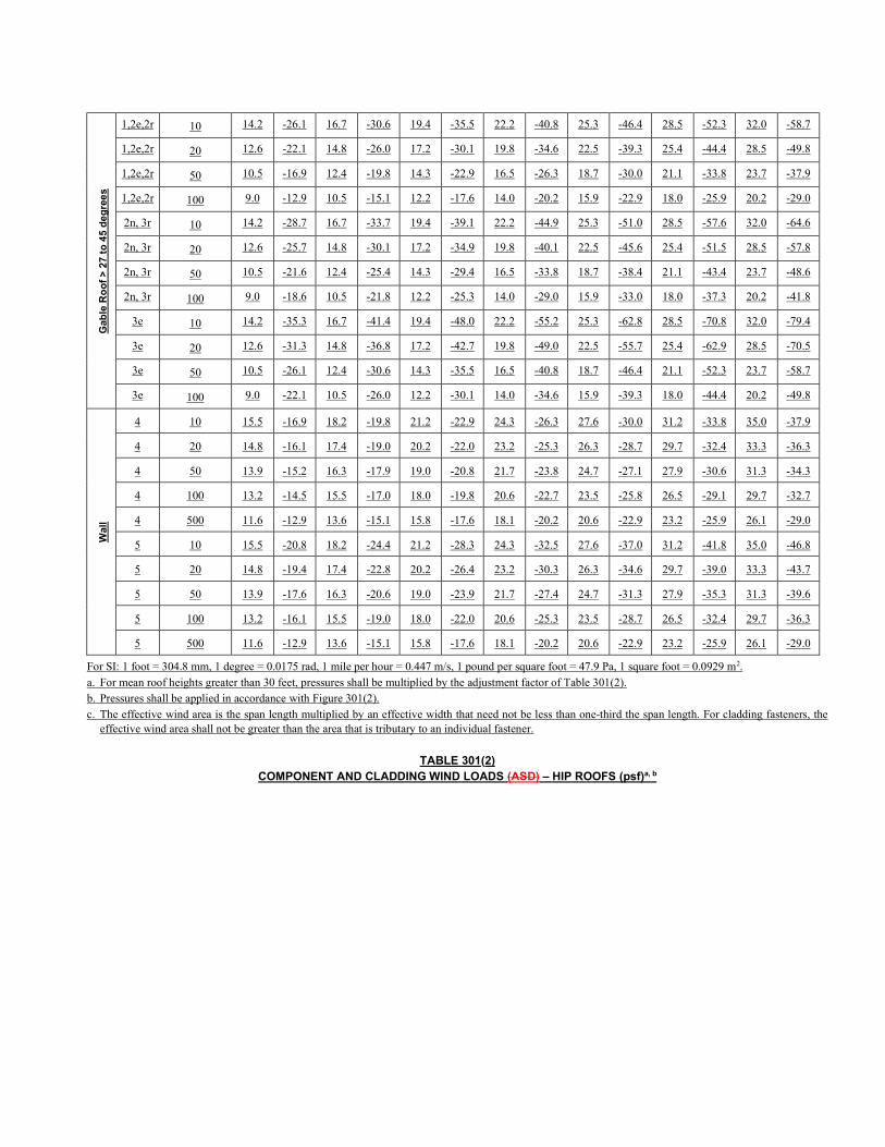
For SI: 1 foot = 304.8 mm, 1 degree = 0.0175 rad, 1 mile per hour = 0.447 m/s, 1 pound per square foot = 47.9 Pa, 1 square foot = 0.0929 m2. a. For mean roof heights greater than 30 feet, pressures shall be multiplied by the adjustment factor of Table 301(2). b. Pressures shall be applied in accordance with Figure 301(2). c. The effective wind area is the span length multiplied by an effective width that need not be less than one-third the span length. For cladding fasteners, the
effective wind area shall not be greater than the area that is tributary to an individual fastener.
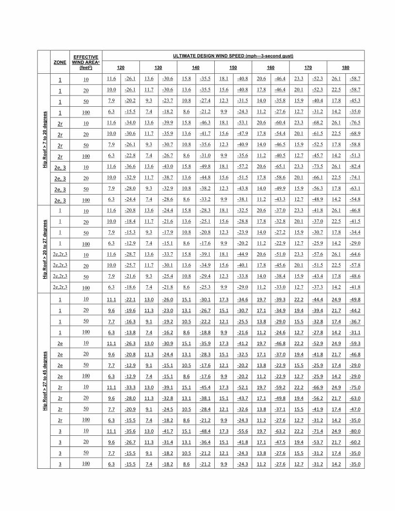
TABLE 301(2) COMPONENT AND CLADDING WIND LOADS (ASD) – HIP ROOFS (psf)a, b
ZONE EFFECTIVE
WIND AREAc
(feet2)
ULTIMATE DESIGN WIND SPEED (mph—3-second gust)
120 130 140 150 160 170 180
Hip
Ro
of
> 7
to
20
deg
rees
1 10 11.6 -26.1 13.6 -30.6 15.8 -35.5 18.1 -40.8 20.6 -46.4 23.3 -52.3 26.1 -58.7
1 20 10.0 -26.1 11.7 -30.6 13.6 -35.5 15.6 -40.8 17.8 -46.4 20.1 -52.3 22.5 -58.7
1 50 7.9 -20.2 9.3 -23.7 10.8 -27.4 12.3 -31.5 14.0 -35.8 15.9 -40.4 17.8 -45.3
1 100 6.3 -15.5 7.4 -18.2 8.6 -21.2 9.9 -24.3 11.2 -27.6 12.7 -31.2 14.2 -35.0
2r 10 11.6 -34.0 13.6 -39.9 15.8 -46.3 18.1 -53.1 20.6 -60.4 23.3 -68.2 26.1 -76.5
2r 20 10.0 -30.6 11.7 -35.9 13.6 -41.7 15.6 -47.9 17.8 -54.4 20.1 -61.5 22.5 -68.9
2r 50 7.9 -26.1 9.3 -30.7 10.8 -35.6 12.3 -40.9 14.0 -46.5 15.9 -52.5 17.8 -58.8
2r 100 6.3 -22.8 7.4 -26.7 8.6 -31.0 9.9 -35.6 11.2 -40.5 12.7 -45.7 14.2 -51.3
2e, 3 10 11.6 -36.6 13.6 -43.0 15.8 -49.8 18.1 -57.2 20.6 -65.1 23.3 -73.5 26.1 -82.4
2e, 3 20 10.0 -32.9 11.7 -38.7 13.6 -44.8 15.6 -51.5 17.8 -58.6 20.1 -66.1 22.5 -74.1
2e, 3 50 7.9 -28.0 9.3 -32.9 10.8 -38.2 12.3 -43.8 14.0 -49.9 15.9 -56.3 17.8 -63.1
2e, 3 100 6.3 -24.4 7.4 -28.6 8.6 -33.2 9.9 -38.1 11.2 -43.3 12.7 -48.9 14.2 -54.8
Hip
Ro
of
> 2
0 t
o 2
7 d
eg
ree
s
1 10 11.6 -20.8 13.6 -24.4 15.8 -28.3 18.1 -32.5 20.6 -37.0 23.3 -41.8 26.1 -46.8
1 20 10.0 -18.4 11.7 -21.6 13.6 -25.1 15.6 -28.8 17.8 -32.8 20.1 -37.0 22.5 -41.5
1 50 7.9 -15.3 9.3 -17.9 10.8 -20.8 12.3 -23.9 14.0 -27.2 15.9 -30.7 17.8 -34.4
1 100 6.3 -12.9 7.4 -15.1 8.6 -17.6 9.9 -20.2 11.2 -22.9 12.7 -25.9 14.2 -29.0
2e,2r,3 10 11.6 -28.7 13.6 -33.7 15.8 -39.1 18.1 -44.9 20.6 -51.0 23.3 -57.6 26.1 -64.6
2e,2r,3 20 10.0 -25.7 11.7 -30.1 13.6 -34.9 15.6 -40.1 17.8 -45.6 20.1 -51.5 22.5 -57.8
2e,2r,3 50 7.9 -21.6 9.3 -25.4 10.8 -29.4 12.3 -33.8 14.0 -38.4 15.9 -43.4 17.8 -48.6
2e,2r,3 100 6.3 -18.6 7.4 -21.8 8.6 -25.3 9.9 -29.0 11.2 -33.0 12.7 -37.3 14.2 -41.8
Hip
Ro
of
> 2
7 t
o 4
5 d
eg
ree
s
1 10 11.1 -22.1 13.0 -26.0 15.1 -30.1 17.3 -34.6 19.7 -39.3 22.2 -44.4 24.9 -49.8
1 20 9.6 -19.6 11.3 -23.0 13.1 -26.7 15.1 -30.7 17.1 -34.9 19.4 -39.4 21.7 -44.2
1 50 7.7 -16.3 9.1 -19.2 10.5 -22.2 12.1 -25.5 13.8 -29.0 15.5 -32.8 17.4 -36.7
1 100 6.3 -13.8 7.4 -16.2 8.6 -18.8 9.9 -21.6 11.2 -24.6 12.7 -27.8 14.2 -31.1
2e 10 11.1 -26.3 13.0 -30.9 15.1 -35.9 17.3 -41.2 19.7 -46.8 22.2 -52.9 24.9 -59.3
2e 20 9.6 -20.8 11.3 -24.4 13.1 -28.3 15.1 -32.5 17.1 -37.0 19.4 -41.8 21.7 -46.8
2e 50 7.7 -12.9 9.1 -15.1 10.5 -17.6 12.1 -20.2 13.8 -22.9 15.5 -25.9 17.4 -29.0
2e 100 6.3 -12.9 7.4 -15.1 8.6 -17.6 9.9 -20.2 11.2 -22.9 12.7 -25.9 14.2 -29.0
2r 10 11.1 -33.3 13.0 -39.1 15.1 -45.4 17.3 -52.1 19.7 -59.2 22.2 -66.9 24.9 -75.0
2r 20 9.6 -28.0 11.3 -32.8 13.1 -38.1 15.1 -43.7 17.1 -49.8 19.4 -56.2 21.7 -63.0
2r 50 7.7 -20.9 9.1 -24.5 10.5 -28.4 12.1 -32.6 13.8 -37.1 15.5 -41.9 17.4 -47.0
2r 100 6.3 -15.5 7.4 -18.2 8.6 -21.2 9.9 -24.3 11.2 -27.6 12.7 -31.2 14.2 -35.0
3 10 11.1 -35.6 13.0 -41.7 15.1 -48.4 17.3 -55.6 19.7 -63.2 22.2 -71.4 24.9 -80.0
3 20 9.6 -26.7 11.3 -31.4 13.1 -36.4 15.1 -41.8 17.1 -47.5 19.4 -53.7 21.7 -60.2
3 50 7.7 -15.5 9.1 -18.2 10.5 -21.2 12.1 -24.3 13.8 -27.6 15.5 -31.2 17.4 -35.0
3 100 6.3 -15.5 7.4 -18.2 8.6 -21.2 9.9 -24.3 11.2 -27.6 12.7 -31.2 14.2 -35.0
Wal
l
4 10 15.5 -16.9 18.2 -19.8 21.2 -22.9 24.3 -26.3 27.6 -30.0 31.2 -33.8 35.0 -37.9
4 20 14.8 -16.1 17.4 -19.0 20.2 -22.0 23.2 -25.3 26.3 -28.7 29.7 -32.4 33.3 -36.3
4 50 13.9 -15.2 16.3 -17.9 19.0 -20.8 21.7 -23.8 24.7 -27.1 27.9 -30.6 31.3 -34.3
4 100 13.2 -14.5 15.5 -17.0 18.0 -19.8 20.6 -22.7 23.5 -25.8 26.5 -29.1 29.7 -32.7
4 500 11.6 -12.9 13.6 -15.1 15.8 -17.6 18.1 -20.2 20.6 -22.9 23.2 -25.9 26.1 -29.0
5 10 15.5 -20.8 18.2 -24.4 21.2 -28.3 24.3 -32.5 27.6 -37.0 31.2 -41.8 35.0 -46.8
5 20 14.8 -19.4 17.4 -22.8 20.2 -26.4 23.2 -30.3 26.3 -34.6 29.7 -39.0 33.3 -43.7
5 50 13.9 -17.6 16.3 -20.6 19.0 -23.9 21.7 -27.4 24.7 -31.3 27.9 -35.3 31.3 -39.6
5 100 13.2 -16.1 15.5 -19.0 18.0 -22.0 20.6 -25.3 23.5 -28.7 26.5 -32.4 29.7 -36.3
5 500 11.6 -12.9 13.6 -15.1 15.8 -17.6 18.1 -20.2 20.6 -22.9 23.2 -25.9 26.1 -29.0
For SI: 1 foot = 304.8 mm, 1 degree = 0.0175 rad, 1 mile per hour = 0.447 m/s, 1 pound per square foot = 47.9 Pa, 1 square foot = 0.0929 m2. a. For mean roof heights greater than 30 feet, pressures shall be multiplied by the adjustment factor of Table 301(2). b. Pressures shall be applied in accordance with Figure 301(2). c. The effective wind area is the span length multiplied by an effective width that need not be less than one-third the span length. For cladding fasteners, the
effective wind area shall not be greater than the area that is tributary to an individual fastener.
TABLE 301(23) HEIGHT AND EXPOSURE CATEGORY ADJUSTMENT COEFFICIENTS FOR TABLE 301(1)
MEAN ROOF HEIGHT (feet)
EXPOSURE B EXPOSURE C EXPOSURE D
15 0.82 1.00 1.21 1.47
20 0.89 1.00 1.29 1.55
25 0.94 1.00 1.35 1.61
30 1.00 1.40 1.66
35 1.05 1.45 1.70
40 1.09 1.49 1.74
45 1.12 1.53 1.78
50 1.16 1.56 1.81
For SI: 1 foot = 304.8 mm.
TABLE 301(34) ULTIMATE DESIGN WIND SPEED ADJUSTMENTS FOR EXPOSURE CATEGORY D
ULTIMATE DESIGN WIND SPEED (mph) EXPOSURE D
APPLICABLE ULTIMATE DESIGN WIND SPEED (MPH) EXPOSURE C
100 110
110 120
120 140
130 150
140 160
150 170
160 180
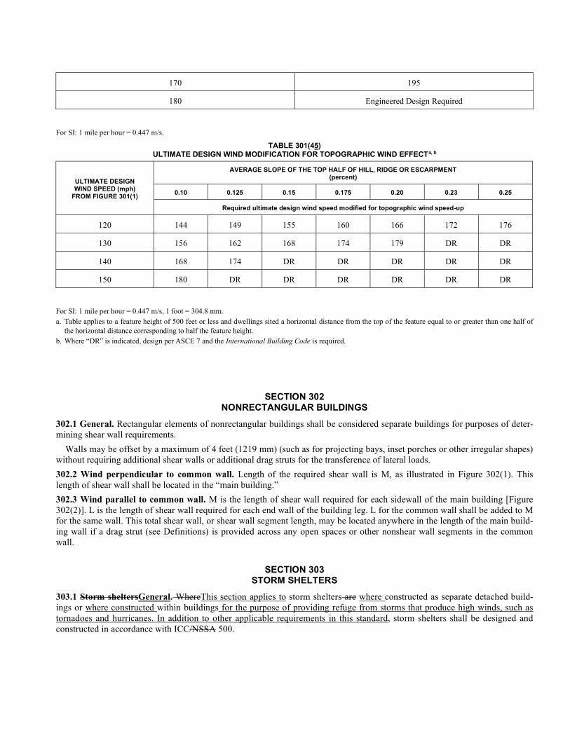
170 195
180 Engineered Design Required
For SI: 1 mile per hour = 0.447 m/s.
TABLE 301(45) ULTIMATE DESIGN WIND MODIFICATION FOR TOPOGRAPHIC WIND EFFECTa, b
ULTIMATE DESIGN WIND SPEED (mph)
FROM FIGURE 301(1)
AVERAGE SLOPE OF THE TOP HALF OF HILL, RIDGE OR ESCARPMENT (percent)
0.10 0.125 0.15 0.175 0.20 0.23 0.25
Required ultimate design wind speed modified for topographic wind speed-up
120 144 149 155 160 166 172 176
130 156 162 168 174 179 DR DR
140 168 174 DR DR DR DR DR
150 180 DR DR DR DR DR DR
For SI: 1 mile per hour = 0.447 m/s, 1 foot = 304.8 mm. a. Table applies to a feature height of 500 feet or less and dwellings sited a horizontal distance from the top of the feature equal to or greater than one half of
the horizontal distance corresponding to half the feature height. b. Where “DR” is indicated, design per ASCE 7 and the International Building Code is required.
SECTION 302 NONRECTANGULAR BUILDINGS
302.1 General. Rectangular elements of nonrectangular buildings shall be considered separate buildings for purposes of deter-mining shear wall requirements.
Walls may be offset by a maximum of 4 feet (1219 mm) (such as for projecting bays, inset porches or other irregular shapes) without requiring additional shear walls or additional drag struts for the transference of lateral loads.
302.2 Wind perpendicular to common wall. Length of the required shear wall is M, as illustrated in Figure 302(1). This length of shear wall shall be located in the “main building.”
302.3 Wind parallel to common wall. M is the length of shear wall required for each sidewall of the main building [Figure 302(2)]. L is the length of shear wall required for each end wall of the building leg. L for the common wall shall be added to M for the same wall. This total shear wall, or shear wall segment length, may be located anywhere in the length of the main build-ing wall if a drag strut (see Definitions) is provided across any open spaces or other nonshear wall segments in the common wall.
SECTION 303 STORM SHELTERS
303.1 Storm sheltersGeneral. WhereThis section applies to storm shelters are where constructed as separate detached build-ings or where constructed within buildings for the purpose of providing refuge from storms that produce high winds, such as tornadoes and hurricanes. In addition to other applicable requirements in this standard, storm shelters shall be designed and constructed in accordance with ICC/NSSA 500.
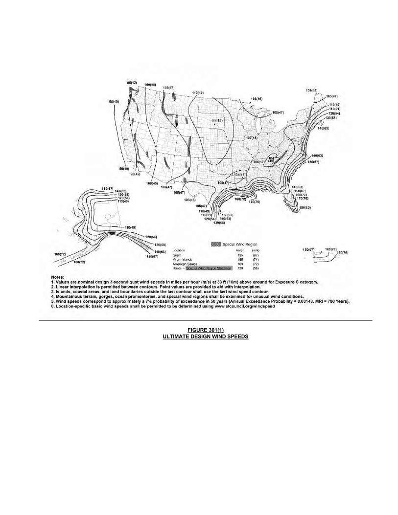
FIGURE 301(1) ULTIMATE DESIGN WIND SPEEDS
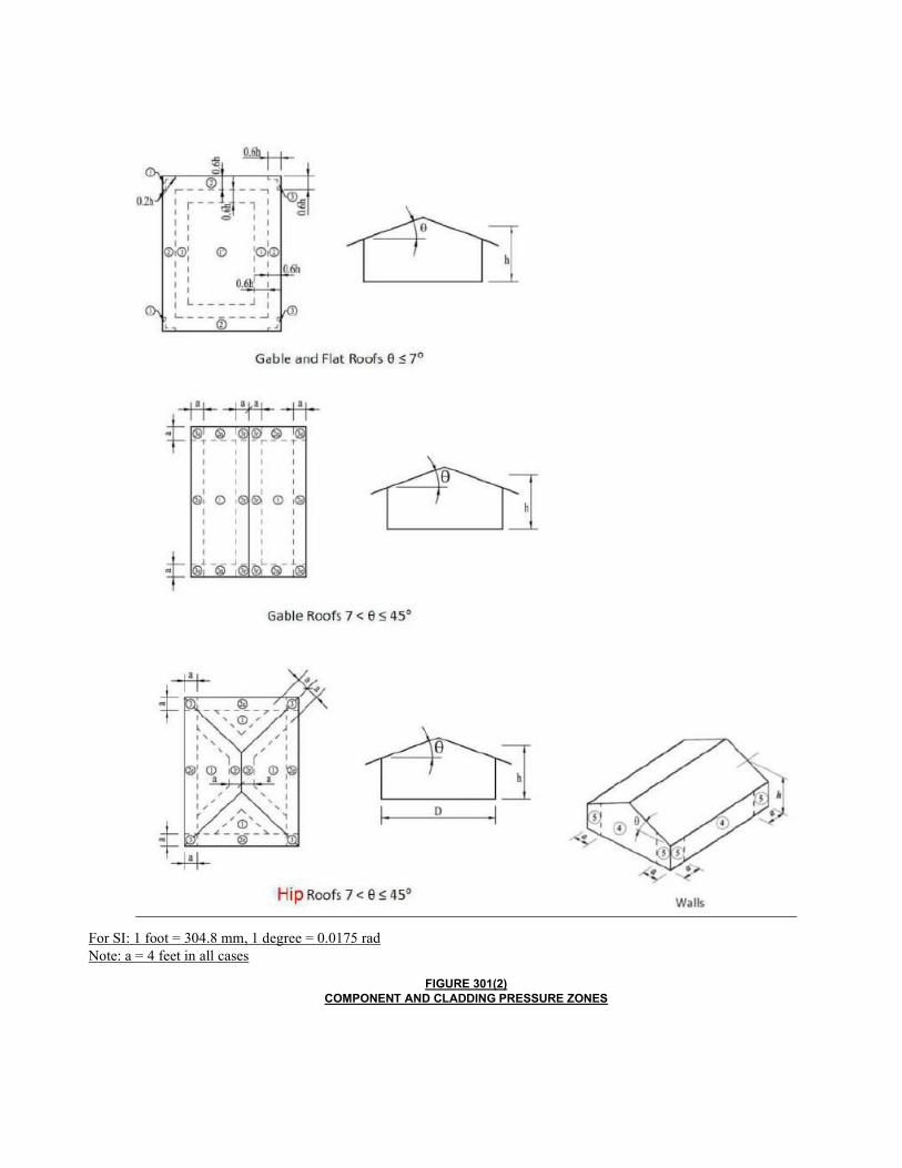
For SI: 1 foot = 304.8 mm, 1 degree = 0.0175 rad Note: a = 4 feet in all cases
FIGURE 301(2) COMPONENT AND CLADDING PRESSURE ZONES
CHAPTER 4
BUILDINGS WITH CONCRETE OR MASONRY EXTERIOR WALLS
SECTION 401 SCOPE
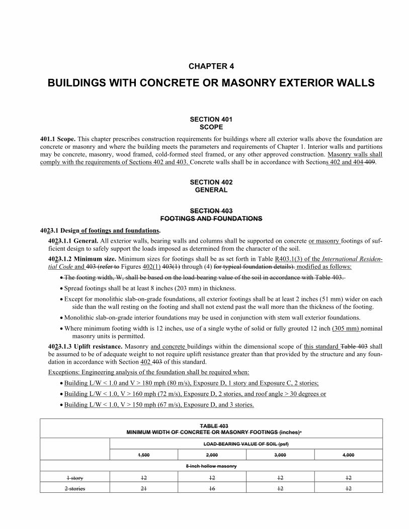
401.1 Scope. This chapter prescribes construction requirements for buildings where all exterior walls above the foundation are concrete or masonry and where the building meets the parameters and requirements of Chapter 1. Interior walls and partitions may be concrete, masonry, wood framed, cold-formed steel framed, or any other approved construction. Masonry walls shall comply with the requirements of Sections 402 and 403. Concrete walls shall be in accordance with Sections 402 and 404 409.
SECTION 402 GENERAL
SECTION 403 FOOTINGS AND FOUNDATIONS
4023.1 Design of footings and foundations.
4023.1.1 General. All exterior walls, bearing walls and columns shall be supported on concrete or masonry footings of suf-ficient design to safely support the loads imposed as determined from the character of the soil.
4023.1.2 Minimum size. Minimum sizes for footings shall be as set forth in Table R403.1(3) of the International Residen-tial Code and 403 (refer to Figures 402(1) 403(1) through (4) for typical foundation details). modified as follows:
The footing width, W, shall be based on the load-bearing value of the soil in accordance with Table 403.
Spread footings shall be at least 8 inches (203 mm) in thickness.
Except for monolithic slab-on-grade foundations, all exterior footings shall be at least 2 inches (51 mm) wider on each side than the wall resting on the footing and shall not extend past the wall more than the thickness of the footing.
Monolithic slab-on-grade interior foundations may be used in conjunction with stem wall exterior foundations.
Where minimum footing width is 12 inches, use of a single wythe of solid or fully grouted 12 inch (305 mm) nominal masonry units is permitted.
4023.1.3 Uplift resistance. Masonry and concrete buildings within the dimensional scope of this standard Table 403 shall be assumed to be of adequate weight to not require uplift resistance greater than that provided by the structure and any foun-dation in accordance with Section 402 403 of this standard.
Exceptions: Engineering analysis of the foundation shall be required when:
Building L/W < 1.0 and V > 180 mph (80 m/s), Exposure D, 1 story and Exposure C, 2 stories;
Building L/W < 1.0, V > 160 mph (72 m/s), Exposure D, 2 stories, and roof angle > 30 degrees or
Building L/W < 1.0, V > 150 mph (67 m/s), Exposure D, and 3 stories.
TABLE 403 MINIMUM WIDTH OF CONCRETE OR MASONRY FOOTINGS (inches)a
LOAD-BEARING VALUE OF SOIL (psf)
1,500 2,000 3,000 4,000
8-inch hollow masonry
1 story 12 12 12 12
2 stories 21 16 12 12
3 stories 32 24 16 12
8-inch solid or fully grouted masonry, ICF and flat panel concrete
1 story 16 12 12 12
2 stories 29 21 14 12
3 stories 42 32 21 16
For SI: 1 inch = 25.4 mm, 1 pound per square foot = 0.0479 kPa. a. Where minimum footing width is 12 inches, use of a single wythe of solid or fully grouted 12-inch nominal masonry units is permitted.
For SI: 1 inch = 25.4 mm.
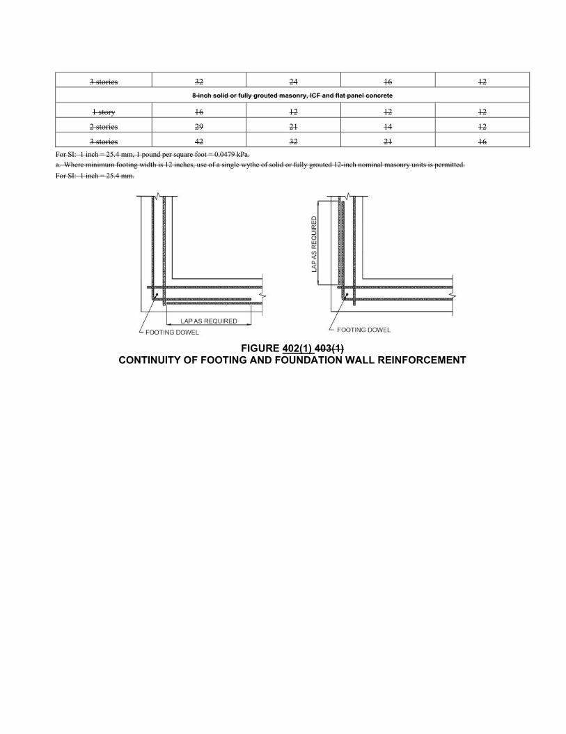
FIGURE 402(1) 403(1)
CONTINUITY OF FOOTING AND FOUNDATION WALL REINFORCEMENT
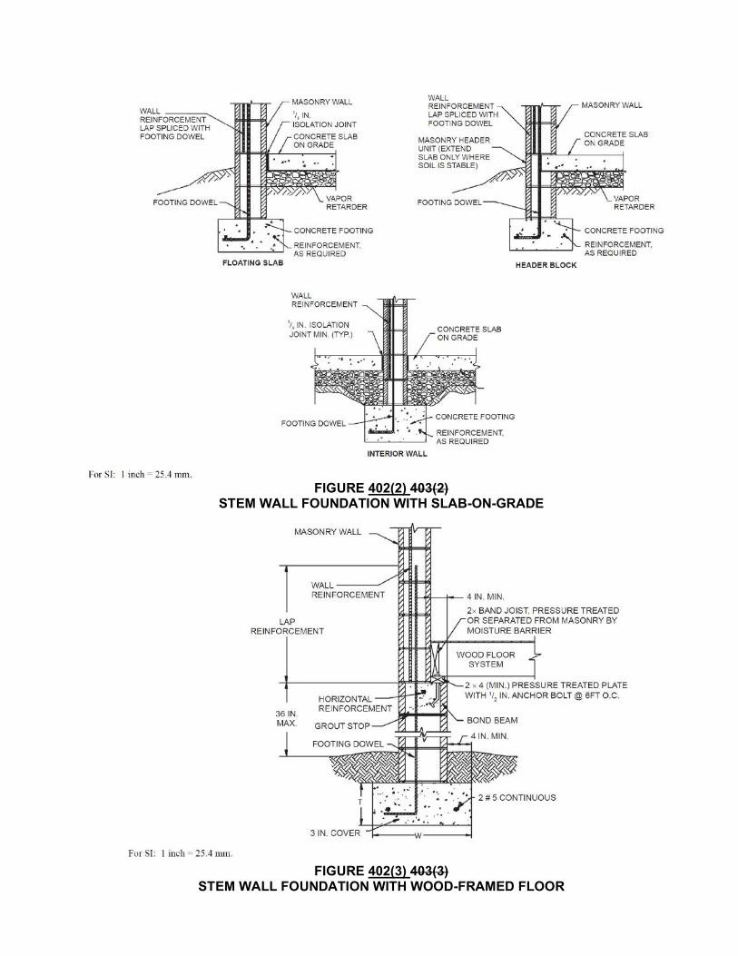
FIGURE 402(2) 403(2)
STEM WALL FOUNDATION WITH SLAB-ON-GRADE
FIGURE 402(3) 403(3)
STEM WALL FOUNDATION WITH WOOD-FRAMED FLOOR
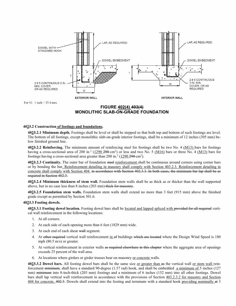
FIGURE 402(4) 403(4)
MONOLITHIC SLAB-ON-GRADE FOUNDATION
4023.2 Construction of footings and foundations.
4023.2.1 Minimum depth. Footings shall be level or shall be stepped so that both top and bottom of such footings are level. The bottom of all footings, except monolithic slab-on-grade interior footings, shall be a minimum of 12 inches (305 mm) be-low finished ground line.
4023.2.2 Reinforcing. The minimum amount of reinforcing steel for footings shall be two No. 4 (M13) bars for footings having a cross-sectional area of 200 in.2 (1290 290 cm2) or less and two No. 5 (M16) bars or three No. 4 (M13) bars for footings having a cross-sectional area greater than 200 in.2 (1290 290 cm2).
4023.2.3 Continuity. The outer bar of foundation steel reinforcement shall be continuous around corners using corner bars or by bending the bar. Reinforcement detailing in masonry shall comply with Section 403.2.3. Reinforcement detailing in concrete shall comply with Section 404. in accordance with Section 402.3.3. In both cases, the minimum bar lap shall be as required in Section 402.3.
4023.2.4 Minimum thickness of stem wall. Foundation stem walls shall be as thick as or thicker than the wall supported above, but in no case less than 8 inches (203 mm) thick for masonry.
4023.2.5 Foundation stem walls. Foundation stem walls shall extend no more than 3 feet (915 mm) above the finished grade except as permitted by Section 301.6.
4023.3 Footing dowels.
4023.3.1 Footing dowel location. Footing dowel bars shall be located and lapped spliced with provided for all required verti-cal wall reinforcement in the following locations:
1. At all corners.
2. At each side of each opening more than 6 feet (1829 mm) wide.
3. At each end of each shear wall segment.
4. At other required vertical wall reinforcement in of buildings which are located where the Design Wind Speed is 180 mph (80.5 m/s) or greater.
5. At vertical reinforcement in exterior walls as required elsewhere in this chapter where the aggregate area of openings exceeds 25 percent of the wall area.
6. At locations where girders or girder trusses bear on masonry or concrete walls.
4023.3.2 Dowel bars. All footing dowel bars shall be the same size or greater than as the vertical wall or stem wall rein-forcement minimum, shall have a standard 90-degree (1.57 rad) hook, and shall be embedded a minimum of 5 inches (127 mm) minimum into 8-inch-thick (203 mm) footings and a minimum of 6 inches (152 mm) into all other footings. Dowel bars shall lap vertical wall reinforcement in accordance with the provisions of Section 403.2.3.2 for masonry and Section 404 for concrete. 402.3. Dowels shall extend into the footing and terminate with a standard hook providing nominally at 3
inches (76 mm) of cover to the bottom of the footing clear of the footing bottom. Vertical wall reinforcing shall be lap spliced with the dowel, extend into the bond beam at the wall top and terminate with a standard hook at 11/2 inches (38 mm) clear of the top of the bond beam. Alternately stem wall vertical reinforcing shall be permitted to extend into the footing and be terminated with a standard hook at 3 inches (76 mm) clear of the bottom of the footing. Dowel bars shall also be In addi-tion, grouted, reinforced vertical cells shall be provided at hold down post anchorages and at uplift anchorages that use straps embedded into concrete or masonry.
SECTION 408 OPEN STRUCTURES
402.6 Open structures 408.1 General. Open structures shall be in accordance with Section 508 as modified by Sections 402.6.1, 402.6.2, and 402.6.3 408.2, 408.3 and 408.4.
402.6.1 408.2 Exterior walls. Exterior walls shall be in accordance with applicable sections of Chapter 4. The connection be-tween the porch roof and the wall shall be in accordance with Section 508 or may be attached directly to a bond beam as pro-vided for in Section 403.7 for masonry or Section 404 for concrete 407.6. When a single connector is used for connecting the porch roof and the main structure, the connector shall be rated for the sum of the component loads.
402.6.2 408.3 Posts. Use of solid grouted masonry posts with a minimum cross-sectional dimension of 8 inches by 8 inches (203 mm by 203 mm) with a minimum of one No. 4 (M13) in the center of the cell minimum continuous with one No. 4 (M13) dowel into the foundation shall be permitted in lieu of wood posts. An embedded anchor with a rated capacity for a Type 2A or 2B con-nection as appropriate in Table 508 shall be provided at the top of the post when using a wood beam in accordance with Section 508.
402.6.3 408.4 Beams. Masonry beams meeting the requirements of Section 403.9 405.8 shall be permitted when using masonry posts. Masonry beams shall be connected to the masonry post with one No. 4 (M13) standard hook minimum extending into the beam. Roof members shall be connected to the masonry beam with anchors rated for the minimum capacity indicated for a Type 1 connection in Table 508.
SECTION 404 FLOOR SYSTEMS
402.4 Floor Systems
402.4.1 404.1 Concrete slab-on-grade. 404.1.1 Minimum thickness. Concrete slab-on-grade shall be 31/2 inches thick (89 mm) minimum. 404.1.2 Reinforcement. Reinforcement is not required for slab-on-grade floors.
404.2 Suspended concrete slabs.
404.2.1 Suspended concrete floors. Suspended concrete floors shall be hollowcore floor systems, designed and installed in accordance with the manufacturer’s specifications. See Figures 404(1), 404(2) and 404(3) for typical connection details.
402.4.2 404.3 Wood floor framing. Wood floor framing shall be in accordance with this chapter and Chapter 5. section and Section R502 of the International Residential Code or the AWC WFCM.
404.3.1 Floor joists. Floor joists shall be sized in accordance with the AWC STJR or the AWC WFCM.
404.3.2 Wood I-joists. Single- or continuous-span I-joists shall comply with the manufacturer’s code evaluation report.
404.3.3 Floor trusses. Floor trusses shall be in accordance with ANSI/TPI-1.
404.3.4 Floor sheathing thickness. Floor sheathing shall be a minimum of 7/16-inch (11 mm) wood structural panels, in-stalled with the long dimension perpendicular to framing and with end joints staggered [see Figure 404(4)].
404.3.5 Floor sheathing spans. Floor framing shall be spaced so that the sheathing spans do not exceed those specified in Table R503.2.1.1(1) of the International Residential Code.
404.3.6 Bracing. Full-depth blocking, perpendicular to floor framing members, in the first two framing spaces at each end of floor system spaced 4 feet (1220 mm) on center maximum [see Figure 404(4)] shall be provided. See Section 404.4 for other blocking.
404.3.7 Fastening. Fastening shall be in accordance with Table R602.3(1) of the International Residential Code and Tables 2306.3.1 and 2306.3.2 of the International Building Code to provide the required shear capacities.
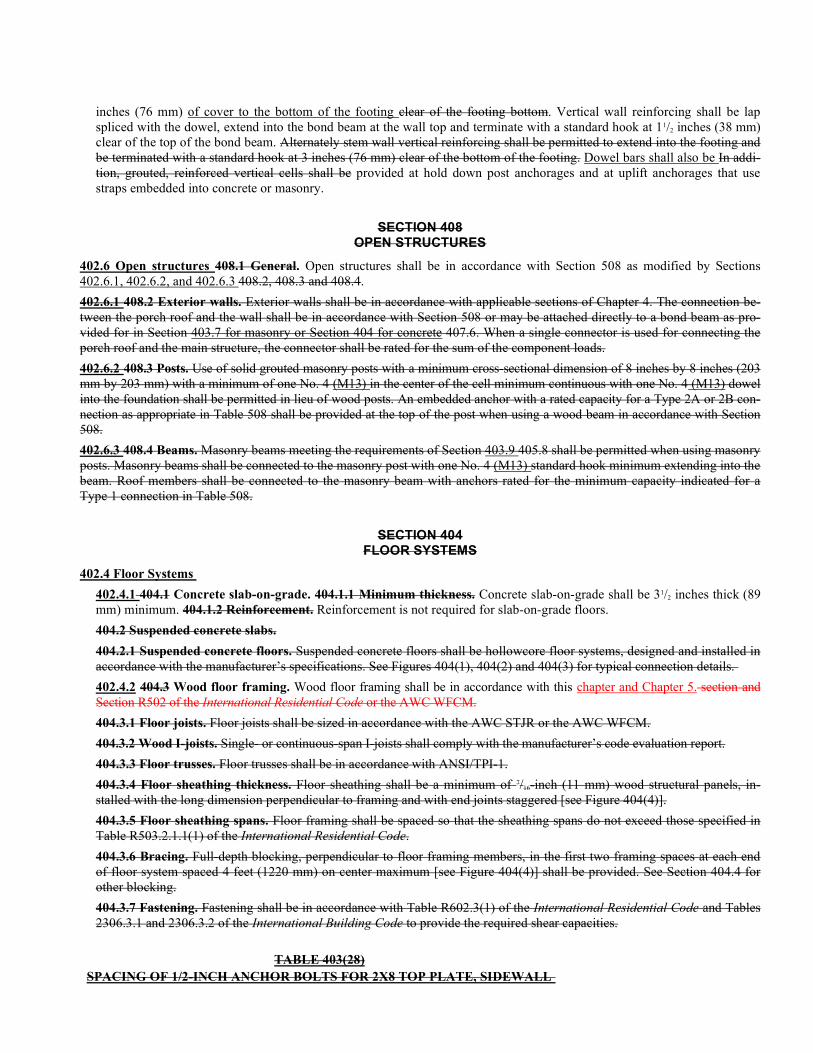
TABLE 403(28)
SPACING OF 1/2-INCH ANCHOR BOLTS FOR 2X8 TOP PLATE, SIDEWALL
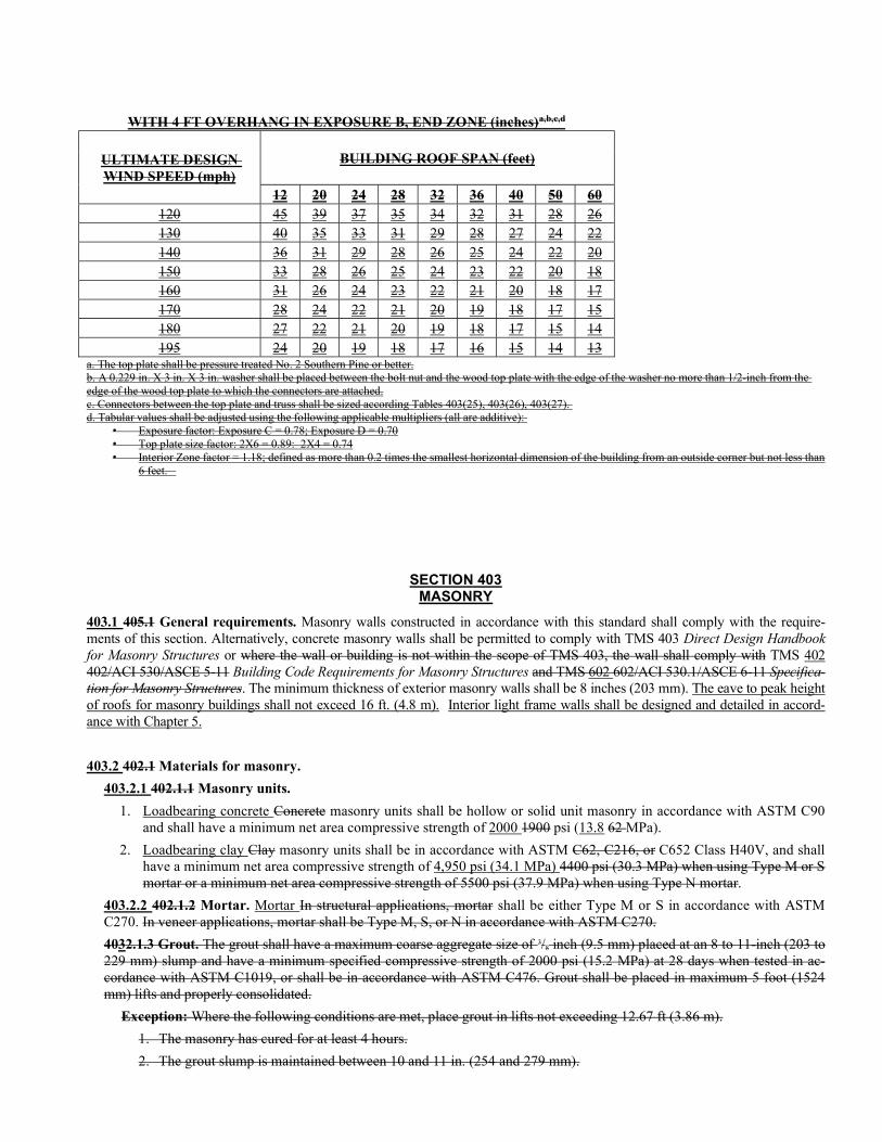
WITH 4 FT OVERHANG IN EXPOSURE B, END ZONE (inches)a,b,c,d
ULTIMATE DESIGN WIND SPEED (mph)
BUILDING ROOF SPAN (feet)
12 20 24 28 32 36 40 50 60 120 45 39 37 35 34 32 31 28 26 130 40 35 33 31 29 28 27 24 22 140 36 31 29 28 26 25 24 22 20 150 33 28 26 25 24 23 22 20 18 160 31 26 24 23 22 21 20 18 17 170 28 24 22 21 20 19 18 17 15 180 27 22 21 20 19 18 17 15 14 195 24 20 19 18 17 16 15 14 13
a. The top plate shall be pressure treated No. 2 Southern Pine or better. b. A 0.229 in. X 3 in. X 3 in. washer shall be placed between the bolt nut and the wood top plate with the edge of the washer no more than 1/2-inch from the edge of the wood top plate to which the connectors are attached. c. Connectors between the top plate and truss shall be sized according Tables 403(25), 403(26), 403(27). d. Tabular values shall be adjusted using the following applicable multipliers (all are additive):
• Exposure factor: Exposure C = 0.78; Exposure D = 0.70 • Top plate size factor: 2X6 = 0.89: 2X4 = 0.74 • Interior Zone factor = 1.18; defined as more than 0.2 times the smallest horizontal dimension of the building from an outside corner but not less than
6 feet.
SECTION 403 MASONRY
403.1 405.1 General requirements. Masonry walls constructed in accordance with this standard shall comply with the require-ments of this section. Alternatively, concrete masonry walls shall be permitted to comply with TMS 403 Direct Design Handbook for Masonry Structures or where the wall or building is not within the scope of TMS 403, the wall shall comply with TMS 402 402/ACI 530/ASCE 5-11 Building Code Requirements for Masonry Structures and TMS 602 602/ACI 530.1/ASCE 6-11 Specifica-tion for Masonry Structures. The minimum thickness of exterior masonry walls shall be 8 inches (203 mm). The eave to peak height of roofs for masonry buildings shall not exceed 16 ft. (4.8 m). Interior light frame walls shall be designed and detailed in accord-ance with Chapter 5.
403.2 402.1 Materials for masonry.
403.2.1 402.1.1 Masonry units.
1. Loadbearing concrete Concrete masonry units shall be hollow or solid unit masonry in accordance with ASTM C90 and shall have a minimum net area compressive strength of 2000 1900 psi (13.8 62 MPa).
2. Loadbearing clay Clay masonry units shall be in accordance with ASTM C62, C216, or C652 Class H40V, and shall have a minimum net area compressive strength of 4,950 psi (34.1 MPa) 4400 psi (30.3 MPa) when using Type M or S mortar or a minimum net area compressive strength of 5500 psi (37.9 MPa) when using Type N mortar.
403.2.2 402.1.2 Mortar. Mortar In structural applications, mortar shall be either Type M or S in accordance with ASTM C270. In veneer applications, mortar shall be Type M, S, or N in accordance with ASTM C270.
4032.1.3 Grout. The grout shall have a maximum coarse aggregate size of 3/8 inch (9.5 mm) placed at an 8 to 11-inch (203 to 229 mm) slump and have a minimum specified compressive strength of 2000 psi (15.2 MPa) at 28 days when tested in ac-cordance with ASTM C1019, or shall be in accordance with ASTM C476. Grout shall be placed in maximum 5 foot (1524 mm) lifts and properly consolidated.
Exception: Where the following conditions are met, place grout in lifts not exceeding 12.67 ft (3.86 m).
1. The masonry has cured for at least 4 hours.
2. The grout slump is maintained between 10 and 11 in. (254 and 279 mm).
3. No intermediate reinforced bond beams are placed between the top and the bottom of the pour height.
403.2.3 402.1.4 Metal accessories. Reinforcing steel. Reinforcing bars, joint reinforcement, anchors, ties, wires, plates, and related metal accessories shall comply with the requirements of TMS 602. Reinforcing bars shall be Grade 60. The reinforc-ing steel shall be minimum Grade 60 and identified in accordance with ASTM A615, A706 or A996. ASTM A996 bars pro-duced from rail steel shall be Type R.
402.1.5 Metal accessories. Joint reinforcement, anchors, ties and wire fabric shall conform to the following standards:
1. ASTM A951 for joint reinforcement and wire anchors and ties. 2. ASTM A36/A36M for plate, headed and bent bar anchors. 3. ASTM A1008/A1008M for sheet metal anchors and ties.
402.1.6 Galvanization. Metal accessories for use in exterior wall construction and not directly exposed to the weather shall be hot dip galvanized and metal accessories for use in interior wall construction shall be mill galvanized in accordance the following:
a. Mill galvanized coatings:
1) Joint reinforcement .............................................. ..................... ASTM A641. (0.1 oz/ft2) (31 g/m2)
2) Sheet-metal ties and sheet-metal anchors ............ .............. ASTM A653 Coating Designation G60
b. Hot-dip galvanized coatings:
1) Joint reinforcement, wire ties, and wire anchors .................. ASTM A153 (1.50 oz/ft2) (458 g/m2)
2) Sheet-metal ties and sheet-metal anchors ............ ...........................................ASTM A153 Class B
3) Steel plates and bars (as applicable to size and form indicated). ............... ASTM A123 or ASTM A153, Class B
402.1.7 Fasteners and connectors. 402.1.7.1 Continuous load path. A continuous load path between foundations, walls and roofs shall be provided. Ap-proved connectors, anchors and other fastening devices shall be installed in accordance with the manufacturer’s recom-mendations. Where fasteners are not otherwise specified in this standard, fasteners shall be provided in accordance with Table R602.3(1) of the International Residential Code. Nails, screws or bolts shall be able to resist the forces described in this standard. Nails, screws and bolts shall comply with requirements contained in the AWC NDS.
402.1.7.2 Nails. Unless otherwise stated, sizes given for nails are common wire nails. Common wire nail length diameter and head diameter shall be as shown in Appendix L, Table L4 of AWC NDS. Nails shall conform to the requirements of ASTM F1667 including supplementary requirements.
402.1.7.3 Corrosion. Fasteners and connectors that are exposed directly to the weather in areas within 3,000 feet (914 m) of a saltwater coastline or subject to salt corrosion, as determined by the building official, or in contact with treated wood shall comply with Section 402.1.7.3.1 or 402.1.7.3.2:
402.1.7.3.1 Screws, bolts and nails. Screws, bolts and nails shall be corrosion resistant by coating, galvanization or composition (stainless steel, nonferrous metal or other suitable corrosion-resistant material). The corrosion resistance of galvanized fasteners with diameters over 3/8 inch (9.5 mm) shall be equal to or equivalent to that provided by com-pliance with ASTM A153. The corrosion resistance of fasteners with diameters of 3/8 inch (9.5 mm) or less shall be demonstrated through one of the following methods:
1. Compliance, or equivalent, with ASTM A153.
2. Compliance, or equivalent, with ASTM A641 Class 1.
3. Corrosion resistance exhibiting not more than 5 percent red rust after 1000 hours exposure in accordance with ASTM B117.
4. Corrosion resistance exhibiting not more than 5 percent red rust after 280 hours exposure for nails, 1000 hours for roof tile fasteners or 360 hours exposure for other carbon steel fasteners in accordance with ASTM G85, Annex 5.
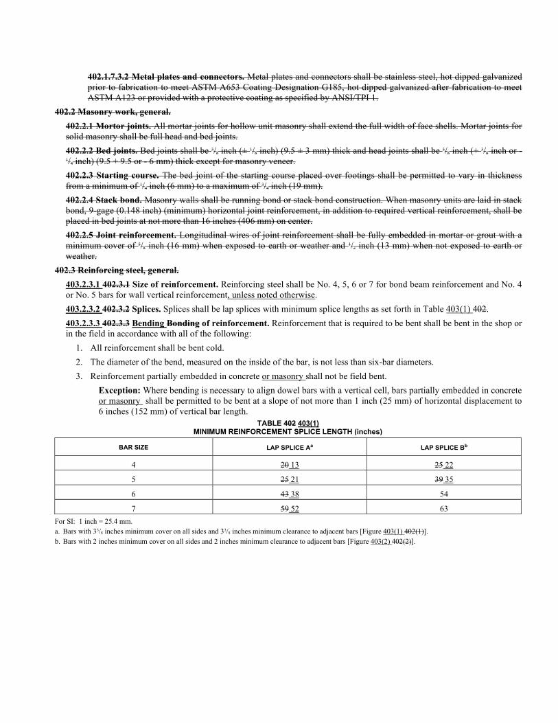
402.1.7.3.2 Metal plates and connectors. Metal plates and connectors shall be stainless steel, hot dipped galvanized prior to fabrication to meet ASTM A653 Coating Designation G185, hot dipped galvanized after fabrication to meet ASTM A123 or provided with a protective coating as specified by ANSI/TPI 1.
402.2 Masonry work, general.
402.2.1 Mortor joints. All mortar joints for hollow unit masonry shall extend the full width of face shells. Mortar joints for solid masonry shall be full head and bed joints.
402.2.2 Bed joints. Bed joints shall be 3/8 inch (± 1/8 inch) (9.5 ± 3 mm) thick and head joints shall be 3/8 inch (+ 3/8 inch or - 1/4 inch) (9.5 + 9.5 or - 6 mm) thick except for masonry veneer.
402.2.3 Starting course. The bed joint of the starting course placed over footings shall be permitted to vary in thickness from a minimum of 1/4 inch (6 mm) to a maximum of 3/4 inch (19 mm).
402.2.4 Stack bond. Masonry walls shall be running bond or stack bond construction. When masonry units are laid in stack bond, 9-gage (0.148 inch) (minimum) horizontal joint reinforcement, in addition to required vertical reinforcement, shall be placed in bed joints at not more than 16 inches (406 mm) on center.
402.2.5 Joint reinforcement. Longitudinal wires of joint reinforcement shall be fully embedded in mortar or grout with a minimum cover of 5/8 inch (16 mm) when exposed to earth or weather and 1/2 inch (13 mm) when not exposed to earth or weather.
402.3 Reinforcing steel, general.
403.2.3.1 402.3.1 Size of reinforcement. Reinforcing steel shall be No. 4, 5, 6 or 7 for bond beam reinforcement and No. 4 or No. 5 bars for wall vertical reinforcement, unless noted otherwise.
403.2.3.2 402.3.2 Splices. Splices shall be lap splices with minimum splice lengths as set forth in Table 403(1) 402.
403.2.3.3 402.3.3 Bending Bonding of reinforcement. Reinforcement that is required to be bent shall be bent in the shop or in the field in accordance with all of the following:
1. All reinforcement shall be bent cold.
2. The diameter of the bend, measured on the inside of the bar, is not less than six-bar diameters.
3. Reinforcement partially embedded in concrete or masonry shall not be field bent.
Exception: Where bending is necessary to align dowel bars with a vertical cell, bars partially embedded in concrete or masonry shall be permitted to be bent at a slope of not more than 1 inch (25 mm) of horizontal displacement to 6 inches (152 mm) of vertical bar length.
TABLE 402 403(1) MINIMUM REINFORCEMENT SPLICE LENGTH (inches)
BAR SIZE LAP SPLICE Aa LAP SPLICE Bb
4 20 13 25 22
5 25 21 39 35
6 43 38 54
7 59 52 63
For SI: 1 inch = 25.4 mm. a. Bars with 33/8 inches minimum cover on all sides and 33/8 inches minimum clearance to adjacent bars [Figure 403(1) 402(1)]. b. Bars with 2 inches minimum cover on all sides and 2 inches minimum clearance to adjacent bars [Figure 403(2) 402(2)].
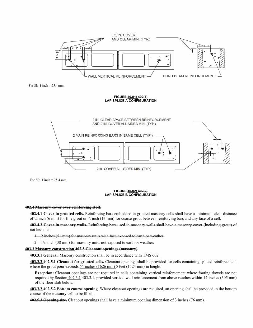
FIGURE 403(1) 402(1) LAP SPLICE A CONFIGURATION
FIGURE 403(2) 402(2) LAP SPLICE B CONFIGURATION
402.4 Masonry cover over reinforcing steel.
402.4.1 Cover in grouted cells. Reinforcing bars embedded in grouted masonry cells shall have a minimum clear distance of 1/4 inch (6 mm) for fine grout or 1/2 inch (13 mm) for coarse grout between reinforcing bars and any face of a cell.
402.4.2 Cover in masonry walls. Reinforcing bars used in masonry walls shall have a masonry cover (including grout) of not less than:
1. 2 inches (51 mm) for masonry units with face exposed to earth or weather.
2. 11/2 inch (38 mm) for masonry units not exposed to earth or weather.
403.3 Masonry construction 402.5 Cleanout openings (masonry).
403.3.1 General. Masonry construction shall be in accordance with TMS 602.
403.3.2 402.5.1 Cleanout for grouted cells. Cleanout openings shall be provided for cells containing spliced reinforcement where the grout pour exceeds 64 inches (1626 mm) 5 feet (1524 mm) in height.
Exception: Cleanout openings are not required in cells containing vertical reinforcement where footing dowels are not required by Section 402.3.1 403.3.1, provided vertical wall reinforcement from above reaches within 12 inches (305 mm) of the floor slab below.
403.3.2 402.5.2 Bottom course opening. Where cleanout openings are required, an opening shall be provided in the bottom course of the masonry cell to be filled.
402.5.3 Opening size. Cleanout openings shall have a minimum opening dimension of 3 inches (76 mm).
402.6 Grouting (masonry).
402.6.1 Masonry protrusions. Masonry protrusions extending 1/2 inch (13 mm) or more into cells or cavities to be grouted shall be removed for grout pours over 5 feet (1524 mm).
402.6.2 Grouted spaces. Spaces to be grouted shall be free of mortar droppings, debris, loose aggregates, and any material harmful to masonry grout.
402.6.3 Solid grout. All cells containing reinforcement or anchor bolts shall be grouted solid.
403.4 Reinforcing.
403.4.1 General. Masonry walls shall be reinforced in accordance with Figure 403(4) and the following:
403.4.1.1 A minimum of one bar of the size used for vertical wall reinforcement shall be provided on each side of openings wider than 6 feet (1829 mm). Where vertical reinforcement is interrupted by an opening, a minimum of one-half of the equivalent area of reinforcement interrupted by the opening shall be placed within 16 inches (406 mm) of each side of the opening.
403.4.1.2 The maximum spacing of vertical wall reinforcement shall not exceed 10 ft (3 m). The maximum spacing of the vertical reinforcement shall be the same for each story.
403.4.1.3 A vertical reinforcing bar of the size used for vertical wall reinforcement shall be provided in each corner, including interior corners and corners created by changes in wall direction or offsetting of walls such as at projected bays and inset porches.
403.4.1.4 Vertical wall reinforcement shall be lap spliced to foundation dowels at locations specified in Section 402.3. Lap splices shall be in accordance with Section 403.2.3.2.
403.4.1.5 A vertical reinforcing bar of the size used for vertical wall reinforcement shall be provided at both ends of each shear segment.
403.4.1.6 Vertical wall reinforcement shall be terminated in the bond beam at the roof level with a standard hook. The hook may be formed by bending the vertical wall reinforcement in accordance with Section 402.2.3.3 or by lap splic-ing to a standard hook. The hook shall extend to the uppermost horizontal reinforcement of the bond beam and shall be embedded a minimum of 6 inches (152 mm) into the bond beam in accordance with Figure 403(5). In multistory construction, vertical wall reinforcement shall extend through bond beams and shall be continuous with the vertical wall reinforcement of the wall above in accordance with Figure 403(6).
Exceptions:
1. Where more than one bar in the same cell is required for vertical wall reinforcement, only one bar shall be required to be continuous between stories.
2. Where vertical wall reinforcement is offset between floor levels, reinforcement for the lower story shall be anchored into the upper floor level bond beam in accordance with Section 403.4.1.6 and rein-forcement for the upper story shall be anchored into the upper and lower floor level bond beams in ac-cordance with Section 403.4.1.6.
403.4.1.7 Horizontal reinforcement shall be continuous around corners in accordance with Figure 403(3). Where more than one bar is required, only one bar need be continuous around corners.
403.4.1.8 Reinforced masonry bond beams shall be provided at the top of the wall and at each elevated story level. The minimum nominal bond beam depth shall be 8 inches (203 mm). The maximum specified depth of horizontal bond beam reinforcement shall not exceed 2.75 in. (70 mm) from the top of the unit.
403.4.1.9 Where girders or girder trusses bearing on masonry, additional vertical reinforcement shall be provided to resist uplift. This reinforcement shall be lap spliced to the bar of the same size terminating in both the bond beam and in the footing with a standard hook. The maximum design uplift shall not exceed 10,800 lb (48,040 N) for one No. 4 (M#13) reinforcing bar; 16,740 lb (74,460 N) for one No. 5 (M#16) reinforcing bar; 23,760 lb (105,690 N) for one No. 6 (M#19) reinforcing bar; or 32,400 lb (144,120 N) for one No. 7 (M#22) reinforcing bar.
403.4.1.10 Unless otherwise noted, reinforcing requirements are not additive as a single reinforcing bar may fulfill more than one requirement. In all cases, the most stringent requirement shall apply.
403.4.2 Vertical wall reinforcing. Masonry walls shall be vertically reinforced in accordance with Table 403(2) or Table 403(5).
405.3.3 Girders. A minimum of one bar of the size used for vertical wall reinforcement shall be provided at all locations where girders or girder trusses bear on masonry walls.
405.3.8 Continuity of reinforcement. See Section 405.7 for details of connection of vertical wall reinforcing to footings and bond beams.
405.2 Bond beams.
405.2.1 General. A reinforced bond beam shall be provided in masonry walls at the top of the wall and at each floor level (except at slab-on-grade) of each exterior wall. (See Section 405.4.1 for rake beam at top of gable endwalls). Bond beams shall contain one #4 bar minimum.
405.2.2 Size. Bond beams shall be one of the following:
8 inches thick x 8 inches high masonry (203 x 203 mm)
8 inches thick x 12 inches high masonry (203 x 305 mm)
8 inches thick x 16 inches high masonry (203 x 406 mm)
8 inches thick x 24 inches high masonry (203 x 610 mm)
8 inches thick x 32 inches high masonry (203 x 813 mm)
Precast units certified by the manufacturer to be suitable for the loads stipulated in Section 405.8.1, installed in accord-ance with the manufacturer’s specifications, and approved by the building official.
405.2.3 Continuity of reinforcement. Reinforcement shall be continuous around corners [see Figure 405(1)]. Where more than one bar is required, only one bar need be continuous around corners.
405.2.4 Splices. All splices shall be lapped in accordance with Section 402.3.2.
405.2.5 Precast bond beams. Precast bond beams shall properly receive and retain all vertical wall reinforcement. Precast bond beams shall contain the minimum amount of continuous reinforcement indicated in Section 405.8.1 and shall be rein-forced at joints to act as drag struts and diaphragm chords.
405.2.6 Amount of bond beam reinforcement. The minimum reinforcement for bond beam roof diaphragm chord tension reinforcement steel shall be as set forth in Tables 405(1) and (2) for the appropriate Exposure Category. The minimum rein-forcement for bond beam uplift-resisting reinforcement shall be as set forth in Tables 405(3) - 405(6) for the loads set forth in Table 407(3). The total minimum area of bond beam reinforcement shall be the sum of the required area of the diaphragm chord tension steel and the required area of bond beam uplift steel. Bond beam area of steel shall be converted to bar size in accordance with Table 405(8).
405.3 Vertical reinforcement.
405.3.1 Corners. One No. 4 bar minimum shall be provided in each corner, including interior corners and corners created by changes in wall direction or offsetting of walls such as at projected bays and inset porches.
405.3.2 Openings in masonry walls. A minimum of one bar of the size used for vertical wall reinforcement shall be pro-vided on each side of openings wider than 6 feet (1829 mm). If more vertical reinforcement is interrupted by an opening than is provided beside the opening (total in the first and second cells adjacent to the opening on both sides of the opening), a minimum of one-half of the equivalent area of reinforcement interrupted by the opening shall be placed on each side of the opening. This reinforcement shall be placed within the first and/or second cells beside the opening.
405.3.3 Girders. A minimum of one bar of the size used for vertical wall reinforcement shall be provided at all locations where girders or girder trusses bear on masonry walls.
405.3.4 Shear walls. Vertical reinforcement shall be provided at the ends of each shear wall segment in accordance with Section 405.5.5 of this standard.
405.3.5 Spacing of vertical reinforcement. Vertical reinforcement shall be provided for the design windspeed, building width, wall height and exposure specified in Table 405(9).
1. For spacing of reinforcement at continuous gable endwalls, see Section 405.4.
2. Vertical reinforcement used in conjunction with precast bond beams shall be spaced the same as for masonry bond beams unless other spacing is substantiated by the beam manufacturer and approved by the building official and shall hook into the precast beam in accordance with Section 405.7.
405.3.6 Duplication. Reinforcing steel requirements are not additive. A single reinforcing bar may fulfill more than one re-quirement. For example, a single bar will satisfy the requirements for a bar at the side of an opening which occurs at the same location as a bar required by Tables 405(8) and 405(9). In all cases, the most stringent requirements shall be applied.
405.3.7 Wall reinforcement summary. See Figure 405(11).
405.3.8 Continuity of reinforcement. See Section 405.7 for details of connection of vertical wall reinforcing to footings and bond beams.
403.5 405.5 Exterior shear walls. Exterior shear walls shall comply with the requirements of Section 403.5.1 through 403.5.6. Shear walls are required to resist horizontal movement or forces at ends of diaphragms.
403.5.1 405.5.1 Shear wall segments. Required shear wall segment lengths shall be determined from Tables 403(3) and 403(4) or Tables 403(6) and 403(7) as required in accordance with Figure 403(7). 405(17) through 405(19) and 405(20) through 405(22). The required shear segment length shall apply to each line of resistance in a building. When using Table 403(3) or Table 403(6) Tables 405(17) through (19) (for endwalls) and the building contains one or more interior shear walls, the distance to the first interior shear wall shall be used in determining the length-to-width ratio for use in the table. The building length used shall be the distance between adjacent shear walls. The distance Distance between adjacent shear walls shall not exceed 2 21/2 times the building width when used in conjunction with a wood roof or floor diaphragm. The minimum Minimum shear wall segment length shall be 2 feet (610 mm).
Values less than 2 feet (610 mm) as shown in the tables are to be used only when adding together required shear wall seg-ment lengths for separate parts of a building, such as in common walls of nonrectangular buildings (see Section 105.3).
403.5.2 405.5.2 Multiple shear wall segments. Shear wall segment lengths shown in Tables 403(3), 403(4), 403(6), and 403(7) 405(17) through 405(22) are for a single shear wall segment of the specified length. Shear walls may be divided into multiple smaller segments if:
1. All individual shear wall segment lengths meet the minimum requirements of Section 403.5.1405.5.1.
2. Individual shear wall segments are subject to the same reinforcement requirements as a single shear wall segment.
3. The sum of the lengths of individual shear wall segments shall be equal to or greater than the length specified by the applicable table.
4. The length of the largest individual segment shall be no more than four times the length of the smallest segment with-in the shear wall.
403.5.3 405.5.3 Openings. Shear wall piers and shear wall segments shall not contain openings, (other than incidental utility penetrations,) with a maximum horizontal or vertical dimension of 5 inches (127 mm) for piers and 12 inches (305 mm) for portions of shear wall segments above and below piers. The total area of openings in any single shear segment one segment of shear wall shall not exceed 144 square inches (929 cm2).
403.5.4 405.5.4 Arrangement. The maximum clear distance between shear wall segments shall be 18 feet (5,486 mm). A minimum 2-foot (610 mm) shear wall segment shall be located at each building corner where the wall length is greater than 4 feet (1,220 mm) in accordance with Figure 403(4). [see Figure 405(11)]. Each exterior wall shall have the required length of effective shear wall determined by Tables 405(17) through 405(22).
405.5.5 Reinforcement. Each shear wall or shear wall segment shall contain the amount of vertical reinforcement indicated in Tables 405(17) through 405(22) in each end of each shear wall segment. This reinforcement, shall be anchored with a stand-ard hook into the bond beam at the top and with a standard hook into bond beams or footings below.
403.5.5 405.5.6 Multi-story shear walls. Shear wall segments in an upper story shall be located directly over shear wall segments in the story below and reinforcement at the ends of the shear wall segment shall be continuous from the bond beam of the upper story through the story below.
403.5.6 405.5.7 Nonrectangular buildings. For nonrectangular buildings, the required length of shear walls shall be deter-mined in accordance with Section 302. (See Section 302).
403.6 405.6 Interior shear walls.
403.6.1 405.6.1 Length-to-width ratio of building. Interior shear walls used to decrease the length-to-width ratio of build-ings shall comply with the following:
1. Bond beams in interior walls containing shear walls shall extend the full width or length of the building segment the full width of the building and shall be subject to the same restrictions as shear walls in exterior walls;
2. The length of an interior shear wall shall be sized in accordance with Section 403.5 405.5. For interior shear walls, the total shear wall segment length shall be the sum of the shear wall segment lengths required for each building length on each side of the interior shear wall;
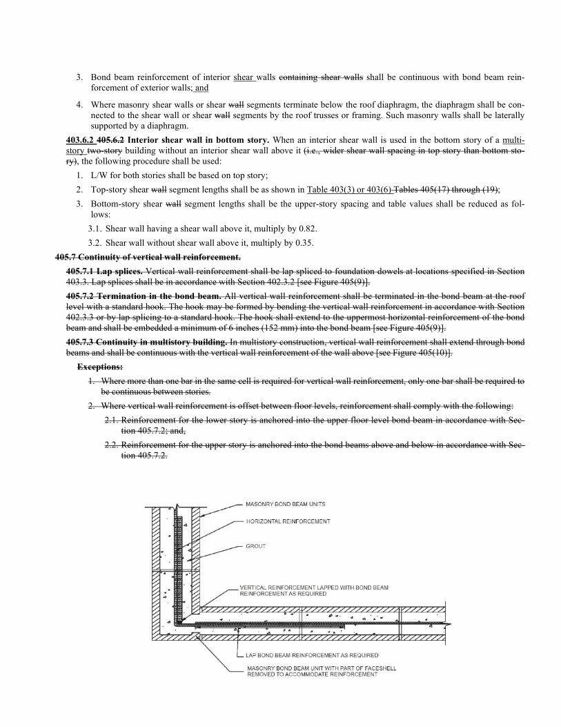
3. Bond beam reinforcement of interior shear walls containing shear walls shall be continuous with bond beam rein-forcement of exterior walls; and
4. Where masonry shear walls or shear wall segments terminate below the roof diaphragm, the diaphragm shall be con-nected to the shear wall or shear wall segments by the roof trusses or framing. Such masonry walls shall be laterally supported by a diaphragm.
403.6.2 405.6.2 Interior shear wall in bottom story. When an interior shear wall is used in the bottom story of a multi-story two-story building without an interior shear wall above it (i.e., wider shear wall spacing in top story than bottom sto-ry), the following procedure shall be used:
1. L/W for both stories shall be based on top story;
2. Top-story shear wall segment lengths shall be as shown in Table 403(3) or 403(6) Tables 405(17) through (19);
3. Bottom-story shear wall segment lengths shall be the upper-story spacing and table values shall be reduced as fol-lows:
3.1. Shear wall having a shear wall above it, multiply by 0.82.
3.2. Shear wall without shear wall above it, multiply by 0.35.
405.7 Continuity of vertical wall reinforcement.
405.7.1 Lap splices. Vertical wall reinforcement shall be lap spliced to foundation dowels at locations specified in Section 403.3. Lap splices shall be in accordance with Section 402.3.2 [see Figure 405(9)].
405.7.2 Termination in the bond beam. All vertical wall reinforcement shall be terminated in the bond beam at the roof level with a standard hook. The hook may be formed by bending the vertical wall reinforcement in accordance with Section 402.3.3 or by lap splicing to a standard hook. The hook shall extend to the uppermost horizontal reinforcement of the bond beam and shall be embedded a minimum of 6 inches (152 mm) into the bond beam [see Figure 405(9)].
405.7.3 Continuity in multistory building. In multistory construction, vertical wall reinforcement shall extend through bond beams and shall be continuous with the vertical wall reinforcement of the wall above [see Figure 405(10)].
Exceptions:
1. Where more than one bar in the same cell is required for vertical wall reinforcement, only one bar shall be required to be continuous between stories.
2. Where vertical wall reinforcement is offset between floor levels, reinforcement shall comply with the following:
2.1. Reinforcement for the lower story is anchored into the upper floor level bond beam in accordance with Sec-tion 405.7.2; and,
2.2. Reinforcement for the upper story is anchored into the bond beams above and below in accordance with Sec-tion 405.7.2.
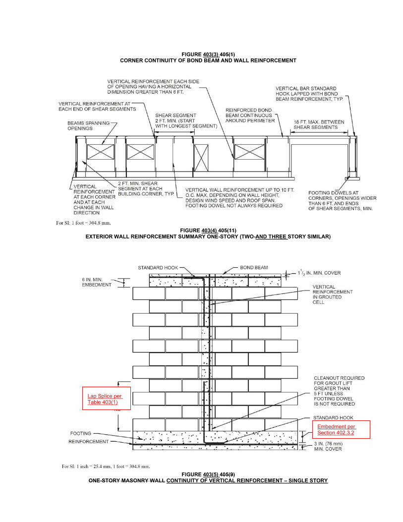
FIGURE 403(3) 405(1) CORNER CONTINUITY OF BOND BEAM AND WALL REINFORCEMENT
FIGURE 403(4) 405(11)
EXTERIOR WALL REINFORCEMENT SUMMARY ONE-STORY (TWO-AND THREE STORY SIMILAR)
FIGURE 403(5) 405(9)
ONE-STORY MASONRY WALL CONTINUITY OF VERTICAL REINFORCEMENT – SINGLE STORY
Lap Splice per Table 403(1)
Embedment per Section 402.3.2
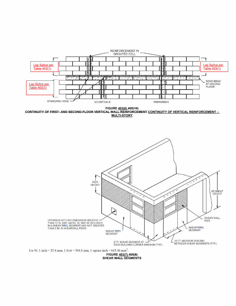
FIGURE 403(6) 405(10)
CONTINUITY OF FIRST- AND SECOND-FLOOR VERTICAL WALL REINFORCEMENT CONTINUITY OF VERTICAL REINFORCEMENT – MULTI-STORY
FIGURE 403(7) 405(8)
SHEAR WALL SEGMENTS
Lap Splice per Table 403(1)
Lap Splice per Table 403(1)
Lap Splice per Table 403(1)
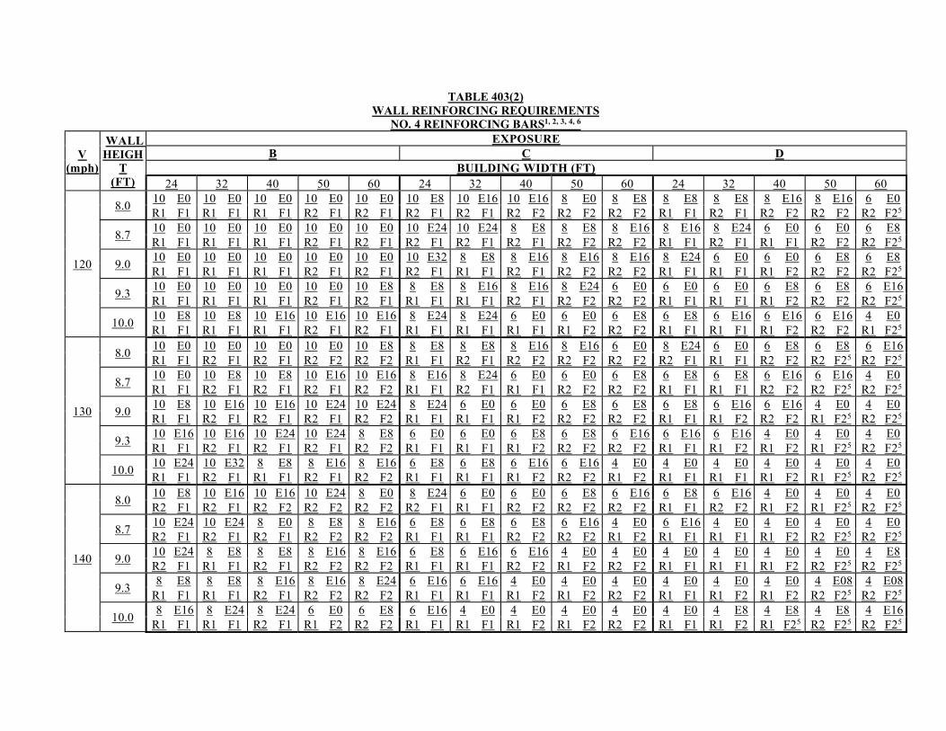
TABLE 403(2)
WALL REINFORCING REQUIREMENTS NO. 4 REINFORCING BARS1, 2, 3, 4, 6
V (mph)
WALL HEIGH
T (FT)
EXPOSURE B C D
BUILDING WIDTH (FT) 24 32 40 50 60 24 32 40 50 60 24 32 40 50 60
120
8.0 10 E0 10 E0 10 E0 10 E0 10 E0 10 E8 10 E16 10 E16 8 E0 8 E8 8 E8 8 E8 8 E16 8 E16 6 E0 R1 F1 R1 F1 R1 F1 R2 F1 R2 F1 R2 F1 R2 F1 R2 F2 R2 F2 R2 F2 R1 F1 R2 F1 R2 F2 R2 F2 R2 F25
8.7 10 E0 10 E0 10 E0 10 E0 10 E0 10 E24 10 E24 8 E8 8 E8 8 E16 8 E16 8 E24 6 E0 6 E0 6 E8 R1 F1 R1 F1 R1 F1 R2 F1 R2 F1 R2 F1 R2 F1 R2 F1 R2 F2 R2 F2 R1 F1 R2 F1 R1 F1 R2 F2 R2 F25
9.0 10 E0 10 E0 10 E0 10 E0 10 E0 10 E32 8 E8 8 E16 8 E16 8 E16 8 E24 6 E0 6 E0 6 E8 6 E8 R1 F1 R1 F1 R1 F1 R2 F1 R2 F1 R2 F1 R1 F1 R2 F1 R2 F2 R2 F2 R1 F1 R1 F1 R1 F2 R2 F2 R2 F25
9.3 10 E0 10 E0 10 E0 10 E0 10 E8 8 E8 8 E16 8 E16 8 E24 6 E0 6 E0 6 E0 6 E8 6 E8 6 E16 R1 F1 R1 F1 R1 F1 R2 F1 R2 F1 R1 F1 R1 F1 R2 F1 R2 F2 R2 F2 R1 F1 R1 F1 R1 F2 R2 F2 R2 F25
10.0 10 E8 10 E8 10 E16 10 E16 10 E16 8 E24 8 E24 6 E0 6 E0 6 E8 6 E8 6 E16 6 E16 6 E16 4 E0 R1 F1 R1 F1 R1 F1 R2 F1 R2 F1 R1 F1 R1 F1 R1 F1 R1 F2 R2 F2 R1 F1 R1 F1 R1 F2 R2 F2 R1 F25
130
8.0 10 E0 10 E0 10 E0 10 E0 10 E8 8 E8 8 E8 8 E16 8 E16 6 E0 8 E24 6 E0 6 E8 6 E8 6 E16 R1 F1 R2 F1 R2 F1 R2 F2 R2 F2 R1 F1 R2 F1 R2 F2 R2 F2 R2 F2 R2 F1 R1 F1 R2 F2 R2 F25 R2 F25
8.7 10 E0 10 E8 10 E8 10 E16 10 E16 8 E16 8 E24 6 E0 6 E0 6 E8 6 E8 6 E8 6 E16 6 E16 4 E0 R1 F1 R2 F1 R2 F1 R2 F1 R2 F2 R1 F1 R2 F1 R1 F1 R2 F2 R2 F2 R1 F1 R1 F1 R2 F2 R2 F25 R2 F25
9.0 10 E8 10 E16 10 E16 10 E24 10 E24 8 E24 6 E0 6 E0 6 E8 6 E8 6 E8 6 E16 6 E16 4 E0 4 E0 R1 F1 R2 F1 R2 F1 R2 F1 R2 F2 R1 F1 R1 F1 R1 F2 R2 F2 R2 F2 R1 F1 R1 F2 R2 F2 R1 F25 R2 F25
9.3 10 E16 10 E16 10 E24 10 E24 8 E8 6 E0 6 E0 6 E8 6 E8 6 E16 6 E16 6 E16 4 E0 4 E0 4 E0 R1 F1 R2 F1 R2 F1 R2 F1 R2 F2 R1 F1 R1 F1 R1 F2 R2 F2 R2 F2 R1 F1 R1 F2 R1 F2 R1 F25 R2 F25
10.0 10 E24 10 E32 8 E8 8 E16 8 E16 6 E8 6 E8 6 E16 6 E16 4 E0 4 E0 4 E0 4 E0 4 E0 4 E0 R1 F1 R2 F1 R1 F1 R2 F1 R2 F2 R1 F1 R1 F1 R1 F2 R2 F2 R1 F2 R1 F1 R1 F1 R1 F2 R1 F25 R2 F25
140
8.0 10 E8 10 E16 10 E16 10 E24 8 E0 8 E24 6 E0 6 E0 6 E8 6 E16 6 E8 6 E16 4 E0 4 E0 4 E0 R2 F1 R2 F1 R2 F2 R2 F2 R2 F2 R2 F1 R1 F1 R2 F2 R2 F2 R2 F2 R1 F1 R2 F2 R1 F2 R1 F25 R2 F25
8.7 10 E24 10 E24 8 E0 8 E8 8 E16 6 E8 6 E8 6 E8 6 E16 4 E0 6 E16 4 E0 4 E0 4 E0 4 E0 R2 F1 R2 F1 R2 F1 R2 F2 R2 F2 R1 F1 R1 F1 R2 F2 R2 F2 R1 F2 R1 F1 R1 F1 R1 F2 R2 F25 R2 F25
9.0 10 E24 8 E8 8 E8 8 E16 8 E16 6 E8 6 E16 6 E16 4 E0 4 E0 4 E0 4 E0 4 E0 4 E0 4 E8 R2 F1 R1 F1 R2 F1 R2 F2 R2 F2 R1 F1 R1 F1 R2 F2 R1 F2 R2 F2 R1 F1 R1 F1 R1 F2 R2 F25 R2 F25
9.3 8 E8 8 E8 8 E16 8 E16 8 E24 6 E16 6 E16 4 E0 4 E0 4 E0 4 E0 4 E0 4 E0 4 E08 4 E08
R1 F1 R1 F1 R2 F1 R2 F2 R2 F2 R1 F1 R1 F1 R1 F2 R1 F2 R2 F2 R1 F1 R1 F2 R1 F2 R2 F25 R2 F25
10.0 8 E16 8 E24 8 E24 6 E0 6 E8 6 E16 4 E0 4 E0 4 E0 4 E0 4 E0 4 E8 4 E8 4 E8 4 E16
R1 F1 R1 F1 R2 F1 R1 F2 R2 F2 R1 F1 R1 F1 R1 F2 R1 F2 R2 F2 R1 F1 R1 F2 R1 F25 R2 F25 R2 F25
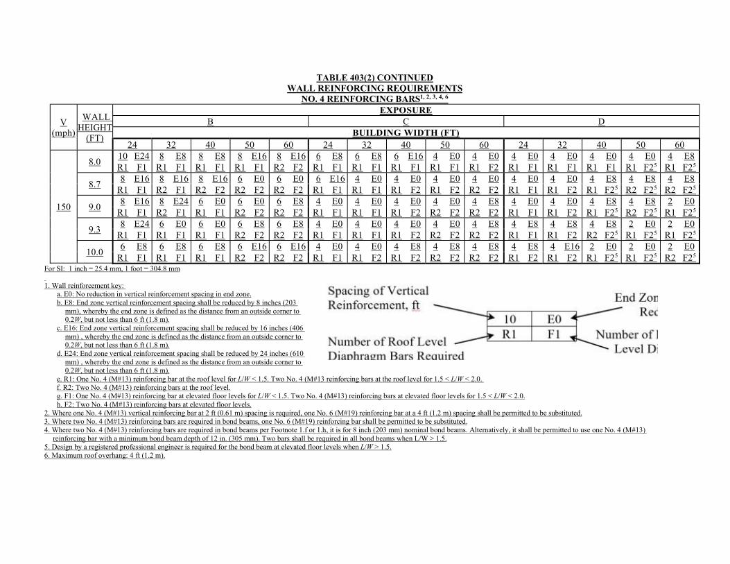
TABLE 403(2) CONTINUED WALL REINFORCING REQUIREMENTS
NO. 4 REINFORCING BARS1, 2, 3, 4, 6
V (mph)
WALL HEIGHT
(FT)
EXPOSURE B C D
BUILDING WIDTH (FT) 24 32 40 50 60 24 32 40 50 60 24 32 40 50 60
150
8.0 10 E24 8 E8 8 E8 8 E16 8 E16 6 E8 6 E8 6 E16 4 E0 4 E0 4 E0 4 E0 4 E0 4 E0 4 E8 R1 F1 R1 F1 R1 F1 R1 F1 R2 F2 R1 F1 R1 F1 R1 F1 R1 F1 R1 F2 R1 F1 R1 F1 R1 F1 R1 F25 R1 F25
8.7 8 E16 8 E16 8 E16 6 E0 6 E0 6 E16 4 E0 4 E0 4 E0 4 E0 4 E0 4 E0 4 E8 4 E8 4 E8
R1 F1 R2 F1 R2 F2 R2 F2 R2 F2 R1 F1 R1 F1 R1 F2 R1 F2 R2 F2 R1 F1 R1 F2 R1 F25 R2 F25 R2 F25
9.0 8 E16 8 E24 6 E0 6 E0 6 E8 4 E0 4 E0 4 E0 4 E0 4 E8 4 E0 4 E0 4 E8 4 E8 2 E0
R1 F1 R2 F1 R1 F1 R2 F2 R2 F2 R1 F1 R1 F1 R1 F2 R2 F2 R2 F2 R1 F1 R1 F2 R1 F25 R2 F25 R1 F25
9.3 8 E24 6 E0 6 E0 6 E8 6 E8 4 E0 4 E0 4 E0 4 E0 4 E8 4 E8 4 E8 4 E8 2 E0 2 E0
R1 F1 R1 F1 R1 F1 R2 F2 R2 F2 R1 F1 R1 F1 R1 F2 R2 F2 R2 F2 R1 F1 R1 F2 R2 F25 R1 F25 R1 F25
10.0 6 E8 6 E8 6 E8 6 E16 6 E16 4 E0 4 E0 4 E8 4 E8 4 E8 4 E8 4 E16 2 E0 2 E0 2 E0
R1 F1 R1 F1 R1 F1 R2 F2 R2 F2 R1 F1 R1 F2 R1 F2 R2 F2 R2 F2 R1 F2 R1 F2 R1 F25 R1 F25 R2 F25 For SI: 1 inch = 25.4 mm, 1 foot = 304.8 mm 1. Wall reinforcement key:
a. E0: No reduction in vertical reinforcement spacing in end zone. b. E8: End zone vertical reinforcement spacing shall be reduced by 8 inches (203
mm), whereby the end zone is defined as the distance from an outside corner to 0.2W, but not less than 6 ft (1.8 m).
c. E16: End zone vertical reinforcement spacing shall be reduced by 16 inches (406 mm) , whereby the end zone is defined as the distance from an outside corner to 0.2W, but not less than 6 ft (1.8 m).
d. E24: End zone vertical reinforcement spacing shall be reduced by 24 inches (610 mm) , whereby the end zone is defined as the distance from an outside corner to 0.2W, but not less than 6 ft (1.8 m).
e. R1: One No. 4 (M#13) reinforcing bar at the roof level for L/W < 1.5. Two No. 4 (M#13 reinforcing bars at the roof level for 1.5 < L/W < 2.0. f. R2: Two No. 4 (M#13) reinforcing bars at the roof level. g. F1: One No. 4 (M#13) reinforcing bar at elevated floor levels for L/W < 1.5. Two No. 4 (M#13) reinforcing bars at elevated floor levels for 1.5 < L/W < 2.0. h. F2: Two No. 4 (M#13) reinforcing bars at elevated floor levels.
2. Where one No. 4 (M#13) vertical reinforcing bar at 2 ft (0.61 m) spacing is required, one No. 6 (M#19) reinforcing bar at a 4 ft (1.2 m) spacing shall be permitted to be substituted. 3. Where two No. 4 (M#13) reinforcing bars are required in bond beams, one No. 6 (M#19) reinforcing bar shall be permitted to be substituted. 4. Where two No. 4 (M#13) reinforcing bars are required in bond beams per Footnote 1.f or 1.h, it is for 8 inch (203 mm) nominal bond beams. Alternatively, it shall be permitted to use one No. 4 (M#13)
reinforcing bar with a minimum bond beam depth of 12 in. (305 mm). Two bars shall be required in all bond beams when L/W > 1.5. 5. Design by a registered professional engineer is required for the bond beam at elevated floor levels when L/W > 1.5. 6. Maximum roof overhang: 4 ft (1.2 m).
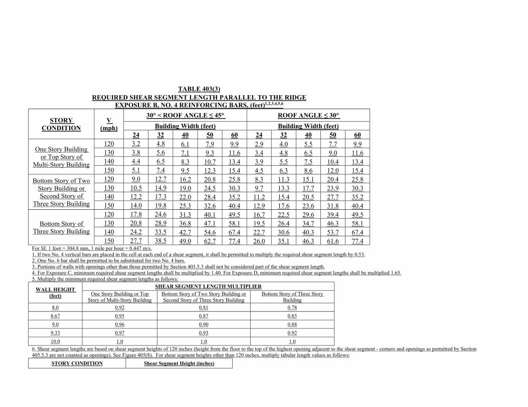
TABLE 403(3) REQUIRED SHEAR SEGMENT LENGTH PARALLEL TO THE RIDGE
EXPOSURE B, NO. 4 REINFORCING BARS, (feet)1,2,3,4,5,6
STORY CONDITION
V (mph)
30° < ROOF ANGLE ≤ 45° ROOF ANGLE ≤ 30°
Building Width (feet) Building Width (feet) 24 32 40 50 60 24 32 40 50 60
One Story Building or Top Story of
Multi-Story Building
120 3.2 4.8 6.1 7.9 9.9 2.9 4.0 5.5 7.7 9.9 130 3.8 5.6 7.1 9.3 11.6 3.4 4.8 6.5 9.0 11.6 140 4.4 6.5 8.3 10.7 13.4 3.9 5.5 7.5 10.4 13.4 150 5.1 7.4 9.5 12.3 15.4 4.5 6.3 8.6 12.0 15.4
Bottom Story of Two Story Building or Second Story of
Three Story Building
120 9.0 12.7 16.2 20.8 25.8 8.3 11.3 15.1 20.4 25.8 130 10.5 14.9 19.0 24.5 30.3 9.7 13.3 17.7 23.9 30.3 140 12.2 17.3 22.0 28.4 35.2 11.2 15.4 20.5 27.7 35.2 150 14.0 19.8 25.3 32.6 40.4 12.9 17.6 23.6 31.8 40.4
Bottom Story of Three Story Building
120 17.8 24.6 31.3 40.1 49.5 16.7 22.5 29.6 39.4 49.5 130 20.8 28.9 36.8 47.1 58.1 19.5 26.4 34.7 46.3 58.1 140 24.2 33.5 42.7 54.6 67.4 22.7 30.6 40.3 53.7 67.4 150 27.7 38.5 49.0 62.7 77.4 26.0 35.1 46.3 61.6 77.4
For SI: 1 foot = 304.8 mm, 1 mile per hour = 0.447 m/s. 1. If two No. 4 vertical bars are placed in the cell at each end of a shear segment, it shall be permitted to multiply the required shear segment length by 0.53. 2. One No. 6 bar shall be permitted to be substituted for two No. 4 bars. 3. Portions of walls with openings other than those permitted by Section 403.5.3 shall not be considered part of the shear segment length. 4. For Exposure C, minimum required shear segment lengths shall be multiplied by 1.40. For Exposure D, minimum required shear segment lengths shall be multiplied 1.65. 5. Multiply the minimum required shear segment lengths as follows:
WALL HEIGHT (feet)
SHEAR SEGMENT LENGTH MULTIPLIER
One Story Building or Top Story of Multi-Story Building
Bottom Story of Two Story Building or Second Story of Three Story Building
Bottom Story of Three Story Building
8.0 0.92 0.81 0.78
8.67 0.95 0.87 0.85
9.0 0.96 0.90 0.88
9.33 0.97 0.93 0.92
10.0 1.0 1.0 1.0
6. Shear segment lengths are based on shear segment heights of 120 inches (height from the floor to the top of the highest opening adjacent to the shear segment - corners and openings as permitted by Section 405.5.3 are not counted as openings). See Figure 405(8). For shear segment heights other than 120 inches, multiply tabular length values as follows:
STORY CONDITION Shear Segment Height (inches)
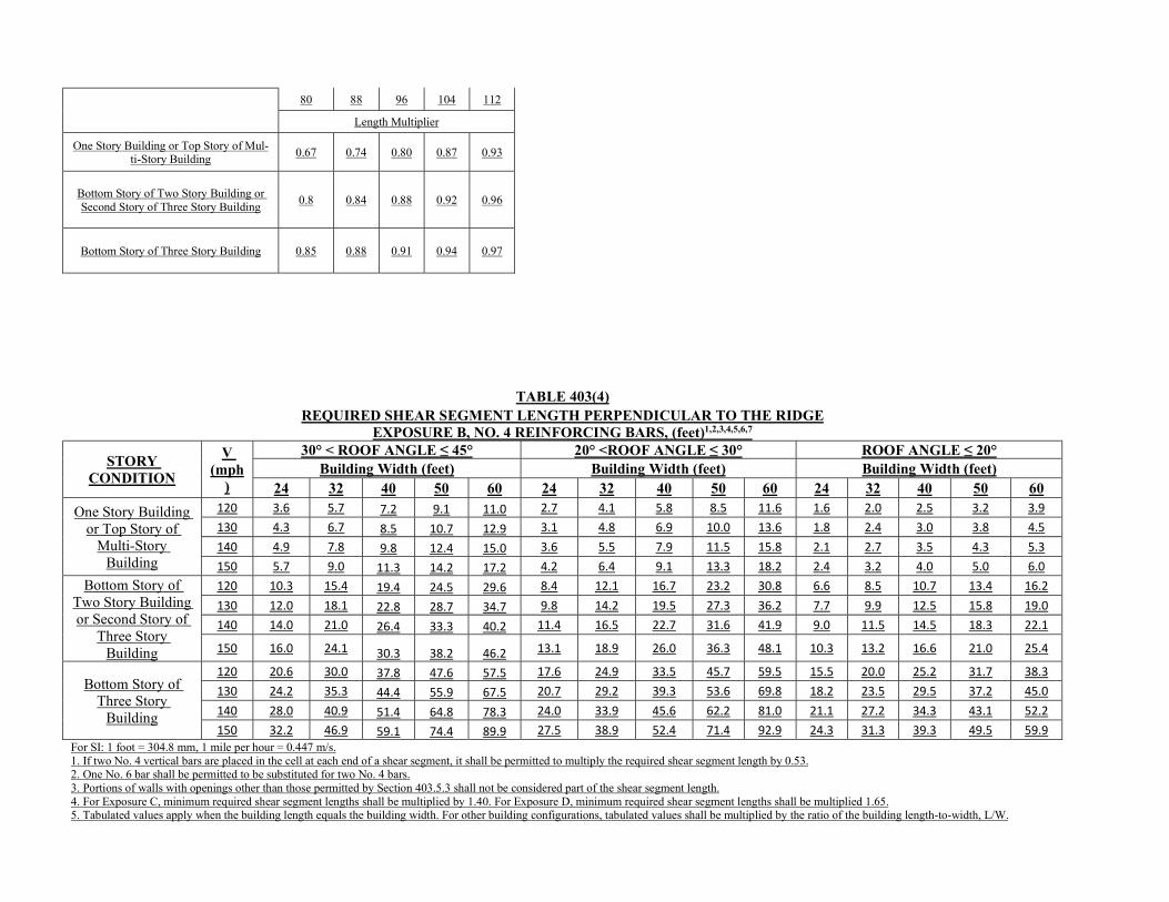
80 88 96 104 112
Length Multiplier
One Story Building or Top Story of Mul-ti-Story Building
0.67 0.74 0.80 0.87 0.93
Bottom Story of Two Story Building or Second Story of Three Story Building
0.8 0.84 0.88 0.92 0.96
Bottom Story of Three Story Building 0.85 0.88 0.91 0.94 0.97
TABLE 403(4) REQUIRED SHEAR SEGMENT LENGTH PERPENDICULAR TO THE RIDGE
EXPOSURE B, NO. 4 REINFORCING BARS, (feet)1,2,3,4,5,6,7
STORY CONDITION
V (mph
)
30° < ROOF ANGLE ≤ 45° 20° <ROOF ANGLE ≤ 30° ROOF ANGLE ≤ 20° Building Width (feet) Building Width (feet) Building Width (feet)
24 32 40 50 60 24 32 40 50 60 24 32 40 50 60
One Story Building or Top Story of
Multi-Story Building
120 3.6 5.7 7.2 9.1 11.0 2.7 4.1 5.8 8.5 11.6 1.6 2.0 2.5 3.2 3.9 130 4.3 6.7 8.5 10.7 12.9 3.1 4.8 6.9 10.0 13.6 1.8 2.4 3.0 3.8 4.5 140 4.9 7.8 9.8 12.4 15.0 3.6 5.5 7.9 11.5 15.8 2.1 2.7 3.5 4.3 5.3 150 5.7 9.0 11.3 14.2 17.2 4.2 6.4 9.1 13.3 18.2 2.4 3.2 4.0 5.0 6.0
Bottom Story of Two Story Building or Second Story of
Three Story Building
120 10.3 15.4 19.4 24.5 29.6 8.4 12.1 16.7 23.2 30.8 6.6 8.5 10.7 13.4 16.2 130 12.0 18.1 22.8 28.7 34.7 9.8 14.2 19.5 27.3 36.2 7.7 9.9 12.5 15.8 19.0 140 14.0 21.0 26.4 33.3 40.2 11.4 16.5 22.7 31.6 41.9 9.0 11.5 14.5 18.3 22.1
150 16.0 24.1 30.3 38.2 46.2 13.1 18.9 26.0 36.3 48.1 10.3 13.2 16.6 21.0 25.4
Bottom Story of Three Story
Building
120 20.6 30.0 37.8 47.6 57.5 17.6 24.9 33.5 45.7 59.5 15.5 20.0 25.2 31.7 38.3 130 24.2 35.3 44.4 55.9 67.5 20.7 29.2 39.3 53.6 69.8 18.2 23.5 29.5 37.2 45.0 140 28.0 40.9 51.4 64.8 78.3 24.0 33.9 45.6 62.2 81.0 21.1 27.2 34.3 43.1 52.2 150 32.2 46.9 59.1 74.4 89.9 27.5 38.9 52.4 71.4 92.9 24.3 31.3 39.3 49.5 59.9
For SI: 1 foot = 304.8 mm, 1 mile per hour = 0.447 m/s. 1. If two No. 4 vertical bars are placed in the cell at each end of a shear segment, it shall be permitted to multiply the required shear segment length by 0.53. 2. One No. 6 bar shall be permitted to be substituted for two No. 4 bars. 3. Portions of walls with openings other than those permitted by Section 403.5.3 shall not be considered part of the shear segment length. 4. For Exposure C, minimum required shear segment lengths shall be multiplied by 1.40. For Exposure D, minimum required shear segment lengths shall be multiplied 1.65. 5. Tabulated values apply when the building length equals the building width. For other building configurations, tabulated values shall be multiplied by the ratio of the building length-to-width, L/W.
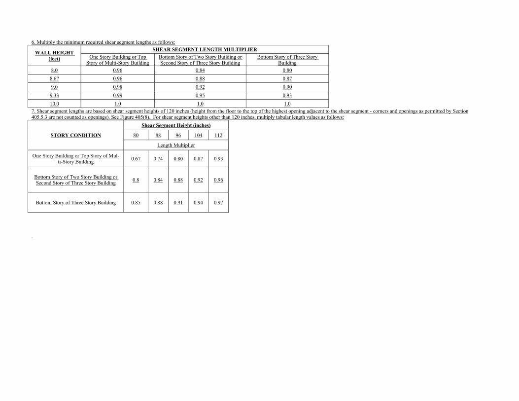
6. Multiply the minimum required shear segment lengths as follows:
WALL HEIGHT (feet)
SHEAR SEGMENT LENGTH MULTIPLIER
One Story Building or Top Story of Multi-Story Building
Bottom Story of Two Story Building or Second Story of Three Story Building
Bottom Story of Three Story Building
8.0 0.96 0.84 0.80
8.67 0.96 0.88 0.87
9.0 0.98 0.92 0.90
9.33 0.99 0.95 0.93
10.0 1.0 1.0 1.0
7. Shear segment lengths are based on shear segment heights of 120 inches (height from the floor to the top of the highest opening adjacent to the shear segment - corners and openings as permitted by Section 405.5.3 are not counted as openings). See Figure 405(8). For shear segment heights other than 120 inches, multiply tabular length values as follows:
STORY CONDITION
Shear Segment Height (inches)
80 88 96 104 112
Length Multiplier
One Story Building or Top Story of Mul-ti-Story Building
0.67 0.74 0.80 0.87 0.93
Bottom Story of Two Story Building or Second Story of Three Story Building
0.8 0.84 0.88 0.92 0.96
Bottom Story of Three Story Building 0.85 0.88 0.91 0.94 0.97
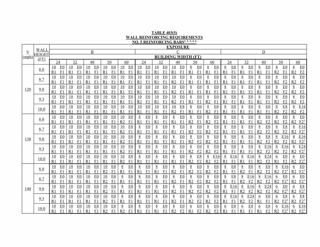
TABLE 403(5)
WALL REINFORCING REQUIREMENTS NO. 5 REINFORCING BARS1, 2, 3, 4, 6
V (mph)
WALL HEIGHT
(FT)
EXPOSURE B C D
BUILDING WIDTH (FT) 24 32 40 50 60 24 32 40 50 60 24 32 40 50 60
120
8.0 10 E0 10 E0 10 E0 10 E0 10 E0 10 E0 10 E0 10 E0 8 E0 8 E0 8 E0 8 E0 8 E0 8 E0 8 E0 R1 F1 R1 F1 R1 F1 R1 F1 R1 F1 R1 F1 R1 F1 R1 F1 R1 F1 R1 F1 R1 F1 R1 F1 R1 F1 R2 F1 R2 F2
8.7 10 E0 10 E0 10 E0 10 E0 10 E0 10 E0 10 E0 10 E0 8 E0 8 E0 8 E0 8 E0 8 E0 8 E0 8 E0 R1 F1 R1 F1 R1 F1 R1 F1 R1 F1 R1 F1 R1 F1 R2 F1 R1 F1 R1 F1 R1 F1 R1 F1 R1 F1 R2 F2 R2 F2
9.0 10 E0 10 E0 10 E0 10 E0 10 E0 10 E0 10 E0 10 E0 8 E0 8 E0 8 E0 8 E0 8 E0 8 E0 8 E0 R1 F1 R1 F1 R1 F1 R1 F1 R1 F1 R1 F1 R1 F1 R2 F1 R1 F1 R1 F1 R1 F1 R1 F1 R1 F1 R2 F2 R2 F2
9.3 10 E0 10 E0 10 E0 10 E0 10 E0 10 E0 10 E0 10 E0 8 E0 8 E0 8 E0 8 E0 8 E0 8 E0 8 E0 R1 F1 R1 F1 R1 F1 R1 F1 R1 F1 R1 F1 R1 F1 R2 F1 R1 F1 R2 F1 R1 F1 R1 F1 R1 F1 R2 F2 R2 F2
10.0 10 E0 10 E0 10 E0 10 E0 10 E0 10 E0 10 E8 10 E8 8 E0 8 E0 8 E0 8 E0 8 E0 8 E8 8 E16 R1 F1 R1 F1 R1 F1 R1 F1 R1 F1 R1 F1 R1 F1 R2 F1 R1 F1 R2 F1 R1 F1 R1 F1 R1 F1 R2 F2 R2 F2
130
8.0 10 E0 10 E0 10 E0 10 E0 10 E0 8 E0 8 E0 8 E0 8 E0 8 E0 8 E0 8 E0 8 E0 8 E0 8 E0 R1 F1 R1 F1 R1 F1 R1 F1 R2 F1 R1 F1 R1 F1 R1 F1 R2 F1 R2 F2 R1 F1 R1 F1 R2 F2 R2 F2 R2 F25
8.7 10 E0 10 E0 10 E0 10 E0 10 E0 8 E0 8 E0 8 E0 8 E0 8 E0 8 E0 8 E0 8 E0 8 E8 8 E16 R1 F1 R1 F1 R1 F1 R1 F1 R2 F1 R1 F1 R1 F1 R1 F1 R2 F2 R2 F2 R1 F1 R1 F1 R2 F2 R2 F2 R2 F25
9.0 10 E0 10 E0 10 E0 10 E0 10 E0 8 E0 8 E0 8 E0 8 E0 8 E0 8 E0 8 E0 8 E8 8 E16 8 E16 R1 F1 R1 F1 R1 F1 R1 F1 R2 F1 R1 F1 R1 F1 R1 F1 R2 F2 R2 F2 R1 F1 R1 F1 R2 F2 R2 F2 R2 F25
9.3 10 E0 10 E0 10 E0 10 E0 10 E0 8 E0 8 E0 8 E0 8 E0 8 E0 8 E0 8 E8 8 E16 8 E16 8 E24 R1 F1 R1 F1 R1 F1 R1 F1 R2 F1 R1 F1 R1 F1 R1 F1 R2 F2 R2 F2 R1 F1 R1 F1 R2 F2 R2 F2 R2 F25
10.0 10 E0 10 E0 10 E0 10 E0 10 E0 8 E0 8 E0 8 E0 8 E8 8 E16 8 E16 8 E16 8 E24 6 E0 6 E0 R1 F1 R1 F1 R1 F1 R1 F1 R2 F1 R1 F1 R1 F1 R1 F1 R2 F2 R2 F2 R1 F1 R1 F1 R2 F2 R1 F2 R2 F25
140
8.0 10 E0 10 E0 10 E0 10 E0 8 E0 8 E0 8 E0 8 E0 8 E0 8 E0 8 E0 8 E0 8 E8 8 E16 6 E0 R1 F1 R1 F1 R1 F1 R2 F1 R1 F1 R1 F1 R1 F1 R2 F1 R2 F2 R2 F2 R1 F1 R2 F1 R2 F2 R2 F25 R2 F25
8.7 10 E0 10 E0 10 E0 10 E0 8 E0 8 E0 8 E0 8 E0 8 E0 8 E0 8 E8 8 E16 8 E16 6 E0 6 E0 R1 F1 R1 F1 R1 F1 R2 F1 R1 F1 R1 F1 R1 F1 R2 F1 R2 F2 R2 F2 R1 F1 R2 F2 R2 F2 R2 F25 R2 F25
9.0 10 E0 10 E0 10 E0 10 E0 8 E0 8 E0 8 E0 8 E0 8 E0 8 E0 8 E16 8 E16 8 E24 6 E0 6 E8 R1 F1 R1 F1 R1 F1 R2 F1 R1 F1 R1 F1 R1 F1 R2 F1 R2 F2 R2 F2 R1 F1 R2 F2 R2 F2 R2 F25 R2 F25
9.3 10 E0 10 E0 10 E0 10 E0 8 E0 8 E0 8 E0 8 E0 8 E0 8 E0 8 E16 8 E24 6 E0 6 E8 6 E8 R1 F1 R1 F1 R1 F1 R2 F1 R1 F1 R1 F1 R1 F1 R2 F1 R2 F2 R2 F2 R1 F1 R2 F2 R1 F1 R2 F25 R2 F25
10.0 10 E0 10 E0 10 E8 10 E8 8 E0 8 E0 8 E0 8 E0 6 E0 6 E0 6 E0 6 E8 6 E8 6 E16 6 E16 R1 F1 R1 F1 R1 F1 R2 F1 R2 F1 R1 F1 R1 F1 R2 F2 R1 F2 R2 F2 R1 F1 R1 F1 R1 F2 R2 F25 R2 F25
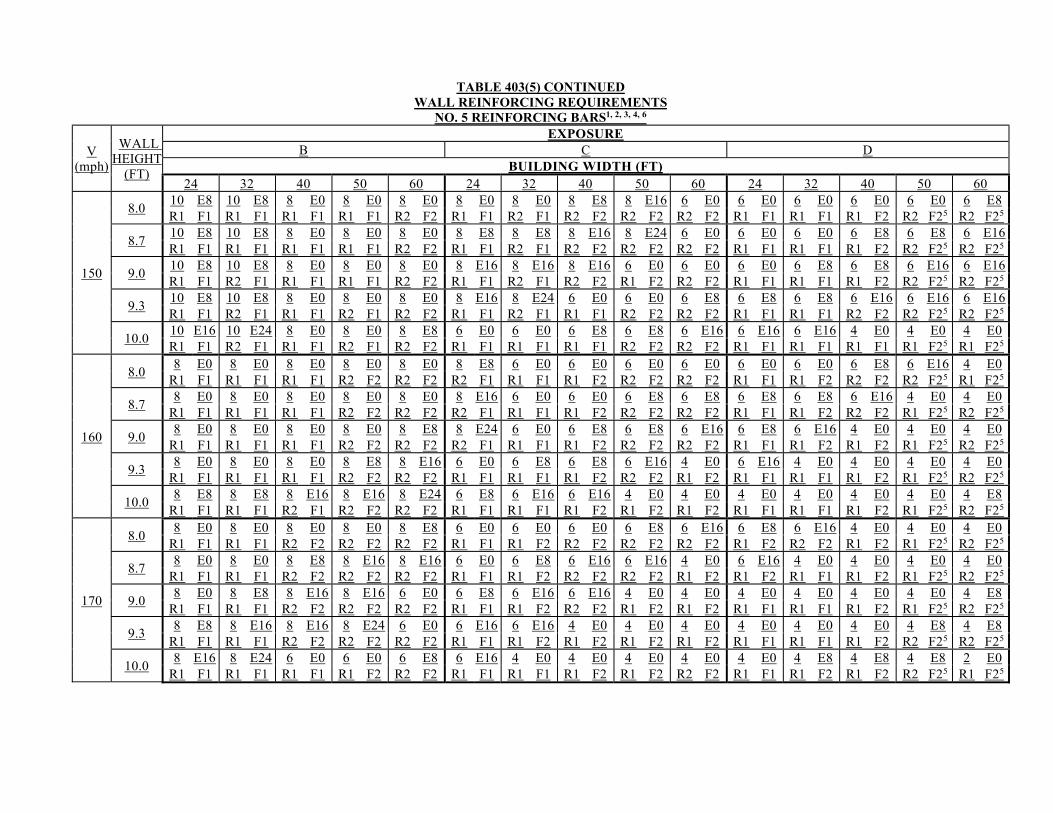
TABLE 403(5) CONTINUED WALL REINFORCING REQUIREMENTS
NO. 5 REINFORCING BARS1, 2, 3, 4, 6
V (mph)
WALL HEIGHT
(FT)
EXPOSURE B C D
BUILDING WIDTH (FT) 24 32 40 50 60 24 32 40 50 60 24 32 40 50 60
150
8.0 10 E8 10 E8 8 E0 8 E0 8 E0 8 E0 8 E0 8 E8 8 E16 6 E0 6 E0 6 E0 6 E0 6 E0 6 E8 R1 F1 R1 F1 R1 F1 R1 F1 R2 F2 R1 F1 R2 F1 R2 F2 R2 F2 R2 F2 R1 F1 R1 F1 R1 F2 R2 F25 R2 F25
8.7 10 E8 10 E8 8 E0 8 E0 8 E0 8 E8 8 E8 8 E16 8 E24 6 E0 6 E0 6 E0 6 E8 6 E8 6 E16 R1 F1 R1 F1 R1 F1 R1 F1 R2 F2 R1 F1 R2 F1 R2 F2 R2 F2 R2 F2 R1 F1 R1 F1 R1 F2 R2 F25 R2 F25
9.0 10 E8 10 E8 8 E0 8 E0 8 E0 8 E16 8 E16 8 E16 6 E0 6 E0 6 E0 6 E8 6 E8 6 E16 6 E16 R1 F1 R2 F1 R1 F1 R1 F1 R2 F2 R1 F1 R2 F1 R2 F2 R1 F2 R2 F2 R1 F1 R1 F1 R1 F2 R2 F25 R2 F25
9.3 10 E8 10 E8 8 E0 8 E0 8 E0 8 E16 8 E24 6 E0 6 E0 6 E8 6 E8 6 E8 6 E16 6 E16 6 E16 R1 F1 R2 F1 R1 F1 R2 F1 R2 F2 R1 F1 R2 F1 R1 F1 R2 F2 R2 F2 R1 F1 R1 F1 R2 F2 R2 F25 R2 F25
10.0 10 E16 10 E24 8 E0 8 E0 8 E8 6 E0 6 E0 6 E8 6 E8 6 E16 6 E16 6 E16 4 E0 4 E0 4 E0 R1 F1 R2 F1 R1 F1 R2 F1 R2 F2 R1 F1 R1 F1 R1 F1 R2 F2 R2 F2 R1 F1 R1 F1 R1 F1 R1 F25 R1 F25
160
8.0 8 E0 8 E0 8 E0 8 E0 8 E0 8 E8 6 E0 6 E0 6 E0 6 E0 6 E0 6 E0 6 E8 6 E16 4 E0
R1 F1 R1 F1 R1 F1 R2 F2 R2 F2 R2 F1 R1 F1 R1 F2 R2 F2 R2 F2 R1 F1 R1 F2 R2 F2 R2 F25 R1 F25
8.7 8 E0 8 E0 8 E0 8 E0 8 E0 8 E16 6 E0 6 E0 6 E8 6 E8 6 E8 6 E8 6 E16 4 E0 4 E0
R1 F1 R1 F1 R1 F1 R2 F2 R2 F2 R2 F1 R1 F1 R1 F2 R2 F2 R2 F2 R1 F1 R1 F2 R2 F2 R1 F25 R2 F25
9.0 8 E0 8 E0 8 E0 8 E0 8 E8 8 E24 6 E0 6 E8 6 E8 6 E16 6 E8 6 E16 4 E0 4 E0 4 E0
R1 F1 R1 F1 R1 F1 R2 F2 R2 F2 R2 F1 R1 F1 R1 F2 R2 F2 R2 F2 R1 F1 R1 F2 R1 F2 R1 F25 R2 F25
9.3 8 E0 8 E0 8 E0 8 E8 8 E16 6 E0 6 E8 6 E8 6 E16 4 E0 6 E16 4 E0 4 E0 4 E0 4 E0
R1 F1 R1 F1 R1 F1 R2 F2 R2 F2 R1 F1 R1 F1 R1 F2 R2 F2 R1 F2 R1 F1 R1 F1 R1 F2 R1 F25 R2 F25
10.0 8 E8 8 E8 8 E16 8 E16 8 E24 6 E8 6 E16 6 E16 4 E0 4 E0 4 E0 4 E0 4 E0 4 E0 4 E8
R1 F1 R1 F1 R2 F1 R2 F2 R2 F2 R1 F1 R1 F1 R1 F2 R1 F2 R1 F2 R1 F1 R1 F1 R1 F2 R1 F25 R2 F25
170
8.0 8 E0 8 E0 8 E0 8 E0 8 E8 6 E0 6 E0 6 E0 6 E8 6 E16 6 E8 6 E16 4 E0 4 E0 4 E0
R1 F1 R1 F1 R2 F2 R2 F2 R2 F2 R1 F1 R1 F2 R2 F2 R2 F2 R2 F2 R1 F2 R2 F2 R1 F2 R1 F25 R2 F25
8.7 8 E0 8 E0 8 E8 8 E16 8 E16 6 E0 6 E8 6 E16 6 E16 4 E0 6 E16 4 E0 4 E0 4 E0 4 E0
R1 F1 R1 F1 R2 F2 R2 F2 R2 F2 R1 F1 R1 F2 R2 F2 R2 F2 R1 F2 R1 F2 R1 F1 R1 F2 R1 F25 R2 F25
9.0 8 E0 8 E8 8 E16 8 E16 6 E0 6 E8 6 E16 6 E16 4 E0 4 E0 4 E0 4 E0 4 E0 4 E0 4 E8
R1 F1 R1 F1 R2 F2 R2 F2 R2 F2 R1 F1 R1 F2 R2 F2 R1 F2 R1 F2 R1 F1 R1 F1 R1 F2 R1 F25 R2 F25
9.3 8 E8 8 E16 8 E16 8 E24 6 E0 6 E16 6 E16 4 E0 4 E0 4 E0 4 E0 4 E0 4 E0 4 E8 4 E8
R1 F1 R1 F1 R2 F2 R2 F2 R2 F2 R1 F1 R1 F2 R1 F2 R1 F2 R1 F2 R1 F1 R1 F1 R1 F2 R2 F25 R2 F25
10.0 8 E16 8 E24 6 E0 6 E0 6 E8 6 E16 4 E0 4 E0 4 E0 4 E0 4 E0 4 E8 4 E8 4 E8 2 E0
R1 F1 R1 F1 R1 F1 R1 F2 R2 F2 R1 F1 R1 F1 R1 F2 R1 F2 R2 F2 R1 F1 R1 F2 R1 F2 R2 F25 R1 F25
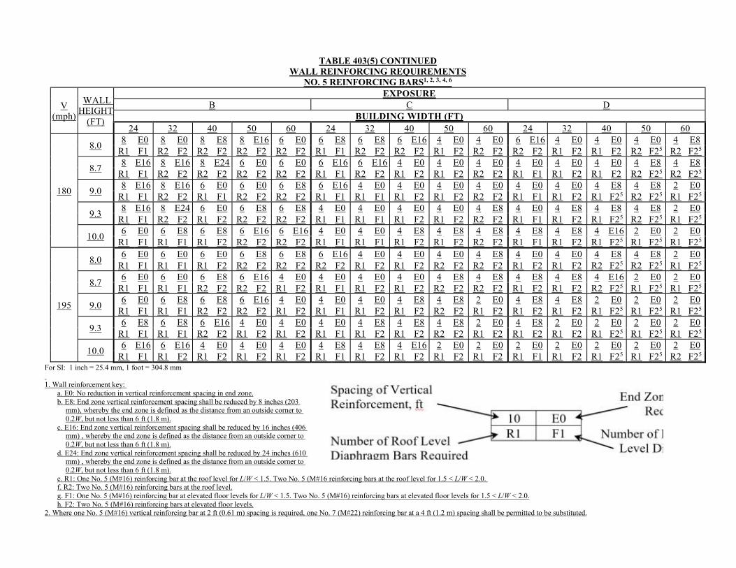
TABLE 403(5) CONTINUED WALL REINFORCING REQUIREMENTS
NO. 5 REINFORCING BARS1, 2, 3, 4, 6
V (mph)
WALL HEIGHT
(FT)
EXPOSURE B C D
BUILDING WIDTH (FT) 24 32 40 50 60 24 32 40 50 60 24 32 40 50 60
180
8.0 8 E0 8 E0 8 E8 8 E16 6 E0 6 E8 6 E8 6 E16 4 E0 4 E0 6 E16 4 E0 4 E0 4 E0 4 E8
R1 F1 R2 F2 R2 F2 R2 F2 R2 F2 R1 F1 R2 F2 R2 F2 R1 F2 R2 F2 R2 F2 R1 F2 R1 F2 R2 F25 R2 F25
8.7 8 E16 8 E16 8 E24 6 E0 6 E0 6 E16 6 E16 4 E0 4 E0 4 E0 4 E0 4 E0 4 E0 4 E8 4 E8
R1 F1 R2 F2 R2 F2 R2 F2 R2 F2 R1 F1 R2 F2 R1 F2 R1 F2 R2 F2 R1 F1 R1 F2 R1 F2 R2 F25 R2 F25
9.0 8 E16 8 E16 6 E0 6 E0 6 E8 6 E16 4 E0 4 E0 4 E0 4 E0 4 E0 4 E0 4 E8 4 E8 2 E0
R1 F1 R2 F2 R1 F1 R2 F2 R2 F2 R1 F1 R1 F1 R1 F2 R1 F2 R2 F2 R1 F1 R1 F2 R1 F25 R2 F25 R1 F25
9.3 8 E16 8 E24 6 E0 6 E8 6 E8 4 E0 4 E0 4 E0 4 E0 4 E8 4 E0 4 E8 4 E8 4 E8 2 E0
R1 F1 R2 F2 R1 F2 R2 F2 R2 F2 R1 F1 R1 F1 R1 F2 R1 F2 R2 F2 R1 F1 R1 F2 R1 F25 R2 F25 R1 F25
10.0 6 E0 6 E8 6 E8 6 E16 6 E16 4 E0 4 E0 4 E8 4 E8 4 E8 4 E8 4 E8 4 E16 2 E0 2 E0
R1 F1 R1 F1 R1 F2 R2 F2 R2 F2 R1 F1 R1 F1 R1 F2 R1 F2 R2 F2 R1 F1 R1 F2 R1 F25 R1 F25 R1 F25
195
8.0 6 E0 6 E0 6 E0 6 E8 6 E8 6 E16 4 E0 4 E0 4 E0 4 E8 4 E0 4 E0 4 E8 4 E8 2 E0
R1 F1 R1 F1 R1 F2 R2 F2 R2 F2 R2 F2 R1 F2 R1 F2 R2 F2 R2 F2 R1 F2 R1 F2 R2 F25 R2 F25 R1 F25
8.7 6 E0 6 E0 6 E8 6 E16 4 E0 4 E0 4 E0 4 E0 4 E8 4 E8 4 E8 4 E8 4 E16 2 E0 2 E0
R1 F1 R1 F1 R2 F2 R2 F2 R1 F2 R1 F1 R1 F2 R1 F2 R2 F2 R2 F2 R1 F2 R1 F2 R2 F25 R1 F25 R1 F25
9.0 6 E0 6 E8 6 E8 6 E16 4 E0 4 E0 4 E0 4 E8 4 E8 2 E0 4 E8 4 E8 2 E0 2 E0 2 E0
R1 F1 R1 F1 R2 F2 R2 F2 R1 F2 R1 F1 R1 F2 R1 F2 R2 F2 R1 F2 R1 F2 R1 F2 R1 F25 R1 F25 R1 F25
9.3 6 E8 6 E8 6 E16 4 E0 4 E0 4 E0 4 E8 4 E8 4 E8 2 E0 4 E8 2 E0 2 E0 2 E0 2 E0
R1 F1 R1 F1 R2 F2 R1 F2 R1 F2 R1 F1 R1 F2 R1 F2 R2 F2 R1 F2 R1 F2 R1 F2 R1 F25 R1 F25 R1 F25
10.0 6 E16 6 E16 4 E0 4 E0 4 E0 4 E8 4 E8 4 E16 2 E0 2 E0 2 E0 2 E0 2 E0 2 E0 2 E0
R1 F1 R1 F2 R1 F2 R1 F2 R1 F2 R1 F1 R1 F2 R1 F2 R1 F2 R1 F2 R1 F1 R1 F2 R1 F25 R1 F25 R2 F25 For SI: 1 inch = 25.4 mm, 1 foot = 304.8 mm 1. Wall reinforcement key:
a. E0: No reduction in vertical reinforcement spacing in end zone. b. E8: End zone vertical reinforcement spacing shall be reduced by 8 inches (203
mm), whereby the end zone is defined as the distance from an outside corner to 0.2W, but not less than 6 ft (1.8 m).
c. E16: End zone vertical reinforcement spacing shall be reduced by 16 inches (406 mm) , whereby the end zone is defined as the distance from an outside corner to 0.2W, but not less than 6 ft (1.8 m).
d. E24: End zone vertical reinforcement spacing shall be reduced by 24 inches (610 mm) , whereby the end zone is defined as the distance from an outside corner to 0.2W, but not less than 6 ft (1.8 m).
e. R1: One No. 5 (M#16) reinforcing bar at the roof level for L/W < 1.5. Two No. 5 (M#16 reinforcing bars at the roof level for 1.5 < L/W < 2.0. f. R2: Two No. 5 (M#16) reinforcing bars at the roof level. g. F1: One No. 5 (M#16) reinforcing bar at elevated floor levels for L/W < 1.5. Two No. 5 (M#16) reinforcing bars at elevated floor levels for 1.5 < L/W < 2.0. h. F2: Two No. 5 (M#16) reinforcing bars at elevated floor levels.
2. Where one No. 5 (M#16) vertical reinforcing bar at 2 ft (0.61 m) spacing is required, one No. 7 (M#22) reinforcing bar at a 4 ft (1.2 m) spacing shall be permitted to be substituted.
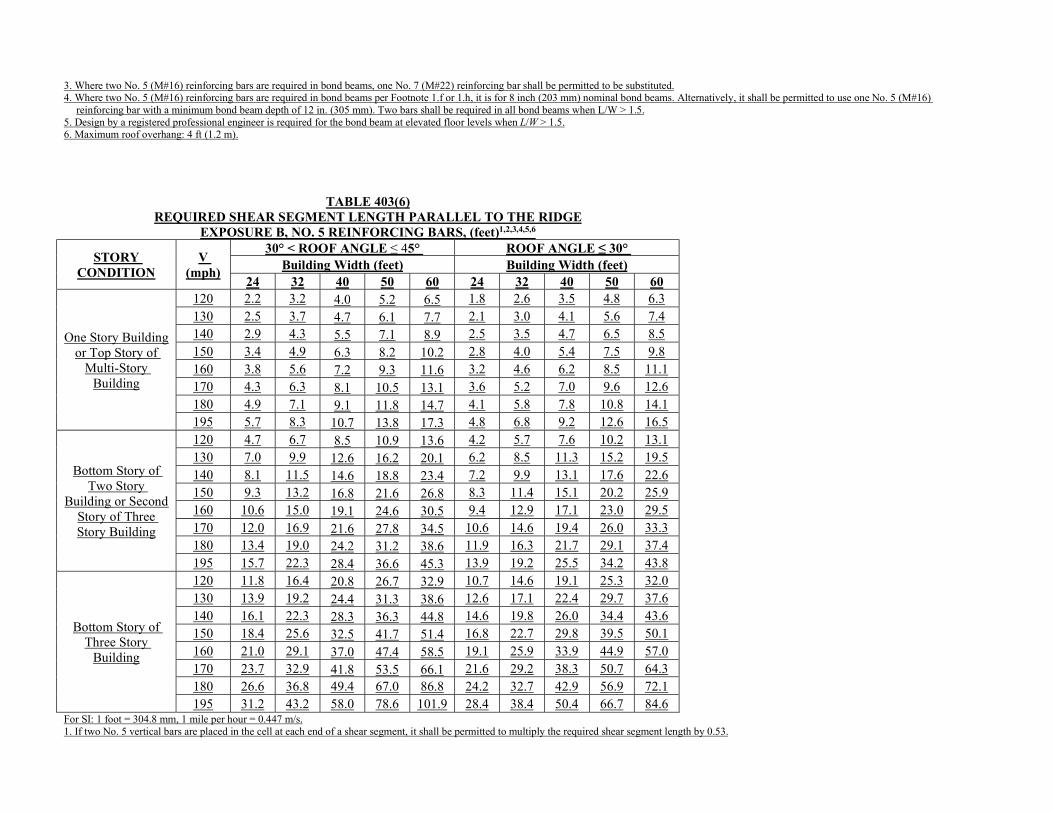
3. Where two No. 5 (M#16) reinforcing bars are required in bond beams, one No. 7 (M#22) reinforcing bar shall be permitted to be substituted. 4. Where two No. 5 (M#16) reinforcing bars are required in bond beams per Footnote 1.f or 1.h, it is for 8 inch (203 mm) nominal bond beams. Alternatively, it shall be permitted to use one No. 5 (M#16)
reinforcing bar with a minimum bond beam depth of 12 in. (305 mm). Two bars shall be required in all bond beams when L/W > 1.5. 5. Design by a registered professional engineer is required for the bond beam at elevated floor levels when L/W > 1.5. 6. Maximum roof overhang: 4 ft (1.2 m).
TABLE 403(6)
REQUIRED SHEAR SEGMENT LENGTH PARALLEL TO THE RIDGE EXPOSURE B, NO. 5 REINFORCING BARS, (feet)1,2,3,4,5,6
STORY CONDITION
V (mph)
30° < ROOF ANGLE ≤ 45° ROOF ANGLE ≤ 30° Building Width (feet) Building Width (feet)
24 32 40 50 60 24 32 40 50 60
One Story Building or Top Story of
Multi-Story Building
120 2.2 3.2 4.0 5.2 6.5 1.8 2.6 3.5 4.8 6.3 130 2.5 3.7 4.7 6.1 7.7 2.1 3.0 4.1 5.6 7.4 140 2.9 4.3 5.5 7.1 8.9 2.5 3.5 4.7 6.5 8.5 150 3.4 4.9 6.3 8.2 10.2 2.8 4.0 5.4 7.5 9.8 160 3.8 5.6 7.2 9.3 11.6 3.2 4.6 6.2 8.5 11.1 170 4.3 6.3 8.1 10.5 13.1 3.6 5.2 7.0 9.6 12.6 180 4.9 7.1 9.1 11.8 14.7 4.1 5.8 7.8 10.8 14.1 195 5.7 8.3 10.7 13.8 17.3 4.8 6.8 9.2 12.6 16.5
Bottom Story of Two Story
Building or Second Story of Three Story Building
120 4.7 6.7 8.5 10.9 13.6 4.2 5.7 7.6 10.2 13.1 130 7.0 9.9 12.6 16.2 20.1 6.2 8.5 11.3 15.2 19.5 140 8.1 11.5 14.6 18.8 23.4 7.2 9.9 13.1 17.6 22.6 150 9.3 13.2 16.8 21.6 26.8 8.3 11.4 15.1 20.2 25.9 160 10.6 15.0 19.1 24.6 30.5 9.4 12.9 17.1 23.0 29.5 170 12.0 16.9 21.6 27.8 34.5 10.6 14.6 19.4 26.0 33.3 180 13.4 19.0 24.2 31.2 38.6 11.9 16.3 21.7 29.1 37.4 195 15.7 22.3 28.4 36.6 45.3 13.9 19.2 25.5 34.2 43.8
Bottom Story of Three Story
Building
120 11.8 16.4 20.8 26.7 32.9 10.7 14.6 19.1 25.3 32.0 130 13.9 19.2 24.4 31.3 38.6 12.6 17.1 22.4 29.7 37.6 140 16.1 22.3 28.3 36.3 44.8 14.6 19.8 26.0 34.4 43.6 150 18.4 25.6 32.5 41.7 51.4 16.8 22.7 29.8 39.5 50.1 160 21.0 29.1 37.0 47.4 58.5 19.1 25.9 33.9 44.9 57.0 170 23.7 32.9 41.8 53.5 66.1 21.6 29.2 38.3 50.7 64.3 180 26.6 36.8 49.4 67.0 86.8 24.2 32.7 42.9 56.9 72.1 195 31.2 43.2 58.0 78.6 101.9 28.4 38.4 50.4 66.7 84.6
For SI: 1 foot = 304.8 mm, 1 mile per hour = 0.447 m/s. 1. If two No. 5 vertical bars are placed in the cell at each end of a shear segment, it shall be permitted to multiply the required shear segment length by 0.53.
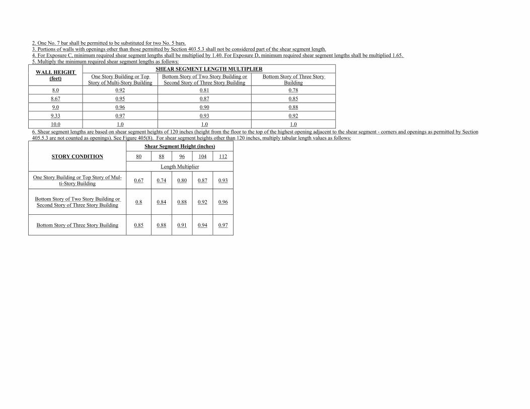
2. One No. 7 bar shall be permitted to be substituted for two No. 5 bars. 3. Portions of walls with openings other than those permitted by Section 403.5.3 shall not be considered part of the shear segment length. 4. For Exposure C, minimum required shear segment lengths shall be multiplied by 1.40. For Exposure D, minimum required shear segment lengths shall be multiplied 1.65. 5. Multiply the minimum required shear segment lengths as follows:
WALL HEIGHT (feet)
SHEAR SEGMENT LENGTH MULTIPLIER
One Story Building or Top Story of Multi-Story Building
Bottom Story of Two Story Building or Second Story of Three Story Building
Bottom Story of Three Story Building
8.0 0.92 0.81 0.78
8.67 0.95 0.87 0.85
9.0 0.96 0.90 0.88
9.33 0.97 0.93 0.92
10.0 1.0 1.0 1.0
6. Shear segment lengths are based on shear segment heights of 120 inches (height from the floor to the top of the highest opening adjacent to the shear segment - corners and openings as permitted by Section 405.5.3 are not counted as openings). See Figure 405(8). For shear segment heights other than 120 inches, multiply tabular length values as follows:
STORY CONDITION
Shear Segment Height (inches)
80 88 96 104 112
Length Multiplier
One Story Building or Top Story of Mul-ti-Story Building
0.67 0.74 0.80 0.87 0.93
Bottom Story of Two Story Building or Second Story of Three Story Building
0.8 0.84 0.88 0.92 0.96
Bottom Story of Three Story Building 0.85 0.88 0.91 0.94 0.97
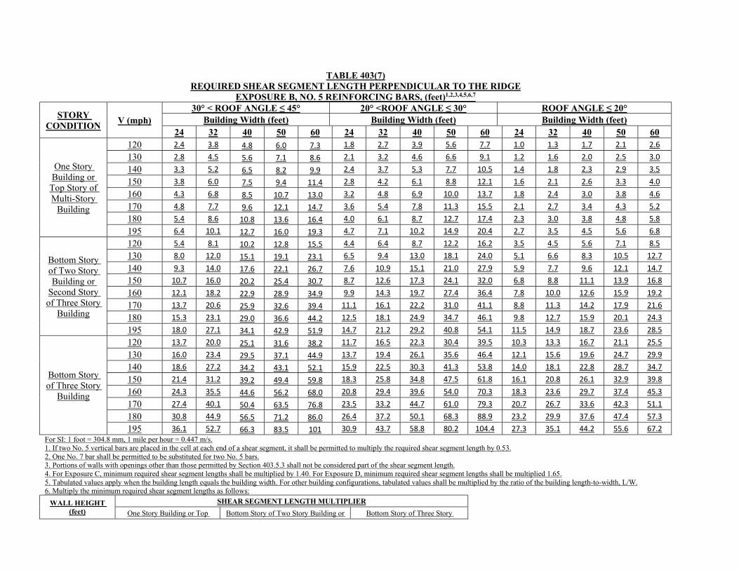
TABLE 403(7)
REQUIRED SHEAR SEGMENT LENGTH PERPENDICULAR TO THE RIDGE EXPOSURE B, NO. 5 REINFORCING BARS, (feet)1,2,3,4,5,6,7
STORY CONDITION
V (mph) 30° < ROOF ANGLE ≤ 45° 20° <ROOF ANGLE ≤ 30° ROOF ANGLE ≤ 20°
Building Width (feet) Building Width (feet) Building Width (feet) 24 32 40 50 60 24 32 40 50 60 24 32 40 50 60
One Story Building or
Top Story of Multi-Story
Building
120 2.4 3.8 4.8 6.0 7.3 1.8 2.7 3.9 5.6 7.7 1.0 1.3 1.7 2.1 2.6 130 2.8 4.5 5.6 7.1 8.6 2.1 3.2 4.6 6.6 9.1 1.2 1.6 2.0 2.5 3.0 140 3.3 5.2 6.5 8.2 9.9 2.4 3.7 5.3 7.7 10.5 1.4 1.8 2.3 2.9 3.5
150 3.8 6.0 7.5 9.4 11.4 2.8 4.2 6.1 8.8 12.1 1.6 2.1 2.6 3.3 4.0 160 4.3 6.8 8.5 10.7 13.0 3.2 4.8 6.9 10.0 13.7 1.8 2.4 3.0 3.8 4.6
170 4.8 7.7 9.6 12.1 14.7 3.6 5.4 7.8 11.3 15.5 2.1 2.7 3.4 4.3 5.2 180 5.4 8.6 10.8 13.6 16.4 4.0 6.1 8.7 12.7 17.4 2.3 3.0 3.8 4.8 5.8
195 6.4 10.1 12.7 16.0 19.3 4.7 7.1 10.2 14.9 20.4 2.7 3.5 4.5 5.6 6.8
Bottom Story of Two Story Building or
Second Story of Three Story
Building
120 5.4 8.1 10.2 12.8 15.5 4.4 6.4 8.7 12.2 16.2 3.5 4.5 5.6 7.1 8.5 130 8.0 12.0 15.1 19.1 23.1 6.5 9.4 13.0 18.1 24.0 5.1 6.6 8.3 10.5 12.7
140 9.3 14.0 17.6 22.1 26.7 7.6 10.9 15.1 21.0 27.9 5.9 7.7 9.6 12.1 14.7 150 10.7 16.0 20.2 25.4 30.7 8.7 12.6 17.3 24.1 32.0 6.8 8.8 11.1 13.9 16.8
160 12.1 18.2 22.9 28.9 34.9 9.9 14.3 19.7 27.4 36.4 7.8 10.0 12.6 15.9 19.2 170 13.7 20.6 25.9 32.6 39.4 11.1 16.1 22.2 31.0 41.1 8.8 11.3 14.2 17.9 21.6 180 15.3 23.1 29.0 36.6 44.2 12.5 18.1 24.9 34.7 46.1 9.8 12.7 15.9 20.1 24.3
195 18.0 27.1 34.1 42.9 51.9 14.7 21.2 29.2 40.8 54.1 11.5 14.9 18.7 23.6 28.5
Bottom Story of Three Story
Building
120 13.7 20.0 25.1 31.6 38.2 11.7 16.5 22.3 30.4 39.5 10.3 13.3 16.7 21.1 25.5
130 16.0 23.4 29.5 37.1 44.9 13.7 19.4 26.1 35.6 46.4 12.1 15.6 19.6 24.7 29.9 140 18.6 27.2 34.2 43.1 52.1 15.9 22.5 30.3 41.3 53.8 14.0 18.1 22.8 28.7 34.7
150 21.4 31.2 39.2 49.4 59.8 18.3 25.8 34.8 47.5 61.8 16.1 20.8 26.1 32.9 39.8
160 24.3 35.5 44.6 56.2 68.0 20.8 29.4 39.6 54.0 70.3 18.3 23.6 29.7 37.4 45.3 170 27.4 40.1 50.4 63.5 76.8 23.5 33.2 44.7 61.0 79.3 20.7 26.7 33.6 42.3 51.1
180 30.8 44.9 56.5 71.2 86.0 26.4 37.2 50.1 68.3 88.9 23.2 29.9 37.6 47.4 57.3 195 36.1 52.7 66.3 83.5 101 30.9 43.7 58.8 80.2 104.4 27.3 35.1 44.2 55.6 67.2
For SI: 1 foot = 304.8 mm, 1 mile per hour = 0.447 m/s. 1. If two No. 5 vertical bars are placed in the cell at each end of a shear segment, it shall be permitted to multiply the required shear segment length by 0.53. 2. One No. 7 bar shall be permitted to be substituted for two No. 5 bars. 3. Portions of walls with openings other than those permitted by Section 403.5.3 shall not be considered part of the shear segment length. 4. For Exposure C, minimum required shear segment lengths shall be multiplied by 1.40. For Exposure D, minimum required shear segment lengths shall be multiplied 1.65. 5. Tabulated values apply when the building length equals the building width. For other building configurations, tabulated values shall be multiplied by the ratio of the building length-to-width, L/W. 6. Multiply the minimum required shear segment lengths as follows:
WALL HEIGHT (feet)
SHEAR SEGMENT LENGTH MULTIPLIER
One Story Building or Top Bottom Story of Two Story Building or Bottom Story of Three Story
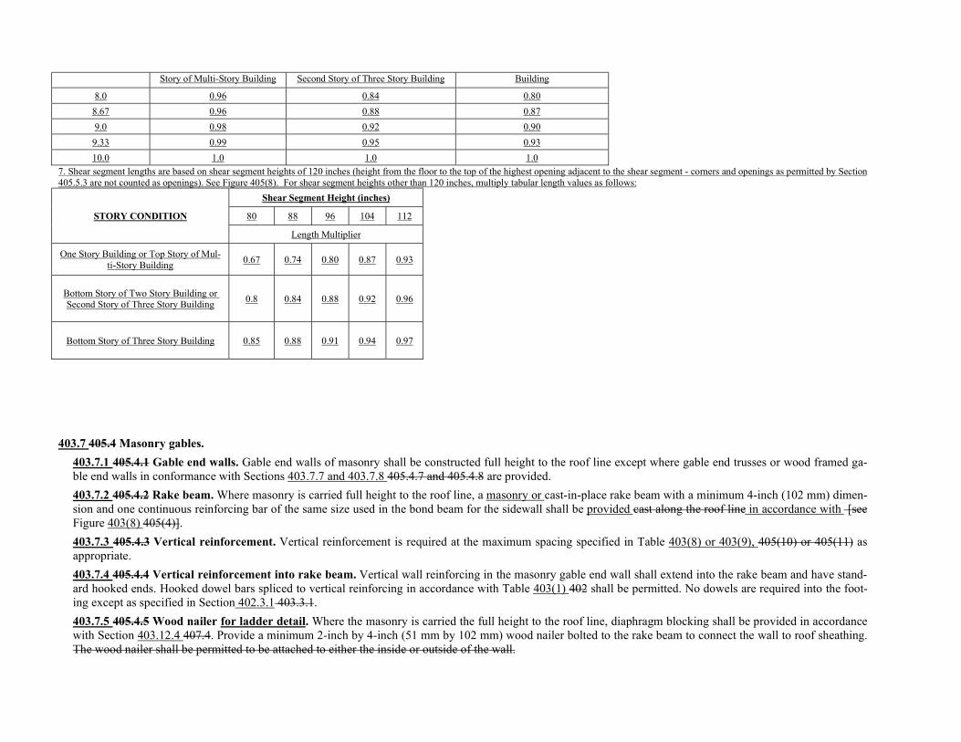
Story of Multi-Story Building Second Story of Three Story Building Building
8.0 0.96 0.84 0.80
8.67 0.96 0.88 0.87
9.0 0.98 0.92 0.90
9.33 0.99 0.95 0.93
10.0 1.0 1.0 1.0
7. Shear segment lengths are based on shear segment heights of 120 inches (height from the floor to the top of the highest opening adjacent to the shear segment - corners and openings as permitted by Section 405.5.3 are not counted as openings). See Figure 405(8). For shear segment heights other than 120 inches, multiply tabular length values as follows:
STORY CONDITION
Shear Segment Height (inches)
80 88 96 104 112
Length Multiplier
One Story Building or Top Story of Mul-ti-Story Building
0.67 0.74 0.80 0.87 0.93
Bottom Story of Two Story Building or Second Story of Three Story Building
0.8 0.84 0.88 0.92 0.96
Bottom Story of Three Story Building 0.85 0.88 0.91 0.94 0.97
403.7 405.4 Masonry gables.
403.7.1 405.4.1 Gable end walls. Gable end walls of masonry shall be constructed full height to the roof line except where gable end trusses or wood framed ga-ble end walls in conformance with Sections 403.7.7 and 403.7.8 405.4.7 and 405.4.8 are provided.
403.7.2 405.4.2 Rake beam. Where masonry is carried full height to the roof line, a masonry or cast-in-place rake beam with a minimum 4-inch (102 mm) dimen-sion and one continuous reinforcing bar of the same size used in the bond beam for the sidewall shall be provided cast along the roof line in accordance with [see Figure 403(8) 405(4)].
403.7.3 405.4.3 Vertical reinforcement. Vertical reinforcement is required at the maximum spacing specified in Table 403(8) or 403(9), 405(10) or 405(11) as appropriate.
403.7.4 405.4.4 Vertical reinforcement into rake beam. Vertical wall reinforcing in the masonry gable end wall shall extend into the rake beam and have stand-ard hooked ends. Hooked dowel bars spliced to vertical reinforcing in accordance with Table 403(1) 402 shall be permitted. No dowels are required into the foot-ing except as specified in Section 402.3.1 403.3.1.
403.7.5 405.4.5 Wood nailer for ladder detail. Where the masonry is carried the full height to the roof line, diaphragm blocking shall be provided in accordance with Section 403.12.4 407.4. Provide a minimum 2-inch by 4-inch (51 mm by 102 mm) wood nailer bolted to the rake beam to connect the wall to roof sheathing. The wood nailer shall be permitted to be attached to either the inside or outside of the wall.
403.7.6 405.4.6 Roof diaphragm attachment. The roof diaphragm shall be attached to the continuous masonry gable as denoted in either Figure 403(11), 403(12) or 403(13) 405(5) or 405(6).
403.7.7 405.4.7 Bond beam. Where masonry is not carried full height, gable end walls shall have a bond beam at the top of the masonry wall. Intermediate bond beams are not required.
403.7.8 405.4.8 Sheathing and bracing. Where masonry is not carried full height, gable end walls shall be framed and sheathed in accordance with the WFCM. with 15/32-inch (11.9 mm) wood structural panels with 8d common or 8d hot dipped galvanized box nails spaced at 6 inches (152 mm) o.c. and 12 inches (305 mm) o.c at intermediate framing. Other approved structural materials shall be permitted provided they are designed to meet the suction and compression loads as re-quired by Section 1609 of the International Building Code. The top of the masonry wall shall be braced in accordance with Figure 403(13a) or 403(13b) Tables 405(14) and 405(15) and Figure 405(7) or bracing shall be designed by a registered professional engineer or architect.
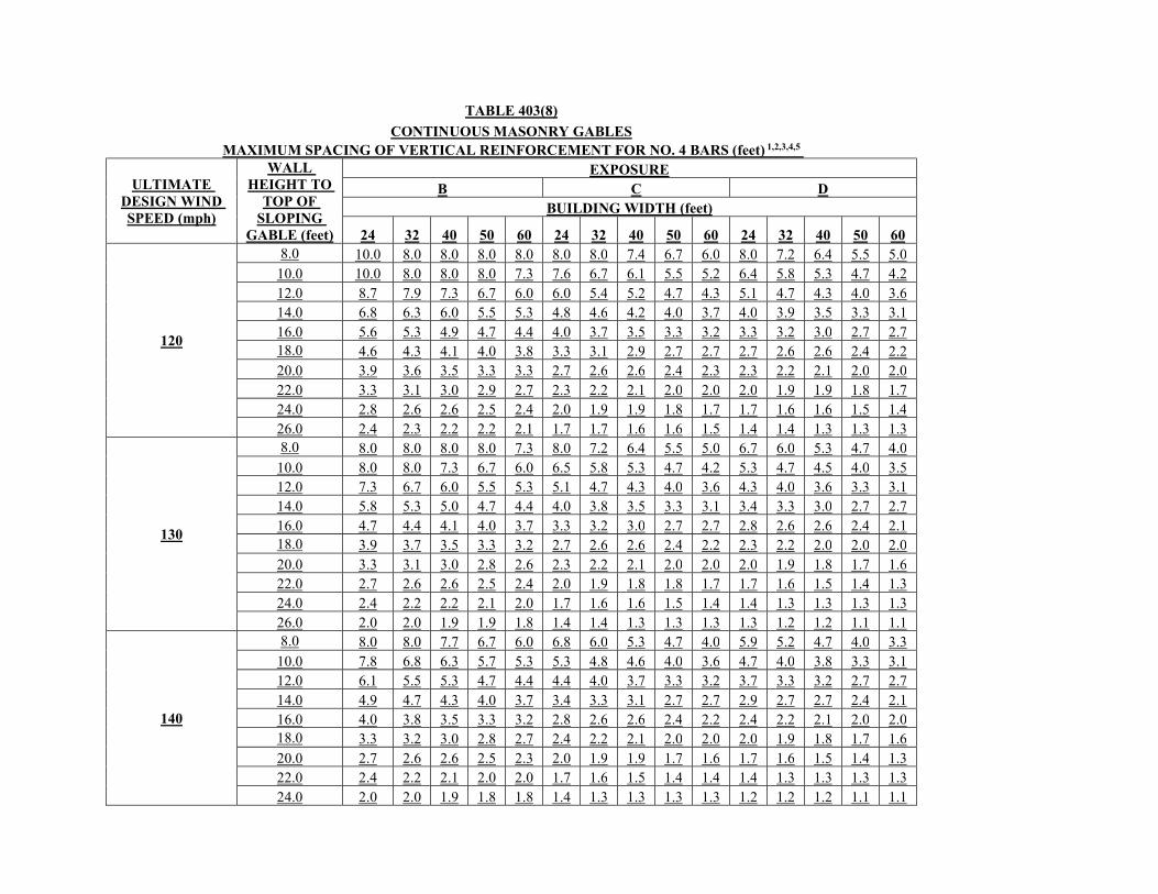
TABLE 403(8)
CONTINUOUS MASONRY GABLES MAXIMUM SPACING OF VERTICAL REINFORCEMENT FOR NO. 4 BARS (feet) 1,2,3,4,5
ULTIMATE DESIGN WIND SPEED (mph)
WALL HEIGHT TO
TOP OF SLOPING
GABLE (feet)
EXPOSURE B C D
BUILDING WIDTH (feet)
24 32 40 50 60 24 32 40 50 60 24 32 40 50 60
120
8.0 10.0 8.0 8.0 8.0 8.0 8.0 8.0 7.4 6.7 6.0 8.0 7.2 6.4 5.5 5.0 10.0 10.0 8.0 8.0 8.0 7.3 7.6 6.7 6.1 5.5 5.2 6.4 5.8 5.3 4.7 4.2 12.0 8.7 7.9 7.3 6.7 6.0 6.0 5.4 5.2 4.7 4.3 5.1 4.7 4.3 4.0 3.6 14.0 6.8 6.3 6.0 5.5 5.3 4.8 4.6 4.2 4.0 3.7 4.0 3.9 3.5 3.3 3.1 16.0 5.6 5.3 4.9 4.7 4.4 4.0 3.7 3.5 3.3 3.2 3.3 3.2 3.0 2.7 2.7 18.0 4.6 4.3 4.1 4.0 3.8 3.3 3.1 2.9 2.7 2.7 2.7 2.6 2.6 2.4 2.2 20.0 3.9 3.6 3.5 3.3 3.3 2.7 2.6 2.6 2.4 2.3 2.3 2.2 2.1 2.0 2.0 22.0 3.3 3.1 3.0 2.9 2.7 2.3 2.2 2.1 2.0 2.0 2.0 1.9 1.9 1.8 1.7 24.0 2.8 2.6 2.6 2.5 2.4 2.0 1.9 1.9 1.8 1.7 1.7 1.6 1.6 1.5 1.4 26.0 2.4 2.3 2.2 2.2 2.1 1.7 1.7 1.6 1.6 1.5 1.4 1.4 1.3 1.3 1.3
130
8.0 8.0 8.0 8.0 8.0 7.3 8.0 7.2 6.4 5.5 5.0 6.7 6.0 5.3 4.7 4.0 10.0 8.0 8.0 7.3 6.7 6.0 6.5 5.8 5.3 4.7 4.2 5.3 4.7 4.5 4.0 3.5 12.0 7.3 6.7 6.0 5.5 5.3 5.1 4.7 4.3 4.0 3.6 4.3 4.0 3.6 3.3 3.1 14.0 5.8 5.3 5.0 4.7 4.4 4.0 3.8 3.5 3.3 3.1 3.4 3.3 3.0 2.7 2.7 16.0 4.7 4.4 4.1 4.0 3.7 3.3 3.2 3.0 2.7 2.7 2.8 2.6 2.6 2.4 2.1 18.0 3.9 3.7 3.5 3.3 3.2 2.7 2.6 2.6 2.4 2.2 2.3 2.2 2.0 2.0 2.0 20.0 3.3 3.1 3.0 2.8 2.6 2.3 2.2 2.1 2.0 2.0 2.0 1.9 1.8 1.7 1.6 22.0 2.7 2.6 2.6 2.5 2.4 2.0 1.9 1.8 1.8 1.7 1.7 1.6 1.5 1.4 1.3 24.0 2.4 2.2 2.2 2.1 2.0 1.7 1.6 1.6 1.5 1.4 1.4 1.3 1.3 1.3 1.3 26.0 2.0 2.0 1.9 1.9 1.8 1.4 1.4 1.3 1.3 1.3 1.3 1.2 1.2 1.1 1.1
140
8.0 8.0 8.0 7.7 6.7 6.0 6.8 6.0 5.3 4.7 4.0 5.9 5.2 4.7 4.0 3.3 10.0 7.8 6.8 6.3 5.7 5.3 5.3 4.8 4.6 4.0 3.6 4.7 4.0 3.8 3.3 3.1 12.0 6.1 5.5 5.3 4.7 4.4 4.4 4.0 3.7 3.3 3.2 3.7 3.3 3.2 2.7 2.7 14.0 4.9 4.7 4.3 4.0 3.7 3.4 3.3 3.1 2.7 2.7 2.9 2.7 2.7 2.4 2.1 16.0 4.0 3.8 3.5 3.3 3.2 2.8 2.6 2.6 2.4 2.2 2.4 2.2 2.1 2.0 2.0 18.0 3.3 3.2 3.0 2.8 2.7 2.4 2.2 2.1 2.0 2.0 2.0 1.9 1.8 1.7 1.6 20.0 2.7 2.6 2.6 2.5 2.3 2.0 1.9 1.9 1.7 1.6 1.7 1.6 1.5 1.4 1.3 22.0 2.4 2.2 2.1 2.0 2.0 1.7 1.6 1.5 1.4 1.4 1.4 1.3 1.3 1.3 1.3 24.0 2.0 2.0 1.9 1.8 1.8 1.4 1.3 1.3 1.3 1.3 1.2 1.2 1.2 1.1 1.1
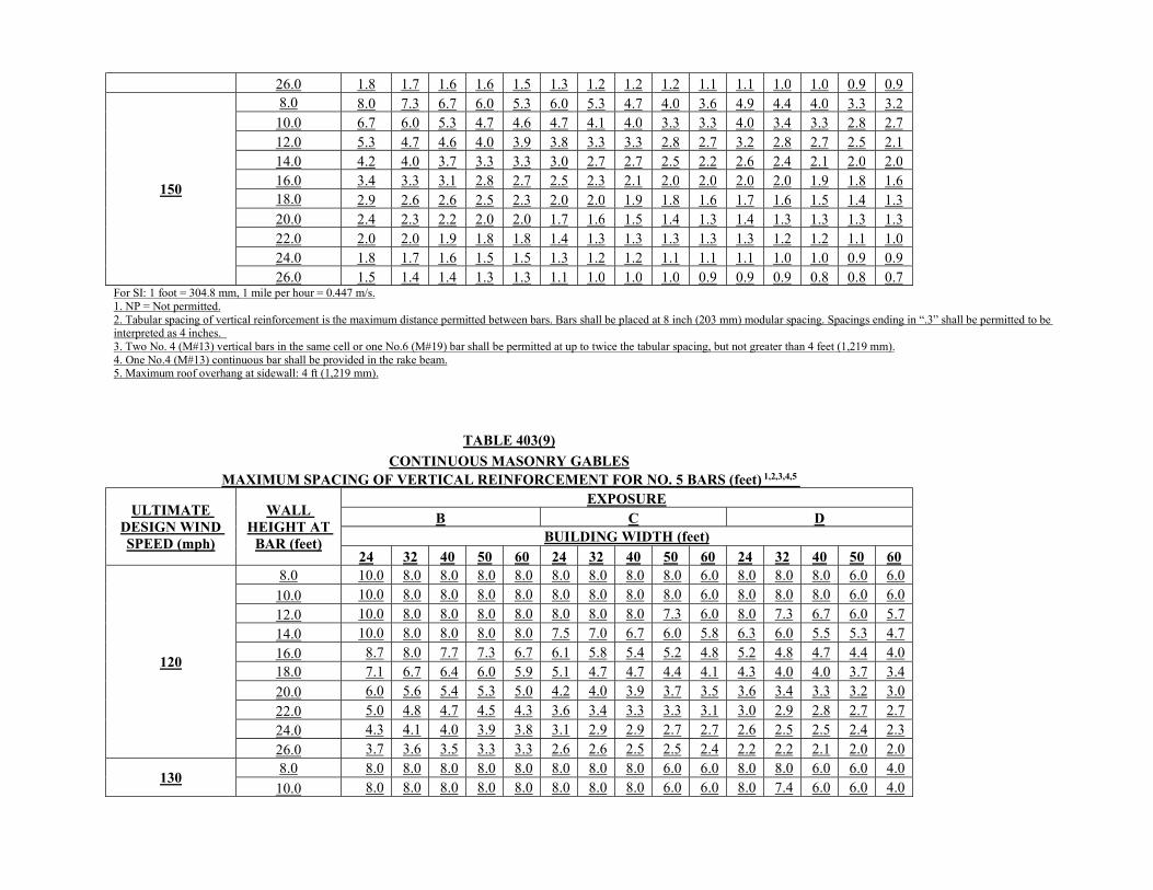
26.0 1.8 1.7 1.6 1.6 1.5 1.3 1.2 1.2 1.2 1.1 1.1 1.0 1.0 0.9 0.9
150
8.0 8.0 7.3 6.7 6.0 5.3 6.0 5.3 4.7 4.0 3.6 4.9 4.4 4.0 3.3 3.2 10.0 6.7 6.0 5.3 4.7 4.6 4.7 4.1 4.0 3.3 3.3 4.0 3.4 3.3 2.8 2.7 12.0 5.3 4.7 4.6 4.0 3.9 3.8 3.3 3.3 2.8 2.7 3.2 2.8 2.7 2.5 2.1 14.0 4.2 4.0 3.7 3.3 3.3 3.0 2.7 2.7 2.5 2.2 2.6 2.4 2.1 2.0 2.0 16.0 3.4 3.3 3.1 2.8 2.7 2.5 2.3 2.1 2.0 2.0 2.0 2.0 1.9 1.8 1.6 18.0 2.9 2.6 2.6 2.5 2.3 2.0 2.0 1.9 1.8 1.6 1.7 1.6 1.5 1.4 1.3 20.0 2.4 2.3 2.2 2.0 2.0 1.7 1.6 1.5 1.4 1.3 1.4 1.3 1.3 1.3 1.3 22.0 2.0 2.0 1.9 1.8 1.8 1.4 1.3 1.3 1.3 1.3 1.3 1.2 1.2 1.1 1.0 24.0 1.8 1.7 1.6 1.5 1.5 1.3 1.2 1.2 1.1 1.1 1.1 1.0 1.0 0.9 0.9 26.0 1.5 1.4 1.4 1.3 1.3 1.1 1.0 1.0 1.0 0.9 0.9 0.9 0.8 0.8 0.7
For SI: 1 foot = 304.8 mm, 1 mile per hour = 0.447 m/s. 1. NP = Not permitted. 2. Tabular spacing of vertical reinforcement is the maximum distance permitted between bars. Bars shall be placed at 8 inch (203 mm) modular spacing. Spacings ending in “.3” shall be permitted to be interpreted as 4 inches. 3. Two No. 4 (M#13) vertical bars in the same cell or one No.6 (M#19) bar shall be permitted at up to twice the tabular spacing, but not greater than 4 feet (1,219 mm). 4. One No.4 (M#13) continuous bar shall be provided in the rake beam. 5. Maximum roof overhang at sidewall: 4 ft (1,219 mm).
TABLE 403(9)
CONTINUOUS MASONRY GABLES MAXIMUM SPACING OF VERTICAL REINFORCEMENT FOR NO. 5 BARS (feet) 1,2,3,4,5
ULTIMATE DESIGN WIND SPEED (mph)
WALL HEIGHT AT
BAR (feet)
EXPOSURE B C D
BUILDING WIDTH (feet)
24 32 40 50 60 24 32 40 50 60 24 32 40 50 60
120
8.0 10.0 8.0 8.0 8.0 8.0 8.0 8.0 8.0 8.0 6.0 8.0 8.0 8.0 6.0 6.0
10.0 10.0 8.0 8.0 8.0 8.0 8.0 8.0 8.0 8.0 6.0 8.0 8.0 8.0 6.0 6.0
12.0 10.0 8.0 8.0 8.0 8.0 8.0 8.0 8.0 7.3 6.0 8.0 7.3 6.7 6.0 5.7 14.0 10.0 8.0 8.0 8.0 8.0 7.5 7.0 6.7 6.0 5.8 6.3 6.0 5.5 5.3 4.7
16.0 8.7 8.0 7.7 7.3 6.7 6.1 5.8 5.4 5.2 4.8 5.2 4.8 4.7 4.4 4.0 18.0 7.1 6.7 6.4 6.0 5.9 5.1 4.7 4.7 4.4 4.1 4.3 4.0 4.0 3.7 3.4
20.0 6.0 5.6 5.4 5.3 5.0 4.2 4.0 3.9 3.7 3.5 3.6 3.4 3.3 3.2 3.0
22.0 5.0 4.8 4.7 4.5 4.3 3.6 3.4 3.3 3.3 3.1 3.0 2.9 2.8 2.7 2.7 24.0 4.3 4.1 4.0 3.9 3.8 3.1 2.9 2.9 2.7 2.7 2.6 2.5 2.5 2.4 2.3
26.0 3.7 3.6 3.5 3.3 3.3 2.6 2.6 2.5 2.5 2.4 2.2 2.2 2.1 2.0 2.0
130 8.0 8.0 8.0 8.0 8.0 8.0 8.0 8.0 8.0 6.0 6.0 8.0 8.0 6.0 6.0 4.0
10.0 8.0 8.0 8.0 8.0 8.0 8.0 8.0 8.0 6.0 6.0 8.0 7.4 6.0 6.0 4.0
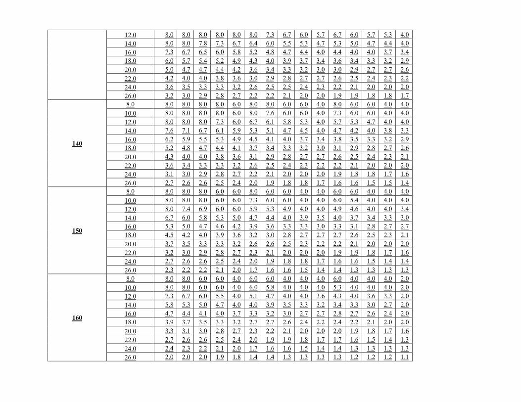
12.0 8.0 8.0 8.0 8.0 8.0 8.0 7.3 6.7 6.0 5.7 6.7 6.0 5.7 5.3 4.0 14.0 8.0 8.0 7.8 7.3 6.7 6.4 6.0 5.5 5.3 4.7 5.3 5.0 4.7 4.4 4.0
16.0 7.3 6.7 6.5 6.0 5.8 5.2 4.8 4.7 4.4 4.0 4.4 4.0 4.0 3.7 3.4 18.0 6.0 5.7 5.4 5.2 4.9 4.3 4.0 3.9 3.7 3.4 3.6 3.4 3.3 3.2 2.9 20.0 5.0 4.7 4.7 4.4 4.2 3.6 3.4 3.3 3.2 3.0 3.0 2.9 2.7 2.7 2.6
22.0 4.2 4.0 4.0 3.8 3.6 3.0 2.9 2.8 2.7 2.7 2.6 2.5 2.4 2.3 2.2 24.0 3.6 3.5 3.3 3.3 3.2 2.6 2.5 2.5 2.4 2.3 2.2 2.1 2.0 2.0 2.0
26.0 3.2 3.0 2.9 2.8 2.7 2.2 2.2 2.1 2.0 2.0 1.9 1.9 1.8 1.8 1.7
140
8.0 8.0 8.0 8.0 8.0 6.0 8.0 8.0 6.0 6.0 4.0 8.0 6.0 6.0 4.0 4.0
10.0 8.0 8.0 8.0 8.0 6.0 8.0 7.6 6.0 6.0 4.0 7.3 6.0 6.0 4.0 4.0
12.0 8.0 8.0 8.0 7.3 6.0 6.7 6.1 5.8 5.3 4.0 5.7 5.3 4.7 4.0 4.0 14.0 7.6 7.1 6.7 6.1 5.9 5.3 5.1 4.7 4.5 4.0 4.7 4.2 4.0 3.8 3.3
16.0 6.2 5.9 5.5 5.3 4.9 4.5 4.1 4.0 3.7 3.4 3.8 3.5 3.3 3.2 2.9 18.0 5.2 4.8 4.7 4.4 4.1 3.7 3.4 3.3 3.2 3.0 3.1 2.9 2.8 2.7 2.6
20.0 4.3 4.0 4.0 3.8 3.6 3.1 2.9 2.8 2.7 2.7 2.6 2.5 2.4 2.3 2.1
22.0 3.6 3.4 3.3 3.3 3.2 2.6 2.5 2.4 2.3 2.2 2.2 2.1 2.0 2.0 2.0 24.0 3.1 3.0 2.9 2.8 2.7 2.2 2.1 2.0 2.0 2.0 1.9 1.8 1.8 1.7 1.6
26.0 2.7 2.6 2.6 2.5 2.4 2.0 1.9 1.8 1.8 1.7 1.6 1.6 1.5 1.5 1.4
150
8.0 8.0 8.0 8.0 6.0 6.0 8.0 6.0 6.0 4.0 4.0 6.0 6.0 4.0 4.0 4.0
10.0 8.0 8.0 8.0 6.0 6.0 7.3 6.0 6.0 4.0 4.0 6.0 5.4 4.0 4.0 4.0
12.0 8.0 7.4 6.9 6.0 6.0 5.9 5.3 4.9 4.0 4.0 4.9 4.6 4.0 4.0 3.4
14.0 6.7 6.0 5.8 5.3 5.0 4.7 4.4 4.0 3.9 3.5 4.0 3.7 3.4 3.3 3.0
16.0 5.3 5.0 4.7 4.6 4.2 3.9 3.6 3.3 3.3 3.0 3.3 3.1 2.8 2.7 2.7 18.0 4.5 4.2 4.0 3.9 3.6 3.2 3.0 2.8 2.7 2.7 2.7 2.6 2.5 2.3 2.1
20.0 3.7 3.5 3.3 3.3 3.2 2.6 2.6 2.5 2.3 2.2 2.2 2.1 2.0 2.0 2.0 22.0 3.2 3.0 2.9 2.8 2.7 2.3 2.1 2.0 2.0 2.0 1.9 1.9 1.8 1.7 1.6
24.0 2.7 2.6 2.6 2.5 2.4 2.0 1.9 1.8 1.8 1.7 1.6 1.6 1.5 1.4 1.4
26.0 2.3 2.2 2.2 2.1 2.0 1.7 1.6 1.6 1.5 1.4 1.4 1.3 1.3 1.3 1.3
160
8.0 8.0 8.0 6.0 6.0 4.0 6.0 6.0 4.0 4.0 4.0 6.0 4.0 4.0 4.0 2.0
10.0 8.0 8.0 6.0 6.0 4.0 6.0 5.8 4.0 4.0 4.0 5.3 4.0 4.0 4.0 2.0 12.0 7.3 6.7 6.0 5.5 4.0 5.1 4.7 4.0 4.0 3.6 4.3 4.0 3.6 3.3 2.0
14.0 5.8 5.3 5.0 4.7 4.0 4.0 3.9 3.5 3.3 3.2 3.4 3.3 3.0 2.7 2.0
16.0 4.7 4.4 4.1 4.0 3.7 3.3 3.2 3.0 2.7 2.7 2.8 2.7 2.6 2.4 2.0 18.0 3.9 3.7 3.5 3.3 3.2 2.7 2.7 2.6 2.4 2.2 2.4 2.2 2.1 2.0 2.0
20.0 3.3 3.1 3.0 2.8 2.7 2.3 2.2 2.1 2.0 2.0 2.0 1.9 1.8 1.7 1.6 22.0 2.7 2.6 2.6 2.5 2.4 2.0 1.9 1.9 1.8 1.7 1.7 1.6 1.5 1.4 1.3
24.0 2.4 2.3 2.2 2.1 2.0 1.7 1.6 1.6 1.5 1.4 1.4 1.3 1.3 1.3 1.3 26.0 2.0 2.0 2.0 1.9 1.8 1.4 1.4 1.3 1.3 1.3 1.3 1.2 1.2 1.2 1.1
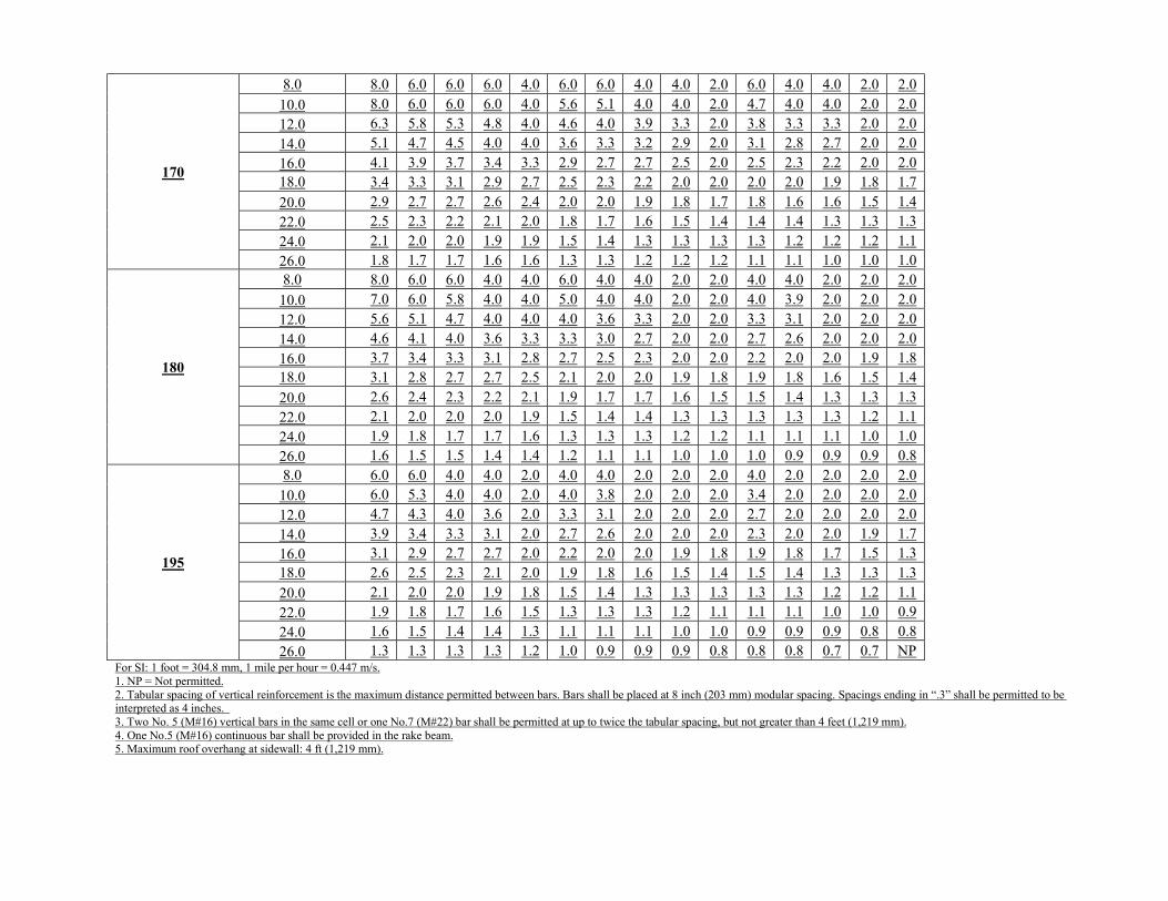
170
8.0 8.0 6.0 6.0 6.0 4.0 6.0 6.0 4.0 4.0 2.0 6.0 4.0 4.0 2.0 2.0
10.0 8.0 6.0 6.0 6.0 4.0 5.6 5.1 4.0 4.0 2.0 4.7 4.0 4.0 2.0 2.0 12.0 6.3 5.8 5.3 4.8 4.0 4.6 4.0 3.9 3.3 2.0 3.8 3.3 3.3 2.0 2.0
14.0 5.1 4.7 4.5 4.0 4.0 3.6 3.3 3.2 2.9 2.0 3.1 2.8 2.7 2.0 2.0
16.0 4.1 3.9 3.7 3.4 3.3 2.9 2.7 2.7 2.5 2.0 2.5 2.3 2.2 2.0 2.0 18.0 3.4 3.3 3.1 2.9 2.7 2.5 2.3 2.2 2.0 2.0 2.0 2.0 1.9 1.8 1.7
20.0 2.9 2.7 2.7 2.6 2.4 2.0 2.0 1.9 1.8 1.7 1.8 1.6 1.6 1.5 1.4 22.0 2.5 2.3 2.2 2.1 2.0 1.8 1.7 1.6 1.5 1.4 1.4 1.4 1.3 1.3 1.3
24.0 2.1 2.0 2.0 1.9 1.9 1.5 1.4 1.3 1.3 1.3 1.3 1.2 1.2 1.2 1.1 26.0 1.8 1.7 1.7 1.6 1.6 1.3 1.3 1.2 1.2 1.2 1.1 1.1 1.0 1.0 1.0
180
8.0 8.0 6.0 6.0 4.0 4.0 6.0 4.0 4.0 2.0 2.0 4.0 4.0 2.0 2.0 2.0
10.0 7.0 6.0 5.8 4.0 4.0 5.0 4.0 4.0 2.0 2.0 4.0 3.9 2.0 2.0 2.0 12.0 5.6 5.1 4.7 4.0 4.0 4.0 3.6 3.3 2.0 2.0 3.3 3.1 2.0 2.0 2.0
14.0 4.6 4.1 4.0 3.6 3.3 3.3 3.0 2.7 2.0 2.0 2.7 2.6 2.0 2.0 2.0 16.0 3.7 3.4 3.3 3.1 2.8 2.7 2.5 2.3 2.0 2.0 2.2 2.0 2.0 1.9 1.8 18.0 3.1 2.8 2.7 2.7 2.5 2.1 2.0 2.0 1.9 1.8 1.9 1.8 1.6 1.5 1.4
20.0 2.6 2.4 2.3 2.2 2.1 1.9 1.7 1.7 1.6 1.5 1.5 1.4 1.3 1.3 1.3 22.0 2.1 2.0 2.0 2.0 1.9 1.5 1.4 1.4 1.3 1.3 1.3 1.3 1.3 1.2 1.1
24.0 1.9 1.8 1.7 1.7 1.6 1.3 1.3 1.3 1.2 1.2 1.1 1.1 1.1 1.0 1.0 26.0 1.6 1.5 1.5 1.4 1.4 1.2 1.1 1.1 1.0 1.0 1.0 0.9 0.9 0.9 0.8
195
8.0 6.0 6.0 4.0 4.0 2.0 4.0 4.0 2.0 2.0 2.0 4.0 2.0 2.0 2.0 2.0 10.0 6.0 5.3 4.0 4.0 2.0 4.0 3.8 2.0 2.0 2.0 3.4 2.0 2.0 2.0 2.0
12.0 4.7 4.3 4.0 3.6 2.0 3.3 3.1 2.0 2.0 2.0 2.7 2.0 2.0 2.0 2.0
14.0 3.9 3.4 3.3 3.1 2.0 2.7 2.6 2.0 2.0 2.0 2.3 2.0 2.0 1.9 1.7 16.0 3.1 2.9 2.7 2.7 2.0 2.2 2.0 2.0 1.9 1.8 1.9 1.8 1.7 1.5 1.3 18.0 2.6 2.5 2.3 2.1 2.0 1.9 1.8 1.6 1.5 1.4 1.5 1.4 1.3 1.3 1.3 20.0 2.1 2.0 2.0 1.9 1.8 1.5 1.4 1.3 1.3 1.3 1.3 1.3 1.2 1.2 1.1
22.0 1.9 1.8 1.7 1.6 1.5 1.3 1.3 1.3 1.2 1.1 1.1 1.1 1.0 1.0 0.9
24.0 1.6 1.5 1.4 1.4 1.3 1.1 1.1 1.1 1.0 1.0 0.9 0.9 0.9 0.8 0.8 26.0 1.3 1.3 1.3 1.3 1.2 1.0 0.9 0.9 0.9 0.8 0.8 0.8 0.7 0.7 NP
For SI: 1 foot = 304.8 mm, 1 mile per hour = 0.447 m/s. 1. NP = Not permitted. 2. Tabular spacing of vertical reinforcement is the maximum distance permitted between bars. Bars shall be placed at 8 inch (203 mm) modular spacing. Spacings ending in “.3” shall be permitted to be interpreted as 4 inches. 3. Two No. 5 (M#16) vertical bars in the same cell or one No.7 (M#22) bar shall be permitted at up to twice the tabular spacing, but not greater than 4 feet (1,219 mm). 4. One No.5 (M#16) continuous bar shall be provided in the rake beam. 5. Maximum roof overhang at sidewall: 4 ft (1,219 mm).
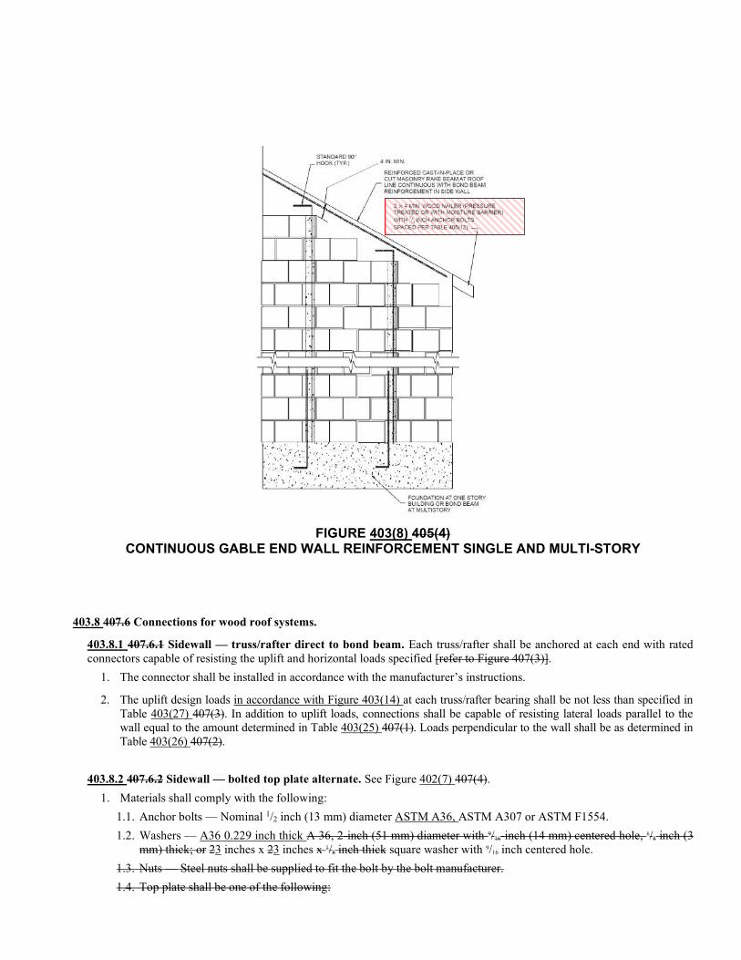
FIGURE 403(8) 405(4)
CONTINUOUS GABLE END WALL REINFORCEMENT SINGLE AND MULTI-STORY
403.8 407.6 Connections for wood roof systems.
403.8.1 407.6.1 Sidewall — truss/rafter direct to bond beam. Each truss/rafter shall be anchored at each end with rated connectors capable of resisting the uplift and horizontal loads specified [refer to Figure 407(3)].
1. The connector shall be installed in accordance with the manufacturer’s instructions.
2. The uplift design loads in accordance with Figure 403(14) at each truss/rafter bearing shall be not less than specified in Table 403(27) 407(3). In addition to uplift loads, connections shall be capable of resisting lateral loads parallel to the wall equal to the amount determined in Table 403(25) 407(1). Loads perpendicular to the wall shall be as determined in Table 403(26) 407(2).
403.8.2 407.6.2 Sidewall — bolted top plate alternate. See Figure 402(7) 407(4).
1. Materials shall comply with the following:
1.1. Anchor bolts — Nominal 1/2 inch (13 mm) diameter ASTM A36, ASTM A307 or ASTM F1554.
1.2. Washers — A36 0.229 inch thick A 36, 2-inch (51 mm) diameter with 9/16-inch (14 mm) centered hole, 1/8 inch (3 mm) thick; or 23 inches x 23 inches x 1/8 inch thick square washer with 9/16 inch centered hole.
1.3. Nuts — Steel nuts shall be supplied to fit the bolt by the bolt manufacturer.
1.4. Top plate shall be one of the following:
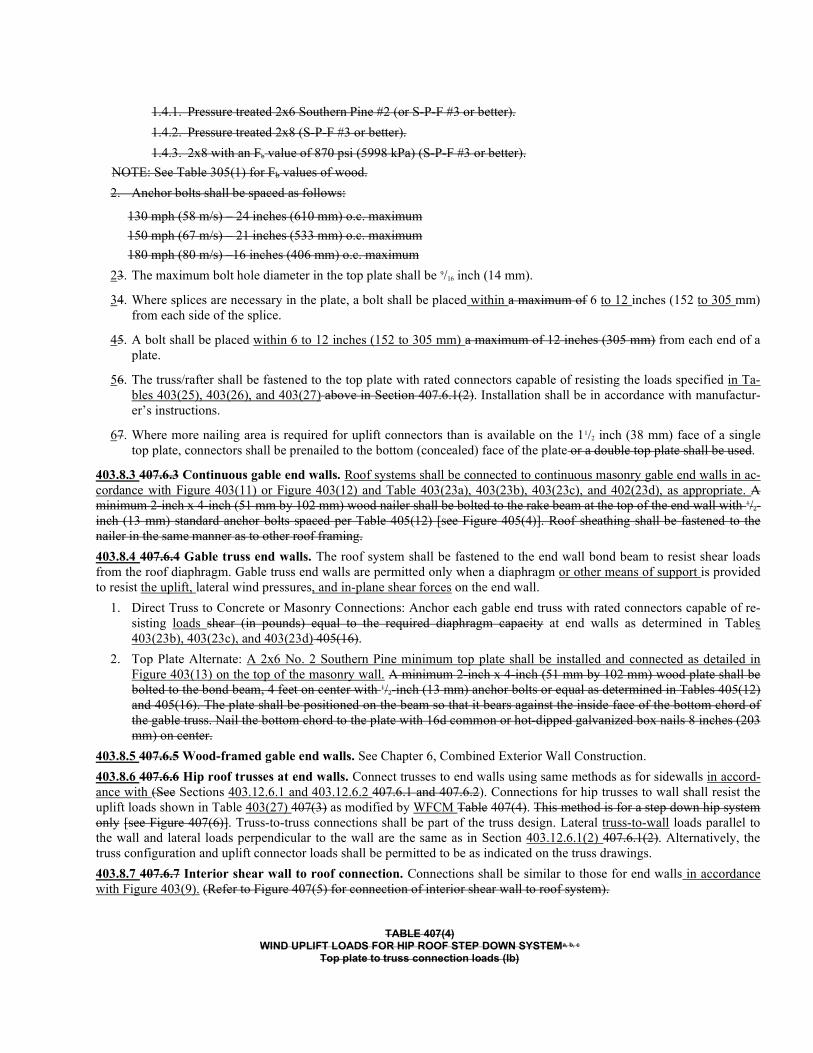
1.4.1. Pressure treated 2x6 Southern Pine #2 (or S-P-F #3 or better).
1.4.2. Pressure treated 2x8 (S-P-F #3 or better).
1.4.3. 2x8 with an Fb value of 870 psi (5998 kPa) (S-P-F #3 or better).
NOTE: See Table 305(1) for Fb values of wood.
2. Anchor bolts shall be spaced as follows:
130 mph (58 m/s) – 24 inches (610 mm) o.c. maximum
150 mph (67 m/s) – 21 inches (533 mm) o.c. maximum
180 mph (80 m/s) –16 inches (406 mm) o.c. maximum
23. The maximum bolt hole diameter in the top plate shall be 9/16 inch (14 mm).
34. Where splices are necessary in the plate, a bolt shall be placed within a maximum of 6 to 12 inches (152 to 305 mm) from each side of the splice.
45. A bolt shall be placed within 6 to 12 inches (152 to 305 mm) a maximum of 12 inches (305 mm) from each end of a plate.
56. The truss/rafter shall be fastened to the top plate with rated connectors capable of resisting the loads specified in Ta-bles 403(25), 403(26), and 403(27) above in Section 407.6.1(2). Installation shall be in accordance with manufactur-er’s instructions.
67. Where more nailing area is required for uplift connectors than is available on the 11/2 inch (38 mm) face of a single top plate, connectors shall be prenailed to the bottom (concealed) face of the plate or a double top plate shall be used.
403.8.3 407.6.3 Continuous gable end walls. Roof systems shall be connected to continuous masonry gable end walls in ac-cordance with Figure 403(11) or Figure 403(12) and Table 403(23a), 403(23b), 403(23c), and 402(23d), as appropriate. A minimum 2-inch x 4-inch (51 mm by 102 mm) wood nailer shall be bolted to the rake beam at the top of the end wall with 1/2-inch (13 mm) standard anchor bolts spaced per Table 405(12) [see Figure 405(4)]. Roof sheathing shall be fastened to the nailer in the same manner as to other roof framing.
403.8.4 407.6.4 Gable truss end walls. The roof system shall be fastened to the end wall bond beam to resist shear loads from the roof diaphragm. Gable truss end walls are permitted only when a diaphragm or other means of support is provided to resist the uplift, lateral wind pressures, and in-plane shear forces on the end wall.
1. Direct Truss to Concrete or Masonry Connections: Anchor each gable end truss with rated connectors capable of re-sisting loads shear (in pounds) equal to the required diaphragm capacity at end walls as determined in Tables 403(23b), 403(23c), and 403(23d) 405(16).
2. Top Plate Alternate: A 2x6 No. 2 Southern Pine minimum top plate shall be installed and connected as detailed in Figure 403(13) on the top of the masonry wall. A minimum 2-inch x 4-inch (51 mm by 102 mm) wood plate shall be bolted to the bond beam, 4 feet on center with 1/2-inch (13 mm) anchor bolts or equal as determined in Tables 405(12) and 405(16). The plate shall be positioned on the beam so that it bears against the inside face of the bottom chord of the gable truss. Nail the bottom chord to the plate with 16d common or hot-dipped galvanized box nails 8 inches (203 mm) on center.
403.8.5 407.6.5 Wood-framed gable end walls. See Chapter 6, Combined Exterior Wall Construction.
403.8.6 407.6.6 Hip roof trusses at end walls. Connect trusses to end walls using same methods as for sidewalls in accord-ance with (See Sections 403.12.6.1 and 403.12.6.2 407.6.1 and 407.6.2). Connections for hip trusses to wall shall resist the uplift loads shown in Table 403(27) 407(3) as modified by WFCM Table 407(4). This method is for a step down hip system only [see Figure 407(6)]. Truss-to-truss connections shall be part of the truss design. Lateral truss-to-wall loads parallel to the wall and lateral loads perpendicular to the wall are the same as in Section 403.12.6.1(2) 407.6.1(2). Alternatively, the truss configuration and uplift connector loads shall be permitted to be as indicated on the truss drawings.
403.8.7 407.6.7 Interior shear wall to roof connection. Connections shall be similar to those for end walls in accordance with Figure 403(9). (Refer to Figure 407(5) for connection of interior shear wall to roof system).
TABLE 407(4) WIND UPLIFT LOADS FOR HIP ROOF STEP DOWN SYSTEMa, b, c
Top plate to truss connection loads (lb)
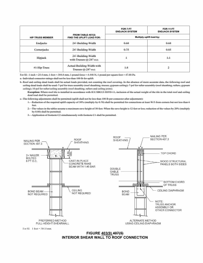
HIP TRUSS MEMBER FROM TABLE 407(3)
FIND THE UPLIFT LOAD FOR:
FOR 7-FT ENDJACK SYSTEM
FOR 11-FT ENDJACK SYSTEM
Multiply uplift load by:
Endjacks 24’ Building Width 0.68 0.68
Cornerjacks 24’ Building Width 0.75 0.85
Hipjack 24’ Building Width
with Trusses @ 24” o.c. 1 1.1
#1 Hip Truss Actual Building Width with
Trusses @ 24” o.c. 1.8 2
For SI: 1 inch = 25.4 mm, 1 foot = 304.8 mm, 1 pound force = 4.448 N, 1 pound per square foot = 47.88 Pa. a. Individual connector ratings shall not be less than 100 lb for uplift. b. Roof and ceiling dead loads shall be actual loads provided, not counting the roof covering. In the absence of more accurate data, the following roof and
ceiling dead loads shall be used: 7 psf for truss assembly (roof sheathing, trusses, gypsum ceiling); 7 psf for rafter assembly (roof sheathing, rafters, gypsum ceiling); 10 psf for rafter/ceiling assembly (roof sheathing, rafters and ceiling joists).
Exception: Where roof tile is installed in accordance with ICC/SBCCI SSTD-11, inclusion of the actual weight of the tile in the total roof and ceiling dead load shall be permitted.
c. The following adjustments shall be permitted (uplift shall not be less than 100 lb per connector after adjustment): 1. Reduction of the required uplift capacity of 30% (multiply by 0.70) shall be permitted for connections at least W/5 from corners but not less than 6
feet. 2. The values in the tables assume a maximum eave height of 30 feet. When the eave height is 12 feet or less, reduction of the values by 20% (multiply
by 0.80) shall be permitted. 3. Application of footnote C2 simultaneously with footnote C1 shall be permitted.
FIGURE 403(9) 407(5)
INTERIOR SHEAR WALL TO ROOF CONNECTION
FIGURE 407(6)
HIP ROOF FRAMING USING TRUSSES
403.9 404.3.8 Connections for wood floor systems masonry walls in accordance with Section 405.
1. Bearing ends of joists or trusses shall be connected to masonry walls by a ledger bolted to the wall as shown in Figure 403(10) 404(5). Anchor bolts shall be sized and spaced in accordance with Table 403(12a) and 403(12b)404 and with a bolt located not less than 6 inches (152 mm) nor more than 12 inches (305 mm) from each end of each ledger mem-ber. The ledger shall be treated No. 2 Southern Pine or better No. 2 Douglas Fir. Framing shall be fastened to the ledger with metal joist hangers properly rated for all gravity loads. Floor sheathing shall be fastened to the ledger the same as to other floor framing members.
2. Where the masonry wall above the floor line is thinner than the wall below, first-story wood floors shall be permitted to bear on and be attached to the top of the wall below as shown for stem walls in Figure 402(3) 403(3). Framing shall be fastened to the plate in accordance with Table R602.3(1) of the International Residential Code. The plate shall be bolted to the wall with 1/2-inch-diameter (13 mm) anchor bolts spaced at a maximum of 6 feet (1829 mm) on center, with a bolt located not less than 6 inches (152 mm) nor more than 12 inches (305 mm) from each end of each plate member and embedded a minimum of 7 inches (178 mm) into the masonry wall.
403.9.1 404.4 Floor diaphragms. Floor sheathing, fasteners and ledger sizes shall be capable of resisting the total shear loads specified in Tables 404(1)a and 404(1)b for the applicable exposure and wind speed. Shear capacities for wood floor diaphragms shall be based on the spacing of the floor framing members, sheathing material, sheathing thickness, nail size and nail spacing as specified in the AWC SDPWS and Chapter 5 of this standard. Anchoring of the ledgers to the masonry walls shall be in accordance with Figure 403(10) and the appropriate Tables 403(10), 403(11), 403(12a), 403(12b), and 403(13) of this standard.
The suspended concrete slabs specified in Section 402.7.2 shall 404.2 have a minimum diaphragm capacity of 4,000 plf (58.4 kN/m).
FIGURE 404(1)
HOLLOWCORE CONNECTION TO EXTERIOR BEARING WALL
FIGURE 404(2)
HOLLOWCORE CONNECTION TO INTERIOR BEARING WALL
FIGURE 404(3)
HOLLOWCORE CONNECTION TO NONBEARING WALL
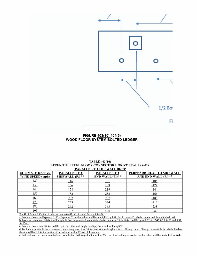
FIGURE 403(10) 404(5)
WOOD FLOOR SYSTEM BOLTED LEDGER
TABLE 403(10) STRENGTH LEVEL FLOOR CONNECTOR HORIZONTAL LOADS
PARALLEL TO THE WALL (lb/ft)a ULTIMATE DESIGN WIND SPEED (mph)
PARALLEL TO SIDEWALL (F4) b, d
PARALLEL TO END WALL (F4)b, e
PERPENDICULAR TO SIDEWALL AND END WALL (F5)c, d
120 116 161 -106 130 136 189 -124 140 158 219 -144 150 182 252 -166 160 207 287 -188 170 233 324 -213 180 262 363 -238 195 307 426 -280
For SI: 1 foot = 0.3048 m, 1 mile per hour = 0.447 m/s, 1 pound force = 4.448 N. a. Loads are based on Exposure B. For Exposure C, tabular values shall be multiplied by 1.40. For Exposure D, tabular values shall be multiplied 1.65. b. Loads are based on a 10-foot wall height. It shall be permitted to multiply tabular values by 0.9 for 8-foot wall heights; 0.92 for 8'-4"; 0.95 for 9'; and 0.97 for 9"-4". c. Loads are based on a 10-foot wall height. For other wall heights multiply by actual wall height/10. d. For buildings with the least horizontal dimension greater than 30 feet and with roof angles between 20 degrees and 30 degrees, multiply the tabular load on the sidewall by 1.5 for the portion of the sidewall within 12 feet of the corner. e. End wall loads are based on a building with the length (L) equal to the width (W). For other building ratios, the tabular values shall be multiplied by W/L.
See Tables 403(12a), 403(12b), and 403(13) for anchor bolt size and spacing.
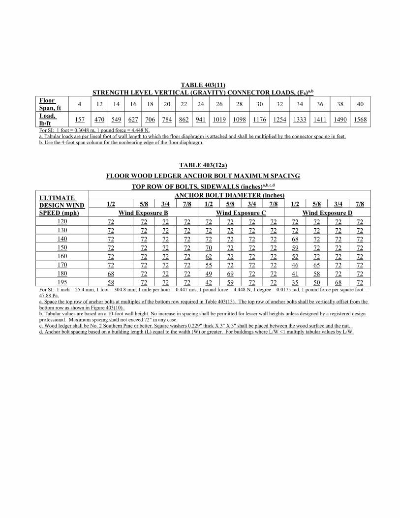
TABLE 403(11) STRENGTH LEVEL VERTICAL (GRAVITY) CONNECTOR LOADS, (F6)a,b
Floor Span, ft
4 12 14 16 18 20 22 24 26 28 30 32 34 36 38 40
Load, lb/ft
157 470 549 627 706 784 862 941 1019 1098 1176 1254 1333 1411 1490 1568
For SI: 1 foot = 0.3048 m, 1 pound force = 4.448 N. a. Tabular loads are per lineal foot of wall length to which the floor diaphragm is attached and shall be multiplied by the connector spacing in feet. b. Use the 4-foot span column for the nonbearing edge of the floor diaphragm.
TABLE 403(12a)
FLOOR WOOD LEDGER ANCHOR BOLT MAXIMUM SPACING
TOP ROW OF BOLTS, SIDEWALLS (inches)a,b,c,d
ULTIMATE DESIGN WIND SPEED (mph)
ANCHOR BOLT DIAMETER (inches) 1/2 5/8 3/4 7/8 1/2 5/8 3/4 7/8 1/2 5/8 3/4 7/8
Wind Exposure B Wind Exposure C Wind Exposure D 120 72 72 72 72 72 72 72 72 72 72 72 72 130 72 72 72 72 72 72 72 72 72 72 72 72 140 72 72 72 72 72 72 72 72 68 72 72 72 150 72 72 72 72 70 72 72 72 59 72 72 72 160 72 72 72 72 62 72 72 72 52 72 72 72 170 72 72 72 72 55 72 72 72 46 65 72 72 180 68 72 72 72 49 69 72 72 41 58 72 72 195 58 72 72 72 42 59 72 72 35 50 68 72
For SI: 1 inch = 25.4 mm, 1 foot = 304.8 mm, 1 mile per hour = 0.447 m/s, 1 pound force = 4.448 N, 1 degree = 0.0175 rad, 1 pound force per square foot = 47.88 Pa. a. Space the top row of anchor bolts at multiples of the bottom row required in Table 403(13). The top row of anchor bolts shall be vertically offset from the bottom row as shown in Figure 403(10). b. Tabular values are based on a 10-foot wall height. No increase in spacing shall be permitted for lesser wall heights unless designed by a registered design professional. Maximum spacing shall not exceed 72" in any case. c. Wood ledger shall be No. 2 Southern Pine or better. Square washers 0.229" thick X 3" X 3" shall be placed between the wood surface and the nut. d. Anchor bolt spacing based on a building length (L) equal to the width (W) or greater. For buildings where L/W <1 multiply tabular values by L/W.
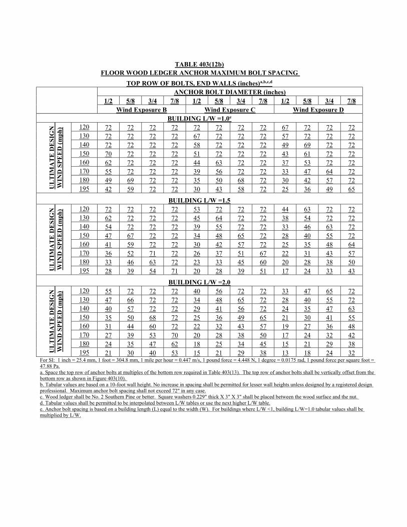
TABLE 403(12b)
FLOOR WOOD LEDGER ANCHOR MAXIMUM BOLT SPACING
TOP ROW OF BOLTS, END WALLS (inches)a,b,c,d ANCHOR BOLT DIAMETER (inches) 1/2 5/8 3/4 7/8 1/2 5/8 3/4 7/8 1/2 5/8 3/4 7/8 Wind Exposure B Wind Exposure C Wind Exposure D
BUILDING L/W =1.0e
UL
TIM
AT
E D
ES
IGN
W
IND
SP
EE
D (
mp
h) 120 72 72 72 72 72 72 72 72 67 72 72 72
130 72 72 72 72 67 72 72 72 57 72 72 72 140 72 72 72 72 58 72 72 72 49 69 72 72 150 70 72 72 72 51 72 72 72 43 61 72 72 160 62 72 72 72 44 63 72 72 37 53 72 72 170 55 72 72 72 39 56 72 72 33 47 64 72 180 49 69 72 72 35 50 68 72 30 42 57 72 195 42 59 72 72 30 43 58 72 25 36 49 65
BUILDING L/W =1.5
UL
TIM
AT
E D
ES
IGN
W
IND
SP
EE
D (
mp
h) 120 72 72 72 72 53 72 72 72 44 63 72 72
130 62 72 72 72 45 64 72 72 38 54 72 72 140 54 72 72 72 39 55 72 72 33 46 63 72 150 47 67 72 72 34 48 65 72 28 40 55 72 160 41 59 72 72 30 42 57 72 25 35 48 64 170 36 52 71 72 26 37 51 67 22 31 43 57 180 33 46 63 72 23 33 45 60 20 28 38 50 195 28 39 54 71 20 28 39 51 17 24 33 43
BUILDING L/W =2.0
UL
TIM
AT
E D
ES
IGN
W
IND
SP
EE
D (
mp
h) 120 55 72 72 72 40 56 72 72 33 47 65 72
130 47 66 72 72 34 48 65 72 28 40 55 72 140 40 57 72 72 29 41 56 72 24 35 47 63 150 35 50 68 72 25 36 49 65 21 30 41 55 160 31 44 60 72 22 32 43 57 19 27 36 48 170 27 39 53 70 20 28 38 50 17 24 32 42 180 24 35 47 62 18 25 34 45 15 21 29 38 195 21 30 40 53 15 21 29 38 13 18 24 32
For SI: 1 inch = 25.4 mm, 1 foot = 304.8 mm, 1 mile per hour = 0.447 m/s, 1 pound force = 4.448 N, 1 degree = 0.0175 rad, 1 pound force per square foot = 47.88 Pa. a. Space the top row of anchor bolts at multiples of the bottom row required in Table 403(13). The top row of anchor bolts shall be vertically offset from the bottom row as shown in Figure 403(10). b. Tabular values are based on a 10-foot wall height. No increase in spacing shall be permitted for lesser wall heights unless designed by a registered design professional. Maximum anchor bolt spacing shall not exceed 72" in any case. c. Wood ledger shall be No. 2 Southern Pine or better. Square washers 0.229" thick X 3" X 3" shall be placed between the wood surface and the nut. d. Tabular values shall be permitted to be interpolated between L/W tables or use the next higher L/W table. e. Anchor bolt spacing is based on a building length (L) equal to the width (W). For buildings where L/W <1, building L/W=1.0 tabular values shall be multiplied by L/W.
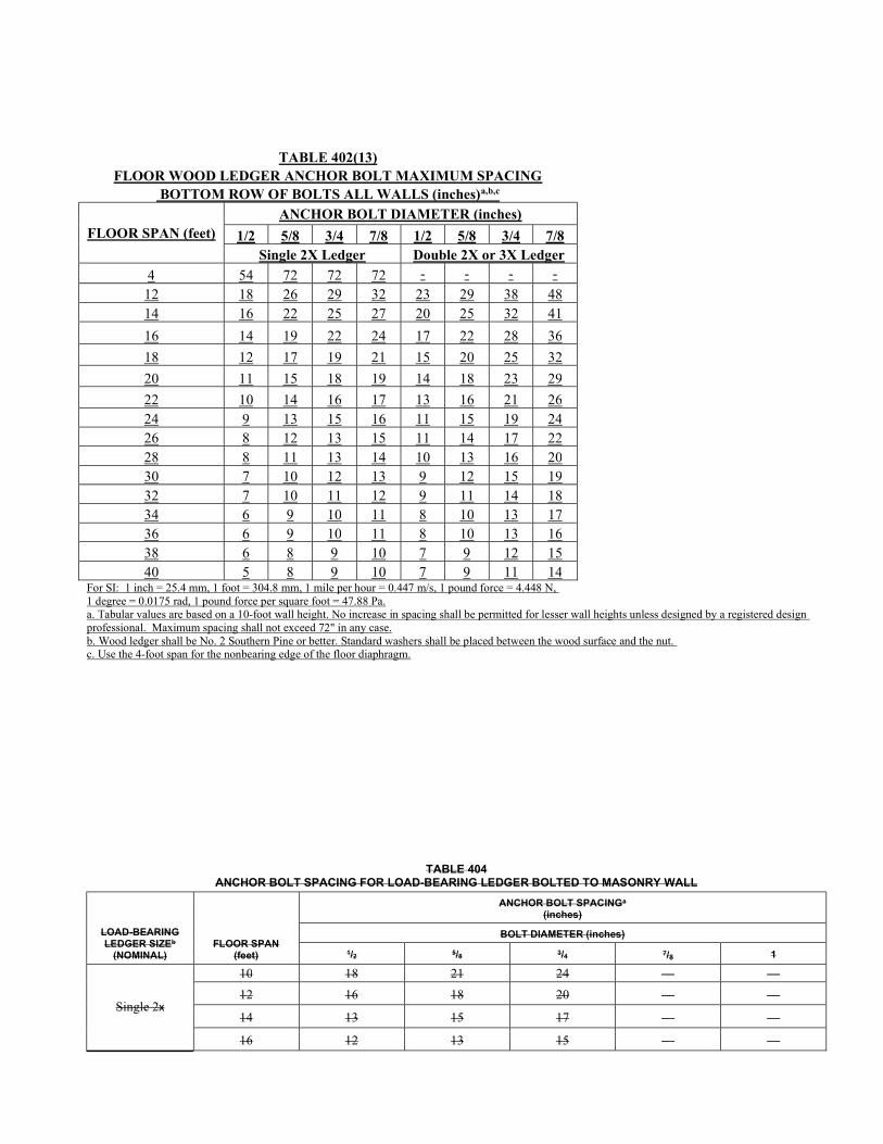
TABLE 402(13) FLOOR WOOD LEDGER ANCHOR BOLT MAXIMUM SPACING
BOTTOM ROW OF BOLTS ALL WALLS (inches)a,b,c
FLOOR SPAN (feet) ANCHOR BOLT DIAMETER (inches)
1/2 5/8 3/4 7/8 1/2 5/8 3/4 7/8 Single 2X Ledger Double 2X or 3X Ledger
4 54 72 72 72 - - - -
12 18 26 29 32 23 29 38 48 14 16 22 25 27 20 25 32 41
16 14 19 22 24 17 22 28 36
18 12 17 19 21 15 20 25 32
20 11 15 18 19 14 18 23 29
22 10 14 16 17 13 16 21 26 24 9 13 15 16 11 15 19 24 26 8 12 13 15 11 14 17 22 28 8 11 13 14 10 13 16 20 30 7 10 12 13 9 12 15 19 32 7 10 11 12 9 11 14 18 34 6 9 10 11 8 10 13 17 36 6 9 10 11 8 10 13 16 38 6 8 9 10 7 9 12 15 40 5 8 9 10 7 9 11 14
For SI: 1 inch = 25.4 mm, 1 foot = 304.8 mm, 1 mile per hour = 0.447 m/s, 1 pound force = 4.448 N, 1 degree = 0.0175 rad, 1 pound force per square foot = 47.88 Pa. a. Tabular values are based on a 10-foot wall height. No increase in spacing shall be permitted for lesser wall heights unless designed by a registered design professional. Maximum spacing shall not exceed 72" in any case. b. Wood ledger shall be No. 2 Southern Pine or better. Standard washers shall be placed between the wood surface and the nut. c. Use the 4-foot span for the nonbearing edge of the floor diaphragm.
TABLE 404
ANCHOR BOLT SPACING FOR LOAD-BEARING LEDGER BOLTED TO MASONRY WALL
LOAD-BEARING LEDGER SIZEb
(NOMINAL) FLOOR SPAN
(feet)
ANCHOR BOLT SPACINGa
(inches)
BOLT DIAMETER (inches)
1/2 5/8 3/4 7/8 1
Single 2x
10 18 21 24 — —
12 16 18 20 — —
14 13 15 17 — —
16 12 13 15 — —
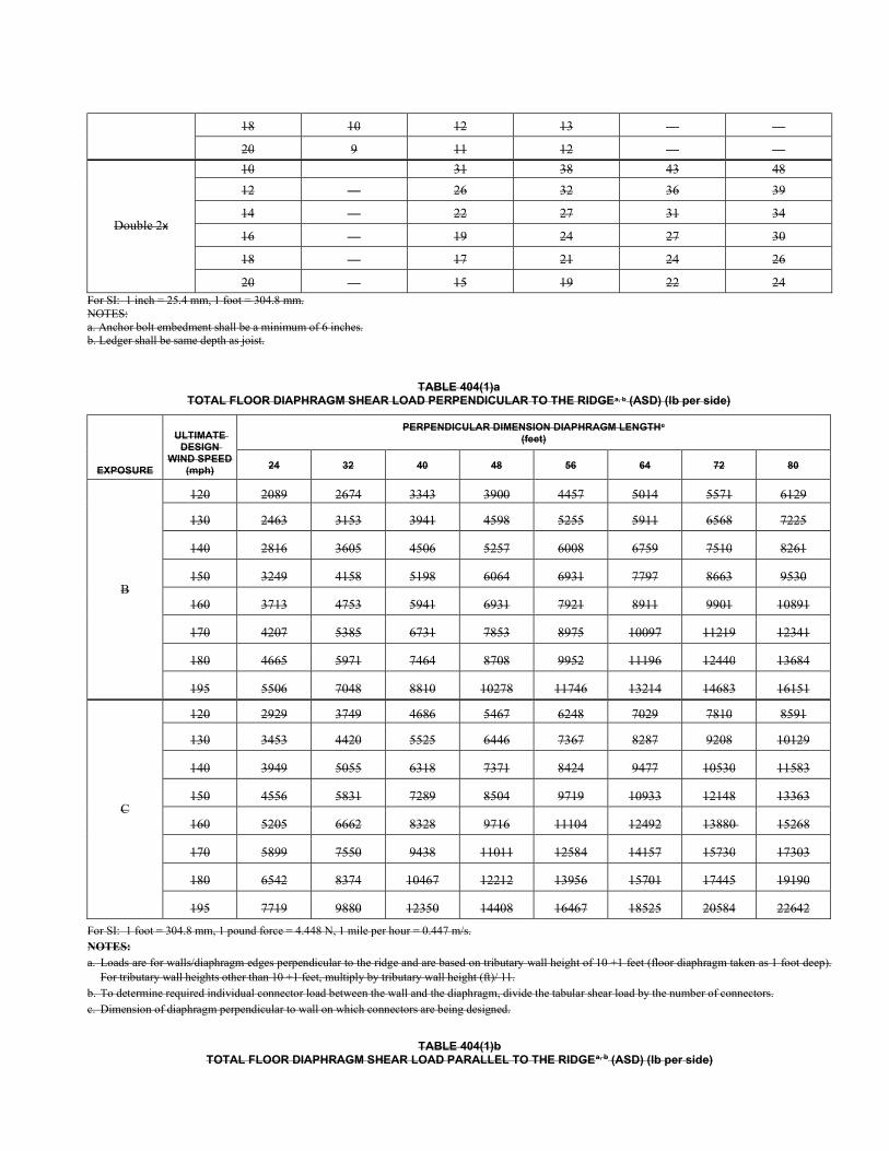
18 10 12 13 — —
20 9 11 12 — —
Double 2x
10 31 38 43 48
12 — 26 32 36 39
14 — 22 27 31 34
16 — 19 24 27 30
18 — 17 21 24 26
20 — 15 19 22 24 For SI: 1 inch = 25.4 mm, 1 foot = 304.8 mm. NOTES: a. Anchor bolt embedment shall be a minimum of 6 inches. b. Ledger shall be same depth as joist.
TABLE 404(1)a TOTAL FLOOR DIAPHRAGM SHEAR LOAD PERPENDICULAR TO THE RIDGEa, b (ASD) (lb per side)
EXPOSURE
ULTIMATE DESIGN
WIND SPEED (mph)
PERPENDICULAR DIMENSION DIAPHRAGM LENGTHc
(feet)
24 32 40 48 56 64 72 80
B
120 2089 2674 3343 3900 4457 5014 5571 6129
130 2463 3153 3941 4598 5255 5911 6568 7225
140 2816 3605 4506 5257 6008 6759 7510 8261
150 3249 4158 5198 6064 6931 7797 8663 9530
160 3713 4753 5941 6931 7921 8911 9901 10891
170 4207 5385 6731 7853 8975 10097 11219 12341
180 4665 5971 7464 8708 9952 11196 12440 13684
195 5506 7048 8810 10278 11746 13214 14683 16151
C
120 2929 3749 4686 5467 6248 7029 7810 8591
130 3453 4420 5525 6446 7367 8287 9208 10129
140 3949 5055 6318 7371 8424 9477 10530 11583
150 4556 5831 7289 8504 9719 10933 12148 13363
160 5205 6662 8328 9716 11104 12492 13880 15268
170 5899 7550 9438 11011 12584 14157 15730 17303
180 6542 8374 10467 12212 13956 15701 17445 19190
195 7719 9880 12350 14408 16467 18525 20584 22642
For SI: 1 foot = 304.8 mm, 1 pound force = 4.448 N, 1 mile per hour = 0.447 m/s. NOTES: a. Loads are for walls/diaphragm edges perpendicular to the ridge and are based on tributary wall height of 10 +1 feet (floor diaphragm taken as 1 foot deep).
For tributary wall heights other than 10 +1 feet, multiply by tributary wall height (ft)/ 11. b. To determine required individual connector load between the wall and the diaphragm, divide the tabular shear load by the number of connectors. c. Dimension of diaphragm perpendicular to wall on which connectors are being designed.
TABLE 404(1)b TOTAL FLOOR DIAPHRAGM SHEAR LOAD PARALLEL TO THE RIDGEa, b (ASD) (lb per side)
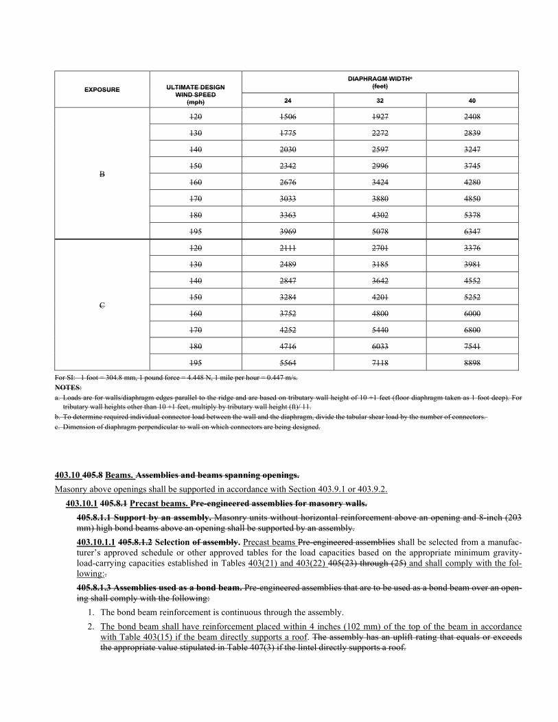
EXPOSURE ULTIMATE DESIGN WIND SPEED
(mph)
DIAPHRAGM WIDTHc
(feet)
24 32 40
B
120 1506 1927 2408
130 1775 2272 2839
140 2030 2597 3247
150 2342 2996 3745
160 2676 3424 4280
170 3033 3880 4850
180 3363 4302 5378
195 3969 5078 6347
C
120 2111 2701 3376
130 2489 3185 3981
140 2847 3642 4552
150 3284 4201 5252
160 3752 4800 6000
170 4252 5440 6800
180 4716 6033 7541
195 5564 7118 8898
For SI: 1 foot = 304.8 mm, 1 pound force = 4.448 N, 1 mile per hour = 0.447 m/s. NOTES: a. Loads are for walls/diaphragm edges parallel to the ridge and are based on tributary wall height of 10 +1 feet (floor diaphragm taken as 1 foot deep). For
tributary wall heights other than 10 +1 feet, multiply by tributary wall height (ft)/ 11. b. To determine required individual connector load between the wall and the diaphragm, divide the tabular shear load by the number of connectors. c. Dimension of diaphragm perpendicular to wall on which connectors are being designed.
403.10 405.8 Beams. Assemblies and beams spanning openings.
Masonry above openings shall be supported in accordance with Section 403.9.1 or 403.9.2.
403.10.1 405.8.1 Precast beams. Pre-engineered assemblies for masonry walls.
405.8.1.1 Support by an assembly. Masonry units without horizontal reinforcement above an opening and 8-inch (203 mm) high bond beams above an opening shall be supported by an assembly.
403.10.1.1 405.8.1.2 Selection of assembly. Precast beams Pre-engineered assemblies shall be selected from a manufac-turer’s approved schedule or other approved tables for the load capacities based on the appropriate minimum gravity-load-carrying capacities established in Tables 403(21) and 403(22) 405(23) through (25) and shall comply with the fol-lowing:.
405.8.1.3 Assemblies used as a bond beam. Pre-engineered assemblies that are to be used as a bond beam over an open-ing shall comply with the following:
1. The bond beam reinforcement is continuous through the assembly.
2. The bond beam shall have reinforcement placed within 4 inches (102 mm) of the top of the beam in accordance with Table 403(15) if the beam directly supports a roof. The assembly has an uplift rating that equals or exceeds the appropriate value stipulated in Table 407(3) if the lintel directly supports a roof.
Exception: If the reinforcement in the top of the assembly meets the requirements of Section 405.2, the lintel need not be rated for uplift.
403.10.1.2 405.8.1.4 Span. Assembly span. Pre-engineered assemblies Precast beams spanning openings shall extend a minimum of 4 inches (102 mm) nominal past each side of the opening.
403.10.2 Masonry beams. 405.8.2 Bond beams combined with lintels.
403.10.2.1 Design. Masonry beams shall meet the applicable requirements of Table 403(14) through 403(19).
403.10.2.2 Span. Masonry beams spanning openings shall extend a minimum of 8 inches (203 mm) nominal past each side of the opening.
403.10.2.3 Effective depth. Reinforcing bars shall not be placed more than 4 inches (102 mm) from the bottom of the beam.
403.10.2.4 Reinforcement length. Reinforcing bars shall extend past each side of the opening a minimum of 4 inches (102 mm).
403.10.2.5 Uplift. Masonry beams located in the top story of bearing walls shall have mirrored reinforcement above the opening at the roof diaphragm connection.
405.8.2.1 General. The provisions of this section shall apply when the lintel, the wall area between the lintel and the bond beam, and the bond beam itself are solid grouted masonry units or cast together as one unit.
405.8.2.2 Combined bond beams/lintels. Combined bond beams/lintels shall meet the requirements of the appropriate Tables 405(26) through (28).
405.8.2.3 Top reinforcement length. Top reinforcement which is in addition to that required in the bond beam over the wall shall extend a minimum of 24 inches (610 mm) past each side of the opening. Top bond beam reinforcement shall be continuous over wall and opening.
405.8.2.4 Bottom reinforcement length. Bottom reinforcing shall extend past each side of the opening a minimum of 4 inches (102 mm) for masonry walls. When using a precast lintel, the reinforcing in the precast lintel shall be included when determining the total amount of bottom reinforcement furnished.
405.8.2.5 Cleanout opening. For masonry walls, a cleanout [12 square inches (77 cm2) minimum] shall be provided in the cells directly above the ends of the lintel when the reinforcing steel in the bottom of the lintel is more than 22 inches (559 mm) below the top of the bond beam.
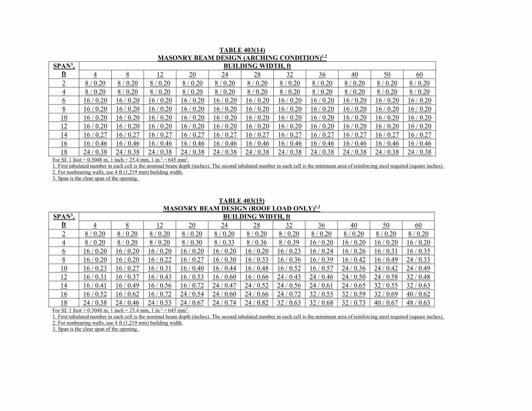
TABLE 403(14) MASONRY BEAM DESIGN (ARCHING CONDITION)1,2
SPAN3, ft
BUILDING WIDTH, ft 4 8 12 20 24 28 32 36 40 50 60
2 8 / 0.20 8 / 0.20 8 / 0.20 8 / 0.20 8 / 0.20 8 / 0.20 8 / 0.20 8 / 0.20 8 / 0.20 8 / 0.20 8 / 0.20 4 8 / 0.20 8 / 0.20 8 / 0.20 8 / 0.20 8 / 0.20 8 / 0.20 8 / 0.20 8 / 0.20 8 / 0.20 8 / 0.20 8 / 0.20 6 16 / 0.20 16 / 0.20 16 / 0.20 16 / 0.20 16 / 0.20 16 / 0.20 16 / 0.20 16 / 0.20 16 / 0.20 16 / 0.20 16 / 0.20 8 16 / 0.20 16 / 0.20 16 / 0.20 16 / 0.20 16 / 0.20 16 / 0.20 16 / 0.20 16 / 0.20 16 / 0.20 16 / 0.20 16 / 0.20 10 16 / 0.20 16 / 0.20 16 / 0.20 16 / 0.20 16 / 0.20 16 / 0.20 16 / 0.20 16 / 0.20 16 / 0.20 16 / 0.20 16 / 0.20 12 16 / 0.20 16 / 0.20 16 / 0.20 16 / 0.20 16 / 0.20 16 / 0.20 16 / 0.20 16 / 0.20 16 / 0.20 16 / 0.20 16 / 0.20 14 16 / 0.27 16 / 0.27 16 / 0.27 16 / 0.27 16 / 0.27 16 / 0.27 16 / 0.27 16 / 0.27 16 / 0.27 16 / 0.27 16 / 0.27 16 16 / 0.46 16 / 0.46 16 / 0.46 16 / 0.46 16 / 0.46 16 / 0.46 16 / 0.46 16 / 0.46 16 / 0.46 16 / 0.46 16 / 0.46 18 24 / 0.38 24 / 0.38 24 / 0.38 24 / 0.38 24 / 0.38 24 / 0.38 24 / 0.38 24 / 0.38 24 / 0.38 24 / 0.38 24 / 0.38
For SI: 1 foot = 0.3048 m, 1 inch = 25.4 mm, 1 in.2 = 645 mm2. 1. First tabulated number in each cell is the nominal beam depth (inches). The second tabulated number in each cell is the minimum area of reinforcing steel required (square inches). 2. For nonbearing walls, use 4 ft (1,219 mm) building width. 3. Span is the clear span of the opening.
TABLE 403(15) MASONRY BEAM DESIGN (ROOF LOAD ONLY)1,2
SPAN3, ft
BUILDING WIDTH, ft 4 8 12 20 24 28 32 36 40 50 60
2 8 / 0.20 8 / 0.20 8 / 0.20 8 / 0.20 8 / 0.20 8 / 0.20 8 / 0.20 8 / 0.20 8 / 0.20 8 / 0.20 8 / 0.20 4 8 / 0.20 8 / 0.20 8 / 0.20 8 / 0.30 8 / 0.33 8 / 0.36 8 / 0.39 16 / 0.20 16 / 0.20 16 / 0.20 16 / 0.20 6 16 / 0.20 16 / 0.20 16 / 0.20 16 / 0.20 16 / 0.20 16 / 0.20 16 / 0.23 16 / 0.24 16 / 0.26 16 / 0.31 16 / 0.35 8 16 / 0.20 16 / 0.20 16 / 0.22 16 / 0.27 16 / 0.30 16 / 0.33 16 / 0.36 16 / 0.39 16 / 0.42 16 / 0.49 24 / 0.33 10 16 / 0.23 16 / 0.27 16 / 0.31 16 / 0.40 16 / 0.44 16 / 0.48 16 / 0.52 16 / 0.57 24 / 0.36 24 / 0.42 24 / 0.49 12 16 / 0.31 16 / 0.37 16 / 0.43 16 / 0.53 16 / 0.60 16 / 0.66 24 / 0.43 24 / 0.46 24 / 0.50 24 / 0.58 32 / 0.48 14 16 / 0.41 16 / 0.49 16 / 0.56 16 / 0.72 24 / 0.47 24 / 0.52 24 / 0.56 24 / 0.61 24 / 0.65 32 / 0.55 32 / 0.63 16 16 / 0.52 16 / 0.62 16 / 0.72 24 / 0.54 24 / 0.60 24 / 0.66 24 / 0.72 32 / 0.55 32 / 0.59 32 / 0.69 40 / 0.62 18 24 / 0.38 24 / 0.46 24 / 0.53 24 / 0.67 24 / 0.74 24 / 0.82 32 / 0.63 32 / 0.68 32 / 0.73 40 / 0.67 48 / 0.63
For SI: 1 foot = 0.3048 m, 1 inch = 25.4 mm, 1 in.2 = 645 mm2. 1. First tabulated number in each cell is the nominal beam depth (inches). The second tabulated number in each cell is the minimum area of reinforcing steel required (square inches). 2. For nonbearing walls, use 4 ft (1,219 mm) building width. 3. Span is the clear span of the opening.
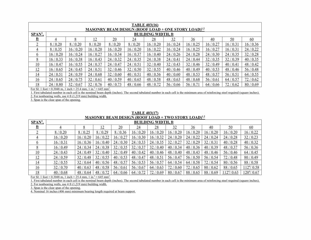
TABLE 403(16)
MASONRY BEAM DESIGN (ROOF LOAD + ONE STORY LOAD)1,2 SPAN3,
ft BUILDING WIDTH, ft
4 8 12 20 24 28 32 36 40 50 60 2 8 / 0.20 8 / 0.20 8 / 0.20 8 / 0.20 8 / 0.20 16 / 0.20 16 / 0.24 16 / 0.25 16 / 0.27 16 / 0.31 16 / 0.36 4 8 / 0.35 16 / 0.20 16 / 0.20 16 / 0.20 16 / 0.20 16 / 0.22 16 / 0.24 16 / 0.25 16 / 0.27 16 / 0.31 24 / 0.22 6 16 / 0.20 16 / 0.24 16 / 0.27 16 / 0.34 16 / 0.37 16 / 0.40 24 / 0.26 24 / 0.28 24 / 0.30 24 / 0.35 32 / 0.28 8 16 / 0.33 16 / 0.38 16 / 0.43 24 / 0.32 24 / 0.35 24 / 0.38 24 / 0.41 24 / 0.44 32 / 0.35 32 / 0.39 40 / 0.35 10 16 / 0.47 16 / 0.55 24 / 0.37 24 / 0.47 24 / 0.51 32 / 0.40 32 / 0.43 32 / 0.46 32 / 0.49 40 / 0.41 48 / 0.42 12 16 / 0.65 24 / 0.45 24 / 0.51 32 / 0.46 32 / 0.50 32 / 0.55 40 / 0.46 40 / 0.49 40 / 0.53 48 / 0.46 56 / 0.48 14 24 / 0.51 24 / 0.59 24 / 0.68 32 / 0.60 40 / 0.51 40 / 0.56 40 / 0.60 48 / 0.53 48 / 0.57 56 / 0.51 64 / 0.55 16 24 / 0.65 24 / 0.75 32 / 0.61 40 / 0.59 40 / 0.65 48 / 0.58 48 / 0.63 48 / 0.68 56 / 0.61 64 / 0.57 72 / 0.62 18 24 / 0.80 32 / 0.67 32 / 0.76 40 / 0.73 48 / 0.66 48 / 0.72 56 / 0.66 56 / 0.71 64 / 0.66 72 / 0.62 80 / 0.69
For SI: 1 foot = 0.3048 m, 1 inch = 25.4 mm, 1 in.2 = 645 mm2. 1. First tabulated number in each cell is the nominal beam depth (inches). The second tabulated number in each cell is the minimum area of reinforcing steel required (square inches). 2. For nonbearing walls, use 4 ft (1,219 mm) building width. 3. Span is the clear span of the opening.
TABLE 403(17) MASONRY BEAM DESIGN (ROOF LOAD + TWO STORY LOAD)1,2
SPAN3, ft
BUILDING WIDTH, ft 4 8 12 20 24 28 32 36 40 50 60
2 8 / 0.20 8 / 0.25 8 / 0.29 8 / 0.36 16 / 0.20 16 / 0.20 16 / 0.20 16 / 0.20 16 / 0.20 16 / 0.20 16 / 0.22 4 16 / 0.20 16 / 0.20 16 / 0.22 16 / 0.27 16 / 0.30 16 / 0.32 24 / 0.20 24 / 0.22 24 / 0.24 24 / 0.28 32 / 0.23 6 16 / 0.31 16 / 0.36 16 / 0.40 24 / 0.30 24 / 0.33 24 / 0.35 32 / 0.27 32 / 0.29 32 / 0.31 40 / 0.28 40 / 0.32 8 16 / 0.49 24 / 0.34 24 / 0.38 32 / 0.35 32 / 0.37 32 / 0.40 40 / 0.34 40 / 0.36 40 / 0.39 48 / 0.37 56 / 0.36 10 24 / 0.43 24 / 0.49 32 / 0.40 32 / 0.49 40 / 0.42 40 / 0.46 48 / 0.40 48 / 0.43 48 / 0.46 56 / 0.46 64 / 0.45 12 24 / 0.59 32 / 0.48 32 / 0.55 40 / 0.53 48 / 0.47 48 / 0.51 56 / 0.47 56 / 0.50 56 / 0.54 72 / 0.48 80 / 0.49 14 32 / 0.55 32 / 0.64 40 / 0.56 48 / 0.57 56 / 0.53 56 / 0.57 64 / 0.54 64 / 0.58 72 / 0.54 80 / 0.56 88 / 0.58 16 32 / 0.70 40 / 0.63 48 / 0.58 56 / 0.61 56 / 0.67 64 / 0.63 72 / 0.60 72 / 0.65 80 / 0.62 88 / 0.65 1124/ 0.58 18 40 / 0.68 48 / 0.64 48 / 0.72 64 / 0.66 64 / 0.72 72 / 0.69 80 / 0.67 88 / 0.65 88 / 0.69 1124/ 0.63 1204/ 0.67
For SI: 1 foot = 0.3048 m, 1 inch = 25.4 mm, 1 in.2 = 645 mm2. 1. First tabulated number in each cell is the nominal beam depth (inches). The second tabulated number in each cell is the minimum area of reinforcing steel required (square inches). 2. For nonbearing walls, use 4 ft (1,219 mm) building width. 3. Span is the clear span of the opening. 4. Nominal 16 inches (406 mm) minimum bearing length required at beam support.
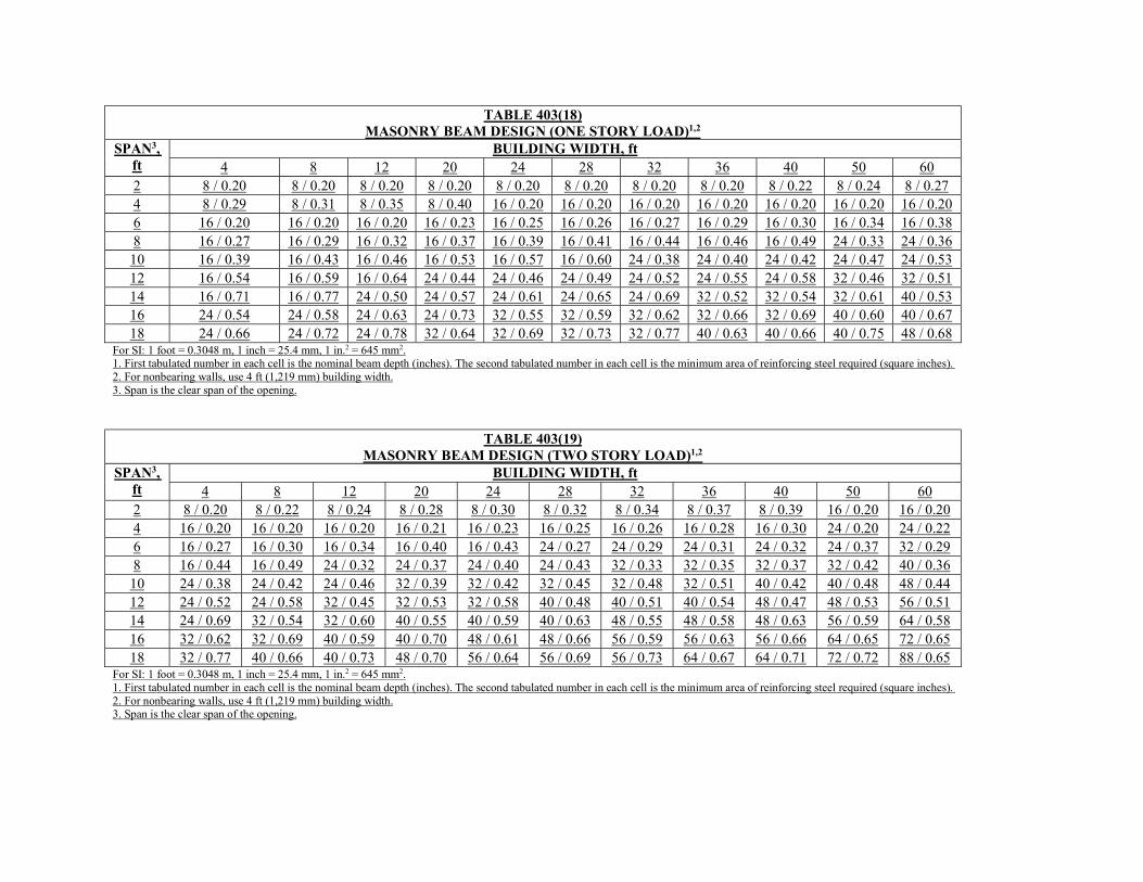
TABLE 403(18) MASONRY BEAM DESIGN (ONE STORY LOAD)1,2
SPAN3, ft
BUILDING WIDTH, ft 4 8 12 20 24 28 32 36 40 50 60
2 8 / 0.20 8 / 0.20 8 / 0.20 8 / 0.20 8 / 0.20 8 / 0.20 8 / 0.20 8 / 0.20 8 / 0.22 8 / 0.24 8 / 0.27 4 8 / 0.29 8 / 0.31 8 / 0.35 8 / 0.40 16 / 0.20 16 / 0.20 16 / 0.20 16 / 0.20 16 / 0.20 16 / 0.20 16 / 0.20 6 16 / 0.20 16 / 0.20 16 / 0.20 16 / 0.23 16 / 0.25 16 / 0.26 16 / 0.27 16 / 0.29 16 / 0.30 16 / 0.34 16 / 0.38 8 16 / 0.27 16 / 0.29 16 / 0.32 16 / 0.37 16 / 0.39 16 / 0.41 16 / 0.44 16 / 0.46 16 / 0.49 24 / 0.33 24 / 0.36 10 16 / 0.39 16 / 0.43 16 / 0.46 16 / 0.53 16 / 0.57 16 / 0.60 24 / 0.38 24 / 0.40 24 / 0.42 24 / 0.47 24 / 0.53 12 16 / 0.54 16 / 0.59 16 / 0.64 24 / 0.44 24 / 0.46 24 / 0.49 24 / 0.52 24 / 0.55 24 / 0.58 32 / 0.46 32 / 0.51 14 16 / 0.71 16 / 0.77 24 / 0.50 24 / 0.57 24 / 0.61 24 / 0.65 24 / 0.69 32 / 0.52 32 / 0.54 32 / 0.61 40 / 0.53 16 24 / 0.54 24 / 0.58 24 / 0.63 24 / 0.73 32 / 0.55 32 / 0.59 32 / 0.62 32 / 0.66 32 / 0.69 40 / 0.60 40 / 0.67 18 24 / 0.66 24 / 0.72 24 / 0.78 32 / 0.64 32 / 0.69 32 / 0.73 32 / 0.77 40 / 0.63 40 / 0.66 40 / 0.75 48 / 0.68
For SI: 1 foot = 0.3048 m, 1 inch = 25.4 mm, 1 in.2 = 645 mm2. 1. First tabulated number in each cell is the nominal beam depth (inches). The second tabulated number in each cell is the minimum area of reinforcing steel required (square inches). 2. For nonbearing walls, use 4 ft (1,219 mm) building width. 3. Span is the clear span of the opening.
TABLE 403(19) MASONRY BEAM DESIGN (TWO STORY LOAD)1,2
SPAN3, ft
BUILDING WIDTH, ft 4 8 12 20 24 28 32 36 40 50 60
2 8 / 0.20 8 / 0.22 8 / 0.24 8 / 0.28 8 / 0.30 8 / 0.32 8 / 0.34 8 / 0.37 8 / 0.39 16 / 0.20 16 / 0.20 4 16 / 0.20 16 / 0.20 16 / 0.20 16 / 0.21 16 / 0.23 16 / 0.25 16 / 0.26 16 / 0.28 16 / 0.30 24 / 0.20 24 / 0.22 6 16 / 0.27 16 / 0.30 16 / 0.34 16 / 0.40 16 / 0.43 24 / 0.27 24 / 0.29 24 / 0.31 24 / 0.32 24 / 0.37 32 / 0.29 8 16 / 0.44 16 / 0.49 24 / 0.32 24 / 0.37 24 / 0.40 24 / 0.43 32 / 0.33 32 / 0.35 32 / 0.37 32 / 0.42 40 / 0.36 10 24 / 0.38 24 / 0.42 24 / 0.46 32 / 0.39 32 / 0.42 32 / 0.45 32 / 0.48 32 / 0.51 40 / 0.42 40 / 0.48 48 / 0.44 12 24 / 0.52 24 / 0.58 32 / 0.45 32 / 0.53 32 / 0.58 40 / 0.48 40 / 0.51 40 / 0.54 48 / 0.47 48 / 0.53 56 / 0.51 14 24 / 0.69 32 / 0.54 32 / 0.60 40 / 0.55 40 / 0.59 40 / 0.63 48 / 0.55 48 / 0.58 48 / 0.63 56 / 0.59 64 / 0.58 16 32 / 0.62 32 / 0.69 40 / 0.59 40 / 0.70 48 / 0.61 48 / 0.66 56 / 0.59 56 / 0.63 56 / 0.66 64 / 0.65 72 / 0.65 18 32 / 0.77 40 / 0.66 40 / 0.73 48 / 0.70 56 / 0.64 56 / 0.69 56 / 0.73 64 / 0.67 64 / 0.71 72 / 0.72 88 / 0.65
For SI: 1 foot = 0.3048 m, 1 inch = 25.4 mm, 1 in.2 = 645 mm2. 1. First tabulated number in each cell is the nominal beam depth (inches). The second tabulated number in each cell is the minimum area of reinforcing steel required (square inches). 2. For nonbearing walls, use 4 ft (1,219 mm) building width. 3. Span is the clear span of the opening.
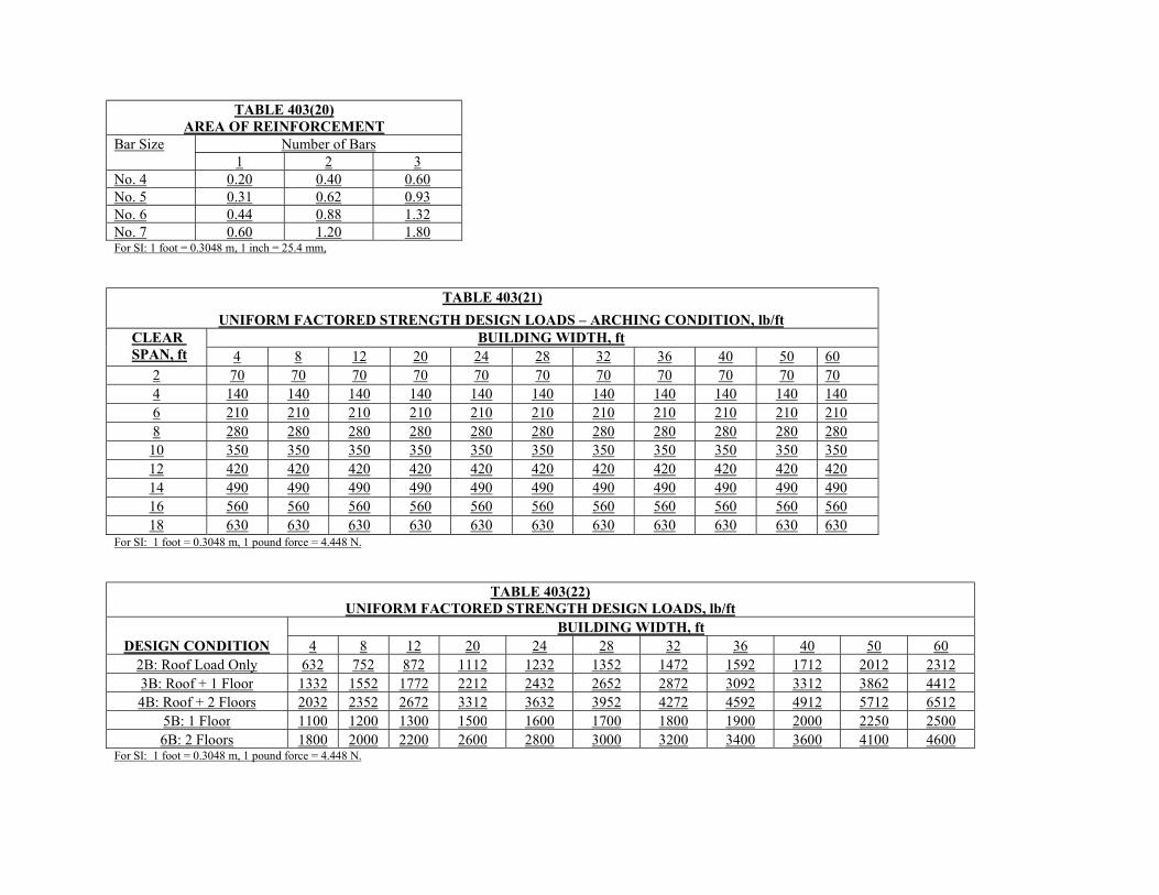
TABLE 403(20) AREA OF REINFORCEMENT
Bar Size Number of Bars 1 2 3
No. 4 0.20 0.40 0.60 No. 5 0.31 0.62 0.93 No. 6 0.44 0.88 1.32 No. 7 0.60 1.20 1.80 For SI: 1 foot = 0.3048 m, 1 inch = 25.4 mm,
TABLE 403(21)
UNIFORM FACTORED STRENGTH DESIGN LOADS – ARCHING CONDITION, lb/ft CLEAR SPAN, ft
BUILDING WIDTH, ft 4 8 12 20 24 28 32 36 40 50 60
2 70 70 70 70 70 70 70 70 70 70 70 4 140 140 140 140 140 140 140 140 140 140 140 6 210 210 210 210 210 210 210 210 210 210 210 8 280 280 280 280 280 280 280 280 280 280 280
10 350 350 350 350 350 350 350 350 350 350 350 12 420 420 420 420 420 420 420 420 420 420 420 14 490 490 490 490 490 490 490 490 490 490 490 16 560 560 560 560 560 560 560 560 560 560 560 18 630 630 630 630 630 630 630 630 630 630 630
For SI: 1 foot = 0.3048 m, 1 pound force = 4.448 N.
TABLE 403(22) UNIFORM FACTORED STRENGTH DESIGN LOADS, lb/ft
DESIGN CONDITION BUILDING WIDTH, ft
4 8 12 20 24 28 32 36 40 50 60 2B: Roof Load Only 632 752 872 1112 1232 1352 1472 1592 1712 2012 2312 3B: Roof + 1 Floor 1332 1552 1772 2212 2432 2652 2872 3092 3312 3862 4412 4B: Roof + 2 Floors 2032 2352 2672 3312 3632 3952 4272 4592 4912 5712 6512
5B: 1 Floor 1100 1200 1300 1500 1600 1700 1800 1900 2000 2250 2500 6B: 2 Floors 1800 2000 2200 2600 2800 3000 3200 3400 3600 4100 4600
For SI: 1 foot = 0.3048 m, 1 pound force = 4.448 N.
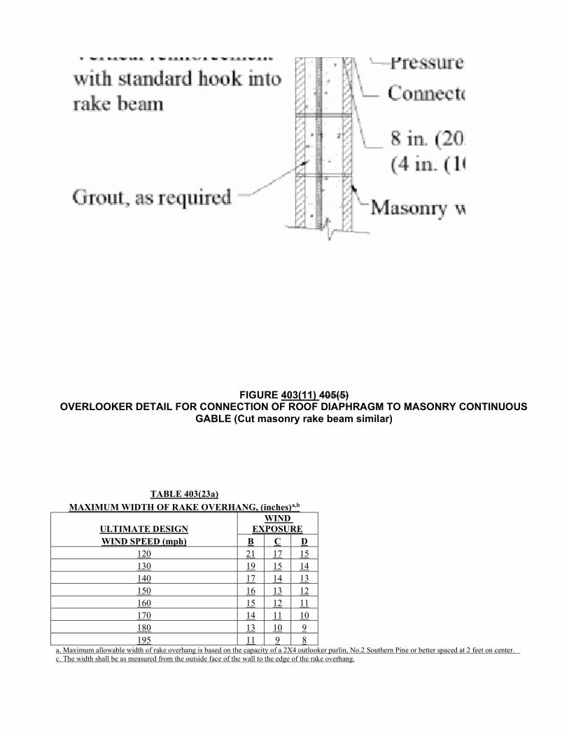
FIGURE 403(11) 405(5)
OVERLOOKER DETAIL FOR CONNECTION OF ROOF DIAPHRAGM TO MASONRY CONTINUOUS GABLE (Cut masonry rake beam similar)
TABLE 403(23a)
MAXIMUM WIDTH OF RAKE OVERHANG, (inches)a,b
ULTIMATE DESIGN WIND
EXPOSURE WIND SPEED (mph) B C D
120 21 17 15 130 19 15 14 140 17 14 13 150 16 13 12 160 15 12 11 170 14 11 10 180 13 10 9 195 11 9 8
a. Maximum allowable width of rake overhang is based on the capacity of a 2X4 outlooker purlin, No.2 Southern Pine or better spaced at 2 feet on center. c. The width shall be as measured from the outside face of the wall to the edge of the rake overhang.
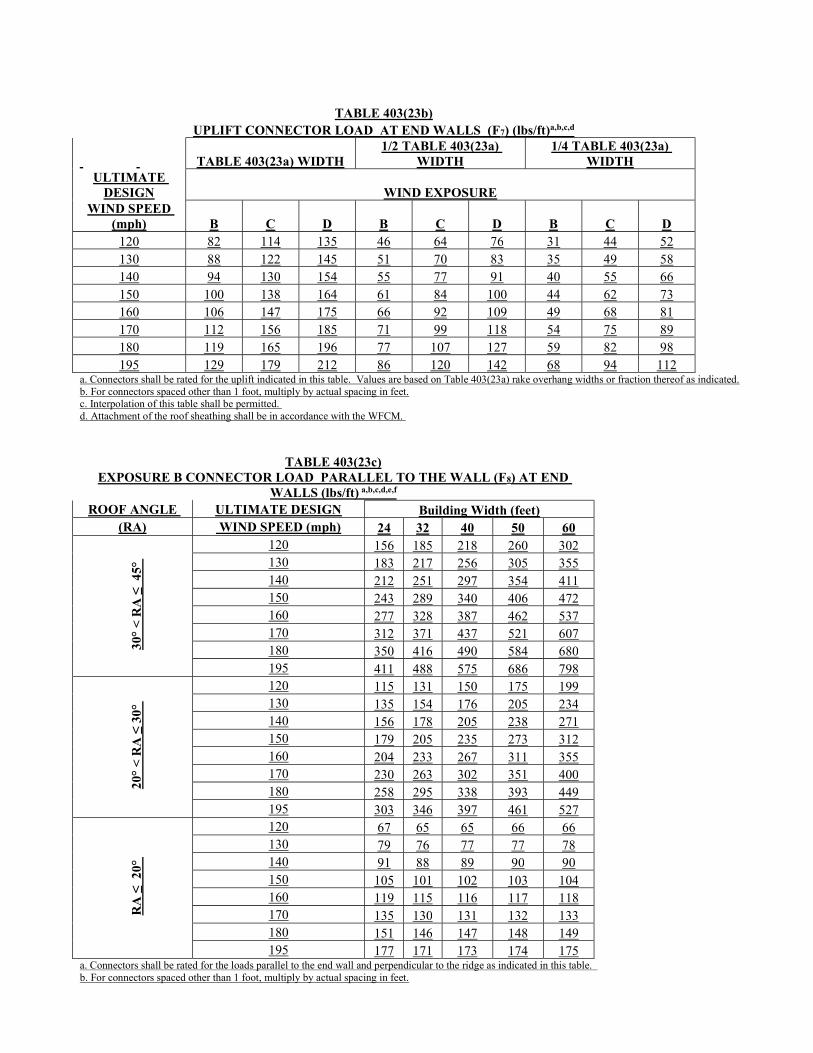
TABLE 403(23b) UPLIFT CONNECTOR LOAD AT END WALLS (F7) (lbs/ft)a,b,c,d
TABLE 403(23a) WIDTH 1/2 TABLE 403(23a)
WIDTH 1/4 TABLE 403(23a)
WIDTH ULTIMATE
DESIGN WIND EXPOSURE WIND SPEED
(mph) B C D B C D B C D 120 82 114 135 46 64 76 31 44 52 130 88 122 145 51 70 83 35 49 58 140 94 130 154 55 77 91 40 55 66 150 100 138 164 61 84 100 44 62 73 160 106 147 175 66 92 109 49 68 81 170 112 156 185 71 99 118 54 75 89 180 119 165 196 77 107 127 59 82 98 195 129 179 212 86 120 142 68 94 112
a. Connectors shall be rated for the uplift indicated in this table. Values are based on Table 403(23a) rake overhang widths or fraction thereof as indicated. b. For connectors spaced other than 1 foot, multiply by actual spacing in feet. c. Interpolation of this table shall be permitted. d. Attachment of the roof sheathing shall be in accordance with the WFCM.
TABLE 403(23c) EXPOSURE B CONNECTOR LOAD PARALLEL TO THE WALL (F8) AT END
WALLS (lbs/ft) a,b,c,d,e,f ROOF ANGLE ULTIMATE DESIGN Building Width (feet)
(RA) WIND SPEED (mph) 24 32 40 50 60
30°
< R
A ≤
45°
120 156 185 218 260 302 130 183 217 256 305 355 140 212 251 297 354 411 150 243 289 340 406 472 160 277 328 387 462 537 170 312 371 437 521 607 180 350 416 490 584 680 195 411 488 575 686 798
20°
< R
A ≤
30°
120 115 131 150 175 199 130 135 154 176 205 234 140 156 178 205 238 271 150 179 205 235 273 312 160 204 233 267 311 355 170 230 263 302 351 400 180 258 295 338 393 449 195 303 346 397 461 527
RA
≤ 2
0°
120 67 65 65 66 66 130 79 76 77 77 78 140 91 88 89 90 90 150 105 101 102 103 104 160 119 115 116 117 118 170 135 130 131 132 133 180 151 146 147 148 149 195 177 171 173 174 175
a. Connectors shall be rated for the loads parallel to the end wall and perpendicular to the ridge as indicated in this table. b. For connectors spaced other than 1 foot, multiply by actual spacing in feet.
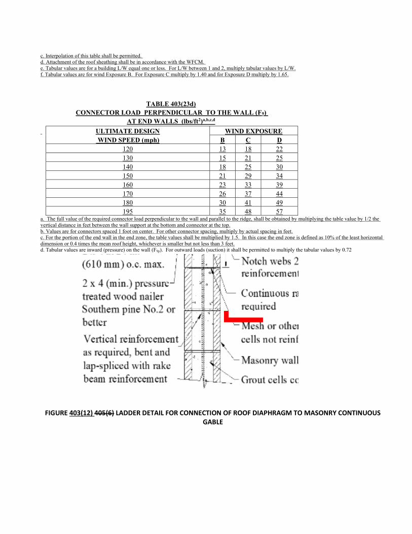
c. Interpolation of this table shall be permitted. d. Attachment of the roof sheathing shall be in accordance with the WFCM. e. Tabular values are for a building L/W equal one or less. For L/W between 1 and 2, multiply tabular values by L/W. f. Tabular values are for wind Exposure B. For Exposure C multiply by 1.40 and for Exposure D multiply by 1.65.
TABLE 403(23d) CONNECTOR LOAD PERPENDICULAR TO THE WALL (F9)
AT END WALLS (lbs/ft2)a,b,c,d
ULTIMATE DESIGN WIND EXPOSURE WIND SPEED (mph) B C D 120 13 18 22 130 15 21 25 140 18 25 30 150 21 29 34 160 23 33 39 170 26 37 44 180 30 41 49 195 35 48 57 a. The full value of the required connector load perpendicular to the wall and parallel to the ridge, shall be obtained by multiplying the table value by 1/2 the vertical distance in feet between the wall support at the bottom and connector at the top. b. Values are for connectors spaced 1 foot on center. For other connector spacing, multiply by actual spacing in feet. c. For the portion of the end wall in the end zone, the table values shall be multiplied by 1.5. In this case the end zone is defined as 10% of the least horizontal dimension or 0.4 times the mean roof height, whichever is smaller but not less than 3 feet. d. Tabular values are inward (pressure) on the wall (F9p). For outward loads (suction) it shall be permitted to multiply the tabular values by 0.72
FIGURE 403(12) 405(6) LADDER DETAIL FOR CONNECTION OF ROOF DIAPHRAGM TO MASONRY CONTINUOUS GABLE
Max. distance from wall to truss: 20 in. (508 mm)
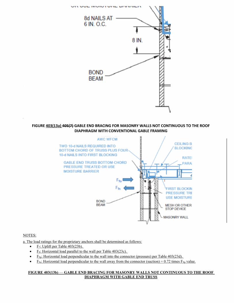
FIGURE 403(13a) 405(7) GABLE END BRACING FOR MASONRY WALLS NOT CONTINUOUS TO THE ROOF DIAPHRAGM WITH CONVENTIONAL GABLE FRAMING
Section A-A
NOTES:
a. The load ratings for the proprietary anchors shall be determined as follows: F7: Uplift per Table 403(23b). F8: Horizontal load parallel to the wall per Table 403(23c). F9p: Horizontal load perpendicular to the wall into the connector (pressure) per Table 403(23d). F9s: Horizontal load perpendicular to the wall away from the connector (suction) = 0.72 times F9p value.
FIGURE 403(13b) — GABLE END BRACING FOR MASONRY WALLS NOT CONTINUOUS TO THE ROOF DIAPHRAGM WITH GABLE END TRUSS

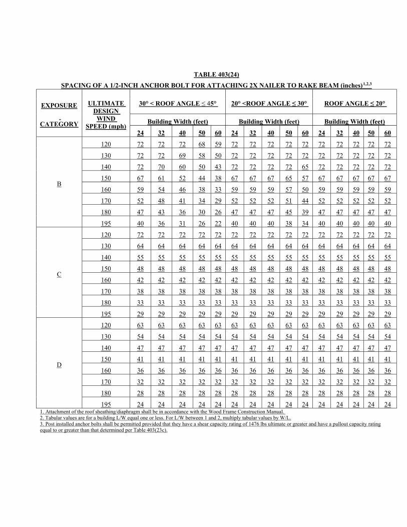
TABLE 403(24)
SPACING OF A 1/2-INCH ANCHOR BOLT FOR ATTACHING 2X NAILER TO RAKE BEAM (inches)1,2,3
EXPOSURE
CATEGORY
ULTIMATE DESIGN
WIND SPEED (mph)
30° < ROOF ANGLE ≤ 45° 20° <ROOF ANGLE ≤ 30° ROOF ANGLE ≤ 20°
Building Width (feet) Building Width (feet) Building Width (feet)
24 32 40 50 60 24 32 40 50 60 24 32 40 50 60
B
120 72 72 72 68 59 72 72 72 72 72 72 72 72 72 72
130 72 72 69 58 50 72 72 72 72 72 72 72 72 72 72
140 72 70 60 50 43 72 72 72 72 65 72 72 72 72 72
150 67 61 52 44 38 67 67 67 65 57 67 67 67 67 67
160 59 54 46 38 33 59 59 59 57 50 59 59 59 59 59
170 52 48 41 34 29 52 52 52 51 44 52 52 52 52 52
180 47 43 36 30 26 47 47 47 45 39 47 47 47 47 47
195 40 36 31 26 22 40 40 40 38 34 40 40 40 40 40
C
120 72 72 72 72 72 72 72 72 72 72 72 72 72 72 72
130 64 64 64 64 64 64 64 64 64 64 64 64 64 64 64
140 55 55 55 55 55 55 55 55 55 55 55 55 55 55 55
150 48 48 48 48 48 48 48 48 48 48 48 48 48 48 48
160 42 42 42 42 42 42 42 42 42 42 42 42 42 42 42
170 38 38 38 38 38 38 38 38 38 38 38 38 38 38 38
180 33 33 33 33 33 33 33 33 33 33 33 33 33 33 33
195 29 29 29 29 29 29 29 29 29 29 29 29 29 29 29
D
120 63 63 63 63 63 63 63 63 63 63 63 63 63 63 63
130 54 54 54 54 54 54 54 54 54 54 54 54 54 54 54
140 47 47 47 47 47 47 47 47 47 47 47 47 47 47 47
150 41 41 41 41 41 41 41 41 41 41 41 41 41 41 41
160 36 36 36 36 36 36 36 36 36 36 36 36 36 36 36
170 32 32 32 32 32 32 32 32 32 32 32 32 32 32 32
180 28 28 28 28 28 28 28 28 28 28 28 28 28 28 28
195 24 24 24 24 24 24 24 24 24 24 24 24 24 24 24 1. Attachment of the roof sheathing/diaphragm shall be in accordance with the Wood Frame Construction Manual. 2. Tabular values are for a building L/W equal one or less. For L/W between 1 and 2, multiply tabular values by W/L. 3. Post installed anchor bolts shall be permitted provided that they have a shear capacity rating of 1476 lbs ultimate or greater and have a pullout capacity rating equal to or greater than that determined per Table 403(23c).
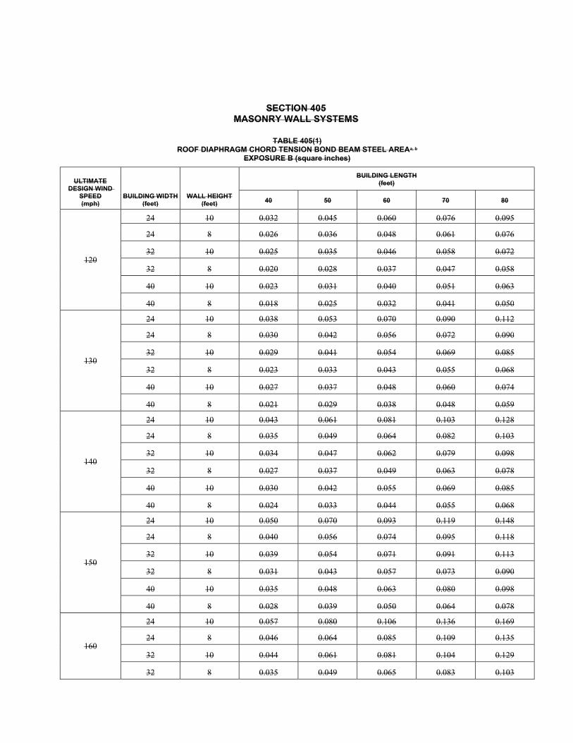
SECTION 405 MASONRY WALL SYSTEMS
TABLE 405(1) ROOF DIAPHRAGM CHORD TENSION BOND BEAM STEEL AREAa, b
EXPOSURE B (square inches)
ULTIMATE DESIGN WIND
SPEED (mph)
BUILDING WIDTH (feet)
WALL HEIGHT (feet)
BUILDING LENGTH (feet)
40 50 60 70 80
120
24 10 0.032 0.045 0.060 0.076 0.095
24 8 0.026 0.036 0.048 0.061 0.076
32 10 0.025 0.035 0.046 0.058 0.072
32 8 0.020 0.028 0.037 0.047 0.058
40 10 0.023 0.031 0.040 0.051 0.063
40 8 0.018 0.025 0.032 0.041 0.050
130
24 10 0.038 0.053 0.070 0.090 0.112
24 8 0.030 0.042 0.056 0.072 0.090
32 10 0.029 0.041 0.054 0.069 0.085
32 8 0.023 0.033 0.043 0.055 0.068
40 10 0.027 0.037 0.048 0.060 0.074
40 8 0.021 0.029 0.038 0.048 0.059
140
24 10 0.043 0.061 0.081 0.103 0.128
24 8 0.035 0.049 0.064 0.082 0.103
32 10 0.034 0.047 0.062 0.079 0.098
32 8 0.027 0.037 0.049 0.063 0.078
40 10 0.030 0.042 0.055 0.069 0.085
40 8 0.024 0.033 0.044 0.055 0.068
150
24 10 0.050 0.070 0.093 0.119 0.148
24 8 0.040 0.056 0.074 0.095 0.118
32 10 0.039 0.054 0.071 0.091 0.113
32 8 0.031 0.043 0.057 0.073 0.090
40 10 0.035 0.048 0.063 0.080 0.098
40 8 0.028 0.039 0.050 0.064 0.078
160
24 10 0.057 0.080 0.106 0.136 0.169
24 8 0.046 0.064 0.085 0.109 0.135
32 10 0.044 0.061 0.081 0.104 0.129
32 8 0.035 0.049 0.065 0.083 0.103
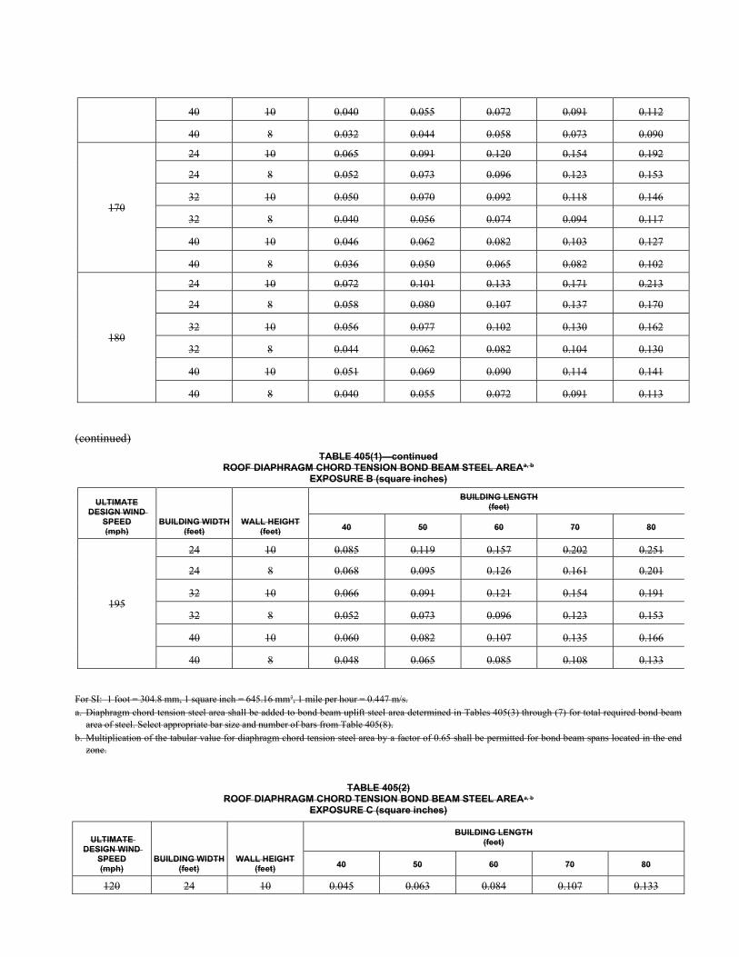
40 10 0.040 0.055 0.072 0.091 0.112
40 8 0.032 0.044 0.058 0.073 0.090
170
24 10 0.065 0.091 0.120 0.154 0.192
24 8 0.052 0.073 0.096 0.123 0.153
32 10 0.050 0.070 0.092 0.118 0.146
32 8 0.040 0.056 0.074 0.094 0.117
40 10 0.046 0.062 0.082 0.103 0.127
40 8 0.036 0.050 0.065 0.082 0.102
180
24 10 0.072 0.101 0.133 0.171 0.213
24 8 0.058 0.080 0.107 0.137 0.170
32 10 0.056 0.077 0.102 0.130 0.162
32 8 0.044 0.062 0.082 0.104 0.130
40 10 0.051 0.069 0.090 0.114 0.141
40 8 0.040 0.055 0.072 0.091 0.113
(continued)
TABLE 405(1)—continued ROOF DIAPHRAGM CHORD TENSION BOND BEAM STEEL AREAa, b
EXPOSURE B (square inches)
ULTIMATE DESIGN WIND
SPEED (mph)
BUILDING WIDTH (feet)
WALL HEIGHT (feet)
BUILDING LENGTH (feet)
40 50 60 70 80
195
24 10 0.085 0.119 0.157 0.202 0.251
24 8 0.068 0.095 0.126 0.161 0.201
32 10 0.066 0.091 0.121 0.154 0.191
32 8 0.052 0.073 0.096 0.123 0.153
40 10 0.060 0.082 0.107 0.135 0.166
40 8 0.048 0.065 0.085 0.108 0.133
For SI: 1 foot = 304.8 mm, 1 square inch = 645.16 mm2, 1 mile per hour = 0.447 m/s. a. Diaphragm chord tension steel area shall be added to bond beam uplift steel area determined in Tables 405(3) through (7) for total required bond beam
area of steel. Select appropriate bar size and number of bars from Table 405(8). b. Multiplication of the tabular value for diaphragm chord tension steel area by a factor of 0.65 shall be permitted for bond beam spans located in the end
zone.
TABLE 405(2) ROOF DIAPHRAGM CHORD TENSION BOND BEAM STEEL AREAa, b
EXPOSURE C (square inches)
ULTIMATE DESIGN WIND
SPEED (mph)
BUILDING WIDTH (feet)
WALL HEIGHT (feet)
BUILDING LENGTH (feet)
40 50 60 70 80
120 24 10 0.045 0.063 0.084 0.107 0.133
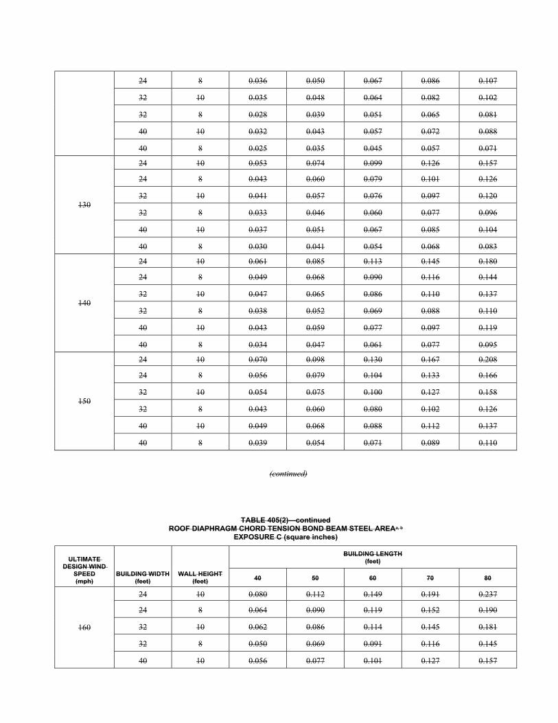
24 8 0.036 0.050 0.067 0.086 0.107
32 10 0.035 0.048 0.064 0.082 0.102
32 8 0.028 0.039 0.051 0.065 0.081
40 10 0.032 0.043 0.057 0.072 0.088
40 8 0.025 0.035 0.045 0.057 0.071
130
24 10 0.053 0.074 0.099 0.126 0.157
24 8 0.043 0.060 0.079 0.101 0.126
32 10 0.041 0.057 0.076 0.097 0.120
32 8 0.033 0.046 0.060 0.077 0.096
40 10 0.037 0.051 0.067 0.085 0.104
40 8 0.030 0.041 0.054 0.068 0.083
140
24 10 0.061 0.085 0.113 0.145 0.180
24 8 0.049 0.068 0.090 0.116 0.144
32 10 0.047 0.065 0.086 0.110 0.137
32 8 0.038 0.052 0.069 0.088 0.110
40 10 0.043 0.059 0.077 0.097 0.119
40 8 0.034 0.047 0.061 0.077 0.095
150
24 10 0.070 0.098 0.130 0.167 0.208
24 8 0.056 0.079 0.104 0.133 0.166
32 10 0.054 0.075 0.100 0.127 0.158
32 8 0.043 0.060 0.080 0.102 0.126
40 10 0.049 0.068 0.088 0.112 0.137
40 8 0.039 0.054 0.071 0.089 0.110
(continued)
TABLE 405(2)—continued ROOF DIAPHRAGM CHORD TENSION BOND BEAM STEEL AREAa, b
EXPOSURE C (square inches)
ULTIMATE DESIGN WIND
SPEED (mph)
BUILDING WIDTH (feet)
WALL HEIGHT (feet)
BUILDING LENGTH (feet)
40 50 60 70 80
160
24 10 0.080 0.112 0.149 0.191 0.237
24 8 0.064 0.090 0.119 0.152 0.190
32 10 0.062 0.086 0.114 0.145 0.181
32 8 0.050 0.069 0.091 0.116 0.145
40 10 0.056 0.077 0.101 0.127 0.157
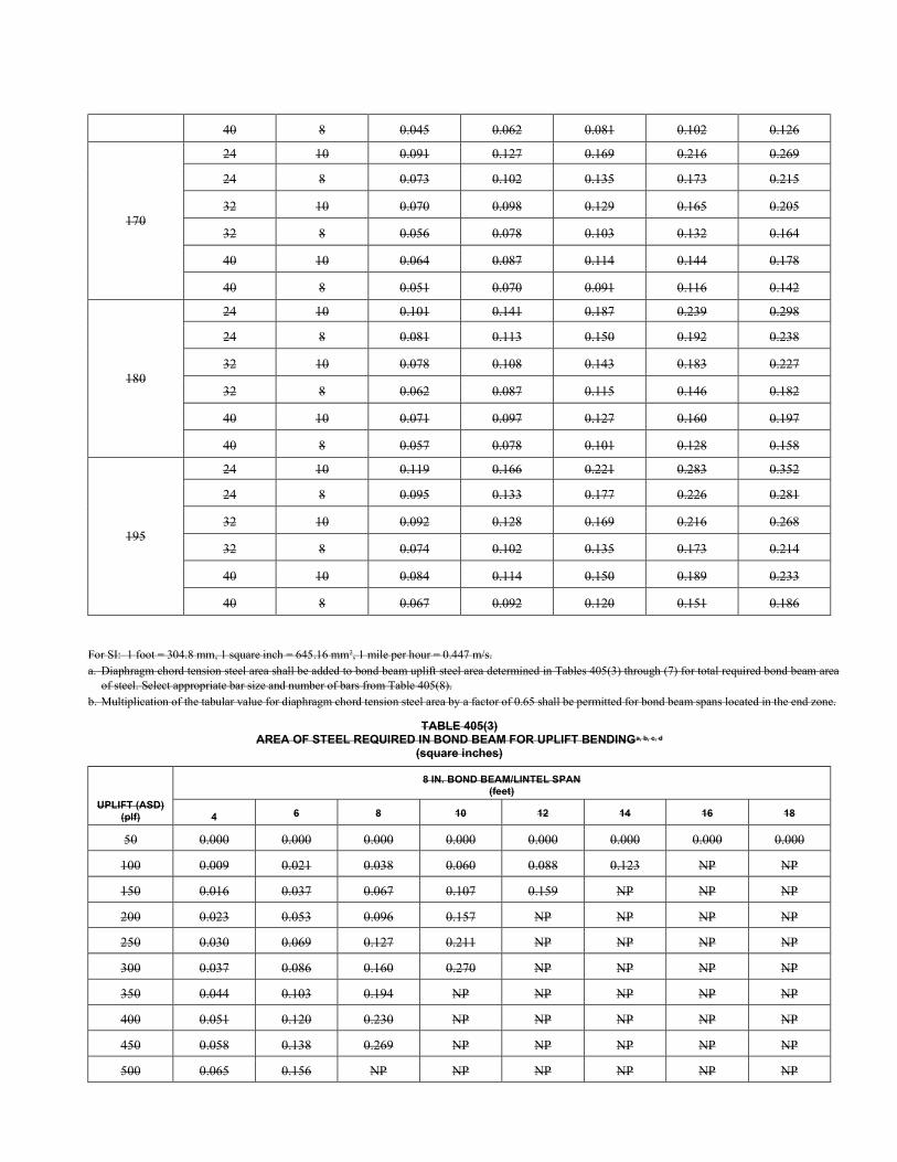
40 8 0.045 0.062 0.081 0.102 0.126
170
24 10 0.091 0.127 0.169 0.216 0.269
24 8 0.073 0.102 0.135 0.173 0.215
32 10 0.070 0.098 0.129 0.165 0.205
32 8 0.056 0.078 0.103 0.132 0.164
40 10 0.064 0.087 0.114 0.144 0.178
40 8 0.051 0.070 0.091 0.116 0.142
180
24 10 0.101 0.141 0.187 0.239 0.298
24 8 0.081 0.113 0.150 0.192 0.238
32 10 0.078 0.108 0.143 0.183 0.227
32 8 0.062 0.087 0.115 0.146 0.182
40 10 0.071 0.097 0.127 0.160 0.197
40 8 0.057 0.078 0.101 0.128 0.158
195
24 10 0.119 0.166 0.221 0.283 0.352
24 8 0.095 0.133 0.177 0.226 0.281
32 10 0.092 0.128 0.169 0.216 0.268
32 8 0.074 0.102 0.135 0.173 0.214
40 10 0.084 0.114 0.150 0.189 0.233
40 8 0.067 0.092 0.120 0.151 0.186
For SI: 1 foot = 304.8 mm, 1 square inch = 645.16 mm2, 1 mile per hour = 0.447 m/s. a. Diaphragm chord tension steel area shall be added to bond beam uplift steel area determined in Tables 405(3) through (7) for total required bond beam area
of steel. Select appropriate bar size and number of bars from Table 405(8). b. Multiplication of the tabular value for diaphragm chord tension steel area by a factor of 0.65 shall be permitted for bond beam spans located in the end zone.
TABLE 405(3) AREA OF STEEL REQUIRED IN BOND BEAM FOR UPLIFT BENDINGa, b, c, d
(square inches)
UPLIFT (ASD) (plf)
8 IN. BOND BEAM/LINTEL SPAN (feet)
4 6 8 10 12 14 16 18
50 0.000 0.000 0.000 0.000 0.000 0.000 0.000 0.000
100 0.009 0.021 0.038 0.060 0.088 0.123 NP NP
150 0.016 0.037 0.067 0.107 0.159 NP NP NP
200 0.023 0.053 0.096 0.157 NP NP NP NP
250 0.030 0.069 0.127 0.211 NP NP NP NP
300 0.037 0.086 0.160 0.270 NP NP NP NP
350 0.044 0.103 0.194 NP NP NP NP NP
400 0.051 0.120 0.230 NP NP NP NP NP
450 0.058 0.138 0.269 NP NP NP NP NP
500 0.065 0.156 NP NP NP NP NP NP
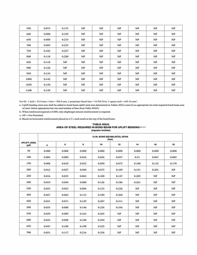
550 0.073 0.175 NP NP NP NP NP NP
600 0.080 0.195 NP NP NP NP NP NP
650 0.088 0.215 NP NP NP NP NP NP
700 0.095 0.235 NP NP NP NP NP NP
750 0.103 0.257 NP NP NP NP NP NP
800 0.110 0.280 NP NP NP NP NP NP
850 0.118 NP NP NP NP NP NP NP
900 0.126 NP NP NP NP NP NP NP
950 0.134 NP NP NP NP NP NP NP
1000 0.142 NP NP NP NP NP NP NP
1050 0.150 NP NP NP NP NP NP NP
1100 0.158 NP NP NP NP NP NP NP
For SI: 1 inch = 25.4 mm, 1 foot = 304.8 mm, 1 pound per lineal foot = 14.594 N/m, 1 square inch = 645.16 mm2. a. Uplift bending steel area shall be added to bond beam uplift steel area determined in Tables 405(1) and (2) as appropriate for total required bond beam area
of steel. Select appropriate bar size and number of bars from Table 405(8). b. When reinforced required is 0.000, only diaphragm tension reinforcement is required. c. NP = Not Permitted. d. Based on horizontal reinforcement placed in a 23/4-inch notch in the top of the bond beam.
TABLE 405(4) AREA OF STEEL REQUIRED IN BOND BEAM FOR UPLIFT BENDINGa, b, c, d
(square inches)
UPLIFT (ASD) (plf)
12 IN. BOND BEAM/LINTEL SPAN (feet)
4 6 8 10 12 14 16 18
50 0.000 0.000 0.000 0.000 0.000 0.000 0.000 0.000
100 0.004 0.009 0.016 0.026 0.037 0.51 0.067 0.085
150 0.008 0.018 0.032 0.050 0.073 0.100 0.132 0.170
200 0.012 0.027 0.048 0.075 0.109 0.151 0.201 NP
250 0.016 0.035 0.063 0.100 0.147 0.205 NP NP
300 0.019 0.044 0.080 0.126 0.186 0.261 NP NP
350 0.023 0.053 0.096 0.153 0.226 NP NP NP
400 0.027 0.062 0.112 0.180 0.268 NP NP NP
450 0.031 0.071 0.129 0.207 0.311 NP NP NP
500 0.035 0.080 0.146 0.236 0.356 NP NP NP
550 0.039 0.089 0.163 0.265 NP NP NP NP
600 0.043 0.098 0.180 0.294 NP NP NP NP
650 0.047 0.108 0.198 0.325 NP NP NP NP
700 0.051 0.117 0.216 0.356 NP NP NP NP
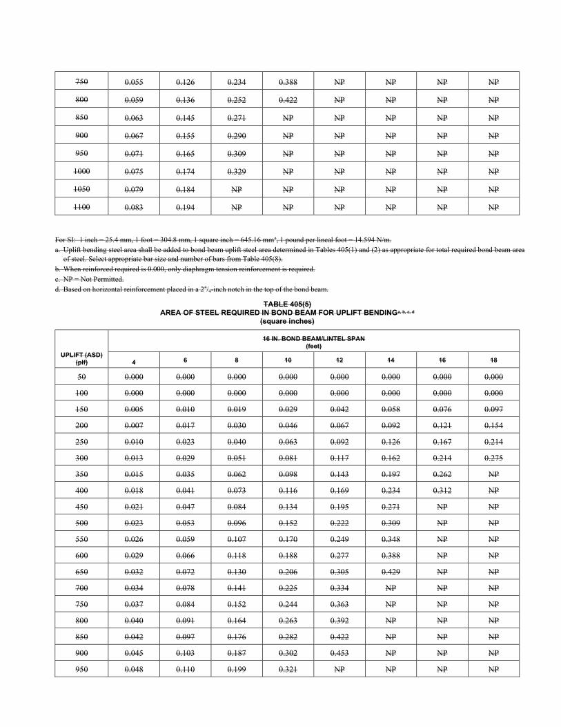
750 0.055 0.126 0.234 0.388 NP NP NP NP
800 0.059 0.136 0.252 0.422 NP NP NP NP
850 0.063 0.145 0.271 NP NP NP NP NP
900 0.067 0.155 0.290 NP NP NP NP NP
950 0.071 0.165 0.309 NP NP NP NP NP
1000 0.075 0.174 0.329 NP NP NP NP NP
1050 0.079 0.184 NP NP NP NP NP NP
1100 0.083 0.194 NP NP NP NP NP NP
For SI: 1 inch = 25.4 mm, 1 foot = 304.8 mm, 1 square inch = 645.16 mm2, 1 pound per lineal foot = 14.594 N/m. a. Uplift bending steel area shall be added to bond beam uplift steel area determined in Tables 405(1) and (2) as appropriate for total required bond beam area
of steel. Select appropriate bar size and number of bars from Table 405(8). b. When reinforced required is 0.000, only diaphragm tension reinforcement is required. c. NP = Not Permitted. d. Based on horizontal reinforcement placed in a 23/4-inch notch in the top of the bond beam.
TABLE 405(5) AREA OF STEEL REQUIRED IN BOND BEAM FOR UPLIFT BENDINGa, b, c, d
(square inches)
UPLIFT (ASD) (plf)
16 IN. BOND BEAM/LINTEL SPAN (feet)
4 6 8 10 12 14 16 18
50 0.000 0.000 0.000 0.000 0.000 0.000 0.000 0.000
100 0.000 0.000 0.000 0.000 0.000 0.000 0.000 0.000
150 0.005 0.010 0.019 0.029 0.042 0.058 0.076 0.097
200 0.007 0.017 0.030 0.046 0.067 0.092 0.121 0.154
250 0.010 0.023 0.040 0.063 0.092 0.126 0.167 0.214
300 0.013 0.029 0.051 0.081 0.117 0.162 0.214 0.275
350 0.015 0.035 0.062 0.098 0.143 0.197 0.262 NP
400 0.018 0.041 0.073 0.116 0.169 0.234 0.312 NP
450 0.021 0.047 0.084 0.134 0.195 0.271 NP NP
500 0.023 0.053 0.096 0.152 0.222 0.309 NP NP
550 0.026 0.059 0.107 0.170 0.249 0.348 NP NP
600 0.029 0.066 0.118 0.188 0.277 0.388 NP NP
650 0.032 0.072 0.130 0.206 0.305 0.429 NP NP
700 0.034 0.078 0.141 0.225 0.334 NP NP NP
750 0.037 0.084 0.152 0.244 0.363 NP NP NP
800 0.040 0.091 0.164 0.263 0.392 NP NP NP
850 0.042 0.097 0.176 0.282 0.422 NP NP NP
900 0.045 0.103 0.187 0.302 0.453 NP NP NP
950 0.048 0.110 0.199 0.321 NP NP NP NP
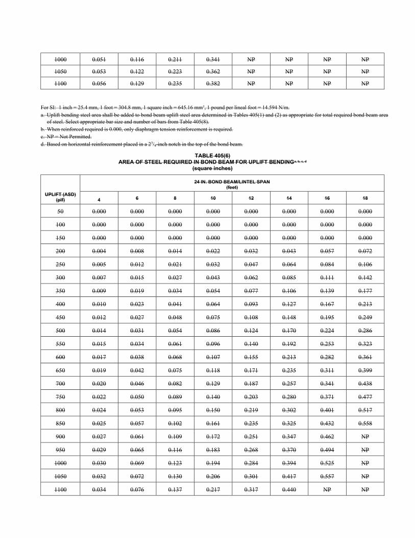
1000 0.051 0.116 0.211 0.341 NP NP NP NP
1050 0.053 0.122 0.223 0.362 NP NP NP NP
1100 0.056 0.129 0.235 0.382 NP NP NP NP
For SI: 1 inch = 25.4 mm, 1 foot = 304.8 mm, 1 square inch = 645.16 mm2, 1 pound per lineal foot = 14.594 N/m. a. Uplift bending steel area shall be added to bond beam uplift steel area determined in Tables 405(1) and (2) as appropriate for total required bond beam area
of steel. Select appropriate bar size and number of bars from Table 405(8). b. When reinforced required is 0.000, only diaphragm tension reinforcement is required. c. NP = Not Permitted. d. Based on horizontal reinforcement placed in a 23/4-inch notch in the top of the bond beam.
TABLE 405(6) AREA OF STEEL REQUIRED IN BOND BEAM FOR UPLIFT BENDINGa, b, c, d
(square inches)
UPLIFT (ASD) (plf)
24 IN. BOND BEAM/LINTEL SPAN (feet)
4 6 8 10 12 14 16 18
50 0.000 0.000 0.000 0.000 0.000 0.000 0.000 0.000
100 0.000 0.000 0.000 0.000 0.000 0.000 0.000 0.000
150 0.000 0.000 0.000 0.000 0.000 0.000 0.000 0.000
200 0.004 0.008 0.014 0.022 0.032 0.043 0.057 0.072
250 0.005 0.012 0.021 0.032 0.047 0.064 0.084 0.106
300 0.007 0.015 0.027 0.043 0.062 0.085 0.111 0.142
350 0.009 0.019 0.034 0.054 0.077 0.106 0.139 0.177
400 0.010 0.023 0.041 0.064 0.093 0.127 0.167 0.213
450 0.012 0.027 0.048 0.075 0.108 0.148 0.195 0.249
500 0.014 0.031 0.054 0.086 0.124 0.170 0.224 0.286
550 0.015 0.034 0.061 0.096 0.140 0.192 0.253 0.323
600 0.017 0.038 0.068 0.107 0.155 0.213 0.282 0.361
650 0.019 0.042 0.075 0.118 0.171 0.235 0.311 0.399
700 0.020 0.046 0.082 0.129 0.187 0.257 0.341 0.438
750 0.022 0.050 0.089 0.140 0.203 0.280 0.371 0.477
800 0.024 0.053 0.095 0.150 0.219 0.302 0.401 0.517
850 0.025 0.057 0.102 0.161 0.235 0.325 0.432 0.558
900 0.027 0.061 0.109 0.172 0.251 0.347 0.462 NP
950 0.029 0.065 0.116 0.183 0.268 0.370 0.494 NP
1000 0.030 0.069 0.123 0.194 0.284 0.394 0.525 NP
1050 0.032 0.072 0.130 0.206 0.301 0.417 0.557 NP
1100 0.034 0.076 0.137 0.217 0.317 0.440 NP NP
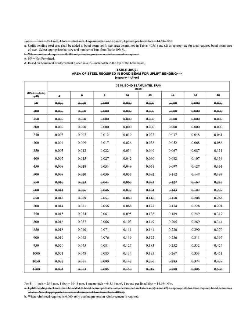
For SI: 1 inch = 25.4 mm, 1 foot = 304.8 mm, 1 square inch = 645.16 mm2, 1 pound per lineal foot = 14.694 N/m. a. Uplift bending steel area shall be added to bond beam uplift steel area determined in Tables 405(1) and (2) as appropriate for total required bond beam area
of steel. Select appropriate bar size and number of bars from Table 405(8). b. When reinforced required is 0.000, only diaphragm tension reinforcement is required. c. NP = Not Permitted. d. Based on horizontal reinforcement placed in a 23/4-inch notch in the top of the bond beam.
TABLE 405(7) AREA OF STEEL REQUIRED IN BOND BEAM FOR UPLIFT BENDINGa, b, c
(square inches)
UPLIFT (ASD) (plf)
32 IN. BOND BEAM/LINTEL SPAN (feet)
4 6 8 10 12 14 16 18
50 0.000 0.000 0.000 0.000 0.000 0.000 0.000 0.000
100 0.000 0.000 0.000 0.000 0.000 0.000 0.000 0.000
150 0.000 0.000 0.000 0.000 0.000 0.000 0.000 0.000
200 0.000 0.000 0.000 0.000 0.000 0.000 0.000 0.000
250 0.003 0.007 0.012 0.019 0.027 0.037 0.048 0.061
300 0.004 0.009 0.017 0.026 0.038 0.052 0.068 0.086
350 0.005 0.012 0.022 0.034 0.049 0.067 0.087 0.111
400 0.007 0.015 0.027 0.042 0.060 0.082 0.107 0.136
450 0.008 0.018 0.031 0.049 0.071 0.097 0.127 0.161
500 0.009 0.020 0.036 0.057 0.082 0.112 0.147 0.187
550 0.010 0.023 0.041 0.065 0.093 0.127 0.167 0.213
600 0.011 0.026 0.046 0.072 0.104 0.143 0.187 0.239
650 0.013 0.029 0.051 0.080 0.116 0.158 0.208 0.265
700 0.014 0.031 0.056 0.088 0.127 0.174 0.228 0.291
750 0.015 0.034 0.061 0.095 0.138 0.189 0.249 0.317
800 0.016 0.037 0.066 0.103 0.149 0.205 0.269 0.344
850 0.018 0.040 0.071 0.111 0.161 0.220 0.290 0.370
900 0.019 0.042 0.076 0.119 0.172 0.236 0.311 0.397
950 0.020 0.045 0.081 0.127 0.183 0.252 0.332 0.424
1000 0.021 0.048 0.085 0.134 0.195 0.267 0.353 0.451
1050 0.022 0.051 0.090 0.142 0.206 0.283 0.374 0.479
1100 0.024 0.053 0.095 0.150 0.218 0.299 0.395 0.506
For SI: 1 inch = 25.4 mm, 1 foot = 304.8 mm, 1 square inch = 645.16 mm2, 1 pound per lineal foot = 14.694 N/m. a. Uplift bending steel area shall be added to bond beam uplift steel area determined in Tables 405(1) and (2) as appropriate for total required bond beam area
of steel. Select appropriate bar size and number of bars from Table 405(8). b. When reinforced required is 0.000, only diaphragm tension reinforcement is required.
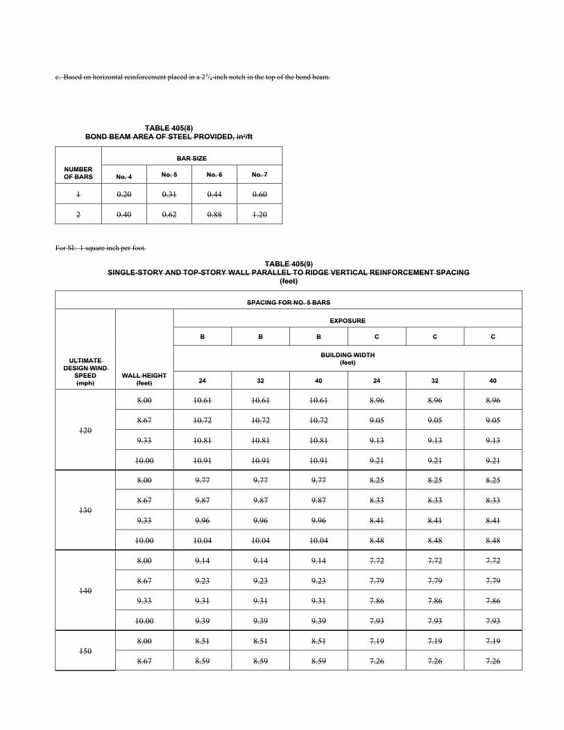
c. Based on horizontal reinforcement placed in a 23/4-inch notch in the top of the bond beam.
TABLE 405(8) BOND BEAM AREA OF STEEL PROVIDED, in2/ft
NUMBER OF BARS
BAR SIZE
No. 4 No. 5 No. 6 No. 7
1 0.20 0.31 0.44 0.60
2 0.40 0.62 0.88 1.20
For SI: 1 square inch per foot.
TABLE 405(9) SINGLE-STORY AND TOP-STORY WALL PARALLEL TO RIDGE VERTICAL REINFORCEMENT SPACING
(feet)
SPACING FOR NO. 5 BARS
ULTIMATE DESIGN WIND
SPEED (mph)
WALL HEIGHT (feet)
EXPOSURE
B B B C C C
BUILDING WIDTH (feet)
24 32 40 24 32 40
120
8.00 10.61 10.61 10.61 8.96 8.96 8.96
8.67 10.72 10.72 10.72 9.05 9.05 9.05
9.33 10.81 10.81 10.81 9.13 9.13 9.13
10.00 10.91 10.91 10.91 9.21 9.21 9.21
130
8.00 9.77 9.77 9.77 8.25 8.25 8.25
8.67 9.87 9.87 9.87 8.33 8.33 8.33
9.33 9.96 9.96 9.96 8.41 8.41 8.41
10.00 10.04 10.04 10.04 8.48 8.48 8.48
140
8.00 9.14 9.14 9.14 7.72 7.72 7.72
8.67 9.23 9.23 9.23 7.79 7.79 7.79
9.33 9.31 9.31 9.31 7.86 7.86 7.86
10.00 9.39 9.39 9.39 7.93 7.93 7.93
150 8.00 8.51 8.51 8.51 7.19 7.19 7.19
8.67 8.59 8.59 8.59 7.26 7.26 7.26

9.33 8.67 8.67 8.67 7.32 7.18 6.68
10.00 8.74 8.74 8.74 6.98 6.51 6.10
160
8.00 7.96 7.96 7.96 6.72 6.72 6.72
8.67 8.04 8.04 8.04 6.79 6.79 6.30
9.33 8.11 8.11 8.11 6.69 6.19 5.76
10.00 8.18 8.18 7.68 6.03 5.62 5.26
170
8.00 7.48 7.48 7.48 6.32 6.32 6.01
8.67 7.55 7.55 7.55 6.38 5.94 5.48
9.33 7.62 7.62 7.31 5.84 5.40 5.02
10.00 7.62 7.12 6.67 5.27 4.90 4.59
180
8.00 7.10 7.10 7.10 6.00 5.85 5.36
8.67 7.17 7.17 7.12 5.79 5.31 4.89
9.33 7.23 6.99 6.51 5.22 4.82 4.48
10.00 6.80 6.34 5.94 4.71 4.38 4.10
195
8.00 6.54 6.54 6.48 5.39 4.89 4.47
8.67 6.60 6.41 5.92 4.84 4.43 4.09
9.33 6.29 5.82 5.41 4.36 4.03 3.74
10.00 5.68 5.29 4.95 3.94 3.67 3.43
(continued)
TABLE 405(9)—continued SINGLE-STORY AND TOP-STORY WALL PARALLEL TO RIDGE VERTICAL REINFORCEMENT SPACING
(feet)
SPACING FOR NO. 4 BARS
ULTIMATE DESIGN WIND
SPEED (mph)
WALL HEIGHT (feet)
EXPOSURE
B B B C C C
BUILDING WIDTH (feet)
24 32 40 24 32 40
120
8.00 10.61 10.61 10.61 8.96 8.96 8.73
8.67 10.72 10.72 10.72 9.05 8.52 7.91
9.33 10.81 10.81 10.81 8.26 7.68 7.18
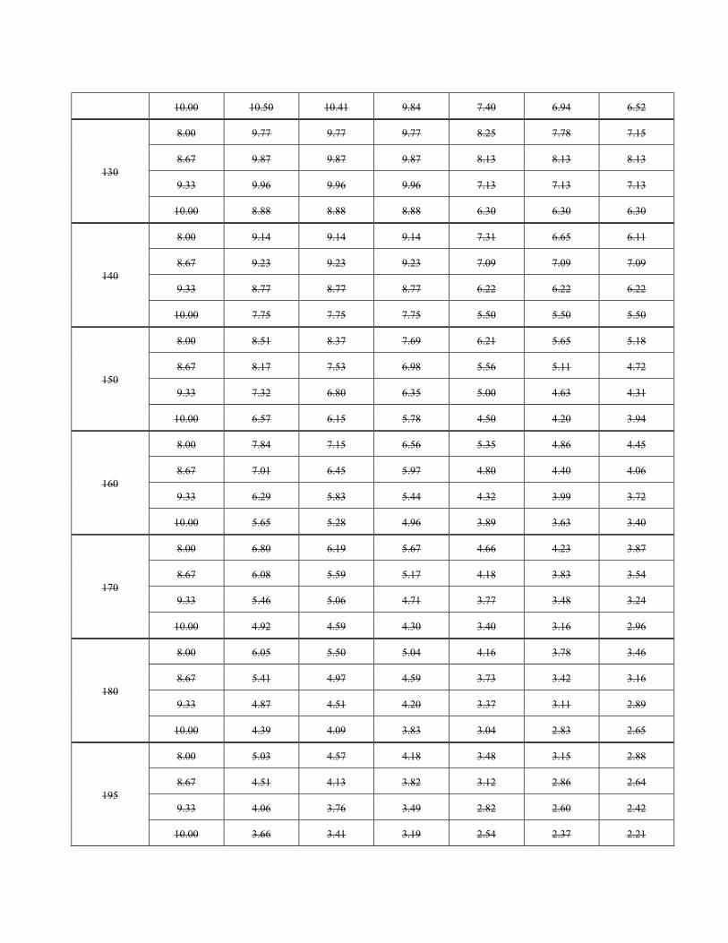
10.00 10.50 10.41 9.84 7.40 6.94 6.52
130
8.00 9.77 9.77 9.77 8.25 7.78 7.15
8.67 9.87 9.87 9.87 8.13 8.13 8.13
9.33 9.96 9.96 9.96 7.13 7.13 7.13
10.00 8.88 8.88 8.88 6.30 6.30 6.30
140
8.00 9.14 9.14 9.14 7.31 6.65 6.11
8.67 9.23 9.23 9.23 7.09 7.09 7.09
9.33 8.77 8.77 8.77 6.22 6.22 6.22
10.00 7.75 7.75 7.75 5.50 5.50 5.50
150
8.00 8.51 8.37 7.69 6.21 5.65 5.18
8.67 8.17 7.53 6.98 5.56 5.11 4.72
9.33 7.32 6.80 6.35 5.00 4.63 4.31
10.00 6.57 6.15 5.78 4.50 4.20 3.94
160
8.00 7.84 7.15 6.56 5.35 4.86 4.45
8.67 7.01 6.45 5.97 4.80 4.40 4.06
9.33 6.29 5.83 5.44 4.32 3.99 3.72
10.00 5.65 5.28 4.96 3.89 3.63 3.40
170
8.00 6.80 6.19 5.67 4.66 4.23 3.87
8.67 6.08 5.59 5.17 4.18 3.83 3.54
9.33 5.46 5.06 4.71 3.77 3.48 3.24
10.00 4.92 4.59 4.30 3.40 3.16 2.96
180
8.00 6.05 5.50 5.04 4.16 3.78 3.46
8.67 5.41 4.97 4.59 3.73 3.42 3.16
9.33 4.87 4.51 4.20 3.37 3.11 2.89
10.00 4.39 4.09 3.83 3.04 2.83 2.65
195
8.00 5.03 4.57 4.18 3.48 3.15 2.88
8.67 4.51 4.13 3.82 3.12 2.86 2.64
9.33 4.06 3.76 3.49 2.82 2.60 2.42
10.00 3.66 3.41 3.19 2.54 2.37 2.21
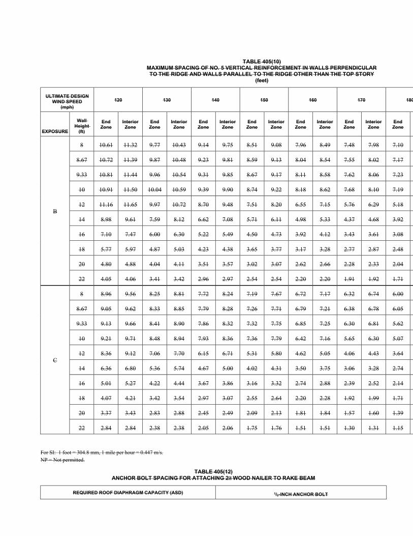
TABLE 405(10) MAXIMUM SPACING OF NO. 5 VERTICAL REINFORCEMENT IN WALLS PERPENDICULAR TO THE RIDGE AND WALLS PARALLEL TO THE RIDGE OTHER THAN THE TOP STORY
(feet)
ULTIMATE DESIGN WIND SPEED
(mph)
120 130 140 150 160 170 180
EXPOSURE
Wall Height
(ft)
End Zone
Interior Zone
End Zone
Interior Zone
End Zone
Interior Zone
End Zone
Interior Zone
End Zone
Interior Zone
End Zone
Interior Zone
End Zone
B
8 10.61 11.32 9.77 10.43 9.14 9.75 8.51 9.08 7.96 8.49 7.48 7.98 7.10
8.67 10.72 11.39 9.87 10.48 9.23 9.81 8.59 9.13 8.04 8.54 7.55 8.02 7.17
9.33 10.81 11.44 9.96 10.54 9.31 9.85 8.67 9.17 8.11 8.58 7.62 8.06 7.23
10 10.91 11.50 10.04 10.59 9.39 9.90 8.74 9.22 8.18 8.62 7.68 8.10 7.19
12 11.16 11.65 9.97 10.72 8.70 9.48 7.51 8.20 6.55 7.15 5.76 6.29 5.18
14 8.98 9.61 7.59 8.12 6.62 7.08 5.71 6.11 4.98 5.33 4.37 4.68 3.92
16 7.10 7.47 6.00 6.30 5.22 5.49 4.50 4.73 3.92 4.12 3.43 3.61 3.08
18 5.77 5.97 4.87 5.03 4.23 4.38 3.65 3.77 3.17 3.28 2.77 2.87 2.48
20 4.80 4.88 4.04 4.11 3.51 3.57 3.02 3.07 2.62 2.66 2.28 2.33 2.04
22 4.05 4.06 3.41 3.42 2.96 2.97 2.54 2.54 2.20 2.20 1.91 1.92 1.71
C
8 8.96 9.56 8.25 8.81 7.72 8.24 7.19 7.67 6.72 7.17 6.32 6.74 6.00
8.67 9.05 9.62 8.33 8.85 7.79 8.28 7.26 7.71 6.79 7.21 6.38 6.78 6.05
9.33 9.13 9.66 8.41 8.90 7.86 8.32 7.32 7.75 6.85 7.25 6.30 6.81 5.62
10 9.21 9.71 8.48 8.94 7.93 8.36 7.36 7.79 6.42 7.16 5.65 6.30 5.07
12 8.36 9.12 7.06 7.70 6.15 6.71 5.31 5.80 4.62 5.05 4.06 4.43 3.64
14 6.36 6.80 5.36 5.74 4.67 5.00 4.02 4.31 3.50 3.75 3.06 3.28 2.74
16 5.01 5.27 4.22 4.44 3.67 3.86 3.16 3.32 2.74 2.88 2.39 2.52 2.14
18 4.07 4.21 3.42 3.54 2.97 3.07 2.55 2.64 2.20 2.28 1.92 1.99 1.71
20 3.37 3.43 2.83 2.88 2.45 2.49 2.09 2.13 1.81 1.84 1.57 1.60 1.39
22 2.84 2.84 2.38 2.38 2.05 2.06 1.75 1.76 1.51 1.51 1.30 1.31 1.15
For SI: 1 foot = 304.8 mm, 1 mile per hour = 0.447 m/s. NP = Not permitted.
TABLE 405(12) ANCHOR BOLT SPACING FOR ATTACHING 2 WOOD NAILER TO RAKE BEAM
REQUIRED ROOF DIAPHRAGM CAPACITY (ASD) 1/2-INCH ANCHOR BOLT
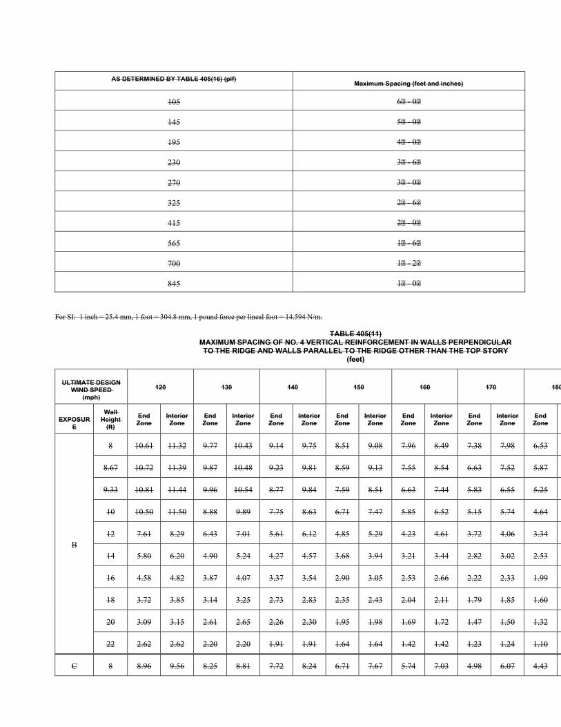
AS DETERMINED BY TABLE 405(16) (plf) Maximum Spacing (feet and inches)
105 6 - 0
145 5 - 0
195 4 - 0
230 3 - 6
270 3 - 0
325 2 - 6
415 2 - 0
565 1 - 6
700 1 - 2
845 1 - 0
For SI: 1 inch = 25.4 mm, 1 foot = 304.8 mm, 1 pound force per lineal foot = 14.594 N/m.
TABLE 405(11) MAXIMUM SPACING OF NO. 4 VERTICAL REINFORCEMENT IN WALLS PERPENDICULAR TO THE RIDGE AND WALLS PARALLEL TO THE RIDGE OTHER THAN THE TOP STORY
(feet)
ULTIMATE DESIGN WIND SPEED
(mph)
120 130 140 150 160 170 180
EXPOSURE
Wall Height
(ft)
End Zone
Interior Zone
End Zone
Interior Zone
End Zone
Interior Zone
End Zone
Interior Zone
End Zone
Interior Zone
End Zone
Interior Zone
End Zone
B
8 10.61 11.32 9.77 10.43 9.14 9.75 8.51 9.08 7.96 8.49 7.38 7.98 6.53
8.67 10.72 11.39 9.87 10.48 9.23 9.81 8.59 9.13 7.55 8.54 6.63 7.52 5.87
9.33 10.81 11.44 9.96 10.54 8.77 9.84 7.59 8.51 6.63 7.44 5.83 6.55 5.25
10 10.50 11.50 8.88 9.89 7.75 8.63 6.71 7.47 5.85 6.52 5.15 5.74 4.64
12 7.61 8.29 6.43 7.01 5.61 6.12 4.85 5.29 4.23 4.61 3.72 4.06 3.34
14 5.80 6.20 4.90 5.24 4.27 4.57 3.68 3.94 3.21 3.44 2.82 3.02 2.53
16 4.58 4.82 3.87 4.07 3.37 3.54 2.90 3.05 2.53 2.66 2.22 2.33 1.99
18 3.72 3.85 3.14 3.25 2.73 2.83 2.35 2.43 2.04 2.11 1.79 1.85 1.60
20 3.09 3.15 2.61 2.65 2.26 2.30 1.95 1.98 1.69 1.72 1.47 1.50 1.32
22 2.62 2.62 2.20 2.20 1.91 1.91 1.64 1.64 1.42 1.42 1.23 1.24 1.10
C 8 8.96 9.56 8.25 8.81 7.72 8.24 6.71 7.67 5.74 7.03 4.98 6.07 4.43
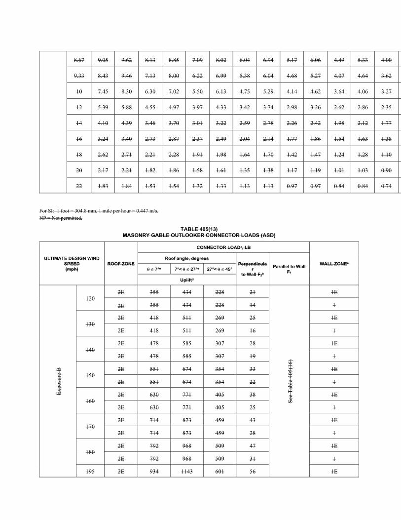
8.67 9.05 9.62 8.13 8.85 7.09 8.02 6.04 6.94 5.17 6.06 4.49 5.33 4.00
9.33 8.43 9.46 7.13 8.00 6.22 6.99 5.38 6.04 4.68 5.27 4.07 4.64 3.62
10 7.45 8.30 6.30 7.02 5.50 6.13 4.75 5.29 4.14 4.62 3.64 4.06 3.27
12 5.39 5.88 4.55 4.97 3.97 4.33 3.42 3.74 2.98 3.26 2.62 2.86 2.35
14 4.10 4.39 3.46 3.70 3.01 3.22 2.59 2.78 2.26 2.42 1.98 2.12 1.77
16 3.24 3.40 2.73 2.87 2.37 2.49 2.04 2.14 1.77 1.86 1.54 1.63 1.38
18 2.62 2.71 2.21 2.28 1.91 1.98 1.64 1.70 1.42 1.47 1.24 1.28 1.10
20 2.17 2.21 1.82 1.86 1.58 1.61 1.35 1.38 1.17 1.19 1.01 1.03 0.90
22 1.83 1.84 1.53 1.54 1.32 1.33 1.13 1.13 0.97 0.97 0.84 0.84 0.74
For SI: 1 foot = 304.8 mm, 1 mile per hour = 0.447 m/s. NP = Not permitted.
TABLE 405(13) MASONRY GABLE OUTLOOKER CONNECTOR LOADS (ASD)
ULTIMATE DESIGN WIND SPEED (mph)
ROOF ZONE
CONNECTOR LOADa, LB
WALL ZONEc Roof angle, degrees
Perpendicular
to Wall F2b
Parallel to Wall F1
7°e 7°< 27°e 27°< 45°
Upliftd
Exp
osur
e B
120 2E 355 434 228 21 S
ee T
able
405
(16)
1E
2E 355 434 228 14 1
130 2E 418 511 269 25 1E
2E 418 511 269 16 1
140 2E 478 585 307 28 1E
2E 478 585 307 19 1
150 2E 551 674 354 33 1E
2E 551 674 354 22 1
160 2E 630 771 405 38 1E
2E 630 771 405 25 1
170 2E 714 873 459 43 1E
2E 714 873 459 28 1
180 2E 792 968 509 47 1E
2E 792 968 509 31 1
195 2E 934 1143 601 56 1E
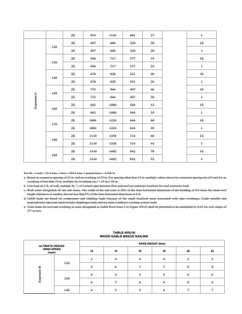
2E 934 1143 601 37 1 E
xpos
ure
C
120 2E 497 608 320 30 1E
2E 497 608 320 20 1
130 2E 586 717 377 35 1E
2E 586 717 377 23 1
140 2E 670 820 431 40 1E
2E 670 820 431 26 1
150 2E 773 946 497 46 1E
2E 773 946 497 30 1
160 2E 883 1080 568 53 1E
2E 883 1080 568 35 1
170 2E 1001 1224 644 60 1E
2E 1001 1224 644 39 1
180 2E 1110 1358 714 66 1E
2E 1110 1358 714 44 1
195 2E 1310 1602 842 78 1E
2E 1310 1602 842 52 1
For SI: 1 inch = 25.4 mm, 1 foot = 304.8 mm, 1 pound force = 4.448 N. a. Based on connector spacing of 24 in. and an overhang of 24 in. For spacing other than 24 in. multiply values shown by connector spacing (in.)/24 and for an
overhang of less than 24 in. multiply by (overhang (in.) + 24 in.)/ 48 in. b. Unit load on 2 ft. of wall, multiply by 1/2 of vertical span between floor and roof (at connector location) for total connector load. c. Wall zones designated 1E are end zones. The width of the end zone is 20% of the least horizontal dimension of the building or 0.8 times the mean roof
height whichever is smaller, but not less than 8% of the least horizontal dimension or 6 ft. d. Uplift loads are based on components and cladding loads because of the small localized areas associated with rake overhangs. Loads parallel and
perpendicular represent much broader diaphragm loads and are main windforce resisting system loads. e. Total loads for roof and overhang in areas designated as Gable Roof Zone 2 in Figure 301(2) shall be permitted to be multiplied by 0.65 for roof slopes of
27° or less.
TABLE 405(14) WOOD GABLE BRACE NAILING
ULTIMATE DESIGN WIND SPEED
(mph)
RAKE HEIGHT (feet)
12 14 16 18 20 22
Exp
osur
e B
120 3 4 4 4 5 5
5 6 7 7 8 9
130 4 4 5 5 6 6
6 7 8 9 9 9
140 4 5 5 6 7 7
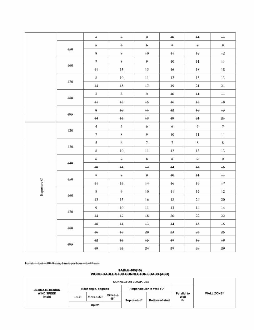
7 8 9 10 11 11
150 5 6 6 7 8 8
8 9 10 11 12 12
160 7 8 9 10 11 11
11 13 15 16 18 18
170 8 10 11 12 13 13
14 15 17 19 21 21
180 7 8 9 10 11 11
11 13 15 16 18 18
195 8 10 11 12 13 13
14 15 17 19 21 21
Exp
osur
e C
120 4 5 6 6 7 7
7 8 9 10 11 11
130 5 6 7 7 8 8
8 10 11 12 13 13
140 6 7 8 8 9 9
10 11 12 14 15 15
150 7 8 9 10 11 11
11 13 14 16 17 17
160 8 9 10 11 12 12
13 15 16 18 20 20
170 9 10 11 13 14 14
14 17 18 20 22 22
180 10 11 13 14 15 15
16 18 20 23 25 25
195 12 13 15 17 18 18
19 22 24 27 29 29
For SI: 1 foot = 304.8 mm, 1 mile per hour = 0.447 m/s.
TABLE 405(15) WOOD GABLE STUD CONNECTOR LOADS (ASD)
ULTIMATE DESIGN WIND SPEED
(mph)
CONNECTOR LOADa, LBS
WALL ZONEd
Roof angle, degrees Perpendicular to Wall F2c
Parallel to Wall F1
7° 7° < 27° 27°<
45° Top of studb Bottom of stud
Upliftc
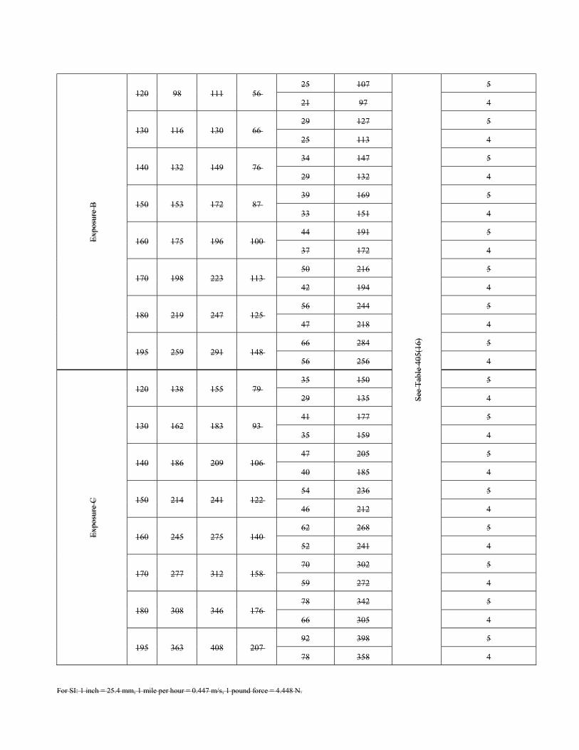
Exp
osur
e B
120 98 111 56
25 107
See
Tab
le 4
05(1
6)
5
21 97 4
130 116 130 66 29 127 5
25 113 4
140 132 149 76 34 147 5
29 132 4
150 153 172 87 39 169 5
33 151 4
160 175 196 100 44 191 5
37 172 4
170 198 223 113 50 216 5
42 194 4
180 219 247 125 56 244 5
47 218 4
195 259 291 148 66 284 5
56 256 4
Exp
osur
e C
120 138 155 79 35 150 5
29 135 4
130 162 183 93 41 177 5
35 159 4
140 186 209 106 47 205 5
40 185 4
150 214 241 122 54 236 5
46 212 4
160 245 275 140 62 268 5
52 241 4
170 277 312 158 70 302 5
59 272 4
180 308 346 176 78 342 5
66 305 4
195 363 408 207 92 398 5
78 358 4
For SI: 1 inch = 25.4 mm, 1 mile per hour = 0.447 m/s, 1 pound force = 4.448 N.
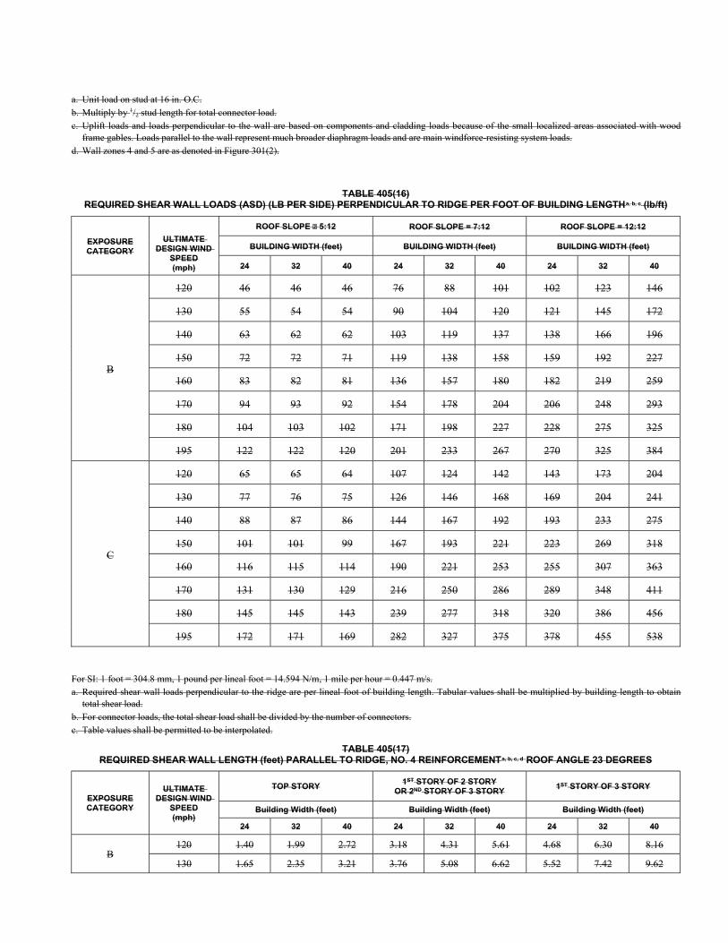
a. Unit load on stud at 16 in. O.C. b. Multiply by 1/2 stud length for total connector load. c. Uplift loads and loads perpendicular to the wall are based on components and cladding loads because of the small localized areas associated with wood
frame gables. Loads parallel to the wall represent much broader diaphragm loads and are main windforce-resisting system loads. d. Wall zones 4 and 5 are as denoted in Figure 301(2).
TABLE 405(16) REQUIRED SHEAR WALL LOADS (ASD) (LB PER SIDE) PERPENDICULAR TO RIDGE PER FOOT OF BUILDING LENGTHa, b, c (lb/ft)
EXPOSURE CATEGORY
ULTIMATE DESIGN WIND
SPEED (mph)
ROOF SLOPE 5:12 ROOF SLOPE = 7:12 ROOF SLOPE = 12:12
BUILDING WIDTH (feet) BUILDING WIDTH (feet) BUILDING WIDTH (feet)
24 32 40 24 32 40 24 32 40
B
120 46 46 46 76 88 101 102 123 146
130 55 54 54 90 104 120 121 145 172
140 63 62 62 103 119 137 138 166 196
150 72 72 71 119 138 158 159 192 227
160 83 82 81 136 157 180 182 219 259
170 94 93 92 154 178 204 206 248 293
180 104 103 102 171 198 227 228 275 325
195 122 122 120 201 233 267 270 325 384
C
120 65 65 64 107 124 142 143 173 204
130 77 76 75 126 146 168 169 204 241
140 88 87 86 144 167 192 193 233 275
150 101 101 99 167 193 221 223 269 318
160 116 115 114 190 221 253 255 307 363
170 131 130 129 216 250 286 289 348 411
180 145 145 143 239 277 318 320 386 456
195 172 171 169 282 327 375 378 455 538
For SI: 1 foot = 304.8 mm, 1 pound per lineal foot = 14.594 N/m, 1 mile per hour = 0.447 m/s. a. Required shear wall loads perpendicular to the ridge are per lineal foot of building length. Tabular values shall be multiplied by building length to obtain
total shear load. b. For connector loads, the total shear load shall be divided by the number of connectors. c. Table values shall be permitted to be interpolated.
TABLE 405(17) REQUIRED SHEAR WALL LENGTH (feet) PARALLEL TO RIDGE, NO. 4 REINFORCEMENTa, b, c, d ROOF ANGLE 23 DEGREES
EXPOSURE CATEGORY
ULTIMATE DESIGN WIND
SPEED (mph)
TOP STORY 1ST STORY OF 2 STORY
OR 2ND STORY OF 3 STORY 1ST STORY OF 3 STORY
Building Width (feet) Building Width (feet) Building Width (feet)
24 32 40 24 32 40 24 32 40
B 120 1.40 1.99 2.72 3.18 4.31 5.61 4.68 6.30 8.16
130 1.65 2.35 3.21 3.76 5.08 6.62 5.52 7.42 9.62
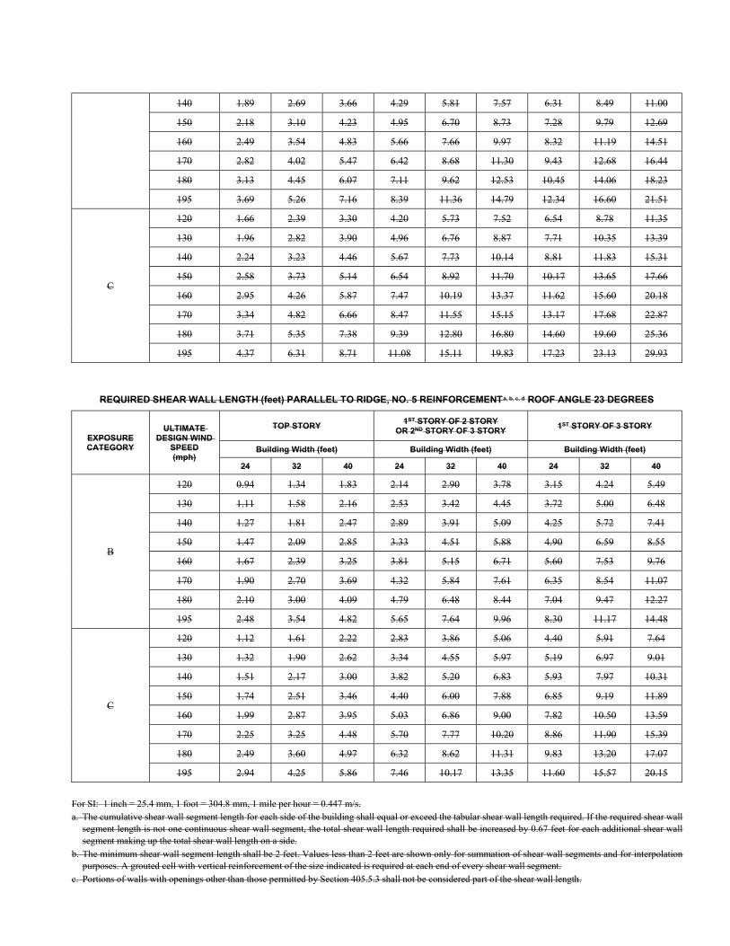
140 1.89 2.69 3.66 4.29 5.81 7.57 6.31 8.49 11.00
150 2.18 3.10 4.23 4.95 6.70 8.73 7.28 9.79 12.69
160 2.49 3.54 4.83 5.66 7.66 9.97 8.32 11.19 14.51
170 2.82 4.02 5.47 6.42 8.68 11.30 9.43 12.68 16.44
180 3.13 4.45 6.07 7.11 9.62 12.53 10.45 14.06 18.23
195 3.69 5.26 7.16 8.39 11.36 14.79 12.34 16.60 21.51
C
120 1.66 2.39 3.30 4.20 5.73 7.52 6.54 8.78 11.35
130 1.96 2.82 3.90 4.96 6.76 8.87 7.71 10.35 13.39
140 2.24 3.23 4.46 5.67 7.73 10.14 8.81 11.83 15.31
150 2.58 3.73 5.14 6.54 8.92 11.70 10.17 13.65 17.66
160 2.95 4.26 5.87 7.47 10.19 13.37 11.62 15.60 20.18
170 3.34 4.82 6.66 8.47 11.55 15.15 13.17 17.68 22.87
180 3.71 5.35 7.38 9.39 12.80 16.80 14.60 19.60 25.36
195 4.37 6.31 8.71 11.08 15.11 19.83 17.23 23.13 29.93
REQUIRED SHEAR WALL LENGTH (feet) PARALLEL TO RIDGE, NO. 5 REINFORCEMENTa, b, c, d ROOF ANGLE 23 DEGREES
EXPOSURE CATEGORY
ULTIMATE DESIGN WIND
SPEED (mph)
TOP STORY 1ST STORY OF 2 STORY
OR 2ND STORY OF 3 STORY 1ST STORY OF 3 STORY
Building Width (feet) Building Width (feet) Building Width (feet)
24 32 40 24 32 40 24 32 40
B
120 0.94 1.34 1.83 2.14 2.90 3.78 3.15 4.24 5.49
130 1.11 1.58 2.16 2.53 3.42 4.45 3.72 5.00 6.48
140 1.27 1.81 2.47 2.89 3.91 5.09 4.25 5.72 7.41
150 1.47 2.09 2.85 3.33 4.51 5.88 4.90 6.59 8.55
160 1.67 2.39 3.25 3.81 5.15 6.71 5.60 7.53 9.76
170 1.90 2.70 3.69 4.32 5.84 7.61 6.35 8.54 11.07
180 2.10 3.00 4.09 4.79 6.48 8.44 7.04 9.47 12.27
195 2.48 3.54 4.82 5.65 7.64 9.96 8.30 11.17 14.48
C
120 1.12 1.61 2.22 2.83 3.86 5.06 4.40 5.91 7.64
130 1.32 1.90 2.62 3.34 4.55 5.97 5.19 6.97 9.01
140 1.51 2.17 3.00 3.82 5.20 6.83 5.93 7.97 10.31
150 1.74 2.51 3.46 4.40 6.00 7.88 6.85 9.19 11.89
160 1.99 2.87 3.95 5.03 6.86 9.00 7.82 10.50 13.59
170 2.25 3.25 4.48 5.70 7.77 10.20 8.86 11.90 15.39
180 2.49 3.60 4.97 6.32 8.62 11.31 9.83 13.20 17.07
195 2.94 4.25 5.86 7.46 10.17 13.35 11.60 15.57 20.15
For SI: 1 inch = 25.4 mm, 1 foot = 304.8 mm, 1 mile per hour = 0.447 m/s. a. The cumulative shear wall segment length for each side of the building shall equal or exceed the tabular shear wall length required. If the required shear wall
segment length is not one continuous shear wall segment, the total shear wall length required shall be increased by 0.67 feet for each additional shear wall segment making up the total shear wall length on a side.
b. The minimum shear wall segment length shall be 2 feet. Values less than 2 feet are shown only for summation of shear wall segments and for interpolation purposes. A grouted cell with vertical reinforcement of the size indicated is required at each end of every shear wall segment.
c. Portions of walls with openings other than those permitted by Section 405.5.3 shall not be considered part of the shear wall length.
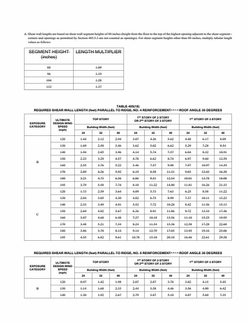
d. Shear wall lengths are based on shear wall segment heights of 80 inches (height from the floor to the top of the highest opening adjacent to the shear segment - corners and openings as permitted by Section 405.5.3 are not counted as openings). For shear segment heights other than 80 inches, multiply tabular length values as follows:
SEGMENT HEIGHT (inches)
LENGTH MULTIPLIER
88 1.09
96 1.19
104 1.28
112 1.37
TABLE 405(18) REQUIRED SHEAR WALL LENGTH (feet) PARALLEL TO RIDGE, NO. 4 REINFORCEMENTa, b, c, d ROOF ANGLE 30 DEGREES
EXPOSURE CATEGORY
ULTIMATE DESIGN WIND
SPEED (mph)
TOP STORY 1ST STORY OF 2 STORY
OR 2ND STORY OF 3 STORY 1ST STORY OF 3 STORY
Building Width (feet) Building Width (feet) Building Width (feet)
24 32 40 24 32 40 24 32 40
B
120 1.44 2.12 2.94 3.07 4.26 5.62 4.48 6.17 8.09
130 1.69 2.50 3.46 3.62 5.02 6.62 5.29 7.28 9.54
140 1.94 2.85 3.96 4.14 5.74 7.57 6.04 8.32 10.91
150 2.23 3.29 4.57 4.78 6.62 8.74 6.97 9.60 12.59
160 2.55 3.76 5.22 5.46 7.57 9.98 7.97 10.97 14.39
170 2.89 4.26 5.92 6.19 8.58 11.31 9.03 12.43 16.30
180 3.21 4.73 6.56 6.86 9.51 12.54 10.01 13.78 18.08
195 3.79 5.58 7.74 8.10 11.22 14.80 11.81 16.26 21.33
C
120 1.73 2.59 3.64 4.09 5.73 7.63 6.25 8.58 11.22
130 2.04 3.05 4.30 4.82 6.75 8.99 7.37 10.11 13.23
140 2.33 3.49 4.91 5.52 7.72 10.28 8.42 11.56 15.13
150 2.69 4.02 5.67 6.36 8.91 11.86 9.72 13.34 17.46
160 3.07 4.60 6.48 7.27 10.18 13.56 11.10 15.25 19.95
170 3.48 5.21 7.34 8.24 11.54 15.36 12.58 17.28 22.60
180 3.86 5.78 8.14 9.14 12.79 17.03 13.95 19.16 25.06
195 4.55 6.82 9.61 10.78 15.10 20.10 16.46 22.61 29.58
REQUIRED SHEAR WALL LENGTH (feet) PARALLEL TO RIDGE, NO. 5 REINFORCEMENTa, b, c, d ROOF ANGLE 30 DEGREES
EXPOSURE CATEGORY
ULTIMATE DESIGN WIND
SPEED (mph)
TOP STORY 1ST STORY OF 2 STORY
OR 2ND STORY OF 3 STORY 1ST STORY OF 3 STORY
Building Width (feet) Building Width (feet) Building Width (feet)
24 32 40 24 32 40 24 32 40
B
120 0.97 1.42 1.98 2.07 2.87 3.78 3.02 4.15 5.45
130 1.14 1.68 2.33 2.44 3.38 4.46 3.56 4.90 6.42
140 1.30 1.92 2.67 2.79 3.87 5.10 4.07 5.60 7.35
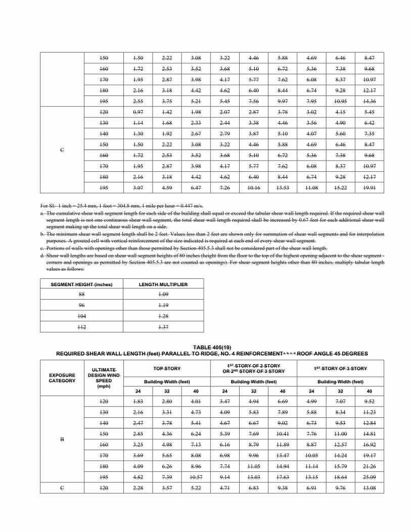
150 1.50 2.22 3.08 3.22 4.46 5.88 4.69 6.46 8.47
160 1.72 2.53 3.52 3.68 5.10 6.72 5.36 7.38 9.68
170 1.95 2.87 3.98 4.17 5.77 7.62 6.08 8.37 10.97
180 2.16 3.18 4.42 4.62 6.40 8.44 6.74 9.28 12.17
195 2.55 3.75 5.21 5.45 7.56 9.97 7.95 10.95 14.36
C
120 0.97 1.42 1.98 2.07 2.87 3.78 3.02 4.15 5.45
130 1.14 1.68 2.33 2.44 3.38 4.46 3.56 4.90 6.42
140 1.30 1.92 2.67 2.79 3.87 5.10 4.07 5.60 7.35
150 1.50 2.22 3.08 3.22 4.46 5.88 4.69 6.46 8.47
160 1.72 2.53 3.52 3.68 5.10 6.72 5.36 7.38 9.68
170 1.95 2.87 3.98 4.17 5.77 7.62 6.08 8.37 10.97
180 2.16 3.18 4.42 4.62 6.40 8.44 6.74 9.28 12.17
195 3.07 4.59 6.47 7.26 10.16 13.53 11.08 15.22 19.91
For SI: 1 inch = 25.4 mm, 1 foot = 304.8 mm, 1 mile per hour = 0.447 m/s. a. The cumulative shear wall segment length for each side of the building shall equal or exceed the tabular shear wall length required. If the required shear wall
segment length is not one continuous shear wall segment, the total shear wall length required shall be increased by 0.67 feet for each additional shear wall segment making up the total shear wall length on a side.
b. The minimum shear wall segment length shall be 2 feet. Values less than 2 feet are shown only for summation of shear wall segments and for interpolation purposes. A grouted cell with vertical reinforcement of the size indicated is required at each end of every shear wall segment.
c. Portions of walls with openings other than those permitted by Section 405.5.3 shall not be considered part of the shear wall length. d. Shear wall lengths are based on shear wall segment heights of 80 inches (height from the floor to the top of the highest opening adjacent to the shear segment -
corners and openings as permitted by Section 405.5.3 are not counted as openings). For shear segment heights other than 80 inches, multiply tabular length values as follows:
SEGMENT HEIGHT (inches) LENGTH MULTIPLIER
88 1.09
96 1.19
104 1.28
112 1.37
TABLE 405(19) REQUIRED SHEAR WALL LENGTH (feet) PARALLEL TO RIDGE, NO. 4 REINFORCEMENTa, b, c, d ROOF ANGLE 45 DEGREES
EXPOSURE CATEGORY
ULTIMATE DESIGN WIND
SPEED (mph)
TOP STORY 1ST STORY OF 2 STORY
OR 2ND STORY OF 3 STORY 1ST STORY OF 3 STORY
Building Width (feet) Building Width (feet) Building Width (feet)
24 32 40 24 32 40 24 32 40
B
120 1.83 2.80 4.01 3.47 4.94 6.69 4.99 7.07 9.52
130 2.16 3.31 4.73 4.09 5.83 7.89 5.88 8.34 11.23
140 2.47 3.78 5.41 4.67 6.67 9.02 6.73 9.53 12.84
150 2.85 4.36 6.24 5.39 7.69 10.41 7.76 11.00 14.81
160 3.25 4.98 7.13 6.16 8.79 11.89 8.87 12.57 16.92
170 3.69 5.65 8.08 6.98 9.96 13.47 10.05 14.24 19.17
180 4.09 6.26 8.96 7.74 11.05 14.94 11.14 15.79 21.26
195 4.82 7.39 10.57 9.14 13.03 17.63 13.15 18.64 25.09
C 120 2.28 3.57 5.22 4.71 6.83 9.38 6.91 9.76 13.08
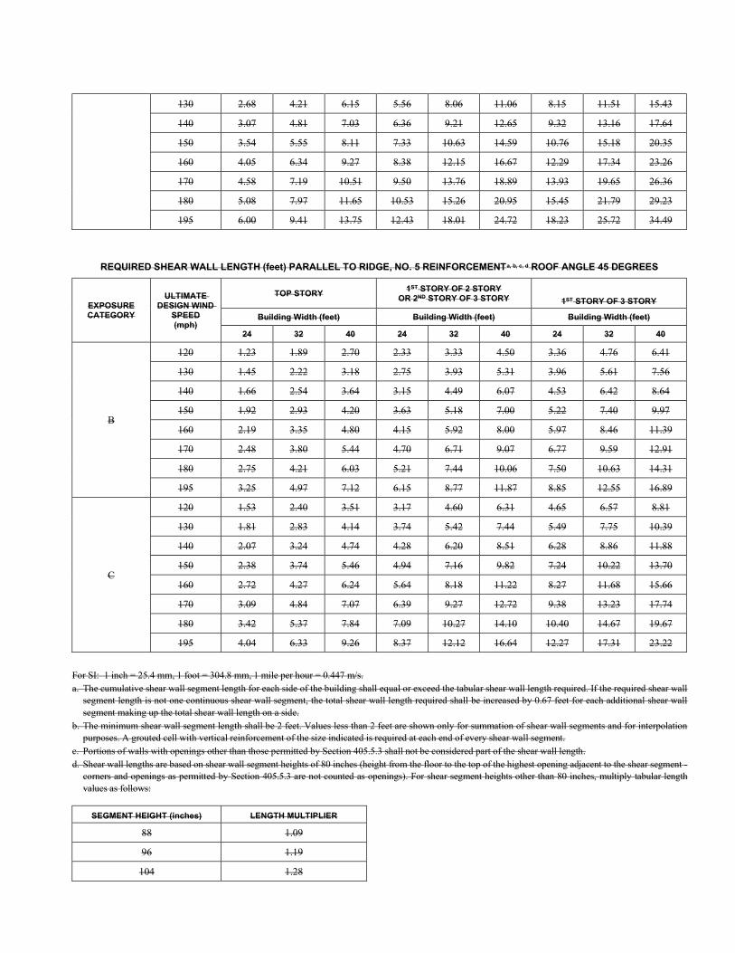
130 2.68 4.21 6.15 5.56 8.06 11.06 8.15 11.51 15.43
140 3.07 4.81 7.03 6.36 9.21 12.65 9.32 13.16 17.64
150 3.54 5.55 8.11 7.33 10.63 14.59 10.76 15.18 20.35
160 4.05 6.34 9.27 8.38 12.15 16.67 12.29 17.34 23.26
170 4.58 7.19 10.51 9.50 13.76 18.89 13.93 19.65 26.36
180 5.08 7.97 11.65 10.53 15.26 20.95 15.45 21.79 29.23
195 6.00 9.41 13.75 12.43 18.01 24.72 18.23 25.72 34.49
REQUIRED SHEAR WALL LENGTH (feet) PARALLEL TO RIDGE, NO. 5 REINFORCEMENTa, b, c, d ROOF ANGLE 45 DEGREES
EXPOSURE CATEGORY
ULTIMATE DESIGN WIND
SPEED (mph)
TOP STORY 1ST STORY OF 2 STORY
OR 2ND STORY OF 3 STORY 1ST STORY OF 3 STORY
Building Width (feet) Building Width (feet) Building Width (feet)
24 32 40 24 32 40 24 32 40
B
120 1.23 1.89 2.70 2.33 3.33 4.50 3.36 4.76 6.41
130 1.45 2.22 3.18 2.75 3.93 5.31 3.96 5.61 7.56
140 1.66 2.54 3.64 3.15 4.49 6.07 4.53 6.42 8.64
150 1.92 2.93 4.20 3.63 5.18 7.00 5.22 7.40 9.97
160 2.19 3.35 4.80 4.15 5.92 8.00 5.97 8.46 11.39
170 2.48 3.80 5.44 4.70 6.71 9.07 6.77 9.59 12.91
180 2.75 4.21 6.03 5.21 7.44 10.06 7.50 10.63 14.31
195 3.25 4.97 7.12 6.15 8.77 11.87 8.85 12.55 16.89
C
120 1.53 2.40 3.51 3.17 4.60 6.31 4.65 6.57 8.81
130 1.81 2.83 4.14 3.74 5.42 7.44 5.49 7.75 10.39
140 2.07 3.24 4.74 4.28 6.20 8.51 6.28 8.86 11.88
150 2.38 3.74 5.46 4.94 7.16 9.82 7.24 10.22 13.70
160 2.72 4.27 6.24 5.64 8.18 11.22 8.27 11.68 15.66
170 3.09 4.84 7.07 6.39 9.27 12.72 9.38 13.23 17.74
180 3.42 5.37 7.84 7.09 10.27 14.10 10.40 14.67 19.67
195 4.04 6.33 9.26 8.37 12.12 16.64 12.27 17.31 23.22
For SI: 1 inch = 25.4 mm, 1 foot = 304.8 mm, 1 mile per hour = 0.447 m/s. a. The cumulative shear wall segment length for each side of the building shall equal or exceed the tabular shear wall length required. If the required shear wall
segment length is not one continuous shear wall segment, the total shear wall length required shall be increased by 0.67 feet for each additional shear wall segment making up the total shear wall length on a side.
b. The minimum shear wall segment length shall be 2 feet. Values less than 2 feet are shown only for summation of shear wall segments and for interpolation purposes. A grouted cell with vertical reinforcement of the size indicated is required at each end of every shear wall segment.
c. Portions of walls with openings other than those permitted by Section 405.5.3 shall not be considered part of the shear wall length. d. Shear wall lengths are based on shear wall segment heights of 80 inches (height from the floor to the top of the highest opening adjacent to the shear segment -
corners and openings as permitted by Section 405.5.3 are not counted as openings). For shear segment heights other than 80 inches, multiply tabular length values as follows:
SEGMENT HEIGHT (inches) LENGTH MULTIPLIER
88 1.09
96 1.19
104 1.28
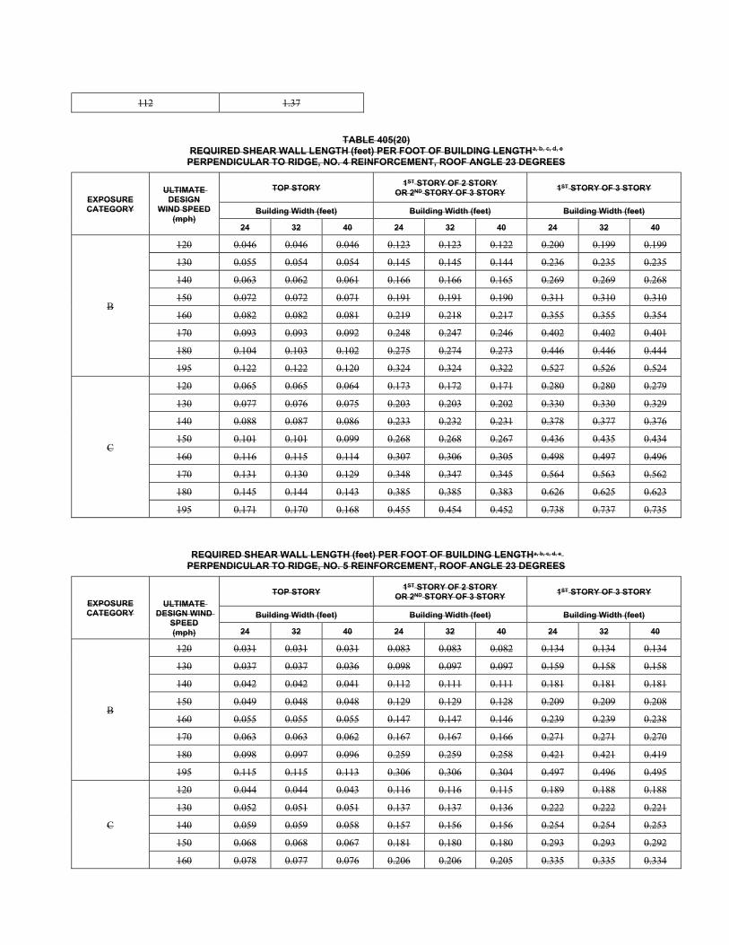
112 1.37
TABLE 405(20) REQUIRED SHEAR WALL LENGTH (feet) PER FOOT OF BUILDING LENGTHa, b, c, d, e
PERPENDICULAR TO RIDGE, NO. 4 REINFORCEMENT, ROOF ANGLE 23 DEGREES
EXPOSURE CATEGORY
ULTIMATE DESIGN
WIND SPEED (mph)
TOP STORY 1ST STORY OF 2 STORY
OR 2ND STORY OF 3 STORY 1ST STORY OF 3 STORY
Building Width (feet) Building Width (feet) Building Width (feet)
24 32 40 24 32 40 24 32 40
B
120 0.046 0.046 0.046 0.123 0.123 0.122 0.200 0.199 0.199
130 0.055 0.054 0.054 0.145 0.145 0.144 0.236 0.235 0.235
140 0.063 0.062 0.061 0.166 0.166 0.165 0.269 0.269 0.268
150 0.072 0.072 0.071 0.191 0.191 0.190 0.311 0.310 0.310
160 0.082 0.082 0.081 0.219 0.218 0.217 0.355 0.355 0.354
170 0.093 0.093 0.092 0.248 0.247 0.246 0.402 0.402 0.401
180 0.104 0.103 0.102 0.275 0.274 0.273 0.446 0.446 0.444
195 0.122 0.122 0.120 0.324 0.324 0.322 0.527 0.526 0.524
C
120 0.065 0.065 0.064 0.173 0.172 0.171 0.280 0.280 0.279
130 0.077 0.076 0.075 0.203 0.203 0.202 0.330 0.330 0.329
140 0.088 0.087 0.086 0.233 0.232 0.231 0.378 0.377 0.376
150 0.101 0.101 0.099 0.268 0.268 0.267 0.436 0.435 0.434
160 0.116 0.115 0.114 0.307 0.306 0.305 0.498 0.497 0.496
170 0.131 0.130 0.129 0.348 0.347 0.345 0.564 0.563 0.562
180 0.145 0.144 0.143 0.385 0.385 0.383 0.626 0.625 0.623
195 0.171 0.170 0.168 0.455 0.454 0.452 0.738 0.737 0.735
REQUIRED SHEAR WALL LENGTH (feet) PER FOOT OF BUILDING LENGTHa, b, c, d, e PERPENDICULAR TO RIDGE, NO. 5 REINFORCEMENT, ROOF ANGLE 23 DEGREES
EXPOSURE CATEGORY
ULTIMATE DESIGN WIND
SPEED (mph)
TOP STORY 1ST STORY OF 2 STORY
OR 2ND STORY OF 3 STORY 1ST STORY OF 3 STORY
Building Width (feet) Building Width (feet) Building Width (feet)
24 32 40 24 32 40 24 32 40
B
120 0.031 0.031 0.031 0.083 0.083 0.082 0.134 0.134 0.134
130 0.037 0.037 0.036 0.098 0.097 0.097 0.159 0.158 0.158
140 0.042 0.042 0.041 0.112 0.111 0.111 0.181 0.181 0.181
150 0.049 0.048 0.048 0.129 0.129 0.128 0.209 0.209 0.208
160 0.055 0.055 0.055 0.147 0.147 0.146 0.239 0.239 0.238
170 0.063 0.063 0.062 0.167 0.167 0.166 0.271 0.271 0.270
180 0.098 0.097 0.096 0.259 0.259 0.258 0.421 0.421 0.419
195 0.115 0.115 0.113 0.306 0.306 0.304 0.497 0.496 0.495
C
120 0.044 0.044 0.043 0.116 0.116 0.115 0.189 0.188 0.188
130 0.052 0.051 0.051 0.137 0.137 0.136 0.222 0.222 0.221
140 0.059 0.059 0.058 0.157 0.156 0.156 0.254 0.254 0.253
150 0.068 0.068 0.067 0.181 0.180 0.180 0.293 0.293 0.292
160 0.078 0.077 0.076 0.206 0.206 0.205 0.335 0.335 0.334
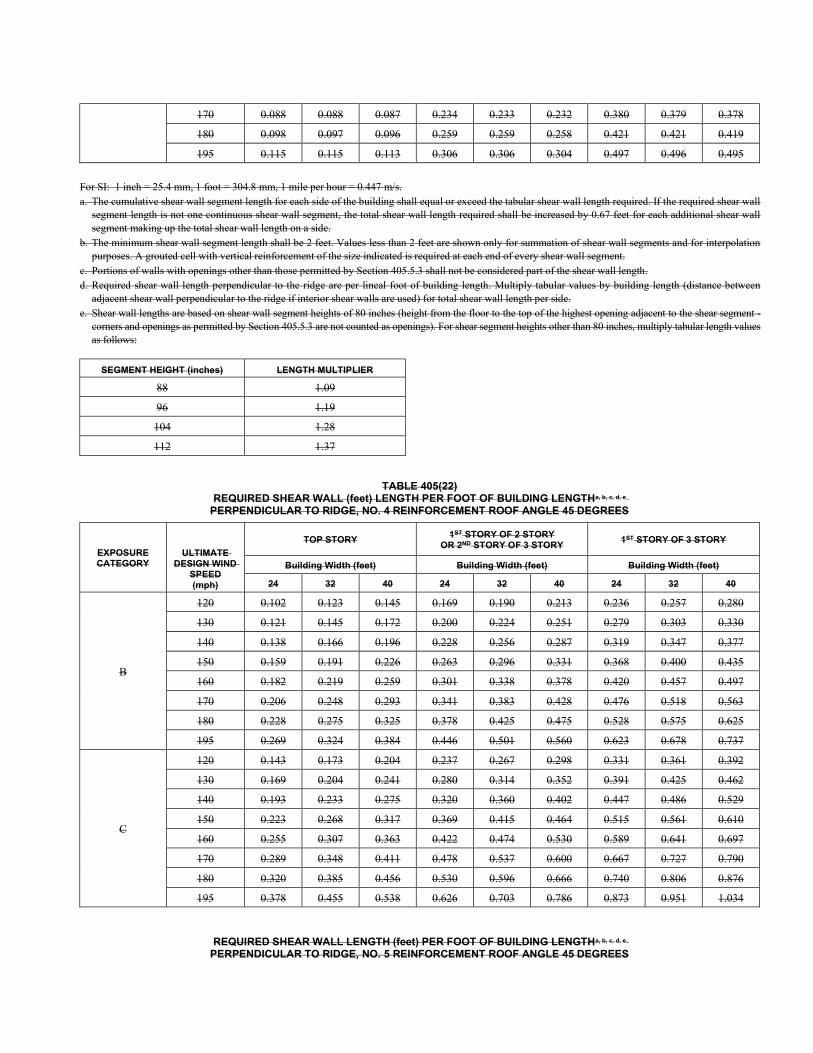
170 0.088 0.088 0.087 0.234 0.233 0.232 0.380 0.379 0.378
180 0.098 0.097 0.096 0.259 0.259 0.258 0.421 0.421 0.419
195 0.115 0.115 0.113 0.306 0.306 0.304 0.497 0.496 0.495
For SI: 1 inch = 25.4 mm, 1 foot = 304.8 mm, 1 mile per hour = 0.447 m/s. a. The cumulative shear wall segment length for each side of the building shall equal or exceed the tabular shear wall length required. If the required shear wall
segment length is not one continuous shear wall segment, the total shear wall length required shall be increased by 0.67 feet for each additional shear wall segment making up the total shear wall length on a side.
b. The minimum shear wall segment length shall be 2 feet. Values less than 2 feet are shown only for summation of shear wall segments and for interpolation purposes. A grouted cell with vertical reinforcement of the size indicated is required at each end of every shear wall segment.
c. Portions of walls with openings other than those permitted by Section 405.5.3 shall not be considered part of the shear wall length. d. Required shear wall length perpendicular to the ridge are per lineal foot of building length. Multiply tabular values by building length (distance between
adjacent shear wall perpendicular to the ridge if interior shear walls are used) for total shear wall length per side. e. Shear wall lengths are based on shear wall segment heights of 80 inches (height from the floor to the top of the highest opening adjacent to the shear segment -
corners and openings as permitted by Section 405.5.3 are not counted as openings). For shear segment heights other than 80 inches, multiply tabular length values as follows:
SEGMENT HEIGHT (inches) LENGTH MULTIPLIER
88 1.09
96 1.19
104 1.28
112 1.37
TABLE 405(22) REQUIRED SHEAR WALL (feet) LENGTH PER FOOT OF BUILDING LENGTHa, b, c, d, e
PERPENDICULAR TO RIDGE, NO. 4 REINFORCEMENT ROOF ANGLE 45 DEGREES
EXPOSURE CATEGORY
ULTIMATE DESIGN WIND
SPEED (mph)
TOP STORY 1ST STORY OF 2 STORY
OR 2ND STORY OF 3 STORY 1ST STORY OF 3 STORY
Building Width (feet) Building Width (feet) Building Width (feet)
24 32 40 24 32 40 24 32 40
B
120 0.102 0.123 0.145 0.169 0.190 0.213 0.236 0.257 0.280
130 0.121 0.145 0.172 0.200 0.224 0.251 0.279 0.303 0.330
140 0.138 0.166 0.196 0.228 0.256 0.287 0.319 0.347 0.377
150 0.159 0.191 0.226 0.263 0.296 0.331 0.368 0.400 0.435
160 0.182 0.219 0.259 0.301 0.338 0.378 0.420 0.457 0.497
170 0.206 0.248 0.293 0.341 0.383 0.428 0.476 0.518 0.563
180 0.228 0.275 0.325 0.378 0.425 0.475 0.528 0.575 0.625
195 0.269 0.324 0.384 0.446 0.501 0.560 0.623 0.678 0.737
C
120 0.143 0.173 0.204 0.237 0.267 0.298 0.331 0.361 0.392
130 0.169 0.204 0.241 0.280 0.314 0.352 0.391 0.425 0.462
140 0.193 0.233 0.275 0.320 0.360 0.402 0.447 0.486 0.529
150 0.223 0.268 0.317 0.369 0.415 0.464 0.515 0.561 0.610
160 0.255 0.307 0.363 0.422 0.474 0.530 0.589 0.641 0.697
170 0.289 0.348 0.411 0.478 0.537 0.600 0.667 0.727 0.790
180 0.320 0.385 0.456 0.530 0.596 0.666 0.740 0.806 0.876
195 0.378 0.455 0.538 0.626 0.703 0.786 0.873 0.951 1.034
REQUIRED SHEAR WALL LENGTH (feet) PER FOOT OF BUILDING LENGTHa, b, c, d, e PERPENDICULAR TO RIDGE, NO. 5 REINFORCEMENT ROOF ANGLE 45 DEGREES
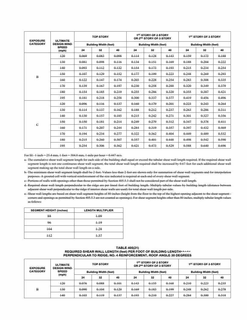
EXPOSURE CATEGORY
ULTIMATE DESIGN WIND
SPEED (mph)
TOP STORY 1ST STORY OF 2 STORY
OR 2ND STORY OF 3 STORY 1ST STORY OF 3 STORY
Building Width (feet) Building Width (feet) Building Width (feet)
24 32 40 24 32 40 24 32 40
B
120 0.069 0.083 0.098 0.114 0.128 0.143 0.159 0.173 0.188
130 0.081 0.098 0.116 0.134 0.151 0.169 0.188 0.204 0.222
140 0.093 0.112 0.132 0.154 0.173 0.193 0.215 0.234 0.254
150 0.107 0.129 0.152 0.177 0.199 0.223 0.248 0.269 0.293
160 0.122 0.147 0.174 0.203 0.228 0.254 0.283 0.308 0.335
170 0.139 0.167 0.197 0.230 0.258 0.288 0.320 0.349 0.379
180 0.154 0.185 0.219 0.255 0.286 0.320 0.355 0.387 0.421
195 0.181 0.218 0.258 0.300 0.337 0.377 0.419 0.456 0.496
C
120 0.096 0.116 0.137 0.160 0.179 0.201 0.223 0.243 0.264
130 0.114 0.137 0.162 0.188 0.212 0.237 0.263 0.286 0.311
140 0.130 0.157 0.185 0.215 0.242 0.271 0.301 0.327 0.356
150 0.150 0.181 0.214 0.249 0.279 0.312 0.347 0.378 0.411
160 0.171 0.207 0.244 0.284 0.319 0.357 0.397 0.432 0.469
170 0.194 0.234 0.277 0.322 0.362 0.404 0.449 0.489 0.532
180 0.215 0.260 0.307 0.357 0.401 0.448 0.498 0.542 0.590
195 0.254 0.306 0.362 0.421 0.473 0.529 0.588 0.640 0.696
For SI: 1 inch = 25.4 mm, 1 foot = 304.8 mm, 1 mile per hour = 0.447 m/s. a. The cumulative shear wall segment length for each side of the building shall equal or exceed the tabular shear wall length required. If the required shear wall
segment length is not one continuous shear wall segment, the total shear wall length required shall be increased by 0.67 feet for each additional shear wall segment making up the total shear wall length on a side.
b. The minimum shear wall segment length shall be 2 feet. Values less than 2 feet are shown only for summation of shear wall segments and for interpolation purposes. A grouted cell with vertical reinforcement of the size indicated is required at each end of every shear wall segment.
c. Portions of walls with openings other than those permitted by Section 405.5.3 shall not be considered part of the shear wall length. d. Required shear wall length perpendicular to the ridge are per lineal foot of building length. Multiply tabular values by building length (distance between
adjacent shear wall perpendicular to the ridge if interior shear walls are used) for total shear wall length per side. e. Shear wall lengths are based on shear wall segment heights of 80 inches (height from the floor to the top of the highest opening adjacent to the shear segment -
corners and openings as permitted by Section 405.5.3 are not counted as openings). For shear segment heights other than 80 inches, multiply tabular length values as follows:
SEGMENT HEIGHT (inches) LENGTH MULTIPLIER
88 1.09
96 1.19
104 1.28
112 1.37
TABLE 405(21) REQUIRED SHEAR WALL LENGTH (feet) PER FOOT OF BUILDING LENGTHa, b, c, d, e
PERPENDICULAR TO RIDGE, NO. 4 REINFORCEMENT, ROOF ANGLE 30 DEGREES
EXPOSURE CATEGORY
ULTIMATE DESIGN WIND
SPEED (mph)
TOP STORY 1ST STORY OF 2 STORY
OR 2ND STORY OF 3 STORY 1ST STORY OF 3 STORY
Building Width (feet) Building Width (feet) Building Width (feet)
24 32 40 24 32 40 24 32 40
B
120 0.076 0.088 0.101 0.143 0.155 0.168 0.210 0.223 0.235
130 0.090 0.104 0.120 0.169 0.183 0.199 0.248 0.262 0.278
140 0.103 0.119 0.137 0.193 0.210 0.227 0.284 0.300 0.318
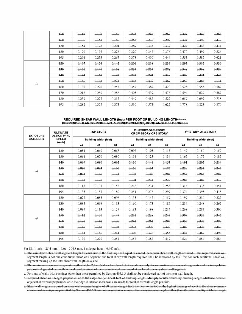
150 0.119 0.138 0.158 0.223 0.242 0.262 0.327 0.346 0.366
160 0.136 0.157 0.180 0.255 0.276 0.299 0.374 0.396 0.419
170 0.154 0.178 0.204 0.289 0.313 0.339 0.424 0.448 0.474
180 0.170 0.197 0.226 0.320 0.347 0.376 0.470 0.497 0.526
195 0.201 0.233 0.267 0.378 0.410 0.444 0.555 0.587 0.621
C
120 0.107 0.124 0.142 0.201 0.218 0.236 0.295 0.312 0.330
130 0.126 0.146 0.168 0.237 0.257 0.278 0.348 0.368 0.389
140 0.144 0.167 0.192 0.271 0.294 0.318 0.398 0.421 0.445
150 0.166 0.193 0.221 0.313 0.339 0.367 0.459 0.485 0.514
160 0.190 0.220 0.253 0.357 0.387 0.420 0.525 0.555 0.587
170 0.216 0.250 0.286 0.405 0.439 0.476 0.594 0.629 0.587
180 0.239 0.277 0.317 0.449 0.487 0.527 0.659 0.697 0.738
195 0.282 0.327 0.375 0.530 0.575 0.622 0.778 0.823 0.870
REQUIRED SHEAR WALL LENGTH (feet) PER FOOT OF BUILDING LENGTHa, b, c, d, e
PERPENDICULAR TO RIDGE, NO. 5 REINFORCEMENT, ROOF ANGLE 30 DEGREES
EXPOSURE CATEGORY
ULTIMATE DESIGN WIND
SPEED (mph)
TOP STORY 1ST STORY OF 2 STORY
OR 2ND STORY OF 3 STORY 1ST STORY OF 3 STORY
Building Width (feet) Building Width (feet) Building Width (feet)
24 32 40 24 32 40 24 32 40
B
120 0.051 0.060 0.068 0.097 0.105 0.113 0.142 0.150 0.159
130 0.061 0.070 0.080 0.114 0.123 0.134 0.167 0.177 0.187
140 0.069 0.080 0.092 0.130 0.141 0.153 0.191 0.202 0.214
150 0.080 0.093 0.106 0.150 0.163 0.176 0.220 0.233 0.247
160 0.091 0.106 0.121 0.172 0.186 0.202 0.252 0.266 0.282
170 0.103 0.120 0.137 0.194 0.211 0.228 0.285 0.302 0.319
180 0.115 0.133 0.152 0.216 0.234 0.253 0.316 0.335 0.354
195 0.135 0.157 0.180 0.254 0.276 0.299 0.374 0.395 0.418
C
120 0.072 0.083 0.096 0.135 0.147 0.159 0.199 0.210 0.222
130 0.085 0.098 0.113 0.160 0.173 0.187 0.234 0.248 0.262
140 0.097 0.113 0.129 0.183 0.198 0.214 0.268 0.283 0.300
150 0.112 0.130 0.149 0.211 0.228 0.247 0.309 0.327 0.346
160 0.128 0.148 0.170 0.241 0.261 0.283 0.353 0.373 0.395
170 0.145 0.168 0.193 0.273 0.296 0.320 0.400 0.423 0.448
180 0.161 0.186 0.214 0.302 0.328 0.355 0.444 0.469 0.496
195 0.190 0.220 0.252 0.357 0.387 0.419 0.524 0.554 0.586
For SI: 1 inch = 25.4 mm, 1 foot = 304.8 mm, 1 mile per hour = 0.447 m/s. a. The cumulative shear wall segment length for each side of the building shall equal or exceed the tabular shear wall length required. If the required shear wall
segment length is not one continuous shear wall segment, the total shear wall length required shall be increased by 0.67 feet for each additional shear wall segment making up the total shear wall length on a side.
b. The minimum shear wall segment length shall be 2 feet. Values less than 2 feet are shown only for summation of shear wall segments and for interpolation purposes. A grouted cell with vertical reinforcement of the size indicated is required at each end of every shear wall segment.
c. Portions of walls with openings other than those permitted by Section 405.5.3 shall not be considered part of the shear wall length. d. Required shear wall length perpendicular to the ridge are per lineal foot of building length. Multiply tabular values by building length (distance between
adjacent shear wall perpendicular to the ridge if interior shear walls are used) for total shear wall length per side. e. Shear wall lengths are based on shear wall segment heights of 80 inches (height from the floor to the top of the highest opening adjacent to the shear segment -
corners and openings as permitted by Section 405.5.3 are not counted as openings). For shear segment heights other than 80 inches, multiply tabular length
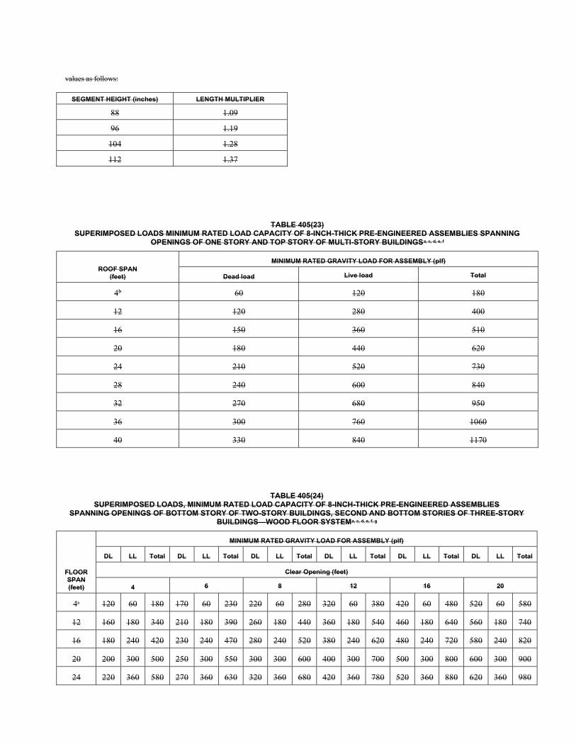
values as follows:
SEGMENT HEIGHT (inches) LENGTH MULTIPLIER
88 1.09
96 1.19
104 1.28
112 1.37
TABLE 405(23) SUPERIMPOSED LOADS MINIMUM RATED LOAD CAPACITY OF 8-INCH-THICK PRE-ENGINEERED ASSEMBLIES SPANNING
OPENINGS OF ONE STORY AND TOP STORY OF MULTI-STORY BUILDINGSa, c, d, e, f
ROOF SPAN (feet)
MINIMUM RATED GRAVITY LOAD FOR ASSEMBLY (plf)
Dead load Live load Total
4b 60 120 180
12 120 280 400
16 150 360 510
20 180 440 620
24 210 520 730
28 240 600 840
32 270 680 950
36 300 760 1060
40 330 840 1170
TABLE 405(24) SUPERIMPOSED LOADS, MINIMUM RATED LOAD CAPACITY OF 8-INCH-THICK PRE-ENGINEERED ASSEMBLIES
SPANNING OPENINGS OF BOTTOM STORY OF TWO-STORY BUILDINGS, SECOND AND BOTTOM STORIES OF THREE-STORY BUILDINGS—WOOD FLOOR SYSTEMa, c, d, e, f, g
FLOOR SPAN (feet)
MINIMUM RATED GRAVITY LOAD FOR ASSEMBLY (plf)
DL LL Total DL LL Total DL LL Total DL LL Total DL LL Total DL LL Total
Clear Opening (feet)
4 6 8 12 16 20
4b 120 60 180 170 60 230 220 60 280 320 60 380 420 60 480 520 60 580
12 160 180 340 210 180 390 260 180 440 360 180 540 460 180 640 560 180 740
16 180 240 420 230 240 470 280 240 520 380 240 620 480 240 720 580 240 820
20 200 300 500 250 300 550 300 300 600 400 300 700 500 300 800 600 300 900
24 220 360 580 270 360 630 320 360 680 420 360 780 520 360 880 620 360 980
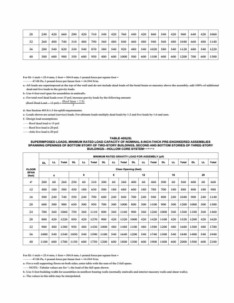
28 240 420 660 290 420 710 340 420 760 440 420 860 540 420 960 640 420 1060
32 260 480 740 310 480 790 360 480 840 460 480 940 560 480 1040 660 480 1140
36 280 540 820 330 540 870 380 540 920 480 540 1020 580 540 1120 680 540 1220
40 300 600 900 350 600 950 400 600 1000 500 600 1100 600 600 1200 700 600 1300
For SI: 1 inch = 25.4 mm, 1 foot = 304.8 mm, 1 pound force per square foot = 47.88 Pa, 1 pound-force per linear foot = 14.594 N/m. a. All loads are superimposed at the top of the wall and do not include dead loads of the bond beam or masonry above the assembly, add 100% of additional
dead and live loads to the gravity loads. b. Use 4-foot roof span for assemblies in endwalls. c. For total roof dead loads over 15 psf, increase gravity loads by the following amount:
(Roof Dead Load 15 psf) (Roof Span + 2 ft)2
--------------------------------------------–
d. See Section 405.8.1.3 for uplift requirements. e. Loads shown are actual (service) loads. For ultimate loads multiply dead loads by 1.2 and live loads by 1.6 and sum. f. Design load assumptions:
Roof dead load is 15 psf. Roof live load is 20 psf. Attic live load is 20 psf.
TABLE 405(25) SUPERIMPOSED LOADS, MINIMUM RATED LOAD CAPACITY OF NOMINAL 8-INCH-THICK PRE-ENGINEERED ASSEMBLIES
SPANNING OPENINGS OF BOTTOM STORY OF TWO-STORY BUILDINGS, SECOND AND BOTTOM STORIES OF THREE-STORY BUILDINGS—HOLLOW CORE SYSTEMa, c, d, e, f, g
FLOOR SPAN (feet)
MINIMUM RATED GRAVITY LOAD FOR ASSEMBLY (plf)
DL LL Total DL LL Total DL LL Total DL LL Total DL LL Total DL LL Total
Clear Opening (feet)
4 6 8 12 16 20
4b 200 60 260 250 60 310 300 60 360 400 60 460 500 60 560 600 60 660
12 400 180 580 450 180 630 500 180 680 600 180 780 700 180 880 800 180 980
16 500 240 740 550 240 790 600 240 840 700 240 940 800 240 1040 900 240 1140
20 600 300 900 650 300 950 700 300 1000 800 300 1100 900 300 1200 1000 300 1300
24 700 360 1060 750 360 1110 800 360 1160 900 360 1260 1000 360 1360 1100 360 1460
28 800 420 1220 850 420 1270 900 420 1320 1000 420 1420 1100 420 1520 1200 420 1620
32 900 480 1380 950 480 1430 1000 480 1480 1100 480 1580 1200 480 1680 1300 480 1780
36 1000 540 1540 1050 540 1590 1100 540 1640 1200 540 1740 1300 540 1840 1400 540 1940
40 1100 600 1700 1150 600 1750 1200 600 1800 1300 600 1900 1400 600 2000 1500 600 2100
For SI: 1 inch = 25.4 mm, 1 foot = 304.8 mm, 1 pound force per square foot = 47.88 Pa, 1 pound-force per linear foot = 14.594 N/m. a. For a wall supporting floors on both sides, enter table with the sum of the 2 full spans. NOTE: Tabular values are for 1/2 the load of the full span shown. b. Use 4-foot building width for assemblies in nonfloor-bearing walls (normally endwalls and interior masonry walls and shear walls). c. The values in this table may be interpolated.
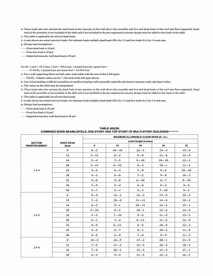
d. These loads take into account the dead load of any masonry in the wall above the assembly and live and dead loads of the roof and floor supported. Dead load of the assembly is not included in the table and if not included in the pre-engineered concrete design must be added to the loads in the table.
e. This table is applicable for all roof dead loads. f. Loads shown are actual (service) loads. For ultimate loads multiply dead loads (DL) by 1.2 and live loads (LL) by 1.6 and sum. g. Design load assumptions:
Floor dead load is 10 psf. Floor live load is 30 psf. Supported masonry wall dead load is 50 psf.
For SI: 1 inch = 25.4 mm, 1 foot = 304.8 mm, 1 pound force per square foot = 47.88 Pa, 1 pound-force per linear foot = 14.594 N/m. a. For a wall supporting floors on both sides, enter table with the sum of the 2 full spans. NOTE: Tabular values are for 1/2 the load of the full span shown. b. Use 4-foot building width for assemblies in nonfloor-bearing walls (normally endwalls and interior masonry walls and shear walls). c. The values in this table may be interpolated. d. These loads take into account the dead load of any masonry in the wall above the assembly and live and dead loads of the roof and floor supported. Dead
load of the assembly is not included in the table and if not included in the pre-engineered concrete design must be added to the loads in the table. e. This table is applicable for all roof dead loads. f. Loads shown are actual (service) loads. For ultimate loads multiply dead loads (DL) by 1.2 and live loads (LL) by 1.6 and sum. g. Design load assumptions:
Floor dead load is 50 psf. Floor live load is 30 psf. Supported masonry wall dead load is 50 psf.
TABLE 405(26) COMBINED BOND BEAM/LINTELS, ONE STORY AND TOP STORY OF MULTI-STORY BUILDINGSa, b, d, e, f, g
BOTTOM REINFORCEMENT
ROOF SPAN (feet)
MAXIMUM ALLOWABLE CLEAR SPAN (ft - in.)
Lintel Height (inches)
8 12 16 24 32
1 # 4
4c 8 – 2 10 – 10 12 – 5 14 – 4 15 – 6
12 5 – 11 8 – 2 9 – 8 11 – 8 13 – 0
16 5 – 4 7 – 5 8 – 10 10 – 10 12 – 1
20 4 – 11 6 – 10 8 – 2 10 – 1 11 – 5
24 4 – 6 6 – 4 7 – 8 9 – 6 10 – 10
28 4 – 3 6 – 0 7 – 2 9 – 0 10 – 3
32 4 – 0 5 – 8 6 – 10 8 – 7 9 – 10
36 3 – 9 5 – 4 6 – 6 8 – 2 9 – 5
40 3 – 7 5 – 1 6 – 3 7 – 10 9 – 1
1 # 5
4c 9 – 9 13 – 2 15 – 3 17 – 9 19 – 3
12 7 – 2 10 – 0 11 – 11 14 – 6 16 – 2
16 6 – 5 9 – 1 10 – 11 13 – 5 15 – 1
20 5 – 10 8 – 5 10 – 1 12 – 6 14 – 2
24 5 – 5 7 – 10 9 – 5 11 – 9 13 – 5
28 5 – 1 7 – 4 8 – 11 11 – 2 12 – 9
32 4 – 9 6 – 11 8 – 5 10 – 8 12 – 3
36 4 – 5 6 – 7 8 – 1 10 – 2 11 – 9
40 4 – 0 6 – 0 7 – 8 9 – 9 11 – 3
2 # 4
4c 10 – 8 14 – 9 17 – 2 20 – 1 21 – 9
12 7 – 9 11 – 2 13 – 5 16 – 4 18 – 3
16 7 – 0 10 – 2 13 – 3 15 – 2 17 – 1
20 6 – 5 9 – 4 11 – 5 14 – 2 16 – 1
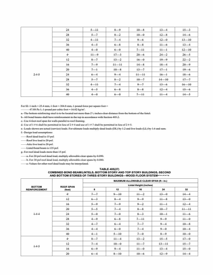
24 5 – 11 8 – 9 10 – 8 13 – 4 15 – 3
28 5 – 7 8 – 2 10 – 0 12 – 8 14 – 6
32 4 – 11 7 – 4 9 – 6 12 – 0 13 – 10
36 4 – 5 6 – 8 8 – 8 11 – 6 13 – 4
40 4 – 0 6 – 0 7 – 11 11 – 1 12 – 10
2 # 5
4c 11 – 9 17 – 3 20 – 6 24 – 2 26 – 5
12 8 – 7 13 – 2 16 – 0 19 – 9 22 – 2
16 7 – 9 11 – 11 14 – 8 18 – 4 20 – 9
20 7 – 1 10 – 8 13 – 7 17 – 1 19 – 6
24 6 – 4 9 – 4 11 – 11 16 – 1 18 – 6
28 5 – 7 8 – 2 10 – 7 14 – 10 17 – 7
32 4 – 11 7 – 4 9 – 7 13 – 6 16 – 10
36 4 – 5 6 – 8 8 – 8 12 – 4 15 – 6
40 4 – 0 6 – 0 7 – 11 11 – 4 14 – 5
For SI: 1 inch = 25.4 mm, 1 foot = 304.8 mm, 1 pound force per square foot = 47.88 Pa 1, 1 pound per cubic foot = 16.02 kg/m3. a. The bottom reinforcing steel is to be located not more than 23/4 inches clear distance from the bottom of the lintel. b. All bond beams shall have reinforcement in the top in accordance with Section 405.2. c. Use 4-foot roof span for walls parallel to roof framing. d. Use of 1 # 6 shall be permitted in lieu of 2 # 4 and use of 1 # 7 shall be permitted in lieu of 2 # 5. e. Loads shown are actual (service) loads. For ultimate loads multiply dead loads (DL) by 1.2 and live loads (LL) by 1.6 and sum. f. Design load assumptions:
Roof dead load is 15 psf. Roof live load is 20 psf. Attic live load is 20 psf. Lintel/bond beam is 135 pcf. g. For roof dead loads more than 15 psf.
a. For 20 psf roof dead load, multiply allowable clear spans by 0.090. b. For 30 psf roof dead load, multiply allowable clear spans by 0.080. c. Values for other roof dead loads may be interpolated.
TABLE 405(27) COMBINED BOND BEAM/LINTELS, BOTTOM STORY AND TOP STORY BUILDINGS, SECOND
AND BOTTOM STORIES OF THREE-STORY BUILDINGS—WOOD FLOOR SYSTEMa, b, c, d, e, f, g
BOTTOM REINFORCEMENT
ROOF SPAN (feet)
MAXIMUM ALLOWABLE CLEAR SPAN (ft - in.)
Lintel Height (inches)
8 12 16 24 32
1 # 4
4c 7 – 7 9 – 10 11 – 2 13 – 0 14 – 4
12 6 – 3 8 – 4 9 – 9 11 – 8 13 – 0
16 5 – 9 7 – 9 9 – 2 11 – 1 12 – 4
20 5 – 5 7 – 4 8 – 8 10 – 7 11 – 11
24 5 – 0 7 – 0 8 – 3 10 – 1 11 – 6
28 4 – 9 6 – 8 7 – 11 9 – 9 11 – 0
32 4 – 7 6 – 4 7 – 7 9 – 4 10 – 8
36 4 – 4 6 – 0 7 – 4 9 – 0 10 – 4
40 4 – 1 5 – 10 7 – 0 8 – 9 10 – 0
1 # 5
4c 8 – 7 11 – 4 13 – 2 15 – 5 17 – 0
12 7 – 4 10 – 0 11 – 7 13 – 11 15 – 7
16 6 – 9 9 – 4 11 – 0 13 – 4 15 – 0
20 6 – 4 8 – 10 10 – 6 12 – 9 14 – 4
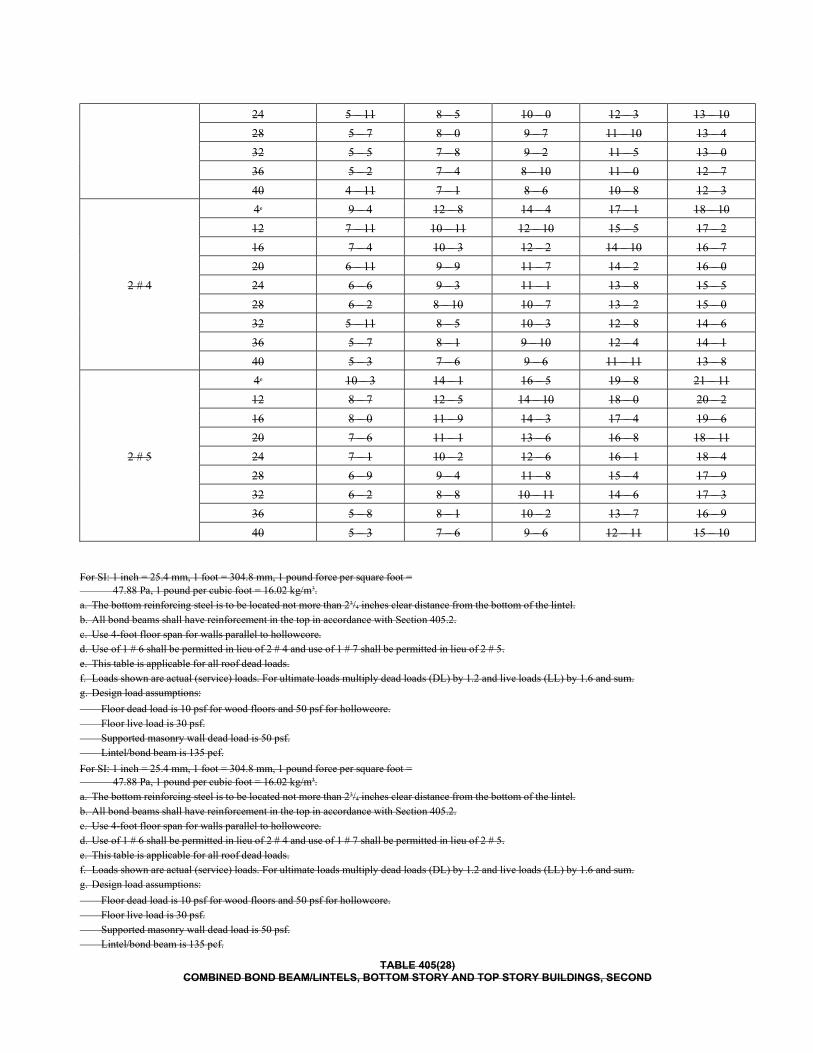
24 5 – 11 8 – 5 10 – 0 12 – 3 13 – 10
28 5 – 7 8 – 0 9 – 7 11 – 10 13 – 4
32 5 – 5 7 – 8 9 – 2 11 – 5 13 – 0
36 5 – 2 7 – 4 8 – 10 11 – 0 12 – 7
40 4 – 11 7 – 1 8 – 6 10 – 8 12 – 3
2 # 4
4c 9 – 4 12 – 8 14 – 4 17 – 1 18 – 10
12 7 – 11 10 – 11 12 – 10 15 – 5 17 – 2
16 7 – 4 10 – 3 12 – 2 14 – 10 16 – 7
20 6 – 11 9 – 9 11 – 7 14 – 2 16 – 0
24 6 – 6 9 – 3 11 – 1 13 – 8 15 – 5
28 6 – 2 8 – 10 10 – 7 13 – 2 15 – 0
32 5 – 11 8 – 5 10 – 3 12 – 8 14 – 6
36 5 – 7 8 – 1 9 – 10 12 – 4 14 – 1
40 5 – 3 7 – 6 9 – 6 11 – 11 13 – 8
2 # 5
4c 10 – 3 14 – 1 16 – 5 19 – 8 21 – 11
12 8 – 7 12 – 5 14 – 10 18 – 0 20 – 2
16 8 – 0 11 – 9 14 – 3 17 – 4 19 – 6
20 7 – 6 11 – 1 13 – 6 16 – 8 18 – 11
24 7 – 1 10 – 2 12 – 6 16 – 1 18 – 4
28 6 – 9 9 – 4 11 – 8 15 – 4 17 – 9
32 6 – 2 8 – 8 10 – 11 14 – 6 17 – 3
36 5 – 8 8 – 1 10 – 2 13 – 7 16 – 9
40 5 – 3 7 – 6 9 – 6 12 – 11 15 – 10
For SI: 1 inch = 25.4 mm, 1 foot = 304.8 mm, 1 pound force per square foot = 47.88 Pa, 1 pound per cubic foot = 16.02 kg/m3. a. The bottom reinforcing steel is to be located not more than 23/4 inches clear distance from the bottom of the lintel. b. All bond beams shall have reinforcement in the top in accordance with Section 405.2. c. Use 4-foot floor span for walls parallel to hollowcore. d. Use of 1 # 6 shall be permitted in lieu of 2 # 4 and use of 1 # 7 shall be permitted in lieu of 2 # 5. e. This table is applicable for all roof dead loads. f. Loads shown are actual (service) loads. For ultimate loads multiply dead loads (DL) by 1.2 and live loads (LL) by 1.6 and sum. g. Design load assumptions:
Floor dead load is 10 psf for wood floors and 50 psf for hollowcore. Floor live load is 30 psf. Supported masonry wall dead load is 50 psf. Lintel/bond beam is 135 pcf.
TABLE 405(28) COMBINED BOND BEAM/LINTELS, BOTTOM STORY AND TOP STORY BUILDINGS, SECOND
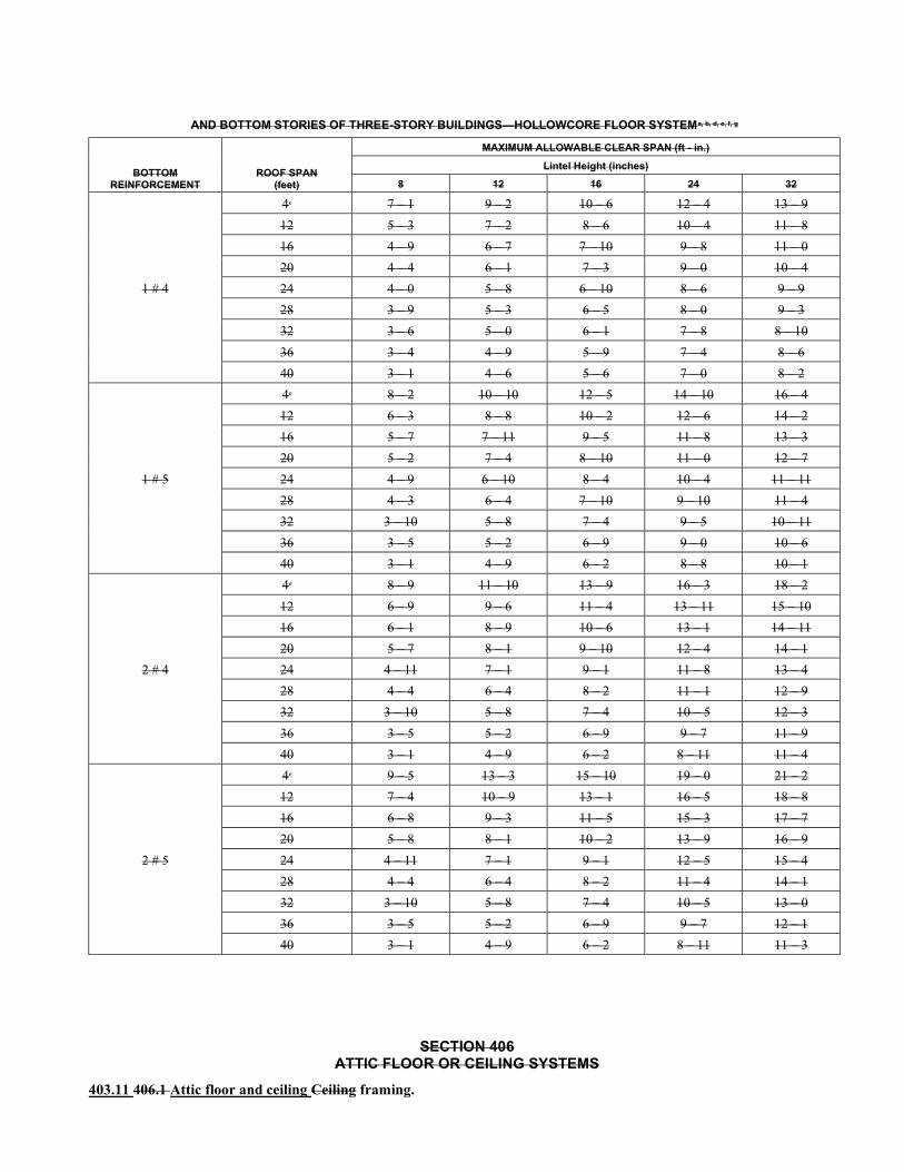
AND BOTTOM STORIES OF THREE-STORY BUILDINGS—HOLLOWCORE FLOOR SYSTEMa, b, d, e, f, g
BOTTOM REINFORCEMENT
ROOF SPAN (feet)
MAXIMUM ALLOWABLE CLEAR SPAN (ft - in.)
Lintel Height (inches)
8 12 16 24 32
1 # 4
4c 7 – 1 9 – 2 10 – 6 12 – 4 13 – 9
12 5 – 3 7 – 2 8 – 6 10 – 4 11 – 8
16 4 – 9 6 – 7 7 – 10 9 – 8 11 – 0
20 4 – 4 6 – 1 7 – 3 9 – 0 10 – 4
24 4 – 0 5 – 8 6 – 10 8 – 6 9 – 9
28 3 – 9 5 – 3 6 – 5 8 – 0 9 – 3
32 3 – 6 5 – 0 6 – 1 7 – 8 8 – 10
36 3 – 4 4 – 9 5 – 9 7 – 4 8 – 6
40 3 – 1 4 – 6 5 – 6 7 – 0 8 – 2
1 # 5
4c 8 – 2 10 – 10 12 – 5 14 – 10 16 – 4
12 6 – 3 8 – 8 10 – 2 12 – 6 14 – 2
16 5 – 7 7 – 11 9 – 5 11 – 8 13 – 3
20 5 – 2 7 – 4 8 – 10 11 – 0 12 – 7
24 4 – 9 6 – 10 8 – 4 10 – 4 11 – 11
28 4 – 3 6 – 4 7 – 10 9 – 10 11 – 4
32 3 – 10 5 – 8 7 – 4 9 – 5 10 – 11
36 3 – 5 5 – 2 6 – 9 9 – 0 10 – 6
40 3 – 1 4 – 9 6 – 2 8 – 8 10 – 1
2 # 4
4c 8 – 9 11 – 10 13 – 9 16 – 3 18 – 2
12 6 – 9 9 – 6 11 – 4 13 – 11 15 – 10
16 6 – 1 8 – 9 10 – 6 13 – 1 14 – 11
20 5 – 7 8 – 1 9 – 10 12 – 4 14 – 1
24 4 – 11 7 – 1 9 – 1 11 – 8 13 – 4
28 4 – 4 6 – 4 8 – 2 11 – 1 12 – 9
32 3 – 10 5 – 8 7 – 4 10 – 5 12 – 3
36 3 – 5 5 – 2 6 – 9 9 – 7 11 – 9
40 3 – 1 4 – 9 6 – 2 8 – 11 11 – 4
2 # 5
4c 9 – 5 13 – 3 15 – 10 19 – 0 21 – 2
12 7 – 4 10 – 9 13 – 1 16 – 5 18 – 8
16 6 – 8 9 – 3 11 – 5 15 – 3 17 – 7
20 5 – 8 8 – 1 10 – 2 13 – 9 16 – 9
24 4 – 11 7 – 1 9 – 1 12 – 5 15 – 4
28 4 – 4 6 – 4 8 – 2 11 – 4 14 – 1
32 3 – 10 5 – 8 7 – 4 10 – 5 13 – 0
36 3 – 5 5 – 2 6 – 9 9 – 7 12 – 1
40 3 – 1 4 – 9 6 – 2 8 – 11 11 – 3
SECTION 406 ATTIC FLOOR OR CEILING SYSTEMS
403.11 406.1 Attic floor and ceiling Ceiling framing.
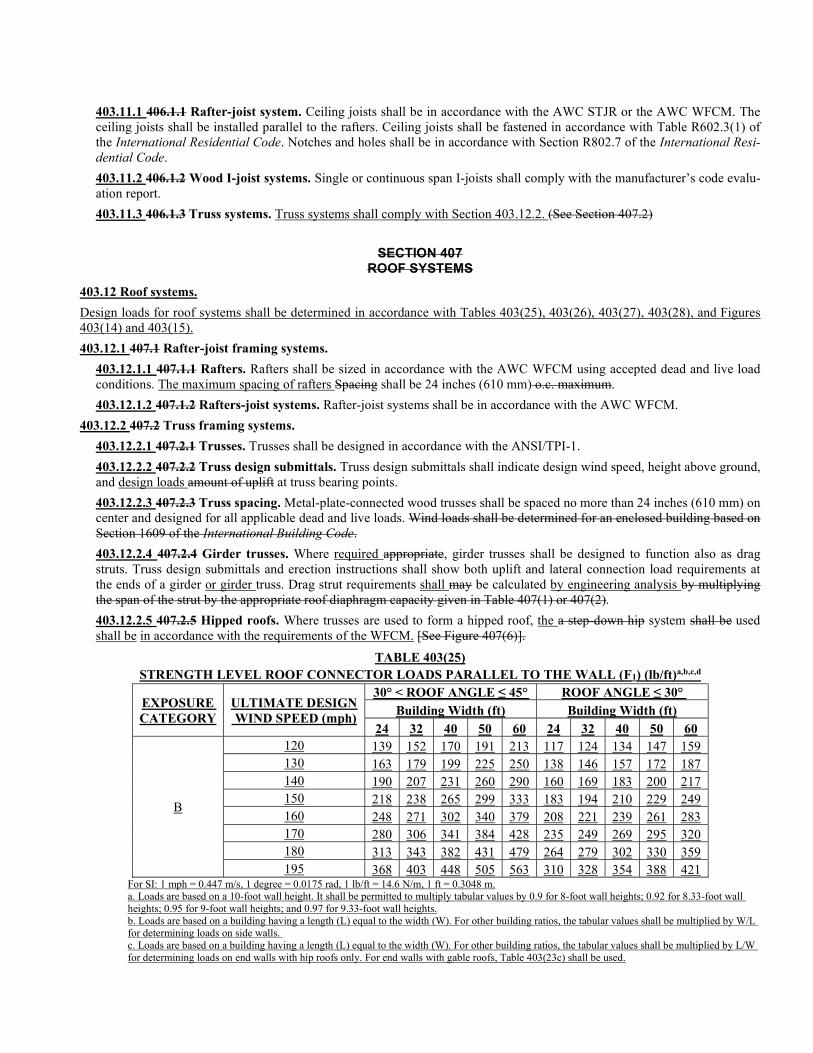
403.11.1 406.1.1 Rafter-joist system. Ceiling joists shall be in accordance with the AWC STJR or the AWC WFCM. The ceiling joists shall be installed parallel to the rafters. Ceiling joists shall be fastened in accordance with Table R602.3(1) of the International Residential Code. Notches and holes shall be in accordance with Section R802.7 of the International Resi-dential Code.
403.11.2 406.1.2 Wood I-joist systems. Single or continuous span I-joists shall comply with the manufacturer’s code evalu-ation report.
403.11.3 406.1.3 Truss systems. Truss systems shall comply with Section 403.12.2. (See Section 407.2)
SECTION 407 ROOF SYSTEMS
403.12 Roof systems.
Design loads for roof systems shall be determined in accordance with Tables 403(25), 403(26), 403(27), 403(28), and Figures 403(14) and 403(15).
403.12.1 407.1 Rafter-joist framing systems.
403.12.1.1 407.1.1 Rafters. Rafters shall be sized in accordance with the AWC WFCM using accepted dead and live load conditions. The maximum spacing of rafters Spacing shall be 24 inches (610 mm) o.c. maximum.
403.12.1.2 407.1.2 Rafters-joist systems. Rafter-joist systems shall be in accordance with the AWC WFCM.
403.12.2 407.2 Truss framing systems.
403.12.2.1 407.2.1 Trusses. Trusses shall be designed in accordance with the ANSI/TPI-1.
403.12.2.2 407.2.2 Truss design submittals. Truss design submittals shall indicate design wind speed, height above ground, and design loads amount of uplift at truss bearing points.
403.12.2.3 407.2.3 Truss spacing. Metal-plate-connected wood trusses shall be spaced no more than 24 inches (610 mm) on center and designed for all applicable dead and live loads. Wind loads shall be determined for an enclosed building based on Section 1609 of the International Building Code.
403.12.2.4 407.2.4 Girder trusses. Where required appropriate, girder trusses shall be designed to function also as drag struts. Truss design submittals and erection instructions shall show both uplift and lateral connection load requirements at the ends of a girder or girder truss. Drag strut requirements shall may be calculated by engineering analysis by multiplying the span of the strut by the appropriate roof diaphragm capacity given in Table 407(1) or 407(2).
403.12.2.5 407.2.5 Hipped roofs. Where trusses are used to form a hipped roof, the a step-down hip system shall be used shall be in accordance with the requirements of the WFCM. [See Figure 407(6)].
TABLE 403(25) STRENGTH LEVEL ROOF CONNECTOR LOADS PARALLEL TO THE WALL (F1) (lb/ft)a,b,c,d
EXPOSURE CATEGORY
ULTIMATE DESIGN WIND SPEED (mph)
30° < ROOF ANGLE ≤ 45° ROOF ANGLE ≤ 30° Building Width (ft) Building Width (ft)
24 32 40 50 60 24 32 40 50 60
B
120 139 152 170 191 213 117 124 134 147 159 130 163 179 199 225 250 138 146 157 172 187 140 190 207 231 260 290 160 169 183 200 217 150 218 238 265 299 333 183 194 210 229 249 160 248 271 302 340 379 208 221 239 261 283 170 280 306 341 384 428 235 249 269 295 320 180 313 343 382 431 479 264 279 302 330 359 195 368 403 448 505 563 310 328 354 388 421
For SI: 1 mph = 0.447 m/s, 1 degree = 0.0175 rad, 1 lb/ft = 14.6 N/m, 1 ft = 0.3048 m. a. Loads are based on a 10-foot wall height. It shall be permitted to multiply tabular values by 0.9 for 8-foot wall heights; 0.92 for 8.33-foot wall heights; 0.95 for 9-foot wall heights; and 0.97 for 9.33-foot wall heights. b. Loads are based on a building having a length (L) equal to the width (W). For other building ratios, the tabular values shall be multiplied by W/L for determining loads on side walls. c. Loads are based on a building having a length (L) equal to the width (W). For other building ratios, the tabular values shall be multiplied by L/W for determining loads on end walls with hip roofs only. For end walls with gable roofs, Table 403(23c) shall be used.
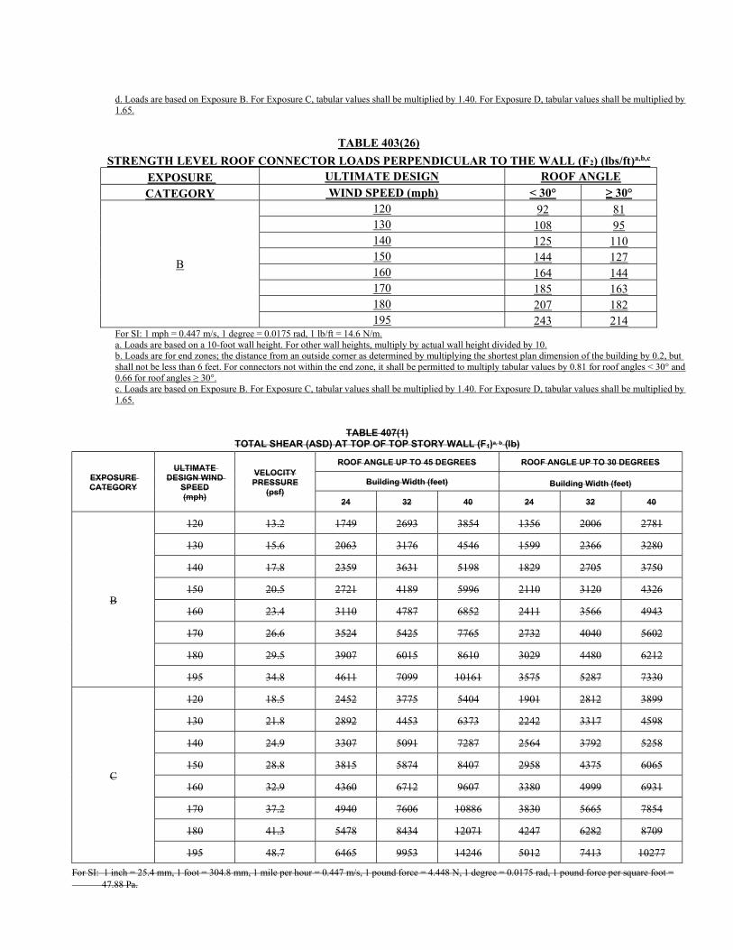
d. Loads are based on Exposure B. For Exposure C, tabular values shall be multiplied by 1.40. For Exposure D, tabular values shall be multiplied by 1.65.
TABLE 403(26)
STRENGTH LEVEL ROOF CONNECTOR LOADS PERPENDICULAR TO THE WALL (F2) (lbs/ft)a,b,c
EXPOSURE ULTIMATE DESIGN ROOF ANGLE
CATEGORY WIND SPEED (mph) < 30° ≥ 30°
B
120 92 81 130 108 95 140 125 110 150 144 127 160 164 144 170 185 163 180 207 182 195 243 214
For SI: 1 mph = 0.447 m/s, 1 degree = 0.0175 rad, 1 lb/ft = 14.6 N/m. a. Loads are based on a 10-foot wall height. For other wall heights, multiply by actual wall height divided by 10. b. Loads are for end zones; the distance from an outside corner as determined by multiplying the shortest plan dimension of the building by 0.2, but shall not be less than 6 feet. For connectors not within the end zone, it shall be permitted to multiply tabular values by 0.81 for roof angles < 30° and 0.66 for roof angles ≥ 30°. c. Loads are based on Exposure B. For Exposure C, tabular values shall be multiplied by 1.40. For Exposure D, tabular values shall be multiplied by 1.65.
TABLE 407(1)
TOTAL SHEAR (ASD) AT TOP OF TOP STORY WALL (F1)a, b (lb)
EXPOSURE CATEGORY
ULTIMATE DESIGN WIND
SPEED (mph)
VELOCITY PRESSURE
(psf)
ROOF ANGLE UP TO 45 DEGREES ROOF ANGLE UP TO 30 DEGREES
Building Width (feet) Building Width (feet)
24 32 40 24 32 40
B
120 13.2 1749 2693 3854 1356 2006 2781
130 15.6 2063 3176 4546 1599 2366 3280
140 17.8 2359 3631 5198 1829 2705 3750
150 20.5 2721 4189 5996 2110 3120 4326
160 23.4 3110 4787 6852 2411 3566 4943
170 26.6 3524 5425 7765 2732 4040 5602
180 29.5 3907 6015 8610 3029 4480 6212
195 34.8 4611 7099 10161 3575 5287 7330
C
120 18.5 2452 3775 5404 1901 2812 3899
130 21.8 2892 4453 6373 2242 3317 4598
140 24.9 3307 5091 7287 2564 3792 5258
150 28.8 3815 5874 8407 2958 4375 6065
160 32.9 4360 6712 9607 3380 4999 6931
170 37.2 4940 7606 10886 3830 5665 7854
180 41.3 5478 8434 12071 4247 6282 8709
195 48.7 6465 9953 14246 5012 7413 10277
For SI: 1 inch = 25.4 mm, 1 foot = 304.8 mm, 1 mile per hour = 0.447 m/s, 1 pound force = 4.448 N, 1 degree = 0.0175 rad, 1 pound force per square foot = 47.88 Pa.
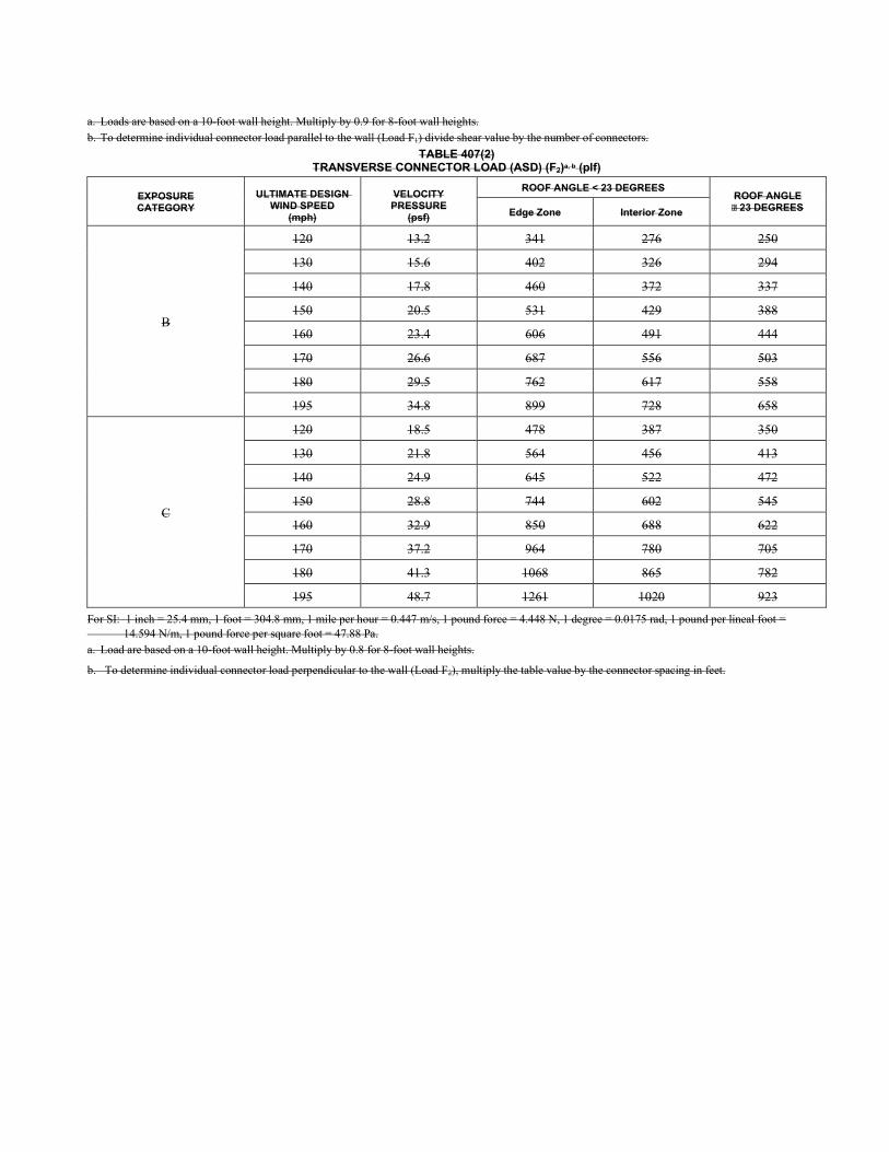
a. Loads are based on a 10-foot wall height. Multiply by 0.9 for 8-foot wall heights. b. To determine individual connector load parallel to the wall (Load F1) divide shear value by the number of connectors.
TABLE 407(2) TRANSVERSE CONNECTOR LOAD (ASD) (F2)a, b (plf)
EXPOSURE CATEGORY
ULTIMATE DESIGN WIND SPEED
(mph)
VELOCITY PRESSURE
(psf)
ROOF ANGLE < 23 DEGREES ROOF ANGLE 23 DEGREES Edge Zone Interior Zone
B
120 13.2 341 276 250
130 15.6 402 326 294
140 17.8 460 372 337
150 20.5 531 429 388
160 23.4 606 491 444
170 26.6 687 556 503
180 29.5 762 617 558
195 34.8 899 728 658
C
120 18.5 478 387 350
130 21.8 564 456 413
140 24.9 645 522 472
150 28.8 744 602 545
160 32.9 850 688 622
170 37.2 964 780 705
180 41.3 1068 865 782
195 48.7 1261 1020 923
For SI: 1 inch = 25.4 mm, 1 foot = 304.8 mm, 1 mile per hour = 0.447 m/s, 1 pound force = 4.448 N, 1 degree = 0.0175 rad, 1 pound per lineal foot = 14.594 N/m, 1 pound force per square foot = 47.88 Pa. a. Load are based on a 10-foot wall height. Multiply by 0.8 for 8-foot wall heights.
b. To determine individual connector load perpendicular to the wall (Load F2), multiply the table value by the connector spacing in feet.
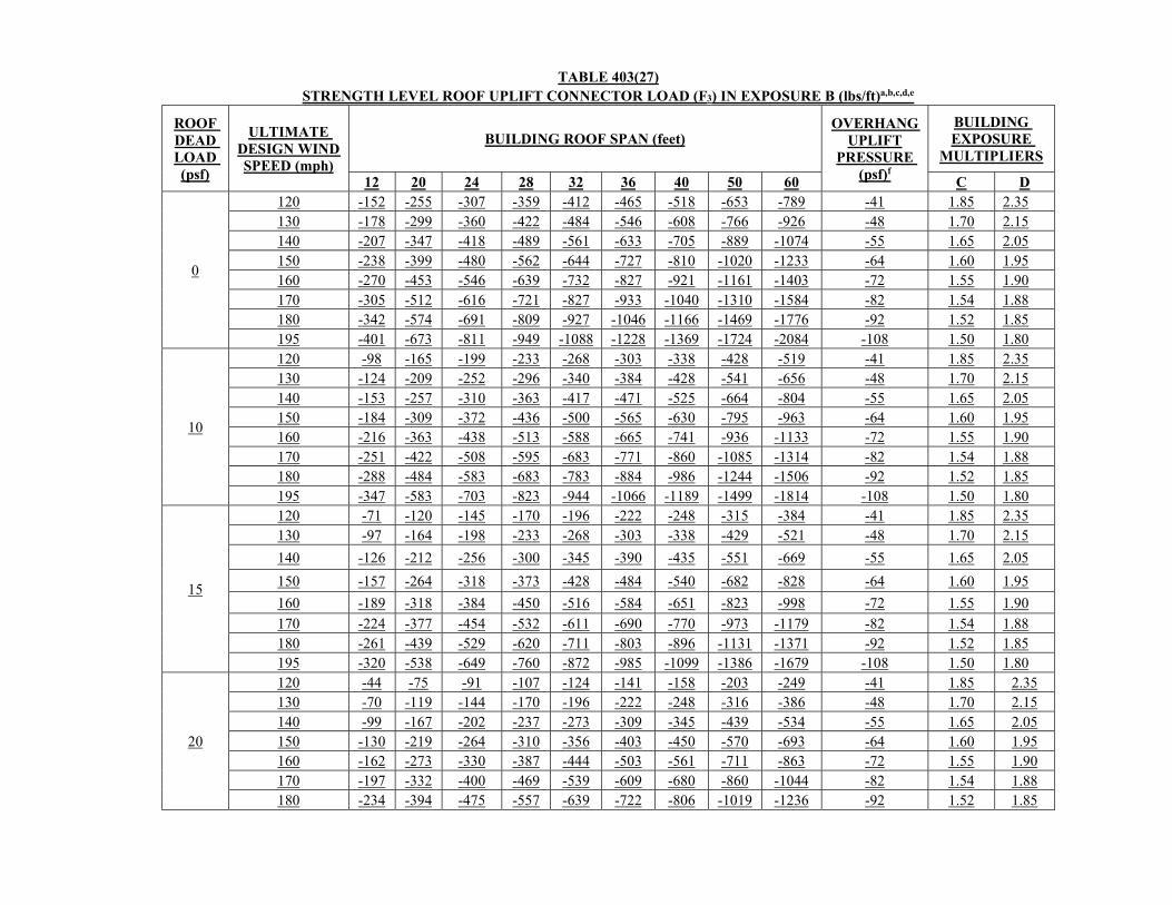
TABLE 403(27) STRENGTH LEVEL ROOF UPLIFT CONNECTOR LOAD (F3) IN EXPOSURE B (lbs/ft)a,b,c,d,e
ROOF DEAD LOAD (psf)
ULTIMATE DESIGN WIND SPEED (mph)
BUILDING ROOF SPAN (feet) OVERHANG
UPLIFT PRESSURE
(psf)f
BUILDING EXPOSURE
MULTIPLIERS
12 20 24 28 32 36 40 50 60 C D
0
120 -152 -255 -307 -359 -412 -465 -518 -653 -789 -41 1.85 2.35 130 -178 -299 -360 -422 -484 -546 -608 -766 -926 -48 1.70 2.15 140 -207 -347 -418 -489 -561 -633 -705 -889 -1074 -55 1.65 2.05 150 -238 -399 -480 -562 -644 -727 -810 -1020 -1233 -64 1.60 1.95 160 -270 -453 -546 -639 -732 -827 -921 -1161 -1403 -72 1.55 1.90 170 -305 -512 -616 -721 -827 -933 -1040 -1310 -1584 -82 1.54 1.88 180 -342 -574 -691 -809 -927 -1046 -1166 -1469 -1776 -92 1.52 1.85 195 -401 -673 -811 -949 -1088 -1228 -1369 -1724 -2084 -108 1.50 1.80
10
120 -98 -165 -199 -233 -268 -303 -338 -428 -519 -41 1.85 2.35 130 -124 -209 -252 -296 -340 -384 -428 -541 -656 -48 1.70 2.15 140 -153 -257 -310 -363 -417 -471 -525 -664 -804 -55 1.65 2.05 150 -184 -309 -372 -436 -500 -565 -630 -795 -963 -64 1.60 1.95 160 -216 -363 -438 -513 -588 -665 -741 -936 -1133 -72 1.55 1.90 170 -251 -422 -508 -595 -683 -771 -860 -1085 -1314 -82 1.54 1.88 180 -288 -484 -583 -683 -783 -884 -986 -1244 -1506 -92 1.52 1.85 195 -347 -583 -703 -823 -944 -1066 -1189 -1499 -1814 -108 1.50 1.80
15
120 -71 -120 -145 -170 -196 -222 -248 -315 -384 -41 1.85 2.35 130 -97 -164 -198 -233 -268 -303 -338 -429 -521 -48 1.70 2.15
140 -126 -212 -256 -300 -345 -390 -435 -551 -669 -55 1.65 2.05
150 -157 -264 -318 -373 -428 -484 -540 -682 -828 -64 1.60 1.95
160 -189 -318 -384 -450 -516 -584 -651 -823 -998 -72 1.55 1.90
170 -224 -377 -454 -532 -611 -690 -770 -973 -1179 -82 1.54 1.88 180 -261 -439 -529 -620 -711 -803 -896 -1131 -1371 -92 1.52 1.85 195 -320 -538 -649 -760 -872 -985 -1099 -1386 -1679 -108 1.50 1.80
20
120 -44 -75 -91 -107 -124 -141 -158 -203 -249 -41 1.85 2.35 130 -70 -119 -144 -170 -196 -222 -248 -316 -386 -48 1.70 2.15 140 -99 -167 -202 -237 -273 -309 -345 -439 -534 -55 1.65 2.05 150 -130 -219 -264 -310 -356 -403 -450 -570 -693 -64 1.60 1.95 160 -162 -273 -330 -387 -444 -503 -561 -711 -863 -72 1.55 1.90 170 -197 -332 -400 -469 -539 -609 -680 -860 -1044 -82 1.54 1.88 180 -234 -394 -475 -557 -639 -722 -806 -1019 -1236 -92 1.52 1.85
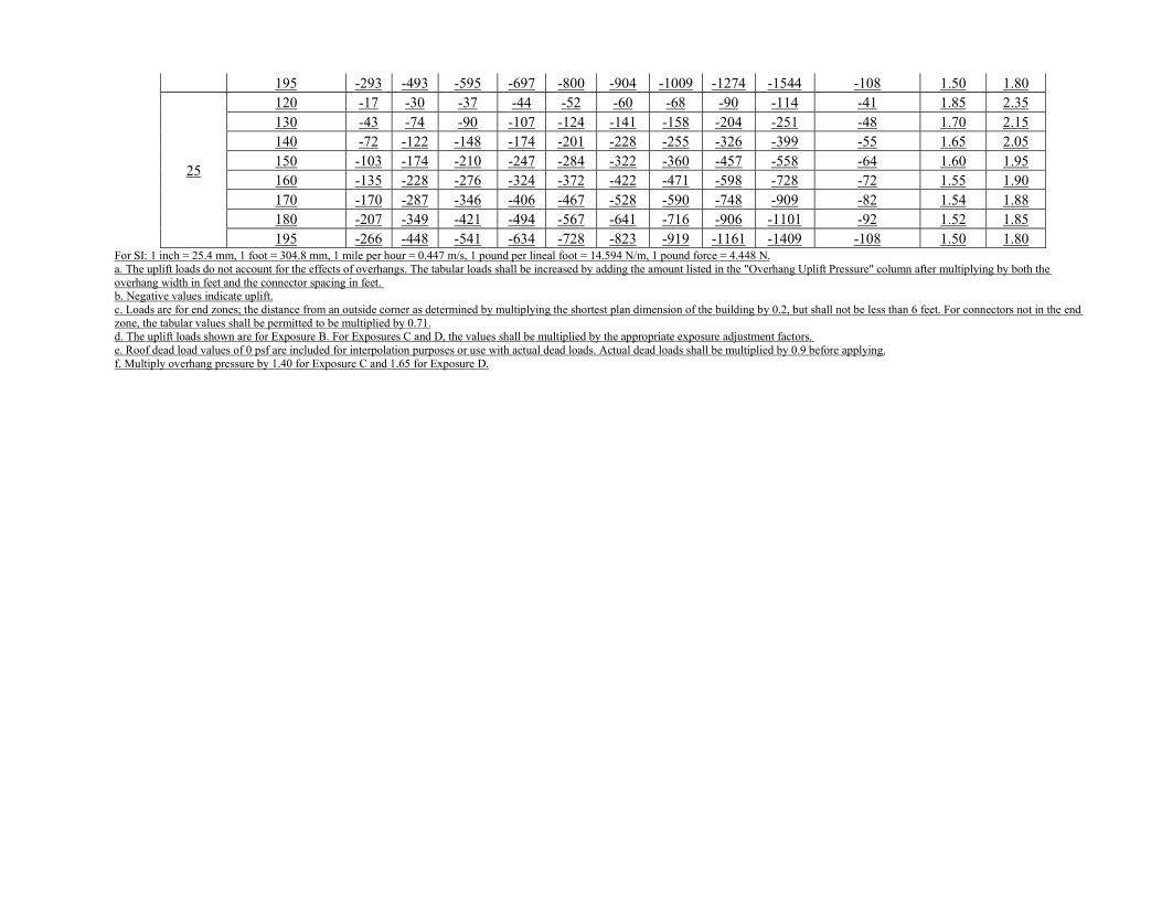
195 -293 -493 -595 -697 -800 -904 -1009 -1274 -1544 -108 1.50 1.80
25
120 -17 -30 -37 -44 -52 -60 -68 -90 -114 -41 1.85 2.35 130 -43 -74 -90 -107 -124 -141 -158 -204 -251 -48 1.70 2.15 140 -72 -122 -148 -174 -201 -228 -255 -326 -399 -55 1.65 2.05 150 -103 -174 -210 -247 -284 -322 -360 -457 -558 -64 1.60 1.95 160 -135 -228 -276 -324 -372 -422 -471 -598 -728 -72 1.55 1.90 170 -170 -287 -346 -406 -467 -528 -590 -748 -909 -82 1.54 1.88 180 -207 -349 -421 -494 -567 -641 -716 -906 -1101 -92 1.52 1.85 195 -266 -448 -541 -634 -728 -823 -919 -1161 -1409 -108 1.50 1.80
For SI: 1 inch = 25.4 mm, 1 foot = 304.8 mm, 1 mile per hour = 0.447 m/s, 1 pound per lineal foot = 14.594 N/m, 1 pound force = 4.448 N. a. The uplift loads do not account for the effects of overhangs. The tabular loads shall be increased by adding the amount listed in the "Overhang Uplift Pressure" column after multiplying by both the overhang width in feet and the connector spacing in feet. b. Negative values indicate uplift. c. Loads are for end zones; the distance from an outside corner as determined by multiplying the shortest plan dimension of the building by 0.2, but shall not be less than 6 feet. For connectors not in the end zone, the tabular values shall be permitted to be multiplied by 0.71. d. The uplift loads shown are for Exposure B. For Exposures C and D, the values shall be multiplied by the appropriate exposure adjustment factors. e. Roof dead load values of 0 psf are included for interpolation purposes or use with actual dead loads. Actual dead loads shall be multiplied by 0.9 before applying. f. Multiply overhang pressure by 1.40 for Exposure C and 1.65 for Exposure D.
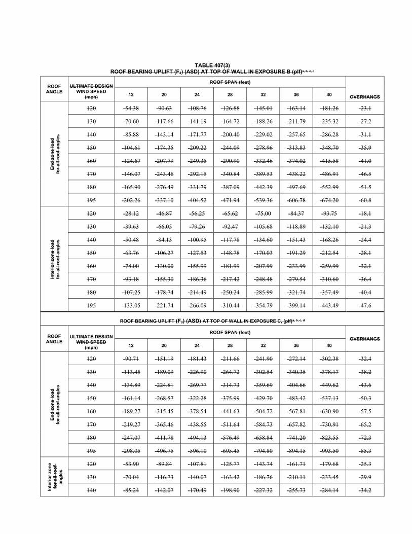
TABLE 407(3)
ROOF BEARING UPLIFT (F3) (ASD) AT TOP OF WALL IN EXPOSURE B (plf)a, b, c, d
ROOF ANGLE
ULTIMATE DESIGN WIND SPEED
(mph)
ROOF SPAN (feet)
OVERHANGS 12 20 24 28 32 36 40
En
d z
on
e l
oad
fo
r a
ll ro
of
an
gle
s
120 -54.38 -90.63 -108.76 -126.88 -145.01 -163.14 -181.26 -23.1
130 -70.60 -117.66 -141.19 -164.72 -188.26 -211.79 -235.32 -27.2
140 -85.88 -143.14 -171.77 -200.40 -229.02 -257.65 -286.28 -31.1
150 -104.61 -174.35 -209.22 -244.09 -278.96 -313.83 -348.70 -35.9
160 -124.67 -207.79 -249.35 -290.90 -332.46 -374.02 -415.58 -41.0
170 -146.07 -243.46 -292.15 -340.84 -389.53 -438.22 -486.91 -46.5
180 -165.90 -276.49 -331.79 -387.09 -442.39 -497.69 -552.99 -51.5
195 -202.26 -337.10 -404.52 -471.94 -539.36 -606.78 -674.20 -60.8
Inte
rio
r zo
ne
load
fo
r a
ll ro
of
an
gle
s
120 -28.12 -46.87 -56.25 -65.62 -75.00 -84.37 -93.75 -18.1
130 -39.63 -66.05 -79.26 -92.47 -105.68 -118.89 -132.10 -21.3
140 -50.48 -84.13 -100.95 -117.78 -134.60 -151.43 -168.26 -24.4
150 -63.76 -106.27 -127.53 -148.78 -170.03 -191.29 -212.54 -28.1
160 -78.00 -130.00 -155.99 -181.99 -207.99 -233.99 -259.99 -32.1
170 -93.18 -155.30 -186.36 -217.42 -248.48 -279.54 -310.60 -36.4
180 -107.25 -178.74 -214.49 -250.24 -285.99 -321.74 -357.49 -40.4
195 -133.05 -221.74 -266.09 -310.44 -354.79 -399.14 -443.49 -47.6
ROOF BEARING UPLIFT (F3) (ASD) AT TOP OF WALL IN EXPOSURE C, (plf)a, b, c, d
ROOF ANGLE
ULTIMATE DESIGN WIND SPEED
(mph)
ROOF SPAN (feet)
OVERHANGS 12 20 24 28 32 36 40
En
d z
on
e l
oad
fo
r a
ll ro
of
an
gle
s
120 -90.71 -151.19 -181.43 -211.66 -241.90 -272.14 -302.38 -32.4
130 -113.45 -189.09 -226.90 -264.72 -302.54 -340.35 -378.17 -38.2
140 -134.89 -224.81 -269.77 -314.73 -359.69 -404.66 -449.62 -43.6
150 -161.14 -268.57 -322.28 -375.99 -429.70 -483.42 -537.13 -50.3
160 -189.27 -315.45 -378.54 -441.63 -504.72 -567.81 -630.90 -57.5
170 -219.27 -365.46 -438.55 -511.64 -584.73 -657.82 -730.91 -65.2
180 -247.07 -411.78 -494.13 -576.49 -658.84 -741.20 -823.55 -72.3
195 -298.05 -496.75 -596.10 -695.45 -794.80 -894.15 -993.50 -85.3
Inte
rio
r zo
ne
fo
r a
ll ro
of
ang
les
120 -53.90 -89.84 -107.81 -125.77 -143.74 -161.71 -179.68 -25.3
130 -70.04 -116.73 -140.07 -163.42 -186.76 -210.11 -233.45 -29.9
140 -85.24 -142.07 -170.49 -198.90 -227.32 -255.73 -284.14 -34.2
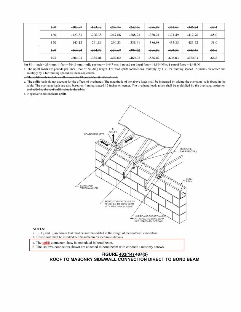
150 -103.87 -173.12 -207.74 -242.36 -276.99 -311.61 -346.24 -39.4
160 -123.83 -206.38 -247.66 -288.93 -330.21 -371.49 -412.76 -45.0
170 -145.12 -241.86 -290.23 -338.61 -386.98 -435.35 -483.72 -51.0
180 -164.84 -274.73 -329.67 -384.62 -386.98 -494.51 -549.45 -56.6
195 -201.01 -335.01 -402.02 -469.02 -536.02 -603.03 -670.03 -66.8
For SI: 1 inch = 25.4 mm, 1 foot = 304.8 mm, 1 mile per hour = 0.447 m/s, 1 pound per lineal foot = 14.594 N/m, 1 pound force = 4.448 N. a. The uplift loads are pounds per lineal foot of building length. For roof uplift connections, multiply by 1.33 for framing spaced 16 inches on center and
multiply by 2 for framing spaced 24 inches on center. b. The uplift loads include an allowance for 10 pounds/sq. ft. of dead load. c. The uplift loads do not account for the effects of overhangs. The magnitude of the above loads shall be increased by adding the overhang loads found in the
table. The overhang loads are also based on framing spaced 12 inches on center. The overhang loads given shall be multiplied by the overhang projection and added to the roof uplift value in the table.
d. Negative values indicate uplift.
FIGURE 403(14) 407(3) ROOF TO MASONRY SIDEWALL CONNECTION DIRECT TO BOND BEAM
c. The uplift connector show is embedded in bond beam. d. The last two connectors shown are attached to bond beam with concrete / masonry screws.
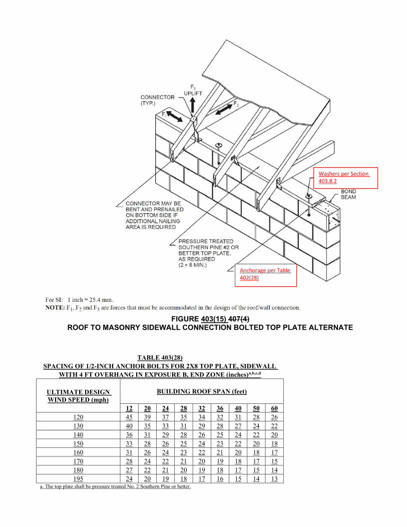
FIGURE 403(15) 407(4)
ROOF TO MASONRY SIDEWALL CONNECTION BOLTED TOP PLATE ALTERNATE
TABLE 403(28) SPACING OF 1/2-INCH ANCHOR BOLTS FOR 2X8 TOP PLATE, SIDEWALL
WITH 4 FT OVERHANG IN EXPOSURE B, END ZONE (inches)a,b,c,d
ULTIMATE DESIGN WIND SPEED (mph)
BUILDING ROOF SPAN (feet)
12 20 24 28 32 36 40 50 60 120 45 39 37 35 34 32 31 28 26 130 40 35 33 31 29 28 27 24 22 140 36 31 29 28 26 25 24 22 20 150 33 28 26 25 24 23 22 20 18 160 31 26 24 23 22 21 20 18 17 170 28 24 22 21 20 19 18 17 15 180 27 22 21 20 19 18 17 15 14 195 24 20 19 18 17 16 15 14 13
a. The top plate shall be pressure treated No. 2 Southern Pine or better.
Washers per Section 403.8.2
Anchorage per Table 402(28)
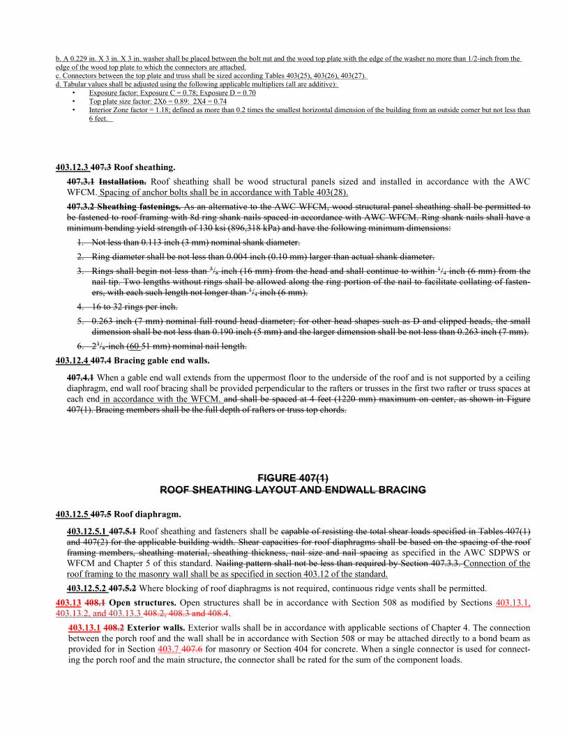
b. A 0.229 in. X 3 in. X 3 in. washer shall be placed between the bolt nut and the wood top plate with the edge of the washer no more than 1/2-inch from the edge of the wood top plate to which the connectors are attached. c. Connectors between the top plate and truss shall be sized according Tables 403(25), 403(26), 403(27). d. Tabular values shall be adjusted using the following applicable multipliers (all are additive):
• Exposure factor: Exposure C = 0.78; Exposure D = 0.70 • Top plate size factor: 2X6 = 0.89: 2X4 = 0.74 • Interior Zone factor = 1.18; defined as more than 0.2 times the smallest horizontal dimension of the building from an outside corner but not less than
6 feet.
403.12.3 407.3 Roof sheathing.
407.3.1 Installation. Roof sheathing shall be wood structural panels sized and installed in accordance with the AWC WFCM. Spacing of anchor bolts shall be in accordance with Table 403(28).
407.3.2 Sheathing fastenings. As an alternative to the AWC WFCM, wood structural panel sheathing shall be permitted to be fastened to roof framing with 8d ring shank nails spaced in accordance with AWC WFCM. Ring shank nails shall have a minimum bending yield strength of 130 ksi (896,318 kPa) and have the following minimum dimensions:
1. Not less than 0.113 inch (3 mm) nominal shank diameter.
2. Ring diameter shall be not less than 0.004 inch (0.10 mm) larger than actual shank diameter.
3. Rings shall begin not less than 5/8 inch (16 mm) from the head and shall continue to within 1/4 inch (6 mm) from the nail tip. Two lengths without rings shall be allowed along the ring portion of the nail to facilitate collating of fasten-ers, with each such length not longer than 1/4 inch (6 mm).
4. 16 to 32 rings per inch.
5. 0.263 inch (7 mm) nominal full round head diameter; for other head shapes such as D and clipped heads, the small dimension shall be not less than 0.190 inch (5 mm) and the larger dimension shall be not less than 0.263 inch (7 mm).
6. 23/8-inch (60 51 mm) nominal nail length.
403.12.4 407.4 Bracing gable end walls.
407.4.1 When a gable end wall extends from the uppermost floor to the underside of the roof and is not supported by a ceiling diaphragm, end wall roof bracing shall be provided perpendicular to the rafters or trusses in the first two rafter or truss spaces at each end in accordance with the WFCM. and shall be spaced at 4 feet (1220 mm) maximum on center, as shown in Figure 407(1). Bracing members shall be the full depth of rafters or truss top chords.
FIGURE 407(1)
ROOF SHEATHING LAYOUT AND ENDWALL BRACING
403.12.5 407.5 Roof diaphragm.
403.12.5.1 407.5.1 Roof sheathing and fasteners shall be capable of resisting the total shear loads specified in Tables 407(1) and 407(2) for the applicable building width. Shear capacities for roof diaphragms shall be based on the spacing of the roof framing members, sheathing material, sheathing thickness, nail size and nail spacing as specified in the AWC SDPWS or WFCM and Chapter 5 of this standard. Nailing pattern shall not be less than required by Section 407.3.3. Connection of the roof framing to the masonry wall shall be as specified in section 403.12 of the standard.
403.12.5.2 407.5.2 Where blocking of roof diaphragms is not required, continuous ridge vents shall be permitted.
403.13 408.1 Open structures. Open structures shall be in accordance with Section 508 as modified by Sections 403.13.1, 403.13.2, and 403.13.3 408.2, 408.3 and 408.4.
403.13.1 408.2 Exterior walls. Exterior walls shall be in accordance with applicable sections of Chapter 4. The connection between the porch roof and the wall shall be in accordance with Section 508 or may be attached directly to a bond beam as provided for in Section 403.7 407.6 for masonry or Section 404 for concrete. When a single connector is used for connect-ing the porch roof and the main structure, the connector shall be rated for the sum of the component loads.
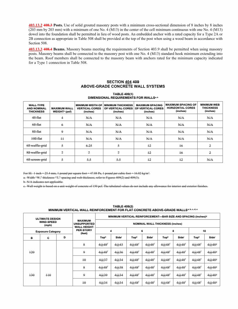
403.13.2 408.3 Posts. Use of solid grouted masonry posts with a minimum cross-sectional dimension of 8 inches by 8 inches (203 mm by 203 mm) with a minimum of one No. 4 (M13) in the center of the cell minimum continuous with one No. 4 (M13) dowel into the foundation shall be permitted in lieu of wood posts. An embedded anchor with a rated capacity for a Type 2A or 2B connection as appropriate in Table 508 shall be provided at the top of the post when using a wood beam in accordance with Section 508.
403.13.3 408.4 Beams. Masonry beams meeting the requirements of Section 403.9 shall be permitted when using masonry posts. Masonry beams shall be connected to the masonry post with one No. 4 (M13) standard hook minimum extending into the beam. Roof members shall be connected to the masonry beam with anchors rated for the minimum capacity indicated for a Type 1 connection in Table 508.
SECTION 404 409 ABOVE-GRADE CONCRETE WALL SYSTEMS
TABLE 409(1) DIMENSIONAL REQUIREMENTS FOR WALLSa, b
WALL TYPE AND NOMINAL
THICKNESS MAXIMUM WALL
WEIGHTc (psf)
MINIMUM WIDTH OF VERTICAL CORES
(inches)
MINIMUM THICKNESS OF VERTICAL CORES
(inches)
MAXIMUM SPACING OF VERTICAL CORES
(inches)
MAXIMUM SPACING OF HORIZONTAL CORES
(inches)
MINIMUM WEB THICKNESS
(inches)
4 flat 4 N/A N/A N/A N/A N/A
6 flat 6 N/A N/A N/A N/A N/A
8 flat 9 N/A N/A N/A N/A N/A
10 flat 11 N/A N/A N/A N/A N/A
6 waffle-grid 5 6.25 5 12 16 2
8 waffle-grid 7 7 7 12 16 2
6 screen-grid 5 5.5 5.5 12 12 N/A
For SI: 1 inch = 25.4 mm, 1 pound per square foot = 47.88 Pa, 1 pound per cubic foot = 16.02 kg/m3. a. Width “W,” thickness “T,” spacing and web thickness, refer to Figures 409(2) and 409(3). b. N/A indicates not applicable. c. Wall weight is based on a unit weight of concrete of 150 pcf. The tabulated values do not include any allowance for interior and exterior finishes.
TABLE 409(2) MINIMUM VERTICAL WALL REINFORCEMENT FOR FLAT CONCRETE ABOVE-GRADE WALLSa, b, c, d, e
ULTIMATE DESIGN WIND SPEED
(mph)
MAXIMUM UNSUPPORTED WALL HEIGHT
PER STORY (feet)
MINIMUM VERTICAL REINFORCEMENT—BAR SIZE AND SPACING (inches)g
NOMINAL WALL THICKNESS (inches)
Exposure Category 4 6 8 10
B C D Toph Sidei Toph Sidei Toph Sidei Toph Sidei
120
8 4@48f 4@43 4@48f 4@48f 4@48f 4@48f 4@48f 4@48g
9 4@48f 4@36 4@48f 4@48f 4@48f 4@48f 4@48f 4@48g
10 4@37 4@34 4@48f 4@48f 4@48f 4@48f 4@48f 4@48g
130 110
8 4@48f 4@38 4@48f 4@48f 4@48f 4@48f 4@48f 4@48g
9 4@39 4@34 4@48f 4@48f 4@48f 4@48f 4@48f 4@48g
10 4@34 4@34 4@48f 4@48f 4@48f 4@48f 4@48f 4@48g
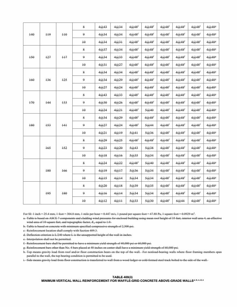
140 119 110
8 4@43 4@34 4@48f 4@48f 4@48f 4@48f 4@48f 4@48g
9 4@34 4@34 4@48f 4@48f 4@48f 4@48f 4@48f 4@48g
10 4@34 4@31 4@48f 4@48f 4@48f 4@48f 4@48f 4@48g
150 127 117
8 4@37 4@34 4@48f 4@48f 4@48f 4@48f 4@48f 4@48g
9 4@34 4@33 4@48f 4@48f 4@48f 4@48f 4@48f 4@48g
10 4@31 4@27 4@48f 4@48f 4@48f 4@48f 4@48f 4@48g
160 136 125
8 4@34 4@34 4@48f 4@48f 4@48f 4@48f 4@48f 4@48g
9 4@34 4@29 4@48f 4@48f 4@48f 4@48f 4@48f 4@48g
10 4@27 4@24 4@48f 4@48f 4@48f 4@48f 4@48f 4@48g
170 144 133
8 4@43 4@33 4@48f 4@48f 4@48f 4@48f 4@48f 4@48g
9 4@30 4@26 4@48f 4@48f 4@48f 4@48f 4@48f 4@48g
10 4@24 4@21 4@48f 5@40 4@48f 4@48f 4@48f 4@48g
180 153 141
8 4@34 4@29 4@48f 4@48f 4@48f 4@48f 4@48f 4@48g
9 4@27 4@24 4@48f 5@44 4@48f 4@48f 4@48f 4@48g
10 4@21 4@19 5@41 5@36 4@48f 4@48f 4@48f 4@48g
165 152
8 4@29 4@25 4@48f 4@48f 4@48f 4@48f 4@48f 4@48g
9 4@23 4@20 5@43 5@38 4@48f 4@48f 4@48f 4@48g
10 4@18 4@16 5@35 5@34 4@48f 4@48f 4@48f 4@48g
180 166
8 4@24 4@22 4@48f 5@40 4@48f 4@48f 4@48f 4@48g
9 4@19 4@17 5@36 5@34 4@48f 4@48f 4@48f 4@48g
10 4@15 4@14 5@34 5@34 4@48f 4@48f 4@48f 4@48g
195 180
8 4@20 4@18 5@39 5@35 4@48f 4@48f 4@48f 4@48g
9 4@16 4@14 5@34 5@34 4@48f 4@48f 4@48f 4@48g
10 4@12 4@11 5@33 5@30 4@48f 6@44 4@48f 4@48g
For SI: 1 inch = 25.4 mm, 1 foot = 304.8 mm, 1 mile per hour = 0.447 m/s, 1 pound per square foot = 47.88 Pa, 1 square foot = 0.0929 m2. a. Table is based on ASCE 7 components and cladding wind pressures for enclosed building using mean roof height of 35 feet, interior wall area 4, an effective
wind area of 10 square feet, and topographic factor, Kzt equal to 1.0. b. Table is based on concrete with minimum specified compressive strength of 2,500 psi. c. Reinforcement location shall comply with Section 409.3. d. Deflection criterion is L/240 where L is the unsupported height of the wall in inches. e. Interpolation shall not be permitted. f. Reinforcement bars shall be permitted to have a minimum yield strength of 40,000 psi or 60,000 psi. g. Reinforcement bars other than No. 4 bars placed at 48 inches on center shall have a minimum yield strength of 60,000 psi. h. Top means gravity load from roof and/or floor construction bears on the top of the wall. For nonload-bearing walls where floor framing members span
parallel to the wall, the top bearing condition is permitted to be used. i. Side means gravity load from floor construction is transferred to wall from a wood ledger or cold-formed steel track bolted to the side of the wall.
TABLE 409(3) MINIMUM VERTICAL WALL REINFORCEMENT FOR WAFFLE-GRID CONCRETE ABOVE-GRADE WALLSa, b, c, d, e
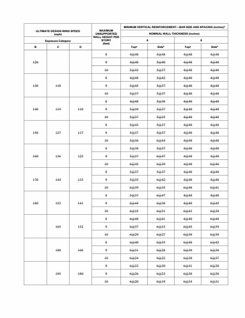
ULTIMATE DESIGN WIND SPEED (mph)
MAXIMUM UNSUPPORTED
WALL HEIGHT PER STORY (feet)
MINIMUM VERTICAL REINFORCEMENT—BAR SIZE AND SPACING (inches)f
NOMINAL WALL THICKNESS (inches)
Exposure Category 6 8
B C D Topg Sideh Topg Sideh
120
8 4@48 5@48 4@48 4@48
9 4@48 5@40 4@48 4@48
10 5@43 5@37 4@48 4@48
130 110
8 4@48 5@42 4@48 4@48
9 5@45 5@37 4@48 4@48
10 5@37 5@37 4@48 4@48
140 119 110
8 4@48 5@38 4@48 4@48
9 5@39 5@37 4@48 4@48
10 5@37 5@35 4@48 4@48
150 127 117
8 5@43 5@37 4@48 4@48
9 5@37 5@37 4@48 4@48
10 5@36 6@44 4@48 4@48
160 136 125
8 5@38 5@37 4@48 4@48
9 5@37 6@47 4@48 4@48
10 6@45 6@39 4@48 6@46
170 144 133
8 5@37 5@37 4@48 4@48
9 5@35 6@42 4@48 4@48
10 6@39 6@35 6@48 6@41
180 153 141
8 5@37 6@47 4@48 4@48
9 6@44 6@38 4@48 6@45
10 6@35 6@31 6@43 6@38
165 152
8 6@48 6@41 4@48 6@48
9 6@37 6@33 6@45 6@39
10 6@29 6@27 6@38 6@38
180 166
8 6@40 6@35 6@48 6@42
9 6@31 6@28 6@38 6@38
10 6@24 6@22 6@38 6@37
195 180
8 6@33 6@30 6@41 6@38
9 6@26 6@23 6@38 6@38
10 6@20 6@19 6@34 6@31
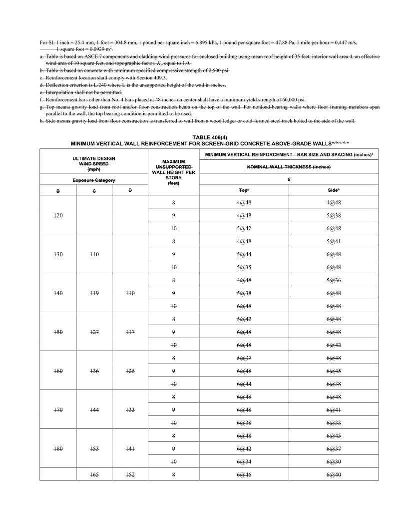
For SI: 1 inch = 25.4 mm, 1 foot = 304.8 mm, 1 pound per square inch = 6.895 kPa, 1 pound per square foot = 47.88 Pa, 1 mile per hour = 0.447 m/s, 1 square foot = 0.0929 m2. a. Table is based on ASCE 7 components and cladding wind pressures for enclosed building using mean roof height of 35 feet, interior wall area 4, an effective
wind area of 10 square feet, and topographic factor, Kzt equal to 1.0. b. Table is based on concrete with minimum specified compressive strength of 2,500 psi. c. Reinforcement location shall comply with Section 409.3. d. Deflection criterion is L/240 where L is the unsupported height of the wall in inches. e. Interpolation shall not be permitted. f. Reinforcement bars other than No. 4 bars placed at 48 inches on center shall have a minimum yield strength of 60,000 psi. g. Top means gravity load from roof and/or floor construction bears on the top of the wall. For nonload-bearing walls where floor framing members span
parallel to the wall, the top bearing condition is permitted to be used. h. Side means gravity load from floor construction is transferred to wall from a wood ledger or cold-formed steel track bolted to the side of the wall.
TABLE 409(4) MINIMUM VERTICAL WALL REINFORCEMENT FOR SCREEN-GRID CONCRETE ABOVE-GRADE WALLSa, b, c, d, e
ULTIMATE DESIGN WIND SPEED
(mph)
MAXIMUM UNSUPPORTED
WALL HEIGHT PER STORY (feet)
MINIMUM VERTICAL REINFORCEMENT—BAR SIZE AND SPACING (inches)f
NOMINAL WALL THICKNESS (inches)
Exposure Category 6
B C D Topg Sideh
120
8 4@48 4@48
9 4@48 5@38
10 5@42 6@48
130 110
8 4@48 5@41
9 5@44 6@48
10 5@35 6@48
140 119 110
8 4@48 5@36
9 5@38 6@48
10 6@48 6@48
150 127 117
8 5@42 6@48
9 6@48 6@48
10 6@48 6@42
160 136 125
8 5@37 6@48
9 6@48 6@45
10 6@44 6@38
170 144 133
8 6@48 6@48
9 6@48 6@41
10 6@38 6@33
180 153 141
8 6@48 6@45
9 6@42 6@37
10 6@34 6@30
165 152 8 6@46 6@40

9 6@36 6@32
10 6@29 6@26
180 166
8 6@38 6@34
9 6@30 6@27
10 6@24 6@22
195 180
8 6@33 6@29
9 6@25 6@23
10 6@20 6@18
For SI: 1 inch = 25.4 mm, 1 foot = 304.8 mm, 1 mile per hour = 0.447 m/s, 1 pound per square inch = 6.895 kPa, 1 pound per square foot = 47.88 Pa, 1 square foot = 0.0929 m2. a. Table is based on ASCE 7 components and cladding wind pressures for enclosed building using mean roof height of 35 feet, interior wall area 4, an effective
wind area of 10 square feet, and topographic factor, Kzt equal to 1.0, 1 square foot = 0.0929 m2. b. Table is based on concrete with minimum specified compressive strength of 2,500 psi. c. Reinforcement location shall comply with Section 409.3. d. Deflection criterion is L/240 where L is the unsupported height of the wall in inches. e. Interpolation shall not be permitted. f. Reinforcement bars other than No. 4 bars placed at 48 inches on center shall have a minimum yield strength of 60,000 psi. g. Top means gravity load from roof and/or floor construction bears on the top of the wall. For nonload-bearing walls where floor framing members span
parallel to the wall, the top bearing condition is permitted to be used. h. Side means gravity load from floor construction is transferred to wall from a wood ledger or cold-formed steel track bolted to the side of the wall.
TABLE 409(5) MINIMUM UNREDUCED LENGTH OF SOLID ENDWALL REQUIRED IN EACH EXTERIOR ENDWALL
FOR WIND PERPENDICULAR TO RIDGE FOR ONE STORY OR TOP STORY OF TWO STORYa, c, d, e, f, g
EXPOSURE CATEGORY MINIMUM LENGTH OF SOLID WALL REQUIRED IN ENDWALLS FOR WIND PERPENDICULAR TO RIDGE (feet)
B 120 130 140 150 160 170 180
Minimumb
C 110 119 127 136 144 153 165 180
D 110 117 125 133 141 152 166 180
Sidewall length (feet)
Endwall length (feet)
Roof slope
Velocity pressure (ASD) (psf)
23 27 31 36 41 46 52 60 72 84
15
15
1:12 1.12 1.32 1.53 1.76 2.00 2.25 2.53 2.94 3.50 4.12 0.92
5:12 1.56 1.83 2.12 2.43 2.77 3.13 3.50 4.08 4.86 5.71 1.15
7:12 2.18 2.56 2.97 3.41 3.88 4.38 4.91 5.72 6.80 8.01 1.25
12:12 3.48 4.09 4.74 5.55 6.19 6.99 7.84 9.12 10.86 12.78 1.54
30
1:12 1.12 1.32 1.53 1.76 2.00 2.25 2.53 2.94 3.50 4.12 0.98
5:12 1.56 1.83 2.12 2.43 2.77 3.13 3.50 4.08 4.86 5.71 1.43
7:12 3.03 3.56 4.13 4.74 5.39 6.09 6.82 7.94 9.45 11.12 1.64
12:12 5.63 6.61 7.67 8.80 10.01 11.30 12.67 14.76 17.56 20.67 2.21
45
1:12 1.12 1.32 1.53 1.76 2.00 2.25 2.53 2.94 3.50 4.12 1.04
5:12 1.56 1.83 2.12 2.43 2.77 3.13 3.50 4.08 4.86 5.71 1.72
7:12 3.88 4.56 5.28 6.07 6.90 7.79 8.74 10.17 12.11 14.24 2.03
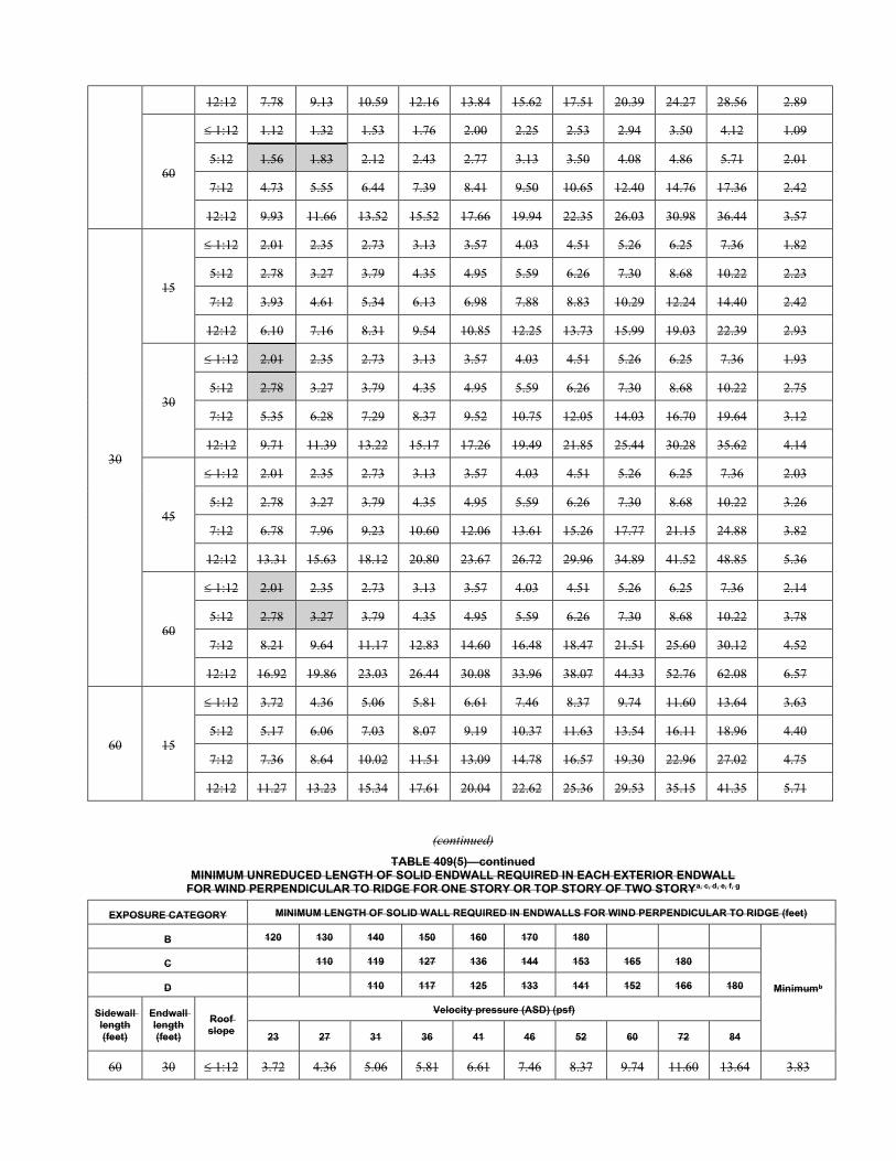
12:12 7.78 9.13 10.59 12.16 13.84 15.62 17.51 20.39 24.27 28.56 2.89
60
1:12 1.12 1.32 1.53 1.76 2.00 2.25 2.53 2.94 3.50 4.12 1.09
5:12 1.56 1.83 2.12 2.43 2.77 3.13 3.50 4.08 4.86 5.71 2.01
7:12 4.73 5.55 6.44 7.39 8.41 9.50 10.65 12.40 14.76 17.36 2.42
12:12 9.93 11.66 13.52 15.52 17.66 19.94 22.35 26.03 30.98 36.44 3.57
30
15
1:12 2.01 2.35 2.73 3.13 3.57 4.03 4.51 5.26 6.25 7.36 1.82
5:12 2.78 3.27 3.79 4.35 4.95 5.59 6.26 7.30 8.68 10.22 2.23
7:12 3.93 4.61 5.34 6.13 6.98 7.88 8.83 10.29 12.24 14.40 2.42
12:12 6.10 7.16 8.31 9.54 10.85 12.25 13.73 15.99 19.03 22.39 2.93
30
1:12 2.01 2.35 2.73 3.13 3.57 4.03 4.51 5.26 6.25 7.36 1.93
5:12 2.78 3.27 3.79 4.35 4.95 5.59 6.26 7.30 8.68 10.22 2.75
7:12 5.35 6.28 7.29 8.37 9.52 10.75 12.05 14.03 16.70 19.64 3.12
12:12 9.71 11.39 13.22 15.17 17.26 19.49 21.85 25.44 30.28 35.62 4.14
45
1:12 2.01 2.35 2.73 3.13 3.57 4.03 4.51 5.26 6.25 7.36 2.03
5:12 2.78 3.27 3.79 4.35 4.95 5.59 6.26 7.30 8.68 10.22 3.26
7:12 6.78 7.96 9.23 10.60 12.06 13.61 15.26 17.77 21.15 24.88 3.82
12:12 13.31 15.63 18.12 20.80 23.67 26.72 29.96 34.89 41.52 48.85 5.36
60
1:12 2.01 2.35 2.73 3.13 3.57 4.03 4.51 5.26 6.25 7.36 2.14
5:12 2.78 3.27 3.79 4.35 4.95 5.59 6.26 7.30 8.68 10.22 3.78
7:12 8.21 9.64 11.17 12.83 14.60 16.48 18.47 21.51 25.60 30.12 4.52
12:12 16.92 19.86 23.03 26.44 30.08 33.96 38.07 44.33 52.76 62.08 6.57
60 15
1:12 3.72 4.36 5.06 5.81 6.61 7.46 8.37 9.74 11.60 13.64 3.63
5:12 5.17 6.06 7.03 8.07 9.19 10.37 11.63 13.54 16.11 18.96 4.40
7:12 7.36 8.64 10.02 11.51 13.09 14.78 16.57 19.30 22.96 27.02 4.75
12:12 11.27 13.23 15.34 17.61 20.04 22.62 25.36 29.53 35.15 41.35 5.71
(continued)
TABLE 409(5)—continued MINIMUM UNREDUCED LENGTH OF SOLID ENDWALL REQUIRED IN EACH EXTERIOR ENDWALL
FOR WIND PERPENDICULAR TO RIDGE FOR ONE STORY OR TOP STORY OF TWO STORYa, c, d, e, f, g
EXPOSURE CATEGORY MINIMUM LENGTH OF SOLID WALL REQUIRED IN ENDWALLS FOR WIND PERPENDICULAR TO RIDGE (feet)
B 120 130 140 150 160 170 180
Minimumb
C 110 119 127 136 144 153 165 180
D 110 117 125 133 141 152 166 180
Sidewall length (feet)
Endwall length (feet)
Roof slope
Velocity pressure (ASD) (psf)
23 27 31 36 41 46 52 60 72 84
60 30 1:12 3.72 4.36 5.06 5.81 6.61 7.46 8.37 9.74 11.60 13.64 3.83
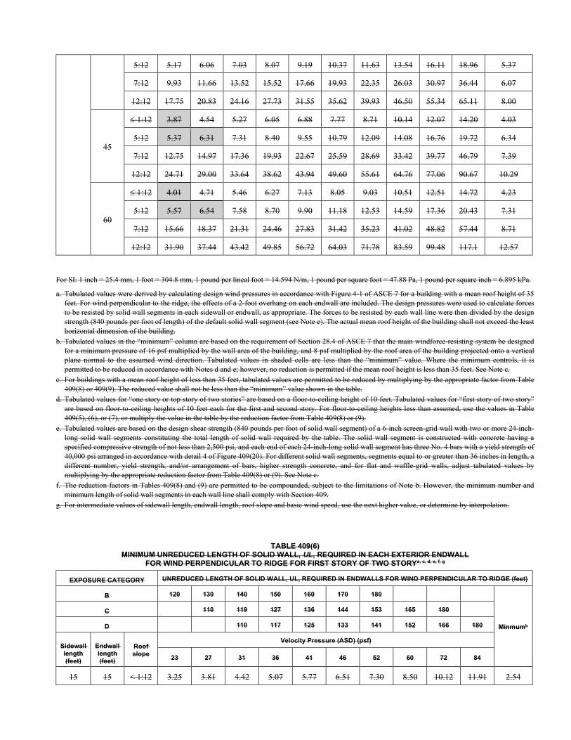
5:12 5.17 6.06 7.03 8.07 9.19 10.37 11.63 13.54 16.11 18.96 5.37
7:12 9.93 11.66 13.52 15.52 17.66 19.93 22.35 26.03 30.97 36.44 6.07
12:12 17.75 20.83 24.16 27.73 31.55 35.62 39.93 46.50 55.34 65.11 8.00
45
1:12 3.87 4.54 5.27 6.05 6.88 7.77 8.71 10.14 12.07 14.20 4.03
5:12 5.37 6.31 7.31 8.40 9.55 10.79 12.09 14.08 16.76 19.72 6.34
7:12 12.75 14.97 17.36 19.93 22.67 25.59 28.69 33.42 39.77 46.79 7.39
12:12 24.71 29.00 33.64 38.62 43.94 49.60 55.61 64.76 77.06 90.67 10.29
60
1:12 4.01 4.71 5.46 6.27 7.13 8.05 9.03 10.51 12.51 14.72 4.23
5:12 5.57 6.54 7.58 8.70 9.90 11.18 12.53 14.59 17.36 20.43 7.31
7:12 15.66 18.37 21.31 24.46 27.83 31.42 35.23 41.02 48.82 57.44 8.71
12:12 31.90 37.44 43.42 49.85 56.72 64.03 71.78 83.59 99.48 117.1 12.57
For SI: 1 inch = 25.4 mm, 1 foot = 304.8 mm, 1 pound per lineal foot = 14.594 N/m, 1 pound per square foot = 47.88 Pa, 1 pound per square inch = 6.895 kPa.
a. Tabulated values were derived by calculating design wind pressures in accordance with Figure 4-1 of ASCE 7 for a building with a mean roof height of 35 feet. For wind perpendicular to the ridge, the effects of a 2-foot overhang on each endwall are included. The design pressures were used to calculate forces to be resisted by solid wall segments in each sidewall or endwall, as appropriate. The forces to be resisted by each wall line were then divided by the design strength (840 pounds per foot of length) of the default solid wall segment (see Note e). The actual mean roof height of the building shall not exceed the least horizontal dimension of the building.
b. Tabulated values in the “minimum” column are based on the requirement of Section 28.4 of ASCE 7 that the main windforce-resisting system be designed for a minimum pressure of 16 psf multiplied by the wall area of the building, and 8 psf multiplied by the roof area of the building projected onto a vertical plane normal to the assumed wind direction. Tabulated values in shaded cells are less than the “minimum” value. Where the minimum controls, it is permitted to be reduced in accordance with Notes d and e; however, no reduction is permitted if the mean roof height is less than 35 feet. See Note c.
c. For buildings with a mean roof height of less than 35 feet, tabulated values are permitted to be reduced by multiplying by the appropriate factor from Table 409(8) or 409(9). The reduced value shall not be less than the “minimum” value shown in the table.
d. Tabulated values for “one story or top story of two stories” are based on a floor-to-ceiling height of 10 feet. Tabulated values for “first story of two story” are based on floor-to-ceiling heights of 10 feet each for the first and second story. For floor-to-ceiling heights less than assumed, use the values in Table 409(5), (6), or (7), or multiply the value in the table by the reduction factor from Table 409(8) or (9).
e. Tabulated values are based on the design shear strength (840 pounds per foot of solid wall segment) of a 6-inch screen-grid wall with two or more 24-inch- long solid wall segments constituting the total length of solid wall required by the table. The solid wall segment is constructed with concrete having a specified compressive strength of not less than 2,500 psi, and each end of each 24-inch-long solid wall segment has three No. 4 bars with a yield strength of 40,000 psi arranged in accordance with detail 4 of Figure 409(20). For different solid wall segments, segments equal to or greater than 36 inches in length, a different number, yield strength, and/or arrangement of bars, higher strength concrete, and for flat and waffle-grid walls, adjust tabulated values by multiplying by the appropriate reduction factor from Table 409(8) or (9). See Note c.
f. The reduction factors in Tables 409(8) and (9) are permitted to be compounded, subject to the limitations of Note b. However, the minimum number and minimum length of solid wall segments in each wall line shall comply with Section 409.
g. For intermediate values of sidewall length, endwall length, roof slope and basic wind speed, use the next higher value, or determine by interpolation.
TABLE 409(6) MINIMUM UNREDUCED LENGTH OF SOLID WALL, UL, REQUIRED IN EACH EXTERIOR ENDWALL
FOR WIND PERPENDICULAR TO RIDGE FOR FIRST STORY OF TWO STORYa, c, d, e, f, g
EXPOSURE CATEGORY UNREDUCED LENGTH OF SOLID WALL, UL, REQUIRED IN ENDWALLS FOR WIND PERPENDICULAR TO RIDGE (feet)
B 120 130 140 150 160 170 180
Minmumb
C 110 119 127 136 144 153 165 180
D 110 117 125 133 141 152 166 180
Sidewall length (feet)
Endwall length (feet)
Roof slope
Velocity Pressure (ASD) (psf)
23 27 31 36 41 46 52 60 72 84
15 15 < 1:12 3.25 3.81 4.42 5.07 5.77 6.51 7.30 8.50 10.12 11.91 2.54
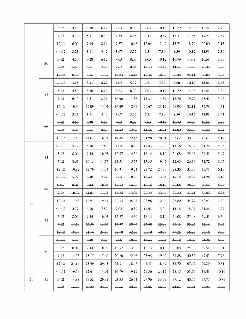
5:12 4.50 5.28 6.12 7.03 8.00 9.03 10.12 11.79 14.03 16.51 2.76
7:12 4.70 5.51 6.39 7.34 8.35 9.43 10.57 12.31 14.65 17.23 2.87
12:12 6.00 7.04 8.16 9.37 10.66 12.04 13.49 15.71 18.70 22.00 3.15
30
< 1:12 3.25 3.81 4.42 5.07 5.77 6.51 7.30 8.50 10.12 11.91 2.59
5:12 4.50 5.28 6.12 7.03 8.00 9.03 10.12 11.79 14.03 16.51 3.05
7:12 5.55 6.51 7.55 8.67 9.86 11.13 12.48 14.54 17.30 20.35 3.26
12:12 8.15 9.56 11.09 12.73 14.49 16.35 18.33 21.35 25.41 29.89 3.83
45
< 1:12 3.25 3.81 4.42 5.07 5.77 6.51 7.30 8.50 10.12 11.91 2.65
5:12 4.50 5.28 6.12 7.03 8.00 9.03 10.12 11.79 14.03 16.51 3.34
7:12 6.40 7.51 8.71 10.00 11.37 12.84 14.39 16.76 19.95 23.47 3.65
12:12 10.30 12.09 14.02 16.09 18.31 20.67 23.17 26.98 32.11 37.78 4.51
60
< 1:12 3.25 3.81 4.42 5.07 5.77 6.51 7.30 8.50 10.12 11.91 2.71
5:12 4.50 5.28 6.12 7.03 8.00 9.03 10.12 11.79 14.03 16.51 3.63
7:12 7.25 8.51 9.87 11.32 12.89 14.55 16.31 18.99 22.60 26.59 4.04
12:12 12.45 14.61 16.94 19.45 22.13 24.98 28.01 32.62 38.82 45.67 5.19
30
15
< 1:12 5.79 6.80 7.89 9.05 10.30 11.63 13.04 15.18 18.07 21.26 5.06
5:12 8.04 9.44 10.95 12.57 14.30 16.14 18.10 21.08 25.08 29.51 5.47
7:12 8.65 10.15 11.77 13.51 15.37 17.35 19.45 22.65 26.96 31.72 5.65
12:12 10.82 12.70 14.73 16.91 19.24 21.72 24.35 28.36 33.75 39.71 6.17
30
< 1:12 5.79 6.80 7.89 9.05 10.30 11.63 13.04 15.18 18.07 21.26 5.16
5 :12 8.04 9.44 10.95 12.57 14.30 16.14 18.10 21.08 25.08 29.51 5.98
7:12 10.07 11.82 13.71 15.74 17.91 20.22 22.66 26.39 31.41 36.96 6.35
12:12 14.43 16.93 19.64 22.54 25.65 28.96 32.46 37.80 44.99 52.93 7.38
45
< 1:12 5.79 6.80 7.89 9.05 10.30 11.63 13.04 15.18 18.07 21.26 5.27
5:12 8.04 9.44 10.95 12.57 14.30 16.14 18.10 21.08 25.08 29.51 6.50
7:12 11.50 13.50 15.65 17.97 20.45 23.08 25.88 30.13 35.86 42.19 7.06
12:12 18.03 21.16 24.55 28.18 32.06 36.19 40.58 47.25 56.23 66.16 8.60
60
< 1:12 5.79 6.80 7.89 9.05 10.30 11.63 13.04 15.18 18.07 21.26 5.38
5:12 8.04 9.44 10.95 12.57 14.30 16.14 18.10 21.08 25.08 29.51 7.01
7:12 12.93 15.17 17.60 20.20 22.98 25.95 29.09 33.88 40.32 47.43 7.76
12:12 21.64 25.40 29.45 33.81 38.47 43.43 48.69 56.70 67.47 79.39 9.81
60 15
< 1:12 10.74 12.61 14.62 16.79 19.10 21.56 24.17 28.15 33.50 39.41 10.10
5:12 14.93 17.52 20.32 23.33 26.54 29.96 33.59 39.12 46.55 54.77 10.87
7:12 16.42 19.27 22.35 25.66 29.20 32.96 36.95 43.03 51.21 60.25 11.22
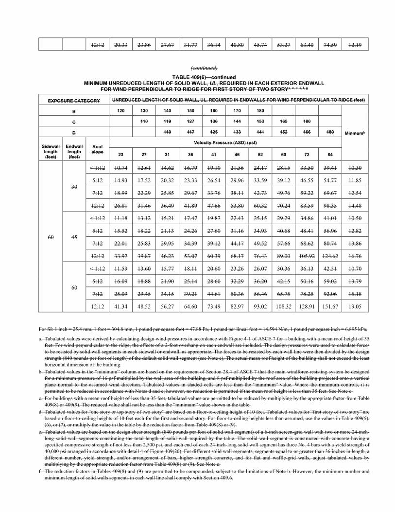
12:12 20.33 23.86 27.67 31.77 36.14 40.80 45.74 53.27 63.40 74.59 12.19
(continued)
TABLE 409(6)—continued MINIMUM UNREDUCED LENGTH OF SOLID WALL, UL, REQUIRED IN EACH EXTERIOR ENDWALL
FOR WIND PERPENDICULAR TO RIDGE FOR FIRST STORY OF TWO STORYa, c, d, e, f, g
EXPOSURE CATEGORY UNREDUCED LENGTH OF SOLID WALL, UL, REQUIRED IN ENDWALLS FOR WIND PERPENDICULAR TO RIDGE (feet)
B 120 130 140 150 160 170 180
Minmumb
C 110 119 127 136 144 153 165 180
D 110 117 125 133 141 152 166 180
Sidewall length (feet)
Endwall length (feet)
Roof slope
Velocity Pressure (ASD) (psf)
23 27 31 36 41 46 52 60 72 84
60
30
< 1:12 10.74 12.61 14.62 16.79 19.10 21.56 24.17 28.15 33.50 39.41 10.30
5:12 14.93 17.52 20.32 23.33 26.54 29.96 33.59 39.12 46.55 54.77 11.85
7:12 18.99 22.29 25.85 29.67 33.76 38.11 42.73 49.76 59.22 69.67 12.54
12:12 26.81 31.46 36.49 41.89 47.66 53.80 60.32 70.24 83.59 98.35 14.48
45
< 1:12 11.18 13.12 15.21 17.47 19.87 22.43 25.15 29.29 34.86 41.01 10.50
5:12 15.52 18.22 21.13 24.26 27.60 31.16 34.93 40.68 48.41 56.96 12.82
7:12 22.01 25.83 29.95 34.39 39.12 44.17 49.52 57.66 68.62 80.74 13.86
12:12 33.97 39.87 46.23 53.07 60.39 68.17 76.43 89.00 105.92 124.62 16.76
60
< 1:12 11.59 13.60 15.77 18.11 20.60 23.26 26.07 30.36 36.13 42.51 10.70
5:12 16.09 18.88 21.90 25.14 28.60 32.29 36.20 42.15 50.16 59.02 13.79
7:12 25.09 29.45 34.15 39.21 44.61 50.36 56.46 65.75 78.25 92.06 15.18
12:12 41.34 48.52 56.27 64.60 73.49 82.97 93.02 108.32 128.91 151.67 19.05
For SI: 1 inch = 25.4 mm, 1 foot = 304.8 mm, 1 pound per square foot = 47.88 Pa, 1 pound per lineal foot = 14.594 N/m, 1 pound per square inch = 6.895 kPa.
a. Tabulated values were derived by calculating design wind pressures in accordance with Figure 4-1 of ASCE 7 for a building with a mean roof height of 35 feet. For wind perpendicular to the ridge, the effects of a 2-foot overhang on each endwall are included. The design pressures were used to calculate forces to be resisted by solid wall segments in each sidewall or endwall, as appropriate. The forces to be resisted by each wall line were then divided by the design strength (840 pounds per foot of length) of the default solid wall segment (see Note e). The actual mean roof height of the building shall not exceed the least horizontal dimension of the building.
b. Tabulated values in the “minimum” column are based on the requirement of Section 28.4 of ASCE 7 that the main windforce-resisting system be designed for a minimum pressure of 16 psf multiplied by the wall area of the building, and 8 psf multiplied by the roof area of the building projected onto a vertical plane normal to the assumed wind direction. Tabulated values in shaded cells are less than the “minimum” value. Where the minimum controls, it is permitted to be reduced in accordance with Notes d and e; however, no reduction is permitted if the mean roof height is less than 35 feet. See Note c.
c. For buildings with a mean roof height of less than 35 feet, tabulated values are permitted to be reduced by multiplying by the appropriate factor from Table 409(8) or 409(9). The reduced value shall not be less than the “minimum” value shown in the table.
d. Tabulated values for “one story or top story of two story” are based on a floor-to-ceiling height of 10 feet. Tabulated values for “first story of two story” are based on floor-to-ceiling heights of 10 feet each for the first and second story. For floor-to-ceiling heights less than assumed, use the values in Table 409(5), (6), or (7), or multiply the value in the table by the reduction factor from Table 409(8) or (9).
e. Tabulated values are based on the design shear strength (840 pounds per foot of solid wall segment) of a 6-inch screen-grid wall with two or more 24-inch- long solid wall segments constituting the total length of solid wall required by the table. The solid wall segment is constructed with concrete having a specified compressive strength of not less than 2,500 psi, and each end of each 24-inch-long solid wall segment has three No. 4 bars with a yield strength of 40,000 psi arranged in accordance with detail 4 of Figure 409(20). For different solid wall segments, segments equal to or greater than 36 inches in length, a different number, yield strength, and/or arrangement of bars, higher strength concrete, and for flat and waffle-grid walls, adjust tabulated values by multiplying by the appropriate reduction factor from Table 409(8) or (9). See Note c.
f. The reduction factors in Tables 409(8) and (9) are permitted to be compounded, subject to the limitations of Note b. However, the minimum number and minimum length of solid walls segments in each wall line shall comply with Section 409.6.
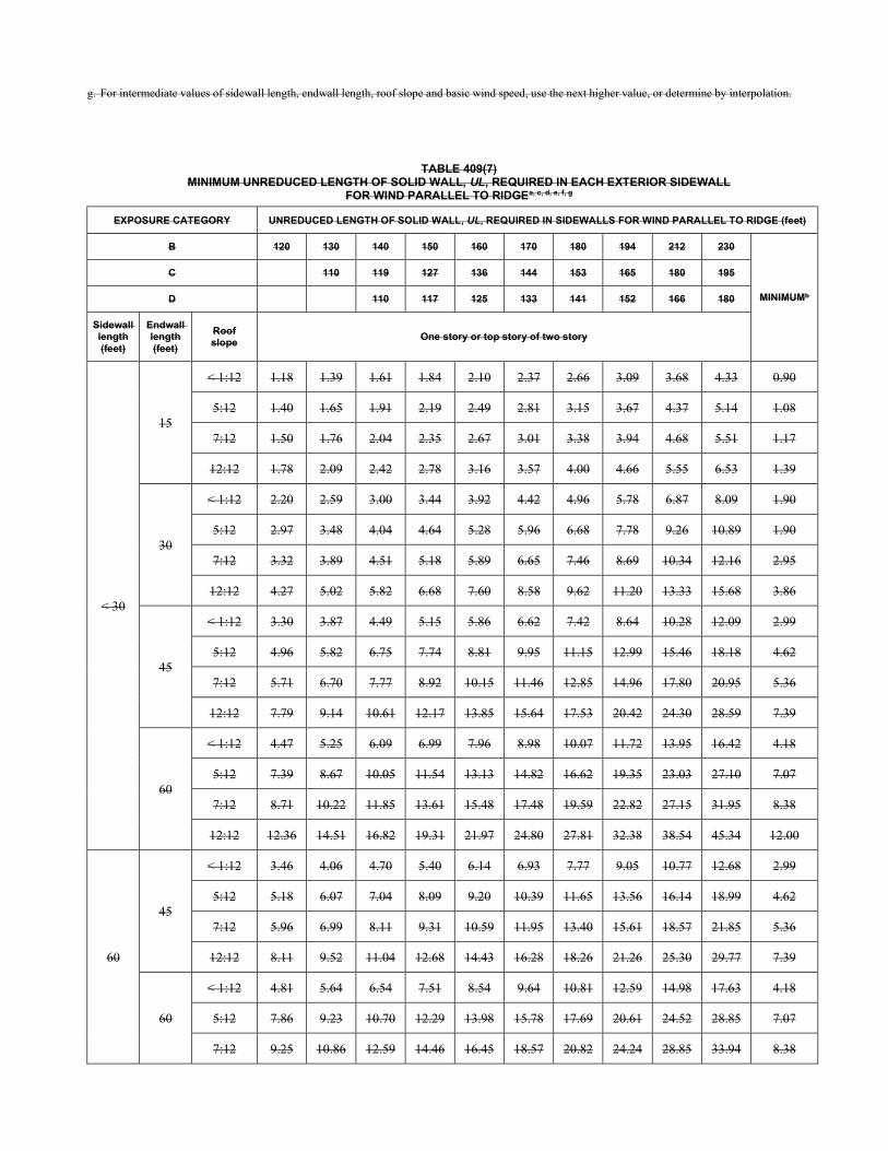
g. For intermediate values of sidewall length, endwall length, roof slope and basic wind speed, use the next higher value, or determine by interpolation.
TABLE 409(7) MINIMUM UNREDUCED LENGTH OF SOLID WALL, UL, REQUIRED IN EACH EXTERIOR SIDEWALL
FOR WIND PARALLEL TO RIDGEa, c, d, e, f, g
EXPOSURE CATEGORY UNREDUCED LENGTH OF SOLID WALL, UL, REQUIRED IN SIDEWALLS FOR WIND PARALLEL TO RIDGE (feet)
B 120 130 140 150 160 170 180 194 212 230
MINIMUMb
C 110 119 127 136 144 153 165 180 195
D 110 117 125 133 141 152 166 180
Sidewall length (feet)
Endwall length (feet)
Roof slope
One story or top story of two story
< 30
15
< 1:12 1.18 1.39 1.61 1.84 2.10 2.37 2.66 3.09 3.68 4.33 0.90
5:12 1.40 1.65 1.91 2.19 2.49 2.81 3.15 3.67 4.37 5.14 1.08
7:12 1.50 1.76 2.04 2.35 2.67 3.01 3.38 3.94 4.68 5.51 1.17
12:12 1.78 2.09 2.42 2.78 3.16 3.57 4.00 4.66 5.55 6.53 1.39
30
< 1:12 2.20 2.59 3.00 3.44 3.92 4.42 4.96 5.78 6.87 8.09 1.90
5:12 2.97 3.48 4.04 4.64 5.28 5.96 6.68 7.78 9.26 10.89 1.90
7:12 3.32 3.89 4.51 5.18 5.89 6.65 7.46 8.69 10.34 12.16 2.95
12:12 4.27 5.02 5.82 6.68 7.60 8.58 9.62 11.20 13.33 15.68 3.86
45
< 1:12 3.30 3.87 4.49 5.15 5.86 6.62 7.42 8.64 10.28 12.09 2.99
5:12 4.96 5.82 6.75 7.74 8.81 9.95 11.15 12.99 15.46 18.18 4.62
7:12 5.71 6.70 7.77 8.92 10.15 11.46 12.85 14.96 17.80 20.95 5.36
12:12 7.79 9.14 10.61 12.17 13.85 15.64 17.53 20.42 24.30 28.59 7.39
60
< 1:12 4.47 5.25 6.09 6.99 7.96 8.98 10.07 11.72 13.95 16.42 4.18
5:12 7.39 8.67 10.05 11.54 13.13 14.82 16.62 19.35 23.03 27.10 7.07
7:12 8.71 10.22 11.85 13.61 15.48 17.48 19.59 22.82 27.15 31.95 8.38
12:12 12.36 14.51 16.82 19.31 21.97 24.80 27.81 32.38 38.54 45.34 12.00
60
45
< 1:12 3.46 4.06 4.70 5.40 6.14 6.93 7.77 9.05 10.77 12.68 2.99
5:12 5.18 6.07 7.04 8.09 9.20 10.39 11.65 13.56 16.14 18.99 4.62
7:12 5.96 6.99 8.11 9.31 10.59 11.95 13.40 15.61 18.57 21.85 5.36
12:12 8.11 9.52 11.04 12.68 14.43 16.28 18.26 21.26 25.30 29.77 7.39
60
< 1:12 4.81 5.64 6.54 7.51 8.54 9.64 10.81 12.59 14.98 17.63 4.18
5:12 7.86 9.23 10.70 12.29 13.98 15.78 17.69 20.61 24.52 28.85 7.07
7:12 9.25 10.86 12.59 14.46 16.45 18.57 20.82 24.24 28.85 33.94 8.38
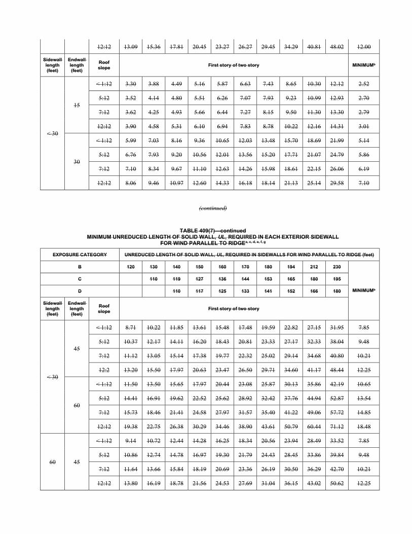
12:12 13.09 15.36 17.81 20.45 23.27 26.27 29.45 34.29 40.81 48.02 12.00
Sidewall length (feet)
Endwall length (feet)
Roof slope
First story of two story MINIMUMb
< 30
15
< 1:12 3.30 3.88 4.49 5.16 5.87 6.63 7.43 8.65 10.30 12.12 2.52
5:12 3.52 4.14 4.80 5.51 6.26 7.07 7.93 9.23 10.99 12.93 2.70
7:12 3.62 4.25 4.93 5.66 6.44 7.27 8.15 9.50 11.30 13.30 2.79
12:12 3.90 4.58 5.31 6.10 6.94 7.83 8.78 10.22 12.16 14.31 3.01
30
< 1:12 5.99 7.03 8.16 9.36 10.65 12.03 13.48 15.70 18.69 21.99 5.14
5:12 6.76 7.93 9.20 10.56 12.01 13.56 15.20 17.71 21.07 24.79 5.86
7:12 7.10 8.34 9.67 11.10 12.63 14.26 15.98 18.61 22.15 26.06 6.19
12:12 8.06 9.46 10.97 12.60 14.33 16.18 18.14 21.13 25.14 29.58 7.10
(continued)
TABLE 409(7)—continued MINIMUM UNREDUCED LENGTH OF SOLID WALL, UL, REQUIRED IN EACH EXTERIOR SIDEWALL
FOR WIND PARALLEL TO RIDGEa, c, d, e, f, g
EXPOSURE CATEGORY UNREDUCED LENGTH OF SOLID WALL, UL, REQUIRED IN SIDEWALLS FOR WIND PARALLEL TO RIDGE (feet)
B 120 130 140 150 160 170 180 194 212 230
MINIMUMb
C 110 119 127 136 144 153 165 180 195
D 110 117 125 133 141 152 166 180
Sidewall length (feet)
Endwall length (feet)
Roof slope
First story of two story
< 30
45
< 1:12 8.71 10.22 11.85 13.61 15.48 17.48 19.59 22.82 27.15 31.95 7.85
5:12 10.37 12.17 14.11 16.20 18.43 20.81 23.33 27.17 32.33 38.04 9.48
7:12 11.12 13.05 15.14 17.38 19.77 22.32 25.02 29.14 34.68 40.80 10.21
12:2 13.20 15.50 17.97 20.63 23.47 26.50 29.71 34.60 41.17 48.44 12.25
60
< 1:12 11.50 13.50 15.65 17.97 20.44 23.08 25.87 30.13 35.86 42.19 10.65
5:12 14.41 16.91 19.62 22.52 25.62 28.92 32.42 37.76 44.94 52.87 13.54
7:12 15.73 18.46 21.41 24.58 27.97 31.57 35.40 41.22 49.06 57.72 14.85
12:12 19.38 22.75 26.38 30.29 34.46 38.90 43.61 50.79 60.44 71.12 18.48
60 45
< 1:12 9.14 10.72 12.44 14.28 16.25 18.34 20.56 23.94 28.49 33.52 7.85
5:12 10.86 12.74 14.78 16.97 19.30 21.79 24.43 28.45 33.86 39.84 9.48
7:12 11.64 13.66 15.84 18.19 20.69 23.36 26.19 30.50 36.29 42.70 10.21
12:12 13.80 16.19 18.78 21.56 24.53 27.69 31.04 36.15 43.02 50.62 12.25
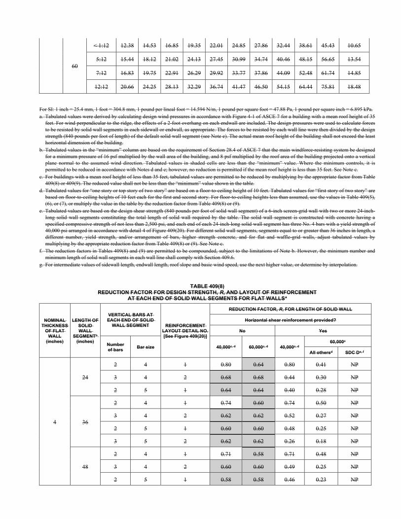
60
< 1:12 12.38 14.53 16.85 19.35 22.01 24.85 27.86 32.44 38.61 45.43 10.65
5:12 15.44 18.12 21.02 24.13 27.45 30.99 34.74 40.46 48.15 56.65 13.54
7:12 16.83 19.75 22.91 26.29 29.92 33.77 37.86 44.09 52.48 61.74 14.85
12:12 20.66 24.25 28.13 32.29 36.74 41.47 46.50 54.15 64.44 75.81 18.48
For SI: 1 inch = 25.4 mm, 1 foot = 304.8 mm, 1 pound per lineal foot = 14.594 N/m, 1 pound per square foot = 47.88 Pa, 1 pound per square inch = 6.895 kPa. a. Tabulated values were derived by calculating design wind pressures in accordance with Figure 4-1 of ASCE 7 for a building with a mean roof height of 35
feet. For wind perpendicular to the ridge, the effects of a 2-foot overhang on each endwall are included. The design pressures were used to calculate forces to be resisted by solid wall segments in each sidewall or endwall, as appropriate. The forces to be resisted by each wall line were then divided by the design strength (840 pounds per foot of length) of the default solid wall segment (see Note e). The actual mean roof height of the building shall not exceed the least horizontal dimension of the building.
b. Tabulated values in the “minimum” column are based on the requirement of Section 28.4 of ASCE 7 that the main windforce-resisting system be designed for a minimum pressure of 16 psf multiplied by the wall area of the building, and 8 psf multiplied by the roof area of the building projected onto a vertical plane normal to the assumed wind direction. Tabulated values in shaded cells are less than the “minimum” value. Where the minimum controls, it is permitted to be reduced in accordance with Notes d and e; however, no reduction is permitted if the mean roof height is less than 35 feet. See Note c.
c. For buildings with a mean roof height of less than 35 feet, tabulated values are permitted to be reduced by multiplying by the appropriate factor from Table 409(8) or 409(9). The reduced value shall not be less than the “minimum” value shown in the table.
d. Tabulated values for “one story or top story of two story” are based on a floor-to-ceiling height of 10 feet. Tabulated values for “first story of two story” are based on floor-to-ceiling heights of 10 feet each for the first and second story. For floor-to-ceiling heights less than assumed, use the values in Table 409(5), (6), or (7), or multiply the value in the table by the reduction factor from Table 409(8) or (9).
e. Tabulated values are based on the design shear strength (840 pounds per foot of solid wall segment) of a 6-inch screen-grid wall with two or more 24-inch- long solid wall segments constituting the total length of solid wall required by the table. The solid wall segment is constructed with concrete having a specified compressive strength of not less than 2,500 psi, and each end of each 24-inch-long solid wall segment has three No. 4 bars with a yield strength of 40,000 psi arranged in accordance with detail 4 of Figure 409(20). For different solid wall segments, segments equal to or greater than 36 inches in length, a different number, yield strength, and/or arrangement of bars, higher strength concrete, and for flat and waffle-grid walls, adjust tabulated values by multiplying by the appropriate reduction factor from Table 409(8) or (9). See Note c.
f. The reduction factors in Tables 409(8) and (9) are permitted to be compounded, subject to the limitations of Note b. However, the minimum number and minimum length of solid wall segments in each wall line shall comply with Section 409.6.
g. For intermediate values of sidewall length, endwall length, roof slope and basic wind speed, use the next higher value, or determine by interpolation.
TABLE 409(8) REDUCTION FACTOR FOR DESIGN STRENGTH, R, AND LAYOUT OF REINFORCEMENT
AT EACH END OF SOLID WALL SEGMENTS FOR FLAT WALLSa
NOMINAL THICKNESS
OF FLAT WALL
(inches)
LENGTH OF SOLID WALL
SEGMENTb (inches)
VERTICAL BARS AT EACH END OF SOLID
WALL SEGMENT REINFORCEMENT LAYOUT DETAIL NO. [See Figure 409(20)]
REDUCTION FACTOR, R, FOR LENGTH OF SOLID WALL
Horizontal shear reinforcement provided?
No Yes
Number of bars
Bar size 40,000c, d 60,000c, d 40,000c, d 60,000c
All othersd SDC De, f
4
24
2 4 1 0.80 0.64 0.80 0.41 NP
3 4 2 0.68 0.68 0.44 0.30 NP
2 5 1 0.64 0.64 0.40 0.28 NP
36
2 4 1 0.74 0.60 0.74 0.50 NP
3 4 2 0.62 0.62 0.52 0.27 NP
2 5 1 0.60 0.60 0.48 0.25 NP
3 5 2 0.62 0.62 0.26 0.18 NP
48
2 4 1 0.71 0.58 0.71 0.48 NP
3 4 2 0.60 0.60 0.49 0.25 NP
2 5 1 0.58 0.58 0.46 0.23 NP
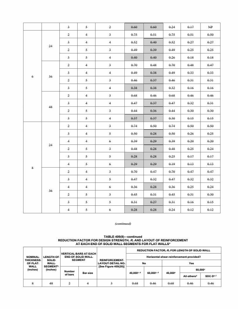
3 5 2 0.60 0.60 0.24 0.17 NP
6
24
2 4 3 0.75 0.51 0.75 0.51 0.50
3 4 4 0.52 0.40 0.52 0.27 0.27
2 5 3 0.49 0.39 0.49 0.25 0.25
3 5 4 0.40 0.40 0.26 0.18 0.18
36
2 4 3 0.70 0.48 0.70 0.48 0.47
3 4 4 0.49 0.38 0.49 0.33 0.33
2 5 3 0.46 0.37 0.46 0.31 0.31
3 5 4 0.38 0.38 0.32 0.16 0.16
48
2 4 3 0.68 0.46 0.68 0.46 0.46
3 4 4 0.47 0.37 0.47 0.32 0.31
2 5 3 0.44 0.36 0.44 0.30 0.30
3 5 4 0.37 0.37 0.30 0.15 0.15
8
24
2 4 3 0.74 0.50 0.74 0.50 0.50
3 4 5 0.50 0.28 0.50 0.26 0.25
4 4 6 0.39 0.29 0.39 0.20 0.20
2 5 3 0.48 0.28 0.48 0.25 0.24
3 5 5 0.28 0.28 0.25 0.17 0.17
4 5 6 0.29 0.29 0.19 0.13 0.13
36
2 4 3 0.70 0.47 0.70 0.47 0.47
3 4 5 0.47 0.32 0.47 0.32 0.32
4 4 6 0.36 0.28 0.36 0.25 0.24
2 5 3 0.45 0.31 0.45 0.31 0.30
3 5 5 0.31 0.27 0.31 0.16 0.15
4 5 6 0.28 0.28 0.24 0.12 0.12
(continued)
TABLE 409(8)—continued REDUCTION FACTOR FOR DESIGN STRENGTH, R, AND LAYOUT OF REINFORCEMENT
AT EACH END OF SOLID WALL SEGMENTS FOR FLAT WALLSa
NOMINAL THICKNESS
OF FLAT WALL
(inches)
LENGTH OF SOLID WALL
SEGMENTb (inches)
VERTICAL BARS AT EACH END OF SOLID WALL
SEGMENT REINFORCEMENT LAYOUT DETAIL NO. [See Figure 409(20)]
REDUCTION FACTOR, R, FOR LENGTH OF SOLID WALL
Horizontal shear reinforcement provided?
No Yes
Number of bars
Bar size 40,000c, d 60,000c, d 40,000e 60,000c
All othersd SDC De, f
8 48 2 4 3 0.68 0.46 0.68 0.46 0.46
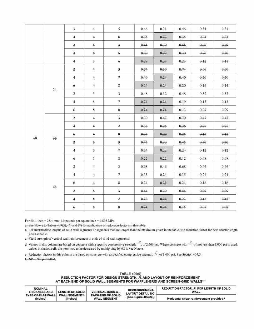
3 4 5 0.46 0.31 0.46 0.31 0.31
4 4 6 0.35 0.27 0.35 0.24 0.23
2 5 3 0.44 0.30 0.44 0.30 0.29
3 5 5 0.30 0.27 0.30 0.20 0.20
4 5 6 0.27 0.27 0.23 0.12 0.11
10
24
2 4 3 0.74 0.50 0.74 0.50 0.50
4 4 7 0.40 0.24 0.40 0.20 0.20
6 4 8 0.24 0.24 0.20 0.14 0.14
2 5 3 0.48 0.32 0.48 0.32 0.32
4 5 7 0.24 0.24 0.19 0.13 0.13
6 5 8 0.24 0.24 0.13 0.09 0.09
36
2 4 3 0.70 0.47 0.70 0.47 0.47
4 4 7 0.36 0.25 0.36 0.25 0.25
6 4 8 0.25 0.22 0.25 0.13 0.12
2 5 3 0.45 0.30 0.45 0.30 0.30
4 5 7 0.24 0.22 0.24 0.12 0.12
6 5 8 0.22 0.22 0.12 0.08 0.08
48
2 4 3 0.68 0.46 0.68 0.46 0.46
4 4 7 0.35 0.24 0.35 0.24 0.24
6 4 8 0.24 0.21 0.24 0.16 0.16
2 5 3 0.44 0.29 0.44 0.29 0.29
4 5 7 0.23 0.21 0.23 0.15 0.15
6 5 8 0.21 0.21 0.15 0.08 0.08
For SI: 1 inch = 25.4 mm; 1.0 pounds per square inch = 6.895 MPa a. See Note e to Tables 409(5), (6) and (7) for application of reduction factors in this table. b. For intermediate lengths of solid wall segments or segments that are longer than the maximum given in the table, use reduction factor for next shorter length
given in table. c. Yield strength of vertical wall reinforcement at ends of solid wall segments.
d. Values in this column are based on concrete with a specific compressive strength, f c, of 2,500 psi. Where concrete with f c of not less than 3,000 psi is used, values in shaded cells are permitted to be decreased by multiplying by 0.91. See Note e.
e Reduction factors in this column are based on concrete with a specified compressive strength, f c, of 3,000 psi. See Section 409.5. f. NP = Not permitted.
TABLE 409(9) REDUCTION FACTOR FOR DESIGN STRENGTH, R, AND LAYOUT OF REINFORCEMENT
AT EACH END OF SOLID WALL SEGMENTS FOR WAFFLE-GRID AND SCREEN-GRID WALLSa, f
NOMINAL THICKNESS AND
TYPE OF FLAT WALL (inches)
LENGTH OF SOLID WALL SEGMENTb
(inches)
VERTICAL BARS AT EACH END OF SOLID
WALL SEGMENT
REINFORCEMENT LAYOUT DETAIL NO. [See Figure 409(20)]
REDUCTION FACTOR, R, FOR LENGTH OF SOLID WALL
Horizontal shear reinforcement provided?
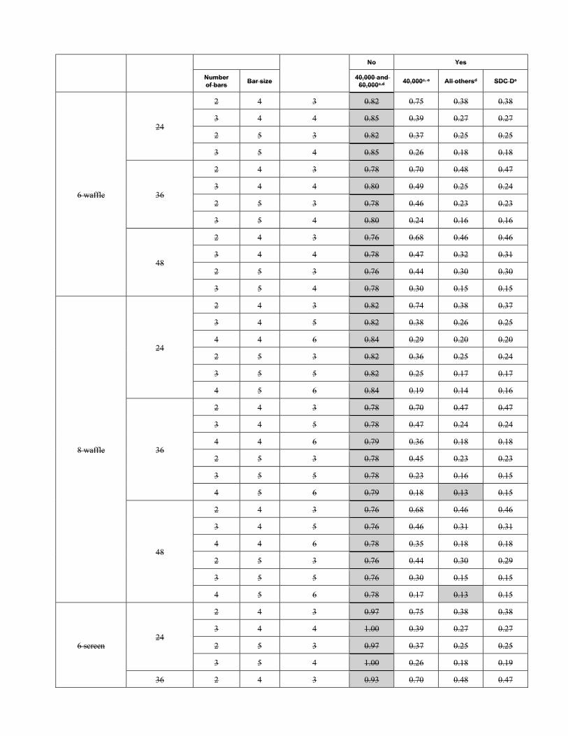
No Yes
Number of bars
Bar size 40,000 and
60,000c,d 40,000c, e All othersd SDC De
6 waffle
24
2 4 3 0.82 0.75 0.38 0.38
3 4 4 0.85 0.39 0.27 0.27
2 5 3 0.82 0.37 0.25 0.25
3 5 4 0.85 0.26 0.18 0.18
36
2 4 3 0.78 0.70 0.48 0.47
3 4 4 0.80 0.49 0.25 0.24
2 5 3 0.78 0.46 0.23 0.23
3 5 4 0.80 0.24 0.16 0.16
48
2 4 3 0.76 0.68 0.46 0.46
3 4 4 0.78 0.47 0.32 0.31
2 5 3 0.76 0.44 0.30 0.30
3 5 4 0.78 0.30 0.15 0.15
8 waffle
24
2 4 3 0.82 0.74 0.38 0.37
3 4 5 0.82 0.38 0.26 0.25
4 4 6 0.84 0.29 0.20 0.20
2 5 3 0.82 0.36 0.25 0.24
3 5 5 0.82 0.25 0.17 0.17
4 5 6 0.84 0.19 0.14 0.16
36
2 4 3 0.78 0.70 0.47 0.47
3 4 5 0.78 0.47 0.24 0.24
4 4 6 0.79 0.36 0.18 0.18
2 5 3 0.78 0.45 0.23 0.23
3 5 5 0.78 0.23 0.16 0.15
4 5 6 0.79 0.18 0.13 0.15
48
2 4 3 0.76 0.68 0.46 0.46
3 4 5 0.76 0.46 0.31 0.31
4 4 6 0.78 0.35 0.18 0.18
2 5 3 0.76 0.44 0.30 0.29
3 5 5 0.76 0.30 0.15 0.15
4 5 6 0.78 0.17 0.13 0.15
6 screen 24
2 4 3 0.97 0.75 0.38 0.38
3 4 4 1.00 0.39 0.27 0.27
2 5 3 0.97 0.37 0.25 0.25
3 5 4 1.00 0.26 0.18 0.19
36 2 4 3 0.93 0.70 0.48 0.47
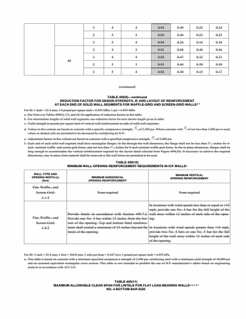
3 4 4 0.94 0.49 0.25 0.24
2 5 3 0.93 0.46 0.23 0.23
3 5 4 0.94 0.24 0.16 0.18
48
2 4 3 0.91 0.68 0.46 0.46
3 4 4 0.92 0.47 0.32 0.31
2 5 3 0.91 0.44 0.30 0.30
3 5 4 0.92 0.30 0.15 0.17
(continued)
TABLE 409(9)—continued REDUCTION FACTOR FOR DESIGN STRENGTH, R, AND LAYOUT OF REINFORCEMENT
AT EACH END OF SOLID WALL SEGMENTS FOR WAFFLE-GRID AND SCREEN-GRID WALLSa, f
For SI: 1 inch = 25.4 mm; 1.0 pound per square inch = 6.895 MPa, 1 psi = 6.895 MPa. a. See Note e to Tables 409(6), (7), and (8) for application of reduction factors in this table. b. For intermediate lengths of solid wall segments, use reduction factor for next shorter length given in table. c. Yield strength in pounds per square inch of vertical wall reinforcement at ends of solid wall segments.
d. Values in this column are based on concrete with a specific compressive strength, f c, of 2,500 psi. Where concrete with f c of not less than 3,000 psi is used, values in shaded cells are permitted to be decreased by multiplying by 0.91.
e. Adjustment factors in this column are based on concrete with a specified compressive strength, f c, of 3,000 psi. f. Each end of each solid wall segment shall have rectangular flanges. In the through-the-wall dimension, the flange shall not be less than 51/2 inches for 6-
inch- nominal waffle- and screen-grid forms, and not less than 71/2 inches for 8-inch-nominal waffle-grid forms. In the in-plane dimension, flanges shall be long enough to accommodate the vertical reinforcement required by the layout detail selected from Figure 409(20). If necessary to achieve the required dimensions, stay-in-place form material shall be removed or flat wall forms are permitted to be used.
TABLE 409(10) MINIMUM WALL OPENING REINFORCEMENT REQUIREMENTS IN ICF WALLSa
WALL TYPE AND OPENING WIDTH (L)
(feet) MINIMUM HORIZONTAL
OPENING REINFORCEMENT
MINIMUM VERTICAL OPENING REINFORCEMENT
Flat, Waffle-, and
Screen-Grid:
L 2
None required None required
Flat, Waffle-, and
Screen-Grid:
L 2
Provide lintels in accordance with Section 409.7.2. Provide one No. 4 bar within 12 inches from the bot-tom of the opening. Top and bottom lintel reinforce-ment shall extend a minimum of 24 inches beyond the limits of the opening.
In locations with wind speeds less than or equal to 110 mph, provide one No. 4 bar for the full height of the wall story within 12 inches of each side of the open-ing. In locations with wind speeds greater than 110 mph, provide two No. 4 bars or one No. 5 bar for the full height of the wall story within 12 inches of each side of the opening.
For SI: 1 inch = 25.4 mm, 1 foot = 304.8 mm, 1 mile per hour = 0.447 m/s; 1 pound per square inch = 6.895 kPa. a. This table is based on concrete with a minimum specified compressive strength of 2,500 psi, reinforcing steel with a minimum yield strength of 40,000 psi
and an assumed equivalent rectangular cross section. This table is not intended to prohibit the use of ICF manufacturer’s tables based on engineering analysis in accordance with ACI 318.
TABLE 409(11) MAXIMUM ALLOWABLE CLEAR SPAN FOR LINTELS FOR FLAT LOAD-BEARING WALLSa, b, c, d, f
NO. 4 BOTTOM BAR SIZE
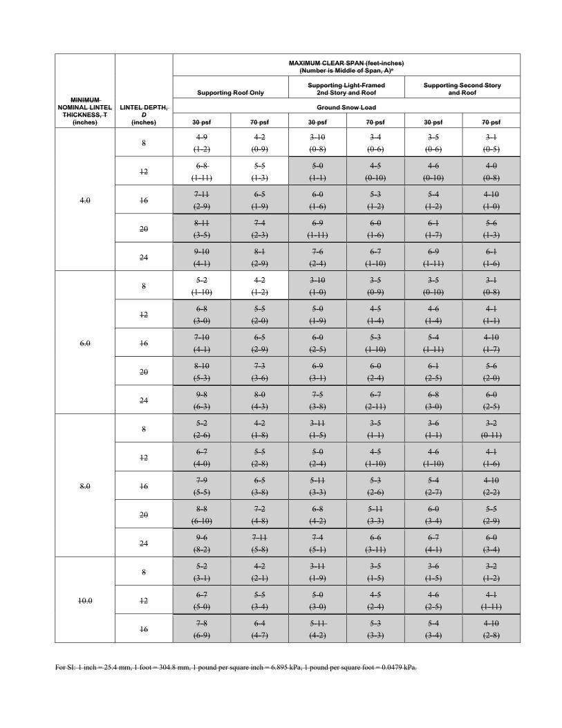
MINIMUM NOMINAL LINTEL
THICKNESS, T (inches)
LINTEL DEPTH, D
(inches)
MAXIMUM CLEAR SPAN (feet-inches) (Number is Middle of Span, A)e
Supporting Roof Only Supporting Light-Framed
2nd Story and Roof Supporting Second Story
and Roof
Ground Snow Load
30 psf 70 psf 30 psf 70 psf 30 psf 70 psf
4.0
8 4-9
(1-2)
4-2
(0-9)
3-10
(0-8)
3-4
(0-6)
3-5
(0-6)
3-1
(0-5)
12 6-8
(1-11)
5-5
(1-3)
5-0
(1-1)
4-5
(0-10)
4-6
(0-10)
4-0
(0-8)
16 7-11
(2-9)
6-5
(1-9)
6-0
(1-6)
5-3
(1-2)
5-4
(1-2)
4-10
(1-0)
20 8-11
(3-5)
7-4
(2-3)
6-9
(1-11)
6-0
(1-6)
6-1
(1-7)
5-6
(1-3)
24 9-10
(4-1)
8-1
(2-9)
7-6
(2-4)
6-7
(1-10)
6-9
(1-11)
6-1
(1-6)
6.0
8 5-2
(1-10)
4-2
(1-2)
3-10
(1-0)
3-5
(0-9)
3-5
(0-10)
3-1
(0-8)
12 6-8
(3-0)
5-5
(2-0)
5-0
(1-9)
4-5
(1-4)
4-6
(1-4)
4-1
(1-1)
16 7-10
(4-1)
6-5
(2-9)
6-0
(2-5)
5-3
(1-10)
5-4
(1-11)
4-10
(1-7)
20 8-10
(5-3)
7-3
(3-6)
6-9
(3-1)
6-0
(2-4)
6-1
(2-5)
5-6
(2-0)
24 9-8
(6-3)
8-0
(4-3)
7-5
(3-8)
6-7
(2-11)
6-8
(3-0)
6-0
(2-5)
8.0
8 5-2
(2-6)
4-2
(1-8)
3-11
(1-5)
3-5
(1-1)
3-6
(1-1)
3-2
(0-11)
12 6-7
(4-0)
5-5
(2-8)
5-0
(2-4)
4-5
(1-10)
4-6
(1-10)
4-1
(1-6)
16 7-9
(5-5)
6-5
(3-8)
5-11
(3-3)
5-3
(2-6)
5-4
(2-7)
4-10
(2-2)
20 8-8
(6-10)
7-2
(4-8)
6-8
(4-2)
5-11
(3-3)
6-0
(3-4)
5-5
(2-9)
24 9-6
(8-2)
7-11
(5-8)
7-4
(5-1)
6-6
(3-11)
6-7
(4-1)
6-0
(3-4)
10.0
8 5-2
(3-1)
4-2
(2-1)
3-11
(1-9)
3-5
(1-5)
3-6
(1-5)
3-2
(1-2)
12 6-7
(5-0)
5-5
(3-4)
5-0
(3-0)
4-5
(2-4)
4-6
(2-5)
4-1
(1-11)
16 7-8
(6-9)
6-4
(4-7)
5-11
(4-2)
5-3
(3-3)
5-4
(3-4)
4-10
(2-8)
For SI: 1 inch = 25.4 mm, 1 foot = 304.8 mm, 1 pound per square inch = 6.895 kPa, 1 pound per square foot = 0.0479 kPa.
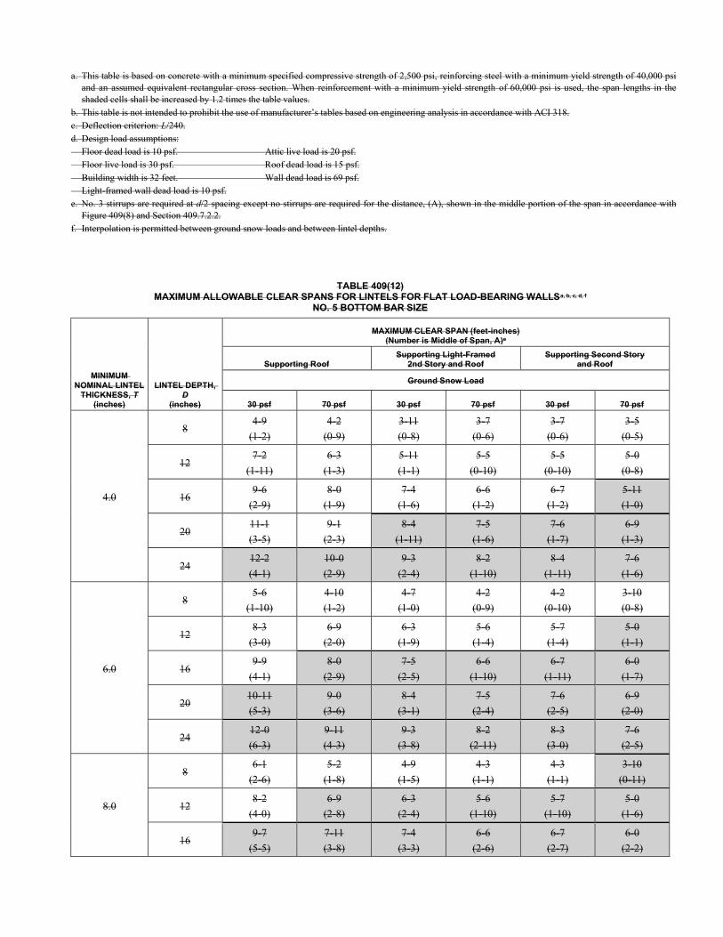
a. This table is based on concrete with a minimum specified compressive strength of 2,500 psi, reinforcing steel with a minimum yield strength of 40,000 psi and an assumed equivalent rectangular cross section. When reinforcement with a minimum yield strength of 60,000 psi is used, the span lengths in the shaded cells shall be increased by 1.2 times the table values.
b. This table is not intended to prohibit the use of manufacturer’s tables based on engineering analysis in accordance with ACI 318. c. Deflection criterion: L/240. d. Design load assumptions: Floor dead load is 10 psf. Attic live load is 20 psf. Floor live load is 30 psf. Roof dead load is 15 psf. Building width is 32 feet. Wall dead load is 69 psf. Light-framed wall dead load is 10 psf. e. No. 3 stirrups are required at d/2 spacing except no stirrups are required for the distance, (A), shown in the middle portion of the span in accordance with
Figure 409(8) and Section 409.7.2.2. f. Interpolation is permitted between ground snow loads and between lintel depths.
TABLE 409(12) MAXIMUM ALLOWABLE CLEAR SPANS FOR LINTELS FOR FLAT LOAD-BEARING WALLSa, b, c, d, f
NO. 5 BOTTOM BAR SIZE
MINIMUM NOMINAL LINTEL
THICKNESS, T (inches)
LINTEL DEPTH, D
(inches)
MAXIMUM CLEAR SPAN (feet-inches) (Number is Middle of Span, A)e
Supporting Roof Supporting Light-Framed
2nd Story and Roof Supporting Second Story
and Roof
Ground Snow Load
30 psf 70 psf 30 psf 70 psf 30 psf 70 psf
4.0
8 4-9
(1-2)
4-2
(0-9)
3-11
(0-8)
3-7
(0-6)
3-7
(0-6)
3-5
(0-5)
12 7-2
(1-11)
6-3
(1-3)
5-11
(1-1)
5-5
(0-10)
5-5
(0-10)
5-0
(0-8)
16 9-6
(2-9)
8-0
(1-9)
7-4
(1-6)
6-6
(1-2)
6-7
(1-2)
5-11
(1-0)
20 11-1
(3-5)
9-1
(2-3)
8-4
(1-11)
7-5
(1-6)
7-6
(1-7)
6-9
(1-3)
24 12-2
(4-1)
10-0
(2-9)
9-3
(2-4)
8-2
(1-10)
8-4
(1-11)
7-6
(1-6)
6.0
8 5-6
(1-10)
4-10
(1-2)
4-7
(1-0)
4-2
(0-9)
4-2
(0-10)
3-10
(0-8)
12 8-3
(3-0)
6-9
(2-0)
6-3
(1-9)
5-6
(1-4)
5-7
(1-4)
5-0
(1-1)
16 9-9
(4-1)
8-0
(2-9)
7-5
(2-5)
6-6
(1-10)
6-7
(1-11)
6-0
(1-7)
20 10-11
(5-3)
9-0
(3-6)
8-4
(3-1)
7-5
(2-4)
7-6
(2-5)
6-9
(2-0)
24 12-0
(6-3)
9-11
(4-3)
9-3
(3-8)
8-2
(2-11)
8-3
(3-0)
7-6
(2-5)
8.0
8 6-1
(2-6)
5-2
(1-8)
4-9
(1-5)
4-3
(1-1)
4-3
(1-1)
3-10
(0-11)
12 8-2
(4-0)
6-9
(2-8)
6-3
(2-4)
5-6
(1-10)
5-7
(1-10)
5-0
(1-6)
16 9-7
(5-5)
7-11
(3-8)
7-4
(3-3)
6-6
(2-6)
6-7
(2-7)
6-0
(2-2)
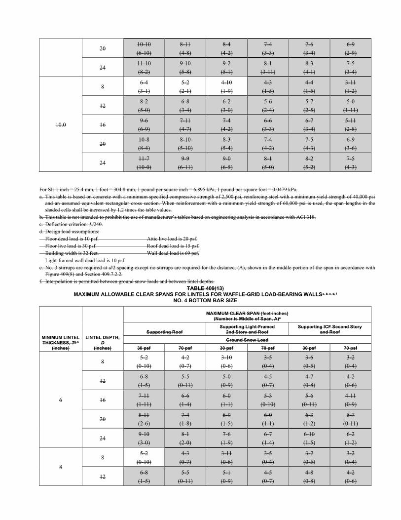
20 10-10
(6-10)
8-11
(4-8)
8-4
(4-2)
7-4
(3-3)
7-6
(3-4)
6-9
(2-9)
24 11-10
(8-2)
9-10
(5-8)
9-2
(5-1)
8-1
(3-11)
8-3
(4-1)
7-5
(3-4)
10.0
8 6-4
(3-1)
5-2
(2-1)
4-10
(1-9)
4-3
(1-5)
4-4
(1-5)
3-11
(1-2)
12 8-2
(5-0)
6-8
(3-4)
6-2
(3-0)
5-6
(2-4)
5-7
(2-5)
5-0
(1-11)
16 9-6
(6-9)
7-11
(4-7)
7-4
(4-2)
6-6
(3-3)
6-7
(3-4)
5-11
(2-8)
20 10-8
(8-4)
8-10
(5-10)
8-3
(5-4)
7-4
(4-2)
7-5
(4-3)
6-9
(3-6)
24 11-7
(10-0)
9-9
(6-11)
9-0
(6-5)
8-1
(5-0)
8-2
(5-2)
7-5
(4-3)
For SI: 1 inch = 25.4 mm, 1 foot = 304.8 mm, 1 pound per square inch = 6.895 kPa, 1 pound per square foot = 0.0479 kPa. a. This table is based on concrete with a minimum specified compressive strength of 2,500 psi, reinforcing steel with a minimum yield strength of 40,000 psi
and an assumed equivalent rectangular cross section. When reinforcement with a minimum yield strength of 60,000 psi is used, the span lengths in the shaded cells shall be increased by 1.2 times the table values.
b. This table is not intended to prohibit the use of manufacturer’s tables based on engineering analysis in accordance with ACI 318. c. Deflection criterion: L/240. d. Design load assumptions: Floor dead load is 10 psf. Attic live load is 20 psf. Floor live load is 30 psf. Roof dead load is 15 psf. Building width is 32 feet. Wall dead load is 69 psf. Light-framed wall dead load is 10 psf. e. No. 3 stirrups are required at d/2 spacing except no stirrups are required for the distance, (A), shown in the middle portion of the span in accordance with
Figure 409(8) and Section 409.7.2.2. f. Interpolation is permitted between ground snow loads and between lintel depths.
TABLE 409(13) MAXIMUM ALLOWABLE CLEAR SPANS FOR LINTELS FOR WAFFLE-GRID LOAD-BEARING WALLSa, b, c, d, f
NO. 4 BOTTOM BAR SIZE
MINIMUM LINTEL THICKNESS, Tg,h
(inches)
LINTEL DEPTH, D
(inches)
MAXIMUM CLEAR SPAN (feet-inches) (Number is Middle of Span, A)e
Supporting Roof Supporting Light-Framed
2nd Story and Roof Supporting ICF Second Story
and Roof
Ground Snow Load
30 psf 70 psf 30 psf 70 psf 30 psf 70 psf
6
8 5-2
(0-10)
4-2
(0-7)
3-10
(0-6)
3-5
(0-4)
3-6
(0-5)
3-2
(0-4)
12 6-8
(1-5)
5-5
(0-11)
5-0
(0-9)
4-5
(0-7)
4-7
(0-8)
4-2
(0-6)
16 7-11
(1-11)
6-6
(1-4)
6-0
(1-1)
5-3
(0-10)
5-6
(0-11)
4-11
(0-9)
20 8-11
(2-6)
7-4
(1-8)
6-9
(1-5)
6-0
(1-1)
6-3
(1-2)
5-7
(0-11)
24 9-10
(3-0)
8-1
(2-0)
7-6
(1-9)
6-7
(1-4)
6-10
(1-5)
6-2
(1-2)
8
8 5-2
(0-10)
4-3
(0-7)
3-11
(0-6)
3-5
(0-4)
3-7
(0-5)
3-2
(0-4)
12 6-8
(1-5)
5-5
(0-11)
5-1
(0-9)
4-5
(0-7)
4-8
(0-8)
4-2
(0-6)
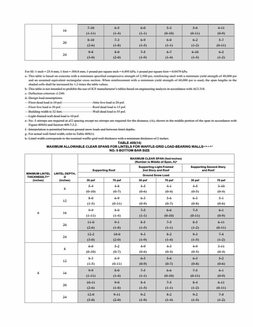
16 7-10
(1-11)
6-5
(1-4)
6-0
(1-1)
5-3
(0-10)
5-6
(0-11)
4-11
(0-9)
20 8-10
(2-6)
7-3
(1-8)
6-9
(1-5)
6-0
(1-1)
6-2
(1-2)
5-7
(0-11)
24 9-8
(3-0)
8-0
(2-0)
7-5
(1-9)
6-7
(1-4)
6-10
(1-5)
6-2
(1-2)
For SI: 1 inch = 25.4 mm, 1 foot = 304.8 mm, 1 pound per square inch = 6.895 kPa, 1 pound per square foot = 0.0479 kPa. a. This table is based on concrete with a minimum specified compressive strength of 2,500 psi, reinforcing steel with a minimum yield strength of 40,000 psi
and an assumed equivalent rectangular cross section. When reinforcement with a minimum yield strength of 60,000 psi is used, the span lengths in the shaded cells shall be increased by 1.2 times the table values.
b. This table is not intended to prohibit the use of ICF manufacturer’s tables based on engineering analysis in accordance with ACI 318. c. Deflection criterion: L/240. d. Design load assumptions: Floor dead load is 10 psf. Attic live load is 20 psf. Floor live load is 30 psf. Roof dead load is 15 psf. Building width is 32 feet. Wall dead load is 55 psf. Light-framed wall dead load is 10 psf. e. No. 3 stirrups are required at d/2 spacing except no stirrups are required for the distance, (A), shown in the middle portion of the span in accordance with
Figure 409(8) and Section 409.7.2.2. f. Interpolation is permitted between ground snow loads and between lintel depths. g. For actual wall lintel width, refer to Table 409(1). h. Lintel width corresponds to the nominal waffle-grid wall thickness with a minimum thickness of 2 inches.
TABLE 409(14) MAXIMUM ALLOWABLE CLEAR SPANS FOR LINTELS FOR WAFFLE-GRID LOAD-BEARING WALLSa, b, c, d, f
NO. 5 BOTTOM BAR SIZE
MINIMUM LINTEL THICKNESS,Tg,h
(inches)
LINTEL DEPTH, D
(inches)
MAXIMUM CLEAR SPAN (feet-inches) (Number is Middle of Span, A)e
Supporting Roof Supporting Light-Framed
2nd Story and Roof Supporting Second Story
and Roof
Ground Snow Load
30 psf 70 psf 30 psf 70 psf 30 psf 70 psf
6
8 5-4
(0-10)
4-8
(0-7)
4-5
(0-6)
4-1
(0-4)
4-5
(0-5)
3-10
(0-4)
12 8-0
(1-5)
6-9
(0-11)
6-3
(0-9)
5-6
(0-7)
6-3
(0-8)
5-1
(0-6)
16 9-9
(1-11)
8-0
(1-4)
7-5
(1-1)
6-6
(0-10)
7-5
(0-11)
6-1
(0-9)
20 11-0
(2-6)
9-1
(1-8)
8-5
(1-5)
7-5
(1-1)
8-5
(1-2)
6-11
(0-11)
24 12-2
(3-0)
10-0
(2-0)
9-3
(1-9)
8-2
(1-4)
9-3
(1-5)
7-8
(1-2)
8
8 6-0
(0-10)
5-2
(0-7)
4-9
(0-6)
4-3
(0-4)
4-9
(0-5)
3-11
(0-4)
12 8-3
(1-5)
6-9
(0-11)
6-3
(0-9)
5-6
(0-7)
6-3
(0-8)
5-2
(0-6)
16 9-9
(1-11)
8-0
(1-4)
7-5
(1-1)
6-6
(0-10)
7-5
(0-11)
6-1
(0-9)
20 10-11
(2-6)
9-0
(1-8)
8-4
(1-5)
7-5
(1-1)
8-4
(1-2)
6-11
(0-11)
24 12-0
(3-0)
9-11
(2-0)
9-2
(1-9)
8-2
(1-4)
9-2
(1-5)
7-8
(1-2)
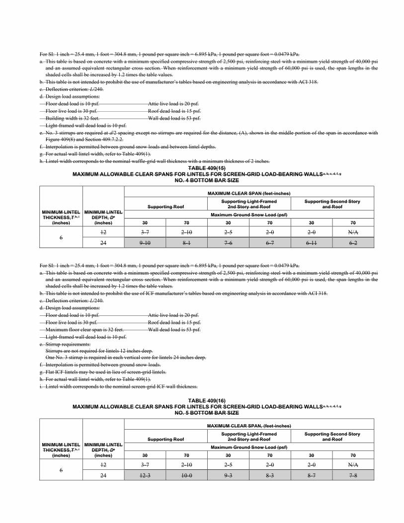
For SI: 1 inch = 25.4 mm, 1 foot = 304.8 mm, 1 pound per square inch = 6.895 kPa, 1 pound per square foot = 0.0479 kPa. a. This table is based on concrete with a minimum specified compressive strength of 2,500 psi, reinforcing steel with a minimum yield strength of 40,000 psi
and an assumed equivalent rectangular cross section. When reinforcement with a minimum yield strength of 60,000 psi is used, the span lengths in the shaded cells shall be increased by 1.2 times the table values.
b. This table is not intended to prohibit the use of manufacturer’s tables based on engineering analysis in accordance with ACI 318. c. Deflection criterion: L/240. d. Design load assumptions: Floor dead load is 10 psf. Attic live load is 20 psf. Floor live load is 30 psf. Roof dead load is 15 psf. Building width is 32 feet. Wall dead load is 53 psf. Light-framed wall dead load is 10 psf. e. No. 3 stirrups are required at d/2 spacing except no stirrups are required for the distance, (A), shown in the middle portion of the span in accordance with
Figure 409(8) and Section 409.7.2.2. f. Interpolation is permitted between ground snow loads and between lintel depths. g. For actual wall lintel width, refer to Table 409(1). h. Lintel width corresponds to the nominal waffle-grid wall thickness with a minimum thickness of 2 inches.
TABLE 409(15) MAXIMUM ALLOWABLE CLEAR SPANS FOR LINTELS FOR SCREEN-GRID LOAD-BEARING WALLSa, b, c, d, f, g
NO. 4 BOTTOM BAR SIZE
MINIMUM LINTEL THICKNESS,T h, i
(inches)
MINIMUM LINTEL DEPTH, De
(inches)
MAXIMUM CLEAR SPAN (feet-inches)
Supporting Roof Supporting Light-Framed
2nd Story and Roof Supporting Second Story
and Roof
Maximum Ground Snow Load (psf)
30 70 30 70 30 70
6 12 3-7 2-10 2-5 2-0 2-0 N/A
24 9-10 8-1 7-6 6-7 6-11 6-2
For SI: 1 inch = 25.4 mm, 1 foot = 304.8 mm, 1 pound per square inch = 6.895 kPa, 1 pound per square foot = 0.0479 kPa. a. This table is based on concrete with a minimum specified compressive strength of 2,500 psi, reinforcing steel with a minimum yield strength of 40,000 psi
and an assumed equivalent rectangular cross section. When reinforcement with a minimum yield strength of 60,000 psi is used, the span lengths in the shaded cells shall be increased by 1.2 times the table values.
b. This table is not intended to prohibit the use of ICF manufacturer’s tables based on engineering analysis in accordance with ACI 318. c. Deflection criterion: L/240. d. Design load assumptions: Floor dead load is 10 psf. Attic live load is 20 psf. Floor live load is 30 psf. Roof dead load is 15 psf. Maximum floor clear span is 32 feet. Wall dead load is 53 psf. Light-framed wall dead load is 10 psf. e. Stirrup requirements:
Stirrups are not required for lintels 12 inches deep. One No. 3 stirrup is required in each vertical core for lintels 24 inches deep.
f. Interpolation is permitted between ground snow loads. g. Flat ICF lintels may be used in lieu of screen-grid lintels. h. For actual wall lintel width, refer to Table 409(1). i. Lintel width corresponds to the nominal screen-grid ICF wall thickness.
TABLE 409(16) MAXIMUM ALLOWABLE CLEAR SPANS FOR LINTELS FOR SCREEN-GRID LOAD-BEARING WALLSa, b, c, d, f, g
NO. 5 BOTTOM BAR SIZE
MINIMUM LINTEL THICKNESS,T h, i
(inches)
MINIMUM LINTEL DEPTH, De
(inches)
MAXIMUM CLEAR SPAN, (feet-inches)
Supporting Roof Supporting Light-Framed
2nd Story and Roof Supporting Second Story
and Roof
Maximum Ground Snow Load (psf)
30 70 30 70 30 70
6 12 3-7 2-10 2-5 2-0 2-0 N/A
24 12-3 10-0 9-3 8-3 8-7 7-8
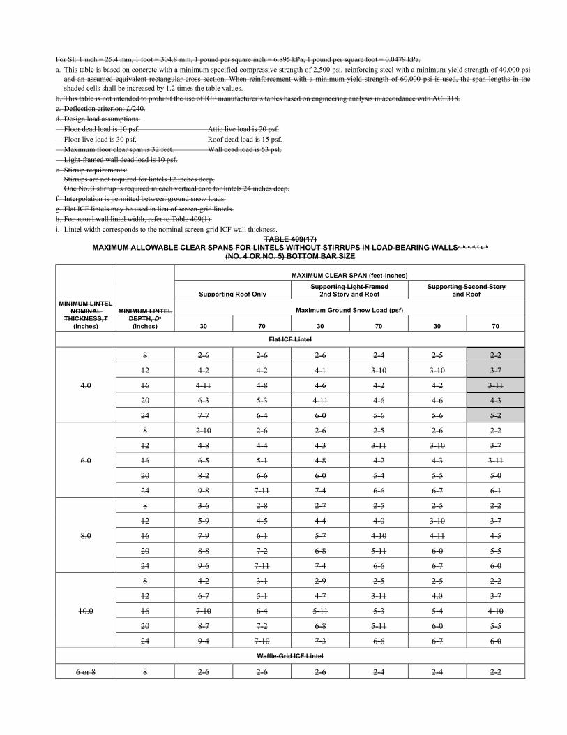
For SI: 1 inch = 25.4 mm, 1 foot = 304.8 mm, 1 pound per square inch = 6.895 kPa, 1 pound per square foot = 0.0479 kPa. a. This table is based on concrete with a minimum specified compressive strength of 2,500 psi, reinforcing steel with a minimum yield strength of 40,000 psi
and an assumed equivalent rectangular cross section. When reinforcement with a minimum yield strength of 60,000 psi is used, the span lengths in the shaded cells shall be increased by 1.2 times the table values.
b. This table is not intended to prohibit the use of ICF manufacturer’s tables based on engineering analysis in accordance with ACI 318. c. Deflection criterion: L/240. d. Design load assumptions: Floor dead load is 10 psf. Attic live load is 20 psf. Floor live load is 30 psf. Roof dead load is 15 psf. Maximum floor clear span is 32 feet. Wall dead load is 53 psf. Light-framed wall dead load is 10 psf. e. Stirrup requirements:
Stirrups are not required for lintels 12 inches deep. One No. 3 stirrup is required in each vertical core for lintels 24 inches deep.
f. Interpolation is permitted between ground snow loads. g. Flat ICF lintels may be used in lieu of screen-grid lintels. h. For actual wall lintel width, refer to Table 409(1). i. Lintel width corresponds to the nominal screen-grid ICF wall thickness.
TABLE 409(17) MAXIMUM ALLOWABLE CLEAR SPANS FOR LINTELS WITHOUT STIRRUPS IN LOAD-BEARING WALLSa, b, c, d, f, g, h
(NO. 4 OR NO. 5) BOTTOM BAR SIZE
MINIMUM LINTEL NOMINAL
THICKNESS,T (inches)
MINIMUM LINTEL DEPTH, De
(inches)
MAXIMUM CLEAR SPAN (feet-inches)
Supporting Roof Only Supporting Light-Framed
2nd Story and Roof Supporting Second Story
and Roof
Maximum Ground Snow Load (psf)
30 70 30 70 30 70
Flat ICF Lintel
4.0
8 2-6 2-6 2-6 2-4 2-5 2-2
12 4-2 4-2 4-1 3-10 3-10 3-7
16 4-11 4-8 4-6 4-2 4-2 3-11
20 6-3 5-3 4-11 4-6 4-6 4-3
24 7-7 6-4 6-0 5-6 5-6 5-2
6.0
8 2-10 2-6 2-6 2-5 2-6 2-2
12 4-8 4-4 4-3 3-11 3-10 3-7
16 6-5 5-1 4-8 4-2 4-3 3-11
20 8-2 6-6 6-0 5-4 5-5 5-0
24 9-8 7-11 7-4 6-6 6-7 6-1
8.0
8 3-6 2-8 2-7 2-5 2-5 2-2
12 5-9 4-5 4-4 4-0 3-10 3-7
16 7-9 6-1 5-7 4-10 4-11 4-5
20 8-8 7-2 6-8 5-11 6-0 5-5
24 9-6 7-11 7-4 6-6 6-7 6-0
10.0
8 4-2 3-1 2-9 2-5 2-5 2-2
12 6-7 5-1 4-7 3-11 4.0 3-7
16 7-10 6-4 5-11 5-3 5-4 4-10
20 8-7 7-2 6-8 5-11 6-0 5-5
24 9-4 7-10 7-3 6-6 6-7 6-0
Waffle-Grid ICF Lintel
6 or 8 8 2-6 2-6 2-6 2-4 2-4 2-2
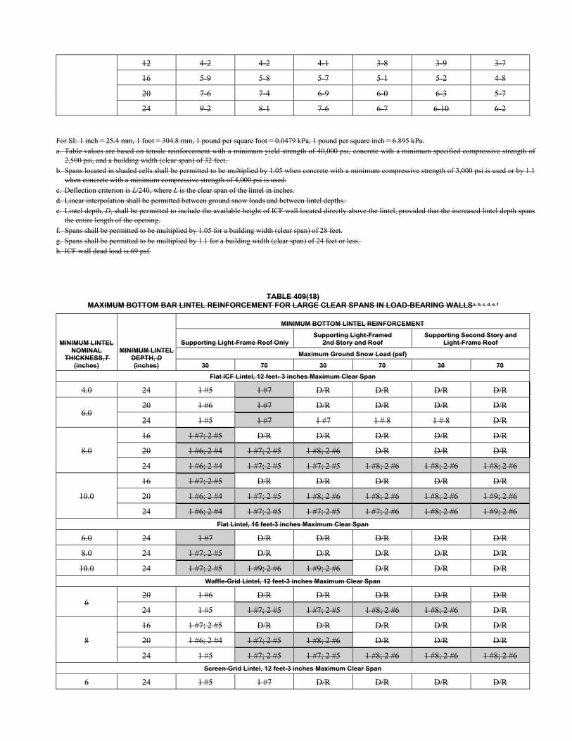
12 4-2 4-2 4-1 3-8 3-9 3-7
16 5-9 5-8 5-7 5-1 5-2 4-8
20 7-6 7-4 6-9 6-0 6-3 5-7
24 9-2 8-1 7-6 6-7 6-10 6-2
For SI: 1 inch = 25.4 mm, 1 foot = 304.8 mm, 1 pound per square foot = 0.0479 kPa, 1 pound per square inch = 6.895 kPa. a. Table values are based on tensile reinforcement with a minimum yield strength of 40,000 psi, concrete with a minimum specified compressive strength of
2,500 psi, and a building width (clear span) of 32 feet. b. Spans located in shaded cells shall be permitted to be multiplied by 1.05 when concrete with a minimum compressive strength of 3,000 psi is used or by 1.1
when concrete with a minimum compressive strength of 4,000 psi is used. c. Deflection criterion is L/240, where L is the clear span of the lintel in inches. d. Linear interpolation shall be permitted between ground snow loads and between lintel depths. e. Lintel depth, D, shall be permitted to include the available height of ICF wall located directly above the lintel, provided that the increased lintel depth spans
the entire length of the opening. f. Spans shall be permitted to be multiplied by 1.05 for a building width (clear span) of 28 feet. g. Spans shall be permitted to be multiplied by 1.1 for a building width (clear span) of 24 feet or less. h. ICF wall dead load is 69 psf.
TABLE 409(18) MAXIMUM BOTTOM BAR LINTEL REINFORCEMENT FOR LARGE CLEAR SPANS IN LOAD-BEARING WALLSa, b, c, d, e, f
MINIMUM LINTEL NOMINAL
THICKNESS,T
(inches)
MINIMUM LINTEL DEPTH, D (inches)
MINIMUM BOTTOM LINTEL REINFORCEMENT
Supporting Light-Frame Roof Only Supporting Light-Framed
2nd Story and Roof Supporting Second Story and
Light-Frame Roof
Maximum Ground Snow Load (psf)
30 70 30 70 30 70
Flat ICF Lintel, 12 feet- 3 inches Maximum Clear Span
4.0 24 1 #5 1 #7 D/R D/R D/R D/R
6.0 20 1 #6 1 #7 D/R D/R D/R D/R
24 1 #5 1 #7 1 #7 1 # 8 1 # 8 D/R
8.0
16 1 #7; 2 #5 D/R D/R D/R D/R D/R
20 1 #6; 2 #4 1 #7; 2 #5 1 #8; 2 #6 D/R D/R D/R
24 1 #6; 2 #4 1 #7; 2 #5 1 #7; 2 #5 1 #8; 2 #6 1 #8; 2 #6 1 #8; 2 #6
10.0
16 1 #7; 2 #5 D/R D/R D/R D/R D/R
20 1 #6; 2 #4 1 #7; 2 #5 1 #8; 2 #6 1 #8; 2 #6 1 #8; 2 #6 1 #9; 2 #6
24 1 #6; 2 #4 1 #7; 2 #5 1 #7; 2 #5 1 #7; 2 #6 1 #8; 2 #6 1 #9; 2 #6
Flat Lintel, 16 feet-3 inches Maximum Clear Span
6.0 24 1 #7 D/R D/R D/R D/R D/R
8.0 24 1 #7; 2 #5 D/R D/R D/R D/R D/R
10.0 24 1 #7; 2 #5 1 #9; 2 #6 1 #9; 2 #6 D/R D/R D/R
Waffle-Grid Lintel, 12 feet-3 inches Maximum Clear Span
6 20 1 #6 D/R D/R D/R D/R D/R
24 1 #5 1 #7; 2 #5 1 #7; 2 #5 1 #8; 2 #6 1 #8; 2 #6 D/R
8
16 1 #7; 2 #5 D/R D/R D/R D/R D/R
20 1 #6; 2 #4 1 #7; 2 #5 1 #8; 2 #6 D/R D/R D/R
24 1 #5 1 #7; 2 #5 1 #7; 2 #5 1 #8; 2 #6 1 #8; 2 #6 1 #8; 2 #6
Screen-Grid Lintel, 12 feet-3 inches Maximum Clear Span
6 24 1 #5 1 #7 D/R D/R D/R D/R
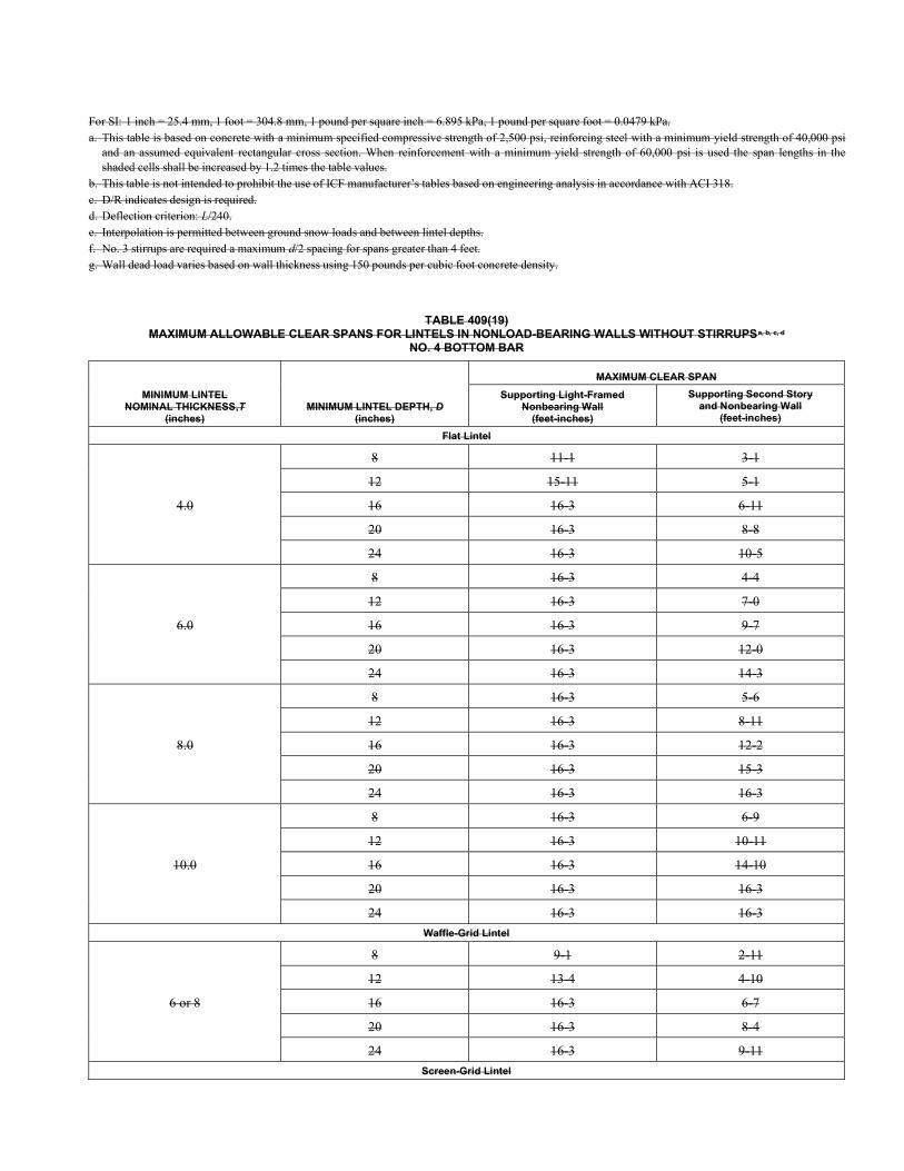
For SI: 1 inch = 25.4 mm, 1 foot = 304.8 mm, 1 pound per square inch = 6.895 kPa, 1 pound per square foot = 0.0479 kPa. a. This table is based on concrete with a minimum specified compressive strength of 2,500 psi, reinforcing steel with a minimum yield strength of 40,000 psi
and an assumed equivalent rectangular cross section. When reinforcement with a minimum yield strength of 60,000 psi is used the span lengths in the shaded cells shall be increased by 1.2 times the table values.
b. This table is not intended to prohibit the use of ICF manufacturer’s tables based on engineering analysis in accordance with ACI 318. c. D/R indicates design is required. d. Deflection criterion: L/240. e. Interpolation is permitted between ground snow loads and between lintel depths. f. No. 3 stirrups are required a maximum d/2 spacing for spans greater than 4 feet. g. Wall dead load varies based on wall thickness using 150 pounds per cubic foot concrete density.
TABLE 409(19) MAXIMUM ALLOWABLE CLEAR SPANS FOR LINTELS IN NONLOAD-BEARING WALLS WITHOUT STIRRUPSa, b, c, d
NO. 4 BOTTOM BAR
MINIMUM LINTEL NOMINAL THICKNESS,T
(inches) MINIMUM LINTEL DEPTH, D
(inches)
MAXIMUM CLEAR SPAN
Supporting Light-Framed Nonbearing Wall
(feet-inches)
Supporting Second Story and Nonbearing Wall
(feet-inches)
Flat Lintel
4.0
8 11-1 3-1
12 15-11 5-1
16 16-3 6-11
20 16-3 8-8
24 16-3 10-5
6.0
8 16-3 4-4
12 16-3 7-0
16 16-3 9-7
20 16-3 12-0
24 16-3 14-3
8.0
8 16-3 5-6
12 16-3 8-11
16 16-3 12-2
20 16-3 15-3
24 16-3 16-3
10.0
8 16-3 6-9
12 16-3 10-11
16 16-3 14-10
20 16-3 16-3
24 16-3 16-3
Waffle-Grid Lintel
6 or 8
8 9-1 2-11
12 13-4 4-10
16 16-3 6-7
20 16-3 8-4
24 16-3 9-11
Screen-Grid Lintel
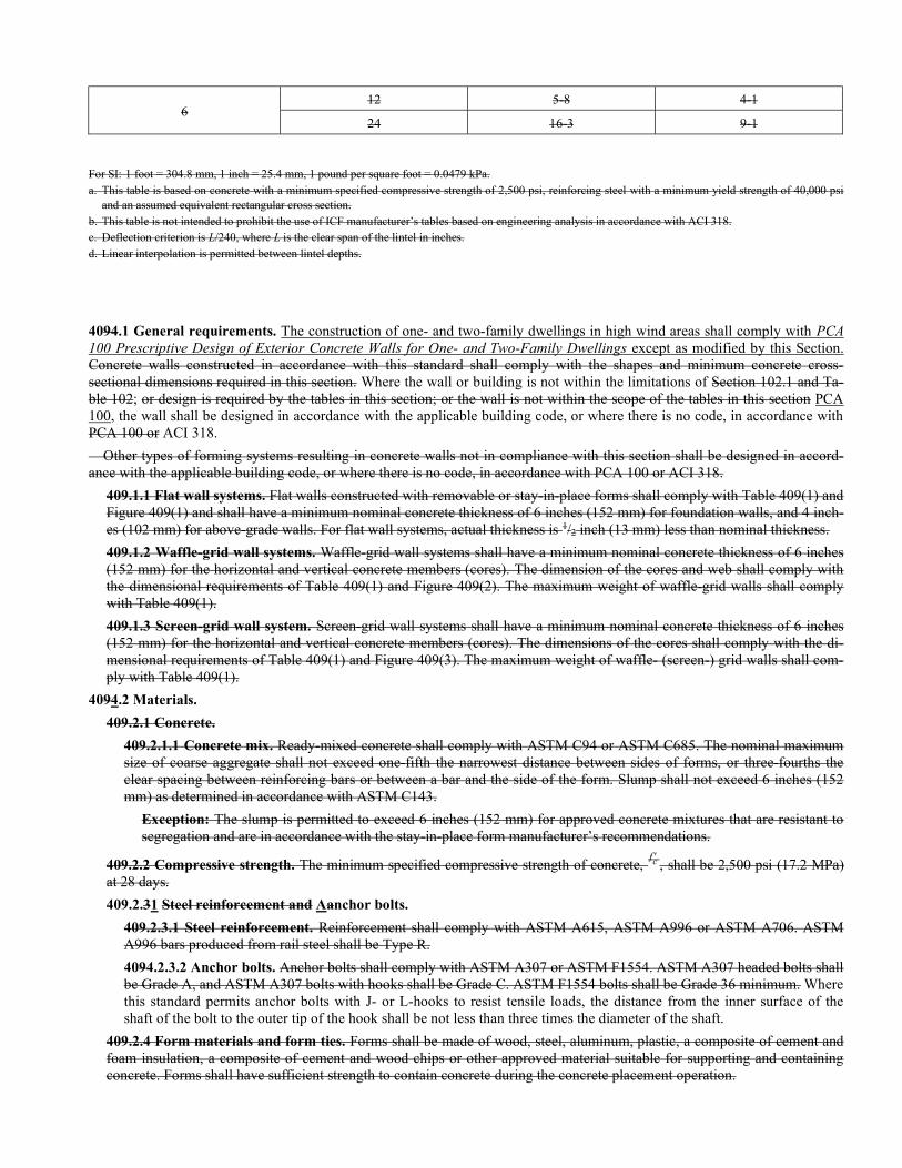
6 12 5-8 4-1
24 16-3 9-1
For SI: 1 foot = 304.8 mm, 1 inch = 25.4 mm, 1 pound per square foot = 0.0479 kPa. a. This table is based on concrete with a minimum specified compressive strength of 2,500 psi, reinforcing steel with a minimum yield strength of 40,000 psi
and an assumed equivalent rectangular cross section. b. This table is not intended to prohibit the use of ICF manufacturer’s tables based on engineering analysis in accordance with ACI 318. c. Deflection criterion is L/240, where L is the clear span of the lintel in inches. d. Linear interpolation is permitted between lintel depths.
4094.1 General requirements. The construction of one- and two-family dwellings in high wind areas shall comply with PCA 100 Prescriptive Design of Exterior Concrete Walls for One- and Two-Family Dwellings except as modified by this Section. Concrete walls constructed in accordance with this standard shall comply with the shapes and minimum concrete cross-sectional dimensions required in this section. Where the wall or building is not within the limitations of Section 102.1 and Ta-ble 102; or design is required by the tables in this section; or the wall is not within the scope of the tables in this section PCA 100, the wall shall be designed in accordance with the applicable building code, or where there is no code, in accordance with PCA 100 or ACI 318.
Other types of forming systems resulting in concrete walls not in compliance with this section shall be designed in accord-ance with the applicable building code, or where there is no code, in accordance with PCA 100 or ACI 318.
409.1.1 Flat wall systems. Flat walls constructed with removable or stay-in-place forms shall comply with Table 409(1) and Figure 409(1) and shall have a minimum nominal concrete thickness of 6 inches (152 mm) for foundation walls, and 4 inch-es (102 mm) for above-grade walls. For flat wall systems, actual thickness is 1/2 inch (13 mm) less than nominal thickness.
409.1.2 Waffle-grid wall systems. Waffle-grid wall systems shall have a minimum nominal concrete thickness of 6 inches (152 mm) for the horizontal and vertical concrete members (cores). The dimension of the cores and web shall comply with the dimensional requirements of Table 409(1) and Figure 409(2). The maximum weight of waffle-grid walls shall comply with Table 409(1).
409.1.3 Screen-grid wall system. Screen-grid wall systems shall have a minimum nominal concrete thickness of 6 inches (152 mm) for the horizontal and vertical concrete members (cores). The dimensions of the cores shall comply with the di-mensional requirements of Table 409(1) and Figure 409(3). The maximum weight of waffle- (screen-) grid walls shall com-ply with Table 409(1).
4094.2 Materials.
409.2.1 Concrete.
409.2.1.1 Concrete mix. Ready-mixed concrete shall comply with ASTM C94 or ASTM C685. The nominal maximum size of coarse aggregate shall not exceed one-fifth the narrowest distance between sides of forms, or three-fourths the clear spacing between reinforcing bars or between a bar and the side of the form. Slump shall not exceed 6 inches (152 mm) as determined in accordance with ASTM C143.
Exception: The slump is permitted to exceed 6 inches (152 mm) for approved concrete mixtures that are resistant to segregation and are in accordance with the stay-in-place form manufacturer’s recommendations.
409.2.2 Compressive strength. The minimum specified compressive strength of concrete, f c , shall be 2,500 psi (17.2 MPa)
at 28 days.
409.2.31 Steel reinforcement and Aanchor bolts.
409.2.3.1 Steel reinforcement. Reinforcement shall comply with ASTM A615, ASTM A996 or ASTM A706. ASTM A996 bars produced from rail steel shall be Type R.
4094.2.3.2 Anchor bolts. Anchor bolts shall comply with ASTM A307 or ASTM F1554. ASTM A307 headed bolts shall be Grade A, and ASTM A307 bolts with hooks shall be Grade C. ASTM F1554 bolts shall be Grade 36 minimum. Where this standard permits anchor bolts with J- or L-hooks to resist tensile loads, the distance from the inner surface of the shaft of the bolt to the outer tip of the hook shall be not less than three times the diameter of the shaft.
409.2.4 Form materials and form ties. Forms shall be made of wood, steel, aluminum, plastic, a composite of cement and foam insulation, a composite of cement and wood chips or other approved material suitable for supporting and containing concrete. Forms shall have sufficient strength to contain concrete during the concrete placement operation.
The flame-spread index of stay-in-place forms made with foam plastic shall not exceed 75 and the smoke-developed in-dex shall not exceed 450, where tested in accordance with ASTM E84. The flame-spread index of stay-in-place forms made with other materials shall comply with the applicable building code, and if there is no code, the flame spread index shall not exceed 200 and the smoke-developed index shall not exceed 450, where tested in accordance with ASTM E84.
Form ties shall be steel, solid plastic, foam plastic, a composite of cement and wood chips, a composite of cement and foam plastic or other suitable material capable of resisting the forces created by the fluid pressure of fresh concrete.
409.3 Reinforcement installation details.
409.3.1 Support and cover. Reinforcement shall be secured in the proper location in the forms with tie wire or other bar support system such that displacement will not occur during the concrete placement operation. Steel reinforcement in con-crete cast against the earth shall have a minimum cover of 3 inches (76 mm). Minimum cover for reinforcement in concrete cast in removable forms that will be exposed to the earth or weather shall be 11/2 inches (38 mm) for No. 5 bars and smaller, and 2 inches (50 mm) for No. 6 bars and larger. For concrete cast-in removable forms that will not be exposed to the earth or weather, and for concrete cast-in stay-in-place forms, minimum cover shall be 3/4 inch (19 mm). The minus tolerance for cover shall not exceed the smaller of one-third the required cover or 3/8 inch (10 mm).
409.3.2 Lap splices. Vertical and horizontal wall reinforcement required by Sections 409.5.2 and 409.5.3 shall be the long-est lengths practical. Where splices are necessary in reinforcement, the length of lap splice shall be in accordance with Fig-ure 409(4) and a minimum of 40db, where db is the diameter of the smallest bar. The maximum gap between noncontact par-allel bars at a lap splice shall not exceed the smaller of one-fifth the required lap length or 6 inches (152 mm).
409.3.3 Standard hooks. Where reinforcement is required by this standard to terminate with a standard hook, the hook shall comply with Figure 409(5).
409.3.4 Webs of waffle-grid walls. Reinforcement, including stirrups, shall not be placed in webs of waffle-grid walls, in-cluding lintels. Webs are permitted to have form ties.
409.4 Covering for stay-in-place forms.
409.4.1 Interior covering. Stay-in-place forms constructed of rigid foam plastic shall be protected on the interior of the building as required by the applicable building code. In the absence of a code, rigid foam plastic that remains in place on the interior of the building, including attic and crawl spaces, shall be covered with a minimum of 1/2-inch (13 mm) gypsum board or an approved finish material that provides a thermal barrier to limit the average temperature rise of the unexposed surface to no more than 250°F (121°C) after 15 minutes of fire exposure in accordance with ASTM E119. The gypsum board shall be installed with a mechanical fastening system. Use of adhesives in addition to mechanical fasteners is permit-ted.
409.4.2 Exterior covering. Stay-in-place forms constructed of rigid foam plastics shall be protected from sunlight and phys-ical damage by the application of an approved exterior wall covering complying with the requirements of the applicable building code. Exterior surfaces of other stay-in-place forming systems shall be protected in accordance with the applicable building code.
409.5 Above-grade wall requirements.
409.5.1 General. Above-grade concrete walls shall be constructed in accordance with this section and Figure 409(6). Con-crete walls shall be supported on continuous foundation walls or slabs-on-grade that are monolithic with the footing in ac-cordance with Section 403. The minimum length of solid wall without openings shall be in accordance with Section 409.6. Reinforcement around openings, including lintels, shall be in accordance with Section 409.7 Lateral support for above-grade walls shall be provided by the roof system and floor framing system, if applicable, in accordance with Section 409.8. The wall thickness shall be equal to or greater than the thickness of the wall in the story above.
409.5.2 Wall reinforcement. The vertical wall reinforcement shall satisfy the requirements in Tables 409(2), 409(3) and 409(4). There shall be a vertical bar at all corners of exterior walls. The minimum horizontal reinforcement shall be four No. 4 bars (Grade 40) placed as follows: top bar within 12 inches (305 mm) of the top of the wall, bottom bar within 12 inches (305 mm) of the finish floor, and one bar each at approximately one-third and two-thirds of the wall height.
409.5.3 Continuity of wall reinforcement between stories. Vertical reinforcement shall be continuous from the bottom of the foundation wall to the roof. Lap splices, where required, shall comply with Section 409.3.2 and Figure 409(4). Where splices are needed to provide the required continuity, dowel bars with a size and spacing to match the vertical above-grade concrete wall reinforcement shall be embedded in the foundation wall and lap-spliced with the above-grade wall reinforce-ment in accordance with Section 409.3.2 and Figure 409(4).
409.5.4 Termination of reinforcement. Where the design wind pressure exceeds 40 psf (1.92 kPa) in accordance with Ta-ble 301(1) vertical wall reinforcement in the top-most story with concrete walls shall terminate with a 90-degree (1.57 rad) standard hook in accordance with Section 409.3.3 and Figure 409(5). The free end of the hook shall be within 4 inches (102 mm) of the top of the wall and shall be oriented parallel to the horizontal steel in the top of the wall.
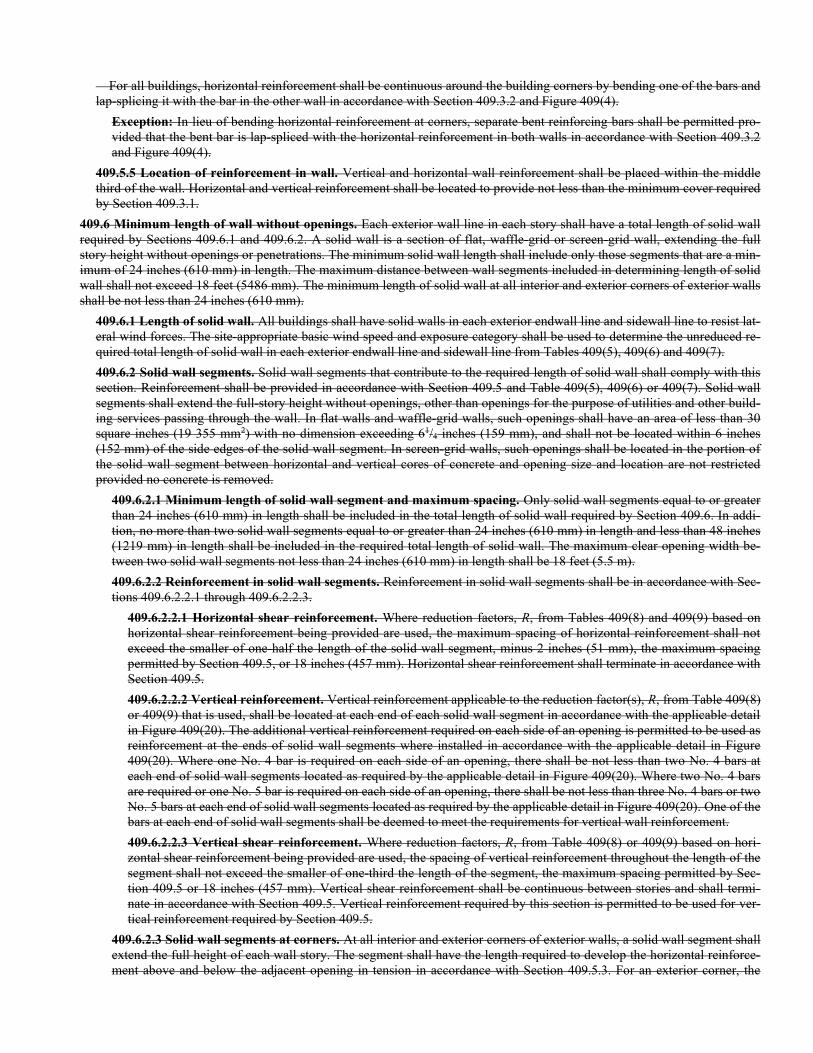
For all buildings, horizontal reinforcement shall be continuous around the building corners by bending one of the bars and lap-splicing it with the bar in the other wall in accordance with Section 409.3.2 and Figure 409(4).
Exception: In lieu of bending horizontal reinforcement at corners, separate bent reinforcing bars shall be permitted pro-vided that the bent bar is lap-spliced with the horizontal reinforcement in both walls in accordance with Section 409.3.2 and Figure 409(4).
409.5.5 Location of reinforcement in wall. Vertical and horizontal wall reinforcement shall be placed within the middle third of the wall. Horizontal and vertical reinforcement shall be located to provide not less than the minimum cover required by Section 409.3.1.
409.6 Minimum length of wall without openings. Each exterior wall line in each story shall have a total length of solid wall required by Sections 409.6.1 and 409.6.2. A solid wall is a section of flat, waffle-grid or screen-grid wall, extending the full story height without openings or penetrations. The minimum solid wall length shall include only those segments that are a min-imum of 24 inches (610 mm) in length. The maximum distance between wall segments included in determining length of solid wall shall not exceed 18 feet (5486 mm). The minimum length of solid wall at all interior and exterior corners of exterior walls shall be not less than 24 inches (610 mm).
409.6.1 Length of solid wall. All buildings shall have solid walls in each exterior endwall line and sidewall line to resist lat-eral wind forces. The site-appropriate basic wind speed and exposure category shall be used to determine the unreduced re-quired total length of solid wall in each exterior endwall line and sidewall line from Tables 409(5), 409(6) and 409(7).
409.6.2 Solid wall segments. Solid wall segments that contribute to the required length of solid wall shall comply with this section. Reinforcement shall be provided in accordance with Section 409.5 and Table 409(5), 409(6) or 409(7). Solid wall segments shall extend the full-story height without openings, other than openings for the purpose of utilities and other build-ing services passing through the wall. In flat walls and waffle-grid walls, such openings shall have an area of less than 30 square inches (19 355 mm2) with no dimension exceeding 61/4 inches (159 mm), and shall not be located within 6 inches (152 mm) of the side edges of the solid wall segment. In screen-grid walls, such openings shall be located in the portion of the solid wall segment between horizontal and vertical cores of concrete and opening size and location are not restricted provided no concrete is removed.
409.6.2.1 Minimum length of solid wall segment and maximum spacing. Only solid wall segments equal to or greater than 24 inches (610 mm) in length shall be included in the total length of solid wall required by Section 409.6. In addi-tion, no more than two solid wall segments equal to or greater than 24 inches (610 mm) in length and less than 48 inches (1219 mm) in length shall be included in the required total length of solid wall. The maximum clear opening width be-tween two solid wall segments not less than 24 inches (610 mm) in length shall be 18 feet (5.5 m).
409.6.2.2 Reinforcement in solid wall segments. Reinforcement in solid wall segments shall be in accordance with Sec-tions 409.6.2.2.1 through 409.6.2.2.3.
409.6.2.2.1 Horizontal shear reinforcement. Where reduction factors, R, from Tables 409(8) and 409(9) based on horizontal shear reinforcement being provided are used, the maximum spacing of horizontal reinforcement shall not exceed the smaller of one-half the length of the solid wall segment, minus 2 inches (51 mm), the maximum spacing permitted by Section 409.5, or 18 inches (457 mm). Horizontal shear reinforcement shall terminate in accordance with Section 409.5.
409.6.2.2.2 Vertical reinforcement. Vertical reinforcement applicable to the reduction factor(s), R, from Table 409(8) or 409(9) that is used, shall be located at each end of each solid wall segment in accordance with the applicable detail in Figure 409(20). The additional vertical reinforcement required on each side of an opening is permitted to be used as reinforcement at the ends of solid wall segments where installed in accordance with the applicable detail in Figure 409(20). Where one No. 4 bar is required on each side of an opening, there shall be not less than two No. 4 bars at each end of solid wall segments located as required by the applicable detail in Figure 409(20). Where two No. 4 bars are required or one No. 5 bar is required on each side of an opening, there shall be not less than three No. 4 bars or two No. 5 bars at each end of solid wall segments located as required by the applicable detail in Figure 409(20). One of the bars at each end of solid wall segments shall be deemed to meet the requirements for vertical wall reinforcement.
409.6.2.2.3 Vertical shear reinforcement. Where reduction factors, R, from Table 409(8) or 409(9) based on hori-zontal shear reinforcement being provided are used, the spacing of vertical reinforcement throughout the length of the segment shall not exceed the smaller of one-third the length of the segment, the maximum spacing permitted by Sec-tion 409.5 or 18 inches (457 mm). Vertical shear reinforcement shall be continuous between stories and shall termi-nate in accordance with Section 409.5. Vertical reinforcement required by this section is permitted to be used for ver-tical reinforcement required by Section 409.5.
409.6.2.3 Solid wall segments at corners. At all interior and exterior corners of exterior walls, a solid wall segment shall extend the full height of each wall story. The segment shall have the length required to develop the horizontal reinforce-ment above and below the adjacent opening in tension in accordance with Section 409.5.3. For an exterior corner, the

limiting dimension is measured on the outside of the wall, and for an interior corner, the limiting dimension is measured on the inside of the wall. The length of a segment contributing to the required length of solid wall shall comply with Sec-tion 409.6.1.
The end of a solid wall segment complying with the minimum length requirements of Section 409.6.1 shall be located no more than 6 feet (1828 mm) from each corner.
409.6.2.4 Minimum wall thickness. The minimum nominal thickness of flat walls shall be 4 inches (102 mm).
409.7 Wall openings.
409.7.1 Minimum reinforcement. Wall openings shall have a minimum of 8 inches (203 mm) of depth of concrete for flat and waffle-grid ICF walls and 12 inches (305 mm) for screen-grid walls over the length of the opening. When the depth of concrete above the opening is less than 12 inches for flat or waffle-grid walls, or the width of the opening is greater than or equal to 2 feet (610 mm), lintels in accordance with Section 409.7.2 shall be provided. Reinforcement around openings shall be provided in accordance with Table 409(10) and Figure 409(8). Reinforcement placed horizontally above or below an opening shall extend a minimum of 24 inches (610 mm) beyond the limits of the opening. Wall opening reinforcement shall be provided in addition to the reinforcement required by Section 409.5.2. The perimeter of all wall openings shall be framed with a minimum 2-inch by 4-inch (51 mm by 102 mm) plate, anchored to the wall with 1/2-inch diameter (13 mm) anchor bolts spaced a maximum of 24 inches (610 mm) on center. The bolts shall be embedded into the concrete a minimum of 4 inches (102 mm) and have a minimum of 11/2 inches (38 mm) of concrete cover to the face of the wall.
Exception: The 2-inch by 4-inch (51 mm by 102 mm) plate is not required where the wall is formed to provide solid concrete around the perimeter of the opening with a minimum depth of 4 inches (102 mm) for the full thickness of the wall.
409.7.2 Lintels.
409.7.2.1 General requirements. Lintels shall be provided over all openings greater than or equal to 2 feet (1.2 m) in width. Lintels for flat ICF walls shall be constructed in accordance with Figure 409(9) and Table 409(11) or 409(12). Lintels for waffle-grid walls shall be constructed in accordance with Figure 409(10) or 409(11) and Table 409(13) or 409(14). Lintels for screen-grid walls shall be constructed in accordance with Figure 409(12) or 409(13) and Table 409(15) or 409(16). Lintels depths are permitted to be increased by the height of wall located directly above the lintels, provided that the lintel depth spans the entire length of the opening.
409.7.2.2 Stirrups. Where required, No. 3 stirrups shall be installed in flat, waffle-grid and screen-grid wall lintels in ac-cordance with the following:
1. For flat walls the stirrups shall be spaced at a maximum spacing of d/2 where d equals the depth of the lintel (D) minus the bottom cover of concrete as shown in Figure 409(9). Stirrups shall not be required in the middle portion of the span (A) per Figure 409(8), for flat walls for a length not to exceed the values shown in parenthesis in Ta-bles 409(12) and 409(13) or for spans in accordance with Table 409(17).
2. For waffle-grid walls a minimum of two No. 3 stirrups shall be placed in each vertical core of waffle-grid lintels. Stirrups shall not be required in the middle portion of the span (A) per Figure 409(9), for waffle-grid walls for a length not to exceed the values shown in parenthesis in Tables 409(14) and 409(15) or for spans in accordance with Table 409(18).
3. For screen-grid walls one No. 3 stirrup shall be placed in each vertical core of screen-grid lintels.
Exception: Stirrups are not required in screen-grid lintels meeting the following requirements: 1. Lintel Depth (D) = 12 inches (305 mm) spans less than or equal 3 feet 7 inches (1092 mm).
2. Lintel Depth (D) = 24 inches (610 mm) spans less than or equal 4 feet 4 inches (1320 mm).
409.7.2.3 Horizontal reinforcement. One No. 4 horizontal bar shall be provided in the top of the lintel. Horizontal rein-forcement placed within 12 inches (305 mm) of the top of the wall in accordance with Section 409.5.2 shall be permitted to serve as the top or bottom reinforcement in the lintel if the reinforcement meets the location requirements in Figure 409(8), 409(9), 409(10), 409(11), 409(12) or 409(13), and the size requirements in Table 409(11), 409(12), 409(13), 409(14), 409(15) or 409(16).
409.7.2.4 Load-bearing walls. Lintels for flat walls supporting roof or floor loads shall comply with Table 409(11), 409(12) or 409(17). Lintels for waffle-grid walls supporting roof or floor loads shall comply with Table 409(13), 409(14) or 409(17). Lintels for screen-grid walls supporting roof or floor loads shall comply with Table 409(15) or 409(16).
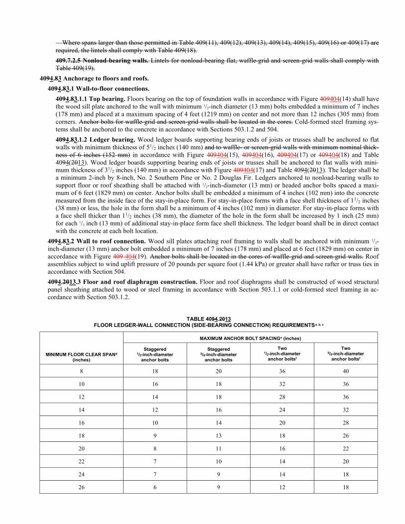
Where spans larger than those permitted in Table 409(11), 409(12), 409(13), 409(14), 409(15), 409(16) or 409(17) are required, the lintels shall comply with Table 409(18).
409.7.2.5 Nonload-bearing walls. Lintels for nonload-bearing flat, waffle-grid and screen-grid walls shall comply with Table 409(19).
4094.83 Anchorage to floors and roofs.
4094.83.1 Wall-to-floor connections.
4094.83.1.1 Top bearing. Floors bearing on the top of foundation walls in accordance with Figure 409404(14) shall have the wood sill plate anchored to the wall with minimum 1/2-inch diameter (13 mm) bolts embedded a minimum of 7 inches (178 mm) and placed at a maximum spacing of 4 feet (1219 mm) on center and not more than 12 inches (305 mm) from corners. Anchor bolts for waffle-grid and screen-grid walls shall be located in the cores. Cold-formed steel framing sys-tems shall be anchored to the concrete in accordance with Sections 503.1.2 and 504.
4094.83.1.2 Ledger bearing. Wood ledger boards supporting bearing ends of joists or trusses shall be anchored to flat walls with minimum thickness of 51/2 inches (140 mm) and to waffle- or screen-grid walls with minimum nominal thick-ness of 6 inches (152 mm) in accordance with Figure 409404(15), 409404(16), 409404(17) or 409404(18) and Table 4094(2013). Wood ledger boards supporting bearing ends of joists or trusses shall be anchored to flat walls with mini-mum thickness of 31/2 inches (140 mm) in accordance with Figure 409404(17) and Table 4094(2013). The ledger shall be a minimum 2-inch by 8-inch, No. 2 Southern Pine or No. 2 Douglas Fir. Ledgers anchored to nonload-bearing walls to support floor or roof sheathing shall be attached with 1/2-inch-diameter (13 mm) or headed anchor bolts spaced a maxi-mum of 6 feet (1829 mm) on center. Anchor bolts shall be embedded a minimum of 4 inches (102 mm) into the concrete measured from the inside face of the stay-in-place form. For stay-in-place forms with a face shell thickness of 11/2 inches (38 mm) or less, the hole in the form shall be a minimum of 4 inches (102 mm) in diameter. For stay-in-place forms with a face shell thicker than 11/2 inches (38 mm), the diameter of the hole in the form shall be increased by 1 inch (25 mm) for each 1/2 inch (13 mm) of additional stay-in-place form face shell thickness. The ledger board shall be in direct contact with the concrete at each bolt location.
4094.83.2 Wall to roof connection. Wood sill plates attaching roof framing to walls shall be anchored with minimum 1/2-inch-diameter (13 mm) anchor bolt embedded a minimum of 7 inches (178 mm) and placed at 6 feet (1829 mm) on center in accordance with Figure 409 404(19). Anchor bolts shall be located in the cores of waffle-grid and screen-grid walls. Roof assemblies subject to wind uplift pressure of 20 pounds per square foot (1.44 kPa) or greater shall have rafter or truss ties in accordance with Section 504.
4094.2013.3 Floor and roof diaphragm construction. Floor and roof diaphragms shall be constructed of wood structural panel sheathing attached to wood or steel framing in accordance with Section 503.1.1 or cold-formed steel framing in ac-cordance with Section 503.1.2.
TABLE 4094.2013 FLOOR LEDGER-WALL CONNECTION (SIDE-BEARING CONNECTION) REQUIREMENTSa, b, c
MINIMUM FLOOR CLEAR SPANd
(inches)
MAXIMUM ANCHOR BOLT SPACINGe (inches)
Staggered 1/2-inch-diameter
anchor bolts
Staggered 5/8-inch-diameter
anchor bolts
Two 1/2-inch-diameter
anchor boltsf
Two 5/8-inch-diameter
anchor boltsf
8 18 20 36 40
10 16 18 32 36
12 14 18 28 36
14 12 16 24 32
16 10 14 20 28
18 9 13 18 26
20 8 11 16 22
22 7 10 14 20
24 7 9 14 18
26 6 9 12 18
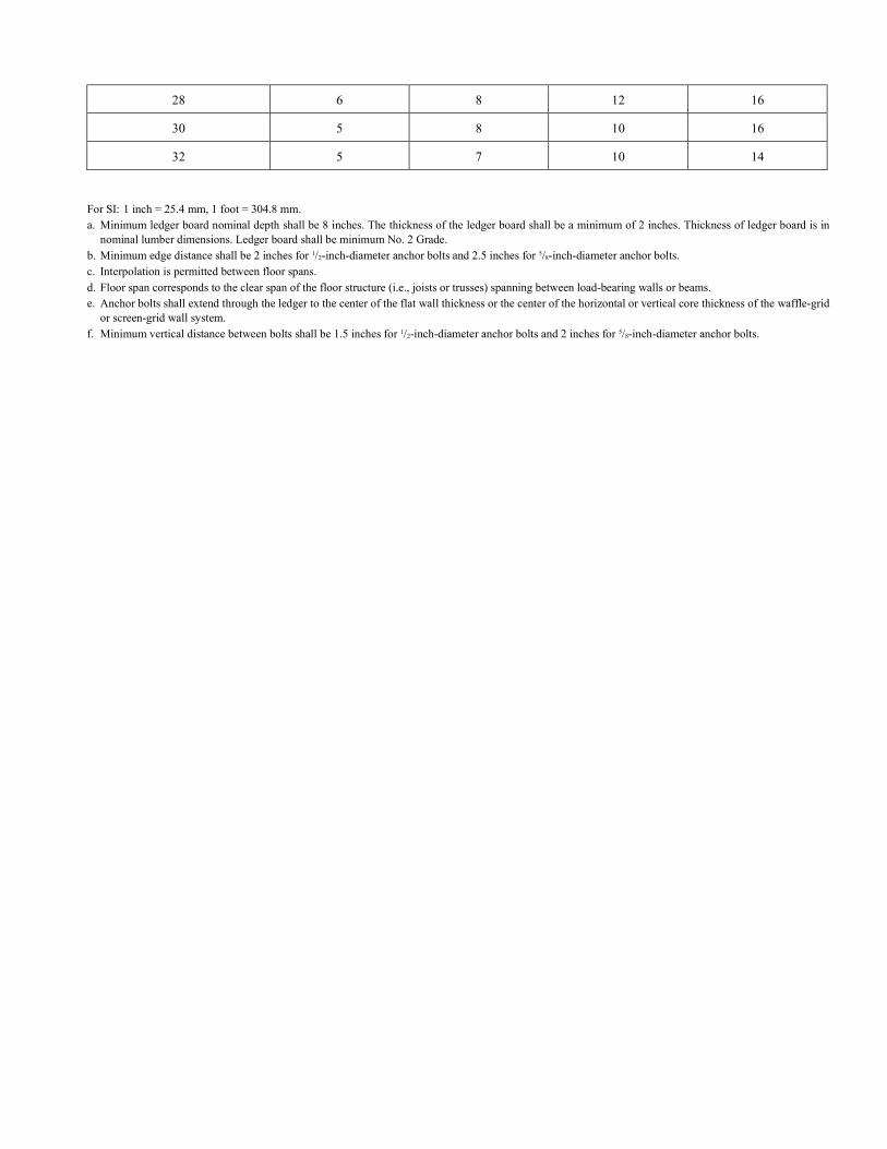
28 6 8 12 16
30 5 8 10 16
32 5 7 10 14
For SI: 1 inch = 25.4 mm, 1 foot = 304.8 mm. a. Minimum ledger board nominal depth shall be 8 inches. The thickness of the ledger board shall be a minimum of 2 inches. Thickness of ledger board is in
nominal lumber dimensions. Ledger board shall be minimum No. 2 Grade. b. Minimum edge distance shall be 2 inches for 1/2-inch-diameter anchor bolts and 2.5 inches for 5/8-inch-diameter anchor bolts. c. Interpolation is permitted between floor spans. d. Floor span corresponds to the clear span of the floor structure (i.e., joists or trusses) spanning between load-bearing walls or beams. e. Anchor bolts shall extend through the ledger to the center of the flat wall thickness or the center of the horizontal or vertical core thickness of the waffle-grid
or screen-grid wall system. f. Minimum vertical distance between bolts shall be 1.5 inches for 1/2-inch-diameter anchor bolts and 2 inches for 5/8-inch-diameter anchor bolts.
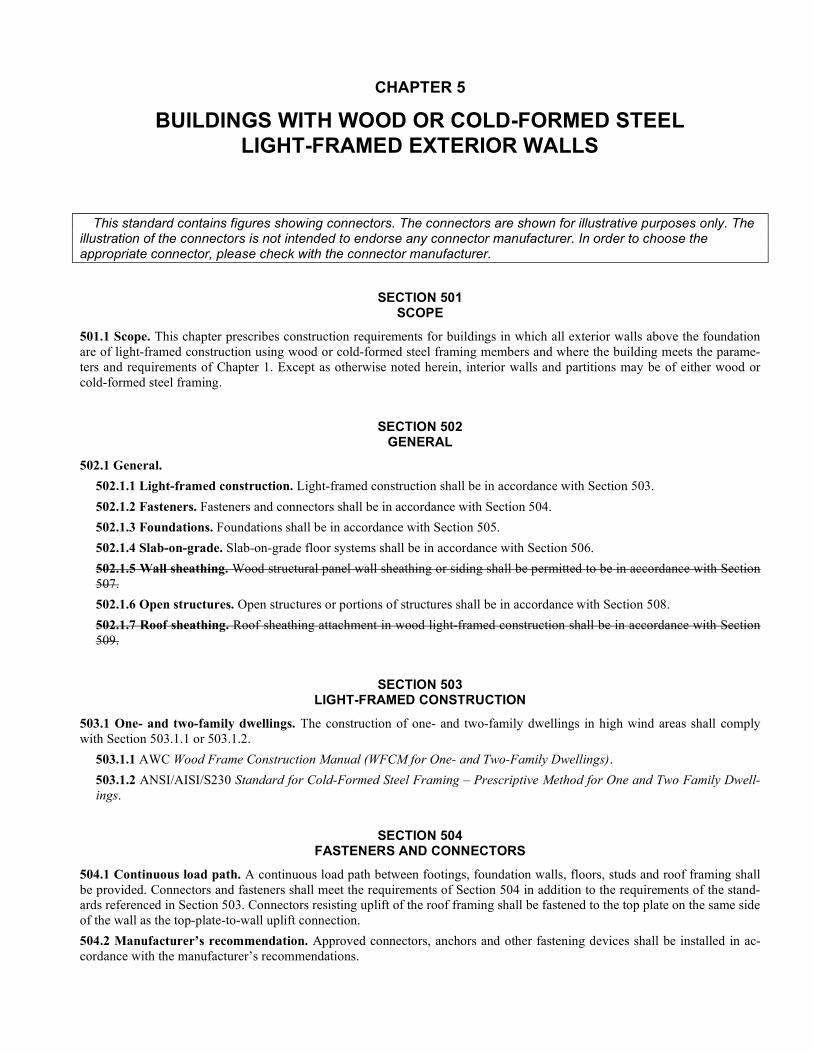
CHAPTER 5
BUILDINGS WITH WOOD OR COLD-FORMED STEEL LIGHT-FRAMED EXTERIOR WALLS
This standard contains figures showing connectors. The connectors are shown for illustrative purposes only. The illustration of the connectors is not intended to endorse any connector manufacturer. In order to choose the appropriate connector, please check with the connector manufacturer.
SECTION 501 SCOPE
501.1 Scope. This chapter prescribes construction requirements for buildings in which all exterior walls above the foundation are of light-framed construction using wood or cold-formed steel framing members and where the building meets the parame-ters and requirements of Chapter 1. Except as otherwise noted herein, interior walls and partitions may be of either wood or cold-formed steel framing.
SECTION 502 GENERAL
502.1 General.
502.1.1 Light-framed construction. Light-framed construction shall be in accordance with Section 503.
502.1.2 Fasteners. Fasteners and connectors shall be in accordance with Section 504.
502.1.3 Foundations. Foundations shall be in accordance with Section 505.
502.1.4 Slab-on-grade. Slab-on-grade floor systems shall be in accordance with Section 506.
502.1.5 Wall sheathing. Wood structural panel wall sheathing or siding shall be permitted to be in accordance with Section 507.
502.1.6 Open structures. Open structures or portions of structures shall be in accordance with Section 508.
502.1.7 Roof sheathing. Roof sheathing attachment in wood light-framed construction shall be in accordance with Section 509.
SECTION 503 LIGHT-FRAMED CONSTRUCTION
503.1 One- and two-family dwellings. The construction of one- and two-family dwellings in high wind areas shall comply with Section 503.1.1 or 503.1.2.
503.1.1 AWC Wood Frame Construction Manual (WFCM for One- and Two-Family Dwellings).
503.1.2 ANSI/AISI/S230 Standard for Cold-Formed Steel Framing – Prescriptive Method for One and Two Family Dwell-ings.
SECTION 504 FASTENERS AND CONNECTORS
504.1 Continuous load path. A continuous load path between footings, foundation walls, floors, studs and roof framing shall be provided. Connectors and fasteners shall meet the requirements of Section 504 in addition to the requirements of the stand-ards referenced in Section 503. Connectors resisting uplift of the roof framing shall be fastened to the top plate on the same side of the wall as the top-plate-to-wall uplift connection.
504.2 Manufacturer’s recommendation. Approved connectors, anchors and other fastening devices shall be installed in ac-cordance with the manufacturer’s recommendations.
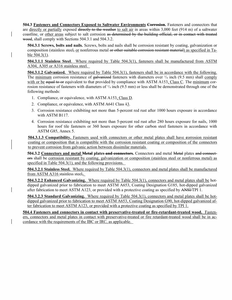
504.3 Fasteners and Connectors Exposed to Saltwater Environments Corrosion. Fasteners and connectors that are directly or partially exposed directly to the weather to salt air in areas within 3,000 feet (914 m) of a saltwater coastline, or other areas subject to salt corrosion as determined by the building official, or in contact with treated wood, shall comply with Sections 504.3.1 and 504.3.2.
504.3.1 Screws, bolts and nails. Screws, bolts and nails shall be corrosion resistant by coating, galvanization or composition (stainless steel, or nonferrous metal or other suitable corrosion resistant material) as specified in Ta-ble 504.3(1).
504.3.1.1 Stainless Steel. Where required by Table 504.3(1), fasteners shall be manufactured from ASTM A304, A305 or A316 stainless steel.
504.3.1.2 Galvanized. Where required by Table 504.3(1), fasteners shall be in accordance with the following. The minimum corrosion resistance of galvanized fasteners with diameters over 3/8 inch (9.5 mm) shall comply with or be equal to or equivalent to that provided by compliance with ASTM A153, Class C. The minimum cor-rosion resistance of fasteners with diameters of 3/8 inch (9.5 mm) or less shall be demonstrated through one of the following methods:
1. Compliance, or equivalence, with ASTM A153, Class D.
2. Compliance, or equivalence, with ASTM A641 Class 13.
3. Corrosion resistance exhibiting not more than 5-percent red rust after 1000 hours exposure in accordance with ASTM B117.
4. Corrosion resistance exhibiting not more than 5-percent red rust after 280 hours exposure for nails, 1000 hours for roof tile fasteners or 360 hours exposure for other carbon steel fasteners in accordance with ASTM G85, Annex 5.
504.3.1.3 Compatibility. Fasteners used with connectors or other metal plates shall have corrosion resistant coating or composition that is compatible with the corrosion resistant coating or composition of the connectors to prevent corrosion from galvanic action between dissimilar materials.
504.3.2 Connectors and metal Metal plates and connectors. Connectors and metal Metal plates and connect-ors shall be corrosion resistant by coating, galvanization or composition (stainless steel or nonferrous metal) as specified in Table 504.3(1), and the following provisions.
504.3.2.1 Stainless Steel. Where required by Table 504.3(1), connectors and metal plates shall be manufactured from ASTM A316 stainless steel,.
504.3.2.2 Enhanced Galvanizing. Where required by Table 504.3(1), connectors and metal plates shall be hot-dipped galvanized prior to fabrication to meet ASTM A653, Coating Designation G185, hot-dipped galvanized after fabrication to meet ASTM A123, or provided with a protective coating as specified by ANSI/TPI 1.
504.3.2.3 Standard Galvanizing. Where required by Table 504.3(1), connectors and metal plates shall be hot-dipped galvanized prior to fabrication to meet ASTM A653, Coating Designation G90, hot-dipped galvanized af-ter fabrication to meet ASTM A123, or provided with a protective coating as specified by TPI 1.
504.4 Fasteners and connectors in contact with preservative-treated or fire-retardant-treated wood. Fasten-ers, connectors and metal plates in contact with preservative-treated or fire retardant-treated wood shall be in ac-cordance with the requirements of the IBC or IRC, as applicable.
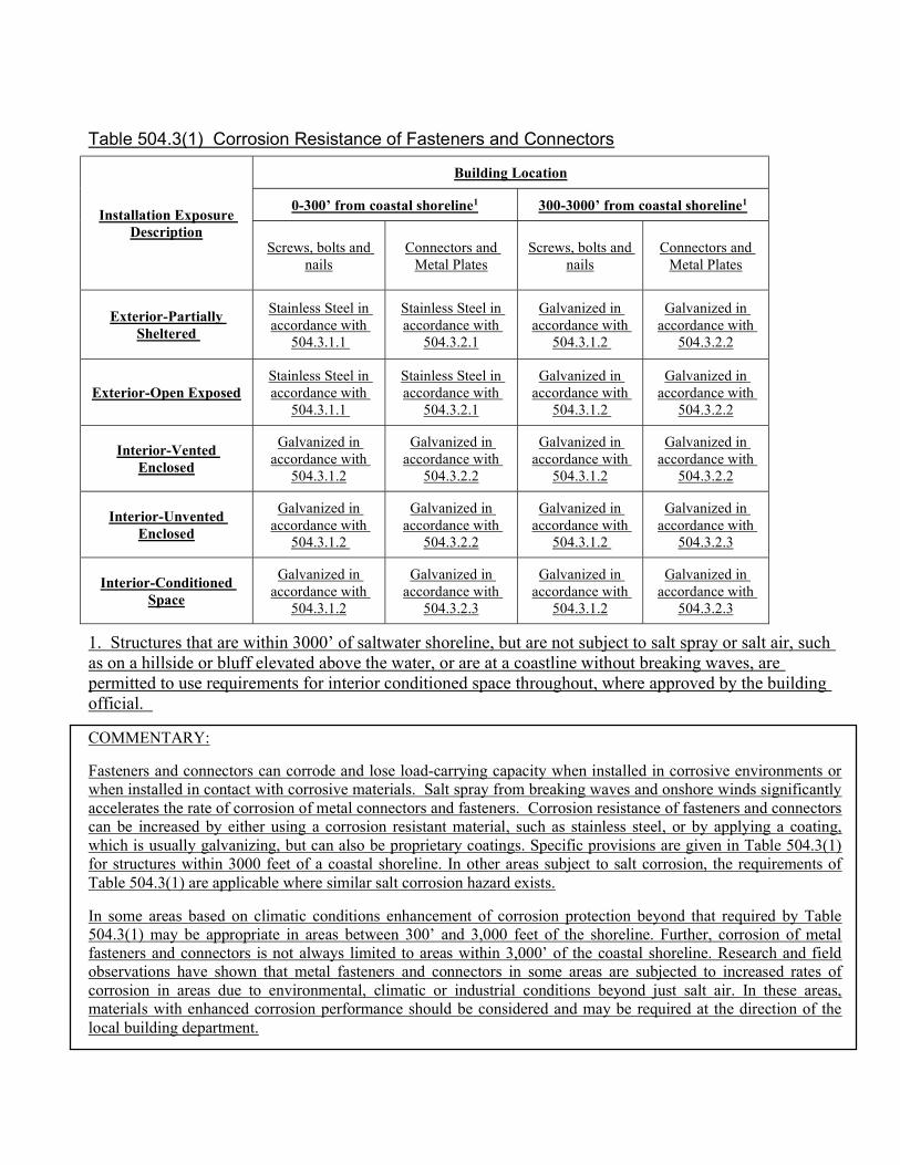
Table 504.3(1) Corrosion Resistance of Fasteners and Connectors
Installation Exposure Description
Building Location
0-300’ from coastal shoreline1 300-3000’ from coastal shoreline1
Screws, bolts and nails
Connectors and Metal Plates
Screws, bolts and nails
Connectors and Metal Plates
Exterior-Partially Sheltered
Stainless Steel in accordance with
504.3.1.1
Stainless Steel in accordance with
504.3.2.1
Galvanized in accordance with
504.3.1.2
Galvanized in accordance with
504.3.2.2
Exterior-Open Exposed Stainless Steel in accordance with
504.3.1.1
Stainless Steel in accordance with
504.3.2.1
Galvanized in accordance with
504.3.1.2
Galvanized in accordance with
504.3.2.2
Interior-Vented Enclosed
Galvanized in accordance with
504.3.1.2
Galvanized in accordance with
504.3.2.2
Galvanized in accordance with
504.3.1.2
Galvanized in accordance with
504.3.2.2
Interior-Unvented Enclosed
Galvanized in accordance with
504.3.1.2
Galvanized in accordance with
504.3.2.2
Galvanized in accordance with
504.3.1.2
Galvanized in accordance with
504.3.2.3
Interior-Conditioned Space
Galvanized in accordance with
504.3.1.2
Galvanized in accordance with
504.3.2.3
Galvanized in accordance with
504.3.1.2
Galvanized in accordance with
504.3.2.3
1. Structures that are within 3000’ of saltwater shoreline, but are not subject to salt spray or salt air, such as on a hillside or bluff elevated above the water, or are at a coastline without breaking waves, are permitted to use requirements for interior conditioned space throughout, where approved by the building official.
COMMENTARY:
Fasteners and connectors can corrode and lose load-carrying capacity when installed in corrosive environments or when installed in contact with corrosive materials. Salt spray from breaking waves and onshore winds significantly accelerates the rate of corrosion of metal connectors and fasteners. Corrosion resistance of fasteners and connectors can be increased by either using a corrosion resistant material, such as stainless steel, or by applying a coating, which is usually galvanizing, but can also be proprietary coatings. Specific provisions are given in Table 504.3(1) for structures within 3000 feet of a coastal shoreline. In other areas subject to salt corrosion, the requirements of Table 504.3(1) are applicable where similar salt corrosion hazard exists.
In some areas based on climatic conditions enhancement of corrosion protection beyond that required by Table 504.3(1) may be appropriate in areas between 300’ and 3,000 feet of the shoreline. Further, corrosion of metal fasteners and connectors is not always limited to areas within 3,000’ of the coastal shoreline. Research and field observations have shown that metal fasteners and connectors in some areas are subjected to increased rates of corrosion in areas due to environmental, climatic or industrial conditions beyond just salt air. In these areas, materials with enhanced corrosion performance should be considered and may be required at the direction of the local building department.
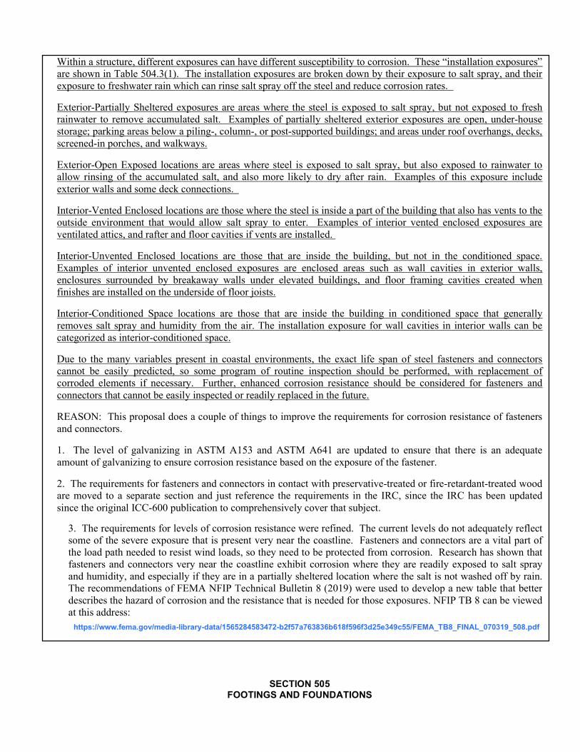
Within a structure, different exposures can have different susceptibility to corrosion. These “installation exposures” are shown in Table 504.3(1). The installation exposures are broken down by their exposure to salt spray, and their exposure to freshwater rain which can rinse salt spray off the steel and reduce corrosion rates.
Exterior-Partially Sheltered exposures are areas where the steel is exposed to salt spray, but not exposed to fresh rainwater to remove accumulated salt. Examples of partially sheltered exterior exposures are open, under-house storage; parking areas below a piling-, column-, or post-supported buildings; and areas under roof overhangs, decks, screened-in porches, and walkways.
Exterior-Open Exposed locations are areas where steel is exposed to salt spray, but also exposed to rainwater to allow rinsing of the accumulated salt, and also more likely to dry after rain. Examples of this exposure include exterior walls and some deck connections.
Interior-Vented Enclosed locations are those where the steel is inside a part of the building that also has vents to the outside environment that would allow salt spray to enter. Examples of interior vented enclosed exposures are ventilated attics, and rafter and floor cavities if vents are installed.
Interior-Unvented Enclosed locations are those that are inside the building, but not in the conditioned space. Examples of interior unvented enclosed exposures are enclosed areas such as wall cavities in exterior walls, enclosures surrounded by breakaway walls under elevated buildings, and floor framing cavities created when finishes are installed on the underside of floor joists.
Interior-Conditioned Space locations are those that are inside the building in conditioned space that generally removes salt spray and humidity from the air. The installation exposure for wall cavities in interior walls can be categorized as interior-conditioned space.
Due to the many variables present in coastal environments, the exact life span of steel fasteners and connectors cannot be easily predicted, so some program of routine inspection should be performed, with replacement of corroded elements if necessary. Further, enhanced corrosion resistance should be considered for fasteners and connectors that cannot be easily inspected or readily replaced in the future.
REASON: This proposal does a couple of things to improve the requirements for corrosion resistance of fasteners and connectors.
1. The level of galvanizing in ASTM A153 and ASTM A641 are updated to ensure that there is an adequate amount of galvanizing to ensure corrosion resistance based on the exposure of the fastener.
2. The requirements for fasteners and connectors in contact with preservative-treated or fire-retardant-treated wood are moved to a separate section and just reference the requirements in the IRC, since the IRC has been updated since the original ICC-600 publication to comprehensively cover that subject.
3. The requirements for levels of corrosion resistance were refined. The current levels do not adequately reflect some of the severe exposure that is present very near the coastline. Fasteners and connectors are a vital part of the load path needed to resist wind loads, so they need to be protected from corrosion. Research has shown that fasteners and connectors very near the coastline exhibit corrosion where they are readily exposed to salt spray and humidity, and especially if they are in a partially sheltered location where the salt is not washed off by rain. The recommendations of FEMA NFIP Technical Bulletin 8 (2019) were used to develop a new table that better describes the hazard of corrosion and the resistance that is needed for those exposures. NFIP TB 8 can be viewed at this address: https://www.fema.gov/media-library-data/1565284583472-b2f57a763836b618f596f3d25e349c55/FEMA_TB8_FINAL_070319_508.pdf
SECTION 505 FOOTINGS AND FOUNDATIONS
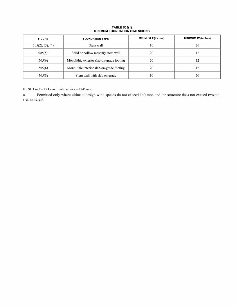
TABLE 505(1) MINIMUM FOUNDATION DIMENSIONS
FIGURE FOUNDATION TYPE MINIMUM T (inches) MINIMUM W (inches)
505(2), (3), (4) Stem wall 10 20
505(5)a Solid or hollow masonry stem wall 20 12
505(6) Monolithic exterior slab-on-grade footing 20 12
505(6) Monolithic interior slab-on-grade footing 20 12
505(8) Stem wall with slab on grade 10 20
For SI: 1 inch = 25.4 mm, 1 mile per hour = 0.447 m/s.
a. Permitted only where ultimate design wind speeds do not exceed 140 mph and the structure does not exceed two sto-ries in height.
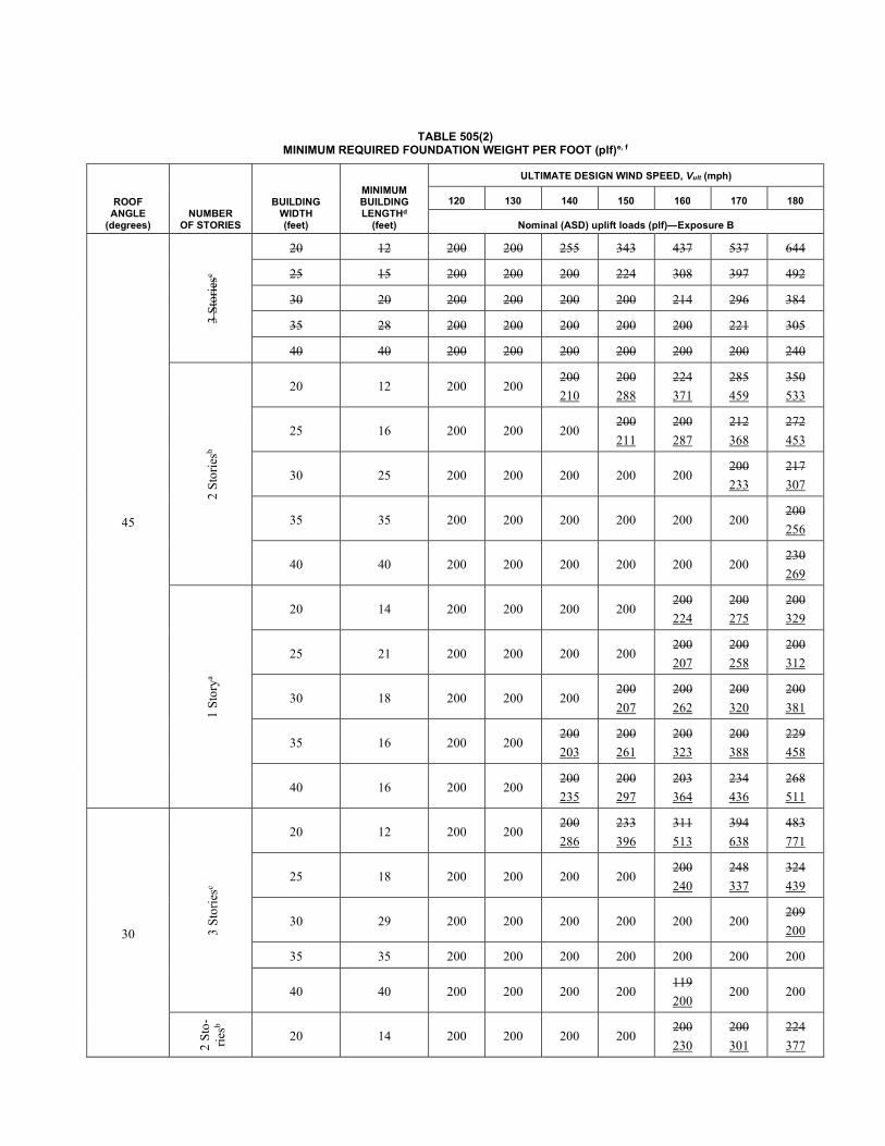
TABLE 505(2) MINIMUM REQUIRED FOUNDATION WEIGHT PER FOOT (plf)e, f
ROOF ANGLE
(degrees) NUMBER
OF STORIES
BUILDING WIDTH (feet)
MINIMUM BUILDING LENGTHd
(feet)
ULTIMATE DESIGN WIND SPEED, Vult (mph)
120 130 140 150 160 170 180
Nominal (ASD) uplift loads (plf)—Exposure B
45
3 S
tori
esc
20 12 200 200 255 343 437 537 644
25 15 200 200 200 224 308 397 492
30 20 200 200 200 200 214 296 384
35 28 200 200 200 200 200 221 305
40 40 200 200 200 200 200 200 240
2 S
tori
esb
20 12 200 200 200
210
200
288
224
371
285
459
350
533
25 16 200 200 200 200
211
200
287
212
368
272
453
30 25 200 200 200 200 200 200
233
217
307
35 35 200 200 200 200 200 200 200
256
40 40 200 200 200 200 200 200 230
269
1 S
tory
a
20 14 200 200 200 200 200
224
200
275
200
329
25 21 200 200 200 200 200
207
200
258
200
312
30 18 200 200 200 200
207
200
262
200
320
200
381
35 16 200 200 200
203
200
261
200
323
200
388
229
458
40 16 200 200 200
235
200
297
203
364
234
436
268
511
30 3 S
tori
esc
20 12 200 200 200
286
233
396
311
513
394
638
483
771
25 18 200 200 200 200 200
240
248
337
324
439
30 29 200 200 200 200 200 200 209
200
35 35 200 200 200 200 200 200 200
40 40 200 200 200 200 119
200 200 200
2 S
to-
ries
b
20 14 200 200 200 200 200
230
200
301
224
377
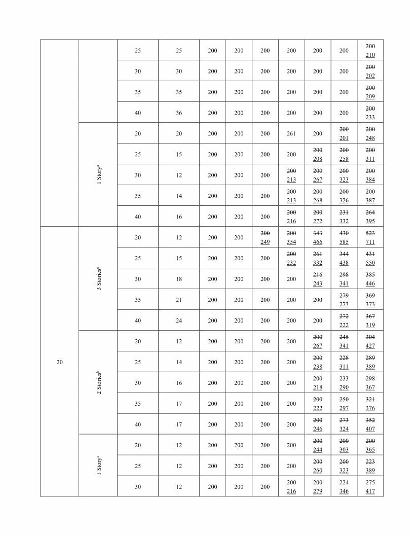
25 25 200 200 200 200 200 200 200
210
30 30 200 200 200 200 200 200 200
202
35 35 200 200 200 200 200 200 200
209
40 36 200 200 200 200 200 200 200
233
1 S
tory
a
20 20 200 200 200 261 200 200
201
200
248
25 15 200 200 200 200 200
208
200
258
200
311
30 12 200 200 200 200
213
200
267
200
323
200
384
35 14 200 200 200 200
213
200
268
200
326
200
387
40 16 200 200 200 200
216
200
272
231
332
264
395
20
3 S
tori
esc
20 12 200 200 200
249
200
354
343
466
430
585
523
711
25 15 200 200 200 200
232
261
332
344
438
431
550
30 18 200 200 200 200 216
243
298
341
385
446
35 21 200 200 200 200 200 279
273
369
373
40 24 200 200 200 200 200 272
222
367
319
2 S
tori
esb
20 12 200 200 200 200 200
267
245
341
304
427
25 14 200 200 200 200 200
238
228
311
289
389
30 16 200 200 200 200 200
218
233
290
298
367
35 17 200 200 200 200 200
222
250
297
321
376
40 17 200 200 200 200 200
246
273
324
352
407
1 S
tory
a
20 12 200 200 200 200 200
244
200
303
200
365
25 12 200 200 200 200 200
260
200
323
223
389
30 12 200 200 200 200
216
200
279
224
346
275
417
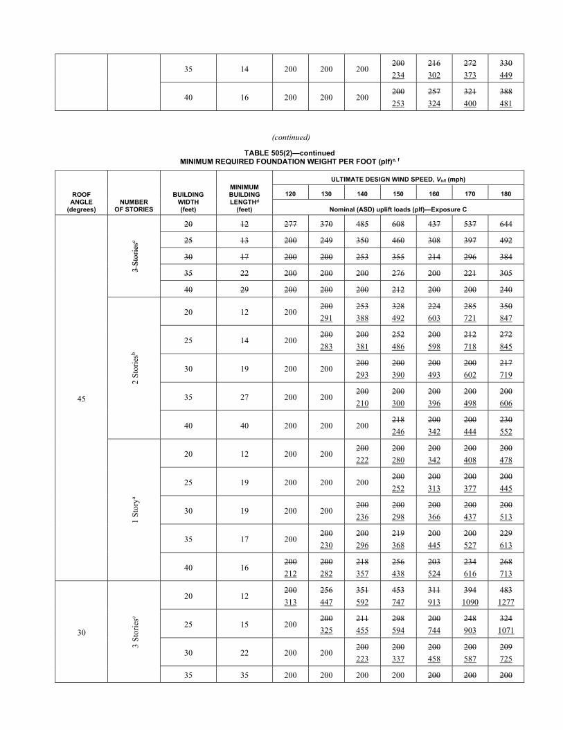
35 14 200 200 200 200
234
216
302
272
373
330
449
40 16 200 200 200 200
253
257
324
321
400
388
481
(continued)
TABLE 505(2)—continued MINIMUM REQUIRED FOUNDATION WEIGHT PER FOOT (plf)e, f
ROOF ANGLE
(degrees) NUMBER
OF STORIES
BUILDING WIDTH (feet)
MINIMUM BUILDING LENGTHd
(feet)
ULTIMATE DESIGN WIND SPEED, Vult (mph)
120 130 140 150 160 170 180
Nominal (ASD) uplift loads (plf)—Exposure C
45
3 S
tori
esc
20 12 277 370 485 608 437 537 644
25 13 200 249 350 460 308 397 492
30 17 200 200 253 355 214 296 384
35 22 200 200 200 276 200 221 305
40 29 200 200 200 212 200 200 240
2 S
tori
esb
20 12 200 200
291
253
388
328
492
224
603
285
721
350
847
25 14 200 200
283
200
381
252
486
200
598
212
718
272
845
30 19 200 200 200
293
200
390
200
493
200
602
217
719
35 27 200 200 200
210
200
300
200
396
200
498
200
606
40 40 200 200 200 218
246
200
342
200
444
230
552
1 S
tory
a
20 12 200 200 200
222
200
280
200
342
200
408
200
478
25 19 200 200 200 200
252
200
313
200
377
200
445
30 19 200 200 200
236
200
298
200
366
200
437
200
513
35 17 200 200
230
200
296
219
368
200
445
200
527
229
613
40 16 200
212
200
282
218
357
256
438
203
524
234
616
268
713
30
3 S
tori
esc
20 12 200
313
256
447
351
592
453
747
311
913
394
1090
483
1277
25 15 200 200
325
211
455
298
594
200
744
248
903
324
1071
30 22 200 200 200
223
200
337
200
458
200
587
209
725
35 35 200 200 200 200 200 200 200
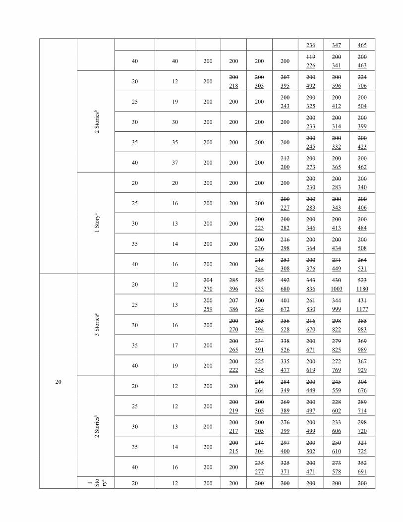
236 347 465
40 40 200 200 200 200 119
226
200
341
200
463
2 S
tori
esb
20 12 200 200
218
200
303
207
395
200
492
200
596
224
706
25 19 200 200 200 200
243
200
325
200
412
200
504
30 30 200 200 200 200 200
233
200
314
200
399
35 35 200 200 200 200 200
245
200
332
200
423
40 37 200 200 200 212
200
200
273
200
365
200
462
1 S
tory
a
20 20 200 200 200 200 200
230
200
283
200
340
25 16 200 200 200 200
227
200
283
200
343
200
406
30 13 200 200 200
223
200
282
200
346
200
413
200
484
35 14 200 200 200
236
216
298
200
364
200
434
200
508
40 16 200 200 215
244
253
308
200
376
231
449
264
531
20
3 S
tori
esc
20 12 204
270
285
396
385
533
492
680
343
836
430
1003
523
1180
25 13 200
259
207
386
300
524
401
672
261
830
344
999
431
1177
30 16 200 200
270
255
394
356
528
216
670
298
822
385
983
35 17 200 200
265
234
391
338
526
200
671
279
825
369
989
40 19 200 200
222
225
345
335
477
200
619
272
769
367
929
2 S
tori
esb
20 12 200 200 216
264
284
349
200
449
245
559
304
676
25 12 200 200
219
200
305
269
389
200
497
228
602
289
714
30 13 200 200
217
200
305
276
399
200
499
233
606
298
720
35 14 200 200
215
214
304
297
400
200
502
250
610
321
725
40 16 200 200 235
277
325
371
200
471
273
578
352
691
1 Sto ry
a
20 12 200 200 200 200 200 200 200
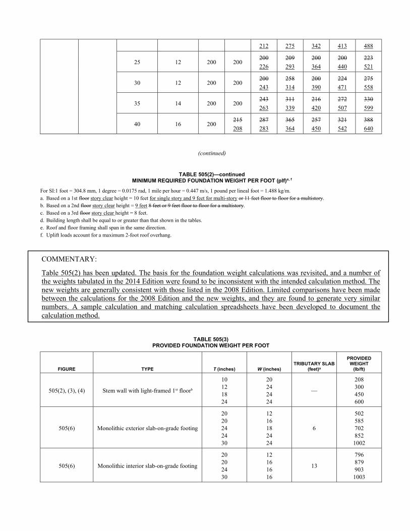
212 275 342 413 488
25 12 200 200 200
226
209
293
200
364
200
440
223
521
30 12 200 200 200
243
258
314
200
390
224
471
275
558
35 14 200 200 243
263
311
339
216
420
272
507
330
599
40 16 200 215
208
287
283
365
364
257
450
321
542
388
640
(continued)
TABLE 505(2)—continued MINIMUM REQUIRED FOUNDATION WEIGHT PER FOOT (plf)e, f
For SI:1 foot = 304.8 mm, 1 degree = 0.0175 rad, 1 mile per hour = 0.447 m/s, 1 pound per lineal foot = 1.488 kg/m. a. Based on a 1st floor story clear height = 10 feet for single story and 9 feet for multi-story or 11 feet floor to floor for a multistory. b. Based on a 2nd floor story clear height = 9 feet 8 feet or 9 feet floor to floor for a multistory. c. Based on a 3rd floor story clear height = 8 feet. d. Building length shall be equal to or greater than that shown in the tables. e. Roof and floor framing shall span in the same direction. f. Uplift loads account for a maximum 2-foot roof overhang.
COMMENTARY:
Table 505(2) has been updated. The basis for the foundation weight calculations was revisited, and a number of the weights tabulated in the 2014 Edition were found to be inconsistent with the intended calculation method. The new weights are generally consistent with those listed in the 2008 Edition. Limited comparisons have been made between the calculations for the 2008 Edition and the new weights, and they are found to generate very similar numbers. A sample calculation and matching calculation spreadsheets have been developed to document the calculation method.
TABLE 505(3) PROVIDED FOUNDATION WEIGHT PER FOOT
FIGURE TYPE T (inches) W (inches) TRIBUTARY SLAB
(feet)a
PROVIDED WEIGHT
(lb/ft)
505(2), (3), (4) Stem wall with light-framed 1st floorb
10 12 18 24
20 24 24 24
—
208 300 450 600
505(6) Monolithic exterior slab-on-grade footing
20 20 24 24 30
12 16 18 24 24
6
502 585 702 852
1002
505(6) Monolithic interior slab-on-grade footing
20 20 24 30
12 16 16 16
13
796 879 903
1003
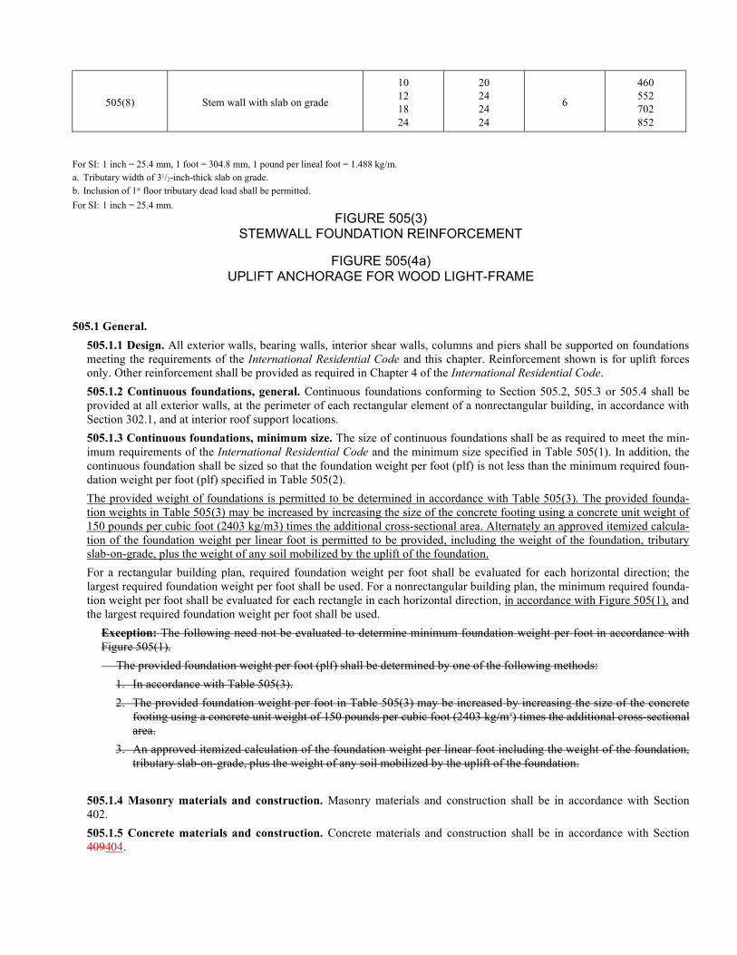
505(8) Stem wall with slab on grade
10 12 18 24
20 24 24 24
6
460 552 702 852
For SI: 1 inch = 25.4 mm, 1 foot = 304.8 mm, 1 pound per lineal foot = 1.488 kg/m. a. Tributary width of 31/2-inch-thick slab on grade. b. Inclusion of 1st floor tributary dead load shall be permitted.
For SI: 1 inch = 25.4 mm.
FIGURE 505(3) STEMWALL FOUNDATION REINFORCEMENT
FIGURE 505(4a) UPLIFT ANCHORAGE FOR WOOD LIGHT-FRAME
505.1 General.
505.1.1 Design. All exterior walls, bearing walls, interior shear walls, columns and piers shall be supported on foundations meeting the requirements of the International Residential Code and this chapter. Reinforcement shown is for uplift forces only. Other reinforcement shall be provided as required in Chapter 4 of the International Residential Code.
505.1.2 Continuous foundations, general. Continuous foundations conforming to Section 505.2, 505.3 or 505.4 shall be provided at all exterior walls, at the perimeter of each rectangular element of a nonrectangular building, in accordance with Section 302.1, and at interior roof support locations.
505.1.3 Continuous foundations, minimum size. The size of continuous foundations shall be as required to meet the min-imum requirements of the International Residential Code and the minimum size specified in Table 505(1). In addition, the continuous foundation shall be sized so that the foundation weight per foot (plf) is not less than the minimum required foun-dation weight per foot (plf) specified in Table 505(2).
The provided weight of foundations is permitted to be determined in accordance with Table 505(3). The provided founda-tion weights in Table 505(3) may be increased by increasing the size of the concrete footing using a concrete unit weight of 150 pounds per cubic foot (2403 kg/m3) times the additional cross-sectional area. Alternately an approved itemized calcula-tion of the foundation weight per linear foot is permitted to be provided, including the weight of the foundation, tributary slab-on-grade, plus the weight of any soil mobilized by the uplift of the foundation.
For a rectangular building plan, required foundation weight per foot shall be evaluated for each horizontal direction; the largest required foundation weight per foot shall be used. For a nonrectangular building plan, the minimum required founda-tion weight per foot shall be evaluated for each rectangle in each horizontal direction, in accordance with Figure 505(1), and the largest required foundation weight per foot shall be used.
Exception: The following need not be evaluated to determine minimum foundation weight per foot in accordance with Figure 505(1).
The provided foundation weight per foot (plf) shall be determined by one of the following methods:
1. In accordance with Table 505(3).
2. The provided foundation weight per foot in Table 505(3) may be increased by increasing the size of the concrete footing using a concrete unit weight of 150 pounds per cubic foot (2403 kg/m3) times the additional cross-sectional area.
3. An approved itemized calculation of the foundation weight per linear foot including the weight of the foundation, tributary slab-on-grade, plus the weight of any soil mobilized by the uplift of the foundation.
505.1.4 Masonry materials and construction. Masonry materials and construction shall be in accordance with Section 402.
505.1.5 Concrete materials and construction. Concrete materials and construction shall be in accordance with Section 409404.
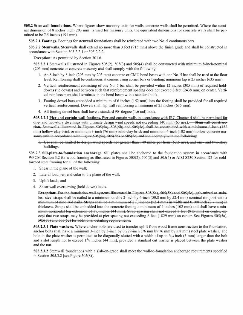
505.2 Stemwall foundations. Where figures show masonry units for walls, concrete walls shall be permitted. Where the nomi-nal dimension of 8 inches inch (203 mm) is used for masonry units, the equivalent dimensions for concrete walls shall be per-mitted to be 7.5 inches (191 mm).
505.2.1 Footings. Footings for stemwall foundations shall be reinforced with two No. 5 continuous bars.
505.2.2 Stemwalls. Stemwalls shall extend no more than 3 feet (915 mm) above the finish grade and shall be constructed in accordance with Section 505.2.2.1 or 505.2.2.2.
Exception: As permitted by Section 301.6.
505.2.2.1 Stemwalls illustrated in Figures 505(2), 505(3) and 505(4) shall be constructed with minimum 8-inch-nominal (203 mm) concrete or concrete masonry and shall comply with the following:
1. An 8-inch by 8-inch (203 mm by 203 mm) concrete or CMU bond beam with one No. 5 bar shall be used at the floor level. Reinforcing shall be continuous at corners using corner bars or bending; minimum lap is 25 inches (635 mm).
2. Vertical reinforcement consisting of one No. 5 bar shall be provided within 12 inches (305 mm) of required hold-downs (tie downs) and between such that reinforcement spacing does not exceed 8 feet (2438 mm) on center. Verti-cal reinforcement shall terminate in the bond beam with a standard hook.
3. Footing dowel bars embedded a minimum of 6 inches (152 mm) into the footing shall be provided for all required vertical reinforcement. Dowels shall lap wall reinforcing a minimum of 25 inches (635 mm).
4. All footing dowel bars shall have a standard 90- degree (1.6 rad) hook.
505.2.2.2 Pier and curtain wall footings. Pier and curtain walls in accordance with IRC Chapter 4 shall be permitted for one- and two-story dwellings with ultimate design wind speeds not exceeding 140 mph (63 m/s). Stemwall construc-tion. Stemwalls illustrated in Figures 505(5a), 505(5b) and 505(5c) shall be constructed with a minimum 6-inch (152 mm) hollow clay brick or minimum 3-inch (76 mm) solid clay brick and minimum 4-inch (102 mm) hollow concrete ma-sonry unit in accordance with Figure 505(5a), 505(5b) or 505(5c) and shall comply with the following:
1. Use shall be limited to design wind speeds not greater than 140 miles per hour (62.6 m/s), and one- and two-story buildings.
505.2.3 Sill-plate-to-foundation anchorage. Sill plates shall be anchored to the foundation system in accordance with WFCM Section 3.2 for wood framing as illustrated in Figures 505(2), 505(3) and 505(4) or AISI S230 Section D2 for cold-formed steel framing for all of the following:
1. Shear in the plane of the wall;
2. Lateral load perpendicular to the plane of the wall;
3. Uplift loads; and
4. Shear wall overturning (hold-down) loads.
Exception: For the foundation wall systems illustrated in Figures 505(5a), 505(5b) and 505(5c), galvanized or stain-less steel straps shall be nailed to a minimum double 2-inch by 6-inch (50.8 mm by 52.4 mm) nominal rim joist with a minimum of nine 16d nails. Straps shall be a minimum of 21/16 inches (52.4 mm) in width and 0.108 inch (2.7 mm) in thickness. Straps shall be embedded into the concrete footing a minimum of 4 inches (102 mm) and shall have a min-imum horizontal leg extension of 13/4 inches (44 mm). Strap spacing shall not exceed 3 feet (915 mm) on center, ex-cept that two straps may be provided at pier spacing not exceeding 6 feet (1829 mm) on center. See Figures 505(5a), 505(5b) and 505(5c) for additional detailing requirements.
505.2.3.1 Plate washers. Where anchor bolts are used to transfer uplift from wood frame construction to the foundation, anchor bolts shall have a minimum 3-inch by 3-inch by 0.229-inch (76 mm by 76 mm by 5.8 mm) steel plate washer. The hole in the plate washer is permitted to be diagonally slotted with a width of up to 3/16 inch (5 mm) larger than the bolt and a slot length not to exceed 13/4 inches (44 mm), provided a standard cut washer is placed between the plate washer and the nut.
505.2.3.2 Stemwall foundations with a slab-on-grade shall meet the wall-to-foundation anchorage requirements specified in Section 505.3.2 [see Figure 505(8)].
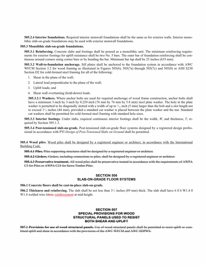
505.2.4 Interior foundations. Required interior stemwall foundations shall be the same as for exterior walls. Interior mono-lithic slab-on-grade foundations may be used with exterior stemwall foundations.
505.3 Monolithic slab-on-grade foundations.
505.3.1 Reinforcing. Concrete slabs and footings shall be poured as a monolithic unit. The minimum reinforcing require-ments for exterior footings for uplift resistance shall be two No. 5 bars. The outer bar of foundation reinforcing shall be con-tinuous around corners using corner bars or by bending the bar. Minimum bar lap shall be 25 inches (635 mm).
505.3.2 Wall-to-foundation anchorage. Sill plates shall be anchored to the foundation system in accordance with AWC WFCM Section 3.2 for wood framing as illustrated in Figures 505(6), 505(7a) through 505(7c) and 505(8) or AISI S230 Section D2 for cold-formed steel framing for all of the following:
1. Shear in the plane of the wall;
2. Lateral load perpendicular to the plane of the wall;
3. Uplift loads; and
4. Shear wall overturning (hold-down) loads.
505.3.2.1 Washers. Where anchor bolts are used for required anchorage of wood frame construction, anchor bolts shall have a minimum 3-inch by 3-inch by 0.229-inch (76 mm by 76 mm by 5.8 mm) steel plate washer. The hole in the plate washer is permitted to be diagonally slotted with a width of up to 3/16 inch (5 mm) larger than the bolt and a slot length not to exceed 13/4 inches (44 mm), provided a standard cut washer is placed between the plate washer and the nut. Standard cut washers shall be permitted for cold-formed steel framing with standard hole sizes.
505.3.3 Interior footings. Under slabs, required continuous interior footings shall be the width, W, and thickness, T, re-quired by Section 505.1.3.
505.3.4 Post-tensioned slab-on-grade. Post-tensioned slab-on-grade floor systems designed by a registered design profes-sional in accordance with PTI Design of Post-Tensioned Slabs on Ground shall be permitted.
505.4 Wood piles. Wood piles shall be designed by a registered engineer or architect, in accordance with the International Building Code.
505.4.1 Piles. Piles supporting structures shall be designed by a registered engineer or architect.
505.4.2 Girders. Girders, including connections to piles, shall be designed by a registered engineer or architect.
505.4.3 Preservative treatment. All wood piles shall be preservative treated in accordance with the requirements of AWPA C3 for Piles or AWPA C24 for Sawn Timber Piles.
SECTION 506 SLAB-ON-GRADE FLOOR SYSTEMS
506.1 Concrete floors shall be cast-in-place slab-on-grade.
506.2 Thickness and reinforcing. The slab shall be not less than 31/2 inches (89 mm) thick. The slab shall have 6 6 W1.4 W1.4 welded wire fabric reinforcement at mid-height.
SECTION 507 SPECIAL PROVISIONS FOR WOOD
STRUCTURAL PANELS USED TO RESIST BOTH SHEAR AND UPLIFT
507.1 Provisions for use of wood structural panels. Use of wood structural panels shall be permitted to resist uplift or com-bined uplift and shear in accordance with the provisions of the AWC WFCM and AWC SDPWS.
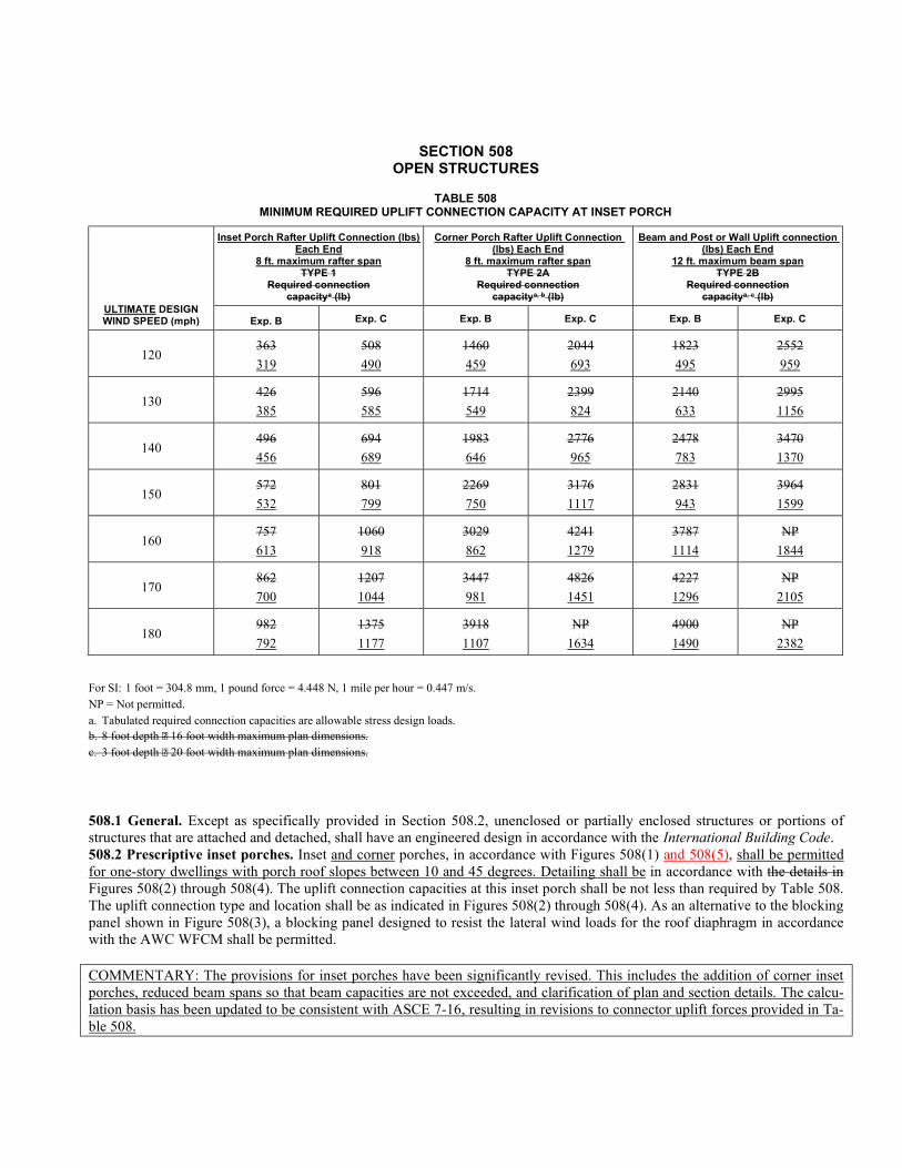
SECTION 508 OPEN STRUCTURES
TABLE 508 MINIMUM REQUIRED UPLIFT CONNECTION CAPACITY AT INSET PORCH
ULTIMATE DESIGN WIND SPEED (mph)
Inset Porch Rafter Uplift Connection (lbs) Each End
8 ft. maximum rafter span TYPE 1
Required connection capacitya (lb)
Corner Porch Rafter Uplift Connection (lbs) Each End
8 ft. maximum rafter span TYPE 2A
Required connection capacitya, b (lb)
Beam and Post or Wall Uplift connection (lbs) Each End
12 ft. maximum beam span TYPE 2B
Required connection capacitya, c (lb)
Exp. B Exp. C Exp. B Exp. C Exp. B Exp. C
120 363
319
508
490
1460
459
2044
693
1823
495
2552
959
130 426
385
596
585
1714
549
2399
824
2140
633
2995
1156
140 496
456
694
689
1983
646
2776
965
2478
783
3470
1370
150 572
532
801
799
2269
750
3176
1117
2831
943
3964
1599
160 757
613
1060
918
3029
862
4241
1279
3787
1114
NP
1844
170 862
700
1207
1044
3447
981
4826
1451
4227
1296
NP
2105
180 982
792
1375
1177
3918
1107
NP
1634
4900
1490
NP
2382
For SI: 1 foot = 304.8 mm, 1 pound force = 4.448 N, 1 mile per hour = 0.447 m/s. NP = Not permitted. a. Tabulated required connection capacities are allowable stress design loads. b. 8 foot depth 16 foot width maximum plan dimensions. c. 3 foot depth 20 foot width maximum plan dimensions.
508.1 General. Except as specifically provided in Section 508.2, unenclosed or partially enclosed structures or portions of structures that are attached and detached, shall have an engineered design in accordance with the International Building Code. 508.2 Prescriptive inset porches. Inset and corner porches, in accordance with Figures 508(1) and 508(5), shall be permitted for one-story dwellings with porch roof slopes between 10 and 45 degrees. Detailing shall be in accordance with the details in Figures 508(2) through 508(4). The uplift connection capacities at this inset porch shall be not less than required by Table 508. The uplift connection type and location shall be as indicated in Figures 508(2) through 508(4). As an alternative to the blocking panel shown in Figure 508(3), a blocking panel designed to resist the lateral wind loads for the roof diaphragm in accordance with the AWC WFCM shall be permitted. COMMENTARY: The provisions for inset porches have been significantly revised. This includes the addition of corner inset porches, reduced beam spans so that beam capacities are not exceeded, and clarification of plan and section details. The calcu-lation basis has been updated to be consistent with ASCE 7-16, resulting in revisions to connector uplift forces provided in Ta-ble 508.
SECTION 509 ROOF SHEATHING IN WOOD
LIGHT-FRAMED CONSTRUCTION
509.1 Installation. Roof sheathing in wood light-framed construction shall be wood structural panels sized and installed in accordance with the AWC WFCM.
509.2 Sheathing fastenings. As an alternative to the AWC WFCM, wood structural panel sheathing shall be permitted to be fastened to roof framing with ring-shank nails spaced in accordance with the AWC WFCM. Ring-shank nails shall have a min-imum bending yield strength of 130 ksi (896.4 mPa) and the following minimum dimensions:
1. Not less than 0.113-inch (2.9 mm) nominal shank diameter.
2. Ring diameter shall be not less than 0.004-inch (0.10 mm) larger than actual shank diameter.
3. Rings shall begin not less than 5/8 inch (15.9 mm) from the head and shall continue to within 1/4 inch (6.4 mm) from the nail tip. Two lengths without rings shall be allowed along the ring portion of the nail to facilitate collating of fasteners, with each such length not longer than 1/4 inch (6.4 mm).
4. 16 to 32 rings per inch.
5. 0.263-inch (6.7 mm) nominal full round head diameter; for other head shapes such as D and clipped heads, the small dimension shall be not less than 0.199 inch (5 mm) and the larger dimension shall be not less than 0.263 inch (6.7 mm).
6. 23/8-inch (60.3 mm) nominal nail length.
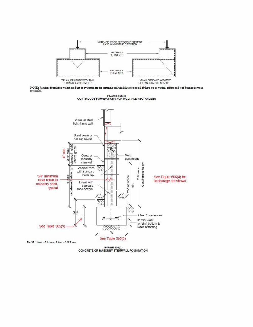
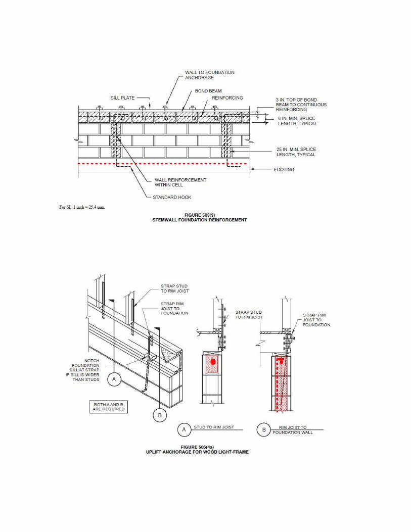


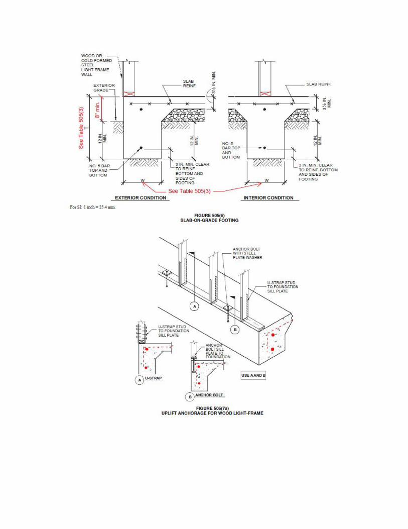
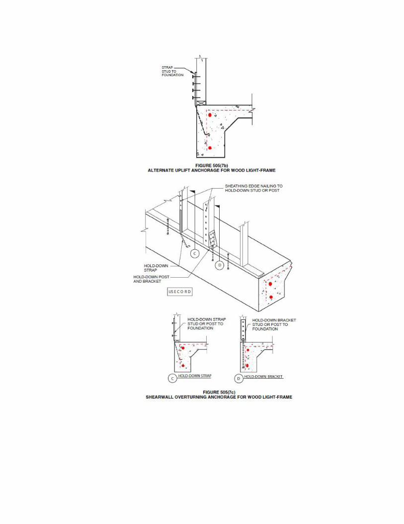

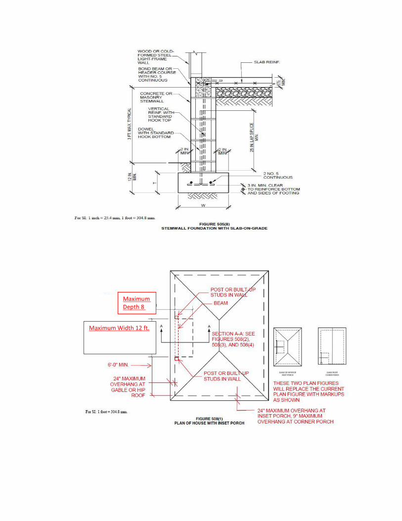
Maximum Depth 8 ft.
Maximum Width 12 ft.
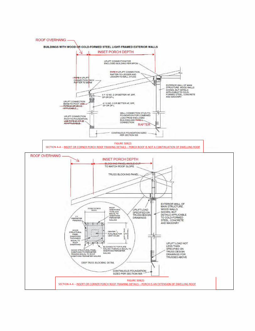
FIGURE 508(3) SECTION A-A – INSERT OR CORNER PORCH ROOF FRAMING DETAILS – PORCH IS AN EXTENSION OF DWELLING ROOF
FIGURE 508(2) SECTION A-A – INSERT OR CORNER PORCH ROOF FRAMING DETAILS – PORCH ROOF IS NOT A CONTINUATION OF DWELLING ROOF
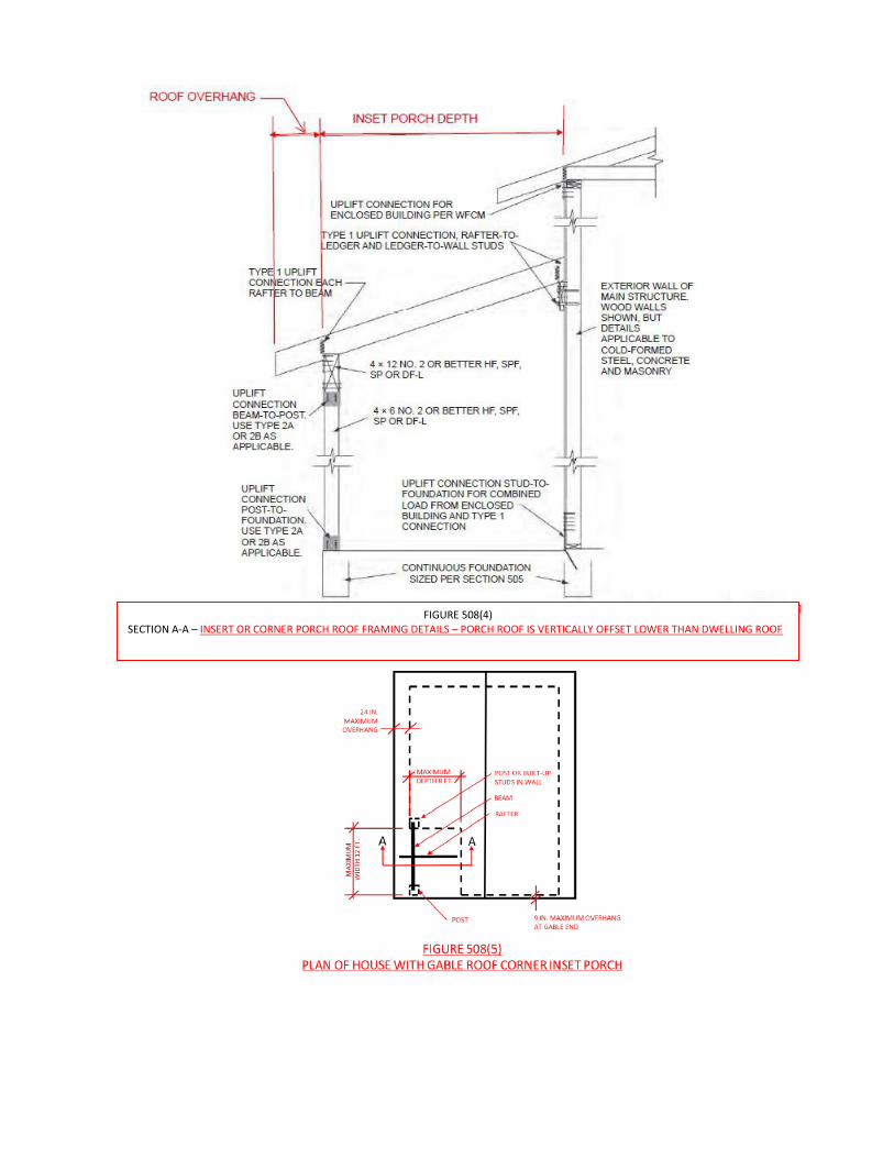
FIGURE 508(4) SECTION A-A – INSERT OR CORNER PORCH ROOF FRAMING DETAILS – PORCH ROOF IS VERTICALLY OFFSET LOWER THAN DWELLING ROOF
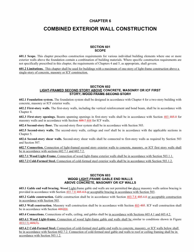
CHAPTER 6
COMBINED EXTERIOR WALL CONSTRUCTION
SECTION 601 SCOPE
601.1 Scope. This chapter prescribes construction requirements for various individual building elements where one or more exterior walls above the foundation contain a combination of building materials. Where specific construction requirements are not specifically prescribed in this chapter, the requirements of Chapters 4 and 5, as appropriate, shall govern.
601.2 Limitations. This chapter shall be used for buildings with a maximum of one-story of light-frame construction above a single-story of concrete, masonry or ICF construction.
SECTION 602 LIGHT-FRAMED SECOND STORY ABOVE CONCRETE, MASONRY OR ICF FIRST
STORY; WOOD FRAME SECOND STORY
602.1 Foundation system. The foundation system shall be designed in accordance with Chapter 4 for a two-story building with concrete, masonry or ICF exterior walls.
602.2 First-story walls. The first-story walls, including the vertical reinforcement and bond beam, shall be in accordance with Chapter 4.
602.3 First-story openings. Beams spanning openings in first-story walls shall be in accordance with Section 403 405.8 for masonry walls and in accordance with Section 409.7 404 for ICF walls.
602.4 Second-story floor. The second-story floor system shall be in accordance with Section 503.
602.5 Second-story walls. The second-story walls, ceilings and roof shall be in accordance with the applicable sections in Chapter 5.
602.6 Second-story shear walls. Second-story shear walls shall be connected to first-story walls as required by Section 503 and Section 507.
602.7 Connection. Connection of light-framed second story exterior walls to concrete, masonry, or ICF first story walls shall be in accordance with sections 602.7.1 and 602.7.2.
602.7.1 Wood Light-Frame. Connection of wood light-frame exterior walls shall be in accordance with Section 503.1.1.
602.7.2 Cold-Formed Steel. Connection of cold-formed steel exterior walls shall be in accordance with Section 503.1.2.
SECTION 603 WOOD LIGHT-FRAME GABLE END WALLS
ABOVE CONCRETE, MASONRY OR ICF WALLS
603.1 Gable end wall bracing. Wood Light-frame gable end walls are not permitted for above masonry walls unless bracing is provided in accordance with Section 403.7.8 405.4.8 or acceptable bracing in accordance with Section 503.
603.2 Gable construction. Gable construction shall be in accordance with Section 403.7.8 405.4.8 or acceptable construction in accordance with Section 503.
603.3 Wall construction. Masonry wall construction shall be in accordance with Section 403 405. ICF wall construction shall be in accordance with Section 409404.
603.4 Connections. Connections of walls, ceiling, and gables shall be in accordance with Sections 603.4.1 and 603.4.2.
603.4.1 Wood Light-frame. Connection of wood light-frame gable end walls shall be similar to conditions shown in Figure 403(13) 405(7).
603.4.2 Cold-Formed Steel. Connection of cold-formed steel gable end walls to concrete, masonry, or ICF walls below shall be in accordance with Section 602.7.2. Connection of cold-formed steel gable end walls to roof or ceiling framing shall be in accordance with Section 503.1.2.
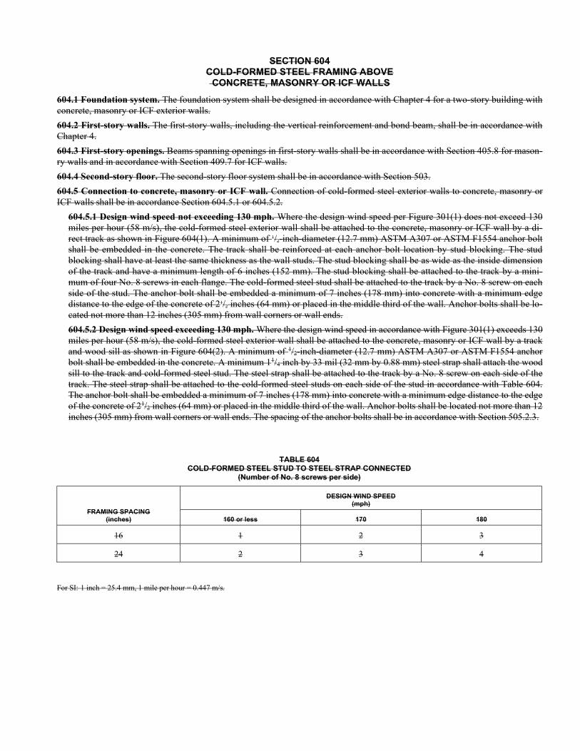
SECTION 604 COLD-FORMED STEEL FRAMING ABOVE CONCRETE, MASONRY OR ICF WALLS
604.1 Foundation system. The foundation system shall be designed in accordance with Chapter 4 for a two-story building with concrete, masonry or ICF exterior walls.
604.2 First-story walls. The first-story walls, including the vertical reinforcement and bond beam, shall be in accordance with Chapter 4.
604.3 First-story openings. Beams spanning openings in first-story walls shall be in accordance with Section 405.8 for mason-ry walls and in accordance with Section 409.7 for ICF walls.
604.4 Second-story floor. The second-story floor system shall be in accordance with Section 503.
604.5 Connection to concrete, masonry or ICF wall. Connection of cold-formed steel exterior walls to concrete, masonry or ICF walls shall be in accordance Section 604.5.1 or 604.5.2.
604.5.1 Design wind speed not exceeding 130 mph. Where the design wind speed per Figure 301(1) does not exceed 130 miles per hour (58 m/s), the cold-formed steel exterior wall shall be attached to the concrete, masonry or ICF wall by a di-rect track as shown in Figure 604(1). A minimum of 1/2-inch-diameter (12.7 mm) ASTM A307 or ASTM F1554 anchor bolt shall be embedded in the concrete. The track shall be reinforced at each anchor bolt location by stud blocking. The stud blocking shall have at least the same thickness as the wall studs. The stud blocking shall be as wide as the inside dimension of the track and have a minimum length of 6 inches (152 mm). The stud blocking shall be attached to the track by a mini-mum of four No. 8 screws in each flange. The cold-formed steel stud shall be attached to the track by a No. 8 screw on each side of the stud. The anchor bolt shall be embedded a minimum of 7 inches (178 mm) into concrete with a minimum edge distance to the edge of the concrete of 21/2 inches (64 mm) or placed in the middle third of the wall. Anchor bolts shall be lo-cated not more than 12 inches (305 mm) from wall corners or wall ends.
604.5.2 Design wind speed exceeding 130 mph. Where the design wind speed in accordance with Figure 301(1) exceeds 130 miles per hour (58 m/s), the cold-formed steel exterior wall shall be attached to the concrete, masonry or ICF wall by a track and wood sill as shown in Figure 604(2). A minimum of 1/2-inch-diameter (12.7 mm) ASTM A307 or ASTM F1554 anchor bolt shall be embedded in the concrete. A minimum 11/4 inch by 33 mil (32 mm by 0.88 mm) steel strap shall attach the wood sill to the track and cold-formed steel stud. The steel strap shall be attached to the track by a No. 8 screw on each side of the track. The steel strap shall be attached to the cold-formed steel studs on each side of the stud in accordance with Table 604. The anchor bolt shall be embedded a minimum of 7 inches (178 mm) into concrete with a minimum edge distance to the edge of the concrete of 21/2 inches (64 mm) or placed in the middle third of the wall. Anchor bolts shall be located not more than 12 inches (305 mm) from wall corners or wall ends. The spacing of the anchor bolts shall be in accordance with Section 505.2.3.
TABLE 604 COLD-FORMED STEEL STUD TO STEEL STRAP CONNECTED
(Number of No. 8 screws per side)
FRAMING SPACING (inches)
DESIGN WIND SPEED (mph)
160 or less 170 180
16 1 2 3
24 2 3 4
For SI: 1 inch = 25.4 mm, 1 mile per hour = 0.447 m/s.
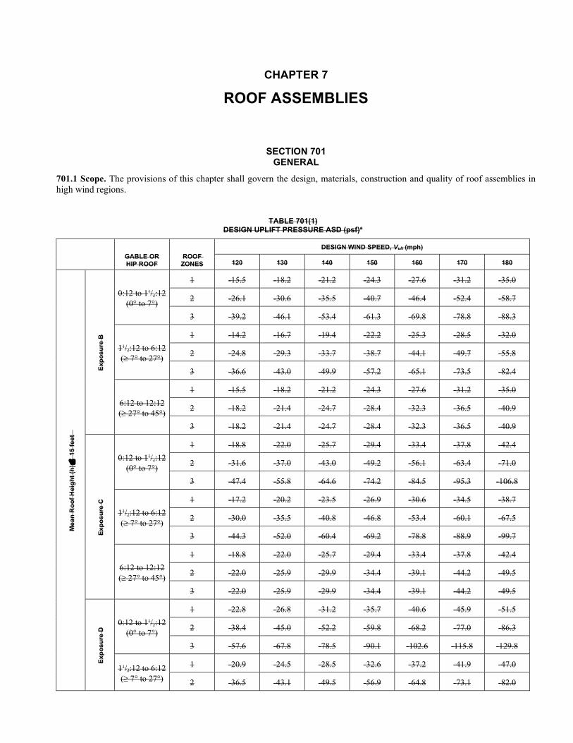
CHAPTER 7
ROOF ASSEMBLIES
SECTION 701 GENERAL
701.1 Scope. The provisions of this chapter shall govern the design, materials, construction and quality of roof assemblies in high wind regions.
TABLE 701(1) DESIGN UPLIFT PRESSURE ASD (psf)a
GABLE OR HIP ROOF
ROOF ZONES
DESIGN WIND SPEED, Vult (mph)
120 130 140 150 160 170 180
Mea
n R
oo
f H
eig
ht
(h)
15
fee
t
Ex
po
su
re B
0:12 to 11/2:12 (0° to 7°)
1 -15.5 -18.2 -21.2 -24.3 -27.6 -31.2 -35.0
2 -26.1 -30.6 -35.5 -40.7 -46.4 -52.4 -58.7
3 -39.2 -46.1 -53.4 -61.3 -69.8 -78.8 -88.3
11/2:12 to 6:12 ( 7° to 27°)
1 -14.2 -16.7 -19.4 -22.2 -25.3 -28.5 -32.0
2 -24.8 -29.3 -33.7 -38.7 -44.1 -49.7 -55.8
3 -36.6 -43.0 -49.9 -57.2 -65.1 -73.5 -82.4
6:12 to 12:12 (27° to 45°)
1 -15.5 -18.2 -21.2 -24.3 -27.6 -31.2 -35.0
2 -18.2 -21.4 -24.7 -28.4 -32.3 -36.5 -40.9
3 -18.2 -21.4 -24.7 -28.4 -32.3 -36.5 -40.9
Ex
po
su
re C
0:12 to 11/2:12 (0° to 7°)
1 -18.8 -22.0 -25.7 -29.4 -33.4 -37.8 -42.4
2 -31.6 -37.0 -43.0 -49.2 -56.1 -63.4 -71.0
3 -47.4 -55.8 -64.6 -74.2 -84.5 -95.3 -106.8
11/2:12 to 6:12 ( 7° to 27°)
1 -17.2 -20.2 -23.5 -26.9 -30.6 -34.5 -38.7
2 -30.0 -35.5 -40.8 -46.8 -53.4 -60.1 -67.5
3 -44.3 -52.0 -60.4 -69.2 -78.8 -88.9 -99.7
6:12 to 12:12 (27° to 45°)
1 -18.8 -22.0 -25.7 -29.4 -33.4 -37.8 -42.4
2 -22.0 -25.9 -29.9 -34.4 -39.1 -44.2 -49.5
3 -22.0 -25.9 -29.9 -34.4 -39.1 -44.2 -49.5
Ex
po
su
re D
0:12 to 11/2:12 (0° to 7°)
1 -22.8 -26.8 -31.2 -35.7 -40.6 -45.9 -51.5
2 -38.4 -45.0 -52.2 -59.8 -68.2 -77.0 -86.3
3 -57.6 -67.8 -78.5 -90.1 -102.6 -115.8 -129.8
11/2:12 to 6:12 ( 7° to 27°)
1 -20.9 -24.5 -28.5 -32.6 -37.2 -41.9 -47.0
2 -36.5 -43.1 -49.5 -56.9 -64.8 -73.1 -82.0
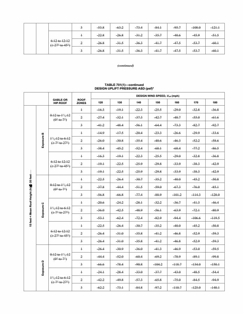
3 -53.8 -63.2 -73.4 -84.1 -95.7 -108.0 -121.1
6:12 to 12:12 (27° to 45°)
1 -22.8 -26.8 -31.2 -35.7 -40.6 -45.9 -51.5
2 -26.8 -31.5 -36.3 -41.7 -47.5 -53.7 -60.1
3 -26.8 -31.5 -36.3 -41.7 -47.5 -53.7 -60.1
(continued)
TABLE 701(1)—continued DESIGN UPLIFT PRESSURE ASD (psf)a
GABLE OR HIP ROOF
ROOF ZONES
DESIGN WIND SPEED, Vult (mph)
120 130 140 150 160 170 180
15 f
eet
< M
ea
n R
oo
f H
eig
ht
(h)
35
fee
t
Ex
po
su
re B
0:12 to 11/2:12 (0° to 7°)
1 -16.3 -19.1 -22.3 -25.5 -29.0 -32.8 -36.8
2 -27.4 -32.1 -37.3 -42.7 -48.7 -55.0 -61.6
3 -41.2 -48.4 -56.1 -64.4 -73.3 -82.7 -92.7
11/2:12 to 6:12 ( 7° to 27°)
1 -14.9 -17.5 -20.4 -23.3 -26.6 -29.9 -33.6
2 -26.0 -30.8 -35.4 -40.6 -46.3 -52.2 -58.6
3 -38.4 -45.2 -52.4 -60.1 -68.4 -77.2 -86.5
6:12 to 12:12 (27° to 45°)
1 -16.3 -19.1 -22.3 -25.5 -29.0 -32.8 -36.8
2 -19.1 -22.5 -25.9 -29.8 -33.9 -38.3 -42.9
3 -19.1 -22.5 -25.9 -29.8 -33.9 -38.3 -42.9
Ex
po
su
re C
0:12 to 11/2:12 (0° to 7°)
1 -22.5 -26.4 -30.7 -35.2 -40.0 -45.2 -50.8
2 -37.8 -44.4 -51.5 -59.0 -67.3 -76.0 -85.1
3 -56.8 -66.8 -77.4 -88.9 -101.2 -114.3 -128.0
11/2:12 to 6:12 ( 7° to 27°)
1 -20.6 -24.2 -28.1 -32.2 -36.7 -41.3 -46.4
2 -36.0 -42.5 -48.9 -56.1 -63.9 -72.1 -80.9
3 -53.1 -62.4 -72.4 -82.9 -94.4 -106.6 -119.5
6:12 to 12:12 (27° to 45°)
1 -22.5 -26.4 -30.7 -35.2 -40.0 -45.2 -50.8
2 -26.4 -31.0 -35.8 -41.2 -46.8 -52.9 -59.3
3 -26.4 -31.0 -35.8 -41.2 -46.8 -52.9 -59.3
Ex
po
su
re D
0:12 to 11/2:12 (0° to 7°)
1 -26.4 -30.9 -36.0 -41.3 -46.9 -53.0 -59.5
2 -44.4 -52.0 -60.4 -69.2 -78.9 -89.1 -99.8
3 -66.6 -78.4 -90.8 -104.2 -118.7 -134.0 -150.1
11/2:12 to 6:12 ( 7° to 27°)
1 -24.1 -28.4 -33.0 -37.7 -43.0 -48.5 -54.4
2 -42.2 -49.8 -57.3 -65.8 -75.0 -84.5 -94.9
3 -62.2 -73.1 -84.8 -97.2 -110.7 -125.0 -140.1
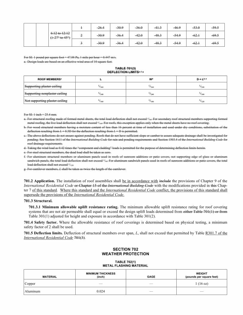
6:12 to 12:12 (27° to 45°)
1 -26.4 -30.9 -36.0 -41.3 -46.9 -53.0 -59.5
2 -30.9 -36.4 -42.0 -48.3 -54.9 -62.1 -69.5
3 -30.9 -36.4 -42.0 -48.3 -54.9 -62.1 -69.5
For SI: 1 pound per square foot = 47.88 Pa, 1 mile per hour = 0.447 m/s. a. Design loads are based on an effective wind area of 10 square feet.
TABLE 701(3) DEFLECTION LIMITSa, f, g
ROOF MEMBERSc L Wd D + Lb, e
Supporting plaster ceiling L/360 L/360 L/240
Supporting nonplaster ceiling L/240 L/240 L/180
Not supporting plaster ceiling L/180 L/180 L/120
For SI: 1 inch = 25.4 mm. a. For structural roofing made of formed metal sheets, the total load deflection shall not exceed L/60. For secondary roof structural members supporting formed
metal roofing, the live load deflection shall not exceed L/150. For roofs, this exception applies only when the metal sheets have no roof covering. b. For wood structural members having a moisture content of less than 16 percent at time of installation and used under dry conditions, substitution of the
deflection resulting from L + 0.5D for the deflection resulting from L + D is permitted. c. The above deflections do not ensure against ponding. Roofs that do not have sufficient slope or camber to assure adequate drainage shall be investigated for
ponding. See Section 1611 of the International Building Code for rain and ponding requirements and Section 1503.4 of the International Building Code for roof drainage requirements.
d. Taking the wind load as 0.42 times the “component and cladding” loads is permitted for the purpose of determining deflection limits herein. e. For steel structural members, the dead load shall be taken as zero. f. For aluminum structural members or aluminum panels used in roofs of sunroom additions or patio covers, not supporting edge of glass or aluminum
sandwich panels, the total load deflection shall not exceed L/60. For aluminum sandwich panels used in roofs of sunroom additions or patio covers, the total load deflection shall not exceed L/120.
g. For cantilever members, L shall be taken as twice the length of the cantilever.
701.2 Application. The installation of roof assemblies shall be in accordance with include the provisions of Chapter 9 of the International Residential Code or Chapter 15 of the International Building Code with the modifications provided in this Chap-ter 7 of this standard. Where this standard and the International Residential Code conflict, the provisions of this standard shall supersede the provisions of the International Residential Code.
701.3 Structural.
701.3.1 Minimum allowable uplift resistance rating. The minimum allowable uplift resistance rating for roof covering systems that are not air permeable shall equal or exceed the design uplift loads determined from either Table 701(1) or from Table 301(1) adjusted for height and exposure in accordance with Table 301(2).
701.4 Safety factor. Where the allowable resistance of roof coverings is determined based on physical testing, a minimum safety factor of 2 shall be used.
701.5 Deflection limits. Deflection of structural members over span, L, shall not exceed that permitted by Table R301.7 of the International Residential Code 701(3).
SECTION 702 WEATHER PROTECTION
TABLE 702(1) METAL FLASHING MATERIAL
MATERIAL MINIMUM THICKNESS
(inch) GAGE WEIGHT
(pounds per square feet)
Copper — — 1 (16 oz)
Aluminum 0.024 — —
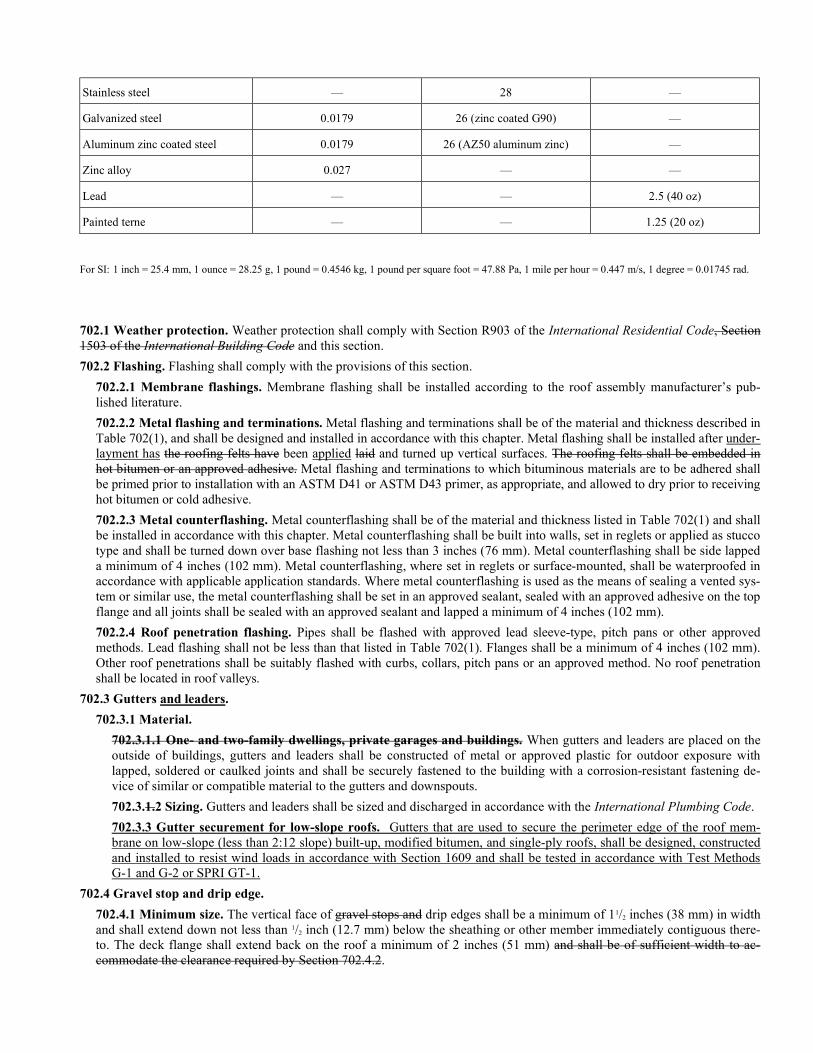
Stainless steel — 28 —
Galvanized steel 0.0179 26 (zinc coated G90) —
Aluminum zinc coated steel 0.0179 26 (AZ50 aluminum zinc) —
Zinc alloy 0.027 — —
Lead — — 2.5 (40 oz)
Painted terne — — 1.25 (20 oz)
For SI: 1 inch = 25.4 mm, 1 ounce = 28.25 g, 1 pound = 0.4546 kg, 1 pound per square foot = 47.88 Pa, 1 mile per hour = 0.447 m/s, 1 degree = 0.01745 rad.
702.1 Weather protection. Weather protection shall comply with Section R903 of the International Residential Code, Section 1503 of the International Building Code and this section.
702.2 Flashing. Flashing shall comply with the provisions of this section.
702.2.1 Membrane flashings. Membrane flashing shall be installed according to the roof assembly manufacturer’s pub-lished literature.
702.2.2 Metal flashing and terminations. Metal flashing and terminations shall be of the material and thickness described in Table 702(1), and shall be designed and installed in accordance with this chapter. Metal flashing shall be installed after under-layment has the roofing felts have been applied laid and turned up vertical surfaces. The roofing felts shall be embedded in hot bitumen or an approved adhesive. Metal flashing and terminations to which bituminous materials are to be adhered shall be primed prior to installation with an ASTM D41 or ASTM D43 primer, as appropriate, and allowed to dry prior to receiving hot bitumen or cold adhesive.
702.2.3 Metal counterflashing. Metal counterflashing shall be of the material and thickness listed in Table 702(1) and shall be installed in accordance with this chapter. Metal counterflashing shall be built into walls, set in reglets or applied as stucco type and shall be turned down over base flashing not less than 3 inches (76 mm). Metal counterflashing shall be side lapped a minimum of 4 inches (102 mm). Metal counterflashing, where set in reglets or surface-mounted, shall be waterproofed in accordance with applicable application standards. Where metal counterflashing is used as the means of sealing a vented sys-tem or similar use, the metal counterflashing shall be set in an approved sealant, sealed with an approved adhesive on the top flange and all joints shall be sealed with an approved sealant and lapped a minimum of 4 inches (102 mm).
702.2.4 Roof penetration flashing. Pipes shall be flashed with approved lead sleeve-type, pitch pans or other approved methods. Lead flashing shall not be less than that listed in Table 702(1). Flanges shall be a minimum of 4 inches (102 mm). Other roof penetrations shall be suitably flashed with curbs, collars, pitch pans or an approved method. No roof penetration shall be located in roof valleys.
702.3 Gutters and leaders.
702.3.1 Material.
702.3.1.1 One- and two-family dwellings, private garages and buildings. When gutters and leaders are placed on the outside of buildings, gutters and leaders shall be constructed of metal or approved plastic for outdoor exposure with lapped, soldered or caulked joints and shall be securely fastened to the building with a corrosion-resistant fastening de-vice of similar or compatible material to the gutters and downspouts.
702.3.1.2 Sizing. Gutters and leaders shall be sized and discharged in accordance with the International Plumbing Code.
702.3.3 Gutter securement for low-slope roofs. Gutters that are used to secure the perimeter edge of the roof mem-brane on low-slope (less than 2:12 slope) built-up, modified bitumen, and single-ply roofs, shall be designed, constructed and installed to resist wind loads in accordance with Section 1609 and shall be tested in accordance with Test Methods G-1 and G-2 or SPRI GT-1.
702.4 Gravel stop and drip edge.
702.4.1 Minimum size. The vertical face of gravel stops and drip edges shall be a minimum of 11/2 inches (38 mm) in width and shall extend down not less than 1/2 inch (12.7 mm) below the sheathing or other member immediately contiguous there-to. The deck flange shall extend back on the roof a minimum of 2 inches (51 mm) and shall be of sufficient width to ac-commodate the clearance required by Section 702.4.2.
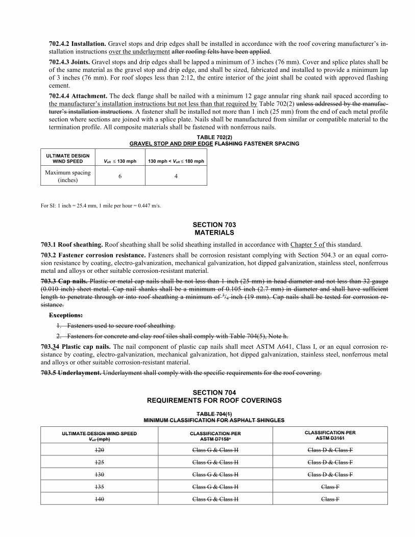
702.4.2 Installation. Gravel stops and drip edges shall be installed in accordance with the roof covering manufacturer’s in-stallation instructions over the underlayment after roofing felts have been applied.
702.4.3 Joints. Gravel stops and drip edges shall be lapped a minimum of 3 inches (76 mm). Cover and splice plates shall be of the same material as the gravel stop and drip edge, and shall be sized, fabricated and installed to provide a minimum lap of 3 inches (76 mm). For roof slopes less than 2:12, the entire interior of the joint shall be coated with approved flashing cement.
702.4.4 Attachment. The deck flange shall be nailed with a minimum 12 gage annular ring shank nail spaced according to the manufacturer’s installation instructions but not less than that required by Table 702(2) unless addressed by the manufac-turer’s installation instructions. A fastener shall be installed not more than 1 inch (25 mm) from the end of each metal profile section where sections are joined with a splice plate. Nails shall be manufactured from similar or compatible material to the termination profile. All composite materials shall be fastened with nonferrous nails.
TABLE 702(2) GRAVEL STOP AND DRIP EDGE FLASHING FASTENER SPACING
ULTIMATE DESIGN WIND SPEED Vult 130 mph 130 mph < Vult 180 mph
Maximum spacing (inches)
6 4
For SI: 1 inch = 25.4 mm, 1 mile per hour = 0.447 m/s.
SECTION 703 MATERIALS
703.1 Roof sheathing. Roof sheathing shall be solid sheathing installed in accordance with Chapter 5 of this standard.
703.2 Fastener corrosion resistance. Fasteners shall be corrosion resistant complying with Section 504.3 or an equal corro-sion resistance by coating, electro-galvanization, mechanical galvanization, hot dipped galvanization, stainless steel, nonferrous metal and alloys or other suitable corrosion-resistant material.
703.3 Cap nails. Plastic or metal cap nails shall be not less than 1 inch (25 mm) in head diameter and not less than 32 gauge (0.010 inch) sheet metal. Cap nail shanks shall be a minimum of 0.105 inch (2.7 mm) in diameter and shall have sufficient length to penetrate through or into roof sheathing a minimum of 3/4 inch (19 mm). Cap nails shall be tested for corrosion re-sistance.
Exceptions:
1. Fasteners used to secure roof sheathing.
2. Fasteners for concrete and clay roof tiles shall comply with Table 704(5), Note h.
703.34 Plastic cap nails. The nail component of plastic cap nails shall meet ASTM A641, Class I, or an equal corrosion re-sistance by coating, electro-galvanization, mechanical galvanization, hot dipped galvanization, stainless steel, nonferrous metal and alloys or other suitable corrosion-resistant material.
703.5 Underlayment. Underlayment shall comply with the specific requirements for the roof covering.
SECTION 704 REQUIREMENTS FOR ROOF COVERINGS
TABLE 704(1) MINIMUM CLASSIFICATION FOR ASPHALT SHINGLES
ULTIMATE DESIGN WIND SPEED Vult (mph)
CLASSIFICATION PER ASTM D7158a
CLASSIFICATION PER ASTM D3161
120 Class G & Class H Class D & Class F
125 Class G & Class H Class D & Class F
130 Class G & Class H Class D & Class F
135 Class G & Class H Class F
140 Class G & Class H Class F
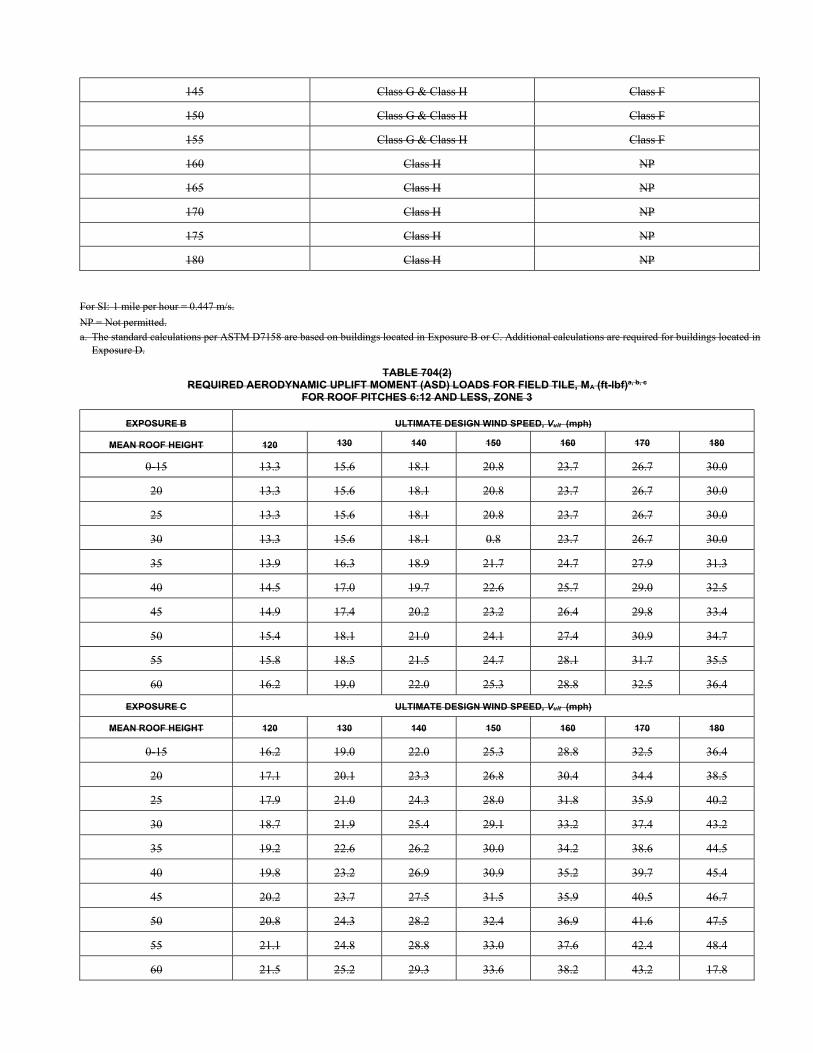
145 Class G & Class H Class F
150 Class G & Class H Class F
155 Class G & Class H Class F
160 Class H NP
165 Class H NP
170 Class H NP
175 Class H NP
180 Class H NP
For SI: 1 mile per hour = 0.447 m/s.
NP = Not permitted. a. The standard calculations per ASTM D7158 are based on buildings located in Exposure B or C. Additional calculations are required for buildings located in
Exposure D.
TABLE 704(2) REQUIRED AERODYNAMIC UPLIFT MOMENT (ASD) LOADS FOR FIELD TILE, MA (ft-lbf)a, b, c
FOR ROOF PITCHES 6:12 AND LESS, ZONE 3
EXPOSURE B ULTIMATE DESIGN WIND SPEED, Vult (mph)
MEAN ROOF HEIGHT 120 130 140 150 160 170 180
0-15 13.3 15.6 18.1 20.8 23.7 26.7 30.0
20 13.3 15.6 18.1 20.8 23.7 26.7 30.0
25 13.3 15.6 18.1 20.8 23.7 26.7 30.0
30 13.3 15.6 18.1 0.8 23.7 26.7 30.0
35 13.9 16.3 18.9 21.7 24.7 27.9 31.3
40 14.5 17.0 19.7 22.6 25.7 29.0 32.5
45 14.9 17.4 20.2 23.2 26.4 29.8 33.4
50 15.4 18.1 21.0 24.1 27.4 30.9 34.7
55 15.8 18.5 21.5 24.7 28.1 31.7 35.5
60 16.2 19.0 22.0 25.3 28.8 32.5 36.4
EXPOSURE C ULTIMATE DESIGN WIND SPEED, Vult (mph)
MEAN ROOF HEIGHT 120 130 140 150 160 170 180
0-15 16.2 19.0 22.0 25.3 28.8 32.5 36.4
20 17.1 20.1 23.3 26.8 30.4 34.4 38.5
25 17.9 21.0 24.3 28.0 31.8 35.9 40.2
30 18.7 21.9 25.4 29.1 33.2 37.4 43.2
35 19.2 22.6 26.2 30.0 34.2 38.6 44.5
40 19.8 23.2 26.9 30.9 35.2 39.7 45.4
45 20.2 23.7 27.5 31.5 35.9 40.5 46.7
50 20.8 24.3 28.2 32.4 36.9 41.6 47.5
55 21.1 24.8 28.8 33.0 37.6 42.4 48.4
60 21.5 25.2 29.3 33.6 38.2 43.2 17.8
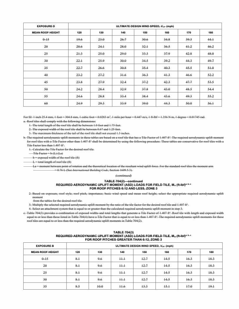
EXPOSURE D ULTIMATE DESIGN WIND SPEED, Vult (mph)
MEAN ROOF HEIGHT 120 130 140 150 160 170 180
0-15 19.6 23.0 26.7 30.6 34.8 39.3 44.1
20 20.6 24.1 28.0 32.1 36.5 41.2 46.2
25 21.3 25.0 29.0 33.3 37.9 42.8 48.0
30 22.1 25.9 30.0 34.5 39.2 44.3 49.7
35 22.7 26.6 30.8 35.4 40.3 45.5 51.0
40 23.2 27.2 31.6 36.3 41.3 46.6 52.2
45 23.8 27.9 32.4 37.2 42.3 47.7 53.5
50 24.2 28.4 32.9 37.8 43.0 48.5 54.4
55 24.6 28.8 33.4 38.4 43.6 49.3 55.2
60 24.9 29.3 33.9 39.0 44.3 50.0 56.1
For SI: 1 inch 25.4 mm, 1 foot = 304.8 mm, 1 cubic foot = 0.0283 m3, 1 mile per hour = 0.447 m/s, 1 ft-lbf = 1.356 N m, 1 degree = 0.01745 rad. a. Roof tiles shall comply with the following dimensions:
1. The total length of the roof tile shall be between 1.0 foot and 1.75 feet. 2. The exposed width of the roof tile shall be between 0.67 and 1.25 feet. 3. The maximum thickness of the tail of the roof tile shall not exceed 1.3 inches.
b. The required aerodynamic uplift moments in these tables are based on a roof tile that has a Tile Factor of 1.407 ft3. The required aerodynamic uplift moment for roof tiles with a Tile Factor other than 1.407 ft3 shall be determined by using the following procedure. These tables are conservative for roof tiles with a Tile Factor less than 1.407 ft3.
1. Calculate the Tile Factor for the desired roof tile. Tile Factor = b (L) (La)
b = exposed width of the roof tile (ft) L = total length of roof tile (ft) La = moment between point of rotation and the theoretical location of the resultant wind uplift force. For the standard roof tiles the moment arm
= 0.76 L (See International Building Code, Section 1609.5.3).
(continued)
TABLE 704(2)—continued REQUIRED AERODYNAMIC UPLIFT MOMENT (ASD) LOADS FOR FIELD TILE, MA (ft-lbf)a, b, c
FOR ROOF PITCHES 6:12 AND LESS, ZONE 3
2. Based on exposure, roof style, roof pitch, importance, basic wind speed and mean roof height, select the appropriate required aerodynamic uplift moment from the tables for the desired roof tile.
3. Multiply the selected required aerodynamic uplift moment by the ratio of the tile factor for the desired roof tile and 1.407 ft3. 4. Select an attachment system that is equal to or greater than the calculated required aerodynamic uplift moment in step 3.
c. Table 704(3) provides a combination of exposed widths and total lengths that generate a Tile Factor of 1.407 ft3. Roof tile with length and exposed width equal to or less than those listed in Table 704(4) have a Tile Factor that is equal to or less than 1.407 ft3. The required aerodynamic uplift moments for these roof tiles are equal to or less than the required aerodynamic uplift moments in Table 704(2).
TABLE 704(3) REQUIRED AERODYNAMIC UPLIFT MOMENT (ASD) LOADS FOR FIELD TILE, MA (ft-lbf)a, b, c
FOR ROOF PITCHES GREATER THAN 6:12, ZONE 3
EXPOSURE B ULTIMATE DESIGN WIND SPEED, Vult (mph)
MEAN ROOF HEIGHT 120 130 140 150 160 170 180
0-15 8.1 9.6 11.1 12.7 14.5 16.3 18.3
20 8.1 9.6 11.1 12.7 14.5 16.3 18.3
25 8.1 9.6 11.1 12.7 14.5 16.3 18.3
30 8.1 9.6 11.1 12.7 14.5 16.3 18.3
35 8.5 10.0 11.6 13.3 15.1 17.0 19.1
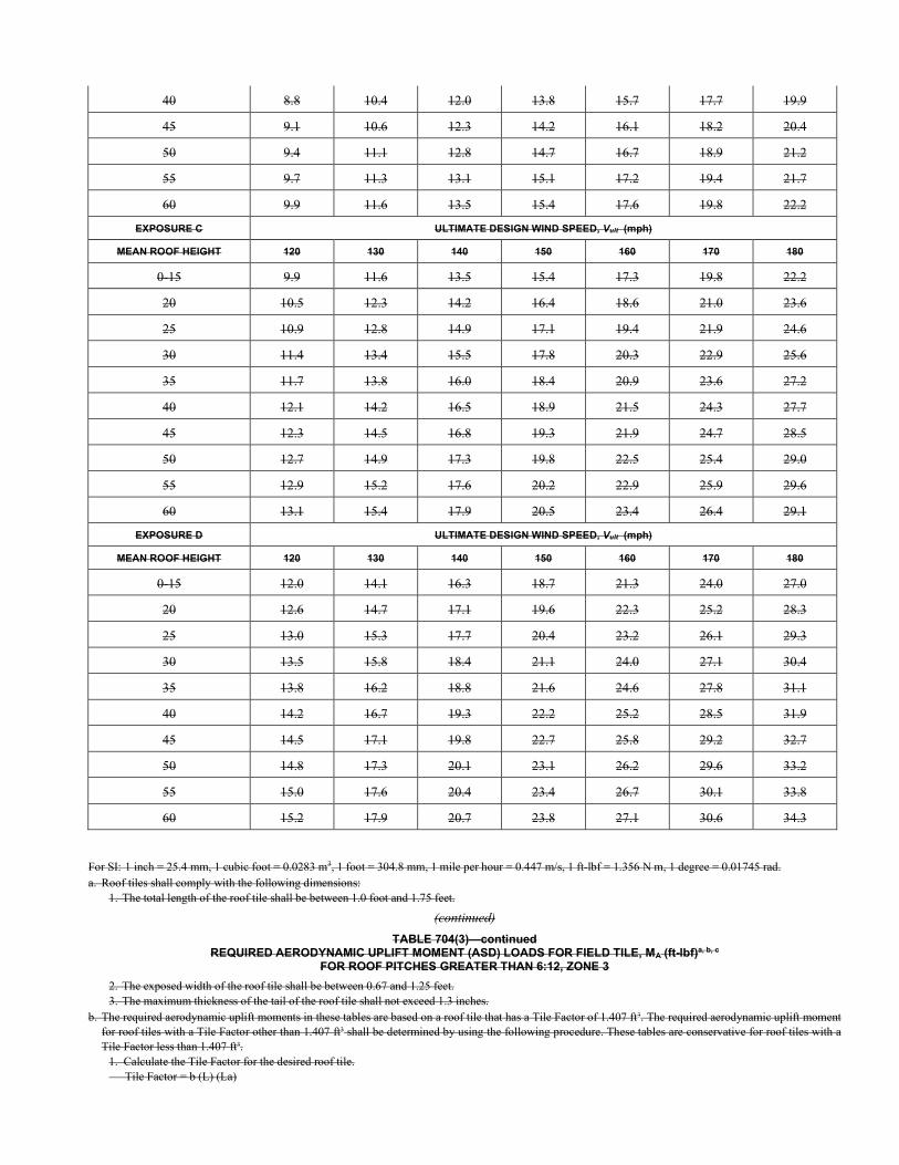
40 8.8 10.4 12.0 13.8 15.7 17.7 19.9
45 9.1 10.6 12.3 14.2 16.1 18.2 20.4
50 9.4 11.1 12.8 14.7 16.7 18.9 21.2
55 9.7 11.3 13.1 15.1 17.2 19.4 21.7
60 9.9 11.6 13.5 15.4 17.6 19.8 22.2
EXPOSURE C ULTIMATE DESIGN WIND SPEED, Vult (mph)
MEAN ROOF HEIGHT 120 130 140 150 160 170 180
0-15 9.9 11.6 13.5 15.4 17.3 19.8 22.2
20 10.5 12.3 14.2 16.4 18.6 21.0 23.6
25 10.9 12.8 14.9 17.1 19.4 21.9 24.6
30 11.4 13.4 15.5 17.8 20.3 22.9 25.6
35 11.7 13.8 16.0 18.4 20.9 23.6 27.2
40 12.1 14.2 16.5 18.9 21.5 24.3 27.7
45 12.3 14.5 16.8 19.3 21.9 24.7 28.5
50 12.7 14.9 17.3 19.8 22.5 25.4 29.0
55 12.9 15.2 17.6 20.2 22.9 25.9 29.6
60 13.1 15.4 17.9 20.5 23.4 26.4 29.1
EXPOSURE D ULTIMATE DESIGN WIND SPEED, Vult (mph)
MEAN ROOF HEIGHT 120 130 140 150 160 170 180
0-15 12.0 14.1 16.3 18.7 21.3 24.0 27.0
20 12.6 14.7 17.1 19.6 22.3 25.2 28.3
25 13.0 15.3 17.7 20.4 23.2 26.1 29.3
30 13.5 15.8 18.4 21.1 24.0 27.1 30.4
35 13.8 16.2 18.8 21.6 24.6 27.8 31.1
40 14.2 16.7 19.3 22.2 25.2 28.5 31.9
45 14.5 17.1 19.8 22.7 25.8 29.2 32.7
50 14.8 17.3 20.1 23.1 26.2 29.6 33.2
55 15.0 17.6 20.4 23.4 26.7 30.1 33.8
60 15.2 17.9 20.7 23.8 27.1 30.6 34.3
For SI: 1 inch = 25.4 mm, 1 cubic foot = 0.0283 m3, 1 foot = 304.8 mm, 1 mile per hour = 0.447 m/s, 1 ft-lbf = 1.356 N m, 1 degree = 0.01745 rad. a. Roof tiles shall comply with the following dimensions:
1. The total length of the roof tile shall be between 1.0 foot and 1.75 feet.
(continued)
TABLE 704(3)—continued REQUIRED AERODYNAMIC UPLIFT MOMENT (ASD) LOADS FOR FIELD TILE, MA (ft-lbf)a, b, c
FOR ROOF PITCHES GREATER THAN 6:12, ZONE 3
2. The exposed width of the roof tile shall be between 0.67 and 1.25 feet. 3. The maximum thickness of the tail of the roof tile shall not exceed 1.3 inches.
b. The required aerodynamic uplift moments in these tables are based on a roof tile that has a Tile Factor of 1.407 ft3. The required aerodynamic uplift moment for roof tiles with a Tile Factor other than 1.407 ft3 shall be determined by using the following procedure. These tables are conservative for roof tiles with a Tile Factor less than 1.407 ft3.
1. Calculate the Tile Factor for the desired roof tile. Tile Factor = b (L) (La)
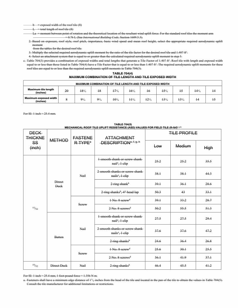
b = exposed width of the roof tile (ft) L = total length of roof tile (ft) La = moment between point of rotation and the theoretical location of the resultant wind uplift force. For the standard roof tiles the moment arm
= 0.76 L (See International Building Code, Section 1609.5.3). 2. Based on exposure, roof style, roof pitch, importance, basic wind speed and mean roof height, select the appropriate required aerodynamic uplift
moment from the tables for the desired roof tile.
3. Multiply the selected required aerodynamic uplift moment by the ratio of the tile factor for the desired roof tile and 1.407 ft3. 4. Select an attachment system that is equal to or greater than the calculated required aerodynamic uplift moment in step 3.
c. Table 704(3) provides a combination of exposed widths and total lengths that generate a Tile Factor of 1.407 ft3. Roof tile with length and exposed width equal to or less than those listed in Table 704(4) have a Tile Factor that is equal to or less than 1.407 ft3. The required aerodynamic uplift moments for these roof tiles are equal to or less than the required aerodynamic uplift moments in Table 704(3).
TABLE 704(4) MAXIMUM COMBINATION OF TILE LENGTH AND TILE EXPOSED WIDTH
MAXIMUM COMBINATION OF TILE LENGTH AND TILE EXPOSED WIDTH
Maximum tile length (inches)
20 181/2 18 171/2 161/2 16 151/2 15 141/2 14
Maximum exposed width (inches)
8 91/4 93/4 101/4 113/4 121/2 131/4 133/4 14 15
For SI: 1 inch = 25.4 mm.
TABLE 704(5)
MECHANICAL ROOF TILE UPLIFT RESISTANCE (ASD) VALUES FOR FIELD TILE (ft-lbf)i, j, k
DECK THICKNE
SS (inch)
METHOD FASTENER TYPEa
ATTACHMENT DESCRIPTIONe, f, g, h
TILE PROFILE
Low Medium High
15/32
Direct Deck
Nail
1 smooth shank or screw shank nailc, 1 clip
25.2 25.2 35.5
2 smooth shanks or screw shank nailsc, 1 clip
38.1 38.1 44.3
2 ring shankb 39.1 36.1 28.6
2 ring shanksb, 4" head lap 50.3 43 33.1
Screw 1 No. 8 screwd 39.1 33.2 28.7
2 No. 8 screwsd 50.2 55.5 51.3
Batten
Nail
1 smooth shank or screw shank nailc, 1 clip
27.5 27.5 29.4
2 smooth shanks or screw shank nailsc, 1 clip
37.6 37.6 47.2
2 ring shanksb 24.6 36.4 26.8
Screw 1 No. 8 screwd 25.6 30.1 25.5
2 No. 8 screwsd 36.1 41.9 37.1
19/32 Direct Deck Nail 2 ring shanksb 46.4 45.5 41.2
For SI: 1 inch = 25.4 mm, 1 foot-pound force = 1.356 N m. a. Fasteners shall have a minimum edge distance of 11/2 inches from the head of the tile and located in the pan of the tile to obtain the values in Table 704(5).
Consult the tile manufacturer for additional limitations or restrictions.
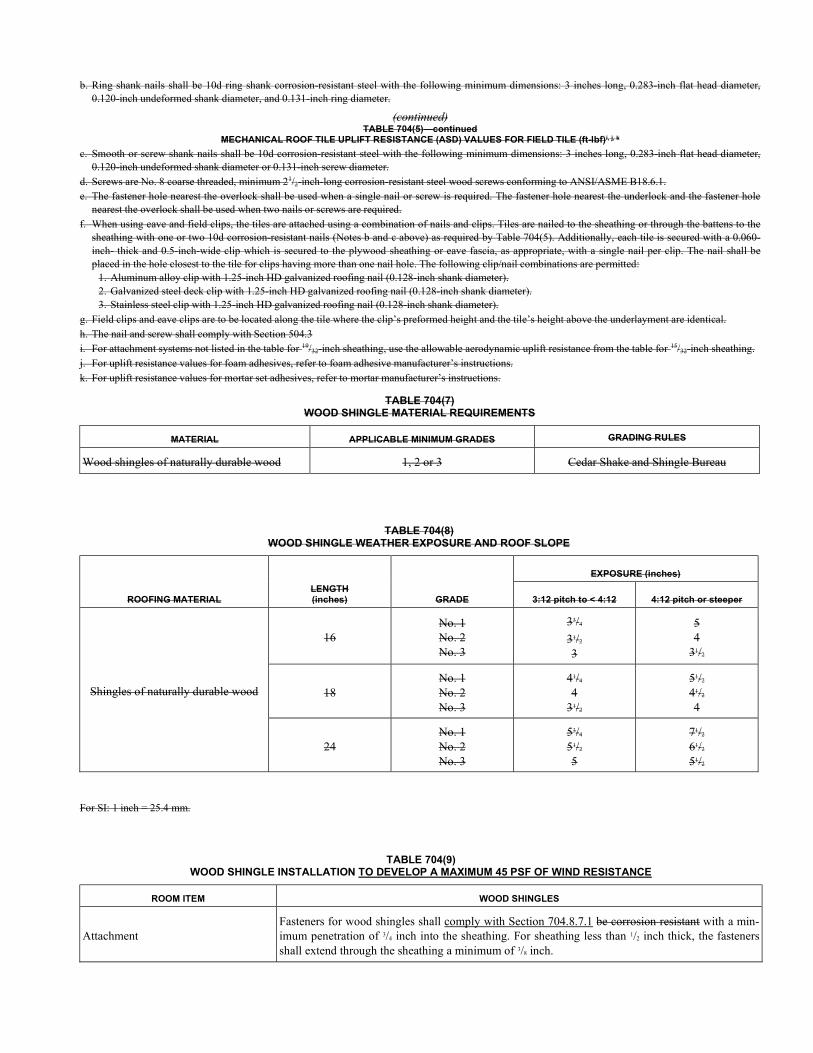
b. Ring shank nails shall be 10d ring shank corrosion-resistant steel with the following minimum dimensions: 3 inches long, 0.283-inch flat head diameter, 0.120-inch undeformed shank diameter, and 0.131-inch ring diameter.
(continued) TABLE 704(5)—continued
MECHANICAL ROOF TILE UPLIFT RESISTANCE (ASD) VALUES FOR FIELD TILE (ft-lbf)i, j, k
c. Smooth or screw shank nails shall be 10d corrosion-resistant steel with the following minimum dimensions: 3 inches long, 0.283-inch flat head diameter, 0.120-inch undeformed shank diameter or 0.131-inch screw diameter.
d. Screws are No. 8 coarse threaded, minimum 21/2-inch-long corrosion-resistant steel wood screws conforming to ANSI/ASME B18.6.1. e. The fastener hole nearest the overlock shall be used when a single nail or screw is required. The fastener hole nearest the underlock and the fastener hole
nearest the overlock shall be used when two nails or screws are required. f. When using eave and field clips, the tiles are attached using a combination of nails and clips. Tiles are nailed to the sheathing or through the battens to the
sheathing with one or two 10d corrosion-resistant nails (Notes b and c above) as required by Table 704(5). Additionally, each tile is secured with a 0.060-inch- thick and 0.5-inch-wide clip which is secured to the plywood sheathing or eave fascia, as appropriate, with a single nail per clip. The nail shall be placed in the hole closest to the tile for clips having more than one nail hole. The following clip/nail combinations are permitted:
1. Aluminum alloy clip with 1.25-inch HD galvanized roofing nail (0.128-inch shank diameter). 2. Galvanized steel deck clip with 1.25-inch HD galvanized roofing nail (0.128-inch shank diameter). 3. Stainless steel clip with 1.25-inch HD galvanized roofing nail (0.128-inch shank diameter).
g. Field clips and eave clips are to be located along the tile where the clip’s preformed height and the tile’s height above the underlayment are identical. h. The nail and screw shall comply with Section 504.3 i. For attachment systems not listed in the table for 19/32-inch sheathing, use the allowable aerodynamic uplift resistance from the table for 15/32-inch sheathing. j. For uplift resistance values for foam adhesives, refer to foam adhesive manufacturer’s instructions. k. For uplift resistance values for mortar set adhesives, refer to mortar manufacturer’s instructions.
TABLE 704(7) WOOD SHINGLE MATERIAL REQUIREMENTS
MATERIAL APPLICABLE MINIMUM GRADES GRADING RULES
Wood shingles of naturally durable wood 1, 2 or 3 Cedar Shake and Shingle Bureau
TABLE 704(8) WOOD SHINGLE WEATHER EXPOSURE AND ROOF SLOPE
ROOFING MATERIAL LENGTH (inches) GRADE
EXPOSURE (inches)
3:12 pitch to < 4:12 4:12 pitch or steeper
Shingles of naturally durable wood
16 No. 1 No. 2 No. 3
33/4
31/2
3
5 4
31/2
18 No. 1 No. 2 No. 3
41/4
4 31/2
51/2
41/2
4
24 No. 1 No. 2 No. 3
53/4
51/2
5
71/2
61/2
51/2
For SI: 1 inch = 25.4 mm.
TABLE 704(9) WOOD SHINGLE INSTALLATION TO DEVELOP A MAXIMUM 45 PSF OF WIND RESISTANCE
ROOM ITEM WOOD SHINGLES
Attachment Fasteners for wood shingles shall comply with Section 704.8.7.1 be corrosion resistant with a min-imum penetration of 3/4 inch into the sheathing. For sheathing less than 1/2 inch thick, the fasteners shall extend through the sheathing a minimum of 3/8 inch.
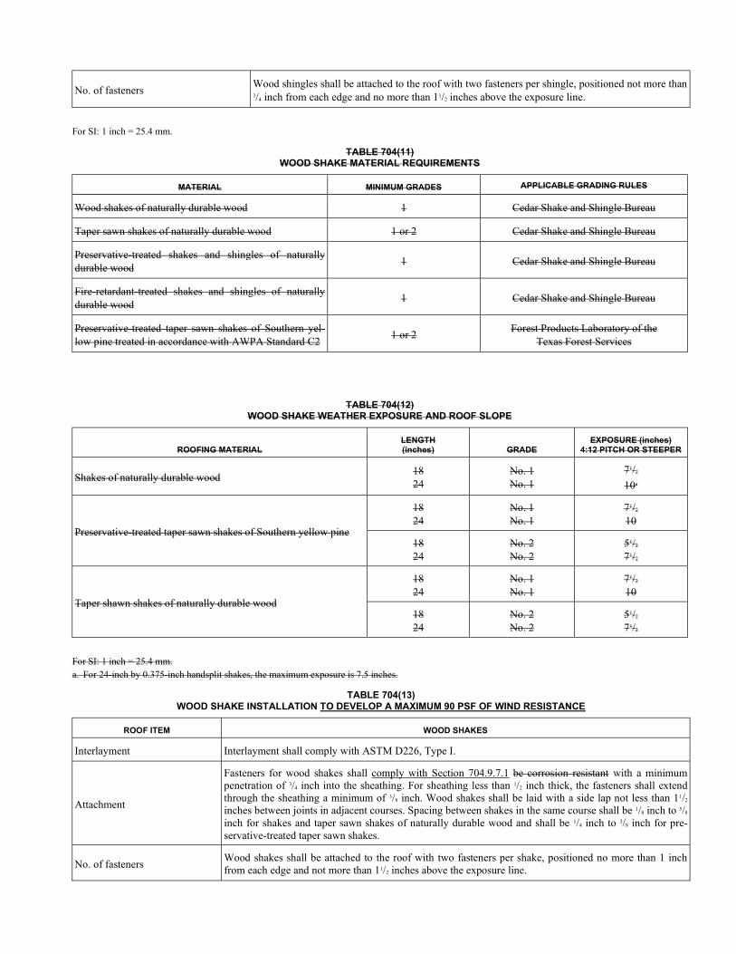
No. of fasteners Wood shingles shall be attached to the roof with two fasteners per shingle, positioned not more than 3/4 inch from each edge and no more than 11/2 inches above the exposure line.
For SI: 1 inch = 25.4 mm.
TABLE 704(11) WOOD SHAKE MATERIAL REQUIREMENTS
MATERIAL MINIMUM GRADES APPLICABLE GRADING RULES
Wood shakes of naturally durable wood 1 Cedar Shake and Shingle Bureau
Taper sawn shakes of naturally durable wood 1 or 2 Cedar Shake and Shingle Bureau
Preservative-treated shakes and shingles of naturally durable wood
1 Cedar Shake and Shingle Bureau
Fire-retardant-treated shakes and shingles of naturally durable wood
1 Cedar Shake and Shingle Bureau
Preservative-treated taper sawn shakes of Southern yel-low pine treated in accordance with AWPA Standard C2
1 or 2 Forest Products Laboratory of the
Texas Forest Services
TABLE 704(12) WOOD SHAKE WEATHER EXPOSURE AND ROOF SLOPE
ROOFING MATERIAL LENGTH (inches) GRADE
EXPOSURE (inches) 4:12 PITCH OR STEEPER
Shakes of naturally durable wood 18 24
No. 1 No. 1
71/2
10a
Preservative-treated taper sawn shakes of Southern yellow pine
18 24
No. 1 No. 1
71/2
10
18 24
No. 2 No. 2
51/2
71/2
Taper shawn shakes of naturally durable wood
18 24
No. 1 No. 1
71/2
10
18 24
No. 2 No. 2
51/2
71/2
For SI: 1 inch = 25.4 mm. a. For 24-inch by 0.375-inch handsplit shakes, the maximum exposure is 7.5 inches.
TABLE 704(13) WOOD SHAKE INSTALLATION TO DEVELOP A MAXIMUM 90 PSF OF WIND RESISTANCE
ROOF ITEM WOOD SHAKES
Interlayment Interlayment shall comply with ASTM D226, Type I.
Attachment
Fasteners for wood shakes shall comply with Section 704.9.7.1 be corrosion resistant with a minimum penetration of 3/4 inch into the sheathing. For sheathing less than 1/2 inch thick, the fasteners shall extend through the sheathing a minimum of 3/8 inch. Wood shakes shall be laid with a side lap not less than 11/2 inches between joints in adjacent courses. Spacing between shakes in the same course shall be 1/8 inch to 5/8 inch for shakes and taper sawn shakes of naturally durable wood and shall be 1/4 inch to 3/8 inch for pre-servative-treated taper sawn shakes.
No. of fasteners Wood shakes shall be attached to the roof with two fasteners per shake, positioned no more than 1 inch from each edge and not more than 11/2 inches above the exposure line.

For SI: 1 inch = 25.4 mm.
704.1 Scope. Roof coverings shall be applied in accordance with Section R905 of the International Residential Code or Section 1507 of the International Building Code, the applicable provisions of this section and the manufacturer’s installation instruc-tions.
704.2 Underlayment. Underlayment for asphalt shingles, clay and concrete tile, metal roof shingles, mineral-surfaced roll roofing, slate and slate-type shingles, wood shingles, wood shakes, and metal roof panels shall comply with the Wind Design Required provisions of Section R905.1.1 of the International Residential Code. conform to the applicable standards listed in this chapter. Underlayment materials required to comply with ASTM D226, D1970, D4869 and D6757 shall bear a label indi-cating compliance to the standard designation and, if applicable, type classification indicated in Table 704.2(1). Underlayment shall be applied in accordance with Table 704.2(2). Underlayment shall be attached in accordance with Table 704.2(3).
Exceptions:
1. As an alternative, self-adhering polymer modified bitumen underlayment complying with ASTM D1970 installed in accordance with both the underlayment manufacturer’s and roof covering manufacturer’s instructions for the deck ma-terial, roof ventilation configuration and climate exposure for the roof covering to be installed, shall be permitted.
2. As an alternative, a minimum 4-inch-wide (102 mm) strip of self-adhering polymer modified bitumen membrane complying with ASTM D1970 installed in accordance with the manufacturer’s instructions for the deck material shall be applied over all joints in the roof decking. An approved underlayment for the applicable roof covering shall be ap-plied over the entire roof over the 4-inch-wide (102 mm) membrane strips.
TABLE 704.2(1) UNDERLAYMENT TYPES
ROOF COVERING
SECTION TYPES
Asphalt shingles 704.3
ASTM D226 Type II
ASTM D4869 Type IV
ASTM D6757
Clay and concrete tile 704.4
ASTM D226 Type II
ASTM D2626 Type I
ASTM D6380 Class M mineral-surfaced roll roofing
Metal roof panels 704.5 ASTM D226 Type II
ASTM D4869 Type IV
Metal roof shingles 704.6 ASTM D226 Type II
ASTM D4869 Type IV
Mineral-surfaced roll roofing
704.10 ASTM D226 Type II
ASTM D4869 Type IV
Slate and slate-type shingles
704.7 ASTM D226 Type II
ASTM D4869 Type IV
Wood shingles 704.8 ASTM D226 Type II
ASTM D4869 Type IV
Wood shakes 704.9 ASTM D226 Type II
ASTM D4869 Type IV
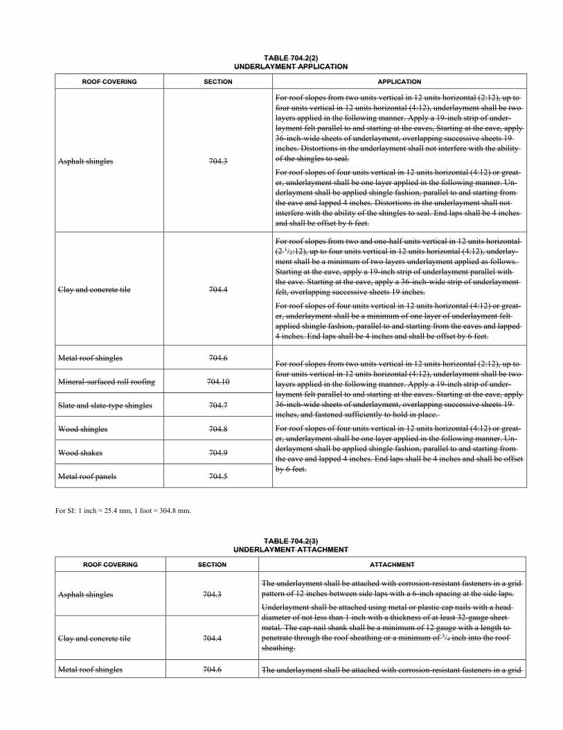
TABLE 704.2(2) UNDERLAYMENT APPLICATION
ROOF COVERING SECTION APPLICATION
Asphalt shingles 704.3
For roof slopes from two units vertical in 12 units horizontal (2:12), up to four units vertical in 12 units horizontal (4:12), underlayment shall be two layers applied in the following manner. Apply a 19-inch strip of under-layment felt parallel to and starting at the eaves, Starting at the eave, apply 36-inch-wide sheets of underlayment, overlapping successive sheets 19 inches. Distortions in the underlayment shall not interfere with the ability of the shingles to seal.
For roof slopes of four units vertical in 12 units horizontal (4:12) or great-er, underlayment shall be one layer applied in the following manner. Un-derlayment shall be applied shingle fashion, parallel to and starting from the eave and lapped 4 inches. Distortions in the underlayment shall not interfere with the ability of the shingles to seal. End laps shall be 4 inches and shall be offset by 6 feet.
Clay and concrete tile 704.4
For roof slopes from two and one-half units vertical in 12 units horizontal (2 1/2:12), up to four units vertical in 12 units horizontal (4:12), underlay-ment shall be a minimum of two layers underlayment applied as follows. Starting at the eave, apply a 19-inch strip of underlayment parallel with the eave. Starting at the eave, apply a 36-inch-wide strip of underlayment felt, overlapping successive sheets 19 inches.
For roof slopes of four units vertical in 12 units horizontal (4:12) or great-er, underlayment shall be a minimum of one layer of underlayment felt applied shingle fashion, parallel to and starting from the eaves and lapped 4 inches. End laps shall be 4 inches and shall be offset by 6 feet.
Metal roof shingles 704.6 For roof slopes from two units vertical in 12 units horizontal (2:12), up to four units vertical in 12 units horizontal (4:12), underlayment shall be two layers applied in the following manner. Apply a 19-inch strip of under-layment felt parallel to and starting at the eaves. Starting at the eave, apply 36-inch-wide sheets of underlayment, overlapping successive sheets 19 inches, and fastened sufficiently to hold in place.
For roof slopes of four units vertical in 12 units horizontal (4:12) or great-er, underlayment shall be one layer applied in the following manner. Un-derlayment shall be applied shingle fashion, parallel to and starting from the eave and lapped 4 inches. End laps shall be 4 inches and shall be offset by 6 feet.
Mineral-surfaced roll roofing 704.10
Slate and slate-type shingles 704.7
Wood shingles 704.8
Wood shakes 704.9
Metal roof panels 704.5
For SI: 1 inch = 25.4 mm, 1 foot = 304.8 mm.
TABLE 704.2(3) UNDERLAYMENT ATTACHMENT
ROOF COVERING SECTION ATTACHMENT
Asphalt shingles 704.3 The underlayment shall be attached with corrosion-resistant fasteners in a grid pattern of 12 inches between side laps with a 6-inch spacing at the side laps.
Underlayment shall be attached using metal or plastic cap nails with a head diameter of not less than 1 inch with a thickness of at least 32-gauge sheet metal. The cap-nail shank shall be a minimum of 12 gauge with a length to penetrate through the roof sheathing or a minimum of 3/4 inch into the roof sheathing.
Clay and concrete tile 704.4
Metal roof shingles 704.6 The underlayment shall be attached with corrosion-resistant fasteners in a grid
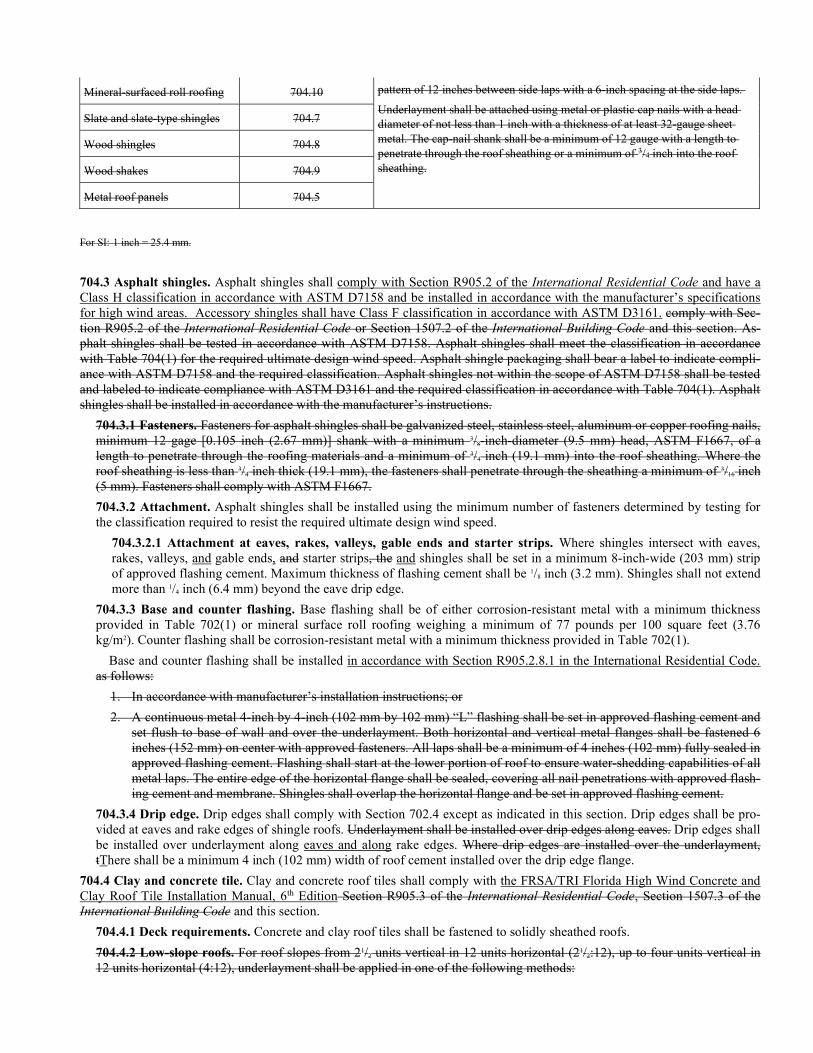
Mineral-surfaced roll roofing 704.10 pattern of 12 inches between side laps with a 6-inch spacing at the side laps.
Underlayment shall be attached using metal or plastic cap nails with a head diameter of not less than 1 inch with a thickness of at least 32-gauge sheet metal. The cap-nail shank shall be a minimum of 12 gauge with a length to penetrate through the roof sheathing or a minimum of 3/4 inch into the roof sheathing.
Slate and slate-type shingles 704.7
Wood shingles 704.8
Wood shakes 704.9
Metal roof panels 704.5
For SI: 1 inch = 25.4 mm.
704.3 Asphalt shingles. Asphalt shingles shall comply with Section R905.2 of the International Residential Code and have a Class H classification in accordance with ASTM D7158 and be installed in accordance with the manufacturer’s specifications for high wind areas. Accessory shingles shall have Class F classification in accordance with ASTM D3161. comply with Sec-tion R905.2 of the International Residential Code or Section 1507.2 of the International Building Code and this section. As-phalt shingles shall be tested in accordance with ASTM D7158. Asphalt shingles shall meet the classification in accordance with Table 704(1) for the required ultimate design wind speed. Asphalt shingle packaging shall bear a label to indicate compli-ance with ASTM D7158 and the required classification. Asphalt shingles not within the scope of ASTM D7158 shall be tested and labeled to indicate compliance with ASTM D3161 and the required classification in accordance with Table 704(1). Asphalt shingles shall be installed in accordance with the manufacturer’s instructions.
704.3.1 Fasteners. Fasteners for asphalt shingles shall be galvanized steel, stainless steel, aluminum or copper roofing nails, minimum 12 gage [0.105 inch (2.67 mm)] shank with a minimum 3/8-inch-diameter (9.5 mm) head, ASTM F1667, of a length to penetrate through the roofing materials and a minimum of 3/4 inch (19.1 mm) into the roof sheathing. Where the roof sheathing is less than 3/4 inch thick (19.1 mm), the fasteners shall penetrate through the sheathing a minimum of 3/16 inch (5 mm). Fasteners shall comply with ASTM F1667.
704.3.2 Attachment. Asphalt shingles shall be installed using the minimum number of fasteners determined by testing for the classification required to resist the required ultimate design wind speed.
704.3.2.1 Attachment at eaves, rakes, valleys, gable ends and starter strips. Where shingles intersect with eaves, rakes, valleys, and gable ends, and starter strips, the and shingles shall be set in a minimum 8-inch-wide (203 mm) strip of approved flashing cement. Maximum thickness of flashing cement shall be 1/8 inch (3.2 mm). Shingles shall not extend more than 1/4 inch (6.4 mm) beyond the eave drip edge.
704.3.3 Base and counter flashing. Base flashing shall be of either corrosion-resistant metal with a minimum thickness provided in Table 702(1) or mineral surface roll roofing weighing a minimum of 77 pounds per 100 square feet (3.76 kg/m2). Counter flashing shall be corrosion-resistant metal with a minimum thickness provided in Table 702(1).
Base and counter flashing shall be installed in accordance with Section R905.2.8.1 in the International Residential Code. as follows:
1. In accordance with manufacturer’s installation instructions; or
2. A continuous metal 4-inch by 4-inch (102 mm by 102 mm) “L” flashing shall be set in approved flashing cement and set flush to base of wall and over the underlayment. Both horizontal and vertical metal flanges shall be fastened 6 inches (152 mm) on center with approved fasteners. All laps shall be a minimum of 4 inches (102 mm) fully sealed in approved flashing cement. Flashing shall start at the lower portion of roof to ensure water-shedding capabilities of all metal laps. The entire edge of the horizontal flange shall be sealed, covering all nail penetrations with approved flash-ing cement and membrane. Shingles shall overlap the horizontal flange and be set in approved flashing cement.
704.3.4 Drip edge. Drip edges shall comply with Section 702.4 except as indicated in this section. Drip edges shall be pro-vided at eaves and rake edges of shingle roofs. Underlayment shall be installed over drip edges along eaves. Drip edges shall be installed over underlayment along eaves and along rake edges. Where drip edges are installed over the underlayment, tThere shall be a minimum 4 inch (102 mm) width of roof cement installed over the drip edge flange.
704.4 Clay and concrete tile. Clay and concrete roof tiles shall comply with the FRSA/TRI Florida High Wind Concrete and Clay Roof Tile Installation Manual, 6th Edition Section R905.3 of the International Residential Code, Section 1507.3 of the International Building Code and this section.
704.4.1 Deck requirements. Concrete and clay roof tiles shall be fastened to solidly sheathed roofs.
704.4.2 Low-slope roofs. For roof slopes from 21/2 units vertical in 12 units horizontal (21/2:12), up to four units vertical in 12 units horizontal (4:12), underlayment shall be applied in one of the following methods:
Method 1: Two layer underlayment:
1. Starting at the eave, a 19-inch-wide (483 mm) strip of underlayment shall be applied parallel with the eave and fas-tened as necessary to hold in place.
2. Starting at the eave, 36-inch-wide (914 mm) strips of underlayment felt shall be applied, overlapping successive sheets 19 inches (483 mm), and fastened as necessary to hold in place.
Method 2: Fully adhered cap sheet with compatible asphalt.
Method 3: Self-adhering underlayment complying with ASTM D1970.
704.4.3 High-slope roofs. For roof slopes of 4 units vertical in 12 units horizontal (4:12) or greater, underlayment shall be a minimum of one layer of underlayment felt applied shingle fashion, parallel to and starting from the eaves and lapped 2 inches (51 mm), fastened as necessary to hold in place.
704.4.24 Attachment. Clay and concrete tile shall be mechanically attached or adhesive set in accordance with the FRSA/TRI Florida High Wind Concrete and Clay Roof Tile Installation Manual, 6th Edition this section and the manufac-turer’s instructions. Clay and concrete roof tiles shall be secured to resist the appropriate design wind speed in accordance with this section or Section 1609.5.3 of the International Building Code. The allowable aerodynamic uplift moment deter-mined by Table 704(5) plus any gravity moment caused by the dead weight of the roof tile shall be equal to or greater than the required aerodynamic uplift moment determined by Table 704(2) or 704(3).
704.4.5 Mechanical fastening systems. Mechanical fastening systems in Table 704(5) are the allowable aerodynamic uplift moment.
704.4.6 Adhesive set systems. The approved allowable aerodynamic uplift moment for an adhesive set system plus any gravity moment caused by the dead weight of the roof tile shall be equal to or greater than the required aerodynamic uplift moment determined by Section 704.4.4 or Section 1609.5.3 of the International Building Code. Underlayment type and in-stallation shall be in accordance with the adhesive manufacturer’s published instructions. Roof tiles using the adhesive sys-tem should be installed by technicians trained and having a current certification by the adhesive manufacturer.
704.4.37 Hip and ridge tiles. Hip and ridge tiles shall be secured to hip and ridge boards attached to the roof framing.
704.4.7.1 Hip and ridge boards. Hip and ridge boards shall be attached to the roof framing to resist the uplift pressure listed in Tables 301(1) and 301(2) Table 701(1) assuming the exposed width of the hip/ridge tile is 1 foot (304.8 mm). For installations not covered in Table 701(1), the uplift pressure for the hip/ridge tile shall be determined in accordance with Section 1609 of the International Building Code as a roof covering that is not air permeable based on the actual ex-posed width of the tile.
704.4.37.2 Installing hip and ridge tiles. Hip and ridge tiles shall be installed using either procedure 1 or 2:
1. Mechanically fastened hip/ridge tiles. Mechanically fastened hip/ridge tiles shall use a wood ridge board and either nails or screws to secure the hip/ridge tiles. Drill a 3/16-inch (4.8 mm) hole in the lower one-third of the hip/ridge start-er tile. Use a #8 wood screw or a 10d box ring shank nail and secure the starter tile at both the drilled hole in the lower third of the tile and in the preformed hole at the head of the tile. The remaining hip/ridge tiles are to be installed with a minimum 2 inches (51 mm) headlap unless the roof tile manufacturer recommends a different headlap. Place the nose of each subsequent hip/ridge tile into a 4-inch to 5- inch (102 mm to 127 mm) bead of roof tile adhesive along the head of the lower tile. The head of each subsequent hip/ridge tile is to be secured using a #8 wood screw or a 10d ring shank nail. Fasteners are to have a minimum embedment of 3/4 inch (19.1 mm) into the roof framing. Seal the head of the fastener with a UV-resistant sealant.
2. Adhesive set hip/ridge tiles. Adhesive set hip/ridge tiles shall use a wood or metal ridge board and an approved roof tile adhesive to secure the hip/ridge tiles to the hip/ridge board. Install the hip/ridge starter tile by applying a bead or paddy of an approved roof tile adhesive along the hip/ridge board for the entire length of the starter tile. Center the hip/ridge starter tile over the hip/ridge board and center the hip/ridge starter tile in place. The remaining hip/ridge tiles are to be installed with a minimum 2 inches (51 mm) headlap unless the roof tile manufacturer rec-ommends a different headlap using one of the following methods.
Method 1: Apply a bead or paddy of an approved roof tile adhesive along the hip/ridge board for the entire length of the hip/ridge tile and center the hip/ridge tile in place.
Method 2: Place a 4-inch to 5-inch (102 mm to 127 mm) bead or paddy of approved roof tile adhesive between the head of the lower hip/ridge tile and the hip/ridge board. Center and place the head of this hip/ridge in the bead or paddy. Place a 4-inch to 5-inch (102 mm to 127 mm) bead or paddy of an approved roof tile adhesive on the head of the lower tile and center and place the overlap of the nose of the upper tile into the bead or paddy. Fasteners shall be installed in the hip/ridge tiles on roof slopes greater than 7:12. These fasteners shall be sufficient to prevent the hip/ridge tiles from sliding while the adhesive cures.
704.4.8 Flashing. Flashing for concrete and clay roof tiles shall comply with this section.
704.4.8.1 Base and counterflashing. Base and counterflashing shall be installed as follows:
1. In accordance with manufacturer’s installation instructions; or
2. A continuous metal 5-inch (vertical) by 6-inch (base) (127 mm by 152 mm) with 1-inch (25 mm) return shall be set in approved flashing cement and set flush to the base of the wall and over the underlayment. Both horizontal and vertical metal flanges shall be fastened 6 inches (152 mm) on center with approved fasteners. All laps shall be a minimum of 4 inches (102 mm) fully sealed in approved flashing cement. Flashing shall start at the lower portion of roof. The entire edge of the horizontal flange shall be sealed covering all nail penetrations with approved flashing cement and membrane. Tiles shall overlap the horizontal flange.
When installing counterflashing, lap the top flange a minimum of 21/2 inches (63 mm). The outside edge shall be fastened 6 inches (152 mm) on center with approved fasteners. All laps shall be a minimum of 3 inches (76 mm).
Base flashing shall be of either corrosion-resistant metal with a minimum thickness provided in Table 702(1) or miner-al surface roll roofing weighing a minimum of 77 pounds per 100 square feet (3.76 kg/m2). Counter flashing shall be cor-rosion-resistant metal with a minimum thickness provided in Table 702(1).
704.4.8.2 Valleys. Valley linings shall be installed in accordance with manufacturer’s installation instructions. Valley lin-ings shall be of the following types:
1. Open valley: Install a preformed open-valley metal having a minimum width of 16 inches (406 mm) with a mini-mum 1-inch-high (25 mm) twin center diverters and a minimum 1-inch-high (25 mm) edge returns. Lap joints must be a minimum of 6 inches (152 mm) and fully sealed with flashing cement or separator sheet. Flashing and separator shall be corrosion-resistant metals complying with Table 702(1).
2. Closed valley: Install a preformed valley metal having a minimum width of 16 inches (406 mm) with a minimum 21/2-inches-high (63 mm) center diverter at the flow line formed as part of the flashing and a minimum 1-inch-high (25 mm) edge return or preformed valley metal having a ribbed design with a minimum 1-inch (25 mm) center di-verter and a minimum of four 3/8-inch (9.5 mm) ribs spaced 31/2 inches (89 mm) apart with a 33/4-inch (95 mm) flange. Lap joints a minimum of 6 inches (152 mm) and fully sealed with flashing cement or separator sheet. Flashing and separator shall be corrosion-resistant metals complying with Table 702(1).
704.4.8.3 Crickets and saddles. A cricket or saddle shall be installed on the ridge side of any chimney more than 30 inches (762 mm) wide. Cricket or saddle coverings shall be sheet metal or roof tiles.
704.4.8.4 Sidewall flashing. Flashing against a vertical sidewall shall be by the step-flashing method.
704.4.8.5 Other flashing. Flashing against a vertical front wall, as well as soil stack, vent pipe and chimney flashing shall be applied according to the roof tile manufacturer’s published instructions.
704.4.8.6 Drip edge. Drip edges shall comply with Section 702.4 except as indicated in this section. Provide drip edges at the eaves. Underlayment shall be installed over drip edges along eaves. Drip edges shall be installed over underlay-ment along rake edges. Where drip edges are installed over the underlayment, there shall be a minimum width of 2 inches (51 mm) of roof cement installed over the drip edge flange.
704.5 Metal roof panels. Metal roof panels shall comply with Section R905.10 of the International Residential Code, Section 1507.4 of the International Building Code and this section.
704.5.1 Uplift resistance. Metal roof panels shall be installed in accordance with approved manufacturer’s installation in-structions. The installation instructions shall state the allowable uplift resistance for the attachment system. The installation of metal roof panels shall be limited to roofs where the allowable uplift resistance is equal to or greater than the design uplift pressure for the roof specified listed in Tables 301(1) and 301(2) 701(1). For installations not covered in Table 701(1), the allowable uplift resistance for metal roof panels shall be determined in accordance with Section 1609 of the International Building Code.
704.5.2 Testing. Metal panel roof systems applied to a solid or closely fitted deck shall be tested in accordance with FM 4474, UL 580, or UL 1897. Structural standing-seam metal panel roof systems shall be tested in accordance with ASTM E1592 or FM 4474. Structural through-fastened metal panel roof systems shall be tested in accordance with ASTM E1592, FM 4474, or UL 580.
Exceptions:
1. Metal roofs constructed of cold-formed steel shall be permitted to be designed and tested in accord-ance with the applicable referenced structural design standard in Section 2210.1 of the International Building Code.
2. Metal roofs constructed of aluminum shall be permitted to be designed and tested in accordance with the applicable referenced structural design standard in Section 2002.1 of the International Building Code.
704.6 Metal roof shingles. Metal roof shingles shall comply with Section R905.4 of the International Residential Code, Sec-tion 1507.5 of the International Building Code and this section.
704.6.1 Application. Metal roof shingles shall be installed in accordance with this section and the approved manufacturer’s installation instructions. The installation instructions shall state the allowable uplift resistance for the attachment system. The installation of metal roof shingles shall be limited to roofs where the allowable uplift resistance is equal to or greater than the design uplift pressure for the roof listed in the appropriate Table 701(1). For installations not covered in Table 701(1), the al-lowable uplift resistance for metal roof shingles shall be determined in accordance with Section 1609 of the International Building Code.
704.7 Slate and slate-type shingles. Slate and slate-type shingles shall comply with Section R905.6 of the International Resi-dential Code, Section 1507.7 of the International Building Code and this section.
704.7.1 Deck requirements. Slate shingles shall be fastened to solidly sheathed roofs.
704.7.2 Deck slope. Slate shingles shall only be used on slopes of four units vertical in 12 units horizontal (33-percent slope) or greater.
704.7.3 Material standards. Slate shingles shall comply with ASTM C406.
704.7.14 Fasteners. Slate shingle fasteners shall be a minimum No. 10 gage copper weld, copper, stainless or aluminum al-loy slating nails. The nails shall be a minimum of 11/2 inches (38 mm) for long field shingles and a minimum of 2 inches (51 mm) for hip and ridge zones. If longer nails are required because of the thickness of the slate shingle, the minimum length of the nail shall be twice the thickness of slate shingle plus 1 inch (25 mm). The gage for longer nails shall be increased as rec-ommended by the slate shingle manufacturer when longer nails are used.
704.7.5 Hooks. Hooks shall be copper or stainless steel.
704.7.6 Application. Minimum headlap for slate shingles shall be in accordance with Table 704(6).
TABLE 704(6) SLATE SHINGLE HEADLAP
SLOPE HEADLAP (inches)
4:12 < slope < 8:12 4
8:12 < slope < 20:12 3
Slope > 20:12 2
For SI: 1 inch = 25.4 mm.
704.7.7 Attachment. Slate and slate-type shingles shall be installed in accordance with this section and the manufacturer’s installation instructions. The installation instructions shall state the allowable uplift resistance for the attachment system. The installation of slate and slate-type shingles shall be limited to roofs where the allowable uplift resistance is equal to or greater than the design uplift pressure for the roof specified listed in Tables 301(1) and 301(2) 701(1). For installations not covered in Table 701(1), the allowable uplift resistance for slate and slate-type shingles shall be determined in accordance with Section 1609 of the International Building Code.
704.7.8 Flashing. Flashing and counterflashing shall be as provided in Table 702(1) nonferrous metal or stainless steel. Val-ley flashing shall be a minimum of 16 inches (406 mm) wide. Chimney, stucco or brick walls shall have a minimum of two layers of felt for cap flashing consisting of a 4-inch-wide (102 mm) strip of felt set in plastic cement and extending 1 inch (25 mm) above the first felt and a top coating of plastic cement. The felt shall extend 2 inches (51 mm) over the base flash-ing.
704.8 Wood shingles. Wood shingles shall comply with Section R905.7 of the International Residential Code, Section 1507.8 of the International Building Code and this section.
704.8.1 Deck requirements. Wood shingles shall be installed on solid sheathing. Where battens are used, the battens shall not be less than 1-inch by 4-inch (25 mm by 102 mm) nominal dimensions and shall be spaced on centers equal to the weather exposure to coincide with the placement of fasteners.
704.8.2 Deck slope. Wood shingles shall be installed on slopes of three units vertical in 12 units horizontal (25-percent slope) or greater.
704.8.3 Material standards.
704.8.3.1 Wood shingles. Wood shingles shall be of naturally durable wood and comply with the requirements of Table 704(7).
704.8.4 Application. Wood shingles shall be installed according to this section and the manufacturer’s installation instruc-tions. Weather exposure for wood shingles shall not exceed those set in Table 704(8).
704.8.5 Attachment. Attachment in accordance with Table 704(9) shall be used for roofs with a mean roof height of 40 feet (12.2 m) or less and in regions with a design wind speed of 130 mph (58 m/s) or less.
704.8.1 Uplift resistance. Wood shingles shall be installed in accordance with this section and the approved manufacturer’s installation instructions. The installation instructions shall state the allowable uplift resistance for the attachment system. The installation of wood shingles shall be limited to roofs where the allowable uplift resistance is equal to or greater than the design uplift pressure for the roof specified in Tables 301(1) and 301(2).
704.8.26 Attachment to develop a maximum of 45 psf of wind resistance. Wood shingles shall be permitted to be in-stalled in accordance with Table 704(9) and the requirements of Section 704.8.6 have an allowable uplift resistance of where the design uplift loads specified in Tables 301(1) and 301(2) do not exceed 45 psf (255 Pa). Where the design uplift loads specified in Tables 301(1) and 301(2) exceed 45 psf, the attachment of wood shingles shall be designed in accordance with accepted engineering practice. The installation of wood shingles shall be limited to roofs where the allowable uplift re-sistance is equal to or greater than the design uplift pressure for the roof listed in Table 701(1). For installations not covered in Table 701(1) the allowable uplift resistance for wood shingles shall be determined in accordance with Section 1609 of the International Building Code.
704.8.26.1 Fasteners.
704.8. 26.1.1 Nails. Nails to attach the wood shingles shall be 3d stainless steel ring shank nails. The nails shall have sufficient length to penetrate through the wood shingles and shall penetrate through the sheathing.
704.8. 26.1.2 Screws. Screws to attach the battens to the framing shall be No. 8 by 21/2-inch-long (64 mm) corrosion-resistant wood screws. Wood screws shall be corrosion-resistant screws conforming to ANSI/ASME B18.6.1. The corrosion resistance shall comply with Section 504.3.
704.8. 26.2 Wood battens. 1-inch by 4-inch (25 mm by 102 mm) wood battens shall be attached to the wood joists with two screws per joist. The first batten shall be located 6 inches (152 mm) from the outer edge of the wood joist. The sec-ond batten shall be spaced 11/4 inches (27 mm) from the first batten. The remaining battens shall be spaced a maximum 2 inches (51 mm) apart, except the last one which shall be spaced no more than 3/4 inch (19 mm) from the previous batten.
704.8.6.3 Shingles. Shingles shall be attached to the battens with two nails for each shingle placed 11/2 inches (38 mm) above the exposure line. The nails shall be 3/4 to 1 inch (19 to 25 mm) from the shingle edges.
704.8.37 Flashing. At the juncture of the roof and vertical surfaces, flashing and counterflashing shall be installed in ac-cordance with the manufacturer’s installation instructions, and where of metal, shall not be less than 0.019-inch (0.48 mm) (No. 26 galvanized sheet gage) corrosion-resistant metal.
704.8.37.1 Valley flashing. Valley flashing shall extend at least 11 inches (279 mm) from the centerline each way and have a splash diverter rib not less than 1 inch (25 mm) high at the flow line formed as part of the flashing. Sections of flashing shall have an end lap of not less than 4 inches (102 mm). For roof slopes of three units vertical in 12 units hori-zontal (25-percent slope) and over, the valley flashing shall have a 36-inch-wide (915 mm) underlayment of one layer of ASTM D226 Type I underlayment running the full length of the valley, in addition to other required underlayment. Val-ley flashing and flashing metal shall be a minimum thickness as provided in Table 702(1) nonferrous metal or stainless steel.
704.8.8 Uplift resistance. Wood shingles shall be installed in accordance with this section and the approved manufacturer’s installation instructions. The installation instructions shall state the allowable uplift resistance for the attachment system. The installation of wood shingles shall be limited to roofs where the allowable uplift resistance is equal to or greater than the design uplift pressure for the roof listed in Table 701(1). For installations not covered in Table 701(1), the allowable uplift resistance for wood shingles shall be determined in accordance with Section 1609 of the International Building Code.
704.8.49 Label required. Each bundle of shingles shall be identified by a label of an approved grading or inspection bureau or agency.
704.9 Wood shakes. Wood shakes shall comply with Section R905.8 of the International Residential Code, Section 1507.9 of the International Building Code and this section.
704.9.1 Deck requirements. Wood shakes shall be installed on solid sheathing. Where battens are used, the battens shall not be less than 1-inch by 4-inch (25 mm by 102 mm) nominal dimension and shall be spaced on centers equal to the weath-er exposure to coincide with the placement of fasteners.
704.9.2 Deck slope. Wood shakes shall only be used on slopes of four units vertical in 12 units horizontal (33-percent slope) or greater.
704.9.3 Material standards. Wood shakes shall comply with the requirements of Table 704(11).
704.9.4 Application. Wood shakes shall be installed according to this section and the manufacturer’s installation instruc-tions. Weather exposure for wood shakes shall not exceed those set forth in Table 704(12).
704.9.5 Attachment. Attachment in accordance with Table 704(13) shall be used for roofs with a mean roof height of 40 feet (12.2 m) or less and in regions with a design wind speed of 130 mph (58 m/s) or less.
704.9.1 Uplift resistance. Wood shakes shall be installed in accordance with approved manufacturer’s installation instruc-tions. The installation instructions shall state the allowable uplift resistance for the attachment system. The installation of wood shakes shall be limited to roofs where the allowable uplift resistance is equal to or greater than the design uplift pres-sure for the roof specified in Tables 301(1) and 301(2).
704.9.26 Attachment to develop a maximum of 90 psf of wind resistance. Wood shakes shall be permitted to be installed in accordance with Table 704(12) and the requirements of Section 704.9.6 have an allowable uplift resistance of where the design uplift loads specified in Tables 301(1) and 301(2) do not exceed 90 psf (4310 Pa). Where the design uplift loads specified in Tables 301(1) and 301(2) exceed 90 psf, the attachment of wood shakes shall be designed in accordance with accepted engineering practice. The installation of wood shakes shall be limited to roofs where the allowable uplift resistance is equal to or greater than the design uplift pressure for the roof listed in Table 701(1). For installations not covered in Table 701(1), the allowable uplift resistance for wood shakes shall be determined in accordance with Section 1609 of the Interna-tional Building Code.
704.9. 26.1 Fasteners.
704.9. 26.1.1 Nails. Nails to attach the wood shakes shall be 6d stainless steel ring shank nails. The nails shall have sufficient length to penetrate through both the wood shakes and the sheathing.
704.9. 26.1.2 Screws. Screws to attach the battens to the framing shall be No. 8 by 21/2 inch-long (64 mm) corrosion-resistant wood screws. Wood screws shall be corrosion-resistant screws conforming to ANSI/ASME B18.6.1. The corrosion resistance shall comply with Section 504.3.
704.9. 26.2 Wood battens. One-inch by 6-inch (25 mm by 152 mm) wood battens shall be attached to the wood joists with two screws per joist. The first batten shall be located 6 inches (152 mm) from the outer edge of the wood joist. The second batten shall be spaced 11/4 inches (32 mm) from the first batten. The remaining battens shall be spaced a maximum 2 inches (51 mm) apart, except the last one which shall be spaced no greater than 3/4 inch (19 mm) from the previous bat-ten.
704.9. 26.3 Shakes. Shakes shall be attached to the battens with two nails for each shake placed 11/2 inches (38 mm) above the exposure line. The nails shall be 3/4 to 1 inch (19 to 25 mm) from the shake edges.
704.9.7 Shake placement. The starter course at the eaves shall be doubled and the bottom layer shall be either 15-inch (381 mm), 18-inch (457 mm) or 24-inch (610 mm) wood shakes or wood shingles. Fifteen-inch (381 mm) or 18-inch (457 mm) wood shakes may be used for the final course at the ridge. Shakes shall be interlaid with 18-inch-wide (457 mm) strips of not less than No. 30 felt shingled between each course in such a manner that no felt is exposed to the weather by positioning the lower edge of each felt strip above the butt end of the shake it covers, a distance equal to twice the weather exposure.
704.9.38 Flashing. At the juncture of the roof and vertical surfaces, flashing and counterflashing shall be in accordance with the manufacturer’s installation instructions, and where of metal, shall not be less than 0.019-inch (0.48 mm) (No. 26 galva-nized sheet gage) corrosion-resistant metal.
704.9. 38.1 Valley flashing. Valley flashing shall extend at least 11 inches (279 mm) from the centerline each way and have a splash diverter rib not less than 1 inch (25 mm) high at the flow line formed as part of the flashing. Sections of flashing shall have an end lap of not less than 4 inches (102 mm). For roof slopes of four units vertical in 12 units hori-zontal (33-percent slope) and over, the valley flashing shall have a 36-inch-wide (915 mm) underlayment of one layer of ASTM D226 Type I underlayment running the full length of the valley, in addition to other required underlayment. Val-ley flashing and flashing metal shall be a minimum thickness as provided in Table 702(1) nonferrous metal or stainless steel.
704.9.9 Uplift resistance. Wood shakes shall be installed in accordance with approved manufacturer’s installation instruc-tions. The installation instructions shall state the allowable uplift resistance for the attachment system. The installation of wood shakes shall be limited to roofs where the allowable uplift resistance is equal to or greater than the design uplift pres-
sure for the roof listed in Table 701(1). For installations not covered in Table 701(1), the allowable uplift resistance for wood shakes shall be determined in accordance with Section 1609 of the International Building Code.
704.9.410 Label required. Each bundle of shakes shall be identified by a label of an approved grading or inspection bureau or agency.
704.10 Mineral-surfaced roll roofing. Mineral-surfaced roll roofing shall comply with Section R905.5 of the International Residential Code, Section 1507.6 of the International Building Code and this section.
704.10.1 Deck requirements. Mineral-surfaced roll roofing shall be fastened to solidly sheathed roofs.
704.10.2 Deck slope. Mineral-surfaced roll roofing shall not be applied on roof slopes below one unit vertical in 12 units horizontal (8-percent slope).
704.10.3 Material standards. Mineral-surfaced roll roofing shall conform to ASTM D6380, ASTM D371 or ASTM D3909.
704.10.14 Application. Mineral-surfaced roll roofing shall be installed according to this section and the manufacturer’s in-stallation instructions. The installation instructions shall state the allowable uplift resistance for the attachment system. The installation of mineral-surfaced roll roofing shall be limited to roofs where the allowable uplift resistance is equal to or greater than the design uplift pressure for the roof specified listed in Tables 301(1) and 301(2) Table 701(1). For installa-tions not covered in Table 701(1), the allowable uplift resistance for mineral-surfaced roll roofing shall be determined in ac-cordance with Section 1609 of the International Building Code.
704.11 Built-up roofs. Built-up roofs shall comply with Section R905.9 of the International Residential Code, Section 1507.10 of the International Building Code and this section.
704.11.1 Application. Built-up roofs shall be installed according to this section and the manufacturer’s installation instruc-tions. The installation instructions shall state the allowable uplift resistance for the attachment system. The installation of a built-up roof shall be limited to roofs where the allowable uplift resistance is equal to or greater than the design uplift pres-sure for the roof specified listed in Tables 301(1) and 301(2) Table 701(1). For installations not covered in Table 701(1), the allowable uplift resistance for mineral-surfaced roll roofing shall be determined in accordance with Section 1609 of the International Building Code.
704.12 Modified bitumen roofing. Modified bitumen roofing shall comply with Section R905.11 of the International Residen-tial Code, Section 1507.11 of the International Building Code and this section.
704.12.1 Application. Modified bitumen roofing shall be installed according to this section and the manufacturer’s installa-tion instructions. The installation instructions shall state the allowable uplift resistance for the attachment system. The instal-lation of modified bitumen roofing shall be limited to roofs where the allowable uplift resistance is equal to or greater than the design uplift pressure for the roof specified listed in Tables 301(1) and 301(2) Table 701(1). For installations not cov-ered in Table 701(1), the allowable uplift resistance for mineral-surfaced roll roofing shall be determined in accordance with Section 1609 of the International Building Code.
704.13 Thermoset single-ply roofing. Thermoset single-ply roofing shall comply with Section R905.12 of the International Residential Code, Section 1507.12 of the International Building Code and this section.
704.13.1 Application. Thermoset single-ply roofs shall be installed according to this section and the manufacturer’s installa-tion instructions. The installation instructions shall state the allowable uplift resistance for the attachment system. The instal-lation of a thermoset single-ply roof shall be limited to roofs where the allowable uplift resistance is equal to or greater than the design uplift pressure for the roof specified listed in Tables 301(1) and 301(2) Table 701(1). For installations not cov-ered in Table 701(1), the allowable uplift resistance for thermoset single-ply roofing shall be determined in accordance with Section 1609 of the International Building Code.
704.14 Thermoplastic single-ply roofing. Thermoplastic single-ply roofing shall comply with Section R905.13 of the Interna-tional Residential Code, Section 1507.13 of the International Building Code and this section.
704.14.1 Application. Thermoplastic single-ply roofs shall be installed according to this section and the manufacturer’s in-stallation instructions. The installation of a thermoplastic single-ply roof shall be limited to roofs where the allowable uplift resistance is equal to or greater than the design uplift pressure for the roof specified listed in Tables 301(1) and 301(2) Ta-ble 701(1). For installations not covered in Table 701(1), the allowable uplift resistance for thermoplastic single-ply roofing shall be determined in accordance with Section 1609 of the International Building Code.
704.15 Sprayed polyurethane foam roofing. Sprayed polyurethane foam roofing shall comply with Section R905.14 of the International Residential Code, Section 1507.14 of the International Building Code and this section.
704.15.1 Application. Foamed-in-place roof insulation shall be installed in accordance with this section and the manufac-turer’s installation instructions. A liquid-applied protective coating that complies with Section R905.15 of the International Residential Code or Section 1507.16 of the International Building Code shall be applied no less than 2 hours nor more than
72 hours following the application of the foam. The installation of foamed-in-place roof insulation shall be limited to roofs where the allowable uplift resistance is equal to or greater than the design uplift pressure for the roof specified listed in Ta-bles 301(1) and 301(2) Table 701(1). For installations not covered in Table 701(1), the allowable uplift resistance for sprayed polyurethane foam roofing shall be determined in accordance with Section 1609 of the International Building Code.
704.16 Liquid-applied coatings. Liquid-applied coatings shall comply with Section R905.15 of the International Residential Code, Section 1507.15 of the International Building Code and this section.
704.16.1 Application. Liquid-applied roof coatings shall be installed according to this section and the manufacturer’s instal-lation instructions. The installation of liquid-applied roof coatings shall be limited to roofs where the allowable uplift re-sistance is equal to or greater than the design uplift pressure for the roof specified listed in Tables 301(1) and 301(2) Table 701(1). For installations not covered in Table 701(1), the allowable uplift resistance for liquid-applied roof coatings shall be determined in accordance with Section 1609 of the International Building Code.
CHAPTER 8
FENESTRATION
SECTION 801 SCOPE GENERAL
801.1 Scope. This chapter prescribes performance and construction requirements for windows, unit skylights, garage doors, slid-ing glass doors, glass patio doors and entry doors installed in the exterior wall and roof systems and door systems. Waterproof-ing, sealing and flashing are not included in the scope of this section.
801.1.1 Application. The installation of fenestrations shall comply with Chapters 3 and 6 of the International Residential Code and with modifications provided in this chapter. Where, in any specific case, sections of this standard chapter specify different materials, methods of construction or other requirements which conflict with the International Residential Code, the most re-strictive shall govern.
SECTION 802 WINDOWS, UNIT SKYLIGHTS, GARAGE DOORS, SLIDING GLASS DOORS,
GLASS PATIO DOORS AND ENTRY DOORS INSTALLED IN WALL/ROOF SYSTEMS
802.1 General.
802.1.1 Performance requirements for exterior windows, doors, garage doors and unit skylights. The design pressure rating for windows, doors, garage doors and unit skylights shall be determined in accordance with the provisions of Section 802.1.2, 802.1.3 or 802.1.4. The design pressure rating of each fenestration shall be greater than or equal to the design wind loads calculated for the area on the building envelope where the fenestration is located. The design wind loads shall comply with Section 802.2 of this chapter,
802.1.2 Performance Testing and labeling requirements for exterior windows, sliding glass doors and glass patio doors. Exterior windows and doors shall comply with Section R609 of the International Residential Code in addition to the provisions of this chapter. Windows, entry doors, sliding glass doors and glass patio doors shall be tested by an approved testing laboratory and bear the permanent label of an approved inspection agency to indicate compliance with the require-ments of at least one of the following standards: R609 of the International Residential Code or Florida Codes Test Applica-tion Standard (TAS) 202.
1. ANSI/AAMA/NWWDA 101/I.S.2.
2. ANSI/AAMA/WDMA 101/I.S.2/NAFS.
3. AAMA/WDMA/CSA 101/I.S.2/A440.
Exterior windows, entry doors, sliding glass doors and glass patio doors shall be labeled with a permanent label, marking, or etching providing traceability to the manufacturer and product. The following shall also be required either on a permanent la-bel or on a temporary supplemental label applied by the manufacturer: information identifying the manufacturer, the product model/series number, positive and negative design pressure rating, product maximum size tested, impact-resistance rating if applicable, Florida product approval number or Miami-Dade product approval number, applicable test standard(s), and ap-proved product certification agency, testing laboratory, evaluation entity or Miami-Dade product approval.
For this section and Sections 803.1 and 803.2, Aa label shall be permanent if it cannot be removed and reattached without destroying the label or the product.
802.1.3 Performance Testing and labeling requirements for unit skylights. Unit skylights shall comply with Section R308.6 of the International Residential Code in addition to the provisions of this chapter. Unit skylights shall be tested by an approved testing laboratory and bear the permanent label of an approved inspection agency to indicate compliance with the re-quirements of the following standard: R308.6.9 of the International Residential Code or Florida Codes Test Application Standard (TAS) 202.
AAMA/WDMA/CSA 101/I.S.2/A440.
Unit skylights shall be labeled with a permanent label, marking, or etching providing traceability to the manufacturer and product. The following shall also be required either on a permanent label or on a temporary supplemental label applied by the manufacturer: information identifying the manufacturer, the product model/series number, positive and negative design pres-

sure rating, product maximum size tested, impact-resistance rating if applicable, Florida product approval number or Miami-Dade product approval number, applicable test standard(s), and approved product certification agency, testing laboratory, evaluation entity or Miami-Dade product approval.
A label shall be permanent if it cannot be removed and reattached without destroying the label or the product.
802.1.4 Other doors. Doors not included in Section 802.1.2 shall be tested in compliance with the requirements of at least one of the following standards:
1. ASTM E330.
2. ANSI/DASMA 108 (for garage doors).
3. TAS 202.
802.1.4 Testing and labeling requirements for Garage doors. Garage doors shall comply with Section R609 of the International Residential Code in addition to the provisions of this chapter. Garage doors shall be tested by an approved testing laboratory and bear a permanent label to indicate compliance with the requirements of R609 of the International Residential Code or Florida Codes Test Application Standard (TAS) 202. Garage doors shall be labeled in compliance with Section R609.4.1 of the International Residential Code and provide traceability to the manufacturer and product. In addition to the product performance data required by R609.4.1, the permanent label shall provide maximum size tested, and impact-resistance rating if applicable, either on the label or through traceability.
A label shall be permanent if it cannot be removed and reattached without destroying the label or the product.
802.1.5 Hardware. Hardware shall be tested as part of the assembly. Only hardware listed on the certified test report shall be accepted.
802.2 Design wind load pressure requirements.
802.2.1 Design pressures Windows, skylights and doors. Design wind load pressure performance shall comply with Sec-tion R308.6 and Section R609.2 of the International Residential Code in addition to the provisions of this chapter. Design wind load pressure requirements for all fenestrations, except garage doors, windows, sliding glass doors, glass patio doors, and entry doors shall be determined from Table 802(1), or from Table 301 (2) Section R609.2 of the International Residen-tial Code or Section 301.3, Section 301.4, and Section 301.5 of this standard adjusted for height, and exposure category, and topographic wind effect where applicable in accordance with Table 301(23), Table 301 (4), and Table 301 (5) of this stand-ard. Design pressure requirements for unit skylights shall be determined from Table 301(1) adjusted for height and exposure in accordance with Table 301(2).
802.2.2 Garage doors. Design wind load pressure performance shall comply with Section R609.4 of the International Resi-dential Code in addition to the provisions of this chapter. Design wind load pressure requirements for garage doors installed in buildings with a mean roof height of not more than 30 feet (9 m), with plan dimensions not more than 40 feet by 60 feet (12 mm by 18 mm) and located in Exposure exposure category B, are listed in shall be determined from Table 802(21). For mean roof heights greater than 30 feet (9 m) and or for other exposure categories or for topographic wind effect where applicable, the table values shall be multiplied adjusted by the appropriate height, exposure category, and topographic wind effect ad-justment factors in Table 301(23), Table 301 (4), and Table 301 (5) of this standard.
802.3 Anchorage methods.
802.3.1 General. The methods cited in this section apply only to anchorage of windows, unit skylights and door assemblies to the main windforce-resisting system.
802.3.2 Anchoring requirements. All assemblies shall be anchored in accordance with the manufacturer’s published rec-ommendations to resist the design pressure specified. Substitute anchoring systems used for substrates not specified by the fenestration manufacturer shall provide equal or greater anchoring performance as demonstrated by accepted engineering practice.
802.3.3 Anchorage details for masonry, concrete or other structural substrate. Where the wood shim or buck thickness is less than 11/2 inches (38 mm), window and door assemblies shall be anchored through the main frame or by jamb clip or sub-frame system, in accordance with the manufacturer’s published installation instructions. Anchors shall be securely fastened directly into the masonry, concrete or other structural substrate material. Unless otherwise tested, bucks shall extend beyond the interior face of the window or door frame such that the frame is fully supported.
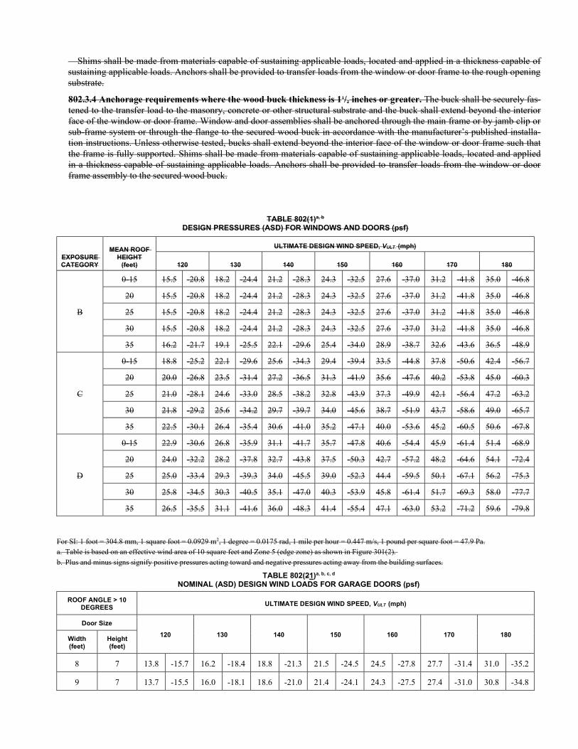
Shims shall be made from materials capable of sustaining applicable loads, located and applied in a thickness capable of sustaining applicable loads. Anchors shall be provided to transfer loads from the window or door frame to the rough opening substrate.
802.3.4 Anchorage requirements where the wood buck thickness is 11/2 inches or greater. The buck shall be securely fas-tened to the transfer load to the masonry, concrete or other structural substrate and the buck shall extend beyond the interior face of the window or door frame. Window and door assemblies shall be anchored through the main frame or by jamb clip or sub-frame system or through the flange to the secured wood buck in accordance with the manufacturer’s published installa-tion instructions. Unless otherwise tested, bucks shall extend beyond the interior face of the window or door frame such that the frame is fully supported. Shims shall be made from materials capable of sustaining applicable loads, located and applied in a thickness capable of sustaining applicable loads. Anchors shall be provided to transfer loads from the window or door frame assembly to the secured wood buck.
TABLE 802(1)a, b
DESIGN PRESSURES (ASD) FOR WINDOWS AND DOORS (psf)
EXPOSURE CATEGORY
MEAN ROOF HEIGHT
(feet)
ULTIMATE DESIGN WIND SPEED, VULT (mph)
120 130 140 150 160 170 180
B
0-15 15.5 -20.8 18.2 -24.4 21.2 -28.3 24.3 -32.5 27.6 -37.0 31.2 -41.8 35.0 -46.8
20 15.5 -20.8 18.2 -24.4 21.2 -28.3 24.3 -32.5 27.6 -37.0 31.2 -41.8 35.0 -46.8
25 15.5 -20.8 18.2 -24.4 21.2 -28.3 24.3 -32.5 27.6 -37.0 31.2 -41.8 35.0 -46.8
30 15.5 -20.8 18.2 -24.4 21.2 -28.3 24.3 -32.5 27.6 -37.0 31.2 -41.8 35.0 -46.8
35 16.2 -21.7 19.1 -25.5 22.1 -29.6 25.4 -34.0 28.9 -38.7 32.6 -43.6 36.5 -48.9
C
0-15 18.8 -25.2 22.1 -29.6 25.6 -34.3 29.4 -39.4 33.5 -44.8 37.8 -50.6 42.4 -56.7
20 20.0 -26.8 23.5 -31.4 27.2 -36.5 31.3 -41.9 35.6 -47.6 40.2 -53.8 45.0 -60.3
25 21.0 -28.1 24.6 -33.0 28.5 -38.2 32.8 -43.9 37.3 -49.9 42.1 -56.4 47.2 -63.2
30 21.8 -29.2 25.6 -34.2 29.7 -39.7 34.0 -45.6 38.7 -51.9 43.7 -58.6 49.0 -65.7
35 22.5 -30.1 26.4 -35.4 30.6 -41.0 35.2 -47.1 40.0 -53.6 45.2 -60.5 50.6 -67.8
D
0-15 22.9 -30.6 26.8 -35.9 31.1 -41.7 35.7 -47.8 40.6 -54.4 45.9 -61.4 51.4 -68.9
20 24.0 -32.2 28.2 -37.8 32.7 -43.8 37.5 -50.3 42.7 -57.2 48.2 -64.6 54.1 -72.4
25 25.0 -33.4 29.3 -39.3 34.0 -45.5 39.0 -52.3 44.4 -59.5 50.1 -67.1 56.2 -75.3
30 25.8 -34.5 30.3 -40.5 35.1 -47.0 40.3 -53.9 45.8 -61.4 51.7 -69.3 58.0 -77.7
35 26.5 -35.5 31.1 -41.6 36.0 -48.3 41.4 -55.4 47.1 -63.0 53.2 -71.2 59.6 -79.8
For SI: 1 foot = 304.8 mm, 1 square foot = 0.0929 m2, 1 degree = 0.0175 rad, 1 mile per hour = 0.447 m/s, 1 pound per square foot = 47.9 Pa. a. Table is based on an effective wind area of 10 square feet and Zone 5 (edge zone) as shown in Figure 301(2). b. Plus and minus signs signify positive pressures acting toward and negative pressures acting away from the building surfaces.
TABLE 802(21)a, b, c, d
NOMINAL (ASD) DESIGN WIND LOADS FOR GARAGE DOORS (psf)
ROOF ANGLE > 10 DEGREES
ULTIMATE DESIGN WIND SPEED, VULT (mph)
Door Size
120 130 140 150 160 170 180 Width (feet)
Height (feet)
8 7 13.8 -15.7 16.2 -18.4 18.8 -21.3 21.5 -24.5 24.5 -27.8 27.7 -31.4 31.0 -35.2
9 7 13.7 -15.5 16.0 -18.1 18.6 -21.0 21.4 -24.1 24.3 -27.5 27.4 -31.0 30.8 -34.8
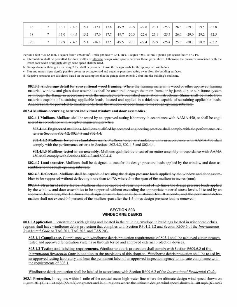
16 7 13.1 -14.6 15.4 -17.1 17.8 -19.9 20.5 -22.8 23.3 -25.9 26.3 -29.3 29.5 -32.8
18 7 13.0 -14.4 15.2 -17.0 17.7 -19.7 20.3 -22.6 23.1 -25.7 26.0 -29.0 29.2 -32.5
20 7 12.9 -14.3 15.1 -16.8 17.5 -19.5 20.1 -22.4 22.9 -25.4 25.8 -28.7 28.9 -32.2
For SI: 1 foot = 304.8 mm, 1 square foot = 0.0929 m2, 1 mile per hour = 0.447 m/s, 1 degree = 0.0175 rad, 1 pound per square foot = 47.9 Pa. a. Interpolation shall be permitted for door widths or ultimate design wind speeds between those given above. Otherwise the pressures associated with the
lower door width or ultimate design wind speed shall be used. b. Garage doors with height exceeding 7 feet shall be permitted to use the design loads for the appropriate width door. c. Plus and minus signs signify positive pressures acting toward and negative pressures acting away from the building surfaces. d. Negative pressures are calculated based on the assumption that the garage door extends 2 feet into the building’s end zone.
802.3.5 Anchorage detail for conventional wood framing. Where the framing material is wood or other approved framing material, window and glass door assemblies shall be anchored through the main frame or by jamb clip or sub-frame system or through the flange in accordance with the manufacturer’s published installation instructions. Shims shall be made from materials capable of sustaining applicable loads, located and applied in a thickness capable of sustaining applicable loads. Anchors shall be provided to transfer loads from the window or door frame to the rough opening substrate.
802.4 Mullions occurring between individual window and door assemblies.
802.4.1 Mullions. Mullions shall be tested by an approved testing laboratory in accordance with AAMA 450, or shall be engi-neered in accordance with accepted engineering practice.
802.4.1.1 Engineered mullions. Mullions qualified by accepted engineering practice shall comply with the performance cri-teria in Sections 802.4.2, 802.4.3 and 802.4.4.
802.4.1.2 Mullions tested as standalone units. Mullions tested as standalone units in accordance with AAMA 450 shall comply with the performance criteria in Sections 802.4.2, 802.4.3 and 802.4.4.
802.4.1.3 Mullions tested in an assembly. Mullions qualified by a test of an entire assembly in accordance with AAMA 450 shall comply with Sections 802.4.2 and 802.4.4.
802.4.2 Load transfer. Mullions shall be designed to transfer the design pressure loads applied by the window and door as-semblies to the rough opening substrate.
802.4.3 Deflection. Mullions shall be capable of resisting the design pressure loads applied by the window and door assem-blies to be supported without deflecting more than L/175, where L is the span of the mullion in inches (mm).
802.4.4 Structural safety factor. Mullions shall be capable of resisting a load of 1.5 times the design pressure loads applied by the window and door assemblies to be supported without exceeding the appropriate material stress levels. If tested by an approved laboratory, the 1.5 times the design pressure load shall be sustained for 10 seconds, and the permanent defor-mation shall not exceed 0.4 percent of the mullion span after the 1.5 times design pressure load is removed.
SECTION 803 WINDBORNE DEBRIS
803.1 Application. Fenestrations with glazing and located in the building envelope in buildings located in windborne debris regions shall have windborne debris protection that complies with Section R301.2.1.2 and Section R609.6 of the International Residential Code or TAS 201, TAS 202, and TAS 203.
803.1.1 Compliance. Compliance with windborne debris protection requirements of 803.1 shall be achieved either through tested and approved fenestration systems or through tested and approved external protection devices.
803.1.2 Testing and labeling requirements. Windborne debris protection shall comply with Section R609.6.2 of the International Residential Code in addition to the provisions of this chapter. Windborne debris protection shall be tested by an approved testing laboratory and bear the permanent label of an approved inspection agency to indicate compliance with the requirements of 803.1.
Windborne debris protection shall be labeled in accordance with Section R609.6.2 of the International Residential Code.
803.1 Protection. In regions within 1 mile of the coastal mean high water line where the ultimate design wind speed shown on Figure 301(1) is 130 mph (58 m/s) or greater and in all regions where the ultimate design wind speed shown is 140 mph (63 m/s)
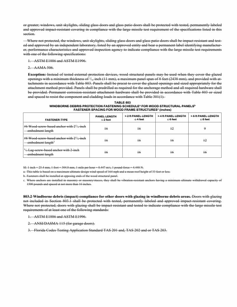
or greater; windows, unit skylights, sliding glass doors and glass patio doors shall be protected with tested, permanently labeled and approved impact-resistant covering in compliance with the large missile test requirement of the specifications listed in this section.
Where not protected, the windows, unit skylights, sliding glass doors and glass patio doors shall be impact resistant and test-ed and approved by an independent laboratory, listed by an approved entity and bear a permanent label identifying manufactur-er, performance characteristics and approved inspection agency to indicate compliance with the large missile test requirements with one of the following specifications:
1. ASTM E1886 and ASTM E1996.
2. AAMA 506.
Exception: Instead of tested external protection devices, wood structural panels may be used when they cover the glazed openings with a minimum thickness of 7/16 inch (11 mm), a maximum panel span of 8 feet (2438 mm), and provided with at-tachments in accordance with Table 803. Panels shall be precut to cover the glazed openings and sized appropriately for the attachment method provided. Panels shall be predrilled as required for the anchorage method and all required hardware shall be provided. Permanent corrosion-resistant attachment hardware shall be provided in accordance with Table 803 or sized and spaced to resist the component and cladding loads in accordance with Table 301(1).
TABLE 803 WINDBORNE DEBRIS PROTECTION FASTENING SCHEDULEa FOR WOOD STRUCTURAL PANELSb
FASTENER SPACING FOR WOOD FRAME STRUCTURESc (inches)
FASTENER TYPE PANEL LENGTH
2 feet > 2 ft PANEL LENGTH
4 feet > 4 ft PANEL LENGTH
6 feet > 6 ft PANEL LENGTH
8 feet
#6 Wood-screw-based anchor with 21/2-inch embedment length
16 16 12 9
#8 Wood-screw-based anchor with 21/2-inch embedment length3
16 16 16 12
1/4 Lag-screw-based anchor with 2-inch embedment length
16 16 16 16
SI: 1 inch = 25.4 mm, 1 foot = 304.8 mm, 1 mile per hour = 0.447 m/s, 1 pound-force = 4.448 N. a. This table is based on a maximum ultimate design wind speed of 164 mph and a mean roof height of 33 feet or less. b. Fasteners shall be installed at opposing ends of the wood structural panel. c. Where anchors are installed in masonry or masonry/stucco, they shall be vibration-resistant anchors having a minimum ultimate withdrawal capacity of
1500 pounds and spaced at not more than 16 inches.
803.2 Windborne debris (impact) compliance for other doors with glazing in windborne debris areas. Doors with glazing not included in Section 803.1 shall be protected with tested, permanently labeled and approved impact-resistant covering. Where not protected, doors with glazing shall be impact resistant and tested to indicate compliance with the large missile test requirements of at least one of the following standards:
1. ASTM E1886 and ASTM E1996.
2. ANSI/DASMA 115 (for garage doors).
3. Florida Codes Testing Application Standard TAS 201 and, TAS 202 and or TAS 203.
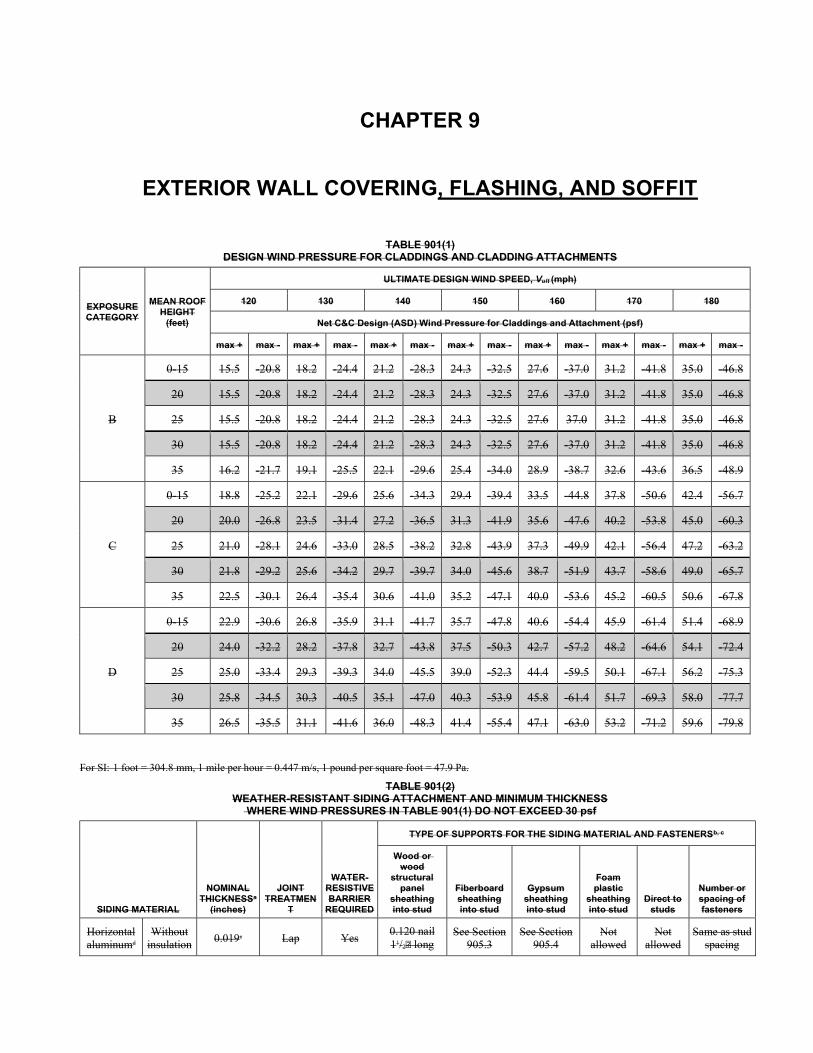
CHAPTER 9
EXTERIOR WALL COVERING, FLASHING, AND SOFFIT
TABLE 901(1) DESIGN WIND PRESSURE FOR CLADDINGS AND CLADDING ATTACHMENTS
EXPOSURE CATEGORY
MEAN ROOF HEIGHT
(feet)
ULTIMATE DESIGN WIND SPEED, Vult (mph)
120 130 140 150 160 170 180
Net C&C Design (ASD) Wind Pressure for Claddings and Attachment (psf)
max + max - max + max - max + max - max + max - max + max - max + max - max + max -
B
0-15 15.5 -20.8 18.2 -24.4 21.2 -28.3 24.3 -32.5 27.6 -37.0 31.2 -41.8 35.0 -46.8
20 15.5 -20.8 18.2 -24.4 21.2 -28.3 24.3 -32.5 27.6 -37.0 31.2 -41.8 35.0 -46.8
25 15.5 -20.8 18.2 -24.4 21.2 -28.3 24.3 -32.5 27.6 37.0 31.2 -41.8 35.0 -46.8
30 15.5 -20.8 18.2 -24.4 21.2 -28.3 24.3 -32.5 27.6 -37.0 31.2 -41.8 35.0 -46.8
35 16.2 -21.7 19.1 -25.5 22.1 -29.6 25.4 -34.0 28.9 -38.7 32.6 -43.6 36.5 -48.9
C
0-15 18.8 -25.2 22.1 -29.6 25.6 -34.3 29.4 -39.4 33.5 -44.8 37.8 -50.6 42.4 -56.7
20 20.0 -26.8 23.5 -31.4 27.2 -36.5 31.3 -41.9 35.6 -47.6 40.2 -53.8 45.0 -60.3
25 21.0 -28.1 24.6 -33.0 28.5 -38.2 32.8 -43.9 37.3 -49.9 42.1 -56.4 47.2 -63.2
30 21.8 -29.2 25.6 -34.2 29.7 -39.7 34.0 -45.6 38.7 -51.9 43.7 -58.6 49.0 -65.7
35 22.5 -30.1 26.4 -35.4 30.6 -41.0 35.2 -47.1 40.0 -53.6 45.2 -60.5 50.6 -67.8
D
0-15 22.9 -30.6 26.8 -35.9 31.1 -41.7 35.7 -47.8 40.6 -54.4 45.9 -61.4 51.4 -68.9
20 24.0 -32.2 28.2 -37.8 32.7 -43.8 37.5 -50.3 42.7 -57.2 48.2 -64.6 54.1 -72.4
25 25.0 -33.4 29.3 -39.3 34.0 -45.5 39.0 -52.3 44.4 -59.5 50.1 -67.1 56.2 -75.3
30 25.8 -34.5 30.3 -40.5 35.1 -47.0 40.3 -53.9 45.8 -61.4 51.7 -69.3 58.0 -77.7
35 26.5 -35.5 31.1 -41.6 36.0 -48.3 41.4 -55.4 47.1 -63.0 53.2 -71.2 59.6 -79.8
For SI: 1 foot = 304.8 mm, 1 mile per hour = 0.447 m/s, 1 pound per square foot = 47.9 Pa.
TABLE 901(2) WEATHER-RESISTANT SIDING ATTACHMENT AND MINIMUM THICKNESS
WHERE WIND PRESSURES IN TABLE 901(1) DO NOT EXCEED 30 psf
SIDING MATERIAL
NOMINAL THICKNESSa
(inches)
JOINT TREATMEN
T
WATER- RESISTIVE BARRIER
REQUIRED
TYPE OF SUPPORTS FOR THE SIDING MATERIAL AND FASTENERSb, c
Wood or wood
structural panel
sheathing into stud
Fiberboard sheathing into stud
Gypsum sheathing into stud
Foam plastic
sheathing into stud
Direct to studs
Number or spacing of fasteners
Horizontal aluminumd
Without insulation
0.019e Lap Yes 0.120 nail 11/2 long
See Section 905.3
See Section 905.4
Not allowed
Not allowed
Same as stud spacing
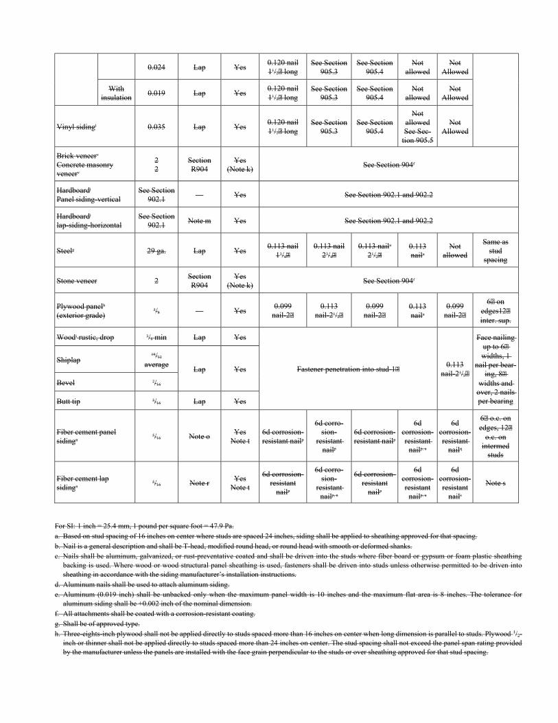
0.024 Lap Yes 0.120 nail 11/2 long
See Section 905.3
See Section 905.4
Not allowed
Not Allowed
With insulation
0.019 Lap Yes 0.120 nail 11/2 long
See Section 905.3
See Section 905.4
Not allowed
Not Allowed
Vinyl sidingl 0.035 Lap Yes 0.120 nail 11/2 long
See Section 905.3
See Section 905.4
Not allowed See Sec-
tion 905.5
Not Allowed
Brick veneerv
Concrete masonry veneerv
2 2
Section R904
Yes (Note k)
See Section 904f
Hardboardj
Panel siding-vertical See Section
902.1 — Yes See Section 902.1 and 902.2
Hardboardj
lap-siding-horizontal See Section
902.1 Note m Yes See Section 902.1 and 902.2
Steelg 29 ga. Lap Yes 0.113 nail
13/4 0.113 nail
23/4 0.113 nailu
21/2 0.113 nailu
Not allowed
Same as stud
spacing
Stone veneer 2 Section R904
Yes (Note k)
See Section 904f
Plywood panelh
(exterior grade) 3/8 — Yes
0.099 nail-2
0.113 nail-21/2
0.099 nail-2
0.113 nailu
0.099 nail-2
6 on edges12 inter. sup.
Woodi rustic, drop 3/8 min Lap Yes
Fastener penetration into stud-1 0.113
nail-21/2
Face nailing up to 6 widths, 1
nail per bear-ing, 8
widths and over, 2 nails per bearing
Shiplap 19/32
average Lap Yes
Bevel 7/16
Butt tip 3/16 Lap Yes
Fiber cement panel sidingn
5/16 Note o Yes
Note t 6d corrosion- resistant nailp
6d corro-sion-
resistant nailp
6d corrosion- resistant nailp
6d corrosion- resistant
nailp, u
6d corrosion- resistant
nailq
6 o.c. on edges, 12
o.c. on intermed
studs
Fiber cement lap sidingn
5/16 Note r Yes
Note t
6d corrosion- resistant
nailp
6d corro-sion-
resistant nailp, n
6d corrosion- resistant
nailp
6d corrosion- resistant
nailp, u
6d corrosion- resistant
nails
Note s
For SI: 1 inch = 25.4 mm, 1 pound per square foot = 47.9 Pa. a. Based on stud spacing of 16 inches on center where studs are spaced 24 inches, siding shall be applied to sheathing approved for that spacing. b. Nail is a general description and shall be T-head, modified round head, or round head with smooth or deformed shanks. c. Nails shall be aluminum, galvanized, or rust-preventative coated and shall be driven into the studs where fiber board or gypsum or foam plastic sheathing
backing is used. Where wood or wood structural panel sheathing is used, fasteners shall be driven into studs unless otherwise permitted to be driven into sheathing in accordance with the siding manufacturer’s installation instructions.
d. Aluminum nails shall be used to attach aluminum siding. e. Aluminum (0.019 inch) shall be unbacked only when the maximum panel width is 10 inches and the maximum flat area is 8 inches. The tolerance for
aluminum siding shall be +0.002 inch of the nominal dimension. f. All attachments shall be coated with a corrosion-resistant coating. g. Shall be of approved type. h. Three-eights-inch plywood shall not be applied directly to studs spaced more than 16 inches on center when long dimension is parallel to studs. Plywood 1/2-
inch or thinner shall not be applied directly to studs spaced more than 24 inches on center. The stud spacing shall not exceed the panel span rating provided by the manufacturer unless the panels are installed with the face grain perpendicular to the studs or over sheathing approved for that stud spacing.
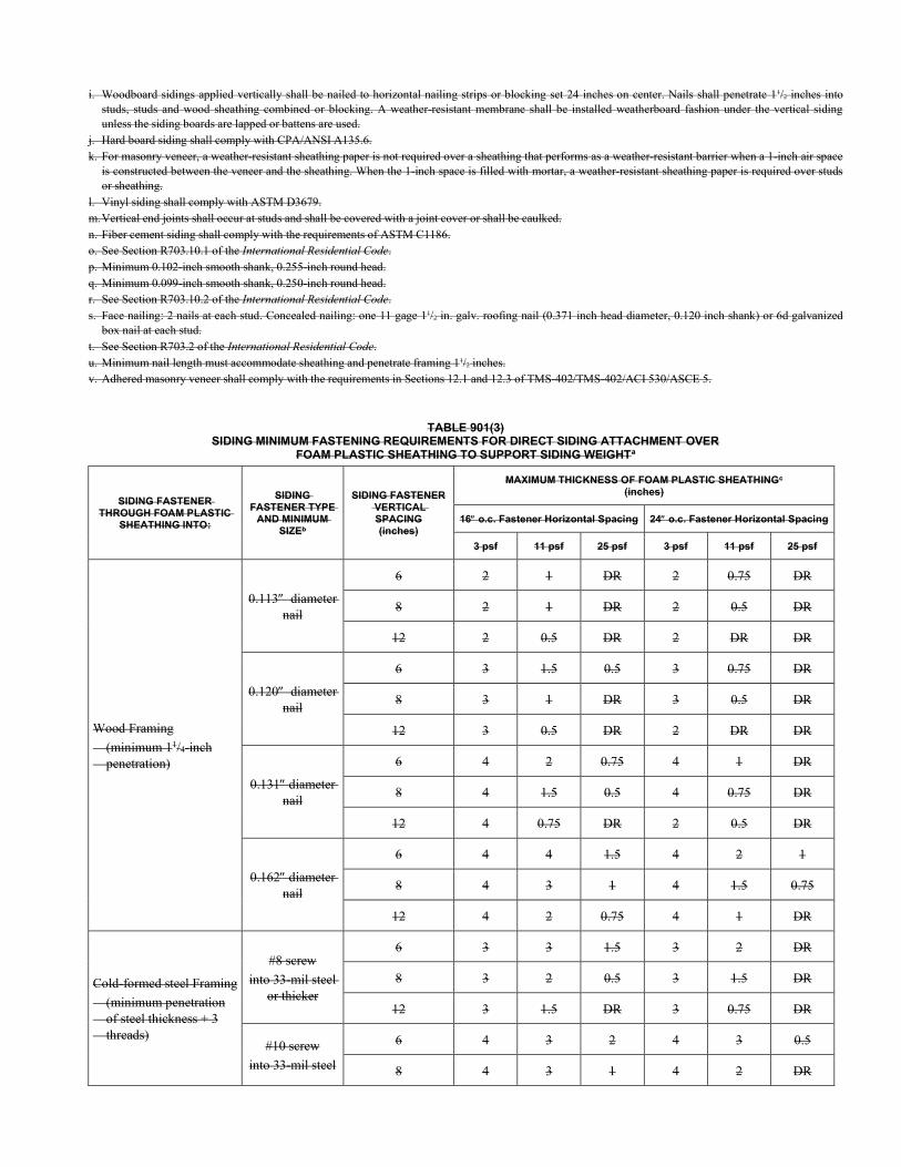
i. Woodboard sidings applied vertically shall be nailed to horizontal nailing strips or blocking set 24 inches on center. Nails shall penetrate 11/2 inches into studs, studs and wood sheathing combined or blocking. A weather-resistant membrane shall be installed weatherboard fashion under the vertical siding unless the siding boards are lapped or battens are used.
j. Hard board siding shall comply with CPA/ANSI A135.6. k. For masonry veneer, a weather-resistant sheathing paper is not required over a sheathing that performs as a weather-resistant barrier when a 1-inch air space
is constructed between the veneer and the sheathing. When the 1-inch space is filled with mortar, a weather-resistant sheathing paper is required over studs or sheathing.
l. Vinyl siding shall comply with ASTM D3679. m. Vertical end joints shall occur at studs and shall be covered with a joint cover or shall be caulked. n. Fiber cement siding shall comply with the requirements of ASTM C1186. o. See Section R703.10.1 of the International Residential Code. p. Minimum 0.102-inch smooth shank, 0.255-inch round head. q. Minimum 0.099-inch smooth shank, 0.250-inch round head. r. See Section R703.10.2 of the International Residential Code. s. Face nailing: 2 nails at each stud. Concealed nailing: one 11 gage 11/2 in. galv. roofing nail (0.371 inch head diameter, 0.120 inch shank) or 6d galvanized
box nail at each stud. t. See Section R703.2 of the International Residential Code. u. Minimum nail length must accommodate sheathing and penetrate framing 11/2 inches. v. Adhered masonry veneer shall comply with the requirements in Sections 12.1 and 12.3 of TMS-402/TMS-402/ACI 530/ASCE 5.
TABLE 901(3) SIDING MINIMUM FASTENING REQUIREMENTS FOR DIRECT SIDING ATTACHMENT OVER
FOAM PLASTIC SHEATHING TO SUPPORT SIDING WEIGHTa
SIDING FASTENER THROUGH FOAM PLASTIC
SHEATHING INTO:
SIDING FASTENER TYPE
AND MINIMUM SIZEb
SIDING FASTENER VERTICAL SPACING (inches)
MAXIMUM THICKNESS OF FOAM PLASTIC SHEATHINGc
(inches)
16 o.c. Fastener Horizontal Spacing 24 o.c. Fastener Horizontal Spacing
3 psf 11 psf 25 psf 3 psf 11 psf 25 psf
Wood Framing
(minimum 11/4-inch penetration)
0.113 diameter nail
6 2 1 DR 2 0.75 DR
8 2 1 DR 2 0.5 DR
12 2 0.5 DR 2 DR DR
0.120 diameter nail
6 3 1.5 0.5 3 0.75 DR
8 3 1 DR 3 0.5 DR
12 3 0.5 DR 2 DR DR
0.131 diameter nail
6 4 2 0.75 4 1 DR
8 4 1.5 0.5 4 0.75 DR
12 4 0.75 DR 2 0.5 DR
0.162 diameter nail
6 4 4 1.5 4 2 1
8 4 3 1 4 1.5 0.75
12 4 2 0.75 4 1 DR
Cold-formed steel Framing
(minimum penetration of steel thickness + 3 threads)
#8 screw
into 33-mil steel or thicker
6 3 3 1.5 3 2 DR
8 3 2 0.5 3 1.5 DR
12 3 1.5 DR 3 0.75 DR
#10 screw
into 33-mil steel
6 4 3 2 4 3 0.5
8 4 3 1 4 2 DR
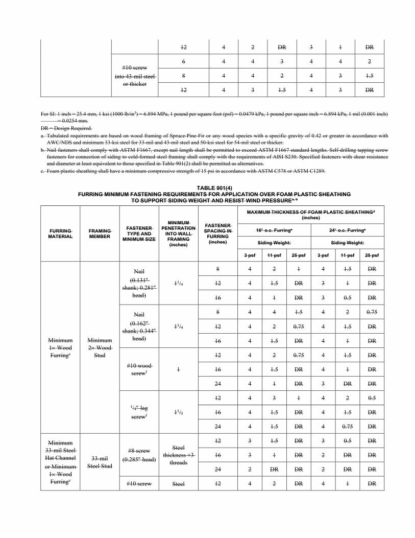
12 4 2 DR 3 1 DR
#10 screw
into 43-mil steel or thicker
6 4 4 3 4 4 2
8 4 4 2 4 3 1.5
12 4 3 1.5 4 3 DR
For SI: 1 inch = 25.4 mm, 1 ksi (1000 lb/in2) = 6.894 MPa, 1 pound per square foot (psf) = 0.0479 kPa, 1 pound per square inch = 6.894 kPa, 1 mil (0.001 inch) = 0.0254 mm. DR = Design Required. a. Tabulated requirements are based on wood framing of Spruce-Pine-Fir or any wood species with a specific gravity of 0.42 or greater in accordance with
AWC/NDS and minimum 33-ksi steel for 33-mil and 43-mil steel and 50-ksi steel for 54-mil steel or thicker. b. Nail fasteners shall comply with ASTM F1667, except nail length shall be permitted to exceed ASTM F1667 standard lengths. Self-drilling tapping screw
fasteners for connection of siding to cold-formed steel framing shall comply with the requirements of AISI S230. Specified fasteners with shear resistance and diameter at least equivalent to those specified in Table 901(2) shall be permitted as alternatives.
c. Foam plastic sheathing shall have a minimum compressive strength of 15 psi in accordance with ASTM C578 or ASTM C1289.
TABLE 901(4) FURRING MINIMUM FASTENING REQUIREMENTS FOR APPLICATION OVER FOAM PLASTIC SHEATHING
TO SUPPORT SIDING WEIGHT AND RESIST WIND PRESSUREa, b
FURRING MATERIAL
FRAMING MEMBER
FASTENER TYPE AND
MINIMUM SIZE
MINIMUM PENETRATION
INTO WALL FRAMING (inches)
FASTENER SPACING IN
FURRING (inches)
MAXIMUM THICKNESS OF FOAM PLASTIC SHEATHINGd
(inches)
16 o.c. Furringe 24 o.c. Furringe
Siding Weight: Siding Weight:
3 psf 11 psf 25 psf 3 psf 11 psf 25 psf
Minimum 1 Wood Furringc
Minimum 2 Wood
Stud
Nail
(0.131 shank; 0.281
head)
11/4
8 4 2 1 4 1.5 DR
12 4 1.5 DR 3 1 DR
16 4 1 DR 3 0.5 DR
Nail
(0.162 shank; 0.344
head)
11/4
8 4 4 1.5 4 2 0.75
12 4 2 0.75 4 1.5 DR
16 4 1.5 DR 4 1 DR
#10 wood screwf
1
12 4 2 0.75 4 1.5 DR
16 4 1.5 DR 4 1 DR
24 4 1 DR 3 DR DR
1/4 lag
screwf 11/2
12 4 3 1 4 2 0.5
16 4 1.5 DR 4 1.5 DR
24 4 1.5 DR 4 0.75 DR
Minimum 33-mil Steel Hat Channel
or Minimum 1 Wood Furringc
33-mil Steel Stud
#8 screw
(0.285 head)
Steel thickness +3
threads
12 3 1.5 DR 3 0.5 DR
16 3 1 DR 2 DR DR
24 2 DR DR 2 DR DR
#10 screw Steel 12 4 2 DR 4 1 DR
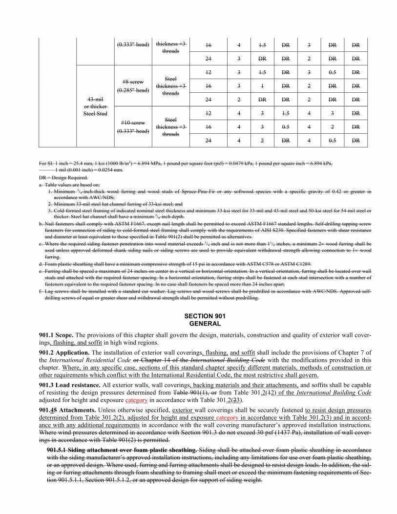
(0.333 head) thickness +3 threads
16 4 1.5 DR 3 DR DR
24 3 DR DR 2 DR DR
43-mil or thicker Steel Stud
#8 screw
(0.285 head)
Steel thickness +3
threads
12 3 1.5 DR 3 0.5 DR
16 3 1 DR 2 DR DR
24 2 DR DR 2 DR DR
#10 screw
(0.333 head)
Steel thickness +3
threads
12 4 3 1.5 4 3 DR
16 4 3 0.5 4 2 DR
24 4 2 DR 4 0.5 DR
For SI: 1 inch = 25.4 mm, 1 ksi (1000 lb/in2) = 6.894 MPa, 1 pound per square foot (psf) = 0.0479 kPa, 1 pound per square inch = 6.894 kPa, 1 mil (0.001 inch) = 0.0254 mm.
DR = Design Required. a. Table values are based on:
1. Minimum 3/4-inch-thick wood furring and wood studs of Spruce-Pine-Fir or any softwood species with a specific gravity of 0.42 or greater in accordance with AWC/NDS;
2. Minimum 33-mil steel hat channel furring of 33-ksi steel; and 3. Cold-formed steel framing of indicated nominal steel thickness and minimum 33-ksi steel for 33-mil and 43-mil steel and 50-ksi steel for 54-mil steel or
thicker. Steel hat channel shall have a minimum 7/8-inch depth. b. Nail fasteners shall comply with ASTM F1667, except nail length shall be permitted to exceed ASTM F1667 standard lengths. Self-drilling tapping screw
fasteners for connection of siding to cold-formed steel framing shall comply with the requirements of AISI S230. Specified fasteners with shear resistance and diameter at least equivalent to those specified in Table 901(2) shall be permitted as alternatives.
c. Where the required siding fastener penetration into wood material exceeds 3/4 inch and is not more than 11/2 inches, a minimum 2 wood furring shall be used unless approved deformed shank siding nails or siding screws are used to provide equivalent withdrawal strength allowing connection to 1 wood furring.
d. Foam plastic sheathing shall have a minimum compressive strength of 15 psi in accordance with ASTM C578 or ASTM C1289. e. Furring shall be spaced a maximum of 24 inches on center in a vertical or horizontal orientation. In a vertical orientation, furring shall be located over wall
studs and attached with the required fastener spacing. In a horizontal orientation, furring strips shall be fastened at each stud intersection with a number of fasteners equivalent to the required fastener spacing. In no case shall fasteners be spaced more than 24 inches apart.
f. Lag screws shall be installed with a standard cut washer. Lag screws and wood screws shall be predrilled in accordance with AWC/NDS. Approved self-drilling screws of equal or greater shear and withdrawal strength shall be permitted without predrilling.
SECTION 901 GENERAL
901.1 Scope. The provisions of this chapter shall govern the design, materials, construction and quality of exterior wall cover-ings, flashing, and soffit in high wind regions.
901.2 Application. The installation of exterior wall coverings, flashing, and soffit shall include the provisions of Chapter 7 of the International Residential Code or Chapter 14 of the International Building Code with the modifications provided in this chapter. Where, in any specific case, sections of this standard chapter specify different materials, methods of construction or other requirements which conflict with the International Residential Code, the most restrictive shall govern.
901.3 Load resistance. All exterior walls, wall coverings, backing materials and their attachments, and soffits shall be capable of resisting the design pressures determined from Table 901(1), or from Table 301.2(12) of the International Building Code adjusted for height and exposure category in accordance with Table 301.2(23).
901.45 Attachments. Unless otherwise specified, exterior wall coverings shall be securely fastened to resist design pressures determined from Table 301.2(2), adjusted for height and exposure category in accordance with Table 301.2(3) and in accord-ance with any additional requirements in accordance with the wall covering manufacturer’s approved installation instructions. Where wind pressures determined in accordance with Section 901.3 do not exceed 30 psf (1437 Pa), installation of wall cover-ings in accordance with Table 901(2) is permitted.
901.5.1 Siding attachment over foam plastic sheathing. Siding shall be attached over foam plastic sheathing in accordance with the siding manufacturer’s approved installation instructions, including any limitations for use over foam plastic sheathing, or an approved design. Where used, furring and furring attachments shall be designed to resist design loads. In addition, the sid-ing or furring attachments through foam sheathing to framing shall meet or exceed the minimum fastening requirements of Sec-tion 901.5.1.1, Section 901.5.1.2, or an approved design for support of siding weight.
901.5.1.1 Siding attachment. Siding installed directly over foam plastic sheathing shall comply with Table 901(3) in re-gard to minimum fastening requirements and maximum foam plastic sheathing thickness limitations to support siding weight. The siding fastener and siding installation shall otherwise comply with this standard and shall not result in a less stringent fastening requirement than required by Section 901.5 or the manufacturer’s installation instructions for the spe-cific siding material used.
Exception: For exterior insulation and finish systems, refer to Section 906.
901.5.1.2 Furred siding attachment. When furring is used over foam plastic sheathing, the siding shall be attached in accordance with Section 901.5 to minimum 1-inch by 3-inch (25 mm by 76 mm) wood or minimum 33-mil steel hat channel furring placed over the foam plastic sheathing. Furring shall be attached through the foam plastic sheathing to wall framing in accordance with Table 901(4) in regard to minimum fastening requirements and maximum foam plastic sheathing thickness limitations to support siding dead load. For 25 psf (1198 Pa) siding weight in accordance with Table 901(4), the seismic design category shall not exceed D0 for 16 inches on center furring or C for 24 inches on center fur-ring. When placed horizontally over foam plastic sheathing, wood furring shall be preservative-treated wood or naturally durable wood and fasteners shall be corrosion resistant in accordance with Section R317 of the International Residential Code. Steel hat channel furring shall have a minimum G60 galvanized coating.
SECTION 902
SECTION 902
Wall Coverings
902.1 Wood, hardboard and wood structural panel siding. Wood, hardboard and wood structural panel siding shall comply with R703.5 of the International Residential Code.
902.1.1 Wood, hardboard and wood structural panel siding. In areas with design wind speeds less than 140 mph (63 m/s), wood, hardboard, and wood structural panel siding and their attachment shall comply with R703.5 of the In-ternational Residential Code. In areas with design winds speeds of 140 mph (63 m/s) or greater, wood, hardboard, and wood structural panel siding and their attachment shall comply with the WFCM or shall be designed.
902.2 Wood shakes and shingles. Wood shakes and shingles shall comply with R703.6 of the International Residential Code.
902.2.1 Wood shakes and shingles. In areas with design wind speeds less than 140 mph (63 m/s), wood shakes and shingles and their attachment shall comply with R703.6 of the International Residential Code. In areas with design winds speeds of 140 mph (63 m/s) or greater, wood shakes and shingles and their attachment shall be designed.
902.3 Exterior plaster (stucco). Exterior plaster (stucco) shall comply with R703.7 of the International Residential Code.
902.3.1 Exterior plaster (stucco). In areas with design wind speeds less than 140 mph (63 m/s), exterior plaster and its attachment shall comply with R703.7 of the International Residential Code. In areas with design winds speeds of 140 mph (63 m/s) or greater, exterior plaster and its attachment shall be designed.
Exception: Exterior plaster bonded directly to masonry or concrete backing without the use of lath shall not require design.
902.4 Anchored stone and masonry veneer. Anchored stone and masonry veneer shall comply with the requirements of R703.8 of the International Residential Code except as follows:
902.4.1 Design wind speeds less than 140 mph. In areas with design wind speeds less than 140 mph (63 m/s), the at-tachment of anchored stone and masonry veneer shall comply with R703.8.4.1 of the International Residential Code.
902.4.2 Design wind speeds greater than 140 mph and less than 170 mph. In areas with design wind speeds greater than 140 mph (63 m/s) and less than 170 mph (76 m/s), the attachment of anchored stone and masonry veneer shall comply with R703.8.4.1 of the International Residential Code modified as follows:
902.4.2.1 Ties. Each tie shall support not more than 1.78 ft2 (0.165 m2) of wall area and shall be spaced not more than 16 in. (406 mm) on center horizontally and vertically.
902.4.2.2 Metal ties. Metal ties around the perimeter of openings shall be spaced not more than 2 feet (635 mm) on center.
902.4.3 Design winds speeds of 170 mph or greater. In areas with design winds speeds of 170 mph (76 m/s) or greater, anchored stone and masonry veneer and their attachment shall be designed.
902.5 Exterior insulation and finish system (EIFS). Exterior insulation and finish system (EIFS) shall comply with R703.9 of the International Residential Code.
902.5.1 Exterior insulation and finish system (EIFS). In areas with design wind speeds less than 140 mph (63 m/s), an EIFS and its attachment shall comply with R703.9 of the International Residential Code. In areas with design winds speeds of 140 mph (63 m/s) or greater, an EIFS and its attachment shall be designed.
902.6 Fiber cement siding. Fiber cement siding shall comply with R703.10 of the International Residential Code.
902.6.1 Fiber cement siding. In areas with design wind speeds less than 140 mph (63 m/s), fiber cement siding and its attachment shall comply with R703.10 of the International Residential Code. In areas with design winds speeds of 140 mph (63 m/s) or greater, fiber cement siding and its attachment shall be designed.
902.7 Vinyl siding. Vinyl siding shall comply with R703.11 of the International Residential Code.
902.7.1 Vinyl siding. In areas with design wind speeds less than 140 mph (63 m/s), vinyl siding and its attachment shall comply with R703.11 of the International Residential Code. In areas with design winds speeds of 140 mph (63 m/s) or greater, vinyl siding and its attachment shall be designed.
905.4 902.7.2 Gypsum sheathing behind horizontal vinyl siding and aluminum siding. In areas with design wind speeds less than 140 mph (63 m/s), and Where walls are clad with gypsum sheathing behind aluminum or vinyl siding, the gypsum sheathing shall be not less than 5/8-inch-thick (16 mm) gypsum sheathing. Installation is limited to areas where wind pressures determined in accordance with Section 901.3 do not exceed 30 psf (1437 Pa). Material shall be fastened using 13/4-inch-long (45 mm) 11 gage galvanized roofing nails or 11/4-inch-long (36 mm) Type S-12 screws spaced at 8 inches (203 mm) on center at edges, ends and intermediate framing members. Studs shall be spaced not more than 16 inches (406 mm) on center. Steel framing members shall be minimum 43 mils [18 gage (1.1 mm)] mate-rial. In areas with design winds speeds 140 mph (63 m/s) or greater, gypsum sheathing behind horizontal vinyl siding and its attachment shall be designed accordingly.
902.7.3 Installation over foam plastic insulating sheathing. Where installed over foam plastic insulating sheathing, vinyl siding installation shall comply with Section R703.11.2 of the IRC.
902.8 Adhered masonry veneer. Adhered masonry veneer installation shall comply with R703.12 of the IRC.
902.8.1 Adhered masonry veneer. In areas with design wind speeds less than 140 mph (63 m/s), adhered masonry veneer and its attachment shall comply with R703.12 of the International Residential Code. In areas with design winds speeds of 140 mph (63 m/s) or greater, adhered veneer and its attachment shall be designed.
Exception: Adhered veneer bonded directly to masonry or concrete backing without the use of lath shall not require design.
902.9 Insulated vinyl siding. In areas with design wind speeds less than 140 mph (63 m/s), insulated vinyl siding and its at-tachment shall comply with R703.13 of the International Residential Code. In areas with design winds speeds of 140 mph (63 m/s) or greater, insulated vinyl siding and its attachment shall be designed.
902.10 Polypropylene siding. In areas with design wind speeds less than 140 mph (63 m/s), polypropylene siding and its at-tachment shall comply with R703.14 of the International Residential Code. In areas with design winds speeds of 140 mph (63 m/s) or greater, polypropylene siding and its attachment shall be designed.
SECTION 904 Masonry Veneer
904.1 902.10 Masonry Veneer Scope. These provisions apply to anchored masonry veneers attached to backing systems that have been designed to resist all the wind loading on the veneer. Figure 904 shows the application of masonry veneer to a one- or two-story concrete or masonry wall, for buildings with slab-on-grade foundation. For buildings with masonry veneer on light-frame stud walls, see Figure R703.8 of the International Residential Code. Veneer ties shall be installed in accordance with Section 12.2 of TMS 402. Use Table 9042.10 for metal tie thickness and spacing. A water-resistant barrier shall be applied between the masonry or concrete wall and the masonry veneer. Design wind pressures for Sections 904.2 and 904.3 shall be determined from Section 901.3.
904.2 902.10.1 Nominal design wind pressure not more than 24 psf [40 psf ultimate]. Where the nominal design wind pressure does not exceed 24 psf (1.15 kPa) [40 psf (1.92 kPa) ultimate design wind pressure], the provisions de-scribed in Sections 12.1 and 12.2 of the TMS 402/ACI 530/ASCE 5 for anchored veneers shall apply, with spacing and tie tributary area requirements as applicable for the design wind pressure under consideration.
904.3 902.10.2 Nominal design wind pressure greater than 24 psf [40 psf ultimate]. Where the nominal design wind pressure exceeds 24 psf (1.15 kPa) [40 psf (1.92 kPa) ultimate design wind pressure] but does not exceed 33 psf
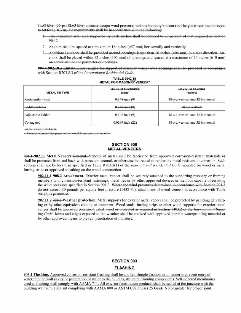
(1.58 kPa) [55 psf (2.63 kPa) ultimate design wind pressure] and the building’s mean roof height is less than or equal to 60 feet (18.3 m), tie requirements shall be in accordance with the following:
1. The maximum wall area supported by each anchor shall be reduced to 70 percent of that required in Section 904.2.
2. Anchors shall be spaced at a maximum 18 inches (457 mm) horizontally and vertically.
3. Additional anchors shall be provided around openings larger than 16 inches (406 mm) in either direction. An-chors shall be placed within 12 inches (305 mm) of openings and spaced at a maximum of 24 inches (610 mm) on center around the perimeter of openings.
904.4 902.10.3 Lintels. Lintel angles for support of masonry veneer over openings shall be provided in accordance with Section R703.8.3 of the International Residential Code.
TABLE 9042.10 METAL FOR MASONRY VENEERa
METAL TIE TYPE MINIMUM THICKNESS
(gage) MAXIMUM SPACING
(inches)
Rectangular (box) 0.148 inch (9) 18 o.c. vertical and 32 horizontal
Ladder or truss 0.148 inch (9) 18 o.c. vertical
Adjustable ladder 0.148 inch (9) 18 o.c. vertical and 32 horizontal
Corrugated 0.0299 inch (22) 18 o.c. vertical and 32 horizontal
For SI: 1 inch = 25.4 mm. a. Corrugated metal ties permitted on wood frame construction only.
SECTION 908 METAL VENEERS
908.1 902.11 Metal Veneers.General. Veneers of metal shall be fabricated from approved corrosion-resistant materials or shall be protected front and back with porcelain enamel, or otherwise be treated to render the metal resistant to corrosion. Such veneers shall not be less than specified in Table R703.3(1) of the International Residential Code mounted on wood or metal furring strips or approved sheathing on the wood construction.
902.11.1 908.2 Attachment. Exterior metal veneer shall be securely attached to the supporting masonry or framing members with corrosion-resistant fastenings, metal ties or by other approved devices or methods capable of resisting the wind pressures specified in Section 901.3. Where the wind pressures determined in accordance with Section 901.3 do not exceed 30 pounds per square foot pressure (1438 Pa), attachment of metal veneers in accordance with Table 901(2) is permitted.
902.11.2 908.3 Weather protection. Metal supports for exterior metal veneer shall be protected by painting, galvaniz-ing or by other equivalent coating or treatment. Wood studs, furring strips or other wood supports for exterior metal veneer shall be approved pressure-treated wood or protected as required in Section 1403.2 of the International Build-ing Code. Joints and edges exposed to the weather shall be caulked with approved durable waterproofing material or by other approved means to prevent penetration of moisture.
SECTION 903
FLASHING
903.1 Flashing. Approved corrosion-resistant flashing shall be applied shingle-fashion in a manner to prevent entry of water into the wall cavity or penetration of water to the building structural framing components. Self-adhered membranes used as flashing shall comply with AAMA 711. All exterior fenestration products shall be sealed at the juncture with the building wall with a sealant complying with AAMA 800 or ASTM C920 Class 25 Grade NS or greater for proper joint
expansion and contraction, ASTM C1281, AAMA 812, or other approved standard as appropriate for the type of sealant. Fluid-applied membranes used as flashing in exterior walls shall comply with AAMA 714. The flashing shall extend to the surface of the exterior wall finish. Approved corrosion-resistant flashings shall be installed at the following locations:
1. Exterior window and door openings. 2. At the intersection of chimneys or other masonry construction with frame or stucco walls, with projecting lips on both
sides under stucco copings. 3. Under and at the ends of masonry, wood or metal copings and sills. 4. Continuously above all projecting wood trim. 5. Where exterior porches, decks or stairs attach to a wall or floor assembly of wood-frame construction. 6. At wall and roof intersections. 7. At built-in gutters.
Flashing at exterior window and door openings shall extend to the surface of the exterior wall finish or to the water-resistive barrier complying with Section 703.2 of the International Residential Code for subsequent drainage. Mechanically attached flexible flashings shall comply with AAMA 712. Flashing at exterior window and door openings shall be installed in accordance with one or more of the following:
1. The fenestration manufacturer’s installation and flashing instructions, or for applications not addressed in the fenestration manufacturer’s instructions, in accordance with the flashing manufacturer’s instructions. Where flashing instructions or details are not provided, pan flashing shall be installed at the sill of exterior window and door openings. Pan flashing shall be sealed or sloped in such a manner as to direct water to the surface of the exterior wall finish or to the water-resistive barrier for subsequent drainage. Openings using pan flashing shall incorporate flashing or protection at the head and sides.
2. In accordance with the flashing design or method of a registered design professional. 3. In accordance with other approved methods.
a. In accordance with FMA/AAMA 100, FMA/AAMA 200, FMA/WDMA 250, FMA/AAMA/WDMA 300 or FMA/AAMA/WDMA 400.
Section 904
SOFFIT
904.1 Soffit. Soffits shall comply with Section R703.3.1 of the International Residential Code.
901.3.1 Soffits. All exterior soffits and soffit systems shall be capable of resisting the component and cladding design pres-sures for adjacent walls. The component and cladding positive and negative pressures shall be based on an effective wind area of 10 square feet (0.93 m2) for the wall located below the soffit.
901.4 Water-resistive barrier. One layer of No. 15 asphalt felt or other approved water-resistive barrier shall be applied over studs or sheathing of all exterior walls in accordance with Section R703.2 of the International Residential Code.
WOOD, HARDBOARD AND WOOD
STRUCTURAL PANEL SIDING/SHEATHING
TABLE 902(1) MINIMUM THICKNESS OF WOOD, HARDBOARD, FIBERBOARD, AND WOOD STRUCTURAL PANEL SHEATHING/SIDING
700-YEAR BASIC WIND SPEED (mph)
120 130 140 150 160 170 180
Wood Structural Panel and Hardboard Panel Sheathing/Siding
(Strength Axis Parallel to Studs)
Exposure Category Stud Spacing (inches o.c.)
Minimum Panel Thickness (inches)
B
12 3/8 3/8 3/8 3/8 3/8 3/8 3/8
16 3/8 3/8 3/8 7/16 15/32 15/32 15/32
24 15/32 19/32 19/32 19/32 19/32 23/32 23/32
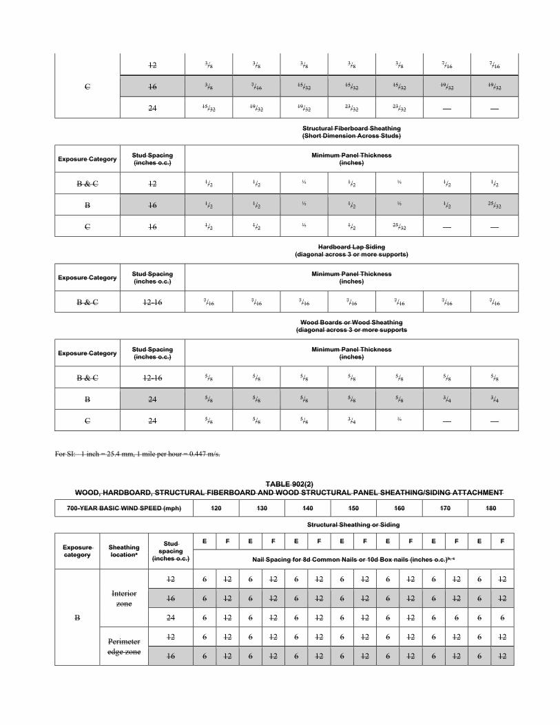
C
12 3/8 3/8 3/8 3/8 3/8 7/16 7/16
16 3/8 7/16 15/32 15/32 15/32 19/32 19/32
24 15/32 19/32 19/32 23/32 23/32 — —
Structural Fiberboard Sheathing (Short Dimension Across Studs)
Exposure Category Stud Spacing (inches o.c.)
Minimum Panel Thickness (inches)
B & C 12 1/2 1/2 ½ 1/2 ½ 1/2 1/2
B 16 1/2 1/2 ½ 1/2 ½ 1/2 25/32
C 16 1/2 1/2 ½ 1/2 25/32 — —
Hardboard Lap Siding
(diagonal across 3 or more supports)
Exposure Category Stud Spacing (inches o.c.)
Minimum Panel Thickness (inches)
B & C 12-16 7/16 7/16 7/16 7/16 7/16 7/16 7/16
Wood Boards or Wood Sheathing
(diagonal across 3 or more supports
Exposure Category Stud Spacing (inches o.c.)
Minimum Panel Thickness (inches)
B & C 12-16 5/8 5/8 5/8 5/8 5/8 5/8 5/8
B 24 5/8 5/8 5/8 5/8 5/8 3/4 3/4
C 24 5/8 5/8 5/8 3/4 ¾ — —
For SI: 1 inch = 25.4 mm, 1 mile per hour = 0.447 m/s.
TABLE 902(2) WOOD, HARDBOARD, STRUCTURAL FIBERBOARD AND WOOD STRUCTURAL PANEL SHEATHING/SIDING ATTACHMENT
700-YEAR BASIC WIND SPEED (mph) 120 130 140 150 160 170 180
Structural Sheathing or Siding
Exposure category
Sheathing locationa
Stud spacing
(inches o.c.)
E F E F E F E F E F E F E F
Nail Spacing for 8d Common Nails or 10d Box nails (inches o.c.)b, c
B
Interior zone
12 6 12 6 12 6 12 6 12 6 12 6 12 6 12
16 6 12 6 12 6 12 6 12 6 12 6 12 6 12
24 6 12 6 12 6 12 6 12 6 12 6 6 6 6
Perimeter edge zone
12 6 12 6 12 6 12 6 12 6 12 6 12 6 12
16 6 12 6 12 6 12 6 12 6 12 6 12 6 12
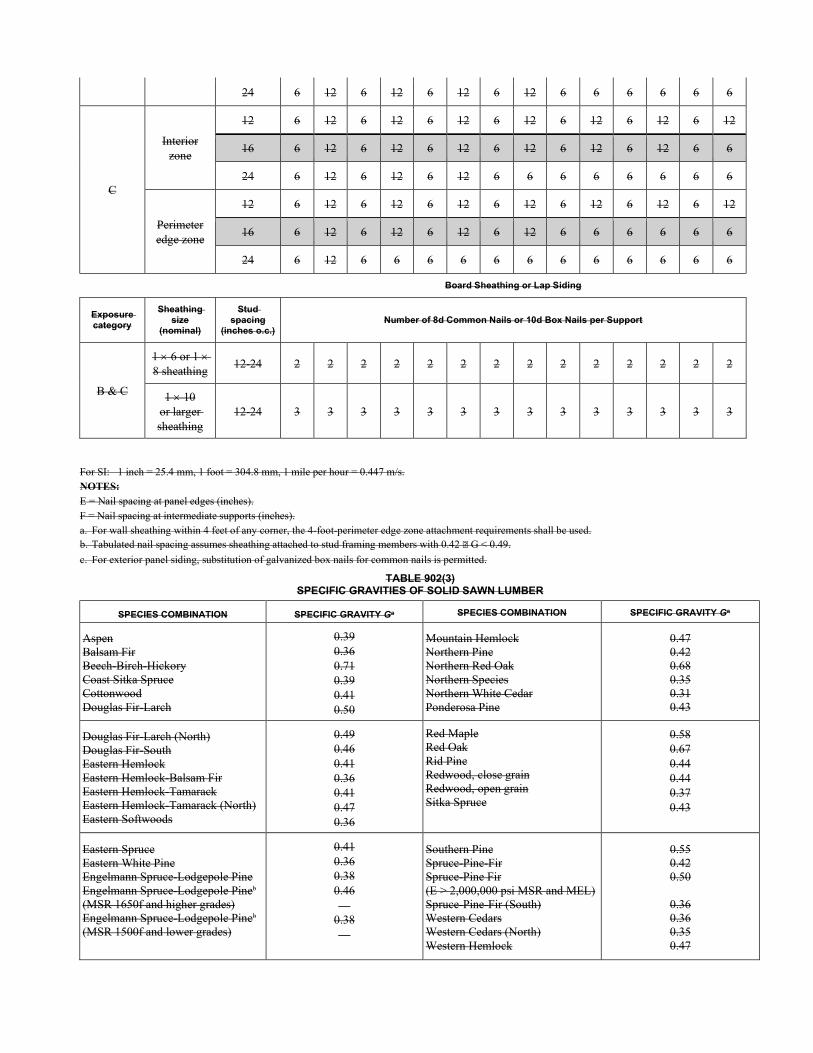
24 6 12 6 12 6 12 6 12 6 6 6 6 6 6
C
Interior zone
12 6 12 6 12 6 12 6 12 6 12 6 12 6 12
16 6 12 6 12 6 12 6 12 6 12 6 12 6 6
24 6 12 6 12 6 12 6 6 6 6 6 6 6 6
Perimeter edge zone
12 6 12 6 12 6 12 6 12 6 12 6 12 6 12
16 6 12 6 12 6 12 6 12 6 6 6 6 6 6
24 6 12 6 6 6 6 6 6 6 6 6 6 6 6
Board Sheathing or Lap Siding
Exposure category
Sheathing size
(nominal)
Stud spacing
(inches o.c.) Number of 8d Common Nails or 10d Box Nails per Support
B & C
1 6 or 1 8 sheathing
12-24 2 2 2 2 2 2 2 2 2 2 2 2 2 2
1 10 or larger sheathing
12-24 3 3 3 3 3 3 3 3 3 3 3 3 3 3
For SI: 1 inch = 25.4 mm, 1 foot = 304.8 mm, 1 mile per hour = 0.447 m/s. NOTES: E = Nail spacing at panel edges (inches). F = Nail spacing at intermediate supports (inches). a. For wall sheathing within 4 feet of any corner, the 4-foot-perimeter edge zone attachment requirements shall be used. b. Tabulated nail spacing assumes sheathing attached to stud framing members with 0.42 G < 0.49.
c. For exterior panel siding, substitution of galvanized box nails for common nails is permitted.
TABLE 902(3) SPECIFIC GRAVITIES OF SOLID SAWN LUMBER
SPECIES COMBINATION SPECIFIC GRAVITY Ga SPECIES COMBINATION SPECIFIC GRAVITY Ga
Aspen Balsam Fir Beech-Birch-Hickory Coast Sitka Spruce Cottonwood Douglas Fir-Larch
0.39 0.36 0.71 0.39 0.41 0.50
Mountain Hemlock Northern Pine Northern Red Oak Northern Species Northern White Cedar Ponderosa Pine
0.47 0.42 0.68 0.35 0.31 0.43
Douglas Fir-Larch (North) Douglas Fir-South Eastern Hemlock Eastern Hemlock-Balsam Fir Eastern Hemlock-Tamarack Eastern Hemlock-Tamarack (North) Eastern Softwoods
0.49 0.46 0.41 0.36 0.41 0.47 0.36
Red Maple Red Oak Rid Pine Redwood, close grain Redwood, open grain Sitka Spruce
0.58 0.67 0.44 0.44 0.37 0.43
Eastern Spruce Eastern White Pine Engelmann Spruce-Lodgepole Pine Engelmann Spruce-Lodgepole Pineb
(MSR 1650f and higher grades) Engelmann Spruce-Lodgepole Pineb
(MSR 1500f and lower grades)
0.41 0.36 0.38 0.46 —
0.38 —
Southern Pine Spruce-Pine-Fir Spruce-Pine Fir (E > 2,000,000 psi MSR and MEL) Spruce-Pine-Fir (South) Western Cedars Western Cedars (North) Western Hemlock
0.55 0.42 0.50
0.36 0.36 0.35 0.47
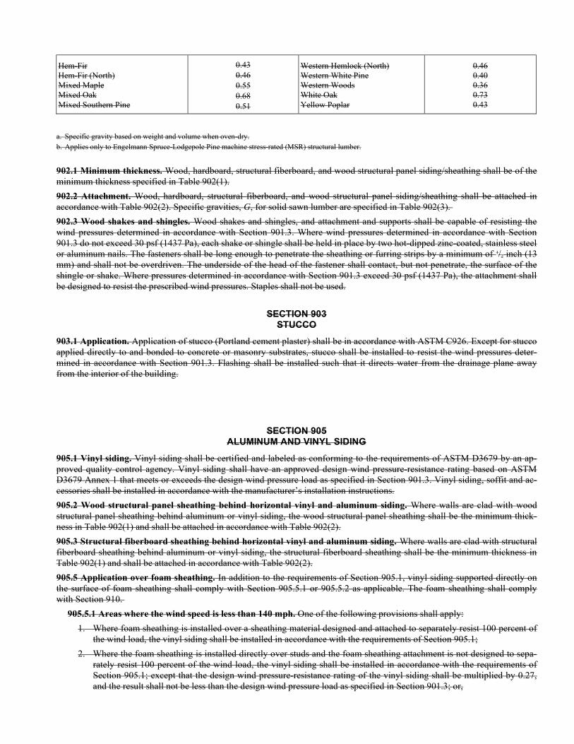
Hem-Fir Hem-Fir (North) Mixed Maple Mixed Oak Mixed Southern Pine
0.43 0.46 0.55 0.68 0.51
Western Hemlock (North) Western White Pine Western Woods White Oak Yellow Poplar
0.46 0.40 0.36 0.73 0.43
a. Specific gravity based on weight and volume when oven-dry. b. Applies only to Engelmann Spruce-Lodgepole Pine machine stress-rated (MSR) structural lumber.
902.1 Minimum thickness. Wood, hardboard, structural fiberboard, and wood structural panel siding/sheathing shall be of the minimum thickness specified in Table 902(1).
902.2 Attachment. Wood, hardboard, structural fiberboard, and wood structural panel siding/sheathing shall be attached in accordance with Table 902(2). Specific gravities, G, for solid sawn lumber are specified in Table 902(3).
902.3 Wood shakes and shingles. Wood shakes and shingles, and attachment and supports shall be capable of resisting the wind pressures determined in accordance with Section 901.3. Where wind pressures determined in accordance with Section 901.3 do not exceed 30 psf (1437 Pa), each shake or shingle shall be held in place by two hot-dipped zinc-coated, stainless steel or aluminum nails. The fasteners shall be long enough to penetrate the sheathing or furring strips by a minimum of 1/2 inch (13 mm) and shall not be overdriven. The underside of the head of the fastener shall contact, but not penetrate, the surface of the shingle or shake. Where pressures determined in accordance with Section 901.3 exceed 30 psf (1437 Pa), the attachment shall be designed to resist the prescribed wind pressures. Staples shall not be used.
SECTION 903 STUCCO
903.1 Application. Application of stucco (Portland cement plaster) shall be in accordance with ASTM C926. Except for stucco applied directly to and bonded to concrete or masonry substrates, stucco shall be installed to resist the wind pressures deter-mined in accordance with Section 901.3. Flashing shall be installed such that it directs water from the drainage plane away from the interior of the building.
SECTION 905 ALUMINUM AND VINYL SIDING
905.1 Vinyl siding. Vinyl siding shall be certified and labeled as conforming to the requirements of ASTM D3679 by an ap-proved quality control agency. Vinyl siding shall have an approved design wind pressure-resistance rating based on ASTM D3679 Annex 1 that meets or exceeds the design wind pressure load as specified in Section 901.3. Vinyl siding, soffit and ac-cessories shall be installed in accordance with the manufacturer’s installation instructions.
905.2 Wood structural panel sheathing behind horizontal vinyl and aluminum siding. Where walls are clad with wood structural panel sheathing behind aluminum or vinyl siding, the wood structural panel sheathing shall be the minimum thick-ness in Table 902(1) and shall be attached in accordance with Table 902(2).
905.3 Structural fiberboard sheathing behind horizontal vinyl and aluminum siding. Where walls are clad with structural fiberboard sheathing behind aluminum or vinyl siding, the structural fiberboard sheathing shall be the minimum thickness in Table 902(1) and shall be attached in accordance with Table 902(2).
905.5 Application over foam sheathing. In addition to the requirements of Section 905.1, vinyl siding supported directly on the surface of foam sheathing shall comply with Section 905.5.1 or 905.5.2 as applicable. The foam sheathing shall comply with Section 910.
905.5.1 Areas where the wind speed is less than 140 mph. One of the following provisions shall apply: 1. Where foam sheathing is installed over a sheathing material designed and attached to separately resist 100 percent of
the wind load, the vinyl siding shall be installed in accordance with the requirements of Section 905.1; 2. Where the foam sheathing is installed directly over studs and the foam sheathing attachment is not designed to sepa-
rately resist 100 percent of the wind load, the vinyl siding shall be installed in accordance with the requirements of Section 905.1; except that the design wind pressure-resistance rating of the vinyl siding shall be multiplied by 0.27, and the result shall not be less than the design wind pressure load as specified in Section 901.3; or,
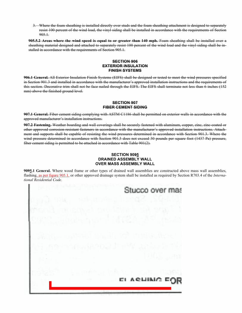
3. Where the foam sheathing is installed directly over studs and the foam sheathing attachment is designed to separately resist 100 percent of the wind load, the vinyl siding shall be installed in accordance with the requirements of Section 905.1.
905.5.2 Areas where the wind speed is equal to or greater than 140 mph. Foam sheathing shall be installed over a sheathing material designed and attached to separately resist 100 percent of the wind load and the vinyl siding shall be in-stalled in accordance with the requirements of Section 905.1.
SECTION 906 EXTERIOR INSULATION
FINISH SYSTEMS
906.1 General. All Exterior Insulation Finish Systems (EIFS) shall be designed or tested to meet the wind pressures specified in Section 901.3 and installed in accordance with the manufacturer’s approved installation instructions and the requirements of this section. Decorative trim shall not be face nailed through the EIFS. The EIFS shall terminate not less than 6 inches (152 mm) above the finished ground level.
SECTION 907 FIBER CEMENT SIDING
907.1 General. Fiber cement siding complying with ASTM C1186 shall be permitted on exterior walls in accordance with the approved manufacturer’s installation instructions.
907.2 Fastening. Weather boarding and wall coverings shall be securely fastened with aluminum, copper, zinc, zinc-coated or other approved corrosion-resistant fasteners in accordance with the manufacturer’s approved installation instructions. Attach-ment and supports shall be capable of resisting the wind pressures determined in accordance with Section 901.3. Where the wind pressure determined in accordance with Section 901.3 does not exceed 30 pounds per square foot (1437 Pa) pressure, fiber cement siding is permitted to be attached in accordance with Table 901(2).
SECTION 9095 DRAINED ASSEMBLY WALL
OVER MASS ASSEMBLY WALL
9095.1 General. Where wood frame or other types of drained wall assemblies are constructed above mass wall assemblies, flashing, as per figure 905.1, or other approved drainage system shall be installed as required by Section R703.4 of the Interna-tional Residential Code.
FIGURE 905.1 FLASHING FOR DRAINED WALL ASSEMBLY OVER MASS WALL ASSEMBLY

SECTION 91006 FOAM PLASTIC INSULATING SHEATHING
91006.1 General. Foam plastic insulating sheathing and claddings shall comply with Section R316 of the International Resi-dential Code, SBCA ANSI/FS 100 and the manufacturer’s installation instructions.
906.2 Cladding and furring over foam plastic insulating sheathing. 910.2 Cladding installation. Cladding and furring, where included, shall be installed over foam plastic insulating sheathing in accordance with the more stringent fastening re-quirement of Section R703.15, R703.16, or R703.17 of the International Residential Code and the applicable cladding material attachment for wind load resistance.

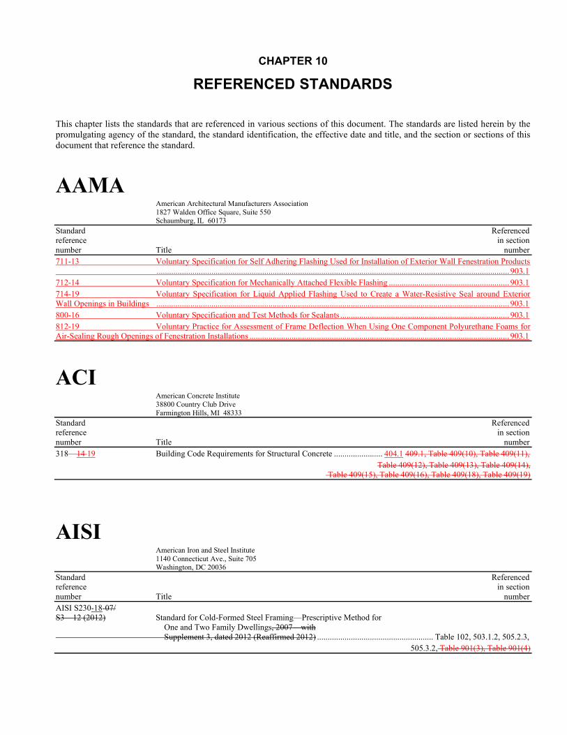
CHAPTER 10
REFERENCED STANDARDS
This chapter lists the standards that are referenced in various sections of this document. The standards are listed herein by the promulgating agency of the standard, the standard identification, the effective date and title, and the section or sections of this document that reference the standard.
AAMA American Architectural Manufacturers Association 1827 Walden Office Square, Suite 550 Schaumburg, IL 60173
Standard Referenced reference in section number Title number 711-13 Voluntary Specification for Self Adhering Flashing Used for Installation of Exterior Wall Fenestration Products ....................................................................................................................................................................... 903.1 712-14 Voluntary Specification for Mechanically Attached Flexible Flashing ......................................................... 903.1 714-19 Voluntary Specification for Liquid Applied Flashing Used to Create a Water-Resistive Seal around Exterior Wall Openings in Buildings ....................................................................................................................................................................... 903.1 800-16 Voluntary Specification and Test Methods for Sealants ................................................................................ 903.1 812-19 Voluntary Practice for Assessment of Frame Deflection When Using One Component Polyurethane Foams for Air-Sealing Rough Openings of Fenestration Installations ........................................................................................................................... 903.1
ACI American Concrete Institute 38800 Country Club Drive Farmington Hills, MI 48333
Standard Referenced reference in section number Title number 318—14 19 Building Code Requirements for Structural Concrete ....................... 404.1 409.1, Table 409(10), Table 409(11),
Table 409(12), Table 409(13), Table 409(14), Table 409(15), Table 409(16), Table 409(18), Table 409(19)
AISI American Iron and Steel Institute 1140 Connecticut Ave., Suite 705 Washington, DC 20036
Standard Referenced reference in section number Title number AISI S230-18-07/ S3—12 (2012) Standard for Cold-Formed Steel Framing—Prescriptive Method for One and Two Family Dwellings, 2007—with Supplement 3, dated 2012 (Reaffirmed 2012) ....................................................... Table 102, 503.1.2, 505.2.3,
505.3.2, Table 901(3), Table 901(4)
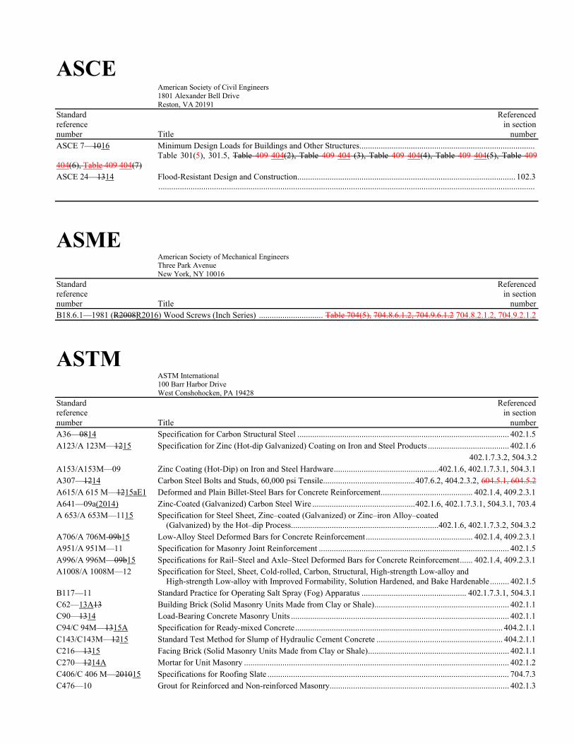
ASCE American Society of Civil Engineers 1801 Alexander Bell Drive Reston, VA 20191
Standard Referenced reference in section number Title number ASCE 7—1016 Minimum Design Loads for Buildings and Other Structures .................................................................................. Table 301(5), 301.5, Table 409 404(2), Table 409 404 (3), Table 409 404(4), Table 409 404(5), Table 409 404(6), Table 409 404(7) ASCE 24—1314 Flood-Resistant Design and Construction ...................................................................................................... 102.3 ................................................................................................................................................................................
ASME American Society of Mechanical Engineers Three Park Avenue New York, NY 10016
Standard Referenced reference in section number Title number B18.6.1—1981 (R2008R2016) Wood Screws (Inch Series) .............................. Table 704(5), 704.8.6.1.2, 704.9.6.1.2 704.8.2.1.2, 704.9.2.1.2
ASTM ASTM International 100 Barr Harbor Drive West Conshohocken, PA 19428
Standard Referenced reference in section number Title number A36—0814 Specification for Carbon Structural Steel ................................................................................................... 402.1.5 A123/A 123M—1215 Specification for Zinc (Hot-dip Galvanized) Coating on Iron and Steel Products ...................................... 402.1.6
402.1.7.3.2, 504.3.2 A153/A153M—09 Zinc Coating (Hot-Dip) on Iron and Steel Hardware .................................................402.1.6, 402.1.7.3.1, 504.3.1 A307—1214 Carbon Steel Bolts and Studs, 60,000 psi Tensile ........................................... 407.6.2, 404.2.3.2, 604.5.1, 604.5.2 A615/A 615 M—1215aE1 Deformed and Plain Billet-Steel Bars for Concrete Reinforcement ........................................... 402.1.4, 409.2.3.1 A641—09a(2014) Zinc-Coated (Galvanized) Carbon Steel Wire ................................................ 402.1.6, 402.1.7.3.1, 504.3.1, 703.4 A 653/A 653M—1115 Specification for Steel Sheet, Zinc–coated (Galvanized) or Zinc–iron Alloy–coated (Galvanized) by the Hot–dip Process .....................................................................402.1.6, 402.1.7.3.2, 504.3.2 A706/A 706M-09b15 Low-Alloy Steel Deformed Bars for Concrete Reinforcement .................................................. 402.1.4, 409.2.3.1 A951/A 951M—11 Specification for Masonry Joint Reinforcement ......................................................................................... 402.1.5 A996/A 996M—09b15 Specifications for Rail–Steel and Axle–Steel Deformed Bars for Concrete Reinforcement ...... 402.1.4, 409.2.3.1 A1008/A 1008M—12 Specification for Steel, Sheet, Cold-rolled, Carbon, Structural, High-strength Low-alloy and High-strength Low-alloy with Improved Formability, Solution Hardened, and Bake Hardenable ......... 402.1.5 B117—11 Standard Practice for Operating Salt Spray (Fog) Apparatus ................................................. 402.1.7.3.1, 504.3.1 C62—13A13 Building Brick (Solid Masonry Units Made from Clay or Shale) ............................................................... 402.1.1 C90—1314 Load-Bearing Concrete Masonry Units ...................................................................................................... 402.1.1 C94/C 94M—1315A Specification for Ready-mixed Concrete ................................................................................................. 404.2.1.1 C143/C143M—1215 Standard Test Method for Slump of Hydraulic Cement Concrete ........................................................... 404.2.1.1 C216—1315 Facing Brick (Solid Masonry Units Made from Clay or Shale) .................................................................. 402.1.1 C270—1214A Mortar for Unit Masonry ............................................................................................................................ 402.1.2 C406/C 406 M—201015 Specifications for Roofing Slate ................................................................................................................. 704.7.3 C476—10 Grout for Reinforced and Non-reinforced Masonry.................................................................................... 402.1.3
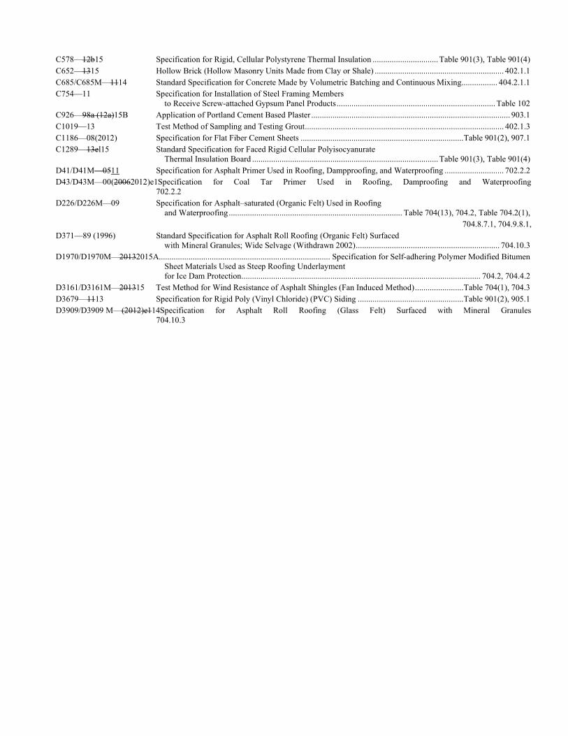
C578—12b15 Specification for Rigid, Cellular Polystyrene Thermal Insulation ............................... Table 901(3), Table 901(4) C652—1315 Hollow Brick (Hollow Masonry Units Made from Clay or Shale) ............................................................. 402.1.1 C685/C685M—1114 Standard Specification for Concrete Made by Volumetric Batching and Continuous Mixing................. 404.2.1.1 C754—11 Specification for Installation of Steel Framing Members to Receive Screw-attached Gypsum Panel Products ........................................................................... Table 102 C926—98a (12a)15B Application of Portland Cement Based Plaster .............................................................................................. 903.1 C1019—13 Test Method of Sampling and Testing Grout .............................................................................................. 402.1.3 C1186—08(2012) Specification for Flat Fiber Cement Sheets ............................................................................. Table 901(2), 907.1 C1289—13el15 Standard Specification for Faced Rigid Cellular Polyisocyanurate Thermal Insulation Board ........................................................................................ Table 901(3), Table 901(4) D41/D41M—0511 Specification for Asphalt Primer Used in Roofing, Dampproofing, and Waterproofing ............................ 702.2.2 D43/D43M—00(20062012)e1Specification for Coal Tar Primer Used in Roofing, Damproofing and Waterproofing 702.2.2 D226/D226M—09 Specification for Asphalt–saturated (Organic Felt) Used in Roofing and Waterproofing .................................................................................. Table 704(13), 704.2, Table 704.2(1),
704.8.7.1, 704.9.8.1, D371—89 (1996) Standard Specification for Asphalt Roll Roofing (Organic Felt) Surfaced with Mineral Granules; Wide Selvage (Withdrawn 2002) .................................................................... 704.10.3 D1970/D1970M—20132015A................................................................................. Specification for Self-adhering Polymer Modified Bitumen Sheet Materials Used as Steep Roofing Underlayment for Ice Dam Protection ................................................................................................................. 704.2, 704.4.2 D3161/D3161M—201315 Test Method for Wind Resistance of Asphalt Shingles (Fan Induced Method) ....................... Table 704(1), 704.3 D3679—1113 Specification for Rigid Poly (Vinyl Chloride) (PVC) Siding .................................................. Table 901(2), 905.1 D3909/D3909 M—(2012)e114Specification for Asphalt Roll Roofing (Glass Felt) Surfaced with Mineral Granules 704.10.3
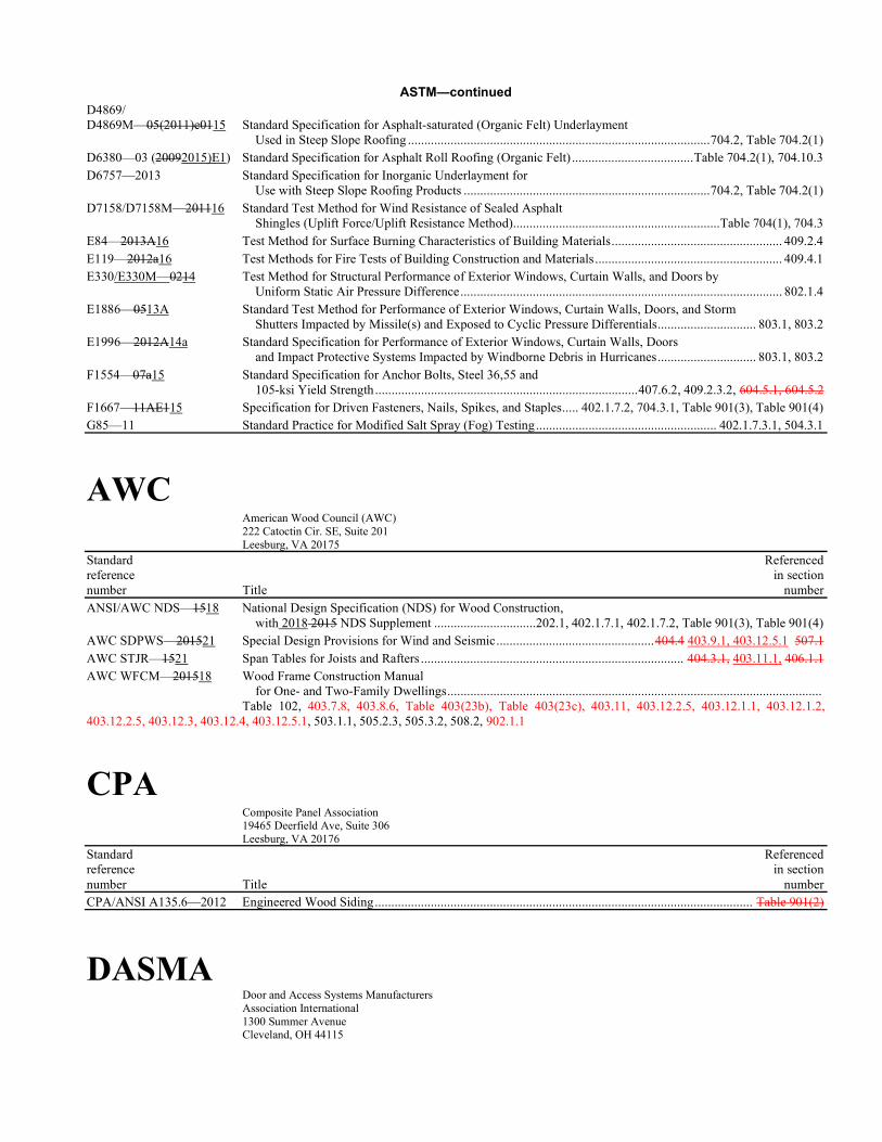
ASTM—continued D4869/ D4869M—05(2011)e0115 Standard Specification for Asphalt-saturated (Organic Felt) Underlayment Used in Steep Slope Roofing ............................................................................................ 704.2, Table 704.2(1) D6380—03 (20092015)E1) Standard Specification for Asphalt Roll Roofing (Organic Felt) ..................................... Table 704.2(1), 704.10.3 D6757—2013 Standard Specification for Inorganic Underlayment for Use with Steep Slope Roofing Products ........................................................................... 704.2, Table 704.2(1) D7158/D7158M—201116 Standard Test Method for Wind Resistance of Sealed Asphalt Shingles (Uplift Force/Uplift Resistance Method) ............................................................... Table 704(1), 704.3 E84—2013A16 Test Method for Surface Burning Characteristics of Building Materials .................................................... 409.2.4 E119—2012a16 Test Methods for Fire Tests of Building Construction and Materials ......................................................... 409.4.1 E330/E330M—0214 Test Method for Structural Performance of Exterior Windows, Curtain Walls, and Doors by Uniform Static Air Pressure Difference .................................................................................................. 802.1.4 E1886—0513A Standard Test Method for Performance of Exterior Windows, Curtain Walls, Doors, and Storm Shutters Impacted by Missile(s) and Exposed to Cyclic Pressure Differentials .............................. 803.1, 803.2 E1996—2012A14a Standard Specification for Performance of Exterior Windows, Curtain Walls, Doors and Impact Protective Systems Impacted by Windborne Debris in Hurricanes .............................. 803.1, 803.2 F1554—07a15 Standard Specification for Anchor Bolts, Steel 36,55 and 105-ksi Yield Strength ................................................................................ 407.6.2, 409.2.3.2, 604.5.1, 604.5.2 F1667—11AE115 Specification for Driven Fasteners, Nails, Spikes, and Staples ..... 402.1.7.2, 704.3.1, Table 901(3), Table 901(4) G85—11 Standard Practice for Modified Salt Spray (Fog) Testing ....................................................... 402.1.7.3.1, 504.3.1
AWC American Wood Council (AWC) 222 Catoctin Cir. SE, Suite 201 Leesburg, VA 20175
Standard Referenced reference in section number Title number ANSI/AWC NDS—1518 National Design Specification (NDS) for Wood Construction, with 2018 2015 NDS Supplement ...............................202.1, 402.1.7.1, 402.1.7.2, Table 901(3), Table 901(4) AWC SDPWS—201521 Special Design Provisions for Wind and Seismic ................................................ 404.4 403.9.1, 403.12.5.1 507.1 AWC STJR—1521 Span Tables for Joists and Rafters ................................................................................ 404.3.1, 403.11.1, 406.1.1 AWC WFCM—201518 Wood Frame Construction Manual for One- and Two-Family Dwellings .................................................................................................................. Table 102, 403.7.8, 403.8.6, Table 403(23b), Table 403(23c), 403.11, 403.12.2.5, 403.12.1.1, 403.12.1.2, 403.12.2.5, 403.12.3, 403.12.4, 403.12.5.1, 503.1.1, 505.2.3, 505.3.2, 508.2, 902.1.1
CPA Composite Panel Association 19465 Deerfield Ave, Suite 306 Leesburg, VA 20176
Standard Referenced reference in section number Title number CPA/ANSI A135.6—2012 Engineered Wood Siding ................................................................................................................... Table 901(2)
DASMA Door and Access Systems Manufacturers Association International 1300 Summer Avenue Cleveland, OH 44115
Standard Referenced reference in section number Title number 115—20122017 Standard Method for Testing Garage Doors: Determination of Structural Performance Under Missile Impact and Cyclic Wind Pressure ...................................................................................... 803.2 108—20122017 Standard Method for Testing Sectional Garage Doors: Determination of Structural Performance Under Uniform Static Air Pressure Difference .................................................................. 802.1.4
DOC United States Department of Commerce 100 Bureau Drive Stop 3460 Gaithersburg, MD 20899
Standard Referenced reference in section number Title number PS1—0919 Construction and Industrial Plywood ................................................................................................................ 202 PS2—1018 Performance Standard for Wood-based Structural-use Panels .......................................................................... 202
FEMA Federal Emergency Management Agency (IS-RHW4-11/12) 500 C Street, SW Washington DC 20472
Standard Referenced reference in section number Title number FEMA P-550 Recommended Residential Construction for Coastal Areas: Building on Strong and Safe Foundations, Second Edition, December 2009 ............................................ 102.3
Florida Codes Building Codes and Standards Office Florida Department of Business and Professional Regulation 1940 North Monroe Street, Suite 90A Tallahassee, FL 32399
Standard Referenced reference in section number Title number TAS 201—94 Florida Building Code – Test Protocols – Impact Test Procedures ............................................................... 803.1 TAS 202—94 Florida Building Code – Test Protocols – Criteria For Testing Impact and Nonimpact-Resistant Building Envelope Components Using Uniform Static Air Pressure ............................... 802.1.2, 802.1.3, 802.1.4, 803.1 TAS 203—94 Florida Building Code – Test Protocols – Criteria For Testing Products Subject To Cyclic Wind Pressure Loading ............................................................................................................. 803.1
FMA Fenestration Manufacturers Association 1625 Summit Lake Dr. Suite 300
Tallahassee, FL 32317
Standard Referenced reference in section number Title number FMA/AAMA 100-12 Standard Practice for the Installation of Windows with Flanges or Mounting........................................ 903.1. FMA/AAMA 200-12 Standard Practice for the Installation of Windows with Frontal Flanges for Surface Barrier Masonry ... 903.1 FMA/WDMA 250-10 Standard Practice for the Installation of Non-Frontal Flange Windows with Mounting Flanges for Surface Barrier Masonry for Extreme Wind/Water Conditions ................................................................................................................................. 903.1 FMA/AAMA/WDMA 300-13 Standard Practice for the Installation of Exterior Doors in Wood Frame Construction for Extreme Wind/Weather Exposure ...................................................................................................................................................... 903.1 FMA/AAMA/WDMA 400-13 Standard Practice for the Installation of Exterior Doors in Surface Barrier Masonry Construction for Extreme Wind/Weather Exposure ................................................................................................................................................................. 903.1
ICC International Code Council 500 New Jersey Avenue, NW 6th Floor Washington, DC 20001
Standard Referenced reference in section number Title number IBC—1521 International Building Code®........................ 101.2.1, 101.3, 101.4, 101.5, Table 301(4), 301.5, 404.3.7, 405.4.8,
407.2.3, 701.2, Table 701(3), 702.1, 704.1, 704.3, Table 704(2), Table 704(3), 704.4, 704.4.4, 704.4.6, 704.4.7.1, 704.5,
704.6, 704.6.1, 704.7, 704.8, 704.8.6, 704.9, 704.9.6, 704.9.9, 704.10, 704.10.4, 704.11, 704.12, 704.12.1, 704.13, 704.13.1, 704.14,
704.14.1, 704.15, 704.15.1, 704.16, 704.16.1, 901.2, 902.5, 908.3 ICC 500—20142020 ICC/NSSA Standard on the Design and Construction of Storm Shelters ...................................................... 303.1 IRC—1521 International Residential Code® ....................................... 101.2.1, 101.5, 102.3, 301.6, 402.1.7.1, 404.3, 404.3.5, 404.3.7, 404.3.8, 406.1.1, 505.1.1, 505.1.3, 508.1, 701.2, 702.1, 704.1, 704.3, 704.4, 704.5, 704.6, 704.7, 704.8,
704.9, 704.10, 704.11, 704.12, 704.13, 704.14, 704.15, 704.15.1, 704.16, 901.2, Table 901(2), 901.4, 902.5, 901.5.1.2, 904.1, 904.5, 908.1, 909.1
SBCCI SSTD 11—97 Standard for Determining Wind Resistance of Concrete or Clay Roof Tiles ..................................... Table 407(4)
PCA Portland Cement Association 5420 Old Orchard Road Skokie, IL 60077
Standard Referenced reference in section number Title number PCA 100—1217 Prescriptive Design of Exterior Concrete Walls for One- and Two-Family Dwellings ....................... 409.1 404.1
SBCA Structural Building Components Association 6300 Enterprise Lane Madison, WI 53719
Standard Referenced reference in section number Title number ANSI/FS 100—12(R2018) Standard Requirements for Wind Pressure Resistance of Foam Plastic Insulating Sheathing Used in Exterior Wall Covering Assemblies .................................................. 906.1 910.1
TMS The Masonry Society 3970 Broadway, Suite 201-D Boulder, CO 80304
Standard Referenced reference in section number Title number
402/ACI 530/ASCE 5—1316 Building Code Requirements for Masonry Structures ................................................ 403.1, Table 901(2), 904(2) 602/ACI 530.1/ASCE 6—1316Specification for Masonry Structures 405.1, Table 901(2), 904(2) 403—1317 Direct Design Handbook for Masonry Structures .......................................................................................... 403.1
TPI Truss Plate Institute 583 D'Onofrio Drive, Suite 200 Madison, WI 53719
Standard Referenced reference in section number Title number ANSI/TPI 1—20122014 National Design Standard for Metal-Plate-Connected Wood Truss Construction ................................. 402.1.7.3.2, 404.3.3, 403.12.2.1, 504.3.2.2, 407.2.1, 504.3.2.3
WDMA Window & Door Manufacturers Association 2025 M. Street, NW, Suite 800 Washington, DC 20036-3309
Standard Referenced reference in section number Title number 101/I.S.2/A440—11 17 North American Fenestration Standard/ Specifications for Windows, Doors and Skylights .................................................................... 802.1.2, 802.1.3 101/I.S.2/NAFS—02 Voluntary Performance Specification for Windows, Skylights and Glass Doors ....................................... 802.1.2
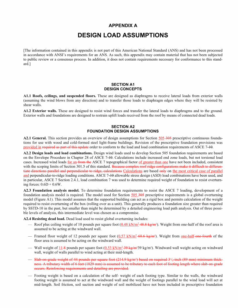
APPENDIX A
DESIGN LOAD ASSUMPTIONS
[The information contained in this appendix is not part of this American National Standard (ANS) and has not been processed in accordance with ANSI’s requirements for an ANS. As such, this appendix may contain material that has not been subjected to public review or a consensus process. In addition, it does not contain requirements necessary for conformance to this stand-ard.]
SECTION A1 DESIGN CONCEPTS
A1.1 Roofs, ceilings, and suspended floors. These are designed as diaphragms to receive lateral loads from exterior walls (assuming the wind blows from any direction) and to transfer those loads to diaphragm edges where they will be resisted by shear walls.
A1.2 Exterior walls. These are designed to resist wind forces and transfer the lateral loads to diaphragms and to the ground. Exterior walls and foundations are designed to restrain uplift loads received from the roof by means of connected dead loads.
SECTION A2 FOUNDATION DESIGN ASSUMPTIONS
A2.1 General. This section provides an overview of design assumptions for Section 505 305 prescriptive continuous founda-tions for use with wood and cold-formed steel light-frame buildings. Revision of the prescriptive foundation provisions was provided in required as part of this update order to conform to the load and load combination requirements of ASCE 7-10.
A2.2 Design loads and load combinations. Design wind loads used to develop Section 505 foundation requirements are based on the Envelope Procedure in Chapter 28 of ASCE 7-10. Calculations include increased end zone loads, but not torsional load cases. Increased wind loads for an from the ASCE 7 topographical factor of greater than one have not been included, consistent with the scoping limits of Section 301.5 of this standard. Because complex roof ridge configurations make it difficult to differen-tiate directions parallel and perpendicular to ridge, calculations Calculations are based only on the most critical case of parallel and perpendicular-to-ridge loading conditions. ASCE 7-10 allowable stress design (ASD) load combinations have been used, and in particular, ASCE 7 Section 2.4.1, load combination 7 was used to determine required weight of foundation to resist overturn-ing forces: 0.6D + 0.6W.
A2.3 Foundation analysis model. To determine foundation requirements to resist the ASCE 7 loading, development of a foundation analysis model is required. The model used for Section 505 305 prescriptive requirements is a global overturning model (Figure A1). This model assumes that the supported building can act as a rigid box and permits calculation of the weight required to resist overturning of the box (rolling over as a unit). This generally produces a foundation size greater than required by SSTD-10 in the past, but smaller than might be determined by a detailed engineering load path analysis. Out of three possi-ble levels of analysis, this intermediate level was chosen as a compromise.
A2.4 Resisting dead load. Dead load used to resist global overturning includes:
— Roof plus ceiling weight of 10 pounds per square foot (0.48 kN/m2 48.8 kg/m2). Weight from one-half of the roof area is assumed to be acting at the windward wall.
— Framed floor weight of 12 pounds per square foot (0.57 kN/m2 68.6 kg/m2). Weight from one-half one-fourth of the floor area is assumed to be acting on the windward wall.
— Wall weight of 11 8 pounds per square foot (0.53 kN/m2 39 kg/m239 kg/m2). Windward wall weight acting on windward wall, weight of walls parallel to wind acting at their mid-length.
— Slab-on-grade weight of 44 pounds per square foot (214.9 kg/m2) based on required 31/2-inch (89 mm) minimum thick-ness. A tributary width of 6 feet (1829 mm) is assumed to be tributary to each foot of footing length where slab-on-grade occurs. Reinforcing requirements and detailing are provided.
— Footing weight is based on a calculation of the self- weight of each footing type. Similar to the walls, the windward footing weight is assumed to act at the windward wall and the weight of footings parallel to the wind load will act at mid-length. Soil friction, soil suction and weight of soil mobilized have not been included in prescriptive foundation

weight; however, provisions allow for the detailed calculation of footing resisting weight on a case-by-case basis when permitted by the building official.
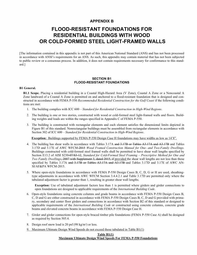
APPENDIX B
FLOOD-RESISTANT FOUNDATIONS FOR RESIDENTIAL BUILDINGS WITH WOOD
OR COLD-FORMED STEEL LIGHT-FRAMED WALLS
[The information contained in this appendix is not part of this American National Standard (ANS) and has not been processed in accordance with ANSI’s requirements for an ANS. As such, this appendix may contain material that has not been subjected to public review or a consensus process. In addition, it does not contain requirements necessary for conformance to this stand-ard.]
SECTION B1 FLOOD-RESISTANT FOUNDATIONS
B1 General.
B1.1 Scope. Placing a residential building in a Coastal High-Hazard Area (V Zone), Coastal A Zone or a Noncoastal A Zone landward of a Coastal A Zone is permitted on and anchored to a flood-resistant foundation that is designed and con-structed in accordance with FEMA P-550 Recommended Residential Construction for the Gulf Coast if the following condi-tions are met:
1. The building complies with ICC 600 – Standard for Residential Construction in High-Wind Regions.
2. The building is one or two stories, constructed with wood or cold-formed steel light-framed walls and floors. Build-ing weights and loads are within the ranges specified in Appendix C of FEMA P-550.
3. The building is constructed with rectangular elements and each element satisfies the dimensional limits depicted in Figure B1 of this standard. Nonrectangular buildings must be assembled from rectangular elements in accordance with Section 302 of ICC 600 – Standard for Residential Construction in High-Wind Regions.
Exception: Buildings supported by FEMA P-550 Design Case H foundations may have widths as low as 14’8”.
4. The building has shear walls in accordance with Tables 3.17A and 3.17B or Tables A3.17A and A3.17B and Tables 3.17D and 3.17E of AWC WFCM-2015 Wood Framed Construction Manual for One- and Two-Family Dwellings. Buildings constructed with cold-formed steel framed walls shall be permitted to have shear wall lengths specified by Section E13.2 of AISI S230-07/S3-12, Standard for Cold-Formed Steel Framing – Prescriptive Method for One and Two Family Dwellings, 2007 with Supplement 3, dated 2015, if provided the shear wall lengths are not less than those specified by Tables 3.17A and 3.17B or Tables A3.17A and A3.17B and Tables 3.17D and 3.17E of AWC AN-SI/AF&PA WFCM-2015.
5. Where open-style foundations in accordance with FEMA P-550 Design Cases B, C, D, G or H are used, sheathing-type adjustments in accordance with AWC WFCM Section 3.4.4.2.1 and Table 3.17D are permitted only where the tabulated adjustment factor is greater than 1, resulting in greater shear wall lengths.
Exception: Use of tabulated adjustment factors less than 1 is permitted where girders and girder connections to open foundations are designed to applicable requirements of the International Building Code.
6. Open-style foundations using concrete columns and grade beams in accordance with FEMA P-550 Design Cases B, C, D and G are either constructed in accordance with FEMA P-550 Design Cases B, C, D and G provided with prima-ry, secondary and center floor girders and connections in accordance with Section B2 of this standard or designed to applicable requirements of the International Building Code or constructed using concrete columns, concrete grade beams and elevated concrete beams in accordance with FEMA P-550 Design Case H.
7. Girder and girder connections for open-style braced timber pile foundations (FEMA P-550 Case A) shall be designed as required by Section 505.4.
8. Design roof snow load is 20 psf (98 kg/m2) or less.
9. Maximum Ultimate Design Wind Speeds do not exceed those tabulated in Table B1(1)
Table B1(1) Maximum Ultimate Design Wind Speeds For FEMA P-550 Foundations
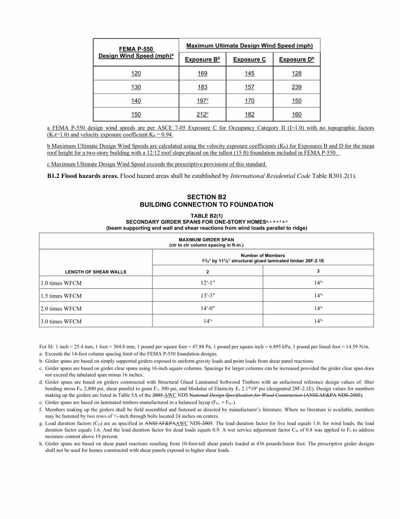
FEMA P-550 Design Wind Speed (mph)a
Maximum Ultimate Design Wind Speed (mph)
Exposure Bb Exposure C Exposure Db
120 169 145 128
130 183 157 239
140 197c 170 150
150 212c 182 160
a FEMA P-550 design wind speeds are per ASCE 7-05 Exposure C for Occupancy Category II (I=1.0) with no topographic factors (Kzt=1.0) and velocity exposure coefficient Kh = 0.94.
b Maximum Ultimate Design Wind Speeds are calculated using the velocity exposure coefficients (Kh) for Exposures B and D for the mean roof height for a two-story building with a 12:12 roof slope placed on the tallest (15 ft) foundation included in FEMA P-550.
c Maximum Ultimate Design Wind Speed exceeds the prescriptive provisions of this standard.
B1.2 Flood hazards areas. Flood hazard areas shall be established by International Residential Code Table R301.2(1).
SECTION B2 BUILDING CONNECTION TO FOUNDATION
TABLE B2(1) SECONDARY GIRDER SPANS FOR ONE-STORY HOMESb, c, d, e, f, g, h
(beam supporting end wall and shear reactions from wind loads parallel to ridge)
MAXIMUM GIRDER SPAN (ctr to ctr column spacing in ft-in.)
LENGTH OF SHEAR WALLS
Number of Members 13/4" by 117/8" structural glued laminated timber 28F-2.1E
2 3
1.0 times WFCM 12'-1" 14'a
1.5 times WFCM 13'-3" 14'a
2.0 times WFCM 14'-0" 14'a
3.0 times WFCM 14'a 14'a
For SI: 1 inch = 25.4 mm, 1 foot = 304.8 mm, 1 pound per square foot = 47.88 Pa, 1 pound per square inch = 6.895 kPa, 1 pound per lineal foot = 14.59 N/m. a. Exceeds the 14-foot column spacing limit of the FEMA P-550 foundation designs. b. Girder spans are based on simply supported girders exposed to uniform gravity loads and point loads from shear panel reactions. c. Girder spans are based on girder clear spans using 16-inch square columns. Spacings for larger columns can be increased provided the girder clear span does
not exceed the tabulated span minus 16 inches. d. Girder spans are based on girders constructed with Structural Glued Laminated Softwood Timbers with an unfactored reference design values of: fiber
bending stress Fbx 2,800 psi, shear parallel to grain Fvx 300 psi, and Modulus of Elasticity Ex 2.1*106 psi (designated 28F-2.1E). Design values for members making up the girders are listed in Table 5A of the 2005 AWC NDS National Design Specification for Wood Construction (ANSI/AF&PA NDS-2005).
e. Girder spans are based on laminated timbers manufactured in a balanced layup (Fbx- = Fbx+). f. Members making up the girders shall be field assembled and fastened as directed by manufacturer’s literature. Where no literature is available, members
may be fastened by two rows of 1/2-inch through bolts located 24 inches on centers. g. Load duration factors (CD) are as specified in ANSI/AF&PAAWC NDS-2005. The load duration factor for live load equals 1.0; for wind loads, the load
duration factor equals 1.6. And the load duration factor for dead loads equals 0.9. A wet service adjustment factor CM of 0.8 was applied to Fb to address moisture content above 19 percent.
h. Girder spans are based on shear panel reactions resulting from 10-foot-tall shear panels loaded at 436 pounds/linear foot. The prescriptive girder designs shall not be used for homes constructed with shear panels exposed to higher shear loads.
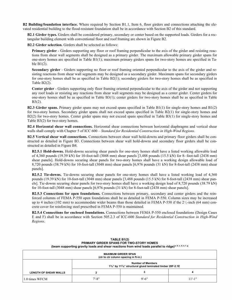
B2 Building/foundation interface. Where required by Section B1.1, Item 6, floor girders and connections attaching the ele-vated residential building to the flood-resistant foundation shall be in accordance with Section B2 of this standard.
B2.1 Girder types. Girders shall be considered primary, secondary or center based on the supported loads. Girders for a rec-tangular building element with conventional floor and roof framing are shown in Figure B2.
B2.2 Girder selection. Girders shall be selected as follows:
Primary girder - Girders supporting any floor or roof framing perpendicular to the axis of the girder and resisting reac-tions from shear wall segments shall be designed as a primary girder. The maximum allowable primary girder spans for one-story homes are specified in Table B1(1); maximum primary girders spans for two-story homes are specified in Ta-ble B1(2).
Secondary girder - Girders supporting no floor or roof framing oriented perpendicular to the axis of the girder and re-sisting reactions from shear wall segments may be designed as a secondary girder. Maximum spans for secondary girders for one-story homes shall be as specified in Table B2(1); secondary girders for two-story homes shall be as specified in Table B2(2).
Center girder - Girders supporting only floor framing oriented perpendicular to the axis of the girder and not supporting any roof loads or resisting any reactions from shear wall segments may be designed as a center girder. Center girders for one-story homes shall be as specified in Table B3(1); center girders for two-story homes shall be as specified in Table B3(2).
B2.3 Girder spans. Primary girder spans may not exceed spans specified in Table B1(1) for single-story homes and B1(2) for two-story homes. Secondary girder spans shall not exceed spans specified in Table B2(1) for single-story homes and B2(2) for two-story homes. Center girder spans may not exceed spans specified in Table B3(1) for single-story homes and Table B3(2) for two-story homes.
B2.4 Horizontal shear wall connections. Horizontal shear connections between horizontal diaphragms and vertical shear walls shall comply with Chapter 5 of ICC 600 – Standard for Residential Construction in High-Wind Regions.
B2.5 Vertical shear wall connections. Connections between shear wall hold-downs and primary floor girders shall be con-structed as detailed in Figure B3. Connections between shear wall hold-downs and secondary floor girders shall be con-structed as detailed in Figure B4.
B2.5.1 Hold-downs. Hold-downs securing shear panels for one-story homes shall have a listed working allowable load of 4,360 pounds (19.39 kN) for 10-foot-tall (3048 mm) shear panels [3,488 pounds (15.5 kN) for 8- foot-tall (2438 mm) shear panels]. Hold-downs securing shear panels for two-story homes shall have a working design allowable load of 8,720 pounds (38.79 kN) for 10-foot-tall (3048 mm) shear panels [6,976 pounds (31 kN) for 8-foot-tall (2438 mm) shear panels].
B2.5.2 Tie-downs. Tie-downs securing shear panels for one-story homes shall have a listed working load of 4,360 pounds (19.39 kN) for 10-foot-tall (3048 mm) shear panels [3,488 pounds (15.5 kN) for 8-foot-tall (2438 mm) shear pan-els]. Tie-downs securing shear panels for two-story homes shall have a working design load of 8,720 pounds (38.79 kN) for 10-foot-tall (3048 mm) shear panels [6,976 pounds (31 kN) for 8-foot-tall (2438 mm) shear panels].
B2.5.3 Connections for open foundations. Connections between primary, secondary and center girders and the rein-forced columns of FEMA P-550 open foundations shall be as detailed in FEMA P-550. Column sizes may be increased up to 4 inches (102 mm) to accommodate wider beams than those detailed in FEMA P-550 if the 21/2-inch (64 mm) con-crete cover for reinforcing steel prescribed in FEMA P-550 is maintained.
B2.5.4 Connections for enclosed foundations. Connections between FEMA P-550 enclosed foundations (Design Cases E and F) shall be in accordance with Section 505.2.3 of ICC-600 Standard for Residential Construction in High-Wind Regions.
TABLE B1(2) PRIMARY GIRDER SPANS FOR TWO-STORY HOMES
(beam supporting gravity loads and shear reactions from wind loads parallel to ridge)a, b, c, d, e, f, g
MAXIMUM GIRDER SPAN (ctr to ctr column spacing in ft-in.)
LENGTH OF SHEAR WALLS
Number of Members 13/4" by 117/8" structural glued laminated timber 28F-2.1E
2 3 4
1.0 times WFCM 7'-8" 9'-6" 11'-1"
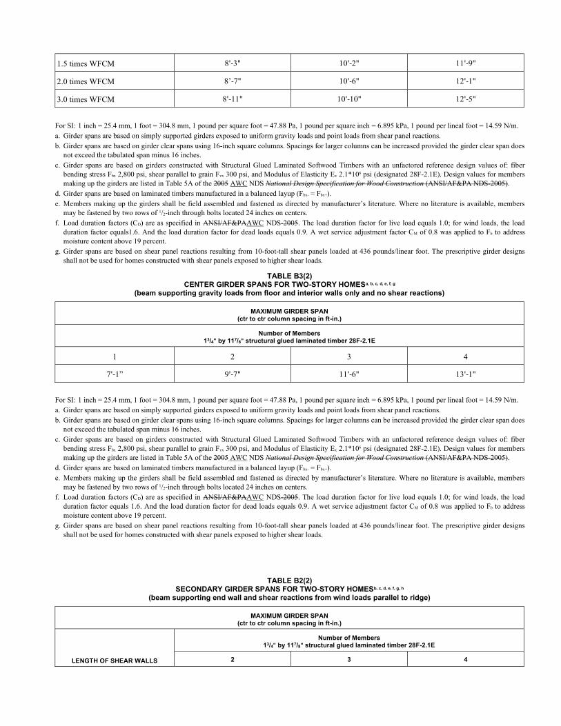
1.5 times WFCM 8'-3" 10'-2" 11'-9"
2.0 times WFCM 8’-7" 10'-6" 12'-1"
3.0 times WFCM 8'-11" 10'-10" 12'-5"
For SI: 1 inch = 25.4 mm, 1 foot = 304.8 mm, 1 pound per square foot = 47.88 Pa, 1 pound per square inch = 6.895 kPa, 1 pound per lineal foot = 14.59 N/m. a. Girder spans are based on simply supported girders exposed to uniform gravity loads and point loads from shear panel reactions. b. Girder spans are based on girder clear spans using 16-inch square columns. Spacings for larger columns can be increased provided the girder clear span does
not exceed the tabulated span minus 16 inches. c. Girder spans are based on girders constructed with Structural Glued Laminated Softwood Timbers with an unfactored reference design values of: fiber
bending stress Fbx 2,800 psi, shear parallel to grain Fvx 300 psi, and Modulus of Elasticity Ex 2.1*106 psi (designated 28F-2.1E). Design values for members making up the girders are listed in Table 5A of the 2005 AWC NDS National Design Specification for Wood Construction (ANSI/AF&PA NDS-2005).
d. Girder spans are based on laminated timbers manufactured in a balanced layup (Fbx- = Fbx+). e. Members making up the girders shall be field assembled and fastened as directed by manufacturer’s literature. Where no literature is available, members
may be fastened by two rows of 1/2-inch through bolts located 24 inches on centers. f. Load duration factors (CD) are as specified in ANSI/AF&PAAWC NDS-2005. The load duration factor for live load equals 1.0; for wind loads, the load
duration factor equals1.6. And the load duration factor for dead loads equals 0.9. A wet service adjustment factor CM of 0.8 was applied to Fb to address moisture content above 19 percent.
g. Girder spans are based on shear panel reactions resulting from 10-foot-tall shear panels loaded at 436 pounds/linear foot. The prescriptive girder designs shall not be used for homes constructed with shear panels exposed to higher shear loads.
TABLE B3(2) CENTER GIRDER SPANS FOR TWO-STORY HOMESa, b, c, d, e, f, g
(beam supporting gravity loads from floor and interior walls only and no shear reactions)
MAXIMUM GIRDER SPAN (ctr to ctr column spacing in ft-in.)
Number of Members 13/4" by 117/8" structural glued laminated timber 28F-2.1E
1 2 3 4
7'-1” 9'-7" 11'-6" 13'-1"
For SI: 1 inch = 25.4 mm, 1 foot = 304.8 mm, 1 pound per square foot = 47.88 Pa, 1 pound per square inch = 6.895 kPa, 1 pound per lineal foot = 14.59 N/m. a. Girder spans are based on simply supported girders exposed to uniform gravity loads and point loads from shear panel reactions. b. Girder spans are based on girder clear spans using 16-inch square columns. Spacings for larger columns can be increased provided the girder clear span does
not exceed the tabulated span minus 16 inches. c. Girder spans are based on girders constructed with Structural Glued Laminated Softwood Timbers with an unfactored reference design values of: fiber
bending stress Fbx 2,800 psi, shear parallel to grain Fvx 300 psi, and Modulus of Elasticity Ex 2.1*106 psi (designated 28F-2.1E). Design values for members making up the girders are listed in Table 5A of the 2005 AWC NDS National Design Specification for Wood Construction (ANSI/AF&PA NDS-2005).
d. Girder spans are based on laminated timbers manufactured in a balanced layup (Fbx- = Fbx+). e. Members making up the girders shall be field assembled and fastened as directed by manufacturer’s literature. Where no literature is available, members
may be fastened by two rows of 1/2-inch through bolts located 24 inches on centers. f. Load duration factors (CD) are as specified in ANSI/AF&PAAWC NDS-2005. The load duration factor for live load equals 1.0; for wind loads, the load
duration factor equals 1.6. And the load duration factor for dead loads equals 0.9. A wet service adjustment factor CM of 0.8 was applied to Fb to address moisture content above 19 percent.
g. Girder spans are based on shear panel reactions resulting from 10-foot-tall shear panels loaded at 436 pounds/linear foot. The prescriptive girder designs shall not be used for homes constructed with shear panels exposed to higher shear loads.
TABLE B2(2) SECONDARY GIRDER SPANS FOR TWO-STORY HOMESb, c, d, e, f, g, h
(beam supporting end wall and shear reactions from wind loads parallel to ridge)
MAXIMUM GIRDER SPAN (ctr to ctr column spacing in ft-in.)
LENGTH OF SHEAR WALLS
Number of Members 13/4" by 117/8" structural glued laminated timber 28F-2.1E
2 3 4
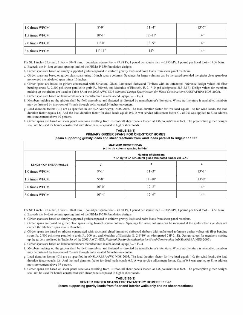
1.0 times WFCM 8'-9" 11'-4" 13'-7"
1.5 times WFCM 10'-1" 12'-11" 14'a
2.0 times WFCM 11'-0" 13'-9" 14'a
3.0 times WFCM 11'-11" 14'a 14'a
For SI: 1 inch = 25.4 mm, 1 foot = 304.8 mm, 1 pound per square foot = 47.88 Pa, 1 pound per square inch = 6.895 kPa, 1 pound per lineal foot = 14.59 N/m. a. Exceeds the 14-foot column spacing limit of the FEMA P-550 foundation designs. b. Girder spans are based on simply supported girders exposed to uniform gravity loads and point loads from shear panel reactions. c. Girder spans are based on girder clear spans using 16-inch square columns. Spacings for larger columns can be increased provided the girder clear span does
not exceed the tabulated span minus 16 inches. d. Girder spans are based on girders constructed with Structural Glued Laminated Softwood Timbers with an unfactored reference design values of: fiber
bending stress Fbx 2,800 psi, shear parallel to grain Fvx 300 psi, and Modulus of Elasticity Ex 2.1*106 psi (designated 28F-2.1E). Design values for members making up the girders are listed in Table 5A of the 2005 AWC NDS National Design Specification for Wood Construction (ANSI/AF&PA NDS-2005).
e. Girder spans are based on laminated timbers manufactured in a balanced layup (Fbx- = Fbx+). f. Members making up the girders shall be field assembled and fastened as directed by manufacturer’s literature. Where no literature is available, members
may be fastened by two rows of 1/2-inch through bolts located 24 inches on centers. g. Load duration factors (CD) are as specified in ANSI/AF&PAAWC NDS-2005. The load duration factor for live load equals 1.0; for wind loads, the load
duration factor equals 1.6. And the load duration factor for dead loads equals 0.9. A wet service adjustment factor CM of 0.8 was applied to Fb to address moisture content above 19 percent.
h. Girder spans are based on shear panel reactions resulting from 10-foot-tall shear panels loaded at 436 pounds/linear foot. The prescriptive girder designs shall not be used for homes constructed with shear panels exposed to higher shear loads.
TABLE B1(1) PRIMARY GIRDER SPANS FOR ONE-STORY HOMES
(beam supporting gravity loads and shear reactions from wind loads parallel to ridge)b, c, d, e, f, g, h
MAXIMUM GIRDER SPAN (ctr to ctr column spacing in ft-in.)
LENGTH OF SHEAR WALLS
Number of Members 13/4" by 117/8" structural glued laminated timber 28F-2.1E
2 3 4
1.0 times WFCM 9'-1" 11'-3" 13'-1"
1.5 times WFCM 9'-8" 11'-10" 13'-9"
2.0 times WFCM 10'-0" 12'-2" 14'a
3.0 times WFCM 10'-4" 12'-6" 14'a
For SI: 1 inch = 25.4 mm, 1 foot = 304.8 mm, 1 pound per square foot = 47.88 Pa, 1 pound per square inch = 6.895 kPa, 1 pound per lineal foot = 14.59 N/m. a. Exceeds the 14-foot column spacing limit of the FEMA P-550 foundation designs. b. Girder spans are based on simply supported girders exposed to uniform gravity loads and point loads from shear panel reactions. c. Girder spans are based on girder clear spans using 16-inch square columns. Spacings for larger columns can be increased if the girder clear span does not
exceed the tabulated span minus 16 inches. d. Girder spans are based on girders constructed with structural glued laminated softwood timbers with unfactored reference design values of: fiber bending
stress Fbx 2,800 psi, shear parallel to grain Fvx 300 psi, and Modulus of Elasticity Ex 2.1*106 psi (designated 28F-2.1E). Design values for members making up the girders are listed in Table 5A of the 2005 AWC NDS, National Design Specification for Wood Construction (ANSI/AF&PA NDS-2005).
e. Girder spans are based on laminated timbers manufactured in a balanced layup (Fbx- = Fbx+). f. Members making up the girders shall be field assembled and fastened as directed by manufacturer’s literature. Where no literature is available, members
may be fastened by two rows of 1/2-inch through bolts located 24 inches on centers. g. Load duration factors (CD) are as specified in ANSI/AF&PAAWC NDS-2005. The load duration factor for live load equals 1.0; for wind loads, the load
duration factor equals 1.6. And the load duration factor for dead loads equals 0.9. A wet service adjustment factor, CM, of 0.8 was applied to Fb to address moisture content above 19 percent.
h. Girder spans are based on shear panel reactions resulting from 10-foot-tall shear panels loaded at 436 pounds/linear foot. The prescriptive girder designs shall not be used for homes constructed with shear panels exposed to higher shear loads.
TABLE B3(1) CENTER GIRDER SPANS FOR TWO-STORY HOMESb, c, d, e, f, g, h
(beam supporting gravity loads from floor and interior walls only and no shear reactions)
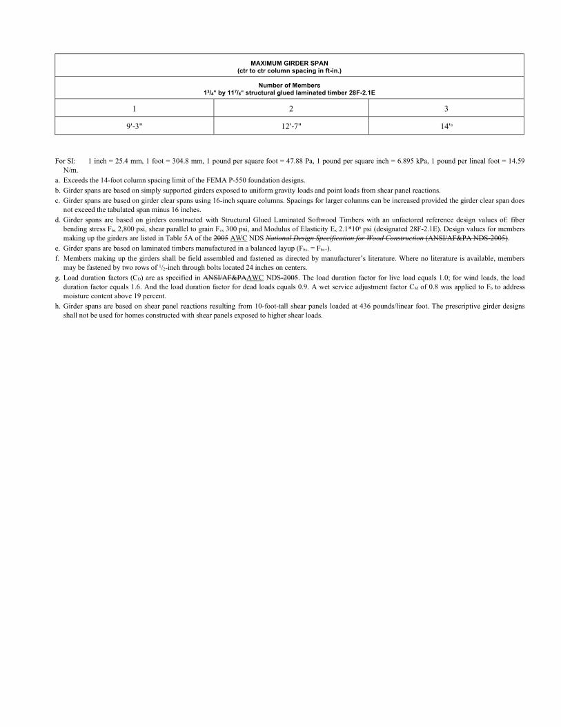
MAXIMUM GIRDER SPAN (ctr to ctr column spacing in ft-in.)
Number of Members 13/4" by 117/8" structural glued laminated timber 28F-2.1E
1 2 3
9'-3" 12'-7" 14'a
For SI: 1 inch = 25.4 mm, 1 foot = 304.8 mm, 1 pound per square foot = 47.88 Pa, 1 pound per square inch = 6.895 kPa, 1 pound per lineal foot = 14.59
N/m. a. Exceeds the 14-foot column spacing limit of the FEMA P-550 foundation designs. b. Girder spans are based on simply supported girders exposed to uniform gravity loads and point loads from shear panel reactions. c. Girder spans are based on girder clear spans using 16-inch square columns. Spacings for larger columns can be increased provided the girder clear span does
not exceed the tabulated span minus 16 inches. d. Girder spans are based on girders constructed with Structural Glued Laminated Softwood Timbers with an unfactored reference design values of: fiber
bending stress Fbx 2,800 psi, shear parallel to grain Fvx 300 psi, and Modulus of Elasticity Ex 2.1*106 psi (designated 28F-2.1E). Design values for members making up the girders are listed in Table 5A of the 2005 AWC NDS National Design Specification for Wood Construction (ANSI/AF&PA NDS-2005).
e. Girder spans are based on laminated timbers manufactured in a balanced layup (Fbx- = Fbx+). f. Members making up the girders shall be field assembled and fastened as directed by manufacturer’s literature. Where no literature is available, members
may be fastened by two rows of 1/2-inch through bolts located 24 inches on centers. g. Load duration factors (CD) are as specified in ANSI/AF&PAAWC NDS-2005. The load duration factor for live load equals 1.0; for wind loads, the load
duration factor equals 1.6. And the load duration factor for dead loads equals 0.9. A wet service adjustment factor CM of 0.8 was applied to Fb to address moisture content above 19 percent.
h. Girder spans are based on shear panel reactions resulting from 10-foot-tall shear panels loaded at 436 pounds/linear foot. The prescriptive girder designs shall not be used for homes constructed with shear panels exposed to higher shear loads.
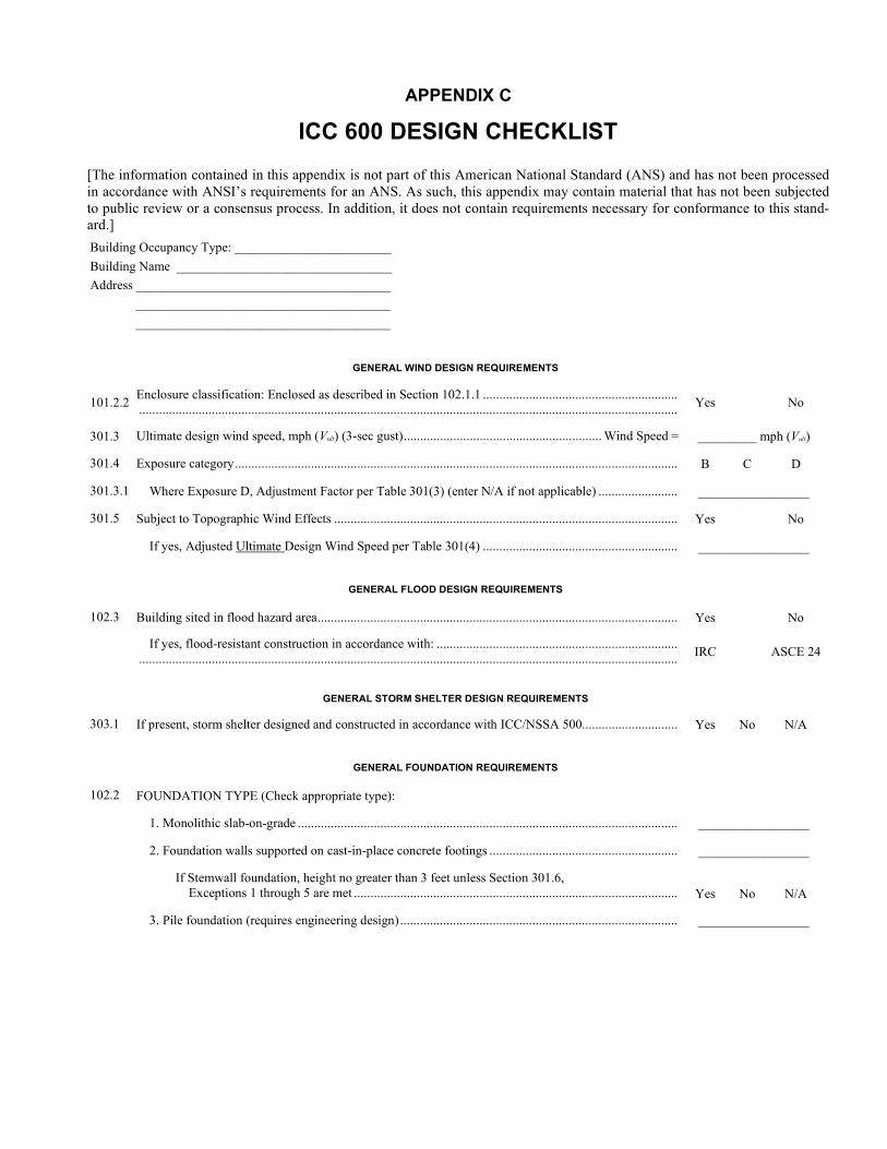
APPENDIX C
ICC 600 DESIGN CHECKLIST
[The information contained in this appendix is not part of this American National Standard (ANS) and has not been processed in accordance with ANSI’s requirements for an ANS. As such, this appendix may contain material that has not been subjected to public review or a consensus process. In addition, it does not contain requirements necessary for conformance to this stand-ard.]
Building Occupancy Type: ________________________
Building Name _________________________________
Address _______________________________________
_______________________________________
_______________________________________
GENERAL WIND DESIGN REQUIREMENTS
101.2.2 Enclosure classification: Enclosed as described in Section 102.1.1 ........................................................... ................................................................................................................................................................... Yes No
301.3 Ultimate design wind speed, mph (Vult) (3-sec gust) ............................................................ Wind Speed = _________ mph (Vult)
301.4 Exposure category ...................................................................................................................................... B C D
301.3.1 Where Exposure D, Adjustment Factor per Table 301(3) (enter N/A if not applicable) ........................ _________________
301.5 Subject to Topographic Wind Effects ........................................................................................................ Yes No
If yes, Adjusted Ultimate Design Wind Speed per Table 301(4) ........................................................... _________________
GENERAL FLOOD DESIGN REQUIREMENTS
102.3 Building sited in flood hazard area ............................................................................................................. Yes No
If yes, flood-resistant construction in accordance with: ......................................................................... ................................................................................................................................................................... IRC ASCE 24
GENERAL STORM SHELTER DESIGN REQUIREMENTS
303.1 If present, storm shelter designed and constructed in accordance with ICC/NSSA 500............................. Yes No N/A
GENERAL FOUNDATION REQUIREMENTS
102.2 FOUNDATION TYPE (Check appropriate type):
1. Monolithic slab-on-grade ................................................................................................................... _________________
2. Foundation walls supported on cast-in-place concrete footings ......................................................... _________________
If Stemwall foundation, height no greater than 3 feet unless Section 301.6, Exceptions 1 through 5 are met ..................................................................................................
Yes
No
N/A
3. Pile foundation (requires engineering design) .................................................................................... _________________
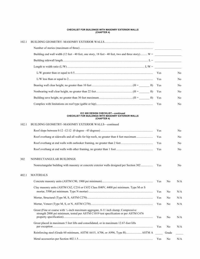
CHECKLIST FOR BUILDINGS WITH MASONRY EXTERIOR WALLS (CHAPTER 4)
102.1 BUILDING GEOMETRY–MASONRY EXTERIOR WALLS.........................................................................
Number of stories (maximum of three) .................................................................................................. __________________
Building end wall width (12 feet - 40 feet, one story, 18 feet - 40 feet, two and three story) .......... W = __________________
Building sidewall length................................................................................................................... L = __________________
Length to width ratio (L/W) ........................................................................................................ L/W = __________________
L/W greater than or equal to 0.5 ......................................................................................................... Yes No
L/W less than or equal to 2 ................................................................................................................. Yes No
Bearing wall clear height, no greater than 10 feet ....................................................... (H = _______ ft) Yes No
Nonbearing wall clear height, no greater than 22 feet ................................................. (H = _______ ft) Yes No
Building eave height, no greater than 30 feet maximum ............................................. (H = _______ ft) Yes No
Complies with limitations on roof type (gable or hip) ............................................................................ Yes No
ICC 600 DESIGN CHECKLIST—continued
CHECKLIST FOR BUILDINGS WITH MASONRY EXTERIOR WALLS (CHAPTER 4)
102.1 BUILDING GEOMETRY–MASONRY EXTERIOR WALLS—continued
Roof slope between 0:12 -12:12 (0 degree - 45 degrees) ...................................................................... Yes No
Roof overhang at sidewalls and all walls for hip roofs, no greater than 4 feet maximum ...................... Yes No
Roof overhang at end walls with outlooker framing, no greater than 2 feet ........................................... Yes No
Roof overhang at end walls with other framing, no greater than 1 foot ................................................. Yes No
302 NONRECTANGULAR BUILDINGS
Nonrectangular building with masonry or concrete exterior walls designed per Section 302 ................ Yes No
402.1 MATERIALS
Concrete masonry units (ASTM C90, 1900 psi minimum) .................................................................... Yes No N/A
Clay masonry units (ASTM C62, C216 or C652 Class H40V, 4400 psi minimum. Type M or S mortar, 5500 psi minimum. Type N mortar) ......................................................................................
Yes
No
N/A
Mortar, Structural (Type M, S, ASTM C270) ........................................................................................ Yes No N/A
Mortar, Veneer (Type M, S, or N, ASTM C270) ................................................................................... Yes No N/A
Grout (Fine or coarse with 3/8-inch maximum aggregate, 8-11 inch slump; Compressive strength 2000 psi minimum, tested per ASTM C1019 test specification or per ASTM C476 property specification) ........................................................................................................................
Yes
No
N/A
Grout placed in maximum 5 feet lifts and consolidated, or in maximum 12.67-foot lifts per exception ......................................................................................................................................
Yes
No
N/A
Reinforcing steel (Grade 60 minimum, ASTM A615, A706, or A996, Type R) ..................... ASTM A _____ Grade _____
Metal accessories per Section 402.1.5 .................................................................................................... Yes No N/A
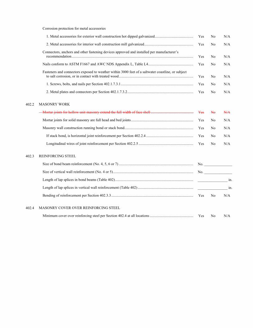
Corrosion protection for metal accessories
1. Metal accessories for exterior wall construction hot dipped galvanized......................................... Yes No N/A
2. Metal accessories for interior wall construction mill galvanized .................................................... Yes No N/A
Connectors, anchors and other fastening devices approved and installed per manufacturer’s recommendation .................................................................................................................................
Yes
No
N/A
Nails conform to ASTM F1667 and AWC NDS Appendix L, Table L4................................................ Yes No N/A
Fasteners and connectors exposed to weather within 3000 feet of a saltwater coastline, or subject to salt corrosion, or in contact with treated wood ...............................................................................
Yes
No
N/A
1. Screws, bolts, and nails per Section 402.1.7.3.1 ............................................................................. Yes No N/A
2. Metal plates and connectors per Section 402.1.7.3.2 ...................................................................... Yes No N/A
402.2 MASONRY WORK
Mortar joints for hollow unit masonry extend the full width of face shell ............................................. Yes No N/A
Mortar joints for solid masonry are full head and bed joints .................................................................. Yes No N/A
Masonry wall construction running bond or stack bond ......................................................................... Yes No N/A
If stack bond, is horizontal joint reinforcement per Section 402.2.4 .................................................. Yes No N/A
Longitudinal wires of joint reinforcement per Section 402.2.5 .......................................................... Yes No N/A
402.3 REINFORCING STEEL
Size of bond beam reinforcement (No. 4, 5, 6 or 7) ............................................................................... No. _______________
Size of vertical wall reinforcement (No. 4 or 5) ..................................................................................... No. _______________
Length of lap splices in bond beams (Table 402) ................................................................................... ________________ in.
Length of lap splices in vertical wall reinforcement (Table 402) ........................................................... ________________ in.
Bending of reinforcement per Section 402.3.3 ....................................................................................... Yes No N/A
402.4 MASONRY COVER OVER REINFORCING STEEL
Minimum cover over reinforcing steel per Section 402.4 at all locations .............................................. Yes No N/A
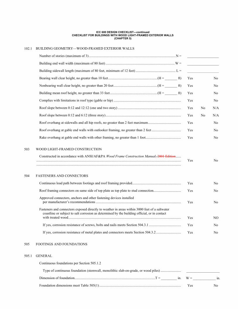
ICC 600 DESIGN CHECKLIST—continued
CHECKLIST FOR BUILDINGS WITH WOOD LIGHT-FRAMED EXTERIOR WALLS (CHAPTER 5)
102.1 BUILDING GEOMETRY—WOOD-FRAMED EXTERIOR WALLS
Number of stories (maximum of 3) .................................................................................................. N = __________________
Building end wall width (maximum of 80 feet) .............................................................................. W = __________________
Building sidewall length (maximum of 80 feet, minimum of 12 feet) ............................................. L = __________________
Bearing wall clear height, no greater than 10 feet ....................................................... (H = _______ ft) Yes No
Nonbearing wall clear height, no greater than 20 feet ................................................. (H = _______ ft) Yes No
Building mean roof height, no greater than 33 feet ..................................................... (H = _______ ft) Yes No
Complies with limitations in roof type (gable or hip) ............................................................................ Yes No
Roof slope between 0:12 and 12:12 (one and two story) ....................................................................... Yes No N/A
Roof slope between 0:12 and 6:12 (three story) ..................................................................................... Yes No N/A
Roof overhang at sidewalls and all hip roofs, no greater than 2 feet maximum ..................................... Yes No
Roof overhang at gable end walls with outlooker framing, no greater than 2 feet ................................. Yes No
Rake overhang at gable end walls with other framing, no greater than 1 foot........................................ Yes No
503 WOOD LIGHT-FRAMED CONSTRUCTION
Constructed in accordance with ANSI/AF&PA Wood Frame Construction Manual, 2001 Edition ...... ................................................................................................................................................................... ...................................................................................................................................................................
Yes No
504 FASTENERS AND CONNECTORS
Continuous load path between footings and roof framing provided ....................................................... Yes No
Roof framing connectors on same side of top plate as top plate to stud connection............................... Yes No
Approved connectors, anchors and other fastening devices installed per manufacturer’s recommendations ................................................................................................
Yes
No
Fasteners and connectors exposed directly to weather in areas within 3000 feet of a saltwater coastline or subject to salt corrosion as determined by the building official, or in contact with treated wood ...............................................................................................................................
Yes
NO
If yes, corrosion resistance of screws, bolts and nails meets Section 504.3.1 .................................... Yes No
If yes, corrosion resistance of metal plates and connectors meets Section 504.3.2 ............................ Yes No
505 FOOTINGS AND FOUNDATIONS
505.1 GENERAL
Continuous foundations per Section 505.1.2
Type of continuous foundation (stemwall, monolithic slab-on-grade, or wood piles) ....................... ___________________
Dimension of foundation...........................................................................................T = _________ in. W = _____________ in.
Foundation dimensions meet Table 505(1) ............................................................................................ Yes No
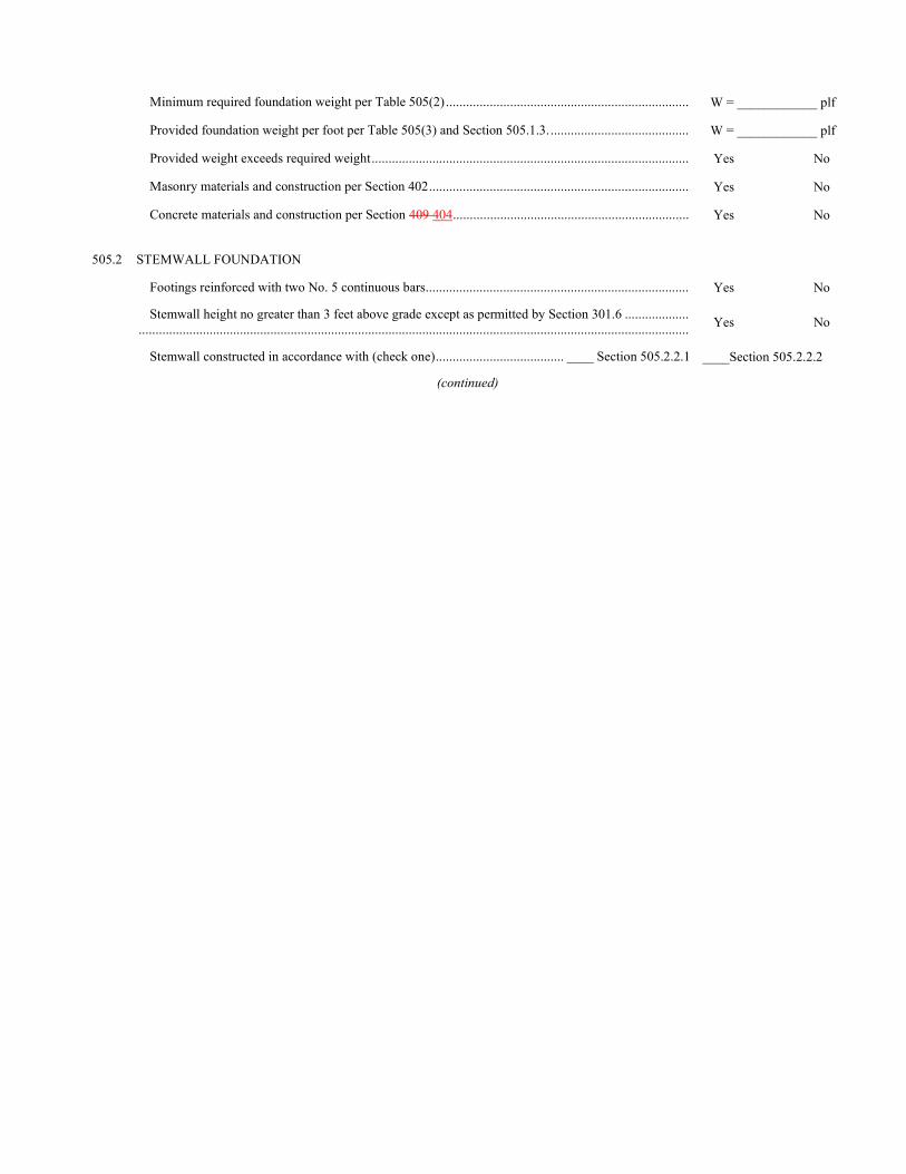
Minimum required foundation weight per Table 505(2) ........................................................................ W = ____________ plf
Provided foundation weight per foot per Table 505(3) and Section 505.1.3. ......................................... W = ____________ plf
Provided weight exceeds required weight .............................................................................................. Yes No
Masonry materials and construction per Section 402 ............................................................................. Yes No
Concrete materials and construction per Section 409 404 ...................................................................... Yes No
505.2 STEMWALL FOUNDATION
Footings reinforced with two No. 5 continuous bars .............................................................................. Yes No
Stemwall height no greater than 3 feet above grade except as permitted by Section 301.6 ................... ................................................................................................................................................................... Yes No
Stemwall constructed in accordance with (check one) ...................................... ____ Section 505.2.2.1 ____Section 505.2.2.2
(continued)
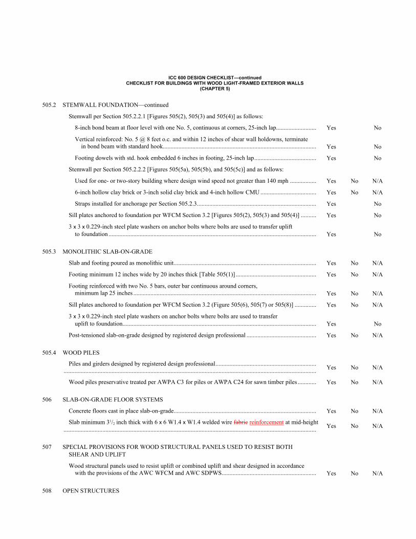
ICC 600 DESIGN CHECKLIST—continued
CHECKLIST FOR BUILDINGS WITH WOOD LIGHT-FRAMED EXTERIOR WALLS (CHAPTER 5)
505.2 STEMWALL FOUNDATION—continued
Stemwall per Section 505.2.2.1 [Figures 505(2), 505(3) and 505(4)] as follows:
8-inch bond beam at floor level with one No. 5, continuous at corners, 25-inch lap.......................... Yes No
Vertical reinforced: No. 5 @ 8 feet o.c. and within 12 inches of shear wall holdowns, terminate in bond beam with standard hook ...................................................................................................
Yes
No
Footing dowels with std. hook embedded 6 inches in footing, 25-inch lap ........................................ Yes No
Stemwall per Section 505.2.2.2 [Figures 505(5a), 505(5b), and 505(5c)] and as follows:
Used for one- or two-story building where design wind speed not greater than 140 mph ................. Yes No N/A
6-inch hollow clay brick or 3-inch solid clay brick and 4-inch hollow CMU .................................... Yes No N/A
Straps installed for anchorage per Section 505.2.3 ............................................................................. Yes No
Sill plates anchored to foundation per WFCM Section 3.2 [Figures 505(2), 505(3) and 505(4)] .......... Yes No
3 x 3 x 0.229-inch steel plate washers on anchor bolts where bolts are used to transfer uplift to foundation ......................................................................................................................................
Yes
No
505.3 MONOLITHIC SLAB-ON-GRADE
Slab and footing poured as monolithic unit ............................................................................................ Yes No N/A
Footing minimum 12 inches wide by 20 inches thick [Table 505(1)] .................................................... Yes No N/A
Footing reinforced with two No. 5 bars, outer bar continuous around corners, minimum lap 25 inches ......................................................................................................................
Yes
No
N/A
Sill plates anchored to foundation per WFCM Section 3.2 (Figure 505(6), 505(7) or 505(8)] .............. Yes No N/A
3 x 3 x 0.229-inch steel plate washers on anchor bolts where bolts are used to transfer uplift to foundation .............................................................................................................................
Yes
No
Post-tensioned slab-on-grade designed by registered design professional ............................................. Yes No N/A
505.4 WOOD PILES
Piles and girders designed by registered design professional ................................................................. ................................................................................................................................................................... Yes No N/A
Wood piles preservative treated per AWPA C3 for piles or AWPA C24 for sawn timber piles ............ Yes No N/A
506 SLAB-ON-GRADE FLOOR SYSTEMS
Concrete floors cast in place slab-on-grade ............................................................................................ Yes No N/A
Slab minimum 31/2 inch thick with 6 x 6 W1.4 x W1.4 welded wire fabric reinforcement at mid-height ...................................................................................................................................................................
Yes No N/A
507 SPECIAL PROVISIONS FOR WOOD STRUCTURAL PANELS USED TO RESIST BOTH SHEAR AND UPLIFT
Wood structural panels used to resist uplift or combined uplift and shear designed in accordance with the provisions of the AWC WFCM and AWC SDPWS .............................................................
Yes
No
N/A
508 OPEN STRUCTURES
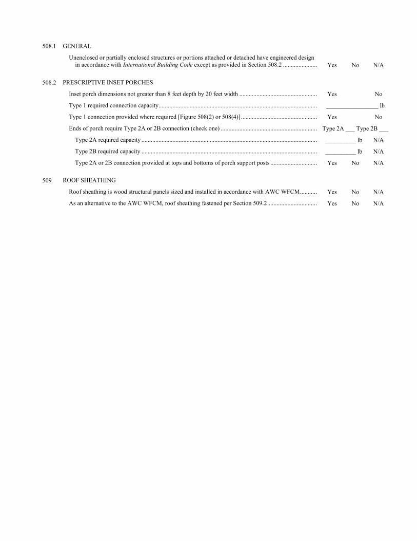
508.1 GENERAL
Unenclosed or partially enclosed structures or portions attached or detached have engineered design in accordance with International Building Code except as provided in Section 508.2 ......................
Yes
No
N/A
508.2 PRESCRIPTIVE INSET PORCHES
Inset porch dimensions not greater than 8 feet depth by 20 feet width .................................................. Yes No
Type 1 required connection capacity ...................................................................................................... _________________ lb
Type 1 connection provided where required [Figure 508(2) or 508(4)] ................................................. Yes No
Ends of porch require Type 2A or 2B connection (check one) .............................................................. Type 2A ___ Type 2B ___
Type 2A required capacity ................................................................................................................. __________ lb N/A
Type 2B required capacity ................................................................................................................. __________ lb N/A
Type 2A or 2B connection provided at tops and bottoms of porch support posts .............................. Yes No N/A
509 ROOF SHEATHING
Roof sheathing is wood structural panels sized and installed in accordance with AWC WFCM ........... Yes No N/A
As an alternative to the AWC WFCM, roof sheathing fastened per Section 509.2 ................................ Yes No N/A
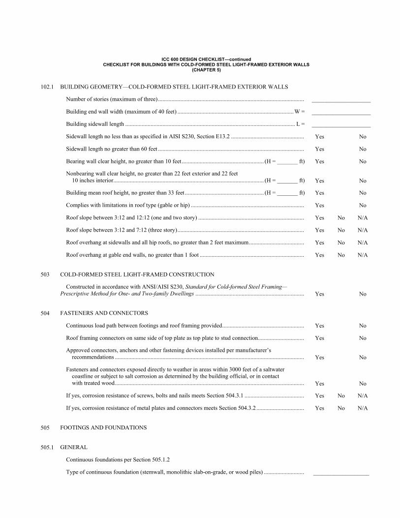
ICC 600 DESIGN CHECKLIST—continued CHECKLIST FOR BUILDINGS WITH COLD-FORMED STEEL LIGHT-FRAMED EXTERIOR WALLS
(CHAPTER 5)
102.1 BUILDING GEOMETRY—COLD-FORMED STEEL LIGHT-FRAMED EXTERIOR WALLS
Number of stories (maximum of three) .................................................................................................. ____________________
Building end wall width (maximum of 40 feet) .............................................................................. W = ____________________
Building sidewall length .................................................................................................................. L = ____________________
Sidewall length no less than as specified in AISI S230, Section E13.2 ................................................. Yes No
Sidewall length no greater than 60 feet .................................................................................................. Yes No
Bearing wall clear height, no greater than 10 feet ....................................................... (H = _______ ft) Yes No
Nonbearing wall clear height, no greater than 22 feet exterior and 22 feet 10 inches interior ..................................................................................................... (H = _______ ft)
Yes
No
Building mean roof height, no greater than 33 feet ..................................................... (H = _______ ft) Yes No
Complies with limitations in roof type (gable or hip) ............................................................................ Yes No
Roof slope between 3:12 and 12:12 (one and two story) ....................................................................... Yes No N/A
Roof slope between 3:12 and 7:12 (three story) ..................................................................................... Yes No N/A
Roof overhang at sidewalls and all hip roofs, no greater than 2 feet maximum ..................................... Yes No N/A
Roof overhang at gable end walls, no greater than 1 foot ...................................................................... Yes No N/A
503 COLD-FORMED STEEL LIGHT-FRAMED CONSTRUCTION
Constructed in accordance with ANSI/AISI S230, Standard for Cold-formed Steel Framing—Prescriptive Method for One- and Two-family Dwellings .........................................................................
Yes
No
504 FASTENERS AND CONNECTORS
Continuous load path between footings and roof framing provided ....................................................... Yes No
Roof framing connectors on same side of top plate as top plate to stud connection............................... Yes No
Approved connectors, anchors and other fastening devices installed per manufacturer’s recommendations ...............................................................................................................................
Yes
No
Fasteners and connectors exposed directly to weather in areas within 3000 feet of a saltwater coastline or subject to salt corrosion as determined by the building official, or in contact with treated wood ...............................................................................................................................
Yes
No
If yes, corrosion resistance of screws, bolts and nails meets Section 504.3.1 ........................................ Yes No N/A
If yes, corrosion resistance of metal plates and connectors meets Section 504.3.2 ................................ Yes No N/A
505 FOOTINGS AND FOUNDATIONS
505.1 GENERAL
Continuous foundations per Section 505.1.2
Type of continuous foundation (stemwall, monolithic slab-on-grade, or wood piles) ........................... ___________________
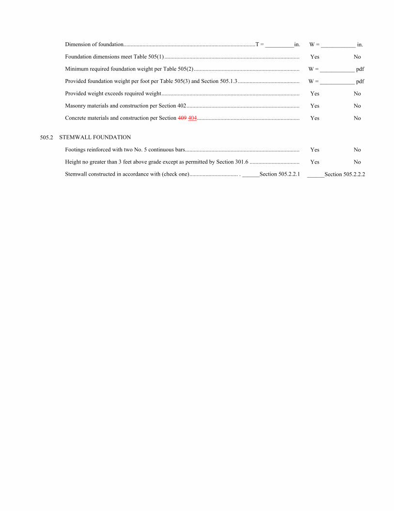
Dimension of foundation..........................................................................................T = __________in. W = ____________ in.
Foundation dimensions meet Table 505(1) ............................................................................................ Yes No
Minimum required foundation weight per Table 505(2) ........................................................................ W = ____________ pdf
Provided foundation weight per foot per Table 505(3) and Section 505.1.3 .......................................... W = ____________ pdf
Provided weight exceeds required weight .............................................................................................. Yes No
Masonry materials and construction per Section 402 ............................................................................. Yes No
Concrete materials and construction per Section 409 404 ...................................................................... Yes No
505.2 STEMWALL FOUNDATION
Footings reinforced with two No. 5 continuous bars .............................................................................. Yes No
Height no greater than 3 feet above grade except as permitted by Section 301.6 .................................. Yes No
Stemwall constructed in accordance with (check one) ................................. . ______Section 505.2.2.1 ______Section 505.2.2.2
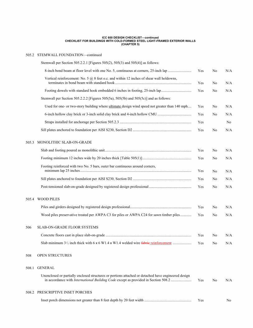
ICC 600 DESIGN CHECKLIST—continued CHECKLIST FOR BUILDINGS WITH COLD-FORMED STEEL LIGHT-FRAMED EXTERIOR WALLS
(CHAPTER 5)
505.2 STEMWALL FOUNDATION—continued
Stemwall per Section 505.2.2.1 [Figures 505(2), 505(3) and 505(4)] as follows:
8-inch bond beam at floor level with one No. 5, continuous at corners, 25-inch lap ......................... Yes No N/A
Vertical reinforcement: No. 5 @ 8 feet o.c. and within 12 inches of shear wall holdowns, terminates in bond beam with standard hook .................................................................................
Yes
No
N/A
Footing dowels with standard hook embedded 6 inches in footing, 25-inch lap ................................ Yes No N/A
Stemwall per Section 505.2.2.2 [Figures 505(5a), 505(5b) and 505(5c)] and as follows:
Used for one- or two-story building where ultimate design wind speed not greater than 140 mph.... Yes No N/A
6-inch hollow clay brick or 3-inch solid clay brick and 4-inch hollow CMU .................................... Yes No N/A
Straps installed for anchorage per Section 505.2.3 ............................................................................ Yes No
Sill plates anchored to foundation per AISI S230, Section D2 .............................................................. Yes No N/A
505.3 MONOLITHIC SLAB-ON-GRADE
Slab and footing poured as monolithic unit............................................................................................ Yes No N/A
Footing minimum 12 inches wide by 20 inches thick [Table 505(1)] .................................................... Yes No N/A
Footing reinforced with two No. 5 bars, outer bar continuous around corners, minimum lap 25 inches ......................................................................................................................
Yes
No
N/A
Sill plates anchored to foundation per AISI S230, Section D2 .............................................................. Yes No N/A
Post-tensioned slab-on-grade designed by registered design professional ............................................. Yes No N/A
505.4 WOOD PILES
Piles and girders designed by registered design professional ................................................................. Yes No N/A
Wood piles preservative treated per AWPA C3 for piles or AWPA C24 for sawn timber piles ............ Yes No N/A
506 SLAB-ON-GRADE FLOOR SYSTEMS
Concrete floors cast in place slab-on-grade ........................................................................................... Yes No N/A
Slab minimum 31/2 inch thick with 6 x 6 W1.4 x W1.4 welded wire fabric reinforcement .................... Yes No N/A
508 OPEN STRUCTURES
508.1 GENERAL
Unenclosed or partially enclosed structures or portions attached or detached have engineered design in accordance with International Building Code except as provided in Section 508.2 ......................
Yes
No
N/A
508.2 PRESCRIPTIVE INSET PORCHES
Inset porch dimensions not greater than 8 feet depth by 20 feet width .................................................. Yes No
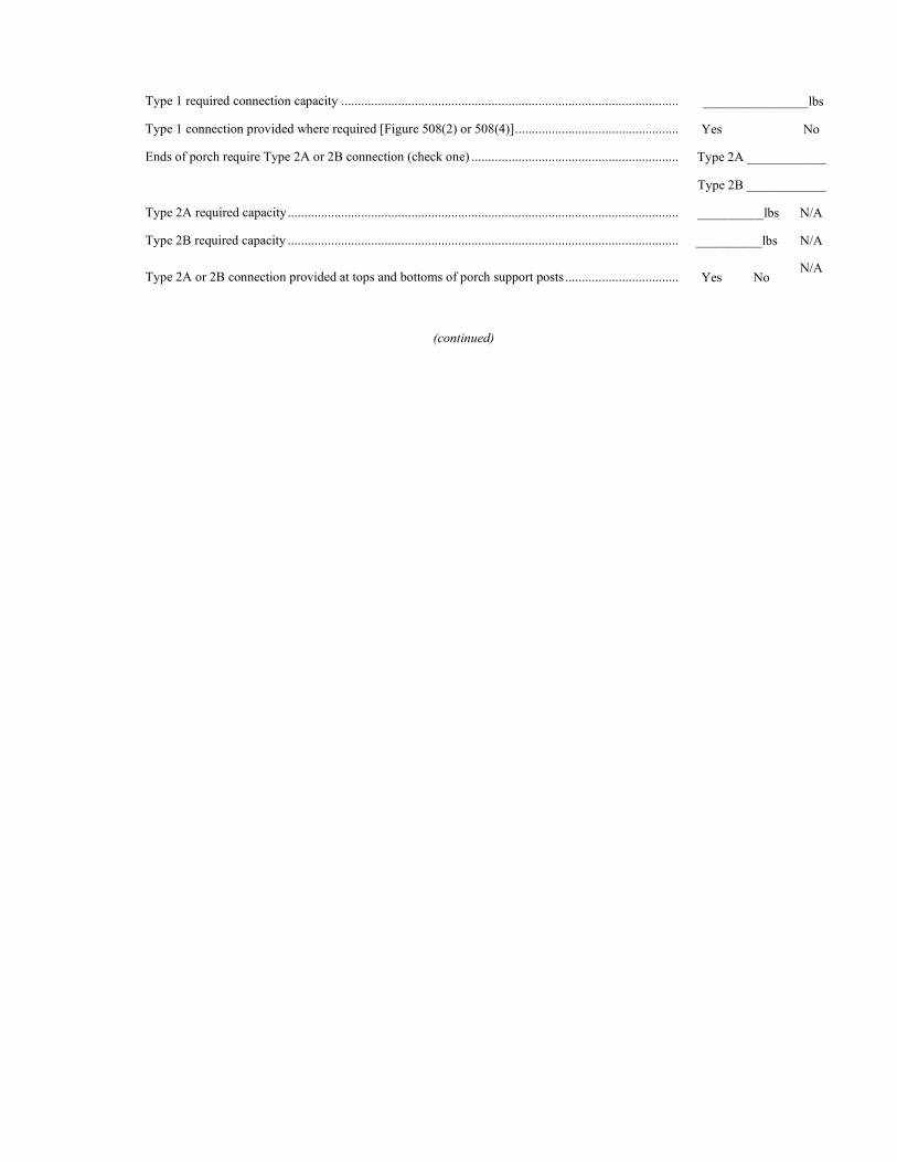
Type 1 required connection capacity ..................................................................................................... ________________lbs
Type 1 connection provided where required [Figure 508(2) or 508(4)] ................................................. Yes No
Ends of porch require Type 2A or 2B connection (check one) .............................................................. Type 2A ____________
Type 2B ____________
Type 2A required capacity ..................................................................................................................... __________lbs N/A
Type 2B required capacity ..................................................................................................................... __________lbs N/A
Type 2A or 2B connection provided at tops and bottoms of porch support posts .................................. Yes No N/A
(continued)
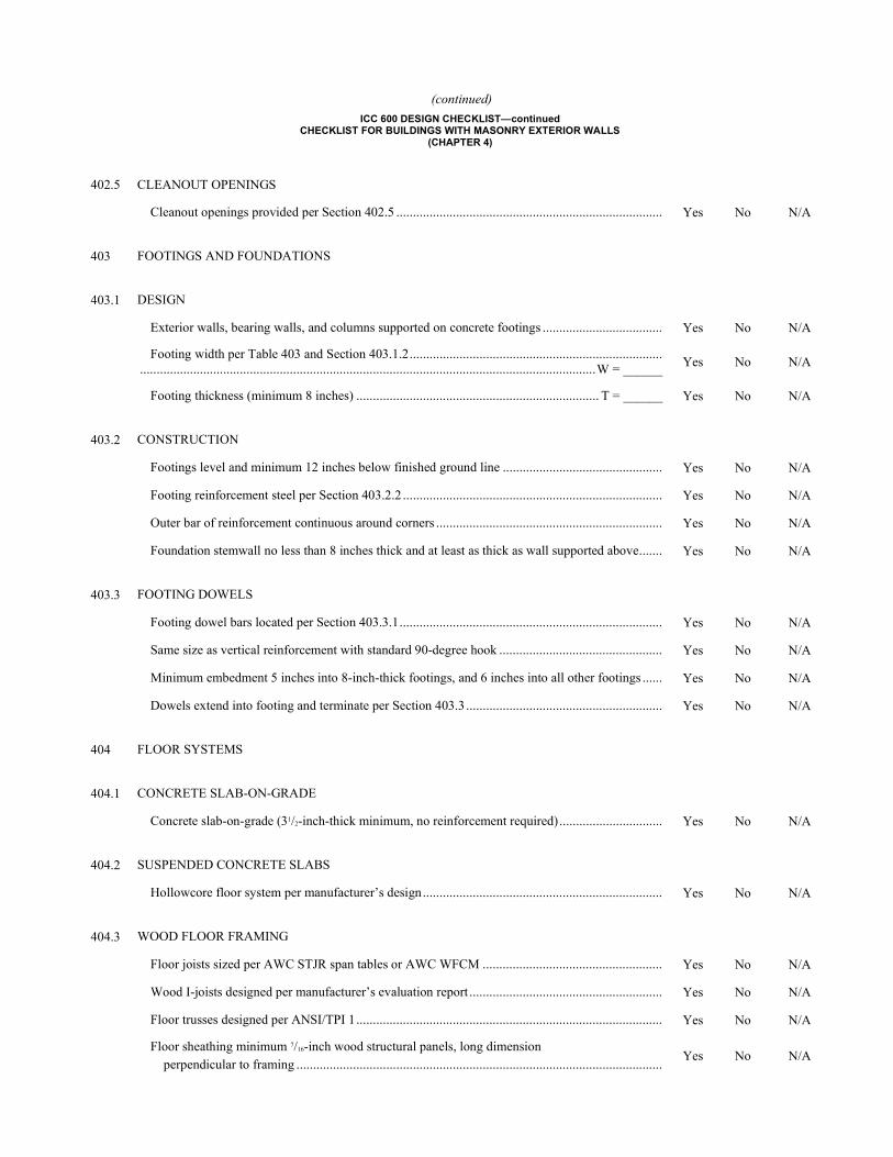
(continued)
ICC 600 DESIGN CHECKLIST—continued CHECKLIST FOR BUILDINGS WITH MASONRY EXTERIOR WALLS
(CHAPTER 4)
402.5 CLEANOUT OPENINGS
Cleanout openings provided per Section 402.5 ................................................................................ Yes No N/A
403 FOOTINGS AND FOUNDATIONS
403.1 DESIGN
Exterior walls, bearing walls, and columns supported on concrete footings .................................... Yes No N/A
Footing width per Table 403 and Section 403.1.2 ............................................................................ ......................................................................................................................................... W = ______ Yes No N/A
Footing thickness (minimum 8 inches) ......................................................................... T = ______ Yes No N/A
403.2 CONSTRUCTION
Footings level and minimum 12 inches below finished ground line ................................................ Yes No N/A
Footing reinforcement steel per Section 403.2.2 .............................................................................. Yes No N/A
Outer bar of reinforcement continuous around corners .................................................................... Yes No N/A
Foundation stemwall no less than 8 inches thick and at least as thick as wall supported above ....... Yes No N/A
403.3 FOOTING DOWELS
Footing dowel bars located per Section 403.3.1 ............................................................................... Yes No N/A
Same size as vertical reinforcement with standard 90-degree hook ................................................. Yes No N/A
Minimum embedment 5 inches into 8-inch-thick footings, and 6 inches into all other footings ...... Yes No N/A
Dowels extend into footing and terminate per Section 403.3 ........................................................... Yes No N/A
404 FLOOR SYSTEMS
404.1 CONCRETE SLAB-ON-GRADE
Concrete slab-on-grade (31/2-inch-thick minimum, no reinforcement required) ............................... Yes No N/A
404.2 SUSPENDED CONCRETE SLABS
Hollowcore floor system per manufacturer’s design ........................................................................ Yes No N/A
404.3 WOOD FLOOR FRAMING
Floor joists sized per AWC STJR span tables or AWC WFCM ...................................................... Yes No N/A
Wood I-joists designed per manufacturer’s evaluation report .......................................................... Yes No N/A
Floor trusses designed per ANSI/TPI 1 ............................................................................................ Yes No N/A
Floor sheathing minimum 7/16-inch wood structural panels, long dimension perpendicular to framing ..............................................................................................................
Yes No N/A
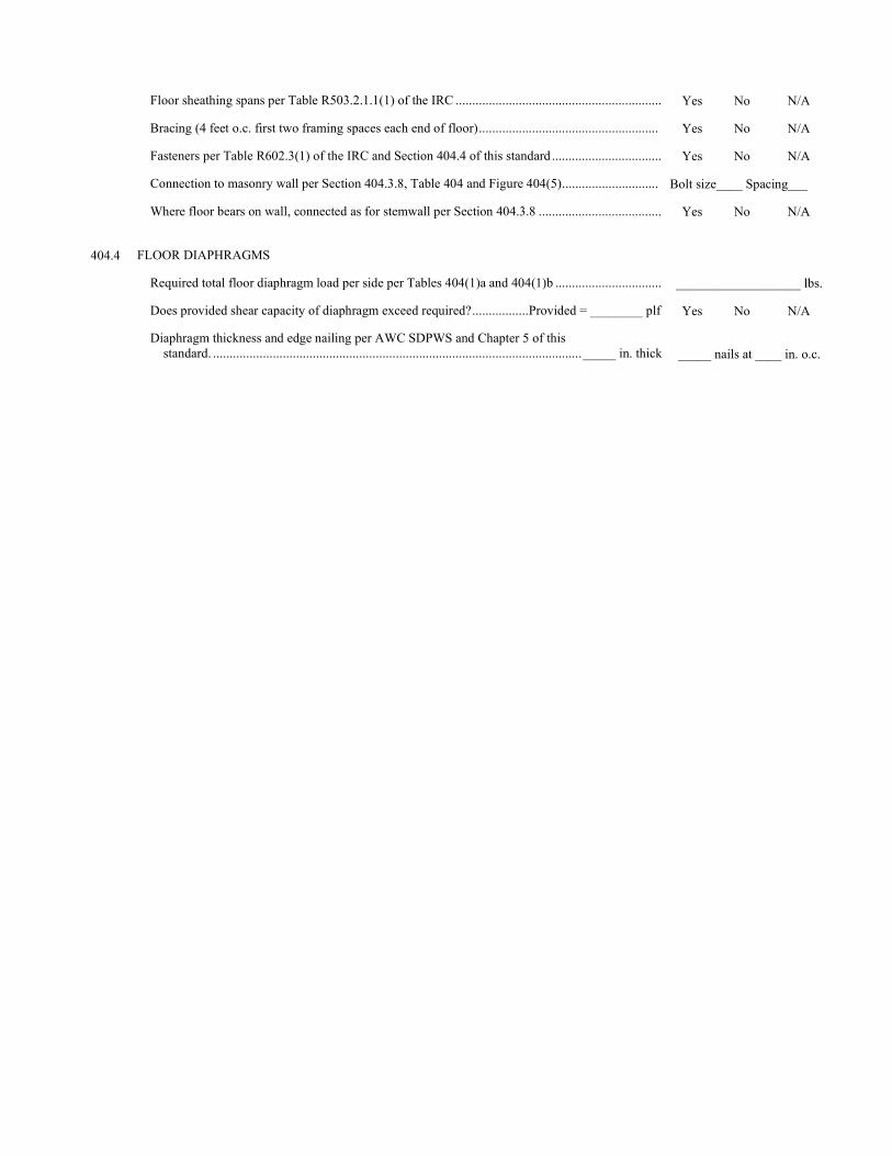
Floor sheathing spans per Table R503.2.1.1(1) of the IRC .............................................................. Yes No N/A
Bracing (4 feet o.c. first two framing spaces each end of floor) ...................................................... Yes No N/A
Fasteners per Table R602.3(1) of the IRC and Section 404.4 of this standard ................................. Yes No N/A
Connection to masonry wall per Section 404.3.8, Table 404 and Figure 404(5) ............................. Bolt size____ Spacing___
Where floor bears on wall, connected as for stemwall per Section 404.3.8 ..................................... Yes No N/A
404.4 FLOOR DIAPHRAGMS
Required total floor diaphragm load per side per Tables 404(1)a and 404(1)b ................................ ___________________ lbs.
Does provided shear capacity of diaphragm exceed required? ................. Provided = ________ plf Yes No N/A
Diaphragm thickness and edge nailing per AWC SDPWS and Chapter 5 of this standard. ............................................................................................................... _____ in. thick
_____ nails at ____ in. o.c.
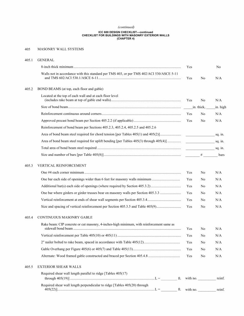
(continued) ICC 600 DESIGN CHECKLIST—continued
CHECKLIST FOR BUILDINGS WITH MASONRY EXTERIOR WALLS (CHAPTER 4)
405 MASONRY WALL SYSTEMS
405.1 GENERAL
8-inch thick minimum ...................................................................................................................... Yes No
Walls not in accordance with this standard per TMS 403, or per TMS 402/ACI 530/ASCE 5-11 and TMS 602/ACI 530.1/ASCE 6-11...........................................................................................
Yes
No
N/A
405.2 BOND BEAMS (at top, each floor and gable)
Located at the top of each wall and at each floor level (includes rake beam at top of gable end walls) .............................................................................
Yes
No
N/A
Size of bond beam ............................................................................................................................ _____in. thick, _____in. high
Reinforcement continuous around corners ....................................................................................... Yes No N/A
Approved precast bond beam per Section 405.2.2 (if applicable) .................................................... Yes No N/A
Reinforcement of bond beam per Sections 405.2.3, 405.2.4, 405.2.5 and 405.2.6
Area of bond beam steel required for chord tension [per Tables 405(1) and 405(2)] ....................... ________________ sq. in.
Area of bond beam steel required for uplift bending [per Tables 405(3) through 405(4)] ............... ________________ sq. in.
Total area of bond beam steel required ............................................................................................ ________________ sq. in.
Size and number of bars [per Table 405(8)] ..................................................................................... ________ # ________ bars
405.3 VERTICAL REINFORCEMENT
One #4 each corner minimum .......................................................................................................... Yes No N/A
One bar each side of openings wider than 6 feet for masonry walls minimum ............................... Yes No N/A
Additional bar(s) each side of openings (where required by Section 405.3.2) ................................. Yes No N/A
One bar where girders or girder trusses bear on masonry walls per Section 405.3.3 ....................... Yes No N/A
Vertical reinforcement at ends of shear wall segments per Section 405.3.4 ..................................... Yes No N/A
Size and spacing of vertical reinforcement per Section 405.3.5 and Table 405(9) ........................... Yes No N/A
405.4 CONTINUOUS MASONRY GABLE
Rake beam: CIP concrete or cut masonry, 4-inches-high minimum, with reinforcement same as sidewall bond beam .............................................................................................................................
Yes
No
N/A
Vertical reinforcement per Table 405(10) or 405(11) ...................................................................... Yes No N/A
2" nailer bolted to rake beam, spaced in accordance with Table 405(12) ........................................ Yes No N/A
Gable Overhang per Figure 405(6) or 405(7) and Table 405(13) ..................................................... Yes No N/A
Alternate: Wood framed gable constructed and braced per Section 405.4.8 ................................... Yes No N/A
405.5 EXTERIOR SHEAR WALLS
Required shear wall length parallel to ridge [Tables 405(17) through 405(19)] ............................................................................................. L = _________ ft.
with no. __________ reinf.
Required shear wall length perpendicular to ridge [Tables 405(20) through 405(22)] ........................................................................................................... L = _________ ft.
with no. __________ reinf.
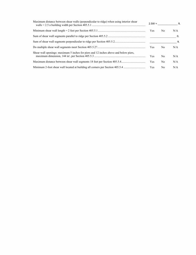
Maximum distance between shear walls (perpendicular to ridge) when using interior shear walls = 2.5 x building width per Section 405.5.1 ......................................................................... 2.5W = ______________ ft.
Minimum shear wall length = 2 feet per Section 405.5.1 ................................................................. Yes No N/A
Sum of shear wall segments parallel to ridge per Section 405.5.2 ................................................... __________________ ft.
Sum of shear wall segments perpendicular to ridge per Section 405.5.2.......................................... ___________________ ft.
Do multiple shear wall segments meet Section 405.5.2? .................................................................. Yes No N/A
Shear wall openings: maximum 5 inches for piers and 12 inches above and below piers, maximum dimension, 144 in2, per Section 405.5.3 ......................................................................
Yes
No
N/A
Maximum distance between shear wall segments 18 feet per Section 405.5.4 ................................. Yes No N/A
Minimum 2-foot shear wall located at building all corners per Section 405.5.4 .............................. Yes No N/A
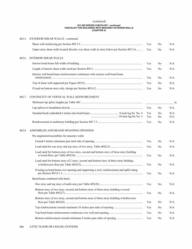
(continued) ICC 600 DESIGN CHECKLIST—continued
CHECKLIST FOR BUILDINGS WITH MASONRY EXTERIOR WALLS (CHAPTER 4)
405.5 EXTERIOR SHEAR WALLS—continued
Shear wall reinforcing per Section 405.5.5 ...................................................................................... Yes No N/A
Upper story shear walls located directly over shear walls in story below per Section 405.5.6 ......... Yes No N/A
405.6 INTERIOR SHEAR WALLS
Interior bond beam full width of building ........................................................................................ Yes No N/A
Length of interior shear walls sized per Section 405.5 ..................................................................... Yes No N/A
Interior wall bond beam reinforcement continuous with exterior wall bond beam reinforcement ...............................................................................................................................
Yes
No
N/A
Top of shear wall supported per Figure 407(5) ................................................................................ Yes No N/A
If used on bottom story only, design per Section 405.6.2 ................................................................. Yes No N/A
405.7 CONTINUITY OF VERTICAL WALL REINFORCEMENT
Minimum lap splice lengths per Table 402 ...................................................................................... ____________________ in.
Lap splices to foundation dowels ..................................................................................................... Yes No N/A
Standard hook embedded 6 inches into bond beam: ........................................ 8-inch leg for No. 4 ...................................... 10-inch leg for No. 5
Yes Yes
No No
N/A N/A
Reinforcement in multistory building per Section 405.7.3 ............................................................... Yes No N/A
405.8 ASSEMBLIES AND BEAMS SPANNING OPENINGS
Pre-engineered assemblies for masonry walls:
Extend 4 inches minimum past each side of opening ................................................................... Yes No N/A
Load rated for one story and top story of two story, Table 405(23) ............................................. Yes No N/A
Load rated for bottom story of two story, second and bottom story of three-story building w/wood floor, per Table 405(24) ..............................................................................................
Yes
No
N/A
Load rated for bottom story of 2 story, second and bottom story of three-story building w/hollowcore floor per Table 405(25) ......................................................................................
Yes
No
N/A
If acting as bond beam over opening and supporting a roof, reinforcement and uplift rating per Section 405.8.1.3 ................................................................................................................
Yes
No
N/A
Bond beam combined with lintel:
One story and top story of multi-story per Table 405(26) ............................................................ Yes No N/A
Bottom story of two story, second and bottom story of three-story building w/wood floor per Table 405(27) ............................................................................................................
Yes
No
N/A
Bottom story of two story, second and bottom story of three-story building w/hollowcore floor per Table 405(28) ............................................................................................................
Yes
No
N/A
Top reinforcement extends minimum 24 inches past sides of opening ........................................ Yes No N/A
Top bond beam reinforcement continuous over wall and opening ............................................... Yes No N/A
Bottom reinforcement extends minimum 4 inches past sides of opening ..................................... Yes No N/A
406 ATTIC FLOOR OR CEILING SYSTEMS
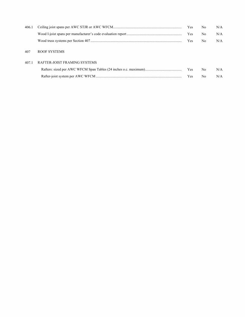
406.1 Ceiling joist spans per AWC STJR or AWC WFCM ........................................................................... Yes No N/A
Wood I-joist spans per manufacturer’s code evaluation report ............................................................ Yes No N/A
Wood truss systems per Section 407 .................................................................................................... Yes No N/A
407 ROOF SYSTEMS
407.1 RAFTER-JOIST FRAMING SYSTEMS
Rafters: sized per AWC WFCM Span Tables (24 inches o.c. maximum) ........................................ Yes No N/A
Rafter-joist system per AWC WFCM .............................................................................................. Yes No N/A
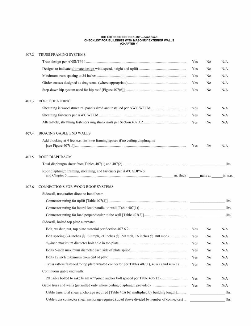
ICC 600 DESIGN CHECKLIST—continued CHECKLIST FOR BUILDINGS WITH MASONRY EXTERIOR WALLS
(CHAPTER 4)
407.2 TRUSS FRAMING SYSTEMS
Truss design per ANSI/TPI-1 ........................................................................................................... Yes No N/A
Designs to indicate ultimate design wind speed, height and uplift ................................................... Yes No N/A
Maximum truss spacing at 24 inches ................................................................................................ Yes No N/A
Girder trusses designed as drag struts (where appropriate) .............................................................. Yes No N/A
Step-down hip system used for hip roof [Figure 407(6)] ................................................................. Yes No N/A
407.3 ROOF SHEATHING
Sheathing is wood structural panels sized and installed per AWC WFCM ...................................... Yes No N/A
Sheathing fasteners per AWC WFCM ............................................................................................. Yes No N/A
Alternately, sheathing fasteners ring shank nails per Section 407.3.2 .............................................. Yes No N/A
407.4 BRACING GABLE END WALLS
Add blocking at 4 feet o.c. first two framing spaces if no ceiling diaphragms [see Figure 407(1)] .......................................................................................................................
Yes
No
N/A
407.5 ROOF DIAPHRAGM
Total diaphragm shear from Tables 407(1) and 407(2) .................................................................... ___________________ lbs.
Roof diaphragm framing, sheathing, and fasteners per AWC SDPWS and Chapter 5 ..................................................................................................... ______ in. thick
______nails at ______in. o.c.
407.6 CONNECTIONS FOR WOOD ROOF SYSTEMS
Sidewall, truss/rafter direct to bond beam:
Connector rating for uplift [Table 407(3)] .................................................................................... ___________________ lbs.
Connector rating for lateral load parallel to wall [Table 407(1)] .................................................. ___________________ lbs.
Connector rating for load perpendicular to the wall [Table 407(2)] ............................................. ___________________ lbs.
Sidewall, bolted top plate alternate:
Bolt, washer, nut, top plate material per Section 407.6.2 ............................................................. Yes No N/A
Bolt spacing (24 inches @ 130 mph, 21 inches @ 150 mph, 16 inches @ 180 mph) .................. Yes No N/A
9/16-inch maximum diameter bolt hole in top plate ........................................................................ Yes No N/A
Bolts 6-inch maximum diameter each side of plate splice............................................................ Yes No N/A
Bolts 12 inch maximum from end of plate ................................................................................... Yes No N/A
Truss rafters fastened to top plate w/rated connector per Tables 407(1), 407(2) and 407(3) ........ Yes No N/A
Continuous gable end walls:
2 nailer bolted to rake beam w/1/2-inch anchor bolt spaced per Table 405(12) ........................... Yes No N/A
Gable truss end walls (permitted only where ceiling diaphragm provided)...................................... Yes No N/A
Gable truss total shear anchorage required [Table 405(16) multiplied by building length] .......... ___________________ lbs.
Gable truss connector shear anchorage required (Load above divided by number of connectors) ... ___________________ lbs.
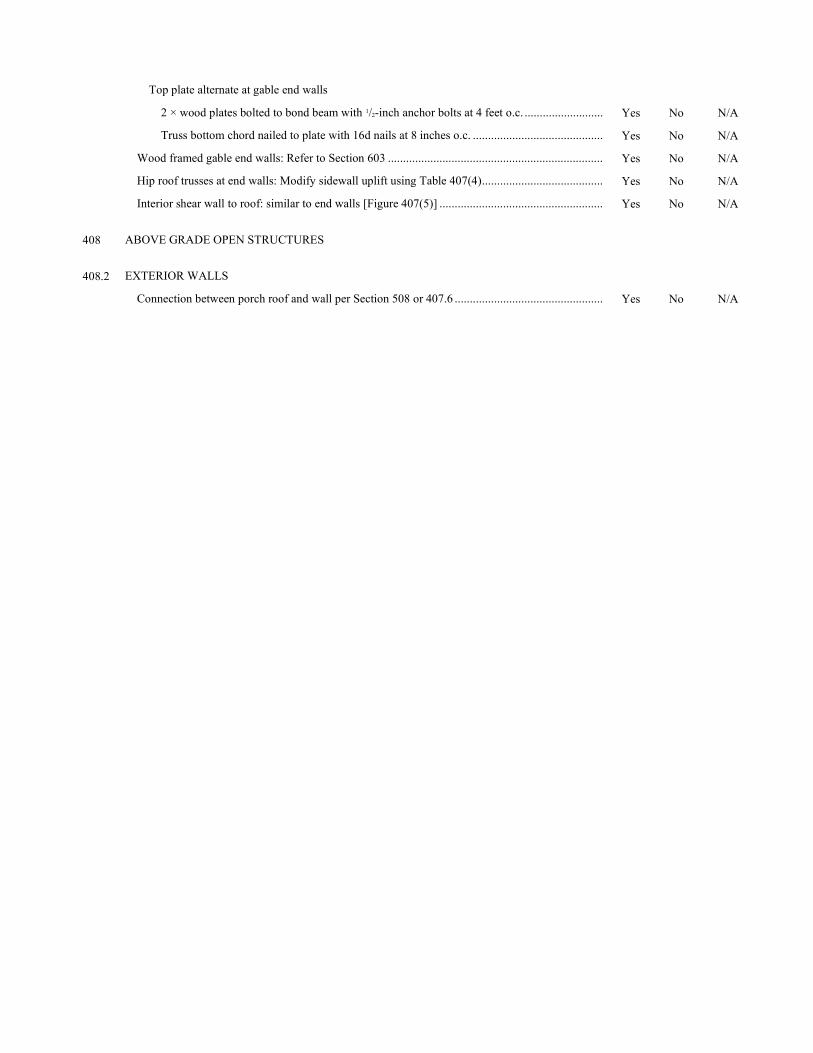
Top plate alternate at gable end walls
2 × wood plates bolted to bond beam with 1/2-inch anchor bolts at 4 feet o.c. .......................... Yes No N/A
Truss bottom chord nailed to plate with 16d nails at 8 inches o.c. ........................................... Yes No N/A
Wood framed gable end walls: Refer to Section 603 ....................................................................... Yes No N/A
Hip roof trusses at end walls: Modify sidewall uplift using Table 407(4) ........................................ Yes No N/A
Interior shear wall to roof: similar to end walls [Figure 407(5)] ...................................................... Yes No N/A
408 ABOVE GRADE OPEN STRUCTURES
408.2 EXTERIOR WALLS
Connection between porch roof and wall per Section 508 or 407.6 ................................................. Yes No N/A
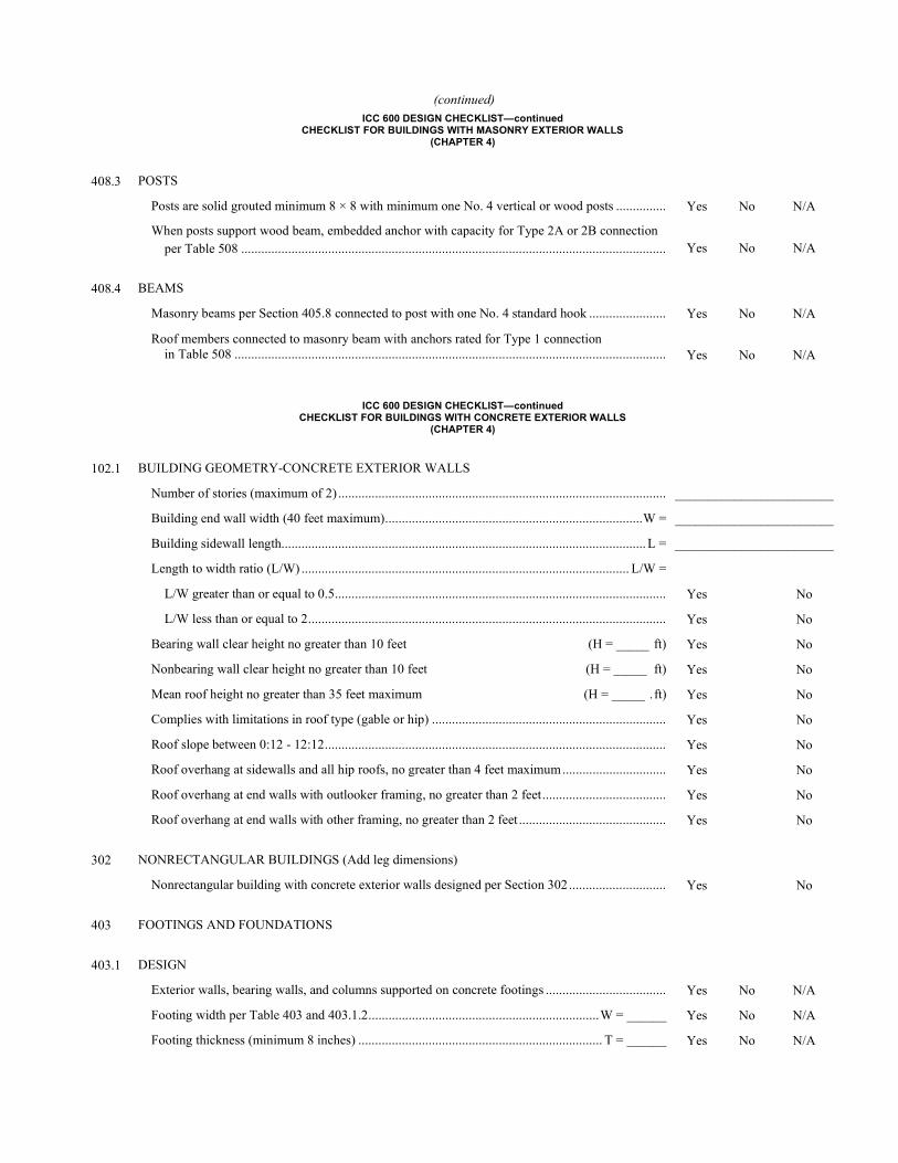
(continued) ICC 600 DESIGN CHECKLIST—continued
CHECKLIST FOR BUILDINGS WITH MASONRY EXTERIOR WALLS (CHAPTER 4)
408.3 POSTS
Posts are solid grouted minimum 8 × 8 with minimum one No. 4 vertical or wood posts ............... Yes No N/A
When posts support wood beam, embedded anchor with capacity for Type 2A or 2B connection per Table 508 ...............................................................................................................................
Yes
No
N/A
408.4 BEAMS
Masonry beams per Section 405.8 connected to post with one No. 4 standard hook ....................... Yes No N/A
Roof members connected to masonry beam with anchors rated for Type 1 connection in Table 508 .................................................................................................................................
Yes
No
N/A
ICC 600 DESIGN CHECKLIST—continued CHECKLIST FOR BUILDINGS WITH CONCRETE EXTERIOR WALLS
(CHAPTER 4)
102.1 BUILDING GEOMETRY-CONCRETE EXTERIOR WALLS
Number of stories (maximum of 2) .................................................................................................. ________________________
Building end wall width (40 feet maximum) ............................................................................. W = ________________________
Building sidewall length............................................................................................................. L = ________________________
Length to width ratio (L/W) .................................................................................................. L/W =
L/W greater than or equal to 0.5 ................................................................................................... Yes No
L/W less than or equal to 2 ........................................................................................................... Yes No
Bearing wall clear height no greater than 10 feet (H = _____ ft) Yes No
Nonbearing wall clear height no greater than 10 feet (H = _____ ft) Yes No
Mean roof height no greater than 35 feet maximum (H = _____ . ft) Yes No
Complies with limitations in roof type (gable or hip) ...................................................................... Yes No
Roof slope between 0:12 - 12:12 ...................................................................................................... Yes No
Roof overhang at sidewalls and all hip roofs, no greater than 4 feet maximum ............................... Yes No
Roof overhang at end walls with outlooker framing, no greater than 2 feet ..................................... Yes No
Roof overhang at end walls with other framing, no greater than 2 feet ............................................ Yes No
302 NONRECTANGULAR BUILDINGS (Add leg dimensions)
Nonrectangular building with concrete exterior walls designed per Section 302 ............................. Yes No
403 FOOTINGS AND FOUNDATIONS
403.1 DESIGN
Exterior walls, bearing walls, and columns supported on concrete footings .................................... Yes No N/A
Footing width per Table 403 and 403.1.2 ..................................................................... W = ______ Yes No N/A
Footing thickness (minimum 8 inches) ......................................................................... T = ______ Yes No N/A
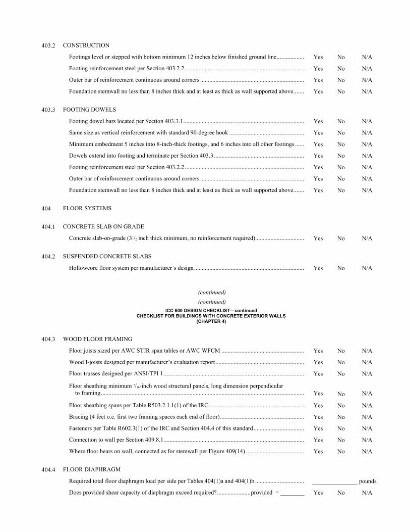
403.2 CONSTRUCTION
Footings level or stepped with bottom minimum 12 inches below finished ground line .................. Yes No N/A
Footing reinforcement steel per Section 403.2.2 .............................................................................. Yes No N/A
Outer bar of reinforcement continuous around corners .................................................................... Yes No N/A
Foundation stemwall no less than 8 inches thick and at least as thick as wall supported above ....... Yes No N/A
403.3 FOOTING DOWELS
Footing dowel bars located per Section 403.3.1 ............................................................................... Yes No N/A
Same size as vertical reinforcement with standard 90-degree hook ................................................. Yes No N/A
Minimum embedment 5 inches into 8-inch-thick footings, and 6 inches into all other footings ...... Yes No N/A
Dowels extend into footing and terminate per Section 403.3 ........................................................... Yes No N/A
Footing reinforcement steel per Section 403.2.2 .............................................................................. Yes No N/A
Outer bar of reinforcement continuous around corners .................................................................... Yes No N/A
Foundation stemwall no less than 8 inches thick and at least as thick as wall supported above ....... Yes No N/A
404 FLOOR SYSTEMS
404.1 CONCRETE SLAB ON GRADE
Concrete slab-on-grade (31/2 inch thick minimum, no reinforcement required) ................................ Yes No N/A
404.2 SUSPENDED CONCRETE SLABS
Hollowcore floor system per manufacturer’s design ........................................................................ Yes No N/A
(continued)
(continued) ICC 600 DESIGN CHECKLIST—continued
CHECKLIST FOR BUILDINGS WITH CONCRETE EXTERIOR WALLS (CHAPTER 4)
404.3 WOOD FLOOR FRAMING
Floor joists sized per AWC STJR span tables or AWC WFCM ...................................................... Yes No N/A
Wood I-joists designed per manufacturer’s evaluation report .......................................................... Yes No N/A
Floor trusses designed per ANSI/TPI 1 ............................................................................................ Yes No N/A
Floor sheathing minimum 7/16-inch wood structural panels, long dimension perpendicular to framing .....................................................................................................................................
Yes
No
N/A
Floor sheathing spans per Table R503.2.1.1(1) of the IRC .............................................................. Yes No N/A
Bracing (4 feet o.c. first two framing spaces each end of floor) ....................................................... Yes No N/A
Fasteners per Table R602.3(1) of the IRC and Section 404.4 of this standard ................................. Yes No N/A
Connection to wall per Section 409.8.1 ............................................................................................ Yes No N/A
Where floor bears on wall, connected as for stemwall per Figure 409(14) ...................................... Yes No N/A
404.4 FLOOR DIAPHRAGM
Required total floor diaphragm load per side per Tables 404(1)a and 404(1)b ................................ _______________ pounds
Does provided shear capacity of diaphragm exceed required? ...................... provided = ________ Yes No N/A
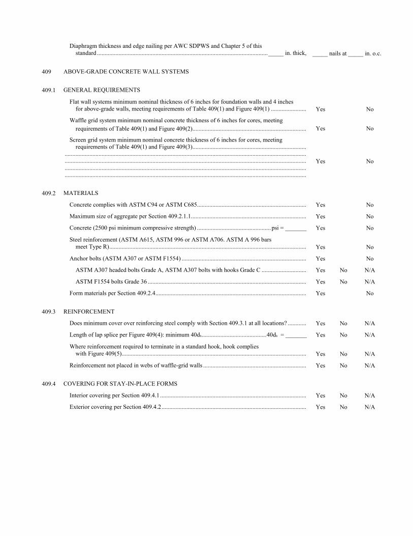
Diaphragm thickness and edge nailing per AWC SDPWS and Chapter 5 of this standard ............................................................................................................... _____ in. thick,
_____ nails at _____ in. o.c.
409 ABOVE-GRADE CONCRETE WALL SYSTEMS
409.1 GENERAL REQUIREMENTS
Flat wall systems minimum nominal thickness of 6 inches for foundation walls and 4 inches for above-grade walls, meeting requirements of Table 409(1) and Figure 409(1) .......................
Yes
No
Waffle grid system minimum nominal concrete thickness of 6 inches for cores, meeting requirements of Table 409(1) and Figure 409(2) ..........................................................................
Yes
No
Screen grid system minimum nominal concrete thickness of 6 inches for cores, meeting requirements of Table 409(1) and Figure 409(3) .......................................................................... ............................................................................................................................................................. ............................................................................................................................................................. ............................................................................................................................................................. .............................................................................................................................................................
Yes
No
409.2 MATERIALS
Concrete complies with ASTM C94 or ASTM C685 ....................................................................... Yes No
Maximum size of aggregate per Section 409.2.1.1........................................................................... Yes No
Concrete (2500 psi minimum compressive strength) ................................................ psi = _______ Yes No
Steel reinforcement (ASTM A615, ASTM 996 or ASTM A706. ASTM A 996 bars meet Type R) ................................................................................................................................
Yes
No
Anchor bolts (ASTM A307 or ASTM F1554) ................................................................................. Yes No
ASTM A307 headed bolts Grade A, ASTM A307 bolts with hooks Grade C ............................. Yes No N/A
ASTM F1554 bolts Grade 36 ....................................................................................................... Yes No N/A
Form materials per Section 409.2.4 .................................................................................................. Yes No
409.3 REINFORCEMENT
Does minimum cover over reinforcing steel comply with Section 409.3.1 at all locations? ............ Yes No N/A
Length of lap splice per Figure 409(4): minimum 40db .......................................... 40db = _______ Yes No N/A
Where reinforcement required to terminate in a standard hook, hook complies with Figure 409(5) ........................................................................................................................
Yes
No
N/A
Reinforcement not placed in webs of waffle-grid walls ................................................................... Yes No N/A
409.4 COVERING FOR STAY-IN-PLACE FORMS
Interior covering per Section 409.4.1 ............................................................................................... Yes No N/A
Exterior covering per Section 409.4.2 .............................................................................................. Yes No N/A
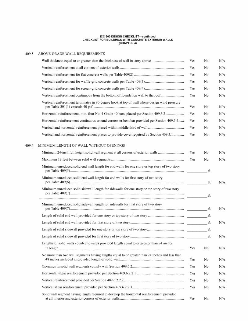
ICC 600 DESIGN CHECKLIST—continued CHECKLIST FOR BUILDINGS WITH CONCRETE EXTERIOR WALLS
(CHAPTER 4)
409.5 ABOVE-GRADE WALL REQUIREMENTS
Wall thickness equal to or greater than the thickness of wall in story above.................................... Yes No N/A
Vertical reinforcement at all corners of exterior walls ..................................................................... Yes No N/A
Vertical reinforcement for flat concrete walls per Table 409(2) ...................................................... Yes No N/A
Vertical reinforcement for waffle-grid concrete walls per Table 409(3) .......................................... Yes No N/A
Vertical reinforcement for screen-grid concrete walls per Table 409(4) .......................................... Yes No N/A
Vertical reinforcement continuous from the bottom of foundation wall to the roof ......................... Yes No N/A
Vertical reinforcement terminates in 90-degree hook at top of wall where design wind pressure per Table 301(1) exceeds 40 psf ...................................................................................................
Yes
No
N/A
Horizontal reinforcement, min. four No. 4 Grade 40 bars, placed per Section 409.5.2 .................... Yes No N/A
Horizontal reinforcement continuous around corners or bent bar provided per Section 409.5.4 ...... Yes No N/A
Vertical and horizontal reinforcement placed within middle third of wall ....................................... Yes No N/A
Vertical and horizontal reinforcement places to provide cover required by Section 409.3.1 ........... Yes No N/A
409.6 MINIMUM LENGTH OF WALL WITHOUT OPENINGS
Minimum 24-inch full height solid wall segment at all corners of exterior walls ............................ Yes No N/A
Maximum 18 feet between solid wall segments ............................................................................... Yes No N/A
Minimum unreduced solid end wall length for end walls for one story or top story of two story per Table 409(5) ...........................................................................................................................
___________ ft.
Minimum unreduced solid end wall length for end walls for first story of two story per Table 409(6) ...........................................................................................................................
___________ ft.
N/A
Minimum unreduced solid sidewall length for sidewalls for one story or top story of two story per Table 409(7) ........................................................................................................................... .............................................................................................................................................................
___________ ft.
Minimum unreduced solid sidewall length for sidewalls for first story of two story per Table 409(7) ...........................................................................................................................
___________ ft.
N/A
Length of solid end wall provided for one story or top story of two story ....................................... ___________ ft.
Length of solid end wall provided for first story of two story .......................................................... ___________ ft. N/A
Length of solid sidewall provided for one story or top story of two story ........................................ ___________ ft.
Length of solid sidewall provided for first story of two story .......................................................... ___________ ft. N/A
Lengths of solid walls counted towards provided length equal to or greater than 24 inches in length .......................................................................................................................................
Yes
No
N/A
No more than two wall segments having lengths equal to or greater than 24 inches and less than 48 inches included in provided length of solid wall .....................................................................
Yes
No
N/A
Openings in solid wall segments comply with Section 409.6.2........................................................ Yes No N/A
Horizontal shear reinforcement provided per Section 409.6.2.2.1 ................................................... Yes No N/A
Vertical reinforcement provided per Section 409.6.2.2.2 ................................................................. Yes No N/A
Vertical shear reinforcement provided per Section 409.6.2.2.3 ........................................................ Yes No N/A
Solid wall segment having length required to develop the horizontal reinforcement provided at all interior and exterior corners of exterior walls ......................................................................
Yes
No
N/A
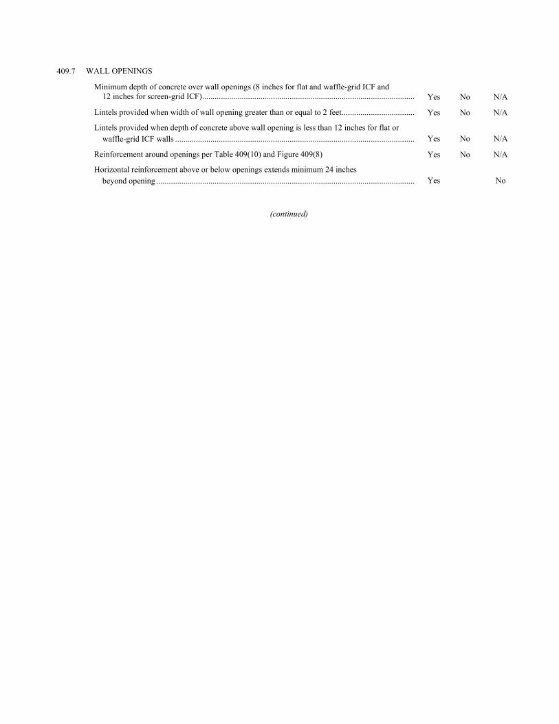
409.7 WALL OPENINGS
Minimum depth of concrete over wall openings (8 inches for flat and waffle-grid ICF and 12 inches for screen-grid ICF) ......................................................................................................
Yes
No
N/A
Lintels provided when width of wall opening greater than or equal to 2 feet ................................... Yes No N/A
Lintels provided when depth of concrete above wall opening is less than 12 inches for flat or waffle-grid ICF walls ...................................................................................................................
Yes
No
N/A
Reinforcement around openings per Table 409(10) and Figure 409(8) Yes No N/A
Horizontal reinforcement above or below openings extends minimum 24 inches beyond opening ............................................................................................................................
Yes
No
(continued)
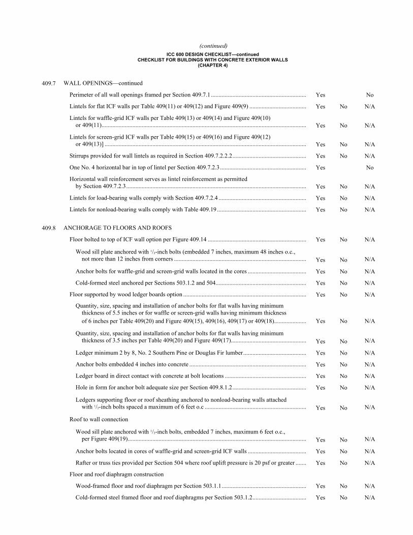
(continued) ICC 600 DESIGN CHECKLIST—continued
CHECKLIST FOR BUILDINGS WITH CONCRETE EXTERIOR WALLS (CHAPTER 4)
409.7 WALL OPENINGS—continued
Perimeter of all wall openings framed per Section 409.7.1 .............................................................. Yes No
Lintels for flat ICF walls per Table 409(11) or 409(12) and Figure 409(9) ..................................... Yes No N/A
Lintels for waffle-grid ICF walls per Table 409(13) or 409(14) and Figure 409(10) or 409(11) .....................................................................................................................................
Yes
No
N/A
Lintels for screen-grid ICF walls per Table 409(15) or 409(16) and Figure 409(12) or 409(13)] ...................................................................................................................................
Yes
No
N/A
Stirrups provided for wall lintels as required in Section 409.7.2.2.2 ................................................ Yes No N/A
One No. 4 horizontal bar in top of lintel per Section 409.7.2.3 ........................................................ Yes No
Horizontal wall reinforcement serves as lintel reinforcement as permitted by Section 409.7.2.3 .....................................................................................................................
Yes
No
N/A
Lintels for load-bearing walls comply with Section 409.7.2.4 ......................................................... Yes No N/A
Lintels for nonload-bearing walls comply with Table 409.19 .......................................................... Yes No N/A
409.8 ANCHORAGE TO FLOORS AND ROOFS
Floor bolted to top of ICF wall option per Figure 409.14 ................................................................ Yes No N/A
Wood sill plate anchored with 1/2-inch bolts (embedded 7 inches, maximum 48 inches o.c., not more than 12 inches from corners ......................................................................................
Yes
No
N/A
Anchor bolts for waffle-grid and screen-grid walls located in the cores ...................................... Yes No N/A
Cold-formed steel anchored per Sections 503.1.2 and 504........................................................... Yes No N/A
Floor supported by wood ledger boards option ................................................................................ Yes No N/A
Quantity, size, spacing and installation of anchor bolts for flat walls having minimum thickness of 5.5 inches or for waffle or screen-grid walls having minimum thickness of 6 inches per Table 409(20) and Figure 409(15), 409(16), 409(17) or 409(18).....................
Yes
No
N/A
Quantity, size, spacing and installation of anchor bolts for flat walls having minimum thickness of 3.5 inches per Table 409(20) and Figure 409(17).................................................
Yes
No
N/A
Ledger minimum 2 by 8, No. 2 Southern Pine or Douglas Fir lumber ......................................... Yes No N/A
Anchor bolts embedded 4 inches into concrete ............................................................................ Yes No N/A
Ledger board in direct contact with concrete at bolt locations ..................................................... Yes No N/A
Hole in form for anchor bolt adequate size per Section 409.8.1.2 ................................................ Yes No N/A
Ledgers supporting floor or roof sheathing anchored to nonload-bearing walls attached with 1/2-inch bolts spaced a maximum of 6 feet o.c ..................................................................
Yes
No
N/A
Roof to wall connection
Wood sill plate anchored with 1/2-inch bolts, embedded 7 inches, maximum 6 feet o.c., per Figure 409(19) ....................................................................................................................
Yes
No
N/A
Anchor bolts located in cores of waffle-grid and screen-grid ICF walls ...................................... Yes No N/A
Rafter or truss ties provided per Section 504 where roof uplift pressure is 20 psf or greater ....... Yes No N/A
Floor and roof diaphragm construction
Wood-framed floor and roof diaphragm per Section 503.1.1 ....................................................... Yes No N/A
Cold-formed steel framed floor and roof diaphragms per Section 503.1.2 ................................... Yes No N/A
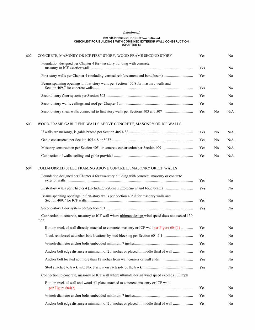
(continued)
ICC 600 DESIGN CHECKLIST—continued CHECKLIST FOR BUILDINGS WITH COMBINED EXTERIOR WALL CONSTRUCTION
(CHAPTER 6)
602 CONCRETE, MASONRY OR ICF FIRST STORY, WOOD-FRAME SECOND STORY Yes No
Foundation designed per Chapter 4 for two-story building with concrete, masonry or ICF exterior walls ............................................................................................................
Yes
No
First-story walls per Chapter 4 (including vertical reinforcement and bond beam) ............................... Yes No
Beams spanning openings in first-story walls per Section 405.8 for masonry walls and Section 409.7 for concrete walls ........................................................................................................
Yes
No
Second-story floor system per Section 503 ............................................................................................ Yes No
Second-story walls, ceilings and roof per Chapter 5 .............................................................................. Yes No
Second-story shear walls connected to first story walls per Sections 503 and 507 ................................ Yes No N/A
603 WOOD-FRAME GABLE END WALLS ABOVE CONCRETE, MASONRY OR ICF WALLS
If walls are masonry, is gable braced per Section 405.4.8? .................................................................... Yes No N/A
Gable constructed per Section 405.4.8 or 503? ...................................................................................... Yes No N/A
Masonry construction per Section 405, or concrete construction per Section 409 ................................. Yes No N/A
Connection of walls, ceiling and gable provided ................................................................................... Yes No N/A
604 COLD-FORMED STEEL FRAMING ABOVE CONCRETE, MASONRY OR ICF WALLS
Foundation designed per Chapter 4 for two-story building with concrete, masonry or concrete exterior walls ......................................................................................................................................
Yes
No
First-story walls per Chapter 4 (including vertical reinforcement and bond beam) ............................... Yes No
Beams spanning openings in first-story walls per Section 405.8 for masonry walls and Section 409.7 for ICF walls ...............................................................................................................
Yes
No
Second-story floor system per Section 503 ............................................................................................ Yes No
Connection to concrete, masonry or ICF wall where ultimate design wind speed does not exceed 130 mph
Bottom track of wall directly attached to concrete, masonry or ICF wall per Figure 604(1) ............. Yes No
Track reinforced at anchor bolt locations by stud blocking per Section 604.5.1 ................................ Yes No
1/2-inch-diameter anchor bolts embedded minimum 7 inches ............................................................. Yes No
Anchor bolt edge distance a minimum of 21/2 inches or placed in middle third of wall ..................... Yes No
Anchor bolt located not more than 12 inches from wall corners or wall ends.................................... Yes No
Stud attached to track with No. 8 screw on each side of the track ..................................................... Yes No
Connection to concrete, masonry or ICF wall where ultimate design wind speed exceeds 130 mph
Bottom track of wall and wood sill plate attached to concrete, masonry or ICF wall per Figure 604(2) ...........................................................................................................................
Yes
No
1/2-inch-diameter anchor bolts embedded minimum 7 inches ............................................................. Yes No
Anchor bolt edge distance a minimum of 21/2 inches or placed in middle third of wall ..................... Yes No
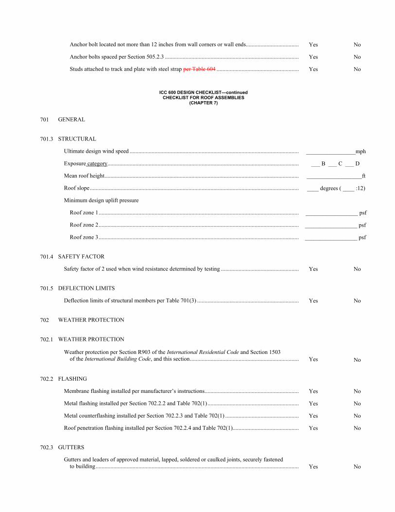
Anchor bolt located not more than 12 inches from wall corners or wall ends.................................... Yes No
Anchor bolts spaced per Section 505.2.3 ........................................................................................... Yes No
Studs attached to track and plate with steel strap per Table 604 ........................................................ Yes No
ICC 600 DESIGN CHECKLIST—continued CHECKLIST FOR ROOF ASSEMBLIES
(CHAPTER 7)
701 GENERAL
701.3 STRUCTURAL
Ultimate design wind speed ................................................................................................................... _________________mph
Exposure category .................................................................................................................................. ___ B ___ C ___ D
Mean roof height .................................................................................................................................... ___________________ft
Roof slope .............................................................................................................................................. ____ degrees ( ____ :12)
Minimum design uplift pressure
Roof zone 1 ........................................................................................................................................ __________________ psf
Roof zone 2 ........................................................................................................................................ __________________ psf
Roof zone 3 ........................................................................................................................................ __________________ psf
701.4 SAFETY FACTOR
Safety factor of 2 used when wind resistance determined by testing ..................................................... Yes No
701.5 DEFLECTION LIMITS
Deflection limits of structural members per Table 701(3) ..................................................................... Yes No
702 WEATHER PROTECTION
702.1 WEATHER PROTECTION
Weather protection per Section R903 of the International Residential Code and Section 1503 of the International Building Code, and this section ..........................................................................
Yes
No
702.2 FLASHING
Membrane flashing installed per manufacturer’s instructions ................................................................ Yes No
Metal flashing installed per Section 702.2.2 and Table 702(1) .............................................................. Yes No
Metal counterflashing installed per Section 702.2.3 and Table 702(1) .................................................. Yes No
Roof penetration flashing installed per Section 702.2.4 and Table 702(1)............................................. Yes No
702.3 GUTTERS
Gutters and leaders of approved material, lapped, soldered or caulked joints, securely fastened to building ..........................................................................................................................................
Yes
No
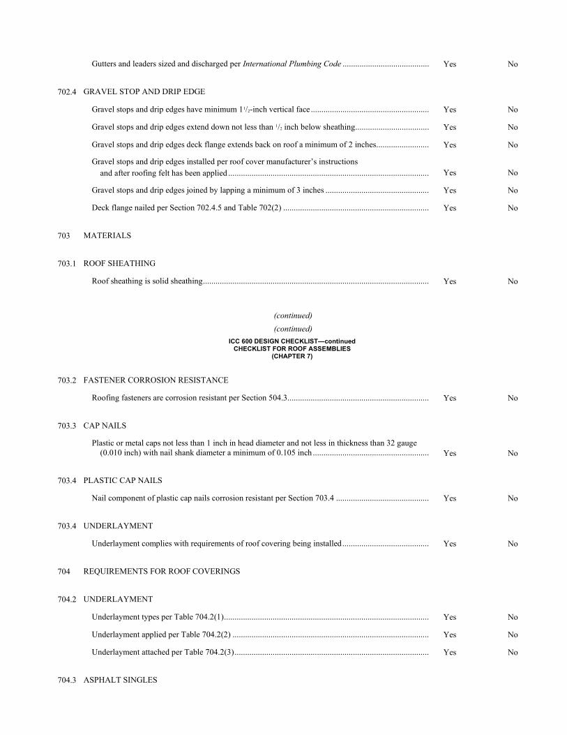
Gutters and leaders sized and discharged per International Plumbing Code ......................................... Yes No
702.4 GRAVEL STOP AND DRIP EDGE
Gravel stops and drip edges have minimum 11/2-inch vertical face ........................................................ Yes No
Gravel stops and drip edges extend down not less than 1/2 inch below sheathing ................................... Yes No
Gravel stops and drip edges deck flange extends back on roof a minimum of 2 inches ......................... Yes No
Gravel stops and drip edges installed per roof cover manufacturer’s instructions and after roofing felt has been applied ...............................................................................................
Yes
No
Gravel stops and drip edges joined by lapping a minimum of 3 inches ................................................. Yes No
Deck flange nailed per Section 702.4.5 and Table 702(2) ..................................................................... Yes No
703 MATERIALS
703.1 ROOF SHEATHING
Roof sheathing is solid sheathing ........................................................................................................... Yes No
(continued)
(continued)
ICC 600 DESIGN CHECKLIST—continued CHECKLIST FOR ROOF ASSEMBLIES
(CHAPTER 7)
703.2 FASTENER CORROSION RESISTANCE
Roofing fasteners are corrosion resistant per Section 504.3 ................................................................... Yes No
703.3 CAP NAILS
Plastic or metal caps not less than 1 inch in head diameter and not less in thickness than 32 gauge (0.010 inch) with nail shank diameter a minimum of 0.105 inch .......................................................
Yes
No
703.4 PLASTIC CAP NAILS
Nail component of plastic cap nails corrosion resistant per Section 703.4 ............................................ Yes No
703.4 UNDERLAYMENT
Underlayment complies with requirements of roof covering being installed ......................................... Yes No
704 REQUIREMENTS FOR ROOF COVERINGS
704.2 UNDERLAYMENT
Underlayment types per Table 704.2(1) ................................................................................................. Yes No
Underlayment applied per Table 704.2(2) ............................................................................................. Yes No
Underlayment attached per Table 704.2(3) ............................................................................................ Yes No
704.3 ASPHALT SINGLES
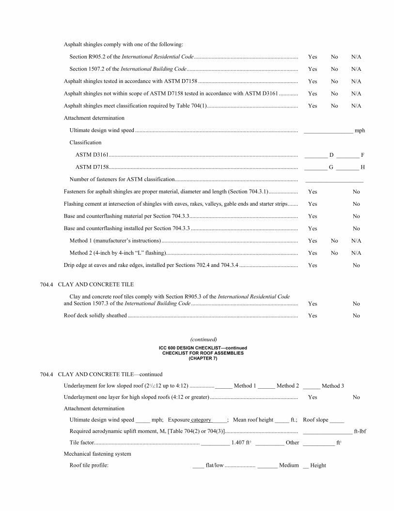
Asphalt shingles comply with one of the following:
Section R905.2 of the International Residential Code ....................................................................... Yes No N/A
Section 1507.2 of the International Building Code ............................................................................ Yes No N/A
Asphalt shingles tested in accordance with ASTM D7158 .................................................................... Yes No N/A
Asphalt shingles not within scope of ASTM D7158 tested in accordance with ASTM D3161 ............. Yes No N/A
Asphalt shingles meet classification required by Table 704(1) .............................................................. Yes No N/A
Attachment determination
Ultimate design wind speed ............................................................................................................... _________________ mph
Classification
ASTM D3161................................................................................................................................. ________ D ________ F
ASTM D7158................................................................................................................................. ________ G ________ H
Number of fasteners for ASTM classification .................................................................................... ____________________
Fasteners for asphalt shingles are proper material, diameter and length (Section 704.3.1) .................... Yes No
Flashing cement at intersection of shingles with eaves, rakes, valleys, gable ends and starter strips ....... Yes No
Base and counterflashing material per Section 704.3.3 .......................................................................... Yes No
Base and counterflashing installed per Section 704.3.3 ......................................................................... Yes No
Method 1 (manufacturer’s instructions) ............................................................................................. Yes No N/A
Method 2 (4-inch by 4-inch “L” flashing) .......................................................................................... Yes No N/A
Drip edge at eaves and rake edges, installed per Sections 702.4 and 704.3.4 ........................................ Yes No
704.4 CLAY AND CONCRETE TILE
Clay and concrete roof tiles comply with Section R905.3 of the International Residential Code and Section 1507.3 of the International Building Code .........................................................................
Yes
No
Roof deck solidly sheathed .................................................................................................................... Yes No
(continued)
ICC 600 DESIGN CHECKLIST—continued CHECKLIST FOR ROOF ASSEMBLIES
(CHAPTER 7)
704.4 CLAY AND CONCRETE TILE—continued
Underlayment for low sloped roof (21/2:12 up to 4:12) ................. ______ Method 1 ______ Method 2 ______ Method 3
Underlayment one layer for high sloped roofs (4:12 or greater) ............................................................ Yes No
Attachment determination
Ultimate design wind speed _____ mph; Exposure category _____; Mean roof height _____ ft.; Roof slope _____
Required aerodynamic uplift moment, Ma [Table 704(2) or 704(3)] .................................................. _________________ ft-lbf
Tile factor ........................................................................ __________ 1.407 ft3 __________ Other ___________ ft3
Mechanical fastening system
Roof tile profile: ____ flat/low ..................... _______ Medium __ Height
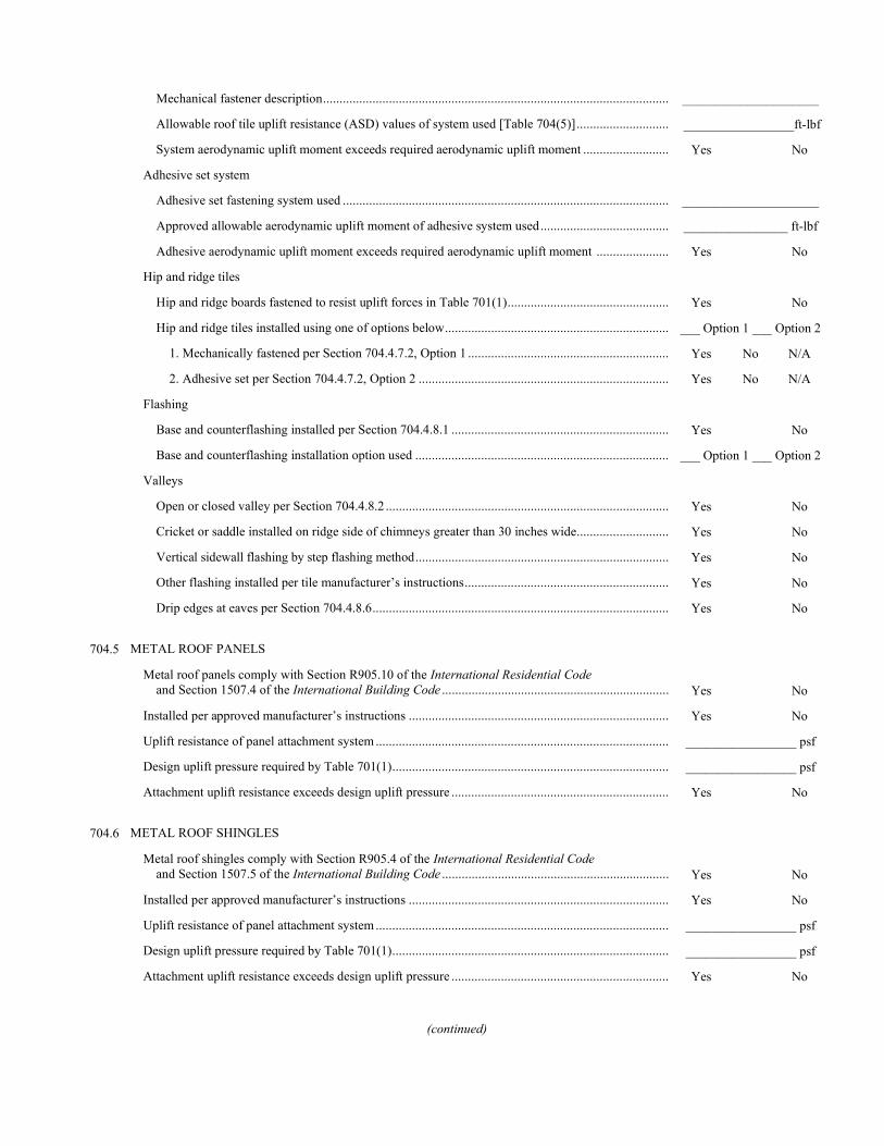
Mechanical fastener description ......................................................................................................... _____________________
Allowable roof tile uplift resistance (ASD) values of system used [Table 704(5)] ............................ _________________ft-lbf
System aerodynamic uplift moment exceeds required aerodynamic uplift moment .......................... Yes No
Adhesive set system
Adhesive set fastening system used ................................................................................................... _____________________
Approved allowable aerodynamic uplift moment of adhesive system used ....................................... ________________ ft-lbf
Adhesive aerodynamic uplift moment exceeds required aerodynamic uplift moment ...................... Yes No
Hip and ridge tiles
Hip and ridge boards fastened to resist uplift forces in Table 701(1) ................................................. Yes No
Hip and ridge tiles installed using one of options below .................................................................... ___ Option 1 ___ Option 2
1. Mechanically fastened per Section 704.4.7.2, Option 1 ............................................................. Yes No N/A
2. Adhesive set per Section 704.4.7.2, Option 2 ............................................................................ Yes No N/A
Flashing
Base and counterflashing installed per Section 704.4.8.1 .................................................................. Yes No
Base and counterflashing installation option used ............................................................................. ___ Option 1 ___ Option 2
Valleys
Open or closed valley per Section 704.4.8.2 ...................................................................................... Yes No
Cricket or saddle installed on ridge side of chimneys greater than 30 inches wide ............................ Yes No
Vertical sidewall flashing by step flashing method ............................................................................. Yes No
Other flashing installed per tile manufacturer’s instructions .............................................................. Yes No
Drip edges at eaves per Section 704.4.8.6 .......................................................................................... Yes No
704.5 METAL ROOF PANELS
Metal roof panels comply with Section R905.10 of the International Residential Code and Section 1507.4 of the International Building Code .....................................................................
Yes
No
Installed per approved manufacturer’s instructions ............................................................................... Yes No
Uplift resistance of panel attachment system ......................................................................................... _________________ psf
Design uplift pressure required by Table 701(1) .................................................................................... _________________ psf
Attachment uplift resistance exceeds design uplift pressure .................................................................. Yes No
704.6 METAL ROOF SHINGLES
Metal roof shingles comply with Section R905.4 of the International Residential Code and Section 1507.5 of the International Building Code .....................................................................
Yes
No
Installed per approved manufacturer’s instructions ............................................................................... Yes No
Uplift resistance of panel attachment system ......................................................................................... _________________ psf
Design uplift pressure required by Table 701(1) .................................................................................... _________________ psf
Attachment uplift resistance exceeds design uplift pressure .................................................................. Yes No
(continued)
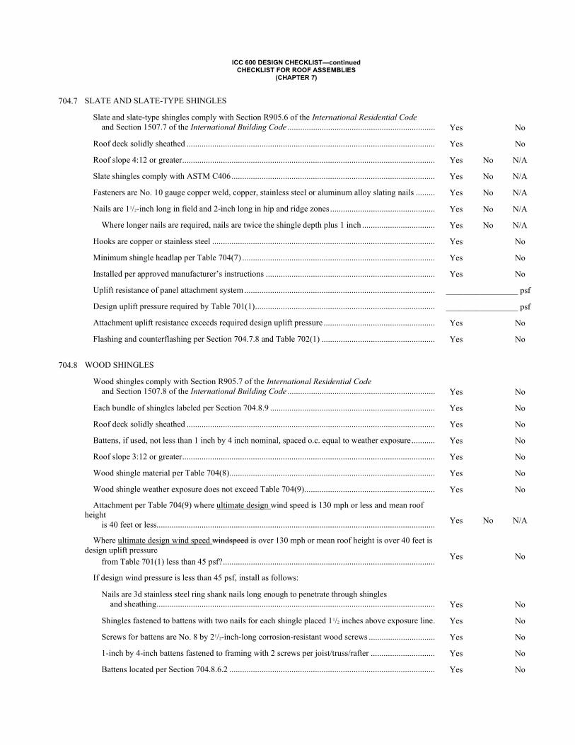
ICC 600 DESIGN CHECKLIST—continued CHECKLIST FOR ROOF ASSEMBLIES
(CHAPTER 7)
704.7 SLATE AND SLATE-TYPE SHINGLES
Slate and slate-type shingles comply with Section R905.6 of the International Residential Code and Section 1507.7 of the International Building Code .....................................................................
Yes
No
Roof deck solidly sheathed .................................................................................................................... Yes No
Roof slope 4:12 or greater ...................................................................................................................... Yes No N/A
Slate shingles comply with ASTM C406 ............................................................................................... Yes No N/A
Fasteners are No. 10 gauge copper weld, copper, stainless steel or aluminum alloy slating nails ......... Yes No N/A
Nails are 11/2-inch long in field and 2-inch long in hip and ridge zones ................................................. Yes No N/A
Where longer nails are required, nails are twice the shingle depth plus 1 inch .................................. Yes No N/A
Hooks are copper or stainless steel ........................................................................................................ Yes No
Minimum shingle headlap per Table 704(7) .......................................................................................... Yes No
Installed per approved manufacturer’s instructions ............................................................................... Yes No
Uplift resistance of panel attachment system ......................................................................................... _________________ psf
Design uplift pressure required by Table 701(1) .................................................................................... _________________ psf
Attachment uplift resistance exceeds required design uplift pressure .................................................... Yes No
Flashing and counterflashing per Section 704.7.8 and Table 702(1) ..................................................... Yes No
704.8 WOOD SHINGLES
Wood shingles comply with Section R905.7 of the International Residential Code and Section 1507.8 of the International Building Code .....................................................................
Yes
No
Each bundle of shingles labeled per Section 704.8.9 ............................................................................. Yes No
Roof deck solidly sheathed .................................................................................................................... Yes No
Battens, if used, not less than 1 inch by 4 inch nominal, spaced o.c. equal to weather exposure ........... Yes No
Roof slope 3:12 or greater ...................................................................................................................... Yes No
Wood shingle material per Table 704(8) ................................................................................................ Yes No
Wood shingle weather exposure does not exceed Table 704(9) ............................................................. Yes No
Attachment per Table 704(9) where ultimate design wind speed is 130 mph or less and mean roof height is 40 feet or less..................................................................................................................................
Yes
No
N/A
Where ultimate design wind speed windspeed is over 130 mph or mean roof height is over 40 feet is design uplift pressure from Table 701(1) less than 45 psf? ...................................................................................................
Yes
No
If design wind pressure is less than 45 psf, install as follows:
Nails are 3d stainless steel ring shank nails long enough to penetrate through shingles and sheathing ..................................................................................................................................
Yes
No
Shingles fastened to battens with two nails for each shingle placed 11/2 inches above exposure line . Yes No
Screws for battens are No. 8 by 21/2-inch-long corrosion-resistant wood screws ............................... Yes No
1-inch by 4-inch battens fastened to framing with 2 screws per joist/truss/rafter .............................. Yes No
Battens located per Section 704.8.6.2 ................................................................................................ Yes No
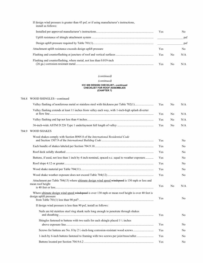
If design wind pressure is greater than 45 psf, or if using manufacturer’s instructions, install as follows:
Installed per approved manufacturer’s instructions ............................................................................ Yes No
Uplift resistance of shingle attachment system .................................................................................. _________________ psf
Design uplift pressure required by Table 701(1) ................................................................................ _________________ psf
Attachment uplift resistance exceeds design uplift pressure Yes No
Flashing and counterflashing at juncture of roof and vertical surfaces .................................................. Yes No N/A
Flashing and counterflashing, where metal, not less than 0.019-inch (26 ga.) corrosion-resistant metal .......................................................................................................
Yes
No
N/A
(continued)
(continued)
ICC 600 DESIGN CHECKLIST—continued CHECKLIST FOR ROOF ASSEMBLIES
(CHAPTER 7)
704.8 WOOD SHINGLES—continued
Valley flashing of nonferrous metal or stainless steel with thickness per Table 702(1) ......................... Yes No N/A
Valley flashing extends at least 11 inches from valley each way, with 1-inch-high splash diverter at flow line .........................................................................................................................................
Yes
No
N/A
Valley flashing end lap not less than 4 inches ........................................................................................ Yes No N/A
36-inch-wide ASTM D 226 Type 1 underlayment full length of valley ................................................ Yes No N/A
704.9 WOOD SHAKES
Wood shakes comply with Section R905.8 of the International Residential Code and Section 1507.9 of the International Building Code .....................................................................
Yes
No
Each bundle of shakes labeled per Section 704.9.10 .............................................................................. Yes No
Roof deck solidly sheathed .................................................................................................................... Yes No
Battens, if used, not less than 1 inch by 4 inch nominal, spaced o.c. equal to weather exposure ........... Yes No
Roof slope 4:12 or greater ...................................................................................................................... Yes No
Wood shake material per Table 704(11) ................................................................................................ Yes No
Wood shake weather exposure does not exceed Table 704(12) ............................................................. Yes No
Attachment per Table 704(13) where ultimate design wind speed windspeed is 130 mph or less and mean roof height is 40 feet or less..................................................................................................................................
Yes
No
N/A
Where ultimate design wind speed windspeed is over 130 mph or mean roof height is over 40 feet is design uplift pressure from Table 701(1) less than 90 psf? ...................................................................................................
Yes
No
If design wind pressure is less than 90 psf, install as follows:
Nails are 6d stainless steel ring shank nails long enough to penetrate through shakes and sheathing .............................................................................................................................
Yes
No
Shingles fastened to battens with two nails for each shingle placed 11/2 inches above exposure line ....................................................................................................................
Yes
No
Screws for battens are No. 8 by 21/2-inch-long corrosion-resistant wood screws ........................... Yes No
1-inch by 6-inch battens fastened to framing with two screws per joist/truss/rafter ....................... Yes No
Battens located per Section 704.9.6.2 ............................................................................................ Yes No
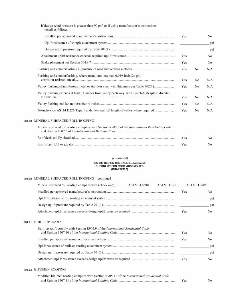
If design wind pressure is greater than 90 psf, or if using manufacturer’s instructions, install as follows:
Installed per approved manufacturer’s instructions ........................................................................ Yes No
Uplift resistance of shingle attachment system .............................................................................. _________________ psf
Design uplift pressure required by Table 701(1) ............................................................................ _________________ psf
Attachment uplift resistance exceeds required uplift resistance ......................................................... Yes No
Shake placement per Section 704.9.7 ................................................................................................. Yes No
Flashing and counterflashing at juncture of roof and vertical surfaces .................................................. Yes No N/A
Flashing and counterflashing, where metal, not less than 0.019-inch (26 ga.) corrosion-resistant metal ....................................................................................................................
Yes
No
N/A
Valley flashing of nonferrous metal or stainless steel with thickness per Table 702(1) ......................... Yes No N/A
Valley flashing extends at least 11 inches from valley each way, with 1-inch-high splash diverter at flow line .........................................................................................................................................
Yes
No
N/A
Valley flashing end lap not less than 4 inches ........................................................................................ Yes No N/A
36-inch-wide ASTM D226 Type 1 underlayment full length of valley where required ......................... Yes No N/A
704.10 MINERAL SURFACED ROLL ROOFING
Mineral surfaced roll roofing complies with Section R905.5 of the International Residential Code and Section 1507.6 of the International Building Code .....................................................................
Roof deck solidly sheathed .................................................................................................................... Yes No
Roof slope 1:12 or greater ...................................................................................................................... Yes No
(continued) ICC 600 DESIGN CHECKLIST—continued
CHECKLIST FOR ROOF ASSEMBLIES (CHAPTER 7)
704.10 MINERAL SURFACED ROLL ROOFING—continued
Mineral surfaced roll roofing complies with (check one): ..... ____ ASTM D 6380 ____ ASTM D 371 ____ ASTM D3909
Installed per approved manufacturer’s instructions ............................................................................... Yes No
Uplift resistance of roll roofing attachment system................................................................................ _________________ psf
Design uplift pressure required by Table 701(1) .................................................................................... _________________ psf
Attachment uplift resistance exceeds design uplift pressure required .................................................... Yes No
704.11 BUILT-UP ROOFS
Built-up roofs comply with Section R905.9 of the International Residential Code and Section 1507.10 of the International Building Code ...................................................................
Yes
No
Installed per approved manufacturer’s instructions ............................................................................... Yes No
Uplift resistance of built-up roofing attachment system......................................................................... _________________ psf
Design uplift pressure required by Table 701(1) .................................................................................... _________________ psf
Attachment uplift resistance exceeds design uplift pressure required .................................................... Yes No
704.12 BITUMEN ROOFING
Modified bitumen roofing complies with Section R905.11 of the International Residential Code and Section 1507.11 of the International Building Code ...................................................................
Yes
No
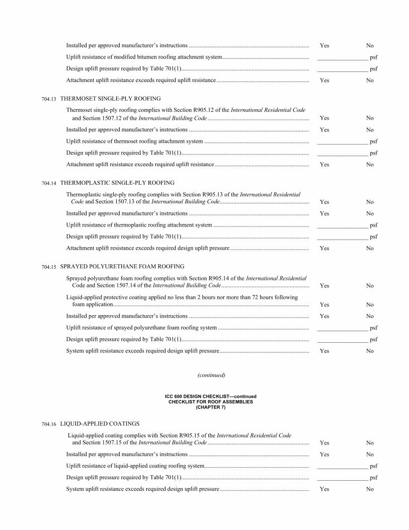
Installed per approved manufacturer’s instructions ............................................................................... Yes No
Uplift resistance of modified bitumen roofing attachment system ......................................................... _________________ psf
Design uplift pressure required by Table 701(1) .................................................................................... _________________ psf
Attachment uplift resistance exceeds required uplift resistance ............................................................. Yes No
704.13 THERMOSET SINGLE-PLY ROOFING
Thermoset single-ply roofing complies with Section R905.12 of the International Residential Code and Section 1507.12 of the International Building Code ...................................................................
Yes
No
Installed per approved manufacturer’s instructions ............................................................................... Yes No
Uplift resistance of thermoset roofing attachment system ..................................................................... _________________ psf
Design uplift pressure required by Table 701(1) .................................................................................... _________________ psf
Attachment uplift resistance exceeds required uplift resistance .............................................................. Yes No
704.14 THERMOPLASTIC SINGLE-PLY ROOFING
Thermoplastic single-ply roofing complies with Section R905.13 of the International Residential Code and Section 1507.13 of the International Building Code ...........................................................
Yes
No
Installed per approved manufacturer’s instructions ............................................................................... Yes No
Uplift resistance of thermoplastic roofing attachment system ............................................................... _________________ psf
Design uplift pressure required by Table 701(1) .................................................................................... _________________ psf
Attachment uplift resistance exceeds required design uplift pressure .................................................... Yes No
704.15 SPRAYED POLYURETHANE FOAM ROOFING
Sprayed polyurethane foam roofing complies with Section R905.14 of the International Residential Code and Section 1507.14 of the International Building Code ..........................................................
Yes
No
Liquid-applied protective coating applied no less than 2 hours nor more than 72 hours following foam application.................................................................................................................................
Yes
No
Installed per approved manufacturer’s instructions ............................................................................... Yes No
Uplift resistance of sprayed polyurethane foam roofing system ............................................................ _________________ psf
Design uplift pressure required by Table 701(1) .................................................................................... _________________ psf
System uplift resistance exceeds required design uplift pressure ........................................................... Yes No
(continued)
ICC 600 DESIGN CHECKLIST—continued CHECKLIST FOR ROOF ASSEMBLIES
(CHAPTER 7)
704.16 LIQUID-APPLIED COATINGS
Liquid-applied coating complies with Section R905.15 of the International Residential Code and Section 1507.15 of the International Building Code ...................................................................
Yes
No
Installed per approved manufacturer’s instructions ............................................................................... Yes No
Uplift resistance of liquid-applied coating roofing system..................................................................... _________________ psf
Design uplift pressure required by Table 701(1) .................................................................................... _________________ psf
System uplift resistance exceeds required design uplift pressure ........................................................... Yes No
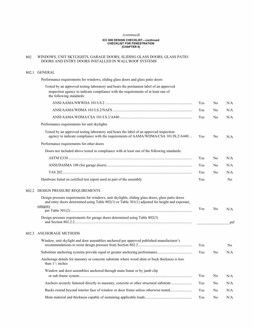
(continued) ICC 600 DESIGN CHECKLIST—continued
CHECKLIST FOR FENESTRATION (CHAPTER 8)
802 WINDOWS, UNIT SKYLIGHTS, GARAGE DOORS, SLIDING GLASS DOORS, GLASS PATIO DOORS AND ENTRY DOORS INSTALLED IN WALL/ROOF SYSTEMS
802.1 GENERAL
Performance requirements for windows, sliding glass doors and glass patio doors
Tested by an approved testing laboratory and bears the permanent label of an approved inspection agency to indicate compliance with the requirements of at least one of the following standards:
ANSI/AAMA/NWWDA 101/I.S.2 ............................................................................................ Yes No N/A
ANSI/AAMA/WDMA 101/I.S.2/NAFS .................................................................................... Yes No N/A
ANSI/AAMA/WDMA/CSA 101/I.S.2/A440 ............................................................................. Yes No N/A
Performance requirements for unit skylights
Tested by an approved testing laboratory and bears the label of an approved inspection agency to indicate compliance with the requirements of AAMA/WDMA/CSA 101/IS.2/A440 ...
Yes
No
N/A
Performance requirements for other doors
Doors not included above tested in compliance with at least one of the following standards:
ASTM E330 ................................................................................................................................... Yes No N/A
ANSI/DASMA 108 (for garage doors) .......................................................................................... Yes No N/A
TAS 202 ......................................................................................................................................... Yes No N/A
Hardware listed on certified test report used as part of the assembly Yes No
802.2 DESIGN PRESSURE REQUIREMENTS
Design pressure requirements for windows, unit skylights, sliding glass doors, glass patio doors and entry doors determined using Table 802(1) or Table 301(1) adjusted for height and exposure category per Table 301(2) .................................................................................................................................
Yes
No
N/A
Design pressure requirements for garage doors determined using Table 802(3) and Section 802.2.2 ............................................................................................................................
_________________ psf
802.3 ANCHORAGE METHODS
Window, unit skylight and door assemblies anchored per approved published manufacturer’s recommendations to resist design pressure from Section 802.2 .........................................................
Yes
No
Substitute anchoring systems provide equal or greater anchoring performance ..................................... Yes No N/A
Anchorage details for masonry or concrete substrate where wood shim or buck thickness is less than 11/2 inches
Window and door assemblies anchored through main frame or by jamb clip or sub-frame system .......................................................................................................................
Yes
No
N/A
Anchors securely fastened directly to masonry, concrete or other structural substrate ...................... Yes No N/A
Bucks extend beyond interior face of window or door frame unless otherwise tested ....................... Yes No N/A
Shim material and thickness capable of sustaining applicable loads .................................................. Yes No N/A
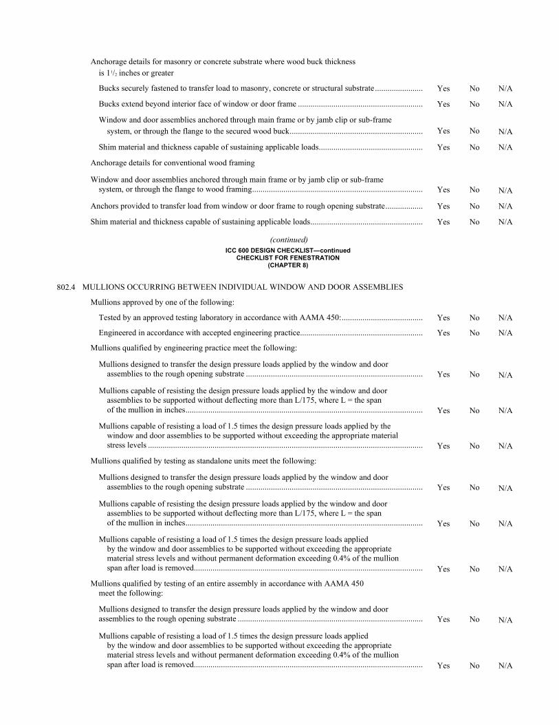
Anchorage details for masonry or concrete substrate where wood buck thickness is 11/2 inches or greater
Bucks securely fastened to transfer load to masonry, concrete or structural substrate ....................... Yes No N/A
Bucks extend beyond interior face of window or door frame ............................................................ Yes No N/A
Window and door assemblies anchored through main frame or by jamb clip or sub-frame system, or through the flange to the secured wood buck ................................................................
Yes
No
N/A
Shim material and thickness capable of sustaining applicable loads .................................................. Yes No N/A
Anchorage details for conventional wood framing
Window and door assemblies anchored through main frame or by jamb clip or sub-frame system, or through the flange to wood framing ..................................................................................
Yes
No
N/A
Anchors provided to transfer load from window or door frame to rough opening substrate .................. Yes No N/A
Shim material and thickness capable of sustaining applicable loads ...................................................... Yes No N/A
(continued) ICC 600 DESIGN CHECKLIST—continued
CHECKLIST FOR FENESTRATION (CHAPTER 8)
802.4 MULLIONS OCCURRING BETWEEN INDIVIDUAL WINDOW AND DOOR ASSEMBLIES
Mullions approved by one of the following:
Tested by an approved testing laboratory in accordance with AAMA 450: ....................................... Yes No N/A
Engineered in accordance with accepted engineering practice........................................................... Yes No N/A
Mullions qualified by engineering practice meet the following:
Mullions designed to transfer the design pressure loads applied by the window and door assemblies to the rough opening substrate .....................................................................................
Yes
No
N/A
Mullions capable of resisting the design pressure loads applied by the window and door assemblies to be supported without deflecting more than L/175, where L = the span of the mullion in inches ..................................................................................................................
Yes
No
N/A
Mullions capable of resisting a load of 1.5 times the design pressure loads applied by the window and door assemblies to be supported without exceeding the appropriate material stress levels ....................................................................................................................................
Yes
No
N/A
Mullions qualified by testing as standalone units meet the following:
Mullions designed to transfer the design pressure loads applied by the window and door assemblies to the rough opening substrate .....................................................................................
Yes
No
N/A
Mullions capable of resisting the design pressure loads applied by the window and door assemblies to be supported without deflecting more than L/175, where L = the span of the mullion in inches ..................................................................................................................
Yes
No
N/A
Mullions capable of resisting a load of 1.5 times the design pressure loads applied by the window and door assemblies to be supported without exceeding the appropriate material stress levels and without permanent deformation exceeding 0.4% of the mullion span after load is removed ..............................................................................................................
Yes
No
N/A
Mullions qualified by testing of an entire assembly in accordance with AAMA 450 meet the following:
Mullions designed to transfer the design pressure loads applied by the window and door assemblies to the rough opening substrate .........................................................................................
Yes
No
N/A
Mullions capable of resisting a load of 1.5 times the design pressure loads applied by the window and door assemblies to be supported without exceeding the appropriate material stress levels and without permanent deformation exceeding 0.4% of the mullion span after load is removed ..............................................................................................................
Yes
No
N/A

803 WINDBORNE DEBRIS
803.1 PROTECTION
The following applies in windborne debris regions (areas within 1 mile of the coastal mean high water line where the ultimate design wind speed shown on Figure 301(1) is 130 mph or greater and in all regions where the ultimate design wind speed shown is 140 mph or greater.)
Windows, unit skylights, sliding glass doors and glass patio doors protected or impact resistant in accordance with one of the following:
Protected with tested, permanently labeled and approved impact-resistant covering in compliance with the large missile test requirement of one of the following specifications:
ASTM E1886 and ..................................................................................................................... Yes No N/A
ASTM E1996, or ........................................................................................................................ Yes No N/A
AAMA 506 ................................................................................................................................ Yes No N/A
Impact resistant, tested and approved by an independent laboratory, listed by an approved entity and bear a permanent label identifying manufacturer, performance characteristics and approved inspection agency to indicate compliance with the large missile test requirements of one of the following specifications:
ASTM E1886 and ASTM E1996, or .......................................................................................... Yes No N/A
AAMA 506 Yes No N/A
As an alternate to tested external protection devices, wood structural panels constructed and installed per Section 803.1 and Table 803 ...............................................................................
Yes
No
N/A
Doors with glazing not included above protected or impact resistant in accordance with one of the following:
Protected with tested, permanently labeled and approved impact-resistant covering ......................... Yes No
Impact resistant and tested to indicate compliance with the large missile test requirements of at least one of the following standards:
ASTM E1886 and ASTM E1996 or ................................................................................................... Yes No
ANSI/DASMA 115 (for garage doors) or .......................................................................................... Yes No
TAS 201, TAS202, and TAS 203 ....................................................................................................... Yes No
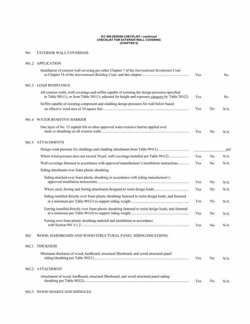
ICC 600 DESIGN CHECKLIST—continued CHECKLIST FOR EXTERIOR WALL COVERING
(CHAPTER 9)
901 EXTERIOR WALL COVERINGS
901.2 APPLICATION
Installation of exterior wall covering per either Chapter 7 of the International Residential Code or Chapter 14 of the International Building Code, and this chapter ...................................................
Yes
No
901.3 LOAD RESISTANCE
All exterior walls, wall coverings and soffits capable of resisting the design pressures specified in Table 901(1), or from Table 301(1), adjusted for height and exposure category by Table 301(2)
Yes
No
Soffits capable of resisting component and cladding design pressures for wall below based on effective wind area of 10 square feet .............................................................................................
Yes
No
N/A
901.4 WATER-RESISTIVE BARRIER
One layer of No. 15 asphalt felt or other approved water-resistive barrier applied over studs or sheathing on all exterior walls ..............................................................................................
Yes
No
N/A
901.5 ATTACHMENTS
Design wind pressure for claddings and cladding attachment from Table 901(1) ................................. _________________ psf
Where wind pressure does not exceed 30 psf, wall coverings installed per Table 901(2) ...................... Yes No N/A
Wall coverings fastened in accordance with approved manufacturer’s installation instructions ............ Yes No N/A
Siding attachment over foam plastic sheathing
Siding attached over foam plastic sheathing in accordance with siding manufacturer’s approved installation instructions ...................................................................................................
Yes
No
N/A
Where used, furring and furring attachment designed to resist design loads...................................... Yes No N/A
Siding installed directly over foam plastic sheathing fastened to resist design loads, and fastened at a minimum per Table 901(3) to support siding weight...............................................................
Yes
No
N/A
Furring installed directly over foam plastic sheathing fastened to resist design loads, and fastened at a minimum per Table 901(4) to support siding weight...............................................................
Yes
No
N/A
Furring over foam plastic sheathing material and installation in accordance with Section 901.5.1.2 ....................................................................................................................
Yes
No
N/A
902 WOOD, HARDBOARD AND WOOD STRUCTURAL PANEL SIDING/SHEATHING
902.1 THICKNESS
Minimum thickness of wood, hardboard, structural fiberboard, and wood structural panel siding/sheathing per Table 902(1) ......................................................................................................
Yes
No
N/A
902.2 ATTACHMENT
Attachment of wood, hardboard, structural fiberboard, and wood structural panel siding/ sheathing per Table 902(2).................................................................................................................
Yes
No
N/A
902.3 WOOD SHAKES AND SHINGLES
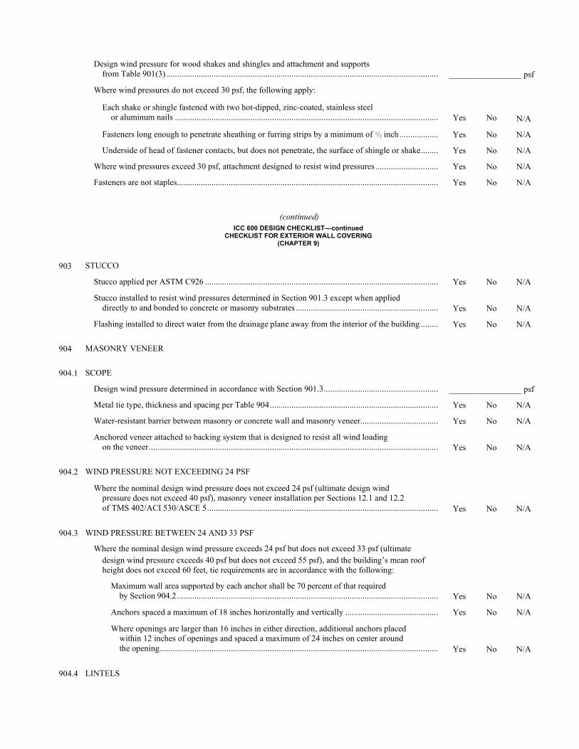
Design wind pressure for wood shakes and shingles and attachment and supports from Table 901(3) ..............................................................................................................................
_________________ psf
Where wind pressures do not exceed 30 psf, the following apply:
Each shake or shingle fastened with two hot-dipped, zinc-coated, stainless steel or aluminum nails ..........................................................................................................................
Yes
No
N/A
Fasteners long enough to penetrate sheathing or furring strips by a minimum of 1/2 inch .................. Yes No N/A
Underside of head of fastener contacts, but does not penetrate, the surface of shingle or shake ........ Yes No N/A
Where wind pressures exceed 30 psf, attachment designed to resist wind pressures ............................. Yes No N/A
Fasteners are not staples ......................................................................................................................... Yes No N/A
(continued) ICC 600 DESIGN CHECKLIST—continued
CHECKLIST FOR EXTERIOR WALL COVERING (CHAPTER 9)
903 STUCCO
Stucco applied per ASTM C926 ............................................................................................................ Yes No N/A
Stucco installed to resist wind pressures determined in Section 901.3 except when applied directly to and bonded to concrete or masonry substrates ..................................................................
Yes
No
N/A
Flashing installed to direct water from the drainage plane away from the interior of the building ........ Yes No N/A
904 MASONRY VENEER
904.1 SCOPE
Design wind pressure determined in accordance with Section 901.3 ..................................................... _________________ psf
Metal tie type, thickness and spacing per Table 904 .............................................................................. Yes No N/A
Water-resistant barrier between masonry or concrete wall and masonry veneer .................................... Yes No N/A
Anchored veneer attached to backing system that is designed to resist all wind loading on the veneer ......................................................................................................................................
Yes
No
N/A
904.2 WIND PRESSURE NOT EXCEEDING 24 PSF
Where the nominal design wind pressure does not exceed 24 psf (ultimate design wind pressure does not exceed 40 psf), masonry veneer installation per Sections 12.1 and 12.2 of TMS 402/ACI 530/ASCE 5 ...........................................................................................................
Yes
No
N/A
904.3 WIND PRESSURE BETWEEN 24 AND 33 PSF
Where the nominal design wind pressure exceeds 24 psf but does not exceed 33 psf (ultimate design wind pressure exceeds 40 psf but does not exceed 55 psf), and the building’s mean roof height does not exceed 60 feet, tie requirements are in accordance with the following:
Maximum wall area supported by each anchor shall be 70 percent of that required by Section 904.2 .........................................................................................................................
Yes
No
N/A
Anchors spaced a maximum of 18 inches horizontally and vertically ........................................... Yes No N/A
Where openings are larger than 16 inches in either direction, additional anchors placed within 12 inches of openings and spaced a maximum of 24 inches on center around the opening .................................................................................................................................
Yes
No
N/A
904.4 LINTELS
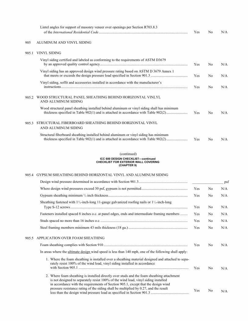
Lintel angles for support of masonry veneer over openings per Section R703.8.3 of the International Residential Code ................................................................................................
Yes
No
N/A
905 ALUMINUM AND VINYL SIDING
905.1 VINYL SIDING
Vinyl siding certified and labeled as conforming to the requirements of ASTM D3679 by an approved quality control agency ...............................................................................................
Yes
No
N/A
Vinyl siding has an approved design wind pressure rating based on ASTM D 3679 Annex 1 that meets or exceeds the design pressure load specified in Section 901.3 ........................................
Yes
No
N/A
Vinyl siding, soffit and accessories installed in accordance with the manufacturer’s instructions .........................................................................................................................................
Yes
No
N/A
905.2 WOOD STRUCTURAL PANEL SHEATHING BEHIND HORIZONTAL VINLYL AND ALUMINUM SIDING
Wood structural panel sheathing installed behind aluminum or vinyl siding shall has minimum thickness specified in Table 902(1) and is attached in accordance with Table 902(2) .......................
Yes
No
N/A
905.3 STRUCTURAL FIBERBOARD SHEATHING BEHIND HORIZONTAL VINYL AND ALUMINUM SIDING
Structural fiberboard sheathing installed behind aluminum or vinyl siding has minimum thickness specified in Table 902(1) and is attached in accordance with Table 902(2) .......................
Yes
No
N/A
(continued) ICC 600 DESIGN CHECKLIST—continued
CHECKLIST FOR EXTERIOR WALL COVERING (CHAPTER 9)
905.4 GYPSUM SHEATHING BEHIND HORIZONTAL VINYL AND ALUMINUM SIDING
Design wind pressure determined in accordance with Section 901.3 ..................................................... _________________ psf
Where design wind pressures exceed 30 psf, gypsum is not permitted .................................................. Yes No N/A
Gypsum sheathing minimum 5/8 inch thickness ...................................................................................... Yes No N/A
Sheathing fastened with 13/4-inch-long 11-gauge galvanized roofing nails or 11/4-inch-long Type S-12 screws ...............................................................................................................................
Yes
No
N/A
Fasteners installed spaced 8 inches o.c. at panel edges, ends and intermediate framing members ........ Yes No N/A
Studs spaced no more than 16 inches o.c. .............................................................................................. Yes No N/A
Steel framing members minimum 43 mils thickness (18 ga.) ................................................................ Yes No N/A
905.5 APPLICATION OVER FOAM SHEATHING
Foam sheathing complies with Section 910 ........................................................................................... Yes No N/A
In areas where the ultimate design wind speed is less than 140 mph, one of the following shall apply:
1. Where the foam sheathing is installed over a sheathing material designed and attached to sepa-
rately resist 100% of the wind load, vinyl siding installed in accordance with Section 905.1 .......................................................................................................................
Yes
No
N/A
2. Where foam sheathing is installed directly over studs and the foam sheathing attachment is not designed to separately resist 100% of the wind load, vinyl siding installed in accordance with the requirements of Section 905.1, except that the design wind pressure resistance rating of the siding shall be multiplied by 0.27, and the result less than the design wind pressure load as specified in Section 901.3 .........................................
Yes
No
N/A
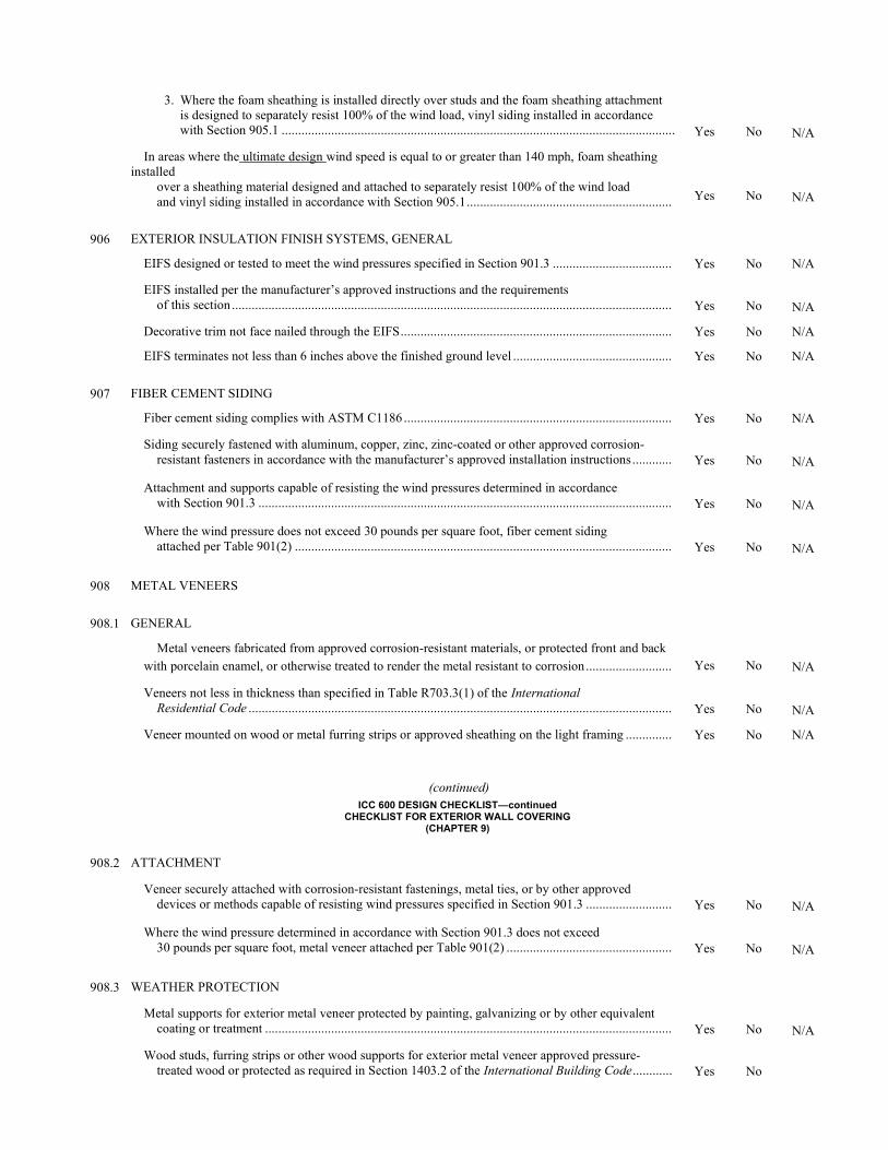
3. Where the foam sheathing is installed directly over studs and the foam sheathing attachment
is designed to separately resist 100% of the wind load, vinyl siding installed in accordance with Section 905.1 .......................................................................................................................
Yes
No
N/A
In areas where the ultimate design wind speed is equal to or greater than 140 mph, foam sheathing installed over a sheathing material designed and attached to separately resist 100% of the wind load and vinyl siding installed in accordance with Section 905.1 ..............................................................
Yes
No
N/A
906 EXTERIOR INSULATION FINISH SYSTEMS, GENERAL
EIFS designed or tested to meet the wind pressures specified in Section 901.3 .................................... Yes No N/A
EIFS installed per the manufacturer’s approved instructions and the requirements of this section .....................................................................................................................................
Yes
No
N/A
Decorative trim not face nailed through the EIFS .................................................................................. Yes No N/A
EIFS terminates not less than 6 inches above the finished ground level ................................................ Yes No N/A
907 FIBER CEMENT SIDING
Fiber cement siding complies with ASTM C1186 ................................................................................. Yes No N/A
Siding securely fastened with aluminum, copper, zinc, zinc-coated or other approved corrosion- resistant fasteners in accordance with the manufacturer’s approved installation instructions ............
Yes
No
N/A
Attachment and supports capable of resisting the wind pressures determined in accordance with Section 901.3 .............................................................................................................................
Yes
No
N/A
Where the wind pressure does not exceed 30 pounds per square foot, fiber cement siding attached per Table 901(2) ..................................................................................................................
Yes
No
N/A
908 METAL VENEERS
908.1 GENERAL
Metal veneers fabricated from approved corrosion-resistant materials, or protected front and back with porcelain enamel, or otherwise treated to render the metal resistant to corrosion ..........................
Yes
No
N/A
Veneers not less in thickness than specified in Table R703.3(1) of the International Residential Code ................................................................................................................................
Yes
No
N/A
Veneer mounted on wood or metal furring strips or approved sheathing on the light framing .............. Yes No N/A
(continued) ICC 600 DESIGN CHECKLIST—continued
CHECKLIST FOR EXTERIOR WALL COVERING (CHAPTER 9)
908.2 ATTACHMENT
Veneer securely attached with corrosion-resistant fastenings, metal ties, or by other approved devices or methods capable of resisting wind pressures specified in Section 901.3 ..........................
Yes
No
N/A
Where the wind pressure determined in accordance with Section 901.3 does not exceed 30 pounds per square foot, metal veneer attached per Table 901(2) ..................................................
Yes
No
N/A
908.3 WEATHER PROTECTION
Metal supports for exterior metal veneer protected by painting, galvanizing or by other equivalent coating or treatment ...........................................................................................................................
Yes
No
N/A
Wood studs, furring strips or other wood supports for exterior metal veneer approved pressure- treated wood or protected as required in Section 1403.2 of the International Building Code ............
Yes
No

N/A
Joints and edges exposed to the weather caulked with approved durable waterproofing material or by other approved means to prevent penetration of moisture ..........................................
Yes
No
N/A
909 DRAINED ASSEMBLY WALL OVER MASS ASSEMBLY WALL
Flashing or other approved drainage system installed per Section R703.4 of the International Residential Code when wood frame or other type of drained wall assembly is constructed over a mass wall assembly .................................................................................................................
Yes
No
N/A
910 FOAM PLASTIC INSULATING SHEATHING
Foam plastic insulating sheathing complies with Section R316 of the International Residential Code, ANSI/SBCA FS 100 and the manufacturer’s installation instructions ...............................................
Yes
No
N/A
Cladding and furring, if included, installed over foam plastic insulating sheathing with fastening designed to resist the component and cladding wind loads of Section 1609 of the International Building Code or Table 901(1) of this standard .................................................................................
Yes
No
N/A
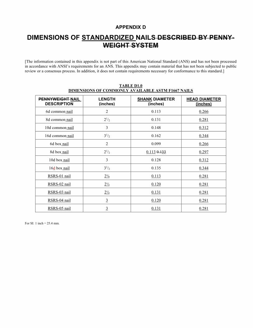
APPENDIX D
DIMENSIONS OF STANDARDIZED NAILS DESCRIBED BY PENNY-WEIGHT SYSTEM
[The information contained in this appendix is not part of this American National Standard (ANS) and has not been processed in accordance with ANSI’s requirements for an ANS. This appendix may contain material that has not been subjected to public review or a consensus process. In addition, it does not contain requirements necessary for conformance to this standard.]
TABLE D1.0 DIMENSIONS OF COMMONLY AVAILABLE ASTM F1667 NAILS
PENNYWEIGHT NAIL DESCRIPTION
LENGTH (inches)
SHANK DIAMETER (inches)
HEAD DIAMETER (inches)
6d common nail 2 0.113 0.266
8d common nail 21/2 0.131 0.281
10d common nail 3 0.148 0.312
16d common nail 31/2 0.162 0.344
6d box nail 2 0.099 0.266
8d box nail 21/2 0.113 0.133 0.297
10d box nail 3 0.128 0.312
16d box nail 31/2 0.135 0.344
RSRS-01 nail 2⅜ 0.113 0.281
RSRS-02 nail 2½ 0.120 0.281
RSRS-03 nail 2½ 0.131 0.281
RSRS-04 nail 3 0.120 0.281
RSRS-05 nail 3 0.131 0.281
For SI: 1 inch = 25.4 mm.
Copyright © 2022 FDOKUMEN

