


Bahasa
Halaman
Hukum

Handling Ambiguity and Errors: Visual Languages for Calligraphic Interaction
JOÃO PAULO PEREIRA1
MANUEL JOÃO FONSECA 2
JOAQUIM ARMANDO PIRES JORGE2
1ISEP – Instituto Superior de Engenharia do Porto, Porto, [email protected]
2INESC – Instituto de Engenharia de Sistemas e Computadores – Rua Alves Redol, 9, 6º 1000-029 Lisboa, Portugal{jaj,mjf}@inesc.pt
Abstract. This paper describes error handling and ambiguity in a class of applications organized arounddrawing and sketching, which we call Calligraphic Interfaces. While errors and imprecision are unavoidablefeatures of human input, these have long been considered nuisances and problems to circumvent in userinterface design. However, the transition away from non-WIMP interface styles and into continuous mediafeaturing recognition requires that we take a fresh approach to errors and imprecision. We present new toolsand interaction styles to allow designers to develop error tolerant and simpler interaction dialogues.
1 Introduction
Recognition-based interfaces have made significantprogress over the last few years due to advances inaffordable computing power. The advent of mobiledevices and new interaction modalities looks poised toprovide viable alternatives to pervasive WIMP-baseddesktop applications. Nevertheless, integral use ofsketches, pen strokes and gestures in computerinterfaces is still restricted, because gestures are difficultfor computers to analyze. While handwriting and speechrecognition have been active research topics for thirtyyears, they still pose serious problems. Gestures are sodifferent from conventional input modalities that theydemand radically new methods for input handling anddialogue design. Pen stroke data are hard to classify dueto noise and user variations, requiring patternrecognition techniques to convert them into moretractable form. Even the best recognizer will sometimesgive different interpretations of input that humanobservers perceive as similar. This problem iscompounded by the difficulty in using contextualinformation (other than a dictionary) to aid inrecognition.
To overcome these limitations, new approaches, whichwe call Calligraphic Interfaces, use sketching anddrawing as the main organizing paradigm. Suchapplications rely on continuous input modalities ratherthan discrete interactions characteristic of WIMP. Theword “calligraphy'' comes from the Greek kalligraphiaformed by the composition of kallos (= beautiful) andgraphein (= to scratch, draw or write). It stands forbeautiful or expert handwriting, or simply handwriting,and in a broad sense, denotes the art of fine handdrawing.
However, replacing direct manipulation by sketchingdoes not provide a definitive answer. While the
temptation to follow the paper-and-pencil metaphor isgreat, free-hand sketch recognition remains an elusivegoal. Further, using gestures and sketches to entercommands and draw shapes requires users to learn acommand set – sketches do not enjoy the self-disclosingcharacteristics of menus. Moreover, the imprecise natureof interactions presents additional problems that are notadequately addressed by present-generation multimodalinterfaces.
In this paper we address the three problemsoutlined above through a combination of differentparadigms: a sketching metaphor provides a paper-and-pencil like interaction. A kind of dynamic menus –expectation lists – tries to expose the state of theapplication without interfering with the task. Finallyincremental drawing paradigms based on visuallanguages allows precise drawings to be progressivelyconstructed from sketches through constraints andparsing.
We present our work on two different domain areasto support our points. In the first section we describeDocSketch, a calligraphic interface to input documentlayout by means of freehand sketches. Next, we presentour work on Gesture-based Incremental Design Systems(GIDeS), which embodies the incremental drawingapproach coupled with expectation lists. Both systemsextend the paper and pencil paradigm in novel andinteresting ways. While these are still emergingapplications, suffering from many infancy troubles, theydiffer sufficiently from the current paradigm to allow usa glimpse at what we think are some fundamental traitsof post-WIMP applications.
2 Related Work
The idea of calligraphic interfaces is not new. In fact,communication through sketches and planar diagramsprecedes the invention of writing by more than 30
centuries. Also, using pen-based interfaces in tasksrelated to the automatic recognition of hand written ordrawn information is over a generation old. However, itdid not make significant progress for three majorreasons: early gesture recognition systems had had lowrecognition rates; dealing with the ambiguity inherent tohuman-provided information was not easily solved; andthe advent of easy-to-use direct manipulation WIMPinterfaces led to a widespread lack of interest forgesture-based interfaces.
In 1963, Sutherland presented Sketchpad [25] the firstinteractive system that used one light pen to drawdiagrams directly over the screen surface. The mainlimitation of this system was in the recognitioncapabilities, limited resources and high cost of thecomputer used. Landay [24] describes a sketch-basedapproach for the early stages of user interface design.His work uses electronic sketching to allow designers toquickly record design ideas in a tangible form, obviatingthe need to specify too much detail too early in theprocess. His electronic sketches possess the advantagesnormally associated with computer-based tools, makingthem well suited to user interface design.
Sketch [23] is an example of a system that allows usersto create 3D scenes based on CSG-like primitivesinstantiated by 2D strokes. All interaction relies on athree-button mouse, occasionally combined withmodifier keys on the keyboard. Sketch uses two types ofgestural elements – five classes of strokes (draw whilepressing the first mouse button) and two classes ofinteractors (made with the second button). Cameramanipulation is performed with the third mouse button.Another feature of Sketch are direction dependentgesture strokes to infer CSG operations. Zeleznik’s et al.work has proceeded with Jot [9], an extension toSketch’s interface that relies not only on pen input butalso on immersive virtual reality technology such as six-degrees-of-freedom physical props and stereo glasses.
Our approach differs from Sketch’s in three main ways.First, GIDeS uses a stylus for all operations. Second,except for camera manipulation, which uses the sidebutton, all commands, drawing and 3D primitives areinferred only from the available (drawn) information.Lastly, all gestures are independent of direction, relyingon perspective to retain the pencil-and-paper flavor.
Encarnação et al. [5,7] developed a system thatcombines traditional desktop metaphors with a virtualreality interface. This allows the user to directly create
simple objects in true 3D, through the use of iconicgestures that resemble the contours of the top-downprojections of objects. Their system uses verysophisticated equipment such as transparent pen andpad, shutter glasses, magnetic trackers and a virtual tabledisplay device.
Igarashi et al. developed Teddy [12], a system thatallows modeling of freeform 3D objects from sketched2D outlines. However, resulting models are constrainedto a sphere-equivalent topology and Boolean operationswere not taken into account.
Igarashi et al. describe a technique for rapid geometricdesign called interactive beautification [11]. Freehandstrokes drawn by users are converted by their system –Pegasus – in line segments that must satisfy certaingeometric constraints such as perpendicularity,congruence and symmetry amongst others. Pegasus alsouses context information to deal with ambiguity. Itgenerates multiple candidates by combining inferredconstraints appropriately and evaluates them in order tofind the most plausible ones and reject the others. Theuser is then allowed to select the candidate that meetshis or her wishes by tapping on it directly. Theprocedure is completed as soon as the user taps outsidethe candidates or draws the next stroke.
As the authors say, the problem with this way ofhandling ambiguity is that it is difficult for users toperform the selection they want amongst a large numberof overlapping candidates.
Mankoff et al. [16] present a survey on interfaces thatmake use of various forms of recognition such asgesture, handwriting and speech interpretation. Theirwork also focuses on the problem of handlingrecognition errors and ambiguity by means of dialoguesbetween the system and the user – a process they callmediation. Based on that survey, the authors created auser interface toolkit called OOPS – organized optionpruning system [15]. OOPS consists of a library ofreusable mediation techniques combined witharchitectural solutions to model and provide support forambiguity at the level of user input events.
Gross et al. [10], Back of an Envelope (BoE) projectapplies pen-based interfaces to a wide range of domainssuch as databases, simulation programs and 3Dmodeling. Their approach tries to combine the virtues ofhighly structured interfaces for creating accuratedrawings and models with the benefits inherent tofreehand drawing interfaces.
Turner et al. [22] designed Stilton, a sketch modelingsystem that resembles a desktop VRML browser,allowing users to interact with a 3D model inperspective projection, or panoramic photographsmapped onto the scene as a “floor” and “walls”. Thesystem can be used to reconstruct geometry frompanoramic images or to add new objects to an existingscene. Object creation relies on geometric informationsketched by users on an imaginary 2D drawing plane.
While most of the approaches outlined above explicitlyuse sketches and drawing as a novel organizingparadigm, ambiguous input and recognition errors areconsidered nuisances and hurdles to overcome. In mostapproaches, explicit formal syntactic analysis is notaddressed. Ambiguity is handled for misrecognizedconstituents through hard-coded confidence values insome cases and in ad-hoc manner in others, with thenotable exception of Mankoff’s work. Visuallyambiguous arrangements concerning spatialrelationships are also not treated. Error recovery is userdependent and requires dialog boxes not consistent withthe hand-drawn philosophy of most approaches. Thehard-coded nature of the rules also limits the systemflexibility in extending and changing the visuallanguage.
We will present several avenues to attack this problemin what follows. At the lowest level we present CalI, aset of software components to address strokerecognition. At a level above we discuss ambiguousvisual arrangements and present fuzzy visual languagesused in DocSketch [18] a page composition program.Finally, at the three-dimensional level we discussexpectation lists, reduced-instruction set interfacesand the judicious use of constraints to transformimprecise input into rigourous three-dimensionaldrawings using GIDeS.
3 CALI -A Library for 2D Gesture Recognition
In this section we present CALI [3], a softwarelibrary for the development of Calligraphic Interfaces,centered mainly on a simple Shape Recognizer.
The Recognizer [4] is a fast, simple and compactapproach to identify Scribbles (multi-stroke geometricshapes) drawn with a stylus on a digitizing tablet. Themethod is able to identify shapes of different sizes androtated at arbitrary angles, drawn with dashed,continuous strokes or overlapping lines.
The recognition process is based on three mainideas. Firstly, it uses entirely global geometric propertiesextracted from input shapes. Since we are mainlyinterested in identifying geometric entities, therecognizer relies mainly on geometric information.Secondly, to enhance recognition performance, we use aset of filters either to identify shapes or to filter out
unwanted shapes using distinctive criteria. Finally, toovercome uncertainty and imprecision in shape sketches,we use fuzzy logic to associate degrees of certainty torecognized shapes, thereby handling ambiguitiesnaturally.
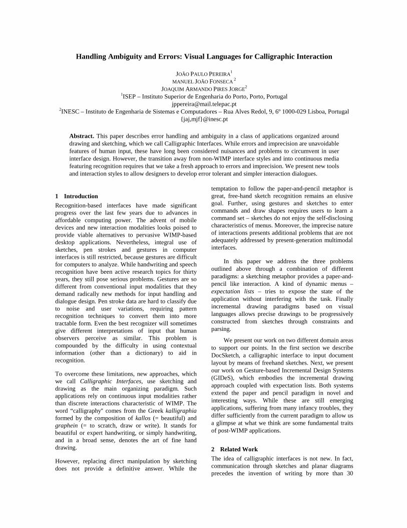
This algorithm recognizes elementary geometricshapes, such as Triangles, Rectangles,Diamonds, Circles, Ellipses, Lines andArrows, and five gesture commands, Delete,Cross, WavyLine, Move and Copy, as depicted inFigure 1. Shapes are recognized independently ofchanges in rotation, size or number of individual strokes.Commands are shapes drawn using a single stroke,except Cross, which requires two strokes.
The recognizer works by looking up values ofspecific features in fuzzy sets associated to each shapeand command. This process yields a list of plausibleshapes ordered by degree of certainty.
Figure 1: Multi-stroke and uni-stroke shapes.
The set of shapes selected and presented in Figure1 are the basic elements to construct technical diagrams,such as electric or logic circuits, flowcharts orarchitectural sketches. These diagrams also requiredistinguishing between solid, dash and bold depictionsof shapes in the same family. Some authors notice thatthe majority of diagrams were built of ellipses,rectangles and lines [1]. Another author [2] has foundthat designers use a small set of symbols and that theyshare drawing conventions, so there is coherencebetween symbols used by different designers.
The recognizer has a recognition rate of 96%. It isfast: each scribble requires, on average, less than 50 ms(using a Pentium II @ 233 MHz) to be recognized, fromfeature vector computation to final classification. Thefast response characteristic makes it very usable ininteractive applications.
This approach extends and improves Kimura'swork [1], which recognizes a small number of shapesand did not distinguish rotated, open/closed, dashed andbold shapes.
4 Example Application: Document Layout
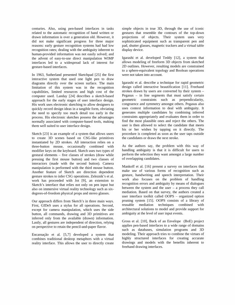
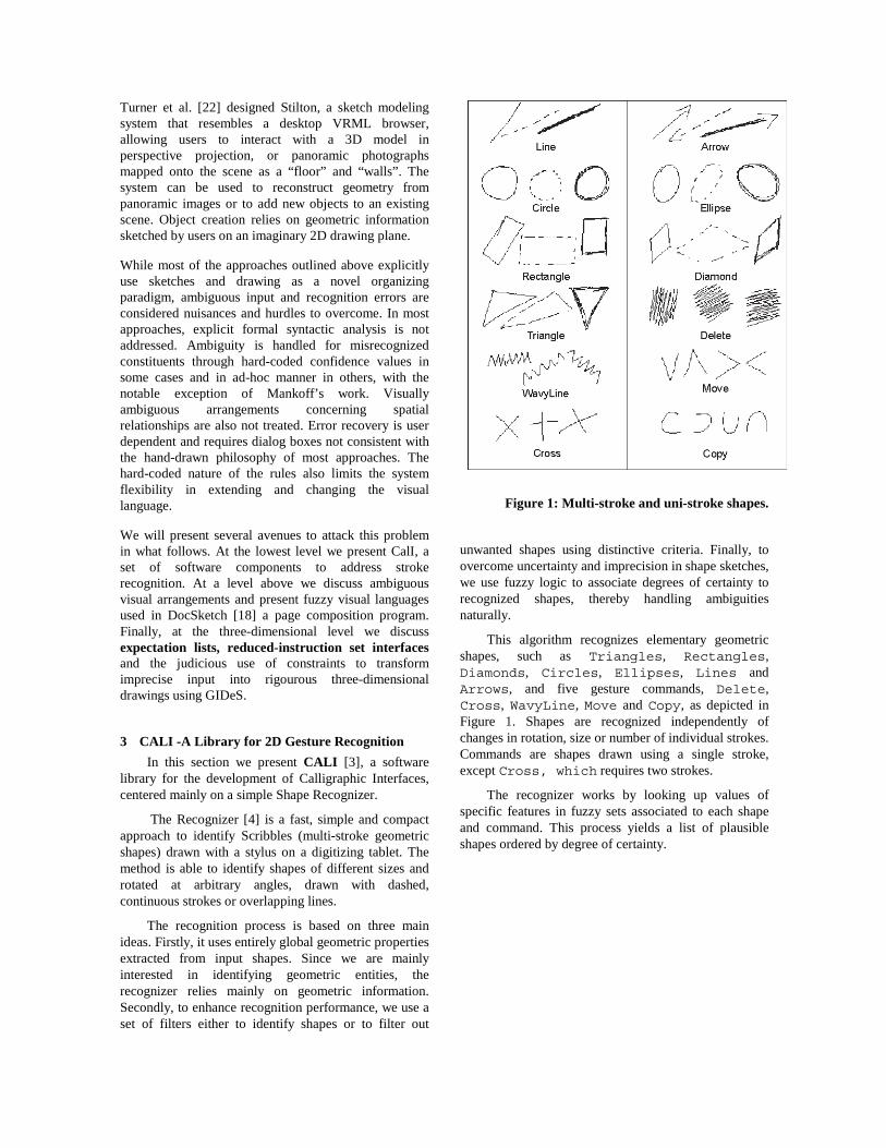
This section describes an example interactionscenario using the DocSketch system to design adocument layout. Figure 2 shows an example that can beused to produce an HTML page like that in Figure 3. InFigure 2 the user has drawn five types of designelements: three headers, one scrolled windowwith a vertical scroll bar to the right, oneimage, one label and several buttons. These arethe main construction elements and respective spatialarrangements shown in this example. The system isresponsible for inferring the most likely documentlayout, an example of which appears in Figure 3. Thisway, DocSketch enables the designer to focus on theexploration of design ideas and not on details.
The interaction sequence starts when the usersketches shapes to compose a document layout, using apen on a digitizing tablet. The system tries to identifyeach shape as soon as it is drawn, using the recognizerdescribed above. After identifying a shape, the systemtries to combine it with previously inserted shapes, usingbasic spatial and adjacency fuzzy relations. Thisinformation about shapes and relations is then fed to arule--based system, which uses basic knowledge aboutthe structure and patterns of document layout to infer,which design element was intended. The inference rulesof this system are grouped into a grammaticalspecification of a visual language for document design.Since each rule also gets associated degrees of certaintycomputed from its components, the system is naturallyguided to infer the most likely document designconstituents.
DocSketch allows users to manage designcomponents through the usual commands Delete,Move and Copy, which are supported and recognizedas gestures.
The visual elements used to define the types oftypographic operators, their positions and dimensions,as well as other visual characteristics make up a visuallanguage for document design. In this visual languagesymbols are sketches built by composition of simpleshapes from a subset of those presented in Figure 1. Avisual grammar defines rules of composition ofindividual elements as described in [18].
Figure 2: Sketched document layout example. Figure 3: CNN weather forecast page.
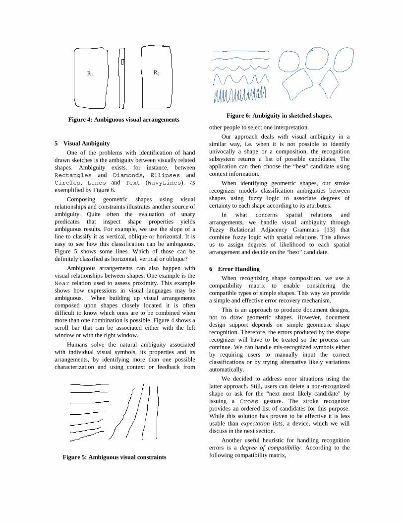
5 Visual Ambiguity
One of the problems with identification of handdrawn sketches is the ambiguity between visually relatedshapes. Ambiguity exists, for instance, betweenRectangles and Diamonds, Ellipses andCircles, Lines and Text (WavyLines), asexemplified by Figure 6.
Composing geometric shapes using visualrelationships and constraints illustrates another source ofambiguity. Quite often the evaluation of unarypredicates that inspect shape properties yieldsambiguous results. For example, we use the slope of aline to classify it as vertical, oblique or horizontal. It iseasy to see how this classification can be ambiguous.Figure 5 shows some lines. Which of those can bedefinitely classified as horizontal, vertical or oblique?
Ambiguous arrangements can also happen withvisual relationships between shapes. One example is theNear relation used to assess proximity. This exampleshows how expressions in visual languages may beambiguous. When building up visual arrangementscomposed upon shapes closely located it is oftendifficult to know which ones are to be combined whenmore than one combination is possible. Figure 4 shows ascroll bar that can be associated either with the leftwindow or with the right window.
Humans solve the natural ambiguity associatedwith individual visual symbols, its properties and itsarrangements, by identifying more than one possiblecharacterization and using context or feedback from
other people to select one interpretation.
Our approach deals with visual ambiguity in asimilar way, i.e. when it is not possible to identifyunivocally a shape or a composition, the recognitionsubsystem returns a list of possible candidates. Theapplication can then choose the “best'' candidate usingcontext information.
When identifying geometric shapes, our strokerecognizer models classification ambiguities betweenshapes using fuzzy logic to associate degrees ofcertainty to each shape according to its attributes.
In what concerns spatial relations andarrangements, we handle visual ambiguity throughFuzzy Relational Adjacency Grammars [13] thatcombine fuzzy logic with spatial relations. This allowsus to assign degrees of likelihood to each spatialarrangement and decide on the “best” candidate.
6 Error Handling
When recognizing shape composition, we use acompatibility matrix to enable considering thecompatible types of simple shapes. This way we providea simple and effective error recovery mechanism.
This is an approach to produce document designs,not to draw geometric shapes. However, documentdesign support depends on simple geometric shaperecognition. Therefore, the errors produced by the shaperecognizer will have to be treated so the process cancontinue. We can handle mis-recognized symbols eitherby requiring users to manually input the correctclassifications or by trying alternative likely variationsautomatically.
We decided to address error situations using thelatter approach. Still, users can delete a non-recognizedshape or ask for the “next most likely candidate" byissuing a Cross gesture. The stroke recognizerprovides an ordered list of candidates for this purpose.While this solution has proven to be effective it is lessusable than expectation lists, a device, which we willdiscuss in the next section.
Another useful heuristic for handling recognitionerrors is a degree of compatibility. According to thefollowing compatibility matrix,
Figure 6: Ambiguity in sketched shapes.Figure 4: Ambiguous visual arrangements
Figure 5: Ambiguous visual constraints
(compatible, Diamond, Rectangle, 0.60)
(compatible, Ellipse, Rectangle, 50)
(compatible, Circle, Rectangle, 0.40)
(compatible, Line, Text, 0.60)
when the analyzer receives a Diamond from therecognizer, if it is not capable of producing anycomposition, it will try to proceed by substituting thatshape for a Rectangle. In the same spirit we candefine Ellipse and a Circle as shapescompatible, to an extent with Rectangle. The lastitem specifies a substitution for Line, but in this lastcase, a symbol of type Text will replace it. Thiscompatibility relation defines a degree of conformancebetween shapes. The degree of likelihood of the ``new"shape is defined by the minimum between the degree ofconformance and the degree of likelihood assigned bythe recognizer to the shape being substituted.
7 GIDES: Sketching in Three Dimensions
In the previous section, we have seen grammatical,visual and heuristic ways with handling visual ambiguityin two-dimensional compositions. In the followingsections we will present GIDeS, a calligraphic interfaceto create three-dimensional models. The architecture ofGIDeS calligraphic interface consists basically of a setof three gesture recognition subsystems, an expectationlist generator and a set of constraint-based interactionmodes that allow users to perform geometrictransformations and cuts on objects.
8 Gesture Recognition
Command gesture interpretation relies on tworecognition subsystems. The first one is an improvedversion of Rubine’s trainable recognizer [21], combinedwith ours [3] to add some new features:
• Support for multiple-stroke gesture recognition. Thesequence by which strokes are drawn is irrelevant.
• Recognize strokes regardless of direction.• Force recognition to depend on context aspects not
necessarily related to gesture geometry.• Support for handling ambiguity.
A detailed description of the changes we made toRubine’s algorithm can be found in [17].
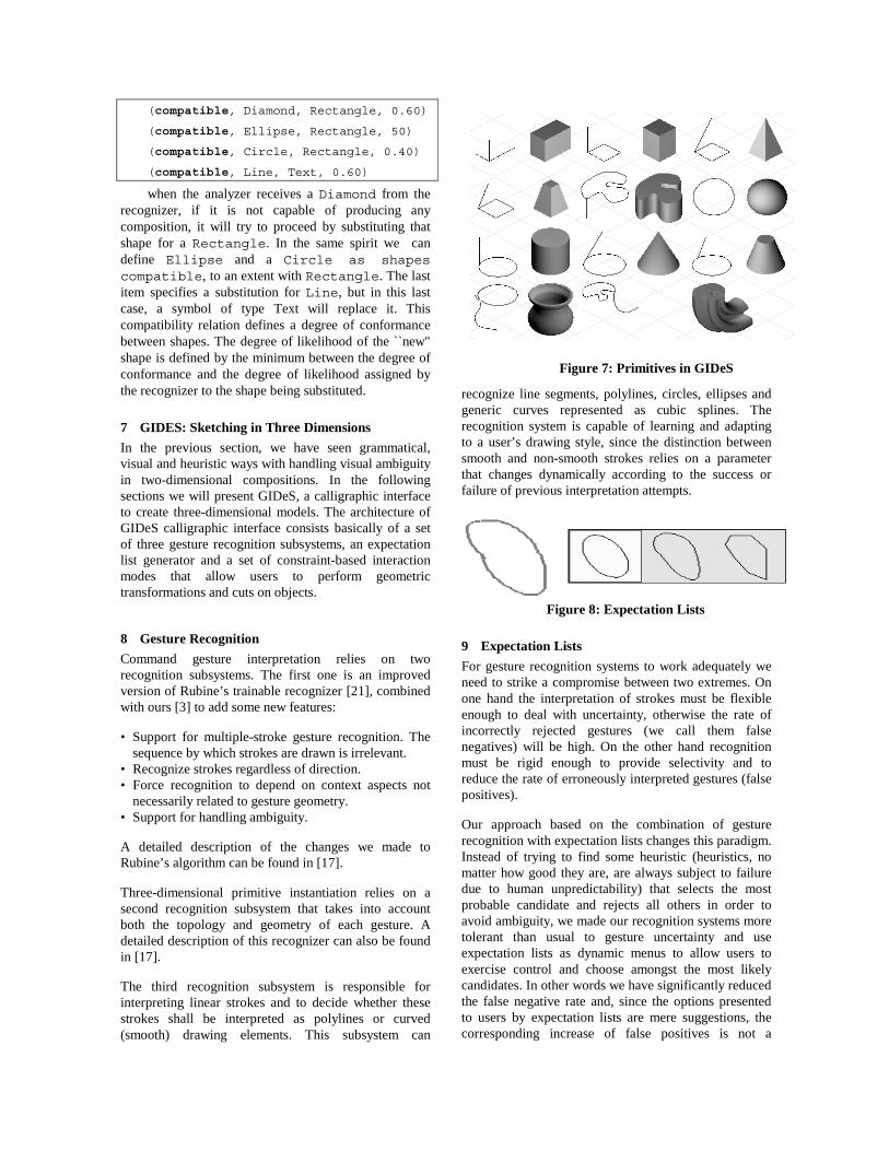
Three-dimensional primitive instantiation relies on asecond recognition subsystem that takes into accountboth the topology and geometry of each gesture. Adetailed description of this recognizer can also be foundin [17].
The third recognition subsystem is responsible forinterpreting linear strokes and to decide whether thesestrokes shall be interpreted as polylines or curved(smooth) drawing elements. This subsystem can
recognize line segments, polylines, circles, ellipses andgeneric curves represented as cubic splines. Therecognition system is capable of learning and adaptingto a user’s drawing style, since the distinction betweensmooth and non-smooth strokes relies on a parameterthat changes dynamically according to the success orfailure of previous interpretation attempts.
9 Expectation Lists
For gesture recognition systems to work adequately weneed to strike a compromise between two extremes. Onone hand the interpretation of strokes must be flexibleenough to deal with uncertainty, otherwise the rate ofincorrectly rejected gestures (we call them falsenegatives) will be high. On the other hand recognitionmust be rigid enough to provide selectivity and toreduce the rate of erroneously interpreted gestures (falsepositives).
Our approach based on the combination of gesturerecognition with expectation lists changes this paradigm.Instead of trying to find some heuristic (heuristics, nomatter how good they are, are always subject to failuredue to human unpredictability) that selects the mostprobable candidate and rejects all others in order toavoid ambiguity, we made our recognition systems moretolerant than usual to gesture uncertainty and useexpectation lists as dynamic menus to allow users toexercise control and choose amongst the most likelycandidates. In other words we have significantly reducedthe false negative rate and, since the options presentedto users by expectation lists are mere suggestions, thecorresponding increase of false positives is not a
Figure 8: Expectation Lists
Figure 7: Primitives in GIDeS
problem, because users can simply ignore thesesuggestions in the same way they ignore other unwantedoptions. That is, instead of trying to avoid ambiguity, weencourage its occurrence and explore it to user’s benefit.
We have tried to extend expectation lists to all levels ofuser interaction. With the exception of commandexpectation lists that use icons to make suggestions, alllists prompt the user with small-scale models of theobjects that can be created in relation to the existingcontext.
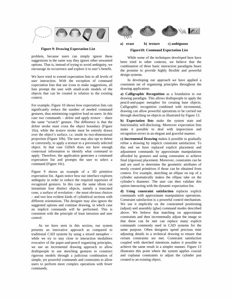
For example, Figure 10 shows how expectation lists cansignificantly reduce the number of needed commandgestures, thus minimizing cognitive load on users. In thiscase two commands – delete and apply texture – sharethe same “scratch” gesture. The difference is that thedelete stroke must cross the object boundary (Figure10a), while the texture stroke must be entirely drawnover the object’s surface, i.e. inside its two-dimensionalprojection (Figure 10b). The user may also opt to deleteor conversely, to apply a texture to a previously selectedobject. In that case GIDeS does not have enoughcontextual information to identify what command toapply. Therefore, the application generates a commandexpectation list and prompts the user to select acommand (Figure 10c).
Figure 9 shows an example of a 3D primitiveexpectation list. Again notice how our interface exploresambiguity in order to reduce the required repertoire ofrecognized gestures. In this case the same idiom caninstantiate four distinct objects, namely a truncatedcone, a surface of revolution – the most obvious choices– and two less evident kinds of cylindrical sections withdifferent orientations. The designer may also ignore thesuggested options and continue drawing, in which caseno implicit commands will be performed. This isconsistent with the principle of least intrusion and usercontrol.
As we have seen in this section, our systempresents an innovative approach as compared totraditional CAD systems by using a mixed metaphor –while we try to stay close to interaction modalitiesevocative of the paper-and-pencil organizing principles,we use an incremental drawing approach to allowdraftspeople to use sketching gestures to constructrigorous models through a judicious combination ofsimple, yet powerful commands and constraints to allowusers to perform more complex operations with fewercommands.
While some of the techniques developed here havebeen tried in other contexts, we believe that thecombination of three basic interaction paradigms bearsthe promise to provide highly flexible and powerfuldesign systems.
In developing our approach we have applied aconsistent set of organizing principles throughout thedrawing application:
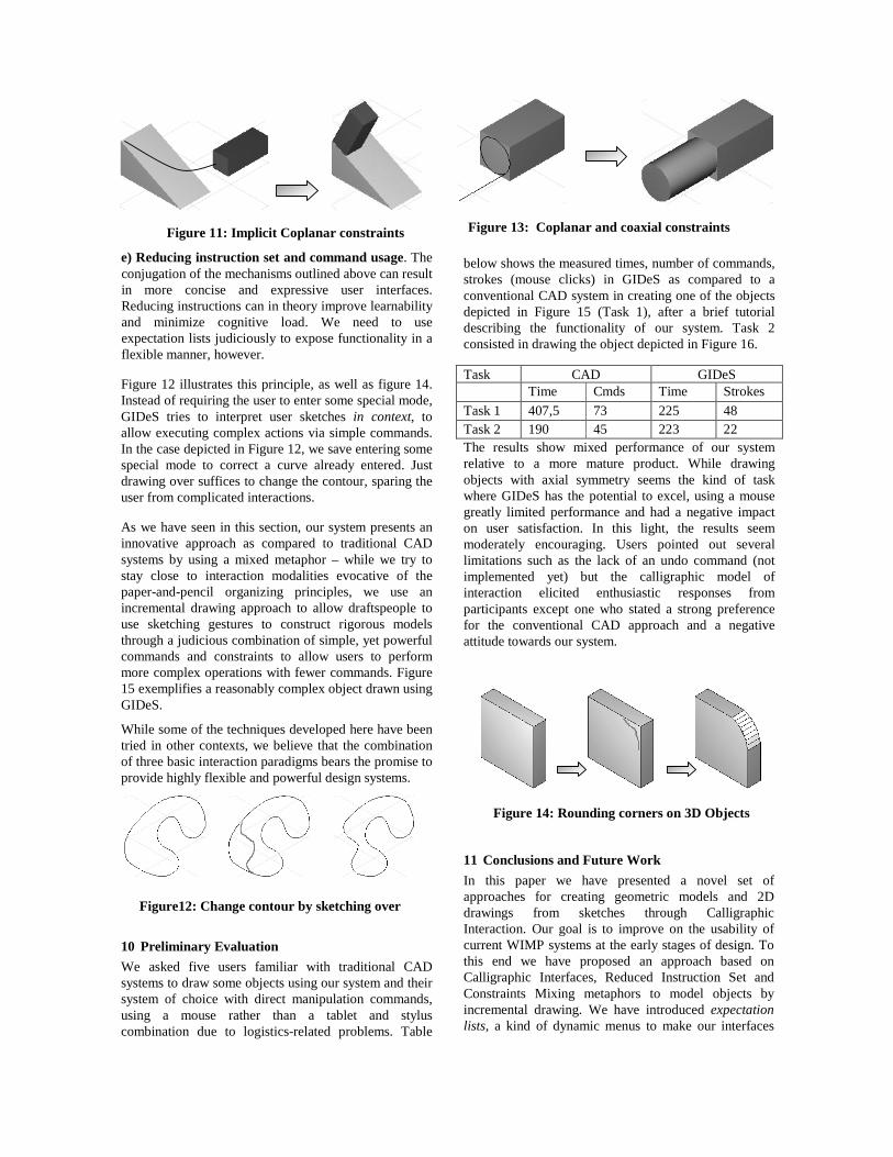
a) Calligraphic Recognition as a foundation to ourdrawing paradigm. This allows draftspeople to apply thepencil-and-paper metaphor for creating base objects.Calligraphic recognition combined with incremental,drawing can allow powerful operations to be carried outthrough sketching on objects as illustrated by Figure 13.
b) Expectation lists make the system state andfunctionality self-disclosing. Moreover expectation listsmake it possible to deal with imprecision andrecognition errors in an elegant and graceful manner.
c) Incremental Drawing makes it possible to graduallyrefine a drawing by implicit constraint satisfaction. Tothis end we have replaced explicit placement andadjustment commands by approximate manipulationsafforded by gestures and using constraints to achievefinal (rigorous) placement. Moreover, constraints can beand are used to determine the geometric attributes ofnewly created primitives if those can be obtained fromcontext. For example, sketching an ellipse on top of acylinder automatically makes the ellipse take on thecylinder’s diameter. The user can then validate thisoption interacting with the dynamic expectation list.
d) Using constraint satisfaction replaces explicitcommands with approximate manipulation operations.Constraint satisfaction is a powerful control mechanism.We use it implicitly on the constrained positioning(adjust) and assembly (glue) command modes describedabove. We believe that matching on approximateconstraints and then incrementally adjust the image sothat these can be met can replace many explicitcommands commonly used in CAD systems for thesame purpose. Often designers spend precious timeadjusting details in a technical drawing to ensure thatcertain constraints are met. Constraint satisfactioncoupled with sketched intentions makes it possible toachieve the same result in a simpler manner. Figure 13illustrates this point where the system applies coaxialand coplanar constraints to adjust the cylinder justcreated to an existing object.
Figure 9: Drawing Expectation List
a) erase b) texture c) ambiguous
Figure10: Command Expectation List
e) Reducing instruction set and command usage. Theconjugation of the mechanisms outlined above can resultin more concise and expressive user interfaces.Reducing instructions can in theory improve learnabilityand minimize cognitive load. We need to useexpectation lists judiciously to expose functionality in aflexible manner, however.
Figure 12 illustrates this principle, as well as figure 14.Instead of requiring the user to enter some special mode,GIDeS tries to interpret user sketches in context, toallow executing complex actions via simple commands.In the case depicted in Figure 12, we save entering somespecial mode to correct a curve already entered. Justdrawing over suffices to change the contour, sparing theuser from complicated interactions.
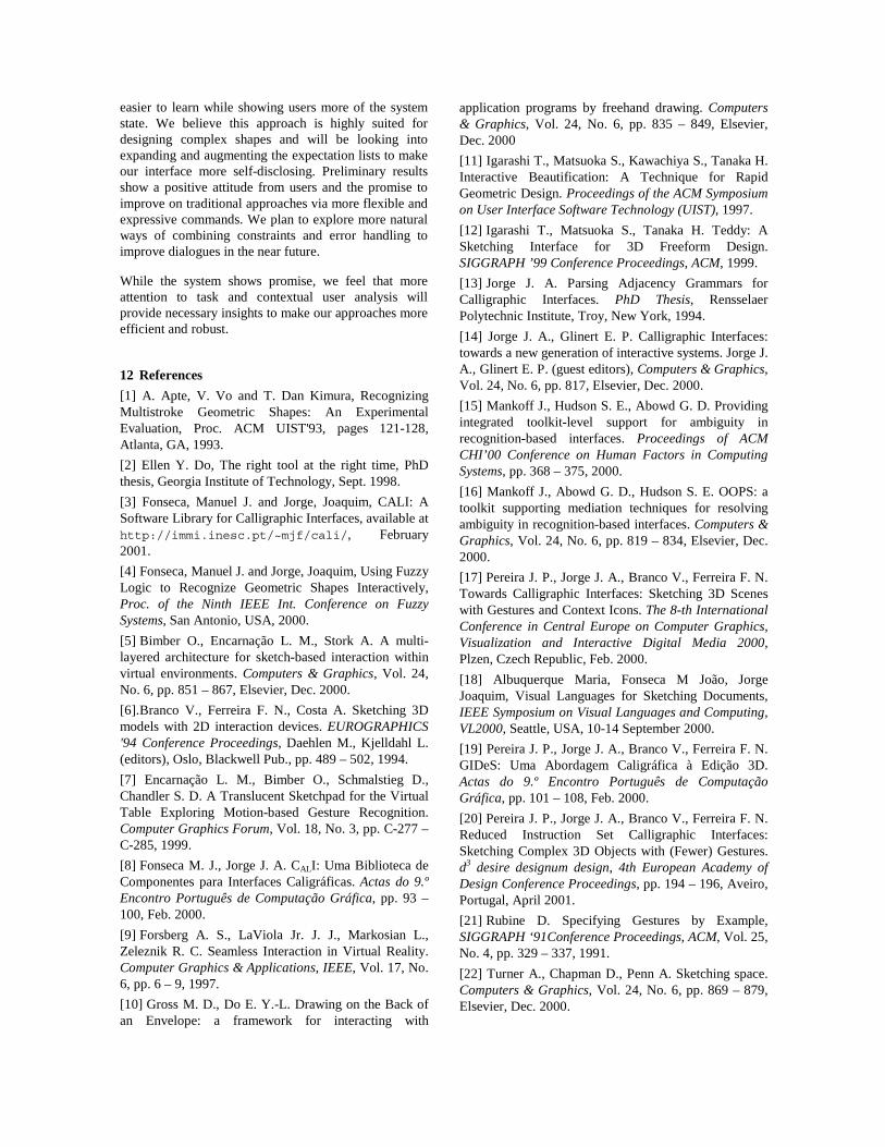
As we have seen in this section, our system presents aninnovative approach as compared to traditional CADsystems by using a mixed metaphor – while we try tostay close to interaction modalities evocative of thepaper-and-pencil organizing principles, we use anincremental drawing approach to allow draftspeople touse sketching gestures to construct rigorous modelsthrough a judicious combination of simple, yet powerfulcommands and constraints to allow users to performmore complex operations with fewer commands. Figure15 exemplifies a reasonably complex object drawn usingGIDeS.
While some of the techniques developed here have beentried in other contexts, we believe that the combinationof three basic interaction paradigms bears the promise toprovide highly flexible and powerful design systems.
10 Preliminary Evaluation
We asked five users familiar with traditional CADsystems to draw some objects using our system and theirsystem of choice with direct manipulation commands,using a mouse rather than a tablet and styluscombination due to logistics-related problems. Table
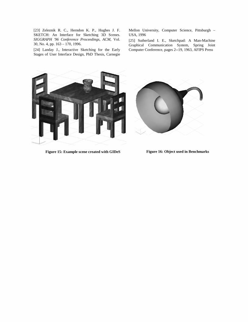
below shows the measured times, number of commands,strokes (mouse clicks) in GIDeS as compared to aconventional CAD system in creating one of the objectsdepicted in Figure 15 (Task 1), after a brief tutorialdescribing the functionality of our system. Task 2consisted in drawing the object depicted in Figure 16.
Task CAD GIDeSTime Cmds Time Strokes
Task 1 407,5 73 225 48Task 2 190 45 223 22The results show mixed performance of our systemrelative to a more mature product. While drawingobjects with axial symmetry seems the kind of taskwhere GIDeS has the potential to excel, using a mousegreatly limited performance and had a negative impacton user satisfaction. In this light, the results seemmoderately encouraging. Users pointed out severallimitations such as the lack of an undo command (notimplemented yet) but the calligraphic model ofinteraction elicited enthusiastic responses fromparticipants except one who stated a strong preferencefor the conventional CAD approach and a negativeattitude towards our system.
11 Conclusions and Future Work
In this paper we have presented a novel set ofapproaches for creating geometric models and 2Ddrawings from sketches through CalligraphicInteraction. Our goal is to improve on the usability ofcurrent WIMP systems at the early stages of design. Tothis end we have proposed an approach based onCalligraphic Interfaces, Reduced Instruction Set andConstraints Mixing metaphors to model objects byincremental drawing. We have introduced expectationlists, a kind of dynamic menus to make our interfaces
Figure 11: Implicit Coplanar constraints
Figure12: Change contour by sketching over
Figure 14: Rounding corners on 3D Objects
Figure 13: Coplanar and coaxial constraints
easier to learn while showing users more of the systemstate. We believe this approach is highly suited fordesigning complex shapes and will be looking intoexpanding and augmenting the expectation lists to makeour interface more self-disclosing. Preliminary resultsshow a positive attitude from users and the promise toimprove on traditional approaches via more flexible andexpressive commands. We plan to explore more naturalways of combining constraints and error handling toimprove dialogues in the near future.
While the system shows promise, we feel that moreattention to task and contextual user analysis willprovide necessary insights to make our approaches moreefficient and robust.
12 References
[1] A. Apte, V. Vo and T. Dan Kimura, RecognizingMultistroke Geometric Shapes: An ExperimentalEvaluation, Proc. ACM UIST'93, pages 121-128,Atlanta, GA, 1993.
[2] Ellen Y. Do, The right tool at the right time, PhDthesis, Georgia Institute of Technology, Sept. 1998.
[3] Fonseca, Manuel J. and Jorge, Joaquim, CALI: ASoftware Library for Calligraphic Interfaces, available athttp://immi.inesc.pt/~mjf/cali/, February2001.
[4] Fonseca, Manuel J. and Jorge, Joaquim, Using FuzzyLogic to Recognize Geometric Shapes Interactively,Proc. of the Ninth IEEE Int. Conference on FuzzySystems, San Antonio, USA, 2000.
[5] Bimber O., Encarnação L. M., Stork A. A multi-layered architecture for sketch-based interaction withinvirtual environments. Computers & Graphics, Vol. 24,No. 6, pp. 851 – 867, Elsevier, Dec. 2000.
[6].Branco V., Ferreira F. N., Costa A. Sketching 3Dmodels with 2D interaction devices. EUROGRAPHICS'94 Conference Proceedings, Daehlen M., Kjelldahl L.(editors), Oslo, Blackwell Pub., pp. 489 – 502, 1994.
[7] Encarnação L. M., Bimber O., Schmalstieg D.,Chandler S. D. A Translucent Sketchpad for the VirtualTable Exploring Motion-based Gesture Recognition.Computer Graphics Forum, Vol. 18, No. 3, pp. C-277 –C-285, 1999.
[8] Fonseca M. J., Jorge J. A. CALI: Uma Biblioteca deComponentes para Interfaces Caligráficas. Actas do 9.ºEncontro Português de Computação Gráfica, pp. 93 –100, Feb. 2000.
[9] Forsberg A. S., LaViola Jr. J. J., Markosian L.,Zeleznik R. C. Seamless Interaction in Virtual Reality.Computer Graphics & Applications, IEEE, Vol. 17, No.6, pp. 6 – 9, 1997.
[10] Gross M. D., Do E. Y.-L. Drawing on the Back ofan Envelope: a framework for interacting with
application programs by freehand drawing. Computers& Graphics, Vol. 24, No. 6, pp. 835 – 849, Elsevier,Dec. 2000
[11] Igarashi T., Matsuoka S., Kawachiya S., Tanaka H.Interactive Beautification: A Technique for RapidGeometric Design. Proceedings of the ACM Symposiumon User Interface Software Technology (UIST), 1997.
[12] Igarashi T., Matsuoka S., Tanaka H. Teddy: ASketching Interface for 3D Freeform Design.SIGGRAPH ’99 Conference Proceedings, ACM, 1999.
[13] Jorge J. A. Parsing Adjacency Grammars forCalligraphic Interfaces. PhD Thesis, RensselaerPolytechnic Institute, Troy, New York, 1994.
[14] Jorge J. A., Glinert E. P. Calligraphic Interfaces:towards a new generation of interactive systems. Jorge J.A., Glinert E. P. (guest editors), Computers & Graphics,Vol. 24, No. 6, pp. 817, Elsevier, Dec. 2000.
[15] Mankoff J., Hudson S. E., Abowd G. D. Providingintegrated toolkit-level support for ambiguity inrecognition-based interfaces. Proceedings of ACMCHI’00 Conference on Human Factors in ComputingSystems, pp. 368 – 375, 2000.
[16] Mankoff J., Abowd G. D., Hudson S. E. OOPS: atoolkit supporting mediation techniques for resolvingambiguity in recognition-based interfaces. Computers &Graphics, Vol. 24, No. 6, pp. 819 – 834, Elsevier, Dec.2000.
[17] Pereira J. P., Jorge J. A., Branco V., Ferreira F. N.Towards Calligraphic Interfaces: Sketching 3D Sceneswith Gestures and Context Icons. The 8-th InternationalConference in Central Europe on Computer Graphics,Visualization and Interactive Digital Media 2000,Plzen, Czech Republic, Feb. 2000.
[18] Albuquerque Maria, Fonseca M João, JorgeJoaquim, Visual Languages for Sketching Documents,IEEE Symposium on Visual Languages and Computing,VL2000, Seattle, USA, 10-14 September 2000.
[19] Pereira J. P., Jorge J. A., Branco V., Ferreira F. N.GIDeS: Uma Abordagem Caligráfica à Edição 3D.Actas do 9.º Encontro Português de ComputaçãoGráfica, pp. 101 – 108, Feb. 2000.
[20] Pereira J. P., Jorge J. A., Branco V., Ferreira F. N.Reduced Instruction Set Calligraphic Interfaces:Sketching Complex 3D Objects with (Fewer) Gestures.d3 desire designum design, 4th European Academy ofDesign Conference Proceedings, pp. 194 – 196, Aveiro,Portugal, April 2001.
[21] Rubine D. Specifying Gestures by Example,SIGGRAPH ‘91Conference Proceedings, ACM, Vol. 25,No. 4, pp. 329 – 337, 1991.
[22] Turner A., Chapman D., Penn A. Sketching space.Computers & Graphics, Vol. 24, No. 6, pp. 869 – 879,Elsevier, Dec. 2000.
[23] Zeleznik R. C., Herndon K. P., Hughes J. F.SKETCH: An Interface for Sketching 3D Scenes.SIGGRAPH '96 Conference Proceedings, ACM, Vol.30, No. 4, pp. 163 – 170, 1996.
[24] Landay J., Interactive Sketching for the EarlyStages of User Interface Design, PhD Thesis, Carnegie
Mellon University, Computer Science, Pittsburgh –USA, 1996
[25] Sutherland I. E., Sketchpad: A Man-MachineGraphical Communication System, Spring JointComputer Conference, pages 2--19, 1963, AFIPS Press
Figure 15: Example scene created with GIDeS Figure 16: Object used in Benchmarks
Top Related
Copyright © 2022 FDOKUMEN

