


Bahasa
Halaman
Hukum

Presented at SatNav 2003 The 6th International Symposium on
Satellite Navigation Technology Including Mobile Positioning & Location Services
Melbourne, Australia
22–25 July 2003
FedSat Orbit Determination: Results From Daily GPS Flight Code Observations
Yanming Feng, Ning Zhou, Werner Enderle
Cooperative Research Centre for Satellite Systems Queensland University of Technology
GPO Box 2434, Q4001, Australia Phone 07 38641363, fax 07 38641517, email: [email protected]
ABSTRACT
The Australian Federation Satellite, FedSat, was successfully launched into a 780-km low-earth orbit on 14 December 2002. Since then, the onboard Blackjack GPS receiver has operated on a duty cycle basis, providing effective data sets at an average of 10 to 15 minutes per orbit with its only aft-looking antenna, which views a field of two-third of the hemisphere. This paper presents the technical description of the FedSat Orbit Determination and Tracking (FODT) software, which is used to perform FedSat orbit filtering and prediction on daily basis. We present results from GPS flight data sets of two periods: the very first 24 hour data collected on Day 364/02 and the very first data sets of 5 consecutive days in March 2003. The analysis is focused on the evaluation of the FedSat flight GPS data quality and the accuracy of orbit propagation solutions currently achievable with the FODT software. The results from the two data periods have shown that the FODT derived FedSat orbits from code measurements can be propagated forward 72 and 96 hours with the maximal orbit errors of 120m and 240m respectively, which will satisfy the precise pointing requirement for Ka-Band tracking. In general, these preliminary FedSat orbit determination results are considered encouraging and promising, given consideration of rather harsh FedSat observational environment. KEYWORDS: FedSat, Orbit Determination, Low Earth Orbit (LEO), Global Positioning Systems (GPS).
1. INTRODUCTION The Australian Federation Satellite, FedSat, was successfully launched into a 780-km Low-Earth Orbit (LEO) on 14 December 2002. Since then, the onboard Blackjack GPS receiver has operated on duty cycle basis. Operating usually lasts 20 to 30 minutes per orbit period,
PAPER 61 1
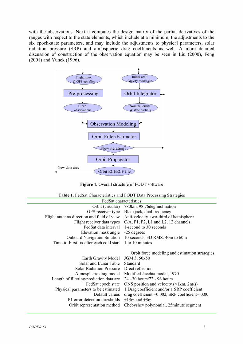
which in turn provides the effective data sets with an average of 10 to 15 minutes for each orbit period. Normally in a LEO satellite mission, a GPS receiver with an up-looking antenna is used as an onboard navigation system, for navigation, timing and precise orbit determination (POD) purposes. The antennae mounted towards other directions are used for specific scientific missions. FedSat collects GPS data with its only aft-looking antenna, for both orbit determination and scientific applications, including atmosphere occultation and ionosphere studies. As a result, the field of view of the antenna is only two-third of the hemisphere, with about half the measurements observed at negative elevations. This paper will describe the FedSat Orbit Determination and Tracking (FODT) software and strategies used to satisfy certain orbit requirements under the above unusual conditions. After examination of the quality of the raw FedSat GPS data, we present the orbit filtering and prediction results from the data sets of GPS onboard measurements collected on Day 364, Day 083 to Day 0087, 2003, to demonstrate the accuracy performance of the FODT orbit solutions. 2. FEDSAT ORBIT DETERMINATION AND TRACKING (FODT SOFTWARE) The FedSat orbit determination and tracking (FODT) software is designed at the Cooperative Research Centre for Satellite Systems (CRCSS) to autonomously process FedSat flight GPS data on the ground on daily basis for production of FedSat orbit solutions. The current version is based on flight GPS rinex data and broadcast GPS ephemeredes. Future development will use IGS ultra-rapid GPS orbits and clocks instead. As shown in Figure 1, the software is structured by five major components/programs: Pre-Processor (PP), Orbit Integrator (OI), Observation Modeling (OM), Orbit Filter/Estimator (OE) and Orbit Propagator (OP). The Pre-processor (PP) reads flight rinex file, detects and excludes the outliers in code measurements, based on statistics of P1M and PCM as defined by Equations (1) and (2) in Section 3. This process depends on flight measurements only and is independent from Selective Availability, satellite orbit and geometry. The criteria for acceptance/ rejection of a measurement vary from mission to mission in each procedure, achieving a balance between information quality and quantity for overall orbit accuracy. A conservative strategy used in FedSat case is to set a strict threshold for data entry to orbit estimation processing, for instance, ±5m, as discussed in the next section of the paper. PP outputs a clean and standardized RINEX file for follow-up processing. Orbit Integrator (OI), operated as a stand-alone program and subroutine, computes spacecraft orbits with numerical integration techniques. OI starts with a set of specified initial orbit states, uses several forces models to integrate the differential equation to produce an nominal orbit, which is a set of time-tagged state vectors, together with the partial derivatives that relate the current states to the epoch-state, which is set at the beginning or the end of the data arc. Two numerical integration methods have been built into OI to create an orbit trajectory and partial derivatives simultaneously. An adaptive-size fourth-order Runge-Kutta method based on differential equation and a fix-size Integration Equation (IE) method as described in Feng (2001) are built into the software. Observation Modeling (OM) establishes the linear relationships between GPS measurements and the epoch-state of the orbit. First, it computes the theoretical range measurements using the nominal orbit of the spacecraft and known GPS orbits, then forms the pre-fit residuals
PAPER 61 2
with the observations. Next it computes the design matrix of the partial derivatives of the ranges with respect to the state elements, which include at a minimum, the adjustments to the six epoch-state parameters, and may include the adjustments to physical parameters, solar radiation pressure (SRP) and atmospheric drag coefficients as well. A more detailed discussion of construction of the observation equation may be seen in Liu (2000), Feng (2001) and Yunck (1996).
Pre-processing
Observation Modeling
Flight rinex & GPS eph files
Initial orbitGravity model,etc
Orbit Integrator
Clean observations
Nominal orbits & state partials
Orbit Filter/Estimator
Orbit Propagator
Orbit ECI/ECF file
New iteration?
New data arc?
Figure 1. Overall structure of FODT software
Table 1. FedSat Characteristics and FODT Data Processing Strategies
FedSat characteristics Orbit (circular) 780km, 98.76deg inclination
GPS receiver type Blackjack, dual frequency Flight antenna direction and field of view Anti-velocity, two-third of hemisphere
Flight receiver data types C/A, P1, P2, L1 and L2, 12 channels FedSat data interval 1-second to 30 seconds
Elevation mask angle -25 degrees Onboard Navigation Solution 10-seconds, 3D RMS: 40m to 60m
Time-to-First fix after each cold start 1 to 10 minutes
Orbit force modeling and estimation strategiesEarth Gravity Model JGM 3, 50x50
Solar and Lunar Table Standard Solar Radiation Pressure Drect reflection Atmospheric drag model Modified Jacchia model, 1970
Length of filtering/prediction data arc 24 –30 hours/72 - 96 hours FedSat epoch state ONS position and velocity (<1km, 2m/s)
Physical parameters to be estimated 1 Drag coefficient and/or 1 SRP coefficient Default values drag coefficient =0.002, SRP coefficient= 0.00
P1 error detection thresholds ±15m and ±5m Orbit representation method Chebyshev polynomial, 25minute segment
PAPER 61 3
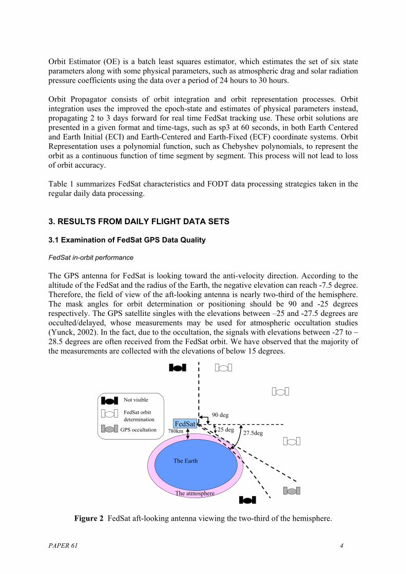
Orbit Estimator (OE) is a batch least squares estimator, which estimates the set of six state parameters along with some physical parameters, such as atmospheric drag and solar radiation pressure coefficients using the data over a period of 24 hours to 30 hours. Orbit Propagator consists of orbit integration and orbit representation processes. Orbit integration uses the improved the epoch-state and estimates of physical parameters instead, propagating 2 to 3 days forward for real time FedSat tracking use. These orbit solutions are presented in a given format and time-tags, such as sp3 at 60 seconds, in both Earth Centered and Earth Initial (ECI) and Earth-Centered and Earth-Fixed (ECF) coordinate systems. Orbit Representation uses a polynomial function, such as Chebyshev polynomials, to represent the orbit as a continuous function of time segment by segment. This process will not lead to loss of orbit accuracy. Table 1 summarizes FedSat characteristics and FODT data processing strategies taken in the regular daily data processing. 3. RESULTS FROM DAILY FLIGHT DATA SETS 3.1 Examination of FedSat GPS Data Quality FedSat in-orbit performance The GPS antenna for FedSat is looking toward the anti-velocity direction. According to the altitude of the FedSat and the radius of the Earth, the negative elevation can reach -7.5 degree. Therefore, the field of view of the aft-looking antenna is nearly two-third of the hemisphere. The mask angles for orbit determination or positioning should be 90 and -25 degrees respectively. The GPS satellite singles with the elevations between –25 and -27.5 degrees are occulted/delayed, whose measurements may be used for atmospheric occultation studies (Yunck, 2002). In the fact, due to the occultation, the signals with elevations between -27 to –28.5 degrees are often received from the FedSat orbit. We have observed that the majority of the measurements are collected with the elevations of below 15 degrees.
FedSat25 deg
90 deg
Not visible
FedSat orbit determination
GPS occultation 780km
The Earth
The atmosphere
27.5deg
Figure 2 FedSat aft-looking antenna viewing the two-third of the hemisphere.
PAPER 61 4

FedSat GPS measurement quality The quality of actual flight GPS data may vary from mission to mission, although the same type of receivers may be used. In the discussion below, analysis of code measurement noise level is based on the following equations (Zhou & Feng, 2002, Kuan et al., 2001): P1M (t) =[P1 (t+1)-P1 (t)]- ( [L1 (t+1)-L1 (t)] PCM (t) =[PC (t+1)-PC (t)]-( [LC (t+1)-LC (t)] t=1,2,3… (1) where PC is ionosphere-corrected code measurements; λ is the wavelength of L1 frequency (1575.42MHz); P1M and PCM mainly contain receiver noise and multipath errors. The RMS values of the observations P1 and PC are given as:
2,
2
221
1PCM
PCMP
Pσ
σσ
σ == (2)
Due to possible variation of atmospheric conditions between epochs, (σP1 and σPC are a conservative estimates to the standard deviation for the measurements P1 and PC. Figure 3 illustrates P1 ranging noises against elevation for Day 364/02. The overall P1 range RMS value for the data set is 1.03m. The RMS was estimated with rejection thresholds of ±15m (the P1 ranging noises outside ± 15 m were excluded).
Figure 3. Scattered points for P1 ranging noises plotted against the elevation for Day 364, 2002. The overall P1 ranging RMS value is 1.03m for the error rejection threshold of ±15m and 0.89m for the
threshold of ±5m.
PAPER 61 5
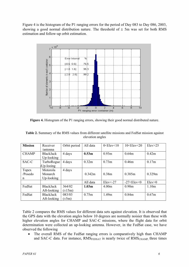
Figure 4 is the histogram of the P1 ranging errors for the period of Day 083 to Day 086, 2003, showing a good normal distribution nature. The threshold of ± 5m was set for both RMS estimation and follow-up orbit estimation.
Figure 4. Histogram of the P1 ranging errors, showing their good normal distributed nature.
Table 2. Summary of the RMS values from different satellite missions and FedSat mission against elevation angles
Mission Receiver
/antenna Orbit period All data 0<Elev<10 10<Elev<20 Elev>25
CHAMP BlackJack Up-looking
4 days
0.53m 0.93m 0.64m 0.42m
SAC-C TurboRogue oUp-looing
4 days 0.32m 0.73m 0.46m 0.17m
Topex /Posedon
Motorola Monarch Up-looking
4 days 0.342m 0.38m 0.385m 0.329m
All data Elev<-27 -27<Elev<0 Elev>0 FedSat BlackJack
Aft-looking 364/02 (±15m)
1.03m 4.00m 0.90m 1.10m
FedSat BlackJack Aft-looking
083/03 (±5m)
0.75m 1.49m 0.84m 0.67m
Table 2 compares the RMS values for different data sets against elevation. It is observed that the GPS data with the elevation angles below 10 degrees are normally noisier than these with higher elevation angles for CHAMP and SAC-C missions, where the flight data for orbit determination were collected an up-looking antenna. However, in the FedSat case, we have observed the following
• The overall RMS of the FedSat ranging errors is comparatively high than CHAMP and SAC-C data. For instance, RMSFEDSAT is nearly twice of RMSCHAMP, three times
PAPER 61 6
of RMSSAC-C if the error rejection threshold is of ±15m. • Applying the threshold of ±5m as the error rejection criteria to the data sets over the
period of Day 083 to Day 086, the overall RMS is below 0.60m (Figure 4), which is close to the RMS of 0.52 m for CHAMP mission.
• The data with elevation angle below –27 degrees is much noisier than these above –27 degrees. Other than this, the ranging measurements with negative elevation are not necessarily/significantly noisier than these with positive elevations.
3.2 FODT Orbit Filtering and Prediction Results With the FODT software, batch least squares estimation is performed with the above data sets to produce an orbit filtering solution for each day and propagation solutions for 3 to 4 days into future. To assess the performance of the FODT solutions, we conduct two comparisons: (1) compare the FODT solutions with the onboard navigation solutions (ONS), and (2) compare the FODT daily filtering solutions with the FODT prediction solutions. Both comparisons focus on the accuracy performance of the predicted orbits.
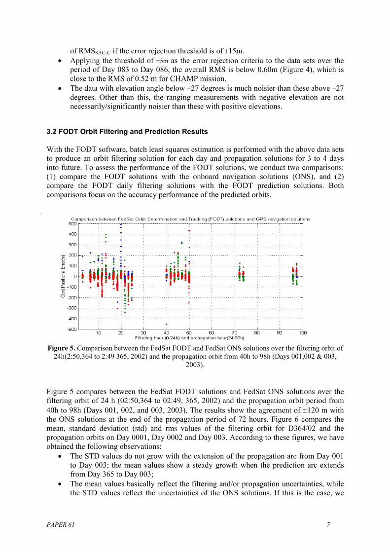
Figure 5. Comparison between the FedSat FODT and FedSat ONS solutions over the filtering orbit of 24h(2:50,364 to 2:49 365, 2002) and the propagation orbit from 40h to 98h (Days 001,002 & 003,
2003). Figure 5 compares between the FedSat FODT solutions and FedSat ONS solutions over the filtering orbit of 24 h (02:50,364 to 02:49, 365, 2002) and the propagation orbit period from 40h to 98h (Days 001, 002, and 003, 2003). The results show the agreement of ±120 m with the ONS solutions at the end of the propagation period of 72 hours. Figure 6 compares the mean, standard deviation (std) and rms values of the filtering orbit for D364/02 and the propagation orbits on Day 0001, Day 0002 and Day 003. According to these figures, we have obtained the following observations:
• The STD values do not grow with the extension of the propagation arc from Day 001 to Day 003; the mean values show a steady growth when the prediction arc extends from Day 365 to Day 003;
• The mean values basically reflect the filtering and/or propagation uncertainties, while the STD values reflect the uncertainties of the ONS solutions. If this is the case, we
PAPER 61 7
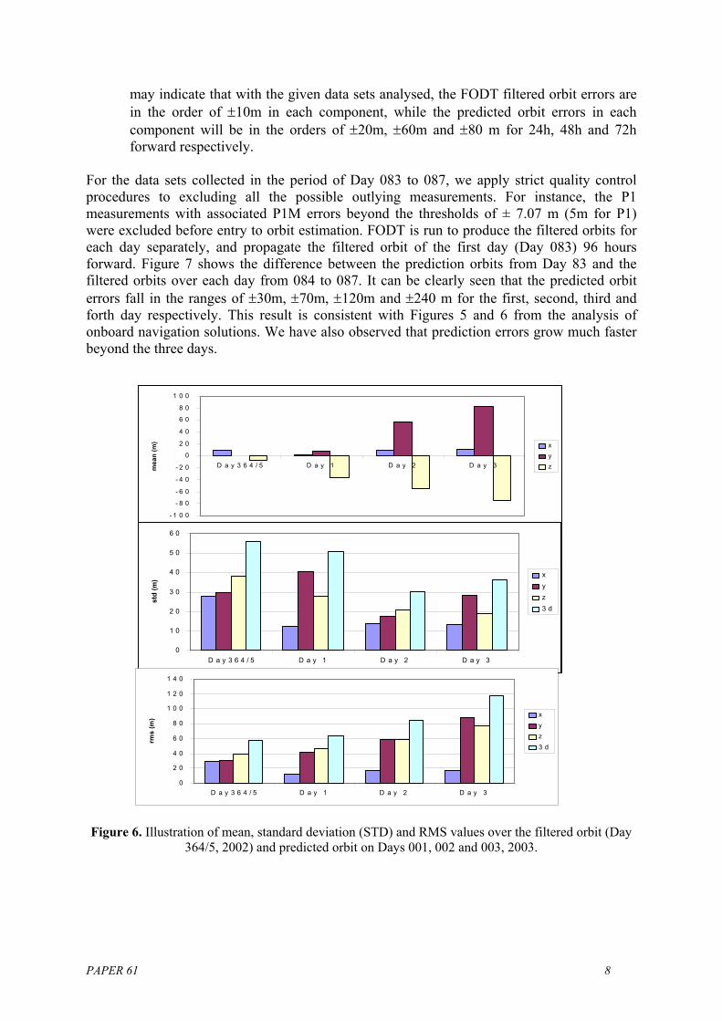
may indicate that with the given data sets analysed, the FODT filtered orbit errors are in the order of ±10m in each component, while the predicted orbit errors in each component will be in the orders of ±20m, ±60m and ±80 m for 24h, 48h and 72h forward respectively.
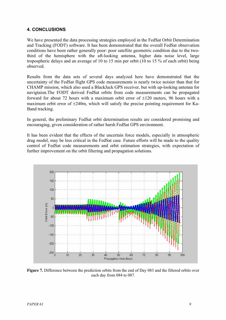
For the data sets collected in the period of Day 083 to 087, we apply strict quality control procedures to excluding all the possible outlying measurements. For instance, the P1 measurements with associated P1M errors beyond the thresholds of ± 7.07 m (5m for P1) were excluded before entry to orbit estimation. FODT is run to produce the filtered orbits for each day separately, and propagate the filtered orbit of the first day (Day 083) 96 hours forward. Figure 7 shows the difference between the prediction orbits from Day 83 and the filtered orbits over each day from 084 to 087. It can be clearly seen that the predicted orbit errors fall in the ranges of ±30m, ±70m, ±120m and ±240 m for the first, second, third and forth day respectively. This result is consistent with Figures 5 and 6 from the analysis of onboard navigation solutions. We have also observed that prediction errors grow much faster beyond the three days.
- 1 0 0
- 8 0
- 6 0
- 4 0
- 2 0
0
2 0
4 0
6 0
8 0
1 0 0
D a y 3 6 4 / 5 D a y 1 D a y 2 D a y 3mea
n (m
) xyz
0
1 0
2 0
3 0
4 0
5 0
6 0
D a y 3 6 4 / 5 D a y 1 D a y 2 D a y 3
std
(m)
xyz3 d
0
2 0
4 0
6 0
8 0
1 0 0
1 2 0
1 4 0
D a y 3 6 4 / 5 D a y 1 D a y 2 D a y 3
rms
(m) x
yz3 d
Figure 6. Illustration of mean, standard deviation (STD) and RMS values over the filtered orbit (Day
364/5, 2002) and predicted orbit on Days 001, 002 and 003, 2003.
PAPER 61 8
4. CONCLUSIONS We have presented the data processing strategies employed in the FedSat Orbit Determination and Tracking (FODT) software. It has been demonstrated that the overall FedSat observation conditions have been rather generally poor: poor satellite geometric condition due to the two-third of the hemisphere with the aft-looking antenna, higher data noise level, large tropospheric delays and an average of 10 to 15 min per orbit (10 to 15 % of each orbit) being observed. Results from the data sets of several days analyzed here have demonstrated that the uncertainty of the FedSat flight GPS code measurements is nearly twice noisier than that for CHAMP mission, which also used a BlackJack GPS receiver, but with up-looking antenna for navigtaion.The FODT derived FedSat orbits from code measurements can be propagated forward for about 72 hours with a maximum orbit error of ±120 meters, 96 hours with a maximum orbit error of ±240m, which will satisfy the precise pointing requirement for Ka-Band tracking. In general, the preliminary FedSat orbit determination results are considered promising and encouraging, given consideration of rather harsh FedSat GPS environment. It has been evident that the effects of the uncertain force models, especially in atmospheric drag model, may be less critical in the FedSat case. Future efforts will be made to the quality control of FedSat code measurements and orbit estimation strategies, with expectation of further improvement on the orbit filtering and propagation solutions.
Figure 7. Difference between the prediction orbits from the end of Day 083 and the filtered orbits over
each day from 084 to 087.
PAPER 61 9
PAPER 61 10
ACKNOWLEDGEMENT: This work was carried out in the Cooperative Research Centre for Satellite System with financial support from the Commonwealth of Australia through the Cooperative Research Centre program and Queensland State Government. REFERENCES Feng, Y. (2001). "Alternative Orbit Integration Algorithm for GPS-Based precise LEO
Autonomous Navigation." Journal of GPS solutions Vol 5 No.2, Fall. Kuang, D, Y. Bar-Sever, W. Bertiger, S. Desai, B. Haines, Byron Iijima, G. Kruizinga, T.
Meehan, L. Romans (2001). "Precise Orbit Determination for CHAMP using GPS Data from BlackJack Receiver", Proceedings of ION NTM 2001, 22-24.
Liu, L. (2000). “Orbit Theory of Spacecraft”, Defense Industrial Publication, China. P
419~450 Yunck, T (1996), “Orbital Determination”, Global Positioning System: Theory and
Applications, Volume II, published by AIAA, pp 559-592, 1996. Zhou, N. Y. Feng (2002), “Short-Arc Batch Estimation for GPS-Based Onboard Spacecraft
Orbit Determination”, Journal of Global Positioning Systems, Vo1, No2, 2002, p106-112.
Yunck, T (2002), “An Overview of Atmospheric Radio Occultation”, Journal of Global
Positioning Systems, Vo1, No1, 2002, p58-60.
Copyright © 2022 FDOKUMEN

