


Bahasa
Halaman
Hukum


Mechatronics
Electricity
Advanced Mechatronics System (AMS)
Courseware Sample 89789-F0

Order no.: 89789-10
First Edition
Revision level: 01/2015
By the staff of Festo Didactic
© Festo Didactic Ltée/Ltd, Quebec, Canada 2014
Internet: www.festo-didactic.com
e-mail: [email protected]
Printed in Canada
All rights reserved
ISBN 978-2-89640-844-3 (Printed version)
ISBN 978-2-89640-845-0 (CD-ROM)
Legal Deposit – Bibliothèque et Archives nationales du Québec, 2014
Legal Deposit – Library and Archives Canada, 2014
The purchaser shall receive a single right of use which is non-exclusive, non-time-limited and limited
geographically to use at the purchaser's site/location as follows.
The purchaser shall be entitled to use the work to train his/her staff at the purchaser's site/location and
shall also be entitled to use parts of the copyright material as the basis for the production of his/her own
training documentation for the training of his/her staff at the purchaser's site/location with
acknowledgement of source and to make copies for this purpose. In the case of schools/technical
colleges, training centers, and universities, the right of use shall also include use by school and college
students and trainees at the purchaser's site/location for teaching purposes.
The right of use shall in all cases exclude the right to publish the copyright material or to make this
available for use on intranet, Internet and LMS platforms and databases such as Moodle, which allow
access by a wide variety of users, including those outside of the purchaser's site/location.
Entitlement to other rights relating to reproductions, copies, adaptations, translations, microfilming and
transfer to and storage and processing in electronic systems, no matter whether in whole or in part, shall
require the prior consent of Festo Didactic GmbH & Co. KG.
Information in this document is subject to change without notice and does not represent a commitment on
the part of Festo Didactic. The Festo materials described in this document are furnished under a license
agreement or a nondisclosure agreement.
Festo Didactic recognizes product names as trademarks or registered trademarks of their respective
holders.
All other trademarks are the property of their respective owners. Other trademarks and trade names may
be used in this document to refer to either the entity claiming the marks and names or their products.
Festo Didactic disclaims any proprietary interest in trademarks and trade names other than its own.

© Festo Didactic 89789-10 III
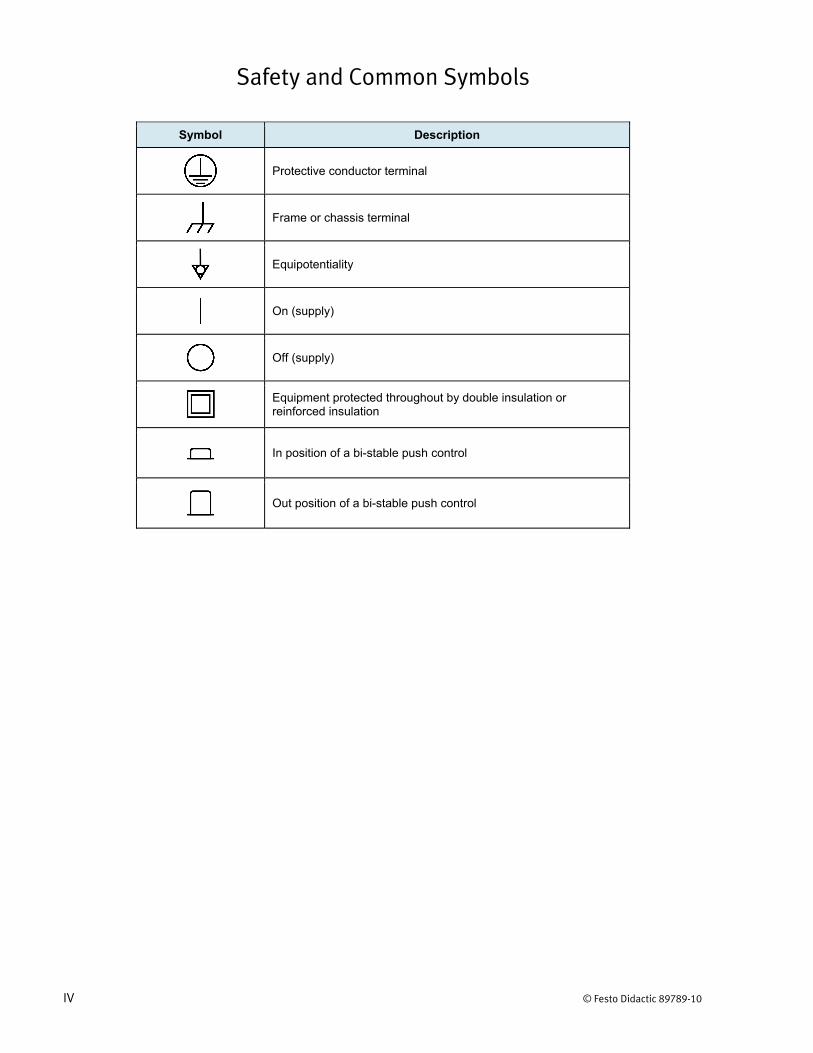
Safety and Common Symbols
The following safety and common symbols may be used in this manual and on the equipment:
Symbol Description
DANGER indicates a hazard with a high level of risk which, if not avoided, will result in death or serious injury.
WARNING indicates a hazard with a medium level of risk which, if not avoided, could result in death or serious injury.
CAUTION indicates a hazard with a low level of risk which, if not avoided, could result in minor or moderate injury.
CAUTION used without the Caution, risk of danger sign , indicates a hazard with a potentially hazardous situation which, if not avoided, may result in property damage.
Caution, risk of electric shock
Caution, hot surface
Caution, risk of danger
Caution, lifting hazard
Caution, hand entanglement hazard
Notice, non-ionizing radiation
Direct current
Alternating current
Both direct and alternating current
Three-phase alternating current
Earth (ground) terminal
Safety and Common Symbols
IV © Festo Didactic 89789-10
Symbol Description
Protective conductor terminal
Frame or chassis terminal
Equipotentiality
On (supply)
Off (supply)
Equipment protected throughout by double insulation or reinforced insulation
In position of a bi-stable push control
Out position of a bi-stable push control
© Festo Didactic 89789-10 V
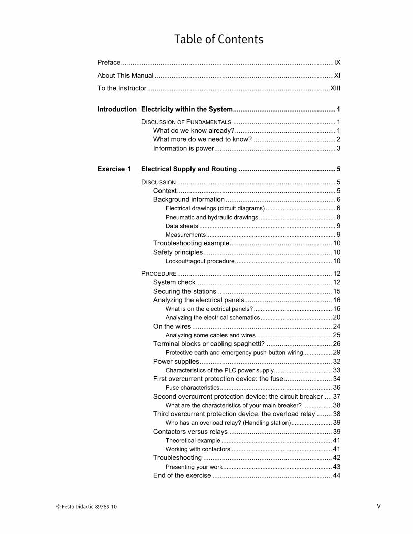
Table of Contents
Preface .................................................................................................................. IX
About This Manual ................................................................................................ XI
To the Instructor .................................................................................................. XIII
Introduction Electricity within the System ....................................................... 1
DISCUSSION OF FUNDAMENTALS ....................................................... 1 What do we know already? ...................................................... 1 What more do we need to know? ............................................ 2 Information is power ................................................................. 3
Exercise 1 Electrical Supply and Routing .................................................... 5
DISCUSSION ..................................................................................... 5 Context ..................................................................................... 5 Background information ........................................................... 6
Electrical drawings (circuit diagrams) ......................................... 6 Pneumatic and hydraulic drawings ............................................. 8 Data sheets ................................................................................ 9 Measurements ............................................................................ 9
Troubleshooting example ....................................................... 10 Safety principles ..................................................................... 10
Lockout/tagout procedure ......................................................... 10
PROCEDURE ................................................................................... 12 System check ......................................................................... 12 Securing the stations ............................................................. 15 Analyzing the electrical panels............................................... 16
What is on the electrical panels? .............................................. 16 Analyzing the electrical schematics .......................................... 20
On the wires ........................................................................... 24 Analyzing some cables and wires ............................................ 25
Terminal blocks or cabling spaghetti? ................................... 26 Protective earth and emergency push-button wiring................. 29
Power supplies ....................................................................... 32 Characteristics of the PLC power supply .................................. 33
First overcurrent protection device: the fuse .......................... 34 Fuse characteristics .................................................................. 36
Second overcurrent protection device: the circuit breaker .... 37 What are the characteristics of your main breaker? ................. 38
Third overcurrent protection device: the overload relay ........ 38 Who has an overload relay? (Handling station) ........................ 39
Contactors versus relays ....................................................... 39 Theoretical example ................................................................. 41 Working with contactors ........................................................... 41
Troubleshooting ..................................................................... 42 Presenting your work ................................................................ 43
End of the exercise ................................................................ 44

Table of Contents
VI © Festo Didactic 89789-10
Exercise 2 Switches, Sensors, and Actuators ........................................... 47
DISCUSSION ................................................................................... 47 Overview ................................................................................ 47 Control buttons ....................................................................... 48 Sensors .................................................................................. 48
Mechanical limit switches ......................................................... 49 Photoelectric sensors ............................................................... 49 Capacitive proximity switches (electrostatic field) ..................... 53 Inductive sensors (electromagnetic field) .................................. 55 Magnetic reed switches ............................................................ 57 Air pressure sensors ................................................................. 58
Actuators ................................................................................ 58 Solenoids .................................................................................. 59
PROCEDURE ................................................................................... 59 System setup ......................................................................... 59 Control buttons ....................................................................... 60
Control buttons (packaging station) .......................................... 60 Emergency push-button (handling station) ............................... 61
Digital sensors ........................................................................ 62 Any mechanical limit switch? .................................................... 62 Other digital sensors ................................................................. 63
The analog sensor ................................................................. 66 The pressure transmitter (packaging station)............................ 67
A first type of actuator: the solenoid....................................... 68 Solenoid and spring (packaging station) ................................... 68 Valve solenoid (Handling station) ............................................. 69
Troubleshooting ..................................................................... 69 Presenting your work ............................................................. 70 End of the exercise ................................................................ 71
Exercise 3 DC and Step Motors ................................................................... 73
DISCUSSION ................................................................................... 73 Overview ................................................................................ 73 DC motors .............................................................................. 74
DC motor drives ........................................................................ 76 Step motors ............................................................................ 77
Wiring and connection .............................................................. 79 How to drive step motors .......................................................... 80 Why use a step motor? ............................................................. 81
Differences between ac and dc motors ................................. 82
PROCEDURE ................................................................................... 83 System setup ......................................................................... 83 DC motors (packaging station) .............................................. 83
Specifications of the dc motors ................................................. 84 DC motor drive (packaging station) ....................................... 86
DC motor drive activity .............................................................. 87
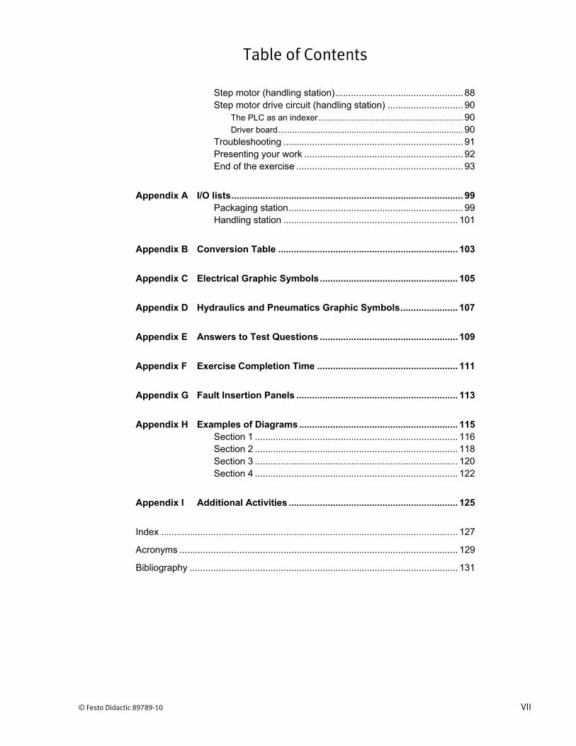
Table of Contents
© Festo Didactic 89789-10 VII
Step motor (handling station) ................................................. 88 Step motor drive circuit (handling station) ............................. 90
The PLC as an indexer ............................................................. 90 Driver board .............................................................................. 90
Troubleshooting ..................................................................... 91 Presenting your work ............................................................. 92 End of the exercise ................................................................ 93
Appendix A I/O lists ......................................................................................... 99 Packaging station ................................................................... 99 Handling station ................................................................... 101
Appendix B Conversion Table ..................................................................... 103
Appendix C Electrical Graphic Symbols ..................................................... 105
Appendix D Hydraulics and Pneumatics Graphic Symbols ...................... 107
Appendix E Answers to Test Questions ..................................................... 109
Appendix F Exercise Completion Time ...................................................... 111
Appendix G Fault Insertion Panels .............................................................. 113
Appendix H Examples of Diagrams ............................................................. 115 Section 1 .............................................................................. 116 Section 2 .............................................................................. 118 Section 3 .............................................................................. 120 Section 4 .............................................................................. 122
Appendix I Additional Activities ................................................................. 125
Index .................................................................................................................. 127
Acronyms ........................................................................................................... 129
Bibliography ....................................................................................................... 131

© Festo Didactic 89789-10 IX
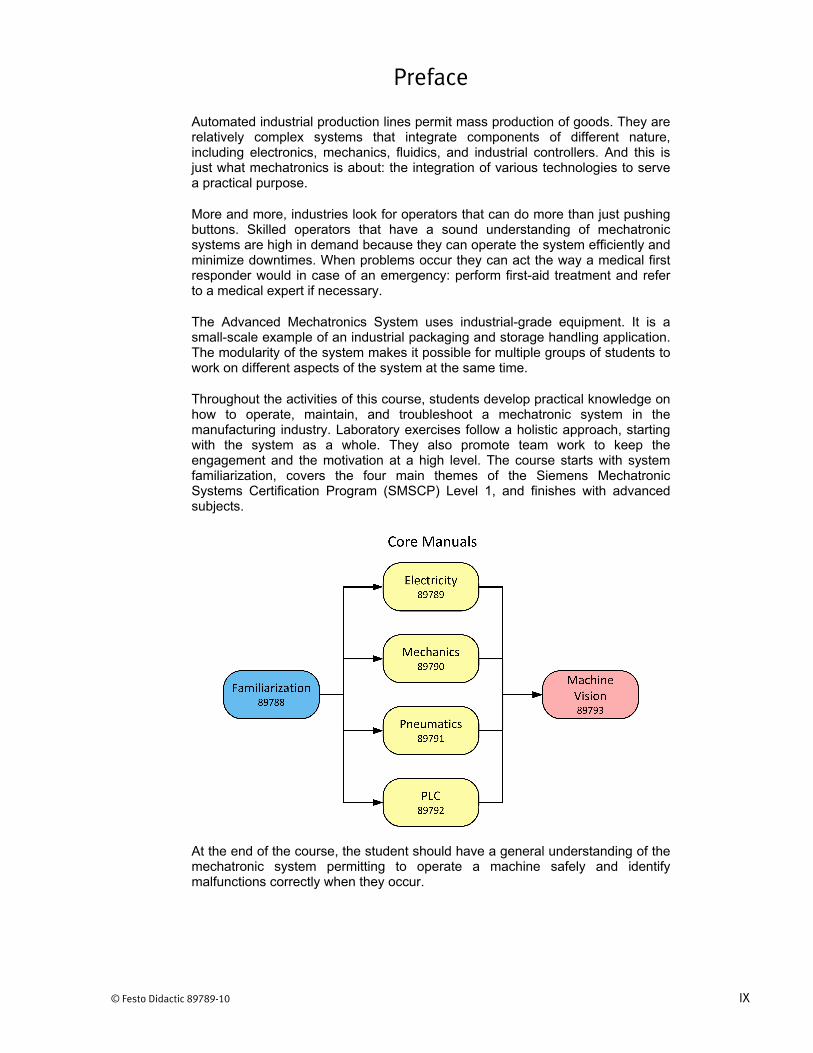
Preface
Automated industrial production lines permit mass production of goods. They are relatively complex systems that integrate components of different nature, including electronics, mechanics, fluidics, and industrial controllers. And this is just what mechatronics is about: the integration of various technologies to serve a practical purpose.
More and more, industries look for operators that can do more than just pushing buttons. Skilled operators that have a sound understanding of mechatronic systems are high in demand because they can operate the system efficiently and minimize downtimes. When problems occur they can act the way a medical first responder would in case of an emergency: perform first-aid treatment and refer to a medical expert if necessary.
The Advanced Mechatronics System uses industrial-grade equipment. It is a small-scale example of an industrial packaging and storage handling application. The modularity of the system makes it possible for multiple groups of students to work on different aspects of the system at the same time.
Throughout the activities of this course, students develop practical knowledge on how to operate, maintain, and troubleshoot a mechatronic system in the manufacturing industry. Laboratory exercises follow a holistic approach, starting with the system as a whole. They also promote team work to keep the engagement and the motivation at a high level. The course starts with system familiarization, covers the four main themes of the Siemens Mechatronic Systems Certification Program (SMSCP) Level 1, and finishes with advanced subjects.
At the end of the course, the student should have a general understanding of the mechatronic system permitting to operate a machine safely and identify malfunctions correctly when they occur.

Preface
X © Festo Didactic 89789-10
We invite readers of this manual to send us their tips, feedback and suggestions for improving the book.
Please send these to [email protected].
The authors and Festo Didactic look forward to your comments.

© Festo Didactic 89789-10 XI
About This Manual
Manual objectives
When you have completed this manual, you should be able to:
operate a mechatronic system safely;
understand mechatronic systems, sub-systems, and components in terms of energy, material, and information flow;
comprehend the role and physical principle of mechatronic components of different natures;
read and understand technical documents such as schematics, diagrams, and specification sheets;
perform routine maintenance tasks;
identify and document possible malfunctions and correct them if possible.
Safety considerations
Safety symbols that may be used in this manual and on the equipment provided are listed in the Safety Symbols table at the beginning of the manual.
Safety procedures related to the tasks that you will be asked to perform are indicated in each exercise. You should never perform a task if you have any reason to think that a manipulation could be dangerous for you or your teammates.
Reference material
The electrical and pneumatic schematics as well as some assembly drawings are provided separately for each of the workstations.
You may also refer to the resource disk. This disk contains documentation and videos of the system in action.
Prerequisite
Basic electrical knowledge is a prerequisite to this series of manuals. It is assumed that you have a general understanding of these concepts:
DC and ac voltage, current, and power
Basic electrical components (resistor/potentiometer, inductor, capacitor, diode, transistor)
Ohm’s law
Series and parallel circuits
Electrical measurement

About This Manual
XII © Festo Didactic 89789-10
Systems of units
Units are expressed using the SI system of units followed by the units expressed in the U.S. customary system of units (between parentheses).
Exercise structure
Throughout this series of manuals, most exercises follow the steps shown below.
Structure of a typical exercise.
Additional recommendations
Even though mechatronic programs differ from school to school, the familiarization manual should always be your starting point for using the system.
This system is a good starting and end point for teaching mechatronics. However, additional equipment and software are highly recommended for more thorough coverage.
Factory tours and videos are good ways to maintain interest for the subject.
In accordance with the SMSCP philosophy, responsibilities should be given to the students and team work should be the norm. Some examples of group projects followed by presentations are already suggested throughout the manuals.
© Festo Didactic 89789-10 XIII
To the Instructor
You will find in this Instructor Guide all the elements included in the Student Manual together with the answers to all questions, results of measurements, graphs, explanations, suggestions, and, in some cases, instructions to help you guide the students through their learning process. All the information that applies to you is placed between markers and appears in red.
Accuracy of measurements
The numerical results of the hands-on exercises may differ from one student to another. For this reason, the results and answers given in this manual should be considered as a guide. Students who correctly performed the exercises should expect to demonstrate the principles involved and make observations and measurements similar to those given as answers.

Sample Exercise
Extracted from
the Student Manual
and the Instructor Guide


© Festo Didactic 89789-10 47
Become familiar with how control buttons are connected
Become acquainted with basic types of digital sensors
See how an analog pressure sensor operates
Learn about a first type of actuator: the solenoid
Find a fault in a mechatronic system
Explain your troubleshooting strategy
The Discussion of this exercise covers the following points:
Overview Control buttons Sensors
Mechanical limit switches. Photoelectric sensors. Capacitive proximity switches (electrostatic field). Inductive sensors (electromagnetic field). Magnetic reed switches. Air pressure sensors.
Actuators Solenoids.
Overview
Now that we know how the system is powered and electrically protected, let us take a look at the flow of information between the field devices and the PLC. Some visible system elements are outlined in Figure 43.
Switches, Sensors, and Actuators
Exercise 2
EXERCISE OBJECTIVE
DISCUSSION OUTLINE
DISCUSSION

Exercise 2 – Switches, Sensors, and Actuators Discussion
48 © Festo Didactic 89789-10
Figure 43. Location of some switches, sensors and actuators.
Remember that control buttons and sensors send information to the PLC. This data is analyzed and the output of this calculation in turn becomes instructions controlling the actions of the actuators.
Control buttons
Control panel devices, such as push buttons, selectors, or toggle switches (Figure 44) have sets of contacts that open and close when the mechanism is triggered. These openings and closings channel control currents going to a PLC, for example.
Figure 44. Two-position toggle switch sending current to upper or lower branch.
Sensors
Sensors are the eyes and ears of the PLC. They either send a digital (on/off) or an analog (e.g., 4-20 mA or 0-5 V dc) signal that relates to a given variable such as a position, pressure, level, temperature, or speed. Because they measure different variables, sensors, whether digital or analog, must operate according to various principles.

Exercise 2 – Switches, Sensors, and Actuators Discussion
© Festo Didactic 89789-10 49
Mechanical limit switches
A limit switch is an electro-mechanical device that consists of an actuator mechanically linked to a set of contacts. The actuator can be a rotary lever or plunger, for example. When an object comes into contact with this actuator, the device operates the contacts to make or break an electrical connection. Limit switches are used in a variety of applications and environments because of their ruggedness, simple visible operation, ease of installation, and reliability of operation.
Figure 45. Mechanical limit switch.
Photoelectric sensors
Photoelectric sensors are a family of devices that detect the presence or absence of virtually any type of object without any physical contact. Therefore, they can satisfy a wide range of control needs: sense height, size, or position, count, monitor operating speed, and much more.
Photoelectric sensors consist of a light emitter and a light receiver. The emitter is a light emitting diode (LED) that emits a specific wavelength of light. Most photoelectric sensors use infrared, visible red, green, or blue light sources. Visible and infrared lights are tiny parts of the electromagnetic spectrum. Infrared LEDs are used where maximum light output is required for an extended sensing range. Visible light beams ease the setup or help confirm sensor operation.
The receiver is a photodiode, or phototransistor, that provides a change in conducted current depending on how much light is detected. Photodiodes and phototransistors are more sensitive to certain wavelengths of light. To improve efficiency, the light emitter and receiver must be spectrally matched. Figure 46 shows the three basic types of photoelectric sensors: throughbeam, retroreflective, and diffuse reflective.

Exercise 2 – Switches, Sensors, and Actuators Discussion
50 © Festo Didactic 89789-10
Figure 46. Throughbeam, retroreflective, and diffuse photoelectric sensors.
The emitter and receiver of a throughbeam sensor are in separate housings. The emitter projects a light beam directly toward the receiver (Figure 47). The target object interrupts the beam and the receiver senses the absence of the light beam (presence of an object). Throughbeam sensors provide the longest sensing distances. These sensors are well suited to operate in very dusty or dirty industrial environments, but may be not suitable to detect translucent or transparent targets since the receiver will see through this type of target.
Emitter Receiver
Target
Object detected(no light)
(a) Throughbeam
(b) Retroreflective
(c) Diffuse reflective
Retroreflective surface
Light beam
Exercise 2 – Switches, Sensors, and Actuators Discussion
© Festo Didactic 89789-10 51
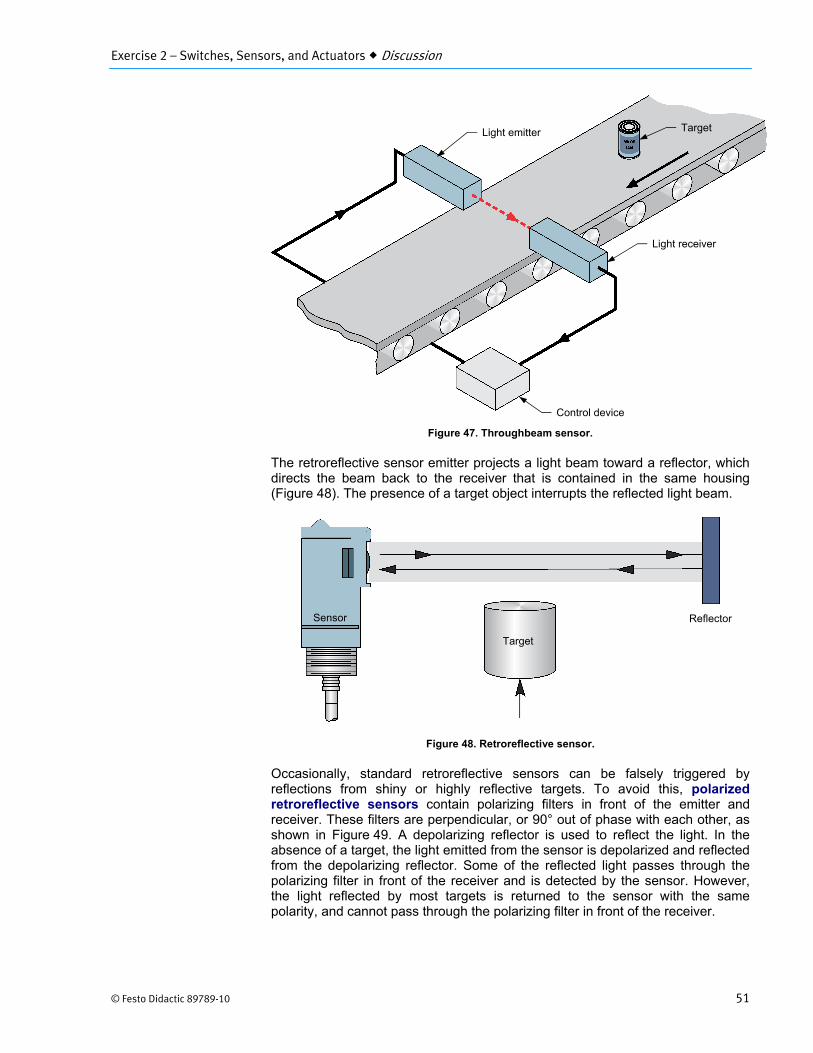
Figure 47. Throughbeam sensor.
The retroreflective sensor emitter projects a light beam toward a reflector, which directs the beam back to the receiver that is contained in the same housing (Figure 48). The presence of a target object interrupts the reflected light beam.
Figure 48. Retroreflective sensor.
Occasionally, standard retroreflective sensors can be falsely triggered by reflections from shiny or highly reflective targets. To avoid this, polarized retroreflective sensors contain polarizing filters in front of the emitter and receiver. These filters are perpendicular, or 90° out of phase with each other, as shown in Figure 49. A depolarizing reflector is used to reflect the light. In the absence of a target, the light emitted from the sensor is depolarized and reflected from the depolarizing reflector. Some of the reflected light passes through the polarizing filter in front of the receiver and is detected by the sensor. However, the light reflected by most targets is returned to the sensor with the same polarity, and cannot pass through the polarizing filter in front of the receiver.
Control device
Light receiver
Light emitter Target
Target
Reflector Sensor

Exercise 2 – Switches, Sensors, and Actuators Discussion
52 © Festo Didactic 89789-10
Figure 49. Polarized retroreflective sensor.
With diffuse sensors, the emitter and receiver are also contained in the same housing but no reflector is used (Figure 50). The emitter projects a light beam, and when a target object enters the beam, light reflects off the object back to the receiver. The primary advantage of a diffuse-reflective sensor is its simplicity.
Polarized light
Depolarized light
Target
Polarized light
Polarized light
Polarized filter
Polarized filter
Polarized filter
Polarized filter
Depolarizing retroreflector
Depolarizing retroreflector
Emitter
Emitter
Light at the receiver(no target)
No light at the receiver(target detected)
Lens
Lens

Exercise 2 – Switches, Sensors, and Actuators Discussion
© Festo Didactic 89789-10 53
Figure 50. Diffuse sensor.
When the target is very close and very reflective, a special type of diffuse sensor is used. Background suppression sensors detect the presence of both the target and the background. They contain two active photoelectric sensing elements calibrated to detect objects in front and behind the nominal sensing distance. As Figure 51 shows, sensing element 1 detects reflections from behind the nominal sensing distance, and sensing element 2 detects reflections in front of the nominal sensing distance. By comparing the two signals, the sensor can ignore the presence of a very reflective background almost directly behind a dark, less-reflective target. The sensor output will change state on active detection of the target, or on active detection of the background.
Figure 51. Background suppression (diffuse) sensor.
Capacitive proximity switches (electrostatic field)
Capacitive proximity switches are designed to detect both metallic and nonmetallic objects. They detect their presence by generating an electrostatic field and detecting changes in this field caused by a target approaching. Capacitive proximity switches consist of a capacitive probe, oscillator, rectifier (detector circuit), and output circuit.
A capacitor is formed when two electrical conductors (plates), separated by an insulating material (dielectric), are connected to opposite poles of a voltage source, as shown in Figure 4-1. One plate becomes positively charged, while the second plate becomes negatively charged. The amount of electrical charge a capacitor can store is referred to as the capacitance.
Sensor Target
Target
Background surface
Sensor housing
Sensing element 1
Sensing element 2
Nominal sensing distance

Exercise 2 – Switches, Sensors, and Actuators Discussion
54 © Festo Didactic 89789-10
Figure 52. Charged capacitor.
Capacitive proximity switches operate on the same principle as a capacitor. The capacitive probe of the sensor acts as the positive pole, and the ground acts as the negative pole.
Figure 53 shows that when an object approaches the sensor, the dielectric constant of the capacitor changes. When the capacitance of the probe system reaches a specified threshold, the oscillator is activated. The rectifier converts the AC oscillations to a DC voltage. When the DC voltage reaches the "operating level," the output transistor switches on. When the DC voltage decreases to the "releasing level," the output transistor switches off.
Because the sensor is activated by a change in electrical energy rather than magnetic energy, it detects both metallic and nonmetallic materials. The sensing distance of capacitive proximity switches depends on the size of both the probe and the target object. Large probes have a higher capacitance than small ones, so an object will influence the electrostatic field of a large probe from a greater distance.
The dielectric constant of the target material affects the sensing distance. Materials having a low dielectric constant are difficult to detect. For example, a capacitive proximity switch will detect glass at only 40% of the standard distance, and paper at 10%. Temperature, humidity, and nearby objects may also affect the operation of capacitive proximity switches.
Voltage source
Dielectric (air)
Electrostatic field
Plate
Plate

Exercise 2 – Switches, Sensors, and Actuators Discussion
© Festo Didactic 89789-10 55
Figure 53. Operation of a capacitive proximity sensor.
Inductive sensors (electromagnetic field)
Inductive proximity switches detect the presence of metallic objects by generating an electromagnetic field and detecting changes in this field. They consist of a coil, oscillator, rectifier (detector circuit), and output circuit, as shown in Figure 54.
Figure 54. Inductive proximity sensor.
The oscillator produces a high frequency voltage applied to the coil to produce an electromagnetic field. Figure 55 shows that when a metallic object enters the magnetic field, eddy currents are induced in the object. This causes a loss in energy and a reduction in the magnitude of the oscillations. When the energy loss becomes significant enough, the oscillator stops functioning.
Target
Capacitive proximity switch
Amplitude of oscillations
Rectifier output voltage
Output
Releasing level
Operating level
ON
OFF OFF
Electromagnetic field
Coil Oscillator Detector circuit
Output circuit

Exercise 2 – Switches, Sensors, and Actuators Discussion
56 © Festo Didactic 89789-10
Figure 55. Operation of an inductive proximity switch.
The rectifier converts the AC output signal from the oscillator to a DC voltage. When the DC voltage reaches the "operating level," the output transistor switches on. When the DC voltage decreases to the "releasing level," the output transistor switches off.
Because the magnetic field associated with the induced eddy currents is quite small, the maximum sensing distance of an inductive proximity switch is also quite small. Typical sensing distances are from 1 mm to 15 mm (0.04 in to 0.6 in). Sensing distance for inductive proximity sensors depends on the size of the coil and the type of metal. Inductive proximity switches must be spaced from surrounding metallic objects and other sensors to avoid affecting the operation.
Figure 56 shows two examples of how inductive sensors are used. On the left, an inductive proximity switch checks bottles for bottle caps. Bottles without caps are rejected. Inductive proximity switches work better than other proximity switches in this application because they are not affected by high humidity. In Figure 56b, an inductive proximity switch counts the rivets on a finished work piece.
Metallic target
Inductive proximity switch
Amplitude of oscillations
Rectifier output voltage
Output
Releasing levelOperating level
ON
OFF OFF

Exercise 2 – Switches, Sensors, and Actuators Discussion
© Festo Didactic 89789-10 57
Figure 56. Two applications for an inductive proximity switch.
Magnetic reed switches
Figure 57 shows a typical reed switch diagram. This type of switch is named after the thin metal reeds enclosed in its glass capsule. The capsule is filled with an inert gas to prevent the reeds from rusting. The portions of the reeds that come in contact when the switch closes are plated with precious metal to ensure good conductivity.
Figure 57. Reed switch (not actuated).
The working principle of a reed switch is simple. The reed switch is normally open. The gap between the two reeds isolates them and no current can flow through the switch. However, if a permanent magnet is placed close to the switch, the magnetic flux generated by the magnet draws the two reeds together. As shown in Figure 58, the plated tip of one of the reeds becomes a magnetic north pole, while the tip of the other reed becomes a magnetic south pole. Since the tips of the reeds have opposite magnetic poles, they attract each other and the two reeds snap together to close the electric circuit. When the magnet is removed from the proximity of the switch, the stiffness of the reeds brings them apart and the electrical circuit is open again.
Glass capsule
Inert gas Contact plating
TerminalReed
Gap
Exercise 2 – Switches, Sensors, and Actuators Discussion
58 © Festo Didactic 89789-10
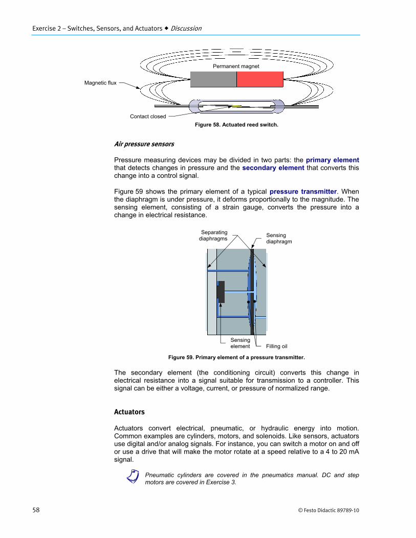
Figure 58. Actuated reed switch.
Air pressure sensors
Pressure measuring devices may be divided in two parts: the primary element that detects changes in pressure and the secondary element that converts this change into a control signal.
Figure 59 shows the primary element of a typical pressure transmitter. When the diaphragm is under pressure, it deforms proportionally to the magnitude. The sensing element, consisting of a strain gauge, converts the pressure into a change in electrical resistance.
Figure 59. Primary element of a pressure transmitter.
The secondary element (the conditioning circuit) converts this change in electrical resistance into a signal suitable for transmission to a controller. This signal can be either a voltage, current, or pressure of normalized range.
Actuators
Actuators convert electrical, pneumatic, or hydraulic energy into motion. Common examples are cylinders, motors, and solenoids. Like sensors, actuators use digital and/or analog signals. For instance, you can switch a motor on and off or use a drive that will make the motor rotate at a speed relative to a 4 to 20 mA signal.
a Pneumatic cylinders are covered in the pneumatics manual. DC and step motors are covered in Exercise 3.
Permanent magnet
Magnetic flux
Contact closed
Sensing diaphragm
Separatingdiaphragms
Sensing element Filling oil
Exercise 2 – Switches, Sensors, and Actuators Procedure Outline
© Festo Didactic 89789-10 59
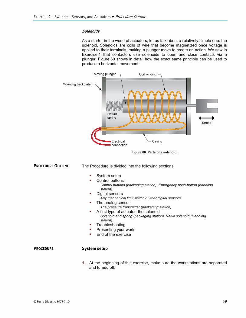
Solenoids
As a starter in the world of actuators, let us talk about a relatively simple one: the solenoid. Solenoids are coils of wire that become magnetized once voltage is applied to their terminals, making a plunger move to create an action. We saw in Exercise 1 that contactors use solenoids to open and close contacts via a plunger. Figure 60 shows in detail how the exact same principle can be used to produce a horizontal movement.
Figure 60. Parts of a solenoid.
The Procedure is divided into the following sections:
System setup Control buttons
Control buttons (packaging station). Emergency push-button (handling station).
Digital sensors Any mechanical limit switch? Other digital sensors.
The analog sensor The pressure transmitter (packaging station).
A first type of actuator: the solenoid Solenoid and spring (packaging station). Valve solenoid (Handling station).
Troubleshooting Presenting your work End of the exercise
System setup
1. At the beginning of this exercise, make sure the workstations are separated and turned off.
PROCEDURE OUTLINE
PROCEDURE
Electrical connection
Return spring
Mounting backplate
Casing
Stroke
Coil windingMoving plunger
Exercise 2 – Switches, Sensors, and Actuators Procedure
60 © Festo Didactic 89789-10
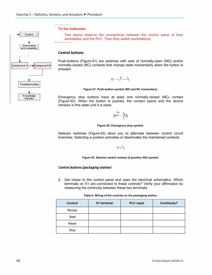
To the instructor
Two teams observe the connections between the control panel of their workstation and the PLC. Then they switch workstations.
Control buttons
Push-buttons (Figure 61) are switches with sets of normally-open (NO) and/or normally-closed (NC) contacts that change state momentarily when the button is pressed.
Figure 61. Push-button symbol (NO and NC momentary).
Emergency stop buttons have at least one normally-closed (NC) contact (Figure 62). When the button is pushed, the contact opens and the device remains in this state until it is reset.
Figure 62. Emergency stop symbol.
Selector switches (Figure 63) allow you to alternate between control circuit branches. Selecting a position activates or deactivates the maintained contacts.
Figure 63. Selector switch contact (2-position NO) symbol.
Control buttons (packaging station)
2. Get closer to the control panel and open the electrical schematics. Which terminals on X1 are connected to these controls? Verify your affirmation by measuring the continuity between these two terminals.
Table 8. Wiring of the controls on the packaging station.
Control X1 terminal PLC input Continuity?
Recipe
Start
Reset
Stop
Exercise 2 – Switches, Sensors, and Actuators Procedure
© Festo Didactic 89789-10 61
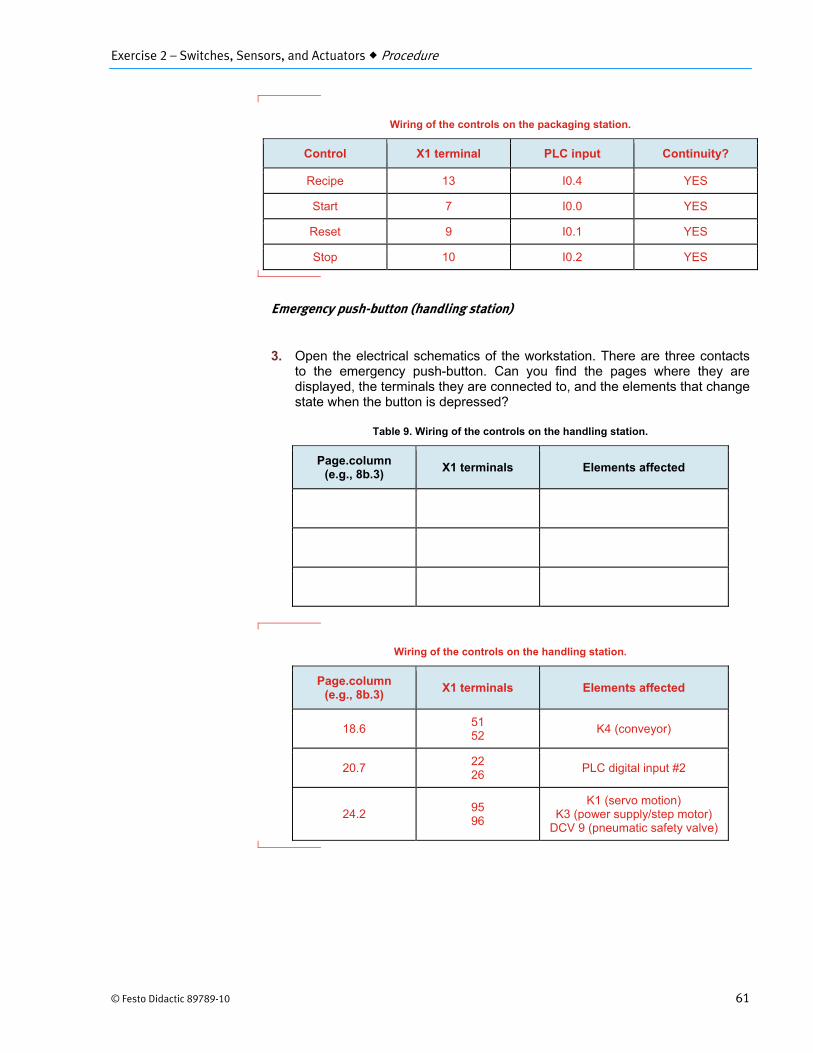
Wiring of the controls on the packaging station.
Control X1 terminal PLC input Continuity?
Recipe 13 I0.4 YES
Start 7 I0.0 YES
Reset 9 I0.1 YES
Stop 10 I0.2 YES
Emergency push-button (handling station)
3. Open the electrical schematics of the workstation. There are three contacts to the emergency push-button. Can you find the pages where they are displayed, the terminals they are connected to, and the elements that change state when the button is depressed?
Table 9. Wiring of the controls on the handling station.
Page.column (e.g., 8b.3)
X1 terminals Elements affected
Wiring of the controls on the handling station.
Page.column (e.g., 8b.3)
X1 terminals Elements affected
18.6 51 52
K4 (conveyor)
20.7 22 26
PLC digital input #2
24.2 95 96
K1 (servo motion) K3 (power supply/step motor)
DCV 9 (pneumatic safety valve)

Exercise 2 – Switches, Sensors, and Actuators Procedure
62 © Festo Didactic 89789-10
Digital sensors
Each sensor has one or multiple NO or NC contacts. Different methods can be used to actuate a digital sensor and switch these contacts. For example, it can be via a lever, a roller plunger, or an electrical, magnetic, or optical signal level. The IEC symbol of a mechanical limit switch is shown in Figure 64.
Figure 64. Limit switch symbol (NO contact).
Below is a summary of the different sensor types that you can find on the system:
Mechanical limit switch
Reed magnetic switch
Capacitive sensor
Inductive sensor
Photoelectric sensor
o Polarized retroreflective
o Background suppression (diffuse)
o Fiber optic (diffuse reflective)
Any mechanical limit switch?
4. Pick one workstation and identify how many mechanical limit switches are present.
Packaging station: 4 limit switches (2 on the box distributor and 2 on the side trays) Handling station: 20 limit switches (2 on the box distributor, 1 on the cover distributor, and 17 on the ASRS, two of which are connected to the X and Y servo motor drives and not the PLC)
To the instructor
Two teams observe the digital sensors present on their respective workstation.
5. When do they deliver a signal to the PLC?
A control signal leaves the switch when the mechanical lever is triggered (pushed). However, note that mechanical switches could operate the other way around (i.e., NC instead of NO).
Exercise 2 – Switches, Sensors, and Actuators Procedure
© Festo Didactic 89789-10 63
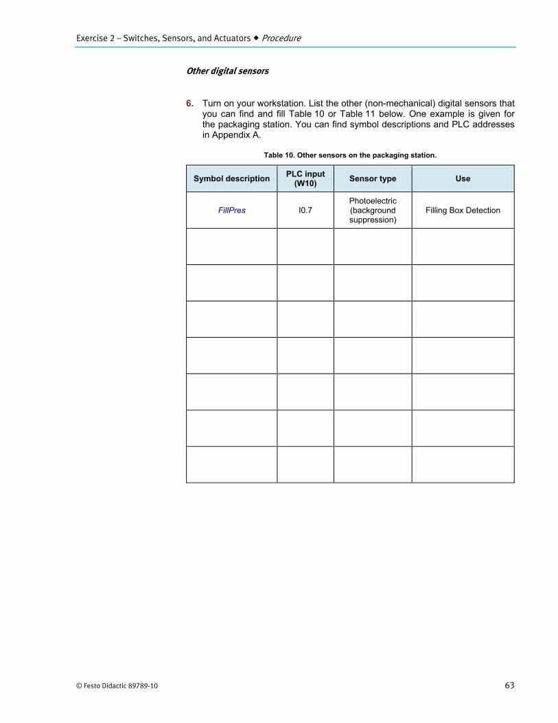
Other digital sensors
6. Turn on your workstation. List the other (non-mechanical) digital sensors that you can find and fill Table 10 or Table 11 below. One example is given for the packaging station. You can find symbol descriptions and PLC addresses in Appendix A.
Table 10. Other sensors on the packaging station.
Symbol description PLC input
(W10) Sensor type Use
FillPres I0.7 Photoelectric (background suppression)
Filling Box Detection

Exercise 2 – Switches, Sensors, and Actuators Procedure
64 © Festo Didactic 89789-10
Other sensors on the packaging station.
Symbol description PLC input
(W10) Sensor type Use
FillPres I0.7 Photoelectric (background suppression)
Filling Box Detection
HopLev1 I1.0 Capacitive Hopper 1 Level Blue
HopLev2 I1.1 Capacitive Hopper 2 Level Black
HopTurn1 I1.2 Inductive Filling 1/4 Turn Blue
HopTurn2 I1.3 Inductive Filling 1/4 Turn Black
CameraTrig I1.4 Photoelectric (background suppression)
Camera Trigger
SortPres I1.5 Photoelectric (background suppression)
Sorting Device Box Detection
EndConveyor I2.0 Photoelectric
(polarized retroreflective)
Conveyor End Box Detection
To the instructor
You can discuss which other sensor types could have been used instead of the ones observed.

Exercise 2 – Switches, Sensors, and Actuators Procedure
© Festo Didactic 89789-10 65
Table 11. Other sensors on the handling station.
Symbol description PLC input (W20/W21)
Sensor type Use
Other sensors on the handling station.
Symbol description PLC input (W20/W21)
Sensor type Use
BoxPres I0.4 (W20) Photoelectric (fiber-optic,
diffuse reflective) Box Detection for Cover
PushPres I0.6 (W20) Photoelectric (background suppression)
Pushing Device Box Detection
StepHome I0.0 (W21) Magnetic reed
switch Cover Arm Reference
Position
StepHighHwLimit I0.1 (W21) Magnetic reed
switch Cover Arm Clockwise
Limit
StepLowHwLimit I0.2 (W21) Magnetic reed
switch Cover Arm
Counterclockwise Limit
To the instructor
You can discuss which other sensor types could have been used instead of the ones observed.

Exercise 2 – Switches, Sensors, and Actuators Procedure
66 © Festo Didactic 89789-10
7. Who is the manufacturer and what is the part number of the following sensors?
CameraTrig (packaging station):
EndConveyor (packaging station):
BoxPres (handling station):
StepHome (handling station):
CameraTrig (packaging station): ROCKWELL (AB), 42CA-B2LPBC-A2 EndConveyor (packaging station): ROCKWELL (AB), 42CA-P2MPB-A2 BoxPres (handling station): OMRON, E3X-SD51-2M StepHome (handling station): The sensor is HAMLIN, 59145-010 (options 1-T-02-F). The actuator is HAMLIN, 57135-000
To the instructor
You can ask students to find the local distributor of these components.
8. What are the maximum sensing distances of sensors CameraTrig (packaging station) and PushPres (handling station)?
Sensor CameraTrig (packaging station): around 5 cm (2.0 in) Sensor PushPres (handling station): around 5 cm (2.0 in)
The analog sensor
The packaging workstation features one analog sensor: the air pressure transmitter, depicted in Figure 65 and returning feedback about the system air pressure.
Figure 65. Pressure transducer on the packaging station.
a The air pressure transmitter on the system has two configurable digital outputs.

Exercise 2 – Switches, Sensors, and Actuators Procedure
© Festo Didactic 89789-10 67
The pressure transmitter (packaging station)
9. Examine the pressure transmitter and the related documentation (electrical and pneumatic drawings, datasheet).
To the instructor
You can demonstrate the analog pressure sensor operation in the context of the first workstation.
The two workstations are detached. The packaging station is powered but not running. Ask a student to vary system pressure on this station through the pressure regulator so that the indicated value changes on the sensor display. Point out that the value on the gauge and on the display should be similar.
Then take the electrical schematics and relate the different wires and terminals connected to the pressure sensor and the PLC analog input to what is indicated on the plan. In particular, it should be noted that:
The sensor is 24 V dc powered.
The sensor Aout terminal is connected to the (+) terminal of the PLC analog input.
The (-) terminal of the analog PLC input is connected to 24 V dc (-).
Exhibit a copy of the sensor datasheet showing the specifications of the device and focus on the electrical characteristics.
10. What is the voltage used to power the pressure transmitter?
10.8 V dc to 26.4 V dc
11. What is the pressure range of the transmitter?
-100 kPa to 1000 kPa (-14.5 psi to +145 psi)
12. What type of signal does the pressure transmitter send to the PLC?
4 to 20 mA
13. What are the X3 and X1 terminal numbers that relay the analog signal from the transmitter to the PLC input?
X3: terminal 8 X1: terminal 70
Exercise 2 – Switches, Sensors, and Actuators Procedure
68 © Festo Didactic 89789-10
14. Vary the station input pressure using the rotary knob. What is the pressure reading under which the reading on the display becomes red, meaning that it is too low?
138 kPa (20 psi)
15. Return the packaging station input pressure to around 210 kPa (30 psi).
A first type of actuator: the solenoid
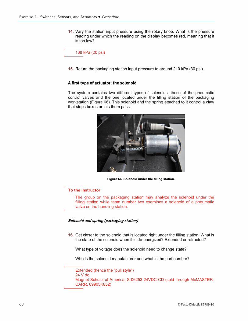
The system contains two different types of solenoids: those of the pneumatic control valves and the one located under the filling station of the packaging workstation (Figure 66). This solenoid and the spring attached to it control a claw that stops boxes or lets them pass.
Figure 66. Solenoid under the filling station.
To the instructor
The group on the packaging station may analyze the solenoid under the filling station while team number two examines a solenoid of a pneumatic valve on the handling station.
Solenoid and spring (packaging station)
16. Get closer to the solenoid that is located right under the filling station. What is the state of the solenoid when it is de-energized? Extended or retracted?
What type of voltage does the solenoid need to change state?
Who is the solenoid manufacturer and what is the part number?
Extended (hence the “pull style”) 24 V dc Magnet-Schultz of America, S-06253 24VDC-CD (sold through McMASTER-CARR, 69905K852)

Exercise 2 – Switches, Sensors, and Actuators Procedure
© Festo Didactic 89789-10 69
Valve solenoid (Handling station)
17. Take a look at the pneumatic valve DCV4. What does it control?
This valve has two positions. How are they each triggered?
Describe what happens when the PLC output #9 is energized.
Who is the manufacturer and what is the part number of this valve?
DCV4 controls the up and down movement of the packaging unit.
These two positions are triggered by a different solenoid.
When PLC output #9 is energized, 24 V dc is applied to the solenoid that puts the valve plunger in a position that sends compressed air to the side of the (up/down) cylinder that lifts the assembly.
SMC is the manufacturer. The part number is SY3220-5L0Z-N7.
Troubleshooting
To the instructor
Before troubleshooting begins or after the exercise, you can ask students what could possibly go wrong with the different sensors and solenoids.
18. Look away while the instructor inserts one or multiple faults.
To the instructor
Insert at least one fault in each workstation. Refer to Appendix G for the complete list of faults that can be inserted through the fault switch panel.
Suggestion for the packaging station: PLC input fault FS2, FS3, FS4, FS8, FS9, or FS12 Suggestion for the handling station: PLC output fault FS7
19. Use the workstation in stand-alone mode and observe what happens.
Ex
70
xercise 2 – Swi
0
tches, Sensors
2
P
2
T
2
2
s, and Actuato
20. Answer th
a. What
b. What
a Refe
c. What
d. Is it meas
e. How c
f. Does
Presenting yo
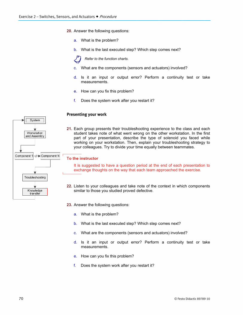
21. Each groustudent tapart of yoworking oyour colle
To the instruc
It is suggeexchange
22. Listen to ysimilar to t
23. Answer th
a. What
b. What
c. What
d. Is it meas
e. How c
f. Does
ors Procedur
he following q
is the problem
is the last exe
er to the functio
are the comp
an input orurements.
can you fix th
the system w
our work
up presents takes note of wour presenta
on your worksagues. Try to
ctor
ested to have thoughts on
your colleaguthose you stu
he following q
is the problem
is the last exe
are the comp
an input orurements.
can you fix th
the system w
re
uestions:
m?
ecuted step?
on charts.
ponents (sens
r output erro
is problem?
work after you
heir troubleshwhat went wrtion, describestation. Then,o divide your t
e a question the way that
ues and take udied proved
uestions:
m?
ecuted step?
ponents (sens
r output erro
is problem?
work after you
Which step c
sors and actu
or? Perform
u restart it?
hooting experong on the oe the type o, explain youtime equally b
period at the each team ap
note of the cdefective.
Which step c
sors and actu
or? Perform
restart it?
© Fes
comes next?
ators) involve
a continuity
rience to the other workstaof solenoid yr troubleshoo
between team
end of eachpproached th
context in wh
comes next?
ators) involve
a continuity
sto Didactic 89789
ed?
y test or ta
class and eaation. In the fyou faced whoting strategy
mmates.
presentatione exercise.
ich compone
ed?
y test or ta
9-10
ake
ach first hile y to
n to
nts
ake

Exercise 2 – Switches, Sensors, and Actuators Conclusion
© Festo Didactic 89789-10 71
To the instructor
Students can answer these questions for each presenting team.
End of the exercise
24. Verify that each workstation operates normally.
25. Turn off the workstations and clean the work area in preparation for the next laboratory exercise.
In this second exercise, you focused your attention on the sensors and actuators of the mechatronic system. You started by reviewing the assemblies on both stations. Then, you identified some components on the electrical panel before examining each in sequence. Finally, you had to find a fault in the system and present your approach to the class. The next exercise concentrates on other actuators: the electrical motors operating on dc current.
1. Which type of objects can be detected by an inductive proximity sensor?
Metallic objects.
2. What are the three basic types of photoelectric sensors?
Throughbeam Retroreflective Diffuse
3. Describe in a few words how a reed switch operates.
Two thin metal reeds are enclosed in a glass capsule. If a permanent magnet is placed close to the switch, the magnetic flux generated by the magnet draws the two reeds together.
4. Explain what the primary element of a pressure transmitter is.
The primary element detects changes in pressure, resulting in a change in electrical resistance.
CONCLUSION
REVIEW QUESTIONS

Exercise 2 – Switches, Sensors, and Actuators Review Questions
72 © Festo Didactic 89789-10
5. Which sensor detects changes in the electrostatic field?
The capacitive proximity switch.

© Festo Didactic 89789-10 131
Bibliography
Brumbach, M. E., and Clade, J. A., Industrial Maintenance, NY: Delmar, Cengage Learning, 2003, ISBN 0-7668-2695-3.
Wildi, Theodore, Electrical Machines, Drives, and Power Systems, 6th Edition, Upper Saddle River: Prentice Hall, 2005, ISBN 978-0131776913.
Stenerson, Jon, Fundamentals of Programmable Logic Controllers, Sensors, and Communication, 3rd Edition, Upper Saddle River: Prentice Hall, 200, ISBN 0-13-061890-X.
Top Related
Copyright © 2022 FDOKUMEN

