


Bahasa
Halaman
Hukum

El-E: An Assistive Robot that Fetches Objects from FlatSurfaces
Hai NguyenGeorgia Tech
Atlanta, Georgia [email protected]
Cressel AndersonGeorgia Tech
Atlanta, Georgia [email protected]
Alexander TrevorGeorgia Tech
Atlanta, Georgia [email protected]
Advait JainGeorgia Tech
Atlanta, Georgia [email protected]
Zhe XuGeorgia Tech
Atlanta, Georgia [email protected]
Charles C. KempGeorgia Tech
Atlanta, Georgia [email protected]
ABSTRACTObjects within human environments are usually found onflat surfaces that are orthogonal to gravity, such as floors,tables, and shelves. We first present a new assistive robotthat is explicitly designed to take advantage of this commonstructure in order to retrieve unmodeled, everyday objectsfor people with motor impairments. This compact, stati-cally stable mobile manipulator has a novel kinematic andsensory configuration that facilitates autonomy and human-robot interaction within indoor human environments. Sec-ond, we present a behavior system that enables this robot tofetch objects selected with a laser pointer from the floor andtables. The robot can approach an object selected with thelaser pointer interface, detect if the object is on an elevatedsurface, raise or lower its arm and sensors to this surface,and visually and tacitly grasp the object. Once the objectis acquired, the robot can place the object on a laser des-ignated surface above the floor, follow the laser pointer onthe floor, or deliver the object to a seated person selectedwith the laser pointer. Within this paper we present initialresults for object acquisition and delivery to a seated, able-bodied individual. For this test, the robot succeeded in 6out of 7 trials (86%).
1. INTRODUCTIONIn this paper we present our platform El-E (Elevated - En-gagement), a robot designed around two key innovations.First, El-E is equipped with a laser pointer interface thatdetects when a user illuminates a location with a green laserpointer and estimates the 3D location selected by this“point-and-click”. This enables a user to unambiguously commu-nicate a 3D location to the robot with modest effort, whichprovides a direct way to tell the robot which object to manip-
The Robotic Helpers Workshop at HRI’08, March 12, 2008, Amsterdam,The Netherlands.
ulate or where to go. Second, El-E is able translate its ma-nipulator and associated sensors to different heights, whichenables it to grasp objects on a variety of surfaces, suchas the floor and tables, using the same perception and ma-nipulation strategies. This effectively takes advantage of acommon symmetry found within human environments thathas likely evolved due to people’s desire to place objects instable configurations. Smooth flat surfaces that are orthog-onal to gravity are rarely found outdoors, but are nearlyubiquitous in built-for-human environments.
To use our robot helper, the human points at an item ofinterest and illuminates it with an unaltered, off-the-shelf,green laser pointer. The robot then moves near the perceived3D location using the laser range finder. If the location is onthe floor, the robot will attempt to grasp the object. If thelocation is not on the floor, the robot uses the laser rangefinder to scan for an elevated surface. Once the elevated sur-face is found the robot docks with the surface and attemptsto grasp the object. In both cases grasping is accomplishedthrough a combination of visual segmentation and tactilesensing. After successfully grasping and lifting an object,the robot will await a command from the user. If the userilluminates him or herself with the laser pointer, the robotwill deliver the object. If the user illuminates a table, therobot will place the object on the table. If the user illumi-nates the floor near the robot, the robot will follow the laserpointer.
2. MOTIVATIONAutonomous mobile robots with manipulation capabilitiesoffer the potential to dramatically improve the quality oflife for people with motor impairments. With over 250,000people with spinal cord injuries and 3,000,000 stroke sur-vivors in the US alone, the impact of affordable, robust as-sistive manipulation could be profound [3, 4]. Moreover, asis often noted, the elderly population worldwide is increas-ing substantially as a percentage of overall population, andthere are over 16,000,000 people currently over the age of75 in the US [16] . This aging population creates a realneed for affordable, robust robotic assistance, since 20% ofpeople in the US between 75 and 79 years of age have beenshown to require assistance in activities of everyday living,
and this percentage increases precipitously with age, with50% of people over 85 years of age requiring assistance [1].
Currently, this assistance is most often provided by a humancaregiver, such as a spouse or nurse, which reduces privacyand independence, and often places a heavy burden on aloved one or entails high costs. Highly trained animals, suchas service dogs or helper monkeys, can also provide physicalassistance, but they come with a host of other complications,including high costs ($17000-$35000), difficult training, reli-ability issues, and their own need for care [2, 10].
As members of the Healthcare Robotics Lab at GeorgiaTech, we are working to develop assistive, autonomous mo-bile manipulators that can meet the needs of people withmotor impairments in a manner similar to helper animalsand human assistants. We consider object fetching to bean especially important area for research, since people withmotor impairments have consistently placed a high priorityon the ability to retrieve objects from the floor and shelves[19], and since object fetching is a fundamental capability forautonomous robot manipulation upon which future assistiveapplications could be built.
Trained helper monkeys for quadriplegics serves as an inspi-ration for our research. People direct these monkeys usinga laser pointer and simple words. This style of interactionhelped inspire our design, and helps validate the feasibilityof our robot’s interface from a usability stand point. Withhelper monkeys, a quadriplegic can operate the laser pointerwith his or her mouth, but other interfaces would also bepossible, such as a joystick or sip-and-puff interface to a ser-voed laser pointer. When discussing his life before he hada helper monkey, Chris Watts, a quadriplegic, stated in aninterview with CBS, ”If I dropped the phone on the floor,if I dropped my water on the floor, or I dropped my pillsor any of those kinds of things, they stayed on the floor un-til someone came home,” [22]. For many people with ALSor spinal cord injuries, the retrieval of dropped objects is asignificant concern and a frequent need.
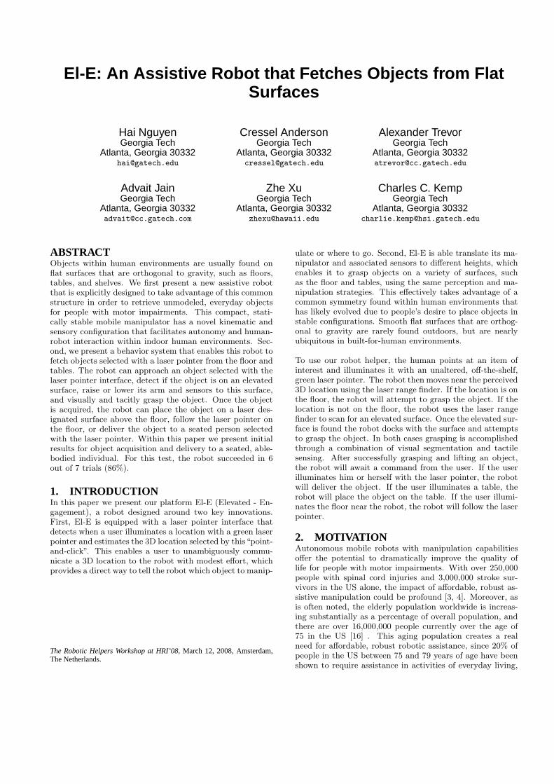
3. ROBOT DESIGNThe robot, El-E, is primarily constructed from off-the-shelfcomponents as seen in Figure 1. Its mobile base is an ER-RATIC platform from Videre Design, which includes an on-board computer with a Core Duo processor and 1 GB ofmemory with which the robot performs all its computation.The computer runs Ubuntu GNU/Linux and we have writ-ten most of our software with Python and occasionally C++.We also make use of a variety of open source packages in-cluding SciPy, Player/Stage and OpenCV.
The ERRATIC base has differential drive steering with twowheels and a caster in the back. Attached to the center ofthe ERRATIC base is a 1-DoF linear actuator built from aFesto DGE-25-900-SP-KF-GV, which uses a ball screw, andan Animatics SM2315DT servo. This linear actuator, whichwe refer to as the zenither, raises and lowers an aluminumcarriage containing sensors and actuators in order for therobot to interact with objects at various heights. The servodrives the carriage platform using either torque or positioncommands. Mounted on this carriage is a 5-DoF NeuronicsKatana 6M manipulator with a two finger gripper containing
Figure 1: An image of the entire mobile manipulatorwith the integrated interface system (i.e. the robot’shead)
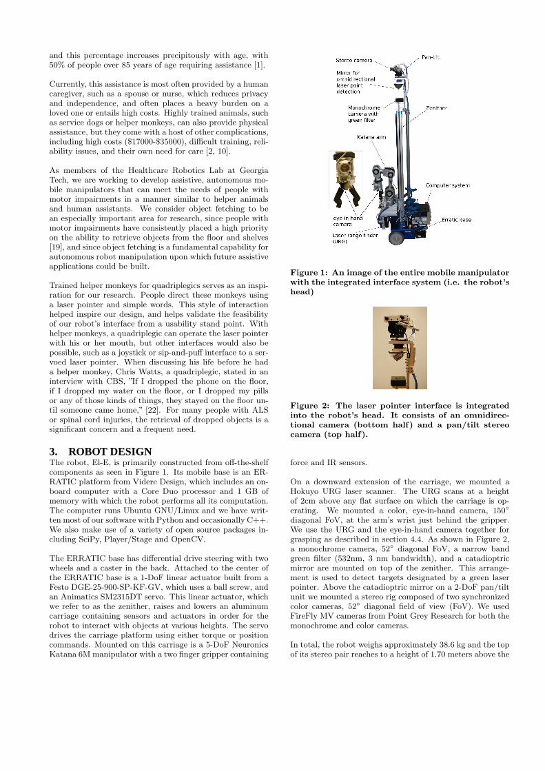
Figure 2: The laser pointer interface is integratedinto the robot’s head. It consists of an omnidirec-tional camera (bottom half) and a pan/tilt stereocamera (top half).
force and IR sensors.
On a downward extension of the carriage, we mounted aHokuyo URG laser scanner. The URG scans at a heightof 2cm above any flat surface on which the carriage is op-erating. We mounted a color, eye-in-hand camera, 150◦
diagonal FoV, at the arm’s wrist just behind the gripper.We use the URG and the eye-in-hand camera together forgrasping as described in section 4.4. As shown in Figure 2,a monochrome camera, 52◦ diagonal FoV, a narrow bandgreen filter (532nm, 3 nm bandwidth), and a catadioptricmirror are mounted on top of the zenither. This arrange-ment is used to detect targets designated by a green laserpointer. Above the catadioptric mirror on a 2-DoF pan/tiltunit we mounted a stereo rig composed of two synchronizedcolor cameras, 52◦ diagonal field of view (FoV). We usedFireFly MV cameras from Point Grey Research for both themonochrome and color cameras.
In total, the robot weighs approximately 38.6 kg and the topof its stereo pair reaches to a height of 1.70 meters above the
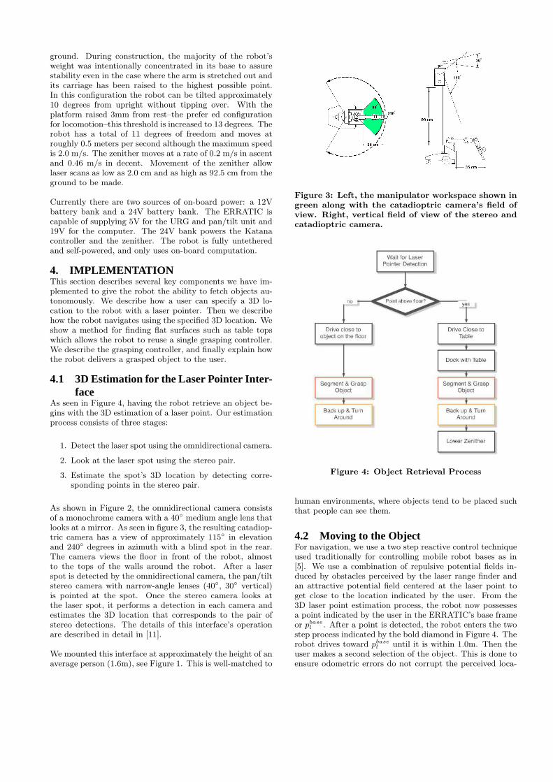
ground. During construction, the majority of the robot’sweight was intentionally concentrated in its base to assurestability even in the case where the arm is stretched out andits carriage has been raised to the highest possible point.In this configuration the robot can be tilted approximately10 degrees from upright without tipping over. With theplatform raised 3mm from rest–the prefer ed configurationfor locomotion–this threshold is increased to 13 degrees. Therobot has a total of 11 degrees of freedom and moves atroughly 0.5 meters per second although the maximum speedis 2.0 m/s. The zenither moves at a rate of 0.2 m/s in ascentand 0.46 m/s in decent. Movement of the zenither allowlaser scans as low as 2.0 cm and as high as 92.5 cm from theground to be made.
Currently there are two sources of on-board power: a 12Vbattery bank and a 24V battery bank. The ERRATIC iscapable of supplying 5V for the URG and pan/tilt unit and19V for the computer. The 24V bank powers the Katanacontroller and the zenither. The robot is fully untetheredand self-powered, and only uses on-board computation.
4. IMPLEMENTATIONThis section describes several key components we have im-plemented to give the robot the ability to fetch objects au-tonomously. We describe how a user can specify a 3D lo-cation to the robot with a laser pointer. Then we describehow the robot navigates using the specified 3D location. Weshow a method for finding flat surfaces such as table topswhich allows the robot to reuse a single grasping controller.We describe the grasping controller, and finally explain howthe robot delivers a grasped object to the user.
4.1 3D Estimation for the Laser Pointer Inter-face
As seen in Figure 4, having the robot retrieve an object be-gins with the 3D estimation of a laser point. Our estimationprocess consists of three stages:
1. Detect the laser spot using the omnidirectional camera.
2. Look at the laser spot using the stereo pair.
3. Estimate the spot’s 3D location by detecting corre-sponding points in the stereo pair.
As shown in Figure 2, the omnidirectional camera consistsof a monochrome camera with a 40◦ medium angle lens thatlooks at a mirror. As seen in figure 3, the resulting catadiop-tric camera has a view of approximately 115◦ in elevationand 240◦ degrees in azimuth with a blind spot in the rear.The camera views the floor in front of the robot, almostto the tops of the walls around the robot. After a laserspot is detected by the omnidirectional camera, the pan/tiltstereo camera with narrow-angle lenses (40◦, 30◦ vertical)is pointed at the spot. Once the stereo camera looks atthe laser spot, it performs a detection in each camera andestimates the 3D location that corresponds to the pair ofstereo detections. The details of this interface’s operationare described in detail in [11].
We mounted this interface at approximately the height of anaverage person (1.6m), see Figure 1. This is well-matched to
Figure 3: Left, the manipulator workspace shown ingreen along with the catadioptric camera’s field ofview. Right, vertical field of view of the stereo andcatadioptric camera.
Figure 4: Object Retrieval Process
human environments, where objects tend to be placed suchthat people can see them.
4.2 Moving to the ObjectFor navigation, we use a two step reactive control techniqueused traditionally for controlling mobile robot bases as in[5]. We use a combination of repulsive potential fields in-duced by obstacles perceived by the laser range finder andan attractive potential field centered at the laser point toget close to the location indicated by the user. From the3D laser point estimation process, the robot now possessesa point indicated by the user in the ERRATIC’s base frameor pbase
l . After a point is detected, the robot enters the twostep process indicated by the bold diamond in Figure 4. Therobot drives toward pbase
l until it is within 1.0m. Then theuser makes a second selection of the object. This is done toensure odometric errors do not corrupt the perceived loca-
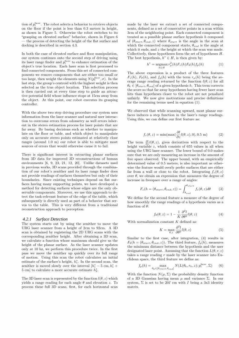
tion of pbasel . The robot selects a behavior to retrieve objects
on the floor if the point is less than 0.3 meters in height,as shown in Figure 5. Otherwise the robot switches to its“grasping on elevated surface” behavior, shown in Figure 6— the process of detecting the height of the flat surface anddocking is described in section 4.3.
In both the case of elevated surface and floor manipulation,our system continues onto the second step of driving usingits laser range finder and pbase
l to enhance estimation of theobject’s true location. Each laser scan is first processed tofind connected components. From this set of connected com-ponents we remove components that are either too small ortoo large, then weight the elements using N(pbase
l , σ). In thelast step, the group’s centroid with the highest weight is thenselected as the true object location. This selection processis then carried out at every time step to guide an attrac-tive potential field whose influence stops at 15cm away fromthe object. At this point, our robot executes its graspingcontroller.
With the above two step driving procedure our system usesinformation from the laser scanner and natural user interac-tion to overcome errors from odometry as well errors inher-ent in the stereo estimation process for laser points that arefar away. By basing decisions such as whether to manipu-late on the floor or table, and which object to manipulateonly on accurate stereo points estimated at relatively closeranges (around 1.0 m) our robot is able to mitigate mostsources of errors that would otherwise cause it to fail.
There is significant interest in extracting planar surfacesfrom 3D data for improved 3D reconstructions of humanenvironments [6, 9, 23, 21, 12, 20]. Unlike datasets usedin previous works, 3D scans provided through the combina-tion of our robot’s zenither and its laser range finder doesnot provide readings of surfaces themselves but only of theirboundaries. Since existing techniques depend on flat sur-faces having many supporting points, we have developed amethod for detecting surfaces whose edges are the only ob-servable components. Moreover, we use this approach to de-tect the task-relevant feature of the edge of the table, whichsubsequently is directly used as part of a behavior that ser-vos to the table. This is very different from a traditionalreconstruction approach to perception.
4.2.1 Surface DetectionThe system starts out by using the zenither to move theURG laser scanner from a height of 2cm to 92cm. A 3Dscan is obtained by registering the 2D URG scans with thecorresponding zenither height. After obtaining a 3D scan,we calculate a function whose maximum should give us theheight of the planar surface. As the laser scanner updatesonly at 10 hz, we perform this procedure twice. In the firstpass we move the zenither up quickly over its full rangeof motion. Using this scan the robot calculates an initialestimate of the surface’s height, h∗
1. In the second scan, thezenither is moved slowly over the interval [h∗
1 − 5 cm, h∗
1 +5 cm] to calculate a more accurate estimate h∗
2.
The 3D laser scan is represented by the function l(θ, z) whichyields a range reading for each angle θ and elevation z. Toprocess these full 3D scans, first, for each horizontal scan
made by the laser we extract a set of connected compo-nents, defined as a set of consecutive points in a scan within3cm of the neighboring point. Each connected component istreated as a possible planar surface hypothesis h composedof (θstart, θend, z) where θstart is the angle in the scan atwhich the connected component starts, θend is the angle atwhich it ends, and z the height at which the scan was made.Collectively, these hypotheses form the set of hypotheses H.The best hypothesis, h∗
∈ H, is then given by:
h∗ = argmax
h∈H
r2µ(h)Fz(h)Fθ(h)fp(h) (1)
The above expression is a product of the three featuresFz(h), Fθ(h), and fp(h) with the term rµ(h) being the av-erage range reading returned by the function l(θ, z) for allθk ∈ [θstart, θend] of a given hypothesis h. This term correctsthe score so that far away hypotheses having fewer laser scanhits than hypotheses closer to the robot are not penalizedunfairly. We now give motivations and precise definitionsfor the remaining terms used in equation (1).
We observed that while scanning upward, most planar sur-faces induces a step function in the laser’s range readings.Using this, we can define our first feature as:
fz(θ, z) = min(max(∂l
∂zl(θ, z), 0), 0.5 m) (2)
The term ∂l∂z
l(θ, z), gives derivatives with respect to theheight variable z, which consists of 655 values in all whenusing the URG laser scanner. The lower bound of 0.0 makessure that we are only measuring an increase in the amount offree space observed. The upper bound, with an empiricallydetermined value of 0.5 meters, is also important as other-wise the feature would overly prefer surfaces that are eitherfar from a wall or close to the robot. Integrating fz(θ, z)over θ, we obtain an expression that measures the degree ofincrease in freespace over a range of angles:
Fz(h = (θstart, θend, z)) =
Z θstart
θend
fz(θ, z)dθ (3)
We define for the second feature a measure of the degree ofhow smoothly the range readings of a hypothesis varies as afunction of θ:
fθ(θ, z) = 1 −1
K
∂2l
∂θ2l(θ, z) (4)
With normalization constant K defined as:
K = maxθ,z
∂2l
∂θ2l(θ, z) (5)
Similar to the first case, after integration, (4) results inFθ(h = (θstart, θend, z)). The third feature, fp(h), measuresthe minimum distance between the hypothesis and the userdesignated laser point. Assuming that the function L(θ, r, z)takes a range reading r made by the laser scanner into Eu-clidean space, the third feature we define as:
fp(h) = maxθk∈[θstart,θend]
N(L(θk, rk, z); pbasel , Σ) (6)
With the function N(µ, Σ) the probability density functionof a 3D Gaussian having mean µ and variance Σ. In oursystem, Σ is set to be 20I cm with I being a 3x3 identitymatrix.
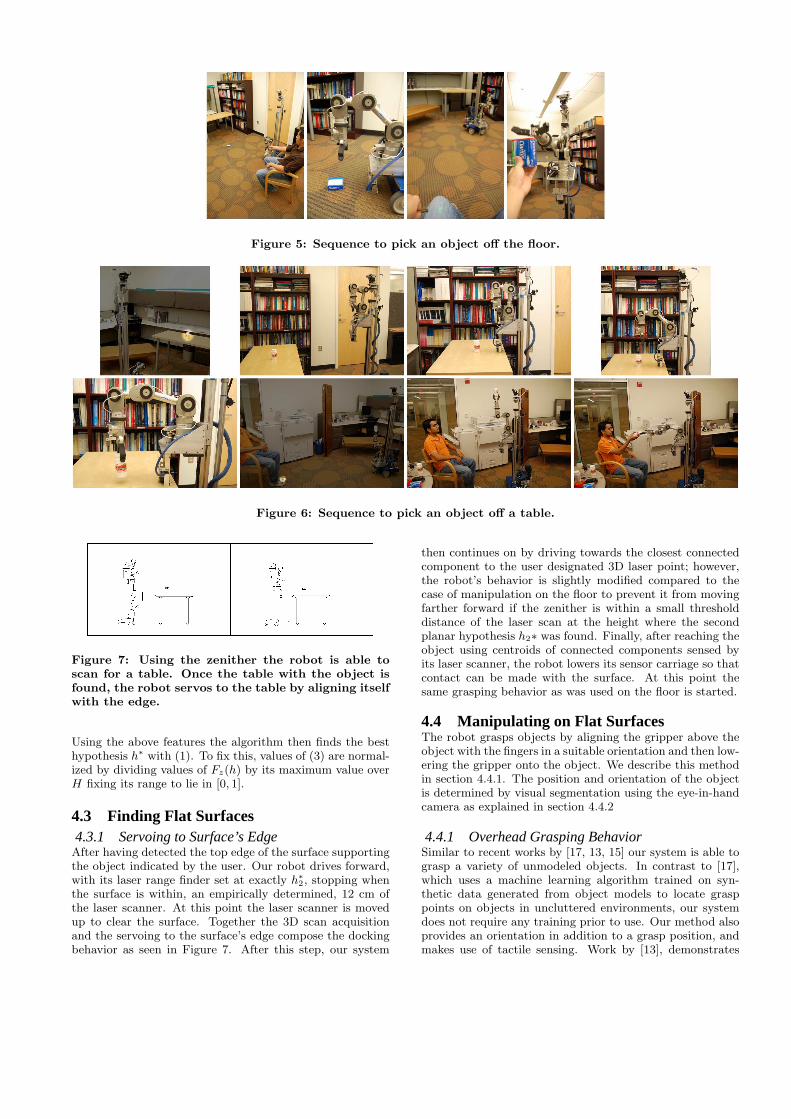
Figure 5: Sequence to pick an object off the floor.
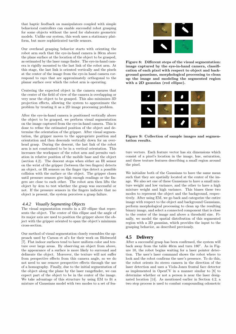
Figure 6: Sequence to pick an object off a table.
Figure 7: Using the zenither the robot is able toscan for a table. Once the table with the object isfound, the robot servos to the table by aligning itselfwith the edge.
Using the above features the algorithm then finds the besthypothesis h∗ with (1). To fix this, values of (3) are normal-ized by dividing values of Fz(h) by its maximum value overH fixing its range to lie in [0, 1].
4.3 Finding Flat Surfaces4.3.1 Servoing to Surface’s EdgeAfter having detected the top edge of the surface supportingthe object indicated by the user. Our robot drives forward,with its laser range finder set at exactly h∗
2, stopping whenthe surface is within, an empirically determined, 12 cm ofthe laser scanner. At this point the laser scanner is movedup to clear the surface. Together the 3D scan acquisitionand the servoing to the surface’s edge compose the dockingbehavior as seen in Figure 7. After this step, our system
then continues on by driving towards the closest connectedcomponent to the user designated 3D laser point; however,the robot’s behavior is slightly modified compared to thecase of manipulation on the floor to prevent it from movingfarther forward if the zenither is within a small thresholddistance of the laser scan at the height where the secondplanar hypothesis h2∗ was found. Finally, after reaching theobject using centroids of connected components sensed byits laser scanner, the robot lowers its sensor carriage so thatcontact can be made with the surface. At this point thesame grasping behavior as was used on the floor is started.
4.4 Manipulating on Flat SurfacesThe robot grasps objects by aligning the gripper above theobject with the fingers in a suitable orientation and then low-ering the gripper onto the object. We describe this methodin section 4.4.1. The position and orientation of the objectis determined by visual segmentation using the eye-in-handcamera as explained in section 4.4.2
4.4.1 Overhead Grasping BehaviorSimilar to recent works by [17, 13, 15] our system is able tograsp a variety of unmodeled objects. In contrast to [17],which uses a machine learning algorithm trained on syn-thetic data generated from object models to locate grasppoints on objects in uncluttered environments, our systemdoes not require any training prior to use. Our method alsoprovides an orientation in addition to a grasp position, andmakes use of tactile sensing. Work by [13], demonstrates
that haptic feedback on manipulators coupled with simplebehavioral controllers can enable successful robot graspingfor some objects without the need for elaborate geometricmodels. Unlike our system, this work uses a stationary plat-form, but more sophisticated tactile sensors.
Our overhead grasping behavior starts with orienting therobot arm such that the eye-in-hand camera is 30cm abovethe plane surface at the location of the object to be grasped,as estimated by the laser range finder. The eye-in-hand cam-era is rigidly mounted to the last link of the robot arm. Atthis stage, the last link is oriented vertically and the pixelsat the center of the image from the eye-in hand camera cor-respond to rays that are approximately orthogonal to theplanar surface over which the robot arm is operating.
Centering the expected object in the camera ensures thatthe center of the field of view of the camera is overlapping orvery near the object to be grasped. This also minimizes 3Dprojection effects, allowing the system to approximate theproblem by treating it as a 2D image processing problem.
After the eye-in-hand camera is positioned vertically abovethe object to be grasped, we perform visual segmentationon the image captured from the eye-in-hand camera. This isdone to refine the estimated position of the object and de-termine the orientation of the gripper. After visual segmen-tation, the gripper moves to the appropriate position andorientation and then descends vertically down for an over-head grasp. During the descent, the last link of the robotarm is not constrained to be in a vertical orientation. Thisincreases the workspace of the robot arm and permits vari-ation in relative position of the mobile base and the object(section 4.2). The descent stops when either an IR sensoron the wrist of the gripper (between the two fingers) detectsan object, or IR sensors on the finger tips detect a possiblecollision with the surface or the object. The gripper closesuntil pressure sensors give high enough readings or the fin-gers are close to each other. The robot arm then lifts theobject by 4cm to test whether the grasp was successful ornot. If the pressure sensors in the fingers indicate that noobject is present, the system perceives a grasp failure.
4.4.2 Visually Segmenting ObjectsThe visual segmentation results in a 2D ellipse that repre-sents the object. The center of this ellipse and the angle ofits major axis are used to position the gripper above the ob-ject with the gripper oriented to span the object’s minimumcross-section.
Our method of visual segmentation closely resembles the ap-proach used by Carson et al’s for their work on Blobworld[7]. Flat indoor surfaces tend to have uniform color and tex-ture over large areas. By observing an object from above,the appearance of a surface is more likely to surround anddelineate the object. Moreover, the texture will not sufferfrom perspective effects from this camera angle, so we donot need to use remove perspective effects through the useof a homography. Finally, due to the initial segmentation ofthe object along the plane by the laser rangefinder, we canexpect part of the object to be in the center of the image.We take advantage of this structure by using EM to fit amixture of Gaussians model with two modes to a set of fea-
Figure 8: Different steps of the visual segmentation:image captured by the eye-in-hand camera, classifi-cation of each pixel with respect to object and back-ground gaussians, morphological processing to cleanup the image and modeling the segmented regionwith a 2D gaussian (red ellipse).
Figure 9: Collection of sample images and segmen-tation results.
ture vectors. Each feature vector has six dimensions whichconsist of a pixel’s location in the image, hue, saturation,and three texture features describing a small region aroundthe pixel.
We initialize both of the Gaussians to have the same meansuch that they are spatially located at the center of the im-age. We also set one of these Gaussians to have a small mix-ture weight and low variance, and the other to have a highmixture weight and high variance. This biases these twomodes to represent the object and the background, respec-tively. After using EM, we go back and categorize the entireimage with respect to the object and background Gaussians,perform morphological processing to clean up the resultingbinary image, and select a connected component that is closeto the center of the image and above a threshold size. Fi-nally, we model the spatial distribution of this segmentedregion with a 2D gaussian, which provides the input to thegrasping behavior, as described previously.
4.5 DeliveryAfter a successful grasp has been confirmed, the system willback away from the table 40cm and turn 180◦. As in Fig-ure 10, the robot begins waiting for a laser pointer detec-tion. The user’s laser command shows the robot where tolook and the robot confirms the user’s presence. To do this,the robot orients its stereo camera in the direction of thelaser detection and uses a Viola-Jones frontal face detectoras implemented in OpenCV in a manner similar to [8] todetermine whether or not a person is near the laser desig-nated location [14]. As mentioned earlier in Section 4.2, atwo step process is used to combat compounding odometric
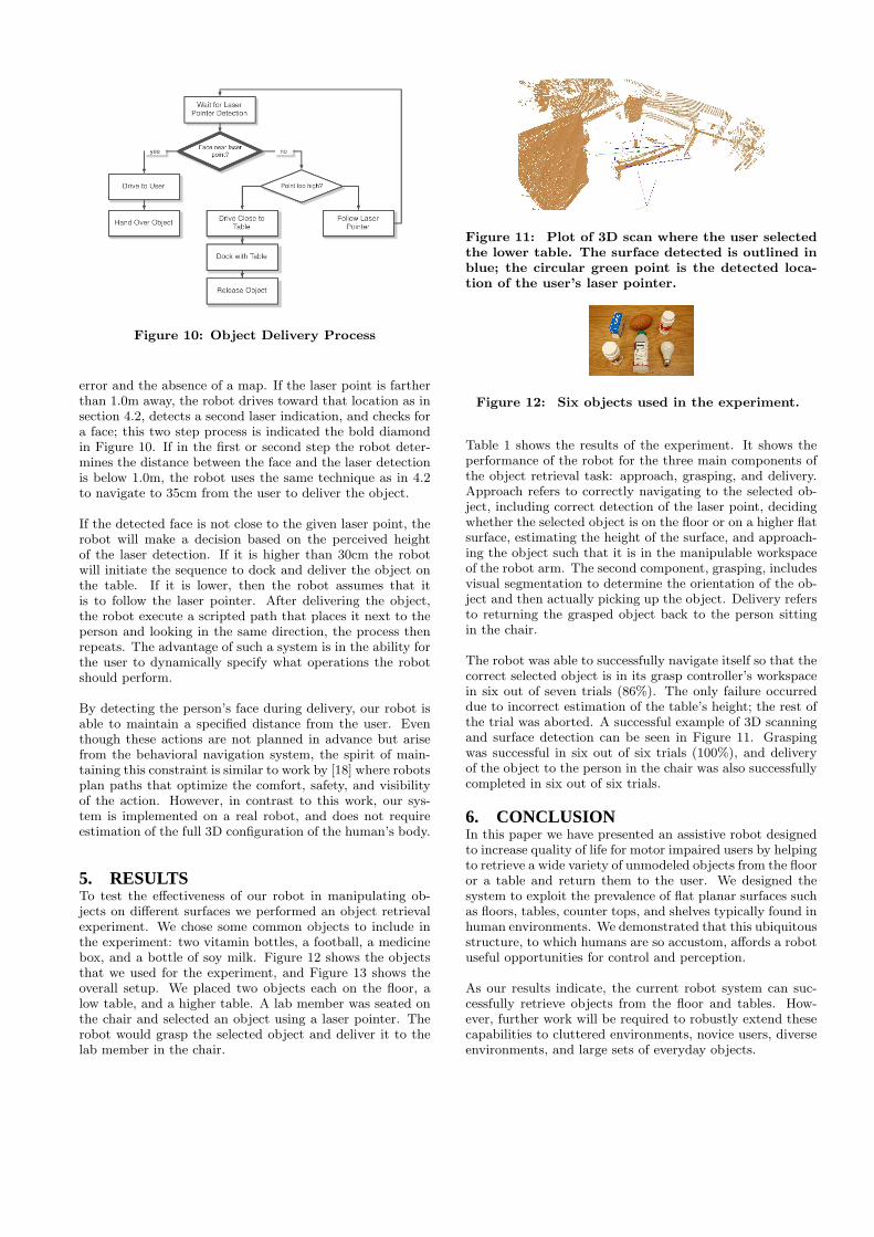
Figure 10: Object Delivery Process
error and the absence of a map. If the laser point is fartherthan 1.0m away, the robot drives toward that location as insection 4.2, detects a second laser indication, and checks fora face; this two step process is indicated the bold diamondin Figure 10. If in the first or second step the robot deter-mines the distance between the face and the laser detectionis below 1.0m, the robot uses the same technique as in 4.2to navigate to 35cm from the user to deliver the object.
If the detected face is not close to the given laser point, therobot will make a decision based on the perceived heightof the laser detection. If it is higher than 30cm the robotwill initiate the sequence to dock and deliver the object onthe table. If it is lower, then the robot assumes that itis to follow the laser pointer. After delivering the object,the robot execute a scripted path that places it next to theperson and looking in the same direction, the process thenrepeats. The advantage of such a system is in the ability forthe user to dynamically specify what operations the robotshould perform.
By detecting the person’s face during delivery, our robot isable to maintain a specified distance from the user. Eventhough these actions are not planned in advance but arisefrom the behavioral navigation system, the spirit of main-taining this constraint is similar to work by [18] where robotsplan paths that optimize the comfort, safety, and visibilityof the action. However, in contrast to this work, our sys-tem is implemented on a real robot, and does not requireestimation of the full 3D configuration of the human’s body.
5. RESULTSTo test the effectiveness of our robot in manipulating ob-jects on different surfaces we performed an object retrievalexperiment. We chose some common objects to include inthe experiment: two vitamin bottles, a football, a medicinebox, and a bottle of soy milk. Figure 12 shows the objectsthat we used for the experiment, and Figure 13 shows theoverall setup. We placed two objects each on the floor, alow table, and a higher table. A lab member was seated onthe chair and selected an object using a laser pointer. Therobot would grasp the selected object and deliver it to thelab member in the chair.
Figure 11: Plot of 3D scan where the user selectedthe lower table. The surface detected is outlined inblue; the circular green point is the detected loca-tion of the user’s laser pointer.
Figure 12: Six objects used in the experiment.
Table 1 shows the results of the experiment. It shows theperformance of the robot for the three main components ofthe object retrieval task: approach, grasping, and delivery.Approach refers to correctly navigating to the selected ob-ject, including correct detection of the laser point, decidingwhether the selected object is on the floor or on a higher flatsurface, estimating the height of the surface, and approach-ing the object such that it is in the manipulable workspaceof the robot arm. The second component, grasping, includesvisual segmentation to determine the orientation of the ob-ject and then actually picking up the object. Delivery refersto returning the grasped object back to the person sittingin the chair.
The robot was able to successfully navigate itself so that thecorrect selected object is in its grasp controller’s workspacein six out of seven trials (86%). The only failure occurreddue to incorrect estimation of the table’s height; the rest ofthe trial was aborted. A successful example of 3D scanningand surface detection can be seen in Figure 11. Graspingwas successful in six out of six trials (100%), and deliveryof the object to the person in the chair was also successfullycompleted in six out of six trials.
6. CONCLUSIONIn this paper we have presented an assistive robot designedto increase quality of life for motor impaired users by helpingto retrieve a wide variety of unmodeled objects from the flooror a table and return them to the user. We designed thesystem to exploit the prevalence of flat planar surfaces suchas floors, tables, counter tops, and shelves typically found inhuman environments. We demonstrated that this ubiquitousstructure, to which humans are so accustom, affords a robotuseful opportunities for control and perception.
As our results indicate, the current robot system can suc-cessfully retrieve objects from the floor and tables. How-ever, further work will be required to robustly extend thesecapabilities to cluttered environments, novice users, diverseenvironments, and large sets of everyday objects.
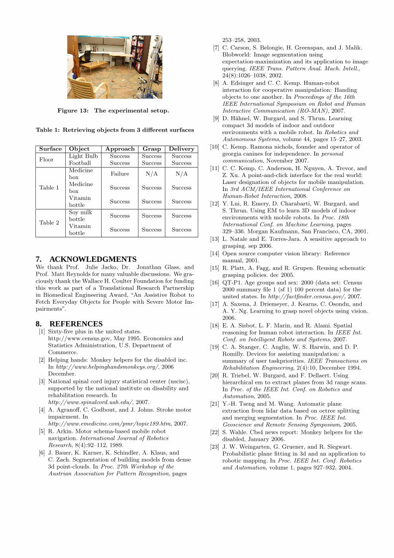
Figure 13: The experimental setup.
Table 1: Retrieving objects from 3 different surfaces
Surface Object Approach Grasp Delivery
FloorLight Bulb Success Success SuccessFootball Success Success Success
Table 1
MedicineFailure N/A N/A
boxMedicine
Success Success SuccessboxVitamin
Success Success Successbottle
Table 2
Soy milkSuccess Success Success
bottleVitamin
Success Success Successbottle
7. ACKNOWLEDGMENTSWe thank Prof. Julie Jacko, Dr. Jonathan Glass, andProf. Matt Reynolds for many valuable discussions. We gra-ciously thank the Wallace H. Coulter Foundation for fundingthis work as part of a Translational Research Partnershipin Biomedical Engineering Award, “An Assistive Robot toFetch Everyday Objects for People with Severe Motor Im-pairments”.
8. REFERENCES[1] Sixty-five plus in the united states.
http://www.census.gov, May 1995. Economics andStatistics Administration, U.S. Department ofCommerce.
[2] Helping hands: Monkey helpers for the disabled inc.In http://www.helpinghandsmonkeys.org/, 2006December.
[3] National spinal cord injury statistical center (nscisc),supported by the national institute on disability andrehabilitation research. Inhttp://www.spinalcord.uab.edu/, 2007.
[4] A. Agranoff, C. Godbout, and J. Johns. Stroke motorimpairment. Inhttp://www.emedicine.com/pmr/topic189.htm, 2007.
[5] R. Arkin. Motor schema-based mobile robotnavigation. International Journal of RoboticsResearch, 8(4):92–112, 1989.
[6] J. Bauer, K. Karner, K. Schindler, A. Klaus, andC. Zach. Segmentation of building models from dense3d point-clouds. In Proc. 27th Workshop of theAustrian Association for Pattern Recognition, pages
253–258, 2003.
[7] C. Carson, S. Belongie, H. Greenspan, and J. Malik.Blobworld: Image segmentation usingexpectation-maximization and its application to imagequerying. IEEE Trans. Pattern Anal. Mach. Intell.,24(8):1026–1038, 2002.
[8] A. Edsinger and C. C. Kemp. Human-robotinteraction for cooperative manipulation: Handingobjects to one another. In Proceedings of the 16thIEEE International Symposium on Robot and HumanInteractive Communication (RO-MAN), 2007.
[9] D. Hahnel, W. Burgard, and S. Thrun. Learningcompact 3d models of indoor and outdoorenvironments with a mobile robot. In Robotics andAutonomous Systems, volume 44, pages 15–27, 2003.
[10] C. Kemp. Ramona nichols, founder and operator ofgeorgia canines for independence. In personalcommunication, November 2007.
[11] C. C. Kemp, C. Anderson, H. Nguyen, A. Trevor, andZ. Xu. A point-and-click interface for the real world:Laser designation of objects for mobile manipulation.In 3rd ACM/IEEE International Conference onHuman-Robot Interaction, 2008.
[12] Y. Lui, R. Emery, D. Charabarti, W. Burgard, andS. Thrun. Using EM to learn 3D models of indoorenvironments with mobile robots. In Proc. 18thInternational Conf. on Machine Learning, pages329–336. Morgan Kaufmann, San Francisco, CA, 2001.
[13] L. Natale and E. Torres-Jara. A sensitive approach tograsping. sep 2006.
[14] Open source computer vision library: Referencemanual, 2001.
[15] R. Platt, A. Fagg, and R. Grupen. Reusing schematicgrasping policies. dec 2005.
[16] QT-P1. Age groups and sex: 2000 (data set: Census2000 summary file 1 (sf 1) 100 percent data) for theunited states. In http://factfinder.census.gov/, 2007.
[17] A. Saxena, J. Driemeyer, J. Kearns, C. Osondu, andA. Y. Ng. Learning to grasp novel objects using vision.2006.
[18] E. A. Sisbot, L. F. Marin, and R. Alami. Spatialreasoning for human robot interaction. In IEEE Int.Conf. on Intelligent Robots and Systems, 2007.
[19] C. A. Stanger, C. Anglin, W. S. Harwin, and D. P.Romilly. Devices for assisting manipulation: asummary of user taskpriorities. IEEE Transactions onRehabilitation Engineering, 2(4):10, December 1994.
[20] R. Triebel, W. Burgard, and F. Dellaert. Usinghierarchical em to extract planes from 3d range scans.In Proc. of the IEEE Int. Conf. on Robotics andAutomation, 2005.
[21] Y.-H. Tseng and M. Wang. Automatic planeextraction from lidar data based on octree splittingand merging segmentation. In Proc. IEEE Int.Geoscience and Remote Sensing Symposium, 2005.
[22] S. Wahle. Cbs4 news report: Monkey helpers for thedisabled, January 2006.
[23] J. W. Weingarten, G. Gruener, and R. Siegwart.Probabilistic plane fitting in 3d and an application torobotic mapping. In Proc. IEEE Int. Conf. Roboticsand Automation, volume 1, pages 927–932, 2004.
Copyright © 2022 FDOKUMEN

