


Bahasa
Halaman
Hukum


EEPROM with Arduino – Internal & External
DroneBot Workshop Tutorial
https://dronebotworkshop.com
For more projects and tutorials visit the DroneBot Workshop - https://dronebotworkshop.com
Table of Contents
Understanding EEPROMs 3 Non-Volatile Memory Types 3 EEPROM Limitations 5
EEPROM with Arduino – Two Types 6 Internal EEPROM 6 External EEPROM 7
Using Internal EEPROM 8 Arduino EEPROM Library 9
EEPROM Update 9 EEPROM Read 14 EEPROM Clear 18
Using External EEPROM 20 AT24LC256 EEPROM 20
AT24LC256 Modules 21 External EEPROM Hookup 22 External EEPROM Arduino Code 24
Running the External EEPROM Sketch 32 Conclusion 33
https://dronebotworkshop.com 1

For more projects and tutorials visit the DroneBot Workshop - https://dronebotworkshop.com
Today we will be working with EEPROMs, a special type of memory chip that keeps its
data even after powering down your project.
Introduction
Computers and microcontrollers need memory to store data, either permanently or
temporarily, and while this memory can come in a variety of forms it can be divided into
two basic types – volatile and nonvolatile.
Volatile memory is usually in the form of RAM or Random Access Memory. This is the
“working” memory for your device, it holds temporary data used during program
operation. Once the power is removed the memory is erased.
Nonvolatile memory, as you may have guessed by now, retains its data even after being
powered-down. There are a variety of different types of non-volatile memory, and today
https://dronebotworkshop.com 2

For more projects and tutorials visit the DroneBot Workshop - https://dronebotworkshop.com
we will be examining one of them – the Electrically Erasable Programmable Read-Only
Memory or EEPROM.
Specifically, we will be looking at how to use EEPROM with an Arduino.
Understanding EEPROMs
There are many other forms of non-volatile memory, including Flash memory, SD
Cards, USB drives, hard disk drives, and SSDs. So where does the EEPROM fit in all
of this?
Compared to the aforementioned memory types an EEPROM has a very small amount
of storage, in fact, EEPROM capacities are commonly measured in Bits as opposed to
Bytes. Since they only store a small amount of data they don’t consume a great deal of
current, making them ideal for battery and low-powered applications.
EEPROMs were developed in the early 1970s and the first EEPROM was patented by
NEC in 1975.
Non-Volatile Memory Types
An EEPROM is constructed using an array of floating-gate transistors, with two
transistors per bit. It is part of the ROM, or Read-Only Memory, family of devices.
EEPROMs are similar to Flash Memory, the difference being that Flash Memory is
larger and uses larger data blocks. This comes at the expense of the number or rewrites
or “write cycles”, Flash Memory can only be rewritten about 10,000 times.
The Arduino microcontrollers use Flash Memory to store the programs (sketches) that
are uploaded to it. Arduino also has internal EEPROM, as we will see shortly.
https://dronebotworkshop.com 3

For more projects and tutorials visit the DroneBot Workshop - https://dronebotworkshop.com
Other members of the ROM family include the following:
● ROM – Read-Only Memory. These chips are programmed during manufacture and cannot be altered.
● PROM – Programmable Read-Only Memory. These chips can be programmed using a special device, however, they can not be erased and reprogrammed.
● EPROM – Erasable Programmable Read-Only Memory. Like a PROM, an EPROM requires a special programming device. This type of memory chip can be erased using ultraviolet light and then reused.
As it requires no external programming or “burning” device an EEPROM is the easiest
of these devices to use.
https://dronebotworkshop.com 4
For more projects and tutorials visit the DroneBot Workshop - https://dronebotworkshop.com
EEPROM Limitations
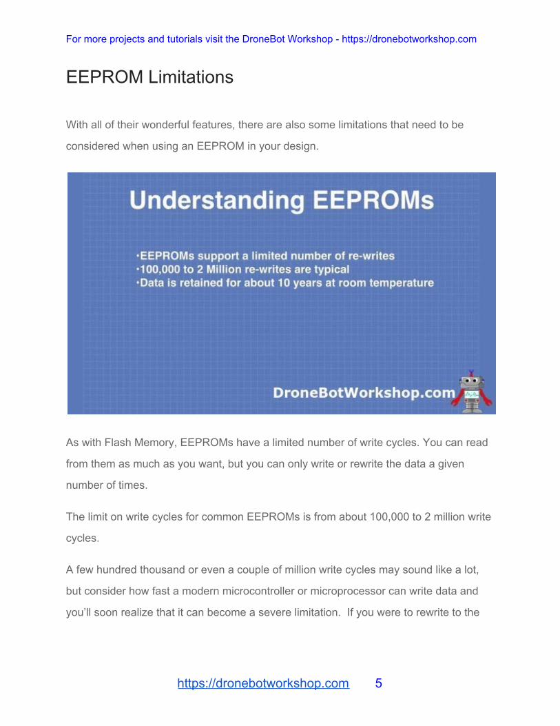
With all of their wonderful features, there are also some limitations that need to be
considered when using an EEPROM in your design.
As with Flash Memory, EEPROMs have a limited number of write cycles. You can read
from them as much as you want, but you can only write or rewrite the data a given
number of times.
The limit on write cycles for common EEPROMs is from about 100,000 to 2 million write
cycles.
A few hundred thousand or even a couple of million write cycles may sound like a lot,
but consider how fast a modern microcontroller or microprocessor can write data and
you’ll soon realize that it can become a severe limitation. If you were to rewrite to the
https://dronebotworkshop.com 5

For more projects and tutorials visit the DroneBot Workshop - https://dronebotworkshop.com
EEPROM every second and it has a write cycle capacity of 100,000 writes then you’d
exceed that capacity in a little over one day!
When designing using EEPROMs you will want to write to the device as little as
possible. Another technique, which we will examine in a while, is to read the bit first
before it is written – no sense rewriting it if it is already the correct value.
Another EEPROM limitation is data retention time. While EEPROM technology is
constantly improving todays EEPROMs can retain data for about 10 years at room
temperature before it becomes corrupted. Rewriting that data will start the counter
again, prolonging the life of the EEPROM.
And finally, an obvious limitation of sorts is the EEPROM storage capacity, which is
quite small when compared to other memory devices. But, as the most common use of
EEPROMs is to retain configuration and calibration data, this is seldom an issue.
EEPROM with Arduino – Two Types
Adding EEPROM to our Arduino designs can allow our projects to retain data after
being powered down. This can be very useful for applications that require calibration, or
the storage of a user’s favorite settings.
Internal EEPROM
We can add EEPROM capability to our Arduino projects quite easily. In fact, the Arduino
already has some internal EEPROM that we can use in our programs. The amount of
memory depends upon which Arduino model we are using.
https://dronebotworkshop.com 6

For more projects and tutorials visit the DroneBot Workshop - https://dronebotworkshop.com
The following table illustrates the amount of internal EEPROM in some popular Arduino
models:
Microcontroller EEPROM Capacity
Atmega2560 (Arduino Mega 2560) 4096 Bytes
ATmega328 (Arduino Uno, Mini ands some Nanos) 1024 Bytes
ATmega168 (Some Nanos) 512 Bytes
In many designs, this small amount of non-volatile memory will be sufficient.
External EEPROM
If your design requires more EEPROM capacity then you can add an external
EEPROM.
As EEPROMs operate on a bit level they are usually designed to use serial data, in
other words, data that is transmitted one bit at a time. This has lead to the development
of many I2C-based EEPROM devices.
Using an I2C EEPROM device with an Arduino is very simple, as the Arduino already
has connections for I2C and libraries to use them. Many of the I2C EEPROMs can be
configured for unique addresses, allowing you to use multiple devices in the same
circuit.
https://dronebotworkshop.com 7
For more projects and tutorials visit the DroneBot Workshop - https://dronebotworkshop.com
Another advantage with many I2C EEPROMs is that they have a larger write-cycle
tolerance than the 100,000 writes you are limited to with the Arduino internal EEPROM.
Using Internal EEPROM
We will start our EEPROM experiments using the internal EEPROM in the Arduino. For
our experiment I’m using an Arduino Uno, but you may substitute a different Arduino if
you prefer.
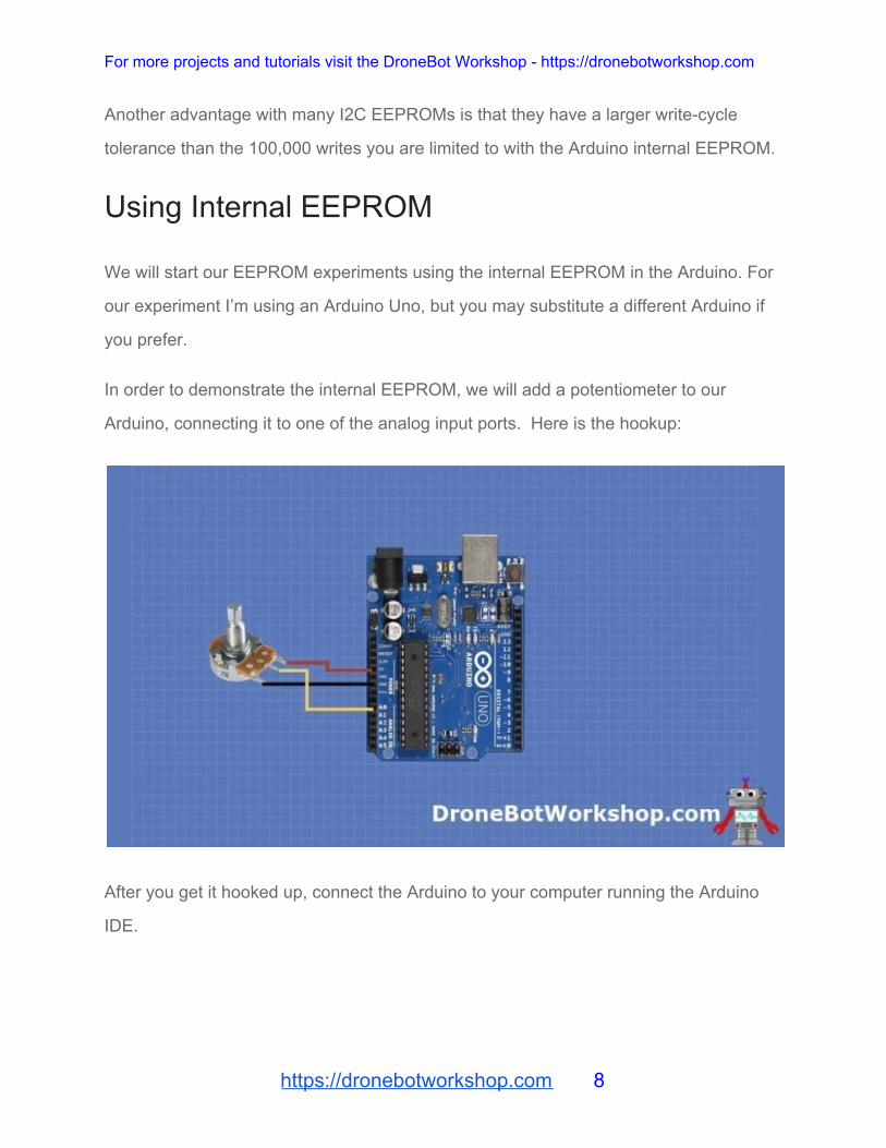
In order to demonstrate the internal EEPROM, we will add a potentiometer to our
Arduino, connecting it to one of the analog input ports. Here is the hookup:
After you get it hooked up, connect the Arduino to your computer running the Arduino
IDE.
https://dronebotworkshop.com 8
For more projects and tutorials visit the DroneBot Workshop - https://dronebotworkshop.com
Arduino EEPROM Library
Our experiments will be greatly simplified by using the Arduino EEPROM Library, which
is already included in the Arduino IDE.
The library comes with a number of short example sketches. We can use them to
experiment with the Arduino’s internal EEPROM. Note that the library only works with
the internal EEPROM, to use an external device will require a different library.
In order to use the example programs in the Arduino IDE go through the following steps:
● Start the Arduino IDE. ● Click on the File menu on the top of the screen. ● Select Examples. A sub-menu will appear. ● Select EEPROM. An additional sub-menu will appear. ● You may select an example from the sub-menu.
There are eight examples included with the library, and the code within them will assist
you in writing your own code for working with the Arduino built-in EEPROM. Here are a
few you can try:
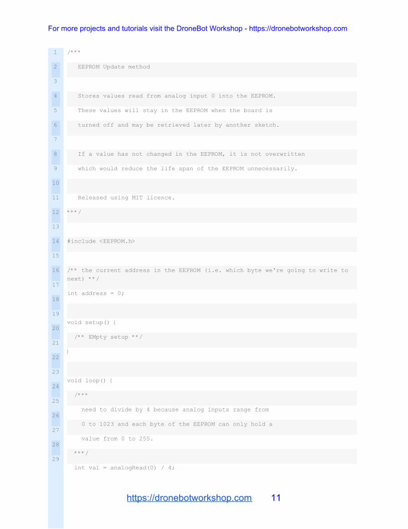
EEPROM Update
Although there is an EEPROM Write sketch, using the update method is a better choice
when writing data to the EEPROM. This is because this method reads the EEPROM
value first, and then only updates it if it is different, in fact it’s simply a combination of
both the Read and Write method.
https://dronebotworkshop.com 9

For more projects and tutorials visit the DroneBot Workshop - https://dronebotworkshop.com
By doing this the number of writes to the EEPROM are reduced, and considering that
the Arduino EEPROM has a write cycle life of 100,000 operations that is a good thing to
do.
This technique is often referred to as “wear levelling”.
https://dronebotworkshop.com 10
For more projects and tutorials visit the DroneBot Workshop - https://dronebotworkshop.com
1
2
3
4
5
6
7
8
9
10
11
12
13
14
15
16
17
18
19
20
21
22
23
24
25
26
27
28
29
/***
EEPROM Update method
Stores values read from analog input 0 into the EEPROM.
These values will stay in the EEPROM when the board is
turned off and may be retrieved later by another sketch.
If a value has not changed in the EEPROM, it is not overwritten
which would reduce the life span of the EEPROM unnecessarily.
Released using MIT licence.
***/
#include <EEPROM.h>
/** the current address in the EEPROM (i.e. which byte we're going to write to
next) **/
int address = 0;
void setup() {
/** EMpty setup **/
}
void loop() {
/***
need to divide by 4 because analog inputs range from
0 to 1023 and each byte of the EEPROM can only hold a
value from 0 to 255.
***/
int val = analogRead(0) / 4;
https://dronebotworkshop.com 11
For more projects and tutorials visit the DroneBot Workshop - https://dronebotworkshop.com
30
31
32
33
34
35
36
37
38
39
40
41
42
43
44
45
46
47
48
49
50
51
52
53
54
55
56
57
58
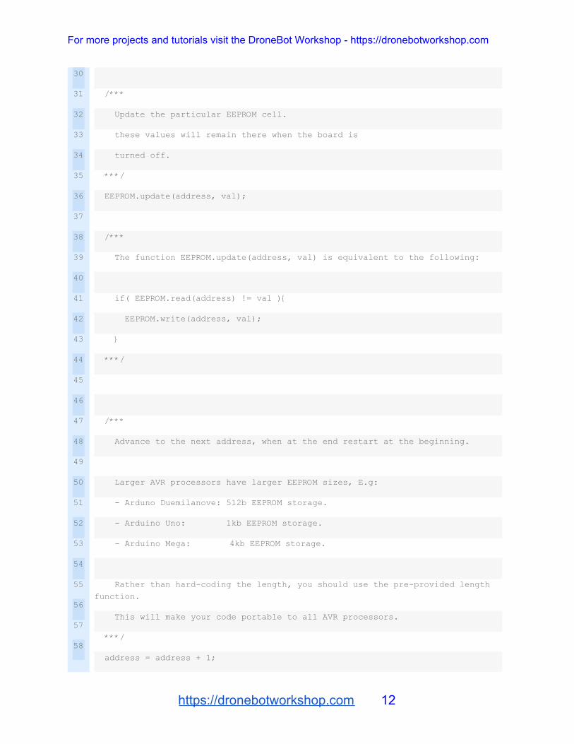
/***
Update the particular EEPROM cell.
these values will remain there when the board is
turned off.
***/
EEPROM.update(address, val);
/***
The function EEPROM.update(address, val) is equivalent to the following:
if( EEPROM.read(address) != val ){
EEPROM.write(address, val);
}
***/
/***
Advance to the next address, when at the end restart at the beginning.
Larger AVR processors have larger EEPROM sizes, E.g:
- Arduno Duemilanove: 512b EEPROM storage.
- Arduino Uno: 1kb EEPROM storage.
- Arduino Mega: 4kb EEPROM storage.
Rather than hard-coding the length, you should use the pre-provided length
function.
This will make your code portable to all AVR processors.
***/
address = address + 1;
https://dronebotworkshop.com 12
For more projects and tutorials visit the DroneBot Workshop - https://dronebotworkshop.com
59
60
61
62
63
64
65
66
67
68
69
70
71
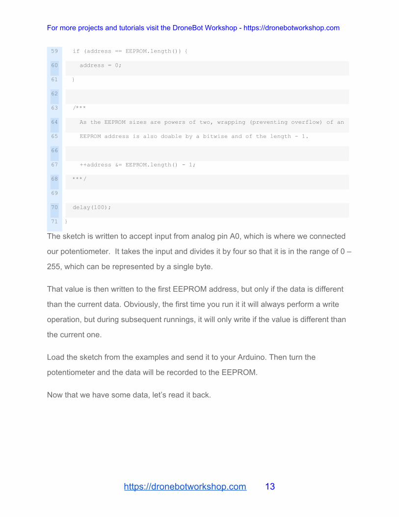
if (address == EEPROM.length()) {
address = 0;
}
/***
As the EEPROM sizes are powers of two, wrapping (preventing overflow) of an
EEPROM address is also doable by a bitwise and of the length - 1.
++address &= EEPROM.length() - 1;
***/
delay(100);
}
The sketch is written to accept input from analog pin A0, which is where we connected
our potentiometer. It takes the input and divides it by four so that it is in the range of 0 –
255, which can be represented by a single byte.
That value is then written to the first EEPROM address, but only if the data is different
than the current data. Obviously, the first time you run it it will always perform a write
operation, but during subsequent runnings, it will only write if the value is different than
the current one.
Load the sketch from the examples and send it to your Arduino. Then turn the
potentiometer and the data will be recorded to the EEPROM.
Now that we have some data, let’s read it back.
https://dronebotworkshop.com 13

For more projects and tutorials visit the DroneBot Workshop - https://dronebotworkshop.com
EEPROM Read
From its name, I believe you can guess what this sketch does!
https://dronebotworkshop.com 14

For more projects and tutorials visit the DroneBot Workshop - https://dronebotworkshop.com
1
2
3
4
5
6
7
8
9
10
11
12
13
14
15
16
17
18
19
20
21
22
23
24
25
26
27
28
29
/*
* EEPROM Read
*
* Reads the value of each byte of the EEPROM and prints it
* to the computer.
* This example code is in the public domain.
*/
#include <EEPROM.h>
// start reading from the first byte (address 0) of the EEPROM
int address = 0;
byte value;
void setup() {
// initialize serial and wait for port to open:
Serial.begin(9600);
while (!Serial) {
; // wait for serial port to connect. Needed for native USB port only
}
}
void loop() {
// read a byte from the current address of the EEPROM
value = EEPROM.read(address);
Serial.print(address);
Serial.print("\t");
Serial.print(value, DEC);
https://dronebotworkshop.com 15
For more projects and tutorials visit the DroneBot Workshop - https://dronebotworkshop.com
30
31
32
33
34
35
36
37
38
39
40
41
42
43
44
45
46
47
48
49
50
51
52
53
54
55
56
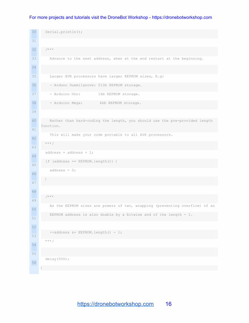
Serial.println();
/***
Advance to the next address, when at the end restart at the beginning.
Larger AVR processors have larger EEPROM sizes, E.g:
- Arduno Duemilanove: 512b EEPROM storage.
- Arduino Uno: 1kb EEPROM storage.
- Arduino Mega: 4kb EEPROM storage.
Rather than hard-coding the length, you should use the pre-provided length
function.
This will make your code portable to all AVR processors.
***/
address = address + 1;
if (address == EEPROM.length()) {
address = 0;
}
/***
As the EEPROM sizes are powers of two, wrapping (preventing overflow) of an
EEPROM address is also doable by a bitwise and of the length - 1.
++address &= EEPROM.length() - 1;
***/
delay(500);
}
https://dronebotworkshop.com 16

For more projects and tutorials visit the DroneBot Workshop - https://dronebotworkshop.com
The sketch simply reads the EEPROM and prints the data to the serial monitor. So if
you were to run it after the previous sketch you should see the values created by the
potentiometer movements.
The sketch uses a tab character (“\t”) to format the display nicely, show you both the
address and data value of each EEPROM location.
https://dronebotworkshop.com 17
For more projects and tutorials visit the DroneBot Workshop - https://dronebotworkshop.com
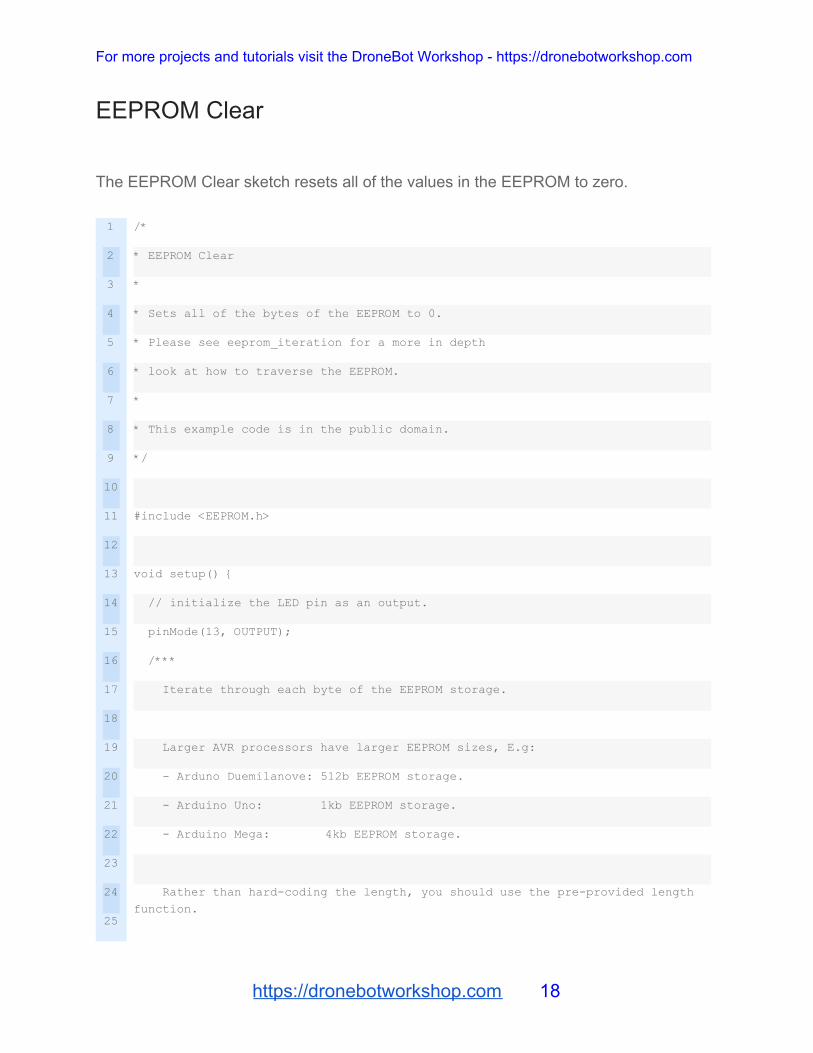
EEPROM Clear
The EEPROM Clear sketch resets all of the values in the EEPROM to zero.
1
2
3
4
5
6
7
8
9
10
11
12
13
14
15
16
17
18
19
20
21
22
23
24
25
/*
* EEPROM Clear
*
* Sets all of the bytes of the EEPROM to 0.
* Please see eeprom_iteration for a more in depth
* look at how to traverse the EEPROM.
*
* This example code is in the public domain.
*/
#include <EEPROM.h>
void setup() {
// initialize the LED pin as an output.
pinMode(13, OUTPUT);
/***
Iterate through each byte of the EEPROM storage.
Larger AVR processors have larger EEPROM sizes, E.g:
- Arduno Duemilanove: 512b EEPROM storage.
- Arduino Uno: 1kb EEPROM storage.
- Arduino Mega: 4kb EEPROM storage.
Rather than hard-coding the length, you should use the pre-provided length
function.
https://dronebotworkshop.com 18
For more projects and tutorials visit the DroneBot Workshop - https://dronebotworkshop.com
26
27
28
29
30
31
32
33
34
35
36
37
38
39
This will make your code portable to all AVR processors.
***/
for (int i = 0 ; i < EEPROM.length() ; i++) {
EEPROM.write(i, 0);
}
// turn the LED on when we're done
digitalWrite(13, HIGH);
}
void loop() {
/** Empty loop. **/
}
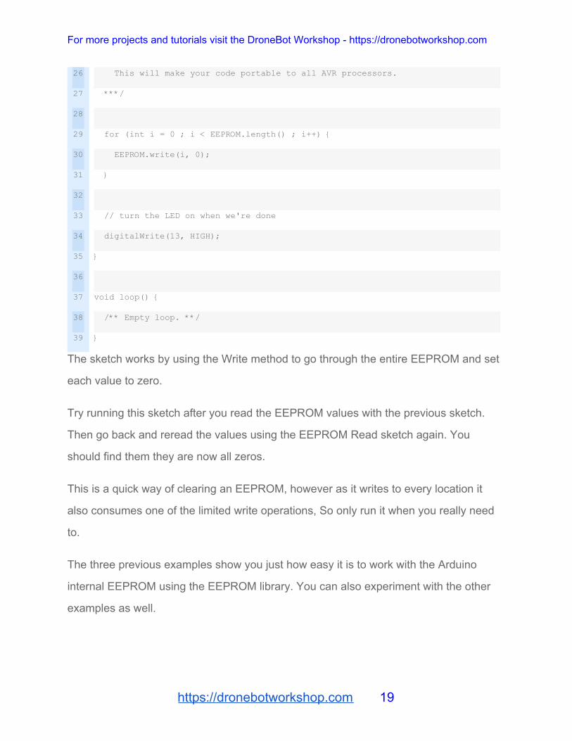
The sketch works by using the Write method to go through the entire EEPROM and set
each value to zero.
Try running this sketch after you read the EEPROM values with the previous sketch.
Then go back and reread the values using the EEPROM Read sketch again. You
should find them they are now all zeros.
This is a quick way of clearing an EEPROM, however as it writes to every location it
also consumes one of the limited write operations, So only run it when you really need
to.
The three previous examples show you just how easy it is to work with the Arduino
internal EEPROM using the EEPROM library. You can also experiment with the other
examples as well.
https://dronebotworkshop.com 19
For more projects and tutorials visit the DroneBot Workshop - https://dronebotworkshop.com
Using External EEPROM
If the limited amount of nonvolatile storage in the Arduino is insufficient for your
application then you can add an external EEPROM. Using an I2C device simplifies both
the wiring and code.
AT24LC256 EEPROM
The AT24LC256 is a 256 Kilobit EEPROM. As there are eight bits in a byte this
translates to 32 Kb of nonvolatile memory.
This I2C EEPROM has three I2C address lines, allowing you to select from one of eight
possible addresses. So you can add more AT24LC256 chips to your design if you need
more storage space.
The device, which is also branded “AT24C256” (the “L” is for the popular low-powered
version of the chip), is capable of over 1 million write cycles, so it is more robust than
the EEPROM included in the Arduino.
https://dronebotworkshop.com 20
For more projects and tutorials visit the DroneBot Workshop - https://dronebotworkshop.com
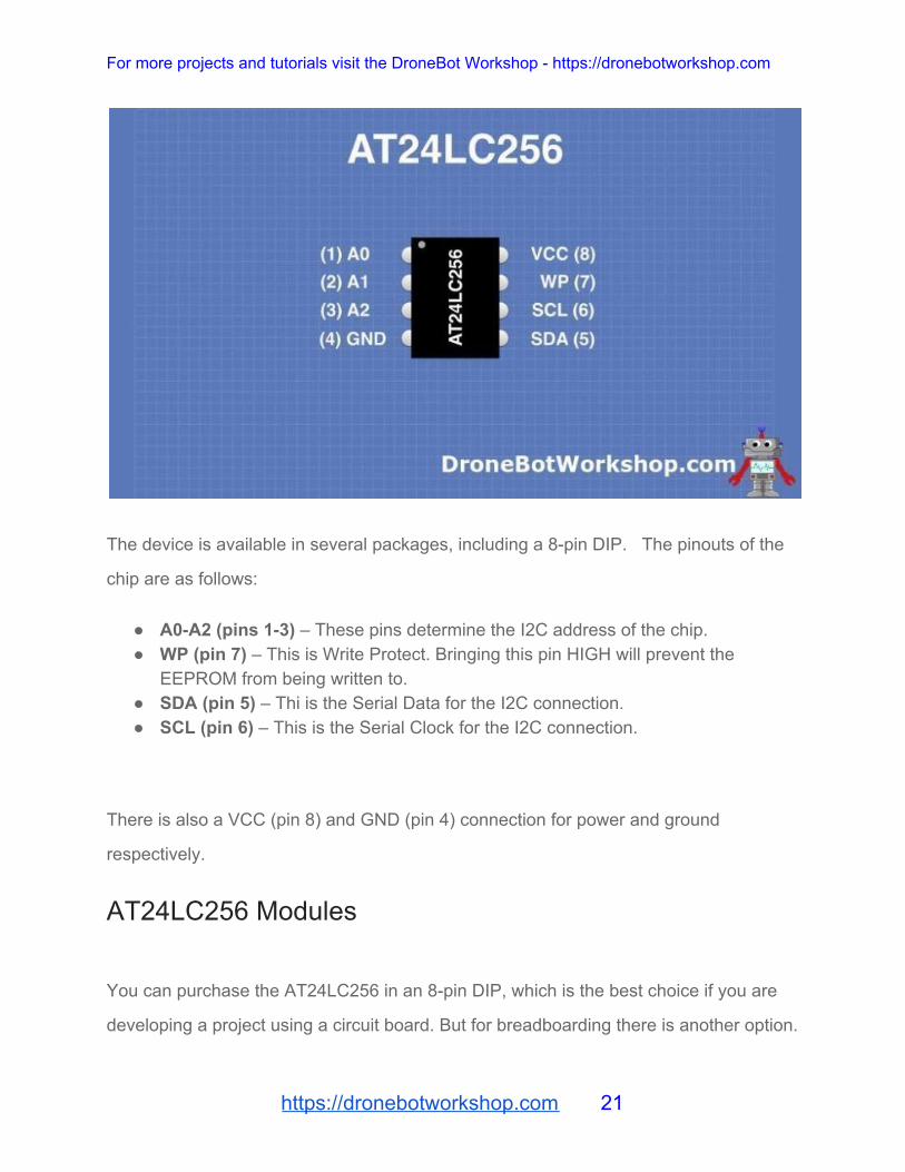
The device is available in several packages, including a 8-pin DIP. The pinouts of the
chip are as follows:
● A0-A2 (pins 1-3) – These pins determine the I2C address of the chip. ● WP (pin 7) – This is Write Protect. Bringing this pin HIGH will prevent the
EEPROM from being written to. ● SDA (pin 5) – Thi is the Serial Data for the I2C connection. ● SCL (pin 6) – This is the Serial Clock for the I2C connection.
There is also a VCC (pin 8) and GND (pin 4) connection for power and ground
respectively.
AT24LC256 Modules
You can purchase the AT24LC256 in an 8-pin DIP, which is the best choice if you are
developing a project using a circuit board. But for breadboarding there is another option.
https://dronebotworkshop.com 21
For more projects and tutorials visit the DroneBot Workshop - https://dronebotworkshop.com
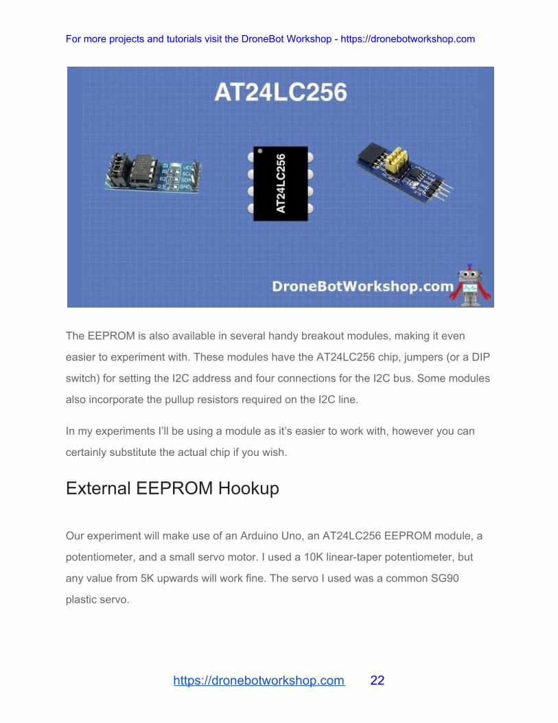
The EEPROM is also available in several handy breakout modules, making it even
easier to experiment with. These modules have the AT24LC256 chip, jumpers (or a DIP
switch) for setting the I2C address and four connections for the I2C bus. Some modules
also incorporate the pullup resistors required on the I2C line.
In my experiments I’ll be using a module as it’s easier to work with, however you can
certainly substitute the actual chip if you wish.
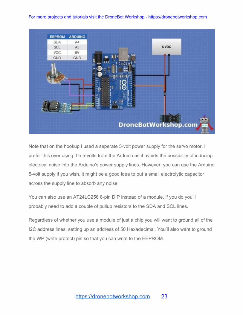
External EEPROM Hookup
Our experiment will make use of an Arduino Uno, an AT24LC256 EEPROM module, a
potentiometer, and a small servo motor. I used a 10K linear-taper potentiometer, but
any value from 5K upwards will work fine. The servo I used was a common SG90
plastic servo.
https://dronebotworkshop.com 22
For more projects and tutorials visit the DroneBot Workshop - https://dronebotworkshop.com
Note that on the hookup I used a seperate 5-volt power supply for the servo motor, I
prefer this over using the 5-volts from the Arduino as it avoids the possibility of inducing
electrical noise into the Arduino’s power supply lines. However, you can use the Arduino
5-volt supply if you wish, it might be a good idea to put a small electrolytic capacitor
across the supply line to absorb any noise.
You can also use an AT24LC256 8-pin DIP instead of a module, if you do you’ll
probably need to add a couple of pullup resistors to the SDA and SCL lines.
Regardless of whether you use a module of just a chip you will want to ground all of the
I2C address lines, setting up an address of 50 Hexadecimal. You’ll also want to ground
the WP (write protect) pin so that you can write to the EEPROM.
https://dronebotworkshop.com 23
For more projects and tutorials visit the DroneBot Workshop - https://dronebotworkshop.com
External EEPROM Arduino Code
Now that we have everything hooked up let’s look at the code.
Our sketch will record the servo movements in the EEPROM. It will do that for about a
minute and then end (you can make it longer if you wish). After that, it will wait five
seconds and then playback the movements. The serial monitor will display both the
recording and playback.
https://dronebotworkshop.com 24

For more projects and tutorials visit the DroneBot Workshop - https://dronebotworkshop.com
1
2
3
4
5
6
7
8
9
10
11
12
13
14
15
16
17
18
19
20
21
22
23
24
25
26
27
28
29
/*
External EEPROM Recording & Playback Demo
ext_eeprom_demo.ino
Uses AT24LC256 External I2C EEPROM
DroneBot Workshop 2019
https://dronebotworkshop.com
*/
// Include the I2C Wire Library
#include "Wire.h"
// Include the Servo Library
#include "Servo.h"
// EEPROM I2C Address
#define EEPROM_I2C_ADDRESS 0x50
// Analog pin for potentiometer
int analogPin = 0;
// Integer to hold potentiometer value
int val = 0;
// Byte to hold data read from EEPROM
int readVal = 0;
// Integer to hold number of addresses to fill
int maxaddress = 1500;
https://dronebotworkshop.com 25
For more projects and tutorials visit the DroneBot Workshop - https://dronebotworkshop.com
30
31
32
33
34
35
36
37
38
39
40
41
42
43
44
45
46
47
48
49
50
51
52
53
54
55
56
57
58
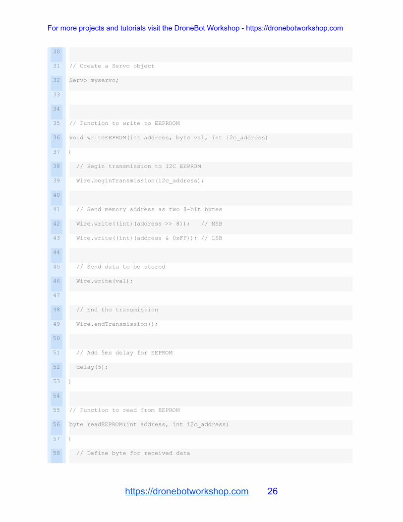
// Create a Servo object
Servo myservo;
// Function to write to EEPROOM
void writeEEPROM(int address, byte val, int i2c_address)
{
// Begin transmission to I2C EEPROM
Wire.beginTransmission(i2c_address);
// Send memory address as two 8-bit bytes
Wire.write((int)(address >> 8)); // MSB
Wire.write((int)(address & 0xFF)); // LSB
// Send data to be stored
Wire.write(val);
// End the transmission
Wire.endTransmission();
// Add 5ms delay for EEPROM
delay(5);
}
// Function to read from EEPROM
byte readEEPROM(int address, int i2c_address)
{
// Define byte for received data
https://dronebotworkshop.com 26

For more projects and tutorials visit the DroneBot Workshop - https://dronebotworkshop.com
59
60
61
62
63
64
65
66
67
68
69
70
71
72
73
74
75
76
77
78
79
80
81
82
83
84
85
86
87
byte rcvData = 0xFF;
// Begin transmission to I2C EEPROM
Wire.beginTransmission(i2c_address);
// Send memory address as two 8-bit bytes
Wire.write((int)(address >> 8)); // MSB
Wire.write((int)(address & 0xFF)); // LSB
// End the transmission
Wire.endTransmission();
// Request one byte of data at current memory address
Wire.requestFrom(i2c_address, 1);
// Read the data and assign to variable
rcvData = Wire.read();
// Return the data as function output
return rcvData;
}
void setup()
{
// Connect to I2C bus as master
Wire.begin();
// Setup Serial Monitor
https://dronebotworkshop.com 27
For more projects and tutorials visit the DroneBot Workshop - https://dronebotworkshop.com
88
89
90
91
92
93
94
95
96
97
98
99
100
101
102
103
104
105
106
107
108
109
110
111
112
113
114
115
116
Serial.begin(9600);
// Attach servo on pin 9 to the servo object
myservo.attach(9);
// Print to Serial Monitor
Serial.println("Start Recording...");
// Run until maximum address is reached
for (int address = 0; address <= maxaddress; address++) {
// Read pot and map to range of 0-180 for servo
val = map(analogRead(analogPin), 0, 1023, 0, 180);
// Write to the servo
// Delay to allow servo to settle in position
myservo.write(val);
delay(15);
// Record the position in the external EEPROM
writeEEPROM(address, val, EEPROM_I2C_ADDRESS);
// Print to Serial Monitor
Serial.print("ADDR = ");
Serial.print(address);
Serial.print("\t");
Serial.println(val);
https://dronebotworkshop.com 28

For more projects and tutorials visit the DroneBot Workshop - https://dronebotworkshop.com
117
118
119
120
121
122
123
124
125
126
127
128
129
130
131
132
133
134
135
136
137
138
139
140
141
142
143
144
145
}
// Print to Serial Monitor
Serial.println("Recording Finished!");
// Delay 5 Seconds
delay(5000);
// Print to Serial Monitor
Serial.println("Begin Playback...");
// Run until maximum address is reached
for (int address = 0; address <= maxaddress; address++) {
// Read value from EEPROM
readVal = readEEPROM(address, EEPROM_I2C_ADDRESS);
// Write to the servo
// Delay to allow servo to settle in position
// Convert value to integer for servo
myservo.write(readVal);
delay(15);
// Print to Serial Monitor
Serial.print("ADDR = ");
Serial.print(address);
Serial.print("\t");
https://dronebotworkshop.com 29
For more projects and tutorials visit the DroneBot Workshop - https://dronebotworkshop.com
146
147
148
149
150
151
152
153
154
155
156
157
158
159
160
Serial.println(readVal);
}
// Print to Serial Monitor
Serial.println("Playback Finished!");
}
void loop()
{
// Nothing in loop
}
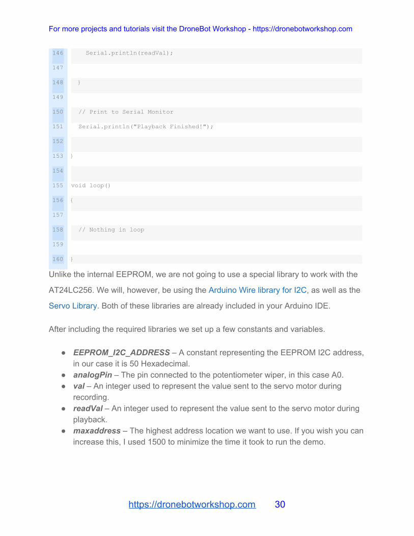
Unlike the internal EEPROM, we are not going to use a special library to work with the
AT24LC256. We will, however, be using the Arduino Wire library for I2C, as well as the
Servo Library. Both of these libraries are already included in your Arduino IDE.
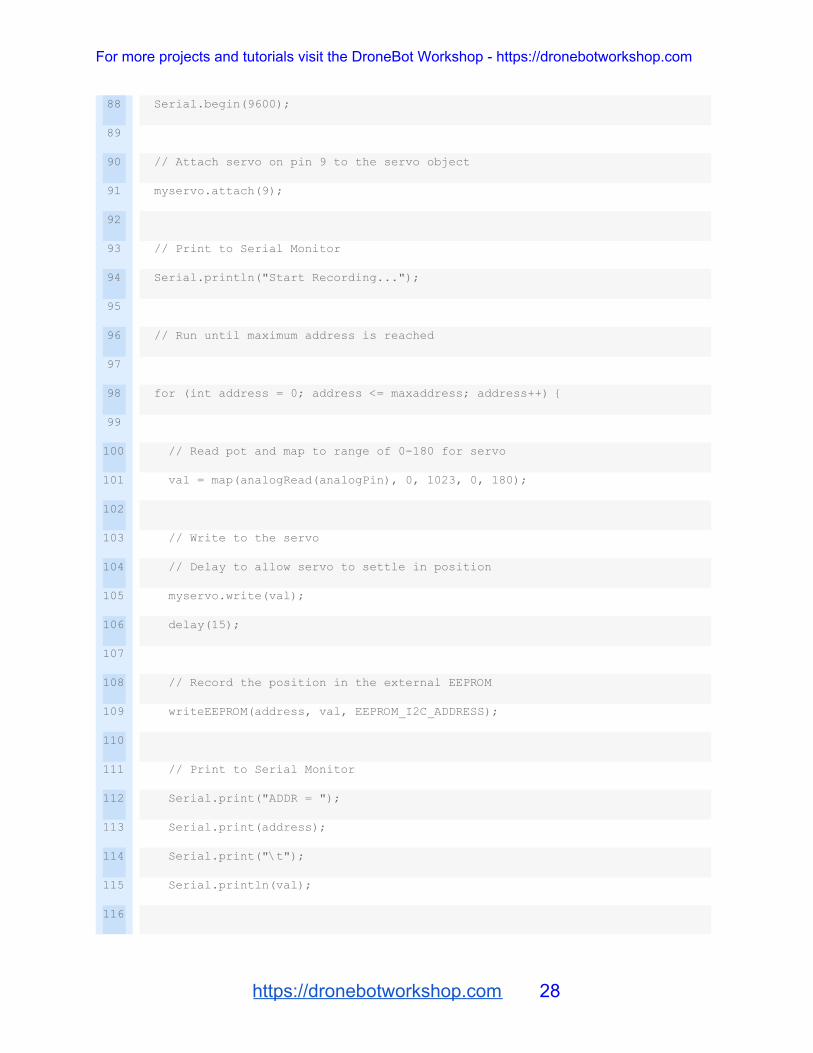
After including the required libraries we set up a few constants and variables.
● EEPROM_I2C_ADDRESS – A constant representing the EEPROM I2C address, in our case it is 50 Hexadecimal.
● analogPin – The pin connected to the potentiometer wiper, in this case A0. ● val – An integer used to represent the value sent to the servo motor during
recording. ● readVal – An integer used to represent the value sent to the servo motor during
playback. ● maxaddress – The highest address location we want to use. If you wish you can
increase this, I used 1500 to minimize the time it took to run the demo.
https://dronebotworkshop.com 30

For more projects and tutorials visit the DroneBot Workshop - https://dronebotworkshop.com
We then create a servo object called myservo to represent the motor.
Next, we define two functions, writeEEPROM and readEEPROM, which perform our
EEPROM writing and reading respectively.
The writeEEPROM function takes the memory address, the data you wish to write to
that address and the EEPROM I2C address as inputs. It then connects to the EEPROM
and passes the memory address as two independent bytes. This is because the I2C
bus only allows you to transfer one address byte at a time.
Next, we place the value we wish to record onto the I2C bus. After that, we end the
transmission.
I’ve also added a 5ms delay after writing, as the EEPROM requires this between writes.
The readEEPROM function takes the memory address and I2C address as inputs. It
then connects to the I2C bus, passes the address information and ends the
transmission. This causes the EEPROM to place the data at the specified address into
its output buffer, ready to be read by the host. We read that value and then output it to
end the function.
The setup is where we put everything together.
We start by connecting to the I2C bus as master, setting up the serial monitor and
attaching to the servo motor on pin 9.
After printing to the serial monitor we go into a for-next loop, cycling through all of the
addresses. On each address we capture the value from the analog port that the
potentiometer is attached to and convert it to a value from 0-180 for our servo motor.
We write to the servo and allow a 15ms delay for it to settle into position. Then we write
the value to the EEPROM and print it to the serial monitor.
https://dronebotworkshop.com 31
For more projects and tutorials visit the DroneBot Workshop - https://dronebotworkshop.com
After cycling through the addresses we print to the serial monitor again and wait five
seconds.
Then we run through the addresses again. This time we read every value and write it to
both the serial monitor and servo motor. Once again we provide a delay for the servo.
Finally, we print to the serial monitor and end the setup.
As all of the “action” takes place in the Setup routine there is nothing to do in the loop.
Running the External EEPROM Sketch
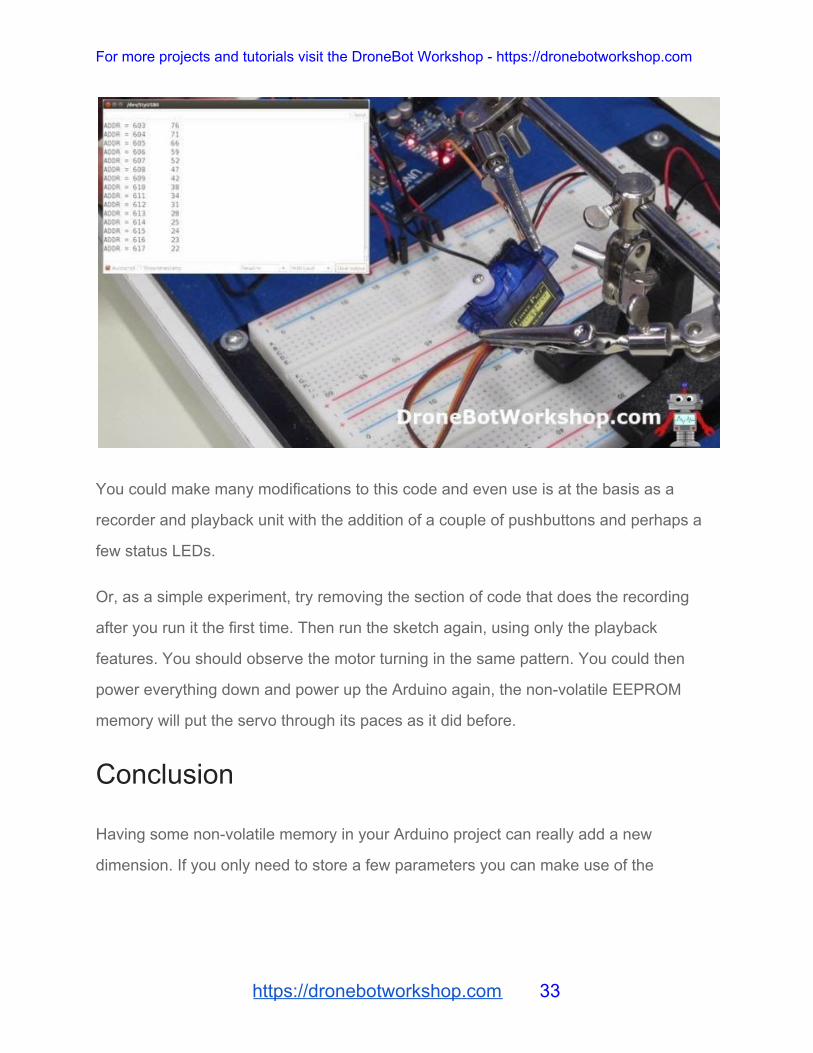
Load the sketch to your Arduino and start turning the potentiometer. You should
observe the servo turning accordingly, as well as the data being displayed on the serial
monitor.
After about a minute the recording will end. Following a 5-second delay, the motor will
start moving on its own, in the same pattern you recorded.
https://dronebotworkshop.com 32
For more projects and tutorials visit the DroneBot Workshop - https://dronebotworkshop.com
You could make many modifications to this code and even use is at the basis as a
recorder and playback unit with the addition of a couple of pushbuttons and perhaps a
few status LEDs.
Or, as a simple experiment, try removing the section of code that does the recording
after you run it the first time. Then run the sketch again, using only the playback
features. You should observe the motor turning in the same pattern. You could then
power everything down and power up the Arduino again, the non-volatile EEPROM
memory will put the servo through its paces as it did before.
Conclusion
Having some non-volatile memory in your Arduino project can really add a new
dimension. If you only need to store a few parameters you can make use of the
https://dronebotworkshop.com 33

For more projects and tutorials visit the DroneBot Workshop - https://dronebotworkshop.com
Arduinos internal EEPROM. And for large memory requirements, you can use external
EEPROM.
Just remember the limitations of EEPROM, don’t write to it too often and you’ll soon
have an Arduino that is like an elephant – it never forgets!
https://dronebotworkshop.com 34
Copyright © 2022 FDOKUMEN

