


Bahasa
Halaman
Hukum


07INDIVIDUALCATALOG
EARTHLEAKAGECIRCUITBREAKERS
SG series Motor-operated breakers
EG series Protective relaysBRR, RRD, EL
HG series
4-poleSG and EG series
Handle-operated type LOWVOLTAGE
EQUIPMENTUp to 600 Volts
from D&C CATALOG 19th EditionRevised

LOW VOLTAGE PRODUCTS Up to 600 VoltsIndividualcatalog No.
01 Magnetic Contactors and StartersThermal Overload Relays, Solid-state Contactors
02
Industrial Relays, Industrial Control RelaysAnnunciator Relay Unit, Time Delay RelaysElectronic Counters
DUO seriesManual Motor Starters and Contactors Combination Starters
Pushbuttons, Selector Switches, Pilot Lights
AS-Interface, Limit SwitchesProximity SwitchesPhotoelectric Switches
Rotary Switches, Cam Type Selector SwitchesPanel Switches, Terminal Blocks, Testing Terminals
Molded Case Circuit Breakers
Earth Leakage Circuit BreakersEarth Leakage Protective Relays
Circuit Protectors
Measuring Instruments, Arresters, TransducersPower Factor ControllersPower Monitoring Equipment (F-MPC)
Low Voltage Current-Limiting FusesAir Circuit Breakers
03
04
05
06
07
08
09
10
HIGH VOLTAGE PRODUCTS Up to 36kV
11Disconnecting Switches, Power FusesAir Load Break SwitchesInstrument Transformers — VT, CT
D & C CATALOG DIGEST INDEX
AC Power RegulatorsNoise Suppression FiltersControl Power Transformers
Vacuum Circuit Breakers, Vacuum Magnetic Contactors12 Protective Relays

07 Earth Leakage Circuit BreakersEarth Leakage Protective Relays
Page
Earth Leakage Circuit Breakers General information............................................................................................ 07/1Design features .................................................................................................. 07/4Breaking capacities ............................................................................................ 07/7Quick reference guide
Line protectionSG series .................................................................................................. 07/9EG series ................................................................................................ 07/14HG series ................................................................................................ 07/19
Motor protectionSG series ................................................................................................ 07/21EG series ................................................................................................ 07/23
UL Listed ...................................................................................................... 07/24Mounting modifications .................................................................................... 07/30Terminal connections ....................................................................................... 07/31Wire size and terminal ..................................................................................... 07/32Type number nomenclature ............................................................................. 07/34Type number
Line protectionSG series ................................................................................................ 07/36EG series ................................................................................................ 07/38HG series ................................................................................................ 07/41
Motor protectionSG series ................................................................................................ 07/42EG series ................................................................................................ 07/43
UL Listed ...................................................................................................... 07/44Dimensions ....................................................................................................... 07/45Characteristic curves ....................................................................................... 07/56Accessories ...................................................................................................... 07/68
Internal accessories..................................................................................... 07/70Motor-operated breakers ............................................................................. 07/85Mechanical interlocking device ................................................................... 07/88Operating handles ....................................................................................... 07/91Steel enclosures ........................................................................................ 07/103Terminal covers ......................................................................................... 07/105Insulation barriers ...................................................................................... 07/106Mounting modification kits ......................................................................... 07/107Padlocking device...................................................................................... 07/108
Application guide ............................................................................................ 07/120CCC approved................................................................................................ 07/122
Earth Leakage Protective Relays Selection guide ............................................................................................... 07/109Specifications
BRR type ................................................................................................... 07/111RRD type ................................................................................................... 07/112EL type ....................................................................................................... 07/114
Dimensions ..................................................................................................... 07/116

MINIMUM ORDERS
Orders amounting to less than ¥10,000 net per order willbe charged as ¥10,000 net per order plus freight andother charges.
WEIGHTS AND DIMENSIONS
Weights and dimensions appearing in this catalog are thebest information available at the time of going to press.FUJI ELECTRIC FA has a policy of continuous productimprovement, and design changes may make thisinformation out of date.Please confirm such details before planning actualconstruction.
INFORMATION IN THIS CATALOG IS SUBJECT TO
CHANGE WITHOUT NOTICE.
Fuji Electric FA Components & Systems Co., Ltd./D & C CatalogInformation subject to change without notice 07/1
07
Earth Leakage Circuit BreakersGeneral information
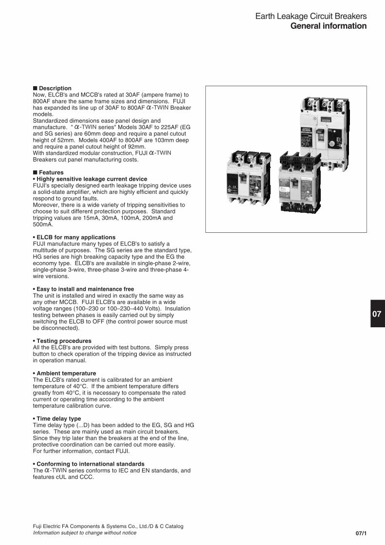
� DescriptionNow, ELCB's and MCCB's rated at 30AF (ampere frame) to800AF share the same frame sizes and dimensions. FUJIhas expanded its line up of 30AF to 800AF Breakermodels.Standardized dimensions ease panel design andmanufacture. " series" Models 30AF to 225AF (EGand SG series) are 60mm deep and require a panel cutoutheight of 52mm. Models 400AF to 800AF are 103mm deepand require a panel cutout height of 92mm.With standardized modular construction, FUJI Breakers cut panel manufacturing costs.
� Features• Highly sensitive leakage current deviceFUJI's specially designed earth leakage tripping device usesa solid-state amplifier, which are highly efficient and quicklyrespond to ground faults.Moreover, there is a wide variety of tripping sensitivities tochoose to suit different protection purposes. Standardtripping values are 15mA, 30mA, 100mA, 200mA and500mA.
• ELCB for many applicationsFUJI manufacture many types of ELCB's to satisfy amultitude of purposes. The SG series are the standard type,HG series are high breaking capacity type and the EG theeconomy type. ELCB's are available in single-phase 2-wire,single-phase 3-wire, three-phase 3-wire and three-phase 4-wire versions.
• Easy to install and maintenance freeThe unit is installed and wired in exactly the same way asany other MCCB. FUJI ELCB's are available in a widevoltage ranges (100–230 or 100–230–440 Volts). Insulationtesting between phases is easily carried out by simplyswitching the ELCB to OFF (the control power source mustbe disconnected).
• Testing proceduresAll the ELCB's are provided with test buttons. Simply pressbutton to check operation of the tripping device as instructedin operation manual.
• Ambient temperatureThe ELCB's rated current is calibrated for an ambienttemperature of 40°C. If the ambient temperature differsgreatly from 40°C, it is necessary to compensate the ratedcurrent or operating time according to the ambienttemperature calibration curve.
• Time delay typeTime delay type (...D) has been added to the EG, SG and HGseries. These are mainly used as main circuit breakers.Since they trip later than the breakers at the end of the line,protective coordination can be carried out more easily.For further information, contact FUJI.
• Conforming to international standardsThe series conforms to IEC and EN standards, andfeatures cUL and CCC.

Fuji Electric FA Components & Systems Co., Ltd./D & C CatalogInformation subject to change without notice07/2
Earth Leakage Circuit BreakersGeneral information
Circuit breaker
Earthleakagerelay unit
Amplifier
Sensor
Testbutton
R
T.C
� Variety of ELCB'sChoose from a wide variety ofmodels—from economical to high-performance.Three series of Breakersensure the best choice for theapplication: the economical E series,the standard S series, and the high-performance, high-breaking capacity Hseries. The E series line-up ofcompact, economical ELCB is best forcircuits with relatively low short-circuitcurrents. The S series new andunique current-liminting mechanismprovides a surprisingly high breakingcapacity for a compact breaker. The Hseries features an excellent current-limiting mechanism and an enhancedmethod of arc-extinguishing to achievea higher breaking capacity than the Eand S series.
SG, EG and HG seriesThe SG, EG and HG series haveelectric device provided with ICs andcan be applied to a wide variety ofvoltages. The 2-pole breakers can beused within the range of rated voltageof 100–230 volts and the 3-polebreakers within the range of 100–230–440 volts. The SG and EG areavailable with ratings between 30AFand 800AF.The HG series are available withratings between 50AF and 800AF.SG series of over 30AF, HG and EGseries of over 50AF are also availablein the sensitive current changeovertype.
SG series – 3-phase 4-wireThe SG series 4-pole ELCB is astandard 3-pole ELCB to which afourth neutral pole has been added.It has been designed for 3-phase 4-wire power systems. 100A, 225A and400A frame sizes are available.SG104H and SG204H have a highbreaking capacity of 85kA at 200V AC.They are ideally suited for mainbreakers in distribution circuits. Theearth leakage tripping device is a solid-state type. The breaker is so designedthat the neutral pole makes the firstcontact on closing, and the last breakwhen opening so reducing thepossibility of incorrect or carelessoperation.
Motor protection ELCBFUJI ELCB's are designed to eliminateerroneous operations due to the rushcurrent produced at the time of startingthe motor. They will trip in the face ofsustained overcurrent when theintegrated bimetal relay has operated.
� Wiring diagram (skelton)
� ModificationsMounting modificationsFUJI SG, EG and HG series ELCB'sare normally supplied as frontmounting front connection type.However, they are also available eitheras X-type (front mounting rearconnection), E-type (flush mounting) orP-type (plug-in mounting).
Accessories-modificationsFUJI ELCB's can be supplied withaccessories such as alarm switch,auxiliary switch or shunt trip device,which are customer-mountable orfactory-mounted.For details see page 07/68.
CE markingLine protectionSG series
Standard
EG series
Economical
Motor protectionSG, EG series
Standard, economical
UL approvedUL489 approved line protectionSG-UL series EG-UL series
Fuji Electric FA Components & Systems Co., Ltd./D & C CatalogInformation subject to change without notice 07/3
07
Earth Leakage Circuit BreakersGeneral information
Note: Type number with " -CE" indicates the IEC and CE marking conformed model,but type number without " -CE" indicates also the same.
Series
SG
EG
HG
SG
EG
Pole
3
3
2
3
3
3
4
4
Standard
IEC 60947-2JIS C8201-2
JIS C8371
IEC 60947-2JIS C8201-2
JIS C8371
JIS C8371
Ampere frame
30
SG33C -CE
EG32AC -CE
EG33AC -CEEG33C -CE
50
SG53C -CESG53RC -CE
EG52AC -CE
EG53AC -CEEG53C -CE
HG53B
60
SG63C -CESG63RC -CE
EG63C -CE
100
SG103C -CESG103RC -CE
EG102C -CE
EG103AC -CEEG103C -CE
HG103B
SGa104ASG104H
EG104A
225
SG203C -CESG203RC -CE
EG203C -CE
HG203B
SGa204ASG204H
400
SG403C -CE
SG403RC
EG403C -CE
HG403B
SGa404A
600
SG603RC
EG603C
HG603B
800
SG803RC
EG803C
HG803B
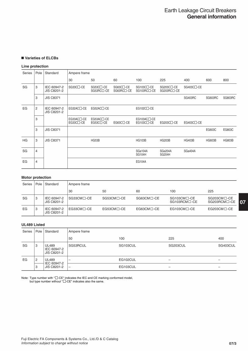
Varieties of ELCBs
Line protection
Series
SG
EG
Pole
3
3
Standard
IEC 60947-2JIS C8201-2
IEC 60947-2JIS C8201-2
Ampere frame
30
SG33CM -CE
EG33CM -CE
50
SG53CM -CE
EG53CM -CE
60
SG63CM -CE
EG63CM -CE
100
SG103CM -CESG103RCM -CE
EG103CM -CE
225
SG203CM -CESG203RCM -CE
EG203CM -CE
Motor protection
Series
SG
EG
Pole
3
2
3
Standard
UL489IEC 60947-2JIS C8201-2
UL489IEC 60947-2JIS C8201-2
Ampere frame
50
SG53RCUL
–
–
225
SG203CUL
–
–
400
SG403CUL
–
–
100
SG103CUL
EG102CUL
EG103CUL
UL489 Listed

Fuji Electric FA Components & Systems Co., Ltd./D & C CatalogInformation subject to change without notice07/4
Panel cutout52, 92mm
Terminalheight24mm(Up to 225AF)
Depth60, 103mm
Earth Leakage Circuit BreakersDesign features
MCCB ELCB Earth leakagedetector
Earth leakagedetector
Miniaturization, size unification
ZCT
Feed through primaryconductor
Insulation tube
10 mm
Base
Earth-leakage tripindicator
Earth-leakage tripcoil
Connector
Armature
Trip spring
Test circuit contact
� DescriptionToday's industries have introducedadvanced information systems andautomated systems to increaseefficiency.These systems rely on a stable supplyof electrical power. The reliability,operational ease, and costeffectiveness of these power suppliesmust improved. Earth leakage circuitbreakers must also be more compactwith improved reliability. They need tobe economical to reduce the overalldistribution panel cost.The new FUJI ELCB has beendeveloped to meet these expectationsand requirements. Now, for the firsttime, FUJI ELCB and MCCB of thesame rating are the same size, a long-awaited development in themanufacture of low-voltage distributionboard.
� Features• Standardized ELCB and MCCB
outline dimensionsFUJI breakers featurecompact and modular construction.The ELCB's and MCCB's of the samerating, from 30AF to 800AF, are thesame size.
• Standardized modular constructionHaving circuit breakers of the samebasic dimensions promote modulardesigns. New ELCB's areavailable in two standard depths: 60and 103mm, choose it from two frontpanel cutout height of 52mm or 92mm.The center of the window frame ispositioned at the center of the circuitbreaker. These design featuresenable a radical reduction in thenumber of mounting patterns.
• Ultra-small leakage detector andtrip unit
The leakage detector is equipped witha new, thin, high-performance ZCTwith uniform magnetic characteristics.The new ZCT allows a compactleakage detector with stable balancingcharacteristics to be manufactured.
• Simple and highly reliableelectronic circuit
Very stable operation across a widevoltage range has been obtained witha highly reliable dedicated IC which isoperated with minute currents and aFUJI designed power circuit.
• Small, high-efficiency trip unitA small, highly efficient trip coil whichoperates with a small tripping currentand has a strong driving force hasbeen developed with a CAD(Computer Aided Design) basedmethod of magnetic field analysis.
• One ELCB can be used with circuitvoltages of 100–230–440V AC (high-speed type)Easy selection of ELCB and greatflexibility in meeting specificationchanges.Selection of the proper ELCB is madeeasier because of the wide voltagerange of one unit, (100–230–440V AC).Changes in specifications can also bemade more easily with such a widevoltage range.
• Three-step, sensitivity to faultcurrents (100/200/500mA)A three-step change (100/200/500mA)in the rated sensitivity to fault currentshas widened the range of application.This allows full compliance withchanges in specifications.
• Easily interchangeable ELCB andMCCBThe ELCB and MCCB allow thedesigner to quickly alter distributionpanel and facility design whenspecifications are changed.The ELCB and MCCB can be easilyreplaced by each other because theirsizes and basic specifications are thesame.
ZCTSolid-stateamplifier
Powersupplycircuit
Currentlimitingcircuit
R
T
Charging capacitor
100V/ 240V/440V circuit
Magnetic hold type trip coil

Fuji Electric FA Components & Systems Co., Ltd./D & C CatalogInformation subject to change without notice 07/5
07
Earth Leakage Circuit BreakersDesign features
The ELCB can be mechanically tripped externally.
Insulation has been strengthened by using resin to mold the main circuit conductor and ZCT into an integrated unit.
The sensitive trip mechanism operation can be checked at any time by simply pressing the test button.
A unit construction for the ELR and greater wiring efficiency has boosted connection reliability.
Accessorymounting space
Insulationmechanism
Earth leakagedetection section
Arc quencher(Larger arc-extinguishing space)
Overcurrent tripping device
Resin molded
ZCT
Conductor
When the breaker opens due to an earth leakage current the trip indication button pops out to indicate that an earth leakage has occurred.
Tripping indication button ELR unit with less wiring
Test button
Solid-state insulation ZCT
Trip button
� Construction

07/6Fuji Electric FA Components & Systems Co., Ltd./D & C Catalog
Information subject to change without notice
Earth Leakage Circuit BreakersDesign features
� Internal and external accessoriesA wider range of customer-mountable accessoriesThe range of cassette-type internalaccessories has been greatlyexpanded for ELCBs. Thisspeeds up and simplifies customerresponse to specification changes.All accessories shown here can bemounted by the customer except formotor operating mechanism and platetype padlocking device.
Wide variety of internal accessorycombinationsUp to two auxiliary switches, two alarmswitches, and one shunt trip device orundervoltage trip device quickly snapon or in.
Quick and easy mountingNo need to open breaker cover tomount accessories. Internalaccessories easily snap into a pocketat the left of the breaker window frame.
No adjustmentsAccessory mounting is quick and easy— accessories adjust automatically atthe correct position when mounted.
AF93-82 AF93-81
• Terminal block typesTerminal blocks are mounted on theside of the breaker case. Blocks areonly 12.5 or 19mm thick, minimizingpanel mounting space. Installed leadwires are parallel to the side of thecase.
Two ways to connect — lead wiresor terminal blocks• Lead wire typesLeads are marked with to indicate thecorrect terminal number of theaccessory — incorrect wiring isminimized. To make wiring easy andprevent to incorrect connection, thelead wires are provided with colorcoated tube and marking on it.
Undervoltage trip deviceShunt trip device
Auxiliary switch Terminal block
Modification kitsOperating handles
Mechanical interlockingdeviceLong type
Short type
Alarm switch
Interphase barrierEarth barrier
Steel enclosureN type V type
Handle padlocking deviceHandle locking cover
Motor operatingmechanism
Terminal covers Insulation barriers
For front mounting,rear connection
For plug-inmounting
For flush mounting,rear connection

07/7Fuji Electric FA Components & Systems Co., Ltd./D & C CatalogInformation subject to change without notice
07
Earth Leakage Circuit BreakersBreaking capacities
� Breaking capacitiesEarth leakage + Overcurrent + Short-circuit protection
Series
SG
EG
Breaker ampereframe
30
5050
6060
100100
225225
400
303030
505050
60
100100100
225
400
Breakertype
SG33C -CE
SG53C -CESG53RC -CE
SG63C -CESG63RC -CE
SG103C -CESG103RC -CE
SG203C -CESG203RC -CE
SG403C -CE
EG32AC -CEEG33AC -CEEG33C -CE
EG52AC -CEEG53AC -CEEG53C -CE
EG63C -CE
EG103AC -CEEG102C -CEEG103C -CE
EG203C -CE
EG403C -CE
Pole
3
33
33
33
33
3
233
233
3
323
3
3
Rated current
(A)
3, 5, 10, 15, 20, 30
5, 10, 15, 20, 30, 40, 5010, 15, 20, 30, 40, 50
6060
15, 20, 30, 40, 50, 60, 75, 10015, 20, 30, 40, 50, 60, 75, 100
125, 150, 175, 200, 225125, 150, 175, 200, 225
250, 300, 350, 400
5, 10, 15, 20, 305, 10, 15, 20, 305, 10, 15, 20, 30
5, 10, 15, 20, 30, 40, 505, 10, 15, 20, 30, 40, 505, 10, 15, 20, 30, 40, 50
60
60, 75, 10050, 60, 75, 10050, 60, 75, 100
125, 150, 175, 200, 225
250, 300, 350, 400
Rated voltage
(V AC)
100–440
100–440100–440
100–440100–440
100–440100–440
100–440100–440
100–440
100–230100–230100–440
100–230100–230100–440
100–440
100–230100–230100–440
100–440
100–440
Sensitive current
(mA)
30, 100/200/500
30, 100/200/50030, 100/200/500
30, 100/200/50030, 100/200/500
30, 100/200/50030, 100/200/500
30, 100/200/50030, 100/200/500
30, 100/200/500
15, 30, 10015, 30, 10015, 30, 100
15, 30, 10015, 30, 10015, 30, 100/200
15, 30, 100/200
30, 100/20030, 100/20030, 100/200/500
30, 100/200/500
30, 100/200/500
Breaking capacity (kA) (Icu/Ics)
230V
5/3
10/525/13
10/525/13
50/25100/50
50/25100/50
50/25
2.5/22.5/22.5/2
2.5/22.5/25/3
5/3
5/310/525/13
35/18
35/18
100V
5/3
10/525/13
10/525/13
50/25100/50
50/25100/50
50/25
2.5/22.5/25/3
2.5/22.5/25/3
5/3
5/310/525/13
35/18
35/18
400V
2.5/2
7.5/410/5
7.5/410/5
30/850/13
30/850/13
35/18
––1.5/1
––2.5/2
2.5/2
––10/5
18/5
25/13
440V
2.5/2
7.5/410/5
7.5/410/5
25/750/13
25/750/13
35/18
––1.5/1
––2.5/2
2.5/2
––10/5
15/4
25/13
• IEC 60947-2, JIS C8201-2 IEC and CE marking conformed

07/8Fuji Electric FA components & Systems Co., Ltd./D & C Catalog
Information subject to change without notice
Earth Leakage Circuit BreakersBreaking capacities
Note: * 3P+1N, neutral phase cannot be made or broken.
� Breaking capacitiesEarth leakage + Overcurrent + Short-circuit protection type
Series
SG
EG
HG
Breaker ampereframe
400600
800
100100
225225
400
100
600
800
50
100
225
400
600
800
Breakertype
SG403RCSG603RC
SG803RC
SGa104ASG104H
SGa204ASG204H
SGa404A
EG104A
EG603C
EG803C
HG53B
HG103B
HG203B
HG403B
HG603B
HG803B
Pole
33
3
44
44
4
*
3
3
3
3
3
3
3
3
Rated current
(A)
250, 300, 350, 400500, 600
700, 800
40, 50, 60, 75, 10050, 60, 75, 100
125, 150, 175, 200, 225125, 150, 175, 200, 225
250, 300, 350, 400
30, 40, 50, 60, 75, 100
500, 600
700, 800
15, 20, 30, 40, 50
15, 20, 30, 40, 50, 60, 75, 100
125, 150, 175, 200, 225
250, 300, 350, 400
500, 600
700, 800
Rated voltage
(V AC)
100-415100-415
100-415
200-415200-415
200-415200-415
200-415
380-415
100-415
100-415
100-415
100-415
100-415
100-415
100-415
100-415
Sensitive current
(mA)
30, 100/200/500100/200/500
100/200/500
30, 100/200/50030, 100/200/500
30, 100/200/50030, 100/200/500
30, 100/200/500
30, 100, 300, 500
100/200/500
100/200/500
30, 100/200/500
30, 100/200/500
30, 100/200/500
30, 100/200/500
100/200/500
100/200/500
Breaking capacity (kA) sym.
200V
8585
85
5085
4285
42
–
50
50
100
100
100
125
125
125
100V
8585
85
––
––
–
–
50
50
100
100
100
125
125
125
415V
5050
50
2542
2542
25
14
35
35
65
65
65
65
65
65
• JIS C8371
Breaker ampereframe
50
100100100
225
400
Breakertype
SG53RCUL
EG102CULEG103CULSG103CUL
SG203CUL
SG403CUL
Pole
3
233
3
3
Rated current
(A)
3, 5, 10, 15, 20, 30, 40, 50
60, 70, 75, 80, 90, 10060, 70, 75, 80, 90, 10032, 40, 50, 60, 75, 100
125, 150, 175, 200, 225
250, 300, 350, 400
Rated voltage
(V AC)
100–440
100–440100–440100–440
100–440
100–440
Sensitive current
(mA)
30, 100/200/500
30, 100/20030, 100/200/50030, 100/200/500
30, 100/200/500
30, 100/200/500
Breaking capacity (kA)
14
141435
35
42
• UL489 Listed
240V
Fuji Electric FA Components & Systems Co., Ltd./D & C CatalogInformation subject to change without notice 07/9
Earth Leakage Circuit BreakersQuick reference guide
Line protection
07
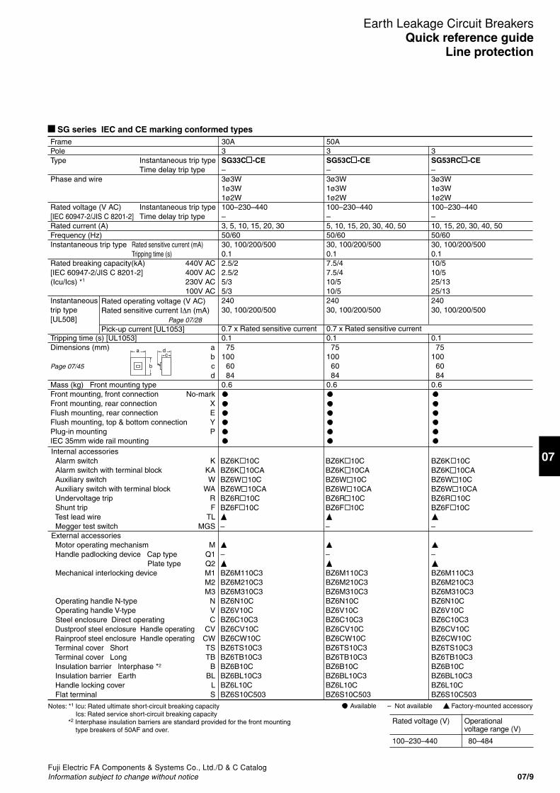
SG series IEC and CE marking conformed types
Instantaneous trip typeTime delay trip type
Instantaneous trip typeTime delay trip type
FramePoleType
Phase and wire
Rated voltage (V AC)[IEC 60947-2/JIS C 8201-2]Rated current (A)Frequency (Hz)Instantaneous trip type
Rated breaking capacity(kA)[IEC 60947-2/JIS C 8201-2](Icu/Ics) *1
Instantaneoustrip type[UL508]
Tripping time (s) [UL1053]Dimensions (mm) a
bPage 07/45 c
dMass (kg) Front mounting typeFront mounting, front connection No-markFront mounting, rear connection XFlush mounting, rear connection EFlush mounting, top & bottom connection YPlug-in mounting PIEC 35mm wide rail mounting
Rated sensitive current (mA)Tripping time (s)
Rated operating voltage (V AC)Rated sensitive current I∆n (mA) Page 07/28Pick-up current [UL1053]
440V AC400V AC230V AC100V AC
30A3SG33C -CE–3ø3W1ø3W1ø2W100–230–440–3, 5, 10, 15, 20, 3050/6030, 100/200/5000.12.5/22.5/25/35/324030, 100/200/500
0.7 x Rated sensitive current0.1 75100 60 840.6
50A3SG53C -CE–3ø3W1ø3W1ø2W100–230–440–5, 10, 15, 20, 30, 40, 5050/6030, 100/200/5000.17.5/47.5/410/510/524030, 100/200/500
0.7 x Rated sensitive current0.1 75100 60 840.6
3SG53RC -CE–3ø3W1ø3W1ø2W100–230–440–10, 15, 20, 30, 40, 5050/6030, 100/200/5000.110/510/525/1325/1324030, 100/200/500
0.1 75100 60 840.6
Internal accessories Alarm switch K Alarm switch with terminal block KA Auxiliary switch W Auxiliary switch with terminal block WA Undervoltage trip R Shunt trip F Test lead wire TL Megger test switch MGSExternal accessories Motor operating mechanism M Handle padlocking device Cap type Q1 Plate type Q2 Mechanical interlocking device M1
M2M3
Operating handle N-type N Operating handle V-type V Steel enclosure Direct operating C Dustproof steel enclosure Handle operating CV Rainproof steel enclosure Handle operating CW Terminal cover Short TS Terminal cover Long TB Insulation barrier Interphase *2 B Insulation barrier Earth BL Handle locking cover L Flat terminal S
ca d
b
–
BZ6M110C3BZ6M210C3BZ6M310C3BZ6N10CBZ6V10CBZ6C10C3BZ6CV10CBZ6CW10CBZ6TS10C3BZ6TB10C3BZ6B10CBZ6BL10C3BZ6L10CBZ6S10C503
BZ6K 10CBZ6K 10CABZ6W 10CBZ6W 10CABZ6R 10CBZ6F 10C
–
–
BZ6M110C3BZ6M210C3BZ6M310C3BZ6N10CBZ6V10CBZ6C10C3BZ6CV10CBZ6CW10CBZ6TS10C3BZ6TB10C3BZ6B10CBZ6BL10C3BZ6L10CBZ6S10C503
BZ6K 10CBZ6K 10CABZ6W 10CBZ6W 10CABZ6R 10CBZ6F 10C
–
–
BZ6M110C3BZ6M210C3BZ6M310C3BZ6N10CBZ6V10CBZ6C10C3BZ6CV10CBZ6CW10CBZ6TS10C3BZ6TB10C3BZ6B10CBZ6BL10C3BZ6L10CBZ6S10C503
BZ6K 10CBZ6K 10CABZ6W 10CBZ6W 10CABZ6R 10CBZ6F 10C
–
Notes: *1 Icu: Rated ultimate short-circuit breaking capacityIcs: Rated service short-circuit breaking capacity
*2 Interphase insulation barriers are standard provided for the front mounting type breakers of 50AF and over.
Factory-mounted accessoryAvailable – Not available
Rated voltage (V) Operationalvoltage range (V)
100–230–440 80–484

07/10Fuji Electric FA Components & Systems Co., Ltd./D & C Catalog
Information subject to change without notice
Earth Leakage Circuit BreakersQuick reference guideLine protection
SG series IEC and CE marking conformed types
Instantaneous trip typeTime delay trip type
Instantaneous trip typeTime delay trip type
FramePoleType
Phase and wire
Rated voltage (V AC)[IEC 60947-2/JIS C 8201-2]Rated current (A)Frequency (Hz)Instantaneous trip type
Rated breaking capacity(kA)[IEC 60947-2/JIS C 8201-2](Icu/Ics) *1
Instantaneoustrip type[UL508]
Tripping time (s) [UL1053]Dimensions (mm) a
bPage 07/45 c
dMass (kg) Front mounting typeFront mounting, front connection No-markFront mounting, rear connection XFlush mounting, rear connection EFlush mounting, top & bottom connection YPlug-in mounting PIEC 35mm wide rail mounting
Rated sensitive current (mA)Tripping time (s)
Rated operating voltage (V AC)Rated sensitive current I∆n (mA) Page 07/28Pick-up current [UL1053]
440V AC400V AC230V AC100V AC
3SG63RC -CE–3ø3W1ø3W1ø2W100–230–440–6050/6030, 100/200/5000.110/510/525/1325/1324030, 100/200/500
0.1 75100 60 840.6
60A3SG63C -CE–3ø3W1ø3W1ø2W100–230–440–6050/6030, 100/200/5000.17.5/47.5/410/510/524030, 100/200/500
0.7 x Rated sensitive current0.1 75100 60 840.6
ca d
b
Internal accessories Alarm switch K Alarm switch with terminal block KA Auxiliary switch W Auxiliary switch with terminal block WA Undervoltage trip R Shunt trip F Test lead wire TLExternal accessories Motor operating mechanism M Handle padlocking device Cap type Q1 Plate type Q2 Mechanical interlocking device M1
M2M3
Operating handle N-type N Operating handle V-type V Steel enclosure Direct operating C Dustproof steel enclosure Handle operating CV Rainproof steel enclosure Handle operating CW Terminal cover Short TS Terminal cover Long TB Insulation barrier Interphase *2 B Insulation barrier Earth BL Handle locking cover L Flat terminal S
BZ6M110C3BZ6M210C3BZ6M310C3BZ6N10CBZ6V10CBZ6C10C3BZ6CV10CBZ6CW10CBZ6TS10C3BZ6TB10C3BZ6B10CBZ6BL10C3BZ6L10CBZ6S10C1003
BZ6K 10CBZ6K 10CABZ6W 10CBZ6W 10CABZ6R 10CBZ6F 10C
BZ6M110C3BZ6M210C3BZ6M310C3BZ6N10CBZ6V10CBZ6C10C3BZ6CV10CBZ6CW10CBZ6TS10C3BZ6TB10C3BZ6B10CBZ6BL10C3BZ6L10CBZ6S10C1003
BZ6K 10CBZ6K 10CABZ6W 10CBZ6W 10CABZ6R 10CBZ6F 10C
Notes: *1 Icu: Rated ultimate short-circuit breaking capacityIcs: Rated service short-circuit breaking capacity
*2 Interphase insulation barriers are standard provided for the front mounting type breakers of 50AF and over.
– – ––
––
3SG103RC -CE–3ø3W1ø3W1ø2W100–230–440–
50/6030, 100/200/5000.150/1350/13100/50100/50––
–– 90155 60 821.3
100A3SG103C -CE–3ø3W1ø3W1ø2W100–230–440–15, 20, 30, 40, 50, 60, 75, 10050/6030, 100/200/5000.125/730/850/2550/25––
–– 90155 60 821.3
–––BZ-N30CBZ6V30CBZ6C30C3BZ-CV30CBZ-CW30CBZ-TS30B-3BZ-TB30B-3BZ-B30BBZ-BL35BBZ6L30CBZ-S35B-1003
BZ6K 30C
BZ6W 30C
–
–
–––BZ-N30CBZ6V30CBZ6C30C3BZ-CV30CBZ-CW30CBZ-TS30B-3BZ-TB30B-3BZ-B30BBZ-BL35BBZ6L30CBZ-S35B-1003
BZ6K 30C
BZ6W 30C
–
–
Factory-mounted accessoryAvailable – Not available
Rated voltage (V) Operationalvoltage range (V)
100–230–440 80–484

Fuji Electric FA Components & Systems Co., Ltd./D & C CatalogInformation subject to change without notice 07/11
Earth Leakage Circuit BreakersQuick reference guide
Line protection
07
Instantaneous trip typeTime delay trip type
Instantaneous trip typeTime delay trip type
FramePoleType
Phase and wire
Rated voltage (V AC)[IEC 60947-2/JIS C 8201-2]Rated current (A)Frequency (Hz)Instantaneous trip type
Rated breaking capacity(kA)[IEC 60947-2/JIS C 8201-2](Icu/Ics) *1
Instantaneoustrip type[UL508]
Tripping time (s) [UL1053]Dimensions (mm) a
bPage 07/46 c
dMass (kg) Front mounting typeFront mounting, front connection No-markFront mounting, rear connection XFlush mounting, rear connection EFlush mounting, top & bottom connection YPlug-in mounting PIEC 35mm wide rail mounting
Rated sensitive current (mA)Tripping time (s)
Rated operating voltage (V AC)Rated sensitive current I∆n (mA) Pick-up current [UL1053]
440V AC400V AC230V AC100V AC
225A3SG203C -CE–3ø3W1ø3W1ø2W100–230–440–125, 150, 175, 200, 22550/6030, 100/200/5000.125/730/850/2550/25––
––105165 60 841.5
3SG203RC -CE–3ø3W1ø3W1ø2W100–230–440–125, 150, 175, 200, 22550/6030, 100/200/5000.150/1350/13100/50100/50––
––105165 60 841.5
400A3SG403C -CE–3ø3W1ø3W1ø2W100–230–440–250, 300, 350, 40050/6030, 100/200/5000.135/1835/1850/2550/25––
––1402571031465.6
Internal accessories Alarm switch K Alarm switch with terminal block KA Auxiliary switch W Auxiliary switch with terminal block WA Undervoltage trip R Shunt trip F Test lead wire TL Megger test switch MGSExternal accessories Motor operating mechanism M Handle padlocking device Cap type Q1 Plate type Q2 Mechanical interlocking device M1
M2M3
Operating handle N-type N Operating handle V-type V Steel enclosure Direct operating C Dustproof steel enclosure Handle operating CV Rainproof steel enclosure Handle operating CW Terminal cover Short TS Terminal cover Long TB Insulation barrier Interphase *2 B Insulation barrier Earth BL Handle locking cover L Flat terminal S
ca d
b
–––––BZ-N40CBZ6V40CBZ-C40BBZ-CV40CBZ-CW40CBZ-TS40BBZ-TB40BBZ-B40BBZ-BL40BBZ6L40CBZ-S50B-2253
BZ6K 40C
BZ6W 40C
–
–
–––––BZ-N40CBZ6V40CBZ-C40BBZ-CV40CBZ-CW40CBZ-TS40BBZ-TB40BBZ-B40BBZ-BL40BBZ6L40CBZ-S50B-2253
BZ6K 40C
BZ6W 40C
–
–
–
BZ-M160CBZ-M260CBZ-M360CBZ-N60CBZ6V60CBZ-C60BBZ-CV60CBZ-CW60C–BZ-TB60BB-43A–BZ-L70B–
BZ-K70BBZ-K70BABZ-W70BBZ-W70BABZ-R70B-BZ-F70B-
–
–
– – –
Notes: *1 Icu: Rated ultimate short-circuit breaking capacityIcs: Rated service short-circuit breaking capacity
*2 Interphase insulation barriers are standard provided for the front mounting type breakers of 50AF and over.
Factory-mounted accessoryAvailable – Not available
SG series IEC and CE marking conformed types
Rated voltage (V) Operationalvoltage range (V)
100–230–440 80–484

07/12Fuji Electric FA Components & Systems Co., Ltd./D & C Catalog
Information subject to change without notice
Earth Leakage Circuit BreakersQuick reference guideLine protection
SG series
Instantaneous trip typeTime delay trip type
Instantaneous trip typeTime delay trip type
FramePoleType
Phase and wire
Rated voltage (V AC)[JIS C 8371]Rated current (A)Frequency (Hz)Instantaneous trip type
Time delay trip type
Rated breaking capacity(kA)[JIS C 8371] sym.
Instantaneoustrip type[UL508]
Dimensions (mm) ab
Page 07/46 cd
Mass (kg) Front mounting typeFront mounting, front connection No-markFront mounting, rear connection XFlush mounting, rear connection EFlush mounting, top & bottom connection YPlug-in mounting PIEC 35mm wide rail mounting
Rated sensitive current (mA)Tripping time (s)Rated sensitive current (mA)Tripping time (s)Inertia non-tripping time (s) [2I∆n]
Rated operating voltage (V AC)Rated sensitive current I∆n (mA) Pick-up current [UL1053]
415V AC200V AC100V AC
400A3SG403RCSG403RCD3ø3W1ø3W1ø2W100–200–415200–415250, 300, 350, 40050/6030, 100/200/5000.1100/200/5000.3/0.8/20.15/0.4/1508585––
–1402571031465.6
600A3SG603RC SG603RCD3ø3W1ø3W1ø2W100–200–415200–415500, 60050/60100/200/5000.1100/200/5000.3/0.8/20.15/0.4/1508585––
–21027510314610
800A3SG803RC SG803RCD3ø3W1ø3W1ø2W100–200–415200–415700, 80050/60100/200/5000.1100/200/5000.3/0.8/20.15/0.4/1508585––
21027510314610
Internal accessories Alarm switch K Alarm switch with terminal block KA Auxiliary switch W Auxiliary switch with terminal block WA Undervoltage trip R Shunt trip F Test lead wire TL Megger test switch MGSExternal accessories Motor operating mechanism M Handle padlocking device Cap type Q1 Plate type Q2 Mechanical interlocking device M1
M2M3
Operating handle N-type N Operating handle V-type V Steel enclosure Direct operating C Dustproof steel enclosure Handle operating CV Rainproof steel enclosure Handle operating CW Terminal cover Short TS Terminal cover Long TB Insulation barrier Interphase *1 B Insulation barrier Earth BL Handle locking cover L Flat terminal S
ca d
b
BZ-M160CBZ-M260CBZ-M360CBZ-N60CBZ6V60CBZ-C60BBZ-CV60CBZ-CW60C–BZ-TB60BB-43A–BZ-L70B–
–
BZ-M170CBZ-M270CBZ-M370CBZ-N70CBZ6V70CBZ-C70BBZ-CV70C––BZ-TB70BB-43A–BZ-L70B–
BZ-K70BBZ-K70BABZ-W70BBZ-W70BABZ-R70B-BZ-F70B-
–
BZ-M170CBZ-M270CBZ-M370CBZ-N70CBZ6V70CBZ-C70BBZ-CV70C––BZ-TB60BB-43A–BZ-L70B–
BZ-K70BBZ-K70BABZ-W70BBZ-W70BABZ-R70B-BZ-F70B-
–
– – –
BZ-K70BBZ-K70BABZ-W70BBZ-W70BABZ-R70B-BZ-F70B-
Notes: *1 Interphase insulation barriers are standard provided for the front mounting type breakers of 50AF and over.
Factory-mounted accessoryAvailable – Not availableRated voltage (V) Operational
voltage range (V)
100–200–415 80–484200–415 160–484

Fuji Electric FA Components & Systems Co., Ltd./D & C CatalogInformation subject to change without notice 07/13
Earth Leakage Circuit BreakersQuick reference guide
Line protection
07
■ SG series/4-pole
Note: • Time delay trip types are also available on request.* For motor-operated breaker, sensitive current and tripping time are fixed. Specify the sensitive current and tripping time when ordering.
Rated voltage (V) Operationalvoltage range (V)
200–415 160–484
Frame
Pole
Type
Phase and wire
Rated current (Amps) Ambient temp.: 40°C
Rated voltage (Volts)
Rated sensitive current (mA)
Tripping time (sec)
Rated breaking capacity 415V AC(kA) sym. 200V AC
Earth leakage tripping device
Overcurrent tripping device
Dimensions a(mm) b
cPage 07/48 d
Mass (kg) Front mounting type
Front mounting, front connection No-mark rear connection X
Flush mounting, rear connection E top & bottom connection Y
Plug-in mounting P
Alarm switch KAuxiliary switch WUndervoltage trip RShunt trip FTest lead wire TLMegger test switch MGSEarth leakage indication contact EAL
Motor operating mechanism M*Padlocking device QMechanical interlocking device M1Operating handle N-type NOperating handle G-type G
Steel enclosure CSteel enclosure with G-type handle CG
Terminal cover Inside panel use A1Terminal cover Outside panel use T1Insulation barrier Interphase BInsulation barrier Earth BL
100A
4
SGa104A
3ø4W
40, 50, 60, 75, 100
200-415
30, 100/200/500
0.1
25 50
Solid-state
Thermal-magnetic
140230 86109
3.2
–
–
––
–
–N-13EAG-12A
––
A1-14–––
SG104H
50, 60, 75, 100
42 85
225A
4
SGa204A
3ø4W
125, 150, 175, 200, 225
200-415
30, 100/200/500
0.1
25 42
Solid-state
Thermal-magnetic
185350103134
8.7
–
–
––
–
–N-23EAG-22A
––
––B-44A–
400A
4
SGa404A
3ø4W
250, 300, 350, 400
200-415
30, 100/200/500
0.1
25 42
Solid-state
Thermal-magnetic
185350103134
11.3
–
–
––
–
–N-23EAG-22A
––
––B-44A–
SG204H
42 85
Factory-mounted accessoryAvailable – Not available
ca d
b
07/14Fuji Electric FA Components & Systems Co., Ltd./D & C Catalog
Information subject to change without notice
Earth Leakage Circuit BreakersQuick reference guideLine protection
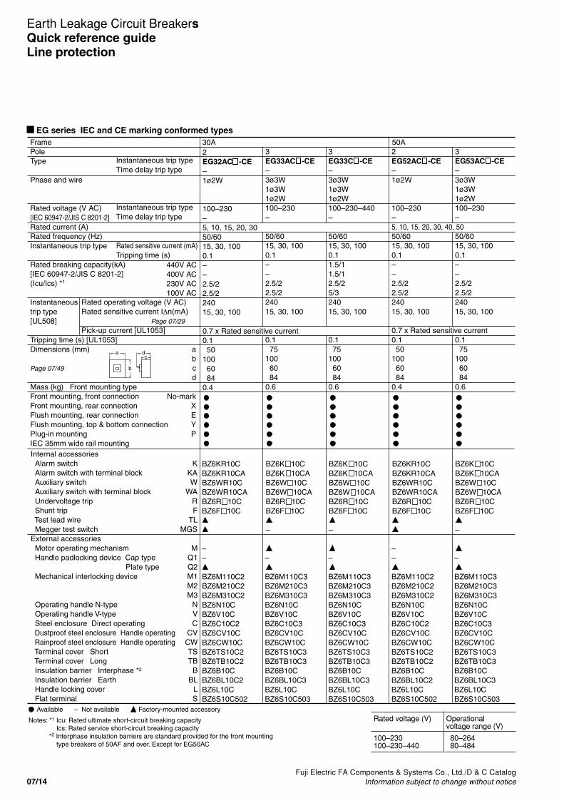
EG series IEC and CE marking conformed types
Internal accessories Alarm switch K Alarm switch with terminal block KA Auxiliary switch W Auxiliary switch with terminal block WA Undervoltage trip R Shunt trip F Test lead wire TL Megger test switch MGSExternal accessories Motor operating mechanism M Handle padlocking device Cap type Q1 Plate type Q2 Mechanical interlocking device M1
M2M3
Operating handle N-type N Operating handle V-type V Steel enclosure Direct operating C Dustproof steel enclosure Handle operating CV Rainproof steel enclosure Handle operating CW Terminal cover Short TS Terminal cover Long TB Insulation barrier Interphase *2 B Insulation barrier Earth BL Handle locking cover L Flat terminal S
––
BZ6M110C2BZ6M210C2BZ6M310C2BZ6N10CBZ6V10CBZ6C10C2BZ6CV10CBZ6CW10CBZ6TS10C2BZ6TB10C2BZ6B10CBZ6BL10C2BZ6L10CBZ6S10C502
BZ6KR10CBZ6KR10CABZ6WR10CBZ6WR10CABZ6R 10CBZ6F 10C
BZ6K 10CBZ6K 10CABZ6W 10CBZ6W 10CABZ6R 10CBZ6F 10C
–
BZ6K 10CBZ6K 10CABZ6W 10CBZ6W 10CABZ6R 10CBZ6F 10C
–
BZ6KR10CBZ6KR10CABZ6WR10CBZ6WR10CABZ6R 10CBZ6F 10C
BZ6K 10CBZ6K 10CABZ6W 10CBZ6W 10CABZ6R 10CBZ6F 10C
–
––
BZ6M110C2BZ6M210C2BZ6M310C2BZ6N10CBZ6V10CBZ6C10C2BZ6CV10CBZ6CW10CBZ6TS10C2BZ6TB10C2BZ6B10CBZ6BL10C2BZ6L10CBZ6S10C502
–
BZ6M110C3BZ6M210C3BZ6M310C3BZ6N10CBZ6V10CBZ6C10C3BZ6CV10CBZ6CW10CBZ6TS10C3BZ6TB10C3BZ6B10CBZ6BL10C3BZ6L10CBZ6S10C503
–
BZ6M110C3BZ6M210C3BZ6M310C3BZ6N10CBZ6V10CBZ6C10C3BZ6CV10CBZ6CW10CBZ6TS10C3BZ6TB10C3BZ6B10CBZ6BL10C3BZ6L10CBZ6S10C503
–
BZ6M110C3BZ6M210C3BZ6M310C3BZ6N10CBZ6V10CBZ6C10C3BZ6CV10CBZ6CW10CBZ6TS10C3BZ6TB10C3BZ6B10CBZ6BL10C3BZ6L10CBZ6S10C503
Instantaneous trip typeTime delay trip type
Instantaneous trip typeTime delay trip type
FramePoleType
Phase and wire
Rated voltage (V AC)[IEC 60947-2/JIS C 8201-2]Rated current (A)Rated frequency (Hz)Instantaneous trip type
Rated breaking capacity(kA)[IEC 60947-2/JIS C 8201-2](Icu/Ics) *1
Instantaneoustrip type[UL508]
Tripping time (s) [UL1053]Dimensions (mm) a
bPage 07/49 c
dMass (kg) Front mounting typeFront mounting, front connection No-markFront mounting, rear connection XFlush mounting, rear connection EFlush mounting, top & bottom connection YPlug-in mounting PIEC 35mm wide rail mounting
Rated sensitive current (mA)Tripping time (s)
Rated operating voltage (V AC) Rated sensitive current I∆n(mA) Page 07/29 Pick-up current [UL1053]
440V AC400V AC230V AC100V AC
2EG32AC -CE–1ø2W
100–230–5, 10, 15, 20, 3050/6015, 30, 1000.1––2.5/22.5/224015, 30, 100
0.7 x Rated sensitive current0.1 50100 60 840.4
3EG33AC -CE–3ø3W1ø3W1ø2W100–230–
50/6015, 30, 1000.1 ––2.5/22.5/224015, 30, 100
0.1 75100 60 840.6
3EG33C -CE–3ø3W1ø3W1ø2W100–230–440–
50/6015, 30, 1000.11.5/11.5/12.5/25/324015, 30, 100
0.1 75100 60 840.6
2EG52AC -CE–1ø2W
100–230 –5, 10, 15, 20, 30, 40, 5050/6015, 30, 1000.1 ––2.5/22.5/224015, 30, 100
0.7 x Rated sensitive current0.1 50100 60 840.4
30A 50A3EG53AC -CE–3ø3W1ø3W1ø2W100–230–
50/6015, 30, 1000.1 ––2.5/22.5/224015, 30, 100
0.1 75100 60 840.6
ca d
b
Notes: *1 Icu: Rated ultimate short-circuit breaking capacityIcs: Rated service short-circuit breaking capacity
*2 Interphase insulation barriers are standard provided for the front mounting type breakers of 50AF and over. Except for EG50AC
Factory-mounted accessoryAvailable – Not availableRated voltage (V) Operational
voltage range (V)
100–230 80–264100–230–440 80–484

Fuji Electric FA Components & Systems Co., Ltd./D & C CatalogInformation subject to change without notice 07/15
Earth Leakage Circuit BreakersQuick reference guide
Line protection
07
EG series IEC and CE marking conformed types
Internal accessories Alarm switch K Alarm switch with terminal block KA Auxiliary switch W Auxiliary switch with terminal block WA Undervoltage trip R Shunt trip F Test lead wire TL Megger test switch MGSExternal accessories Motor operating mechanism M Handle padlocking device Cap type Q1 Plate type Q2 Mechanical interlocking device M1
M2M3
Operating handle N-type N Operating handle V-type V Steel enclosure Direct operating C Dustproof steel enclosure Handle operating CV Rainproof steel enclosure Handle operating CW Terminal cover Short TS Terminal cover Long TB Insulation barrier Interphase *2 B Insulation barrier Earth BL Handle locking cover L Flat terminal S
–
BZ6M110C3BZ6M210C3BZ6M310C3BZ6N10CBZ6V10CBZ6C10C3BZ6CV10CBZ6CW10CBZ6TS10C3BZ6TB10C3BZ6B10CBZ6BL10C3BZ6L10CBZ6S10C503
BZ6K 10CBZ6K 10CABZ6W 10CBZ6W 10CABZ6R 10CBZ6F 10C
–
BZ6K 10CBZ6K 10CABZ6W 10CBZ6W 10CABZ6R 10CBZ6F 10C
–
BZ6K 10CBZ6K 10CABZ6W 10CBZ6W 10CABZ6R 10CBZ6F 10C
–
BZ6K 10CBZ6K 10CABZ6W 10CBZ6W 10CABZ6R 10CBZ6F 10C
BZ6K 10CBZ6K 10CABZ6W 10CBZ6W 10CABZ6R 10CBZ6F 10C
–
–
BZ6M110C3BZ6M210C3BZ6M310C3BZ6N10CBZ6V10CBZ6C25C3BZ6CV25CBZ6CW25CBZ6TS10C3BZ6TB10C3BZ6B10CBZ6BL10C3BZ6L10CBZ6S10C1002
–
BZ6M110C3BZ6M210C3BZ6M310C3BZ6N10CBZ6V10CBZ6C10C3BZ6CV10CBZ6CW10CBZ6TS10C3BZ6TB10C3BZ6B10CBZ6BL10C3BZ6L10CBZ6S10C1003
–
BZ6M110C3BZ6M210C3BZ6M310C3BZ6N10CBZ6V10CBZ6C25C3BZ6CV25CBZ6CW25CBZ6TS10C3BZ6TB10C3BZ6B10CBZ6BL10C3BZ6L10CBZ6S10C1003
–
BZ6M110C3BZ6M210C3BZ6M310C3BZ6N10CBZ6V10CBZ6C25C3BZ6CV25CBZ6CW25CBZ6TS10C3BZ6TB10C3BZ6B10CBZ6BL10C3BZ6L10CBZ6S10C1003
Instantaneous trip typeTime delay trip type
Instantaneous trip typeTime delay trip type
FramePoleType
Phase and wire
Rated voltage (V AC)[IEC 60947-2/JIS C 8201-2]Rated current (A)Rated frequency (Hz)Instantaneous trip type
Rated breaking capacity(kA)[IEC 60947-2/JIS C 8201-2](Icu/Ics) *1
Instantaneoustrip type[UL508]
Tripping time (s) [UL1053]Dimensions (mm) a
bPage 07/49 c
dMass (kg) Front mounting typeFront mounting, front connection No-markFront mounting, rear connection XFlush mounting, rear connection EFlush mounting, top & bottom connection YPlug-in mounting PIEC 35mm wide rail mounting
Rated sensitive current (mA)Tripping time (s)
Rated operating voltage (V AC) Rated sensitive current I∆n(mA) Page 07/29 Pick-up current [UL1053]
440V AC400V AC230V AC100V AC
3EG53C -CE–3ø3W1ø3W1ø2W100–230–440–5,10,15,20,30,40,5050/6015, 30, 100/2000.12.5/22.5/25/35/324015, 30, 100/200
0.7 x Rated sensitive current0.1 75100 60 840.6
3EG63C -CE–3ø3W1ø3W1ø2W100–230–440–6050/6015, 30, 100/2000.12.5/22.5/25/35/324015, 30, 100/200
0.1 75100 60 840.6
3EG103AC -CE–3ø3W1ø3W1ø2W100–230–60, 75, 10050/6030, 100/2000.1––5/35/324030, 100/200
0.7 x Rated sensitive current0.1 75100 60 840.6
2EG102C -CE–1ø2W
100–230 –50, 60, 75, 10050/6030, 100/2000.1––10/510/524030, 100/200
0.1 75100 60 840.55
50A 60A 100A3EG103C -CE–3ø3W1ø3W1ø2W100–230–440–
50/6030, 100/200/5000.110/510/525/1325/1324030, 100/200/500
0.1 75100 60 840.6
ca d
b
Notes: *1 Icu: Rated ultimate short-circuit breaking capacityIcs: Rated service short-circuit breaking capacity
*2 Interphase insulation barriers are standard provided for the front mounting type breakers of 50AF and over. Except for EG50AC and EG100AC
Factory-mounted accessoryAvailable – Not availableRated voltage (V) Operational
voltage range (V)
100–230 80–264100–230–440 80–484

07/16Fuji Electric FA Components & Systems Co., Ltd./D & C Catalog
Information subject to change without notice
Earth Leakage Circuit BreakersQuick reference guideLine protection
EG series IEC and CE marking conformed types
Instantaneous trip typeTime delay trip type
Instantaneous trip typeTime delay trip type
FramePoleType
Phase and wire
Rated voltage (V AC)[IEC 60947-2/JIS C 8201-2]Rated current (A)Rated frequency (Hz)Instantaneous trip type
Rated breaking capacity(kA)[IEC 60947-2/JIS C 8201-2](Icu/Ics) *1
Instantaneoustrip type[UL508]
Tripping time (s) [UL1053]Dimensions (mm) a
bPage 07/50 c
dMass (kg) Front mounting typeFront mounting, front connection No-markFront mounting, rear connection XFlush mounting, rear connection EFlush mounting, top & bottom connection YPlug-in mounting PIEC 35mm wide rail mounting
Rated sensitive current (mA)Tripping time (s)
Rated operating voltage (V AC)Rated sensitive current I∆n (mA) Pick-up current [UL1053]
440V AC400V AC230V AC100V AC
400A3EG403C -CE–3ø3W1ø3W1ø2W100–230–440–250, 300, 350, 40050/6030, 100/200/5000.125/1325/1335/1835/18––
––1402571301465.6
225A3EG203C -CE–3ø3W1ø3W1ø2W100–230–440–125, 150, 175, 200, 22550/6030, 100/200/5000.115/418/535/1835/18––
––105165 60 841.5
ca d
b
Internal accessories Alarm switch K Alarm switch with terminal block KA Auxiliary switch W Auxiliary switch with terminal block WA Undervoltage trip R Shunt trip F Test lead wire TL Megger test switch MGSExternal accessories Motor operating mechanism M Handle padlocking device Cap type Q1 Plate type Q2 Mechanical interlocking device M1
M2M3
Operating handle N-type N Operating handle V-type V Steel enclosure Direct operating C Dustproof steel enclosure Handle operating CV Rainproof steel enclosure Handle operating CW Terminal cover Short TS Terminal cover Long TB Insulation barrier Interphase *2 B Insulation barrier Earth BL Handle locking cover L Flat terminal S
–
–––BZ-N40CBZ6V40CBZ-C40B-3BZ-CV40CBZ-CW40CBZ-TS40BBZ-TB40BBZ-B40BBZ-BL40BBZ6L40CBZ-S50B-2253
BZ6K 40C
BZ6W 40C
–
–
BZ-M160CBZ-M260CBZ-M360CBZ-N60CBZ6V60CBZ-C60B-3BZ-CV60CBZ-CW60C–BZ-TB60BB-43A–BZ-L70B–
BZ-K70BBZ-K70BABZ-W70BBZ-W70BABZ-R70B-BZ-F70B-
–
–
– –
Notes: *1 Icu: Rated ultimate short-circuit breaking capacityIcs: Rated service short-circuit breaking capacity
*2 Interphase insulation barriers are standard provided for the front mounting type breakers of 50AF and over.
Factory-mounted accessoryAvailable – Not available
Rated voltage (V) Operationalvoltage range (V)
100–230–440 80–484

Fuji Electric FA Components & Systems Co., Ltd./D & C CatalogInformation subject to change without notice 07/17
Earth Leakage Circuit BreakersQuick reference guide
Line protection
07
EG series
Instantaneous trip typeTime delay trip type
Instantaneous trip typeTime delay trip type
FramePoleType
Phase and wire
Rated voltage (V AC)[JIS C 8371]Rated current (A)Rated frequency (Hz)Instantaneous trip type
Time delay trip type
Rated breaking capacity(kA)[JIS C 8371] sym.
Instantaneoustrip type[UL508]
Tripping time (s) [UL1053]Dimensions (mm) a
bPage 07/51 c
dMass (kg) Front mounting typeFront mounting, front connection No-markFront mounting, rear connection XFlush mounting, rear connection EFlush mounting, top & bottom connection YPlug-in mounting PIEC 35mm wide rail mounting
Rated sensitive current (mA)Tripping time (s)Rated sensitive current (mA)Tripping time (s)Inertia non-tripping time (s) [2I∆n]
Rated operating voltage (V AC)Rated sensitive current I∆n (mA) Pick-up current [UL1053]
415V AC200V AC100V AC
800A3EG803CEG803CD3ø3W1ø3W1ø2W100–200–415200–415700, 80050/60100/200/5000.1100/200/5000.3/0.8/20.15/0.4/1355050––
––21027510314610
600A3EG603CEG603CD3ø3W1ø3W1ø2W100–200–415200–415500, 60050/60100/200/5000.1100/200/5000.3/0.8/20.15/0.4/1355050––
––21027510314610
ca d
b
Internal accessories Alarm switch K Alarm switch with terminal block KA Auxiliary switch W Auxiliary switch with terminal block WA Undervoltage trip R Shunt trip F Test lead wire TL Megger test switch MGSExternal accessories Motor operating mechanism M Handle padlocking device Cap type Q1 Plate type Q2 Mechanical interlocking device M1
M2M3
Operating handle N-type N Operating handle V-type V Steel enclosure Direct operating C Dustproof steel enclosure Handle operating CV Rainproof steel enclosure Handle operating CW Terminal cover Short TS Terminal cover Long TB Insulation barrier Interphase *1 B Insulation barrier Earth BL Handle locking cover L Flat terminal S
BZ6M170CBZ-M270CBZ-M370CBZ-N70CBZ6V70CBZ-C70BBZ-CV70C––BZ-TB70BB-43A–BZ-L70B–
BZ-K70BBZ-K70BABZ-W70BBZ-W70BABZ-R70B-BZ-F70B-
–
BZ6M170CBZ-M270CBZ-M370CBZ-N70CBZ6V70CBZ-C70BBZ-CV70C––BZ-TB70BB-43A–BZ-L70B–
BZ-K70BBZ-K70BABZ-W70BBZ-W70BABZ-R70B-BZ-F70B-
–
– –
Notes: *1 Interphase insulation barriers are standard provided for the front mounting type breakers of 50AF and over.
Factory-mounted accessoryAvailable – Not available
Rated voltage (V) Operationalvoltage range (V)
100–200–415 80–484

07/18Fuji Electric FA Components & Systems Co., Ltd./D & C Catalog
Information subject to change without notice
Earth Leakage Circuit BreakersQuick reference guideLine protection
Rated voltage (V) Operationalvoltage range (V)
380–415 304–484
■ EG series/3P+1N
Note: * For motor-operated breaker, sensitive current and tripping time are fixed. Specify the sensitive current and tripping time when ordering.
Frame
Pole
Type
Phase and wire
Rated current (A) Ambient temp.: 40°C
Rated voltage (V)
Rated sensitive current (mA)
Tripping time (s)
Rated breaking capacity 415V AC(kA) (sym) 200V AC
Earth leakage tripping device
Overcurrent tripping device
Dimensions a(mm) b
cPage 07/51 d
Mass (kg) Front mounting type
Front mounting, front connection No-mark rear connection X
Flush mounting, rear connection E top & bottom connection Y
Plug-in mounting P
Alarm switch KAuxiliary switch WUndervoltage trip RShunt trip FTest lead wire TLMegger test switch MGSEarth leakage indication contact EAL
Motor operating mechanism M*Padlocking device QMechanical interlocking device M1Operating handle N-type NOperating handle G-type G
Steel enclosure CSteel enclosure with G-type handle CG
Terminal cover Inside panel use A1Terminal cover Outside panel use T1Insulation barrier Interphase BInsulation barrier Earth BL
100A
4
EG104A
3ø4W
30, 40, 50, 60, 75, 100
380-415
30, 100, 300, 500
0.1
14 –
Solid-state
Hydraulic-magnetic
120200 60 80
1.8
–
––
–
–––––––
–––N-6EAG-5A
––
––––
ca d
b
Factory-mounted accessoryAvailable – Not available

Fuji Electric FA Components & Systems Co., Ltd./D & C CatalogInformation subject to change without notice 07/19
Earth Leakage Circuit BreakersQuick reference guide
Line protection
07
■ HG series/3-pole
Frame
Pole
Type Instantaneous trip type
Time delay trip type
Phase and wire
Rated current (A) Ambient temp.: 40°C
Rated voltage (V AC) Instantaneous trip type
[JIS C 8371] Time delay trip type
Instantaneous trip type Rated sensitive current (mA)
Tripping time (s)
Time delay trip type Rated sensitive current (mA)
Tripping time (s)
Inertia non-tripping time (s) [2I∆n]
Rated breaking capacity 415V AC(kA) sym. 200V AC[JIS C 8371] 100V AC
Earth leakage tripping device
Overcurrent tripping device
Dimensions a(mm) b
cPage 07/52 d
Mass (kg) Front mounting type
Front mounting, front connection No-mark rear connection X
Flush mounting, rear connection E top & bottom connection Y
Plug-in mounting P
Alarm switch KAuxiliary switch WUndervoltage trip RShunt trip FTest lead wire TLMegger test switch MGSEarth leakage indication contact EAL
Motor operating mechanism M*Padlocking device QMechanical interlocking device M1Operating handle N-type NOperating handle V-type VOperating handle G-type G
Steel enclosure CSteel enclosure with G-type handle CG
Terminal cover Short TSTerminal cover Long TBInsulation barrier Interphase BInsulation barrier Earth BL
50A
3
HG53B
HG53BD
3ø3W, 1ø3W, 1ø2W
15, 20, 30, 40, 50
100–200–415
200–415
30, 100/200/500
0.1
100/200/500
0.3/0.8/2
0.15/0.4/1
65100100
Solid-state
Thermal-magnetic
90155 82104
2.3
–
––
–
BZ-M130C-3BZ-N35B– BZ-G35C
BZ-C35B(CG-type BZ-CG35B)
BZ-TS35BBZ-TB35BBZ-B35BBZ-BL35B
100A
3
HG103B
HG103BD
3ø3W, 1ø3W, 1ø2W
15, 20, 30, 40, 50, 60, 75, 100
100–200–415
200–415
30, 100/200/500
0.1
100/200/500
0.3/0.8/2
0.15/0.4/1
65100100
Solid-state
Thermal-magnetic
90155 82104
2.3
–
––
–
BZ-M130C-3BZ-N35B–BZ-G35C
BZ-C35B(CG-type BZ-CG35B)
BZ-TS35BBZ-TB35BBZ-B35BBZ-BL35B
225A
3
HG203B
HG203BD
3ø3W, 1ø3W, 1ø2W
125, 150, 175, 200, 225
100–200–415
200–415
30, 100/200/500
0.1
100/200/500
0.3/0.8/2
0.15/0.4/1
65100100
Solid-state
Thermal-magnetic
105165 99127
3,3
–
––
–
BZ-M140CBZ-N50CBZ-V50C–
BZ-C50B–
BZ-TS50BBZ-TB50BBZ-B50BBZ-BL50B
ca d
b
Factory-mounted accessoryAvailable – Not availableNotes: • Terminal covers (Height: 5mm) are standard provided for the X and P mounting types of 50AF to 225AF.• Time delay trip types are also available on request.* For motor-operated breaker, sensitive current and tripping time are fixed. Specify the sensitive current and tripping time when ordering.
Rated voltage (V) Operationalvoltage range (V)
100–200–415 80–484

07/20Fuji Electric FA Components & Systems Co., Ltd./D & C Catalog
Information subject to change without notice
Earth Leakage Circuit BreakersQuick reference guideLine protection
■ HG series/3-pole
Frame
Pole
Type Instantaneous trip type
Time delay trip type
Phase and wire
Rated current (Amps) Ambient temp.: 40°C
Rated voltage (Volts)
Instantaneous trip type Rated sensitive current (mA)
Tripping time (sec)
Time delay trip type Rated sensitive current (mA)
Tripping time (s)
Inertia non-tripping time (s) [2I∆n]
Rated breaking capacity 415V AC(kA) sym. 200V AC
100V AC
Earth leakage tripping device
Overcurrent tripping device
Dimensions a(mm) b
cPage 07/53 d
Mass (kg) Front mounting type
Applicable wire size (Max. mm2)
Front mounting, front connection No-mark rear connection X
Flush mounting, rear connection E top & bottom connection Y
Plug-in mounting P
Alarm switch KAuxiliary switch WUndervoltage trip RShunt trip FTest lead wire TLMegger test switch MGSEarth leakage indication contact EAL
Motor operating mechanism M*Padlocking device QMechanical interlocking device M1Operating handle N-type NOperating handle V-type V
Steel enclosure CSteel enclosure with V-type handle CV
Terminal cover Short TSTerminal cover Long TBInsulation barrier Interphase BInsulation barrier Earth BL
400A
3
HG403B
HG403BD
3ø3W, 1ø3W, 1ø2W
250, 300, 350, 400
100–200–415
200–415
30, 100/200/500
0.1
100/200/500
0.3/0.8/2
0.15/0.4/1
65125125
Solid-state
Thermal-magnetic
140257103146
5.6
325
–
BZ-K70BBZ-W70BBZ-R70B-BZ-F70B-
BZ-M160CBZ-N60CBZ-V60C
BZ-C60BBZ-CV60C
–BZ-TB60BB-43A–
600A
3
HG603B
HG603BD
3ø3W, 1ø3W, 1ø2W
500, 600
100–200–415
200–415
100/200/500
0.1
100/200/500
0.3/0.8/2
0.15/0.4/1
65125125
Solid-state
Thermal-magnetic
210275103146
10
325
–
BZ-K70BBZ-W70BBZ-R70B-BZ-F70B-
BZ-M170CBZ-N70CBZ-V70C
BZ-C70BBZ-CV70C
–BZ-TB70BB-43A–
800A
3
HG803B
HG803BD
3ø3W, 1ø3W, 1ø2W
700, 800
100–200–415
200–415
100/200/500
0.1
100/200/500
0.3/0.8/2
0.15/0.4/1
65125125
Solid-state
Thermal-magnetic
210275103146
10
325
–
BZ-K70BBZ-W70BBZ-R70B-BZ-F70B-
BZ-M170CBZ-N70CBZ-V70C
BZ-C70BBZ-CV70C
–BZ-TB70BB-43A–
Factory-mounted accessoryAvailable – Not available
ca d
b
Note: * For motor-operated breaker, sensitive current and tripping time are fixed. Specify the sensitive current and tripping time when ordering.
Rated voltage (V) Operationalvoltage range (V)
100–200–415 80–484

Fuji Electric FA Components & Systems Co., Ltd./D & C CatalogInformation subject to change without notice 07/21
Earth Leakage Circuit BreakersQuick reference guide
Motor protection
07
SG series IEC and CE marking conformed types
Instantaneous trip typeTime delay trip type
Instantaneous trip typeTime delay trip type
FramePoleType
Phase and wire
Rated voltage (V AC)[IEC 60947-2/JIS C 8201-2]Rated current (A) Ambient temp.: 40°C for general use
45°C for marine useFrequency (Hz)Instantaneous trip type
Rated breaking capacity(kA)[IEC 60947-2/JIS C 8201-2](Icu/Ics) *1
Dimensions (mm) ab
Page 07/45 cd
Mass (kg) Front mounting typeFront mounting, front connection No-markFront mounting, rear connection XFlush mounting, rear connection EFlush mounting, top & bottom connection YPlug-in mounting PIEC 35mm wide rail mounting
Rated sensitive current (mA)Tripping time (s)
440V AC400V AC230V AC100V AC
30A3SG33CM -CE–3ø3W1ø3W1ø2W100–230–440–0.7, 1.4, 2, 2.6, 4, 5, 8,10, 12, 16, 24, 32
50/6030, 100/200/5000.12.5/22.5/25/35/3 75100 60 840.6
50A3SG53CM -CE–3ø3W1ø3W1ø2W100–230–440–0.7, 1.4, 2, 2.6, 4, 5, 8,10, 12, 16, 24, 32, 40, 45
50/6030, 100/200/5000.17.5/47.5/410/510/5 75100 60 840.6
Internal accessories Alarm switch K Alarm switch with terminal block KA Auxiliary switch W Auxiliary switch with terminal block WA Undervoltage trip R Shunt trip F Test lead wire TLExternal accessories Motor operating mechanism M Handle padlocking device Cap type Q1 Plate type Q2 Mechanical interlocking device M1
M2M3
Operating handle N-type N Operating handle V-type V Steel enclosure Direct operating C Dustproof steel enclosure Handle operating CV Rainproof steel enclosure Handle operating CW Terminal cover Short TS Terminal cover Long TB Insulation barrier Interphase *2 B Insulation barrier Earth BL Handle locking cover L Flat terminal S
ca d
b
–
BZ6M110C3BZ6M210C3BZ6M310C3BZ6N10CBZ6V10CBZ6C10C3BZ6CV10CBZ6CW10CBZ6TS10C3BZ6TB10C3BZ6B10CBZ6BL10C3BZ6L10CBZ6S10C503
BZ6K 10CBZ6K 10CABZ6W 10CBZ6W 10CABZ6R 10CBZ6F 10C
–
BZ6M110C3BZ6M210C3BZ6M310C3BZ6N10CBZ6V10CBZ6C10C3BZ6CV10CBZ6CW10CBZ6TS10C3BZ6TB10C3BZ6B10CBZ6BL10C3BZ6L10CBZ6S10C503
BZ6K 10CBZ6K 10CABZ6W 10CBZ6W 10CABZ6R 10CBZ6F 10C
–
BZ6M110C3BZ6M210C3BZ6M310C3BZ6N10CBZ6V10CBZ6C10C3BZ6CV10CBZ6CW10CBZ6TS10C3BZ6TB10C3BZ6B10CBZ6BL10C3BZ6L10CBZ6S10C1003
––BZ6M130C3BZ-M230C-3BZ-M330C-3BZ-N30CBZ6V30CBZ6C30C3BZ-CV30CBZ-CW30CBZ-TS30B-3BZ-TB30B-3BZ-B30BBZ-BL35BBZ6L30CBZ-S35B-1003
BZ6K 10CBZ6K 10CABZ6W 10CBZ6W 10CABZ6R 10CBZ6F 10C
BZ6K 30CBZ6K 30CABZ6W 30CBZ6W 30CA
60A3SG63CM -CE–3ø3W1ø3W1ø2W100–230–440–60
50/6030, 100/200/5000.17.5/47.5/410/510/5 75100 60 840.6
100A3SG103CM -CE–3ø3W1ø3W1ø2W100–230–440–75, 90
50/6030, 100/200/5000.125/730/850/2550/25 90155 60 821.3
Notes: *1 Icu: Rated ultimate short-circuit breaking capacityIcs: Rated service short-circuit breaking capacity
*2 Interphase insulation barriers are standard provided for the front mounting type breakers of 50AF and over.
–
–
Factory-mounted accessoryAvailable – Not available
Rated voltage (V) Operationalvoltage range (V)
100–230–440 80–484

07/22Fuji Electric FA Components & Systems Co., Ltd./D & C Catalog
Information subject to change without notice
Earth Leakage Circuit BreakersQuick reference guideMotor protection
SG series IEC and CE marking conformed types
Instantaneous trip typeTime delay trip type
Instantaneous trip typeTime delay trip type
FramePoleType
Phase and wire
Rated voltage (V AC)[IEC 60947-2/JIS C 8201-2]Rated current (A) Ambient temp.: 40°C for general use
45°C for marine useRated frequency (Hz)Instantaneous trip type
Rated breaking capacity(kA)[IEC 60947-2/JIS C 8201-2](Icu/Ics) *1
Dimensions (mm) ab
Page 07/46 cd
Mass (kg) Front mounting typeFront mounting, front connection No-markFront mounting, rear connection XFlush mounting, rear connection EFlush mounting, top & bottom connection YPlug-in mounting PIEC 35mm wide rail mounting
Rated sensitive current (mA)Tripping time (s)
440V AC400V AC230V AC100V AC
ca d
b
Internal accessories Alarm switch K Alarm switch with terminal block KA Auxiliary switch W Auxiliary switch with terminal block WA Undervoltage trip R Shunt trip F Test lead wire TLExternal accessories Motor operating mechanism M Handle padlocking device Cap type Q1 Plate type Q2 Mechanical interlocking device M1
M2M3
Operating handle N-type N Operating handle V-type V Steel enclosure Direct operating C Dustproof steel enclosure Handle operating CV Rainproof steel enclosure Handle operating CW Terminal cover Short TS Terminal cover Long TB Insulation barrier Interphase *2 B Insulation barrier Earth BL Handle locking cover L Flat terminal S
Notes: *1 Icu: Rated ultimate short-circuit breaking capacityIcs: Rated service short-circuit breaking capacity
*2 Interphase insulation barriers are standard provided for the front mounting type breakers of 50AF and over.
100A3SG103RCM -CE–3ø3W1ø3W1ø2W100–230–440–45, 60, 75, 90
50/6030, 100/200/5000.150/1350/13100/50100/50 90155 60 821.3
––BZ6M130C3BZ-M230C-3BZ-M330C-3BZ-N30CBZ6V30CBZ6C30C3BZ-CV30CBZ-CW30CBZ-TS30B-3BZ-TB30B-3BZ-B30BBZ-BL35BBZ6L30CBZ-S35B-1003
BZ6K 30CBZ6K 30CABZ6W 30CBZ6W 30CA
–
–
225A3SG203CM -CE–3ø3W1ø3W1ø2W100–230–440–125, 150, 175, 225
50/6030, 100/200/5000.125/730/850/2550/25105165 60 841.5
3SG203RCM -CE–3ø3W1ø3W1ø2W100–230–440–125, 150, 175, 225
50/6030, 100/200/5000.150/1350/13100/50100/50105165 60 841.5
––BZ6M140CBZ-M240CBZ-M340CBZ-N40CBZ6V40CBZ-C40BBZ-CV40CBZ-CW40CBZ-TS40BBZ-TB40BBZ-B40BBZ-BL40BBZ6L40CBZ-S50B-2253
BZ6K 40CBZ6K 40CABZ6W 40CBZ6W 40CA
–
––BZ6M140CBZ-M240CBZ-M340CBZ-N40CBZ6V40CBZ-C40BBZ-CV40CBZ-CW40CBZ-TS40BBZ-TB40BBZ-B40BBZ-BL40BBZ6L40CBZ-S50B-2253
BZ6K 40CBZ6K 40CABZ6W 40CBZ6W 40CA
–
– –
Factory-mounted accessoryAvailable – Not available
Rated voltage (V) Operationalvoltage range (V)
100–230–440 80–484

Fuji Electric FA Components & Systems Co., Ltd./D & C CatalogInformation subject to change without notice 07/23
Earth Leakage Circuit BreakersQuick reference guide
Motor protection
07
Instantaneous trip typeTime delay trip type
Instantaneous trip typeTime delay trip type
FramePoleType
Phase and wire
Rated voltage (V AC)[IEC 60947-2/JIS C 8201-2]Rated current (A) Ambient temp.: 40°C for general use
45°C for marine useRated frequency (Hz)Instantaneous trip type
Rated breaking capacity(kA)[IEC 60947-2/JIS C 8201-2](Icu/Ics) *1
Dimensions (mm) ab
Page 07/49 cd
Mass (kg) Front mounting typeFront mounting, front connection No-markFront mounting, rear connection XFlush mounting, rear connection EFlush mounting, top & bottom connection YPlug-in mounting PIEC 35mm wide rail mounting
Rated sensitive current (mA)Tripping time (s)
440V AC400V AC230V AC100V AC
30A3EG33CM -CE–3ø3W1ø3W1ø2W100–230–440–1.4, 2.6, 4, 5, 8, 10, 16, 24, 32
50/6030, 1000.11.5/11.5/12.5/25/3 75100 60 840.6
Internal accessories Alarm switch K Alarm switch with terminal block KA Auxiliary switch W Auxiliary switch with terminal block WA Undervoltage trip R Shunt trip F Test lead wire TL Megger test switch MGSExternal accessories Motor operating mechanism M Handle padlocking device Cap type Q1 Plate type Q2 Mechanical interlocking device M1
M2M3
Operating handle N-type N Operating handle V-type V Steel enclosure Direct operating C Dustproof steel enclosure Handle operating CV Rainproof steel enclosure Handle operating CW Terminal cover Short TS Terminal cover Long TB Insulation barrier Interphase *2 B Insulation barrier Earth BL Handle locking cover L Flat terminal S
ca d
b
–
BZ6M110C3BZ6M210C3BZ6M310C3BZ6N10CBZ6V10CBZ6C10C3BZ6CV10CBZ6CW10CBZ6TS10C3BZ6TB10C3BZ6B10CBZ6BL10C3BZ6L10CBZ6S10C503
BZ6K 10CBZ6K 10CABZ6W 10CBZ6W 10CABZ6R 10CBZ6F 10C
–
–
BZ6M110C3BZ6M210C3BZ6M310C3BZ6N10CBZ6V10CBZ6C10C3BZ6CV10CBZ6CW10CBZ6TS10C3BZ6TB10C3BZ6B10CBZ6BL10C3BZ6L10CBZ6S10C503
BZ6K 10CBZ6K 10CABZ6W 10CBZ6W 10CABZ6R 10CBZ6F 10C
–
BZ6K 10CBZ6K 10CABZ6W 10CBZ6W 10CABZ6R 10CBZ6F 10C
–
BZ6K 10CBZ6K 10CABZ6W 10CBZ6W 10CABZ6R 10CBZ6F 10C
–
–
BZ6M110C3BZ6M210C3BZ6M310C3BZ6N10CBZ6V10CBZ6C10C3BZ6CV10CBZ6CW10CBZ6TS10C3BZ6TB10C3BZ6B10CBZ6BL10C3BZ6L10CBZ6S10C1003
–
BZ6M110C3BZ6M210C3BZ6M310C3BZ6N10CBZ6V10CBZ6C25C3BZ6CV25CBZ6CW25CBZ6TS10C3BZ6TB10C3BZ6B10CBZ6BL10C3BZ6L10CBZ6S10C1003
3EG53CM -CE–3ø3W1ø3W1ø2W100–230–440–45
50/6030, 100/2000.12.5/22.5/25/35/3 75100 60 840.6
3EG63CM -CE–3ø3W1ø3W1ø2W100–230–440–60
50/6030, 100/2000.12.5/22.5/25/35/3 75100 60 840.6
50A 60A 100A3EG103CM -CE–3ø3W1ø3W1ø2W100–230–440–60, 75, 90
50/6030, 100/200/5000.110/510/525/1325/13 75100 60 840.6
225A3EG203CM -CE–3ø3W1ø3W1ø2W100–230–440–125, 150, 175, 225
50/6030, 100/200/5000.115/418/535/1835/18105165 60 841.5
–––––BZ6N40CBZ6V40CBZ-C40BBZ-CV40CBZ-CW40CBZ-TS40BBZ-TB40BBZ-B40BBZ-BL40BBZ6L40CBZ-S50B-2253
BZ6K 40C
BZ6W 40C
–
–
–
Factory-mounted accessoryAvailable – Not availableNotes: *1 Icu: Rated ultimate short-circuit breaking capacityIcs: Rated service short-circuit breaking capacity
*2 Interphase insulation barriers are standard provided for the front mounting type breakers of 50AF and over.
EG series IEC and CE marking conformed types
Rated voltage (V) Operationalvoltage range (V)
100–230–440 80–484

07/24Fuji Electric FA Components & Systems Co., Ltd./D & C Catalog
Information subject to change without notice
Earth Leakage Circuit BreakersQuick reference guideUL Listed
SG series UL489 Listed
Instantaneous trip typeTime delay trip type
Instantaneous trip typeTime delay trip type
FramePoleType
Phase and wire
Rated voltage (V AC)[IEC 60947-2/JIS C 8201-2]Rated current (A)Frequency (Hz)Instantaneous trip type
Rated breaking capacity (kA)
Dimensions (mm) ab
Page 07/54 cd
Mass (kg) Front mounting typeConnecting terminal Screw Flat Block
Rated sensitive current (mA)Tripping time (s)UL489 [cUL] 240V ACIEC 60947-2 440V AC[Icu/Ics] *1 400V ACJIS C 8201-2 230V AC
100V AC
50A3SG53RCUL–3ø3W1ø3W1ø2W100–230–440–3, 5, 10, 15, 20, 30, 40, 5050/6030, 100/200/5000.11410/510/525/1325/13 75120 60 840.6
–
100A3SG103CUL–3ø3W1ø3W1ø2W100–230–440–32, 40, 50, 60, 75, 10050/6030, 100/200/5000.13525/730/850/1350/13 90155 60 821.3
Internal accessories Alarm switch K Alarm switch with terminal block KA Auxiliary switch W Auxiliary switch with terminal block WA Undervoltage trip with terminal block RA Shunt trip with terminal block FA Test lead wire TL Megger test switch MGSExternal accessories Handle padlocking device Cap type Q1 Operating handle N-type N Operating handle V-type V Terminal cover Short TS Terminal cover Long TB Terminal cover For flat terminal TL Insulation barrier Interphase *2 B Handle locking cover L Flat terminal S Block terminal –
ca d
b
–BZ6N10CPBZ6V10CProvidedBZ6TB10C3U––BZ6L10CBZ-SU20B
BZ6K 10CUBZ6K 10CAUBZ6W 10CUBZ6W 10CAUBZ6R 10CAUBZ6F 10CAU
–
–BZ6N30CPBZ6V30CBZ-TS30B-3BZ-TB30B-3BZ-TL30B-3BZ6B30CUBZ6L30CBZ6SU35BBZ6TA100
BZ6K 30CU
BZ6W 30CU
–
225A3SG203CUL–3ø3W1ø3W1ø2W100–230–440–125, 150, 175, 200, 22550/6030, 100/200/5000.13525/730/850/1350/13105165 65 841.5
–BZ6N40CPBZ6V40CBZ-TS40BBZ-TB40BBZ-TL40BBZ6B40CUBZ6L40CBZ6SU50BBZ6TA225
BZ6K 40CU
BZ6W 40CU
– –
400A3SG403CUL–3ø3W1ø3W1ø2W100–230–440–250, 300, 350, 40050/6030, 100/200/5000.14235/1835/1850/2550/251402571031465.6–
BZ6N60CPBZ6V60C–BZ-TB60B–B-43ABZ-L70B––
Notes: *1 Icu: Rated ultimate short-circuit breaking capacityIcs: Rated service short-circuit breaking capacity
*2 Interphase insulation barriers are standard provided for the front mounting type breakers of 50AF and over.
Factory-mounted accessoryAvailable – Not available
Rated voltage (V) Operationalvoltage range (V)
100–230–440 80–484

Fuji Electric FA Components & Systems Co., Ltd./D & C CatalogInformation subject to change without notice 07/25
Earth Leakage Circuit BreakersQuick reference guide
UL Listed
07
EG series UL489 Listed
Internal accessories Alarm switch K Alarm switch with terminal block KA Auxiliary switch W Auxiliary switch with terminal block WA Undervoltage trip with terminal block RA Shunt trip with terminal block FA Test lead wire TL Megger test switch MGSExternal accessories Handle padlocking device Cap type Q1 Operating handle N-type N Operating handle V-type V Terminal cover Short TS Terminal cover Long TB Terminal cover For flat terminal TL Insulation barrier Interphase *2 B Handle locking cover L Flat terminal S Block teminal
–BZ6N10CPBZ6V10CProvidedBZ6TB10C3U––BZ6L10CBZ-SU20B–
BZ6K 10CUBZ6K 10CAUBZ6W 10CUBZ6W 10CAUBZ6R 10CAUBZ6F 10CAU
–
BZ6K 10CU
BZ6W 10CU
BZ6R 10CAUBZ6F 10CAU
–
–BZ6N10CPBZ6V10CProvidedBZ6TB10C3U––BZ6L10CBZ-SU20B–
Instantaneous trip typeTime delay trip type
Instantaneous trip typeTime delay trip type
FramePoleType
Phase and wire
Rated voltage (V AC)[IEC 60947-2/JIS C 8201-2]Rated current (A)Rated frequency (Hz)Instantaneous trip type
Rated breaking capacity (kA)
Dimensions (mm) ab
Page 07/55 cd
Mass (kg) Front mounting typeConnecting terminal Screw Flat Block
Rated sensitive current (mA)Tripping time (s)
2EG102CUL–1ø2W
100–230-440–60, 70, 75, 80, 90, 10050/6030, 100/2000.114––10/510/5 75120 60 840.6
–
3EG103CUL–3ø3W1ø3W1ø2W100–230–440–60, 70, 75, 80, 90, 10050/6030, 100/200/5000.11410/510/525/1325/13 75120 60 840.6
–
100A
UL489 [cUL] 240V ACIEC 60947-2 440V AC[Icu/Ics] *1 400V ACJIS C 8201-2 230V AC
100V AC
ca d
b
Notes: *1 Icu: Rated ultimate short-circuit breaking capacityIcs: Rated service short-circuit breaking capacity
*2 Interphase insulation barriers are standard provided for the front mounting type breakers of 50AF and over. Except for EG50AC and EG100AC
Factory-mounted accessoryAvailable – Not available
Rated voltage (V) Operationalvoltage range (V)
100–230–440 80–484

07/26Fuji Electric FA Components & Systems Co., Ltd./D & C Catalog
Information subject to change without notice
Earth Leakage Circuit BreakersUL Listed circuit breaker selection
Circuit configuration and breaker application for controlpanels of industrial machinery in North America.
UL508A (Industrial control panels) requirements
1. The requirements of NFPA70 (NEC), NFPA79, andapplicable UL standards must be satisfied.
2. Positioning of protective equipment• Install branch circuit protection (BCP) for the main circuit at
the point of electrical inlet.• Use equipment that is UL508 listed as applicable to each
kind of loads, installed under appropriate load conditions,as protective equipment for load circuits used in branchcircuits downstream from the BCP.
UL508/Group Installation, which combines UL489 Listed SG/EG-UL series and UL508 Listed Manual Motor Controllers(MMCs), complies with the UL508A requirements for NorthAmerican industrial control panels.
UL489Listed
Item NEC430.53 Group Installation
SG/EG-ULseries
UL508Listed
1 Applicable to motor loads
2 Applicable to other general use loads
3 Applicable to resistance loads (heaters)
4 Applicable to discharge lamp loads
5 Applicable to incandescent lamp loads
Includes an isolating function.
1
2345
Application of UL489 Listed SG/EG-UL series andUL508 Listed MMCs (Group installation)
1. For group installations, if the UL489 Listed SG/EG-ULseries is installed at the power inlet point (upstream) andany of the following conditions is satisfied in the circuit, aUL508 Listed MMC can be used as a downstream multi-circuit protective device. (In accordance with NEC430.53.)
a. No conductor to the motor shall have an ampacity lessthan that of the branch-circuit conductors.
b. No conductor to the motor shall have an ampacity lessthan one-third than of the branch-circuit conductors, theconductors to the motor overload device being not morethan 7.5m(25ft) long and being protected from physicaldamage.
c. Conductors from the branch-circuit short-circuit andground-fault protective device to a listed manual motorcontroller shall be permitted to have an ampacity not lessthan 1/10 the rating or setting of the branch-circuit short-circuit and ground-fault protective device. The conductorsfrom the branch-circuit short-circuit and ground-faultprotective device to the controller shall (1) be suitablyprotected from physical damage and enclosed either by anenclosed controller or by a raceway and shall be not morethan 3m(10ft) long or (2) shall have an ampacity not lessthan that of the branch circuit conductors.
2. The UL508 Listed MMC also has UL508 Group Installationcertification.
3. See NEC 430.53 for detail.
4. Refer to the table on the next page for breaking capacity ofthe UL508 Listed Group Installation when making yourselection.
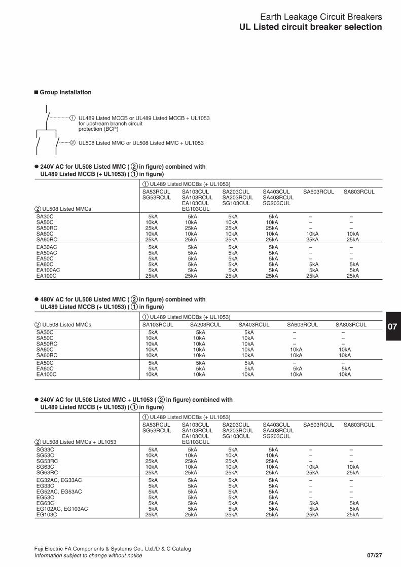
Fuji Electric FA Components & Systems Co., Ltd./D & C CatalogInformation subject to change without notice 07/27
Earth Leakage Circuit BreakersUL Listed circuit breaker selection
07
Group Installation
2 UL508 Listed MMCsSA30CSA50CSA50RCSA60CSA60RCEA30ACEA50ACEA50CEA60CEA100ACEA100C
1 UL489 Listed MCCBs (+ UL1053)SA53RCULSG53RCUL
5kA10kA25kA10kA25kA5kA5kA5kA5kA5kA
25kA
SA103CULSA103RCULEA103CULEG103CUL
5kA10kA25kA10kA25kA5kA5kA5kA5kA5kA
25kA
SA203CULSA203RCULSG103CUL
5kA10kA25kA10kA25kA5kA5kA5kA5kA5kA
25kA
SA403CULSA403RCULSG203CUL
5kA10kA25kA10kA25kA5kA5kA5kA5kA5kA
25kA
SA603RCUL
– – –10kA25kA
– – –
5kA5kA
25kA
SA803RCUL
– – –10kA25kA
– – –
5kA5kA
25kA
240V AC for UL508 Listed MMC ( 2 in figure) combined with UL489 Listed MCCB (+ UL1053) ( 1 in figure)
480V AC for UL508 Listed MMC ( 2 in figure) combined with UL489 Listed MCCB (+ UL1053) ( 1 in figure)
240V AC for UL508 Listed MMC + UL1053 ( 2 in figure) combined with UL489 Listed MCCB (+ UL1053) ( 1 in figure)
2 UL508 Listed MMCsSA30CSA50CSA50RCSA60CSA60RCEA50CEA60CEA100C
1 UL489 Listed MCCBs (+ UL1053)SA103RCUL
5kA10kA10kA10kA10kA5kA5kA
10kA
SA203RCUL5kA
10kA10kA10kA10kA5kA5kA
10kA
SA403RCUL5kA
10kA10kA10kA10kA5kA5kA
10kA
SA603RCUL – – –10kA10kA
–5kA
10kA
SA803RCUL – – –10kA10kA
–5kA
10kA
2 UL508 Listed MMCs + UL1053SG33CSG53CSG53RCSG63CSG63RCEG32AC, EG33ACEG33CEG52AC, EG53ACEG53CEG63CEG102AC, EG103ACEG103C
1 UL489 Listed MCCBs (+ UL1053)SA53RCULSG53RCUL
5kA10kA25kA10kA25kA5kA5kA5kA5kA5kA5kA
25kA
SA103CULSA103RCULEA103CULEG103CUL
5kA10kA25kA10kA25kA5kA5kA5kA5kA5kA5kA
25kA
SA203CULSA203RCULSG103CUL
5kA10kA25kA10kA25kA5kA5kA5kA5kA5kA5kA
25kA
SA403CULSA403RCULSG203CUL
5kA10kA25kA10kA25kA5kA5kA5kA5kA5kA5kA
25kA
SA603RCUL
– – –10kA25kA
– – – –
5kA5kA
25kA
SA803RCUL
– – –10kA25kA
– – – –
5kA5kA
25kA
1
2
UL489 Listed MCCB or UL489 Listed MCCB + UL1053for upstream branch circuit protection (BCP)
UL508 Listed MMC or UL508 Listed MMC + UL1053

Fuji Electric FA Components & Systems Co., Ltd./D & C CatalogInformation subject to change without notice07/28
Earth Leakage Circuit BreakersQuick reference guideUL Listed
� SG series UL/cUL508 Listed (File No. E216772)
Note: *1 The performance of UL508 approved models is indicated as applicable motor rating (HP), and the detection current of UL1053 approved models is indicated as the pick-up current value (70% of I n).*2 Rated current x 1*3 Rated current x 1/2
Instantaneous trip typeTime delay trip type
FrameType
Phase and wirePoleRated operating voltage (V AC)Max. motor rating(HP)UL508 [cUL]CSA C22.2 No. 14Load (A)UL508 [cUL]CSA C22.2 No. 14
Instantaneoustrip type
Tripping time (s) [UL1053]
Rated operating voltage (V AC)Rated sensitive current I∆n (mA) [UL508] [cUL]Pick-up current [UL1053]
Rated current (A)3-phase3-pole type onlySingle-phase
50ASG53C -CE–3ø3W, 1ø3W, 1ø2W3240
5, 10, 15, 20, 30, 40, 502.5, 5, 7.5, 10, 15, 20, 255, 10, 15, 20, 30, 40, 505, 10, 15, 20, 30, 40, 5024030, 100/200/500
0.1
SG53RC -CE–3ø3W, 1ø3W, 1ø2W3240
10, 15, 20, 30, 40, 505, 7.5, 10, 15, 20, 2510, 15, 20, 30, 40, 5010, 15, 20, 30, 40, 5024030, 100/200/500
0.1
50.5
1/6
50.5
1/6
101
1/3
50.5
1/6
152
3/4
202
1
303
2
405
3
507.5
3
101
1/3
152
3/4
202
1
303
2
405
3
507.5
3
101
1/3
152
3/4
202
1
303
2
60ASG63C -CE–3ø3W, 1ø3W, 1ø2W32406010
56030606024030, 100/200/500
0.7 x Rated sensitive current0.1
SG63RC -CE–3ø3W, 1ø3W, 1ø2W32406010
56030606024030, 100/200/500
0.7 x Rated sensitive current0.1
30A
220-240V AC
220-240V AC
SG33C -CE–3ø3W, 1ø3W, 1ø2W3240
3, 5, 10, 15, 20, 301.5, 2.5, 5, 7.5, 10, 153, 5, 10, 15, 20, 303, 5, 10, 15, 20, 3024030, 100/200/500
0.7 x Rated sensitive current0.1
Instantaneous trip typeTime delay trip type
FrameType
Phase and wirePoleRated operating voltage (V AC)Max. motor rating(HP)UL508 [cUL]CSA C22.2 No. 14Load (A)UL508 [cUL]CSA C22.2 No. 14
Instantaneoustrip type
Tripping time (s) [UL1053]
Rated operating voltage (V AC)Rated sensitive current I∆n (mA) [UL508] [cUL]Pick-up current [UL1053]
Rated current (A)3-phase3-pole type onlySingle-phase
220-240V AC
220-240V AC
*1
*1
Resistance *2
Discharge lamp *3
Incandescent lamp *2
Others *2
Resistance *2
Discharge lamp *3
Incandescent lamp *2
Others *2

Fuji Electric FA Components & Systems Co., Ltd./D & C CatalogInformation subject to change without notice 07/29
07
Earth Leakage Circuit BreakersQuick reference guide
UL Listed
Note: *1 The performance of UL508 approved models is indicated as applicable motor rating (HP), and the detection current of UL1053 approved models is indicated as the pick-up current value (70% of I n).*2 Rated current x 1*3 Rated current x 1/2
� EG series UL/cUL508 Listed (File No. E216772)
Instantaneous trip typeFrameTypePhase and wirePoleRated operating voltage (V AC)Max. motor rating(HP)UL508 [cUL]CSA C22.2 No. 14Load (A)UL508 [cUL]CSA C22.2 No. 14
Instantaneoustrip type
Tripping time (s) [UL1053]
Rated operating voltage (V AC)Rated sensitive current I∆n (mA) [UL508] [cUL]Pick-up current [UL1053]
Rated current (A)3-phase3-pole type onlySingle-phase
220-240V AC
220-240V AC
*1
EG32AC -CE1ø2W2240
5, 10, 15, 20, 302.5, 5, 7.5, 10, 155, 10, 15, 20, 305, 10, 15, 20, 3024015, 30, 100
0.7 x Rated sensitive current0.1
EG33AC -CE3ø3W, 1ø3W, 1ø2W3240
24015, 30, 100
0.1
EG33C -CE
3240
101
1/3
152
3/4
202
1
30A
60AEG63C -CE3ø3W, 1ø3W, 1ø2W3240
6030606024015, 30, 100/200
0.7 x Rated sensitive current0.1
EG103AC -CE3ø3W, 1ø3W, 1ø2W3240
60, 75, 10030, 37.5, 5060, 75, 10060, 75, 10024030, 100/200
0.1
EG102C -CE1ø2W2240
50, 60, 75, 10025, 30, 37.5, 5050, 60, 75, 10050, 60, 75, 10024030, 100/200
0.1
EG103C -CE3ø3W, 1ø3W, 1ø2W3240
24030, 100/200/500
0.1
100A
6010
5
7510
5
10015
7.5
75–
5
60–
5
50–
3
6010
5
100–
7.5
6010
5
507.5
3
7510
5
10015
7.5
50.5
1/6
303
2
10–
1/3
15–
3/4
20–
1
5–
1/6
30–
2
Instantaneous trip typeFrameTypePhase and wirePoleRated operating voltage (V AC)Max. motor rating(HP)UL508 [cUL]CSA C22.2 No. 14Load (A)UL508 [cUL]CSA C22.2 No. 14
Instantaneoustrip type
Tripping time (s) [UL1053]
Rated operating voltage (V AC)Rated sensitive current I∆n (mA) [UL508] [cUL]Pick-up current [UL1053]
Rated current (A)3-phase3-pole type onlySingle-phase
220-240V AC
220-240V AC
*1
EG52AC -CE1ø2W2240
5, 10, 15, 20, 30, 40, 502.5, 5, 7.5, 10, 15, 20, 255, 10, 15, 20, 30, 40, 505, 10, 15, 20, 30, 40, 5024015, 30, 100
0.7 x Rated sensitive current0.1
5–
1/6
10–
1/3
15–
3/4
20–
1
30–
2
40–
3
50–
3
50.5
1/6
101
1/3
152
3/4
202
1
303
2
405
3
507.5
3
50AEG53C -CE
3240
24015, 30,100
0.1
EG53AC -CE3ø3W, 1ø3W, 1ø2W3240
24015, 30, 100
0.1
Instantaneous trip typeFrameTypePhase and wirePoleRated operating voltage (V AC)Max. motor rating(HP)UL508 [cUL]CSA C22.2 No. 14Load (A)UL508 [cUL]CSA C22.2 No. 14
Instantaneoustrip type
Tripping time (s) [UL1053]
Rated operating voltage (V AC)Rated sensitive current I∆n (mA) [UL508] [cUL]Pick-up current [UL1053]
Rated current (A)3-phase3-pole type onlySingle-phase
220-240V AC
220-240V AC
*1
Resistance *2
Discharge lamp *3
Incandescent lamp *2
Others *2
Resistance *2
Discharge lamp *3
Incandescent lamp *2
Others *2
Resistance *2
Discharge lamp *3
Incandescent lamp *2
Others *2

Fuji Electric FA Components & Systems Co., Ltd./D & C CatalogInformation subject to change without notice07/30
� Mounting modificationsStandard type FUJI breakers are frontmounting with front connections. Thestandard breaker can easily bemodified to become front mountingrear connection type, flush mountingtype and plug-in type. The additionalparts such as insulation bases,barriers, covers and similar parts areadded as required.
Earth Leakage Circuit BreakersMounting modifications
Standard typeFront mountingFront connection
BASIC DESIGN
Additionalmain parts
Additionalmain parts
Additionalmain parts
Additionalmain parts
Round studterminal
Bar studterminal
Bar studterminal
Round studterminal
Bar studterminal
Bar studterminal
Round studterminal
Bar studterminal
Bar studterminal
Front mountingRear connection (X type)
Flush mountingRear connection (E type)
Plug-in mounting(P type)
Flush mountingTop and bottomconnection (Y type)
HG50BHG100B
Bar studs can be turnedby 90˚.
Bar studs can be turnedby 90˚.
SG30CSG50CSG50RCSG60CSG60RC
EG30CEG30ACEG50CEG50ACEG60CEG100CEG100AC
SG100CSG100RCSG225CSG225RCSG400CSG400RCSG600RCSG800RC
EG225CEG400CEG600CEG800C
HG225BHG400BHG600BHG800B
HG50BHG100B
SG30CSG50CSG50RCSG60CSG60RC
EG30CEG30ACEG50CEG50ACEG60CEG100CEG100AC
SG100CSG100RCSG225CSG225RCSG400CSG400RCSG600RCSG800RC
EG225CEG400CEG600CEG800C
HG225BHG400BHG600BHG800B
HG50BHG100B
SG100CSG100RC
SG30CSG50CSG50RCSG60CSG60RC
EG30CEG30ACEG50CEG50ACEG60CEG100CEG100AC
SG225CSG225RCSG400CSG400RCSG600RCSG800RC
EG225CEG400CEG600CEG800C
HG225BHG400BHG600BHG800B
SG30CSG50CSG50RCSG60CSG60RC
EG30CEG30ACEG50CEG50ACEG60CEG100CEG100AC
Bar studs can be turnedby 90˚.
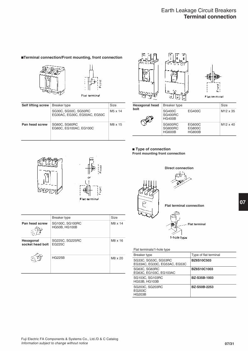
Fuji Electric FA Components & Systems Co., Ltd./D & C CatalogInformation subject to change without notice 07/31
07
Earth Leakage Circuit BreakersTerminal connection
�Terminal connection/Front mounting, front connection
Self lifting screw
Pan head screw
Breaker type
SG30C, SG50C, SG50RCEG30AC, EG30C, EG50AC, EG50C
SG60C, SG60RCEG60C, EG100AC, EG100C
Size
M5 x 14
M8 x 15
Hexagonal headbolt
Breaker type
SG400C EG400CSG400RCHG400B
SG600RC EG600CSG800RC EG800CHG600B HG800B
Size
M12 x 35
M12 x 40
Pan head screw
Hexagonalsocket head bolt
Breaker type
SG100C, SG100RCHG50B, HG100B
SG225C, SG225RCEG225C
HG225B
Size
M8 x 14
M8 x 16
M8 x 20
� Type of connectionFront mounting front connection
Direct connection
Flat terminal connection
Flat terminals/1-hole type
Breaker type Type of flat terminal
SG33C, SG53C, SG53RC BZ6S10C503EG33AC, EG33C, EG53AC, EG53C
SG63C, SG63RC BZ6S10C1003EG63C, EG103C, EG103AC
SG103C, SG103RC BZ-S35B-1003HG53B, HG103B
SG203C, SG203RC BZ-S50B-2253EG203CHG203B
Flat terminal

07/32Fuji Electric FA Components & Systems Co., Ltd./D & C Catalog
Information subject to change without notice
Earth Leakage Circuit BreakersWire size and terminal
� Wire size and crimp terminalThe following is the size recommendations for crimpterminals.
Crimp terminal R: JIS C2805CB: JEM-1399JST: Product of Japan Crimp Terminal Co., Ltd.F: FUJI special crimp terminal
Ampereframe
30
50
60
100
225
400
600
800
ELCB type
SG30CEG30AC, EG30C
SG50C, SG50RCEG50AC, EG50C
HG50B
SG60C, SG60RCEG60C
SG100C, SG100RCHG100B
EG100ACEG100C
SG225C, SG225RCEG225CHG225B
SG400C, SG400RCEG400C, HG400B
SG600RC, EG600CHG600B
SG800RC, EG800CHG800B
Wire size (mm2)
1.04 |2.63
R2-5
R2-5
R2-8
R2-8
R2-8
R2-8
2.63 |6.64
R5.5-5
R5.5-5
R5.5-8
R5.5-8
R5.5-8
R5.5-8
6.64 |10.52
R8-5
R8-5
R8-8
R8-8
R8-8
R8-8
10.52 |16.78
R14-5
R14-5
R14-8
R14-8
R14-8
R14-8
R14-8
16.78 |26.66
JST22-S8
JST22-S8
R22-8
JST22-S8
R22-8
26.66 |42.42
JST38-S8
JST38-S8
R38-8
R38-12
42.42 |60.57
CB60-8
F60-8
R60-8
R60-12
96.3 |117.2
CB100-8
R100-12
R100-12
R100-12
117.2 |152.05
CB150-8
R150-12
R150-12
R150-12
192.6 |242.27
R200-12
R200-12
R200-12
242.27 |325
JST325-12
JST325-12
JST325-12
Block terminal connection (For UL Listed)ELCB type
SG100CUL
SG225CUL
Rated current(A)
324045506075
100125150175200225
Connectable wire size(AWG)
10AWG8AWG8AWG8AWG6AWG4AWG3AWG1AWG
1/0AWG2/0AWG3/0AWG4/0AWG
Tightening torque(N·m)5.8(5.8 to 6.4)
23(23 to 25.3)
Type of screw head and size(mm)Slotted screw head
Hexagonal socket headbolt 6.35mm (1/4 inch)
Notes: • AWG is abbreviation of "American Wire Gauge" and the UL approved wire unit.• The allowable temperature of wire is 75°C. (UL CSA approved)

Fuji Electric FA Components & Systems Co., Ltd./D & C CatalogInformation subject to change without notice 07/33
07� Breaker termination
ELCB type Front connection
SG30C, SG50C, SG50RCEG50C
EG30AC, EG30C, EG50AC(Front connection type only)
SG60C, SG60RCEG60C, EG100C
EG100AC(Front connection type only)
SG100C, SG100RC
SG225C, SG225RCEG225C
SG400C, SG400RCSG600RC, SG800RCEG400C, EG600C, EG800C
Rear connection X
Flush mountingE Y
Plug-in mountingP
Flat terminal
Flat terminal
Flat terminal
Self-lifiting terminal
90° rotational stud
Earth Leakage Circuit BreakersWire size and terminal
Crimp terminal connection (For UL Listed)ELCBtype
SG50RCUL
EG100CUL
SG100CUL
SG225CUL
Ratedcurrent(A)
35
1015203040506075
100324045506070758090
100125150175200225
Applicable crimp terminalJ.S.T. Mfg. Co., Ltd
60°C wire
R5.5-8R8-8R14-8
22-S8
38-S8
Aikoku Kogyo K.K.
60°C wire
R5.5-8R8-8R14-8
22-8
38-S8
75°C wireR2-5
R5.5-5
R8-5
R14-822-S838-S8R5.5-8R8-8R14-8
22-S8
38-S8
38-S8R60-870-8CB80-S8CB100-S8
75°C wireR2-5
R5.5-5
R8-5
R14-822-838-S8R5.5-8R8-8R14-8
22-8
38-S8
38-S8R60-8
Nichifu Co., Ltd.
60°C wire
R5.5-8R8-8R14-8
22-S8
38-S8
75°C wire
R5.5-8R8-8R14-8
22-S8
38-S8
38-S860-870-8CB80-S8CB100-8
Daido SolderlessTerminal Mfg. Co., Ltd.60°C wire
R5.5-8R8-8R14-8
22-S8
38-S8
Connectablewire size(AWG)60°C wire
10AWG8AWG6AWG
4AWG
3AWG
2AWG1AWG
75°C wire14AWG
12AWG10AWG8AWG
6AWG4AWG3AWG10AWG8AWG6AWG
4AWG
3AWG
1AWG1/0AWG2/0AWG3/0AWG4/0AWG
Tighteningtorque(N•m)
2.3-2.8
5.5-7.5
5.8(5.3-6.4)
10.5(8-13)
Type of screwhead and size(mm)
Cross-recessedpan-head screwM5 x 14
Cross-recessedpan-head screwM8 x 14Cross-recessedpan-head screwM8 x 14
Hexagonalsocket head boltM8 x 16
Notes: • AWG is abbreviation of "American Wire Gauge" and the UL approved wire unit.• The allowable temperature of wire is 75°C. (UL and CSA approved)
75°C wire
R5.5-8R8-8R14-8
22-S8
38-S8
R38-S8R60-8R70-8

07/34Fuji Electric FA Components & Systems Co., Ltd./D & C Catalog
Information subject to change without notice
Earth Leakage Circuit BreakersType number nomenclature
Ordering informationSpecify the following:1. Type number of ELCB including factory-mounted optional accessories2. Type number of customer-mountable optional accessories
Customer-mountable optional accessories/Sold separatelyInternal accessoriesAuxiliary switch, alarm switch, shunt trip device (except for SG100, SG225, EG225),undervoltage trip device (except for SG100, SG225, EG225), terminal block
External accessoriesOperating handles (N, V and G-type), terminal covers, insulation barrier,steel enclosures, handle locking covers, kits for mounting modification,flat terminal, mechanical interlock device
Factory-mounted optional accessoriesExternal accessoriesHandle padlocking devices/Q1 and Q2, motor-operating mechanism/M,megger test switch/MGS, test lead wire/TL
Further information: See pages 07/68.
� Type number nomenclature
SeriesEG: E seriesSG: S seriesHG: H series
Frame size
No. of poles2: 2-pole3: 3-pole4: 4-pole
Operating characteristicBlank: Line protectionM: Motor protection
Rated current
3: 30AF5: 50AF6: 60AF10: 100AF20: 225AF40: 400AF60: 600AF80: 800AF
15MA: 15mA30MA: 30mA100MA: 100mACO: Sensitive current changeover
CCC approvedSee page 07/122
IEC and CE marking conformedSG and EG series up to 400AF, 2- and 3-pole only
Optional accessories/Factory-mountedMGS: Megger test switchTL: Test lead wire
OperationBlank: Manual operationM: With motor operating deviceSee page 07/85
Tripping deviceF: Shunt trip, see page 07/82R: Undervoltage trip, see page 07/83
Handle padlocking deviceO1: Cap typeQ2: Plate type
Mounting and connectionBlank: Front mounting front connectionX: Front mounting rear connectionE: Flush mounting rear connectionY: Flush mounting top & bottom connectionP: Plug-in mounting
Rated sensitive current
SG 5 3 C M / 50 - 30MA X Q2 F M1 MGS -CE (CCC)
• These ELCBs are pollution degree 2.
Time delay type is available, JIS C 8371.

Fuji Electric FA Components & Systems Co., Ltd./D & C CatalogInformation subject to change without notice 07/35
07
SeriesEG: E seriesSG: S series
Frame size
No. of poles2: 2-pole3: 3-pole
UL489 approved
5: 50AF10: 100AF20: 225AF
30MA: 30mACO: Sensitive current changeover
Handle padlocking device
Terminal*See the table below.
Rated sensitive current
Rated current
EG 10 3 C UL / 100 - 30MA L1 Q1
Code
BlankL1L3L4L5L6L7L8
* Combination of terminals
Terminal position
Line side
ScrewFlat terminalScrewFlat terminalScrewBlock terminalFlat terminalBlock terminal
Load side
ScrewFlat terminalFlat terminalScrewBlock terminalScrewBlock terminalFlat terminal
Applicable ELCB type
SG53RCULEG102CULEG103CUL
: Available : Not available
SG103CULSG203CUL
SG403CUL
Note: •When using both a flat terminal and terminal cover for SG103CUL and 203CUL,the terminal cover for the flat terminal is required.
•For SG50RCUL and EG100CUL, use an insulation barriersupplied.Terminal cover is not available.
Ordering informationSpecify the following:1. Type number of ELCB including factory-mounted optional accessories2. Type number of customer-mountable optional accessories
Customer-mountable optional accessories/Sold separatelyInternal accessoriesAuxiliary switch, alarm switch, shunt trip device, undervoltage trip device,terminal block
External accessoriesOperating handles (N and V-type), terminal covers, insulation barrier,steel enclosures, handle locking covers, kits for mounting modification,flat terminal, mechanical interlock device
Earth Leakage Circuit BreakersType number nomenclature
UL approved
� Type number nomenclature / UL489 approved

Fuji Electric FA Components & Systems Co., Ltd./D & C CatalogInformation subject to change without notice07/36
Breaker Rated Sensitive current Sensitive current : Available mountingampere current 30mA 100/200/500mA selectable and connectionframe (A) Type Type
30 3 SG33C/3-30MA -CE SG33C/3-CO -CE Blank, X, E, Y, P5 SG33C/5-30MA -CE SG33C/5-CO -CE
10 SG33C/10-30MA -CE SG33C/10-CO -CE15 SG33C/15-30MA -CE SG33C/15-CO -CE20 SG33C/20-30MA -CE SG33C/20-CO -CE30 SG33C/30-30MA -CE SG33C/30-CO -CE
50 5 SG53C/5-30MA -CE SG53C/5-CO -CE Blank, X, E, Y, P10 SG53C/10-30MA -CE SG53C/10-CO -CE15 SG53C/15-30MA -CE SG53C/15-CO -CE20 SG53C/20-30MA -CE SG53C/20-CO -CE30 SG53C/30-30MA -CE SG53C/30-CO -CE40 SG53C/40-30MA -CE SG53C/40-CO -CE50 SG53C/50-30MA -CE SG53C/50-CO -CE
10 SG53RC/10-30MA -CE SG53RC/10-CO -CE Blank, X, E, Y, P15 SG53RC/15-30MA -CE SG53RC/15-CO -CE20 SG53RC/20-30MA -CE SG53RC/20-CO -CE30 SG53RC/30-30MA -CE SG53RC/30-CO -CE40 SG53RC/40-30MA -CE SG53RC/40-CO -CE50 SG53RC/50-30MA -CE SG53RC/50-CO -CE
60 60 SG63C/60-30MA -CE SG63C/60-CO -CE Blank, X, E, Y, P
60 SG63RC/60-30MA -CE SG63RC/60-CO -CE Blank, X, E, Y, P
100 15 SG103C/15-30MA -CE SG103C/15-CO -CE Blank, X, E, P20 SG103C/20-30MA -CE SG103C/20-CO -CE30 SG103C/30-30MA -CE SG103C/30-CO -CE40 SG103C/40-30MA -CE SG103C/40-CO -CE50 SG103C/50-30MA -CE SG103C/50-CO -CE60 SG103C/60-30MA -CE SG103C/60-CO -CE75 SG103C/75-30MA -CE SG103C/75-CO -CE
100 SG103C/100-30MA -CE SG103C/100-CO -CE
15 SG103RC/15-30MA -CE SG103RC/15-CO -CE Blank, X, E, P20 SG103RC/20-30MA -CE SG103RC/20-CO -CE30 SG103RC/30-30MA -CE SG103RC/30-CO -CE40 SG103RC/40-30MA -CE SG103RC/40-CO -CE50 SG103RC/50-30MA -CE SG103RC/50-CO -CE60 SG103RC/60-30MA -CE SG103RC/60-CO -CE75 SG103RC/75-30MA -CE SG103RC/75-CO -CE
100 SG103RC/100-30MA -CE SG103RC/100-CO -CE
225 125 SG203C/125-30MA -CE SG203C/125-CO -CE Blank, X, E, P150 SG203C/150-30MA -CE SG203C/150-CO -CE175 SG203C/175-30MA -CE SG203C/175-CO -CE200 SG203C/200-30MA -CE SG203C/200-CO -CE225 SG203C/225-30MA -CE SG203C/225-CO -CE
125 SG203RC/125-30MA -CE SG203RC/125-CO -CE Blank, X, E, P150 SG203RC/150-30MA -CE SG203RC/150-CO -CE175 SG203RC/175-30MA -CE SG203RC/175-CO -CE200 SG203RC/200-30MA -CE SG203RC/200-CO -CE225 SG203RC/225-30MA -CE SG203RC/225-CO -CE
400 250 SG403C/250-30MA -CE SG403C/250-CO -CE Blank, X, E, P300 SG403C/300-30MA -CE SG403C/300-CO -CE350 SG403C/350-30MA -CE SG403C/350-CO -CE400 SG403C/400-30MA -CE SG403C/400-CO -CE
Earth Leakage Circuit BreakersType numberLine protection
Earth leakage + Overcurrent + Short-circuit protection type� SG series/3-pole IEC and CE marking conformed
Mounting Connection
Front Front BlankFront Rear XFlush Rear EFlush Top and bottom YPlug-in P

Fuji Electric FA Components & Systems Co., Ltd./D & C CatalogInformation subject to change without notice 07/37
07
Earth Leakage Circuit BreakersType number
Line protection
Mounting Connection
Front Front BlankFront Rear XFlush Rear EPlug-in P
Breaker Rated Sensitive current Sensitive current : Available mountingampere current 30mA 100/200/500mA selectable and connectionframe (A) Type Type
400 250 SG403RC/250-30MA SG403RC/250-CO Blank, X, E, P300 SG403RC/300-30MA SG403RC/300-CO350 SG403RC/350-30MA SG403RC/350-CO400 SG403RC/400-30MA SG403RC/400-CO
600 500 – SG603RC/500-CO Blank, X, E, P600 SG603RC/600-CO
800 700 – SG803RC/700-CO Blank, X, E, P800 SG803RC/800-CO
Earth leakage + Overcurrent + Short-circuit protection type� SG series/3-pole JIS C8371
� SG series/4-pole JIS C8371
Breaker Rated Sensitive current Sensitive current : Available mountingampere current 30mA 100/200/500mA selectable and connectionframe (A) Type Type
100 40 SGa104A/40-30MA SGa104A/40-CO Blank, X, E50 SGa104A/50-30MA SGa104A/50-CO60 SGa104A/60-30MA SGa104A/60-CO75 SGa104A/75-30MA SGa104A/75-CO
100 SGa104A/100-30MA SGa104A/100-CO
100 50 SG104H/50-30MA SG104H/50-CO Blank, X, E60 SG104H/60-30MA SG104H/60-CO75 SG104H/75-30MA SG104H/75-CO
100 SG104H/100-30MA SG104H/100-CO
225 125 SGa204A/125-30MA SGa204A/125-CO Blank, X, E150 SGa204A/150-30MA SGa204A/150-CO175 SGa204A/175-30MA SGa204A/175-CO200 SGa204A/200-30MA SGa204A/200-CO225 SGa204A/225-30MA SGa204A/225-CO
225 125 SG204H/125-30MA SG204H/125-CO Blank, X, E150 SG204H/150-30MA SG204H/150-CO175 SG204H/175-30MA SG204H/175-CO200 SG204H/200-30MA SG204H/200-CO225 SG204H/225-30MA SG204H/225-CO
400 250 SGa404A/250-30MA SGa404A/250-CO Blank, X, E300 SGa404A/300-30MA SGa404A/300-CO350 SGa404A/350-30MA SGa404A/350-CO400 SGa404A/400-30MA SGa404A/400-CO

Fuji Electric FA Components & Systems Co., Ltd./D & C CatalogInformation subject to change without notice07/38
Earth Leakage Circuit BreakersType numberLine protection
Mounting Connection
Front Front BlankFront Rear XFlush Rear EFlush Top and bottom YPlug-in P
Breaker Rated Sensitive current Sensitive current Sensitive current : Available mountingampere current 15mA 30mA 100mA and connectionframe (A)
Type Type Type
30 5 EG32AC/5-15MA -CE EG32AC/5-30MA -CE EG32AC/5-100MA -CE Blank, X, E, Y, P10 EG32AC/10-15MA -CE EG32AC/10-30MA -CE EG32AC/10-100MA -CE15 EG32AC/15-15MA -CE EG32AC/15-30MA -CE EG32AC/15-100MA -CE20 EG32AC/20-15MA -CE EG32AC/20-30MA -CE EG32AC/20-100MA -CE30 EG32AC/30-15MA -CE EG32AC/30-30MA -CE EG32AC/30-100MA -CE
50 5 EG52AC/5-15MA -CE EG52AC/5-30MA -CE EG52AC/5-100MA -CE Blank, X, E, Y, P10 EG52AC/10-15MA -CE EG52AC/10-30MA -CE EG52AC/10-100MA -CE15 EG52AC/15-15MA -CE EG52AC/15-30MA -CE EG52AC/15-100MA -CE20 EG52AC/20-20MA -CE EG52AC/20-30MA -CE EG52AC/20-100MA -CE30 EG52AC/30-15MA -CE EG52AC/30-30MA -CE EG52AC/30-100MA -CE40 EG52AC/40-15MA -CE EG52AC/40-30MA -CE EG52AC/40-100MA -CE50 EG52AC/50-15MA -CE EG52AC/50-30MA -CE EG52AC/50-100MA -CE
100 Sensitive current Blank, X, E, Y, P100/200mA selectable
50 – EG102C/50-30MA -CE EG102C/50-CO -CE60 – EG102C/60-30MA -CE EG102C/60-CO -CE75 – EG102C/75-30MA -CE EG102C/75-CO -CE
100 – EG102C/100-30MA -CE EG102C/100-CO -CE
Earth leakage + Overcurrent + Short-circuit protection type� EG series/2-pole IEC and CE marking conformed

Fuji Electric FA Components & Systems Co., Ltd./D & C CatalogInformation subject to change without notice 07/39
07
Breaker Rated Sensitive current Sensitive current Sensitive current : Available mountingampere current 15mA 30mA 100mA and connectionframe (A)
Type Type Type
30 5 EG33AC/5-15MA -CE EG33AC/5-30MA -CE EG33AC/5-100MA -CE Blank, X, E, Y, P10 EG33AC/10-15MA -CE EG33AC/10-30MA -CE EG33AC/10-100MA -CE15 EG33AC/15-15MA -CE EG33AC/15-30MA -CE EG33AC/15-100MA -CE20 EG33AC/20-15MA -CE EG33AC/20-30MA -CE EG33AC/20-100MA -CE30 EG33AC/30-15MA -CE EG33AC/30-30MA -CE EG33AC/30-100MA -CE
5 EG33C/5-15MA -CE EG33C/5-30MA -CE EG33C/5-100MA -CE Blank, X, E, Y, P10 EG33C/10-15MA -CE EG33C/10-30MA -CE EG33C/10-100MA -CE15 EG33C/15-15MA -CE EG33C/15-30MA -CE EG33C/15-100MA -CE20 EG33C/20-20MA -CE EG33C/20-30MA -CE EG33C/20-100MA -CE30 EG33C/30-15MA -CE EG33C/30-30MA -CE EG33C/30-100MA -CE
50 5 EG53AC/5-15MA -CE EG53AC/5-30MA -CE EG53AC/5-100MA -CE Blank, X, E, Y, P10 EG53AC/10-15MA -CE EG53AC/10-30MA -CE EG53AC/10-100MA -CE15 EG53AC/15-15MA -CE EG53AC/15-30MA -CE EG53AC/15-100MA -CE20 EG53AC/20-15MA -CE EG53AC/20-30MA -CE EG53AC/20-100MA -CE30 EG53AC/30-15MA -CE EG53AC/30-30MA -CE EG53AC/30-100MA -CE40 EG53AC/40-15MA -CE EG53AC/40-30MA -CE EG53AC/40-100MA -CE50 EG53AC/50-15MA -CE EG53AC/50-30MA -CE EG53AC/50-100MA -CE
Sensitive current Blank, X, E, Y, P100/200mA selectable
5 EG53C/5-15MA -CE EG53C/5-30MA -CE EG53C/5-CO -CE10 EG53C/10-15MA -CE EG53C/10-30MA -CE EG53C/10-CO -CE15 EG53C/15-15MA -CE EG53C/15-30MA -CE EG53C/15-CO -CE20 EG53C/20-15MA -CE EG53C/20-30MA -CE EG53C/20-CO -CE30 EG53C/30-15MA -CE EG53C/30-30MA -CE EG53C/30-CO -CE40 EG53C/40-15MA -CE EG53C/40-30MA -CE EG53C/40-CO -CE50 EG53C/50-15MA -CE EG53C/50-30MA -CE EG53C/50-CO -CE
60 Sensitive current Blank, X, E, Y, P100/200mA selectable
60 EG63C/60-15MA -CE EG63C/60-30MA -CE EG63C/60-CO -CE
100 Sensitive current Blank, X, E, Y, P100/200mA selectable
60 – EG103AC/60-30MA -CE EG103AC/60-CO -CE75 – EG103AC/75-30MA -CE EG103AC/75-CO -CE
100 – EG103AC/100-30MA -CE EG103AC/100-CO -CE
Sensitive current Blank, X, E, Y, P100/200/500mA selectable
50 – EG103C/50-30MA -CE EG103C/50-CO -CE60 – EG103C/60-30MA -CE EG103C/60-CO -CE75 – EG103C/75-30MA -CE EG103C/75-CO -CE
100 – EG103C/100-30MA -CE EG103C/100-CO -CE
225 Sensitive current Blank, X, E, P100/200/500mA selectable
125 – EG203C/125-30MA -CE EG203C/125-CO -CE150 – EG203C/150-30MA -CE EG203C/150-CO -CE175 – EG203C/175-30MA -CE EG203C/175-CO -CE200 – EG203C/200-30MA -CE EG203C/200-CO -CE225 – EG203C/225-30MA -CE EG203C/225-CO -CE
400 Sensitive current Blank, X, E, P100/200/500mA selectable
250 – EG403C/250-30MA -CE EG403C/250-CO -CE300 – EG403C/300-30MA -CE EG403C/300-CO -CE350 – EG403C/350-30MA -CE EG403C/350-CO -CE400 – EG403C/400-30MA -CE EG403C/400-CO -CE
Earth Leakage Circuit BreakersType number
Line protection
Earth leakage + Overcurrent + Short-circuit protection type� EG series/3-pole IEC and CE marking conformed
Mounting Connection
Front Front BlankFront Rear XFlush Rear EFlush Top and bottom YPlug-in P

Fuji Electric FA Components & Systems Co., Ltd./D & C CatalogInformation subject to change without notice07/40
Breaker Rated Sensitive current : Available mountingampere current 100/200/500mA selectable and connectionframe (A)
Type600 500 EG603C/500-CO Blank, X, E, P
600 EG603C/600-CO800 700 EG803C/700-CO Blank, X, E, P
800 EG803C/800-CO
Earth Leakage Case BreakersType numberLine protection
Earth leakage + Overcurrent + Short-circuit protection type� EG series/3-pole JIS C8371
Mounting Connection
Front Front BlankFront Rear XFlush Rear EFlush Top and bottom YPlug-in P
� EG series/4-pole (3P+1N) JIS C8371Front mounting, front connection
Breaker Rated Sensitive current Sensitive current Sensitive current Sensitive currentampere current 30mA 100mA 300mA 500mAframe (A) Type Type Type Type
100 30 EG104A/30-30MA EG104A/30-100MA EG104A/30-300MA EG104A/30-500MA40 EG104A/40-30MA EG104A/40-100MA EG104A/40-300MA EG104A/40-500MA50 EG104A/50-30MA EG104A/50-100MA EG104A/50-300MA EG104A/50-500MA60 EG104A/60-30MA EG104A/60-100MA EG104A/60-300MA EG104A/60-500MA75 EG104A/75-30MA EG104A/75-100MA EG104A/75-300MA EG104A/75-500MA
100 EG104A/100-30MA EG104A/100-100MA EG104A/100-300MA EG104A/100-500MA

Fuji Electric FA Components & Systems Co., Ltd./D & C CatalogInformation subject to change without notice 07/41
07
Earth Leakage Circuit BreakersType number
Line protection
Breaker Rated Sensitive current Sensitive current : Available mountingampere current 30mA 100/200/500mA selectable and connectionframe (A) Type Type50 15 HG53B/15-30MA HG53B/15-CO Blank, X, E, P
20 HG53B/20-30MA HG53B/20-CO30 HG53B/30-30MA HG53B/30-CO40 HG53B/40-30MA HG53B/40-CO50 HG53B/50-30MA HG53B/50-CO
100 15 HG103B/15-30MA HG103B/15-CO Blank, X, E, P20 HG103B/20-30MA HG103B/20-CO30 HG103B/30-30MA HG103B/30-CO40 HG103B/40-30MA HG103B/40-CO50 HG103B/50-30MA HG103B/50-CO60 HG103B/60-30MA HG103B/60-CO75 HG103B/75-30MA HG103B/75-CO
100 HG103B/100-30MA HG103B/100-CO225 125 HG203B/125-30MA HG203B/125-CO Blank, X, E, P
150 HG203B/150-30MA HG203B/150-CO175 HG203B/175-30MA HG203B/175-CO200 HG203B/200-30MA HG203B/200-CO225 HG203B/225-30MA HG203B/225-CO
400 250 HG403B/250-30MA HG403B/250-CO Blank, X, E, P300 HG403B/300-30MA HG403B/300-CO350 HG403B/350-30MA HG403B/350-CO400 HG403B/400-30MA HG403B/400-CO
600 500 – HG603B/500-CO Blank, X, E, P600 – HG603B/600-CO
800 700 – HG803B/700-CO Blank, X, E, P800 – HG803B/800-CO
Earth leakage + Overcurrent + Short-circuit protection type� HG series/3-pole JIS C8371
Mounting Connection
Front Front BlankFront Rear XFlush Rear EPlug-in P

Earth Leakage Circuit BreakersType numberMotor protection
Fuji Electric FA Components & Systems Co., Ltd./D & C CatalogInformation subject to change without notice07/42
: Availablemounting andconnection
Blank, X, E, Y, P
Blank, X, E, Y, P
Blank, X, E, Y, P
Blank, X, E, P
Ratedcurrent(A)
0.7 1.4 2 2.6 4 5
81012162432
0.7 1.4 2 2.6 4 5 8
10121624324045
60
7590
Motor capacity(kW)200/220V 400/440V
— 0.2 0.2 0.4 — 0.75 0.4 — 0.75 1.5 — 2.2
1.5 3.7 2.2 — — 5.5 3.7 7.5 5.5 11 7.5 15
— 0.2 0.2 0.4 — 0.75 0.4 — 0.75 1.5 — 2.2 1.5 3.7
2.2 — — 5.5 3.7 7.5 5.5 11 7.5 15 — 18.511 22
15 30
18.5 3722 45
Breakerampereframe
30
50
60
100
Sensitive current30mA
SG33CM/0.7-30MA -CESG33CM/1.4-30MA -CESG33CM/2-30MA -CESG33CM/2.6-30MA -CESG33CM/4-30MA -CESG33CM/5-30MA -CE
SG33CM/8-30MA -CESG33CM/10-30MA -CESG33CM/12-30MA -CESG33CM/16-30MA -CESG33CM/24-30MA -CESG33CM/32-30MA -CE
SG53CM/0.7-30MA -CESG53CM/1.4-30MA -CESG53CM/2-30MA -CESG53CM/2.6-30MA -CESG53CM/4-30MA -CESG53CM/5-30MA -CESG53CM/8-30MA -CE
SG53CM/10-30MA -CESG53CM/12-30MA -CESG53CM/16-30MA -CESG53CM/24-30MA -CESG53CM/32-30MA -CESG53CM/40-30MA -CESG53CM/45-30MA -CE
SG63CM/60-30MA -CE
SG103CM/75-30MA -CESG103CM/90-30MA -CE
Sensitive current100/200/500mA selectable
SG33CM/0.7-CO -CESG33CM/1.4-CO -CESG33CM/2-CO -CESG33CM/2.6-CO -CESG33CM/4-CO -CESG33CM/5-CO -CE
SG33CM/8-CO -CESG33CM/10-CO -CESG33CM/12-CO -CESG33CM/16-CO -CESG33CM/24-CO -CESG33CM/32-CO -CE
SG53CM/0.7-CO -CESG53CM/1.4-CO -CESG53CM/2-CO -CESG53CM/2.6-CO -CESG53CM/4-CO -CESG53CM/5-CO -CESG53CM/8-CO -CE
SG53CM/10-CO -CESG53CM/12-CO -CESG53CM/16-CO -CESG53CM/24-CO -CESG53CM/32-CO -CESG53CM/40-CO -CESG53CM/45-CO -CE
SG63CM/60-CO -CE
SG103CM/75-CO -CESG103CM/90-CO -CE
45 60 75 90
125150175225
125150175225
Blank, X, E, P
SG103RCM/45-30MA -CESG103RCM/60-30MA -CESG103RCM/75-30MA -CESG103RCM/90-30MA -CE
SG203CM/125-30MA -CESG203CM/150-30MA -CESG203CM/175-30MA -CESG203CM/225-30MA -CE
SG203RCM/125-30MA -CESG203RCM/150-30MA -CESG203RCM/175-30MA -CESG203RCM/225-30MA -CE
225
11 2215 3018.5 3722 45
30 5537 7545 9055 110
30 5537 7545 9055 110
SG103RCM/45-CO -CESG103RCM/60-CO -CESG103RCM/75-CO -CESG103RCM/90-CO -CE
SG203CM/125-CO -CESG203CM/150-CO -CESG203CM/175-CO -CESG203CM/225-CO -CE
SG203RCM/125-CO -CESG203RCM/150-CO -CESG203RCM/175-CO -CESG203RCM/225-CO -CE
� SG series, 3-pole IEC and CE marking conformed

Earth Leakage Circuit BreakersType number
Motor protection
07/43Fuji Electric FA Components & Systems Co., Ltd./D & C CatalogInformation subject to change without notice
07
0.2 0.40.4 —0.75 1.51 2.21.5 3.72.2 —3.7 7.55.5 117.5 15
11 22
15 30
15 3018.5 3722 45
30 5537 7545 9055 110
EG33CM/1.4-30MA -CEEG33CM/2.6-30MA -CEEG33CM/4-30MA -CEEG33CM/5-30MA -CEEG33CM/8-30MA -CEEG33CM/10-30MA -CEEG33CM/16-30MA -CEEG33CM/24-30MA -CEEG33CM/32-30MA -CE
EG53CM/45-30MA -CE
EG63CM/60-30MA -CE
EG103CM/60-30MA -CEEG103CM/75-30MA -CEEG103CM/90-30MA -CE
EG203CM/125-30MA -CEEG203CM/150-30MA -CEEG203CM/175-30MA -CEEG203CM/225-30MA -CE
Blank, X, E, Y, P
Blank, X, E, Y, P
Blank, X, E, Y, P
Blank, X, E, Y, P
Blank, X, E, P
1.4 2.6 4 5 8 10 16 24 32
45
60
60 75 90
125150175225
30
50
60
100
225
EG33CM/1.4-100MA -CEEG33CM/2.6-100MA -CEEG33CM/4-100MA -CEEG33CM/5-100MA -CEEG33CM/8-100MA -CEEG33CM/10-100MA -CEEG33CM/16-100MA -CEEG33CM/24-100MA -CEEG33CM/32-100MA -CE
Sensitive current 100/200mAEG53CM/45-CO -CE
Sensitive current 100/200mAEG63CM/60-CO -CE
Sensitive current 100/200/500mAEG103CM/60-CO -CEEG103CM/75-CO -CEEG103CM/90-CO -CE
Sensitive current 100/200/500mAEG203CM/125-CO -CEEG203CM/150-CO -CEEG203CM/175-CO -CEEG203CM/225-CO -CE
: Availablemounting andconnection
Ratedcurrent(A)
Motor capacity(kW)200/220V 400/440V
Breakerampereframe
Sensitive current30mA
Sensitive current100mA
� EG series, 3-pole IEC and CE marking conformed

Earth Leakage Circuit BreakersType numberUL Listed
Fuji Electric FA Components & Systems Co., Ltd./D & C CatalogInformation subject to change without notice07/44
EG102CUL/60-30MAEG102CUL/70-30MAEG102CUL/75-30MAEG102CUL/80-30MAEG102CUL/90-30MAEG102CUL/100-30MA
60 70 75 80 90100
100 EG102CUL/60-COEG102CUL/70-COEG102CUL/75-COEG102CUL/80-COEG102CUL/90-COEG102CUL/100-CO
Ratedcurrent(A)
Breakerampereframe
Sensitive current30mA
Sensitive current100/200mA selectable
Earth leakage + Overcurrent + Short-circuit protection type� EG series, 2-pole UL489 approved
SG53RCUL/3-30MASG53RCUL/5-30MASG53RCUL/10-30MASG53RCUL/15-30MASG53RCUL/20-30MASG53RCUL/30-30MASG53RCUL/40-30MASG53RCUL/50-30MA
SG103CUL/32-30MASG103CUL/40-30MASG103CUL/50-30MASG103CUL/60-30MASG103CUL/75-30MASG103CUL/100-30MA
SG203CUL/125-30MASG203CUL/150-30MASG203CUL/175-30MASG203CUL/200-30MASG203CUL/225-30MA
SG403CUL/250-30MASG403CUL/300-30MASG403CUL/350-30MASG403CUL/400-30MA
EG103CUL/60-30MAEG103CUL/70-30MAEG103CUL/75-30MAEG103CUL/80-30MAEG103CUL/90-30MAEG103CUL/100-30MA
3 5 10 15 20 30 40 50
32 40 50 60 75100
125150175200225
250300350400
60 70 75 80 90100
50
100
200
400
100
SG53RCUL/3-COSG53RCUL/5-COSG53RCUL/10-COSG53RCUL/15-COSG53RCUL/20-COSG53RCUL/30-COSG53RCUL/40-COSG53RCUL/50-CO
SG103CUL/32-COSG103CUL/40-COSG103CUL/50-COSG103CUL/60-COSG103CUL/75-COSG103CUL/100-CO
SG203CUL/125-COSG203CUL/150-COSG203CUL/175-COSG203CUL/200-COSG203CUL/225-CO
SG403CUL/250-COSG403CUL/300-COSG403CUL/350-COSG403CUL/400-CO
EG103CUL/60-COEG103CUL/70-COEG103CUL/75-COEG103CUL/80-COEG103CUL/90-COEG103CUL/100-CO
Ratedcurrent(A)
Breakerampereframe
Sensitive current30mA
Sensitive current100/200/500mA selectable
Earth leakage + Overcurrent + Short-circuit protection type� SG and EG series, 3-pole UL489 approved

Fuji Electric FA Components & Systems Co., Ltd./D & C CatalogInformation subject to change without notice 07/45
07
Earth Leakage Circuit BreakersDimensions
SG series/3-pole
SG63C -CE, 63RC -CE
Dimensions, mm Front mounting, front connection
SG33C -CE, 53C -CE, 53RC -CE
SG103C -CE
7
CL
CL
52 o
rm
ore
CL
CL
84
ON
50
5084 10
0
CL
4042
CL
507275
1724
7
25
516084
84
43
46 2.5
Mounting hole ø4.9
Insulation barrier
Counterbore ø7.8
Trip button
EL trip indicatingbutton
Test button
Sensitive currentselective switch R2
or le
ss
74 or more
M5 x 14
Max
. 15 ø5.5
t ≤ 4
M4 or ø5ELCB ELCB
Panel drilling Front panel cutting Terminal section
CL
CL
CL
CL
84
ON
50
5084 10
0
CL
4042
CL
507275
ø9
7
7
2417
25
516084
84
43
46 2.5
Panel drilling Front panel cutting Terminal section
Mounting hole ø4.9Counterbore ø7.8
Sensitive currentselective switch
Trip button
Test button
EL trip indicatingbutton
Detachableinsulation barrier
M4 or ø5ELCB ELCB
R2 or
less
52 o
rm
ore
74 or more
M8 x 15M
ax. 1
5
t ≤ 6
52 o
rm
ore
R2 or
less
87 or more
M8 x 14
Max
. 16.
5
t ≤ 6
M4 or ø5 ELCB ELCB
Panel drilling Front panel cutting Terminal section
132
30
CL
CL
CL
CL
8.510
17
24
8
ø9
Mounting hole
Trip button
EL trip indicatingbutton
Test button
Sensitive currentselective switch
insulationbarrier
5658
CL
ON
1.5
47
511
6082
2
6
85
34.5
12.5
9413
.5
155
60
22
90
50 102
135
50
CL
CLø4.
5
ø8.
5
P.C.B box(Power)

Fuji Electric FA Components & Systems Co., Ltd./D & C CatalogInformation subject to change without notice07/46
Earth Leakage Circuit BreakersDimensionsSG series/3-pole
Dimensions, mm Front mounting, front connection
SG103RC -CE
SG203C -CE, 203RC -CE
SG403C -CE
52 o
rm
ore
R2 or
less
87 or more
M8 x 14
Max
. 16.
5
t ≤ 6
M4 or ø5 ELCB ELCB
Panel drilling Front panel cutting Terminal section
132
30
CL
CL
CL
CL
8.510
17
24
8
ø9
Mounting hole
Trip button
EL trip indicatingbutton
Test button
Sensitive currentselective switch
insulationbarrier
5658
CL
ON
1.5
47
511
6082
2
6
85
34.5
12.5
9413
.5
155
60
22
90
50 102
135
50
CL
CLø4.
5
ø8.
5
P.C.B box(Power)
Panel drilling Front panel cutting Terminal section
M4 or ø5 ELCB ELCB
R2 or
less
CL CL
CLCL 126
10.5 11
35
25.5
8
24
ø9
M8 x 16
Max
. 25
t ≤ 6
52 o
rm
ore
102 or more
Mounting hole
Detachable
Trip button
EL trip indicatingbutton
Test button
Sensitive currentselective switchinsulation barrier
5658.5
CL
ON
1
47
511
6084
2
6
ø4.
5
ø8.
5
7035
12.5
9421
165
100
22
105
50 102
144
80
CL
CLP.C.B box(Power)
Panel drilling Front panel cutting
ø13
.5
8
ON
CL
103
107
84
ø8
44
4.5
94.5
146
448
137
CL25
102
9010
5
CL
51
225
257
40.5
40.5
15
44 4456 56
135140
M12 x 35 bolt
137 or more
CLCL
214–
216
44
CL
92 o
r m
ore
CL
Mounting hole
Detachableinsulation barrier
EL trip indicatingbutton
Sensitive currentselective switch
Test button
Operating time selective switch (403RC)
Trip button
M6 or ø7ELCBELCB
R2 or
less

Fuji Electric FA Components & Systems Co., Ltd./D & C CatalogInformation subject to change without notice 07/47
07
Earth Leakage Circuit BreakersDimensions
SG series/3-pole
Dimensions, mm Front mounting, front connection
SG603RC
SG803RC
Detachableinsulation barrier
CL
CL
102
90
105
8724
324.5
275
87
815
32
44
51
53
140
210
205
CL 243
ø14
.5
ø7
107
1034.5
146
94.5
70
41.5
47
7
7
38.5
ON
C CLL
Mounting hole
EL trip indicatingbutton
Sensitive currentselective switch
Trip button
Test button
Operating timeselective switch
M12 x 40 bolt
Panel drilling Front panel cutting
M6 or ø7ELCB ELCB
R2 or
less
92 o
rm
ore
207 or more
CL CL
CL
ø14
.5
ø7
107
1034.5
146
94.5
10
41.5
ON
CL
CL
102
90
105
8724
3 243
24.5
275
87
815
32
44
51
53
140
210
205
70
44.5
47
10
Detachableinsulation barrier
Mounting hole
EL trip indicatingbutton
Sensitive currentselective switch
Trip button
Test button
Operating timeselective switch
M12 x 40 bolt
Panel drilling Front panel cutting
M6 or ø7ELCB ELCB
R2 or
less
92 o
rm
ore
207 or more

Fuji Electric FA Components & Systems Co., Ltd./D & C CatalogInformation subject to change without notice07/48
Earth Leakage Circuit BreakersDimensionsSG series/4-pole
Dimensions, mm Front mounting, front connection
SGa104A, 104H
SGa204A, 204H
SGa404A
Sensitive currentselective switch Test button
Operating timeadjustable dial
CL
26
11.5°
25
47.5
81865
109
230 30
14052.5
13535 35 3535 35
185
92.5
57.5 50
191
212
35
52.5
191
*58.
5
*52
*137
*51
(SG104AD,HD)
Terminal M8 Mounting hole 6-ø4.5
Mounting hole 6-ø4.5
CL of handle
CL of handle
CL of handle
CL of handle
5°
OFF
ON
Panel cutting
Panel drilling
*1mm clearance on each side of ELCB window frame
Protection devicefor overload andshort-circuit
R S T
U V W
N
NZCT
Trip coil
Solid-stateamplifier
Testbutton
Resistor
Operating timeadjustable dial
2-ø8 10.5 Mounting hole
Terminal M10
Mounting hole 4-ø7
Sensitive currentselective switch
Test button(SG204AD,HD)
2-ø8 15.5 Mounting hole
CL of handle
46.5
CL of handle
CL of handle CL of handle
CL
CL CL
17° 54
84
15°
OFF
ON
Panel cuttingPanel drilling
*1mm clearance on each side of ELCB window frame
3697
1037134
303
to 3
10.5
350
213 10
6.5
9795
318
18570.5
18044 4444
44 44
70.5
303
to 3
10.5
*96
*99
*182
*68.5
Operating timeadjustable dial
2-ø8 10.5 Mounting hole
2-ø8 15.5 Mounting holeTerminal M12
Sensitive currentselective switch
Test button
(SG404AD)
CL of handle
46.5
CL of handle
CL CLCL
17° 54
15°
OFF
ON
Mounting hole 4-ø7
CL of handle CL of handle
Panel cuttingPanel drilling
*1mm clearance on each side of ELCB window frame
44
70.5
303
to 3
10.5
*96 99
*182
*68.5
97
84
44
66
1037134
8
45
67
318
303
to 3
10.5
350
213
95
106.
5
185
70.5180
44 44444426.5
97
20.5
49.5
(Center and neutral poles)
ø13

Fuji Electric FA Components & Systems Co., Ltd./D & C CatalogInformation subject to change without notice 07/49
07
Earth Leakage Circuit BreakersDimensions
EG series/2, 3-pole
Dimensions, mm Front mounting, front connection
EG32AC -CE, 52AC -CE
EG63C -CE
EG33AC -CE, 53AC -CE, 33C -CE, 53C -CE
Panel drilling Front panel cutting Terminal section
Mounting hole ø4.9Counterbore ø7.8 EL trip indicating
button
ON
Trip button
Test button
M4 or ø5ELCB ELCB
52 o
rm
ore
50 ormore
R2 or
less
Max
. 15
M5 x 14
t ≤ 4
50 84 100
L
4042
CL
2547.550
L
L
7
516084
84
43
46
24
2.5
L
L
847
ø5.5
C
C
C 17
C
C
Panel drilling Front panel cutting Terminal sectionMounting hole ø4.9Counterbore ø7.8 EL trip indicating
button
ON
Trip button
Test button
M4 or ø5
ELCB ELCB
R2 or
less
Max
. 15
M5 x 14
t ≤ 4
7
516084
84
43
46
24
2.5
7
ø5.5
17
Sensitive currentselective switch
52 o
rm
ore
74 or more50 84 100
CL
4042
CL
507275
50
CL
CL
84 CL
CL
25
Insulation barrier
CL
CL
CL
CL
84
ON
50
5084 10
0
CL
4042
CL
507275
ø9
7
7
2417
25
516084
84
43
46 2.5
Panel drilling Front panel cutting Terminal section
Mounting hole ø4.9Counterbore ø7.8
Sensitive currentselective switch
Trip button
Test button
EL trip indicatingbutton
Detachableinsulation barrier
M4 or ø5ELCB ELCB
R2 or
less
52 o
rm
ore
74 or more
M8 x 15
Max
. 15
t ≤ 6

Fuji Electric FA Components & Systems Co., Ltd./D & C CatalogInformation subject to change without notice07/50
Earth Leakage Circuit BreakersDimensionsEG series/2, 3-pole
Dimensions, mm Front mounting, front connection
EG103AC -CE, 102C -CE, 103C -CE
EG403C -CE
EG203C -CE
CL
CL 50
50
507275
84 100
4042
Mounting hole ø4.9
Counterbore ø7.8
EL trip indicatingbutton
Trip button
Test button
51
43
ON
6084
84
CL
CL
25
84 CL
CL
R2 or
less
52 o
rm
ore
46 2.5
Max
. 15 ø9
7
t ≤ 6
7
2417
Insulation barrier
Sensitive currentselective switch
Panel drilling Front panel cutting Terminal section
ELCB ELCBM4 or ø5
74 or more
M8 x 15
Panel drilling Front panel cutting Terminal section
M4 or ø5 ELCB ELCB
R2 or
less
CL CL
CLCL 126
10.5 11
35
25.5
8
24
ø9
M8 x 16
Max
. 25
t ≤ 6
52 o
rm
ore
102 or more
Mounting hole
Detachable
Trip button
EL trip indicatingbutton
Test button
Sensitive currentselective switchinsulation barrier
5658.5
CL
ON
1
47
511
6084
2
6
ø4.
5
ø8.
5
7035
12.5
9421
165
100
22
105
50 102
144
80
CL
CLP.C.B box(Power)
Panel drilling Front panel cutting
ø13
.5
8
ON
CL
103
107
84
ø8
44
4.5
94.5
146
448
137
CL25
102
9010
5
CL
51
225
257
40.5
40.5
15
44 4456 56
135140
M12 x 35 bolt
137 or more
CLCL
214–
216
44
CL
92 o
r m
ore
CL
Mounting hole
Detachableinsulation barrier
EL trip indicatingbutton
Sensitive currentselective switch
Test button
Trip button
M6 or ø7ELCBELCB
R2 or
less

Fuji Electric FA Components & Systems Co., Ltd./D & C CatalogInformation subject to change without notice 07/51
07
Earth Leakage Circuit BreakersDimensions
EG series/3-pole, 4-pole
EG803C
Dimensions, mm Front mounting, front connection
EG603C
EG104A
Detachableinsulation barrier
CL
CL
102
90
105
8724
324.5
275
87
815
32
44
51
53
140
210
205
CL 243
ø14
.5
ø7
107
1034.5
146
94.5
70
41.5
47
7
7
38.5
ON
C CLL
Mounting hole
EL trip indicatingbutton
Sensitive currentselective switch
Trip button
Test button
Operating timeselective switch
M12 x 40 bolt
Panel drilling Front panel cutting
M6 or ø7ELCB ELCB
R2 or
less
92 o
rm
ore
207 or more
CL CL
CL
ø14
.5
ø7
107
1034.5
146
94.5
10
41.5
ON
CL
CL
102
90
105
8724
3 243
24.5
275
87
815
32
44
51
53
140
210
205
70
44.5
47
10
Detachableinsulation barrier
Mounting hole
EL trip indicatingbutton
Sensitive currentselective switch
Trip button
Test button
Operating timeselective switch
M12 x 40 bolt
Panel drilling Front panel cutting
M6 or ø7ELCB ELCB
R2 or
less
92 o
rm
ore
207 or more
Test button
Panel drilling Front panel cutting
*1mm clearance on each side of ELCB window frame
7.5
8
*52
*59
182
27.5
200
2828
20°
8.5°
185
182
505871
143
M8 14
224
18
120117
30303030
806055
22 30
26
38
*119
5
Mounting hole 2-ø4.5Terminal screw M8Terminal cover
ON
OFF
2-M4 or 2-ø5
Terminal section
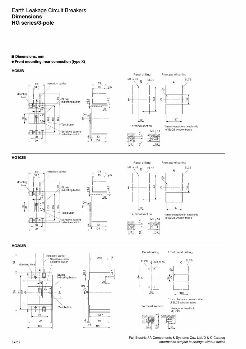
Fuji Electric FA Components & Systems Co., Ltd./D & C CatalogInformation subject to change without notice07/52
Earth Leakage Circuit BreakersDimensionsHG series/3-pole
Dimensions, mm Front mounting, rear connection (type X)
HG53B
HG103B
HG203B
CL
34.5
4
Sensitive currentselective switch
EL trip indicating button
Test button
Panel drilling
Terminal section
CL
CL CL132
*52
M4 or ø5
R2
*87CL
7885
22
9060
73 4.5
824
26
104
50 102
135
155
50
ø8.
5
108.
5
CL
CL
Mounting hole
Insulation barrier
ON
30
M8 14
17 24
ø4.
5
*1mm clearance on each side of ELCB window frame
Front panel cutting
ELCBELCB
CL
34.5
4
Sensitive currentselective switch
EL trip indicating button
Test button
Panel drilling
Terminal section
CL
CL CL132
*52
M4 or ø5
R2
*87CL
7885
22
9060
73 4.5
824
26
104
50 102
135
155
50
ø8.
5
108.
5
CL
CL
Mounting hole
Insulation barrier
ON
30
M8 14
17 24
ø4.
5
*1mm clearance on each side of ELCB window frame
Front panel cutting
ELCBELCB
99
ON
Terminal section
1110
.5
M8 20
25.5 24
Hexagonal head bolt
CL
22
CL
CL
CL CL126
*52
Panel drilling Front panel cutting
M4 or ø5 ELCBELCB
*102 CL
CL
90.5
126
4
3.5
26
3
70
100
105
ø4.
5
50102
144
165
80
ø8.
5
Mounting hole
Insulation barrier
35
94.5
R2
Sensitive currentselective switch
EL trip indicating button
Test button
*1mm clearance on each side of ELCB window frame

Fuji Electric FA Components & Systems Co., Ltd./D & C CatalogInformation subject to change without notice 07/53
07
Earth Leakage Circuit BreakersDimensions
HG series/3-pole
Dimensions, mm Front mounting, front connection
HG403B
HG603B
HG803B
8
51
135
Sensitive currentselective switch
EL trip indicating button
Test button
Trip button
Operating timeselective switch
CL CL
CL
CL
CL CL
CL
92 o
r m
ore
Panel drilling Front panel cutting
M6 or ø7ELCB ELCBR2 or less
137 or more
137
25
146
4.5 10710394.5
8
44
44
4444
56 56
140
ø8
ø13
.5
40.5
15
9010
5
102
225
40.5
214
to 2
16
257
Mounting hole
Insulation barrier
ON
M12 35 bolt
44
84
51 Sensitive currentselective switch
EL trip indicating button
Test button
Trip button
Operating timeselective switch
CL
CL
CL CLCL
CLCL
92 o
r m
ore
Panel drilling Front panel cutting
M6 or ø7 ELCBELCBR2 or less
207 or more
38.5
7
70 70
44
205
210
1074.5
146
10394.5
7
47
70
ø14
.5
ø7
105
102
90 243
7027
5
832
15
70
243
Mounting hole
Insulation barrier
ON
M12 40 bolt
41.5
51
CL
CL
92 o
r m
ore
243
Front panel cutting
ELCBR2 or less
207 or more
CL
CL
Panel drilling
M6 or ø7ELCB
70
Sensitive currentselective switch
EL trip indicating button
Test button
Trip button
Operating timeselective switch
CL
CL
CL
41.5
10
70 70
44
205
210
1074.5
146
10394.5
10
47
ø14
.5
ø7
105
102
90 243
7027
5
832
15
70
Mounting hole
Insulation barrier
ON
M12 40 bolt
44.5

Fuji Electric FA Components & Systems Co., Ltd./D & C CatalogInformation subject to change without notice07/54
Earth Leakage Circuit BreakersDimensionsUL Listed
Dimensions, inch [mm] Front mounting, front connection
SG53RCUL
SG103CUL
SG203CUL
CL
3.307 [84]
0.157 [4] 0.315 [8]
2.362 [60]
2.008 [51]
ON 1.909 [48.5]
0.098 [2.5]2.008 [51]
1.693 [43]
LC
LC
2.953 [75]
1.969 [50]
0.38
6 [9
.8]
0.38
6 [9
.8]
3.93
7 [1
00]
3.30
7 [8
4]
1.96
9 [5
0]
1.65
4 [4
2]1.
575
[40]
(Short type)
0.94
5 [2
4]
0.315 [8] 0.327 [8.3]
0.66
9 [1
7]
M5 x 14
LC
LC
0.984 [25]
3.30
7 [8
4]
0.164-32 tap or 0.197 dia.ELB[M4 or ø5]
Mounting hole
Sensitive currentselective switch
Terminal CoverEL trip indicating button
Trip button
Test button
Panel drilling Terminal section
52 o
rm
ore
R2 or
less
87 or more
M8 x 14
Max
. 16.
5
t ≤ 6
M4 or ø5 ELCB ELCB
Panel drilling Front panel cutting Terminal section
132
30
CL
CL
CL
CL
8.510
17
24
8
ø9
Mounting hole
Trip button
EL trip indicatingbutton
Test button
Sensitive currentselective switch
insulationbarrier
5658
CL
ON
1.5
47
511
6082
2
6
85
34.5
12.5
9413
.5
155
60
22
90
50 102
135
50
CL
CLø4.
5
ø8.
5
P.C.B box(Power)
Panel drilling Front panel cutting Terminal section
M4 or ø5 ELCB ELCB
R2 or
less
CL CL
CLCL 126
10.5 11
35
25.5
8
24
ø9
M8 x 16
Max
. 25
t ≤ 6
52 o
rm
ore
102 or more
Mounting hole
Detachable
Trip button
EL trip indicatingbutton
Test button
Sensitive currentselective switchinsulation barrier
5658.5
CL
ON
1
47
511
6084
2
6
ø4.
5
ø8.
5
7035
12.5
9421
165
100
22
105
50 102
144
80
CL
CLP.C.B box(Power)

Fuji Electric FA Components & Systems Co., Ltd./D & C CatalogInformation subject to change without notice 07/55
07
Earth Leakage Circuit BreakersDimensions
UL Listed
Dimensions, inch [mm] Front mounting, front connection
SG403CUL
EG102CUL, 103CUL
0.31
5 di
a [ø
8]
3.307 [84]
0.53
1dia
[ø13
.5]
1.732 [44]0.315 [8]
5.748 [146]
0.177 [4.5] 4.213 [107]
4.055 [103]3.72 [94.5]
1.732 [44]0.315 [8]
4.01
6 [1
02]
3.54
3 [9
0]
2.008 [51]
5.512 [140]5.315 [135]
2.205 [56] 2.205 [56]
1.732 [44] 1.732 [44]
0.59
1 [1
5]1.
594
[40.
5]10
.118
[257
]8.
858
[225
]
1.59
4 [4
0.5]
0.984 [25]
4.13
4 [1
05]
5.394 [137]
LC
LC LC
M12 x 35 bolt
8.42
5-8.
504
[214
-216
]
1.732 [44]
LC
LC
[M6 or ø7]
FAB 0.2500-20 tap or 0.276 dia.
Panel drilling
Mounting hole
Insulation barrier
Trip button
CL
3.307 [84]
0.157 [4] 0.315 [8]
2.362 [60]
2.008 [51]
ON 1.909 [48.5]
0.098 [2.5]2.008 [51]
1.693 [43]
LC
LC
2.953 [75]
1.969 [50]
0.38
6 [9
.8]
0.38
6 [9
.8]
3.93
7 [1
00]
3.30
7 [8
4]
1.96
9 [5
0]
1.65
4 [4
2]1.
575
[40]
(Short type)
M8 x 15
0.315 [8] 0.327 [8.3]
0.94
5 [2
4]0.
669
[17]
EG102CUL types are supplied in 3-pole frames withcurrent carrying parts omitted from center pole.
LC
LC
0.984 [25]
3.30
7 [8
4]
0.164-32 tap or 0.197 dia.ELB[M4 or ø5]
Mounting hole
Sensitive currentselective switch
Terminal CoverEL trip indicating button
Trip button
Test button
Panel drilling Terminal section

Fuji Electric FA Components & Systems Co., Ltd./D & C CatalogInformation subject to change without notice07/56
Earth Leakage Circuit Breakers
� Characteristic curves/2, 3-pole
Line protection Motor protection
Earth leakage tripping
SG30C, SG50C, SG50RC
0.010.02
0.040.060.1
0.2
0.40.6
1
2
46
10
20
401246
10
20
4060
120180
1 1.5 2 3 4 5 678 10 15 20 304050 70100
Min
ute
Instantaneoustrippingcharacteristic800%-1200%(3, 15, 20, 30, 50A)
Ope
ratin
g tim
eS
econ
d
Multiple of rated current (A)
Max. value
Instantaneoustrippingcharacteristic960%-1440%(5, 10, 40A)
Min. value
0.010.02
0.040.06
0.1
0.2
0.40.6
1
2
46
10
20
401246
10
20
4060
120180
1 1.5 2 3 4 5 6 78 10 15 20 30 4050 70 100
Min
ute
Ope
ratin
g tim
eS
econ
d
Multiple of rated current (A)
Max. value
Instantaneoustrippingcharacteristic960%-1440%
Min. value
Reference temp. 40
Ope
ratin
g tim
eco
rrec
tion
fact
or (
%)
Ambient temperature ( )
400
50
100
150
200
250
300
350
0-10 10 20 30 40 50
0.04
0.1
1
10
0.0110 30 100 200 500 1000 3000 10000
30mA
Ground fault current(Multiple of rated sensitive current %)
5I n 0.04s max. (30mA type: At 250mA)
Ope
ratin
g tim
e (s
)
Min. 100mA
Rat
ed s
ensi
tive
curr
ent(
I n)
Rat
ed n
on-t
rippi
ng c
urre
nt
Characteristic curvesSG and EG series
Line protection Motor protection
Earth leakage tripping
EG30AC, EG30C, EG50AC, EG50C
0.010.02
0.040.060.1
0.2
0.40.6
1
2
46
10
20
401246
10
20
4060
120180
1 1.5 2 3 4 5 678 10 15 20 304050 70100
Instantaneoustrippingcharacteristic800%-1200%(3, 15, 20, 30, 50A)
Min
ute
Ope
ratin
g tim
eS
econ
d
Multiple of rated current (A)
Max. value
Instantaneoustrippingcharacteristic960%-1440%(5, 10, 40A)
Min. value
0.010.02
0.040.06
0.1
0.2
0.40.6
1
2
46
10
20
401246
10
20
4060
120180
1 1.5 2 3 4 5 678 10 15 20 304050 70100
Min
ute
Ope
ratin
g tim
eS
econ
d
Multiple of rated current (A)
Max. value
Instantaneoustrippingcharacteristic960%-1440%
Min. value
Reference temp. 40
Ope
ratin
g tim
eco
rrec
tion
fact
or (
%)
Ambient temperature ( )
400
50
100
150
200
250
300
350
0-10 10 20 30 40 50
0.04
0.1
1
10
0.0110 30 100 200 500 1000 3000 10000
30mA 15mA
Ground fault current(Multiple of rated sensitive current %)
5I n 0.04s max. (15, 30mA types: At 250mA)
Ope
ratin
g tim
e (s
)
Min. 100mA
Rat
ed s
ensi
tive
curr
ent(
I n)
Rat
ed n
on-t
rippi
ng c
urre
nt

Fuji Electric FA Components & Systems Co., Ltd./D & C CatalogInformation subject to change without notice 07/57
07
Earth Leakage Circuit Breakers
Line protection Motor protection
Earth leakage tripping
SG60C, SG60RC, EG60C
0.010.02
0.040.060.1
0.2
0.40.6
1
2
46
10
20
401246
10
20
4060
120180
1 1.5 2 3 4 5 678 10 15 20 304050 70100
Min
ute
Ope
ratin
g tim
eS
econ
d
Multiple of rated current (A)
Max. value
Instantaneoustrippingcharacteristic960%-1440%
Min. value
0.010.02
0.040.060.1
0.2
0.40.6
1
2
46
10
20
401246
10
20
4060
120180
1 1.5 2 3 4 5 6 78 10 15 20 30 4050 70 100
Min
ute
Ope
ratin
g tim
eS
econ
d
Multiple of rated current (A)
Max. value
Instantaneoustrippingcharacteristic960%-1440%
Min. value
Reference temp. 40
Ope
ratin
g tim
eco
rrec
tion
fact
or (
%)
Ambient temperature ( )
400
50
100
150
200
250
300
350
0-10 10 20 30 40 50
0.04
0.1
1
10
0.0110 30 100 200 500 1000 3000 10000
30mA 15mA
Ground fault current(Multiple of rated sensitive current %)
5I n 0.04s max. (15, 30mA types: At 250mA)
Ope
ratin
g tim
e (s
)
Min. 100mA
Rat
ed s
ensi
tive
curr
ent(
I n)
Rat
ed n
on-t
rippi
ng c
urre
nt
� Characteristic curves/2, 3-pole
Characteristic curvesSG and EG series
Line protection Motor protection
Earth leakage tripping
SG100C
1 1.5 2 3 4 5 6 7 810 15 20 30 40 50 1008060
0.02
0.01
0.040.06
0.10.20.40.6
1
246
10
20
401246
1020
4060
120180
(40~100A)
(15~30A)
Ope
ratin
g tim
e
Multiple of rated current (A)
Max. value
Instantaneoustrippingcharacteristic800%-1500%Min. value
Sec
ond
Min
ute
0.010.02
0.040.060.1
0.2
0.40.6
1
2
46
10
20
401246
10
20
4060
120180
1 1.5 2 3 4 5 6 78 10 15 20 30 4050 70 100
Min
ute
Ope
ratin
g tim
eS
econ
d
Multiple of rated current (A)
Max. value
Instantaneoustrippingcharacteristic960%-1440%
Min. value
0.04
0.1
1
10
0.0110 30 100 200 500 1000 3000 10000
30mA
Ground fault current(Multiple of rated sensitive current %)
5I n 0.04s max. (30mA type: At 250mA)
Ope
ratin
g tim
e (s
)
Min. 100mA
Rat
ed s
ensi
tive
curr
ent(
I n)
Rat
ed n
on-t
rippi
ng c
urre
nt
Reference temp.40°C
50
100
150
0 10 20 30 40 50
Ambient temp. (°C)
Rat
ed c
urre
nt
corr
ectio
n ra
tio (
%)
40-100A
15-30A

Fuji Electric FA Components & Systems Co., Ltd./D & C CatalogInformation subject to change without notice07/58
Earth Leakage Circuit Breakers
� Characteristic curves/2, 3-pole
Line protection Motor protection
Earth leakage tripping
SG100RC
0.01
0.020.040.06
0.10.20.40.6
1246
10
20
401246
1020
4060
120180
1 1.5 2 3 4 5 67 8 10 15 20 30 40 5060 80 100
(40~100A)
(15~30A)
Ope
ratin
g tim
e
Multiple of rated current (A)
Max. value
Instantaneoustrippingcharacteristic800%-1500%
Min. value
Sec
ond
Min
ute (40-90A)
Min
ute
Ope
ratin
g tim
eS
econ
d
Multiple of rated current (A)
Max. value
Max. totalfault clearingtime
Instantaneoustrippingcharacteristic1000%-2000%
Min. value
0.01
0.020.040.06
0.10.2
0.40.8
12
46
10
20
401246
1020
4060
120180
1 1.5 2 3 4 5 6 7 8 10 15 20 30 40 5060 80100
90
0.04
0.1
1
10
0.0110 30 100 200 500 1000 3000 10000
30mA
Ground fault current(Multiple of rated sensitive current %)
5I n 0.04s max. (30mA type: At 250mA)
Ope
ratin
g tim
e (s
)
Min. 100mA
Rat
ed s
ensi
tive
curr
ent(
I n)
Rat
ed n
on-t
rippi
ng c
urre
nt
Line protection Motor protection
Earth leakage tripping
EG100AC, EG100C
0.02
0.040.06
0.1
0.2
0.40.6
1
2
46
10
20
401246
10
20
4060
120180
1 1.5 2 3 4 5 6 7 8 10 15 20 30 4050 70 100
Min
ute
Ope
ratin
g tim
eS
econ
d
Multiple of rated current (A)
Max. value
Instantaneoustrippingcharacteristic960%-1440%(60,75A)
Instantaneoustrippingcharacteristic800%-1200%(50,100A)
Min. value
0.01 0.010.02
0.040.06
0.1
0.2
0.40.6
1
2
46
10
20
401246
10
20
4060
120180
1 1.5 2 3 4 5 6 78 10 15 20 30 4050 70 100
Min
ute
Ope
ratin
g tim
eS
econ
d
Multiple of rated current (A)
Max. value
Instantaneoustrippingcharacteristic960%-1440%
Min. value
Reference temp. 40
Ope
ratin
g tim
eco
rrec
tion
fact
or (
%)
Ambient temperature ( )
400
50
100
150
200
250
300
350
0-10 10 20 30 40 50
0.04
0.1
1
10
0.0110 30 100 200 500 1000 3000 10000
30mA
Ground fault current(Multiple of rated sensitive current %)
5I n 0.04s max. (30mA type: At 250mA)
Ope
ratin
g tim
e (s
)
Min. 100mA
Rat
ed s
ensi
tive
curr
ent(
I n)
Rat
ed n
on-t
rippi
ng c
urre
nt
Characteristic curvesSG and EG series
Reference temp.40°C
50
100
150
0 10 20 30 40 50
Ambient temp. (°C)
Rat
ed c
urre
nt
corr
ectio
n ra
tio (
%)
40-100A
15-30A

Fuji Electric FA Components & Systems Co., Ltd./D & C CatalogInformation subject to change without notice 07/59
07
Earth Leakage Circuit Breakers
� Characteristic curves/2, 3-pole
Line protection Motor protection
Earth leakage tripping
SG225C, SG225RC
0.01
0.020.040.060.10.20.40.6
1246
10
20
401246
1020
4060
120180
1 1.5 2 3 4 5 6 78 10 15 20 30 405060 80100
Ope
ratin
g tim
e
Multiple of rated current (A)
Sec
ond
Min
ute
Max. value
Instantaneoustrippingcharacteristic800%-1400%
Min. value
Reference temp. 40
Ope
ratin
g tim
eco
rrec
tion
fact
or (
%)
Ambient temperature ( )
150
50
100
0-10 10 20 30 40 50
0.04
0.1
1
10
0.0110 30 100 200 500 1000 3000 10000
30mA
Ground fault current(Multiple of rated sensitive current %)
5I n 0.04s max. (30mA type: At 250mA)
Ope
ratin
g tim
e (s
)
Min. 100mA
Rat
ed s
ensi
tive
curr
ent(
I n)
Rat
ed n
on-t
rippi
ng c
urre
nt
Line protection Motor protection
Earth leakage tripping
EG225C
0.01
0.020.040.060.10.20.40.6
1246
10
20
401246
1020
4060
120180
1 1.5 2 3 4 5 6 78 10 15 20 30 405060 80100
Ope
ratin
g tim
e
Multiple of rated current (A)
Sec
ond
Min
ute
Max. value
Instantaneoustrippingcharacteristic800%-1400%
Min. value
Reference temp. 40
Ope
ratin
g tim
eco
rrec
tion
fact
or (
%)
Ambient temperature ( )
150
50
100
0-10 10 20 30 40 50
0.04
0.1
1
10
0.0110 30 100 200 500 1000 3000 10000
30mA
Ground fault current(Multiple of rated sensitive current %)
5I n 0.04s max. (30mA type: At 250mA)
Ope
ratin
g tim
e (s
)
Min. 100mA
Rat
ed s
ensi
tive
curr
ent(
I n)
Rat
ed n
on-t
rippi
ng c
urre
nt
Characteristic curvesSG and EG series
0.01
0.02
0.040.060.1
0.2
0.4
0.812
46
10
20
401
246
10
20
4060
120180
1 1.5 2 3 4 5 678 10 15 20 30 40 50 80100
90
Min
ute
Sec
ond
Ope
ratin
g tim
e
Multiple of rated current (A)
Max. value
Instantaneoustrippingcharacteristic1000 – 1600%
Min. value
0.01
0.02
0.040.060.1
0.2
0.4
0.812
46
10
20
401
246
10
20
4060
120180
1 1.5 2 3 4 5 678 10 15 20 30 40 50 80100
90
Min
ute
Sec
ond
Ope
ratin
g tim
e
Multiple of rated current (A)
Max. value
Instantaneoustrippingcharacteristic1000 – 1600%
Min. value

Fuji Electric FA Components & Systems Co., Ltd./D & C CatalogInformation subject to change without notice07/60
Earth Leakage Circuit Breakers
� Characteristic curves/2, 3-pole
Earth leakage tripping
SG400C, SG400RC, EG400C
Ope
ratin
g tim
eS
econ
dM
inut
e
Multiple of rated current (A)1 1.5 2 3 4 5 6 7 8 10 15 20 30 40 50 70 100
0.010.020.040.060.1
0.20.40.6
1
1
2
246
46
10
10
20
20
40
4060
120180
Max. value
Instantaneoustrippingcharacteristic800%-1400%
Min. value
Ground fault current(Multiple of rated sensitive current %)
0.010.02
0.050.10.2
0.512
5102030
124
10
30
60120240
25 50 100 500
Rat
ed s
ensi
tive
curr
ent(
I n)
Rat
ed n
on-t
rippi
ng c
urre
nt
Ope
ratin
g tim
eS
econ
dM
inut
e
Earth leakage tripping
SG600RC, EG600C
0.01
0.020.040.06
0.10.20.40.6
12
46
1020
401246
1020
4060
120180
1 1.5 2 3 4 5 6 7 8 10 15 20 30 40 50 70 100
Ope
ratin
g tim
eS
econ
dM
inut
e
Multiple of rated current (A)
Max. value
Instantaneoustrippingcharacteristic800%-1300%
Min. value
Max. totalfault clearingtime
Ground fault current(Multiple of rated sensitive current %)
0.010.02
0.050.10.2
0.512
5102030
124
10
30
60120240
25 50 100 500
Rat
ed s
ensi
tive
curr
ent(
I n)
Rat
ed n
on-t
rippi
ng c
urre
nt
Ope
ratin
g tim
eS
econ
dM
inut
e
Characteristic curvesSG and EG series
Reference temp.40°C
50
100
150
0 10 20 30 40 50
Ambient temp. (°C)
Rat
ed c
urre
nt
corr
ectio
n ra
tio (
%)
Reference temp.40°C
50
100
150
0 10 20 30 40 50
Ambient temp. (°C)
Rat
ed c
urre
nt
corr
ectio
n ra
tio (
%)

Fuji Electric FA Components & Systems Co., Ltd./D & C CatalogInformation subject to change without notice 07/61
07
Earth Leakage Circuit Breakers
� Characteristic curves/2, 3-pole
Earth leakage tripping
SG800RC, EG800C
0.01
0.020.040.060.10.20.40.6
1246
10
20
401246
1020
4060
120180
1 1.5 2 3 4 5 67810 15 20 304050 70100
Ope
ratin
g tim
eS
econ
dM
inut
e
Multiple of rated current (A)
Max. value
Instantaneoustrippingcharacteristic600%-1000%
Min. value
Ground fault current(Multiple of rated sensitive current %)
0.010.02
0.050.10.2
0.512
5102030124
10
30
60120240
25 50 100 500
Rat
ed s
ensi
tive
curr
ent(
I n)
Rat
ed n
on-t
rippi
ng c
urre
nt
Ope
ratin
g tim
eS
econ
dM
inut
e
Characteristic curvesSG and EG series
Reference temp.40°C
50
100
150
0 10 20 30 40 50
Ambient temp. (°C)
Rat
ed c
urre
nt
corr
ectio
n ra
tio (
%)

Fuji Electric FA Components & Systems Co., Ltd./D & C CatalogInformation subject to change without notice07/62
Earth Leakage Circuit Breakers
� Characteristic curves/4-pole
SGa104A, SG104H SGa204A, SG204H SGa404A
EG104ARated current 30A
Characteristic curvesSG and EG series/4-pole
0.01
0.020.040.06
0.1
0.20.40.6
1
246
102040
1
2
46
10
204060
120180
1 1.5 2 3 4 5 6 7810 15 20 30 4050 70100
Ope
ratin
g tim
eS
econ
dM
inut
e
Multiple of rated current (A)
Max. value
Instantaneoustrippingcharacteristic800%-1500%
Min. value
Max. total faultclearing time
0.010.02
0.040.06
0.10.2
0.40.6
12
610
2040
1
246
10
204060
120240
1 1.5 2 3 4 5 678 10 15 20 3040 60 80
Ope
ratin
g tim
eS
econ
dM
inut
e
Multiple of rated current (A)
Max. value
Instantaneoustrippingcharacteristic800%-1400%
Min. value
Max. total faultclearing time
0.010.02
0.040.060.10.2
0.40.6
12
610
20401
246
10
204060
120240
1 1.5 2 3 4 5 678 10 15 20 3040 60 80
Ope
ratin
g tim
eS
econ
dM
inut
e
Multiple of rated current (A)
Max. value
Instantaneoustrippingcharacteristic800%-1400%
Min. value
Max. total faultclearing time
Rated current 40A-100A
15A
60to100A
150
100
500 10 20 30 40 50
Rate
d c
urr
ent co
rrect
ion r
atio
(%
) Reference temp. 40°C
Ambient temp. (°C)
90
100
110
120
130
140
0 1010 20 30 40 50
Reference temp. 40°C
Ambient temp. (°C)
Rate
d c
urr
ent co
rrect
ion r
atio
(%
)
90
100
110
120
130
140
0 1010 20 30 40 50
300A,400A
250A
350A
Reference temp. 40°C
Ambient temp. (°C)Rate
d c
urr
ent co
rrect
ion r
atio
(%
)

Fuji Electric FA Components & Systems Co., Ltd./D & C CatalogInformation subject to change without notice 07/63
07
Earth Leakage Circuit BreakersCharacteristic curves
HG series
� Characteristic curves/2, 3-pole
HG50B, HG100B HG225B
180120
6040
20
10
64
2
1
40
20
10
6
4
2
1
0.6
0.4
0.2
0.1
0.060.04
0.02
0.011 1.5 2 3 4 5 6 7 8 10 15 20 30 40 50 80 100
Max. value
Min. value
(15-30A)
Instantaneoustrippingcharacteristic800% – 1500%
Max. totalfaultclearingtime
Min
ute
Sec
ond
Ope
ratin
g tim
e
Multiple of rated current (A)
HG50B: 40 – 50AHG100B: 40 – 100A
60
Reference temp 40°C
150
50
100
0 10 20 30 40 50 60Rat
ed c
urre
nt c
orre
ctio
n ra
tio (%
)
15 to 30A
40 to 100A
Reference temp.40°C
Ambient temp. (°C)
HG400B
150
100
500 10 20 30 40 50
Reference temp.40°C
Ambient temp. (°C)
Rat
ed c
urre
nt c
orre
ctio
n ra
tio(%
)
150
100
500 10 20 30 40 50
Reference temp.40°C
Ambient temp. (°C)
Rat
ed c
urre
nt c
orre
ctio
n ra
tio(%
)
180120
6040
20
10
64
2
1
40
20
10
6
4
2
1
0.6
0.4
0.2
0.1
0.060.04
0.02
0.011 1.5 2 3 4 5 6 7 10 15 20 30 40 50 80 100
Max. value
Min. value
Instantaneoustrippingcharacteristic800% – 1400%
Max. totalfaultclearingtime
Min
ute
Sec
ond
Ope
ratin
g tim
e
Multiple of rated current (A)60
Reference temp. 40°C
0.01
0.020.040.060.1
0.20.40.6
1
246
1020401
2
46
10
204060
120180
1 1.5 2 3 4 5 678 10 15 20 304050 70 100
Ope
ratin
g tim
eS
econ
dM
inut
e
Multiple of rated current (A)
Max. value
Reference temp. 40˚C
Instantaneoustrippingcharacteristic800%-1400%
Min. value
Max. totalfaultclearing time

Fuji Electric FA Components & Systems Co., Ltd./D & C CatalogInformation subject to change without notice07/64
Earth Leakage Circuit BreakersCharacteristic curvesHG series
� Characteristic curves/2, 3-pole
HG600B HG800B
150
100
500 10 20 30 40 50
Reference temp.40°C
Ambient temp. (°C)
Rat
ed c
urre
nt c
orre
ctio
n ra
tio (
%)
Instantaneoustrippingcharacteristic800% – 1300%
180120
6040
20
10
64
2
1
40
20
10
6
4
2
1
0.4
0.2
0.1
0.060.04
0.02
0.011 1.5 2 3 4 5 6 7 10 15 20 30 40 50 80 100
Max. value
Min. value
Max. totalfaultclearingtime
Min
ute
Sec
ond
Ope
ratin
g tim
e
Multiple of rated current (A)60
Reference temp. 40°C
150
100
500 10 20 30 40 50
Reference temp.40°C
Ambient temp. (°C)
Rat
ed c
urre
nt c
orre
ctio
n ra
tio (
%)
Instantaneoustrippingcharacteristic600% – 1000%
180120
6040
20
10
64
2
1
40
20
10
6
4
2
1
0.4
0.2
0.1
0.060.04
0.02
0.011 1.5 2 3 4 5 6 7 10 15 20 30 40 50 80 100
Max. value
Min. value
Max. totalfaultclearingtime
Min
ute
Sec
ond
Ope
ratin
g tim
e
Multiple of rated current (A)60
Reference temp. 40°C
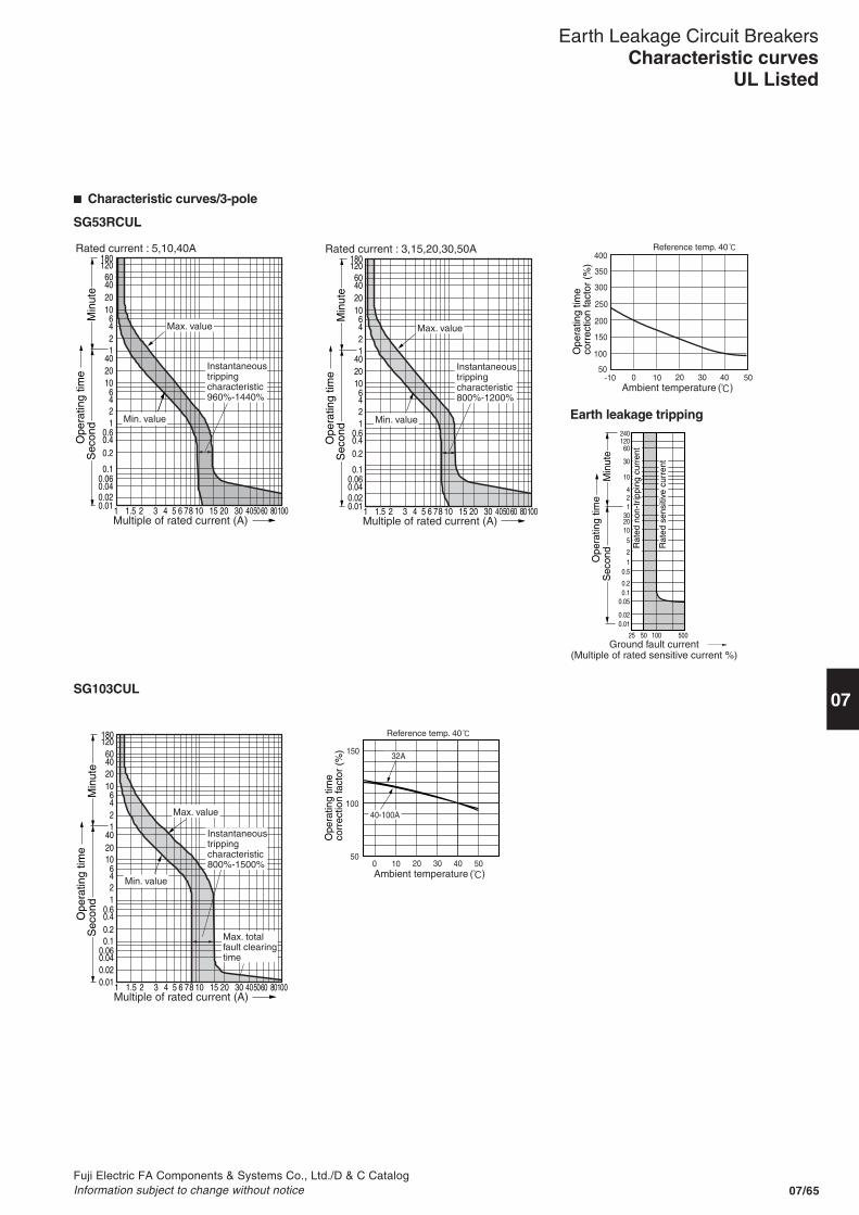
Fuji Electric FA Components & Systems Co., Ltd./D & C CatalogInformation subject to change without notice 07/65
07
Earth Leakage Circuit BreakersCharacteristic curves
UL Listed
� Characteristic curves/3-pole
Earth leakage tripping
SG53RCUL
SG103CUL
0.010.020.040.06
0.1
0.20.40.6
1246
102040
1246
10204060
120180
1 1.5 2 3 4 5 6 78 10 15 20 30 4050 8010060
Min
ute
Sec
ond
Ope
ratin
g tim
e
Multiple of rated current (A)
Rated current : 5,10,40A
Max. value
Instantaneoustrippingcharacteristic960%-1440%
Min. value
0.010.020.040.06
0.1
0.20.40.6
1246
102040
1246
10204060
120180
1 1.5 2 3 4 5 6 78 10 15 20 30 4050 8010060
Min
ute
Sec
ond
Ope
ratin
g tim
e
Multiple of rated current (A)
Rated current : 3,15,20,30,50A
Max. value
Instantaneoustrippingcharacteristic800%-1200%
Min. value
-10 0 10 20 30 40 50
400
300
350
250
200
150
100
50
Reference temp. 40
Ope
ratin
g tim
eco
rrec
tion
fact
or (
%)
Ambient temperature ( )
0.010.02
0.050.10.2
0.512
5102030
124
10
30
60120240
25 50 100 500
Min
ute
Ope
ratin
g tim
eS
econ
d Rat
ed s
ensi
tive
curr
ent
Rat
ed n
on-t
rippi
ng c
urre
ntGround fault current
(Multiple of rated sensitive current %)
0.010.020.040.060.10.20.40.6
1246
1020401246
10204060
120180
1 1.5 2 3 4 5 6 78 10 15 20 30 4050 8010060
Min
ute
Sec
ond
Ope
ratin
g tim
e
Multiple of rated current (A)
Max. value
Instantaneoustrippingcharacteristic800%-1500%
Min. value
Max. totalfault clearingtime
0 10 20 30 40 50
150
100
50
Reference temp. 40
Ope
ratin
g tim
eco
rrec
tion
fact
or (
%)
Ambient temperature ( )
32A
40-100A
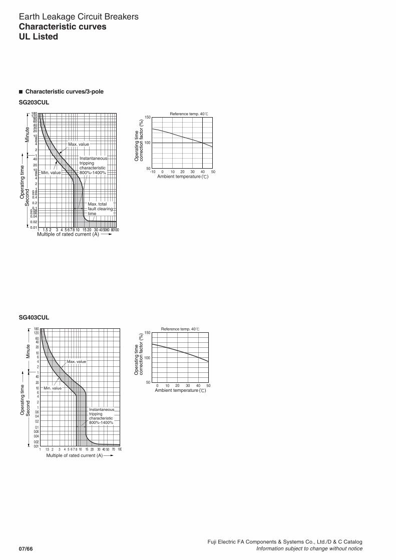
Fuji Electric FA Components & Systems Co., Ltd./D & C CatalogInformation subject to change without notice07/66
Earth Leakage Circuit BreakersCharacteristic curvesUL Listed
� Characteristic curves/3-pole
SG203CUL
SG403CUL
0.01
0.02
0.040.060.080.1
0.2
0.40.60.8
1
2
468
1020
401
2
468
1020
4030
6090
120180
1 1.5 2 3 4 5 6 7 8 10 15 20 30 40 50 8010060
Min
ute
Sec
ond
Ope
ratin
g tim
e
Multiple of rated current (A)
Max. value
Instantaneoustrippingcharacteristic800%-1400%Min. value
Max. totalfault clearingtime
0 -10 10 20 30 40 50
150
100
50
Reference temp. 40
Ope
ratin
g tim
eco
rrec
tion
fact
or (
%)
Ambient temperature ( )
Ope
ratin
g tim
eS
econ
dM
inut
e
Multiple of rated current (A)1 1.5 2 3 4 5 6 7 8 10 15 20 30 40 50 70 100
0.010.020.040.060.1
0.20.40.6
1
1
2
246
46
10
10
20
20
40
4060
120180
Max. value
Instantaneoustrippingcharacteristic800%-1400%
Min. value0 10 20 30 40 50
150
100
50
Reference temp. 40
Ope
ratin
g tim
eco
rrec
tion
fact
or (
%)
Ambient temperature ( )

Fuji Electric FA Components & Systems Co., Ltd./D & C CatalogInformation subject to change without notice 07/67
07
Earth Leakage Circuit BreakersCharacteristic curves
UL Listed
� Characteristic curves/3-pole
EG102CUL, EG103CUL
0.010.020.040.06
0.1
0.20.40.6
1246
102040
1246
10204060
120180
1 1.5 2 3 4 5 6 78 10 15 20 30 4050 8010060
Min
ute
Sec
ond
Ope
ratin
g tim
e
Multiple of rated current (A)
Rated current : 5,10,40,60,70,80,90A
Max. value
Instantaneoustrippingcharacteristic960%-1440%
Min. value
0.010.020.040.06
0.1
0.20.40.6
1246
102040
1246
10204060
120180
1 1.5 2 3 4 5 6 78 10 15 20 30 4050 8010060
Min
ute
Sec
ond
Ope
ratin
g tim
e
Multiple of rated current (A)
Rated current : 3,15,20,30,50,100A
Max. value
Instantaneoustrippingcharacteristic800%-1200%
Min. value
-10 0 10 20 30 40 50
400
300
350
250
200
150
100
50
Reference temp. 40
Ope
ratin
g tim
eco
rrec
tion
fact
or (
%)
Ambient temperature ( )

Fuji Electric FA Components & Systems Co., Ltd./D & C CatalogInformation subject to change without notice07/68
Earth Leakage Circuit Breakers
Auxiliary switch (Type W)
This switch is used for indicator lamp or control circuit.
Alarm switch (Type K)
This switch can be connected to a warning lamp or buzzer to indicatewhen the breaker has been tripped.
Shunt trip device (Type F)
The purpose of this accessory is to trip the breaker from a distance.
Undervoltage trip device (Type R)
The device is designed to protect circuits from harmful voltage drops. It can also be used for remote controlpurposes. The trip operates when thevoltage drops to less than 70% of nominal coil rating, and the breakercannot be reset until the voltagerecovers 85% of its normal rating.
Terminal block (Type A)
A wiring terminal for internal accessories(Order with W, K or F)
Test lead wire (Type TL)
Trips the ELCB with a contact signal for electrical operation test.
Megger test switch (Type MGS)
Interlocked with the main contact of the ELCB. When the handle is turned OFF, the control circuit is automatically isolated, enabling megger testing between phases on the load side.
Accessories
Variation of internal accessory

Fuji Electric FA Components & Systems Co., Ltd./D & C CatalogInformation subject to change without notice 07/69
Earth Leakage Circuit Breakers
07
07OFF
ON
ON
OF
FTR
IP
OPEN/RESET
ON
TRIP
OF
F
OPEN/RES
ET
Handlelockingcover
Mechanical interlock device
The mechanical interlock device can be mounted onto two separate breakers to maintain a mutual ON or OFF condition. The device can also be locked with a padlock.See page 07/88
External operating handles
There are two handles available in the series: the V type handle on panel mount and the N type handle on breaker mount. An extension shaft (sold separately) for the V type handle allows the distance between the handle and the breaker to be adjusted. The protective structure of the V type handle operation section conforms to IP54. Both handle types can be locked with a padlock conforming to IEC 60204-1. The panel cutout dimensions are the same for both handles.See page 07/91
Steel enclosures
Enclosures are available in three types–two with V-type handle which allows the operation from the outside, and other direct operating.See page 07/103
Insulation barriers
The interphase barrier reinforces the insulation between terminals, while the earth barrier increases the insulation between the terminal and the mounting panel.See page 07/106
Terminal covers
Finger protection guards against shock from accidentally touching live terminals.Two types of terminal covers are available–long type and short type. See page 07/105
Interface barrier
ELCB
Long type Short type
Earth barrier
Motor-operating mechanism
A new drive structure in the motor operating mechanism speeds up drive operation to drastically reduce ON/OFF switching time from 2s to 0.1s.See page 07/85
N type
V type
Accessories
Variation of external accessory

Fuji Electric FA Components & Systems Co., Ltd./D & C CatalogInformation subject to change without notice07/70
Earth Leakage Circuit Breakers
Terminal blocks for internal accessories• It indicates the terminal No. of internal accessory.
The connection method of internal accessory is lead-wiresystem and terminal block system.
• Specify the connection method when ordering. It is lead-wire system unless specified.
• The lead wires are pulled out and terminal blocks areattached on the same side of the internal accessory will beattached
• For the available configuration of internal accessory, seepage 07/72.
Internal accessories
Accessory
Auxiliary switch
Alarm switch
Shunt trip device : F
Undervoltage trip device : R
Test lead wire : TL
Megger test switch : MGS
Earth leakage indication contact : EAL
SPDT: W
2PDT: W2
SPDT: K
2PDT: K2
With 1NO contact to prevent coilburn-out
Continuous rating
30 – 225AFLeft side mounting Right side mounting
400 – 800AFLeft side mounting
21AXcR
22AXbR
24AXaR
21AXcR
22AXbR
24AXaR
01ALcR
02ALbR
04ALaR
01ALcR
02ALbR
04ALaR
11AXcL
12AXbL
14AXaL
21AXc
22AXb
24AXa
11AXc
12AXb
14AXa
11AXcL
12AXbL
14AXaL
11AXc
12AXb
14AXa
91ALcL
92ALbL
94ALaL
01ALc
02ALb
04ALa
91ALc
92ALb
94ALa
91ALcL
92ALbL
94ALaL
91ALc
92ALb
94ALa
C2S2
C1S1
C2S2
C1S1
D2P2
D1P1
U<
TL1
TL2
Test button
EAL2EAL1
Amplifier
MGS
ON, OFF, Over current trip
OFF
ELCB'sstatus
Contact
Earth leakage trip
ON
Notes: • The voltage is applied to the lead wires.• Use a switch for the test button whose rating is more than the main circuit voltage and making/breaking current is higher than 1A.• Do not share the switch for the test button with other ELCB.
Lead-wire wiring With terminal block IEC and CE marking conformed type

Fuji Electric FA Components & Systems Co., Ltd./D & C CatalogInformation subject to change without notice 07/71
Earth Leakage Circuit Breakers
07
07
AXC1AXb1
AXa1
AXC1AXb1
AXa1
AXC2AXb2
AXa2
ALC1ALb1
ALa1
ALC1ALb1
ALa1
ALC2ALb2
ALa2
S2S1
S2S1
P1
P2
AccessoryAuxiliary switch
Alarm switch
Shunt trip device : F
Undervoltage trip device : R
Test lead wire : TL
Megger test switch : MGS
Earth leakage indication contact : EAL
SPDT: W
2PDT: W2
SPDT: K
2PDT: K2
With 1NO contact to prevent coilburn-out
Continuous rating
Terminal number
Notes: • The voltage is applied to the lead wires.• Use a switch for the test button whose rating is more than the main circuit voltage and making/breaking current is higher than 1A.• Do not share the switch for the test button with other ELCB.
TL1
TL2
Test button
EAL2EAL1
Amplifier
MGS
ON, OFF, Over current trip
OFF
ELCB'sstatus
Contact
Earth leakage trip
ON
Internal accessories
HG50B, HG100B and HG225B types

Fuji Electric FA Components & Systems Co., Ltd./D & C CatalogInformation subject to change without notice07/72
Earth Leakage Circuit BreakersInternal accessories
� Available configurations
EG series
Pole
SG seriesELCB ELCB
2
SG33CSG53CSG53RCSG63CSG63RC
2, 3
SG103CSG103RCSG203CSG203RC
EG203C
– –
– –
3
SGa104ASG104HSGa204ASG204HSGa404A
4
EG32ACEG52AC
–
– – – –
EG33ACEG53ACEG33CEG53CEG63CEG103ACEG102CEG103C
EG403CEG603CEG803C
SG403CSG403RCSG603RCSG803RC
HG series
EG series
SG series SG33CSG53CSG53RCSG63CSG63RC
SG103CSG103RCSG203CSG203RC
EG203CEG32ACEG52AC
EG33ACEG53ACEG33CEG53CEG63CEG103ACEG102CEG103C
HG403BHG603BHG803B
3 2 2, 3 3
HG53BHG103BHG203B
3
Megger test switch: MGS
Shunt trip: F(External mounting method)
Test lead: TL
Handle
3P
Left Right
Handle
2P
Right
Alarm switch: K
Auxiliary switch: W
Undervoltage trip: R
Auxiliary switchSPDT WArarm switchSPDT KShunt tripFUndervoltageRW2
W+K
W2+K
K2
W+K2
W2+K2
W+F
W2+F
W+R
W2+R
K+F
K+R
W+K+F
W+K+R
K2+F
K2+R
W2+K+F
W2+K+R
W+K2+F
W+K2+R
W2+K2+F
W2+K2+R
Megger test switchMGSTest leadTL
PoleMegger test switchMGSMGS+W
MGS+K MGS+W+K MGS+R MGS+W+R MGS+K+R MGS+W+K+R Test leadTL
TL+W
TL+K
TL+W+K
Notes: • If you install the auxiliary switch "W" and the alarm switch "K" closely side-by-side, add suffix "B" to the type number when ordering. Example: WB or KB• The installation of the megger-test switch uses the space of auxiliary switch(W). Therefore, one auxiliary switch will be subtracted from the number of combinations of the above tables.

Fuji Electric FA Components & Systems Co., Ltd./D & C CatalogInformation subject to change without notice 07/73
Earth Leakage Circuit Breakers
07
07
Internal accessoriesUL listed
� UL type available configurations
Note: * Terminal block connection is standard method.
Shunt trip: F(External mounting method)
Handle
3P
Left Right
Handle
2P
Right
Alarm switch: K
Auxiliary switch: W
Undervoltage trip: R
Auxiliary switchSPDT WArarm switchSPDT KShunt tripFUndervoltageRW2
W+K
W2+K
K2
W+K2
W2+K2
W+F
W+R
W2+R
K+F
K+R
K2+R
W+K+F
W+K+R
W2+K+R
W+K2+R
W2+K2+R
Pole 2, 3 3 3
SG series SG53RCUL * SG103CULSG203CUL
–
SG403CUL
–EG series EG102CUL *EG103CUL *
ELCB
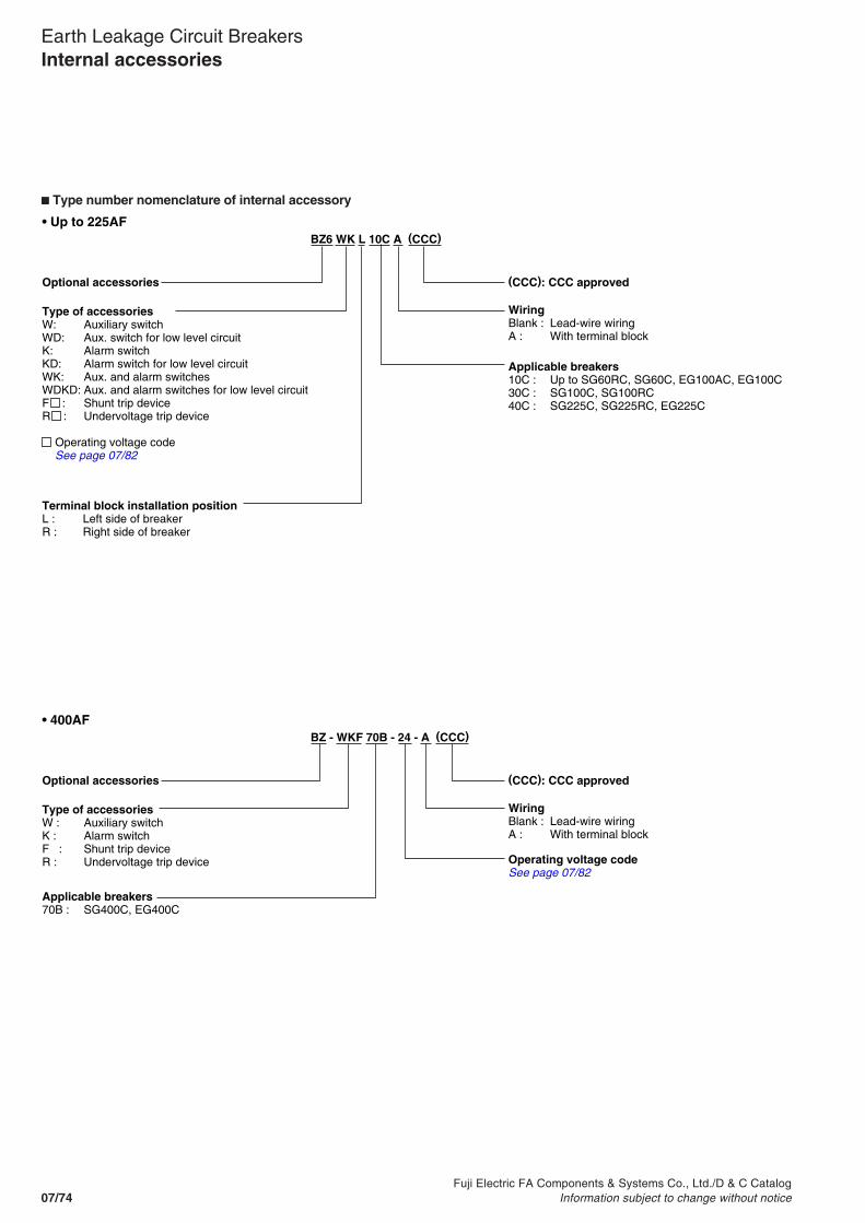
Fuji Electric FA Components & Systems Co., Ltd./D & C CatalogInformation subject to change without notice07/74
Earth Leakage Circuit BreakersInternal accessories
� Type number nomenclature of internal accessory
BZ6 WK L 10C A (CCC)
Optional accessories (CCC): CCC approved
Type of accessoriesW: Auxiliary switchWD: Aux. switch for low level circuitK: Alarm switchKD: Alarm switch for low level circuitWK: Aux. and alarm switchesWDKD: Aux. and alarm switches for low level circuitF : Shunt trip deviceR : Undervoltage trip device
Operating voltage code See page 07/82
WiringBlank : Lead-wire wiringA : With terminal block
Applicable breakers10C : Up to SG60RC, SG60C, EG100AC, EG100C30C : SG100C, SG100RC40C : SG225C, SG225RC, EG225C
Terminal block installation positionL : Left side of breakerR : Right side of breaker
BZ - WKF 70B - 24 - A (CCC)
Optional accessories
Type of accessoriesW : Auxiliary switchK : Alarm switchF : Shunt trip deviceR : Undervoltage trip device
WiringBlank : Lead-wire wiringA : With terminal block
(CCC): CCC approved
Applicable breakers70B : SG400C, EG400C
Operating voltage codeSee page 07/82
• Up to 225AF
• 400AF

Fuji Electric FA Components & Systems Co., Ltd./D & C CatalogInformation subject to change without notice 07/75
Earth Leakage Circuit Breakers
07
07
� Operation of auxiliary switches(W) and alarm switches(K)
Internal accessories
Accessory
Auxiliary switch
Alarm switch
SPDT: W
SPDT: K
2PDT: K2
2PDT: W2
Handle positionON OFF Trip
11/AXcL
12/AXbL
14/AXaL
11/AXcL
12/AXbL
14/AXaL
21/AXcR
22/AXbR
24/AXaR
91/ALcL 94/ALaL
92/ALbL
91/ALcL 94/ALaL
92/ALbL
01/ALcR 04/ALaR
02/ALbR
91/ALcL 94/ALaL
92/ALbL
91/ALcL 94ALaL
92/ALbL
01/ALcL 04/ALaL
02/ALbL
11/AXcL
12/AXbL
14/AXaL
11/AXcL
12/AXbL
14/AXaL
21/AXcR
22/AXbR
24/AXaR
Note: Ring mark indication
AXc1
AXb1
AXa1
AXc2
AXb1
AXa2
ALc1 ALa1
ALb1
ALc2 ALa2
ALb2
ALc1 ALa1
ALb1
ALc2 ALa2
ALb2
AXc1
AXb1
AXa1
AXc2
AXb2
AXa2
AlarmswitchSPDT: K
2PDT: K2
Auxiliary switchSPDT: W
2PDT: W2
HG50BHG100BHG225B

Fuji Electric FA Components & Systems Co., Ltd./D & C CatalogInformation subject to change without notice07/76
Earth Leakage Circuit Breakers
� Ratings of auxiliary switches(W) and alarm switches(K)
Internal accessories
Standard type
For low level circuit
EG series
EG30ACEG30CEG50ACEG50CEG60CEG100ACEG100C–
EG225C
EG400CEG600CEG800C
ELCBSG series
SG30CSG50CSG50RCSG60CSG60RC
–
SG100CSG100RCSG225CSG225RC
SG400CSG400RCSG600RCSG800RC
HG series
–
HG50BHG100BHG225B–
HG400BHG600BHG800B
ACVoltage (V)
125
250
125250500125
250
125
250
500
Make/break current (A)Res. load5 (5)
5 (5)
5 (3)5 (2)25 (2)
3 (1)
5
5
2
Ind. load4 (5)
4 (5)
4 (2)4 (1)12 (2)
1 (1)
4
4
1
DCVoltage (V)
30
125
250
3012525030
125
250
30
125
250
Make/break current (A)Res. load3 (3)
0.6 (0.6)
0.3 (0.3)
3 (2)0.4 (0.4)0.24 (1)
0.4 (0.5)
0.2 (0.2)
3
0.4
0.2
Ind. load2 (3)
0.4 (0.6)
0.2 (0.3)
2 (1)0.2 (0.1)0.13 (1)
0.4 (0.5)
0.2 (0.2)
2
0.2
0.1
Minimumload current
5V DC 160mA30V DC 30mA
EG series
EG30ACEG30CEG50ACEG50CEG60CEG100ACEG100C–
EG225C
EG400CEG600CEG800C
ELCBSG series
SG30CSG50CSG50RCSG60CSG60RC
–
SG100CSG100RCSG225CSG225RCSG400CSG400RCSG600RCSG800RC
HG series
–
HG50BHG100BHG225B–
HG400BHG600BHG800B
DCVoltage (V)
30
30
30
30
Make/break current (A)
0.1
0.1(Res. load)
0.1
0.1
Minimumload current
5V DC 1mA30V DC 1mA
Note: ( ) Reference value for IEC60947-5-1 or JIS C8201-5-1

Fuji Electric FA Components & Systems Co., Ltd./D & C CatalogInformation subject to change without notice 07/77
Earth Leakage Circuit Breakers
07
07
� Ratings of auxiliary switches(W) and alarm switches(K)
Internal accessoriesUL Listed
� Operation of auxiliary switches(W) and alarm switches(K)
Accessory
Auxiliary switch
Alarm switch
SPDT: W
SPDT: K
2PDT: K2
2PDT: W2
Handle positionON OFF Trip
11/AXcL
12/AXbL
14/AXaL
11/AXcL
12/AXbL
14/AXaL
21/AXcR
22/AXbR
24/AXaR
91/ALcL 94/ALaL
92/ALbL
91/ALcL 94/ALaL
92/ALbL
01/ALcR 04/ALaR
02/ALbR
91/ALcL 94/ALaL
92/ALbL
91/ALcL 94ALaL
92/ALbL
01/ALcL 04/ALaL
02/ALbL
11/AXcL
12/AXbL
14/AXaL
11/AXcL
12/AXbL
14/AXaL
21/AXcR
22/AXbR
24/AXaR
Note: Ring mark indication
Standard type
Low level circuit
EG series
EG100CUL
–
–
ELCBSG series
SG50RCUL
SG100CULSG225CULSG400CUL
ACVoltage (V)
120240120240120240
Make/break current (A)3.61.85355
DCVoltage (V)
125250
Make/break current (A)0.550.27
Minimumload current
5V DC 160mA30V DC 30mA
EG series
EG100CUL
–
–
ELCBSG series
SG50RCUL
SG100CULSG225CULSG400CUL
DCVoltage (V)
30
30
30
Make/break current (A)
0.1
0.1
0.1
Minimumload current
5V DC 1mA30V DC 1mA

Fuji Electric FA Components & Systems Co., Ltd./D & C CatalogInformation subject to change without notice07/78
Earth Leakage Circuit Breakers
� Rating of shunt trip (F)
Internal accessories
Note: Allowable voltage function AC voltage: 85% to 110% of coil rated voltageDC voltage: 75% to 125% of coil rated voltage
UL Listed
IEC and CE marking conformed
EG series
EG30ACEG30CEG50ACEG50CEG60CEG100ACEG100CEG225C
EG400CEG600CEG800C
Applicable breaker typeSG series
SG30CSG50CSG50RCSG60CSG60RC
SG100CSG100RCSG225CSG225RCSG400CSG400RCSG600RCSG800RC
HG series
–
–
HG400BHG600BHG800B
Power consumptionACV 100(50Hz)/100-110(60Hz)200(50Hz)/200-220(60Hz)400(50Hz)/400-440(60Hz)––
100(50Hz)/100-110(60Hz)200(50Hz)/200-220(60Hz)400(50Hz)/400-440(60Hz)–24-48 (50/60Hz)100-240 (50/60Hz)380-550 (50/60Hz)
VA161622––
200150200–234
W–––3623
–––20023–
Time ratingof coil
Continuous
Continuous
Continuous
Operatingtime(ms)7-13
7-13
8-20
DCV–––24100-110
–––100-11024-48100-220–
EG series
EG100CUL
–
–
Applicable breaker typeSG series
SG50RCUL
SG100CULSG225CUL
SG400RCUL
HG series
–
–
–
Power consumptionACV 100(50Hz)/100-110(60Hz)200(50Hz)/200-220(60Hz)400(50Hz)/400-440(60Hz)100(50Hz)/100-110(60Hz)200(50Hz)/200-220(60Hz)400(50Hz)/400-440(60Hz)24-48 (50/60Hz)100-240 (50/60Hz)
VA16162220015020023
W––––––23
Time ratingof coil
Continuous
Continuous
Continuous
Operatingtime(ms)7-13
7-13
8-20
DCV––––––24-48100-220
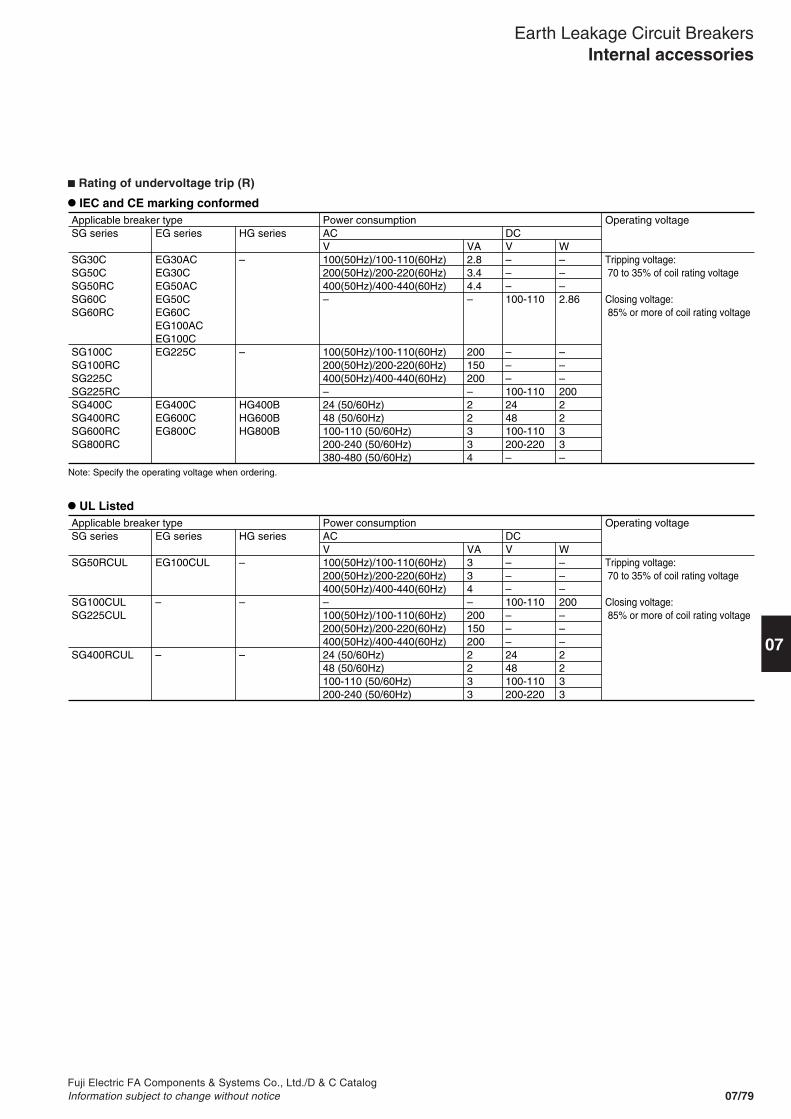
Fuji Electric FA Components & Systems Co., Ltd./D & C CatalogInformation subject to change without notice 07/79
Earth Leakage Circuit Breakers
07
07
� Rating of undervoltage trip (R)
Internal accessories
UL Listed
IEC and CE marking conformed
EG series
EG30ACEG30CEG50ACEG50CEG60CEG100ACEG100CEG225C
EG400CEG600CEG800C
Applicable breaker typeSG series
SG30CSG50CSG50RCSG60CSG60RC
SG100CSG100RCSG225CSG225RCSG400CSG400RCSG600RCSG800RC
HG series
–
–
HG400BHG600BHG800B
Power consumptionACV 100(50Hz)/100-110(60Hz)200(50Hz)/200-220(60Hz)400(50Hz)/400-440(60Hz)–
100(50Hz)/100-110(60Hz)200(50Hz)/200-220(60Hz)400(50Hz)/400-440(60Hz)–24 (50/60Hz)48 (50/60Hz)100-110 (50/60Hz)200-240 (50/60Hz)380-480 (50/60Hz)
VA2.83.44.4–
200150200–22334
W–––2.86
–––2002233–
Operating voltage
Tripping voltage: 70 to 35% of coil rating voltage
Closing voltage: 85% or more of coil rating voltage
DCV–––100-110
–––100-1102448100-110200-220–
EG series
EG100CUL
–
–
Applicable breaker typeSG series
SG50RCUL
SG100CULSG225CUL
SG400RCUL
HG series
–
–
–
Power consumptionACV 100(50Hz)/100-110(60Hz)200(50Hz)/200-220(60Hz)400(50Hz)/400-440(60Hz)–100(50Hz)/100-110(60Hz)200(50Hz)/200-220(60Hz)400(50Hz)/400-440(60Hz)24 (50/60Hz)48 (50/60Hz)100-110 (50/60Hz)200-240 (50/60Hz)
VA334–2001502002233
W–––200–––2233
Operating voltage
Tripping voltage: 70 to 35% of coil rating voltage
Closing voltage: 85% or more of coil rating voltage
DCV–––100-110–––2448100-110200-220
Note: Specify the operating voltage when ordering.

Fuji Electric FA Components & Systems Co., Ltd./D & C CatalogInformation subject to change without notice07/80
Earth Leakage Circuit Breakers
■ Dimensions, mmshunt trip device "F" and undervoltage trip device "R"
Internal accessories
M3.5
C
C
CL
L
L
72512.5
1111
128
63.5
6970
155
90
60
7760
5141
24
3
68
M3.5
2575
10.545
61
41.5
100
CL
CL
CL
72512.5
M3.5
128
60.5
1111
7366
60
165
105
C
C
C L
L
L
EG series
EG30AC, EG33CEG50AC, EG50CEG60CEG100AC, EG100C
–
EG225C
Fig.
Fig.1
Fig.2
Fig.3
Mass (kg)
0.15
0.17
SG series
SG30CSG50C, SG50RCSG60C, SG60RC
SG100C, SG100RC
SG225C, SG225RC
Fig.2Fig.1
Fig.3

Fuji Electric FA Components & Systems Co., Ltd./D & C CatalogInformation subject to change without notice 07/81
Earth Leakage Circuit Breakers
07
07
Internal accessories
■ Terminal block specifications
■ Lead wire specifications
UL Listed
SG seriesSG30CSG50C, SG50RCSG60C, SG60RC
SG100C, SG100RCSG225C, SG225RCSG400CSG400RCSG600RCSG800RC
EG seriesEG30AC, EG30CEG50AC, EG50CEG60CEG100AC, EG100C
EG225CEG400CEG600CEG800C
HG series–
HG50BHG100BHG225BHG400BHG600BHG800B
Wire sizeAWG22 (0.4mm2)
0.5mm2
Wire length500mm
500mm
SG seriesSG50RCULSG100CULSG225CULSG400CUL
EG seriesEG100CUL
HG series–
Wire size20AWG
Wire length500mm
IEC and CE marking conformed
ELCBSG seriesSG30CSG50C, SG50RCSG60C, SG60RC
SG50RCULSG100C, SG100CULSG100RCSG225C, SG225CULSG225RC–
–SG400C, SG400CULSG400RCSG600RCSG800RC
EG seriesEG30AC, EG30CEG50AC, EG50CEG60CEG100AC, EG100CEG100CUL–
EG225C
–
–EG400C
EG600CEG800C
HG series–
––
–
HG50BHG100BHG225BHG400B
HG600BHG800B
TerminalscrewM3.5
Dimensions (mm)Fig.Fig.1
Fig.2Fig.3
Fig.4
Fig.5
A0
0-17
-14.5
+4.7
+0.2 -6.5
B 9
9 4
4
24.9
34.9–
C23.5
23.519
19
41.8
51.8–
D36
3631
31
54.2
64.2–
E48.5
48.543.5
43.4
66.5
76.5–
F–
––
76.5
85.5
G–
––
–
–
H–
––
–
–
I–
––
–
–
Fig.4 Fig.5
Fig.2 Fig.3
C
+A
EDC
48 B
94L
7
77.2
53.7
30.2
12.5
CL
100.
577 53
.530
.5
M3.5
Load
Line
(Left) (Right)
38 19
8 8
+A
81.569
56.544
9.5 80 11
117.
5F
8
12.5
CL CL
Line
30.2
53.7
77.2
M3.5
7
Load
CL C
48 B
+A
94
EDC
(Left) (Right)
CL CL
+A
EDC
48 B
7
77.2
9453.7
30.2
12.5
Fig.1
Note: The applicable wire size for the lead terminal block is either ø1.6mm solid wire or 2mm2 stranded wire.
L
Lead-wire extension type is not available.(SG50RCUL, EG100CUL)
CL
48B
+A
94
ED
C
CL
25.5

Fuji Electric FA Components & Systems Co., Ltd./D & C CatalogInformation subject to change without notice07/82
Earth Leakage Circuit BreakersInternal accessories
■ Type number
ELCB typeSG seriesSG30C *SG50C *, SG50RC *SG60C *, SG60RC *
SG100C, SG100RC
SG225C, SG225RC
–
SG400C, SG400RCSG600RCSG800RC
Auxiliary
BZ6W 10CBZ6W 10CA
BZ6W 30C
BZ6W 40C
BZ-W70BBZ-W70B-A
Mass(kg)0.010.04
0.020.050.020.050.05
0.020.11
Mass(kg)0.010.04
0.020.050.020.050.05
0.020.11
Mass(kg)0.020.08
0.040.070.040.070.07
0.040.13
Alarm
BZ6K 10CBZ6K 10CA
BZ6K 30C
BZ6K 40C
BZ-K70BBZ-K70B-A
Auxiliary + Alarm
BZ6WK 10CBZ6WK 10CA
BZ6WK 30C
BZ6WK 40C
BZ-WK70BBZ-WK70B-A
EG seriesEG30AC *, EG30C *EG50AC *, EG50C *EG60C *EG100AC *, EG100C *
–
EG225C
–
EG400CEG600CEG800C
HG series–
–
–
HG53BHG103BHG203BHG403BHG603BHG803B
Notes: • Auxiliary switch and alarm switch for low level circuit are also available on request, in this case add D to the type number when ordering. Example: WD, KD• Replace the mark by the R when an auxiliary switch or an alarm switch is mounted on right hand side of the breaker. Enter the L when it is mounted on left hand side of the breaker.* 2-pole types are mountable on right side only.
Factory-mounted accessory
Shunt trip devices (F)
ELCB type
SG series
SG30CSG50C, SG50RCSG60C, SG60RC
SG100C, SG100RC
SG225C, SG225RC
SG400C, SG400RCSG600RCSG800RC
EG series
EG30AC, EG33CEG50AC, EG50CEG60CEG100AEG100AC, EG100C
–
EG225C
EG400CEG600CEG800C
Voltage
100V AC 50Hz, 100-110V AC 60Hz110V AC 50Hz, 110-127V AC 60Hz200V AC 50Hz, 200-220V AC 60Hz220V AC 50Hz, 220-240V AC 60Hz230V AC 50Hz, 230-240V AC 60Hz240V AC 50Hz380V AC 50Hz, 380-415V AC 60Hz400V AC 50Hz, 400-440V AC 60Hz24V DC100-110V DC24V DC100V AC 50Hz, 100-110V AC 60Hz100-110V DC200-240V AC 50/60Hz380-440V AC 50/60Hz24V DC100V AC 50Hz, 100-110V AC 60Hz100-110V DC110-130V AC 50/60Hz200-240V AC 50/60Hz380-480V AC 50/60Hz24-48V AC 50/60Hz, 24-48V DC100-240V AC 50/60Hz, 100-220V 50/60Hz380-450V AC 50/60Hz
Operating voltage Type number
BZ6F210CBZ6F110CBZ6F710CBZ6F410CBZ6F510CBZ6FB10CBZ6F010CBZ6F810C
BZ-F70B-24BZ-F70B-100BZ-F70B-380
With terminal block
BZ6F210CABZ6F110CABZ6F710CABZ6F410CABZ6F510CABZ6FB10CABZ6F010CABZ6F810CA
BZ-F70B-24ABZ-F70B-100ABZ-F70B-380A
Code
21745B08MLM2L4CM2L14C24100380
HG series
–
–
–
HG403BHG603BHG803B
Notes: • Specify operating voltage when ordering.• Terminal block is provided as standard.
Factory-mounted accessory
Auxiliary switches (W) and alarm switches (K)

Fuji Electric FA Components & Systems Co., Ltd./D & C CatalogInformation subject to change without notice 07/83
Earth Leakage Circuit Breakers
07
07
Internal accessories
Undervoltage trip devices (R)
ELCB type
SG series
SG30CSG50C, SG50RCSG60C, SG60RC
SG100C, SG100RCSG225C, SG225RC
SG400C, SG400RCSG600RCSG800RC
EG series
EG30AC, EG30CEG50AC, EG50CEG60CEG100AC, EG100C
EG225C
EG400CEG600CEG800C
Voltage
24V DC100V AC 50Hz, 100-110V AC 60Hz100-110V DC110V AC 50Hz, 110-127V AC 60Hz200V AC 50Hz, 200-220V AC 60Hz220V AC 50Hz, 220-240V AC 60Hz230V AC 50Hz, 230-240V AC 60Hz240V AC 50Hz380V AC 50Hz, 380-415V AC 60Hz400V AC 50Hz, 400-440V AC 60Hz24V DC100V AC 50Hz, 100-110V AC 60Hz100-110V DC200V AC 50Hz/200-220V AC 60Hz400V AC 50Hz/400-440V AC 60Hz24V AC 50/60Hz, 24V DC48V AC 50/60Hz, 48V DC100-110V AC 50/60Hz, 100-110V DC200-240V AC 50/60Hz, 200-220V DC380-480V AC 50/60Hz
Operating voltage Type number
BZ6RF10CBZ6R210CBZ6RT10CBZ6R110CBZ6RW10CBZ6R410CBZ6R510CBZ6R810CBZ6R010CBZ6R910C
BZ-R70B-24BZ-R70B-48BZ-R70B-100BZ-R70B-200BZ-R70B-380
Mass(kg)0.140.140.140.140.140.140.140.140.140.140.180.180.180.180.180.060.060.060.060.06
Code
F2T1W45809F2T4CRSXUE
HG series
–
–
HG403BHG603BHG803B
Notes: • Specify operating voltage when ordering.• Terminal block is provided as standard.
Factory-mounted accessory
UL type Auxiliary switches (W) and alarm switches (K)
UL type Shunt trip devices (F)
UL type Undervoltage trip devices (R)
ELCB typeSG seriesSG53RCUL
EG seriesEG102CULEG103CUL
Rated voltage
100V AC 50Hz/100-110V AC 60Hz200V AC 50Hz/200-220V AC 60Hz400V AC 50Hz/400-440V AC 60Hz
Type numberWith terminal blockBZ6R210CAUBZ6RW10CAUBZ6R910CAU
ELCB typeSG seriesSG53RCUL
EG seriesEG102CULEG103CUL
Rated voltage
100V AC 50Hz/100-110V AC 60Hz200V AC 50Hz/200-220V AC 60Hz400V AC 50Hz/400-440V AC 60Hz
Type numberLead wire–––
With terminal blockBZ6F210CAUBZ6F710CAUBZ6F810CAU
ELCB type
SG seriesSG53RCUL
EG seriesEG100CUL
Type numberAuxiliary switch / WSPDTBZ6W 10CUBZ6W 10CAU(With terminal block)
Alarm switch / KSPDTBZ6K 10CUBZ6K 10CAU(With terminal block)
Auxiliary switch + Alarm switch / WK
BZ6WK 10CUBZ6WK 10CAU(With terminal block)

Fuji Electric FA Components & Systems Co., Ltd./D & C CatalogInformation subject to change without notice07/84
Earth Leakage Circuit BreakersInternal accessories
Operating voltage for 400AF to 800AF
Operatingvoltage
Code
Shunt trip
24/48V AC/DC
24
100-110V AC/DC
100
200-240V AC200-220V DC
200
380-480V AC
380
Undervoltage trip
24V AC/DC
24
48V AC/DC
48
100-240V AC100-220V DC
100
380-550V AC
380
BZ - WKF 70B - 100 - A
Type of accessory
Operating voltage
Terminal
� Ordering informationSpecifty the following.1. Type number2. Lead-wire connection or
terminal block type
Internal accessories (optional) for 400AF to 800AF
Accessory type Auxiliary switch Alarm switch Shunt trip Undervoltage trip Number Mass (kg)W W2 K K2 F R of terminal w/lead w/terminal
blocks wire block
BZ-W70B- � 1 0.05 0.14BZ-K70B- � 1 0.05 0.14BZ-F70B-�- � 1 0.09 0.18BZ-R70B-�- � 1 0.09 0.18BZ-W270B- � 2 0.07 0.25BZ-WK70B- � � 1 0.07 0.16BZ-W2K70B- � � 2 0.09 0.27BZ-K270B- � 2 0.07 0.25BZ-WK270B- � � 2 0.09 0.27BZ-W2K270B- � � 2 0.11 0.29BZ-WF70B-�- � � 1 0.11 0.20BZ-W2F70B-�- � � 2 0.13 0.31BZ-WR70B-�- � � 1 0.11 0.20BZ-W2R70B-�- � � 2 0.13 0.31BZ-KF70B-�- � � 1 0.11 0.20BZ-KR70B-�- � � 1 0.11 0.20BZ-WKF70B-�- � � � 1 0.13 0.22BZ-WKR70B-�- � � � 1 0.13 0.22BZ-K2F70B-�- � � 2 0.13 0.31BZ-K2R70B-�- � � 2 0.13 0.31BZ-W2KF70B-�- � � � 2 0.15 0.33BZ-W2KR70B-�- � � � 2 0.15 0.33BZ-WK2F70B-�- � � � 2 0.15 0.33BZ-WK2R70B-�- � � � 2 0.15 0.33BZ-W2K2F70B-�- � � � 2 0.17 0.35BZ-W2K2R70B-�- � � � 2 0.17 0.35
Notes: � Indicates the mountable accessories.• Replace the mark � by the operating voltage of shunt trip or undervoltage trip device.• Replace the mark by the A suffix for terminal block type, blank for lead-wire connection type.

Fuji Electric FA Components & Systems Co., Ltd./D & C CatalogInformation subject to change without notice 07/85
07
Earth Leakage Circuit Breakers
400AF and larger, 4-pole
CP-1214
SG series
SG33C/MSG53C/M, 53RC/MSG63C/M, 63RC/M
SG103C/MSG103RC/M
SG203C/MSG203RC/M
SG403C/MSG403RC/MSG603RC/MSG803RC/M
EG series
EG33AC/M, 33C/MEG53AC/M, 53C/MEG63C/MEG102C/M, 103AC/M, 103C/M
EG203C/M
EG403C/MEG603C/MEG803C/M
Motor rating
Operating voltage
100V DC100/110V AC200/220V AC
24V DC48V DC100V DC100/110V AC200/220V AC
100/110V DC100/110V AC200/220V AC
Operating time
0.1s
2s
2.5s
2s
Time rating
15s peron-offoperation
30s
30s
30s
Power sourcecapacity
500VA
50VA
50VA
100VA at 100/110V DC, 100/110V AC200VA at 200/220V AC
Motor-operated breakers
DescriptionThe breaker is fitted with a motoroperating mechanism which enablesON, OFF and RESET operations to becarried out electronically by remotecontrol.4-pole motor operated breakers are alsoavailable.
Types and ratings
Ordering informationSpecify the following:1. Type number2. Motor operating voltage
External accessoriesMotor-operated breakers
AF93-403AF02-54
100 to 225AF
� Dimensions, mm / Front mounting, front connectionSG33C/M, SG53C/M, SG53RC/M, SG63C/M, SG63RC/MEG33AC/M, EG33C/M, EG53AC/M, EG53C/M, EG63C/M, EG102C/M, EG103C/M
DRIVEUNIT
5
OFF ON
Power supply(Non polarity)
4 3 E 2 1
CONTROLCIRCUIT
� Wiring diagrams100/110V AC, 200/220V AC, 100V DC
Terminal cover
Test button
Trip button
Insulation barrier(Except EG33AC/M, 53AC/M, SG33C/M)Mounting hole
ø4.5Operating handle
Notes: • Trip button operation can be carried out at right side of the breaker.• IEC 35mm rail is not available.
LC
CL LC
139135
4
6751
75100
75
84
25
50
50
70
10
CL
CL
M4 or ø5
25
84
Panel drilling

Fuji Electric FA Components & Systems Co., Ltd./D & C CatalogInformation subject to change without notice07/86
Earth Leakage Circuit Breakers
C : Control relay for breaker closing
T : Control relay for breaker open
M : Motor
Ca1-Cc : Relay terminal number forclosing
Ta1-Tc : Relay terminal number for open
: Diode
Z : Z-trap (Surge absorber)
SS : ON/OFF changeover switch
E, 1-5 : Terminal number for externalwire connection
: Resistor : LED
: Silicon diode
: Transformer
: Capacitor
AURS : Automatic reset switch(supplied on request)
SG103RC/M, SG103C/M
SG203C/M, SG203RC/MEG203C/M
Note: Interphase insulation barriers are standard provided forthe front mounting type breakers of 50AF to 225AF.
24V DC, 48V DC, 100V DC
100/110V AC, 200/220V AC
External accessoriesMotor-operated breakers
Insuration barrierDetachable
90
30
100
132
155
144
142
56
2-M4 or ø5 30
189
132
R65
57°
Panel drilling
50
75
Testleadwire
500
Max. 4
CL
CL
105 500
35
126
100
165
138
14256
4-M4 or ø5
Max. 4
35
189
126
R65
57°
Panel drilling80
75
Insuration barrierDetachable
Test lead wire
� Dimensions, mm / Front mounting, front connection � Wiring diagrams

Fuji Electric FA Components & Systems Co., Ltd./D & C CatalogInformation subject to change without notice 07/87
07
Earth Leakage Circuit Breakers
Amp. frame A (line side) B (load side) C
600AF 38.5 41.5 7
800AF 41.5 44.5 10
SG603RC/M, SG803RC/MEG603C/M, EG803C/M
100/110V DC
External accessoriesMotor-operated breakers
Dimensions for reference only. Confirm before construction begins.
56 56
257
327
15
140
25
CL
CL
220
BoltM12 x 35
8
44Panel
M6
44
216256
215
M8 or ø7
40.5
40.5
8 18
44500
Test lead wire
327
210
44
CL
CL
220
BoltM12 x 40
Test lead wire
C
A
Panel
M6
216291
243
ø7
18
140
8727
5
500
87
BC 15
328
CL
70
CL
CL
SG403C/M, SG403RC/MEG403C/M
� Dimensions, mm/Front mounting, front connection � Wiring diagrams/400 to 800AF
100/110V AC, 200/220V AC, 50/60Hz
C : Control relay for breaker closing R : ResistorT : Control relay for breaker open LS : Limit switchM : MotorAURS: Automatic reset switch
(supplied on request)
Panel drilling
Panel drilling
Manual/motoroperationindicator
Manual/motoroperationindicator
Type (ELCB with motor operating mechanism)SG33C/M, SG53C/M, SG53RC/MEG33AC/M, EG33C/M, EG53AC/M, EG53C/MSG63C/M, SG63RC/MEG63C/M, EG102C/M, EG103AC/M, EG103C/MSG103C/MSG103RC/MSG203C/M, SG203RC/MEG203C/MSG403C/M, SG403RC/M, EG403C/MSG603RC/M, EG603C/MSG803RC/M, EG803C/M
Mass (kg)1.2
1.3
2.12.22.3
14.217.518.5
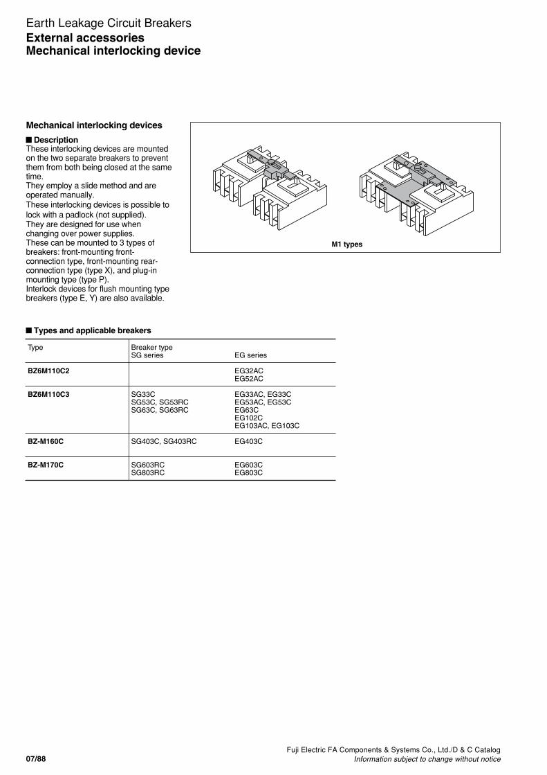
Fuji Electric FA Components & Systems Co., Ltd./D & C CatalogInformation subject to change without notice07/88
Earth Leakage Circuit Breakers
These interlocking devices are mountedon the two separate breakers to preventthem from both being closed at the sametime.They employ a slide method and areoperated manually.These interlocking devices is possible tolock with a padlock (not supplied).They are designed for use whenchanging over power supplies.These can be mounted to 3 types ofbreakers: front-mounting front-connection type, front-mounting rear-connection type (type X), and plug-inmounting type (type P).Interlock devices for flush mounting typebreakers (type E, Y) are also available.
Types and applicable breakers
Type
BZ6M110C2
BZ6M110C3
BZ-M160C
BZ-M170C
Breaker typeSG series
SG33CSG53C, SG53RCSG63C, SG63RC
SG403C, SG403RC
SG603RCSG803RC
EG series EG32ACEG52AC EG33AC, EG33CEG53AC, EG53CEG63CEG102CEG103AC, EG103C EG403C
EG603CEG803C
Mechanical interlocking devices
Description
External accessoriesMechanical interlocking device
M1 types

Fuji Electric FA Components & Systems Co., Ltd./D & C CatalogInformation subject to change without notice 07/89
07
Earth Leakage Circuit BreakersExternal accessories
Mechanical interlocking device
Type
BZ6M110C2
BZ6M110C3
EG series
EG32ACEG52AC
EG33ACEG33CEG53ACEG53CEG63CEG102CEG103ACEG103C
Dimensions, mmA
85
110
B
42.5
55
C
83
108
Mass (kg)
0.11
0.12
Breaker typeSG series
SG33CSG53CSG63CSG53RCSG63RC
Notes: • BZ6M110C2 is not available for padlock.• Applicable padlock(ø3.5) dimensions, mm
9.5
20
12ø3.5 ø3.5 14
25
14
2-ø4.5 mounting holePadlock
of breaker
of sliderCL
CL
(Not supplied)
26
35
9
13
11
56
100
A
68
BC
88
CL CL
CL CL
Breaker mounting hole
Breaker mounting hole
Breaker Breaker
BreakerBreaker
2-ø4.5 or M4
2-ø4.5 or M4
of breakerCL
of breakerCL
BZ6M110C2
BZ6M110C3
45
68
100
110
68
45
85
CL CL
CL CL
� Dimensions, mm• 30AF to EG100AF
Panel drilling

Fuji Electric FA Components & Systems Co., Ltd./D & C CatalogInformation subject to change without notice07/90
Earth Leakage Circuit BreakersExternal accessoriesMechanical interlocking device
Type
BZ-M160C
BZ-M170C
EG series
EG403C
EG603CEG803C
Breaker typeSG series
SG403CSG403RC
SG603RCSG803RC
A (A')
355 (70)
500 (105)
Dimensions, mmB
257
275
C
215
290
D
0
20
E
94.5
94.5
F
126
126
G
54.5
54.5
H
171
220
J (J')
44 (70)
70 (105)
K
215
243
L
38
38
Mass(kg)
0.56
0.64
Note: Applicable padlock(ø3.5) dimensions, mm
9.5
20
12ø3.5 ø3.5 14
25
14
Padlock(not supplied)
Mounting screw(Provided)
of slider
of breaker
DB
A
CA'
CL
CL
CL
of handleCL
of slider
of breakerCL
CL
of handle
K
BZ-M160C, M170CBZ6M140C
J'J'J' J' M6 or ø7
HJJJ H
N N
J
Breaker
Breaker
Breaker10-M4 or ø5
GL
F
E
PQ
(BZ-M140C: 8-M4 or ø5)
Panel drilling
■ Dimensions, mm

Fuji Electric FA Components & Systems Co., Ltd./D & C CatalogInformation subject to change without notice 07/91
07
Earth Leakage Circuit Breakers
N type handles G type handle
AF92-448KK03-017
BZ-N C BZ-G10B
KK03-015AF96-173
BZ6N10C
N type handles BZ-N C
G type handles BZ-G10B
BZ6V10CV type handle
External operating handles
■ DescriptionEarth leakage circuit breaker handlesare generally directly manual-operatedbut when mounted in motor controlcenters or on control panels they aresometimes required to be operatedexternally. To meet such applicationsFUJI offers the following three types ofhandles.
N type handleThis type has a knob handle directlyattached to the breaker. It is easily fittedby cutting a hole in the panel, which isprovided with a door interlock. Theymay be fitted to all breakers up to 800ampere frame sizes. N type handles forSG/EG30AF to EG100AF are UL508listed.
V type handleThe V type handle may be fitted tobreakers of up to 800AF.A separately sold extension shaft(BZ-VS1)provides distance adjustmentbetween the handle and breaker.Conformed to EN60947-1 isolationfunction.Available for EN60204-1 power breakingdevice.
G type handleThe G type handle is mounted on thepanel, and also has a door-interlock. Gtype handle with a cylinder lock key isalso available on request.G type handle with a padlockable handlelock plate is standard provided for circuitbreaker of up to 225AF, and is optionalfor 400AF and larger.
External accessoriesOperating handles
V type handles BZ6V C
Breaker
Decorative plateN type handle onbreaker
Breaker
V type handle onpanel
Breaker
G type handle onpanel

07/92Fuji Electric FA Components & Systems Co., Ltd./D & C Catalog
Information subject to change without notice
Earth Leakage Circuit BreakersExternal accessoriesOperating handles
G type handles
StandardBZ-G35CG-12AG-22A
G-5A
Cylinder key typeBZ-G35C-KG-12A-KG-22A-K
G-5A-K
TypeHG53B, 103BSGa104A, 104HSGa204A, 204HSGa404AEG104A
N type handles V type handles
SG series–
–––
SGa104A, 104HSGa204A, 204HSGa404A–
EG series–
–––
––
EG104A
HG seriesHG53BHG103BHG203BHG403BHG603BHG803B––
–
N type handleBZ-N35B
BZ-N50CBZ-N60CBZ-N70C
N-13EAN-23EA
N-6EA
HG seriesHG203BHG403BHG603B, HG803B
V type handleBZ-V50CBZ-V60CBZ-V70C
Notes: • N type handles for up to 800AF can be padloked. Padlock is not provided.• N type handles are not CE marked.
● For breakers up to 800AFN type handles V type handles
SG series
SG33CSG53CSG53RCSG63CSG63RC
SG103CSG103RC
SG203CSG203RC
SG403CSG403RC
SG603RCSG803RC
EG series
EG32AC, 33AC, 33CEG52AC, 53AC, 53CEG63CEG103AC, 102C, 103C
–
EG203C
EG403C
EG603CEG803C
N type handle
BZ6N10CUL508(File No. E216772)
BZ-N30C
BZ-N40C
BZ-N60C
BZ-N70C
SG series
SG53RCUL
SG103CUL
SG203CUL
SG403CUL
EG series
EG102CUL, 103CUL
–
–
–
N type handleUL489(File No. E93289)
BZ6N10CP
BZ6N30CP
BZ6N40CP
BZ6N60CP
SG series
SG33CSG53CSG53RCSG63CSG63RCSG53RCUL
SG103CSG103CULSG103RC
SG203CSG203CULSG203RC
SG403CSG403CULSG403RC
SG603RCSG803RC
EG series
EG32AC, 33AC, 33CEG52AC, 53AC, 53CEG63CEG103AC, 102C, 103CEG102CUL, 103CUL
–
EG203C
EG403C
EG603CEG803C
V type handle
BZ6V10CUL489 (File No. E93289)
BZ6V30CUL489 (File No. E93289)
BZ6V40CUL489 (File No. E93289)
BZ6V60CUL489 (File No. E93289)
BZ6V70CUL489 (File No. E93289)
● For breakers other than series

Fuji Electric FA Components & Systems Co., Ltd./D & C CatalogInformation subject to change without notice 07/93
07
Earth Leakage Circuit BreakersExternal accessories
N type operating handles
N type operating handles
■ Operating instructions1. ELCB operation• Close the door with the handle in the OFF position. Turn the
handle to the ON position and the ELCB will be ON.• Turn the handle to the OFF position and ELCB will be OFF.• When the breaker trips, the handle moves to the TRIP position.
To reset, move the handle to the RESET position.
2. Door locking• The door cannot be opened when the handle is in the ON, OFF
or TRIP position, and can be opened only when the handle is inthe OPEN position.
• The breaker cannot be ON when the door is open.• If it is necessary to open the door with the breaker closed, turn
the doorclose lock release screw counterclockwise using ascrewdriver.
3. Handle lockingThe handle can be locked in either the ON or OFF position when apadlock (not supplied) is used. Pull out the handle lock plate and fityour padlock to the plate. If the breaker trips while it is locked in theON position, the handle moves to the TRIP position.
■ Installation BZ6N10C to BZ-N40C
1. Drilling and cutting the doorDrill and cut the door. The dimensions for drilling and cutting arethe same whether the ELCB is installed horizontally or vertically.
2. Preparing a base plate (Fig. 1)Prepare a base plate to adjust breaker mounting position (baseplate: not supplied). Front mounting, front connection type breakerscan only be suitable for this handle. Drill the breaker mountingholes on the base plate.
3. Fitting the N-handle mechanism and ELCB to the baseplate (Fig. 1)
Commonly tighten the N-handle body and ELCB to the base platewith the mounting screws. For N10C to N30C, tighten twomounting screws on a diagonal line, and for N40C, tighten fourmounting screws. Assemble the driving unit so that the breakerhandle engages the N handle arm. (Fig. 4)
4. Mounting the decorative plateMount the decorative plate and the retaining plate to the door withscrews provided. (Fig. 2)Adjust the position of the handle unit so that it does not tilt againstthe breaker. (Fig. 3)
Fig. 1
Fig. 2
Fig. 3
Retaining plate
Decorative plate
Base plate
For N10C, N30C
Mounting screw
For N40C For N10C, N30C
Not correct
ELCB ELCB
Decorative plate Decorative plate
Handle windowSpace
Fig. 4
ELCBhandle
N handlearm

07/94Fuji Electric FA Components & Systems Co., Ltd./D & C Catalog
Information subject to change without notice
Earth Leakage Circuit BreakersExternal accessoriesN type operating handles
■ Installation BZ-N60C, BZ-N70C
1. Drilling and cutting the doorDrill and cut the door. The dimensions for drilling and cutting are thesame whether the ELCB is installed horizontally or vertically.
2. Preparing a base plate (Fig. 1)Prepare a base plate to adjust breaker mounting position (baseplate: not supplied). Front mounting, front connection type breakerscan only be suitable for this handle. Drill the breaker mountingholes on the base plate.
3. Fitting the N-handle mechanism and ELCB to the baseplate (Fig. 1)
Commonly tighten the N-handle body and ELCB to the base platewith the four mounting screws. Assemble the driving unit so that thebreaker handle engages the N handle arm. (Fig. 4)
4. Mounting the decorative plateMount the decorative plate and the retaining plate to the door withscrews provided. (Fig. 2)Adjust the position of the handle unit so that it does not tilt againstthe breaker. (Fig. 3)
Fig. 1
Fig. 2
Fig. 3 Fig. 4
ELCB
Handlewindow
Decorativeplate
Space
Decorativeplate
ELCB
Not correct
N handle arm
ELCB handle
■ Type number nomenclature
BZ – N C T – RInstallationBlank: VerticallyR: Horizontally, right line sideL: Horizontally, left line side
Door locking deviceBlank: ProvidedT: Not provided
Basic typeBZ6N10CBZ-N CN- EA
Note:To order an N handle for front-mounting rear connection breakers, add “-X” to thetype number, for plug-in mounting breakers, add “-P” to the type number.

Fuji Electric FA Components & Systems Co., Ltd./D & C CatalogInformation subject to change without notice 07/95
07
Earth Leakage Circuit BreakersExternal accessories
N type operating handles
■ Dimensions, mmBZ6N10C to BZ-N50C (Dust proof paking: BZ-NP-1C, optional)
Line
Load69 max.
Breaker type
SG30C, SG50C, 50RC, SG60C, 60RCSG50RCULEG30AC, 30C, EG50AC, 50C, EG60CEG100AC, 100C, 100CUL
SG100C, 100RC, 100CUL
Handletype
BZ6N10CBZ6N10CP
BZ-N30CBZ6N30CP
A
103
103
Mountingscrew
M4 × 80
M4 × 85
Mass(kg)
0.47
0.56
Breaker type
EG225CSG225C, 225RC, 225CUL
HG225B
Handletype
BZ-N40CBZ-N40CP
BZ-N50C
A
103
142
Mountingscrew
M4 × 85
M4 × 125
Mass(kg)
0.56
0.62
4-ø15
7 114
48
55 103±26069Max
105
105
78
78
ø90
Panel71
48.5
Padlockø4 to ø8
127134173
200 200
7 2428 2820
5 21OF
F
/
Line
Load
FAB,ELBhandleC/L
FAB,ELBhandleC/L
HandleC/L
ONTRIP
Door panel cutting Door hinge installation area
Panel thickness 1.2 to 3.2
BZ6N10CP, BZ6N30CP, BZ6N40CP (Dust proof paking: BZ-NP-1C, optional)

07/96Fuji Electric FA Components & Systems Co., Ltd./D & C Catalog
Information subject to change without notice
Earth Leakage Circuit Breakers
Dimensions for refernce only. Confirm before construction begins.
External accessoriesN type operating handles
■ Dimensions, mm
of handleCL
of panel cutting
CL
Door panel cutting
Lock lever
Mass: 0.45kg
Packing(Optional)
Line
Load
Decorative plate
105
105
60 max52.5 54.5
43 125±2
Panel Mounting screwPanel thickness 1.2 to 3.2
78
ø9078
4 -ø15
3030
1515
105
100 100150 150
200 200
5
1515
3030
Install the door hinge in the shaded area.
BZ-N35B (Dust proof packing: BZ-NP-1, optional)
Dimensions of N type handles for 4-pole: Contact FUJI.
Breaker type Handle Mounting Masstype screw (kg)
SG400C, SG400RC BZ-N60C M6 x 110 1.9SG400CUL BZ-N60CPEG400CHG400B
SG600RC, SG800RC BZ-N70C M6 x 110 1.9EG600C, EG800C BZ-N70CPHG600B, HG800B
OPE
NR
ES
ET
OF
F
T
RI P
O N
RE
LEA
SE
Decorative plate
150
150
9696
17
Line
Load
Aux. handle(Only BZ-N70C)
Breaker andhandle
C/L
Breaker andhandle
C/L
HandleC/L
Lock plate
15753
150
Mounting screw
4 -ø15
ø138
112
112
100100
6535
7.5
152535
65
25
200 200
Install the door hinge in the shaded area.
Panel thickness 1.6 to 3.2
Door panel cutting
Note: • Handle protection degree IP50 (IEC60529, JIS C 0920) (with the optional dust-proof packing)• The handle cannot hold the door.
Door hinge installation area
P
BZ-N60C, BZ-N70C, BZ-N60CP, BZ-N70CP (Dust proof packing: BZ-NP-2, optional)
Notes:1. The N type handles are used with front mounting front connection type
breakers. They are normally installed vertically. However, it is possible to installthem horizontally if required. In this case please specify so in your order.(Example) Specify as follows:BZ-N C-R..... Installed horizontally, the line positioned on the right side.BZ-N C-L......Installed horizontally, the line positioned on the left side.
2. Breakers use different size screws for the P-type (Plug-in) breakers

Fuji Electric FA Components & Systems Co., Ltd./D & C CatalogInformation subject to change without notice 07/97
07
Earth Leakage Circuit BreakersExternal accessories
V type operating handles
V type operating handles, up to 225AF
■ Operating instructions1. ELCB operation• Close the door and turn the handle to the ON position and the
breaker will be positioned at ON.• When the breaker is interrupted automatically the handle will
move to the TRIP position.• To reset move the handle to the RESET position.
2. Door panel locking• Turn the handle to the RESET position and the lock
mechanism will be released thus allowing the door to beopened.
• The door cannot be opened when the breaker is positioned atON.
3. Handle lockingThe padlock can lock the handle in the OFF position.• Locking ELCB with the door open : Fig.1• Locking ELCB with the door closed : Fig.2
Pull out the lock plate and lock the padlock.
4. Interlock releaseThis type is provided with an interlock release screw. Turn thisscrew if it is necessary to open the door in the ON position. Thisrelease the lock and allows the door to be opened. Whenreclosing the door, make sure the handle of the breakercoincides with the position (ON or OFF) of the external handleposition.
■ InstallationBZ6V10C to V50C1. Drilling and cutting of the door panelDrill and cut the door panel as shown in the drawing.
2. Mounting of the ELCBThe distance between the backside of the door panel andbreaker mounting plate should be the dimension "H" shown inthe drawing below.H dimensions, mm (Fig.3)• BZ6V10C: 105• BZ6V30C: 105• BZ6V40C: 105• BZ-V50C: 144
3. Mounting the driving unit• Set the breaker handle to the OFF position. Assemble the
driving unit so that the breaker handle engages the V handlearm. (Fig.4 )
• Secure the driving unit and breaker together to the mountingplate by tightening the four attached mounting screws. (Fig.5)
4. Mounting the handle unit• Put the handle unit, cover holder, packing, and retainer in
front of and behind the panel and tighten the screwstemporarily as shown in Fig.6. Adjust the position of thehandle unit so that it does not tilt against the breaker. (Fig.7)
• Put the handle of the handle unit in the OFF position andclose the door. Check that the shaft engages the latch whenthe door closes. (Fig.8)
Padlock(Not supplied)
Terminal cover
Driving unitLatchMounting screw
Breaker
For V10C, V30C
For V40C
Retainer
Door panel
Packing
Cover holder
Handle unit
Interlock-release screw
Latch
Shaft
Fig. 2Fig. 1
Fig. 5
Fig. 3
Fig. 6
Fig. 8
Fig. 4
Fig. 7
Lock plate

07/98Fuji Electric FA Components & Systems Co., Ltd./D & C Catalog
Information subject to change without notice
Earth Leakage Circuit BreakersExternal accessoriesV type operating handles
� Dimensions, mm
Door hinge installation area
BZ6V10C, 6V30C, 6V40CDoor panel cutting
Optional shaft BZ-VS1X = H - 96
The distance between the handleand breaker can be shortened bycutting the optional shaft. Install the door hinge in the shaded area.
H61
Panel thickness 1.2-3.2
105
105
64
H
Panel thickness 1.2-3.2
B
B
4-ø15
ø90
78
78
105
105
R EOPO
FTR O
48.5
X
2055
120
10
Handle Handle
HandleCL
CL
Handle
Door panel
Door panel
BZ-V40V, V50C
2540
CL
CL
Notes:• Handle protection degree IP54 (IEC60529, JIS C 0920)• The handle cannot hold the door.
Breaker type
SG series
SG30CSG50CSG50RCSG60CSG60RCSG50RCUL
SG100CSG100RCSG100CUL
SG225CSG225RCSG225CUL
–
EG series
EG30ACEG30CEG50ACEG50CEG60CEG100ACEG100CEG100CUL
–
EG225C
–
HG series
–
–
–
HG225B
Handle type
BZ6V10C
BZ6V30C
BZ6V40C
BZ-V50C
StandardtypeH
105
105
105
144
With the optional shaft (X=154)
H
250
250
250
289
B
60
60
60
99
Mountingscrew
M4 x 80
M4 x 85
M4 x 85
M4 x 125
Mass(kg)
0.64
0.67
0.67
0.67
Area in which the hinge with H can be installed
142 to 250
142 to 250
142 to 250
181 to 289
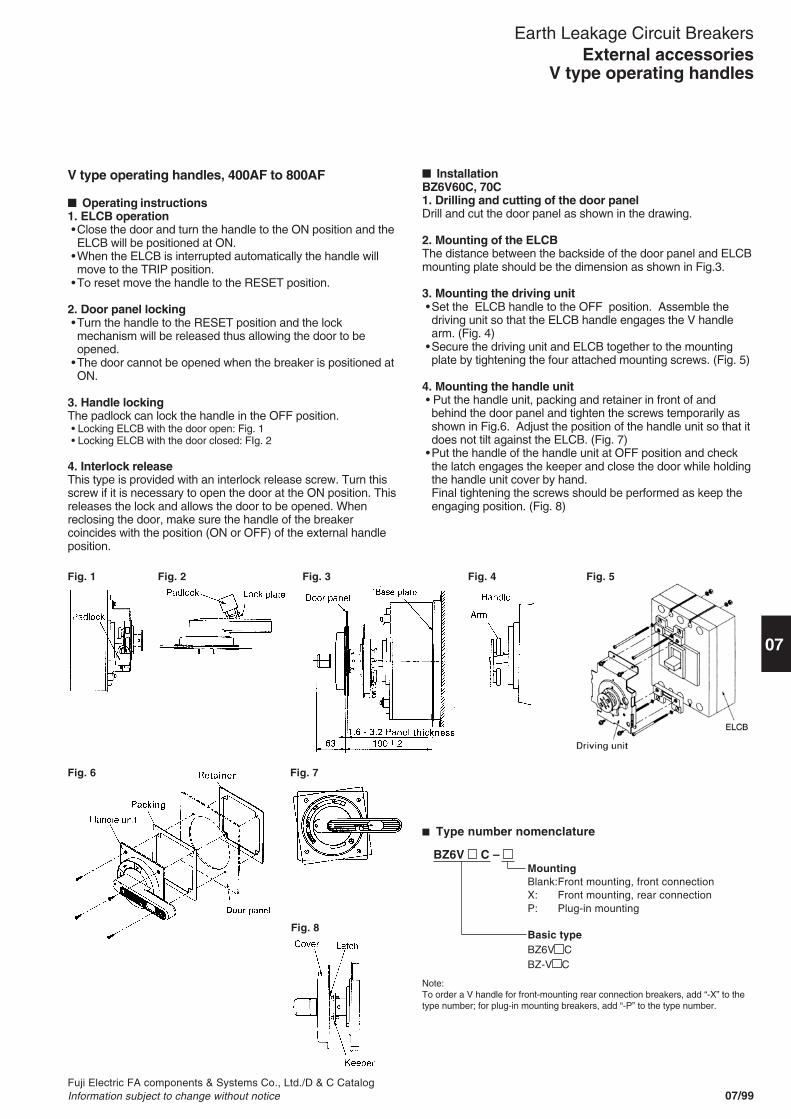
Fuji Electric FA components & Systems Co., Ltd./D & C CatalogInformation subject to change without notice 07/99
07
Earth Leakage Circuit BreakersExternal accessories
V type operating handles
V type operating handles, 400AF to 800AF
� Operating instructions1. ELCB operation•Close the door and turn the handle to the ON position and theELCB will be positioned at ON.
•When the ELCB is interrupted automatically the handle willmove to the TRIP position.
•To reset move the handle to the RESET position.
2. Door panel locking•Turn the handle to the RESET position and the lockmechanism will be released thus allowing the door to beopened.
•The door cannot be opened when the breaker is positioned atON.
3. Handle lockingThe padlock can lock the handle in the OFF position.• Locking ELCB with the door open: Fig. 1• Locking ELCB with the door closed: FIg. 2
4. Interlock releaseThis type is provided with an interlock release screw. Turn thisscrew if it is necessary to open the door at the ON position. Thisreleases the lock and allows the door to be opened. Whenreclosing the door, make sure the handle of the breakercoincides with the position (ON or OFF) of the external handleposition.
� InstallationBZ6V60C, 70C1. Drilling and cutting of the door panelDrill and cut the door panel as shown in the drawing.
2. Mounting of the ELCBThe distance between the backside of the door panel and ELCBmounting plate should be the dimension as shown in Fig.3.
3. Mounting the driving unit•Set the ELCB handle to the OFF position. Assemble thedriving unit so that the ELCB handle engages the V handlearm. (Fig. 4)
•Secure the driving unit and ELCB together to the mountingplate by tightening the four attached mounting screws. (Fig. 5)
4. Mounting the handle unit• Put the handle unit, packing and retainer in front of andbehind the door panel and tighten the screws temporarily asshown in Fig.6. Adjust the position of the handle unit so that itdoes not tilt against the ELCB. (Fig. 7)
•Put the handle of the handle unit at OFF position and checkthe latch engages the keeper and close the door while holdingthe handle unit cover by hand.Final tightening the screws should be performed as keep theengaging position. (Fig. 8)
� Type number nomenclature
BZ6V C – MountingBlank:Front mounting, front connectionX: Front mounting, rear connectionP: Plug-in mounting
Basic typeBZ6V CBZ-V C
Note:To order a V handle for front-mounting rear connection breakers, add “-X” to thetype number; for plug-in mounting breakers, add “-P” to the type number.
Fig. 6 Fig. 7
Fig. 8
Fig. 5Fig. 4Fig. 3Fig. 1 Fig. 2

07/100Fuji Electric FA Components & Systems Co., Ltd./D & C Catalog
Information subject to change without notice
Earth Leakage Circuit BreakersExternal accessoriesV type operating handles
Notes:• Handle protection degree IP54 (IEC60529, JIS C0920).• The handle cannot hold the door.• Breakers use different size screws for the X type (rear connection) or P-type (Pulg-in) breakers.
105530
100
Install the door hinge in the shaded area.
200
x
Handle4-ø10
ø138Breaker andhandle
112
112
Mounting screw
H63
Panel
Lock plate
Decorativeplate
Load
150
7575
150
Line
RE
LEA
SE
T
RI P
O N
OPE
NR
ES
ET
OF
F
150
Panel thickness 1.6 to 3.2
Door panel cutting Optional shaft( BZ-VS2)
The distance between the handle andbreaker can be shortened by cutting theoptional shaft.( X = H - 161.5 )
Door hinge installation area
CL
CL
� Dimnsions, mmBZ6V60C, 6V70C, BZ-V60C, V70C
Breaker
SG series
SG400CSG400RCSG400CUL
–
SG600RCSG800RC
–
EG series
EG400C
–
EG600CEG800C
–
HG series
–
HG400B
–
HG600BHG800B
Handle type
BZ6V60C
BZ-V60C
BZ6V70C
BZ-V70C
Standard type
H
190±2
With the optional shaft
H
250±2
Mass(kg)
2.2
2.2
2.2
2.2
Area in which the hinge with H can be installed
202 to 250

Fuji Electric FA components & Systems Co., Ltd./D & C CatalogInformation subject to change without notice 07/101
07
Earth Leakage Circuit Breakers
G type operating handles
� Operating instructions1.ELCB operation• Close the door and turn the handle to the ON position and the
breaker will be positioned at ON.• When the breaker is interrupted automatically the handle will
move to the TRIP position.• To reset move the handle to the RESET position.
2.Door panel locking• Turn the handle to the OPEN position and the lock
mechanism will be released thus allowing the door to beopened.
• The door cannot be opened when the breaker is positioned atON.
3.Handle lockingThe cylinder key can lock the handle in either the ON or OFFposition. Even if it is locked at the ON position when the breakertrips, the handle will indicate TRIP.
4. Interlock releaseThis type is provided with an interlock release screw. Turn thisscrew if it is necessary to open the door at the ON position. Thisreleases the lock and allows the door to be opened. Whenreclosing the door make sure the handle of the breakercoincides with the position (ON or OFF) of that of the externalhandle.
� InstallationBZ–G35C1. Drilling and cutting of the door panelDrill and cut the door panel as shown in the drawing.
2. Mounting of the ELCBThe distance between the backside of the door panel andbreaker mounting plate should be 125mm as shown in thedrawing below.
Mount the breaker and the retaining plate commonly to thepanel board.
3. Fitting decoratire plate and handleFit the decorative plate and handle mechanism to the door panelby means of the mounting screws as shown in the illustration.
4. Adjusting the retaining plateAdjust the height of the retaining plate by means of adjustingscrews.
� Type number nomenclature
BZ–G C–KKeyBlank: Without keyK: With cylinder keyQ: With padlocking deviceBasic typeBZ-G CG- A
External accessoriesG type operating handles
LO
CK
Locked
LO
CK
Unlocked
Thickness 1.2 to 3.2
PanelMounting plate
Breaker
44 125±2
Retaining plate
Adjusting screw
OFF
ON
TRIP
Decorativelegend plate
Mountingscrew
Door panel
Handle
Handle mechanism
Locklever

07/102Fuji Electric FA Components & Systems Co., Ltd./D & C Catalog
Information subject to change without notice
Earth Leakage Circuit Breakers
of breaker
Door panel cutting
36±1
Load side
80
ø11
20
292945
3-ø5.5
ø29
Interlockreleasescrew
OPEN
Retainingplate
ON or OFF
OFF
2140
30°
25°
25°
152
111
110
732.
3
120
32
ON
107
OPEN
C±3
Door
30
max
3.2
25.7
±0.5
150±
1
4915
2.5±
1
Line side
CL
of handleCL
H-2
215
Breaker mounting hole4-ø8
137
6744
128
to 1
41A
djus
tabl
e he
ight14
3.2
235
25
117
57.5
45 75
External accessoriesG type operating handles
� Dimensions, mmBZ-G35C, BZ-G35C-K
G-22A, G-22A-K Retaining plate and supporter (Sold separately)
Mass: 1.2kg

Fuji Electric FA Components & Systems Co., Ltd./D & C CatalogInformation subject to change without notice 07/103
07
Earth Leakage Circuit Breakers
■ Type of enclosures
External accessoriesSteel enclosures
Pressed steel enclosures
■ DescriptionBZ-type enclosures are available in three types — two with V andG-type handle which allows the operation from the outside andother with the operating handle of the breaker extending from itto allow it to be directly switched ON or OFF from outside theenclosure.Enclosures with V and G-type handles are provided with a doorinterlocking mechanism which prevents the door from beingopened in the ON condition.Knockout holes for wiring use are provided as shown in thediagram.(For G-type handles, contact FUJI.)
Breaker type
SG series
–
SG33CSG53C, SG53RCSG63C, SG63RC
–
SG103C, SG103RC
–
SG203C, SG203RC
–
SG403C, SG403RC
SG603RCSG803RC
EG series
EG32ACEG52AC
EG33AC, EG33CEG53AC, EG53CEG63C
EG102CEG103C, EG103AC
–
–
EG203C
–
EG403C
EG603CEG803C
HG series
–
–
–
–
HG53BHG103B
–
HG203B
HG403B
HG603BHG803B
Enclosure
Standard
BZ6C10C2
BZ6C10C3
BZ6C25C3
BZ6C30C3
BZ-C35B
BZ-C40B
BZ-C50B
BZ-C60B
BZ-C70B
With V type handleDustproof IP40
BZ6CV10C
BZ6CV10C
BZ6CV25C
BZ-CV30C
–
BZ-CV40C
–
BZ-CV60C
BZ-CV70C
Rainproof IP54 *
BZ6CW10C
BZ6CW10C
BZ6CW25C
BZ-CW30C
–
BZ-CW40C
–
BZ-CW60C
–
Standard Dustproof Rainproof
AF90-780 AF96-175 CP97-2636
■ Ordering informationSpecify the following:1. Type number of enclosures

Fuji Electric FA Components & Systems Co., Ltd./D & C CatalogInformation subject to change without notice07/104
Earth Leakage Circuit Breakers
TypeBZ6C10C2BZ6C10C3BZ6C25C3BZ6C30C3BZ-C35BBZ-C40BBZ-C50BBZ-C60BBZ-C70BBZ6CV10CBZ6CV25CBZ-CV30CBZ-CV40CBZ-CV60CBZ-CV70C
135
200200200200200400
180250
400
225
320320320360360750
300400
750
95
9595
12095
140175
114142
206
90
120120120120120300
100170
300
170
240240240280280650
220320
650
65
8080808080
200
70110
200
40
404040454580
4050
80
25
2525252525
100
100100
100
1.351.352.312.372.682.533.09
19.319.30.646.406.406.53
21.721.7
22, 35
30, 4530, 4530, 4540, 5540, 5563, 78, 106
28, 35, 4335, 52, 63
63, 78, 106
Connectiona, b, c
a, b, c, d
A B C D E G H I Mass (kg)M (Ø)
CL
CL
BreakerDA
C
H
IG
E B
Earth terminal M6
øM lead hole
Mounting hole ø7
D
E B
A
OF
F
TRIPON
RES
ET
C
178.5 : BZ6CV10C206.5 : BZ6CV25C191.0 : BZ-CV30C, 40C
2-ø23 lead hole
17 : BZ6CV25C, BZ-CV30C, BZ-CV40C
G
H
280
: BZ
6CV
25C
to B
Z-C
V40
C
Mounting holeø7 : BZ6CV10Cø9 : BZ6CV25C to BZ-CV40C
4-øM lead hole
2-øM lead hole
Earth terminal M6
CL
CL
CL
2-øM lead hole
2-ø28 lead hole
4-øM lead hole
H
Earth terminal M6G
Mounting hole ø12
E B580
A
D 269C
Standard With V type handleBZ6CV10C to BZ-CV40C
BZ-CV60C, 70C
■ Dimensions, mm
External accessoriesSteel enclosures
c da b
Load
Line Line Load
LineLoad
Line
Load
■ Connection method diagrams

Fuji Electric FA Components & Systems Co., Ltd./D & C CatalogInformation subject to change without notice 07/105
07
Earth Leakage Circuit Breakers
Terminal covers
� DescriptionThese terminal covers are used as guards to prevent accidentaltouch with live line terminations.These terminal covers can be fitted to either line or load side.� Up to 225AFShort type BZ-TS• Snap-on fitting• Transparent and black (BZ6TS10C only), sealing possibleLong type BZ-TB• Crimp connection use• Transparent and black (BZ6TB10C only), sealing possible� 400AF and largerLong type BZ-TB• Transparent
B
Breaker
External accessoriesTerminal covers
UL Listed
Breaker typeSG series–
SG33CSG53C, SG53RCSG63C, SG63RC
SG103C, SG103RC
–
SG203C, SG203RC
–
SG403C, SG403RC
SG603RCSG803RC
EG seriesEG32ACEG52AC
EG33AC, EG33CEG53AC, EG53CEG63CEG102CEG103AC, EG103C–
–
EG203C
–
EG403C
EG603CEG803C
HG series–
–
–
HG53BHG103B–
HG203B
HG403B
HG603BHG803B
Terminal coverShort typeBZ6TS10C2 (Black)BZ6TSH10C2 (Transparent)BZ6TS10C3 (Black)BZ6TSH10C3 (Transparent)
BZ-TS30B-3
BZ-TS35B
BZ-TS40B
BZ-TS50B
–
–
Packing quantity : 2 pcs.
B dimension(mm)
10
10
10
10
10
10
–
–
Mass(g)25
32
43
60
60
76
–
–
Mass(g)68
87
86
122
107
175
549
568
Terminal coverLong typeBZ6TB10C2 (Black)BZ6TBH10C2 (Transparent)BZ6TB10C3 (Black)BZ6TBH10C3 (Transparent)
BZ-TB30B-3
BZ-TB35B
BZ-TB40B
BZ-TB50B
BZ-TB60B
BZ-TB70B
B dimension(mm)
40
40
40
40
50
40
116
135
Breaker typeSG seriesSGa104A, SGa104H
Terminal coverLong typeA1-14
B dimension(mm)
28
Mass(g)60
Breaker typeSG seriesSG53RCUL
SG103CUL
SG203CUL
SG403CUL
EG seriesEG102CULEG103CUL
Terminal coverShort typeBZ6TS10C3U (Black)*
BZ-TS30B-3
BZ-TS40B
–
Terminal coverLong typeBZ6TB10C3U (Black)
BZ-TB30B-3
BZ-TB40B
BZ-TB60B
Terminal coverFor flat terminal–
BZ-TL30B-3
BZ-TL40B
–
Mass(g)33.5
43
60
–
Mass(g)38.5
86
107
549
Mass(g)
–
110
150
–
Note: * Standard-provided
Short type Long type

Fuji Electric FA Components & Systems Co., Ltd./D & C CatalogInformation subject to change without notice07/106
Earth Leakage Circuit BreakersExternal accessoriesInsulation barriers
Insulation barriers
� DescriptionThe interphase barriers are provided on frame size of 30AF to400AF breakers for front mounting. The barriers are installed inthe molded slots between terminals.The earth barrier is used to increase the insulation with themounting plate surface when two crimp terminals are wired.Installation of these barriers after wiring is possible even whenan external accessory is installed.
Interphase barrier Earth barrier
Breaker type
SG series–
SG33CSG53C, 53RCSG63C, 63RC
SG103C, 103RC
SG103CUL
–
SG203C, 203RC
SG203CUL
–
SG403C, 403RC, 403CULSG603RCSG803RCSGa204A, 204HSGa404A
EG seriesEG32ACEG52ACEG102CEG33AC, 33CEG53AC, 53CEG63CEG103AC, 103C–
–
–
EG203C
–
–
EG403CEG603CEG803C–
HG series–
–
–
–
HG53BHG103B–
–
HG203B
HG403BHG603BHG803B–
Interphase barrierType
BZ6B10C
BZ-B30B
BZ6B30CU
BZ-B35B
BZ-B40B
BZ6B40CU
BZ-B50B
B-43A
B-44A
Dimensions, mmA50
50
50
50
80
80
80
105
105
B49
51
58
73
52
58.5
90.5
95
95
Packingquantity4
4
4
4
4
4
4
4
6
Mass(g)23
29
31
38
48
52
82
131
195
Breaker type
SG series–
SG33CSG53C, 53RCSG63C, 63RC
SG103C, 103RC
SG203C, 203RC
–
EG seriesEG32ACEG52ACEG33AC, 33CEG53AC, 53CEG63CEG102CEG103AC, 103C–
EG203C
–
HG series–
–
HG53BHG103B–
HG203B
Earth barrierType
BZ6BL10C2
BZ6BL10C3
BZ-BL35B
BZ-BL40B
BZ-BL50B
Dimensions, mm*A100(50, 75)
125(75, 100)
130(90, 110)
190(105, 147)
190(105, 147)
B43(30)
43(30)
70(40)
100(50, 72)
100(50, 72)
Packingquantity2
2
2
2
2
Mass(g)33
41
16
48
48
� Earth barrier
� Interphase barrier
Note: * The value in parentheses is the dimensions after the barrier is cut.
Interphase barrier
A
B
Bre
aker
Earth barrierA
B
Breaker
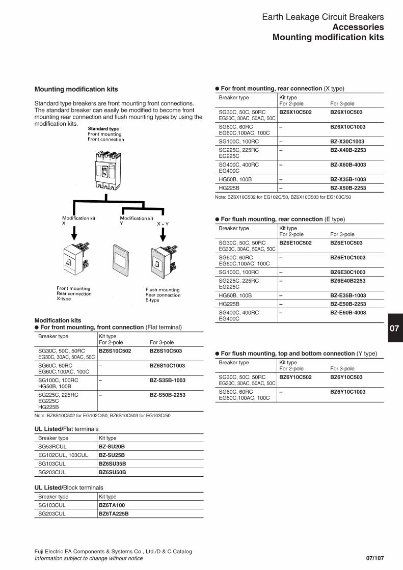
Fuji Electric FA Components & Systems Co., Ltd./D & C CatalogInformation subject to change without notice 07/107
Earth Leakage Circuit Breakers
07Modification kits� For front mounting, front connection (Flat terminal)
Breaker type Kit typeFor 2-pole For 3-pole
SG30C, 50C, 50RC BZ6S10C502 BZ6S10C503EG30C, 30AC, 50AC, 50C
SG60C, 60RC – BZ6S10C1003EG60C,100AC, 100C
SG100C, 100RC – BZ-S35B-1003HG50B, 100B
SG225C, 225RC – BZ-S50B-2253EG225CHG225B
AccessoriesMounting modification kits
Mounting modification kits
Standard type breakers are front mounting front connections.The standard breaker can easily be modified to become frontmounting rear connection and flush mounting types by using themodification kits.
Note: BZ6S10C502 for EG102C/50, BZ6S10C503 for EG103C/50
� For front mounting, rear connection (X type)
Breaker type Kit typeFor 2-pole For 3-pole
SG30C, 50C, 50RC BZ6X10C502 BZ6X10C503EG30C, 30AC, 50AC, 50C
SG60C, 60RC – BZ6X10C1003EG60C,100AC, 100C
SG100C, 100RC – BZ-X30C1003
SG225C, 225RC – BZ-X40B-2253EG225C
SG400C, 400RC – BZ-X60B-4003EG400C
HG50B, 100B – BZ-X35B-1003
HG225B – BZ-X50B-2253
� For flush mounting, rear connection (E type)
Breaker type Kit typeFor 2-pole For 3-pole
SG30C, 50C, 50RC BZ6E10C502 BZ6E10C503EG30C, 30AC, 50AC, 50C
SG60C, 60RC – BZ6E10C1003EG60C,100AC, 100C
SG100C, 100RC – BZ6E30C1003
SG225C, 225RC – BZ6E40B2253EG225C
HG50B, 100B – BZ-E35B-1003
HG225B – BZ-E50B-2253
SG400C, 400RC – BZ-E60B-4003EG400C
Note: BZ6X10C502 for EG102C/50, BZ6X10C503 for EG103C/50
UL Listed/Flat terminalsBreaker type Kit type
SG53RCUL BZ-SU20B
EG102CUL, 103CUL BZ-SU25B
SG103CUL BZ6SU35B
SG203CUL BZ6SU50B
UL Listed/Block terminalsBreaker type Kit type
SG103CUL BZ6TA100
SG203CUL BZ6TA225B
� For flush mounting, top and bottom connection (Y type)Breaker type Kit type
For 2-pole For 3-pole
SG30C, 50C, 50RC BZ6Y10C502 BZ6Y10C503EG30C, 30AC, 50AC, 50C
SG60C, 60RC – BZ6Y10C1003EG60C,100AC, 100C

Fuji Electric FA Components & Systems Co., Ltd./D & C CatalogInformation subject to change without notice07/108
Earth Leakage Circuit Breakers
� Handle locking covers
For front mounting, front connection (S type)Kit type Mass (kg)
BZ6S10C502 0.1BZ6S10C503 0.15
BZ6S10C1003 0.35
BZ-S35B-1003 0.35
BZ-S50B-2253 0.5
BZ-SU20B 0.1BZ-SU25B 0.2BZ6SU35B 0.2BZ6SU50B 0.25
For front mounting, rear connection (X type)Kit type Mass (kg)
BZ6X10C502 0.3BZ6X10C503 0.43
BZ6X10C1003 0.43
BZ-X30C-1003 0.63
BZ-X40B-2253 0.77
BZ-X60B-4003 2.71
BZ-X35B-1003 0.63
BZ-X50B-2253 0.80
For flush mounting, rear connection (E type)Kit type (g) Mass (kg)
BZ6E10C502 0.44BZ6E10C503 0.59
BZ6E10C1003 0.59
BZ6E30C1003 1.07
BZ6E40B2253 1.42
BZ-E35B-1003 1.11
BZ-E50B-2253 1.27
BZ-E60B-4003 3.67
� Mass
AccessoriesMounting modification kits and padlocking device
HG series
HG50BHG100BHG225B
HG400BHG600BHG800B
Breaker type
SG30C, 50C, 50RC, 50RCUL, 60C, 60RCEG30AC, 30C, 50AC, 50C, 60C, 100AC, 100C, 100CUL
SG100C, 100RC, 100CUL
SG225C, 225RC, 225CULEG225C
HG225B
SG400C, SG400RC, SG400CUL, SG600RC, SG800RCEG400C, EG600C, EG800C
Handle locking cover
BZ6L10C
BZ6L30C
BZ6L40C
BZ-L50B
BZ-L70BSG series
SG30CSG50CSG50RCSG60CSG60RCSG100CSG100RC
SG225CSG225RC
SG400CSG400RC
SG600RC
SG800RC
EG series
EG30CEG30ACEG50CEG50ACEG60C
EG100CEG100ACEG225C
EG400CEG600CEG800C
Cap type Q1*
Plate type Q2
A padlock is not provided.
� Padlocking device (UL not approved)Breaker handles can be fitted with locks. The handle can belocked at either the ON or OFF position. If an overcurrentflows, the breaker trips even when the handle is kept locking.Add the suffix Q1 or Q2 to the ELCB type number to order thepadlocking device (not sold separately).
Q1 : Cap type Q2 : Plate type
Applicable padlocking device
Handle locking cover is required when using the Q1 type for SGand EG series of 30 to 225AF.
Handle locking cover: BZ6L10C
Padlock/Not supplied
ON OFF
ø3.5
14mm
25mm

07/109
07
Fuji Electric FA Components & Systems Co., Ltd./D & C CatalogInformation subject to change without notice
RRD10AZ RRD12AZ RRD25P0 RRD40P0 RRD60P0 RRD90P0
3 4 3 4 ø25 ø40 ø60 ø90
RRD120P0
ø1203 4
RRD8AZ
3 4
Type
No. of poles or sensor hole (mm)
Main circuit voltage (V AC)
Rated current (A)
Control voltage * (V AC)
Mass/Relay+Sensor (kg)
BRR42H
2, 3, 4
Max. 600
400
120, 240, 415
200
� RRD(Separate type)/Solid-state tripping device
Earth leakage protective relays
� DescriptionIn the earth leakage relay the breakingmechanism is omitted from the ELCB,and the ZCT and earth leakage trippingdevice are integrated into a commonbody. These relays are available in bothinstantaneous and time-delay versions.Generally these relays are used inconjunction with MCCB's, ACB's andmotor starters.
Relay and sensor–Unit typeBRR/Pass-through type • Instantaneous trip • Solid-state tripping device • Sensitive current: 30, 100, 200mA
500mA • Control voltage: Up to 415V AC
Relay and sensor–Separate typeRRD/Pass-through type • Time-delay trip • Solid-state tripping device • Sensitive current: 100/200, 200/500mA 500/1000mA • Control voltage: Up to 415V AC
BRR11N
ø25
120, 240
30
0.2
BRR01N
ø10
Max. 600
120, 240
30
0.12
BRR09N
100
BRR45H
500
100/200, 200/500, 500/1000
� Selection guide� BRR(Unit type)/Solid-state tripping device
BRR22N
200
BRR21N
ø40
120, 240, 415
30
0.52
Type
Sensor hole (mm)
Main circuit voltage (V AC)
Control voltage * (V AC)
Rated sensitive current (mA)
Mass (kg)
Type
No. of poles
Main circuit voltage (V AC)
Rated current (A)
Control voltage * (V AC)
Rated sensitive current (mA)
Mass (kg)
Time-delay type0.2 to 2 sec.adjustable
Ratedsensitivecurrent (mA)
8.1 12.0 9.3
120, 240, 415
14.6 12.0 16.0 15.7 25.4 0.7
600
Max. 600
800 1000 1200
1.2 1.8
100/200, 200/500, 500/1000120, 240, 415
–
Max. 600
2.6 7.0
RRD6AZ
BRR19N
100
BRR29N
100
Note: * 100/110V or 200/220V is available.
BRR25N
500
Y-1706
SB-1824 SF-1034
BRR21NRRD60P0 EL90P0
RRD relay unit EL relay unit
EL/Pass-through type • Instantaneous or time-delay trip • Solid-state tripping device • Sensitive current: 30, 100/200, 200/500mA 500/1000mA • Control voltage: Up to 415V AC • Easily modified from front mounting to flush mounting
Earth Leakage Protective RelaysBRR, RRD and EL series
2-pole: 3.0, 3-pole: 3.3, 4-pole: 3.6

07/110Fuji Electric FA Components & Systems Co., Ltd./D & C Catalog
Information subject to change without notice
� Type number nomenclature, BRR unit typeBRR 2 1 N-0 24 S
� Selection guide� EL (Separate type)/Solid-state tripping device
Sensor hole (mm)
Main circuit voltage (V AC)
Control voltage (V AC)
Mass/Relay+Sensor (kg)
Type
Ratedsensitivecurrent(mA)
Instantaneous
Time-delay type
EL25P0 EL40P0 EL60P0 EL90P0 EL120P0
ø25 ø40 ø60 ø90 ø120
Max. 600
100/200, 120/240, 415
30, 100/200, 200/500500/1000
100/200, 200/500500/1000
100/200, 200/500, 500/100(Tripping time: 0.3 or 0.8 sec. fixed)
0.3 0.85 1.45 2.25 6.6
Type Contactarrangement
Thermalcurrent
Making current Breaking current (cos ø=0.3–0.4) (L/R=7ms)415V AC 240V AC 120V AC 24V DC
BRR01N, 09N 11N, 19N
BRR21N, 29N, 22N, 25NBRR42H, 45H
EL 120/240V AC415V AC
RRD 120/240V AC415V AC
1NO *SPDT
SPDT
SPDT1NO
2PDTSPDT
3A3A
5A
5A3A
5A5A
10A (at 240V AC)
10A (at 240V AC)
10A 6A
10A 6A
– 1A 1A –– 1A 1A –
2.5A 5A 5A 2A
– 3A 3A 2A2A 3A 3A 2A
– 3A 3A 2A2.5A 3A 3A 2A
Note: * Also available with SPDT contact.
ProtectionS : Without enclosure (standard)Control voltage (AC)1 : 100/110V 12 : 120V2 : 200/220V 2 : 240V4 : 415VPolesN-0 : Pass-through typeH-2 : 2-pole with conductor and
terminal assemblyH-3 : 3-pole with conductor and
terminal assemblyH-4 : 4-pole with conductor and
terminal assemblySensitive current1 : 30mA9 : 100mA2 : 200mA5 : 500mA
Rated current0 : Pass-through type ø101 : Pass-through type ø252 : Pass-through type ø404 : 400A
Basic type
Earth Leakage Protective RelaysBRR, RRD, and EL types
� Auxiliary contact ratings

07/111
07
Fuji Electric FA Components & Systems Co., Ltd./D & C CatalogInformation subject to change without notice
Series Rated current *1 Sensor hole Rated Control Tripping Typeor sensitive voltage *3 timeNo. of poles current *2
(A) (mA) (V AC) (sec)
BRR 2-wire: 37 ø10mm 30 120 0.1 BRR01N-012S3-wire: 37 240 BRR01N-024S4-wire: 27 100 120 BRR09N-012S
240 BRR09N-024S
2-wire: 162 ø25mm 30 120 BRR11N-012S3-wire: 115 240 BRR11N-024S4-wire: 115 100 120 BRR19N-012S
240 BRR19N-024S
2-wire: 344 ø40mm 30 120 BRR21N-012S3:wire: 298 240 BRR21N-024S4-wire: 257 415 BBR21N-04S
100 120 BRR29N-012S240 BRR29N-024S415 BBR29N-04S
200 120 BRR22N-012S240 BRR22N-024S415 BBR22N-04S
500 120 BRR25N-012S240 BRR25N-024S415 BBR25N-04S
400 2-pole 200 120 0.1 BRR42H-212S240 BRR42H-224S415 BBR42H-24S
500 120 BRR45H-212S240 BRR45H-224S415 BBR45H-24S
3-pole 200 120 BRR42H-312S240 BRR42H-324S415 BBR42H-34S
500 120 BRR45H-312S240 BRR45H-324S415 BBR45H-34S
4-pole 200 120 BRR42H-412S240 BRR42H-424S415 BBR42H-44S
500 120 BRR45H-412S240 BRR45H-424S415 BRR45H-44S
Notes: *1 Using IV 600V cable.*2 Non-tripping current is 0.5 times sensitive current.*3 100/110V or 200/220V is available.
� Wire sizeZCT sensing hole diameter and applicable cable(IV 600V)
Diameter(mm)
1025406090, 120
Wire2-wire
3.5mm2
38mm2
125mm2
325mm2
500mm2
3-wire
3.5mm2
22mm2
100mm2
200mm2
500mm2
4-wire
2mm2
22mm2
80mm2
200mm2
500mm2
Conforming to JIS C 3307.
Earth Leakage Protective RelaysBRR type
� Specifications/BRR type

07/112Fuji Electric FA Components & Systems Co., Ltd./D & C Catalog
Information subject to change without notice
Series Rated current No. of poles Rated Control Tripping Typesensitive voltage *2 timecurrent *1
(A) (mA) (V AC) (sec)
RRD 600 3-pole: 3 100/200 120 0.2–2 RRD6AZ -1/2-V124-pole: 4 240 adjustable RRD6AZ -1/2-V24
415 RRD6AZ -1/2-V4
200/500 120 RRD6AZ -2/5-V12240 RRD6AZ -2/5-V24415 RRD6AZ -2/5-V4
500/1000 120 RRD6AZ -5/10-V12240 RRD6AZ -5/10-V24415 RRD6AZ -5/10-V4
800 100/200 120 RRD8AZ -1/2-V12240 RRD8AZ -1/2-V24415 RRD8AZ -1/2-V4
200/500 120 RRD8AZ -2/5-V12240 RRD8AZ -2/5-V24415 RRD8AZ -2/5-V4
500/1000 120 RRD8AZ -5/10-V12240 RRD8AZ -5/10-V24415 RRD8AZ -5/10-V4
1000 100/200 120 RRD10AZ -1/2-V12240 RRD10AZ -1/2-V24415 RRD10AZ -1/2-V4
200/500 120 RRD10AZ -2/5-V12240 RRD10AZ -2/5-V24415 RRD10AZ -2/5-V4
500/1000 120 RRD10AZ -5/10-V12240 RRD10AZ -5/10-V24415 RRD10AZ -5/10-V4
1200 100/200 120 RRD12AZ -1/2-V12240 RRD12AZ -1/2-V24415 RRD12AZ -1/2-V4
200/500 120 RRD12AZ -2/5-V12240 RRD12AZ -2/5-V24415 RRD12AZ -2/5-V4
500/1000 120 RRD12AZ -5/10-V12240 RRD12AZ -5/10-V24415 RRD12AZ -5/10-V4
Earth Leakage Protective RelaysRRD series
Replace themark in thetype numberby the codeshown below.
� Specifications/RRD type, with conductors
Notes: *1 The rated sensitive current can be selected by jumper connection.Non-tripping current 0.5 times sensitive current.
*2 100/110V or 200/220V is available.
� Type number nomenclature, RRD typeRRD 40 P0 - 2/5 -V2
Control voltage (AC)V1 : 100/110V V4 : 415V V24 : 240VV2 : 200/220V V12 : 120VSensitive current (selective)1/2 : 100/200mA2/5 : 200/500mA 5/10 : 500/1000mAPolesP0 : Pass-through typeZ3 : 3-pole with conductorZ4 : 4-pole with conductorDia. of sensor hole or rated current25 : ø25 6A : 600A40 : ø40 8A : 800A60 : ø60 10A : 1000A90 : ø90 12A : 1200A120 : ø120Basic type

07/113
07
Fuji Electric FA Components & Systems Co., Ltd./D & C CatalogInformation subject to change without notice
Earth Leakage Protective RelaysRRD type
� Specifications/RRD, poss-through type
Notes: *1 Using IV 600V cable. (See page 07/111 for reference.)*2 The rated sensitive current can be selected by jumper connection.
Non-tripping current 0.5 times sensitive current.*3 100/110V or 200/220V is available.
Series Rated current *1 Sensor hole Rated Control Tripping Typesensitive voltage *3 timecurrent *2
(A) (mm) (mA) (V AC) (sec)
RRD 2-wire: 162 ø25 100/200 120 0.2–2 RRD25P0-1/2-V123-wire: 115 240 adjustable RRD25P0-1/2-V244-wire: 115 415 RRD25P0-1/2-V4
200/500 120 RRD25P0-2/5-V12240 RRD25P0-2/5-V24415 RRD25P0-2/5-V4
500/1000 120 RRD25P0-5/10-V12240 RRD25P0-5/10-V24415 RRD25P0-5/10-V4
2-wire: 344 ø40 100/200 120 RRD40P0-1/2-V123-wire: 298 240 RRD40P0-1/2-V244-wire: 257 415 RRD40P0-1/2-V4
200/500 120 RRD40P0-2/5-V12240 RRD40P0-2/5-V24415 RRD40P0-2/5-V4
500/1000 120 RRD40P0-5/10-V12240 RRD40P0-5/10-V24415 RRD40P0-5/10-V4
2-wire: 650 ø60 100/200 120 RRD60P0-1/2-V123-wire: 469 240 RRD60P0-1/2-V244-wire: 469 415 RRD60P0-1/2-V4
200/500 120 RRD60P0-2/5-V12240 RRD60P0-2/5-V24415 RRD60P0-2/5-V4
500/1000 120 RRD60P0-5/10-V12240 RRD60P0-5/10-V24415 RRD60P0-5/10-V4
2-wire: 842 ø90 100/200 120 RRD90P0-1/2-V123-wire: 842 240 RRD90P0-1/2-V244-wire: 842 415 RRD90P0-1/2-V4
200/500 120 RRD90P0-2/5-V12240 RRD90P0-2/5-V24415 RRD90P0-2/5-V4
500/1000 120 RRD90P0-5/10-V12240 RRD90P0-5/10-V24415 RRD90P0-5/10-V4
2-wire: 842 ø120 100/200 120 RRD120P0-1/2-V123-wire: 842 240 RRD120P0-1/2-V244-wire: 842 415 RRD120P0-1/2-V4
200/500 120 RRD120P0-2/5-V12240 RRD120P0-2/5-V24415 RRD120P0-2/5-V4
500/1000 120 RRD120P0-5/10-V12240 RRD120P0-5/10-V24415 RRD120P0-5/10-V4

07/114Fuji Electric FA Components & Systems Co., Ltd./D & C Catalog
Information subject to change without notice
Series Rated current *1 Sensor Rated Control Tripping 120/240V 415Vhole sensitive voltage *3 time
current *2
(A) (mm) (mA) (V AC) (sec) Type TypeEL 2-wire: 162 ø25 30 120/240 0.1 EL25P0-30MA-V12 EL25P0-30MA-V4
3-wire: 115 100/200 415 EL25P0-1/2-V12 EL25P0-1/2-V44-wire: 115 200/500 EL25P0-2/5-V12 EL25P0-2/5-V4
500/1000 EL25P0-5/10-V12 EL25P0-5/10-V42-wire: 344 ø40 30 EL40P0-30MA-V12 EL40P0-30MA-V43-wire: 298 100/200 EL40P0-1/2-V12 EL40P0-1/2-V44-wire: 257 200/500 EL40P0-2/5-V12 EL40P0-2/5-V4
500/1000 EL40P0-5/10-V12 EL40P0-5/10-V42-wire: 650 ø60 30 EL60P0-30MA-V12 EL60P0-30MA-V43-wire: 469 100/200 EL60P0-1/2-V12 EL60P0-1/2-V44-wire: 469 200/500 EL60P0-2/5-V12 EL60P0-2/5-V4
500/1000 EL60P0-5/10-V12 EL60P0-5/10-V42-wire: 842 ø90 100/200 EL90P0-1/2-V12 EL90P0-1/2-V43-wire: 842 200/500 EL90P0-2/5-V12 EL90P0-2/5-V44-wire: 842 500/1000 EL90P0-5/10-V12 EL90P0-5/10-V42-wire: 842 ø120 100/200 EL120P0-1/2-V12 EL120P0-1/2-V43-wire: 842 200/500 EL120P0-2/5-V12 EL120P0-2/5-V44-wire: 842 500/1000 EL120P0-5/10-V12 EL120P0-5/10-V4
EL 2-wire: 162 ø25 100/200 120/240 0.3 EL25P0-1/2-D3-V12 EL25P0-1/2-D3-V43-wire: 115 200/500 415 EL25P0-2/5-D3-V12 EL25P0-2/5-D3-V44-wire: 115 500/1000 EL25P0-5/10-D3-V12 EL25P0-5/10-D3-V4
Time 2-wire: 344 ø40 100/200 EL40P0-1/2-D3-V12 EL40P0-1/2-D3-V4delay 3-wire: 298 200/500 EL40P0-2/5-D3-V12 EL40P0-2/5-D3-V4
4-wire: 257 500/1000 EL40P0-5/10-D3-V12 EL40P0-5/10-D3-V42-wire: 650 ø60 100/200 EL60P0-1/2-D3-V12 EL60P0-1/2-D3-V43-wire: 469 200/500 EL60P0-2/5-D3-V12 EL60P0-2/5-D3-V44-wire: 469 500/1000 EL60P0-5/10-D3-V12 EL60P0-5/10-D3-V42-wire: 842 ø90 100/200 EL90P0-1/2-D3-V12 EL90P0-1/2-D3-V43-wire: 842 200/500 EL90P0-2/5-D3-V12 EL90P0-2/5-D3-V44-wire: 842 500/1000 EL90P0-5/10-D3-V12 EL90P0-5/10-D3-V42-wire: 842 ø120 100/200 EL120P0-1/2-D3-V12 EL120P0-1/2-D3-V43-wire: 842 200/500 EL120P0-2/5-D3-V12 EL120P0-2/5-D3-V44-wire: 842 500/1000 EL120P0-5/10-D3-V12 EL120P0-5/10-D3-V42-wire: 162 ø25 100/200 120/240 0.8 EL25P0-1/2-D8-V12 EL25P0-1/2-D8-V43-wire: 115 200/500 415 EL25P0-2/5-D8-V12 EL25P0-2/5-D8-V44-wire: 115 500/1000 EL25P0-5/10-D8-V12 EL25P0-5/10-D8-V42-wire: 344 ø40 100/200 EL40P0-1/2-D8-V12 EL40P0-1/2-D8-V43-wire: 298 200/500 EL40P0-2/5-D8-V12 EL40P0-2/5-D8-V44-wire: 257 500/1000 EL40P0-5/10-D8-V12 EL40P0-5/10-D8-V42-wire: 650 ø60 100/200 EL60P0-1/2-D8-V12 EL60P0-1/2-D8-V43-wire: 469 200/500 EL60P0-2/5-D8-V12 EL60P0-2/5-D8-V44-wire: 469 500/1000 EL60P0-5/10-D8-V12 EL60P0-5/10-D8-V42-wire: 842 ø90 100/200 EL90P0-1/2-D8-V12 EL90P0-1/2-D8-V43-wire: 842 200/500 EL90P0-2/5-D8-V12 EL90P0-2/5-D8-V44-wire: 842 500/1000 EL90P0-5/10-D8-V12 EL90P0-5/10-D8-V42-wire: 842 ø120 100/200 EL120P0-1/2-D8-V12 EL120P0-1/2-D8-V43-wire: 842 200/500 EL120P0-2/5-D8-V12 EL120P0-2/5-D8-V124-wire: 842 500/1000 EL120P0-5/10-D8-V12 EL120P0-5/10-D8-V4
� Specifications/EL type
Earth Leakage Protective RelaysEL types
Instan-taneous
Notes: *1 Using IV 600V cable. (See page 07/111 for reference.)*2 Non tripping current is 0.5 times sensitive current.
*3 100/110V or 200/220V is available.
EL 25 P0 - 1/2 - D3 V4
Tripping timeBlank : InstantaneousD3 : 0.3 sec. time delayD8 : 0.8 sec. time delay
Sensitive current30MA : 30mA1/2 : 100/200mA (selective)2/5 : 200/500mA (selective)5/10 : 500/1000mA (selective)
Pass-through type
Control voltage (AC)No-mark : 100/200V V12 : 120/240VV4 : 415V
Diameter of sensor hole (mm)25 : ø25 60 : ø60 120 : ø12040 : ø40 90 : ø90
Basic type
� Type number nomenclature, ELtype
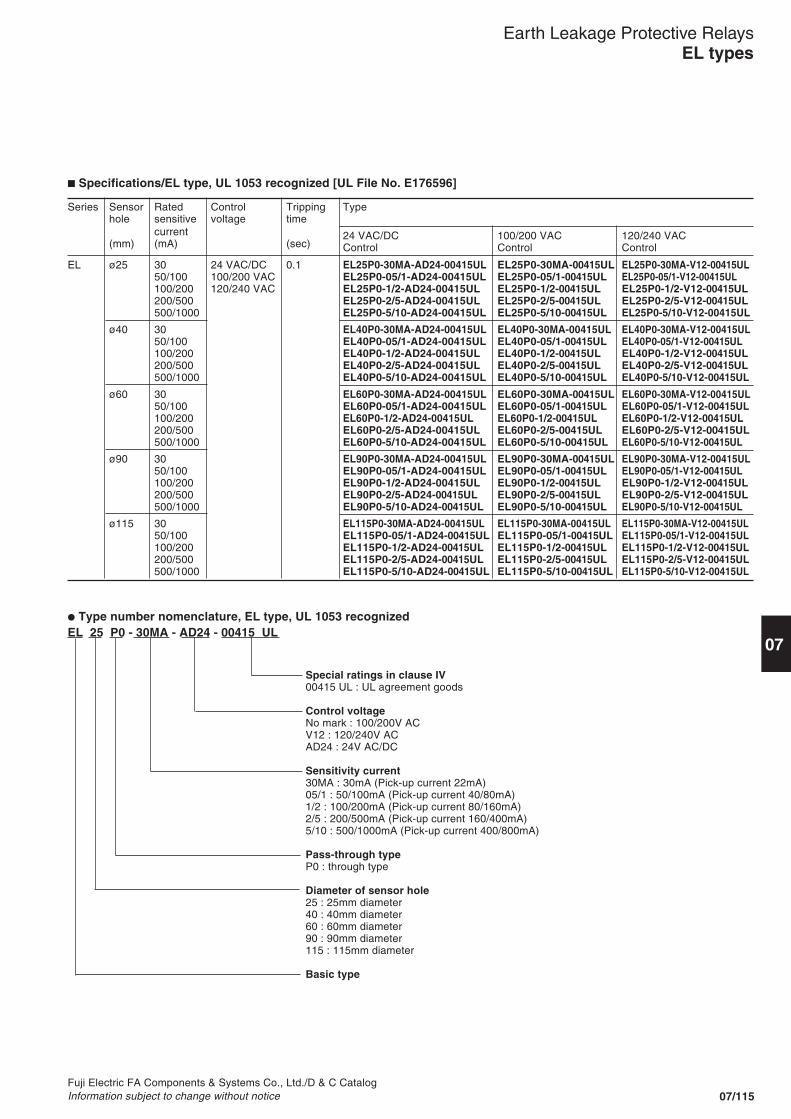
07/115
07
Fuji Electric FA Components & Systems Co., Ltd./D & C CatalogInformation subject to change without notice
Earth Leakage Protective RelaysEL types
� Specifications/EL type, UL 1053 recognized [UL File No. E176596]
Series Sensor Rated Control Tripping Typehole sensitive voltage time
current 24 VAC/DC 100/200 VAC 120/240 VAC(mm) (mA) (sec) Control Control Control
EL ø25 30 24 VAC/DC 0.1 EL25P0-30MA-AD24-00415UL EL25P0-30MA-00415UL EL25P0-30MA-V12-00415UL50/100 100/200 VAC EL25P0-05/1-AD24-00415UL EL25P0-05/1-00415UL EL25P0-05/1-V12-00415UL100/200 120/240 VAC EL25P0-1/2-AD24-00415UL EL25P0-1/2-00415UL EL25P0-1/2-V12-00415UL200/500 EL25P0-2/5-AD24-00415UL EL25P0-2/5-00415UL EL25P0-2/5-V12-00415UL500/1000 EL25P0-5/10-AD24-00415UL EL25P0-5/10-00415UL EL25P0-5/10-V12-00415UL
ø40 30 EL40P0-30MA-AD24-00415UL EL40P0-30MA-00415UL EL40P0-30MA-V12-00415UL50/100 EL40P0-05/1-AD24-00415UL EL40P0-05/1-00415UL EL40P0-05/1-V12-00415UL100/200 EL40P0-1/2-AD24-00415UL EL40P0-1/2-00415UL EL40P0-1/2-V12-00415UL200/500 EL40P0-2/5-AD24-00415UL EL40P0-2/5-00415UL EL40P0-2/5-V12-00415UL500/1000 EL40P0-5/10-AD24-00415UL EL40P0-5/10-00415UL EL40P0-5/10-V12-00415UL
ø60 30 EL60P0-30MA-AD24-00415UL EL60P0-30MA-00415UL EL60P0-30MA-V12-00415UL50/100 EL60P0-05/1-AD24-00415UL EL60P0-05/1-00415UL EL60P0-05/1-V12-00415UL100/200 EL60P0-1/2-AD24-00415UL EL60P0-1/2-00415UL EL60P0-1/2-V12-00415UL200/500 EL60P0-2/5-AD24-00415UL EL60P0-2/5-00415UL EL60P0-2/5-V12-00415UL500/1000 EL60P0-5/10-AD24-00415UL EL60P0-5/10-00415UL EL60P0-5/10-V12-00415UL
ø90 30 EL90P0-30MA-AD24-00415UL EL90P0-30MA-00415UL EL90P0-30MA-V12-00415UL50/100 EL90P0-05/1-AD24-00415UL EL90P0-05/1-00415UL EL90P0-05/1-V12-00415UL100/200 EL90P0-1/2-AD24-00415UL EL90P0-1/2-00415UL EL90P0-1/2-V12-00415UL200/500 EL90P0-2/5-AD24-00415UL EL90P0-2/5-00415UL EL90P0-2/5-V12-00415UL500/1000 EL90P0-5/10-AD24-00415UL EL90P0-5/10-00415UL EL90P0-5/10-V12-00415UL
ø115 30 EL115P0-30MA-AD24-00415UL EL115P0-30MA-00415UL EL115P0-30MA-V12-00415UL50/100 EL115P0-05/1-AD24-00415UL EL115P0-05/1-00415UL EL115P0-05/1-V12-00415UL100/200 EL115P0-1/2-AD24-00415UL EL115P0-1/2-00415UL EL115P0-1/2-V12-00415UL200/500 EL115P0-2/5-AD24-00415UL EL115P0-2/5-00415UL EL115P0-2/5-V12-00415UL500/1000 EL115P0-5/10-AD24-00415UL EL115P0-5/10-00415UL EL115P0-5/10-V12-00415UL
� Type number nomenclature, EL type, UL 1053 recognizedEL 25 P0 - 30MA - AD24 - 00415 UL
Special ratings in clause IV00415 UL : UL agreement goods
Control voltageNo mark : 100/200V ACV12 : 120/240V ACAD24 : 24V AC/DC
Sensitivity current30MA : 30mA (Pick-up current 22mA)05/1 : 50/100mA (Pick-up current 40/80mA)1/2 : 100/200mA (Pick-up current 80/160mA)2/5 : 200/500mA (Pick-up current 160/400mA)5/10 : 500/1000mA (Pick-up current 400/800mA)
Pass-through typeP0 : through type
Diameter of sensor hole25 : 25mm diameter40 : 40mm diameter60 : 60mm diameter90 : 90mm diameter115 : 115mm diameter
Basic type

07/116Fuji Electric FA Components & Systems Co., Ltd./D & C Catalog
Information subject to change without notice
BRR11N, 19N
BRR21N, 29N, 22N, 23N, 25N
� Dimensions, mmBRR01N, 09N
Earth Leakage Protective RelaysBRR type
3-pole
4-pole
BRR42H, 45H2-pole
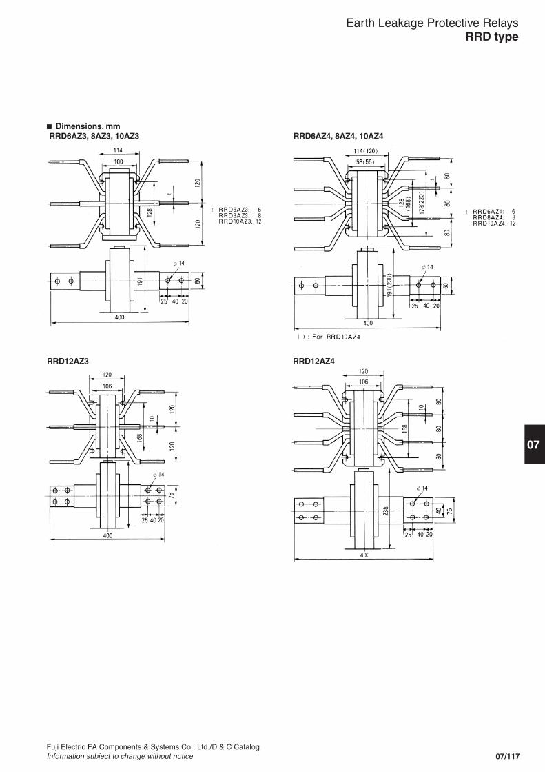
07/117
07
Fuji Electric FA Components & Systems Co., Ltd./D & C CatalogInformation subject to change without notice
RRD12AZ3 RRD12AZ4
� Dimensions, mmRRD6AZ3, 8AZ3, 10AZ3
Earth Leakage Protective RelaysRRD type
RRD6AZ4, 8AZ4, 10AZ4

07/118Fuji Electric FA Components & Systems Co., Ltd./D & C Catalog
Information subject to change without notice
SensorsRRD25, 40, 60, 90P0EL25, 40, 60, 90P0
Type A B C D E F G H J K L M N
RRD25 ø25 55 72 29 28 40 42 10 5 54 13 7 7EL25 ø25 55 72 29 28 40 42 10 5 54 13 7 7
RRD40 ø40 90 115 62 45 70 75 18 5 90 22 8 18EL40 ø40 90 115 62 45 70 75 18 5 90 22 8 18
RRD60 ø60 120 145 62 60 100 75 18 6 90 22 8 18EL60 ø60 120 145 62 60 100 75 18 6 90 22 8 18
RRD90 ø90 160 185 66 80 125 88 22 7 110 22 8 18EL90 ø90 160 185 66 80 125 88 22 7 110 22 8 18
� Dimensions, mmRelay RRD type Relay EL type
RRD120, EL120P0
Earth Leakage Protective RelaysRRD and EL types
70
90
12 7.593
7219
105
24.5
5.5
988.
5
4083
7.5 12 5
427290
93
72 83
105
Mounting hole 5 x 7(base mounting)
Trip indicating lamp(RED)
Reset buttonTest pushbutton
Tripping timeadjusting dial
TerminalM3.5 x8
N.P. Space for M4 nut
Mounting hole 2- ø5(Flush mounting)
Panel mounting
R1 or less
2- ø5
2-M4 or 2- ø5
Base mounting
60 76
679
10
482-M4or 2- ø558
ø5
50.5
Test pushbutton
TerminalM3.5 x 8
Sensitive Currentchangeover switch
40.5
58 60 76
48
Trip indicatinglamp (RED)
Mounting hole4.5 x 6 Reset button
9
58(60)
n: No. of mounting unit( ) : Flush mounting
(47)
(60n-5) +0.50
45+
0.5
0
Panel mounting
Panel cutting
Note: When flush mounting type is required, an adaptor EL-E is needed. (Sold separately)
Z1 Z2
T1 T2
J
L M
F
66
D G K
L
B
HE
C
MTerminal M3.5 x 8
A
N
130
180
58
2.3 95
185
20
(20)
ø7
T1 T2 Z1 Z2
75 85 102
Terminal block
20
Terminal block
ø120
Terminal M3.5

07/119
07
Fuji Electric FA Components & Systems Co., Ltd./D & C CatalogInformation subject to change without notice
� Wiring diagramsBRR01N, 09N
RRD type� Where SPDT is selected.
� Where 2PDT is selected.
(415V)Powersource
BRR11N, 19N, 21N, 29N, 22N, 23N, 25NBRR42H, 45H
EL type100/200V, 120/240V 415V
Sensor
Relay
SC: Terminal for changingsensitivity (Low sensitivitycan be selected byconnecting 2 SC's.
Testcircuit(T1, T2)
ZCTcircuit(Z1, Z2)
(120V, 240V)Powersource
Reset button
Test button
Relay
Earth Leakage Protective RelaysBRR, RRD and EL types
Testpushbutton
ResistorZCT Solid-state
amplifier
Reset buttonPower source
a b R S T
U V W
24 21
22
Line
Load
Test pushbutton
Resistor ZCT Solid-stateamplifier
Reset buttonPower source
a bR S T
U V W
2422 21
R
Load
Line
b1P1 a2 c 2
b1P1 a2 c 2a1 c 1 b2
SCP2 T2 Z 2SC T1 Z 1
T2 Z 2T1 Z 1

07/120Fuji Electric FA Components & Systems Co., Ltd./D & C Catalog
Information subject to change without notice
� ELCB should always be included in the following types of electrical installations1. Where there is danger of people
coming in contact with liveconductors.
2. Where line voltage to groundexceeds 150V AC.
3. Inside buildings in which are storedinflammable or explosive materials.
4. Where heating elements areembedded in concrete.
5. Where heating panels or pipes, orportable heaters are installed.
6. Where heating elements areinstalled in the ground or in water ormud.
7. In underwater lighting system forswimming pool use.
8. Where portable electrical equipmentand tools are used.
9. Where electrical equipment is used indangerous locations, such as in water,wet place, on metal platforms, etc.
10.Where emergency or temporarywiring is installed, such as flood-lighting, temporary traffic signals orsigns, etc.
� Check points for selecting ELCB1. Sensitivity current2. Earth fault current breaking
capacity3. Short-circuit breaking capacity4. Operating time5. Selective protective coordination6. Rated voltage and frequency7. Rated current8. Detecting device
� Selection of sensitivity current• Appropriate sensitivity currentshould be selected after consideringthe application purpose.Select ELCB with a sensitivity of less than30mA where risk of human life ispresent and between 200mA and500mA for protection against firedue to electrical leakage.• Protection systemELCB are generally arranged in one ofthe following ways.(a) In this case a wide range of protectioncan be achieved economically using asingle ELCB unit. However, if an earthfault occurs in only one branch of thecircuit the main ELCB will trip and allfeeders will stop. It will take time toisolate and repair the trouble.Also, in any circuit there will be a minute
earth leakage. The more complicatedthe electrical wiring system the greaterthe accumulated effect of leakagecurrent. Consequently, if a too sensitiveELCB is selected there is the possibilityof mistripping because of this effect.Generally, taking the case of a 30mAELCB, constantly leaking current, in somecases, would trip the breaker in the circuitof motor load over 50A or in the circuit oflamp load over 100A. However the 30mAELCB will normally be suitable for homeor small shop use.
(b) In this system an ELCB is providedto each branch feeder. This system willcost more because of the greaternumber of ELCB's but since only thecircuit where the earth fault occurstrips the other feeders will not beaffected by the outage. This system isto be preferred where there is dangerto life from electric shock using highsensitivity current type ELCB.
� Breaking capacity and shortcircuit protection� Earth fault current breakingcapacityELCB detects earth fault current andbreaks the circuit. Select an ELCBwhich has an adequate breakingcapacity as well as the appropriateearth fault current expected to occurin the circuit. The earth fault currentvalues are determined according to thecircuit voltage (Voltage to ground) andresistance. In some cases a massiveearth fault current, which could have avalue as much as the short circuitcurrent, could flow.
� Short-circuit breaking capacityBesides earth fault current andovercurrent the short-circuit currentflows into the ELCB. Thus it isnecessary to consider its magnitude.Generally the breaking capacity ofan ELCB tends to be less than acorresponding MCCB. In case theshort-circuit current is too big for theELCB to handle it is necessary toinstall back-up protection using MCCB,fuse or similar devices.To determine short-circuit currentsplease refer to FUJI with detailsof your application.
� SG and EG seriesThis series provides protection in threeways, against earth fault current,overcurrent and short-circuit current.
Earth Leakage Circuit BreakersApplication guide
(a)
(b)
Load
Load
ELCB
ELCB
MCCB

07/121
07
Fuji Electric FA Components & Systems Co., Ltd./D & C CatalogInformation subject to change without notice
� ELCB operating timeThe safe limit of current time that ahuman being can withstand is 30mAsec. Thus an ELCB for shock protectionmust satisfy operating time less than30mA sec/total current through body(mA). So, assuming that the resistanceof a human body is 500 and thevoltage to ground 200V the bodycurrent will be =400mAHence the ELCB must operate within =0.075 s.FUJI ELCB's meet this requirementand so ensure complete and certainsafety in operation.
� Selective earth-fault current breaking coordinationWhere several ELCB's are providedbetween the power source and branchload, consideration must be given tothe appropriate selection of operatingtime and sensitivity current. In casethe sensitivity current of the branch circuitELCB is higher than that of the maincircuit ELCB, mistripping may occurbecause selective protective coordinationis lost as is seen in example (B).Therefore the arrangement given inexample (A) could be employed. Thatis, the less sensitive ELCB should bepositioned nearest to the power source.
30mA•S400mA
Earth Leakage Circuit BreakersApplication guide
200V500
However, using this method perfectearth fault protection cannot beexpected. This is because even if theELCB's are installed according to theirsensitivities, i.e., 500mA, 200mA,30mA, the operating times are thesame. Consequently, if the earth faultshould occur in branch load the maincircuit ELCB might trip. Thus the neareran ELCB is positioned to thepower source the slower its operatingtime should be.In order to meet this requirement FUJIcan supply earth leakage protectiverelays provided with a time delayfunction. Since its operating time isadjustable between 0.2 and 2 secondsit facilitates the selection protectivecoordination of systems of all kinds.These protective relays are generallyinstalled in main circuits incombination with MCCB.
� Rated voltageWhen selecting solid-state amplifiertype ELCB's make sure that a correctrated voltage is chosen. This is notnecessary in the case of the permanentmagnet ELCB, since in this case nooutside control source is required.
� Rated currentFUJI ELCB's are calibrated for ambienttemperature of 40°C. Overheating maybe expected if ELCB's are used attheir maximum rated current atambient temperatures exceeding 40°C.Select a rated current with a suitableallowance. The load should be around80% of the rated current.
Example (A)..... Instantaneous typeoperating characteristic
Example (B).....
ELCB
15mA30mA
Current
Dis
trib
utio
n
Mai
n ci
rcui
t
Rec
eivi
ng
Tim
e
100mA200mA
250mA500mA
Time delay typeoperating characteristic
15mA30mA
CurrentD
istr
ibut
ion
Mai
n ci
rcui
t
Rec
eivi
ng
Tim
e
100mA200mA
250mA500mA
ELCB
500mA
200mA
30mA
30mA
100mA

07/122Fuji Electric FA Components & Systems Co., Ltd./D & C Catalog
Information subject to change without notice
Earth Leakage Circuit BreakersCCC approved
CCC approved
ELCB types
Series
SG
EG
AF
30
50
60
100
225
400
30
50
60
100
225
400
3-pole
SG33CSG33CMSG53CSG53CMSG53RCSG63CSG63CMSG63RCSG103CSG103CMSG103RCSG103RCMSG203CSG203CMSG203RCSG203RCMSG403CSG403RCEG33ACEG33CEG33CMEG53ACEG53CEG53CMEG63CEG63CMEG103AC–EG103CEG103CMEG203CEG203CMEG403C
Rated breaking current [kA]Ue: 230V551010251010255050100100505010010050852.52.52.52.555555102525353535
Ue: 400V2.52.57.57.5107.57.51025255050252550503550–1.51.5–2.52.52.52.5––1010151525
Certificate No.
2004010307138024
2004010307138031
20040103071380262004010307138033
20040103071380272005010307140481
2004010307138030
2004010307138035
2004010307138029
20040103071380372004010307138028
20040103071380372004010307138024
2004010307138036
200401030713803820040103071380252004010307138027
2005010307140482
2004010307138029
2-pole
––––––––––––––––––EG32AC––EG52AC–––––EG102C–––––

Catalog Disclaimer
The information contained in this catalog does not constitute an express or implied warranty of quality, any warranty of merchantability of fitness for a particular purpose is hereby disclaimed.
Since the user's product information, specific use application, and conditions of use are all outside of Fuji Electric FA Components & Systems'control, it shall be the responsibility of the user to determine the suitability of any of the
products mentioned for the user's application.
One Year Limited Warranty
The products identified in this catalog shall be sold pursuant to the terms and conditions identified in the"Conditions of Sale" issued by Fuji Electric FA with each order confirmation.
Except to the extent otherwise provided for in the Conditions of Sale issued by Fuji Electric FA, Fuji Electric FA warrants that the Fuji Electric FA products identified in this catalog shall be free from significant defects in materials and workmanship provided the product has not been: 1) repaired or altered by others than Fuji Electric FA; 2) subjected to negligence, accident, misuse, or damage by circumstances beyond Fuji Electric FA's control; 3) improperly operated, maintained or stored; or 4) used in other than normal use or service. This warranty shall apply only to defects appearing within one (1) year from the date of shipment by Fuji Electric FA, and in such case, only if such defects are reported to Fuji Electric FA within thirty (30) days of discovery by purchaser. Such notice should be submitted in writing to Fuji Electric FA at 5-7, Nihonbashi Odemma-cho, Chuo-ku, Tokyo, Japan. The sole and exclusive remedy with respected to the above warranty whether such claim is based on warranty, contract, negligence, strict liability or any other theory, is limited to the repair or replacement of such product or, at Fuji Electric FA's option reimbursement by Fuji Electric FA of the purchase price paid to Fuji Electric FA for the particular product. Fuji Electric FA does not make any other
representations or warranties, whether oral or in writing, expressed or implied, including but not limited to any
warranty regarding merchantability or fitness for a particular purpose. Except as provided in the Conditions of Sale, no agent or representative of Fuji Electric FA is authorized to modify the terms of this warranty in writing or orally. In no event shall Fuji Electric FA be liable for special, indirect or consequential damages, including but not limited to, loss of use of the product, other equipment, plant and power system which is installed with the product, loss of profits or revenues, cost of capital, or claims against the purchaser or user of the product by its customers resulting from the use of information, recommendations and descriptions contained herein. The purchaser agrees to pass on to its customers and users, in writing at the time inquiries and orders are received by buyer, Fuji Electric FA's warranty as set forth above.
Caution "Safety precautions"
• Operate (keep) in the environment specified in the operating instructions and manual. High temperature, high humidity, condensation, dust, corrosive gases, oil, organic solvents, excessive vibration or shock might cause electric shock, fire, erratic operation or failure.
• Follow the regulations of industrial wastes when the product is to be discarded.• The products covered in this catalogs have not been designed or manufactured for use in equipment or systems which,
in the event of failure, can lead to loss of human life.• If you intend to use the products covered in this catalog for special applications, such as for nuclear energy control,
aerospace, medical, or transportation, please consult tour Fuji Electric FA agent.• Be sure to provide protective measures when using the product covered in these catalogs in equipment which, in the
event of failure, may lead to loss of human life or other grave results.• Follow the directions of the operating instructions when mounting the product.

Printed on 100% recycled paper using soy-based ink
07
Printed in Japan 2006-3 FIS DEC1907a
INDIVIDUALCATALOG
Fuji Electric FA Components & Systems Co., Ltd.
from D&C CATALOG 19th Edition Revised
Information in this catalog is subject to change without notice.
5-7, Nihonbashi Odemma-cho, Chuo-ku, Tokyo, 103-0011, Japan
URL http://www.fujielectric.co.jp/fcs/eng
Top Related
Copyright © 2022 FDOKUMEN

