


Bahasa
Halaman
Hukum

Director, Operational Test and Evaluation
Annual ReportFY 2003
Navy and Marine Corps ProgramsAmphibious Systems, Surface Ships, Mine Warfare Systems, EW, Submarine Systems,Munitions, C4I, Aviation Systems, UAV Systems
DoD ProgramsMissile Defense, Chemical and Biological, Health Systems, Logistics, Support Systems
Army ProgramsAviation, C4I, Armored Vehicles, Fire Support, Munitions, UAV Systems
Air Force ProgramsAircraft Systems, Space Systems, Munitions,C4I, Avionics, UAV Systems

i
DIRECTOR’S INTRODUCTION
In 1983, Congress legislated in Title 10 the creation of the office of Director, Operational Test and Evaluation (DOT&E).Since then, the cold war ended and a global war on terrorism began. These developments have led to far-reachingchanges in the way we fight and procure weapons. They have necessitated a rethinking of how we organize and
structure our military forces, how we man and train them realistically to face these new threats, and how we equip them ina timely and effective manner with the best systems that rapidly advancing technologies can offer.
In support of these objectives, DoD has undertaken a major transformation of its acquisition process, codifying the latestchanges in May 2003. In parallel, significant changes in the regulation governing requirements generation eliminated theterm “requirement” in all the documentation, and replaced it with “capability” for new weapons programs.
These innovations have not altered the core mission of DOT&E. This is largely attributable to the original legislationbeing so clear, focused, and close to the core mission of the acquisition system. Our maxim remains one of determiningwhether systems will be effective, suitable and survivable in combat, and providing that information to decision makersbefore commitment to full-rate production or deployment with our combat forces. Congressional establishment ofDOT&E was, and remains, the embodiment of the “fly before you buy” philosophy.
Critical to the transformation of how our forces fight with their systems is their growing interdependence. Systems nowdepend on “jointness,” system-of-systems operations, network-centric warfare, and the complexity of precision attackinterlinking intelligence, surveillance, reconnaissance, and weaponry. To create realistic operational test opportunitieswith the required links and relevant environments is expensive. The Services are often reluctant to dedicate the resourcesrequired for such testing. Accordingly, some operational tests, especially major command and control tests, tend tobecome secondary efforts to training exercises, as was the case for the Army’s Stryker Brigade Operational Evaluation.The difficulty, simply put, is that test objectives often compete with training objectives. We will need a more integratedplanning and execution approach in order to assure test adequacy. The Services must give adequate priority andresources to testing done in conjunction with exercises.
DOT&E will respond to an acquisition system no longer structured around a traditional research, development, test, andevaluation process that leads to a full-rate production Milestone. DoD will likely continue to buy more systems in low-rate initial production than are needed for testing. Given these substantial expenditures, DOT&E’s early and continuousinvolvement prior to IOT&E and full assessment of effectiveness and suitability will be critical.
There are two new acquisition styles: evolutionary acquisition (which includes incremental development and spiraldevelopment) and capabilities-based acquisition. Neither necessarily produces a fixed configuration with which tojudge a system’s operational effectiveness and suitability or survivability against criteria based on military missionrequirements. To address this potential problem, a significant feature of this year’s update to regulations was the cleararticulation of the acquisition system’s purpose: to provide systems “that meet user needs with a measurableimprovement to mission capability and operational support….” This is an important criterion for evaluation, no matterwhat other criteria are used. To meet the challenges of increasing complexity and movement away from articulatedrequirements, DOT&E is emphasizing two strategies:
• Comprehensive evaluation based on determining a new system’s effect on mission capability rather than merelymeasuring its compliance with specifications.
• Objective evaluation based on direct comparison of the current system against the proposed new ways ofconducting a mission. Such comparative evaluation provides the most direct answer to the question “Does thesystem provide a measurable improvement to mission capability or operational support?”
The F-22 IOT&E, planned for FY04, exemplifies a major system test and evaluation with a mission capability focus. TheAir Force will evaluate the F-22’s fighter escort mission capability by flying F-22s as escorts for attack aircraft andassessing the level of the attack mission accomplishment, and will also compare that to results of F-15s flying similarmissions. This approach will demonstrate whether the F-22 is effective in carrying out required combat missions andwhether it provides a measurable improvement over the existing F-15 fighter force.
ii
DIRECTOR’S INTRODUCTION
Comparative evaluations have been useful in other critical ways. In the past, systems sometimes failed to meet specifiedrequirements. By comparing it with the current way of doing a mission, DOT&E was able to evaluate the new systemmore meaningfully. For example, the Army’s M270A1 Multiple Launch Rocket System failed to meet its requirement to beable to move within a certain number of seconds after firing (rapid movement after firing helps survivability by movingbefore the enemy can respond with counterfire). Even though it failed the specified time requirement, it provided asignificant improvement over the current capability, and to survivability.
Comparative evaluation also gives us a means to calibrate the difficulty of a test. A comparison base allows analysis toovercome significant inadequacies in test instrumentation and execution. Cases where comparative evaluations haveproved useful include IOT&Es of: F-18 E/F, Longbow Apache, and Stryker.
Nevertheless, the realities of the high operational tempo of our forces in the war on terrorism, combined with the desire toget new capabilities into these forces as quickly as possible, increase the potential for systems to circumvent a rigorousacquisition process. Worse yet, our warfighters may get weapons without knowing their operational capabilities andlimitations as demonstrated by adequate operational test and evaluation.
This concern has translated into action by the T&E community to inform warfighters about systems recently used incombat, and their effectiveness, such as the Patriot PAC-3.
• The Patriot PAC-3 completed its IOT&E prior to deployment but failed to demonstrate a ripple fire capability(which is the doctrine for ballistic missile threats). An early failure to salvo two missiles during testing waslinked to a software problem that was corrected. During deployment the system successfully engaged twoballistic missile threats with ripple fired PAC-3 missiles.
• The ATFLIR lasers in the first Engineering Demonstration Models (EDMs) were not reliable enough to use intargeting laser-guided weapons. Operational commanders decided to not use those ATFLIR pods, deployed bythe Navy to provide an early operational capability, in combat operations over Afghanistan. A seconddeployment of improved EDM pods in Iraq supported dozens of laser-guided weapons during combatoperations with a 100 percent success rate.
• Joint Global Positioning System Combat Effectiveness (JGPSCE) field tests discovered potential weaponsystems vulnerabilities to GPS degradation. The quick-look test results concerning these vulnerabilitiesprovided valuable and timely information to warfighters during Operation Iraqi Freedom (OIF).
• To support an impending Stryker deployment to Iraq, the Live Fire Test and Evaluation armor-testing programwas intensive. The objective was to verify that the armored vehicle system provides crew protection againstmunitions up to 14.5mm and reduces system vulnerability to rocket propelled grenades. The Army conductedlimited testing of every armor configuration on the brigade vehicles and applied interim mitigation measures tothose armor configurations that failed.
• The Joint Technical Coordinating Group for Munitions Effectiveness (JTCG/ME), which is part of DOT&E’s LiveFire responsibility, published two interim versions of their Air-to-Surface Weaponeering System joint munitionseffectiveness manual in direct support of Operation Enduring freedom (OEF) and OIF. Details are in the live firesection.
Missile defense provides another example of how the operational test and evaluation community is adjusting to the newacquisition environment of capabilities-based acquisition, and spiral development. In close coordination with the MissileDefense Agency (MDA), the Operational Test Agencies (OTAs), and the Joint Staff, a joint assessment team overseesdevelopment, review and approval of test plans, and provides input to military utility studies. Details are in the missiledefense section.
Last year’s annual report stated that T&E needed to serve the development process better by changing how it dealt withpeople, processes, and facilities. Developments on each account occurred during this past year. DoD put forward, andCongress enacted, a number of recommendations on people that will help maintain a flexible, expert workforce. These
iii
DIRECTOR’S INTRODUCTION
include a recommendation in the DOT&E report that would allow increased use of pay banding initiatives. The size ofthe T&E workforce remains a major concern.
With respect to process improvements, last year DOT&E recommended increasing the tempo of testing (related to theworkforce size), develop common instrumentation, provide earlier involvement of operational military personnel, testbefore deployment, make testing more valuable, and address the shortfall in methodologies of Information Assuranceand Interoperability.
• To increase the tempo of testing, we need to increase test resources and the means to move, share, analyze dataand improve test design. Details are in the resources section.
• The Central T&E Investment Program (CTEIP) stresses the need for common solutions to instrumentation andother test capability problems.
• To make early involvement more effective, DOT&E has begun to apprise the Services at Milestone A of T&Einformation needs with evaluation plans.
• Early involvement of DOT&E should help the warfighters with respect to deployment before testing. Thismakes information available before the need to use a system in combat. It requires the early and sustainedinvolvement of the Service OTAs, which continue to be understaffed. For example, the Air Force OperationalTest and Evaluation Center will lose 68 military and 11 civilian personnel authorizations in FY04.
• A major finding noted last year was the need to test the way we fight. To do that, DOT&E recommendedcreating a Joint test and evaluation capability (Joint TEC). In 2003, our efforts to establish this capabilityevolved to address a Joint Forces Test Capability. Details are in the resources section.
• Congress directed DOT&E to assist Combatant Commanders in testing and evaluating fielded systems withrespect to computer attack and other forms of information warfare, an effort known as Information Assurance(IA). This effort will focus on providing evaluations conducted in conjunction with major CombatantCommander training exercises. Details are in the IA section.
• DOT&E assumed management of the Joint Test and Evaluation (JT&E) Program in 2003. We have redirectedthat program to ensure joint tests provide quick and more relevant information to warfighters. An initial effort,undertaken at the suggestion of the Army, Air Force, and Marine Corps OTA Commanders, will evaluate thecauses of battle damage to platforms in Iraq. The JT&E Program also served our forces well in preparation forOIF. Details are in the JT&E Program section.
Last year, legislation established a Defense Test Resource Management Center (DTRMC), responsible to the UnderSecretary of Defense for Acquisition, Technology, and Logistics. The DTRMC is tasked with developing a strategicplan for infrastructure investment and with certifying the adequacy of budgets for test infrastructure and test programs.DOT&E will transfer both the CTEIP and the T&E Science and Technology Program to the DTRMC once it is fullyestablished and staffed. In last year’s annual report, DOT&E outlined the needs of T&E infrastructure. It includedspecific recommendations for improvement in facilities by warfare area. We believe the DTRMC, when it produces itsstrategic plan, must address these needs.
In the twenty years since the establishment of DOT&E by Congress, much has changed. This office has relied on itswell-defined role as prescribed in the law. This has worked well, producing systems that improve mission capability suchas those demonstrated in OIF. However, due to changing acquisition regulations and the growing complexity of combat,DOT&E will bolster its role, while maintaining our focus on evaluation of mission capability, adequate testing, and timelyinformation that comes from early and continuous involvement.
Thomas P. ChristieDirector

iv
DIRECTOR’S INTRODUCTION
v
TABLE OF CONTENTS
DOT&E Activity and OversightDOT&E Activity Summary........................................................................................................................................................... 1DOT&E Program Oversight......................................................................................................................................................... 5
DoD ProgramsBallistic Missile Defense System (BMDS)............................................................................................................................. 11Business System Modernization (BSM)................................................................................................................................ 19Composite Health Care System II (CHCS II)........................................................................................................................... 21Defense Medical Logistics Standard Support Automated Information System (DMLSS AIS)....................................... 23Defense Message System (DMS)............................................................................................................................................ 25Defense Travel System (DTS)................................................................................................................................................... 27Fuels Automated System (FAS)............................................................................................................................................... 29Global Command and Control System - Joint (GCCS-J)......................................................................................................... 31Global Information Grid-Bandwidth Expansion (GIG-BE)...................................................................................................... 33Joint Biological Agent Identification and Diagnosis System (JBAIDS)..............................................................................35Joint Biological Point Detection System (JBPDS) ................................................................................................................. 37Joint Biological Standoff Detection System (JBSDS) Block I............................................................................................... 39Joint Chemical Agent Detector (JCAD)................................................................................................................................... 41Joint Service Light Nuclear, Biological, and Chemical Reconnaissance System (JSLNBCRS)........................................ 43Joint Service Lightweight Standoff Chemical Agent Detector (JSLSCAD)..........................................................................45Joint Warning and Reporting Network (JWARN).................................................................................................................. 47Teleport.........................................................................................................................................................................................49Theater Medical Information Program (TMIP)....................................................................................................................... 51
Army ProgramsAerial Common Sensor (ACS)................................................................................................................................................... 53AH-64D Longbow Apache & Longbow Hellfire Missile...................................................................................................... 55All Source Analysis System (ASAS)....................................................................................................................................... 57Bradley Fighting Vehicle System Upgrade-A3........................................................................................................................59CH-47F Improved Cargo Helicopter (ICH)...............................................................................................................................61Chemical Demilitarization Program........................................................................................................................................... 63Comanche (RAH-66)...................................................................................................................................................................67Excalibur Family of Artillery Projectiles....................................................................................................................................69Family of Medium Tactical Vehicles (FMTV).......................................................................................................................... 71Force XXI Battle Command, Brigade and Below (FBCB2).................................................................................................... 73Future Combat Systems............................................................................................................................................................. 75Global Combat Support System - Army (GCSS-A)................................................................................................................. 77Guided Multiple Launch Rocket System (GMLRS)................................................................................................................ 79High Mobility Artillery Rocket System (HIMARS)................................................................................................................ 81Integrated Systems Control (ISYSCON) (V)4..........................................................................................................................83Joint Land Attack Cruise Missile Defense Elevated Netted Sensor (JLENS)..................................................................... 85Joint Simulation System (JSIMS).............................................................................................................................................. 87Joint Tactical Radio System (JTRS).......................................................................................................................................... 89Kiowa Warrior (OH-58D)............................................................................................................................................................91Land Warrior................................................................................................................................................................................ 93Line-of-Sight Anti-Tank Missile (LOSAT).............................................................................................................................. 95Maneuver Control System (MCS)............................................................................................................................................ 97Precision Guided Mortar Munitions (PGMM)........................................................................................................................ 99Reserve Component Automation System (RCAS)............................................................................................................... 101
vi
TABLE OF CONTENTS
Suite of Integrated Infrared Countermeasures (SIIRCM) and Common Missile Warning System (CMWS, AN/AAR-57) Includes: AdvancedThreat Infrared Countermeasures (ATIRCM, AN/ALQ-212)................................................................................................................................................ 103Stryker Armored Vehicle.......................................................................................................................................................... 105Suite of Integrated Radio Frequency Countermeasures (SIRC) (AN/ALQ-211).............................................................. 109Surface-Launched Advanced Medium Range Air-to-Air Missile (SLAMRAAM)..........................................................111Transportation Coordinators’ Automated Information for Movement System II (TC-AIMS II).................................. 113UH-60M Black Hawk.................................................................................................................................................................115Warfighter Information Network - Tactical (WIN-T)............................................................................................................ 117
Navy ProgramsAcoustic Rapid COTS Insertion AN/BQQ-10(V) Sonar System......................................................................................... 119Advanced Seal Delivery System (ASDS).............................................................................................................................. 121AGM-88E Advanced Anti-Radiation Guided Missile (AARGM) Program....................................................................... 123AIM-9X Sidewinder Air-to-Air Missile..................................................................................................................................125Airborne Mine Neutralization System (AMNS)....................................................................................................................127Amphibious Helicopter Assault Ships LHA(R).................................................................................................................... 129Amphibious Helicopter Dock Ship (LHD 8)...........................................................................................................................131Cobra Judy Replacement (CJR) - Ship Based Radar System...............................................................................................133Cooperative Engagement Capability (CEC).......................................................................................................................... 135CVN 21 Next Generation Aircraft Carrier................................................................................................................................137DDG 51 Destroyer Including: AN/SPY-1D Radar and AN/SQQ-89
Integrated Surface Ship Anti-Submarine Warfare Combat System............................................................................ 139DD(X) Land Attack Destroyer................................................................................................................................................. 143Defense Integrated Military Human Resources System (DIMHRS).................................................................................. 145Deployable Joint Command and Control (DJC2)...................................................................................................................147E-2C Advanced Hawkeye.........................................................................................................................................................149EA-6B Upgrades........................................................................................................................................................................151Evolved Seasparrow Missile (ESSM).................................................................................................................................... 153Expeditionary Fighting Vehicle (EFV).....................................................................................................................................155F/A-18E/F/G Super Hornet...................................................................................................................................................... 157F-35 Joint Strike Fighter (JSF)..................................................................................................................................................161Global Command and Control System-Maritime (GCCS-M)............................................................................................... 163Integrated Defensive Electronic Countermeasures (IDECM)............................................................................................. 165Joint Standoff Weapon (JSOW)..............................................................................................................................................167KC-130J Aircraft.........................................................................................................................................................................171Littoral Combat Ship (LCS)...................................................................................................................................................... 173LPD 17 Amphibious Transport Ship-Dock.............................................................................................................................175Mark 48 Mods........................................................................................................................................................................... 177MH-60R Multi-Mission Helicopter Upgrade.........................................................................................................................179MH-60S Fleet Combat Support Helicopter............................................................................................................................ 181Mobile User Objective System (MUOS)................................................................................................................................183Multifunctional Information Distribution System-Low Volume Terminal (MIDS-LVT).................................................. 185Navy Extremely High Frequency Satellite Communications Program (NESP).................................................................. 187Navy Marine Corps Intranet (NMCI)..................................................................................................................................... 189Navy Standard Integrated Personnel System (NSIPS).........................................................................................................191Rolling Airframe Missile (RAM) Weapon System................................................................................................................193Seawolf SSN 21 Class Attack Submarine and AN/BSY-2 Combat System ....................................................................... 195Ship Self Defense System (SSDS)...........................................................................................................................................197SSGN-26 Ohio Class Conversion............................................................................................................................................199
vii
TABLE OF CONTENTS
SSN 774 Virginia Class............................................................................................................................................................ 201Strategic Sealift Program (SSP)................................................................................................................................................203Submarine Exterior Communications System (SubECS).......................................................................................................205Tactical Tomahawk Missile...................................................................................................................................................... 207T-AKE 1 Class Dry Cargo/Ammunition Ship.........................................................................................................................211Unmanned Combat Aerial Vehicle - Navy.............................................................................................................................. 213USMC H-1 Upgrades................................................................................................................................................................ 215V-22 Osprey.................................................................................................................................................................................217VXX Presidential Replacement Helicopter Program..............................................................................................................221
Air Force ProgramsAdvanced Extremely High Frequency (AEHF) Satellite Communications System......................................................... 223AIM-120 Advanced Medium Range Air-to-Air Missile (AMRAAM)...............................................................................225ALR-69A Radar Warning Receiver (RWR).............................................................................................................................227B-1B Conventional Mission Upgrade Program (CMUP).................................................................................................... 229B-2................................................................................................................................................................................................231C-5 Avionics Modernization Program (AMP) and Reliability Enhancement and Re-Engining Program (RERP)......... 233C-17 Globemaster III Airlift Aircraft.........................................................................................................................................235C-130 Avionics Modernization Program (AMP)....................................................................................................................237C-130J Airlift Aircraft.................................................................................................................................................................239Combat Survivor Evader Locator (CSEL) System.................................................................................................................241Distributed Common Ground/Surface Systems (DCGS).......................................................................................................243E-3 Airborne Warning and Control System (AWACS).........................................................................................................245E-4B Modernization Program...................................................................................................................................................247E-10A Multi-Sensor Command and Control Aircraft (MC2A).............................................................................................249Evolved Expendable Launch Vehicle (EELV)..........................................................................................................................251F/A-22 Raptor............................................................................................................................................................................ 253Global Broadcast Service (GBS).............................................................................................................................................. 257Global Command and Control System – Air Force (GCCS-AF).......................................................................................... 259Joint Air-to-Surface Standoff Missile (JASSM)................................................................................................................... 261Joint Direct Attack Munition (JDAM)................................................................................................................................... 263Joint Helmet Mounted Cueing System (JHMCS)................................................................................................................. 265Joint Mission Planning System (JMPS)................................................................................................................................ 267Joint Primary Aircraft Training System (JPATS).................................................................................................................. 269KC-135 Global Air Traffic Management (GATM) Upgrade................................................................................................ 271Large Aircraft Infrared Countermeasures (LAIRCM).......................................................................................................... 273Milstar Satellite System........................................................................................................................................................... 275Minuteman III Guidance and Propulsion Replacement Programs..................................................................................... 277Multi-Platform Common Data Link (MP-CDL)...................................................................................................................... 279Multi-Platform - Radar Technology Insertion Program (MP-RTIP).................................................................................... 281National Airspace System (NAS)........................................................................................................................................... 283National Polar-Orbiting Operational Environmental Satellite System (NPOESS)............................................................ 285NAVSTAR Global Positioning System (GPS)........................................................................................................................ 287RQ-4A Global Hawk Unmanned Aerial Vehicle (UAV)......................................................................................................... 289RQ/MQ-1 and MQ-9 Predator Unmanned Aerial Vehicle (UAV) System.......................................................................... 291Small Diameter Bomb (SDB).....................................................................................................................................................293Space-Based Infrared System (SBIRS)...................................................................................................................................295Space-Based Radar (SBR)....................................................................................................................................................... 297
viii
TABLE OF CONTENTS
Unmanned Combat Aerial Vehicle (UCAV) -Air Force ....................................................................................................... 299Wideband Gapfiller Satellite (WGS)....................................................................................................................................... 301
Live Fire Test and EvaluationOverview.................................................................................................................................................................................... 303
Joint Test and EvaluationOverview.....................................................................................................................................................................................311
Information AssuranceInformation Assurance and Interoperability Evaluations During CombatantCommand and Service Exercises............................................................................................................................................. 333
Systems and Test ResourcesOverview.....................................................................................................................................................................................337
Index of Programs................................................................................................................................................................. 351

1
DOT&E ACTIVITY AND OVERSIGHT
DOT&E ACTIVITY SUMMARY
DOT&E activity for FY03 involved oversight of 256 programs, including 18 major automated information systems.Oversight activity begins with the early acquisition milestones, continues through approval for full-rate productionand, in some instances, during full production until deleted from the DOT&E oversight list.
Our review of test planning activities for FY03 included approval of 53 Test and Evaluation Master Plans (TEMPs), as well as 37Operational Test Plans. Live Fire Test and Evaluation (LFT&E) activity included the approval of 9 LFT&E Strategies and TestPlans for inclusion in the TEMPs. In FY03 through December 31, 2003, DOT&E prepared seven reports for the Secretary ofDefense and Congress.
DOT&E also prepared and submitted numerous reports to the Defense Acquisition Board (DAB) principals for consideration inDAB deliberations.
TEST AND EVALUATION MASTER PLANS APPROVED
Advanced Amphibious Assault Vehicle (AAAV)
Advanced Seal Delivery System (ASDS)
Aerial Common Sensor (ACS)
AN/AAR-47 Missile Warning System Program
AN/APG-79 Active Electronically Scanned Array (AESA)Phase III Radar Upgrade
Auxillary Cargo and Ammunition Ship (T-AKE)
C-130X Phase I Avionics Modernization Program (AMP)
Cobra Judy Replacement Program
Comanche Engineering and Manufacturing Development
Combat Survivor Evader Locator (CSEL)
Defense Integrated Military Human Resources System
Defense Travel System (DTS)
DoD Teleport Version 2.1
Dry Cargo/Ammunition Ship (T-AKE)
E-2 Advanced Hawkeye
EA-6B Improved Capability Three (ICAP III)
Evolved Seasparrow Missile (ESSM) Program
F/A-18E/F
F-35 Joint Strike Fighter (JSF)
Force XXI Battle Command Brigade and Below (FBCB2)/Blue Force Tracking (BFT)
Fuels Automated System (FAS)
Future Combat System (FCS)
Global Information Grid - Bandwith Expansion (GIG-BE)
Global Transportation Network 21 version 7.2
Guided Multiple Launch Rocket System (GMLRS) DualPurpose Improved Conventional Munitions (DPICM)
High Mobility Artillery Rocket System (HIMARS)
Integrated Defensive Electronic Countermeasures(IDECM) Capstone
Joint Biological Agent Identification and DiagnosticSystem (JBAIDS)
Joint Biological Point Detection System (JBPDS)
Joint Biological Standoff Detection System (JBSDS)
Joint Standoff Weapon AGM-154A (JSOW-A)
Joint Tactical Radio System - Joint
Joint Warning and Reporting Network (JWARN)
KC-135 Global Air Traffic Management (GATM)
Line-of-Sight Anti-Tank (LOSAT) Weapon System
Littoral Combat Ship (LCS)
MH-60R Multi-Purpose Helicopter
Multi-Platform - Radar Technology Insertion Program (MP-RTIP)
National Polar-Orbiting Operational Environmental SatelliteSystem (NPOESS)
Navy Marine Corps Intranet (NMCI)
Ohio Class SSGN Conversion Program
Rapid Airborne Mine Clearance System (RAMICS)
2
DOT&E ACTIVITY AND OVERSIGHT
TEST AND EVALUATION MASTER PLANS APPROVED (continued)
Rolling Airframe Missile (RAM) Block 1 Upgrade
RQ-4A Global Hawk, Rev A, Change 1
Small Diameter Bomb (SDB)
Strategic Sealift Program (SSP)
Stryker Interim Armored Vehicle (IAV)
Suite of Integrated Infrared Countermeasures (SIIRCM)
Theater Medical Information Program Annex A-Block 1
Tomahawk Cruise Missiles
USMC H-1 Upgrades
Warfighter Information Network Tactical (WIN-T) Program
Wideband Gapfiller Satellite (WGS)
OPERATIONAL TEST PLANS APPROVED
Aberdeen Chemical Agent Disposal Facility
Advanced Tomahawk Weapon Control System (ATWCS1.7.1.2) (AN/SWG-4(V)) OT-IIIZ
AGM-154A Joint Standoff Weapon System OT-IIIB
AGM-154A Joint Standoff Weapon System OT-IIIBModification
AGM-154C Joint Standoff Weapon System OT-IIA
Amphibious Assault Ship (Replacement) (LHA(R))Program Evaluation Strategy
CH-47F Reliability and Maintainability (R&M)
Defense Travel System (DTS)
E-2C Cooperative Engagement Capability (CEC) OT-IIIA
EA-6B Improved Capabilities (ICAP III) OT-IIA
Evolved Seasparrow Missile (ESSM) Program OT-C1
F/A-18E/F with new high order language tactical software(H1E) and Advanced Mission Computers and Displays(AMC&D)
F/A-22 Raptor
Fuels Automated System (Posts, Camps, and Stations)
Global Broadcast Service (GBS) AN/SSR-2 ShipboardReceive Suite (SRS), AN/SSR-2A Dual Antenna SRS, andAN/BSR-1 Sub-Surface Receive Suite (SSRS)
Integrated Defensive Electronic Countermeasures(IDECM) Block 2 (OTII-A)
Joint Air-to-Surface Standoff Missile (JASSM)
Joint Primary Aircraft Training System (JPATS)
Joint Service Family of Decontamination Systems,Decontamination Foam 200 EOA
KC-135 Global Air Traffic Management (GATM)
MH-53E Airborne Mine Neutralization System (AMNS)
MH-60R Multi-Purpose Helicopter
MIDS-LVT 1 (F/A-18 only)
Mobile User Objective System (MUOS) OT-A
Nuclear, Biological and Chemical Reconnaissance Vehicle(NBCRV)
Reserve Component Automation System (RCAS)Increment 8
Rolling Airframe Missile (RAM) Block 1 Upgrade OT-IIIA
Sensor Upgrade (OT-IIIM) AN/AAR-47(V)2 MissileWarning Set / Laser Warning Set, with Change 1
Serial 1200/0237-01
Stryker Family of Vehicles Risk Mitigation on HullDeformation with ERA RPG Add-on Armor
Stryker Interim Armored Vehicle (IAV)
Tactical Tomahawk Weapon Control System (TTWCS)(AN/SWG-5(V)) OT-IIB
Tactical Tomahawk Weapon Control System (TTWCS)(AN/SWG-5(V)) OT-IIB
Teleport
Teleport System Generation One
Transportation Coordinators’ Automated Information forMovements System II (TC-AIMS II)
USMC H-1 Upgrades OT-IIA
3
DOT&E ACTIVITY AND OVERSIGHT
LFT&E STRATEGIES AND TEST PLANS APPROVED
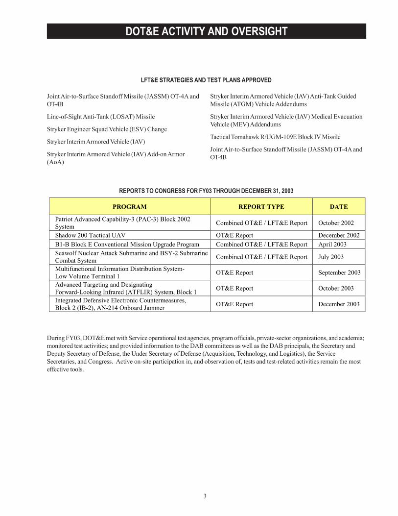
REPORTS TO CONGRESS FOR FY03 THROUGH DECEMBER 31, 2003
Joint Air-to-Surface Standoff Missile (JASSM) OT-4A andOT-4B
Line-of-Sight Anti-Tank (LOSAT) Missile
Stryker Engineer Squad Vehicle (ESV) Change
Stryker Interim Armored Vehicle (IAV)
Stryker Interim Armored Vehicle (IAV) Add-on Armor(AoA)
Stryker Interim Armored Vehicle (IAV) Anti-Tank GuidedMissile (ATGM) Vehicle Addendums
Stryker Interim Armored Vehicle (IAV) Medical EvacuationVehicle (MEV) Addendums
Tactical Tomahawk R/UGM-109E Block IV Missile
Joint Air-to-Surface Standoff Missile (JASSM) OT-4A andOT-4B
During FY03, DOT&E met with Service operational test agencies, program officials, private-sector organizations, and academia;monitored test activities; and provided information to the DAB committees as well as the DAB principals, the Secretary andDeputy Secretary of Defense, the Under Secretary of Defense (Acquisition, Technology, and Logistics), the ServiceSecretaries, and Congress. Active on-site participation in, and observation of, tests and test-related activities remain the mosteffective tools.
PROGRAM REPORT TYPE DATE
Patriot Advanced Capability-3 (PAC-3) Block 2002 System Combined OT&E / LFT&E Report October 2002
Shadow 200 Tactical UAV OT&E Report December 2002 B1-B Block E Conventional Mission Upgrade Program Combined OT&E / LFT&E Report April 2003 Seawolf Nuclear Attack Submarine and BSY-2 Submarine Combat System Combined OT&E / LFT&E Report July 2003
Multifunctional Information Distribution System- Low Volume Terminal 1 OT&E Report September 2003
Advanced Targeting and Designating Forward-Looking Infrared (ATFLIR) System, Block 1 OT&E Report October 2003
Integrated Defensive Electronic Countermeasures, Block 2 (IB-2), AN-214 Onboard Jammer OT&E Report December 2003

4
DOT&E ACTIVITY AND OVERSIGHT
5
DOT&E ACTIVITY AND OVERSIGHT
DOT&E PROGRAM OVERSIGHT
DOT&E is responsible for approving the adequacy of plans for operational test and evaluation and for reportingthe operational test results for all major defense acquisition programs to the Secretary of Defense, UnderSecretary of Defense (Acquisition, Technology and Logistics), Service Secretaries, and Congress. For DOT&E
oversight purposes, major defense acquisition programs were defined in the law to mean those programs meeting thecriteria for reporting under section 2430, Title 10, United States Code (Selected Acquisition Reports (SARs)). The law(sec.139(a)(2)(B)) also stipulates that DOT&E may designate any other programs for the purpose of oversight, review,and reporting. With the addition of such “non-major” programs, DOT&E was responsible for oversight of a total of 256acquisition programs during FY03.
Non-major programs are selected for DOT&E oversight after careful consideration of the relative importance of theindividual program. In determining non-SAR systems for oversight, consideration is given to one or more of thefollowing essential elements:
• Congress or OSD agencies have expressed a high level of interest in the program.• Congress has directed that DOT&E assess or report on the program as a condition for progress or production.• The program requires joint or multi-Service testing (the law (sec. 139(b)(4)) requires the DOT&E to coordinate
“testing conducted jointly by more than one military department or defense agency”).• The program exceeds or has the potential to exceed the dollar threshold definition of a major program according
to DoD 5000.1, but does not appear on the current SAR list (e.g., highly classified systems).• The program has a close relationship to or is a key component of a major program.• The program is an existing system undergoing major modification.• The program was previously a SAR program and operational testing is not yet complete.
This office is also responsible for the oversight of LFT&E programs, in accordance with 10 USC 139. DoD regulationuses the term “covered system” to include all categories of systems or programs identified in 10 USC 2366 as requiringlive fire test and evaluation. In addition, systems or programs that do not have acquisition points referenced in 10 USC2366, but otherwise meet the statutory criteria, are considered “covered systems” for the purpose of DOT&E oversight.
A covered system, for the purpose of oversight for LFT&E, has been determined by DOT&E to meet one or more of thefollowing criteria:
• A major system, within the meaning of that term in Title 10 USC 2302(5), that is:- User-occupied and designed to provide some degree of protection to the system or its occupants in
combat.- A conventional munitions program or missile program.
• A conventional munitions program for which more than 1,000,000 rounds are planned to be acquired.• A modification to a covered system that is likely to affect significantly the survivability or lethality of such a
system.
DOT&E was responsible for the oversight of 94 LFT&E acquisition programs during FY03.
6
DOT&E ACTIVITY AND OVERSIGHT
PROGRAMS UNDER DOT&E OVERSIGHT FISCAL YEAR 2003(As taken from the February 2003 Official T&E Oversight List)
ARMY PROGRAMSABRAMS Upgrade - Abrams Tank Upgrade
Advanced Field Artillery Tactical Data System (AFATDS)
Advanced Threat Infrared Countermeasures / CommonMissile Warning System (ATIRCM/CMWS)
Aerial Common Sensor (ACS)
Air and Missile Defense Planning and Control System(AMDPCS)
All Source Analysis System (ASAS)
AN/TPQ-47 Counterfire Radar
Army Tactical Missile System - Brilliant Anti-ArmorSubmunition (ATACMS BAT) (includes ATACMS BLKs II/IIA, and BAT P3I)
Battlefield Combat Identification System (BCIS)
Black Hawk Upgrades (UH-60M)
Bradley Upgrade - Bradley Fighting Vehicle SystemUpgrade
CH-47F – Cargo Helicopter (CH-47D helicopter upgradeprogram)
Comanche (RAH-66) Reconnaissance Attack Helicopter(Includes 20mm ammunition)
Combat Service Support Control System (CSSCS)
Common Missile
Distributed Common Ground System - Army (DCGS-A)
Excalibur (155mm Round)
Family of Medium Tactical Vehicles (FMTV)
Force XXI Battle Command Brigade & Below (FBCB2)Program
Forward Area Air Defense System (FAADS) Command,Control, and Intelligence (C2I) - includes GBS
Future Combat System (FCS) and all associated systems,including:
• Infantry Carrier Vehicle (ICV)• Command and Control Vehicle (C2V)• Recon and Surveillance Vehicle (R&SV)• Mounted Combat system (MCS)• Non-Line-of-Sight Mortar (NLOS Mortar)• Non-Line-of-Sight Cannon (NLOS Cannon)• FCS Medical Vehicle (MV)
FCS and all associated systems (Continued)• FCS Recovery Maintenance Vehicle (FRMV)• Future Tac Trk Systs-Utility (C2)• Future Tac Trk Systs-Utility (Support)• Future Tac Trk Systs-Maneuver Sustainment• Future Tac Trk Systs-Ambulance• Multi-Mission Radar• UAV Class I (Organic Air Vehicle – Light) (UAV CL I)• UAV Class II (Organic Air Vehicle-Medium)
(UAV CL II)• UAV Class III (Small UAV) (UAV CL III)• UAV Class IV (Shadow) (UAV CL IV GROUND)• Armed Robotic Vehicle (ARV)• Multi-Function Utility/Logistics and Equipment
Vehicle (MULE)• Small Unmanned Ground Vehicle (SUGV)• Unmanned Ground Sensors (UGS)• Non-Line-of-Sight Launch System (NLOS LS) • Intelligent Munitions System (IMS)
Global Combat Support System – Army/Tactical(GCSS-A/T)Global Command and Control System - Army (GCCS-A)
Guided Multiple Launch Rocket System (GMLRS)
Guided Multiple Launch Rocket System (GMLRS) –Unitary
High Mobility Artillery Rocket System (HIMARS)
Integrated System Control (ISYSCON V4)
Javelin- Advance Anti-Tank Weapon System – Medium
Joint Land Attack Cruise Missile Defense Elevated NettedSensors (JLENS)
Joint Simulation System (JSIMS)
Joint Tactical Radio System (JTRS) Cluster I(JTRS Cluster I)
Kiowa Warrior (OH-58D)
Land Warrior
Line-of-Sight Anti-Tank Missile (LOSAT)
Longbow Apache (AH-64D)
Longbow Hellfire Missile (Upgrades/Modifications)
M829E3 (120mm Round)
7
DOT&E ACTIVITY AND OVERSIGHT
ARMY PROGRAMS (continued)Stinger Re-programmable Microprocessor Missile (RMP)
Stryker – Armored Vehicle
Surface-Launched AMRAAM (SLAMRAAM) Missile
Suite of Integrated Radio Frequency Countermeasures(SIRFC) (AN/ALQ-211)
Tow-Fire & Forget Anti-Tank Missile
Transportation Coordinator Automated InformationMovement System II (TC-AIMS II)
Warfighter Information Network-Tactical (WIN-T)
NAVY PROGRAMSAcoustic Rapid COTS Insertion for SONAR
Active Electronically Scanned Array (AESA)
Advanced Amphibious Assault Vehicle (AAAV)
AGM-88E Advanced Anti-Radiation Guided Missile(AARGM) Program
Advanced Seal Delivery System (ASDS)
AIM-9X Air-to-Air Missile Upgrade
Airborne Mine Neutralization System (AMNS)
Air Early Warning (AEW)
AN/AAR-47 V2 Upgrade Missile / Laser Warning Receiver
AN/ALR-67 Advanced Special Receiver (ASR) V2 & V3
AN/APR-39A V2 Radar Warning Receiver
AN/SPY-1 B/D (All Versions)
AV-8B Remanufacture
Broad Area Maritime Surveillance (BAMS)
Cooperative Engagement Capability (CEC)
Cobra Judy Replacement (CJR) - Ship-based radar system
Cruiser Conversion
CVN 68 - Nimitz CLASS Nuclear Powered Aircraft Carriers
CVN (X) - Next Generation Nuclear Attack Carrier
DDG-51 Guided Missile Destroyer
DD(X) Future Surface Combatant Program
Defense Integrated Military Human Resources System(DIMHRS)
Deployable Joint Command and Control (DJC2)
E-2C Advanced Hawkeye (E2C Radar ModernizationProgram (RMP) )
E-2C Reproduction Hawkeye
EA-6B Improved Capabilities (ICAP) III & MultipleUpgrades (Low Band Transmitter, Band 7-8 Transmitter,USQ-113 Communications Jammer)
E/A-18G (electronic variant of F/A-18)
Evolved Seasparrow Missile (ESSM)
Extended Range Active Missile (ERAM)
Extended Range Guided Munition (ERGM)
F-35 -Joint Strike Fighter (JSF) Program
F/A-18 E/F Hornet Naval Strike Fighter (All upgrades)
Fixed Distributed System/Advanced Deployable System(FDS/ADS)
Global Command and Control System – Maritime(GCCS-M)
HyFly
Maneuver Control System (MCS) Army Tactical Commandand Control System (MCS (ATCCS))
Objective Crew Served Weapon System (OCSWS) XM307
Objective Individual Combat Weapon System (OICWS)
PATRIOT PAC-3 Patriot Advanced Capability-3
Precision Guided Mortar Munitions (PGMM)
Reserve Component Automation System (RCAS)
Sensor Fuzed Munition
Single Channel Anti-Jam Man-Portable (SCAMP)(MILSTAR, Block II)
8
DOT&E ACTIVITY AND OVERSIGHT
NAVY PROGRAMS (continued)Integrated Defensive Electronic Countermeasure (IDECM)
Integrated Surface Ship ASW Combat System(AN/SQQ-89)
Joint Maritime Command and Control Capability (JCC (X))
Joint Mission Planning System (JMPS)
Joint Standoff Weapon (JSOW) Baseline/BLU-108/Unitary
Joint Tactical Radio System Cluster 3 (JTRS Cluster 3)
KC-130J Aircraft
LHA(R) - New Amphibious Assault Ship
LHD 1 - Amphibious Assault Ship
Littoral Combatant Ship (LCS)
LPD-17 Amphibious Assault Ship (Includes 30mmammunition)
MH-60R Multi-Mission Helicopter Upgrade
MH-60S Helicopter (Utility helicopter replacing existingCH-46D, HH-60H, SH-3 & UH-1N helicopters)
Multi-Functional Information Distribution System - LowVolume Terminal (MIDS-LVT)
MK-48 Torpedo Mods
Multi-Mission Maritime Aircraft (MMA)
Maritime Prepositioning Force (Future) (MPF (F))
Naval Integrated Fire Control-Counter Air (NIFC-CA)
Navy Advanced EHF Multi-Band Terminal (NMT)
Navy-Marine Corps Intranet (NMCI)
Navy Standard Integrated Personnel System (NSIPS)
Rapid Airborne Mine Clearance System (RAMICS)
Rolling Airframe Missile (RAM)
Ship Self Defense System (SSDS)
Surface Electronic Warfare Improvement Program (SEWIP)
SSGN Trident Conversion
SSN-21 Seawolf AN/BSY-2
SSN-23 Jimmy Carter
SSN-774 Virginia Class
Standard Missile-2 (SM-2) (Blocks I/II/III/IV)
Standoff Land Attack Missile - Expanded Response(SLAM-ER)
Strategic Sealift Program (SSP) Ship Class
SUB Comms (SubECS/SCSS)
Surveillance Towed Array Sensor System (SURTASS) /Low Frequency Active (LFA)
T-AKE Lewis & Clark Class of Auxiliary Dry Cargo Ships
T-AOE(X) (Triple Product Station Ship)
T-45TS (Undergraduate Jet Pilot Training System)
Tactical Control System (TCS)
Tactical Tomahawk Missile
Tactical Tomahawk Mission Planning System / TomahawkCommand & Control System (MPS/TCCS)
Trident II Missile
Unmanned Combat Aerial Vehicle - Navy
USMC H-1 Upgrades (4BW/4BN)
V-22 Osprey Joint Advanced Vertical Lift Aircraft
Vertical Take-Off Unmanned Aerial Vehicle (VTUAV)
VXX (Presidential Replacement Helicopter) Program
9
DOT&E ACTIVITY AND OVERSIGHT
AIR FORCE PROGRAMSAdvanced Wideband System (AWS)
ALR-56M Radar Warning Receiver
ALR-69 Radar Warning Receiver
Advanced Medium Range Air-to-Air Missile (AMRAAM)
Airborne Warning and Control System (AWACS (E-3))Upgrades (Includes AWACS RSIP (E-3))
Air Force Tanker Replacement Program (Follow-on toKC-10 aircraft)
B-1B CMUP – B-1 LANCER Penetrating BomberConventional Munitions Upgrade Program (CMUP)
B-2 Radar Pathfinder Program (B-2 RPP)
B-2A Spirit Stealth Bomber
C-5 Avionics Modernization Program (AMP)
C-5 Reliability and Re-engining Program (RERP)
C-17A - Globemaster III Advance Cargo Aircraft
C-130 AMP - Avionics Modernization Program
C-130J Hercules Cargo Aircraft (All Variants)
Combat Survivor Evader Locator (CSEL)
Combat Search & Rescue Replacement Aircraft Program(CSAR)
Distributed Common Ground System - Air Force(DCGS-AF) Block 20
E-4B Modernization Program
Evolved Expendable Launch Vehicle (EELV)
F-117 Infrared Acquisition and Designation System(IRADS)
F-15 Tactical Electronic Warfare Suite (TEWS) (AN/ALQ-135 Band 1.5 Fiber-Optic Towed Decoy)
F/A-22 – Advanced Tactical Fighter
Global Broadcast Service (GBS)
Global Combat Support System - Air Force (GCSS-AF)
Global Command and Control System - Air Force(GCCS-AF)
• Theater Battle Management Core System (TBMCS)• Air Operations Center - Weapons System (AOC-WS)
Global Hawk High Altitude Endurance Unmanned AerialVehicle
Global Transportation Network-21 (GTN-21)
Integrated Log System-Supply (ILS-S)
Integrated Maintenance Data System (IMDS)
Joint Air-Surface Standoff Missile (JASSM)
Joint Direct Attack Munition (JDAM)
Joint Helmet Mounted Cueing System (JHMCS)
Joint Mission Planning System (JMPS) / Air Force MissionSupport System (AFMSS)
Joint Primary Aircraft Training System (JPATS)
Joint Surveillance Target Attack Radar System (JSTARS)
Joint Tactical Radio System Cluster 4 (JTRS Cluster 4)
KC-767A Aerial Tanker Aircraft
KC-135 Global Air Traffic Management (GATM) Upgrade
Large Aircraft Infrared Countermeasures (LAIRCM)
MILSTAR - (Satellite Low/Med Data RateCommunications)
Minuteman III - Guidance Replacement Program (GRP)
Minuteman III - Propulsion Replacement Program (PRP)
Multiple Platform – Common Data Link (MP-CDL)
Multi-Platform Radar Technology Insertion Program(MP-RTIP)
Multi-Sensor Command and Control Aircraft (MC2A)Program
Mobile User Objective System (MUOS)
National Airspace System (NAS)
National Polar-Orbiting Operational Environment Satellite(NPOESS)
NAVSTAR Global Positioning System (GPS)
Navy Extremely High Frequency (NESP) SatelliteCommunications (SATCOM) Program
Predator Unmanned Aerial Vehicle (UAV) RQ/MQ-1
Predator Unmanned Aerial Vehicle (UAV) MQ-9
10
DOT&E ACTIVITY AND OVERSIGHT
Space-Based Infrared System Program High Component(SBIRS-HIGH)
Space Based Radar (SBR)
Sensor Fuzed Weapon (SFW) P3I (CBU-97/B)
Small Diameter Bomb (SDB)
AIR FORCE PROGRAMS (continued)
OTHER DoD PROGRAMS
Secure Mobile Anti-Jam Reliable Tactical Terminal(SMART-T)
Strategic Warfare Planning System (SWPS)
Ultra High Frequency (UHF) Follow-on Satellite
Unmanned Combat Aerial Vehicle - Air Force
Wideband Gapfiller
Ballistic Missile Defense Program• Ground Based Midcourse Defense Segment (Includes
Ground Based Interceptor [GBI], Ground Based Radar[GBR], and Battle Management C3 [BMC3])
• Medium Extended Air Defense System (MEADS)• Navy Theater-Wide Ballistic Missile Defense
(incorporates AEGIS BMD and SM-3 BLOCK II)• Space-Based Infrared System-Low (SBIRS-L)• Theater High-Altitude Area Defense (THAAD) • YAL-1 Airborne Laser (ABL)
Business System Modernization (BSM)
Chemical Biological Defense Program (CBDP)• Artemis (Chemical Agent Standoff Detection System)• Joint Biological Agent Identification and Diagnosis
System (JBAIDS)• Joint Biological Point Detection System (JBPDS)• Joint Biological Standoff Detection System (JBSDS)• Joint Chemical Agent Detector (JCAD)• Joint Service Family of Decontamination Systems
(JSFDS)• Joint Service Light NBC Reconnaissance• Joint Service Lightweight Standoff Chemical Agent
Detector (JSLSCAD)• Joint Service Sensitive Equipment Decontamination
(JSSED)• Joint Warning and Reporting Network (JWARN)
Chemical Demilitarization
Composite Health Care System II (CHCS II)
Defense Medical Logistics Standard Support (DMLSS)
Defense Message System (DMS)
Defense Procurement Payment System (DPPS)
Defense Travel System (DTS)
DFAS Corporate Database/Warehouse (DCD/DCW)
Fuels Automated System (FAS)
Global Information Grid Bandwidth Expansion (GIG-BE))
Global Command & Control System – Joint (GCCS-J)
High Performance Computing Modernization (HPCM)
Joint Tactical Radio System (JTRS) Cluster II (Multi-BandIntra Team Radio)
Joint Tactical Radio System Waveform (JTRS Waveform)
Net- Centric Enterprise Services (NCES)
Public Key Infrastructure (PKI)
Teleport
Theater Medical Information Program (TMIP)

11
DOD PROGRAMS
BALLISTIC MISSILE DEFENSE SYSTEM (BMDS)
This report provides an unclassified assessment of the adequacy and sufficiency of the Ballistic Missile DefenseSystem (BMDS) element test programs during FY03. Classified discussions of these topics will be included in theannual Operational Test & Evaluation Assessment of the BMDS Test Program submitted in February 2004.
The BMDS is intended to provide a layered defense for the entire United States, deployed U.S. forces, friends, and alliesfrom all ranges of threat ballistic missiles during all phases of flight. The BMDS will consist of land-, sea- and space-based sensors (both optical and radar), battle management systems, communications networks, long- and short-rangeinterceptors, and directed-energy weapons.
On December 17, 2002, the President directed the Secretary of Defense, “…to proceed with plans to deploy a set of initialmissile defense capabilities beginning in 2004.” The Missile Defense Agency (MDA) is working to develop a set ofInitial Defensive Capabilities (IDC), which can be deployed to conduct Initial Defensive Operations (IDO), using Ground-based Midcourse Defense (GMD), Aegis Ballistic Missile Defense (Aegis BMD), and other BMDS elements. Each ofthese elements’ support of the IDO is discussed in its respective section.
It is prudent to identify and exploit defensive capabilities inherent in the BMDS infrastructure during the developmentphase. However, it is important to understand that assessments of these capabilities are based primarily on modeling andsimulation, developmental testing of components and subsystems, and analyses – not end-to-end operational testing ofa mature integrated system. Due to the immature nature of the systems they emulate, models and simulations of theBMDS cannot be adequately validated at this time. Confidence in assessed capabilities will improve as more systemperformance data is gathered to anchor the simulations or directly demonstrate these capabilities.
Planned operational assessments of IDO capability will focus on system performance against nation specific threats, asdocumented in a series of Defense Intelligence Agency (DIA) threat assessments. MDA is designing BMDS based onthe capabilities of broad threat classes. MDA and the operational test agencies (OTAs) are working to connect the MDAthreat capability document to the DIA threat assessment. IDO capability will be assessed for four engagement sequencegroups consistent with North Korean Intercontinental Ballistic Missile (ICBM) attack scenarios. The Command andControl, Battle Management and Communications (C2BMC) element will integrate the other BMDS elements into asystem capable of providing integrated, layered defenses against all types of ballistic missile threats. For Block 2004 andIDO, C2BMC is planned to provide enhanced situational awareness for the warfighter. Specifically, this will consist of acommon operating picture that provides early launch warning and impact point predictions to the warfighter and voiceauthorization for weapons release provided through an appropriate concept of operations. Plans call for enhancingC2BMC capabilities in Block 2006.
Due to immature BMDS elements, very little system level testing was performed by the close of FY03. Therefore, BMDScapabilities assessed for IDO will be based on test events planned for FY04. The OTAs are involved in the planning ofthese events and DOT&E is reviewing and approving operational test objectives for combined developmental test/operational test events. These tests will be executed using simulated or theoretical performance characteristics for someelements. Scenarios are still being developed for the system level integrated ground-test (IGT-2), planned to support theinitial deployment of BMDS. Flight tests planned to support validation of the ground-testing and modeling efforts haveslipped to the point that data will not be available prior to IGT-2. Data from flight testing and ground testing is needed tosupport extensive validation, verification, and accreditation efforts currently underway. Without the results of the flighttesting, the ground-testing efforts are at risk. If models accurately reflect flight test performance, IGT-2 results will bevalidated after the fact. At this point in time, it is not clear what mission capability will be demonstrated prior to IDO.
12
DOD PROGRAMS
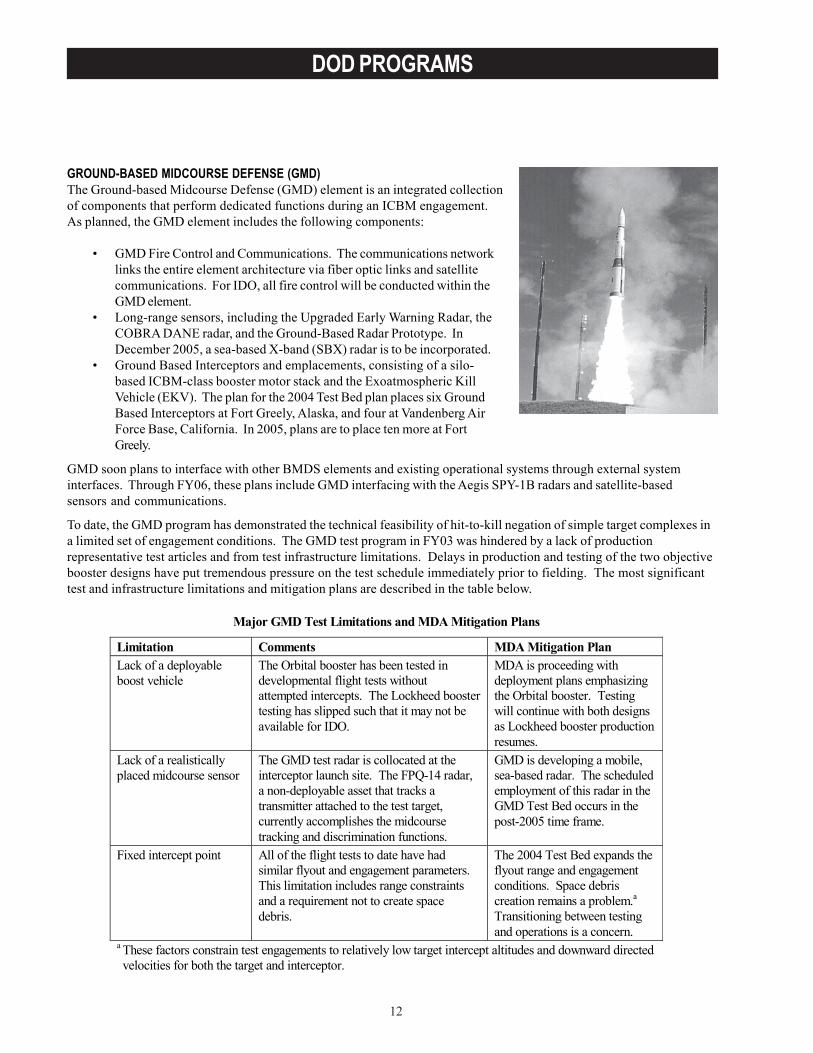
GROUND-BASED MIDCOURSE DEFENSE (GMD)The Ground-based Midcourse Defense (GMD) element is an integrated collectionof components that perform dedicated functions during an ICBM engagement.As planned, the GMD element includes the following components:
• GMD Fire Control and Communications. The communications networklinks the entire element architecture via fiber optic links and satellitecommunications. For IDO, all fire control will be conducted within theGMD element.
• Long-range sensors, including the Upgraded Early Warning Radar, theCOBRA DANE radar, and the Ground-Based Radar Prototype. InDecember 2005, a sea-based X-band (SBX) radar is to be incorporated.
• Ground Based Interceptors and emplacements, consisting of a silo-based ICBM-class booster motor stack and the Exoatmospheric KillVehicle (EKV). The plan for the 2004 Test Bed plan places six GroundBased Interceptors at Fort Greely, Alaska, and four at Vandenberg AirForce Base, California. In 2005, plans are to place ten more at FortGreely.
GMD soon plans to interface with other BMDS elements and existing operational systems through external systeminterfaces. Through FY06, these plans include GMD interfacing with the Aegis SPY-1B radars and satellite-basedsensors and communications.
To date, the GMD program has demonstrated the technical feasibility of hit-to-kill negation of simple target complexes ina limited set of engagement conditions. The GMD test program in FY03 was hindered by a lack of productionrepresentative test articles and from test infrastructure limitations. Delays in production and testing of the two objectivebooster designs have put tremendous pressure on the test schedule immediately prior to fielding. The most significanttest and infrastructure limitations and mitigation plans are described in the table below.
Major GMD Test Limitations and MDA Mitigation Plans
Limitation Comments MDA Mitigation Plan Lack of a deployable boost vehicle
The Orbital booster has been tested in developmental flight tests without attempted intercepts. The Lockheed booster testing has slipped such that it may not be available for IDO.
MDA is proceeding with deployment plans emphasizing the Orbital booster. Testing will continue with both designs as Lockheed booster production resumes.
Lack of a realistically placed midcourse sensor
The GMD test radar is collocated at the interceptor launch site. The FPQ-14 radar, a non-deployable asset that tracks a transmitter attached to the test target, currently accomplishes the midcourse tracking and discrimination functions.
GMD is developing a mobile, sea-based radar. The scheduled employment of this radar in the GMD Test Bed occurs in the post-2005 time frame.
Fixed intercept point All of the flight tests to date have had similar flyout and engagement parameters. This limitation includes range constraints and a requirement not to create space debris.
The 2004 Test Bed expands the flyout range and engagement conditions. Space debris creation remains a problem.a Transitioning between testing and operations is a concern.
a These factors constrain test engagements to relatively low target intercept altitudes and downward directed velocities for both the target and interceptor.
13
DOD PROGRAMS
Intercept Flight Test - 9 (IFT-9) took place on October 14, 2002, resulting in a successful intercept. The target suiteconsisted of a mock warhead and a number of decoys launched from the Vandenberg Air Force Base, California, towardsthe Reagan Test Site. IFT-9 (largely a replay of IFT-8) was designed to increase confidence in the GMD capability toexecute hit-to-kill intercepts. Overall, the test execution was nominal although the EKV experienced the track gateanomaly previously observed in IFT-7 and IFT-8. The software changes incorporated in IFT-9 to mitigate this problemwere not successful. Further changes were made prior to IFT-10.
In December 2002, GMD attempted a night intercept in IFT-10. In this test, the EKV failed to separate from the surrogateboost vehicle and therefore the ability to intercept the target could not be tested. The failure to separate was attributedto a quality control failure combined with shock and vibration loads on the EKV. As a result, corrective measures takento fix the track gate anomaly found in previous tests could not be tested.
GMD suspended intercept flight testing after the EKV failed to separate from the surrogate booster in IFT-10. IFT-11 andIFT-12 that employed the problematic surrogate booster were eliminated from the schedule. This decision wasreasonable given the increased risk of surrogate boost vehicle failure, the resources that would have to be diverted fromtactical booster development to fix the problems, and the limited amount of additional information to be gained in IFT-11and IFT-12 over that available from previous flight tests. It does, however, leave very limited time for demonstration ofboost vehicle performance, integration of the boost vehicle to the new, upgraded EKV, and demonstration of integratedboost vehicle/interceptor performance. IFT-13A and IFT-13B remain in the schedule as non-intercept flight tests toconfirm booster integration and performance. IFT-13C was added to the schedule and represents a significant exercise ofthe Test Bed infrastructure. It will be the first system-level flight test to use the Kodiak, Alaska, facility to launch a targetmissile. While it is not a planned intercept attempt, it will fully exercise the system and may result in an intercept. IFT-13C also addresses a long-standing concern over target presentation that has not yet been tested. IFT-14 and IFT 15 arethe next official intercept attempts and are scheduled for May 2004 and July 2004, respectively.
The Orbital Sciences Corporation booster was successfully tested with a mock EKV on August 16, 2003. Shock andvibration environments were measured and compared to previous test levels. Preliminary analyses suggest that the newbooster produces lower than expected vibrations at the EKV. Performance of the real EKV mated with the Orbital boosterwill be demonstrated in IFT-14 prior to IDO. Similar demonstration flights for the Lockheed Martin booster design areslipping due to technical difficulties and several explosions at the missile propellant mixing facility.Silos and related construction projects at Fort Greely, Alaska; Kodiak, Alaska; and Vandenberg Air Force Base, California,are proceeding on schedule. Due to safety considerations, no tests are currently planned to launch interceptors from theoperational missile fields.
To date, EKV discrimination and homing have been demonstrated against simple target complexes in a limited set ofengagement conditions. Demonstrations of EKV performance are needed at higher closing velocities and against targetswith signatures, countermeasures, and flight dynamics more closely matching the projected threat. In addition, systemdiscrimination performance against target suites for which there is imperfect a priori knowledge remains uncertain.GMD is developing a SBX radar mounted on a semi-submersible platform. The SBX radar, scheduled for incorporationinto the GMD element in December 2005, is designed to be a more capable and flexible midcourse sensor for supportingGMD engagements. This radar will improve the operational realism of the flight test program by providing a moveablemid-course sensor.
A flight demonstration of the BMDS capability using Aegis SPY-1B data (particularly for defense of Hawaii) is plannedfor IFT-15 in FY04. A flight demonstration of COBRA DANE is currently not planned, and its capability will need to bedemonstrated by other means until an air-launched target is developed. IFT-14 and IFT-15, scheduled for FY04, areintended to provide demonstrations of integrated boost vehicle/EKV performance. Even with successful intercepts inboth of these attempts, the small number of tests would limit confidence in the integrated interceptor performance.
14
DOD PROGRAMS
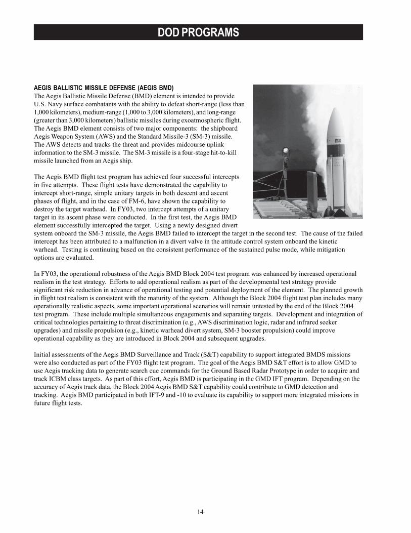
AEGIS BALLISTIC MISSILE DEFENSE (AEGIS BMD)The Aegis Ballistic Missile Defense (BMD) element is intended to provideU.S. Navy surface combatants with the ability to defeat short-range (less than1,000 kilometers), medium-range (1,000 to 3,000 kilometers), and long-range(greater than 3,000 kilometers) ballistic missiles during exoatmospheric flight.The Aegis BMD element consists of two major components: the shipboardAegis Weapon System (AWS) and the Standard Missile-3 (SM-3) missile.The AWS detects and tracks the threat and provides midcourse uplinkinformation to the SM-3 missile. The SM-3 missile is a four-stage hit-to-killmissile launched from an Aegis ship.
The Aegis BMD flight test program has achieved four successful interceptsin five attempts. These flight tests have demonstrated the capability tointercept short-range, simple unitary targets in both descent and ascentphases of flight, and in the case of FM-6, have shown the capability todestroy the target warhead. In FY03, two intercept attempts of a unitarytarget in its ascent phase were conducted. In the first test, the Aegis BMDelement successfully intercepted the target. Using a newly designed divertsystem onboard the SM-3 missile, the Aegis BMD failed to intercept the target in the second test. The cause of the failedintercept has been attributed to a malfunction in a divert valve in the attitude control system onboard the kineticwarhead. Testing is continuing based on the consistent performance of the sustained pulse mode, while mitigationoptions are evaluated.
In FY03, the operational robustness of the Aegis BMD Block 2004 test program was enhanced by increased operationalrealism in the test strategy. Efforts to add operational realism as part of the developmental test strategy providesignificant risk reduction in advance of operational testing and potential deployment of the element. The planned growthin flight test realism is consistent with the maturity of the system. Although the Block 2004 flight test plan includes manyoperationally realistic aspects, some important operational scenarios will remain untested by the end of the Block 2004test program. These include multiple simultaneous engagements and separating targets. Development and integration ofcritical technologies pertaining to threat discrimination (e.g., AWS discrimination logic, radar and infrared seekerupgrades) and missile propulsion (e.g., kinetic warhead divert system, SM-3 booster propulsion) could improveoperational capability as they are introduced in Block 2004 and subsequent upgrades.
Initial assessments of the Aegis BMD Surveillance and Track (S&T) capability to support integrated BMDS missionswere also conducted as part of the FY03 flight test program. The goal of the Aegis BMD S&T effort is to allow GMD touse Aegis tracking data to generate search cue commands for the Ground Based Radar Prototype in order to acquire andtrack ICBM class targets. As part of this effort, Aegis BMD is participating in the GMD IFT program. Depending on theaccuracy of Aegis track data, the Block 2004 Aegis BMD S&T capability could contribute to GMD detection andtracking. Aegis BMD participated in both IFT-9 and -10 to evaluate its capability to support more integrated missions infuture flight tests.
15
DOD PROGRAMS
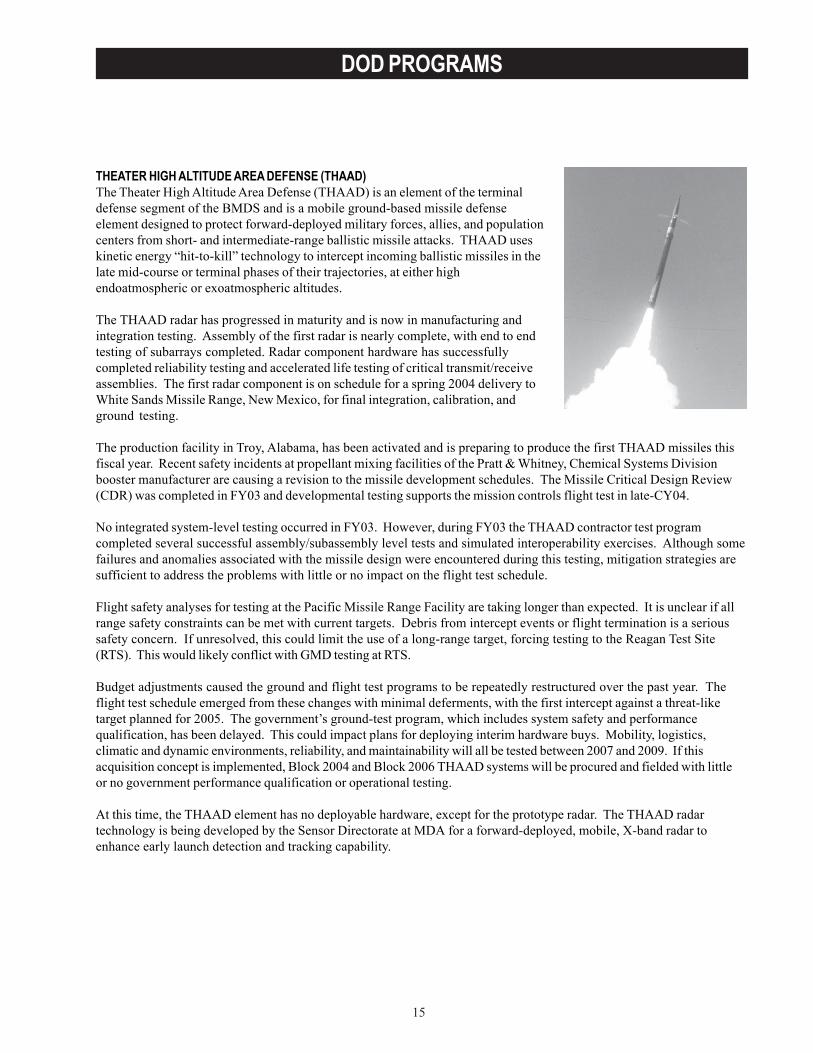
THEATER HIGH ALTITUDE AREA DEFENSE (THAAD)The Theater High Altitude Area Defense (THAAD) is an element of the terminaldefense segment of the BMDS and is a mobile ground-based missile defenseelement designed to protect forward-deployed military forces, allies, and populationcenters from short- and intermediate-range ballistic missile attacks. THAAD useskinetic energy “hit-to-kill” technology to intercept incoming ballistic missiles in thelate mid-course or terminal phases of their trajectories, at either highendoatmospheric or exoatmospheric altitudes.
The THAAD radar has progressed in maturity and is now in manufacturing andintegration testing. Assembly of the first radar is nearly complete, with end to endtesting of subarrays completed. Radar component hardware has successfullycompleted reliability testing and accelerated life testing of critical transmit/receiveassemblies. The first radar component is on schedule for a spring 2004 delivery toWhite Sands Missile Range, New Mexico, for final integration, calibration, andground testing.
The production facility in Troy, Alabama, has been activated and is preparing to produce the first THAAD missiles thisfiscal year. Recent safety incidents at propellant mixing facilities of the Pratt & Whitney, Chemical Systems Divisionbooster manufacturer are causing a revision to the missile development schedules. The Missile Critical Design Review(CDR) was completed in FY03 and developmental testing supports the mission controls flight test in late-CY04.
No integrated system-level testing occurred in FY03. However, during FY03 the THAAD contractor test programcompleted several successful assembly/subassembly level tests and simulated interoperability exercises. Although somefailures and anomalies associated with the missile design were encountered during this testing, mitigation strategies aresufficient to address the problems with little or no impact on the flight test schedule.
Flight safety analyses for testing at the Pacific Missile Range Facility are taking longer than expected. It is unclear if allrange safety constraints can be met with current targets. Debris from intercept events or flight termination is a serioussafety concern. If unresolved, this could limit the use of a long-range target, forcing testing to the Reagan Test Site(RTS). This would likely conflict with GMD testing at RTS.
Budget adjustments caused the ground and flight test programs to be repeatedly restructured over the past year. Theflight test schedule emerged from these changes with minimal deferments, with the first intercept against a threat-liketarget planned for 2005. The government’s ground-test program, which includes system safety and performancequalification, has been delayed. This could impact plans for deploying interim hardware buys. Mobility, logistics,climatic and dynamic environments, reliability, and maintainability will all be tested between 2007 and 2009. If thisacquisition concept is implemented, Block 2004 and Block 2006 THAAD systems will be procured and fielded with littleor no government performance qualification or operational testing.
At this time, the THAAD element has no deployable hardware, except for the prototype radar. The THAAD radartechnology is being developed by the Sensor Directorate at MDA for a forward-deployed, mobile, X-band radar toenhance early launch detection and tracking capability.
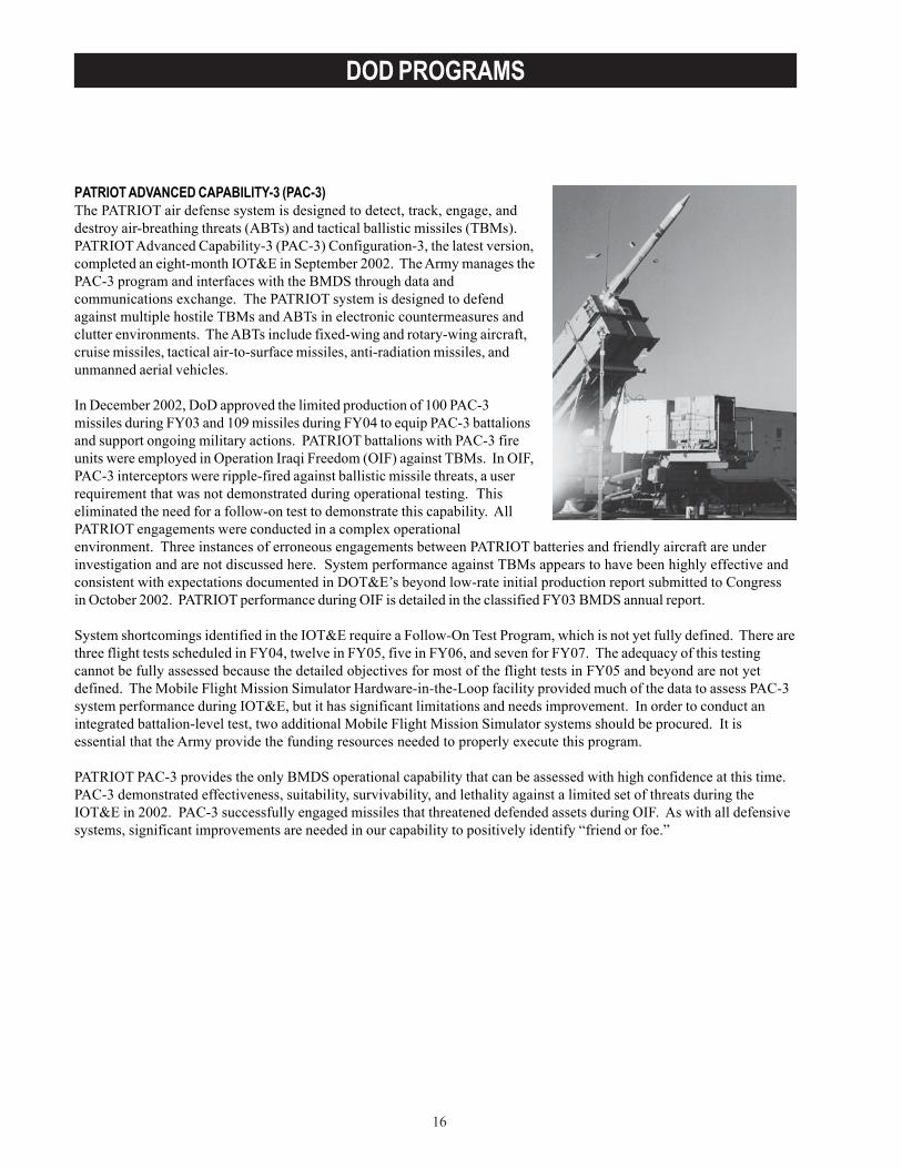
16
DOD PROGRAMS
PATRIOT ADVANCED CAPABILITY-3 (PAC-3)The PATRIOT air defense system is designed to detect, track, engage, anddestroy air-breathing threats (ABTs) and tactical ballistic missiles (TBMs).PATRIOT Advanced Capability-3 (PAC-3) Configuration-3, the latest version,completed an eight-month IOT&E in September 2002. The Army manages thePAC-3 program and interfaces with the BMDS through data andcommunications exchange. The PATRIOT system is designed to defendagainst multiple hostile TBMs and ABTs in electronic countermeasures andclutter environments. The ABTs include fixed-wing and rotary-wing aircraft,cruise missiles, tactical air-to-surface missiles, anti-radiation missiles, andunmanned aerial vehicles.
In December 2002, DoD approved the limited production of 100 PAC-3missiles during FY03 and 109 missiles during FY04 to equip PAC-3 battalionsand support ongoing military actions. PATRIOT battalions with PAC-3 fireunits were employed in Operation Iraqi Freedom (OIF) against TBMs. In OIF,PAC-3 interceptors were ripple-fired against ballistic missile threats, a userrequirement that was not demonstrated during operational testing. Thiseliminated the need for a follow-on test to demonstrate this capability. AllPATRIOT engagements were conducted in a complex operationalenvironment. Three instances of erroneous engagements between PATRIOT batteries and friendly aircraft are underinvestigation and are not discussed here. System performance against TBMs appears to have been highly effective andconsistent with expectations documented in DOT&E’s beyond low-rate initial production report submitted to Congressin October 2002. PATRIOT performance during OIF is detailed in the classified FY03 BMDS annual report.
System shortcomings identified in the IOT&E require a Follow-On Test Program, which is not yet fully defined. There arethree flight tests scheduled in FY04, twelve in FY05, five in FY06, and seven for FY07. The adequacy of this testingcannot be fully assessed because the detailed objectives for most of the flight tests in FY05 and beyond are not yetdefined. The Mobile Flight Mission Simulator Hardware-in-the-Loop facility provided much of the data to assess PAC-3system performance during IOT&E, but it has significant limitations and needs improvement. In order to conduct anintegrated battalion-level test, two additional Mobile Flight Mission Simulator systems should be procured. It isessential that the Army provide the funding resources needed to properly execute this program.
PATRIOT PAC-3 provides the only BMDS operational capability that can be assessed with high confidence at this time.PAC-3 demonstrated effectiveness, suitability, survivability, and lethality against a limited set of threats during theIOT&E in 2002. PAC-3 successfully engaged missiles that threatened defended assets during OIF. As with all defensivesystems, significant improvements are needed in our capability to positively identify “friend or foe.”

17
DOD PROGRAMS
MEDIUM EXTENDED AIR DEFENSE SYSTEM (MEADS)The Army manages the Medium Extended Air Defense System(MEADS) program, which is intended to be a highly mobile airdefense system for the protection of maneuver forces and fixedassets. PATRIOT will either evolve to the MEADS capability orbe replaced by the MEADS system, depending on the acquisitionstrategy adopted for the program. The system should providearea and point defense capabilities against multiple,simultaneous, 360-degree attacks by ballistic missiles, largecaliber rockets, fixed-wing and rotary-wing aircraft, unmannedaerial vehicles, cruise missiles, tactical air-to-surface missiles, andanti-radiation missiles. It should be strategically deployable byC-130 roll-on/roll-off, and tactically mobile to keep up withmaneuver forces. MEADS has not yet entered the System Design and Development phase and currently has nooperational capability. Testing has been limited to demonstrations using prototype software in digital simulations.
MEADS is an international program that DoD is reevaluating to determine if it can be integrated with the PATRIOTproduct improvement program. The evaluation is ongoing with the international community.
AIRBORNE LASER (ABL)The Airborne Laser (ABL) program is employing a spiraldevelopment concept. The Block 2004 effort develops,integrates, and tests the initial weapon system on a Boeing 747aircraft. ABL is intended to engage and destroy enemy ballisticmissiles during their boost phase. The ABL engagementconcept places laser energy on the threat missile booster motorcasing. This energy damages the casing, causing the missile torupture or lose thrust and flight control, falling short of itstarget. Engagement in the boost phase negates the missilebefore decoys, warheads, or submunitions are deployed.
Three different Block configurations are planned. Blocks 2004and 2008 are on Boeing 747 transport aircraft modified toaccommodate ABL subsystems. Block 2006 continues testingthe Block 2004 aircraft, with minimal hardware and softwareupdate, against a wider variety of ballistic missile targets. Also, during this spiral, deployable ground support equipmentwill be developed to support early operational capability and MDA test activities.
To date, the program has been concentrating on activities associated with getting “first light” through six fully integratedlaser modules, and integrating the beam control system. All Block 2004 efforts are focused on achieving a successful,live shoot-down of a ballistic missile during FY05.
In order to demonstrate system performance as soon as possible, the Block 2004 program will delay some integration andtesting until after the ballistic missile shoot-down. For example, integration and testing of the Active Ranger System isnow scheduled to occur after the shoot-down.
The program has also reorganized the High Energy Laser (HEL) Lethal Edge Irradiance characterization, reducing thenumber of tests and engagement geometries occurring prior to the ballistic missile shoot-down. This limits the amount ofdata available through FY05, for extrapolating ABL’s negation capabilities against other missile threat classes. HEL beamcharacterization flight tests will be re-planned to the degree possible after the shoot-down event. Characterization of theHEL beam should continue in the Block 2006 test program to increase understanding of ABL lethality.
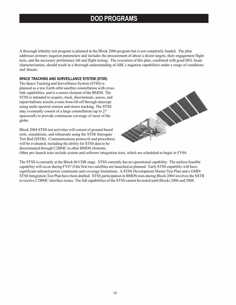
18
DOD PROGRAMS
A thorough lethality test program is planned in the Block 2006 program but is not completely funded. The planaddresses primary negation parameters and includes the procurement of about a dozen targets, their engagement flighttests, and the necessary preliminary lab and flight testing. The execution of this plan, combined with good HEL beamcharacterization, should result in a thorough understanding of ABL’s negation capabilities under a range of conditionsand threats.
SPACE TRACKING AND SURVEILLANCE SYSTEM (STSS)The Space Tracking and Surveillance System (STSS) isplanned as a low Earth orbit satellite constellation with cross-link capabilities, and is a sensor element of the BMDS. TheSTSS is intended to acquire, track, discriminate, assess, andreport ballistic missile events from lift-off through interceptusing multi-spectral sensors and stereo tracking. The STSSmay eventually consist of a large constellation (up to 27spacecraft) to provide continuous coverage of most of theglobe.
Block 2004 STSS test activities will consist of ground-basedtests, simulations, and rehearsals using the STSS SurrogateTest Bed (SSTB). Communications protocols and procedureswill be evaluated, including the ability for STSS data to bedisseminated through C2BMC to other BMDS elements.Other pre-launch tests include system and software integration tests, which are scheduled to begin in FY04.
The STSS is currently at the Block 06 CDR stage. STSS currently has no operational capability. The earliest feasiblecapability will occur during FY07 if the first two satellites are launched as planned. Early STSS capability will havesignificant onboard power constraints and coverage limitations. A STSS Development Master Test Plan and a GMD/STSS Integration Test Plan have been drafted. STSS participation in BMDS tests during Block 2004 involves the SSTBto resolve C2BMC interface issues. The full capabilities of the STSS cannot be tested until Blocks 2006 and 2008.
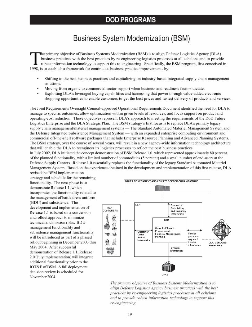
19
DOD PROGRAMS
Business System Modernization (BSM)
The primary objective of Business Systems Modernization is toalign Defense Logistics Agency business practices with the bestpractices by re-engineering logistics processes at all echelonsand to provide robust information technology to support thisre-engineering.
The primary objective of Business Systems Modernization (BSM) is to align Defense Logistics Agency (DLA)business practices with the best practices by re-engineering logistics processes at all echelons and to providerobust information technology to support this re-engineering. Specifically, the BSM program, first conceived in
1998, is to establish a framework for continuous business practice improvements by:
• Shifting to the best business practices and capitalizing on industry-based integrated supply chain managementsolutions.
• Moving from organic to commercial sector support when business and readiness factors dictate.• Exploiting DLA’s leveraged buying capabilities and harnessing that power through value-added electronic
shopping opportunities to enable customers to get the best prices and fastest delivery of products and services.
The Joint Requirements Oversight Council-approved Operational Requirements Document identified the need for DLA tomanage to specific outcomes, allow optimization within given levels of resources, and focus support on product andoperating-cost reduction. These objectives represent DLA’s approach to meeting the requirements of the DoD FutureLogistics Enterprise and the DLA Strategic Plan. The BSM strategy’s first focus is to replace DLA’s primary legacysupply chain management/materiel management systems — The Standard Automated Materiel Management System andthe Defense Integrated Subsistence Management System — with an expanded enterprise computing environment andcommercial off-the-shelf software packages that include Enterprise Resource Planning and Advanced Planning Systems.The BSM strategy, over the course of several years, will result in a new agency-wide information technology architecturethat will enable the DLA to reengineer its logistics processes to reflect the best business practices.In July 2002, DLA initiated the concept demonstration of BSM Release 1.0, which represented approximately 80 percentof the planned functionality, with a limited number of commodities (5 percent) and a small number of end-users at theDefense Supply Centers. Release 1.0 essentially replaces the functionality of the legacy Standard Automated MaterielManagement System. Based on the experience obtained in the development and implementation of this first release, DLArevised the BSM implementationstrategy and schedule for the remainingfunctionality. The next phase is todemonstrate Release 1.1, whichincorporates the functionality related tothe management of battle dress uniform(BDU) and subsistence. Thedevelopment and implementation ofRelease 1.1 is based on a conversionand rollout approach to minimizetechnical and mission risks. BDUmanagement functionality andsubsistence management functionalitywill be introduced as part of a phasedrollout beginning in December 2003 thruMay 2004. After successfuldemonstration of Release 1.1, Release2.0 (July implementation) will integrateadditional functionality prior to theIOT&E of BSM. A full deploymentdecision review is scheduled forNovember 2004.
20
DOD PROGRAMS
TEST & EVALUATION ACTIVITY• DOT&E approved the revised BSM Test and Evaluation Master Plan in May 2002.• The Joint Interoperability Test Command conducted an operational assessment (OA) on selected functionality
of Release 1.0 in the Fall of 2002, to assess system maturity. The OA was conducted in productionenvironments at the following locations: DLA Headquarters, Ft. Belvoir, Virginia; Defense Supply Center inRichmond, Virginia; Defense Supply Centers in Richmond, Virginia; Philadelphia, Pennsylvania; and Columbus,Ohio; and the BSM Production Center in Denver, Colorado; and with the Defense Finance and AccountingService in Columbus, Ohio.
• The IOT&E of BSM, which will support full deployment, is planned for October 2004.
TEST & EVALUATION ASSESSMENTThe OA results revealed that BSM was able to successfully perform 90 percent of its functional requirements. Of the fourprimary BSM functional areas, Order Fulfillment achieved the most favorable results. Users in this area experienced littleor no operational difficulties. The Planning and Financial Management functionality performed well in general. However,some Demand Planning users experienced difficulties completing demand analysis and forecasting actions. TheProcurement functionality was the least favorable overall. Users could not consistently complete contract evaluationsand process awards ¾ mostly due to excessive manual workarounds required by the Procurement Desktop 2 subsystem.The 21 external system interfaces assessed all performed well with no interoperability failures observed. The OA resultsalso revealed that shortcomings in the areas of information assurance and usability exist. The Program Manager iscurrently working to correct these identified deficiencies prior to an OA for Release 1.1, which is scheduled for March2004.
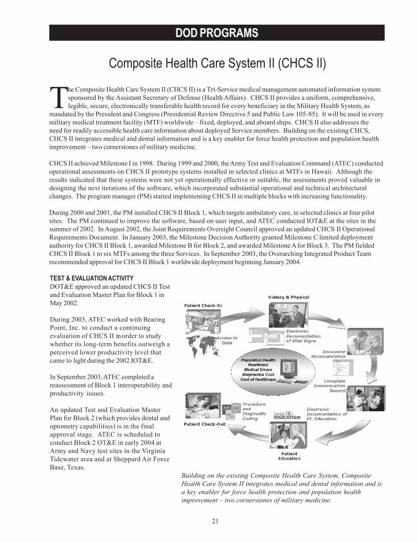
21
DOD PROGRAMS
Composite Health Care System II (CHCS II)
The Composite Health Care System II (CHCS II) is a Tri-Service medical management automated information systemsponsored by the Assistant Secretary of Defense (Health Affairs). CHCS II provides a uniform, comprehensive,legible, secure, electronically transferable health record for every beneficiary in the Military Health System, as
mandated by the President and Congress (Presidential Review Directive 5 and Public Law 105-85). It will be used in everymilitary medical treatment facility (MTF) worldwide – fixed, deployed, and aboard ships. CHCS II also addresses theneed for readily accessible health care information about deployed Service members. Building on the existing CHCS,CHCS II integrates medical and dental information and is a key enabler for force health protection and population healthimprovement – two cornerstones of military medicine.
CHCS II achieved Milestone I in 1998. During 1999 and 2000, the Army Test and Evaluation Command (ATEC) conductedoperational assessments on CHCS II prototype systems installed in selected clinics at MTFs in Hawaii. Although theresults indicated that these systems were not yet operationally effective or suitable, the assessments proved valuable indesigning the next iterations of the software, which incorporated substantial operational and technical architecturalchanges. The program manager (PM) started implementing CHCS II in multiple blocks with increasing functionality.
During 2000 and 2001, the PM installed CHCS II Block 1, which targets ambulatory care, in selected clinics at four pilotsites. The PM continued to improve the software, based on user input, and ATEC conducted IOT&E at the sites in thesummer of 2002. In August 2002, the Joint Requirements Oversight Council approved an updated CHCS II OperationalRequirements Document. In January 2003, the Milestone Decision Authority granted Milestone C limited deploymentauthority for CHCS II Block 1, awarded Milestone B for Block 2, and awarded Milestone A for Block 3. The PM fieldedCHCS II Block 1 to six MTFs among the three Services. In September 2003, the Overarching Integrated Product Teamrecommended approval for CHCS II Block 1 worldwide deployment beginning January 2004.
TEST & EVALUATION ACTIVITYDOT&E approved an updated CHCS II Testand Evaluation Master Plan for Block 1 inMay 2002.
During 2003, ATEC worked with BearingPoint, Inc. to conduct a continuingevaluation of CHCS II in order to studywhether its long-term benefits outweigh aperceived lower productivity level thatcame to light during the 2002 IOT&E.
In September 2003, ATEC completed areassessment of Block 1 interoperability andproductivity issues.
An updated Test and Evaluation MasterPlan for Block 2 (which provides dental andoptometry capabilities) is in the finalapproval stage. ATEC is scheduled toconduct Block 2 OT&E in early 2004 atArmy and Navy test sites in the VirginiaTidewater area and at Sheppard Air ForceBase, Texas.
Building on the existing Composite Health Care System, CompositeHealth Care System II integrates medical and dental information and isa key enabler for force health protection and population healthimprovement – two cornerstones of military medicine.
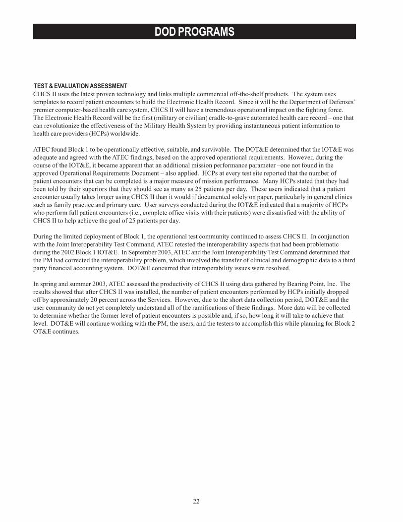
22
DOD PROGRAMS
TEST & EVALUATION ASSESSMENTCHCS II uses the latest proven technology and links multiple commercial off-the-shelf products. The system usestemplates to record patient encounters to build the Electronic Health Record. Since it will be the Department of Defenses’premier computer-based health care system, CHCS II will have a tremendous operational impact on the fighting force.The Electronic Health Record will be the first (military or civilian) cradle-to-grave automated health care record – one thatcan revolutionize the effectiveness of the Military Health System by providing instantaneous patient information tohealth care providers (HCPs) worldwide.
ATEC found Block 1 to be operationally effective, suitable, and survivable. The DOT&E determined that the IOT&E wasadequate and agreed with the ATEC findings, based on the approved operational requirements. However, during thecourse of the IOT&E, it became apparent that an additional mission performance parameter –one not found in theapproved Operational Requirements Document – also applied. HCPs at every test site reported that the number ofpatient encounters that can be completed is a major measure of mission performance. Many HCPs stated that they hadbeen told by their superiors that they should see as many as 25 patients per day. These users indicated that a patientencounter usually takes longer using CHCS II than it would if documented solely on paper, particularly in general clinicssuch as family practice and primary care. User surveys conducted during the IOT&E indicated that a majority of HCPswho perform full patient encounters (i.e., complete office visits with their patients) were dissatisfied with the ability ofCHCS II to help achieve the goal of 25 patients per day.
During the limited deployment of Block 1, the operational test community continued to assess CHCS II. In conjunctionwith the Joint Interoperability Test Command, ATEC retested the interoperability aspects that had been problematicduring the 2002 Block 1 IOT&E. In September 2003, ATEC and the Joint Interoperability Test Command determined thatthe PM had corrected the interoperability problem, which involved the transfer of clinical and demographic data to a thirdparty financial accounting system. DOT&E concurred that interoperability issues were resolved.
In spring and summer 2003, ATEC assessed the productivity of CHCS II using data gathered by Bearing Point, Inc. Theresults showed that after CHCS II was installed, the number of patient encounters performed by HCPs initially droppedoff by approximately 20 percent across the Services. However, due to the short data collection period, DOT&E and theuser community do not yet completely understand all of the ramifications of these findings. More data will be collectedto determine whether the former level of patient encounters is possible and, if so, how long it will take to achieve thatlevel. DOT&E will continue working with the PM, the users, and the testers to accomplish this while planning for Block 2OT&E continues.
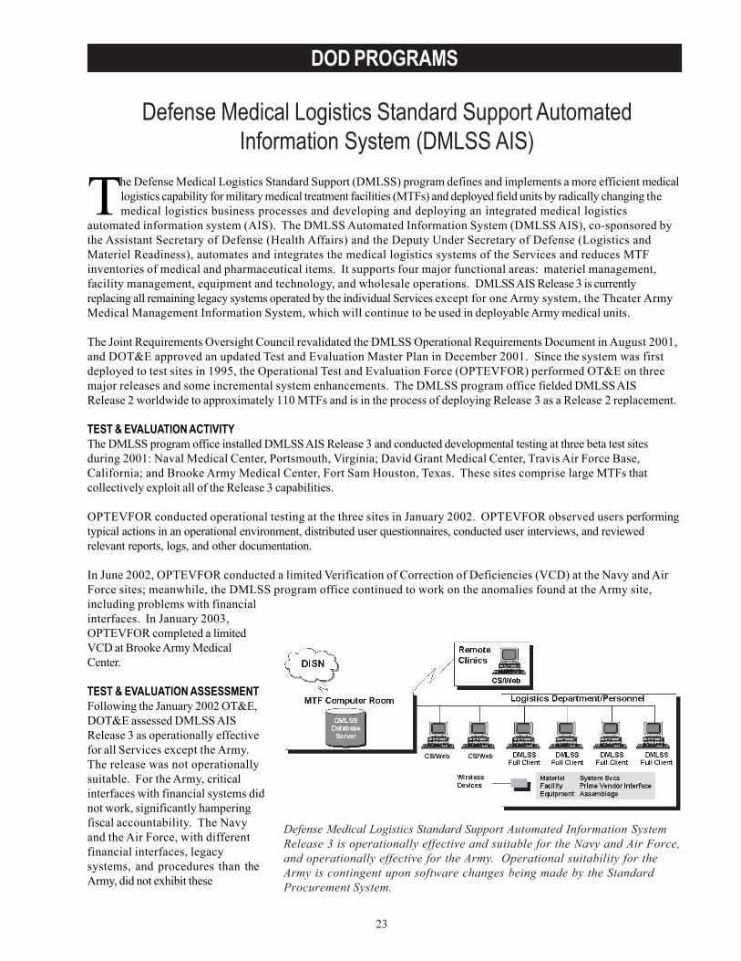
23
DOD PROGRAMS
Defense Medical Logistics Standard Support AutomatedInformation System (DMLSS AIS)
The Defense Medical Logistics Standard Support (DMLSS) program defines and implements a more efficient medicallogistics capability for military medical treatment facilities (MTFs) and deployed field units by radically changing themedical logistics business processes and developing and deploying an integrated medical logistics
automated information system (AIS). The DMLSS Automated Information System (DMLSS AIS), co-sponsored bythe Assistant Secretary of Defense (Health Affairs) and the Deputy Under Secretary of Defense (Logistics andMateriel Readiness), automates and integrates the medical logistics systems of the Services and reduces MTFinventories of medical and pharmaceutical items. It supports four major functional areas: materiel management,facility management, equipment and technology, and wholesale operations. DMLSS AIS Release 3 is currentlyreplacing all remaining legacy systems operated by the individual Services except for one Army system, the Theater ArmyMedical Management Information System, which will continue to be used in deployable Army medical units.
The Joint Requirements Oversight Council revalidated the DMLSS Operational Requirements Document in August 2001,and DOT&E approved an updated Test and Evaluation Master Plan in December 2001. Since the system was firstdeployed to test sites in 1995, the Operational Test and Evaluation Force (OPTEVFOR) performed OT&E on threemajor releases and some incremental system enhancements. The DMLSS program office fielded DMLSS AISRelease 2 worldwide to approximately 110 MTFs and is in the process of deploying Release 3 as a Release 2 replacement.
TEST & EVALUATION ACTIVITYThe DMLSS program office installed DMLSS AIS Release 3 and conducted developmental testing at three beta test sitesduring 2001: Naval Medical Center, Portsmouth, Virginia; David Grant Medical Center, Travis Air Force Base,California; and Brooke Army Medical Center, Fort Sam Houston, Texas. These sites comprise large MTFs thatcollectively exploit all of the Release 3 capabilities.
OPTEVFOR conducted operational testing at the three sites in January 2002. OPTEVFOR observed users performingtypical actions in an operational environment, distributed user questionnaires, conducted user interviews, and reviewedrelevant reports, logs, and other documentation.
In June 2002, OPTEVFOR conducted a limited Verification of Correction of Deficiencies (VCD) at the Navy and AirForce sites; meanwhile, the DMLSS program office continued to work on the anomalies found at the Army site,including problems with financialinterfaces. In January 2003,OPTEVFOR completed a limitedVCD at Brooke Army MedicalCenter.
TEST & EVALUATION ASSESSMENTFollowing the January 2002 OT&E,DOT&E assessed DMLSS AISRelease 3 as operationally effectivefor all Services except the Army.The release was not operationallysuitable. For the Army, criticalinterfaces with financial systems didnot work, significantly hamperingfiscal accountability. The Navyand the Air Force, with differentfinancial interfaces, legacysystems, and procedures than theArmy, did not exhibit these
Defense Medical Logistics Standard Support Automated Information SystemRelease 3 is operationally effective and suitable for the Navy and Air Force,and operationally effective for the Army. Operational suitability for theArmy is contingent upon software changes being made by the StandardProcurement System.
24
DOD PROGRAMS
effectiveness deficiencies. DOT&E assessed the releases as not operationally suitable based on deficiencies in logisticsupportability, training, and documentation. In May 2002, the Program Manager corrected these deficiencies and invitedimmediate verification of his corrective actions.
In June 2002, OPTEVFOR performed a VCD at the Navy and Air Force sites and found all deficiencies werecorrected with one remaining anomaly – an automated materiel management quality control feature requiringworkaround. From October 28, 2002, through January 24, 2003, OPTEVFOR performed a VCD for the Army anddetermined that all known deficiencies had been corrected, with the exception of interoperability with the StandardProcurement System (SPS), the correction of which will require software changes by the SPS program in order tointerface with DMLSS AIS Release 3. This interface is intended to automate the Army’s ability to order certainitems not readily available through the normal supply process. The users can order these supplies manually, butwith greater effort.
As of May 2003, the DMLSS AIS Release 3 is operationally effective and suitable for the Navy and Air Force, andoperationally effective for the Army. Operational suitability for the Army is contingent upon software changesbeing made by SPS. Additionally, the DMLSS Operational Requirements Document requires interfaces to systemsstill in development. As these systems become operational, DMLSS will interface with these systems and conductadditional OT&E to verify successful performance and interoperability.
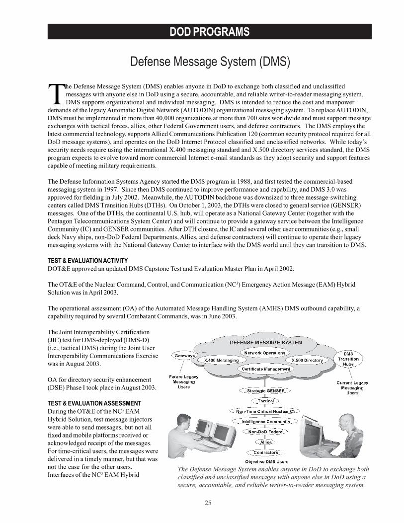
25
DOD PROGRAMS
Defense Message System (DMS)
The Defense Message System enables anyone in DoD to exchange bothclassified and unclassified messages with anyone else in DoD using asecure, accountable, and reliable writer-to-reader messaging system.
The Defense Message System (DMS) enables anyone in DoD to exchange both classified and unclassifiedmessages with anyone else in DoD using a secure, accountable, and reliable writer-to-reader messaging system.DMS supports organizational and individual messaging. DMS is intended to reduce the cost and manpower
demands of the legacy Automatic Digital Network (AUTODIN) organizational messaging system. To replace AUTODIN,DMS must be implemented in more than 40,000 organizations at more than 700 sites worldwide and must support messageexchanges with tactical forces, allies, other Federal Government users, and defense contractors. The DMS employs thelatest commercial technology, supports Allied Communications Publication 120 (common security protocol required for allDoD message systems), and operates on the DoD Internet Protocol classified and unclassified networks. While today’ssecurity needs require using the international X.400 messaging standard and X.500 directory services standard, the DMSprogram expects to evolve toward more commercial Internet e-mail standards as they adopt security and support featurescapable of meeting military requirements.
The Defense Information Systems Agency started the DMS program in 1988, and first tested the commercial-basedmessaging system in 1997. Since then DMS continued to improve performance and capability, and DMS 3.0 wasapproved for fielding in July 2002. Meanwhile, the AUTODIN backbone was downsized to three message-switchingcenters called DMS Transition Hubs (DTHs). On October 1, 2003, the DTHs were closed to general service (GENSER)messages. One of the DTHs, the continental U.S. hub, will operate as a National Gateway Center (together with thePentagon Telecommunications System Center) and will continue to provide a gateway service between the IntelligenceCommunity (IC) and GENSER communities. After DTH closure, the IC and several other user communities (e.g., smalldeck Navy ships, non-DoD Federal Departments, Allies, and defense contractors) will continue to operate their legacymessaging systems with the National Gateway Center to interface with the DMS world until they can transition to DMS.
TEST & EVALUATION ACTIVITYDOT&E approved an updated DMS Capstone Test and Evaluation Master Plan in April 2002.
The OT&E of the Nuclear Command, Control, and Communication (NC3) Emergency Action Message (EAM) HybridSolution was in April 2003.
The operational assessment (OA) of the Automated Message Handling System (AMHS) DMS outbound capability, acapability required by several Combatant Commands, was in June 2003.
The Joint Interoperability Certification(JIC) test for DMS-deployed (DMS-D)(i.e., tactical DMS) during the Joint UserInteroperability Communications Exercisewas in August 2003.
OA for directory security enhancement(DSE) Phase I took place in August 2003.
TEST & EVALUATION ASSESSMENTDuring the OT&E of the NC3 EAMHybrid Solution, test message injectorswere able to send messages, but not allfixed and mobile platforms received oracknowledged receipt of the messages.For time-critical users, the messages weredelivered in a timely manner, but that wasnot the case for the other users.Interfaces of the NC3 EAM Hybrid
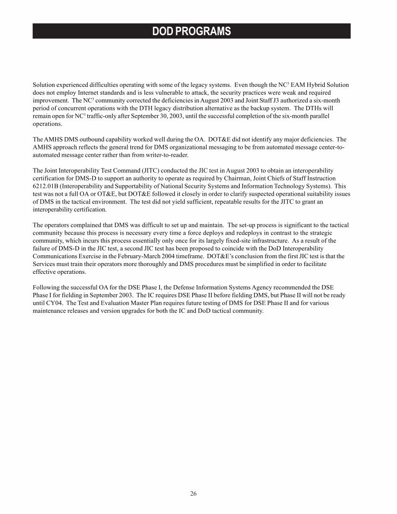
26
DOD PROGRAMS
Solution experienced difficulties operating with some of the legacy systems. Even though the NC3 EAM Hybrid Solutiondoes not employ Internet standards and is less vulnerable to attack, the security practices were weak and requiredimprovement. The NC3 community corrected the deficiencies in August 2003 and Joint Staff J3 authorized a six-monthperiod of concurrent operations with the DTH legacy distribution alternative as the backup system. The DTHs willremain open for NC3 traffic-only after September 30, 2003, until the successful completion of the six-month paralleloperations.
The AMHS DMS outbound capability worked well during the OA. DOT&E did not identify any major deficiencies. TheAMHS approach reflects the general trend for DMS organizational messaging to be from automated message center-to-automated message center rather than from writer-to-reader.
The Joint Interoperability Test Command (JITC) conducted the JIC test in August 2003 to obtain an interoperabilitycertification for DMS-D to support an authority to operate as required by Chairman, Joint Chiefs of Staff Instruction6212.01B (Interoperability and Supportability of National Security Systems and Information Technology Systems). Thistest was not a full OA or OT&E, but DOT&E followed it closely in order to clarify suspected operational suitability issuesof DMS in the tactical environment. The test did not yield sufficient, repeatable results for the JITC to grant aninteroperability certification.
The operators complained that DMS was difficult to set up and maintain. The set-up process is significant to the tacticalcommunity because this process is necessary every time a force deploys and redeploys in contrast to the strategiccommunity, which incurs this process essentially only once for its largely fixed-site infrastructure. As a result of thefailure of DMS-D in the JIC test, a second JIC test has been proposed to coincide with the DoD InteroperabilityCommunications Exercise in the February-March 2004 timeframe. DOT&E’s conclusion from the first JIC test is that theServices must train their operators more thoroughly and DMS procedures must be simplified in order to facilitateeffective operations.
Following the successful OA for the DSE Phase I, the Defense Information Systems Agency recommended the DSEPhase I for fielding in September 2003. The IC requires DSE Phase II before fielding DMS, but Phase II will not be readyuntil CY04. The Test and Evaluation Master Plan requires future testing of DMS for DSE Phase II and for variousmaintenance releases and version upgrades for both the IC and DoD tactical community.
27
DOD PROGRAMS
Defense Travel System (DTS)
The Defense Travel System (DTS) is a seamless, paperless, automated information system that is to reduce costs,support travel requirements, and provide superior customer service. DTS integrates commercial travel reservationsystems and DoD accounting and disbursing systems via a virtual private government network to provide the
traveler with an end-to-end travel process. The Program Director (PD) is developing DTS as an evolutionary acquisitionusing a spiral development process that will field the system in increments of increasing functionality. There are twophases, or blocks, of development. The initial focus (Block 1) is on Temporary Duty Travel. After fielding the Block 1releases (named after U.S. Presidents), the focus will shift to developing the Permanent Change of Station travel releases(Block 2).
The travel process begins with the users accessing the DTS via a web portal to create and digitally sign travel requestsbased on real-time transportation, lodging, and rental car availability using interfaces to various commercial reservationsystems. The user-generated travel authorization contains an estimate of the trip. DTS enforces compliance with DoDtravel policies based on simplified entitlements using audit alerts. Once completed, the authorizations are routed toauthorizing officials for approval via designated routing lists. When travel is concluded, the traveler prepares an on-linevoucher that is validated through appropriate financial systems that generates the reimbursement.
The program manager installed early DTS prototype systems at various pilot sites a few years ago. In May 2002, theAssistant Secretary of Defense (Command, Control, Communications, and Intelligence) put DTS on OSD acquisitionoversight and the Army Test and Evaluation Command (ATEC) was the lead Operational Test Agency. At that time, theAdams release, which had a client-server architecture, was already in use or soon to be installed at approximately 20 pilotsites. During 2002 and 2003, the PD developed a new release, called Jefferson, which is web-based. Based on feedbackfrom the Adams users, the PD decided to make further enhancements to the Jefferson software before releasing it. ThePD declared the improved release, called Enhanced Jefferson, ready for IOT&E in June 2003. Milestone C and adeclaration of initial operational capability were reached in 1QFY04.
TEST & EVALUATION ACTIVITYDOT&E approved the Test and Evaluation Master Plan and a detailed test plan in June 2003.
The PD completed developmental testand evaluation on EnhancedJefferson in June 2003.
ATEC completed the first phases ofinitial operational testing onEnhanced Jefferson in July 2003.
ATEC conducted an in-fieldoperational assessment on EnhancedJefferson in July and August 2003.
TEST & EVALUATION ASSESSMENTOT&E of a web-based system likeDTS presents major challenges. ThePD develops initial capabilities andsubsequent enhancements in acontractor’s developmentenvironment. However, once a newsoftware release is made available toselected users for alpha testing, itmust replace the previously fieldedrelease completely. This is because
The Enhanced Jefferson release of Defense Travel System is operationallyeffective, operationally suitable, and survivable. However, some features(such as group travel) still require workarounds.
28
DOD PROGRAMS
all users worldwide log on to a single web site in order to use the system. The web server exchanges information withmultiple Defense Accounting and Disbursing Systems. Thus, while functionality can be tested in the developmentenvironment, the system must be fielded in order to be tested in the users’ actual web-based environment. It cannot befielded to a partial set of web-based users while other web-based users continue to use an older release.
To meet this challenge, ATEC developed a plan to conduct operational testing of the Enhanced Jefferson release inseveral phases. First, the operational testers visited several of the Adams release pilot sites to develop a baseline andlearn more about DTS procedures. Next, they monitored the establishment of new pilot sites to evaluate installation andtraining. Once the PD completed developmental testing of the Enhanced Jefferson software, the operational testersbrought in users from the field and conducted the initial phase of operational testing in a development environmentusing scripted scenarios. This allowed the operational testers to simulate all the required capabilities of the systemwithout forcing the users to actually travel solely for the purpose of conducting the tests. Meanwhile, the PD pulled theAdams release from the web site, replacing it with Enhanced Jefferson. After the new release had been in use for onemonth, ATEC followed up with in-field surveys and interviews of users at selected locations to determine whether thesystem was performing the same in the field as it had in the development environment.
The Enhanced Jefferson release of DTS is operationally effective, operationally suitable, and survivable. However, somefeatures (such as group travel) still require workarounds; the system needs to be made more intuitive to the user, andtraining needs improvement. DOT&E also notes that since DTS changes several business processes, it is moresuccessful when vigorously implemented and supported by the using commands. Information received after the IOT&Eindicated a possible deficiency in system security, but the PD appears to have corrected this problem almost as soon as itwas found. The security fix has been validated by ATEC and DOT&E supports full fielding of Enhanced Jefferson whilefixes and improvements are made to Madison, the next release.
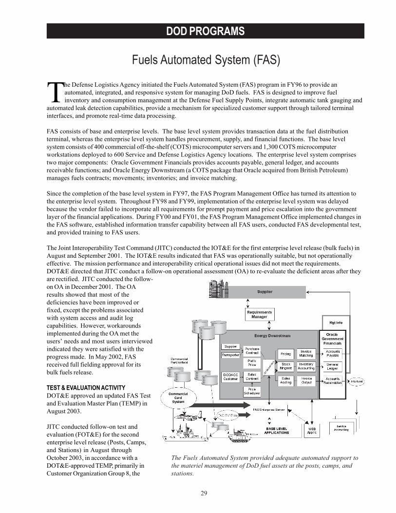
29
DOD PROGRAMS
Fuels Automated System (FAS)
The Fuels Automated System provided adequate automated support tothe materiel management of DoD fuel assets at the posts, camps, andstations.
The Defense Logistics Agency initiated the Fuels Automated System (FAS) program in FY96 to provide anautomated, integrated, and responsive system for managing DoD fuels. FAS is designed to improve fuelinventory and consumption management at the Defense Fuel Supply Points, integrate automatic tank gauging and
automated leak detection capabilities, provide a mechanism for specialized customer support through tailored terminalinterfaces, and promote real-time data processing.
FAS consists of base and enterprise levels. The base level system provides transaction data at the fuel distributionterminal, whereas the enterprise level system handles procurement, supply, and financial functions. The base levelsystem consists of 400 commercial off-the-shelf (COTS) microcomputer servers and 1,300 COTS microcomputerworkstations deployed to 600 Service and Defense Logistics Agency locations. The enterprise level system comprisestwo major components: Oracle Government Financials provides accounts payable, general ledger, and accountsreceivable functions; and Oracle Energy Downstream (a COTS package that Oracle acquired from British Petroleum)manages fuels contracts; movements; inventories; and invoice matching.
Since the completion of the base level system in FY97, the FAS Program Management Office has turned its attention tothe enterprise level system. Throughout FY98 and FY99, implementation of the enterprise level system was delayedbecause the vendor failed to incorporate all requirements for prompt payment and price escalation into the governmentlayer of the financial applications. During FY00 and FY01, the FAS Program Management Office implemented changes inthe FAS software, established information transfer capability between all FAS users, conducted FAS developmental test,and provided training to FAS users.
The Joint Interoperability Test Command (JITC) conducted the IOT&E for the first enterprise level release (bulk fuels) inAugust and September 2001. The IOT&E results indicated that FAS was operationally suitable, but not operationallyeffective. The mission performance and interoperability critical operational issues did not meet the requirements.DOT&E directed that JITC conduct a follow-on operational assessment (OA) to re-evaluate the deficient areas after theyare rectified. JITC conducted the follow-on OA in December 2001. The OAresults showed that most of thedeficiencies have been improved orfixed, except the problems associatedwith system access and audit logcapabilities. However, workaroundsimplemented during the OA met theusers’ needs and most users interviewedindicated they were satisfied with theprogress made. In May 2002, FASreceived full fielding approval for itsbulk fuels release.
TEST & EVALUATION ACTIVITYDOT&E approved an updated FAS Testand Evaluation Master Plan (TEMP) inAugust 2003.
JITC conducted follow-on test andevaluation (FOT&E) for the secondenterprise level release (Posts, Camps,and Stations) in August throughOctober 2003, in accordance with aDOT&E-approved TEMP, primarily inCustomer Organization Group 8, the
30
DOD PROGRAMS
Northwestern United States. During the FOT&E, FAS operated in parallel with the legacy system, Defense FuelsAutomated Management System, the system of record during the test period.
TEST & EVALUATION ASSESSMENTThe test results for the second enterprise level release revealed that FAS provided adequate automated support to themateriel management of DoD fuel assets at the posts, camps, and stations. JITC was able to resolve four criticaloperational issues, including mission performance; interoperability; usability; and reliability, availability, andmaintainability. However, the information assurance critical operational issue was not satisfactorily resolved. During theFOT&E, JITC noted many deficiencies in accordance with the recently released DoD Instruction 8500.2 on informationassurance. DOT&E immediately mandated the program manager develop an action plan to correct the deficiencies. TheDefense Logistics Agency plans to merge FAS with the Business Systems Modernization program. The FAS programfunding will remain independent of the Business Systems Modernization program until the end of FY04.
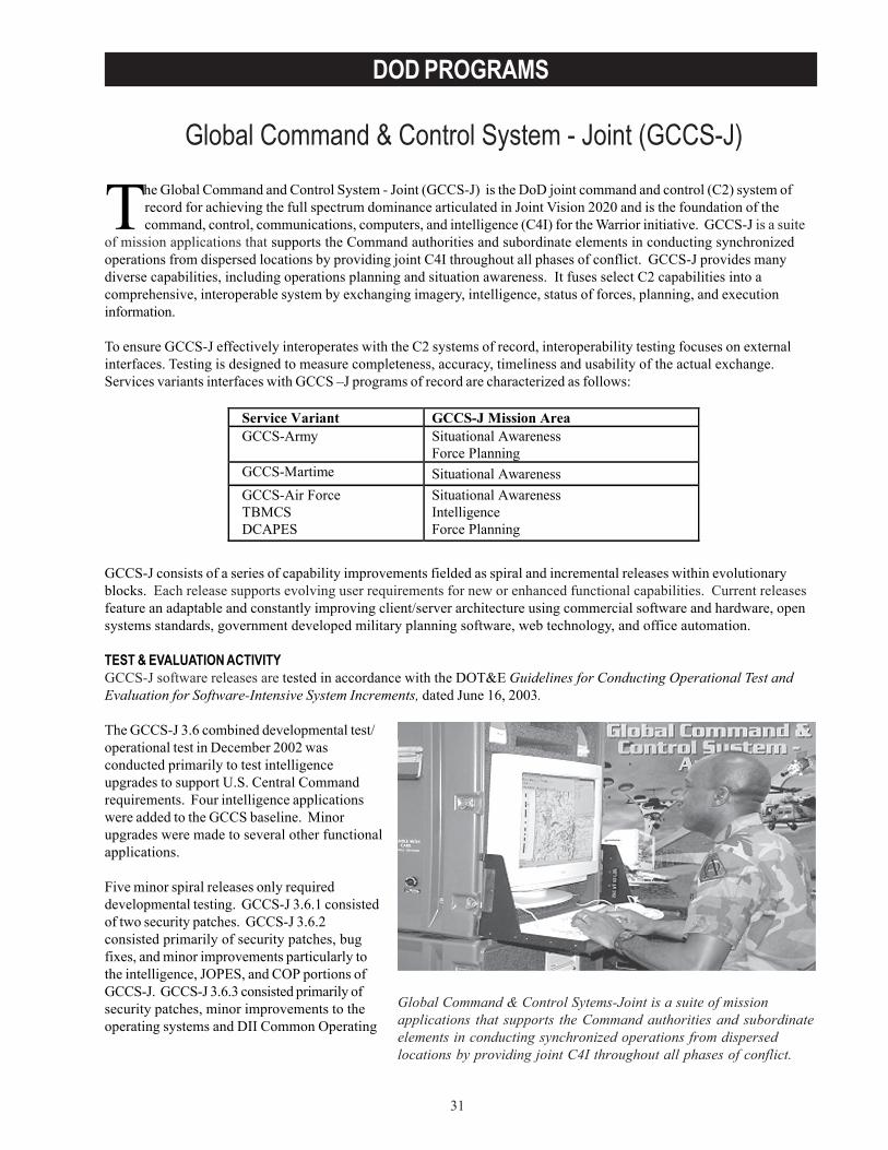
31
DOD PROGRAMS
Global Command & Control System - Joint (GCCS-J)
The Global Command and Control System - Joint (GCCS-J) is the DoD joint command and control (C2) system ofrecord for achieving the full spectrum dominance articulated in Joint Vision 2020 and is the foundation of thecommand, control, communications, computers, and intelligence (C4I) for the Warrior initiative. GCCS-J is a suite
of mission applications that supports the Command authorities and subordinate elements in conducting synchronizedoperations from dispersed locations by providing joint C4I throughout all phases of conflict. GCCS-J provides manydiverse capabilities, including operations planning and situation awareness. It fuses select C2 capabilities into acomprehensive, interoperable system by exchanging imagery, intelligence, status of forces, planning, and executioninformation.
To ensure GCCS-J effectively interoperates with the C2 systems of record, interoperability testing focuses on externalinterfaces. Testing is designed to measure completeness, accuracy, timeliness and usability of the actual exchange. Services variants interfaces with GCCS –J programs of record are characterized as follows:
GCCS-J consists of a series of capability improvements fielded as spiral and incremental releases within evolutionaryblocks. Each release supports evolving user requirements for new or enhanced functional capabilities. Current releasesfeature an adaptable and constantly improving client/server architecture using commercial software and hardware, opensystems standards, government developed military planning software, web technology, and office automation.
TEST & EVALUATION ACTIVITYGCCS-J software releases are tested in accordance with the DOT&E Guidelines for Conducting Operational Test andEvaluation for Software-Intensive System Increments, dated June 16, 2003.
The GCCS-J 3.6 combined developmental test/operational test in December 2002 wasconducted primarily to test intelligenceupgrades to support U.S. Central Commandrequirements. Four intelligence applicationswere added to the GCCS baseline. Minorupgrades were made to several other functionalapplications.
Five minor spiral releases only requireddevelopmental testing. GCCS-J 3.6.1 consistedof two security patches. GCCS-J 3.6.2consisted primarily of security patches, bugfixes, and minor improvements particularly tothe intelligence, JOPES, and COP portions ofGCCS-J. GCCS-J 3.6.3 consisted primarily ofsecurity patches, minor improvements to theoperating systems and DII Common Operating
Service Variant GCCS-J Mission Area GCCS-Army Situational Awareness
Force Planning GCCS-Martime Situational Awareness GCCS-Air Force TBMCS DCAPES
Situational Awareness Intelligence Force Planning
Global Command & Control Sytems-Joint is a suite of missionapplications that supports the Command authorities and subordinateelements in conducting synchronized operations from dispersedlocations by providing joint C4I throughout all phases of conflict.
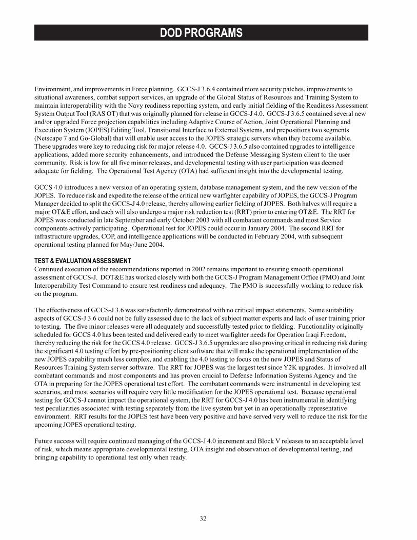
32
DOD PROGRAMS
Environment, and improvements in Force planning. GCCS-J 3.6.4 contained more security patches, improvements tosituational awareness, combat support services, an upgrade of the Global Status of Resources and Training System tomaintain interoperability with the Navy readiness reporting system, and early initial fielding of the Readiness AssessmentSystem Output Tool (RAS OT) that was originally planned for release in GCCS-J 4.0. GCCS-J 3.6.5 contained several newand/or upgraded Force projection capabilities including Adaptive Course of Action, Joint Operational Planning andExecution System (JOPES) Editing Tool, Transitional Interface to External Systems, and prepositions two segments(Netscape 7 and Go-Global) that will enable user access to the JOPES strategic servers when they become available.These upgrades were key to reducing risk for major release 4.0. GCCS-J 3.6.5 also contained upgrades to intelligenceapplications, added more security enhancements, and introduced the Defense Messaging System client to the usercommunity. Risk is low for all five minor releases, and developmental testing with user participation was deemedadequate for fielding. The Operational Test Agency (OTA) had sufficient insight into the developmental testing.
GCCS 4.0 introduces a new version of an operating system, database management system, and the new version of theJOPES. To reduce risk and expedite the release of the critical new warfighter capability of JOPES, the GCCS-J ProgramManager decided to split the GCCS-J 4.0 release, thereby allowing earlier fielding of JOPES. Both halves will require amajor OT&E effort, and each will also undergo a major risk reduction test (RRT) prior to entering OT&E. The RRT forJOPES was conducted in late September and early October 2003 with all combatant commands and most Servicecomponents actively participating. Operational test for JOPES could occur in January 2004. The second RRT forinfrastructure upgrades, COP, and intelligence applications will be conducted in February 2004, with subsequentoperational testing planned for May/June 2004.
TEST & EVALUATION ASSESSMENTContinued execution of the recommendations reported in 2002 remains important to ensuring smooth operationalassessment of GCCS-J. DOT&E has worked closely with both the GCCS-J Program Management Office (PMO) and JointInteroperability Test Command to ensure test readiness and adequacy. The PMO is successfully working to reduce riskon the program.
The effectiveness of GCCS-J 3.6 was satisfactorily demonstrated with no critical impact statements. Some suitabilityaspects of GCCS-J 3.6 could not be fully assessed due to the lack of subject matter experts and lack of user training priorto testing. The five minor releases were all adequately and successfully tested prior to fielding. Functionality originallyscheduled for GCCS 4.0 has been tested and delivered early to meet warfighter needs for Operation Iraqi Freedom,thereby reducing the risk for the GCCS 4.0 release. GCCS-J 3.6.5 upgrades are also proving critical in reducing risk duringthe significant 4.0 testing effort by pre-positioning client software that will make the operational implementation of thenew JOPES capability much less complex, and enabling the 4.0 testing to focus on the new JOPES and Status ofResources Training System server software. The RRT for JOPES was the largest test since Y2K upgrades. It involved allcombatant commands and most components and has proven crucial to Defense Information Systems Agency and theOTA in preparing for the JOPES operational test effort. The combatant commands were instrumental in developing testscenarios, and most scenarios will require very little modification for the JOPES operational test. Because operationaltesting for GCCS-J cannot impact the operational system, the RRT for GCCS-J 4.0 has been instrumental in identifyingtest peculiarities associated with testing separately from the live system but yet in an operationally representativeenvironment. RRT results for the JOPES test have been very positive and have served very well to reduce the risk for theupcoming JOPES operational testing.
Future success will require continued managing of the GCCS-J 4.0 increment and Block V releases to an acceptable levelof risk, which means appropriate developmental testing, OTA insight and observation of developmental testing, andbringing capability to operational test only when ready.
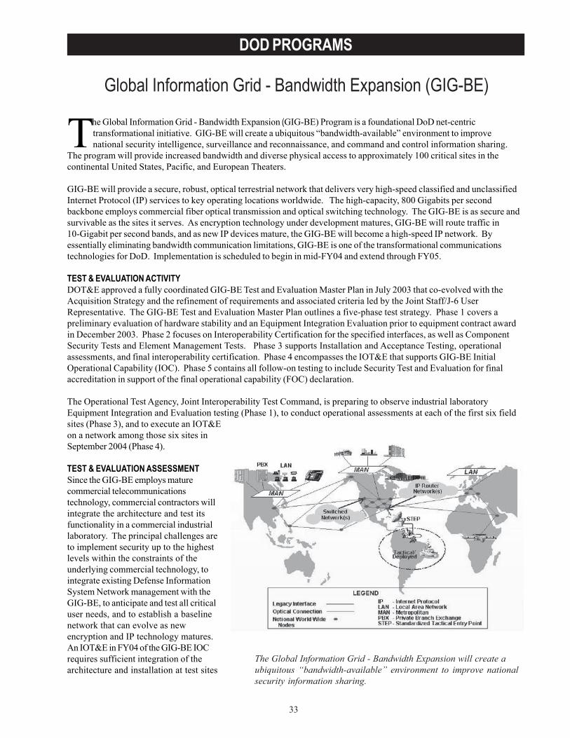
33
DOD PROGRAMS
Global Information Grid - Bandwidth Expansion (GIG-BE)
The Global Information Grid - Bandwidth Expansion will create aubiquitous “bandwidth-available” environment to improve nationalsecurity information sharing.
The Global Information Grid - Bandwidth Expansion (GIG-BE) Program is a foundational DoD net-centrictransformational initiative. GIG-BE will create a ubiquitous “bandwidth-available” environment to improvenational security intelligence, surveillance and reconnaissance, and command and control information sharing.
The program will provide increased bandwidth and diverse physical access to approximately 100 critical sites in thecontinental United States, Pacific, and European Theaters.
GIG-BE will provide a secure, robust, optical terrestrial network that delivers very high-speed classified and unclassifiedInternet Protocol (IP) services to key operating locations worldwide. The high-capacity, 800 Gigabits per secondbackbone employs commercial fiber optical transmission and optical switching technology. The GIG-BE is as secure andsurvivable as the sites it serves. As encryption technology under development matures, GIG-BE will route traffic in10-Gigabit per second bands, and as new IP devices mature, the GIG-BE will become a high-speed IP network. Byessentially eliminating bandwidth communication limitations, GIG-BE is one of the transformational communicationstechnologies for DoD. Implementation is scheduled to begin in mid-FY04 and extend through FY05.
TEST & EVALUATION ACTIVITYDOT&E approved a fully coordinated GIG-BE Test and Evaluation Master Plan in July 2003 that co-evolved with theAcquisition Strategy and the refinement of requirements and associated criteria led by the Joint Staff/J-6 UserRepresentative. The GIG-BE Test and Evaluation Master Plan outlines a five-phase test strategy. Phase 1 covers apreliminary evaluation of hardware stability and an Equipment Integration Evaluation prior to equipment contract awardin December 2003. Phase 2 focuses on Interoperability Certification for the specified interfaces, as well as ComponentSecurity Tests and Element Management Tests. Phase 3 supports Installation and Acceptance Testing, operationalassessments, and final interoperability certification. Phase 4 encompasses the IOT&E that supports GIG-BE InitialOperational Capability (IOC). Phase 5 contains all follow-on testing to include Security Test and Evaluation for finalaccreditation in support of the final operational capability (FOC) declaration.
The Operational Test Agency, Joint Interoperability Test Command, is preparing to observe industrial laboratoryEquipment Integration and Evaluation testing (Phase 1), to conduct operational assessments at each of the first six fieldsites (Phase 3), and to execute an IOT&Eon a network among those six sites inSeptember 2004 (Phase 4).
TEST & EVALUATION ASSESSMENTSince the GIG-BE employs maturecommercial telecommunicationstechnology, commercial contractors willintegrate the architecture and test itsfunctionality in a commercial industriallaboratory. The principal challenges areto implement security up to the highestlevels within the constraints of theunderlying commercial technology, tointegrate existing Defense InformationSystem Network management with theGIG-BE, to anticipate and test all criticaluser needs, and to establish a baselinenetwork that can evolve as newencryption and IP technology matures.An IOT&E in FY04 of the GIG-BE IOCrequires sufficient integration of thearchitecture and installation at test sites
34
DOD PROGRAMS
with user traffic to evaluate those operational requirements applicable to the IOC network. An OT&E in FY05 of the FOCwill evaluate all operational requirements on the GIG-BE’s complete network configuration (within and outside the UnitedStates). The GIG-BE critical functional capabilities required to support users must be anticipated, exercised, and testedin the developmental laboratory environment or later as stand-alone tests at the various field sites. An existing challengefor the operational tester is identification of user traffic needs for GIG-BE at each site in time to support the scheduledIOT&E in September 2004.
Additional concerns being addressed through developer-tester-user forums include: the ability to evaluate criticalsurvivability and network management capabilities prior to site installation as these may not be implemented until theFOC network is in place; identification of security features and testing of them in representative operationalenvironments; and the ability to assess effectiveness and suitability with representative user traffic and functions duringthe IOT&E.
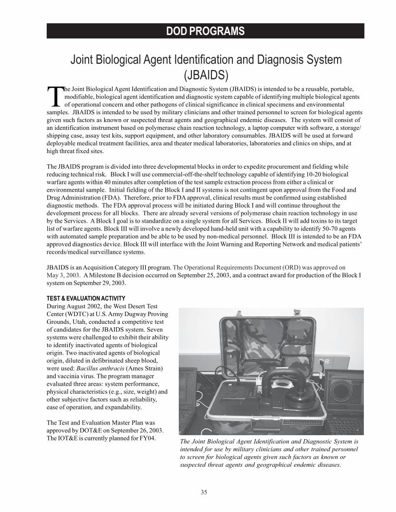
35
DOD PROGRAMS
Joint Biological Agent Identification and Diagnosis System(JBAIDS)
The Joint Biological Agent Identification and Diagnostic System (JBAIDS) is intended to be a reusable, portable,modifiable, biological agent identification and diagnostic system capable of identifying multiple biological agentsof operational concern and other pathogens of clinical significance in clinical specimens and environmental
samples. JBAIDS is intended to be used by military clinicians and other trained personnel to screen for biological agentsgiven such factors as known or suspected threat agents and geographical endemic diseases. The system will consist ofan identification instrument based on polymerase chain reaction technology, a laptop computer with software, a storage/shipping case, assay test kits, support equipment, and other laboratory consumables. JBAIDS will be used at forwarddeployable medical treatment facilities, area and theater medical laboratories, laboratories and clinics on ships, and athigh threat fixed sites.
The JBAIDS program is divided into three developmental blocks in order to expedite procurement and fielding whilereducing technical risk. Block I will use commercial-off-the-shelf technology capable of identifying 10-20 biologicalwarfare agents within 40 minutes after completion of the test sample extraction process from either a clinical orenvironmental sample. Initial fielding of the Block I and II systems is not contingent upon approval from the Food andDrug Administration (FDA). Therefore, prior to FDA approval, clinical results must be confirmed using establisheddiagnostic methods. The FDA approval process will be initiated during Block I and will continue throughout thedevelopment process for all blocks. There are already several versions of polymerase chain reaction technology in useby the Services. A Block I goal is to standardize on a single system for all Services. Block II will add toxins to its targetlist of warfare agents. Block III will involve a newly developed hand-held unit with a capability to identify 50-70 agentswith automated sample preparation and be able to be used by non-medical personnel. Block III is intended to be an FDAapproved diagnostics device. Block III will interface with the Joint Warning and Reporting Network and medical patients’records/medical surveillance systems.
JBAIDS is an Acquisition Category III program. The Operational Requirements Document (ORD) was approved onMay 3, 2003. A Milestone B decision occurred on September 25, 2003, and a contract award for production of the Block Isystem on September 29, 2003.
TEST & EVALUATION ACTIVITYDuring August 2002, the West Desert TestCenter (WDTC) at U.S. Army Dugway ProvingGrounds, Utah, conducted a competitive testof candidates for the JBAIDS system. Sevensystems were challenged to exhibit their abilityto identify inactivated agents of biologicalorigin. Two inactivated agents of biologicalorigin, diluted in defibrinated sheep blood,were used: Bacillus anthracis (Ames Strain)and vaccinia virus. The program managerevaluated three areas: system performance,physical characteristics (e.g., size, weight) andother subjective factors such as reliability,ease of operation, and expandability.
The Test and Evaluation Master Plan wasapproved by DOT&E on September 26, 2003.The IOT&E is currently planned for FY04. The Joint Biological Agent Identification and Diagnostic System is
intended for use by military clinicians and other trained personnelto screen for biological agents given such factors as known orsuspected threat agents and geographical endemic diseases.
36
DOD PROGRAMS
TEST & EVALUATION ASSESSMENTThe results of the competitive test indicate that technology exists to meet the sensitivity and specificity goals ofdetecting biological agents of interest. Two of the systems passed the defined criteria and were taken into sourceselection.
IOT&E must address all target biological agents in appropriate matrices using inactivated threat representative agents.Assay performance will be assessed using assumptions that performance levels are independent of sample matrices. Theapplicability and timeliness of JBAIDS reporting information must be sufficient to support decision-makers and missionperformance
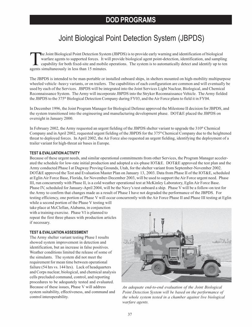
37
DOD PROGRAMS
Joint Biological Point Detection System (JBPDS)
An adequate end-to-end evaluation of the Joint BiologicalPoint Detection System will be based on the performance ofthe whole system tested in a chamber against live biologicalwarfare agents.
The Joint Biological Point Detection System (JBPDS) is to provide early warning and identification of biologicalwarfare agents to supported forces. It will provide biological agent point-detection, identification, and samplingcapability for both fixed-site and mobile operations. The system is to automatically detect and identify up to ten
agents simultaneously in less than 15 minutes.
The JBPDS is intended to be man-portable or installed onboard ships, in shelters mounted on high-mobility multipurposewheeled vehicle -heavy variants, or on trailers. The capabilities of each configuration are common and will eventually beused by each of the Services. JBPDS will be integrated into the Joint Services Light Nuclear, Biological, and ChemicalReconnaissance System. The Army will incorporate JBPDS into the Stryker Reconnaissance Vehicle. The Army fieldedthe JBPDS to the 375th Biological Detection Company during FY03, and the Air Force plans to field it in FY04.
In December 1996, the Joint Program Manager for Biological Defense approved the Milestone II decision for JBPDS, andthe system transitioned into the engineering and manufacturing development phase. DOT&E placed the JBPDS onoversight in January 2000.
In February 2002, the Army requested an urgent fielding of the JBPDS shelter variant to upgrade the 310th ChemicalCompany and in April 2002, requested urgent fielding of the JBPDS for the 375th Chemical Company due to the heightenedthreat to deployed forces. In April 2002, the Air Force also requested an urgent fielding, identifying the deployment of atrailer variant for high-threat air bases in Europe.
TEST & EVALUATION ACTIVITYBecause of these urgent needs, and similar operational commitments from other Services, the Program Manager acceler-ated the schedule for low-rate initial production and adopted a six-phase IOT&E. DOT&E approved the test plan and theArmy conducted Phase I at Dugway Proving Grounds, Utah, for the shelter variant from September-November 2002.DOT&E approved the Test and Evaluation Master Plan on January 13, 2003. Data from Phase II of the IOT&E, scheduledat Eglin Air Force Base, Florida, for November-December 2003, will be used to support the Air Force urgent need. PhaseIII, run concurrently with Phase II, is a cold weather operational test at McKinley Laboratory, Eglin Air Force Base.Phase IV, scheduled for January-April 2004, will be the Navy’s test onboard a ship. Phase V will be a follow-on test forthe Army to confirm that changes made as a result of Phase I have not degraded the performance of the JBPDS. Fortesting efficiency, one portion of Phase V will occur concurrently with the Air Force Phase II and Phase III testing at Eglinwhile a second portion of the Phase V testing willtake place at McClellan, Alabama, in conjunctionwith a training exercise. Phase VI is planned torepeat the first three phases with production articlesif necessary.
TEST & EVALUATION ASSESSMENTThe Army shelter variant testing Phase I resultsshowed system improvement in detection andidentification, but an increase in false positives.Weather conditions limited the release of some ofthe simulants. The system did not meet therequirement for mean time between operationalfailure (54 hrs vs. 144 hrs). Lack of headquartersand Corps nuclear, biological, and chemical analysiscells precluded command, control, and reportingprocedures to be adequately tested and evaluated.Because of these issues, Phase V will addresssystem suitability, effectiveness, and command andcontrol interoperability.
38
DOD PROGRAMS
Additional developmental component-level testing of biological warfare agents is underway with aerosol challengesagainst the biological aerosol warning sensor and liquid-injection challenges against the assay identifier. These tests willbe used to establish a tentative correlation between live biological warfare agents and their simulants used for IOT&Efield releases. The biological aerosol warning sensor and assay identifier– as components– do not represent the wholesystem. An adequate end-to-end evaluation of the JBPDS will be based on the performance of the whole system testedin a chamber against live biological warfare agents. The whole system test will consist of a sample collection and includeits transportation and delivery to a theater medical laboratory for analysis. It was requested that the West Desert TestCenter conduct a feasibility study to accomplish whole-system live-agent testing and the risks associated with thedevelopment, construction, operation, and maintenance of this facility. The National Research Council of the NationalAcademy of Sciences were requested to validate the solution proposed by the West Desert Test Center.
Adequate whole-system testing will be the basis for characterizing JBPDS biological warfare and simulant detectionperformance before a full-rate production decision.
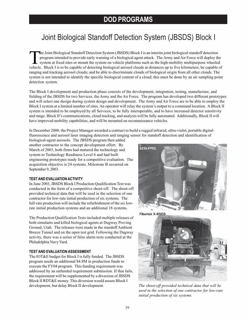
39
DOD PROGRAMS
Joint Biological Standoff Detection System (JBSDS) Block I
The Joint Biological Standoff Detection System (JBSDS) Block I is an interim joint biological standoff detectionprogram intended to provide early warning of a biological agent attack. The Army and Air Force will deploy thesystem at fixed sites or mount the system on vehicle platforms such as the high-mobility multipurpose wheeled
vehicle. Block I is to be capable of detecting biological aerosol clouds at distances up to five kilometers; be capable ofranging and tracking aerosol clouds; and be able to discriminate clouds of biological origin from all other clouds. Thesystem is not intended to identify the specific biological content of a cloud; this must be done by an air sampling pointdetection system.
The Block I development and production phase consists of the development, integration, testing, manufacture, andfielding of the JBSDS for two Services, the Army and the Air Force. The program has developed two different prototypesand will select one design during system design and development. The Army and Air Force are to be able to employ theBlock I system at a limited number of sites. An operator will relay the system’s output to a command location. A Block IIsystem is intended to be employed by all Services, to be fully interoperable, and to have increased detector sensitivityand range. Block II’s communications, cloud tracking, and analysis will be fully automated. Additionally, Block II willhave improved mobility capabilities, and will be mounted on reconnaissance vehicles.
In December 2000, the Project Manager awarded a contract to build a rugged infrared, ultra-violet, portable digital-fluorescence and aerosol laser imaging detection and ranging sensor for standoff detection and identification ofbiological-agent aerosols. The JBSDS program then addedanother contractor to the concept development effort. ByMarch of 2003, both firms had matured the technology andsystem to Technology Readiness Level 6 and had builtengineering prototypes ready for a competitive evaluation. Theacquisition objective is 24 systems. Milestone B occurred onSeptember 9, 2003.
TEST AND EVALUATION ACTIVITYIn June 2003, JBSDS Block I Production Qualification Test wasconducted in the form of a competitive shoot-off. The shoot-offprovided technical data that will be used in the selection of onecontractor for low-rate initial production of six systems. Thefull-rate production will include the refurbishment of the six low-rate initial production systems and an additional 18 systems.
The Production Qualification Tests included multiple releases ofboth simulants and killed biological agents at Dugway ProvingGround, Utah. The releases were made in the standoff AmbientBreeze Tunnel and on the open test grid. Following the Dugwayactivity, there was a series of false alarm tests conducted at thePhiladelphia Navy Yard.
TEST AND EVALUATION ASSESSMENTThe IOT&E budget for Block I is fully funded. The JBSDSprogram needs an additional $4.8M in production funds toexecute the FY04 program. This funding requirement wasaddressed by an unfunded requirement submission. If that fails,the requirement will be supplemented by a diversion of JBSDSBlock II RDT&E money. This diversion would assure Block Idevelopment, but delay Block II development. The shoot-off provided technical data that will be
used in the selection of one contractor for low-rateinitial production of six systems.

40
DOD PROGRAMS
Test planning appears adequate; however some questions remain regarding the correlation of simulants to live agents.This correlation is under study at Sandia National Laboratory. One of the concerns with the JBSDS program is whetherlive biological agents can be adequately represented by gamma-radiated biological agents or by other non-lethalsimulants.
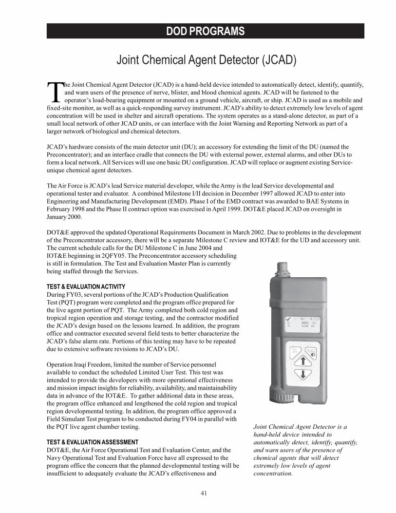
41
DOD PROGRAMS
Joint Chemical Agent Detector (JCAD)
Joint Chemical Agent Detector is ahand-held device intended toautomatically detect, identify, quantify,and warn users of the presence ofchemical agents that will detectextremely low levels of agentconcentration.
The Joint Chemical Agent Detector (JCAD) is a hand-held device intended to automatically detect, identify, quantify,and warn users of the presence of nerve, blister, and blood chemical agents. JCAD will be fastened to theoperator’s load-bearing equipment or mounted on a ground vehicle, aircraft, or ship. JCAD is used as a mobile and
fixed-site monitor, as well as a quick-responding survey instrument. JCAD’s ability to detect extremely low levels of agentconcentration will be used in shelter and aircraft operations. The system operates as a stand-alone detector, as part of asmall local network of other JCAD units, or can interface with the Joint Warning and Reporting Network as part of alarger network of biological and chemical detectors.
JCAD’s hardware consists of the main detector unit (DU); an accessory for extending the limit of the DU (named thePreconcentrator); and an interface cradle that connects the DU with external power, external alarms, and other DUs toform a local network. All Services will use one basic DU configuration. JCAD will replace or augment existing Service-unique chemical agent detectors.
The Air Force is JCAD’s lead Service material developer, while the Army is the lead Service developmental andoperational tester and evaluator. A combined Milestone I/II decision in December 1997 allowed JCAD to enter intoEngineering and Manufacturing Development (EMD). Phase I of the EMD contract was awarded to BAE Systems inFebruary 1998 and the Phase II contract option was exercised in April 1999. DOT&E placed JCAD on oversight inJanuary 2000.
DOT&E approved the updated Operational Requirements Document in March 2002. Due to problems in the developmentof the Preconcentrator accessory, there will be a separate Milestone C review and IOT&E for the UD and accessory unit.The current schedule calls for the DU Milestone C in June 2004 andIOT&E beginning in 2QFY05. The Preconcentrator accessory schedulingis still in formulation. The Test and Evaluation Master Plan is currentlybeing staffed through the Services.
TEST & EVALUATION ACTIVITYDuring FY03, several portions of the JCAD’s Production QualificationTest (PQT) program were completed and the program office prepared forthe live agent portion of PQT. The Army completed both cold region andtropical region operation and storage testing, and the contractor modifiedthe JCAD’s design based on the lessons learned. In addition, the programoffice and contractor executed several field tests to better characterize theJCAD’s false alarm rate. Portions of this testing may have to be repeateddue to extensive software revisions to JCAD’s DU.
Operation Iraqi Freedom, limited the number of Service personnelavailable to conduct the scheduled Limited User Test. This test wasintended to provide the developers with more operational effectivenessand mission impact insights for reliability, availability, and maintainabilitydata in advance of the IOT&E. To gather additional data in these areas,the program office enhanced and lengthened the cold region and tropicalregion developmental testing. In addition, the program office approved aField Simulant Test program to be conducted during FY04 in parallel withthe PQT live agent chamber testing.
TEST & EVALUATION ASSESSMENTDOT&E, the Air Force Operational Test and Evaluation Center, and theNavy Operational Test and Evaluation Force have all expressed to theprogram office the concern that the planned developmental testing will beinsufficient to adequately evaluate the JCAD’s effectiveness and
42
DOD PROGRAMS
suitability for aircraft operations. These issues include aircraft integration, operations under reduced atmosphericpressure conditions, agent detection, power requirements, aircraft employment concepts, training, and system logistics.The PQT plan provides for a robust set of agent and interferent (ie fog, smoke, blowing dust, etc.) challenges to theJCAD, including weapons-grade agent testing. Preliminary PQT data indicate that the JCAD is experiencing problems indetecting chemical agents at extremely low concentration levels. This must be corrected for JCAD to be operationallyeffective in aircraft, shelter, and other operations that require undiminished visual acuity.
Developmental test results indicate the JCAD has an unacceptably high false alarm rate, particularly when exposed toinsect repellent and Aqueous Film Forming Foam (AFFF). AFFF is commonly used as a fire extinguishing agent on Navyships, as well as in Air Force aircraft fire bottles, hangars, runways, and ramps. Recent developmental testing appears toestablish a correlation between aircraft in-flight pressure changes and false alarms. The contractor is attempting toresolve the false alarm issue by refining the JCAD’s DU detection algorithm. Additional field testing is scheduled forFY04 to determine the success in addressing this issue.
The JCAD’s Preconcentrator accessory unit experienced software and hardware problems. The unit performs erraticallyin high and low temperatures and causes the DU to go into failure mode when the unit is removed from, and thenreinserted into, the interface cradle. Glass shards from the interior of the Preconcentrator can enter the DU and interferewith its detection of chemical agents. DU live agent PQT continues while the contractor develops and implements asolution for the Preconcentrator problems. Once the Preconcentrator is fixed, the program office will have to conduct liveagent regression testing and additional operational testing on the Preconcentrator-equipped DU.
The contractor examination of JCAD units previously used in developmental testing indicates that the surface acousticwave (SAW) array service life will be approximately 1,100 hours of operation, which is considerably less than previousestimates. The program office will add a PQT service life subtest to better estimate service life. The contractorassessment also indicates that the SAW array might have to be replaced once the unit has been exposed to chemicalagents more than eighty times. This would have a negative impact on several projected Service uses for the JCAD,including screening of vehicles and personnel during decontamination operations. It would also place a burden onService logistics and maintenance systems. The contractor is exploring ways of allowing the JCAD’s operator or unitmaintenance personnel to more easily replace the detector array without requiring depot-level maintenance.
From the aspect of JCAD response, agent-simulant correlation testing has identified Triethyl Phosphate (TEP) as themost desirable simulant. The Navy determined that TEP is not currently safe for use on ships and a different simulant isrequired.
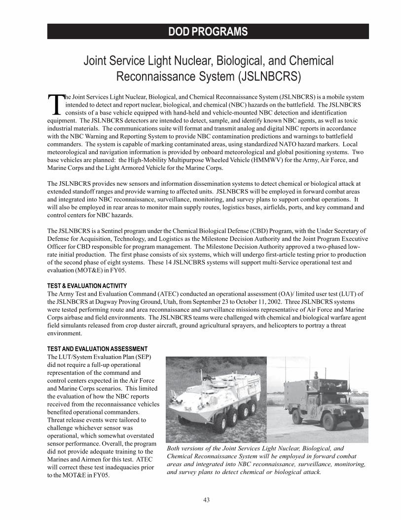
43
DOD PROGRAMS
Joint Service Light Nuclear, Biological, and ChemicalReconnaissance System (JSLNBCRS)
Both versions of the Joint Services Light Nuclear, Biological, andChemical Reconnaissance System will be employed in forward combatareas and integrated into NBC reconnaissance, surveillance, monitoring,and survey plans to detect chemical or biological attack.
The Joint Services Light Nuclear, Biological, and Chemical Reconnaissance System (JSLNBCRS) is a mobile systemintended to detect and report nuclear, biological, and chemical (NBC) hazards on the battlefield. The JSLNBCRSconsists of a base vehicle equipped with hand-held and vehicle-mounted NBC detection and identification
equipment. The JSLNBCRS detectors are intended to detect, sample, and identify known NBC agents, as well as toxicindustrial materials. The communications suite will format and transmit analog and digital NBC reports in accordancewith the NBC Warning and Reporting System to provide NBC contamination predictions and warnings to battlefieldcommanders. The system is capable of marking contaminated areas, using standardized NATO hazard markers. Localmeteorological and navigation information is provided by onboard meteorological and global positioning systems. Twobase vehicles are planned: the High-Mobility Multipurpose Wheeled Vehicle (HMMWV) for the Army, Air Force, andMarine Corps and the Light Armored Vehicle for the Marine Corps.
The JSLNBCRS provides new sensors and information dissemination systems to detect chemical or biological attack atextended standoff ranges and provide warning to affected units. JSLNBCRS will be employed in forward combat areasand integrated into NBC reconnaissance, surveillance, monitoring, and survey plans to support combat operations. Itwill also be employed in rear areas to monitor main supply routes, logistics bases, airfields, ports, and key command andcontrol centers for NBC hazards.
The JSLNBCRS is a Sentinel program under the Chemical Biological Defense (CBD) Program, with the Under Secretary ofDefense for Acquisition, Technology, and Logistics as the Milestone Decision Authority and the Joint Program ExecutiveOfficer for CBD responsible for program management. The Milestone Decision Authority approved a two-phased low-rate initial production. The first phase consists of six systems, which will undergo first-article testing prior to productionof the second phase of eight systems. These 14 JSLNCBRS systems will support multi-Service operational test andevaluation (MOT&E) in FY05.
TEST & EVALUATION ACTIVITYThe Army Test and Evaluation Command (ATEC) conducted an operational assessment (OA)/ limited user test (LUT) ofthe JSLNBCRS at Dugway Proving Ground, Utah, from September 23 to October 11, 2002. Three JSLNBCRS systemswere tested performing route and area reconnaissance and surveillance missions representative of Air Force and MarineCorps airbase and field environments. The JSLNBCRS teams were challenged with chemical and biological warfare agentfield simulants released from crop duster aircraft, ground agricultural sprayers, and helicopters to portray a threatenvironment.
TEST AND EVALUATION ASSESSMENTThe LUT/System Evaluation Plan (SEP)did not require a full-up operationalrepresentation of the command andcontrol centers expected in the Air Forceand Marine Corps scenarios. This limitedthe evaluation of how the NBC reportsreceived from the reconnaissance vehiclesbenefited operational commanders.Threat release events were tailored tochallenge whichever sensor wasoperational, which somewhat overstatedsensor performance. Overall, the programdid not provide adequate training to theMarines and Airmen for this test. ATECwill correct these test inadequacies priorto the MOT&E in FY05.
44
DOD PROGRAMS
Because the OA/LUT began without planned key system integration and interoperability tests, the JSLNBCRS systemsexperienced numerous integration problems with the software, sensors, and connecting cables during the test. The newdevelopment sensors integrated with the JSLNBCRS – Chemical Biological Mass Spectrometer, Joint Biological PointDetection System, and Joint Service Lightweight Standoff Chemical Agent Detector (JSLSCAD) – performed poorlymainly due to immature sensors and software. As designs mature the performance of these sensors are expected toimprove. However, because the JSLSCAD has not met its operational requirements, the Joint Program Executive Officerdeveloped an alternative strategy to fulfill the standoff chemical agent detection requirement. The Milestone DecisionAuthority will decide whether the JSLNBCRS will integrate the current version of the JSLSCAD or an alternative withinthe next fiscal year.
Additional engineering and testing is required before commitment to the full number of low-rate initial productionsystems to support the MOT&E. Operational reliability, immature sensor integration, overpressure failures, insufficientpower, excessive vehicle weight, safety, and human factors integration are key design issues that limit the system’seffectiveness and suitability in an operational environment. An OA is scheduled for late FY04, using the test results of afirst-article test to provide evidence that the critical deficiencies have been corrected before the MOT&E.
The Test and Evaluation Master Plan is currently being updated to reflect engineering and test plans to address theseperformance problems and to support an incremental approval for low-rate initial production systems for the MOT&E.The updated Test and Evaluation Master Plan must also address strategies to fulfill the standoff chemical agentdetection requirement should the JSLSCAD not be available.

45
DOD PROGRAMS
Joint Service Lightweight Standoff Chemical Agent Detector(JSLSCAD)
This system will be installed in fixed locations to protectfacilities and installations. The mobile configurations of theJoint Service Lightweight Standoff Chemical Agent Detectorwill be used on platforms such as ground vehicles and ships.
JSLSCAD is intended to be a passive detector of chemical agent vapors at ranges up to 5 kilometers and ultimately to10 kilometers. It is intended to provide real-time detection of specific types of chemical warfare threats to U.S. forcesat fixed sites and while on-the-move. This system will be installed in fixed locations for protection of facilities and
installations such as air bases. The mobile configurations of JSLSCAD will be used on platforms such as groundvehicles and ships.
The JSLSCAD will have visual and audible indicators to display the chemical agent class (nerve, blister, and blood), andto indicate the azimuth and elevation (but not distance) of the detection. Detection and warning information may beentered automatically into Service command, control, communications, computers, and intelligence (C4I) systems, or theinformation may be reviewed and distributed manually. JSLSCAD is to be interoperable with the Joint Warning andReporting Network when it becomes available.
JSLSCAD consists of four major components: scanner module, sensor electronics module, operator display unit, andpower adapter. There are two configurations of the scanner module. The aerial applications scanner covers a 60-degreeforward-looking cone and ground mobile, fixed-site, and shipboard configurations scan 360-degrees in azimuth and +50to -10-degrees in elevation. The mobile configurations of JSLSCAD Block I will be used on platforms such as groundvehicles and ships. Aircraft configurations will be included in JSLSCAD Block II. The JSLSCAD Block I is intended tobe integrated into the Joint Service Light Nuclear, Biological, and Chemical (NBC) Reconnaissance System (JSLNBCRS)and the Stryker-NBC Reconnaissance Vehicle, and will be employed at fixed sites such as air bases and aboard Navylanding ship docks (or equivalent aviation capable amphibious ships). JSLSCAD Block II is intended to be carried onArmy and Navy helicopters, and outboard on selected Air Force C-130 aircraft. Present plans call for the JSLSCAD to becarried as an unmanned aerial vehicle payload, but the unmanned aerial vehicle to be used has not been selected.
The Joint Program Office for Chemical, Biological, Radiological, and Nuclear Defense approved the current operationalrequirements document in July 2003. JSLSCAD achieved Milestone II on September 17, 1996. The Test and EvaluationMaster Plan (TEMP) for JSLSCAD was approved in 1997, before the system came under DOT&E oversight inJanuary 2000. In August 2003, the Joint ProgramExecutive Office for Chemical and Biological Defensedecided to restructure the program, which required arevised TEMP.
TEST & EVALUATION ACTIVITYTo investigate false alarm performance, the JSLSCADwas operated at Eglin Air Force Base, Florida;Philadelphia, Pennsylvania; and Wallops Island,Virginia; as well as in the agent chamber at DugwayProving Ground, Utah. Developmental field testingwith simulant releases in the open air were conductedat Dugway and over water at Dahlgren, Virginia. Otherdevelopmental tests included a laser glint vulnerabilityassessment at White Sands, New Mexico. TheProgram Manager terminated the desert storage test atYuma, Arizona, because of the program restructuring.
TEST & EVALUATION ASSESSMENTDevelopmental testing can be characterized as a test-fix-test process, and has resulted in the JSLSCADProgram Office’s decision to restructure the program.The proposed strategy is to purchase a limited number

46
DOD PROGRAMS
of the current system for integration into the Stryker Reconnaissance Vehicle, the JSLNBCRS, and naval ships (fixed sitesare also under consideration), and to purchase systems to meet the remainder of the requirement by a commercial buy. Atest and evaluation strategy supporting this plan will be documented in the TEMP. The test strategy must include aprotocol (such as that recommended by the National Research Council for passive infrared standoff detectors) that canprovide confidence that JSLSCAD can detect and identify actual chemical warfare agents in a realistic environment atstandoff distances. To implement the National Research Council recommendations, the developmental and operationalevaluators require a signal-processing model, validated algorithm stimulator, background spectra, and an increasedunderstanding of algorithm operations.
Test limitations in the multi-Service operational test and evaluation will include the use of simulants instead of actualagents. Although the chosen simulants approximate spectral or physical characteristics of agents, they do not matchthem. Current testing is intended to support the ability to correlate concentration levels of real chemical vapors toconcentration levels of simulant vapors. Even if a good correlation could be determined, the details of the algorithm inthe JSLSCAD must be changed to allow it to detect a simulant vapor, and hence there could be some question about thesystem’s operational effectiveness on the battlefield. The implementation of the NRC recommendations in the test andevaluation strategy will increase the robustness of test and evaluation and mitigate this limitation.
Other test limitations include the simulation of agent delivery by explosive, line, and stack-release devices instead ofactual weapons and a restricted network warning capability instead of a full-theater or joint task force C4I system.Achieving ideal delivery conditions during tests is difficult due to the uncertainties of weather and the desired effects ofthe atmospheric mixing layer dictate that releases are best made during pre-dawn hours, but this is the same challengeany threat force would face. The test site at Dugway, an isolated, desert location that does not represent military bases,cities, or many types of battlefields where JSLSCAD likely will be deployed, is a limitation. The Navy plans to conduct atest at sea and the Air Force plans to test the system at Eglin Air Force Base.
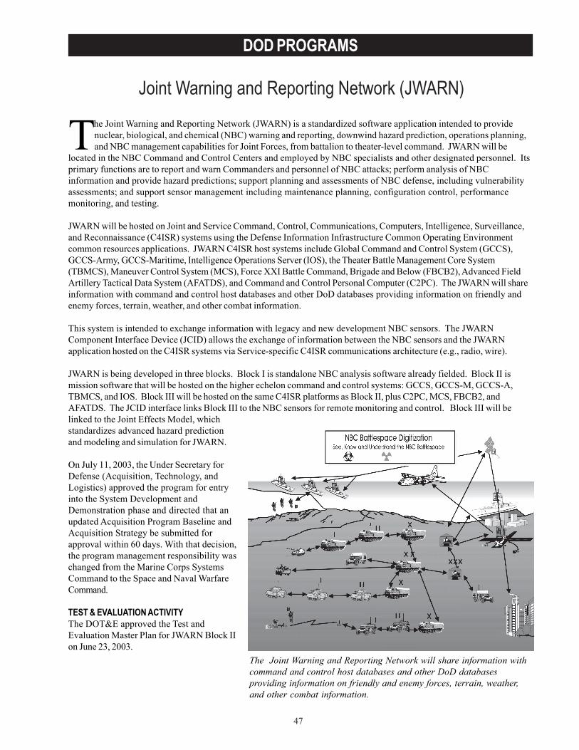
47
DOD PROGRAMS
Joint Warning and Reporting Network (JWARN)
The Joint Warning and Reporting Network will share information withcommand and control host databases and other DoD databasesproviding information on friendly and enemy forces, terrain, weather,and other combat information.
The Joint Warning and Reporting Network (JWARN) is a standardized software application intended to providenuclear, biological, and chemical (NBC) warning and reporting, downwind hazard prediction, operations planning,and NBC management capabilities for Joint Forces, from battalion to theater-level command. JWARN will be
located in the NBC Command and Control Centers and employed by NBC specialists and other designated personnel. Itsprimary functions are to report and warn Commanders and personnel of NBC attacks; perform analysis of NBCinformation and provide hazard predictions; support planning and assessments of NBC defense, including vulnerabilityassessments; and support sensor management including maintenance planning, configuration control, performancemonitoring, and testing.
JWARN will be hosted on Joint and Service Command, Control, Communications, Computers, Intelligence, Surveillance,and Reconnaissance (C4ISR) systems using the Defense Information Infrastructure Common Operating Environmentcommon resources applications. JWARN C4ISR host systems include Global Command and Control System (GCCS),GCCS-Army, GCCS-Maritime, Intelligence Operations Server (IOS), the Theater Battle Management Core System(TBMCS), Maneuver Control System (MCS), Force XXI Battle Command, Brigade and Below (FBCB2), Advanced FieldArtillery Tactical Data System (AFATDS), and Command and Control Personal Computer (C2PC). The JWARN will shareinformation with command and control host databases and other DoD databases providing information on friendly andenemy forces, terrain, weather, and other combat information.
This system is intended to exchange information with legacy and new development NBC sensors. The JWARNComponent Interface Device (JCID) allows the exchange of information between the NBC sensors and the JWARNapplication hosted on the C4ISR systems via Service-specific C4ISR communications architecture (e.g., radio, wire).
JWARN is being developed in three blocks. Block I is standalone NBC analysis software already fielded. Block II ismission software that will be hosted on the higher echelon command and control systems: GCCS, GCCS-M, GCCS-A,TBMCS, and IOS. Block III will be hosted on the same C4ISR platforms as Block II, plus C2PC, MCS, FBCB2, andAFATDS. The JCID interface links Block III to the NBC sensors for remote monitoring and control. Block III will belinked to the Joint Effects Model, whichstandardizes advanced hazard predictionand modeling and simulation for JWARN.
On July 11, 2003, the Under Secretary forDefense (Acquisition, Technology, andLogistics) approved the program for entryinto the System Development andDemonstration phase and directed that anupdated Acquisition Program Baseline andAcquisition Strategy be submitted forapproval within 60 days. With that decision,the program management responsibility waschanged from the Marine Corps SystemsCommand to the Space and Naval WarfareCommand.
TEST & EVALUATION ACTIVITYThe DOT&E approved the Test andEvaluation Master Plan for JWARN Block IIon June 23, 2003.
48
DOD PROGRAMS
TEST & EVALUATION ASSESSMENTDOT&E provided the new Program Manager a test and evaluation concept paper and specific guidance for the Block IIITest and Evaluation Master Plan. Timely warning and reporting within a systems-of-systems test with JWARN, theC4ISR networks, the JWARN JCID, the Joint Effects Model, and NBC sensors will be key in test planning duringBlock III.
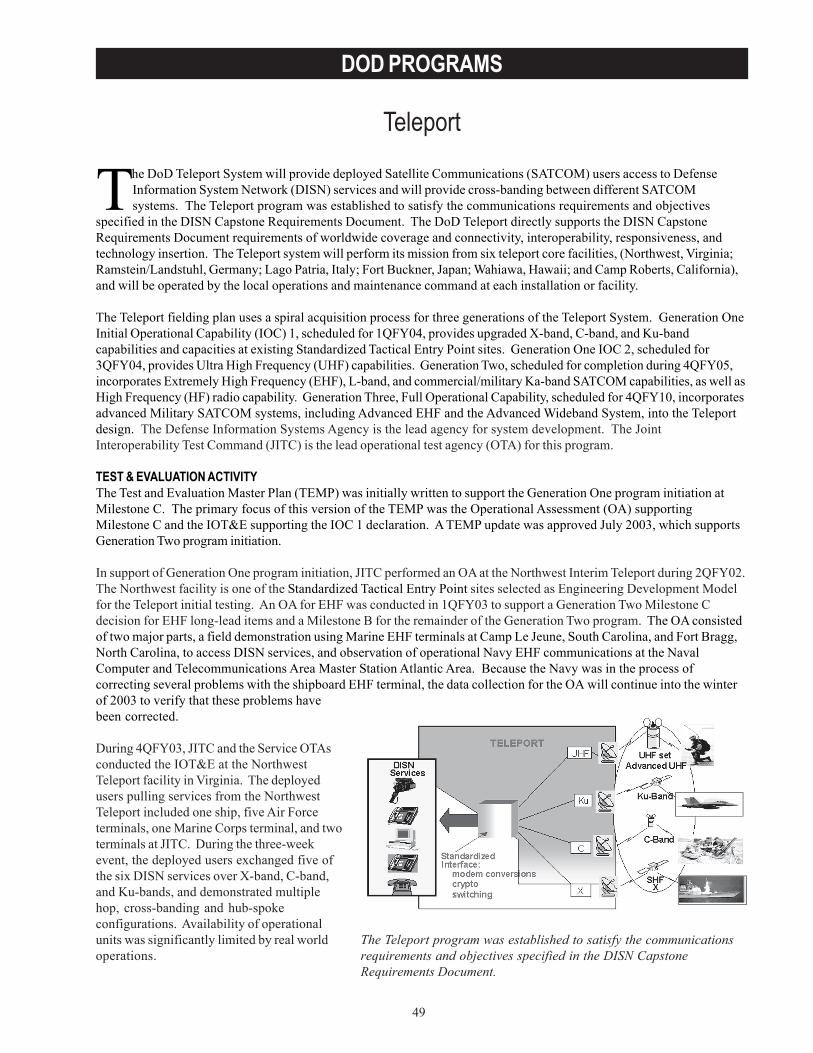
49
DOD PROGRAMS
Teleport
The DoD Teleport System will provide deployed Satellite Communications (SATCOM) users access to DefenseInformation System Network (DISN) services and will provide cross-banding between different SATCOMsystems. The Teleport program was established to satisfy the communications requirements and objectives
specified in the DISN Capstone Requirements Document. The DoD Teleport directly supports the DISN CapstoneRequirements Document requirements of worldwide coverage and connectivity, interoperability, responsiveness, andtechnology insertion. The Teleport system will perform its mission from six teleport core facilities, (Northwest, Virginia;Ramstein/Landstuhl, Germany; Lago Patria, Italy; Fort Buckner, Japan; Wahiawa, Hawaii; and Camp Roberts, California),and will be operated by the local operations and maintenance command at each installation or facility.
The Teleport fielding plan uses a spiral acquisition process for three generations of the Teleport System. Generation OneInitial Operational Capability (IOC) 1, scheduled for 1QFY04, provides upgraded X-band, C-band, and Ku-bandcapabilities and capacities at existing Standardized Tactical Entry Point sites. Generation One IOC 2, scheduled for3QFY04, provides Ultra High Frequency (UHF) capabilities. Generation Two, scheduled for completion during 4QFY05,incorporates Extremely High Frequency (EHF), L-band, and commercial/military Ka-band SATCOM capabilities, as well asHigh Frequency (HF) radio capability. Generation Three, Full Operational Capability, scheduled for 4QFY10, incorporatesadvanced Military SATCOM systems, including Advanced EHF and the Advanced Wideband System, into the Teleportdesign. The Defense Information Systems Agency is the lead agency for system development. The JointInteroperability Test Command (JITC) is the lead operational test agency (OTA) for this program.
TEST & EVALUATION ACTIVITYThe Test and Evaluation Master Plan (TEMP) was initially written to support the Generation One program initiation atMilestone C. The primary focus of this version of the TEMP was the Operational Assessment (OA) supportingMilestone C and the IOT&E supporting the IOC 1 declaration. A TEMP update was approved July 2003, which supportsGeneration Two program initiation.
In support of Generation One program initiation, JITC performed an OA at the Northwest Interim Teleport during 2QFY02.The Northwest facility is one of the Standardized Tactical Entry Point sites selected as Engineering Development Modelfor the Teleport initial testing. An OA for EHF was conducted in 1QFY03 to support a Generation Two Milestone Cdecision for EHF long-lead items and a Milestone B for the remainder of the Generation Two program. The OA consistedof two major parts, a field demonstration using Marine EHF terminals at Camp Le Jeune, South Carolina, and Fort Bragg,North Carolina, to access DISN services, and observation of operational Navy EHF communications at the NavalComputer and Telecommunications Area Master Station Atlantic Area. Because the Navy was in the process ofcorrecting several problems with the shipboard EHF terminal, the data collection for the OA will continue into the winterof 2003 to verify that these problems havebeen corrected.
During 4QFY03, JITC and the Service OTAsconducted the IOT&E at the NorthwestTeleport facility in Virginia. The deployedusers pulling services from the NorthwestTeleport included one ship, five Air Forceterminals, one Marine Corps terminal, and twoterminals at JITC. During the three-weekevent, the deployed users exchanged five ofthe six DISN services over X-band, C-band,and Ku-bands, and demonstrated multiplehop, cross-banding and hub-spokeconfigurations. Availability of operationalunits was significantly limited by real worldoperations.
The Teleport program was established to satisfy the communicationsrequirements and objectives specified in the DISN CapstoneRequirements Document.
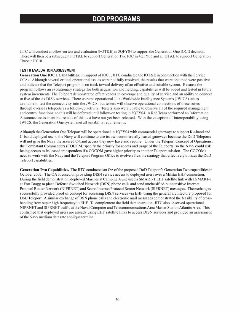
50
DOD PROGRAMS
JITC will conduct a follow-on test and evaluation (FOT&E) in 3QFY04 to support the Generation One IOC 2 decision.There will then be a subsequent FOT&E to support Generation Two IOC in 4QFY05 and a FOT&E to support GenerationThree in FY10.
TEST & EVALUATION ASSESSMENTGeneration One IOC 1 Capabilities. In support of IOC1, JITC conducted the IOT&E in conjunction with the ServiceOTAs. Although several critical operational issues were not fully resolved, the results that were obtained were positiveand indicate that the Teleport program is on track toward delivery of an effective and suitable system. Because theprogram follows an evolutionary strategy for both acquisition and fielding, capabilities will be added and tested in futuresystem increments. The Teleport demonstrated effectiveness in coverage and quality of service and an ability to connectto five of the six DISN services. There were no operational Joint Worldwide Intelligence Systems (JWICS) suitesavailable to test the connectivity into the JWICS, but testers will observe operational connections of these suitesthrough overseas teleports as a follow-up activity. Testers also were unable to observe all of the required managementand control functions, so this will be deferred until follow-on testing in 3QFY04. A Red Team performed an InformationAssurance assessment but results of this test have not yet been released. With the exception of interoperability usingJWICS, the Generation One system met all suitability requirements.
Although the Generation One Teleport will be operational in 1QFY04 with commercial gateways to support Ku-band andC-band deployed users, the Navy will continue to use its own commercially leased gateways because the DoD Teleportswill not give the Navy the assured C-band access they now have and require. Under the Teleport Concept of Operations,the Combatant Commanders (COCOM) specify the priority for access and usage of the Teleports, so the Navy could risklosing access to its leased transponders if a COCOM gave higher priority to another Teleport mission. The COCOMsneed to work with the Navy and the Teleport Program Office to evolve a flexible strategy that effectively utilizes the DoDTeleport capabilities.
Generation Two Capabilities. The JITC conducted an OA of the proposed DoD Teleport’s Generation Two capabilities inOctober 2002. The OA focused on providing DISN service access to deployed users over a Milstar EHF connection.During the field demonstration, deployed Marines at Camp Le Jeune used a SMART-T EHF satellite link with a SMART-Tat Fort Bragg to place Defense Switched Network (DSN) phone calls and send unclassified-but-sensitive InternetProtocol Router Network (NIPRNET) and Secret Internet Protocol Router Network (SIPRNET) messages. The exchangessuccessfully provided proof of concept for accessing DISN services via EHF using the general architecture proposed forDoD Teleport. A similar exchange of DSN phone calls and electronic mail messages demonstrated the feasibility of cross-banding from super high frequency to EHF. To complement the field demonstration, JITC also observed operationalNIPRNET and SIPRNET traffic at the Naval Computer and Telecommunications Area Master Station Atlantic Area. Thisconfirmed that deployed users are already using EHF satellite links to access DISN services and provided an assessmentof the Navy medium data rate appliqué terminal.
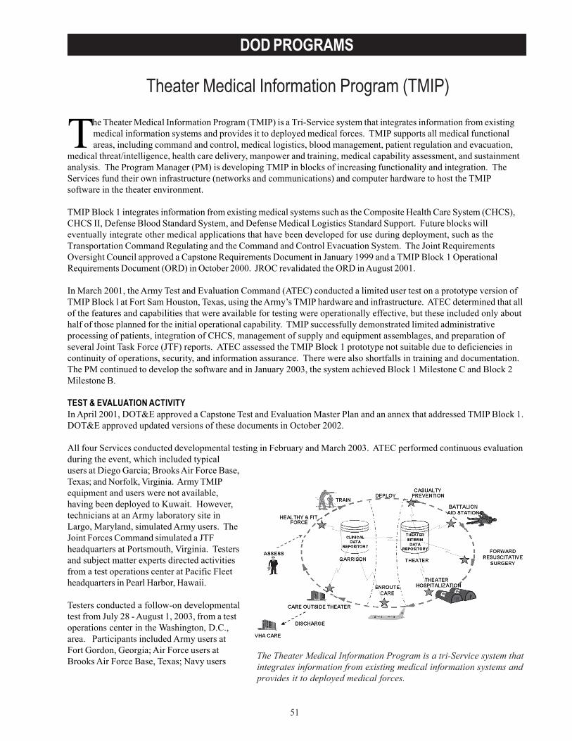
51
DOD PROGRAMS
Theater Medical Information Program (TMIP)
The Theater Medical Information Program is a tri-Service system thatintegrates information from existing medical information systems andprovides it to deployed medical forces.
The Theater Medical Information Program (TMIP) is a Tri-Service system that integrates information from existingmedical information systems and provides it to deployed medical forces. TMIP supports all medical functionalareas, including command and control, medical logistics, blood management, patient regulation and evacuation,
medical threat/intelligence, health care delivery, manpower and training, medical capability assessment, and sustainmentanalysis. The Program Manager (PM) is developing TMIP in blocks of increasing functionality and integration. TheServices fund their own infrastructure (networks and communications) and computer hardware to host the TMIPsoftware in the theater environment.
TMIP Block 1 integrates information from existing medical systems such as the Composite Health Care System (CHCS),CHCS II, Defense Blood Standard System, and Defense Medical Logistics Standard Support. Future blocks willeventually integrate other medical applications that have been developed for use during deployment, such as theTransportation Command Regulating and the Command and Control Evacuation System. The Joint RequirementsOversight Council approved a Capstone Requirements Document in January 1999 and a TMIP Block 1 OperationalRequirements Document (ORD) in October 2000. JROC revalidated the ORD in August 2001.
In March 2001, the Army Test and Evaluation Command (ATEC) conducted a limited user test on a prototype version ofTMIP Block l at Fort Sam Houston, Texas, using the Army’s TMIP hardware and infrastructure. ATEC determined that allof the features and capabilities that were available for testing were operationally effective, but these included only abouthalf of those planned for the initial operational capability. TMIP successfully demonstrated limited administrativeprocessing of patients, integration of CHCS, management of supply and equipment assemblages, and preparation ofseveral Joint Task Force (JTF) reports. ATEC assessed the TMIP Block 1 prototype not suitable due to deficiencies incontinuity of operations, security, and information assurance. There were also shortfalls in training and documentation.The PM continued to develop the software and in January 2003, the system achieved Block 1 Milestone C and Block 2Milestone B.
TEST & EVALUATION ACTIVITYIn April 2001, DOT&E approved a Capstone Test and Evaluation Master Plan and an annex that addressed TMIP Block 1.DOT&E approved updated versions of these documents in October 2002.
All four Services conducted developmental testing in February and March 2003. ATEC performed continuous evaluationduring the event, which included typicalusers at Diego Garcia; Brooks Air Force Base,Texas; and Norfolk, Virginia. Army TMIPequipment and users were not available,having been deployed to Kuwait. However,technicians at an Army laboratory site inLargo, Maryland, simulated Army users. TheJoint Forces Command simulated a JTFheadquarters at Portsmouth, Virginia. Testersand subject matter experts directed activitiesfrom a test operations center at Pacific Fleetheadquarters in Pearl Harbor, Hawaii.
Testers conducted a follow-on developmentaltest from July 28 - August 1, 2003, from a testoperations center in the Washington, D.C.,area. Participants included Army users atFort Gordon, Georgia; Air Force users atBrooks Air Force Base, Texas; Navy users
52
DOD PROGRAMS
aboard two ships of the 7th Fleet; and Marine Corps users in Okinawa. The Joint Forces Command again simulated a JTFat Portsmouth, Virginia.
TEST & EVALUATION ASSESSMENTTMIP must integrate several existing and developmental systems into a single system that can be easily used by theatercommanders and medical personnel in combat environments. Its heavy dependence on the successful operation of theother systems presents additional technical challenges. The functional and operational testing of each TMIP applicationis supposed to occur prior to delivery to the TMIP PM for integration. This can impose a scheduling problem for TMIPsince a delay in or problem with, any application can impact the delivery of that TMIP block. In the past, this and otherfactors resulted in schedule slippage, and there were difficulties in sharing data with the various applications. However,the system successfully completed Block 1 integration and independent software qualification testing in October 2002.In December 2002, the PM issued the joint TMIP software to the Services for training and developmental testing.
Developmental testing during 2003 showed that all of the planned TMIP Block 1 applications were working asdesigned and that required information from multiple sources could be received, processed, and displayed at JTFheadquarters. The second round of developmental testing conducted in a simulated user environment showed thatcomputer systems aboard Navy ships could be adapted to use TMIP and transmit medical information to a fleetheadquarters and then forwarded to a JTF. Following the successful developmental testing, TMIP hardware andsoftware were retained for real world use at a naval clinic in Diego Garcia, aboard two 7th Fleet ships, and at Pacific Fleetheadquarters. Meanwhile, Army equipment with installed TMIP software remains in Kuwait, where it is available for realworld use as required.
ATEC led the efforts to develop a comprehensive System Assessment Plan that focused its continuing operationalevaluation during the joint developmental testing and will also guide future planning for OT&E. Independent operationaltesting was not practicable during FY03 due to the real world deployment of potential users during Operation IraqiFreedom. The latest TMIP software release was available for developmental testing in November 2003. Among other things,this software release upgrades the TMIP operating system from Windows NT to Windows 2000®. While developmentaltesting is ongoing, planning for IOT&E continues.
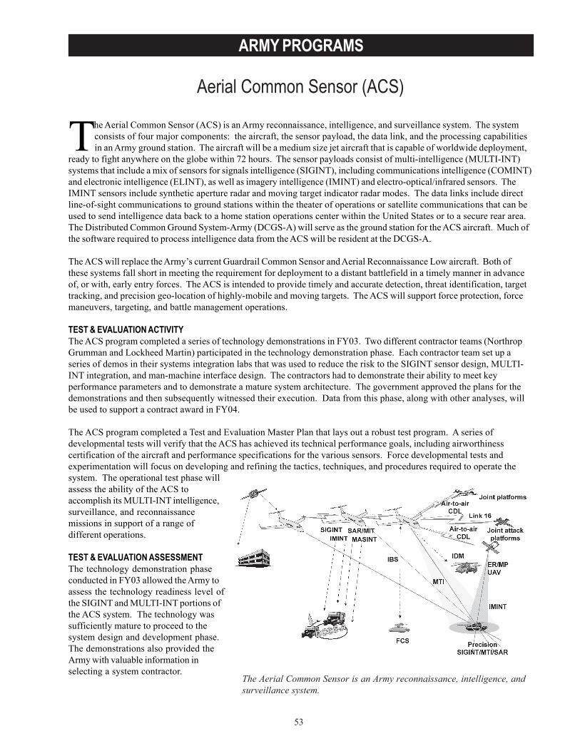
53
ARMY PROGRAMS
Aerial Common Sensor (ACS)
The Aerial Common Sensor is an Army reconnaissance, intelligence, andsurveillance system.
The Aerial Common Sensor (ACS) is an Army reconnaissance, intelligence, and surveillance system. The systemconsists of four major components: the aircraft, the sensor payload, the data link, and the processing capabilitiesin an Army ground station. The aircraft will be a medium size jet aircraft that is capable of worldwide deployment,
ready to fight anywhere on the globe within 72 hours. The sensor payloads consist of multi-intelligence (MULTI-INT)systems that include a mix of sensors for signals intelligence (SIGINT), including communications intelligence (COMINT)and electronic intelligence (ELINT), as well as imagery intelligence (IMINT) and electro-optical/infrared sensors. TheIMINT sensors include synthetic aperture radar and moving target indicator radar modes. The data links include directline-of-sight communications to ground stations within the theater of operations or satellite communications that can beused to send intelligence data back to a home station operations center within the United States or to a secure rear area.The Distributed Common Ground System-Army (DCGS-A) will serve as the ground station for the ACS aircraft. Much ofthe software required to process intelligence data from the ACS will be resident at the DCGS-A.
The ACS will replace the Army’s current Guardrail Common Sensor and Aerial Reconnaissance Low aircraft. Both ofthese systems fall short in meeting the requirement for deployment to a distant battlefield in a timely manner in advanceof, or with, early entry forces. The ACS is intended to provide timely and accurate detection, threat identification, targettracking, and precision geo-location of highly-mobile and moving targets. The ACS will support force protection, forcemaneuvers, targeting, and battle management operations.
TEST & EVALUATION ACTIVITYThe ACS program completed a series of technology demonstrations in FY03. Two different contractor teams (NorthropGrumman and Lockheed Martin) participated in the technology demonstration phase. Each contractor team set up aseries of demos in their systems integration labs that was used to reduce the risk to the SIGINT sensor design, MULTI-INT integration, and man-machine interface design. The contractors had to demonstrate their ability to meet keyperformance parameters and to demonstrate a mature system architecture. The government approved the plans for thedemonstrations and then subsequently witnessed their execution. Data from this phase, along with other analyses, willbe used to support a contract award in FY04.
The ACS program completed a Test and Evaluation Master Plan that lays out a robust test program. A series ofdevelopmental tests will verify that the ACS has achieved its technical performance goals, including airworthinesscertification of the aircraft and performance specifications for the various sensors. Force developmental tests andexperimentation will focus on developing and refining the tactics, techniques, and procedures required to operate thesystem. The operational test phase willassess the ability of the ACS toaccomplish its MULTI-INT intelligence,surveillance, and reconnaissancemissions in support of a range ofdifferent operations.
TEST & EVALUATION ASSESSMENTThe technology demonstration phaseconducted in FY03 allowed the Army toassess the technology readiness level ofthe SIGINT and MULTI-INT portions ofthe ACS system. The technology wassufficiently mature to proceed to thesystem design and development phase.The demonstrations also provided theArmy with valuable information inselecting a system contractor.

54
ARMY PROGRAMS
Several issues will be of importance to the successful execution of the ACS program. The ACS calls for the MULTI-INTintegration of COMINT, ELINT, IMINT, and electro-optic/infrared sensors onto a single aircraft. This integration will becomplex and will have to overcome the potential co-site interference between the different sensors. Processing the datafrom the different sensors will also require a system architecture that can prosecute MULTI-INT missions at both theaircraft and at the DCGS-A ground station. A significant amount of processing will have to occur at the DCGS-A in orderto complete many missions. The ACS will also need to be interoperable and integrated with joint Service networks toconduct joint operations with other Services.
There are concerns about the size, weight, and power requirements of the aircraft required to carry and operate theMULTI-INT sensor payload. Associated with this issue, there are concerns about the growth potential of the aircraft toadd additional systems and capabilities in the future, consistent with the growth experienced with most other U.S. aircraftplatforms.
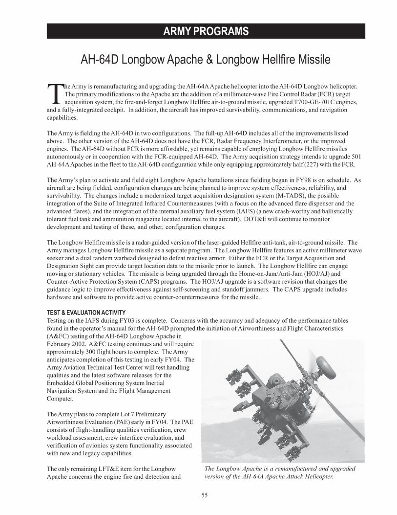
55
ARMY PROGRAMS
AH-64D Longbow Apache & Longbow Hellfire Missile
The Longbow Apache is a remanufactured and upgradedversion of the AH-64A Apache Attack Helicopter.
The Army is remanufacturing and upgrading the AH-64A Apache helicopter into the AH-64D Longbow helicopter.The primary modifications to the Apache are the addition of a millimeter-wave Fire Control Radar (FCR) targetacquisition system, the fire-and-forget Longbow Hellfire air-to-ground missile, upgraded T700-GE-701C engines,
and a fully-integrated cockpit. In addition, the aircraft has improved survivability, communications, and navigationcapabilities.
The Army is fielding the AH-64D in two configurations. The full-up AH-64D includes all of the improvements listedabove. The other version of the AH-64D does not have the FCR, Radar Frequency Interferometer, or the improvedengines. The AH-64D without FCR is more affordable, yet remains capable of employing Longbow Hellfire missilesautonomously or in cooperation with the FCR-equipped AH-64D. The Army acquisition strategy intends to upgrade 501AH-64A Apaches in the fleet to the AH-64D configuration while only equipping approximately half (227) with the FCR.
The Army’s plan to activate and field eight Longbow Apache battalions since fielding began in FY98 is on schedule. Asaircraft are being fielded, configuration changes are being planned to improve system effectiveness, reliability, andsurvivability. The changes include a modernized target acquisition designation system (M-TADS), the possibleintegration of the Suite of Integrated Infrared Countermeasures (with a focus on the advanced flare dispenser and theadvanced flares), and the integration of the internal auxiliary fuel system (IAFS) (a new crash-worthy and ballisticallytolerant fuel tank and ammunition magazine located internal to the aircraft). DOT&E will continue to monitordevelopment and testing of these, and other, configuration changes.
The Longbow Hellfire missile is a radar-guided version of the laser-guided Hellfire anti-tank, air-to-ground missile. TheArmy manages Longbow Hellfire missile as a separate program. The Longbow Hellfire features an active millimeter waveseeker and a dual tandem warhead designed to defeat reactive armor. Either the FCR or the Target Acquisition andDesignation Sight can provide target location data to the missile prior to launch. The Longbow Hellfire can engagemoving or stationary vehicles. The missile is being upgraded through the Home-on-Jam/Anti-Jam (HOJ/AJ) andCounter-Active Protection System (CAPS) programs. The HOJ/AJ upgrade is a software revision that changes theguidance logic to improve effectiveness against self-screening and standoff jammers. The CAPS upgrade includeshardware and software to provide active counter-countermeasures for the missile.
TEST & EVALUATION ACTIVITYTesting on the IAFS during FY03 is complete. Concerns with the accuracy and adequacy of the performance tablesfound in the operator’s manual for the AH-64D prompted the initiation of Airworthiness and Flight Characteristics(A&FC) testing of the AH-64D Longbow Apache inFebruary 2002. A&FC testing continues and will requireapproximately 300 flight hours to complete. The Armyanticipates completion of this testing in early FY04. TheArmy Aviation Technical Test Center will test handlingqualities and the latest software releases for theEmbedded Global Positioning System InertialNavigation System and the Flight ManagementComputer.
The Army plans to complete Lot 7 PreliminaryAirworthiness Evaluation (PAE) early in FY04. The PAEconsists of flight-handling qualities verification, crewworkload assessment, crew interface evaluation, andverification of avionics system functionality associatedwith new and legacy capabilities.
The only remaining LFT&E item for the LongbowApache concerns the engine fire and detection and
56
ARMY PROGRAMS
suppression system (FDSS) test. The FDSS test, required by the Apache Longbow Test and Evaluation Master Plan, isbeing deferred so that it might be conducted with the Army Aviation Halon replacement. However, since a suitable drop-in halon replacement is not forthcoming, the Program Management Office is in the process of planning to conduct thistest with the existing Halon 1301 system. The Army intends to use a fully operational representative, but notflightworthy, aircraft as the ground test article to conduct this series of tests in 2QFY04.
The Army conducted ten Hellfire missile flight tests in FY03 to support the HOJ/AJ software regression testing anddetermine its effectiveness in countermeasure environments. Analysis of this testing is ongoing with results expectedduring 2QFY04. For the CAPS upgrade, pre-qualification testing was conducted in FY03 to address the radome design,antenna design, effective radiated power, guidance section performance, and radar cross-section. Because the CAPS isadded to the exterior of the existing missile, aerodynamic impacts of the upgrade are being studied; sub-scale wind tunneltesting was proposed for FY04.
Opportunities to analyze and evaluate the effectiveness, suitability, and survivability of the AH-64A/D aircraft undercombat conditions abounded during operations in FY02 against al Qaeda and Taliban fighters in Afghanistan and inFY03 during Operation Iraqi Freedom.
TEST & EVALUATION ASSESSMENTThe Army found the IAFS effective and suitable and is fielding the subsystem. This addition/modification to the aircraftprovides the units in the field with an aircraft that has an extended range capability with a fuel system that is crashworthyand ballistically tolerant. This is a much-needed improvement in the system, even though 30 millimeter round carryingcapability is reduced from 1,200 rounds to 300 rounds due to the modification.
As expected, the A&FC aircraft testing confirms that the published performance charts for the AH-64D need refinement,but the magnitude and extent of the changes is not yet known. Early results of ongoing software regression testingshow no significant anomalies.
The Lot 7 interoperability assessment confirms the aircraft’s ability to send/receive joint variable message format andtactical fire direction system messages. In-flight workload assessment surveys and low airspeed testing are complete.Testing of the final software configuration is complete and a safety confirmation recommendation was forwarded to theArmy Developmental Test Command for approval.
Four missile flights supported software regression testing and evaluation under benign conditions while six additionalmissile flights provided data to demonstrate HOJ/AJ performance under electronic countermeasure (ECM) conditions.Analysis is ongoing to reconcile differences between pre-flight predictions and actual flight-test results for at least oneof the six ECM flights. A test report and simulation verification and validation report are expected in early CY04. “RocketBall” testing, a series of contractor-run engineering tests, reportedly confirmed good radio frequency performance ofthree CAPS prototype systems. This series of tests also showed that there was no discernable difference in performancedue radome-to-radome variability. There was a small increase in baseline radar cross section with the addition of CAPSto the missile. The ERP test showed that the design has sufficient radio frequency performance margin.
Results of recent combat deployments and training exercises confirm the results of the 1995 IOT&E assessment for theLongbow Apache helicopter - the AH-64D helicopter provides effective air-to-ground combat power. The Army after-action reports from the Iraqi conflict conclude that the Longbow Apache aircraft survives, protects the crew, and can bequickly repaired and returned to combat. Still, improvements to the Apache aircraft and training devices could enhancethe aircraft’s effectiveness. The Army should consider accelerating the procurement and fielding of M-TADS to enabletarget identification at standoff ranges. Additionally, the Army should incorporate “running/diving fire” engagementtactics, techniques, and procedures, as well as dynamic engagements during peacetime training. This training would beespecially beneficial in the Longbow qualification training at Fort Rucker, Alabama, and during unit aerial gunnerytraining.
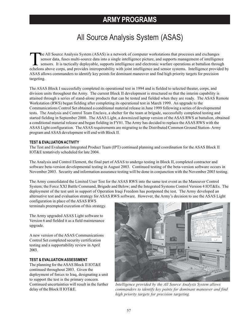
57
ARMY PROGRAMS
All Source Analysis System (ASAS)
Intelligence provided by the All Source Analysis System allowscommanders to identify key points for dominant maneuver and findhigh priority targets for precision targeting.
The All Source Analysis System (ASAS) is a network of computer workstations that processes and exchangessensor data, fuses multi-source data into a single intelligence picture, and supports management of intelligencesensors. It is tactically deployable, supports intelligence and electronic warfare operations at battalion through
echelons above corps, and provides interoperability with joint intelligence and sensor systems. Intelligence provided byASAS allows commanders to identify key points for dominant maneuver and find high priority targets for precisiontargeting.
The ASAS Block I successfully completed its operational test in 1994 and is fielded to selected theater, corps, anddivision units throughout the Army. The current Block II development is structured so that the interim capability isattained through a series of stand-alone products that can be tested and fielded when they are ready. The ASAS RemoteWorkstation (RWS) began fielding after completing its operational test in March 1999. An upgrade to theCommunications Control Set obtained a conditional material release in June 1999 following a series of developmentaltests. The Analysis and Control Team Enclave, a shelter for the team at brigade, successfully completed testing andstarted fielding in September 2000. The ASAS Light, a downsized laptop version of the ASAS RWS at battalion, obtaineda conditional material release and began fielding in FY01. The Army has decided to replace the ASAS RWS with theASAS Light configuration. The ASAS requirements are migrating to the Distributed Common Ground Station- Armyprogram and ASAS development will end with Block II.
TEST & EVALUATION ACTIVITYThe Test and Evaluation Integrated Product Team (IPT) continued planning and coordination for the ASAS Block IIIOT&E tentatively scheduled for late 2004.
The Analysis and Control Element, the final part of ASAS to undergo testing in Block II, completed contractor andsoftware beta-version developmental testing in August 2003. Continued testing of the beta-version software occurs inNovember 2003. Security and information assurance testing will be done in conjunction with the November 2003 testing.
The Army consolidated the Limited User Test for the ASAS RWS into the same test event as the Maneuver ControlSystem; the Force XXI Battle Command, Brigade and Below; and the Integrated Systems Control Version 4 IOT&Es. Thedeployment of the test unit in support of Operation Iraqi Freedom has postponed the test. The Army developed analternative test and evaluation strategy for ASAS RWS software. However, the Army’s decision to use the ASAS Lightconfiguration in place of the ASAS RWSterminals preempted execution of this strategy.
The Army upgraded ASAS Light software toVersion 6 and fielded it as a field maintenanceupgrade.
A new version of the ASAS CommunicationsControl Set completed security certificationtesting and a supportability review in April2003.
TEST & EVALUATION ASSESSMENTThe planning for the ASAS Block II IOT&Econtinued throughout 2003. Given thedeployment of forces to Iraq, designating a unitto support the test is the primary concern.Continued uncertainties will result in the furtherdelay of the Block II IOT&E.
58
ARMY PROGRAMS
The ASAS RWS risk assessment identified four accomplishments to be completed to support fielding of the Version 6software to non- Army Battle Command System units as an upgrade to Version 4: developmental testing, an operationalassessment, intra-Army interoperability certification (IAIC), and joint interoperability certification. The ASAS RWS hasaccomplished only the developmental test to date. IAIC testing conducted in August 2003 identified a problem sendingmessages to the Maneuver Control System. A fix has been developed and once successful regression testing isaccomplished, the IAIC will be released. The Army’s switch from the ASAS RWS to the ASAS Light platform deleted therequirement for an operational assessment of the RWS. However, the plan to use the ASAS Light as a replacement forthe RWS in the Analysis and Control Team and the Analysis and Control Element will require developmental andoperational test and evaluation of the changes in both software and employment. The joint interoperability certificationremains an open issue with sufficient testing unlikely until the Block II IOT&E.
The ASAS is experiencing difficulties obtaining a test unit. The operational tempo and deployments have limited theavailability of forces to support Army operational tests. The Army and OSD continue to seek acceptable venues toaccomplish required operational testing; however, continued delays will adversely affect program schedules and fieldingplans. For programs like ASAS, which are included in the digital Army Battle Command System family, the deployment ofthe 4th Infantry Division has created an untenable situation in terms of completing required testing. Currently, the 4th
Infantry Division is the only unit capable of supporting an adequate operational test of this digital information sharingarchitecture.
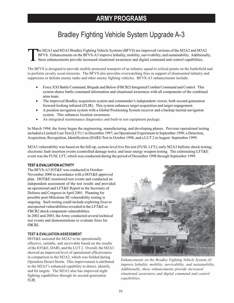
59
ARMY PROGRAMS
Bradley Fighting Vehicle System Upgrade A-3
Enhancements on the Bradley Fighting Vehicle System-A3improve lethality, mobility, survivability, and sustainability.Additionally, these enhancements provide increasedsituational awareness and digital command and controlcapabilities.
The M2A3 and M3A3 Bradley Fighting Vehicle Systems (BFVS) are improved versions of the M2A2 and M3A2BFVS. Enhancements on the BFVS-A3 improve lethality, mobility, survivability, and sustainability. Additionally,these enhancements provide increased situational awareness and digital command and control capabilities.
The BFVS is designed to provide mobile protected transport of an infantry squad to critical points on the battlefield andto perform cavalry scout missions. The BFVS also provides overwatching fires in support of dismounted infantry andsuppresses or defeats enemy tanks and other enemy fighting vehicles. BFVS-A3 enhancements include:
• Force XXI Battle Command, Brigade and Below (FBCB2) Integrated Combat Command and Control. Thissystem shares battle command information and situational awareness with all components of the combinedarms team.
• The improved Bradley acquisition system and commander’s independent viewer, both second-generationforward-looking infrared (FLIR). This system enhances target acquisition and target engagement.
• A position navigation system with a Global Positioning System receiver and a backup inertial navigationsystem. This enhances location awareness.
• An integrated maintenance diagnostics and built-in test equipment package.
In March 1994, the Army began the engineering, manufacturing, and developing phases. Previous operational testingincluded a Limited User Test (LUT) 1 in December 1997; an Operational Experiment in September 1998; a Detection,Acquisition, Recognition, Identification (DARI) Test in October 1998, and a LUT 2 in August- September 1999.
M2A3 vulnerability was based on the full-up, system-level live fire test (FUSL LFT); early M2A3 ballistic shock testing;electronic fault insertion events (controlled damage tests); and laser energy weapon testing. The culminating LFT&Eevent was the FUSL LFT, which was conducted during the period of December 1998 through September 1999.
TEST & EVALUATION ACTIVITYThe BFVS-A3 IOT&E was conducted in October-November 2000 in accordance with a DOT&E approvedplan. DOT&E monitored test events and conducted anindependent assessment of the test results and providedan operational and LFT&E Report to the Secretary ofDefense and Congress in April 2001. Planning forpossible post-Milestone III vulnerability testing isongoing. Such testing could include exploring fixes tounexpected vulnerabilities revealed in the LFT&E orFBCB2 shock component vulnerabilities.In 2002 and 2003, the Army conducted several technicaltest events and demonstrations to evaluate fixes forFBCB2.
TEST & EVALUATION ASSESSMENTDOT&E assessed the M2A3 to be operationallyeffective, suitable, and survivable based on the resultsof the IOT&E, DARI, and the LUT 2. Overall, the M2A3showed an improved level of operational effectivenessin comparison to the M2A2, which was fielded duringOperation Desert Storm. This improvement is attributedto the M2A3’s enhanced capability to detect, identify,and hit targets. The M2A3 also has improved nightfighting capabilities through its second-generationFLIR.
60
ARMY PROGRAMS
The FBCB2 digital command and control, as integrated into the M2A3, demonstrated during the IOT&E that it wasneither effective nor suitable and it did not contribute to the operational effectiveness of the M2A3/M1A2 SystemEnhancement Package-equipped force. Despite this, the M2A3 was able to demonstrate an overall improved level ofoperational effectiveness in comparison to the M2A2 Operation Desert Storm, predominately because of the capabilitiesof the M2A3’s second-generation FLIR and improved fire control system.
Field Test 5, conducted September 12- 27, 2002, at the Electronic Proving Ground, Fort Huachuca, Arizona, and coldweather testing at the Cold Regions Test Center, Alaska, revealed that significant suitability problems with M2A3 FBCB2integration still existed. Recent technical test results indicate that FBCB2 reliability significantly improved when using anew Solid State Hard Drive instead of the standard spinning FBCB2 hard drive. A 1,500-mile follow-on production test atAberdeen Proving Ground, Maryland, and a two-week user demonstration (late November-early December 2003) areplanned to confirm the effectiveness and suitability of this solution. Successful results and subsequent evaluation fromthese tests should close out the digital command and control issues on the BFVS-A3.
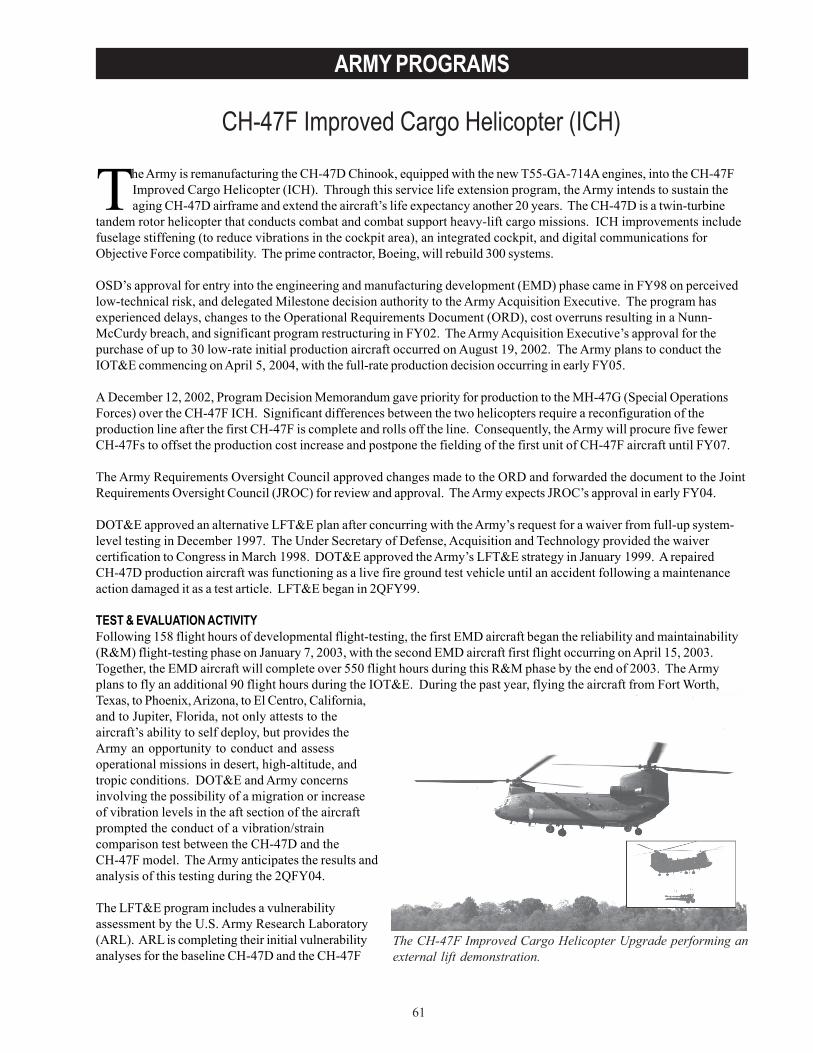
61
ARMY PROGRAMS
CH-47F Improved Cargo Helicopter (ICH)
The Army is remanufacturing the CH-47D Chinook, equipped with the new T55-GA-714A engines, into the CH-47FImproved Cargo Helicopter (ICH). Through this service life extension program, the Army intends to sustain theaging CH-47D airframe and extend the aircraft’s life expectancy another 20 years. The CH-47D is a twin-turbine
tandem rotor helicopter that conducts combat and combat support heavy-lift cargo missions. ICH improvements includefuselage stiffening (to reduce vibrations in the cockpit area), an integrated cockpit, and digital communications forObjective Force compatibility. The prime contractor, Boeing, will rebuild 300 systems.
OSD’s approval for entry into the engineering and manufacturing development (EMD) phase came in FY98 on perceivedlow-technical risk, and delegated Milestone decision authority to the Army Acquisition Executive. The program hasexperienced delays, changes to the Operational Requirements Document (ORD), cost overruns resulting in a Nunn-McCurdy breach, and significant program restructuring in FY02. The Army Acquisition Executive’s approval for thepurchase of up to 30 low-rate initial production aircraft occurred on August 19, 2002. The Army plans to conduct theIOT&E commencing on April 5, 2004, with the full-rate production decision occurring in early FY05.
A December 12, 2002, Program Decision Memorandum gave priority for production to the MH-47G (Special OperationsForces) over the CH-47F ICH. Significant differences between the two helicopters require a reconfiguration of theproduction line after the first CH-47F is complete and rolls off the line. Consequently, the Army will procure five fewerCH-47Fs to offset the production cost increase and postpone the fielding of the first unit of CH-47F aircraft until FY07.
The Army Requirements Oversight Council approved changes made to the ORD and forwarded the document to the JointRequirements Oversight Council (JROC) for review and approval. The Army expects JROC’s approval in early FY04.
DOT&E approved an alternative LFT&E plan after concurring with the Army’s request for a waiver from full-up system-level testing in December 1997. The Under Secretary of Defense, Acquisition and Technology provided the waivercertification to Congress in March 1998. DOT&E approved the Army’s LFT&E strategy in January 1999. A repairedCH-47D production aircraft was functioning as a live fire ground test vehicle until an accident following a maintenanceaction damaged it as a test article. LFT&E began in 2QFY99.
TEST & EVALUATION ACTIVITYFollowing 158 flight hours of developmental flight-testing, the first EMD aircraft began the reliability and maintainability(R&M) flight-testing phase on January 7, 2003, with the second EMD aircraft first flight occurring on April 15, 2003.Together, the EMD aircraft will complete over 550 flight hours during this R&M phase by the end of 2003. The Armyplans to fly an additional 90 flight hours during the IOT&E. During the past year, flying the aircraft from Fort Worth,Texas, to Phoenix, Arizona, to El Centro, California,and to Jupiter, Florida, not only attests to theaircraft’s ability to self deploy, but provides theArmy an opportunity to conduct and assessoperational missions in desert, high-altitude, andtropic conditions. DOT&E and Army concernsinvolving the possibility of a migration or increaseof vibration levels in the aft section of the aircraftprompted the conduct of a vibration/straincomparison test between the CH-47D and theCH-47F model. The Army anticipates the results andanalysis of this testing during the 2QFY04.
The LFT&E program includes a vulnerabilityassessment by the U.S. Army Research Laboratory(ARL). ARL is completing their initial vulnerabilityanalyses for the baseline CH-47D and the CH-47F
The CH-47F Improved Cargo Helicopter Upgrade performing anexternal lift demonstration.
62
ARMY PROGRAMS
ICH using ARL-developed modeling tools in conjunction with detailed aircraft descriptions. The live fire test includescockpit skin panels, cockpit components, fuel subsystem, propulsion system engine nacelle fire suppression system, andwill test the fuselage tunnel flight control systems. The vulnerability assessment is in continual update which will resultin a comparative analysis to assess the vulnerability of the CH-47F ICH relative to the CH-47D.
ARL completed ballistic testing of the cockpit skin panels, cockpit components, and the T55 engine and fuel subsystem.Damage to the test vehicle requires alternate test plans for testing of the fire suppression system and of the fuselagetunnel. Testing of the fuselage tunnel flight controls system will take place during 1QFY04. As a result of losing the testvehicle, ARL’s plan to conduct static and dynamic ballistic tests of the CH-47D rotor blades as part of the DOT&E JointLive Fire Program during FY03 has been interrupted with only static testing having been completed (analysis of theresults pending). Since these blades are the same as those to be used on the CH-47F model, the data derived from theJoint Live Fire Program is directly applicable to the LFT&E of the CH-47F.
OSD approved the Test and Evaluation Master Plan (TEMP) in January 2002. A TEMP update is being staffed and willreceive approval early in FY04. ORD, programmatic, and schedule changes are driving the need for an update to theTEMP.
TEST & EVALUATION ASSESSMENTTo date, overall operational and system effectiveness are good. However, program goals for system reliability, vibrationreduction, and digital interoperability may not be achieved.
Even though reliability testing to date confirms that failures in the CH-47F are common to legacy CH-47D aircraft, thesesame testing results suggest that the CH-47F is at low to moderate risk to achieve ORD R&M thresholds.
Fatigue damage on the CH-47F aircraft is similar to damage found in legacy aircraft. However, higher vibration levels atthe combiner cooling fan location raise concerns within the test community about the long-term reliability of aircraftcomponents and the potential long-term impact on overall structure damage.
Testing on the CH-47F demonstrates the system’s capability to send and receive selected digital messages betweenaircraft and a ground-based Force XXI Battle Command, Brigade and Below simulator. IOT&E will provide theopportunity to demonstrate aircraft-to-aircraft digital messaging, compatibility with Joint and Army technical architecture,and interoperability with a fully loaded tactical internet.
Test data from the Army’s live fire test of the CH-47F and the DOT&E Joint Live Fire Program of the basic CH-47D willsupport an adequate evaluation of the CH-47F. The only LFT&E concern is that accidental damage done to the groundtest vehicle may preclude dynamic testing of the fire suppression system, fuselage tunnel flight controls system, and themain rotor blades.

63
ARMY PROGRAMS
Chemical Demilitarization Program
Need a pull quote from the write-up
As of July 13, 2003, the disposal facilities had successfully destroyedapproximately 26 percent of the total U.S. chemical weapons stockpile.
The Chemical Demilitarization Program is an Army-managed program responsible for the destruction of the U.S.stockpile of lethal chemical agents and munitions, and non-stockpile chemical warfare materiel. This program isrequired to comply with the Chemical Weapons Convention (CWC), which is a major arms control and
nonproliferation treaty that requires destruction of stockpile unitary chemical weapons by April 29, 2007. OSD placed theChemical Demilitarization Program on oversight in December 1994. Since then, DOT&E has provided oversight of thestockpile, non-stockpile, and alternate technologies projects within the Chemical Demilitarization Program.
The Chemical Stockpile Disposal Project is responsible for the development of chemical agent disposal facilities collocated withthe nine chemical depots. The disposal facilities are government owned and contractor operated. Each site’s prime contractorconducts all developmental and operational testing under oversight of the Program Office and the U.S. Army Materiel SystemsAnalysis Activity. Five disposal facilities are employing the baseline chemical weapons disassembly and incineration process.
The Army has selected chemical neutralization of agents, followed by post-treatment of the neutralized products for thedisposal facilities at the two bulk agent storage sites in Aberdeen, Maryland, and Newport, Indiana. The AlternativeTechnology and Approaches Project is responsible for conducting testing at these two sites. At the direction of Congress, theAssembled Chemical Weapons Assessment Program was established in 1996 to evaluate alternative technologies for thePueblo and Blue Grass disposal facilities. In 2003, the Army awarded contracts to implement chemical neutralization of agentsfollowed by post-treatment of the neutralized products as an alternative technology for the Pueblo and Blue Grass disposalfacilities. Due to the events of September 11, 2001, accelerated destruction is being implemented at the two bulk storage sites,and is being considered for the Pueblo and Blue Grass sites, to reduce the risk of continuing agent storage.
The Johnston Atoll disposal facility completed chemical agent operations in November 2000, and completion of the closureprocess, including demolition of the facility, is expected in November 2003. The Tooele disposal facility is currently the onlyfully operational facility. The Aberdeen and Anniston disposal facilities began limited agent operations in April and August2003, respectively. The Umatilla, Pine Bluff, and Newport disposal facilities are scheduled to begin limited agent operations in2004. The Pueblo and Blue Grass disposal facilities are in the design phase, and no testing is anticipated for 2004. As ofJuly 13, 2003, the disposal facilities had successfully destroyed approximately 26 percent of the total U.S. chemical weaponsstockpile (originally 31,496 agent tons). The Army has met the first two Milestones of the CWC (1 percent and 20 percentdestruction, respectively). However, current Army plans for full destruction will not to be complete until April 2012 and arequest for a five-year extension to the CWC 100 percent destruction Milestone will be required.
The Non-Stockpile Chemical Materiel Project is responsible for the destruction of non-stockpile chemical warfare materiel,including the components of binary chemical weapons, miscellaneous chemical warfare materiel, recovered chemical weapons,former production facilities, and buried chemical warfare materiel. The Non-Stockpile Chemical Materiel Project has developed,tested, and fielded several mobile systems: the Explosive Destruction System (EDS), Phase 1, Unit 1 (EDS-1/1); the RapidResponse System; the Mobile Munitions Assessment System; and the Portable Raman System. Two additional variants ofEDS and two other mobile systems are in or have recently completed testing: EDS, Phase 1, Units 2 and 3 (EDS-1/2,3); EDS,Phase 2 (EDS-2); Single Chemical AgentIdentification Set Access Neutralization System(SCANS); and Large Items TransportableAccessing and Neutralization System (LITANS).The Pine Bluff Arsenal Ton ContainerDecontamination Facility is a fixed, non-stockpilefacility in testing at Pine Bluff Arsenal, Arkansas.Three other fixed, non-stockpile facilities are indevelopment: the Munitions Assessment andProcessing System at Aberdeen Proving Ground,Maryland; and the Pine Bluff Non-StockpileFacility and Pine Bluff Binary Destruction Facility,both at Pine Bluff Arsenal, Arkansas.
64
ARMY PROGRAMS
TEST & EVALUATION ACTIVITYThe test and evaluation program for each stockpile incineration disposal facility consists of developmental test (DT), combinedDT/operational test (OT), and OT phases. The DT phase consists of subsystem component testing. The DT/OT phaseemploys surrogate agents in all test events, culminating in trial burns of the furnaces and end-to-end operations of the facility.The OT phase consists of agent trial burns and initial operations with agent. The OT is tailored to a specific agent/munitioncampaign. The OT will support a decision whether to proceed to fully operational status for that specific agent/munitioncampaign. After completion of the campaign, the facility will revert to OT status for the next planned agent/munition campaign.This process will be repeated until destruction of all agent/munition configurations in the site’s stockpile is complete.
For the two bulk agent storage sites implementing accelerated destruction, there is only a DT phase that culminates in end-to-end testing of the facility with surrogate agent, and an OT phase that consists of initial operations with agent. In implementingaccelerated destruction at the Aberdeen and Newport sites, the program office has replaced the approved Test and EvaluationMaster Plans for those sites with Test Concept Plans (TCPs). The TCPs are still subject to DOT&E approval. DOT&E hasreviewed a draft of the TCP for the Newport site and approved the TCP for the Aberdeen site in 2003.
DOT&E monitors the test activity and independently analyzes test data for all stockpile facilities and non-stockpile systems.The test activity and test data support decisions on whether to proceed to the next test phase and determine readiness of eithera stockpile facility to begin fully operational status or of a non-stockpile system to be operationally fielded at the conclusion ofOT. Test activity for stockpile facilities and non-stockpile systems is summarized in the table below.
a Start of the OT phase was delayed for over six months due to the need to address safety concerns.b Sarin filled M-55 rockets are the munitions being tested.c An Operational In-Process Review conditional fielding decision for EDS-1/2,3 was made in October 2002.
TEST & EVALUATION ASSESSMENTArmy testing of stockpile and non-stockpile systems in the Chemical Demilitarization Program has been adequate to ensure thesafe and efficient disposal of the inventory of chemical warfare materiel. The implementation of accelerated destruction at thebulk storage sites increases the amount of manual handling of agent materiel and places increased emphasis on maintainingprogram schedules, thereby increasing the risk of safe operation of these facilities. To date, results at the bulk storage siteshave not provided a clear indication that the intended schedule and cost benefits of the accelerated destruction process will berealized. Emphasis on maintaining the program schedule at the Aberdeen facility led to a hastily conducted final DT prior to the
65
ARMY PROGRAMS
start of OT. The numerous problems and subsequent delays that are occurring during the OT can, in part, be attributed to thehaste with which the final DT was conducted. For the Tooele facility, unexpected events that have occurred during operationsand maintenance have led to lengthy delays and greatly increased program costs, illustrating the need for robust event-driventesting to minimize the possibility of such occurrences for these facilities when they become fully operational. DOT&E willcontinue to monitor the safety issue closely during testing of these facilities.
Operational testing of EDS-1/2,3 at Aberdeen and the remediation site at Spring Valley was adequate for DOT&E to determinethat the system is operationally effective and suitable. All munitions were safely and successfully destroyed by the EDS-1/2,3during testing. DOT&E participated in the Operational Readiness In-Process Review in November 2003, which supported theProgram Manager’s decision to declare EDS-1/2,3 fully operational for use with mustard, sarin, and phosgene. The EDS-2DT/OT at Porton Down, United Kingdom, and Aberdeen is currently going well. The DT/OT testing is being conductedsimilarly to a dedicated OT in that operational crews and procedures are being employed with a production representativesystem. Therefore, a dedicated OT phase is not anticipated for EDS-2, and an Operational Readiness In-Process Review thatwill support a Program Manager’s fielding decision is planned for 2004. At DOT&E’s direction, all EDS variants now have adefined vessel vacuum “go/no go” criterion as part of their operating procedures that is based on past test data. Thiswill reduce the risk of inadvertent agent release from the EDS vessel that could result if detonation occurs without aproper vessel seal.
The original test plan for the SCANS DT/OT was for a configuration that included a sampling port that would not be part of theproduction configuration. At DOT&E’s request, additional production representative SCANS items were included in theDT/OT to ensure an adequate test plan. Results of the SCANS DT/OT indicated a need for an engineering design changein the system. The Army determined that the break pin assembly was susceptible to cracking during operation,potentially leading to a system leak. The assembly was redesigned and additional DT was conducted to confirm theeffectiveness of the new design. DOT&E determined that the system is operationally effective and suitable based onSCANS testing. DOT&E actively participated in a Conditional Operations In-Process Review that supported a ProgramManager’s decision to field in September 2003.
The LITANS system began DT in 2003, and OT is planned to begin in January 2004 at Porton Down. The Pine Bluff TonContainer Decontamination Facility began OT in September 2003. Several treated ton containers contained residual lewisiteagent contamination during the test. Therefore, the Army suspended the OT and the system is being redesigned.
The U.S. Army Materiel Systems Analysis Activity is providing effective independent oversight of the testing of both stockpileand non-stockpile programs.

66
ARMY PROGRAMS
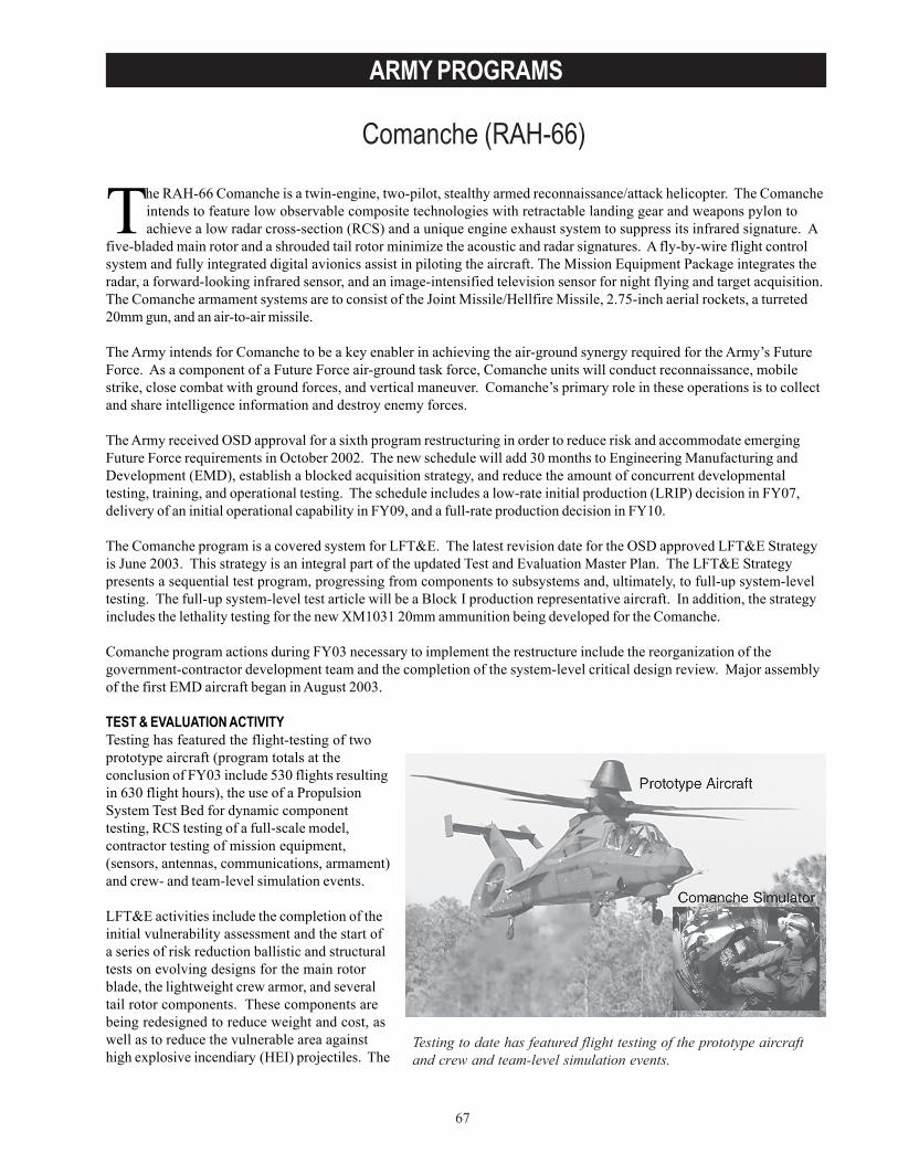
67
ARMY PROGRAMS
Comanche (RAH-66)
Testing to date has featured flight testing of the prototype aircraftand crew and team-level simulation events.
The RAH-66 Comanche is a twin-engine, two-pilot, stealthy armed reconnaissance/attack helicopter. The Comancheintends to feature low observable composite technologies with retractable landing gear and weapons pylon toachieve a low radar cross-section (RCS) and a unique engine exhaust system to suppress its infrared signature. A
five-bladed main rotor and a shrouded tail rotor minimize the acoustic and radar signatures. A fly-by-wire flight controlsystem and fully integrated digital avionics assist in piloting the aircraft. The Mission Equipment Package integrates theradar, a forward-looking infrared sensor, and an image-intensified television sensor for night flying and target acquisition.The Comanche armament systems are to consist of the Joint Missile/Hellfire Missile, 2.75-inch aerial rockets, a turreted20mm gun, and an air-to-air missile.
The Army intends for Comanche to be a key enabler in achieving the air-ground synergy required for the Army’s FutureForce. As a component of a Future Force air-ground task force, Comanche units will conduct reconnaissance, mobilestrike, close combat with ground forces, and vertical maneuver. Comanche’s primary role in these operations is to collectand share intelligence information and destroy enemy forces.
The Army received OSD approval for a sixth program restructuring in order to reduce risk and accommodate emergingFuture Force requirements in October 2002. The new schedule will add 30 months to Engineering Manufacturing andDevelopment (EMD), establish a blocked acquisition strategy, and reduce the amount of concurrent developmentaltesting, training, and operational testing. The schedule includes a low-rate initial production (LRIP) decision in FY07,delivery of an initial operational capability in FY09, and a full-rate production decision in FY10.
The Comanche program is a covered system for LFT&E. The latest revision date for the OSD approved LFT&E Strategyis June 2003. This strategy is an integral part of the updated Test and Evaluation Master Plan. The LFT&E Strategypresents a sequential test program, progressing from components to subsystems and, ultimately, to full-up system-leveltesting. The full-up system-level test article will be a Block I production representative aircraft. In addition, the strategyincludes the lethality testing for the new XM1031 20mm ammunition being developed for the Comanche.
Comanche program actions during FY03 necessary to implement the restructure include the reorganization of thegovernment-contractor development team and the completion of the system-level critical design review. Major assemblyof the first EMD aircraft began in August 2003.
TEST & EVALUATION ACTIVITYTesting has featured the flight-testing of twoprototype aircraft (program totals at theconclusion of FY03 include 530 flights resultingin 630 flight hours), the use of a PropulsionSystem Test Bed for dynamic componenttesting, RCS testing of a full-scale model,contractor testing of mission equipment,(sensors, antennas, communications, armament)and crew- and team-level simulation events.
LFT&E activities include the completion of theinitial vulnerability assessment and the start ofa series of risk reduction ballistic and structuraltests on evolving designs for the main rotorblade, the lightweight crew armor, and severaltail rotor components. These components arebeing redesigned to reduce weight and cost, aswell as to reduce the vulnerable area againsthigh explosive incendiary (HEI) projectiles. The
68
ARMY PROGRAMS
risk reduction ballistic effort will provide data to assist in the validation and verification of a finite element analysis modelthat will be used to determine the dynamic structural response of the tail rotor system when impacted by HEI projectiles.There is still an open issue with the Army to determine the specific configuration of the full-up system-level test articlewith specific emphasis on deciding whether to have fully operational avionics components installed versusrepresentative non-functional ones. The latter approach could avoid damaging valuable avionics hardware; yet still havenecessary avionics operation for the test. An Event Design Plan describing the lethality evaluation for the 20mmprojectile is complete and OSD-approved.
TEST & EVALUATION ASSESSMENTTechnical challenges remain for software integration and testing of mission equipment, weight reduction, radarsignatures, antenna performance, gun system performance, and aided target detection algorithm performance. Since therestructure, the Program Office identified engineering solutions to the known technical challenges. The efficacy of thosesolutions and identification of the unknown issues will not become apparent until developmental testing begins in FY05.The approved Comanche test program will provide ample opportunity to evaluate these technical issues and determinethe effectiveness and suitability of the Comanche helicopter.
The Comanche program retains a medium-risk strategy for integration and testing of mission equipment on the aircraft.Software for delivery prior to LRIP will have minimal function (no armament, radar, aircraft survivability equipment, ordigital communications). Integration testing of most mission equipment software and advanced functionality occurs inthe last year of EMD. Memory requirements, software throughput, and bus requirements for several subsystems areprojected to exceed allocations.
Empty weight projections for Block I, II, and III aircraft are slightly higher than weight goals for each block. Projectedaircraft performance at these projected weights meet ORD requirements for vertical rate-of-climb. To achieve theseprojections, the Army must keep weight growth during development lower than historical averages and also successfullyimplement weight reduction initiatives.
Based on analysis of current designs and limited testing on a contractor range, the radar warning receiver and twocommunications antennas do not meet some RCS allocations. The satellite receiver antenna does not meet performancerequirements, and the radar warning receiver sensitivity is marginal. Efforts to reduce the RCS are likely to adverselyaffect the performance of already marginal antennas.
While the Program Office has taken steps to begin design of a telemetry antenna for the Operational Test and TrainingInstrumentation System (OTTIS) that will limit the effect of the system on the RCS of the Comanche platform, thisremains a risk area. The OTTIS system requires the installation of an external antenna that could have a large RCSsignature, perhaps eclipsing the radar signature of the remainder of the aircraft. In testing and training environments, theComanche radar signature could potentially be much larger than the wartime signature. If so, the Army’s maxim to “trainas you fight” will be compromised and the validity of susceptibility testing will be degraded.
The current turreted gun system design features a lightweight (312 pounds) 20mm armament system that makes it difficultto stabilize the gun and maintain accurate fire. Gun firing will also produce elevated barrel temperatures that rapidlyapproach the temperature limits of nearby composite components. After firing, the gun must remain deployed until thebarrel cools. Leaving the gun deployed increases the aircraft’s radar and infrared signatures compared to the stowedposition.
In laboratory testing, Comanche Aided Target Detection-Classification algorithm performance in known terrainenvironments is outstanding; however, in environments with complex thermal and spatial clutter, performance can bedegraded.
The LFT&E program remains adequate under the new acquisition strategy for Comanche. The LFT&E strategyanticipates completion of the program to support the Milestone III review in 1QFY10. The strategy includes componentqualification and subsystem level ballistic testing for over 20 critical components, and dynamic testing on the full-upproduction-representative aircraft. However, because of the late (2QFY08) delivery of the LFT&E aircraft, correction ofvulnerabilities discovered during LFT&E will be difficult to implement on initial production aircraft.
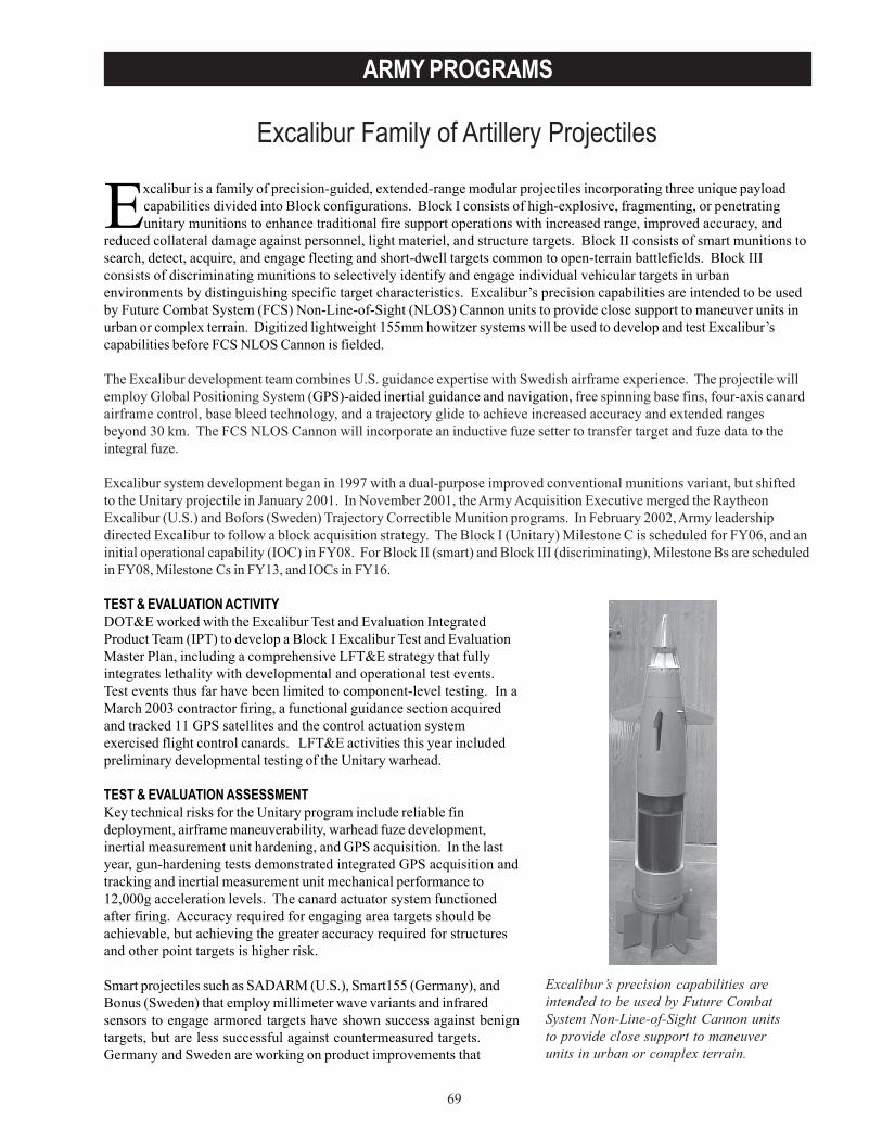
69
ARMY PROGRAMS
Excalibur Family of Artillery Projectiles
Excalibur is a family of precision-guided, extended-range modular projectiles incorporating three unique payloadcapabilities divided into Block configurations. Block I consists of high-explosive, fragmenting, or penetratingunitary munitions to enhance traditional fire support operations with increased range, improved accuracy, and
reduced collateral damage against personnel, light materiel, and structure targets. Block II consists of smart munitions tosearch, detect, acquire, and engage fleeting and short-dwell targets common to open-terrain battlefields. Block IIIconsists of discriminating munitions to selectively identify and engage individual vehicular targets in urbanenvironments by distinguishing specific target characteristics. Excalibur’s precision capabilities are intended to be usedby Future Combat System (FCS) Non-Line-of-Sight (NLOS) Cannon units to provide close support to maneuver units inurban or complex terrain. Digitized lightweight 155mm howitzer systems will be used to develop and test Excalibur’scapabilities before FCS NLOS Cannon is fielded.
The Excalibur development team combines U.S. guidance expertise with Swedish airframe experience. The projectile willemploy Global Positioning System (GPS)-aided inertial guidance and navigation, free spinning base fins, four-axis canardairframe control, base bleed technology, and a trajectory glide to achieve increased accuracy and extended rangesbeyond 30 km. The FCS NLOS Cannon will incorporate an inductive fuze setter to transfer target and fuze data to theintegral fuze.
Excalibur system development began in 1997 with a dual-purpose improved conventional munitions variant, but shiftedto the Unitary projectile in January 2001. In November 2001, the Army Acquisition Executive merged the RaytheonExcalibur (U.S.) and Bofors (Sweden) Trajectory Correctible Munition programs. In February 2002, Army leadershipdirected Excalibur to follow a block acquisition strategy. The Block I (Unitary) Milestone C is scheduled for FY06, and aninitial operational capability (IOC) in FY08. For Block II (smart) and Block III (discriminating), Milestone Bs are scheduledin FY08, Milestone Cs in FY13, and IOCs in FY16.
TEST & EVALUATION ACTIVITYDOT&E worked with the Excalibur Test and Evaluation IntegratedProduct Team (IPT) to develop a Block I Excalibur Test and EvaluationMaster Plan, including a comprehensive LFT&E strategy that fullyintegrates lethality with developmental and operational test events.Test events thus far have been limited to component-level testing. In aMarch 2003 contractor firing, a functional guidance section acquiredand tracked 11 GPS satellites and the control actuation systemexercised flight control canards. LFT&E activities this year includedpreliminary developmental testing of the Unitary warhead.
TEST & EVALUATION ASSESSMENTKey technical risks for the Unitary program include reliable findeployment, airframe maneuverability, warhead fuze development,inertial measurement unit hardening, and GPS acquisition. In the lastyear, gun-hardening tests demonstrated integrated GPS acquisition andtracking and inertial measurement unit mechanical performance to12,000g acceleration levels. The canard actuator system functionedafter firing. Accuracy required for engaging area targets should beachievable, but achieving the greater accuracy required for structuresand other point targets is higher risk.
Smart projectiles such as SADARM (U.S.), Smart155 (Germany), andBonus (Sweden) that employ millimeter wave variants and infraredsensors to engage armored targets have shown success against benigntargets, but are less successful against countermeasured targets.Germany and Sweden are working on product improvements that
Excalibur’s precision capabilities areintended to be used by Future CombatSystem Non-Line-of-Sight Cannon unitsto provide close support to maneuverunits in urban or complex terrain.
70
ARMY PROGRAMS
should make the technology more effective by the start of the Block II and III programs. Technology that discriminatesbetween individual targets is unproven.
The testing for the XM982-Unitary munition described in the draft LFT&E strategy is fully integrated with planneddevelopmental and operational testing, in order to efficiently use available test resources. There are no dedicated, full-up,system-level, LFT&E events. Realistic gun-fired lethality testing is planned during developmental test events using a livefire target array consisting of mixed personnel and light materiel targets, and threat representative structure targets ofspecified construction. Warhead technical testing, and some gun-fired testing, will be completed in time to support aMilestone C decision review.
Excalibur may be susceptible to GPS jamming. If GPS jammers are employed in the vicinity of the target, then the Armyexpects Excalibur to use its inertial navigation system to hit the target. However, if jamming prevents initial GPSacquisition, then the round will follow a ballistic trajectory instead of achieving guided flight and may endanger friendlyforces in the area of the ballistic round’s impact.
Excalibur will require accurate target location data in order to achieve desired effects for the Unitary variant. Targetlocation errors will need to be 35 meters or less for personnel targets, and approximately 10 meters or less for targetsrequiring a direct hit.
Test and evaluation issues to be resolved during the Test and Evaluation Master Plan development include the selectionof an adequate test site that can accommodate testing in a GPS-jammed environment at the extended range Excaliburoffers, and identification of appropriate targets and quantity of fire missions for the IOT&E.

71
ARMY PROGRAMS
Family of Medium Tactical Vehicles (FMTV)
The program intends to provide armor kits for use on trucks deployedto Iraq.
The Family of Medium Tactical Vehicles (FMTV) is a family of 2.5-ton and 5-ton vehicles and trailers based on acommon truck cab, chassis, and internal components. The trucks’ components are primarily non-developmentalitems integrated in rugged tactical configurations. The light-medium tactical vehicles are 2.5-ton payload capacity
models consisting of cargo, airdrop cargo, and van variants. The medium tactical vehicles are 5-ton payload capacitymodels consisting of cargo (with and without material handling crane), long wheel base cargo (with and without materialhandling crane), airdrop cargo, tractor, wrecker, dump, and airdrop dump variants. New variants not yet operationallytested or in production are a 5-ton expansible van, a load handling system (palletized loading) truck-with-trailer, and a10-ton dump truck. The Army designated the first 11,000 of the trucks produced the A0 version; subsequent productiontrucks are designated the A1 version. The Army has a total acquisition objective of 83,000 trucks and 10,000 trailers; andhas fielded over 21,000 A0 and A1 trucks and 1,300 trailers.
The Army conducted initial operational testing at Ft. Bragg, North Carolina, in three phases. Phase I, conductedSeptember-December 1993, was terminated for poor demonstrated reliability. Phase II, conducted June-November 1994,was interrupted and cancelled when the soldiers of the test unit deployed to Haiti. Phase III, conducted April-July 1995,was the basis of the DOT&E test and evaluation report to Congress.
The Army made the first full-rate production decision in August 1995. During 2003 the contract was re-competed in aprogram called the FMTV Competitive Re-buy. The Army awarded the contract to Stewart and Stevenson TacticalVehicle Systems (the incumbent).
TEST & EVALUATION ACTIVITYFMTV testing during FY03 included follow-on production testing to verify the performance and quality of currentproduction A1 vehicles. Testing also included government competitive testing to verify performance, reliability, maintainability, and conformance to the technical data package of the upgraded A1 vehicles submitted by the twoCompetitive Re-buy contractors.
Limited User Tests are planned for the expansible van in June 2005, the load-handling system in October 2005, and the10-ton dump truck in May 2006.
TEST & EVALUATION ASSESSMENTBased on prior operational test and evaluation and current production testing, the FMTV trucks continue to be effectiveand suitable. The reliability for each of the variants has improved from the A0 to the re-buy trucks. The minor changesbetween the A1 truck and the re-buy trucks do not require additional operational testing. Residual concerns can beaddressed in the planned production verification tests and the limited user tests of the expansible van, the load-handlingsystem truck-with-trailer, and the 10-ton dumptruck. The Test and Evaluation Master Planwill be updated to reflect this. The programintends to provide armor kits for use on trucksdeployed to Iraq. The Test and EvaluationMaster Plan will include plans to conductsurvivability testing of trucks with thesearmor kits. Although safety issues related tofailed drivelines have been addressed withmodified driveshafts, the program office isinvestigating an improved driveshaft.DOT&E will follow this development.

72
ARMY PROGRAMS
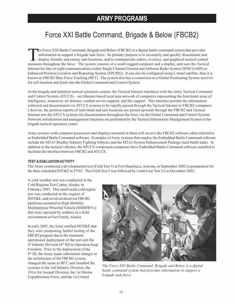
73
ARMY PROGRAMS
Force XXI Battle Command, Brigade & Below (FBCB2)
The Force XXI Battle Command, Brigade and Below is a digitalbattle command system that provides information to support abrigade task force.
The Force XXI Battle Command, Brigade and Below (FBCB2) is a digital battle command system that providesinformation to support a brigade task force. Its primary purpose is to accurately and quickly disseminate anddisplay friendly and enemy unit locations, and to communicate orders, overlays, and graphical tactical control
measures throughout the force. The system consists of a small-rugged computer and a display, and uses the TacticalInternet for line-of-sight communications (either Single Channel Ground and Airborne Radio System (SINCGARS) orEnhanced Position Location and Reporting System (EPLRS)). It can also be configured using L-band satellite, thus it isknown as FBCB2 Blue Force Tracking (BFT). The system also has a connection to a Global Positioning System receiverfor self-location and feeds into the Global Command and Control System.
At the brigade and battalion tactical operation centers, the Tactical Internet interfaces with the Army Tactical Commandand Control System (ATCCS) – an Ethernet-based local area network of computers representing the functional areas ofintelligence, maneuver, air defense, combat service support, and fire support. This interface permits the informationcollected and disseminated via ATCCS systems to be rapidly passed through the Tactical Internet to FBCB2 computers.Likewise, the position reports of individual and unit locations are passed upwards through the FBCB2 and TacticalInternet into the ATCCS systems for dissemination throughout the force via the Global Command and Control System.Network initialization and management functions are performed by the Tactical Information Management System at thebrigade tactical operation center.
Army systems with computer processors and displays mounted in them will receive the FBCB2 software often referred toas Embedded Battle Command software. Examples of Army systems that employ the Embedded Battle Command softwareinclude the M2A3 Bradley Infantry Fighting Vehicles and the M2A2 System Enhancement Package main battle tanks. Inaddition to the tactical vehicles, the ATCCS component computers have Embedded Battle Command software installed tofacilitate the interface between FBCB2 and ATCCS.
TEST & EVALUATION ACTIVITYThe Army conducted a developmental test (Field Test 5) at Fort Huachuca, Arizona, in September 2002 in preparation forthe then-scheduled IOT&E in FY03. This Field Test 5 was followed by Limit User Test 2A in December 2002.
A cold weather test was conducted at theCold Regions Test Center, Alaska, inFebruary 2003. This small-scale cold regiontest was conducted at the request ofDOT&E, and involved about ten FBCB2platforms mounted in High-MobilityMultipurpose Wheeled Vehicle (HMMWVs)that were operated by soldiers in a fieldenvironment at Fort Greely, Alaska.
In early 2003, the Army notified DOT&E thatthey were postponing further testing of theFBCB2 program due to the imminentoperational deployment of the test unit the4th Infantry Division (4th ID) to Operation IraqiFreedom. Prior to the deployment of the4th ID, the Army made substantial changes tothe architecture of the FBCB2 system,changed the name to BFT, and installed thesystems in the 3rd Infantry Division, the101st Air Assault Division, the 1st MarineExpeditionary Force, and the 1st United
74
ARMY PROGRAMS
Kingdom Armored Division – also as a part of Operation Iraqi Freedom. The BFT system relied upon L-band satelliteradio rather than the terrestrial EPLRS network of FBCB2, and was distributed in a much smaller density per division thanthe terrestrial FBCB2 in the 4th ID. In contrast to FBCB2, the purpose of BFT was to create a situational awarenesspicture for higher headquarters for use in tracking friendly units on a macro scale.
TEST & EVALUATION ASSESSMENTThe FBCB2 system continued to improve in performance through the test events conducted in 2003. During Field Test 5at Fort Huachuca, Arizona, the command and control message traffic achieved a message completion rate of over90 percent, including message traffic sent to the Army Battle Command System computers. Although there was messagesuccess, the system was plagued by the inability to reliably pass operational graphics between the FBCB2 andManeuver Control System. The point estimate of the mean time between failures for FBCB2 computers at Field Test 5was about 500 hours. While short of the requirement of 700 hours, this represented the best performance yet achievedby FBCB2.
The cold weather testing at Fort Greely likewise achieved improved performance. Darkened screens which previouslypresented an issue in earlier test events were no longer a problem, and the Tactical Internet and FBCB2 performance werenot seriously affected by the cold weather. The temperature range experienced at the test site during the test was+12 degrees to -30 degrees.
The performance of FBCB2 and BFT during Operation Iraqi Freedom was also generally favorable. DOT&E had access toafter-action reports from all of the units that employed either FBCB2 or BFT (with the exception of the 4th ID), and userresponse to the system has been positive. The BFT system in particular has been well received for the job it wasintended, which is providing an outline of friendly unit locations to senior commanders. In addition, the BFT systemcommunications through the L-band satellite has, in many cases, been reported as the only means of reliablecommunications available due to the extended ranges between units during the operation. The BFT system is to trackmovements, to navigate (particularly in periods of poor visibility), and to orient and plan for fires. Users have reported itas very helpful in coordinating unit linkups, and in avoiding fratricide incidents at unit boundaries.
In recognition of the capability that FBCB2 BFT provides, the Army will conduct a developmental test/operational test ofBlock I in February 2004. This, combined with other events and assessments, will constitute an IOT&E to support a full-rate production decision review for Block I. Following a full or conditional material release decision, the FBCB2 programwill need to provide a Test and Evaluation Master Plan to reflect the new operational concept, acquisition strategy, andtest requirements for the follow-on testing required to demonstrate completion of FBCB2 Block II requirements.However, there are FBCB2 Block II requirements that have not been met, especially the interfaces between the FBCB2and the other Army Battle Command System computers. The Army will continue to develop the FBCB2 Block II programwith another IOT&E required for that block to be held in the future, probably in FY05.
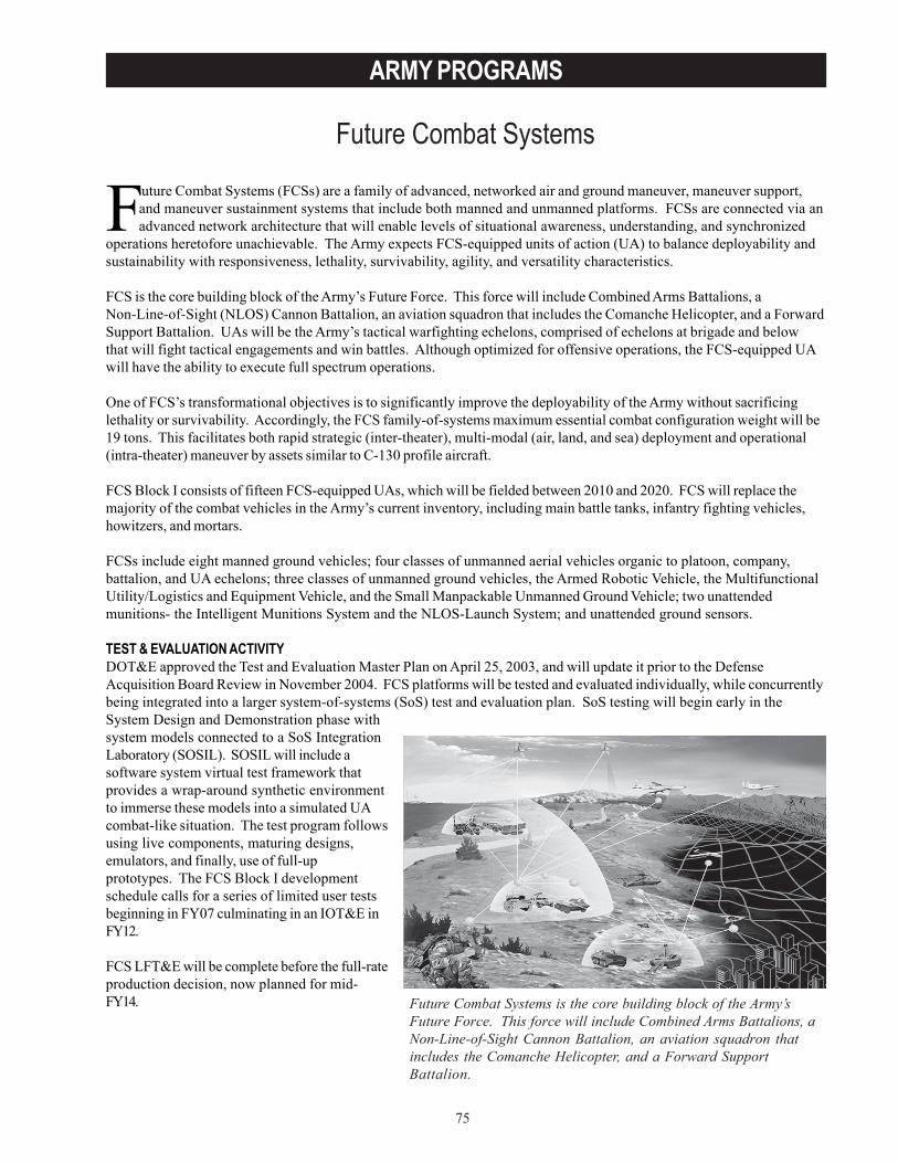
75
ARMY PROGRAMS
Future Combat Systems
Future Combat Systems is the core building block of the Army’sFuture Force. This force will include Combined Arms Battalions, aNon-Line-of-Sight Cannon Battalion, an aviation squadron thatincludes the Comanche Helicopter, and a Forward SupportBattalion.
Future Combat Systems (FCSs) are a family of advanced, networked air and ground maneuver, maneuver support,and maneuver sustainment systems that include both manned and unmanned platforms. FCSs are connected via anadvanced network architecture that will enable levels of situational awareness, understanding, and synchronized
operations heretofore unachievable. The Army expects FCS-equipped units of action (UA) to balance deployability andsustainability with responsiveness, lethality, survivability, agility, and versatility characteristics.
FCS is the core building block of the Army’s Future Force. This force will include Combined Arms Battalions, aNon-Line-of-Sight (NLOS) Cannon Battalion, an aviation squadron that includes the Comanche Helicopter, and a ForwardSupport Battalion. UAs will be the Army’s tactical warfighting echelons, comprised of echelons at brigade and belowthat will fight tactical engagements and win battles. Although optimized for offensive operations, the FCS-equipped UAwill have the ability to execute full spectrum operations.
One of FCS’s transformational objectives is to significantly improve the deployability of the Army without sacrificinglethality or survivability. Accordingly, the FCS family-of-systems maximum essential combat configuration weight will be19 tons. This facilitates both rapid strategic (inter-theater), multi-modal (air, land, and sea) deployment and operational(intra-theater) maneuver by assets similar to C-130 profile aircraft.
FCS Block I consists of fifteen FCS-equipped UAs, which will be fielded between 2010 and 2020. FCS will replace themajority of the combat vehicles in the Army’s current inventory, including main battle tanks, infantry fighting vehicles,howitzers, and mortars.
FCSs include eight manned ground vehicles; four classes of unmanned aerial vehicles organic to platoon, company,battalion, and UA echelons; three classes of unmanned ground vehicles, the Armed Robotic Vehicle, the MultifunctionalUtility/Logistics and Equipment Vehicle, and the Small Manpackable Unmanned Ground Vehicle; two unattendedmunitions- the Intelligent Munitions System and the NLOS-Launch System; and unattended ground sensors.
TEST & EVALUATION ACTIVITYDOT&E approved the Test and Evaluation Master Plan on April 25, 2003, and will update it prior to the DefenseAcquisition Board Review in November 2004. FCS platforms will be tested and evaluated individually, while concurrentlybeing integrated into a larger system-of-systems (SoS) test and evaluation plan. SoS testing will begin early in theSystem Design and Demonstration phase withsystem models connected to a SoS IntegrationLaboratory (SOSIL). SOSIL will include asoftware system virtual test framework thatprovides a wrap-around synthetic environmentto immerse these models into a simulated UAcombat-like situation. The test program followsusing live components, maturing designs,emulators, and finally, use of full-upprototypes. The FCS Block I developmentschedule calls for a series of limited user testsbeginning in FY07 culminating in an IOT&E inFY12.
FCS LFT&E will be complete before the full-rateproduction decision, now planned for mid-FY14.
76
ARMY PROGRAMS
TEST & EVALUATION ASSESSMENTA program of this magnitude, timeline, and payoff does not come without technical or programmatic risks. The Army’splan is to organize, train, test, and equip a mission-capable FCS by FY12. As such, the development of a family of highlycomplex vehicles and the sophisticated command and control network associated with these platforms will be a challengegiven the current schedule.
In particular, the Army’s FCS concept rests upon a network of sensors, platforms, and command nodes linked by reliablehigh-bandwidth and high-speed communications – all capabilities that do not yet exist. In addition, advanced modelingand simulation (M&S) is expected to support both the execution of live operational testing and FCS ballistic survivabilityevaluations. The current ballistic M&S is deficient in several areas, namely structural response of composite structures,ballistic shock, blast and mine damage, characterization of behind-armor debris, and quantification of componentvulnerability to such debris. In order to mitigate these known deficiencies, sufficient resources will have to be set asidein order for M&S to be an effective modeling tool for live operational testing or survivability evaluations. Efforts are alsoongoing within the Army to gain a real-time casualty assessment capability, which will be critical to adequate IOT&E.
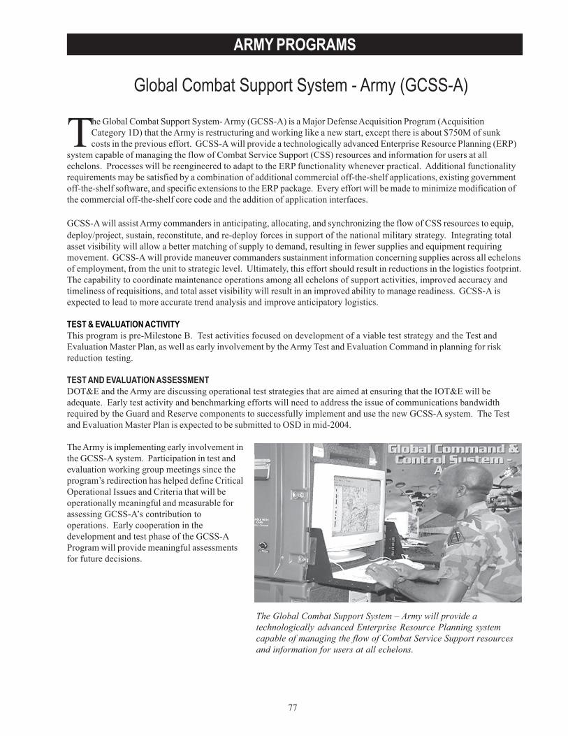
77
ARMY PROGRAMS
Global Combat Support System - Army (GCSS-A)
The Global Combat Support System- Army (GCSS-A) is a Major Defense Acquisition Program (AcquisitionCategory 1D) that the Army is restructuring and working like a new start, except there is about $750M of sunkcosts in the previous effort. GCSS-A will provide a technologically advanced Enterprise Resource Planning (ERP)
system capable of managing the flow of Combat Service Support (CSS) resources and information for users at allechelons. Processes will be reengineered to adapt to the ERP functionality whenever practical. Additional functionalityrequirements may be satisfied by a combination of additional commercial off-the-shelf applications, existing governmentoff-the-shelf software, and specific extensions to the ERP package. Every effort will be made to minimize modification ofthe commercial off-the-shelf core code and the addition of application interfaces.
GCSS-A will assist Army commanders in anticipating, allocating, and synchronizing the flow of CSS resources to equip,deploy/project, sustain, reconstitute, and re-deploy forces in support of the national military strategy. Integrating totalasset visibility will allow a better matching of supply to demand, resulting in fewer supplies and equipment requiringmovement. GCSS-A will provide maneuver commanders sustainment information concerning supplies across all echelonsof employment, from the unit to strategic level. Ultimately, this effort should result in reductions in the logistics footprint.The capability to coordinate maintenance operations among all echelons of support activities, improved accuracy andtimeliness of requisitions, and total asset visibility will result in an improved ability to manage readiness. GCSS-A isexpected to lead to more accurate trend analysis and improve anticipatory logistics.
TEST & EVALUATION ACTIVITYThis program is pre-Milestone B. Test activities focused on development of a viable test strategy and the Test andEvaluation Master Plan, as well as early involvement by the Army Test and Evaluation Command in planning for riskreduction testing.
TEST AND EVALUATION ASSESSMENTDOT&E and the Army are discussing operational test strategies that are aimed at ensuring that the IOT&E will beadequate. Early test activity and benchmarking efforts will need to address the issue of communications bandwidthrequired by the Guard and Reserve components to successfully implement and use the new GCSS-A system. The Testand Evaluation Master Plan is expected to be submitted to OSD in mid-2004.
The Army is implementing early involvement inthe GCSS-A system. Participation in test andevaluation working group meetings since theprogram’s redirection has helped define CriticalOperational Issues and Criteria that will beoperationally meaningful and measurable forassessing GCSS-A’s contribution tooperations. Early cooperation in thedevelopment and test phase of the GCSS-AProgram will provide meaningful assessmentsfor future decisions.
The Global Combat Support System – Army will provide atechnologically advanced Enterprise Resource Planning systemcapable of managing the flow of Combat Service Support resourcesand information for users at all echelons.

78
ARMY PROGRAMS
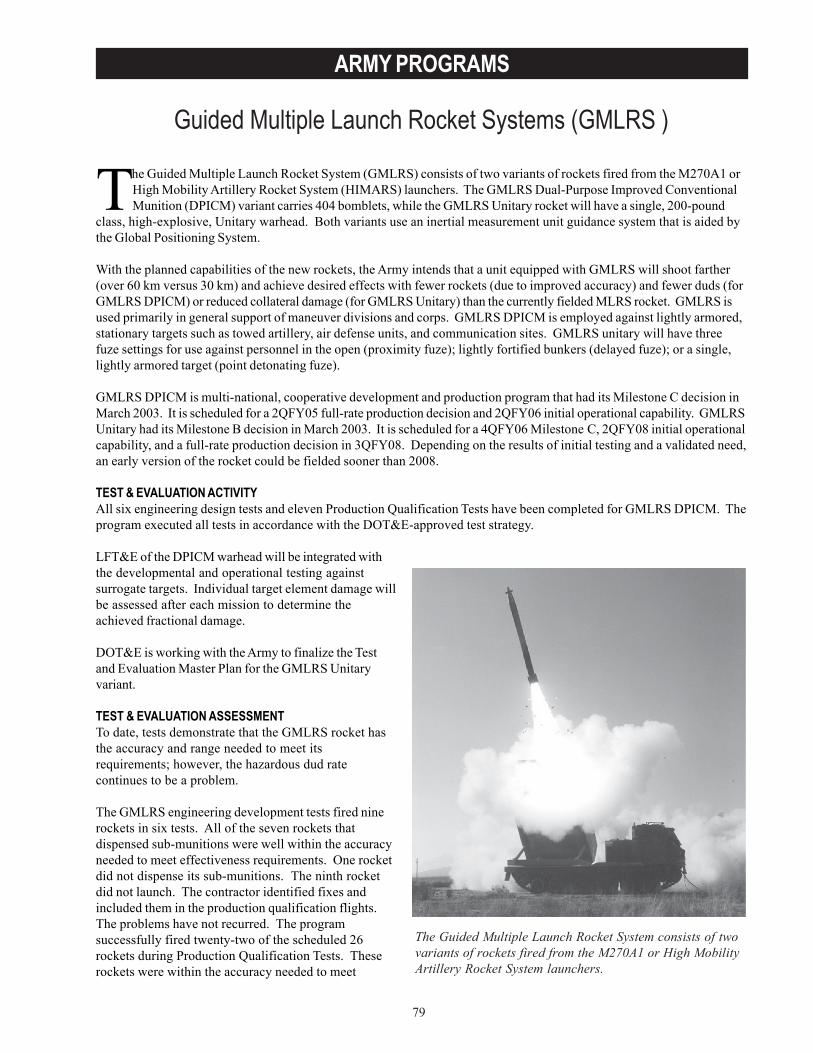
79
ARMY PROGRAMS
Guided Multiple Launch Rocket Systems (GMLRS )
The Guided Multiple Launch Rocket System consists of twovariants of rockets fired from the M270A1 or High MobilityArtillery Rocket System launchers.
The Guided Multiple Launch Rocket System (GMLRS) consists of two variants of rockets fired from the M270A1 orHigh Mobility Artillery Rocket System (HIMARS) launchers. The GMLRS Dual-Purpose Improved ConventionalMunition (DPICM) variant carries 404 bomblets, while the GMLRS Unitary rocket will have a single, 200-pound
class, high-explosive, Unitary warhead. Both variants use an inertial measurement unit guidance system that is aided bythe Global Positioning System.
With the planned capabilities of the new rockets, the Army intends that a unit equipped with GMLRS will shoot farther(over 60 km versus 30 km) and achieve desired effects with fewer rockets (due to improved accuracy) and fewer duds (forGMLRS DPICM) or reduced collateral damage (for GMLRS Unitary) than the currently fielded MLRS rocket. GMLRS isused primarily in general support of maneuver divisions and corps. GMLRS DPICM is employed against lightly armored,stationary targets such as towed artillery, air defense units, and communication sites. GMLRS unitary will have threefuze settings for use against personnel in the open (proximity fuze); lightly fortified bunkers (delayed fuze); or a single,lightly armored target (point detonating fuze).
GMLRS DPICM is multi-national, cooperative development and production program that had its Milestone C decision inMarch 2003. It is scheduled for a 2QFY05 full-rate production decision and 2QFY06 initial operational capability. GMLRSUnitary had its Milestone B decision in March 2003. It is scheduled for a 4QFY06 Milestone C, 2QFY08 initial operationalcapability, and a full-rate production decision in 3QFY08. Depending on the results of initial testing and a validated need,an early version of the rocket could be fielded sooner than 2008.
TEST & EVALUATION ACTIVITYAll six engineering design tests and eleven Production Qualification Tests have been completed for GMLRS DPICM. Theprogram executed all tests in accordance with the DOT&E-approved test strategy.
LFT&E of the DPICM warhead will be integrated withthe developmental and operational testing againstsurrogate targets. Individual target element damage willbe assessed after each mission to determine theachieved fractional damage.
DOT&E is working with the Army to finalize the Testand Evaluation Master Plan for the GMLRS Unitaryvariant.
TEST & EVALUATION ASSESSMENTTo date, tests demonstrate that the GMLRS rocket hasthe accuracy and range needed to meet itsrequirements; however, the hazardous dud ratecontinues to be a problem.
The GMLRS engineering development tests fired ninerockets in six tests. All of the seven rockets thatdispensed sub-munitions were well within the accuracyneeded to meet effectiveness requirements. One rocketdid not dispense its sub-munitions. The ninth rocketdid not launch. The contractor identified fixes andincluded them in the production qualification flights.The problems have not recurred. The programsuccessfully fired twenty-two of the scheduled 26rockets during Production Qualification Tests. Theserockets were within the accuracy needed to meet
80
ARMY PROGRAMS
requirements. Four separate problems caused the four failures, in which three rockets failed to dispense their sub-munitions, and one rocket failed to launch. The contractor has identified the causes and will incorporate fixes into theproduction design. Rocket reliability is within the requirement for the program at this time; however, a higher reliabilitywill be required for the production rockets.
The required dud rate (less than 1 percent) has not been achieved. The Army hoped to achieve this requirement bymaking adjustments to the fuze of the current DPICM bomblet. Even with these changes, the dud rate varies as afunction of range between 1.2 and 7.6 percent. This is significantly better than the current MLRS M26 rocket, which hasaverage dud rates of 10 percent at 17 km and 8 percent at 37 km. The Army continues to experiment with fuzeadjustments, but it is unlikely the bomblet will meet the dud rate requirement for all ranges. Therefore, the Armyrequested changing the GMLRS sub-munition dud rate requirement to two percent averaged between ranges of 20 and60 km and four percent averaged for ranges between 15 to 20 km and 60 to 70 km. The Joint Requirements OversightCouncil approved this proposal in November 2003. The international partners are developing a self-destruct fuze, whichmight reduce the dud rate to less than one percent. Inclusion of this new fuze on the bomblet in production rocketsdepends on the results of upcoming tests and production costs.
Additional tests, including operational and live fire testing, are planned to demonstrate GMLRS DPICM effectivenessagainst countermeasured targets and to show its interoperability. All flight tests to date have been accomplished with amodified Improved Position Determining System launcher, as opposed to an operationally representative one. Plannedinteroperability testing, therefore, will demonstrate that GMLRS can be fired from the M270A1 and HIMARS launchers.
GMLRS Unitary will begin developmental testing in 2004.
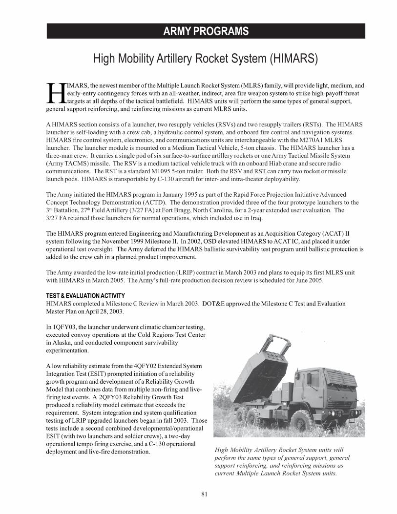
81
ARMY PROGRAMS
High Mobility Artillery Rocket System (HIMARS)
High Mobility Artillery Rocket System units willperform the same types of general support, generalsupport reinforcing, and reinforcing missions ascurrent Multiple Launch Rocket System units.
HIMARS, the newest member of the Multiple Launch Rocket System (MLRS) family, will provide light, medium, andearly-entry contingency forces with an all-weather, indirect, area fire weapon system to strike high-payoff threattargets at all depths of the tactical battlefield. HIMARS units will perform the same types of general support,
general support reinforcing, and reinforcing missions as current MLRS units.
A HIMARS section consists of a launcher, two resupply vehicles (RSVs) and two resupply trailers (RSTs). The HIMARSlauncher is self-loading with a crew cab, a hydraulic control system, and onboard fire control and navigation systems.HIMARS fire control system, electronics, and communications units are interchangeable with the M270A1 MLRSlauncher. The launcher module is mounted on a Medium Tactical Vehicle, 5-ton chassis. The HIMARS launcher has athree-man crew. It carries a single pod of six surface-to-surface artillery rockets or one Army Tactical Missile System(Army TACMS) missile. The RSV is a medium tactical vehicle truck with an onboard Hiab crane and secure radiocommunications. The RST is a standard M1095 5-ton trailer. Both the RSV and RST can carry two rocket or missilelaunch pods. HIMARS is transportable by C-130 aircraft for inter- and intra-theater deployability.
The Army initiated the HIMARS program in January 1995 as part of the Rapid Force Projection Initiative AdvancedConcept Technology Demonstration (ACTD). The demonstration provided three of the four prototype launchers to the3rd Battalion, 27th Field Artillery (3/27 FA) at Fort Bragg, North Carolina, for a 2-year extended user evaluation. The3/27 FA retained those launchers for normal operations, which included use in Iraq.
The HIMARS program entered Engineering and Manufacturing Development as an Acquisition Category (ACAT) IIsystem following the November 1999 Milestone II. In 2002, OSD elevated HIMARS to ACAT IC, and placed it underoperational test oversight. The Army deferred the HIMARS ballistic survivability test program until ballistic protection isadded to the crew cab in a planned product improvement.
The Army awarded the low-rate initial production (LRIP) contract in March 2003 and plans to equip its first MLRS unitwith HIMARS in March 2005. The Army’s full-rate production decision review is scheduled for June 2005.
TEST & EVALUATION ACTIVITYHIMARS completed a Milestone C Review in March 2003. DOT&E approved the Milestone C Test and EvaluationMaster Plan on April 28, 2003.
In 1QFY03, the launcher underwent climatic chamber testing,executed convoy operations at the Cold Regions Test Centerin Alaska, and conducted component survivabilityexperimentation.
A low reliability estimate from the 4QFY02 Extended SystemIntegration Test (ESIT) prompted initiation of a reliabilitygrowth program and development of a Reliability GrowthModel that combines data from multiple non-firing and live-firing test events. A 2QFY03 Reliability Growth Testproduced a reliability model estimate that exceeds therequirement. System integration and system qualificationtesting of LRIP upgraded launchers began in fall 2003. Thosetests include a second combined developmental/operationalESIT (with two launchers and soldier crews), a two-dayoperational tempo firing exercise, and a C-130 operationaldeployment and live-fire demonstration.
82
ARMY PROGRAMS
TEST & EVALUATION ASSESSMENTThe launcher chassis, RSV, and RST are mature, fielded, production vehicles, and the Hiab crane is a commercial item.Ninety-five percent of HIMARS software is common with the fielded M270A1 launcher, and the 1QFY04 ESIT will test anengineering release of MLRS/HIMARS software Version H. All but one of the Fire Control System line replaceable unitsare common with the M270A1, and that HIMARS launcher interface unit has completed system integration testing.HIMARS successfully fired all of the fielded MLRS family of munitions in qualification tests and demonstrated timelineand interoperability key performance parameters during the FY02 ESIT. However, the low-cost fire control paneldeveloped by the M270A1 program experienced problems when initially fielded, and its requalification forced a 3-weekdelay to the HIMARS launcher upgrades. The low cost fire control panel and an improved weapons interface unitdeveloped for firing Guided MLRS rockets were included in the fall 2003 testing.
A HIMARS Project Office accuracy analysis of HIMARS flight test results suggests that there is no statisticallysignificant difference in the accuracy of basic rockets fired from a HIMARS launcher and those fired from an M270 MLRSlauncher. DOT&E will conduct its own analysis of data from flight tests with LRIP configured launchers.
HIMARS is susceptible to ground attack and counterfire. Since the HIMARS cab does not provide ballistic protectionfor the crew, the crew must rely on concealment between missions, and rapid displacement after missions, to survive.The HIMARS initial operational test, scheduled for 4QFY04, will include a counterfire threat.
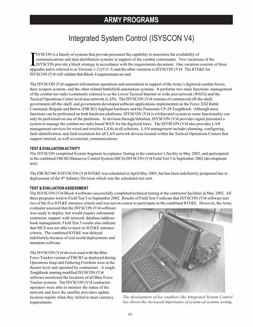
83
ARMY PROGRAMS
Integrated System Control (ISYSCON V4)
ISYSCON is a family of systems that provide personnel the capability to maximize the availability ofcommunications and data distribution systems in support of the combat commander. Two variations of theISYSCON provide a block strategy in accordance with the requirements document. One variation consists of three
upgrades and is referred to as Versions 1-3 ((V)1-3) and the other variation is ISYSCON (V)4. The IOT&E forISYSCON (V)4 will validate that Block 4 requirements are met.
The ISYSCON (V)4 supports information operations and automation in support of the Army’s digitized combat forces,their weapon systems, and the other related battlefield automation systems. It performs two main functions: managementof the combat net radio (commonly referred to as the Lower Tactical Internet or wide area network (WAN)) and theTactical Operations Center local area network (LAN). The ISYSCON (V)4 consists of commercial off-the-shelf,government off-the-shelf, and government-developed software applications implemented on the Force XXI BattleCommand, Brigade and Below (FBCB2) Appliqué hardware and the Panasonic CF-28 Toughbook. Although mostfunctions can be performed on both hardware platforms, ISYSCON (V)4 is a bifurcated system as some functionality canonly be performed on one of the platforms. At division through battalion, ISYSCON (V)4 provides signal personnel asystem to manage the combat net radio based WAN for the digitized force. The ISYSCON (V)4 also provides LANmanagement services for wired and wireless LANs at all echelons. LAN management includes planning, configuring,fault identification, and fault resolution for all LAN network devices located within the Tactical Operations Centers thatsupport internal, as well as external, communications.
TEST & EVALUATION ACTIVITYThe ISYSCON completed System Segment Acceptance Testing at the contractor’s facility in May 2002, and participatedin the combined FBCB2/Manuever Control System (MCS)/ISYSCON (V)4 Field Test 5 in September 2002 (developmenttest).
The FBCB2/MCS/ISYSCON (V)4 IOT&E was scheduled in April/May 2003, but has been indefinitely postponed due todeployment of the 4th Infantry Division which was the scheduled test unit.
TEST & EVALUATION ASSESSMENTThe ISYSCON (V)4 Block 4 software successfully completed technical testing at the contractor facilities in May 2002. Allthree programs went to Field Test 5 in September 2002. Results of Field Test 5 indicate that ISYSCON (V)4 software mettwo of the five IOT&E entrance criteria and was not on course to participate in the combined IOT&E. However, the Armyevaluator assessed that the ISYSCON (V)4 softwarewas ready to deploy, but would require substantialcontractor support with network database/address-book management. Field Test 5 results also indicatethat MCS was not able to meet its IOT&E entrancecriteria. The combined IOT&E was delayedindefinitely because of real world deployments andimmature software.
The ISYSCON (V)4 devices used with the BlueForce Tracker variant of FBCB2 as deployed duringOperations Iraqi and Enduring Freedom were at thetheater level and operated by contractors. A singleToughbook running modified ISYSCON (V)4software monitored the locations of all Blue ForceTracker systems. The ISYSCON (V)4 contractor-operators were able to monitor the status of thenetwork and have the satellite providers updatelocation reports when they failed to meet currencyrequirements.
The development of key enablers like Integrated System Controlhas shown the increased importance of system-of-systems testing.
84
ARMY PROGRAMS
ISYSCON(V)4 is deployed within the original terrestrial-based communications architecture with the digitized forces ofthe 4th Infantry Division in Iraq. DOT&E has received no information as to ISYSCON (V)4 performance in support of the4th Infantry Division.
It is not known when the combined FBCB2/MCS/ISYSCON (V)4 IOT&E can be scheduled due to test unit deployments.The Army is planning to conduct a development test/operational test in 2QFY04 and, combined with available data fromOperation Iraqi Freedom, is seeking a full-rate production decision for FBCB2 Blue Force Tracker in FY04. ISYSCON (V)4is developing a test and evaluation strategy to also support a full-rate production decision in FY04. DOT&E is workingwith the Army to ensure IOT&E standards are met.
The development of key enablers like ISYSCON has shown the increased importance of system-of-systems testing, andthe difficulties that arise in coordinating requirements, development and fielding schedules, threats, scenarios, and testarchitectures. As the Army continues to move towards the Future Force and Future Combat System, it should derivemany lessons learned from these programs and the challenges associated with combined test events.

85
ARMY PROGRAMSJoint Land Attack Cruise Missile Defense Elevated Netted Sensor
(JLENS)
The Joint Land Attack Cruise Missile Defense ElevatedNetted Sensor System is an airborne radar platform designedto provide surveillance and fire control quality radar dataon Land Attack Cruise Missiles and other air-breathingtargets.
The Joint Land Attack Cruise Missile Defense Elevated Netted Sensor System (JLENS) is an airborne radar platformdesigned to provide surveillance and fire control quality radar data on Land Attack Cruise Missiles and other air-breathing targets. The system also acquires and tracks moving surface targets and supports detection of tactical
ballistic missiles.
A JLENS system consists of two aerostats, one containing a Surveillance Radar (SuR) and one containing a PrecisionTrack Illumination Radar (PTIR). The aerostats are non-developmental, 71-meter, unmanned, tethered, non-rigidaerodynamic structures filled with helium and air. Each aerostat is tethered to a mobile mooring station and attached to aprocessing station via a fiber optic/power tether. The SuR provides the initial target detection and then cueing to thePTIR, which generates a fire control quality track. The JLENS system is integrated into the Joint Tactical Architecture viaLink 16, Cooperative Engagement Capability, Single-Channel Ground and Air Radio System, and Enhanced PositionLocation Reporting System. The system provides key contributions to generation of a Single Integrated Air Picture,through the fusion of high accuracy long-range tracking and target classification information with that of other sensorsin the Joint Air and Missile Defense architecture. Both radar systems will include Identification, Friend or Foeinterrogators.
Weapons systems, such as Patriot, Navy Standard Missile, the Marine Corps Complementary Low Altitude WeaponsSystem, and the Army Surface Launched Advanced Medium-Range Air-to-Air Missile (SLAMRAAM), can use theJLENS PTIR data to engage low-flying terrain-masked cruise missiles before their own ground-based sensors can detectthem. JLENS supports air-directed surface-to-air-missile and air-directed air-to-air missile engagements through both theengage-on-remote and forward-pass mechanisms.
The Army restructured the JLENS program in FY03. The Block 1 program now consists of three spirals. The first spiralinvolves the integration of AN/MPQ-64 radars on 32-meter aerostats. Spiral 1 will demonstrate the JLENS concept;support the development of Tactics, Techniques and Procedures (TTP); and support the SLAMRAAM program. Onlyone Spiral 1 system will be produced. Spiral 2 consists primarily of hardware and software upgrade in a laboratoryenvironment. Spiral 3 is the development andintegration of the PITR on 71-meter aerostats.
The JLENS program deployed a 15 meter aerostat toAfghanistan in support of Operation EnduringFreedom. The aerostat carried an electro-optical/infrared package to support force protection activities.
TEST & EVALUATION ACTIVITYThe Army initiated test planning with the formationand convening of a JLENS Test and EvaluationWorking Integrated Product Team.
The draft Test and Evaluation Master Plan is beingupdated to reflect the program’s spiral acquisitionstrategy.
Completion of the Test and Evaluation Master Planremains dependent on the approval of a CapabilityDevelopment Document.
TEST & EVALUATION ASSESSMENTJLENS was scheduled for demonstrations duringRoving Sands 03, which was cancelled due toOperation Iraqi Freedom.

86
ARMY PROGRAMS
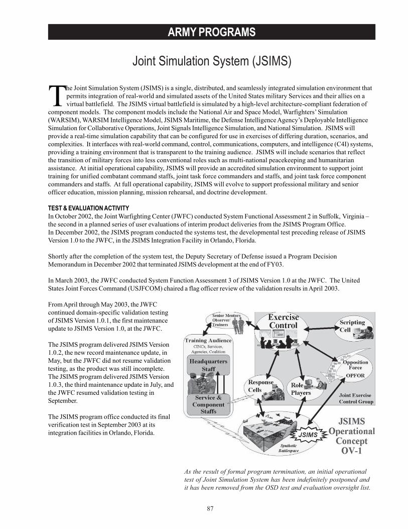
87
ARMY PROGRAMS
Joint Simulation System (JSIMS)
As the result of formal program termination, an initial operationaltest of Joint Simulation System has been indefinitely postponed andit has been removed from the OSD test and evaluation oversight list.
The Joint Simulation System (JSIMS) is a single, distributed, and seamlessly integrated simulation environment thatpermits integration of real-world and simulated assets of the United States military Services and their allies on avirtual battlefield. The JSIMS virtual battlefield is simulated by a high-level architecture-compliant federation of
component models. The component models include the National Air and Space Model, Warfighters’ Simulation(WARSIM), WARSIM Intelligence Model, JSIMS Maritime, the Defense Intelligence Agency’s Deployable IntelligenceSimulation for Collaborative Operations, Joint Signals Intelligence Simulation, and National Simulation. JSIMS willprovide a real-time simulation capability that can be configured for use in exercises of differing duration, scenarios, andcomplexities. It interfaces with real-world command, control, communications, computers, and intelligence (C4I) systems,providing a training environment that is transparent to the training audience. JSIMS will include scenarios that reflectthe transition of military forces into less conventional roles such as multi-national peacekeeping and humanitarianassistance. At initial operational capability, JSIMS will provide an accredited simulation environment to support jointtraining for unified combatant command staffs, joint task force commanders and staffs, and joint task force componentcommanders and staffs. At full operational capability, JSIMS will evolve to support professional military and seniorofficer education, mission planning, mission rehearsal, and doctrine development.
TEST & EVALUATION ACTIVITYIn October 2002, the Joint Warfighting Center (JWFC) conducted System Functional Assessment 2 in Suffolk, Virginia –the second in a planned series of user evaluations of interim product deliveries from the JSIMS Program Office.In December 2002, the JSIMS program conducted the systems test, the developmental test preceding release of JSIMSVersion 1.0 to the JWFC, in the JSIMS Integration Facility in Orlando, Florida.
Shortly after the completion of the system test, the Deputy Secretary of Defense issued a Program DecisionMemorandum in December 2002 that terminated JSIMS development at the end of FY03.
In March 2003, the JWFC conducted System Function Assessment 3 of JSIMS Version 1.0 at the JWFC. The UnitedStates Joint Forces Command (USJFCOM) chaired a flag officer review of the validation results in April 2003.
From April through May 2003, the JWFCcontinued domain-specific validation testingof JSIMS Version 1.0.1, the first maintenanceupdate to JSIMS Version 1.0, at the JWFC.
The JSIMS program delivered JSIMS Version1.0.2, the new record maintenance update, inMay, but the JWFC did not resume validationtesting, as the product was still incomplete.The JSIMS program delivered JSIMS Version1.0.3, the third maintenance update in July, andthe JWFC resumed validation testing inSeptember.
The JSIMS program office conducted its finalverification test in September 2003 at itsintegration facilities in Orlando, Florida.
88
ARMY PROGRAMS
TEST & EVALUATION ASSESSMENTThe developmental and user tests have demonstrated that JSIMS Version 1 consistently has problems with setup at usersites, initialization of a federation of component models, stability of operations, running at the required rate of real timeeven with small scenarios, interfacing with C4I systems, and incomplete and error-prone functionality. All of thesedifficulties justified suspension of validation testing at the JWFC after the USJFCOM review in April 2003.
The scheduled events continued to slip. In accordance with the Program Decision Memorandum, user validation was tobe complete by the end of FY03. Due to the immaturity of the software, validation has now been extended into 1QFY04.USJFCOM has suspended planned use of JSIMS in support of joint task force training exercises until the software canmeet the required standards.
The Program Decision Memorandum directed an Analysis of Alternatives (AoA) be conducted in FY04 to determineoptions for Joint Task Force Commander Training. DOT&E will support the AoA as needed. As the result of formalprogram termination, an initial operational test of JSIMS has been indefinitely postponed and it has been removed fromthe OSD test and evaluation oversight list.
On October 1, 2003, the JSIMS Program Office was closed and the JWFC took responsibility for JSIMS. The ProgramDecision Memorandum provides limited funding to maintain the existing software and to fix known problems. At thispoint, no new development on JSIMS is expected.
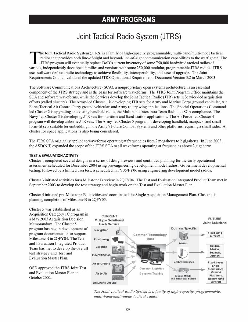
89
ARMY PROGRAMS
Joint Tactical Radio System (JTRS)
The Joint Tactical Radio System (JTRS) is a family of high-capacity, programmable, multi-band/multi-mode tacticalradios that provides both line-of-sight and beyond-line-of-sight communication capabilities to the warfighter. TheJTRS program will eventually replace DoD’s current inventory of some 750,000 hardwired tactical radios of
various, independently developed families and versions with some 250,000 modular, programmable JTRS radios. JTRSuses software defined radio technology to achieve flexibility, interoperability, and ease of upgrade. The JointRequirements Council validated the updated JTRS Operational Requirements Document Version 3.2 in March 2003.
The Software Communications Architecture (SCA), a nonproprietary open systems architecture, is an essentialcomponent of the JTRS strategy and is the basis for software waveforms. The JTRS Joint Program Office maintains theSCA and software waveforms, while the Services develop the Joint Tactical Radio (JTR) sets in Service-led acquisitionefforts (called clusters). The Army-led Cluster 1 is developing JTR sets for Army and Marine Corps ground vehicular, AirForce Tactical Air Control Party ground vehicular, and Army rotary wing applications. The Special Operations Command-led Cluster 2 is upgrading an existing handheld radio, the Multiband Inter/Intra Team Radio, to SCA compliance. TheNavy-led Cluster 3 is developing JTR sets for maritime and fixed-station applications. The Air Force-led Cluster 4program will develop airborne JTR sets. The Army-led Cluster 5 program is developing handheld, manpack, and smallform-fit sets suitable for embedding in the Army’s Future Combat Systems and other platforms requiring a small radio. Acluster for space applications is also being considered.
The JTRS SCA originally applied to waveforms operating at frequencies from 2 megahertz to 2 gigahertz. In June 2003,the ASD(NII) expanded the scope of the JTRS SCA to all waveforms operating at frequencies above 2 gigahertz.
TEST & EVALUATION ACTIVITYCluster 1 completed several designs in a series of design reviews and continued planning for the early operationalassessment scheduled for December 2004 using pre-engineering development model radios. Government developmentaltesting, followed by a limited user test, is scheduled in FY05/FY06 using engineering development model radios.
Cluster 3 initiated activities for a Milestone B review in 2QFY04. The Test and Evaluation Integrated Product Team met inSeptember 2003 to develop the test strategy and begin work on the Test and Evaluation Master Plan.
Cluster 4 initiated pre-Milestone B activities and coordinated the Single Acquisition Management Plan. Cluster 4 isplanning completion of Milestone B in 2QFY05.
Cluster 5 was established as anAcquisition Category 1C program ina May 2003 Acquisition DecisionMemorandum. The Cluster 5program has begun development ofprogram documentation to supportMilestone B in 2QFY04. The Testand Evaluation Integrated ProductTeam has met to develop the overalltest strategy and Test andEvaluation Master Plan.
OSD approved the JTRS Joint Testand Evaluation Master Plan inOctober 2002.
The Joint Tactical Radio System is a family of high-capacity, programmable,multi-band/multi-mode tactical radios.
90
ARMY PROGRAMS
TEST & EVALUATION ASSESSMENTThe JTRS Cluster 1- Ground and Rotary Wing is aggressively executing the planned program and refining the design ofthe Cluster 1 radios. The Program Office delayed the early operational assessment by four months, to December 2004, toaccommodate concerns over the maturity and anticipated functionality of the JTR sets. The functionality of the JTR setsfor the early operational assessment continues to evolve. The program schedule, identified as high-risk at Milestone B,continues as high-risk.
The JTRS Cluster 3- Maritime/Fixed Station is planning Milestone B in 2QFY04. The program is coordinating requireddocumentation through the various integrated product teams. The basic acquisition strategy states that contracts areawarded at Milestone B to two prime system contractors. The program will then select one of the prime systemcontractors to continue into system demonstration at the Critical Design Review in 2005. The system demonstrationphase culminates with an operational assessment and Milestone C decision in 2007 for the program to enter low-rateinitial production in order to support an operational test and full-rate production decision in 2008/2009. Risks are similarto those identified for the JTRS Cluster 1, particularly risks associated with the success-oriented schedule and budget.
The JTRS Cluster 4- Airborne initiated its pre-system development and demonstration phase for requirements definition,conceptual design efforts, and airborne network architecture definition. DOT&E provided comments on the SingleAcquisition Management Plan and identified concerns with the schedule and proposal to possibly use engineeringdevelopmental models in the IOT&E. When started, the Test and Evaluation Integrated Product Team will furtherdiscuss these concerns when developing the test strategy and the Test and Evaluation Master Plan.
The JTRS Cluster 5- Handheld, Manpack, and Small Form-Fit sets initiated activity as a result of the May 2003Acquisition Decision Memorandum. The Test and Evaluation Integrated Product Team met to develop a test strategystarting in July 2003. Concerns include the aggressive schedule, ability of initial products to fulfill all requirements of theBlock I Operational Requirements Document, and the proposal to use engineering developmental models for the Block Ioperational test. The Test and Evaluation Integrated Product Team will address these concerns when developing theTest and Evaluation Master Plan.
An emerging concern across the JTRS Clusters is the proposal to use engineering developmental models in their IOT&Eto alleviate aggressive development and fielding schedules. The various definitions and maturity standards forengineering developmental models could encompass production representative equipment. However, OSD policy is thatthe equipment used in operational testing be production-representative in functionality and essential physicalcharacteristics to support accurate and valid assessments of operational effectiveness, operational suitability, andsurvivability. DOT&E will continue to apply this standard to any equipment entering IOT&E regardless of itsdesignation.
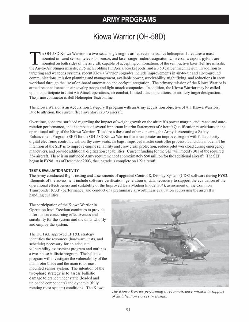
91
ARMY PROGRAMS
Kiowa Warrior (OH-58D)
The Kiowa Warrior performing a reconnaissance mission in supportof Stabilization Forces in Bosnia.
The OH-58D Kiowa Warrior is a two-seat, single engine armed reconnaissance helicopter. It features a mast-mounted infrared sensor, television sensor, and laser range-finder/designator. Universal weapons pylons aremounted on both sides of the aircraft, capable of accepting combinations of the semi-active laser Hellfire missile,
the Air-to-Air Stinger missile, 2.75 inch Folding Fin Aerial Rocket pods, and a 0.50 caliber machine gun. In addition totargeting and weapons systems, recent Kiowa Warrior upgrades include improvements in air-to-air and air-to-groundcommunications, mission planning and management, available power, survivability, night flying, and reductions in crewworkload through the use of on-board automation and cockpit integration. The primary mission of the Kiowa Warrior isarmed reconnaissance in air cavalry troops and light attack companies. In addition, the Kiowa Warrior may be calledupon to participate in Joint Air Attack operations, air combat, limited attack operations, or artillery target designation.The prime contractor is Bell Helicopter Textron, Inc.
The Kiowa Warrior is an Acquisition Category II program with an Army acquisition objective of 411 Kiowa Warriors.Due to attrition, the current fleet inventory is 373 aircraft.
Over time, concerns surfaced regarding the impact of weight growth on the aircraft’s power margin, endurance and auto-rotation performance, and the impact of several important Interim Statements of Aircraft Qualification restrictions on theoperational utility of the Kiowa Warrior. To address these and other concerns, the Army is executing a SafetyEnhancement Program (SEP) for the OH-58D Kiowa Warrior that incorporates an improved engine with full authoritydigital electronic control, crashworthy crew seats, air bags, improved master controller processor, and data modem. Theintention of the SEP is to improve engine reliability and crew crash protection, reduce pilot workload during emergencymaneuvers, and provide additional digitization capabilities. Current funding for the SEP will modify 301 of the required354 aircraft. There is an unfunded Army requirement of approximately $90 million for the additional aircraft. The SEPbegan in FY98. As of December 2003, the upgrade is complete on 192 aircraft.
TEST & EVALUATION ACTIVITYThe Army conducted flight-testing and assessments of upgraded Control & Display System (CDS) software during FY03.Elements of the assessment include software verification; generation of data necessary to support the evaluation of theoperational effectiveness and suitability of the Improved Data Modem (model 304); assessment of the CommonTransponder (CXP) performance; and conduct of a preliminary airworthiness evaluation addressing the aircraft’shandling qualities.
The participation of the Kiowa Warrior inOperation Iraqi Freedom continues to provideinformation concerning effectiveness andsuitability for the system and the units who flyand employ the system.
The DOT&E approved LFT&E strategyidentifies the resources (hardware, tests, andschedule) necessary for an adequatevulnerability assessment program and outlinesa two-phase ballistic program. The ballisticprogram will investigate the vulnerability of themain rotor blade and the main rotor mastmounted sensor system. The intention of thetwo-phase strategy is to assess ballisticdamage tolerance under static (loaded andunloaded components) and dynamic (fullyrotating rotor system) conditions. The Kiowa
92
ARMY PROGRAMS
Warrior live fire testing for the static (Phase I) effort is complete. The Army Research Laboratory intends to conduct theDynamic (Phase II) testing during 1QFY04.
The Army is proposing to concede some dynamic testing of the mast-mounted sensor - given that it failed the statictesting - and desires to replace that segment of the test with a new additional test of the crew seat armor.
TEST & EVALUATION ASSESSMENTThe Kiowa Warrior is making steady progress in integration testing of its latest control and display system (CDS-4) withthe improved data modem, the tactical internet, and fire control systems. Testing results reflect no significant issues.In Operation Iraqi Freedom, SEP-modified aircraft and the addition of engine barrier filters (EBFs) greatly increased theoperational effectiveness, suitability, and survivability of Kiowa Warrior units. Prior to the fielding of EBFs, KiowaWarrior units were experiencing engine failures in sand and dust environments in as little as seven hours of operation.About the best that units could expect the aircraft to operate, without engine failure related problems, was 300 hours.The engine is designed to last between 1,500 and 1,750 hours between overhauls depending on the model. EBF fieldedunits are experiencing no incidents of engine or compressor erosion and are getting full 1,500- 1,750 hours out of theirengines. As a result, units are able to focus more on their mission.
The Army is conducting an adequate live fire test program. The Phase I static test effort is complete as of the end ofFY03 with no significant issues identified. During the dynamic Phase II of the live fire test program, the Army plans toutilize a crashed OH-58 to serve as the operational ground test vehicle; restoration and repair of the vehicle is complete.Plans call for the Army to complete this second phase in early FY04.

93
ARMY PROGRAMS
Land Warrior
The Land Warrior is a first-generation integrated fighting system designed to enhance Infantry team combat powerand situational awareness. The Army purports Land Warrior will enhance small-unit lethality, command andcontrol, survivability, mobility, and sustainment. Land Warrior integrates everything that the soldier wears or
carries into a system-of-systems.
Land Warrior consists of five sub-systems:
• Computer/radio sub-system including a computer, soldier intercom, leader radio, and navigation/GlobalPositioning System.
• Integrated helmet assembly sub-system including a helmet-mounted display and a night image intensificationdevice.
• Weapon sub-system with currently fielded M4 modular weapon system, thermal weapon sight, close combatoptic, infrared aiming light, laser range finder, and digital compass capabilities.
• Software sub-system.• Protective clothing and individual equipment sub-system including body armor, nuclear, biological, and chemical
protective clothing, laser protective eyewear, and load-bearing equipment.
The program integrates a combination of Land Warrior-developed equipment, organizational clothing and individualequipment, and other government furnished equipment. When completely fielded, Land Warrior will be fullyinteroperable with digital command and control systems of other platforms.
The Land Warrior acquisition strategy has changed from what was reported last year. Previously, the Program Officeintended to field three versions of the Land Warrior system: Land Warrior- Initial Capability (LW-IC), Land Warrior-Stryker Interoperable, and Land Warrior- Advanced Capability. These versions were designed to meet one of the threeblocks of requirements defined in the Land Warrior OperationalRequirements Document (ORD). The Block I Land Warrior-InitialCapability acquisition was terminated because of technical andreliability issues. The current acquisition strategy is to acquireBlock II Land Warrior- Stryker Interoperable systems that areinteroperable with Stryker Medium Armored Vehicles. Block I and IIfunctionality requirements will be met with this version. TheProgram Office will add functionality to provide the system withadditional capabilities to allow interoperability with the Army’sFuture Combat Systems. The Land Warrior- Advanced Capabilityversion will be designed to meet undefined Block III requirements.
The Army Acquisition Executive approved a restructuredAcquisition Strategy and Program Baseline on September 30, 2003.
An Early Operational Experiment (EOE) with ten surrogateprototypes was conducted from October to December 1996 at FortBenning, Georgia. This EOE provided human factors informationon helmet and load-bearing equipment. Additionally, the EOE wasused to aid in the development of tactics, techniques, andprocedures. Land Warrior was originally scheduled to beginoperational testing in FY98. Due to hardware problems duringtechnical testing in April 1998, the Program Manager halted furthersystem development pending an overall program review andsubsequent program restructuring. As a result, OSD placed LandWarrior on oversight in April 1998.
The Land Warrior is a first-generation integratedfighting system designed to enhance Infantry teamcombat power and situational awareness.
94
ARMY PROGRAMS
TEST & EVALUATION ACTIVITYThere have been no operational tests to date. Land Warrior participated in the Joint Contingency Force AdvanceWarfighting Experiment (JCF AWE) conducted at the Joint Readiness Training Center, Fort Polk, Louisiana, in September2000. During the JCF AWE, a platoon from the 82nd Airborne Division, equipped with prototype Land Warrior systems,demonstrated the potential of Land Warrior to enhance tactical movement, survivability, and situational awareness.Combined contractor and developmental testing for the restructured program began in August 2002 and demonstratedthe presence of LW-IC functionally while also establishing a program reliability baseline.
LW-IC met developmental testing criteria in September 2002. Government testing during November 2002 indicated thatthe LW-IC reliability was low. An early functional assessment by U.S. Army Rangers during February 2003 concludedthat the LW-IC systems were not reliable. The Program Manager halted developmental testing in March 2003.
The Land Warrior Test and Evaluation Master Plan (TEMP) was approved at the Army level in October 2003 andforwarded to OSD. The revised Land Warrior TEMP that reflects the restructured acquisition strategy is under review.The Program Manager has scheduled the initial operational test for FY06.
TEST & EVALUATION ASSESSMENTThe LW-IC effort was canceled because of low reliability in developmental testing. Two Limited User Tests will beconducted prior to the IOT&E in order to reduce the risk of previous reliability and power problems associated with theprogram. In addition, Land Warrior and Future Combat Systems integration will likely be a challenge in any futureoperational test events linking the two systems.
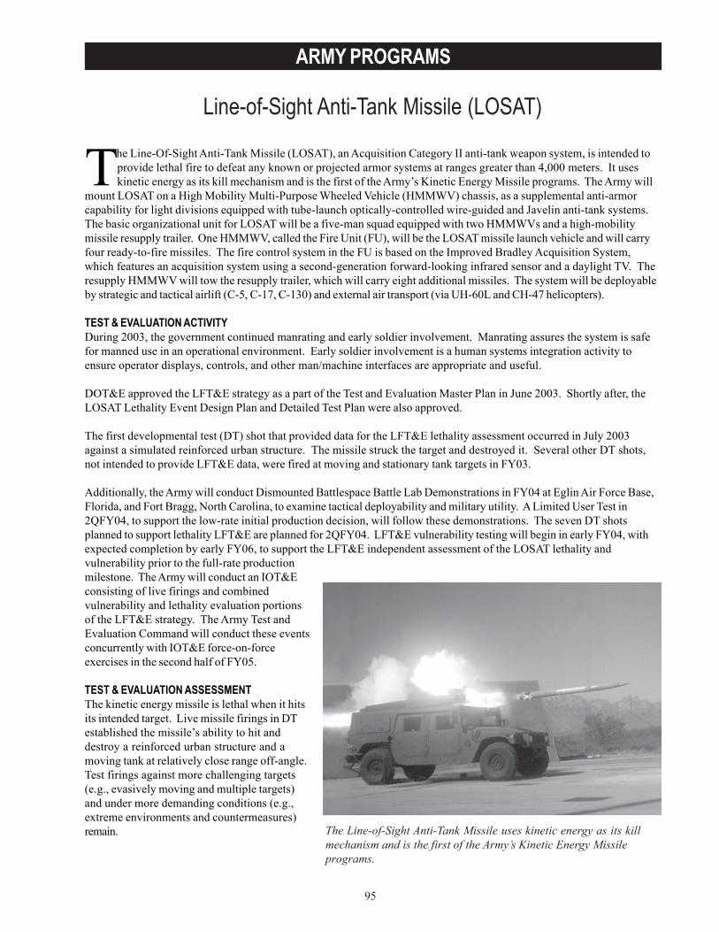
95
ARMY PROGRAMS
Line-of-Sight Anti-Tank Missile (LOSAT)
The Line-of-Sight Anti-Tank Missile uses kinetic energy as its killmechanism and is the first of the Army’s Kinetic Energy Missileprograms.
The Line-Of-Sight Anti-Tank Missile (LOSAT), an Acquisition Category II anti-tank weapon system, is intended toprovide lethal fire to defeat any known or projected armor systems at ranges greater than 4,000 meters. It useskinetic energy as its kill mechanism and is the first of the Army’s Kinetic Energy Missile programs. The Army will
mount LOSAT on a High Mobility Multi-Purpose Wheeled Vehicle (HMMWV) chassis, as a supplemental anti-armorcapability for light divisions equipped with tube-launch optically-controlled wire-guided and Javelin anti-tank systems.The basic organizational unit for LOSAT will be a five-man squad equipped with two HMMWVs and a high-mobilitymissile resupply trailer. One HMMWV, called the Fire Unit (FU), will be the LOSAT missile launch vehicle and will carryfour ready-to-fire missiles. The fire control system in the FU is based on the Improved Bradley Acquisition System,which features an acquisition system using a second-generation forward-looking infrared sensor and a daylight TV. Theresupply HMMWV will tow the resupply trailer, which will carry eight additional missiles. The system will be deployableby strategic and tactical airlift (C-5, C-17, C-130) and external air transport (via UH-60L and CH-47 helicopters).
TEST & EVALUATION ACTIVITYDuring 2003, the government continued manrating and early soldier involvement. Manrating assures the system is safefor manned use in an operational environment. Early soldier involvement is a human systems integration activity toensure operator displays, controls, and other man/machine interfaces are appropriate and useful.
DOT&E approved the LFT&E strategy as a part of the Test and Evaluation Master Plan in June 2003. Shortly after, theLOSAT Lethality Event Design Plan and Detailed Test Plan were also approved.
The first developmental test (DT) shot that provided data for the LFT&E lethality assessment occurred in July 2003against a simulated reinforced urban structure. The missile struck the target and destroyed it. Several other DT shots,not intended to provide LFT&E data, were fired at moving and stationary tank targets in FY03.
Additionally, the Army will conduct Dismounted Battlespace Battle Lab Demonstrations in FY04 at Eglin Air Force Base,Florida, and Fort Bragg, North Carolina, to examine tactical deployability and military utility. A Limited User Test in2QFY04, to support the low-rate initial production decision, will follow these demonstrations. The seven DT shotsplanned to support lethality LFT&E are planned for 2QFY04. LFT&E vulnerability testing will begin in early FY04, withexpected completion by early FY06, to support the LFT&E independent assessment of the LOSAT lethality andvulnerability prior to the full-rate productionmilestone. The Army will conduct an IOT&Econsisting of live firings and combinedvulnerability and lethality evaluation portionsof the LFT&E strategy. The Army Test andEvaluation Command will conduct these eventsconcurrently with IOT&E force-on-forceexercises in the second half of FY05.
TEST & EVALUATION ASSESSMENTThe kinetic energy missile is lethal when it hitsits intended target. Live missile firings in DTestablished the missile’s ability to hit anddestroy a reinforced urban structure and amoving tank at relatively close range off-angle.Test firings against more challenging targets(e.g., evasively moving and multiple targets)and under more demanding conditions (e.g.,extreme environments and countermeasures)remain.

96
ARMY PROGRAMS
Recently, the Army delayed the missile flight program so the Program Manager can investigate cracks that appeared in aheat-conditioned missile motor. The heat cracks are a safety concern and the delay in the firing program will impact thesafety release for man-in-the-cab missile firings.
The survivability of the overall system is an issue. The Program Manager chose to trade some ballistic protection forenhanced deployability (to ensure that the LOSAT system remains sling-loadable from a UH-60L helicopter). The LFT&Eprogram will assess the degree to which the LOSAT system, including the missile, both HMMWV vehicles, and theloaded trailer, is vulnerable to the expected threats. This program describes critical vulnerability and lethality issues andthe scope of testing needed to address them, including the need for more than one FU for full-up, system-level LFT&E tosupport the planned full-rate production decision.
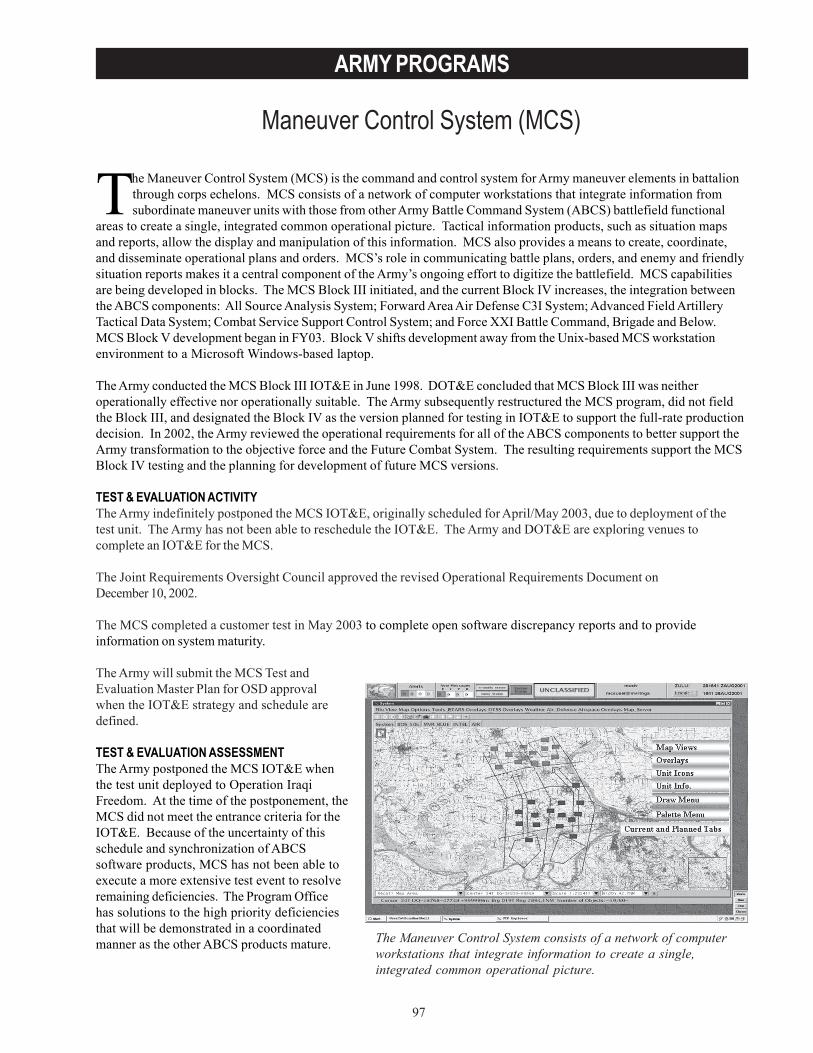
97
ARMY PROGRAMS
Maneuver Control System (MCS)
The Maneuver Control System consists of a network of computerworkstations that integrate information to create a single,integrated common operational picture.
The Maneuver Control System (MCS) is the command and control system for Army maneuver elements in battalionthrough corps echelons. MCS consists of a network of computer workstations that integrate information fromsubordinate maneuver units with those from other Army Battle Command System (ABCS) battlefield functional
areas to create a single, integrated common operational picture. Tactical information products, such as situation mapsand reports, allow the display and manipulation of this information. MCS also provides a means to create, coordinate,and disseminate operational plans and orders. MCS’s role in communicating battle plans, orders, and enemy and friendlysituation reports makes it a central component of the Army’s ongoing effort to digitize the battlefield. MCS capabilitiesare being developed in blocks. The MCS Block III initiated, and the current Block IV increases, the integration betweenthe ABCS components: All Source Analysis System; Forward Area Air Defense C3I System; Advanced Field ArtilleryTactical Data System; Combat Service Support Control System; and Force XXI Battle Command, Brigade and Below.MCS Block V development began in FY03. Block V shifts development away from the Unix-based MCS workstationenvironment to a Microsoft Windows-based laptop.
The Army conducted the MCS Block III IOT&E in June 1998. DOT&E concluded that MCS Block III was neitheroperationally effective nor operationally suitable. The Army subsequently restructured the MCS program, did not fieldthe Block III, and designated the Block IV as the version planned for testing in IOT&E to support the full-rate productiondecision. In 2002, the Army reviewed the operational requirements for all of the ABCS components to better support theArmy transformation to the objective force and the Future Combat System. The resulting requirements support the MCSBlock IV testing and the planning for development of future MCS versions.
TEST & EVALUATION ACTIVITYThe Army indefinitely postponed the MCS IOT&E, originally scheduled for April/May 2003, due to deployment of thetest unit. The Army has not been able to reschedule the IOT&E. The Army and DOT&E are exploring venues tocomplete an IOT&E for the MCS.
The Joint Requirements Oversight Council approved the revised Operational Requirements Document onDecember 10, 2002.
The MCS completed a customer test in May 2003 to complete open software discrepancy reports and to provideinformation on system maturity.
The Army will submit the MCS Test andEvaluation Master Plan for OSD approvalwhen the IOT&E strategy and schedule aredefined.
TEST & EVALUATION ASSESSMENTThe Army postponed the MCS IOT&E whenthe test unit deployed to Operation IraqiFreedom. At the time of the postponement, theMCS did not meet the entrance criteria for theIOT&E. Because of the uncertainty of thisschedule and synchronization of ABCSsoftware products, MCS has not been able toexecute a more extensive test event to resolveremaining deficiencies. The Program Officehas solutions to the high priority deficienciesthat will be demonstrated in a coordinatedmanner as the other ABCS products mature.
98
ARMY PROGRAMS
The test unit, 4th Infantry Division, deployed to Operation Iraqi Freedom with its full complement of MCS systems anddigital tactical operations centers. No information has been made available to DOT&E as to how these systems areperforming in support of current operations.
The May 2003 customer test successfully demonstrated correction of several software discrepancy reports. However,due to test limitations, several software discrepancy reports remain open. System maturity continues to improve and theMCS individual workstation functions were stable during the test. However, the network and database functions andprocedures that integrate MCS and the Army Battle Command Systems into a digital command and control system remainproblematic and fragile.
The Army and DOT&E are working to find acceptable alternative venues, such as warfighter exercises, to accomplish anIOT&E in support of a full-rate production decision as soon as possible.
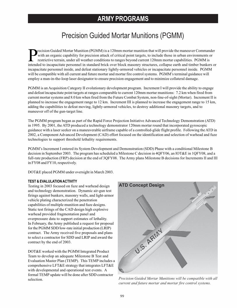
99
ARMY PROGRAMS
Precision Guided Mortar Munitions (PGMM)
Precision Guided Mortar Munitions will be compatible with allcurrent and future mortar and mortar fire control systems.
Precision Guided Mortar Munition (PGMM) is a 120mm mortar munition that will provide the maneuver Commanderwith an organic capability for precision attack of critical point targets, to include those in urban environments orrestrictive terrain, under all weather conditions to ranges beyond current 120mm mortar capabilities. PGMM is
intended to incapacitate personnel in standard brick over block masonry structures, collapse earth and timber bunkers orincapacitate personnel inside, and defeat stationary lightly-armored vehicles or incapacitate personnel inside. PGMMwill be compatible with all current and future mortar and mortar fire control systems. PGMM’s terminal guidance willemploy a man-in-the-loop laser designator to ensure precision engagement and to minimize collateral damage.
PGMM is an Acquisition Category II evolutionary development program. Increment I will provide the ability to engageand defeat/incapacitate point targets at ranges comparable to current 120mm mortar munitions: 7.2 km when fired fromcurrent mortar systems and 8.0 km when fired from the Future Combat System, non-line-of-sight (Mortar). Increment II isplanned to increase the engagement range to 12 km. Increment III is planned to increase the engagement range to 15 km,adding the capabilities to defeat moving, lightly-armored vehicles, to destroy additional masonry targets, and tomaneuver off of the gun-target line.
The PGMM program began as part of the Rapid Force Projection Initiative Advanced Technology Demonstration (ATD)in 1995. By 2001, the ATD produced a technology demonstrator 120mm mortar round that incorporated gyroscopicguidance with a laser seeker on a maneuverable airframe capable of a controlled-glide flight profile. Following the ATD in2002, a Component Advanced Development (CAD) effort focused on the identification and selection of warhead and fuzetechnologies to support threshold lethality requirements.
PGMM’s Increment I entered its System Development and Demonstration (SDD) Phase with a conditional Milestone Bdecision in September 2003. The program has scheduled a Milestone C decision in 4QFY06, an IOT&E in 1QFY08, and afull-rate production (FRP) decision at the end of 3QFY08. The Army plans Milestone B decisions for Increments II and IIIin FY08 and FY10, respectively.
DOT&E placed PGMM under oversight in March 2003.
TEST & EVALULATION ACTIVITYTesting in 2003 focused on fuze and warhead designand technology demonstration. Dynamic air-gun testfirings against bunkers, masonry walls, and light-armorvehicle plating characterized the penetrationcapabilities of multiple munition and fuze designs.Static test firings of the CAD design high explosivewarhead provided fragmentation panel andoverpressure data to support estimates of lethality.In February, the Army published a request for proposalfor the PGMM SDD/low-rate initial production (LRIP)contract. The Army received five proposals and plansto select a contractor for SDD and LRIP and award thecontract by the end of 2003.
DOT&E worked with the PGMM Integrated ProductTeam to develop an adequate Milestone B Test andEvaluation Master Plan (TEMP). This TEMP includes acomprehensive LFT&E strategy that integrates LFT&Ewith developmental and operational test events. Aformal TEMP update will be done after SDD contractorselection.
100
ARMY PROGRAMS
TEST & EVALUATION ASSESSMENTIn ATD and CAD testing, guidance, airframe, control actuation, sensor (laser detector), and warhead/fuze subsystemsdemonstrated appropriate technology readiness levels for entry into the SDD phase of acquisition.
The Milestone B TEMP establishes appropriate LRIP and IOT&E entrance criteria and describes sufficient operationaland live fire testing to support major program decisions. A Limited User Test will support an operational assessmentbefore the Milestone C LRIP decision, and robust LFT&E and IOT&E programs will support the FRP decision. End-to-end firings of all-up rounds will constitute the principal source of live fire test data; there will be no dedicated LFT&Eevents. The TEMP update after the contractor selection will provide details of SDD contractor and governmentdevelopmental test plans and may modify portions of live fire and operational test plans. This update will also include acomprehensive and executable Reliability Growth Program.
Because soldiers have not previously employed laser designators for the terminal guidance of mortar munitions,DOT&E’s system evaluation will include an assessment of the effectiveness of the tactics, techniques, and proceduresfor the employment of PGMM, to include limitations on laser designator employment.
Since the PGMM ORD requires the minimization of collateral damage, as compared to that caused by other availablemunitions, DOT&E will require a detailed plan to assess this capability.
The January 2003 PGMM Acquisition Strategy and Acquisition Plan stated that the Army plans to award an FRP contractthrough full and open competition. Should a contractor other than the SDD/LRIP contractor be selected for this award,additional testing will be required for an adequate assessment of operational effectiveness and suitability.
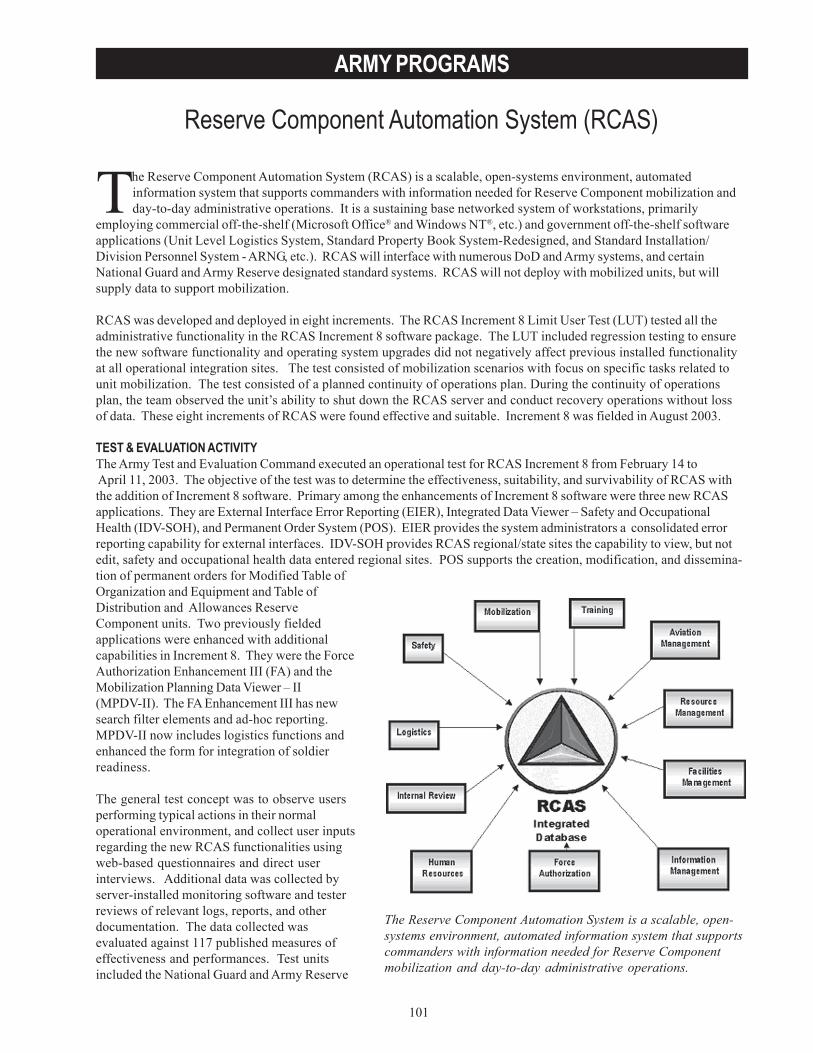
101
ARMY PROGRAMS
Reserve Component Automation System (RCAS)
The Reserve Component Automation System is a scalable, open-systems environment, automated information system that supportscommanders with information needed for Reserve Componentmobilization and day-to-day administrative operations.
The Reserve Component Automation System (RCAS) is a scalable, open-systems environment, automatedinformation system that supports commanders with information needed for Reserve Component mobilization andday-to-day administrative operations. It is a sustaining base networked system of workstations, primarily
employing commercial off-the-shelf (Microsoft Office® and Windows NT®, etc.) and government off-the-shelf softwareapplications (Unit Level Logistics System, Standard Property Book System-Redesigned, and Standard Installation/Division Personnel System - ARNG, etc.). RCAS will interface with numerous DoD and Army systems, and certainNational Guard and Army Reserve designated standard systems. RCAS will not deploy with mobilized units, but willsupply data to support mobilization.
RCAS was developed and deployed in eight increments. The RCAS Increment 8 Limit User Test (LUT) tested all theadministrative functionality in the RCAS Increment 8 software package. The LUT included regression testing to ensurethe new software functionality and operating system upgrades did not negatively affect previous installed functionalityat all operational integration sites. The test consisted of mobilization scenarios with focus on specific tasks related tounit mobilization. The test consisted of a planned continuity of operations plan. During the continuity of operationsplan, the team observed the unit’s ability to shut down the RCAS server and conduct recovery operations without lossof data. These eight increments of RCAS were found effective and suitable. Increment 8 was fielded in August 2003.
TEST & EVALUATION ACTIVITYThe Army Test and Evaluation Command executed an operational test for RCAS Increment 8 from February 14 to April 11, 2003. The objective of the test was to determine the effectiveness, suitability, and survivability of RCAS withthe addition of Increment 8 software. Primary among the enhancements of Increment 8 software were three new RCASapplications. They are External Interface Error Reporting (EIER), Integrated Data Viewer – Safety and OccupationalHealth (IDV-SOH), and Permanent Order System (POS). EIER provides the system administrators a consolidated errorreporting capability for external interfaces. IDV-SOH provides RCAS regional/state sites the capability to view, but notedit, safety and occupational health data entered regional sites. POS supports the creation, modification, and dissemina-tion of permanent orders for Modified Table ofOrganization and Equipment and Table ofDistribution and Allowances ReserveComponent units. Two previously fieldedapplications were enhanced with additionalcapabilities in Increment 8. They were the ForceAuthorization Enhancement III (FA) and theMobilization Planning Data Viewer – II(MPDV-II). The FA Enhancement III has newsearch filter elements and ad-hoc reporting.MPDV-II now includes logistics functions andenhanced the form for integration of soldierreadiness.
The general test concept was to observe usersperforming typical actions in their normaloperational environment, and collect user inputsregarding the new RCAS functionalities usingweb-based questionnaires and direct userinterviews. Additional data was collected byserver-installed monitoring software and testerreviews of relevant logs, reports, and otherdocumentation. The data collected wasevaluated against 117 published measures ofeffectiveness and performances. Test unitsincluded the National Guard and Army Reserve
102
ARMY PROGRAMS
Headquarters, Delaware Army National Guard, and sites of the 99th Army Reserve Regional Support Command inPennsylvania and Virginia.
Regression testing conducted on all seven previous increments showed that Increment 8 did not adversely effect thesystem’s operations. Continuity of Operations testing was successfully exercised by the Delaware Army National Guard.
TEST & EVALUATION ASSESSMENTThe Increment 8 operational test found that, although some features had shortcomings, all five new or enhanced RCASapplications operated in an acceptable fashion. The threshold for successful completion of RCAS developed applicationtransitions is 95 percent. The POS was used extensively with the activities to support Operation Enduring Freedom andOperation Iraqi Freedom. POS, IDV-SOH, and EIER each exceeded the threshold of a 95 percent success rate in attemptedtransactions. The enhancements made to the previously delivered mobilization application significantly reduced the timeto mobilize, once paper mobilization records were converted to electronic documents. A few common data elements in theUnit Personnel System application were not shared in the MPDV-II application and this caused two of sevenfunctionalities to fail to achieve the desired threshold for the Army National Guard. This was corrected in a MaintenanceRelease 8.1 that was successfully installed and tested in May 2003.
The RCAS logistics support, interoperability, and overall security features operated at acceptable levels. Policies andprocedures for Continuity of Operations are adequate. Some network and server vulnerabilities were discovered duringthe vulnerability assessments. These were primarily due to lack of training on installation of security oriented softwarepatches. RCAS provides the user with tools that significantly improve their day-to-day management of soldiers and itingrate personnel, mobilization, and logistic functions which allows sharing of soldier readiness.
DOT&E finds, with the full fielding of Increment 8, RCAS to be operationally effective, suitable, and survivable. Thisfinal Increment completes DoD oversight of the development and deployment of RCAS, effective August 2003.
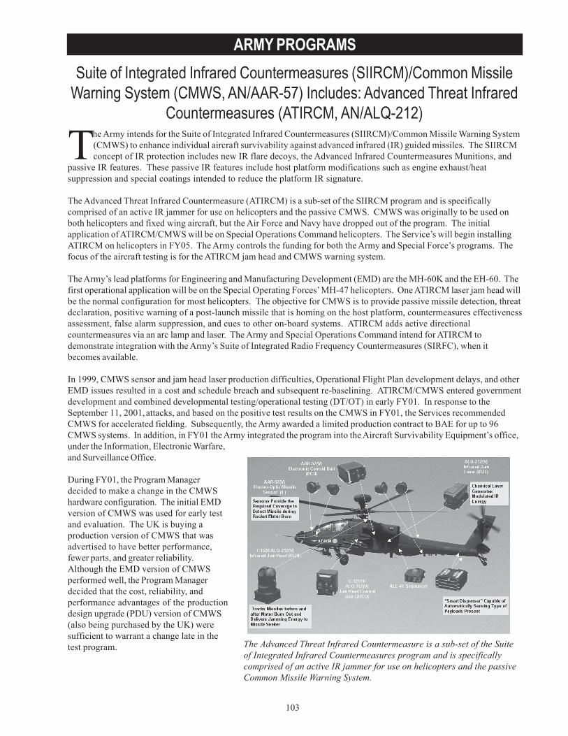
103
ARMY PROGRAMSSuite of Integrated Infrared Countermeasures (SIIRCM)/Common Missile
Warning System (CMWS, AN/AAR-57) Includes: Advanced Threat InfraredCountermeasures (ATIRCM, AN/ALQ-212)
The Advanced Threat Infrared Countermeasure is a sub-set of the Suiteof Integrated Infrared Countermeasures program and is specificallycomprised of an active IR jammer for use on helicopters and the passiveCommon Missile Warning System.
The Army intends for the Suite of Integrated Infrared Countermeasures (SIIRCM)/Common Missile Warning System(CMWS) to enhance individual aircraft survivability against advanced infrared (IR) guided missiles. The SIIRCMconcept of IR protection includes new IR flare decoys, the Advanced Infrared Countermeasures Munitions, and
passive IR features. These passive IR features include host platform modifications such as engine exhaust/heatsuppression and special coatings intended to reduce the platform IR signature.
The Advanced Threat Infrared Countermeasure (ATIRCM) is a sub-set of the SIIRCM program and is specificallycomprised of an active IR jammer for use on helicopters and the passive CMWS. CMWS was originally to be used onboth helicopters and fixed wing aircraft, but the Air Force and Navy have dropped out of the program. The initialapplication of ATIRCM/CMWS will be on Special Operations Command helicopters. The Service’s will begin installingATIRCM on helicopters in FY05. The Army controls the funding for both the Army and Special Force’s programs. Thefocus of the aircraft testing is for the ATIRCM jam head and CMWS warning system.
The Army’s lead platforms for Engineering and Manufacturing Development (EMD) are the MH-60K and the EH-60. Thefirst operational application will be on the Special Operating Forces’ MH-47 helicopters. One ATIRCM laser jam head willbe the normal configuration for most helicopters. The objective for CMWS is to provide passive missile detection, threatdeclaration, positive warning of a post-launch missile that is homing on the host platform, countermeasures effectivenessassessment, false alarm suppression, and cues to other on-board systems. ATIRCM adds active directionalcountermeasures via an arc lamp and laser. The Army and Special Operations Command intend for ATIRCM todemonstrate integration with the Army’s Suite of Integrated Radio Frequency Countermeasures (SIRFC), when itbecomes available.
In 1999, CMWS sensor and jam head laser production difficulties, Operational Flight Plan development delays, and otherEMD issues resulted in a cost and schedule breach and subsequent re-baselining. ATIRCM/CMWS entered governmentdevelopment and combined developmental testing/operational testing (DT/OT) in early FY01. In response to theSeptember 11, 2001, attacks, and based on the positive test results on the CMWS in FY01, the Services recommendedCMWS for accelerated fielding. Subsequently, the Army awarded a limited production contract to BAE for up to 96CMWS systems. In addition, in FY01 the Army integrated the program into the Aircraft Survivability Equipment’s office,under the Information, Electronic Warfare,and Surveillance Office.
During FY01, the Program Managerdecided to make a change in the CMWShardware configuration. The initial EMDversion of CMWS was used for early testand evaluation. The UK is buying aproduction version of CMWS that wasadvertised to have better performance,fewer parts, and greater reliability.Although the EMD version of CMWSperformed well, the Program Managerdecided that the cost, reliability, andperformance advantages of the productiondesign upgrade (PDU) version of CMWS(also being purchased by the UK) weresufficient to warrant a change late in thetest program.
104
ARMY PROGRAMS
During FY04, the Army plans to award a limited production contract for 59 ATIRCM systems. The Army plans to buy atotal of 619 systems beginning in FY05. The Army will not field any of these ATIRCM systems until the successfulcompletion of the FY04 DT/OT tests and the FY05 IOT&E.
TEST & EVALUATION ACTIVITYContractor testing of the ATIRCM redesign and of software upgrade for CMWS were the predominant test activities inFY03. The Special Operating Forces will conduct a limited users test in the FY04 for the CMWS-only configuration onthe MH-47 helicopter, primarily to assess the pilot vehicle interface. A second live fire test will be conducted at the ACRstarting in FY04. Together, with the Reliability Development Test (RDT) and the logistics demonstration, these willcomprehensively test the overall redesigned ATRICM/CMWS system. Successful completion of these is the criterion forentering IOT&E in FY05. DOT&E approved a revised Test and Evaluation Plan in March 2003 that covers these tests.
Hardware-in-the-Loop (HITL) modeling capabilities are essential to providing an assessment of the operationaleffectiveness and operational suitability of the ATIRCM/CMWS system. Developing new T&E concepts, which employmodeling and simulation, reduced actual missile firings and drone target requirements from 400 to 175 events. ContractorHITL testing in FY01 was beneficial in validating modeling and simulation conclusions.
TEST & EVALUATION ASSESSMENTThe ATIRCM/CMWS has demonstrated adequate performance to date. The tests have shown the need to modify thesoftware for certain operational conditions and these modifications need to be re-evaluated during subsequent testing,especially with live fire shots at the aerial cable facility. The redesigned jam head has performed satisfactorily in thecontractor tests to date.
With the changes incorporated into the laser jam head and the limited testing on the newer PDU CMWS sensor, the FY04RDT, logistics demonstration, and live fire tests are essential to ensure system performance has not been degraded. Thenewer PDU sensor is much lower risk than the updates to the ATIRCM jam head redesign.
During the FY01 tests, the IR jammer experienced a number of reliability problems, requiring some significant mechanicalredesign. The redesign is now complete and the contractor environmental tests to date have shown satisfactoryprogress. The redesigned units will enter into a 1,100-hour RDT in July FY04 as part of the DT/OT. Also during the FY01tests, the built-in test performed unsatisfactorily. The built-in test has since been redesigned and will be tested duringthe Logistics Demonstration scheduled for FY04.
Modeling and simulation is a critical element of the T&E program because the matrix of potential missile-aircraftinteractions would require a substantial increase in the number of test firings. The development of the end-to-end modelhas progressed this past year and, in addition to being used for pre-test predictions and post-test analyses, has someutility for scenario evaluations. The Army has not completely verified, validated, or accredited the model for use in anoperational evaluation. Verification and validation have progressed satisfactorily in FY03. The accreditation requirementremains a significant challenge. The overriding issue for SIIRCM/CMWS is the need to conduct OT&E on the upgradedSIIRCM/CMWS.
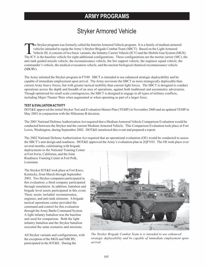
105
ARMY PROGRAMS
Stryker Armored Vehicle
The Stryker Brigade Combat Team is is intended to use enhancedstrategic deployability and be capable of immediate employment uponarrival.
The Stryker program was formerly called the Interim Armored Vehicle program. It is a family of medium armoredvehicles intended to equip the Army’s Stryker Brigade Combat Team (SBCT). Based on the Light ArmoredVehicle III, it consists of two basic variants, the Infantry Carrier Vehicle (ICV) and the Mobile Gun System (MGS).
The ICV is the baseline vehicle for eight additional configurations. These configurations are the mortar carrier (MC), theanti-tank guided missile vehicle, the reconnaissance vehicle, the fire support vehicle, the engineer squad vehicle, thecommander’s vehicle, the medical evacuation vehicle, and the nuclear biological chemical reconnaissance vehicle(NBCRV).
The Army initiated the Stryker program in FY00. SBCT is intended to use enhanced strategic deployability and becapable of immediate employment upon arrival. The Army envisions the SBCT as more strategically deployable thancurrent Army heavy forces, but with greater tactical mobility than current light forces. The SBCT is designed to conductoperations across the depth and breadth of an area of operations, against both traditional and asymmetric adversaries.Though optimized for small scale contingencies, the SBCT is designed to engage in all types of military conflicts,including Major Theater Wars when augmented or when operating as part of a larger force.
TEST & EVALUATION ACTIVITYDOT&E approved the initial Stryker Test and Evaluation Master Plan (TEMP) in November 2000 and an updated TEMP inMay 2003 in conjunction with the Milestone B decision.
The 2001 National Defense Authorization Act required that a Medium Armored Vehicle Comparison Evaluation would beconducted between the Stryker and the current Medium Armored Vehicle. This Comparison Evaluation took place at FortLewis, Washington, during September 2002. DOT&E monitored this event and prepared a report.
The 2002 National Defense Authorization Act required that an operational evaluation (OE) would be conducted to assessthe SBCT’s unit design and readiness. DOT&E approved the Army’s evaluation plan in 2QFY03. The OE took place overseveral months, culminating with brigadedeployments to the National Training Centerat Fort Irwin, California, and the JointReadiness Training Center at Fort Polk,Louisiana.
The Stryker IOT&E took place at Fort Knox,Kentucky, from March through September2003. Two Stryker companies participated inthis evaluation; a third company participatedthrough simulation. In addition, battalion andbrigade level assets participated in this event.These assets included reconnaissance,engineer, and anti-tank elements. A brigadetactical operations center provided thecommand and control for this evaluationthrough the Army Battle Command System.A light infantry battalion was the baselineunit used for comparison. Both the lightinfantry battalion and the Stryker battalionexecuted the same scenarios and missions.
All Stryker variants and configurations, withthe exception of the MGS and NBCRV,participated in the IOT&E. During the
106
ARMY PROGRAMS
IOT&E, the MC had a dismounted mortar only (designated MC-A). A soft-recoil 120mm mounted mortar (designatedMC-B) began developmental testing in June 2003. In addition to developmental testing, a separate IOT&E for the MC-Bis planned for early 2004, which will supplement the results of the IOT&E. A three-shot live fire test is planned for theMC-B as well. This is scheduled to be complete prior to the February 2004 Milestone III review.
Additional operational test events are planned for variants, which were not available during the IOT&E. The MGS willundergo a limited user test in 2004 at Fort Knox, Kentucky and an IOT&E in 2005.
NBCRV Production Qualification Testing was conducted from June to December 2003. Key tests included sensorperformance; automotive safety and performance; environmental testing; eletro-magnetic interference, and systemoverpressure testing. This variant contains a variety of chemical and biological sensor systems. Additional side-by-sidetesting is being conducted between the Joint Service Light Standoff Chemical Agent Detector and the M21 Rascalchemical standoff detection device to validate requirements.
The Army conducted an NBCRV limited user test at Dugway Proving Ground, Utah, in October 2003. Two systems wereevaluated in three 72-hour NBC reconnaissance and security scenarios. Results from these tests are pending. Of majorconcern with this variant is the ability to conduct standoff chemical detection.
The Stryker LFT&E program will support the system’s survivability evaluation. Base-vehicle armor coupon testingaddressing small arms (through 14.5mm heavy machine gun fire) and fragments from high explosive artillery munitionsbegan in FY02 to qualify and characterize armor recipes used in production. Testing continued into FY03 as the contrac-tor refined armor recipes to address specific performance shortfalls. 4QFY03 was marked by a period of high-priorityarmor coupon testing following the revelation that inadequate internal controls between the vehicle contractor and itsarmor subcontractors resulted in the installation of untested, unqualified armor configurations on some vehicles in thefirst and second Stryker brigades. This investigative-type testing and corresponding mitigation program supported theArmy’s short-term SBCT needs to deploy the SBCT to Iraq. Government qualification of each armor configuration iscurrently ongoing and expected to be complete before the Milestone III review in February 2004. Stryker vehicles alreadyfielded will be retrofitted with appropriately tested and qualified configurations as necessary.
Production Qualification Testing of the rocket-propelled grenade-level add-on armor began in May 2003 and found thatthe armor performance did not meet Army requirements. As a result, the Stryker program experienced delays in all add-onarmor related testing to allow the contractor to refine its armor solution to meet Army requirements. Re-qualification ofthe new add-on armor solution resumed in September 2003 and will continue through February 2004.
Full-up system-level (FUSL) testing of production-representative configurations began in July 2002. Fifty-one of sixty-five system-level test events have been completed to date for six different Stryker configurations: the ICV, the engineersquad vehicle, the commander’s vehicle, the reconnaissance vehicle, the anti-tank guided missile, and the medicalevacuation vehicle. The fire support vehicle was removed from the test series due to commonality with other configura-tions so it can be evaluated using data provided by other testing. FUSL testing for the Stryker vehicle with add-on armoris expected to resume in November 2003 and for the Mortar Carrier B in December 2003. DOT&E will address StrykerFUSL test results in the classified beyond low-rate initial production (BLRIP) report to Congress.
The Army will include additional details of the survivability test programs supporting the later Milestone reviews for theNBCRV and MGS in the next TEMP. DOT&E continues to participate in the test planning, execution, and reporting ofeach system-level test event.
107
ARMY PROGRAMS
TEST & EVALUATION ASSESSMENTThe Stryker test and evaluation program is challenging because of the requirement to test and evaluate ten differentvariants. The Army’s OE Report concludes, “current design and training performance of the first SBCT meets therequirements of the Organizational and Operational Concept.” Based on the Army’s assessment, DOT&E does notbelieve there are any unit design issues. However, the OE was not sufficient to completely address the operationaleffectiveness and suitability of an SBCT, nor did it address the operational effectiveness, suitability, or survivability ofthe Stryker vehicles themselves. Stryker vehicle effectiveness, suitability, and survivability will be assessed in the BLRIPreport.
The Army recently completed the Stryker IOT&E. DOT&E’s independent evaluation is ongoing. This evaluation willdetermine the operational effectiveness and suitability of eight of ten Stryker vehicles types that were available fortesting. This BLRIP report will be disseminated in 2QFY04.

108
ARMY PROGRAMS
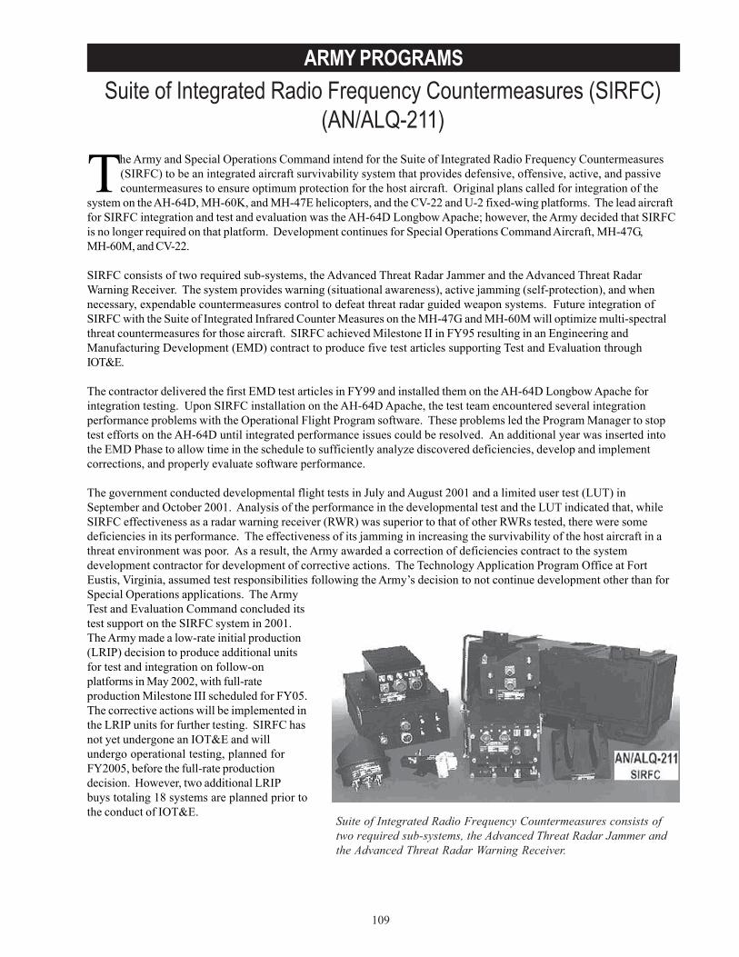
109
ARMY PROGRAMSSuite of Integrated Radio Frequency Countermeasures (SIRFC)
(AN/ALQ-211)
Suite of Integrated Radio Frequency Countermeasures consists oftwo required sub-systems, the Advanced Threat Radar Jammer andthe Advanced Threat Radar Warning Receiver.
The Army and Special Operations Command intend for the Suite of Integrated Radio Frequency Countermeasures(SIRFC) to be an integrated aircraft survivability system that provides defensive, offensive, active, and passivecountermeasures to ensure optimum protection for the host aircraft. Original plans called for integration of the
system on the AH-64D, MH-60K, and MH-47E helicopters, and the CV-22 and U-2 fixed-wing platforms. The lead aircraftfor SIRFC integration and test and evaluation was the AH-64D Longbow Apache; however, the Army decided that SIRFCis no longer required on that platform. Development continues for Special Operations Command Aircraft, MH-47G,MH-60M, and CV-22.
SIRFC consists of two required sub-systems, the Advanced Threat Radar Jammer and the Advanced Threat RadarWarning Receiver. The system provides warning (situational awareness), active jamming (self-protection), and whennecessary, expendable countermeasures control to defeat threat radar guided weapon systems. Future integration ofSIRFC with the Suite of Integrated Infrared Counter Measures on the MH-47G and MH-60M will optimize multi-spectralthreat countermeasures for those aircraft. SIRFC achieved Milestone II in FY95 resulting in an Engineering andManufacturing Development (EMD) contract to produce five test articles supporting Test and Evaluation throughIOT&E.
The contractor delivered the first EMD test articles in FY99 and installed them on the AH-64D Longbow Apache forintegration testing. Upon SIRFC installation on the AH-64D Apache, the test team encountered several integrationperformance problems with the Operational Flight Program software. These problems led the Program Manager to stoptest efforts on the AH-64D until integrated performance issues could be resolved. An additional year was inserted intothe EMD Phase to allow time in the schedule to sufficiently analyze discovered deficiencies, develop and implementcorrections, and properly evaluate software performance.
The government conducted developmental flight tests in July and August 2001 and a limited user test (LUT) inSeptember and October 2001. Analysis of the performance in the developmental test and the LUT indicated that, whileSIRFC effectiveness as a radar warning receiver (RWR) was superior to that of other RWRs tested, there were somedeficiencies in its performance. The effectiveness of its jamming in increasing the survivability of the host aircraft in athreat environment was poor. As a result, the Army awarded a correction of deficiencies contract to the systemdevelopment contractor for development of corrective actions. The Technology Application Program Office at FortEustis, Virginia, assumed test responsibilities following the Army’s decision to not continue development other than forSpecial Operations applications. The ArmyTest and Evaluation Command concluded itstest support on the SIRFC system in 2001.The Army made a low-rate initial production(LRIP) decision to produce additional unitsfor test and integration on follow-onplatforms in May 2002, with full-rateproduction Milestone III scheduled for FY05.The corrective actions will be implemented inthe LRIP units for further testing. SIRFC hasnot yet undergone an IOT&E and willundergo operational testing, planned forFY2005, before the full-rate productiondecision. However, two additional LRIPbuys totaling 18 systems are planned prior tothe conduct of IOT&E.
110
ARMY PROGRAMS
TEST & EVALUATION ACTIVITYTest activity in FY03 consisted of laboratory tests at Fort Monmouth, New Jersey, and was to evaluate performance ofthe corrective actions and incremental software drops.
TEST & EVALUATION ASSESSMENTResults of the tests at Fort Monmouth have shown promise; however, a true indication of the performance of theupgraded SIRFC will not be available until the developmental test and operational flight tests that begin in FY04.
SIRFC consists of two required sub-systems, the Advanced Threat Radar Jammer and the Advanced Threat RadarWarning Receiver. Development continues for Special Operations Command Aircraft, MH-47G, MH-60M, and CV-22.
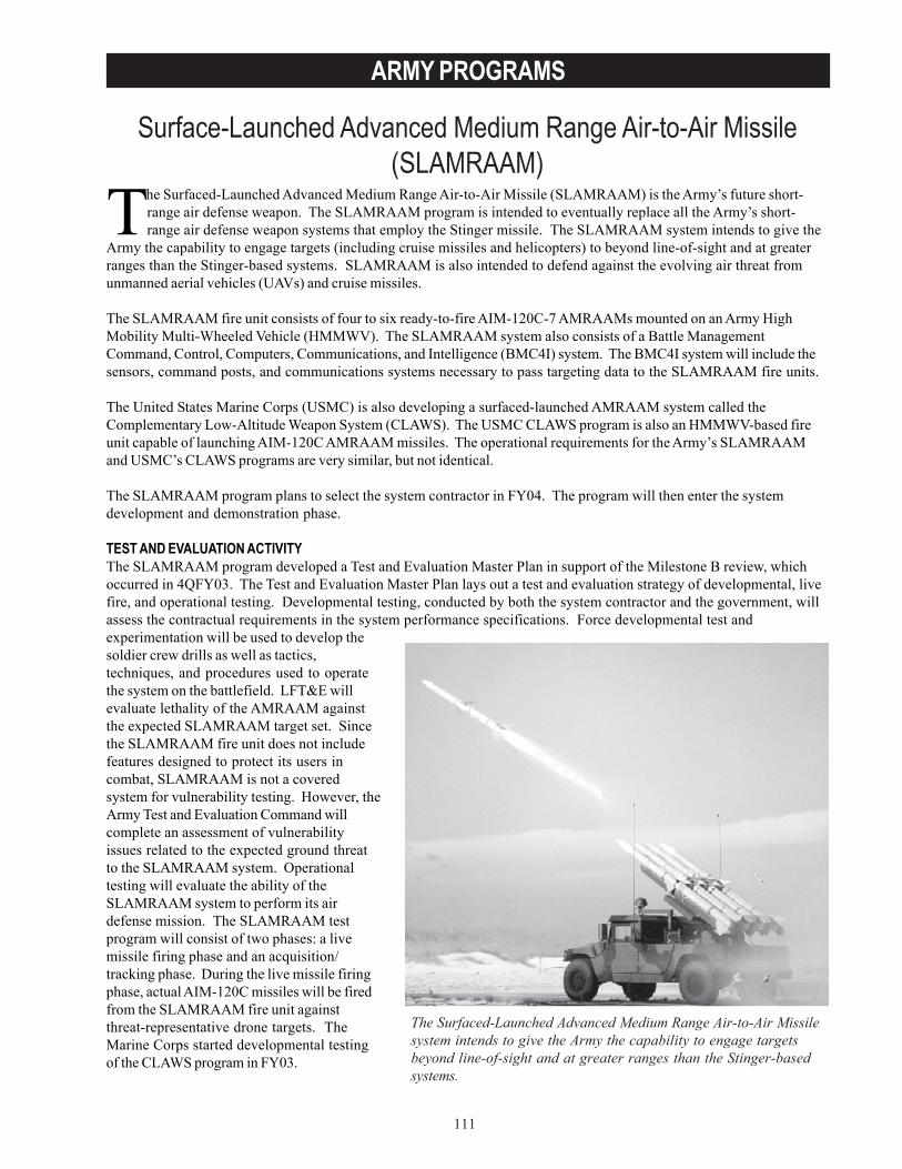
111
ARMY PROGRAMS
Surface-Launched Advanced Medium Range Air-to-Air Missile(SLAMRAAM)
The Surfaced-Launched Advanced Medium Range Air-to-Air Missilesystem intends to give the Army the capability to engage targetsbeyond line-of-sight and at greater ranges than the Stinger-basedsystems.
The Surfaced-Launched Advanced Medium Range Air-to-Air Missile (SLAMRAAM) is the Army’s future short-range air defense weapon. The SLAMRAAM program is intended to eventually replace all the Army’s short-range air defense weapon systems that employ the Stinger missile. The SLAMRAAM system intends to give the
Army the capability to engage targets (including cruise missiles and helicopters) to beyond line-of-sight and at greaterranges than the Stinger-based systems. SLAMRAAM is also intended to defend against the evolving air threat fromunmanned aerial vehicles (UAVs) and cruise missiles.
The SLAMRAAM fire unit consists of four to six ready-to-fire AIM-120C-7 AMRAAMs mounted on an Army HighMobility Multi-Wheeled Vehicle (HMMWV). The SLAMRAAM system also consists of a Battle ManagementCommand, Control, Computers, Communications, and Intelligence (BMC4I) system. The BMC4I system will include thesensors, command posts, and communications systems necessary to pass targeting data to the SLAMRAAM fire units.
The United States Marine Corps (USMC) is also developing a surfaced-launched AMRAAM system called theComplementary Low-Altitude Weapon System (CLAWS). The USMC CLAWS program is also an HMMWV-based fireunit capable of launching AIM-120C AMRAAM missiles. The operational requirements for the Army’s SLAMRAAMand USMC’s CLAWS programs are very similar, but not identical.
The SLAMRAAM program plans to select the system contractor in FY04. The program will then enter the systemdevelopment and demonstration phase.
TEST AND EVALUATION ACTIVITYThe SLAMRAAM program developed a Test and Evaluation Master Plan in support of the Milestone B review, whichoccurred in 4QFY03. The Test and Evaluation Master Plan lays out a test and evaluation strategy of developmental, livefire, and operational testing. Developmental testing, conducted by both the system contractor and the government, willassess the contractual requirements in the system performance specifications. Force developmental test andexperimentation will be used to develop thesoldier crew drills as well as tactics,techniques, and procedures used to operatethe system on the battlefield. LFT&E willevaluate lethality of the AMRAAM againstthe expected SLAMRAAM target set. Sincethe SLAMRAAM fire unit does not includefeatures designed to protect its users incombat, SLAMRAAM is not a coveredsystem for vulnerability testing. However, theArmy Test and Evaluation Command willcomplete an assessment of vulnerabilityissues related to the expected ground threatto the SLAMRAAM system. Operationaltesting will evaluate the ability of theSLAMRAAM system to perform its airdefense mission. The SLAMRAAM testprogram will consist of two phases: a livemissile firing phase and an acquisition/tracking phase. During the live missile firingphase, actual AIM-120C missiles will be firedfrom the SLAMRAAM fire unit againstthreat-representative drone targets. TheMarine Corps started developmental testingof the CLAWS program in FY03.
112
ARMY PROGRAMS
The LFT&E strategy will build upon previous lethality testing and live missile firings, and will use modeling andsimulation to assess lethality against the expanded target set. Most of the expanded target set vulnerable areas havebeen characterized and confirmed through previous modeling and testing. Modeling and analysis will determine newtarget vulnerabilities to SLAMRAAM. Lethality against these targets will be determined using validated and accreditedAMRAAM models. This two-year effort will begin in 1QFY04 and complete in 1QFY06.
TEST AND EVALUATION ASSESSMENTTwo issues are critical to an adequate assessment of the operational effectiveness and suitability of the SLAMRAAMprogram. The first issue is the ability of the AIM-120C AMRAAM missile to perform against the targets of interest to theArmy, namely, UAVs, cruise missiles, and helicopters. Firings against these types of targets have not been donethroughout the long history of the AMRAAM test program conducted by the Air Force and Navy.
Second, the integration of the BMC4I is critical to the success of SLAMRAAM. The SLAMRAAM system, unlike theStinger-based weapons, cannot autonomously engage targets. The SLAMRAAM fire unit must receive targeting datafrom the BMC4I system, including targeting data acquired from sensors operated by other Services. The BMC4I systemmust also provide target identification of friendly aircraft. This becomes critical since SLAMRAAM provides a beyondline-of-sight engagement capability that cannot rely on visual identification means to distinguish friendly aircraft fromenemy threats. The BMC4I system must also be mobile enough to keep up with rapidly advancing maneuver forces.
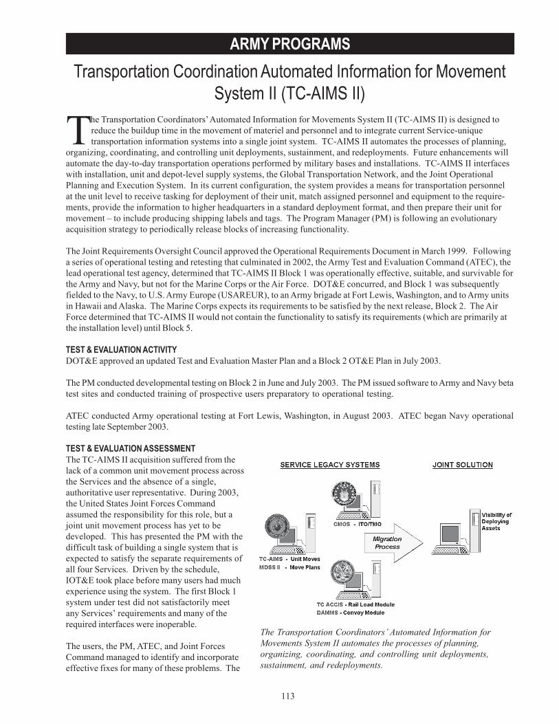
113
ARMY PROGRAMSTransportation Coordination Automated Information for Movement
System II (TC-AIMS II)
The Transportation Coordinators’ Automated Information forMovements System II automates the processes of planning,organizing, coordinating, and controlling unit deployments,sustainment, and redeployments.
The Transportation Coordinators’ Automated Information for Movements System II (TC-AIMS II) is designed toreduce the buildup time in the movement of materiel and personnel and to integrate current Service-uniquetransportation information systems into a single joint system. TC-AIMS II automates the processes of planning,
organizing, coordinating, and controlling unit deployments, sustainment, and redeployments. Future enhancements willautomate the day-to-day transportation operations performed by military bases and installations. TC-AIMS II interfaceswith installation, unit and depot-level supply systems, the Global Transportation Network, and the Joint OperationalPlanning and Execution System. In its current configuration, the system provides a means for transportation personnelat the unit level to receive tasking for deployment of their unit, match assigned personnel and equipment to the require-ments, provide the information to higher headquarters in a standard deployment format, and then prepare their unit formovement – to include producing shipping labels and tags. The Program Manager (PM) is following an evolutionaryacquisition strategy to periodically release blocks of increasing functionality.
The Joint Requirements Oversight Council approved the Operational Requirements Document in March 1999. Followinga series of operational testing and retesting that culminated in 2002, the Army Test and Evaluation Command (ATEC), thelead operational test agency, determined that TC-AIMS II Block 1 was operationally effective, suitable, and survivable forthe Army and Navy, but not for the Marine Corps or the Air Force. DOT&E concurred, and Block 1 was subsequentlyfielded to the Navy, to U.S. Army Europe (USAREUR), to an Army brigade at Fort Lewis, Washington, and to Army unitsin Hawaii and Alaska. The Marine Corps expects its requirements to be satisfied by the next release, Block 2. The AirForce determined that TC-AIMS II would not contain the functionality to satisfy its requirements (which are primarily atthe installation level) until Block 5.
TEST & EVALUATION ACTIVITYDOT&E approved an updated Test and Evaluation Master Plan and a Block 2 OT&E Plan in July 2003.
The PM conducted developmental testing on Block 2 in June and July 2003. The PM issued software to Army and Navy betatest sites and conducted training of prospective users preparatory to operational testing.
ATEC conducted Army operational testing at Fort Lewis, Washington, in August 2003. ATEC began Navy operationaltesting late September 2003.
TEST & EVALUATION ASSESSMENTThe TC-AIMS II acquisition suffered from thelack of a common unit movement process acrossthe Services and the absence of a single,authoritative user representative. During 2003,the United States Joint Forces Commandassumed the responsibility for this role, but ajoint unit movement process has yet to bedeveloped. This has presented the PM with thedifficult task of building a single system that isexpected to satisfy the separate requirements ofall four Services. Driven by the schedule,IOT&E took place before many users had muchexperience using the system. The first Block 1system under test did not satisfactorily meetany Services’ requirements and many of therequired interfaces were inoperable.
The users, the PM, ATEC, and Joint ForcesCommand managed to identify and incorporateeffective fixes for many of these problems. The
114
ARMY PROGRAMS
PM adopted a short-term/long-term plan that identified certain users (Navy and USAREUR) who had achieved relativesuccess during IOT&E and who wished to acquire the system as soon as practicable. The PM made the required shortterm fixes based on IOT&E data, and ATEC tested them. ATEC’s evaluation focused on the fundamental ability of thesystem to produce timely and accurate critical mission functions. Meanwhile, Army major commands addressed TC-AIMS II techniques and procedures during functional operations at the Fort Lewis beta site. The TC-AIMS II acquisi-tion community adopted a similar strategy for the longer term.
ATEC and DOT&E are evaluating the results of the Block 2 Army operational testing. Preliminary results from the Armytesting indicate that the software is still immature and that several deficiencies will need to be corrected before Block 2 isready for fielding. The Army is pursuing the prospect of establishing of an additional beta site in the Korea in order tovalidate a stable baseline and help define future requirements. Meanwhile, the PM continues to incorporate MarineCorps-specific capabilities into Block 2 before conducting developmental testing for the Marine Corps version. TheMarine Corps Operational Test and Evaluation Agency plans to conduct operational testing in mid-FY04. DOT&E willcontinue to monitor and assess the TC-AIMS II through the Integrated Product Team process.
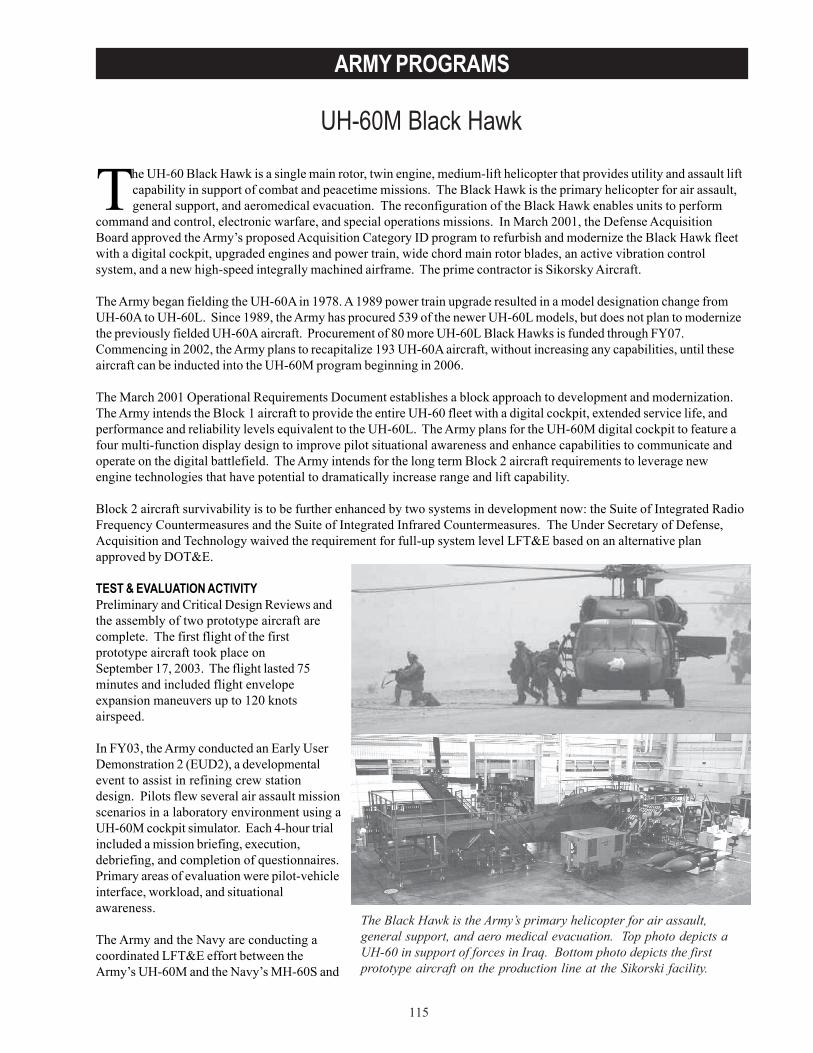
115
ARMY PROGRAMS
UH-60M Black Hawk
The Black Hawk is the Army’s primary helicopter for air assault,general support, and aero medical evacuation. Top photo depicts aUH-60 in support of forces in Iraq. Bottom photo depicts the firstprototype aircraft on the production line at the Sikorski facility.
The UH-60 Black Hawk is a single main rotor, twin engine, medium-lift helicopter that provides utility and assault liftcapability in support of combat and peacetime missions. The Black Hawk is the primary helicopter for air assault,general support, and aeromedical evacuation. The reconfiguration of the Black Hawk enables units to perform
command and control, electronic warfare, and special operations missions. In March 2001, the Defense AcquisitionBoard approved the Army’s proposed Acquisition Category ID program to refurbish and modernize the Black Hawk fleetwith a digital cockpit, upgraded engines and power train, wide chord main rotor blades, an active vibration controlsystem, and a new high-speed integrally machined airframe. The prime contractor is Sikorsky Aircraft.
The Army began fielding the UH-60A in 1978. A 1989 power train upgrade resulted in a model designation change fromUH-60A to UH-60L. Since 1989, the Army has procured 539 of the newer UH-60L models, but does not plan to modernizethe previously fielded UH-60A aircraft. Procurement of 80 more UH-60L Black Hawks is funded through FY07.Commencing in 2002, the Army plans to recapitalize 193 UH-60A aircraft, without increasing any capabilities, until theseaircraft can be inducted into the UH-60M program beginning in 2006.
The March 2001 Operational Requirements Document establishes a block approach to development and modernization.The Army intends the Block 1 aircraft to provide the entire UH-60 fleet with a digital cockpit, extended service life, andperformance and reliability levels equivalent to the UH-60L. The Army plans for the UH-60M digital cockpit to feature afour multi-function display design to improve pilot situational awareness and enhance capabilities to communicate andoperate on the digital battlefield. The Army intends for the long term Block 2 aircraft requirements to leverage newengine technologies that have potential to dramatically increase range and lift capability.
Block 2 aircraft survivability is to be further enhanced by two systems in development now: the Suite of Integrated RadioFrequency Countermeasures and the Suite of Integrated Infrared Countermeasures. The Under Secretary of Defense,Acquisition and Technology waived the requirement for full-up system level LFT&E based on an alternative planapproved by DOT&E.
TEST & EVALUATION ACTIVITYPreliminary and Critical Design Reviews andthe assembly of two prototype aircraft arecomplete. The first flight of the firstprototype aircraft took place onSeptember 17, 2003. The flight lasted 75minutes and included flight envelopeexpansion maneuvers up to 120 knotsairspeed.
In FY03, the Army conducted an Early UserDemonstration 2 (EUD2), a developmentalevent to assist in refining crew stationdesign. Pilots flew several air assault missionscenarios in a laboratory environment using aUH-60M cockpit simulator. Each 4-hour trialincluded a mission briefing, execution,debriefing, and completion of questionnaires.Primary areas of evaluation were pilot-vehicleinterface, workload, and situationalawareness.
The Army and the Navy are conducting acoordinated LFT&E effort between theArmy’s UH-60M and the Navy’s MH-60S and
116
ARMY PROGRAMS
MH-60R to reduce costs and compress the schedule. The testing to date includes ballistic testing of several flight-criticalmain rotor drives, flight control components, and the entire fuel system under static and dynamic load conditions. Theprogram is procuring several damaged Army and Navy H-60 aircraft, and a fully operational, but not flight worthy, YCH-60 prototype that is serving as the production representative ground test vehicle. The Army is updating earliervulnerability models to be more representative of the latest design configuration.
TEST & EVALUATION ASSESSMENTTechnical risks for the UH-60M program include the structural design of the airframe and software integration. TheDOT&E-approved UH-60M test program will provide ample opportunity to evaluate these technical issues and determinethe operational effectiveness and suitability of the UH-60M helicopter.
Until the prototype aircraft flight-testing is complete, the adequacy of the UH-60M structural design will not be validated.It is possible that unexpected fatigue, dynamic, or vibration loads could be encountered in the newly designed airframe.
Software development and integration issues remain with the processor throughput for some subsystems. The aircraftsystem computer resource utilization is desired to be less than 50 percent. However, three subsystems exceed the 50percent utilization goal in the program.
The EUD2 demonstrates that pilots in the UH-60M cockpit can perform today’s air assault mission. Pilot vehicleinterfaces are adequate with the exception of free text messaging procedures. The messaging procedures are notintuitive and are time-consuming, requiring the copilot to remain focused inside the cockpit for extended periods of time.With respect to workload levels, pilots report that they retain the capacity to perform all desirable additional tasks whenoperating in the new cockpit. Pilot situational awareness is enhanced by the navigation aids and digital map displaysystems.
The integrated Army/Navy LFT&E plan takes into account vulnerability reduction features that were incorporated intothe Black Hawk since its initial fielding in 1978, combat damage experience, subsystem qualification efforts, computermodeling and simulation, as well as other Services’ testing. Test results show improved survivability over prior H-60model aircraft.
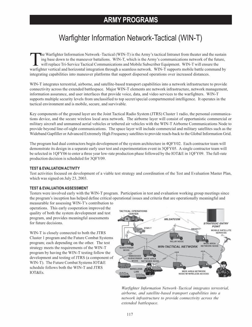
117
ARMY PROGRAMS
Warfighter Information Network-Tactical (WIN-T)
Warfighter Information Network–Tactical integrates terrestrial,airborne, and satellite-based transport capabilities into anetwork infrastructure to provide connectivity across theextended battlespace.
The Warfighter Information Network–Tactical (WIN-T) is the Army’s tactical Intranet from theater and the sustaining base down to the maneuver battalions. WIN-T, which is the Army’s communications network of the future,will replace Tri-Service Tactical Communications and Mobile Subscriber Equipment. WIN-T will ensure the
warfighter vertical and horizontal integration through a seamless network. WIN-T supports mobile battle command byintegrating capabilities into maneuver platforms that support dispersed operations over increased distances.
WIN-T integrates terrestrial, airborne, and satellite-based transport capabilities into a network infrastructure to provideconnectivity across the extended battlespace. Major WIN-T elements are network infrastructure, network management,information assurance, and user interfaces that provide voice, data, and video services to the warfighters. WIN-Tsupports multiple security levels from unclassified to top secret/special compartmented intelligence. It operates in thetactical environment and is mobile, secure, and survivable.
Key components of the ground layer are the Joint Tactical Radio System (JTRS) Cluster 1 radio, the personal communica-tions device, and the secure wireless local area network. The airborne layer will consist of opportunistic commercial ormilitary aircraft and unmanned aerial vehicles or tethered air vehicles with the WIN-T Airborne Communications Node toprovide beyond line-of-sight communications. The space layer will include commercial and military satellites such as theWideband Gapfiller or Advanced Extremely High Frequency satellites to provide reach-back to the Global Information Grid.
The program had dual contractors begin development of the system architecture in 4QFY02. Each contractor team willdemonstrate its design in a separate early user test and experimentation event in 3QFY05. A single contractor team willbe selected in 1QFY06 to enter a three year low-rate production phase followed by the IOT&E in 1QFY09. The full-rateproduction decision is scheduled for 3QFY09.
TEST & EVALUATION ACTIVITYTest activities focused on development of a viable test strategy and coordination of the Test and Evaluation Master Plan,which was signed on July 23, 2003.
TEST & EVALUATION ASSESSMENTTesters were involved early with the WIN-T program. Participation in test and evaluation working group meetings sincethe program’s inception has helped define critical operational issues and criteria that are operationally meaningful andmeasurable for assessing WIN-T’s contribution tooperations. This early cooperation improved thequality of both the system development and testprogram, and provides meaningful assessmentsfor future decisions.
WIN-T is closely connected to both the JTRSCluster 1 program and the Future Combat Systemsprogram; each depending on the other. The teststrategy meets the requirements of the WIN-Tprogram by having the WIN-T testing follow thedevelopment and testing of JTRS (a component ofWIN-T). The Future Combat Systems IOT&Eschedule follows both the WIN-T and JTRSIOT&Es.

118
ARMY PROGRAMS
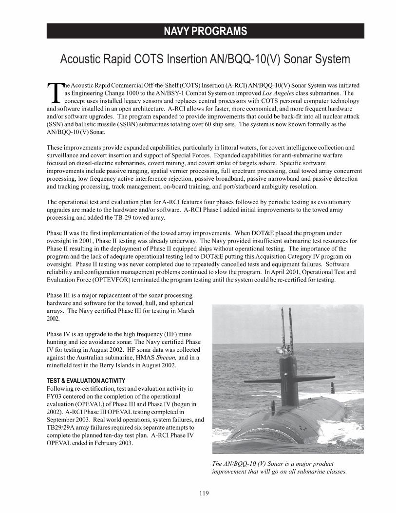
119
NAVY PROGRAMS
Acoustic Rapid COTS Insertion AN/BQQ-10(V) Sonar System
The AN/BQQ-10 (V) Sonar is a major productimprovement that will go on all submarine classes.
The Acoustic Rapid Commercial Off-the-Shelf (COTS) Insertion (A-RCI) AN/BQQ-10(V) Sonar System was initiatedas Engineering Change 1000 to the AN/BSY-1 Combat System on improved Los Angeles class submarines. Theconcept uses installed legacy sensors and replaces central processors with COTS personal computer technology
and software installed in an open architecture. A-RCI allows for faster, more economical, and more frequent hardwareand/or software upgrades. The program expanded to provide improvements that could be back-fit into all nuclear attack(SSN) and ballistic missile (SSBN) submarines totaling over 60 ship sets. The system is now known formally as theAN/BQQ-10 (V) Sonar.
These improvements provide expanded capabilities, particularly in littoral waters, for covert intelligence collection andsurveillance and covert insertion and support of Special Forces. Expanded capabilities for anti-submarine warfarefocused on diesel-electric submarines, covert mining, and covert strike of targets ashore. Specific softwareimprovements include passive ranging, spatial vernier processing, full spectrum processing, dual towed array concurrentprocessing, low frequency active interference rejection, passive broadband, passive narrowband and passive detectionand tracking processing, track management, on-board training, and port/starboard ambiguity resolution.
The operational test and evaluation plan for A-RCI features four phases followed by periodic testing as evolutionaryupgrades are made to the hardware and/or software. A-RCI Phase I added initial improvements to the towed arrayprocessing and added the TB-29 towed array.
Phase II was the first implementation of the towed array improvements. When DOT&E placed the program underoversight in 2001, Phase II testing was already underway. The Navy provided insufficient submarine test resources forPhase II resulting in the deployment of Phase II equipped ships without operational testing. The importance of theprogram and the lack of adequate operational testing led to DOT&E putting this Acquisition Category IV program onoversight. Phase II testing was never completed due to repeatedly cancelled tests and equipment failures. Softwarereliability and configuration management problems continued to slow the program. In April 2001, Operational Test andEvaluation Force (OPTEVFOR) terminated the program testing until the system could be re-certified for testing.
Phase III is a major replacement of the sonar processinghardware and software for the towed, hull, and sphericalarrays. The Navy certified Phase III for testing in March2002.
Phase IV is an upgrade to the high frequency (HF) minehunting and ice avoidance sonar. The Navy certified PhaseIV for testing in August 2002. HF sonar data was collectedagainst the Australian submarine, HMAS Sheean, and in aminefield test in the Berry Islands in August 2002.
TEST & EVALUATION ACTIVITYFollowing re-certification, test and evaluation activity inFY03 centered on the completion of the operationalevaluation (OPEVAL) of Phase III and Phase IV (begun in2002). A-RCI Phase III OPEVAL testing completed inSeptember 2003. Real world operations, system failures, andTB29/29A array failures required six separate attempts tocomplete the planned ten-day test plan. A-RCI Phase IVOPEVAL ended in February 2003.
120
NAVY PROGRAMS
TEST & EVALUATION ASSESSMENTOPTEVFOR is evaluating A-RCI Phase III OPEVAL data. DOT&E’s initial assessment is that A-RCI Phase III does notmeet all requirements and continues to have maintenance and reliability problems, but is an improvement over legacysystems.
OPTEVFOR evaluated A-RCI Phase IV as ineffective and unsuitable because the system failed to meet performancerequirements. Despite not meeting requirements, DOT&E assesses Phase IV as an improvement over legacy HF systems.
The procurement and deployment of Phase II and III systems continued in 2003, even though the Director cited theA-RCI program in a letter to the Secretary of the Navy in August 2002. Navy leadership should support OPTEVFOR toensure that the resources (test submarines and time) are available for the adequate operational test and evaluation ofA-RCI before ships are deployed with these systems.
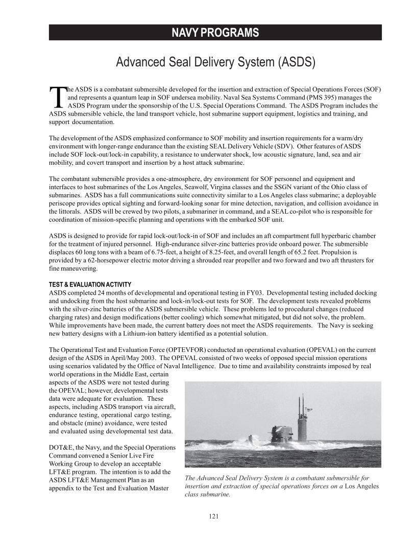
121
NAVY PROGRAMS
Advanced Seal Delivery System (ASDS)
The Advanced Seal Delivery System is a combatant submersible forinsertion and extraction of special operations forces on a Los Angelesclass submarine.
The ASDS is a combatant submersible developed for the insertion and extraction of Special Operations Forces (SOF)and represents a quantum leap in SOF undersea mobility. Naval Sea Systems Command (PMS 395) manages theASDS Program under the sponsorship of the U.S. Special Operations Command. The ASDS Program includes the
ASDS submersible vehicle, the land transport vehicle, host submarine support equipment, logistics and training, andsupport documentation.
The development of the ASDS emphasized conformance to SOF mobility and insertion requirements for a warm/dryenvironment with longer-range endurance than the existing SEAL Delivery Vehicle (SDV). Other features of ASDSinclude SOF lock-out/lock-in capability, a resistance to underwater shock, low acoustic signature, land, sea and airmobility, and covert transport and insertion by a host attack submarine.
The combatant submersible provides a one-atmosphere, dry environment for SOF personnel and equipment andinterfaces to host submarines of the Los Angeles, Seawolf, Virgina classes and the SSGN variant of the Ohio class ofsubmarines. ASDS has a full communications suite connectivity similar to a Los Angeles class submarine; a deployableperiscope provides optical sighting and forward-looking sonar for mine detection, navigation, and collision avoidance inthe littorals. ASDS will be crewed by two pilots, a submariner in command, and a SEAL co-pilot who is responsible forcoordination of mission-specific planning and operations with the embarked SOF unit.
ASDS is designed to provide for rapid lock-out/lock-in of SOF and includes an aft compartment full hyperbaric chamberfor the treatment of injured personnel. High-endurance silver-zinc batteries provide onboard power. The submersibledisplaces 60 long tons with a beam of 6.75-feet, a height of 8.25-feet, and overall length of 65.2 feet. Propulsion isprovided by a 62-horsepower electric motor driving a shrouded rear propeller and two forward and two aft thrusters forfine maneuvering.
TEST & EVALUATION ACTIVITYASDS completed 24 months of developmental and operational testing in FY03. Developmental testing included dockingand undocking from the host submarine and lock-in/lock-out tests for SOF. The development tests revealed problemswith the silver-zinc batteries of the ASDS submersible vehicle. These problems led to procedural changes (reducedcharging rates) and design modifications (better cooling) which somewhat mitigated, but did not solve, the problem.While improvements have been made, the current battery does not meet the ASDS requirements. The Navy is seekingnew battery designs with a Lithium-ion battery identified as a potential solution.
The Operational Test and Evaluation Force (OPTEVFOR) conducted an operational evaluation (OPEVAL) on the currentdesign of the ASDS in April/May 2003. The OPEVAL consisted of two weeks of opposed special mission operationsusing scenarios validated by the Office of Naval Intelligence. Due to time and availability constraints imposed by realworld operations in the Middle East, certainaspects of the ASDS were not tested duringthe OPEVAL; however, developmental testsdata were adequate for evaluation. Theseaspects, including ASDS transport via aircraft,endurance testing, operational cargo testing,and obstacle (mine) avoidance, were testedand evaluated using developmental test data.
DOT&E, the Navy, and the Special OperationsCommand convened a Senior Live FireWorking Group to develop an acceptableLFT&E program. The intention is to add theASDS LFT&E Management Plan as anappendix to the Test and Evaluation Master
122
NAVY PROGRAMS
Plan. The Navy and DOT&E are nearing an agreement on the nature and content of the LFT&E program, and the LFT&EManagement Plan is now close to adequate.
TEST & EVALUATION ASSESSMENTOPTEVFOR evaluated ASDS operationally effective and suitable under certain specified threats and environments andprovided several recommendations including necessary improvements to the battery, sensors, and logistical support.OPTEVFOR recommended correction of deficiencies and vulnerabilities verification in an additional phase of OPEVAL.
ASDS maintainability and reliability is poor due to low battery service life, low charging and cooling rates, and electricalgrounds. During OPEVAL, low main motor controller electrical grounds reduced the endurance and cruise speed andresulted in a loss of ASDS propulsion. Onboard crew repairs enabled completion the OPEVAL SOF mission; however, hadthe crew been unable to affect at sea repairs, the ASDS could have been stranded and required safety ship assistance.Also, during transit in a recent forward site exercise, the ASDS sustained damage. An investigation to determine thecause is underway. In spite of these problems, the ASDS is a clear improvement over the SDV. It has a dry, warmenvironment, onboard sensor and communications equipment, greater speed, range endurance, and payload capacity.
The ASDS system requires further test and evaluation to verify correction of the deficiencies associated with the battery,electrical system grounds, noise signature, and other identified deficiencies.
Depending on the near-term schedule for ASDS 1, it is desirable to arrange a trial against simulated threat mines todetermine likely burst points (e.g., using the Versatile Exercise Mine System). For ASDS 2, a more robust LFT&E strategycould be applied. Any resulting changes to subsequent vehicles could then be evaluated for backfit on case-bases forASDS 1.
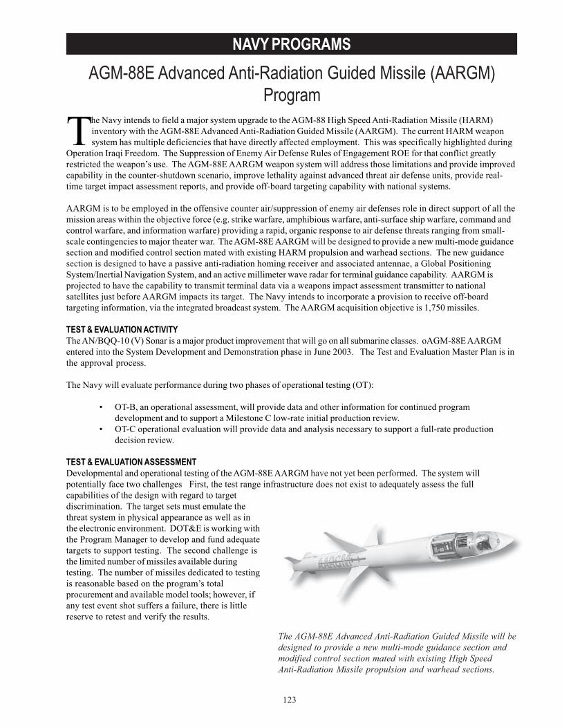
123
NAVY PROGRAMSAGM-88E Advanced Anti-Radiation Guided Missile (AARGM)
Program
The Navy intends to field a major system upgrade to the AGM-88 High Speed Anti-Radiation Missile (HARM)inventory with the AGM-88E Advanced Anti-Radiation Guided Missile (AARGM). The current HARM weaponsystem has multiple deficiencies that have directly affected employment. This was specifically highlighted during
Operation Iraqi Freedom. The Suppression of Enemy Air Defense Rules of Engagement ROE for that conflict greatlyrestricted the weapon’s use. The AGM-88E AARGM weapon system will address those limitations and provide improvedcapability in the counter-shutdown scenario, improve lethality against advanced threat air defense units, provide real-time target impact assessment reports, and provide off-board targeting capability with national systems.
AARGM is to be employed in the offensive counter air/suppression of enemy air defenses role in direct support of all themission areas within the objective force (e.g. strike warfare, amphibious warfare, anti-surface ship warfare, command andcontrol warfare, and information warfare) providing a rapid, organic response to air defense threats ranging from small-scale contingencies to major theater war. The AGM-88E AARGM will be designed to provide a new multi-mode guidancesection and modified control section mated with existing HARM propulsion and warhead sections. The new guidancesection is designed to have a passive anti-radiation homing receiver and associated antennae, a Global PositioningSystem/Inertial Navigation System, and an active millimeter wave radar for terminal guidance capability. AARGM isprojected to have the capability to transmit terminal data via a weapons impact assessment transmitter to nationalsatellites just before AARGM impacts its target. The Navy intends to incorporate a provision to receive off-boardtargeting information, via the integrated broadcast system. The AARGM acquisition objective is 1,750 missiles.
TEST & EVALUATION ACTIVITYThe AN/BQQ-10 (V) Sonar is a major product improvement that will go on all submarine classes. oAGM-88E AARGMentered into the System Development and Demonstration phase in June 2003. The Test and Evaluation Master Plan is inthe approval process.
The Navy will evaluate performance during two phases of operational testing (OT):
• OT-B, an operational assessment, will provide data and other information for continued programdevelopment and to support a Milestone C low-rate initial production review.
• OT-C operational evaluation will provide data and analysis necessary to support a full-rate productiondecision review.
TEST & EVALUATION ASSESSMENTDevelopmental and operational testing of the AGM-88E AARGM have not yet been performed. The system willpotentially face two challenges First, the test range infrastructure does not exist to adequately assess the fullcapabilities of the design with regard to targetdiscrimination. The target sets must emulate thethreat system in physical appearance as well as inthe electronic environment. DOT&E is working withthe Program Manager to develop and fund adequatetargets to support testing. The second challenge isthe limited number of missiles available duringtesting. The number of missiles dedicated to testingis reasonable based on the program’s totalprocurement and available model tools; however, ifany test event shot suffers a failure, there is littlereserve to retest and verify the results.
The AGM-88E Advanced Anti-Radiation Guided Missile will bedesigned to provide a new multi-mode guidance section andmodified control section mated with existing High SpeedAnti-Radiation Missile propulsion and warhead sections.

124
NAVY PROGRAMS
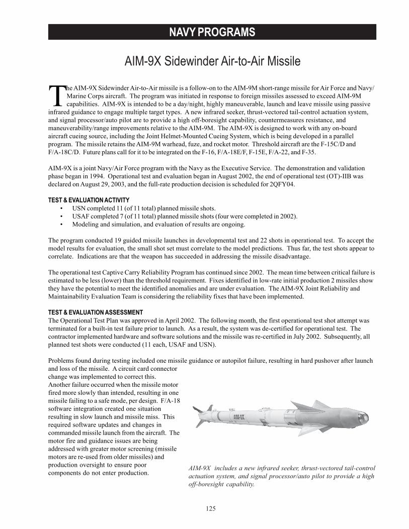
125
NAVY PROGRAMS
AIM-9X Sidewinder Air-to-Air Missile
AIM-9X includes a new infrared seeker, thrust-vectored tail-controlactuation system, and signal processor/auto pilot to provide a highoff-boresight capability.
The AIM-9X Sidewinder Air-to-Air missile is a follow-on to the AIM-9M short-range missile for Air Force and Navy/Marine Corps aircraft. The program was initiated in response to foreign missiles assessed to exceed AIM-9Mcapabilities. AIM-9X is intended to be a day/night, highly maneuverable, launch and leave missile using passive
infrared guidance to engage multiple target types. A new infrared seeker, thrust-vectored tail-control actuation system,and signal processor/auto pilot are to provide a high off-boresight capability, countermeasures resistance, andmaneuverability/range improvements relative to the AIM-9M. The AIM-9X is designed to work with any on-boardaircraft cueing source, including the Joint Helmet-Mounted Cueing System, which is being developed in a parallelprogram. The missile retains the AIM-9M warhead, fuze, and rocket motor. Threshold aircraft are the F-15C/D andF/A-18C/D. Future plans call for it to be integrated on the F-16, F/A-18E/F, F-15E, F/A-22, and F-35.
AIM-9X is a joint Navy/Air Force program with the Navy as the Executive Service. The demonstration and validationphase began in 1994. Operational test and evaluation began in August 2002, the end of operational test (OT)-IIB wasdeclared on August 29, 2003, and the full-rate production decision is scheduled for 2QFY04.
TEST & EVALUATION ACTIVITY• USN completed 11 (of 11 total) planned missile shots.• USAF completed 7 (of 11 total) planned missile shots (four were completed in 2002).• Modeling and simulation, and evaluation of results are ongoing.
The program conducted 19 guided missile launches in developmental test and 22 shots in operational test. To accept themodel results for evaluation, the small shot set must correlate to the model predictions. Thus far, the test shots appear tocorrelate. Indications are that the weapon has succeeded in addressing the missile disadvantage.
The operational test Captive Carry Reliability Program has continued since 2002. The mean time between critical failure isestimated to be less (lower) than the threshold requirement. Fixes identified in low-rate initial production 2 missiles showthey have the potential to meet the identified anomalies and are under evaluation. The AIM-9X Joint Reliability andMaintainability Evaluation Team is considering the reliability fixes that have been implemented.
TEST & EVALUATION ASSESSMENTThe Operational Test Plan was approved in April 2002. The following month, the first operational test shot attempt wasterminated for a built-in test failure prior to launch. As a result, the system was de-certified for operational test. Thecontractor implemented hardware and software solutions and the missile was re-certified in July 2002. Subsequently, allplanned test shots were conducted (11 each, USAF and USN).
Problems found during testing included one missile guidance or autopilot failure, resulting in hard pushover after launchand loss of the missile. A circuit card connectorchange was implemented to correct this.Another failure occurred when the missile motorfired more slowly than intended, resulting in onemissile failing to a safe mode, per design. F/A-18software integration created one situationresulting in slow launch and missile miss. Thisrequired software updates and changes incommanded missile launch from the aircraft. Themotor fire and guidance issues are beingaddressed with greater motor screening (missilemotors are re-used from older missiles) andproduction oversight to ensure poorcomponents do not enter production.
126
NAVY PROGRAMS
While design problems and test issues contributed to a prolonged test program, the most significant delays were causedby test support resource shortfalls. Poor availability of QF-4 target drones, range airspace, and test squadron aircraftdelayed the program. The support priority given to real world combat operations had a particularly strong impact on theNavy’s portion of the testing, but both services did complete testing.
Modeling and simulation, in conjunction with flight testing, is key to the development and evaluation of the AIM-9X.Due to this missile’s expanded capabilities and the high cost of launches, a family of simulations is used to assess missileperformance across a wide spectrum of engagements encompassing various threats, backgrounds, and countermeasures.Actual missile firings validate the simulations. The simulations then assess the required probability of a kill against thethreat targets. Simulation initiatives allow the number of guided test missiles to be significantly reduced.
The final operational test report is currently being prepared by the Air Force Operational Test and Evaluation Center andOPTEVFOR. DOT&E will prepare the beyond low-rate initial production report with a goal of supporting a Milestone IIIreview in 2QFY04.
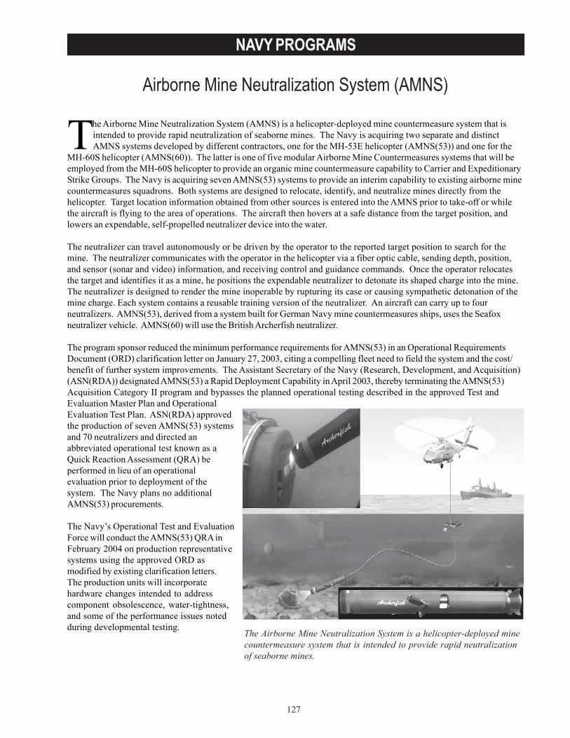
127
NAVY PROGRAMS
Airborne Mine Neutralization System (AMNS)
The Airborne Mine Neutralization System is a helicopter-deployed minecountermeasure system that is intended to provide rapid neutralizationof seaborne mines.
The Airborne Mine Neutralization System (AMNS) is a helicopter-deployed mine countermeasure system that isintended to provide rapid neutralization of seaborne mines. The Navy is acquiring two separate and distinctAMNS systems developed by different contractors, one for the MH-53E helicopter (AMNS(53)) and one for the
MH-60S helicopter (AMNS(60)). The latter is one of five modular Airborne Mine Countermeasures systems that will beemployed from the MH-60S helicopter to provide an organic mine countermeasure capability to Carrier and ExpeditionaryStrike Groups. The Navy is acquiring seven AMNS(53) systems to provide an interim capability to existing airborne minecountermeasures squadrons. Both systems are designed to relocate, identify, and neutralize mines directly from thehelicopter. Target location information obtained from other sources is entered into the AMNS prior to take-off or whilethe aircraft is flying to the area of operations. The aircraft then hovers at a safe distance from the target position, andlowers an expendable, self-propelled neutralizer device into the water.
The neutralizer can travel autonomously or be driven by the operator to the reported target position to search for themine. The neutralizer communicates with the operator in the helicopter via a fiber optic cable, sending depth, position,and sensor (sonar and video) information, and receiving control and guidance commands. Once the operator relocatesthe target and identifies it as a mine, he positions the expendable neutralizer to detonate its shaped charge into the mine.The neutralizer is designed to render the mine inoperable by rupturing its case or causing sympathetic detonation of themine charge. Each system contains a reusable training version of the neutralizer. An aircraft can carry up to fourneutralizers. AMNS(53), derived from a system built for German Navy mine countermeasures ships, uses the Seafoxneutralizer vehicle. AMNS(60) will use the British Archerfish neutralizer.
The program sponsor reduced the minimum performance requirements for AMNS(53) in an Operational RequirementsDocument (ORD) clarification letter on January 27, 2003, citing a compelling fleet need to field the system and the cost/benefit of further system improvements. The Assistant Secretary of the Navy (Research, Development, and Acquisition)(ASN(RDA)) designated AMNS(53) a Rapid Deployment Capability in April 2003, thereby terminating the AMNS(53)Acquisition Category II program and bypasses the planned operational testing described in the approved Test andEvaluation Master Plan and OperationalEvaluation Test Plan. ASN(RDA) approvedthe production of seven AMNS(53) systemsand 70 neutralizers and directed anabbreviated operational test known as aQuick Reaction Assessment (QRA) beperformed in lieu of an operationalevaluation prior to deployment of thesystem. The Navy plans no additionalAMNS(53) procurements.
The Navy’s Operational Test and EvaluationForce will conduct the AMNS(53) QRA inFebruary 2004 on production representativesystems using the approved ORD asmodified by existing clarification letters.The production units will incorporatehardware changes intended to addresscomponent obsolescence, water-tightness,and some of the performance issues notedduring developmental testing.
128
NAVY PROGRAMS
TEST & EVALUATION ACTIVITY• AMNS(53) concluded developmental testing during 1QFY03 under the direction of the Naval Surface Warfare
Center, Dahlgren Division, Coastal Systems Station, located at Panama City, Florida.• DOT&E observed end-to-end live fire testing at the Underwater Explosive Test Facility at Aberdeen Test Center,
Aberdeen, Maryland. Expendable neutralizers were used to detonate moored mines filled with explosive material.• DOT&E observed high-current testing at Pensacola, Florida, in December 2002.• DOT&E representatives participated in the development of the Test and Evaluation Master Plan for AMNS(60).
TEST & EVALUATION ASSESSMENTAMNS(53) performance improved during developmental testing, but did not achieve the minimum performancethresholds for probability of neutralization, expendable neutralizer reliability, and high-current performance required in theORD. AMNS(53) has not demonstrated satisfactory performance in ocean currents of any appreciable velocity, or theability of fleet sailors to operate and maintain the system. A team of engineers and technicians provided a higher level ofsupport during developmental testing than would be expected in a typical fleet environment. This system, thoughpurchased, has not demonstrated the necessary performance to allow operational forces to accomplish their mineneutralization mission.
AMNS(53) is lethal against threat mines that are comparable to the U.S. Mark 6 and Mark 56 moored mines whendetonated in the correct firing position. Additional data will be collected during the QRA to evaluate the likelihood ofcorrect placement and neutralizer detonation.
AMNS(60) is still in development and has not yet undergone any operational or live fire testing.
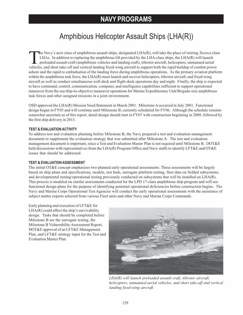
129
NAVY PROGRAMS
Amphibious Helicopter Assault Ships (LHA(R))
LHA(R) will launch preloaded assault craft, tiltrotor aircraft,helicopters, unmanned aerial vehicles, and short take-off and verticallanding fixed-wing aircraft.
The Navy’s next class of amphibious assault ships, designated LHA(R), will take the place of retiring Tarawa classLHAs. In addition to replacing the amphibious lift provided by the LHA-class ships, the LHA(R) will launchpreloaded assault craft (amphibious vehicles and landing craft), tiltrotor aircraft, helicopters, unmanned aerial
vehicles, and short take-off and vertical landing fixed-wing aircraft to support both the rapid buildup of combat powerashore and the rapid re-embarkation of the landing force during amphibious operations. As the primary aviation platformwithin the amphibious task force, the LHA(R) must launch and recover helicopters, tiltrotor aircraft, and fixed-wingaircraft as well as conduct simultaneous well-deck and flight-deck operations day and night. Finally, the ship is expectedto have command, control, communication, computer, and intelligence capabilities sufficient to support operationalmaneuver from the sea/ship-to-objective maneuver operations for Marine Expeditionary Unit/Brigade-size amphibioustask forces and other assigned missions in a joint environment.
OSD approved the LHA(R) Mission Need Statement in March 2001. Milestone A occurred in July 2001. Functionaldesign began in FY03 and will continue until Milestone B, currently scheduled for FY06. Although the schedule remainssomewhat uncertain as of this report, detail design should start in FY07 with construction beginning in 2009, followed bythe first ship delivery in 2013.
TEST & EVALUATION ACTIVITYTo address test and evaluation planning before Milestone B, the Navy prepared a test and evaluation managementdocument to supplement the evaluation strategy that was submitted after Milestone A. The test and evaluationmanagement document is important, since a Test and Evaluation Master Plan is not required until Milestone B. DOT&Eheld discussions with representatives from the LHA(R) Program Office and Navy staffs to identify LFT&E and OT&Eissues that should be addressed.
TEST & EVALUATION ASSESSMENTThe initial OT&E concept emphasizes two planned early operational assessments. These assessments will be largelybased on ship plans and specifications, models, test beds, surrogate platform testing, fleet data on fielded subsystems,and developmental testing/operational testing previously conducted on subsystems that will be installed on LHA(R).This process is modeled on similar assessments conducted for the LPD 17-class amphibious ship program and will usefunctional design plans for the purpose of identifying potential operational deficiencies before construction begins. TheNavy and Marine Corps Operational Test Agencies will conduct the early operational assessments with the assistance ofsubject matter experts selected from various Fleet units and other Navy and Marine Corps Commands.
Early planning and execution of LFT&E forLHA(R) could affect the ship’s survivabilitydesign. Tasks that should be completed beforeMilestone B are the surrogate testing, theMilestone B Vulnerability Assessment Report,DOT&E approval of an LFT&E ManagementPlan, and LFT&E strategy input for the Test andEvaluation Master Plan.

130
NAVY PROGRAMS
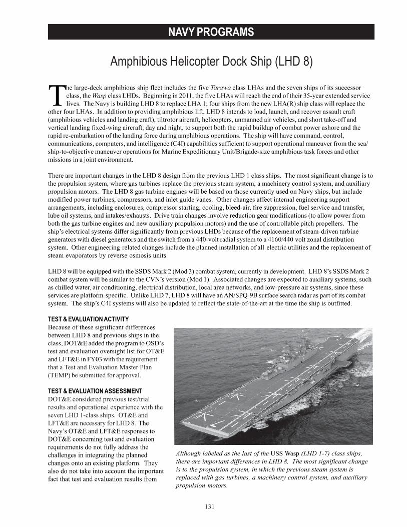
131
NAVY PROGRAMS
Amphibious Helicopter Dock Ship (LHD 8)
Although labeled as the last of the USS Wasp (LHD 1-7) class ships,there are important differences in LHD 8. The most significant changeis to the propulsion system, in which the previous steam system isreplaced with gas turbines, a machinery control system, and auxiliarypropulsion motors.
The large-deck amphibious ship fleet includes the five Tarawa class LHAs and the seven ships of its successorclass, the Wasp class LHDs. Beginning in 2011, the five LHAs will reach the end of their 35-year extended servicelives. The Navy is building LHD 8 to replace LHA 1; four ships from the new LHA(R) ship class will replace the
other four LHAs. In addition to providing amphibious lift, LHD 8 intends to load, launch, and recover assault craft(amphibious vehicles and landing craft), tiltrotor aircraft, helicopters, unmanned air vehicles, and short take-off andvertical landing fixed-wing aircraft, day and night, to support both the rapid buildup of combat power ashore and therapid re-embarkation of the landing force during amphibious operations. The ship will have command, control,communications, computers, and intelligence (C4I) capabilities sufficient to support operational maneuver from the sea/ship-to-objective maneuver operations for Marine Expeditionary Unit/Brigade-size amphibious task forces and othermissions in a joint environment.
There are important changes in the LHD 8 design from the previous LHD 1 class ships. The most significant change is tothe propulsion system, where gas turbines replace the previous steam system, a machinery control system, and auxiliarypropulsion motors. The LHD 8 gas turbine engines will be based on those currently used on Navy ships, but includemodified power turbines, compressors, and inlet guide vanes. Other changes affect internal engineering supportarrangements, including enclosures, compressor starting, cooling, bleed-air, fire suppression, fuel service and transfer,lube oil systems, and intakes/exhausts. Drive train changes involve reduction gear modifications (to allow power fromboth the gas turbine engines and new auxiliary propulsion motors) and the use of controllable pitch propellers. Theship’s electrical systems differ significantly from previous LHDs because of the replacement of steam-driven turbinegenerators with diesel generators and the switch from a 440-volt radial system to a 4160/440 volt zonal distributionsystem. Other engineering-related changes include the planned installation of all-electric utilities and the replacement ofsteam evaporators by reverse osmosis units.
LHD 8 will be equipped with the SSDS Mark 2 (Mod 3) combat system, currently in development. LHD 8’s SSDS Mark 2combat system will be similar to the CVN’s version (Mod 1). Associated changes are expected to auxiliary systems, suchas chilled water, air conditioning, electrical distribution, local area networks, and low-pressure air systems, since theseservices are platform-specific. Unlike LHD 7, LHD 8 will have an AN/SPQ-9B surface search radar as part of its combatsystem. The ship’s C4I systems will also be updated to reflect the state-of-the-art at the time the ship is outfitted.
TEST & EVALUATION ACTIVITYBecause of these significant differencesbetween LHD 8 and previous ships in theclass, DOT&E added the program to OSD’stest and evaluation oversight list for OT&Eand LFT&E in FY03 with the requirementthat a Test and Evaluation Master Plan(TEMP) be submitted for approval.
TEST & EVALUATION ASSESSMENTDOT&E considered previous test/trialresults and operational experience with theseven LHD 1-class ships. OT&E andLFT&E are necessary for LHD 8. TheNavy’s OT&E and LFT&E responses toDOT&E concerning test and evaluationrequirements do not fully address thechallenges in integrating the plannedchanges onto an existing platform. Theyalso do not take into account the importantfact that test and evaluation results from
132
NAVY PROGRAMS
LHD 8 will likely be applicable to LHA(R). Specifically, the Navy’s LHA(R) Test and Evaluation Management Document(approved in May 2003) states that the first LHA(R) will evolve from LHD 8 and therefore, the LHA(R) test andevaluation program will utilize as much of LHD 8’s test and evaluation data as possible to reduce the scope and expenseof LHA(R) T&E. DOT&E supports that concept; a TEMP for LHD 8 is the appropriate document to describe the test andevaluation strategy and associated resource requirements needed to generate test data that are relevant for LHA(R)program use.
For LFT&E, changes being made to LHD 8 are significant and in some cases pervasive. The integration of these changespotentially create vulnerabilities that must be understood and mitigated. Moreover, since some of these technologies willmigrate to the LHA(R), understanding these vulnerabilities through a carefully planned LHD 8 LFT&E program providesthe basis for improving the LHA(R) design and/or casualty procedures.
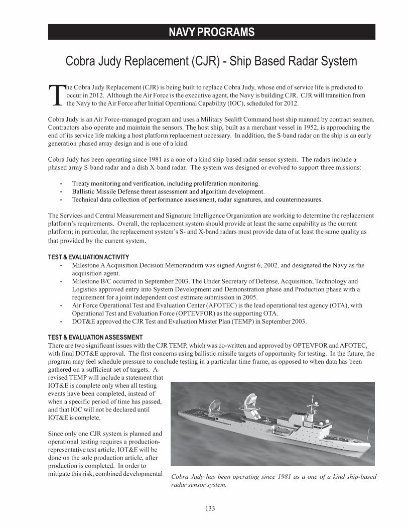
133
NAVY PROGRAMS
Cobra Judy Replacement (CJR) - Ship Based Radar System
Cobra Judy has been operating since 1981 as a one of a kind ship-basedradar sensor system.
The Cobra Judy Replacement (CJR) is being built to replace Cobra Judy, whose end of service life is predicted tooccur in 2012. Although the Air Force is the executive agent, the Navy is building CJR. CJR will transition fromthe Navy to the Air Force after Initial Operational Capability (IOC), scheduled for 2012.
Cobra Judy is an Air Force-managed program and uses a Military Sealift Command host ship manned by contract seamen.Contractors also operate and maintain the sensors. The host ship, built as a merchant vessel in 1952, is approaching theend of its service life making a host platform replacement necessary. In addition, the S-band radar on the ship is an earlygeneration phased array design and is one of a kind.
Cobra Judy has been operating since 1981 as a one of a kind ship-based radar sensor system. The radars include aphased array S-band radar and a dish X-band radar. The system was designed or evolved to support three missions:
• Treaty monitoring and verification, including proliferation monitoring.• Ballistic Missile Defense threat assessment and algorithm development.• Technical data collection of performance assessment, radar signatures, and countermeasures.
The Services and Central Measurement and Signature Intelligence Organization are working to determine the replacementplatform’s requirements. Overall, the replacement system should provide at least the same capability as the currentplatform; in particular, the replacement system’s S- and X-band radars must provide data of at least the same quality asthat provided by the current system.
TEST & EVALUATION ACTIVITY• Milestone A Acquisition Decision Memorandum was signed August 6, 2002, and designated the Navy as the
acquisition agent.• Milestone B/C occurred in September 2003. The Under Secretary of Defense, Acquisition, Technology and
Logistics approved entry into System Development and Demonstration phase and Production phase with arequirement for a joint independent cost estimate submission in 2005.
• Air Force Operational Test and Evaluation Center (AFOTEC) is the lead operational test agency (OTA), withOperational Test and Evaluation Force (OPTEVFOR) as the supporting OTA.
• DOT&E approved the CJR Test and Evaluation Master Plan (TEMP) in September 2003.
TEST & EVALUATION ASSESSMENTThere are two significant issues with the CJR TEMP, which was co-written and approved by OPTEVFOR and AFOTEC,with final DOT&E approval. The first concerns using ballistic missile targets of opportunity for testing. In the future, theprogram may feel schedule pressure to conclude testing in a particular time frame, as opposed to when data has beengathered on a sufficient set of targets. Arevised TEMP will include a statement thatIOT&E is complete only when all testingevents have been completed, instead ofwhen a specific period of time has passed,and that IOC will not be declared untilIOT&E is complete.
Since only one CJR system is planned andoperational testing requires a production-representative test article, IOT&E will bedone on the sole production article, afterproduction is completed. In order tomitigate this risk, combined developmental

134
NAVY PROGRAMS
test/operational test and operational assessment events should be conducted to evaluate the sensor systems, theirsensor integration into the command and control and common operational picture architectures, and, finally, the sensorsuite integration into the host ship.
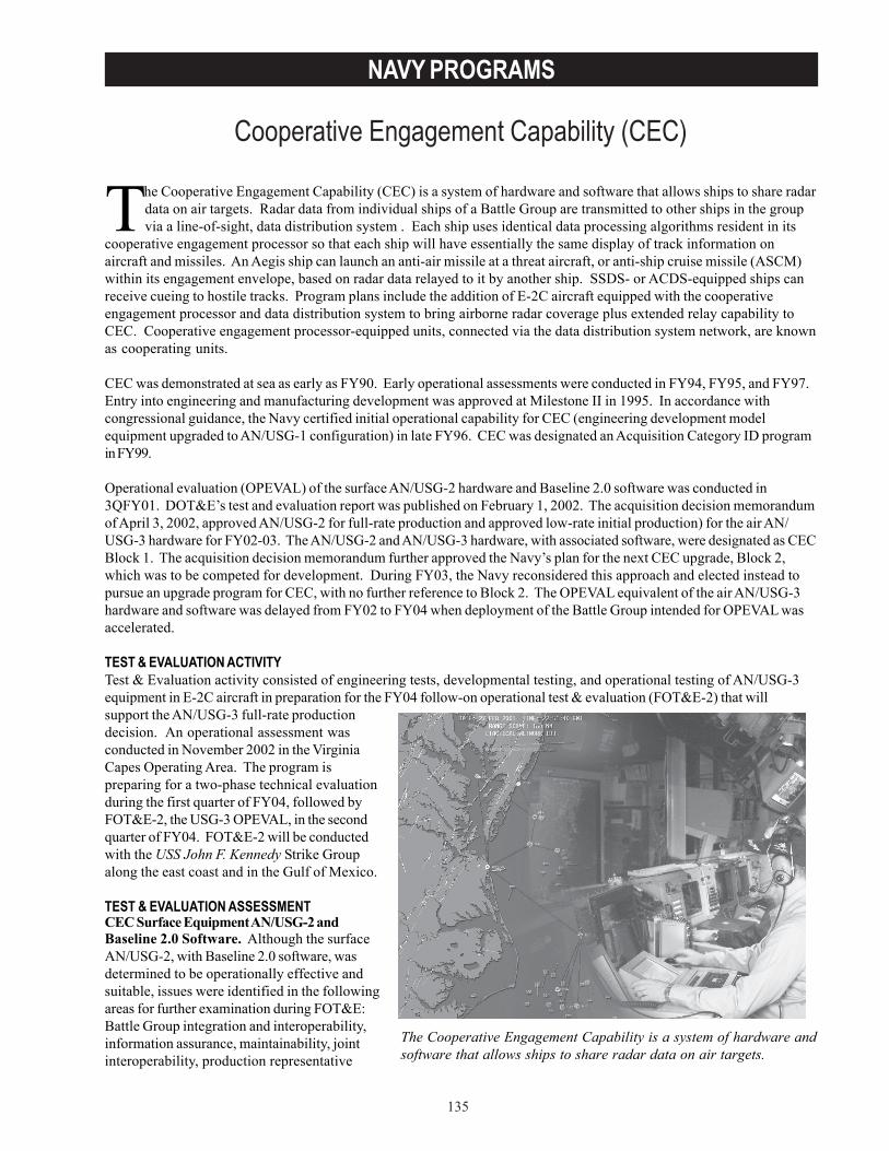
135
NAVY PROGRAMS
Cooperative Engagement Capability (CEC)
The Cooperative Engagement Capability is a system of hardware andsoftware that allows ships to share radar data on air targets.
The Cooperative Engagement Capability (CEC) is a system of hardware and software that allows ships to share radardata on air targets. Radar data from individual ships of a Battle Group are transmitted to other ships in the groupvia a line-of-sight, data distribution system . Each ship uses identical data processing algorithms resident in its
cooperative engagement processor so that each ship will have essentially the same display of track information onaircraft and missiles. An Aegis ship can launch an anti-air missile at a threat aircraft, or anti-ship cruise missile (ASCM)within its engagement envelope, based on radar data relayed to it by another ship. SSDS- or ACDS-equipped ships canreceive cueing to hostile tracks. Program plans include the addition of E-2C aircraft equipped with the cooperativeengagement processor and data distribution system to bring airborne radar coverage plus extended relay capability toCEC. Cooperative engagement processor-equipped units, connected via the data distribution system network, are knownas cooperating units.
CEC was demonstrated at sea as early as FY90. Early operational assessments were conducted in FY94, FY95, and FY97.Entry into engineering and manufacturing development was approved at Milestone II in 1995. In accordance withcongressional guidance, the Navy certified initial operational capability for CEC (engineering development modelequipment upgraded to AN/USG-1 configuration) in late FY96. CEC was designated an Acquisition Category ID programin FY99.
Operational evaluation (OPEVAL) of the surface AN/USG-2 hardware and Baseline 2.0 software was conducted in3QFY01. DOT&E’s test and evaluation report was published on February 1, 2002. The acquisition decision memorandumof April 3, 2002, approved AN/USG-2 for full-rate production and approved low-rate initial production) for the air AN/USG-3 hardware for FY02-03. The AN/USG-2 and AN/USG-3 hardware, with associated software, were designated as CECBlock 1. The acquisition decision memorandum further approved the Navy’s plan for the next CEC upgrade, Block 2,which was to be competed for development. During FY03, the Navy reconsidered this approach and elected instead topursue an upgrade program for CEC, with no further reference to Block 2. The OPEVAL equivalent of the air AN/USG-3hardware and software was delayed from FY02 to FY04 when deployment of the Battle Group intended for OPEVAL wasaccelerated.
TEST & EVALUATION ACTIVITYTest & Evaluation activity consisted of engineering tests, developmental testing, and operational testing of AN/USG-3equipment in E-2C aircraft in preparation for the FY04 follow-on operational test & evaluation (FOT&E-2) that willsupport the AN/USG-3 full-rate productiondecision. An operational assessment wasconducted in November 2002 in the VirginiaCapes Operating Area. The program ispreparing for a two-phase technical evaluationduring the first quarter of FY04, followed byFOT&E-2, the USG-3 OPEVAL, in the secondquarter of FY04. FOT&E-2 will be conductedwith the USS John F. Kennedy Strike Groupalong the east coast and in the Gulf of Mexico.
TEST & EVALUATION ASSESSMENTCEC Surface Equipment AN/USG-2 andBaseline 2.0 Software. Although the surfaceAN/USG-2, with Baseline 2.0 software, wasdetermined to be operationally effective andsuitable, issues were identified in the followingareas for further examination during FOT&E:Battle Group integration and interoperability,information assurance, maintainability, jointinteroperability, production representative
136
NAVY PROGRAMS
AN/USG-3 equipment, and new combat system integration. While the CEC Program Manager (PM) is attempting toaddress these issues, correction of certain issues in the area of Battle Group integration and interoperability requirechanges to the combat systems integrated with CEC. In spite of acquisition decision memorandum-direction to the Navyto fund expeditious solution of problems associated with integration and interoperability, there is no evidence thatcorrection of most of these problems will be demonstrated soon.
FOT&E-2. The primary objective of this testing is to demonstrate improved operational effectiveness and suitabilitywith production-representative AN/USG-3 equipment and software operating in a Strike Group-level CEC network whileexecuting the air defense mission. At a minimum, FOT&E-2 should demonstrate that the air defense mission can beexecuted without degradation resulting from integration of the production-representative AN/USG-3 and the E-2C radar.This testing requires a CEC-configured Strike Group detecting, tracking, and engaging threat-representative ASCMsurrogates during operationally realistic air defense scenarios with actual and simulated Standard and Seasparrowmissiles. Given the current immature air defense T&E infrastructure on the east coast and Gulf of Mexico, and with theclosure of the Atlantic Fleet Weapons Training Facility outer range in Puerto Rico, DOT&E is concerned about theadequacy of FOT&E-2. DOT&E is particularly concerned that the OT&E is to be integrated with training of a StrikeGroup that is also using the immature infrastructure.
FOT&E-3. The primary objective of this testing is to demonstrate operational effectiveness and suitability with a ShipSelf Defense System Mark 2 combat system operating in a Strike Group-level CEC network while executing air defense.The Navy plans this testing for early FY05 with the Reagan Strike Group on the west coast. DOT&E is concerned thatthe Strike Group deployment may be accelerated, as was the Nimitz Battle Group’s in FY02, with the testing delayed untilthe next Strike Group becomes available. DOT&E is also concerned that the Strike Group composition may not beadequately representative of a CEC Strike Group in terms of numbers of CEC-capable ships and aircraft.
OT&E of Network Centric Warfare Systems. The challenge associated with adequate testing of CEC is an example ofthe challenges facing this generic category of systems. The Navy has applied substantial effort to development of theDistributed Engineering Plant (DEP), an interconnection of land-based combat system sites for interoperability testing.This has been a useful tool for new system development and for software interoperability certification. Futureimprovements in the DEP will likely provide significant useful data for the overall warfare system test process, butoperational testing under realistic combat conditions will, for the foreseeable future, require an ensemble of platforms –both in quantities and types – that truly represent the size and complexity of at-sea battle forces. The DEP is not asubstitute for realistic operational test and evaluation, but it may be used to augment testing.
Adequate OT&E that supports acquisition investment decisions for networking systems such as CEC for the Fleet isimportant. Effective training of the Fleet in preparation for deployment is also essential. When effectively integrated,mutual contribution and benefit can result with both T&E and training bringing resources that can improve theoperational realism of the combined training/T&E environment. With the flexibility and surge capability called for by theNavy’s new Fleet Response Plan, effective integration of the two will require collaboration at the highest Fleet and Navyacquisition executive levels.
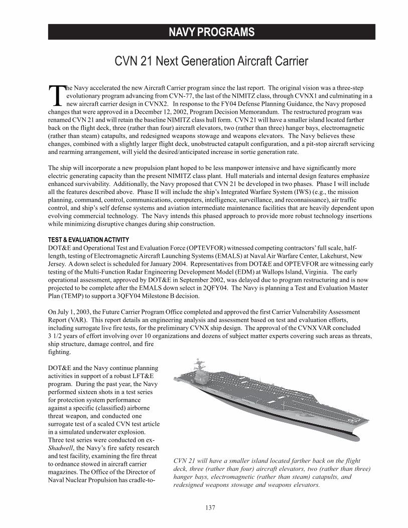
137
NAVY PROGRAMS
CVN 21 Next Generation Aircraft Carrier
The Navy accelerated the new Aircraft Carrier program since the last report. The original vision was a three-stepevolutionary program advancing from CVN-77, the last of the NIMITZ class, through CVNX1 and culminating in anew aircraft carrier design in CVNX2. In response to the FY04 Defense Planning Guidance, the Navy proposed
changes that were approved in a December 12, 2002, Program Decision Memorandum. The restructured program wasrenamed CVN 21 and will retain the baseline NIMITZ class hull form. CVN 21 will have a smaller island located fartherback on the flight deck, three (rather than four) aircraft elevators, two (rather than three) hanger bays, electromagnetic(rather than steam) catapults, and redesigned weapons stowage and weapons elevators. The Navy believes thesechanges, combined with a slightly larger flight deck, unobstructed catapult configuration, and a pit-stop aircraft servicingand rearming arrangement, will yield the desired/anticipated increase in sortie generation rate.
The ship will incorporate a new propulsion plant hoped to be less manpower intensive and have significantly moreelectric generating capacity than the present NIMITZ class plant. Hull materials and internal design features emphasizeenhanced survivability. Additionally, the Navy proposed that CVN 21 be developed in two phases. Phase I will includeall the features described above. Phase II will include the ship’s Integrated Warfare System (IWS) (e.g., the missionplanning, command, control, communications, computers, intelligence, surveillance, and reconnaissance), air trafficcontrol, and ship’s self defense systems and aviation intermediate maintenance facilities that are heavily dependent uponevolving commercial technology. The Navy intends this phased approach to provide more robust technology insertionswhile minimizing disruptive changes during ship construction.
TEST & EVALUATION ACTIVITYDOT&E and Operational Test and Evaluation Force (OPTEVFOR) witnessed competing contractors’ full scale, half-length, testing of Electromagnetic Aircraft Launching Systems (EMALS) at Naval Air Warfare Center, Lakehurst, NewJersey. A down select is scheduled for January 2004. Representatives from DOT&E and OPTEVFOR are witnessing earlytesting of the Multi-Function Radar Engineering Development Model (EDM) at Wallops Island, Virginia. The earlyoperational assessment, approved by DOT&E in September 2002, was delayed due to program restructuring and is nowprojected to be complete after the EMALS down select in 2QFY04. The Navy is planning a Test and Evaluation MasterPlan (TEMP) to support a 3QFY04 Milestone B decision.
On July 1, 2003, the Future Carrier Program Office completed and approved the first Carrier Vulnerability AssessmentReport (VAR). This report details an engineering analysis and assessment based on test and evaluation efforts,including surrogate live fire tests, for the preliminary CVNX ship design. The approval of the CVNX VAR concluded3 1/2 years of effort involving over 10 organizations and dozens of subject matter experts covering such areas as threats,ship structure, damage control, and firefighting.
DOT&E and the Navy continue planningactivities in support of a robust LFT&Eprogram. During the past year, the Navyperformed sixteen shots in a test seriesfor protection system performanceagainst a specific (classified) airbornethreat weapon, and conducted onesurrogate test of a scaled CVN test articlein a simulated underwater explosion.Three test series were conducted on ex-Shadwell, the Navy’s fire safety researchand test facility, examining the fire threatto ordnance stowed in aircraft carriermagazines. The Office of the Director ofNaval Nuclear Propulsion has cradle-to-
CVN 21 will have a smaller island located farther back on the flightdeck, three (rather than four) aircraft elevators, two (rather than three)hanger bays, electromagnetic (rather than steam) catapults, andredesigned weapons stowage and weapons elevators.
138
NAVY PROGRAMS
grave responsibility for all aspects of nuclear propulsion plants, and DOT&E does not evaluate the nuclear propulsionplant part of these ships.
TEST & EVALUATION ASSESSMENTThe technical risk for this program is moderate. The Navy is conducting a comprehensive early operational assessmentin FY04 intended to identify additional risk factors in ten major areas of the ship. By using the proven Nimitz hull formthe Navy reduced technical risk in Phase I of the ships development. The Navy plans to use Multi-Function Radar andVolume Search Radar for CVN-21 and these are being developed as part of the new DD(X) destroyer program. Thegreatest risk will probably be in the IWS, most of which is in Phase II of the CVN 21 program. Safe and adequateoperational testing of the IWS providing self-defense against anti-ship cruise missiles will require testing with a self-defense test ship.
The program has a competitive test and evaluation program set up for EMALS. A successful EMALS program shouldsignificantly reduce the complexity, space, and manpower consumed by legacy steam and hydraulic systems. It couldalso help increase the life expectancy of carrier aircraft due to a much smoother launch sequence.
The LFT&E program, as planned by the Navy and DOT&E, will be a comprehensive evaluation based on CVNsurvivability studies, battle damage lessons learned, flight deck accident lessons learned, relevant weapons effects tests,probability of kill versus probability of hit studies, damage scenario-based engineering analyses of specific hits,vulnerability assessment reports, a total ship survivability trial, a ship shock trial, and extensive surrogate testing.
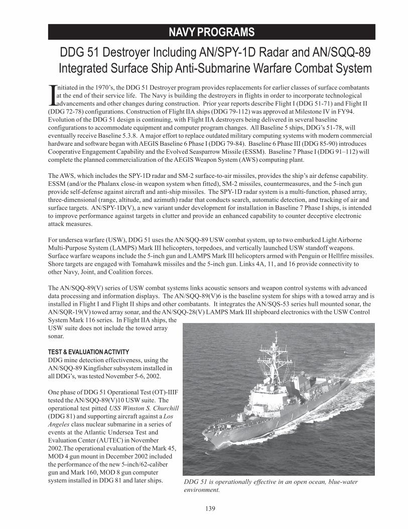
139
NAVY PROGRAMSDDG 51 Destroyer Including AN/SPY-1D Radar and AN/SQQ-89Integrated Surface Ship Anti-Submarine Warfare Combat System
DDG 51 is operationally effective in an open ocean, blue-waterenvironment.
Initiated in the 1970’s, the DDG 51 Destroyer program provides replacements for earlier classes of surface combatantsat the end of their service life. The Navy is building the destroyers in flights in order to incorporate technologicaladvancements and other changes during construction. Prior year reports describe Flight I (DDG 51-71) and Flight II
(DDG 72-78) configurations. Construction of Flight IIA ships (DDG 79-112) was approved at Milestone IV in FY94.Evolution of the DDG 51 design is continuing, with Flight IIA destroyers being delivered in several baselineconfigurations to accommodate equipment and computer program changes. All Baseline 5 ships, DDG’s 51-78, willeventually receive Baseline 5.3.8. A major effort to replace outdated military computing systems with modern commercialhardware and software began with AEGIS Baseline 6 Phase I (DDG 79-84). Baseline 6 Phase III (DDG 85-90) introducesCooperative Engagement Capability and the Evolved Seasparrow Missile (ESSM). Baseline 7 Phase I (DDG 91–112) willcomplete the planned commercialization of the AEGIS Weapon System (AWS) computing plant.
The AWS, which includes the SPY-1D radar and SM-2 surface-to-air missiles, provides the ship’s air defense capability.ESSM (and/or the Phalanx close-in weapon system when fitted), SM-2 missiles, countermeasures, and the 5-inch gunprovide self-defense against aircraft and anti-ship missiles. The SPY-1D radar system is a multi-function, phased array,three-dimensional (range, altitude, and azimuth) radar that conducts search, automatic detection, and tracking of air andsurface targets. AN/SPY-1D(V), a new variant under development for installation in Baseline 7 Phase I ships, is intendedto improve performance against targets in clutter and provide an enhanced capability to counter deceptive electronicattack measures.
For undersea warfare (USW), DDG 51 uses the AN/SQQ-89 USW combat system, up to two embarked Light AirborneMulti-Purpose System (LAMPS) Mark III helicopters, torpedoes, and vertically launched USW standoff weapons.Surface warfare weapons include the 5-inch gun and LAMPS Mark III helicopters armed with Penguin or Hellfire missiles.Shore targets are engaged with Tomahawk missiles and the 5-inch gun. Links 4A, 11, and 16 provide connectivity toother Navy, Joint, and Coalition forces.
The AN/SQQ-89(V) series of USW combat systems links acoustic sensors and weapon control systems with advanceddata processing and information displays. The AN/SQQ-89(V)6 is the baseline system for ships with a towed array and isinstalled in Flight I and Flight II ships and other combatants. It integrates the AN/SQS-53 series hull mounted sonar, theAN/SQR-19(V) towed array sonar, and the AN/SQQ-28(V) LAMPS Mark III shipboard electronics with the USW ControlSystem Mark 116 series. In Flight IIA ships, theUSW suite does not include the towed arraysonar.
TEST & EVALUATION ACTIVITYDDG mine detection effectiveness, using theAN/SQQ-89 Kingfisher subsystem installed inall DDG’s, was tested November 5-6, 2002.
One phase of DDG 51 Operational Test (OT)-IIIFtested the AN/SQQ-89(V)10 USW suite. Theoperational test pitted USS Winston S. Churchill(DDG 81) and supporting aircraft against a LosAngeles class nuclear submarine in a series ofevents at the Atlantic Undersea Test andEvaluation Center (AUTEC) in November2002.The operational evaluation of the Mark 45,MOD 4 gun mount in December 2002 includedthe performance of the new 5-inch/62-calibergun and Mark 160, MOD 8 gun computersystem installed in DDG 81 and later ships.
140
NAVY PROGRAMS
The Navy tested the performance of the Flight IIA ship and the AEGIS Baseline 6.1.5 computer program against cruisemissile and small boat threats in February 13-22, 2003.
DOT&E participated in test and evaluation working groups involved in planning the tests completed in FY03 and thetests that will examine the performance of AEGIS Baseline 6 Phase III ships,AN/SPY-1D(V), and AN/SQQ-89(V)14 in FY04.
DOT&E provided testability advice during the sponsor’s development of revisions to the operational requirements forthe AN/SQQ-89(V)15 and AN/SQQ-89A(V)15 variants of the USW combat system. DOT&E participated in Test andEvaluation Master Plan revisions for DDG 51, AN/SQQ-89(V10), and AN/SPY-1D(V).
TEST & EVALUATION ASSESSMENTDDG 51 is operationally effective in an open ocean, blue-water environment – it’s designed operating environment.However, it is less effective and at greater risk in littoral areas, where it may encounter asymmetric threats. Flight I and IIships are operationally suitable, but maintainability, compatibility, interoperability, and safety deficiencies degrade theoperational suitability of Flight IIA variants.
In OT-IIIF Phase I, USS Cole (DDG 67), outfitted with Baseline 5.3.8, conducted simulated engagements against 47manned aircraft presentations and live SM-2 engagements against six aerial targets representing anti-ship cruise missilethreats. The ship’s air defense performance exceeds the prescribed operational requirements. However, the improvedradar performance unmasked issues with command and decision subsystem processing of certain tracks in an electronicattack environment that can result in false tracks and possibly unnecessary missile expenditures. These deficienciesshould be addressed in future baseline upgrades. The ship’s overall effectiveness against stream raids has not beendemonstrated and requires additional testing.
Baseline 5.3.8 software reliability, AWS hardware reliability, and the ship’s operational availability for the air defensemission is better than required; however, the time required to restore functionality when a critical computer program faultdoes occur exceeds the maximum time allowed. These critical faults are infrequent, but when they do occur the combatsystem is not available during restoration. A review of prior test results shows that computer program restoration timeshave exceeded the requirement in all but one event and have generally been increasing. The increasing trend in faultidentification and restoration times will be monitored closely in future operational tests to determine if it is a by-productof the introduction of commercial hardware and software.
A Flight IIA DDG with the Baseline 6.1.5 hardware and computer program configuration conducted air defense and strikewarfare mission operational testing (OT-IIIF Phase II) in FY03. Although not tested against all threats, the Flight IIA shipcontinues to be effective against the predominant anti-ship cruise missile threats. Analysis of extensive data from tacticalengagements shows that DDGs and other surface combatants can effectively complete strike warfare missions usingTomahawk Land Attack Missiles.
DDG 51 does not have an effective mine detection capability. The probability that a moored mine will be detected andcorrectly classified using the AN/SQQ-89 Kingfisher subsystem is below the prescribed operational requirement.Although bottom mines constitute a very real threat in the littorals, DDG 51 has no equipment designed to detect bottommines. Part of OT-IIIF evaluated DDG 51 Flight IIA undersea warfare effectiveness. By design, the AN/SQQ-89(V)10does not provide any improvement in effectiveness and diminishes the ship’s organic sensor capability through theremoval of the AN/SQR-19 towed sonar array. Overall, DOT&E found the (V)10 to not be effective or suitable for anti-submarine warfare operations. The system failed to meet its threshold requirement for submarine detection andclassification, and its software exhibited significant reliability and interoperability problems. Although OT-IIIF did notexplicitly test torpedo detection, (V)10 inherits the survivability deficiencies identified in the baseline (V)6.
The anti-submarine warfare testing at AUTEC highlighted the problems created by the recent closing of the Atlantic FleetWeapons Training Facility. The restricted size, unusual bathymetry, and limited shipping traffic make AUTEC an
141
NAVY PROGRAMS
degraded by lack of an effective range-finding capability. An interoperability deficiency that impedes the transmission ofsensor information from AWS to the Gun Weapon System degrades the Baseline 6.1.5 ship’s gunnery effectivenessagainst air and sea targets. Poor performance of the ship’s laser range finder adversely impacts system performanceagainst sea targets.
The inability to get a stable version of AEGIS baseline 7.1 software delayed the SPY-1D(V) operational assessment fromJuly 2003 to February 2004. The technical evaluation is scheduled for late-August 2004, and operational evaluation isplanned for late-November 2004. The compressed schedule allows very little time to correct technical evaluationdeficiencies prior to operational evaluation. To adequately evaluate SPY-1D(V)’s improved performance the ship mustconduct integrated air defense against a stream raid of threat representative anti-ship cruise missiles in a typical littoralenvironment with electronic counter measures using SM-2 and ESSM.
The operational suitability of the Flight IIA DDG is not as good as that of Flight I and II ships. Reliability, availability,logistic supportability, training, human factors, documentation, and computer program supportability of the Baseline 6.1.5ships are satisfactory. Major deficiencies include the safety and compatibility issues related to the limited storage spacein the helicopter hangars cited in last year’s report; failure of the Operational Readiness Test Set to meet requirements forfault detection, isolation, and identification of applicable technical documentation; continuing problems with excessiveAEGIS computer program restoration times; lack of CIWS Block 1B surface mode integration into AWS; and failure of theAWS to pass AN/SPS-67 surface search radar data to the Gun Weapon System.
Since program inception in the 1980’s, an extensive LFT&E program has been conducted on the Arleigh Burke class ofguided missile destroyer. The results of LFT&E indicate that it is highly survivable against the majority of threats it isexpected to encounter, but is not invulnerable to all threats. Details are classified and will be forwarded in a separatereport to Congress in FY04.
unrealistic site for operational testing. As the Navy continues to emphasize shallow water operations, the lack of anappropriate littoral test site constitutes a serious limitation.
DDG 51 is not effective in countering the small boat threat. During OT-IIIF Phase II, USS Bulkeley (DDG 84) engaged aswarm of five small boats using its helicopter’s Hellfire missiles, SM-2 missiles, the 5-inch/62-caliber gun, and the PhalanxBlock 1B Close-In Weapon System (CIWS). The ship’s sensors and weapons were unable to support situationalawareness or to effectively counter the small boat threat.
The Mark 34, Mod 1 Gun Weapon System and 5-inch/62-caliber gun installed in DDG 81 and later ships effectivelysupported accomplishment of the Naval Shore Fire Support mission. Counter-battery performance continues to be

142
NAVY PROGRAMS
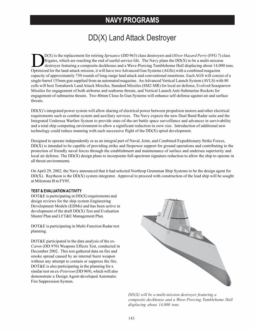
143
NAVY PROGRAMS
DD(X) Land Attack Destroyer
Need a pull quote from the write-up
DD(X) will be a multi-mission destroyer featuring acomposite deckhouse and a Wave-Piercing Tumblehome Hulldisplacing about 14,000 tons.
DD(X) is the replacement for retiring Spruance (DD 963) class destroyers and Oliver Hazard Perry (FFG 7) classfrigates, which are reaching the end of useful service life. The Navy plans the DD(X) to be a multi-missiondestroyer featuring a composite deckhouse and a Wave-Piercing Tumblehome Hull displacing about 14,000 tons.
Optimized for the land-attack mission, it will have two Advanced Gun Systems (AGSs) with a combined magazinecapacity of approximately 750 rounds of long-range land attack and conventional munitions. Each AGS will consist of asingle-barrel 155mm gun supplied from an automated magazine. An Advanced Vertical Launch System (AVLS) with 80cells will host Tomahawk Land Attack Missiles, Standard Missiles (SM2-MR) for local air defense, Evolved SeasparrowMissiles for engagement of both airborne and seaborne threats, and Vertical Launch Anti-Submarine Rockets forengagement of submarine threats. Two 40mm Close-In Gun Systems will enhance self-defense against air and surfacethreats.
DD(X)’s integrated power system will allow sharing of electrical power between propulsion motors and other electricalrequirements such as combat system and auxiliary services. The Navy expects the new Dual Band Radar suite and theIntegrated Undersea Warfare System to provide state-of-the-art battle space surveillance and advances in survivabilityand a total ship computing environment to allow a significant reduction in crew size. Introduction of additional newtechnology could reduce manning with each successive flight of the DD(X) spiral development.
Designed to operate independently or as an integral part of Naval, Joint, and Combined Expeditionary Strike Forces,DD(X) is intended to be capable of providing strike and firepower support for ground operations and contributing to theprotection of friendly naval forces through the establishment and maintenance of surface and undersea superiority andlocal air defense. The DD(X) design plans to incorporate full-spectrum signature reduction to allow the ship to operate inall threat environments.
On April 29, 2002, the Navy announced that it had selected Northrop Grumman Ship Systems to be the design agent forDD(X). Raytheon is the DD(X) system integrator. Approval to proceed with construction of the lead ship will be soughtat Milestone B in FY05.
TEST & EVALUATION ACTIVITYDOT&E is participating in DD(X) requirements anddesign reviews for the ship system EngineeringDevelopment Models (EDMs) and has been active indevelopment of the draft DD(X) Test and EvaluationMaster Plan and LFT&E Management Plan.
DOT&E is participating in Multi-Function Radar testplanning.
DOT&E participated in the data analysis of the ex-Caron (DD 970) Weapons Effects Test, conducted inDecember 2002. This test gathered data on fire andsmoke spread caused by an internal burst weaponwithout any attempt to contain or suppress the fire.DOT&E is also participating in the planning for asimilar test on ex-Peterson (DD 969), which will alsodemonstrate a Design Agent-developed AutomaticFire Suppression System.
144
NAVY PROGRAMS
TEST & EVALUATION ASSESSMENTThe Operational Requirements Document for DD(X) has not been approved so design and mission capabilityrequirements are not solidified. Although no operational testing has been done, plans for extensive prototyping of thenew technologies to be introduced in DD(X) will provide a rich environment for early operational testing of key DD(X)features. Twelve EDM’s are being developed for systems perceived to have the greatest risk. Among them are, AGS,Long Range Land Attack Projectile (LRLAP), AVLS, deckhouse, total ship computing environment, and the IntegratedPropulsion System. Preliminary design reviews of almost all the EDM’s have been completed and development isprogressing. Additionally, the program office is using ex-Radford (DD 968) to support early at-sea developmental testingof some of the new technologies.
An early operational assessment is scheduled prior to Milestone B, with four other operational assessments scheduledprior to operational evaluation. The early operational assessment will start 4QFY04. Operational evaluation is scheduledfor FY13.
Some operational testing challenges remain to be worked out. There is no shore-based range that will accommodate end-to-end testing of the AGS using the LRLAP. Additionally, safe and operationally realistic self-defense testing withEvolved Seasparrow Missiles against anti-ship cruise missiles can only be accomplished with the Self Defense Test Ship.
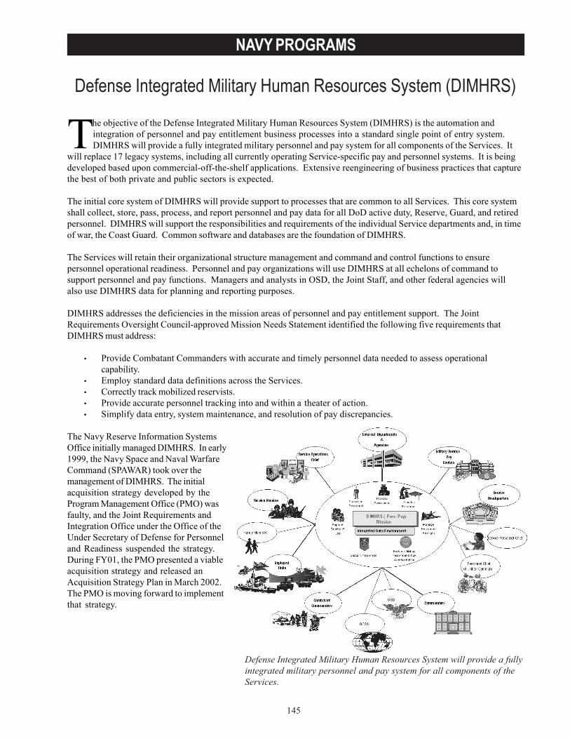
145
NAVY PROGRAMS
Defense Integrated Military Human Resources System (DIMHRS)
The objective of the Defense Integrated Military Human Resources System (DIMHRS) is the automation andintegration of personnel and pay entitlement business processes into a standard single point of entry system.DIMHRS will provide a fully integrated military personnel and pay system for all components of the Services. It
will replace 17 legacy systems, including all currently operating Service-specific pay and personnel systems. It is beingdeveloped based upon commercial-off-the-shelf applications. Extensive reengineering of business practices that capturethe best of both private and public sectors is expected.
The initial core system of DIMHRS will provide support to processes that are common to all Services. This core systemshall collect, store, pass, process, and report personnel and pay data for all DoD active duty, Reserve, Guard, and retiredpersonnel. DIMHRS will support the responsibilities and requirements of the individual Service departments and, in timeof war, the Coast Guard. Common software and databases are the foundation of DIMHRS.
The Services will retain their organizational structure management and command and control functions to ensurepersonnel operational readiness. Personnel and pay organizations will use DIMHRS at all echelons of command tosupport personnel and pay functions. Managers and analysts in OSD, the Joint Staff, and other federal agencies willalso use DIMHRS data for planning and reporting purposes.
DIMHRS addresses the deficiencies in the mission areas of personnel and pay entitlement support. The JointRequirements Oversight Council-approved Mission Needs Statement identified the following five requirements thatDIMHRS must address:
• Provide Combatant Commanders with accurate and timely personnel data needed to assess operationalcapability.
• Employ standard data definitions across the Services.• Correctly track mobilized reservists.• Provide accurate personnel tracking into and within a theater of action.• Simplify data entry, system maintenance, and resolution of pay discrepancies.
The Navy Reserve Information SystemsOffice initially managed DIMHRS. In early1999, the Navy Space and Naval WarfareCommand (SPAWAR) took over themanagement of DIMHRS. The initialacquisition strategy developed by theProgram Management Office (PMO) wasfaulty, and the Joint Requirements andIntegration Office under the Office of theUnder Secretary of Defense for Personneland Readiness suspended the strategy.During FY01, the PMO presented a viableacquisition strategy and released anAcquisition Strategy Plan in March 2002.The PMO is moving forward to implementthat strategy.
Defense Integrated Military Human Resources System will provide a fullyintegrated military personnel and pay system for all components of theServices.
146
NAVY PROGRAMS
TEST & EVALUATION ACTIVITYThe PMO held several Test and Evaluation Integrated Product Team (T&E IPT) meetings over the past three years.There have been no actual test events for this program to date.
DOT&E approved a DIMHRS Test and Evaluation Master Plan (TEMP) in March 2003. Because much of thedevelopment strategy and schedule would be determined by the system integrator, DOT&E required that the TEMP berevised and resubmitted within 120 days of the system integrator contract award. In September 2003, Northrop GrummanInformation Technology won the contract. Based on the currently projected schedule, the IOT&E of the first increment(Army implementation) is not expected before January 2005.
TEST & EVALUATION ASSESSMENTThe PMO worked hard to develop a viable test strategy and supporting documents. The operational test agency foreach of the Services plans to evaluate DIMHRS in their own respective Service environment in accordance with a TEMPjointly developed by the Services. The Navy Operational Test and Evaluation Force will coordinate all operational testactivities. The Army is scheduled to be the first Service to receive DIMHRS for operational testing purposes. Thecoordination of the Service-specific operational test agency efforts has been the focus of several T&E IPT meetings andthe planning is becoming more mature.
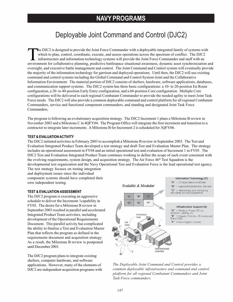
147
NAVY PROGRAMS
Deployable Joint Command and Control (DJC2)
The Deployable Joint Command and Control provides acommon deployable infrastructure and command and controlplatform for all regional Combatant Commanders and JointTask Force commanders.
The DJC2 is designed to provide the Joint Force Commander with a deployable integrated family of systems withwhich to plan, control, coordinate, execute, and assess operations across the spectrum of conflict. The DJC2infrastructure and information technology systems will provide the Joint Force Commander and staff with an
environment for collaborative planning, predictive battlespace situational awareness, dynamic asset synchronization andoversight, and executive battle management and control. The Joint Command and Control system will eventually providethe majority of the information technology for garrison and deployed operations. Until then, the DJC2 will use existingcommand and control systems including the Global Command and Control System-Joint and the CollaborativeInformation Environment. The material portion of DJC2 consists of shelters, hardware, software applications, databases,and communication support systems. The DJC2 system has three basic configurations: a 10- to 20-position En Routeconfiguration, a 20- to 40-position Early Entry configuration, and a 60-position Core configuration. Multiple Coreconfigurations will be delivered to each regional Combatant Commander to provide the needed agility to meet Joint TaskForce needs. The DJC2 will also provide a common deployable command and control platform for all regional CombatantCommanders, service and functional component commanders, and standing and designated Joint Task ForceCommanders.
The program is following an evolutionary acquisition strategy. The DJC2 Increment 1 plans a Milestone B review inNovember 2003 and a Milestone C in 4QFY04. The Program Office will integrate the first increment and transition to acontractor to integrate later increments. A Milestone B for Increment 2 is scheduled for 3QFY06.
TEST & EVALUATION ACTIVITYThe DJC2 initiated activities in February 2003 to accomplish a Milestone B review in September 2003. The Test andEvaluation Integrated Product Team developed a test strategy and draft Test and Evaluation Master Plan. The strategyincludes an operational assessment in FY04 and an initial operational test and evaluation of Increment 1 in FY05. TheDJC2 Test and Evaluation Integrated Product Team continues working to define the scope of each event consistent withthe evolving requirements, system design, and acquisition strategy. The Air Force 46th Test Squadron is thedevelopmental test organization and the Navy Operational Test and Evaluation Force is the lead operational test agency.The test strategy focuses on testing integrationand deployment issues since the individualcomponent systems should have completed theirown independent testing.
TEST & EVALUATION ASSESSMENTThe DJC2 program is executing an aggressiveschedule to deliver the Increment 1capability inFY05. The desire for a Milestone B review inSeptember 2003 resulted in parallel and acceleratedIntegrated Product Team activities, includingdevelopment of the Operational RequirementsDocument. This parallel activity has complicatedthe ability to finalize a Test and Evaluation MasterPlan that reflects the program as defined in therequirements document and acquisition strategy.As a result, the Milestone B review is postponeduntil December 2003.
The DJC2 program plans to integrate existingshelters, computer hardware, and softwareapplications. However, many of the elements ofDJC2 are independent acquisition programs with
148
NAVY PROGRAMS
their own development and test schedules or procurements of existing items. The integration of capabilities that havenot already completed independent or interoperability testing require additional testing.
The integration of these independent acquisition programs is dependant upon the successful, timely completion of theirdevelopment and scheduled tests.
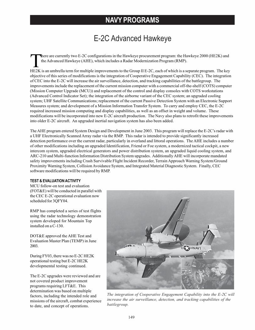
149
NAVY PROGRAMS
E-2C Advanced Hawkeye
The integration of Cooperative Engagement Capability into the E-2C willincrease the air surveillance, detection, and tracking capabilities of thebattlegroup.
There are currently two E-2C configurations in the Hawkeye procurement program: the Hawkeye 2000 (HE2K) andthe Advanced Hawkeye (AHE), which includes a Radar Modernization Program (RMP).
HE2K is an umbrella term for multiple improvements to the Group II E-2C, each of which is a separate program. The keyobjective of this series of modifications is the integration of Cooperative Engagement Capability (CEC). The integrationof CEC into the E-2C will increase the air surveillance, detection, and tracking capabilities of the battlegroup. Theimprovements include the replacement of the current mission computer with a commercial off-the-shelf (COTS) computer(Mission Computer Upgrade (MCU)) and replacement of the control and display consoles with COTS workstations(Advanced Control Indicator Set); the integration of the airborne variant of the CEC system; an upgraded coolingsystem; UHF Satellite Communications; replacement of the current Passive Detection System with an Electronic SupportMeasures system; and development of a Mission Information Transfer System. To carry and employ CEC, the E-2Crequired increased mission computing and display capabilities, as well as an offset in weight and volume. Thesemodifications will be incorporated into new E-2C aircraft production. The Navy also plans to retrofit these improvementsinto older E-2C aircraft. An upgraded inertial navigation system has also been added.
The AHE program entered System Design and Development in June 2003. This program will replace the E-2C’s radar witha UHF Electronically Scanned Array radar via the RMP. This radar is intended to provide significantly increaseddetection performance over the current radar, particularly in overland and littoral operations. The AHE includes a numberof other modifications including an upgraded Identification, Friend or Foe system, a modernized tactical cockpit, a newintercom system, upgraded electrical generators and power distribution system, an upgraded liquid cooling system, andARC-210 and Multi-function Information Distribution System upgrades. Additionally AHE will incorporate mandatedsafety improvements including Crash Survivable Flight Incident Recorder, Terrain Approach Warning System/GroundProximity Warning System, Collision Avoidance System, and Integrated Material Diagnostic System. Finally, CECsoftware modifications will be required by RMP.
TEST & EVALUATION ACTIVITYMCU follow-on test and evaluation(FOT&E) will be conducted in parallel withthe CEC E-2C operational evaluation nowscheduled for 3QFY04.
RMP has completed a series of test flightsusing the radar technology demonstrationsystem developed for Mountain Topinstalled on a C-130.
DOT&E approved the AHE Test andEvaluation Master Plan (TEMP) in June2003.
During FY03, there was no E-2C HE2Koperational testing but E-2C HE2Kdevelopmental testing continued.
The E-2C upgrades were reviewed and arenot covered product improvementprograms requiring LFT&E. Thisdetermination was based on multiplefactors, including the intended role andmissions of the aircraft, combat experienceto date, and concept of operations.
150
NAVY PROGRAMS
Due to its importance to fleet air operations, the survivability of the E-2C will be evaluated for expected combat missions.The Navy has developed a comprehensive survivability evaluation plan to ensure the needed data and information areavailable.
TEST & EVALUATION ASSESSMENTThe MCU TEMP approval memo, signed July 27, 2000, called for an update to the TEMP within 90 days to define MCUFOT&E, which will include Electronic Support Measures and Satellite Communications. This TEMP has yet to beformally submitted to DOT&E.
The E-2C survivability program is adequate to evaluate the survivability of the aircraft.
Advanced Hawkeye radar risk reduction flight-testing was performed at the Naval Air Warfare Center Aircraft Division,Patuxent River, Maryland, on the NC-130H aircraft from December 2002 - June of 2003. The Advanced DevelopmentModel radar system used during the demonstrations at the Pacific Makaha Ridge Facility in 1997 and 1999 was integratedinto the NC-130H. Specific risk reduction objectives included evaluation of space time adaptive processing operation incritical operational environments and conditions and radar system performance. The system was operated in overlandand littoral environments that included ground traffic, clutter, jamming, and casual electromagnetic interference. Radarsystem assessment included controlled target detection range performance in clutter and jamming environments andsystem accuracy. Initial analysis of flight test data indicates the program met all system risk reduction objectives andachieved all predicted performance capabilities.
A critical aspect of E-2C AHE operational testing will be joint interoperability, an area that was unresolved in the MCUoperational evaluation. The Joint Air and Missile Defense Organization is coordinating significant resource investmentby OSD in a 2010 theater air and missile defense architecture. In addition to AHE, this effort includes other upgrades,such as the Block 40/45 upgrade to the E-3 and new platforms, such as the Joint Land Attack Cruise Missile DefenseElevated Netted Sensor. Additionally, the Single Integrated Air Picture System Engineering Task Force is coordinating aneffort to improve the quality of the air picture available to the Joint Forces Air Component Commander and to the forcesconducting and fighting the air battle through improvements in the available data links. Joint interoperability will be keyto OSD achieving its theater air and missile defense goals. Therefore, testing the joint interoperability of the participatingplatforms will be a critical part of their OT&Es.
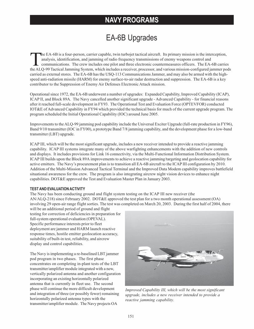
151
NAVY PROGRAMS
EA-6B Upgrades
Improved Capability III, which will be the most significantupgrade, includes a new receiver intended to provide areactive jamming capability.
The EA-6B is a four-person, carrier capable, twin turbojet tactical aircraft. Its primary mission is the interception,analysis, identification, and jamming of radio frequency transmissions of enemy weapons control andcommunications. The crew includes one pilot and three electronic countermeasures officers. The EA-6B carries
the ALQ-99 Tactical Jamming System, which includes a receiver, processor, and various mission-configured jammer podscarried as external stores. The EA-6B has the USQ-113 Communications Jammer, and may also be armed with the high-speed anti-radiation missile (HARM) for enemy surface-to-air radar destruction and suppression. The EA-6B is a keycontributor to the Suppression of Enemy Air Defenses Electronic Attack mission.
Operational since 1972, the EA-6B underwent a number of upgrades: Expanded Capability, Improved Capability (ICAP),ICAP II, and Block 89A. The Navy cancelled another significant upgrade - Advanced Capability - for financial reasonsafter it reached full-scale development in FY93. The Operational Test and Evaluation Force (OPTEVFOR) conductedIOT&E of Advanced Capability in FY94 which provided the technical basis for much of the current upgrade program. Theprogram scheduled the Initial Operational Capability (IOC) around June 2005.
Improvements to the ALQ-99 jamming pod capability include the Universal Exciter Upgrade (full-rate production in FY96),Band 9/10 transmitter (IOC in FY00), a prototype Band 7/8 jamming capability, and the development phase for a low-bandtransmitter (LBT) upgrade.
ICAP III, which will be the most significant upgrade, includes a new receiver intended to provide a reactive jammingcapability. ICAP III systems integrate many of the above warfighting enhancements with the addition of new controlsand displays. It includes provisions for Link 16 connectivity, via the Multi-Functional Information Distribution System.ICAP III builds upon the Block 89A improvements to achieve a reactive jamming/targeting and geolocation capability foractive emitters. The Navy’s procurement plan is to transition all EA-6B aircraft to the ICAP III configuration by 2010.Addition of the Multi-Mission Advanced Tactical Terminal and the Improved Data Modem capability improves battlefieldsituational awareness for the crew. The program is also integrating aircrew night vision devices to enhance nightcapabilities. DOT&E approved the Test and Evaluation Master Plan in January 2003.
TEST AND EVALUATION ACTIVITYThe Navy has been conducting ground and flight system testing on the ICAP III new receiver (theAN/ALQ-218) since February 2002. DOT&E approved the test plan for a two month operational assessment (OA)involving 29 open-air range flight sorties. The test was completed on March 20, 2003. During the first half of 2004, therewill be an additional period of ground and flighttesting for correction of deficiencies in preparation forfull-system operational evaluation (OPEVAL).Specific performance interests prior to fleetdeployment are jammer and HARM launch reactiveresponse times, hostile emitter geolocation accuracy,suitability of built-in test, reliability, and aircrewdisplay and control capabilities.
The Navy is implementing a re-baselined LBT jammerpod program in two phases. The first phaseconcentrates on completing in-plant tests of the LBTtransmitter/amplifier module integrated with a new,vertically polarized antenna and another configurationincorporating an existing horizontally polarizedantenna that is currently in fleet use. The secondphase will continue the more difficult developmentand integration of three (or possibly fewer) remaininghorizontally polarized antenna types with thetransmitter/amplifier module. The Navy projects OA
152
NAVY PROGRAMS
field-testing of the LBT to begin around March 2004, subject to completion of developmental testing. A prototypeBand 7/8 jammer pod based on the Band 9/10 architecture is in its early design/fabrication phases.
There was no formal USQ-113 communications jammer test and evaluation activity in FY03. Upgrades and correction ofdeficiencies are underway in preparation for additional flight testing by OPTEVFOR in early 2004.
TEST AND EVALUATION ASSESSMENTThe ICAP III receiver upgrade program risk centers on its ability to provide accurate emitter geolocation in full azimuthcoverage for HARM targeting and the reactive jamming of selected hostile emitters. Twenty-nine OA sorties indicatethat with some exceptions, the system is potentially effective and potentially suitable in this role. Prior to enteringOPEVAL, deficiencies observed during OA in target emitter display rates, alphanumeric keyboard dysfunction, andmission planner must be corrected. Additionally, the OA revealed a number of operator display and control inefficiencies.Needed correction of deficiencies, almost all by software changes, is predicted to delay the start of OPEVAL fromDecember 2003 to around April 2004. The Navy has scheduled IOC for June 2005. Even after OPEVAL and IOC, there willbe a period of tactical concept development and further software refinements to make the best use of the ICAP IIIselective reactive jamming capability.
The LBT program continues in the development phase. The program office is closely monitoring problems in successfulcompletion of in-plant testing. The Naval Air Warfare Center, Point Mugu, California, has completed aircraft integrationtesting with one engineering development model. In-plant vibration qualification regression tests resulted inunacceptable damage to a newly designed support bracket. The LBT Reliability Development/Growth Test effortcontinues to fall behind schedule in both demonstrated mean time between failure measures (71.4 hours vice 277 hoursrequired), and accumulated test time (1,499 hours vice 4,345 hours previously scheduled for this point in the program). The Navy’s developmental test began in October 2003.
There were five major deficiencies observed during the January to June 2001 follow-on operational test and evaluation(FOT&E) of the AN/USQ-113(V)3 Radio Countermeasures Set. One was a safety concern and two involved human factorconsiderations. The FOT&E revealed signal classification and interoperability problems. During the past two years offleet operation, the Navy initiated an effort to correct selected deficiencies. Two deficiencies are being addressed in aVerification of Correction of Deficiencies that is scheduled to end flight test in December 2003. Testing at requiredfrequencies is denied because of the impact on civilian sector usage of certain frequency bands. Those same frequencybands are the ones that the enemy will plan to use because of readily available, cheap, and effective equipment. Thisinability to test at all required frequencies in other-than-remote test locations complicates adequate testing. Testing atremote locations is being explored, but such an approach will require transportable, real, or simulated target/victimequipment and associated diagnostic instrumentation. Some of these same testing challenges apply to the LBT.
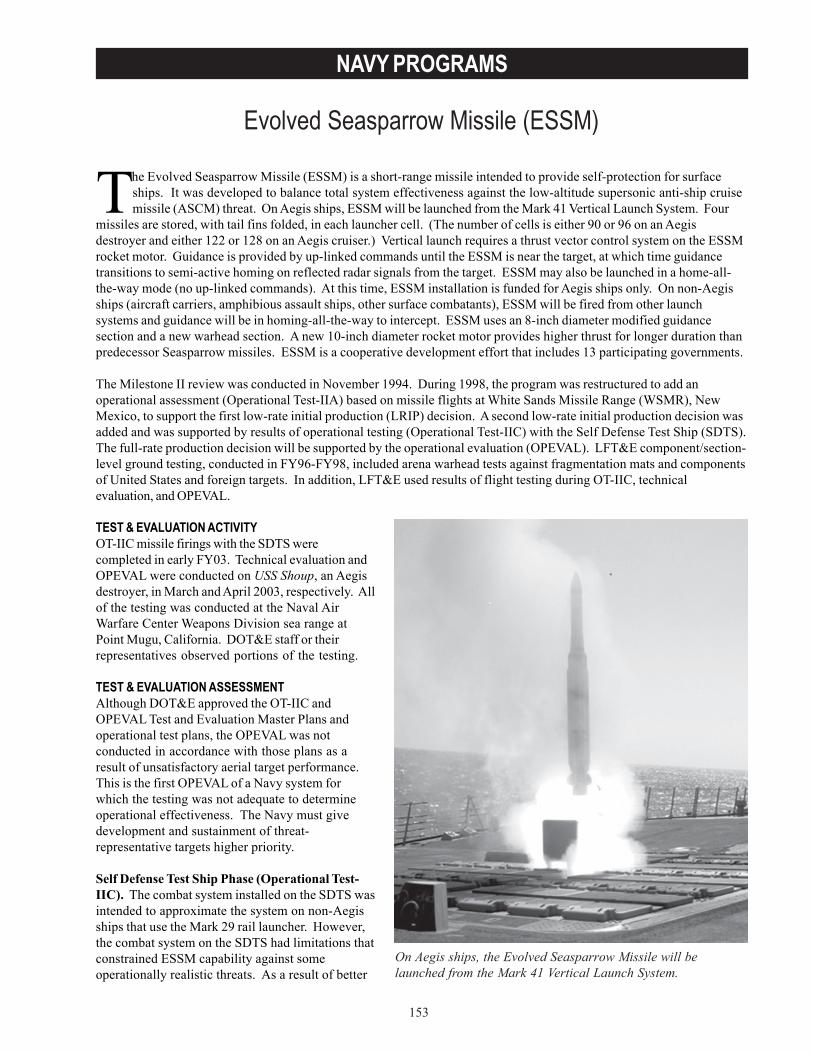
153
NAVY PROGRAMS
Evolved Seasparrow Missile (ESSM)
The Evolved Seasparrow Missile (ESSM) is a short-range missile intended to provide self-protection for surfaceships. It was developed to balance total system effectiveness against the low-altitude supersonic anti-ship cruisemissile (ASCM) threat. On Aegis ships, ESSM will be launched from the Mark 41 Vertical Launch System. Four
missiles are stored, with tail fins folded, in each launcher cell. (The number of cells is either 90 or 96 on an Aegisdestroyer and either 122 or 128 on an Aegis cruiser.) Vertical launch requires a thrust vector control system on the ESSMrocket motor. Guidance is provided by up-linked commands until the ESSM is near the target, at which time guidancetransitions to semi-active homing on reflected radar signals from the target. ESSM may also be launched in a home-all-the-way mode (no up-linked commands). At this time, ESSM installation is funded for Aegis ships only. On non-Aegisships (aircraft carriers, amphibious assault ships, other surface combatants), ESSM will be fired from other launchsystems and guidance will be in homing-all-the-way to intercept. ESSM uses an 8-inch diameter modified guidancesection and a new warhead section. A new 10-inch diameter rocket motor provides higher thrust for longer duration thanpredecessor Seasparrow missiles. ESSM is a cooperative development effort that includes 13 participating governments.
The Milestone II review was conducted in November 1994. During 1998, the program was restructured to add anoperational assessment (Operational Test-IIA) based on missile flights at White Sands Missile Range (WSMR), NewMexico, to support the first low-rate initial production (LRIP) decision. A second low-rate initial production decision wasadded and was supported by results of operational testing (Operational Test-IIC) with the Self Defense Test Ship (SDTS).The full-rate production decision will be supported by the operational evaluation (OPEVAL). LFT&E component/section-level ground testing, conducted in FY96-FY98, included arena warhead tests against fragmentation mats and componentsof United States and foreign targets. In addition, LFT&E used results of flight testing during OT-IIC, technicalevaluation, and OPEVAL.
TEST & EVALUATION ACTIVITYOT-IIC missile firings with the SDTS werecompleted in early FY03. Technical evaluation andOPEVAL were conducted on USS Shoup, an Aegisdestroyer, in March and April 2003, respectively. Allof the testing was conducted at the Naval AirWarfare Center Weapons Division sea range atPoint Mugu, California. DOT&E staff or theirrepresentatives observed portions of the testing.
TEST & EVALUATION ASSESSMENTAlthough DOT&E approved the OT-IIC andOPEVAL Test and Evaluation Master Plans andoperational test plans, the OPEVAL was notconducted in accordance with those plans as aresult of unsatisfactory aerial target performance.This is the first OPEVAL of a Navy system forwhich the testing was not adequate to determineoperational effectiveness. The Navy must givedevelopment and sustainment of threat-representative targets higher priority.
Self Defense Test Ship Phase (Operational Test-IIC). The combat system installed on the SDTS wasintended to approximate the system on non-Aegisships that use the Mark 29 rail launcher. However,the combat system on the SDTS had limitations thatconstrained ESSM capability against someoperationally realistic threats. As a result of better
On Aegis ships, the Evolved Seasparrow Missile will belaunched from the Mark 41 Vertical Launch System.
154
NAVY PROGRAMS
understanding the impact of these limitations, two missile firing scenarios planned for the SDTS phase were modified andmoved to the OPEVAL.
Fifteen ESSMs were launched at various targets in FY02/FY03. Included were maneuvering and non-maneuvering,subsonic and supersonic, low-altitude targets, as well as a supersonic high diving target. Some of the critical scenarioswere scripted to be unrealistic or used targets that were not adequately threat-representative. ESSM problems werediscovered during flight tests, solutions were implemented, and corrections were demonstrated.
OPEVAL. As a result of unsatisfactory aerial target performance, the testing was not adequate for determining ESSMoperational effectiveness. ESSM capability against the supersonic, maneuvering ASCM threat was not demonstrated.Capability against the high-altitude, supersonic, terminal diving missile threat was not demonstrated. ESSMdemonstrated capability against the non-maneuvering, low-altitude, subsonic ASCM threat. ESSM is operationallysuitable. As demonstrated during OPEVAL and live fire test and evaluation events, the ESSM warhead is lethal againstthe ASCM threat.
Although capability against a supersonic low-G maneuvering sea-skimming ASCM target was demonstrated in technicalevaluation and during OT-IIC, the scenarios were scripted to be unrealistic. Although capability against a high-altitude,supersonic, terminal diving missile target was demonstrated during OT-IIC, it was not adequately threat-representative.
The supersonic, maneuvering sea-skimmer targets and supersonic, high-altitude, terminal diving target scenarios movedfrom the SDTS phase became more difficult to execute as a result of the significant challenge in balancing range safetyrequirements against operationally realistic scenarios involving a manned ship. The scenarios were not conducted asplanned due to the unsatisfactory target performance. Fourteen scenario attempts resulted in six scenarios thatproduced useable test results. The other attempts involved target problems.
Follow-on OT&E (FOT&E). FOT&E requires flight testing against the threat ASCM categories that were not adequatelyexamined during the OPEVAL, primarily as a result of the unsatisfactory aerial target performance. Flight testing is alsorequired in the presence of electronic jamming and with ESSMs that have undergone fleet representative shipboardstorage time. In addition, a new ASCM threat has appeared for which there is no credible surrogate target. The Navyneeds to acquire adequate surrogates and conduct ESSM testing against them.
The OPEVAL was conducted with an Aegis Weapon System Baseline 6.3 with Mark 41 vertical launch system. Othercombat systems are sufficiently different that ESSM flight testing is required when it is integrated with them.
ESSMs are intended to provide close-in defense of Aegis ships against ASCMs, with standard missiles providinginterceptor capability at longer ranges (both self defense and defense for other ships.). There are circumstances inwhich the Aegis Weapon System could be controlling ESSMs and SM-2s simultaneously. This is primarily an AegisWeapon System (Baseline 6.3) issue that requires operational testing under the DDG-51 program’s FOT&E.
Although it is not a requirement, non-Aegis combat systems with predecessor Seasparrows provide a useful capabilityagainst surface targets. Limitations in the Aegis Weapon System Baseline 6.3 computer program and shipboardilluminator radars precluded testing ESSM’s capability against surface targets. Consideration should be given toproviding this surface target engagement capability with this and follow-on Aegis baselines.
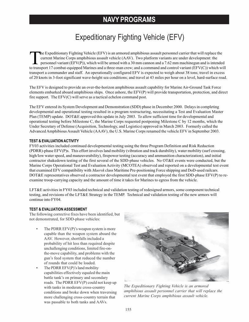
155
NAVY PROGRAMS
Expeditionary Fighting Vehicle (EFV)
The Expeditionary Fighting Vehicle is an armoredamphibious assault personnel carrier that will replace thecurrent Marine Corps amphibious assault vehicle.
The Expeditionary Fighting Vehicle (EFV) is an armored amphibious assault personnel carrier that will replace thecurrent Marine Corps amphibious assault vehicle (AAV). Two platform variants are under development: thepersonnel variant (EFV(P)), which will be armed with a 30 mm cannon and a 7.62 mm machinegun and is intended
to transport 17 combat-equipped Marines and a three-man crew; and a command and control variant (EFV(C)) which willtransport a commander and staff. An operationally configured EFV is expected to weigh about 38 tons; travel in excessof 20 knots in 3-foot significant wave-height sea conditions; and travel at 43 miles per hour on a level, hard-surface road.
The EFV is designed to provide an over-the-horizon amphibious assault capability for Marine Air-Ground Task Forceelements embarked aboard amphibious ships. Once ashore, the EFV(P) will provide transportation, protection, and directfire support. The EFV(C) will serve as a tactical echelon command post.
The EFV entered its System Development and Demonstration (SDD) phase in December 2000. Delays in completingdevelopmental and operational testing resulted in a program restructuring, necessitating a Test and Evaluation MasterPlan (TEMP) update. DOT&E approved this update in July 2003. To allow sufficient time for developmental andoperational testing before Milestone C, the Marine Corps requested postponing Milestone C by 12 months, which theUnder Secretary of Defense (Acquisition, Technology, and Logistics) approved in March 2003. Formerly called theAdvanced Amphibious Assault Vehicle (AAAV), the U.S. Marine Corps renamed the vehicle EFV in September 2003.
TEST & EVALUATION ACTIVITYFY03 activities included continued developmental testing using the three Program Definition and Risk Reduction(PDRR)-phase EFV(P)s. This effort involves land mobility (vibration and track durability), water mobility (surf crossing,high/low water speed, and maneuverability), firepower testing (accuracy and ammunition characterization), and initialcontractor shakedown testing of the first several of the SDD-phase vehicles. No OT&E events were conducted, but theMarine Corps Operational Test and Evaluation Activity (MCOTEA) observed and reported on a developmental test eventthat examined EFV compatibility with Maersk class Maritime Pre-positioning Force shipping and DoD-used railcars.DOT&E representatives observed a contractor developmental test event that employed the first SDD-phase EFV(P) to re-examine troop-carrying capacity and the amount of time it takes for Marines to egress from the vehicle.
LFT&E activities in FY03 included technical and validation testing of redesigned armors, some component technicaltesting, and revisions of the LFT&E Strategy in the TEMP. Technical and validation testing of the new armors willcontinue into FY04.
TEST & EVALUATION ASSESSMENTThe following corrective fixes have been identified, butnot demonstrated, for SDD-phase vehicles:
• The PDRR EFV(P)’s weapon system is morecapable than the weapon system aboard theAAV. However, shortfalls included aprobability of hit less than required despiteunchallenging conditions, limited fire-on-the-move capability, and problems with thegun’s feed system that reduced the numberof rounds that could be loaded.
• The PDRR EFV(P)’s land mobilitycapabilities effectively equaled the mainbattle tank’s on primary and secondaryroads. The PDRR EFV(P) could not keep upwith tanks in moderate cross-countryconditions and broke down when traversingmore challenging cross-country terrain thatwas passable to both tanks and AAVs.
156
NAVY PROGRAMS
• The PDRR EFV(P)’s demonstrated reliability (a Key Performance Parameter (KPP)) was roughly half the level thathad been predicted at that stage of development.
• Safety-related concerns included high interior noise levels, carbon monoxide accumulation during 30 mm cannonfiring, and elevated interior temperatures when operating in hot ambient conditions.
Although the Program Manager identified corrective fixes for the SDD-phase vehicles, they have mostly not beendemonstrated. However, data from recently completed contractor developmental tests showed that the interior designchanges implemented in the SDD EFV(P)s significantly increased troop carrying capacity and reduced the amount of timeit takes for Marines to egress the vehicle. Therefore, it appears more likely that SDD EFV(P)s will meet the troop carryingKPP and Operational Requirements Document-specified egress time during the upcoming OT&Es.
The Maritime Pre-positioning Force shipping event showed that the vehicle was compatible with Maersk class ships inmost respects; however, an EFV cannot move from its stowage area to the stern ramp in order to offload in-stream. TheEFV’s footprint is approximately 25 percent larger than an AAV’s; thus, deck-space needed to embark EFV units will becorrespondingly greater.
Assuming reliability improvement initiatives are adequately funded and weight-reducing design trades do not adverselyaffect reliability, the risk is still high that the vehicle’s 70-hour mean time between operational mission failures(MTBOMF) requirement (a KPP) will not be met during IOT&E. Poor reliability jeopardizes mission accomplishment: Ifthe EFV’s MTBOMF falls short of the required 70 hours, fewer than 70 percent of a unit’s EFVs would be predicted tocomplete the specified 24-hour mission without experiencing significant failures.
Operationally relevant questions will remain unanswered until OT&E resumes in FY05. The EFV(P) has not demonstratedthat it can accomplish its primary mission, that is, transport combat-equipped Marines from an amphibious ship located20 to 25 nautical miles offshore to objectives located inland without degrading their physical condition. The performanceof an integrated EFV(C) will also not be demonstrated during OT&E until conducted by MCOTEA in FY05. Finally,concerns remain about the use of the less corrosion resistant aluminum alloy, Al 2519, and the potential impact on lifecycle cost.
The test program described in the revised LFT&E Strategy, including thorough characterization of new armors, ballistictesting of new and unique EFV components, comprehensive controlled damage testing and full-up system-level testingof refurbished EFV(P) and EFV(C) SDD prototypes should be adequate to support the required vulnerability evaluationof the EFV. DOT&E and MCOTEA will continue to seek better insight into technical and developmental testing so as tobest leverage data gathered in these tests and help refine the scope of full-up system level tests outlined in the LFT&EStrategy.
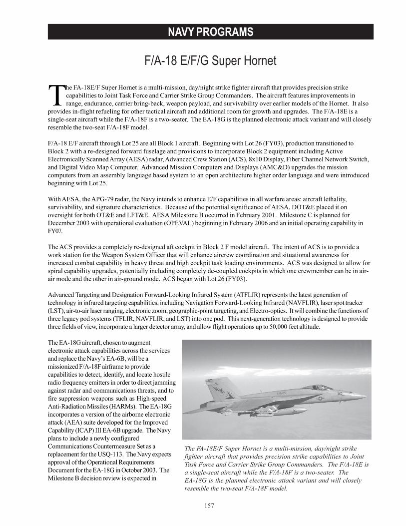
157
NAVY PROGRAMS
F/A-18 E/F/G Super Hornet
The FA-18E/F Super Hornet is a multi-mission, day/night strikefighter aircraft that provides precision strike capabilities to JointTask Force and Carrier Strike Group Commanders. The F/A-18E isa single-seat aircraft while the F/A-18F is a two-seater. TheEA-18G is the planned electronic attack variant and will closelyresemble the two-seat F/A-18F model.
The FA-18E/F Super Hornet is a multi-mission, day/night strike fighter aircraft that provides precision strikecapabilities to Joint Task Force and Carrier Strike Group Commanders. The aircraft features improvements inrange, endurance, carrier bring-back, weapon payload, and survivability over earlier models of the Hornet. It also
provides in-flight refueling for other tactical aircraft and additional room for growth and upgrades. The F/A-18E is asingle-seat aircraft while the F/A-18F is a two-seater. The EA-18G is the planned electronic attack variant and will closelyresemble the two-seat F/A-18F model.
F/A-18 E/F aircraft through Lot 25 are all Block 1 aircraft. Beginning with Lot 26 (FY03), production transitioned toBlock 2 with a re-designed forward fuselage and provisions to incorporate Block 2 equipment including ActiveElectronically Scanned Array (AESA) radar, Advanced Crew Station (ACS), 8x10 Display, Fiber Channel Network Switch,and Digital Video Map Computer. Advanced Mission Computers and Displays (AMC&D) upgrades the missioncomputers from an assembly language based system to an open architecture higher order language and were introducedbeginning with Lot 25.
With AESA, the APG-79 radar, the Navy intends to enhance E/F capabilities in all warfare areas: aircraft lethality,survivability, and signature characteristics. Because of the potential significance of AESA, DOT&E placed it onoversight for both OT&E and LFT&E. AESA Milestone B occurred in February 2001. Milestone C is planned forDecember 2003 with operational evaluation (OPEVAL) beginning in February 2006 and an initial operating capability inFY07.
The ACS provides a completely re-designed aft cockpit in Block 2 F model aircraft. The intent of ACS is to provide awork station for the Weapon System Officer that will enhance aircrew coordination and situational awareness forincreased combat capability in heavy threat and high cockpit task loading environments. ACS was designed to allow forspiral capability upgrades, potentially including completely de-coupled cockpits in which one crewmember can be in air-air mode and the other in air-ground mode. ACS began with Lot 26 (FY03).
Advanced Targeting and Designation Forward-Looking Infrared System (ATFLIR) represents the latest generation oftechnology in infrared targeting capabilities, including Navigation Forward-Looking Infrared (NAVFLIR), laser spot tracker(LST), air-to-air laser ranging, electronic zoom, geographic-point targeting, and Electro-optics. It will combine the functions ofthree legacy pod systems (TFLIR, NAVFLIR, and LST) into one pod. This next-generation technology is designed to providethree fields of view, incorporate a larger detector array, and allow flight operations up to 50,000 feet altitude.
The EA-18G aircraft, chosen to augmentelectronic attack capabilities across the servicesand replace the Navy’s EA-6B, will be amissionized F/A-18F airframe to providecapabilities to detect, identify, and locate hostileradio frequency emitters in order to direct jammingagainst radar and communications threats, and tofire suppression weapons such as High-speedAnti-Radiation Missiles (HARMs). The EA-18Gincorporates a version of the airborne electronicattack (AEA) suite developed for the ImprovedCapability (ICAP) III EA-6B upgrade. The Navyplans to include a newly configuredCommunications Countermeasure Set as areplacement for the USQ-113. The Navy expectsapproval of the Operational RequirementsDocument for the EA-18G in October 2003. TheMilestone B decision review is expected in
158
NAVY PROGRAMS
November 2003; Milestone C is planned for April 2007. A spiral acquisition strategy leads to a planned Core Block I capability(described below) at the initial operating capability in FY09.
TEST & EVALUATION ACTIVITYIn April 2000, DOT&E’s beyond low-rate initial production (BLRIP) report to Congress stated that the F/A-18E/F wasoperationally effective and operationally suitable. The Operational Test and Evaluation Force conducted follow-on testand evaluation (FOT&E) 1 of the F/A-18E/F with new tactical software (Software Configuration Set (SCS)-18E) fromSeptember 2001 to May 2002 in accordance with a DOT&E-approved Test and Evaluation Master Plan (TEMP) and TestPlan.
The Operational Test and Evaluation Force conducted the second FOT&E period with Lot 25 aircraft from May 12, 2003 -November 2003. This period tested the new higher order language SCS known as H-1 and the first version of AMC&D.It also tested several component upgrades, such as the Signal Data Computer Replacement, Digital Expandable ColorDisplay, and others. OPEVAL of the ATFLIR Block 1 was conducted from March 21 - June 23, 2003.
FOT&E 3 is scheduled to begin in March 2004 and will test SCS H-2 (the first higher order language software that willdeploy in late FY04 or early FY05), the Shared Advanced Reconnaissance Pod (SHARP) reconnaissance pod, ATFLIRBlock 2, AIM-9X (for the E/F), and other F/A-18 roadmap improvements.
FY03 test and evaluation activities focused on preparation of the TEMP for the AEA suite’s integration into the F/A-18E/F. Risk reduction testing continued during FY03 in preparation for a System Development and Demonstration contractaward in February 2004. The TEMP correlates with the EA-18G Acquisition Strategy and current plans and funding for aCore Block I configuration. Core Block I will consist of a repackaged ICAP III receiver/antenna system (the ALQ-218), anexisting Multi-Mission Advanced Tactical Terminal, a newly configured Communications Countermeasure Set, andexisting ALQ-99 jammer pods. It will be able to deliver HARM and Advanced Medium Range Air-to-Air Missile weapons.The electronic attack system will not be interoperable with AESA, nor will the aircraft have Integrated DefensiveElectronic Countermeasures or ALR-67.
Initial test efforts included wind tunnel aeromechanical testing, antenna measurements, limited initial flight tests that didnot include functional avionics, and preliminary electromagnetic interference/compatibility measurements. These initialtests supported feasibility studies and early design activity, and revealed potential antenna problems. The early testswere conducted in a limited flight envelope and provided initial flying qualities, loads, noise, and vibration data that wereused to define EA-18G design criteria.
TEST & EVALUATION ASSESSMENTDOT&E based its assessment on operational testing activities conducted during the past year, as well as operationalexperience gained in Operation Iraqi Freedom. The Navy certified several new systems for early operational capability inconjunction with accelerated wartime deployments: ATLFIR, Multi-functional Information Distribution system (MIDS),joint helmet mounted cueing system (JHMCS), and SHARP were all deployed aboard USS NIMITZ. All these systemsreceived either a preliminary report or an operational assessment prior to the early operational capability. OPEVAL ofMIDS, JHMCS, and ATFLIR are complete. The Navy will conduct OPEVAL for SHARP as part of FOT&E 3 beginning inMarch 2004.
For the F/A-18E/F OPEVAL the Navy approved 50 waivers to the testing of required capabilities. FOT&E 1 resolved 30of those waivers with nine additional waivers to be resolved during FOT&E 2. ATFLIR OPEVAL resolved four morewaivers (one ATFLIR test waiver is to be resolved during FOT&E 3). The Navy expects that incorporation of the testingof the Advanced Crew Station will resolve two more test waivers and AESA will resolve the final four waivers to requiredcapabilities.
159
NAVY PROGRAMS
The DOT&E beyond low-rate production report to Congress found that the ATFLIR was operationally effective for air-to-surface operations, its primary mission area, and operationally suitable. DOT&E found that Block 1 is notoperationally effective for air-to-air operations.
Even though the EA-18G has a high degree of commonality with the F/A-18F airframe and is integrating existing jammerpods, the new antennae and receiver will be a significant challenge and represent high risk with the given schedule.Three key areas will need to be demonstrated: Does it meet the EA-6B ICAP III baseline performance? Does it meetreliability, availability, and maintainability requirements? Will a two person aircrew be able to accomplish the requiredElectronic Attack and Electronic Support functions? At present, a comprehensive definition of the EA-18G AEA systemwill not be available until a Preliminary Design Review has been reached in late 2004.
The Navy plans to review the first TEMP submitted for Milestone B decision review shortly after the Preliminary DesignReview. The limited number of operational assessment flights prior to a Milestone C decision date is a concern and isassociated with the timeliness and adequacy of modeling and simulation facilities needed to supplement flight testing.The capability of the wingtip receiver pod design to support interferometric-based geolocation requirements warrantsspecial consideration in early T&E planning and assessments, along with aircrew display and control interfaces.Because the aircrew is reduced from four to two, there will be an impact on operator workload and consequentmodifications to existing EA-6B operational concepts and tactics.

160
NAVY PROGRAMS
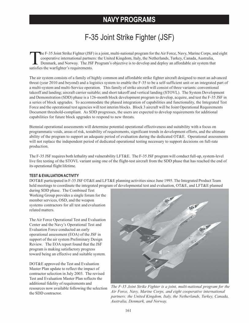
161
NAVY PROGRAMS
F-35 Joint Strike Fighter (JSF)
The F-35 Joint Strike Fighter (JSF) is a joint, multi-national program for the Air Force, Navy, Marine Corps, and eightcooperative international partners: the United Kingdom, Italy, the Netherlands, Turkey, Canada, Australia,Denmark, and Norway. The JSF Program’s objective is to develop and deploy an affordable air system that
satisfies the warfighter’s requirements.
The air system consists of a family of highly common and affordable strike fighter aircraft designed to meet an advancedthreat (year 2010 and beyond) and a logistics system to enable the F-35 to be a self-sufficient unit or an integrated part ofa multi-system and multi-Service operation. This family of strike aircraft will consist of three variants: conventionaltakeoff and landing; aircraft carrier suitable; and short takeoff and vertical landing (STOVL). The System Developmentand Demonstration (SDD) phase is a 126-month block development program to develop, acquire, and test the F-35 JSF ina series of block upgrades. To accommodate the phased integration of capabilities and functionality, the Integrated TestForce and the operational test agencies will test interim blocks. Block 3 aircraft will be Joint Operational RequirementsDocument threshold-compliant. As SDD progresses, the users are expected to develop requirements for additionalcapabilities for future block upgrades to respond to new threats.
Biennial operational assessments will determine potential operational effectiveness and suitability with a focus onprogrammatic voids, areas of risk, testability of requirements, significant trends in development efforts, and the ultimateability of the program to support an adequate period of evaluation during the dedicated OT&E. Operational assessmentswill not replace the independent period of dedicated operational testing necessary to support decisions on full-rateproduction.
The F-35 JSF requires both lethality and vulnerability LFT&E. The F-35 JSF program will conduct full-up, system-levellive fire testing of the STOVL variant using one of the flight-test aircraft from the SDD phase that has reached the end ofits operational flight lifetime.
TEST & EVALUATION ACTIVITYDOT&E participated in F-35 JSF OT&E and LFT&E planning activities since June 1995. The Integrated Product Teamheld meetings to coordinate the integrated program of developmental test and evaluation, OT&E, and LFT&E plannedduring SDD phase. The Combined TestWorking Group provides a single forum for themember services, OSD, and the weaponsystems contractors for all test and evaluationrelated matters.
The Air Force Operational Test and EvaluationCenter and the Navy’s Operational Test andEvaluation Force conducted an earlyoperational assessment (EOA) of the JSF insupport of the air system Preliminary DesignReview. The EOA report found that the JSFprogram is making satisfactory progresstoward being an effective and suitable system.
DOT&E approved the Test and EvaluationMaster Plan update to reflect the impact ofcontractor selection in July 2003. The revisedTest and Evaluation Master Plan reflects theadditional fidelity of requirements andresources now available following the selectionthe SDD contractor.
The F-35 Joint Strike Fighter is a joint, multi-national program for theAir Force, Navy, Marine Corps, and eight cooperative internationalpartners: the United Kingdom, Italy, the Netherlands, Turkey, Canada,Australia, Denmark, and Norway.
162
NAVY PROGRAMS
The F-35 JSF Air System Preliminary Design Review was closed in June 2003 and the F-135 Engine and F-136 Enginecritical design reviews were closed in October 2003.
The following LFT&E test series were conducted during fiscal year 2003:
• Replica fuselage tank/inlet duct damage control tests (December 2002).• Canopy spall ballistic tests (December 2002).• Man-portable air defense system characterization tests (February 2003).• STOVL lift fan shaft & coupling ballistic tests (May 2003).• Fuel tank hydrodynamic ram mitigation ballistic tests (June 2003).• STOVL three-bearing swivel duct nozzle ballistic tests (July 2003).• Aft Boom man portable air defense system test (September 2003).
TEST & EVALUATION ASSESSMENTThe findings from the EOA were beneficial to the JPO in identifying areas of risk that could impact potential operationaleffectiveness and suitability, program documentation and testability of user requirements, programmatic voids, and theability of the program to support operational test and evaluation. The F-35 JSF Integrated Product Teams worked theareas of risk identified by the EOA report and resolved, mitigated, or refined the issues in support of the air systemPreliminary Design Review.
Weight growth is a significant risk for all three variants of the F-35 JSF. Aircraft weight is not a key performanceparameter, but weight does impact the aircraft’s ability to satisfy key performance requirements. No variant of the F- 35JSF design exceeds the weight at which key performance parameters predictions are breached; however, the STOVLdesign remained consistently above target weight projections. The JPO has been aggressively pursuing weightreduction initiatives. Additional aircraft weight reductions are required, particularly in the case of the STOVL variant, tosatisfy all key performance parameters and preserve sufficient weight reserve for post SDD block upgrades.
The F-35 JSF Program SDD schedule is aggressive and aircraft weight reduction efforts have eroded a significant portionof available development time. The first flight of the U.S. Air Force conventional takeoff and landing variant will be in2005, followed by the STOVL variant. This schedule is very challenging. The F-35 JSF Program should remain eventdriven with continued weight reduction efforts and design optimization before producing SDD test aircraft. Thedecisions the JPO face at this point in the program are significant drivers to cost and performance limitations through thelife cycle of an aircraft.
Planning for dedicated OT&E includes 14 low-rate initial production flight-test aircraft in Block 2 configuration plusseveral ground test articles. While this large number of aircraft is adequate for the conduct of a thorough operationaltest, it is not excessive since three different aircraft configurations must be tested in the accomplishment of a variety ofmissions. In Block 3, six additional jets - two of each variant - will be added to allow for additional operational testrequirements.
Live fire tests of candidate fuel tank liner concepts were conducted using expected threats against test panels. Based onthe test results, a successful liner concept was identified that produced fuel leakage rates substantially lower than enginefuel ingestion tolerances, thus increasing aircraft survivability.
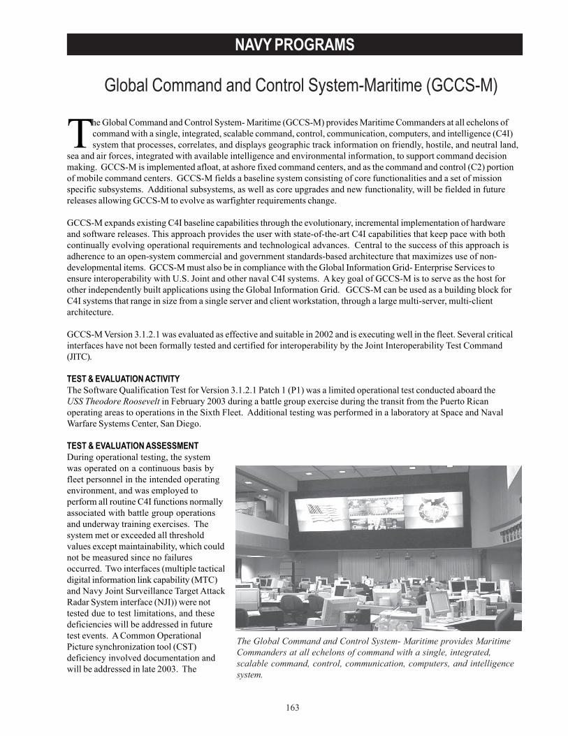
163
NAVY PROGRAMS
Global Command and Control System-Maritime (GCCS-M)
The Global Command and Control System- Maritime (GCCS-M) provides Maritime Commanders at all echelons ofcommand with a single, integrated, scalable command, control, communication, computers, and intelligence (C4I)system that processes, correlates, and displays geographic track information on friendly, hostile, and neutral land,
sea and air forces, integrated with available intelligence and environmental information, to support command decisionmaking. GCCS-M is implemented afloat, at ashore fixed command centers, and as the command and control (C2) portionof mobile command centers. GCCS-M fields a baseline system consisting of core functionalities and a set of missionspecific subsystems. Additional subsystems, as well as core upgrades and new functionality, will be fielded in futurereleases allowing GCCS-M to evolve as warfighter requirements change.
GCCS-M expands existing C4I baseline capabilities through the evolutionary, incremental implementation of hardwareand software releases. This approach provides the user with state-of-the-art C4I capabilities that keep pace with bothcontinually evolving operational requirements and technological advances. Central to the success of this approach isadherence to an open-system commercial and government standards-based architecture that maximizes use of non-developmental items. GCCS-M must also be in compliance with the Global Information Grid- Enterprise Services toensure interoperability with U.S. Joint and other naval C4I systems. A key goal of GCCS-M is to serve as the host forother independently built applications using the Global Information Grid. GCCS-M can be used as a building block forC4I systems that range in size from a single server and client workstation, through a large multi-server, multi-clientarchitecture.
GCCS-M Version 3.1.2.1 was evaluated as effective and suitable in 2002 and is executing well in the fleet. Several criticalinterfaces have not been formally tested and certified for interoperability by the Joint Interoperability Test Command(JITC).
TEST & EVALUATION ACTIVITYThe Software Qualification Test for Version 3.1.2.1 Patch 1 (P1) was a limited operational test conducted aboard theUSS Theodore Roosevelt in February 2003 during a battle group exercise during the transit from the Puerto Ricanoperating areas to operations in the Sixth Fleet. Additional testing was performed in a laboratory at Space and NavalWarfare Systems Center, San Diego.
TEST & EVALUATION ASSESSMENTDuring operational testing, the systemwas operated on a continuous basis byfleet personnel in the intended operatingenvironment, and was employed toperform all routine C4I functions normallyassociated with battle group operationsand underway training exercises. Thesystem met or exceeded all thresholdvalues except maintainability, which couldnot be measured since no failuresoccurred. Two interfaces (multiple tacticaldigital information link capability (MTC)and Navy Joint Surveillance Target AttackRadar System interface (NJI)) were nottested due to test limitations, and thesedeficiencies will be addressed in futuretest events. A Common OperationalPicture synchronization tool (CST)deficiency involved documentation andwill be addressed in late 2003. The
The Global Command and Control System- Maritime provides MaritimeCommanders at all echelons of command with a single, integrated,scalable command, control, communication, computers, and intelligencesystem.
164
NAVY PROGRAMS
Software Qualification Test report declared GCCS-M 3.1.2.1P1 operationally effective (excluding MTC and NJI) andoperationally suitable (excluding MTC, NJI, and CST), and recommended approval for fleet release.
The GCCS-M Management Office needs to submit a proposed Interoperability key performance parameter for approval.Together with associated information exchange requirements, this will be required before JITC interoperabilitycertification can be achieved. The GCCS-M program and JITC are making progress in this area, and DOT&E expects thework to be accomplished in time to support testing and interface certifying for GCCS-M 4.0, which is the next majorrelease scheduled for testing by August 2004.
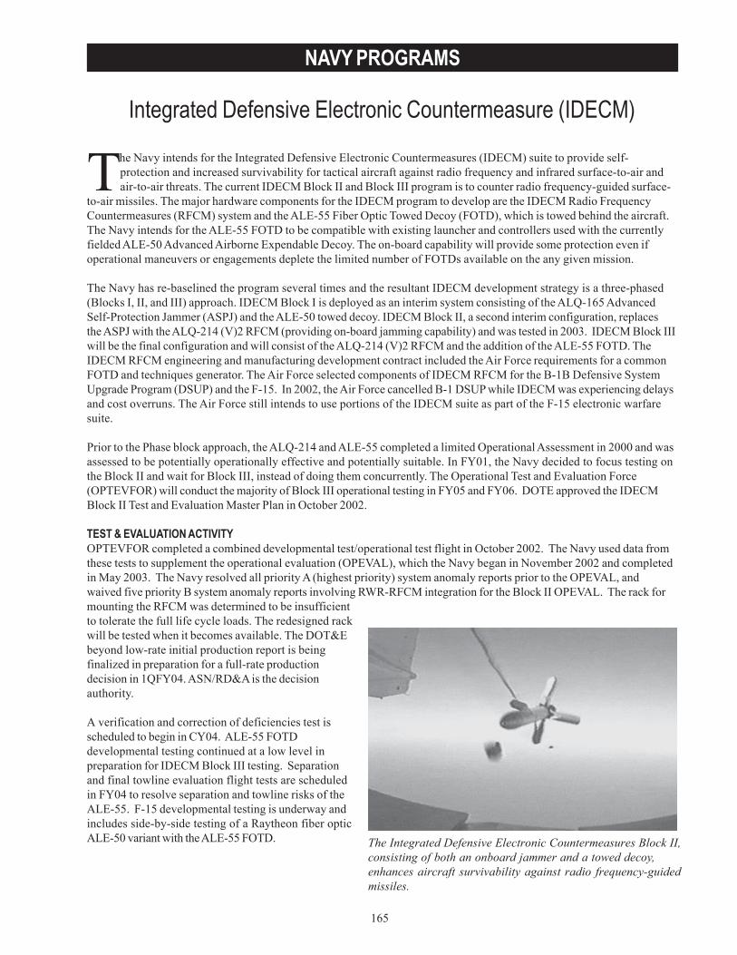
165
NAVY PROGRAMS
Integrated Defensive Electronic Countermeasure (IDECM)
The Integrated Defensive Electronic Countermeasures Block II,consisting of both an onboard jammer and a towed decoy,enhances aircraft survivability against radio frequency-guidedmissiles.
The Navy intends for the Integrated Defensive Electronic Countermeasures (IDECM) suite to provide self-protection and increased survivability for tactical aircraft against radio frequency and infrared surface-to-air andair-to-air threats. The current IDECM Block II and Block III program is to counter radio frequency-guided surface-
to-air missiles. The major hardware components for the IDECM program to develop are the IDECM Radio FrequencyCountermeasures (RFCM) system and the ALE-55 Fiber Optic Towed Decoy (FOTD), which is towed behind the aircraft.The Navy intends for the ALE-55 FOTD to be compatible with existing launcher and controllers used with the currentlyfielded ALE-50 Advanced Airborne Expendable Decoy. The on-board capability will provide some protection even ifoperational maneuvers or engagements deplete the limited number of FOTDs available on the any given mission.
The Navy has re-baselined the program several times and the resultant IDECM development strategy is a three-phased(Blocks I, II, and III) approach. IDECM Block I is deployed as an interim system consisting of the ALQ-165 AdvancedSelf-Protection Jammer (ASPJ) and the ALE-50 towed decoy. IDECM Block II, a second interim configuration, replacesthe ASPJ with the ALQ-214 (V)2 RFCM (providing on-board jamming capability) and was tested in 2003. IDECM Block IIIwill be the final configuration and will consist of the ALQ-214 (V)2 RFCM and the addition of the ALE-55 FOTD. TheIDECM RFCM engineering and manufacturing development contract included the Air Force requirements for a commonFOTD and techniques generator. The Air Force selected components of IDECM RFCM for the B-1B Defensive SystemUpgrade Program (DSUP) and the F-15. In 2002, the Air Force cancelled B-1 DSUP while IDECM was experiencing delaysand cost overruns. The Air Force still intends to use portions of the IDECM suite as part of the F-15 electronic warfaresuite.
Prior to the Phase block approach, the ALQ-214 and ALE-55 completed a limited Operational Assessment in 2000 and wasassessed to be potentially operationally effective and potentially suitable. In FY01, the Navy decided to focus testing onthe Block II and wait for Block III, instead of doing them concurrently. The Operational Test and Evaluation Force(OPTEVFOR) will conduct the majority of Block III operational testing in FY05 and FY06. DOTE approved the IDECMBlock II Test and Evaluation Master Plan in October 2002.
TEST & EVALUATION ACTIVITYOPTEVFOR completed a combined developmental test/operational test flight in October 2002. The Navy used data fromthese tests to supplement the operational evaluation (OPEVAL), which the Navy began in November 2002 and completedin May 2003. The Navy resolved all priority A (highest priority) system anomaly reports prior to the OPEVAL, andwaived five priority B system anomaly reports involving RWR-RFCM integration for the Block II OPEVAL. The rack formounting the RFCM was determined to be insufficientto tolerate the full life cycle loads. The redesigned rackwill be tested when it becomes available. The DOT&Ebeyond low-rate initial production report is beingfinalized in preparation for a full-rate productiondecision in 1QFY04. ASN/RD&A is the decisionauthority.
A verification and correction of deficiencies test isscheduled to begin in CY04. ALE-55 FOTDdevelopmental testing continued at a low level inpreparation for IDECM Block III testing. Separationand final towline evaluation flight tests are scheduledin FY04 to resolve separation and towline risks of theALE-55. F-15 developmental testing is underway andincludes side-by-side testing of a Raytheon fiber opticALE-50 variant with the ALE-55 FOTD.
166
NAVY PROGRAMS
TEST & EVALUATION ASSESSMENTThe Navy fielded Block I on initial F-18E/F deployments and, by virtue of being an interim solution, has limited logisticssupportability. Follow-on IDECM Blocks II or III need to produce an effective and suitable replacement for the Block Isuite before its available logistics support expires. Block II performance results in developmental test and OPEVALindicate the system was tested adequately and is operationally effective and operationally suitable, but needs suitabilityimprovement.
The IDECM Block II showed a substantial contribution to aircraft survivability, both in the absolute and as compared tothe current on-board F/A-18C ECM system, the ALQ-126B. OPTEVFOR should have more thoroughly tested jointinteroperability, reprogramming capability, and system response. Although most available test assets were used, thediversity of threats tested was very small. This is due to a shortfall in electronic warfare test capabilities. A substantialand sustained investment in both the number of different threat systems and the quality of data available from them isneeded so that future electric countermeasure systems can be more completely tested. A common family of missile fly-out models should be supported (several exist) to maximize commonality across test facilities.
Test results showed suitability concerns. The cockpit interface and controls made it very difficult for the pilot to set-upand determine the state of the system. This led to two safety issues involving inadvertent or partial decoy deployment.Control of chaff and flare dispense was also difficult. Updates to both the ALQ-214 and Mission Computer are beingworked and are scheduled to be tested 2QFY04. Reliability was acceptable, but far from the desired mature system levels,and two lots of bad squibs (explosive charges to launch the decoys) were undetected until late in the test and drasticallyreduced measures of ALE-50 reliability. Built-in test (BIT) performance was marginal. Use of the pilot-initiated BITallowed an acceptable number of missions to be completed, though without relieving the burden on maintenance of thehigh BIT false alarm rate.
In the lab environment, the Block III RFCM and FOTD proved to be highly effective and very close to predictedperformance. For Block III, the deployment of the FOTD and the durability of the towline under operational conditionsare still high risk.
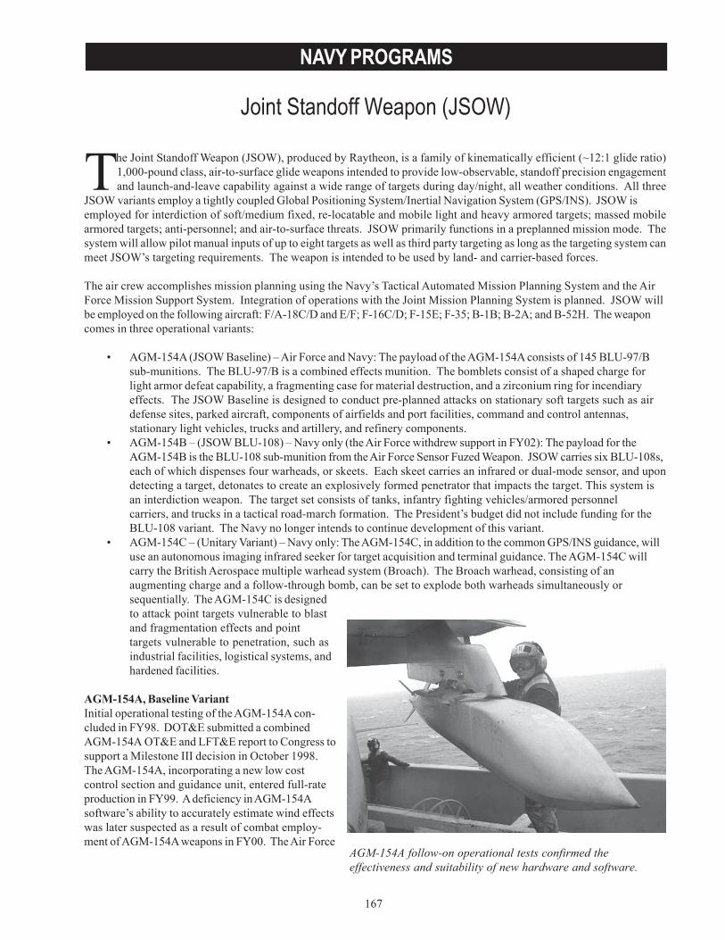
167
NAVY PROGRAMS
Joint Standoff Weapon (JSOW)
The Joint Standoff Weapon (JSOW), produced by Raytheon, is a family of kinematically efficient (~12:1 glide ratio)1,000-pound class, air-to-surface glide weapons intended to provide low-observable, standoff precision engagementand launch-and-leave capability against a wide range of targets during day/night, all weather conditions. All three
JSOW variants employ a tightly coupled Global Positioning System/Inertial Navigation System (GPS/INS). JSOW isemployed for interdiction of soft/medium fixed, re-locatable and mobile light and heavy armored targets; massed mobilearmored targets; anti-personnel; and air-to-surface threats. JSOW primarily functions in a preplanned mission mode. Thesystem will allow pilot manual inputs of up to eight targets as well as third party targeting as long as the targeting system canmeet JSOW’s targeting requirements. The weapon is intended to be used by land- and carrier-based forces.
The air crew accomplishes mission planning using the Navy’s Tactical Automated Mission Planning System and the AirForce Mission Support System. Integration of operations with the Joint Mission Planning System is planned. JSOW willbe employed on the following aircraft: F/A-18C/D and E/F; F-16C/D; F-15E; F-35; B-1B; B-2A; and B-52H. The weaponcomes in three operational variants:
• AGM-154A (JSOW Baseline) – Air Force and Navy: The payload of the AGM-154A consists of 145 BLU-97/Bsub-munitions. The BLU-97/B is a combined effects munition. The bomblets consist of a shaped charge forlight armor defeat capability, a fragmenting case for material destruction, and a zirconium ring for incendiaryeffects. The JSOW Baseline is designed to conduct pre-planned attacks on stationary soft targets such as airdefense sites, parked aircraft, components of airfields and port facilities, command and control antennas,stationary light vehicles, trucks and artillery, and refinery components.
• AGM-154B – (JSOW BLU-108) – Navy only (the Air Force withdrew support in FY02): The payload for theAGM-154B is the BLU-108 sub-munition from the Air Force Sensor Fuzed Weapon. JSOW carries six BLU-108s,each of which dispenses four warheads, or skeets. Each skeet carries an infrared or dual-mode sensor, and upondetecting a target, detonates to create an explosively formed penetrator that impacts the target. This system isan interdiction weapon. The target set consists of tanks, infantry fighting vehicles/armored personnelcarriers, and trucks in a tactical road-march formation. The President’s budget did not include funding for theBLU-108 variant. The Navy no longer intends to continue development of this variant.
• AGM-154C – (Unitary Variant) – Navy only: The AGM-154C, in addition to the common GPS/INS guidance, willuse an autonomous imaging infrared seeker for target acquisition and terminal guidance. The AGM-154C willcarry the British Aerospace multiple warhead system (Broach). The Broach warhead, consisting of anaugmenting charge and a follow-through bomb, can be set to explode both warheads simultaneously orsequentially. The AGM-154C is designedto attack point targets vulnerable to blastand fragmentation effects and pointtargets vulnerable to penetration, such asindustrial facilities, logistical systems, andhardened facilities.
AGM-154A, Baseline VariantInitial operational testing of the AGM-154A con-cluded in FY98. DOT&E submitted a combinedAGM-154A OT&E and LFT&E report to Congress tosupport a Milestone III decision in October 1998.The AGM-154A, incorporating a new low costcontrol section and guidance unit, entered full-rateproduction in FY99. A deficiency in AGM-154Asoftware’s ability to accurately estimate wind effectswas later suspected as a result of combat employ-ment of AGM-154A weapons in FY00. The Air Force
AGM-154A follow-on operational tests confirmed theeffectiveness and suitability of new hardware and software.
168
NAVY PROGRAMS
and Navy later confirmed the deficiency during developmental testing in FY01. Operational tests of both new hardwareand updated software began in FY02.
AGM-154B, BLU-108 VariantThe Navy approved the low-rate initial production of the AGM-154B in FY99. Continued developmental tests ceased inFY00 during production verification due to numerous system performance shortfalls.
AGM-154C, Unitary VariantIn September 2000, the Under Secretary of Defense (Acquisition, Technology and Logistics) approved incorporation ofthe developmental Broach warhead. Due to incorporation of the new warhead, LFT&E is required.
TEST & EVALUATION ACTIVITYAGM-154A, Baseline VariantAdequate operational test of both new hardware and updated software began in FY02, but was not complete prior todeployment in the Navy in November 2002. Adequate operational testing of this AGM-154A hardware and softwareconfiguration was not complete until December 2002. Operational testing in FY03 also included evaluation of theeffectiveness and suitability of a further re-design of the AGM-154A control section intended to enable the F-16 toemploy the weapon throughout the entire F-16 operational envelope.
AGM-154B, BLU-108 VariantAlthough the Navy conducted test planning for operational evaluation (OPEVAL) through mid-FY03, testing is no longerplanned.
AGM-154C, Unitary VariantAn operational assessment to support an AGM-154C low-rate initial production decision began in January 2003. Testingconcluded in June 2003 and consisted, primarily, of captive carry missions to evaluate seeker performance and concludedwith the free flight of an inert AGM-154C. Developmental flight-testing is slated to conclude in FY04. The Navy hasinitial operational testing planned for FY04.
LFT&E of static warhead arena testing to characterize the Broach warhead’s blast and fragmentation performance beganin September 2002. Dynamic warhead integration sled testing began in October 2002. Live warhead developmental flight-testing began in August 2003.
TEST & EVALUATION ASSESSMENTAGM-154A, Baseline VariantDOT&E’s evaluation of the results of Navy operational evaluation and Air Force IOT&E confirmed that the AGM-154A,in the low-rate initial production configuration, is operationally effective and suitable.
Follow-on operational tests concluded in December 2002 and July 2003, were adequate to evaluate the effectiveness andsuitability of new software and hardware. Results confirm the hardware deployed to the fleet, the redesigned controlsection to support F-16 full envelope employment, and updated Baseline software are effective and suitable for combat.Operational testing to evaluate F-16 capability to employ weapons from the BRU-57 smart rack was delayed, awaitingcertification of an expanded employment envelope, and will be accomplished under additional follow-on operationaltesting.
AGM-154C, Unitary VariantAn operational assessment of the unitary variant, concluded in June 2003, was adequate. Initial performance of thesystem resulted in the seeker tracking well outside requirements. Mission planning was slow and was evaluated as not
169
NAVY PROGRAMS
suitable. Regression testing with updated seeker software later demonstrated that guidance to the intended point ofimpact has the potential to meet requirements. However, improvements to mission planning remain undemonstrated.
Sled tests against concrete slabs have not demonstrated follow-through bomb lethality. The results from one of threedevelopmental flight-tests using live warheads against similar targets has resulted in no follow-through bomb detona-tion. Additional risk-reduction efforts performed by the contractor occurred prior to the last developmental free-flighttest event. Although risk reduction efforts and an additional weapon drop have delayed entry into operational testing,additional developmental testing and further risk reduction should increase the probability of weapon system successduring OPEVAL.
Four static arena tests occurred in FY03 to characterize the blast and fragmentation performance of the Broach warheadin both simultaneous and sequential detonation modes. Analysis of these results will be available in FY04. Warheadlethality and the intended level of damage against realistic targets will be assessed during the combined OT&E andLFT&E.
To proceed forward with OPEVAL, target materials and construction where lethal warhead effects occur must be realisticfor all targets. OPEVAL will test the weapon in a realistic GPS-jamming and camouflaged, concealment, and deceptionenvironment, but will simulate surface-to-air threat systems. The Navy will complete an evaluation of weaponsurvivability against realistic surface-to-air threat systems during follow-on operational testing.

170
NAVY PROGRAMS
171
NAVY PROGRAMS
KC-130J Aircraft
The KC-130J’s primary mission is aerial refueling of fixed and rotarywing Marine Corps aircraft.
The KC-130J, a variant of the C-130J, is a medium sized, four-engine turboprop aircraft modified to perform a primarymission of aerial refueling of fixed and rotary wing aircraft for the United States Marine Corps (USMC). Secondarymissions include rapid ground refueling, assault transport, logistics support, and special warfare, while preserving
personnel and cargo transport capabilities. The KC-130J will perform the same missions as the aircraft it will replace, theKC-130F and KC-130R. Procurement of the KC-130J is proceeding under a commercial off-the-shelf acquisition strategy,instituting catalog pricing and commercial payments through the United States Air Force’s C-130 System Program Office.
The KC-130J Navy/USMC test program is specifically designed to address differences in aircraft configuration andmission employment from the baseline U.S. Air Force (USAF) C-130J. The KC-130J program intends to build upon thecontractor, Federal Aviation Administration, and USAF test efforts and data collection rather than duplicate efforts. TheUSAF effort has been ongoing since 1995.
TEST & EVALUATION ACTIVITYThe Navy/USMC developmental test and evaluation program has completed approximately 1,200 flight test hours.Operational testing (OT-IIIA/B) began in October 2003 to determine the operational effectiveness and suitability for air/land, air delivery, and aerial refueling capability, and to support a recommendation for fleet introduction.
As part of the LFT&E program, measurements of oxygen concentrations inside the removable center fuselage fuel tankullage were made from July to August 2003. The data collected will be used to assist in selecting shotlines for ballistictesting, currently scheduled for FY04.
DOT&E approved the Test and Evaluation Master Plan and the Operational Test Plan in October 2003.
TEST & EVALUATION ASSESSMENTThe new KC-130J aerial refueling system was not qualified because of flight safety and operational performanceproblems. There were incidents of pull-offs where the refueling hose disengaged from the aircraft being refueled. Thisproblem caused a one-year slip in testing from the original schedule. The new refueling system was replaced by theexisting (legacy) system used on the KC-130T. Legacy pods will be installed in the near-term. However, the legacy podswill be upgraded and installed after developmental and operational testing is completed. The upgraded pods will containa Rapid Ground Refueling port and reliability enhancements. They will be integrated into the aircraft mission computer,which will be produced and retrofitted onto existing KC-130J and incorporated into production aircraft starting in October2004.
The excessive false alarm rate to identify failures increases the maintenance burden to an unacceptable level. Deficiencycorrections are not budgeted to be incorporated until FY08-FY09 timeframe.
Assessment of the LFT&E ullagemeasurement data awaits completion of the46th Test Wing ullage test report.

172
NAVY PROGRAMS
173
NAVY PROGRAMS
Littoral Combatant Ship (LCS)
The Littoral Combatant Ship will have three primary or focusedmissions: surface warfare against small hostile boats; minecountermeasures; and littoral anti-submarine warfare.
Envisioned as a networked, agile, stealthy surface combatant capable of defeating asymmetric threats in the littoralsand ensuring U.S. forces access to those regions of the world, the Littoral Combat Ship (LCS) will be a relativelysmall, high-speed, and maneuverable combatant. The Navy expects it to complement the Aegis Fleet, DD(X), and
CG(X) by operating in environments where it is less desirable to employ larger, multi-mission ships. It is expected to beable to deploy independently, remain on station for long periods of time, operate with a strike group or through a forward-basing arrangement, and conduct underway replenishment.
The LCS will likely be an advanced hull form employing open software architecture to integrate different combat systems,or mission packages, depending on its assigned mission. It is expected to be rapidly reconfigurable in response tochanges in mission, threat, and technology. Each mission package will rely heavily on manned and unmanned vehiclesto execute assigned missions.
The LCS will have three primary or focused missions: surface warfare against small hostile boats; mine countermeasures;and littoral anti-submarine warfare. It will only be capable of conducting one focused mission at a time. Likely secondarymissions include: intelligence; surveillance and reconnaissance; Special Operations Forces support; logistic support formovement of personnel and materials; Maritime Intercept Operations; and Homeland Defense. A spiral developmentapproach is planned to meet accelerated production and deployment goals. The first ship is scheduled for delivery inFY07. The initial two ships, comprising Flight 0, will deliver a set of core warfighting capabilities that must include self-defense and core command and control capabilities. Flight 0 will also produce a limited set of mission modules based oncurrent or near-term systems. While Flight 0 ships and mission packages are being built, the Flight 1 ship and missionpackage designs will be developed.
TEST & EVALUATION ACTIVITYAlthough still very early in the LCS program, the Program Office developed a Flight 0 Interim Requirements Documentand promulgated it with the Preliminary Design Request for Proposal. Additionally, DOT&E has been active in thedevelopment of both the Acquisition Strategy and Test and Evaluation Strategy documents, which are due atMilestone A.
TEST & EVALUATION ASSESSMENTThe accelerated acquisition timeline for LCSleaves very little time to apply any lessonslearned from the construction/operational testingof Flight 0 ships to Flight 1 hull and missionpackage designs. The two Flight 0 hulls willlikely be different designs and their constructionschedules will overlap. Hull #1 will be deliveredapproximately nine months prior to hull #2. Thefinal design of hull #3, the first Flight 1 ship, willstart a few months after delivery of hull #1 andprior to the delivery of hull #2.
The Program Office, the operational test agency,and DOT&E have reduced program risk throughearly planning and good liaison. Several earlyoperational assessments on each of the differenthulls and mission packages are planned. ALFT&E program is planned, although manydetails remain to be worked out before theLFT&E Management Plan can be approved.
174
NAVY PROGRAMS
Operational effectiveness determination of LCS self-defense in the littoral environment against the anti-ship cruisemissile threat will be required. The program should plan on using a self-defense test ship, as that is the only way toconduct safe and adequately realistic operational testing. An instrumented shallow water range will be required to fullyevaluate LCS’s anti-surface warfare capability and would be very beneficial to evaluate it’s mine warfare capability.Threat representative targets will also be critical to evaluate LCS’s effectiveness against the diesel submarine threat inshallow water.
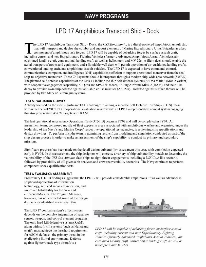
175
NAVY PROGRAMS
LPD 17 Amphibious Transport Ship - Dock
The LPD 17 Amphibious Transport Ship - Dock, the USS San Antonio, is a diesel-powered amphibious assault shipthat will transport and deploy the combat and support elements of Marine Expeditionary Units/Brigades as a keycomponent of amphibious task forces. LPD 17 will be capable of debarking forces by surface assault craft,
including current and new Expeditionary Fighting Vehicles (formerly Advanced Amphibious Assault Vehicles), air-cushioned landing craft, conventional landing craft, as well as helicopters and MV-22s. A flight deck should enable theaerial transport of troops and equipment, and a floodable well deck will permit operation of air-cushioned landing crafts,conventional landing craft, and amphibious assault vehicles. The LPD 17 is expected to have command, control,communications, computer, and intelligence (C4I) capabilities sufficient to support operational maneuver from the sea/ship-to-objective maneuver. These C4I systems should interoperate through a modern ship-wide area network (SWAN).The planned self-defense capabilities of the LPD 17 include the ship self-defense system (SSDS) Mark 2 (Mod 2 variant)with cooperative engagement capability, SPQ-9B and SPS-48E radars, Rolling Airframe Missile (RAM), and the Nulkadecoy to provide own-ship defense against anti-ship cruise missiles (ASCMs). Defense against surface threats will beprovided by two Mark 46 30mm gun systems.
TEST & EVALUATION ACTIVITYActivity focused on the most significant T&E challenge: planning a separate Self Defense Test Ship (SDTS) phasewithin the FY06/FY07 LPD 17 operational evaluation window with an LPD 17-representative combat system engagingthreat-representative ASCM targets with RAM.
The last operational assessment (Operational Test (OT)-IIB) began in FY02 and will be completed in FY04. Anassessment team, composed mostly of fleet experts in areas associated with amphibious warfare and organized under theleadership of the Navy’s and Marine Corps’ respective operational test agencies, is reviewing ship specifications anddesign drawings. To perform this, the team is examining results from modeling and simulation conducted as part of theship design process in order to make an assessment of the ship’s capability to conduct its primary and secondarymissions.
Significant progress has been made on the detail design vulnerability assessment this year, with completion expectedearly in FY04. In this assessment, the ship designers will exercise a variety of ship vulnerability models to determine thevulnerability of the USS San Antonio class ships to eight threat engagements including a USS Cole-like scenario,followed by probability of kill given a hit analyses and crew recoverability scenarios. The Navy continues to performcomponent shock qualification tests.
TEST & EVALUATION ASSESSMENTPreliminary OT-IIB findings suggest that the LPD 17 will provide considerable amphibious lift as well as advances inshipboard application of informationtechnology, reduced radar cross-section, andimproved habitability for the crew andembarked Marines. The Program Manager,however, has not corrected some of the designdeficiencies identified as early as 1996.
The LPD 17 combat system’s effectivenessdepends on the complex integration of separatesensor, weapon, and control element programs.The only hard-kill defensive system (RAM),along with soft-kill systems (such as Nulka andchaff), must achieve the threshold requirementfor ASCM defense - the primary threat in thechallenging littoral environment. Defenseagainst fighter/attack-type aircraft is a
LPD 17 will be capable of debarking forces by surface assaultcraft, including current and new Expeditionary FightingVehicles (formerly Advanced Amphibious Assault Vehicles), air-cushioned landing craft, conventional landing craft, as well ashelicopters and MV-22s.

176
NAVY PROGRAMS
vulnerable area because LPD 17 does not have any demonstrated capability against these threats. A RAM upgradeprogram will enable RAM to engage helicopters, some aircraft (“low/slow flyers,” not jet aircraft), and surface craft, butthe new missile will not be fielded in time for LPD 17 nor is SSDS Mark 2 expected to be modified to accommodate themissile’s improved capabilities. Real-time tracks provided by SSDS Mark 2 are not fused with near real-time friendly unitpositions and control measures provided by nonintegrated systems such as the ship’s Amphibious Assault DirectionSystem. System operators and supervisory personnel must manually deconflict the tracks, increasing their workloadsand the risk of misclassifying a threat as a friendly or friendly as a threat. Finally, concerns remain about the ship’ssusceptibility to torpedoes.
The ship was designed to carry a substantial amount of cargo; however, there are currently no backup systems for theelevators that service two of the ship’s three cargo and ammunition magazines. Combined, these two hold approximately85 percent of the supplies carried aboard the ship. DOT&E is especially concerned because the Marine Corps’ Sea-Based Logistics concept states that most supplies and ammunition remain aboard ship and are brought ashore only whenneeded. An emergency ordnance handling system has been proposed, but has not been tested and evaluated.
Five systems that are not part of the ship’s baseline were identified as necessary during the OT-IIB. These include JointOperations Planning and Execution System; Joint Service Imagery Processing System – Navy; Theater BattleManagement Core System; High Frequency, Automatic Link Establishment Radio; and Global Broadcast Service terminal.Discussions are ongoing among various Navy and Marine Corps staffs to determine whether these systems are requiredfor LPD 17-class ships and, if so, how they can be funded.
Three other systems that are also not part of the ship’s baseline are necessary. These are Advanced Field ArtilleryTactical Data System; Naval Aviation Logistics Command Management Information System; and Digital Terrain AnalysisMapping System. Although the Navy stated that the landing force can bring the needed hardware and software aboardthe ship before deploying, this approach potentially introduces integration and Information Assurance concerns.
Finally, although corrective actions for several significant C4I shortfalls have been identified, it is unclear that these fixeswill be applied before the ship’s IOT&E. If they are not, there is a risk that the ship, as tested, will not be operationallyeffective.
Like the 1970s-era amphibious ships it will replace, the LPD 17 will not fully support concurrent, nighttime, flight-deckand well-deck operations because of lighting that is not compatible with night vision devices. The Program Office isworking with other Navy organizations to define and support a solution, and promising approaches have been identifiedand tested at sea. Nevertheless, progress to date makes it questionable that a solution will be found and implemented onLPD 17.
The ship’s sophisticated SWAN is crucial to mission accomplishment. The SWAN is expected to facilitate improvedinformation technology capabilities, but it potentially introduces information assurance-related vulnerabilities, due tointernal security shortfalls in areas such as firewalls, intrusion/virus detection software, and network load management.
DOT&E approval of Test and Evaluation Master Plans and operational test plans for LPD 17 and SSDS will hinge on anadequate OT&E strategy. An adequate strategy includes a separate SDTS phase within the FY06/FY07 LPD 17operational evaluation window with an LPD 17-representative combat system engaging threat-representative ASCMtargets with RAM.
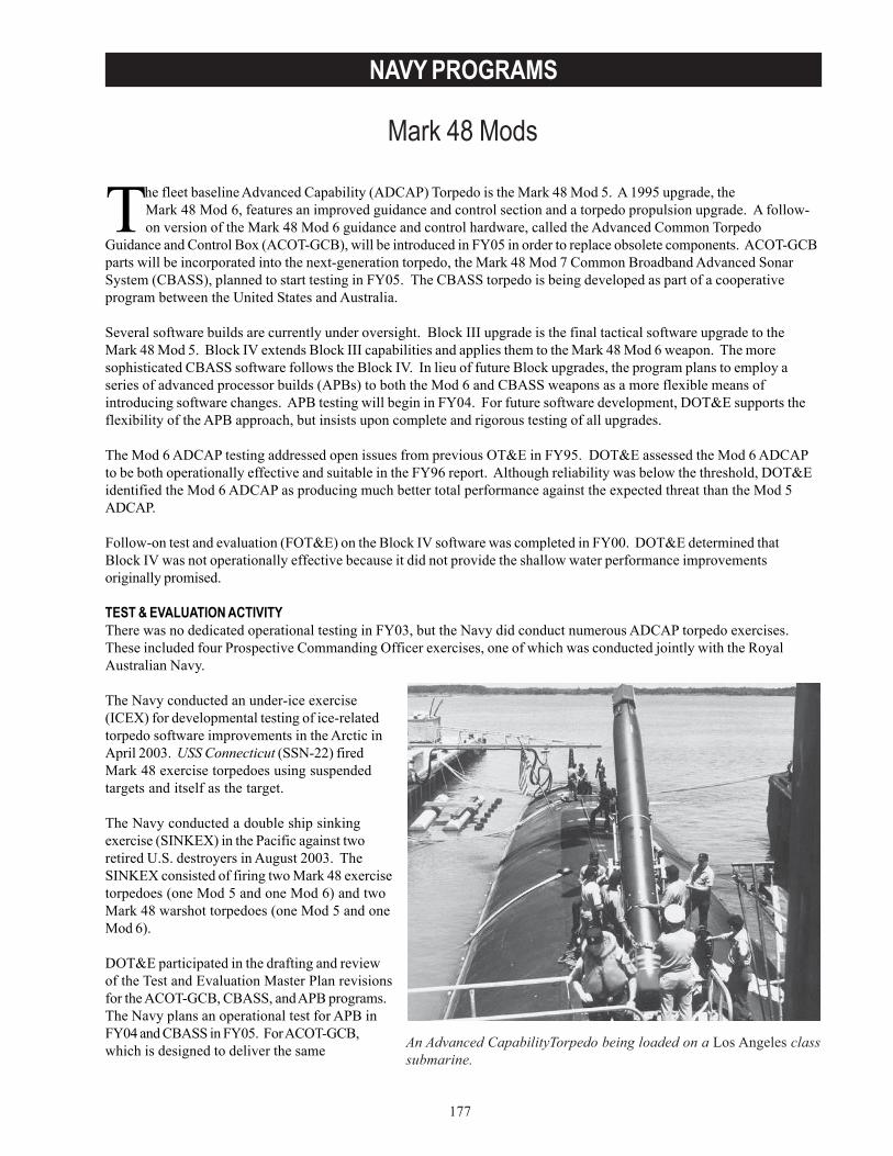
177
NAVY PROGRAMS
Mark 48 Mods
The fleet baseline Advanced Capability (ADCAP) Torpedo is the Mark 48 Mod 5. A 1995 upgrade, theMark 48 Mod 6, features an improved guidance and control section and a torpedo propulsion upgrade. A follow-on version of the Mark 48 Mod 6 guidance and control hardware, called the Advanced Common Torpedo
Guidance and Control Box (ACOT-GCB), will be introduced in FY05 in order to replace obsolete components. ACOT-GCBparts will be incorporated into the next-generation torpedo, the Mark 48 Mod 7 Common Broadband Advanced SonarSystem (CBASS), planned to start testing in FY05. The CBASS torpedo is being developed as part of a cooperativeprogram between the United States and Australia.
Several software builds are currently under oversight. Block III upgrade is the final tactical software upgrade to theMark 48 Mod 5. Block IV extends Block III capabilities and applies them to the Mark 48 Mod 6 weapon. The moresophisticated CBASS software follows the Block IV. In lieu of future Block upgrades, the program plans to employ aseries of advanced processor builds (APBs) to both the Mod 6 and CBASS weapons as a more flexible means ofintroducing software changes. APB testing will begin in FY04. For future software development, DOT&E supports theflexibility of the APB approach, but insists upon complete and rigorous testing of all upgrades.
The Mod 6 ADCAP testing addressed open issues from previous OT&E in FY95. DOT&E assessed the Mod 6 ADCAPto be both operationally effective and suitable in the FY96 report. Although reliability was below the threshold, DOT&Eidentified the Mod 6 ADCAP as producing much better total performance against the expected threat than the Mod 5ADCAP.
Follow-on test and evaluation (FOT&E) on the Block IV software was completed in FY00. DOT&E determined thatBlock IV was not operationally effective because it did not provide the shallow water performance improvementsoriginally promised.
TEST & EVALUATION ACTIVITYThere was no dedicated operational testing in FY03, but the Navy did conduct numerous ADCAP torpedo exercises.These included four Prospective Commanding Officer exercises, one of which was conducted jointly with the RoyalAustralian Navy.
The Navy conducted an under-ice exercise(ICEX) for developmental testing of ice-relatedtorpedo software improvements in the Arctic inApril 2003. USS Connecticut (SSN-22) firedMark 48 exercise torpedoes using suspendedtargets and itself as the target.
The Navy conducted a double ship sinkingexercise (SINKEX) in the Pacific against tworetired U.S. destroyers in August 2003. TheSINKEX consisted of firing two Mark 48 exercisetorpedoes (one Mod 5 and one Mod 6) and twoMark 48 warshot torpedoes (one Mod 5 and oneMod 6).
DOT&E participated in the drafting and reviewof the Test and Evaluation Master Plan revisionsfor the ACOT-GCB, CBASS, and APB programs.The Navy plans an operational test for APB inFY04 and CBASS in FY05. For ACOT-GCB,which is designed to deliver the same An Advanced CapabilityTorpedo being loaded on a Los Angeles class
submarine.
178
NAVY PROGRAMS
performance as the legacy Mod 6 hardware, DOT&E supports plans to test the two guidance and control sections side-by-side in the Navy’s Weapons Analysis Facility hardware-in-the-loop simulator. The simulated data will besupplemented with a limited set of in-water confidence tests. The verification, validation, and accreditation of theWeapons Analysis Facility will be a significant project in FY04.
TEST & EVALUATION ASSESSMENTThe Block IV Verification of Correction of Deficiencies (VCD) testing, conducted in 2002, consisted of a small number ofexercise torpedo firings at shallow water sites near Maui, Hawaii, and Southern California. The VCD focused on technicalissues affecting torpedo performance, rather than overall operational effectiveness. In February 2003, Navy testersissued a VCD report stating that neither the technical nor operational level performance provided conclusive evidencethat the original deficiency had been corrected. The fact that the test was not conducted at the same site as the FY00operational test, raised concerns regarding the impact of acoustic conditions on the validity of the VCD results. Despitethe shortcomings, Navy testers recommended fleet release based on the improved deep-water performance of theBlock IV.
The 2003 ICEX did not feature operationally realistic firings against a valid target, but did provide a demonstration of theMark 48 Mod 6 ADCAP’s ability to perform reliably in the Arctic environment.
During the 2003 SINKEX, the two exercise weapons ran as planned, but the two warshots did not; the Navy isinvestigating whether this was due to reliability problems or other causes. In the last few years, the Navy hasexperienced some unsuccessful, incomplete, or otherwise ambiguous results in its SINKEX program, raising concernsregarding the warshot inventory performance and reliability. Torpedo reliability, as described in previous AnnualReports, remains an ongoing concern. These failures highlight the overall problem of ADCAP reliability, which continuesto run in cycles and identifies a need for more Navy investment in its torpedo SINKEX program. Work force reductionsat the weapon’s depots may also threaten the fleet’s ability to process weapons quickly and accurately.
The new level of cooperation between the U.S. Navy and the Royal Australian Navy provided valuable opportunities fortraining and testing, particularly against diesel-electric submarines. However, some torpedo performance questionsremain unresolved due to inadequate T&E resources and funding provided by the Navy. For open-ocean shallow waterexercises, the tested torpedo’s internal monitoring equipment is the only source of data, resulting in post-run analysisbiases and errors. Development of a mobile test range, or other independent instrumentation, is necessary to alleviateshallow water testing shortfalls. As a more permanent solution, given the high priority of the diesel submarine threat, aninstrumented shallow water test range in a threat representative environment would help hasten maturation of littoralSubmarine Warfare tactics and torpedo performance improvement in shallow water. The cumbersome nature of openocean torpedo firings, coupled with seasonal marine mammal habitat restrictions at many locations, has significantlylengthened development cycle times. Navy funding support for a viable instrumented shallow water test range isneeded.

179
NAVY PROGRAMS
MH-60R Multi-Mission Helicopter Upgrade
Originally conceived as an aircraft remanufacture and avionics upgrade program, cost considerations redefined theMH-60R Multi-Mission Helicopter program to procure new production vice remanufactured aircraft. TheAssistant Secretary of the Navy, Research, Development and Acquisition (ASN(RDA)), approved the current
Acquisition Program Baseline schedule on March 14, 2002. The program combines the missions of the legacy SH-60B andSH-60F aircraft into a single airframe. The Navy expects the aircraft’s improved avionics to enhance undersea and surfacewarfare, surveillance, identification, and power projection objectives. The program entered engineering development atMilestone II in FY93.
The initial variant (Block 0) of the multi-phase evolutionary acquisition program develops the AN/AQS-22 Airborne Low-Frequency Sonar with increased sonobuoy acoustic signal processing capability. The program also develops theAN/APS-147 Multi-Mode Radar that includes Inverse Synthetic Aperture Radar imaging and periscope detection modesof operation. Other improvements include the AN/ALQ-210 electronic support system, a fully integrated self defensesystem; and the AN/AAS-44 Forward-Looking Infrared sensor with laser designator. The MH-60R will have the CommonCockpit design, also used in the MH-60S, which has multi-functional displays and a complex tactical data processingsystem.
DOT&E designated the MH-60R as a covered system for LFT&E in 1998. ASN(RDA) granted a waiver from full-upsystem level LFT&E of the MH-60R under an extension of a July 1996 memorandum. The Army and Navy established ajoint LFT&E test program for the UH-60M, MH-60S, and MH-60R development programs to address data voids andreduce costs. The joint effort recognized the high degree of commonality among the H-60 variants’ structural anddynamic components. Both Services provided airframe components and the prototype YCH-60S aircraft to be used astest articles for static and dynamic ballistic testing that began in 2001. The joint LFT&E program will continue into FY05.
TEST & EVALUATION ACTIVITYThe Navy conducted developmental tests (DT-IID) from November 2002 – July 2003 using a test-fix-test methodology ofthe fully integrated radar, electronic support measures, acoustics, weapons system, and Common Cockpit systems. Testresults supported conduct of the operational assessment (OA) begun in June.
The Joint Requirements Oversight Council approved an Operational Requirements Document revision and DOT&Eapproved changes to the Test and Evaluation Master Plan in May 2003.
On September 3, 2003, the Program Executive Office decertified the MH-60R for test due to poor performance andstopped the OA begun in June. The OAfocused on the performance of radar, electronicsupport measures, acoustic, and CommonCockpit systems.
Technical evaluation of the fully integratedBlock 0-configured MH-60R may be delayed upto ten months.
The Army and Navy joint LFT&E test programconducted static and dynamic ballistic tests onaircraft components and on the YCH-60S testaircraft while operating at hover. Testingcontinued throughout the year at the Army’sAberdeen Proving Ground, Maryland, and atthe Naval Air Warfare Center, WeaponsDivision, China Lake, California. DOT&Eobserved these tests. The MH-60R combines the missions of the legacy SH-60B and SH-60F
aircraft into a single airframe.
180
NAVY PROGRAMS
TEST & EVALUATION ASSESSMENTCommon Cockpit and mission systems integration for the MH-60R has resulted in numerous software instabilityproblems. System integration was not complete prior to the start of the June 2003 OA, thereby precluding test of theweapon system and Integrated Self Defense System. The Program Executive Office de-certified the MH-60R for furtheroperational test and evaluation in early September 2003 because the aircraft mission systems failed to demonstrateadequate performance during the OA. Deficiencies were recorded for the Electronic Support Measures, acoustic, andmulti-mode radar systems. Failure analyses and fault isolation efforts are ongoing to fix and verify correction of thedeficiencies prior to the start of the rescheduled technical evaluation (TECHEVAL) and operational evaluation. Toprovide additional risk reduction, the program office plans to run an additional OA concurrently with TECHEVAL.
The joint LFT&E program is adequately resourced and is expected to provide the required information to evaluate thesurvivability of the MH-60R. Testing, beginning with the program’s full-scale development tests and the availablecombat data on earlier versions of this aircraft, indicates that the MH-60R will be more survivable than previous modelsof this airframe.
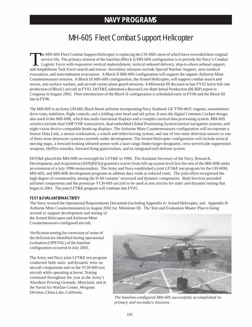
181
NAVY PROGRAMS
MH-60S Fleet Combat Support Helicopter
The baseline-configured MH-60S successfully accomplished itsprimary and secondary missions.
The MH-60S Fleet Combat Support Helicopter is replacing the CH-46D, most of which have exceeded their originalservice life. The primary mission of the baseline (Block I) MH-60S configuration is to provide the Navy’s CombatLogistic Force with responsive vertical replenishment, vertical onboard delivery, ship-to-shore airhead support,
and Amphibious Task Force search and rescue. Secondary missions include Special Warfare Support, aero-medicalevacuation, and noncombatant evacuation. A Block II MH-60S configuration will support the organic Airborne MineCountermeasures mission. A Block III MH-60S configuration, the Armed Helicopter, will support combat search andrescue, anti-surface warfare, and aircraft carrier plane guard missions. A Milestone III decision in late FY02 led to full-rateproduction of Block I aircraft in FY02. DOT&E submitted a Beyond Low-Rate Initial Production (BLRIP) report toCongress in August 2002. Fleet introduction of the Block II configuration is scheduled early in FY06 and the Block IIIlate in FY06.
The MH-60S is an Army UH-60L Black Hawk airframe incorporating Navy Seahawk GE T700-401C engines, transmission/drive train, stabilator, flight controls, and a folding rotor head and tail pylon. It uses the digital Common Cockpit design,also used in the MH-60R, which has multi-functional displays and a complex tactical data processing system. MH-60Savionics include dual UHF/VHF transceivers, dual embedded Global Positioning System/inertial navigation systems, andnight vision device-compatible heads-up displays. The Airborne Mine Countermeasures configuration will incorporate aSensor Data Link, a sensor workstation, a winch and tether/towing system, and one of two mine detection sensors or oneof three mine destructor systems currently under development. The Armed Helicopter configuration will include tacticalmoving maps, a forward-looking infrared sensor with a laser range finder/target designator, crew-served side suppressionweapons, Hellfire missiles, forward firing guns/rockets, and an integrated self-defense system.
DOT&E placed the MH-60R on oversight for LFT&E in 1998. The Assistant Secretary of the Navy, Research,Development, and Acquisition (ASN(RDA)) granted a waiver from full-up system level live fire test of the MH-60R underan extension of a July 1996 memorandum. The Army and Navy established a joint LFT&E test program for the UH-60M,MH-60S, and MH-60R development programs to address data voids at reduced costs. The joint effort recognized thehigh degree of commonality among the H-60 variants’ structural and dynamic components. Both Services providedairframe components and the prototype YCH-60S aircraft to be used as test articles for static and dynamic testing thatbegan in 2001. The joint LFT&E program will continue into FY05.
TEST & EVALUATION ACTIVITYThe Navy revised the Operational Requirements Document (including Appendix A- Armed Helicopter, and Appendix B-Airborne Mine Countermeasures) in August 2002 for Milestone III. The Test and Evaluation Master Plan is beingrevised to support development and testing ofthe Armed Helicopter and Airborne MineCountermeasures-configured aircraft.
Verification testing for correction of some ofthe deficiencies identified during operationalevaluation (OPEVAL) of the baselineconfiguration occurred in July 2003.
The Army and Navy joint LFT&E test programconducted both static and dynamic tests onaircraft components and on the YCH-60S testaircraft while operating at hover. Testingcontinued throughout the year at the Army’sAberdeen Proving Grounds, Maryland, and atthe Naval Air Warfare Center, Weapons Division, China Lake, California.
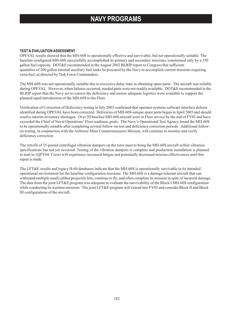
182
NAVY PROGRAMS
TEST & EVALUATION ASSESSMENTOPEVAL results showed that the MH-60S is operationally effective and survivable, but not operationally suitable. Thebaseline-configured MH-60S successfully accomplished its primary and secondary missions, constrained only by a 350gallon fuel capacity. DOT&E recommended in the August 2002 BLRIP report to Congress that sufficientquantities of 200 gallon internal auxiliary fuel tanks be procured by the Navy to accomplish current missions requiringextra fuel, as directed by Task Force Commanders.
The MH-60S was not operationally suitable due to excessive delay time in obtaining spare parts. The aircraft was reliableduring OPEVAL. However, when failures occurred, needed parts were not readily available. DOT&E recommended in theBLRIP report that the Navy act to correct the deficiency and ensure adequate logistics were available to support theplanned rapid introduction of the MH-60S to the Fleet.
Verification of Correction of Deficiency testing in July 2003 confirmed that operator-systems software interface defectsidentified during OPEVAL have been corrected. Deliveries of MH-60S-unique spare parts began in April 2003 and shouldresolve interim inventory shortages. Over 50 baseline MH-60S aircraft were in Fleet service by the end of FY03 and haveexceeded the Chief of Naval Operations’ Fleet readiness goals. The Navy’s Operational Test Agency found the MH-60Sto be operationally suitable after completing several follow-on test and deficiency correction periods. Additional follow-on testing, in conjunction with the Airborne Mine Countermeasures Mission, will continue to monitor and verifydeficiency correction.
The retrofit of 35-pound centrifugal vibration dampers on the rotor mast to bring the MH-60S aircraft within vibrationspecifications has not yet occurred. Testing of the vibration dampers is complete and production installation is plannedto start in 1QFY04. Crews will experience increased fatigue and potentially decreased mission effectiveness until thisrepair is made.
The LFT&E results and legacy H-60 databases indicate that the MH-60S is operationally survivable in its intendedoperational environment for the baseline configuration missions. The MH-60S is a damage-tolerant aircraft that canwithstand multiple small caliber projectile hits, continue to fly, and often complete its mission in spite of incurred damage.The data from the joint LFT&E program was adequate to evaluate the survivability of the Block I MH-60S configurationwhile conducting its wartime missions. The joint LFT&E program will extend into FY05 and consider Block II and BlockIII configurations of the aircraft.
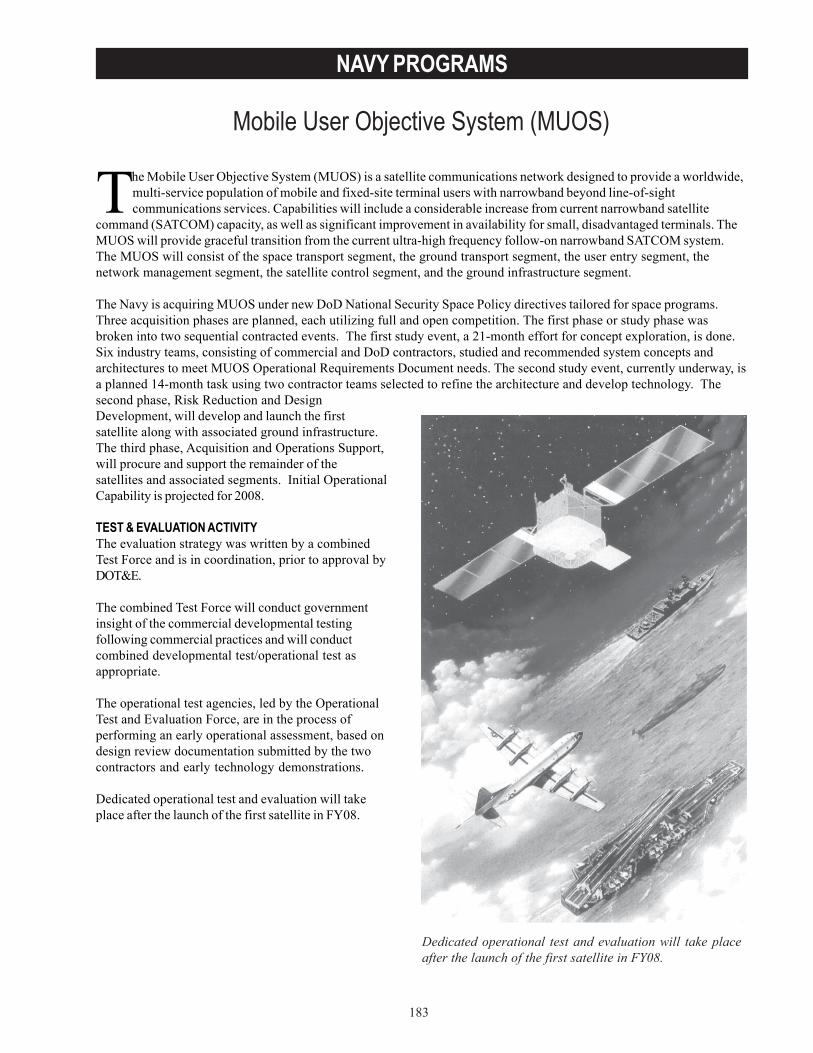
183
NAVY PROGRAMS
Mobile User Objective System (MUOS)
Dedicated operational test and evaluation will take placeafter the launch of the first satellite in FY08.
The Mobile User Objective System (MUOS) is a satellite communications network designed to provide a worldwide,multi-service population of mobile and fixed-site terminal users with narrowband beyond line-of-sightcommunications services. Capabilities will include a considerable increase from current narrowband satellite
command (SATCOM) capacity, as well as significant improvement in availability for small, disadvantaged terminals. TheMUOS will provide graceful transition from the current ultra-high frequency follow-on narrowband SATCOM system.The MUOS will consist of the space transport segment, the ground transport segment, the user entry segment, thenetwork management segment, the satellite control segment, and the ground infrastructure segment.
The Navy is acquiring MUOS under new DoD National Security Space Policy directives tailored for space programs.Three acquisition phases are planned, each utilizing full and open competition. The first phase or study phase wasbroken into two sequential contracted events. The first study event, a 21-month effort for concept exploration, is done.Six industry teams, consisting of commercial and DoD contractors, studied and recommended system concepts andarchitectures to meet MUOS Operational Requirements Document needs. The second study event, currently underway, isa planned 14-month task using two contractor teams selected to refine the architecture and develop technology. Thesecond phase, Risk Reduction and DesignDevelopment, will develop and launch the firstsatellite along with associated ground infrastructure.The third phase, Acquisition and Operations Support,will procure and support the remainder of thesatellites and associated segments. Initial OperationalCapability is projected for 2008.
TEST & EVALUATION ACTIVITYThe evaluation strategy was written by a combinedTest Force and is in coordination, prior to approval byDOT&E.
The combined Test Force will conduct governmentinsight of the commercial developmental testingfollowing commercial practices and will conductcombined developmental test/operational test asappropriate.
The operational test agencies, led by the OperationalTest and Evaluation Force, are in the process ofperforming an early operational assessment, based ondesign review documentation submitted by the twocontractors and early technology demonstrations.
Dedicated operational test and evaluation will takeplace after the launch of the first satellite in FY08.

184
NAVY PROGRAMS
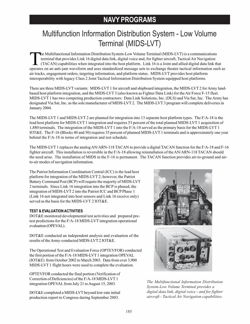
185
NAVY PROGRAMS
Multifunction Information Distribution System - Low VolumeTerminal (MIDS-LVT)
The Multifunctional Information Distribution System-Low Volume Terminal (MIDS-LVT) is a communicationsterminal that provides Link 16 digital data link, digital voice and, for fighter aircraft, Tactical Air Navigation(TACAN) capabilities when integrated into the host platform. Link 16 is a Joint and allied digital data link that
operates on an anti-jam waveform and uses standardized message sets to exchange theater tactical information such asair tracks, engagement orders, targeting information, and platform status. MIDS-LVT provides host platforminteroperability with legacy Class 2 Joint Tactical Information Distribution System equipped host platforms.
There are three MIDS-LVT variants: MIDS-LVT 1 for aircraft and shipboard integration, the MIDS-LVT 2 for Army land-based host platform integration, and the MIDS-LVT 3 (also known as Fighter Data Link) for the Air Force F-15 fleet.MIDS-LVT 1 has two competing production contractors: Data Link Solutions, Inc. (DLS) and Via Sat, Inc. The Army hasdesignated Via Sat, Inc. as the sole manufacturer of MIDS-LVT 2. The MIDS-LVT 3 program will complete deliveries inJanuary 2004.
The MIDS-LVT 1 and MIDS-LVT 2 are planned for integration into 13 separate host platform types. The F/A-18 is thelead host platform for MIDS-LVT 1 integration and requires 53 percent of the total planned MIDS-LVT 1 acquisition of1,880 terminals. The integration of the MIDS-LVT 1 into the F/A-18 served as the primary basis for the MIDS-LVT 1IOT&E. The F-16 (Blocks 40 and 50) requires 35 percent of planned MIDS-LVT 1 terminals and is approximately one yearbehind the F/A-18 in terms of integration and test schedule.
The MIDS-LVT 1 replaces the analog AN/ARN-118 TACAN to provide a digital TACAN function for the F/A-18 and F-16fighter aircraft. This installation is reversible in the F/A-18 allowing reinstallation of the AN/ARN-118 TACAN shouldthe need arise. The installation of MIDS in the F-16 is permanent. The TACAN function provides air-to-ground and air-to-air modes of navigation information.
The Patriot Information Coordination Central (ICC) is the lead hostplatform for integration of the MIDS-LVT 2; however, the PatriotBattery Command Post (BCP) will require the majority of MIDS-LVT2 terminals. Since Link 16 integration into the BCP is phased, theintegration of MIDS-LVT 2 into the Patriot ICC and BCP Phase 1(Link 16 not integrated into host sensors and Link 16 receive only)served as the basis for the MIDS-LVT 2 IOT&E.
TEST & EVALUATION ACTIVITIESDOT&E monitored developmental test activities and prepared pre-test predictions for the F/A-18 MIDS-LVT integration operationalevaluation (OPEVAL).
DOT&E conducted an independent analysis and evaluation of theresults of the Army-conducted MIDS-LVT 2 IOT&E.
The Operational Test and Evaluation Force (OPTEVFOR) conductedthe first portion of the F/A-18 MIDS-LVT 1 integration OPEVAL(IOT&E) from October 2002 to March 2003. Data from over 3,900MIDS-LVT 1 flight hours were used to complete the evaluation.
OPTEVFOR conducted the final portion (Verification ofCorrection of Deficiencies) of the F/A-18 MIDS-LVT 1integration OPEVAL from July 21 to August 15, 2003.
DOT&E completed a MIDS-LVT beyond low-rate initialproduction report to Congress during September 2003.
The Multifunctional Information DistributionSystem-Low Volume Terminal provides adigital data link, digital voice - and for fighteraircraft - Tactical Air Navigation capabilities.
186
NAVY PROGRAMS
TEST & EVALUATION ASSESSMENTDOT&E concluded that F/A-18 MIDS-LVT testing was adequate to evaluate operational effectiveness and operationalsuitability.
DOT&E, OPTEVFOR, and the Navy’s operational test squadron, Air Test and Evaluation Squadron Nine (VX-9) agreethat the F/A-18 MIDS-LVT 1 integration was operationally effective but not operationally suitable.
• Principally, the air-to-ground TACAN function performance was not stable and was unacceptable foraircraft carrier approach operations. TACAN deficiencies included frequent loss of magnetic bearing andrange information while in marshal and approach patterns for those TACAN stations operating in a set ofnotched radio frequencies, and overall reliability regarding the availability of TACAN air-to-air and air-to-ground functions.
• Built-in test (BIT) exhibited excessive false alarms, and the intermediate maintenance capability was notready for evaluation.
• Integration testing indicated longer than required time to initialize the MIDS-LVT terminal and enter theLink 16 network while preparing the aircraft for flight.
• The F/A-18 MIDS-LVT integration does not include reliable transmission and receipt of emergencymessages such as “Bailout” or “Aircraft Down.”
• The F/A-18 and F-15E cannot exchange precision ground target coordinates on Link 16.
DOT&E continues to monitor F-16 MIDS-LVT 1 integration and emerging results indicate integration issues with theMIDS-LVT 1 TACAN function, terminal initialization and initial network entry, BIT false alarms, and human factors.
The Army IOT&E and preceding developmental tests indicated MIDS-LVT 2 and Patriot ICC host platform integrationissues leading to loss of Link 16 data exchange.
• The testing also indicated that the MIDS-LVT 2 did not meet reliability requirements. A follow-onlaboratory test conducted by the Army Test and Evaluation Command indicated that terminal modificationsresulted in meeting the laboratory reliability requirement of 1,000 hours mean time between failures.
• The Army Research Laboratory conducted a very comprehensive information assurance (IA) vulnerabilityanalysis of the MIDS-LVT 2 terminal and the data indicated some potential vulnerability with moderate tolow risk of occurrence.
DOT&E makes the following conclusions with respect to MIDS systems:
• A Follow-on test and evaluation is needed to verify that the Navy has corrected the 22 major – andnumerous minor – deficiencies identified in the IOT&E test reports for the F/A-18 MIDS integration.
• The F-16 MIDS-LVT 1 integration should not proceed to IOT&E until the TACAN and other emergingintegration issues have been addressed.
• The Army should employ the Patriot ICC MIDS-LVT 2 in a dense Link 16 environment or large Forceexercise to determine if the data exchange halts have been resolved during periods of high data throughput.
• The MIDS-LVT Program Manager should coordinate for an in-depth IA vulnerability assessment for theMIDS-LVT 1; establish a program to mitigate the vulnerabilities; and conduct a follow-on and periodictesting of MIDS-LVT 1 and MIDS-LVT 2 IA vulnerability.
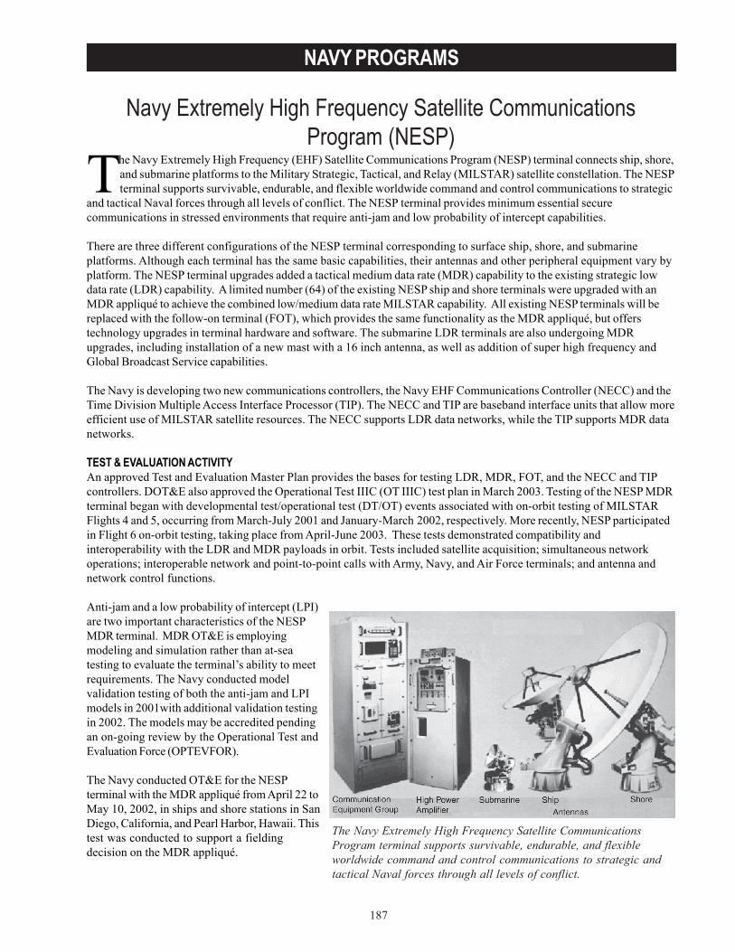
187
NAVY PROGRAMS
Navy Extremely High Frequency Satellite CommunicationsProgram (NESP)
The Navy Extremely High Frequency Satellite CommunicationsProgram terminal supports survivable, endurable, and flexibleworldwide command and control communications to strategic andtactical Naval forces through all levels of conflict.
The Navy Extremely High Frequency (EHF) Satellite Communications Program (NESP) terminal connects ship, shore,and submarine platforms to the Military Strategic, Tactical, and Relay (MILSTAR) satellite constellation. The NESPterminal supports survivable, endurable, and flexible worldwide command and control communications to strategic
and tactical Naval forces through all levels of conflict. The NESP terminal provides minimum essential securecommunications in stressed environments that require anti-jam and low probability of intercept capabilities.
There are three different configurations of the NESP terminal corresponding to surface ship, shore, and submarineplatforms. Although each terminal has the same basic capabilities, their antennas and other peripheral equipment vary byplatform. The NESP terminal upgrades added a tactical medium data rate (MDR) capability to the existing strategic lowdata rate (LDR) capability. A limited number (64) of the existing NESP ship and shore terminals were upgraded with anMDR appliqué to achieve the combined low/medium data rate MILSTAR capability. All existing NESP terminals will bereplaced with the follow-on terminal (FOT), which provides the same functionality as the MDR appliqué, but offerstechnology upgrades in terminal hardware and software. The submarine LDR terminals are also undergoing MDRupgrades, including installation of a new mast with a 16 inch antenna, as well as addition of super high frequency andGlobal Broadcast Service capabilities.
The Navy is developing two new communications controllers, the Navy EHF Communications Controller (NECC) and theTime Division Multiple Access Interface Processor (TIP). The NECC and TIP are baseband interface units that allow moreefficient use of MILSTAR satellite resources. The NECC supports LDR data networks, while the TIP supports MDR datanetworks.
TEST & EVALUATION ACTIVITYAn approved Test and Evaluation Master Plan provides the bases for testing LDR, MDR, FOT, and the NECC and TIPcontrollers. DOT&E also approved the Operational Test IIIC (OT IIIC) test plan in March 2003. Testing of the NESP MDRterminal began with developmental test/operational test (DT/OT) events associated with on-orbit testing of MILSTARFlights 4 and 5, occurring from March-July 2001 and January-March 2002, respectively. More recently, NESP participatedin Flight 6 on-orbit testing, taking place from April-June 2003. These tests demonstrated compatibility andinteroperability with the LDR and MDR payloads in orbit. Tests included satellite acquisition; simultaneous networkoperations; interoperable network and point-to-point calls with Army, Navy, and Air Force terminals; and antenna andnetwork control functions.
Anti-jam and a low probability of intercept (LPI)are two important characteristics of the NESPMDR terminal. MDR OT&E is employingmodeling and simulation rather than at-seatesting to evaluate the terminal’s ability to meetrequirements. The Navy conducted modelvalidation testing of both the anti-jam and LPImodels in 2001with additional validation testingin 2002. The models may be accredited pendingan on-going review by the Operational Test andEvaluation Force (OPTEVFOR).
The Navy conducted OT&E for the NESPterminal with the MDR appliqué from April 22 toMay 10, 2002, in ships and shore stations in SanDiego, California, and Pearl Harbor, Hawaii. Thistest was conducted to support a fieldingdecision on the MDR appliqué.
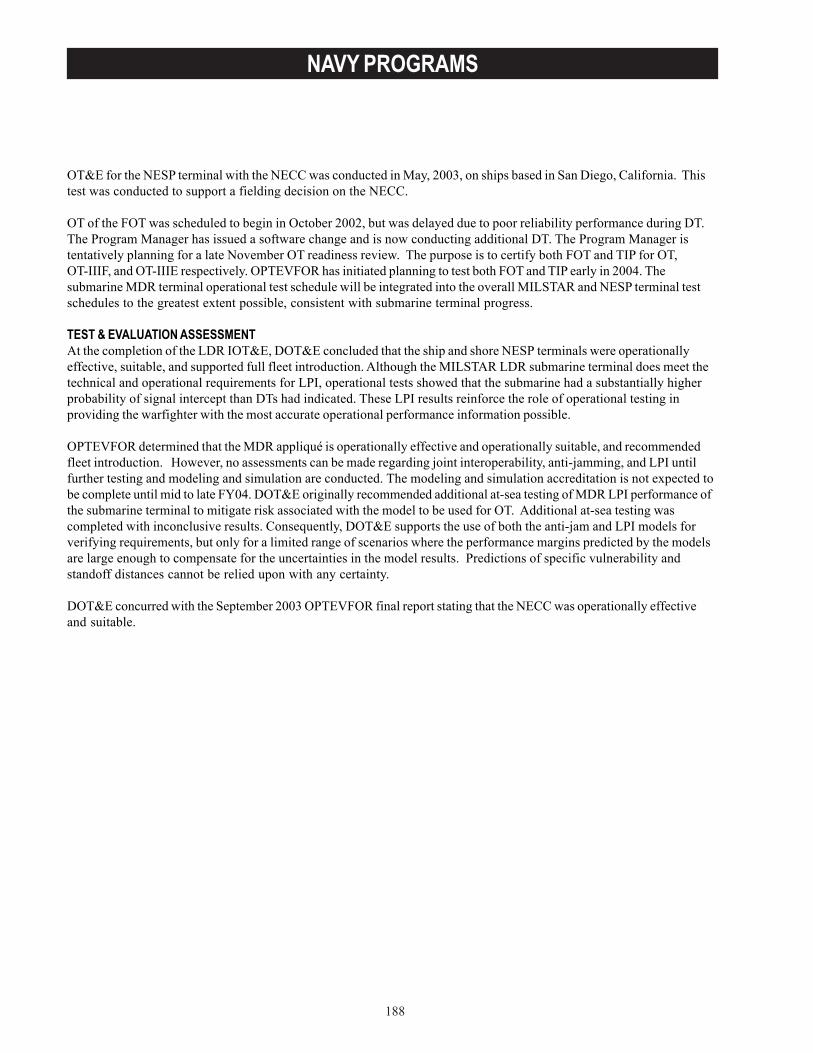
188
NAVY PROGRAMS
OT&E for the NESP terminal with the NECC was conducted in May, 2003, on ships based in San Diego, California. Thistest was conducted to support a fielding decision on the NECC.
OT of the FOT was scheduled to begin in October 2002, but was delayed due to poor reliability performance during DT.The Program Manager has issued a software change and is now conducting additional DT. The Program Manager istentatively planning for a late November OT readiness review. The purpose is to certify both FOT and TIP for OT,OT-IIIF, and OT-IIIE respectively. OPTEVFOR has initiated planning to test both FOT and TIP early in 2004. Thesubmarine MDR terminal operational test schedule will be integrated into the overall MILSTAR and NESP terminal testschedules to the greatest extent possible, consistent with submarine terminal progress.
TEST & EVALUATION ASSESSMENTAt the completion of the LDR IOT&E, DOT&E concluded that the ship and shore NESP terminals were operationallyeffective, suitable, and supported full fleet introduction. Although the MILSTAR LDR submarine terminal does meet thetechnical and operational requirements for LPI, operational tests showed that the submarine had a substantially higherprobability of signal intercept than DTs had indicated. These LPI results reinforce the role of operational testing inproviding the warfighter with the most accurate operational performance information possible.
OPTEVFOR determined that the MDR appliqué is operationally effective and operationally suitable, and recommendedfleet introduction. However, no assessments can be made regarding joint interoperability, anti-jamming, and LPI untilfurther testing and modeling and simulation are conducted. The modeling and simulation accreditation is not expected tobe complete until mid to late FY04. DOT&E originally recommended additional at-sea testing of MDR LPI performance ofthe submarine terminal to mitigate risk associated with the model to be used for OT. Additional at-sea testing wascompleted with inconclusive results. Consequently, DOT&E supports the use of both the anti-jam and LPI models forverifying requirements, but only for a limited range of scenarios where the performance margins predicted by the modelsare large enough to compensate for the uncertainties in the model results. Predictions of specific vulnerability andstandoff distances cannot be relied upon with any certainty.
DOT&E concurred with the September 2003 OPTEVFOR final report stating that the NECC was operationally effectiveand suitable.
189
NAVY PROGRAMS
Navy Marine Corps Intranet (NMCI)
The Navy Marine Corps Intranet (NMCI) is an information technology (IT) service contract intended to providereliable, secure, and seamless information services to the shore-based components of the Navy and Marine Corps.NMCI infrastructure and services will not extend to afloat or deployed units. However, NMCI will provide
deployable workstations to deployed forces to be used with the Navy’s Integrated Shipboard Network System and theMarine Corps Tactical Network. NMCI supports new processes and enables new initiatives such as knowledgemanagement, distance learning, and tele-medicine to improve the quality of life for Department of the Navy employeesand support personnel. NMCI will provide IT services using a seat management contract that delivers comprehensiveinformation services through a common computing and communications environment. Seat management is a method ofcoordinating all the workstations in an enterprise network by overseeing the installation, operation, and maintenance ofhardware and software at each workstation. Upgrades, modernization, and technology refreshment will occur over theNMCI contract life cycle.
The NMCI contract is for the procurement of IT services (not systems) based upon a commercial model of service-levelagreements. Under this model, emphasis is placed on the verification, validation, and monitoring of the end-user servicesand not on the underlying infrastructure or systems. The architecture will support Navy and Marine Corps bases,camps, stations, and activities in the Continental U.S., Alaska, Hawaii, Puerto Rico, and Guantanamo Bay, Cuba, for anestimated 360,000 seats. It is anticipated that a total of 72 server farms, six network operations centers, and two help deskcenters will be required.
The Navy Operational Test and Evaluation Force (OPTEVFOR) conducted a baseline system assessment (BSA) in FY01on the pre-NMCI IT configuration, including hardware, software, security, and current performance levels at four Navalaviation sites. DOT&E evaluated the results of the BSA and will reference those results against the future system (whichwill be evaluated during operational evaluation (OPEVAL)) to measure improvements provided by NMCI. Due to thelarge scale and complexity of the NMCI initiative, implementation will take several years to reach full operating capability.
TEST & EVALUATION ACTIVITYDOT&E approved an updated Test and Evaluation Strategy for NMCI on September 4, 2002.
OPTEVFOR conducted anoperational assessment (OA) duringSeptember-October 2002 to assessNMCI readiness for OPEVAL and tosupport further initial deployment.This OA was conducted at fiveoperational sites, including fourNaval aviation sites and Fleet ForcesCommand, under a DOT&E-approved test plan.
The United States Marine Corps(USMC) conducted an OA for theNMCI deployable solutions at aMarine Corps base in Hawaii duringFebruary-March 2003.
OPTEVFOR conducted an OPEVALduring October-November 2003.
The Navy Marine Corps Intranet is an information technology service contractintended to provide reliable, secure, and seamless information services to theshore-based components of the Navy and Marine Corps.

190
NAVY PROGRAMS
TEST & EVALUATION ASSESSMENTThe September-October 2002 OA was unable to provide a comprehensive review of NMCI operations because many ofthe target capabilities were either not yet available or the data collection process was not sufficiently mature to producethe required data for evaluation. Working with the partial data obtained during the OA, OPTEVFOR found only 6 of the16 critical operational issues (COIs) were met. Five COIs (customer service and support, network support,interoperability, mission support, and logistic supportability) of the remaining ten posed high risk for failure to meetrequirements during the OPEVAL, four COIs posed a moderate risk, and one COI was not tested. Overall, 72 majordeficiencies were identified across nine COIs. The Program Director initiated a corrective action plan, and in April 2003,OPTEVFOR began a VCD to confirm the fixes. The VCD completed in October 2003. DOT&E assessment is ongoing.
The USMC OA of the NMCI deployable solutions identified several deficiencies. Field operators could not conducteffective reachback from deployed positions, nor could they access the NMCI help desk.
OPTEVFOR conducted an OPEVAL during October-November 2003 to assess the operational effectiveness andoperational suitability of NMCI at five test sites: Naval Air Facility Washington, DC; Naval Air Systems CommandHeadquarters, Patuxent River, Maryland; Naval Air Station Lemoore, California; Naval Reserve Center Lemoore,California; and Fleet Forces Command, Virginia. An aircraft carrier was to be part of the OPEVAL to evaluate thedeployable solutions, but none were available during the OPEVAL period. OPTEVFOR plans to evaluate the deployablesolutions on a carrier in a follow-on operational test. DOT&E’s assessment of the OPEVAL is ongoing.

191
NAVY PROGRAMS
Navy Standard Integrated Personnel System (NSIPS)
The Navy Standard Integrated Personnel System will consolidate the Navyactive and reserve field source personnel data collection systems, bothashore and afloat.
The Navy Standard Integrated Personnel System (NSIPS) will consolidate the Navy active and reserve field sourcepersonnel data collection systems, both ashore and afloat. The objective is to produce a standard, single point-of-entry system for all personnel and pay information. The primary interfaces for NSIPS will be with systems of
the Defense Finance and Accounting Service. NSIPS was to provide pay and personnel functionality for the NavyReserve force in Release 0, and for the Navy active force in Release 1. The client-server architecture will haveinformation stored at the local level and at the regional level. A corporate-level database will be used for planning andanalysis purposes.
In 1997, the program manager developed a prototype system to prove the planned architecture and user friendliness ofthe graphical user interface and selected PeopleSoft® as the basic human resource software package. The ProgramManagement Office customized this Release 0 package to address the Navy reserve requirements. The Release 0operational evaluation (OPEVAL) began in mid-September 1999. DOT&E noted many deficiencies, including inaccuratetransmittal logs, missing e-mail functionality, corrupted reports, and inadequate training. The program managerimmediately developed a plan to address these shortcomings. Beginning in October 1999, the Navy installed threeseparate software builds to fix the problems and OPEVAL resumed in November 1999. In January 2000, DOT&Econcurred with the Operational Test and Evaluation Force’s (OPTEVFOR) conclusion that NSIPS Release 0 isoperationally effective and operationally suitable, and recommended approval for fleet introduction. NSIPS Release 0,which replaced the Reserve Standard Training, Administration, and Readiness Support (Manpower and Personnel)System, is operational at 260 reserve sites.
In June 2000, the program manager announced a four-month schedule slip in software development and proposed thatRelease 1 be delivered in two separate increments. The first increment (Release 0.2) would address personnel actions andthe second increment (Release 1) would address pay actions for the Navy active force. OPTEVFOR conducted theOPEVAL of Release 0.2 from April 23to May 4, 2001. The resultsindicated that two effectiveness andeight (of ten) suitability criticaloperational issues were resolvedsatisfactorily. Interoperability anddocumentation were unsatisfactory.The PMO made the corrections andthe Navy conducted a follow-onVerification of CorrectedDeficiencies (VCD) test in July 2001.Test results indicated thatpreviously identified deficiencieshad been corrected. The AssistantSecretary of Defense (Command,Control, Communications, andIntelligence) approved the NSIPSRelease 0.2 for fleet introduction inSeptember 2001.
OPTEVFOR conducted the OPEVALof NSIPS Release 1 from June 10through July 12, 2002, at sevenoperational test sites. OPEVALresults revealed that while NSIPSRelease 1 was able to meet many ofits required performance thresholds,it did not meet the key performance
192
NAVY PROGRAMS
parameter of 98 percent accuracy in processing personnel or pay transactions (only 89 percent accuracy was achieved).Of the 13 external system interfaces, JITC certified only six as interoperable. Because of these and other deficiencies,OPTEVFOR considered NSIPS Release 1 operationally ineffective and operationally unsuitable for fleet introduction.DOT&E concurred and required a follow-on test to confirm corrections to the identified deficiencies.
TEST & EVALUATION ACTIVITY• DOT&E approved the NSIPS TEMP in May 2001.• On March 10-19, 2003, OPTEVFOR conducted a VCD at Personnel Support Detachment (PSD) Newport, Rhode
Island; PSD Recruit Training Command Great Lakes, Illinois; PSD Guam; and PSD Point Loma, California, toverify the corrections.
TEST & EVALUATION ASSESSMENTThe VCD results revealed that most previously identified deficiencies were rectified, with some human factorsdeficiencies remaining. Several of these human factors deficiencies are associated with Navy policies. For example,NSIPS Release 1 does not allow for assisting customers who are not assigned to the command and does not provideflexibility when assisting Reservists and officer accessions (for security and information integrity reasons). NSIPS haltsorder processing if errors are encountered and it does not allow PSD to correct erroneous data without intervention fromthe Navy Bureau of Personnel. Other human-factor deficiencies are related to report formatting and dependent dataentry. DOT&E recommended that the program manager work with the functional proponent to review existing Navypolicies with regard to assisting customers not assigned to the command and providing more flexible support toreservists and officer accessions. If the Navy policies can be modified to allow additional accessibility and flexibilitywithout sacrificing security and information integrity, then the program manager should modify the NSIPS softwareaccordingly. Any major revisions to the system must be evaluated by OPTEVFOR and DOT&E.
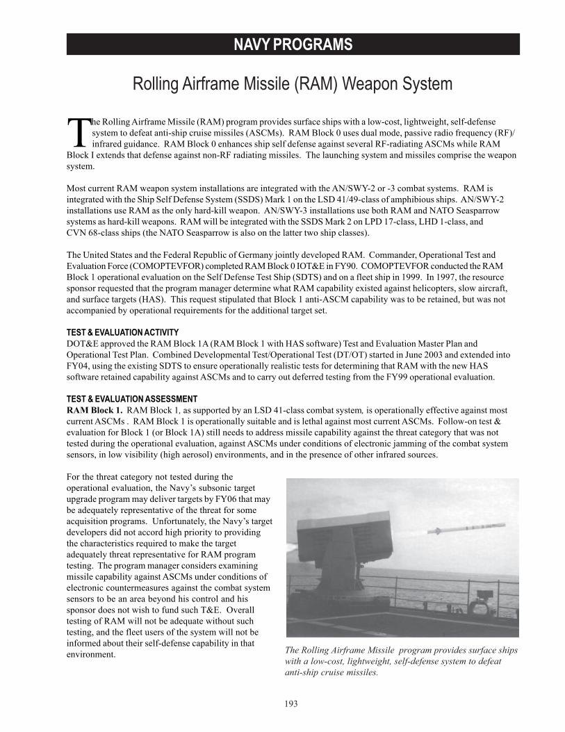
193
NAVY PROGRAMS
Rolling Airframe Missile (RAM) Weapon System
The Rolling Airframe Missile (RAM) program provides surface ships with a low-cost, lightweight, self-defensesystem to defeat anti-ship cruise missiles (ASCMs). RAM Block 0 uses dual mode, passive radio frequency (RF)/infrared guidance. RAM Block 0 enhances ship self defense against several RF-radiating ASCMs while RAM
Block I extends that defense against non-RF radiating missiles. The launching system and missiles comprise the weaponsystem.
Most current RAM weapon system installations are integrated with the AN/SWY-2 or -3 combat systems. RAM isintegrated with the Ship Self Defense System (SSDS) Mark 1 on the LSD 41/49-class of amphibious ships. AN/SWY-2installations use RAM as the only hard-kill weapon. AN/SWY-3 installations use both RAM and NATO Seasparrowsystems as hard-kill weapons. RAM will be integrated with the SSDS Mark 2 on LPD 17-class, LHD 1-class, andCVN 68-class ships (the NATO Seasparrow is also on the latter two ship classes).
The United States and the Federal Republic of Germany jointly developed RAM. Commander, Operational Test andEvaluation Force (COMOPTEVFOR) completed RAM Block 0 IOT&E in FY90. COMOPTEVFOR conducted the RAMBlock 1 operational evaluation on the Self Defense Test Ship (SDTS) and on a fleet ship in 1999. In 1997, the resourcesponsor requested that the program manager determine what RAM capability existed against helicopters, slow aircraft,and surface targets (HAS). This request stipulated that Block 1 anti-ASCM capability was to be retained, but was notaccompanied by operational requirements for the additional target set.
TEST & EVALUATION ACTIVITYDOT&E approved the RAM Block 1A (RAM Block 1 with HAS software) Test and Evaluation Master Plan andOperational Test Plan. Combined Developmental Test/Operational Test (DT/OT) started in June 2003 and extended intoFY04, using the existing SDTS to ensure operationally realistic tests for determining that RAM with the new HASsoftware retained capability against ASCMs and to carry out deferred testing from the FY99 operational evaluation.
TEST & EVALUATION ASSESSMENTRAM Block 1. RAM Block 1, as supported by an LSD 41-class combat system, is operationally effective against mostcurrent ASCMs . RAM Block 1 is operationally suitable and is lethal against most current ASCMs. Follow-on test &evaluation for Block 1 (or Block 1A) still needs to address missile capability against the threat category that was nottested during the operational evaluation, against ASCMs under conditions of electronic jamming of the combat systemsensors, in low visibility (high aerosol) environments, and in the presence of other infrared sources.
For the threat category not tested during theoperational evaluation, the Navy’s subsonic targetupgrade program may deliver targets by FY06 that maybe adequately representative of the threat for someacquisition programs. Unfortunately, the Navy’s targetdevelopers did not accord high priority to providingthe characteristics required to make the targetadequately threat representative for RAM programtesting. The program manager considers examiningmissile capability against ASCMs under conditions ofelectronic countermeasures against the combat systemsensors to be an area beyond his control and hissponsor does not wish to fund such T&E. Overalltesting of RAM will not be adequate without suchtesting, and the fleet users of the system will not beinformed about their self-defense capability in thatenvironment. The Rolling Airframe Missile program provides surface ships
with a low-cost, lightweight, self-defense system to defeatanti-ship cruise missiles.
194
NAVY PROGRAMS
RAM HAS Mode. The program sponsor has not issued detailed performance goals for RAM HAS. From an OT&Eperspective, the absence of operational requirements undermines objective assessment of operational test results andhampers the program manager’s ability to understand the impact of performance trades on mission accomplishment andoperational effectiveness against HAS targets. In addition to the combined DT/OT against ASCMs in FY03/FY04 on theSDTS, developmental testing is planned in FY04 with the same Block 1A rounds against a small number of representativeHAS targets from an upgraded RAM launcher operated in a standalone mode. The Navy will conduct DT/OT from amanned ship against an aerial target drone in FY05/FY06, accompanied by a maintenance demonstration and evaluationof the Mod 3 launcher.
During the initial flight tests of the combined DT/OT of Block 1A, a defect in microcircuitry of the guidance system wasdiscovered. Isolating the problem and locating missiles containing the defective components delayed completion of DT/OT until FY04. However, the value of operationally realistic operational testing conducted with the SDTS was reaffirmedduring later tests in September 2003. Problems with SSDS Mark 1 and with the RAM HAS software were discoveredduring a realistic test against ASCMs that could not have been conducted with a manned ship.
In November 2002, the Navy discovered that the seeker-focus shifts over time which could reduce missile performanceafter extended storage. The problem is understood and a fix is being implemented.
RAM Block 0 and Block 1 LFT&E evaluated lethality against various ASCMs. RAM HAS was designated for lethalityLFT&E oversight based on its new target set. There is little data on RAM warhead lethality against those targets.Additional tests are needed for information on the lethality of the weapon and for the development of simulations thatcan be used to predict lethality/effectiveness against threats under a variety of scenarios. The LFT&E strategy for RAMHAS includes ground testing of the warhead against whole targets and/or components, flight testing, and simulation-based analyses.
As with any shipboard combat system required to provide self defense with short range weapons such as RAM and theEvolved Sea Sparrow Missile, safe and effective OT&E requires the use of an SDTS. The current SDTS, Ex-Decatur, isnearly 50 years old and evidences severe deterioration. The current combined DT/OT is probably the last testing thatwill be conducted with this ship. The first was in 1994 and several important weapons and combat system elements havebeen realistically tested over the years. The replacement SDTS, a decommissioned Spruance-class destroyer, is at PortHueneme, California, awaiting conversion for the next testing. As DOT&E has noted in the discussion of the LPD 17 andthe SSDS, the adequacy of the OT&E for both programs (and approval of the test plans) hinges on having an LPD 17-representative combat system on the new SDTS, along with funded resources, including RAMs and targets, for thetesting. This should be funded in time to support the LPD 17 FY06/FY07 operational evaluation before the ships areready for deployment.
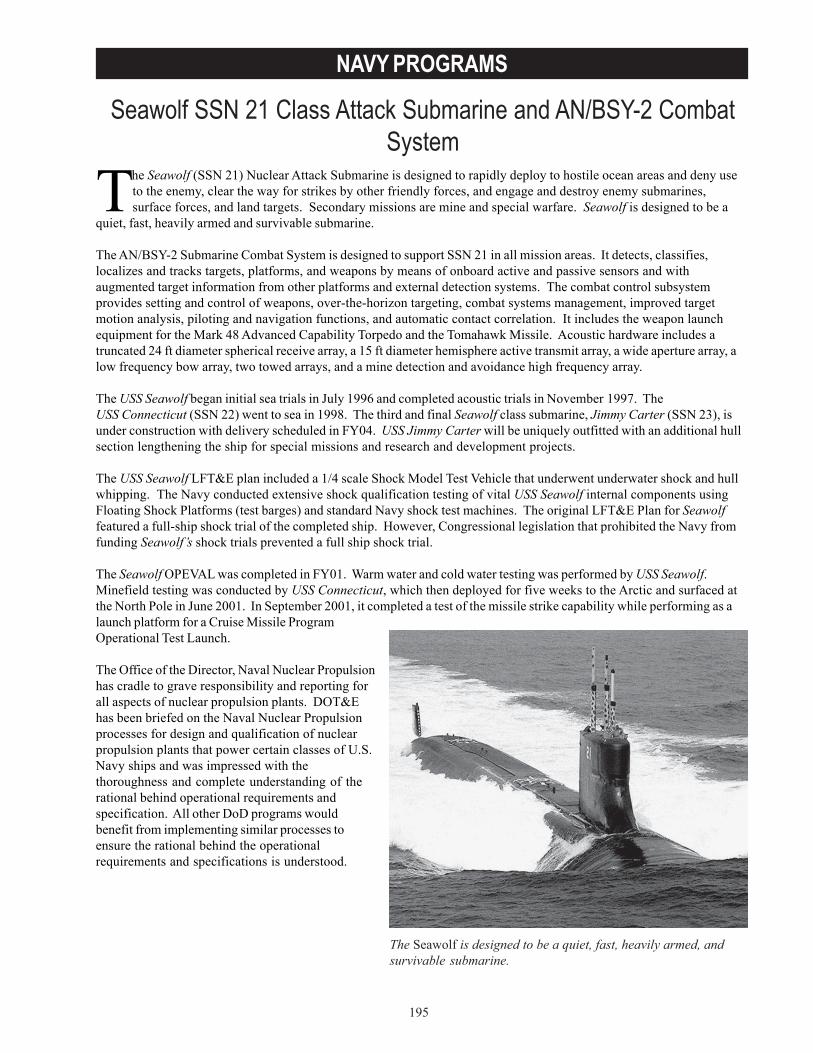
195
NAVY PROGRAMS
Seawolf SSN 21 Class Attack Submarine and AN/BSY-2 CombatSystem
The Seawolf (SSN 21) Nuclear Attack Submarine is designed to rapidly deploy to hostile ocean areas and deny useto the enemy, clear the way for strikes by other friendly forces, and engage and destroy enemy submarines,surface forces, and land targets. Secondary missions are mine and special warfare. Seawolf is designed to be a
quiet, fast, heavily armed and survivable submarine.
The AN/BSY-2 Submarine Combat System is designed to support SSN 21 in all mission areas. It detects, classifies,localizes and tracks targets, platforms, and weapons by means of onboard active and passive sensors and withaugmented target information from other platforms and external detection systems. The combat control subsystemprovides setting and control of weapons, over-the-horizon targeting, combat systems management, improved targetmotion analysis, piloting and navigation functions, and automatic contact correlation. It includes the weapon launchequipment for the Mark 48 Advanced Capability Torpedo and the Tomahawk Missile. Acoustic hardware includes atruncated 24 ft diameter spherical receive array, a 15 ft diameter hemisphere active transmit array, a wide aperture array, alow frequency bow array, two towed arrays, and a mine detection and avoidance high frequency array.
The USS Seawolf began initial sea trials in July 1996 and completed acoustic trials in November 1997. TheUSS Connecticut (SSN 22) went to sea in 1998. The third and final Seawolf class submarine, Jimmy Carter (SSN 23), isunder construction with delivery scheduled in FY04. USS Jimmy Carter will be uniquely outfitted with an additional hullsection lengthening the ship for special missions and research and development projects.
The USS Seawolf LFT&E plan included a 1/4 scale Shock Model Test Vehicle that underwent underwater shock and hullwhipping. The Navy conducted extensive shock qualification testing of vital USS Seawolf internal components usingFloating Shock Platforms (test barges) and standard Navy shock test machines. The original LFT&E Plan for Seawolffeatured a full-ship shock trial of the completed ship. However, Congressional legislation that prohibited the Navy fromfunding Seawolf’s shock trials prevented a full ship shock trial.
The Seawolf OPEVAL was completed in FY01. Warm water and cold water testing was performed by USS Seawolf.Minefield testing was conducted by USS Connecticut, which then deployed for five weeks to the Arctic and surfaced atthe North Pole in June 2001. In September 2001, it completed a test of the missile strike capability while performing as alaunch platform for a Cruise Missile ProgramOperational Test Launch.
The Office of the Director, Naval Nuclear Propulsionhas cradle to grave responsibility and reporting forall aspects of nuclear propulsion plants. DOT&Ehas been briefed on the Naval Nuclear Propulsionprocesses for design and qualification of nuclearpropulsion plants that power certain classes of U.S.Navy ships and was impressed with thethoroughness and complete understanding of therational behind operational requirements andspecification. All other DoD programs wouldbenefit from implementing similar processes toensure the rational behind the operationalrequirements and specifications is understood.
The Seawolf is designed to be a quiet, fast, heavily armed, andsurvivable submarine.
196
NAVY PROGRAMS
TEST & EVALUATION ACTIVITYTest and evaluation activity in 2003 consisted of a short trip to the Arctic by USS Connecticut to confirm retest fixes fordeficiencies and to conduct developmental testing of under-ice software for Mark 48 torpedoes.
DOT&E issued a classified combined OT&E/LFT&E Report on the USS Seawolf and the BSY-2 Submarine CombatControl System on July 15, 2003.
TEST & EVALUATION ASSESSMENTAlthough several requirement thresholds were not met, DOT&E evaluated the Seawolf Class Nuclear Attack Submarineand the BSY-2 Submarine Combat Control System as operationally effective and operationally suitable. Details of USSSeawolf’s performance during OPEVAL are available in the classified OT&E/LFT&E Report. The Seawolf and the BSY-2Combat Control System were adequately tested to assess operational effectiveness and suitability, but the lack of a fullship shock trial prevented full assessment of Seawolf’s survivability. However, the Seawolf design incorporatesnumerous features that improve survivability over previous classes. These features make Seawolf less susceptible andvulnerable and thus, considered more survivable than the Los Angeles class submarine.
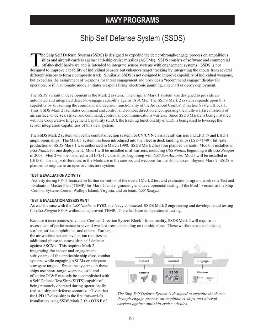
197
NAVY PROGRAMS
Ship Self Defense System (SSDS)
The Ship Self Defense System is designed to expedite the detect-through-engage process on amphibious ships and aircraftcarriers against anti-ship cruise missiles.
The Ship Self Defense System (SSDS) is designed to expedite the detect-through-engage process on amphibiousships and aircraft carriers against anti-ship cruise missiles (ASCMs). SSDS consists of software and commercialoff-the-shelf hardware and is intended to integrate sensor systems with engagement systems. SSDS is not
designed to improve capability of individual sensors but enhances target tracking by integrating the inputs from severaldifferent sensors to form a composite track. Similarly, SSDS is not designed to improve capability of individual weapons,but expedites the assignment of weapons for threat engagement and provides a “recommend engage” display foroperators, or if in automatic mode, initiates weapons firing, electronic jamming, and chaff or decoy deployment.
The SSDS variant in development is the Mark 2 system. The original Mark 1 system was designed to provide anautomated and integrated detect-to-engage capability against ASCMs. The SSDS Mark 2 system expands upon thiscapability by subsuming the command and decision functionality of the Advanced Combat Direction System Block 1.Thus, SSDS Mark 2 facilitates command and control and combat direction encompassing the multi-warfare missions ofair, surface, undersea, strike, and command, control, and communications warfare. Since SSDS Mark 2 is being installedwith the Cooperative Engagement Capability (CEC), the tracking functionality of CEC is being used to leverage thesensor integration capabilities of this new system.
The SSDS Mark 2 system will be the combat direction system for CV/CVN class aircraft carriers and LPD 17 and LHD 1amphibious ships. The Mark 1 system has been introduced into the Fleet in dock landing ships (LSD 41/49); full-rateproduction of SSDS Mark 1 was authorized in March 1998. SSDS Mark 2 has four planned variants. Mod 0 is installed inUSS Nimitz for one deployment. Mod 1 will be installed in all carriers, including USS Nimitz, beginning with USS Reaganin 2003. Mod 2 will be installed in all LPD 17 class ships, beginning with USS San Antonio. Mod 3 will be installed inLHD 8. The major differences in the Mods are in the sensors and weapons for the ship classes. Beyond Mark 2, SSDS isplanned to migrate to an open architecture system.
TEST & EVALUATION ACTIVITYActivity during FY03 focused on further definition of the overall Mark 2 test and evaluation program, work on a Test andEvaluation Master Plan (TEMP) for Mark 2, and engineering and developmental testing of the Mod 1 version at the ShipCombat Systems Center, Wallops Island, Virginia, and on board USS Reagan.
TEST & EVALUATION ASSESSMENTAs was the case with the USS Nimitz in FY02, the Navy conducted SSDS Mark 2 engineering and developmental testingfor USS Reagan FY03 without an approved TEMP. There has been no operational testing.
Because it incorporates Advanced Combat Direction System Block 1 functionality, SSDS Mark 2 will require anassessment of performance in several warfare areas, depending on the ship class. These warfare areas include air,surface, strike, amphibious, and others. Further,the air warfare test and evaluation requires anadditional phase to assess ship self defenseagainst ASCMs. This requires Mark 2integrating the sensor and engagementsubsystems of the applicable ship class combatsystems while engaging ASCMs or adequatesurrogate targets. Since the systems on theseships use short-range weapons, safe andeffective OT&E can only be accomplished witha Self Defense Test Ship (SDTS) capable ofbeing remotely operated during operationallyrealistic ship air defense scenarios. Given thatthe LPD 17-class ship is the first forward-fitinstallation using SSDS Mark 2, this OT&E of
198
NAVY PROGRAMS
Mark 2 must be combined with the SDTS phase of the LPD 17 operational evaluation, projected for FY06-FY07. Delayingthe testing will result in several ships being deployed with combat systems that have not been adequately tested.
DOT&E’s concerns on this issue are clear. DOT&E approval of TEMPs and operational test plans for LPD 17 and SSDSwill hinge on an adequate OT&E strategy. An adequate strategy includes a separate SDTS phase within the FY06-FY07LPD 17 OPEVAL window with an LPD 17-representative combat system engaging threat-representative ASCM targetswith Rolling Airframe Missiles.
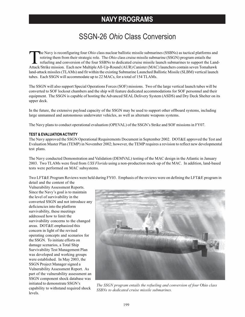
199
NAVY PROGRAMS
SSGN-26 Ohio Class Conversion
The SSGN program entails the refueling and conversion of four Ohio classSSBNs to dedicated cruise missile submarines.
The Navy is reconfiguring four Ohio class nuclear ballistic missile submarines (SSBNs) as tactical platforms andretiring them from their strategic role. The Ohio class cruise missile submarine (SSGN) program entails therefueling and conversion of the four SSBNs to dedicated cruise missile launch submarines to support the Land-
Attack/Strike mission. Each new Multiple All-Up-Round (AUR) Canister (MAC) launchers contain seven Tomahawkland-attack missiles (TLAMs) and fit within the existing Submarine Launched Ballistic Missile (SLBM) vertical launchtubes. Each SSGN will accommodate up to 22 MACs, for a total of 154 TLAMs.
The SSGN will also support Special Operations Forces (SOF) missions. Two of the large vertical launch tubes will beconverted to SOF lockout chambers and the ship will feature dedicated accommodations for SOF personnel and theirequipment. The SSGN is capable of hosting the Advanced SEAL Delivery System (ASDS) and Dry Deck Shelter on itsupper deck.
In the future, the extensive payload capacity of the SSGN may be used to support other offboard systems, includinglarge unmanned and autonomous underwater vehicles, as well as alternate weapons systems.
The Navy plans to conduct operational evaluation (OPEVAL) of the SSGN’s Strike and SOF missions in FY07.
TEST & EVALUATION ACTIVITYThe Navy approved the SSGN Operational Requirements Document in September 2002. DOT&E approved the Test andEvaluation Master Plan (TEMP) in November 2002; however, the TEMP requires a revision to reflect new developmentaltest plans.
The Navy conducted Demonstration and Validation (DEMVAL) testing of the MAC design in the Atlantic in January2003. Two TLAMs were fired from USS Florida using a non-production mock-up of the MAC. In addition, land-basedtests were performed on MAC subsystems.
Two LFT&E Program Reviews were held during FY03. Emphasis of the reviews were on defining the LFT&E program indetail and the content of theVulnerability Assessment Reports.Since the Navy’s goal is to maintainthe level of survivability in theconverted SSGN and not introduce anydeficiencies into the platformsurvivability, these meetingsaddressed how to limit thesurvivability concerns to the changedareas. DOT&E emphasized thisconcern in light of the revisedoperating concepts and scenarios forthe SSGN. To initiate efforts ondamage scenarios, a Total ShipSurvivability Test Management Planwas developed and working groupswere established. In May 2003, theSSGN Project Manager signed aVulnerability Assessment Report. Aspart of the vulnerability assessment anSSGN component shock database wasinitiated to demonstrate SSGN’scapability to withstand required shocklevels.
200
NAVY PROGRAMS
TEST & EVALUATION ASSESSMENTDuring the DEMVAL firings, USS Florida successfully launched two TLAMS that reached their targets. The launchersystem employed a demonstration article (DEMVAL MAC) which replicated the AUR spacing in a tactical productionMAC, featuring two AUR missiles and an Inert Instrumented Test Vehicle (IITV). Due to the use of a Trident C4 diametermissile tube, the DEMVAL MAC could accommodate only three (vice seven) AURs. While two TLAMs were designatedas launch articles, the IITV was intended to be a witness round to measure the survivability of adjacent enclosures. Theprogram reported the witness round experienced some damage, and there were indications of post-launch debris andlaunch pressure transient problems. The program initiated a redesign effort of the AUR Capsule Closure Assembly(CCA) to enhance survivability during launch events.
The Program Office believes land-based testing of the CCA redesign will replicate all aspects of the SSGN environmentand provide capability for repeatability testing, lifecycle testing, and testing at environmental extremes. DOT&E believesthat additional at-sea TLAM developmental test firings should be scheduled as developmental tests using theproduction MAC in order to adequately test the launch system prior to starting OPEVAL. The Navy could leveragepreviously scheduled TLAM test firings by using the SSGN as the launch platform. While the Navy has extensiveexperience with vertical launch of TLAMs from Improved Los Angeles class SSNs and SLBMs from SSBNs, the MACrepresents an entirely new launch system. Specifically, the MAC includes up to seven separate AUR TLAM canistersplaced within a vertical tube with a single hatch. There are several risks associated with the launch concept, includingthe effects of launch debris on the ship and associated systems, launch damage to adjacent AURs, and the effects of theSSGN’s hydrodynamic flow field on the missiles. DOT&E supports the program’s DEMVAL plan as an importanttechnical test and risk mitigation effort, but will require a full end-to-end test of the production-representative system atsea to satisfy operational test requirements. Ideally, a full salvo of TLAMs would be fired, but cost and range safetyrestrictions limit the launch rate of real cruise missiles. Firing of inert TLAM-surrogates would demonstrate the launchand booster firing without transitioning to flight, but no such test articles exist. The current Strike operational test plansinclude the launch of five TLAMs from a single MAC, spaced as closely as possible over the course of several days.While the consecutive firings may provide some indication of the cumulative stress on the system, the firing rate will betoo slow to replicate a true salvo.
The SSGN program is developing an AUR Simulator that incorporates TLAM electronic simulation, pressure/vent volumeand control capability, and power demand. The simulators will be loaded into SSGN MACs to replicate a 32-missile salvo.In addition, a full set of 32 AURs will be loaded and spun up as part of the at-sea testing of the weapons control system.
For both the Strike and SOF mission operational tests, the conduct of realistic operations against a capable opposingforce is essential. DOT&E emphasizes that the SSGN missions will involve new concepts of operations and take it intonew environments, including the littorals. The SSGN must demonstrate the ability to execute its missions effectivelywhile maintaining survivability. DOT&E is particularly interested in the shallow water, slow speed ship control and theability of the sonar and combat systems to support the situational awareness to accomplish these new missions.
Progress has been made on the direction and scope of the LFT&E program. However, the Navy allocated limitedresources for LFT&E while maintaining an aggressive program schedule. The LFT&E program scope is the minimumacceptable, considering the upgraded weapon system and its new operating environments.
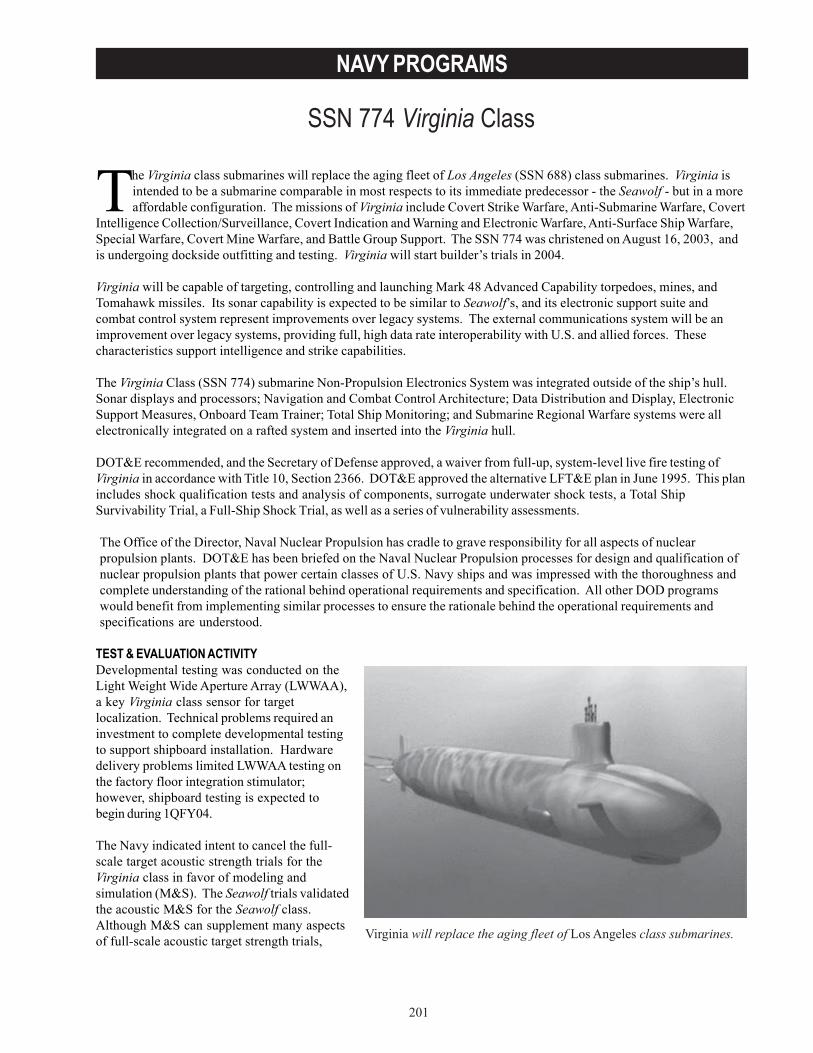
201
NAVY PROGRAMS
SSN 774 Virginia Class
Virginia will replace the aging fleet of Los Angeles class submarines.
The Virginia class submarines will replace the aging fleet of Los Angeles (SSN 688) class submarines. Virginia isintended to be a submarine comparable in most respects to its immediate predecessor - the Seawolf - but in a moreaffordable configuration. The missions of Virginia include Covert Strike Warfare, Anti-Submarine Warfare, Covert
Intelligence Collection/Surveillance, Covert Indication and Warning and Electronic Warfare, Anti-Surface Ship Warfare,Special Warfare, Covert Mine Warfare, and Battle Group Support. The SSN 774 was christened on August 16, 2003, andis undergoing dockside outfitting and testing. Virginia will start builder’s trials in 2004.
Virginia will be capable of targeting, controlling and launching Mark 48 Advanced Capability torpedoes, mines, andTomahawk missiles. Its sonar capability is expected to be similar to Seawolf’s, and its electronic support suite andcombat control system represent improvements over legacy systems. The external communications system will be animprovement over legacy systems, providing full, high data rate interoperability with U.S. and allied forces. Thesecharacteristics support intelligence and strike capabilities.
The Virginia Class (SSN 774) submarine Non-Propulsion Electronics System was integrated outside of the ship’s hull.Sonar displays and processors; Navigation and Combat Control Architecture; Data Distribution and Display, ElectronicSupport Measures, Onboard Team Trainer; Total Ship Monitoring; and Submarine Regional Warfare systems were allelectronically integrated on a rafted system and inserted into the Virginia hull.
DOT&E recommended, and the Secretary of Defense approved, a waiver from full-up, system-level live fire testing ofVirginia in accordance with Title 10, Section 2366. DOT&E approved the alternative LFT&E plan in June 1995. This planincludes shock qualification tests and analysis of components, surrogate underwater shock tests, a Total ShipSurvivability Trial, a Full-Ship Shock Trial, as well as a series of vulnerability assessments.
The Office of the Director, Naval Nuclear Propulsion has cradle to grave responsibility for all aspects of nuclearpropulsion plants. DOT&E has been briefed on the Naval Nuclear Propulsion processes for design and qualification ofnuclear propulsion plants that power certain classes of U.S. Navy ships and was impressed with the thoroughness andcomplete understanding of the rational behind operational requirements and specification. All other DOD programswould benefit from implementing similar processes to ensure the rationale behind the operational requirements andspecifications are understood.
TEST & EVALUATION ACTIVITYDevelopmental testing was conducted on theLight Weight Wide Aperture Array (LWWAA),a key Virginia class sensor for targetlocalization. Technical problems required aninvestment to complete developmental testingto support shipboard installation. Hardwaredelivery problems limited LWWAA testing onthe factory floor integration stimulator;however, shipboard testing is expected tobegin during 1QFY04.
The Navy indicated intent to cancel the full-scale target acoustic strength trials for theVirginia class in favor of modeling andsimulation (M&S). The Seawolf trials validatedthe acoustic M&S for the Seawolf class.Although M&S can supplement many aspectsof full-scale acoustic target strength trials,
202
NAVY PROGRAMS
DOT&E feels the model must be validated for the Virginia and that M&S cannot replace all full-scale tests.
The Navy’s LFT&E program includes three separate Vulnerability Assessment Reports, a modified Total ShipSurvivability Trial, component shock qualification testing for new/changed components, a variety of component andsurrogate tests, and M&S. DOT&E witnessed component shock qualification tests and reviewed the results ofcompleted component and surrogate testing.
TEST & EVALUATION ASSESSMENTIndications are that the propulsor will not meet all performance design objectives for the Virginia class. The Navy hasnot indicated its plan to address this shortfall.
Developmental testing identified several LWWAA performance issues. The two most severe are channel-to-channelphase variations in the fiber optic signals and failure of the system to meet system cold-start time requirements. Thephase variations erode the system signal processing gain, and the excessive start time will impact system suitability.Failure to meet system cold-start time requirements is a continuing problem often seen in commercial off-the-shelfsystems. Correction of these problems will be verified during dockside testing to ensure the LWWAA will be reliable forthe builder’s trials and follow-on testing.
The Operation Test and Evaluation Force reported concerns regarding the linked issues of habitability, access, anddamage control in the last two operational assessments. The most detrimental impact of poor habitability is on thedamage control response to a major casualty, such as fire or flooding. Access to spaces outboard the berthing areas isextremely limited. These outboard spaces contain many high-pressure air and hydraulic lines, as well as electrical cablesand water piping. Additionally, small passageways and lack of space in berthing areas limit the ability of the crew toevacuate from, and respond to, casualties from these crowded spaces.
The Navy chose the Voyage Manager System (VMS) as the new program of record to provide paperless navigationcapability to VIRGINIA. The initiative to integrate VMS in Virginia does not support installation and testing of apaperless charting system until 2006. Consequently, Virginia will conduct all initial at-sea operations using paper chartsand temporary plotting tables - an arrangement which the ship is not configured for that adversely affects habitabilityand navigation.
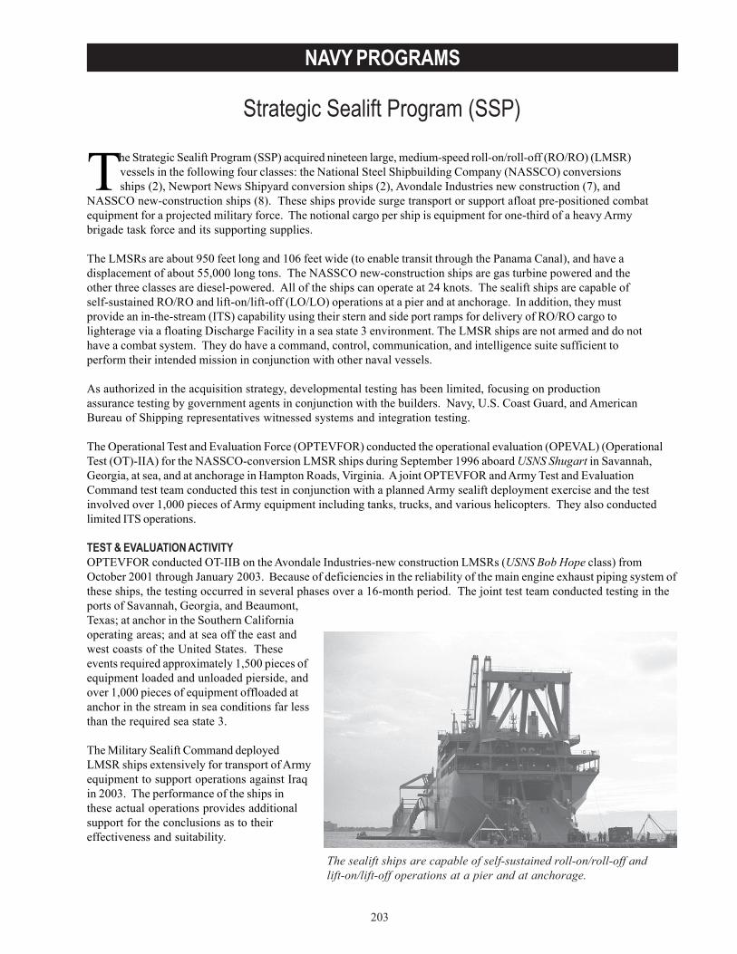
203
NAVY PROGRAMS
Strategic Sealift Program (SSP)
The sealift ships are capable of self-sustained roll-on/roll-off andlift-on/lift-off operations at a pier and at anchorage.
The Strategic Sealift Program (SSP) acquired nineteen large, medium-speed roll-on/roll-off (RO/RO) (LMSR)vessels in the following four classes: the National Steel Shipbuilding Company (NASSCO) conversionsships (2), Newport News Shipyard conversion ships (2), Avondale Industries new construction (7), and
NASSCO new-construction ships (8). These ships provide surge transport or support afloat pre-positioned combatequipment for a projected military force. The notional cargo per ship is equipment for one-third of a heavy Armybrigade task force and its supporting supplies.
The LMSRs are about 950 feet long and 106 feet wide (to enable transit through the Panama Canal), and have adisplacement of about 55,000 long tons. The NASSCO new-construction ships are gas turbine powered and theother three classes are diesel-powered. All of the ships can operate at 24 knots. The sealift ships are capable ofself-sustained RO/RO and lift-on/lift-off (LO/LO) operations at a pier and at anchorage. In addition, they mustprovide an in-the-stream (ITS) capability using their stern and side port ramps for delivery of RO/RO cargo tolighterage via a floating Discharge Facility in a sea state 3 environment. The LMSR ships are not armed and do nothave a combat system. They do have a command, control, communication, and intelligence suite sufficient toperform their intended mission in conjunction with other naval vessels.
As authorized in the acquisition strategy, developmental testing has been limited, focusing on productionassurance testing by government agents in conjunction with the builders. Navy, U.S. Coast Guard, and AmericanBureau of Shipping representatives witnessed systems and integration testing.
The Operational Test and Evaluation Force (OPTEVFOR) conducted the operational evaluation (OPEVAL) (OperationalTest (OT)-IIA) for the NASSCO-conversion LMSR ships during September 1996 aboard USNS Shugart in Savannah,Georgia, at sea, and at anchorage in Hampton Roads, Virginia. A joint OPTEVFOR and Army Test and EvaluationCommand test team conducted this test in conjunction with a planned Army sealift deployment exercise and the testinvolved over 1,000 pieces of Army equipment including tanks, trucks, and various helicopters. They also conductedlimited ITS operations.
TEST & EVALUATION ACTIVITYOPTEVFOR conducted OT-IIB on the Avondale Industries-new construction LMSRs (USNS Bob Hope class) fromOctober 2001 through January 2003. Because of deficiencies in the reliability of the main engine exhaust piping system ofthese ships, the testing occurred in several phases over a 16-month period. The joint test team conducted testing in theports of Savannah, Georgia, and Beaumont,Texas; at anchor in the Southern Californiaoperating areas; and at sea off the east andwest coasts of the United States. Theseevents required approximately 1,500 pieces ofequipment loaded and unloaded pierside, andover 1,000 pieces of equipment offloaded atanchor in the stream in sea conditions far lessthan the required sea state 3.
The Military Sealift Command deployedLMSR ships extensively for transport of Armyequipment to support operations against Iraqin 2003. The performance of the ships inthese actual operations provides additionalsupport for the conclusions as to theireffectiveness and suitability.
204
NAVY PROGRAMS
TEST & EVALUATION ASSESSMENTThe LMSRs are operationally effective and operationally suitable (in conventional environments that do not containchemical, biological, and radiological (CBR) agents) based on their performance in operational testing conducted in thetwo OPEVAL events. The propulsion reliability of the seven USNS Bob Hope class ships is not yet fully determinedbecause of the brief period of testing the improved main propulsion exhaust system. The intended capability to handlecargo in the stream in sea state 3 has not yet been demonstrated because the required supporting equipment (the RO/ROdischarge facility) does not exist. Testers identified some additional deficiencies and the Program Office and the MilitarySealift Command have instituted actions to correct them.
The 1996 OT-IIA found the NASSCO-conversion LMSR to be operationally effective and potentially operationallysuitable. The joint test team observed no significant deficiencies from the operational testing. However, theyconducted only limited ITS operations during this test. Its findings identified deficiencies in compatibility,interoperability, and training. The results of OT-IIB indicate that training deficiencies persist. The crews of theships designated for surge transportation duties are not routinely trained in CBR procedures and developing asystem to provide this training before exposing the crews to CBR threat conditions must be done. OPTEVFORcompleted assessment of the performance of the remaining two ship classes not subjected to actual operationaltesting, and reported that those ships have no class-unique deficiencies. The OPEVALs are adequate to describethe demonstrated performance of all of the LMSRs.
After an improved exhaust system was installed in the USNS Bob Hope class ship USNS Brittin, a 28-hour high-speed trial (including 4 hours at full power) was conducted as the final phase of the test. OPTEVFOR, the leadoperational test agency for the multi-Service test team, reported a satisfactory rating for all critical operationalissues except reliability, interoperability, and training. Reliability was only partially resolved because of the shortduration of the operational test of the improved main propulsion exhaust system. The Army operational test agencyrated interoperability as unsatisfactory because no RO/RO discharge facility exists that can support operations insea state 3. Training was rated as unsatisfactory because of deficiencies in training the ship’s crew to fight firescorrectly and to operate in CBR environments.
It is likely that existing deficiencies in the overall SSP will hinder LMSR ship mission performance. The existinglighterage system is not safe for cargo loading in sea states higher than two, and the RO/RO discharge facilityequipment shares this limitation. This can adversely affect our ability to project power in a timely manner insituations where adequate port facilities are not available. Only a few ports in areas of expected deployment havesufficient depth of water and length of berth to allow pierside offload of an LMSR. Deployment through less-capable ports will require ITS operations. DOT&E is concerned that other aspects of ITS RO/RO operations in anysea state (training, expected offload flow rate, and stern ramp operations) and ITS LO/LO capabilities, includingcontrol of load pendulation, will present additional deficiencies that could not be tested operationally. Additionaltesting of LMSR ITS offload capability in sea state 3 must be performed when sea state 3-capable lighterageconnectivity with RO/RO Discharge Facility equipment is developed. This testing should be performed during theoperational test of the improved lighterage.
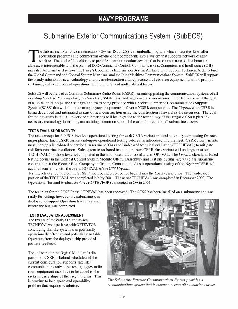
205
NAVY PROGRAMS
Submarine Exterior Communications System (SubECS)
The Submarine Exterior Communications System provides acommunications system that is common across all submarine classes.
The Submarine Exterior Communications System (SubECS) is an umbrella program, which integrates 15 smalleracquisition programs and commercial off-the-shelf components into a system that supports network centricwarfare. The goal of this effort is to provide a communications system that is common across all submarine
classes, is interoperable with the planned DoD Command, Control, Communications, Computers and Intelligence (C4I)infrastructure, and will support the Navy’s Copernicus Information System Architecture, the Joint Technical Architecture,the Global Command and Control System Maritime, and the Joint Maritime Communications System. SubECS will supportthe steady infusion of new technology and the modernization and replacement of obsolete equipment to allow prompt,sustained, and synchronized operations with joint U.S. and multinational forces.
SubECS will be fielded as Common Submarine Radio Room (CSRR) variants upgrading the communications systems of allLos Angeles class, Seawolf class, Trident class, SSGNclass, and Virginia class submarines. In order to arrive at the goalof a CSRR on all ships, the Los Angeles class is being provided with a backfit Submarine Communications SupportSystem (SCSS) that will eliminate many legacy components in favor of CSRR components. The Virginia class CSRR isbeing developed and integrated as part of new construction using the construction shipyard as the integrator. The goalfor the out-years is that all in-service submarines will be upgraded to the technology of the Virginia CSRR plus anynecessary technology insertions, maintaining a common state-of-the-art radio room on all submarine classes.
TEST & EVALUATION ACTIVITYThe test concept for SubECS involves operational testing for each CSRR variant and end-to-end system testing for eachmajor phase. Each CSRR variant undergoes operational testing before it is introduced into the fleet. CSRR class variantsmay undergo a land-based operational assessment (OA) and land-based technical evaluation (TECHEVAL) to mitigaterisk for submarine installation. Subsequent to on-board installation, each CSRR class variant will undergo an at-seaTECHEVAL (for those tests not completed in the land-based radio room) and an OPEVAL. The Virginia class land-basedtesting occurs in the Combat Control System Module Off-hull Assembly and Test site during Virginia class submarineconstruction at the Electric Boat Company in Groton, Connecticut. At-sea operational testing of the Virginia CSRR willoccur concurrently with the overall OPEVAL of the USS Virginia.Testing activity focused on the SCSS Phase I being prepared for backfit into the Los Angeles class. The land-basedportion of the TECHEVAL was completed in May 2001. The at-sea TECHEVAL was completed in December 2002. TheOperational Test and Evaluation Force (OPTEVFOR) conducted an OA in 2001.
The test plan for the SCSS Phase I OPEVAL has been approved. The SCSS has been installed on a submarine and wasready for testing; however the submarine wasdeployed to support Operation Iraqi Freedombefore the test was completed.
TEST & EVALUATION ASSESSMENTThe results of the early OA and at-seaTECHEVAL were positive, with OPTEVFORconcluding that the system was potentiallyoperationally effective and potentially suitable.Operators from the deployed ship providedpositive feedback.
The software for the Digital Modular Radioportion of CSRR is behind schedule and thecurrent configuration supports satellitecommunications only. As a result, legacy radioroom equipment may have to be added to theracks in early ships of the Virginia class. Thisis proving to be a space and operabilityproblem that requires resolution.

206
NAVY PROGRAMS
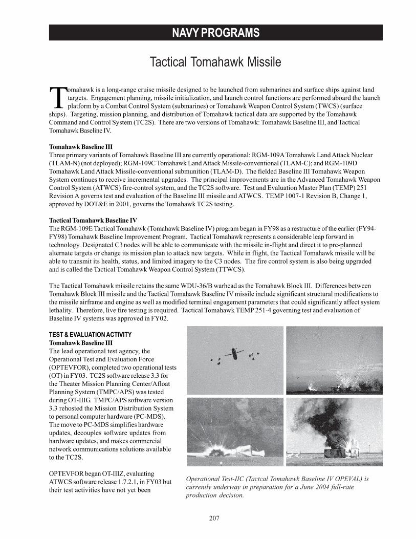
207
NAVY PROGRAMS
Tactical Tomahawk Missile
Operational Test-IIC (Tactcal Tomahawk Baseline IV OPEVAL) iscurrently underway in preparation for a June 2004 full-rateproduction decision.
Tomahawk is a long-range cruise missile designed to be launched from submarines and surface ships against landtargets. Engagement planning, missile initialization, and launch control functions are performed aboard the launchplatform by a Combat Control System (submarines) or Tomahawk Weapon Control System (TWCS) (surface
ships). Targeting, mission planning, and distribution of Tomahawk tactical data are supported by the TomahawkCommand and Control System (TC2S). There are two versions of Tomahawk: Tomahawk Baseline III, and TacticalTomahawk Baseline IV.
Tomahawk Baseline IIIThree primary variants of Tomahawk Baseline III are currently operational: RGM-109A Tomahawk Land Attack Nuclear(TLAM-N) (not deployed); RGM-109C Tomahawk Land Attack Missile-conventional (TLAM-C); and RGM-109DTomahawk Land Attack Missile-conventional submunition (TLAM-D). The fielded Baseline III Tomahawk WeaponSystem continues to receive incremental upgrades. The principal improvements are in the Advanced Tomahawk WeaponControl System (ATWCS) fire-control system, and the TC2S software. Test and Evaluation Master Plan (TEMP) 251Revision A governs test and evaluation of the Baseline III missile and ATWCS. TEMP 1007-1 Revision B, Change 1,approved by DOT&E in 2001, governs the Tomahawk TC2S testing.
Tactical Tomahawk Baseline IVThe RGM-109E Tactical Tomahawk (Tomahawk Baseline IV) program began in FY98 as a restructure of the earlier (FY94-FY98) Tomahawk Baseline Improvement Program. Tactical Tomahawk represents a considerable leap forward intechnology. Designated C3 nodes will be able to communicate with the missile in-flight and direct it to pre-plannedalternate targets or change its mission plan to attack new targets. While in flight, the Tactical Tomahawk missile will beable to transmit its health, status, and limited imagery to the C3 nodes. The fire control system is also being upgradedand is called the Tactical Tomahawk Weapon Control System (TTWCS).
The Tactical Tomahawk missile retains the same WDU-36/B warhead as the Tomahawk Block III. Differences betweenTomahawk Block III missile and the Tactical Tomahawk Baseline IV missile include significant structural modifications tothe missile airframe and engine as well as modified terminal engagement parameters that could significantly affect systemlethality. Therefore, live fire testing is required. Tactical Tomahawk TEMP 251-4 governing test and evaluation ofBaseline IV systems was approved in FY02.
TEST & EVALUATION ACTIVITYTomahawk Baseline IIIThe lead operational test agency, theOperational Test and Evaluation Force(OPTEVFOR), completed two operational tests(OT) in FY03. TC2S software release 3.3 forthe Theater Mission Planning Center/AfloatPlanning System (TMPC/APS) was testedduring OT-IIIG. TMPC/APS software version3.3 rehosted the Mission Distribution Systemto personal computer hardware (PC-MDS).The move to PC-MDS simplifies hardwareupdates, decouples software updates fromhardware updates, and makes commercialnetwork communications solutions availableto the TC2S.
OPTEVFOR began OT-IIIZ, evaluatingATWCS software release 1.7.2.1, in FY03 buttheir test activities have not yet been
208
NAVY PROGRAMS
completed. This software is an evolutionary improvement on software release 1.7.1, evaluated in FY02. Theimprovements are designed to reduce mission response time and increase system throughput; to incorporate strikeplanning and coordination functionality and ensure compatibility with existing and future Naval and Joint C3I systems;to improve human computer interface technologies to reduce operator workload; and to provide on-line embeddedtraining that incorporates simulations and instruction for individuals, functional groups, ship teams, and C2 teams/staffs.
Tactical Tomahawk Baseline IVOT-IIA, an operational assessment of Tactical Tomahawk, was completed by OPTEVFOR in FY03. Key test eventsincluded a Functional Ground Test, completed on May 17, 2002. The Functional Ground Test exercised most facets ofmissile operation while the missile was confined to a test stand. The operational assessment also used data derived fromthe first two missile developmental test (DT) flights (DT-0 and DT-1). Both were launched from fixed sites with the primecontractor assuming primary responsibility for test conduct. The Program Office completed DT-0 in August 2002, andDT-1 in November 2002. OPTEVFOR also used data from DT of TTWCS and TC2S for their operational assessment.
OT-IIB was conducted by OPTEVFOR in FY03. This test evaluated the backward compatibility between TomahawkBaseline IV’s TTWCS and the Tomahawk Block III All-Up Round (AUR). Test events included two 48-hour at-sea battlegroup scenarios in which TTWCS will receive tasking and intelligence inputs; perform mission planning, engagementplanning, and C3 functions; and launch simulated missiles, including salvo launches. Also included were two Block IIIAUR test flights, a maintenance demonstration, and supplementary battle force simulation exercises at Naval SurfaceWarfare Center – Dahlgren Division.
Naval Air Warfare Center – China Lake completed two live warhead sled tests and two live warhead flight tests againstrealistic targets in FY03.
TEST & EVALUATION ASSESSMENTTomahawk Baseline IIIOT-IIIG testing resulted in OPTEVFOR rating TC2S TMPC/APS software version 3.3 operationally effective andoperationally suitable. OPTEVFOR resolved all Critical Operational Issues as satisfactory and recommended fleetintroduction of TC2S software version TMPC/APS 3.3.
Tactical Tomahawk Baseline IVOT-IIA resulted in OPTEVFOR rating Tactical Tomahawk potentially operationally effective and potentially operationallysuitable. They rated the Training Critical Operational Issues Red, noting serious risk to a satisfactory resolution in futuretesting. The current embedded training architecture does not support Tomahawk Strike Network (TSN) two-way satellite-enabled communication between the Tactical Tomahawk AUR and C3 nodes when TTWCS is in training mode. TSNmessages include in-flight updates to the mission plan, AUR health and status, and battle damage assessment imagery.Currently, fleet personnel are limited to the training they can derive from simulations contained within their ownshipboard computers. The valuable learning implicit in live training exercise communications among ships, shore nodes,and simulated in-flight missiles is not currently available.
In the near term, Fleet personnel will be able to receive some of the needed training in shore-based training facilities,limited by the availability of training schedule time. The Navy’s plan to incorporate live TSN communication withTTWCS in training mode is called the Integrated Training Architecture. According to current program plans, theIntegrated Training Architecture will reach the Fleet in FY06. This is after the planned TTWS initial operationalcapabilities in FY04, but approximately concurrent with the arrival of significant numbers of Tactical Tomahawk AURs inthe Fleet. DOT&E expects future testing to provide better understanding of this issue and the effectiveness of theNavy’s proposed solutions.
209
NAVY PROGRAMS
Despite initial problems, OPTEVFOR has completed OT-IIB (TTWCS backward compatibility with Baseline III missilesand TC2S). Analysis and reporting is in progress. DT-IIC (Baseline IV Tactical Tomahawk technical evaluation), inpreparation for Baseline IV Tactical Tomahawk OPEVAL, is also under way.
Results from four LFT&E test events completed in FY03 are still undergoing analysis. Quick look analyses suggest thatLFT&E test objectives were met in the tests, and results were generally consistent with the pretest predictions. Datafrom the tests should support a limited demonstration of Tactical Tomahawk lethality in both functional modes (PrecisionWarhead Detonation and Vertical Dive Attack), and a similarly limited comparison of Block III and Tactical Tomahawklethality.
The Program Executive Officer’s (PEO) proposed test configuration for the IOT&E supporting the initial operationalcapability and beyond low-rate initial production decisions is inadequate. The PEO has proposed limited livecommunications with the TSN (one flight AUR plus three hardware-in-the loop AUR simulators), to be supplemented withmore extensive scenario work in a laboratory, where all communications paths and the AURs would be simulated. Thelaboratory does not adequately replicate the operational environments aboard the launch platforms and otherparticipating C2 nodes (battle group staff and higher commands). OPTEVFOR and the Program Office are discussingoptions for satisfying these concerns.

210
NAVY PROGRAMS
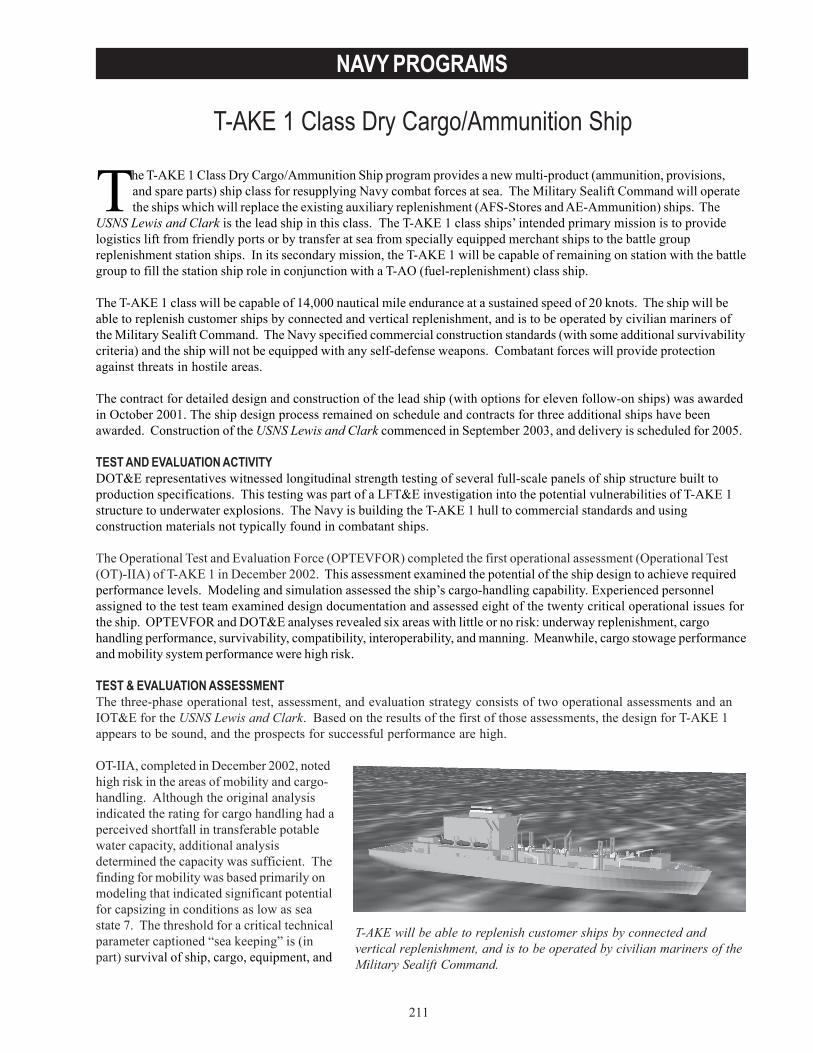
211
NAVY PROGRAMS
T-AKE 1 Class Dry Cargo/Ammunition Ship
T-AKE will be able to replenish customer ships by connected andvertical replenishment, and is to be operated by civilian mariners of theMilitary Sealift Command.
The T-AKE 1 Class Dry Cargo/Ammunition Ship program provides a new multi-product (ammunition, provisions,and spare parts) ship class for resupplying Navy combat forces at sea. The Military Sealift Command will operatethe ships which will replace the existing auxiliary replenishment (AFS-Stores and AE-Ammunition) ships. The
USNS Lewis and Clark is the lead ship in this class. The T-AKE 1 class ships’ intended primary mission is to providelogistics lift from friendly ports or by transfer at sea from specially equipped merchant ships to the battle groupreplenishment station ships. In its secondary mission, the T-AKE 1 will be capable of remaining on station with the battlegroup to fill the station ship role in conjunction with a T-AO (fuel-replenishment) class ship.
The T-AKE 1 class will be capable of 14,000 nautical mile endurance at a sustained speed of 20 knots. The ship will beable to replenish customer ships by connected and vertical replenishment, and is to be operated by civilian mariners ofthe Military Sealift Command. The Navy specified commercial construction standards (with some additional survivabilitycriteria) and the ship will not be equipped with any self-defense weapons. Combatant forces will provide protectionagainst threats in hostile areas.
The contract for detailed design and construction of the lead ship (with options for eleven follow-on ships) was awardedin October 2001. The ship design process remained on schedule and contracts for three additional ships have beenawarded. Construction of the USNS Lewis and Clark commenced in September 2003, and delivery is scheduled for 2005.
TEST AND EVALUATION ACTIVITYDOT&E representatives witnessed longitudinal strength testing of several full-scale panels of ship structure built toproduction specifications. This testing was part of a LFT&E investigation into the potential vulnerabilities of T-AKE 1structure to underwater explosions. The Navy is building the T-AKE 1 hull to commercial standards and usingconstruction materials not typically found in combatant ships.
The Operational Test and Evaluation Force (OPTEVFOR) completed the first operational assessment (Operational Test(OT)-IIA) of T-AKE 1 in December 2002. This assessment examined the potential of the ship design to achieve requiredperformance levels. Modeling and simulation assessed the ship’s cargo-handling capability. Experienced personnelassigned to the test team examined design documentation and assessed eight of the twenty critical operational issues forthe ship. OPTEVFOR and DOT&E analyses revealed six areas with little or no risk: underway replenishment, cargohandling performance, survivability, compatibility, interoperability, and manning. Meanwhile, cargo stowage performanceand mobility system performance were high risk.
TEST & EVALUATION ASSESSMENTThe three-phase operational test, assessment, and evaluation strategy consists of two operational assessments and anIOT&E for the USNS Lewis and Clark. Based on the results of the first of those assessments, the design for T-AKE 1appears to be sound, and the prospects for successful performance are high.
OT-IIA, completed in December 2002, notedhigh risk in the areas of mobility and cargo-handling. Although the original analysisindicated the rating for cargo handling had aperceived shortfall in transferable potablewater capacity, additional analysisdetermined the capacity was sufficient. Thefinding for mobility was based primarily onmodeling that indicated significant potentialfor capsizing in conditions as low as seastate 7. The threshold for a critical technicalparameter captioned “sea keeping” is (inpart) survival of ship, cargo, equipment, and
212
NAVY PROGRAMS
personnel in sea state 9, all headings, zero speed. This is an unachievable goal for a T-AKE 1-size ship. It wasapparently set as a result of modeling findings that simulated only a subset of the important capsizing mechanisms. Thecritical technical parameter has been modified to require survival in see state 8 (significant wave height up to 60 feet)when the ship has propulsion power to maintain a favorable heading into the seas. The modeling conducted to supportthe operational assessment indicates that T-AKE 1 should achieve this level of performance.
In LFT&E, the longitudinal strength testing and the analysis of the test results will continue into FY04. Preliminaryresults indicate the existing analytical tools used to predict the strength of the hull and the ship’s response to underwaterexplosion loading can be used reliably in the vulnerability assessment of T-AKE 1. Other events in the LFT&E surrogatetest program are behind schedule due to over-commitment of test resource. This may contribute to a delay in completingthe Detail Design Vulnerability Assessment Report and, with four ships already under contract, may reduce the likelihoodthat any deficiencies identified in the assessment will be corrected in the ship design.
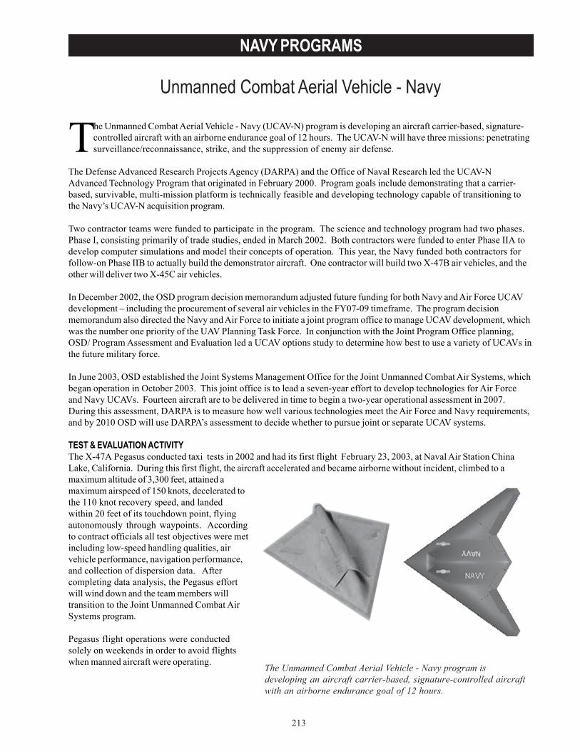
213
NAVY PROGRAMS
Unmanned Combat Aerial Vehicle - Navy
The Unmanned Combat Aerial Vehicle - Navy program isdeveloping an aircraft carrier-based, signature-controlled aircraftwith an airborne endurance goal of 12 hours.
The Unmanned Combat Aerial Vehicle - Navy (UCAV-N) program is developing an aircraft carrier-based, signature-controlled aircraft with an airborne endurance goal of 12 hours. The UCAV-N will have three missions: penetratingsurveillance/reconnaissance, strike, and the suppression of enemy air defense.
The Defense Advanced Research Projects Agency (DARPA) and the Office of Naval Research led the UCAV-NAdvanced Technology Program that originated in February 2000. Program goals include demonstrating that a carrier-based, survivable, multi-mission platform is technically feasible and developing technology capable of transitioning tothe Navy’s UCAV-N acquisition program.
Two contractor teams were funded to participate in the program. The science and technology program had two phases.Phase I, consisting primarily of trade studies, ended in March 2002. Both contractors were funded to enter Phase IIA todevelop computer simulations and model their concepts of operation. This year, the Navy funded both contractors forfollow-on Phase IIB to actually build the demonstrator aircraft. One contractor will build two X-47B air vehicles, and theother will deliver two X-45C air vehicles.
In December 2002, the OSD program decision memorandum adjusted future funding for both Navy and Air Force UCAVdevelopment – including the procurement of several air vehicles in the FY07-09 timeframe. The program decisionmemorandum also directed the Navy and Air Force to initiate a joint program office to manage UCAV development, whichwas the number one priority of the UAV Planning Task Force. In conjunction with the Joint Program Office planning,OSD/ Program Assessment and Evaluation led a UCAV options study to determine how best to use a variety of UCAVs inthe future military force.
In June 2003, OSD established the Joint Systems Management Office for the Joint Unmanned Combat Air Systems, whichbegan operation in October 2003. This joint office is to lead a seven-year effort to develop technologies for Air Forceand Navy UCAVs. Fourteen aircraft are to be delivered in time to begin a two-year operational assessment in 2007.During this assessment, DARPA is to measure how well various technologies meet the Air Force and Navy requirements,and by 2010 OSD will use DARPA’s assessment to decide whether to pursue joint or separate UCAV systems.
TEST & EVALUATION ACTIVITYThe X-47A Pegasus conducted taxi tests in 2002 and had its first flight February 23, 2003, at Naval Air Station ChinaLake, California. During this first flight, the aircraft accelerated and became airborne without incident, climbed to amaximum altitude of 3,300 feet, attained amaximum airspeed of 150 knots, decelerated tothe 110 knot recovery speed, and landedwithin 20 feet of its touchdown point, flyingautonomously through waypoints. Accordingto contract officials all test objectives were metincluding low-speed handling qualities, airvehicle performance, navigation performance,and collection of dispersion data. Aftercompleting data analysis, the Pegasus effortwill wind down and the team members willtransition to the Joint Unmanned Combat AirSystems program.
Pegasus flight operations were conductedsolely on weekends in order to avoid flightswhen manned aircraft were operating.
214
NAVY PROGRAMS
TEST & EVALUATION ASSESSMENTDOT&E supports the competitive nature of the operational assessment and the opportunity for side-by-side flightevaluations of the X-45 and X-47. DOT&E plans to work with the operational test agencies to ensure that relevant earlyoperational data are collected to support transition to a formal acquisition program. The inability to mix manned andunmanned flight operations in controlled airspace could be a significant hurdle during UCAV development and severelyrestricts the number of test flight days available to UCAV developers.
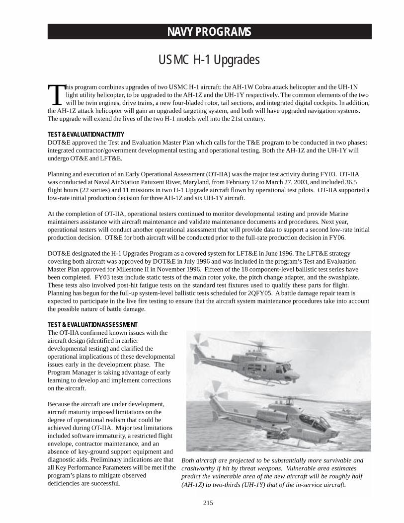
215
NAVY PROGRAMS
USMC H-1 Upgrades
Both aircraft are projected to be substantially more survivable andcrashworthy if hit by threat weapons. Vulnerable area estimatespredict the vulnerable area of the new aircraft will be roughly half(AH-1Z) to two-thirds (UH-1Y) that of the in-service aircraft.
This program combines upgrades of two USMC H-1 aircraft: the AH-1W Cobra attack helicopter and the UH-1Nlight utility helicopter, to be upgraded to the AH-1Z and the UH-1Y respectively. The common elements of the twowill be twin engines, drive trains, a new four-bladed rotor, tail sections, and integrated digital cockpits. In addition,
the AH-1Z attack helicopter will gain an upgraded targeting system, and both will have upgraded navigation systems.The upgrade will extend the lives of the two H-1 models well into the 21st century.
TEST & EVALUATION ACTIVITYDOT&E approved the Test and Evaluation Master Plan which calls for the T&E program to be conducted in two phases:integrated contractor/government developmental testing and operational testing. Both the AH-1Z and the UH-1Y willundergo OT&E and LFT&E.
Planning and execution of an Early Operational Assessment (OT-IIA) was the major test activity during FY03. OT-IIAwas conducted at Naval Air Station Patuxent River, Maryland, from February 12 to March 27, 2003, and included 36.5flight hours (22 sorties) and 11 missions in two H-1 Upgrade aircraft flown by operational test pilots. OT-IIA supported alow-rate initial production decision for three AH-1Z and six UH-1Y aircraft.
At the completion of OT-IIA, operational testers continued to monitor developmental testing and provide Marinemaintainers assistance with aircraft maintenance and validate maintenance documents and procedures. Next year,operational testers will conduct another operational assessment that will provide data to support a second low-rate initialproduction decision. OT&E for both aircraft will be conducted prior to the full-rate production decision in FY06.
DOT&E designated the H-1 Upgrades Program as a covered system for LFT&E in June 1996. The LFT&E strategycovering both aircraft was approved by DOT&E in July 1996 and was included in the program’s Test and EvaluationMaster Plan approved for Milestone II in November 1996. Fifteen of the 18 component-level ballistic test series havebeen completed. FY03 tests include static tests of the main rotor yoke, the pitch change adapter, and the swashplate.These tests also involved post-hit fatigue tests on the standard test fixtures used to qualify these parts for flight.Planning has begun for the full-up system-level ballistic tests scheduled for 2QFY05. A battle damage repair team isexpected to participate in the live fire testing to ensure that the aircraft system maintenance procedures take into accountthe possible nature of battle damage.
TEST & EVALUATION ASSESSMENTThe OT-IIA confirmed known issues with theaircraft design (identified in earlierdevelopmental testing) and clarified theoperational implications of these developmentalissues early in the development phase. TheProgram Manager is taking advantage of earlylearning to develop and implement correctionson the aircraft.
Because the aircraft are under development,aircraft maturity imposed limitations on thedegree of operational realism that could beachieved during OT-IIA. Major test limitationsincluded software immaturity, a restricted flightenvelope, contractor maintenance, and anabsence of key-ground support equipment anddiagnostic aids. Preliminary indications are thatall Key Performance Parameters will be met if theprogram’s plans to mitigate observeddeficiencies are successful.
216
NAVY PROGRAMS
The AH-1Z attack helicopter demonstrated a doubling in payload and a 20 percent increase in range and endurance overthe AH-1W aircraft. The digital cockpit enhanced pilot situational awareness and reduced workload in some areas.However, poor targeting performance of the newly installed Targeting Sight System (TSS) degraded missioneffectiveness and increased pilot workload. Problems with TSS stability, focusing, target loss during field-of-viewchanges, and anomalous TSS behavior must be resolved before this aircraft can be considered operationally effective.
The UH-1Y utility helicopter demonstrated a significant increase in payload, range, speed, and situational awarenessover the legacy UH-1N utility aircraft. Assuming internal fuel cell problems can be corrected, the UH-1Y may be able toachieve the required mission radius of 110 nautical miles. The design of the aircraft increases the possibility of tail strikes(mitigated by the redesign of the tail boom stinger), infrared signature, and hover limitations. Excessive noise levels inthe UH-1Y cabin degraded mission performance and elevated cabin temperatures might change mission effectiveness inhot weather. Collectively, these problems, if uncorrected, will limit the effectiveness of the UH-1Y across the full range ofutility helicopter missions.
Both aircraft are projected to be substantially more survivable and crashworthy if hit by threat weapons. Vulnerable areaestimates predict the vulnerable area of the new aircraft will be roughly half (AH-1Z) to two-thirds (UH-1Y) that of the in-service AH-1W and UH-1N aircraft. To date, testing has demonstrated that the components of the AH-1Z and the UH-1Ywill retain or exceed the degree of damage tolerance found in their predecessors. The test results have been used to makeseveral design changes that improve survivability.
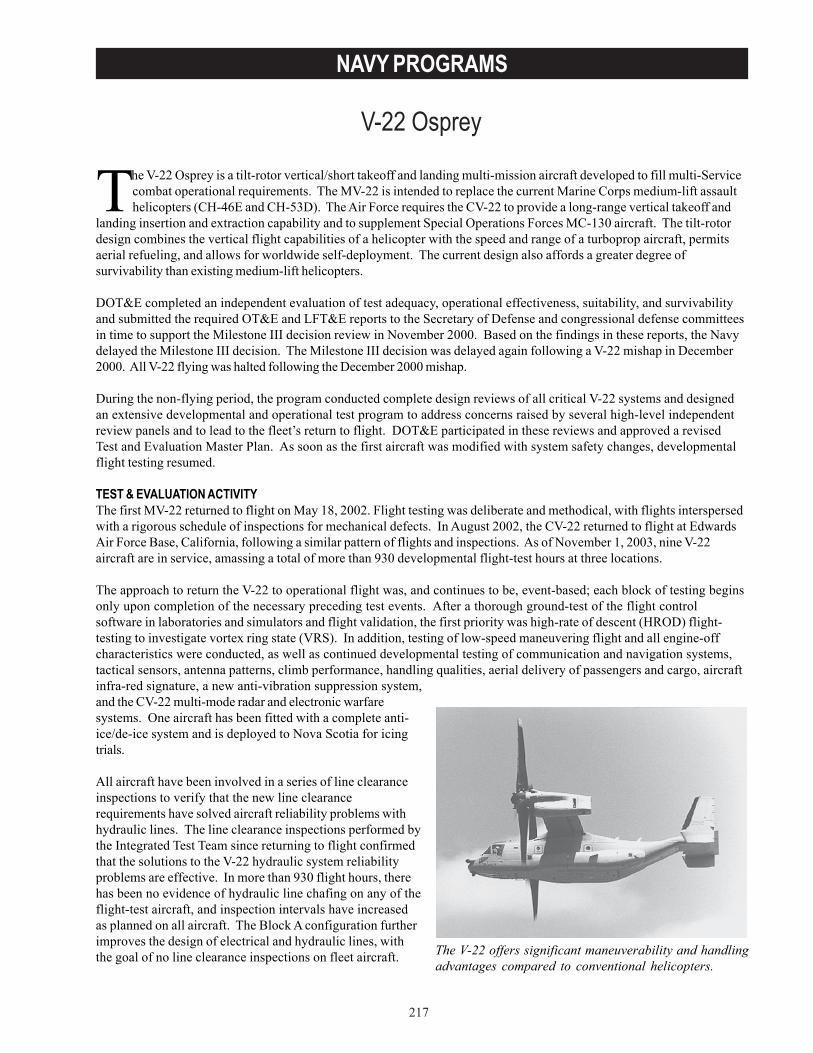
217
NAVY PROGRAMS
V-22 Osprey
The V-22 offers significant maneuverability and handlingadvantages compared to conventional helicopters.
The V-22 Osprey is a tilt-rotor vertical/short takeoff and landing multi-mission aircraft developed to fill multi-Servicecombat operational requirements. The MV-22 is intended to replace the current Marine Corps medium-lift assaulthelicopters (CH-46E and CH-53D). The Air Force requires the CV-22 to provide a long-range vertical takeoff and
landing insertion and extraction capability and to supplement Special Operations Forces MC-130 aircraft. The tilt-rotordesign combines the vertical flight capabilities of a helicopter with the speed and range of a turboprop aircraft, permitsaerial refueling, and allows for worldwide self-deployment. The current design also affords a greater degree ofsurvivability than existing medium-lift helicopters.
DOT&E completed an independent evaluation of test adequacy, operational effectiveness, suitability, and survivabilityand submitted the required OT&E and LFT&E reports to the Secretary of Defense and congressional defense committeesin time to support the Milestone III decision review in November 2000. Based on the findings in these reports, the Navydelayed the Milestone III decision. The Milestone III decision was delayed again following a V-22 mishap in December2000. All V-22 flying was halted following the December 2000 mishap.
During the non-flying period, the program conducted complete design reviews of all critical V-22 systems and designedan extensive developmental and operational test program to address concerns raised by several high-level independentreview panels and to lead to the fleet’s return to flight. DOT&E participated in these reviews and approved a revisedTest and Evaluation Master Plan. As soon as the first aircraft was modified with system safety changes, developmentalflight testing resumed.
TEST & EVALUATION ACTIVITYThe first MV-22 returned to flight on May 18, 2002. Flight testing was deliberate and methodical, with flights interspersedwith a rigorous schedule of inspections for mechanical defects. In August 2002, the CV-22 returned to flight at EdwardsAir Force Base, California, following a similar pattern of flights and inspections. As of November 1, 2003, nine V-22aircraft are in service, amassing a total of more than 930 developmental flight-test hours at three locations.
The approach to return the V-22 to operational flight was, and continues to be, event-based; each block of testing beginsonly upon completion of the necessary preceding test events. After a thorough ground-test of the flight controlsoftware in laboratories and simulators and flight validation, the first priority was high-rate of descent (HROD) flight-testing to investigate vortex ring state (VRS). In addition, testing of low-speed maneuvering flight and all engine-offcharacteristics were conducted, as well as continued developmental testing of communication and navigation systems,tactical sensors, antenna patterns, climb performance, handling qualities, aerial delivery of passengers and cargo, aircraftinfra-red signature, a new anti-vibration suppression system,and the CV-22 multi-mode radar and electronic warfaresystems. One aircraft has been fitted with a complete anti-ice/de-ice system and is deployed to Nova Scotia for icingtrials.
All aircraft have been involved in a series of line clearanceinspections to verify that the new line clearancerequirements have solved aircraft reliability problems withhydraulic lines. The line clearance inspections performed bythe Integrated Test Team since returning to flight confirmedthat the solutions to the V-22 hydraulic system reliabilityproblems are effective. In more than 930 flight hours, therehas been no evidence of hydraulic line chafing on any of theflight-test aircraft, and inspection intervals have increasedas planned on all aircraft. The Block A configuration furtherimproves the design of electrical and hydraulic lines, withthe goal of no line clearance inspections on fleet aircraft.
218
NAVY PROGRAMS
On August 28, 2003, the Marine Corps activated a new tilt-rotor test squadron, VMX-22. The squadron, which will reportto the Navy’s Commander, Operational Test and Evaluation Force, will plan and conduct OT&E and develop tactics,techniques, and procedures for the operational employment of the V-22. An operational assessment (OT-IIF) will be donein conjunction with developmental test and evaluation beginning in mid-2004. After confirmation of the safe flightenvelope in the HROD tests, the Navy plans to issue a limited flight clearance to operational V-22 units which will allowtraining flights to prepare for a second phase of operational evaluation (OPEVAL II or OT-IIG) to address the issuesraised in the November 2000 OT&E report (testing not conducted, waived items, and correction of deficiencies). Overalldegree of mission accomplishment by a sea-based Marine Expeditionary Unit equipped with MV-22 aircraft will beevaluated in OPEVAL Phase Two, scheduled to begin in late 2004. Following that, DOT&E will submit a second OT&Ereport containing an assessment of test results and the design changes.
The first full-up Block A aircraft was delivered to Naval Air Station Patuxent River in August. This configuration formsthe basis of all fleet aircraft and includes completely redesigned engine nacelle areas, reliability improvements, andseveral system upgrades. The Block A configuration will be tested in both OT-IIF and OT-IIG.
TEST & EVALUATION ASSESSMENTIn the November 2000 OT&E report, DOT&E concluded testing had been adequate to determine the MV-22’s operationaleffectiveness, operational suitability, and survivability. However, additional testing was needed to verify correction ofdeficiencies, the effectiveness and suitability of waived items, and to investigate the phenomenon of VRS. The MV-22was assessed by DOT&E as operationally effective, but not operationally suitable. Results from OT-IIE (OPEVALPhase I) indicated that the V-22 would provide major range, speed, and payload improvements to meet Marine Corps andSpecial Operations Forces requirements. The V-22 offers significant maneuverability and handling advantages comparedto conventional helicopters (e.g., rapid deceleration upon arrival at a landing zone and rapid acceleration duringdeparture). When tactics are fully developed, these capabilities should provide substantive advantages in missionaccomplishment and survivability.
Based on developmental tests since returning to flight, DOT&E has increased confidence that the V-22 characteristicsinvolving VRS are well understood and knowledge of VRS consequences is widespread in the V-22 community. Severalfactors contribute to this confidence:
• Extensive HROD testing confirmed the V-22 VRS envelope; the flight conditions necessary to enter VRS wereverified and closely matched predictions by aerodynamic modeling and simulations.
• Published operating limitations appear adequate for normal conditions. DOT&E and the program will investigatethe question of whether that margin may be reduced under unusual wind or maneuvering conditions.
• Published operating limitations are equivalent to all other rotorcraft and testing has proven that V-22 has moremargin between the limitation and the VRS boundary.
• In maneuvering testing inside the VRS region, pilot control inputs delayed VRS onset and did notprecipitate it.
• The flight simulators and flight syllabus emphasize avoiding the phenomenon.• Flight manual cautions, warnings, and advisories were amended.• An HROD warning system is present for both pilots and appears functional.• Readability of the pilots’ vertical speed indicator has improved.• Nacelle tilt is a powerful VRS recovery tool, demonstrated and understood.
These items tend to reduce the likelihood of another mishap caused by VRS.
For any rotorcraft, including the V-22 tiltrotor, the ability to save the aircraft– or at least ensure the survival of itsoccupants– in the event of a single or dual engine failure must be determined. In either the airplane or helicopter mode,the recommended procedure in the event of an engine failure is to convert to airplane mode, proceed immediately to asuitable landing spot, convert back to helicopter mode and land as soon as possible. The ability of the V-22 to perform
219
NAVY PROGRAMS
single-engine landings is better than the helicopters it replaces. In the event of either sudden dual-engine failures, or asingle failure of one engine coupled with a failure of the interconnecting drive train, while the aircraft is in either airplaneor in the helicopter mode, the recommended method to recover is to tilt the nacelles down and attain the best glide speedavailable, then flare to a survivable landing. In 2003, the program demonstrated by flight-test the recommended speedand altitude approaches to the landing field that allow the pilot to perform a survivable landing if the second engine failsduring approach. This testing validated the fidelity of the V-22 simulators. Although testing of this procedure all theway to landing is not practicable, limited testing has confirmed that, while the aircraft can perform an auto-rotativedescent, it cannot consistently auto-rotate to a safe landing. The approach to safety adopted long ago by the program isto minimize the possibility of such disastrous occurrences through system design. DOT&E will pursue, in conjunctionwith the program office and VMX-22, possible means to minimize the Fleet Marine Force mishap rate.
The effectiveness of the V-22’s vulnerability reduction features was demonstrated during LFT&E. A continuous processof design refinements has been an integral part of the overall system engineering effort since the start of live fire testing,and several design changes have been made based on the test results, such as revising the sponson fuel tank structure.This process continues with particular emphasis on addressing the concerns outlined in the November 2000 LFT&Ereport.
The following are survivability assessments of the design changes and efforts to address the results of the originalLFT&E program:
• Fire protection can be effectively provided to the mid-wing nacelles, main landing gear dry bays, and underfloorareas.
• The design changes to the hydraulic system made since November 2000 have a negligible impact on theaircraft’s vulnerability.
• The aircraft battle damage repair program continued to experience delays due to insufficient funding and is nownearing a contract award. It is programmed to be funded through FY06.
• The impact of adding internal mission auxiliary fuel tanks, countermeasure dispensers, and improvements tothe engine nacelles require further study.

220
NAVY PROGRAMS
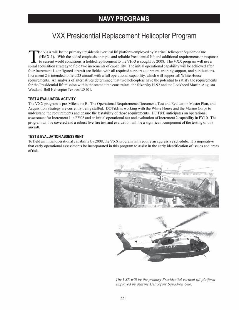
221
NAVY PROGRAMS
VXX Presidential Replacement Helicopter Program
The VXX will be the primary Presidential vertical lift platformemployed by Marine Helicopter Squadron One.
The VXX will be the primary Presidential vertical lift platform employed by Marine Helicopter Squadron One(HMX-1). With the added emphasis on rapid and reliable Presidential lift and additional requirements in responseto current world conditions, a fielded replacement to the VH-3 is sought by 2008. The VXX program will use a
spiral acquisition strategy to field two increments of capability. The initial operational capability will be achieved afterfour Increment 1-configured aircraft are fielded with all required support equipment, training support, and publications.Increment 2 is intended to field 23 aircraft with a full operational capability, which will support all White Houserequirements. An analysis of alternatives determined that two helicopters have the potential to satisfy the requirementsfor the Presidential lift mission within the stated time constraints: the Sikorsky H-92 and the Lockheed Martin-AugustaWestland-Bell Helicopter Textron US101.
TEST & EVALUATION ACTIVITYThe VXX program is pre-Milestone B. The Operational Requirements Document, Test and Evaluation Master Plan, andAcquisition Strategy are currently being staffed. DOT&E is working with the White House and the Marine Corps tounderstand the requirements and ensure the testability of those requirements. DOT&E anticipates an operationalassessment for Increment 1 in FY08 and an initial operational test and evaluation of Increment 2 capability in FY10. Theprogram will be covered and a robust live fire test and evaluation will be a significant component of the testing of thisaircraft.
TEST & EVALUATION ASSESSMENTTo field an initial operational capability by 2008, the VXX program will require an aggressive schedule. It is imperativethat early operational assessments be incorporated in this program to assist in the early identification of issues and areasof risk.

222
NAVY PROGRAMS
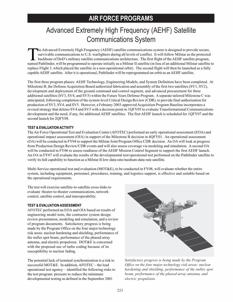
223
AIR FORCE PROGRAMSAdvanced Extremely High Frequency (AEHF) Satellite
Communications System
Satisfactory progress is being made by the ProgramOffice on the four major technology risk areas: nuclearhardening and shielding, performance of the nuller spotbeam, performance of the phased array antenna, andelectric propulsion.
The Advanced Extremely High Frequency (AEHF) satellite communications system is designed to provide secure,survivable communications to U.S. warfighters during all levels of conflict. It will follow Milstar as the protectedbackbone of DoD’s military satellite communications architecture. The first flight of the AEHF satellite program,
named Pathfinder, will be programmed to operate initially as a Milstar II satellite (in lieu of an additional Milstar satellite toreplace Flight 3, which placed the satellite in a non-operational orbit). The second flight will then be launched as a fullycapable AEHF satellite. After it is operational, Pathfinder will be reprogrammed on-orbit as an AEHF satellite.
The first three program phases: AEHF Technology, Engineering Models, and System Definition have been completed. AtMilestone B, the Defense Acquisition Board authorized fabrication and assembly of the first two satellites (SV1, SV2),development and deployment of the ground command and control segment, and advanced procurement for threeadditional satellites (SV3, SV4, and SV5) within the Future Years Defense Program. A separate tailored Milestone C wasanticipated, following completion of the system-level Critical Design Review (CDR), to provide final authorization forproduction of SV3, SV4, and SV5. However, a February 2003-approved Acquisition Program Baseline incorporates arevised strategy that deletes SV4 and SV5 with a decision point in 1QFY05 to evaluate Transformational Communicationsdevelopment and the need, if any, for additional AEHF satellites. The first AEHF launch is scheduled for 1QFY07 and thesecond launch for 2QFY08.
TEST & EVALUATION ACTIVITYThe Air Force Operational Test and Evaluation Center (AFOTEC) performed an early operational assessment (EOA) andoperational impact assessment (OIA) in support of the Milestone B decision in 4QFY01. An operational assessment(OA) will be conducted in FY04 to support the Milstar Joint Program Office CDR decision. An OA will look at progressfrom Production Design Review/CDR events and will also assess coverage via modeling and simulation. A second OAwill be conducted in FY06 to assess readiness of the AEHF Mission Control Segment to support the first AEHF launch.An OA in FY07 will evaluate the results of the developmental test/operational test performed on the Pathfinder satellite toverify its full capability to function as a Milstar II low-data-rate/medium-data-rate satellite.
Multi-Service operational test and evaluation (MOT&E), to be conducted in FY08, will evaluate whether the entiresystem, including equipment, personnel, procedures, training, and logistics support, is effective and suitable based onthe operational requirements.
The test will exercise satellite-to-satellite cross-links toevaluate theater-to-theater communications, networkcontrol, satellite control, and interoperability.
TEST & EVALUATION ASSESSMENTAFOTEC performed an EOA and OIA based on results ofengineering model tests, the contractor system designreview presentation, modeling and simulation, and a reviewof program documents. Satisfactory progress is beingmade by the Program Office on the four major technologyrisk areas: nuclear hardening and shielding, performance ofthe nuller spot beam, performance of the phased arrayantenna, and electric propulsion. DOT&E is concernedwith the proposed use of turbo coding because of itssusceptibility to nuclear fading.
The potential lack of terminal synchronization is a risk tosuccessful MOT&E. In addition, AFOTEC – the leadoperational test agency – identified the following risks tothe test program: pressure to reduce the minimumdevelopmental testing as defined in the September 2001
224
AIR FORCE PROGRAMS
Test and Evaluation Master Plan, insufficient software testing, the need for a payload simulator that is common to all ofthe terminal development programs, and availability of Pathfinder for MOT&E after it has become an operational asset.Monitoring the fidelity of the AUST-T terminal simulator and the payload simulators is imperative. If their configurationsdo not remain standardized and consistent with the true payload, the new terminals will not be compatible with thepayload or with each other. Also, modeling and simulation will be used for both developmental and operational testing toassess nuller spot beam performance in a variety of single and multiple jammer scenarios. However, contractor modelvalidation testing will be limited to only single jammer cases. DOT&E is concerned that the contractor needs more robustvalidation testing to reduce risk associated with using this model to evaluate nuller operational performance.
In addition to those items identified by AFOTEC, the program manager identified a high program risk associated with thedevelopment of the cryptographic capability to support the AEHF data rate. This includes the manufacture of a highlycomplex Application Specific Integrated Circuit (ASIC). To reduce the probability of a first-pass manufacturing failure ofthis ASIC, the foundry process is being initially exercised by the manufacturer with a test chip that represents 90 percentof the final ASIC design. Although the program remains on schedule for a December 2006 launch, schedule slips incryptographic development have consumed the entire available margin.
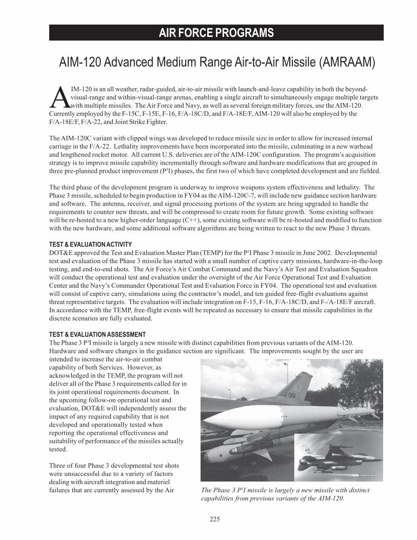
225
AIR FORCE PROGRAMS
AIM-120 Advanced Medium Range Air-to-Air Missile (AMRAAM)
The Phase 3 P3I missile is largely a new missile with distinctcapabilities from previous variants of the AIM-120.
AIM-120 is an all weather, radar-guided, air-to-air missile with launch-and-leave capability in both the beyond-visual-range and within-visual-range arenas, enabling a single aircraft to simultaneously engage multiple targetswith multiple missiles. The Air Force and Navy, as well as several foreign military forces, use the AIM-120.
Currently employed by the F-15C, F-15E, F-16, F/A-18C/D, and F/A-18E/F, AIM-120 will also be employed by theF/A-18E/F, F/A-22, and Joint Strike Fighter.
The AIM-120C variant with clipped wings was developed to reduce missile size in order to allow for increased internalcarriage in the F/A-22. Lethality improvements have been incorporated into the missile, culminating in a new warheadand lengthened rocket motor. All current U.S. deliveries are of the AIM-120C configuration. The program’s acquisitionstrategy is to improve missile capability incrementally through software and hardware modifications that are grouped inthree pre-planned product improvement (P3I) phases, the first two of which have completed development and are fielded.
The third phase of the development program is underway to improve weapons system effectiveness and lethality. ThePhase 3 missile, scheduled to begin production in FY04 as the AIM-120C-7, will include new guidance section hardwareand software. The antenna, receiver, and signal processing portions of the system are being upgraded to handle therequirements to counter new threats, and will be compressed to create room for future growth. Some existing softwarewill be re-hosted to a new higher-order language (C++), some existing software will be re-hosted and modified to functionwith the new hardware, and some additional software algorithms are being written to react to the new Phase 3 threats.
TEST & EVALUATION ACTIVITYDOT&E approved the Test and Evaluation Master Plan (TEMP) for the P3I Phase 3 missile in June 2002. Developmentaltest and evaluation of the Phase 3 missile has started with a small number of captive carry missions, hardware-in-the-looptesting, and end-to-end shots. The Air Force’s Air Combat Command and the Navy’s Air Test and Evaluation Squadronwill conduct the operational test and evaluation under the oversight of the Air Force Operational Test and EvaluationCenter and the Navy’s Commander Operational Test and Evaluation Force in FY04. The operational test and evaluationwill consist of captive carry, simulations using the contractor’s model, and ten guided free-flight evaluations againstthreat representative targets. The evaluation will include integration on F-15, F-16, F/A-18C/D, and F-/A-18E/F aircraft.In accordance with the TEMP, free-flight events will be repeated as necessary to ensure that missile capabilities in thediscrete scenarios are fully evaluated.
TEST & EVALUATION ASSESSMENTThe Phase 3 P3I missile is largely a new missile with distinct capabilities from previous variants of the AIM-120.Hardware and software changes in the guidance section are significant. The improvements sought by the user areintended to increase the air-to-air combatcapability of both Services. However, asacknowledged in the TEMP, the program will notdeliver all of the Phase 3 requirements called for inits joint operational requirements document. Inthe upcoming follow-on operational test andevaluation, DOT&E will independently assess theimpact of any required capability that is notdeveloped and operationally tested whenreporting the operational effectiveness andsuitability of performance of the missiles actuallytested.
Three of four Phase 3 developmental test shotswere unsuccessful due to a variety of factorsdealing with aircraft integration and materielfailures that are currently assessed by the Air
226
AIR FORCE PROGRAMS
Force as not pertinent to technical development of the Phase 3 missile. A fourth shot was successfully conducted.DOT&E continues to monitor progress towards accreditation of the model and readiness for operational testing. Thelimited number of planned live shots places a strong reliance on modeling and simulation to confirm the full weaponsemployment envelope and operational effectiveness of the Phase 3 P3I AMRAAM missile. The modeling and simulationsuite has not yet been delivered to the government organizations that must understand and validate it. If this situation isnot corrected, completion of operational testing on schedule is in jeopardy. Additional live test shots will have to beadded to the planned operational test to ensure an adequate effectiveness evaluation in the event that the modeling andsimulation suite cannot be validated.
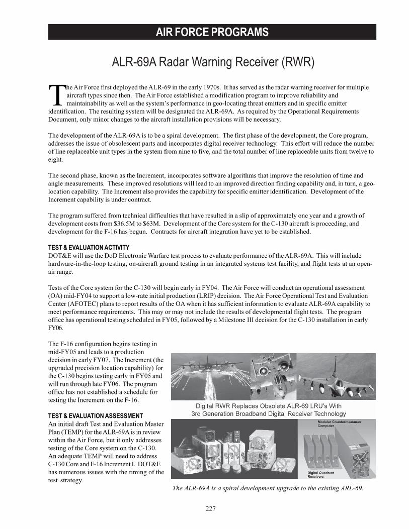
227
AIR FORCE PROGRAMS
ALR-69A Radar Warning Receiver (RWR)
The Air Force first deployed the ALR-69 in the early 1970s. It has served as the radar warning receiver for multipleaircraft types since then. The Air Force established a modification program to improve reliability andmaintainability as well as the system’s performance in geo-locating threat emitters and in specific emitter
identification. The resulting system will be designated the ALR-69A. As required by the Operational RequirementsDocument, only minor changes to the aircraft installation provisions will be necessary.
The development of the ALR-69A is to be a spiral development. The first phase of the development, the Core program,addresses the issue of obsolescent parts and incorporates digital receiver technology. This effort will reduce the numberof line replaceable unit types in the system from nine to five, and the total number of line replaceable units from twelve toeight.
The second phase, known as the Increment, incorporates software algorithms that improve the resolution of time andangle measurements. These improved resolutions will lead to an improved direction finding capability and, in turn, a geo-location capability. The Increment also provides the capability for specific emitter identification. Development of theIncrement capability is under contract.
The program suffered from technical difficulties that have resulted in a slip of approximately one year and a growth ofdevelopment costs from $36.5M to $63M. Development of the Core system for the C-130 aircraft is proceeding, anddevelopment for the F-16 has begun. Contracts for aircraft integration have yet to be established.
TEST & EVALUATION ACTIVITYDOT&E will use the DoD Electronic Warfare test process to evaluate performance of the ALR-69A. This will includehardware-in-the-loop testing, on-aircraft ground testing in an integrated systems test facility, and flight tests at an open-air range.
Tests of the Core system for the C-130 will begin early in FY04. The Air Force will conduct an operational assessment(OA) mid-FY04 to support a low-rate initial production (LRIP) decision. The Air Force Operational Test and EvaluationCenter (AFOTEC) plans to report results of the OA when it has sufficient information to evaluate ALR-69A capability tomeet performance requirements. This may or may not include the results of developmental flight tests. The programoffice has operational testing scheduled in FY05, followed by a Milestone III decision for the C-130 installation in earlyFY06.
The F-16 configuration begins testing inmid-FY05 and leads to a productiondecision in early FY07. The Increment (theupgraded precision location capability) forthe C-130 begins testing early in FY05 andwill run through late FY06. The programoffice has not established a schedule fortesting the Increment on the F-16.
TEST & EVALUATION ASSESSMENTAn initial draft Test and Evaluation MasterPlan (TEMP) for the ALR-69A is in reviewwithin the Air Force, but it only addressestesting of the Core system on the C-130.An adequate TEMP will need to addressC-130 Core and F-16 Increment I. DOT&Ehas numerous issues with the timing of thetest strategy.
The ALR-69A is a spiral development upgrade to the existing ARL-69.
228
AIR FORCE PROGRAMS
DOTE also has concerns with the plan to use an OA that may not be based on flight tests and the increased risk that thesystem will enter LRIP with significant performance flaws. The program office can mitigate this risk by keeping thenumber of LRIP units small.
The program plans to use a favorable Milestone III decision as clearance to buy all units with only minimal testing toverify each installation. It is DOT&E’s position that the ALR-69A should be tested on each individual aircraft prior to theacquisition decision maker approving the acquisition of those units. The basis for resolving this issue will be review andapproval of the TEMP.
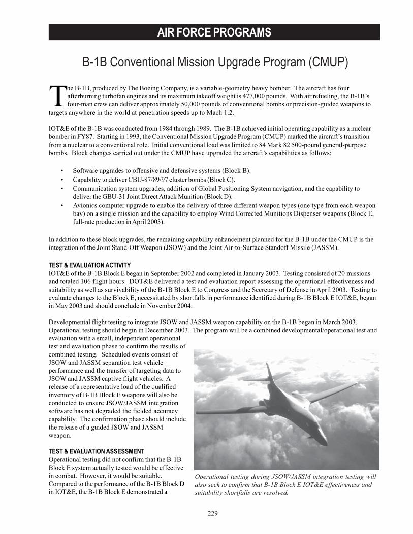
229
AIR FORCE PROGRAMS
B-1B Conventional Mission Upgrade Program (CMUP)
Operational testing during JSOW/JASSM integration testing willalso seek to confirm that B-1B Block E IOT&E effectiveness andsuitability shortfalls are resolved.
The B-1B, produced by The Boeing Company, is a variable-geometry heavy bomber. The aircraft has fourafterburning turbofan engines and its maximum takeoff weight is 477,000 pounds. With air refueling, the B-1B’sfour-man crew can deliver approximately 50,000 pounds of conventional bombs or precision-guided weapons to
targets anywhere in the world at penetration speeds up to Mach 1.2.
IOT&E of the B-1B was conducted from 1984 through 1989. The B-1B achieved initial operating capability as a nuclearbomber in FY87. Starting in 1993, the Conventional Mission Upgrade Program (CMUP) marked the aircraft’s transitionfrom a nuclear to a conventional role. Initial conventional load was limited to 84 Mark 82 500-pound general-purposebombs. Block changes carried out under the CMUP have upgraded the aircraft’s capabilities as follows:
• Software upgrades to offensive and defensive systems (Block B).• Capability to deliver CBU-87/89/97 cluster bombs (Block C).• Communication system upgrades, addition of Global Positioning System navigation, and the capability to
deliver the GBU-31 Joint Direct Attack Munition (Block D).• Avionics computer upgrade to enable the delivery of three different weapon types (one type from each weapon
bay) on a single mission and the capability to employ Wind Corrected Munitions Dispenser weapons (Block E,full-rate production in April 2003).
In addition to these block upgrades, the remaining capability enhancement planned for the B-1B under the CMUP is theintegration of the Joint Stand-Off Weapon (JSOW) and the Joint Air-to-Surface Standoff Missile (JASSM).
TEST & EVALUATION ACTIVITYIOT&E of the B-1B Block E began in September 2002 and completed in January 2003. Testing consisted of 20 missionsand totaled 106 flight hours. DOT&E delivered a test and evaluation report assessing the operational effectiveness andsuitability as well as survivability of the B-1B Block E to Congress and the Secretary of Defense in April 2003. Testing toevaluate changes to the Block E, necessitated by shortfalls in performance identified during B-1B Block E IOT&E, beganin May 2003 and should conclude in November 2004.
Developmental flight testing to integrate JSOW and JASSM weapon capability on the B-1B began in March 2003.Operational testing should begin in December 2003. The program will be a combined developmental/operational test andevaluation with a small, independent operationaltest and evaluation phase to confirm the results ofcombined testing. Scheduled events consist ofJSOW and JASSM separation test vehicleperformance and the transfer of targeting data toJSOW and JASSM captive flight vehicles. Arelease of a representative load of the qualifiedinventory of B-1B Block E weapons will also beconducted to ensure JSOW/JASSM integrationsoftware has not degraded the fielded accuracycapability. The confirmation phase should includethe release of a guided JSOW and JASSMweapon.
TEST & EVALUATION ASSESSMENTOperational testing did not confirm that the B-1BBlock E system actually tested would be effectivein combat. However, it would be suitable.Compared to the performance of the B-1B Block Din IOT&E, the B-1B Block E demonstrated a
230
AIR FORCE PROGRAMS
16 percent decrease in weapon release rate and a reduction in accuracy of Mark 82 low-drag weapons. When employingthe Ground Moving Target Indicator/Ground Moving Track mode of the radar to engage moving targets, the B-1BBlock E system demonstrated a hit rate of 14 percent. In addition, the operational test indicated a tendency forWind Corrected Munition Dispenser weapons to go to unintended impact points with miss distances as high as6,500 feet, thus increasing the chance of collateral damage. While technical order publications, weapons load checklistprocedures, and maintainer training deficiencies are resolved, effectiveness and suitability shortfalls remain.
Since the conclusion of IOT&E, operational testing was initiated to confirm the effectiveness and suitability of hardwareand software solutions intended to rectify deficiencies identified in B-1B Block E IOT&E. Operational testing is expectedto conclude in November 2004. Operational testing during JSOW/JASSM integration testing will also seek to confirmthat B-1B Block E IOT&E effectiveness and suitability shortfalls are resolved.
Developmental flight-testing of JSOW and JASSM integration on the B-1B has demonstrated satisfactory weapon safeseparation. Combined developmental and operational testing as well as independent operational testing begins inDecember 2003.
The B-1B LFT&E program for Block D identified a number of vulnerabilities to threats. These baseline vulnerabilities arealso in Block E. However, there is no significant increase in vulnerability due to the addition of B-1B Block E-uniqueequipment.
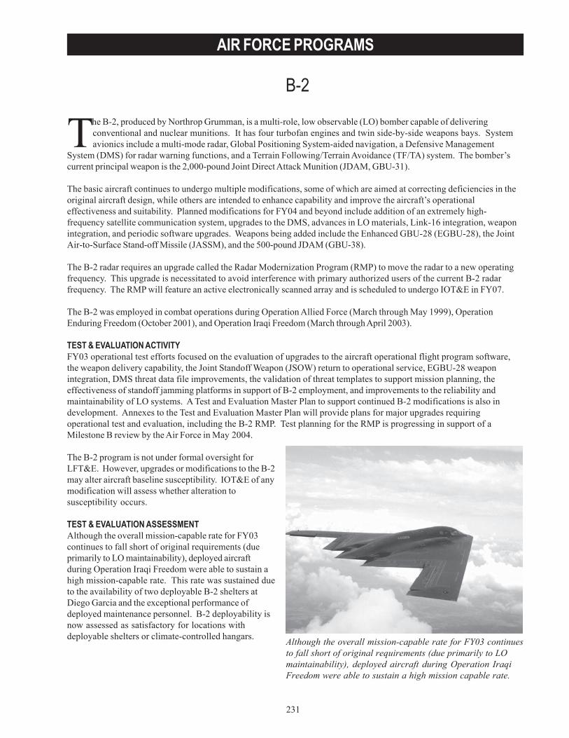
231
AIR FORCE PROGRAMS
B-2
Although the overall mission-capable rate for FY03 continuesto fall short of original requirements (due primarily to LOmaintainability), deployed aircraft during Operation IraqiFreedom were able to sustain a high mission capable rate.
The B-2, produced by Northrop Grumman, is a multi-role, low observable (LO) bomber capable of deliveringconventional and nuclear munitions. It has four turbofan engines and twin side-by-side weapons bays. Systemavionics include a multi-mode radar, Global Positioning System-aided navigation, a Defensive Management
System (DMS) for radar warning functions, and a Terrain Following/Terrain Avoidance (TF/TA) system. The bomber’scurrent principal weapon is the 2,000-pound Joint Direct Attack Munition (JDAM, GBU-31).
The basic aircraft continues to undergo multiple modifications, some of which are aimed at correcting deficiencies in theoriginal aircraft design, while others are intended to enhance capability and improve the aircraft’s operationaleffectiveness and suitability. Planned modifications for FY04 and beyond include addition of an extremely high-frequency satellite communication system, upgrades to the DMS, advances in LO materials, Link-16 integration, weaponintegration, and periodic software upgrades. Weapons being added include the Enhanced GBU-28 (EGBU-28), the JointAir-to-Surface Stand-off Missile (JASSM), and the 500-pound JDAM (GBU-38).
The B-2 radar requires an upgrade called the Radar Modernization Program (RMP) to move the radar to a new operatingfrequency. This upgrade is necessitated to avoid interference with primary authorized users of the current B-2 radarfrequency. The RMP will feature an active electronically scanned array and is scheduled to undergo IOT&E in FY07.
The B-2 was employed in combat operations during Operation Allied Force (March through May 1999), OperationEnduring Freedom (October 2001), and Operation Iraqi Freedom (March through April 2003).
TEST & EVALUATION ACTIVITYFY03 operational test efforts focused on the evaluation of upgrades to the aircraft operational flight program software,the weapon delivery capability, the Joint Standoff Weapon (JSOW) return to operational service, EGBU-28 weaponintegration, DMS threat data file improvements, the validation of threat templates to support mission planning, theeffectiveness of standoff jamming platforms in support of B-2 employment, and improvements to the reliability andmaintainability of LO systems. A Test and Evaluation Master Plan to support continued B-2 modifications is also indevelopment. Annexes to the Test and Evaluation Master Plan will provide plans for major upgrades requiringoperational test and evaluation, including the B-2 RMP. Test planning for the RMP is progressing in support of aMilestone B review by the Air Force in May 2004.
The B-2 program is not under formal oversight forLFT&E. However, upgrades or modifications to the B-2may alter aircraft baseline susceptibility. IOT&E of anymodification will assess whether alteration tosusceptibility occurs.
TEST & EVALUATION ASSESSMENTAlthough the overall mission-capable rate for FY03continues to fall short of original requirements (dueprimarily to LO maintainability), deployed aircraftduring Operation Iraqi Freedom were able to sustain ahigh mission-capable rate. This rate was sustained dueto the availability of two deployable B-2 shelters atDiego Garcia and the exceptional performance ofdeployed maintenance personnel. B-2 deployability isnow assessed as satisfactory for locations withdeployable shelters or climate-controlled hangars.

232
AIR FORCE PROGRAMS
The most promising near-term improvement to LO maintainability (alternate high-frequency materials (AHFM), inconjunction with the implementation of a primer/sealer) has not undergone OT&E or reached the operational squadrons.The Air Force plans to verify through OT&E of AHFM-modified B-2 aircraft that no degradation to B-2 baseline LOcharacteristics occurs and that AHFM can support the Air Force sortie generation requirement. However, the B-2community does not currently possess an organic capability to accurately identify LO defects and verify the LO qualityof repairs. This is primarily due to the lack of integrated diagnostic tools. Sole reliance on the LO Combat ReadinessModel to evaluate aircraft LO capability is also not effective, given limitations in modeling and inspection routines.Operational tests during FY03 demonstrate the LO Combat Readiness Model is incorrect 83 percent of the time inpredicting B-2 signature suitability for combat operations.
The DMS does not provide adequate situational awareness to avoid pop-up threats. DMS mission data fileimprovements continue to be made, but additional upgrades that may resolve DMS capability shortfalls are not funded.
Operational testing of the Situational Awareness Communications upgrade, which is an enhancement to missionflexibility, demonstrated the ability to enable the warfighter to plan and transmit missions to aircraft en route. Thiscapability was used in Operation Iraqi Freedom.
Five JDAMs were released during an Air Force Quick Reaction Test in December 2002 and 583 JDAMs were deliveredduring Operation Iraqi Freedom. Results identified in the Quick Reaction Test met requirements. The addition of thesmart bomb rack assembly with the next operational flight program software upgrade in 2004 should provide thecapability to deliver up to 80 500-pound JDAM weapons. The Air Force carried out separation and guided weaponreleases of up to 80 500-pound JDAM in FY03. Developmental testing indicates the potential for the 500-pound variantto meet requirements when delivered from the B-2. The Air Force plans operational testing of the B-2 with this JDAMvariant in FY04.
The Air Force conducted operational testing of the JSOW (Baseline) weapon on the B-2 in March and April 2003,including captive carry releases and live launches of three JSOW (Baseline) weapons, to restore the JSOW to B-2operational use. Although only one weapon dispensed bomblets within Operation Requirements Document criterion, theAir Force elected interim operational fielding of the JSOW (Baseline) on the B-2 provided workarounds are employed.These workarounds do not affect the ability of the B-2 to employ the JSOW effectively. However, additional tests ofJSOW on the B-2 are required to increase confidence in JSOW/B-2 effectiveness.
Developmental testing of the EGBU-28 on the B-2 indicates the weapon has the potential to meet user requirements.However, the Air Force identified potential upgrades as a result of operational testing for possible future implementation.Integration testing of the EGBU-28 should conclude in FY04.
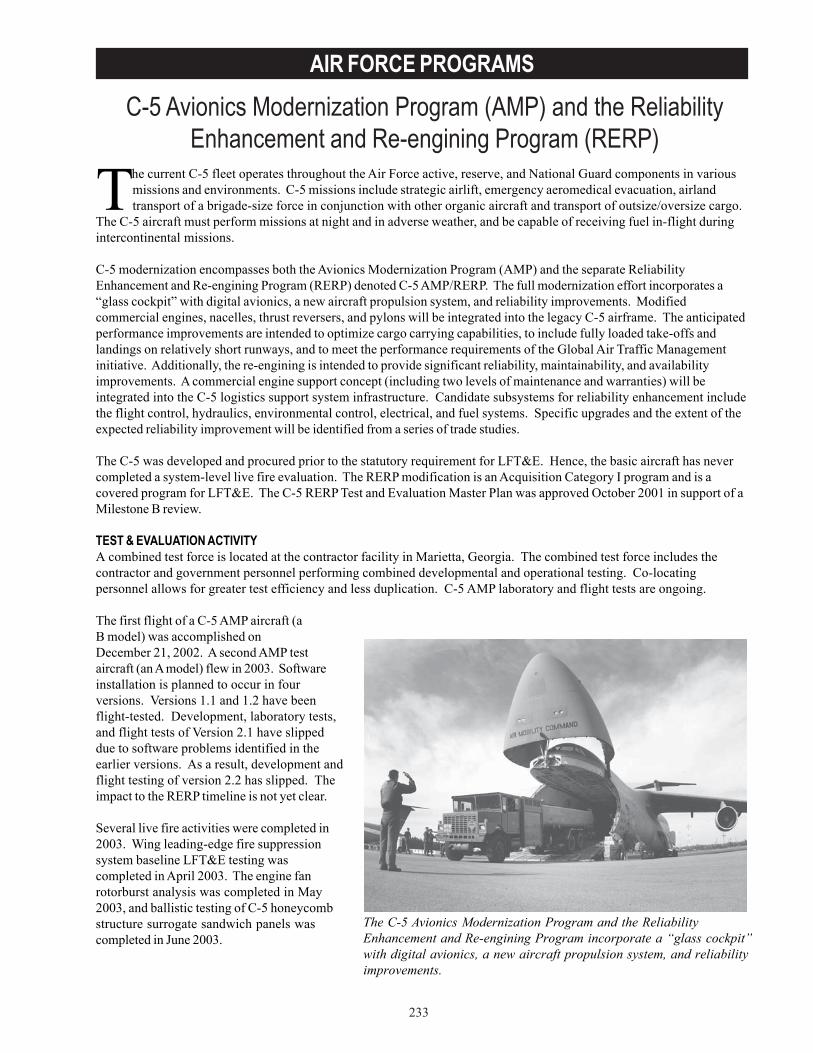
233
AIR FORCE PROGRAMS
C-5 Avionics Modernization Program (AMP) and the ReliabilityEnhancement and Re-engining Program (RERP)
The C-5 Avionics Modernization Program and the ReliabilityEnhancement and Re-engining Program incorporate a “glass cockpit”with digital avionics, a new aircraft propulsion system, and reliabilityimprovements.
The current C-5 fleet operates throughout the Air Force active, reserve, and National Guard components in variousmissions and environments. C-5 missions include strategic airlift, emergency aeromedical evacuation, airlandtransport of a brigade-size force in conjunction with other organic aircraft and transport of outsize/oversize cargo.
The C-5 aircraft must perform missions at night and in adverse weather, and be capable of receiving fuel in-flight duringintercontinental missions.
C-5 modernization encompasses both the Avionics Modernization Program (AMP) and the separate ReliabilityEnhancement and Re-engining Program (RERP) denoted C-5 AMP/RERP. The full modernization effort incorporates a“glass cockpit” with digital avionics, a new aircraft propulsion system, and reliability improvements. Modifiedcommercial engines, nacelles, thrust reversers, and pylons will be integrated into the legacy C-5 airframe. The anticipatedperformance improvements are intended to optimize cargo carrying capabilities, to include fully loaded take-offs andlandings on relatively short runways, and to meet the performance requirements of the Global Air Traffic Managementinitiative. Additionally, the re-engining is intended to provide significant reliability, maintainability, and availabilityimprovements. A commercial engine support concept (including two levels of maintenance and warranties) will beintegrated into the C-5 logistics support system infrastructure. Candidate subsystems for reliability enhancement includethe flight control, hydraulics, environmental control, electrical, and fuel systems. Specific upgrades and the extent of theexpected reliability improvement will be identified from a series of trade studies.
The C-5 was developed and procured prior to the statutory requirement for LFT&E. Hence, the basic aircraft has nevercompleted a system-level live fire evaluation. The RERP modification is an Acquisition Category I program and is acovered program for LFT&E. The C-5 RERP Test and Evaluation Master Plan was approved October 2001 in support of aMilestone B review.
TEST & EVALUATION ACTIVITYA combined test force is located at the contractor facility in Marietta, Georgia. The combined test force includes thecontractor and government personnel performing combined developmental and operational testing. Co-locatingpersonnel allows for greater test efficiency and less duplication. C-5 AMP laboratory and flight tests are ongoing.
The first flight of a C-5 AMP aircraft (aB model) was accomplished onDecember 21, 2002. A second AMP testaircraft (an A model) flew in 2003. Softwareinstallation is planned to occur in fourversions. Versions 1.1 and 1.2 have beenflight-tested. Development, laboratory tests,and flight tests of Version 2.1 have slippeddue to software problems identified in theearlier versions. As a result, development andflight testing of version 2.2 has slipped. Theimpact to the RERP timeline is not yet clear.
Several live fire activities were completed in2003. Wing leading-edge fire suppressionsystem baseline LFT&E testing wascompleted in April 2003. The engine fanrotorburst analysis was completed in May2003, and ballistic testing of C-5 honeycombstructure surrogate sandwich panels wascompleted in June 2003.

234
AIR FORCE PROGRAMS
TEST & EVALUATION ASSESSMENTThere is a high schedule risk for the C-5 AMP development and test programs. The C-5 AMP schedule has slipped atleast four months from the original schedule. If not completed as planned, this high-risk schedule will impact the C-5RERP schedule. The C-5 RERP program is dependent upon the success of the C-5 AMP program.
A preliminary reliability demonstration, included as part of the RERP IOT&E, is required prior to the RERP full-rateproduction decision. In the current Test and Evaluation Master Plan, four aircraft are planned to fly approximately 200sorties for approximately 800 flying hours between IOT&E and the reliability demonstration. Due to funding issues, thenumber of aircraft for developmental testing was reduced to three. This may impact the number of aircraft available forIOT&E. In order to assess the impact to IOT&E, AFOTEC is developing a model and the Air Mobility Command isproviding field data. The model will be used to verify IOT&E planning and the viability of a three-aircraft reliabilityevaluation.
The LFT&E engine fan rotorburst analysis examined the trajectories of various-size fragments arising from an in-flightengine fan failure. The analysis indicated that the probability of inducing damage to C-5 critical systems was negligible;and therefore, in-flight engine fan rotorburst does not contribute to the overall system-level vulnerability of the C-5.
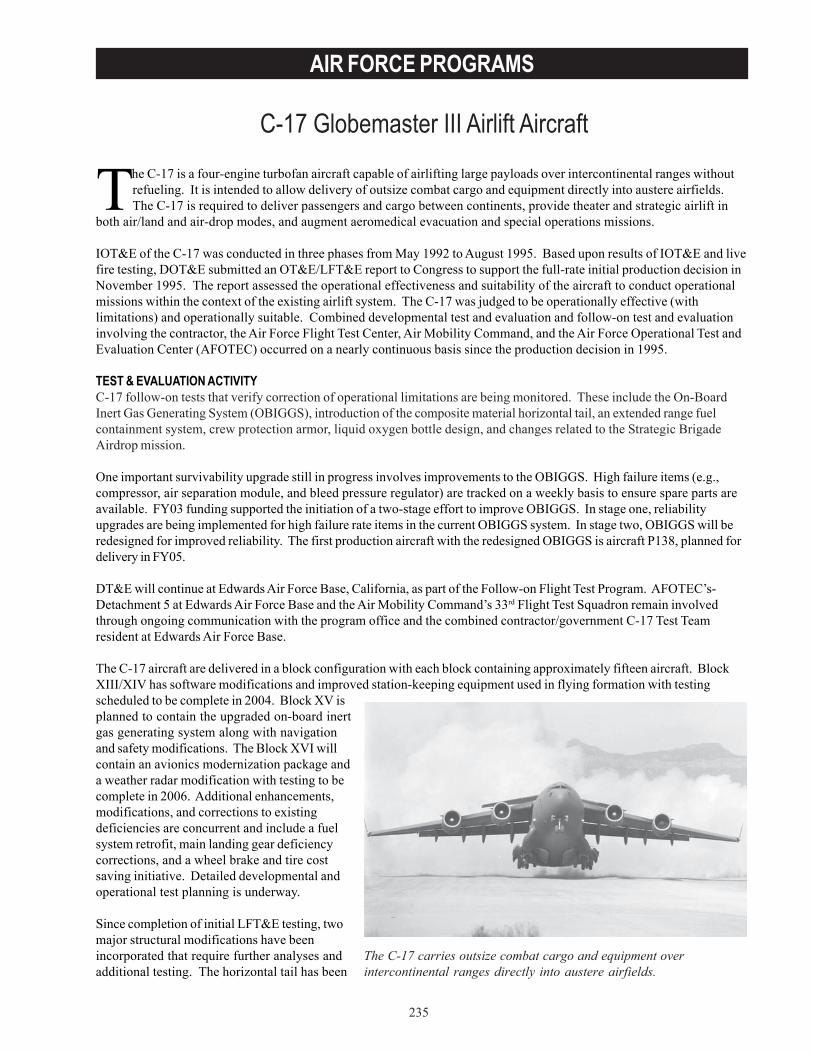
235
AIR FORCE PROGRAMS
C-17 Globemaster III Airlift Aircraft
The C-17 carries outsize combat cargo and equipment overintercontinental ranges directly into austere airfields.
The C-17 is a four-engine turbofan aircraft capable of airlifting large payloads over intercontinental ranges withoutrefueling. It is intended to allow delivery of outsize combat cargo and equipment directly into austere airfields.The C-17 is required to deliver passengers and cargo between continents, provide theater and strategic airlift in
both air/land and air-drop modes, and augment aeromedical evacuation and special operations missions.
IOT&E of the C-17 was conducted in three phases from May 1992 to August 1995. Based upon results of IOT&E and livefire testing, DOT&E submitted an OT&E/LFT&E report to Congress to support the full-rate initial production decision inNovember 1995. The report assessed the operational effectiveness and suitability of the aircraft to conduct operationalmissions within the context of the existing airlift system. The C-17 was judged to be operationally effective (withlimitations) and operationally suitable. Combined developmental test and evaluation and follow-on test and evaluationinvolving the contractor, the Air Force Flight Test Center, Air Mobility Command, and the Air Force Operational Test andEvaluation Center (AFOTEC) occurred on a nearly continuous basis since the production decision in 1995.
TEST & EVALUATION ACTIVITYC-17 follow-on tests that verify correction of operational limitations are being monitored. These include the On-BoardInert Gas Generating System (OBIGGS), introduction of the composite material horizontal tail, an extended range fuelcontainment system, crew protection armor, liquid oxygen bottle design, and changes related to the Strategic BrigadeAirdrop mission.
One important survivability upgrade still in progress involves improvements to the OBIGGS. High failure items (e.g.,compressor, air separation module, and bleed pressure regulator) are tracked on a weekly basis to ensure spare parts areavailable. FY03 funding supported the initiation of a two-stage effort to improve OBIGGS. In stage one, reliabilityupgrades are being implemented for high failure rate items in the current OBIGGS system. In stage two, OBIGGS will beredesigned for improved reliability. The first production aircraft with the redesigned OBIGGS is aircraft P138, planned fordelivery in FY05.
DT&E will continue at Edwards Air Force Base, California, as part of the Follow-on Flight Test Program. AFOTEC’s-Detachment 5 at Edwards Air Force Base and the Air Mobility Command’s 33rd Flight Test Squadron remain involvedthrough ongoing communication with the program office and the combined contractor/government C-17 Test Teamresident at Edwards Air Force Base.
The C-17 aircraft are delivered in a block configuration with each block containing approximately fifteen aircraft. BlockXIII/XIV has software modifications and improved station-keeping equipment used in flying formation with testingscheduled to be complete in 2004. Block XV isplanned to contain the upgraded on-board inertgas generating system along with navigationand safety modifications. The Block XVI willcontain an avionics modernization package anda weather radar modification with testing to becomplete in 2006. Additional enhancements,modifications, and corrections to existingdeficiencies are concurrent and include a fuelsystem retrofit, main landing gear deficiencycorrections, and a wheel brake and tire costsaving initiative. Detailed developmental andoperational test planning is underway.
Since completion of initial LFT&E testing, twomajor structural modifications have beenincorporated that require further analyses andadditional testing. The horizontal tail has been
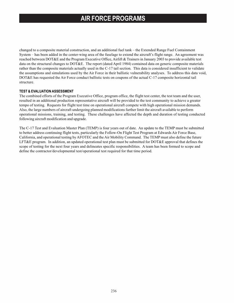
236
AIR FORCE PROGRAMS
changed to a composite material construction, and an additional fuel tank – the Extended Range Fuel ContainmentSystem – has been added in the center-wing area of the fuselage to extend the aircraft’s flight range. An agreement wasreached between DOT&E and the Program Executive Office, Airlift & Trainers in January 2003 to provide available testdata on the structural changes to DOT&E. The report (dated April 1984) contained data on generic composite materialsrather than the composite materials actually used in the C-17 tail section. This data is considered insufficient to validatethe assumptions and simulations used by the Air Force in their ballistic vulnerability analyses. To address this data void,DOT&E has requested the Air Force conduct ballistic tests on coupons of the actual C-17 composite horizontal tailstructure.
TEST & EVALUATION ASSESSMENTThe combined efforts of the Program Executive Office, program office, the flight test center, the test team and the user,resulted in an additional production representative aircraft will be provided to the test community to achieve a greatertempo of testing. Requests for flight test time on operational aircraft compete with high operational mission demands.Also, the large numbers of aircraft undergoing planned modifications further limit the aircraft available to performoperational missions, training, and testing. These challenges have affected the depth and duration of testing conductedfollowing aircraft modification and upgrade.
The C-17 Test and Evaluation Master Plan (TEMP) is four years out of date. An update to the TEMP must be submittedto better address continuing flight tests, particularly the Follow-On Flight Test Program at Edwards Air Force Base,California, and operational testing by AFOTEC and the Air Mobility Command. The TEMP must also define the futureLFT&E program. In addition, an updated operational test plan must be submitted for DOT&E approval that defines thescope of testing for the next four years and delineates specific responsibilities. A team has been formed to scope anddefine the contractor/developmental test/operational test required for that time period.
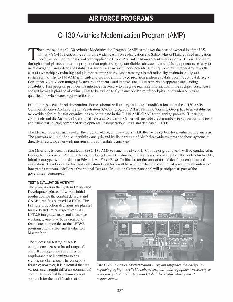
237
AIR FORCE PROGRAMS
C-130 Avionics Modernization Program (AMP)
The purpose of the C-130 Avionics Modernization Program (AMP) is to lower the cost of ownership of the U.S.military’s C-130 fleet, while complying with the Air Force Navigation and Safety Master Plan, required navigationperformance requirements, and other applicable Global Air Traffic Management requirements. This will be done
through a cockpit modernization program that replaces aging, unreliable subsystems, and adds equipment necessary tomeet navigation and safety and Global Air Traffic Management requirements. New equipment is intended to lower thecost of ownership by reducing cockpit crew manning as well as increasing aircraft reliability, maintainability, andsustainability. The C-130 AMP is intended to provide an improved precision airdrop capability for the combat deliveryfleet, meet Night Vision Imaging System requirements, and improve the C-130’s precision approach and landingcapability. This program provides the interfaces necessary to integrate real time information in the cockpit. A standardcockpit layout is planned allowing pilots to be trained to fly in any AMP aircraft cockpit and to undergo missionqualification when reaching a specific unit.
In addition, selected Special Operations Forces aircraft will undergo additional modification under the C-130 AMP/Common Avionics Architecture for Penetration (CAAP) program. A Test Planning Working Group has been establishedto provide a forum for test organizations to participate in the C-130 AMP/CAAP test planning process. The usingcommands and the Air Force Operational Test and Evaluation Center will provide crew members to support ground testsand flight tests during combined developmental test/operational tests and dedicated OT&E.
The LFT&E program, managed by the program office, will develop a C-130 fleet-wide system-level vulnerability analysis.The program will include a vulnerability analysis and ballistic testing of AMP electronic systems and those systems itdirectly affects, together with mission abort vulnerability analyses.
The Milestone B decision resulted in the C-130 AMP contract in July 2001. Contractor ground tests will be conducted atBoeing facilities in San Antonio, Texas, and Long Beach, California. Following a series of flights at the contractor facility,initial prototypes will transition to Edwards Air Force Base, California, for the start of formal developmental test andevaluation. Developmental test and evaluation flight tests will be accomplished by a combined government/contractorintegrated test team. Air Force Operational Test and Evaluation Center personnel will participate as part of thegovernment contingent.
TEST & EVALUATION ACTIVITYThe program is in the System Design andDevelopment phase. Low- rate initialproduction for the combat delivery andCAAP aircraft is planned for FY06. Thefull-rate production decisions are plannedfor FY08 and FY09, respectively. AnLFT&E integrated team and a test planworking group have been created toformulate the specifics of the LFT&Eprogram and the Test and EvaluationMaster Plan.
The successful testing of AMPcomponents across a broad range ofaircraft configurations and missionrequirements will continue to be asignificant challenge. The concept isfeasible; however, it is essential that thevarious users (eight different commands)commit to a unified fleet managementapproach for the modification of all
The C-130 Avionics Modernization Program upgrades the cockpit byreplacing aging, unreliable subsystems, and adds equipment necessary tomeet navigation and safety and Global Air Traffic Managementrequirements.
238
AIR FORCE PROGRAMS
aircraft. Fleet management of more than 700 aircraft is one of the keys to success. A tentative plan calls for some aircraftbeing retired, some moved from one unit to another to manage structural life, some sent to depot, and others used for testpurposes. In addition, concurrent development of different Mission Design Series modifications will add risk to thetechnical developments and to the schedule.
The following table shows the different Mission Design Series (MDS) of the C-130s to be modified and some of thespecial test requirements applicable to them:
TEST & EVALUATION ASSESSMENTThe entire C-130 AMP/CAAP program has been restructured due to funding changes and a renewed emphasis on themissions of the Special Operations Forces aircraft. The restructuring proposes to accelerate the previously planned riskreduction effort (18 months of flying the APN-241 radar in a Special Operations Forces Combat Talon I aircraft withtesting at a government range) for feasibility studies on the radar, new data processing algorithms, and enhancedsituational awareness features for terrain following/terrain avoidance missions with low probability of intercept. Thereshould be less risk to the CAAP portion of the program due to this change, but it could also lengthen the completion ofAMP for other platforms.
The C-130 AMP Test and Evaluation Master Plan was approved by DOT&E in September 2002. An update is required forsubmittal in FY04 due to program funding changes that will impact the currently planned test schedule.
C-130s and Special Test Requirements by MDS
MDS Nomenclature Special Tests C130E/H/H1/H2/H3 Combat Delivery Global Air Traffic Alert and Collision Avoidance
System, Terrain Awareness Warning System, Night Vision Imaging System, Flight Management System
AC-130H/U Gunship Gunfire Accuracy, Enhanced Situational Awareness, Defensive Systems
EC-130H Compass Call Mission Unique HC-130N/P Combat Rescue Mission Unique MC-130E Combat Talon I Terrain Following/Terrain Avoidance Navigation MC-130H Combat Talon II Terrain Following/Terrain Avoidance Navigation,
Enhanced Situational Awareness, Defensive Systems
MC-130P Combat Shadow Mission Unique LC-130H Ski Mission Unique
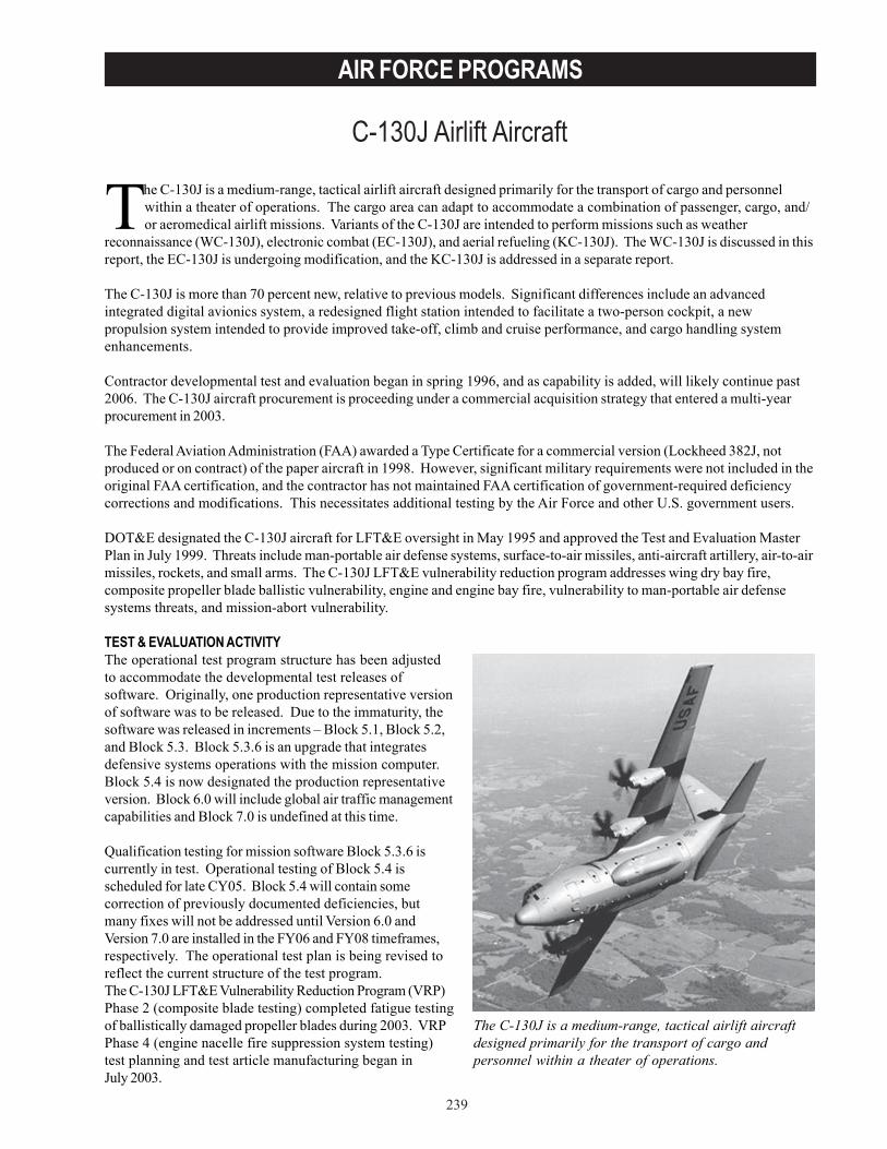
239
AIR FORCE PROGRAMS
C-130J Airlift Aircraft
The C-130J is a medium-range, tactical airlift aircraft designed primarily for the transport of cargo and personnelwithin a theater of operations. The cargo area can adapt to accommodate a combination of passenger, cargo, and/or aeromedical airlift missions. Variants of the C-130J are intended to perform missions such as weather
reconnaissance (WC-130J), electronic combat (EC-130J), and aerial refueling (KC-130J). The WC-130J is discussed in thisreport, the EC-130J is undergoing modification, and the KC-130J is addressed in a separate report.
The C-130J is more than 70 percent new, relative to previous models. Significant differences include an advancedintegrated digital avionics system, a redesigned flight station intended to facilitate a two-person cockpit, a newpropulsion system intended to provide improved take-off, climb and cruise performance, and cargo handling systemenhancements.
Contractor developmental test and evaluation began in spring 1996, and as capability is added, will likely continue past2006. The C-130J aircraft procurement is proceeding under a commercial acquisition strategy that entered a multi-yearprocurement in 2003.
The Federal Aviation Administration (FAA) awarded a Type Certificate for a commercial version (Lockheed 382J, notproduced or on contract) of the paper aircraft in 1998. However, significant military requirements were not included in theoriginal FAA certification, and the contractor has not maintained FAA certification of government-required deficiencycorrections and modifications. This necessitates additional testing by the Air Force and other U.S. government users.
DOT&E designated the C-130J aircraft for LFT&E oversight in May 1995 and approved the Test and Evaluation MasterPlan in July 1999. Threats include man-portable air defense systems, surface-to-air missiles, anti-aircraft artillery, air-to-airmissiles, rockets, and small arms. The C-130J LFT&E vulnerability reduction program addresses wing dry bay fire,composite propeller blade ballistic vulnerability, engine and engine bay fire, vulnerability to man-portable air defensesystems threats, and mission-abort vulnerability.
TEST & EVALUATION ACTIVITYThe operational test program structure has been adjustedto accommodate the developmental test releases ofsoftware. Originally, one production representative versionof software was to be released. Due to the immaturity, thesoftware was released in increments – Block 5.1, Block 5.2,and Block 5.3. Block 5.3.6 is an upgrade that integratesdefensive systems operations with the mission computer.Block 5.4 is now designated the production representativeversion. Block 6.0 will include global air traffic managementcapabilities and Block 7.0 is undefined at this time.
Qualification testing for mission software Block 5.3.6 iscurrently in test. Operational testing of Block 5.4 isscheduled for late CY05. Block 5.4 will contain somecorrection of previously documented deficiencies, butmany fixes will not be addressed until Version 6.0 andVersion 7.0 are installed in the FY06 and FY08 timeframes,respectively. The operational test plan is being revised toreflect the current structure of the test program.The C-130J LFT&E Vulnerability Reduction Program (VRP)Phase 2 (composite blade testing) completed fatigue testingof ballistically damaged propeller blades during 2003. VRPPhase 4 (engine nacelle fire suppression system testing)test planning and test article manufacturing began inJuly 2003.
The C-130J is a medium-range, tactical airlift aircraftdesigned primarily for the transport of cargo andpersonnel within a theater of operations.
240
AIR FORCE PROGRAMS
TEST & EVALUATION ASSESSMENTC-130JMajor issues confronting the C-130J program include funding of logistics support and training systems; hardware,software, and technical order deficiencies; manufacturing quality; subsystem reliability; failure to meet required measuresof system effectiveness and suitability; and resolution of documented deficiencies.
Due to system immaturity, operational testing was initially segmented into three phases of testing: Phase 1A, Phase 1B,and Phase 2. Phase 1A evaluated the ability of the aircraft to be used to train pilots. Phase 1B evaluated the aircraft’sability to perform the air/land mission. Phase 2, planned for FY06, will evaluate the ability to perform all missions toinclude airdrop. Based on the evaluation of test results conducted from Phase 1A and Phase 1B, the aircraft is notoperationally effective. The airdrop mission cannot be evaluated until deficiency corrections are implemented and thedevelopmental tests are completed in FY06. Aircrew workload issues, software discrepancies, and cargo loading andconstraint requirements are still major issues. The using commands (United States Air Force, Air Force Reserves, and AirNational Guard) are unable to verify manpower requirements to field this system until the crew workload evaluation iscomplete.
DOT&E determined that the aircraft is not operationally suitable. The evaluated reliability, maintainability, availability,and logistics supportability during Phase 1B were below operational requirements. Deficiencies were noted with on-aircraft integrated diagnostics and fault isolation systems, portable maintenance aids, maintenance technical orders, andthe availability of spare parts. Additional contractor field service representatives are required to assist in themaintenance of the aircraft for the foreseeable future.
Although hardware and software modifications in Block Upgrade 5.3 showed improved navigation functions, flightdisplays, technical publications, and reduced nuisance faults, a large number of deficiency reports remain open that needto be resolved to achieve operational capability that is equal to the current C-130E/H fleet. An executable plandelineating deficiency correction with adequate funding that will result in an operational capability has not beenformulated. Without an executable plan, the units with aircraft that have already been delivered and those that willreceive additional aircraft prior to the correction of documented deficiencies are unable to perform the full range ofessential combat delivery functions.
Assessment of the live fire VRP ballistic testing of the C-130J composite propeller blades awaits completion of the 46th
Test Wing live fire test report. Test facility limitations narrowed the realism of the testing. The test facility was unable tosupport ballistic testing of dynamically rotating propellers. As a result, ballistic testing was accomplished on stationaryblades with fatigue testing of the damaged blades conducted separately after the ballistic testing was complete.
WC-130JFour major issues confront the weather reconnaissance aircraft. The radar cannot perform the hurricane reconnaissancemission, continuous satellite communication is not achieved, there is propeller delamination, and there is excessivevibration in the auxiliary crew member’s station.
The low-power color radar was designed as a weather avoidance radar, but it was installed in the WC-130J to perform theweather penetration mission. The radar does not support operational requirements for the weather mission. The programoffice has developed a plan to correct this deficiency. Additional software modification tests were planned for late 2003(storm season), but testing was not accomplished due to software deficiencies. Hardware modifications will be testedapproximately 26 months after the contract is awarded. Initial operational capability may be no sooner than FY06. Sincethe WC-130J cannot perform its primary mission, the correction of this deficiency is critical. The secondary impact is thatthe ten older WC-130H models that currently perform the mission were to be converted to aerial refueling tankers andtransferred to Air Combat Command. That will not occur until the WC-130J is fully operational.
A proposed fix to the propeller delamination problem has been installed on test aircraft. Data are currently beingcollected by the Air Force Reserves. The fix must be tested in a hurricane environment.
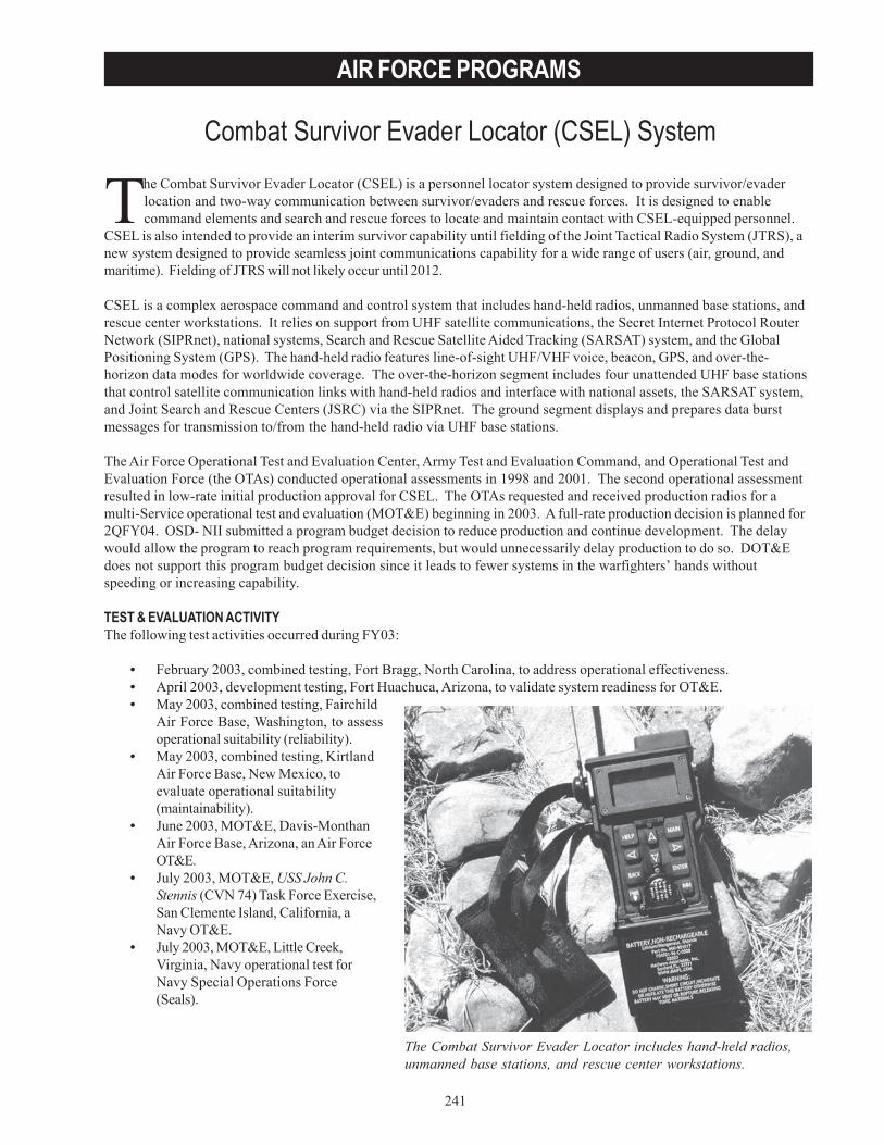
241
AIR FORCE PROGRAMS
Combat Survivor Evader Locator (CSEL) System
The Combat Survivor Evader Locator includes hand-held radios,unmanned base stations, and rescue center workstations.
The Combat Survivor Evader Locator (CSEL) is a personnel locator system designed to provide survivor/evaderlocation and two-way communication between survivor/evaders and rescue forces. It is designed to enablecommand elements and search and rescue forces to locate and maintain contact with CSEL-equipped personnel.
CSEL is also intended to provide an interim survivor capability until fielding of the Joint Tactical Radio System (JTRS), anew system designed to provide seamless joint communications capability for a wide range of users (air, ground, andmaritime). Fielding of JTRS will not likely occur until 2012.
CSEL is a complex aerospace command and control system that includes hand-held radios, unmanned base stations, andrescue center workstations. It relies on support from UHF satellite communications, the Secret Internet Protocol RouterNetwork (SIPRnet), national systems, Search and Rescue Satellite Aided Tracking (SARSAT) system, and the GlobalPositioning System (GPS). The hand-held radio features line-of-sight UHF/VHF voice, beacon, GPS, and over-the-horizon data modes for worldwide coverage. The over-the-horizon segment includes four unattended UHF base stationsthat control satellite communication links with hand-held radios and interface with national assets, the SARSAT system,and Joint Search and Rescue Centers (JSRC) via the SIPRnet. The ground segment displays and prepares data burstmessages for transmission to/from the hand-held radio via UHF base stations.
The Air Force Operational Test and Evaluation Center, Army Test and Evaluation Command, and Operational Test andEvaluation Force (the OTAs) conducted operational assessments in 1998 and 2001. The second operational assessmentresulted in low-rate initial production approval for CSEL. The OTAs requested and received production radios for amulti-Service operational test and evaluation (MOT&E) beginning in 2003. A full-rate production decision is planned for2QFY04. OSD- NII submitted a program budget decision to reduce production and continue development. The delaywould allow the program to reach program requirements, but would unnecessarily delay production to do so. DOT&Edoes not support this program budget decision since it leads to fewer systems in the warfighters’ hands withoutspeeding or increasing capability.
TEST & EVALUATION ACTIVITYThe following test activities occurred during FY03:
• February 2003, combined testing, Fort Bragg, North Carolina, to address operational effectiveness.• April 2003, development testing, Fort Huachuca, Arizona, to validate system readiness for OT&E.• May 2003, combined testing, Fairchild
Air Force Base, Washington, to assessoperational suitability (reliability).
• May 2003, combined testing, KirtlandAir Force Base, New Mexico, toevaluate operational suitability(maintainability).
• June 2003, MOT&E, Davis-MonthanAir Force Base, Arizona, an Air ForceOT&E.
• July 2003, MOT&E, USS John C.Stennis (CVN 74) Task Force Exercise,San Clemente Island, California, aNavy OT&E.
• July 2003, MOT&E, Little Creek,Virginia, Navy operational test forNavy Special Operations Force(Seals).
242
AIR FORCE PROGRAMS
• August 2003, MOT&E, Exercise Desert Rescue, Naval Air Station, Fallon, Nevada, a multi-Service operationaltest and evaluation, joint and coalition interoperability.
• September 2003, combined testing, Hurlburt Field, Florida, water integrity testing.• October 2003, combined testing, Fort Huachuca, Arizona, GPS jamming susceptibility.
TEST & EVALUATION ASSESSMENTThe operational assessment conducted by the OTAs in 2001 determined CSEL to be potentially effective and suitable,but not ready for operational employment. The OTAs identified several areas that required corrective action prior to thestart of MOT&E: Concept of Operations updates, battery improvements, training, manning requirements, ORDrequirements, fielding plan, and communications infrastructure. The contractor subsequently announced that all systemdeficiencies generated from both operational assessments have been corrected. These fixes were validated duringdevelopmental testing in 2002. Because of software and integration problems with the new Selective Availability Anti-Spoofing Module, the contractor encountered difficulties in providing the requested numbers of productionrepresentative hand-held radios for MOT&E. The delays and the lack of hand-held radios caused the operational testagencies to reschedule MOT&E several times in 2002 and 2003.
CSEL was tested in joint and coalition environments, and integrated into end-to-end combat rescue scenarios withoperationally representative survivor/evaders, Joint Search and Rescue Centers, life support, and rescue forces. WhileCSEL has made substantial progress in the past 18 months, there are still issues with employment concepts, training,hand-held radio data loading and maintenance, information assurance, batteries, and national asset support. The OTAsconducted MOT&E test events from June to October 2003 and are in the process of analyzing and reporting the results.MOT&E findings have demonstrated certain individual capabilities (radio function, message relay, JSRC receipt, etc.), buthave had difficulty in showing total system capability in end-to-end tests that exercise all aspects of the CSEL system.Deficiencies have been identified in water intrusion and ground reference point calculations. Both are being re-tested inlate 2003. DOT&E expects the evaluation to be complete before the end of the calendar year in order to support theMilestone review in March 2004.
The number of users requesting survivor radios continues to grow. Survivor radio needs cannot be met with just onesystem (either PRC-112 “Hook” radios or CSEL). The Personnel Recovery Advisory Group recommended immediateefforts to provide capabilities with both systems. They recommend immediate implementation of an over-the-horizoncapability for PRC-112 (which CSEL has, but Hook lacks) and terminal area guidance for CSEL (which Hook has, butCSEL lacks). The goal of both efforts is to provide a wide-ranging interim capability for survivor communications untilthe implementation of JTRS. DOT&E supports these recommendations and also recommends follow-on operational testand evaluation of Hook and CSEL. The follow-on operational test and evaluation must conduct end-to-end testing ofeach system in its respective operational environment. Evaluation of these results will provide the user with the bestpicture of Combat SAR communication capabilities, and assist combatant commanders in choosing the appropriatesystem for their use. DOT&E is nominating the PRC-112 radio for the oversight list in order to support this evaluation.
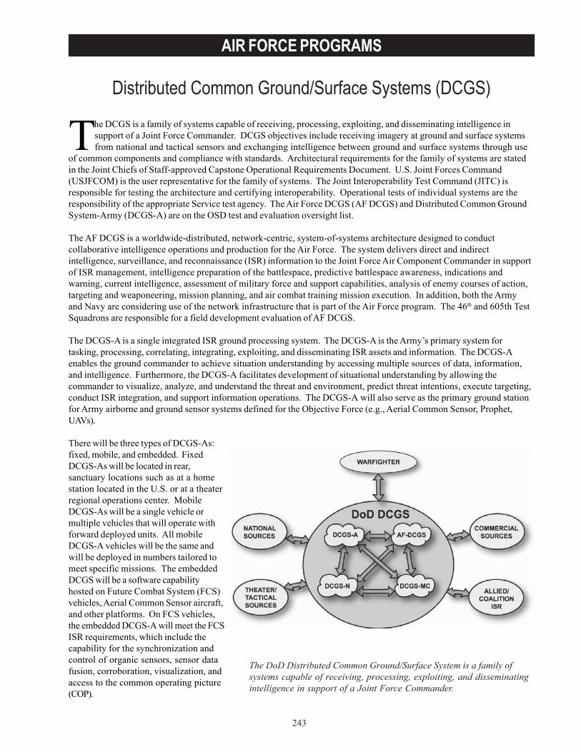
243
AIR FORCE PROGRAMS
Distributed Common Ground/Surface Systems (DCGS)
The DoD Distributed Common Ground/Surface System is a family ofsystems capable of receiving, processing, exploiting, and disseminatingintelligence in support of a Joint Force Commander.
The DCGS is a family of systems capable of receiving, processing, exploiting, and disseminating intelligence insupport of a Joint Force Commander. DCGS objectives include receiving imagery at ground and surface systemsfrom national and tactical sensors and exchanging intelligence between ground and surface systems through use
of common components and compliance with standards. Architectural requirements for the family of systems are statedin the Joint Chiefs of Staff-approved Capstone Operational Requirements Document. U.S. Joint Forces Command(USJFCOM) is the user representative for the family of systems. The Joint Interoperability Test Command (JITC) isresponsible for testing the architecture and certifying interoperability. Operational tests of individual systems are theresponsibility of the appropriate Service test agency. The Air Force DCGS (AF DCGS) and Distributed Common GroundSystem-Army (DCGS-A) are on the OSD test and evaluation oversight list.
The AF DCGS is a worldwide-distributed, network-centric, system-of-systems architecture designed to conductcollaborative intelligence operations and production for the Air Force. The system delivers direct and indirectintelligence, surveillance, and reconnaissance (ISR) information to the Joint Force Air Component Commander in supportof ISR management, intelligence preparation of the battlespace, predictive battlespace awareness, indications andwarning, current intelligence, assessment of military force and support capabilities, analysis of enemy courses of action,targeting and weaponeering, mission planning, and air combat training mission execution. In addition, both the Armyand Navy are considering use of the network infrastructure that is part of the Air Force program. The 46th and 605th TestSquadrons are responsible for a field development evaluation of AF DCGS.
The DCGS-A is a single integrated ISR ground processing system. The DCGS-A is the Army’s primary system fortasking, processing, correlating, integrating, exploiting, and disseminating ISR assets and information. The DCGS-Aenables the ground commander to achieve situation understanding by accessing multiple sources of data, information,and intelligence. Furthermore, the DCGS-A facilitates development of situational understanding by allowing thecommander to visualize, analyze, and understand the threat and environment, predict threat intentions, execute targeting,conduct ISR integration, and support information operations. The DCGS-A will also serve as the primary ground stationfor Army airborne and ground sensor systems defined for the Objective Force (e.g., Aerial Common Sensor, Prophet,UAVs).
There will be three types of DCGS-As:fixed, mobile, and embedded. FixedDCGS-As will be located in rear,sanctuary locations such as at a homestation located in the U.S. or at a theaterregional operations center. MobileDCGS-As will be a single vehicle ormultiple vehicles that will operate withforward deployed units. All mobileDCGS-A vehicles will be the same andwill be deployed in numbers tailored tomeet specific missions. The embeddedDCGS will be a software capabilityhosted on Future Combat System (FCS)vehicles, Aerial Common Sensor aircraft,and other platforms. On FCS vehicles,the embedded DCGS-A will meet the FCSISR requirements, which include thecapability for the synchronization andcontrol of organic sensors, sensor datafusion, corroboration, visualization, andaccess to the common operating picture(COP).
244
AIR FORCE PROGRAMS
TEST & EVALUATION ACTIVITY• JITC completed a working draft of the Capstone Test and Evaluation Master Plan (TEMP).• JITC is developing plans to evaluate the architecture during USJFCOM Combined Joint Task Force Exercise
(CJTFEX) 04-2 on the East Coast.• Air Force test agencies are planning for the potential participation of AF DCGS in CJTFEX 04-2.• During FY03, the DCGS-A program undertook the development of a test strategy to be published in its TEMP
prior to the Milestone B in FY04.
TEST & EVALUATION ASSESSMENTJITC has established interoperability certification programs with 23 of the 26 systems that are members of the DCGSfamily, but only about three of the systems have been granted interoperability certifications. Many of the systems donot have a Joint Chiefs of Staff-approved interoperability key performance parameter that is a prerequisite forinteroperability certification testing.
CJTFEX 04-2 will be the first opportunity to accomplish an operational assessment of a joint network of Service DCGSsystems. Participation of individual Service systems is still to be determined. Lack of Service participation may limit thejoint nature of the architecture.
Seeing, understanding, and acting are vital to the success of the Army’s FCS and Objective Force. Providing andintegrating command and control, ISR, and communications connectivity stands out as the most critical challenge andthe most vital aspect of developing, fielding, and employing FCS capabilities. As the Army’s ISR processing system, theDCGS-A will be a lynchpin of the ISR network that supports FCS. Understanding first will require the DCGS-A tointegrate and fuse data from multiple ISR sources. Currently, there is minimal capability to perform automated fusion.Presently, building the COP requires substantial human interface with inadequate assurance that it is current due tolatency. Achieving a low-latency COP will require significant technological advances in fusion. A significant portion ofDCGS-A will be software, and software development will be the greatest risk to the program.
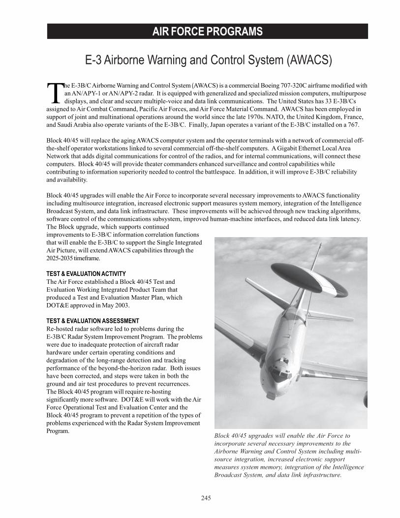
245
AIR FORCE PROGRAMS
E-3 Airborne Warning and Control System (AWACS)
Block 40/45 upgrades will enable the Air Force toincorporate several necessary improvements to theAirborne Warning and Control System including multi-source integration, increased electronic supportmeasures system memory, integration of the IntelligenceBroadcast System, and data link infrastructure.
The E-3B/C Airborne Warning and Control System (AWACS) is a commercial Boeing 707-320C airframe modified withan AN/APY-1 or AN/APY-2 radar. It is equipped with generalized and specialized mission computers, multipurposedisplays, and clear and secure multiple-voice and data link communications. The United States has 33 E-3B/Cs
assigned to Air Combat Command, Pacific Air Forces, and Air Force Material Command. AWACS has been employed insupport of joint and multinational operations around the world since the late 1970s. NATO, the United Kingdom, France,and Saudi Arabia also operate variants of the E-3B/C. Finally, Japan operates a variant of the E-3B/C installed on a 767.
Block 40/45 will replace the aging AWACS computer system and the operator terminals with a network of commercial off-the-shelf operator workstations linked to several commercial off-the-shelf computers. A Gigabit Ethernet Local AreaNetwork that adds digital communications for control of the radios, and for internal communications, will connect thesecomputers. Block 40/45 will provide theater commanders enhanced surveillance and control capabilities whilecontributing to information superiority needed to control the battlespace. In addition, it will improve E-3B/C reliabilityand availability.
Block 40/45 upgrades will enable the Air Force to incorporate several necessary improvements to AWACS functionalityincluding multisource integration, increased electronic support measures system memory, integration of the IntelligenceBroadcast System, and data link infrastructure. These improvements will be achieved through new tracking algorithms,software control of the communications subsystem, improved human-machine interfaces, and reduced data link latency.The Block upgrade, which supports continuedimprovements to E-3B/C information correlation functionsthat will enable the E-3B/C to support the Single IntegratedAir Picture, will extend AWACS capabilities through the2025-2035 timeframe.
TEST & EVALUATION ACTIVITYThe Air Force established a Block 40/45 Test andEvaluation Working Integrated Product Team thatproduced a Test and Evaluation Master Plan, whichDOT&E approved in May 2003.
TEST & EVALUATION ASSESSMENTRe-hosted radar software led to problems during theE-3B/C Radar System Improvement Program. The problemswere due to inadequate protection of aircraft radarhardware under certain operating conditions anddegradation of the long-range detection and trackingperformance of the beyond-the-horizon radar. Both issueshave been corrected, and steps were taken in both theground and air test procedures to prevent recurrences.The Block 40/45 program will require re-hostingsignificantly more software. DOT&E will work with the AirForce Operational Test and Evaluation Center and theBlock 40/45 program to prevent a repetition of the types ofproblems experienced with the Radar System ImprovementProgram.

246
AIR FORCE PROGRAMS
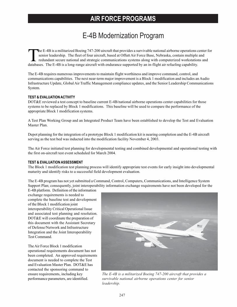
247
AIR FORCE PROGRAMS
E-4B Modernization Program
The E-4B is a militarized Boeing 747-200 aircraft that provides a survivable national airborne operations center forsenior leadership. The fleet of four aircraft, based at Offutt Air Force Base, Nebraska, contain multiple andredundant secure national and strategic communications systems along with computerized workstations and
databases. The E-4B is a long-range aircraft with endurance supported by an in-flight air refueling capability.
The E-4B requires numerous improvements to maintain flight worthiness and improve command, control, andcommunications capabilities. The next near-term major improvement is a Block 1 modification and includes an AudioInfrastructure Update, Global Air Traffic Management compliance updates, and the Senior Leadership CommunicationsSystem.
TEST & EVALUATION ACTIVITYDOT&E reviewed a test concept to baseline current E-4B/national airborne operations center capabilities for thosesystems to be replaced by Block 1 modifications. This baseline will be used to compare the performance of theappropriate Block 1 modification systems.
A Test Plan Working Group and an Integrated Product Team have been established to develop the Test and EvaluationMaster Plan.
Depot planning for the integration of a prototype Block 1 modification kit is nearing completion and the E-4B aircraftserving as the test bed was inducted into the modification facility November 4, 2003.
The Air Force initiated test planning for developmental testing and combined developmental and operational testing withthe first on-aircraft test event scheduled for March 2004.
TEST & EVALUATION ASSESSMENTThe Block 1 modification test planning process will identify appropriate test events for early insight into developmentalmaturity and identify risks to a successful field development evaluation.
The E-4B program has not yet submitted a Command, Control, Computers, Communications, and Intelligence SystemSupport Plan; consequently, joint interoperability information exchange requirements have not been developed for theE-4B platform. Definition of the informationexchange requirements is needed tocomplete the baseline test and developmentof the Block 1 modification jointinteroperability Critical Operational Issueand associated test planning and resolution.DOT&E will coordinate the preparation ofthis document with the Assistant Secretaryof Defense/Network and InfrastructureIntegration and the Joint InteroperabilityTest Command.
The Air Force Block 1 modificationoperational requirements document has notbeen completed. An approved requirementsdocument is needed to complete the Testand Evaluation Master Plan. DOT&E hascontacted the sponsoring command toensure requirements, including keyperformance parameters, are identified.
The E-4B is a militarized Boeing 747-200 aircraft that provides asurvivable national airborne operations center for seniorleadership.

248
AIR FORCE PROGRAMS
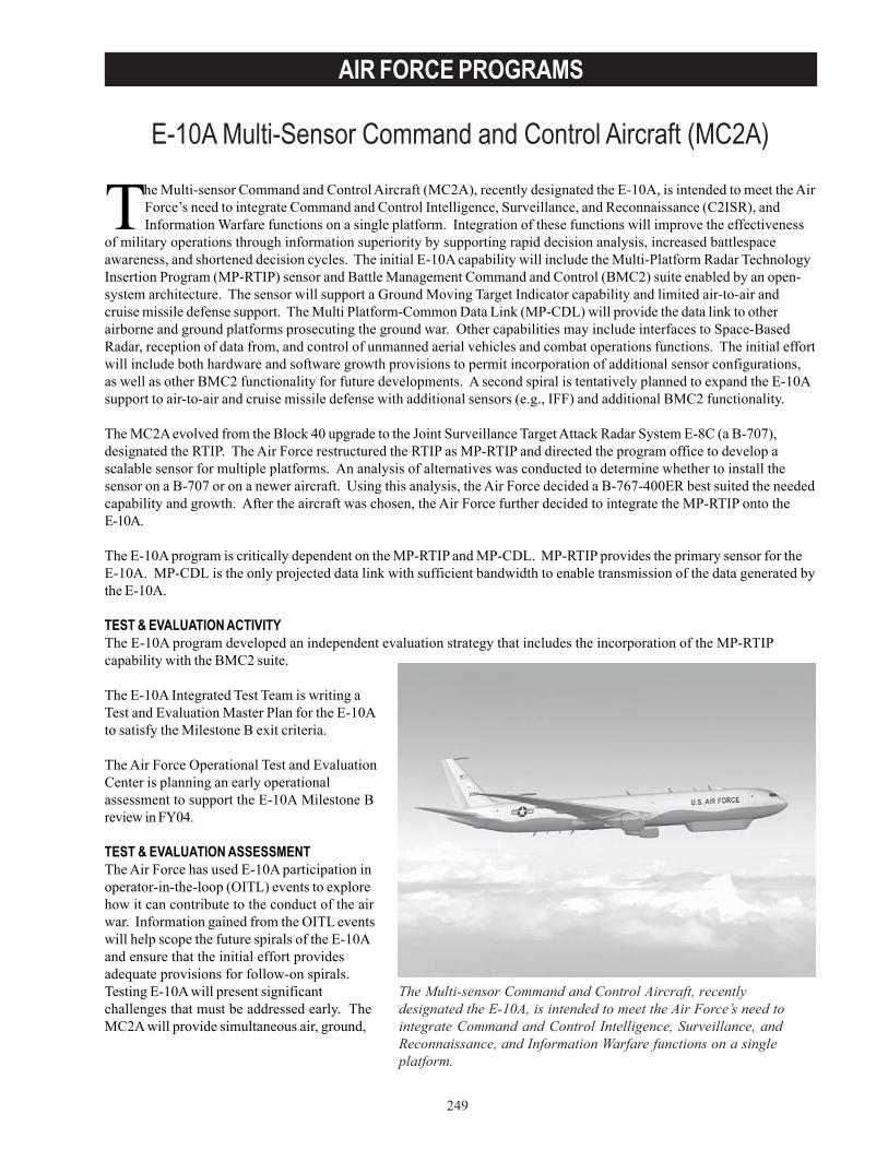
249
AIR FORCE PROGRAMS
E-10A Multi-Sensor Command and Control Aircraft (MC2A)
The Multi-sensor Command and Control Aircraft, recentlydesignated the E-10A, is intended to meet the Air Force’s need tointegrate Command and Control Intelligence, Surveillance, andReconnaissance, and Information Warfare functions on a singleplatform.
The Multi-sensor Command and Control Aircraft (MC2A), recently designated the E-10A, is intended to meet the AirForce’s need to integrate Command and Control Intelligence, Surveillance, and Reconnaissance (C2ISR), andInformation Warfare functions on a single platform. Integration of these functions will improve the effectiveness
of military operations through information superiority by supporting rapid decision analysis, increased battlespaceawareness, and shortened decision cycles. The initial E-10A capability will include the Multi-Platform Radar TechnologyInsertion Program (MP-RTIP) sensor and Battle Management Command and Control (BMC2) suite enabled by an open-system architecture. The sensor will support a Ground Moving Target Indicator capability and limited air-to-air andcruise missile defense support. The Multi Platform-Common Data Link (MP-CDL) will provide the data link to otherairborne and ground platforms prosecuting the ground war. Other capabilities may include interfaces to Space-BasedRadar, reception of data from, and control of unmanned aerial vehicles and combat operations functions. The initial effortwill include both hardware and software growth provisions to permit incorporation of additional sensor configurations,as well as other BMC2 functionality for future developments. A second spiral is tentatively planned to expand the E-10Asupport to air-to-air and cruise missile defense with additional sensors (e.g., IFF) and additional BMC2 functionality.
The MC2A evolved from the Block 40 upgrade to the Joint Surveillance Target Attack Radar System E-8C (a B-707),designated the RTIP. The Air Force restructured the RTIP as MP-RTIP and directed the program office to develop ascalable sensor for multiple platforms. An analysis of alternatives was conducted to determine whether to install thesensor on a B-707 or on a newer aircraft. Using this analysis, the Air Force decided a B-767-400ER best suited the neededcapability and growth. After the aircraft was chosen, the Air Force further decided to integrate the MP-RTIP onto theE-10A.
The E-10A program is critically dependent on the MP-RTIP and MP-CDL. MP-RTIP provides the primary sensor for theE-10A. MP-CDL is the only projected data link with sufficient bandwidth to enable transmission of the data generated bythe E-10A.
TEST & EVALUATION ACTIVITYThe E-10A program developed an independent evaluation strategy that includes the incorporation of the MP-RTIPcapability with the BMC2 suite.
The E-10A Integrated Test Team is writing aTest and Evaluation Master Plan for the E-10Ato satisfy the Milestone B exit criteria.
The Air Force Operational Test and EvaluationCenter is planning an early operationalassessment to support the E-10A Milestone Breview in FY04.
TEST & EVALUATION ASSESSMENTThe Air Force has used E-10A participation inoperator-in-the-loop (OITL) events to explorehow it can contribute to the conduct of the airwar. Information gained from the OITL eventswill help scope the future spirals of the E-10Aand ensure that the initial effort providesadequate provisions for follow-on spirals.Testing E-10A will present significantchallenges that must be addressed early. TheMC2A will provide simultaneous air, ground,
250
AIR FORCE PROGRAMS
and sea C2ISR support and targeting information to all the Services. It will require a high degree of joint interoperabilityfor both ground combat and air defense. Demonstrating the ability to support the joint prosecution of the air and groundwars simultaneously will require carefully planned field tests augmented by modeling and simulation, and will demand anunprecedented level of joint cooperation.
Finally, the risk associated with the interdependency of two Acquisition Category ID programs (E-10A and MP-RTIP)along with the MP-CDL must not be underestimated. E-10A is dependent on MP-RTIP to deliver its primary sensor.MP-RTIP is dependent on E-10A to provide a test platform for the sensor and the MP-CDL to serve as the pipeline forradar data to the users. Planned delivery of the three must be closely coordinated to ensure no part of the overall systemhas to wait for the delivery of the others. Due to the scope and the long lead-times required for these programs, suchdelays will significantly increase risk.

251
AIR FORCE PROGRAMS
Evolved Expandable Launch Vehicle (EELV)
The Evolved Expendable Launch Vehicle (EELV) program fulfills government satellite launch requirements currentlyserved by Delta II, Atlas II, Titan II, and Titan IV. The EELV will be DoD’s only medium, intermediate, and heavypayload space launch capability after current heritage inventories are exhausted. FY03 marked the transition to
the new launch vehicle, which is expected to provide launch services through 2020.
The government intends to maintain an ongoing competition between two contractors, Boeing and Lockheed Martin,rather than down-selecting to one. Boeing’s EELV family of launch vehicles is designated the Delta IV, and LockheedMartin’s family the Atlas V. DoD will acquire launch services from these contractors. Production and launch operationsresponsibilities, as well as ownership of all EELV flight hardware and launch pad structures, will remain with thecontractor. DoD will lease launch pad real property and other on-base facilities required for operations to thecontractors. The contractors have shared development costs with the government to satisfy both DoD civil launchrequirements and commercial launch needs.
The EELV system includes launch vehicles, infrastructure, support systems, and interfaces. The contractor isstandardizing payload interfaces, launch pads, and infrastructure so that all configurations of each contractor’s EELVfamily can be launched from the same pad and payloads can be interchanged between vehicles in the same class(i.e., medium, intermediate, or heavy). The EELV program will maintain current mass-to-orbit capability while increasinglaunch rate and decreasing costs. Potential savings will be generated through the commercial launch market and shareddevelopment by government and commercial customers.
TEST & EVALUATION ACTIVITYFY03 DOT&E activity consisted of:
• Attendance at several wet dress rehearsals.• Participation in the Program Office-run Flight
Readiness Reviews that occur before each launch.• First-hand observation of launch day activities
(sitting on console with ability to hear contractorcommunications).
• Witnessing EELV launches including spacecraftseparation.
• Participation in both the contractor-run post-launchdata reviews and the Special Programs Office-runpost launch briefings.
DOT&E also participated in Test Integrated ProductTeam meetings, with the goal of updating theSeptember 1998 Test and Evaluation Master Planand ensuring critical documentation and data areavailable for independent review and analysis.
The Air Force Operational Test and Evaluation Center(AFOTEC) conducted an EELV operational assessment (OA)II from April 2001 to December 2002 to support the firstgovernment launch.
TEST & EVALUATION ASSESSMENTThere do not appear to be any insurmountable problem areasaffecting the EELV program as a whole. Both the Atlas V andDelta IV boosters have launched successfully. Post-flightanalyses for the launches indicate that first and second stage
Since OperationalAssessment II marked the endof AFOTEC’s Evolved Expandable LaunchVehicle test program involvement, DOT&Earranged for additional system performanceanalysis through a detailed test plan laid out inthe 2003 Test and Evaluation Master Plan.
252
AIR FORCE PROGRAMS
engine performance and orbital insertion were nominal. Further, both contractors’ vehicles have successfully flown withsolid boosters strapped to the main booster.
AFOTEC completed OA II on December 18, 2002, and found the system to be a potentially effective and potentiallysuitable launch service which can support the requirements of the National Launch Forecast. Areas that were rated asmaking satisfactory progress with qualifications included vehicle design reliability; logistics supportability; and anumber of payload interfaces. OA II supported the Air Force Space Command’s launch readiness review for the firstgovernment payload launch, a Defense Satellite Communications System payload launched March 11, 2003.
Since OA II marked the end of AFOTEC’s EELV test program involvement, DOT&E arranged for additional systemperformance analysis through a detailed test plan laid out in the 2003 Test and Evaluation Master Plan. Specifically,DOT&E will be involved in a final operational test phase that will encompass several launches presently planned for eachcontractor, and should include medium launch vehicles, heavy lift vehicles, and East Coast and West Coast launches.This final phase of operational testing has been identified as the Post-OA-II operational evaluation (POE).
This POE concept relies almost exclusively on combined developmental/operational testing. Due to the currentacquisition strategy, there are no further scheduled dedicated operational test events. The test strategy includesextensive use of models and simulations to predict individual subsystem and total system performance. Despite thecommercial involvement in the program, the government needs to evaluate system effectiveness and suitability and howwell the system can support DoD missions.
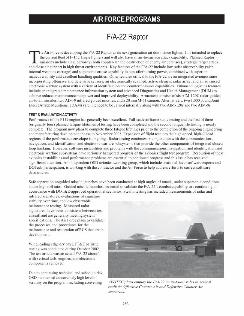
253
AIR FORCE PROGRAMS
F/A-22 Raptor
AFOTEC plans employ the F/A-22 in air-to-air roles in severalrealistic Offensive Counter Air and Defensive Counter Airscenarios.
The Air Force is developing the F/A-22 Raptor as its next-generation air dominance fighter. It is intended to replacethe current fleet of F-15C Eagle fighters and will also have an air-to-surface attack capability. Planned Raptormissions include air superiority (both counter-air and destruction of enemy air defenses), strategic target attack,
and close air support in high threat environments. Key features of the F/A-22 include low radar observability (withinternal weapons carriage) and supersonic cruise capability in non-afterburning power, combined with superiormaneuverability and excellent handling qualities. Other features critical to the F/A-22 are an integrated avionics suiteincorporating offensive and defensive sensors; an electronically scanned, active element radar array; and an advancedelectronic warfare system with a variety of identification and countermeasures capabilities. Enhanced logistics featuresinclude an integrated maintenance information system and advanced Diagnostics and Health Management (DHM) toachieve reduced maintenance manpower and improved deployability. Armament consists of six AIM-120C radar-guidedair-to-air missiles, two AIM-9 infrared guided missiles, and a 20 mm M-61 cannon. Alternatively, two 1,000 pound JointDirect Attack Munitions (JDAMs) are intended to be carried internally along with two AIM-120s and two AIM-9s.
TEST & EVALUATION ACTIVITYPerformance of the F119 engine has generally been excellent. Full-scale airframe static testing and the first of three(originally four) planned fatigue lifetimes of testing have been completed and the second fatigue life testing is nearlycomplete. The program now plans to complete three fatigue lifetimes prior to the completion of the ongoing engineeringand manufacturing development phase in November 2005. Expansion of flight test into the high-speed, high-G loadregions of the performance envelope is ongoing. Radar testing continues in conjunction with the communications,navigation, and identification and electronic warfare subsystems that provide the other components of integrated closed-loop tracking. However, software instabilities and problems with the communications, navigation, and identification andelectronic warfare subsystems have seriously hampered progress of the avionics flight test program. Resolution of theseavionics instabilities and performance problems are essential to continued progress and this issue has receivedsignificant attention. An independent OSD avionics working group, which includes national-level software experts andDOT&E participation, is working with the contractor and the Air Force to help address efforts to correct softwaredeficiencies.
Safe separation unguided missile launches have been conducted at high angles of attack, under supersonic conditions,and at high roll rates. Guided missile launches, essential to validate the F/A-22’s combat capability, are continuing inaccordance with DOT&E-approved operational scenarios. Stealth testing has included measurements of radar andinfrared signatures, evaluations of signaturestability over time, and low observablemaintenance testing. Measured radarsignatures have been consistent between testaircraft and are generally meeting systemspecifications. The Air Force plans to validatethe processes and procedures for themaintenance and restoration of RCS that are indevelopment.
Wing leading edge dry bay LFT&E ballistictesting was conducted during October 2002.The test article was an actual F/A-22 aircraftwith vertical tails, engines, and electroniccomponents removed.
Due to continuing technical and schedule risk,OSD maintained an extremely high level ofscrutiny on the program including convening

254
AIR FORCE PROGRAMS
Quarterly Defense Acquisition Board (DAB) reviews chaired by the Defense Acquisition Executive (DAE). DOT&Eparticipates in regular Air Force Readiness to Test meetings in order to track progress and understand issues. At the July2003 DAB, the DAE directed that a preliminary phase of operational testing and evaluation (OT&E Phase I) be conductedto establish a performance baseline prior to the start of IOT&E. If demonstrated performance during OT&E Phase I issuccessful and the F/A-22 weapons system, as tested, does not require substantial modification prior to the start ofIOT&E, the results from OT&E Phase I could be used to reduce the scope of the subsequent IOT&E. The intent is forthe Air Force Operational Test and Evaluation Center (AFOTEC) to determine what works, what does not, and whatneeds to be fixed before entering IOT&E. DOT&E approved the Air Force test plan for OT&E Phase I and IOT&E,including a comparison test using the F-15C, on September 10, 2003. AFOTEC will conduct OT&E Phase I and theIOT&E, which are both mission-oriented operational tests. AFOTEC plans employ the F/A-22 in air-to-air roles in severalrealistic Offensive Counter Air and Defensive Counter Air scenarios.
TEST & EVALUATION ASSESSMENTDOT&E has focused attention on determining whether or not the Air Force is providing a production representativeweapons system for the upcoming operational testing. To this end, the program continues to identify modifications to beimplemented on production representative test aircraft. Differences between the aircraft planned for operational testingand production aircraft exist, particularly in the avionics hardware, aircraft canopies, and maintenance informationsystems. DOT&E continues to review and assess the impact of differences on performance with the Air Force to ensurean adequate evaluation.
Only one flight test aircraft incorporates the structural modifications and special instrumentation needed to enable theflight envelope to be fully cleared to its airspeed, altitude, and G-load design limits. This situation poses a schedule riskin clearing the required flight envelope prior to IOT&E. Additionally, all operational test aircraft currently have multipleoperating limitations, including the aircraft intended to be production representative and available for operational testing.Successful conduct of IOT&E requires an adequate flight envelope and unmonitored flight clearance (without controlroom support to monitor loads/stresses during maneuvers typical of visual “close-in” air combat).
Avionics software instabilities have resulted in an inefficient avionics test program, delays in integrating requiredfunctionality, and delays in fixing system deficiencies. Resolving avionics system instabilities and functionality issueshas required dedication of an F/A-22 test aircraft to stability testing, development of numerous software fixes, andextensive regression testing. Additional software problems were sometimes created during incorporation of plannedfunctionality and the software stability resolution process, further complicating efforts to achieve the planned softwareintegration schedule. Additional time may be required to incorporate and validate all necessary stability andfunctionality-related avionics modifications prior to an event-driven start of IOT&E. While significant progress has beenmade by the program in reducing the root causes of software instabilities, several remain as well as numerousdeficiencies in functionality that will potentially affect mission performance.
Maintainability and sortie generation require adequate integrated diagnostics. This capability will not be available untilafter planned software is implemented that allows maintenance personnel to operate the interface between plannedsupport equipment and aircraft systems. Integrated diagnostics is required for an adequate IOT&E suitability evaluation.Maintaining the operational test aircraft during the IOT&E will require some contractor-operated special test equipment;consequently, the user has modified the maintenance concept for units that will operate initial production lots. Inaddition to sufficiently mature DHM, flight-line maintenance lacks the functionality in the integrated maintenanceinformation system necessary to troubleshoot and track aircraft maintenance as well as adequate, useable technical orderdata for performing the required routine maintenance tasks. Recently, the Air Force determined that an F/A-22 unit willnot need to deploy with as many personnel or materiel to repair low observable defects as was originally envisioned.However, maintaining the aircraft’s low observable features depends on validation of maintenance procedures, signatureassessment system software and databases through adequate flight test.
The maintainability dilemma is exacerbated by lower than predicted reliability in aircraft systems and the cockpit canopyhas fallen far short of its service life requirement, resulting in the need to procure additional spare canopies to support
255
AIR FORCE PROGRAMS
the IOT&E. Low aircraft systems reliability, in concert with the other suitability factors mentioned here, has resulted invery low sortie generation rates despite a significant amount of maintenance performed on aircraft used for operationaltest pilot and maintainer training. This has caused the operational test unit to re-plan the training program required priorto IOT&E. The suitability deficiencies must be corrected and adequate spare parts provided to be able to fully train theoperational test force and subsequently succeed in IOT&E.
End-to-end weapons integration missile shots have had mixed results. Four shots have demonstrated the capability toengage and destroy enemy aircraft in specific, discreet combat representative scenarios. However, three other shotsindicated fire control deficiencies exist that need to be resolved in development. Some F/A-22 weapons separation, fullyintegrated guided missile test launches, and JDAM testing are planned to be done concurrently with IOT&E. JDAMemployment is planned for follow-on test and evaluation, to be conducted after IOT&E. DOT&E believes that a largeF/A-22 development risk, from both a technical and schedule perspective, lies in the integration of the avionics suite withrealistic air-to-air and, eventually, air-to-surface weapons employment.
The F/A-22 Air Combat Simulator (ACS), an integral part of the planned IOT&E, is intended to model the densesurface-to-air and air-to-air threat and electronic signal environment that is impractical or too costly to generate in open-air trails. Development of the ACS (consisting of four actual F/A-22 cockpits installed in visual scene domes and tenother manned interactive cockpit stations) continues, but delays in integrated avionics flight test and threat model-related development have affected ACS verification, validation, and accreditation activities. The contractor has takensteps to improve ACS realism and has a plan to provide a dense track environment in which to model F/A-22performance. There is a risk that ACS cannot be accredited and contingency plans for additional open air testing arecalled for in the IOT&E test plan.
The ballistic vulnerability LFT&E program surfaced several vulnerabilites that the Program Office is working to resolve.
Significant F/A-22 operational capability is being deferred until after the start of IOT&E. Deferred testing includes theferry configuration, external stores and JDAM carriage and release, full missile and gun employment envelope, andnumerous system specification compliance test points. Deferred mission avionics capabilities include JDAMemployment, AIM-9X integration, helmet mounted cueing system integration, Joint Tactical Information Data Systemtransmit capability, and transition to the planned production version of the F/A-22 Common Integrated Processor, withattendant changes to avionics core processing. An updated Test and Evaluation Master Plan is required for DOT&Eapproval that details the test strategy for an adequate follow-on test and evaluation for the deferred capability, as well asdeficiencies identified in IOT&E.
DOT&E assesses technical and schedule risk in providing an effective and suitable production representative weaponssystem for a successful IOT&E by the planned March 2004 start date as high. In particular, a sufficient amount of timemust be allowed to incorporate fixes to test aircraft prior to the start of IOT&E, based on the assessment of performancein the preceding OT&E Phase I.

256
AIR FORCE PROGRAMS
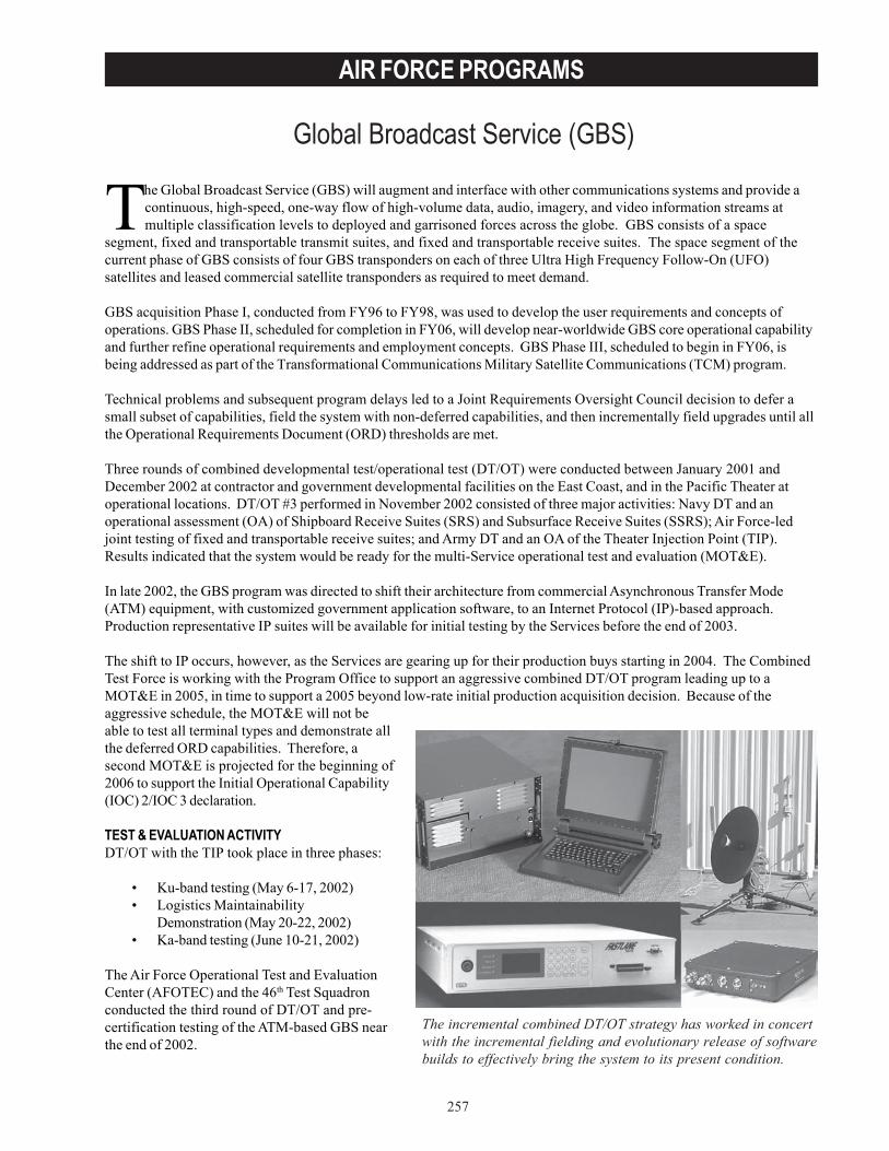
257
AIR FORCE PROGRAMS
Global Broadcast Service (GBS)
The incremental combined DT/OT strategy has worked in concertwith the incremental fielding and evolutionary release of softwarebuilds to effectively bring the system to its present condition.
The Global Broadcast Service (GBS) will augment and interface with other communications systems and provide acontinuous, high-speed, one-way flow of high-volume data, audio, imagery, and video information streams atmultiple classification levels to deployed and garrisoned forces across the globe. GBS consists of a space
segment, fixed and transportable transmit suites, and fixed and transportable receive suites. The space segment of thecurrent phase of GBS consists of four GBS transponders on each of three Ultra High Frequency Follow-On (UFO)satellites and leased commercial satellite transponders as required to meet demand.
GBS acquisition Phase I, conducted from FY96 to FY98, was used to develop the user requirements and concepts ofoperations. GBS Phase II, scheduled for completion in FY06, will develop near-worldwide GBS core operational capabilityand further refine operational requirements and employment concepts. GBS Phase III, scheduled to begin in FY06, isbeing addressed as part of the Transformational Communications Military Satellite Communications (TCM) program.
Technical problems and subsequent program delays led to a Joint Requirements Oversight Council decision to defer asmall subset of capabilities, field the system with non-deferred capabilities, and then incrementally field upgrades until allthe Operational Requirements Document (ORD) thresholds are met.
Three rounds of combined developmental test/operational test (DT/OT) were conducted between January 2001 andDecember 2002 at contractor and government developmental facilities on the East Coast, and in the Pacific Theater atoperational locations. DT/OT #3 performed in November 2002 consisted of three major activities: Navy DT and anoperational assessment (OA) of Shipboard Receive Suites (SRS) and Subsurface Receive Suites (SSRS); Air Force-ledjoint testing of fixed and transportable receive suites; and Army DT and an OA of the Theater Injection Point (TIP).Results indicated that the system would be ready for the multi-Service operational test and evaluation (MOT&E).
In late 2002, the GBS program was directed to shift their architecture from commercial Asynchronous Transfer Mode(ATM) equipment, with customized government application software, to an Internet Protocol (IP)-based approach.Production representative IP suites will be available for initial testing by the Services before the end of 2003.
The shift to IP occurs, however, as the Services are gearing up for their production buys starting in 2004. The CombinedTest Force is working with the Program Office to support an aggressive combined DT/OT program leading up to aMOT&E in 2005, in time to support a 2005 beyond low-rate initial production acquisition decision. Because of theaggressive schedule, the MOT&E will not beable to test all terminal types and demonstrate allthe deferred ORD capabilities. Therefore, asecond MOT&E is projected for the beginning of2006 to support the Initial Operational Capability(IOC) 2/IOC 3 declaration.
TEST & EVALUATION ACTIVITYDT/OT with the TIP took place in three phases:
• Ku-band testing (May 6-17, 2002)• Logistics Maintainability
Demonstration (May 20-22, 2002)• Ka-band testing (June 10-21, 2002)
The Air Force Operational Test and EvaluationCenter (AFOTEC) and the 46th Test Squadronconducted the third round of DT/OT and pre-certification testing of the ATM-based GBS nearthe end of 2002.
258
AIR FORCE PROGRAMS
MOT&E was postponed until FY05 due to ATM-based system limitations and GBS architecture transition to IP.
Operational test of the Navy SRS was conducted by the Operational Test and Evaluation Force in late 2003.
The Program Office and test community rewrote the Test and Evaluation Master Plan to reflect the IP-based strategy andit is currently in the signature process.
TEST & EVALUATION ASSESSMENTPre-certification testing indicated that most of the ATM-based system was ready to enter MOT&E. However, there werestill a number of effectiveness and suitability issues with both the TIP and SRS. Given the limitations on the TIP andSRS, along with the projected phase-out of the ATM equipment, DOT&E supported an AFOTEC recommendation todefer the MOT&E for the IP-based system. AFOTEC wrote an OA using the pre-certification test data to support thedeclaring IOC 1 declaration. The Air Force Space Command has delayed declaring IOC 1, originally scheduled forSeptember 2003. The incremental combined DT/OT strategy has worked in concert with the incremental fielding andevolutionary release of software builds to effectively bring the system to its present condition.
Broadcast software and overall system performance. The most recent testing indicates that product reception rates were96 percent for unclassified data, 93 percent for classified data, and 100 percent for video products – both classified andunclassified. Spot beam control was successful for 100 percent of the requested moves within an average of six minutes.Some problems still exist with dynamic tuning and the loss of permanent virtual circuits with cryptography equipment. Inaddition, dynamic bandwidth allocation will not be possible until implementation of the IP architecture. Overall,reliability, availability, and maintainability are good.
Navy Receive Suites. The Navy 2002 OA determined that the SRS and SSRS are potentially effective and suitable.Product reception rates for the SRS were 77 percent for unclassified products and 82 percent for classified products,below the ORD threshold of 90 percent. Results from the Navy OT during August – September 2003 are still pending.Antenna blockage due to superstructure and other antennas is a Navy-unique problem. When a ship holds a course fora lengthy period such as during flight operations, this could pose a serious operational problem.
Theater Injection Point. TIP test results are fair, with an overall product reception rate of 44 percent for unclassified dataand 28 percent for classified data. Generally, testing went well with the Ku-band broadcast, but significant problemsoccurred during the Ka-band broadcast. Hardware issues persist and there is no trained crew capable of operating theTIP without extensive support from a Raytheon contractor. Due to these deficiencies, the Joint Forces Command statedthe TIP should not be deployed until corrective actions are implemented. Receive sites also lack adequate operatingprocedures with respect to reception of the TIP broadcast.
Other Considerations. AFOTEC found that the GBS system is in good condition with respect to interoperability andinformation assurance, but identified the following concerns of particular note:
• Slow connectivity and large data products. The GBS system delivers data to the Receive Suites at a rate of upto 23.5 megabits per second. In forward locations, the local area tactical networks are not always capable ofdisseminating this information rapidly enough to the end users.
• Beam Movements. Current operational security procedures call for three different beam movements to support asingle submarine reception – two fictitious locations and one true location, so as not to compromise submarinelocations. Since GBS operations support multiple submarines in theater and there is up to ten-minuteprogramming delay in conjunction with each beam move, this could eventually result in a significant loss inbroadcast time.
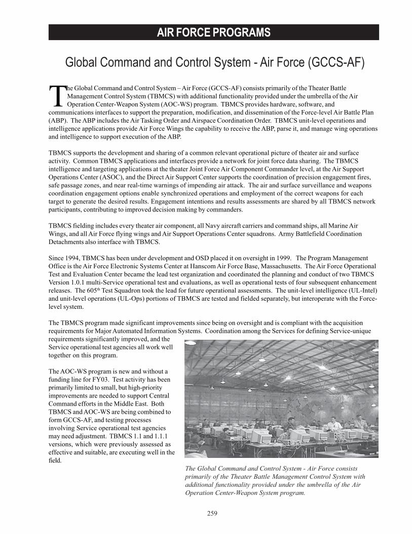
259
AIR FORCE PROGRAMS
Global Command and Control System - Air Force (GCCS-AF)
The Global Command and Control System - Air Force consistsprimarily of the Theater Battle Management Control System withadditional functionality provided under the umbrella of the AirOperation Center-Weapon System program.
The Global Command and Control System – Air Force (GCCS-AF) consists primarily of the Theater BattleManagement Control System (TBMCS) with additional functionality provided under the umbrella of the AirOperation Center-Weapon System (AOC-WS) program. TBMCS provides hardware, software, and
communications interfaces to support the preparation, modification, and dissemination of the Force-level Air Battle Plan(ABP). The ABP includes the Air Tasking Order and Airspace Coordination Order. TBMCS unit-level operations andintelligence applications provide Air Force Wings the capability to receive the ABP, parse it, and manage wing operationsand intelligence to support execution of the ABP.
TBMCS supports the development and sharing of a common relevant operational picture of theater air and surfaceactivity. Common TBMCS applications and interfaces provide a network for joint force data sharing. The TBMCSintelligence and targeting applications at the theater Joint Force Air Component Commander level, at the Air SupportOperations Center (ASOC), and the Direct Air Support Center supports the coordination of precision engagement fires,safe passage zones, and near real-time warnings of impending air attack. The air and surface surveillance and weaponscoordination engagement options enable synchronized operations and employment of the correct weapons for eachtarget to generate the desired results. Engagement intentions and results assessments are shared by all TBMCS networkparticipants, contributing to improved decision making by commanders.
TBMCS fielding includes every theater air component, all Navy aircraft carriers and command ships, all Marine AirWings, and all Air Force flying wings and Air Support Operations Center squadrons. Army Battlefield CoordinationDetachments also interface with TBMCS.
Since 1994, TBMCS has been under development and OSD placed it on oversight in 1999. The Program ManagementOffice is the Air Force Electronic Systems Center at Hanscom Air Force Base, Massachusetts. The Air Force OperationalTest and Evaluation Center became the lead test organization and coordinated the planning and conduct of two TBMCSVersion 1.0.1 multi-Service operational test and evaluations, as well as operational tests of four subsequent enhancementreleases. The 605th Test Squadron took the lead for future operational assessments. The unit-level intelligence (UL-Intel)and unit-level operations (UL-Ops) portions of TBMCS are tested and fielded separately, but interoperate with the Force-level system.
The TBMCS program made significant improvements since being on oversight and is compliant with the acquisitionrequirements for Major Automated Information Systems. Coordination among the Services for defining Service-uniquerequirements significantly improved, and theService operational test agencies all work welltogether on this program.
The AOC-WS program is new and without afunding line for FY03. Test activity has beenprimarily limited to small, but high-priorityimprovements are needed to support CentralCommand efforts in the Middle East. BothTBMCS and AOC-WS are being combined toform GCCS-AF, and testing processesinvolving Service operational test agenciesmay need adjustment. TBMCS 1.1 and 1.1.1versions, which were previously assessed aseffective and suitable, are executing well in thefield.
260
AIR FORCE PROGRAMS
TEST & EVALUATION ACTIVITYThe following test activity took place during FY03:
• TBMCS UL- Intel Spiral 7 FDE, April 2003.• TBMCS 1.1.2 (Force-level) Combined Developmental Test/Operational Test, May 2003.• AOC-WS 10.0.2 Combined Developmental Test/Operational Test, May 2003.• TBMCS UL-Ops Spiral 7 Development Test, June 2003.
TEST & EVALUATION ASSESSMENTTBMCS UL-Intel is using a nine-month spiral development approach, with time programmed in the schedule for fixingproblems found during early testing. During Spiral 7, this approach worked very well and problems found duringdevelopmental testing were fixed before the system entered final developmental evaluation. As a result, the finaldevelopmental evaluation went smoothly, and the system was assessed to be effective and suitable.
TBMCS 1.1.2 experienced a response slowdown associated with the intelligence server. Subsequent testing by the46th Test Squadron in an automated developmental test environment revealed the problem still exists, and this version iscurrently assessed as not effective and not suitable. DOT&E agrees with the responsible test organization that thisproblem should be fixed before fielding approval.
Most systems within the AOC-WS baseline are produced and tested separately. Testing of AOC-WS 10.0.2 focusedheavily on defining the AOC-WS end system configuration based on the evolving baseline used by Central Command,bringing the system under close configuration management and ensuring the various systems interoperate. Significantprogress has been made. Eliminating the need for the virtual private network surrounding TBMCS will offer furtherimprovements.
TBMCS Unit-level Operations Spiral 7 experienced numerous delays due to problems found in the software duringdevelopmental testing. Unit-level Operations Spiral 7 will be operationally tested in April 2004.
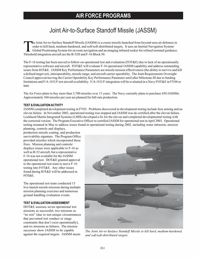
261
AIR FORCE PROGRAMS
Joint Air-to-Surface Standoff Missile (JASSM)
The Joint Air-to-Surface Standoff Missile (JASSM) is a cruise missile launched from beyond-area air defenses inorder to kill hard, medium-hardened, and soft/soft-distributed targets. It uses an Inertial Navigation System/Global Positioning System for en route navigation and an imaging infrared seeker for refined terminal guidance.
Threshold integration aircraft are the B-52H and F-16 Block 50.
The F-16 testing has been moved to follow-on operational test and evaluation (FOT&E) due to lack of an operationallyrepresentative software and aircraft. FOT&E will evaluate F-16 operational JASSM capability and address outstandingissues from IOT&E. JASSM Key Performance Parameters are missile mission effectiveness (the ability to survive and killa defined target set), interoperability, missile range, and aircraft carrier operability. The Joint Requirements OversightCouncil approved moving the Carrier Operability Key Performance Parameter until after Milestone III due to fundinglimitations and F/A-18 E/F test aircraft availability. F/A-18 E/F integration will be evaluated in a Navy FOT&E in FY04 orlater.
The Air Force plans to buy more than 3,700 missiles over 13 years. The Navy currently plans to purchase 450 JASSMs.Approximately 360 missiles per year are planned for full-rate production.
TEST & EVALUATION ACTIVITYJASSM completed development testing in FY03. Problems discovered in development testing include fuze arming and anelevon failure. In November 2002, operational testing was stopped and JASSM was de-certified after the elevon failure.Lockheed Martin Integrated Systems (LMIS) developed a fix for the elevon and completed developmental testing withthe corrected version. The Program Executive Officer re-certified JASSM for operational test in April 2003. Operationaltesting resumed in May to address issues found in operational testing during 2002, including water intrusion, missionplanning, controls and displays,production missile coating, and productionsurvivability signature. The Program Officeprovided missiles which incorporated thesefixes. Mission planning and controls/displays issues were applicable to F-16 aswell as B-52 aircraft, but a representativeF-16 was not available for the JASSMoperational test. DOT&E granted approvalto the operational test team to move F-16testing into FOT&E. Any other issuesfound during IOT&E will be addressed inFOT&E.
The operational test team conducted 15live-launch missile missions during multiplemission planning exercises and numerousground handling evaluation events.
TEST & EVALUATION ASSESSMENTDOT&E assesses seven operational testmissions as successful, two missions as“no test” (due to test-unique circumstancesthat prevented test conduct or rangeconstraints that don’t exist operationally),and six missions as failures. The missionsuccesses show JASSM to be capableagainst the required targets. JASSM meets
The Joint Air-to-Surface Standoff Missile to kill hard, medium-hardened,and soft/soft-distributed targets.
262
AIR FORCE PROGRAMS
the Key Performance Parameters of range, missile mission effectiveness, and interoperability. One mission discovered aproblem with missile mission data changes. The crew changed missile missions (a typical crew procedure) leading to theloss of the preplanned seeker template for that missile. The missile successfully struck the target without seeker updates.The solution to this problem will be implemented with a missile software change and tested in FOT&E.
Of the six JASSM missiles with live warheads launched at realistic targets, four hit their targets. Two shots were requiredto kill a hardened bunker; however, a single shot killed a medium hardened bunker. The attack of a weapons bunkerresulted in the failure of the warhead to detonate and no kill was achieved. There were a total of 15 live-warheadlaunches against realistic targets (developmental test and operational test), nine of which provided useful lethality data.Twice JASSM demonstrated it can kill a hardened bunker in just two shots and it can kill a representative medium-hardened bunker, communications van, radar, and weapons bunker with a single shot. Of the three flights in which thewarhead failed to detonate (twice in FY01 against a radar and once in FY03 against a weapons bunker), the causes offailure have been identified only for the FY01 occurrences.
The six failures include problems in fuzing (two failures), engine start (one failure), and B-52 carriage and interface (threefailures). The fuze failures were attributed to production quality control and are being mitigated by extra steps in fuzequalification and production oversight. The engine failure was attributed to damage from a foreign object in the fuel lineand is being mitigated with changed production procedures to reduce the possibility of reoccurrence. The B-52 problemswere attributed to computer processor and carriage equipment problems. These are being deferred to a later date whenthe B-52 avionics can be updated. In the short term, they are mitigated by changes in crew procedures to try to preventthe problems from reoccurring.
Reliability and maintainability testing included captive-carry, environmental, and aircraft loading evaluations on the B-52.Rainwater collected inside the protective ground covers and the missile itself, causing paint bubbling and electricalfailures. The events completed after recertification show the viability of the fixes implemented to correct problems withwater intrusion/retention and missile durability found during previous operational testing. These events also includedtesting with a re-designed missile cover. The redesigned cover does not mitigate all risks and problems found in usingsuch a cover, but it corrects the mission-essential problems of water intrusion/retention.
The Air Force intends to develop and field a JASSM-Extended Range variant to increase the missile’s standoff range. Ata minimum, the engine and fuel system will be modified. DOT&E is working with the Air Force Operational Test andEvaluation Center and the JASSM Program Office to develop a test and evaluation strategy for this new capability.
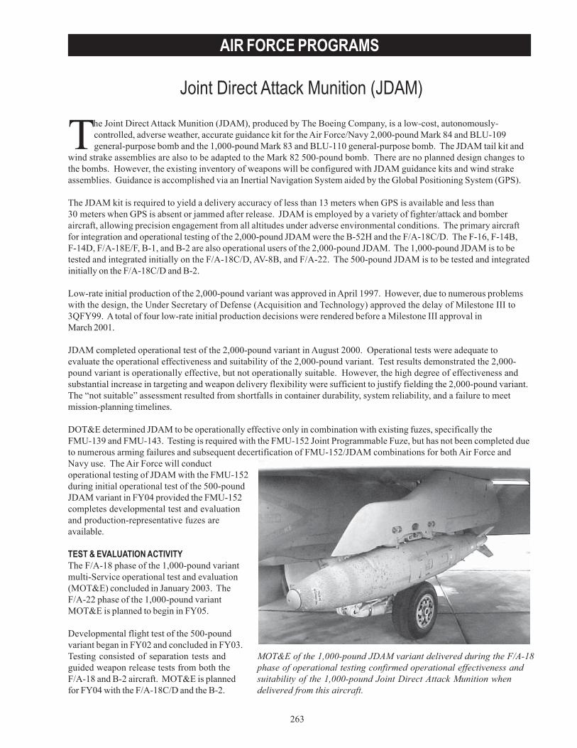
263
AIR FORCE PROGRAMS
Joint Direct Attack Munition (JDAM)
MOT&E of the 1,000-pound JDAM variant delivered during the F/A-18phase of operational testing confirmed operational effectiveness andsuitability of the 1,000-pound Joint Direct Attack Munition whendelivered from this aircraft.
The Joint Direct Attack Munition (JDAM), produced by The Boeing Company, is a low-cost, autonomously-controlled, adverse weather, accurate guidance kit for the Air Force/Navy 2,000-pound Mark 84 and BLU-109general-purpose bomb and the 1,000-pound Mark 83 and BLU-110 general-purpose bomb. The JDAM tail kit and
wind strake assemblies are also to be adapted to the Mark 82 500-pound bomb. There are no planned design changes tothe bombs. However, the existing inventory of weapons will be configured with JDAM guidance kits and wind strakeassemblies. Guidance is accomplished via an Inertial Navigation System aided by the Global Positioning System (GPS).
The JDAM kit is required to yield a delivery accuracy of less than 13 meters when GPS is available and less than30 meters when GPS is absent or jammed after release. JDAM is employed by a variety of fighter/attack and bomberaircraft, allowing precision engagement from all altitudes under adverse environmental conditions. The primary aircraftfor integration and operational testing of the 2,000-pound JDAM were the B-52H and the F/A-18C/D. The F-16, F-14B,F-14D, F/A-18E/F, B-1, and B-2 are also operational users of the 2,000-pound JDAM. The 1,000-pound JDAM is to betested and integrated initially on the F/A-18C/D, AV-8B, and F/A-22. The 500-pound JDAM is to be tested and integratedinitially on the F/A-18C/D and B-2.
Low-rate initial production of the 2,000-pound variant was approved in April 1997. However, due to numerous problemswith the design, the Under Secretary of Defense (Acquisition and Technology) approved the delay of Milestone III to3QFY99. A total of four low-rate initial production decisions were rendered before a Milestone III approval inMarch 2001.
JDAM completed operational test of the 2,000-pound variant in August 2000. Operational tests were adequate toevaluate the operational effectiveness and suitability of the 2,000-pound variant. Test results demonstrated the 2,000-pound variant is operationally effective, but not operationally suitable. However, the high degree of effectiveness andsubstantial increase in targeting and weapon delivery flexibility were sufficient to justify fielding the 2,000-pound variant.The “not suitable” assessment resulted from shortfalls in container durability, system reliability, and a failure to meetmission-planning timelines.
DOT&E determined JDAM to be operationally effective only in combination with existing fuzes, specifically theFMU-139 and FMU-143. Testing is required with the FMU-152 Joint Programmable Fuze, but has not been completed dueto numerous arming failures and subsequent decertification of FMU-152/JDAM combinations for both Air Force andNavy use. The Air Force will conductoperational testing of JDAM with the FMU-152during initial operational test of the 500-poundJDAM variant in FY04 provided the FMU-152completes developmental test and evaluationand production-representative fuzes areavailable.
TEST & EVALUATION ACTIVITYThe F/A-18 phase of the 1,000-pound variantmulti-Service operational test and evaluation(MOT&E) concluded in January 2003. TheF/A-22 phase of the 1,000-pound variantMOT&E is planned to begin in FY05.
Developmental flight test of the 500-poundvariant began in FY02 and concluded in FY03.Testing consisted of separation tests andguided weapon release tests from both theF/A-18 and B-2 aircraft. MOT&E is plannedfor FY04 with the F/A-18C/D and the B-2.
264
AIR FORCE PROGRAMS
TEST & EVALUATION ASSESSMENTMOT&E of the 1,000-pound JDAM variant delivered during the F/A-18 phase of operational testing confirmedoperational effectiveness and suitability of the 1,000-pound JDAM when delivered from this aircraft. Operational testingconfirmed that JDAM reliability and mission planning now meet requirements. However, a redesigned JDAM containerwas not ready for evaluation during FY03 operational testing. Evaluation of a redesigned JDAM container will beconducted during initial operational test of the 500-pound JDAM variant. Delivery of the 1,000-pound variant from theF/A-22 is still necessary to complete MOT&E of the 1,000-pound JDAM.
Developmental tests of the 500-pound variant of the JDAM indicate performance that is comparable to the 2,000-poundand 1,000-pound variants.
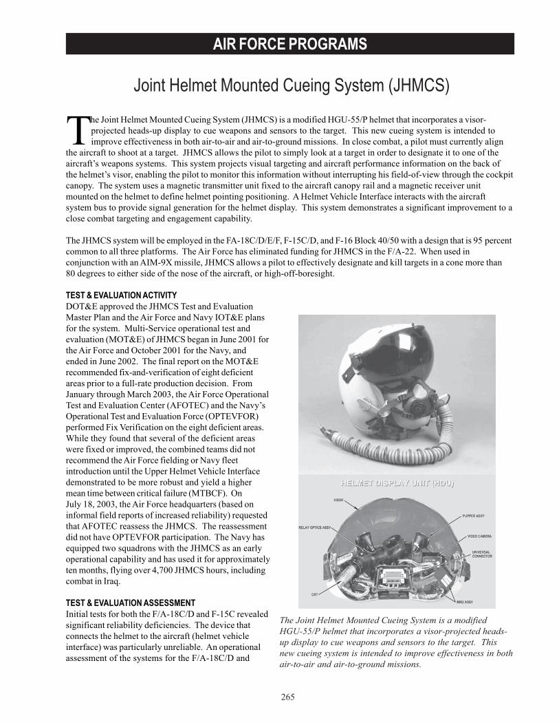
265
AIR FORCE PROGRAMS
Joint Helmet Mounted Cueing System (JHMCS)
The Joint Helmet Mounted Cueing System (JHMCS) is a modified HGU-55/P helmet that incorporates a visor-projected heads-up display to cue weapons and sensors to the target. This new cueing system is intended toimprove effectiveness in both air-to-air and air-to-ground missions. In close combat, a pilot must currently align
the aircraft to shoot at a target. JHMCS allows the pilot to simply look at a target in order to designate it to one of theaircraft’s weapons systems. This system projects visual targeting and aircraft performance information on the back ofthe helmet’s visor, enabling the pilot to monitor this information without interrupting his field-of-view through the cockpitcanopy. The system uses a magnetic transmitter unit fixed to the aircraft canopy rail and a magnetic receiver unitmounted on the helmet to define helmet pointing positioning. A Helmet Vehicle Interface interacts with the aircraftsystem bus to provide signal generation for the helmet display. This system demonstrates a significant improvement to aclose combat targeting and engagement capability.
The JHMCS system will be employed in the FA-18C/D/E/F, F-15C/D, and F-16 Block 40/50 with a design that is 95 percentcommon to all three platforms. The Air Force has eliminated funding for JHMCS in the F/A-22. When used inconjunction with an AIM-9X missile, JHMCS allows a pilot to effectively designate and kill targets in a cone more than80 degrees to either side of the nose of the aircraft, or high-off-boresight.
TEST & EVALUATION ACTIVITYDOT&E approved the JHMCS Test and EvaluationMaster Plan and the Air Force and Navy IOT&E plansfor the system. Multi-Service operational test andevaluation (MOT&E) of JHMCS began in June 2001 forthe Air Force and October 2001 for the Navy, andended in June 2002. The final report on the MOT&Erecommended fix-and-verification of eight deficientareas prior to a full-rate production decision. FromJanuary through March 2003, the Air Force OperationalTest and Evaluation Center (AFOTEC) and the Navy’sOperational Test and Evaluation Force (OPTEVFOR)performed Fix Verification on the eight deficient areas.While they found that several of the deficient areaswere fixed or improved, the combined teams did notrecommend the Air Force fielding or Navy fleetintroduction until the Upper Helmet Vehicle Interfacedemonstrated to be more robust and yield a highermean time between critical failure (MTBCF). OnJuly 18, 2003, the Air Force headquarters (based oninformal field reports of increased reliability) requestedthat AFOTEC reassess the JHMCS. The reassessmentdid not have OPTEVFOR participation. The Navy hasequipped two squadrons with the JHMCS as an earlyoperational capability and has used it for approximatelyten months, flying over 4,700 JHMCS hours, includingcombat in Iraq.
TEST & EVALUATION ASSESSMENTInitial tests for both the F/A-18C/D and F-15C revealedsignificant reliability deficiencies. The device thatconnects the helmet to the aircraft (helmet vehicleinterface) was particularly unreliable. An operationalassessment of the systems for the F/A-18C/D and
The Joint Helmet Mounted Cueing System is a modifiedHGU-55/P helmet that incorporates a visor-projected heads-up display to cue weapons and sensors to the target. Thisnew cueing system is intended to improve effectiveness in bothair-to-air and air-to-ground missions.
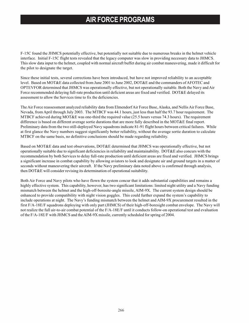
266
AIR FORCE PROGRAMS
F-15C found the JHMCS potentially effective, but potentially not suitable due to numerous breaks in the helmet vehicleinterface. Initial F-15C flight tests revealed that the legacy computer was slow in providing necessary data to JHMCS.This slow data input to the helmet, coupled with normal aircraft buffet during air combat maneuvering, made it difficult forthe pilot to designate the target.
Since these initial tests, several corrections have been introduced, but have not improved reliability to an acceptablelevel. Based on MOT&E data collected from June 2001 to June 2002, DOT&E and the commanders of AFOTEC andOPTEVFOR determined that JHMCS was operationally effective, but not operationally suitable. Both the Navy and AirForce recommended delaying full-rate production until deficient areas are fixed and verified. DOT&E delayed itsassessment to allow the Services time to fix the deficiencies.
The Air Force reassessment analyzed reliability data from Elmendorf Air Force Base, Alaska, and Nellis Air Force Base,Nevada, from April through July 2003. The MTBCF was 44.1 hours, just less than half the 93.7 hour requirement. TheMTBCF achieved during MOT&E was one-third the required value (25.5 hours versus 74.3 hours). The requirementdifference is based on different average sortie durations that are more fully described in the MOT&E final report.Preliminary data from the two still-deployed Navy squadrons indicate 81-91 flight hours between critical failures. Whileat first glance the Navy numbers suggest significantly better reliability, without the average sortie duration to calculateMTBCF on the same basis, no definitive conclusions should be made regarding reliability.
Based on MOT&E data and test observations, DOT&E determined that JHMCS was operationally effective, but notoperationally suitable due to significant deficiencies in reliability and maintainability. DOT&E also concurs with therecommendation by both Services to delay full-rate production until deficient areas are fixed and verified. JHMCS bringsa significant increase in combat capability by allowing aviators to look and designate air and ground targets in a matter ofseconds without maneuvering their aircraft. If the Navy preliminary data noted above is confirmed through analysis,then DOT&E will consider revising its determination of operational suitability.
Both Air Force and Navy pilots who have flown the system concur that it adds substantial capabilities and remains ahighly effective system. This capability, however, has two significant limitations: limited night utility and a Navy fundingmismatch between the helmet and the high-off-boresite-angle missile, AIM-9X. The current system design should beenhanced to provide compatibility with night vision goggles. This could further expand the system’s capability toinclude operations at night. The Navy’s funding mismatch between the helmet and AIM-9X procurement resulted in thefirst F/A-18E/F squadrons deploying with only part (JHMCS) of their high-off-boresight combat envelope. The Navy willnot realize the full air-to-air combat potential of the F/A-18E/F until it conducts follow-on operational test and evaluationof the F/A-18E/F with JHMCS and the AIM-9X missile, currently scheduled for spring of 2004.
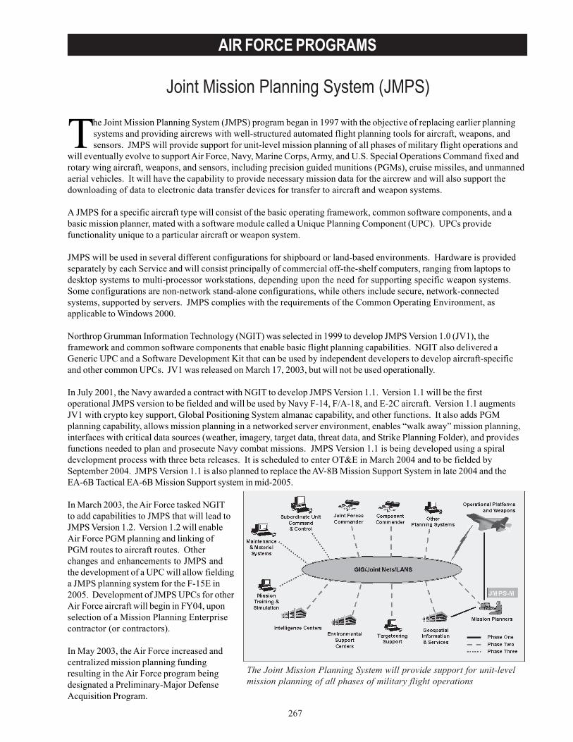
267
AIR FORCE PROGRAMS
Joint Mission Planning System (JMPS)
The Joint Mission Planning System will provide support for unit-levelmission planning of all phases of military flight operations
The Joint Mission Planning System (JMPS) program began in 1997 with the objective of replacing earlier planningsystems and providing aircrews with well-structured automated flight planning tools for aircraft, weapons, andsensors. JMPS will provide support for unit-level mission planning of all phases of military flight operations and
will eventually evolve to support Air Force, Navy, Marine Corps, Army, and U.S. Special Operations Command fixed androtary wing aircraft, weapons, and sensors, including precision guided munitions (PGMs), cruise missiles, and unmannedaerial vehicles. It will have the capability to provide necessary mission data for the aircrew and will also support thedownloading of data to electronic data transfer devices for transfer to aircraft and weapon systems.
A JMPS for a specific aircraft type will consist of the basic operating framework, common software components, and abasic mission planner, mated with a software module called a Unique Planning Component (UPC). UPCs providefunctionality unique to a particular aircraft or weapon system.
JMPS will be used in several different configurations for shipboard or land-based environments. Hardware is providedseparately by each Service and will consist principally of commercial off-the-shelf computers, ranging from laptops todesktop systems to multi-processor workstations, depending upon the need for supporting specific weapon systems.Some configurations are non-network stand-alone configurations, while others include secure, network-connectedsystems, supported by servers. JMPS complies with the requirements of the Common Operating Environment, asapplicable to Windows 2000.
Northrop Grumman Information Technology (NGIT) was selected in 1999 to develop JMPS Version 1.0 (JV1), theframework and common software components that enable basic flight planning capabilities. NGIT also delivered aGeneric UPC and a Software Development Kit that can be used by independent developers to develop aircraft-specificand other common UPCs. JV1 was released on March 17, 2003, but will not be used operationally.
In July 2001, the Navy awarded a contract with NGIT to develop JMPS Version 1.1. Version 1.1 will be the firstoperational JMPS version to be fielded and will be used by Navy F-14, F/A-18, and E-2C aircraft. Version 1.1 augmentsJV1 with crypto key support, Global Positioning System almanac capability, and other functions. It also adds PGMplanning capability, allows mission planning in a networked server environment, enables “walk away” mission planning,interfaces with critical data sources (weather, imagery, target data, threat data, and Strike Planning Folder), and providesfunctions needed to plan and prosecute Navy combat missions. JMPS Version 1.1 is being developed using a spiraldevelopment process with three beta releases. It is scheduled to enter OT&E in March 2004 and to be fielded bySeptember 2004. JMPS Version 1.1 is also planned to replace the AV-8B Mission Support System in late 2004 and theEA-6B Tactical EA-6B Mission Support system in mid-2005.
In March 2003, the Air Force tasked NGITto add capabilities to JMPS that will lead toJMPS Version 1.2. Version 1.2 will enableAir Force PGM planning and linking ofPGM routes to aircraft routes. Otherchanges and enhancements to JMPS andthe development of a UPC will allow fieldinga JMPS planning system for the F-15E in2005. Development of JMPS UPCs for otherAir Force aircraft will begin in FY04, uponselection of a Mission Planning Enterprisecontractor (or contractors).
In May 2003, the Air Force increased andcentralized mission planning fundingresulting in the Air Force program beingdesignated a Preliminary-Major DefenseAcquisition Program.
268
AIR FORCE PROGRAMS
TEST & EVALUATION ACTIVITYEarly builds of the Navy’s JMPS Version 1.1 underwent an Enhanced Development Test (EDT) at the Naval Air WarfareCenter–Weapons Division, Pt. Mugu, California, and Space and Naval Warfare, Philadelphia, Pennsylvania, in October2002. The EDT expanded on the usual developmental test activities by having aviators representing the usercommunities plan realistic missions and comment on how Version 1.1 performed. The fleet aviators were also invited tooriginate deficiency reports on problems they encountered during testing.
A second phase of EDT (EDT Phase 2) was carried out at Pt. Mugu in March 2003 on Version 1.1, Build 0.2, which wasreleased in February 2003. EDT Phase 3 on Version 1.1, Build 0.25 was conducted at Pt. Mugu during June 2003. Duringthese test periods, a group of multi-Service fleet aircrew evaluated the system in stand-alone and client-serverconfigurations.
The design of Version 1.1 was frozen in September 2003. Current plans call for a nine-week period for integration testingof UPCs. In December 2003, a final EDT will be conducted on the final Version 1.1 and beta versions of UPCs. A three-month period of regression testing will then lead to an OT&E readiness review in February 2004. OPEVAL of Version 1.1will proceed in parallel for all aircraft platforms for a six-month period beginning in March 2004. Fleet release is expectedin September 2004.
TEST & EVALUATION ASSESSMENTThe EDT periods conducted on JMPS Version 1.1 have been valuable in identifying performance issues of concern toaircrews early-on that are being addressed before delivery of the final product. EDT Phase 1 identified numerousdiscrepancies and high-risk operational issues that could have prevented JMPS from being effective and suitable. Theareas with the most discrepancies were route planning, printing of briefing materials, performance calculations, andtasking.
EDT Phase 2 saw progress in JMPS performance and a reduction in the number of deficiencies reported. Stability andmaturity of the software was improved; however, system performance issues persisted. Among the concerns reportedwere slowness in accessing mapping data, calculating route data, starting up the program, and filtering threats. Somefunctions were rated as “user-unfriendly,” because of the complexity of operation or the time it took for execution.
EDT Phase 3 provided fleet user evaluations of several new Version 1.1 functions, including mission binders,collaborative planning, early versions of UPCs for F/A-18, E-2C, EA-6B, and the Electronic Warfare Tactical InformationReport and Management System. Over 80 hours of testing was conducted using operationally realistic scenarios. Onceagain, performance problems requiring further development were identified and a significant number of deficiency reportswere generated. Nevertheless, the user community assessment concluded that JMPS Version 1.1, Build 0.25 had amarkedly lower risk for entry into OT&E compared to previous developmental versions of the software.
Test planning for OT&E of JMPS Versions 1.1 (Navy) and 1.2 (Air Force) continued throughout FY03. The planned testprograms appear to be adequate; however, the details of these plans have yet to be documented in approved Test andEvaluation Master Plans (TEMPs) or test plans. Both the Navy and Air Force TEMPs are still in draft form. The AirForce TEMP is in final coordination within the Air Force. The Navy (JMPS-Maritime) TEMP is not expected to completeNavy coordination until January 2004. Delays in the TEMPs resulted in part from delays in approval of the Services’Operational Requirements Documents (ORDs). The Navy’s ORD was signed in June 2003, but the Air Force ORD remainsin coordination.
Considering the status of JMPS, the Navy’s TEMP and test plans are seriously overdue and the Air Force TEMP and testplans need to be delivered soon. This represents a high risk to the Navy system entering OT&E on schedule.
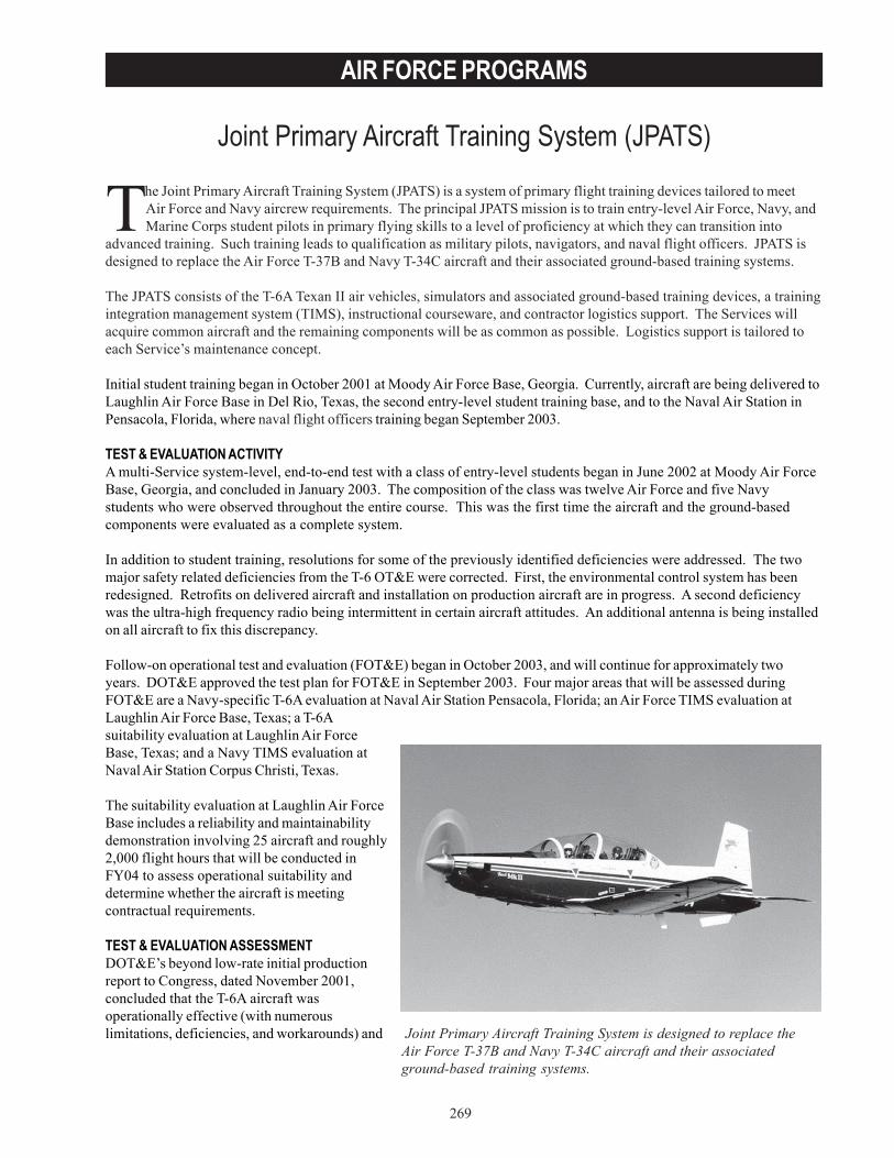
269
AIR FORCE PROGRAMS
Joint Primary Aircraft Training System (JPATS)
The Joint Primary Aircraft Training System (JPATS) is a system of primary flight training devices tailored to meetAir Force and Navy aircrew requirements. The principal JPATS mission is to train entry-level Air Force, Navy, andMarine Corps student pilots in primary flying skills to a level of proficiency at which they can transition into
advanced training. Such training leads to qualification as military pilots, navigators, and naval flight officers. JPATS isdesigned to replace the Air Force T-37B and Navy T-34C aircraft and their associated ground-based training systems.
The JPATS consists of the T-6A Texan II air vehicles, simulators and associated ground-based training devices, a trainingintegration management system (TIMS), instructional courseware, and contractor logistics support. The Services willacquire common aircraft and the remaining components will be as common as possible. Logistics support is tailored toeach Service’s maintenance concept.
Initial student training began in October 2001 at Moody Air Force Base, Georgia. Currently, aircraft are being delivered toLaughlin Air Force Base in Del Rio, Texas, the second entry-level student training base, and to the Naval Air Station inPensacola, Florida, where naval flight officers training began September 2003.
TEST & EVALUATION ACTIVITYA multi-Service system-level, end-to-end test with a class of entry-level students began in June 2002 at Moody Air ForceBase, Georgia, and concluded in January 2003. The composition of the class was twelve Air Force and five Navystudents who were observed throughout the entire course. This was the first time the aircraft and the ground-basedcomponents were evaluated as a complete system.
In addition to student training, resolutions for some of the previously identified deficiencies were addressed. The twomajor safety related deficiencies from the T-6 OT&E were corrected. First, the environmental control system has beenredesigned. Retrofits on delivered aircraft and installation on production aircraft are in progress. A second deficiencywas the ultra-high frequency radio being intermittent in certain aircraft attitudes. An additional antenna is being installedon all aircraft to fix this discrepancy.
Follow-on operational test and evaluation (FOT&E) began in October 2003, and will continue for approximately twoyears. DOT&E approved the test plan for FOT&E in September 2003. Four major areas that will be assessed duringFOT&E are a Navy-specific T-6A evaluation at Naval Air Station Pensacola, Florida; an Air Force TIMS evaluation atLaughlin Air Force Base, Texas; a T-6Asuitability evaluation at Laughlin Air ForceBase, Texas; and a Navy TIMS evaluation atNaval Air Station Corpus Christi, Texas.
The suitability evaluation at Laughlin Air ForceBase includes a reliability and maintainabilitydemonstration involving 25 aircraft and roughly2,000 flight hours that will be conducted inFY04 to assess operational suitability anddetermine whether the aircraft is meetingcontractual requirements.
TEST & EVALUATION ASSESSMENTDOT&E’s beyond low-rate initial productionreport to Congress, dated November 2001,concluded that the T-6A aircraft wasoperationally effective (with numerouslimitations, deficiencies, and workarounds) and Joint Primary Aircraft Training System is designed to replace the
Air Force T-37B and Navy T-34C aircraft and their associatedground-based training systems.
270
AIR FORCE PROGRAMS
not operationally suitable. Deficiency and safety related areas included the engine, environmental control system, ultra-high frequency and very-high frequency radio performance, flight manuals and checklists, the emergency oxygensystem, ground egress, the trim systems, power control lever, wheel brakes, cockpit storage, and rear view mirrors.Improvements have been noted in the past year. Still unresolved are the inter-cockpit communications system, theemergency oxygen system, the slow rate of pitch trim (the trim system is currently in redesign), and braking performance.Suitability will be re-evaluated during FOT&E.
The T-6A ground-based training system consists of three major components: simulators and other aircrew trainingdevices, the computer-based courseware, and the TIMS. The aircrew training devices and the computer-basedcourseware are working well with minor deficiencies. However, TIMS was not operationally effective or suitable duringthe end-to-end evaluation. Numerous workarounds and real-time changes were required to keep the system running.Functions that worked included academics, student status, schedule viewer, and the gradebook. Functions that requiredworkarounds include the schedule build (flight-level only), training forecast schedule, maintenance, and the flightsurgeon inputs. Many deficiency corrections have been incorporated since the last evaluation and the TIMS will bere-evaluated during FOT&E.
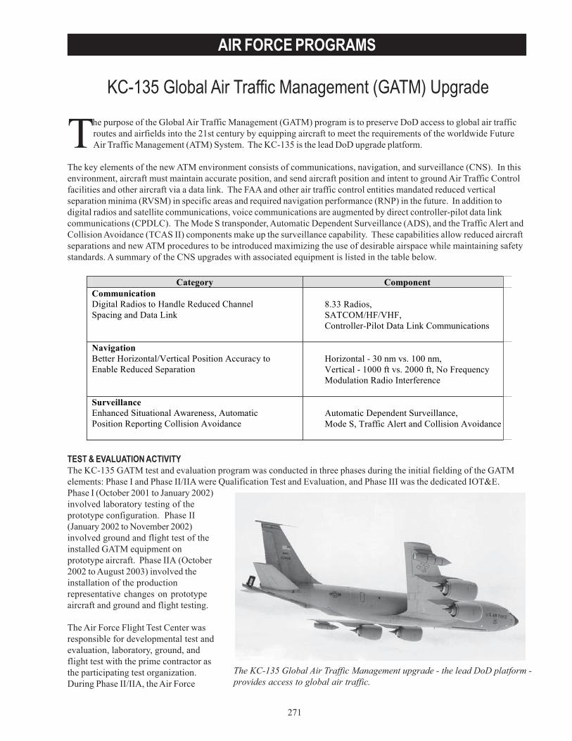
271
AIR FORCE PROGRAMS
The purpose of the Global Air Traffic Management (GATM) program is to preserve DoD access to global air trafficroutes and airfields into the 21st century by equipping aircraft to meet the requirements of the worldwide FutureAir Traffic Management (ATM) System. The KC-135 is the lead DoD upgrade platform.
The key elements of the new ATM environment consists of communications, navigation, and surveillance (CNS). In thisenvironment, aircraft must maintain accurate position, and send aircraft position and intent to ground Air Traffic Controlfacilities and other aircraft via a data link. The FAA and other air traffic control entities mandated reduced verticalseparation minima (RVSM) in specific areas and required navigation performance (RNP) in the future. In addition todigital radios and satellite communications, voice communications are augmented by direct controller-pilot data linkcommunications (CPDLC). The Mode S transponder, Automatic Dependent Surveillance (ADS), and the Traffic Alert andCollision Avoidance (TCAS II) components make up the surveillance capability. These capabilities allow reduced aircraftseparations and new ATM procedures to be introduced maximizing the use of desirable airspace while maintaining safetystandards. A summary of the CNS upgrades with associated equipment is listed in the table below.
TEST & EVALUATION ACTIVITYThe KC-135 GATM test and evaluation program was conducted in three phases during the initial fielding of the GATMelements: Phase I and Phase II/IIA were Qualification Test and Evaluation, and Phase III was the dedicated IOT&E.Phase I (October 2001 to January 2002)involved laboratory testing of theprototype configuration. Phase II(January 2002 to November 2002)involved ground and flight test of theinstalled GATM equipment onprototype aircraft. Phase IIA (October2002 to August 2003) involved theinstallation of the productionrepresentative changes on prototypeaircraft and ground and flight testing.
The Air Force Flight Test Center wasresponsible for developmental test andevaluation, laboratory, ground, andflight test with the prime contractor asthe participating test organization.During Phase II/IIA, the Air Force
KC-135 Global Air Traffic Management (GATM) Upgrade
The KC-135 Global Air Traffic Management upgrade - the lead DoD platform -provides access to global air traffic.
Category Component Communication Digital Radios to Handle Reduced Channel Spacing and Data Link
8.33 Radios, SATCOM/HF/VHF, Controller-Pilot Data Link Communications
Navigation Better Horizontal/Vertical Position Accuracy to Enable Reduced Separation
Horizontal - 30 nm vs. 100 nm, Vertical - 1000 ft vs. 2000 ft, No Frequency Modulation Radio Interference
Surveillance Enhanced Situational Awareness, Automatic Position Reporting Collision Avoidance
Automatic Dependent Surveillance, Mode S, Traffic Alert and Collision Avoidance
272
AIR FORCE PROGRAMS
Operational Test and Evaluation Center (AFOTEC) participated in order to determine readiness for IOT&E. Uponcompletion of Phase IIA, AFOTEC conducted Phase III IOT&E in October 2003 on GATM production representativeaircraft.
Two distinct Integrated Systems Evaluations were performed during the developmental phase to prepare for the IOT&E.The Integrated Systems Evaluations were conducted in operationally realistic global environments to demonstratereadiness for IOT&E.
DOT&E approved the Test and Evaluation Master Plan and Operational Test Plan in September 2003.
TEST & EVALUATION ASSESSMENTAFOTEC conducted the IOT&E from September 15, 2003, to October 8, 2003. The aircraft located at Fairchild Air ForceBase, Washington, the initial operational unit for GATM-equipped tankers, conducted local air refueling sorties,maintenance demos, and information assurance testing. One aircraft flew around the world to demonstrate capabilityacross a range of air traffic control centers, including operation in 12 of the 17 Flight Information Regions of militaryinterest. The majority of future air navigation (FANS) system airspace was accessed, as well as other regions where theKC-135 performs its mission. Air refueling was conducted during several of these missions.
The results of the testing are being evaluated. A detailed evaluation will be contained in the beyond low-rate initialproduction report in 2004.
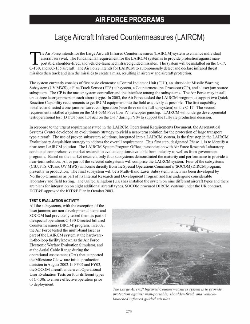
273
AIR FORCE PROGRAMS
Large Aircraft Infrared Countermeasures (LAIRCM)
The Large Aircraft Infrared Countermeasures system is to provideprotection against man-portable, shoulder-fired, and vehicle-launched infrared guided missiles.
The Air Force intends for the Large Aircraft Infrared Countermeasures (LAIRCM) system to enhance individualaircraft survival. The fundamental requirement for the LAIRCM system is to provide protection against man-portable, shoulder-fired, and vehicle-launched infrared guided missiles. The system will be installed on the C-17,
C-130, and KC-135 aircraft. The Air Force intends for LAIRCM to autonomously detect and declare infrared threatmissiles then track and jam the missiles to create a miss, resulting in aircrew and aircraft protection.
The system currently consists of five basic elements: a Control Indicator Unit (CIU), an ultraviolet Missile WarningSubsystem (UV MWS), a Fine Track Sensor (FTS) subsystem, a Countermeasures Processor (CP), and a laser jam sourcesubsystem. The CP is the master system controller and the interface among the subsystems. The Air Force may installup to three laser jammers on each aircraft type. In 2003, the Air Force tasked the LAIRCM program to support two QuickReaction Capability requirements to get IRCM equipment into the field as quickly as possible. The first capabilityinstalled and tested a one-jammer turret configuration (vice three on the full-up system) on the C-17. The secondrequirement installed a system on the MH-53M Pave Low IV helicopter gunship. LAIRCM will undergo developmentaltest/operational test (DT/OT) and IOT&E on the C-17 during FY04 to support the full-rate production decision.
In response to the urgent requirement stated in the LAIRCM Operational Requirements Document, the AeronauticalSystems Center developed an evolutionary strategy to yield a near-term solution for the protection of large transporttype aircraft. The use of proven subsystem solutions, integrated into a LAIRCM system, is the first step in the LAIRCMEvolutionary Acquisition strategy to address the overall requirement. This first step, designated Phase 1, is to identify anear-term LAIRCM solution. The LAIRCM System Program Office, in association with Air Force Research Laboratory,conducted comprehensive market research to evaluate options available from industry as well as from governmentprograms. Based on the market research, only four subsystems demonstrated the maturity and performance to provide anear-term solution. All or part of the selected subsystems will comprise the LAIRCM system. Four of the subsystems(CIU, FTS, CP, and UV MWS) will come directly from the Special Operations Command’s (SOCOM) DIRCM program,presently in production. The final subsystem will be a Multi-Band Laser Subsystem, which has been developed byNorthrop Grumman as part of its Internal Research and Development Program and has undergone considerablelaboratory and field testing. The United Kingdom (UK) has installed the system on nine different aircraft types and thereare plans for integration on eight additional aircraft types. SOCOM procured DIRCM systems under the UK contract.DOT&E approved the IOT&E Plan in October 2003.
TEST & EVALUATION ACTIVITYAll the subsystems, with the exception of thelaser jammer, are non-developmental items andSOCOM had previously tested them as part ofthe special operations C-130 Directed InfraredCountermeasures (DIRCM) program. In 2002,the Air Force tested the multi-band laser aspart of the LAIRCM system at the hardware-in-the-loop facility known as the Air ForceElectronic Warfare Evaluation Simulator, andat the Aerial Cable Range during theoperational assessment (OA) that supportedthe Milestone C low-rate initial productiondecision in August 2002. In FY02 and FY03,the SOCOM aircraft underwent OperationalUser Evaluation Tests on four different typesof C-130s to ensure effective operation priorto deployment.
274
AIR FORCE PROGRAMS
In FY03, the primary T&E activities were two quick-look tests performed to support the Quick Reaction Capability (QRC)requirements on the C-17 and the MH-53 helicopter. Both aircraft needed IRCM protection for their operations in SouthWest Asia. The C-17 installation, known as LAIRCM Lite, consisted of six missile-warning sensors (MWSs) and onelaser jammer (vice the three planned for the standard C-17 configuration). The Air Force conducted effectiveness flightsat Edwards Air Force Base, California. These tests consisted of irradiating the aircraft with ground-based missile plumestimulators to determine if the system produced the correct jamming energy from the aircraft to a sensor on the ground.The Air Force evaluated false alarm susceptibility and the robustness of the LAIRCM Lite system on the aircraft. The AirForce tested the MH-53 system, known as the MH-53 DIRCM system, in a similar manner at Eglin Air Force Base.
The Air Force Operational Test and Evaluation Center (AFOTEC) plans to conduct DT/OT and IOT&E for the C-17 andC-130 in FY04. The DT/OT tests will include open-air range tests, a sled test to ensure that the laser jamming canirradiate jamming energy on a missile seeker that is moving at realistic missile speeds, and several flights to testsuitability in operational environments such as unprepared runways and tactical descents. AFOTEC has accreditedmodels and simulations based on the FY02 OA and the QRC quick-look tests. Together with the open-air test data, thesemodels will be used to evaluate the FY04 DT/OT and IOT&E results.
TEST & EVALUATION ASSESSMENTLAIRCM, using the majority of the components of the already fielded DIRCM system, has met with success in its OAand DT/OT tests to date. The previously accomplished C-130 tests, the several successful live fire tests against theDIRCM system, and the extensive qualification and environmental tests that were performed on the DIRCM system allsubstantially mitigated the usual risks associated with complex systems in development. The DIRCM program had tosolve several problems during its infancy, which resulted in a more mature system for LAIRCM. The only developmentalcomponent within LAIRCM is the multi-band laser, which to date has performed almost flawlessly during the 4,000 runsin hardware-in-the-loop tests, 150 hours of system operating time, and during the LAIRCM Lite and MH-53 DIRCM tests.
Prior to the QRC flight tests discussed above, one of the main concerns was whether the laser jammer could withstandthe vibration and temperature environment in the C-17’s tail section. Considerable engineering analysis and preliminaryflight tests with representative mock-up models of the equipment were conducted to measure the vibration andtemperature levels at that location. Incorporating a rigid truss assembly in the tail cone reduced the vibration levels.This appears to have been successful since there were no laser jammer failures during these flights. There were nofailures in the MH-53 vibration environment.
Although the LAIRCM Lite and the MH-53 tests were successful, they were limited in scope. The MH-53 testsconducted at Eglin used two of the same laser jammers and four of the MWSs that are used in the C-17 system.Although both were abbreviated tests, the C-17 LARICM Lite and the MH-53 DIRCM systems performed adequatelyenough to be deployed as QRC systems. To support full-rate production of the multi-jammer system, a more detailed testand analysis of the system performance is required and scenarios that are more realistic should be performed. In order totest the interactions of the three-jammer configuration, scenarios that include more than one missile simulator/stimulatortogether with false alarm sources should be included. In addition, operational flight profiles should be flown that test thesuitability of the system when aircraft lands on unprepared runways and conducts tactical descents. These types oftests are planned for the C-17 LAIRCM DT/OT in December 2003 and the IOT&E in January/February 2004. A similar DT/OT and IOT&E are planned for the C-130 in February- May 2004. Use of the modeling and simulation described earlierwill support the overall system evaluation.
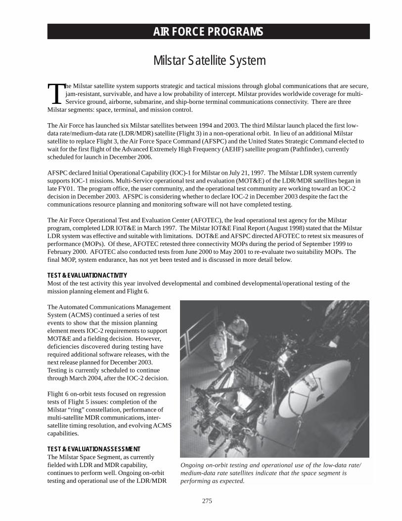
275
AIR FORCE PROGRAMS
Milstar Satellite System
The Milstar satellite system supports strategic and tactical missions through global communications that are secure,jam-resistant, survivable, and have a low probability of intercept. Milstar provides worldwide coverage for multi-Service ground, airborne, submarine, and ship-borne terminal communications connectivity. There are three
Milstar segments: space, terminal, and mission control.
The Air Force has launched six Milstar satellites between 1994 and 2003. The third Milstar launch placed the first low-data rate/medium-data rate (LDR/MDR) satellite (Flight 3) in a non-operational orbit. In lieu of an additional Milstarsatellite to replace Flight 3, the Air Force Space Command (AFSPC) and the United States Strategic Command elected towait for the first flight of the Advanced Extremely High Frequency (AEHF) satellite program (Pathfinder), currentlyscheduled for launch in December 2006.
AFSPC declared Initial Operational Capability (IOC)-1 for Milstar on July 21, 1997. The Milstar LDR system currentlysupports IOC-1 missions. Multi-Service operational test and evaluation (MOT&E) of the LDR/MDR satellites began inlate FY01. The program office, the user community, and the operational test community are working toward an IOC-2decision in December 2003. AFSPC is considering whether to declare IOC-2 in December 2003 despite the fact thecommunications resource planning and monitoring software will not have completed testing.
The Air Force Operational Test and Evaluation Center (AFOTEC), the lead operational test agency for the Milstarprogram, completed LDR IOT&E in March 1997. The Milstar IOT&E Final Report (August 1998) stated that the MilstarLDR system was effective and suitable with limitations. DOT&E and AFSPC directed AFOTEC to retest six measures ofperformance (MOPs). Of these, AFOTEC retested three connectivity MOPs during the period of September 1999 toFebruary 2000. AFOTEC also conducted tests from June 2000 to May 2001 to re-evaluate two suitability MOPs. Thefinal MOP, system endurance, has not yet been tested and is discussed in more detail below.
TEST & EVALUATION ACTIVITYMost of the test activity this year involved developmental and combined developmental/operational testing of themission planning element and Flight 6.
The Automated Communications ManagementSystem (ACMS) continued a series of testevents to show that the mission planningelement meets IOC-2 requirements to supportMOT&E and a fielding decision. However,deficiencies discovered during testing haverequired additional software releases, with thenext release planned for December 2003.Testing is currently scheduled to continuethrough March 2004, after the IOC-2 decision.
Flight 6 on-orbit tests focused on regressiontests of Flight 5 issues: completion of theMilstar “ring” constellation, performance ofmulti-satellite MDR communications, inter-satellite timing resolution, and evolving ACMScapabilities.
TEST & EVALUATION ASSESSMENTThe Milstar Space Segment, as currentlyfielded with LDR and MDR capability,continues to perform well. Ongoing on-orbittesting and operational use of the LDR/MDR
Ongoing on-orbit testing and operational use of the low-data rate/medium-data rate satellites indicate that the space segment isperforming as expected.
276
AIR FORCE PROGRAMS
satellites indicate that the space segment is performing as expected. Formal assessment of MDR operationaleffectiveness and suitability will be made after the completion of MOT&E.
The loss of Flight 3 degrades operational utility. Worldwide coverage from 65 degrees South to 65 degrees North latitudewill not be available for the Milstar MDR terminals until the launch of the AEHF Pathfinder satellite in FY07. The lack of afourth MDR satellite will limit the ability to provide two-satellite coverage to some contingency operations and, therefore,limit the throughput of protected communications. Another impact of the loss of Flight 3 is that approximately 25 degreesof longitude will have no MDR coverage (based on current plan for satellite placement).
The Milstar Terminal Segment has mixed results. The Navy’s LDR terminals have been successfully fielded for fiveyears, while its MDR-capable version is currently experiencing reliability problems. The Air Force airborne terminaldemonstrated the required reliability and maintainability. The Army ground terminals demonstrated reliability andmaintainability shortfalls. The Army Test and Evaluation Command assessment of these shortfalls did not result in acritical mission impact based on current employment plans. Further discussion of the Navy’s Extremely High FrequencySatellite Program terminals is provided separately in this annual report.
The LDR Mission Control Segment performed its mission successfully. During LDR IOT&E, however, the mobileconstellation control station’s endurance capability was not tested adequately. DOT&E directed a full test of theendurance requirement during follow-on testing. AFOTEC is working toward conducting the endurance retest in 2QFY04and has identified their requirements to the United States Strategic Command to plan an appropriate test event.
Delays in development of ACMS are of concern. Because of the existing shortfalls of ACMS, the Army and Navy fieldedtheir terminals with interim planning software (the Milstar Communications Planning Tool – integrated (MCPT-i)) as theirprimary planning tool, and do not plan to use ACMS. The Army has not yet tested nuller visibility, and interoperabilitybetween ACMS and MCPT-i should be verified.
There is currently no concept of operations for the Joint Task Force mission. Testing of the Joint Task Force mission iscritical to evaluate interoperability of the Milstar system and terminals in an operational context. Some interoperabilitydemonstrations have been conducted during developmental testing, including the Joint Interoperability Test CommandMDR interoperability test. Informal results from these tests show coding, encryption, and modulation equipmentincompatibility issues between Army and Navy terminals. Until the concept of operations is specified, it is not known ifthe limited equipment used in these tests is operationally representative.
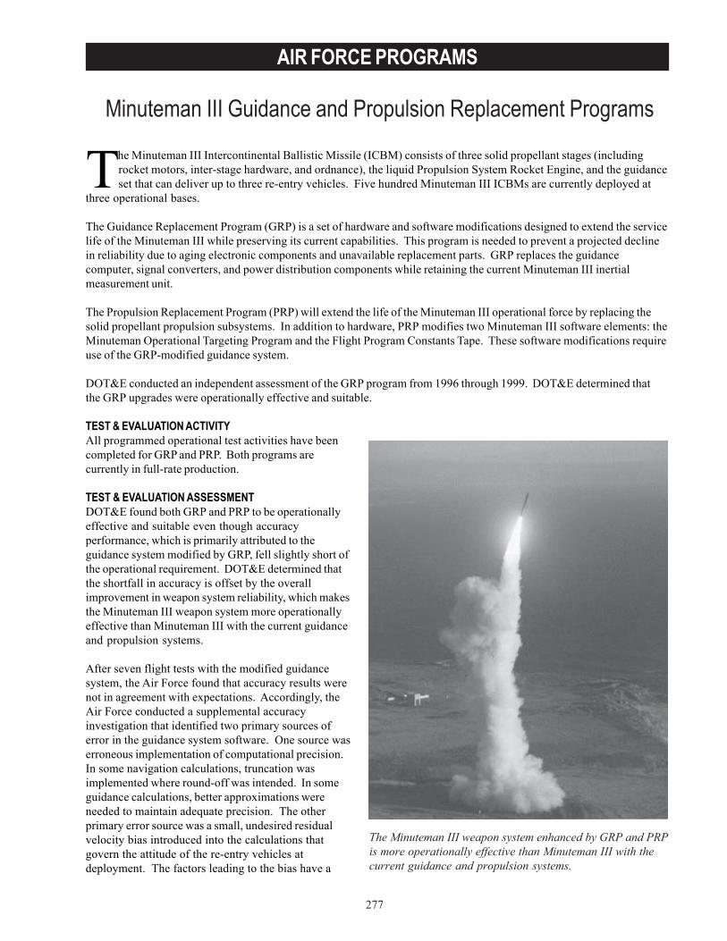
277
AIR FORCE PROGRAMS
Minuteman III Guidance and Propulsion Replacement Programs
The Minuteman III weapon system enhanced by GRP and PRPis more operationally effective than Minuteman III with thecurrent guidance and propulsion systems.
The Minuteman III Intercontinental Ballistic Missile (ICBM) consists of three solid propellant stages (includingrocket motors, inter-stage hardware, and ordnance), the liquid Propulsion System Rocket Engine, and the guidanceset that can deliver up to three re-entry vehicles. Five hundred Minuteman III ICBMs are currently deployed at
three operational bases.
The Guidance Replacement Program (GRP) is a set of hardware and software modifications designed to extend the servicelife of the Minuteman III while preserving its current capabilities. This program is needed to prevent a projected declinein reliability due to aging electronic components and unavailable replacement parts. GRP replaces the guidancecomputer, signal converters, and power distribution components while retaining the current Minuteman III inertialmeasurement unit.
The Propulsion Replacement Program (PRP) will extend the life of the Minuteman III operational force by replacing thesolid propellant propulsion subsystems. In addition to hardware, PRP modifies two Minuteman III software elements: theMinuteman Operational Targeting Program and the Flight Program Constants Tape. These software modifications requireuse of the GRP-modified guidance system.
DOT&E conducted an independent assessment of the GRP program from 1996 through 1999. DOT&E determined thatthe GRP upgrades were operationally effective and suitable.
TEST & EVALUATION ACTIVITYAll programmed operational test activities have beencompleted for GRP and PRP. Both programs arecurrently in full-rate production.
TEST & EVALUATION ASSESSMENTDOT&E found both GRP and PRP to be operationallyeffective and suitable even though accuracyperformance, which is primarily attributed to theguidance system modified by GRP, fell slightly short ofthe operational requirement. DOT&E determined thatthe shortfall in accuracy is offset by the overallimprovement in weapon system reliability, which makesthe Minuteman III weapon system more operationallyeffective than Minuteman III with the current guidanceand propulsion systems.
After seven flight tests with the modified guidancesystem, the Air Force found that accuracy results werenot in agreement with expectations. Accordingly, theAir Force conducted a supplemental accuracyinvestigation that identified two primary sources oferror in the guidance system software. One source waserroneous implementation of computational precision.In some navigation calculations, truncation wasimplemented where round-off was intended. In someguidance calculations, better approximations wereneeded to maintain adequate precision. The otherprimary error source was a small, undesired residualvelocity bias introduced into the calculations thatgovern the attitude of the re-entry vehicles atdeployment. The factors leading to the bias have a
278
AIR FORCE PROGRAMS
complex dependence on the azimuth and trajectory. For test-flight missions from Vandenberg Air Force Base, California,to Kwajalein, the errors reinforce one another. In other trajectories, the errors might increase dispersion but notcontribute significantly to the weapon delivery error. Operational trajectories would still have been less than optimum ifthis situation had not been discovered, so it is fortunate that the Westerly test trajectory highlighted the problem.
The Air Force initiated corrective actions though an Accuracy Upgrade Program (AUP). To date, the Air Force hasconducted a total of four NS-50 flights with the AUP corrections, two in each of FY02 and FY03. The downrange biasesobserved previous to the AUP modifications appear to have been corrected. Additional NS-50 flights will be conductedin accordance with the FDE program. DOT&E will continue to monitor the results of this program.
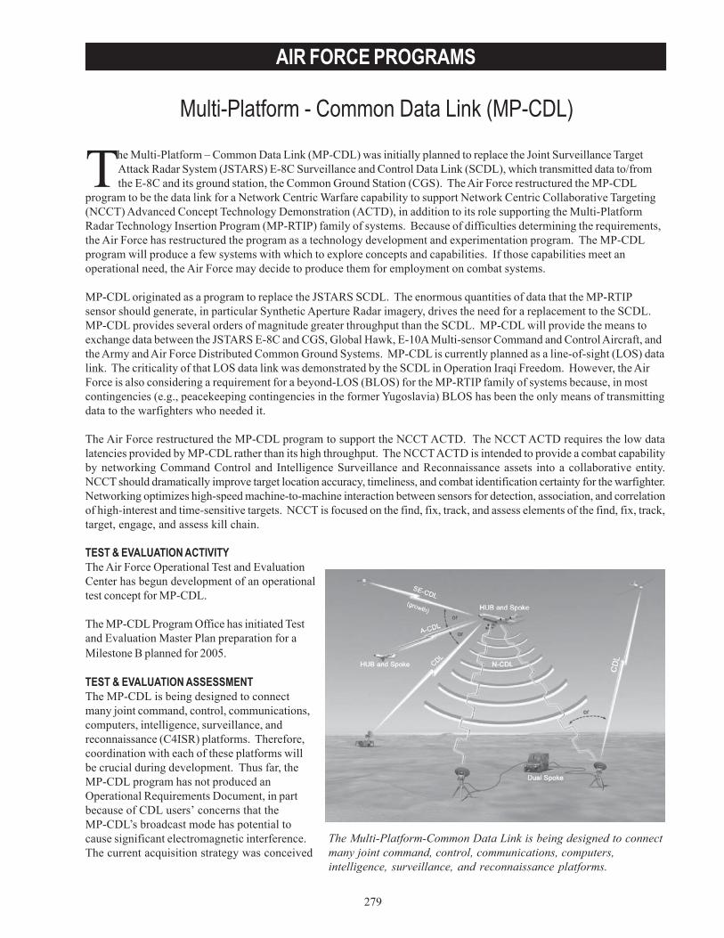
279
AIR FORCE PROGRAMS
Multi-Platform - Common Data Link (MP-CDL)
The Multi-Platform – Common Data Link (MP-CDL) was initially planned to replace the Joint Surveillance TargetAttack Radar System (JSTARS) E-8C Surveillance and Control Data Link (SCDL), which transmitted data to/fromthe E-8C and its ground station, the Common Ground Station (CGS). The Air Force restructured the MP-CDL
program to be the data link for a Network Centric Warfare capability to support Network Centric Collaborative Targeting(NCCT) Advanced Concept Technology Demonstration (ACTD), in addition to its role supporting the Multi-PlatformRadar Technology Insertion Program (MP-RTIP) family of systems. Because of difficulties determining the requirements,the Air Force has restructured the program as a technology development and experimentation program. The MP-CDLprogram will produce a few systems with which to explore concepts and capabilities. If those capabilities meet anoperational need, the Air Force may decide to produce them for employment on combat systems.
MP-CDL originated as a program to replace the JSTARS SCDL. The enormous quantities of data that the MP-RTIPsensor should generate, in particular Synthetic Aperture Radar imagery, drives the need for a replacement to the SCDL.MP-CDL provides several orders of magnitude greater throughput than the SCDL. MP-CDL will provide the means toexchange data between the JSTARS E-8C and CGS, Global Hawk, E-10A Multi-sensor Command and Control Aircraft, andthe Army and Air Force Distributed Common Ground Systems. MP-CDL is currently planned as a line-of-sight (LOS) datalink. The criticality of that LOS data link was demonstrated by the SCDL in Operation Iraqi Freedom. However, the AirForce is also considering a requirement for a beyond-LOS (BLOS) for the MP-RTIP family of systems because, in mostcontingencies (e.g., peacekeeping contingencies in the former Yugoslavia) BLOS has been the only means of transmittingdata to the warfighters who needed it.
The Air Force restructured the MP-CDL program to support the NCCT ACTD. The NCCT ACTD requires the low datalatencies provided by MP-CDL rather than its high throughput. The NCCT ACTD is intended to provide a combat capabilityby networking Command Control and Intelligence Surveillance and Reconnaissance assets into a collaborative entity.NCCT should dramatically improve target location accuracy, timeliness, and combat identification certainty for the warfighter.Networking optimizes high-speed machine-to-machine interaction between sensors for detection, association, and correlationof high-interest and time-sensitive targets. NCCT is focused on the find, fix, track, and assess elements of the find, fix, track,target, engage, and assess kill chain.
TEST & EVALUATION ACTIVITYThe Air Force Operational Test and EvaluationCenter has begun development of an operationaltest concept for MP-CDL.
The MP-CDL Program Office has initiated Testand Evaluation Master Plan preparation for aMilestone B planned for 2005.
TEST & EVALUATION ASSESSMENTThe MP-CDL is being designed to connectmany joint command, control, communications,computers, intelligence, surveillance, andreconnaissance (C4ISR) platforms. Therefore,coordination with each of these platforms willbe crucial during development. Thus far, theMP-CDL program has not produced anOperational Requirements Document, in partbecause of CDL users’ concerns that theMP-CDL’s broadcast mode has potential tocause significant electromagnetic interference.The current acquisition strategy was conceived
The Multi-Platform-Common Data Link is being designed to connectmany joint command, control, communications, computers,intelligence, surveillance, and reconnaissance platforms.
280
AIR FORCE PROGRAMS
as a means to continue test and experimentation to support the MP-RTIP data link and NCCT requirements, whileallowing the CDL community time to resolve the potential problems. However, the Air Force has indicated a need to fieldMP-CDL terminals produced under this strategy if MP-CDL meets the Air Force’s requirements. Therefore, continuedoversight of MP-CDL by the multi-Service CDL community and DOT&E will be required to ensure that the system meetsjoint requirements.
The linkage between MP-CDL and the NCCT ACTD is also a cause for concern. Many of the platforms that requireMP-CDL to handle the large volumes of data generated by MP-RTIP are also platforms that will eventually participate inNCCT after it is fielded. This creates the possibility that platforms might end up with an MP-CDL terminal adequate tosupport NCCT’s needs, but not MP-RTIP’s needs.
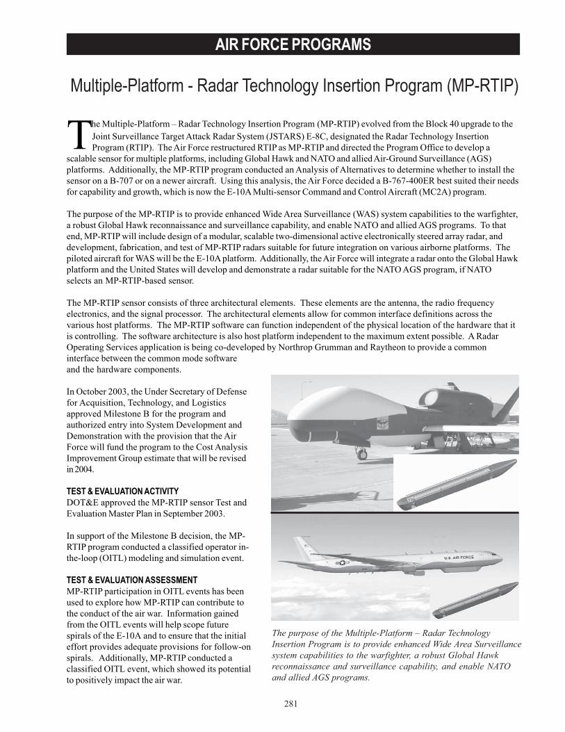
281
AIR FORCE PROGRAMS
Multiple-Platform - Radar Technology Insertion Program (MP-RTIP)
The purpose of the Multiple-Platform – Radar TechnologyInsertion Program is to provide enhanced Wide Area Surveillancesystem capabilities to the warfighter, a robust Global Hawkreconnaissance and surveillance capability, and enable NATOand allied AGS programs.
The Multiple-Platform – Radar Technology Insertion Program (MP-RTIP) evolved from the Block 40 upgrade to theJoint Surveillance Target Attack Radar System (JSTARS) E-8C, designated the Radar Technology InsertionProgram (RTIP). The Air Force restructured RTIP as MP-RTIP and directed the Program Office to develop a
scalable sensor for multiple platforms, including Global Hawk and NATO and allied Air-Ground Surveillance (AGS)platforms. Additionally, the MP-RTIP program conducted an Analysis of Alternatives to determine whether to install thesensor on a B-707 or on a newer aircraft. Using this analysis, the Air Force decided a B-767-400ER best suited their needsfor capability and growth, which is now the E-10A Multi-sensor Command and Control Aircraft (MC2A) program.
The purpose of the MP-RTIP is to provide enhanced Wide Area Surveillance (WAS) system capabilities to the warfighter,a robust Global Hawk reconnaissance and surveillance capability, and enable NATO and allied AGS programs. To thatend, MP-RTIP will include design of a modular, scalable two-dimensional active electronically steered array radar, anddevelopment, fabrication, and test of MP-RTIP radars suitable for future integration on various airborne platforms. Thepiloted aircraft for WAS will be the E-10A platform. Additionally, the Air Force will integrate a radar onto the Global Hawkplatform and the United States will develop and demonstrate a radar suitable for the NATO AGS program, if NATOselects an MP-RTIP-based sensor.
The MP-RTIP sensor consists of three architectural elements. These elements are the antenna, the radio frequencyelectronics, and the signal processor. The architectural elements allow for common interface definitions across thevarious host platforms. The MP-RTIP software can function independent of the physical location of the hardware that itis controlling. The software architecture is also host platform independent to the maximum extent possible. A RadarOperating Services application is being co-developed by Northrop Grumman and Raytheon to provide a commoninterface between the common mode softwareand the hardware components.
In October 2003, the Under Secretary of Defensefor Acquisition, Technology, and Logisticsapproved Milestone B for the program andauthorized entry into System Development andDemonstration with the provision that the AirForce will fund the program to the Cost AnalysisImprovement Group estimate that will be revisedin 2004.
TEST & EVALUATION ACTIVITYDOT&E approved the MP-RTIP sensor Test andEvaluation Master Plan in September 2003.
In support of the Milestone B decision, the MP-RTIP program conducted a classified operator in-the-loop (OITL) modeling and simulation event.
TEST & EVALUATION ASSESSMENTMP-RTIP participation in OITL events has beenused to explore how MP-RTIP can contribute tothe conduct of the air war. Information gainedfrom the OITL events will help scope futurespirals of the E-10A and to ensure that the initialeffort provides adequate provisions for follow-onspirals. Additionally, MP-RTIP conducted aclassified OITL event, which showed its potentialto positively impact the air war.
282
AIR FORCE PROGRAMS
The risk associated with the interdependency of these multiple Acquisition Category 1D programs (E-10A, MP-RTIP andGlobal Hawk) must not be underestimated. The E-10A is dependent on MP-RTIP to deliver its primary sensor. MP-RTIPis dependent on E-10A to provide a test platform for the sensor. Planned delivery of the two will have to be closelycoordinated to ensure neither has to wait for the delivery of the other. Due to the scope and the long lead times requiredfor both programs, neither will be able to tolerate delays without experiencing significantly increased costs. The samecoordination issues exist for MP-RTIP and Global Hawk.
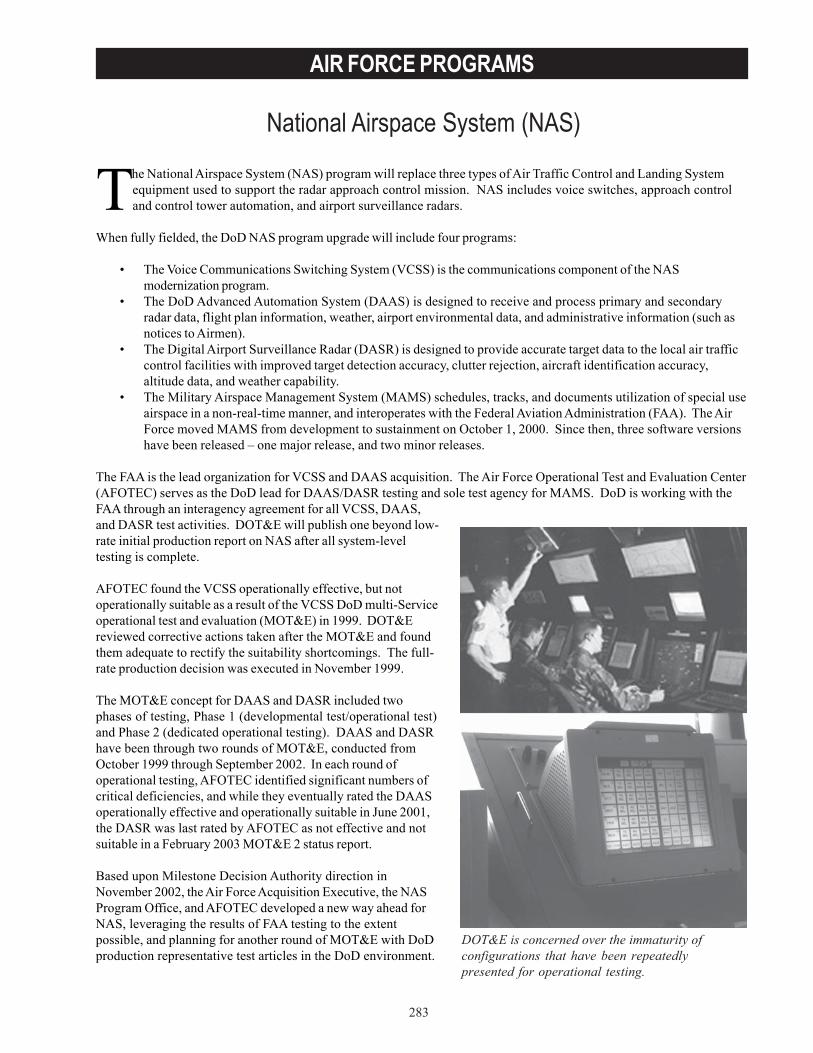
283
AIR FORCE PROGRAMS
National Airspace System (NAS)
DOT&E is concerned over the immaturity ofconfigurations that have been repeatedlypresented for operational testing.
The National Airspace System (NAS) program will replace three types of Air Traffic Control and Landing Systemequipment used to support the radar approach control mission. NAS includes voice switches, approach controland control tower automation, and airport surveillance radars.
When fully fielded, the DoD NAS program upgrade will include four programs:
• The Voice Communications Switching System (VCSS) is the communications component of the NASmodernization program.
• The DoD Advanced Automation System (DAAS) is designed to receive and process primary and secondaryradar data, flight plan information, weather, airport environmental data, and administrative information (such asnotices to Airmen).
• The Digital Airport Surveillance Radar (DASR) is designed to provide accurate target data to the local air trafficcontrol facilities with improved target detection accuracy, clutter rejection, aircraft identification accuracy,altitude data, and weather capability.
• The Military Airspace Management System (MAMS) schedules, tracks, and documents utilization of special useairspace in a non-real-time manner, and interoperates with the Federal Aviation Administration (FAA). The AirForce moved MAMS from development to sustainment on October 1, 2000. Since then, three software versionshave been released – one major release, and two minor releases.
The FAA is the lead organization for VCSS and DAAS acquisition. The Air Force Operational Test and Evaluation Center(AFOTEC) serves as the DoD lead for DAAS/DASR testing and sole test agency for MAMS. DoD is working with theFAA through an interagency agreement for all VCSS, DAAS,and DASR test activities. DOT&E will publish one beyond low-rate initial production report on NAS after all system-leveltesting is complete.
AFOTEC found the VCSS operationally effective, but notoperationally suitable as a result of the VCSS DoD multi-Serviceoperational test and evaluation (MOT&E) in 1999. DOT&Ereviewed corrective actions taken after the MOT&E and foundthem adequate to rectify the suitability shortcomings. The full-rate production decision was executed in November 1999.
The MOT&E concept for DAAS and DASR included twophases of testing, Phase 1 (developmental test/operational test)and Phase 2 (dedicated operational testing). DAAS and DASRhave been through two rounds of MOT&E, conducted fromOctober 1999 through September 2002. In each round ofoperational testing, AFOTEC identified significant numbers ofcritical deficiencies, and while they eventually rated the DAASoperationally effective and operationally suitable in June 2001,the DASR was last rated by AFOTEC as not effective and notsuitable in a February 2003 MOT&E 2 status report.
Based upon Milestone Decision Authority direction inNovember 2002, the Air Force Acquisition Executive, the NASProgram Office, and AFOTEC developed a new way ahead forNAS, leveraging the results of FAA testing to the extentpossible, and planning for another round of MOT&E with DoDproduction representative test articles in the DoD environment.
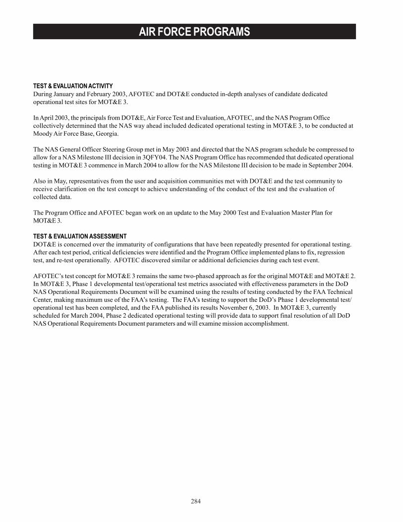
284
AIR FORCE PROGRAMS
TEST & EVALUATION ACTIVITYDuring January and February 2003, AFOTEC and DOT&E conducted in-depth analyses of candidate dedicatedoperational test sites for MOT&E 3.
In April 2003, the principals from DOT&E, Air Force Test and Evaluation, AFOTEC, and the NAS Program Officecollectively determined that the NAS way ahead included dedicated operational testing in MOT&E 3, to be conducted atMoody Air Force Base, Georgia.
The NAS General Officer Steering Group met in May 2003 and directed that the NAS program schedule be compressed toallow for a NAS Milestone III decision in 3QFY04. The NAS Program Office has recommended that dedicated operationaltesting in MOT&E 3 commence in March 2004 to allow for the NAS Milestone III decision to be made in September 2004.
Also in May, representatives from the user and acquisition communities met with DOT&E and the test community toreceive clarification on the test concept to achieve understanding of the conduct of the test and the evaluation ofcollected data.
The Program Office and AFOTEC began work on an update to the May 2000 Test and Evaluation Master Plan forMOT&E 3.
TEST & EVALUATION ASSESSMENTDOT&E is concerned over the immaturity of configurations that have been repeatedly presented for operational testing.After each test period, critical deficiencies were identified and the Program Office implemented plans to fix, regressiontest, and re-test operationally. AFOTEC discovered similar or additional deficiencies during each test event.
AFOTEC’s test concept for MOT&E 3 remains the same two-phased approach as for the original MOT&E and MOT&E 2.In MOT&E 3, Phase 1 developmental test/operational test metrics associated with effectiveness parameters in the DoDNAS Operational Requirements Document will be examined using the results of testing conducted by the FAA TechnicalCenter, making maximum use of the FAA’s testing. The FAA’s testing to support the DoD’s Phase 1 developmental test/operational test has been completed, and the FAA published its results November 6, 2003. In MOT&E 3, currentlyscheduled for March 2004, Phase 2 dedicated operational testing will provide data to support final resolution of all DoDNAS Operational Requirements Document parameters and will examine mission accomplishment.
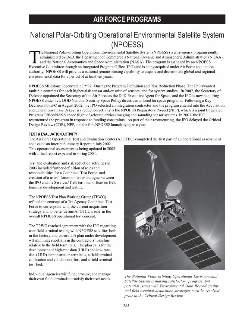
285
AIR FORCE PROGRAMS
National Polar-Orbiting Operational Environmental Satellite System(NPOESS)
The National Polar-orbiting Operational Environmental Satellite System (NPOESS) is a tri-agency program jointlyadministered by DoD, the Department of Commerce’s National Oceanic and Atmospheric Administration (NOAA),and the National Aeronautics and Space Administration (NASA). The program is managed by an NPOESS
Executive Committee through an Integrated Program Office (IPO) and is being acquired under Air Force acquisitionauthority. NPOESS will provide a national remote sensing capability to acquire and disseminate global and regionalenvironmental data for a period of at least ten years.
NPOESS Milestone I occurred in FY97. During the Program Definition and Risk Reduction Phase, The IPO awardedmultiple contracts for each higher-risk sensor and/or suite of sensors, and for system studies. In 2002, the Secretary ofDefense appointed the Secretary of the Air Force as the DoD Executive Agent for Space, and the IPO is now acquiringNPOESS under new DOD National Security Space Policy directives tailored for space programs. Following a KeyDecision Point-C in August 2002, the IPO selected an integration contractor and the program entered into the Acquisitionand Operations Phase. A key risk reduction activity is the NPOESS Preparatory Project (NPP), which is a joint IntegratedProgram Office/NASA space flight of selected critical imaging and sounding sensor systems. In 2003, the IPOrestructured the program in response to funding constraints. As part of their restructuring, the IPO delayed the CriticalDesign Review (CDR), NPP, and the first NPOESS launch by up to a year.
TEST & EVALUATION ACTIVITYThe Air Force Operational Test and Evaluation Center (AFOTEC) completed the first part of an operational assessmentand issued an Interim Summary Report in July 2002.This operational assessment is being updated in 2003with a final report expected in spring 2004.
Test and evaluation and risk reduction activities in2003 included further definition of roles andresponsibilities for a Combined Test Force, andcreation of a users’ forum to foster dialogue betweenthe IPO and the Services’ field terminal offices on fieldterminal development and testing.
The NPOESS Test Plan Working Group (TPWG)refined the concept of a Tri-Agency Combined TestForce to correspond with the current acquisitionstrategy and to better define AFOTEC’s role in theoverall NPOESS operational test concept.
The TPWG reached agreement with the IPO regardinguser field terminal testing with NPOESS satellites bothin the factory and on-orbit. A plan under developmentwill minimize shortfalls in the contractors’ baselinerelative to the field terminals. The plan calls for thedevelopment of high-rate data (HRD) and low-ratedata (LRD) demonstration terminals, a field terminalcalibration and validation effort, and a field terminaltest bed.
Individual agencies will fund, procure, and managetheir own field terminals to satisfy their user needs. The National Polar-orbiting Operational Environmental
Satellite System is making satisfactory progress, butpotential issues with Environmental Data Record qualityand field terminal acquisition strategies must be resolvedprior to the Critical Design Review.

286
AIR FORCE PROGRAMS
TEST & EVALUATION ASSESSMENTAFOTEC will be the lead agency for all operational test and evaluation events, but will combine efforts with other Serviceoperational test agencies, NOAA, and NASA during multi-Service OT&E (MOT&E) to make the most efficient use ofexpertise and resources.
NPOESS is making satisfactory progress, but potential issues with Environmental Data Record (EDR) quality and fieldterminal acquisition strategies must be resolved prior to CDR. Furthermore, there is schedule risk with the planned 2006NPP flight, and the impact on risk reduction of any delays or changes to NPP must be reassessed at CDR.
EDR quality is directly tied to algorithm and sensor performance, and to quality control. Algorithm performance has beenidentified as a leading risk to EDR quality. Three key sensors that represent major advances over legacy sensors eachface a tight development schedule and technical challenges. Quality control of the data processing string in the InterfaceData Processor Segment must ensure that erroneous data is properly filtered and that operators are alerted whenevererror conditions arise.
Any lack of synchronization between the NPOESS program and the Services’ field terminal acquisition programs wouldput two key test events at risk. The first is a combined developmental test/operational test event, which AFOTEC willconduct in FY06 to verify interoperability by connecting at least one of each type of field terminal directly to the satellitein the factory. The second event is MOT&E, the primary system-wide operational test, scheduled for late FY11. The IPOhas been hosting field terminal user meetings and they are starting to recognize the need for integrating the individualService field terminal programs with the overall NPOESS acquisition. DOT&E is concerned that more progress has notbeen made in developing a Field Terminal Closure Plan to aid in synchronizing and tracking NPOESS and terminalprograms to ensure test events stay on schedule.
NPP, with a planned launch in October 2006, is the primary risk reduction flight for NPOESS. It will carry three keyNPOESS sensors and generate 93 percent of the NPOESS data volume. There is significant risk in the schedule deliveryof the three sensors for the NPP launch. Furthermore, the command, control, and communications segment for NPP issubstantially different from that planned for NPOESS, resulting in reduced risk mitigation from the NPP ground segment.
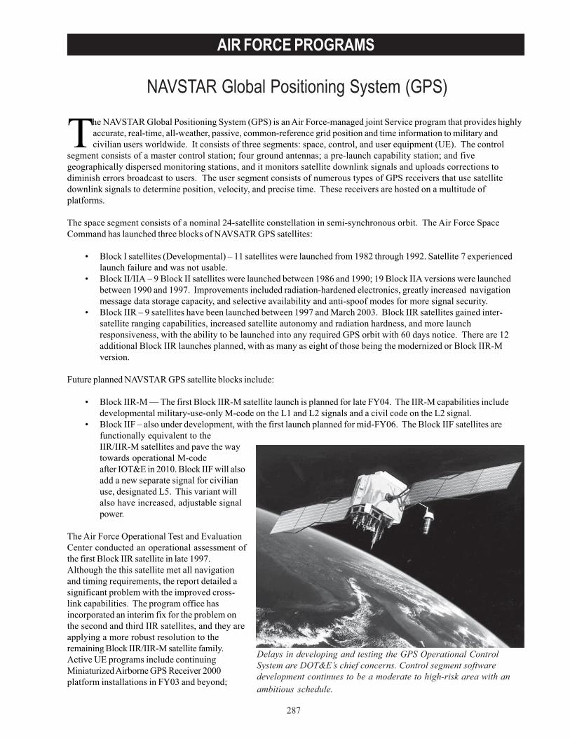
287
AIR FORCE PROGRAMS
NAVSTAR Global Positioning System (GPS)
Delays in developing and testing the GPS Operational ControlSystem are DOT&E’s chief concerns. Control segment softwaredevelopment continues to be a moderate to high-risk area with anambitious schedule.
The NAVSTAR Global Positioning System (GPS) is an Air Force-managed joint Service program that provides highlyaccurate, real-time, all-weather, passive, common-reference grid position and time information to military andcivilian users worldwide. It consists of three segments: space, control, and user equipment (UE). The control
segment consists of a master control station; four ground antennas; a pre-launch capability station; and fivegeographically dispersed monitoring stations, and it monitors satellite downlink signals and uploads corrections todiminish errors broadcast to users. The user segment consists of numerous types of GPS receivers that use satellitedownlink signals to determine position, velocity, and precise time. These receivers are hosted on a multitude ofplatforms.
The space segment consists of a nominal 24-satellite constellation in semi-synchronous orbit. The Air Force SpaceCommand has launched three blocks of NAVSATR GPS satellites:
• Block I satellites (Developmental) – 11 satellites were launched from 1982 through 1992. Satellite 7 experiencedlaunch failure and was not usable.
• Block II/IIA – 9 Block II satellites were launched between 1986 and 1990; 19 Block IIA versions were launchedbetween 1990 and 1997. Improvements included radiation-hardened electronics, greatly increased navigationmessage data storage capacity, and selective availability and anti-spoof modes for more signal security.
• Block IIR – 9 satellites have been launched between 1997 and March 2003. Block IIR satellites gained inter-satellite ranging capabilities, increased satellite autonomy and radiation hardness, and more launchresponsiveness, with the ability to be launched into any required GPS orbit with 60 days notice. There are 12additional Block IIR launches planned, with as many as eight of those being the modernized or Block IIR-Mversion.
Future planned NAVSTAR GPS satellite blocks include:
• Block IIR-M — The first Block IIR-M satellite launch is planned for late FY04. The IIR-M capabilities includedevelopmental military-use-only M-code on the L1 and L2 signals and a civil code on the L2 signal.
• Block IIF – also under development, with the first launch planned for mid-FY06. The Block IIF satellites arefunctionally equivalent to theIIR/IIR-M satellites and pave the waytowards operational M-codeafter IOT&E in 2010. Block IIF will alsoadd a new separate signal for civilianuse, designated L5. This variant willalso have increased, adjustable signalpower.
The Air Force Operational Test and EvaluationCenter conducted an operational assessment ofthe first Block IIR satellite in late 1997.Although the this satellite met all navigationand timing requirements, the report detailed asignificant problem with the improved cross-link capabilities. The program office hasincorporated an interim fix for the problem onthe second and third IIR satellites, and they areapplying a more robust resolution to theremaining Block IIR/IIR-M satellite family.Active UE programs include continuingMiniaturized Airborne GPS Receiver 2000platform installations in FY03 and beyond;
288
AIR FORCE PROGRAMS
Defense Advanced GPS Receiver deliveries beginning in FY03; and M-code receiver deliveries beginning in FY10. Allreceivers produced after FY02 are to have the Selective Availability Anti- Spoofing module capability installed.
TEST & EVALUATION ACTIVITYFY03 activity included continued test planning meetings and combined developmental/operational testing (DT/OT) ofGPS Modernization backward compatibility with legacy user equipment.
Future testing includes a series of combined DT/OT events and operational assessments in support of the developmentand fielding of the new operational control system, the launch of the first IIR-M and IIF satellites, and M-code fielding.
The next round of IOT&E will occur when 24 operational Block IIR-M and Block IIF satellites are on-orbit and controlsegment software Version 6 is declared operational.
IOT&E will be a system-wide test of the space and control segments. Legacy and modernized (M-code capable) UE andis scheduled to take place in FY10.
TEST & EVALUATION ASSESSMENTGround testing and on-orbit tests continue to indicate that the proposed solution to the Block IIR cross-link problem isbeing resolved satisfactorily. However, it is still too early to report a final determination of the effectiveness andsuitability of the entire series of IIR satellites.
Delays in developing and testing the GPS Operational Control System are DOT&E’s chief concerns. Control segmentsoftware development continues to be a moderate to high-risk area with an ambitious schedule. There is little time forregression testing in between software builds, and some significant capabilities will not be tested until the firstoperational build is released. Adequate operational flavor must be added to this contractor-led testing throughout thetest program to increase robustness and mitigate risk.
The November 2001 Test and Evaluation Master Plan and associated test planning documents are being revised by theGPS test community to accommodate the introduction of variable satellite signal power settings and increases in signalstrength. The proposed test approach to be incorporated into a new version of the GPS Test and Evaluation Master Plancalls for extensive DT/OT to ensure early and adequate insight into the new capabilities planned for inclusion into theGPS mission (i.e., control segment software and M-code functionality, second and third civil signals, and signalprotection for U.S. and allied forces). DOT&E feels that fielding the new operational control system and M-codeavailability warrant not just combined DT/OT, but dedicated operational assessments.
DOT&E continues to advocate the testing of new and legacy GPS receivers as early in the program as possible. Thesereceivers must be integrated into representative platforms (e.g., ships, aircraft, and land vehicles) and tested inoperational environments. Development of M-code-capable UE lags behind the development of the space and controlsegments, and this may induce delays in testing the Block IIR-M and IIF systems, along with the attendant M-code andcivil signal capabilities. Before that time, backward compatibility will be tested using legacy receivers and initial M-codeperformance will be tested using prototype receivers.

289
AIR FORCE PROGRAMS
RQ-4A Global Hawk Unmanned Aerial Vehicle (UAV)
The Global Hawk UAV system comprises an air vehicle componentwith air vehicles, sensor payloads, avionics, and data links.
The Global Hawk Unmanned Aerial Vehicle (UAV) system is a theater commander’s asset designed to satisfysurveillance and reconnaissance shortfalls. The Global Hawk UAV is to provide high-resolution syntheticaperture radar (SAR) and electro-optical/infrared (EO/IR) imagery at long-range with long loiter times over target
areas. Signals intelligence (SIGINT) capability is also being developed. Potential Global Hawk UAV missions cover thespectrum of intelligence collection capabilities to support joint combatant forces in worldwide peace, crisis, and wartimeoperations.
The Global Hawk UAV program began as an advanced concept technology demonstration in 1995 under the DefenseAdvanced Research Projects Agency management and, in October 1998, transitioned to the Air Force systems programoffice at Wright-Patterson Air Force Base, Ohio. The program Milestone II decision in March 2001 approved entry intoengineering and manufacturing development as well as low-rate initial production. Subsequent acquisition decisions inMarch 2002 and December 2002 have re-baselined the program, adopting a spiral acquisition approach and increasing thenumber of low-rate initial production air vehicles from six to nineteen. The September 2000 Operational RequirementsDocument was updated to reflect the new program, and it was approved in October 2002 by the Joint RequirementsOversight Council.
The Global Hawk UAV system comprises an air vehicle component with air vehicles, sensor payloads, avionics, and datalinks; a ground segment with a launch and recovery element (LRE); a mission control element (MCE) with embeddedground communications equipment; a support element; and trained personnel.
The Global Hawk UAV is optimized for high altitude, long range and endurance; it is to be capable of providing 28 hoursof endurance while carrying 3,000 pounds of payload and operating at 65,000 feet mean sea level. The integrated sensorsuite consists of SAR, EO, and IR sensors. Each of the sensors provides wide area search imagery and a high-resolutionspot mode. The radar also has a ground moving target indicator mode. A limited initial SIGINT capability will beincorporated prior to the IOT&E in FY06, while a more capable system in development will be integrated in productionaircraft in the years that follow. The Global Hawk UAV is intended to operate autonomously using a satellite data link(either Ku or UHF) to send sensor data from the aircraft to the MCE. The common data link can also be used for directdown-link of imagery when the UAV is operating within line-of-sight of users with compatible ground stations.
The ground segment consists of the MCE formission planning, command and control, andimage processing and dissemination; the LREfor controlling launch and recovery; andassociated ground support equipment. Byhaving separable elements in the groundsegment, the MCE and the LRE can operate ingeographically separate locations, and theMCE can be deployed with the supportedcommand’s primary exploitation site. Bothground segments are contained in militaryshelters with external antennas for line-of-sight and satellite communications with the airvehicles.
TEST & EVALUATION ACTIVITYAn updated Test and Evaluation Master Plan(TEMP) was approved by DOT&E in March2003 to support the new spiral acquisition.The TEMP outlines a set of test phases withincreasing scopes, tied to technologyintegration and a defined set of the
290
AIR FORCE PROGRAMS
Operational Requirements Documents. Two mission-level dedicated operational tests are scheduled to precede theDefense Acquisition Board-level review: an FY04 operational assessment (OA) prior to an in-process review, and an FY06IOT&E prior to the full-rate production decision. An FOT&E and a second IOT&E follow for the full-SIGINT and Multi-platform – Radar Technology Insertion Program configurations, respectively. Phases of developmental test/operationaltest (DT/OT) are scheduled between dedicated OT&E phases. These DT/OT phases are systems-level evaluations thatsupport yearly Configuration Control Board decisions on technology integration into production lots, as well as entryinto OT&E.
During FY03, no operational testing was conducted. One Global Hawk was deployed to support Operation IraqiFreedom, flying 16 combat missions March 8 - May 2, 2003. Combined Test Force activities at Edwards Air Force Base,California, consisted of developmental testing to support Operation Iraqi Freedom, pilot training support, technical ordervalidation and verification, support for a U.S.-German demonstration of a European Aeronautic Defence and Space(EADS) Company SIGINT sensor, delivery and checkout flight of two new air vehicles, and initial Spiral 1 developmentaltesting.
Another ACTD air vehicle, AV-7, was delivered in February 2003. After a period of modifications and check flights, GlobalHawk Advanced Synthetic Aperture Radar System Improvement Program (AIP) radar data was first collected inAugust 2003. Spiral 1 capabilities are to be incorporated and tested on AV-7 to support development, ConfigurationControl Board decisions, and entry into the FY04 OA. Spiral 1 capabilities include a new mission management computerand a sensor processing computer. The new systems are PowerPC-based to address diminishing manufacturing sourceissues with the current systems and provide greater computing power, and a more robust, open architecture. While theexisting mission management software was ported, the decision was made to use the AIP software developed for the U-2,which runs on PowerPC. Spiral 1 also includes improved communications and equipment designed to meet the Global AirTraffic Management requirement and provide the ability to fly in all classes of airspace.
TEST & EVALUATION ASSESSMENTThis past year, flight testing continued to compete with operations for both test and development resources. Limitedengineering and manufacturing development flight testing has occurred to date. The first sensor flight of AV-7, whichwas anticipated in January 2003, took place in August. Because of issues discovered with the AIP spot mode (imagequality and target geo-accuracy), the program has decided to develop a hybrid version of the SAR processing software,porting the ACTD spot modes to the new hardware and combining them with the AIP wide-area modes.
EO/IR testing has lagged the radar because of a lack of availability of test items. Spiral 1 EO/IR units were acceleratedand delivered in ACTD configuration to support Operation Enduring Freedom. The upgrade of these EO/IR units toSpiral 1 configuration was delayed because the units were dedicated to operations. As a result, delivery of the firstSpiral 1 configuration EO/IR unit is not expected until the end of 2004, limiting test time prior to the OA.
The schedule to reach the OA in the late summer 2004 is challenging. Besides development testing, Global Hawkactivities include several demonstrations prior to then, as well as the effort to stand up the squadron at Beale Air ForceBase, California, and maintain operational readiness. The demonstrations include two overseas deployments: theGerman EADS SIGINT demonstration and a Pacific Command forward-operating location demonstration.

291
AIR FORCE PROGRAMS
RQ/MQ-1 and MQ-9 Predator Unmanned Aerial Vehicle (UAV)System
Two Predator Unmanned Aerial Vehicle (UAV) systems are on oversight: the RQ/MQ-1 Predator and the follow-onMQ-9, which is commonly referred to as Predator B.
The RQ/MQ-1 Predator is a medium altitude UAV intended to provide reconnaissance, surveillance, and targetacquisition support to a theater as well as a limited strike capability. Originally designated RQ-1, the designation waschanged to MQ-1, acknowledging the system’s multi-role capability after the integration of the Hellfire missile and multi-spectral targeting sensor, which includes a laser designator.
MQ-9 is intended to fly higher and faster, provide more power, and carry larger payloads than the original Predatorsystem. It is also intended to provide a more robust airframe, using a conventional turbo-prop engine and redundantavionics. MQ-9 will be used primarily in an armed reconnaissance (“hunter-killer”) role and will perform reconnaissance,surveillance, and target acquisition (RSTA) as a secondary role. The hunter-killer mission requires the system to find,identify, and kill targets. The combination of Intelligence, Surveillance, and Reconnaissance (ISR) capability and theability to engage with on-board weapons or coordinate off-board strike assets is intended to increase the probability ofdetecting and successfully negating time sensitive targets. Two prototypes, designated YMQ-9, have flown, but cannotcarry the size payload the Air Force is seeking. The third air vehicle delivered (also given the YMQ designation) willhave an increased gross takeoff weight and increased payload capacity, more thrust, and triple redundant avionics.YMQ-9 uses a ground station common with the MQ-1.
The ground station provides command and control of the air vehicle through pilot stations where the air vehicle is flownusing stick and rudder control. The ground station also provides for mission planning, communications, and imagerydissemination.
The RQ-1 Predator IOT&E took place in October 2000. The system under test was the baseline ISR system. DuringKosovo operations in 1999, a few Predators were equipped with a laser designator for designating targets for laser-guided weapons released by another platform. In 2001, developmental flights demonstrated the ability to launch theAGM-114 Hellfire missile from Predator. Since then, the capability has been employed operationally and funding wasprovided to incorporate the strike capability into production.
The planned pace of MQ-9 acquisition has slowed since 2002 when a Pathfinder designation and spiral development andfielding were considered by the Air Force. Thecurrent Air Force strategy anticipates a moredeliberate acquisition with several years of SystemDesign and Development (SDD) followed by anIOT&E in 2007 and a full-rate production decision in2008. An MQ-9 Interim Requirements Document(IRD) was approved by ACC in May 2002. TheMay 2002 IRD supported the spiral developmentand fielding of systems with phased increases insensor and weapons capability. A new requirementsdocument, a Capabilities Description Document(CDD), is currently in draft.
TEST & EVALUATION ACTIVITYDetachment 4 of the 53rd Test and Evaluation Groupcontinues to support RQ-1/MQ-1 Block upgrades.Testing conducted in the past year includes testingof Block 20 ground station upgrades and remotesplit operations concept where a launch andrecovery control element separate from the groundcontrol station is used.
Originally designated RQ-1, the designation was changed toMQ-1, acknowledging the system’s multirole capability afterthe integration of the Hellfire missile and multispectraltargeting sensor, which includes a laser designator.
292
AIR FORCE PROGRAMS
The first two prototype Predator B vehicles have flown over 300 hours at altitudes up to 50,000 feet during contractortesting intended to assess basic flying qualities. Some initial integration and functionality flights of the Lynx SyntheticAperture Radar have also taken place. First flight of the third vehicle is expected in October 2003.
TEST & EVALUATION ASSESSMENTAn Air Force High Performance Team met in 2003 to establish MQ-1 requirements. A draft Capabilities DescriptionDocument is now is coordination. An updated Test and Evaluation Master Plan is expected.
No operational testing of MQ-9 has occurred to date. Work to draft a Test and Evaluation Master Plan has begun basedon the current draft requirements and acquisition strategy to support a Milestone B review in early 2004.
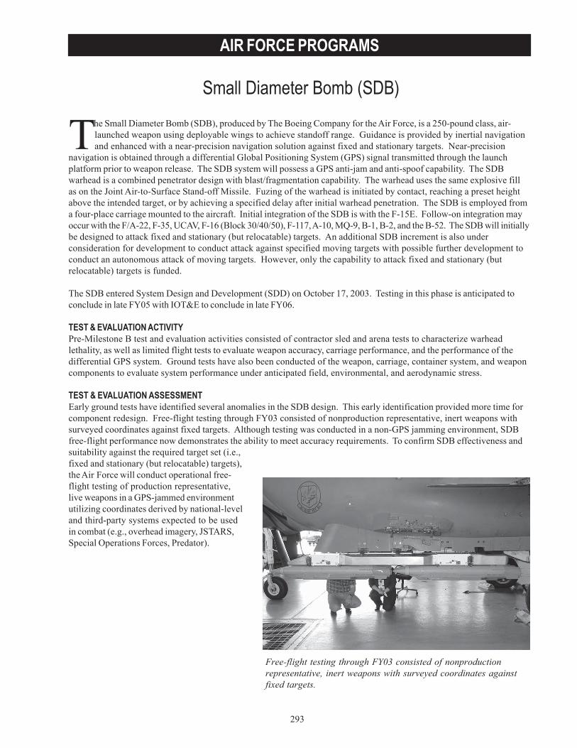
293
AIR FORCE PROGRAMS
Small Diameter Bomb (SDB)
Free-flight testing through FY03 consisted of nonproductionrepresentative, inert weapons with surveyed coordinates againstfixed targets.
The Small Diameter Bomb (SDB), produced by The Boeing Company for the Air Force, is a 250-pound class, air-launched weapon using deployable wings to achieve standoff range. Guidance is provided by inertial navigationand enhanced with a near-precision navigation solution against fixed and stationary targets. Near-precision
navigation is obtained through a differential Global Positioning System (GPS) signal transmitted through the launchplatform prior to weapon release. The SDB system will possess a GPS anti-jam and anti-spoof capability. The SDBwarhead is a combined penetrator design with blast/fragmentation capability. The warhead uses the same explosive fillas on the Joint Air-to-Surface Stand-off Missile. Fuzing of the warhead is initiated by contact, reaching a preset heightabove the intended target, or by achieving a specified delay after initial warhead penetration. The SDB is employed froma four-place carriage mounted to the aircraft. Initial integration of the SDB is with the F-15E. Follow-on integration mayoccur with the F/A-22, F-35, UCAV, F-16 (Block 30/40/50), F-117, A-10, MQ-9, B-1, B-2, and the B-52. The SDB will initiallybe designed to attack fixed and stationary (but relocatable) targets. An additional SDB increment is also underconsideration for development to conduct attack against specified moving targets with possible further development toconduct an autonomous attack of moving targets. However, only the capability to attack fixed and stationary (butrelocatable) targets is funded.
The SDB entered System Design and Development (SDD) on October 17, 2003. Testing in this phase is anticipated toconclude in late FY05 with IOT&E to conclude in late FY06.
TEST & EVALUATION ACTIVITYPre-Milestone B test and evaluation activities consisted of contractor sled and arena tests to characterize warheadlethality, as well as limited flight tests to evaluate weapon accuracy, carriage performance, and the performance of thedifferential GPS system. Ground tests have also been conducted of the weapon, carriage, container system, and weaponcomponents to evaluate system performance under anticipated field, environmental, and aerodynamic stress.
TEST & EVALUATION ASSESSMENTEarly ground tests have identified several anomalies in the SDB design. This early identification provided more time forcomponent redesign. Free-flight testing through FY03 consisted of nonproduction representative, inert weapons withsurveyed coordinates against fixed targets. Although testing was conducted in a non-GPS jamming environment, SDBfree-flight performance now demonstrates the ability to meet accuracy requirements. To confirm SDB effectiveness andsuitability against the required target set (i.e.,fixed and stationary (but relocatable) targets),the Air Force will conduct operational free-flight testing of production representative,live weapons in a GPS-jammed environmentutilizing coordinates derived by national-leveland third-party systems expected to be usedin combat (e.g., overhead imagery, JSTARS,Special Operations Forces, Predator).

294
AIR FORCE PROGRAMS
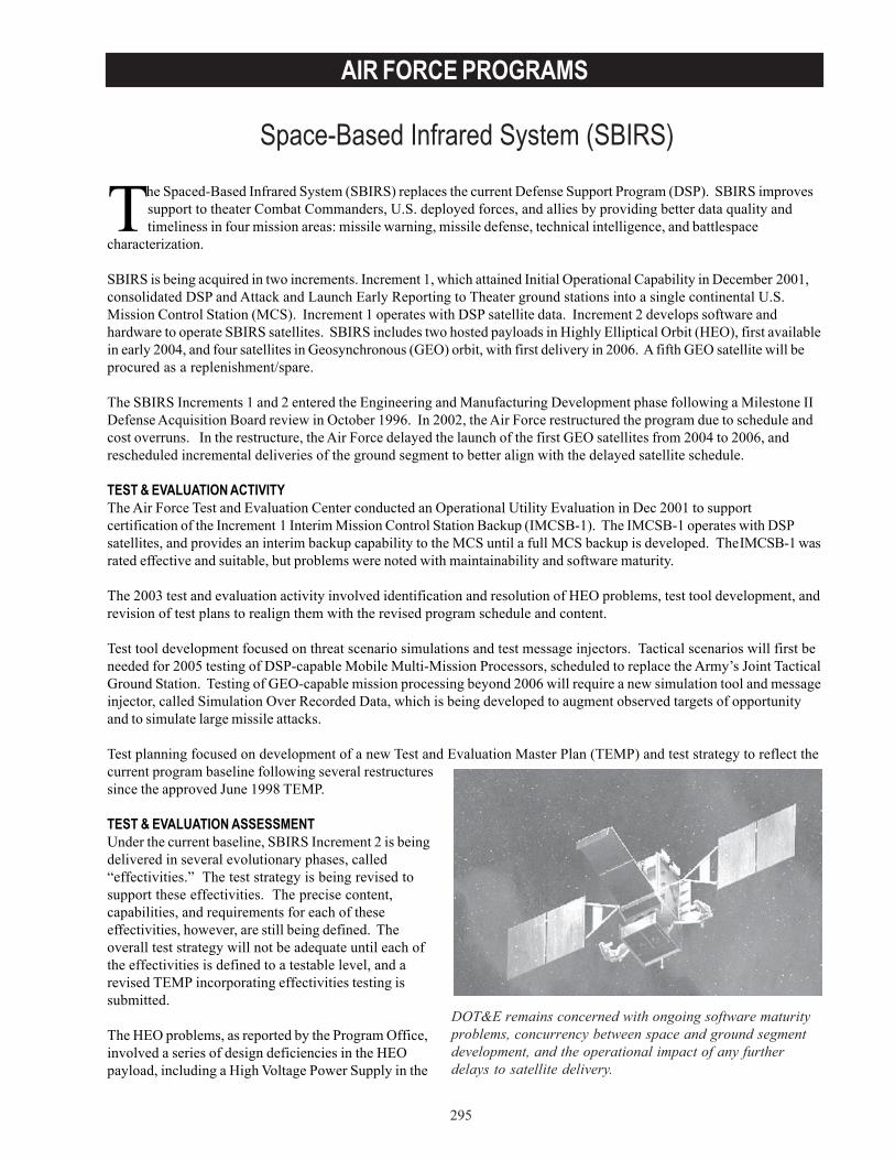
295
AIR FORCE PROGRAMS
Space-Based Infrared System (SBIRS)
DOT&E remains concerned with ongoing software maturityproblems, concurrency between space and ground segmentdevelopment, and the operational impact of any furtherdelays to satellite delivery.
The Spaced-Based Infrared System (SBIRS) replaces the current Defense Support Program (DSP). SBIRS improvessupport to theater Combat Commanders, U.S. deployed forces, and allies by providing better data quality andtimeliness in four mission areas: missile warning, missile defense, technical intelligence, and battlespace
characterization.
SBIRS is being acquired in two increments. Increment 1, which attained Initial Operational Capability in December 2001,consolidated DSP and Attack and Launch Early Reporting to Theater ground stations into a single continental U.S.Mission Control Station (MCS). Increment 1 operates with DSP satellite data. Increment 2 develops software andhardware to operate SBIRS satellites. SBIRS includes two hosted payloads in Highly Elliptical Orbit (HEO), first availablein early 2004, and four satellites in Geosynchronous (GEO) orbit, with first delivery in 2006. A fifth GEO satellite will beprocured as a replenishment/spare.
The SBIRS Increments 1 and 2 entered the Engineering and Manufacturing Development phase following a Milestone IIDefense Acquisition Board review in October 1996. In 2002, the Air Force restructured the program due to schedule andcost overruns. In the restructure, the Air Force delayed the launch of the first GEO satellites from 2004 to 2006, andrescheduled incremental deliveries of the ground segment to better align with the delayed satellite schedule.
TEST & EVALUATION ACTIVITYThe Air Force Test and Evaluation Center conducted an Operational Utility Evaluation in Dec 2001 to supportcertification of the Increment 1 Interim Mission Control Station Backup (IMCSB-1). The IMCSB-1 operates with DSPsatellites, and provides an interim backup capability to the MCS until a full MCS backup is developed. TheIMCSB-1 wasrated effective and suitable, but problems were noted with maintainability and software maturity.
The 2003 test and evaluation activity involved identification and resolution of HEO problems, test tool development, andrevision of test plans to realign them with the revised program schedule and content.
Test tool development focused on threat scenario simulations and test message injectors. Tactical scenarios will first beneeded for 2005 testing of DSP-capable Mobile Multi-Mission Processors, scheduled to replace the Army’s Joint TacticalGround Station. Testing of GEO-capable mission processing beyond 2006 will require a new simulation tool and messageinjector, called Simulation Over Recorded Data, which is being developed to augment observed targets of opportunityand to simulate large missile attacks.
Test planning focused on development of a new Test and Evaluation Master Plan (TEMP) and test strategy to reflect thecurrent program baseline following several restructuressince the approved June 1998 TEMP.
TEST & EVALUATION ASSESSMENTUnder the current baseline, SBIRS Increment 2 is beingdelivered in several evolutionary phases, called“effectivities.” The test strategy is being revised tosupport these effectivities. The precise content,capabilities, and requirements for each of theseeffectivities, however, are still being defined. Theoverall test strategy will not be adequate until each ofthe effectivities is defined to a testable level, and arevised TEMP incorporating effectivities testing issubmitted.
The HEO problems, as reported by the Program Office,involved a series of design deficiencies in the HEOpayload, including a High Voltage Power Supply in the
296
AIR FORCE PROGRAMS
Common Gyro Reference Assembly and an inadequately developed design to control payload electromagneticinterference. Resolution of these problems required extensive rework and parts fabrication, leading to a six-monthAcquisition Program Baseline breach of the HEO payload delivery and message certification dates.
DOT&E remains concerned with ongoing software maturity problems, concurrency between space and ground segmentdevelopment, and the operational impact of any further delays to satellite delivery.

297
AIR FORCE PROGRAMS
Space-Based Radar (SBR)
The Space-Based Radar is at an early stage of development, buttest and evaluation planning is proceeding at an adequate pace.
The Space-Based Radar (SBR) system is a planned constellation of satellites that can be tasked in near real-time toprovide a rapid response to real-time continental U.S. or theater requirements. Moving Target Indicator (MTI)data and Synthetic Aperture Radar (SAR) imagery will be transmitted directly, or via relay satellites, to appropriate
ground receiving stations. Users of such information include air expeditionary forces, Army objective forces, Navalforces, intelligence components, and Homeland Security networks. Fuzed with data from current MTI systems, SBR willimprove near real-time targeting and situational awareness.
The Secretary of Defense appointed the Secretary of the Air Force as the DoD Executive Agent for Space in 2002. TheAir Force is acquiring SBR under new DoD National Security Space Policy directives tailored for space programs. SBR isin the initial phase of development, and passed its first Key Decision Point A (KDP-A) to enter Phase A (the StudyPhase) in July 2003. The purpose of the Study Phase is to develop concepts and architectures to a sufficient level ofmaturity to enter the KDP-B Design Phase, expected in FY04. The Study Phase will consist of further concept definition,concept of operations and requirements development, risk reduction, and initial planning to develop a test andevaluation strategy prior to KDP-B. After KDP-B, the program is expected to enter a system pre-acquisition periodlasting through a planned KDP-C at the end of FY07, when system acquisition activities will begin.
Thus far, the Program Office has formulated a draft acquisition strategy and awarded key contracts to support ongoingrisk reduction activities.
TEST & EVALUATION ACTIVITYThe lead operational test agency, the Air Force Operational Test and Evaluation Center, developed a NecessaryConditions Chart (NCC) during 2002 and 2003, and the Program Office used this as the basis for a test strategy documentin support of KDP-A. The NCC is a test planning aid that provides linkages between operational requirements, contractspecifications, and mission objectives.
The test strategy document emphasized combined developmental and operational testing in order to maximize testingefficiency. As the test strategy matures, the NCC will serve as a template for the development of critical operationalissues, measures of effectiveness, and measures of performance.
TEST & EVALUATION ASSESSMENTSBR is at an early stage of development, but test and evaluation planning is proceeding at an adequate pace to supportan eventual assessment of operational effectiveness and suitability. As the test and evaluation strategy matures, itshould focus on mitigation of key risk areas. Generally these areas involve: information management and the capabilityof the system to manage the very large amounts of data expected; satellite on-board processing capability and reliabilityneeded to “pre-digest” the collected radar data before transmitting to ground; signal processing algorithms in terms oftheir reliability and capability to present radarderived data for rapid analysis and dissemination;spacecraft technology in terms of power,structural integrity, detection technology, andcommunications reliability; and systemsurvivability.

298
AIR FORCE PROGRAMS

299
AIR FORCE PROGRAMS
Unmanned Combat Aerial Vehicle (UCAV) - Air Force
The maximum altitude demonstrated was 35,000 feet and a topspeed of 250 knots.
The Air Force initiated the Unmanned Combat Air Vehicle (UCAV) advanced technology demonstration program in1999 to develop an autonomous, stealthy, unmanned strike aircraft. The aircraft is intended to carry advancedsensors for target acquisition, electronic support measures, and air-to-ground weapons. The Air Force has not yet
selected a weapon, but candidates include Joint Direct Attack Munition and the Small Diameter Bomb. Compared tomanned attack aircraft, the operational concept of the UCAV is intended to reduce operations and support costs.
The Defense Advanced Research Projects Agency (DARPA) is managing the technical feasibility for a UCAV system toeffectively and affordably suppress enemy air defenses, electronic attack, and strike missions. The system design uses aspiral development approach, concurrently developing, producing, testing, and fielding the system in blocks. Thecurrent prototype air vehicles, X-45As, will migrate from Block 1 to Block 4 within the current demonstration program.
In December 2002, the OSD Program Decision Memorandum adjusted funding for both Air Force and Navy UCAVdevelopment – including the procurement of several air vehicles in the FY07-09 timeframe. The Program DecisionMemorandum also directed the Air Force and Navy to initiate a joint program office to manage UCAV development, whichwas the number one priority of the OSD UAV Planning Task Force. In conjunction with the Joint Program Office, OSD/Program Assessment and Evaluation led a UCAV options study to determine how best to use a variety of UCAVs in thefuture military force.
In June 2003, OSD established the Joint Systems Management Office for the Joint Unmanned Combat Air Systems, whichbegan operation in October 2003. OSD instructed this joint office to lead a seven-year effort developing technologies forAir Force and Navy UCAVs. The joint office is to also deliver 14 aircraft in 2007 for a two-year operational assessment.During this assessment, DARPA will measure how well various technologies meet the Air Force and Navy requirements,and by 2010, OSD will use DARPA’s assessment to decide whether to pursue joint or separate UCAV systems.
TEST & EVALUATION ACTIVITYTo date, test activity has been conducted at NASA Dryden Space Center, California, under a joint DARPA/Air Force/Boeing system demonstration program.
The X-45A’s first flight occurred in May 2002. The Block 1 flight demonstrations of basic system functionality werecompleted in February 2003. A total of 16 flights and nearly 13 flight hours were accomplished. The maximum altitudedemonstrated was 35,000 feet and a top speed of 250 knots.
Three weeks of flight-testing the UCAV Block 2flight systems onboard a T-33 aircraft took place atEglin Air Force Base, Florida, during March 2003.Both X-45A demonstrator air vehicles underwentupgrades to begin the Block 2 demonstrations,which will include multi-airvehicle coordinatedflights.
TEST & EVALUATION ASSESSMENTDOT&E supports the competitive nature of theoperational assessment and the opportunity forside-by-side flight evaluations of the X-45 and theNavy’s UCAV-N demonstrator, the X-47A Pegasus.DOT&E plans to work with the operational testagencies to ensure that relevant early operationaldata are collected to support transition to a formalacquisition program.

300
AIR FORCE PROGRAMS
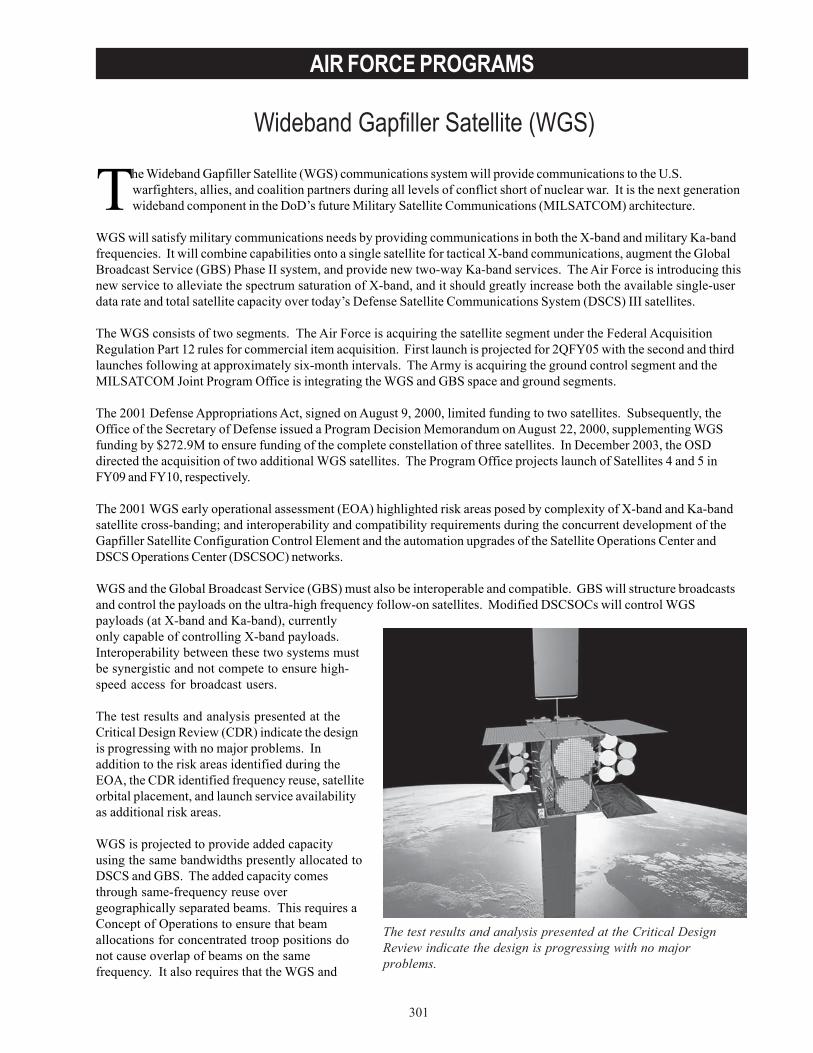
301
AIR FORCE PROGRAMS
Wideband Gapfiller Satellite (WGS)
The test results and analysis presented at the Critical DesignReview indicate the design is progressing with no majorproblems.
The Wideband Gapfiller Satellite (WGS) communications system will provide communications to the U.S.warfighters, allies, and coalition partners during all levels of conflict short of nuclear war. It is the next generationwideband component in the DoD’s future Military Satellite Communications (MILSATCOM) architecture.
WGS will satisfy military communications needs by providing communications in both the X-band and military Ka-bandfrequencies. It will combine capabilities onto a single satellite for tactical X-band communications, augment the GlobalBroadcast Service (GBS) Phase II system, and provide new two-way Ka-band services. The Air Force is introducing thisnew service to alleviate the spectrum saturation of X-band, and it should greatly increase both the available single-userdata rate and total satellite capacity over today’s Defense Satellite Communications System (DSCS) III satellites.
The WGS consists of two segments. The Air Force is acquiring the satellite segment under the Federal AcquisitionRegulation Part 12 rules for commercial item acquisition. First launch is projected for 2QFY05 with the second and thirdlaunches following at approximately six-month intervals. The Army is acquiring the ground control segment and theMILSATCOM Joint Program Office is integrating the WGS and GBS space and ground segments.
The 2001 Defense Appropriations Act, signed on August 9, 2000, limited funding to two satellites. Subsequently, theOffice of the Secretary of Defense issued a Program Decision Memorandum on August 22, 2000, supplementing WGSfunding by $272.9M to ensure funding of the complete constellation of three satellites. In December 2003, the OSDdirected the acquisition of two additional WGS satellites. The Program Office projects launch of Satellites 4 and 5 inFY09 and FY10, respectively.
The 2001 WGS early operational assessment (EOA) highlighted risk areas posed by complexity of X-band and Ka-bandsatellite cross-banding; and interoperability and compatibility requirements during the concurrent development of theGapfiller Satellite Configuration Control Element and the automation upgrades of the Satellite Operations Center andDSCS Operations Center (DSCSOC) networks.
WGS and the Global Broadcast Service (GBS) must also be interoperable and compatible. GBS will structure broadcastsand control the payloads on the ultra-high frequency follow-on satellites. Modified DSCSOCs will control WGSpayloads (at X-band and Ka-band), currentlyonly capable of controlling X-band payloads.Interoperability between these two systems mustbe synergistic and not compete to ensure high-speed access for broadcast users.
The test results and analysis presented at theCritical Design Review (CDR) indicate the designis progressing with no major problems. Inaddition to the risk areas identified during theEOA, the CDR identified frequency reuse, satelliteorbital placement, and launch service availabilityas additional risk areas.
WGS is projected to provide added capacityusing the same bandwidths presently allocated toDSCS and GBS. The added capacity comesthrough same-frequency reuse overgeographically separated beams. This requires aConcept of Operations to ensure that beamallocations for concentrated troop positions donot cause overlap of beams on the samefrequency. It also requires that the WGS and
302
AIR FORCE PROGRAMS
DSCS satellites be separated sufficiently in their orbits so that the least capable X-band antenna can discriminatebetween the two satellites.
The Program Office plan for WGS satellite launch is to integrate them on both Delta and Atlas Evolved ExpendableLaunch Vehicles (EELVs). The first launch will be on Delta and the second on Atlas. Boeing added extra solar panels totheir original design, which added weight and changed the class of EELV. The availability of the launch vehicle and anaggressive integration schedule, less than the normal 24 months, are sources of schedule risk.
TEST & EVALUATION ACTIVITYTest and evaluation planning continued in FY03 for the WGS system.
• The Test and Evaluation Master Plan was updated after the CDR and was approved by DOT&E onMarch 3, 2003.
• The Air Force Operational Test and Evaluation Center (AFOTEC) completed an EOA of the WGS systemSeptember 2000 in support of a combined Milestone II/III review.
• AFOTEC performed an operational assessment based primarily on the CDR data package and briefed DOT&Eon May 21, 2003.
• Government developmental and operational test members started observing contractor developmentaltesting and inter-segment testing in FY03.
TEST & EVALUATION ASSESSMENTThe operational assessment conducted in May 2003 highlighted the following issues:
• Link availability at a five-degree elevation angle is slightly lower than the 99.5 percent Operational RequirementsDocument requisite, but users say this can be managed through power level management and, therefore, will notbe a problem.
• Ka-band reach-back into the Defense Information Systems Network will not be available until this capability isfielded in the DoD Teleports in 2006.
• The new satellite increases operator workload. The Air Force has allocated additional manning, but the Armyhas not. This will limit system effectiveness until Army staffing issues are resolved.
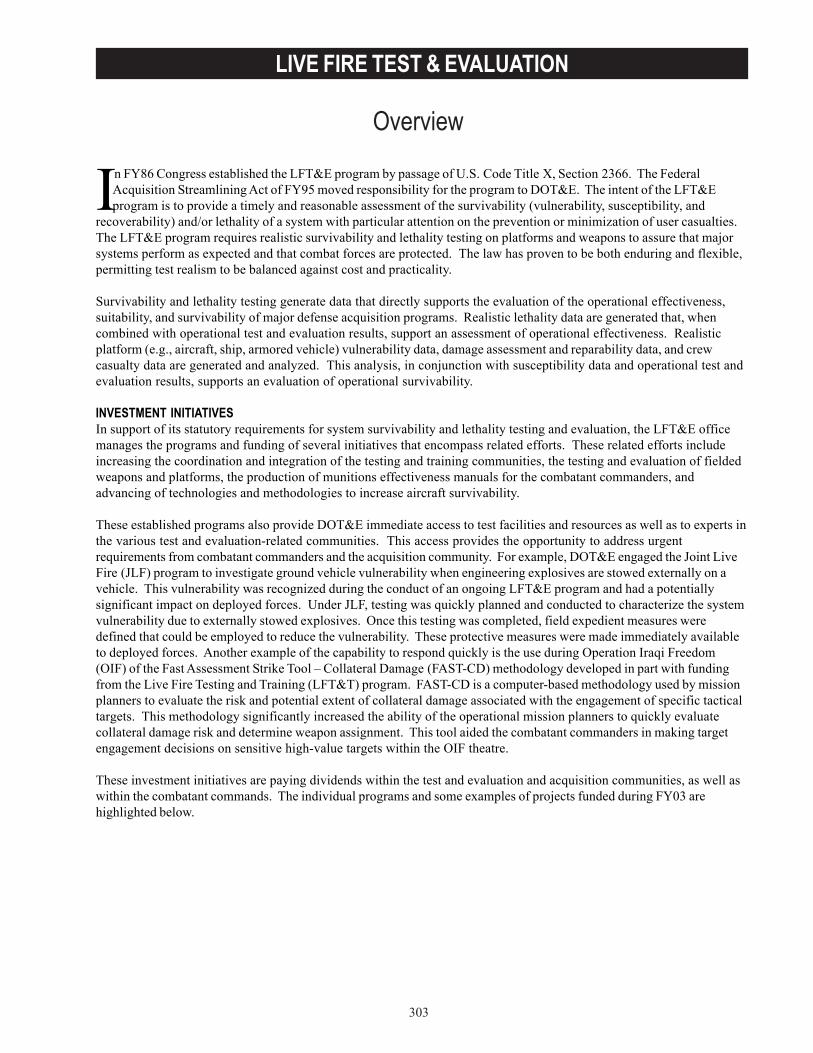
303
LIVE FIRE TEST & EVALUATION
Overview
In FY86 Congress established the LFT&E program by passage of U.S. Code Title X, Section 2366. The FederalAcquisition Streamlining Act of FY95 moved responsibility for the program to DOT&E. The intent of the LFT&Eprogram is to provide a timely and reasonable assessment of the survivability (vulnerability, susceptibility, and
recoverability) and/or lethality of a system with particular attention on the prevention or minimization of user casualties.The LFT&E program requires realistic survivability and lethality testing on platforms and weapons to assure that majorsystems perform as expected and that combat forces are protected. The law has proven to be both enduring and flexible,permitting test realism to be balanced against cost and practicality.
Survivability and lethality testing generate data that directly supports the evaluation of the operational effectiveness,suitability, and survivability of major defense acquisition programs. Realistic lethality data are generated that, whencombined with operational test and evaluation results, support an assessment of operational effectiveness. Realisticplatform (e.g., aircraft, ship, armored vehicle) vulnerability data, damage assessment and reparability data, and crewcasualty data are generated and analyzed. This analysis, in conjunction with susceptibility data and operational test andevaluation results, supports an evaluation of operational survivability.
INVESTMENT INITIATIVESIn support of its statutory requirements for system survivability and lethality testing and evaluation, the LFT&E officemanages the programs and funding of several initiatives that encompass related efforts. These related efforts includeincreasing the coordination and integration of the testing and training communities, the testing and evaluation of fieldedweapons and platforms, the production of munitions effectiveness manuals for the combatant commanders, andadvancing of technologies and methodologies to increase aircraft survivability.
These established programs also provide DOT&E immediate access to test facilities and resources as well as to experts inthe various test and evaluation-related communities. This access provides the opportunity to address urgentrequirements from combatant commanders and the acquisition community. For example, DOT&E engaged the Joint LiveFire (JLF) program to investigate ground vehicle vulnerability when engineering explosives are stowed externally on avehicle. This vulnerability was recognized during the conduct of an ongoing LFT&E program and had a potentiallysignificant impact on deployed forces. Under JLF, testing was quickly planned and conducted to characterize the systemvulnerability due to externally stowed explosives. Once this testing was completed, field expedient measures weredefined that could be employed to reduce the vulnerability. These protective measures were made immediately availableto deployed forces. Another example of the capability to respond quickly is the use during Operation Iraqi Freedom(OIF) of the Fast Assessment Strike Tool – Collateral Damage (FAST-CD) methodology developed in part with fundingfrom the Live Fire Testing and Training (LFT&T) program. FAST-CD is a computer-based methodology used by missionplanners to evaluate the risk and potential extent of collateral damage associated with the engagement of specific tacticaltargets. This methodology significantly increased the ability of the operational mission planners to quickly evaluatecollateral damage risk and determine weapon assignment. This tool aided the combatant commanders in making targetengagement decisions on sensitive high-value targets within the OIF theatre.
These investment initiatives are paying dividends within the test and evaluation and acquisition communities, as well aswithin the combatant commands. The individual programs and some examples of projects funded during FY03 arehighlighted below.

304
LIVE FIRE TEST & EVALUATION
LIVE FIRE TESTING AND TRAININGThe FY97 Defense Appropriation included Congressional funding to investigate alternative uses of simulation and trainingtechnology in support of LFT&E. This initiative became the LFT&T Program and has been funded entirely by Congress.
The LFT&T Program fosters the exchange of technology initiatives and uses betweenthe live fire and training communities. The underlying LFT&T Program objectives areto enhance cost-effective testing and training and to improve war-fighting readiness.Since inception, the program has funded 31 projects totaling approximately $33M.Several projects have transitioned to operational sponsors and are already providingbenefits to the warfighter. Congress did not fund the LFT&T Program for FY04. Dueto the valuable and affordable products generated as a result of this program, DOT&Ewill attempt to provide internal funding to maintain the program until it can beestablished within the President’s budget.
The LFT&T Program funded eight projects in FY03:
• SPECIAL OPERATIONS FORCES SIGNALS TRAINING AND REHEARSAL SYSTEM (SOFSTARS): This is aninitiative that supports the Air Force Special Operations Command (AFSOC). It integrates live, virtual, andconstructive simulations and national intelligence capabilities to provide aircrews with a realistic, simulatedcombat environment for distributed mission operations. SOFSTARS will support a full spectrum of activities toinclude mission preparation and planning, training, testing, mission rehearsal, and experimentation. SOFSTARSwill interface with aircrew training devices, aircraft systems, mission planning/rehearsal tools, and otherServices’ assets required to provide a seamless AFSOC mission environment. SOFSTARS’ capabilities will alsobe integrated into real-world Special Operations Forces and conventional operations, where applicable, tosupport ongoing missions.
• PROJECT GRACE: In the summer of 2003, Project Grace provided an opportunity for warfighters to observe andevaluate the MiG-29 as a total weapons system during a German Air Force MiG-29 deployment to the U.S.Currently, the aircraft, weapons, fire control system, and helmet-mounted display are assessed independentlyand a total weapons system capability is then extrapolated from the results of these independent assessments.The weapon system evaluation made during Project Grace will ensure that future U.S. and allies’ tactics, testing,and training are based on complete and accurate knowledge of MiG-29 system capabilities.
• SUPER FAST ASSESSMENT STRIKE TOOL – COLLATERAL DAMAGE (Super FAST-CD): Super FAST-CDimproves the FAST-CD tool currently used by combatant commanders and component staff to estimateexpected collateral damage in potential target areas. Super FAST-CD will improve the warfighters’ ability toconduct time-critical operations by decreasing decision timelines and by allowing warfighters to optimize theselection of precision munitions against targets that are in or near congested or protected zones.
• ADVANCED ROBOTICS TEST BED (ARTB): ARTB is developing a dynamically composable robotic test bedthat will provide the capability to analyze tactics and train with unmanned forces in a collaborative environment.This capability will be essential for all Services using unmanned vehicles in their warfighting force structureand operations. With the development of the ARTB, survivability and lethality studies can be conducted onindividual platforms, as well as analyses of total system-of-systems’ performance.
• OBJECTIVE INDIVIDUAL COMBAT WEAPON (OICW) EMBEDDED SIMULATION, TRAINING, ANDINSTRUMENTATION: This project will provide a technology solution to support an embedded capability forthe OICW in simulation systems used by the Army Research, Development, and Engineering Command and theDismounted Battlespace Battle Lab. This capability will assist warfighters in assessing new solutions to theirindividual combat weaponry and tactics requirements for the future.
• MOVING WEAPONS PLATFORM SIMULATOR (MWEPS): MWEPS will be a system that allows weapons’concepts to be evaluated on a motion-based platform earlier in the design process, reducing the time requiredfor developmental testing. It will also serve as an individual weapons operator training system and will be thebaseline system for defining system operator training requirements. The Naval Surface Warfare Center has

305
LIVE FIRE TEST & EVALUATION
already used a prototype version of MWEPS to support the testing of remote-controlled small arms mountson a motion-based platform, avoiding the expenditure for live ammunition and a target to calibrate thestabilized mount and auto tracker system. The fully developed MWEPS will provide cost avoidance fortesting and training applications on a wide variety of air, land, and sea platforms.
• JOINT DISTRIBUTED INTEGRATED TEST AND TRAINING SYSTEM: This project expands Virtual At-SeaTrainer (VAST) technology (developed in an earlier LFT&T project) that scores the performance of Navyweapon systems at sea. This follow-on initiative will demonstrate a virtual, transportable “range” for the end-to-end test and evaluation of extended range weapon systems and will increase training and mission planningcapabilities using an enhanced 3-D visualization system for projecting the detailed location of any desiredtarget. The system is being designed to evaluate land, sea or air-launched weapons, as well as providingincreased training and mission planning capabilities using an enhanced 3-D visualization system. Because theNavy selected this system as a near-term replacement of the range capabilities at Vieques, DOT&E hasaccelerated the development of this program.
• MULTIPURPOSE SUPPORTING ARMS TRAINER: This project will apply the latest display technologies,synthetic terrain viewers, and scenario development techniques to the development of a prototype multipurposeterminal control and supporting arms trainer. The trainer will provide a joint, standardized system forinstruction in the employment and techniques for communicating requirements for Naval surface fire, tactical air,and field artillery support in expeditionary operations. Each Service currently performs these requirementsdifferently. The Joint Forward Air Controller community estimates that operational and maintenance costs couldbe reduced by 50 percent by accomplishing close-air support coordination and pilot proficiency training via asynthetic training environment.
JOINT LIVE FIRE PROGRAMOSD initiated the JLF Program in March 1984 to establish a formal process for the test and evaluation of fielded U.S.systems against realistic threats. This process continues today, taking into account changes in operational scenarios,changes in threat munitions and targets, and the testing of legacy systems. JLF provides a means to gather additionaldata not collected by acquisition programs. It contributes to survivability and lethality assessments of fielded systemsor for upgrade programs that do not qualify as a formal LFT&E program.
The JLF program consists of three groups: Aircraft Systems (JLF/AS), Armor/Anti-Armor (JLF/A/AA), and SeaSystems (JLF/SS). The focus of each of these groups is:
• JLF/AS: Vulnerability of U.S. fixed-wing and rotary-wing aircraft to realistic threats and on the lethality offielded U.S. weapons/munitions against foreign aircraft.
• JLF/A/AA: Vulnerability of fielded U.S. ground systems (e.g., tanks, armored personnel carriers) to realisticthreats and on the lethality of fielded U.S. weapons/munitions against realistic targets.
• JLF/SS: Vulnerability of fielded surface combatants and on the lethality of fielded U.S. weapons/munitionsagainst realistic targets.
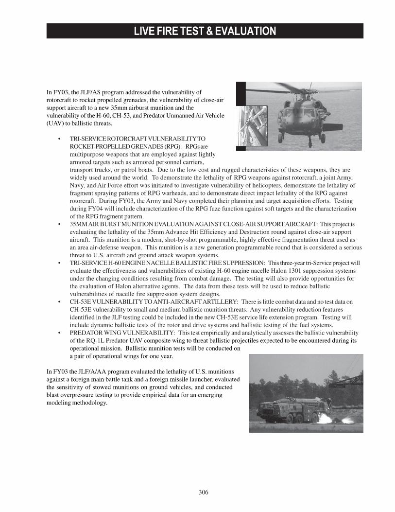
306
LIVE FIRE TEST & EVALUATION
In FY03, the JLF/AS program addressed the vulnerability ofrotorcraft to rocket propelled grenades, the vulnerability of close-airsupport aircraft to a new 35mm airburst munition and thevulnerability of the H-60, CH-53, and Predator Unmanned Air Vehicle(UAV) to ballistic threats.
• TRI-SERVICE ROTORCRAFT VULNERABILITY TOROCKET-PROPELLED GRENADES (RPG): RPGs aremultipurpose weapons that are employed against lightlyarmored targets such as armored personnel carriers,transport trucks, or patrol boats. Due to the low cost and rugged characteristics of these weapons, they arewidely used around the world. To demonstrate the lethality of RPG weapons against rotorcraft, a joint Army,Navy, and Air Force effort was initiated to investigate vulnerability of helicopters, demonstrate the lethality offragment spraying patterns of RPG warheads, and to demonstrate direct impact lethality of the RPG againstrotorcraft. During FY03, the Army and Navy completed their planning and target acquisition efforts. Testingduring FY04 will include characterization of the RPG fuze function against soft targets and the characterizationof the RPG fragment pattern.
• 35MM AIR BURST MUNITION EVALUATION AGAINST CLOSE-AIR SUPPORT AIRCRAFT: This project isevaluating the lethality of the 35mm Advance Hit Efficiency and Destruction round against close-air supportaircraft. This munition is a modern, shot-by-shot programmable, highly effective fragmentation threat used asan area air-defense weapon. This munition is a new generation programmable round that is considered a seriousthreat to U.S. aircraft and ground attack weapon systems.
• TRI-SERVICE H-60 ENGINE NACELLE BALLISTIC FIRE SUPPRESSION: This three-year tri-Service project willevaluate the effectiveness and vulnerabilities of existing H-60 engine nacelle Halon 1301 suppression systemsunder the changing conditions resulting from combat damage. The testing will also provide opportunities forthe evaluation of Halon alternative agents. The data from these tests will be used to reduce ballisticvulnerabilities of nacelle fire suppression system designs.
• CH-53E VULNERABILITY TO ANTI-AIRCRAFT ARTILLERY: There is little combat data and no test data onCH-53E vulnerability to small and medium ballistic munition threats. Any vulnerability reduction featuresidentified in the JLF testing could be included in the new CH-53E service life extension program. Testing willinclude dynamic ballistic tests of the rotor and drive systems and ballistic testing of the fuel systems.
• PREDATOR WING VULNERABILITY: This test empirically and analytically assesses the ballistic vulnerabilityof the RQ-1L Predator UAV composite wing to threat ballistic projectiles expected to be encountered during itsoperational mission. Ballistic munition tests will be conducted ona pair of operational wings for one year.
In FY03 the JLF/A/AA program evaluated the lethality of U.S. munitionsagainst a foreign main battle tank and a foreign missile launcher, evaluatedthe sensitivity of stowed munitions on ground vehicles, and conductedblast overpressure testing to provide empirical data for an emergingmodeling methodology.
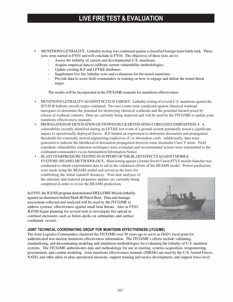
307
LIVE FIRE TEST & EVALUATION
• MUNITIONS LETHALITY: Lethality testing was continued against a classified foreign main battle tank. Thesetests were started in FY01 and will conclude in FY04. The objectives of these tests are to:
- Assess the lethality of current and developmental U.S. munitions.- Acquire empirical data to calibrate current vulnerability methodologies.- Update existing JLF and LFT&E databases.- Supplement live fire lethality tests and evaluations for the tested munitions.- Provide data to assist field commanders in training on how to engage and defeat the tested threat
target.
The results will be incorporated in the JTCG/ME manuals for munitions effectiveness.
• MUNITIONS LETHALITY AGAINST SCUD-B TARGET: Lethality testing of several U.S. munitions against theSCUD-B ballistic missile target continued. Two test events were conducted against chemical warheadsurrogates to determine the potential for destroying chemical warheads and the potential hazard posed byrelease of warhead contents. Data are currently being analyzed and will be used by the JTCG/ME to update jointmunitions effectiveness manuals.
• PROPAGATION OF DETONATION OF STOWED BULK DETONATING CORD AND COMPOSITION-4: Avulnerability recently identified during an LFT&E test event of a ground system potentially posed a significantimpact to operationally deployed forces. JLF funded an experiment to determine detonation and propagationthresholds for externally stowed engineering explosives (C-4, detonation cord). Additionally, data weregenerated to indicate the likelihood of detonation propagation between some dissimilar Class V items. Fieldexpedient vulnerability reduction techniques were evaluated and recommended actions were transmitted to thecombatant commanders via an Ammunition Information Notice.
• BLAST OVERPRESSURE TESTING IN SUPPORT OF THE BLAST EFFECTS AGAINST MOBILESYSTEMS (BEAMS) METHODOLOGY: Blast testing against a former Soviet Union STYX missile launcher wasconducted to obtain experimental data to aid in the validation efforts of the BEAMS model. Pretest predictionswere made using the BEAMS model and served as the basis forestablishing the initial standoff distances. Post-shot analyses ofthe structure and material properties updates are currently beingcompleted in order to revise the BEAMS predictions.
In FY03, the JLF/SS program demonstrated HELLFIRE Missile lethalityagainst an aluminum-hulled Mark III Patrol Boat. Data and damageassessment collected and analyzed will be used by the JTCG/ME toaddress systems’ effectiveness against small boat threats. Also in FY03,JLF/SS began planning for several tests to investigate fire spread inconfined enclosures such as below-decks on submarines and surfacecombatant vessels.
JOINT TECHNICAL COORDINATING GROUP FOR MUNITIONS EFFECTIVENESS (JTCG/ME)
The Joint Logistics Commanders chartered the JTCG/ME over 30 years ago to serve as DoD’s focal point forauthenticated non-nuclear munitions effectiveness information. The JTCG/ME’s efforts include validating,standardizing, and disseminating modeling and simulation methodologies for evaluating the lethality of U.S. munitionsystems. The JTCG/ME authenticates data and methodology for use in training, systems acquisition, weaponeering,procurement, and combat modeling. Joint munitions effectiveness manuals (JMEMs) are used by the U.S. Armed Forces,NATO, and other allies to plan operational missions, support training and tactics development, and support force-level

308
LIVE FIRE TEST & EVALUATION
analyses. The JTCG/ME also develops and standardizes methodologies for the evaluation of munitions effectivenessand maintains databases for target vulnerability, munitions lethality, and weapon system accuracy.
In FY03, the JTCG/ME:
• Enhanced the operational tools and data in the following JMEMs: Air-to-Surface Weaponeering System,including two interim versions in support of Operation Enduring Freedom and Operation Iraqi Freedom; JointAnti-Air Combat Effectiveness; and Surface-to-Surface Weaponeering Effectiveness System.
• Increased support to the warfighter by distributing products and product updates via the classified Internetwith the JTCG/ME Products and Information Access System.
• Continued updating existing databases to incorporate weapons effectiveness and target vulnerability data for 33new air-to-surface targets and 17 new surface-to-surface targets.
• Continued execution and technical coordination efforts to address target vulnerability data generation for a fullspectrum of strike weapons against approximately 50 targets.
• Coordinated with Joint Chiefs of Staff to develop instructions to codify the command requirements data call andprioritization to support the FY04 JTCG/ME program.
• In collaboration with the Defense Intelligence Agency and Service intelligence centers, initiated intelligencecollection and production requirements process and conducted review and analysis of intelligence datapackages in support of target geometry development.
JOINT AIRCRAFT SURVIVABILITY PROGRAM (JASP)The Joint Aeronautical Commanders Group established JASP by Charter in January 2003 through the integration of theJTCG on Aircraft Survivability, the Joint Live Fire Aircraft Systems program, the Joint Combat Assessment Team, and theJoint Accreditation Support Activity. The program focuses on establishing aircraft survivability as a design discipline. Itdevelops vulnerability and susceptibility reduction technologies, provides standard accredited models to assess aircraftsurvivability, supports combat survivability education, collects combat damage data for analysis, and conducts JLF testson combat aircraft. The JASP is the military’s only tri-Service organization solely dedicated to advancing aircraft combatsurvivability.
In FY03, JASP worked closely with members of the defense acquisition community, as well as the Federal AviationAdministration, the Transportation Security Administration, and National Aeronautics and Space Administration, toidentify critical issues regarding aircraft survivability. Accordingly, JASP funded approximately $8.4M for 61survivability projects and funded approximately $1.5M for nine JLF test projects. JASP projects are grouped in threecategories: susceptibility reduction, vulnerability reduction, and survivability assessment.
Examples of these projects are:
• SUSCEPTIBILITY REDUCTION: - The UAV Active Acoustic Cancellation project will measure radiation patterns and spectral content of
acoustic emissions from push/pull propeller-driven UAVs and will then determine passive and activesignature reduction techniques.
- The Imaging Seeker Aim Point project’s objective is to determine how to counter imaging infrared seekers inthreat missiles.
- The Aero Urban Decoy project will develop an inexpensive aero stable flare, safe for deployment in low-altitude environments and capable of protecting low-flying, large, fixed-wing aircraft.
• VULNERABILITY REDUCTION: - The Man Portable Air Defense System (MANPADS) Impact Point Assessment project will validate the
ability of MANPADS fly-out and endgame modeling to discriminate between adjacent infrared targets andpredict hit points.
309
LIVE FIRE TEST & EVALUATION
- The Advanced Survivable Rotorcraft Validation project will enhance the technology base for the design ofhardened rotorcraft structures. This project will also validate a low-cost, low-weight MANPADS hit-pointbiasing concept.
- The Joint Resistance to Ram project characterized inherent hydraulic ram resistance and failure criteria as afunction of joint design.
• SURVIVABILITY ASSESSMENT: - The Dry Bay Fire Model (DBFM) Enhancements project, together with the JTCG/ME, is developing a
standard dry bay fire model and a fuel tank ullage explosion model for stand-alone analysis. The DBFM willprovide the framework to enable modeling of physical threat/target interactions that cannot be done withincurrent models such as hydrodynamic ram filling the dry bay, fire pooling and spread, airflow within the drybay with clutter, and time-dependent damage.
- The JASP funds the Survivability/Vulnerability Information Analysis Center (SURVIAC) Model andSimulation Accreditation Support Information project to provide a credibility assessment of the survivabilityand vulnerability models and simulations that are distributed by SURVIAC.

310
LIVE FIRE TEST & EVALUATION
311
JOINT TEST & EVALUATION
Overview
The Joint Test and Evaluation (JT&E) Program has existed for 30 years and is designed to provide quantitativeinformation for analysis of joint military capabilities and potential options for increasing military effectiveness.The program is complimentary to, but not a part of, the weapons acquisition process. A JT&E test brings together
two or more military departments or other components to:
• Assess the interoperability of Service systems in joint operations.• Evaluate improvements in joint technical and operational concepts.• Evaluate and validate multi-Service testing methodologies.• Assess performance of interacting systems under realistic joint operational conditions.• Provide data from joint field tests and exercises to validate models, simulations, and test beds.
Effective December 9, 2002, DOT&E received responsibility for supervision of the JT&E program. DOT&E is changingthe JT&E process to provide results to the warfighter faster. The program will be more agile and respond more quickly toemergent needs and requirements. JT&E will streamline the process and accelerate testing. Improved implementationwill provide immediate benefits. Quick Reaction Tests (QRTs) will complement ongoing tests, providing testing andreporting of results in six months or less. OSD directed the first QRT, Joint Survivability (JSURV), in August 2003 toidentify systemic deficiencies in tactics, techniques, and procedures (TTP) and materiel used by U.S. forces in Iraq inorder to reduce U.S. casualties. JT&E is accelerating testing and shortening test duration. This year, OSD charteredJoint Datalink Information Combat Execution (JDICE) six months early, and testing will take place within the first year ofcharter. In an effort to implement products early and responsively to its customers, Joint Methodology to assessCommand, Control, Communications, Computers, Intelligence, Surveillance, and Reconnaissance (C4ISR) Architecture(JMACA) is integrating with its U.S. Joint Forces Command (JFCOM) customer now, during testing, in order to provideinterim test results quickly and support an early and smooth transition of test results and products.The JT&E program identifies realistic, cost-effective, Service-executable solutions to the joint problems facing today’swarfghter.
The following JT&E tests participated or contributed this year in Operation Iraqi Freedom (OIF). They applied resultsfrom their tests to make real-time improvements to operations.
• Joint Global Positioning System Combat Effectiveness (JGPSCE) field testing discovered potential weaponsystems vulnerabilities to global positioning system degradation. The quick-look test results concerning thesevulnerabilities provided invaluable and timely information to warfighters during Operation Iraqi Freedom.
• Joint Unmanned Air Vehicles (JUAV) deployed into the U.S. Central Command (CENTCOM) Air OperationsCenter to assist in unmanned aerial vehicle tactics, techniques, and procedures development.
• Joint Cruise Missile Defense (JCMD) provided hardware and software tools for quick assessment of events fromIraqi missile shots.
• Joint Logistics/Planning Enhancement (JLOG/PE) assisted and is currently working with the CENTCOM J4 staffin improving the process of acquiring and assimilating logistics support.
• Joint Command, Control, Intelligence, Surveillance, and Reconnaissance (JC2ISR) deployed to assist in allphases of time-sensitive targeting.
• Joint Battle Damage Assessment (JBDA) provided four enhancements for implementation to the BDA processduring OIF.
In addition, Joint Shipboard Helicopter Integration Process (JSHIP) directly supported Army, Navy, and Air Forcewarfighters participating in Operation Enduring Freedom (OEF). A cadre of JSHIP members provided products andassistance to the USS Kitty Hawk (CTF70) that enabled embarked special operations personnel and aircrews to meldtheir capabilities with the ship’s crew to employ the aircraft carrier as an Afloat Forward Staging Base.During FY03, the JT&E program selected three planning-phase candidates (from 12 submitted) that will be considered forcharter in January 2004.
312
JOINT TEST & EVALUATION
• Joint Urban Fires and Effects will increase the ability of the Joint Force Commander (JFC) to conduct urban fires(lethal, non lethal, other) and assess effects relative to the desired operational effect.
• Joint Space Control Operation will make the JFC’s combat planning and execution more lethal through improvedcommand and control (C2) and space control negation joint tactics, techniques, and procedures (JTTPs).
• Joint Integration and Interoperability of Special Operations will focus on improving the joint planning, rehearsal,and execution within the unique special operations mission areas of direct action and special reconnaissance toensure enhanced integration, interoperability, and collaboration with special operations forces.
A JT&E senior-level board will convene in January 2004 to decide which of these proposed tests will be chartered andproceed to testing. As part of the re-engineering effort, the evaluation periods for these three were shortened by sixmonths to ensure prompt attention to their issues.
The following pages provide additional information on current JT&E test activities and the products they are providingto the warfighter.
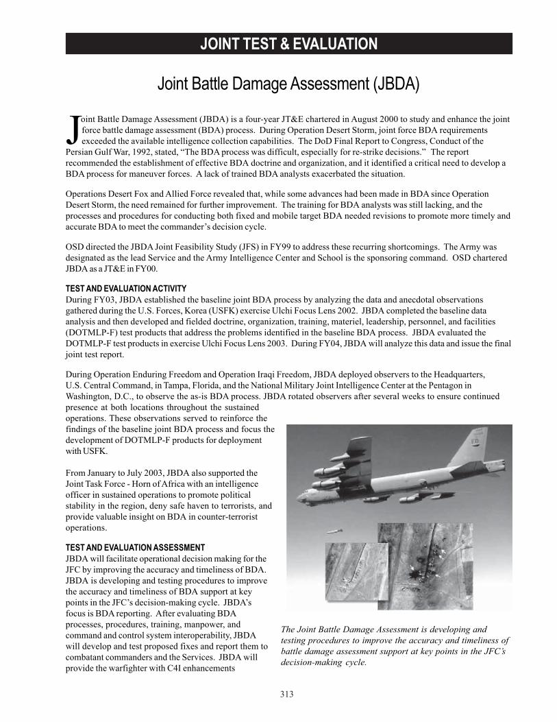
313
JOINT TEST & EVALUATION
Joint Battle Damage Assessment (JBDA) is a four-year JT&E chartered in August 2000 to study and enhance the jointforce battle damage assessment (BDA) process. During Operation Desert Storm, joint force BDA requirementsexceeded the available intelligence collection capabilities. The DoD Final Report to Congress, Conduct of the
Persian Gulf War, 1992, stated, “The BDA process was difficult, especially for re-strike decisions.” The reportrecommended the establishment of effective BDA doctrine and organization, and it identified a critical need to develop aBDA process for maneuver forces. A lack of trained BDA analysts exacerbated the situation.
Operations Desert Fox and Allied Force revealed that, while some advances had been made in BDA since OperationDesert Storm, the need remained for further improvement. The training for BDA analysts was still lacking, and theprocesses and procedures for conducting both fixed and mobile target BDA needed revisions to promote more timely andaccurate BDA to meet the commander’s decision cycle.
OSD directed the JBDA Joint Feasibility Study (JFS) in FY99 to address these recurring shortcomings. The Army wasdesignated as the lead Service and the Army Intelligence Center and School is the sponsoring command. OSD charteredJBDA as a JT&E in FY00.
TEST AND EVALUATION ACTIVITYDuring FY03, JBDA established the baseline joint BDA process by analyzing the data and anecdotal observationsgathered during the U.S. Forces, Korea (USFK) exercise Ulchi Focus Lens 2002. JBDA completed the baseline dataanalysis and then developed and fielded doctrine, organization, training, materiel, leadership, personnel, and facilities(DOTMLP-F) test products that address the problems identified in the baseline BDA process. JBDA evaluated theDOTMLP-F test products in exercise Ulchi Focus Lens 2003. During FY04, JBDA will analyze this data and issue the finaljoint test report.
During Operation Enduring Freedom and Operation Iraqi Freedom, JBDA deployed observers to the Headquarters,U.S. Central Command, in Tampa, Florida, and the National Military Joint Intelligence Center at the Pentagon inWashington, D.C., to observe the as-is BDA process. JBDA rotated observers after several weeks to ensure continuedpresence at both locations throughout the sustainedoperations. These observations served to reinforce thefindings of the baseline joint BDA process and focus thedevelopment of DOTMLP-F products for deploymentwith USFK.
From January to July 2003, JBDA also supported theJoint Task Force - Horn of Africa with an intelligenceofficer in sustained operations to promote politicalstability in the region, deny safe haven to terrorists, andprovide valuable insight on BDA in counter-terroristoperations.
TEST AND EVALUATION ASSESSMENTJBDA will facilitate operational decision making for theJFC by improving the accuracy and timeliness of BDA.JBDA is developing and testing procedures to improvethe accuracy and timeliness of BDA support at keypoints in the JFC’s decision-making cycle. JBDA’sfocus is BDA reporting. After evaluating BDAprocesses, procedures, training, manpower, andcommand and control system interoperability, JBDAwill develop and test proposed fixes and report them tocombatant commanders and the Services. JBDA willprovide the warfighter with C4I enhancements
Joint Battle Damage Assessment (JBDA)
The Joint Battle Damage Assessment is developing andtesting procedures to improve the accuracy and timeliness ofbattle damage assessment support at key points in the JFC’sdecision-making cycle.

314
JOINT TEST & EVALUATION
institutionalized in the USFK Advanced Deep Operations Coordination System. The USFK Joint BDA Guide (developedby JBDA) will be rewritten as the Commander’s Handbook for Joint BDA and posted on the Joint Electronic Library.Additionally, JBDA will send BDA training CDs to the combatant commands for use in training permanent andaugmentation BDA analysts.

315
JOINT TEST & EVALUATION
The JC2ISR JT&E was chartered to improve joint operations by providing recommendations to enhance joint C2ISRtactics, techniques, and procedures (TTP); operational concepts; training; and systems. JC2ISR will enhance jointwarfighter ability to utilize diverse national, theater, and tactical collection sensors and dynamically focus them to
identify, locate, track, and engage high-value, mobile surface targets. Recommendations resulting from the JC2ISR JT&Ewill significantly improve the JFC’s ability to integrate assigned organic and higher echelon platforms and sensors in acoordinated (cross-cued) and cooperative (simultaneous) collection strategy. Results will provide decision-makers withsignificantly improved C2ISR tasking, processing, exploitation, and dissemination (TPED) to support time-criticaltargeting, and will be applicable to all joint warfighters.
The Joint Task Force (JTF) and supporting components’ ability to manage resources to detect, identify, locate, track, andengage high-value mobile surface targets is limited by current joint C2ISR processes. Recent military operations(Operations Desert Storm, Desert Fox, Allied Force, Enduring Freedom, and Iraqi Freedom) confirm our inability to employISR collection assets to consistently locate, identify, and attack fleeting mobile targets. In many cases, enemy mobiletargets are vulnerable for a shorter period of time than it takes to engage them using current procedures. A majorcontributor to this limitation lies in shortfalls in the joint C2ISR TPED system that supports dynamic time-sensitivetargeting (TST) operations. Lessons learned from these military operations have identified a requirement for highlydiscriminate targeting information that avoids collateral or unintended damage despite poor weather and adversarycountermeasures.
OSD chartered the JC2ISR JT&E in FY00 to employ multi-Service and other DoD Agency support, personnel, andequipment to investigate, evaluate, and make recommendations to improve the operational effectiveness of joint C2ISR.Specifically, the JC2ISR JT&E will test and evaluate the JTF and Components’ ability to dynamically task and re-task ISRcollection platforms and sensors, and their ability to process, exploit, and disseminate combat information to supportTST. The JC2ISR JT&E will baseline current C2ISR processes used to prosecute TSTs; identify ISR platform and sensortasking, processing, exploitation, and dissemination deficiencies; and identify opportunities for joint C2ISRimprovements.
JC2ISR executed its first mini-test during JTF Exercise 01-3, conducted August 6-19, 2001. During Mini-Test 1, JC2ISRassisted Second Fleet personnel with the development of the Time Critical Strike Tactical Memorandum.
TEST & EVALUATION ACTIVITYDuring FY03, the JC2ISR JT&E conducted andpublished test reports for Mini-Test 2 and for the firstof two major field tests. The JC2ISR JT&E conductedMini-Test 2 during the JTF Exercise 03-1 trainingexercise, October 28-November 6, 2002. JTF Exercise03-1 was a Chairman, Joint Chiefs of Staff-approved,U.S. Joint Forces Command (JFCOM) scheduled,combined and joint field training exercise employingArmy, Navy, Marine Corps, Air Force, SpecialOperations Forces (SOF), and NATO forces in alittoral environment. Field Test 1 employed Army,Navy, Air Force, SOF, and allied forces in a littoralenvironment in conjunction with the Joint CombatIdentification Evaluation Team (JCIET) 2002 exercisein April 2002. The JC2ISR JT&E used Mini-Test 2 andField Test 1 results primarily to define the joint C2ISRbaseline, recommend improvements, and identifyenhancements to improve joint C2ISR TPED/TaskProcess Post Use (TPPU) capabilities against TSTsduring Field Test 2, to be conducted in conjunctionwith Combined JTF Exercise 04-2 in June 2004.
Joint Command and Control, Intelligence, Surveillance,and Reconnaissance (JC2ISR)
The Joint Command and Control, Intelligence, Surveillanceand Reconaissance Joint Test and Evaluation conductedMini-Test 2 during the JTF Exercise 03-1 training exercise,October 28-November 6, 2002.

316
JOINT TEST & EVALUATION
Combined JTF Exercise 04-2 will employ Army, Navy, Air Force, SOF, and allied forces in a littoral environment in a jointfield training exercise. JFCOM has identified the JC2ISR JT&E as the office of primary responsibility for TST datacollection, analysis, and reporting for Combined JTF Exercise 04-2 requiring multi-Service and Agency coordination. FT2will incorporate Distributed Common Ground/Surface System (DCGS) Family of Systems (FOS) representatives to see ifan interoperable and integrated DCGS FOS can enhance TST operations. JC2ISR is striving to incorporate intelligenceprocesses training to ensure a viable test architecture to conduct joint TPED/TPPU.
The JC2ISR JT&E supported other test events in FY03 with subject matter experts, data collectors, and software; usingthese events as risk reduction exercises to collect systems sample data and observe select TST activities to supportJC2ISR Field Test 2 test requirements. Risk reduction exercises included JCIET Exercise 2003 in August 2003 and theJGPSCE JT&E mini-test in September 2003.
The JC2ISR JT&E also deployed several personnel in direct support of Operation Iraqi Freedom: four to the U.S. CentralCommand Joint Intelligence Center at MacDill Air Force Base, Florida; one as a member of the Predator unmanned aerialvehicle exploitation team at Beale Air Force Base, California; two to U.S. Army, Central Command, Riyadh, Saudi Arabia;and one to Central Command Air Forces Prince Sultan Air Base, Saudi Arabia.
In addition, the JC2ISR JT&E continued active participation in the Air Land Sea Application Center effort to draft TSTmulti-Service TTP documents.
TEST & EVALUATION ASSESSMENTJC2ISR JT&E results will support the development of numerous products for the Joint Staff, combatant commands,Services, national agencies, and other JT&E efforts. For example, JC2ISR results prompted the JT&E to develop an ISR/TST operations integration process model as a tool to effectively evaluate joint C2ISR improvements in TST prosecution.In general, JC2ISR test products will provide warfighters with a baseline effectiveness evaluation of current C2ISRcapabilities and limitations, and will quantify the effects of specific C2ISR enhancements to improve the TST missionarea. The Services and combatant commanders continue to support the JT&E. Resources and planning are on track tosuccessfully complete scheduled testing.
JC2ISR will improve the operational capability of warfighters to employ joint ISR collection assets to conduct time-sensitive targeting. The JC2ISR JT&E is developing products that will enable warfighters to more effectively attack TSTsby improving their use of C2ISR equipment, their joint TTP, and their collection management training.
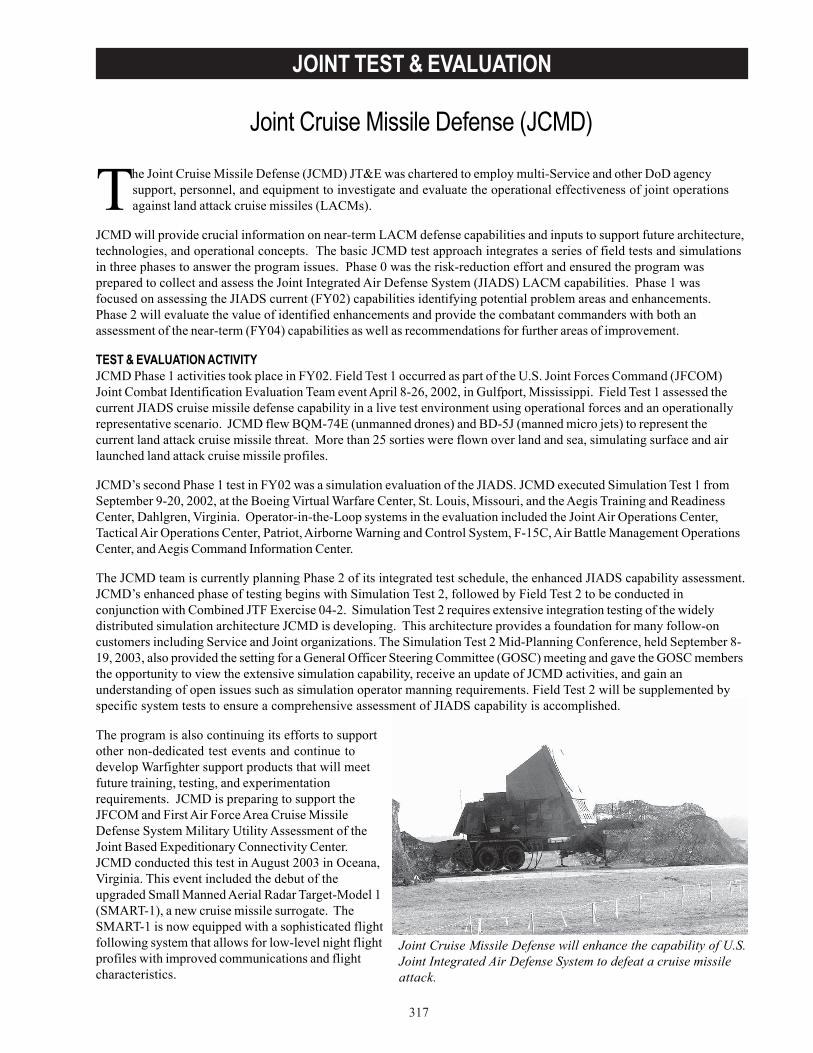
317
JOINT TEST & EVALUATION
The Joint Cruise Missile Defense (JCMD) JT&E was chartered to employ multi-Service and other DoD agencysupport, personnel, and equipment to investigate and evaluate the operational effectiveness of joint operationsagainst land attack cruise missiles (LACMs).
JCMD will provide crucial information on near-term LACM defense capabilities and inputs to support future architecture,technologies, and operational concepts. The basic JCMD test approach integrates a series of field tests and simulationsin three phases to answer the program issues. Phase 0 was the risk-reduction effort and ensured the program wasprepared to collect and assess the Joint Integrated Air Defense System (JIADS) LACM capabilities. Phase 1 wasfocused on assessing the JIADS current (FY02) capabilities identifying potential problem areas and enhancements.Phase 2 will evaluate the value of identified enhancements and provide the combatant commanders with both anassessment of the near-term (FY04) capabilities as well as recommendations for further areas of improvement.
TEST & EVALUATION ACTIVITYJCMD Phase 1 activities took place in FY02. Field Test 1 occurred as part of the U.S. Joint Forces Command (JFCOM)Joint Combat Identification Evaluation Team event April 8-26, 2002, in Gulfport, Mississippi. Field Test 1 assessed thecurrent JIADS cruise missile defense capability in a live test environment using operational forces and an operationallyrepresentative scenario. JCMD flew BQM-74E (unmanned drones) and BD-5J (manned micro jets) to represent thecurrent land attack cruise missile threat. More than 25 sorties were flown over land and sea, simulating surface and airlaunched land attack cruise missile profiles.
JCMD’s second Phase 1 test in FY02 was a simulation evaluation of the JIADS. JCMD executed Simulation Test 1 fromSeptember 9-20, 2002, at the Boeing Virtual Warfare Center, St. Louis, Missouri, and the Aegis Training and ReadinessCenter, Dahlgren, Virginia. Operator-in-the-Loop systems in the evaluation included the Joint Air Operations Center,Tactical Air Operations Center, Patriot, Airborne Warning and Control System, F-15C, Air Battle Management OperationsCenter, and Aegis Command Information Center.
The JCMD team is currently planning Phase 2 of its integrated test schedule, the enhanced JIADS capability assessment.JCMD’s enhanced phase of testing begins with Simulation Test 2, followed by Field Test 2 to be conducted inconjunction with Combined JTF Exercise 04-2. Simulation Test 2 requires extensive integration testing of the widelydistributed simulation architecture JCMD is developing. This architecture provides a foundation for many follow-oncustomers including Service and Joint organizations. The Simulation Test 2 Mid-Planning Conference, held September 8-19, 2003, also provided the setting for a General Officer Steering Committee (GOSC) meeting and gave the GOSC membersthe opportunity to view the extensive simulation capability, receive an update of JCMD activities, and gain anunderstanding of open issues such as simulation operator manning requirements. Field Test 2 will be supplemented byspecific system tests to ensure a comprehensive assessment of JIADS capability is accomplished.
The program is also continuing its efforts to supportother non-dedicated test events and continue todevelop Warfighter support products that will meetfuture training, testing, and experimentationrequirements. JCMD is preparing to support theJFCOM and First Air Force Area Cruise MissileDefense System Military Utility Assessment of theJoint Based Expeditionary Connectivity Center.JCMD conducted this test in August 2003 in Oceana,Virginia. This event included the debut of theupgraded Small Manned Aerial Radar Target-Model 1(SMART-1), a new cruise missile surrogate. TheSMART-1 is now equipped with a sophisticated flightfollowing system that allows for low-level night flightprofiles with improved communications and flightcharacteristics.
Joint Cruise Missile Defense (JCMD)
Joint Cruise Missile Defense will enhance the capability of U.S.Joint Integrated Air Defense System to defeat a cruise missileattack.
318
JOINT TEST & EVALUATION
TEST & EVALUATION ASSESSMENTJCMD will enhance the capability of U.S. JIADS to defeat a cruise missile attack. After evaluating baseline JIADScapabilities and procedures to meet cruise missile defense mission area requirements, JCMD will quantify the effects ofprocedural and hardware enhancements to JIADS in a cruise missile defense role and make recommendations tocombatant commanders and the Services. JCMD products will provide warfighters with a baseline effectivenessevaluation of current JIADS capabilities and procedures to meet the requirements of the JCMD mission area. Once thishas been accomplished, the JCMD JT&E will report the effects of concept of operations and TTP changes as well ascommand and control, sensor, and shooter system enhancements to the JIADS in a cruise missile defense role.
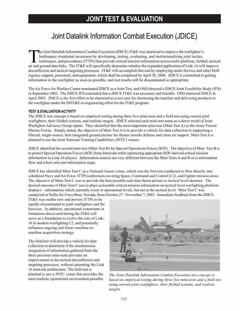
319
JOINT TEST & EVALUATION
The Joint Datalink Information Combat Execution (JDICE) JT&E was chartered to improve the warfighter’sbattlespace situational awareness by developing, testing, evaluating, and institutionalizing joint tactics,techniques, and procedures (JTTPs) that provide critical mission information across multi-platform, fielded, tactical
air and ground data links. The JT&E will specifically determine whether the expanded application of Link-16 will improvedeconfliction and tactical targeting processes. JT&E will accomplish this end by employing multi-Service and other DoDAgency support, personnel, and equipment, which shall be completed by April 30, 2006. JDICE is committed to gettinginformation to the warfighter as soon as possible, and test results will be disseminated as appropriate.
The Air Force Air Warfare Center nominated JDICE as a Joint Test, and OSD directed a JDICE Joint Feasibility Study (JFS)in September 2002. The JDICE JFS concluded that a JDICE JT&E was necessary and feasible. OSD chartered JDICE inApril 2003. JDICE is the first effort to be chartered as a test case for shortening the timeline and delivering products tothe warfighter under the DOT&E re-engineering effort for the JT&E program.
TEST & EVALUATION ACTIVITYThe JDICE test concept is based on empirical testing during three live mini-tests and a field test using current jointwarfighters, their fielded systems, and realistic targets. JDICE selected each mini-test arena as a direct result of JointWarfighter Advisory Group inputs. They identified that the most important mini-test (Mini-Test A) as the Army Forces/Marine Forces. Simply stated, the objective of Mini-Test A is to provide a vehicle for data collection to supporting afiltered, single-source, best integrated ground picture for theater missile defense and close air support. Mini-Test A isplanned to use the Joint National Training Capabilities (JNTC) venues.
JDICE identified the second mini-test (Mini-Test B) for Special Operations Forces (SOF). The objective of Mini- Test B isto protect Special Operation Forces (SOF) from fratricide while optimizing appropriate SOF-derived critical missioninformation to Link-16 players. Information sources are very different between the Mini-Tests A and B as is informationflow and where relevant information stops.
JDICE has identified Mini-Test C as a National Assets venue, which was the first test conducted to flow directly intoscheduled Navy and Air Force JTTP conferences covering Space, Command and Control (C2), and Fighter mission areas.The objective of Mini-Test C was to provide the best possible real-time threat picture to tactical level shooters. Thedesired outcome of Mini-Test C was to place actionable critical mission information on tactical level warfighting platformdisplays – information which currently exists at operational levels, but not at the tactical level. Mini-Test C wasconducted at Nellis Air Force Base, Nevada, from October 27 - November 7, 2003. Immediate feedback from the JDICEJT&E was enable new and proven JTTPs to berapidly disseminated to joint warfighters and theServices. In addition, operational constraints orlimitations discovered during the JT&E willserve as a foundation to evolve the role of Link-16 in modern warfighting C2, and potentiallyinfluence ongoing and future machine-to-machine acquisition strategy.
The field test will provide a vehicle for datacollection to determine if the simultaneousintegration of information gathered from thethree previous mini-tests provides animprovement in the tactical deconfliction andtargeting processes, without saturating the Link16 network architecture. The field test isplanned to use a JNTC venue that provides themost realistic operational environment possible.
Joint Datalink Information Combat Execution (JDICE)
The Joint Datalink Information Combat Execution test concept isbased on empirical testing during three live mini-tests and a field testusing current joint warfighters, their fielded systems, and realistictargets.
320
JOINT TEST & EVALUATION
TEST & EVALUATION ASSESSMENTBased upon the emerging JDICE Mini-Test C results, the JT&E will rapidly develop, document, and disseminateconclusions and recommendations regarding enhancements to Joint Data Link architecture, associated JTTPs, concept ofoperations, and processes. Specific emphasis will be placed on the rapid production of a quick look report and thepresentation of these results at Service-level tactics, techniques, and procedures conferences. The JT&E specificallyaddresses non-materiel solutions and the development of JTTPs to transfer critical, actionable information to the jointuser. Test products will include the JTTPs to take correlated machine-to-machine nationally-collected data and use aman-to-machine interface to distribute specific actionable data via the Link 16 network to the tactical level shooter. Whencomplete, JDICE will present solutions to documented shortfalls in tactical datalink information exchange capabilitiesacross sensor, C2, and “shooter” datalink-capable networks.

321
JOINT TEST & EVALUATION
The JGPSCE JT&E was chartered to evaluate the impact of electronic warfare (EW) targeted against globalpositioning system (GPS) receivers in joint operations. GPS provides highly accurate, real time, passive, common-reference grid position and time information to military and civilian users worldwide. GPS enables the military
forces to determine their position, velocity, and time. Knowledge of the exact position and time is essential toreconnaissance and intelligence missions. GPS will: enhance command and control and coordinate battle tactics andsupport; engage in strategic and tactical warfare; maneuver efficiently on the battlefield; provide accurate and timely firesupport; and facilitate combat service support operations. OSD chartered JGPSCE in July 1999.
The JGPSCE JT&E is conducting field test events representing three types of combat operations: small scalecontingency; limited engagement; and major theater war. Each field test addresses a specific combatant command’stheater of interest using: current tactics, training, and procedures; approved doctrine; actual concepts of operation; and“real” scenarios and threat laydowns.
Each field test is designed to provide key information for warfighters to use in operational decision-making. The fieldtests employ open air GPS jamming representing the real-world threat to evaluate the impact of GPS EW andelectromagnetic interference (EMI) by comparing baseline performance to performance with EW and EMI present.Mitigation techniques and procedures developed during test planning are also employed and evaluated during fieldtesting to assess the ability of troops and commanders to continue operations in a GPS degraded or denied environment.JGPSCE publishes Quick Look Reports to the Services and the combatant commands immediately after each test event.
Phase 1 testing consisted of two live test events, GYPSY ALPHA and GYPSY BRAVO, at the tactical level of warfare.These tests focused on GPS EW and EMI vulnerabilities and mitigations for few-on-few engagements during small-scalecontingencies. Each live test in Phase l concentrated on portions of the sensor-to-shooter architecture. The GYPSYALPHA field test, October and November 2000, exercised ground forces supplemented by limited airborne forces. TheGYPSY BRAVO field test was executed in two parts, January 2002 and July 2002, exercising airborne platforms deliveringprecision guided munitions.
Phase 2 testing consisted of one live test event, GYPSY CHARLIE, to evaluate the tactical and operational-level missionperformance of integrated system-of-systems during limited engagement operations.
Phase 3 testing consists of a single test, GYPSYDELTA, which will evaluate integrated tactical- andoperational-level systems with warfightersperforming missions during a major theater of warscenario.
TEST & EVALUATION ACTIVITYJGPSCE completed the GYPSY CHARLIE field test inFY03, began planning for GYPSY DELTA, andconducted numerous briefings and presentations.
• JGPSCE briefed the GYPSY BRAVO resultsto Deputy Secretary of Defense, theChairman and Joint Chiefs, the ServiceOperations Deputies, three combatantcommands, the Secretary of the Air Force,Under Secretary of Defense(Acquisition,Technology, & Logistics), and DOT&E.These briefings increased awareness ofsystems vulnerability to GPS degradation.
Joint Global Positioning System Combat Effectiveness (JGPSCE)
Global Positioning Systems Combat Effectiveness executed theGYPSY CHARLIE field test at Nellis Air Force Base, Nevada, inSeptember 2003. GYPSY CHARLIE consisted of over 450participants from 25 units, flying 240 sorties over ten nights.
322
JOINT TEST & EVALUATION
• JGPSCE published GYPSY BRAVO Quick Look Reports as well as vulnerability assessment reports for eachsystem executed in the GYPSY BRAVO field test.
• JGPSCE executed the GYPSY CHARLIE field test at Nellis Air Force Base, Nevada, in September 2003. GYPSYCHARLIE consisted of over 450 participants from 25 units, flying 240 sorties over ten nights. GYPSY CHARLIEincluded six adjunct test activities including two aircraft from the Federal Aviation Administration flying 16sorties.
• JGPSCE completed work on its GPS Vulnerability Test Methodology. The execution of the GYPSY CHARLIEfield test validated the JGPSCE developed methodology.
The JGPSCE Joint Test Team received the Joint Meritorious Unit Award on August 1, 2003, for its contribution toOperation Iraqi Freedom.
TEST & EVALUATION ASSESSMENTJGPSCE continues to provide rapid feedback to the warfighter community through quick-look reports and briefings. TheGYPSY BRAVO test results significantly enhanced vulnerability awareness with the DoD senior leadership. CentralCommand conducted additional training and briefed numerous deploying units, and the Navy circulated updates tooperational crews. The Air Force dedicated resources to conduct additional testing, correct system vulnerabilities, andprovide enhanced crew awareness. When complete, JGPSCE will have quantitatively and qualitatively measured andassessed the impacts of the loss of GPS on joint operations, measured and assessed mitigation methods to limit missionimpacts, and developed test methodologies to characterize GPS vulnerabilities in future acquisition and integrationprograms.
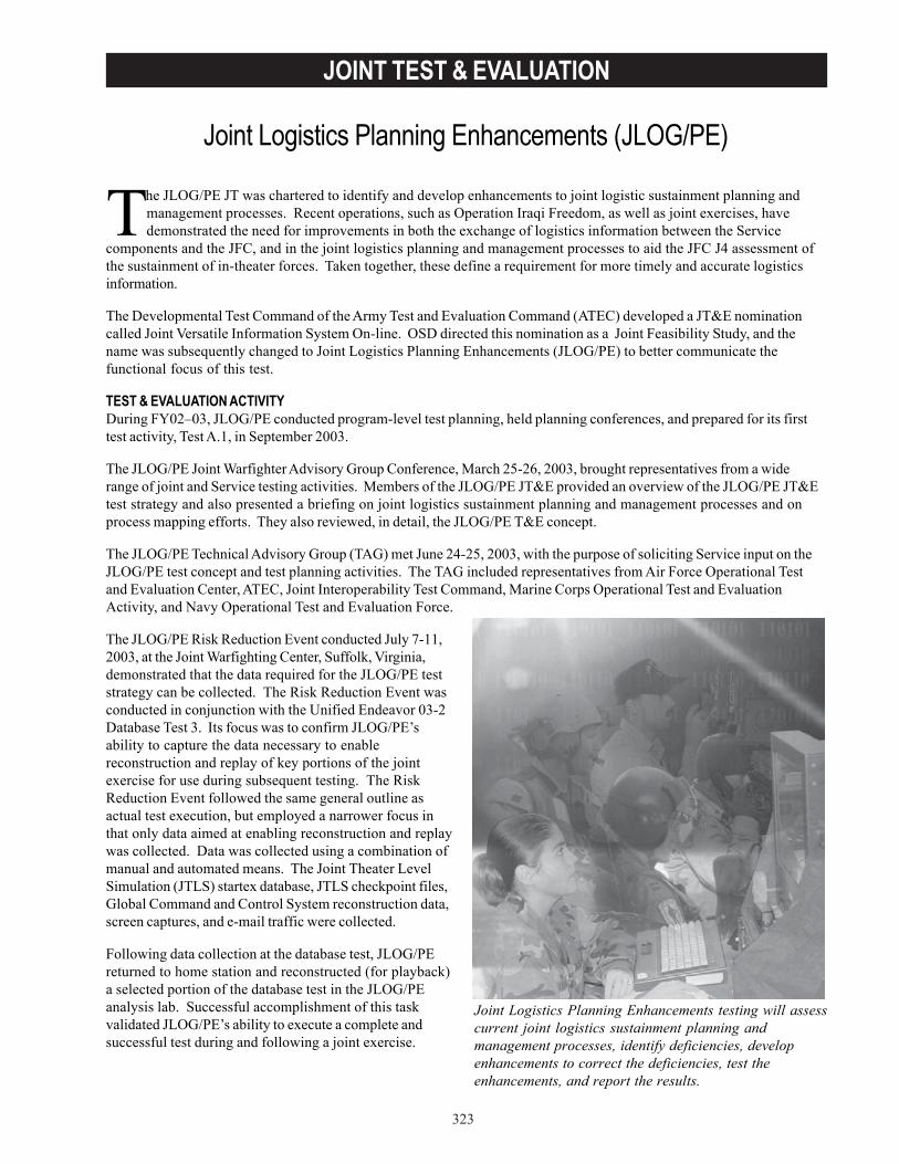
323
JOINT TEST & EVALUATION
The JLOG/PE JT was chartered to identify and develop enhancements to joint logistic sustainment planning andmanagement processes. Recent operations, such as Operation Iraqi Freedom, as well as joint exercises, havedemonstrated the need for improvements in both the exchange of logistics information between the Service
components and the JFC, and in the joint logistics planning and management processes to aid the JFC J4 assessment ofthe sustainment of in-theater forces. Taken together, these define a requirement for more timely and accurate logisticsinformation.
The Developmental Test Command of the Army Test and Evaluation Command (ATEC) developed a JT&E nominationcalled Joint Versatile Information System On-line. OSD directed this nomination as a Joint Feasibility Study, and thename was subsequently changed to Joint Logistics Planning Enhancements (JLOG/PE) to better communicate thefunctional focus of this test.
TEST & EVALUATION ACTIVITYDuring FY02–03, JLOG/PE conducted program-level test planning, held planning conferences, and prepared for its firsttest activity, Test A.1, in September 2003.
The JLOG/PE Joint Warfighter Advisory Group Conference, March 25-26, 2003, brought representatives from a widerange of joint and Service testing activities. Members of the JLOG/PE JT&E provided an overview of the JLOG/PE JT&Etest strategy and also presented a briefing on joint logistics sustainment planning and management processes and onprocess mapping efforts. They also reviewed, in detail, the JLOG/PE T&E concept.
The JLOG/PE Technical Advisory Group (TAG) met June 24-25, 2003, with the purpose of soliciting Service input on theJLOG/PE test concept and test planning activities. The TAG included representatives from Air Force Operational Testand Evaluation Center, ATEC, Joint Interoperability Test Command, Marine Corps Operational Test and EvaluationActivity, and Navy Operational Test and Evaluation Force.
The JLOG/PE Risk Reduction Event conducted July 7-11,2003, at the Joint Warfighting Center, Suffolk, Virginia,demonstrated that the data required for the JLOG/PE teststrategy can be collected. The Risk Reduction Event wasconducted in conjunction with the Unified Endeavor 03-2Database Test 3. Its focus was to confirm JLOG/PE’sability to capture the data necessary to enablereconstruction and replay of key portions of the jointexercise for use during subsequent testing. The RiskReduction Event followed the same general outline asactual test execution, but employed a narrower focus inthat only data aimed at enabling reconstruction and replaywas collected. Data was collected using a combination ofmanual and automated means. The Joint Theater LevelSimulation (JTLS) startex database, JTLS checkpoint files,Global Command and Control System reconstruction data,screen captures, and e-mail traffic were collected.
Following data collection at the database test, JLOG/PEreturned to home station and reconstructed (for playback)a selected portion of the database test in the JLOG/PEanalysis lab. Successful accomplishment of this taskvalidated JLOG/PE’s ability to execute a complete andsuccessful test during and following a joint exercise.
Joint Logistics Planning Enhancements (JLOG/PE)
Joint Logistics Planning Enhancements testing will assesscurrent joint logistics sustainment planning andmanagement processes, identify deficiencies, developenhancements to correct the deficiencies, test theenhancements, and report the results.

324
JOINT TEST & EVALUATION
The JLOG/PE JT&E has prepared a plan to ensure that its evaluation results are released as interim reports to thewarfighters as early as practical. The JLOG/PE Test Product Implementation Plan details the strategy for test productrelease and follow-through to the end user.
TEST & EVALUATION ASSESSMENTJLOG/PE testing will assess current joint logistics sustainment planning and management processes, identifydeficiencies, develop enhancements to correct the deficiencies, test the enhancements, and report the results. Thesejoint logistics sustainment planning and management process enhancements will improve warfighter capabilities. Resultswill manifest themselves in more agile forces that are able to proactively assess operational logistics requirements;improved preparedness of units being committed to operations; faster, more informed decisions; improved measurementsof success; accelerated operational timetables; reduced risk; and the projection of more capable forces requiring fewerresources. The JLOG/PE JT&E will provide that level of utility in terms of process, best practices, analysis, andunderstanding as usable test products.
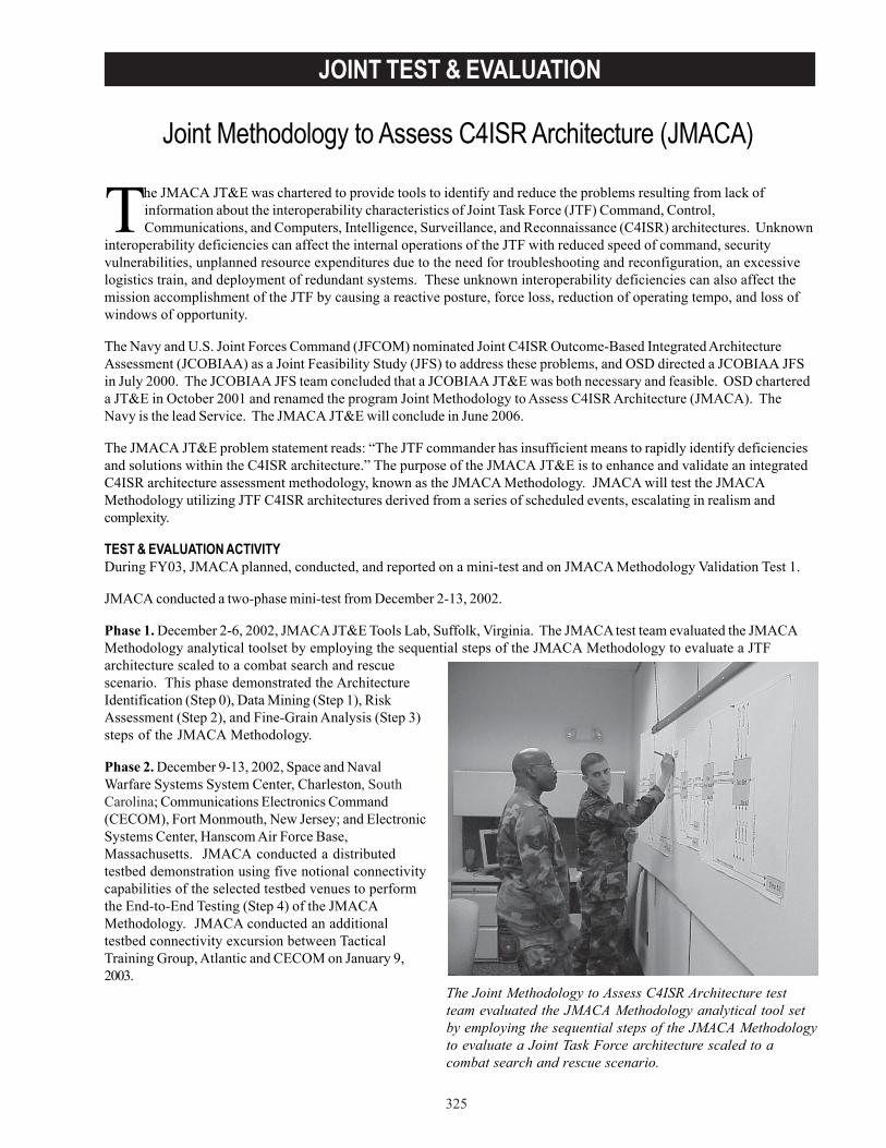
325
JOINT TEST & EVALUATION
The JMACA JT&E was chartered to provide tools to identify and reduce the problems resulting from lack ofinformation about the interoperability characteristics of Joint Task Force (JTF) Command, Control,Communications, and Computers, Intelligence, Surveillance, and Reconnaissance (C4ISR) architectures. Unknown
interoperability deficiencies can affect the internal operations of the JTF with reduced speed of command, securityvulnerabilities, unplanned resource expenditures due to the need for troubleshooting and reconfiguration, an excessivelogistics train, and deployment of redundant systems. These unknown interoperability deficiencies can also affect themission accomplishment of the JTF by causing a reactive posture, force loss, reduction of operating tempo, and loss ofwindows of opportunity.
The Navy and U.S. Joint Forces Command (JFCOM) nominated Joint C4ISR Outcome-Based Integrated ArchitectureAssessment (JCOBIAA) as a Joint Feasibility Study (JFS) to address these problems, and OSD directed a JCOBIAA JFSin July 2000. The JCOBIAA JFS team concluded that a JCOBIAA JT&E was both necessary and feasible. OSD chartereda JT&E in October 2001 and renamed the program Joint Methodology to Assess C4ISR Architecture (JMACA). TheNavy is the lead Service. The JMACA JT&E will conclude in June 2006.
The JMACA JT&E problem statement reads: “The JTF commander has insufficient means to rapidly identify deficienciesand solutions within the C4ISR architecture.” The purpose of the JMACA JT&E is to enhance and validate an integratedC4ISR architecture assessment methodology, known as the JMACA Methodology. JMACA will test the JMACAMethodology utilizing JTF C4ISR architectures derived from a series of scheduled events, escalating in realism andcomplexity.
TEST & EVALUATION ACTIVITYDuring FY03, JMACA planned, conducted, and reported on a mini-test and on JMACA Methodology Validation Test 1.
JMACA conducted a two-phase mini-test from December 2-13, 2002.
Phase 1. December 2-6, 2002, JMACA JT&E Tools Lab, Suffolk, Virginia. The JMACA test team evaluated the JMACAMethodology analytical toolset by employing the sequential steps of the JMACA Methodology to evaluate a JTFarchitecture scaled to a combat search and rescuescenario. This phase demonstrated the ArchitectureIdentification (Step 0), Data Mining (Step 1), RiskAssessment (Step 2), and Fine-Grain Analysis (Step 3)steps of the JMACA Methodology.
Phase 2. December 9-13, 2002, Space and NavalWarfare Systems System Center, Charleston, SouthCarolina; Communications Electronics Command(CECOM), Fort Monmouth, New Jersey; and ElectronicSystems Center, Hanscom Air Force Base,Massachusetts. JMACA conducted a distributedtestbed demonstration using five notional connectivitycapabilities of the selected testbed venues to performthe End-to-End Testing (Step 4) of the JMACAMethodology. JMACA conducted an additionaltestbed connectivity excursion between TacticalTraining Group, Atlantic and CECOM on January 9,2003.
Joint Methodology to Assess C4ISR Architecture (JMACA)
The Joint Methodology to Assess C4ISR Architecture testteam evaluated the JMACA Methodology analytical tool setby employing the sequential steps of the JMACA Methodologyto evaluate a Joint Task Force architecture scaled to acombat search and rescue scenario.
326
JOINT TEST & EVALUATION
JMACA conducted Validation Test 1 from August 18, to September 26, 2003, in two phases.
Phase 1. August 18-27, 2003, JMACA JT&E Tools Lab, Suffolk, Virginia. Trained Service representatives evaluated theJMACA Methodology analytical toolset by employing its sequential steps to evaluate a C4ISR architecture utilizedduring Operation Iraqi Freedom. This phase exercised the Architecture Identification (Step 0), Data Mining (Step 1), RiskAssessment (Step 2), Fine-Grain Analysis (Step 3), and Operational Analysis (Step 5) steps of the JMACA Methodology.
Phase 2. September 15-26, 2003, Joint Interoperability Test Command, Fort Huachuca, Arizona. JMACA exercised End-to-End Testing (Step 4) using select equipment strings identified by the JMACA Methodology during Phase 1.
TEST & EVALUATION ASSESSMENTJMACA successfully accomplished the primary objectives of its mini-test and compiled and detailed the analysis andresults in the JMACA Mini-Test Lessons Learned Report. These accomplishments include:
• Rehearsal of the Architecture Identification (Step 0), Data Mining (Step 1), Risk Assessment (Step 2), and Fine-Grain Analysis (Step 3) steps of the JMACA Methodology using a mission-specific JTF C4ISR architecture.
• Demonstration of distributed testbed connectivity, with test design, configuration, and execution performingcollaboratively between multiple supporting testbed facilities.
• Rehearsal of functional thread testing (including instrumentation and data collection) to evaluate and refine, asnecessary, JMACA test data collection techniques and methods. The specific areas that JMACA addressedinclude manual data collection techniques, automated data collection techniques, accuracy of collected data,and sufficiency of collected data.
• Rehearsal of the End-to-End Testing (Step 4) step of the JMACA Methodology.
The primary objective of Validation Test 1 was to facilitate the collection of data necessary to answer Test Issue 1, “Howwell does the JMACA Methodology support the assessment of a JTF C4ISR architecture?” Based on preliminaryanalysis and observations, this objective was successfully accomplished. The JMACA Validation Test 1 QuicklookReport outlines these findings. Detailed test results, data, and analysis of both primary and secondary objectives may befound in the Validation Test 1 Activity Report, due for release in December 2003.
The JMACA JT&E has begun transition of the JMACA Methodology and associated processes, analysis procedures,and key personnel into the JFCOM Joint Battle Management Command and Control (JBMC2) Systems EngineeringDivision. This transition enhances the JBMC2 Systems Engineering Division’s ability to support JFCOM’sresponsibilities as directed by Management Initiative Directive 912, and lays the groundwork for an early and efficienttransition of JMACA JT&E results to the warfighter. A transition plan and memorandum of agreement between JMACAand JBMC2 are currently under development.
When complete, JMACA will provide tools to assist warfighters in making informed decisions about C4ISR architecturecapabilities when organizing a JTF. JMACA will provide the JFC with a set of tools to assess the JTF integrated C4ISRarchitecture. These tools, designated as the JMACA Methodology, will be timely, supportable, adaptable, and easilyintegrated.
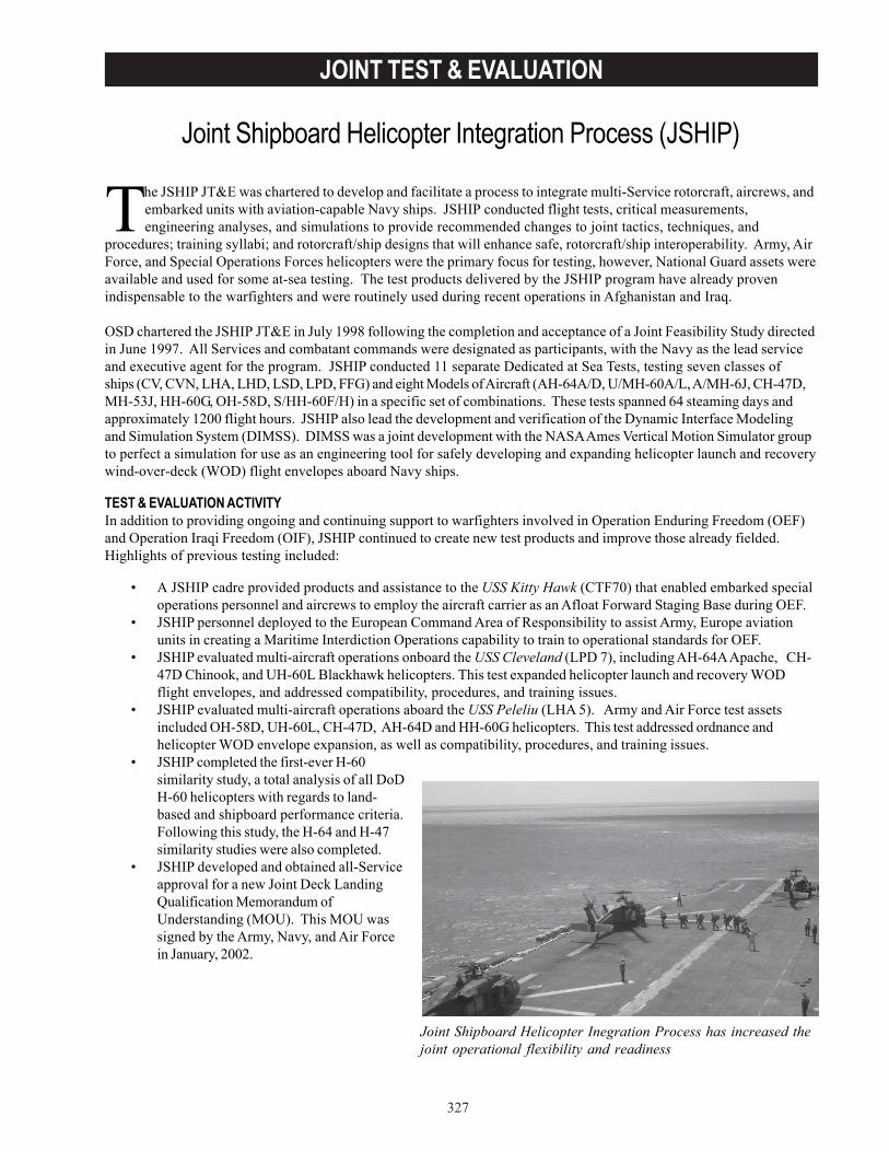
327
JOINT TEST & EVALUATION
The JSHIP JT&E was chartered to develop and facilitate a process to integrate multi-Service rotorcraft, aircrews, andembarked units with aviation-capable Navy ships. JSHIP conducted flight tests, critical measurements,engineering analyses, and simulations to provide recommended changes to joint tactics, techniques, and
procedures; training syllabi; and rotorcraft/ship designs that will enhance safe, rotorcraft/ship interoperability. Army, AirForce, and Special Operations Forces helicopters were the primary focus for testing, however, National Guard assets wereavailable and used for some at-sea testing. The test products delivered by the JSHIP program have already provenindispensable to the warfighters and were routinely used during recent operations in Afghanistan and Iraq.
OSD chartered the JSHIP JT&E in July 1998 following the completion and acceptance of a Joint Feasibility Study directedin June 1997. All Services and combatant commands were designated as participants, with the Navy as the lead serviceand executive agent for the program. JSHIP conducted 11 separate Dedicated at Sea Tests, testing seven classes ofships (CV, CVN, LHA, LHD, LSD, LPD, FFG) and eight Models of Aircraft (AH-64A/D, U/MH-60A/L, A/MH-6J, CH-47D,MH-53J, HH-60G, OH-58D, S/HH-60F/H) in a specific set of combinations. These tests spanned 64 steaming days andapproximately 1200 flight hours. JSHIP also lead the development and verification of the Dynamic Interface Modelingand Simulation System (DIMSS). DIMSS was a joint development with the NASA Ames Vertical Motion Simulator groupto perfect a simulation for use as an engineering tool for safely developing and expanding helicopter launch and recoverywind-over-deck (WOD) flight envelopes aboard Navy ships.
TEST & EVALUATION ACTIVITYIn addition to providing ongoing and continuing support to warfighters involved in Operation Enduring Freedom (OEF)and Operation Iraqi Freedom (OIF), JSHIP continued to create new test products and improve those already fielded.Highlights of previous testing included:
• A JSHIP cadre provided products and assistance to the USS Kitty Hawk (CTF70) that enabled embarked specialoperations personnel and aircrews to employ the aircraft carrier as an Afloat Forward Staging Base during OEF.
• JSHIP personnel deployed to the European Command Area of Responsibility to assist Army, Europe aviationunits in creating a Maritime Interdiction Operations capability to train to operational standards for OEF.
• JSHIP evaluated multi-aircraft operations onboard the USS Cleveland (LPD 7), including AH-64A Apache, CH-47D Chinook, and UH-60L Blackhawk helicopters. This test expanded helicopter launch and recovery WODflight envelopes, and addressed compatibility, procedures, and training issues.
• JSHIP evaluated multi-aircraft operations aboard the USS Peleliu (LHA 5). Army and Air Force test assetsincluded OH-58D, UH-60L, CH-47D, AH-64D and HH-60G helicopters. This test addressed ordnance andhelicopter WOD envelope expansion, as well as compatibility, procedures, and training issues.
• JSHIP completed the first-ever H-60similarity study, a total analysis of all DoDH-60 helicopters with regards to land-based and shipboard performance criteria.Following this study, the H-64 and H-47similarity studies were also completed.
• JSHIP developed and obtained all-Serviceapproval for a new Joint Deck LandingQualification Memorandum ofUnderstanding (MOU). This MOU wassigned by the Army, Navy, and Air Forcein January, 2002.
Joint Shipboard Helicopter Integration Process (JSHIP)
Joint Shipboard Helicopter Inegration Process has increased thejoint operational flexibility and readiness
328
JOINT TEST & EVALUATION
TEST & EVALUATION ASSESSMENTJSHIP testing has made contributions to warfighters in four categories.
• General. The Joint Shipboard Helicopter Integration Planning Guidance and Procedures Document was themain product developed for the warfighter, and it also benefits the testing and acquisition communities. Itencompasses procedures, planning, tactics, techniques, test methods, and training. Additionally, JSHIP hasdeveloped an interactive web site and web-based CD reference and training program for embarked units andship’s company. JSHIP distributed the CD to combatant commands and aviation units that were selected forjoint helicopter shipboard missions.
• Procedures and Training. JSHIP’s test products include safety, training, and procedural guidance to enhancethe warfighter’s capabilities to conduct joint ship/helicopter operations. These test products include PilotDeployment Handbooks, Embarked Unit and Ship’s Company Deployment Planning Guides, Checklists, andSimulator Training Programs.
• Compatibility. Test products include development of an interactive Electromagnetic Vulnerability (EMV)database which allows the warfighter to assess the impact of EMV on joint operations, including restrictions toaircraft and ships. In addition, compatibility test products provide expanded WOD operational aircraft takeoffand recovery flight envelopes and tie-down and aircraft deck spotting guides for non-Navy helicopters.
• DIMSS. JSHIP used this modeling and simulation effort as both an engineering T&E tool and a training device.It supports at-sea helicopter flight testing with the potential to develop helicopter launch/recovery WODenvelopes via simulation. JSHIP incorporated DIMSS into flight trainers supporting the Army’s 101st AirborneDivision (Air Assault) at Ft. Campbell, Kentucky. Additionally, DIMSS has become a key element of the Army’sUH-60 improvement program called Lift Shipboard Integration Program.
JSHIP has increased the joint operational flexibility and readiness of helicopters operating onboard Navy ships. JSHIPdeveloped a process for certification and integration of Army and Air Force helicopters on-board Navy ships to assistJFCs in conducting effective, efficient, and safe joint shipboard operations.
329
JOINT TEST & EVALUATION
The Joint Survivability (JSURV) Quick Reaction Test (QRT) was directed by DOT&E to investigate possible causesof casualty-producing incidents sustained by U.S. forces occupying Iraq after Operation Iraqi Freedom (OIF).Once these causes are identified, JSURV will recommend improvements to tactics, techniques, and procedures
(TTP) and materiel, then assist in fielding those recommendations to reduce U.S. casualties in the OIF theater ofoperations.
The casualties being suffered by U.S. forces occupying Iraq may be preventable and may indicate deficiencies in theprotection offered by certain vehicles; deficiencies in TTP in the employment of equipment; or a combination of both.The JSURV QRT will be executed in four parallel, overlapping phases:
• Phase One. Data Gathering. JSURV will identify and characterize the circumstances of incidents in whichpersonnel become casualties while in ground vehicles. The focus of this effort is on both friendly and enemycharacteristics.
• Phase Two. Problem Definition. JSURV will assess the results of data gathering and subsequent analysis toidentify doctrinal (i.e., TTP) and hardware shortcomings, then conduct trend analysis to identify systemicdeficiencies. The end result will be a compilation of shortcomings — doctrinal, hardware, or a combination —against which mitigating solutions may be applied.
• Phase Three. Identify and Demonstrate Solutions. JSURV will identify proposed TTP and materiel solutions tomitigate the casualty-producing shortcomings. Depending upon the nature of the proposed solution, some“prove out” of individual solutions may be required to ensure the viability of proposed solutions beforeexporting them to the OIF theater of operations for implementation.
• Phase Four. Closedown. Following accomplishment of its assigned tasks, the JSURV QRT will close down ortransition to continuing efforts, as directed.
TEST AND EVALUATION ACTIVITYPhases One and Two, Data Gathering and Problem Definition. JSURV has built a database to track OIF incidents relatedto the objectives of the QRT. The database is fed by U.S. Central Command (CENTCOM) Significant Activities (SIGACT)reports since May 1, 2003, and can be updated in real time. The information contained in the database will allow JSURVto make observations about enemy TTP and friendly vulnerabilities, and make recommendations for friendly TTP andmateriel solutions.
• CENTCOM Database. On September 7, 2003, CENTCOM granted JSURV access to their SIGACT databasewhich catalogues over 400 incidents related to the JSURV problem statement. JSURV has made a preliminaryanalysis of the incidents, developed trends for the attacks, and characterized the enemy TTP and operationalprofile in conjunction with the Army Training and Doctrine Command (TRADOC) G2 and the Department of theArmy G2.
• Coordination with Center for Army Lessons Learned (CALL). On September 8, 2003, JSURV begancoordination with CALL. JSURV has been invited to the CALL Initial Impressions Report Workshop scheduledfor October 13-17, 2003. CALL teams that have recently returned from the OIF theater of operations will bedebriefed, including a team that dealt specifically with the JSURV problem statement. This data will assistJSURV in developing and refining TTPs and identifying near-term materiel solutions.
Phase Three, Identify and Demonstrate Solutions.
• TTP Development. Initial analysis has indicated the potential for improved TTP to mitigate enemy actions.CALL has agreed to let JSURV take the lead on developing a TTP to address the problem statement. Closecoordination with CALL and the Services is under way, and an initial draft will be ready in December 2003.
• Materiel solutions. JSURV is working with Army Materiel Command; Army Research Lab; Army Research,Development, and Engineering Command; TRADOC Systems Manager for Tactical Wheeled Vehicles; and theProduct Management Office - Tactical Vehicles to identify available short-term fixes for rapid fielding to theforces in Iraq. In October 2003, JSURV will conduct testing to analyze the ballistic protection provided by on-
Joint Survivability Quick Reaction Test (JSURV QRT)
330
JOINT TEST & EVALUATION
hand kits with armored doors, undersides, and innovative rocket-propelled grenade (RPG)-catching screens forHigh Mobility Multipurpose Wheeled Vehicles and other light vehicles at Aberdeen Proving Ground, Maryland.JSURV attended the Technology Workshop for the Identification and Defeat of Improvised Explosive Devices atthe Navy Explosive Ordnance Detachment - Technology Division in Indianhead, Maryland, and furtherexpanded the JSURV technical assessments by identifying potential electronic warfare (EW) and electroniccountermeasures (ECM) tools to support early detection or pre-detonation of threats. These EW and ECMtools are available from the Counter-Mine Division of the Army Communications-Electronics Command, theDirected Energy Directorate of the Air Force Research Lab, and the Naval Research Lab.
TEST AND EVALUATION ASSESSMENTJSURV is the first QRT under the DOT&E initiative to re-engineer JT&E processes for faster results to the warfighter.JSURV will use T&E methodology to identify systemic deficiencies in TTP and materiel used by U.S. forces in Iraq, thenwill identify improvements and assist in fielding those improvements to reduce U.S. casualties in the OIF theater ofoperations. JSURV is scheduled for completion in November 2003.
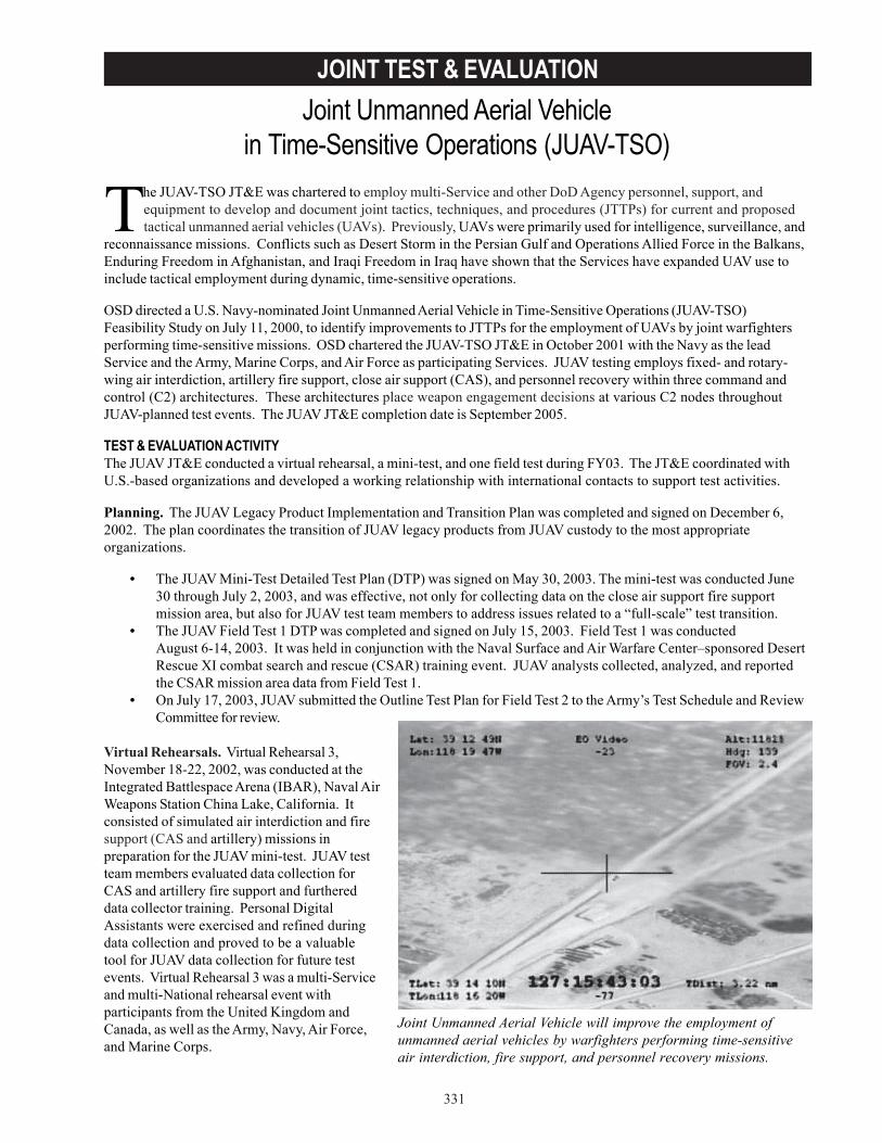
331
JOINT TEST & EVALUATION
The JUAV-TSO JT&E was chartered to employ multi-Service and other DoD Agency personnel, support, andequipment to develop and document joint tactics, techniques, and procedures (JTTPs) for current and proposedtactical unmanned aerial vehicles (UAVs). Previously, UAVs were primarily used for intelligence, surveillance, and
reconnaissance missions. Conflicts such as Desert Storm in the Persian Gulf and Operations Allied Force in the Balkans,Enduring Freedom in Afghanistan, and Iraqi Freedom in Iraq have shown that the Services have expanded UAV use toinclude tactical employment during dynamic, time-sensitive operations.
OSD directed a U.S. Navy-nominated Joint Unmanned Aerial Vehicle in Time-Sensitive Operations (JUAV-TSO)Feasibility Study on July 11, 2000, to identify improvements to JTTPs for the employment of UAVs by joint warfightersperforming time-sensitive missions. OSD chartered the JUAV-TSO JT&E in October 2001 with the Navy as the leadService and the Army, Marine Corps, and Air Force as participating Services. JUAV testing employs fixed- and rotary-wing air interdiction, artillery fire support, close air support (CAS), and personnel recovery within three command andcontrol (C2) architectures. These architectures place weapon engagement decisions at various C2 nodes throughoutJUAV-planned test events. The JUAV JT&E completion date is September 2005.
TEST & EVALUATION ACTIVITYThe JUAV JT&E conducted a virtual rehearsal, a mini-test, and one field test during FY03. The JT&E coordinated withU.S.-based organizations and developed a working relationship with international contacts to support test activities.
Planning. The JUAV Legacy Product Implementation and Transition Plan was completed and signed on December 6,2002. The plan coordinates the transition of JUAV legacy products from JUAV custody to the most appropriateorganizations.
• The JUAV Mini-Test Detailed Test Plan (DTP) was signed on May 30, 2003. The mini-test was conducted June30 through July 2, 2003, and was effective, not only for collecting data on the close air support fire supportmission area, but also for JUAV test team members to address issues related to a “full-scale” test transition.
• The JUAV Field Test 1 DTP was completed and signed on July 15, 2003. Field Test 1 was conductedAugust 6-14, 2003. It was held in conjunction with the Naval Surface and Air Warfare Center–sponsored DesertRescue XI combat search and rescue (CSAR) training event. JUAV analysts collected, analyzed, and reportedthe CSAR mission area data from Field Test 1.
• On July 17, 2003, JUAV submitted the Outline Test Plan for Field Test 2 to the Army’s Test Schedule and ReviewCommittee for review.
Virtual Rehearsals. Virtual Rehearsal 3,November 18-22, 2002, was conducted at theIntegrated Battlespace Arena (IBAR), Naval AirWeapons Station China Lake, California. Itconsisted of simulated air interdiction and firesupport (CAS and artillery) missions inpreparation for the JUAV mini-test. JUAV testteam members evaluated data collection forCAS and artillery fire support and furthereddata collector training. Personal DigitalAssistants were exercised and refined duringdata collection and proved to be a valuabletool for JUAV data collection for future testevents. Virtual Rehearsal 3 was a multi-Serviceand multi-National rehearsal event withparticipants from the United Kingdom andCanada, as well as the Army, Navy, Air Force,and Marine Corps.
Joint Unmanned Aerial Vehiclein Time-Sensitive Operations (JUAV-TSO)
Joint Unmanned Aerial Vehicle will improve the employment ofunmanned aerial vehicles by warfighters performing time-sensitiveair interdiction, fire support, and personnel recovery missions.

332
JOINT TEST & EVALUATION
UAV Operations and Test Events. JUAV military members deployed in FY03 to support Operation Iraqi Freedom. Theygained valuable insights on current Service-specific UAV tactics, techniques, and procedures and presented theirfindings to the JUAV test team members upon their return. Their experiences significantly and positively impacted theJUAV testing process.
FY03 Test Events. The first event was the JUAV mini-test, June 30 -July 2, 2003, at Naval Air Station, Fallon, Nevada.The mini-test focused on the CAS fire support mission area. The test event was not only useful for CAS data collection,analyzing, and reporting, but also served as the catalyst for the “virtual rehearsal to live testing” transition. The secondevent was Field Test 1/Desert Rescue XI, August 6-14, 2003, at Naval Air Station Fallon. Field Test 1 involved allbranches of Service. JUAV teamed with the Joint Unmanned Aerial Vehicle Experimentation Program (JUEP) from theUnited Kingdom. JUEP brought an “Eagle” UAV to participate in the test event. The test focused on the CSAR missionarea.
Due to numerous real-world taskings, JUAV was unable to procure the use of a U.S. UAV for the JUAV mini-test and FieldTest 1. However, JUAV contracted to use an Israeli-made Hermes 450 UAV for both tests, and JUEP brought theEuropean Aeronautic Defense and Space Company Eagle UAV to support Field Test 1.
TEST & EVALUATION ASSESSMENTJUAV JT&E products completed during FY03 include the Virtual Rehearsal 3 Summary Report, JUAV Mini-Test FinalReport, and JUAV Field Test 1 Quick-Look Report. A Joint Unmanned Air Vehicles Joint Test and Evaluation A VirtualRehearsal paper was submitted to the American Institute of Aeronautics and Astronautics “Unmanned Unlimited”Systems, Technologies, and Operations-Aerospace, Land, and Sea Conference and Workshop Exhibit for publication andpresentation at a date and location to be determined. Test products are also anticipated in many of the doctrine,organization, training, materiel, leadership, personnel, and facilities categories.
JUAV will improve the employment of unmanned aerial vehicles by warfighters performing time-sensitive air interdiction,fire support, and personnel recovery missions. When complete, JUAV will develop joint, platform-independent tactics,techniques, and procedures for UAV employment that move away from the Service-centric documents that are currentlyavailable. These tactics, techniques, and procedures will improve UAV employment in time-sensitive operations, withemphasis on air interdiction, fire support, and personnel recovery missions.
333
INFORMATION ASSURANCE
Information Assurance and Interoperability EvaluationsDuring Combatant Command and Service Exercises
The FY03 Appropriations bill directed that the Combatant Commands (COCOMs) and Services conductoperationally realistic information assurance (IA) and interoperability evaluations during major exercises. The billdirected the Service Operational Test Agencies (OTA’s), the Service Information Warfare Centers, and the National
Security Agency (NSA) to assist in the planning, conduct, and evaluations of these exercises. DOT&E’s responsibilityconsists of providing annual updates on DoD’s progress based on results of the exercise evaluations and acquisition.The FY03 bill provided DOT&E $7.6M to initiate this effort and DoD was directed to fund this effort in future budgetsubmissions.
DOT&E’s initial steps have been focused on identifying exercise opportunities (see table), joining with those who planand execute these exercises, and working to enhance the operational realism and relevance of Red Team events duringplanned exercises. These activities will set the stage for both the IA and interoperability evaluations in the future.
Although this is the initial year of this effort, there are many positive comments. This effort has been well receivedacross DoD. Soon after the FY03 Appropriations bill was finalized, DOT&E partnered to implement this language withthe Joint Staff and the Assistant Secretary of Defense for Command, Control, and Communications (now NetworkIntegration and Information). Each of these offices issued a memorandum to respective communities soliciting fullsupport for this initiative. Three workshops have been held to identify exercise opportunities, develop concepts ofoperations, and form teams to plan and execute the evaluations. Each workshop was well attended by representativesfrom the COCOMs and other organizations identified in the language of the bill.
With all of these activities and communications, there has been a perceptible increase in the awareness of IA issues bysenior leaders, including significant interest in conducting more realistic evaluations in the exercise environment.Furthermore, the OTAs are reporting that their involvement in this effort is enhancing the support of acquisitionprograms.
There are many ongoing efforts that are individually focused for the improvement or examination of some portion ofDoD’s IA posture. NSA’s extensive Blue and Red Team Programs are very active with most of the COCOMs; Blue Teamevents are detailed vulnerability assessments performed generally in an administrative environment and in advance of anexercise, while Red Team events are overlaid on exercises to examine the performance of operational networks whensubjected to information operations attacks. The relationships between NSA teams and the COCOMs have provenextremely beneficial to this initiative and will be instrumental to future efforts and IA improvements.
The Service Information Warfare Centers also have active Blue and Red Teams. These teams focus on tactical andoperational events and systems, and support Service exercises and other operations. Their expertise complements thatof the NSA, and there are frequent events where NSA and Service teams partner to leverage each other’s capabilities andshare best practices. There are existing databases of vulnerability assessment results that have been collected by NSAand the Defense Information Systems Agency. These databases are undergoing review for relevant lessons learned andmetrics to help establish the current IA performance baseline.
The Service OTAs and the Joint Interoperability Test Command (JITC) routinely perform IA and interoperabilityevaluations on acquisition programs in accordance with DOT&E policy. Both are well acquainted with the operationalchallenges and rapidly evolving threats. Their efforts are instrumental in raising the IA posture and interoperability offielded systems (to a limited extent, they examine significant upgrades to fielded systems).
In this fiscal year, teams led by the OTAs have postured for improved Red Teaming via the following activities:
• Observation of exercises that have (or offer future opportunity for) Red Teaming.• Development of IA and interoperability metrics that are observable in the exercise environment, meaningful to
the warfighter, and suitable for performing baseline assessments and trend analyses.• Development of an evaluation plan template and an exercise planning checklist to bring appropriate levels of
analytical rigor to exercises.
334
INFORMATION ASSURANCE
• Participation in FY04 exercise conferences to improve the synchronization and relevance of Red Teaming withthe exercise objectives.
In FY04, the OTAs will assemble teams with the proper expertise to plan, execute, collect data, analyze, and report theresults of exercises. They will endeavor to optimize the realism of the Red Team events, the utility of the evaluation andfeedback, and the overall benefits to the warfighter for a given exercise cycle. The following is a sample of the OTAcycle:
• Actively participate in all exercise planning conferences beginning with the Concept Development Conference.Early involvement by the OTA teams will result in greater likelihood that the exercise scenario will besynchronized with realistic Red Team events and given access to data collection.
• Conduct an administrative Blue Team evaluation approximately six months prior to the exercise, providingfeedback to the exercise authority for remedial actions in advance of the exercise; special focus will be paid toensure prior issues have been resolved.
• Assist the exercise authority in acquiring any needed training.• Design a comprehensive Red Team scenario that provides multi-echelon stress with multilevel threats across the
spectrum of information operations; this approach will improve the warfighter’s appreciation for the rapidlyevolving threat and solidify their training and capabilities in all aspects of “protect, detect, and react.”
• Execute the Red Team events safely, legally, and consistent with the exercise objectives.• Capture relevant IA and interoperability data, analyze results, and develop a baseline to support future trend
analyses.• Provide quick-look feedback to the exercise authority and participants, and support after-action reviews.• Identify problems that require external solutions and provide appropriate results to developers and sponsors
who will construct solutions and prioritize efforts.• Update databases, compare performances with rolling baseline, and perform trend analysis. All results will be
provided to DOT&E.• Participate in the NSA Vulnerability Trends Forum. This forum brings together those organizations involved in
vulnerability assessments and system research and development, and fosters sharing of the latest assessmentresults, vulnerability concerns, and IA products.
• Begin the cycle again
The NSA and the Service Information Warfare Centers have been actively developing a training and certification programto support the above activities and the expansion of required resources. Their efforts will support the planning processand the selection and introduction of the appropriate Red Team threat into all facets of the exercise. The DefenseIntelligence Agency has also been very supportive of this effort by standing up the Joint Information Operations (IO)Threat Working Group and committing to providing a comprehensive IO Threat Capabilities Assessment update every sixmonths. This assessment will be critical to proper portrayal of the IO threat not only for the exercises associated withthis effort, but also in all of the formal OT&E for DoD’s acquisition programs.
The OTA teams received a bulk of the funding provided in FY03, as they will every year. The OTAs are expected toassemble the appropriate teams and contract out for those capabilities that they do not have in-house (e.g., Red Teams).DoD programmed $156M for continuation of this effort through FY09, with $18M planned for FY04. Based on currentprojections and planned levels of effort, these funding levels appear to be adequate. However, the response fromexercise authorities has been positive, and additional resources may be required to provide the full support outlinedabove to more than 20 exercises. The plans for FY04 include four exercises with active Blue and Red Teams andassociated support, and 18 additional exercises with lesser efforts. These exercises are identified in the table, as are thelead OTAs and supporting OTAs. Most of these exercises are expected to have full Blue and Red Team events in FY05.
Information Assurance and Interoperability Exercise Events FY04
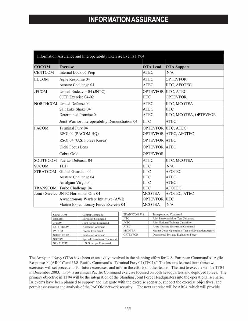
335
INFORMATION ASSURANCE
The Army and Navy OTAs have been extensively involved in the planning effort for U.S. European Command’s “AgileResponse 04 (AR04)” and U.S. Pacific Command’s “Terminal Fury 04 (TF04).” The lessons learned from these twoexercises will set precedents for future exercises, and inform the efforts of other teams. The first to execute will be TF04in December 2003. TF04 is an annual Pacific Command exercise focused on both headquarters and deployed forces. Theprimary objective in TF04 will be the integration of the Standing Joint Force Headquarters into the operational scenario. IA events have been planned to support and integrate with the exercise scenario, support the exercise objectives, andpermit assessment and analysis of the PACOM network security. The next exercise will be AR04, which will provide
Information Assurance and Interoperability Exercise Events FY04 COCOM Exercise OTA Lead OTA Support CENTCOM Internal Look 05 Prep ATEC N/A
EUCOM Agile Response 04 ATEC OPTEVFOR Austere Challenge 04 ATEC JITC, AFOTEC
JFCOM United Endeavor 04 (JNTC) OPTEVFOR JITC, ATEC CJTF Exercise 04-02 JITC OPTEVFOR
NORTHCOM United Defense 04 ATEC JITC, MCOTEA Salt Lake Shake 04 ATEC JITC Determined Promise 04 ATEC JITC, MCOTEA, OPTEVFOR
Joint Warrior Interoperability Demonstration 04 JITC ATEC
PACOM Terminal Fury 04 OPTEVFOR JITC, ATEC RSOI 04 (PACOM HQ) OPTEVFOR ATEC, AFOTEC
RSOI 04 (U.S. Forces Korea) OPTEVFOR ATEC
Ulchi Focus Lens OPTEVFOR ATEC
Cobra Gold OPTEVFOR
SOUTHCOM Fuertas Defensas 04 ATEC JITC, MCOTEA SOCOM TBD JITC N/A STRATCOM Global Guardian 04 JITC AFOTEC Austere Challenge 04 JITC ATEC Amalgam Virgo 04 JITC ATEC TRANSCOM Turbo Challenge 04 JITC AFOTEC Joint / Service JNTC Horizontal One 04 MCOTEA AFOTEC, ATEC Asynchronous Warfare Initiative (AWI) OPTEVFOR JITC Marine Expeditionary Force Exercise 04 MCOTEA N/A
336
INFORMATION ASSURANCE
both training and operational rehearsal to EUCOM and NATO forces preparing for contingency support to the AthensOlympics. Integration of the Standing Joint Force Headquarters is also a major goal of this exercise, and IA events havebeen planned and coordinated to support the scenario. Final planning for this exercise will take place by the end of 2003,and the exercise will execute in March 04.
DOT&E has increased the focus on IA as an evaluation issue for systems on the OT&E oversight list. The DOT&Epolicy for IA evaluations that was implemented in 1999 remains in effect. A dozen programs were identified in FY03 for anexpanded review of the adequacy of IA evaluation planning and to confirm appropriate IA OT&E metrics were in use.This effort included review of Test and Evaluation Master Plans, Test Plans, and Defense Information TechnologySecurity and Accreditation Process documentation. The OTA’s are performing similarly expanded efforts on selectedacquisition programs and both DOT&E and OTA efforts to heighten IA awareness in acquisition program planning willcontinue in FY04. In addition, DOT&E IA policy is being revised to reflect the latest information in IA practices andmetrics and will also address the evaluation of legacy systems during COCOM and Service exercises.
There are many ongoing activities focused on improving DoD’s IA and interoperability posture. The OTA-led effortdescribed in the preceding pages will assist in integrating and finding synergy among these efforts. Still, more must bedone to deliver and maintain systems that are interoperable and information assured. The push to field emergingcapabilities and commercial technologies, combined with the rapidly growing IO threat, will be a constant source offriction with the Department’s information superiority goals, but one that can be best met with the fully engagedorganizations involved in this effort.
SYSTEMS AND TEST RESOURCES
337
Overview
This past year, the DoD T&E community has continued its efforts to refine the T&E infrastructure for the future. ThisT&E infrastructure must be both efficient in its use of available resources and adaptive to the test needs of advancedtechnology weapon systems and transformational joint warfighting concepts.
TRANSFORMING T&E TO MEET FUTURE CHALLENGESEstablishing an effective strategic planning process for T&E resources is an important first step in ensuring theprerequisite T&E capabilities are in place to support the acquisition of transformational warfighting systems. Such aprocess will help focus scarce T&E investment resources towards the most critical needs. A long-term, comprehensiveplan that identifies and addresses future needs is essential to true transformation of T&E capabilities. The recentestablishment of the DoD Test and Resource Management Center (DTRMC) is a step toward this end.
The National Defense Authorization Act for FY03 called for the establishment of DTRMC. The DTRMC reports directlyto the Under Secretary of Defense for Acquisition, Technology, and Logistics and has the following responsibilities:review and provide oversight of DoD budgets for T&E facilities and resources; biennially, prepare a strategic plan forDoD T&E resources; certify proposed budgets for T&E activities; and administer the Central Test and EvaluationInvestment Program (CTEIP) and the Test and Evaluation/Science and Technology (T&E/S&T) Program. The DTRMChas two major interrelated functions, to develop and maintain a strategic plan for T&E and to certify the adequacy ofT&E resources.
Congressional direction requires a strategic plan every two years that covers the next ten-year period. The plan is to bebased on a comprehensive review of DoD T&E requirements and the adequacy of T&E facilities and resources to meetthese requirements. DoD will use the DOT&E annual report, the DoD Science and Technology strategic plan, Serviceplanning documents, and task forces comprised of Service/Agency acquisition and T&E staffs. The plan will include thefollowing:
• An assessment of DoD T&E requirements for the period covered by the plan that identifies performancemeasures associated with the successful achievement of T&E objectives, assesses the T&E facilities andresources needed to meet such requirements and satisfy such performance measures, and assesses the currentstate of DoD T&E facilities and resources.
• An itemization of acquisitions, upgrades, and improvements necessary to ensure that DoD T&E facilities andresources are adequate to meet such requirements and satisfy such performance measures. This itemization willinclude an assessment of the budgetary resources necessary to implement such acquisitions, upgrades, andimprovements.
Although the first T&E strategic plan prepared by interim personnel will not be a comprehensive strategic plan,subsequent plans will provide the necessary level of detail to guide DoD’s T&E resource investment decisions.
The long-term goal of budget certification is to assess how well the budgeted resources comply with the strategic plan.The FY05 budget certification will be limited to complying with the congressional direction to reverse the trend ofincreasing test costs to customers of the Major Range and Test Facility Base (MRTFB). The objective is to chargecustomers only for direct test costs. The certification will also assess progress towards satisfying needs identified in theFY03 Test Resource Master Plan (TRMP) prepared by the Services.
In October 2002 at the direction of the Secretary of Defense, DOT&E led a study to identify future T&E infrastructureinvestments required to adequately test weapon systems both currently under development and likely to emerge fromnew technologies. In preparing that study, DOT&E conducted workshops to identify needed T&E capabilities thatensure adequate and affordable testing into the future. The product of this effort was a draft T&E Modernization Plan.This plan was subsequently integrated with the existing Service TRMP as a baseline for the development by the DTRMCof the DoD T&E Strategic Plan.
SYSTEMS AND TEST RESOURCES
338
The modernization planning effort noted that existing T&E capabilities would not be adequate to support future weaponsystem development and identified a number of T&E capability shortfalls. Among others, shortfalls were identified in thefollowing areas:
• Interoperable test and training ranges.
• Common joint test instrumentation.
• Interoperability testing - Upgraded distributed test beds and increased emphasis on testing of system-of-systems and command, control, communications, computers, intelligence, surveillance, and reconnaissance(C4ISR) capabilities are needed.
• Size of test ranges - Current T&E ranges are not large enough to test the greater reach of weapon systems underdevelopment. The maneuver areas used to test new joint operational concepts also require expanded rangespace.
• Test facilities for urban warfare.
• Shallow water (littoral) test capability.
• Space range - A T&E capability to test space systems in orbit is needed.
• Wind tunnels - Future aircraft will encounter technical challenges that require improved wind tunnel testcapability.
• Threat representation - Realistic threat representations for all warfare areas, to include improved targets areneeded.
• Capability to test hypersonic systems throughout their flight regimes.
• Capabilities for testing directed energy weapons.
• Test data management, processing, and analysis.
One of the principal requirements for the transformed military is that it must be a cohesive joint force. From inception,weapon systems must be developed and tested in a joint context, not in the “Service-centric” manner of the past. Overthe past year, a number of steps have been taken to improve the links between T&E and the joint operational community.DOT&E is closely following the development of the Joint National Training Capability (JNTC). Testing, training, andexperimentation all share some common requirements, to include the need for a robust simulated combat environment,accurate instrumentation to determine “ground truth,” and similar analytic approaches to understanding what took placeand why. The approach JNTC is taking to link training ranges and training capabilities in a persistent distributed networkshould also be adapted for T&E.
DOT&E continues to develop a relationship with U.S. Joint Forces Command (JFCOM). During the past year there was amajor expansion of the Memorandum of Agreement (MOA) between the two organizations. Among the expandedactivities will be:
• Development of requirements for test and training ranges and facilities to support joint training andexperimentation.
• Coordination of test and training range improvements needed to support joint training and experimentation.

SYSTEMS AND TEST RESOURCES
339
• Planning for future joint exercises and experiments and execution of current events to ensure optimum utilizationof existing capability.
• Reviewing, shaping, and scoping Joint T&E (JT&E) nominations to focus the initiatives on solving jointwarfighting deficiencies in tactics, techniques, and procedures.
JFCOM and DOT&E personnel are engaged in re-engineering JT&E and future partnerships.
DOT&E continues to make major strides towards test and training range integration and interoperability. DOT&Eleveraged the JFCOM Joint Combat Identification Exercise in August to demonstrate a prototype of the Test and TrainingEnabling Architecture (TENA). TENA is a set of architectures designed to enable interoperability among various rangefacilities, instrumentation, and simulations in a quick, cost-efficient manner. Currently, range systems tend to be non-interoperable, “stovepipe” systems. Validation of TENA as the JNTC architecture is planned for January 2004 in aWestern Range Complex Training Event.
The process of thoroughly examining and restructuring T&E policies, processes, and capabilities in order to ensure DoDmeets the challenges of transforming the U.S. military is vital. DoD must keep what works, discard what does not, andremain flexible in adapting to new requirements. There must be a corporate approach to policies, processes, andinvestment priorities in order to accomplish this.
DoD is transforming to meet the dynamic operational requirements of the war on terrorism and future high-technologyconflict. This transformation is not limited to new hardware and technological innovation. It also involves transformingT&E capabilities. The future T&E infrastructure should comprise a comprehensive suite of joint, interoperablecapabilities that provide a spectrum of opportunities to test new technologies, improved platforms, and innovativetactics and training methods.
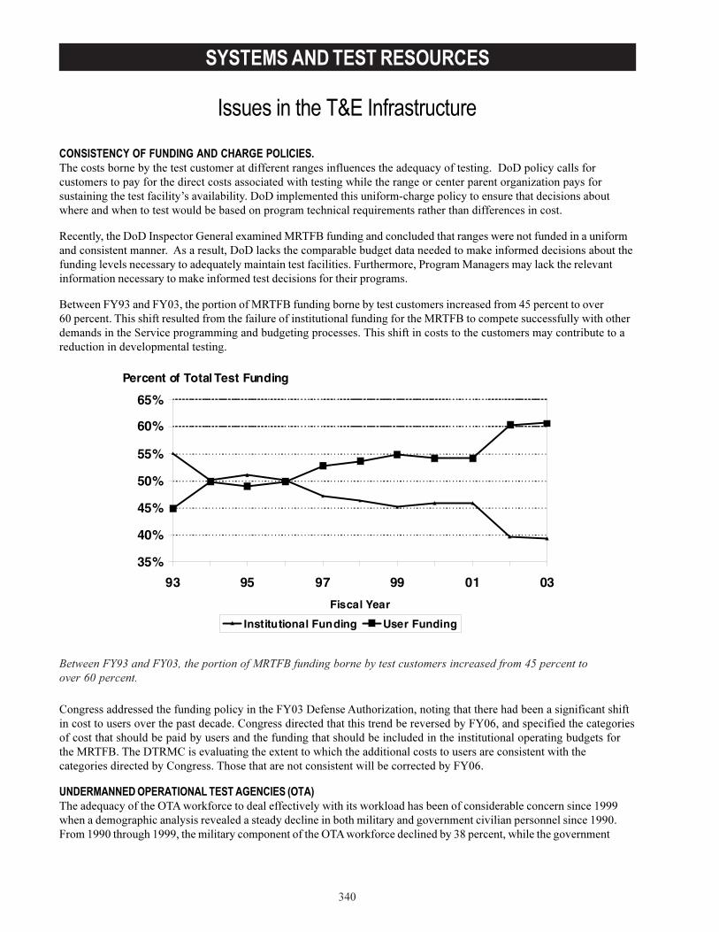
�������������������� ��
�>-
�������� ����������������
������ ��������������������� ����� ������������� ������������������ ������� ��� ��������������������� ��������������������������������� ������ ��������� ������ ����������������������������������� ����� ����� �� ���� ���*���������� ���������������������9������������������������������������ �#�� ���������������� �������������������� ��������������������������������� �� ���������� � �� ������ �� ��������� �������������
$���������������2������ �E��� ���5������%$�+;������������������������ ������� ��������������������� ����������������� ���"��� ������������7��������� ����������������������7������ ����������������������������������������� ������ ������������������������+� �� �� ���3 �� ��%��� �������7���� ��������� ����������� �����7������ ������������������� ���� �� �� ���
;������+,C�����+,-�������� �������%$�+;����������� ��������������� ����� ������ ���>:��� ��������� F-��� ��������������� �������� ���������� ������������������������� ����%$�+;������������������������������ �������������!� ������ �� ������������������� �������������������������������������� �������� ������� �����������������������������
&��� ������ ������������������������������+,-����������"��� �*��������������� ������������������������������������� ����� ��������������&��� ������ ����������� ������� ��� �������+,-F���������������������� �������������������������������� �������������������������������������������������������� ������������� ���%$�+;��������$%&����������������5�������������������������������� �� ��������������������� ������ ��������&��� ������������� ������������������������ ��������+,-F�
��� ����� ���� ��������� ���� �� ������������� ����������6�"��� 7�� ����������������������������� 7���������������������� ��������� ��������GCCC����������� ������������ �������������������������������� ��������� ��������������� �������������GCC-�+ ���GCC-�� �����GCCC��������� �����������������6�"��� 7�� ����������������=��� ������������������ ����
����������������� ����������������������������������������������������������������������� ������������!���" ��������#
35%
40%
45%
50%
55%
60%
65%
93 95 97 99 01 03
Fiscal Year
Institutional Funding User Funding
Percent of Total Test Funding
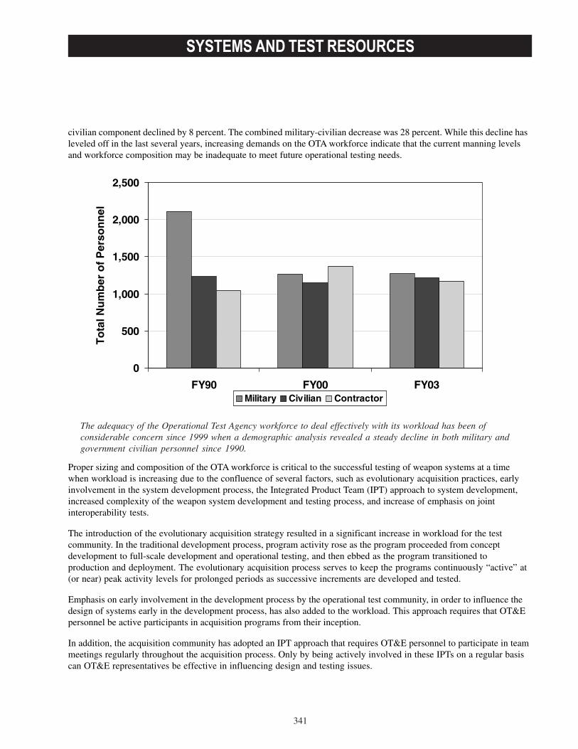
SYSTEMS AND TEST RESOURCES
341
civilian component declined by 8 percent. The combined military-civilian decrease was 28 percent. While this decline hasleveled off in the last several years, increasing demands on the OTA workforce indicate that the current manning levelsand workforce composition may be inadequate to meet future operational testing needs.
Proper sizing and composition of the OTA workforce is critical to the successful testing of weapon systems at a timewhen workload is increasing due to the confluence of several factors, such as evolutionary acquisition practices, earlyinvolvement in the system development process, the Integrated Product Team (IPT) approach to system development,increased complexity of the weapon system development and testing process, and increase of emphasis on jointinteroperability tests.
The introduction of the evolutionary acquisition strategy resulted in a significant increase in workload for the testcommunity. In the traditional development process, program activity rose as the program proceeded from conceptdevelopment to full-scale development and operational testing, and then ebbed as the program transitioned toproduction and deployment. The evolutionary acquisition process serves to keep the programs continuously “active” at(or near) peak activity levels for prolonged periods as successive increments are developed and tested.
Emphasis on early involvement in the development process by the operational test community, in order to influence thedesign of systems early in the development process, has also added to the workload. This approach requires that OT&Epersonnel be active participants in acquisition programs from their inception.
In addition, the acquisition community has adopted an IPT approach that requires OT&E personnel to participate in teammeetings regularly throughout the acquisition process. Only by being actively involved in these IPTs on a regular basiscan OT&E representatives be effective in influencing design and testing issues.
The adequacy of the Operational Test Agency workforce to deal effectively with its workload has been ofconsiderable concern since 1999 when a demographic analysis revealed a steady decline in both military andgovernment civilian personnel since 1990.
0
500
1,000
1,500
2,000
2,500
FY90 FY00 FY03
To
tal N
um
ber
of
Per
son
nel
Military Civilian Contractor
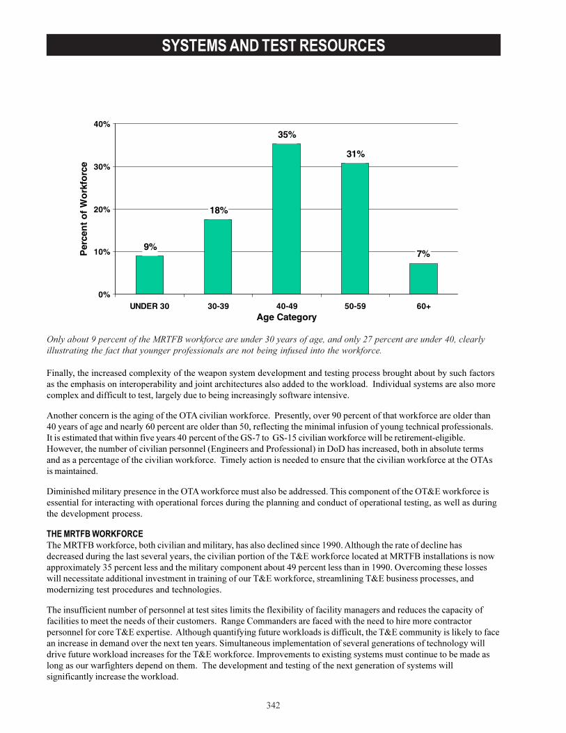
�������������������� ��
�><
+������������� �����������5������������������������������������������ ������� �������������������� �������������������� ��� �������������� ������ ������������������� 7������2���������������� �������� �������5�������������������� �������������������� ������������ �����������
"���� ������ �������������������6�"����������� 7�� �����3 ����������� �C-��� ����������� 7�� ��� ������ ���>-��� ������������� ���F-��� ���� ������ ����:-�� ���������������������������������������������� �����������2�������������������������� ��>-H�� ����������E!#�����E!#G:����������� 7�� ����������� �� ����#���������I����� ���������� �������������� �������'������� �����3 ���������(�������������� ��������������������� ���������� ���������������������� 7�� ��������������������������������� ����������������� 7�� �������6�"������������
��������������� ��� �������������6�"��� 7�� ���������������� ���������������������������6������ 7�� ��������������� ���� ������������ ������� ������ ������������������������������� ����������������������� ������������������ ������
�� ��������������� ����%$�+;��� 7�� ����������������������� �������������������������GCC-��"���������� ������������������ ������� �������������� ���� ���������������� ���������������� 7�� ����������%$�+;������������������� �5�������:��� ������������������� ���������������>C��� ���������������GCC-��6�� ���������������������������������������������������� ����������� ������� 7�� ����� ����������������������� ��������������� ��*�������� ����� ������������������
��������������������� ������ ����������������������������5��������������������� ����� ������������������������������������������������ ������� ����$����&������ �� ����������������������� ���� ����� �� �� ��������� ��� �������5�� ������"������� ������������ ���� 7���������������������������������������7�������������� ���������������� ������5������ ���!����������������������������� ������ ����������������������� ������� ���� 7������� ������� ���������� 7�� ����2�� �����������5�������������������������������������������� �� ����� ��������������������������������������������������5����� ��������������������������������� ��������� 7����
%�&���������������������������������(���������������� ���������������������&��*+�������������������� ���&���&��&&�������������������������������������������&������������������������������������(�����#
9%
18%
35%
31%
7%
0%
10%
20%
30%
40%
UNDER 30 30-39 40-49 50-59 60+Age Category
Per
cen
t o
f W
ork
forc
e
SYSTEMS AND TEST RESOURCES
343
As the MRTFB government workforce grows smaller, its civilian component has grown in seniority. Action must betaken to introduce new professionals into the workforce, particularly in the science and engineering disciplines. Onlyabout 7 percent of the MRTFB workforce (excluding the Base Operation Support and other non-T&E personnel part ofthe overall MRTFB workforce) are under 30 years of age, and only 22 percent are under 40, again illustrating the fact thatnew professionals are not being infused into the workforce. Approximately 43 percent of this workforce are over 50 andare approaching retirement.
DoD must continue to aggressively experiment with and develop new approaches to workforce management, recruiting,and retention if DoD is to succeed in attracting newer, technologically-current cadre of T&E professionals.
CLOSURE OF NASA WIND TUNNELSHistorically, DoD and the National Aeronautics and Space Administration (NASA) have operated complementary windtunnel test facilities in the United States. Under this arrangement, DoD has relied on NASA facilities for specific types oftesting during the development of aerospace systems. Due to increased pressure on its budget, NASA has decided toimplement a full-cost recovery policy at many of its major test facilities. NASA’s test facilities are now expected torecover from their customers the full costs of operations, including overhead and general and administrative costs. As aresult, a number of unique national facilities that have limited but critical workload are now scheduled for closure.
Of immediate concern is NASA’s closure of the largest wind tunnels in the world, the 80 x 120-foot and the 40 x 80-foottunnels at the Ames Research Center in California. These wind tunnels are unique in that they are used to test very large-scale models and full-scale aircraft. They have been important to the development of rotorcraft, the development ofVertical/Short Take-off and Landing aircraft, the testing of high-lift transport and commercial aircraft, and thedevelopment of very large ducted and unducted fan propulsion systems. NASA is also closing the 12-foot PressureTunnel at the Ames Research Center. This facility is important in the design of aircraft in certain critical flight regimes.NASA ceased to operate these three tunnels in FY03. If insufficient contracts for their use are let in FY04, these tunnelswill be closed permanently. In the interim, NASA has already announced that it is terminating the contractor personnelwho operate these tunnels while reassigning an equal number of its own personnel.
While the possible closures of NASA’s unique subsonic wind tunnels pose the most immediate threat to DoD ability totest and field new systems, there is a larger problem in that NASA’s full-cost recovery policy applies to all of its testfacilities. If other test facilities do not generate enough business to cover their costs, NASA will close them as well. Thisincludes transonic, supersonic, and hypersonic wind tunnels and propulsion facilities, as well as specialized facilities foracoustic testing, spin testing, flutter testing, and icing testing. DOT&E will continue to work on this issue to reduce therisk to DoD aerospace acquisition programs.
INADEQUATE AERIAL TARGETS AND SELF DEFENSE TEST SHIP (SDTS)DOT&E is concerned about the availability, reliability, and overall threat fidelity of DoD aerial targets. Over the past year,testing has been delayed or not completed due to the absence or unreliability of the available aerial targets. Furthermore,the venerable QF-4 drone will reach the end of its useful life as a target in 2010, yet no funding has been identified by theServices to replace this target and satisfy a tri-Service T&E requirement. In addition, there are emerging threats for whichno adequate targets currently exist. No funding has been identified to develop or acquire adequate targets to representthese threats. As a result, the performance gap between the threats and the targets available to represent them duringoperational testing is growing larger. DoD’s capability to conduct OT&E under realistic threat conditions depends uponthis trend being reversed.
Safe, operationally realistic testing of Navy short-range air defense systems requires an unmanned, remotely controlledSDTS. The SDTS used for the past 10 years is beyond repair and a replacement hull awaits conversion to an SDTS. TheSDTS is a critical T&E asset for the operational testing of the Ship Self Defense System Mark 2, the Rolling AirframeMissile, the Evolved Seasparrow Missile, LPD 17, Littoral Combat Sysytem, DD(X), and CVN 21. As a matter of priority,the Navy needs to resource the SDTS and install the relevant air defense systems for testing.
RANGE ENCROACHMENTEncroachment refers to the cumulative result of outside influences that inhibit normal military testing and training. Itincludes urban sprawl near military areas; loss of frequency spectrum; restrictions on using air, land, and sea space; and

SYSTEMS AND TEST RESOURCES
344
migration of endangered species to ranges. A steady increase in encroachment has serious consequences and threatensthe use of DoD’s test and training ranges.
Last year, the Administration submitted to Congress an eight-provision legislative package, the Readiness and RangePreservation Initiative. Congress enacted three of those provisions as part of the National Defense Authorization Act forFY03. Two of the enacted provisions allow DoD range installations to cooperate more effectively with state and localgovernments, as well as private entities. One plans for the growth of surrounding test and training ranges by allowingcompatible land use that preserves habitat for imperiled species and the other ensures developments are compatible withtest and training activities. Under the third provision, the Congress provided DoD with a regulatory exemption under theMigratory Bird Treaty Act (MBTA) for the incidental taking of migratory birds during military readiness activities. Thisaction by the Congress provided welcome relief to serious readiness concerns raised by recent judicial extensions of theMBTA.
Last year, Congress did not act on the other five legislative provisions in the Readiness and Range PreservationInitiative. These five proposals remain essential to range sustainment. The five provisions, resubmitted in FY03, reaffirmthe principle that military land, marine areas, and airspace exist to ensure military preparedness while ensuring that DoDremains fully committed to its stewardship responsibilities. The remaining provisions are:
• Endangered Species Act. Authorize use of Integrated Natural Resources Management Plans in appropriatecircumstances as a substitute for critical habitat designations.
• Marine Mammal Protection Act. Reform obsolete and unscientific elements of the Act, such as the definition of“harassment,” and add a national security exemption to the statute.
• Clean Air Act. Modestly extend the allowable time for military readiness activities such as beddown of newweapons systems to comply with the Act. Also, provide additional flexibility by ensuring emissions from militarytraining and testing are consistent with state implementation plans under the Clean Air Act.
• Resource Conservation and Recovery Act (RECRA) and the Comprehensive Environmental Response,Compensation, and Liability Act (CERCLA). Limit regulation of munitions use on operational ranges under theCERCLA and the RECRA if those munitions and their associated constituents remain there, and only while therange remains operational.
This year’s legislative proposals also include some clarifications and modifications based on events since 2002. Of thefive, the Endangered Species Act and the Clean Air Act provisions are unchanged.
RADIO FREQUENCY SPECTRUMThe testing of modern defense systems relies heavily on the use of the radio frequency (RF) spectrum. RF telemetrysystems are used to track test participants, control targets, ensure public safety, and transmit instrumentation data.Technology advances being incorporated into weapon designs require higher telemetry data rates and, consequently,substantially more spectrum. DOT&E has sponsored a number of initiatives to ensure that currently available spectrum isused as efficiently as possible and that additional spectrum is made available to support testing. Equipment to support awaveform that is twice as efficient as the legacy telemetry waveform is now operational, while development of an evenmore efficient waveform is continuing. DOT&E is also investigating the application of modern communicationsnetworking techniques to telemetry. Additionally, the Inter-range Frequency Deconfliction System has been developed tocoordinate the use of spectrum among the test ranges.
More efficient use of currently available frequency spectrum is only a partial solution to the problem. To support futureweapons development, additional RF spectrum will be needed, as well as updating instrumentation, telemetry, andtracking systems. In order to ensure that these needs are satisfied and acknowledged internationally, DOT&E hasworked to ensure that an initiative to identify additional spectrum to support aeronautical flight test telemetry was placedon the agenda of the 2007 World Radiocommunication Conference (WRC). As a result of these efforts, and with thesupport of DoD, other government departments, and industry, this agenda item was confirmed at the 2003 WRC as anitem for the 2007 WRC. DOT&E has also sponsored an investigation into the use of telemetry at higher frequencies thanare currently used.

SYSTEMS AND TEST RESOURCES
345
THE MRTFB CONTINUES TO SUPPORT MOST DEVELOPMENTAL TESTINGMost developmental testing within DoD is conducted at MRTFB locations. These sites, operated by 30,000 military,civilian government, and contractor personnel, range from wind tunnels and electronics integration test facilities toDoD’s largest open-air, land, and sea test ranges. The function of the test infrastructure remained relatively unchangedsince the MRTFB’s founding in 1974: “The MRTFB is a national asset that shall be sized, operated, and maintainedprimarily for DoD T&E support missions.”1 While these major test facilities and ranges provide the majority of thedevelopmental test capabilities we need today, there is a continuous need for investment. Funds must be available forupgrades to existing capabilities and for the introduction of new capabilities to test future weapon systems.
T&E INVESTMENT PROGRAMS ARE IMPROVING AND EXTENDING CURRENT CAPABILITIESSustaining current capabilities and improving test technology are the focus of existing T&E investment programs. TheService and Defense Agency investment and modernization (I&M) programs along with the OSD Central Test andEvaluation Investment Program (CTEIP) program upgrade existing capabilities, but have inadequate resources to developthe new capabilities required by emerging weapons technologies. Several of the Service ranges have identified asignificant list of unfunded requirements needed in order to fully test upcoming systems.
I&M programs fund modernization of existing test facilities and the acquisition of new capabilities to meet test needs.Each Military Service pursues an I&M strategy that often focuses on test assets that are Service-unique with little multi-Service utility. Service I&M funding has been relatively constant in recent years.
Progress in the Last Year
These sites, operated by 30,000 military, civilian government, and contractor personnel, range from windtunnels and electronics integration test facilities to DoD’s largest open-air, land, and sea test ranges.
1DoD Directive 3200.11, “Major Range and Test Facility Base (MRTFB),” May 1, 2002.

SYSTEMS AND TEST RESOURCES
346
In FY03, the Army I&M program completed at Kwajalein Atoll the remote operation of instrumentation, radarmodernization, and the Range Safety Control Center upgrade. These projects will reduce on-island staffing and inter-island transportation and should improve data management and mission response times. Dugway Proving Ground hasinitiated a Joint Test Infrastructure project by using a DoD-wide chemical-biological (CB) testing infrastructure survey toprovide a roadmap for undertaking tasks within the CB area. Projects at White Sands Missile Ranges are investigatingthe options for replacing film with high-speed digital imaging, thereby reducing the time and expense of processing film,while reducing test turn-around time.
In FY03, the Navy’s I&M program completed the upgrade program for its FPS-16 radars at Naval Air Warfare CenterWeapons Division locations and the installation of the manned Flight Simulator at the Naval Air Warfare Center AircraftDivision. The Navy completed the first two phases of the Off-board Advanced System Stimulus (OASYS) at the AtlanticUndersea Test and Evaluation Center (AUTEC). The first phase provided for integrated test and evaluation of underseawarfare combat and sensor systems in a dynamic multi-mission environment. Phase two, using the AUTEC SonobuoySimulation/Stimulation System, provides the capability to test and validate performance of Navy multi-mission platforms,systems, and vehicles. Phase 3 will focus on the AUTEC Mine Field Proxy System.
The Air Force’s I&M investments completed in FY03 include the Electronic Combat Integrated Test facility and theGlobal Air Traffic Management Test Facility at Edwards Air Force Base (AFB), California. The Air Force ElectronicWarfare Evaluation System completed various simulator threat upgrades, including integrated air defense, and hardware-in-the-loop upgrades. The Air Force completed an upgrade of the High Speed Test Track facility at Holloman AFB, NewMexico. It conducted a hypersonic test, wherein the test sled obtained a velocity of 9,465 feet per second (or 6,553 milesper hour) in delivering a 192-pound payload into a target. Other Air Force I&M projects underway include the Open-Airhardware-in-the-loop facility, which includes a 300-foot, free-standing platform, with a 3-axis flight motion simulator and aMultispectral Missile Engagement Hardware-in-the-Loop Simulator, including a multi-channel infrared projector with theability to simulate extended targets and flares at the 46th Test Wing. The major I&M project at Arnold Engineering andDevelopment Center (AEDC), Tennessee, are the Propulsion Wind Tunnel (PWT) upgrades. These upgrades have thepotential of reducing (by at least 30 percent) the cost of testing in the wind tunnels at AEDC.
The Missile Defense Agency (MDA) uses MRTFB facilities and is funding upgrades at the Pacific Missile Range Facility,Ronald Reagan Ballistic Missile Defense Test Site, Wake Island, and White Sands Missile Range. In addition, MDA isfunding test activity at Kodiak, Vandenberg AFB, and Holloman AFB. MDA is also developing a test infrastructure for awide range of airborne sensor programs, including the High-Altitude Observatory II Aircraft and the Wide-body AirborneSensor Platform using a DC-10 aircraft. Also, MDA is investing in the Mobile Extended Range Telemetry and SafetySystem, a standard integrated system that collects telemetry and provides flight safety over the extended Pacific range ofinterest to MDA.
CTEIP is an OSD-managed program established to develop T&E capabilities normally considered beyond a singleService’s area of responsibility. Its objectives include applying state-of-the-art technology to correct deficiencies in T&Ecapabilities and improve the efficiency of the test process; improving interoperability and interconnectivity among testfacilities and ranges; developing, validating, and integrating modeling and simulation with open-air testing; anddeveloping mobile test instrumentation as an alternative to fixed facilities. One portion of CTEIP, the ResourceEnhancement Project (REP), provides quick-reaction, near-term solutions to test shortfalls in support of ongoingoperational test programs. REP funding is appropriate when the timeframe from definition of need through critical testdates does not allow sufficient time in the budget cycle to fund the required capability through normal Service processes.
One of the key elements of CTEIP is its partnership with the Services. CTEIP develops and demonstrates new testcapabilities, which allows the Services to focus on the procurement and sustainability of critical resources. Suchpartnering enables CTEIP to exploit breakthrough technologies that create realistic test conditions required to evaluateand enhance the development of next generation warfighting systems.

SYSTEMS AND TEST RESOURCES
347
New test capabilities being developed by CTEIP include:
• Spectral Efficient Technology Development. The Advanced Range Telemetry project has developed a spectral-efficient technology that improves the reliability, utility, and availability of aeronautical telemetry spectrum foruse in T&E.
• Signature Characterization Capability. The Tri-Service Signature Measurement and Database System projectdeveloped an instrumentation capability that characterized the detailed spatial, spectral, and temporal signaturesof aircraft, missiles, ground vehicles, ships, undersea vehicles, and their countermeasures in realisticenvironments.
• Test and Training Enabling Architecture. The Foundation Initiative 2010 project is developing and validatingthe TENA to enable cost-effective interoperability among ranges, facilities, and simulations to support testingweapon systems and training warfighters.
• High-Intensity RF Sources for Aircraft Vulnerability Testing. The Electromagnetic Environmental EffectsGenerating System project is developing a test capability for use in the Air Combat Environment Test andEvaluation Facility, Patuxent River, Maryland, that will assess the actual performance of a full-scale, fixed- orrotary-winged aircraft completely immersed in a high-intensity RF environment.
• Realistic Live Fire Testing. The Weapon Set-to-Hit Threat Target, developed under the REP, will provide anunmanned, reusable, cost-effective target for conducting set-to-hit testing of Mark 54, Mark 48 AdvancedCapability, and future torpedoes.
• CB Test Instrumentation. The Biological Warfare Referee Instrumentation Towers project, being conductedunder the REP, is providing mobile instrumentation for ground truth measurement for operational test andevaluation, exercise support, and training activities at operationally realistic test and training sites. TheContamination Avoidance Detector Test Suite will develop a suite of new test methodology and instrumentationto dynamically challenge and evaluate current and developmental CB detector systems over the entire range ofexpected conditions of use.
• Time Space Position Information Instrumentation. The Enhanced Range Application Program will develop thenext-generation range data system that will address major deficiencies in current systems, includingincompatibility of range data and acquisition reduction systems, inefficient use of radio frequency spectrum,and inadequate interoperability.
The T&E/S&T Program develops or adapts emerging technologies for test applications in order to enable testtechnologies to pace evolving weapons technology. T&E/S&T investments will transition to test capability investmentprograms to support emerging weapon system development. The Test Technology Area Plan, a detailed roadmap for theoverall T&E/S&T program, was published in July 2003.
The T&E/S&T efforts underway during FY03 continue to address technological issues in three critical areas:
• Hypersonic Test. The objective in this area is to develop technologies that can provide the ability to adequatelytest and evaluate vehicles, propulsion systems, and integrated systems at or above Mach 5 to meet NationalAerospace Initiative demonstration schedules and future hypersonic systems T&E needs.
• Spectrum Efficient Technology. The objective in this area is to develop technologies that increase usageefficiency in current spectrum allocations and investigate technical and economic challenges related to futureusage of an augmented Super High Frequency telemetry band.
• Multi-Spectral Test. The objective in this area is to make technologies available for test and evaluation ofsensor probability of target detection, multi-spectral data extraction, and mission scenario analysis. Model data

SYSTEMS AND TEST RESOURCES
348
produced from this focus area will augment open-air and facility-based testing with real-time, realistic multi-spectral simulation and stimulation of systems and battlefield personnel in all types of environments includingwater, desert, forest, rural, and urban terrains under varying meteorological conditions.
In addition, DoD initiated efforts in two new focus areas:
• Embedded Instrumentation. The objective is to enable development of non-intrusive embedded instrumentationtechnologies that provide performance data in support of continuous T&E and life-cycle data requirements.
• Directed Energy. The objective is to develop the test technologies required to create a Directed Energy T&Einfrastructure capable of supporting future systems test requirements.
DOT&E ACTIVITIES CONTINUE TO CONTRIBUTE TO THE TRANSFORMATION OF T&EDOT&E’s Threat System Office (TSO) provides test resource analyses on the availability, capabilities, and limitations ofthreat representations used for T&E. In addition, the TSO advises DOT&E on the adequacy of service-funded threatsystem investments that support weapon system acquisition and T&E.
Through the TSO, DOT&E is investing in projects to enhance threat representation in T&E. Projects of particular interestare:
• Multi-spectral Test Capabilities. The infrared/ultra-violet end-to-end test requirement study will develop a tri-Service functional design requirement for threat simulators that support testing of aircraft missile warning andinfrared countermeasures systems.
• Real-Time Casualty Assessments (RTCA) Instrumentation. The infrared Man-Portable Air Defense SystemsMethodology Assessment project integrates the existing infrared missile fly-out model at the Threat-Signal-Processor-in-the-Loop facility with a fuse model and an Army Material System Analysis Agency approvedmodel for damage assessment. Overall, this simulation addresses the need for an RTCA tool to provide adequateoperational testing of Army aviation systems.
Additionally, through TSO, DOT&E is sponsoring a number of threat target projects to provide realistic, threat-representative targets for test and evaluation. Projects of particular interest are:
• Diesel-electric submarine target. The Mobile Acoustic Source project develops a mobile diesel electricsubmarine simulator with highly robust acoustic and dynamic characteristics for use in high-risk, open-ocean,and shallow water environments.
• Anti-ship cruise missile. A project studied the performance and feasibility of two candidate target systems(Hawk missile mated with Tomahawk and Standard Missile mated with Tomahawk) that could possibly meet theThreat “D” target requirement. Wind tunnel testing on both candidate systems proceeded in FY03.
• Sub-scale aerial targets. Numerous projects are currently active that seek to improve the flexibility andeconomy of the sub-scale aerial target inventory.
DOT&E’s Center for Countermeasures provides independent precision guided weapon (PGW) countermeasures/counter-countermeasures (CM/CCM) analysis, testing, and evaluation for the entire DoD community, supported by a knowledgebase of over 500 developmental and operational tests of U.S. and foreign PGWs and CM systems. Over the past year,CCM tested, analyzed, or otherwise supported over 30 U.S. and foreign PGW systems or components in acountermeasure environment, as well as other countermeasure and threat warning systems.
To improve the DoD’s business practices, DOT&E has been contributing to the success of the Business InitiativeCouncil (BIC)’sT&E Process Functional Board initiatives. The BIC’s mission is to improve the efficiency of DoD business

SYSTEMS AND TEST RESOURCES
349
operations by identifying and implementing business initiatives that create savings to be reallocated to higher priorityefforts. Among the T&E process initiatives being pursued are:
• Common Flight Clearance Process. This initiative is to develop and implement a Common Flight ClearanceProcess by incorporating the latest Information Technology advancements to reduce clearance turnaround time.
• Common Range Scheduling Tool. This initiative is to develop and implement a web-based schedule displaytool capable of integrating and displaying schedule information that will enhance coordination andcommunications across multiple sites.
• Embedded Instrumentation (EI) for Diagnostics, Prognostics, Testing and Training. This initiative resulted inDoD regulatory guidance to ensure that EI is included in system trade-off studies and design analyses.
• Common Test and Training Range Architecture Policy. This initiative is to establish or change appropriateDoD Polices/Directives so that test and training range systems will comply with the TENA where it makestechnical and fiscal sense. Potential benefits are a significant increase in test and training systeminteroperability, a capability to efficiently design and execute multi-range test and training events, a decrease incosts to conduct testing and training, and easy reuse of test and training software.
• Test and Evaluation Master Plan (TEMP) Preparation and Approval Process Improvement. This is a newinitiative to examine the TEMP preparation and approval process and to recommend improvements.
DOT&E continues to work with the international T&E community and has developed new Test and Evaluation ProgramCooperation Agreements with Canada, France, and Australia. These agreements include a “Reciprocal Use of TestFacilities” clause that allows access to ranges and facilities at direct cost, and a “Cooperative Test and Evaluation”clause that allows for cooperative activities where the cost of testing is shared.
The Canada/U.S. Test and Evaluation Program (CANUSTEP), the longest standing of these agreements, was renegotiatedand signed in September 2002. The original CANUSTEP agreement was signed in 1993. CANUSTEP served as the modelfor the agreements with France and Australia. It is anticipated that these agreements will open the doors for U.S. rangesby establishing new international customers. Areas of cooperation also include the exchange of test technologies,information and data exchanges, and project equipment transfers. DoD is currently negotiating similar agreements withthe Netherlands and the United Kingdom.
Another international program for DOT&E focuses on International Test Operation Procedures. This program is managedby an International T&E Steering Committee and results in mutually agreed upon, technical test procedures. By usingthese test procedures, partner nations can accept each other’s testing without need to retest, thereby reducingacquisition costs. This program continues to grow, with procedures for several new technical areas currently beingdeveloped.
DOT&E also publishes biennially an International Test Facilities and Ranges Capability Summary. The 2001 editionincluded input from eleven nations. Two additional nations have been invited to contribute to the 2003 edition.

SYSTEMS AND TEST RESOURCES
350
INDEX OF PROGRAMS
351
Aerial Common Sensor...................................................................................................................................................................53
Acoustic Rapid COTS Insertion AN/BQQ-10(V) Sonar System.............................................................................................119
Advanced Seal Delivery System (ASDS)...................................................................................................................................121
Advanced Extremely High Frequency (AEHF) Satellite Communications System............................................................. 223
AGM-88E Advanced Anti-Radiation Guided Missile (AARGM) Program........................................................................... 123
AH-64D Longbow Apache & Long Bow Hellfire Missile.........................................................................................................55
AIM-9X Sidewinder Air-to-Air Missile .....................................................................................................................................125
AIM-120 Advanced Medium Range Air-to-Air Missile (AMRAAM)..................................................................................225
Airborne Mine Neutralization System (AMNS)....................................................................................................................... 127
All Source Analysis System (ASAS)........................................................................................................................................... 57
ALR-69A Radar Warning System...............................................................................................................................................227
Amphibious Helicopter Assault Ships LHA(R)........................................................................................................................129
Amphibious Helicopter Dock Ship (LPD 8).............................................................................................................................. 131
B-1B Conventional Mission Upgrade Program (CMUP).........................................................................................................229
B-2...................................................................................................................................................................................................231
Ballistic Missile Defense System (BMDS).................................................................................................................................. 11
Bradley Fighting Vehicle System Upgrade-A3........................................................................................................................... 59
Business System Modernization (BSM)..................................................................................................................................... 19
C-5 Avionics Modernization Program (AMP) and Reliability Enhancement and Re-Engining Program (RERP).............223
C-17 Globemaster III Airlift Aircraft............................................................................................................................................235
C-130 Avionics Modernization Program (AMP).......................................................................................................................237
C-130J Airlift Aircraft....................................................................................................................................................................239
CH-47F Improved Cargo Helicopter (ICH).................................................................................................................................. 61
Chemical Demilitarization Program............................................................................................................................................... 63
Cobra Judy Replacement (CJR) - Ship Based Radar System.................................................................................................. 133
Combat Survivor Evader Locator (CSEL) System.................................................................................................................... 241
Comanche (RAH-66)...................................................................................................................................................................... 67
Composite Health Care System II (CHCS II).............................................................................................................................. 21
Cooperative Engagement Capability (CEC).............................................................................................................................. 135
CVN 21 Next Generation Attack Carrier......................................................................................................................................137
DDG 51 Destroyer Including: AN/SPY-1D Radar and AN/SQQ-89 Integrated Surface Ship Anti-Submarine Warfare Combat System........................................................................................................ 139
DD(X) Land Attack Destroyer.....................................................................................................................................................143
Defense Integrated Military Human Resources System (DIMHRS)......................................................................................145
INDEX OF PROGRAMS
352
Defense Medical Logistics Standard Support Automated Information System (DMLSS AIS).......................................... 23
Defense Message System (DMS).............................................................................................................................................. 25
Defense Travel System (DTS)...................................................................................................................................................... 27
Deployable Joint Command and Control (DJC2)..................................................................................................................... 147
Distributed Common Ground/Surface System..........................................................................................................................243
E-2C Advanced Hawkeye............................................................................................................................................................ 149
E-3 Airborne Warning and Control System (AWACS)............................................................................................................245
E-4B Modernization Program...................................................................................................................................................... 247
E-10A Multi-Sensor Command and Control Aircraft (MC2A)............................................................................................... 249
EA-6B Upgrades...........................................................................................................................................................................151
Evolved Expendable Launch Vehicle (EELV)............................................................................................................................ 251
Evolved Seasparrow Missile (ESSM)....................................................................................................................................... 153
Excalibur Family of Artillery Projectiles....................................................................................................................................... 69
Expeditionary Fighting Vehicle (EFV)........................................................................................................................................ 155
F-35 Joint Strike Fighter (JSF).....................................................................................................................................................161
F/A-18E/F/G Super Hornet .........................................................................................................................................................157
F/A-22 Raptor............................................................................................................................................................................... 253
Family of Medium Tactical Vehicles (FMTV)..............................................................................................................................71
Force XXI Battle Command, Brigade and Below (FBCB2)........................................................................................................ 73
Fuels Automated System (FAS)................................................................................................................................................... 29
Future Combat Systems (FCS)..................................................................................................................................................... 75
Global Broadcast Service (GBS)................................................................................................................................................. 257
Global Combat Support System-Army (GCSS-A)...................................................................................................................... 77
Global Command and Control System - Air Force (GCCS-AF)............................................................................................... 259
Global Command and Control System - Joint (GCCS-J)............................................................................................................ 31
Global Command and Control System - Maritime (GCCS-M)................................................................................................. 163
Global Information Grid-Bandwidth Expansion (GIG-BE)..........................................................................................................33
Guided Multiple Launch Rocket System (HIMARS)................................................................................................................ 79
High Mobility Artillery Rocket System (HIMARS)....................................................................................................................81
Integrated Defensive Electronic Countermeasures (IDECM)................................................................................................ 165
Integrated Systems Control (ISYSCON) (V)4............................................................................................................................. 83
Joint Air-to-Surface Standoff Missile (JASSM)....................................................................................................................... 261
Joint Biological Agent Identification and Diagnosis System (JBAIDS)................................................................................. 35
Joint Biological Point Detection System (JBPDS)..................................................................................................................... 37
Joint Biological Standoff Detection System (JBSDS) Block I...................................................................................................39
INDEX OF PROGRAMS
353
Joint Chemical Agent Detector (JCAD)...................................................................................................................................... 41
Joint Direct Attack Munition (JDAM)...................................................................................................................................... 263
Joint Helmet Mounted Cueing System (JHMCS)..................................................................................................................... 265
Joint Land Attack Cruise Missile Defense Elevated Netted Sensor (JLENS)........................................................................ 85
Joint Mission Planning System (JMPS).................................................................................................................................... 267
Joint Primary Aircraft Training System (JPATS)....................................................................................................................... 269
Joint Service Light Nuclear, Biological, and Chemical Reconnaissance System (JSLNBCRS)........................................... 43
Joint Service Lightweight Standoff Chemical Agent Detector (JSLSCAD)............................................................................ 45
Joint Simulation System (JSIMS)................................................................................................................................................. 87
Joint Standoff Weapon (JSOW)................................................................................................................................................. 167
Joint Tactical Radio System (JTRS)............................................................................................................................................. 89
Joint Warning and Reporting Network (JWARN)...................................................................................................................... 47
KC-130J Airlift............................................................................................................................................................................... 171
KC-135 Global Air Traffic Management (GATM) Upgrade..................................................................................................... 271
Kiowa Warrior (OH-58D)............................................................................................................................................................... 91
Land Warrior................................................................................................................................................................................... 93
Large Aircraft Infrared Countermeasures (LAIRCM).............................................................................................................. 273
Line-of-Sight Anti-Tank Missile (LOSAT).................................................................................................................................. 95
Littoral Combat Ship (LCS)......................................................................................................................................................... 173
LPD 17 Amphibious Transport Ship-Dock............................................................................................................................... 175
Maneuver Control System (MCS)................................................................................................................................................ 97
Mark 48 Mods............................................................................................................................................................................... 177
MH-60R Multi-Mission Helicopter Upgrade........................................................................................................................... 179
MH-60S Fleet Combat Support Helicopter................................................................................................................................ 181
Milstar Satellite System............................................................................................................................................................... 275
Minuteman III Guidance and Propulsion Replacement Programs......................................................................................... 277
Mobile User Objective System (MUOS)................................................................................................................................... 183
Multifunctional Information Distribution System-Low Volume Terminal (MIDS-LVT)...................................................... 185
Multi-Platform Common Data Link (MP-CDL)......................................................................................................................... 279
Multi-Platform Radar Technology Insertion Program (MP-RTIP).......................................................................................... 281
National Airspace System (NAS)............................................................................................................................................... 283
National Polar-Orbiting Operational Environmental Satellite System (NPOESS)................................................................ 285
NAVSTAR Global Positioning System (GPS)........................................................................................................................... 287
Navy Extremely High Frequency Satellite Communications Program (NESP)..................................................................... 187
Navy Marine Corps Intranet (NMCI)........................................................................................................................................ 189
INDEX OF PROGRAMS
354
Navy Standard Integrated Personnel System (NSIPS)............................................................................................................ 191
Precision Guided Mortar Munitions (PGMM)............................................................................................................................ 99
Reserve Component Automation System (RCAS).................................................................................................................. 101
Rolling Airframe Missile (RAM)................................................................................................................................................ 193
RQ-4A Global Hawk Unmanned Aerial Vehicle (UAV)..............................................................................................................289
RQ/MQ-1 and MQ-9 Predator Unmanned Aerial Vehicle (UAV) System.............................................................................. 291
Seawolf SSN 21 Class Attack Submarine and AN/BSY-2 Combat System........................................................................... 195
Ship Self Defense System (SSDS).............................................................................................................................................. 197
Small Diameter Bomb (SDB)........................................................................................................................................................ 293
Space-Based Infrared System (SBIRS)...................................................................................................................................... 295
Space-Based Radar....................................................................................................................................................................... 297
SSGN-26 Ohio Class Conversion............................................................................................................................................... 199
SSN 774 Virginia Class................................................................................................................................................................201
Strategic Sealift Program (SSP)................................................................................................................................................... 203
Stryker Armored Vehicle............................................................................................................................................................. 105
Submarine Exterior Communications System (SubECS).......................................................................................................... 205
Suite of Integrated Infrared Countermeasures (SIIRCM) and Common Missile Warning System (CMWS, AN/AAR-57) Includes: Advanced Threat Infrared Countermeasures (ATIRCM, AN/ALQ-212)......................................................... 103
Suite of Integrated Radio Frequency Countermeasures (SIRFC) AN/ALQ-211.................................................................. 109
Surface-Launched Advanced Medium Range Air-to-Air Missile (SLAMRAAM)............................................................. 111
Tactical Tomahawk Missile......................................................................................................................................................... 207
T-AKE 1 Class Dry Cargo/Ammunition Ship............................................................................................................................ 211
Teleport.............................................................................................................................................................................................49
Theater Medical Information Program (TMIP)........................................................................................................................... 51
Transportation Coordinators’ Automated Information for Movement System II (TC-AIMS II)....................................... 113
UH-60M Black Hawk................................................................................................................................................................... 115
Unmanned Combat Aerial Vehicle-Air Force (UCAV-AF)....................................................................................................... 299
Unmanned Combat Aerial Vehicle-Navy.................................................................................................................................... 213
USMC H-1 Upgrades................................................................................................................................................................... 215
V-22 Osprey.................................................................................................................................................................................. 217
VXX Presidential Replacement Helicopter Program................................................................................................................ 221
Warfighter Information Network-Tactical (WIN-T)................................................................................................................. 117
Wideband Gapfiller Satellite (WGS)............................................................................................................................................301

DOT&E Activityand Oversight
DoD Programs
Army Programs
Navy Programs
Air Force Programs
Live Fire Test and Evaluation
Joint Test & Evaluation
Index www.dote.osd.mil
Information Assurance
Systems and Test Resources
Copyright © 2022 FDOKUMEN

