


Bahasa
Halaman
Hukum


International Journal of Trend in Innovative Research (IJTIIR)
Available Online @ www.ijtiir.com
Paper ID: IJTIIR9102506 @IJTIIR | Volume- 2 | Issue- 5 | October- 2020 Page: 29
Designate: Study on Fatigue Possessions of Glass Epoxy
Composite Laminate 1Jagannath Pattar and
2Dr D Ramesh
1Research Scholor, Dept. of ME Sri Siddhartha Academy of Higher Education Tumkuru, India
2Professor, Dept. of IEM Sri Siddhartha Institute of Technology Tumkuru, India
Abstract-- Polymer matrix composites are heterogeneous
in nature, it is composed of matrix material and
reinforcing materials. The properties of both reinforcing and matrix materials lead improved mechanical
properties than metals. These material have high strength
to weight ratio, corrosion resistance and high stiffness, because of which these materials are being used as
structural materials in the applications like aerospace,
naval, automobiles and civil engineering fields. Even though these materials provide good mechanical
properties the most life limiting failure modes of these
materials is delamination due to the fact that they
composed of laminated layers.Because of which lot of researchers are striving for increasing the strength
between the plies. Many parameters have identified for
mechanical properties of these materials like strength of the fibers, orientation of the fibers, thickness of the
laminates, glass transitiontemperature(TG) of the matrix
material etc. Depending on the properties requirement of
the materials for specific application these materials are designed. One of the most significant behavior of the
material to be studied in any applications is the fatigue
life of the material. So, in this Research the fatigue behavior of pure glass/epoxy composite laminates will
be studied.
Research Objective-- Based on the literature review there is less number of studies on fatigue behavior of
glass fiber reinforced in epoxy composite materials. So,
the objective of the present research is to study the
fatigue behavior of glass fiber/ epoxy composite material.
The sequences of actions undertaken for accomplishing
the objectives are
Selected the levels for facesheet thickness as 1,2
and 3 mm and GSM 300,400 and 600.
The laminates are fabricated using hand layup
technique.
As per ASTM standard D3039 the laminates are
cut in standard size.
The samples were subjected to flexural testing in
IISc Bangalore to get the peak load.
For fatigue test the specimens are subjected to
80% of load.
Keywords-- composite materials, fatigue behavior, glass
fiber, mechanical properties
I. INTRODUCTION
Polymer matrix composites are heterogeneous in nature,
it is composed of matrix material and reinforcing materials. The properties of both reinforcing and matrix
materials lead improved mechanical properties than
metals. These material have high strength to weight
ratio, corrosion resistance and high stiffness, because of which these materials are being used as structural
materials in the applications like aerospace, naval,
automobiles and civil engineering fields. Even though these materials provide good mechanical properties the
most life limiting failure modes of these materials is
delamination due to the fact that they composed of laminated layers [1]. Because of which lot of researchers
are striving for increasing the strength between the plies.
Many parameters have identified for mechanical
properties of these materials like strength of the fibers, orientation of the fibers, thickness of the laminates, glass
transition temperature (TG) of the matrix material etc.
Depending on the properties requirement of the materials for specific application these materials are designed. One
of the most significant behavior of the material to be
studied in any applications is the fatigue life of the
material. So, in this project the fatigue behavior of pure glass/epoxy composite laminates will be studied.
II. COMPOSITE MATERIALS
Composites can be defined as materials that consist of two or more chemically and physically different phases
separated by a distinct interface. The different systems
are combined judiciously to achieve a system with more useful structural or functional properties non attainable
by any of the constituent alone. Composites, the wonder
materials are becoming an essential part of today’s
materials due to the advantages such as low weight, corrosion resistance, high fatigue strength, and faster
assembly. They are extensively used as materials in
making aircraft structures, electronic packaging to medical equipment, and space vehicle to home building.
The difference between blends and composites is that the
two main constituents in the composites remain recognizable while these may not be recognizable in
blends. The predominant useful materials used in our
day-to-day life are wood, concrete, ceramics, and so on.
Surprisingly, the most important polymeric composites are found in nature and these are known as natural
composites. The connective tissues in mammals belong
to the most advanced polymer composites known to mankind where the fibrous protein, collagen is the
reinforcement. It functions both as soft and connective
tissue. Composites are combinations of materials
differing in composition, where the individual constituents retain their separate identities. These
separate constituents act together to give the necessary
mechanical strength or stiffness to the composite part. Composite material is a material composed of two or

International Journal of Trend in Innovative Research (IJTIIR)
Available Online @ www.ijtiir.com
Paper ID: IJTIIR9102506 @IJTIIR | Volume- 2 | Issue- 5 | October- 2020 Page: 30
more distinct phases (matrix phase and dispersed phase)
and having bulk properties significantly different from
those of any of the constituents. Matrix phase is the
primary phase having a continuous character. Matrix is usually more ductile and less hard phase. It holds the
persed phase and shares a load with it. Dispersed
(reinforcing) phase is embedded in the matrix in a discontinuous form. This secondary phase is called the
dispersed phase. Dispersed phase is usually stronger than
the matrix, therefore, it is sometimes called reinforcing phase.
III. CLASSIFICATION OF COMPOSITES
Classification of composite is done based on the both
matrix material and reinforcing material.
The classification of composite is on the basis of
matrix phase, composites can be classified into
polymer matrix composites (PMCs), ceramic matrix composites (CMCs), and metal matrix composites
(MMCs).
The classifications according to types of reinforcement are particulate composite, fibrous
composites and laminate composites.
IV. POLYMER MATRIX COMPOSITES
Polymer matrix composites are very widely used due to their low cost and simple fabrication process. These are
ideal matrix material as they can be processed easily,
possess light weight and have good mechanical properties. The structure of the polymer matrix
composites are more complex then ceramics or metals.
The high temperature resins are extensively used in
aeronautical applications. They get degraded on prolonged exposure to ultra-violet rays. Unlike ceramics
and metals which have fixed melting point, polymers do
not have fixed melting point. The temperature at which crystallinity is destroyed is called glass transition
temperature. The polymer liquid is cooled it contracts or
shrinks. There are two main kinds of polymers, thermosets and thermoplastics.
Thermosets has qualities such as a well-bonded
three-dimensional molecular structure after curing.
When they are heated they get permanently get hardened, on further heating they decompose.
Before failure they accommodate only low strains.
They having the definite shell life. Once they are prepared they cannot be reprocessed.it has the long
curing cycles. In the fabrication process the
temperature required is low. Thermoplastics does not involve chemical reactions.
Thermoplastics before failure they can
accommodate high strains and has the indefinite
shell life. They can reprocessed and has short curing cycles. Thermoplastics have higher viscosity at
higher temperature and hence difficult to process.
The different thermoplastics materials are shown in the figure 1.4, and the different thermosets are shown in the
figure 1.5.
Figure 1: Different thermoplastics materials.
Figure 2: Different thermosets materials
V. CERAMIC MATRIX MATERIALS (CMM)
Ceramic matrix composites are used in the environment
where the temperature is very high. It has a very strong
ionic bonding and in some cases covalent bonding. It has a very high melting point, stability at high temperature
and high compressive strength, good corrosion
resistance. It includes crystalline ceramics, glass ceramics, inorganic silica-based glasses, intermetallics
and carbon. It has the low tensile strain and high
modulus of elasticity. In ceramic matrix it has a wide variety of inorganic materials, they are generally
nonmetallic and are processed at high temperature. The
reinforcements includes oxides carbides and borides.
Figure 3
VI. METAL MATRIX COMPOSITE (MMC)
The metal matrix composite is strong and tough and can
be deformed easily. Now days it has a wide interest in
research. They withstand higher temperature in corrosive environment than polymer matrix composites. Most
alloys and metals can be used as matrices and require
reinforcement materials which need to be stable over a range of temperature. Metal matrix material has to offer
high strength and they require high modulus
reinforcements. The strength-to-weight ratios of
composites can be higher than most alloys. The melting point, physical and mechanical properties of the
composite for various temperatures determine the service
temperature of composites. Many metals, ceramics and compounds can be used with matrices of low melting

International Journal of Trend in Innovative Research (IJTIIR)
Available Online @ www.ijtiir.com
Paper ID: IJTIIR9102506 @IJTIIR | Volume- 2 | Issue- 5 | October- 2020 Page: 31
point alloys. The choice of reinforcements has more
stunted with increase in the melting temperature of
matrix materials. The metal matrix composite component
is shown in the figure 1.3.
Figure 4: Metal matrix composite component
VII. FIBER REINFORCED COMPOSITE
MATERIALS
The important class of reinforcements are fibers, because
they satisfy the desired conditions and transfer strength
for matrix constituent influencing and enhancing their properties. Glass fibers were the earliest known fibers
used in reinforce materials. Ceramic and metal fibers are
subsequently found out and put to extensive use, to render composites stiffer more resistant to heat. Fibers
have short of ideal performance due to several factors.
The performance of the fiber composite is judged by its length, shape, orientation, and composition of the fibers
and the mechanical properties of the matrix. The
orientation of the fiber in matrix is indication of the
strength of composite and strength is greatest along the longitudinal directional of fiber. This doesn’t mean the
longitudinal fibers can take the same quantum of load
irrespective of the direction on which it is applied. Optimum performance from longitudinal fibers can be
obtained if the load is applied along its direction. The
slightest shift in the angle of loading may drastically reduce the strength of the composite.
VIII. PARTICULATE REINFORCED
COMPOSITE MATERIALS
Microstructures of metal and ceramics composites, which show particles of one phase strewn in the other,
are known as particle reinforced composites. Square,
triangular and round shapes of reinforcement are known, but the dimensions of all their sides are observed to be
more or less equal. The dispersed size in particulate
composites is of the order of a few microns and volume
concentration has greater than 28%.. The mechanism put to strengthen each of them is also different. The
dispersed in the dispersion-strengthen materials
reinforces the matrix alloy by arresting motion of dislocations and needs large amount of forces to fracture
the restriction created by dispersion. In particulate
composites, the particles strengthen the system by the
hydrostatic coercion of fillers in matrices and by their
hardness relative to the matrix. Three-dimensional
reinforcement in composites offers isotropic properties,
due to the three systematical orthogonal planes. Since it is not homogeneous, the material properties are
sensitivity to the constituent properties, as well as the
interfacial properties and geometric shapes of the array.
IX. FABRICATION OF COMPOSITES
A. HAND LAY-UP
For the manufacturing of small and large reinforced products the hand lay-up technique is the simplest, oldest
and most commonly used method. The hand lay-up is
shown in the fig. 1.3
Figure 5
X. FATIGUE IN COMPOSITE MATERIALS
The wide application of composite materials is mainly due to their high strength and stiffness, coupled with low
density compared with steel. The fatigue load involves
the formation of cracks on matrix and then on fibres. Composite materials has different combinations (fibre
orientation) and forms, so the fatigue study is
particularly complex and demanding. In brittle materials
the fatigue failure occurs first and characterized by low values of strain, so the matrix is damaged before the
formation of cracks. The fatigue failure can take various
forms on composite materials: broken fibres, fibre-matrix interface failure, delamination, presence of cracks
in the matrix. Cracks decrease stiffness and strength of
the composite materials. The formation and numbers of cracks depends on fibres orientation. In composite
materials with different fibre orientation cracks arise first
in the weaker plans and then in other plans until the
stronger. The laminates offer a lower stiffness and static strength due to the distortion of fibreglass. Another
possible reason is the percentage of fibres that is less
than 60-65%.
XI. ADVANTAGES
The advantage of composite are,
Strength Corrosion resistance
Stiffness
Wear resistance
Attractiveness Weight

International Journal of Trend in Innovative Research (IJTIIR)
Available Online @ www.ijtiir.com
Paper ID: IJTIIR9102506 @IJTIIR | Volume- 2 | Issue- 5 | October- 2020 Page: 32
XII. CHAPTER 2: LITERATURE REVIEW
S. Helmy et al. [1] investigated the tensile fatigue
behavior of tapered glass/epoxy laminates and the effect
of nanoclay addition into the epoxy resin. The parameters considered were, ply drop laminate thickness,
ply drop location, number of plies dropped at one
location, fabric type, loading condition, fiber content and spacing between ply drops. Authors have found that, the
presence of nanoclay in the matrix increases the ultimate
strength and decreases the strain to failure. The nanoclay suppresses the fatigue damage in terms of damage index
and crack growth rate over the whole fatigue life except
the early stage of loading.
Mehmet Karahan et al. [2] Studied the fatigue tensile behavior of carbon/epoxy composite reinforced with
non-crimp 3D orthogonal woven fibric. Authors found
that, The average fatigue life for the warp-directional loading case is about three times longer than that for the
fill-directional loading case.
P.Coronado et al. [3] deliberate the influence of temperature on a carbon-fiber epoxy composite
subjected to static and fatigue loading under mode-1
delamination. In this paper, interlaminar crack initiation
and propagation under mode-1 with static and fatigue loading of a composite materials are experimentally
assessed for different test temperature. The material
under study is made of a 3501-6 epoxy matrix reinforced with AS4unidirectional carbon fibers with a symmetric
laminate configuration. Author have found that, the
material exhibits better mechanical behavior in the test
performed at 9 0C in the static initiation phase, where
obtained the highest values of GIC due to a slight increase
in ductility in the matrix. When the test temperature
decreases, less fracture energy is required to initiate the delamination.
Andrew makeev. [4] studied, interlaminar shear fatigue
behavior of glass/epoxy and carbon/epoxy composites. This work addresses a strong need in accurate fatigue
properties of glass and carbon fiber reinforced polymer-
matrix composites. This work provided the engineering
community with material properties essential for understanding fatigue delamination onset in glass/epoxy
and carbon/epoxy composite systems.
Ermias Gebrekidan Koricho et al. [5] Intentional, The bending fatigue behavior of twill fabric E-glass/epoxy
composite. The amount of stiffness reduction was
observed to be a function of the magnitude of applied fatigue loading on the specimen. Author have found that,
the static tensile and flexural tests revealed that bending
strength is higher than that of tensile strength. When the
fatigue load level increases, the fatigue life decreases is short and the extent of damaged zone prior to
catastrophic failure becomes smaller.
S.Liang et al. [6] Calculated, a comparative study of fatigue behavior of flax/epoxy and glass/epoxy
composites. A slight increase of the hysteresis slope,
which suggests an increase on fibre’s young’s modulus
has been observed. The total loss of modulus of 15-20%
and 50-70%, respectively, is found on FFRE and GFRE
specimens. The flax fibre reinforced composites offered
a more stable cyclic performance than the glass fibre composite. The stiffness degradation of both composites
exhibits no dependence on the loading level.
Ali movaghghar, [7] did theoretical and experimental study of fatigue strength of plain woven glass/epoxy
composite. In this paper an energy-based model for
predicting fatigue life and evalvation of progressive damage in composite materials is proposed. Tests were
performed on a special machine type DP-5/3 which is
used to determine the bending fatigue resistance of sheet
fibrous woven specimens. It has been shown that the theoretical fatigue strength curves obtained by means of
this model were in good agreement with experimental
data.
N.H.Tai et al. [8] Considered, Effects of thickness on the
Fatigue-behavior of quasi-isotropic carbon/epoxy
composite before and after low energy impacts. The fatigue tests were performed in an MTS 810.22 servo-
hydraulic test machine under load control mode. A
desktop ultrasonic system (AIT-5112)was employed to
inspect the damage area of the specimen. Author have found that the residual tensile strengths of the
composites after low-energy impact loading show that
low-energy impact has a more significant influence on tensile strength for thinner than for thicker laminates.
Monotonic and fatigue tests were carried out in four-
point bending on a glass fabric/epoxy composites, using
two different stress ratios by G.Carino et al.[9]. Authors found that, ultimate failure both in monotonic tests and
in fatigue was precipitated by microbuckling phenomena
happening at the compression side of the specimen.
D.Pitchaiah et al. [10] Did experimental study on the
fatigue strength of glass fiber epoxy and chapstan E-
Glass epoxy laminates. The research was aimed to understand the flexural fatigue behavior under high cycle
fatigue conditions of glass fiber epoxy, chapsten E-glass
epoxy and glass fiber polyester epoxy laminates. Author
have found that, the residual bending load is also maximum and the stiffness retention after pivoting state
is 72.5% of the vergin specimen. He states that the glass
fiber polyester epoxy laminate is good for flexural fatigue critical applications such as wind turbine blades,
air craft wing and automotive leaf spring constructions.
Pizhong Qiaoet al. [11] intended the effect of stress ratio, frequency and mean stress on fatigue life of E-
glass/polyurethane composites. An improved model for
fatigue life prediction is proposed for the parameters and
is in good agreement with the predictions of existing available data and present testing data.
XIII. CHAPTER 3: RESEARCH OBJECTIVE
AND METHODOLOGY
A. RESEARCH OBJECTIVE
International Journal of Trend in Innovative Research (IJTIIR)
Available Online @ www.ijtiir.com
Paper ID: IJTIIR9102506 @IJTIIR | Volume- 2 | Issue- 5 | October- 2020 Page: 33
Based on the literature review [1-11] there is less number
of studies on fatigue behavior of glass fiber reinforced in
epoxy composite materials. So, the objective of the
present research is to study the fatigue behavior of glass fiber/ epoxy composite material.
B. RESEARCH METHODOLOGY
The preferred methodology for the study is presented by a flow diagram in figure 3.1.
Figure 6: Methodology
The sequences of actions undertaken for accomplishing the objectives of the project are
Selected the levels for facesheet thickness as 1, 2
and 3 mm and GSM 300,400 and 600.
The laminates are fabricated using hand layup
technique.
As per ASTM standard D3039 the laminates are cut
in standard size.
The samples were subjected to flexural testing in
IISE Bangalore to get the peak load.
For fatigue test the specimens are subjected to 80%
of load.
XIV. CHAPTER 4: MATERIAL AND
EXPERIMENTAL METHODS
A. MATERIAL SELECTION
The material and their properties selected for making the laminates are shown in Table No.4.1
Table 1: Properties of material
Reinforcemen
t Matrix material Hardener
E-glass of 300
GSM
bidirectional
Epoxy resin
(LY556)[Araldite
Hardener
(HY
woven roving ] 951)[Aradur
]
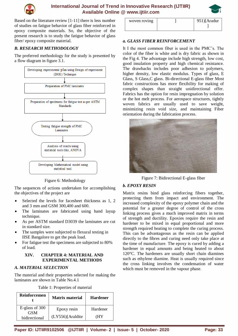
a. GLASS FIBER REINFORCEMENT
It I the most common fiber is used in the PMC’s. The
color of the fiber is white and is dry fabric as shown in
the Fig 4. The advantage include high strength, low cost, good insulation property and high chemical resistance.
The drawbacks includes poor adhesion to polymers,
higher density, low elastic modulus. Types of glass, E
Glass, S Glass,C glass. Bi-directional E-glass fiber Most fabric constructions has more flexibility for making of
complex shapes than straight unidirectional offer.
Fabrics has the option for resin impregnation by solution or the hot melt process. For aerospace structures, tightly
woven fabrics are usually used to save weight,
minimizing resin void size, and maintaining Fiber
orientation during the fabrication process.
Figure 7: Bidirectional E-glass fiber
b. EPOXY RESIN
Matrix resins bind glass reinforcing fibers together, protecting them from impact and environment. The
increased complexity of the epoxy polymer chain and the
potential for a greater degree of control of the cross
linking process gives a much improved matrix in terms of strength and ductility. Epoxies require the resin and
hardener to be mixed in equal proportional and more
strength required heating to complete the curing process. This can be advantageous as the resin can be applied
directly to the fibres and curing need only take place at
the time of manufacture. The epoxy is cured by adding a hardener in equal amounts and being heated to about
120°C. The hardeners are usually short chain diamines
such as ethylene diamine. Heat is usually required since
the cross linking involves the condensation of water which must be removed in the vapour phase.
International Journal of Trend in Innovative Research (IJTIIR)
Available Online @ www.ijtiir.com
Paper ID: IJTIIR9102506 @IJTIIR | Volume- 2 | Issue- 5 | October- 2020 Page: 34
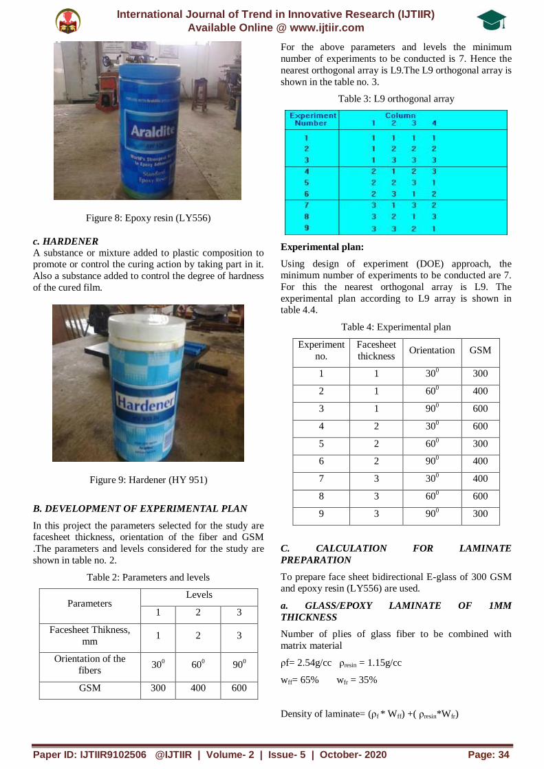
Figure 8: Epoxy resin (LY556)
c. HARDENER
A substance or mixture added to plastic composition to promote or control the curing action by taking part in it.
Also a substance added to control the degree of hardness
of the cured film.
Figure 9: Hardener (HY 951)
B. DEVELOPMENT OF EXPERIMENTAL PLAN
In this project the parameters selected for the study are facesheet thickness, orientation of the fiber and GSM
.The parameters and levels considered for the study are
shown in table no. 2.
Table 2: Parameters and levels
Parameters Levels
1 2 3
Facesheet Thikness,
mm 1 2 3
Orientation of the
fibers 30
0 60
0 90
0
GSM 300 400 600
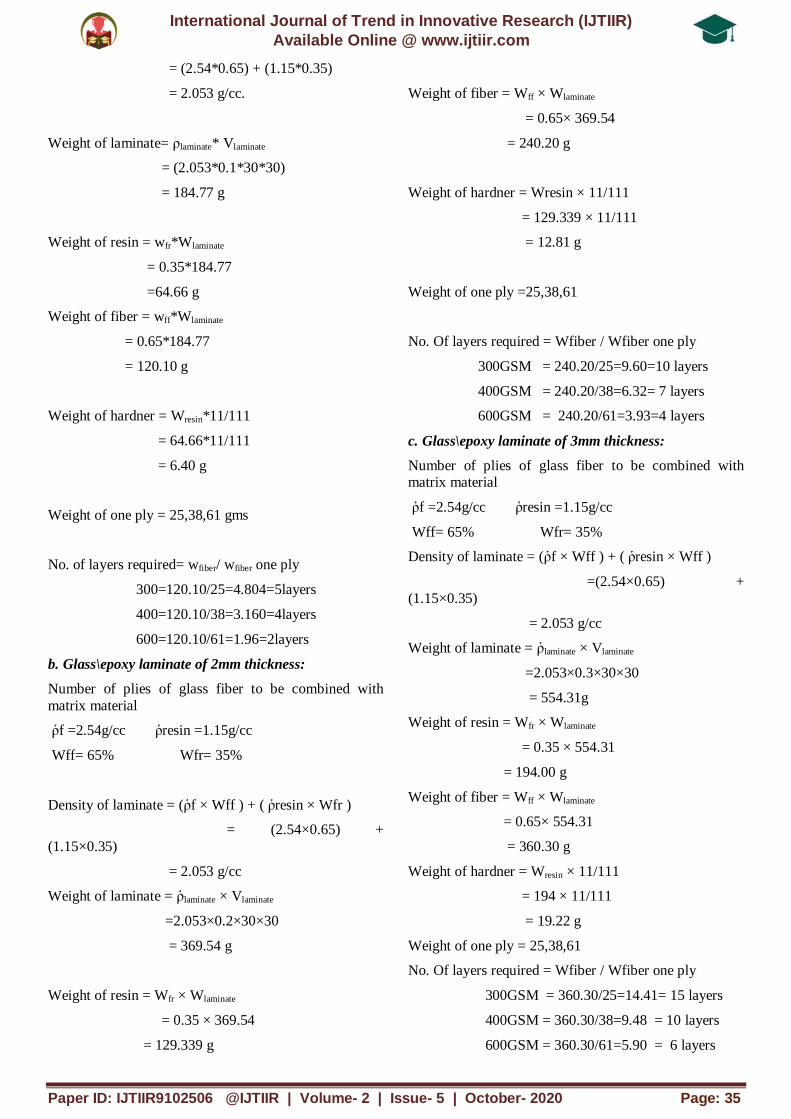
For the above parameters and levels the minimum
number of experiments to be conducted is 7. Hence the
nearest orthogonal array is L9.The L9 orthogonal array is
shown in the table no. 3.
Table 3: L9 orthogonal array
Experimental plan:
Using design of experiment (DOE) approach, the minimum number of experiments to be conducted are 7.
For this the nearest orthogonal array is L9. The
experimental plan according to L9 array is shown in table 4.4.
Table 4: Experimental plan
Experiment
no.
Facesheet
thickness Orientation GSM
1 1 300 300
2 1 600 400
3 1 900 600
4 2 300 600
5 2 600 300
6 2 900 400
7 3 300 400
8 3 600 600
9 3 900 300
C. CALCULATION FOR LAMINATE
PREPARATION
To prepare face sheet bidirectional E-glass of 300 GSM and epoxy resin (LY556) are used.
a. GLASS/EPOXY LAMINATE OF 1MM
THICKNESS
Number of plies of glass fiber to be combined with
matrix material
ρf= 2.54g/cc ρresin = 1.15g/cc
wff= 65% wfr = 35%
Density of laminate= (ρf * Wff) +( ρresin*Wfr)
International Journal of Trend in Innovative Research (IJTIIR)
Available Online @ www.ijtiir.com
Paper ID: IJTIIR9102506 @IJTIIR | Volume- 2 | Issue- 5 | October- 2020 Page: 35
= (2.54*0.65) + (1.15*0.35)
= 2.053 g/cc.
Weight of laminate= ρlaminate* Vlaminate
= (2.053*0.1*30*30)
= 184.77 g
Weight of resin = wfr*Wlaminate
= 0.35*184.77
=64.66 g
Weight of fiber = wff*Wlaminate
= 0.65*184.77
= 120.10 g
Weight of hardner = Wresin*11/111
= 64.66*11/111
= 6.40 g
Weight of one ply = 25,38,61 gms
No. of layers required= wfiber/ wfiber one ply
300=120.10/25=4.804=5layers
400=120.10/38=3.160=4layers
600=120.10/61=1.96=2layers
b. Glass\epoxy laminate of 2mm thickness:
Number of plies of glass fiber to be combined with
matrix material
ῥf =2.54g/cc ῥresin =1.15g/cc
Wff= 65% Wfr= 35%
Density of laminate = (ῥf × Wff ) + ( ῥresin × Wfr )
= (2.54×0.65) +
(1.15×0.35)
= 2.053 g/cc
Weight of laminate = ῥlaminate × Vlaminate
=2.053×0.2×30×30
= 369.54 g
Weight of resin = Wfr × Wlaminate
= 0.35 × 369.54
= 129.339 g
Weight of fiber = Wff × Wlaminate
= 0.65× 369.54
= 240.20 g
Weight of hardner = Wresin × 11/111
= 129.339 × 11/111
= 12.81 g
Weight of one ply =25,38,61
No. Of layers required = Wfiber / Wfiber one ply
300GSM = 240.20/25=9.60=10 layers
400GSM = 240.20/38=6.32= 7 layers
600GSM = 240.20/61=3.93=4 layers
c. Glass\epoxy laminate of 3mm thickness:
Number of plies of glass fiber to be combined with matrix material
ῥf =2.54g/cc ῥresin =1.15g/cc
Wff= 65% Wfr= 35%
Density of laminate = (ῥf × Wff ) + ( ῥresin × Wff )
=(2.54×0.65) +
(1.15×0.35)
= 2.053 g/cc
Weight of laminate = ῥlaminate × Vlaminate
=2.053×0.3×30×30
= 554.31g
Weight of resin = Wfr × Wlaminate
= 0.35 × 554.31
= 194.00 g
Weight of fiber = Wff × Wlaminate
= 0.65× 554.31
= 360.30 g
Weight of hardner = Wresin × 11/111
= 194 × 11/111
= 19.22 g
Weight of one ply = 25,38,61
No. Of layers required = Wfiber / Wfiber one ply
300GSM = 360.30/25=14.41= 15 layers
400GSM = 360.30/38=9.48 = 10 layers
600GSM = 360.30/61=5.90 = 6 layers
International Journal of Trend in Innovative Research (IJTIIR)
Available Online @ www.ijtiir.com
Paper ID: IJTIIR9102506 @IJTIIR | Volume- 2 | Issue- 5 | October- 2020 Page: 36
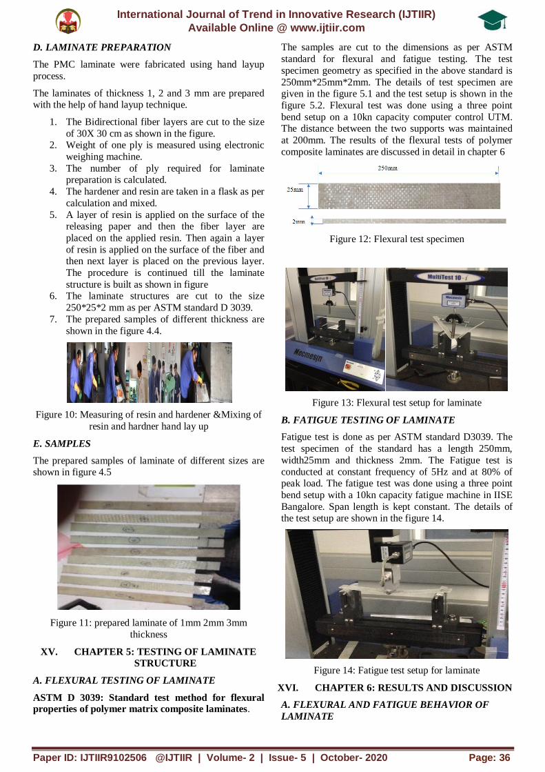
D. LAMINATE PREPARATION
The PMC laminate were fabricated using hand layup
process.
The laminates of thickness 1, 2 and 3 mm are prepared with the help of hand layup technique.
1. The Bidirectional fiber layers are cut to the size
of 30X 30 cm as shown in the figure. 2. Weight of one ply is measured using electronic
weighing machine.
3. The number of ply required for laminate preparation is calculated.
4. The hardener and resin are taken in a flask as per
calculation and mixed.
5. A layer of resin is applied on the surface of the releasing paper and then the fiber layer are
placed on the applied resin. Then again a layer
of resin is applied on the surface of the fiber and then next layer is placed on the previous layer.
The procedure is continued till the laminate
structure is built as shown in figure 6. The laminate structures are cut to the size
250*25*2 mm as per ASTM standard D 3039.
7. The prepared samples of different thickness are
shown in the figure 4.4.
Figure 10: Measuring of resin and hardener &Mixing of
resin and hardner hand lay up
E. SAMPLES
The prepared samples of laminate of different sizes are shown in figure 4.5
Figure 11: prepared laminate of 1mm 2mm 3mm
thickness
XV. CHAPTER 5: TESTING OF LAMINATE
STRUCTURE
A. FLEXURAL TESTING OF LAMINATE
ASTM D 3039: Standard test method for flexural properties of polymer matrix composite laminates.
The samples are cut to the dimensions as per ASTM
standard for flexural and fatigue testing. The test
specimen geometry as specified in the above standard is
250mm*25mm*2mm. The details of test specimen are given in the figure 5.1 and the test setup is shown in the
figure 5.2. Flexural test was done using a three point
bend setup on a 10kn capacity computer control UTM. The distance between the two supports was maintained
at 200mm. The results of the flexural tests of polymer
composite laminates are discussed in detail in chapter 6
Figure 12: Flexural test specimen
Figure 13: Flexural test setup for laminate
B. FATIGUE TESTING OF LAMINATE
Fatigue test is done as per ASTM standard D3039. The
test specimen of the standard has a length 250mm,
width25mm and thickness 2mm. The Fatigue test is
conducted at constant frequency of 5Hz and at 80% of peak load. The fatigue test was done using a three point
bend setup with a 10kn capacity fatigue machine in IISE
Bangalore. Span length is kept constant. The details of the test setup are shown in the figure 14.
Figure 14: Fatigue test setup for laminate
XVI. CHAPTER 6: RESULTS AND DISCUSSION
A. FLEXURAL AND FATIGUE BEHAVIOR OF
LAMINATE
International Journal of Trend in Innovative Research (IJTIIR)
Available Online @ www.ijtiir.com
Paper ID: IJTIIR9102506 @IJTIIR | Volume- 2 | Issue- 5 | October- 2020 Page: 37
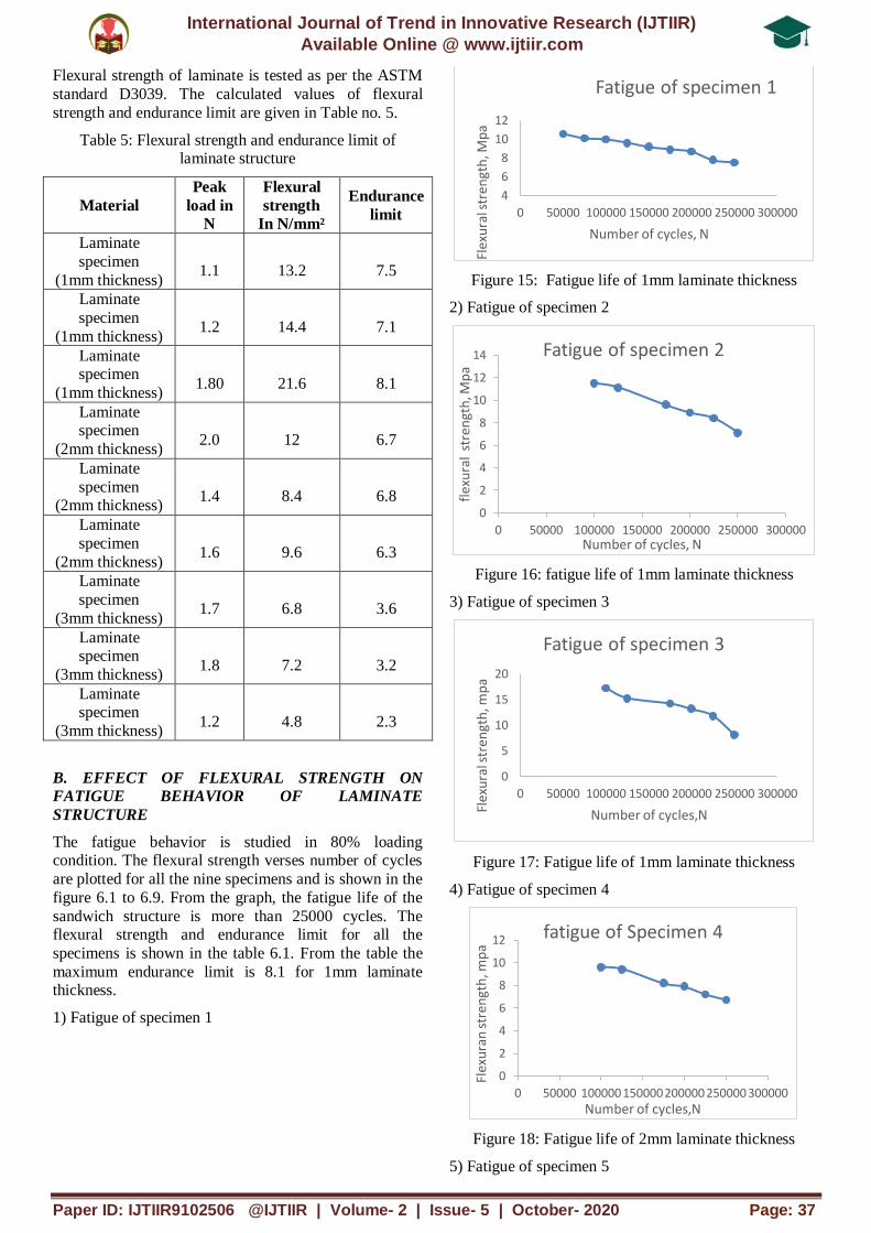
Flexural strength of laminate is tested as per the ASTM
standard D3039. The calculated values of flexural
strength and endurance limit are given in Table no. 5.
Table 5: Flexural strength and endurance limit of laminate structure
Material
Peak
load in
N
Flexural
strength
In N/mm²
Endurance
limit
Laminate
specimen
(1mm thickness)
1.1
13.2
7.5
Laminate
specimen
(1mm thickness)
1.2
14.4
7.1
Laminate specimen
(1mm thickness)
1.80
21.6
8.1
Laminate specimen
(2mm thickness)
2.0
12
6.7
Laminate
specimen (2mm thickness)
1.4
8.4
6.8
Laminate
specimen
(2mm thickness)
1.6
9.6
6.3
Laminate
specimen
(3mm thickness)
1.7
6.8
3.6
Laminate specimen
(3mm thickness)
1.8
7.2
3.2
Laminate specimen
(3mm thickness)
1.2
4.8
2.3
B. EFFECT OF FLEXURAL STRENGTH ON
FATIGUE BEHAVIOR OF LAMINATE
STRUCTURE
The fatigue behavior is studied in 80% loading condition. The flexural strength verses number of cycles
are plotted for all the nine specimens and is shown in the
figure 6.1 to 6.9. From the graph, the fatigue life of the
sandwich structure is more than 25000 cycles. The flexural strength and endurance limit for all the
specimens is shown in the table 6.1. From the table the
maximum endurance limit is 8.1 for 1mm laminate thickness.
1) Fatigue of specimen 1
Figure 15: Fatigue life of 1mm laminate thickness
2) Fatigue of specimen 2
Figure 16: fatigue life of 1mm laminate thickness
3) Fatigue of specimen 3
Figure 17: Fatigue life of 1mm laminate thickness
4) Fatigue of specimen 4
Figure 18: Fatigue life of 2mm laminate thickness
5) Fatigue of specimen 5
4
6
8
10
12
0 50000 100000 150000 200000 250000 300000
Flex
ura
l str
engt
h, M
pa
Number of cycles, N
Fatigue of specimen 1
0
2
4
6
8
10
12
14
0 50000 100000 150000 200000 250000 300000
flex
ura
l st
ren
gth
, Mp
a
Number of cycles, N
Fatigue of specimen 2
0
5
10
15
20
0 50000 100000 150000 200000 250000 300000
Flex
ura
l str
engt
h, m
pa
Number of cycles,N
Fatigue of specimen 3
0
2
4
6
8
10
12
0 50000 100000 150000 200000 250000 300000
Flex
ura
n s
tren
gth
, mp
a
Number of cycles,N
fatigue of Specimen 4

International Journal of Trend in Innovative Research (IJTIIR)
Available Online @ www.ijtiir.com
Paper ID: IJTIIR9102506 @IJTIIR | Volume- 2 | Issue- 5 | October- 2020 Page: 38
Figure 19: Fatigue life of 2mm laminate thickness
6) Fatigue of specimen 6
Figure 20: Fatigue life of 2mm laminate thickness
7) Fatigue of specimen 7
Figure 21: Fatigue life of 3mm laminate thickness
8) Fatigue of specimen 8
Figure 22: Fatigue life of 3mm laminate thickness
9) Fatigue of specimen 9
Figure 23: Fatigue life of 3mm laminate thickness
C. ANOVA FOR ENDURANCE LIMIT
The analysis of variance is performed for the endurance
limit of all the laminate structures to find the most
significant material parameter which corresponds to the
fatigue life. The results of ANOVA are shown in table 6.2 and response plots in figure 6.10. From the results of
ANOVA it is found that the most significant parameter
for endurance limit is laminate thickness contributing 96.02 % followed by fiber orientation of 0.58 % and
GSM of 2.75%. The Table No.6.2 shows the results of
ANOVA for endurance limit.
Table 6: ANOVA tabe for endurance limit
S.No Parameters DOF SS Factor MS Factor F % Influence
1 Laminate thickness 2 34.206667 17.103333 148.00962 96.020211
2 Fiber orientation 2 0.2066667 0.1033333 0.8942308 0.580126
3 GSM 2 0.98 0.49 4.2403846 2.7509201
4 Error 3 0.3466667 0.1155556 1 0.6487431
5 Total 9 35.74 154.14423 100
0
2
4
6
8
10
0 50000 100000 150000 200000 250000 300000
Flex
ura
l str
engt
h, m
pa
Number of cycles,N
Fatigue of specimen 5
0
2
4
6
8
0 50000 100000 150000 200000 250000 300000 Flex
ura
l str
engt
h ,m
pa
Number of cycles,N
Fatigue of specimen 6
0
2
4
6
0 50000 100000 150000 200000 250000 300000
Flex
ura
l str
engt
h ,m
pa
Number of cycles,N
Fatigue of specimen 7
0
1
2
3
4
5
6
0 50000 100000 150000 200000 250000 300000
Flex
ura
l str
engt
h,m
pa
Number of cycles,N
fatigue of specimen 8
0
1
2
3
4
0 50000 100000 150000 200000 250000 300000
Flex
ura
l str
engt
h,m
pa
Number of cycles,N
Fatigue of specimen 9

International Journal of Trend in Innovative Research (IJTIIR)
Available Online @ www.ijtiir.com
Paper ID: IJTIIR9102506 @IJTIIR | Volume- 2 | Issue- 5 | October- 2020 Page: 39
Figure 24: Response plots
CHAPTER 7: CONCLUSION AND FUTURE
SCOPE OF WORK
A. CONCLUSION
Now a days carbon fiber and glass fiber reinforced
composites are being increasingly used in different fields of engineering by replacing conventional materials.
Advantages of these composite materials over
conventional materials include higher stiffness, higher strength, better fatigue behavior, corrosion resistance,
and tailored properties. Conversely, delamination,
discontinuous stress, reparability, and interchangeability
are the disadvantages of polymer composites. Fatigue
behavior of composite materials is different from that of
the metals. Composites are inhomogeneous and
anisotropic as compared to metals which are homogenous in nature and isotropic in behavior. In
fatigue, composite materials undergo a series of changes,
that is, matrix cracking, fiber-matrix debonding, fiber breaking and finally the failure. Thus, matrix, fiber and
interface between fibers and materials play an important
role in deciding the fatigue behavior of a laminate.
The objective of the Research work is to estimate the
fatigue life of the composite laminate by varying the
thickness, One of the most attractive candidates to composite materials is the automotive industry. As
continuous fibrereinforced composites provide good
mechanical properties, they have been increasingly used in many lightweight structures such as structural
automotive parts which were subjected in service to
fatigue loadings. Therefore, a good prediction of fatigue life is required. Hence it can be recommended that the
Glass Fiber Polyester Epoxy laminate is good for
flexural fatigue critical applications such as wind turbine
blades, Air craft wing and auto motive leaf spring constructions.
Acknowledgements
I am Sincerely thankful to Dr.D.Ramesh for being a great mentor and providing precious assistance
throughout this part of PhD research work . I would like
to thank Dr. Mrs. Ravindra Tiwari Dean GIET
Moinabad, providing Excellent Support & Continuous Encouragement. I would like to thank Mr Pavan
Bagali, Assistant Professor of Mechanical Engineering
Department, GIET, Hyderabad. For his valuable support to develop this research work. I would also express by
heartfelt gratitude to Mr. Venkatesh who helped me in
research practical work.
References
[1] S. Helmy, S.V. Hoa, “Tensile fatigue behavior of
tapered glass fiber reinforced epoxy composites
containing nanoclay’’Composite Science and Technology, vol.102, pp 10-19, 2014
[2] Karahan M, Lomov SV, Bogdanovich
AE, Mungalov D, Verpoest I. Internalgeometry evaluation of non-
crimp 3D orthogonal woven carbon fabriccomposite.
Composites: Part A 2010;41:1301–11 [3] P. Coronado “Influence of temperature on a carbon–
fibre epoxy composite subjected to static and fatigue
loading under mode-I delamination” Volume 49,
Issue 21, 15 October 2012, Pages 2934-2940 [4] Andrew Makeev, Interlaminar shear fatigue
behaviour of glass/epoxy and
carbon/epoxy composites, Elsevier, Composites ScienceandTechnology80(2013)93–100
[5] Ermias Gebrekidan Koricho, Giovanni
Belingardi, Alem Tekalign Beyene Bending fatigue
4.5
5
5.5
6
6.5
1 2 3
Levels
GSM S/N Ratio
0 2 4 6 8
1 2 3
Levels
Laminate Thickness S/N
Ratio
5.2
5.4
5.6
5.8
6
1 2 3
Levels
Fiber orientation S/N Ratio
International Journal of Trend in Innovative Research (IJTIIR)
Available Online @ www.ijtiir.com
Paper ID: IJTIIR9102506 @IJTIIR | Volume- 2 | Issue- 5 | October- 2020 Page: 40
behavior of twill fabric glass/epoxy composite
Identifiers journal ISSN: 0263-8223,
[6] A comparative study of fatigue behaviour of
flax/epoxy and glass/epoxy composites S. Liang a,⇑ , P.B. Gning a, L. Guillaumat b aDRIVE–ISAT,
Universite de Bourgogne, 58027 Nevers, Cedex,
France b ENSAM, 49035 Angers, Cedex, France [7] Gennadiy Lvov on 11 July 2017. Strojniški vestnik -
Journal of Mechanical Engineering 58(2012)3, 165-
174. Theoretical and Experimental Study of Fatigue Strength of Plain Woven Glass/Epoxy Composite
[8] Nyan-Hwa Tai & Hui-Chia Yu Effects of low-
energy impact and thermal cycling loadings on
fatigue behavior of the quasi-isotropic carbon/epoxy composites Journal of Polymer
Research volume 5, pages143–151(1998)
[9] Pitchaiah D and Lalithababu K. (2013) “Experimental study of the fatigue strength glass
fibre epoxy and chapstan E- glass epoxy laminates”.
International journal of modern engineering research
Vol.3. [10] PizhongQiaoet al. [11] studied the effect of
stress ratio, frequency and mean stress on fatigue
life of E-glass/polyurethane composites. [11] Fatigue damage modelling of continuous E-glass
fibre/epoxy composite Rim Ben Toumi a,b , Jacques
Renard a , Martine Monin b , Pongsak Nimdum 1877-7058 © 2013 The Authors. Published by
Elsevier Ltd.
[12] Hussain, F., Hojjati, M., Okamoto, M., Gorga,
R.E. (2006). Polymer-matrix nanocomposites, processing, manufacturing, and application: An
overview, Journal of Composite Materials, Vol. 40,
No. 17, 1511-1575.
[13] Ali Movaghghar* – Gennady Ivanovich Lvov
Theoretical and Experimental Study of Fatigue
Strength of Plain Woven Glass/Epoxy Composite
Strojniški vestnik - Journal of Mechanical Engineering 58(2012)3, 175-182 Paper received:
2011-07-12, paper accepted: 2012-01-27
DOI:10.5545/sv-jme.2011.135 © 2012 Journal of Mechanical Engineering.
[14] D. Pitchaiah1 , K. Lalithababu2 , Ch. Ramesh
Babu3 “Experimental Study of the Fatigue Strength of Glass fiber epoxy and Chapstan E-Glass epoxy
laminates” International Journal of Modern
Engineering Research (IJMER).Vol. 3, Issue. 5, Sep
- Oct. 2013 pp-2702-2712 ISSN: 2249-6645 [15] Jagannath Pattar1 and Vundi Saichandra2”
Design and Analysis (Static Strain and Static Stress
Analysis) of Piston Using AL 2014 and Reinforcement as Limonite Powder 1st
International Conference on Recent Trends in
Engineering, Materials, Management and Sciences (ICRTEMMS-2018), SBIT, Khammam, India 25-27
Oct. 2018 ISBN No:978-93-5321-384-8
[16] Vundi Saichandra and Jagannath Pattar” Wear
And Fatigue Behaviour Of Limonite As Reinforcing On Element On Properties Al2014 Based Mmc 1st
International Conference on Recent Trends in
Engineering, Materials, Management and Sciences (ICRTEMMS-2018), SBIT, Khammam, India 25-27
Oct. 2018 ISBN No:978-93-5321-384-8
[17] Jagannath Pattar1, Vundi Saichandra2” Study
on Behavior of Ilmenite as Reinforcing Element on Properties of Al2014 Based MMC by Stir Casting
Method International Journal of Research in
Advent Technology, E-ISSN: 2321-9637
Top Related
Copyright © 2022 FDOKUMEN

