


Bahasa
Halaman
Hukum

Design Guidelines for Regional San Projects
Sacramento Regional County Sanitation District
Version 1.0
October 2020
Design Guidelines for Regional San Projects
Sacramento Regional County Sanitation District i Y:\00_Program Management (CPMO)\F. Standards\Design Guidelines - in progress\Draft Design Guidelines V1_20201020_FINAL.docx October 20, 2020
Contents
1.0 Introduction ........................................................................................................................................ 1-1 1.1 Purpose ........................................................................................................................................................... 1-1 1.2 Relationship with other Design Standards ...................................................................................................... 1-1 1.3 Organization ................................................................................................................................................... 1-2 1.4 Designer-Proposed Changes ........................................................................................................................... 1-2
2.0 General Design Requirements .......................................................................................................... 2-1 2.1 Codes and Standards ....................................................................................................................................... 2-1 2.2 Calculations .................................................................................................................................................... 2-1 2.3 Drawings ......................................................................................................................................................... 2-2
2.3.1 Index Drawings ....................................................................................................................................... 2-3 2.3.2 Symbols and Abbreviations .................................................................................................................... 2-3 2.3.3 Construction Details ................................................................................................................................ 2-3 2.3.4 Drawing numbering ................................................................................................................................ 2-3
2.4 Word Processing Requirements ...................................................................................................................... 2-4 2.5 Specifications .................................................................................................................................................. 2-4 2.6 Testability of Systems ..................................................................................................................................... 2-4 2.7 Equipment Numbering and Coding System .................................................................................................... 2-4
2.7.1 Mechanical Equipment ............................................................................................................................ 2-5 2.7.2 Electrical Equipment ............................................................................................................................... 2-7 2.7.3 Instrument Equipment ............................................................................................................................. 2-7 2.7.4 Manual Valves ........................................................................................................................................ 2-7 2.7.5 Manholes ................................................................................................................................................. 2-7 2.7.6 Slide Gates, Control Units, and Utility Stations ...................................................................................... 2-7 2.7.7 Doors and Rooms .................................................................................................................................... 2-7 2.7.8 Pipelines outside of the Plant Property .................................................................................................... 2-8
2.8 Special Area Classifications ........................................................................................................................... 2-8
3.0 Civil Design ......................................................................................................................................... 3-1 3.1 Codes and Standards ....................................................................................................................................... 3-1 3.2 Surveying ........................................................................................................................................................ 3-1 3.3 Existing Utility Coordination .......................................................................................................................... 3-1 3.4 Roadways within Regional San Property........................................................................................................ 3-1
3.4.1 Process Area Roadways .......................................................................................................................... 3-2 3.4.2 Main Ingress/Egress Roadways .............................................................................................................. 3-2
3.5 Roadways beyond Regional San Property ...................................................................................................... 3-2 3.5.1 Civil Requirements.................................................................................................................................. 3-2 3.5.2 Traffic Control ........................................................................................................................................ 3-2
3.6 Curbing ........................................................................................................................................................... 3-3 3.6.1 Type 1 Curb and Gutter ........................................................................................................................... 3-3 3.6.2 Type 2 Curb and Gutter ........................................................................................................................... 3-4 3.6.3 Type 3, 4, or 5 Curb ................................................................................................................................ 3-4
3.7 Cross Gutter .................................................................................................................................................... 3-4 3.8 Sidewalks and Walkways ............................................................................................................................... 3-4 3.9 Parking ............................................................................................................................................................ 3-4 3.10 Slope Protection ............................................................................................................................................ 3-5 3.11 Landscaping .................................................................................................................................................. 3-5 3.12 Storm Drainage ............................................................................................................................................. 3-5 3.13 Potable and Non-Potable Water Supply Systems ......................................................................................... 3-5 3.14 General Site Piping Design Criteria .............................................................................................................. 3-6
4.0 Architectural Design .......................................................................................................................... 4-1 4.1 Codes and Standards ....................................................................................................................................... 4-1 4.2 Architectural Code Analysis ........................................................................................................................... 4-2
Design Guidelines for Regional San Projects
Sacramento Regional County Sanitation District ii Y:\00_Program Management (CPMO)\F. Standards\Design Guidelines - in progress\Draft Design Guidelines V1_20201020_FINAL.docx October 20, 2020
4.3 Accessibility Requirements ............................................................................................................................ 4-3 4.4 General Materials Guide ................................................................................................................................. 4-3
4.4.1 Concrete .................................................................................................................................................. 4-3 4.4.2 Masonry .................................................................................................................................................. 4-4 4.4.3 Metal ....................................................................................................................................................... 4-5 4.4.4 Wood ....................................................................................................................................................... 4-6 4.4.5 Plastic ...................................................................................................................................................... 4-6
4.5 Thermal and Moisture Protection ................................................................................................................... 4-7 4.5.1 Vapor Barrier .......................................................................................................................................... 4-7 4.5.2 Sealants and Waterproofing .................................................................................................................... 4-8 4.5.3 General Roof and Parapet Requirements ................................................................................................ 4-8 4.5.4 Roof-Mounted Equipment and Solar Panels ........................................................................................... 4-9 4.5.5 Flat Roofs ................................................................................................................................................ 4-9 4.5.6 Built-Up Roof ....................................................................................................................................... 4-10 4.5.7 Single-Ply Roof Membrane. .................................................................................................................. 4-10 4.5.8 Shingles ................................................................................................................................................. 4-10 4.5.9 Clay Tile Roof (Limited Application) ................................................................................................... 4-11 4.5.10 Concrete Tile Roof (Limited Application) .......................................................................................... 4-11 4.5.11 Standing Seam Metal Roof ................................................................................................................. 4-12 4.5.12 Metal Siding ........................................................................................................................................ 4-12 4.5.13 Canopies .............................................................................................................................................. 4-12
4.6 Windows, Louvers, and Doors...................................................................................................................... 4-12 4.6.1 Windows and Louvers ........................................................................................................................... 4-12 4.6.2 Doors ..................................................................................................................................................... 4-13 4.6.3 Hardware ............................................................................................................................................... 4-15
4.7 Finishes ......................................................................................................................................................... 4-16 4.8 Specialties ..................................................................................................................................................... 4-18 4.9 Special Construction ..................................................................................................................................... 4-19
4.9.1 Pre-Engineered Metal Buildings ........................................................................................................... 4-19 4.9.2 Elevators................................................................................................................................................ 4-19 4.9.3 Monorails and Cranes ........................................................................................................................... 4-19
4.10 Personal Protection Gear ............................................................................................................................ 4-19 4.11 Maintenance Access ................................................................................................................................... 4-20 4.12 Sound Control ............................................................................................................................................. 4-21 4.13 Multiple Conduits ....................................................................................................................................... 4-21 4.14 Floors .......................................................................................................................................................... 4-21 4.15 Fall Protection ............................................................................................................................................. 4-21 4.16 Roof Access ................................................................................................................................................ 4-22 4.17 Railing ........................................................................................................................................................ 4-22 4.18 Plumbing Fixtures ....................................................................................................................................... 4-23 4.19 Emergency Lighting ................................................................................................................................... 4-23 4.20 Vehicle/Bicycle Parking ............................................................................................................................. 4-23
5.0 Structural Design ............................................................................................................................... 5-1 5.1 Codes and Standards ....................................................................................................................................... 5-1 5.2 General Service Loads .................................................................................................................................... 5-2
5.2.1 Dead Loads ............................................................................................................................................. 5-2 5.2.2 Crane and Monorail Loads: ..................................................................................................................... 5-2 5.2.3 Heavy Equipment Loads ......................................................................................................................... 5-3 5.2.4 Differential Settlement Loads ................................................................................................................. 5-3 5.2.5 Mechanical Vibration Control ................................................................................................................. 5-3
5.3 Seismic Loads ................................................................................................................................................. 5-3 5.4 Wind Loads ..................................................................................................................................................... 5-3 5.5 Soil Information .............................................................................................................................................. 5-4 5.6 Liquid Loads ................................................................................................................................................... 5-5 5.7 Load Combinations ......................................................................................................................................... 5-5
Design Guidelines for Regional San Projects
Sacramento Regional County Sanitation District iii Y:\00_Program Management (CPMO)\F. Standards\Design Guidelines - in progress\Draft Design Guidelines V1_20201020_FINAL.docx October 20, 2020
5.8 Structural Systems .......................................................................................................................................... 5-5 5.9 Materials – General ......................................................................................................................................... 5-5
5.9.1 Concrete .................................................................................................................................................. 5-5 5.9.2 Masonry .................................................................................................................................................. 5-6 5.9.3 Structural Steel ........................................................................................................................................ 5-6 5.9.4 Stainless Steel ......................................................................................................................................... 5-7 5.9.5 Aluminum ............................................................................................................................................... 5-7 5.9.6 Fiberglass Reinforced Plastic .................................................................................................................. 5-7 5.9.7 Wood ....................................................................................................................................................... 5-8 5.9.8 Metal Framing (Strut Type) Inserts ......................................................................................................... 5-8 5.9.9 Seismic Bracing ...................................................................................................................................... 5-8
5.10 Design Loads on Drawings ........................................................................................................................... 5-8 5.11 Serviceability ................................................................................................................................................ 5-8 5.12 Special Inspection ......................................................................................................................................... 5-9 5.13 Electrical Transformer Structure Design ...................................................................................................... 5-9
6.0 Mechanical Process Design ............................................................................................................... 6-1 6.1 Codes and Standards ....................................................................................................................................... 6-1 6.2 Mechanical Design Intent ............................................................................................................................... 6-1 6.3 Mechanical Design Calculations ..................................................................................................................... 6-1 6.4 Mechanical Equipment ................................................................................................................................... 6-2
6.4.1 Equipment Clearance and Removal ........................................................................................................ 6-2 6.4.2 Steam Equipment .................................................................................................................................... 6-2 6.4.3 Gauges ..................................................................................................................................................... 6-2 6.4.4 Recommended Equipment Types:........................................................................................................... 6-3
6.5 Hydraulics ....................................................................................................................................................... 6-4 6.5.1 Design Flow ............................................................................................................................................ 6-4 6.5.2 Design of Pressure Piping ....................................................................................................................... 6-4 6.5.3 Pipeline Features and Appurtenances...................................................................................................... 6-7
6.6 Pump Selection Criteria .................................................................................................................................. 6-7 6.7 Wet Well Sizing Criteria for Start/Stop Pumping ........................................................................................... 6-9 6.8 Process Piping ................................................................................................................................................. 6-9
6.8.1 Air Piping .............................................................................................................................................. 6-10 6.8.2 Flow Measuring .................................................................................................................................... 6-10 6.8.3 Flow Measuring Elements ..................................................................................................................... 6-11 6.8.4 Piping for Magnetic Flowmeters ........................................................................................................... 6-11 6.8.5 Piping for Non-Magnetic Flowmeters ................................................................................................... 6-13
6.9 Equipment Anchorages ................................................................................................................................. 6-13 6.10 Pipe Supports and Racks ............................................................................................................................. 6-13 6.11 Process and Instrumentation Diagrams ....................................................................................................... 6-13
6.11.1 Drawing Preparation ........................................................................................................................... 6-14 6.11.2 Revision Documentation ..................................................................................................................... 6-14 6.11.3 Existing Components .......................................................................................................................... 6-14
6.12 Process and Piping Schematics ................................................................................................................... 6-14 6.13 Vibration Design Requirements .................................................................................................................. 6-14 6.14 Sound Control ............................................................................................................................................. 6-15 6.15 Equipment Criticality .................................................................................................................................. 6-16 6.16 Conveyance Channels ................................................................................................................................. 6-16
6.16.1 Channel Slide Gates Storage Pits and Access ..................................................................................... 6-16 6.16.2 Steel Materials within the Channel ..................................................................................................... 6-16 6.16.3 Channel Mixing with Shear Diffusers ................................................................................................. 6-16 6.16.4 Channel WRL Washdown Utility Station ........................................................................................... 6-16 6.16.5 Channel Safety for Employee Entry .................................................................................................... 6-16
6.17 Chemical Delivery, Handling, and Storage ................................................................................................ 6-17 6.18 Blow-Offs for Utility and Process Piping ................................................................................................... 6-18 6.19 Motor Sizing ............................................................................................................................................... 6-18
Design Guidelines for Regional San Projects
Sacramento Regional County Sanitation District iv Y:\00_Program Management (CPMO)\F. Standards\Design Guidelines - in progress\Draft Design Guidelines V1_20201020_FINAL.docx October 20, 2020
7.0 Heating, Ventilation, and Air Conditioning Design ........................................................................ 7-1 7.1 Codes and Standards ....................................................................................................................................... 7-1 7.2 Definitions ...................................................................................................................................................... 7-1 7.3 General ............................................................................................................................................................ 7-2 7.4 Outside Design Conditions ............................................................................................................................. 7-2 7.5 Inside Design Conditions ................................................................................................................................ 7-2 7.6 Ventilation Rates ............................................................................................................................................ 7-3 7.7 HVAC Design Intent ...................................................................................................................................... 7-3 7.8 HVAC Design Submittals ............................................................................................................................... 7-3 7.9 HVAC Equipment .......................................................................................................................................... 7-4 7.10 Heating Systems ........................................................................................................................................... 7-6 7.11 Cooling Systems ........................................................................................................................................... 7-6 7.12 Equipment Locations .................................................................................................................................... 7-7 7.13 Configuration ................................................................................................................................................ 7-7 7.14 Special HVAC and Fire Extinguishing Requirements for Switchgear and Motor Control Center
Rooms ................................................................................................................................................................... 7-8 7.15 Fans ............................................................................................................................................................... 7-8
7.15.1 Centrifugal Utility Fans ......................................................................................................................... 7-8 7.15.2 Propeller Wall Fans ............................................................................................................................... 7-8 7.15.3 Roof Exhaust Fans ................................................................................................................................ 7-9 7.15.4 In-Line Fans .......................................................................................................................................... 7-9 7.15.5 Cabinet Fans and Ceiling Fans .............................................................................................................. 7-9
7.16 Air Handling Units........................................................................................................................................ 7-9 7.17 Air Filtration Equipment ............................................................................................................................... 7-9 7.18 Ductwork .................................................................................................................................................... 7-10
7.18.1 General ................................................................................................................................................ 7-10 7.18.2 Duct Sizing and Velocity Ranges ........................................................................................................ 7-10 7.18.3 Insulation ............................................................................................................................................. 7-11 7.18.4 Duct Dimension and Design ............................................................................................................... 7-11 7.18.5 Duct Accessories ................................................................................................................................. 7-11 7.18.6 Grills, Registers, and Diffusers ........................................................................................................... 7-11 7.18.7 Drum Louvers and Ball Turret Louvers .............................................................................................. 7-11
7.19 Louvers ....................................................................................................................................................... 7-12 7.20 Control Dampers ......................................................................................................................................... 7-12 7.21 HVAC Controls .......................................................................................................................................... 7-12
7.21.1 Standardized Equipment ..................................................................................................................... 7-13 7.22 Motor Sizing ............................................................................................................................................... 7-13
8.0 Plumbing Design ................................................................................................................................ 8-1 8.1 Codes and Standards ....................................................................................................................................... 8-1 8.2 Floor Drains .................................................................................................................................................... 8-1 8.3 Plumbing Design Intent .................................................................................................................................. 8-2 8.4 Plumbing Design Submittals .......................................................................................................................... 8-2 8.5 Plumbing Piping ............................................................................................................................................. 8-2 8.6 Plumbing Equipment ...................................................................................................................................... 8-2 8.7 Plumbing Fixtures ........................................................................................................................................... 8-2
8.7.1 Lavatories ................................................................................................................................................ 8-2 8.7.2 Service Sinks ........................................................................................................................................... 8-2 8.7.3 Water Closets .......................................................................................................................................... 8-2 8.7.4 Urinals ..................................................................................................................................................... 8-3
9.0 Electrical Design ................................................................................................................................. 9-1 9.1 General ............................................................................................................................................................ 9-1 9.2 Codes & Standards ......................................................................................................................................... 9-1 9.3 Electrical Design Calculations and Studies .................................................................................................... 9-1 9.4 Power Distribution System ............................................................................................................................. 9-1
9.4.1 Type ........................................................................................................................................................ 9-1
Design Guidelines for Regional San Projects
Sacramento Regional County Sanitation District v Y:\00_Program Management (CPMO)\F. Standards\Design Guidelines - in progress\Draft Design Guidelines V1_20201020_FINAL.docx October 20, 2020
9.4.2 Primary Substation Arrangement (69kV/12.47kV) ................................................................................. 9-2 9.4.3 480V Secondary Substation Arrangement .............................................................................................. 9-2 9.4.4 12kV (4kV) Secondary Substation Arrangement .................................................................................... 9-2 9.4.5 Liquid Filled Transformers ..................................................................................................................... 9-2 9.4.6 12.47kV Distribution System .................................................................................................................. 9-3 9.4.7 Instrument Power .................................................................................................................................... 9-3 9.4.8 Uninterruptable Power Supply (UPS) ..................................................................................................... 9-3 9.4.9 Standardized Equipment ......................................................................................................................... 9-3
9.5 Power Quality Monitoring System ................................................................................................................. 9-3 9.6 Conductor Sizing ............................................................................................................................................ 9-3 9.7 Motor Sizing ................................................................................................................................................... 9-3 9.8 Electrical Rooms ............................................................................................................................................. 9-4
9.8.1 Arrangement ............................................................................................................................................ 9-4 9.8.2 Layout ..................................................................................................................................................... 9-4 9.8.3 Fire Protection System ............................................................................................................................ 9-5
9.9 Switchgear ...................................................................................................................................................... 9-5 9.9.1 12.47kV Switchgear ................................................................................................................................ 9-5 9.9.2 4.16kV Switchgear .................................................................................................................................. 9-6 9.9.3 480V Switchgear ..................................................................................................................................... 9-6
9.10 Motor Control Centers (MCCs) .................................................................................................................... 9-7 9.10.1 Arrangement .......................................................................................................................................... 9-7 9.10.2 Interface with Existing .......................................................................................................................... 9-7 9.10.3 480V MCCs .......................................................................................................................................... 9-7 9.10.4 4.16kV MCCs ....................................................................................................................................... 9-8
9.11 Variable Frequency Drive Systems .............................................................................................................. 9-8 9.11.1 Standardized Equipment ....................................................................................................................... 9-9
9.12 Grounding System ........................................................................................................................................ 9-9 9.12.1 Design ................................................................................................................................................... 9-9 9.12.2 Interface with Existing .......................................................................................................................... 9-9
9.13 Lighting System .......................................................................................................................................... 9-10 9.13.1 Design ................................................................................................................................................. 9-10 9.13.2 Luminaries .......................................................................................................................................... 9-11 9.13.3 Interface with Existing ........................................................................................................................ 9-11
9.14 Receptacle System ...................................................................................................................................... 9-11 9.14.1 Convenience Receptacles (120V) ....................................................................................................... 9-11 9.14.2 Power Receptacles .............................................................................................................................. 9-12
9.15 Raceway System ......................................................................................................................................... 9-12 9.15.1 Branch circuits: ................................................................................................................................... 9-12 9.15.2 Equipment and Conduit Identification ................................................................................................ 9-12 9.15.3 Exterior Circuits .................................................................................................................................. 9-12
9.16 Surge Protections ........................................................................................................................................ 9-14 9.16.1 SPD Type ............................................................................................................................................ 9-14 9.16.2 Electrical Requirements ...................................................................................................................... 9-14 9.16.3 Electrical Demolition Work ................................................................................................................ 9-15
9.17 Cable and Raceway Schedules .................................................................................................................... 9-15
10.0 Instrumentation and Control Design ........................................................................................... 10-1 10.1 Codes and Standards ................................................................................................................................... 10-1 10.2 Drawings ..................................................................................................................................................... 10-1 10.3 Specifications .............................................................................................................................................. 10-1
10.3.1 Plant Computer Control System Control Strategies and Programmable Logic Controller
Control Narratives .......................................................................................................................................... 10-2 10.3.2 Instrument and Input/Output Schedules .............................................................................................. 10-3 10.3.3 Cable and Conduit Schedules .............................................................................................................. 10-3 10.3.4 PCCS and PLC Programming Standards ............................................................................................ 10-4
10.4 Plant Computer Control System ................................................................................................................. 10-4

Design Guidelines for Regional San Projects
Sacramento Regional County Sanitation District vi Y:\00_Program Management (CPMO)\F. Standards\Design Guidelines - in progress\Draft Design Guidelines V1_20201020_FINAL.docx October 20, 2020
10.4.1 Existing Area Control Center Configurations ..................................................................................... 10-4 10.4.2 Modifications to Existing ACC Backup Panels .................................................................................. 10-8 10.4.3 Interceptor Pump Station and Facilities Equipment ............................................................................ 10-9
10.5 Area Control Centers and Control System Rooms ................................................................................... 10-10 10.5.1 ACC Networks .................................................................................................................................. 10-10 10.5.2 New ACC Arrangement .................................................................................................................... 10-11
10.6 PCCS Ovation and Area PLC Controllers ................................................................................................ 10-12 10.6.1 Supervisory Controllers..................................................................................................................... 10-14 10.6.2 Area Programmable Logic Controllers ............................................................................................. 10-15 10.6.3 Subsystem Programmable Logic Controllers .................................................................................... 10-16
10.7 PLC I/O Subsystems ................................................................................................................................. 10-16 10.7.1 Electrical Equipment I/O ................................................................................................................... 10-17 10.7.2 Subsystem PLC I/O ........................................................................................................................... 10-17
10.8 Auxiliary Networks................................................................................................................................... 10-17 10.9 Power Quality Monitoring System ........................................................................................................... 10-19
10.9.1 Power Quality Monitoring Devices and Network ............................................................................. 10-19 10.9.2 Power Quality Monitoring Servers and End User Devices ............................................................... 10-19
10.10 Local Controls ........................................................................................................................................ 10-20 10.10.1 Local Controls Furnished under Electrical System ......................................................................... 10-20 10.10.2 Local Subsystem Controls Furnished with Mechanical or Process Equipment .............................. 10-20 10.10.3 Safety Interlocks.............................................................................................................................. 10-21 10.10.4 Noncritical Alarms and Interlocks .................................................................................................. 10-21
10.11 Instrumentation ....................................................................................................................................... 10-21 10.11.1 Standardized Equipment and Instruments ....................................................................................... 10-21 10.11.2 Temperature Measurement .............................................................................................................. 10-22 10.11.3 Pressure Measurement..................................................................................................................... 10-22 10.11.4 Level Measurement ......................................................................................................................... 10-22 10.11.5 Flow Measurement .......................................................................................................................... 10-23
10.12 Electronic Valve Actuators ..................................................................................................................... 10-23 10.13 Instrument Installation ............................................................................................................................ 10-24 10.14 Instrument Cable System ........................................................................................................................ 10-24
10.14.1 Fieldbus ........................................................................................................................................... 10-24 10.14.2 Analog Field Sensors ...................................................................................................................... 10-25
10.15 Instrumentation Grounding ..................................................................................................................... 10-25 10.15.1 Cables .............................................................................................................................................. 10-25 10.15.2 Control Panels ................................................................................................................................. 10-25 10.15.3 Analog Instruments ......................................................................................................................... 10-25 10.15.4 Fieldbus Instruments ....................................................................................................................... 10-26
10.16 Voice over Internet Protocol Telephone System .................................................................................... 10-26 10.17 Public Address System ........................................................................................................................... 10-26 10.18 Access Control System ........................................................................................................................... 10-27 10.19 Closed-Circuit Television and Digital Video Recording System ........................................................... 10-27 10.20 Fire Detection ......................................................................................................................................... 10-28 10.21 Instrumental and Control Design Documentation ................................................................................... 10-28
10.21.1 Control and Logic Diagrams ........................................................................................................... 10-28 10.21.2 Process and Instrumentation Diagrams ........................................................................................... 10-29
11.0 Corrosion Control Design ............................................................................................................. 11-1 11.1 Material Selection ....................................................................................................................................... 11-1
11.1.1 Corrosion Resistance of Pipeline Materials ........................................................................................ 11-1 11.1.2 Corrosion Resistance of Other Materials for the Wastewater Industry ............................................... 11-4
11.2 Protective Coatings and Linings ................................................................................................................. 11-4 11.2.1 Coatings for Metallic Surfaces ............................................................................................................ 11-5 11.2.2 Coatings for Concrete ......................................................................................................................... 11-6 11.2.3 Coating Environments ......................................................................................................................... 11-6 11.2.4 Re-Coating of Existing Structures ....................................................................................................... 11-7

Design Guidelines for Regional San Projects
Sacramento Regional County Sanitation District vii Y:\00_Program Management (CPMO)\F. Standards\Design Guidelines - in progress\Draft Design Guidelines V1_20201020_FINAL.docx October 20, 2020
11.2.5 Coating Inspection .............................................................................................................................. 11-9 11.2.6 Concrete and Inhibitors ....................................................................................................................... 11-9 11.2.7 Concrete Susceptibility ..................................................................................................................... 11-10 11.2.8 Nonportland Cement Inhibitors ......................................................................................................... 11-10
11.3 Cathodic Protection................................................................................................................................... 11-10 11.3.1 Preparation for Cathodic Protection Systems .................................................................................... 11-10 11.3.2 General Guidelines ............................................................................................................................ 11-11 11.3.3 Construction Checkout Testing ......................................................................................................... 11-11
11.4 Location-Specific Guidelines .................................................................................................................... 11-12 11.4.1 Pipe and Structures in Contact with Soil ........................................................................................... 11-12 11.4.2 Primary Sedimentation Tanks ........................................................................................................... 11-14 11.4.3 Secondary Sedimentation Tanks ....................................................................................................... 11-15 11.4.4 Aeration Basins ................................................................................................................................. 11-15 11.4.5 Lift Gates........................................................................................................................................... 11-15 11.4.6 Electrical Enclosures ......................................................................................................................... 11-16
12.0 Regulatory Requirements.............................................................................................................. 12-1 12.1 Environmental Impact Review ................................................................................................................... 12-1 12.2 National Pollutant Discharge Elimination System (NPDES) Permit .......................................................... 12-2 12.3 Biosolids and Solids Storage and Disposal Permit ..................................................................................... 12-3 12.4 Water Reclamation Permit .......................................................................................................................... 12-3 12.5 Fire and Life Safety .................................................................................................................................... 12-3 12.6 Risk Management, Process Safety Management, and Hazardous Materials Programs .............................. 12-4 12.7 Spill Prevention, Control, and Countermeasure Plan .................................................................................. 12-4 12.8 Air Quality Permit ...................................................................................................................................... 12-5 12.9 Asbestos and Lead-Containing Materials ................................................................................................... 12-5
12.9.1 Asbestos-Containing Materials ........................................................................................................... 12-5 12.9.2 Lead-Containing Materials .................................................................................................................. 12-6
List of Tables
Table 2-1. Equipment Zone Numbering System ....................................................................................................... 2-5 Table 3-1. Applicable Codes and Standards for Civil Design ................................................................................... 3-1 Table 3-2. Process Area Roadway Geometry ............................................................................................................ 3-2 Table 3-3. Ingress/Egress Roadway Geometry ......................................................................................................... 3-2 Table 3-4. Applicable Codes and Standards for Traffic Control .............................................................................. 3-3 Table 4-1. Applicable Codes and Standards for Architectural Design ...................................................................... 4-1 Table 5-1. Codes and Standards for Structural Design .............................................................................................. 5-1 Table 5-2. Minimum Live Loads by Location ........................................................................................................... 5-2 Table 6-1. Codes and Standards for Mechanical Process Design .............................................................................. 6-1 Table 6-2. Types of Process Mechanical Equipment ................................................................................................ 6-3 Table 6-3. Range of Air Velocity by Pipe Diameter................................................................................................. 6-5 Table 6-4. Value of Specific Roughness for Common Pipe Materials ..................................................................... 6-5 Table 6-5. Value of Minor Loss Coefficients for Common Fittings and Valves ...................................................... 6-6 Table 6-6. Flowmeter Type and Application .......................................................................................................... 6-11 Table 7-1. Codes and Standards for HVAC Design .................................................................................................. 7-1 Table 7-2. Outdoor Design Conditions ...................................................................................................................... 7-2 Table 7-3. Indoor Design Conditions ........................................................................................................................ 7-2 Table 7-4. Ventilation Rates ...................................................................................................................................... 7-3 Table 7-5. Type of Equipment for Various Services ................................................................................................. 7-5 Table 8-1. Codes and Standards for Plumbing .......................................................................................................... 8-1 Table 9-1. Codes and Standards for Electrical ........................................................................................................... 9-1 Table 9-2. Electrical Equipment Work Space Distances ........................................................................................... 9-4 Table 9-3. VFD Output Mitigation ............................................................................................................................ 9-8 Table 10-1. Codes and Standards for Instrumentation and Control Design ............................................................. 10-1
Design Guidelines for Regional San Projects
Sacramento Regional County Sanitation District viii Y:\00_Program Management (CPMO)\F. Standards\Design Guidelines - in progress\Draft Design Guidelines V1_20201020_FINAL.docx October 20, 2020
Table 10-2. Equipment within the SRWTP ............................................................................................................. 10-5 Table 10-3. Interceptor Pump Station & Facilities (Interceptor PS&F) .................................................................. 10-9 Table 10-4. Temperature Element Application Guidelines .................................................................................. 10-22 Table 10-5. Types of Level Elements for Typical Process Applications ............................................................... 10-23 Table 11-1. Cement Type versus Sulfate in Soil - Wastewater Piping .................................................................. 11-10 Table 11-2. Soil Corrosivity Testing Standards ..................................................................................................... 11-13 Table 11-3. Soil Corrosion Rating ......................................................................................................................... 11-13 Table 11-4. General Corrosion Control Requirements .......................................................................................... 11-13
List of Figures
Figure 2-1. Regional San Plant Zone Map................................................................................................................ 2-6 Figure 10-1. PCCS and PLC Network Connections ............................................................................................. 10-13 Figure 10-2. Ethernet Link Controller Cabling and Data Flows ........................................................................... 10-14 Figure 10-3. Ethernet Fieldbus Network Connections........................................................................................... 10-16 Figure 10-4. ACC Networks Block Diagram ........................................................................................................ 10-18
List of Appendices
Appendix A. Lists of Guide Specifications, Standard Drawings, and Typical Details
Appendix B. Auto-Numbering Guidance Documents
Appendix C. Mandatory California Green Building Standards
Appendix D. Flowmeter Piping Elevation Method B
Appendix E. Flowmeter Piping Requirements Table
Appendix F. Fire Marshall Memorandum of Understanding
Chapter 1. Introduction
Sacramento Regional County Sanitation District 1-1 Y:\00_Program Management (CPMO)\F. Standards\Design Guidelines - in progress\Draft Design Guidelines V1_20201020_FINAL.docx October 20, 2020
1.0 Introduction
This document presents a summary of discipline-specific general design requirements for Sacramento
Regional County Sanitation District (Regional San) projects located throughout the district and
including the Sacramento Regional Wastewater Treatment Plant (SRWTP).
1.1 Purpose
The purpose of the Design Guidelines is to present discipline-specific guidelines that shall be
followed during the course of design development. In general, the guidelines discuss criteria,
parameters, preferences, and philosophies related to certain design aspects as desired by
Regional San.
In addition to the Design Guidelines, the Designer is encouraged to review applicable Regional
San Guide Specification sections in order to obtain further information on product, material,
and construction details. The concepts are that all elements of the design (plans, specifications,
etc.) need to work together, and that there are appropriate “homes” to present the necessary
information. Stating information in a single location avoids duplication and potential conflicts.
1.2 Relationship with other Design Standards
This document is one component in a suite of design standards. The standards are created and
maintained in order to provide consistency and efficiency among design projects at Regional
San. The standards clearly document requirements, issues, decisions, products, and procedures
preferred by Regional San staff.
Each component of the standards is targeted for a specific purpose. The purpose of this
document is as stated above. The additional components of the design standards include:
Design Contract Requirements – Presents the content requirements for contract
documents prepared for design projects.
Guide Specifications – A library of contract requirements and technical specifications
available for project use. A list of available guide specifications is provided in
Appendix A.
CAD/BIM Standards– Standards to be used on computer aided drafting (CAD)
drawings and Building Information Model (BIM) requirements for data and file
management.
Standard Drawings and Typical Details– A library of CAD drawings common across
all projects and typically used details available for use by the Designer. A list of
common drawings and typical details is provided in Appendix A.
Operations Manual Development Guide– Presents the level of effort required from
the Design Consultant, to develop an Operations Manual for each project. In addition to
providing details of the respective project, the Operations Manual also must include
details of the interconnections to the existing SRWTP or other Regional San projects.
The Operations Manual will serve as a teaching and reference tool for Regional San.

Chapter 1. Introduction
Sacramento Regional County Sanitation District 1-2 Y:\00_Program Management (CPMO)\F. Standards\Design Guidelines - in progress\Draft Design Guidelines V1_20201020_FINAL.docx October 20, 2020
Regional San has developed a Program Management Manual for internal use by Regional San
staff. This two-volume manual addresses design project management procedures (Volume 1)
and construction management procedures (Volume 2). This manual may also be used as a
resource during the course of the project upon request.
1.3 Organization
This Design Guidelines document is organized as follows:
Chapter 1 provides an introduction to this document.
Chapter 2 presents general guidelines for design.
Chapters 3 through 10 present discipline-specific design guidelines for civil;
architectural; structural; mechanical; heating, ventilation and air conditioning (HVAC);
plumbing; electrical; and instrumentation and control (I&C) disciplines, respectively.
Chapter 11 presents general guidelines for corrosion control.
Chapter 12 presents information regarding regulatory requirements.
1.4 Designer-Proposed Changes
It is recognized that not all guidelines may be applicable or appropriate for each design project.
When the Designer believes project-specific changes are warranted, the Designer shall annotate
the specific Design Guidelines and propose changes to the Project Team. If accepted by the
Project Team (and any other affected Regional San staff and management, as applicable), the
Designer shall incorporate the changes, together with the annotated Design Guidelines, into the
Project Design Manual.

Chapter 2. General Design Requirements
Sacramento Regional County Sanitation District 2-1
Y:\00_Program Management (CPMO)\F. Standards\Design Guidelines - in progress\Draft Design Guidelines V1_20201020_FINAL.docx October 20, 2020
2.0 General Design Requirements
The purpose of this chapter is to provide Designers with general design requirements to ensure
continuity with previous projects and current Regional San standards.
2.1 Codes and Standards
There are several codes referenced in subsequent chapters specific to each discipline. The
project shall be designed to comply with applicable portions of the latest codes and standards in
effect at time of design.
The local governmental jurisdictions of projects associated with Regional San may include the
State of California and one or more of the following:
County of Sacramento
County of Yolo
City of Elk Grove
City of Folsom
City of Rancho Cordova
City of Citrus Heights
City of Sacramento
City of Carmichael
City of West Sacramento
2.2 Calculations
In addition to the following requirements for calculations, refer to Regional San’s Design
Contract Requirements for specific design calculations submittal information and the respective
discipline chapter in this document for the types of calculation required.
Calculations shall be presented on 8-1/2 inch by 11-inch sheets for computations and/or 11-inch
by 17-inch foldout sheets for plan layout or details.
Where special equations or source materials are used in calculations, the designer shall show
the equation and reference so that others can easily follow the computations. Charts or tables
used as design aids shall be copied and included with the calculations.
Simulated models used for computer analysis shall be included in the calculations.
The computer input/output printout shall be presented in the calculations.
Derivation of model geometry, member properties, boundary conditions, and applied loads
shall be provided.

Chapter 2. General Design Requirements
Sacramento Regional County Sanitation District 2-2
Y:\00_Program Management (CPMO)\F. Standards\Design Guidelines - in progress\Draft Design Guidelines V1_20201020_FINAL.docx October 20, 2020
Sample calculations depicting how computer results are used in the final design shall be shown.
For proprietary models, design shall provide the electronic models and software for Regional
San’s review of models. If necessary, non-disclosure agreements can be used to protect the
proprietary nature of the models.
All electronic files such as Excel spreadsheets and MathCAD printouts shall be provided for
review. Spreadsheets shall be scrubbed such that all non-essential information is removed from
the files. All spreadsheets shall be print ready for 8-1/2 inch by 11-inch pages (portrait or
landscape) or 11-inch by 17-inch landscape pages. Spreadsheets shall be annotated with
narratives to show the objective, assumptions, references, inputs, and outputs. All formula
calculations provided in the cell shall be displayed.
2.3 Drawings
All drawings shall be prepared using AutoCAD Version 2018 (supplied by AutoDesk, Inc.) or
latest version used by Regional San. Refer to Regional San’s CAD/BIM Standards for the
specific listing of software requirements. Other types of computer aided drafting software shall
not be used unless specifically approved by Regional San.
Regional San requires the use of standardized arrangements, formats, symbols, and techniques
for all contract drawings. Refer to Regional San’s CAD/BIM Standards document and the
Common Contract Drawings for specific information related to CAD standards.
Contract drawings prepared to describe modifications to existing treatment areas or systems
shall include the necessary details as on existing record drawings. All modifications and new
work shown on existing record drawings shall be drawn with bold lines and the area clouded.
Optionally, the existing facility can be shown screened back, and the new work shown with
solid lines. On notes and drawing callouts, avoid using the term “New” since the line weights
will differentiate new and existing work.
Key plan shall be located in the lower right hand corner of all plan drawings to show what part
of the facility is being depicted on the particular drawing.
When incorporating topographical drawing files for site drawings (or any background files for
other drawings), no lettering or other line work shall write over any of the background file. Do
not write or draw on any background file. If foreground lettering, leaders, and/or line work
cannot be located in a clear area of the background drawing file, the background file shall be
bound to the drawing file and the background erased. Electronic copies of both the bound and
unbound drawings shall be provided electronically as directed by the project manager.
Projects that have demolition work shall include separate demolition drawings including plans,
sections and details. Separate drawings for demolition and construction work shall be
provided. Include demolition drawings for all affected disciplines
Avoid using the term “Contractor…” or “The Contractor shall…” on any drawing.
Chapter 2. General Design Requirements
Sacramento Regional County Sanitation District 2-3
Y:\00_Program Management (CPMO)\F. Standards\Design Guidelines - in progress\Draft Design Guidelines V1_20201020_FINAL.docx October 20, 2020
2.3.1 Index Drawings
These drawings shall show an index of all drawings in numerical order. Index shall include
sheet number, drawing number, and drawing title. Detailed information on preparing Index
drawings is provided in Regional San’s CAD/BIM Standards. For projects with multiple work
areas, the index shall be divided into separated areas.
2.3.2 Symbols and Abbreviations
These drawings shall depict all symbols and abbreviations used on the drawings. Symbols shall
conform to National CAD Standards (NCS) as described in Regional San’s CAD/BIM
Standards.
2.3.3 Construction Details
Construction details shall depict construction requirements specific to this project. They shall
not include any detail not used on this project. Details not used shall be removed from the
drawings, line-outs and blank spaces are not acceptable. Typical details shall be drawn to a
selected scale, but labeled “Not to Scale”.
Regional San maintains a Standard Detail Library for structural, mechanical, electrical details;
a complete list is included in Appendix A. For civil details, the City of Elk Grove
(https://www.elkgrovecity.org/city_hall/departments_divisions/public_works/standards_plans_
and_specs/archive/standard_details_and_drawings) or the Sacramento County Civil Standard
Details should be used (www.saccountyspecs.net/drawings.htm), as appropriate. Please note
that if there is a conflict between the City of Elk Grove or Sacramento County detail versus
Regional San’s Guide Specifications, the guide specifications shall prevail. When a detail is
provided from within the City or County library, simply refer to it by its “Title” and “Drawing
Number” (i.e.: COMMERCIAL DRIVEWAY TYPE A-6, PER SACRAMENTO COUNTY
STANDARD DWG NO 4-14) at a minimum. The City or County Standard Details are not
required to be in the plan set unless a detail is modified, but you may choose to also incorporate
the unmodified details to produce a complete set without external reference for the Contractor.
2.3.4 Drawing numbering
As discussed in Regional San’s CAD/BIM Standards, the numbering of project drawings shall
follow the United States National CAD Standards with some Regional San modifications. The
sheet number uses a discipline designator (Civil, Mechanical, etc.) followed by a one digit sheet
type designator following by a three digit sheet sequence number. Regional San also uses a two
digit area number that is added at the end of the sheet sequence number. Specific zone
numbers for projects are assigned by Regional San. The sheets should be grouped first by
discipline and then by process area.
Chapter 2. General Design Requirements
Sacramento Regional County Sanitation District 2-4
Y:\00_Program Management (CPMO)\F. Standards\Design Guidelines - in progress\Draft Design Guidelines V1_20201020_FINAL.docx October 20, 2020
2.4 Word Processing Requirements
All reports, manuals, memos, meeting agendas and minutes, etc. shall be prepared on the
computer word processing software, Microsoft Word 2016, or latest version used by Regional
San.
All printed or typed data shall be a minimum of 9 point font, with 11 point font preferred. All
printing shall be done on recycled paper and double-sided.
2.5 Specifications
Regional San has a guide specification library that should be used for all projects that use the
CSI Masterformat 50 Division Specification numbering system; a list of available guide
specifications has been provided in Appendix A. All new specifications shall match the
numbering system and formatting of Regional San Guide Specifications.
2.6 Testability of Systems
Process systems shall be designed with features that allow for “Preoperational Testing”
(PREOP) during construction and “Operational Testing” (OP TEST) after construction to verify
process operation status and project commissioning. Examples of features include tees and
tapped bosses in pipelines for pressure testing and flow diversions.
2.7 Equipment Numbering and Coding System
A unique tag number should be assigned to any item at this facility that requires any type of
maintenance, inspection, certification, has one or more moving parts, is a component monitored
by the Plant Computer Control System (PCCS), or is visually monitored for leakage (i.e.: tanks
or pipelines). Tag numbers should be assigned for all equipment covered under a construction
contract. This helps assure that Maintenance Staff receives the appropriate maintenance
information for the equipment installed.
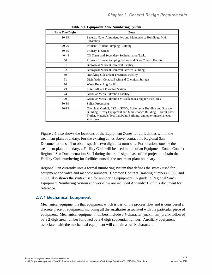
Blocks of numbers have been pre-assigned to various structures and or processes and will be
provided by Regional San to be incorporated in the design submittals. The common feature of
all numbering systems is the first two digits, which in all cases refers to a specific group of
structures or Equipment Zones as follows:
Chapter 2. General Design Requirements
Sacramento Regional County Sanitation District 2-5
Y:\00_Program Management (CPMO)\F. Standards\Design Guidelines - in progress\Draft Design Guidelines V1_20201020_FINAL.docx October 20, 2020
Table 2-1. Equipment Zone Numbering System
First Two Digits Zone
10-19 Security Gate, Administrative and Maintenance Buildings, Main
Substation
20-29 Influent/Effluent Pumping Building
30-39 Primary Treatment
40-48 CO Tanks and Secondary Sedimentation Tanks
50 Primary Effluent Pumping Station and Odor Control Facility
51 Biological Nutrient Removal Facility
52 Biological Nutrient Removal Blower Building
59 Nitrifying Sidestream Treatment Facility
61 Disinfection Contact Basin and Chemical Storage
70 Water Recycling Facility
73 Filter Influent Pumping Station
74 Granular Media Filtration Facility
79 Granular Media Filtration Miscellaneous Support Facilities
80-89 Solids Processing
90-99 Chemical, Outfall, ESB’s, SSB’s, Bufferlands Building and Storage
Building, Heavy Equipment and Maintenance Building, Harvest Crew
Trailer, Materials Test Lab/Paint Building, and other miscellaneous
structures
Figure 2-1 also shows the locations of the Equipment Zones for all facilities within the
treatment plant boundary. For the existing zones above, contact the Regional San
Documentation staff to obtain specific two digit area numbers. For locations outside the
treatment plant boundary, a Facility Code will be used in lieu of an Equipment Zone. Contact
Regional San Documentation Staff during the pre-design phase of the project to obtain the
Facility Code numbering for facilities outside the treatment plant boundary.
Regional San currently uses a formal numbering system that defines the syntax used for
equipment and valve and manhole numbers. Common Contract Drawing numbers GI008 and
GI009 also shows the syntax used for numbering equipment. A guide to Regional San’s
Equipment Numbering System and workflow are included Appendix B of this document for
reference.
2.7.1 Mechanical Equipment
Mechanical equipment is that equipment which is part of the process flow and is considered a
discrete piece of equipment, including all the auxiliaries associated with the particular piece of
equipment. Mechanical equipment numbers include a 4-character (maximum) prefix followed
by a 2-digit area number followed by a 4-digit sequential number. Auxiliary equipment
associated with the mechanical equipment will contain a suffix character.

98
97
91
90
90
15
95
93
41
44
96
84
45
83
43
70
48 13
52
85
82
94
87
81
96
25 8686
89
31
3334
32
8839
21, 22, 23, 24
92
4242
46
93
98
61
89
10
90
4749
35363738
Sacramento Regional Wastewater Treatment Plant (SRWTP)Equipment Zones MapÜ
Legend10 Gate and Security System13 Main Electrical Substation15 Administration Bldg. and Lab Facilities21 Influent/Effluent Bldg: tunnel and sub-tunnel levels22 Influent/Effluent Bldg: EL 98 to 117 (Includes Boiler Room)23 Influent/Effluent Bldg 2nd Floor24 Influent/Effluent Bldg: EL > 133 (south & includes PCC)25 Influent/Effluent Bldg (north)31 Primary Treatment Structure - Battery 132 Primary Treatment Structure - Battery 233 Primary Treatment Structure - Battery 334 Primary Treatment Structure - Battery 435 Primary Treatment Structure (future)36 Primary Treatment Structure (future)37 Primary Treatment Structure (future)38 Primary Treatment Structure (future)39 Primary Treatment Structure - Auxiliary41 Oxidation Tanks 1 Through 1242 Carbonaceous Oxidation Structure - Auxiliary & Tunnels43 Secondary Sedimentation Structure - Battery 144 Secondary Sedimentation Structure - Battery 2, EOS45 Secondary Sedimentation Structure - Battery 346 Carbonaceous Oxidation Structure - Tanks 1 through 1047 Secondary Sedimentatin Structure (future)48 Oxygen Generation49 Secondary Sedimentation Structure (future)50 Primary Effluent Pumping Station (PEPS)51 Biological Nutrient Removal (BNR)52 Blower Building and ACC5253 Biological Nutrient Removal (BNR) (future)59 Nitrified Side Stream Treatment (NST)61 Disinfection70 Water Reclamation Facility and UV73 Filtration74 Granular Media Filters (GMF) Facility75 Granular Media Filters (GMF) (future)79 Granular Media Filters (GMF) Support Facilites81 Digester Battery 182 Digester Battery 283 Digester Battery 384 Digester Battery 4 (future)85 Digester Battery 5 (future)86 WAS Thickeners, GBT87 Gas Management88 Solids Processing Control Building89 Digestion Auxillary (Includes Biogas)90 Solids Storage Basins91 Emergency Storage Basins92 Tunnels Not Covered By Area93 Chemical Handling Area94 Dechlorination95 Sample and Backflow Structures96 IJS, Septage Facility, and Stormwater97 DLD, Landfill and Heavy Equipment98 Miscellaneous Site Structures and Wetlands
March 2019
Zone '99 Plant General and Mobile Equipment' is notarea specific and cannot be displayed geographically.
SacramentoRiver
(see note)
See drawing 'SRWTP-ENZ-MAP' sheet 2 for sectionalview of Influent/Effluent building.
0 750 1,500 2,250 3,000375Feet
73
10
97
59
98
5051
89
90
53
79
7475
90
90
46
General Notes1.
2.
See GIS for a more detailed view of these zones, aswell as areas not shown on this map.
3.
10
Detail 'A' South Gate
File: 10040686
DWIGHT ROAD
90
DWIG
HT R
OAD
SIMS ROAD
FREEPORT BLVD
See Detail 'A' for Continuation
Chapter 2. General Design Requirements
Sacramento Regional County Sanitation District 2-7
Y:\00_Program Management (CPMO)\F. Standards\Design Guidelines - in progress\Draft Design Guidelines V1_20201020_FINAL.docx October 20, 2020
2.7.2 Electrical Equipment
Electrical equipment is that equipment which is not considered “discrete equipment” as
defined, but is related to the switchgear. This would include but is not limited to motor control
centers (MCCs), transformers, and electric breakers.
2.7.3 Instrument Equipment
Instrument equipment is that equipment which is part of the process flow and is considered a
discrete piece of equipment. Separate from the instrument equipment numbering are the
PLC/PCCS numbers which are specified by the Designer.
2.7.4 Manual Valves
Manual valves are those valves which are manually operated (lever, chain, or hand wheel), with
no electric, pneumatic or hydraulic control connected. Manual valve numbers shall be issued to
all valves in a process system and shown on process and piping system schematic diagrams.
2.7.5 Manholes
Manholes include “process” manholes and electrical manholes.
Process manholes are those units that a fluid can flow through. Details and schedules for these
units are found in the “General” drawings of the contract documents.
Electrical manholes and handholes are those units that power, control and signal cables run
through.
2.7.6 Slide Gates, Control Units, and Utility Stations
Slide gates (SLG) are those gates which are manually installed and removed; they are used for
isolation of channels. Details and schedules for these gates are found in the “Structural”
drawings of the contract documents. “Control Units” (CU) are assemblies that supply regulated
water flow to process equipment. “Utility Stations” (US) are assemblies used for accessing
SRWTP utility systems (i.e.: WRH, WP, Steam, SA). Details and schedules for these
assemblies are found in the “Mechanical” drawings of the contract documents.
2.7.7 Doors and Rooms
Each room in each structure of this facility must be identified with a four digit unique number
for construction and maintenance purposes. Each room will be given a unique sequential
number as defined in Regional San’s Auto-numbering Guide (included in Appendix B). These
numbers will always be shown on the “Architectural” drawings of the contract documents.
Each door shall be given a number similar in format to the room numbers. These numbers will
always be shown on the “Architectural” drawings of the contract documents.
Schedules for both rooms and doors shall be located in the “Architectural” drawings of the
contract documents. (Note: Temporary facilities, such as trailers, shall also receive room
Chapter 2. General Design Requirements
Sacramento Regional County Sanitation District 2-8
Y:\00_Program Management (CPMO)\F. Standards\Design Guidelines - in progress\Draft Design Guidelines V1_20201020_FINAL.docx October 20, 2020
and door numbers for maintenance purposes. They shall receive a three digit number.
The numbers shall be identified by complex.)
2.7.8 Pipelines outside of the Plant Property
Pipelines outside the plant property will be identified by pipe segments. Pipe segment lengths
will be determined by the nearest appurtenance (diameter change, valve, blowoff, ARV, etc.).
2.8 Special Area Classifications
Certain areas of the existing SRWTP or new process areas may fall under special classifications
which require special requirements. During pre-design, potential areas shall be identified.
Appropriate design details shall be considered and provided in the plans and specifications.
Special classifications include, but are not limited to:
Hazardous (Classified ) Areas – As defined in National Fire Protection Association
(NFPA) 820
Corrosive Areas – Areas over open tanks, chemical rooms,
Wet Areas – All outdoor areas and indoor process areas. Wet areas shall be considered
to be subjected to high-pressure water.

Chapter 3. Civi l Desi gn Guidelines
Sacramento Regional County Sanitation District Y:\00_Program Management (CPMO)\F. Standards\Design Guidelines - in progress\Draft Design Guidelines V1_20201020_FINAL.docx October 20, 2020
3-1
3.0 Civil Design
The following are the civil design guidelines to be considered for Regional San projects.
3.1 Codes and Standards
The project shall be designed to comply with applicable portions of the codes and standards listed
in Table 3-1 below and as described in this chapter. Designer is to use the most current County-
adopted code edition as posted to www.building.saccounty.net/pages/buildingcodes.aspx up to
submission of the Final Preliminary Design Report (PDR); the Designer is not responsible for any
newer editions beyond Final PDR.
Table 3-1. Applicable Codes and Standards for Civil Design
ASTM American Society for Testing and Materials
AWWA American Water Works Association
Highway Design Manual California Department of Transportation
State Standard Specifications California Department of Transportation
Standard Specifications County of Sacramento Standard Construction Specifications
Improvement Standards City of Elk Grove
Improvement Standards Sacramento County; Section 9 Storm Drainage Design
CBC California Building Code
CFC California Fire Code
AASHTO American Association of State Highway Transportation Officials
ACI American Concrete Institute
Cal OSHA California Occupational Safety & Health Administration
Cal DHS California Department of Health Services Water & Sewer Separation
Guidelines
3.2 Surveying
The Designer shall show the location and character of all survey monuments within the
construction area and place a note on the General Civil Notes plan sheet stating that the
Contractor is responsible for the protection and restoration of all existing monuments and other
survey markers in accordance with Section 8771 of the Land Surveyor’s Act. Regional San
shall supply the Designer with a map of the current benchmarks on SRWTP property; all
survey monuments at the SRWTP are currently shown on Common Contract Drawing GC002.
3.3 Existing Utility Coordination
The Designer shall prepare a project Utility Investigation Plan as outlined in Regional San’s
Design Contract Requirements to assess potential conflicts between any existing utilities and
new construction.
3.4 Roadways within Regional San Property
The following sections describe roadway geometry for various types of facility roads.

Chapter 3. Civi l Desi gn Guidelines
Sacramento Regional County Sanitation District Y:\00_Program Management (CPMO)\F. Standards\Design Guidelines - in progress\Draft Design Guidelines V1_20201020_FINAL.docx October 20, 2020
3-2
3.4.1 Process Area Roadways
Table 3-2 lists how the road geometry within the process areas shall be designed:
Table 3-2. Process Area Roadway Geometry
Width 24 feet measured from edge of pavement
Vehicle Turning Radius 40 feet minimum (inside); 60 feet minimum outside
Design Speed 25 miles per hour
Cross Slopes 1 percent minimum for concrete paved areas, 2 percent maximum
2 percent for asphalt paved areas
Longitudinal Slopes Less than 5 percent
Pavement design shall be based on the size and frequency of the traffic (Traffic Index) and the
soil site conditions per the geotechnical engineer’s recommendations. At a minimum, the
pavement section shall be 3-inch asphalt concrete over 12-inch aggregate base.
3.4.2 Main Ingress/Egress Roadways
Table 3-3 lists how the main ingress/egress roadway geometry shall be designed:
Table 3-3. Ingress/Egress Roadway Geometry
Width 24 feet measured from edge of pavement
Vehicle Turning Radius 40 feet minimum (inside); 60 feet minimum outside
Design Speed 25-45 miles per hour, request clarification from Regional San during design
Cross Slopes Centerline crown with standard cross-slope of 2 percent
Longitudinal Slopes Less than 5 percent
Vertical Curve Length 50 feet minimum
Gradient Change for
Vertical Curve
2 percent
Pavement design shall be based on the size and frequency of the traffic (Traffic Index) and the
soil site conditions per the geotechnical engineer recommendations. At a minimum, the
pavement section shall be 3-inch asphalt concrete over 12-inch aggregate base.
3.5 Roadways beyond Regional San Property
The following sections are intended to provide guidance beyond the facility boundary and
includes Traffic Control.
3.5.1 Civil Requirements
Refer to Section 3.1 above for codes and standards that apply in City and County roads beyond
Regional San property.
3.5.2 Traffic Control
The following is to be considered for Regional San projects outside of the plant boundary.
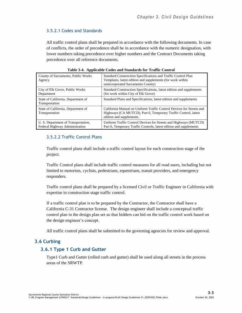
Chapter 3. Civi l Desi gn Guidelines
Sacramento Regional County Sanitation District Y:\00_Program Management (CPMO)\F. Standards\Design Guidelines - in progress\Draft Design Guidelines V1_20201020_FINAL.docx October 20, 2020
3-3
3.5.2.1 Codes and Standards
All traffic control plans shall be prepared in accordance with the following documents. In case
of conflicts, the order of precedence shall be in accordance with the numeric designation, with
lower numbers taking precedence over higher numbers and the Contract Documents taking
precedence over all reference documents.
Table 3-4. Applicable Codes and Standards for Traffic Control
County of Sacramento, Public Works
Agency
Standard Construction Specifications and Traffic Control Plan
Templates, latest edition and supplements (for work within
unincorporated Sacramento County)
City of Elk Grove, Public Works
Department
Standard Construction Specifications, latest edition and supplements
(for work within City of Elk Grove)
State of California, Department of
Transportation
Standard Plans and Specifications, latest edition and supplements
State of California, Department of
Transportation
California Manual on Uniform Traffic Control Devices for Streets and
Highways (CA MUTCD), Part 6, Temporary Traffic Control, latest
edition and supplements.
U. S. Department of Transportation,
Federal Highway Administration
Uniform Traffic Control Devices for Streets and Highways (MUTCD)
Part 6, Temporary Traffic Controls, latest edition and supplements
3.5.2.2 Traffic Control Plans
Traffic control plans shall include a traffic control layout for each construction stage of the
project.
Traffic Control plans shall include traffic control measures for all road users, including but not
limited to motorists, cyclists, pedestrians, equestrians, transit providers, and emergency
responders.
Traffic control plans shall be prepared by a licensed Civil or Traffic Engineer in California with
expertise in construction stage traffic control.
If a traffic control plan is to be prepared by the Contractor, the Contractor shall have a
California C-31 Contractor license. The design engineer shall include a conceptual traffic
control plan in the design plan set so that bidders can bid on the traffic control work based on
the design engineer’s concept.
All traffic control plans shall be submitted to the governing agencies for review and approval.
3.6 Curbing
3.6.1 Type 1 Curb and Gutter
Type1 Curb and Gutter (rolled curb and gutter) shall be used along all streets in the process
areas of the SRWTP.
Chapter 3. Civi l Desi gn Guidelines
Sacramento Regional County Sanitation District Y:\00_Program Management (CPMO)\F. Standards\Design Guidelines - in progress\Draft Design Guidelines V1_20201020_FINAL.docx October 20, 2020
3-4
3.6.2 Type 2 Curb and Gutter
Type 2 Curb and Gutter (vertical curb and gutter) shall be used along streets adjacent to
landscaped areas and pedestrian walkways, and shall be placed in front of buildings to help
protect buildings from damage caused by vehicles.
Vertical curb and gutter also shall be used for drainage control in parking areas.
3.6.3 Type 3, 4, or 5 Curb
Type 3, 4, or 5 Curb (barrier curb) shall be provided at all edges of parking lots that do not have
vertical curb and gutter.
A barrier curb shall be provided at the back of sidewalks where landscape planters containing
soil and/or mulch are adjacent to the sidewalk. A barrier curb is not required at the back of
sidewalks adjacent to lawn.
A barrier curb shall be provided at the back of sidewalks where the ground slopes away from
the sidewalk at greater than 6:1 (H:V). Where a retaining wall is allowed, creating a drop-off
adjacent to the sidewalk, a minimum 36-inch-high barrier fence shall be provided in lieu of the
barrier curb.
3.7 Cross Gutter
Cross gutter shall not be used. Exceptions will be made for intersections that cannot reasonably
be drained to an underground system.
3.8 Sidewalks and Walkways
Sidewalks and walkways shall have a minimum width of 4 feet, a longitudinal slope less than
5 percent, and a transverse slope less than 2 percent. Sidewalks and walkways to be used by
maintenance personnel shall be 6-feet wide. Concrete walkways shall be provided around the
exterior of all structures and shall slope away from buildings at a minimum slope of 0.01:1
(H:V). Landscaping adjacent to structures should be avoided.
3.9 Parking
Visitor and employee parking areas shall be provided with tree shading as required by
Sacramento County Zoning Code. Visitor and employee parking areas shall have accessible
parking spaces for disabled people as required by the California Building Code.
Parking areas within the process areas of the SRWTP which are not generally used by the
public need not comply with the above requirements for shading and accessible parking spaces.
Utility cart and bicycle parking shall be provided at all SRWTP process buildings.
Chapter 3. Civi l Desi gn Guidelines
Sacramento Regional County Sanitation District Y:\00_Program Management (CPMO)\F. Standards\Design Guidelines - in progress\Draft Design Guidelines V1_20201020_FINAL.docx October 20, 2020
3-5
3.10 Slope Protection
Embankments with erosion potential shall have a minimum slope of 3:1 (H:V). If additional
protection is required, an erosion protection system such as rip-rap may be used. Seeding shall
not be used.
3.11 Landscaping
No landscaping shall be within the process areas of the SRWTP.
3.12 Storm Drainage
Incorporate Low Impact Development (LID) techniques where possible to address storm water
runoff (e.g., permeable pavement).
The design of a new storm drain system shall include consideration of the downstream storm
drain. The Designer shall show that the existing storm water system can convey the proposed
drainage without adverse flooding, erosion or other water quality impacts to upstream,
downstream or adjacent facilities or areas; or that such facilities or areas are being improved or
protected to the point where the drainage can be conveyed without adverse impacts.
All new structures shall be protected from the 100-year flood event. Certified building pad
elevations shall be set at least 1.2 feet above all sources of 100-year flooding.
All open channel drainage systems shall be designed to carry the 100-year frequency design
storm, using the worst-case duration, with freeboard greater than 1 foot. The maximum velocity
shall be 6 feet per second for earth channels, 10 feet per second for fully lined channels, and 8
feet per second for bottom-lined channels.
The design of closed conduit drainage systems shall use the Sacramento City/County Drainage
Manual Volume 2: Hydrology Standards and Section 9 Storm Drainage Design of the
Sacramento County Improvement Standards, as appropriate. The minimum inside diameter for
pipes shall be no less than 12 inches. Use of plastic, polyvinyl chloride (PVC) or high density
polyethylene pipes (HDPE) at channel or detention basin outfall shall not be allowed. The
minimum full flow velocity shall be no less than 2 feet per second.
A manhole, junction box, or inlet shall be located at pipe junctions, angle points greater than
15 degrees, and changes in pipe size or materials. Spacing of access points shall not exceed
400 feet for drains 15 inches and smaller in diameter, 500 feet for drains between 18 inches and
36 inches in diameter, and 600 feet for drains greater than 42 inches in diameter.
3.13 Potable and Non-Potable Water Supply Systems
In general, water supply systems shall be looped, with two points of connection to water
sources, separated by a minimum of one isolation valve.
The Hazen-Williams formula shall be used in the hydraulic study of the system, using a
“C” value of 125 for cement-lined pipe, polyvinyl chloride pipe, and ductile iron pipe. Velocity
Chapter 3. Civi l Desi gn Guidelines
Sacramento Regional County Sanitation District Y:\00_Program Management (CPMO)\F. Standards\Design Guidelines - in progress\Draft Design Guidelines V1_20201020_FINAL.docx October 20, 2020
3-6
in distribution mains shall not exceed 7 feet per second at peak hour. Head loss shall not exceed
5 pounds per square inch (psi) per 1,000 feet.
Water supply pressures shall be designed as follows:
Potable water systems shall be designed so that normal operating pressures at service
connections to the distribution system are no less than 35 psi and no more than 100 psi.
During periods of maximum day domestic demand, the pressure shall not be less than
20 psi at the location of the fire flow and no less than 10 psi elsewhere in the
distribution system.
Non-potable water systems shall be designed to maintain a minimum pressure of
40 pounds per square inch (psi) at the service connection.
Required fire flows shall be determined by the California Uniform Fire Code.
Ten (10) feet shall be the minimum horizontal distance between parallel water supply and
sanitary sewer mains or non-potable water mains. The invert of the water supply main shall be
at a higher elevation than the sewer main or non-potable water main. Separation may be less if
it is in accordance with California State Department of Health Services requirements and
approved by Regional San.
At all utility crossings, the water supply main shall maintain a minimum separation of at least
12 inches from the utility. Sanitary sewer and water main crossings shall comply with the latest
California Department of Health Services criteria.
3.14 General Site Piping Design Criteria
To preserve access for future pipeline extensions and to minimize conflicts, separate utility
corridors will be provided for buried utilities.
Where feasible, consider adding pipe chases for utilities crossing under heavily traveled
roadways.
Where feasible, process yard piping will be located outside of roadways and electrical ductbank
corridors.
Water, plant water, plant drainage, and natural gas piping will be located in roadways, where
feasible.
Electrical ductbanks will be located in 20-foot-wide corridors away from process yard piping
and outside of plant roadways.
All pipelines located beneath structures will be concrete encased.
Minimum cover for pressurized process pipes (not for irrigation) shall be 3-feet.

Chapter 3. Civi l Desi gn Guidelines
Sacramento Regional County Sanitation District Y:\00_Program Management (CPMO)\F. Standards\Design Guidelines - in progress\Draft Design Guidelines V1_20201020_FINAL.docx October 20, 2020
3-7
Pipe profiles shall be prepared for process pipe larger than 18-inches in diameter and for
gravity pipe systems.
Buried valves 30-inches in diameter and larger shall be installed in vaults.
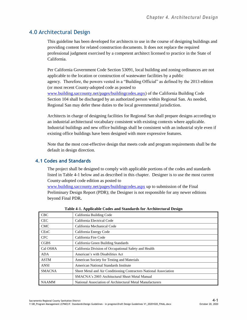
Chapter 4. Architectural Design
Sacramento Regional County Sanitation District 4-1 Y:\00_Program Management (CPMO)\F. Standards\Design Guidelines - in progress\Draft Design Guidelines V1_20201020_FINAL.docx October 20, 2020
4.0 Architectural Design
This guideline has been developed for architects to use in the course of designing buildings and
providing content for related construction documents. It does not replace the required
professional judgment exercised by a competent architect licensed to practice in the State of
California.
Per California Government Code Section 53091, local building and zoning ordinances are not
applicable to the location or construction of wastewater facilities by a public
agency. Therefore, the powers vested in a “Building Official” as defined by the 2013 edition
(or most recent County-adopted code as posted to
www.building.saccounty.net/pages/buildingcodes.aspx) of the California Building Code
Section 104 shall be discharged by an authorized person within Regional San. As needed,
Regional San may defer these duties to the local governmental jurisdiction.
Architects in charge of designing facilities for Regional San shall prepare designs according to
an industrial architectural vocabulary consistent with existing contexts where applicable.
Industrial buildings and new office buildings shall be consistent with an industrial style even if
existing office buildings have been designed with more expressive features.
Note that the most cost-effective design that meets code and program requirements shall be the
default in design direction.
4.1 Codes and Standards
The project shall be designed to comply with applicable portions of the codes and standards
listed in Table 4-1 below and as described in this chapter. Designer is to use the most current
County-adopted code edition as posted to
www.building.saccounty.net/pages/buildingcodes.aspx up to submission of the Final
Preliminary Design Report (PDR); the Designer is not responsible for any newer editions
beyond Final PDR.
Table 4-1. Applicable Codes and Standards for Architectural Design
CBC California Building Code
CEC California Electrical Code
CMC California Mechanical Code
CEnC California Energy Code
CFC California Fire Code
CGBS California Green Building Standards
Cal OSHA California Division of Occupational Safety and Health
ADA American’s with Disabilities Act
ASTM American Society for Testing and Materials
ANSI American National Standards Institute
SMACNA Sheet Metal and Air Conditioning Contractors National Association
SMACNA’s 2003 Architectural Sheet Metal Manual
NAAMM National Association of Architectural Metal Manufacturers

Chapter 4. Architectural Design
Sacramento Regional County Sanitation District 4-2 Y:\00_Program Management (CPMO)\F. Standards\Design Guidelines - in progress\Draft Design Guidelines V1_20201020_FINAL.docx October 20, 2020
UL Underwriter’s Laboratory
FMRC Factory Mutual Research Corporation
SSPC Steel Structures Painting Council
NFPA 10 National Fire Prevention Association Standard for Portable Fire Extinguishers
NFPA 13 National Fire Prevention Association Standard for Automatic Fire Sprinklers
NFPA 430 National Fire Prevention Association Standard for Storage of Liquid and Solid Oxidizers
NFPA 820 National Fire Prevention Association Standard for Wastewater Treatment and Collection
Facilities
Model codes such as the “International Building Code,” “National Electrical Code,”
“NFPA 101,” “NFPA 5000” or similar codes do not have force within this jurisdiction and shall
not be referenced since they have not been adopted by the State of California.
In the case of conflicting codes or standards, the most restrictive shall apply.
The 2013 Edition of the California Code of Regulations, Title 24, as now adopted, includes
Part 11, California Green Building Standards. The design should, as a minimum, address
applicable "Mandatory Measures" identified therein. Refer to Appendix C for a summary of
how the mandatory measures shall be incorporated into Regional San projects.
4.2 Architectural Code Analysis
The following method of code review shall be used in assuring compliance to non-structural
code provisions.
Step 1: The architect shall look up Effective Use of the IBC/CBC located on page v in
the 2010 CBC.
Step 2: The architect shall follow the instructions and compose a list of code sections
identified in Nonstructural Provisions, then provide written justification pertaining to
each section.
Step 3: The architect shall include this annotated list in the construction documents as
part of the code review sheet(s) in the construction drawings. Each listing shall briefly
describe compliance in context to the design. Overall, the architect should avoid
copying the text in the code word-for-word unless accuracy is important.
Step 4: The architect shall create an annotated architectural site code review plan that
includes egress routes and accessibility features. This shall only show enough detail to
show compliance to code. Site features may reference civil sheets. Include this in the
construction drawings.
Step 5: The architect shall create an annotated floor code review plan that includes
occupancy loads, egress routes, fire ratings, egress travel distances, occupancy types,
exit sign locations (reference electrical drawings) and fire extinguisher locations.
Include this in the construction drawings.

Chapter 4. Architectural Design
Sacramento Regional County Sanitation District 4-3 Y:\00_Program Management (CPMO)\F. Standards\Design Guidelines - in progress\Draft Design Guidelines V1_20201020_FINAL.docx October 20, 2020
4.3 Accessibility Requirements
Regional San’s Board has approved exemption of the SRWTP process areas from compliance
with ADA requirements; reference the November 23, 1993 County of Sacramento Board of
Directors letter with subject line “Approval of Sacramento Regional Wastewater Treatment
Plant (SRWTP) New Construction Guidelines for Americans with Disabilities Act (ADA)
Compliance”. Accessibility requirements for all other areas on a project shall be designed per
Chapter 11B of the California Building Code.
4.4 General Materials Guide
Materials shall be selected on the merits of durability, safety, economy, maintenance,
sustainability, and aesthetic context. For economy, materials and designs with the lowest life
cycle costs are preferred over materials or designs that have lower initial costs that will be
offset by higher maintenance costs, replacements costs, or shorter life.
4.4.1 Concrete
Durability
Concrete shall be selected where reinforced concrete structure is acceptable as the
finished element. Selection on this basis is inherently durable.
In industrial areas especially, appropriately designed reinforced concrete can withstand
a hit from vehicular traffic.
Ballistic resistant.
Safety
Provide a non-slip surface where required.
Coordinate recessed thresholds with structural engineer.
Economy
Concrete finishes tend to be economical when compared to other applied finishes.
Concrete may be stained, sealed, hardened or painted with epoxy. Refer to Section 4.7
for finishes.
Stairwells shall not be cast-in-place concrete.
Utilities shall not be embedded into cast-in-place structures.
Maintenance
Inherently easy to maintain.
Over time, efflorescence may become an issue. To reduce this risk, consider the
following during design.

Chapter 4. Architectural Design
Sacramento Regional County Sanitation District 4-4 Y:\00_Program Management (CPMO)\F. Standards\Design Guidelines - in progress\Draft Design Guidelines V1_20201020_FINAL.docx October 20, 2020
Review water table levels in the soil and follow the recommendation of a soils
report issued by a geotechnical engineer. Use under slab vapor barriers where
recommended.
Use below grade waterproofing on the exterior of foundation walls. Make sure
that the perimeter foundation is well drained.
Use a weather proof sealer on vertical exterior surfaces.
Sustainability
Consider using a fly ash additive.
Aesthetic
Much of the SRWTP is composed of cast-in-place concrete. Matching this aesthetic is
an important consideration.
Use of pigments is not advisable unless specifically requested.
Exterior concrete surfaces shall be standard concrete grey.
Where appropriate, form liners may provide texture or relief in a concrete surface.
4.4.2 Masonry
Durability
Concrete masonry shall be selected where reinforced concrete masonry structure is
acceptable as the finished element. Selection on this basis is inherently durable.
In industrial areas especially, appropriately designed reinforced fully grouted concrete
masonry can withstand a hit from vehicular traffic.
Ballistic resistant.
Glass masonry or glass block should be considered only where there is a low risk of
impact.
Economy
In general, concrete masonry is one of the most economical options to provide durable,
structural, and aesthetically pleasing walls.
Maintenance
Inherently easy to maintain.
Over time, efflorescence may become an issue. To reduce this risk, consider using a
weather proof sealer on vertical exterior surfaces.
Chapter 4. Architectural Design
Sacramento Regional County Sanitation District 4-5 Y:\00_Program Management (CPMO)\F. Standards\Design Guidelines - in progress\Draft Design Guidelines V1_20201020_FINAL.docx October 20, 2020
Aesthetic
Concrete masonry is available in a wide range of colors, textures and surfaces. Ensure
that the use of concrete masonry is compatible with the overall context of the facility.
4.4.3 Metal
Durability
Steel
Corrosion is a primary concern. Most steels will require a coating designed to
withstand the expected risk of corrosion.
Use lead-free coatings and coating tints.
When selecting coatings for corrosion resistance consult Regional San,
appropriately certified members of NACE, and SSPC standards.
Consider stainless steel in corrosive locations that are difficult to access, have
intricate shapes, or slender sections such as trusses. The ongoing maintenance
and replacement cost of coatings in these locations often makes stainless steel
competitive when considering life cycle costs.
Hot-dipped galvanized steel shall be used on external fabricated steel structures
when size allows.
Consider aluminum where corrosion is a concern.
Aluminum
If aluminum products are incorporated, provide di-electric separation between
metal and substrate in accordance with manufacturer instructions.
A protective coating or barrier shall be used between aluminum and cement and
similar construction material.
Use metal stud for framing, avoid wood studs.
Economy
Substantiate metal choices based on economy by checking current pricing.
Strength and corrosion resistance shall be considered along with economy.
Maintenance
If alternatives are being weighed, consider that metal may need regular inspection for
corrosion of weather exposed elements.
Chapter 4. Architectural Design
Sacramento Regional County Sanitation District 4-6 Y:\00_Program Management (CPMO)\F. Standards\Design Guidelines - in progress\Draft Design Guidelines V1_20201020_FINAL.docx October 20, 2020
COR-TEN steel is an alternative steel that, if exposed to weather, will create a
protective oxidized surface.
Use stainless steel or aluminum for gutters, downspouts, drain pans, flashing or for
similar sheet metal installations that are routinely exposed to moisture maximize
service life.
4.4.4 Wood
Durability
Wood as a construction material should be avoided and in no case should be used as an
alternative to corrosion resistant materials.
Fire retardant treated wood may have limited use for sheathing in roofing. Fire
retardant treated wood may be used as shims only in locations totally sealed from
moisture and sunlight exposure.
Wood may have limited use as an interior finish in an office context.
Safety
Oxidizers such as sodium hypochlorite may be prone to ignition or increased
flammability in the presence of wood or other carbon based materials.
Economy
Wood is inherently an inexpensive material compared to other building materials, but
generally not appropriate for industrial construction.
Maintenance
Wood is subject to checking or cracking if not properly painted or finished.
Keep wood construction well ventilated and as dictated in the CBC.
Wood is not appropriate in wet areas unless provided with adequate coatings or
pressure treatment.
Sustainability
Consider using wood and wood products from sustainable sources.
4.4.5 Plastic
Use fiber-reinforced plastic (FRP) panel wainscot for toilet rooms, shower rooms,
locker rooms or restrooms if ceramic tile is not preferred.
Use UV resistant ultra-high-molecular-weight (UHMW) polyethylene or similar plastic
d for shims in locations with potential exposure to moisture or sunlight and for pipe
support piers or blocks that rest on roof.
Chapter 4. Architectural Design
Sacramento Regional County Sanitation District 4-7 Y:\00_Program Management (CPMO)\F. Standards\Design Guidelines - in progress\Draft Design Guidelines V1_20201020_FINAL.docx October 20, 2020
Use UHMW or similar plastic material for pipe support piers or blocks that are rest on a
roof.
Durability
FRP has excellent strength and corrosion resistant properties and is commonly used for
grates, guardrails and doors.
FRP is used where corrosion is likely on ferric based metal.
FRP panels may be used as sheathing over metal stud framing. Provide thickness as
manufacturer recommends.
8-mm FRP may be used over water-resistant gypsum board as a finish primarily in
locker rooms and restrooms. It can also be used in laboratories.
Maintenance
FRP panels may be used in non-emersion wet areas, places with corrosion risk, or
where there is a need for abuse resistant surface. Provide thickness as manufacturer
recommends.
Edge beads are typically used, but tend to break off or become bent. Consider more
substantial transition especially in janitor closets and restrooms located in industrial
areas.
Aesthetic
FRP 8-mm panels come in a variety of textures and colors. However, the most
common color is white.
FRP 8-mm panels can be used as an economical alternative to ceramic tile for wall
applications.
4.5 Thermal and Moisture Protection
The following paragraphs are applicable to all Regional San buildings.
4.5.1 Vapor Barrier
Vapor barriers are required to control moisture laden warm air from reaching the
location of the dew point within a wall or roof assembly. Vapor barriers shall always be
placed on the warm side of the assembly.
Architect shall determine the warm side of the wall. This may be difficult since during
the summer, the exterior is clearly the warm side, and in the winter, the inside is clearly
the warm side. DO NOT put a vapor barrier on both sides. Entrapment of moisture is a
leading cause of mold within the wall structure.

Chapter 4. Architectural Design
Sacramento Regional County Sanitation District 4-8 Y:\00_Program Management (CPMO)\F. Standards\Design Guidelines - in progress\Draft Design Guidelines V1_20201020_FINAL.docx October 20, 2020
Use silicon sheet or ethylene propylene diene monomer (EPDM) membranes to bridge
construction gaps (window-wall, wall-wall assemblies, curtain walls) for air/vapor seals.
Do not specify rubberized asphalt (sheet air/vapor barriers [AVBs]).
4.5.2 Sealants and Waterproofing
Apply waterproofing to exterior below grade walls during construction. Avoid
post-construction methods for waterproofing such walls.
Design building and flashings so as not to rely on sealants in the shedding of water and
moisture. Make sure to use capillary breaks.
Sealant and waterproofing materials shall be warranted for at least 30 years.
Sealant
Use sealant containing asbestos-free formula.
Check the width of the gap to be sealed with the manufacturer’s recommended span.
Check substrate and compare with manufacturer’s recommendation.
Check that elasticity is appropriate for joint movement.
Check performance of UV exposure if in direct sunlight.
In building joints, use EPDM sheet as a moisture barrier within the joint (behind the
cover).
Sealant or caulking materials shall be compatible with the construction materials and
location.
4.5.3 General Roof and Parapet Requirements
The roof deck, insulation, and membrane shall be a Factory Mutual (FM) tested and
approved assembly rated for the expected wind loading (See Section 5.4).
Assume all roofs will be accessed for ongoing maintenance and inspection activities and
provide an appropriate fall protection design. See Sections 4.15 and 4.16 for fall
protection and access requirements, respectively.
On flat roofs provide reinforced walkways 360 degrees around process equipment,
HVAC equipment, and photovoltaic panels. Provide reinforced walkway from
equipment to roof hatches, and ladder. On steep roofs provide working platform 360
degreed around process and HVAC equipment.
All roofs to be Title 24 SRI (Solar Reflective Index) compliant. Roofs on unoccupied
and unconditioned structures shall have a minimum SRI of 64 for flat roofs and 16 for
steep roofs.

Chapter 4. Architectural Design
Sacramento Regional County Sanitation District 4-9 Y:\00_Program Management (CPMO)\F. Standards\Design Guidelines - in progress\Draft Design Guidelines V1_20201020_FINAL.docx October 20, 2020
Do not pierce roof curb caps and parapet copings to mount equipment. Weld fasteners to
the cap or coping or use other supporting structure attached to the curb or parapet for
anchoring equipment.
Skylights and tubular daylights must be mounted on roof curbs.
For any given type roofing material and assembly, those with longer warranties are
preferred. Warrantee shall cover parts and labor for the life of the warrantee.
Additions to existing roofs.
Roofing that has evidence of leakage after inspection in conjunction with a new
addition shall be removed. Install new roofing over both new and existing parts of roof
structure.
Existing roofing installation aged 12 years or more in conjunction with a new addition
shall be removed. Install new roofing over both the new and existing parts of the roof
structure.
4.5.4 Roof-Mounted Equipment and Solar Panels
All roof equipment located on roofs must be mounted on roof curbs.
Design roofing assembly such that roof-mounted HVAC or process equipment need not
be removed during replacement of the roofing system.
Provide 110V electrical ground fault interrupter (GFI) outlet and potable water hose
bib adjacent to any roof-mounted process or HVAC equipment. See Electrical and
Plumbing Design Standards.
New roofs shall be built with infrastructure engineered to accommodate the future
installation of solar panels. This includes method of attachment, penetrations for
power, cables, proper drainage and cleaning water source.
Design solar panel attachment points so that repairs or alterations to the roof membrane
are not required when mounting brackets are installed. It is preferred that solar panel
brackets attach to a roof curb or similar permanently installed structure.
Ensure that the structure supporting solar panels does not interfere with roof drainage.
Design the solar panel attachment to withstand expected wind loads; refer to Section
5.4 for Wind Loading.
4.5.5 Flat Roofs
Flat roofs must have a minimum ½-inch per foot slope.
Roof slope shall be achieved through the structural roofing members, not with tapered
insulation board. Tapered insulation board shall be used exclusively for cricket
installation.

Chapter 4. Architectural Design
Sacramento Regional County Sanitation District 4-10 Y:\00_Program Management (CPMO)\F. Standards\Design Guidelines - in progress\Draft Design Guidelines V1_20201020_FINAL.docx October 20, 2020
Slope to scuppers and conductor heads leading to rainwater leaders. Avoid drains that
route rainwater through interior of the building.
Provide crickets to sufficiently divert water around curbs and toward drains/scuppers.
Standard compression strength of polyisocyanurate insulation is 20 pounds per square
foot. Provide additional reinforcing by use of counter battens, additional cover board
layers, or use of polyisocyanurate with increased compression strength when roof is
near photovoltaic panels or solar water heating panels.
4.5.6 Built-Up Roof
Build-up roof uses asphalt impregnated felts hot mopped in multiple layers. This type of
roofing should be considered as the primary choice for flat roofs. Self-adhering or torch
applied materials are not acceptable.
Use a polyurethane or epoxy coating in place of a cap sheet.
Provide a suitable cover board between polyisocyanurate insulation and roofing
membrane. Cover board shall be mechanically attached to the structural roof deck.
4.5.7 Single-Ply Roof Membrane.
Single-ply roof membranes should be thermoplastic polyolefin (TPO), mechanically
applied or fully-adhered.
Mechanically applied or fully-adhered single ply EPDM membrane may be specified,
but only if specifically requested by the Regional San project manager.
Install using fasteners or adhesives, do not use installation tapes or self-adhering
products
Provide a suitable cover board between polyisocyanurate insulation and roofing.
Cover board shall be mechanically attached to the structural roof deck.
4.5.8 Shingles
Asphalt shingles are Regional San’s preference for sloped roofs over occupied (office/
industrial/ laboratory/ storage) floor space.
Do not specify residential grade.
Nail according to high wind or hurricane standards.
Asphalt shingles are easily damaged and should be handled, installed and maintained
with utmost care.
Specify 40 year warranty.

Chapter 4. Architectural Design
Sacramento Regional County Sanitation District 4-11 Y:\00_Program Management (CPMO)\F. Standards\Design Guidelines - in progress\Draft Design Guidelines V1_20201020_FINAL.docx October 20, 2020
Use on roofs greater than or equal to 3:12 or what is recommended by manufacturer,
whichever is steepest.
Avoid designs that place equipment on sloped roofs. If done, provide maintenance
platforms with harness latch points or guardrails at locations requiring routine
maintenance or inspections. This shall be provided so that the worker doing the
maintenance or inspection can do so without special safety preparation.
Caution: Routine foot traffic will cause damage. Design roofs and access requirements
to avoid routine foot traffic.
Do not specify wood shingles or shakes.
4.5.9 Clay Tile Roof (Limited Application)
Not for use at the SRWTP.
This roofing shall not be allowed unless providing repair or renovation work directly
associated with existing clay tile roof.
This roofing is featured on existing buildings at the Lower Northwest Interceptor
facility locations in the City of Sacramento and in Yolo County.
See Section 4.5.10 Concrete Tile Roof if matching the clay tile is in the scope for new
buildings.
Caution: Foot traffic will cause damage. Design roofs and access requirements
accordingly.
Use high wind resistant (hurricane) type installation regardless of roof size or elevation.
4.5.10 Concrete Tile Roof (Limited Application)
Not for use at the SRWTP.
This is the preferred material to match the existing clay tile roof at Lower Northwest
Interceptor facility locations.
Specify tiles with a 50 year warranty.
The roof structure must be specifically designed to carry significant additional loads
compared to other options.
Avoid designs that place equipment on sloped roofs. If done, provide maintenance
platforms with harness latch points or guardrails at locations requiring routine
maintenance or inspections. This shall be provided so that the worker doing the
maintenance or inspection can do so without special safety preparation.
Caution: Routine foot traffic will cause damage. Design roofs and access requirements
to avoid routine foot traffic.
On high elevation or large roofs, specify high wind resistant installation.
Chapter 4. Architectural Design
Sacramento Regional County Sanitation District 4-12 Y:\00_Program Management (CPMO)\F. Standards\Design Guidelines - in progress\Draft Design Guidelines V1_20201020_FINAL.docx October 20, 2020
4.5.11 Standing Seam Metal Roof
Standing seam metal roofs shall not be used except as canopies or awnings over
doorways or windows or as weather protection over equipment.
4.5.12 Metal Siding
Metal siding has many of the same benefits as standing seam metal roof including
corrosion resistant coatings.
Concealed fasteners are preferred over exposed fasteners because the fastener is
concealed behind a sealing flange in the siding section. The fastener is not exposed to
the weathering elements as would an exposed fastener.
4.5.13 Canopies
Where canopies are used to protect equipment, install bird netting from canopy to
ground to prevent birds from accessing or nesting on the equipment. Netting to be
designed to provide ingress/egress points and to be secured to prevent wind damage.
4.6 Windows, Louvers, and Doors
Daylighting of building interiors shall be provided wherever feasible. Daylighting may
be provided by windows, skylights, clerestories or tubular daylighting devices.
Where doors and windows are needed, locate to minimize impacts of prevailing winds.
4.6.1 Windows and Louvers
First floor windows shall be fixed to insure access security. Use operable windows on
upper levels. Exceptions to this include;
All floors that require fixed windows to maintain fire rated continuity.
All floors that require fixed windows to maintain proper air flow balance.
Evaluate cost benefit of operable window ventilation vs. mechanical ventilation.
Consider that operable windows must be globally closed (by automatic or manual
means) when temperatures reach above mid-70s (F) for comfort.
Compliance with CBC.
Compliance with specific program requirement.
Interior windows.
Louvers and Windows
Skylights and clerestory windows should be darkly tinted low-e, frosted, or similarly
opaque type of glass. Translucent fiberglass material may be used where glass would
create a safety hazard.
See Section 4.15 for additional fall protection requirements at skylights.

Chapter 4. Architectural Design
Sacramento Regional County Sanitation District 4-13 Y:\00_Program Management (CPMO)\F. Standards\Design Guidelines - in progress\Draft Design Guidelines V1_20201020_FINAL.docx October 20, 2020
Glazing
Shall be insulated and tinted for doors and windows.
See CBC for locations requiring safety glass.
4.6.2 Doors
At exterior out swinging doors on east and west exposures, consider locating hinges on
the south jamb. On exterior double doors, locate the active leaf with hinges on the south
jamb.
On all except storefront and restroom windows, provide a 100 square inch view light.
Standard personnel door size is 3 feet wide by 7 feet tall.
Where borrowed light or side light is provided, and extraction/installation of equipment
larger than personnel door is required, provide removable transom or jamb.
Storefront
May be used for office or laboratory building entrances.
May be used for interior office partitions.
Not advisable for process areas.
If center mullion is part of a double door assembly, provide removable mullion for
forklift access.
Hollow Metal Doors and Frames
Use insulated hollow metal doors at exterior locations and non-insulated hollow metal
doors at interior locations.
May be used at non-corrosive locations of a facility interior and exterior.
Use galvanized steel in moderately corrosive environments; stainless steel may be used
in harsh environments.
Grout frames solid at concrete and concrete masonry walls.
Use anchors appropriate for the adjacent wall type.
Fire rated doors and frames shall be listed and labeled.
Exterior single doors shall have concrete landings providing at least 60 inches clear in
front of the door, 24 inches clear from the strike side of the jamb, and 12 inches clear
from the hinge side of door.
Chapter 4. Architectural Design
Sacramento Regional County Sanitation District 4-14 Y:\00_Program Management (CPMO)\F. Standards\Design Guidelines - in progress\Draft Design Guidelines V1_20201020_FINAL.docx October 20, 2020
Exterior double doors shall have concrete landings providing at least 60 inches clear in
front of the door and 12 inches clear from the jambs.
See CBC for other landing requirements.
Unless there is a compelling reason otherwise, exterior doors shall open out.
FRP Doors and Frames
Shall be used in high corrosive and/or humid environments. Use stainless steel doors as
an alternative.
Areas of flowing water.
Area of gravity belt thickener.
Area of bar screen.
See metal doors and frames for other requirements.
Access Doors
Size doors and locate to provide access to valves or controls within walls or ceilings.
Not needed for access above suspended ceilings.
Overhead doors
Prefer motorized operation over manual.
Preference for elastomeric sheet type curtain for most non-security type high speed
rolling doors.
Care should be taken in selecting a finish as many types are available. Avoid the use of
powder coating on stainless steel.
Use coiling door as a default. Sectional doors may be considered for use but consider
overhead spatial requirements.
Provide 12-inch clearance on each side and 24 inches above the door head.
Roof Hatches
Avoid where possible.
Determine hatch size by evaluating the size of what needs access and how it is being
extracted or placed.

Chapter 4. Architectural Design
Sacramento Regional County Sanitation District 4-15 Y:\00_Program Management (CPMO)\F. Standards\Design Guidelines - in progress\Draft Design Guidelines V1_20201020_FINAL.docx October 20, 2020
Check CBC for guard rail placement. Roof hatches within 10 feet of the roof edge
require the installation of guard rails or 42-inch parapets.
Consider placing a parapet upwind of hatch to block wind. Opening hatch into the
wind may present a safety issue.
4.6.3 Hardware
Doors must have the ability to open a minimum of 90 degrees.
Coordinate with structural on recessed thresholds or recessed entrance mats.
All doors shall be provided with a means of stopping before hardware or door leaf
contacts the adjacent wall or similar feature.
Door stop control shall preferably be accomplished with floor or landing-mounted
stops. Other means of door stop control shall be installed where this presents a tripping
hazard.
Provide a wall-mounted door stop as an alternative where floor/landing-mounted door
stop presents a tripping hazard.
Where door frame is not flush with the swing side wall surface, and floor-mounted
door stop would otherwise present a tripping hazard, provide door stop control through
closer or other means to prevent contact with corner of rough opening.
Door stops shall be installed at 90-degree open position or 180-degree open position
depending on location of adjacent wall or other feature.
Wall-mounted door stops shall have backing in metal stud constructed walls.
Door stops shall not interfere with entry lockset function.
See CBC for panic hardware requirements.
Use flush bolts top and bottom on inactive leaf of double door.
Prefer cylinder locksets over mortise locksets. Do not specify mortise locksets.
Use knurling on hardware in areas subjected to wet processes.
Use brushed stainless steel as default hardware finish.
Provide removable keyed mullion where forklift traffic is expected through double door
needing such hardware.
C-Cure card reader featured doors shall be equipped with electric strikes. Do not specify
electric locks. Coordinate with electronic security system.
Provide rim devices in lieu of vertical rod type exit devices.
Chapter 4. Architectural Design
Sacramento Regional County Sanitation District 4-16 Y:\00_Program Management (CPMO)\F. Standards\Design Guidelines - in progress\Draft Design Guidelines V1_20201020_FINAL.docx October 20, 2020
Locksets on interior doors (ACC/MCC, telephone, electrical, AHU, mechanical rooms,
etc.) shall be equipped with passage locksets unless security issues take precedence.
Exit doors shall be equipped with rim type panic hardware.
Preferred hardware brands include:
Best Series 90 locksets
Von Duprin exit devices
LCN closers.
4.7 Finishes
Non-bearing metal studs.
Provide for deflection at top of wall.
Adequately detail backing. Backing in framed walls shall be engineered by the
Architect to adequately support the wall hung loads. Use a minimum 16-gauge steel
unless engineering or CBC requires thicker gauge.
Restrooms
Kitchens
Test Stations
Laboratories
Cabinets
Shelves
Monitors
Mirrors
Test equipment
Hand rails
Towel bars
Grab bars
Fire extinguisher cabinets
Bulletin Boards
Chapter 4. Architectural Design
Sacramento Regional County Sanitation District 4-17 Y:\00_Program Management (CPMO)\F. Standards\Design Guidelines - in progress\Draft Design Guidelines V1_20201020_FINAL.docx October 20, 2020
Marker Boards
Benches
Provide adequate space in wall cavity for plumbing, supports and carriers, especially
for wall-hung toilets. If wall-hung toilets or lavatories are specified, ensure that the
appropriate wall backing support is provided.
Use metal studs (20-gauge steel / 0.0329 inch thickness) at minimum 16-inch on
centers as a default. Provide thicker gauges and/or spaced more closely apart as
required by CBC or engineering [the ASTM certified third party testing statement for
equivalent thicknesses shall not apply].
Gypsum Board
Use the latest edition of Gypsum Association GA-600 when detailing fire rated or
sound control wall assemblies.
See CBC for fire rated wall labeling on gypsum board.
Use mold resistant gypsum products where moisture or humidity is known to be an
issue.
Use cement backer board for ceramic tile.
See special framing requirements in the CBC for hard ceilings over showers.
“Gypsum sheathing” as opposed to “gypsum wallboard” shall be used on exterior
gypsum board applications.
Spaces above hard ceiling where there is a temperature difference (such as attics) need
ventilation as prescribed in the CBC.
Suspended Ceiling
Ventilation is not needed.
Provide seismic restraints.
Carpet
For office use only.
Carpet tiles are preferred.
Ceramic Tile
Detail from the North American Tile Council standards.

Chapter 4. Architectural Design
Sacramento Regional County Sanitation District 4-18 Y:\00_Program Management (CPMO)\F. Standards\Design Guidelines - in progress\Draft Design Guidelines V1_20201020_FINAL.docx October 20, 2020
Use cement backer board.
Coordinate with structural for recessed drainage.
Sheet Flooring
Always specify and install under-slab vapor barrier below concrete slab and have
concrete slab tested for moisture prior to installing sheet flooring over concrete.
Before specifying flooring product, determine chemical resistance needed.
Epoxy Flooring
Always specify and install under-slab vapor barrier below concrete slab and have
concrete slab tested for moisture prior to installing epoxy flooring over concrete.
Before specifying flooring product, determine chemical resistance needed.
In laboratories and test facilities, cove up walls 4 inches to 6 inches.
Paint
See Regional San’s Guide Specifications for appropriate industrial coatings.
4.8 Specialties
Fire Extinguishers
Provide according to CFC and NFPA 10.
Consult fire department to confirm number and location.
Confirm type and volume of each fire extinguisher with the fire department. If the fire
department is not available, provide a reasonable allowance for fire extinguisher
selection after bid is awarded.
Bracket-mounted fire extinguishers are preferred. Fire extinguisher cabinets are
preferred in laboratories and administrative office spaces.
Signage
Install exterior building signs for new building displaying the name and building
number according to the context of other existing buildings.
Provide CBC Chapter 11b compliant signage labeling for each room and egress in
locations not designated as a process area. See CBC and Board of Directors letter dated
November 23, 1993.
Provide illuminated exit signage per CBC. Coordinate with electrical engineer.
Chapter 4. Architectural Design
Sacramento Regional County Sanitation District 4-19 Y:\00_Program Management (CPMO)\F. Standards\Design Guidelines - in progress\Draft Design Guidelines V1_20201020_FINAL.docx October 20, 2020
4.9 Special Construction
4.9.1 Pre-Engineered Metal Buildings
Detail where the limits of the PMB transitions to the foundation or adjacent permanent
or existing building.
Consider 4’-0” high cast-in-place concrete or concrete masonry wainscot as an impact
resistant surface.
Take care to establish dimension points and maintain them. Metal framing tends to not
have a uniform dimension.
Select manufacturer recommended coatings consistent with specific corrosion risk
factors.
4.9.2 Elevators
Coordinate elevator design and installation with electrical, mechanical and structural
engineers.
See CBC for ventilation and shaft fire resistance requirements.
See the latest adopted version of ASME 17.1 and Chapter 30 CBC for fire pit
requirements, emergency requirements, and other design requirements.
Check CBC for gurney requirements.
4.9.3 Monorails and Cranes
Coordinate design and installation with mechanical, structural and electrical engineers.
Select according to weight lift, lifting height, rig height and travel distance needed. Rig
height should be assumed to be one-half the width of the lifted load.
4.10 Personal Protection Gear
In areas deemed by the Regional San safety officer exceeding acceptable risk levels, a
personal protection gear station shall be provided.
Contents may include:
Safety glasses
Ear plugs or headsets
First aid kit
Spill kit
Gloves
Face shield

Chapter 4. Architectural Design
Sacramento Regional County Sanitation District 4-20 Y:\00_Program Management (CPMO)\F. Standards\Design Guidelines - in progress\Draft Design Guidelines V1_20201020_FINAL.docx October 20, 2020
At locations next to a sink with potable water, include also a blood-borne
pathogen clean up kit.
Emergency Eyewash and Showers
In exterior locations, eyewash stations and showers shall include insulated piping,
freeze and scald valves, with an upstream strainer and a line to a drain.
Place in a location free of barriers en-route from hazard. Such barriers to a distressed
individual may include a door, stairway, or rounding corners. Access routing to
emergency eye wash and shower must be along a straight path.
Place emergency eye wash and shower not more than a 10-second walk from hazard.
Where substances that are a known risk to human health are stored or distributed,
provide an emergency eye wash and shower with drainage featuring primed traps.
Refer to Section 6.17 in the mechanical design guidelines for additional information
regarding chemical handling, delivery, and storage.
Consider placing interior and exterior emergency showers and eye washes at a single
risk location when fumes or hazardous vapors are an issue.
4.11 Maintenance Access
Rooms and enclosures for equipment shall be designed to provide clearance equal to the largest
maintenance part plus 12 inches or 30 inches minimum, whichever is larger, where servicing of
equipment is required. This shall not be construed as an adequate egress width which is dictated
in the CBC. See Cal OSHA for additional servicing clearances.
Access widths
Maintenance walkways shall be a minimum of 6 feet wide.
Forklift access ways shall be a minimum of 8 feet wide.
Mobile crane access shall be a minimum of 12 feet wide.
Forklift Access
Where lifting of objects greater than 50 pounds is required, provide forklift access
unless other lifting methods such as a crane or monorail are provided.
Elevated Locations
Where maintenance may be required on elevated process, HVAC, or plumbing provide
tie off points. See Section 4.15 for fall protection requirements.
Chapter 4. Architectural Design
Sacramento Regional County Sanitation District 4-21 Y:\00_Program Management (CPMO)\F. Standards\Design Guidelines - in progress\Draft Design Guidelines V1_20201020_FINAL.docx October 20, 2020
4.12 Sound Control
Meet Cal OSHA standards for designing based on maximum exposure limitations.
Sounds may not be more than 80 dBA 3 feet from operating equipment.
Equipment producing 85 dBA or higher noise shall be placed in enclosures that will
reduce noise to 70 dBA outside of enclosure.
Acoustical insulation shall be provided in noise-sensitive locations such as offices and
control rooms.
Engineered sound control shall employ the expertise of a competent acoustic engineer
licensed in the State of California.
Acoustic engineer shall provide recommendations for mitigating sound problems in a
design.
Acoustic engineer shall provide commissioning testing to verify effectiveness of
design.
Architect shall design wall, floor and ceiling assemblies in accordance with tested
assemblies having certified sound transmission ratings (STCs) such as identified in the
Gypsum Association GA-600 manual.
4.13 Multiple Conduits
Buildings with a high concentration of conduit must be designed to minimize
attachment issues and accommodate future conduit additions.
Coordinate with electrical engineer.
4.14 Floors
Provide non-slip floor surfaces in areas prone to wet conditions.
Finish elevation of ground level concrete floor slabs shall be above grade to minimize
hazard of flooding and ensure drainage away from building.
4.15 Fall Protection
Designs are to provide permanently installed features for various applications that comply with
the requirements of the CBC and Cal/OSHA for safe access. Assume all roofs and elevated
maintenance platforms will have ongoing access requirements.
Designs requiring a person to provide more than a harness and lanyard or a portable
ladder tie off for safe access are not acceptable. Provide 42-inch minimum parapets or
permanently installed guardrails, harness latch points, tie-offs, or similar safety features
Flat roofs without parapets or handrails at openings or edges shall have a 4-inch-wide
safety yellow line applied 6 feet from the edge or opening in addition to lanyards and
harness anchors or similar permanently installed safety systems.

Chapter 4. Architectural Design
Sacramento Regional County Sanitation District 4-22 Y:\00_Program Management (CPMO)\F. Standards\Design Guidelines - in progress\Draft Design Guidelines V1_20201020_FINAL.docx October 20, 2020
Maintenance platforms on steep roofs shall be accessible by permanently installed
ladders and walkways.
All hatches and skylights are considered roof openings and shall be protected with a
42-inch railing or parapet. The opening side of the hatch shall have a chain or other
OSHA compliant barrier to prevent falls through an open hatch.
Fall protection devices shall be directly attached to the building structural elements.
316 stainless steel is the preferred material for harness latches, tie-offs, and similar
devices.
Fall protection harness anchors and or ladder tie-offs shall be installed on both sides of
roll-up doors. Position for safe working access to the shaft and operating mechanism.
Ladder tie-offs shall be installed at locations intended to be accessed using portable
ladders and on roofs that require access by portable ladder.
Install tie off and harness anchors in the ceiling or pipe support structure along any run
of piping with an elevation greater than of more than 6’ above floor level. Fall
protection harness anchors and/or ladder tie-offs shall be installed on both sides of roll-
up doors. Position for safe working access to the shaft and operating mechanism.
Install harness attachment points for fall protection equipment in areas having elevated
equipment.
4.16 Roof Access
All flat roofs shall be accessible via ladders or stairs.
Metal canopies over equipment do not require roof access.
Hatches are the least acceptable method of roof access for equipment maintenance.
Stairs or exterior ladders are preferred.
Provide manual hoists adjacent to ladders or hatches where filters or maintenance parts
will need to be transported to and from the roof.
If there is roof mounted equipment, provide a location where a forklift can be positioned
to lift supplies to roof level.
4.17 Railing
Consult CBC and Cal/OSHA for guardrail and handrail design.
Guardrails and toe guards shall be configured and installed in accordance with the CBC.
Preferred metal guardrails shall be painted galvanized steel. Match existing rail material
where renovations or additions demand continuity with existing conditions.
Industrial guardrails may have horizontal intermediate rails.
Guardrails in public or employee areas shall have vertical balustrades.
Chapter 4. Architectural Design
Sacramento Regional County Sanitation District 4-23 Y:\00_Program Management (CPMO)\F. Standards\Design Guidelines - in progress\Draft Design Guidelines V1_20201020_FINAL.docx October 20, 2020
Handrails shall never double as guardrails on a stairway except on equipment platforms
where Cal/OSHA regulations can exclusively be justified.
Handrails shall be mounted alongside the guardrail and not integrated as part of a
guardrail.
Design backing for wall mounted handrails at metal stud framed construction.
4.18 Plumbing Fixtures
Number and scope of plumbing fixtures shall be determined by California Plumbing
Code Table 4 as a minimum except for drinking fountains.
Do not install drinking fountains. In lieu of drinking fountains, provide floor space and
power for regularly serviced and supplied drinking water dispensers with the same
distribution as drinking fountains in Table 4 of the CPC.
4.19 Emergency Lighting
Refer to Section 9.9 of the electrical design guidelines in Chapter 9.
4.20 Vehicle/Bicycle Parking
Refer to Section 3.9 of the civil design guidelines in Chapter 3.

Chapter 5. Structural Design
Sacramento Regional County Sanitation District 5-1 Y:\00_Program Management (CPMO)\F. Standards\Design Guidelines - in progress\Draft Design Guidelines V1_20201020_FINAL.docx October 20, 2020
5.0 Structural Design
This chapter describes the structural design guidelines that will be used for design of structures, both
building and non-building structures, within Regional San, including applicable codes and standards,
design load criteria, and materials of construction.
5.1 Codes and Standards
The project shall be designed to comply with applicable portions of the codes and standards
listed in Table 5-1 below and as described in this chapter. Designer is to use the most current
County-adopted code edition as posted to www.building.saccounty.net/pages/buildingcodes.aspx up to
submission of the Final Preliminary Design Report (PDR); the Designer is not responsible for
any newer editions beyond Final PDR.
Table 5-1. Codes and Standards for Structural Design
Reference Title
ACI 318 Building Code Requirements for Structural Concrete and
Commentary
ACI 350 Code Requirements for Environmental Engineering
Concrete Structures and Commentary
ACI 350.1 Specification for Tightness Testing of Environmental
Engineering Concrete Containment Structures and
Commentary
ACI 350.3 Seismic Design of Liquid-Containing Concrete Structures
and Commentary
ACI 350.4 Design Considerations for Environmental Engineering
Concrete Structures
ACI 530 Building Code Requirements for Masonry Structures
AISC 341 Seismic Provisions for Structural Steel Buildings
AISC 360 Specification for Structural Steel Buildings
AISC Manual of Steel Construction
ASCE 7 Minimum Design Loads for Buildings and Other
Structures
Aluminum Association - Aluminum Design
Manual
AASHTO American Association of State Highway and
Transportation Officials - Standard Specifications for
Highway Bridges
CMAA Crane Manufacturers Association of America -
Specifications No. 70 and 74 for Cranes
AWS D1.1 American Welding Society - Structural Welding Code
AWS D1.2 American Welding Society - Structural Welding Code -
Aluminum
AWS D1.4 American Welding Society - Structural Welding Code –
Reinforcing Steel
AWS D1.6 American Welding Society – Structural Welding Code –
Stainless Steel
CBC California Building Code, with local amendments
OSHA Code of Federal Regulations, 24 CFR Part 1910,
Occupational Safety and Health Administration Standards,
with local amendments
All applicable state and local codes
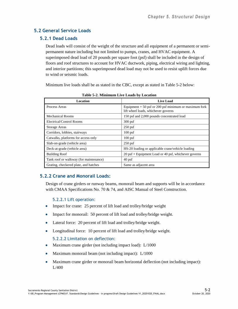
Chapter 5. Structural Design
Sacramento Regional County Sanitation District 5-2 Y:\00_Program Management (CPMO)\F. Standards\Design Guidelines - in progress\Draft Design Guidelines V1_20201020_FINAL.docx October 20, 2020
5.2 General Service Loads
5.2.1 Dead Loads
Dead loads will consist of the weight of the structure and all equipment of a permanent or semi-
permanent nature including but not limited to pumps, cranes, and HVAC equipment. A
superimposed dead load of 20 pounds per square foot (psf) shall be included in the design of
floors and roof structures to account for HVAC ductwork, piping, electrical wiring and lighting,
and interior partitions; this superimposed dead load may not be used to resist uplift forces due
to wind or seismic loads.
Minimum live loads shall be as stated in the CBC, except as stated in Table 5-2 below:
Table 5-2. Minimum Live Loads by Location
Location Live Load
Process Areas Equipment + 50 psf or 200 psf minimum or maximum fork
lift wheel loads, whichever governs
Mechanical Rooms 150 psf and 2,000 pounds concentrated load
Electrical/Control Rooms 300 psf
Storage Areas 250 psf
Corridors, lobbies, stairways 100 psf
Catwalks, platforms for access only 100 psf
Slab-on-grade (vehicle area) 250 psf
Deck-at-grade (vehicle area) HS-20 loading or applicable crane/vehicle loading
Building Roof 20 psf + Equipment Load or 40 psf, whichever governs
Tank roof or walkway (for maintenance) 40 psf
Grating, checkered plate, and hatches Same as adjacent area
5.2.2 Crane and Monorail Loads:
Design of crane girders or runway beams, monorail beam and supports will be in accordance
with CMAA Specifications No. 70 & 74, and AISC Manual of Steel Construction.
5.2.2.1 Lift operation:
Impact for crane: 25 percent of lift load and trolley/bridge weight
Impact for monorail: 50 percent of lift load and trolley/bridge weight.
Lateral force: 20 percent of lift load and trolley/bridge weight.
Longitudinal force: 10 percent of lift load and trolley/bridge weight.
5.2.2.2 Limitation on deflection:
Maximum crane girder (not including impact load): L/1000
Maximum monorail beam (not including impact): L/1000
Maximum crane girder or monorail beam horizontal deflection (not including impact):
L/400

Chapter 5. Structural Design
Sacramento Regional County Sanitation District 5-3 Y:\00_Program Management (CPMO)\F. Standards\Design Guidelines - in progress\Draft Design Guidelines V1_20201020_FINAL.docx October 20, 2020
Where L= span length
Centrifugal force and torsion shall be considered on curve track.
5.2.3 Heavy Equipment Loads
In areas subject to heavy equipment traffic, the structures shall be capable of supporting
existing and planned vehicle loads such as forklifts, maintenance vehicles, mobile cranes, etc.
Consideration shall be given for moving, stationary, and operational loads (such as crane setup
to lift equipment loads), including expected Contractor’s equipment to be used during
construction.
All equipment gallery floors, ground level floors with large access doors shall be designed for
forklift loads or any anticipated maintenance vehicle loads.
The design engineer shall coordinate with the SRWTP Mechanical Maintenance group to
obtain information regarding typical vehicle and crane uses at the SRWTP.
5.2.4 Differential Settlement Loads
For backfilled foundations, the structure shall be checked for a minimum ¼-inch differential
settlement over 20 feet, or as recommended by the geotechnical engineer.
5.2.5 Mechanical Vibration Control
The structural framing for supporting machine vibrations shall be designed at least having
50 percent offset of critical dynamic response of the disturbing force.
5.3 Seismic Loads
Seismic loads and design requirements shall conform to the CBC and the ASCE 7.
The SRWTP’s Seismic Design Category = D, per CBC Section 1613.5.6.
The SRWTP is in Occupancy Category III.
Importance Factor (I) = 1.25
Seismic loads due to earth pressure shall be specified in the project specific geotechnical
report.
Hydrodynamic forces consisting of an impulsive force and a convective force, each
acting at their respective heights, shall be included in the design of liquid-containing
structure walls. Seismic design of liquid-containing concrete structures shall be in
accordance with ACI 350.3.
5.4 Wind Loads
Wind loads and design requirements shall conform to the CBC.
The SRWTP is considered an Occupancy Category III.

Chapter 5. Structural Design
Sacramento Regional County Sanitation District 5-4 Y:\00_Program Management (CPMO)\F. Standards\Design Guidelines - in progress\Draft Design Guidelines V1_20201020_FINAL.docx October 20, 2020
The SRWTP is located in basic wind speed zone of 110 mph per ASCE7-10.
The SRWTP is located in exposure C category.
Wind Importance Factor I = 1.0 per ASCE7-10.
The SRWTP Topographic Factor (Kzt) = 1.0.
5.5 Soil Information
A Geotechnical Interpretation Report (GIR) shall be prepared for the project. The GIR shall
address all of the information needed for compliance with codes, structural design, buried
piping, roads, walkways, and other design elements. The GIR shall emphasize specific
construction concerns and concerns regarding the integrity of sewers, pavement and structures.
The Consultant shall be responsible for establishing the actual scope of work for the GIR.
Recommendations for use in design shall include:
Allowable soil bearing pressures – Dead Loads, Dead Loads + Live Loads, Dead
Loads + Live Loads + short duration loads such as Wind and Earthquakes.
Settlement potential, including total and differential settlement estimates. Differential
settlement shall be given for a specific distance.
Allowable lateral earth pressures – Active, at-rest, passive. Include lateral pressures for
saturated conditions.
Surcharge loading – Construction, traffic.
Friction factors – Soil to concrete base, soil to concrete wall.
Seismic earth pressures and parameters.
Potential geologic and seismic hazards such as ground shaking, liquefaction potential,
and differential settlement due to seismic shaking.
Groundwater table elevation. If groundwater table is expected to be high, a pumping test
shall be required to determine dewatering parameters for inclusion in the specifications.
Buried structures shall be checked for adequacy for buoyant forces. Minimum safety
factor against buoyancy shall be 1.5 for normal ground water elevation, and 1.1 for
flooding water elevation.
Describe and categorize soil types and soil excavation, identify location of hard and stiff
soils, evaluate on-site soil backfill suitability, provide backfill compaction criteria and
pipe bedding requirements, provide trench shoring requirements.
Address in detail the excavation impact of the proposed work on all existing utility
trenches in the vicinity of the proposed project. Evaluate the potential collapse of the
earth prism located between existing parallel utilities and the trench excavated for any
proposed utility installation.
Evaluate soil contamination and identify potential for off-site disposal requirements and
locations.

Chapter 5. Structural Design
Sacramento Regional County Sanitation District 5-5 Y:\00_Program Management (CPMO)\F. Standards\Design Guidelines - in progress\Draft Design Guidelines V1_20201020_FINAL.docx October 20, 2020
5.6 Liquid Loads
A unit weight of 65 pounds per cubic foot (pcf) will be used for the design of structural
elements in contact with liquid. The maximum operating fluid level will be used for the static
load case. Environmental durability factors in accordance with ACI 350 for the appropriate
environmental exposure will be applied to fluid loads for the static load case. In addition to the
static load case, maximum fluid level to the top of an open containment or to the maximum
level possible due to overflow will be used for the overflow case. Environmental durability
factors will not be applied to the overflow loading condition.
5.7 Load Combinations
The above loads will be combined in accordance with Section 1605 of the CBC for non-liquid
containing structures. For liquid containing structures, the above loads will be combined in
accordance with ACI 350, Section 9.2.1. An environmental durability factor will be applied to
load combinations for liquid containing structures as required by Section 9.2.6 of ACI 350.
The design should account for at least two basic soil loading conditions. The first condition to
account for is when the tank is empty and the hydrostatic load is not available to counteract the
soil pressures. The second condition to account for is when the tank is full to the normal
operating level and there is no soil backfill to counteract the hydrostatic pressures.
Vehicular access will be provided to the top of any basin that exceeds 100 feet in any principal
direction for removal and maintenance of equipment.
5.8 Structural Systems
Structures should be designed with appropriate and adequate vertical and lateral load resisting
systems. A description of the structural lateral load resisting systems shall be provided in the
structural calculations and on the drawings.
5.9 Materials – General
General specifications for construction materials shall be as specified in the applicable project
technical specifications.
The following is a list of guidelines to be used with the specific materials.
5.9.1 Concrete
For large projects utilizing large quantities of concrete the source of material and potential for
material shortages shall be investigated during the design phase for implementing an
uninterrupted material procurement plan.
All construction and expansion joints shall be shown on the contract drawings. Construction
joints shall be placed at points of least shear in suspended slabs and beams. The distance
between construction joints shall not exceed 30 feet in walls and 40 feet in slabs.
Chapter 5. Structural Design
Sacramento Regional County Sanitation District 5-6 Y:\00_Program Management (CPMO)\F. Standards\Design Guidelines - in progress\Draft Design Guidelines V1_20201020_FINAL.docx October 20, 2020
All construction and expansion joints in liquid-containing structures shall be provided with
waterstops.
Minimum shrinkage reinforcing will be based on ACI 350 and the grade of reinforcing steel
used. Contraction joints will not be considered as a “movement joint”. Only full expansion
joints will be considered as a “movement joint” to reduce the minimum shrinkage and
temperature reinforcement.
Appropriate environmental exposures in accordance with ACI 350 will be used to determine
the maximum allowable stresses of the flexural reinforcement.
On liquid containing concrete structures rounded fillets shall be provided at wall to floor joints
to prevent debris accumulation.
Reinforcing steel shall conform to ASTM A615 or ASTM A706, Grade 60.
Liquid-containing concrete structures shall be designed to conform to ACI 350. Special
attention shall be taken with the performance specifications for concrete for obtaining durable,
low shrinkage, concrete mix designs. Water curing should be specified for minimum
shrinkage.
For concrete at containment tanks and basins, furnish concrete suitable for the following
exposure categories based on ACI 318:
Permeability: P1 (Low Permeability Required)
Corrosion Protection: C2 (Severe) at slabs rated for vehicular traffic and tanks
containing chlorides. C1 (Moderate) at all other areas.
Concrete structures that are protected with a lining system shall have seams located at least
12 inches away from 90-degree corners.
5.9.2 Masonry
Reinforced masonry shall be designed in accordance with Chapter 21 of the CBC and ACI 530.
Masonry structures shall be designed using a specified compressive strength (f’m) of 1,500 psi.
Higher compressive strengths require more expensive prism testing and more comprehensive
special inspection program.
All reinforced masonry construction requires special inspection.
5.9.3 Structural Steel
All structural steel members and connections shall be designed and detailed in accordance with
AISC Specification for Building Structures. The design of structural connections shall not be
left to the detailed shop drawings.

Chapter 5. Structural Design
Sacramento Regional County Sanitation District 5-7 Y:\00_Program Management (CPMO)\F. Standards\Design Guidelines - in progress\Draft Design Guidelines V1_20201020_FINAL.docx October 20, 2020
All structural steel connections shall be made with high strength bolts conforming to
ASTM A325 Type N, bearing type connections with threads excluded from the shear plane,
unless otherwise required by the design. The use of machine bolts shall be limited to non-
structural applications.
All steel welding qualification and workmanship shall be in accordance with AWS.
Wide Flange shapes shall conform to ASTM A992, Grade 50.
Hollow Structural Sections (HSS) shall conform to ASTM A500, Grade B.
Structural Steel Pipe shall conform to ASTM A53, Grade B.
5.9.4 Stainless Steel
Type 304 or 316 stainless steel bars, shapes, plates, fasteners, and anchor bolts shall be
considered for use in corrosive or submerged areas for long life and low maintenance.
Type 316 stainless steel is a Molybium containing grade which is more resistant to localized
corrosion and is preferred for more aggressive conditions, or for greater assurance against
unusual conditions. For MCCs the use of Type 304 stainless steel anchor bolts could be
appropriate. In all cases, a business case evaluation (BCE) should determine material type.
Type 304L or 316L stainless steel shall be used for welded construction; these low carbon
grades are resistant to intergranular corrosion after welding without further heat treatment.
5.9.5 Aluminum
Aluminum shall not be used without specific approval by Regional San .
Aluminum shall be selectively used for miscellaneous structural support systems, walkway
grating and diamond plate, handrailing and guardrailing, and cover plates to reduce odors.
Severe corrosion conditions shall be considered before specifying aluminum.
Aluminum alloy for structural shapes, bars, plates, and sheets shall be 6061-T6.
Bolts and fasteners for aluminum fabrication shall be Type 316 or Type 304 stainless steel.
5.9.6 Fiberglass Reinforced Plastic
FRP or reinforced thermoset polyester (RTP) shall not be used without specific approval by
Regional San.
FRP or RTP shall be selectively used for grating, guardrail, and cover plates in corrosive areas,
explosive environments, or electrical areas.
A responsible party specializing in fiberglass design shall design FRP or RTP structural
elements.

Chapter 5. Structural Design
Sacramento Regional County Sanitation District 5-8 Y:\00_Program Management (CPMO)\F. Standards\Design Guidelines - in progress\Draft Design Guidelines V1_20201020_FINAL.docx October 20, 2020
FRP and RTP products shall be manufactured using pultruded process utilizing either flame
retardant isotropic polyester or a flame-retardant vinyl ester resin containing an ultra-violet
(UV) inhibitor.
5.9.7 Wood
Unless otherwise approved due to nature of the project, the use of wood construction in
permanent structures shall be limited to nonstructural applications such as nailers, cabinetry,
etc.
5.9.8 Metal Framing (Strut Type) Inserts
Metal framing (strut type) inserts used for support of equipment and appurtenances shall be
embedded at 5 feet on center vertically in all concrete walls and horizontally in concrete
ceilings.
Metal framing (strut type) inserts shall be embedded at the stem bottom of precast “T” beams.
Reinforcing steel in concrete structures shall be placed at least 1.5 inches from the embedded
face of the metal framing strut.
5.9.9 Seismic Bracing
Seismic bracing shall be included in the Contract Documents for pipes larger than 18 inches,
HVAC, electrical conduits, and light fixtures. The design of pipe supports and racks shall be in
accordance with the latest edition of ASCE 7.
Seismic bracing for pipes larger than 18 inches, non-standard bracing systems for critical
equipment, or where the location of the seismic bracing is critical, the contract documents shall
identify the location.
5.10 Design Loads on Drawings
In order to furnish information for future use, all live loads used in the design of a structure
shall be listed under the general notes on the standard structural drawings.
For loadings that do not comply with the general notes, loading information shall be shown and
noted on the plan of the area being designed for the special loads.
5.11 Serviceability
Structural systems and members shall be designed to have adequate stiffness to limit deflection
and lateral drift. The deflection of structural members over span L, shall not exceed that
permitted by the following table.
Element Deflection
Steel Floor Plates and Gratings L/240 Live Load
Beams, Lintels, or Slabs Supporting Masonry L/720 (3/8 inch maximum for lintels above windows)
total load
Roof without Ceilings L/240 Live Load, L/180 Total Load
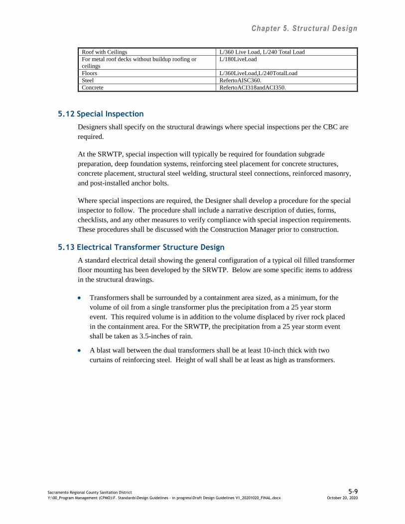
Chapter 5. Structural Design
Sacramento Regional County Sanitation District 5-9 Y:\00_Program Management (CPMO)\F. Standards\Design Guidelines - in progress\Draft Design Guidelines V1_20201020_FINAL.docx October 20, 2020
Roof with Ceilings L/360 Live Load, L/240 Total Load
For metal roof decks without buildup roofing or
ceilings
L/180LiveLoad
Floors L/360LiveLoad,L/240TotalLoad
Steel RefertoAISC360.
Concrete RefertoACI318andACI350.
5.12 Special Inspection
Designers shall specify on the structural drawings where special inspections per the CBC are
required.
At the SRWTP, special inspection will typically be required for foundation subgrade
preparation, deep foundation systems, reinforcing steel placement for concrete structures,
concrete placement, structural steel welding, structural steel connections, reinforced masonry,
and post-installed anchor bolts.
Where special inspections are required, the Designer shall develop a procedure for the special
inspector to follow. The procedure shall include a narrative description of duties, forms,
checklists, and any other measures to verify compliance with special inspection requirements.
These procedures shall be discussed with the Construction Manager prior to construction.
5.13 Electrical Transformer Structure Design
A standard electrical detail showing the general configuration of a typical oil filled transformer
floor mounting has been developed by the SRWTP. Below are some specific items to address
in the structural drawings.
Transformers shall be surrounded by a containment area sized, as a minimum, for the
volume of oil from a single transformer plus the precipitation from a 25 year storm
event. This required volume is in addition to the volume displaced by river rock placed
in the containment area. For the SRWTP, the precipitation from a 25 year storm event
shall be taken as 3.5-inches of rain.
A blast wall between the dual transformers shall be at least 10-inch thick with two
curtains of reinforcing steel. Height of wall shall be at least as high as transformers.

Chapter 6. Mechanical Process Design Guidelines
Sacramento Regional County Sanitation District 6-1 Y:\00_Program Management (CPMO)\F. Standards\Design Guidelines - in progress\Draft Design Guidelines V1_20201020_FINAL.docx October 20, 2020
6.0 Mechanical Process Design
The following are the design guidelines to be utilized in conjunction with the mechanical process
design.
6.1 Codes and Standards
The project shall be designed to comply with applicable portions of the following codes and
standards in Table 6-1 below and as described in this chapter. Designer is to use the most
current County-adopted code edition as posted to
www.building.saccounty.net/pages/buildingcodes.aspx up to submission of the Final
Preliminary Design Report (PDR); the Designer is not responsible for any newer editions
beyond Final PDR.
Table 6-1. Codes and Standards for Mechanical Process Design
ABMA American Bearing Manufacturer’s Association Standards
AGMA American Gear Manufacturer’s Association Standards
ASHRAE 90A American Society of Heating, Refrigeration and Air
Conditioning Engineers, Energy Conservation in New
Building Design
ASME B&PV American Society of Mechanical Engineers Boiler and
Pressure Vessel Code
ASTM American Society for Testing and Materials Standards
HI Hydraulic Institute Standards
OSHPD California Office of Statewide Health Planning and
Development
UMC Uniform Mechanical Code
UPC Uniform Plumbing Code
6.2 Mechanical Design Intent
Provide a description of each mechanical system in the Preliminary Design Report, including
major components, criticality value from Regional San’s Availability of Critical Equipment
(ACE) Table (see Section 6.15), sequence of operation, remote and local control modes of
operation for use by the control system design. Motors shall be supplied by the equipment
manufacturer. 480V, 3ØElectrical starters shall be located in electrical equipment rooms.
Single-phase motor starters and controllers shall be located near the driven equipment,
Coordinate mechanical drive requirements with the electrical design.
6.3 Mechanical Design Calculations
Provide mechanical calculations, pump and fan performance curves, and a range of operating
points for all equipment and systems. The system curves should provide operations zones for
various operation modes, such as winter and summer modes; cycle modes, and slow/fast modes
if applicable.
For units that have fast and slow speed operations, units should be properly sized such that
slow speed is utilized a majority of runtime hours at highest efficiency.
Chapter 6. Mechanical Process Design Guidelines
Sacramento Regional County Sanitation District 6-2 Y:\00_Program Management (CPMO)\F. Standards\Design Guidelines - in progress\Draft Design Guidelines V1_20201020_FINAL.docx October 20, 2020
For units that have temperature requirements, temperature assumptions and respective
operational mode described (i.e. heat exchanger pumping)
For systems that cycle between multiple units the cycle times should be optimized for various
modes (i.e. wet and dry modes, flushing modes)
For units controlled by variable frequency drives (VFDs) and larger than 100hp or system with
multiple units greater than 25 hp provide system performance curves that plot the variable
frequency curves against the system curves; various parameters; and operating modes. A
typically graph layout should have head on the y-axis, flow on the x-axis with selected
parameter (hydraulic efficiency, BHP, system head) plotted along various frequency curves
(i.e. 20hz, 30hz, 40hz, 50hz, 60hz). Various operational ranges (i.e., dry, wet, low and high
temperature) appropriate to system type should be superimposed onto the graphs along with the
system curve.
Specific design deliverable requirements are described in Regional San’s Design Contract
Requirements.
6.4 Mechanical Equipment
Where required, equipment shall be reviewed for reliability, performance, and maintainability.
Equipment selection shall be made using the latest version of Regional San’s Capital Program
Management Office (C-PMO) template for the preparation of an Equipment Business Case
Evaluation (BCE) and the requirements for Reliability Centered Design (RCD).
6.4.1 Equipment Clearance and Removal
Provide more than adequate clearance for service or removal of equipment while adjacent
equipment is in operation. Coordinate with structural design the location of hatches, removable
partitions, landing areas, roll up doors, and bridge cranes to facilitate major equipment removal
and loading for transportation. Regional San places a high emphasis on the maintainability of
its mechanical systems.
6.4.2 Steam Equipment
For equipment utilizing steam, such as steam-to-hot water heat exchangers, the design working
pressure shall be at least 175 pounds per square inch (psi) saturated steam pressure.
6.4.3 Gauges
Gauges are required for the operator to monitor equipment performance during rounds. Provide
gauges on equipment for local readout at a minimum in the following locations:
Pump suction (as appropriate) and discharge lines shall be provided with local pressure
gauges for maintenance.
Pump flush water systems shall be provided with local gauges: pressure gauges and
rotameters. Provide PVC or poly tubing after the wye strainer for flushing of water lines

Chapter 6. Mechanical Process Design Guidelines
Sacramento Regional County Sanitation District 6-3 Y:\00_Program Management (CPMO)\F. Standards\Design Guidelines - in progress\Draft Design Guidelines V1_20201020_FINAL.docx October 20, 2020
(Galvanized pipe grows tubercles, causing clogs and/or break away that damages the
mechanical seals).
Lines with increased risk of plugging (thickened sludge, grit, etc.) shall be provided
with local pressure gauges where plugs are likely to occur (near valves, elbows and
horizontal legs).
Consider locating piping taps (w/ plugs) at intervals along problematic lines so gauges can
be easily installed later to assist in locating plugs.
Gauges on lines containing wastewater, sludge, or chemicals shall be isolated with
diaphragm or annular seals.
During design, Regional San operations staff shall be engaged to verify what local
gauges are required for the specific system being designed.
6.4.4 Recommended Equipment Types:
Regional San recommends specific types of equipment as a starting point for design based on
previous equipment experiences. Table 6-2 lists the type of equipment recommended by
Regional San for various services:
Table 6-2. Types of Process Mechanical Equipment
Service Type of Equipment
Circulating Sludge Chopper Pump, Vaughan or Wemco
Condensate (Steam) Pumping Traps.
CWS Primary Pumps (large) Double Suction Centrifugal Pumps.
CWS Secondary Pumps (large) End Suction Centrifugal Pumps.
CWS Secondary Pumps (small) In-line Centrifugal Pumps
Digested Sludge at Processing
Digesters
Progressive Cavity Pumps
Digested Sludge at Blending
Digesters
Progressive Cavity Pumps
Effluent Non-clog Centrifugal Pumps.
Grinders Spherical Rotor Grinder.
Grit Recessed Impeller Pump. Wemco Model C or Twin Pump.
HRS Primary Pumps (large) Double Suction Centrifugal Pumps.
HRS Secondary Pumps (large) End Suction Centrifugal Pumps. (Motor max Speed 1800 RPM)
HRS Secondary Pumps (small) In-line Centrifugal Pumps
Influent Non-clog Centrifugal Pumps.
Mixed Sludge Chopper Pump, Vaughan or Wemco
Pumped Drainage Submersible Pump (1st choice)
Self-priming Centrifugal Pump (2nd choice)
Primary Scum Progressive Cavity Pumps
Primary Sludge Progressive Cavity Pumps
Thickened Waste Activated
Sludge
Progressive Cavity Pumps
Thickened Waste Activated
Sludge Float
Rotary Lobe Pump

Chapter 6. Mechanical Process Design Guidelines
Sacramento Regional County Sanitation District 6-4 Y:\00_Program Management (CPMO)\F. Standards\Design Guidelines - in progress\Draft Design Guidelines V1_20201020_FINAL.docx October 20, 2020
6.5 Hydraulics
Specific hydraulic design criteria, standards, and guidelines are summarized in this section.
6.5.1 Design Flow
Pressure pipe and pumping systems should be designed for the following flow conditions:
1. Peak flow at the design year;
2. Most common flow for the particular system. A variety of flow analysis and system
control may be required to ensure proper selection that optimizes energy usage.
Examples include:
Average annual flow and mid-point between initial operating year and design year
Diurnal flow patterns based on time of day.
Winter flow patterns vs. summer flow patterns ;
For systems that cycle between multiple units the cycle times should be optimized
for various modes (i.e. wet and dry modes, flushing modes)
3. Minimum flow at initial operating year.
6.5.2 Design of Pressure Piping
Because pump system curves are largely dependent on the piping system layout, design
guidelines for piping systems are presented. Criteria for the design of piping systems include
various velocity considerations, major losses, minor losses, surge issues, and piping
characteristics. Each is discussed below.
6.5.2.1 Velocity
At the design peak flow, with all pumps except the standby pump(s), the maximum velocity in
pressure lines should not exceed 8 ft/sec. Some exceptions are possible for discharge lines
shorter than 10 feet or pipes with diameters greater than 36 inches. Minimum velocity in the
solids bearing fluid at minimum flow shall not be less than 2 ft/sec or 3.5 ft/sec depending on
continuous versus intermittent pumping operations. Where grit is present, adjust velocity
sufficient to maintain solids in suspension. Additional velocity design criteria can be found in
the ASCE Journal of Hydraulic Engineering (April 2003) for the velocity required to keep sand
moving up slopes in inverted siphons.
For solids bearing fluid, vertical discharge piping on pumps with VFDs should be sized to
maintain minimum design velocities during a programmed initial flushing period. VFDs should
be designed and programmed to provide a flushing velocity in the pressure line of at least
3.5 ft/sec at the beginning of each pumping cycle. After an initial flushing of the maximum
practical duration, depending on the wet well volume, the pumping velocity may be reduced.
Velocities should not be allowed to fall below 2 ft/sec.
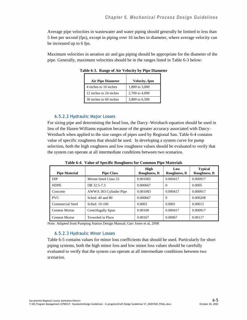
Chapter 6. Mechanical Process Design Guidelines
Sacramento Regional County Sanitation District 6-5 Y:\00_Program Management (CPMO)\F. Standards\Design Guidelines - in progress\Draft Design Guidelines V1_20201020_FINAL.docx October 20, 2020
Average pipe velocities in wastewater and water piping should generally be limited to less than
5 feet per second (fps), except in piping over 16 inches in diameter, where average velocity can
be increased up to 6 fps.
Maximum velocities in aeration air and gas piping should be appropriate for the diameter of the
pipe. Generally, maximum velocities should be in the ranges listed in Table 6-3 below:
Table 6-3. Range of Air Velocity by Pipe Diameter
Air Pipe Diameter Velocity, fpm
4 inches to 10 inches 1,800 to 3,000
12 inches to 24 inches 2,700 to 4,000
30 inches to 60 inches 3,800 to 6,500
6.5.2.2 Hydraulic Major Losses
For sizing pipe and determining the head loss, the Darcy–Weisbach equation should be used in
lieu of the Hazen-Williams equation because of the greater accuracy associated with Darcy–
Weisbach when applied to the size ranges of pipes used by Regional San. Table 6-4 contains
value of specific roughness that should be used. In developing a system curve for pump
selection, both the high roughness and low roughness values should be evaluated to verify that
the system can operate at all intermediate conditions between two scenarios.
Table 6-4. Value of Specific Roughness for Common Pipe Materials
Pipe Material
Pipe Class
High
Roughness, ft
Low
Roughness, ft
Typical
Roughness, ft
DIP Mortar-lined Class 53 0.001083 0.000417 0.000917
HDPE DR 32.5-7.3 0.000667 0 0.0005
Concrete AWWA 303 Cylinder Pipe 0.001083 0.000417 0.000917
PVC Sched. 40 and 80 0.000667 0 0.000208
Commercial Steel Sched. 10-160 0.0003 0.0001 0.00015
Cement Mortar Centrifugally Spun 0.00108 0.000417 0.000917
Cement Mortar Troweled in Place 0.00167 0.00067 0.00117
Note: Adapted from Pumping Station Design Manual; Garr Jones et al, 2008
6.5.2.3 Hydraulic Minor Losses
Table 6-5 contains values for minor loss coefficients that should be used. Particularly for short
piping systems, both the high minor loss and low minor loss values should be carefully
evaluated to verify that the system can operate at all intermediate conditions between two
scenarios.

Chapter 6. Mechanical Process Design Guidelines
Sacramento Regional County Sanitation District 6-6 Y:\00_Program Management (CPMO)\F. Standards\Design Guidelines - in progress\Draft Design Guidelines V1_20201020_FINAL.docx October 20, 2020
Table 6-5. Value of Minor Loss Coefficients for Common Fittings and Valves
Type of Minor Loss High Loss Low Loss Typical Loss
90 Elbow, standard 0.4 0.1 0.25
90 Elbow, long radius 0.4 0.1 0.18
45 Elbow 0.3 0.1 0.18
22 Elbow 0.15 0.08 0.1
Branch Tee 3 0.4 0.75
Passing Tee 1.4 0.08 0.3
Gate 0.3 0.1 0.2
Globe 6 4 5
Swing Check 2.2 0.6 2
Butterfly 0.35 0.16 0.3
Plug 1 0.5 0.6
Note: Adapted from Pumping Station Design Manual; Garr Jones et al, 2008
6.5.2.4 Surge Issues
Surge analysis, or hydraulic transient analysis, for the pump system, pressure lines, and
appurtenances (air release valves) should be performed if one of the following conditions
exists:
1. Pumping total dynamic head (TDH) is greater than 40 feet and flow exceeds 500 gpm.
2. Pipelines have high points or “knees”. Power failures can cause a partial vacuum at the
knee and can result in column separation (with only water vapor in the pipe at the knee).
Surge mitigation can be accomplished by the following control strategies:
a. Reroute force mains to avoid knees by removing or relocating obstructions.
b. Use pump control valves that open and close gradually.
c. Increase rotating moment of inertia by adding a flywheel (with oversized bearings).
d. Use engine drives on some pumps so the entire system cannot fail at once.
e. VFDs guard against continual pounding at startup and shut down but do not protect
from power failure.
f. Add sewage rated air-vacuum relief valves at critical points.
g. Hydropneumatic tanks. If specified, hydropneumatic tanks should be designed,
fabricated, and tested in accordance with the ASME Code for Unfired Pressure
Vessels, and should be equipped with compressed air system controls to maintain
air-to-water ratio.
6.5.2.5 Piping Characteristics
Suction piping diameter to the pump should be at least one size larger than the pump inlet
diameter.

Chapter 6. Mechanical Process Design Guidelines
Sacramento Regional County Sanitation District 6-7 Y:\00_Program Management (CPMO)\F. Standards\Design Guidelines - in progress\Draft Design Guidelines V1_20201020_FINAL.docx October 20, 2020
6.5.3 Pipeline Features and Appurtenances
Pumping systems should be designed so that the pipeline is always full and the vertical
alignment should never go above the energy grade line. The number of low and high points
should be kept to a minimum because high points can lead to air traps and sulfide corrosion. If
high and low points are unavoidable, air relief/vacuum (rated for type of service) and sewage-
rated blowoff valves should be installed respectively at high and low points. If possible,
blowoff valves should discharge to a sanitary sewer manhole. Sewage-rated valves should be
used for any service where solids may be present. Cleanout or flushing attachments to facilitate
maintenance should be provided. Valve location versus the pipe cross section should consider
the potential for scum and grease accumulation.
A 2-inch ball valve with a vent line should be provided on the top of the pump volute discharge
to allow removal of air after servicing and prior to placing dry well pumps back in service. The
vent line should be plumbed to discharge to the wet well or to the plant drain.
To avoid shearing force mains due to differential settlement, a minimum of two flex couplings
should be used on pipelines when exiting structures and vaults. Thrust forces in pressure lines
should be mitigated through joints that are restrained or anchored to prevent excessive
movement and joint separation.
6.6 Pump Selection Criteria
Hydraulic design and pump selection is an iterative process that is dependent on pump
operating levels, dimensions and characteristics. The process starts by developing the high and
low system curves assuming static and dynamic loss conditions and then selecting a pump that
matches those conditions. The pump’s dimensions are then used to verify that the pump meets
the standards set by the American National Standards Institute/Hydraulic Institute Standards
(HI Standards).
Pumps should be selected to operate under the full range of projected system hydraulic
conditions. Evaluation of both new and aged pipe conditions should be used to determine the
limits of pumping conditions while minimizing opportunities for pump runout. There are a
number of critical constraints and criteria for selecting pumps. Selection criteria constituting
good practice should include the following:
1. Suction specific speed preferred value should be 8,500 and the acceptable value
should be no greater than 10,000 where:
Nss = 𝑛√𝑄𝑏𝑒𝑝
(𝑁𝑃𝑆𝐻3𝑏𝑒𝑝)0.75
Nss = Suction Specific Speed, (U.S. Units)
𝑛 = Speed at rated condition, rpm
Qbep = Flow, gpm at best efficiency point (BEP)
NPSH3bep = Net Positive Suction Head at 3 percent loss of head at
BEP, feet H2O
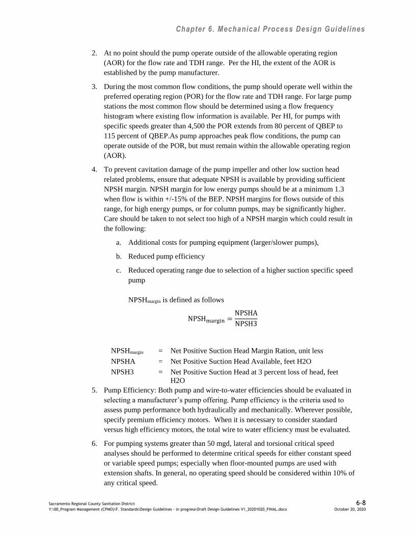
Chapter 6. Mechanical Process Design Guidelines
Sacramento Regional County Sanitation District 6-8 Y:\00_Program Management (CPMO)\F. Standards\Design Guidelines - in progress\Draft Design Guidelines V1_20201020_FINAL.docx October 20, 2020
2. At no point should the pump operate outside of the allowable operating region
(AOR) for the flow rate and TDH range. Per the HI, the extent of the AOR is
established by the pump manufacturer.
3. During the most common flow conditions, the pump should operate well within the
preferred operating region (POR) for the flow rate and TDH range. For large pump
stations the most common flow should be determined using a flow frequency
histogram where existing flow information is available. Per HI, for pumps with
specific speeds greater than 4,500 the POR extends from 80 percent of QBEP to
115 percent of QBEP.As pump approaches peak flow conditions, the pump can
operate outside of the POR, but must remain within the allowable operating region
(AOR).
4. To prevent cavitation damage of the pump impeller and other low suction head
related problems, ensure that adequate NPSH is available by providing sufficient
NPSH margin. NPSH margin for low energy pumps should be at a minimum 1.3
when flow is within +/-15% of the BEP. NPSH margins for flows outside of this
range, for high energy pumps, or for column pumps, may be significantly higher.
Care should be taken to not select too high of a NPSH margin which could result in
the following:
a. Additional costs for pumping equipment (larger/slower pumps),
b. Reduced pump efficiency
c. Reduced operating range due to selection of a higher suction specific speed
pump
NPSHmargin is defined as follows
NPSHmargin =NPSHA
NPSH3
NPSHmargin = Net Positive Suction Head Margin Ration, unit less
NPSHA = Net Positive Suction Head Available, feet H2O
NPSH3 = Net Positive Suction Head at 3 percent loss of head, feet
H2O
5. Pump Efficiency: Both pump and wire-to-water efficiencies should be evaluated in
selecting a manufacturer’s pump offering. Pump efficiency is the criteria used to
assess pump performance both hydraulically and mechanically. Wherever possible,
specify premium efficiency motors. When it is necessary to consider standard
versus high efficiency motors, the total wire to water efficiency must be evaluated.
6. For pumping systems greater than 50 mgd, lateral and torsional critical speed
analyses should be performed to determine critical speeds for either constant speed
or variable speed pumps; especially when floor-mounted pumps are used with
extension shafts. In general, no operating speed should be considered within 10% of
any critical speed.
Chapter 6. Mechanical Process Design Guidelines
Sacramento Regional County Sanitation District 6-9 Y:\00_Program Management (CPMO)\F. Standards\Design Guidelines - in progress\Draft Design Guidelines V1_20201020_FINAL.docx October 20, 2020
7. The pump should have a head–capacity curve that rises continuously from its BEP
to shutoff.
6.7 Wet Well Sizing Criteria for Start/Stop Pumping
To prevent excessive pump starts, the wet well volume required must be checked and compared
against the available volume (including upstream channel volume). The minimum wet well
volume required is calculated by the following formula:
V =𝑇𝑄
4
V = Minimum active wet well volume, gal
Q = Pumping capacity, gpm
T = Allowable minimum cycle time
The above equation is derived based on the relationship that pumps will cycle the most when
the influent flow is half the capacity of the pump. Wet wells with constant speed (C/S) pumps
should be sized based on the equation above. For variable speed pumps, operational volume
should be evaluated considering minimum pump speed and cycle time. Starts per hour for non-
submersible pump motors in a dry pit arrangement should be limited to 6 starts per hour for
200 horsepower or less. Larger dry pit motors would be limited to 3-4 starts per hour or less.
Submersible motors in a submerged application would have more allowable starts per hour due
to improved heat transfer. Submersible motors that are 100 horsepower or smaller can have up
to 8 starts per hour. Larger submersible motors should be maintained at a maximum of 6 starts
per hour.
6.8 Process Piping
Process piping systems shall have the following features:
1. Process piping materials shall conform to Regional San’s Guide Specifications, where
available. Materials can be modified for specific conditions based on process area
locations.
2. Piping shall be located with consideration for maintenance and known future
improvements. Avoid locating piping where it cannot be replaced in the future.
3. Provide isolation valves throughout piping systems including mains and branches.
Additional valves provide operations and maintenance flexibility.
4. Provide PCCS monitored flow and pressure transmitters throughout the distribution
system at key mains and branches for the purpose of detecting leaks and broken valves.
5. To reduce unnecessary shutdowns of process systems, loop utility piping systems
where practical.

Chapter 6. Mechanical Process Design Guidelines
Sacramento Regional County Sanitation District 6-10 Y:\00_Program Management (CPMO)\F. Standards\Design Guidelines - in progress\Draft Design Guidelines V1_20201020_FINAL.docx October 20, 2020
6. All exterior equipment/piping that is fiberglass/PVC etc. shall have a screen, cover, or
coating that prevents direct exposure to sunlight.
7. All exposed piping shall be labeled with the name of the content as well as direction of
flow. Labels shall be placed as necessary to allow the pipe to be traced from end to
end.
8. Provide bypass to allow startup and testing for all equipment.
6.8.1 Air Piping
Air piping systems shall have the following features:
1. Provide flow and pressure meters throughout the distribution system limited to key
mains and branches for the purpose of detecting air leaks and broken valves/actuators.
The pressure and flow meter information should reside in the PCCS.
2. If piping is required to be covered with insulation then it is preferred that materials
provided reduce the ability of air leaks to travel in insulation material undetected.
Otherwise provide other methods (i.e. reduce insulation spans) that improve the ability
to detect leaks in long pipe spans.
3. Where possible low pressure or high pressure compressed air sources should be located
as close to use point as possible to reduce the leak potential.
6.8.2 Flow Measuring
Application of flow measurement requires evaluation of the total cost, flow profile, flowing
condition, Reynolds number, density, turndown, mechanical installation constraints and
accuracy requirements. Turndown shall be selected so that the flowmeter has the ability to
cover the range of flow rates within specified accuracy limits. Calculate the Reynolds number
for the minimum and maximum flow rates. Minimum Reynolds number is calculated by using
the minimum expected fluid flow and density and the maximum expected viscosity. A
maximum Reynolds number is calculated using the maximum expected fluid flow and density
and the minimum expected viscosity. Use Moody’s charts to compensate for pipe or channel
roughness and select piping or channel size to accommodate the required flow profile over the
entire operating range. Locate flowmeters to suit the specific technology requirements.
Magnetic flowmeters are the preferred type for pipelines and typically require a full pipe and
straight pipe lengths of 5x upstream and 3x diameter downstream of their location. Multiple
path transit-time acoustic flowmeters are the preferred type for channels or large pipes and
typically require straight pipe or channel lengths of 10x upstream and 2x diameter downstream
of their location. For difficult conditions consider flow conditioners as necessary to isolate the
liquid flow disturbances from the flowmeter while minimizing the pressure drop across the
conditioner. The flow conditioner should remove swirls from the fluid stream and allow the
profile velocity to come up to fully developed turbulent flow, or at least a stable acceptable
geometry. Coordinate meter installation requirements with Structural design for channels and
I&C design for location.
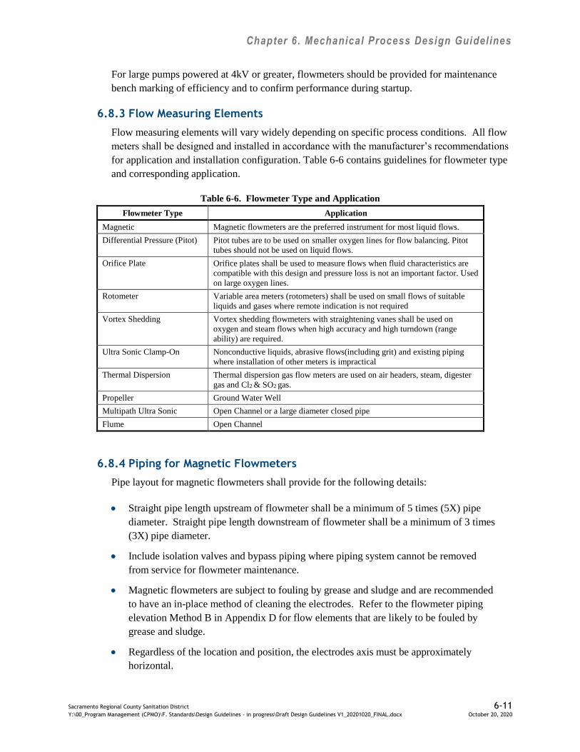
Chapter 6. Mechanical Process Design Guidelines
Sacramento Regional County Sanitation District 6-11 Y:\00_Program Management (CPMO)\F. Standards\Design Guidelines - in progress\Draft Design Guidelines V1_20201020_FINAL.docx October 20, 2020
For large pumps powered at 4kV or greater, flowmeters should be provided for maintenance
bench marking of efficiency and to confirm performance during startup.
6.8.3 Flow Measuring Elements
Flow measuring elements will vary widely depending on specific process conditions. All flow
meters shall be designed and installed in accordance with the manufacturer’s recommendations
for application and installation configuration. Table 6-6 contains guidelines for flowmeter type
and corresponding application.
Table 6-6. Flowmeter Type and Application
Flowmeter Type Application
Magnetic Magnetic flowmeters are the preferred instrument for most liquid flows.
Differential Pressure (Pitot) Pitot tubes are to be used on smaller oxygen lines for flow balancing. Pitot
tubes should not be used on liquid flows.
Orifice Plate Orifice plates shall be used to measure flows when fluid characteristics are
compatible with this design and pressure loss is not an important factor. Used
on large oxygen lines.
Rotometer Variable area meters (rotometers) shall be used on small flows of suitable
liquids and gases where remote indication is not required
Vortex Shedding Vortex shedding flowmeters with straightening vanes shall be used on
oxygen and steam flows when high accuracy and high turndown (range
ability) are required.
Ultra Sonic Clamp-On Nonconductive liquids, abrasive flows(including grit) and existing piping
where installation of other meters is impractical
Thermal Dispersion Thermal dispersion gas flow meters are used on air headers, steam, digester
gas and Cl2 & SO2 gas.
Propeller Ground Water Well
Multipath Ultra Sonic Open Channel or a large diameter closed pipe
Flume Open Channel
6.8.4 Piping for Magnetic Flowmeters
Pipe layout for magnetic flowmeters shall provide for the following details:
Straight pipe length upstream of flowmeter shall be a minimum of 5 times (5X) pipe
diameter. Straight pipe length downstream of flowmeter shall be a minimum of 3 times
(3X) pipe diameter.
Include isolation valves and bypass piping where piping system cannot be removed
from service for flowmeter maintenance.
Magnetic flowmeters are subject to fouling by grease and sludge and are recommended
to have an in-place method of cleaning the electrodes. Refer to the flowmeter piping
elevation Method B in Appendix D for flow elements that are likely to be fouled by
grease and sludge.
Regardless of the location and position, the electrodes axis must be approximately
horizontal.

Chapter 6. Mechanical Process Design Guidelines
Sacramento Regional County Sanitation District 6-12 Y:\00_Program Management (CPMO)\F. Standards\Design Guidelines - in progress\Draft Design Guidelines V1_20201020_FINAL.docx October 20, 2020
To reduce vibration, support the pipeline on both sides of the flowmeter.
Large meter sizes (>8-inch), require additional spool pieces to permit axial shifting of
counter-flanges to facilitate installation.
Avoid strong electromagnetic fields in vicinity of flowmeter.
Do not insulate flowmeter where installed on thermally insulated pipes.
To avoid measuring errors due to debris or air inclusion, observe the following:
Arrange piping so the flowmeter is full of liquid. Install flowmeters in horizontal lines
with 2º upward slope or preceding and upward elbow. Where practical locate
flowmeters in vertical lines with upwards flow.
The pipe configuration shall avoid a buildup or accumulation of any secondary phase
(solids or air). Entrained air shall be carried out of the meter by flow, or by buoyancy
(at zero flow). Solids shall fall from the meter by gravity under zero flow.
For unlined conducting pipe grounding straps shall be required to be bonded between
the pipe flanges and flowmeter flanges with one side connected to ground. Non-
conducting pipe or insulated lined pipes shall be required to have grounding rings
bonded between the pipe flanges and flowmeter flanges with one side connected to
ground.
Avoid installing in the highest point of the line. For an open feed or discharge, install
flowmeter in the low section of pipe.
Where flow tubes are installed in locations with restricted access, locate the transmitter
remotely at 48 inches above floor and within the maximum recommended cable length
between flow tube and transmitter.
Meter size shall be selected to provide nominal velocity requirements of 6 to 9 feet per
second (ft/sec), minimum full scale range is 1.5 ft/sec; maximum is 30 ft/sec,
depending on flowmeter type.
For solids bearing fluids, the velocity should be between 9 and 15 ft/sec to prevent
deposits.
Reducing and expanding from the carrier pipe to a smaller meter size may prove to be
more economical for pipe runs with a low flow velocity. The pressure loss resulting
from pipe reduction/expansion and from the greater velocity in the flowmeter spool
head shall be calculated.
Specific process requirements may warrant consideration of Venturi tubes, flow
nozzles, propeller meters, weirs, and flumes.

Chapter 6. Mechanical Process Design Guidelines
Sacramento Regional County Sanitation District 6-13 Y:\00_Program Management (CPMO)\F. Standards\Design Guidelines - in progress\Draft Design Guidelines V1_20201020_FINAL.docx October 20, 2020
6.8.5 Piping for Non-Magnetic Flowmeters
When compared to magnetic flowmeters, non-magnetic flowmeters are more sensitive to piping
configurations. Refer to the flowmeter piping requirements table in Appendix E (per
www.preferred-mfr.com) for guidelines on diameters of straight pipe for various types of
flowmeters and piping configurations.
6.9 Equipment Anchorages
The construction contractor shall design the equipment anchorages as part of the equipment
submittal.
6.10 Pipe Supports and Racks
The design of pipe supports and racks shall be in accordance with the latest edition of ASCE 7.
For standard process pipes 12 inches or less that do not have significant thermal expansion
issues, the design engineer shall provide anchoring tables and standard details and the
contractor shall show the actual location of the pipe supports in the Contractor’s pipe layout
shop drawing submittal. For standard process pipes, the design engineer should verify
appropriateness of any typical pipe support detail used on the project for worst-case loading
and configuration.
Any process pipe with special mounting requirements, any process piping with thermal
expansion requirements, and any process piping greater than 12 inches in diameter shall be
designed by the design engineer. For these non-standard process pipes, the design engineer
shall provide adequate calculations, specific pipe support details, and identify all pipe support
locations. The Contractor’s pipe layout shop drawing submittal shall show and confirm the
final location of the pipe supports for non-standard process pipes.
Consider using cantilever-style piping racks where racks are required. Allow sufficient vertical
space above outer piping to remove and replace inner piping on the same arm. Piping racks
shall be sized for known future piping, plus spare capacity.
Provide section drawings where necessary to show pipe racks and coordination with electrical
conduit racks and HVAC ductwork. Areas for conduit racks and ductwork shall be identified
with an “X” and labeled “electrical” or “HVAC”, respectively.
6.11 Process and Instrumentation Diagrams
Process and instrumentation diagrams (P&IDs) graphically depict the design information and
the method of process control and monitoring. They also schematically represent plant piping,
indicating size, service, and thus piping materials. Valves are shown on all lines. Pipe material
is defined by service (such as primary sludge (PS), mixed sludge (MS), etc.) in the PIPESPEC
sheets presented in Section 40 05 03 of Regional San’s Guide Specifications. Only those valves
which are modulated are given control valve numbers.
Chapter 6. Mechanical Process Design Guidelines
Sacramento Regional County Sanitation District 6-14 Y:\00_Program Management (CPMO)\F. Standards\Design Guidelines - in progress\Draft Design Guidelines V1_20201020_FINAL.docx October 20, 2020
6.11.1 Drawing Preparation
A P&ID is developed in two distinct phases. In the first phase, the process/mechanical group
inputs the basic process information and in a preliminary manner, describes the process control
using process control narratives. The resultant drawing contains most of the process
information and should be prepared in final draft form as defined in the project scope.
In the second phase of P&ID development, the instrumentation and control (I&C) discipline
graphically describes the control system, including inputs and outputs to the main control
system, interlock description, and a more detailed illustration of the required control devices.
The I&C group also uses the P&IDs to extract information for each device included in the
project. Refer to Chapter 10 for I&C design guidelines.
6.11.2 Revision Documentation
Because P&ID drawings form the major process design summary, documentation of their
preparation provides a useful chronology of design development. Changes to a P&ID should
always be accompanied by a written description of the change and the reasoning.
6.11.3 Existing Components
Where existing components (process, mechanical or instrumentation) interact with new or
modified equipment, they will be annotated sufficiently to define the interface from a control
point of view.
6.12 Process and Piping Schematics
Piping schematics are prepared to clarify the desired piping layout. Piping schematics illustrate
the piping in a manner similar to the P&ID, with the same tags and designations. I&C
information is not shown except for in-line elements such as meters and control valves.
Illustration of these items gives the piping designer a full description of the piping to be
installed. Additionally, Piping Schematics generally show process equipment in plan rather
than in elevation. Representing the equipment in this manner allows the piping to be better
illustrated.
6.13 Vibration Design Requirements
All machinery foundations, auxiliary structural supports, and interface piping shall be designed
so as not to significantly increase or otherwise amplify acceptable machinery vibration levels as
a machine is operated throughout its normal operating range.
The Hydraulic Institute (HI) Standards shall be used to define responsibility for proper design
and for correcting installed machinery vibration problems. Specific vibration requirements shall
be included in the individual equipment specifications and these requirements shall supersede
HI requirement.
Contractor shall provide vibration acceptance testing for all equipment with specified vibration
limits. Equipment provided with machine health monitoring systems do not require additional
Chapter 6. Mechanical Process Design Guidelines
Sacramento Regional County Sanitation District 6-15 Y:\00_Program Management (CPMO)\F. Standards\Design Guidelines - in progress\Draft Design Guidelines V1_20201020_FINAL.docx October 20, 2020
vibration acceptance testing independent of the machine health monitoring system. Vibration
requirements include the following:
Individual technical specifications shall state allowable vibration limits and testing for
construction quality control.
At a minimum vibration measurements shall be per manufacturer’s recommendations.
Typical pump vibration measurements of amplitude and frequency taken at the pumps
operating point are outboard and inboard bearing housings on the motor and pump in
the vertical and horizontal directions and axial vibration measurement on the pump.
Machinery health monitoring systems applications shall be based on criticality, cost of
repairs verses cost of monitoring system and rate of failure. Regional San vibration
monitoring consists of route based and machinery health monitoring systems.
Regional San has standardized machinery health monitoring systems on Bentley-
Nevada equipment.
Typical applications include critical pumps, engines, turbines, cooling tower fans,
compressors, high speed blowers and gear boxes.
During design, Regional San staff should be engaged to determine which equipment will have
health monitoring systems on a case-by-case basis. To provide examples, the following are
applications where health monitoring systems are currently installed at the SRWTP:
X01 Influent pumps-1,250hp, 4kV
X01 Effluent pumps- 1,500hp, 4kV
X01 Channel Air single-stage centrifugal blowers – 1,750hp, 4kV
X04 Recirculation compressors- 250-350Hp, 480V
X07 Multi-stage centrifugal compressors for the oxygen plant – 2,000-3,000hp, 4kV
X08 MSG compressors- 125hp, 480V
6.14 Sound Control
All outdoor and indoor equipment areas shall be designed to control noise level. Design
considerations shall include the following:
Guidelines shall address control of sound pressure per the requirements of Cal-OSHA
T8CCR5097,Hearing Conservation Program. Whenever possible, the employees 8-hour
Time Weighted Average (TWA) should be below the 85dBa “action level”.
Areas where sound pressure exceeds Cal-OSHA limits, shall be identified on the plans
and specifications with noise rating warning placards.
Sound controls shall consist of machinery enclosures, location of equipment to
minimize exposure, sound absorption materials on walls/ceiling, sound curtains and
equipment vibration isolators per ASHRAE recommendations.

Chapter 6. Mechanical Process Design Guidelines
Sacramento Regional County Sanitation District 6-16 Y:\00_Program Management (CPMO)\F. Standards\Design Guidelines - in progress\Draft Design Guidelines V1_20201020_FINAL.docx October 20, 2020
Equipment producing 85 dBA or higher noise shall be placed in enclosures that will
reduce noise to 70 dBA outside of enclosure.
6.15 Equipment Criticality
During design, Regional San staff will assign criticality to specific equipment. Equipment
selected shall be rated and included in the ACE Table based on the criteria in Regional San’s
Standard Maintenance Practices (SMP) Manual, Section 4.1- Equipment Criticality Policy. The
SMP Manual can be obtained from Regional San upon request. Criticality assignments will be
made in consultation with the Designer.
6.16 Conveyance Channels
The following sections provide guidelines for conveyance channels.
6.16.1 Channel Slide Gates Storage Pits and Access
Slide gate storage pits shall be below grade and covered with H‐20 rated open grating. Ensure
that a crane can access both the storage pits and all gate insertion locations. The designer shall
design for the appropriate loading rates for cranes that are required to access equipment in and
around channels. The current plant crane used for work in the channels weighs approximately
22 tons. Install lighting for night time crane operation at all storage rack locations.
6.16.2 Steel Materials within the Channel
All structural steel and hardware, including slide gate channels, slide gates, and pipe hangers,
within the channel should be stainless. Hatches shall be constructed of aluminum plate, but the
rails, springs and all hardware, shall be stainless steel. Hatches shall have an H-20 traffic rating.
6.16.3 Channel Mixing with Shear Diffusers
Where air diffusers are required for mixing it is preferred that imbedded shear diffusers not be
used in the channel floor. If imbedded shear diffusers are a necessity, all material should be
stainless steel.
6.16.4 Channel WRL Washdown Utility Station
At each channel isolation section access hatch, locate a WRL utility station. The WRL utility
station will assist the crew in cleaning out the channels for entry and maintenance and would
also assist them in filling a channel prior to putting it back in service. The intent of the WRL
utility station locations is to minimize labor requirements during channel entry and
maintenance.
6.16.5 Channel Safety for Employee Entry
Where possible provide double gates as a means of protection for channels that have potential
for rapid pressure or head fluctuations. If double gates are not possible then design single gates
with appropriate structural integrity for employee entry and work.

Chapter 6. Mechanical Process Design Guidelines
Sacramento Regional County Sanitation District 6-17 Y:\00_Program Management (CPMO)\F. Standards\Design Guidelines - in progress\Draft Design Guidelines V1_20201020_FINAL.docx October 20, 2020
For safe access to channels provide no more than fifty feet between hatches. Hatches shall be
flush mounted with a minimum size of 3-ft x 4-ft double leaf and spring assisted. In addition to
access hatches, provide penetrations at each end of each isolated section of channel for
ventilation air inlet and outlet.
6.17 Chemical Delivery, Handling, and Storage
Chemical delivery, handling, and storage areas shall be designed with the following features:
1. Liquid chemical truck delivery sites shall be provided with a compressed air service
capable of providing a flow of 30 scfm at a pressure of 110 psi.
2. Spill kits shall be provided along with containment, PPE, eye wash at hazardous
chemical storage areas, petroleum storage areas, and satellite collection locations.
3. Fire suppression equipment shall be provided if required by the chemical or
regulations.
4. Chemical facilities shall have correct and prominent labeling displaying content, NFPA
701 Fire Diamond, capacity, and other appropriate information.
5. Cold sensitive chemicals such as sodium bisulfate tanks and piping shall be heat traced.
6. For only chemicals used in the process, secondary containment shall have drainage to
plant head works that is isolated via manually operated normally closed valves.
7. Chemicals not used in the process shall not have drainage back to the plant head.
8. Secondary containment shall be approachable by a vehicle. It shall be above grade to
eliminate underground storage tank issues.
9. Concrete in secondary containment areas for strong corrosives shall be coated with a
chemical resistant coating.
10. The chemical delivery connection, from truck to plant via hose shall have the following
features:
a. Located within a spill containment area
b. Initial camlock fitting followed by
c. Butterfly valve followed by
d. Check valve followed by
e. Strainer and piped to the storage tank
Chapter 6. Mechanical Process Design Guidelines
Sacramento Regional County Sanitation District 6-18 Y:\00_Program Management (CPMO)\F. Standards\Design Guidelines - in progress\Draft Design Guidelines V1_20201020_FINAL.docx October 20, 2020
f. Located 24-inches to 36 inches above grade
g. Have a minimum of two connections.
6.18 Blow-Offs for Utility and Process Piping
For both utility and process piping (WRL, WRH WN) greater than 18-inches that cross under
roads, provide blow-offs on buried piping at low spots. Blow-offs are needed so the pipeline
can be isolated and drained.
6.19 Motor Sizing
Constant load: Motors shall be selected based on the bHP and torque requirements of
the driven unit. Select a motor for which the load is 75 to 95% of the motor's rated
capacity. For steady loads with a long duty cycle, select motors close to its full-load
capacity, in the area of 95%. The motor's service factor shall not be considered in the
calculation.
Variable load: Motors shall be selected based on the bHP and torque requirements of the
driven unit over the entire load range over which it will operate. Calculate the peak load
RMS horsepower requirement and size the motor so the load falls within 75 to 100% of
the motor capacity. The motor's service factor shall not be considered in the calculation.
Motors for VFD systems shall be required to deliver the motor's nameplate horsepower
rating by any load imposed by the driven machine at any specified operating condition
or any load condition indicated by the driven machine's performance curve at all
operating speeds. VFD systems shall have horsepower selected for necessary cooling at
the lowest operating speed based upon motor manufacturer's heating curves. The
motor's service factor shall not be considered in the calculation. Select TEBC (auxiliary
blower) cooled motors as necessary for constant torque loads at low speeds.

Chapter 7. HVAC Design Guidelines
Sacramento Regional County Sanitation District 7-1 Y:\00_Program Management (CPMO)\F. Standards\Design Guidelines - in progress\Draft Design Guidelines V1_20201020_FINAL.docx October 20, 2020
7.0 Heating, Ventilation, and Air Conditioning Design
Design guidelines utilized in conjunction with heating, ventilating, and air conditioning
(HVAC) systems shall be as follows.
7.1 Codes and Standards
The project shall be designed to comply with applicable portions of the codes and standards
listed in Table 7-1 below and as described in this chapter. Designer is to use the most current
County-adopted code edition as posted to www.building.saccounty.net/pages/buildingcodes.aspx up to
submission of the Final Preliminary Design Report (PDR); the Designer is not responsible for
any newer editions beyond Final PDR.
Table 7-1. Codes and Standards for HVAC Design
ASHRAE American Society of Heating, Refrigeration and Air Conditioning Engineers
ASME American Society of Mechanical Engineers
ANSI American National Standards Institute
ASTM American Society for Testing and Materials
AWWA American Water Works Association
CALGreen California Green Building Standards Code
CAL OSHA California Department of Industrial Relations, Division of Occupational Safety and
Health
CBC California Building Code
CEC California Energy Code
CFC California Fire Code
CMC California Mechanical Code
CPC California Plumbing Code
EGFDO Elk Grove Fire District Ordinance
OSHA U.S. Department of Labor Occupational Safety and Health Administration
OSHPD California Office of Statewide Health Planning and Development
NEC National Electric Code
NFPA National Fire Protection Association
SMACNA Sheet metal and Air Conditioning Contractors Association
Title 24 California Administrative Code
UL Underwriters Laboratory
Sacramento County Ordinances
7.2 Definitions
CIRCULATION RATE: the rate of air movement through the space in question, expressed as
air changes per hour.
VENTILATION RATE: the rate that air within the space is replaced with fresh air, also called
PURGE RATE, expressed as air changes per hour.

Chapter 7. HVAC Design Guidelines
Sacramento Regional County Sanitation District 7-2 Y:\00_Program Management (CPMO)\F. Standards\Design Guidelines - in progress\Draft Design Guidelines V1_20201020_FINAL.docx October 20, 2020
7.3 General
Regional San prefers HVAC systems to be designed to industrial standards; smaller systems
where industrial grade equipment is unavailable may be designed to commercial or residential
standards. Exceptions to this standard shall be approved by Regional San.
Regional San requires HVAC system design be based on ventilation for personnel safety and
comfort, and for protection of process equipment, to remove heat generated by equipment, and
to purge the atmosphere within a space. The Cosumnes Fire District Ordinance discusses
additional requirements for smoke purging.
Regional San prefers that any hazardous areas be ventilated sufficiently to achieve the lowest
possible electrical classification per NFPA 820.
This HVAC design guideline does not cover odor control and treatment systems.
7.4 Outside Design Conditions
HVAC systems shall be designed for the outdoor design conditions as given below in
Table 7-2:
Table 7-2. Outdoor Design Conditions
Outside Design Conditions Notes
Winter Design Temperature 31F dry bulb 99.6% ASHRAE Design Temperature
Summer Design Temperature 100F dry bulb, 70°
wet bulb
0.4% ASHRAE Design Temperature
Prevailing Wind Direction: from the southwest
Average Wind Speed 15 to 20 mph
7.5 Inside Design Conditions
The summer and winter inside design temperatures for each of the process areas are as follows
in Table 7-3:
Table 7-3. Indoor Design Conditions
Winter Summer Notes
ACC 72°F 75°F --
Administrative 72°F 75°F --
Computer rooms (MIS) 78°F 78°F Positive pressure,
alarm at 85°F
Electrical rooms (MCC or switchgear) - 86°F Positive pressure
Laboratory 68°F 75°F
Negative pressure
Mechanical rooms vent only vent only --
Process areas (in general) vent only vent only --
Restrooms vent only vent only Negative pressure,
no recirculation
Shops 68°F 75°F --
Storage vent only vent only --
Tunnels vent only Evap Cool --
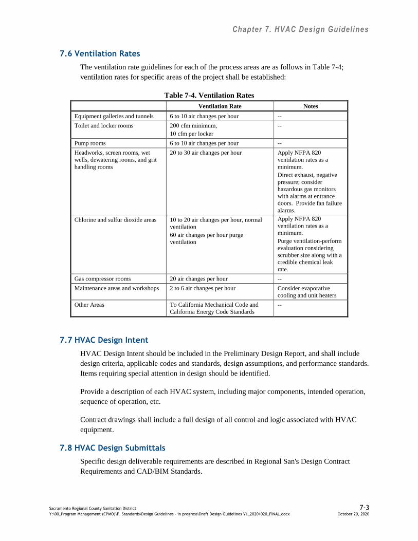
Chapter 7. HVAC Design Guidelines
Sacramento Regional County Sanitation District 7-3 Y:\00_Program Management (CPMO)\F. Standards\Design Guidelines - in progress\Draft Design Guidelines V1_20201020_FINAL.docx October 20, 2020
7.6 Ventilation Rates
The ventilation rate guidelines for each of the process areas are as follows in Table 7-4;
ventilation rates for specific areas of the project shall be established:
Table 7-4. Ventilation Rates
Ventilation Rate Notes
Equipment galleries and tunnels 6 to 10 air changes per hour --
Toilet and locker rooms 200 cfm minimum,
10 cfm per locker
--
Pump rooms 6 to 10 air changes per hour --
Headworks, screen rooms, wet
wells, dewatering rooms, and grit
handling rooms
20 to 30 air changes per hour
Apply NFPA 820
ventilation rates as a
minimum.
Direct exhaust, negative
pressure; consider
hazardous gas monitors
with alarms at entrance
doors. Provide fan failure
alarms.
Chlorine and sulfur dioxide areas 10 to 20 air changes per hour, normal
ventilation
60 air changes per hour purge
ventilation
Apply NFPA 820
ventilation rates as a
minimum.
Purge ventilation-perform
evaluation considering
scrubber size along with a
credible chemical leak
rate.
Gas compressor rooms 20 air changes per hour --
Maintenance areas and workshops 2 to 6 air changes per hour Consider evaporative
cooling and unit heaters
Other Areas To California Mechanical Code and
California Energy Code Standards
--
7.7 HVAC Design Intent
HVAC Design Intent should be included in the Preliminary Design Report, and shall include
design criteria, applicable codes and standards, design assumptions, and performance standards.
Items requiring special attention in design should be identified.
Provide a description of each HVAC system, including major components, intended operation,
sequence of operation, etc.
Contract drawings shall include a full design of all control and logic associated with HVAC
equipment.
7.8 HVAC Design Submittals
Specific design deliverable requirements are described in Regional San's Design Contract
Requirements and CAD/BIM Standards.

Chapter 7. HVAC Design Guidelines
Sacramento Regional County Sanitation District 7-4 Y:\00_Program Management (CPMO)\F. Standards\Design Guidelines - in progress\Draft Design Guidelines V1_20201020_FINAL.docx October 20, 2020
Provide HVAC calculations, pump and fan curves, and a range of operating points for all
equipment and systems. Calculations shall support capacity selections and code compliance.
Provide full control and logic diagrams for all HVAC controller equipment.
Provide drawings detailing the fire alarm control panels, HVAC control panels and all
inputs/outputs to them (i.e. smoke detectors, pull stations, strobes, fire riser components, etc.).
Provide schematics on the drawings for each ventilated area showing equipment, circulation
and ventilation flow rates, temperature zoning, and pressure relationships between spaces.
Provide a simplified control narrative on the drawings describing the operating scenarios for all
powered equipment.
Provide a simplified equipment list on the drawings, not a complete equipment schedule.
7.9 HVAC Equipment
Equipment shall be selected for reliability, performance, and maintainability. Regional San’s
preference is for robust equipment. Equipment to be located in corrosive environments shall be
specified with appropriate materials of construction and protective coatings.
Where possible, select matching equipment from a single manufacturer for equipment such as
split system air conditioners.
Equipment utilizing Waste Heat Water Supply (WHWS) requires special materials of
construction. Examples include cuprous nickel heat exchanger tubing, tube sheets, water
boxes, and head covers.
Follow manufacturer clearance recommendations at a minimum and provide adequate
clearance to remove and replace equipment as a whole; provide more than adequate clearance
for service or removal of equipment. Provide removable panels or walls if needed. Assume
that the replacement equipment will be slightly larger. Size concrete pads accordingly.
Provide gauges on equipment for local readout:
For airside differential pressure gauges, use Dwyer Photohelic gauges with built in
switches. These gauges provide visual indication of the differential pressure for non-
corrosive gases, plus adjustable pressure switches that do not need periodic
recalibration.
For small airside equipment without gauge ports, use flush- or surface-mounted Dwyer
Magnehelic gauges without switches.
For waterside differential pressure gauges, use Dwyer Capsu-Photohelic gauges with
built in switches.

Chapter 7. HVAC Design Guidelines
Sacramento Regional County Sanitation District 7-5 Y:\00_Program Management (CPMO)\F. Standards\Design Guidelines - in progress\Draft Design Guidelines V1_20201020_FINAL.docx October 20, 2020
The first-choice location for HVAC air handlers, pumps, etc. is inside mechanical equipment
rooms. The second-choice location is outside at grade level. The last-choice location is on the
roof of structures. However, roof exhaust fans may be roof mounted; exceptions will be
evaluated on a case-by-case basis.
For roof mounted equipment, the design shall be in accordance with NRCA and SMACNA
recommendations on location, clearances, and maintenance walkways. All roofing details shall
be in accordance with the NRCA Handbook for low slope roofs and Regional San standards.
All roof mounted equipment requiring maintenance shall be provided with a 110v convenience
outlet and a water supply and hose-bib within 50 feet. All roof-mounted equipment shall be
provided with material handling equipment or access such as hand powered hoist or forklift
access at the closest wall.
Roof curbs shall have a minimum height of 14 inches above the finished roof for roof
maintenance.
Closely spaced roof curb rails are discouraged as it creates roof maintenance issues.
Table 7-5 lists the type of equipment preferred for various services.
Table 7-5. Type of Equipment for Various Services
Service Type of Equipment
Condensate (Steam) Pumping Traps or electric-
driven pump as appropriate.
CWS Primary Pumps (large) Double Suction Centrifugal
Pumps.
CWS Secondary Pumps (large) End Suction Centrifugal
Pumps.
CWS Secondary Pumps (small) In-line Centrifugal Pumps
HRS Primary Pumps (large) Double Suction Centrifugal
Pumps.
HRS Secondary Pumps (large) End Suction Centrifugal
Pumps.
HRS Secondary Pumps (small) In-line Centrifugal Pumps
Pumped Drainage Submersible Pump (1st choice)
Self-priming Centrifugal Pump
(2nd choice)
Hydronic pumps shall be specified with the manufacturer’s standard mechanical seals.
All pump motors 5 HP and above shall have a maximum motor speed of 1,800 rpm.
Chapter 7. HVAC Design Guidelines
Sacramento Regional County Sanitation District 7-6 Y:\00_Program Management (CPMO)\F. Standards\Design Guidelines - in progress\Draft Design Guidelines V1_20201020_FINAL.docx October 20, 2020
7.10 Heating Systems
There are three alternative heating methods:
Hot water heating shall be considered for all applications. A Regional San utility map
shows locations of the heating water system which is currently near capacity; any
proposed new connections to the heating water system will require calculations to verify
available capacity and shall be included in the Preliminary Design Report, and must be
approved by Regional San.
Natural gas furnaces are used where gas is available and hot water is not available.
Heat pumps and electric heat strips are used where neither natural gas nor hot water are
available.
Electric or gas unit heaters may be considered for freeze protection in remote locations and
similar applications.
Supply air temperature shall be no more than 40°F warmer than the room temperature design
setpoint.
7.11 Cooling Systems
There are three methods of cooling used at the SRWTP:
Direct evaporative cooling is used for process areas and tunnels; never for MCC rooms,
electrical rooms, or computer rooms.
Chilled water cooling is used for ACC’s, administrative areas, computer rooms,
shop/maintenance areas, and laboratories. Chilled water cooling coils should not exceed
a face velocity of 500 feet/minute. Verify with Regional San that sufficient chilled water
capacity is available at the project location before designing new hydronic systems.
Direct expansion cooling is used where chilled water cooling is not available, and also
as a backup to the chilled water system for computer rooms and other applications
requiring backups. Refrigerant R-22 should not be considered.
No below grade refrigerant piping shall be allowed where the interior coil is at the same grade
or higher. For refrigerant oil trapping; follow industry standards to provide trapping prevention
and oil return.
Regional San favors 100 percent redundant cooling systems for server rooms. No condensate
drain piping, pressurized water piping, or ductwork shall pass over or be located within three
feet of any electrical panel, panel board, or load center. Space clearance zones required by the
NEC above and aside electrical panels, panel boards, and load centers shall be maintained.
Supply air temperature shall be no more than 25°F cooler than the room temperature design
setpoint.
Chapter 7. HVAC Design Guidelines
Sacramento Regional County Sanitation District 7-7 Y:\00_Program Management (CPMO)\F. Standards\Design Guidelines - in progress\Draft Design Guidelines V1_20201020_FINAL.docx October 20, 2020
Regional San owns and uses portable units for backup cooling. Provide electrical and drainage
connections for the portable cooling units for all conditioned spaces.
Regional San prefers not to have systems requiring cooling towers.
7.12 Equipment Locations
Ventilation equipment including fans, ductwork, registers, diffusers, and exhaust grilles, should
be selected and designed to maximize the effectiveness of the system’s ability to purge the
ventilated spaces. This is especially important in process-related areas.
When locating equipment, air intakes and exhausts should take into account the prevailing wind
direction and potential sources of odorous, toxic, or corrosive gases. The HVAC room itself
should be conveniently located to minimize long duct runs and should be sized to allow
sufficient access to equipment. Avoid locating fans directly above noise sensitive areas such as
conference rooms.
Elevated air handlers and fans that require routine maintenance shall be provided with a 360°
maintenance platform and access ladder.
Regional San prefers not elevating air handlers.
7.13 Configuration
Do not transfer air from one space to another space, such as cleaner areas with sensitive
equipment to less sensitive areas.
Air from hazardous areas, rest rooms, locker rooms, kitchens, and odor-generating rooms shall
be exhausted, and not recirculated.
Provide ventilated spaces with powered supply and powered exhaust.
Conditioned spaces shall be designed with recirculating air to minimize heating and cooling
costs. Consider economizers for spaces that need cooling in winter.
Terminal units may serve up to three offices with similar exposures, occupancies, and heat
loads. Balancing dampers must be provided in the branch ducts for each office.
Areas with chlorine or hydrogen sulfide shall be designed with exhaust grilles at low elevations
for effective scavenging.

Chapter 7. HVAC Design Guidelines
Sacramento Regional County Sanitation District 7-8 Y:\00_Program Management (CPMO)\F. Standards\Design Guidelines - in progress\Draft Design Guidelines V1_20201020_FINAL.docx October 20, 2020
7.14 Special HVAC and Fire Extinguishing Requirements for Switchgear and Motor Control Center Rooms
Special HVAC requirements:
Switchgear and MCC Rooms shall have dedicated HVAC or ventilation units capable of
exhausting 100% of the return air upon sensing smoke. Make up air shall be 100%
outside air.
Any ductwork penetrating the walls or ceiling of switchgear and MCC rooms shall be
protected with fire/smoke dampers at the penetration.
Ductwork within the room shall be a minimum of 26-gauge metal.
Switchgear rooms shall have an HVAC shutdown and purge mode monitoring and
control panel located on an exterior wall adjacent to the entrance door. A remote
shutdown switch shall be provided outside an electrical room exterior exit door for
electrical room purge activation after leaving the building (a breakglass switch is
acceptable).
The air supply to MCC rooms shall be chemically filtered per the requirements of
Section 7.17 (Air Filtration Equipment).
Special Fire Extinguishing Requirements:
Portable carbon dioxide fire extinguishers shall be placed at the entrances and at
locations such that the travel distance between extinguishers is no greater than 50 feet.
Prepare test procedure requirements for verifying the proper operation of all fire alarm
system elements and all HVAC elements controlled by the fire alarm system.
7.15 Fans
7.15.1 Centrifugal Utility Fans
Centrifugal utility fans requiring a static pressure of 2 inches or more, or fans with motors
larger than 3 horsepower shall have backward inclined airfoil, or backward inclined blades for
high efficiency. Forward curved blades should only be used on small fans or when low first
cost is of primary concern.
All fans shall be provided with guards and vibration isolators. All fans not operated
continuously shall be provided with backdraft dampers.
7.15.2 Propeller Wall Fans
Propeller wall fans shall be V-belt driven when possible. Small propeller wall fans (smaller
than 18 to 24 inches) are only available in a direct drive configuration. Propeller fans shall be
provided with drive-side guards and wall mounting sleeves.

Chapter 7. HVAC Design Guidelines
Sacramento Regional County Sanitation District 7-9 Y:\00_Program Management (CPMO)\F. Standards\Design Guidelines - in progress\Draft Design Guidelines V1_20201020_FINAL.docx October 20, 2020
7.15.3 Roof Exhaust Fans
Roof exhaust fans shall be specified with manufacturer-supplied roof curbs. Options should
include a hinged base and disconnect switch. Provide direct drive fans where available. Large
fans requiring guaranteed closure shall be provided with motorized dampers.
7.15.4 In-Line Fans
In-line axial, mixed flow, and centrifugal fans will be used where limited space is available for
installation. In-line fans shall be provided with vibration isolators and flexible-duct
connections at each end.
7.15.5 Cabinet Fans and Ceiling Fans
Small cabinet fans and ceiling fans provided with ducting through the roof or wall shall be used
for very small air flow. Ceiling fans shall be considered where air flows are too small for roof
exhaust fans. Differential pressure switches and motorized dampers shall not be used with
small cabinet fans and ceiling fans.
Specify non-sparking fans and explosion-proof motors for service in hazardous areas.
Specify fan failure alarms for service in hazardous areas.
7.16 Air Handling Units
Air handling units (AHU) shall be packaged units which can supply heating, cooling
ventilation, and air filtration. The air handling unit shall be of the single-zone type.
Regional San prefers outdoor air handling units to be located on grade as opposed to roof-
mounted. Air handling unit cabinets located outdoors shall be weatherproof.
Indoor mechanical rooms may be considered for larger buildings subject to architectural
decisions. Indoor HVAC rooms shall be provided with floor drains and equipment drains for
the condensate.
Air handlers shall be provided with access to water and a hose bib with vacuum breaker within
50 feet of the unit.
Air handlers shall be provided with a 110v convenience outlet within 10 inches of the control
panel.
7.17 Air Filtration Equipment
Filtered air ventilation systems shall be provided only when required by code, or noted as
necessary by Regional San for specific areas. Pleated panel 30% filters shall be used with a
face velocity below 500 feet per minute. Use 4 inch thick filters where possible. Clean
pressure drop shall be about 0.2 inch, and dirty pressure drop of about 1.0 inch.

Chapter 7. HVAC Design Guidelines
Sacramento Regional County Sanitation District 7-10 Y:\00_Program Management (CPMO)\F. Standards\Design Guidelines - in progress\Draft Design Guidelines V1_20201020_FINAL.docx October 20, 2020
Provide potassium permanganate chemical filters for motor control center ventilation
systems. Chemical filter systems shall include a 30% 2 inch pre-filter, a chemical filter,
and a 30% post-filter. Chemical filters shall be cartridge type and non-refillable design.
The entire filter system shall be provided with differential pressure gages and alarms.
Regional San preference is for custom filter modules and standardized packaged units
over custom air handlers. A minimum amount of outside air shall be supplied to these
rooms and they shall be maintained at a slight positive pressure to prevent infiltration of
untreated outside air.
7.18 Ductwork
7.18.1 General
ASHRAE and SMACNA standards and recommendations shall be used for all duct designs.
Aluminum ductwork shall be used for all applications except as stated below. Aluminum
ductwork will be fabricated according to Sheet Metal and Air Conditioning Contractor’s
National Association (SMACNA) standards for low-pressure or medium pressure applications.
Fasteners for aluminum ductwork shall be aluminum or stainless steel.
Fiberglass (reinforced thermoset plastic, RTP) ducting shall be used in applications requiring a
high degree of corrosion resistance. RTP ducting shall be treated to be fire resistant.
Galvanized steel ductwork shall not be used.
Flexible duct shall be used only to connect ceiling diffusers to rigid ductwork. Flexible duct
shall not exceed 5 feet in length, and shall not be used on exposed ductwork.
7.18.2 Duct Sizing and Velocity Ranges
The computation of total system pressure (static pressure plus velocity pressure) shall be based
on the equal friction method as defined by SMACNA.
Pressure drop shall be approximately 0.07 to 0.1 inch per 100 feet.
All ducts (except foul air ducts), supply, exhaust, transfer, or return air ducts shall be sized for
the following air velocities, with preference toward the lower end of the range in each case,
especially for noise sensitive areas:
Rectangular Main ducts 1,500 to 2,000 fpm
Branch ducts 800 to 1,600 fpm
Round Main ducts 1,800 to 2,500 fpm
Branch ducts 1,000 to 1,800 fpm
Foul air ducts (RTP type) shall be sized for the following air velocities:
Round Main ducts 2,500 to 3,000 fpm
Branch ducts 2,000 to 2,500 fpm
Chapter 7. HVAC Design Guidelines
Sacramento Regional County Sanitation District 7-11 Y:\00_Program Management (CPMO)\F. Standards\Design Guidelines - in progress\Draft Design Guidelines V1_20201020_FINAL.docx October 20, 2020
7.18.3 Insulation
Thermal insulation shall be provided in accordance with the California Mechanical Code or the
California Energy Code (whichever is more stringent) on all supply, transfer, or return ducting
which carries heated or cooled air. Thermal insulation shall also be provided where required to
prevent condensation. This insulation may be external insulation where damage from traffic is
unlikely, or internal insulation. Internal insulation also acts as acoustical insulation.
7.18.4 Duct Dimension and Design
Rectangular and round ductwork shall have whole number dimensions expressed in inches.
Manufacturer’s standard duct sizes and fittings shall be used whenever possible.
Where space permits, round ductwork is preferred over rectangular ductwork.
Rectangular ducts shall be designed with the smallest possible aspect ratio; aspect ratios of
greater than 4:1 shall be avoided.
7.18.5 Duct Accessories
Turning vanes shall be of the same material as the duct and shall be the single-walled type with
trailing edges.
Access doors shall be provided adjacent to all pieces of duct-mounted equipment or
instrumentation.
Fire dampers will be UL classified with UL-listed fusible links, rated at 160 to 165 degrees
Fahrenheit. Fire dampers shall also be in accordance with NFPA 90A requirements and all
applicable local codes.
Flexible duct connectors shall be used for vibration isolation of moving equipment. Flexible
duct connectors shall allow a minimum of 2 inches of free space between two metal collars to
ensure that no vibration is transmitted from the equipment to the ductwork.
Splitter dampers shall be used to divert and control airflow from a main duct to two branch
ducts of opposite directions. Splitter dampers will be of the same material as the duct.
7.18.6 Grills, Registers, and Diffusers
Grilles, registers, and diffusers shall be sized in accordance with the manufacturer’s
recommendations for air velocity and throw. Noise rating shall not exceed NC-25 for
administrative areas and NC-30 for process areas (including electrical rooms). Grills, registers,
and diffusers shall be of the same material as the duct.
7.18.7 Drum Louvers and Ball Turret Louvers
Drum louvers and ball turret louvers shall be considered for air distribution systems when
concise directional air throws or air throws in excess of approximately 20 feet are used.
Chapter 7. HVAC Design Guidelines
Sacramento Regional County Sanitation District 7-12 Y:\00_Program Management (CPMO)\F. Standards\Design Guidelines - in progress\Draft Design Guidelines V1_20201020_FINAL.docx October 20, 2020
7.19 Louvers
Intake and exhaust louvers shall be provided with and insect screens. Together with the louver
blades, these screens shall produce a 0.05 to 0.10-inch pressure drop when clean. Intake
louvers shall be sized for a face velocity of about 500 fpm, exhaust louvers shall be sized for a
face velocity of no more than 800 fpm.
Location, finish, and color of louvers shall be coordinated with the project architect.
7.20 Control Dampers
Mixing dampers shall be the opposed-blade right-angle type.
Backdraft dampers shall be the parallel-blade type.
Dampers for open-close service shall be parallel-blade type.
Balancing dampers shall be butterfly type in ducts 12 inches and smaller and opposed-blade
type in ducts larger than 12 inches. Balancing dampers shall be provided at all supply, return,
and exhaust duct branch takeoffs.
Variable air volume mixing boxes and terminal units in office areas shall be located such that
ladder access to the ceiling will not be blocked by office furniture.
7.21 HVAC Controls
Controls for HVAC systems shall be compatible with the existing Johnson Controls HVAC
DDC System with network connection back to the master station located in HCC-2 next to the
Boiler Room. Specifications shall require that DDC software and testing and calibration
equipment be turned over to Regional San upon completion of project.
The following controls shall be provided:
Differential pressure sensor across major or critical fans to indicate fan flow.
Duct smoke detector with alarm at discharge of each unit, per NFPA 90A.
Differential pressure gage and/or switch with alarm across air filters.
Economizer cycles shall not be generally used for MCC Rooms, due to possible odors
and corrosive or hazardous gases.
Thermostats and controllers to operate the HVAC units.
Alarms shall be local and remote, audible and/or visual, and can start or stop equipment
depending upon the particular application.
Alarm and SCADA monitoring (including zone temperatures and humidity) shall be
routed through the DDC system network back to the HCC master workstation.

Chapter 7. HVAC Design Guidelines
Sacramento Regional County Sanitation District 7-13 Y:\00_Program Management (CPMO)\F. Standards\Design Guidelines - in progress\Draft Design Guidelines V1_20201020_FINAL.docx October 20, 2020
All new HVAC control systems shall consist of Johnson Controls (JC) equipment (no “or
equal”) for connection into the existing plant BACnet system. The network controller shall be
JC DDC controller MS-NAE3510-2. This first tier Controller shall be a fully user-
programmable, supervisory controller. The Network Controller shall monitor the network of
distributed VMA and FEC controllers, provide global strategy and direction, and communicate
on a peer-to-peer basis with other Network Controllers. The Network Controller shall reside on
the existing campus wide Ethernet Network. Each NAE shall support a sub-network of
controllers on the second tier network.
The second tier network of field controllers shall be Metasys MS-FEC2621 BACnet series and
shall be used for all AHU’s, split systems, condensing units, and purge systems. Room
thermostats shall be model NS-BTB7003-0.
All other sensors required to meet the needs listed above shall be compatible with the specified
master Network Controller.
The HVAC and Purge systems shall each have dedicated control panels. The designer shall
provide panel layout drawings, control and logic diagrams, and interconnection diagrams for
each system.
All equipment shall be NAE 35/45 compatible and should be designed to interface completely
with the plant Metasys network. The room temperature and humidity shall be pulled off the
Metasys network for independent relay to the Plant PCC. The controls contractor will be
responsible to provide a full, compatible, turnkey product.
7.21.1 Standardized Equipment
Refer to Appendix A of Regional San’s Design Contract Requirements for a table of
standardized equipment.
7.22 Motor Sizing
Variable load: Motors shall be selected based on the bHP and torque requirements of the driven
unit over the entire load range over which it will operate. Calculate the peak load RMS
horsepower requirement and size the motor so the load falls within 75 to 100% of the motor
capacity. The motor’s service factor shall not be considered in the calculation.
Motors for VFD systems shall be required to deliver the motor’s nameplate horsepower rating
by any load imposed by the driven machine at any specified operating condition or any load
condition indicated by the driven machine’s performance curve at all operating speeds. VFD
systems shall have horsepower selected for necessary cooling at the lowest operating speed
based upon motor manufacturer’s heating curves. The motor’s service factor shall not be
considered in the calculation.
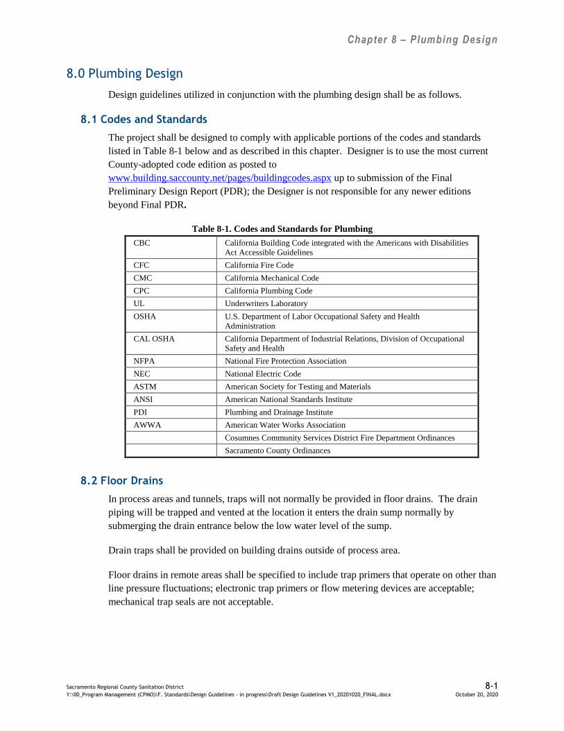
Chapter 8 – Plumbing Design
Sacramento Regional County Sanitation District 8-1
Y:\00_Program Management (CPMO)\F. Standards\Design Guidelines - in progress\Draft Design Guidelines V1_20201020_FINAL.docx October 20, 2020
8.0 Plumbing Design
Design guidelines utilized in conjunction with the plumbing design shall be as follows.
8.1 Codes and Standards
The project shall be designed to comply with applicable portions of the codes and standards
listed in Table 8-1 below and as described in this chapter. Designer is to use the most current
County-adopted code edition as posted to
www.building.saccounty.net/pages/buildingcodes.aspx up to submission of the Final
Preliminary Design Report (PDR); the Designer is not responsible for any newer editions
beyond Final PDR.
Table 8-1. Codes and Standards for Plumbing
CBC California Building Code integrated with the Americans with Disabilities
Act Accessible Guidelines
CFC California Fire Code
CMC California Mechanical Code
CPC California Plumbing Code
UL Underwriters Laboratory
OSHA U.S. Department of Labor Occupational Safety and Health
Administration
CAL OSHA California Department of Industrial Relations, Division of Occupational
Safety and Health
NFPA National Fire Protection Association
NEC National Electric Code
ASTM American Society for Testing and Materials
ANSI American National Standards Institute
PDI Plumbing and Drainage Institute
AWWA American Water Works Association
Cosumnes Community Services District Fire Department Ordinances
Sacramento County Ordinances
8.2 Floor Drains
In process areas and tunnels, traps will not normally be provided in floor drains. The drain
piping will be trapped and vented at the location it enters the drain sump normally by
submerging the drain entrance below the low water level of the sump.
Drain traps shall be provided on building drains outside of process area.
Floor drains in remote areas shall be specified to include trap primers that operate on other than
line pressure fluctuations; electronic trap primers or flow metering devices are acceptable;
mechanical trap seals are not acceptable.
Chapter 8 – Plumbing Design
Sacramento Regional County Sanitation District 8-2
Y:\00_Program Management (CPMO)\F. Standards\Design Guidelines - in progress\Draft Design Guidelines V1_20201020_FINAL.docx October 20, 2020
8.3 Plumbing Design Intent
Plumbing Design Intent should be included in the Preliminary Design Report, and shall include
design criteria, applicable codes and standards. Systems requiring special attention in design
should be identified.
8.4 Plumbing Design Submittals
Ensure adequate sizing of the drain, waste and vent system; because this is an industrial facility,
CPC code minimum sizes may not be sufficient.
Specific design deliverable requirements are described in Regional San’s Design Contract
Requirements.
Provide plumbing calculations to support sizing and code compliance.
8.5 Plumbing Piping
Provide water hammer arresters throughout the domestic hot and cold water systems.
Di-electric unions shall be eliminated by use of compatible piping if possible. When di-electric
unions are necessary, they shall be rated for 180 degrees F and 250 psig.
8.6 Plumbing Equipment
Regional San prefers use of domestic water heaters when appropriate. Power by natural gas
when available.
8.7 Plumbing Fixtures
8.7.1 Lavatories
Stainless steel and enameled cast iron are preferred for durability. Vitreous china shall not be
specified.
Lavatory sinks shall be provided at all new restrooms. In general, all lavatory sinks should be
provided with AC-powered, sensor-type faucets and gooseneck spouts. Specify water-
conserving flowrate of 0.5 gpm per Calgreen.
8.7.2 Service Sinks
Stainless steel floor sinks with stainless steel backsplashes are preferred for janitor rooms.
8.7.3 Water Closets
Water closets shall be provided at all new restrooms. Wall-hung water closets with
AC-powered sensor-type flush valves with manual override are preferred. Specify
water-conserving flowrate of 1.28 gallons per flush per Calgreen.

Chapter 8 – Plumbing Design
Sacramento Regional County Sanitation District 8-3
Y:\00_Program Management (CPMO)\F. Standards\Design Guidelines - in progress\Draft Design Guidelines V1_20201020_FINAL.docx October 20, 2020
8.7.4 Urinals
Urinals shall be provided at all new men’s and unisex restrooms. Provide AC-powered
automatic sensor flush valves with manual override for all urinals. Specify water-conserving
flowrate of 0.5 gallons per flush. Waterless urinals are not to be specified.
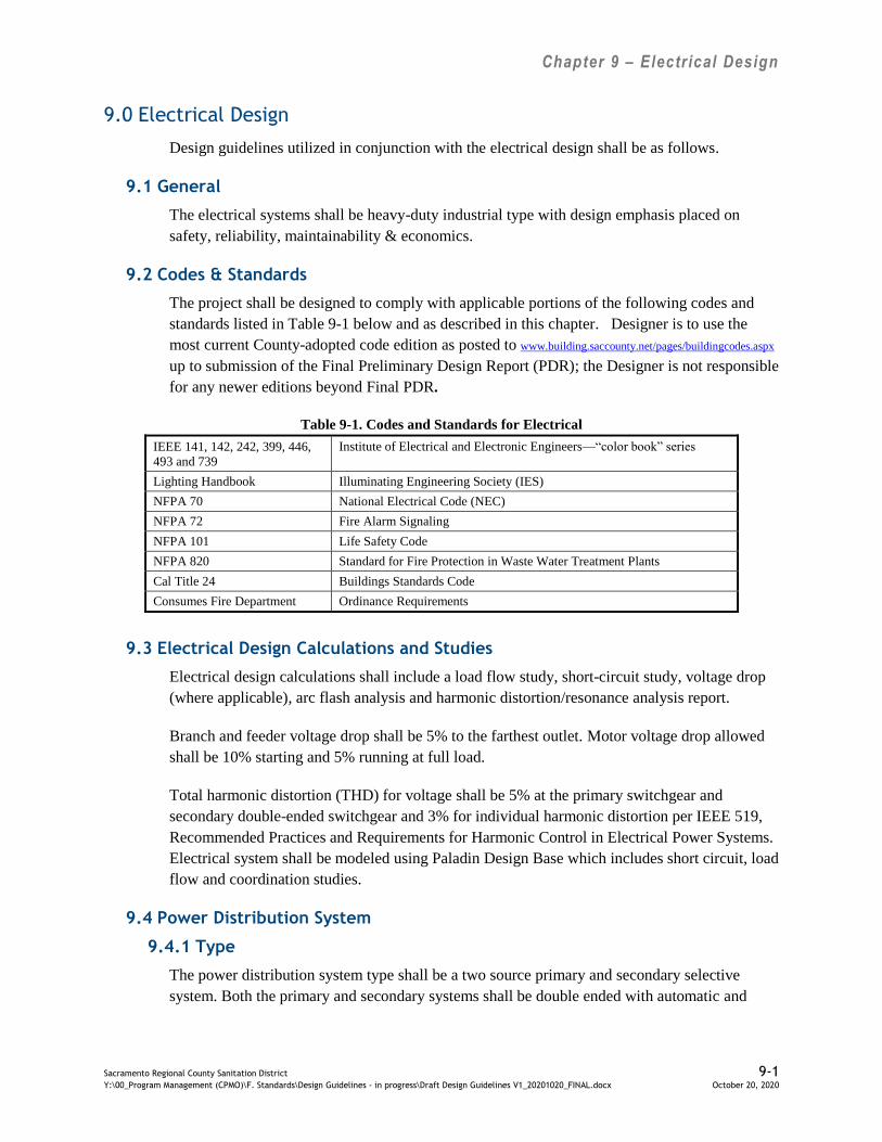
Chapter 9 – Electrical Design
Sacramento Regional County Sanitation District 9-1 Y:\00_Program Management (CPMO)\F. Standards\Design Guidelines - in progress\Draft Design Guidelines V1_20201020_FINAL.docx October 20, 2020
9.0 Electrical Design
Design guidelines utilized in conjunction with the electrical design shall be as follows.
9.1 General
The electrical systems shall be heavy-duty industrial type with design emphasis placed on
safety, reliability, maintainability & economics.
9.2 Codes & Standards
The project shall be designed to comply with applicable portions of the following codes and
standards listed in Table 9-1 below and as described in this chapter. Designer is to use the
most current County-adopted code edition as posted to www.building.saccounty.net/pages/buildingcodes.aspx
up to submission of the Final Preliminary Design Report (PDR); the Designer is not responsible
for any newer editions beyond Final PDR.
Table 9-1. Codes and Standards for Electrical
IEEE 141, 142, 242, 399, 446,
493 and 739
Institute of Electrical and Electronic Engineers—“color book” series
Lighting Handbook Illuminating Engineering Society (IES)
NFPA 70 National Electrical Code (NEC)
NFPA 72 Fire Alarm Signaling
NFPA 101 Life Safety Code
NFPA 820 Standard for Fire Protection in Waste Water Treatment Plants
Cal Title 24 Buildings Standards Code
Consumes Fire Department Ordinance Requirements
9.3 Electrical Design Calculations and Studies
Electrical design calculations shall include a load flow study, short-circuit study, voltage drop
(where applicable), arc flash analysis and harmonic distortion/resonance analysis report.
Branch and feeder voltage drop shall be 5% to the farthest outlet. Motor voltage drop allowed
shall be 10% starting and 5% running at full load.
Total harmonic distortion (THD) for voltage shall be 5% at the primary switchgear and
secondary double-ended switchgear and 3% for individual harmonic distortion per IEEE 519,
Recommended Practices and Requirements for Harmonic Control in Electrical Power Systems.
Electrical system shall be modeled using Paladin Design Base which includes short circuit, load
flow and coordination studies.
9.4 Power Distribution System
9.4.1 Type
The power distribution system type shall be a two source primary and secondary selective
system. Both the primary and secondary systems shall be double ended with automatic and
Chapter 9 – Electrical Design
Sacramento Regional County Sanitation District 9-2 Y:\00_Program Management (CPMO)\F. Standards\Design Guidelines - in progress\Draft Design Guidelines V1_20201020_FINAL.docx October 20, 2020
dummy tie breakers at both primary switchgear and secondary switchgear. Refer to Regional
San’s Master Set Drawings E51, 23E50A through 23E50F for information.
9.4.2 Primary Substation Arrangement (69kV/12.47kV)
Utility service is provided by the Sacramento Municipal Utility District (SMUD) via 69kV
overhead lines to the existing main substation which steps down the voltage to 12.47kV for
SRWTP distribution. Major changes in loads shall be coordinated with SMUD for
incorporation into their power system and protective relay scheme. The 69kV system shall be
over-head line connected SF6 main breaker, load break isolation switches, and main transformer
primary. The main transformers shall be liquid-filled primary unit substation style,∆-primary,
wye-secondary with solid neutral ground, with manual no-load primary and automatic full local
secondary tap changers. Main transformer secondary shall be underground cabled with voltage
rotation shifted to match the SMUD secondary distribution system rotation. Main switchgear
shall be 12kV double-ended with automatic and dummy tie breakers.
9.4.3 480V Secondary Substation Arrangement
The substation shall consist of a 12kV load rated fused interrupter switch and outdoor liquid-
filled secondary unit substation style transformer to double-ended switchgear with dummy and
tie breakers. Transformers shall be a ∆-primary, wye-secondary solid neutral ground. 480V
motors shall be fed from grouped MCCs located in the Electrical room.
9.4.4 12kV (4kV) Secondary Substation Arrangement
The substation shall consist of a 12kV load rated fused interrupter switch and outdoor liquid-
filled primary (secondary) unit substation style transformer to double-ended switchgear with
dummy and tie breakers. Transformers for large motors shall be a ∆-primary, wye-secondary
resistor neutral ground. Medium voltage motors shall be fed from grouped MCCs located in the
Electrical room. 480V loads 1000kVA and under shall be sub-fed from the medium voltage
switchgear to indoor dry-type secondary unit substation style transformers feeding double-
ended switchgear with dummy and tie breakers.480V motors shall be fed from grouped MCCs
located in the Electrical room.
9.4.5 Liquid Filled Transformers
Liquid filled transformers shall be surrounded by a liquid containment structure sized per EPA
requirements with a concrete wall between transformers. Containment area shall be filled with
river rocks to quench temperature and the remaining void volume shall provide for the largest
single transformer oil volume plus an additional 3.5 inches of freeboard for precipitation from a
25-year storm event.
Distribution transformers shall be sized to carry the entire switchgear design load at its
maximum fan cooled rating. Select standard size transformers by varying the future capacity in
the 20-25% range.
Chapter 9 – Electrical Design
Sacramento Regional County Sanitation District 9-3 Y:\00_Program Management (CPMO)\F. Standards\Design Guidelines - in progress\Draft Design Guidelines V1_20201020_FINAL.docx October 20, 2020
9.4.6 12.47kV Distribution System
The main 12kV switchgear shall distribute dual 12kV feeders from opposite sides of the main
tie breaker to process area substations to dual outdoor 12kV fused isolation switches.
Distribution system shall consist of underground medium voltage cables routed through dual
manhole and duct system.
9.4.7 Instrument Power
Instrument power at 120/208V shall be derived through an automatic transfer switch which is
fed from both sides of the double-ended switchgear via dry type transformers. Transfer switch
shall be PCCS monitored for voltage loss on the output circuit. Distribute to all field
instruments via a distribution panelboard.
9.4.8 Uninterruptable Power Supply (UPS)
For loads determined to be on a UPS system 120/208V shall be derived through automatic
transfer switch which is fed from both sides of the double-ended switchgear. Transfer switch
shall be PCCS monitored for voltage loss on the output circuit. UPS shall be PCCS networked
data monitored for status. Distribute to PCCS network and HMI equipment, fire alarm, public
address, security system via a dedicated distribution panelboard.
9.4.9 Standardized Equipment
Refer to Appendix A of Regional San’s Design Contract Requirements for a table of
standardized equipment.
9.5 Power Quality Monitoring System
Regional San currently has a Power Quality Monitoring System that connects the power
monitoring devices to the end users devices via the PCCS and maintenance network.
Switchgear main and feeders are monitored with power quality meters with dual integrated
Ethernet ports and Embedded Web Server. MCC motor loads are monitored with motor
management relays, VFDs, and motor starter smart overloads. All monitoring devices shall be
capable of Ethernet connections to the PCCS and Maintenance networks as described in
Section 10.9.
9.6 Conductor Sizing
Feeder and branch circuits shall be all sized for the loads that they are connected to per the
NEC. Voltage drop shall be considered for long runs and the conductors increased in size
based on the voltage drop calculations.
9.7 Motor Sizing
Motors for VFD systems shall be required to deliver the motor's nameplate horsepower rating
by any load imposed by the driven machine at any specified operating condition or any load
condition indicated by the driven machine's performance curve at all operating speeds.

Chapter 9 – Electrical Design
Sacramento Regional County Sanitation District 9-4 Y:\00_Program Management (CPMO)\F. Standards\Design Guidelines - in progress\Draft Design Guidelines V1_20201020_FINAL.docx October 20, 2020
Coordinate with mechanical design guidelines in Chapter 6, including variable frequency
curves vs. system curves.
9.8 Electrical Rooms
9.8.1 Arrangement
MCC and switchgear front and back work space distances are shown in Table 9-2 below. All
electrical distribution switchgear shall be located inside environmentally controlled buildings at
or above grade. Outdoor or below grade switchgear is unacceptable.
Table 9-2. Electrical Equipment Work Space Distances
480V Equipment (feet)
MCC (Front) 4.5
Switchgear (Front) 5
Switchgear (Rear) 4
UPS (all sides) 4
Access Corridor 5
4KV and 12KV Equipment (feet)
MCC (Front) 6
Switchgear (Front) 8
Switchgear (Rear) 7
Access Corridor 5
Electrical rooms shall have a load break type disconnect for the service entrance equipment
located on the exterior wall of the electrical room.
All conduit penetrations from the electrical room to other adjacent process area rooms shall be
fire stopped.
Coordinate with the civil and architectural design guidelines in Chapters 3 and 4, respectively.
9.8.2 Layout
Electrical rooms typically include switchgear, MCCs and distribution panelboards. 12kV and
4kV electrical rooms also include PLC/HMI controls and PCCS workstations. Do not locate
PCCS I/O cabinets in the 480V switchgear electrical room. All electrical room roofs shall be
sloped and no penetrations or water pipes are allowed above electrical equipment. Provide a
dedicated HVAC with chemical filters housed indoors with an access door inside the electrical
room. Medium voltage electrical only buildings shall include a separate battery room with an
access door inside electrical room. Additionally, provide approximately 64 square feet of clear
working space in 480V electrical rooms and approximately 100 square feet of clear working
space in medium voltage electrical rooms for electrical maintenance and electrician use.
Minimum distance across working space shall be 8 feet clear.
Chapter 9 – Electrical Design
Sacramento Regional County Sanitation District 9-5 Y:\00_Program Management (CPMO)\F. Standards\Design Guidelines - in progress\Draft Design Guidelines V1_20201020_FINAL.docx October 20, 2020
Horizontal workplace clearance requirements per the NEC shall be adhered to when
considering the layout of the electrical equipment in the room.
Coordinate with mechanical and HVAC design guidelines in Chapters 6 and 7, respectively.
9.8.3 Fire Protection System
Refer to SRCSD’s March 5, 1997 Memorandum of Understanding between the Sacramento
Regional Treatment Plant (SRWTP) and the Elk Grove Fire Department (EGFD) regarding the
SRWTP Fire Protection Utility Master Plan included in Appendix F.
Rooms shall be constructed of noncombustible material and include features such as fully
enclosed wiring, fire detection, fire dampers, fire stops, dedicated chemically treated HVAC,
smoke purge system, portable halon extinguishers, and an external main disconnect.
The fire protection system design shall follow the California Code of Regulations and the
Cosumnes Fire Department Standards. An Alternate Means Request should be used for any
deviation.
9.9 Switchgear
9.9.1 12.47kV Switchgear
12.47kV switchgear shall be metal clad, rack out, sized for design load, rated at 15kV, 3000A
minimum, 3W, double- ended configuration with dummy and automatic tie breakers.
Switchgear shall be arc-resistant type, if available. AIC rating shall be based upon the
maximum available fault current at the transformer connection. Tie breakers shall be sized at
120% of highest single side load. The switchgear shall be configured as a cabled bottom entry
with single breaker per section located in the lower compartment only with auxiliaries in the
upper compartment. Refer to Regional San Master Set Drawing E51.
9.9.1.1 Standardized Equipment
Refer to Appendix A of Regional San’s Design Contract Requirements for a table of
standardized equipment.
Locate vacuum breakers in bottom cubicles only and electro-mechanical relays (matching
existing) in adjacent top cubicle.
9.9.1.2 Controls and Monitoring
PCCS Workstation and HMI/PLC breaker control panel are to be located 10 feet away from
switchgear. Switchgear monitoring and control at the PCCS shall consist of: transfer control
logic, mains and tie breakers status, room temperature and main transformer secondary voltage.
Power quality monitors shall be provided at the mains and feeder breakers.
The 125Vdc chargers shall be monitored for trouble by the PCCS.
9.9.1.3 Protection Relay Power

Chapter 9 – Electrical Design
Sacramento Regional County Sanitation District 9-6 Y:\00_Program Management (CPMO)\F. Standards\Design Guidelines - in progress\Draft Design Guidelines V1_20201020_FINAL.docx October 20, 2020
Protection relays shall be powered by a 125Vdc system derived from sealed lead-acid batteries
with dual chargers and distributed through a fused distribution panelboard for breaker trip and
PLC power. 120Vac system shall be derived from the 12kV bus via a control power
transformer with appropriate fuse protections to an external automatic transfer switch feeding a
circuit breaker panelboard for breaker closing power, spring charging motors and battery
chargers.
9.9.2 4.16kV Switchgear
4.16kV switchgear shall be sized for design load, rated 5kV, 3W, double-ended with dummy
and automatic tie breakers. AIC rating shall be based upon the maximum available fault current
at the transformer connection. Tie breakers sized at 120% of highest single side load.
Switchgear shall be arc-resistant type, if available.
9.9.2.1 Standardized Equipment
Refer to Appendix A of Regional San’s Design Contract Requirements for a table of
standardized equipment.
Locate vacuum breakers in bottom cubicles only and electro-mechanical relays (matching
existing) in adjacent top cubicle.
9.9.2.2 Controls and Monitoring
Locate HMI/PLC breaker control panel 10 feet away from switchgear.
Switchgear monitoring and control at the PCCS shall consist of: transfer control, mains and tie
breakers status, room temperature, main transformer secondary voltage, networked switchgear
data monitoring at mains and feeder breakers. The 125Vdc chargers shall be monitored for
trouble by the PCCS.
Power quality monitors shall be provided at the mains and feeder breakers.
9.9.2.3 Power
125Vdc system derived from sealed lead-acid batteries with dual chargers and distributed
through fused distribution panelboard for breaker trip and PLC power. 120Vac system shall be
derived from the 4kV bus via a control power transformer with appropriate fuse protections to
an external automatic transfer switch feeding a circuit breaker panelboard for breaker closing
power, spring charging motors and battery chargers.
9.9.3 480V Switchgear
480V switchgear shall be sized for design load rated 600V, 3W, double-ended with dummy and
automatic tie breakers. Switchgear shall be arc-resistant type, if available. Tie breakers sized at
120% of highest single side load.
All motors over 200hp shall have individual feeder breakers. . Use vacuum draw-out breakers
with switchgear for motor loads greater than 200hp.
Chapter 9 – Electrical Design
Sacramento Regional County Sanitation District 9-7 Y:\00_Program Management (CPMO)\F. Standards\Design Guidelines - in progress\Draft Design Guidelines V1_20201020_FINAL.docx October 20, 2020
9.9.3.1 Standardized Equipment
Refer to Appendix A of Regional San’s Design Contract Requirements for a table of
standardized equipment
9.9.3.2 Controls and Monitoring
Switchgear monitoring and control at the PCCS shall consist of: transfer control, mains and tie
breakers status, room temperature, main transformer secondary voltage, networked switchgear
data monitoring at mains and feeder breakers.
Power quality monitors shall be provided at the mains and feeder breakers.
9.9.3.3 Power
All low voltage panel boards shall be feed from dry type transformers to limit short circuit
current. All dry type transformers and panel boards shall be 3Ø, 100A minimum.
9.10 Motor Control Centers (MCCs)
9.10.1 Arrangement
MCCs shall be front access only and installed against the wall and/or back-to-back
configurations to minimize floor space. For single story structures, MCC shall have a floor
trench system for cable routing to exterior duct bank terminations. In multiple story structures,
MCCs shall have full length pull boxes with clear access from the lower story room.
Coordinate with Architectural Design Guide.
9.10.2 Interface with Existing
When new process equipment will be fed out of existing MCCs, new starters shall be installed
for the equipment under the contract. Existing starters shall not be modified or reused for new
process equipment. New starters can be installed in spare spaces, existing unnecessary starters
can be removed, or (load and space permitting) new MCC sections can be added where space is
available in the MCC or Electrical Room.
9.10.3 480V MCCs
480V MCCs shall be sized for design loads, rated 600V, 3W with main lugs or bus duct
connections to switchgear. The MCC shall include spaces for known future loads and 20%
equipped space. Arrange similar loads including known futures loads distributed between
MCCs that are feed from the opposite sides of the double-ended switchgear. Multilin 469
motor protection relays for large specialty and Variable-speed motors over 200Hp.
9.10.3.1 Standardized Equipment
Refer to Appendix A of Regional San’s Design Contract Requirements for a table of
standardized equipment.

Chapter 9 – Electrical Design
Sacramento Regional County Sanitation District 9-8 Y:\00_Program Management (CPMO)\F. Standards\Design Guidelines - in progress\Draft Design Guidelines V1_20201020_FINAL.docx October 20, 2020
9.10.3.2 Controls and Monitoring
MCC monitoring and control at the PCCS shall consist of: start, stop, ready, running, trouble,
speed controls, and networked data monitoring of all feeders. For interchangeability, do not
locate timers, relays or pilots devices in the MCC cubicles.
Power quality of motor loads shall be monitored with motor starter smart overloads, VFDs, and
motor management relays.
9.10.4 4.16kV MCCs
4.16kV MCCs shall be sized for design load, rated 5kV, 3W with main lugs or bus duct
connections to switchgear. MCC shall be arc-resistant type, if available. Known future loads
shall be equipped spaces. Arrange similar loads including known futures distributed between
MCCs that are feed from the opposite sides of the double-ended switchgear.
9.10.4.1 Standardized Equipment
Refer to Appendix A of Regional San’s Design Contract Requirements for a table of
standardized equipment.
9.10.4.2 Controls and Monitoring
MCC monitoring and control at the PCCS shall consist of: start, stop, ready, running, trouble,
speed controls, and networked data monitoring.
Power quality monitoring via motor starter smart overloads, VFDs, and motor management
relays.
9.11 Variable Frequency Drive Systems
In general, VFDs shall be located in the electrical room in an environmentally controlled space.
However, field mounted VFDs may be allowed in cases where they are needed near the process
for control purposes or to limit motor lead lengths or a building is not practical or desirable due
to added cost. Field mounted VFDs shall be in an enclosure that includes a through-the-back
heat sink integral to the VFD to dissipate heat outside of the enclosure. Harmonic mitigation
shall include a line reactor on the VFD input and if necessary for a group of VFDs active
harmonic filtering at the switchgear bus to limit the voltage THD to 5% in accordance with
IEEE 519.
Low voltage (480V) VFDs shall be 6 step, pulse width modulation type (PWM). Table 9-3 is
provided as a guide for VFD output mitigation against high voltage peaks at the motor.
However, if an inverter duty motor with high winding insulation is used to guard against peak
motor voltages additional mitigation may not be necessary.
Table 9-3. VFD Output Mitigation
Output Reactor dv/dt Filter
Up to 60 HP >40 ft. >200ft.
60HP-150HP >150ft. >200ft.
Over 150HP >300ft. >300ft.

Chapter 9 – Electrical Design
Sacramento Regional County Sanitation District 9-9 Y:\00_Program Management (CPMO)\F. Standards\Design Guidelines - in progress\Draft Design Guidelines V1_20201020_FINAL.docx October 20, 2020
Medium voltage (4.16kV) VFDs shall be 18- or 24-step, PWM type or cascaded H-bridge
current source type. Medium Voltage VFDs shall be fan cooled up to 430A and ducted air over
heat sink cooled above 430A. All medium voltage VFDs shall be grouped in HVAC controlled
building structures. VFDs shall operate at less than 85dB at 6 feet or additional noise reduction
methods will be required to meet the limit. Medium voltage drives shall include a full bypass
contactor as determined by Reliability Centered Design.
Drive controller data shall be available over protocols outlined in Section 10.7.1.
Required voltage harmonic mitigation shall limit the total harmonic distortion to 5% on the
process area switchgear bus For VFD systems, the Consultant shall perform a preliminary
harmonic analysis of the Plant's electrical system to calculate the THD and check for harmonic
resonant frequencies. Where necessary, consultant shall design harmonic resonant filters to
shunt harmonic resonant frequencies to ground.
Motors for variable torque load VFD systems shall not be required to deliver more than
80 percent of the motor's nameplate horsepower rating by any load imposed by the driven
machine at any specified operating condition or any load condition indicated by the driven
machine's performance curve at all operating speeds. Motors for constant torque VFD systems
shall have horsepower selected for necessary cooling at the lowest operating speed based upon
motor manufacturer's heating curves. The motor's service factor shall not be considered in the
calculation. Power factor correction capacitors on VFD systems are not allowed.
9.11.1 Standardized Equipment
Refer to Appendix A of Regional San’s Design Contract Requirements for a table of
standardized equipment.
9.12 Grounding System
9.12.1 Design
Submit calculations showing the grounding system shall be designed will achieve a 2 ohm
resistance earth to ground and conform to IEEE Standard 142. It shall consist of a perimeter
ground grid with rods in test wells for each new substation, structure, or facility. Building steel,
process equipment, electrical equipment and enclosures, and exposed metal which might
become a current conductor shall be connected to the ground grid. Exposed ground connections
shall be compression lug type. Concealed, buried, or embedded ground connections shall be
made by the exothermic method, except for the connection to the ground rod which shall be
compression lug type. All conduits shall contain an equipment grounding conductor per the
NEC.
9.12.2 Interface with Existing
Interconnections between each ground grid and the existing grounding system shall be provided
by ground conductors running within interconnecting duct banks.
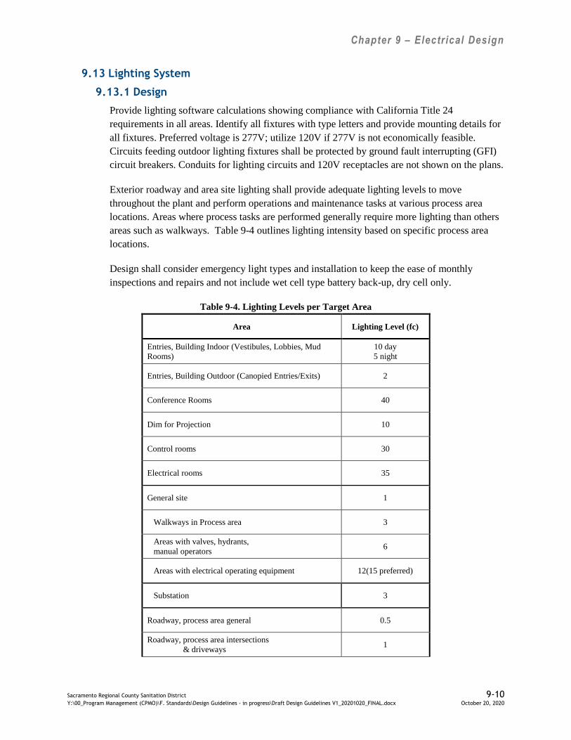
Chapter 9 – Electrical Design
Sacramento Regional County Sanitation District 9-10 Y:\00_Program Management (CPMO)\F. Standards\Design Guidelines - in progress\Draft Design Guidelines V1_20201020_FINAL.docx October 20, 2020
9.13 Lighting System
9.13.1 Design
Provide lighting software calculations showing compliance with California Title 24
requirements in all areas. Identify all fixtures with type letters and provide mounting details for
all fixtures. Preferred voltage is 277V; utilize 120V if 277V is not economically feasible.
Circuits feeding outdoor lighting fixtures shall be protected by ground fault interrupting (GFI)
circuit breakers. Conduits for lighting circuits and 120V receptacles are not shown on the plans.
Exterior roadway and area site lighting shall provide adequate lighting levels to move
throughout the plant and perform operations and maintenance tasks at various process area
locations. Areas where process tasks are performed generally require more lighting than others
areas such as walkways. Table 9-4 outlines lighting intensity based on specific process area
locations.
Design shall consider emergency light types and installation to keep the ease of monthly
inspections and repairs and not include wet cell type battery back-up, dry cell only.
Table 9-4. Lighting Levels per Target Area
Area Lighting Level (fc)
Entries, Building Indoor (Vestibules, Lobbies, Mud
Rooms)
10 day
5 night
Entries, Building Outdoor (Canopied Entries/Exits) 2
Conference Rooms 40
Dim for Projection 10
Control rooms 30
Electrical rooms 35
General site 1
Walkways in Process area 3
Areas with valves, hydrants,
manual operators 6
Areas with electrical operating equipment 12(15 preferred)
Substation 3
Roadway, process area general 0.5
Roadway, process area intersections
& driveways 1

Chapter 9 – Electrical Design
Sacramento Regional County Sanitation District 9-11 Y:\00_Program Management (CPMO)\F. Standards\Design Guidelines - in progress\Draft Design Guidelines V1_20201020_FINAL.docx October 20, 2020
Area Lighting Level (fc)
Lunchrooms 35
Laboratories 75
Designated Maintenance areas 50
Office 50
Process, inside 30
Gallery, general 3
Walkways in gallery, along piping 3
Areas with valves, hydrants,
manual operators 6
Areas with electrical operating equipment 12(15 preferred)
9.13.2 Luminaries
Research on Light Emitting Diode (LED) as an illumination source has been conducted due to
improvements in technology and affordability. The result is the selection of LED as the
approved luminaire of outdoor lighting. The following approved luminaries are: outdoor
lighting shall be LED with integral photocells, indoor low and high-bay locations shall be either
LED or T5 fluorescent 10% up-light, architecturally finished areas shall be standard recessed
troffers or wrap-around surface mounted LED or T8 fluorescent. Emergency lighting shall
conform to Life Safety Requirements utilizing self-contained battery packs.
9.13.3 Interface with Existing
Only “standardized” fixture is for site lighting to match existing, Holophane Somerset HPS
square pole mounted on round concrete base per Regional San Typical Detail E2. Select light
fixtures similar in appearance to existing fixtures.
9.14 Receptacle System
9.14.1 Convenience Receptacles (120V)
120V receptacles shall be powered from dedicated 120/208V panel boards. Adjacent
receptacles shall be fed from alternate panelboard circuits. Locate separately powered
receptacles adjacent to HVAC and other specialized equipment. In interior and exterior process
areas, locate receptacles every 50 feet and every 12 feet of wall space in occupied areas.
Ground fault interrupting (GFI) type receptacles shall be located in lavatories, outdoors,
wash-down process areas, below-grade structures, rooftops and tunnels.

Chapter 9 – Electrical Design
Sacramento Regional County Sanitation District 9-12 Y:\00_Program Management (CPMO)\F. Standards\Design Guidelines - in progress\Draft Design Guidelines V1_20201020_FINAL.docx October 20, 2020
9.14.2 Power Receptacles
Locate 3Ø, 60 ampere, 480 volt power outlets near convenience receptacles near major process
equipment and structures. For large process areas, maximum spacing shall be 200 feet. Multi-
story structures shall have power outlets on each floor. Receptacles shall not be mounted on
lighting fixture poles or handrails. Receptacles shall be stanchion-mounted and grouped with
other power and 120V receptacles. Provide weather proof covers where located outdoors.
9.15 Raceway System
9.15.1 Branch circuits:
All low voltage panel boards shall be feed from dry type transformers to limit short circuit
current; all dry type transformers shall be 3Ø.
9.15.1.1 Interior Circuits
All interior power and control circuits shall be installed in conduit. Minimum conduit size shall
be ¾” and sized based on the NEC using THW insulation with minor variations. Interior circuit
conductors shall have THWN/THHN insulation except VFD line side conductors shall be
XHHW.
9.15.1.2 Conduit Racks
Conduits shall be routed exposed on conduits racks per Regional San Typical Detail E26.
Avoid embedded pull boxes or large numbers of conduits embedded in slabs and walls, where
ever possible. Exceptions will be reviewed by Regional San on a case-by-case basis. Show size
of large pull boxes and conduit racks width and bottom elevation on plan views.
Instrumentation cables will be installed in either cable tray or conduit. All interior conduit
racks, pull boxes, wireways and cable trays shall be designed for 25% spare capacity in
addition to the NEC requirements for sizing cable trays and pullboxes.
Show conduit rack area on mechanical and HVAC drawings; coordinate with Mechanical and
HVAC Design Guides.
9.15.1.3 Hazardous Areas
Hazardous areas as defined by NFPA 820 shall be identified on the drawings. Similarly,
corrosive areas shall be identified on the drawings. The determination of hazardous and
corrosive areas shall be made at the pre-design phase.
9.15.2 Equipment and Conduit Identification
All conduit, equipment, control devices, and major boxes shown will be assigned unique
identifying numbers. All conduits shall be individually identified on the plans or sections. The
use of typical details to show raceway numbering is unacceptable. Identifying numbers shall
follow the format of the Standard Schedules provided as part of Regional San’s Common
Contract Drawings.
9.15.3 Exterior Circuits

Chapter 9 – Electrical Design
Sacramento Regional County Sanitation District 9-13 Y:\00_Program Management (CPMO)\F. Standards\Design Guidelines - in progress\Draft Design Guidelines V1_20201020_FINAL.docx October 20, 2020
Distribute 12.47kV power to process areas via dual redundant manholes for each feeder pair,
Minimum size medium voltage manhole is 8 feet by 8 feet. Typical medium voltage cable shall
be 500kcmil or 750kcmil maximum.
Distribute low voltage power/control and signal in process areas in separate duct banks.
Minimum size power/control and signal conduit is 2 inches, P, C & PC- power and control
(480-120Vac) can be combined in ducts. P, C & PC- are routed via handholes & manholes
labeled “HH” and “MH.” S- signal (<100V and fiber optic) are combined and routed via hand
holes labeled “SB.” Low voltage conductor insulation shall be XHHW.
9.15.3.1 Underground Conduits
Underground conduits shall be grouped in duct banks. All exterior circuits shall be installed in
conduit and multiple conduit runs shall be grouped into reinforced concrete encased duct banks
per Regional San Typical Detail E8. Duct banks under concrete slabs or building floor shall be
non-reinforced per Regional San Typical Detail E7. Minimum ductbank conduit size shall be 2-
inch polyvinyl chloride (PVC). Minimum duct bank depth from top of finished grade shall be 2
feet for low voltage and 3 feet for medium voltage. Include 10% spare conduit (with one spare
minimum) in all duct banks. Duct banks shall be sloped a minimum of 4 inches per 100 feet
and shall be designed to drain away from structures and equipment. Redundant medium voltage
duct banks shall be routed through separate adjacent manholes. All duct banks shall be shown
in plan view. In addition, full-length profiles of all duct banks shall be provided. Duct bank
high and low point elevations shall be shown on the plan and profile views. Conduit cross
sections shall be provided for all duct banks.
9.15.3.2 Handholes and Manholes
Hand holes shall be sized at 10 times conduit size and plans shall list the required length, width
and depth. Handholes deeper than 3 feet shall be 4 feet square minimum. Handholes deeper
than 4 feet shall have one side 5 feet in length minimum for portable ladder access. Medium
voltage manholes shall be 8 feet square minimum and shall have a 480V three-phase sump
pump. Sump pump shall be designed to surface discharge away from the manholes. Handholes
and manholes shall not be located at low points of surface drainage systems. This includes the
gutter in street areas. Handhole and manhole lids shall be set 1 inch to 2 inch above grade and
be traffic rated where located in traffic and parking areas. Locate handholes and manholes on
the site plans.
Coordinate with the civil design guidelines in Chapter 3.
9.15.3.3 Spacing
Pull boxes, handholes, and manholes shall be located as follows:
Straight pulls 400 feet maximum
Bends @ 90 300 feet maximum
Bends @ 180 200 feet maximum
Bends @ 270 100 feet maximum
Bends over 270 Not acceptable

Chapter 9 – Electrical Design
Sacramento Regional County Sanitation District 9-14 Y:\00_Program Management (CPMO)\F. Standards\Design Guidelines - in progress\Draft Design Guidelines V1_20201020_FINAL.docx October 20, 2020
9.15.3.4 Voltage Separation
In general, low voltage signal systems shall be run separately, in dedicated raceway systems.
Underground medium voltage duct banks shall be separated from low voltage duct banks by
3 feet minimum for parallel alignments, and 1 foot minimum for crossing alignments.
Underground low voltage duct banks shall be separated from signal duct banks by 2 feet
minimum for parallel alignments, and 1 foot minimum for crossing alignments.
9.15.3.5 Local Disconnects
Local disconnects shall not be provided except for HVAC equipment, specialized equipment or
special cases, or as required by the NEC. Where provided, they shall be equipped provided with
auxiliary contacts that when opened, the control circuit is also opened and loses READY status
to the PCCS.
9.16 Surge Protections
The Surge Protection Device (SPD) applications covered under this section include low voltage
distribution and branch panel locations, MCCs, switchgear, and switchboard assemblies. All
SPDs shall be tested and demonstrate suitability for application within ANSI/IEEE C62.41
Category C, B, and A.
9.16.1 SPD Type
All SPDs installed on the line side of the service entrance disconnect shall be Type 1 SPDs. All
SPDs installed on the load side of the service entrance disconnect shall be Type 1 or Type 2
SPDs.
9.16.2 Electrical Requirements
9.16.2.1 Maximum Continuous Operating Voltage (MCOV)
The MCOV shall not be less than 115% of the nominal system operating voltage. The
suppression system shall incorporate thermally protected metal-oxide varistors (MOVs) as the
core surge suppression component for the service entrance and all other distribution levels. The
system shall not utilize silicon avalanche diodes, selenium cells, air gaps, or other components
that may crowbar the system voltage leading to system upset or create any environmental
hazards.
9.16.2.2 Protection Modes
The SPD must protect all modes of the electrical system being utilized. The required protection
modes are indicated by bullets in the following:
Configuration L-N L-G L-L N-G
Wye ● ● ● ●
Delta N/A ● ● N/A
Single Split Phase ● ● ● ●
High Leg Delta ● ● ● ●
Chapter 9 – Electrical Design
Sacramento Regional County Sanitation District 9-15 Y:\00_Program Management (CPMO)\F. Standards\Design Guidelines - in progress\Draft Design Guidelines V1_20201020_FINAL.docx October 20, 2020
9.16.2.3 Nominal Discharge Current (In)
All SPDs applied to the distribution system shall have a 20kA Inrating regardless of their SPD
Type (includes Types 1 and 2) or operating voltage. ANSI/UL 1449 3rd Edition Voltage
Protection Rating (VPR) – The maximum ANSI/UL 1449
9.16.3 Electrical Demolition Work
9.16.3.1 Interface with Existing
Demolition work shall not disable existing electrical circuits to equipment that is to remain in
place. Where necessary, design shall include temporary wiring to continue these circuits until
final connections are complete. Reusing existing raceway for new or relocated equipment is not
allowable unless the specific sequence constraints are listed in the project Request for Proposal.
Add new raceway in these cases, the existing raceways will become spares.
9.16.3.2 General
Except for undisturbed wiring, all unused conductors shall be removed. All unused raceways in
conduit racks shall be left in place and relabeled spare per the raceway schedule. Where
exposed raceway conflicts with new work, the raceway shall be removed to the nearest
coupling clear of the new installation. Where embedded raceway stub up conflicts with new
work, it shall be cut off, ground flush and plugged with non-shrink grout on both ends. For
abandoned embedded junction boxes, remove all conductors and install a blank cover inscribed
"abandoned."
9.17 Cable and Raceway Schedules
Raceway numbering shall be issued for all systems – control, power, signal, fire alarm, PA,
security, telephone, etc. -- with the exception of lighting and 120V receptacles which are
unscheduled. Please refer to Regional San Guide Specification Section 26 05 00 COMMON
WORK RESULTS FOR ELECTRICAL, Section 26 06 20.21 ELECTRICAL RACEWAY
SCHEDULE and Section 26 06 20.25 ELECTRICAL CABLE SCHEDULE for specific
numbering format.
Any electrical box with more than two (2) raceways termination on it will require a unique tag
number.
All raceway numbering shall run from the power source to the equipment.
New spare raceways or existing raceways abandoned in place shall be numbered with the prefix
“X” and shown in the raceway schedule. All existing raceways to be removed shall be listed in
a separate demolition schedule.
Equipment numbers shall be included on all nameplates. Electrical equipment numbering shall
be coordinated with Regional San staff to ensure numbers are not duplicated. Raceway
numbers shall be assigned unique numbers associated with the equipment numbers the raceway
is serving.

Chapter 9 – Electrical Design
Sacramento Regional County Sanitation District 9-16 Y:\00_Program Management (CPMO)\F. Standards\Design Guidelines - in progress\Draft Design Guidelines V1_20201020_FINAL.docx October 20, 2020
Control block diagrams shall show the MCC, ACC, Control Panels and all control devices in
block format. Diagrams shall list the equipment cable and raceway numbers and shall also
show the type, number and gauge of all interconnecting control conductors. Control block
diagrams are NOT part of the contract documents. These diagrams shall be submitted by the
Designer to Regional San to aid the review of the cable and raceway schedules.

Chapter 10 – Instrumentation and Control Design
Sacramento Regional County Sanitation District 10-1 Y:\00_Program Management (CPMO)\F. Standards\Design Guidelines - in progress\Draft Design Guidelines V1_20201020_FINAL.docx October 20, 2020
10.0 Instrumentation and Control Design
The purpose of this chapter is to provide design conformity with previous Regional San projects and
standards.
10.1 Codes and Standards
The project shall be designed to comply with applicable portions of the codes and standards
listed in Table 10-1 below and as described in this chapter. Designer is to use the most current
County-adopted code edition as posted to www.building.saccounty.net/pages/buildingcodes.aspx up to
submission of the Final Preliminary Design Report (PDR); the Designer is not responsible for
any newer editions beyond Final PDR.
Table 10-1. Codes and Standards for Instrumentation and Control Design
ANSI American National Standards Institute
ASTM American Society for Testing and Materials
CBC California Building Code
CFC California Fire Code
EIA Electronics Industries Alliance
IEC International Electrotechnical Commission
IEEE Institute of Electrical and Electronic Engineers
IES Illuminating Engineering Society
ISA Instrumentation Systems and Automation
NEC National Electric Code
NFPA National Fire Protection Association
NFPA 70 National Electrical Code
NFPA 72 Fire Alarm Signaling
NFPA 820 Standard for Fire Protection in Wastewater Treatment and
Collection Facilities
NFPA 101 Life Safety Code
TIA Telecommunications Industry Association
UL Underwriters Laboratory
10.2 Drawings
Regional San maintains a library of Common Contract Drawings for use on improvement
projects. Review the drawings for project applicability and propose changes for particular
project requirements. Regional San also maintains a Master Set library of drawings that
document the existing Plant Computer Control System (PCCS); these drawings are available by
request for information only.
10.3 Specifications
Regional San maintains a library of guide specifications and schedules for use on improvement
projects. Review Regional San’s Guide Specifications and schedules for project applicability
and propose changes for particular project requirements.
Chapter 10 – Instrumentation and Control Design
Sacramento Regional County Sanitation District 10-2 Y:\00_Program Management (CPMO)\F. Standards\Design Guidelines - in progress\Draft Design Guidelines V1_20201020_FINAL.docx October 20, 2020
10.3.1 Plant Computer Control System Control Strategies and Programmable Logic Controller Control Narratives
Regional San Guide Specifications include PCCS Control Strategy and Programmable Logic
Controller (PLC) Control Narrative standard format. The PCCS Control Strategies are
descriptions of supervisory and regulatory control logic that is programmed in the Emerson
Ovation distributed control system. PLC Control Narratives are descriptions of regulatory
control logic that is to be programmed in an Allen-Bradley ControlLogix “Area” PLC.
For Regional San projects, all supervisory control shall be documented in PCCS Control
Strategies and all field equipment regulatory control shall be documented in PLC Control
Narratives. For instances where there is no supervisory control program, the PCCS (Ovation)
final control elements, I/O, alarms, and HMI monitoring and control descriptions can be
included as separate paragraphs within a PLC Control Narrative; no separate PCCS Control
Strategy is required when there is no supervisory control.
Supervisory control is defined as control of multiple pieces of equipment and/or multiple
processes. Regulatory control is defined as having direct connections with instruments and
control of field equipment or as providing master PLC control over individual equipment PLCs
such as master blower control PLC control over individual blower PLCs provided as part of the
vendor’s control system. Regulatory control continues closed loop control after a
communications failure with the supervisory control system based on maintaining the last good
setpoint or supervisory command. While division of supervisory and regulatory control may
need to be considered on a case by case basis by Regional San and designer staff, in general the
following rules apply:
1. All supervisory control of multiple dissimilar pieces of equipment or processes shall
reside in the Ovation DCS and be documented in PCCS Control Strategies.
2. All operator process monitoring and control graphics shall reside in the Ovation DCS.
All operator accessible process, calculated, and alarm variables shall reside in the
Ovation DCS and be documented in PCCS Control Strategies.
3. All supervisory I/O points shall conform to Regional San standard point naming
conventions included in the PCCS programming guide and documented in the I/O point
schedule and PCCS Control Strategies.
4. All master control of identical pieces of equipment or process trains shall be considered
regulatory control and documented in PLC Control Narratives.
5. All field device measurement and control shall be monitored and controlled by the
regulatory controller and documented in PLC Control Narratives.
6. All field device statuses shall be monitored and controlled by the regulatory controller
and documented in PLC Control Narratives.
Chapter 10 – Instrumentation and Control Design
Sacramento Regional County Sanitation District 10-3 Y:\00_Program Management (CPMO)\F. Standards\Design Guidelines - in progress\Draft Design Guidelines V1_20201020_FINAL.docx October 20, 2020
7. All local control panel, MCC, drive, actuator, and instrument statuses shall be
monitored and controlled by the regulatory controller and documented in PLC Control
Narratives.
8. All alarm switches and emergency stop statuses shall be monitored and controlled by
the regulatory controller and documented in PLC Control Narratives.
9. All control, field device measurement and control, local control panel, MCC, drive,
actuator, instrument, and alarm statuses for subsystem controllers shall be documented
in the subsystem vendor package specification.
10. All area PLC I/O points shall conform to the Regional San standard point naming
conventions included in the PCCS programming guide and documented in the I/O point
schedule and PLC Control Narratives.
11. All subsystem supplied PLCs (vendor package systems) shall be considered regulatory
control, including all master PLCs provided with large subsystems which encompass
multiple process trains.
12. All subsystem PLC I/O points shall be provided with either the PCCS name that
conforms to the Regional San standard point naming conventions included in the PCCS
programming guide and documented in the I/O point schedule and PLC Control
Narratives, or the subsystem vendor standard I/O naming convention with the
associated point alias field populated with the Regional San standard PCCS name.
10.3.2 Instrument and Input/Output Schedules
The PCCS instrument schedule shall include all instruments connected to the Emerson Ovation
controllers, area PLCs and subsystem PLCs. Subsystem supplied instruments shall be clearly
identified as such in the PCCS instrument schedule.
The PCCS input/output (I/O) schedule includes all hardwired and networked inputs and outputs
that are to be programmed in the Emerson Ovation control system. The PLC I/O schedule
includes all hardwired and networked inputs and outputs that are to be programmed in the
Allen-Bradley ControlLogix PLCs. The I/O schedules shall include all subsystem I/O
associated with vendor package systems. Subsystem I/O shall be clearly identified as such in
the PLC I/O schedule.
Instrument and I/O schedules are developed by the designer specific for the improvement
project. As a minimum, identify the instrument parameters included in the guide specifications
for the instrument, PCCS I/O, and PLC I/O schedules.
10.3.3 Cable and Conduit Schedules
Connection wire and location of exact panel terminations shall not be scheduled for wire within
an Area Control Center (ACC) Control Room or facility Control System Room. ACC
supervisory and regulatory control cabinets shall be considered as a single cabinet, for the
Chapter 10 – Instrumentation and Control Design
Sacramento Regional County Sanitation District 10-4 Y:\00_Program Management (CPMO)\F. Standards\Design Guidelines - in progress\Draft Design Guidelines V1_20201020_FINAL.docx October 20, 2020
raceway and cable schedule preparation. Connecting wiring between these cabinets shall not be
in the raceway and cable schedule, it is part of the installer’s detailed design. In general,
Profibus-networked instruments and motorized valve actuators use Profibus network cable to
connect from the field to the PLC panel, and motor starters, variable frequency drives,
switches, and power monitoring devices use industrial Ethernet cable to connect to the area A/B
PLC network fanout switches. In addition, hardwired discrete and analog signals utilize
individual signal cables from the primary and final elements to connect to the PLC control
panel. All cable and conduit schedules shall be coordinated with the Cable and Raceway
Schedule section in Chapter 9 of these Design Guidelines.
10.3.4 PCCS and PLC Programming Standards
Regional San has PCCS Programming Standards and PLC Programming Standards that shall be
referenced from the specifications and followed by the Ovation and PLC programmers.
10.4 Plant Computer Control System
The Plant Computer Control System (PCCS) is a combination of an Emerson Process
Management Ovation distributed process control system providing supervisory control and
SCADA related functions, and one or more Allen-Bradley ControlLogix PLC(s) providing
process area regulatory control.
The existing Plant Control Center (PCC), located in the influent/effluent pump building,
provides operational supervision and process control for SRWTP and Interceptor Pumps
Stations and Facilities (Interceptor PSF). Refer to Regional San’s Master Set drawings that
document the existing PCCS.
10.4.1 Existing Area Control Center Configurations
The existing PCCS Emerson Ovation control system equipment runs on Solaris operating
software and SPARC processors. Regional San is replacing this hardware and software with
Microsoft Windows software and compatible hardware prior to implementation of any
Regional San Project PCCS expansion.
Existing ACCs have backup control panels for local monitoring and control of equipment, refer
to Table 10-2 below for locations and a list of equipment. Typical backup control panels have
analog controllers and indicators manufactured by Fisher-Porter and Yokogawa, and discrete
controllers “Discrete Control Station Assemblies (DCSA)” for controlling on/off type devices.
Field wiring terminations for backup control panels are shown on Regional San Master Set
Drawings.
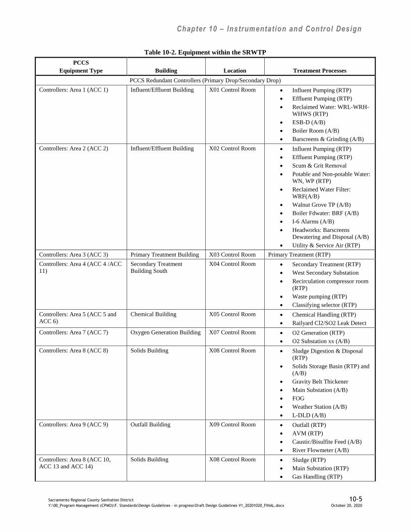
Chapter 10 – Instrumentation and Control Design
Sacramento Regional County Sanitation District 10-5 Y:\00_Program Management (CPMO)\F. Standards\Design Guidelines - in progress\Draft Design Guidelines V1_20201020_FINAL.docx October 20, 2020
Table 10-2. Equipment within the SRWTP
PCCS
Equipment Type Building Location Treatment Processes
PCCS Redundant Controllers (Primary Drop/Secondary Drop)
Controllers: Area 1 (ACC 1) Influent/Effluent Building X01 Control Room Influent Pumping (RTP)
Effluent Pumping (RTP)
Reclaimed Water: WRL-WRH-
WHWS (RTP)
ESB-D (A/B)
Boiler Room (A/B)
Barscreens & Grinding (A/B)
Controllers: Area 2 (ACC 2) Influent/Effluent Building X02 Control Room Influent Pumping (RTP)
Effluent Pumping (RTP)
Scum & Grit Removal
Potable and Non-potable Water:
WN, WP (RTP)
Reclaimed Water Filter:
WRF(A/B)
Walnut Grove TP (A/B)
Boiler Fdwater: BRF (A/B)
I-6 Alarms (A/B)
Headworks: Barscreens
Dewatering and Disposal (A/B)
Utility & Service Air (RTP)
Controllers: Area 3 (ACC 3) Primary Treatment Building X03 Control Room Primary Treatment (RTP)
Controllers: Area 4 (ACC 4 /ACC
11)
Secondary Treatment
Building South
X04 Control Room Secondary Treatment (RTP)
West Secondary Substation
Recirculation compressor room
(RTP)
Waste pumping (RTP)
Classifying selector (RTP)
Controllers: Area 5 (ACC 5 and
ACC 6)
Chemical Building X05 Control Room Chemical Handling (RTP)
Railyard Cl2/SO2 Leak Detect
Controllers: Area 7 (ACC 7) Oxygen Generation Building X07 Control Room O2 Generation (RTP)
O2 Substation xx (A/B)
Controllers: Area 8 (ACC 8) Solids Building X08 Control Room Sludge Digestion & Disposal
(RTP)
Solids Storage Basin (RTP) and
(A/B)
Gravity Belt Thickener
Main Substation (A/B)
FOG
Weather Station (A/B)
L-DLD (A/B)
Controllers: Area 9 (ACC 9) Outfall Building X09 Control Room Outfall (RTP)
AVM (RTP)
Caustic/Bisulfite Feed (A/B)
River Flowmeter (A/B)
Controllers: Area 8 (ACC 10,
ACC 13 and ACC 14)
Solids Building X08 Control Room Sludge (RTP)
Main Substation (RTP)
Gas Handling (RTP)
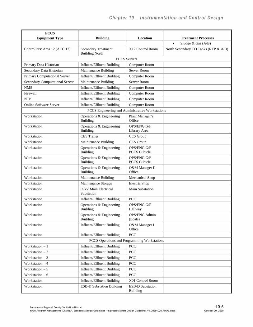
Chapter 10 – Instrumentation and Control Design
Sacramento Regional County Sanitation District 10-6 Y:\00_Program Management (CPMO)\F. Standards\Design Guidelines - in progress\Draft Design Guidelines V1_20201020_FINAL.docx October 20, 2020
PCCS
Equipment Type Building Location Treatment Processes
Sludge & Gas (A/B)
Controllers: Area 12 (ACC 12) Secondary Treatment
Building North
X12 Control Room North Secondary CO Tanks (RTP & A/B)
PCCS Servers
Primary Data Historian Influent/Effluent Building Computer Room
Secondary Data Historian Maintenance Building Server Room
Primary Computational Server Influent/Effluent Building Computer Room
Secondary Computational Server Maintenance Building Server Room
NMS Influent/Effluent Building Computer Room
Firewall Influent/Effluent Building Computer Room
NTP Influent/Effluent Building Computer Room
Online Software Server Influent/Effluent Building Computer Room
PCCS Engineering and Administrative Workstations
Workstation Operations & Engineering
Building
Plant Manager’s
Office
Workstation Operations & Engineering
Building
OPS/ENG G/F
Library Area
Workstation CES Trailer CES Group
Workstation Maintenance Building CES Group
Workstation Operations & Engineering
Building
OPS/ENG G/F
PCCS Cubicle
Workstation Operations & Engineering
Building
OPS/ENG G/F
PCCS Cubicle
Workstation Operations & Engineering
Building
O&M Manager II
Office
Workstation Maintenance Building Mechanical Shop
Workstation Maintenance Storage Electric Shop
Workstation 69kV Main Electrical
Substation
Main Substation
Workstation Influent/Effluent Building PCC
Workstation Operations & Engineering
Building
OPS/ENG G/F
Hallway
Workstation Operations & Engineering
Building
OPS/ENG Admin
(floats)
Workstation Influent/Effluent Building O&M Manager I
Office
Workstation Influent/Effluent Building PCC
PCCS Operations and Programming Workstations
Workstation – 1 Influent/Effluent Building PCC
Workstation – 2 Influent/Effluent Building PCC
Workstation – 3 Influent/Effluent Building PCC
Workstation – 4 Influent/Effluent Building PCC
Workstation – 5 Influent/Effluent Building PCC
Workstation – 6 Influent/Effluent Building PCC
Workstation Influent/Effluent Building X01 Control Room
Workstation ESB-D Substation Building ESB-D Substation
Building
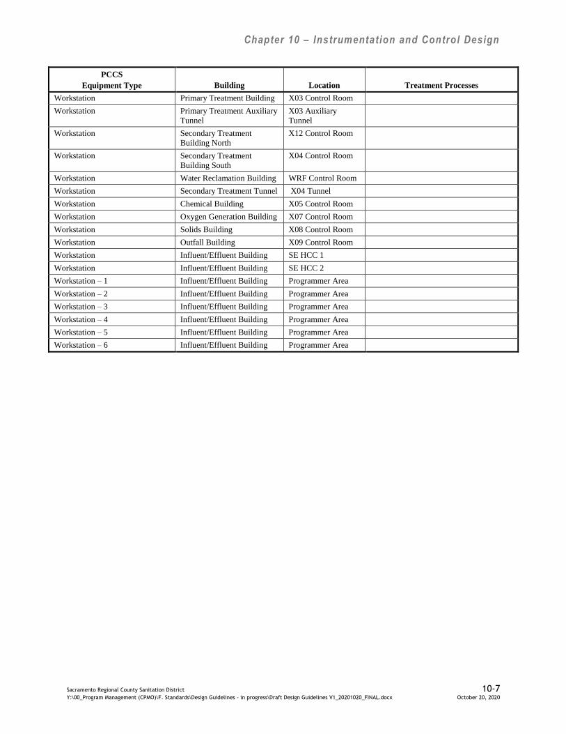
Chapter 10 – Instrumentation and Control Design
Sacramento Regional County Sanitation District 10-7 Y:\00_Program Management (CPMO)\F. Standards\Design Guidelines - in progress\Draft Design Guidelines V1_20201020_FINAL.docx October 20, 2020
PCCS
Equipment Type Building Location Treatment Processes
Workstation Primary Treatment Building X03 Control Room
Workstation Primary Treatment Auxiliary
Tunnel
X03 Auxiliary
Tunnel
Workstation Secondary Treatment
Building North
X12 Control Room
Workstation Secondary Treatment
Building South
X04 Control Room
Workstation Water Reclamation Building WRF Control Room
Workstation Secondary Treatment Tunnel X04 Tunnel
Workstation Chemical Building X05 Control Room
Workstation Oxygen Generation Building X07 Control Room
Workstation Solids Building X08 Control Room
Workstation Outfall Building X09 Control Room
Workstation Influent/Effluent Building SE HCC 1
Workstation Influent/Effluent Building SE HCC 2
Workstation – 1 Influent/Effluent Building Programmer Area
Workstation – 2 Influent/Effluent Building Programmer Area
Workstation – 3 Influent/Effluent Building Programmer Area
Workstation – 4 Influent/Effluent Building Programmer Area
Workstation – 5 Influent/Effluent Building Programmer Area
Workstation – 6 Influent/Effluent Building Programmer Area
Chapter 10 – Instrumentation and Control Design
Sacramento Regional County Sanitation District 10-8 Y:\00_Program Management (CPMO)\F. Standards\Design Guidelines - in progress\Draft Design Guidelines V1_20201020_FINAL.docx October 20, 2020
The existing PCCS I/O subsystem consists of mostly RTP I/O, but includes some Allen-
Bradley PLC5 I/O and Modicon PLC I/O. Existing PCCS controllers communicate with RTP
I/O through a dedicated network switch over an Ethernet connection to one or more RTP
Ethernet I/O Board Controllers (EIOBC) resident in the RTP I/O chassis. The EIOBC
communicates with the RTP I/O cards over the RTP I/O backplane. The RTP I/O subsystem
utilizes a pulse train output to the analog loop controller to raise/lower the analog output
generated by the loop controller. The RTP I/O subsystem sends discrete output commands to
the DCSA modules, which are wired to field devices.
The DCSA modules provide backup operation interface and can perform interlock functions for
discrete devices. Local equipment control selector switches are provided on the DCSA modules
and at local control stations adjacent to the field equipment.
Existing ACCs also have Beta-Alarm annunciator panels. All alarms are hardwired from either
the RTP or Allen Bradley I/O to the annunciator panel. ACC 9 and ACC 14 utilize Allen
Bradley Panel View HMI interfaces instead of panel-mounted loop controllers.
No new Regional San Project ACC shall use the existing ACC configuration. The use of
backup control panels and RTP I/O are legacies that shall not be included in any future ACC
design.
10.4.2 Modifications to Existing ACC Backup Panels
Demolition work shall not disable existing control circuits that are to remain in place during the
modification work. Where necessary, design shall include temporary wiring to continue these
circuits until final connections are complete. Reusing existing raceway for new or relocated
equipment is not allowable unless the specific sequence constraints are listed in the project
Request for Proposal. Add new raceway in these cases, the existing raceways will become
spares. All demolition work shall be coordinated with other sections of these Design
Guidelines.
The addition of any new I/O to an existing ACC shall use either Emerson Ovation I/O modules
or Allen-Bradley PLC I/O cards depending on the type and complexity of monitoring and
control functionality being added.
In the very rare case where the design requires expansion with existing ACC panel mounted
backup controllers and/or RTP I/O (and Regional San approves of expanding with non-Ovation
I/O), Regional San will provide the additional RTP I/O cards, chassis, and any panel mounted
backup analog or discrete controllers. Regional San standard panel mounted loop control is a
Yokogawa YS1700. The Regional San standard RTP I/O to a panel mounted loop controller
utilizes pulse train outputs connected to the loop controller to raise/lower the loop controller
analog output controlling the valve actuator or other field device. The Regional San standard
panel mounted discrete output controller is a DCSA module. A local equipment control selector
switch will be provided on the DCSA module and at the local control station adjacent to the
field equipment.

Chapter 10 – Instrumentation and Control Design
Sacramento Regional County Sanitation District 10-9 Y:\00_Program Management (CPMO)\F. Standards\Design Guidelines - in progress\Draft Design Guidelines V1_20201020_FINAL.docx October 20, 2020
10.4.3 Interceptor Pump Station and Facilities Equipment
The Interceptor Pump Station and Facilities (PS&F) SCADA system communicates with the
PCCS through redundant Ovation SCADA servers located in the computer room adjacent to the
PCC. The preferred system architecture at an offsite facility includes a Modicon Quantum PLC
with a PanelMate HMI interface. All regulatory controls reside locally in the PS&F’s PLC.
Refer to Interceptor PS&F operational strategies which include a PLC Control Narrative
describing the controls at existing facilities. The PCCS monitors and provides supervisory
control with Interceptor PS&F PLCs over an Ethernet connection to the Interceptor PS&F
station. The communication link to all large interceptor pumping stations, which have a PCCS
workstation, is a T1 leased telephone line; some of these pump stations (N50, N51, and N19)
have either a licensed (N51) or an unlicensed (N50 and N19) radio link. All other interceptor
pumping stations and facilities have a DS0 leased telephone line. The facilities are described
below in Table 10-3.
Table 10-3. Interceptor Pump Station & Facilities (Interceptor PS&F)
Facility Name Facility Description Facility Location
N015 North East Siphon Inlet Structure Located immediately south of the entrance gate
to the Northeast Pump Station, 1000 River Walk
Way. (299-B3)
N016 North East Siphon Outlet Structure Located on the north side of Mira Del Rio Dr.,
west of 9539 Mira Del Rio Dr. (299-B4)
N018 North East Chlorination Station Located at 1000 River Walk Way (299-B3)
N019* Arden Sewage Pumping Station Located at 1021 Howe Avenue (298-C3)
N020 Arden Force Main Oxygen Structure Located on west side of So. Watt Avenue 900’
south of Jackson Road. (318-H3)
N040* Iron Point Pumping Station Located on the south side of Iron Point Rd. at
Buckingham Way. (281-E2)
N050* South River Pump Station (316-E7)
N051* New Natomas Pump Station (277-A4)
N052 Power Inn Pump Station (318-D4)
N053* Van Maren Lift Station (259-F3)
N054 Cherry Lane Pump Station (257-J3)
S023 San No. 2 Sewage Pumping Station Located on east side of Elvas Freeway at north
Levee of American River. Access at exit from
Cal Expo Blvd at freeway underpass. (297-J2)
S030 Natomas Sewage Pumping Station Located north of intersection of San Juan Rd and
Airport Rd, east side of Airport Rd. (277-A4)
S033* Cordova Sewage Pumping Station Located at the former Cordova Treatment Plant,
northwest off Coloma Rd to west end of Chase
Dr. (299-E1)
S055 Northeast Sewage Pumping Station Located at 1000 River Walk Way (299-B3)
S078 Mather Sewage Pumping Station Located adjacent to Mather AFB along the
easterly extension of Kiefer Blvd. 800 ft east of
Happy Lane (319-D2)

Chapter 10 – Instrumentation and Control Design
Sacramento Regional County Sanitation District 10-10 Y:\00_Program Management (CPMO)\F. Standards\Design Guidelines - in progress\Draft Design Guidelines V1_20201020_FINAL.docx October 20, 2020
10.5 Area Control Centers and Control System Rooms
10.5.1 ACC Networks
The ACC networks include the following physically separated networks:
PCCS Networks: There will be a PCCS A Network and a PCCS B Network. These
PCCS networks will be configured as a redundant star topology with rapid spanning tree
protocol. The PCCS A Network will connect to the PCCS root switch and the PCCS B
Network will connect to the PCCS backup root switch. PCCS Network A will share the
same backbone cable as PLC A Network but communicate over dedicated fibers. PCCS
B Network and PLC B Network will share a fiber optic cable as well, and communicate
independently over dedicated fibers.
PLC Networks: There will be a PLC A Network and a PLC B Network. These PLC
networks will be configured as a redundant star topology with rapid spanning tree
protocol. The PLC A Network will connect to the PLC A Network root switch and the
PLC B Network will connect to the PLC B Network backup root switch. PLC A
Network will share the same backbone cable as PCCS A Network but communicate
over dedicated fibers. PLC B Network and PCCS B Network will share a fiber optic
cable as well, and communicate independently over dedicated fibers.
Maintenance Networks: This network includes virtual private networks for the
following applications: Power Management, Vibration Monitoring, HVAC, Fire Alarm,
and PLC Programming. The maintenance network is configured as a non-redundant star
topology with rapid spanning tree protocol. The Maintenance A Network will connect to
the Maintenance A Network root switch and the Maintenance B Network will connect
to the Maintenance B Network backup root switch. Maintenance A Network will share
the same backbone cable as the PCCS A and PLC A Networks but communicate over
dedicated fibers. Maintenance B Network will share the same backbone cable as the
PCCS B and PLC B Networks but communicate over dedicated fibers
MIS Network: This network is configured as a star topology and supports Regional San
standard security system software, MIS business applications, and voice over IP
telephony applications.
CCTV Network: This network is configured as a star topology and supports Regional
San standard closed-circuit television (CCTV) system software.
PA System: The public address (PA) system communicates via proprietary protocol
over fiber optic cable to distributed public address system equipment.
The PCCS has two physically separate networks, the PCCS network connects all of the
Emerson Ovation DCS components together as an integrated system and the PLC network
connects all of the area PLCs and subsystem PLCs together as an integrated system. The PCCS
and PLC networks are connected through routers and switches in each Area Control Center
(ACC). Both the PCCS network and the PLC network are configured as redundant star
networks that utilizes root and backup root switches.

Chapter 10 – Instrumentation and Control Design
Sacramento Regional County Sanitation District 10-11 Y:\00_Program Management (CPMO)\F. Standards\Design Guidelines - in progress\Draft Design Guidelines V1_20201020_FINAL.docx October 20, 2020
In addition to plant-wide the PCCS local area network (LAN), the PCCS includes a
telecommunications and radio based wide area network (WAN) for communications with the
Interceptor PFS. This network is managed by the PCCS Support group and Control Shop. The
LAN connects all of the Ovation operator/engineering workstations, Ovation servers, Ovation
controllers, and Ovation SCADA system. The WAN connects the Ovation DCS via the
Ovation SCADA servers to each of the remote SRCSD interceptor facility LANs.
The PCCS network shall utilize Emerson supplied network equipment and shall be installed by
the construction contractor but connected and programmed by Emerson staff. The PLC network
shall conform to IT network equipment standards and shall utilize IT standard networking
equipment. The contractor shall install and connect the PLC network equipment, but the
network equipment shall be programmed by Regional San IT staff. Industrial networking
equipment supplied with PLC control panels may be non-IT standards industrial equipment and
specified in the PROGRAMMABLE LOGIC CONTROLLERS Specification Section 40 63 43.
Regional San is planning to install additional single mode (SM) fiber cables between existing
plant-wide backbone network fiber optic panels to increase the fiber availability and to migrate
the PCCS, PLC, and Maintenance networks to SM fibers from their existing multimode (MM)
fibers to support gbit/s network communication speed.
The preferred fiber optic cables for expanding the fiber optic backbone network are two 96-
strand SM cables. New cables are to be terminated with LC connectors and connect to fiber
optic termination panels distributed throughout the plant. All fiber optic strands shall be
terminated at each end at the fiber optic patch panel.
The preferred fiber optic cables for expanding from a backbone network fiber optic patch panel
to another area as a spur off the backbone shall be one fiber optic cable with 48-strands of SM
fibers.
Check with Regional San for availability of existing backbone fibers. Fiber optic patch cables
on existing FO termination panel are installed by Regional San. Fiber optic cables are to be
scheduled on the conduit and cable schedule. FO patch cables should connect between the FO
patch panels and FO ports on switches, routers, and other networked equipment. The use of FO
media converters should be avoided wherever possible. Extensions to the FO system shall be
shown on the project drawings. FO termination panels are documented on the X-401 series
project drawings and shall include front view with cabinet size, material list and nameplate
engraving schedule.
10.5.2 New ACC Arrangement
The preferred ACC arrangement consists of separate spaces for an operations Control Room, a
control systems room (CS Room), and an Electrical Equipment Room. The Control Room shall
include working space for an operations crew with maintenance and operations supervisor
offices and common space for operations meetings. The Control Room equipment shall include
two PCCS workstations each with one or two large monitors (specific size to be determined at
the time of design), one MIS workstation, printer, fire alarm panel and other system interfaces

Chapter 10 – Instrumentation and Control Design
Sacramento Regional County Sanitation District 10-12 Y:\00_Program Management (CPMO)\F. Standards\Design Guidelines - in progress\Draft Design Guidelines V1_20201020_FINAL.docx October 20, 2020
and communication tools as determined by the needs of Operations in that area. The CS Room
shall be a secured area and shall include all PCCS and auxiliary systems. The network
equipment shall include all network media (cable and jumpers), routers, switches, termination
panels, computers, and equipment racks, with the exception of operator workstation and
printers located in the Control Room. In addition, the CS Room will include the PCCS and
auxiliary equipment including: an Emerson Ovation DCS control panel, an Area PLC control
panel, PCCS or auxiliary system servers, access control panel, HVAC control panel, UPS, and
public address amplifier panel. The electrical equipment room shall include all equipment
described in the Electrical Rooms section of Chapter 9 of these Design Guidelines. ACC design
shall be coordinated with the architectural design guidelines presented in Chapter 4 and the
electrical design guidelines included in Chapter 9.
Smaller process areas shall be provided with a secure CS Room and Electrical Equipment
Room, but not a Control Room. The small process area CS Room will as a minimum include
PCCS and PLC networking equipment, an Area PLC control panel (optionally supplied with a
panel mounted PC running Emerson Ovation HMI software), and UPS. The minimal PCCS and
PLC networking equipment shall include a fiber optic termination panel for termination of the
fiber optic cable connecting the small process area building with its associated ACC, and
switches for connecting the redundant PLCs to the PLC-A and PLC-B networks, and
optionally, switches for connecting the panel mounted and/or operator workstation HMI(s) to
the PCCS-A and PCCS-B networks.
The Operators will control the large and small area processes from the PCC, and operator
workstations in the ACC Control Room. Subsystem control panels shall be equipped with
panel mounted PCs running Emerson Ovation HMI software.
10.6 PCCS Ovation and Area PLC Controllers
All new process improvement projects will include an Emerson Ovation controller for
supervisory control and one or more Allen-Bradley ControlLogix PLC(s) for regulatory
control. See the Plant Computer Control System Control Strategies and Programmable Logic
Controller Control Narratives section above for clarification on assignment of control to
supervisory or regulatory controller.
The PCCS and PLC network equipment, network interface, and network connections are shown
schematically on Figure 10-1 below.
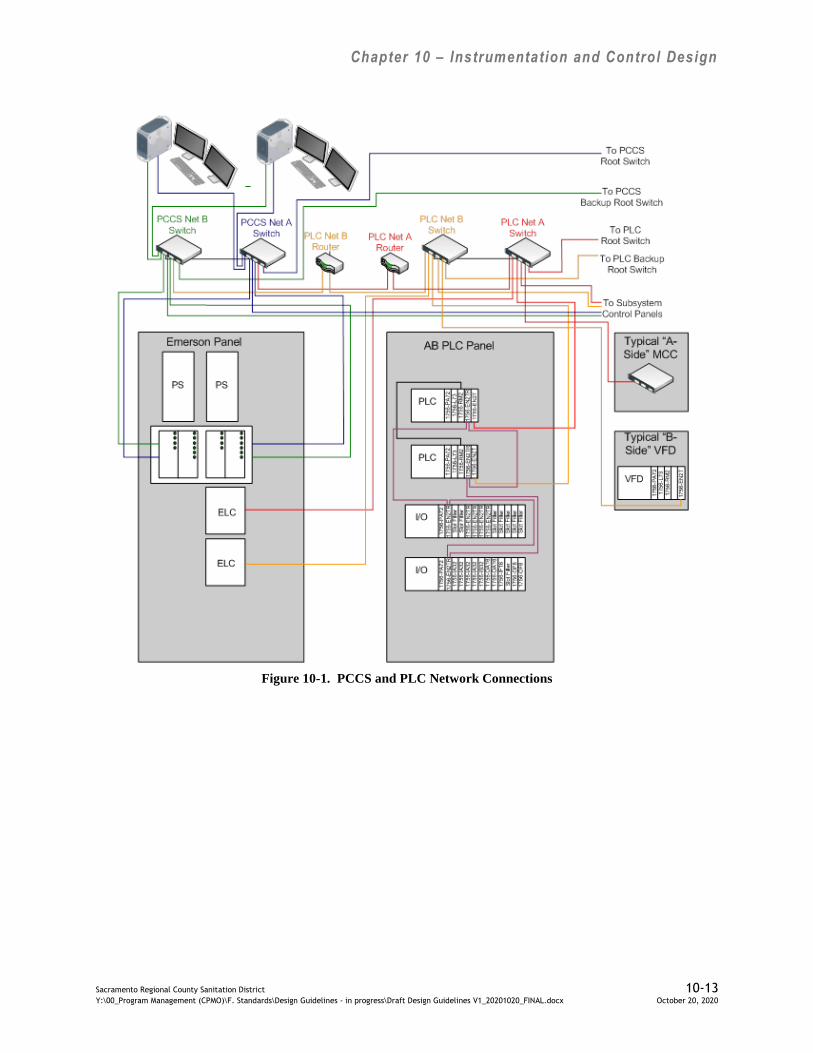
Chapter 10 – Instrumentation and Control Design
Sacramento Regional County Sanitation District 10-13 Y:\00_Program Management (CPMO)\F. Standards\Design Guidelines - in progress\Draft Design Guidelines V1_20201020_FINAL.docx October 20, 2020
Figure 10-1. PCCS and PLC Network Connections

Chapter 10 – Instrumentation and Control Design
Sacramento Regional County Sanitation District 10-14 Y:\00_Program Management (CPMO)\F. Standards\Design Guidelines - in progress\Draft Design Guidelines V1_20201020_FINAL.docx October 20, 2020
10.6.1 Supervisory Controllers
Supervisory control panels shall be supplied by Emerson Process Management and shall
conform to standard control panel specifications. Redundant Emerson Ovation controllers shall
provide supervisory control for each new ACC. The most current version of Ovation controller
that is compatible with the currently operating software running on the PCCS shall be selected
for supervisory controllers.
The interface standard to the Ovation distributed control system shall be EtherNet/IP protocol
over Ethernet networks.
10.6.1.1 Ovation Ethernet Link Controllers
Ovation Ethernet Link Controller (ELC) module is the primary communications interface
between the Emerson Ovation supervisory control system and the Allen-Bradley PLC
regulatory control system. To maximize data throughput for this interface, field data flows from
the PLC to the PLC network as EtherNet/IP protocol and from the PLC network to the ELC
module where it is converted from EtherNet/IP to Ovation protocol. The Ovation protocol data
then is routed from the ELC module through the PLC network to the PCCS network and to the
Ovation controller. The performance of Ovation/Allen-Bradley communications will dictate the
number of ELC modules required for this interface. The Ovation software version will support
direct access of RSLogix tags for incorporation into the Ovation database. Ovation database I/O
will be incorporated into supervisory control strategies, operator graphics, alarms, trends, and
supervisory reports. The connections and data flows for one of the two redundant PCCS and
PLC networks are shown on Figure 10-2 below.
Ovation
Controller
Ovation I/O: Ovation
Proprietary Communications
PCCS (Ovation) Network
PLC I/O: EtherNet/IP
Communications
Allen Bradley
Allen Bradley
ELC
PCCS Net Switch
PLC Net
Router
PLC Net Switch
Figure 10-2. Ethernet Link Controller Cabling and Data Flows

Chapter 10 – Instrumentation and Control Design
Sacramento Regional County Sanitation District 10-15 Y:\00_Program Management (CPMO)\F. Standards\Design Guidelines - in progress\Draft Design Guidelines V1_20201020_FINAL.docx October 20, 2020
In addition, through the PLC network interface, the ELC module will communicate with power
quality meters, VFDs, motor starter Smart overloads and motor management relays. The
protocol for all of these Ethernet interfaces is the ODVA Ethernet Industrial Protocol
(EtherNet/IP). Where EtherNet/IP is not supported by the field device, Open Modbus TCP/IP is
preferred.
In addition to the hardwired I/O shown on the P&IDs for an area UPS, the UPS shall be
connected to the ACC traffic switch and shall utilize Simple Network Management Protocol
(SNMP) for monitoring ACC UPS status from the PCCS.
10.6.2 Area Programmable Logic Controllers
The Area PLCs will be Allen-Bradley ControlLogix. As a minimum, each redundant PLC pair
will communicate with both PLC networks and be capable of bumplessly failing over from the
primary PLC to the redundant PLC when there is a primary PLC failure.
EtherNet/IP will be the standard protocol used for the Ovation to Allen-Bradley interface. The
PCCS supervisory Ovation controllers will communicate with the ControlLogix PLCs via
Ethernet connections to the redundant PLC networks using EtherNet/IP protocol. Emerson
Ovation software v3.6 or higher supports accessing native Allen Bradley ControlLogix tags
using the EtherNet/IP interface. The PLC will be programmed in ladder logic wherever
possible and will follow best practices for structured programming and Regional San PLC
programming standards.
Ethernet networks will be used to communicate between the redundant PLC networks and
MCC motor starters, VFDs, and power quality monitors. The Ethernet network connections to
the PLC networks are shown schematically in Figure 10-3. MCCs may include redundant
industrial network switches (Regional San standard is Allen-Bradley Stratix switches) which
are connected to the PLC networks. Power quality information is routed from the PLC
networks to the Maintenance network at the PCC-Annex and the Administration Building to
communicate power quality data from power quality meters, VFDs, motor starter smart
overloads, and motor management relays to Regional San’s power monitoring software. The
redundant industrial network switches also support multiple protocols should there be some
devices communicating via Open Modbus TCP/IP as well as EtherNet/IP protocol.
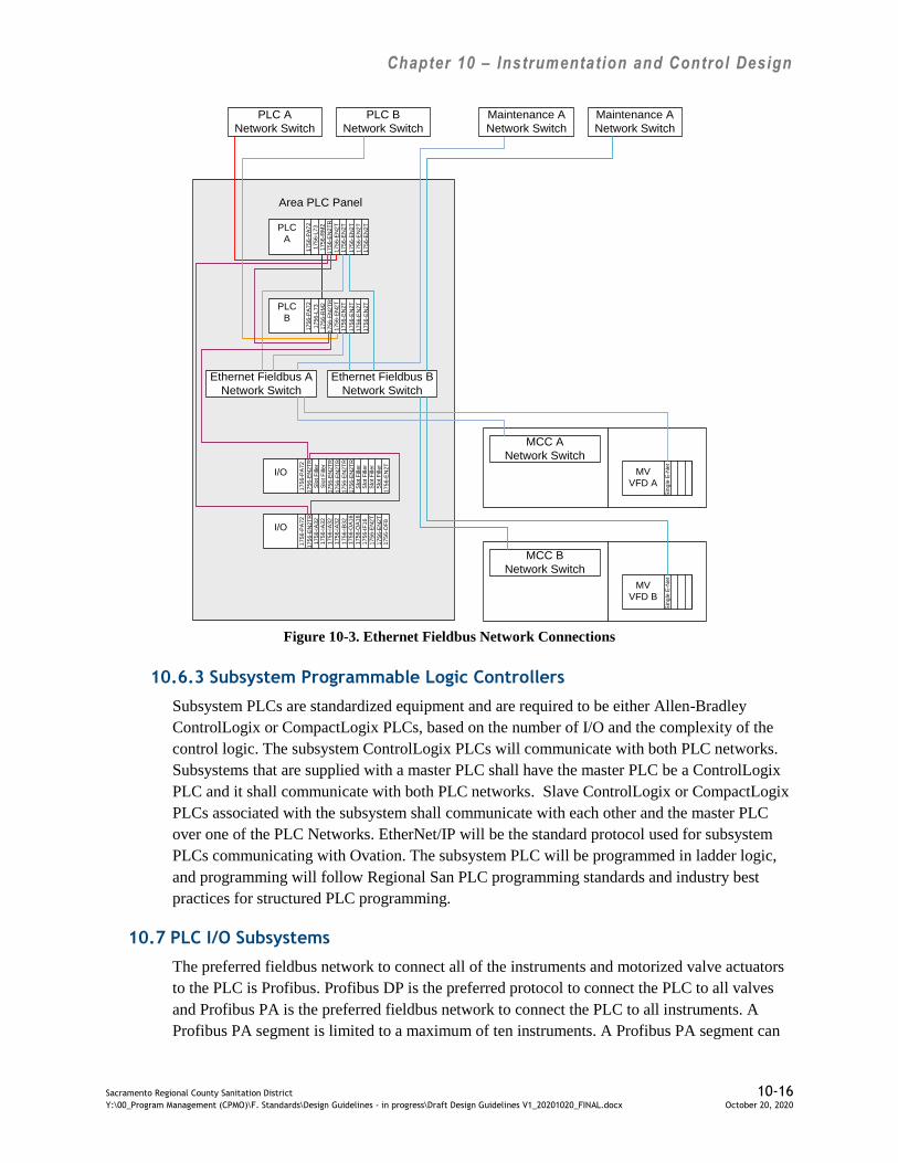
Chapter 10 – Instrumentation and Control Design
Sacramento Regional County Sanitation District 10-16 Y:\00_Program Management (CPMO)\F. Standards\Design Guidelines - in progress\Draft Design Guidelines V1_20201020_FINAL.docx October 20, 2020
PLC
A
17
56
-EN
2T
17
56
-L7
3
17
56
-RM
2
17
56
-EN
2T
R
PLC
B
17
56
-EN
2T
17
56
-L7
3
17
56
-RM
2
17
56
-EN
2T
R
I/O
I/O
17
56
-PA
72
17
56
-PA
72
17
56
-PA
72
17
56
-EN
2T
R
17
56
-PA
72
17
56
-EN
2T
RS
lot F
ille
r
Slo
t F
ille
r
17
56
-EN
2T
R
17
56
-EN
2T
R
17
56
-EN
2T
R
17
56
-EN
2T
R
17
56
-IA
32
17
56
-IB
32
17
56
-IA
32
17
56
-IA
32
17
56
-IA
32
17
56
-OA
16
17
56
-OA
16
17
56-I
F1
6
Area PLC Panel
17
56
-OF
8
Slo
t F
ille
rS
lot F
ille
r
Slo
t F
ille
r
Slo
t F
ille
r
17
56
-EN
2T
17
56
-EN
2T
17
56
-EN
2T
Ethernet Fieldbus A
Network Switch
PLC A
Network Switch
PLC B
Network Switch
Maintenance A
Network Switch
Maintenance A
Network Switch
Ethernet Fieldbus B
Network Switch
17
56
-EN
2T
17
56-E
N2T
17
56-E
N2T
17
56
-EN
2T
17
56-E
N2T
17
56
-EN
2T
17
56
-EN
2T
17
56-E
N2T
MCC A
Network Switch
MV
VFD A
Sin
gle
E-N
et
MCC B
Network Switch
MV
VFD B
Sin
gle
E-N
et
Figure 10-3. Ethernet Fieldbus Network Connections
10.6.3 Subsystem Programmable Logic Controllers
Subsystem PLCs are standardized equipment and are required to be either Allen-Bradley
ControlLogix or CompactLogix PLCs, based on the number of I/O and the complexity of the
control logic. The subsystem ControlLogix PLCs will communicate with both PLC networks.
Subsystems that are supplied with a master PLC shall have the master PLC be a ControlLogix
PLC and it shall communicate with both PLC networks. Slave ControlLogix or CompactLogix
PLCs associated with the subsystem shall communicate with each other and the master PLC
over one of the PLC Networks. EtherNet/IP will be the standard protocol used for subsystem
PLCs communicating with Ovation. The subsystem PLC will be programmed in ladder logic,
and programming will follow Regional San PLC programming standards and industry best
practices for structured PLC programming.
10.7 PLC I/O Subsystems
The preferred fieldbus network to connect all of the instruments and motorized valve actuators
to the PLC is Profibus. Profibus DP is the preferred protocol to connect the PLC to all valves
and Profibus PA is the preferred fieldbus network to connect the PLC to all instruments. A
Profibus PA segment is limited to a maximum of ten instruments. A Profibus PA segment can

Chapter 10 – Instrumentation and Control Design
Sacramento Regional County Sanitation District 10-17 Y:\00_Program Management (CPMO)\F. Standards\Design Guidelines - in progress\Draft Design Guidelines V1_20201020_FINAL.docx October 20, 2020
be configured as either a daisy chain or star configuration. If a daisy chain configuration is
designed, all instruments shall be connected using a “T” connection that allows communication
to all other instruments should one instrument fail. In addition, the Profibus network design
shall include redundant power for all Profibus connected communications and support for
redundant ControlLogix PLC masters that ensures there is no loss of Profibus data when the
primary PLC fails and the secondary PLC takes control.
Hardwired field equipment and instrumentation shall be terminated to the area PLC(s) as
follows: all of the I/O associated with a single piece of equipment shall be terminated on a
single I/O card wherever possible, and I/O associated with redundant equipment shall never be
terminated on the same I/O card. Redundant equipment shall have two independent
communication paths to the PLC.
Profibus and Ethernet networked field equipment and instrumentation shall be segregated to
follow the split power buses, e.g. pumps 1 and 3 powered by the A-Bus may share one fieldbus
network and pumps 2 and 4 powered by the B-Bus may share a separate fieldbus network, but
you would never have one fieldbus shared by pumps 1 and 2 or pumps 3 and 4.
If no Profibus instrument is available for a specific application, discrete and analog I/O shall be
hardwired to the PLC or PLC remote I/O. Discrete I/O shall utilize 120Vac I/O modules (with
the exception of 4kV and 12kV switchgear which shall utilize 125Vdc I/O modules). Non-
fieldbus networked analog I/O shall utilize 4-20 mA, thermocouple, or RTD I/O modules that
support the HART protocol.
ACC preliminary design shall include an estimate of the total I/O point count expected to be
programmed in the PLC to enable Regional San to determine the required PLC resources.
Field located local control stations are to be provided with all new equipment for backup
operations.
10.7.1 Electrical Equipment I/O
Data monitoring and control I/O points for electrical equipment shall be as specified in Chapter
9 of these Design Guidelines.
10.7.2 Subsystem PLC I/O
The subsystem packaged equipment PLC I/O shall follow the same design standards as the
Area PLC I/O.
10.8 Auxiliary Networks
Currently, there are four main Auxiliary Networks in use within Regional San: Management
Information Systems (MIS) network, Maintenance network, and Public Address System
network. A block diagram of the various ACC network logical connections is shown on Figure
10-4.
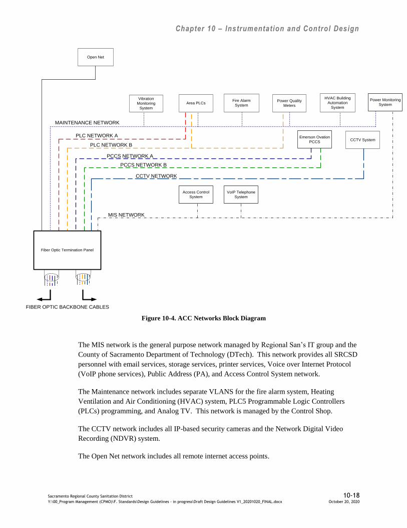
Chapter 10 – Instrumentation and Control Design
Sacramento Regional County Sanitation District 10-18 Y:\00_Program Management (CPMO)\F. Standards\Design Guidelines - in progress\Draft Design Guidelines V1_20201020_FINAL.docx October 20, 2020
Open Net
CCTV System
Vibration
Monitoring
System
Fire Alarm
System
HVAC Building
Automation
System
Power Quality
MetersArea PLCs
0
MAINTENANCE NETWORK
MIS NETWORK
PLC NETWORK B
FIBER OPTIC BACKBONE CABLES
Emerson Ovation
PCCS
PCCS NETWORK B
Fiber Optic Termination Panel
Power Monitoring
System
Access Control
System
VoIP Telephone
System
CCTV NETWORK
PLC NETWORK A
PCCS NETWORK A
Figure 10-4. ACC Networks Block Diagram
The MIS network is the general purpose network managed by Regional San’s IT group and the
County of Sacramento Department of Technology (DTech). This network provides all SRCSD
personnel with email services, storage services, printer services, Voice over Internet Protocol
(VoIP phone services), Public Address (PA), and Access Control System network.
The Maintenance network includes separate VLANS for the fire alarm system, Heating
Ventilation and Air Conditioning (HVAC) system, PLC5 Programmable Logic Controllers
(PLCs) programming, and Analog TV. This network is managed by the Control Shop.
The CCTV network includes all IP-based security cameras and the Network Digital Video
Recording (NDVR) system.
The Open Net network includes all remote internet access points.
Chapter 10 – Instrumentation and Control Design
Sacramento Regional County Sanitation District 10-19 Y:\00_Program Management (CPMO)\F. Standards\Design Guidelines - in progress\Draft Design Guidelines V1_20201020_FINAL.docx October 20, 2020
All IT networks shall conform to IT network equipment standards and shall utilize IT standard
networking equipment. The contractor shall install and connect auxiliary network equipment,
but the network equipment shall be programmed by Regional San IT staff.
10.9 Power Quality Monitoring System
Regional San currently has a Power Quality Monitoring System that connects the power
monitoring devices to the end users devices via the PCCS and maintenance networks.
Switchgear main and feeders are monitored with power quality meters with dual integrated
Ethernet ports and Embedded Web Server. MCC motor loads are monitored with motor
management relays, VFDs, and motor starter smart overloads. All monitoring devices shall be
connected to the PLC networks, segregated from other network traffic via VLAN, and routed to
the power quality monitoring system server on the Maintenance network.
As shown on Figure 10-4, the power quality meters, motor starters, and VFDs are logically
connected to both the PLCs and the Maintenance network so power monitoring devices with a
single Ethernet Port connected to a PLC network will be accessible from both the PCCS
Networks through the PLCs, and from the Maintenance network.
10.9.1 Power Quality Monitoring Devices and Network
Power quality monitor devices include power quality meters, motor monitoring relays, VFDs,
and motor starter smart overloads shall communicate over the PLC networks. These devices
shall be segregated to follow the split power buses; for example, VFDs for pumps 1 and 3
powered by the A-Bus may share one fieldbus network and VFDs for pumps 2 and 4 powered
by the B-Bus may share a separate fieldbus network, but one fieldbus would never be shared by
VFDs for pumps 1 and 2 or for pumps 3 and 4.
Power quality meters are on all switchgear mains and feeder breakers.
Low voltage MCCs and medium voltage MCC motor management relays, VFDs, and motor
starter Smart overloads are connected to PLC Networks for power quality monitoring.
10.9.2 Power Quality Monitoring Servers and End User Devices
10.9.2.1 Power Quality Monitoring Servers
The power monitoring server collects historical data and monitors real-time points via the
Maintenance network and connects to end user’s devices via the PLC network.
The existing PCCS Enterprise Data Server (EDS) collects PCCS historical data and monitors
real-time points via the PCCS network. Power monitoring field data is routed through the PLC
network, the Ovation Ethernet Link Controller (ELC) module and Ovation software to the EDS.
Remote webservers such as, (1) Energy Profiler Online Web Server by Schneider Electric, (2)
Regional San’s power monitoring webserver, and (3) monitoring device embedded webserver
will connect end-users devices to power monitoring devices over the MIS Network in the
future. Web-based monitoring is configured to transmit power quality data available on
Chapter 10 – Instrumentation and Control Design
Sacramento Regional County Sanitation District 10-20 Y:\00_Program Management (CPMO)\F. Standards\Design Guidelines - in progress\Draft Design Guidelines V1_20201020_FINAL.docx October 20, 2020
Maintenance Networks to a remote web server over the MIS network. Recorded data shall be
compatible with the power management host software.
10.9.2.2 Power Quality Monitoring End User Devices
End-users include laptops and remote desktops.
Local laptops loaded with power management host software shall plug into the front of the
meters to access data and diagnostics information.
Remote desktops loaded with power quality monitoring host software shall access the power
quality meters, VFDs, motor starter overloads, and motor management relays via the PLC
Network directly or via the MIS or Maintenance networks.
10.9.2.3 Power Quality Monitoring Points
Power quality monitoring available on the maintenance network, routed through the PLC
network, shall consist of the minimum power quality points: over/under voltage, harmonic
spectrum, power factor, phase and line voltage, phase and line current, voltage and current
unbalance, kW , kVAR, kVA, kWh, kVARh, kVAh, frequency, kW demand, kVAR demand,
kVA demand, THD and crest factor. All power quality monitoring points shall be capable of
being sampled and trended.
Power quality monitoring points communicated to the PCCS network through the PLCs (as
shown in Figure 10-3) shall consist of Amps, kV, kW and THD.
10.10 Local Controls
Local control is required for all equipment with minor exceptions. Local controls vary in size
and complexity depending on specific equipment requirements and include: control stations
furnished under the electrical system, typically Hand-Off-Auto (HOA) switches, critical
interlock status lights, reset buttons, and ready lights near the controlled equipment. Run lights
shall be included at control station for submersible or remotely located motors. Where a local
emergency stop function is required, it shall be accomplished with an E-stop button.
10.10.1 Local Controls Furnished under Electrical System
Local controls are documented on the plan drawings, control and logic diagrams, and P&IDs.
Where 120Vac power is required for a single device motor drive, the local control panel power
shall be derived from the MCC control circuit.
10.10.2 Local Subsystem Controls Furnished with Mechanical or Process Equipment
Subsystem vendor packaged system controls are documented on the plan drawings, control and
logic diagrams, and P&IDs. Some equipment furnished with manufacturer’s standard control
panels requires certain modifications that are not manufacturer’s standard options to integrate
into the Area PLCs. Show all interface points on the P&IDs (typically Start, Stop, Ready,
Running and Trouble) and specify those interface requirements be networked or hardwired to

Chapter 10 – Instrumentation and Control Design
Sacramento Regional County Sanitation District 10-21 Y:\00_Program Management (CPMO)\F. Standards\Design Guidelines - in progress\Draft Design Guidelines V1_20201020_FINAL.docx October 20, 2020
terminal blocks in the equipment technical specification. Custom control panels shall reference
the CONTROL SYSTEM EQUIPMENT PANELS AND RACKS Specification
Section 40 67 00 for the detailed control panel requirements. Equipment technical specification
submittal requirements shall include PLC Control Narratives for the subsystem equipment and
typical control panel requirements. Where 120Vac power is required for a single device motor
drive, the local control panel power shall be derived from the MCC control circuit. If two or
more devices are controlled a separate circuit from an instrument power panel shall be utilized
for power. Subsystem I/O shall be specified in the PROGRAMMABLE LOGIC
CONTROLLER INPUT/OUTPUT Specification Section 40 61 93.20, and the subsystem
instrumentation shall be specified in the SCHEDULES OF INSTRUMENTATION FOR
PROCESS SYSTEMS Specification Section 40 06 70.
10.10.3 Safety Interlocks
Safety interlocks shall conform to all applicable codes and standards. For covered process areas
like the chemical storage and digester gas areas, the safety interlocks will be reviewed for
conformance to NFPA 79 and will be configured in a manner that avoids adverse consequences
to personnel safety, health, and the environment. Safety interlocks can be either hardwired or
for a group of interlocks programmed in a safety rated programmable logic controller.
Process interlocks or equipment protection interlocks are not considered safety interlocks and
can be either hard wired or for a group of interlocks programmed in a standard programmable
logic controller.
10.10.4 Noncritical Alarms and Interlocks
Noncritical alarms may be generated by discrete outputs from a field device, PLC or processing
of an analog value for a trip point. The "READY" status shall be satisfied when all switches
and interlocks are in the normal status. The "RUNNING" status shall be obtained through
auxiliary contact closure from the motor contactor or pilot relay.
10.11 Instrumentation
Edit Regional San Guide Specifications for appropriate operating ranges and compatibility of
materials. List all instruments in the SCHEDULES OF INSTRUMENTATION FOR
PROCESS SYSTEMS Specification Section 40 06 70. In preliminary design, consider the
necessity for instrument redundancy for efficient operation, to meet regulatory requirements,
and operator safety.
10.11.1 Standardized Equipment and Instruments
Regional San’s table of standardized equipment and instruments is found in Appendix A of
Regional San’s Design Contract Requirements. This table has not been updated to reflect
model numbers for equipment connected via Profibus networks. Designers to update table with
appropriate smart instrument model numbers.
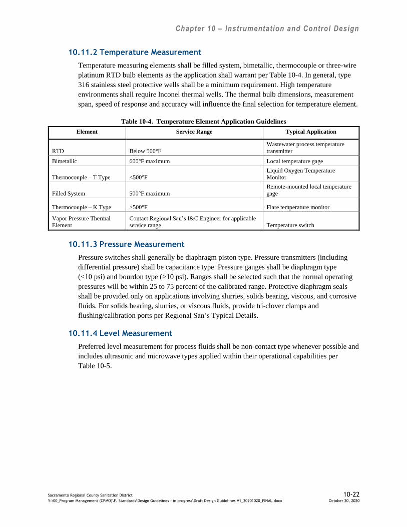
Chapter 10 – Instrumentation and Control Design
Sacramento Regional County Sanitation District 10-22 Y:\00_Program Management (CPMO)\F. Standards\Design Guidelines - in progress\Draft Design Guidelines V1_20201020_FINAL.docx October 20, 2020
10.11.2 Temperature Measurement
Temperature measuring elements shall be filled system, bimetallic, thermocouple or three-wire
platinum RTD bulb elements as the application shall warrant per Table 10-4. In general, type
316 stainless steel protective wells shall be a minimum requirement. High temperature
environments shall require Inconel thermal wells. The thermal bulb dimensions, measurement
span, speed of response and accuracy will influence the final selection for temperature element.
Table 10-4. Temperature Element Application Guidelines
Element Service Range Typical Application
RTD Below 500°F
Wastewater process temperature
transmitter
Bimetallic 600°F maximum Local temperature gage
Thermocouple – T Type <500°F
Liquid Oxygen Temperature
Monitor
Filled System 500°F maximum
Remote-mounted local temperature
gage
Thermocouple – K Type >500°F Flare temperature monitor
Vapor Pressure Thermal
Element
Contact Regional San’s I&C Engineer for applicable
service range Temperature switch
10.11.3 Pressure Measurement
Pressure switches shall generally be diaphragm piston type. Pressure transmitters (including
differential pressure) shall be capacitance type. Pressure gauges shall be diaphragm type
(<10 psi) and bourdon type (>10 psi). Ranges shall be selected such that the normal operating
pressures will be within 25 to 75 percent of the calibrated range. Protective diaphragm seals
shall be provided only on applications involving slurries, solids bearing, viscous, and corrosive
fluids. For solids bearing, slurries, or viscous fluids, provide tri-clover clamps and
flushing/calibration ports per Regional San’s Typical Details.
10.11.4 Level Measurement
Preferred level measurement for process fluids shall be non-contact type whenever possible and
includes ultrasonic and microwave types applied within their operational capabilities per
Table 10-5.

Chapter 10 – Instrumentation and Control Design
Sacramento Regional County Sanitation District 10-23 Y:\00_Program Management (CPMO)\F. Standards\Design Guidelines - in progress\Draft Design Guidelines V1_20201020_FINAL.docx October 20, 2020
Table 10-5. Types of Level Elements for Typical Process Applications
Process Application Element
Sumps (measurement and control) Bubbler, ultrasonic
Sumps (high alarm level) Float or Bubbler pressure switch
Sumps (low level cut-out) Float
Pressurized vessels Differential pressure cell
Chemical tanks Ultrasonic
Digesters Microwave, RF capacitance
Channel levels Bubbler, ultrasonic, microwave
LSG Holder Gage head unit
Primary Scum Hoppers Microwave energy level switch
10.11.5 Flow Measurement
Application of flow measurement requires evaluation of the total cost, flow velocity, flow
profile, process, Reynolds number, density, turndown, mechanical installation constraints and
accuracy requirements. Turndown shall be selected so that the flowmeter has the ability to
cover the range of flow rates within specified accuracy limits. Calculate the Reynolds number
for the minimum and maximum flow rates. Minimum Reynolds number is calculated by using
the minimum expected fluid flow and density and the maximum expected viscosity. A
maximum Reynolds number is calculated using the maximum expected fluid flow and density
and the minimum expected viscosity. Use Moody’s charts to compensate for pipe or channel
roughness and select piping or channel size to accommodate the required flow profile over the
entire operating range. Locate flowmeters to suit the specific technology requirements.
Magnetic flowmeters are the preferred type for pipelines and typically require a full pipe and
straight pipe lengths of 5x upstream and 3x diameter downstream of their location. Multiple
path transit-time acoustic flowmeters are the preferred type for channels or large pipes and
typically require straight pipe or channel lengths of 10x upstream and 2x diameter downstream
of their location.
For difficult conditions consider flow conditioners as necessary to isolate the liquid flow
disturbances from the flowmeter while minimizing the pressure drop across the conditioner.
The flow conditioner should remove swirls from the fluid stream and allow the profile velocity
to come up to fully developed turbulent flow, or at least a stable acceptable geometry.
Coordinate meter installation requirements with mechanical design for pipelines and structural
design for channels.
10.12 Electronic Valve Actuators
Designer shall present available fieldbus options compatible with Profibus DP Network as
shown on Figure 10-3 for controlling electronic valve actuators to Regional San electrical and
I&C staff. Regional San staff will clarify which valve actuator fieldbus is preferred and the
maximum number of valve actuators allowed per network segment upon completion of their
review.

Chapter 10 – Instrumentation and Control Design
Sacramento Regional County Sanitation District 10-24 Y:\00_Program Management (CPMO)\F. Standards\Design Guidelines - in progress\Draft Design Guidelines V1_20201020_FINAL.docx October 20, 2020
10.13 Instrument Installation
Profibus network design and installation shall follow the Profibus International (PI) design
guidelines. Profibus network design shall ensure that a failure of one instrument or valve
actuator does not cause communications failures to other instruments or valve actuators on the
same Profibus segment.
Non-Fieldbus analog instruments will be 4 to 20 mA transmitters that generally are the shielded
two wire type with power and signal being carried by the same pair of wires. Field powered
analog sensors (4 wire transmitters, etc.) shall be powered from the nearest 120Vac instrument
power panel, see paragraph 9.4.7 of these Design Guidelines for further detail on instrument
power. The requirement for 120Vac power shall be shown on the P&ID. Provide a local
disconnect on all 120Vac powered instruments shown on the electrical drawings (“E” Series).
Identify the explosion proof areas on the electrical plan drawings and verify the instruments in
those areas are compatible with the area’s environment. Intrinsically safe barriers shall be used
whenever possible in preference to explosion proof enclosures.
Instruments with digital (LCD/LED) displays shall not be exposed to direct sunlight. Whenever
feasible, outdoor instruments with digital displays shall be oriented to face north. Where it is
not feasible to orient north, design a sunshield by adding appropriate notes and details on the
applicable drawings and schedules.
Materials of construction shall be compatible with process fluids and suitable for anticipated
hostile environmental conditions. Type 316 stainless steel tubing shall be used for all new
instrument process connections, except where process conditions require other material. Verify
the material compatibility with the process and note any deviations on the drawings and
specifications.
10.14 Instrument Cable System
Schedule all instrument field-wiring on the raceway and cable schedules, see paragraph 9.17 of
these Design Guidelines for cable and raceway schedule requirements. Make maximum use of
cable trays in process areas. Run individual conduits from the cable trays to the instrument.
Multi-pair cables shall originate and terminate in terminal cabinets. Multi-pair cables shall be
utilized when routing signals between areas or buildings and shall include a minimum of
25 percent spare capacity.
10.14.1 Fieldbus
Schedule all fieldbus cable on the raceway and cable schedules. Make maximum use of cable
trays in process areas. Run individual conduits from the cable trays to fieldbus network
termination panels. Fieldbus termination panels shall be used to route the fieldbus network to
individual field devices. Any multi-drop fieldbus cable installation must be designed to ensure
communications are not disrupted by failure of a single instrument. The preferred fieldbus
design shall employ spur blocks, couplers, or other fieldbus termination devices mounted in a
termination panel close to the process equipment to distribute the fieldbus trunk to individual

Chapter 10 – Instrumentation and Control Design
Sacramento Regional County Sanitation District 10-25 Y:\00_Program Management (CPMO)\F. Standards\Design Guidelines - in progress\Draft Design Guidelines V1_20201020_FINAL.docx October 20, 2020
instruments in a star configuration. The fieldbus network and termination panel shall include a
minimum of 50 percent spare capacity based on the lesser of software or hardware maximum
point or device limitations. The maximum number of instruments connected to one fieldbus
trunk shall not exceed ten instruments. The fieldbus network shall parallel the Bus A/ Bus B
split bus power distribution and shall be designed so that the failure of one fieldbus network
trunk doesn’t impact multiple parallel process lines or duty and standby equipment.
10.14.2 Analog Field Sensors
Devices that interface to the computer shall be wired directly to the PLC field wiring terminal
blocks within the Area PLC cabinet. Non-Fieldbus analog instruments will be 4-20 mA
transmitters connected by a shielded two wire type cable with power and signal being carried
by the same pair of wires. Field-powered analog sensors (4 wire transmitters, etc.) shall be
powered from the nearest 120Vac Instrument Power Panel. The requirement for 120Vac power
shall be shown on the P&ID. Provide a local disconnect on all 120Vac powered instruments
shown on the electrical drawings (“E” Series).
10.15 Instrumentation Grounding
See the Grounding System section in Chapter 9 for additional grounding requirements.
10.15.1 Cables
The shield drain wire of any cable shall be connected to ground at one end of its length. In
general, signal cable shield drain wires shall be grounded by connecting them to the ground bus
in a control panel. The major exception to this guideline is that the shield drain wires circuits
originating at 4-wire field transmitters shall be grounded at the field transmitter. Whenever
shielded cable is terminated, a separate termination screw shall be provided for the signal drain
wire.
10.15.2 Control Panels
All control panels shall conform to the requirements of the CONTROL SYSTEM
EQUIPMENT PANELS AND RACKS Specification Section 40 67 00. In addition, the PCCS
control panels shall conform to the requirements of Emerson Ovation manufacturer
recommended grounding practices and the PLC control panels shall conform to the Allen-
Bradley ControlLogix manufacturer recommended grounding practices.
10.15.3 Analog Instruments
In general, all non-fieldbus analog instrument and signal wiring shall be powered from the
24Vdc power supplies mounted in the associated control panel. Each signal circuit must be
designed so that only the intended current or voltage will be transmitted throughout the circuit.
Analog circuits powered by the 24Vdc power are connected to the negative terminal on the
24Vdc power supply, ground loops can occur if this return wiring is done through more than
one path. To prevent ground loops, the following signal wiring and signal isolation standards
shall be followed:

Chapter 10 – Instrumentation and Control Design
Sacramento Regional County Sanitation District 10-26 Y:\00_Program Management (CPMO)\F. Standards\Design Guidelines - in progress\Draft Design Guidelines V1_20201020_FINAL.docx October 20, 2020
Each analog signal circuit shall be grounded by connection to the 24Vdc signal
common at one location in each circuit.
All field transmitters (2-wire or 4-wire) shall have isolated outputs.
All signal conversion devices shall have isolated inputs and outputs.
All panel instruments shall have isolated inputs, or have signal current/current
isolator.
10.15.4 Fieldbus Instruments
All fieldbus instruments shall be grounded per the selected fieldbus specifications. Since the
Ethernet Fieldbus Network compatible instrument fieldbus type will be determined at the time
of design, the grounding requirements will be determined by the fieldbus technology selected.
10.16 Voice over Internet Protocol Telephone System
Telephone facilities shall be designed and installed in accordance with the requirements of the
Sacramento County Department of Technology – Operations, Enterprise Communications
Services, Telecom Division (contact Tim Leonard 916-874-2040). The design shall include a
telephone system riser diagram on the X-001 through X-029 series project drawings. Voice
over internet protocol (VoIP) networking equipment shall be compatible with Regional San’s
existing VoIP telephone system and shown on communication plan “E” series project drawings.
Provide at least one telephone termination cabinet in each building, and connect to the Plant’s
telephone system. Applicable elements from Design Submittal #3 shall be provided to General
Services for their review via the project PM. The design shall include conduit and conductors
and wall mounted data receptacles with a minimum of 4 RJ-45 ports terminated to the
appropriate networks. Regional San’s Telecom Division will supply the actual handsets for
each location.
10.17 Public Address System
The Public Address (PA) system shall be extended to provide clear audible sound in all areas of
the project. The existing PA has both normal and emergency zones. Normal zones are all areas
except for conference rooms. The emergency zones are conference rooms only.
Regional San’s PA system is currently being upgraded and design engineer should request the
most recent manuals and drawings relative to the PA system. The existing PA system’s master
PA is located on the fourth floor of the I/E building. Connections between the project’s PA
amplifier(s) and the SRWTP’s master are individual home runs consisting of a multiple
shielded pair (SC MPR) cable. For areas that are remote from the I/E building, the PA system
runs over the MIS network and is separated from other MIS traffic by being configured as its
own VLAN.
Expand the PA system with at least one amplifier per building for normal paging requirements.
A separate PA amplifier is required in buildings with conference rooms for emergency paging.
The preferred location for a PA amplifier is in the CS Room. The PA amplifier(s) shall be

Chapter 10 – Instrumentation and Control Design
Sacramento Regional County Sanitation District 10-27 Y:\00_Program Management (CPMO)\F. Standards\Design Guidelines - in progress\Draft Design Guidelines V1_20201020_FINAL.docx October 20, 2020
mounted in a swing-out panel, unless directed by Regional San to mount the amplifier(s) in a
19-inch rack.
Speaker(s) shall be installed and wired per the manufacturer’s recommendations. Emergency
zone PA speaker connections to conference rooms shall be separate from other speakers. Public
address wiring shall be routed through signal conduits or cable trays. Public address equipment
and wiring shall be shown on the communication plan “E” series drawings. Paging system riser
diagram shall be included in the X-001 through X-029 series project drawings.
10.18 Access Control System
Security System improvements in new process areas are governed by Regional San’s Security
Committee policies. During the pre-design period, verify with Regional San that there have
been no changes to the following policies:
Extend the Tyco Softwarehouse iStar access control system running C-cure 900/9000
software into proposed new and modified areas.
Preferred system architecture is to extend the MIS network backbone into new process
areas and communicate over Ethernet to the Master access controller in the
Administration Building.
Preferred arrangement in new areas is to mount the access control system panel in the
control system room. Control system (PLC or IT) rooms will have a dual access
system, meaning C-Cure as well as keyed. C-Cure doors to be door strike type; keyed
locks to be the type which cannot be left manually unlocked.
Mechanical rooms are keyed only.
Main entry doors (closest to the Ops parking area) for building entrances would have a
dual system (as described above for control system rooms) with other access doors
keyed only.
Storage rooms to be keyed only.
Main access doors to electrical rooms will be a dual type (similar to control system
rooms) and all other doors will be egress-only. (This ‘limited access’ approach reflects
safety concerns about high-voltage equipment.)
10.19 Closed-Circuit Television and Digital Video Recording System
The existing closed-circuit television (CCTV) and digital video recording (DVR) system is
based on analog cameras. The CCTV cameras installed in all new process areas will be IP
based fixed network cameras that are powered from the Ethernet connection (PoE). The area
CCTV cameras will communicate with the DVR equipment over a dedicated single-mode fiber
optic pair on the plant-wide fiber optic backbone cables that are assigned for CCTV
communications. A new DVR server with video management software will be installed in the
I/E building for monitoring and recording the new network CCTV cameras.

Chapter 10 – Instrumentation and Control Design
Sacramento Regional County Sanitation District 10-28 Y:\00_Program Management (CPMO)\F. Standards\Design Guidelines - in progress\Draft Design Guidelines V1_20201020_FINAL.docx October 20, 2020
10.20 Fire Detection
The existing fire system master station is located in the PCC and consists of an Edwards
System EST-3 with FireWorks software. Preferred design is to extend the EST-3 system into
proposed process areas with a Fire Alarm Control Panel (FACP). Fire alarm signaling system
for proposed process areas shall be in conformance with NFPA 72 series. The fire alarm system
shall have Class B wiring. No wiring other than that directly associated with fire alarm
detection or alarm functions shall be permitted in fire alarm conduits. Provide voltage drop
calculations in the design submittals for notification and initiation circuits. Initiating wiring
shall be type FA1 and FA2 for indoor and outdoor uses respectively per the ELECTRICAL
POWER CONDUCTORS AND CABLES Specification Section 26 05 21. Notification
appliance circuits shall utilize type P&C SC.
Fire detection shall include heat and ionization coverage in ACC’s, switchgear rooms, HVAC
rooms, and combustible gas handling areas. The fire detection design shall be coordinated with
the HVAC design for appropriate duct detection and shutdown circuits. The fire detection
design shall also be coordinated with the fire suppression system for appropriate interfacing and
monitoring. Examples include preaction activation and status, sprinkler flow switch, and shut
off valve monitoring. The fire detection system shall be shown on the communication plan “E”
series drawings. Fire detection riser diagrams shall be included in the X-001 through X-029
series project drawings. Riser diagrams shall also include the point interface with the HVAC
purge system.
10.21 Instrumental and Control Design Documentation
10.21.1 Control and Logic Diagrams
Control and Logic Diagrams (diagrams) shall show the logical interconnection between the
electrical and control system equipment. Identical equipment numbers shall be shown on an
Equipment Number Table. Diagrams with motors powered from a MCC show the power circuit
with the motor located at the top left side of the drawing. Fuses, 480/120Vac control power
transformer, and MCC terminal block numbers match the MCC standard wiring schematic.
Diagrams are ladder-rung style with sequential rung number on the left rail. Rungs with relay
coils have rung numbers where the relay’s contact(s) are located listed on the right rail.
Differentiating between open and closed contacts by underlining the appropriate contract
number is optional. 120Vac relay coil and rung numbers begin with the number 1 (one) on each
diagram. Diagram shall show all equipment and devices physically wired together with their
appropriate terminal blocks shown. Equipment terminals have unique symbols defined in a
symbol list table included on each diagram.
Control panel devices and terminals are confined inside a box on the rungs. Associated cabinet
and panel drawing numbers are identified under Notes. Optionally, for small control panels or
control stations the front view can be shown on this diagram with appropriate notes. Example
diagrams are available from Regional San.

Chapter 10 – Instrumentation and Control Design
Sacramento Regional County Sanitation District 10-29 Y:\00_Program Management (CPMO)\F. Standards\Design Guidelines - in progress\Draft Design Guidelines V1_20201020_FINAL.docx October 20, 2020
As part of the development of diagrams, the Designer shall prepare control block diagrams that
show the MCC, ACC, Control Panels, and all control devices in block format. Diagrams shall
list the equipment, cable and raceway numbers and shall also show the type, number and gauge
of all interconnecting control conductors. These diagrams shall be submitted as part of the
electrical calculations in Design Submittal 3 (DS3) to aid the review of the cable and raceway
schedules. Control block diagrams are not part of the contract documents.
10.21.2 Process and Instrumentation Diagrams
Process and instrumentation diagrams (P&IDs) provide a schematic representation of process
piping, equipment, instrumentation and connections to the area and subsystem PLCs and to the
Emerson Ovation supervisory control system. An example P&ID is available from Regional
San. The associated PCCS Control Strategy and PLC Control Narrative numbers are shown in
the top right portion of the P&ID diagram. Lines and symbols used on the P&IDs are shown on
the Instrumentation Symbol Sheet.

Chapter 11. Corrosion Control Design
Sacramento Regional County Sanitation District 11-1 Y:\00_Program Management (CPMO)\F. Standards\Design Guidelines - in progress\Draft Design Guidelines V1_20201020_FINAL.docx October 20, 2020
11.0 Corrosion Control Design
The intent of this guide is to allow the Designer to use the appropriate corrosion control
methodologies to provide minimal maintenance requirements to achieve desired design life for
systems, subsystems, components, subcomponents, and structures within Regional San. If an
introduction to the chemistry and control of corrosion is desired, the Designer should consult
AWWA M27.
In general, the best corrosion control strategy is to make use of appropriate materials selection
and coatings/linings at the design stage. Cathodic protection is beneficial in protecting metals,
especially for buried or submerged surfaces in corrosive conditions. A combination of cathodic
protection, coatings, and appropriate material selection will achieve the longest service life for
assets.
Regional San’s Guide Specifications are intended to provide acceptable corrosion protection in
common situations. However, it is necessary for the Designer to verify that adequate corrosion
protection parameters are specified.
11.1 Material Selection
Due to the volume of materials required for most wastewater industry facilities, complete use of
high alloy or specialty materials is not economically feasible. The key is to choose the
appropriate materials for the anticipated service environment.
The following are general design considerations:
All metal in the airspace under the cover shall be Type 316 stainless steel.
Metal submitted to regular wetting such as that above open tanks or that regularly
washed down shall be Type 316 stainless steel.
Pipe connections shall have full gaskets or sleeves to cover any non-corrosion resistant
metal faces, edges, and surfaces.
In many cases Regional San’s COMMON WORK RESULTS FOR PIPING SYSTEMS
Guide Specification (40 05 03) designates the materials to be used on various systems at
the SRWTP. However, the Designer shall always ensure proper materials are selected
for a specific service. If a discrepancy in material selection exists between Guide
Specification 40 05 03) and the Designer’s recommendation, it shall be brought to
Regional San’s attention for resolution via the project PM.
11.1.1 Corrosion Resistance of Pipeline Materials The descriptions in the sections below provide guidance for the selection of material
characteristics for wastewater materials from a corrosion standpoint. The Designer shall follow
the guidance under the Pipe and Structures in Contact with Soil Section in this chapter for
general external protection requirements.
Chapter 11. Corrosion Control Design
Sacramento Regional County Sanitation District 11-2 Y:\00_Program Management (CPMO)\F. Standards\Design Guidelines - in progress\Draft Design Guidelines V1_20201020_FINAL.docx October 20, 2020
11.1.1.1 Ductile-Iron Pipe (AWWA C151)
If soil-environment conditions meet the following, then a bonded coating and cathodic
protection system shall be specified:
Saturated soil resistivity <500 ohm-cm.
Anaerobic conditions with sulfate-reducing bacteria (6.5<pH<7.5) with low redox
(negative to +100 millivolts [mV]) and sulfides present.
Fluctuating water table above the invert of the pipe.
Specify that the ductile iron pipe be manufactured bare (asphaltic coating-free). Specify
National Association of Pipe Fabricators (NAPF) 500-03R06 in lieu of Society for Protective
Coatings (SSPC) standards for surface preparation.
11.1.1.2 Steel Pipe (AWWA C200, ASTM A53)
Cement-mortar coatings (AWWA C205) on steel pipe shall not be used in soils with a pH of 5
or less, when chloride concentrations exceed 350 ppm (150 ppm in fluctuating groundwater) or
when sulfate concentrations are in excess of 2,000 ppm. In this environment, specify a
dielectric coating and cathodic protection. Acceptable dielectric coatings include 40 mils of a
100% solids epoxy or polyurethane with fast set and abrasion resistance capabilities. Other
dielectric coatings include fusion bonded epoxy and tape wraps.
Specify all joints in cement-mortar-coated steel pipe to be filled with cement-mortar paste that
has chemical and structural characteristics as close as possible to the adjacent factory mortar
lining and factory mortar coating.
11.1.1.3 Stainless Steel Pipe (AWWA C220, ASTM A312)
Stainless steel piping shall not be buried. If burial is unavoidable, the stainless steel shall be
encased with PVC pipe with solvent-welded joints, wax taped in its entirety, or cathodically
protected.
11.1.1.4 Reinforced Concrete Pipe (Non pressure)
Reinforced concrete pipe shall not be used in soils with a pH of 5.0 or less. Where the soil
environment (including the anticipated backfill material) has a soluble sulfate content greater
than 2,000 ppm, Type V cement, 0.45 maximum water/cement ratio and 4,500 pounds per
square inch (psi) minimum strength of concrete shall be specified. When the soil chloride
concentration is in excess of 350 ppm (150 ppm in fluctuating groundwater), an external
dielectric coating shall be specified over the concrete or an alternative pipeline material shall be
specified.
11.1.1.5 Reinforced Concrete Pressure Pipe (AWWA C300, C302)
Reinforced concrete pressure pipe (RCPP) shall not be used in soils with a pH of 5.0 or less. If
the soil sulfate concentration is in excess of 2,000 ppm, specify Type V cement, 0.45 maximum
water/cement ratio and 4,500 pounds per square inch (psi) minimum strength of concrete shall
be specified. When the soil chloride concentration is in excess of 350 ppm (150 ppm in

Chapter 11. Corrosion Control Design
Sacramento Regional County Sanitation District 11-3 Y:\00_Program Management (CPMO)\F. Standards\Design Guidelines - in progress\Draft Design Guidelines V1_20201020_FINAL.docx October 20, 2020
fluctuating groundwater), an external dielectric coating shall be specified over the concrete or
an alternative pipeline material shall be specified.
Where the pipe has a steel cylinder, specify all steel components to be electrically continuous.
All joints that incorporate steel components shall be filled with cement-mortar paste that has
chemical and structural characteristics as close as possible to the adjacent concrete.
11.1.1.6 Concrete Bar-wrapped Cylinder Pipe (AWWA C303)
Concrete bar-wrapped cylinder pipe (CCP) shall not be used in soils with a pH of 5.0 or less. If
the soil sulfate concentration is in excess of 2,000 ppm, specify Type V cement with a water-to-
cement ratio of less than 0.45. When the chloride concentration is in excess of 350 ppm (150
ppmin, fluctuating groundwater), an external dielectric coating shall be specified over the
concrete or an alternative pipeline material shall be specified.
All joints that incorporate steel components shall be filled with cement-mortar paste that has
chemical and structural characteristics as close as possible to the adjacent concrete.
11.1.1.7 Prestressed Concrete Cylinder Pipe (AWWA C301)
Prestressed concrete cylinder pipe (PCCP) shall not be used in soils with a pH of 5 or less. If
the pipeline falls within the limits of fluctuating groundwater, specify a dielectric coating over
the exterior. If the soil sulfate concentration is in excess of 2,000 ppm, specify Type V cement
with a water-to-cement ratio of less than 0.45. When the chloride concentration is in excess of
350 ppm, specify an external dielectric coating applied over the outer cement-mortar coating.
Mortar coating shall be 1-inch minimum, with thickness increased as determined necessary for
strain-compatibility to avoid cracking during handling.
Incorporate into the pipe design shorting straps or straps placed under the prestressing wires to
make all steel components electrically continuous. Specify shorting straps between the wire
anchors and steel cylinder. Incorporate electrical bonding of joints and corrosion monitoring
test stations.
All joints shall be filled with cement-mortar paste that has chemical and structural
characteristics as close as possible to the adjacent concrete core and coating.
11.1.1.8 Plastic Pipe (AWWA C900, C905, C906; ASTM D1785, D3034, D2665, D2661, D2513)
Do not use plastic piping such as polyvinyl chloride (PVC), chlorinated polyvinyl chloride
(CPVC), acrylonitrile butadiene styrene (ABS), high density polyethylene (HDPE), medium
density polyethylene (MDPE), and plastic drain-waste-vent piping in soil containing
hydrocarbon contaminants (petroleum and petroleum products).
Provide an adequate UV resistant coating plastic pipe where the piping is exposed to ultraviolet
light, such as sunlight. Refer to Regional San’s PAINTING AND COATING Specification
(09 90 00) for Regional San’s preferences on coating systems for various materials and
exposures.

Chapter 11. Corrosion Control Design
Sacramento Regional County Sanitation District 11-4 Y:\00_Program Management (CPMO)\F. Standards\Design Guidelines - in progress\Draft Design Guidelines V1_20201020_FINAL.docx October 20, 2020
Coat metallic valves and pipe fittings such as flange rings, bolts, joint harnesses, and flexible
couplings with wax tape per AWWA C217.
11.1.2 Corrosion Resistance of Other Materials for the Wastewater Industry
Selection of non-pipe materials in the wastewater industry follows much the same methodology
as that for pipe material selection. Structural/loading performance of the material in a given
service is usually the primary determinate for the selection of that material. Corrosion
resistance in that environment is a secondary concern, typically weighed against additional
costs that corrosion resistance material can occur. For alloyed material, increases in structural
strength typically reduces corrosion resistance and vice versa.
11.1.2.1 Stainless Steel
Minimize design features that would lead to de-aerated conditions with stainless steel. This
would include minimizing crevices to the extent possible, reducing sharp corners and
protruding outlet/inlet piping, and ensuring process flow velocities are high enough to eliminate
stagnant conditions.
11.1.2.2 Copper and Copper Alloys
The Designer shall follow the guidance under the Pipe and Structures in Contact with Soil
Section below for external protection requirements.
Copper shall not be used in environments that contain H2S. If exposure is unavoidable, copper
shall have a bonded dielectric coating.
11.1.2.3 Aluminum and Aluminum Alloys
Surfaces of aluminum alloys shall be well drained to prevent accumulation of water. Aluminum
shall not be placed in direct contact with concrete, mortar, or cementitious grout.
Ensure aluminum members are electrically isolated from other metals.
Aluminum shall not be buried. If burial is unavoidable, coatings and cathodic protection shall
be specified.
11.2 Protective Coatings and Linings
When specifying any type of coating or sheet goods, emphasize surface preparation prior to
installation. Follow the manufacturer’s recommendations given the coating product and
substrate to be coated.
Specified field-applied coatings must adhere to Sacramento Metropolitan Air Quality
Management District (SMAQMD) Rule 442 Architectural Coatings. For Industrial
Maintenance Coating, this is 250 g/L for volatile organic compounds (VOCs).
In addition, Regional San’s Guide Specification 09 90 00 for Painting and Coating shall be
reviewed since in many cases specific coating products have already been designated for
particular applications. However, the Designer shall always ensure proper coating materials
are selected for a specific service, field touchup or shop application, and for the time
Chapter 11. Corrosion Control Design
Sacramento Regional County Sanitation District 11-5 Y:\00_Program Management (CPMO)\F. Standards\Design Guidelines - in progress\Draft Design Guidelines V1_20201020_FINAL.docx October 20, 2020
available in fast back-into-service structures. If a discrepancy in coating material selection
exists between Regional San’s PAINTING AND COATING Guide Specification (09 90 00)
and the Designer’s recommendation, it shall be brought to Regional San’s attention for
resolution.
11.2.1 Coatings for Metallic Surfaces
11.2.1.1 Inorganic Ceramic (Glass) Linings
Glass linings shall be used for sludge and scum pipelines when solids exceed 4 percent.
11.2.1.2 Liquid Epoxies (AWWA C210)
In wastewater service, epoxies can be specified for use in submerged service on both steel and
concrete.
11.2.1.3 Fusion Bonded Epoxy (AWWA C213, AWWA C116)
Fusion-bonded epoxies can be specified for steel pipe, ductile iron pipe, and for ductile-iron
and gray-iron fittings.
11.2.1.4 Ceramic Epoxy
Ceramic epoxies are one of the only classes of coatings that can be specified as a lining for
ductile-iron pipe for both potable water and wastewater applications. Specify that the
Contractor does not use restraining gaskets in order to avoid damaging the pipe coating.
11.2.1.5 Polyethylene Encasement (AWWA C105)
Polyethylene encasement shall be specified to protect ductile iron in moderately and mildly
corrosive soil, but it will need accompanying cathodic protection in more aggressive soil.
Consideration for a bonded dielectric coating shall also be given in aggressive soil.
11.2.1.6 Polyolefin Tapes (AWWA C209 and C214)
Prefabricated multi-layer, cold-applied polyethylene tape coatings shall be applied in
accordance with ANSI/AWWA C214. Total thickness of the coating shall be 80 mils. Specials
and field joints shall be coated in accordance with ANSI/AWWA C209 with a total coating
thickness of 70 mils minimum.
11.2.1.7 Extruded Polyolefin (AWWA C215)
Extruded polyolefin coatings shall be applied in accordance with ANSI/AWWA C215. Total
thickness of the coating shall be 60 mils. Specials and field joints shall be coated in accordance
with ANSI/AWWA C216 with a total coating thickness of 60 mils minimum.
11.2.1.8 Polyurethane (AWWA C222)
Aromatic polyurethane coating can be specified for immersion service on metallic components.
11.2.1.9 Portland Cement–Based Coatings (AWWA C205)
Portland cement concrete is discussed in depth in the Concrete and Inhibitors section below.

Chapter 11. Corrosion Control Design
Sacramento Regional County Sanitation District 11-6 Y:\00_Program Management (CPMO)\F. Standards\Design Guidelines - in progress\Draft Design Guidelines V1_20201020_FINAL.docx October 20, 2020
11.2.1.10 Sacrificial Metals
Do not specify galvanizing for underground service. Galvanizing can be specified in
aboveground applications such as for fencing, poles, and handrails.
11.2.1.11 Wax Tapes (AWWA C217)
Wax tape shall be specified to protect metallic components of a pipeline, which are not easily
shop coated with a dielectric coating such as flanges, mechanical and restrained joint bolts, nuts
and glands, and grooved-end couplings.
11.2.2 Coatings for Concrete
Any concrete coating shall be specified to be applied during the cooling period of the concrete
structure to lessen the tendency for the concrete pores to off-gas.
11.2.2.1 Vinyl and Polypropylene (Sheet Goods)
Plastic liners shall be specified for internal linings of all unit process between the influent
sanitary sewers and the primary sedimentation tanks. Specify Armorlok PVC or HDPE liners
on flat walls and ceilings whenever possible for large wet wells or basins that are enclosed.
Specify to avoid cleaning the joints with anything other than what is specified. Inspection shall
be specified to be performed by a qualified inspector.
11.2.2.2 Polyurethane
Aromatic polyurethane coating shall be specified for immersion service in areas where PVC
liners are insufficient and where there is no chemical dosing or high H2S atmospheres..
11.2.2.3 Epoxy Novolac
Epoxy Novolac coating shall be specified for chemical dosing areas, high H2S atmospheres,
secondary containment, acid storage areas, and severe immersion service.
11.2.3 Coating Environments
Each coating system shall be designed for the intended service environment. These are broadly
defined below.
Mild Environment: Indoor and outdoor above grade facility conditions that are not
subject to wash downs or wet-dry cycles.
Moderate Environment: Industrial facility conditions where surfaces may be
occasionally exposed to light-moderately aggressive liquids or gases.
Harsh Environment: Industrial facility conditions where surfaces may be subject to
aggressive sewer or chemical liquids or gases, or normally exposed to light-moderately
aggressive liquids or gases. This also includes all headspaces where gases would
accumulate.
The coating manufacturer shall be contacted for the suitability of the specified product to the
intended service environment.

Chapter 11. Corrosion Control Design
Sacramento Regional County Sanitation District 11-7 Y:\00_Program Management (CPMO)\F. Standards\Design Guidelines - in progress\Draft Design Guidelines V1_20201020_FINAL.docx October 20, 2020
11.2.4 Re-Coating of Existing Structures
Prior to recoating of any existing structure, a comprehensive condition assessment shall be
performed for the collection of data. The purpose of the condition assessment is to gain
background information and understanding of the structure prior to generating specifications.
The assessment shall consist of:
Reviewing existing drawings and reports.
Scheduling a site visit to perform visual observations and data collections.
Sampling of existing coatings which shall be tested in a laboratory. Samples shall be
analyzed for lead, and if warranted heavy metals such as zinc and chromium. Analysis
of samples shall be tested in accordance with EPA Flame Atomic Absorption
Spectrometry Lead (Pb) in Paint/Coatings Samples Method SW846-3050B-7420.
If samples have been found to contain detachable levels of lead, any removal of the lead
shall be conducted employing the safety precautions and measures in accordance to
Title 29, Code of Federal Regulations (29-CFR 1926.62). In this case, Regional San’s
LEAD-CONTAINING PAINT ABATEMENT Guide Specification (02 83 19.13) shall
be revised for site-specific conditions and implemented in the design documents.
Health and safety precautions and procedures should be established based on analytical
results for workers, Owners’ personnel and Owners’ representative. Key factors
involved in the selection of the appropriate PPE is material-hazard specific. The
selection of the appropriate PPE should be in accordance with Title 29-CFR 1926.62.
Determination shall be made by a NACE-certified coating specialist (CIP Level 3)
whether the structure can be over coated (encapsulation if heavy metals are present) or
full removal and replacement of coating is required. This determination shall be based
on visual observations, data collection and laboratory analysis. The determination shall
be made in writing and approved by the Engineer.
11.2.4.1 Overcoat and Encapsulation, Heavy Metal Positive
If over-coating an existing coating containing heavy metals (encapsulating), initial surface
preparation requirements are as follows:
Power wash the structure per SSPC SP WJ-4/NACE WJ-4 at a minimum of 4,000 psi,
Waterjet Cleaning of Metals—Light Cleaning (WJ-4) or if circumstances hinder WJ-4,
hand wash per SSPC SP1 to remove dirt, chalkiness, and other deleterious materials.
The surfaces shall be lightly sanded and washed down prior to the application of the
overcoat.
Containment system shall conform to SSPC Guide 6.
Containment and disposal of lead based debris shall conform to 40 CFR 262, 40 CFR
265, and SSPC Guide 7.
Should spot repair of rusted steel or damaged coating be required, any removal of the
lead or chromium material shall be conducted employing the safety precautions and
Chapter 11. Corrosion Control Design
Sacramento Regional County Sanitation District 11-8 Y:\00_Program Management (CPMO)\F. Standards\Design Guidelines - in progress\Draft Design Guidelines V1_20201020_FINAL.docx October 20, 2020
measures in accordance to Title 29, Code of Federal Regulations (29-CFR 1926.62) and
California Code of Regulations Title 8 Section 1532.1 normally applied for (declared)
lead-based paint removal sites. Means and methods of the surface preparation shall be
the responsibility of the Contractor and the procedure approved by the Engineer during
the submittal process.
Coating application shall be specified to be in accordance with the project specifications and
SSPC Painting Manual Volume 1, Good Painting Practice.
11.2.4.2 Overcoat, Heavy Metal Negative
If over-coating an existing coating that does not contain heavy metals, initial surface
preparation requirements are as follows:
Power wash the structure per SSPC SP WJ-4/NACE WJ-4 at a minimum of 4,000 psi,
Waterjet Cleaning of Metals—Light Cleaning (WJ-4) or if circumstances hinder WJ-4,
hand wash per SSPC SP1 to remove dirt, chalkiness, and other deleterious materials.
Should spot repair of rusted steel or damaged coating be required, means and methods
of the surface preparation shall be the responsibility of the Contractor and the procedure
approved by the Engineer during the submittal process. At a minimum, the surfaces
shall be lightly sanded and blown down.
Surface preparations for each type of surface shall be in accordance with the specific
manufacturer’s requirements of each coating and its intended service, and the Coating
System Specification sheets.
Coating application shall be specified to be in accordance with the project specifications and
SSPC Painting Manual Volume 1, Good Painting Practice.
11.2.4.3 Coating Removal and Replacement, Heavy Metal Positive
For surface preparation and coating removal, full containment shall be required.
All materials, equipment, services, employee training and testing, insurance, permits
and agreements, waste characterization, collection, storage, and decontamination
facilities, transport and disposal shall be in accordance with EPA, OSHA, NIOSH, and
State of California Code of Regulations Title 8 Section 1532.1, and Title 29 Code of
Federal Regulations Section 1910.1025 government regulations.
Full containment for conventional abrasive blasting or an approved vacuum blast
method per SSPC Guide 6.
Abated coatings and debris shall be stored in approved DOT type containers. Storage of
abated coatings on project site shall not exceed 90 days.
Disposal of lead based debris shall conform to SSPC Guide 7 and local, state, and
federal regulations.
Chapter 11. Corrosion Control Design
Sacramento Regional County Sanitation District 11-9 Y:\00_Program Management (CPMO)\F. Standards\Design Guidelines - in progress\Draft Design Guidelines V1_20201020_FINAL.docx October 20, 2020
Surface preparations for each type of surface shall be in accordance with the specific
manufacturer’s requirements of each coating and its intended service, and the Coating
System Specification sheets.
Coating application shall be specified to be in accordance with the project specifications and
SSPC Painting Manual Volume 1, Good Painting Practice.
11.2.4.4 Coating Removal and Replacement, Heavy Metal Negative
For surface preparation and coating removal, the following shall apply.
Surface preparations for each type of surface shall be in accordance with the specific
manufacturer’s requirements of each coating and its intended service, and the Coating
System Specification sheets.
Coating application shall be specified to be in accordance with SSPC Painting Manual
Volume 1, Good Painting Practice.
11.2.5 Coating Inspection
For all bonded coatings in moderate and harsh environments, full-time inspection shall be
coordinated between Regional San and the Contractor using a NACE CIP Level 3 third party
inspector during surface preparation, application, post-application testing, and final acceptance.
11.2.6 Concrete and Inhibitors
Any concrete-embedded metal shall have the same minimum clear cover as specified for
reinforcing steel for the anticipated environment in accordance with ACI 318.
Attack on embedded steel that is immersed or buried can be delayed or, in some cases,
prevented by the following methods:
Maintain a minimum concrete clear cover over embedded metal as appropriately
determined for the environment and per ACI 318 and ACI 350.
Use concrete or cement-mortar with a water/cement ratio less than 0.45, but not so low
as to adversely affect its workability or hydration.
Use corrosion inhibitors in the concrete mix for high chloride environments. Corrosion
inhibitors in concrete include consumable inorganic inhibitors such as calcium nitrite
and organic anodic inhibitors.
Prevent chloride ions from contacting embedded steel by waterproofing the concrete or
requiring cement-mortar surface on pipes, using a plastic moisture barrier, with a gravel
capillary break with proper drainage away from the structure; a composite sheet
comprising a thick HDPE film, an aggressive pressure sensitive adhesive and a weather-
resistant protective coating; or by applying a fusion-bonded epoxy coating to the rebar.
Cathodic protection can be used to control corrosion of embedded steel. It may be
applied either before or after corrosion begins.

Chapter 11. Corrosion Control Design
Sacramento Regional County Sanitation District 11-10 Y:\00_Program Management (CPMO)\F. Standards\Design Guidelines - in progress\Draft Design Guidelines V1_20201020_FINAL.docx October 20, 2020
11.2.7 Concrete Susceptibility
When the soil pH is less than 5.5, protect concrete structures from external acid attack by
preventing contact with its environment. Contact can be prevented with a dielectric coating or
waterproofing, a gravel capillary break with proper drainage away from the structure, or a
composite sheet comprising a thick HDPE film, an aggressive pressure sensitive adhesive and a
weather-resistant protective coating.
Use material selection or coatings for protection of both the collection and treatment of
wastewater facilities from internal acid attack. Polyethylene, fiberglass-reinforced polyesters,
and especially PVC sheeting shall be specified.
To prevent sulfate attack, follow Table 11-1 below:
Table 11-1. Cement Type versus Sulfate in Soil - Wastewater Piping
Sulfates (ppm) Cement Type
0 to 1,000 Type I or II if chlorides are below 350 ppm, otherwise Type I is
preferred, but Type II is acceptable
1,000 to 2,000 Type II with water/cement ratio of 0.50 or lower
2,000 to 10,000 Type V, Type II plus pozzolan with R value of 1.0, or 7-sack Type
II with water/cement ratio of 0.45 or lower
10,000 + Type V plus pozzolan with R value of 1.0 or
Type II plus pozzolan with R value of 0.75
When the environment contains 350 ppm chloride concentration (150 ppm with groundwater
fluctuation), specify a barrier coating, a protective mix design that includes pozzolan or
corrosion admixture, or cathodic protection.
11.2.8 Nonportland Cement Inhibitors
Inhibitors shall not be relied on to provide corrosion control since even a small amount of
hydrogen sulfide produced can induce corrosion. The Designer shall focus on material selection
and coatings/linings to provide appropriate corrosion control.
11.3 Cathodic Protection
Due to operations and maintenance requirements, cathodic protection shall only be used as a
protection method of last resort. The use of plastic pipe is strongly encouraged for buried
applications if appropriate for the system being designed.
11.3.1 Preparation for Cathodic Protection Systems
Bond all underground non-circumferentially welded pipe joints for electrical continuity.
Electrical continuity is necessary for corrosion monitoring and cathodic protection. Methods
for electrical continuity with push-on joints may include bonding bars or rod-cable-rod bonding
for steel pipe and bonding wires or jumpers for ductile-iron pipe.
Chapter 11. Corrosion Control Design
Sacramento Regional County Sanitation District 11-11 Y:\00_Program Management (CPMO)\F. Standards\Design Guidelines - in progress\Draft Design Guidelines V1_20201020_FINAL.docx October 20, 2020
Electrically insulate underground metallic pipe from dissimilar metals and from above ground
metallic pipe with insulating joints per NACE Standard SP0286.The most common problem
that prevents the effective application of cathodic protection is lack of electrical isolation from
other structures not intended to receive protection or needing protection.
Where metallic pipelines penetrate concrete structures such as building floors, vault walls, and
thrust blocks use plastic sleeves, rubber seals, or other dielectric material to prevent pipe
contact with the concrete and reinforcing steel.
Incorporate test stations for corrosion monitoring. Install test stations at each end of the
pipeline, at each end of all casings, at foreign pipeline crossings, at insulating joints, and other
locations as necessary so the interval between test stations does not exceed 1,000 feet. Locate
test stations in accessible locations not subject to vehicular traffic. Do not locate test stations in
traffic lanes or parking lot stalls. The use of above ground test stations is preferable to maintain
boards and hardware corrosion free. However, where it is necessary to have in ground test
stations, provide 2 feet by 2 feet by 6 inch thick reinforced concrete pads around test boxes at
unpaved sites. Provide sufficient sloping in the concrete pad or surrounding pavement to
provide drainage away from the concrete test box.
11.3.2 General Guidelines
The following shall be considered when designing a cathodic protection system. Cathodic
protection is most practical for pipelines and must be designed for each application.
Cathodic protection shall be designed and evaluated in accordance with relevant
standards such as NACE International SP0169 or SP0100 and SP0286.
Galvanic anode cathodic protection shall be utilized to the extent possible. Impressed
current cathodic protection shall only be used when the current demand is high enough
such that galvanic anode cathodic protection is not economically feasible.
Ensure the metal structure desired for cathodic protection is electrically continuous
throughout the structure.
Use an appropriate current requirement for the metal given the environment and coating
type. Avoid overprotection, especially for mortar-coated pipe.
Design the cathodic protection system for a service life of at least 20 years.
Ensure the cathodic protection system will not cause stray current corrosion on nearby
foreign structures.
11.3.3 Construction Checkout Testing
The following testing procedures shall be incorporated into the design specifications as
applicable.
Testing of all insulated pipe flanges.
Electrical isolation testing between the project structure and foreign metallic structures.
Chapter 11. Corrosion Control Design
Sacramento Regional County Sanitation District 11-12 Y:\00_Program Management (CPMO)\F. Standards\Design Guidelines - in progress\Draft Design Guidelines V1_20201020_FINAL.docx October 20, 2020
Casing isolation testing.
Testing of exothermic welds.
Electrical continuity testing.
Test station testing.
Wax tape coating inspection.
Native potentials before activation of the cathodic protection system.
Cathodic protection system activation.
Polarized potentials after activation of the cathodic protection system.
For galvanic anode cathodic protection systems, anode current output and open circuit
potential.
For impressed current cathodic protection systems, anode current outputs, rectifier
output, and rectifier tap settings.
A final report shall be submitted containing all approved submittals and test results during the
course of the project. All items testing during the project shall be retested during the final
system checkout. Upon completion of the checkout testing, the cathodic protection systems
shall be tested annually. Additionally, the rectifiers for impressed current cathodic protection
systems shall be checked bi-monthly.
11.4 Location-Specific Guidelines
11.4.1 Pipe and Structures in Contact with Soil
Conduct an analysis of the soil and groundwater for corrosivity towards buried materials and
structures. The soil analysis shall include as-received and saturated resistivity, pH, sulfate,
chloride, and bicarbonate. For buried copper, ammonium and nitrate shall also be analyzed. If
microbiologically induced corrosion is suspected, qualitative sulfide and reduction-oxidation
(redox) potential shall be performed. Testing shall follow the standards presented in Table 11-2
below.
The testing shall include sufficient sample points and depths to evaluate site conditions. A
report shall be provided that includes the results of the testing and corrosion control design
recommendations for the project. The corrosion protection design shall include all buried
structures and materials included in the project.

Chapter 11. Corrosion Control Design
Sacramento Regional County Sanitation District 11-13 Y:\00_Program Management (CPMO)\F. Standards\Design Guidelines - in progress\Draft Design Guidelines V1_20201020_FINAL.docx October 20, 2020
Table 11-2. Soil Corrosivity Testing Standards
Standard Methods Used for Soil Corrosive Testing
Analysis Hach # USEPA
AWWA
Standard
Methods
ASTM CTM
Soil Electrical
Resistivity N/A N/A N/A
G187
D6639 643
pH N/A N/A N/A G51 643
Hardness
(Ca or Mg) N/A N/A N/A D6919 N/A
Sodium N/A N/A N/A D6919 N/A
Conductivity 8160 N/A 2510B D1125 N/A
Carbonate and
Bicarbonate Alkalinity 8221 310.1 2320-B D513 N/A
Sulfide (Quantitative
and Redox potential) N/A N/A
AWWA C105
Appendix A N/A N/A
Chloride N/A 300.0 4500-Cr C D4327 422
Sulfate N/A 300.0 4500-SO42- E D4327 417
Ammonium N/A N/A N/A D6919 N/A
Nitrate N/A 300.0 N/A D4327 N/A
Upon receipt of the soil corrosivity test results, use Table 11-3 and Table 11-4 to determine the
protection requirements.
Table 11-3. Soil Corrosion Rating
Corrosion Rating and Anticipated Corrosion Activity
Resistivity Range (Ohm-
cm)
Corrosion
Rating Anticipated Corrosion Activity
0-1,000 1 Severely Corrosive
1,001-2,000 2 Corrosive
2,001-10,000 3 Moderately Corrosive
OVER 10,000 4 Mildly Corrosive
Table 11-4. General Corrosion Control Requirements
Material Type Corrosion Rating
1
Corrosion Rating
2
Corrosion Rating
3
Corrosion Rating
4
Steel Pipe
See notes 1-4
JB JB JB JB
TS TS TS TS
CTG CTG CTG CTG
EI EI EI EI
CP CP
Ductile Iron Pipe
See notes 1-4
PE PE PE PE
JB JB JB JB
TS TS TS TS
EI EI EI EI
CP CP
Concrete Cylinder
or Mortar Coated
Steel
See notes 1–4
JB JB JB JB
TS TS TS TS
EI EI EI EI
CP CP
Copper Pipe
See notes 1, 2, 8,
9, 10
EI EI EI EI
Stainless Steel
See note 5
NR NR NR NR
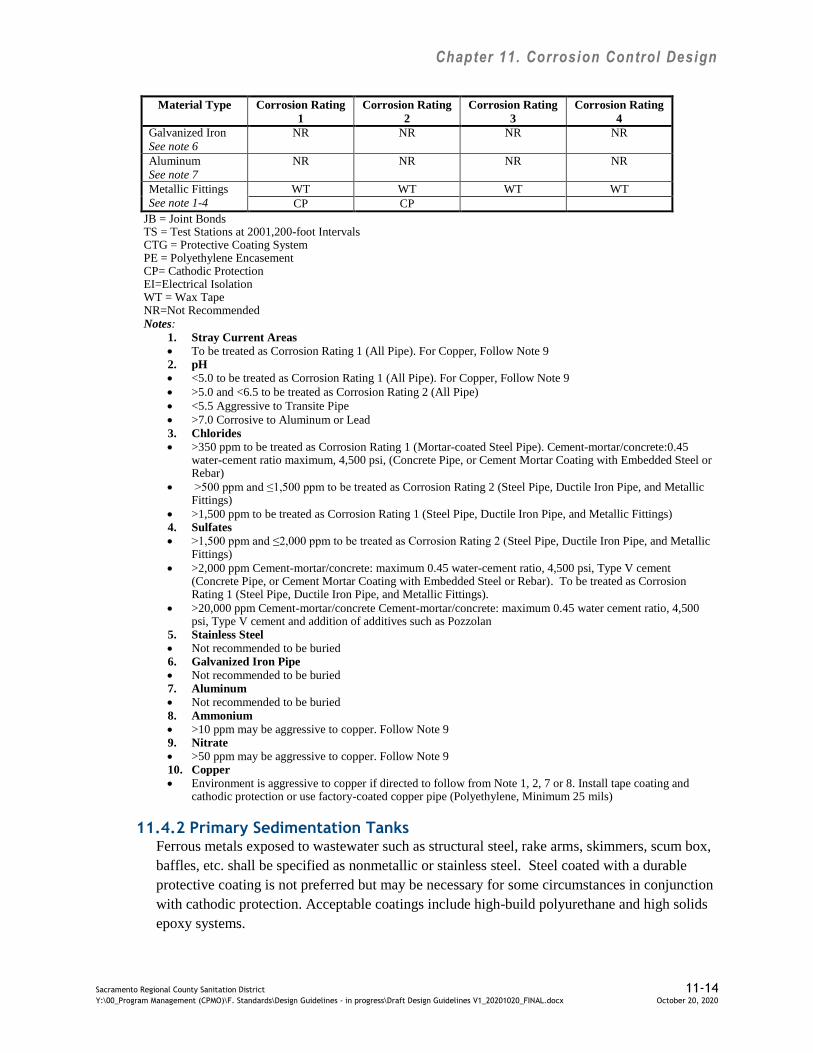
Chapter 11. Corrosion Control Design
Sacramento Regional County Sanitation District 11-14 Y:\00_Program Management (CPMO)\F. Standards\Design Guidelines - in progress\Draft Design Guidelines V1_20201020_FINAL.docx October 20, 2020
Material Type Corrosion Rating
1
Corrosion Rating
2
Corrosion Rating
3
Corrosion Rating
4
Galvanized Iron
See note 6
NR NR NR NR
Aluminum
See note 7
NR NR NR NR
Metallic Fittings
See note 1-4
WT WT WT WT
CP CP
JB = Joint Bonds TS = Test Stations at 2001,200-foot Intervals CTG = Protective Coating System PE = Polyethylene Encasement CP= Cathodic Protection EI=Electrical Isolation WT = Wax Tape NR=Not Recommended Notes:
1. Stray Current Areas
To be treated as Corrosion Rating 1 (All Pipe). For Copper, Follow Note 9 2. pH
<5.0 to be treated as Corrosion Rating 1 (All Pipe). For Copper, Follow Note 9
>5.0 and <6.5 to be treated as Corrosion Rating 2 (All Pipe)
<5.5 Aggressive to Transite Pipe
>7.0 Corrosive to Aluminum or Lead 3. Chlorides
>350 ppm to be treated as Corrosion Rating 1 (Mortar-coated Steel Pipe). Cement-mortar/concrete:0.45 water-cement ratio maximum, 4,500 psi, (Concrete Pipe, or Cement Mortar Coating with Embedded Steel or Rebar)
>500 ppm and ≤1,500 ppm to be treated as Corrosion Rating 2 (Steel Pipe, Ductile Iron Pipe, and Metallic Fittings)
>1,500 ppm to be treated as Corrosion Rating 1 (Steel Pipe, Ductile Iron Pipe, and Metallic Fittings) 4. Sulfates
>1,500 ppm and ≤2,000 ppm to be treated as Corrosion Rating 2 (Steel Pipe, Ductile Iron Pipe, and Metallic Fittings)
>2,000 ppm Cement-mortar/concrete: maximum 0.45 water-cement ratio, 4,500 psi, Type V cement (Concrete Pipe, or Cement Mortar Coating with Embedded Steel or Rebar). To be treated as Corrosion Rating 1 (Steel Pipe, Ductile Iron Pipe, and Metallic Fittings).
>20,000 ppm Cement-mortar/concrete Cement-mortar/concrete: maximum 0.45 water cement ratio, 4,500 psi, Type V cement and addition of additives such as Pozzolan
5. Stainless Steel
Not recommended to be buried 6. Galvanized Iron Pipe
Not recommended to be buried 7. Aluminum
Not recommended to be buried 8. Ammonium
>10 ppm may be aggressive to copper. Follow Note 9 9. Nitrate
>50 ppm may be aggressive to copper. Follow Note 9 10. Copper
Environment is aggressive to copper if directed to follow from Note 1, 2, 7 or 8. Install tape coating and cathodic protection or use factory-coated copper pipe (Polyethylene, Minimum 25 mils)
11.4.2 Primary Sedimentation Tanks Ferrous metals exposed to wastewater such as structural steel, rake arms, skimmers, scum box,
baffles, etc. shall be specified as nonmetallic or stainless steel. Steel coated with a durable
protective coating is not preferred but may be necessary for some circumstances in conjunction
with cathodic protection. Acceptable coatings include high-build polyurethane and high solids
epoxy systems.

Chapter 11. Corrosion Control Design
Sacramento Regional County Sanitation District 11-15 Y:\00_Program Management (CPMO)\F. Standards\Design Guidelines - in progress\Draft Design Guidelines V1_20201020_FINAL.docx October 20, 2020
Exposed ferrous metals such as piping, conduits, and supports shall be specified as nonmetallic
where possible, stainless steel, or coated non-stainless steel. An adequate coating would be
polyurethane.
If the primary sedimentation tanks are to be covered, aluminum dome covers are sufficient.
Ensure electrical isolation between the aluminum components and all other metals and concrete
by using dielectric components.
Hardware, such as anchor bolts and fasteners, shall be specified as Type 316 stainless steel.
All concrete above the operational low water level shall have a PVC liner extending two feet
below the lowest operating liquid level.
At effluent outlets or other areas where turbulent flow is anticipated, concrete shall be coated
with a 100 percent solids aromatic polyurethane.
11.4.3 Secondary Sedimentation Tanks
Nonmetallic components exposed to wastewater such as flights, wear shoes, and wear strips,
shall be specified to the extent possible.
Where metallic components such as hardware, flight guides, anchor bolts, bolts, nuts, washers,
setscrews, and other fasteners are used, they shall be specified as stainless steel in areas where
they will be exposed to wastewater.
11.4.4 Aeration Basins
Basins or chambers containing wastewater or liquid and covered shall have a PVC liner
extending two feet below the lowest operating liquid level. The basins, chambers, and channels
containing return activated sludge (RAS), mixed liquor suspended solids (MLSS), secondary
effluent (SE), or finished effluent (FE) do not require PVC lining unless covered. Where not
feasible, a protective coating such as 100% solids aromatic polyurethane shall be specified.
PVC line or coat, as above, all concrete subjected to turbulent or low pH (< 5.5) wastewater.
All ferrous metals shall be coated for harsh environments or specified as stainless steel.
11.4.5 Lift Gates
For sluice gates, the use of either a coated ASTM A436 Ni-Resist cast iron or ASTM A240
Type 316 or 316L stainless steel shall be used.
Slide gates and weir gates shall be fabricated from ASTM A240 Type 316L stainless steel.
Threaded portions of sluice gate stems, machine surfaces of frames and guides shall be
grease-coated to protect the wearing surfaces.

Chapter 11. Corrosion Control Design
Sacramento Regional County Sanitation District 11-16 Y:\00_Program Management (CPMO)\F. Standards\Design Guidelines - in progress\Draft Design Guidelines V1_20201020_FINAL.docx October 20, 2020
11.4.6 Electrical Enclosures
Electrical distribution and control panel equipment in corrosive areas shall be suitable for the
environment in which they are located. Use PVC-coated electrical conduit and supports with
NEMA 4X stainless steel electrical boxes in corrosive areas.

Chapter 12. Regulatory Requirements
Sacramento Regional County Sanitation District 12-1 Y:\00_Program Management (CPMO)\F. Standards\Design Guidelines - in progress\Draft Design Guidelines V1_20201020_FINAL.docx October 20, 2020
12.0 Regulatory Requirements
The following regulatory requirements should be considered at a minimum for all Regional San design
projects. Unless stated otherwise below, Designers shall initiate contact with Regional San staff as
described below during the Preliminary Design Phase.
12.1 Environmental Impact Review
The California Environmental Quality Act of 1970 (CEQA) requires documentation of
environmental impacts and proposed mitigation measures associated with a project.
The Project Manager is responsible for initiating request for environmental review by the
Sacramento County Department of Environmental Review and Assessment (DERA), which is
the lead agency responsible for preparing the documentation required by CEQA. The project
manager will initiate the request for environmental review by submitting a “Request for
Environmental Document Application Form” to DERA. Prior to submittal, the project
description required within the application form shall be reviewed by the Regional San
Bufferlands Team to screen for readily avoidable impacts to sensitive biological resources.
The Designers shall provide project information as requested by the Project Manager and
incorporate all necessary environmental impact mitigation measures into the project plans and
specifications. Mitigation monitoring and reporting plans shall be included in the appendix of
the project specifications. As appropriate, Regional San shall utilize the Bufferlands Team to
mitigate impacts to sensitive biological resources.
Regional San and its contractors will avoid and minimize permanent and temporary impacts to
habitats and land cover types used by sensitive species potentially occurring in the project area.
Avoidance and minimization of habitat areas will be accomplished during project design work,
and/or during construction by implementing best management practices, including
establishment of buffer zones, installation of fencing around sensitive habitats, and
implementation of a storm water pollution prevention plan (SWPPP) to reduce the potential for
sediments or contaminants to enter sensitive habitats.
Regional San shall obtain all necessary permits and approvals required to impact riparian
habitat and sensitive natural communities, to the extent that these impacts may occur with
development of any of the action alternatives. Necessary permits and approvals will include
Clean Water Act permits (Section 404 and 401), FESA and CESA permits, and CDFW Lake
and Streambed Alteration Agreement, and would include measures to avoid, minimize and
compensate for any impacts so as to avoid any net loss in habitat value. Mitigation would
include restoration of any habitats that were affected temporarily during construction, and could
include purchase of credits from a mitigation bank if there are any permanent impacts to
sensitive natural communities. Designer is responsible for identifying when permits are
required for a project and notifying Regional San.
For Regional San projects that are off-SRWTP property and prior to the start of construction, a
Phase I hazardous waste/hazardous materials study for soil and groundwater contamination

Chapter 12. Regulatory Requirements
Sacramento Regional County Sanitation District 12-2 Y:\00_Program Management (CPMO)\F. Standards\Design Guidelines - in progress\Draft Design Guidelines V1_20201020_FINAL.docx October 20, 2020
shall be completed for the transmission pipeline by the designer. The recommendations set
forth in the Phase I assessment shall be implemented to the satisfaction of applicable agencies
before construction begins. If Phase I assessments indicate the potential for contamination
within the construction zone of the pipelines, Phase II studies shall be completed before
construction begins. Phase II studies will include soil and groundwater sampling and analysis
for anticipated contaminants. The Phase II sampling is intended to identify how to dispose of
any potentially harmful material from excavations, and to determine if construction workers
need specialized personal protective equipment while constructing the pipeline through that
area. If soil or groundwater contaminated by potentially hazardous materials is exposed or
encountered during construction that was not identified in the Phase I assessment, the
appropriate hazardous materials agencies shall be notified. Any contaminated soil that is
encountered during construction shall be disposed of in accordance with applicable regulations,
at an approved landfill.
Regional San will prepare a wetland delineation report to identify and characterize aquatic
resources within the vicinity of the project area and will use this information to avoid wetlands
and waters of the U.S. to the extent feasible. Once verified by the U.S. Army Corps of
Engineers (USACE), the delineation will be used to secure permits/approvals under Sections
404 and 401 of the Clean Water Act (CWA). The wetland delineation report will also be used
to demonstrate consistency with the South Sacramento Habitat Conservation Plan (SSHCP) and
its terms and conditions for CWA and Endangered Species Act compliance. Compliance with
SSHCP habitat-level conservation measures is assumed to satisfy mitigation requirements
under Section 404 permitting, and conservation measures would be implemented by Regional
San even if the SSHCP is not adopted. Regional San may be required to work directly with the
USACE to satisfy Section 404 permitting needs for project impacts to wetlands and other
waters of the U.S. if permitting associated with the SSHCP is not finalized at the time of the
project permitting phase. Designer is responsible for identifying when a wetland delineation
report is required for a project and notifying Regional San.
Regional San shall participate in and comply with the terms and conditions of the Sacramento
County Tree Preservation Ordinance. Native oak trees with a diameter at breast height (DBH)
of six inches or greater, street or public trees, and landmark trees shall not be destroyed, killed,
or removed without a permit. The ordinance protects all oak trees unless they are specifically
designated for removal as part of an approved project. When oaks are removed they must be
replaced with the same tree species equaling in sum the diameter of the tree lost. Designer is
responsible for identifying when permits are required for a project and notifying Regional San.
12.2 National Pollutant Discharge Elimination System (NPDES) Permit
Regional San operates under Waste Discharge Requirements (WDRs) issued by the California
Regional Water Quality Control Board, Central Valley Region (Water Board). Regional San is
currently operating under WDR Order No. R5-2010-0114-01 (NPDES Permit No. CA0077682)
and Time Schedule Order R5-2010-0115-01, as amended by Order R5-2011-0083 adopted and
effective on December 1, 2011. The WDRs contain the limitations and discharge requirements
for the discharge of disinfected secondary treated wastewater effluent to the Sacramento River.

Chapter 12. Regulatory Requirements
Sacramento Regional County Sanitation District 12-3 Y:\00_Program Management (CPMO)\F. Standards\Design Guidelines - in progress\Draft Design Guidelines V1_20201020_FINAL.docx October 20, 2020
All project parameters that may impact the NPDES permit shall be coordinated with Regional
San Operations Support; the current Operations Support contacts is Anna Johnson (916-875-
9198).
Regional San shall implement measures contained in the General Order for Dewatering or other
appropriate NPDES permit or Waste Discharge Requirement. If a project is located within the
SRWTP, no permit is needed as dewatering water may be discharged into an adjacent manhole
that is piped to the SRWTP headworks. Designer to notify Regional San if a dewatering permit
might be needed.
12.3 Biosolids and Solids Storage and Disposal Permit
Regional San operates under a Biosolids and Solids Storage and Disposal Permit WDR Order
No. R5-2015-0133 issued by the Water Board and adopted on December 11, 2015 for the
operation of treatment, storage, and disposal facilities for digested sludge (biosolids) and other
solids (grit and screenings) from the SRWTP. The WDRs contain the limitations and discharge
requirements for twenty unclassified Solids Storage Basins (SSBs), five Class II Dedicated
Land Disposal (DLD) land treatment units (LTUs), and a closed Class III grit and screenings
landfill located at the SRWTP.
All project parameters that may impact the biosolids and solids permit shall be coordinated
with Regional San Operations Support; the current Operations Support contacts is Anna
Johnson (916-875-9198).
12.4 Water Reclamation Permit
Regional San operates under Master Water Reclamation Permit WDR Order No. 97-146 issued
by the Water Board (and adopted on June 20, 1997) for reclamation of treated wastewater from
the SRWTP. The WDRs contain the limitations and discharge requirements for the use of
reclaimed water as irrigation in publicly owned areas of residential neighborhoods, parks,
streetscapes, schools, commercial areas, and at the SRWTP.
All project parameters that may impact the water reclamation permit shall be coordinated with
Regional San Operations Support; the current Operations Support contacts is Anna Johnson
(916-875-9198).
12.5 Fire and Life Safety
The Cosumnes Fire Department (CFD) has jurisdiction on fire and life safety matters at the
SRWTP. All new construction must meet the applicable fire and life safety requirements
contained in the California Fire Code (CFC), California Building Code (CBC), National
Electric Code (NEC), National Fire Protection Act (NFPA), and Occupational Safety and
Health Act (OSHA). Additionally, the NFPA contains standards specific to wastewater
treatment plants (NFPA 820, Recommended Practice for Fire Protection in Wastewater
Treatment Plants).

Chapter 12. Regulatory Requirements
Sacramento Regional County Sanitation District 12-4 Y:\00_Program Management (CPMO)\F. Standards\Design Guidelines - in progress\Draft Design Guidelines V1_20201020_FINAL.docx October 20, 2020
The Project Manager shall initiate a meeting with the CFD and the Regional San Safety Liaison
after Design Submittal #1 to introduce the project and to identify potential areas of concern.
All areas of concern shall be addressed in Design Submittal #2, which will formally be
submitted to CFD for review. The Project Manager shall be responsible for coordinating
contact with, and payment of fees to, CFD. The current Regional San Safety Liaison contact is
Deborah Celestre (916-875-9154).
12.6 Risk Management, Process Safety Management, and Hazardous Materials Programs
Various regulations require that the SRWTP maintains a Risk Management Plan (RMP), a
Process Safety Management Plan (PSM), and a Hazardous Material Plan (HMP). The
RMP/PSM covers acutely hazardous materials (chlorine, sulfur dioxide, and digester gases),
while the HMP covers solids, liquids, and gases.
Regional San Safety Office and Regional San RMP/ Process Safety Management (PSM) Office
shall be consulted to determine if any material or process associated with the project may
trigger specific design considerations or necessitate revisions to the existing RMP/PSM and
HMP. The addition or modification of SRWTP processes covered under the RMP/PSM may
require a Regional San Management of Change (MOC) Review, compliance with the
Mechanical Integrity Program (MIP), and Pre-Startup Safety Review (PSSR). The MIP policy
has been adopted and applies for all stages of a design/modification project involving a covered
process. The Project Manager shall initiate a meeting between the Regional San Safety Office
Senior Safety Specialist, the Regional San RMP/PSM Office Manager, the Regional San MIP
Coordinator, and the project designers to determine if the project will affect the RMP/PSM or
HMP. The current Regional San Safety Office Senior Safety Specialist is Deborah Celestre
(916-875-9154) while the Regional San RMP/PSM Office Manager is Tiffany Beaudry (916-
875-9186), and the Regional San MIP Coordinator is Helen Hu (916-876-6098).
12.7 Spill Prevention, Control, and Countermeasure Plan
The United States Environmental Protection Agency (USEPA) requires that the SRWTP
maintain a Spill Prevention, Control, and Countermeasure (SPCC) Plan. The objective of the
SPCC Plan is to document, define, and describe the practices, procedures, structures, and
equipment used to prevent, control, and/or mitigate releases of petroleum, oil, and lubricants
(POL) products to the environment.
The Designer shall identify all POL products required for the project and provide
documentation to Regional San Operations Support during preparation of Design Submittal #1.
Such documentation may include a site plan, estimated quantities required, and proposed
storage or containment. All project parameters that may impact the SPCC Plan shall be
coordinated with Regional San Operations Support; the current Operations Support contacts is
Anna Johnson (916-875-9198).
Chapter 12. Regulatory Requirements
Sacramento Regional County Sanitation District 12-5 Y:\00_Program Management (CPMO)\F. Standards\Design Guidelines - in progress\Draft Design Guidelines V1_20201020_FINAL.docx October 20, 2020
12.8 Air Quality Permit
Air permitting for Regional San falls under the jurisdiction of the Sacramento Metropolitan Air
Quality Management District (SMAQMD). Air quality permitting is a two-step process. First,
a permit application, including appropriate fees, is filed with SMAQMD. Upon review of
application, an Authority to Construct is issued by SMAQMD. After the project is built, a
representative from SMAQMD conducts an inspection and issues a Permit to Operate. The
SMAQMD Authority to Construct must be obtained before construction can proceed, and the
Permit to Operate must be secured prior to process start-up.
The Designer shall identify all new pollutant emitting sources and provide documentation to
Regional San Operations Support during the permitting process. Such documentation may
include a site plan, and schematics of process systems and air pollution abatement systems.
Communication with SMAQMD shall involve Regional San’s Air Quality Liaison in
Operations Support. The current Regional San Operations Support contacts is Anna Johnson
(916-875-9198).
12.9 Asbestos and Lead-Containing Materials
Prior to recoating of any existing structure or connecting to an existing system, a
comprehensive condition assessment shall be performed for the collection of data. The purpose
of the condition assessment is to gain background information and understanding of the
structure or point of connection prior to generating specifications.
12.9.1 Asbestos-Containing Materials
For suspected asbestos-containing materials, the assessment shall consist of:
Reviewing existing drawings and reports.
Scheduling a site visit to perform visual observations and data collections.
Bulk sampling of existing materials shall be tested in a laboratory. Samples shall be
analyzed using a Polarized Light Microscopy (PLM) method in accordance with EPA
600/R-93/116.
If samples have been found to contain levels equal to or greater than 1% asbestos
material or Presumed Asbestos Containing Materials (PACM) are encountered, any
removal of the material shall be specified to be conducted employing the safety
precautions and measures in accordance to Title 29 of the Code of Federal Regulations
(29-CFR 1926, subparts C and D), Title 8 of the California Code of Regulations (8CCR
1529 Asbestos) and Sacramento County Air Quality Management District Rule 902 and
304. In this case, Regional San’s ASBESTOS ABATEMENT Guide Specification (02
83 13) shall be revised for site-specific conditions and implemented in the design
documents.
The Designer shall identify all potential asbestos-containing materials that may be
encountered in the project and notify Regional San during design. Regional San Safety
Chapter 12. Regulatory Requirements
Sacramento Regional County Sanitation District 12-6 Y:\00_Program Management (CPMO)\F. Standards\Design Guidelines - in progress\Draft Design Guidelines V1_20201020_FINAL.docx October 20, 2020
consults with Mr. Jim Eubanks (916-876-6332), Sacramento County Environmental
Services Specialist, to determine appropriate project-specific abatement controls.
12.9.2 Lead-Containing Materials
For suspected lead-containing materials, the assessment shall consist of:
Reviewing existing drawings and reports.
Scheduling a site visit to perform visual observations and data collections.
Sampling of existing coatings which shall be tested in a laboratory. Samples shall be
analyzed for lead, and if warranted heavy metals such as zinc and chromium. Analysis
of samples shall be tested in accordance with EPA Flame Atomic Absorption
Spectrometry Lead (Pb) in Paint/Coatings Samples Method SW846-3050B-7420.
If samples have been found to contain detachable levels of lead, any removal of the
lead-containing material shall be specified to be conducted employing the safety
precautions and measures in accordance to Title 29, Code of Federal Regulations (29-
CFR 1926.62). In this case, Regional San’s LEAD-CONTAINING PAINT
ABATEMENT Guide Specification (02 83 19.13) shall be revised for site-specific
conditions and implemented in the design documents.
The Designer shall identify all potential lead-containing materials that may be encountered
in the project and notify Regional San during design. Regional San Safety consults with
Mr. Jim Eubanks (916-876-6332), Sacramento County Environmental Services Specialist, to
determine appropriate project-specific abatement controls.

Appendix A
List of Guide Specifications, Common Contract Drawings, and Typical Details
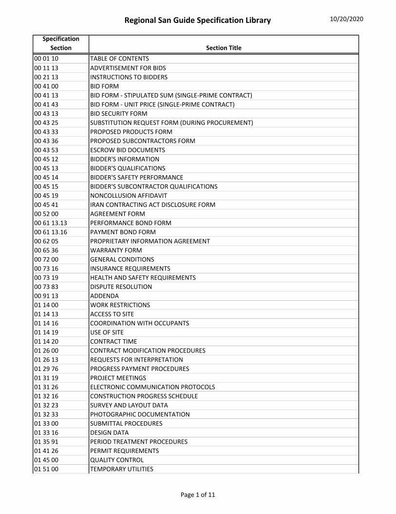
Regional San Guide Specification Library 10/20/2020
Specification
Section Section Title
00 01 10 TABLE OF CONTENTS
00 11 13 ADVERTISEMENT FOR BIDS
00 21 13 INSTRUCTIONS TO BIDDERS
00 41 00 BID FORM
00 41 13 BID FORM ‐ STIPULATED SUM (SINGLE‐PRIME CONTRACT)
00 41 43 BID FORM ‐ UNIT PRICE (SINGLE‐PRIME CONTRACT)
00 43 13 BID SECURITY FORM
00 43 25 SUBSTITUTION REQUEST FORM (DURING PROCUREMENT)
00 43 33 PROPOSED PRODUCTS FORM
00 43 36 PROPOSED SUBCONTRACTORS FORM
00 43 53 ESCROW BID DOCUMENTS
00 45 12 BIDDER'S INFORMATION
00 45 13 BIDDER'S QUALIFICATIONS
00 45 14 BIDDER'S SAFETY PERFORMANCE
00 45 15 BIDDER'S SUBCONTRACTOR QUALIFICATIONS
00 45 19 NONCOLLUSION AFFIDAVIT
00 45 41 IRAN CONTRACTING ACT DISCLOSURE FORM
00 52 00 AGREEMENT FORM
00 61 13.13 PERFORMANCE BOND FORM
00 61 13.16 PAYMENT BOND FORM
00 62 05 PROPRIETARY INFORMATION AGREEMENT
00 65 36 WARRANTY FORM
00 72 00 GENERAL CONDITIONS
00 73 16 INSURANCE REQUIREMENTS
00 73 19 HEALTH AND SAFETY REQUIREMENTS
00 73 83 DISPUTE RESOLUTION
00 91 13 ADDENDA
01 14 00 WORK RESTRICTIONS
01 14 13 ACCESS TO SITE
01 14 16 COORDINATION WITH OCCUPANTS
01 14 19 USE OF SITE
01 14 20 CONTRACT TIME
01 26 00 CONTRACT MODIFICATION PROCEDURES
01 26 13 REQUESTS FOR INTERPRETATION
01 29 76 PROGRESS PAYMENT PROCEDURES
01 31 19 PROJECT MEETINGS
01 31 26 ELECTRONIC COMMUNICATION PROTOCOLS
01 32 16 CONSTRUCTION PROGRESS SCHEDULE
01 32 23 SURVEY AND LAYOUT DATA
01 32 33 PHOTOGRAPHIC DOCUMENTATION
01 33 00 SUBMITTAL PROCEDURES
01 33 16 DESIGN DATA
01 35 91 PERIOD TREATMENT PROCEDURES
01 41 26 PERMIT REQUIREMENTS
01 45 00 QUALITY CONTROL
01 51 00 TEMPORARY UTILITIES
Page 1 of 11

Regional San Guide Specification Library 10/20/2020
Specification
Section Section Title
01 51 16 TEMPORARY FIRE PROTECTION
01 52 00 CONSTRUCTION FACILITIES
01 55 26 TRAFFIC CONTROL
01 56 00 TEMPORARY BARRIERS AND ENCLOSURES
01 57 19 TEMPORARY ENVIRONMENTAL CONTROLS
01 57 23 TEMPORARY STORM WATER POLLUTION CONTROL
01 65 00 PRODUCT DELIVERY REQUIREMENTS
01 73 33 RESTORATION OF IMPROVEMENTS
01 74 23 FINAL CLEANING
01 78 23 OPERATION AND MAINTENANCE DATA
01 78 39 PROJECT RECORD DOCUMENTS
01 78 43 SPARE PARTS
01 79 10 TRAINING
01 91 00 COMMISSIONING
01 91 10 REFERENCE FORMS
02 41 19.21 SELECTIVE ELECTRICAL RACEWAY DEMOLITION SCHEDULE
02 41 19.25 SELECTIVE ELECTRICAL CABLE DEMOLITION SCHEDULE
02 41 19.28 SELECTIVE AREA CONTROL CENTER PANEL DEMOLITION SCHEDULE
02 83 19.15 LEAD‐CONTAINING PAINT ABATEMENT
03 11 00 CONCRETE FORMING
03 15 13 WATERSTOPS
03 15 20 ANCHORAGE IN CONCRETE AND MASONRY
03 16 13 PLASTIC LINING FOR CONCRETE STRUCTURES
03 20 00 CONCRETE REINFORCING
03 23 13 STRESSED BAR REINFORCING
03 30 00 CAST‐IN‐PLACE CONCRETE
03 34 13 CONTROLLED LOW STRENGTH CONCRETE
03 40 00 PRECAST CONCRETE
03 41 33 PRECAST STRUCTURAL PRETENSIONED CONCRETE
03 60 00 GROUTING
04 05 13 MASONRY MORTARING
04 05 16 MASONRY GROUTING
04 22 36 HOLLOW CONCRETE UNIT MASONRY
05 05 13.16 MECHANICALLY‐APPLIED ZINC COATING
05 05 14 HOT DIP ZINC COATING
05 10 00 STRUCTURAL METAL FRAMING
05 40 00 COLD‐FORMED METAL FRAMING
05 52 00 METAL RAILINGS
05 53 12 FLOOR GRATING, STAIR SAFETY NOSINGS, AND FLOOR PLATES
05 58 26 FACILITY TRENCH DRAINS
05 59 00 METAL SPECIALTIES
06 10 00 ROUGH CARPENTRY
06 40 23 INTERIOR ARCHITECTURAL WOODWORK
06 84 13 FIBERGLASS REINFORCED PLASTIC FABRICATIONS
07 11 13 BITUMINOUS DAMPPROOFING
07 13 26 SELF‐ADHERING SHEET WATERPROOFING
Page 2 of 11

Regional San Guide Specification Library 10/20/2020
Specification
Section Section Title
07 14 13 HOT FLUID‐APPLIED RUBBERIZED ASPHALT WATERPROOFING
07 14 16 COLD FLUID‐APPLIED WATERPROOFING
07 17 00 BENTONITE WATERPROOFING
07 21 16 BLANKET INSULATION
07 21 19 FOAMED‐IN‐PLACE INSULATION
07 22 00 ROOF AND DECK INSULATION
07 51 00 BUILT‐UP BITUMINOUS ROOFING
07 52 16 STYRENE‐BUTADIENE‐STYRENE MODIFIED BITUMINOUS MEMBRANE ROOFING
07 53 23 ETHYLENE‐PROPYLENE‐DIENE‐MONOMER ROOFING
07 57 13 SPRAYED POLYURETHANE FOAM ROOFING
07 62 00 SHEET METAL FLASHING AND TRIM
07 72 33 ROOF HATCHES
07 92 00 JOINT SEALANTS
07 95 17 EXPANSION AND SEISMIC JOINT COVER ASSEMBLIES
08 11 13 HOLLOW METAL DOORS AND FRAMES
08 12 16 ALUMINUM FRAMES
08 14 00 WOOD DOORS
08 16 13 FIBERGLASS DOORS
08 31 13 ACCESS DOORS AND FRAMES
08 33 23 OVERHEAD COILING DOORS
08 41 00 ENTRANCES AND STOREFRONTS
08 45 23 FIBERGLASS‐SANDWICH‐PANEL ASSEMBLIES
08 51 13 ALUMINUM WINDOWS
08 51 23 STEEL WINDOWS
08 62 00 UNIT SKYLIGHTS
08 71 00 DOOR HARDWARE
08 81 00 GLASS GLAZING
08 91 00 LOUVERS
09 06 90 SCHEDULES FOR PAINTING AND COATING
09 22 16 NON‐STRUCTURAL METAL FRAMING
09 24 00 CEMENT PLASTERING
09 29 00 GYPSUM BOARD
09 30 00 TILING
09 51 00 ACCOUSTICAL CEILINGS
09 65 19 RESILIENT TILE FLOORING
09 68 13 TILE CARPETING
09 84 13 FIXED SOUND‐ABSORPTIVE PANELS
09 90 00 PAINTING AND COATING
10 14 10 IDENTIFYING SIGNAGE
10 14 15 WARNING SIGNAGE
10 21 00 COMPARTMENTS AND CUBICLES
10 28 13 TOILET ACCESSORIES
10 44 00 FIRE PROTECTION SPECIALTIES
10 51 15 METAL LOCKERS AND BENCHES
10 56 13.33 METAL STORAGE SHELVING AND WORKBENCHES
10 73 16.13 PRE‐MANUFACTURED CANOPIES
Page 3 of 11

Regional San Guide Specification Library 10/20/2020
Specification
Section Section Title
12 35 53.13 METAL LABORATORY CASEWORK
12 36 61 SIMULATED STONE COUNTERTOPS
13 34 23 FABRICATED STRUCTURES
21 13 00 FIRE‐SUPPRESSION SPRINKLER SYSTEMS
22 10 05 FACILITY WATER AND SANITARY SEWERAGE PIPING SPECIALTIES
22 14 29 SUMP PUMPS
22 45 00 EMERGENCY PLUMBING FIXTURES
23 05 23 GENERAL‐DUTY VALVES FOR HVAC PIPING
23 05 93 TESTING, ADJUSTING, AND BALANCING FOR HVAC
23 06 20.16 HYDRONIC CONTROL VALVE SCHEDULE
23 30 00 HVAC AIR DISTRIBUTION
23 34 16.52 UPBLAST ROOF EXHAUST FANS
23 34 19.16 PROPELLER WALL FANS
23 34 26.13 CEILING EXHAUST FANS
23 36 16 VARIABLE‐AIR‐VOLUME UNITS
23 37 23 HVAC GRAVITY VENTILATORS
23 41 13 PANEL AIR FILTERS
23 73 00 INDOOR CENTRAL‐STATION AIR‐HANDLING UNITS
23 81 26 SPLIT SYSTEM AIR CONDITIONERS
23 81 32 UNITARY OUTDOOR DIRECT EXPANSION AIR CONDITIONERS
23 82 39 UNIT HEATERS
26 05 00 COMMON WORK RESULTS FOR ELECTRICAL
26 05 21 ELECTRICAL POWER CONDUCTORS AND CABLES
26 05 26 GROUNDING AND BONDING FOR ELECTRICAL SYSTEMS
26 05 34 RACEWAYS, BOXES, MANHOLES, AND HANDHOLES FOR ELECTRICAL SYSTEMS
26 05 73 OVERCURRENT PROTECTIVE DEVICE COORDINATION STUDY
26 06 20.16 ELECTRICAL PANELBOARD SCHEDULE
26 06 20.19 ELECTRICAL MOTOR‐CONTROL CENTER SCHEDULE
26 06 20.21 ELECTRICAL RACEWAY SCHEDULE
26 06 20.25 ELECTRICAL CABLE SCHEDULE
26 06 50.16 LIGHTING FIXTURE SCHEDULE.
26 08 10 ACCEPTANCE TESTING OF ELECTRICAL SYSTEMS
26 09 16 ELECTRICAL CONTROLS AND RELAYS
26 12 21 SECONDARY SUBSTATION MEDIUM‐VOLTAGE TRANSFORMERS
26 13 27 MEDIUM VOLTAGE VARIABLE‐FREQUENCY MOTOR CONTROLLER
26 22 17 LOW‐VOLTAGE DRY‐TYPE TRANSFORMERS
26 23 00 LOW‐VOLTAGE SWITCHGEAR
26 24 13 SWITCHBOARDS
26 24 16 PANELBOARDS
26 24 19 MOTOR‐CONTROL CENTERS
26 27 26 WIRING DEVICES
26 29 23 VARIABLE‐FREQUENCY MOTOR CONTROLLERS
26 33 53 STATIC UNINTERRUPTIBLE POWER SUPPLY
26 36 15 MEDIUM VOLTAGE LOAD INTERRUPTING AIR SWITCHES
26 36 23 AUTOMATIC TRANSFER SWITCHES
26 50 00 LIGHTING
Page 4 of 11
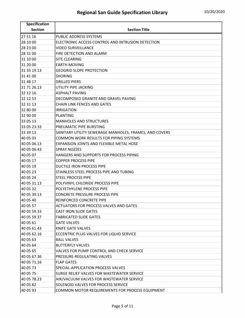
Regional San Guide Specification Library 10/20/2020
Specification
Section Section Title
27 51 16 PUBLIC ADDRESS SYSTEMS
28 10 00 ELECTRONIC ACCESS CONTROL AND INTRUSION DETECTION
28 23 00 VIDEO SURVEILLANCE
28 31 00 FIRE DETECTION AND ALARM
31 10 00 SITE CLEARING
31 20 00 EARTH MOVING
31 35 19.13 GEOGRID SLOPE PROTECTION
31 41 00 SHORING
31 48 17 DRILLED PIERS
31 71 26.13 UTILITY PIPE JACKING
32 12 16 ASPHALT PAVING
32 12 53 DECOMPOSED GRANITE AND GRAVEL PAVING
32 31 13 CHAIN LINK FENCES AND GATES
32 80 00 IRRIGATION
32 90 00 PLANTING
33 05 13 MANHOLES AND STRUCTURES
33 05 23.33 PNEUMATIC PIPE BURSTING
33 39 13 SANITARY UTILITY SEWERAGE MANHOLES, FRAMES, AND COVERS
40 05 03 COMMON WORK RESULTS FOR PIPING SYSTEMS
40 05 06.13 EXPANSION JOINTS AND FLEXIBLE METAL HOSE
40 05 06.43 SPRAY NOZZES
40 05 07 HANGERS AND SUPPORTS FOR PROCESS PIPING
40 05 17 COPPER PROCESS PIPE
40 05 19 DUCTILE IRON PROCESS PIPE
40 05 23 STAINLESS STEEL PROCESS PIPE AND TUBING
40 05 24 STEEL PROCESS PIPE
40 05 31.13 POLYVINYL CHLORIDE PROCESS PIPE
40 05 32 POLYETHYLENE PROCESS PIPE
40 05 39.13 CONCRETE PRESSURE PROCESS PIPE
40 05 40 REINFORCED CONCRETE PIPE
40 05 57 ACTUATORS FOR PROCESS VALVES AND GATES
40 05 59.33 CAST IRON SLIDE GATES
40 05 59.37 FABRICATED SLIDE GATES
40 05 61 GATE VALVES
40 05 61.43 KNIFE GATE VALVES
40 05 62.16 ECCENTRIC PLUG VALVES FOR LIQUID SERVICE
40 05 63 BALL VALVES
40 05 64 BUTTERFLY VALVES
40 05 65 VALVES FOR PUMP CONTROL AND CHECK SERVICE
40 05 67.36 PRESSURE‐REGULATING VALVES
40 05 71.16 FLAP GATES
40 05 73 SPECIAL‐APPLICATION PROCESS VALVES
40 05 75 SURGE RELIEF VALVES FOR WASTEWATER SERVICE
40 05 78.23 AIR/VACUUM VALVES FOR WASTEWATER SERVICE
40 05 82 SOLENOID VALVES FOR PROCESS SERVICE
40 05 93 COMMON MOTOR REQUIREMENTS FOR PROCESS EQUIPMENT
Page 5 of 11

Regional San Guide Specification Library 10/20/2020
Specification
Section Section Title
40 06 20.10 SPRAY NOZZLE SCHEDULE
40 06 20.20 FLAP GATE SCHEDULE
40 06 20.30 FABRICATED SLIDE GATE SCHEDULE
40 06 20.35 CAST IRON SLIDE GATE SCHEDULE
40 06 20.40 SOLENOID VALVE SCHEDULE
40 06 20.50 AIR/VACUUM RELIEF VALVE SCHEDULE
40 06 20.60 PRESSURE REGULATING VALVE SCHEDULE
40 06 40 SCHEDULES FOR PROCESS PIPING AND EQUIPMENT PROTECTION
40 06 60 SCHEDULES FOR PROCESS CONTROL AND PROCESS FACILITY ENTERPRISE MANAGEMENT
SYSTEMS
40 06 60.13 POWER ACTUATED VALVE AND GATE SCHEDULES
40 06 70 SCHEDULES OF INSTRUMENTATION FOR PROCESS SYSTEMS
40 41 13 PROCESS PIPING HEAT TRACING
40 42 00 PROCESS PIPING AND EQUIPMENT INSULATION
40 46 42 CATHODIC PROCESS CORROSION PROTECTION
40 61 13 PROCESS CONTROL SYSTEM GENERAL PROVISIONS
40 61 21 PROCESS CONTROL SYSTEM TESTING
40 61 26 PROCESS CONTROL SYSTEM TRAINING
40 61 93.10 PLANT COMPUTER CONTROL SYSTEM INPUT/OUTPUT
40 61 93.20 PROGRAMMABLE LOGIC CONTROLLER INPUT/OUTPUT
40 61 96.10 PLANT COMPUTER CONTROL SYSTEM CONTROL STRATEGIES
40 61 96.20 PROGRAMMABLE LOGIC CONTROLLER CONTROL NARRATIVES
40 62 63 OPERATOR INTERFACE TERMINALS
40 63 43 PROGRAMMABLE LOGIC CONTROLLERS
40 66 13 SWITCHES AND ROUTERS
40 66 16 FIREWALL HARDWARE
40 66 35 METALLIC AND FIBER OPTIC COMMUNICATION CABLING AND CONNECTORS
40 66 36 PROCESS INSTRUMENTATION NETWORKS
40 67 00 CONTROL SYSTEM EQUIPMENT PANELS AND RACKS
40 70 00 INSTRUMENTATION FOR PROCESS SYSTEMS
40 79 00 MISCELLANEOUS INSTRUMENTS, CALIBRATION EQUIPMENT, INSTRUMENTATION VALVES, AND
FITTINGS
43 42 21 WELDED STEEL PRESSURE TANKS
46 09 09.13 MODIFICATION, RELOCATION, AND REMOVAL OF EXISTING EQUIPMENT
99 99 99 SPECIFICATION TEMPLATE
Page 6 of 11
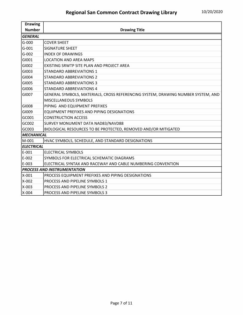
Regional San Common Contract Drawing Library 10/20/2020
Drawing
Number Drawing Title
G‐000 COVER SHEET
G‐001 SIGNATURE SHEET
G‐002 INDEX OF DRAWINGS
GI001 LOCATION AND AREA MAPS
GI002 EXISTING SRWTP SITE PLAN AND PROJECT AREA
GI003 STANDARD ABBREVIATIONS 1
GI004 STANDARD ABBREVIATIONS 2
GI005 STANDARD ABBREVIATIONS 3
GI006 STANDARD ABBREVIATIONS 4
GI007 GENERAL SYMBOLS, MATERIALS, CROSS REFERENCING SYSTEM, DRAWING NUMBER SYSTEM, AND
MISCELLANEOUS SYMBOLS
GI008 PIPING AND EQUIPMENT PREFIXES
GI009 EQUIPMENT PREFIXES AND PIPING DESIGNATIONS
GC001 CONSTRUCTION ACCESS
GC002 SURVEY MONUMENT DATA NAD83/NAVD88
GC003 BIOLOGICAL RESOURCES TO BE PROTECTED, REMOVED AND/OR MITIGATED
M‐001 HVAC SYMBOLS, SCHEDULE, AND STANDARD DESIGNATIONS
E‐001 ELECTRICAL SYMBOLS
E‐002 SYMBOLS FOR ELECTRICAL SCHEMATIC DIAGRAMS
E‐003 ELECTRICAL SYNTAX AND RACEWAY AND CABLE NUMBERING CONVENTION
X‐001 PROCESS EQUIPMENT PREFIXES AND PIPING DESIGNATIONS
X‐002 PROCESS AND PIPELINE SYMBOLS 1
X‐003 PROCESS AND PIPELINE SYMBOLS 2
X‐004 PROCESS AND PIPELINE SYMBOLS 3
GENERAL
PROCESS AND INSTRUMENTATION
ELECTRICAL
MECHANICAL
Page 7 of 11

Regional San Typical Details Library 10/20/2020
Detail ID Typical Detail Title
C1 REMOVABLE TRAFFIC BOLLARD STANDARD DETAIL
E1 TYPICAL DEVICE STANCHION STANDARD DETAIL
E2 LIGHT STANDARD BASE STANDARD DETAIL
E4 FLUORESCENT LUMINAIRE MOUNTING DETAIL STANDARD DETAIL
E5 GROUND WELL AND ROD STANDARD DETAIL
E6 CONDUIT PENETRATION AT EXISTING WALL OR FLOOR STANDARD DETAIL
E7 NON‐REINFORCED DUCTBANK STANDARD DETAIL
E8 REINFORCED DUCTBANK STANDARD DETAIL
E9 UNDERGROUND 600V DUCTBANK ENTRANCE AT NEWLY POURED CONCRETE WALL STANDARD
DETAIL
E10 RISER FROM NON‐METALIC DUCT AND TYPICAL CONDUIT STUB‐UP STANDARD DETAILE11 UNDERGROUND DUCTBANK ENTRANCE STANDARD DETAIL
E12 SPLASH BLOCK DRAIN FOR MANHOLE SUMP PUMP STANDARD DETAIL
E13 TYPICAL PRECAST MANHOLE STANDARD DETAIL
E14 DUAL MANHOLE SUMP PUMPING ARRANGEMENT STANDARD DETAIL
E15 TYPICAL HANDHOLE STANDARD DETAIL
E16 TYPICAL MANHOLE SUMP PUMP STARTER PANEL STANDARD DETAIL
E17 LIGHTING FIXTURE MOUNTING DETAIL STANDARD DETAIL
E18 MEDIUM VOLTAGE MANHOLE CABLE CONFIGURATION STANDARD DETAIL
E19 CONDUIT ENTRANCE AT NEWLY POURED WALL STANDARD DETAIL
E20 480V 3" DIAMETER RECEPTACLE STANCHION STANDARD DETAIL
E21 REINFORCED CONCRETE BASE STANDARD DETAIL
E22 480V 3" DIAMETER RECEPTACLE STANCHION WITH JUNCTION BOX STANDARD DETAIL
E23 REINFORCED CONCRETE BASE STANDARD DETAIL
E24 MOTOR FEED FROM OVERHEAD STANDARD DETAIL
E25 LOW VOLTAGE FEED FROM BELOW SLAB POWER AND CONTROL CONDUITS STANDARD DETAIL
E26 TYPICAL TRAPEZE PIPE SUPPORT STANDARD DETAIL
E27 HAZARDOUS LOCATION CONDUIT INSTALLATION STANDARD DETAIL
E28 GROUND PLATE STANDARD DETAIL
E29 MANHOLE/HANDHOLE COVER PAVED AND UNPAVED AREAS STANDARD DETAIL
E30 TYPICAL OIL FILLED TRANSFORMER FLOOR MOUNTING STANDARD DETAIL
E31 TYPICAL MOUNTING FOR TRANSFORMER AND PANELBOARD STANDARD DETAIL
E32 FLOOR MOUNTING FOR MCC's CONTROL PANELS AND SWITCH GEAR STANDARD DETAIL
E37 CONDUIT PENETRATION FIRESTOP STANDARD DETAIL
E38 CABLE TRAY PENETRATION FIRESTOP STANDARD DETAIL
E100 600A 3‐WAY L‐KIT SEPARABLE CONNECTORS STANDARD DETAIL
E101 600A 3‐WAY L‐KIT SEPARABLE CONNECTORS SECTIONS STANDARD DETAIL
E102 600A 2‐WAY L‐KIT SEPARABLE CONNECTORS STANDARD DETAIL
E103 600A 2‐WAY L‐KIT SEPARABLE CONNECTORS SECTIONS STANDARD DETAIL
M1 TABLE A (PIPE HANGER TYPES) STANDARD DETAIL
M2 PIPE HANGER GENERAL NOTES STANDARD DETAIL
M3 TYPE 1 PIPE HANGER STANDARD DETAIL
M4 TYPE 4 PIPE HANGER (2" THRU 12") STANDARD DETAIL
M5 TYPE 5 PIPE HANGER (10" THRU 24")STANDARD DETAIL
FOR SEWER, WATER, AND STORM DRAIN DETAILS, REFER TO
http://www.saccountyspecs.saccounty.net/Pages/default.aspx
Page 8 of 11
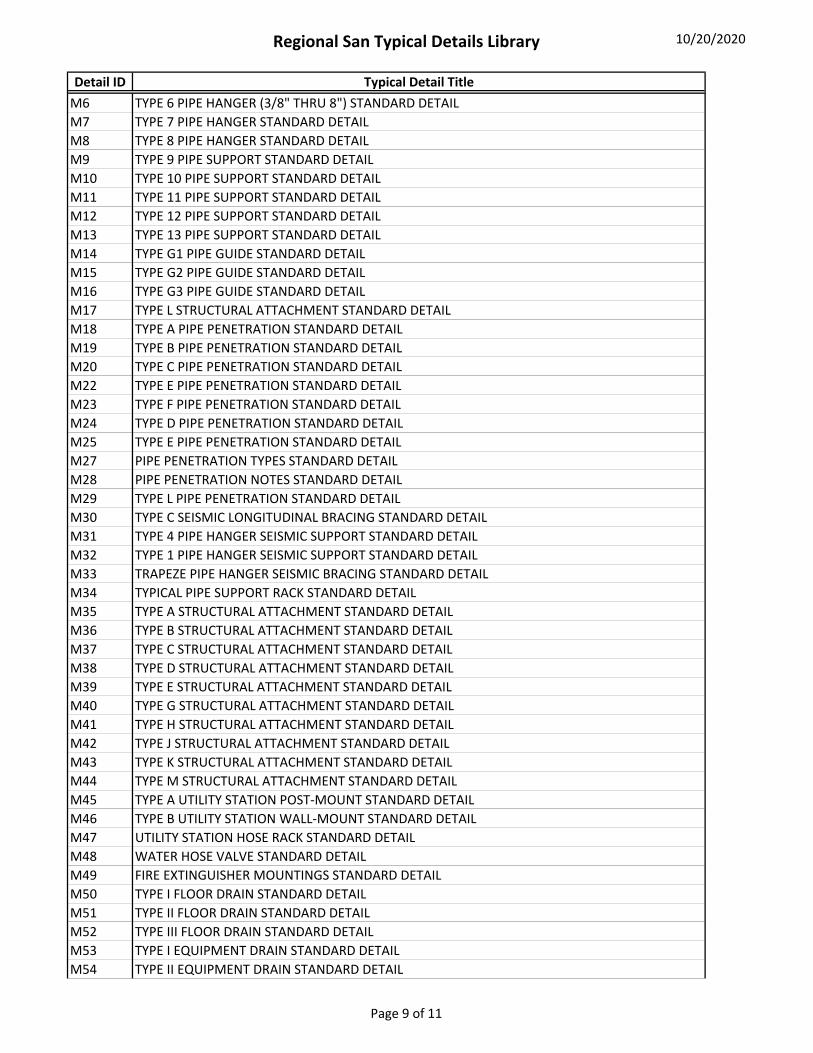
Regional San Typical Details Library 10/20/2020
Detail ID Typical Detail Title
M6 TYPE 6 PIPE HANGER (3/8" THRU 8") STANDARD DETAIL
M7 TYPE 7 PIPE HANGER STANDARD DETAIL
M8 TYPE 8 PIPE HANGER STANDARD DETAIL
M9 TYPE 9 PIPE SUPPORT STANDARD DETAIL
M10 TYPE 10 PIPE SUPPORT STANDARD DETAIL
M11 TYPE 11 PIPE SUPPORT STANDARD DETAIL
M12 TYPE 12 PIPE SUPPORT STANDARD DETAIL
M13 TYPE 13 PIPE SUPPORT STANDARD DETAIL
M14 TYPE G1 PIPE GUIDE STANDARD DETAIL
M15 TYPE G2 PIPE GUIDE STANDARD DETAIL
M16 TYPE G3 PIPE GUIDE STANDARD DETAIL
M17 TYPE L STRUCTURAL ATTACHMENT STANDARD DETAIL
M18 TYPE A PIPE PENETRATION STANDARD DETAIL
M19 TYPE B PIPE PENETRATION STANDARD DETAIL
M20 TYPE C PIPE PENETRATION STANDARD DETAIL
M22 TYPE E PIPE PENETRATION STANDARD DETAIL
M23 TYPE F PIPE PENETRATION STANDARD DETAIL
M24 TYPE D PIPE PENETRATION STANDARD DETAIL
M25 TYPE E PIPE PENETRATION STANDARD DETAIL
M27 PIPE PENETRATION TYPES STANDARD DETAIL
M28 PIPE PENETRATION NOTES STANDARD DETAIL
M29 TYPE L PIPE PENETRATION STANDARD DETAIL
M30 TYPE C SEISMIC LONGITUDINAL BRACING STANDARD DETAIL
M31 TYPE 4 PIPE HANGER SEISMIC SUPPORT STANDARD DETAIL
M32 TYPE 1 PIPE HANGER SEISMIC SUPPORT STANDARD DETAIL
M33 TRAPEZE PIPE HANGER SEISMIC BRACING STANDARD DETAIL
M34 TYPICAL PIPE SUPPORT RACK STANDARD DETAIL
M35 TYPE A STRUCTURAL ATTACHMENT STANDARD DETAIL
M36 TYPE B STRUCTURAL ATTACHMENT STANDARD DETAIL
M37 TYPE C STRUCTURAL ATTACHMENT STANDARD DETAIL
M38 TYPE D STRUCTURAL ATTACHMENT STANDARD DETAIL
M39 TYPE E STRUCTURAL ATTACHMENT STANDARD DETAIL
M40 TYPE G STRUCTURAL ATTACHMENT STANDARD DETAIL
M41 TYPE H STRUCTURAL ATTACHMENT STANDARD DETAIL
M42 TYPE J STRUCTURAL ATTACHMENT STANDARD DETAIL
M43 TYPE K STRUCTURAL ATTACHMENT STANDARD DETAIL
M44 TYPE M STRUCTURAL ATTACHMENT STANDARD DETAIL
M45 TYPE A UTILITY STATION POST‐MOUNT STANDARD DETAIL
M46 TYPE B UTILITY STATION WALL‐MOUNT STANDARD DETAIL
M47 UTILITY STATION HOSE RACK STANDARD DETAIL
M48 WATER HOSE VALVE STANDARD DETAIL
M49 FIRE EXTINGUISHER MOUNTINGS STANDARD DETAIL
M50 TYPE I FLOOR DRAIN STANDARD DETAIL
M51 TYPE II FLOOR DRAIN STANDARD DETAIL
M52 TYPE III FLOOR DRAIN STANDARD DETAIL
M53 TYPE I EQUIPMENT DRAIN STANDARD DETAIL
M54 TYPE II EQUIPMENT DRAIN STANDARD DETAIL
Page 9 of 11

Regional San Typical Details Library 10/20/2020
Detail ID Typical Detail Title
M55 STANDARD CLEANOUT STANDARD DETAIL
M56 CLEANOUT IN PAVED AREA STANDARD DETAIL
M57 YARD CLEANOUT STANDARD DETAIL
M58 FLOOR AND WALKWAY CLEANOUT STANDARD DETAIL
M59 PRESSURE CLEANOUT STANDARD DETAIL
M60 CLEANOUT (IN‐LINE) STANDARD DETAIL
M61 CLEANOUT LINE‐END STANDARD DETAIL
M62 TYPICAL BURIED VALVES STANDARD DETAIL
M63 TYPE V CLEANOUT STANDARD DETAIL
M64 PIPE PENETRATION NOTES STANDARD DETAIL
M65 TABLE B (PIPE HANGER TYPES) STANDARD DETAIL
M66 SANITARY PRESSURE GAUGE PIPING CONNECTION STANDARD DETAIL
M68 FLUSHING COCK (FOR AIR RELEASE OR DRAIN AS REQUIRED) STANDARD DETAIL
M69 CONTROL UNIT TYPE A STANDARD DETAIL
M70 SEAL WATER CONTROL UNIT STANDARD DETAIL
M71 CONTROL UNIT TYPE C STANDARD DETAIL
M72 CONTROL UNIT TYPE D STANDARD DETAIL
M73 LOCATING WIRES FOR UNDERGROUND PIPELINES STANDARD DETAIL
M80 WALL EXHAUST FAN MOUNTING STANDARD DETAIL
M81 LOUVER MOUNTING STANDARD DETAIL
M82 TYPICAL CANTILEVER SUPPORT RACK STANDARD DETAIL
S1 TYPICAL CONSTRUCTION JOINTS ‐ SLABS STANDARD DETAIL
S2 HORIZONTAL CONSTRUCTION JOINTS ‐ WALLS STANDARD DETAIL
S3 BEAM AND SLAB CONSTRUCTION JOINT STANDARD DETAIL
S4 PROVISION FOR FUTURE CONSTRUCTION JOINT STANDARD DETAIL
S5 ISOLATION AND WEAKENED PLANE JOINT AT FLOOR SLABS ON GRADE STANDARD DETAILS6 TYPICAL EXPANSION JOINTS STANDARD DETAIL
S7 PROVISION FOR FUTURE EXPANSION JOINT STANDARD DETAIL
S8 REINFORCING STEEL AT WALL INTERSECTIONS STANDARD DETAIL
S9 REINFORCEMENT AT SLAB AND WALL OPENINGS STANDARD DETAIL
S10 WELDED REINFORCING BAR SPLICE DETAIL STANDARD DETAIL
S11 DOWEL BAR SPLICES STANDARD DETAIL
S12 EQUIPMENT BASE STANDARD DETAIL
S13 ANCHOR BOLT FOR EQUIPMENT STANDARD DETAIL
S14 SUSPENDED SLAB WATERPROOFING STANDARD DETAIL
S16 WALL WATERPROOFING TERMINATION STANDARD DETAIL
S17 MODIFICATION OF EXISTING CONCRETE STANDARD DETAIL
S18 CONCRETE STAIRS STANDARD DETAIL
S19 PIPE ENCASEMENT STANDARD DETAIL
S20 NON‐STRUCTURAL FOOTING STANDARD DETAIL
S21 LIFTING DEVICE STANDARD DETAIL
S22 REINFORCEMENT AT DOOR OPENINGS STANDARD DETAIL
S23 PRESSURE RELIEF VALVE IN CONCRETE SLAB STANDARD DETAIL
S24 TYPICAL CMU WALL ELEVATION STANDARD DETAIL
S25 TOP OF CMU PARTITION WALL STANDARD DETAIL
S26 CMU LINTEL BEAM STANDARD DETAIL
S27 BASE OF CMU PARTITION WALL STANDARD DETAIL
Page 10 of 11
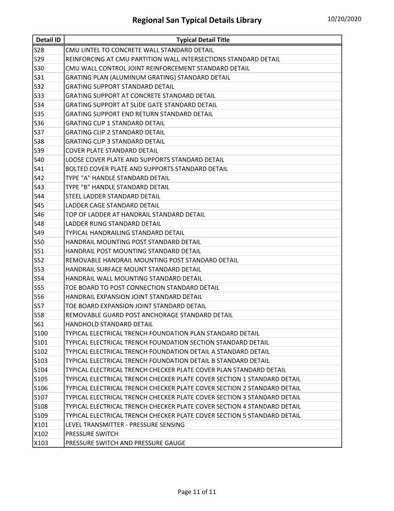
Regional San Typical Details Library 10/20/2020
Detail ID Typical Detail Title
S28 CMU LINTEL TO CONCRETE WALL STANDARD DETAIL
S29 REINFORCING AT CMU PARTITION WALL INTERSECTIONS STANDARD DETAIL
S30 CMU WALL CONTROL JOINT REINFORCEMENT STANDARD DETAIL
S31 GRATING PLAN (ALUMINUM GRATING) STANDARD DETAIL
S32 GRATING SUPPORT STANDARD DETAIL
S33 GRATING SUPPORT AT CONCRETE STANDARD DETAIL
S34 GRATING SUPPORT AT SLIDE GATE STANDARD DETAIL
S35 GRATING SUPPORT END RETURN STANDARD DETAIL
S36 GRATING CLIP 1 STANDARD DETAIL
S37 GRATING CLIP 2 STANDARD DETAIL
S38 GRATING CLIP 3 STANDARD DETAIL
S39 COVER PLATE STANDARD DETAIL
S40 LOOSE COVER PLATE AND SUPPORTS STANDARD DETAIL
S41 BOLTED COVER PLATE AND SUPPORTS STANDARD DETAIL
S42 TYPE "A" HANDLE STANDARD DETAIL
S43 TYPE "B" HANDLE STANDARD DETAIL
S44 STEEL LADDER STANDARD DETAIL
S45 LADDER CAGE STANDARD DETAIL
S46 TOP OF LADDER AT HANDRAIL STANDARD DETAIL
S48 LADDER RUNG STANDARD DETAIL
S49 TYPICAL HANDRAILING STANDARD DETAIL
S50 HANDRAIL MOUNTING POST STANDARD DETAIL
S51 HANDRAIL POST MOUNTING STANDARD DETAIL
S52 REMOVABLE HANDRAIL MOUNTING POST STANDARD DETAIL
S53 HANDRAIL SURFACE MOUNT STANDARD DETAIL
S54 HANDRAIL WALL MOUNTING STANDARD DETAIL
S55 TOE BOARD TO POST CONNECTION STANDARD DETAIL
S56 HANDRAIL EXPANSION JOINT STANDARD DETAIL
S57 TOE BOARD EXPANSION JOINT STANDARD DETAIL
S58 REMOVABLE GUARD POST ANCHORAGE STANDARD DETAIL
S61 HANDHOLD STANDARD DETAIL
S100 TYPICAL ELECTRICAL TRENCH FOUNDATION PLAN STANDARD DETAIL
S101 TYPICAL ELECTRICAL TRENCH FOUNDATION SECTION STANDARD DETAIL
S102 TYPICAL ELECTRICAL TRENCH FOUNDATION DETAIL A STANDARD DETAIL
S103 TYPICAL ELECTRICAL TRENCH FOUNDATION DETAIL B STANDARD DETAIL
S104 TYPICAL ELECTRICAL TRENCH CHECKER PLATE COVER PLAN STANDARD DETAIL
S105 TYPICAL ELECTRICAL TRENCH CHECKER PLATE COVER SECTION 1 STANDARD DETAIL
S106 TYPICAL ELECTRICAL TRENCH CHECKER PLATE COVER SECTION 2 STANDARD DETAIL
S107 TYPICAL ELECTRICAL TRENCH CHECKER PLATE COVER SECTION 3 STANDARD DETAIL
S108 TYPICAL ELECTRICAL TRENCH CHECKER PLATE COVER SECTION 4 STANDARD DETAIL
S109 TYPICAL ELECTRICAL TRENCH CHECKER PLATE COVER SECTION 5 STANDARD DETAIL
X101 LEVEL TRANSMITTER ‐ PRESSURE SENSING
X102 PRESSURE SWITCH
X103 PRESSURE SWITCH AND PRESSURE GAUGE
Page 11 of 11

Appendix B
Auto-Numbering Guidance Documents
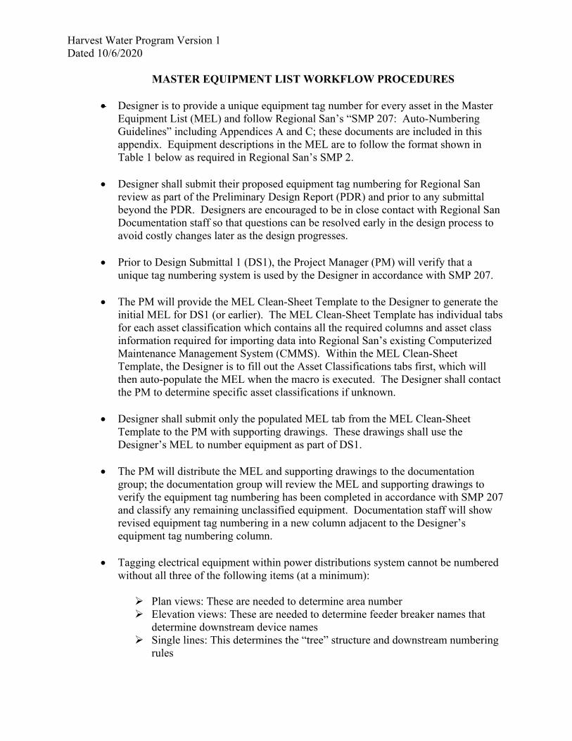
Harvest Water Program Version 1 Dated 10/6/2020
MASTER EQUIPMENT LIST WORKFLOW PROCEDURES Designer is to provide a unique equipment tag number for every asset in the Master
Equipment List (MEL) and follow Regional San’s “SMP 207: Auto-Numbering Guidelines” including Appendices A and C; these documents are included in this appendix. Equipment descriptions in the MEL are to follow the format shown in Table 1 below as required in Regional San’s SMP 2.
Designer shall submit their proposed equipment tag numbering for Regional San
review as part of the Preliminary Design Report (PDR) and prior to any submittal beyond the PDR. Designers are encouraged to be in close contact with Regional San Documentation staff so that questions can be resolved early in the design process to avoid costly changes later as the design progresses.
Prior to Design Submittal 1 (DS1), the Project Manager (PM) will verify that a unique tag numbering system is used by the Designer in accordance with SMP 207.
The PM will provide the MEL Clean-Sheet Template to the Designer to generate the
initial MEL for DS1 (or earlier). The MEL Clean-Sheet Template has individual tabs for each asset classification which contains all the required columns and asset class information required for importing data into Regional San’s existing Computerized Maintenance Management System (CMMS). Within the MEL Clean-Sheet Template, the Designer is to fill out the Asset Classifications tabs first, which will then auto-populate the MEL when the macro is executed. The Designer shall contact the PM to determine specific asset classifications if unknown.
Designer shall submit only the populated MEL tab from the MEL Clean-Sheet
Template to the PM with supporting drawings. These drawings shall use the Designer’s MEL to number equipment as part of DS1.
The PM will distribute the MEL and supporting drawings to the documentation
group; the documentation group will review the MEL and supporting drawings to verify the equipment tag numbering has been completed in accordance with SMP 207 and classify any remaining unclassified equipment. Documentation staff will show revised equipment tag numbering in a new column adjacent to the Designer’s equipment tag numbering column.
Tagging electrical equipment within power distributions system cannot be numbered
without all three of the following items (at a minimum):
Plan views: These are needed to determine area number Elevation views: These are needed to determine feeder breaker names that
determine downstream device names Single lines: This determines the “tree” structure and downstream numbering
rules
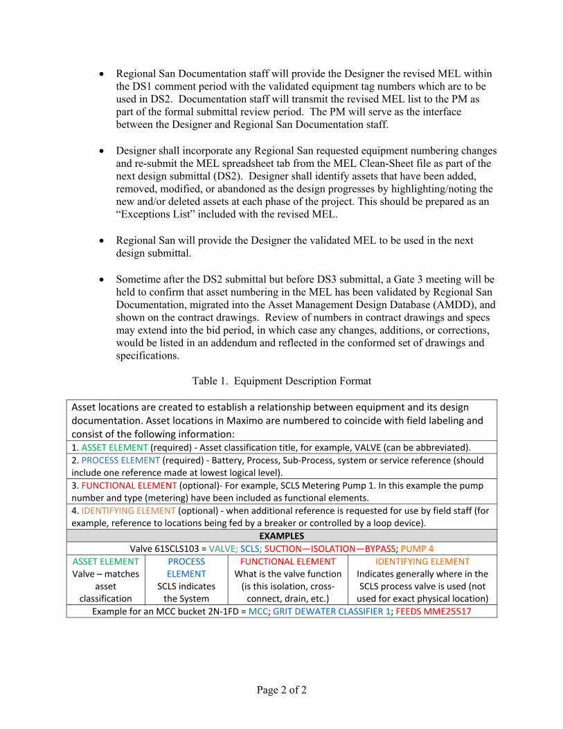
Page 2 of 2
Regional San Documentation staff will provide the Designer the revised MEL within the DS1 comment period with the validated equipment tag numbers which are to be used in DS2. Documentation staff will transmit the revised MEL list to the PM as part of the formal submittal review period. The PM will serve as the interface between the Designer and Regional San Documentation staff.
Designer shall incorporate any Regional San requested equipment numbering changes
and re-submit the MEL spreadsheet tab from the MEL Clean-Sheet file as part of the next design submittal (DS2). Designer shall identify assets that have been added, removed, modified, or abandoned as the design progresses by highlighting/noting the new and/or deleted assets at each phase of the project. This should be prepared as an “Exceptions List” included with the revised MEL.
Regional San will provide the Designer the validated MEL to be used in the next
design submittal. Sometime after the DS2 submittal but before DS3 submittal, a Gate 3 meeting will be
held to confirm that asset numbering in the MEL has been validated by Regional San Documentation, migrated into the Asset Management Design Database (AMDD), and shown on the contract drawings. Review of numbers in contract drawings and specs may extend into the bid period, in which case any changes, additions, or corrections, would be listed in an addendum and reflected in the conformed set of drawings and specifications.
Table 1. Equipment Description Format
Asset locations are created to establish a relationship between equipment and its design documentation. Asset locations in Maximo are numbered to coincide with field labeling and consist of the following information: 1. ASSET ELEMENT (required) ‐ Asset classification title, for example, VALVE (can be abbreviated).
2. PROCESS ELEMENT (required) ‐ Battery, Process, Sub‐Process, system or service reference (should include one reference made at lowest logical level). 3. FUNCTIONAL ELEMENT (optional)‐ For example, SCLS Metering Pump 1. In this example the pump number and type (metering) have been included as functional elements. 4. IDENTIFYING ELEMENT (optional) ‐ when additional reference is requested for use by field staff (for example, reference to locations being fed by a breaker or controlled by a loop device).
EXAMPLES
Valve 61SCLS103 = VALVE; SCLS; SUCTION—ISOLATION—BYPASS; PUMP 4
ASSET ELEMENT Valve – matches
asset classification
PROCESS ELEMENT
SCLS indicates the System
FUNCTIONAL ELEMENT What is the valve function (is this isolation, cross‐connect, drain, etc.)
IDENTIFYING ELEMENT Indicates generally where in the SCLS process valve is used (not used for exact physical location)
Example for an MCC bucket 2N‐1FD = MCC; GRIT DEWATER CLASSIFIER 1; FEEDS MME25517

Section 207
Auto-Numbering Guidelines
SMP 207
REV 3
DATE 08/13/20
APPR DJW
Page 1 of 32
Table of Contents
Introduction .......................................................................................................................... 3
Which Items Need Location IDs? ............................................................................................ 3
Items that get a Location ID ...................................................................................................................... 3
Items that DO NOT get a Location ID ........................................................................................................ 3
Why are Location IDs Important?........................................................................................... 5
O&M Procedures ...................................................................................................................................... 5
EDM/FileNET for File Retrieval .................................................................................................................. 5
Who is Responsible for Assigning Location IDs? ..................................................................... 6
Design/Construction ................................................................................................................................. 6
Equipment Added by District O&M Staff .................................................................................................. 6
Approval .................................................................................................................................................... 6
Location ID Databases ........................................................................................................... 7
Master Equipment List (MEL) Excel Template .......................................................................................... 7
IDEA ........................................................................................................................................................... 7
Maximo ..................................................................................................................................................... 8
Asset ID vs. Location ID .......................................................................................................... 9
Location ID ................................................................................................................................................ 9
Asset ID ..................................................................................................................................................... 9
Labeling Location IDs on Drawings ....................................................................................... 10
Changing Numbers .............................................................................................................. 10
Piping System Changes ........................................................................................................................... 10
Change in Function ................................................................................................................................. 11
Grouping and Sequencing Numbers on Plans ....................................................................... 12
Where to Start .................................................................................................................... 12
Syntax Business Rules .......................................................................................................... 13
Syntax 2 (Parent/Child with Core Numbers) ......................................................................... 14

Section 207
Auto-Numbering Guidelines
SMP 207
REV 3
DATE 08/13/20
APPR DJW
Page 2 of 32
Syntax 2 Code .......................................................................................................................................... 14
Start by Grouping Core Numbers on the Plan Drawings ........................................................................ 14
Zones and Sub-Zones .............................................................................................................................. 15
Applying Core Number Groupings on P&IDs .......................................................................................... 17
Which PLC Should be Listed at the Top of the P&ID? .......................................................................... 21
Syntax 4 (Process Equipment - [PPPP][AA][SS]) .................................................................... 22
Syntax 5 (Simple Sequential - [PPPP][9999]) ........................................................................ 22
Syntax 6 (Manual Valves- [AA][DDDDD][9999]) .................................................................... 23
Identifying Process Flow Pipe System ................................................................................................. 24
Syntax 7/8 Electrical ............................................................................................................ 25
MCC Buckets ........................................................................................................................................... 25
Syntax 10 MCC Buckets ....................................................................................................................... 25
MCC Bucket Description for the MEL .................................................................................................. 26
MCC Bucket Contents .......................................................................................................................... 27
Feeders (FDR) .......................................................................................................................................... 28
Junction Boxes, Conduits, and Raceways ............................................................................................... 29
Additional Business Rules .................................................................................................... 30
Suffixes I and O ....................................................................................................................................... 30
Tying Into Existing Areas of the Plant ..................................................................................................... 30
Planned Future Facilities ......................................................................................................................... 30
Drawing Disciplines ............................................................................................................. 30
Civil .......................................................................................................................................................... 30
Structural ................................................................................................................................................ 31
Architectural ........................................................................................................................................... 31
Fire Risers ................................................................................................................................................ 31
HVAC ....................................................................................................................................................... 32
Reference Documents ......................................................................................................... 32
End of Section ..................................................................................................................... 32
Section 207
Auto-Numbering Guidelines
SMP 207
REV 3
DATE 08/13/20
APPR DJW
Page 3 of 32
Introduction This document was created to guide users though the process of assigning unique numbers to
Regional San equipment. The District’s numbering system is referred to as ‘Auto-Numbering’.
Auto-Numbering was developed by the District in 2006 to apply a consistent numbering format
to new equipment added to the District.
A unique identifying tag number is assigned to each piece of equipment within the District.
Within District applications, the identifying tag number is officially referred to as the ‘Location
ID’. It may also be commonly referred to as the ‘Equipment Number’ or ‘Tag Number’.
Which Items Need Location IDs?
Items that get a Location ID
Assign numbers to each asset within the District which:
Requires any type of maintenance.
Is part of a procedure.
Needs to be discretely identified on drawings or documentation.
Needs to be tracked as part of the Covered Process.
We have highly regulated substances such as Methane Gas at Regional San. These
systems are referred to as the ‘Covered Process’ and are held to strict
regulations. Equipment in direct contact with a regulated substance is part of the
covered process and also equipment that does not come in contact with a regulated
substance, but its failure may result in a release.
If an equipment failure could cause a regulated substance release or interfere with
mitigating the consequences of an accidental release, it must be included in the
covered process as well.
Items that DO NOT get a Location ID
Generally speaking, we only assign Location IDs to physical assets that exist in the real
world. Here are some examples of items which we DO NOT assign numbers to:
PCCS points shown at the tops of P&IDs.
Virtual alarms and switches.
Items inside of panels such as lights, alarms, etc. These are considered to be part of
the panel.
Parts inside of packaged equipment supplied by manufacturers (see SMP - Section
206.10.1 for more clarification). Do not assign Location IDs to parts that are built

Section 207
Auto-Numbering Guidelines
SMP 207
REV 3
DATE 08/13/20
APPR DJW
Page 4 of 32
into equipment by the manufacturer as components and are included in the O&M
Manual of a package unit.
Virtual equipment like PLC program components.
Conduit, Raceway, and Cable numbers shown in schedules.
Do not assign Location IDs to small valves which are part of a large systems and are
service connections such as hose bibs, service connections to utility stations, etc.
Do not assign Location IDs to any valves ½ inch in size or smaller, or any valve that
will not be part of a procedure such as drainage, flushing, isolation, maintenance,
etc.
A good way to check if something needs a Location ID is to search the District’s list of equipment
prefixes. If an item is on the list, then it most likely needs to have a number assigned. If an item
is not on the list, then it most likely does not need to be numbered. In some cases, new prefixes
need to be created, so when in doubt contact District Staff.
This site plan drawing shows tank T610302 on the left and pumps P610701, P610702 and
P610703 on the right. Their Location IDs are labeled in rectangular boxes.
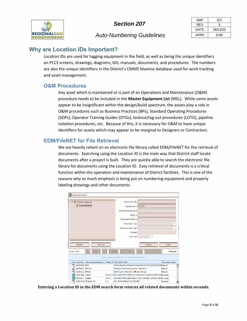
Section 207
Auto-Numbering Guidelines
SMP 207
REV 3
DATE 08/13/20
APPR DJW
Page 5 of 32
Why are Location IDs Important? Location IDs are used for tagging equipment in the field, as well as being the unique identifiers
on PCCS screens, drawings, diagrams, GIS, manuals, documents, and procedures. The numbers
are also the unique identifiers in the District’s CMMS Maximo database used for work tracking
and asset management.
O&M Procedures
Any asset which is maintained or is part of an Operations and Maintenance (O&M)
procedure needs to be included in the Master Equipment List (MEL). While some assets
appear to be insignificant within the design/build spectrum, the assets play a role in
O&M procedures such as Business Practices (BPs), Standard Operating Procedures
(SOPs), Operator Training Guides (OTGs), lockout/tag out procedures (LOTO), pipeline
isolation procedures, etc. Because of this, it is necessary for O&M to have unique
identifiers for assets which may appear to be marginal to Designers or Contractors.
EDM/FileNET for File Retrieval
We are heavily reliant on an electronic file library called EDM/FileNET for the retrieval of
documents. Searching using the Location ID is the main way that District staff locate
documents after a project is built. They are quickly able to search the electronic file
library for documents using the Location ID. Easy retrieval of documents is a critical
function within the operation and maintenance of District facilities. This is one of the
reasons why so much emphasis is being put on numbering equipment and properly
labeling drawings and other documents.
Entering a Location ID in the EDM search form returns all related documents within seconds.
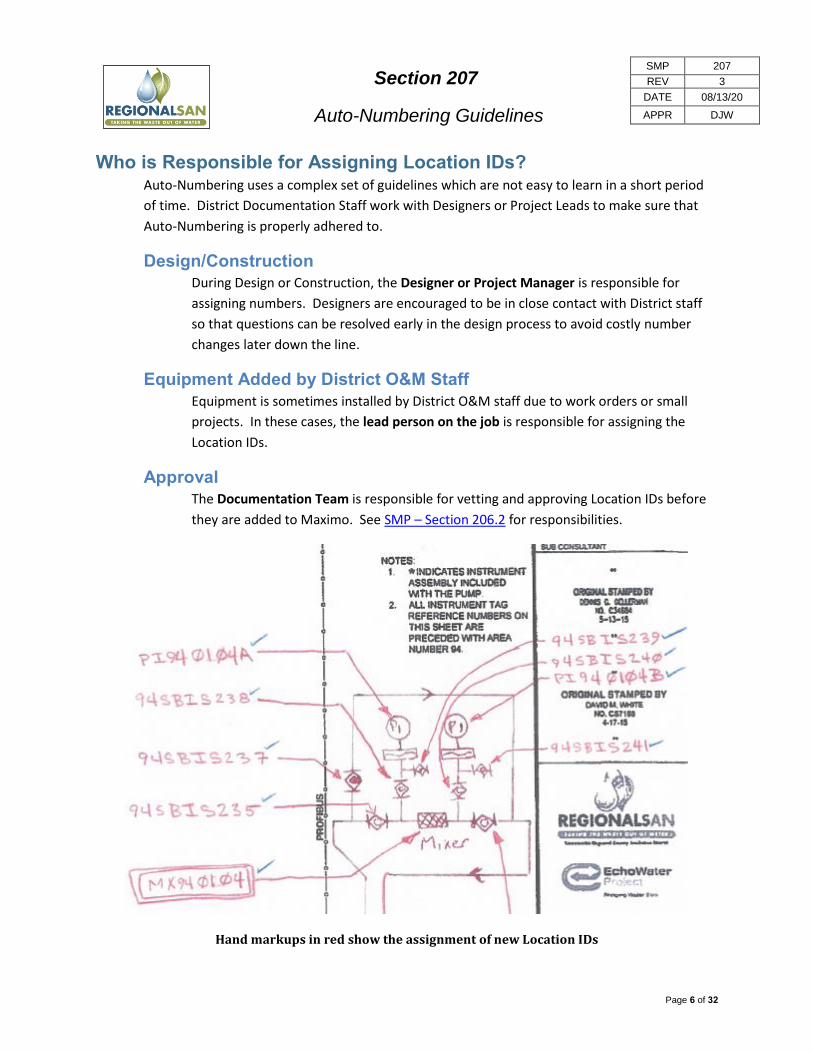
Section 207
Auto-Numbering Guidelines
SMP 207
REV 3
DATE 08/13/20
APPR DJW
Page 6 of 32
Who is Responsible for Assigning Location IDs? Auto-Numbering uses a complex set of guidelines which are not easy to learn in a short period
of time. District Documentation Staff work with Designers or Project Leads to make sure that
Auto-Numbering is properly adhered to.
Design/Construction
During Design or Construction, the Designer or Project Manager is responsible for
assigning numbers. Designers are encouraged to be in close contact with District staff
so that questions can be resolved early in the design process to avoid costly number
changes later down the line.
Equipment Added by District O&M Staff
Equipment is sometimes installed by District O&M staff due to work orders or small
projects. In these cases, the lead person on the job is responsible for assigning the
Location IDs.
Approval
The Documentation Team is responsible for vetting and approving Location IDs before
they are added to Maximo. See SMP – Section 206.2 for responsibilities.
Hand markups in red show the assignment of new Location IDs
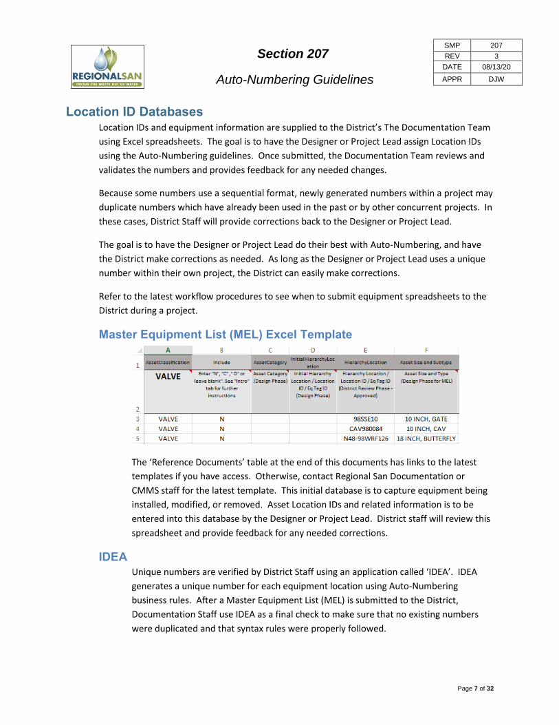
Section 207
Auto-Numbering Guidelines
SMP 207
REV 3
DATE 08/13/20
APPR DJW
Page 7 of 32
Location ID Databases Location IDs and equipment information are supplied to the District’s The Documentation Team
using Excel spreadsheets. The goal is to have the Designer or Project Lead assign Location IDs
using the Auto-Numbering guidelines. Once submitted, the Documentation Team reviews and
validates the numbers and provides feedback for any needed changes.
Because some numbers use a sequential format, newly generated numbers within a project may
duplicate numbers which have already been used in the past or by other concurrent projects. In
these cases, District Staff will provide corrections back to the Designer or Project Lead.
The goal is to have the Designer or Project Lead do their best with Auto-Numbering, and have
the District make corrections as needed. As long as the Designer or Project Lead uses a unique
number within their own project, the District can easily make corrections.
Refer to the latest workflow procedures to see when to submit equipment spreadsheets to the
District during a project.
Master Equipment List (MEL) Excel Template
The ‘Reference Documents’ table at the end of this documents has links to the latest
templates if you have access. Otherwise, contact Regional San Documentation or
CMMS staff for the latest template. This initial database is to capture equipment being
installed, modified, or removed. Asset Location IDs and related information is to be
entered into this database by the Designer or Project Lead. District staff will review this
spreadsheet and provide feedback for any needed corrections.
IDEA
Unique numbers are verified by District Staff using an application called ‘IDEA’. IDEA
generates a unique number for each equipment location using Auto-Numbering
business rules. After a Master Equipment List (MEL) is submitted to the District,
Documentation Staff use IDEA as a final check to make sure that no existing numbers
were duplicated and that syntax rules were properly followed.

Section 207
Auto-Numbering Guidelines
SMP 207
REV 3
DATE 08/13/20
APPR DJW
Page 8 of 32
Maximo
Maximo is the District’s maintenance management database application. MEL Location
IDs and data are loaded into Maximo by CMMS Staff for work orders, GIS, asset
management, and other business needs.
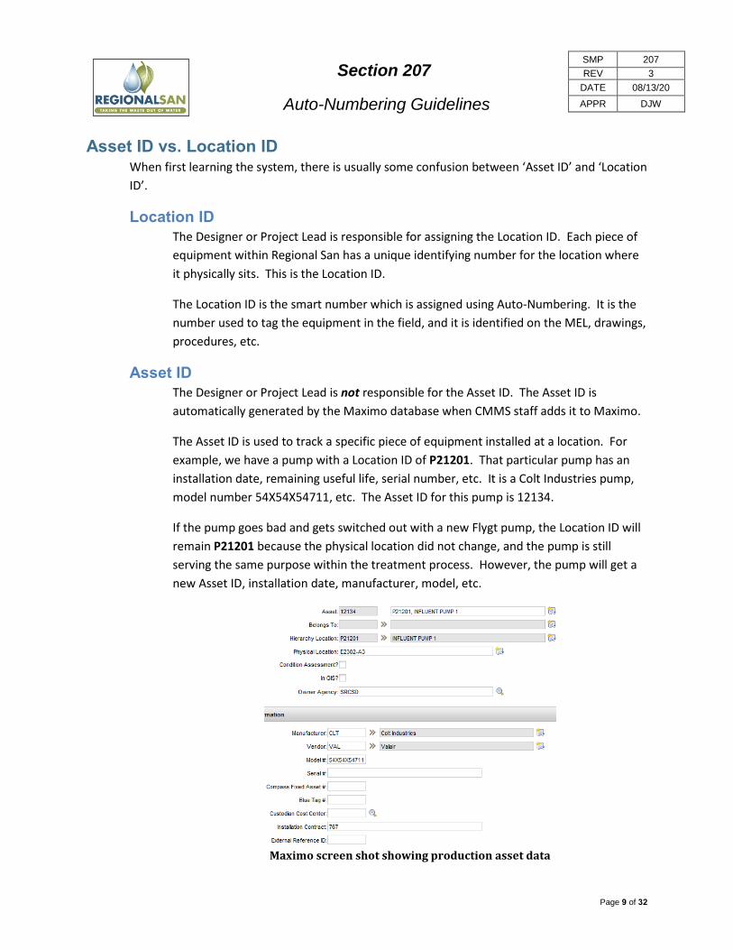
Section 207
Auto-Numbering Guidelines
SMP 207
REV 3
DATE 08/13/20
APPR DJW
Page 9 of 32
Asset ID vs. Location ID When first learning the system, there is usually some confusion between ‘Asset ID’ and ‘Location
ID’.
Location ID
The Designer or Project Lead is responsible for assigning the Location ID. Each piece of
equipment within Regional San has a unique identifying number for the location where
it physically sits. This is the Location ID.
The Location ID is the smart number which is assigned using Auto-Numbering. It is the
number used to tag the equipment in the field, and it is identified on the MEL, drawings,
procedures, etc.
Asset ID
The Designer or Project Lead is not responsible for the Asset ID. The Asset ID is
automatically generated by the Maximo database when CMMS staff adds it to Maximo.
The Asset ID is used to track a specific piece of equipment installed at a location. For
example, we have a pump with a Location ID of P21201. That particular pump has an
installation date, remaining useful life, serial number, etc. It is a Colt Industries pump,
model number 54X54X54711, etc. The Asset ID for this pump is 12134.
If the pump goes bad and gets switched out with a new Flygt pump, the Location ID will
remain P21201 because the physical location did not change, and the pump is still
serving the same purpose within the treatment process. However, the pump will get a
new Asset ID, installation date, manufacturer, model, etc.
Maximo screen shot showing production asset data

Section 207
Auto-Numbering Guidelines
SMP 207
REV 3
DATE 08/13/20
APPR DJW
Page 10 of 32
Labeling Location IDs on Drawings Label Location IDs on drawings according to the project’s drafting standards. All equipment
numbers captured in the MEL need to be shown on at least one drawing. If the Designer is not
going to show all of the equipment on the P&IDs or plans, then standard assembly details need
to include tables relating the individual equipment numbers to the assembly’s components.
Changing Numbers Corrections can be made during the design process to correct or change numbers before they
are approved. Once the Location ID has been added to Maximo and the equipment is in
production, we generally do not change the number unless there is a significant reason (i.e.
duplicate number detected, significant safety concern, etc.). The existing number serves the
purpose of acting as a unique identifier, and will not be changed for aesthetic reasons.
Changing numbers requires a great amount of effort including:
We have to change the drawings, manuals, schedules, SOPs, and other documents.
The Location ID references to EDM/FileNet have to be updated.
The Location ID may have to be updated in GIS.
We have to engrave a new tag and change out the tag in the field.
The old Location ID has to be deleted from databases such as IDEA and Maximo.
The new Location ID has to be added to databases such as IDEA and Maximo.
In Maximo, the Asset has to be re-mapped to the new Location ID.
If work orders or PM’s existed in Maximo, those have to be re-mapped to the new
Location ID.
The Location ID may be referenced in documentation which is not indexed in EDM/FileNet, such
as design drawings, procedure manuals, or construction submittals. In these cases, the change
will most like likely be missed and become out of sync with the new number. Therefore, the
general policy is that once a Location ID has been assigned and put into production, it will
never be changed.
Piping System Changes
What happens if a WN pipeline is reused for WRH? If a pipeline is repurposed for
another use, manual valve Location IDs will become out of sync with the piping system.
For example, a WN pipeline will have manual valve numbers using syntax 6 which
contain the piping system as part of the Location ID. An example of a manual valve part
of a WN pipeline would be 61WN22.
Section 207
Auto-Numbering Guidelines
SMP 207
REV 3
DATE 08/13/20
APPR DJW
Page 11 of 32
For the reasons stated above under ‘Changing Numbers’, the manual valve Location IDs
will not be changed if the pipeline is repurposed. For example, you might have a
manual valve such as 61WN22 which is on a WRH pipeline. The following changes will
be made to make the correct piping system apparent:
1. Update all drawings referencing the piping system.
2. Update all markings or vinyl stickers in the field which denote the piping system.
3. Update the piping system in GIS.
Change in Function
If an asset is modified in way that completely changes its function, then it may be
assigned a new number in some instances.
For example, if a manual valve is converted to a motor operated valve, then you are
effectively changing the type of equipment. In this case, you may assign a new number
to the motor operated valve (syntax 2), and remove the number of the manual valve
(syntax 6). It would go from something like 61WRH22 to V610045.

Section 207
Auto-Numbering Guidelines
SMP 207
REV 3
DATE 08/13/20
APPR DJW
Page 12 of 32
Grouping and Sequencing Numbers on Plans While Auto-Numbering can generate unique numbers for assets, it cannot group these assets
into any logical order. Assignment of equipment numbers requires conscientious users who
understand the processes they are numbering. Equipment numbers should be laid out in some
kind of logical fashion that will make sense to operators, maintenance staff, or any other users
accessing the facilities. The goal of grouping assets is to make the following tasks easier:
Assigning numbers during designs
Sorting lists
Building schedules or tables
Identifying assets in the field
Identifying assets on PCCS screens
Viewing assets in GIS
Where to Start Start by familiarizing yourself with the design. Look at all of the drawings to understand how
the process works. Once you have a basic understanding of the process and project area,
identify the syntax 2 numbers that serve a central or ‘parent’ asset and group them into zones
or sub-zones if needed. Next, you can assign syntax 4 and 5 numbers since they work
independently of the other numbers. Finally, you can review the P&IDs to assign syntax 6
numbers and any syntax 2 numbers that stand alone and do not serve a parent asset.
When in doubt, look at existing facilities to see how equipment numbers are grouped. You can
look at existing tanks, pumps, and processes to get an idea of how numbers have been applied
in the past. Designers should consult with District staff when questions arise.

Section 207
Auto-Numbering Guidelines
SMP 207
REV 3
DATE 08/13/20
APPR DJW
Page 13 of 32
Syntax Business Rules
For a detailed look at the District’s Auto-Numbering syntax rules, please refer to the detailed
SRCSD Auto-Numbering document. The table below is just a summary of mechanical
equipment.
Syntax Length Code Example
Syntax 1
Core/Loop
6 [AA][9999]
[max 2-digit plant area number]
[max 4-digit sequential core number]
450001
Area 45,
Core/Loop# 0001
Syntax 2
Equipment
and
Instruments
11 [PPPP][AA][9999][S]
[max 4-char prefix]
[2-digit plant area number]
[4-digit sequential core number]
[1-char sequential suffix (Null OK)]
P450001A
Area 45,
Auxiliary Pump 1A
Syntax 4
Process
8 [PPPP][AA][SS]
[max 4-char prefix]
[2-digit plant area number]
[2-char sequential suffix]
SLG45E
Slide Gate,
Area 45,
5th gate (E)
Syntax 5
Simple
Sequential
8 [PPPP][9999]
[max 4-char prefix]
[max 4-digit sequential number]
MH17
Electrical Manhole
number 17
Syntax 6
Pipe Service
11 [AA][DDDDD][9999]
[2-digit plant area number]
[max 5-char pipe service code]
[max 4-digit sequential core number]
45WRH37
Area 45, WHR
system, manual
valve number 37
To determine the plant area number, refer to the District’s latest ‘Equipment Zones Map’ or GIS.
Section 207
Auto-Numbering Guidelines
SMP 207
REV 3
DATE 08/13/20
APPR DJW
Page 14 of 32
Syntax 2 (Parent/Child with Core Numbers) Syntax 2 equipment use an area/core number which is used to group related parent/child
assets. All of the assets which serve a central, or ‘parent’ asset, are numbered using the same
six digit area/core number.
Syntax 2 Code
[PPPP][AA][9999][S]
PPPP =max 4-char prefix
AA = 2-digit area number
9999 = 4-digit core number
S = 1-char suffix (null OK)
(Example: P614101A)
Start by Grouping Core Numbers on the Plan Drawings
At the beginning of a design, we normally start with the site plan drawings that show
the related regions of the project.
Look at the plan view drawings, process schematics, and the P&IDs. Make a judgment
as to how the core numbers for the parent assets will be laid out on the plans. Label the
parent equipment numbers on the plans so you have a reference for issuing the child
numbers later on the P&IDs. Everything will build off of the parent numbers that you
establish early on. It may be useful to group the equipment into zones or sub-zones.
We typically start with the flow path of the main process, and then assign core numbers
to any secondary or utility systems. We typically use core numbers 0001-0009 for PLCs,
so start with core number 0010 or a higher number is there are more PLCs. We don’t
typically start with 0000.
It may be preferred to number the tanks, then the pumps, then any downstream
elements. In some projects, it may make the most sense to number the equipment in
sequence along the direction of flow from upstream to downstream.
In another project, it may make more sense to number in groupings based on the
physical layout of equipment. Assets that flow through treatment processes lend
themselves to numbering in the direction of flow. Chemical feed processes have tanks
that are shared by a number of pumps, so it may make more sense to number them in
sequence as they are shown on the plans.
Important!: Once a core number has been used, it may not be used again for another
group or piece of equipment outside of the assembly. Core numbers will be assigned to
Section 207
Auto-Numbering Guidelines
SMP 207
REV 3
DATE 08/13/20
APPR DJW
Page 15 of 32
only one group of parent/child equipment at one physical location. For example, core
number 21201 is used for influent pump P21201 located in the I/E Building. You would
not assign B21201 to a blower in the same area, even though the number would be
technically unique. You would use another core number for the blower and its child
assets.
During a design, it may be useful to have one person be in charge of the MEL. In
previous projects, isolated design groups such as electrical and HVAC inadvertently used
the same core numbers, resulting in changes late in the design process.
Zones and Sub-Zones
Grouping by physical zones can be done by using the first two digits of the 4-digit core
number. As a general procedure, start with the site plan drawings or process
schematics. Map out the zone and sub-zone groupings that will be represented by the
first two digits in the core number. It may be useful to create a working map of the area
numbers and zones to keep them straight during the project (see example on next
page).

Section 207
Auto-Numbering Guidelines
SMP 207
REV 3
DATE 08/13/20
APPR DJW
Page 16 of 32
The first digit of the 4-digit core number is best used for large zones such as whole
buildings or batteries of processes. Let’s say we have two buildings, a pump station, a
clarifier, and a group of three basins. We want the equipment numbers in each region
to have a common thread. To achieve this, we start each of the core numbers with an
identifying digit. For example:
Zone Core Number Series
Samples of Pumps in Each Zone
Building A 0xxx P610001, P610002, P610003, etc.
Building B 1xxx P611001, P611002, P611003, etc.
Pump Station 2xxx P612001, P612002, P612003, etc.
Clarifier 3xxx P613001, P613002, P613003, etc.
Basins 4xxx P614001, P614002, P614003, etc.
Rooms within a building do not constitute sub-zones, they just get ‘ROOMxxxxxx’
numbers. Multiple treatment units within a common zone such as individual SSTs,
basins, thickeners, and digesters are good examples of sub-zones. In our example,
let’s say our process has a group of three basins. You could move to the second-
digit in the core number and assign an identifier to each basin within the ‘Basins’
zone. For basins you could use sub-zone core numbers like this:
Zone Sub-Zone
Core Number Series
Samples of Pumps in Each Basin
Basins (4xxx) Basin 1 41xx P614101, P614102, P614103, etc.
Basins (4xxx) Basin 2 42xx P614201, P614202, P614203, etc.
Basins (4xxx) Basin 3 43xx P614301, P614302, P614303, etc.
Section 207
Auto-Numbering Guidelines
SMP 207
REV 3
DATE 08/13/20
APPR DJW
Page 17 of 32
Applying Core Number Groupings on P&IDs
Once a set of core numbers have been established at the parent level on the plans, the
next task it to assign numbers to child assets that serve the parents. The Process and
Instrumentation Diagrams (P&IDs) are usually the best tools for figuring which assets
should be grouped together using the same core number.
Start by labelling the parent assets on the P&IDs. Once this is finished, circle each
grouping of child assets which serve their parent on the P&ID. Any assets that serve the
parent will get the same core number. Examples of children would include
instrumentation or actuated valves associated with isolation and control of the parent.
Sometimes there are assets which don’t tie directly to a parent asset in a 1:1
relationship. For example, we have a flow meter downstream from three pumps which
all discharge to a common pipe. Since we can’t tie the flow meter to any of the three
pumps individually, we give the flow meter its own unique core number.
Section 207
Auto-Numbering Guidelines
SMP 207
REV 3
DATE 08/13/20
APPR DJW
Page 18 of 32
Examples of Identifying Core Number Groupings
For pumps, everything from the suction point to a common discharge point
takes on the same area/core number. This is true of blowers and other
equipment associated with process flows.
Individual pieces of equipment such as mixers, motor operated valves, gates,
etc. may be treated as individual pieces of equipment with distinct core
numbers.
Package compressors are one core equipment group with the compressor being
a core number and, if there are two compressors, each are A and B suffixes.
If a process stream is split into parallel redundant streams that mirror each
other, the parent numbers should follow an A and B suffix stream like this:
Once the parent/child groupings have been circled on the P&IDs, all you have to do is
populate the final equipment numbers. Apply the area/core number of the parent to
each of the children using prefixes and suffixes within syntax 2. Within a group of assets
that use the same core number, the prefixes will set the numbers apart from each
other. Use suffixes when there are several assets in a grouping that all use the same
prefix and core number. Try to sequence the child numbers from left to right and from
top to bottom as shown on the P&ID.
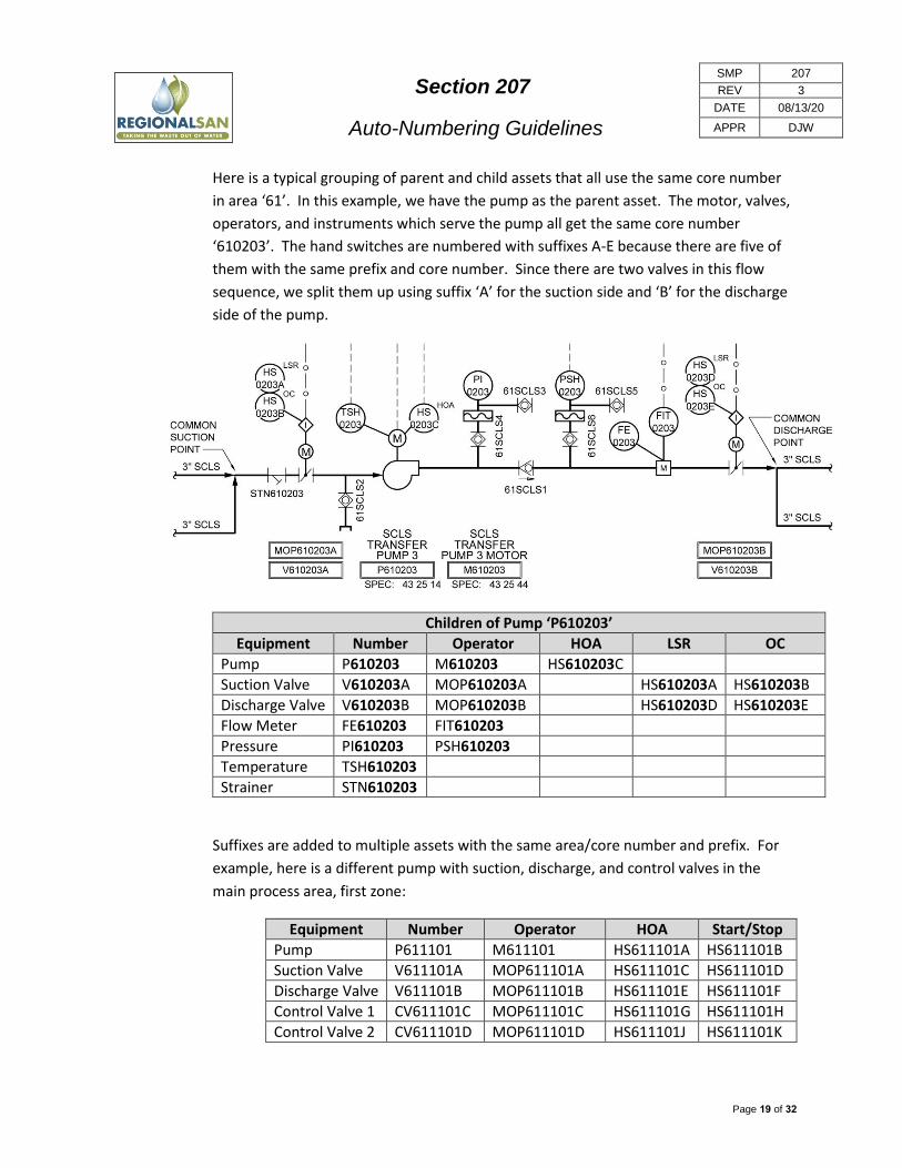
Section 207
Auto-Numbering Guidelines
SMP 207
REV 3
DATE 08/13/20
APPR DJW
Page 19 of 32
Here is a typical grouping of parent and child assets that all use the same core number
in area ‘61’. In this example, we have the pump as the parent asset. The motor, valves,
operators, and instruments which serve the pump all get the same core number
‘610203’. The hand switches are numbered with suffixes A-E because there are five of
them with the same prefix and core number. Since there are two valves in this flow
sequence, we split them up using suffix ‘A’ for the suction side and ‘B’ for the discharge
side of the pump.
Children of Pump ‘P610203’
Equipment Number Operator HOA LSR OC
Pump P610203 M610203 HS610203C
Suction Valve V610203A MOP610203A HS610203A HS610203B
Discharge Valve V610203B MOP610203B HS610203D HS610203E
Flow Meter FE610203 FIT610203
Pressure PI610203 PSH610203
Temperature TSH610203
Strainer STN610203
Suffixes are added to multiple assets with the same area/core number and prefix. For
example, here is a different pump with suction, discharge, and control valves in the
main process area, first zone:
Equipment Number Operator HOA Start/Stop
Pump P611101 M611101 HS611101A HS611101B
Suction Valve V611101A MOP611101A HS611101C HS611101D
Discharge Valve V611101B MOP611101B HS611101E HS611101F
Control Valve 1 CV611101C MOP611101C HS611101G HS611101H
Control Valve 2 CV611101D MOP611101D HS611101J HS611101K

Section 207
Auto-Numbering Guidelines
SMP 207
REV 3
DATE 08/13/20
APPR DJW
Page 20 of 32
Here is a treatment process sequence consisting of a motor operated gate followed by a
series of motor operated valves, control valves, mixers, and a pump. Each asset family
in this sequence gets its own unique core number.
Parent Asset Parent Location ID
Operator (Child)
HOA (Child)
Start/Stop (Child)
Gate G711101 MOP711101 HS711101A HS71101B
Valve V711102 MOP711102 HS711102A HS711102B
Control Valve CV711103 MOP711103 HS711103A HS711103B
Valve V711104 MOP711104 HS711104A HS711104B
Mixer MX711105 M711105 HS711105A HS711105B
Mixer MX711106 M711106 HS711106A HS711106B
Pump P711107 M711107 HS711107A HS711107B

Section 207
Auto-Numbering Guidelines
SMP 207
REV 3
DATE 08/13/20
APPR DJW
Page 21 of 32
Which PLC Should be Listed at the Top of the P&ID?
District Control Systems staff has asked that we show the primary physical PLC
processor that instruments report to at the tops of the P&ID sheets. In a typical control
panel, there will be three PLCs:
PLC-A (main processor)
PLC-B (for redundancy)
I/O (PLC-C)
Since PLC-A is the main processor, it should be the PLC number shown on the P&ID
sheets. All of the PLCs should be shown somewhere on a block diagram or panel
drawing.
For example, for the DCS project, the main PLC processor for area 61 is location ID
PLC610001A. This is the number that should be shown in the double-box at the top of
the P&ID sheets. The benefit to District staff is that they will be able to quickly search in
their file library for P&IDs related to the PLC by searching for the PLC location ID and
choosing ‘Process and Instrumentation Diagram’ as the document sub-type.
Section 207
Auto-Numbering Guidelines
SMP 207
REV 3
DATE 08/13/20
APPR DJW
Page 22 of 32
Syntax 4 (Process Equipment - [PPPP][AA][SS]) If there are process schematics, use those drawings to assign numbers for syntax 4. Some
process flows will not have any process schematics. In these cases, use the plan-view drawings.
We typically number process equipment in sequence along the flow path. From the starting
point of the flow, each asset will get the next sequential number available.
On the P&IDs we typically start with the flow path of the main process, and then assign numbers
to any auxiliary or servicing systems. Assign numbers moving from left to right, then from the
top to the bottom.
Do not use the letters ‘I’ or ‘O’ for suffixes. The letters can too easily be misinterpreted as the
numbers 1 and 0. Skip from H to J and N to P when issuing suffixes.
Syntax 5 (Simple Sequential - [PPPP][9999]) Since these use a sequential syntax, the District has to assign these. Designers will have to use
temporary placeholder numbers, and request these from the District. There is no way for the
Designer to know which syntax 5 numbers already exist within the District, or have been used by
other parallel projects.
Start with the plan-view drawings and number the syntax 5 equipment. Because Syntax 5
numbers do not use an Area Number prefix to set them apart, conflicts are more likely to be
encountered with existing numbers.
Most of the assets covered under syntax 5 will be shown on the plan-view drawings. Try to
arrange the syntax 5 assets into some kind of logical sequence based on their physical location
or proximity to other assets. We typically start numbering at number 10 instead of 1 so the
assets group together on lists when sorting alphanumerically.

Section 207
Auto-Numbering Guidelines
SMP 207
REV 3
DATE 08/13/20
APPR DJW
Page 23 of 32
Syntax 6 (Manual Valves- [AA][DDDDD][9999]) Assign Location IDs to any valves greater than ½ inch in size, or any valve that will be part of a
procedure such as drainage, flushing, isolation, maintenance, etc. All assets within a covered
process need to have Location IDs assigned. Do not assign Location IDs to small valves which are
part of a large systems and are service connections such as hose bibs, service connections to
utility stations, etc. Do not assign Location IDs to valves that are built into equipment by the
manufacturer as a component and are included in the O&M Manual.
We typically number manual valves in sequence along the flow path. From the starting point of
the flow, each manual valve will get the next sequential number available. The Process and
Instrumentation Diagrams (P&IDs) are usually the best tools for figuring out how the process
flows, and in which order to number the valves.
On the P&IDs, we typically assign numbers to the main process pipeline first, starting upstream
and travelling downstream. Next, we assign valve numbers to any secondary or utility pipelines.
Some process flows will not have any process schematics. In these cases, use the plan-view
drawings to assign the manual valve numbers in order by flow direction. We typically start
numbering at number 10 instead of 1 so the assets group together on lists when sorting
alphanumerically.
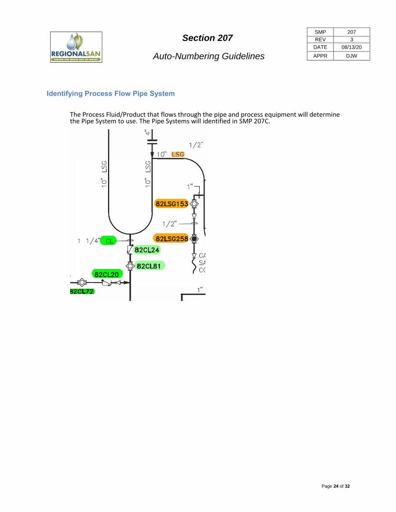
Section 207
Auto-Numbering Guidelines
SMP 207
REV 3
DATE 08/13/20
APPR DJW
Page 24 of 32
Identifying Process Flow Pipe System
The Process Fluid/Product that flows through the pipe and process equipment will determine the Pipe System to use. The Pipe Systems will identified in SMP 207C.
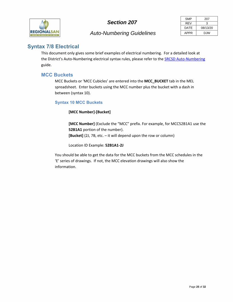
Section 207
Auto-Numbering Guidelines
SMP 207
REV 3
DATE 08/13/20
APPR DJW
Page 25 of 32
Syntax 7/8 Electrical This document only gives some brief examples of electrical numbering. For a detailed look at
the District’s Auto-Numbering electrical syntax rules, please refer to the SRCSD Auto-Numbering
guide.
MCC Buckets
MCC Buckets or ‘MCC Cubicles’ are entered into the MCC_BUCKET tab in the MEL
spreadsheet. Enter buckets using the MCC number plus the bucket with a dash in
between (syntax 10).
Syntax 10 MCC Buckets
[MCC Number]-[Bucket]
[MCC Number] (Exclude the “MCC” prefix. For example, for MCC52B1A1 use the
52B1A1 portion of the number).
[Bucket] (2J, 7B, etc. – it will depend upon the row or column)
Location ID Example: 52B1A1-2J
You should be able to get the data for the MCC buckets from the MCC schedules in the
‘E’ series of drawings. If not, the MCC elevation drawings will also show the
information.
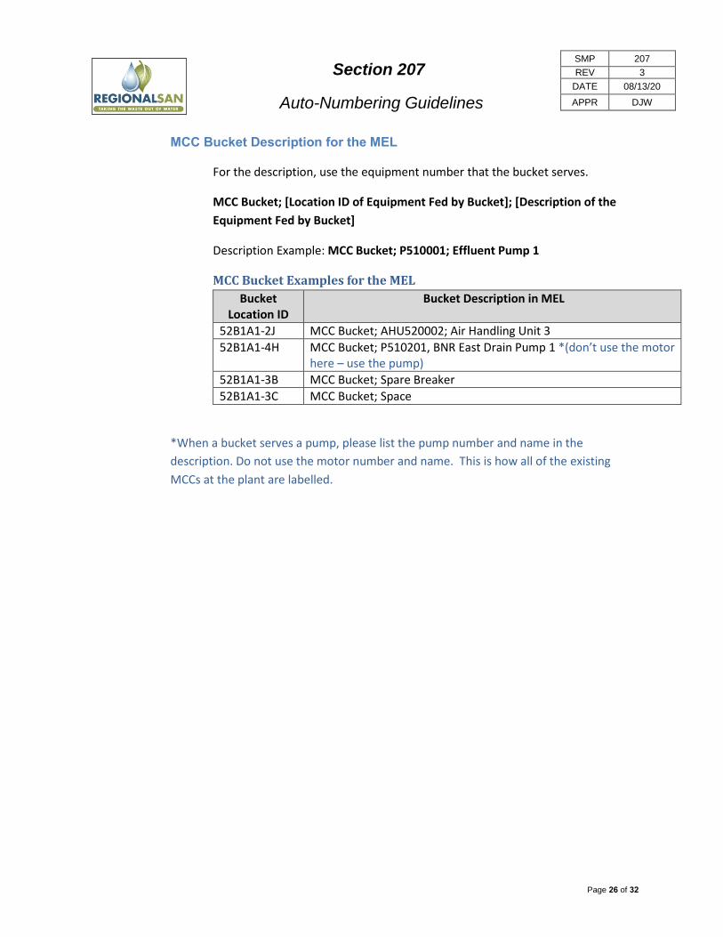
Section 207
Auto-Numbering Guidelines
SMP 207
REV 3
DATE 08/13/20
APPR DJW
Page 26 of 32
MCC Bucket Description for the MEL
For the description, use the equipment number that the bucket serves.
MCC Bucket; [Location ID of Equipment Fed by Bucket]; [Description of the
Equipment Fed by Bucket]
Description Example: MCC Bucket; P510001; Effluent Pump 1
MCC Bucket Examples for the MEL
Bucket Location ID
Bucket Description in MEL
52B1A1-2J MCC Bucket; AHU520002; Air Handling Unit 3
52B1A1-4H MCC Bucket; P510201, BNR East Drain Pump 1 *(don’t use the motor here – use the pump)
52B1A1-3B MCC Bucket; Spare Breaker
52B1A1-3C MCC Bucket; Space
*When a bucket serves a pump, please list the pump number and name in the
description. Do not use the motor number and name. This is how all of the existing
MCCs at the plant are labelled.
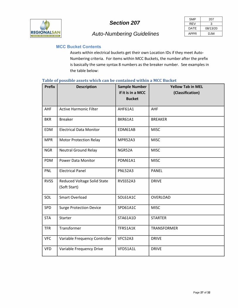
Section 207
Auto-Numbering Guidelines
SMP 207
REV 3
DATE 08/13/20
APPR DJW
Page 27 of 32
MCC Bucket Contents
Assets within electrical buckets get their own Location IDs if they meet Auto-
Numbering criteria. For items within MCC Buckets, the number after the prefix
is basically the same syntax 8 numbers as the breaker number. See examples in
the table below:
Table of possible assets which can be contained within a MCC Bucket
Prefix Description Sample Number
if it is in a MCC
Bucket
Yellow Tab in MEL
(Classification)
AHF Active Harmonic Filter AHF61A1 AHF
BKR Breaker BKR61A1 BREAKER
EDM Electrical Data Monitor EDM61AB MISC
MPR Motor Protection Relay MPR52A3 MISC
NGR Neutral Ground Relay NGR52A MISC
PDM Power Data Monitor PDM61A1 MISC
PNL Electrical Panel PNL52A3 PANEL
RVSS Reduced Voltage Solid State
(Soft Start)
RVSS52A3 DRIVE
SOL Smart Overload SOL61A1C OVERLOAD
SPD Surge Protection Device SPD61A1C MISC
STA Starter STA61A1D STARTER
TFR Transformer TFR51A1K TRANSFORMER
VFC Variable Frequency Controller VFC52A3 DRIVE
VFD Variable Frequency Drive VFD51A1L DRIVE
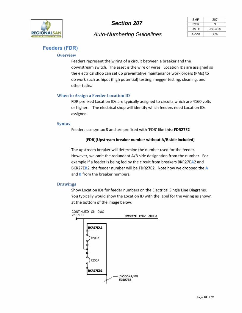
Section 207
Auto-Numbering Guidelines
SMP 207
REV 3
DATE 08/13/20
APPR DJW
Page 28 of 32
Feeders (FDR)
Overview
Feeders represent the wiring of a circuit between a breaker and the
downstream switch. The asset is the wire or wires. Location IDs are assigned so
the electrical shop can set up preventative maintenance work orders (PMs) to
do work such as hipot (high potential) testing, megger testing, cleaning, and
other tasks.
When to Assign a Feeder Location ID
FDR prefixed Location IDs are typically assigned to circuits which are 4160 volts
or higher. The electrical shop will identify which feeders need Location IDs
assigned.
Syntax
Feeders use syntax 8 and are prefixed with ‘FDR’ like this: FDR27E2
[FDR][Upstream breaker number without A/B side included]
The upstream breaker will determine the number used for the feeder.
However, we omit the redundant A/B side designation from the number. For
example if a feeder is being fed by the circuit from breakers BKR27EA2 and
BKR27EB2, the feeder number will be FDR27E2. Note how we dropped the A
and B from the breaker numbers.
Drawings
Show Location IDs for feeder numbers on the Electrical Single Line Diagrams.
You typically would show the Location ID with the label for the wiring as shown
at the bottom of the image below:

Section 207
Auto-Numbering Guidelines
SMP 207
REV 3
DATE 08/13/20
APPR DJW
Page 29 of 32
Junction Boxes, Conduits, and Raceways
Do not add junction boxes, conduits, or raceways to the MEL. The junction boxes shown
in our designs are condulets or small boxes that are used for conduit connections and
cable routing. They require a designer provided tag (used in raceway and cable
schedules) but don’t need to be included in the MEL; it is not a maintenance item.
For larger electrical boxes which are above ground, use ‘PB’ Pullbox syntax 4. Electrical
boxes in the ground should use ‘HH’ Handhole syntax 5. Larger electrical vaults which
allow human entry would be considered ‘MH’ Manhole syntax 5. Don’t forget to assign
Location IDs for sump pumps or ladders inside of manholes.

Section 207
Auto-Numbering Guidelines
SMP 207
REV 3
DATE 08/13/20
APPR DJW
Page 30 of 32
Additional Business Rules
Suffixes I and O
Do not use the letters ‘I’ or ‘O’ for suffixes in any syntax. The letters can too easily be
misinterpreted as the numbers 1 and 0. Skip from H to J and N to P when issuing
suffixes.
Tying Into Existing Areas of the Plant
When tying into existing areas of the plant, any new piece of parent-level equipment
will use new day-forward numbering. New process streams will get new day-forward
core numbers. Only child-level equipment will use existing core numbers when tying
into existing parent-level assets.
Planned Future Facilities
When showing future assets for eventual build out, show the parent-level equipment
numbers on the plans as ‘future’. These numbers can be used if and when the facilities
are built.
In the MEL spreadsheet, add the word ”(FUTURE)” to the end of the description.
Add the word “FUTURE” in the Notes column.
This will alert CMMS to place this location outside of the MAIN hierarchy in Maximo (in
the MEL hierarchy) until it is actually installed, and then they move it over.
Drawing Disciplines Here are some things to look for in each of the drawing disciplines which are commonly
overlooked by many Designers.
Civil
Item Syntax Prefix Example
Road 5 ROAD ROAD1001
Roads
Since these use a sequential syntax, the District has to assign these. Designers
will have to use temporary placeholder numbers, and request these from the
District.
Roads have their own unique numbering system. We assign Location IDs based
on Inspection Units (IUs). Each inspection unit gets its own Location ID in
Maximo.
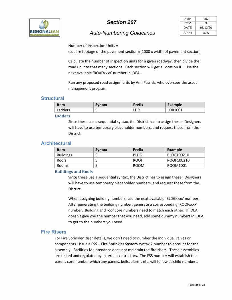
Section 207
Auto-Numbering Guidelines
SMP 207
REV 3
DATE 08/13/20
APPR DJW
Page 31 of 32
Number of Inspection Units =
(square footage of the pavement section)/(1000 x width of pavement section)
Calculate the number of inspection units for a given roadway, then divide the
road up into that many sections. Each section will get a Location ID. Use the
next available ‘ROADxxxx’ number in IDEA.
Run any proposed road assignments by Ami Patrick, who oversees the asset
management program.
Structural
Item Syntax Prefix Example
Ladders 5 LDR LDR1001
Ladders
Since these use a sequential syntax, the District has to assign these. Designers
will have to use temporary placeholder numbers, and request these from the
District.
Architectural
Item Syntax Prefix Example
Buildings 5 BLDG BLDG100210
Roofs 5 ROOF ROOF100210
Rooms 5 ROOM ROOM1001
Buildings and Roofs
Since these use a sequential syntax, the District has to assign these. Designers
will have to use temporary placeholder numbers, and request these from the
District.
When assigning building numbers, use the next available ‘BLDGxxxx’ number.
After generating the building number, generate a corresponding ‘ROOFxxxx’
number. Building and roof core numbers need to match each other. If IDEA
doesn’t give you the number that you need, add some dummy numbers in IDEA
to get to the numbers you need.
Fire Risers
For Fire Sprinkler Riser details, we don’t need to number the individual valves or
components. Issue a FSS – Fire Sprinkler System syntax 2 number to account for the
assembly. Facilities Maintenance does not maintain the fire risers. These assemblies
are tested and regulated by external contractors. The FSS number will establish the
parent core number which any panels, bells, alarms etc. will follow as child numbers.
Section 207
Auto-Numbering Guidelines
SMP 207
REV 3
DATE 08/13/20
APPR DJW
Page 32 of 32
HVAC
For Heating Ventilation and Air Conditioning (HVAC), try to start with an airflow
schematic. If the designer did not provide one, ask for one. At the very least, you need
to be able to tell how the air flows, and which pieces of equipment are tied to the
parent-level asset. In most cases, you will have a parent like an air handling unit (AHU)
or heat pump (HP) pushing air through a subset of child assets.
Tips
Use ACUxxxxxx for air conditioners which only supply cold air.
Use HPxxxxxx for heat pumps which are combination heating and cooling units.
Reference Documents
Title Document Serial# in
EDM Link
Detailed Auto-Numbering Business Rules (SRCSD Auto-Numbering 2007)
CMMS SharePoint
Link
Prefix List (SMP 207 Appendix A) 10086677 Link
Pipe Systems (SMP 207 Appendix C) 10086678 Link
Equipment Zones Map 10040686 Link
MEL Flow Chart 10086679 Link
SMP - Section 2 (See section 2.8.2 to see how to fill out the Location ID (Equipment #) Description column.)
10091700 Link
SMP – Section 206 – Location ID Assignment 10091885 Link
MEL Excel Template CMMS SharePoint
Link
End of Section
[End of document]
Date Rev Appr Description
03/14/19 0 DJW Original document converted to SMP format.
03/22/19 1 DJW Removed package equipment reference, cleaned up obsolete information.
8/13/2019 2 DJW Added ‘Appendix A’ Regional San Equipment Prefix List.
8/13/2020 3 DJW Added “Identifying Process Flow Pipe Systems”.

7/20/2020
File: 10086677
Active Instrument Classification (ACTINST): Control equipment that is either powered or provides and/or receives a signal.
Passive Instrument Classification (PASSINST): Control equipment that is not powered and does not provide and/or receive a signal.
Prefix Description Sample Syntax Classification Location Type DMI/MMI? IDEA Type Comments
(none) Manual Valve 61WRH11 6 VALVE OPERATING DMI VALVES Use syntax 6 for manual valves. There is no alpha
prefix.
(none) Motor Control Center Buckets/Cubicles 61A1-2J 10 MCC Bucket OPERATING MMI POWERDIS The description will be: ELECTRICAL CUBICLE,
[EQUIPMENT FED BY ELECCUBE], [DESCRIPTION OF
EQUIPMENT FED].
A Analyzer A610953 2 N/A COMPONENT DMI INSTRU In the MEL, enter into the "LOCATIONS and
COMPONENTS" tab and choose COMPONENT as the
LOCATION TYPE.
ACC Area Control Center ACC11 5 PLANT COMPUTER CONTROL SYSTEM OPERATING DMI COMPUTER
ACU Air Conditioning (Cooling) Unit ACU610951A 2 CONDENSER OPERATING MMI HVACR
AE Analyzer Element AE940501 2 ACTIVE INSTRUMENT OPERATING DMI INSTRU Components within box are not tagged, but manual
valves, rotometers, strainers, and other elements
leading up to the box are tagged as separate
elements.
AFD Adjustable Frequency Drive AFD610953 2 MOTOR DRIVE OPERATING MMI MISC Interceptor only. Do not use for EchoWater.
AFS Air Flow Switch AFS610953 2 N/A COMPONENT DMI HVACR In the MEL, enter into the "LOCATIONS and
COMPONENTS" tab and choose COMPONENT as the
LOCATION TYPE.
AFT Air Filter Timer AFT610953 2 N/A COMPONENT DMI HVACR In the MEL, enter into the "LOCATIONS and
COMPONENTS" tab and choose COMPONENT as the
LOCATION TYPE.
AHF Active Harmonic Filter AHF61A1 7 Active Harmonic Filter OPERATING DMI POWERDIS
AHU Air Handling Unit AHU610953 2 AIR HANDLER OPERATING MMI HVACR For packaged units, the motor, fan, and filter do not
need separate tag numbers because the asset class
AHU contains attributes for filter, motor and blower
in Maximo.
AI Indicator AI610953 2 PASSIVE INSTRUMENT OPERATING DMI INSTRU
AIC Indicator Controller AIC610953 2 N/A COMPONENT DMI INSTRU In the MEL, enter into the "LOCATIONS and
COMPONENTS" tab and choose COMPONENT as the
LOCATION TYPE.
AIT Indicator Transmitter AIT940501 2 ACTIVE INSTRUMENT OPERATING MMI INSTRU
ANT Antenna ANT248001 2 ACTIVE INSTRUMENT OPERATING DMI MISC Radio Equipment
AR Analyzer Recorder AR610953 2 N/A COMPONENT DMI INSTRU In the MEL, enter into the "LOCATIONS and
COMPONENTS" tab and choose COMPONENT as the
LOCATION TYPE.
ARST Flame Arrestor ARST610002 2 FITTINGS OPERATING MMI MISC
ARV Air Relief Valve ARV390008A 2 RELIEF DEVICE OPERATING MMI VALVES
AV Audio Visual Signaling Device AV610953 2 VIDEO EQUIPMENT OPERATING DMI MISC
AY Analyzer Relay AY610953 2 N/A COMPONENT DMI INSTRU In the MEL, enter into the "LOCATIONS and
COMPONENTS" tab and choose COMPONENT as the
LOCATION TYPE.
B Blower B521001 2 COMPRESSOR OPERATING MMI COMPRES
BAT Battery BAT520313 2 BATTERY OPERATING DMI POWERDIS
BCH Battery Charger BCH520314 2 BATTERY CHARGER OPERATING DMI POWERDIS
BE Burner Element, Flame Element BE610953 2 ACTIVE INSTRUMENT OPERATING DMI INSTRU
BET Boiler Emergency Trip BET610953 2 N/A COMPONENT DMI MISC In the MEL, enter into the "LOCATIONS and
COMPONENTS" tab and choose COMPONENT as the
LOCATION TYPE.
BF Blind Flange, Piping N19-BF0005A 4 FITTINGS OPERATING DMI MISC Covered Process or Interceptor only. Do not use for
EchoWater.
BFP Belt Filter Press BFP610953 2 Misc. Equipment OPERATING DMI MISC
BKR Breaker BKR61A1 8 BREAKER OPERATING MMI POWERDIS
BKRM Manual 'Tie' Breaker BKRM61AB 8 BREAKER OPERATING MMI POWERDIS
BLDG Building BLDG100203 5 STRUCTURE OPERATING MMI MISC Don't forget to issue a roof number which should be
the same as the building number with a different
prefix.
BLR Boiler BLR610953 2 BOILER OPERATING MMI HVACR
BNR Biological Nutrient Removal Basin BNR511100 2 TANK OPERATING MMI MISC (District Use Only)
BP Backflow Preventer BP610059 2 Backflow Preventer OPERATING MMI VALVES
BRN Burner BRN610953 2 FITTINGS OPERATING MMI MISC
BSN Bar Screen BSN610953 2 SCREEN OPERATING MMI MISC
BU Blending Unit BU610953 2 Misc. Equipment OPERATING DMI MISC
BUS Electrical Bus BUS50A 7 BUS OPERATING MMI POWERDIS
C Crane C521025 2 CRANE OPERATING MMI MISC
CAL Calibration Chamber CAL610701 2 Misc. Equipment OPERATING DMI MISC
CAV Combination Air Valve CAV610056 2 RELIEF DEVICE OPERATING MMI VALVES
CB Catch Basins CB6 5 Misc. Equipment OPERATING DMI MISC Do not issue numbers for EchoWater.
CC Cooling Coil CC510231 2 Misc. Equipment OPERATING DMI HVACR
CDC Condensing Coil CDC610953 2 Misc. Equipment OPERATING DMI HVACR
CDU Condensing Unit, Heat Pump CDU610953 2 CONDENSER or SPOT COOLERS OPERATING MMI HVACR
CE Conductivity Element CE2894 5 N/A COMPONENT DMI INSTRU In the MEL, enter into the "LOCATIONS and
COMPONENTS" tab and choose COMPONENT as the
LOCATION TYPE.
CES Monitor/Test Equipment CES1001 5 Test EQ OPERATING DMI MISC Use for mobile testing equipment for Control
Systems/Electrical Shop (CES). For mechanical
mobile equipment, use ME.
CFR Chemical Feeder CFR610953 2 TANK OPERATING MMI MISC
CH Conductivity High CH610953 2 N/A COMPONENT DMI INSTRU In the MEL, enter into the "LOCATIONS and
COMPONENTS" tab and choose COMPONENT as the
LOCATION TYPE.
CHR Chiller CHR610953 2 CHILLER OPERATING MMI HVACR
CI Conductivity Indicator CI610953 2 PASSIVE INSTRUMENT OPERATING DMI INSTRU
SMP 207 Appendix A
Regional San Equipment Prefix List (Prefix List for Auto‐Numbering Equipment Location IDs)
The values shown in the DMI/MMI? column are general suggestions and may be modified based on equipment risk through RCM. See SMP 204
1 o f 10
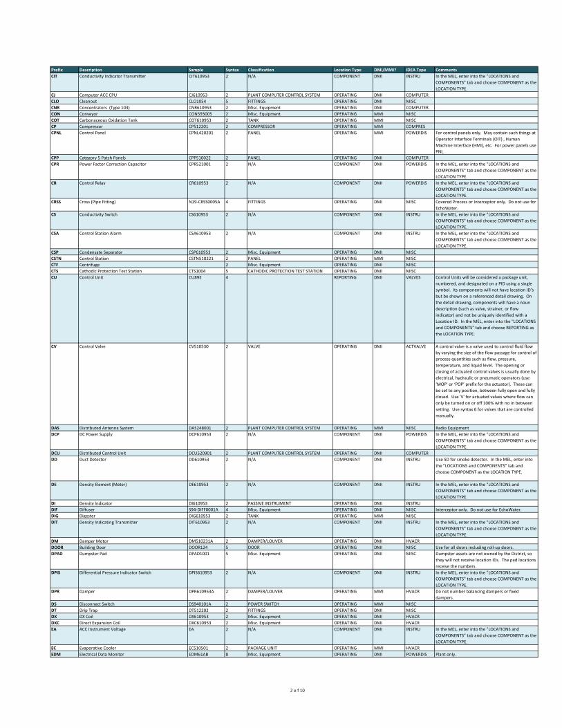
Prefix Description Sample Syntax Classification Location Type DMI/MMI? IDEA Type Comments
CIT Conductivity Indicator Transmitter CIT610953 2 N/A COMPONENT DMI INSTRU In the MEL, enter into the "LOCATIONS and
COMPONENTS" tab and choose COMPONENT as the
LOCATION TYPE.
CJ Computer ACC CPU CJ610953 2 PLANT COMPUTER CONTROL SYSTEM OPERATING DMI COMPUTER
CLO Cleanout CLO1054 5 FITTINGS OPERATING DMI MISC
CNR Concentrators (Type 103) CNR610953 2 Misc. Equipment OPERATING DMI COMPUTER
CON Conveyor CON593005 2 Misc. Equipment OPERATING MMI MISC
COT Carbonaceous Oxidation Tank COT610953 2 TANK OPERATING MMI MISC
CP Compressor CP512201 2 COMPRESSOR OPERATING MMI COMPRES
CPNL Control Panel CPNL420201 2 PANEL OPERATING MMI POWERDIS For control panels only. May contain such things at
Operator Interface Terminals (OIT) , Human
Machine Interface (HMI), etc. For power panels use
PNL.
CPP Category 5 Patch Panels CPP510022 2 PANEL OPERATING DMI COMPUTER
CPR Power Factor Correction Capacitor CPR521001 2 N/A COMPONENT DMI POWERDIS In the MEL, enter into the "LOCATIONS and
COMPONENTS" tab and choose COMPONENT as the
LOCATION TYPE.
CR Control Relay CR610953 2 N/A COMPONENT DMI POWERDIS In the MEL, enter into the "LOCATIONS and
COMPONENTS" tab and choose COMPONENT as the
LOCATION TYPE.
CRSS Cross (Pipe Fitting) N19-CRSS0005A 4 FITTINGS OPERATING DMI MISC Covered Process or Interceptor only. Do not use for
EchoWater.
CS Conductivity Switch CS610953 2 N/A COMPONENT DMI INSTRU In the MEL, enter into the "LOCATIONS and
COMPONENTS" tab and choose COMPONENT as the
LOCATION TYPE.
CSA Control Station Alarm CSA610953 2 N/A COMPONENT DMI INSTRU In the MEL, enter into the "LOCATIONS and
COMPONENTS" tab and choose COMPONENT as the
LOCATION TYPE.
CSP Condensate Separator CSP610953 2 Misc. Equipment OPERATING DMI MISC
CSTN Control Station CSTN510221 2 PANEL OPERATING MMI MISC
CTF Centrifuge 2 Misc. Equipment OPERATING DMI MISC
CTS Cathodic Protection Test Station CTS1004 5 CATHODIC PROTECTION TEST STATION OPERATING DMI MISC
CU Control Unit CU89E 4 REPORTING DMI VALVES Control Units will be considered a package unit,
numbered, and designated on a PID using a single
symbol. Its components will not have location ID’s
but be shown on a referenced detail drawing. On
the detail drawing, components will have a noun
description (such as valve, strainer, or flow
indicator) and not be uniquely identified with a
Location ID. In the MEL, enter into the "LOCATIONS
and COMPONENTS" tab and choose REPORTING as
the LOCATION TYPE.
CV Control Valve CV510530 2 VALVE OPERATING DMI ACTVALVE A control valve is a valve used to control fluid flow
by varying the size of the flow passage for control of
process quantities such as flow, pressure,
temperature, and liquid level. The opening or
closing of actuated control valves is usually done by
electrical, hydraulic or pneumatic operators (use
‘MOP’ or ‘POP’ prefix for the actuator). These can
be set to any position, between fully open and fully
closed. Use 'V' for actuated valves where flow can
only be turned on or off 100% with no in between
setting. Use syntax 6 for valves that are controlled
manually.
DAS Distributed Antenna System DAS248001 2 PLANT COMPUTER CONTROL SYSTEM OPERATING MMI MISC Radio Equipment
DCP DC Power Supply DCP610953 2 N/A COMPONENT DMI POWERDIS In the MEL, enter into the "LOCATIONS and
COMPONENTS" tab and choose COMPONENT as the
LOCATION TYPE.
DCU Distributed Control Unit DCU520901 2 PLANT COMPUTER CONTROL SYSTEM OPERATING DMI COMPUTER
DD Duct Detector DD610953 2 N/A COMPONENT DMI INSTRU Use SD for smoke detector. In the MEL, enter into
the "LOCATIONS and COMPONENTS" tab and
choose COMPONENT as the LOCATION TYPE.
DE Density Element (Meter) DE610953 2 N/A COMPONENT DMI INSTRU In the MEL, enter into the "LOCATIONS and
COMPONENTS" tab and choose COMPONENT as the
LOCATION TYPE.
DI Density Indicator DI610953 2 PASSIVE INSTRUMENT OPERATING DMI INSTRU
DIF Diffuser S94-DIFF0001A 4 Misc. Equipment OPERATING DMI MISC Interceptor only. Do not use for EchoWater.
DIG Digester DIG610953 2 TANK OPERATING MMI MISC
DIT Density Indicating Transmitter DIT610953 2 N/A COMPONENT DMI INSTRU In the MEL, enter into the "LOCATIONS and
COMPONENTS" tab and choose COMPONENT as the
LOCATION TYPE.
DM Damper Motor DM510231A 2 DAMPER/LOUVER OPERATING DMI HVACR
DOOR Building Door DOOR124 5 DOOR OPERATING DMI MISC Use for all doors including roll-up doors.
DPAD Dumpster Pad DPAD1001 5 Misc. Equipment OPERATING DMI MISC Dumpster assets are not owned by the District, so
they will not receive location IDs. The pad locations
receive the numbers.
DPIS Differential Pressure Indicator Switch DPIS610953 2 N/A COMPONENT DMI INSTRU In the MEL, enter into the "LOCATIONS and
COMPONENTS" tab and choose COMPONENT as the
LOCATION TYPE.
DPR Damper DPR610953A 2 DAMPER/LOUVER OPERATING MMI HVACR Do not number balancing dampers or fixed
dampers.
DS Disconnect Switch DS940101A 2 POWER SWITCH OPERATING MMI MISC
DT Drip Trap DT512202 2 FITTINGS OPERATING DMI MISC
DX DX Coil DX610953 2 Misc. Equipment OPERATING DMI HVACR
DXC Direct Expansion Coil DXC610953 2 Misc. Equipment OPERATING DMI HVACR
EA ACC Instrument Voltage EA 2 N/A COMPONENT DMI INSTRU In the MEL, enter into the "LOCATIONS and
COMPONENTS" tab and choose COMPONENT as the
LOCATION TYPE.
EC Evaporative Cooler EC510501 2 PACKAGE UNIT OPERATING MMI HVACR
EDM Electrical Data Monitor EDM61AB 8 Misc. Equipment OPERATING DMI POWERDIS Plant only.
2 o f 10

Prefix Description Sample Syntax Classification Location Type DMI/MMI? IDEA Type Comments
EE Voltage Sensor EE610953 2 N/A COMPONENT DMI INSTRU In the MEL, enter into the "LOCATIONS and
COMPONENTS" tab and choose COMPONENT as the
LOCATION TYPE.
EH Electric Heater EH610953 2 Misc. Equipment OPERATING DMI HVACR
ELC Ethernet Link Controller ELC529005A 2 N/A COMPONENT DMI COMPUTER Plant only. In the MEL, enter into the "LOCATIONS
and COMPONENTS" tab and choose COMPONENT
as the LOCATION TYPE.
EP Electro-Pneumatic Switch EP610953 2 POWER SWITCH OPERATING DMI HVACR
ESH Voltage Switch High ESH610953 2 POWER SWITCH OPERATING DMI INSTRU
ESL Voltage Switch Low ESL610953 2 POWER SWITCH OPERATING DMI INSTRU
ETH Ethernet Switches ETH610003A 2 PLANT COMPUTER CONTROL SYSTEM OPERATING DMI COMPUTER Plant only.
EY Voltage Isolator EY610953 2 N/A COMPONENT DMI INSTRU In the MEL, enter into the "LOCATIONS and
COMPONENTS" tab and choose COMPONENT as the
LOCATION TYPE.
FB Fire Bell/Strobe FB970021A 2 Misc. Equipment OPERATING DMI FIREPRO Shares Core with FSS
FC Flow Control FC610953 2 N/A COMPONENT DMI INSTRU In the MEL, enter into the "LOCATIONS and
COMPONENTS" tab and choose COMPONENT as the
LOCATION TYPE.
FD Fire Damper FD610953 2 DAMPER/LOUVER OPERATING MMI FIREPRO
FDR Feeder Cable from Breaker FDR61AB 8 Misc. Equipment OPERATING MMI POWERDIS
FE Flow Element (Meter) FE610101 2 ACTIVE INSTRUMENT OPERATING DMI INSTRU
FEB Fire Extinguisher Bracket (Hanger) FEB1636 5 Misc. Equipment OPERATING DMI FIREPRO
FFIC Flow Ratio Indicating Controller FFIC610953 2 N/A COMPONENT DMI INSTRU In the MEL, enter into the "LOCATIONS and
COMPONENTS" tab and choose COMPONENT as the
LOCATION TYPE.
FFK Flow Ratio Control Station FFK610953 2 N/A COMPONENT DMI INSTRU In the MEL, enter into the "LOCATIONS and
COMPONENTS" tab and choose COMPONENT as the
LOCATION TYPE.
FG Flap Gate FG610953 2 GATES OPERATING DMI VALVES
FH Fire Hydrant FH1025 5 VALVE OPERATING DMI FIREPRO Number wharf hydrants as syntax 6 (valves).
FHD Fume Hood FHD610953 2 Misc. Equipment OPERATING DMI HVACR
FI Flow Indicator FI510530 2 PASSIVE INSTRUMENT OPERATING DMI INSTRU Includes rotameters.
FIC Flow Indicator Controller FIC610953 2 N/A COMPONENT DMI INSTRU In the MEL, enter into the "LOCATIONS and
COMPONENTS" tab and choose COMPONENT as the
LOCATION TYPE.
FIR Flow Indicator Recorder FIR610953 2 N/A COMPONENT DMI INSTRU In the MEL, enter into the "LOCATIONS and
COMPONENTS" tab and choose COMPONENT as the
LOCATION TYPE.
FIT Flow Indicator Transmitter FIT610101 2 ACTIVE INSTRUMENT OPERATING MMI INSTRU
FLP Fluid Power Unit FLP610953 2 GATES OPERATING MMI PUMPS
FLTA Filter, Air FLTA512201 2 FILTER OPERATING MMI HVACR For HVAC use only
FLTM Filter, Not Air FLTM512203A 2 FILTER OPERATING MMI MISC All other filter types (not HVAC)
FMC Fiber Optic Media Convertor FMC515000A 2 PLANT COMPUTER CONTROL SYSTEM OPERATING DMI COMPUTER Also see FOC (Fiber Optic Convertor).
FMT Force Main Transmission Line FMT610953 2 PIPELINES OPERATING MMI MISC Interceptor or Harvest Water use only. Do not use
for EchoWater.
FMX Flash Mixer FMX44910 2 MIXER OPERATING DMI DRIVES
FN Fan FN610957 2 FAN OPERATING DMI HVACR Add a separate equipment number for the motor
using the same core number if the motor is over 5
horsepower.
FOP Fiber Optic Panel FOP610001 2 PANEL OPERATING DMI COMPUTER
FPR Fault/Feeder Protection Relay FPR52A 7 N/A COMPONENT DMI POWERDIS In the MEL, enter into the "LOCATIONS and
COMPONENTS" tab and choose COMPONENT as the
LOCATION TYPE.
FRS Freezestat FRS610953 2 N/A COMPONENT DMI HVACR In the MEL, enter into the "LOCATIONS and
COMPONENTS" tab and choose COMPONENT as the
LOCATION TYPE.
FRZ Freeze Protection Switch FRZ610953 2 POWER SWITCH OPERATING DMI HVACR
FS Flow Switch FS610953 2 N/A COMPONENT DMI INSTRU In the MEL, enter into the "LOCATIONS and
COMPONENTS" tab and choose COMPONENT as the
LOCATION TYPE.
FSD Fire Smoke Damper FSD24 5 DAMPER/LOUVER OPERATING MMI FIREPRO
FSH Flow Switch High FSH515009A 2 N/A COMPONENT DMI INSTRU In the MEL, enter into the "LOCATIONS and
COMPONENTS" tab and choose COMPONENT as the
LOCATION TYPE.
FSL Flow Switch Low FSL510019 2 N/A COMPONENT DMI INSTRU In the MEL, enter into the "LOCATIONS and
COMPONENTS" tab and choose COMPONENT as the
LOCATION TYPE.
FSS Fire Sprinkler System FSS610953 2 Misc. Equipment OPERATING MMI FIREPRO Use for fire riser assemblies. Do not assign tag
numbers to individual components.
FSV Flow Straightening Vane FSV595068 2 VALVE OPERATING DMI HVACR
FT Flow Transmitter FT610953 2 N/A COMPONENT DMI INSTRU In the MEL, enter into the "LOCATIONS and
COMPONENTS" tab and choose COMPONENT as the
LOCATION TYPE.
FTH Flow Transmitter High FTH610953 2 N/A COMPONENT DMI HVACR In the MEL, enter into the "LOCATIONS and
COMPONENTS" tab and choose COMPONENT as the
LOCATION TYPE.
FX Flow Conditioner FX610953 2 N/A COMPONENT DMI INSTRU In the MEL, enter into the "LOCATIONS and
COMPONENTS" tab and choose COMPONENT as the
LOCATION TYPE.
FY Flow Solenoid/Relay/Accumulator FY610953 2 N/A COMPONENT DMI INSTRU In the MEL, enter into the "LOCATIONS and
COMPONENTS" tab and choose COMPONENT as the
LOCATION TYPE.
G Gate (power actuated) G510012 2 GATES or VALVE OPERATING MMI ACTVALVE
GBT Gravity Belt Thickener GBT610953 2 Misc. Equipment OPERATING DMI MISC
GDR Grinder GDR610953 2 GRINDER OPERATING MMI MISC
GEN Generator GEN610953 2 GENERATOR OPERATING DMI POWERDIS
GF Grease Filter GF610953 2 FILTER OPERATING DMI MISC Interceptor only. Do not use for EchoWater.
GO Gate Operator GO1003 5 VALVE OPERATOR OPERATING MMI SECURITY
GRT Grit Tank / Gravity Transmission Line N21-GRT0004A 5 PIPELINES or TANK OPERATING MMI MISC
HC Heating Coil HC610953 2 IMMERSION HEATER OPERATING DMI HVACR
HEX Heat Exchanger HEX521001 2 HEAT EXCHANGER OPERATING MMI HVACR
3 o f 10

Prefix Description Sample Syntax Classification Location Type DMI/MMI? IDEA Type Comments
HH Handhole (electrical) HH100162 5 MANHOLE or Misc. Equipment OPERATING DMI POWERDIS Electrical boxes in the ground shall use 'HH'. Above
ground electrical boxes shall use ‘PB’ Pullbox syntax
4. Larger electrical vaults which allow human entry
would be considered ‘MH’ Manhole syntax 5.
HIC Hand Indicator Controller HIC610953 2 N/A COMPONENT DMI INSTRU In the MEL, enter into the "LOCATIONS and
COMPONENTS" tab and choose COMPONENT as the
LOCATION TYPE.
HIK Hand Indicator Control Station (Switch) HIK610953 2 N/A COMPONENT DMI INSTRU In the MEL, enter into the "LOCATIONS and
COMPONENTS" tab and choose COMPONENT as the
LOCATION TYPE.
HIT Humidity Indicator Transmitter HIT598013 2 N/A COMPONENT DMI MISC In the MEL, enter into the "LOCATIONS and
COMPONENTS" tab and choose COMPONENT as the
LOCATION TYPE.
HK Hand Control Station (switch) HK610953 2 N/A COMPONENT DMI INSTRU In the MEL, enter into the "LOCATIONS and
COMPONENTS" tab and choose COMPONENT as the
LOCATION TYPE.
HLS Hand Light Switch (DCSA) HLS610953 2 N/A OPERATING DMI INSTRU In the MEL, enter into the "LOCATIONS and
COMPONENTS" tab and choose COMPONENT as the
LOCATION TYPE.
HMD Humidifier HMD610953 2 Misc. Equipment OPERATING DMI HVACR
HMS Humidistat HMS610953 2 N/A COMPONENT DMI HVACR In the MEL, enter into the "LOCATIONS and
COMPONENTS" tab and choose COMPONENT as the
LOCATION TYPE.
HOP Hydraulic Operator HOP610953 2 VALVE OPERATOR OPERATING DMI INSTRU
HP Heat Pump HP520021 2 AIR HANDLER or PACKAGE UNIT OPERATING MMI HVACR
HS Hand Switch HS390101A 2 N/A COMPONENT DMI INSTRU In the MEL, enter into the "LOCATIONS and
COMPONENTS" tab and choose COMPONENT as the
LOCATION TYPE.
HTR Heater HTR597042 2 IMMERSION HEATER OPERATING DMI HVACR
HUB Hub (type 103) HUB610953 2 Misc. Equipment OPERATING DMI COMPUTER
HYD Hydraulic Unit HYD610953 2 Misc. Equipment OPERATING DMI PUMPS
IE Current Sensor (Primary Element) IE610953 2 N/A COMPONENT DMI INSTRU In the MEL, enter into the "LOCATIONS and
COMPONENTS" tab and choose COMPONENT as the
LOCATION TYPE.
IG Ignitor IG610953 2 Misc. Equipment OPERATING DMI MISC
II Current Indicator II610953 2 PASSIVE INSTRUMENT OPERATING DMI INSTRU
IR Inlet Relief (Roof Hood) IR610953 2 Misc. Equipment OPERATING DMI HVACR
ISH Absolute Signal Trip ISH610953 2 N/A COMPONENT DMI INSTRU In the MEL, enter into the "LOCATIONS and
COMPONENTS" tab and choose COMPONENT as the
LOCATION TYPE.
ISY Current Safety Isolator ISY610953 2 N/A COMPONENT DMI INSTRU In the MEL, enter into the "LOCATIONS and
COMPONENTS" tab and choose COMPONENT as the
LOCATION TYPE.
IT Current Transmitter IT610953 2 N/A COMPONENT DMI INSTRU In the MEL, enter into the "LOCATIONS and
COMPONENTS" tab and choose COMPONENT as the
LOCATION TYPE.
ITE Current Transmitter Element ITE610953 2 N/A COMPONENT DMI INSTRU In the MEL, enter into the "LOCATIONS and
COMPONENTS" tab and choose COMPONENT as the
LOCATION TYPE.
IY Current Relay or Isolator IY610953 2 N/A COMPONENT DMI INSTRU In the MEL, enter into the "LOCATIONS and
COMPONENTS" tab and choose COMPONENT as the
LOCATION TYPE.
JE Power Primary Element JE610953 2 N/A COMPONENT DMI INSTRU In the MEL, enter into the "LOCATIONS and
COMPONENTS" tab and choose COMPONENT as the
LOCATION TYPE.
JI Power Indicator JI610953 2 PASSIVE INSTRUMENT OPERATING DMI INSTRU
JIC Power Indicating Controller JIC610953 2 N/A COMPONENT DMI INSTRU In the MEL, enter into the "LOCATIONS and
COMPONENTS" tab and choose COMPONENT as the
LOCATION TYPE.
JNT Joint, Pipe N19-JNT0005C 5 FITTINGS OPERATING DMI MISC Covered Process or Interceptor only. Do not use for
EchoWater.
JSL Power Surge Monitor JSL610953 2 Misc. Equipment OPERATING DMI POWERDIS
JT Power Transmitter JT610953 2 N/A COMPONENT DMI INSTRU In the MEL, enter into the "LOCATIONS and
COMPONENTS" tab and choose COMPONENT as the
LOCATION TYPE.
JX Power Supply JX610953 2 N/A COMPONENT DMI INSTRU In the MEL, enter into the "LOCATIONS and
COMPONENTS" tab and choose COMPONENT as the
LOCATION TYPE.
KS Timer Switch KS610953 2 N/A COMPONENT DMI INSTRU In the MEL, enter into the "LOCATIONS and
COMPONENTS" tab and choose COMPONENT as the
LOCATION TYPE.
KWH Kilowatt Hour Meter (Plant Meter) KWH610953 2 N/A COMPONENT DMI POWERDIS In the MEL, enter into the "LOCATIONS and
COMPONENTS" tab and choose COMPONENT as the
LOCATION TYPE.
KY Time Relay KY610953 2 N/A COMPONENT DMI INSTRU In the MEL, enter into the "LOCATIONS and
COMPONENTS" tab and choose COMPONENT as the
LOCATION TYPE.
LA Level Alarm (Light or Sound) LA610953 2 N/A COMPONENT DMI INSTRU In the MEL, enter into the "LOCATIONS and
COMPONENTS" tab and choose COMPONENT as the
LOCATION TYPE.
LB Load Bank LB610953 2 Misc. Equipment OPERATING DMI POWERDIS
LC Level Controller LC610953 2 N/A COMPONENT DMI INSTRU In the MEL, enter into the "LOCATIONS and
COMPONENTS" tab and choose COMPONENT as the
LOCATION TYPE.
LDIT Level Differential Indicating Transmitter LDIT593003 2 ACTIVE INSTRUMENT OPERATING DMI MISC
LDR Ladder LDR1194 5 MMI MISC In the MEL, enter into the "LOCATIONS and
COMPONENTS" tab and choose COMPONENT as the
LOCATION TYPE.
LDSH Level Differential Switch High LDSH593003 2 N/A COMPONENT DMI MISC In the MEL, enter into the "LOCATIONS and
COMPONENTS" tab and choose COMPONENT as the
LOCATION TYPE.
LE Level Element LE610201 2 ACTIVE INSTRUMENT OPERATING DMI INSTRU
4 o f 10

Prefix Description Sample Syntax Classification Location Type DMI/MMI? IDEA Type Comments
LI Level Indicator LI515001 2 PASSIVE INSTRUMENT OPERATING DMI INSTRU
LIC Level Indicator Controller LIC610953 2 N/A COMPONENT DMI INSTRU In the MEL, enter into the "LOCATIONS and
COMPONENTS" tab and choose COMPONENT as the
LOCATION TYPE.
LIT Level Indicator Transmitter LIT610201 2 ACTIVE INSTRUMENT OPERATING MMI INSTRU
LR Level Recording LR610953 2 N/A COMPONENT DMI INSTRU In the MEL, enter into the "LOCATIONS and
COMPONENTS" tab and choose COMPONENT as the
LOCATION TYPE.
LS Level Switch LS595014 2 ACTIVE INSTRUMENT OPERATING DMI INSTRU
LSH Level Switch High LSH940401 2 N/A COMPONENT DMI INSTRU In the MEL, enter into the "LOCATIONS and
COMPONENTS" tab and choose COMPONENT as the
LOCATION TYPE.
LSHH Level Switch High High LSHH610201 2 N/A COMPONENT DMI INSTRU In the MEL, enter into the "LOCATIONS and
COMPONENTS" tab and choose COMPONENT as the
LOCATION TYPE.
LSL Level Switch Low LSL510210 2 N/A COMPONENT DMI INSTRU In the MEL, enter into the "LOCATIONS and
COMPONENTS" tab and choose COMPONENT as the
LOCATION TYPE.
LSLL Level Switch Low Low LSLL940401 2 N/A COMPONENT DMI INSTRU In the MEL, enter into the "LOCATIONS and
COMPONENTS" tab and choose COMPONENT as the
LOCATION TYPE.
LT Level Transmitter LT610953 2 N/A COMPONENT DMI INSTRU In the MEL, enter into the "LOCATIONS and
COMPONENTS" tab and choose COMPONENT as the
LOCATION TYPE.
LTG Emergency Lights LTG610953 2 N/A COMPONENT DMI POWERDIS In the MEL, enter into the "LOCATIONS and
COMPONENTS" tab and choose COMPONENT as the
LOCATION TYPE.
LV Louver LV610951 2 DAMPER/LOUVER OPERATING DMI HVACR Do not number fixed louvers.
LVBD Low Voltage Bus Duct LVBD59A 2 BUS OPERATING DMI MISC Interceptor only.
LY Level Relay LY610953 2 N/A COMPONENT DMI INSTRU In the MEL, enter into the "LOCATIONS and
COMPONENTS" tab and choose COMPONENT as the
LOCATION TYPE.
LYH Level Relay High LYH610953 2 N/A COMPONENT DMI INSTRU In the MEL, enter into the "LOCATIONS and
COMPONENTS" tab and choose COMPONENT as the
LOCATION TYPE.
LYHH Level Relay High High LYHH610953 2 N/A COMPONENT DMI INSTRU In the MEL, enter into the "LOCATIONS and
COMPONENTS" tab and choose COMPONENT as the
LOCATION TYPE.
LYL Level Relay Low LYL610953 2 N/A COMPONENT DMI INSTRU In the MEL, enter into the "LOCATIONS and
COMPONENTS" tab and choose COMPONENT as the
LOCATION TYPE.
LYLL Level Relay Low Low LYLL610953 2 N/A COMPONENT DMI INSTRU In the MEL, enter into the "LOCATIONS and
COMPONENTS" tab and choose COMPONENT as the
LOCATION TYPE.
M Motor M980058A 2 MOTOR OPERATING MMI MOTORS
MBKR Main Breaker MBKR61A 8 BREAKER OPERATING MMI POWERDIS
MC Magnetic Clutch MC610953 2 MOTOR DRIVE OPERATING MMI DRIVES
MCC Motor Control Center MCC61A1 8 MOTOR CONTROL CENTER OPERATING MMI POWERDIS
MD Air Flow Measuring Station, Motorized Damper MD610953 2 DAMPER/LOUVER OPERATING DMI HVACR
ME Mobile Equipment ME1003 5 Misc. Equipment OPERATING MMI MOBILE Use for mechanical mobile equipment. For mobile
testing equipment for Control Systems/Electrical
Shop (CES), use CES.
MEE Miscellaneous Electrical Equipment MEE940100 2 Misc. Equipment OPERATING DMI POWERDIS
MFU Microfiltration Unit MFU610953 2 FILTER OPERATING DMI MISC
MH Electrical Manhole/ Interceptor Manhole MH100 5 MANHOLE OPERATING DMI MISC For small electrical vaults which do not allow for
human entry use 'HH' Handhole syntax 5.
MIT Moisture Indicator Transmitter MIT610953 2 ACTIVE INSTRUMENT OPERATING DMI INSTRU
MM Micro-Meterological Station MM610953 2 N/A COMPONENT DMI INSTRU In the MEL, enter into the "LOCATIONS and
COMPONENTS" tab and choose COMPONENT as the
LOCATION TYPE.
MME Miscellaneous Mechanical Equipment MME44942 2 Misc. Equipment or VARIES OPERATING DMI MISC Includes: Drinking Fountains, Emergency Eyewash
Shower assemblies (The eyewash shower has only a
single location ID. Only a single isolation valve is
numbered as this is needed for LTV description.
There are additional valves and items within
eyewash shower but they are not tagged).
MNTR MONITOR VALVE MNTR610953 2 VALVE OPERATING DMI ACTVALVE
MOP Motor Operator MOP390101 2 ACTUATOR OPERATING DMI ACTVALVE For motor operated, controlled, or actuated
equipment which use an electric or hydraulic motor.
Assign a 'MOP' number to the actuator portion of
the valve assembly. If driving a valve, the valve
being driven will get a separate 'V' or 'CV' number,
depending on the use.
MPC Mini Power Center MPC595017 2 Misc. Equipment OPERATING DMI POWERDIS
MPR Motor Protection Relay MPR52A3 7 Misc. Equipment OPERATING DMI POWERDIS
MSE Moisture Element MSE51056 2 ACTIVE INSTRUMENT OPERATING DMI INSTRU
MSH Moisture Switch High MSH510019 2 N/A COMPONENT DMI INSTRU In the MEL, enter into the "LOCATIONS and
COMPONENTS" tab and choose COMPONENT as the
LOCATION TYPE.
MSL Moisture Switch Low MSL610953 2 N/A COMPONENT DMI INSTRU In the MEL, enter into the "LOCATIONS and
COMPONENTS" tab and choose COMPONENT as the
LOCATION TYPE.
MT Moisture Transmitter MT510273 2 N/A COMPONENT DMI INSTRU In the MEL, enter into the "LOCATIONS and
COMPONENTS" tab and choose COMPONENT as the
LOCATION TYPE.
MVBD Medium Voltage Bus Duct MVBD610953 2 BUS OPERATING DMI MISC Interceptor only. Do not use for EchoWater.
MW Monitoring Well MW1002 5 Misc. Equipment OPERATING DMI MISC
MX Mixer MX440101 2 MIXER OPERATING MMI MISC
NST Nitrifying Sidestream Treatment Basin NST590027 2 Misc. Equipment OPERATING MMI MISC (District Use Only)
NGR Neutral Ground Relay NGR52A 7 Misc. Equipment OPERATING DMI POWERDIS
OCC Odor Control Canister OCC610953 2 Misc. Equipment OPERATING DMI MISC
5 o f 10

Prefix Description Sample Syntax Classification Location Type DMI/MMI? IDEA Type Comments
OCU Odor Control Unit OCU610953 2 TANK OPERATING MMI MISC
ORF Orifice, Piping N19-ORF0005A 4 FITTINGS OPERATING DMI MISC
ORT Odor Reduction (Removal) Tower ORT610953 2 Misc. Equipment OPERATING DMI MISC
P Pump P44920 2 PUMP OPERATING MMI PUMPS
PAS Voice Paging Horn/Speaker PAS510137 2 Misc. Equipment OPERATING DMI PUBLADDR
PB Pullbox (Electrical) PB51A 4 MANHOLE OPERATING DMI MISC For large electrical boxes which are above ground,
use ‘PB’ Pullbox. Electrical boxes in the ground
should use ‘HH’ Handhole syntax 5. Condulets or
small boxes that are used for conduit connections
and cable routing use 'JB' Junction Box and are not
included in the MEL.
PBUS Profibus PBUS610057A 2 BUS OPERATING DMI COMPUTER Converter.
PC Computer PC610953 2 PLANT COMPUTER CONTROL SYSTEM OPERATING DMI COMPUTER
PCV Pressure Control Valve PCV510016 2 VALVE OPERATING DMI ACTVALVE
PDI Pressure Differential Indicator PDI521001A 2 PASSIVE INSTRUMENT OPERATING DMI INSTRU
PDIC Pressure Differential Indicator Controller PDIC610953 2 N/A COMPONENT DMI INSTRU In the MEL, enter into the "LOCATIONS and
COMPONENTS" tab and choose COMPONENT as the
LOCATION TYPE.
PDIT Pressure Differential Indicator Transmitter PDIT521001A 2 ACTIVE INSTRUMENT OPERATING DMI INSTRU
PDM Power Data Monitor PDM610953 Misc. Equipment OPERATING DMI POWERDIS
PDS Pressure Differential Switch PDS610953 2 N/A COMPONENT DMI INSTRU In the MEL, enter into the "LOCATIONS and
COMPONENTS" tab and choose COMPONENT as the
LOCATION TYPE.
PDSH Pressure Differential Switch High (High/Low) PDSH510214 2 N/A COMPONENT DMI INSTRU In the MEL, enter into the "LOCATIONS and
COMPONENTS" tab and choose COMPONENT as the
LOCATION TYPE.
PDSL Pressure Differential Switch Low PDSL610953 2 N/A COMPONENT DMI INSTRU In the MEL, enter into the "LOCATIONS and
COMPONENTS" tab and choose COMPONENT as the
LOCATION TYPE.
PE Pressure Element PE610953 2 ACTIVE INSTRUMENT OPERATING DMI INSTRU
PET Plant Emergency Trip PET610953 2 PLANT COMPUTER CONTROL SYSTEM OPERATING DMI MISC
PI Pressure Indicator PI610701B 2 PASSIVE INSTRUMENT OPERATING DMI INSTRU
PIC Pressure Indicator Controller PIC610953 2 N/A COMPONENT DMI INSTRU In the MEL, enter into the "LOCATIONS and
COMPONENTS" tab and choose COMPONENT as the
LOCATION TYPE.
PIT Pressure Indicator Transmitter PIT510201 2 ACTIVE INSTRUMENT OPERATING MMI INSTRU
PIV Post Indicator Valve PIV610953 2 VALVE OPERATING DMI FIREPRO
PLC Programmable Logic Controller (type 104) PLC610009 2 PROGRAMABLE LOGIC CONTROLLER OPERATING MMI COMPUTER
PLUG Plug/Cap N17-PLUG0026C 4 FITTINGS OPERATING DMI MISC Covered Process or Interceptor only. Do not use for
EchoWater.
PMH Process Manhole PMH48A 4 MANHOLE OPERATING DMI MISC
PNL Electrical Panel PNL61A1B 8 PANEL OPERATING DMI POWERDIS
PNST Pneumatic Signal Transmitter PNST610953 2 N/A COMPONENT DMI HVACR In the MEL, enter into the "LOCATIONS and
COMPONENTS" tab and choose COMPONENT as the
LOCATION TYPE.
POP Pneumatic Operator POP610001 2 ACTUATOR OPERATING MMI ACTVALVE For pneumatically operated, controlled, or actuated
equipment. Air (or other gas) pressure is the power
source for pneumatic operators. If driving a valve,
the valve being driven will get a separate 'V' or 'CV'
number, depending on the use.
PRT Printer PRT520926 2 Misc. Equipment OPERATING DMI COMPUTER
PRV Pressure Relief Valve PRV390101 2 RELIEF DEVICE OPERATING DMI VALVES
PS Pressure Switch PS610953 2 ACTIVE INSTRUMENT OPERATING DMI INSTRU
PSH Pressure Switch High PSH610228 2 N/A COMPONENT DMI INSTRU In the MEL, enter into the "LOCATIONS and
COMPONENTS" tab and choose COMPONENT as the
LOCATION TYPE.
PSHH Pressure Switch High High PSHH610953 2 N/A COMPONENT DMI INSTRU In the MEL, enter into the "LOCATIONS and
COMPONENTS" tab and choose COMPONENT as the
LOCATION TYPE.
PSHL Pressure Switch High Low PSHL610953 2 N/A COMPONENT DMI INSTRU In the MEL, enter into the "LOCATIONS and
COMPONENTS" tab and choose COMPONENT as the
LOCATION TYPE.
PSL Pressure Switch Low PSL510202 2 N/A COMPONENT DMI INSTRU In the MEL, enter into the "LOCATIONS and
COMPONENTS" tab and choose COMPONENT as the
LOCATION TYPE.
PSLL Pressure Switch Low Low PSLL512204 2 N/A COMPONENT DMI INSTRU In the MEL, enter into the "LOCATIONS and
COMPONENTS" tab and choose COMPONENT as the
LOCATION TYPE.
PST Primary Sedimentation Tank PST610953 2 TANK OPERATING MMI MISC
PT Pressure Transmitter PT610953 2 ACTIVE INSTRUMENT OPERATING DMI INSTRU
PTR Printer (type 105) PTR590005 2 Misc. Equipment OPERATING DMI COMPUTER
PVU Panelview PVU520014 2 VIDEO EQUIPMENT OPERATING DMI COMPUTER
PY Pressure Converter (Relay) PY610953 2 N/A COMPONENT DMI INSTRU In the MEL, enter into the "LOCATIONS and
COMPONENTS" tab and choose COMPONENT as the
LOCATION TYPE.
RC Pneumatic Receiver Controller RC610953 2 N/A COMPONENT DMI HVACR In the MEL, enter into the "LOCATIONS and
COMPONENTS" tab and choose COMPONENT as the
LOCATION TYPE.
RCK Rack, Computer Equipment RCK610017 2 Misc. Equipment OPERATING DMI COMPUTER
RECP Receptacle (480V) RECP610010A 2 Misc. Equipment OPERATING DMI POWERDIS
RED Reducer, Piping N18-RED0103A 4 FITTINGS OPERATING DMI MISC Covered Process or Interceptor only. Do not use for
EchoWater.
RG Roller Gate RG510116 2 GATES OPERATING MMI SLIDEGA Typically very large gates with rollers added or
removed by cranes. Gate is removed from its frame
when open. Stop gates, stop plates and other types
can also fall under this prefix if they have rollers. If
there are no rollers, use SLG.
RLY Current Relay RLY610953 2 N/A COMPONENT DMI POWERDIS In the MEL, enter into the "LOCATIONS and
COMPONENTS" tab and choose COMPONENT as the
LOCATION TYPE.
6 o f 10

Prefix Description Sample Syntax Classification Location Type DMI/MMI? IDEA Type Comments
ROAD Road Service ROAD1075 5 SRWTP ROAD OPERATING MMI MISC (SF of pavement)/(1000*pave width) = x units. Give
1 number per unit.
ROOF Building Roof ROOF100203 5 ROOF OPERATING MMI MISC Roof number should be the same as the building
number.
ROOM Building Room ROOM1002 5 STRUCTURE OPERATING DMI MISC
ROU Remote Optical Unit ROU248001 2 ACTIVE INSTRUMENT OPERATING DMI MISC Radio Equipment
RR Rail Yard Track RR610953 2 Misc. Equipment OPERATING DMI MISC
RTR Router RTR590002A 2 PLANT COMPUTER CONTROL SYSTEM OPERATING DMI COMPUTER Includes modems (type 103)
RTU Remote Telemetry Unit RTU610953 2 N/A COMPONENT DMI MISC In the MEL, enter into the "LOCATIONS and
COMPONENTS" tab and choose COMPONENT as the
LOCATION TYPE.
RU Relay Unit RU610953 2 N/A COMPONENT DMI FIREPRO In the MEL, enter into the "LOCATIONS and
COMPONENTS" tab and choose COMPONENT as the
LOCATION TYPE.
RVSS Reduced Voltage Solid State (Soft Start) 7 RVSS OPERATING DMI POWERDIS
S Silencer S520230 2 Misc. Equipment OPERATING DMI MISC
SAR Surface Aerator SAR610953 2 AERATOR OPERATING MMI MISC
SBR Scrubber SBR610955 2 PRESSURE VESSEL OPERATING MMI MISC Use for positive pressurization units.
SC Speed Controller SC610953 2 MOTOR DRIVE OPERATING DMI INSTRU
SCR Solid State Controller SCR610953 2 N/A COMPONENT DMI HVACR In the MEL, enter into the "LOCATIONS and
COMPONENTS" tab and choose COMPONENT as the
LOCATION TYPE.
SCRN Screen (Fixed or Rotary) SCRN593003 2 SCREEN OPERATING DMI MISC
SCS Signal Coupler/Splitter SCS1001 5 ACTIVE INSTRUMENT OPERATING DMI MISC Radio Equipment
SD Smoke Detector SD610958A 2 ACTIVE INSTRUMENT OPERATING MMI FIREPRO Use DD for duct detector.
SDM Switchgear Data Monitor SDM61A 7 Misc. Equipment OPERATING DMI POWERDIS
SE Speed Element SE610953 2 N/A COMPONENT DMI INSTRU In the MEL, enter into the "LOCATIONS and
COMPONENTS" tab and choose COMPONENT as the
LOCATION TYPE.
SEF Stationary Engineer Facility Group Equipment 5 Misc. Equipment OPERATING DMI MISC
SEL Selector Relay SEL610953 2 N/A COMPONENT DMI HVACR In the MEL, enter into the "LOCATIONS and
COMPONENTS" tab and choose COMPONENT as the
LOCATION TYPE.
SEP Separator or Dryer SEP512201 2 Misc. Equipment OPERATING DMI MISC Can be used for desiccant dryers/filters.
SG Sluice Gate (manual) SG610953 2 GATES or VALVE OPERATING DMI VALVES Use 'G' for power actuated sluice gates. Large cast
iron gates for high head (Heavy Duty Cast Iron
AWWA C560). Used to be more common, but is
rarely used in modern designs.
SI Speed Indicator SI610953 2 PASSIVE INSTRUMENT OPERATING DMI INSTRU
SIT Speed Indicating Transmitter SIT610953 2 N/A COMPONENT DMI INSTRU In the MEL, enter into the "LOCATIONS and
COMPONENTS" tab and choose COMPONENT as the
LOCATION TYPE.
SLG Slide Gate SLG61A 4 GATES or VALVE OPERATING MMI SLIDEGA Use 'G' for power actuated slide gates. Typically
aluminum or stainless steel gates used to stop flow.
Any type of gate can fall under this prefix if it uses a
sliding mechanic, has no rollers (use ‘RG’), and isn’t
a large cast iron sluice gate (use ‘SG’). This may
include what the industry refers to as stop plates,
stop gates, stop logs, bulkhead gates, manual
fabricated gates (that seal on 3 or 4 sides), and
manual fabricated weir gates (that typically seal on
3 sides)
SMUD SMUD Service Point SMUD1002 5 Misc. Equipment OPERATING DMI POWERDIS
SOL Smart Overload SOL61A1C 7 Overload Protection OPERATING DMI POWERDIS
SPD Surge Protection Device SPD61A2 Misc. Equipment OPERATING DMI POWERDIS If mounted in the field use syntax 2. If located
inside of a MCC Bucket use syntax 8.
SPH Siphon Pipeline N19-SPH0003A 5 PIPELINES OPERATING DMI MISC Interceptor only. Do not use for EchoWater.
SS Speed Switch SS610953 2 N/A COMPONENT DMI INSTRU In the MEL, enter into the "LOCATIONS and
COMPONENTS" tab and choose COMPONENT as the
LOCATION TYPE.
SSH Speed Switch High SSH610953 2 N/A COMPONENT DMI INSTRU In the MEL, enter into the "LOCATIONS and
COMPONENTS" tab and choose COMPONENT as the
LOCATION TYPE.
SSL Speed Switch Low SSL610953 2 N/A COMPONENT DMI INSTRU In the MEL, enter into the "LOCATIONS and
COMPONENTS" tab and choose COMPONENT as the
LOCATION TYPE.
SST Secondary Sedimentation Tank SST610953 2 TANK OPERATING MMI MISC
ST Speed Transmitter ST610953 2 N/A COMPONENT DMI INSTRU
STA Starter STA61A1D 8 Starter OPERATING DMI POWERDIS
STD Steam Turbine Drive STD610953 2 MOTOR DRIVE OPERATING MMI HVACR
STN Strainer STN610152A 2 STRAINER OPERATING DMI MISC Use for all sizes, even under 1". Includes motorized
strainers, wye or Y strainers, basket strainers, or any
other type of strainer. Please include the type of
strainer in the description.
STP Steam Trap STP610953 2 STEAM TRAP OPERATING DMI HVACR
STR Sound Trap STR610953 2 Misc. Equipment OPERATING DMI HVACR
SUMP Sump SUMP51A 4 PUMP OPERATING DMI MISC
SV Solenoid Valve or Actuator SV940309 2 VALVE OPERATING DMI ACTVALVE Use 'SV' for solenoid package units which combine
both a valve and solenoid as one unit. When a
solenoid is being used to actuate a separate valve,
use 'SV' for the solenoid portion. In this case, the
valve it is operating will get a separate 'V' or 'CV'
number, depending on the use. If a separate
solenoid is being used to control the air flow to a
pneumatic operator, assign a ‘SV’ number to the
solenoid
SVR Server (type 101) SVR610953 2 Misc. Equipment OPERATING DMI COMPUTER
SW Switch SW61A 8 POWER SWITCH OPERATING MMI POWERDIS
SWR Switchgear SWR61A 7 SWITCHGEAR OPERATING MMI POWERDIS
7 o f 10
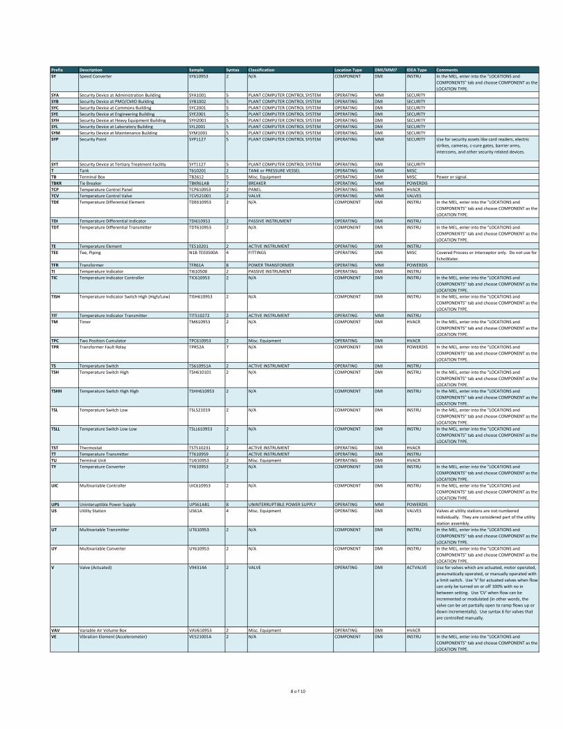
Prefix Description Sample Syntax Classification Location Type DMI/MMI? IDEA Type Comments
SY Speed Converter SY610953 2 N/A COMPONENT DMI INSTRU In the MEL, enter into the "LOCATIONS and
COMPONENTS" tab and choose COMPONENT as the
LOCATION TYPE.
SYA Security Device at Administration Building SYA1001 5 PLANT COMPUTER CONTROL SYSTEM OPERATING MMI SECURITY
SYB Security Device at PMO/CMID Building SYB1002 5 PLANT COMPUTER CONTROL SYSTEM OPERATING DMI SECURITY
SYC Security Device at Commons Building SYC2001 5 PLANT COMPUTER CONTROL SYSTEM OPERATING DMI SECURITY
SYE Security Device at Engineering Building SYE2001 5 PLANT COMPUTER CONTROL SYSTEM OPERATING DMI SECURITY
SYH Security Device at Heavy Equipment Building SYH2001 5 PLANT COMPUTER CONTROL SYSTEM OPERATING DMI SECURITY
SYL Security Device at Laboratory Building SYL2001 5 PLANT COMPUTER CONTROL SYSTEM OPERATING DMI SECURITY
SYM Security Device at Maintenance Building SYM1001 5 PLANT COMPUTER CONTROL SYSTEM OPERATING DMI SECURITY
SYP Security Point SYP1127 5 PLANT COMPUTER CONTROL SYSTEM OPERATING MMI SECURITY Use for security assets like card readers, electric
strikes, cameras, c-cure gates, barrier arms,
intercoms, and other security related devices.
SYT Security Device at Tertiary Treatment Facility SYT1127 5 PLANT COMPUTER CONTROL SYSTEM OPERATING DMI SECURITY
T Tank T610201 2 TANK or PRESSURE VESSEL OPERATING MMI MISC
TB Terminal Box TB2612 5 Misc. Equipment OPERATING DMI MISC Power or signal.
TBKR Tie Breaker TBKR61AB 7 BREAKER OPERATING MMI POWERDIS
TCP Temperature Control Panel TCP610953 2 PANEL OPERATING DMI HVACR
TCV Temperature Control Valve TCV521001 2 VALVE OPERATING MMI VALVES
TDE Temperature Differential Element TDE610953 2 N/A COMPONENT DMI INSTRU In the MEL, enter into the "LOCATIONS and
COMPONENTS" tab and choose COMPONENT as the
LOCATION TYPE.
TDI Temperature Differential Indicator TDI610953 2 PASSIVE INSTRUMENT OPERATING DMI INSTRU
TDT Temperature Differential Transmitter TDT610953 2 N/A COMPONENT DMI INSTRU In the MEL, enter into the "LOCATIONS and
COMPONENTS" tab and choose COMPONENT as the
LOCATION TYPE.
TE Temperature Element TE510201 2 ACTIVE INSTRUMENT OPERATING DMI INSTRU
TEE Tee, Piping N18-TEE0500A 4 FITTINGS OPERATING DMI MISC Covered Process or Interceptor only. Do not use for
EchoWater.
TFR Transformer TFR61A 8 POWER TRANSFORMER OPERATING MMI POWERDIS
TI Temperature Indicator TI610500 2 PASSIVE INSTRUMENT OPERATING DMI INSTRU
TIC Temperature Indicator Controller TIC610953 2 N/A COMPONENT DMI INSTRU In the MEL, enter into the "LOCATIONS and
COMPONENTS" tab and choose COMPONENT as the
LOCATION TYPE.
TISH Temperature Indicator Switch High (High/Low) TISH610953 2 N/A COMPONENT DMI INSTRU In the MEL, enter into the "LOCATIONS and
COMPONENTS" tab and choose COMPONENT as the
LOCATION TYPE.
TIT Temperature Indicator Transmitter TIT510272 2 ACTIVE INSTRUMENT OPERATING MMI INSTRU
TM Timer TM610953 2 N/A COMPONENT DMI HVACR In the MEL, enter into the "LOCATIONS and
COMPONENTS" tab and choose COMPONENT as the
LOCATION TYPE.
TPC Two Position Cumulator TPC610953 2 Misc. Equipment OPERATING DMI HVACR
TPR Transformer Fault Relay TPR52A 7 N/A COMPONENT DMI POWERDIS In the MEL, enter into the "LOCATIONS and
COMPONENTS" tab and choose COMPONENT as the
LOCATION TYPE.
TS Temperature Switch TS610951A 2 ACTIVE INSTRUMENT OPERATING DMI INSTRU
TSH Temperature Switch High TSH610101 2 N/A COMPONENT DMI INSTRU In the MEL, enter into the "LOCATIONS and
COMPONENTS" tab and choose COMPONENT as the
LOCATION TYPE.
TSHH Temperature Switch High High TSHH610953 2 N/A COMPONENT DMI INSTRU In the MEL, enter into the "LOCATIONS and
COMPONENTS" tab and choose COMPONENT as the
LOCATION TYPE.
TSL Temperature Switch Low TSL521019 2 N/A COMPONENT DMI INSTRU In the MEL, enter into the "LOCATIONS and
COMPONENTS" tab and choose COMPONENT as the
LOCATION TYPE.
TSLL Temperature Switch Low Low TSLL610953 2 N/A COMPONENT DMI INSTRU In the MEL, enter into the "LOCATIONS and
COMPONENTS" tab and choose COMPONENT as the
LOCATION TYPE.
TST Thermostat TST510231 2 ACTIVE INSTRUMENT OPERATING DMI HVACR
TT Temperature Transmitter TT610959 2 ACTIVE INSTRUMENT OPERATING DMI INSTRU
TU Terminal Unit TU610953 2 Misc. Equipment OPERATING DMI HVACR
TY Temperature Converter TY610953 2 N/A COMPONENT DMI INSTRU In the MEL, enter into the "LOCATIONS and
COMPONENTS" tab and choose COMPONENT as the
LOCATION TYPE.
UIC Multivariable Controller UIC610953 2 N/A COMPONENT DMI INSTRU In the MEL, enter into the "LOCATIONS and
COMPONENTS" tab and choose COMPONENT as the
LOCATION TYPE.
UPS Uninteruptible Power Supply UPS61AB1 8 UNINTERRUPTIBLE POWER SUPPLY OPERATING MMI POWERDIS
US Utility Station US61A 4 Misc. Equipment OPERATING DMI VALVES Valves at utility stations are not numbered
individually. They are considered part of the utility
station assembly.
UT Multivariable Transmitter UT610953 2 N/A COMPONENT DMI INSTRU In the MEL, enter into the "LOCATIONS and
COMPONENTS" tab and choose COMPONENT as the
LOCATION TYPE.
UY Multivariable Converter UY610953 2 N/A COMPONENT DMI INSTRU In the MEL, enter into the "LOCATIONS and
COMPONENTS" tab and choose COMPONENT as the
LOCATION TYPE.
V Valve (Actuated) V94314A 2 VALVE OPERATING DMI ACTVALVE Use for valves which are actuated, motor operated,
pneumatically operated, or manually operated with
a limit switch. Use 'V' for actuated valves when flow
can only be turned on or off 100% with no in
between setting. Use 'CV' when flow can be
incremented or modulated (in other words, the
valve can be set partially open to ramp flows up or
down incrementally). Use syntax 6 for valves that
are controlled manually.
VAV Variable Air Volume Box VAV610953 2 Misc. Equipment OPERATING DMI HVACR
VE Vibration Element (Accelerometer) VE521001A 2 N/A COMPONENT DMI INSTRU In the MEL, enter into the "LOCATIONS and
COMPONENTS" tab and choose COMPONENT as the
LOCATION TYPE.
8 o f 10

Prefix Description Sample Syntax Classification Location Type DMI/MMI? IDEA Type Comments
VFC Variable Frequency Controller VFC610702 MOTOR DRIVE OPERATING MMI DRIVES If mounted in the field use syntax 2. If located
inside of a MCC Bucket use syntax 8.
VFD Variable Frequency Drive VFD610701 MOTOR DRIVE OPERATING MMI DRIVES If mounted in the field use syntax 2. If located
inside of a MCC Bucket use syntax 8.
VIS Vibration Indicator Switch VIS610953 2 N/A COMPONENT DMI INSTRU In the MEL, enter into the "LOCATIONS and
COMPONENTS" tab and choose COMPONENT as the
LOCATION TYPE.
VIT Vibration Indicating Transmitter VIT610953 2 N/A COMPONENT DMI INSTRU In the MEL, enter into the "LOCATIONS and
COMPONENTS" tab and choose COMPONENT as the
LOCATION TYPE.
VRV Vacuum Relief Valve VRV610953 2 RELIEF DEVICE OPERATING MMI VALVES
VS Vibration Switch VS610953 2 N/A COMPONENT DMI INSTRU In the MEL, enter into the "LOCATIONS and
COMPONENTS" tab and choose COMPONENT as the
LOCATION TYPE.
VSD Variable Speed Drive VSD610953 2 MOTOR DRIVE OPERATING DMI DRIVES
VSH Vibration Switch High VSH610953 2 N/A COMPONENT DMI INSTRU In the MEL, enter into the "LOCATIONS and
COMPONENTS" tab and choose COMPONENT as the
LOCATION TYPE.
VSHH Vibration Switch High High VSHH610953 2 N/A COMPONENT DMI INSTRU In the MEL, enter into the "LOCATIONS and
COMPONENTS" tab and choose COMPONENT as the
LOCATION TYPE.
VT Vibration Transmitter VT610953 2 N/A COMPONENT DMI INSTRU In the MEL, enter into the "LOCATIONS and
COMPONENTS" tab and choose COMPONENT as the
LOCATION TYPE.
VV Variable Volume Box VV610953 2 Misc. Equipment OPERATING DMI HVACR
VY Vibration Relay VY610953 2 N/A COMPONENT DMI INSTRU In the MEL, enter into the "LOCATIONS and
COMPONENTS" tab and choose COMPONENT as the
LOCATION TYPE.
WAP Wireless Access Point WAS1002 5 N/A COMPONENT DMI MISC In the MEL, enter into the "LOCATIONS and
COMPONENTS" tab and choose COMPONENT as the
LOCATION TYPE.
WEIR Weir N17-WEIR0059A 4 WEIRS OPERATING MMI MISC
WKS Workstation (type 101) WKS610001 2 PLANT COMPUTER CONTROL SYSTEM OPERATING DMI COMPUTER
WQ Weight Totalizer WQ597501 2 N/A COMPONENT DMI INSTRU In the MEL, enter into the "LOCATIONS and
COMPONENTS" tab and choose COMPONENT as the
LOCATION TYPE.
WS Torque Switch WS610953 2 N/A COMPONENT DMI INSTRU In the MEL, enter into the "LOCATIONS and
COMPONENTS" tab and choose COMPONENT as the
LOCATION TYPE.
WSH Torque Switch High WSH593003 2 N/A COMPONENT DMI INSTRU In the MEL, enter into the "LOCATIONS and
COMPONENTS" tab and choose COMPONENT as the
LOCATION TYPE.
WSHH Torque Switch High High WSHH610953 2 N/A COMPONENT DMI INSTRU In the MEL, enter into the "LOCATIONS and
COMPONENTS" tab and choose COMPONENT as the
LOCATION TYPE.
WT Weight Transmitter WT597002 2 N/A COMPONENT DMI INSTRU In the MEL, enter into the "LOCATIONS and
COMPONENTS" tab and choose COMPONENT as the
LOCATION TYPE.
WYE Wye, Piping N18-WYE0002A 4 FITTINGS OPERATING DMI MISC Covered Process or Interceptor only. Do not use for
EchoWater.
XA Unclassified Alarm Annunciator XA610953 2 N/A COMPONENT DMI INSTRU In the MEL, enter into the "LOCATIONS and
COMPONENTS" tab and choose COMPONENT as the
LOCATION TYPE.
XE Unclassified Element XE597002A 2 N/A COMPONENT DMI INSTRU In the MEL, enter into the "LOCATIONS and
COMPONENTS" tab and choose COMPONENT as the
LOCATION TYPE.
XS Unclassified Switch XS610953 2 N/A COMPONENT DMI INSTRU In the MEL, enter into the "LOCATIONS and
COMPONENTS" tab and choose COMPONENT as the
LOCATION TYPE.
XSHH Unclassified Switch High High XSHH610953 2 N/A COMPONENT DMI INSTRU In the MEL, enter into the "LOCATIONS and
COMPONENTS" tab and choose COMPONENT as the
LOCATION TYPE.
XSW Transfer Switch XSW61AB1 8 TRANSFER SWITCH OPERATING MMI POWERDIS
XT Unclassified Transmitter XT610953 2 N/A COMPONENT DMI INSTRU In the MEL, enter into the "LOCATIONS and
COMPONENTS" tab and choose COMPONENT as the
LOCATION TYPE.
ZC Position Controller ZC610953 2 N/A COMPONENT DMI INSTRU In the MEL, enter into the "LOCATIONS and
COMPONENTS" tab and choose COMPONENT as the
LOCATION TYPE.
ZE Position Element ZE521001A 2 N/A COMPONENT DMI INSTRU In the MEL, enter into the "LOCATIONS and
COMPONENTS" tab and choose COMPONENT as the
LOCATION TYPE.
ZI Position Indicator ZI610953 2 PASSIVE INSTRUMENT OPERATING DMI INSTRU
ZIC Position Indicating Controller ZIC610953 2 N/A COMPONENT DMI INSTRU In the MEL, enter into the "LOCATIONS and
COMPONENTS" tab and choose COMPONENT as the
LOCATION TYPE.
ZIHL Position Indicator High Low ZIHL610953 2 N/A COMPONENT DMI INSTRU In the MEL, enter into the "LOCATIONS and
COMPONENTS" tab and choose COMPONENT as the
LOCATION TYPE.
ZIT Position Indicating Transmitter ZIT521007A 2 N/A COMPONENT DMI INSTRU In the MEL, enter into the "LOCATIONS and
COMPONENTS" tab and choose COMPONENT as the
LOCATION TYPE.
ZS Position Switch ZS610051A 2 N/A COMPONENT DMI INSTRU In the MEL, enter into the "LOCATIONS and
COMPONENTS" tab and choose COMPONENT as the
LOCATION TYPE.
ZSC Position Switch Controller ZSC597501 2 N/A COMPONENT DMI INSTRU In the MEL, enter into the "LOCATIONS and
COMPONENTS" tab and choose COMPONENT as the
LOCATION TYPE.
ZSD Position Switch Differential ZSD610953 2 N/A COMPONENT DMI INSTRU In the MEL, enter into the "LOCATIONS and
COMPONENTS" tab and choose COMPONENT as the
LOCATION TYPE.
9 o f 10
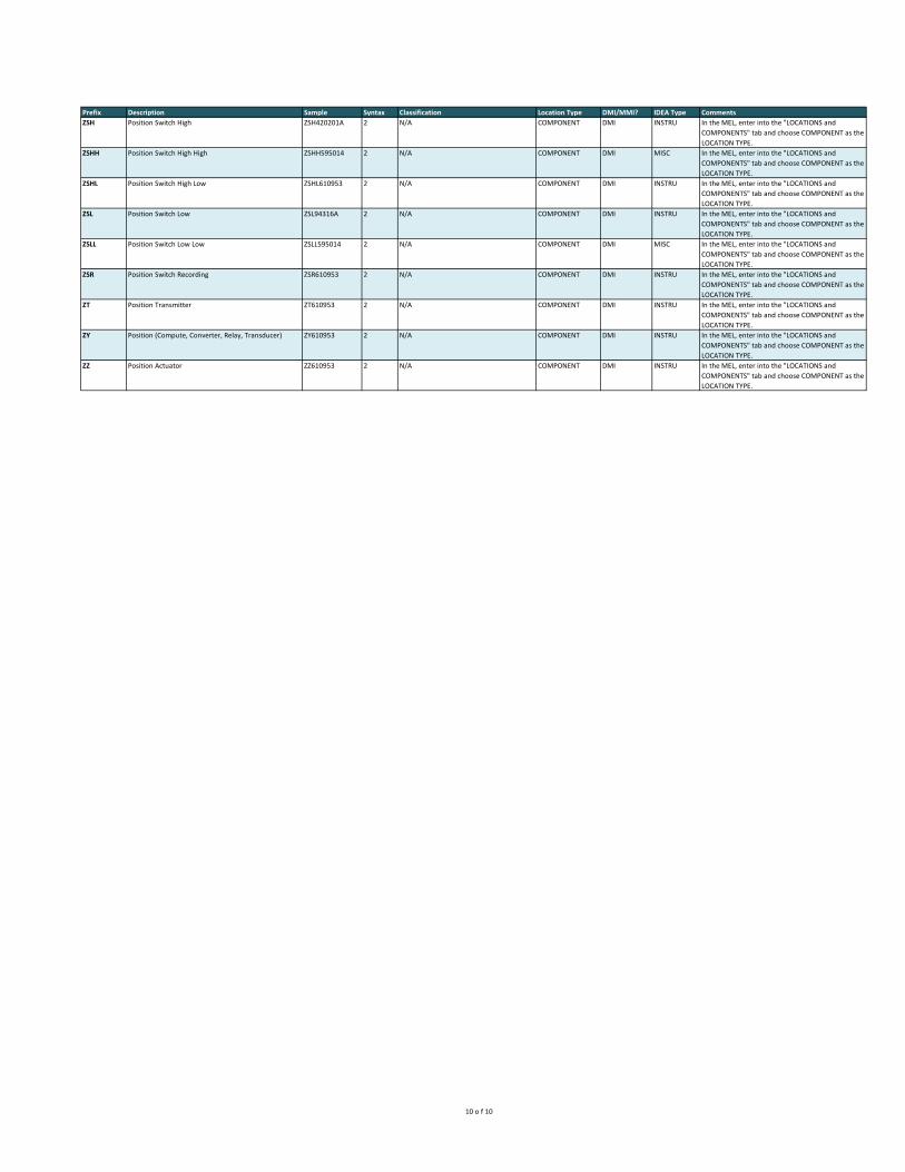
Prefix Description Sample Syntax Classification Location Type DMI/MMI? IDEA Type Comments
ZSH Position Switch High ZSH420201A 2 N/A COMPONENT DMI INSTRU In the MEL, enter into the "LOCATIONS and
COMPONENTS" tab and choose COMPONENT as the
LOCATION TYPE.
ZSHH Position Switch High High ZSHH595014 2 N/A COMPONENT DMI MISC In the MEL, enter into the "LOCATIONS and
COMPONENTS" tab and choose COMPONENT as the
LOCATION TYPE.
ZSHL Position Switch High Low ZSHL610953 2 N/A COMPONENT DMI INSTRU In the MEL, enter into the "LOCATIONS and
COMPONENTS" tab and choose COMPONENT as the
LOCATION TYPE.
ZSL Position Switch Low ZSL94316A 2 N/A COMPONENT DMI INSTRU In the MEL, enter into the "LOCATIONS and
COMPONENTS" tab and choose COMPONENT as the
LOCATION TYPE.
ZSLL Position Switch Low Low ZSLL595014 2 N/A COMPONENT DMI MISC In the MEL, enter into the "LOCATIONS and
COMPONENTS" tab and choose COMPONENT as the
LOCATION TYPE.
ZSR Position Switch Recording ZSR610953 2 N/A COMPONENT DMI INSTRU In the MEL, enter into the "LOCATIONS and
COMPONENTS" tab and choose COMPONENT as the
LOCATION TYPE.
ZT Position Transmitter ZT610953 2 N/A COMPONENT DMI INSTRU In the MEL, enter into the "LOCATIONS and
COMPONENTS" tab and choose COMPONENT as the
LOCATION TYPE.
ZY Position (Compute, Converter, Relay, Transducer) ZY610953 2 N/A COMPONENT DMI INSTRU In the MEL, enter into the "LOCATIONS and
COMPONENTS" tab and choose COMPONENT as the
LOCATION TYPE.
ZZ Position Actuator ZZ610953 2 N/A COMPONENT DMI INSTRU In the MEL, enter into the "LOCATIONS and
COMPONENTS" tab and choose COMPONENT as the
LOCATION TYPE.
10 o f 10

Abbreviation Description Comments
A Aeration Air
AA Agitation Air
AFC Antifoam Concentrate
AFS Antifoam Solution
AHP Air High Pressure
ALM Alum Solution
ALP Air Low Pressure
ASH Ash Pneumatic
BCP Boiler Code Piping
BCT Boiler Chemical Treatment
BD Boiler Blowdown
BF Boiler Feed
BRF Biosolids Recycling Facility Used for Feed line.
BR1 Brass Piping
BSC Biologic Scum
C Chemical Used for Bioxide odor control.
CAA Channel Aeration Air
CC Centrifuge Cake
CD Chemical Drain
CEN Centrate
CF Centrifuge Feed
CFE Chlorinated Final Effluent
CFW Chlorinated Filter Water
CIP Clean In Place MF CIP Drain Pump
CKS Cake Biosolids
CL Low Pressure Condensate
CLG Chlorine Gas
CLL Chloride Liquid
CLS Chloride Solution
CLV Chlorine Vacuum
CM Medium Pressure Condensate
COG Carbon Dioxide Gas
COL Carbon Dioxide Liquid
CPA Chemical Padding Air
CPSA Compressor Starting Air
CR Centrate Return
CS Circulating Sludge
CSO Caustic Soda
CTA Citric Acid
CV Chemical Vent
CWR Chilled Water Return
CWS Chilled Water Supply
D Drain
DFE Dechlorinated Final Effluent
DFEC Dechlorinated Final Effluent Clean
DHW Domestic Water Hot
DIS Distilled Water
DIZ Deionized Water
Version 8/13/2020
File: 10086678
SMP 207 Appendix C
Pipe Systems
Page 1 of 5
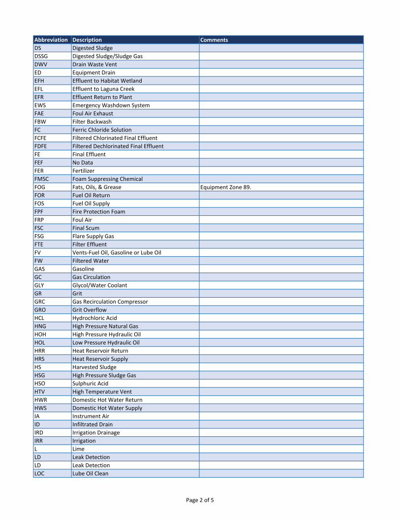
Abbreviation Description Comments
DS Digested Sludge
DSSG Digested Sludge/Sludge Gas
DWV Drain Waste Vent
ED Equipment Drain
EFH Effluent to Habitat Wetland
EFL Effluent to Laguna Creek
EFR Effluent Return to Plant
EWS Emergency Washdown System
FAE Foul Air Exhaust
FBW Filter Backwash
FC Ferric Chloride Solution
FCFE Filtered Chlorinated Final Effluent
FDFE Filtered Dechlorinated Final Effluent
FE Final Effluent
FEF No Data
FER Fertilizer
FMSC Foam Suppressing Chemical
FOG Fats, Oils, & Grease Equipment Zone 89.
FOR Fuel Oil Return
FOS Fuel Oil Supply
FPF Fire Protection Foam
FRP Foul Air
FSC Final Scum
FSG Flare Supply Gas
FTE Filter Effluent
FV Vents-Fuel Oil, Gasoline or Lube Oil
FW Filtered Water
GAS Gasoline
GC Gas Circulation
GLY Glycol/Water Coolant
GR Grit
GRC Gas Recirculation Compressor
GRO Grit Overflow
HCL Hydrochloric Acid
HNG High Pressure Natural Gas
HOH High Pressure Hydraulic Oil
HOL Low Pressure Hydraulic Oil
HRR Heat Reservoir Return
HRS Heat Reservoir Supply
HS Harvested Sludge
HSG High Pressure Sludge Gas
HSO Sulphuric Acid
HTV High Temperature Vent
HWR Domestic Hot Water Return
HWS Domestic Hot Water Supply
IA Instrument Air
ID Infiltrated Drain
IRD Irrigation Drainage
IRR Irrigation
L Lime
LD Leak Detection
LD Leak Detection
LOC Lube Oil Clean
Page 2 of 5

Abbreviation Description Comments
LOD Lube Oil Dirty
LOR Lube Oil Return
LOS Lubricating Oil Supply
LS Lime Slurry
LSG Low Pressure Sludge Gas
MG Mixed Gas
MHL Methanol
ML Mixed Liquor
MLF Mixed Liquor Fermentor
MLR Mixed Liquor Recycle
MO Motor Oil
MS Mixed Sludge
MSC Miscellaneous
MSCS Mixed Sludge/Circulating Sludge
MSDS Mixed Sludge/Digested Sludge
MSG Medium Pressure Sludge Gas
N Nitrogen
NAOCL Sodium Hypochlorite
NAOH Sodium Hydroxide
NC1 High Velocity - Gas Piping
NG Natural Gas
NTL Neutralization Fluid This piping system can contain Sodium Bisulfite; Sodium
Hydroxide; Citric Acid. It all depends on the cleaning process of
the MFUs.
OC Odor Control
OCA Odor Control Air
ODG Oxygen Dry Gas
OF Overflow
OFSG Overflow/Sludge Gas
OHP Oxygen High Pressure Discharge
OIL Oil
OLP Oxygen Low Pressure This piping system is needed for the cross ties between each of
the CO tanks. Installed by Operations Supoort in 2004.
OLPD Oxygen Low Pressure Discharge
OLPS Oxygen Low Pressure Suction
OPPS Oxygen Plant Pipe System
PA Preaeration Air
PAS Primary and Activated Sludge
PBA Purge Blower Air
PC Pneumatic Conveying
PCH High Pressure Process Condensate
PCL Low Pressure Process Condensate
PCO Polymer Concentrated
PCR Process Condensate Return
PD Pumped Drainage
PE Primary Effluent
PEJ Primary Effluent Jetting
PF Pressurized Flow
PNDNG Data Not Availble or is Unassigned
POL Polyelectrolyte
PP Polymer Pneumatic
PR Pneumatic Return
Page 3 of 5
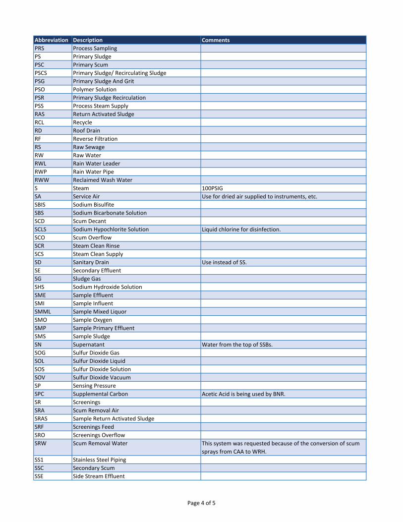
Abbreviation Description Comments
PRS Process Sampling
PS Primary Sludge
PSC Primary Scum
PSCS Primary Sludge/ Recirculating Sludge
PSG Primary Sludge And Grit
PSO Polymer Solution
PSR Primary Sludge Recirculation
PSS Process Steam Supply
RAS Return Activated Sludge
RCL Recycle
RD Roof Drain
RF Reverse Filtration
RS Raw Sewage
RW Raw Water
RWL Rain Water Leader
RWP Rain Water Pipe
RWW Reclaimed Wash Water
S Steam 100PSIG
SA Service Air Use for dried air supplied to instruments, etc.
SBIS Sodium Bisulfite
SBS Sodium Bicarbonate Solution
SCD Scum Decant
SCLS Sodium Hypochlorite Solution Liquid chlorine for disinfection.
SCO Scum Overflow
SCR Steam Clean Rinse
SCS Steam Clean Supply
SD Sanitary Drain Use instead of SS.
SE Secondary Effluent
SG Sludge Gas
SHS Sodium Hydroxide Solution
SME Sample Effluent
SMI Sample Influent
SMML Sample Mixed Liquor
SMO Sample Oxygen
SMP Sample Primary Effluent
SMS Sample Sludge
SN Supernatant Water from the top of SSBs.
SOG Sulfur Dioxide Gas
SOL Sulfur Dioxide Liquid
SOS Sulfur Dioxide Solution
SOV Sulfur Dioxide Vacuum
SP Sensing Pressure
SPC Supplemental Carbon Acetic Acid is being used by BNR.
SR Screenings
SRA Scum Removal Air
SRAS Sample Return Activated Sludge
SRF Screenings Feed
SRO Screenings Overflow
SRW Scum Removal Water This system was requested because of the conversion of scum
sprays from CAA to WRH.
SS1 Stainless Steel Piping
SSC Secondary Scum
SSE Side Stream Effluent
Page 4 of 5
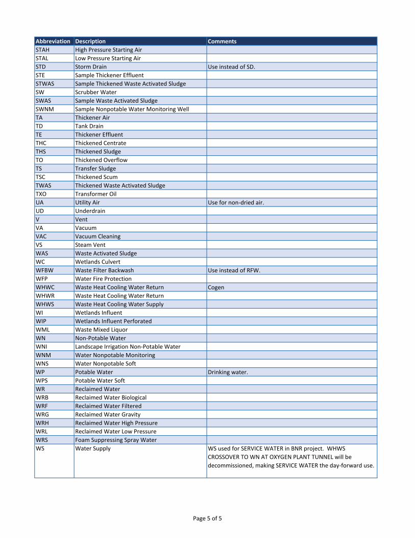
Abbreviation Description Comments
STAH High Pressure Starting Air
STAL Low Pressure Starting Air
STD Storm Drain Use instead of SD.
STE Sample Thickener Effluent
STWAS Sample Thickened Waste Activated Sludge
SW Scrubber Water
SWAS Sample Waste Activated Sludge
SWNM Sample Nonpotable Water Monitoring Well
TA Thickener Air
TD Tank Drain
TE Thickener Effluent
THC Thickened Centrate
THS Thickened Sludge
TO Thickened Overflow
TS Transfer Sludge
TSC Thickened Scum
TWAS Thickened Waste Activated Sludge
TXO Transformer Oil
UA Utility Air Use for non-dried air.
UD Underdrain
V Vent
VA Vacuum
VAC Vacuum Cleaning
VS Steam Vent
WAS Waste Activated Sludge
WC Wetlands Culvert
WFBW Waste Filter Backwash Use instead of RFW.
WFP Water Fire Protection
WHWC Waste Heat Cooling Water Return Cogen
WHWR Waste Heat Cooling Water Return
WHWS Waste Heat Cooling Water Supply
WI Wetlands Influent
WIP Wetlands Influent Perforated
WML Waste Mixed Liquor
WN Non-Potable Water
WNI Landscape Irrigation Non-Potable Water
WNM Water Nonpotable Monitoring
WNS Water Nonpotable Soft
WP Potable Water Drinking water.
WPS Potable Water Soft
WR Reclaimed Water
WRB Reclaimed Water Biological
WRF Reclaimed Water Filtered
WRG Reclaimed Water Gravity
WRH Reclaimed Water High Pressure
WRL Reclaimed Water Low Pressure
WRS Foam Suppressing Spray Water
WS Water Supply WS used for SERVICE WATER in BNR project. WHWS
CROSSOVER TO WN AT OXYGEN PLANT TUNNEL will be
decommissioned, making SERVICE WATER the day-forward use.
Page 5 of 5
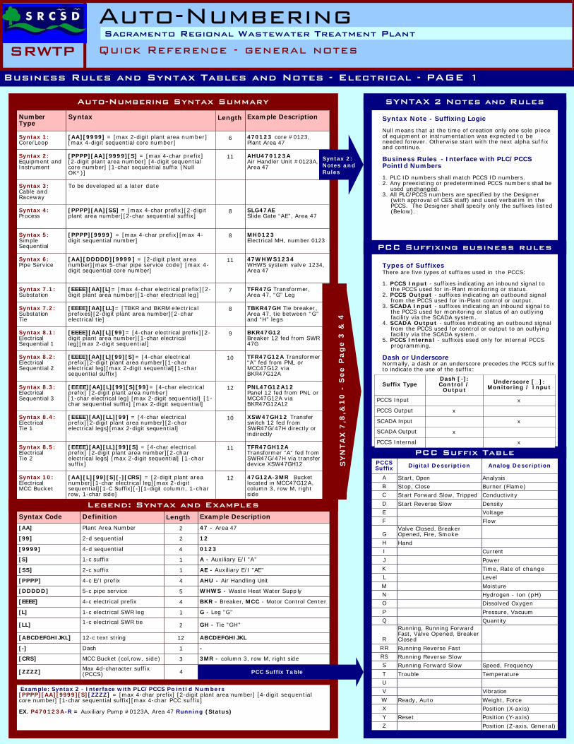
Auto-Numbering Syntax Summary
NumberType
Syntax Example Description
Syntax 1:Core/Loop
[AA][9999] = [max 2-digit plant area number][max 4-digit sequential core number]
470123 core #0123,Plant Area 47
Syntax 2:Equipment andInstrument
[PPPP][AA][9999][S] = [max 4-char prefix][2-digit plant area number] [4-digit sequentialcore number] [1-char sequential suffix (NullOK*)]
AHU470123AAir Handler Unit #0123A,Area 47
Syntax 3:Cable andRaceway
To be developed at a later date
Syntax 4:Process
[PPPP][AA][SS] = [max 4-char prefix][2-digitplant area number][2-char sequential suffix]
SLG47AESlide Gate “AE”, Area 47
Syntax 5:SimpleSequential
[PPPP][9999] = [max 4-char prefix][max 4-digit sequential number]
MH0123Electrical MH, number 0123
Syntax 6:Pipe Service
[AA][DDDDD][9999] = [2-digit plant areanumber][max 5-char pipe service code] [max 4-digit sequential core number]
47WHWS1234WHWS system valve 1234,Area 47
Syntax 7.1:Substation
[EEEE][AA][L]= [max 4-char electrical prefix][2-digit plant area number][1-char electrical leg]
TFR47G Transformer,Area 47, “G” Leg
Syntax 8.1:ElectricalSequential 1
[EEEE][AA][L][99]= [4-char electrical prefix][2-digit plant area number][1-char electricalleg][max 2-digit sequential]
BKR47G12Breaker 12 fed from SWR47G
Syntax 10:ElectricalMCC Bucket
[AA][L][99][S][-][CRS] = [2-digit plant areanumber][1-char electrical leg][max 2-digitsequential][1-C Suffix][-][1-digit column, 1-charrow, 1-char side]
47G12A-3MR Bucketlocated in MCC47G12A,column 3, row M, rightside
Syntax 7.2:SubstationTie
[EEEE][AA][LL]= [TBKR and BKRM electricalprefixes][2-digit plant area number][2-charelectrical tie]
TBKR47GH Tie breaker,Area 47, tie between “G”and “H” legs
Syntax 8.5:ElectricalTie 2
[EEEE][AA][LL][99][S] = [4-char electricalprefix] [2-digit plant area number][2-charelectrical legs] [max 2-digit sequential] [1-charsuffix]
TFR47GH12ATransformer “A” fed fromSWR47G/47H via transferdevice XSW47GH12
Syntax 8.4:ElectricalTie 1
[EEEE][AA][LL][99] = [4-char electricalprefix][2-digit plant area number][2-charelectrical legs][max 2-digit sequential]
XSW47GH12 Transferswitch 12 fed fromSWR47G/47H directly orindirectly
Syntax 8.3:ElectricalSequential 3
[EEEE][AA][L][99][S][99]= [4-char electricalprefix] [2-digit plant area number][1-char electrical leg] [max 2-digit sequential] [1-char sequential suffix] [max 2-digit sequential]
PNL47G12A12Panel 12 fed from PNL orMCC47G12A viaBKR47G12A12
Syntax 8.2:ElectricalSequential 2
[EEEE][AA][L][99][S]= [4-char electricalprefix][2-digit plant area number][1-charelectrical leg][max 2-digit sequential][1-charsequential suffix]
TFR47G12A Transformer“A” fed from PNL orMCC47G12 viaBKR47G12A
Length
6
11
8
8
11
7
8
9
10
12
10
11
12
Syntax 2:Notes andRules
Syntax Note - Suffixing Logic
Null means that at the time of creation only one sole pieceof equipment or instrumentation was expected to beneeded forever. Otherwise start with the next alpha suf fixand continue.
Business Rules - Interface with PLC/PCCSPointId Numbers
1. PLC ID numbers shall match PCCS ID numbers.2. Any preexisting or predetermined PCCS numbers shall be used unchanged.3. All PLC/PCCS numbers are specified by the Designer
(with approval of CES staff) and used verbatim in thePCCS. The Designer shall specify only the suffixes listed(Below).
SYNTAX 2 Notes and Rules
Syntax Code Definition Example Description
[AA] Plant Area Number 47 - Area 47
[99] 2-d sequential 12
[9999] 4-d sequential 0123
[S] 1-c suffix A - Auxiliary E/I "A"
[SS] 2-c suffix AE - Auxiliary E/I "AE"
[PPPP] 4-c E/I prefix AHU - Air Handling Unit
[DDDDD] 5-c pipe service WHWS - Waste Heat Water Supp ly
[L] 1-c electrical SWR leg G - Leg "G"
[CRS] MCC Bucket (col,row, side) 3MR - column 3, row M, right side
[EEEE] 4-c electrical prefix BKR - Breaker, MCC - Motor Control Center
[-] Dash -
[ABCDEFGHIJKL] 12-c text string ABCDEFGHIJKL
[LL] 1-c electrical SWR tie GH - Tie "GH"
Length
2
2
4
1
1
4
5
4
1
2
12
1
3
[ZZZZ] Max 4d-character suffix(PCCS) 4
Legend: Syntax and Examples
Types of SuffixesThere are five types of suffixes used in the PCCS:
1. PCCS Input - suffixes indicating an inbound signal tothe PCCS used for in-Plant monitoring or status.
2. PCCS Output - suffixes indicating an outbound signalfrom the PCCS used for in-Plant control or output.
3. SCADA Input - suffixes indicating an inbound signal tothe PCCS used for monitoring or status of an outlyingfacility via the SCADA system.
4. SCADA Output - suffixes indicating an outbound signalfrom the PCCS used for control or output to an outlyingfacility via the SCADA system.
5. PCCS Internal - suffixes used only for internal PCCSprogramming.
Dash or UnderscoreNormally, a dash or an underscore precedes the PCCS suf fixto indicate the use of the suffix:
PCC Suffix Table
Suffix TypeDash [-]:Control /
OutputUnderscore [_]:
Monitoring / Input
PCCS Input x
PCCS Output x
SCADA Input x
SCADA Output x
PCCS Internal x
PCCSSuffix Digital Description Analog Description
A Start, Open AnalysisB Stop, Close Burner (Flame)C Start Forward Slow, Tripped Conductivity
D Start Reverse Slow DensityE VoltageF Flow
GValve Closed, BreakerOpened, Fire, Smoke
H HandI Current
J PowerK Time, Rate of changeL Level
M MoistureN Hydrogen - Ion (pH)O Dissolved Oxygen
P Pressure, VacuumQ Quantity
R
Running, Running ForwardFast, Valve Opened, BreakerClosed
RR Running Reverse FastRS Running Reverse SlowS Running Forward Slow Speed, Frequency
T Trouble TemperatureU
V Vibration
W Ready, Auto Weight, ForceX Position (X-axis)Y Reset Position (Y-axis)
Z Position (Z-axis, General)
PCC Suffixing business rules
PCC Suffix Table
Example: Syntax 2 - Interface with PLC/PCCS Po intId Numbers[PPPP][AA][9999][S][ZZZZ] = [max 4-char prefix] [2-digit plant area number] [4-digit sequentialcore number] [1-char sequential suffix][max 4-char PCC suffix]
EX. P470123A-R = Auxiliary Pump #0123A, Area 47 Running (Status)
SY
NT
AX
7,8
,&1
0 -
Se
e P
ag
e 3
& 4
Business Rules and Syntax Tables and Notes - Electrical - PAGE 1
Auto-NumberingQuick Reference - general notes
Sacramento Regional Wastewater Treatment Plant800SRWTP
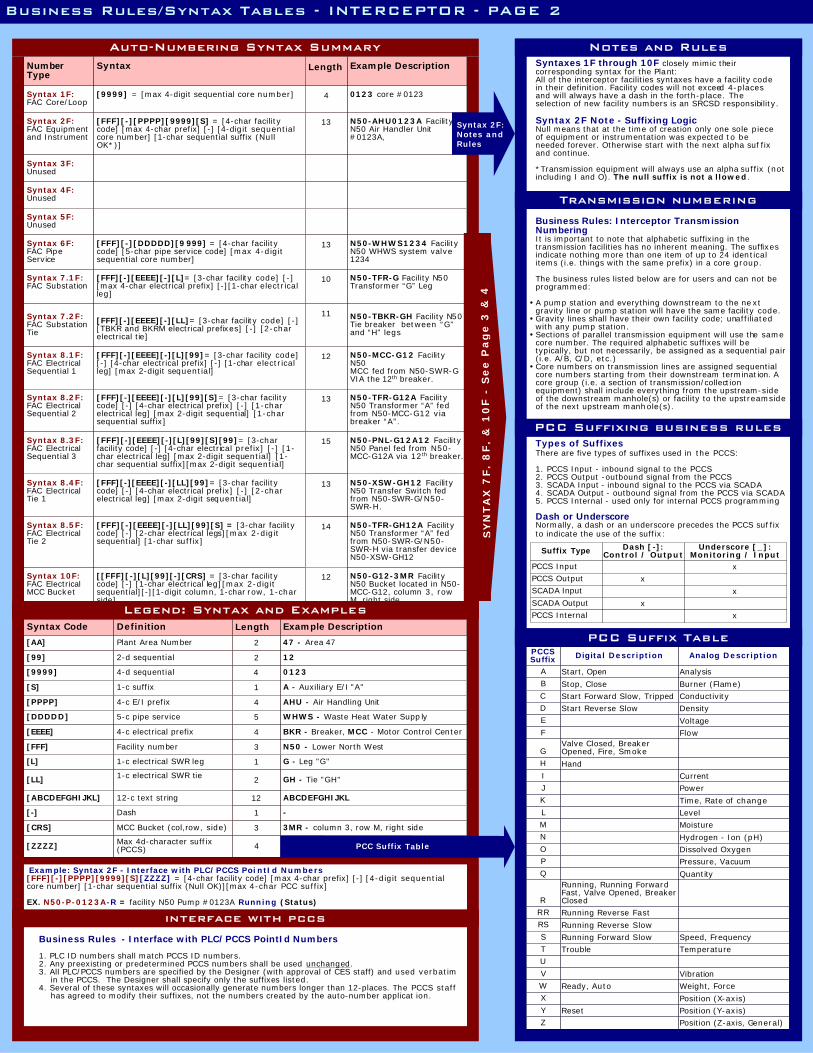
Auto-Numbering Syntax Summary
NumberType
Syntax Example Description
Syntax 1F:FAC Core/Loop
[9999] = [max 4-digit sequential core number] 0123 core #0123
Syntax 2F:FAC Equipmentand Instrument
[FFF][-][PPPP][9999][S] = [4-char facilitycode] [max 4-char prefix] [-] [4-digit sequentialcore number] [1-char sequential suffix (NullOK*)]
N50-AHU0123A FacilityN50 Air Handler Unit#0123A,
Syntax 3F:Unused
Syntax 4F:Unused
Syntax 5F:Unused
Syntax 6F:FAC PipeService
[FFF][-][DDDDD][9999] = [4-char facilitycode] [5-char pipe service code] [max 4-digitsequential core number]
N50-WHWS1234 FacilityN50 WHWS system valve1234
Syntax 7.1F:FAC Substation
[FFF][-][EEEE][-][L]= [3-char facility code] [-][max 4-char electrical prefix] [-][1-char electricalleg]
N50-TFR-G Facility N50Transformer “G” Leg
Syntax 8.1F:FAC ElectricalSequential 1
[FFF][-][EEEE][-][L][99]= [3-char facility code][-] [4-char electrical prefix] [-] [1-char electricalleg] [max 2-digit sequential]
N50-MCC-G12 FacilityN50MCC fed from N50-SWR-GVIA the 12th breaker.
Syntax 10F:FAC ElectricalMCC Bucket
[[FFF][-][L][99][-][CRS] = [3-char facilitycode] [-] [1-char electrical leg][max 2-digitsequential][-][1-digit column, 1-char row, 1-charside]
N50-G12-3MR FacilityN50 Bucket located in N50-MCC-G12, column 3, rowM, right side
Syntax 7.2F:FAC SubstationTie
[FFF][-][EEEE][-][LL]= [3-char facility code] [-][TBKR and BKRM electrical prefixes] [-] [2-charelectrical tie]
N50-TBKR-GH Facility N50Tie breaker between “G”and “H” legs
Syntax 8.5F:FAC ElectricalTie 2
[FFF][-][EEEE][-][LL][99][S] = [3-char facilitycode] [-] [2-char electrical legs][max 2-digitsequential] [1-char suffix]
N50-TFR-GH12A FacilityN50 Transformer “A” fedfrom N50-SWR-G/N50-SWR-H via transfer deviceN50-XSW-GH12
Syntax 8.4F:FAC ElectricalTie 1
[FFF][-][EEEE][-][LL][99]= [3-char facilitycode] [-] [4-char electrical prefix] [-] [2-charelectrical leg] [max 2-digit sequential]
N50-XSW-GH12 FacilityN50 Transfer Switch fedfrom N50-SWR-G/N50-SWR-H.
Syntax 8.3F:FAC ElectricalSequential 3
[FFF][-][EEEE][-][L][99][S][99]= [3-charfacility code] [-] [4-char electrical prefix] [-] [1-char electrical leg] [max 2-digit sequential] [1-char sequential suffix][max 2-digit sequential]
N50-PNL-G12A12 FacilityN50 Panel fed from N50-MCC-G12A via 12th breaker.
Syntax 8.2F:FAC ElectricalSequential 2
[FFF][-][EEEE][-][L][99][S]= [3-char facilitycode] [-] [4-char electrical prefix] [-] [1-charelectrical leg] [max 2-digit sequential] [1-charsequential suffix]
N50-TFR-G12A FacilityN50 Transformer “A” fedfrom N50-MCC-G12 viabreaker “A”.
Length
4
13
13
10
11
12
13
15
13
14
12
Syntax 2F:Notes andRules
Business Rules/Syntax Tables - INTERCEPTOR - PAGE 2
interface with pccs
Example: Syntax 2F - Interface with PLC/PCCS Poi ntId Numbers[FFF][-][PPPP][9999][S][ZZZZ] = [4-char facility code] [max 4-char prefix] [-] [4-digit sequentialcore number] [1-char sequential suffix (Null OK)][max 4-char PCC suffix]
EX. N50-P-0123A-R = facility N50 Pump #0123A Running (Status)
SY
NT
AX
7F
, 8
F,
& 1
0F
- S
ee
Pa
ge
3 &
4
Syntax Code Definition Example Description
[AA] Plant Area Number 47 - Area 47
[99] 2-d sequential 12
[9999] 4-d sequential 0123
[S] 1-c suffix A - Auxiliary E/I "A"
[PPPP] 4-c E/I prefix AHU - Air Handling Unit
[DDDDD] 5-c pipe service WHWS - Waste Heat Water Supp ly
[L] 1-c electrical SWR leg G - Leg "G"
[CRS] MCC Bucket (col,row, side) 3MR - column 3, row M, right side
[EEEE] 4-c electrical prefix BKR - Breaker, MCC - Motor Control Center
[-] Dash -
[ABCDEFGHIJKL] 12-c text string ABCDEFGHIJKL
[LL] 1-c electrical SWR tie GH - Tie "GH"
Length
2
2
4
1
4
5
4
1
2
12
1
3
[ZZZZ] Max 4d-character suffix(PCCS) 4
[FFF] Facility number 3 N50 - Lower North West
Legend: Syntax and Examples
PCC Suffix Table
Syntaxes 1F through 10F closely mimic theircorresponding syntax for the Plant:All of the interceptor facilities syntaxes have a facility codein their definition. Facility codes will not exceed 4-placesand will always have a dash in the forth-place. Theselection of new facility numbers is an SRCSD responsibility.
Syntax 2F Note - Suffixing LogicNull means that at the time of creation only one sole pieceof equipment or instrumentation was expected to beneeded forever. Otherwise start with the next alpha suf fixand continue.
*Transmission equipment will always use an alpha suffix (notincluding I and O). The null suffix is not a llowed.
Notes and Rules
Types of SuffixesThere are five types of suffixes used in the PCCS:
1. PCCS Input - inbound signal to the PCCS2. PCCS Output -outbound signal from the PCCS3. SCADA Input - inbound signal to the PCCS via SCADA4. SCADA Output - outbound signal from the PCCS via SCADA5. PCCS Internal - used only for internal PCCS programming
Dash or UnderscoreNormally, a dash or an underscore precedes the PCCS suf fixto indicate the use of the suffix:
PCC Suffix Table
Suffix Type Dash [-]:Control / Output
Underscore [_]:Monitoring / Input
PCCS Input xPCCS Output xSCADA Input xSCADA Output xPCCS Internal x
PCCSSuffix Digital Description Analog Description
A Start, Open AnalysisB Stop, Close Burner (Flame)C Start Forward Slow, Tripped ConductivityD Start Reverse Slow DensityE VoltageF Flow
GValve Closed, BreakerOpened, Fire, Smoke
H HandI CurrentJ PowerK Time, Rate of changeL LevelM MoistureN Hydrogen - Ion (pH)O Dissolved OxygenP Pressure, VacuumQ Quantity
R
Running, Running ForwardFast, Valve Opened, BreakerClosed
RR Running Reverse FastRS Running Reverse SlowS Running Forward Slow Speed, FrequencyT Trouble TemperatureU
V VibrationW Ready, Auto Weight, ForceX Position (X-axis)Y Reset Position (Y-axis)Z Position (Z-axis, General)
PCC Suffixing business rules
Business Rules: Interceptor TransmissionNumberingIt is important to note that alphabetic suffixing in thetransmission facilities has no inherent meaning. The suffixesindicate nothing more than one item of up to 24 identicalitems (i.e. things with the same prefix) in a core group.
The business rules listed below are for users and can not beprogrammed:
A pump station and everything downstream to the nextgravity line or pump station will have the same facility code.Gravity lines shall have their own facility code; unaffiliatedwith any pump station.Sections of parallel transmission equipment will use the samecore number. The required alphabetic suffixes will betypically, but not necessarily, be assigned as a sequential pair(i.e. A/B, C/D, etc.)Core numbers on transmission lines are assigned sequentialcore numbers starting from their downstream termination. Acore group (i.e. a section of transmission/collectionequipment) shall include everything from the upstream-sideof the downstream manhole(s) or facility to the upstreamsideof the next upstream manhole(s).
Transmission numbering
Business Rules - Interface with PLC/PCCS PointId Numbers
1. PLC ID numbers shall match PCCS ID numbers.2. Any preexisting or predetermined PCCS numbers shall be used unchanged.3. All PLC/PCCS numbers are specified by the Designer (with approval of CES staff) and used verbatim
in the PCCS. The Designer shall specify only the suffixes listed.4. Several of these syntaxes will occasionally generate numbers longer than 12-places. The PCCS staff
has agreed to modify their suffixes, not the numbers created by the auto-number applicat ion.

SYNTAX 7, 8, & 10 (7F, 8F, & 10F) EXAMPLES - ELECTRICAL - PAGE 3
M
SDM
EDM
M
VFD
EDM
UPS
SDM
RED LABEL:Fed From "UPS47G5" and "TFR47H1"
PDM
(NOTE 2)
EDM
VFD
SYNTAX 10(SYNTAX 10F)
SW47G(N50-SW-G)
TFR47G(N50-TFR-G)
MBKR47G(N50-MBKR-G)
SDM47G(N50-MBKR-G)
BKR47G3(N50-BKR-G3)
EDM47G3(N50-EDM-G3)
SWR47G (N50-TFR-G)
BKR47G5(N50-BKR-G5)
TBKR47GH(N50-TBKR-GH)
BKRM47GH(N50-BKRM-GH)
SWR47H(N50-TFR-H)
BKR47H1(N50-BKR-H1)
BKR47H2(N50-BKR-H2)
SDM47H(N50-MBKR-H)
MBKR47H(N50-MBKR-H)
TFR47H(N50-TFR-H)
SW47H(N50-SW-H)
12KV FEEDER
UPS47G5(N50-UPS-G5)
TFR47H1(N50-TFR-H1)
PNL47H2(N50-PNL-H2)
BKR47H2C(N50-BKR-H2C)
PNL47H2C(N50-PNL-H2C)
BKR47H2C1(N50-BKR-H2C1)
TFR47H2C1(N50-TFR-H2C1)
PNL47H2C1(N50-PNL-H2C1)
PDM470001(N50-PDM0001)
CPNL470001(N50-CPNL0001)
MBKR47GH1A(N50-MBKR-GH1A)
XSW47GH1(N50-XSW-GH1)
MBKR47G3(N50-MBKR-G3)
(NOTE 1 - TYP.)
MCC47G3(N50-MCC-G3)
BKR47G3C(N50-BKR-G3C)
STA47G3C(N50-STA-G3C)
BKR47G3B(N50-BKR-G3B)
EDM47G3B(N50-EDM-G3B)
BKR47G3A(N50-BKR-G3A)
VFD47G3A(N50-VFD-G3A)
TFR47G3B(N50-TFR-G3B)
PNL47G3B(N50-PNL-G3B)
M470006A(N50-M0006A)
M470007A(N50-M0007A)
BKR47G3A
VFD47G3A
BKR47G3B
EDM47G3B
BKR47G3C
STA47G3C
12KV FEEDER
SYNTAX KEYSYNTAX 2 (SYNTAX 2F)SYNTAX 7.1 (SYNTAX 7.1F)SYNTAX 7.2 (SYNTAX 7.2F)SYNTAX 8.1 (SYNTAX 8.1F)SYNTAX 8.2 (SYNTAX 8.2F)SYNTAX 8.3 (SYNTAX 8.3F)SYNTAX 8.4 (SYNTAX 8.4F)SYNTAX 8.5 (SYNTAX 8.5F)SYNTAX 10 (SYNTAX 10F)
MDM47G3C(N50-MDM-G3B)
MDM
47G3A-1M(N50-G3-1M)
47G3B-2MR(N50-G3-2MR)
47G3C-3M(N50-G3-3M)
THIS EXAMPLE:47 = AREA 47: BATT 4 SST'S (FUTURE)(N50= N50 FACILITY)G/H = ELECTRICAL LEGTBKR = TIE BREAKER (SYNTAX 7, 7F ONLY)
GENERAL NOTES:1. Buckets are NOT shown on this Single-line. Buckets are typically shown
on schedules and/or detailed single-line (s).2. Main Breakers are optional depending on Facility and/or design
requirements.3. Arrangements shown are for example only. Refer to Latest Gu idelines/
Standards for new installations.4. The numbers in parenthesis show equivalent electrical numbers for an
interceptor facility.
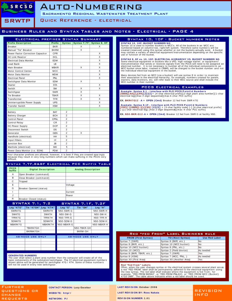
Prefix Description Prefix Syntax Syntax 7,7F Syntax 8, 8F
Breaker BKR X X
Manual “Tie” Breaker BKRM X
Power Factor Correction Capacitor CPR X
DC Link Reactor DCL X
Electrical Data Monitor EDM X
Load Bank LB X
Main Breaker MBKR X X
Motor Control Center MCC X
Motor Data Monitor MDM X
Electrical Panel PNL X
Switchgear Data Monitor SDM X
Starter STA X
Switch SW X X
Switchgear SWR X
Tie Breaker TBKR X X
Transformer TFR X X
Uninterruptible Power Supply UPS X
Transfer Switch XSW X
Battery BAT 2
Battery Charger BCH 2
Control Panel CPNL 2
Control Relay CR 2
DC Power Supply DCP 2
Disconnect Switch DS 2
Generator GEN 2 X
Handhole (electrical) HH 5
Input Filters IF 2
Junction Box JB 2
Manhole (electrical) MH 5
Power Data Monitor (i.e. EDM) PDM 2
Electrical prefixes Syntax Summary
Business Rules and Syntax Tables and Notes - Electrical - PAGE 4
Four character prefixes are allowed, however, it is best if they are created spar inglybecause they result in very long numbers which can make suffixing in the PCCS verydifficult.
Syntax 7,7F,8&8F Electrical PCC Suffix TablePCCSSuffix Digital Description Analog Description
A Open Breaker (command)B Close Breaker (command)C TrippedE VoltageG Breaker Opened (status)I CurrentJ PowerR Breaker Closed (status)
Red “Fed From” LabelsOften, when the user changes syntax or the electrical system crosses several plant are asa red “FED FROM” label shall be permanently adhered to the electrical equipment usingthe new syntax. The red label shall indicate where the equipment is fed from; forexample, “FED FROM BKRA3”, or “FED FROM PNLA3C, or “FED FROM MCC (Bucket)47G3-3MR”. The table above indicates when a red label should be used.
FROM (First Syntax) TO (Next Syntax) Use Red Label
Syntax 7 (SWR) Syntax 8 (BKR, etc.) NoSyntax 8 (BKR, etc.) Syntax 10 (MCC bucket) NoSyntax 10 (MCC bucket) Syntax 8 (PNL, etc.) NoSyntax 10 (MCC) Syntax 2 (Field device) As neededSyntax 8 (BKR, TBKR, etc.) Syntax 7 (SWR) YesSyntax 8 (XSW) Syntax 7 (MCC, PNL, ) As neededSyntax XX (First Area) Syntax XX (Another Area) Yes
Red “fed From” Label Business rule
SYNTAX 7.1, 7.2
SYNTAX 10, 10F: BUCKET NUMBERINGSyntax 10 is used to number buckets in MCC's. All of the buckets in an MCC arenumbered based on column/row, right/left system. Therefore some numbers will becreated (reserved) using this syntax whether or not the buckets actually exist. A bucketmay contain a variety of electrical equipment/instrumentation depending on the specificuse or function of the bucket.
SYNTAX 8, 8F vs. 10, 10F: ELECTRICAL HIERARCHY VS. BUCKET NUMBERI NGSome electrical equipment in buckets like a VFD, high voltage starter, or equipment/instrumentation that sends or receives signals from the PCCS will need to be assigned anelectrical number. It is not necessary to number all of the individual components in anMCC bucket since labor, tracked in CMMS, will be charged to the bucket number and notthe individual electrical equipment in the bucket.
Many devices fed from an MCC (via a bucket) will use syntax 8 in order to maintaintheir association in the electrical hierarchy; for example, numbers created for panels,starters, data monitors, etc. will refer back to their MCC source and shall include theMCC number in their number.
Syntax 10, 10F - Bucket number Notes
GENERATED NUMBERSThe user shall select a plant area number then the computer will create all of thebasic components of the substation/switchgear. The 22 electrical equipment numbersshown above will be generated for switchgear 47G / 47H. Some of these numberswill not be used in every new switchgear.
Leg “47G” Tie “47GH” Leg “47H”SWR47G SWR47H
SW47G SW47HTFR47G TFR47H
SDM47G SDM47HMBKR47G MBKR47H
TBKR47GHBKRM47GH
AS-NEED USE ONLY
SYNTAX 7.1F, 7.2FLeg “G” Tie “GH” Leg “H”
N50-SWR-G N50-SWR-H
N50-SW-G N50-SW-HN50-TFR-G N50-TFR-H
N50-SDM-G N50-SDM-HN50-MBKR-G N50-MBKR-H
N50-TBKR-GHBKRM-GH
AS-NEED USE ONLY
PCCS Electrical Examples Example: Syntax 8.1 - Interface with PLC/PCCS P ointId Numbers[EEEE][AA][L][99][ZZZZ]= [4-char electrical prefix][2-digit plant area number][1-charelectrical leg][max 2-digit sequential][max 4-char PCC suffix]
EX. BKR47G12 -A = OPEN (Cmd) Breaker 12 fed from SWR 47G
Example: Syntax 8.1F - Interface with PLC/PCCS PointId Numbers[FFF][-][EEEE][-][L][99] [ZZZZ] = [3-char facility code] [-] [4-char electrical prefix][-][1-char electrical leg] [max 2-digit sequential][max 4-char PCC suffix]
EX. N50-BKR-G12-A = OPEN (Cmd) Breaker 12 fed from SWR G at facility N50.
Furtherquestions orchangerequests
CONTACT PERSON: Lucy Escobar
WEBSITE: http//
NETWORK: P:/
LAST REVISION: October 2006
LAST REVISION BY: Ross Nakata
REVISION NUMBER: 1.01
REVISIONINFO
Auto-NumberingQuick Reference - electrical
Sacramento Regional Wastewater Treatment Plant800SRWTP

M
SDM
EDM
M
VFD
EDM
UPS
SDM
RED LABEL:Fed From "UPS47G5" and "TFR47H1"
PDM
(NOTE 2)
EDM
VFD
SYNTAX 10(SYNTAX 10F)
SW47G(N50-SW-G)
TFR47G(N50-TFR-G)
MBKR47G(N50-MBKR-G)
SDM47G(N50-MBKR-G)
BKR47G3(N50-BKR-G3)
EDM47G3(N50-EDM-G3)
SWR47G (N50-TFR-G)
BKR47G5(N50-BKR-G5)
TBKR47GH(N50-TBKR-GH)
BKRM47GH(N50-BKRM-GH)
SWR47H(N50-TFR-H)
BKR47H1(N50-BKR-H1)
BKR47H2(N50-BKR-H2)
SDM47H(N50-MBKR-H)
MBKR47H(N50-MBKR-H)
TFR47H(N50-TFR-H)
SW47H(N50-SW-H)
12KV FEEDER
UPS47G5(N50-UPS-G5)
TFR47H1(N50-TFR-H1)
PNL47H2(N50-PNL-H2)
BKR47H2C(N50-BKR-H2C)
PNL47H2C(N50-PNL-H2C)
BKR47H2C1(N50-BKR-H2C1)
TFR47H2C1(N50-TFR-H2C1)
PNL47H2C1(N50-PNL-H2C1)
PDM470001(N50-PDM0001)
CPNL470001(N50-CPNL0001)
MBKR47GH1A(N50-MBKR-GH1A)
XSW47GH1(N50-XSW-GH1)
MBKR47G3(N50-MBKR-G3)
(NOTE 1 - TYP.)
MCC47G3(N50-MCC-G3)
BKR47G3C(N50-BKR-G3C)
STA47G3C(N50-STA-G3C)
BKR47G3B(N50-BKR-G3B)
EDM47G3B(N50-EDM-G3B)
BKR47G3A(N50-BKR-G3A)
VFD47G3A(N50-VFD-G3A)
TFR47G3B(N50-TFR-G3B)
PNL47G3B(N50-PNL-G3B)
M470006A(N50-M0006A)
M470007A(N50-M0007A)
BKR47G3A
VFD47G3A
BKR47G3B
EDM47G3B
BKR47G3C
STA47G3C
12KV FEEDER
SYNTAX KEYSYNTAX 2 (SYNTAX 2F)SYNTAX 7.1 (SYNTAX 7.1F)SYNTAX 7.2 (SYNTAX 7.2F)SYNTAX 8.1 (SYNTAX 8.1F)SYNTAX 8.2 (SYNTAX 8.2F)SYNTAX 8.3 (SYNTAX 8.3F)SYNTAX 8.4 (SYNTAX 8.4F)SYNTAX 8.5 (SYNTAX 8.5F)SYNTAX 10 (SYNTAX 10F)
MDM47G3C(N50-MDM-G3B)
MDM
47G3A(N50-G3-1M)
47G3B(N50-G3-2MR)
47G3C(N50-G3-3M)
Need plan view and one-line to generate Syntax 7.1 and 7.2 numbers(i.e. transformer primary sw, transformer, switchgear, switchgear main and tie breakers)
The physical location of the switchgear in the plant dictates the “area” portion of the numbering (i.e. SWR47H)
Need switchgear elevation views and one-lines to generate Syntax 8.1 numbers(i.e. Switchgear feeder breakers, and downstream switches, transformer, and panels)
The one-line for the switchgear dictates the device type (i.e. BKR47H1, BKR47H2,SW47H3)
The physical location on the elevation view for the switchgear dictates the breaker number ordering (i.e. 47H1, 47H2)
Need one-lines, panel schedules, & elevations to generate Syntax 8.2 numbersfor downstream panels and power distribution devices. (i.e. panels, breakers)The physical location of breaker in the panel dictates the breaker number ordering (i.e. BKR47H2A, BKR47H2B, BKR47H2C, PNL47H2C)
Need one-lines, mcc schedules and elevations view to generate Syntax 8.2 andsyntax 10 numbers for downstream panels and power distribution devices.(i.e. mcc breaker, starter, and cubicle numbers)
If we have just syntax 8.1 number we can generate a block of MCC cubicle syntax 10 numbers unassigned to be used later but not the syntax 8.2 numbers. (i.e. BKR47G3B, TFR47G3B, PNL47G3B)
Need one-lines, panel schedules, and elevations to generate Syntax 8.3 numbers for downstream panels and power distribution devices. (i.e. panels, transformers, and breakers)
The physical location of breaker in the panel dictates the breaker number ordering (i.e. BKR47H2C1, TFR47H2C1, PNL47H2C1)
Need:1. plan views2. one-lines
Need:1. one-lines2. switchgear elevation views
Need:1. one-lines2.panel schedules3. panel elevation views
Need:1. one-lines2. MCC schedules3. MCC elevation views
Last Edited: 10/14/2014
Electrical System Quick Reference Auto-Numbering Explanation

Appendix C
Mandatory California Green Building Standards

Page 1
District Selection of Implementation Measures to:Title 24, Part 11 "CALGreen" NONRESIDENTIAL MANDATORY MEASURE COMPLIANCE FOR FACILITY TYPE
Mechanical/ Electrical/ Process
Occupant
5.1 - PLANNING AND DESIGN
Newly constructed projects and additions which disturb less than one acre of land shall prevent the pollution of stormwater runoff from the construction activities through one or more of the following measures:
5.106.1.1 - Local Ordinance YES YESComply with the lawfully enacted stormwater management and/or erosion control ordinance.
5.106.1.2 - Best management practices YES YES Prevent the loss of soil erosion by implementing BMP(s).
5.106.4.1 - Short-term bicycle parking YES* YES
* While non-occupant buildings could be interpreted as exempt from CAL Green measures, District Guidelines require bicycle parking at these buildings. Per Design Guideline 3.8 "Parking", "Utility cart and bicycle parking shall be provided at all SRWTP process buildings". Provide permanently anchored bicycle racks within 200 feet of the employee entrance door for 5 percent of new vehicle parking spaces, with a minimum of one two-bike capacity rack.
Provide permanently anchored bicycle racks within 200 feet of the visitors' entrance (employee entrance door) for 5 percent of new vehicle parking spaces, with a minimum of one two-bike capacity rack.
5.106.4.2 - Long-term bicycle parking N/A NO
Provide secure bicycle parking for 5 percent of the tenant vehicular parking spaces being added, with a minimum of one space. Acceptable parking facilities: covered, lockable enclosures, bike rooms, bike lockers.
Less than 10 occupants and 10 parking spaces at building
5.106.5.2 - Designated parking NO* NO** If directed by District to provide electrical outlets for plug-in vehicles or utility carts, designate parking spaces with markings at these locations.
Provide designated parking for any combination of low-emitting, fuel-efficient and carpool/van pool vehicles per table 5.106.5.2 (8% +/-)Outdoor lighting systems shall be designed and installed to comply with the following:
5.106.8 (1) - Light pollution reduction NO NOTreatment Plant lighting well separated from property lines and higher lighting provides more safety
Meet min requirements of the California Energy Code (CEC) for Lighting Zones 1-4
Emergency Lighting and Luminaires that qualify in Section 140.7 of CEC
5.106.8 (2) - Light pollution reduction NO NOTreatment Plant lighting well separated from property lines and higher lighting provides more safety
Comply with backlight, uplight and glare (BUG) ratings as defined in IES TM-15-11
Emergency Lighting and Luminaires that qualify in Section 140.7 of CEC
5.106.8 (3) - Light pollution reduction NO NOTreatment Plant lighting well separated from property lines and higher lighting provides more safety Comply with allowable BUG ratings in Table 5.106.8
Emergency Lighting and Luminaires that qualify in Section 140.7 of CEC
5.106.10 - Grading and paving YES YES Site grading and drainage will be designed to keep water from entering the building Site grading and drainage will be designed to keep water from entering the building
5.2 - ENERGY EFFICIENCY
5.201.1 - California Energy Code NO YESThis measure refers to Title 24, Part 6- Building Energy Efficiency Standards, authored by the CA Energy Commission.
For the purposes of mandatory energy efficiency standards in this code, the California Energy Commission will continue to adopt mandatory building standards.
Envelope Insulation NO* YES
* Not when providing concrete exterior walls. If other materials besides concrete are used, receive clarification from the District. Occupant buildings to meet envelope insulation requirements of Building Energy Efficiency Standards.
5.106.4 - Bicycle parking
5.106.8 - (Outdoor) Light pollution reduction
Topics of interest in Building Energy Efficiency Standards
5.106.1 - Storm water pollution prevention
Two versions of the 01 57 23 TEMPORARY STORM WATER POLLUTION CONTROL Guide Specification have been developed – one for a Water Pollution Control Plan (WPCP) and one for a Storm Water Pollution Prevention Plan (SWPPP). The SWPPP stormwater pollution control specification has been developed to address stormwater requirements for construction projects that exist outside of the SRWTP Ring Levee and have an area of soil disturbance greater than 1 acre. Projects with less than an acre of soil disturbance that exist outside of the SRWTP Ring Levee will be required to comply with a Water Pollution Control Plan (WPCP). Projects inside the SRWTP Ring Levee, regardless of size, will only require a WPCP as stormwater is treated via routing to headworks.
5.106 - SITE DEVELOPMENT
DIVISION DIRECTION TO DESIGNERS CAL Green Measure (Description) CAL Green ExceptionsIncorporate into Design?
BUILDING TYPE
MEASURE (SECTION)
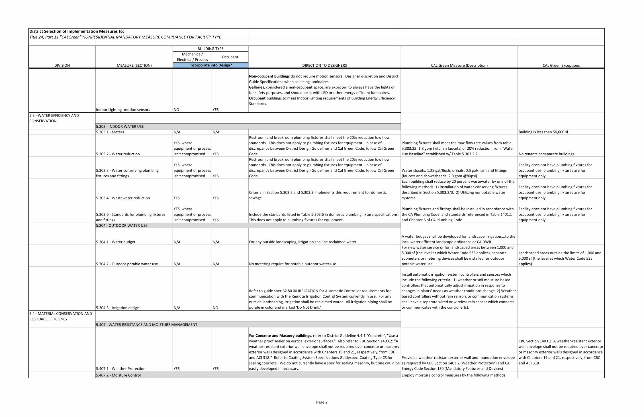
Page 2
District Selection of Implementation Measures to:Title 24, Part 11 "CALGreen" NONRESIDENTIAL MANDATORY MEASURE COMPLIANCE FOR FACILITY TYPE
Mechanical/ Electrical/ Process
Occupant
DIVISION DIRECTION TO DESIGNERS CAL Green Measure (Description) CAL Green ExceptionsIncorporate into Design?
BUILDING TYPE
MEASURE (SECTION)
Indoor Lighting- motion sensors NO YES
Non-occupant buildings do not require motion sensors. Designer discretion and District Guide Specifications when selecting luminaires. Galleries, considered a non-occupant space, are expected to always have the lights on for safety purposes, and should be lit with LED or other energy efficient luminaires. Occupant buildings to meet Indoor lighting requirements of Building Energy Efficiency Standards.
5.3 - WATER EFFICIENCY AND CONSERVATION
5.303.1 - Meters N/A N/A Building is less than 50,000 sf
5.303.2 - Water reduction
YES, where equipment or process isn't compromised YES
Restroom and breakroom plumbing fixtures shall meet the 20% reduction low flow standards. This does not apply to plumbing fixtures for equipment. In case of discrepancy between District Design Guidelines and Cal Green Code, follow Cal Green Code.
Plumbing fixtures shall meet the max flow rate values from table 5.303.23: 1.8 gpm (kitchen faucets) or 20% reduction from "Water Use Baseline" established w/ Table 5.303.2.2 No tenants or separate buildings
5.303.3 - Water conserving plumbing fixtures and fittings
YES, where equipment or process isn't compromised YES
Restroom and breakroom plumbing fixtures shall meet the 20% reduction low flow standards. This does not apply to plumbing fixtures for equipment. In case of discrepancy between District Design Guidelines and Cal Green Code, follow Cal Green Code.
Water closets: 1.28 gal/flush; urinals: 0.5 gal/flush and fittings (faucets and showerheads: 2.0 gpm @80psi)
Facility does not have plumbing fixtures for occupant use; plumbing fixtures are for equipment only.
5.303.4 - Wastewater reduction YES YESCriteria in Section 5.303.2 and 5.303.3 implements this requirement for domestic sewage.
Each building shall reduce by 20 percent wastewater by one of the following methods: 1) Installation of water-conserving fixtures described in Section 5.303.2/3. 2) Utilizing nonpotable water systems.
Facility does not have plumbing fixtures for occupant use; plumbing fixtures are for equipment only.
5.303.6 - Standards for plumbing fixtures and fittings
YES, where equipment or process isn't compromised YES
Include the standards listed in Table 5.303.6 in domestic plumbing fixture specifications. This does not apply to plumbing fixtures for equipment.
Plumbing fixtures and fittings shall be installed in accordance with the CA Plumbing Code, and standards referenced in Table 1401.1 and Chapter 6 of CA Plumbing Code.
Facility does not have plumbing fixtures for occupant use; plumbing fixtures are for equipment only.
5.304.1 - Water budget N/A N/A For any outside landscaping, irrigation shall be reclaimed water.A water budget shall be developed for landscape irrigation….to the local water efficient landscape ordinance or CA DWR
5.304.2 - Outdoor potable water use N/A N/A No metering require for potable outdoor water use.
For new water service or for landscaped areas between 1,000 and 5,000 sf (the level at which Water Code 535 applies), separate submeters or metering devices shall be installed for outdoor potable water use.
Landscaped areas outside the limits of 1,000 and 5,000 sf (the level at which Water Code 535 applies)
5.304.3 - Irrigation design N/A NO
Refer to guide spec 32 80 00 IRRIGATION for Automatic Controller requirements for communication with the Remote Irrigation Control System currently in use. For any outside landscaping, irrigation shall be reclaimed water. All irrigation piping shall be purple in color and marked ‘Do Not Drink.’
Install automatic irrigation system controllers and sensors which include the following criteria: 1) weather or soil moisture based controllers that automatically adjust irrigation in response to changes in plants' needs as weather conditions change. 2) Weather-based controllers without rain sensors or communication systems shall have a separate wired or wireless rain sensor which connects or communicates with the controller(s).
5.4 - MATERIAL CONSERVATION AND RESOURCE EFFICIENCY
5.407.1 - Weather Protection YES YES
For Concrete and Masonry buildings, refer to District Guideline 4.4.1 "Concrete", "Use a weather proof sealer on vertical exterior surfaces." Also refer to CBC Section 1403.2: "A weather-resistant exterior wall envelope shall not be required over concrete or masonry exterior walls designed in accordance with Chapters 19 and 21, respectively, from CBC and ACI 318." Refer to Coating System Specifications Guidespec, Coating Type CS for sealing concrete. We do not currently have a spec for sealing masonry, but one could be easily developed if necessary.
Provide a weather-resistant exterior wall and foundation envelope as required by CBC Section 1403.2 (Weather Protection) and CA Energy Code Section 150 (Mandatory Features and Devices)
CBC Section 1403.2: A weather-resistant exterior wall envelope shall not be required over concrete or masonry exterior walls designed in accordance with Chapters 19 and 21, respectively, from CBC and ACI 318.
Employ moisture control measures by the following methods:5.407.2 - Moisture Control
5.407 - WATER RESISTANCE AND MOISTURE MANAGEMENT
5.303 - INDOOR WATER USE
5.304 - OUTDOOR WATER USE
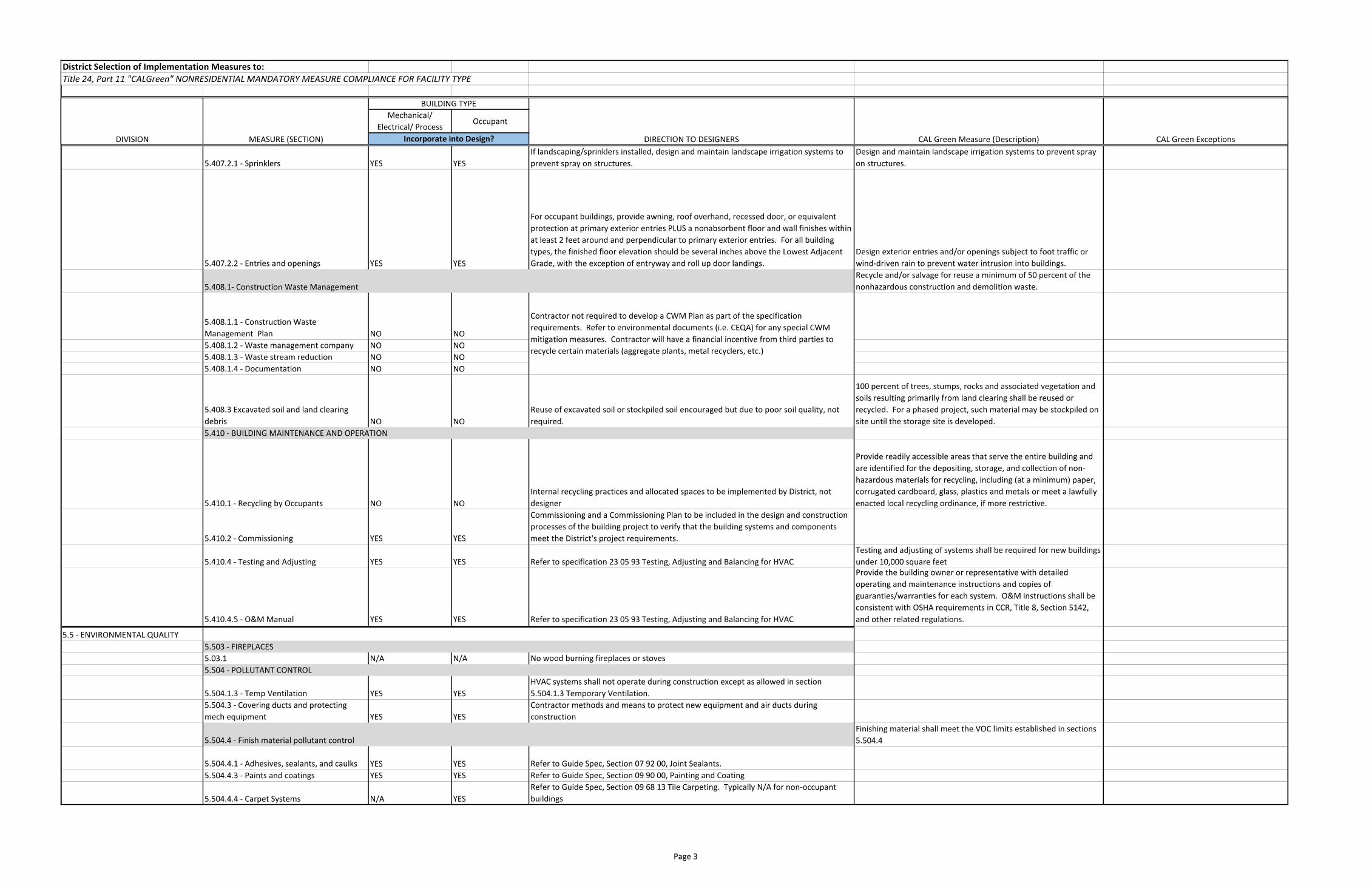
Page 3
District Selection of Implementation Measures to:Title 24, Part 11 "CALGreen" NONRESIDENTIAL MANDATORY MEASURE COMPLIANCE FOR FACILITY TYPE
Mechanical/ Electrical/ Process
Occupant
DIVISION DIRECTION TO DESIGNERS CAL Green Measure (Description) CAL Green ExceptionsIncorporate into Design?
BUILDING TYPE
MEASURE (SECTION)
5.407.2.1 - Sprinklers YES YESIf landscaping/sprinklers installed, design and maintain landscape irrigation systems to prevent spray on structures.
Design and maintain landscape irrigation systems to prevent spray on structures.
5.407.2.2 - Entries and openings YES YES
For occupant buildings, provide awning, roof overhand, recessed door, or equivalent protection at primary exterior entries PLUS a nonabsorbent floor and wall finishes within at least 2 feet around and perpendicular to primary exterior entries. For all building types, the finished floor elevation should be several inches above the Lowest Adjacent Grade, with the exception of entryway and roll up door landings.
Design exterior entries and/or openings subject to foot traffic or wind-driven rain to prevent water intrusion into buildings.Recycle and/or salvage for reuse a minimum of 50 percent of the nonhazardous construction and demolition waste.
5.408.1.1 - Construction Waste Management Plan NO NO5.408.1.2 - Waste management company NO NO5.408.1.3 - Waste stream reduction NO NO5.408.1.4 - Documentation NO NO
5.408.3 Excavated soil and land clearing debris NO NO
Reuse of excavated soil or stockpiled soil encouraged but due to poor soil quality, not required.
100 percent of trees, stumps, rocks and associated vegetation and soils resulting primarily from land clearing shall be reused or recycled. For a phased project, such material may be stockpiled on site until the storage site is developed.
5.410.1 - Recycling by Occupants NO NOInternal recycling practices and allocated spaces to be implemented by District, not designer
Provide readily accessible areas that serve the entire building and are identified for the depositing, storage, and collection of non-hazardous materials for recycling, including (at a minimum) paper, corrugated cardboard, glass, plastics and metals or meet a lawfully enacted local recycling ordinance, if more restrictive.
5.410.2 - Commissioning YES YES
Commissioning and a Commissioning Plan to be included in the design and construction processes of the building project to verify that the building systems and components meet the District's project requirements.
5.410.4 - Testing and Adjusting YES YES Refer to specification 23 05 93 Testing, Adjusting and Balancing for HVACTesting and adjusting of systems shall be required for new buildings under 10,000 square feet
5.410.4.5 - O&M Manual YES YES Refer to specification 23 05 93 Testing, Adjusting and Balancing for HVAC
Provide the building owner or representative with detailed operating and maintenance instructions and copies of guaranties/warranties for each system. O&M instructions shall be consistent with OSHA requirements in CCR, Title 8, Section 5142, and other related regulations.
5.5 - ENVIRONMENTAL QUALITY
5.03.1 N/A N/A No wood burning fireplaces or stoves
5.504.1.3 - Temp Ventilation YES YESHVAC systems shall not operate during construction except as allowed in section 5.504.1.3 Temporary Ventilation.
5.504.3 - Covering ducts and protecting mech equipment YES YES
Contractor methods and means to protect new equipment and air ducts during construction
Finishing material shall meet the VOC limits established in sections 5.504.4
5.504.4.1 - Adhesives, sealants, and caulks YES YES Refer to Guide Spec, Section 07 92 00, Joint Sealants. 5.504.4.3 - Paints and coatings YES YES Refer to Guide Spec, Section 09 90 00, Painting and Coating
5.504.4.4 - Carpet Systems N/A YESRefer to Guide Spec, Section 09 68 13 Tile Carpeting. Typically N/A for non-occupant buildings
Contractor not required to develop a CWM Plan as part of the specification requirements. Refer to environmental documents (i.e. CEQA) for any special CWM mitigation measures. Contractor will have a financial incentive from third parties to recycle certain materials (aggregate plants, metal recyclers, etc.)
5.408.1- Construction Waste Management
5.504.4 - Finish material pollutant control
5.504 - POLLUTANT CONTROL
5.503 - FIREPLACES
5.410 - BUILDING MAINTENANCE AND OPERATION
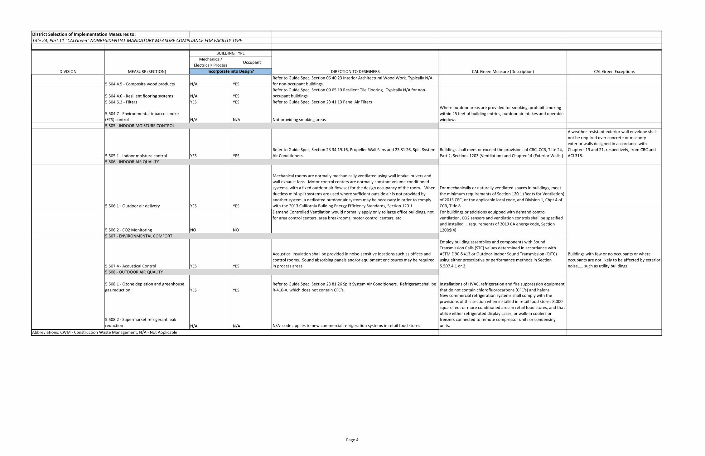
Page 4
District Selection of Implementation Measures to:Title 24, Part 11 "CALGreen" NONRESIDENTIAL MANDATORY MEASURE COMPLIANCE FOR FACILITY TYPE
Mechanical/ Electrical/ Process
Occupant
DIVISION DIRECTION TO DESIGNERS CAL Green Measure (Description) CAL Green ExceptionsIncorporate into Design?
BUILDING TYPE
MEASURE (SECTION)
5.504.4.5 - Composite wood products N/A YESRefer to Guide Spec, Section 06 40 23 Interior Architectural Wood Work. Typically N/A for non-occupant buildings
5.504.4.6 - Resilient flooring systems N/A YESRefer to Guide Spec, Section 09 65 19 Resilient Tile Flooring. Typically N/A for non-occupant buildings
5.504.5.3 - Filters YES YES Refer to Guide Spec, Section 23 41 13 Panel Air Filters
5.504.7 - Environmental tobacco smoke (ETS) control N/A N/A Not providing smoking areas
Where outdoor areas are provided for smoking, prohibit smoking within 25 feet of building entries, outdoor air intakes and operable windows
5.505.1 - Indoor moisture control YES YESRefer to Guide Spec, Section 23 34 19.16, Propeller Wall Fans and 23 81 26, Split System Air Conditioners.
Buildings shall meet or exceed the provisions of CBC, CCR, Tilte 24, Part 2, Sections 1203 (Ventilation) and Chapter 14 (Exterior Walls.)
A weather-resistant exterior wall envelope shall not be required over concrete or masonry exterior walls designed in accordance with Chapters 19 and 21, respectively, from CBC and ACI 318.
5.506.1 - Outdoor air delivery YES YES
Mechanical rooms are normally mechanically ventilated using wall intake louvers and wall exhaust fans. Motor control centers are normally constant volume conditioned systems, with a fixed outdoor air flow set for the design occupancy of the room. When ductless mini-split systems are used where sufficient outside air is not provided by another system, a dedicated outdoor air system may be necessary in order to comply with the 2013 California Building Energy Efficiency Standards, Section 120.1.
For mechanically or naturally ventilated spaces in buildings, meet the minimum requirements of Section 120.1 (Reqts for Ventilation) of 2013 CEC, or the applicable local code, and Division 1, Chpt 4 of CCR, Title 8
5.506.2 - CO2 Monitoring NO NO
Demand Controlled Ventilation would normally apply only to large office buildings, not for area control centers, area breakrooms, motor control centers, etc.
For buildings or additions equipped with demand control ventilation, CO2 sensors and ventilation controls shall be specified and installed … requirements of 2013 CA energy code, Section 120(c)(4)
5.507.4 - Acoustical Control YES YES
Acoustical insulation shall be provided in noise-sensitive locations such as offices and control rooms. Sound absorbing panels and/or equipment enclosures may be required in process areas.
Employ building assemblies and components with Sound Transmission Calls (STC) values determined in accordance with ASTM E 90 &413 or Outdoor-Indoor Sound Transmission (OITC) using either prescriptive or performance methods in Section 5.507.4.1 or 2.
Buildings with few or no occupants or where occupants are not likely to be affected by exterior noise,…. such as utility buildings.
5.508.1 - Ozone depletion and greenhouse gas reduction YES YES
Refer to Guide Spec, Section 23 81 26 Split System Air Conditioners. Refrigerant shall be R-410-A, which does not contain CFC's.
Installations of HVAC, refrigeration and fire suppression equipment that do not contain chlorofluorocarbons (CFC's) and halons.
5.508.2 - Supermarket refrigerant leak reduction N/A N/A N/A- code applies to new commercial refrigeration systems in retail food stores
New commercial refrigeration systems shall comply with the provisions of this section when installed in retail food stores 8,000 square feet or more conditioned area in retail food stores, and that utilize either refrigerated display cases, or walk-in coolers or freezers connected to remote compressor units or condensing units.
Abbreviations: CWM - Construction Waste Management, N/A - Not Applicable
5.508 - OUTDOOR AIR QUALITY
5.507 - ENVIRONMENTAL COMFORT
5.506 - INDOOR AIR QUALITY
5.505 - INDOOR MOISTURE CONTROL

Appendix D
Flowmeter Piping Elevation Method B


Appendix E
Flowmeter Piping Requirements Table
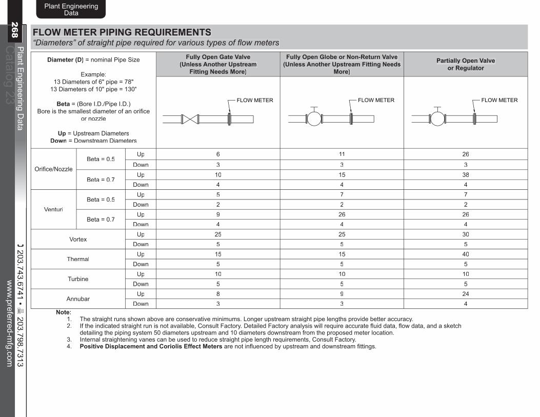
( 203.743.6741 • 6 203.798.7313
ww
w.preferred-m
fg.comP
lant Engineering D
ataC
atalog 23
Plant EngineeringData
268w
ww
.preferred-mfg.com
Plant E
ngineering Data
Catalog 23
Plant EngineeringData
269
FLOW METER PIPING REQUIREMENTS“Diameters” of straight pipe required for various types of fl ow meters
Diameter (D) = nominal Pipe Size
Example:13 Diameters of 6" pipe = 78"
13 Diameters of 10" pipe = 130"
Beta = (Bore I.D./Pipe I.D.)Bore is the smallest diameter of an orifi ce
or nozzle
Up = Upstream DiametersDown = Downstream Diameters
Fully Open Gate Valve(Unless Another Upstream
Fitting Needs More)
Fully Open Globe or Non-Return Valve (Unless Another Upstream Fitting Needs
More)
Partially Open Valve or Regulator
FLOW METER FLOW METER FLOW METER
Orifi ce/NozzleBeta = 0.5
Up 6 11 26
Down 3 3 3
Beta = 0.7Up 10 15 38
Down 4 4 4
VenturiBeta = 0.5
Up 5 7 7Down 2 2 2
Beta = 0.7Up 9 26 26
Down 4 4 4
VortexUp 25 25 30
Down 5 5 5
ThermalUp 15 15 40
Down 5 5 5
TurbineUp 10 10 10
Down 5 5 5
AnnubarUp 8 9 24
Down 3 3 4Note:
1. The straight runs shown above are conservative minimums. Longer upstream straight pipe lengths provide better accuracy.2. If the indicated straight run is not available, Consult Factory. Detailed Factory analysis will require accurate fl uid data, fl ow data, and a sketch
detailing the piping system 50 diameters upstream and 10 diameters downstream from the proposed meter location.3. Internal straightening vanes can be used to reduce straight pipe length requirements, Consult Factory.4. Positive Displacement and Coriolis Effect Meters are not infl uenced by upstream and downstream fi ttings.

ww
w.preferred-m
fg.comP
lant Engineering D
ataC
atalog 23
Plant EngineeringData
268( 203.743.6741 • 6
203.798.7313w
ww
.preferred-mfg.com
Plant E
ngineering Data
Catalog 23
Plant EngineeringData
269
Diameter (D) = nominal Pipe Size
Example:13 Diameters of 6" pipe = 78"
13 Diameters of 10" pipe = 130"
Beta = (Bore I.D./Pipe I.D.)Bore is the smallest diameter of an orifi ce
or nozzle
Up = Upstream DiametersDown = Downstream Diameters
Two Elbows, > 10 Diameters, Fittings in Different Planes
Two Elbows, < 10 Diameters, Fittings in Different Planes
Reducer or Expander (Unless Another
Upstream fi tting Needs More)Atmospheric Intake
���� �����
���
���
���� �����
���� ������� �����
��� �����������
������������� ����� ����� ����
Orifi ce/NozzleBeta = 0.5
Up 16 20 9 8Down 3 3 3 3
Beta = 0.7Up 23 30 12 9
Down 4 4 4 4
VenturiBeta = 0.5
Up 21 21 5 (reducer), 2 (expander) —Down 2 2 2 —
Beta = 0.7Up 21 21 8 (reducer), 4 (expander) —
Down 2 2 4 —
VortexUp 30 45 25 —
Down 5 5 5 —
ThermalUp 15 40 15 (reducer), 30 (expander) —
Down 5 10 5 (reducer), 10 (expander) —
TurbineUp 10 10 10 —
Down 5 5 5 —
AnnubarUp 9 19 8 —
Down 3 4 3 —Note:
1. The straight runs shown above are conservative minimums. Longer upstream straight pipe lengths provide better accuracy.2. If the indicated straight run is not available, Consult Factory. Detailed Factory analysis will require accurate fl uid data, fl ow data, and a sketch
detailing the piping system 50 diameters upstream and 10 diameters downstream from the proposed meter location.3. Internal straightening vanes can be used to reduce straight pipe length requirements, Consult Factory.4. Positive Displacement and Coriolis Effect Meters are not infl uenced by upstream and downstream fi ttings.
FLOW METER PIPING REQUIREMENTS“Diameters” of straight pipe required for various types of fl ow meters

( 203.743.6741 • 6 203.798.7313
ww
w.preferred-m
fg.comP
lant Engineering D
ataC
atalog 23
Plant EngineeringData
270w
ww
.preferred-mfg.com
Plant E
ngineering Data
Catalog 23
Plant EngineeringData
271
Diameter (D) = nominal Pipe Size
Example:13 Diameters of 6" pipe = 78"
13 Diameters of 10" pipe = 130"
Beta = (Bore I.D./Pipe I.D.)Bore is the smallest diameter of an orifi ce
or nozzle
Up = Upstream DiametersDown = Downstream Diameters
One Elbow, T, Y, or Tank Exit(Fittings in the Same Plane)
Two Elbows(Fittings in the Same Plane)
Long Radius Bends(Fittings in the Same Plane)
���������
����������
���� �����
���� �����
���� �����FLOW METER
(For Two Elbows >10D separation, use One Elbow Data)
���� �����
Orifi ce/NozzleBeta = 0.5
Up 7 10 8
Down 3 3 3
Beta = 0.7Up 13 18 16
Down 4 4 4
VenturiBeta = 0.5
Up 4 4 4Down 2 2 2
Beta = 0.7Up 4 4 8
Down 2 2 4
VortexUp 30 30 30
Down 5 5 5
ThermalUp 15 20 20
Down 5 5 5
TurbineUp 10 10 10
Down 5 5 5
AnnubarUp 7 9 —
Down 3 3 —Note:
1. The straight runs shown above are conservative minimums. Longer upstream straight pipe lengths provide better accuracy.2. If the indicated straight run is not available, Consult Factory. Detailed Factory analysis will require accurate fl uid data, fl ow data, and a sketch
detailing the piping system 50 diameters upstream and 10 diameters downstream from the proposed meter location.3. Internal straightening vanes can be used to reduce straight pipe length requirements, Consult Factory.4. Positive Displacement and Coriolis Effect Meters are not infl uenced by upstream and downstream fi ttings.
FLOW METER PIPING REQUIREMENTS“Diameters” of straight pipe required for various types of fl ow meters

Appendix F
Fire Marshall Memorandum of Understanding
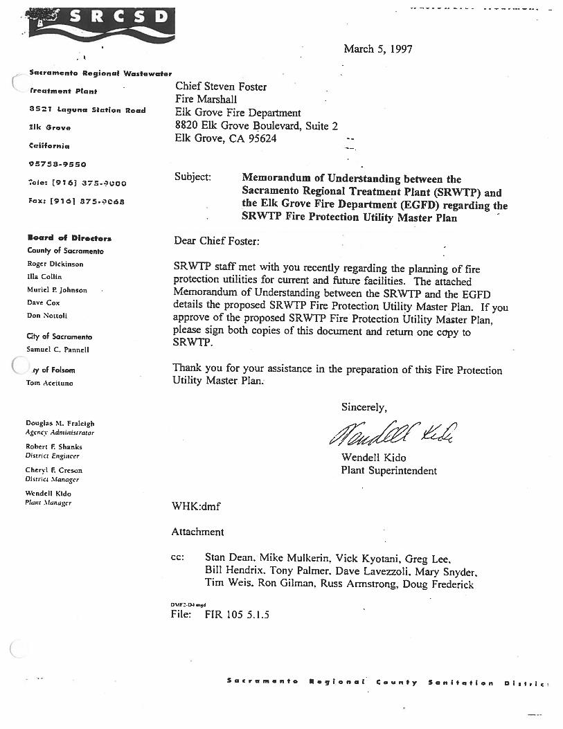
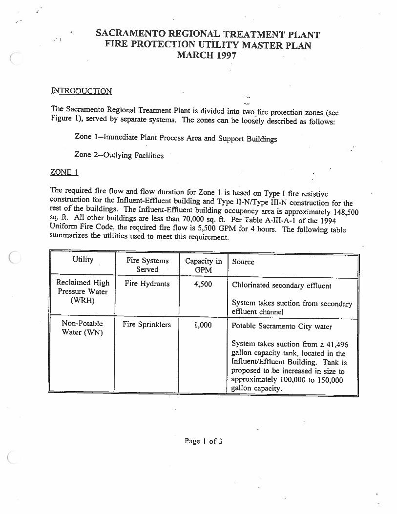

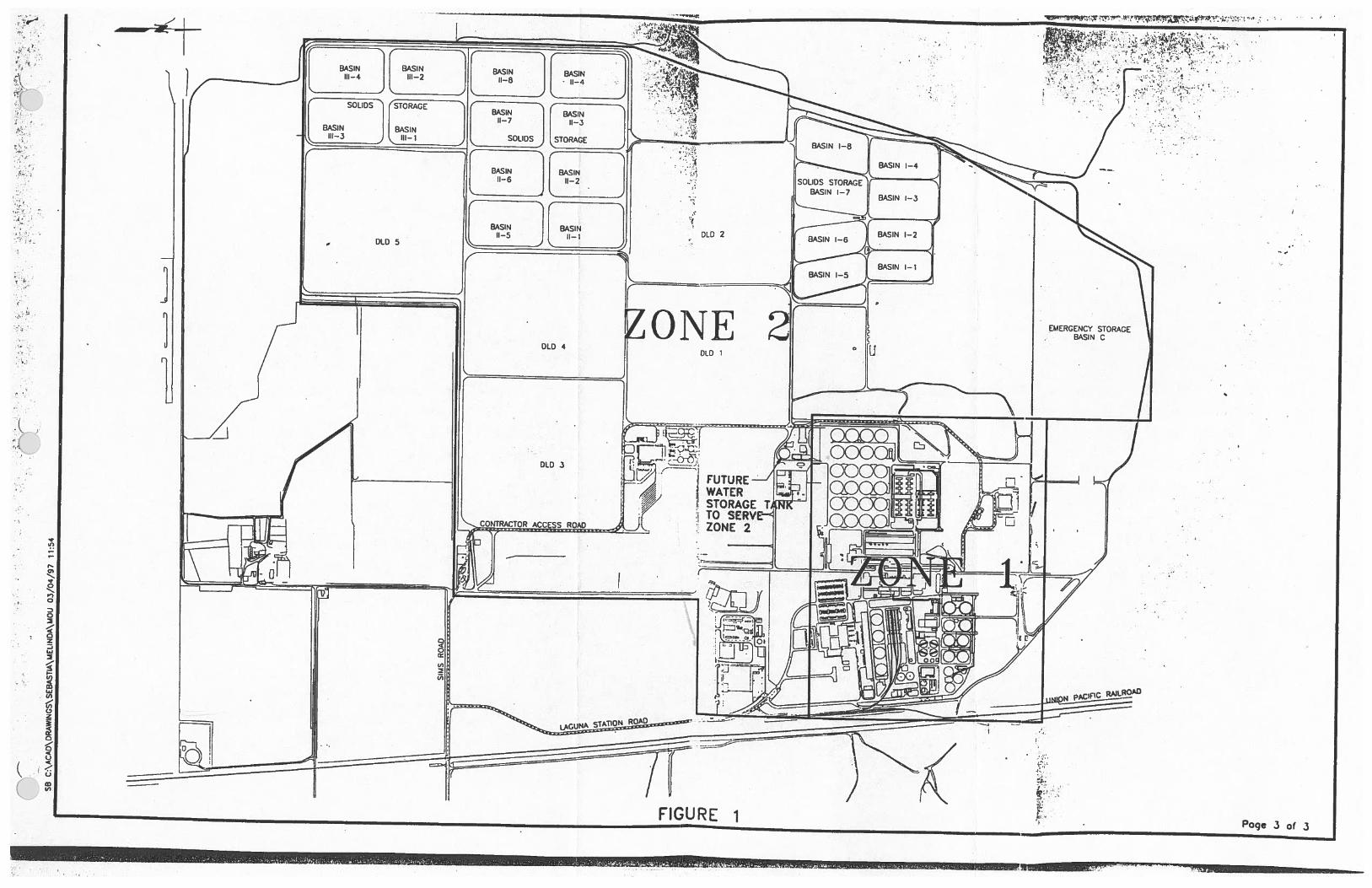
Copyright © 2022 FDOKUMEN

