


Bahasa
Halaman
Hukum

Document Number: ICT-317669-METIS/D6.4
Project Name: Mobile and wireless communications Enablers for the Twenty-twenty Information
Society (METIS)
Deliverable D6.4
Final report on architecture
Date of delivery: 31/01/2015 Version: 2 Start date of Project: 01/11/2012 Duration: 30 months
METIS Public ii
Deliverable D6.4 Final report on architecture
Project Number: ICT-317669
Project Name: Mobile and wireless communications Enablers for the Twenty-twenty Information Society
Document Number: ICT-317669-METIS/D6.4
Document Title: Final report on architecture Editor(s): Heinz Droste, Gerd Zimmermann (Deutsche Telekom
AG)
Authors: Uwe Doetsch (Alcatel-Lucent Bell Labs), Nico Bayer, Heinz Droste, Andreas Roos, Thomas Rosowski, Gerd Zimmermann (Deutsche Telekom AG), Patrick Agyapong (DOCOMO Euro-Labs), Neiva Fonseca Lindqvist, Icaro Da Silva, Hans Eriksson, Hugo Tullberg (Ericsson AB), Ömer Bulakci, Josef Eichinger (Huawei ERC), Konstantina Dimtsa, Makis Stamatelatos (National and Kapodistrian University of Athens), Venkatasubramanian Venkatkumar (Nokia Solutions and Networks), Mauro Boldi (Telecom Italia), Ignacio Berberana (Telefonica)
Dissemination Level: PU
Contractual Date of Delivery: 31/01/2015
Security: Public
Status: Final
Version: 2
File Name: METIS_D6.4_v2.docx Revision History
Revision Date Issued by Description 2 2015-
02-03 Gerd Zimmermann
“List of definitions” added
METIS Public iii
Abstract
The overall purpose of METIS is to develop a 5G system concept to fulfil the requirements of the beyond-2020 connected information society and to extend today’s wireless communication systems for new usage scenarios. This deliverable describes an overall 5G architecture that integrates Horizontal Topic (HT) concepts for Direct Device-to-Device Communication (D2D), Massive Machine Communication (MMC), Moving Networks (MN), Ultra-Dense Networks (UDN) and Ultra-Reliable Communication (URC).
In order to provide a complete story, METIS provides a) a functional architecture that is based on alignment of the HT concepts by identification of needed functionalities and functional decomposition of most relevant technology components developed by METIS technical work packages, b) a logical orchestration & control architecture that shows how flexibility, scalability, and service orientation can be realized in order to setup and implement the network functions, and c) a topological and deployment architecture that reveals deployment aspects and function placement options.
This multi-facial METIS architecture is the result of an extensive top-down and bottom-up analysis considering METIS requirements, technology components, evaluation results and architectural trends. Novel 5G architecture features are elaborated, and different architecture options are investigated and assessed.
Keywords Architecture Option, Building Block, System Concept, Deployment Combination, Functional Architecture, Orchestration, Functional Element, Horizontal Topics, Network Function Virtualization, Software Defined Network, Interface, Technology Components, 5G Baseline System

Document: FP7-ICT-317669-METIS/D6.4 Date: 04/02/2015 Security: Public
Status: Final Version: 2
METIS Public v
Executive summary The METIS project is laying the foundations of the Fifth Generation (5G) mobile and wireless communication system. Besides an in-depth research on technical enablers, the main objective of METIS is to elaborate a 5G system concept that efficiently integrates new services developed in the METIS Horizontal Topics (HTs) with evolved versions of existing services and systems.
In METIS the five HTs Device-to-Device communication (D2D), Massive Machine Communication (MMC), Moving Networks (MN), Ultra-Dense Networks (UDN) and Ultra-Reliable Communication (URC) are in focus. The objective of architectural work described in this deliverable is to support the integration of the HTs into an overall system concept as well as to identify different architecture options and to assess how they can contribute to the final METIS system to be elaborated in the remaining project time. Architecture options refer to dedicated functional architectures that rely on METIS technical enablers, such as M-MIMO (Massive Multiple Input Multiple Output), UDN (Ultra-Dense Network), Multi-RAT (Radio Access Technologies) and Dynamic RAN (Radio Access Network).
In a first step novel functionalities as perceived by analysing the HT concepts [MET14-D62] were listed and grouped into meaningful Building Blocks (BBs). This step is called top-down analysis. By this grouping, divergences and commonalities of the different HT concepts could be identified. Results of top-down analysis show that the different HTs are highly complementary, i.e., network functionalities of one HT frequently can be reused by several other HTs. This in addition motivates the integration of the different HT concepts into a single overall system that fulfils all requirements without manual reconfiguration. The analysis revealed that deeper research on topics like cross-layer reliable service composition and coverage enhancements for MMC is needed in order to better meet requirements of the HT concepts.
In a second step most promising Technology Components (TeCs) provided by the technical work packages of METIS were analysed from architectural point of view and thereby decomposed into so-called Functional Elements (FEs) where one or more of those FEs may be related to dedicated Network Functions (NFs). This bottom-up analysis leads to a functional architecture of the METIS system in which FEs and NFs, respectively, were assigned according to their usability for device and network infrastructure part and collected in separated function pools. Dependent on use cases (scenario environment and service type) different sets of network functions can be applied in devices and infrastructure network elements. This functional architecture may assist future projects to take care of already defined 5G NFs or to identify additional ones.
In order to run a fully operational 5G system there are FEs required that are currently not addressed by METIS TeCs, e.g. for security purposes, authentication, authorization and accounting (AAA) and network management & operation (OAM). In that sense METIS has drafted a thorough 5G functional architecture that is relevant with respect to the research topics covered by the technical work packages. There is a need for future refinements by R&I projects following after METIS, e.g. within the 5G PPP / Horizon 2020 work programme of EU (see [5GPPP] and [EU_H2020]).
In order to make 5G as seen from METIS perspective more concrete, a 5G baseline system is described from deployment point of view. Furthermore, architecture options are discussed to support novel 5G services 1, such as xMBB (extreme Mobile Broadband), mMTC (massive Machine-Type Communication) and uMTC (ultra-reliable Machine-Type Communication). For enabling flexible and service oriented deployment of network functions and protocols in a given network topology, tools provided by current architectural trends like NFV (Network
1 For definition of those 5G services please refer to METIS D6.3 or ”List of Definitions” in present document.
Document: FP7-ICT-317669-METIS/D6.4 Date: 04/02/2015 Security: Public
Status: Final Version: 2
METIS Public vi
Function Virtualization) and SDN (Software Defined Networking) are applied. This finally leads to a logical orchestration & control architecture of the METIS 5G system. In particular, this architecture instantiates the service-oriented mapping from a functional architecture into a real network implementation, i.e., a deployment architecture, by considering the requirements of the functional architecture and the physical infrastructure as well as the target services and use cases.
Most interesting novel network functions considered in METIS on top of the air interface level belong to BBs like Context Management, Spectrum Management, Radio Node Clustering & Dynamic (De-) Activation and RAT Selection. Another contribution from bottom-up analysis was the classification of radio network functions in synchronous (dependent on radio time-domain structure, such as scheduling and power control) and asynchronous (Mobility Management, Radio Node Clustering …). The project identified that so far virtualization and centralization of synchronous radio functions are limited while the centralization and virtualization of asynchronous network functions is more flexible, having the potential to improve network availability (resilience) as they can be moved flexibly from one data center to another in case of failure on the infrastructure part.
Moreover, it turns out that architecture options such as M-MIMO, UDN and Multi-RAT are highly complementary rather than competing. Thus, M-MIMO may be used for example in outdoor UDNs to improve link budgets and provide means for interference mitigation. Multi-RAT may be used in M-MIMO and UDN scenarios to improve device mobility. Wide area networks (WANs) may develop in an evolutional manner as LTE and its enhancements play an important role. They can be integrated into 5G by means of Multi-RAT enablers. Driver for innovative 5G WAN components could be the apparent need for tight integration of D2D and MMC into the WAN air interface.
Document: FP7-ICT-317669-METIS/D6.4 Date: 04/02/2015 Security: Public
Status: Final Version: 2
METIS Public vii
Contents
1 Introduction .................................................................................................................... 17 1.1 Objective of document............................................................................................... 1 1.2 Structure of document ............................................................................................... 1
2 Purpose of Architectural Work in METIS .......................................................................... 3 3 METIS Architecture Description ....................................................................................... 5
3.1 Functional Architecture.............................................................................................. 6 3.1.1 Building blocks derived from architectural top-down analysis ............................. 6 3.1.2 Generic functional architecture derived by functional decomposition of technology components ................................................................................................... 9
3.2 Orchestration & Control Architecture ....................................................................... 13 3.3 Topological & Functional Deployment Architecture ................................................. 16
3.3.1 Deployment aspects ......................................................................................... 16 3.3.2 Synchronous and asynchronous network functions .......................................... 17
4 5G Baseline System and Impact on Architecture ............................................................ 20 4.1 Comparison of 4G to 5G architecture ...................................................................... 20 4.2 5G Baseline System ................................................................................................ 21
4.2.1 Massive MIMO ................................................................................................. 22 4.2.2 UDN ................................................................................................................. 23 4.2.3 Multi-RAT ......................................................................................................... 24 4.2.4 Dynamic RAN .................................................................................................. 27
4.3 5G Core Network View ............................................................................................ 28 5 Results of Architectural Investigations with Impact on System Development .................. 29
5.1 Compilation of results – where to find what ............................................................. 29 5.2 Conclusion on architecture stories .......................................................................... 29 5.3 Next Steps .............................................................................................................. 31
6 References ..................................................................................................................... 32 7 Annex: Architectural Top-Down Analysis ........................................................................ 36
7.1 High level building blocks of the METIS system ...................................................... 36 7.2 Building blocks derived from HT concept descriptions ............................................. 37
7.2.1 Central Management Entities ........................................................................... 37 7.2.1 Radio Node Management ................................................................................ 37 7.2.2 Air Interface ...................................................................................................... 38 7.2.3 Reliable Service Composition........................................................................... 40
7.3 Horizontal Topic Building Blocks ............................................................................. 41 7.3.1 D2D.................................................................................................................. 41 7.3.2 MMC ................................................................................................................ 44 7.3.3 MN ................................................................................................................... 49 7.3.4 UDN ................................................................................................................. 52 7.3.5 URC ................................................................................................................. 55
7.4 Divergences and Commonalities of Horizontal Topic Concepts ............................... 58 7.4.1 Air Interface ...................................................................................................... 59 7.4.2 Radio Node Management ................................................................................ 60 7.4.3 Central Management Entities ........................................................................... 62
8 Annex: In-depth Analysis of Technology Components from Architecture Point of View .. 63 8.1 Selected Technology Components at a Glance ....................................................... 63 8.2 Identification of Alternative and Complementary Components ................................. 68 8.3 Description of Functional Elements ......................................................................... 78
9 Annex: Way towards an Optimized Overall System ...................................................... 132 9.1 Assessment Metrics .............................................................................................. 132
9.1.1 Efficiency ....................................................................................................... 132 9.1.2 Versatility ....................................................................................................... 132 9.1.3 Scalability ....................................................................................................... 133
9.2 Stories applying the architecture options ............................................................... 133
Document: FP7-ICT-317669-METIS/D6.4 Date: 04/02/2015 Security: Public
Status: Final Version: 2
METIS Public viii
9.2.1 Story I – Centralized vs. distributed operation of network functions ................ 133 9.2.2 Story II – Capacity extensions by M-MIMO and UDN and options for integration of WANs 139 9.2.3 Story III - Dynamic RAN Impact on Architecture ............................................. 145 9.2.4 Story IV - uMTC in industrial applications ....................................................... 152
9.3 Role of Architectural Trends and Orchestration & Control Architecture ................. 153 9.3.1 The Paradigm Shift between last RAN Generations ....................................... 153 9.3.2 The Logical Orchestration & Control View of the METIS 5G Architecture ....... 156
9.4 5G Core Networks ................................................................................................. 162 9.5 Outlook on further development of the 5G Architecture ......................................... 164 9.6 Relation to Results on Architectural Topics of other R&D Projects ........................ 166
9.6.1 iJOIN .............................................................................................................. 166 9.6.2 COMBO ......................................................................................................... 168
Document: FP7-ICT-317669-METIS/D6.4 Date: 04/02/2015 Security: Public
Status: Final Version: 2
METIS Public ix
List of Figures Figure 2-1: Basic strategy for architectural work in METIS. ..................................................... 3
Figure 3-1: High-level illustration of METIS 5G multi-facial architecture description. ................ 5
Figure 3-2: High level building blocks of the METIS system. ................................................... 6
Figure 3-3: Building blocks of the overall METIS system. ........................................................ 7
Figure 3-4: Generic functional architecture of METIS 5G System considering interrelations between infrastructure and device part (network-to-device communication). ......................... 10
Figure 3-5: Extended generic functional architecture of METIS 5G System considering interrelations between infrastructure and device part with incorporation of additional network elements as e.g. devices (cluster head, etc.) and mobile relays. ........................................... 12
Figure 3-6: Orchestration & Control Architecture View of METIS 5G System. ....................... 14
Figure 3-7: E2E Reference Network. ..................................................................................... 16
Figure 3-8: Possible deployment of synchronous and asynchronous network functions. ....... 18
Figure 4-1: 5G baseline system from a functional deployment view. ..................................... 21
Figure 4-2: Function placement for M-MIMO. ........................................................................ 22
Figure 4-3: Function placement for typical UDN deployment. ................................................ 24
Figure 4-4: Synchronous-/asynchronous network functions in Multi-RAT environment. ......... 26
Figure 4-5: Function placement for Multi-RAT (2 RATs). ....................................................... 27
Figure 4-6: Function placement for typical Dynamic RAN operation. ..................................... 27
Figure 7-1: High level building blocks of the METIS system. ................................................. 36
Figure 7-2: Building blocks of the overall METIS system. ...................................................... 41
Figure 7-3: HT D2D functional Building Blocks. ..................................................................... 42
Figure 7-4: HT MMC functional Building Blocks. .................................................................... 45
Figure 7-5: HT MN functional Building Blocks. ....................................................................... 50
Figure 7-6: HT UDN functional Building Blocks. .................................................................... 54
Figure 7-7: HT URC functional Building Blocks. .................................................................... 56
Figure 8-1: Blueprint for Air Interface BB (only parts applicable for Infrastructure Radio Nodes). .............................................................................................................................................. 92
Figure 8-2: Blueprint for Air Interface BB (only parts applicable for Device Radio Nodes). .. 105
Figure 8-3: Blueprint for Mobility Management (MM) BB (please note: measurements are performed via the AI (see Section 8.3.1). ............................................................................ 107
Figure 8-4: Blueprint for Interference Identification and Prediction (IIP) BB (please note: measurements are performed via the AI (see Section 8.3.1). .............................................. 109
Figure 8-5: Blueprint for RAT Selection (RATS) BB (please note: measurements are performed via the AI (see Section 8.3.1). ............................................................................ 111
Figure 8-6: Blueprint for D2D Device Detection & Mode Selection (DDDMS) BB (please note: measurements are performed via the AI (see Section 8.3.1). .............................................. 113
Figure 8-7: Blueprint for Long-term Radio Resource & Interference Management (LTRRIM) BB. ............................................................................................................................................ 118
Document: FP7-ICT-317669-METIS/D6.4 Date: 04/02/2015 Security: Public
Status: Final Version: 2
METIS Public x
Figure 8-8: Blueprint for Short-term Radio Resource & Interference Management (STRRIM) BB. ...................................................................................................................................... 121
Figure 8-9: Blueprint for Radio Node Clustering & Dynamic (De-)Activation (RNCDD) BB (please note: measurements are performed via the AI (see Section 8.3.1). ......................... 123
Figure 8-10: Blueprint for Nomadic Nodes Management (NNM) BB. ................................... 124
Figure 8-11: Blueprint for Context Management (CM) BB (please note: measurements are performed via the AI (see Section 8.3.1). ............................................................................ 127
Figure 8-12: Blueprint for Spectrum Management (SM) BB and Novel Network Interface Termination (NNIT) BB. ....................................................................................................... 131
Figure 9-1: Local centralization of small cell functions at macro cell base station. ............... 136
Figure 9-2: Centralized vs. distributed functions (locally). .................................................... 136
Figure 9-3: Higher level centralization between macro cells in network. .............................. 137
Figure 9-4: Thee possible dimensions for capacity improvements. ...................................... 139
Figure 9-5: Illustration of WP3.1 TeC1b. .............................................................................. 140
Figure 9-6: WP3.1 TeC7 - Massive MIMO transmission using higher frequency bands. ...... 140
Figure 9-7: WP3.1 TeC13: Interference mitigation based on JT CoMP and M- MIMO. ........ 141
Figure 9-8: Spectrum Management building blocks. ............................................................ 142
Figure 9-9: Clustering of UDN nodes (WP4.3 TeC2). .......................................................... 143
Figure 9-10: Activation and deactivation of small cells in UDN (WP4.3 TeC4-A2). .............. 144
Figure 9-11: An example NN operation (a) and some associated advantages (b). .............. 145
Figure 9-12: Deployment of functionalities in case of Dynamic NN Selection; high-level view (a) and functional decomposition (b). NN Selection functionality may be implemented at NN to reduce latency. .................................................................................................................... 146
Figure 9-13: Schematic illustration of Virtual Cell formation for the backhaul improvement. 147
Figure 9-14: Illustration of predictor antenna array implementation for moving relays. ......... 148
Figure 9-15: Illustration of coordinated random access management. ................................. 148
Figure 9-16: RAN architecture for V2X communication. ...................................................... 150
Figure 9-17: Illustration of flexible network configuration for some Dynamic RAN elements. 151
Figure 9-18: METIS WP inputs for 5G architecture design supporting METIS HTs, and trends to be considered for the overall 5G mobile and wireless radio network architecture. ........... 156
Figure 9-19: The three key aspects of METIS 5G architecture. The 5G HyperService Cube in the center illustrates a multi-dimensional overview in terms of throughput, latency and number of connections required for the broad range of service requirements to be efficiently supported by the 5G architecture. ........................................................................................................ 157
Figure 9-20: Generic 5G network architecture (high-level topological view). ........................ 158
Figure 9-21: Example E2E service flow with VNFs only (a) [ETSI_NFV] and extensions considering heterogeneous physical resources in 5G deployments (b). .............................. 161
Figure 9-22: Core Network's functional areas. ..................................................................... 163
Figure 9-23 : Design of future network architecture matrix. .................................................. 165
Figure 9-24: Illustration of iJOIN’s RANaaS approach for flexible implementation of radio network functions. ............................................................................................................... 167
Document: FP7-ICT-317669-METIS/D6.4 Date: 04/02/2015 Security: Public
Status: Final Version: 2
METIS Public xi
Figure 9-25: Network Reference Topology in the COMBO Project. ..................................... 168
Document: FP7-ICT-317669-METIS/D6.4 Date: 04/02/2015 Security: Public
Status: Final Version: 2
METIS Public xii
List of Tables Table 3.1: RNM BB specifications ........................................................................................... 7
Table 3.2: AI BB specifications ................................................................................................ 8
Table 5.1: Assessment of Architecture options. ..................................................................... 30
Table 7.1: RNM BB specifications. ........................................................................................ 38
Table 7.2: AI BB specifications. ............................................................................................. 39
Table 7.3: BB commonalities at AI. ........................................................................................ 60
Table 7.4: BB commonalities at RNM. ................................................................................... 62
Table 8.1: Technology Components (TeCs) considered for bottom-up analysis. ................... 63
Table 8.2: Alternative and Complementary Technology Components (TeCs). ....................... 69
Table 8.3: Functional Elements (FEs) for AI describing the Tx part of an Infrastructure Radio Node (IRN). ........................................................................................................................... 81
Table 8.4: Functional Elements (FEs) for AI BB describing the Rx part of an Infrastructure Radio Node (IRN). ................................................................................................................. 84
Table 8.5: Functional Elements (FEs) for AI BB describing the AI Management part of an Infrastructure Radio Node (IRN). ........................................................................................... 89
Table 8.6: Functional Elements (FEs) for AI BB describing the Basic Synchronization part of an Infrastructure Radio Node (IRN). ...................................................................................... 90
Table 8.7: Functional Elements (FEs) for AI describing the Tx part of a Device Radio Node (DRN). ................................................................................................................................... 93
Table 8.8: Functional Elements (FEs) for AI describing the Rx part of a Device Radio Node (DRN). ................................................................................................................................... 97
Table 8.9: Functional Elements (FEs) for AI describing the AI Management part of a Device Radio Node (DRN). ............................................................................................................. 102
Table 8.10: Functional Elements (FEs) for AI BB describing the Basic Synchronization part of a Device Radio Node (IRN). ................................................................................................ 103
Table 8.11: Functional Elements (FEs) for Mobility Management (MM) BB. ........................ 106
Table 8.12: Functional Elements (FEs) for Interference Identification & Prediction (IIP) BB. 107
Table 8.13: Functional Elements (FEs) for RAT Selection (RATS) BB. ................................ 109
Table 8.14: Functional Elements (FEs) for D2D Device Detection & Mode Selection (DDDMS) BB. ...................................................................................................................................... 111
Table 8.15: Functional Elements (FEs) for Long-term Radio Resource & Interference Management (LTRRIM) BB. ................................................................................................ 113
Table 8.16: Functional Elements (FEs) for Short-term Radio Resource & Interference Management (STRRIM) BB. ................................................................................................ 119
Table 8.17: Functional Elements (FEs) for Radio Node Clustering & Dynamic (De-) Activation (RNCDD) BB. ...................................................................................................................... 122
Table 8.18: Functional Elements (FEs) for Nomadic Nodes Management (NNM) BB. ......... 124
Table 8.19: Functional Elements (FEs) for Context Management (CM) BB. ........................ 125
Table 8.20: Functional Elements (FEs) for Spectrum Management (SM) BB....................... 128
Document: FP7-ICT-317669-METIS/D6.4 Date: 04/02/2015 Security: Public
Status: Final Version: 2
METIS Public xiii
Table 8.21: Functional Elements (FEs) for Novel Network Interface Termination (NNIT) BB. ............................................................................................................................................ 130
Table 9.1: List of METIS TeCs with deployment options (centralized, distributed). .............. 134
Table 9.2: List of METIS TeCs that can be implemented solely in a distributed fashion. ...... 135
Table 9.3: Spectrum bands suitable for UDN [MET14-D51]. ................................................ 142
Table 9.4: METIS TeCs for uMTC in industrial applications. ................................................ 153
Document: FP7-ICT-317669-METIS/D6.4 Date: 04/02/2015 Security: Public
Status: Final Version: 2
METIS Public xiv
List of Abbreviations 3GPP 3rd Generation Partnership Project 5G PPP 5th Generation Public Private
Partnership AAA Authentication, Authorization &
Accounting ACM Adaptive Coding & Modulation AI Air Interface,
Availability Indicator AIM Air Interface Management AN Access Node API Application Programing Interface AR Availability Request ARC Asynchronous Radio Control plane
function ARIB Association of Radio Industries
and Businesses ARU Asynchronous Radio User plane
function ASP Application Service Provider BB Building Block BBU BaseBand Unit BER Bit Error Rate BH BackHaul BS Base Station BW BandWidth CAPEX CAPital Expenditure CDN Content Delivery Network CH Cluster Head CM Context Management CME Central Management Entities CMU Central Management Unit cmW centimeter Wave CN Core Network CNE Core Network Element CO Central Office CoMP Coordinated Multi-Point COTS Commercial-Off-The-Shelf CP Control Plane C-Plane Control Plane CPRI Common Public Radio Interface CQI Channel Quality Indicator CRA Coded Random Access C-RAN Cloud-Radio Access Network,
CRC Cyclic Redundancy Check CSA Coded Slotted Aloha CSI Channel State Information D Deliverable D2D Device-to-Device D2D-B Device-to-Device – Backhaul D2D-C Device-to-Device – Critical D2D-M Device-to-Device – Machine D2D-N Device-to-Device – Non-critical DDDMS D2D Device Detection & Mode
Selection DFT Discrete Fourier Transform
DL Downlink D-RAN Distributed RAN DRN Device Radio Node
E2E End-to-End
ECC Electronic Communications Committee
EHF Extremely High Frequency EMF Electro Magnetic Field EMS Element Management System eNB evolved NodeB ETSI European Telecommunications
Standards Institute EU European Union FA Functional Architecture FBMC FilterBank based Multi-Carrier FD Full Duplex FDD Frequency Division Duplex FE Functional Element FEC Forward Error Correction FER Frame Error Rate FMC Fixed Mobile Convergence FuAg Function Agent GFA Generic Functional Architecture GLDB Geo-Location Data-Base GPON Gigabit Passive Optical Network GPRS General Packet Radio Service GPS Global Positioning System GSM Global System for Mobile
communications HARQ Hybrid Automatic Repeat re-Quest HD Half Duplex HO Hand Over HT Horizontal Topics HTD Horizontal Topic Driver HW Hardware IaaS Infrastructure as a Service IEEE Institute of Electrical and
Electronics Engineers IETF Internet Engineering Task Force ICIC Inter-Carrier Interference
Cancellation IIP Interference Identification &
Prediction IM Interference Management IMT International Mobile
Communications IP Internet Protocol IPR Intellectual Property Rights I/Q Inphase/Quadrature IR Internal report IRN Infrastructure Radio Node ISDN Integrated Services Digital
Network ISG Industry Specification Group
Document: FP7-ICT-317669-METIS/D6.4 Date: 04/02/2015 Security: Public
Status: Final Version: 2
METIS Public xv
ISP Internet Service Provider ITS Intelligent Transportation System ITU-R International Telecommunication
Union – Radio sector ITU-T International Telecommunication
Union –Telecommunication sector JT Joint Transmission KPI Key Performance Indicator LAN Local Area Network LLC Logical Link Control LLR Log-Likelihood Ratio LOS Line Of Sight LSA Licensed Shared Access LSAS Large Scale Antenna Systems LTE Long Term Evolution LTE-A Long Term Evolution-Advanced LTRRIM Long-Term Radio Resource &
Interference Management M2M Machine-to-Machine MAC Medium Access Control MBB Mobile BroadBand MC Macro Cell MCS Modulation & Coding Scheme MEC Mobile Edge Computing MF Measurement Function MGT Management MIMO Multiple-Input Multiple-Output MISO Multiple-Input Single-Output MM Mobility Management MMC Massive Machine Communication MMC-A Massive Machine Communication
– Accumulation MMC-D Massive Machine Communication
– Direct access MMC-M Massive Machine Communication
– Machine M-MIMO Massive Multiple-Input Multiple-
Output MMSE Minimum Mean Square Error mMTC Massive Machine-Type
Communication mmW millimeter Wave MN Moving Network MN-M Moving Networks – Mobility MN-N Moving Networks – Nomadic MN-V Moving Networks – Vehicle MPA Message Passing Algorithm MRT Maximum Ratio Transmission MTC Machine-Type Communication MTD Machine-Type Device MU Multi-User MUD Multi-User Detection NA Not Available NE Network Element NF Network Function NFV Network Function Virtualization NGMN Next Generation Mobile Networks NM Network Management
NN Nomadic Node NNIT Novel Network Interface
Termination NNM Nomadic Nodes Management NOMA Non-Orthogonal Multiple Access OAM Operations, Administration &
Maintenance OFDM Orthogonal Frequency Division
Multiplexing OPEX Operational Expenditure OQAM Offset Quadrature Amplitude
Modulation ORI Open Radio equipment Interface OTT Over-The-Top PaaS Platform as a Service PDCP Packet Data Convergence
Protocol PHY PHYsical layer PMT Project Management Team PTT Project Technical Team PU Public QAM Quadrature Amplitude Modulation QAP Quality Assurance Plan QMR Quarterly Management reports QoE Quality of Experience QoS Quality of Service R&D Research and Development R&TTE Radio and Telecommunications
Terminal Equipment RACH Random Access CHannel RAN Radio Access Network RANaaS Radio Access Network as a
Service RAT Radio Access Technology RATS RAT Selection RBS Radio Base Station RF Radio Frequency RLA ReLiability Aspect RLC Radio Link Control RN Radio Node RNCDD Radio Node Clustering & Dynamic
(De-) Activation RNE Radio Network Element RNM Radio Node Management RRC Radio Resource Control RRM Radio Resource Management RRU Remote Radio Unit RS Relay Station RSRP Reference Signal Received Power RSRQ Reference Signal Received Quality RSSI Received Signal Strength Indicator RTD Research and Technological
Development SA System Architecture SC Small Cell,
Single Carrier, Spectrum Controller
SCM Spatial Channel Model
Document: FP7-ICT-317669-METIS/D6.4 Date: 04/02/2015 Security: Public
Status: Final Version: 2
METIS Public xvi
SCMA Sparse Coded Multiple Access SDN Software Defined Network SDR Software Defined Radio SHF Super High Frequency SINR Signal-to-Interference-plus-Noise
Ratio SL Structural Level SLA Service Level Agreement SM Spectrum Management,
Spatial Multiplexing SMS Short Message Service SNR Signal-to-Noise Ratio SPM Software-defined function
Processing Manager SON Self-Organising Network SRC Synchronous Radio Control plane
function SRU Synchronous Radio User plane
function STM Service-oriented Topology
Manager STRRIM Short-Term Radio Resource &
Interference Management SU Single User SW Software TDD Time Division Duplex TDMA Time Division Multiple Access TeC Technology Component TR Technical Report TRX Transceiver TS Technical Solution,
Technical Specification UDN Ultra-Dense Network UDN-C Ultra-Dense Networks Core UDN-E Ultra-Dense Networks Extended
UE User Equipment UFMC Universal Filtered Multi-Carrier UHD Ultra High Definition UHF Ultra High Frequency UL Uplink uMTC Ultra-reliable Machine-Type
Communication UMTS Universal Mobile
Telecommunications System UP User Plane U-Plane User Plane URC Ultra-Reliable Communication URC-E Ultra-Reliable Communication
Emergency URC-L Ultra-Reliable Communication
Long-term URC-S Ultra-Reliable Communication
Short-term V2V Vehicle-to-Vehicle V2X Vehicle-to-anything VN Virtual Network VNF Virtual Network Function WA Wide Area WAN Wide Area Network WBH Wireless BackHaul WLAN Wireless Local Area Network WNC Wireless Network Coding WP Work Package WPL Work Package Leader WRC World Radio communication
Conference xMBB Extreme Mobile BroadBand ZF Zero Forcing
Document: FP7-ICT-317669-METIS/D6.4 Date: 04/02/2015 Security: Public
Status: Final Version: 2
METIS Public xvii
List of Definitions Alternative Technology Components
Alternative technology components (TeCs) contribute to the overall system performance utilizing identical physical sources in a manner that joint deployment does not appear meaningful. Alternative components might be selected according to specific use cases (mode switching) or - in case of use case independence - the most promising component of an alternative set may be selected.
Architecture Option Refers to dedicated functional architectures relying on METIS technical enablers, such as M-MIMO, UDN and Multi-RAT, but highlighting the architectural aspects of such solutions. This notation highlights the architecture view in context with this technical enabler.
Asynchronous Functions / Functional Elements
In METIS 5G architecture context network functions whose processing is time-asynchronous in relation to the radio slots/frames. They typically require low data rates on their interfaces and the processing requirements scales with the number of users, not the overall traffic. They can typically cope with 10s of milliseconds of latency. Therefore, they are good candidates to be flexibly deployed on more centralized or distributed platforms. These functions are also good candidates for function virtualization since most of them are not dependent on hardware acceleration.
Building Block The notation Building Block (BB) is used to represent / abstract / address a main topic (e.g. QoS support, network access control). A building block consists of functional elements as well as interfaces. These interfaces can be grouped in two categories. Firstly, internal interfaces which are interfaces between FEs of the BB. Secondly, external interfaces which are interfaces between a FE of the BB and an external BB and / or FE.
Common Building Blocks Contain functionalities which are required for more than one HT concept (s. Section 7).
Complementary Technology Components
Complementary technology components contribute to the overall system performance utilizing different physical sources and may be deployed at the same time in order to achieve performance improvements by their combination. METIS performance assessment in those cases needs to estimate resulting combined performance.
Core Network Element A Core Network Element (CNE) represents a processing entity that includes core network functions.
Core Network Function Network function associated to the E2E network connectivity of the devices, including, e.g., security AAA, QoS, Multi-access connectivity, Addressing, Mobility, etc.
C-RAN A Cloud-RAN (C-RAN) includes centralized and virtualized baseband processing whereas Centralized RAN is to be associated with centralized baseband processing using non virtualized network functions and dedicated hardware.
Deployment Combinations A deployment combination denotes options for distribution of core and / or radio network functions.
D-RAN Distributed RAN in METIS is used to denote the location (site) where a baseband and radio unit is placed. The radio unit may be connected to the baseband unit by fiber link.
Document: FP7-ICT-317669-METIS/D6.4 Date: 04/02/2015 Security: Public
Status: Final Version: 2
METIS Public xviii
Function Agent The Function Agent (FuAg) is an entity that configures the RNEs and CNEs according to the commands received from 5G orchestrator.
Functional Architecture A Functional Architecture (FA) is an architectural model that identifies building blocks, functional elements and interactions (interfaces) among each other. The FA does not have a direct relation to a specific deployment of these building blocks and / or functional elements. By definition it can allow for several different deployments. The FA itself does not state the location or hardware component on where the building blocks and / or functional elements are implemented. The FA also specifies the requirements of the building block and /or functional elements as well as the interfaces.
Functional Deployment Architecture
s. System Architecture
Functional Element The notion of Functional Element (FE) is used to name an entity in the METIS 5G architecture which is specified to perform a dedicated task. A FE consists of logic and one or more interfaces. In comparison to the notation “Building Block”, the FE has to be understood as more fine granular. The FE is part of a building block. A functional element is to be deployed at a certain location within the network.
Functionality Functionality acts as synonym for building block that combines the outcome of interacting functional elements. In general these functional elements might be placed at different locations within the network. Functionality is used in top-down analysis in order to differentiate between architecture and concept view where functionality is used in the latter case.
Horizontal Topic specific Building Block
Contain functionalities that appear only in one HT.
High Level Building Block Grouping of main building blocks into structural level that can be characterized by certain properties (s. Section 7).
Interface In the context of METIS an interface is a logical connection between two dissimilar FEs (objects, devices, or systems) through which information is passed.
Main Building Block Collection of functionalities that can be transcribed and compiled with a higher level notation.
Mandatory Building Block Mandatory building blocks collect functionalities that are not directly addressed by METIS research on technology components but are needed to make the overall system working (s. Section 7).
Medium Network Layer This term gives a rough estimate on possible placement of network functions or physical resources in Cloud-RANs or at dedicated radio nodes with special tasks.
mMTC Massive Machine-Type Communications (mMTC) concerns massive deployments of e.g. low-cost battery-powered sensors and actuators, remote-controlled and remote-readable utility meters. 5G systems must provide up- and down-scaling connectivity solutions for tens of billions of devices since it is expected that there will be 10-100 more connected devices per one human user of communications systems (for human interaction, connected machines owned by the user and devices owned e.g. by the city the user lives in).
Network Element A Network Element (NE) is a discrete telecommunications entity
Document: FP7-ICT-317669-METIS/D6.4 Date: 04/02/2015 Security: Public
Status: Final Version: 2
METIS Public xix
which can be managed over a specific interface. METIS foresees to use the notion of NE in meaning as applied in [3GPP12-21905] by 3GPP.
Network Function A Network Function (NF) includes a set of actions that can be implemented into software and reused by one or more technology components (it can be aligned for different TeCs). The interfaces (input and output parameter) can be clearly identified, classified and may differ for different TeCs. A function has to be executed at one location within the network, but functions may interwork with others at different locations.
Orchestration & Control Architecture
A logical orchestration & control architecture is an architectural model that instantiates the mapping from a FA into a real network implementation, i.e., a system architecture, by considering the requirements of the FA and physical infrastructure as well as the target services and use cases applying SDN (Software Defined Networking) and NFV (Network Function Virtualization) principles.
Radio Network Element A Radio Network Element (RNE) represents a processing entity that includes radio network functions.
Radio Network Function Radio Network Functions are associated to the radio interface, and can be further classified in control and user plane functions.
Synchronous Functions / Functional Elements
In METIS 5G architecture context network functions whose processing is time-synchronous to the radio interface (slots/frames). They typically require high data rates on their interfaces, which scales with the traffic and number of antennas. Processing typically happens on a per packet level. Potential for centralization is limited, since it would only work in case of low latency, high bandwidth transport networks (back-/fronthaul). Potential for virtualization is also limited, since they benefit a lot from hardware acceleration.
System Architecture ≡ Functional Deployment Architecture
A System Architecture (SA, synonymously Functional Deployment Architecture) is an architectural model that identifies network elements, their locations (e.g. sites) as well as FEs to be implemented on these network elements. The SA can be seen as a translation of a FA into a real network implementation. The SA has to fulfil the requirements of the functional architecture (the functional elements and interfaces).
Structural Level The notation Structural Level (SL) represents an area / part / location in the functional deployment architecture. For instance the core part of a network can be represented by one SL. Other parts of a network e.g. aggregation and access can be represented by other SLs. Each SL can comprise multiple BBs and FEs.
Technology Component ≡ Enabler
Pseudonymously Enabler: A Technology Component (TeC) represents a methodology, algorithm, or module that enables features of the METIS system and contributes to a Technical Solution.
Technical Solution A Technical Solution (TS) represents a combination of technology components which fulfils the technical requirements of one or more test cases. The TS can consist of one or more BBs. The BBs and / or FEs are interconnected by means of interfaces.
uMTC Ultra-reliable Machine-Type Communications (uMTC) relates to the capability to provide a given service level with very high
Document: FP7-ICT-317669-METIS/D6.4 Date: 04/02/2015 Security: Public
Status: Final Version: 2
METIS Public xx
probability. It also includes applications where low delay is a critical factor, such as remote driving, industrial control, and haptic communication enabling remote work in e.g. hazardous environments or remote surgery. The various kinds of MTC will enable the wireless Internet of Things (IoT) encompassing tens of billions connected devices.
xMBB Extreme Mobile Broadband (xMBB) provides the traffic volume and data rates required by new applications such as virtual reality and augmented reality. Improved user Quality of Experience (QoE) in terms of guaranteed minimum data rates and smart content delivery will also be necessarily provided by xMBB.
5G Baseline System Represents an integrated architecture that supports new 5G services, such as xMBB, mMTC, and uMTC.
Document: FP7-ICT-317669-METIS/D6.4 Date: 04/02/2015 Security: Public
Status: Final Version: 2
METIS Public 1
1 Introduction The main objective of METIS is to respond to societal challenges beyond 2020 by providing the basis for the all-communicating world, and by laying the foundation for a future mobile and wireless communications system.
The technical goals derived from these main objectives for METIS are [MET13-D11]:
• 1000 times higher mobile data volume per area, • 10 to 100 times higher typical user data rate, • 10 to 100 times higher number of connected devices, • 10 times longer battery life for low power devices, • 5 times reduced End-to-End (E2E) latency.
It can be deduced that these goals are partly contradicting2 and hence an integrated system concept has to be highly flexible and scalable in order to fulfil the requirements and, additionally, it has to be cost efficient and affordable. The final system and architecture design cannot be decoupled. Therefore, the present deliverable D6.4 and following deliverables D6.5 [MET15-D65] and D6.6 [MET15-D66] are to be seen as a complementary series of documents dealing with architecture, system performance evaluation and system integration including assessment according to fulfillment of requirements, respectively.
1.1 Objective of document The purpose of this document is to provide a summary of the architecture development work done in METIS. An integrated architecture of the METIS system is presented from different perspectives providing all information needed for system optimization and the assessment to be elaborated in deliverable D6.6 [MET15-D66]. The objectives of the architectural work are
to get a clear understanding of functional novelties introduced by METIS Horizontal Topics (HTs) and to support the integration of the HT concepts into an overall METIS system,
to analyse the Technology Components (TeCs) considered by the technical work packages by means of their functional decomposition in order to identify and classify interfaces between Functional Elements (FEs) as a basis for the development of future 5G Network Functions3 (NFs),
to identify the applicability of components for different use cases and classify them as alternative or complementary,
to define the properties of a 5G baseline system and investigate architecture options,
to demonstrate how flexibility and scalability can be introduced, but also to reveal limitations due to architectural requirements and constraints related to the radio network functions,
to determine novel 5G architecture features and their impact on 5G radio access, and
to introduce deployment examples in order to make 5G more concrete.
1.2 Structure of document The main part of the document is structured as follows:
In Section 2 the basic methodology and the purpose of architectural work in METIS is explained.
2 Especially if they have to be fulfilled at the same location or at the same time. 3 For definition of the different notations refer to “List of definitions”
Document: FP7-ICT-317669-METIS/D6.4 Date: 04/02/2015 Security: Public
Status: Final Version: 2
METIS Public 2
The METIS 5G architecture is described from functional, logical orchestration & control as well as topological view in Section 3.
In Section 4 novel architecture features are identified and their impact on 5G is discussed. The investigation of architecture options which provides basic input for further elaboration in Deliverable D6.6 is summarized.
Section 5 compiles results and provides navigation to important text within the document.
The main part of the document is supplemented by three annexes that contain more detailed information on the work performed.
Section 7 presents the results of the top-down analysis that identifies novel functionalities required to realize the HT concepts. In addition divergences and commonalities of the HT concepts are highlighted.
In Section 8, the most promising TeCs are analysed from architecture point of view by functional decomposition into Building Blocks (BBs) and FEs, which are further integrated into the generic functional architecture of the METIS system described in Section 3.1.2. This functional architecture can be used as a basis for identification of novel 5G network functions.
Section 9 plays with architecture options in order to make 5G more concrete. Furthermore, it is shown in more detail how the required flexibility and scalability, as well as service-oriented management can be introduced. Core aspects have been not in focus but most significant impact of 5G on core network functions is discussed. Outcomes of EU funded projects UNIFY as well as iJOIN and COMBO are compiled and demonstrate METIS relations to other R&D activities.
Document: FP7-ICT-317669-METIS/D6.4 Date: 04/02/2015 Security: Public
Status: Final Version: 2
METIS Public 3
2 Purpose of Architectural Work in METIS METIS is set up as explorative project where technical work packages conduct in-depth research to provide novel TeCs that contribute to the project goals. Besides that work, an important objective is to integrate the TeCs in a system concept that delivers the efficiency, versatility and scalability required to cope with challenging and contracting end user and service requirements, by providing at the same time affordable and sustainable solutions for future radio networks. The main purpose of architectural work in METIS is to provide basic input for elaboration of the final METIS system concept in deliverable D6.6 [MET15-D66].
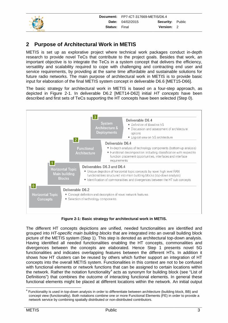
The basic strategy for architectural work in METIS is based on a four-step approach, as depicted in Figure 2-1. In deliverable D6.2 [MET14-D62] initial HT concepts have been described and first sets of TeCs supporting the HT concepts have been selected (Step 0).
Figure 2-1: Basic strategy for architectural work in METIS.
The different HT concepts depictions are unified, needed functionalities are identified and grouped into HT-specific main building blocks that are integrated into an overall building block picture of the METIS system (Step 1). This step is denoted as architectural top-down analysis. Having identified all needed functionalities enabling the HT concepts, commonalities and divergences between the concepts are elaborated. Hence Step 1 presents novel 5G functionalities and indicates overlapping features between the different HTs. In addition it shows how HT clusters can be reused by others which further support an integration of HT concepts into the overall METIS system. Functionalities in this context are not to be confused with functional elements or network functions that can be assigned to certain locations within the network. Rather the notation functionality4 acts as synonym for building block (see “List of Definitions”) that combines the outcome of interacting functional elements. In general these functional elements might be placed at different locations within the network. An initial output 4 Functionality is used in top-down analysis in order to differentiate between architecture (building block, BB) and
concept view (functionality). Both notations combine one or more Functional Elements (FE) in order to provide a network service by combining spatially distributed or non-distributed contributors.
Document: FP7-ICT-317669-METIS/D6.4 Date: 04/02/2015 Security: Public
Status: Final Version: 2
METIS Public 4
of the top-down analysis was already described in deliverable D6.3 [MET14-D63], the final results are presented in Section 3.1.1 of D6.4 and with more details in the Annex.
Considerable effort has been spent on an in-depth analysis of selected TeCs from architectural point of view. This has been done by means of a functional decomposition of TeCs, including a classification of resulting FEs with respect to placement opportunities in the network topology. Based on this analysis, interfaces and interface requirements have been elaborated. This Step 2 has been denoted as bottom-up analysis which is documented in detail in the Annex in Section 8 of this deliverable. Results of this work can be summarized by depiction of the Functional Architecture (FA) of the integrated HT concepts. A high level view in the form of a “Generic Functional Architecture” is presented in Section 3.1.2. The functional architecture shows FEs and their interworking as well as interfaces between them. This can be used as a basis for development of future 5G NFs that may be provided in radio processing function pools.
Based on outputs of the bottom-up analysis, an investigation of system architecture and deployment options has been conducted in Step 3. Architecture option in that context stands for METIS enablers such as Massive MIMO (M-MIMO), Ultra-Dense Networks (UDNs), Dynamic Radio Access Networks (RAN) and Multi-RAT (Radio Access Technology) networks. These enablers are related to specific deployment combinations and consequently also functions and their placement within the network topology. The detailed documentation of the definition of a 5G baseline system, the discussion and assessment of architecture options and the description of the architecture from logical orchestration & control point of view can be found in Section 4 and in the Annex in Section 9 of this deliverable. This logical orchestration & control architecture is building a bridge from the functional architecture to functional deployment architectures and demonstrates how a flexible, scalable and versatile 5G architecture can be realized.
Document: FP7-ICT-317669-METIS/D6.4 Date: 04/02/2015 Security: Public
Status: Final Version: 2
METIS Public 5
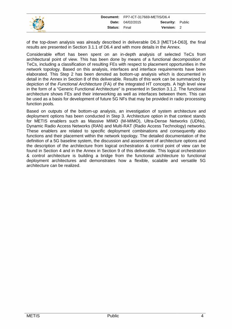
3 METIS Architecture Description In this section, the METIS perspective on the 5G architecture is highlighted. METIS approaches to the architecture description from three different views as illustrated in Figure 3-1. The functional architecture view, as detailed in Section 3.1 is based on identification of novel functionalities of the HT concepts (top-down analysis) and functional decomposition of most relevant TeCs provided by METIS technical work packages (bottom-up analysis). A Functional Architecture is presented in order to lay a foundation for development of novel 5G NFs. Considering the most promising METIS TeCs, FEs and their role within the FA are analyzed and depicted. The logical orchestration & control architecture view, as detailed in Section 3.2, shows how flexibility, scalability, and service orientation can be realized in order to setup and implement the NFs. Accordingly, the logical orchestration & control architecture view provides the means that connect the functional architecture view to the topological and functional deployment architecture view, as detailed in Section 3.3. This view reveals deployment aspects and function placement options, which illustrate the final system after the implementation and setup of the NFs.
As illustrated in Figure 3-1, the logical orchestration & control architecture takes into account the FE descriptions, the interrelations of FEs, the roles of FEs in BBs as defined by the FA, i.e., the FA forms the basis of a function pool. Considering the requirements of the target services, use cases, and given physical infrastructure, the logical orchestration & control architecture then constructs service-oriented logical topologies of data plane and control plane and maps these logical topologies onto the functional deployment architecture. Accordingly, different function placement options in the physical network can be attained taking into account the function classifications (i.e., synchronous or asynchronous control and date plane functions) and the associated requirements as defined by the functional deployment architecture as well as the interfaces between physical network resources. Various depictions of the function placement options are elaborated in Section 4.
Figure 3-1: High-level illustration of METIS 5G multi-facial architecture description.
Document: FP7-ICT-317669-METIS/D6.4 Date: 04/02/2015 Security: Public
Status: Final Version: 2
METIS Public 6
On this basis, the METIS 5G architecture description can collectively be defined by considering these three architecture models together forming a multi-facial architecture description. It is worth noting that in Figure 3-1 only a subset of functional deployment architecture options are depicted for the sake of simplicity. Other options can be realized based on the requirements of diverging target use cases and services. The end-to-end network aspects of such architecture options are further elaborated in Section 4.2.
3.1 Functional Architecture In this section the development of the METIS FA is considered following a two-step approach: (i) the identification and grouping of needed functionalities for each HT into BBs including combination of the HT BBs into a single METIS Building Block picture (top-down analysis), (ii) an in-depth analysis of TeCs and the assignment of FEs to the METIS FA BBs identified in (i) (bottom-up analysis). This section presents a summary of the results of (i) and (ii) while more details about the whole process can be found in the Annex in Sections 7 and 8, respectively.
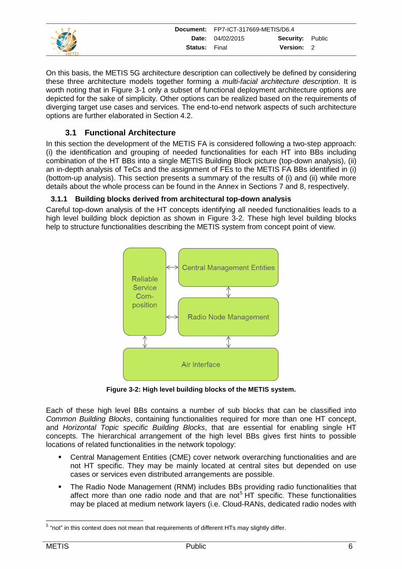
3.1.1 Building blocks derived from architectural top-down analysis Careful top-down analysis of the HT concepts identifying all needed functionalities leads to a high level building block depiction as shown in Figure 3-2. These high level building blocks help to structure functionalities describing the METIS system from concept point of view.
Figure 3-2: High level building blocks of the METIS system.
Each of these high level BBs contains a number of sub blocks that can be classified into Common Building Blocks, containing functionalities required for more than one HT concept, and Horizontal Topic specific Building Blocks, that are essential for enabling single HT concepts. The hierarchical arrangement of the high level BBs gives first hints to possible locations of related functionalities in the network topology:
Central Management Entities (CME) cover network overarching functionalities and are not HT specific. They may be mainly located at central sites but depended on use cases or services even distributed arrangements are possible.
The Radio Node Management (RNM) includes BBs providing radio functionalities that affect more than one radio node and that are not5 HT specific. These functionalities may be placed at medium network layers (i.e. Cloud-RANs, dedicated radio nodes with
5 “not” in this context does not mean that requirements of different HTs may slightly differ.
Document: FP7-ICT-317669-METIS/D6.4 Date: 04/02/2015 Security: Public
Status: Final Version: 2
METIS Public 7
special tasks). The interface requirements have an impact on opportunities for function placement.
Location of Air Interface (AI) functionalities (radio node and devices) may mainly be at lower network layers as directly in devices, antenna sites or at Cloud-RAN sites.
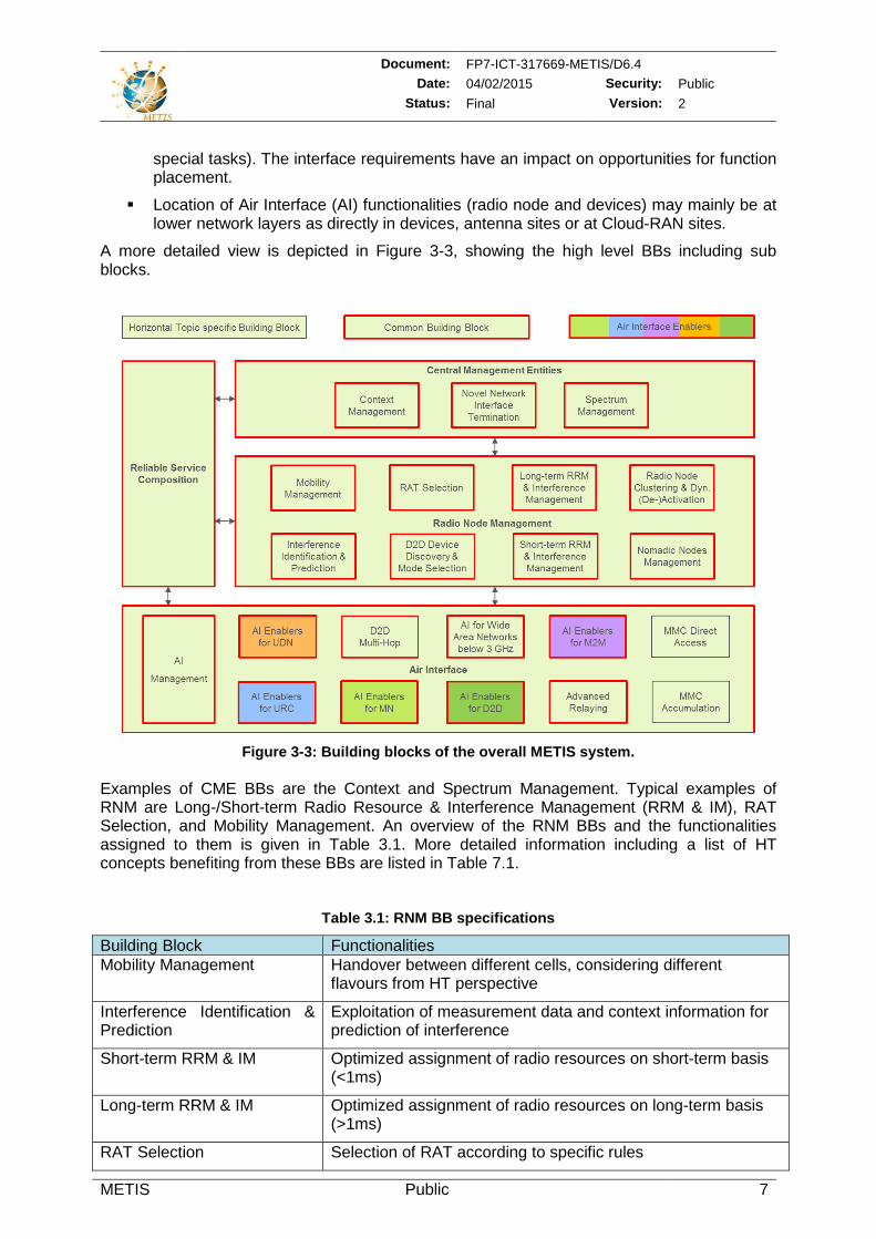
A more detailed view is depicted in Figure 3-3, showing the high level BBs including sub blocks.
Figure 3-3: Building blocks of the overall METIS system.
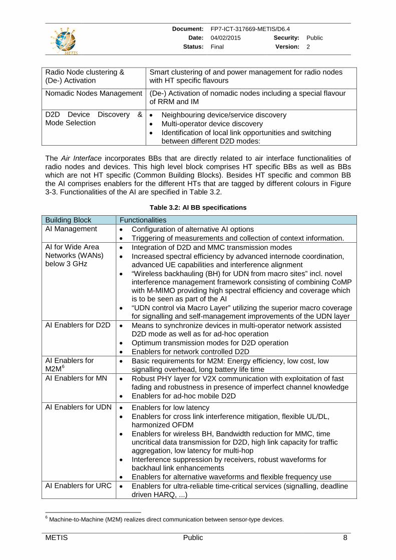
Examples of CME BBs are the Context and Spectrum Management. Typical examples of RNM are Long-/Short-term Radio Resource & Interference Management (RRM & IM), RAT Selection, and Mobility Management. An overview of the RNM BBs and the functionalities assigned to them is given in Table 3.1. More detailed information including a list of HT concepts benefiting from these BBs are listed in Table 7.1.
Table 3.1: RNM BB specifications
Building Block Functionalities Mobility Management Handover between different cells, considering different
flavours from HT perspective
Interference Identification & Prediction
Exploitation of measurement data and context information for prediction of interference
Short-term RRM & IM Optimized assignment of radio resources on short-term basis (<1ms)
Long-term RRM & IM Optimized assignment of radio resources on long-term basis (>1ms)
RAT Selection Selection of RAT according to specific rules
Document: FP7-ICT-317669-METIS/D6.4 Date: 04/02/2015 Security: Public
Status: Final Version: 2
METIS Public 8
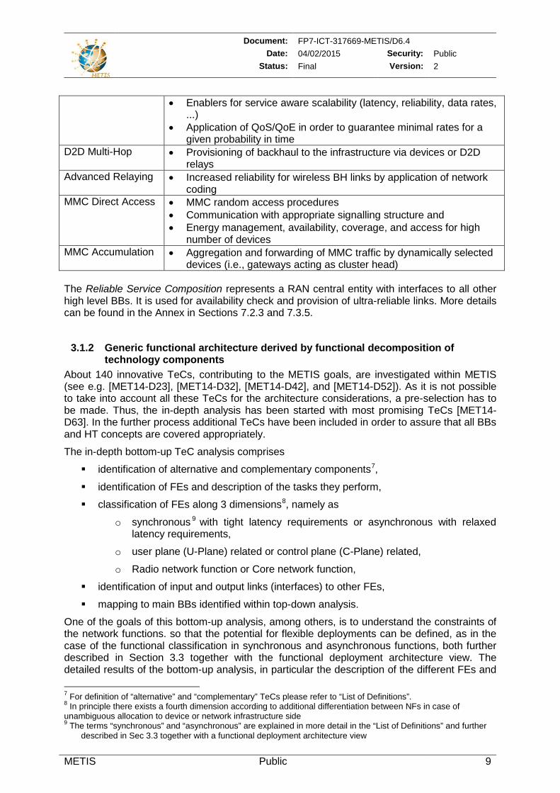
Radio Node clustering & (De-) Activation
Smart clustering of and power management for radio nodes with HT specific flavours
Nomadic Nodes Management (De-) Activation of nomadic nodes including a special flavour of RRM and IM
D2D Device Discovery & Mode Selection
• Neighbouring device/service discovery • Multi-operator device discovery • Identification of local link opportunities and switching
between different D2D modes: The Air Interface incorporates BBs that are directly related to air interface functionalities of radio nodes and devices. This high level block comprises HT specific BBs as well as BBs which are not HT specific (Common Building Blocks). Besides HT specific and common BB the AI comprises enablers for the different HTs that are tagged by different colours in Figure 3-3. Functionalities of the AI are specified in Table 3.2.
Table 3.2: AI BB specifications
Building Block Functionalities AI Management • Configuration of alternative AI options
• Triggering of measurements and collection of context information. AI for Wide Area Networks (WANs) below 3 GHz
• Integration of D2D and MMC transmission modes • Increased spectral efficiency by advanced internode coordination,
advanced UE capabilities and interference alignment • “Wireless backhauling (BH) for UDN from macro sites” incl. novel
interference management framework consisting of combining CoMP with M-MIMO providing high spectral efficiency and coverage which is to be seen as part of the AI
• “UDN control via Macro Layer” utilizing the superior macro coverage for signalling and self-management improvements of the UDN layer
AI Enablers for D2D • Means to synchronize devices in multi-operator network assisted D2D mode as well as for ad-hoc operation
• Optimum transmission modes for D2D operation • Enablers for network controlled D2D
AI Enablers for M2M6
• Basic requirements for M2M: Energy efficiency, low cost, low signalling overhead, long battery life time
AI Enablers for MN • Robust PHY layer for V2X communication with exploitation of fast fading and robustness in presence of imperfect channel knowledge
• Enablers for ad-hoc mobile D2D AI Enablers for UDN
• Enablers for low latency • Enablers for cross link interference mitigation, flexible UL/DL,
harmonized OFDM • Enablers for wireless BH, Bandwidth reduction for MMC, time
uncritical data transmission for D2D, high link capacity for traffic aggregation, low latency for multi-hop
• Interference suppression by receivers, robust waveforms for backhaul link enhancements
• Enablers for alternative waveforms and flexible frequency use AI Enablers for URC • Enablers for ultra-reliable time-critical services (signalling, deadline
driven HARQ, ...)
6 Machine-to-Machine (M2M) realizes direct communication between sensor-type devices.
Document: FP7-ICT-317669-METIS/D6.4 Date: 04/02/2015 Security: Public
Status: Final Version: 2
METIS Public 9
• Enablers for service aware scalability (latency, reliability, data rates, ...)
• Application of QoS/QoE in order to guarantee minimal rates for a given probability in time
D2D Multi-Hop
• Provisioning of backhaul to the infrastructure via devices or D2D relays
Advanced Relaying • Increased reliability for wireless BH links by application of network coding
MMC Direct Access • MMC random access procedures • Communication with appropriate signalling structure and • Energy management, availability, coverage, and access for high
number of devices MMC Accumulation • Aggregation and forwarding of MMC traffic by dynamically selected
devices (i.e., gateways acting as cluster head) The Reliable Service Composition represents a RAN central entity with interfaces to all other high level BBs. It is used for availability check and provision of ultra-reliable links. More details can be found in the Annex in Sections 7.2.3 and 7.3.5.
3.1.2 Generic functional architecture derived by functional decomposition of technology components
About 140 innovative TeCs, contributing to the METIS goals, are investigated within METIS (see e.g. [MET14-D23], [MET14-D32], [MET14-D42], and [MET14-D52]). As it is not possible to take into account all these TeCs for the architecture considerations, a pre-selection has to be made. Thus, the in-depth analysis has been started with most promising TeCs [MET14-D63]. In the further process additional TeCs have been included in order to assure that all BBs and HT concepts are covered appropriately.
The in-depth bottom-up TeC analysis comprises
identification of alternative and complementary components7,
identification of FEs and description of the tasks they perform,
classification of FEs along 3 dimensions8, namely as
o synchronous 9 with tight latency requirements or asynchronous with relaxed latency requirements,
o user plane (U-Plane) related or control plane (C-Plane) related,
o Radio network function or Core network function,
identification of input and output links (interfaces) to other FEs,
mapping to main BBs identified within top-down analysis.
One of the goals of this bottom-up analysis, among others, is to understand the constraints of the network functions. so that the potential for flexible deployments can be defined, as in the case of the functional classification in synchronous and asynchronous functions, both further described in Section 3.3 together with the functional deployment architecture view. The detailed results of the bottom-up analysis, in particular the description of the different FEs and 7 For definition of “alternative” and “complementary” TeCs please refer to “List of Definitions”. 8 In principle there exists a fourth dimension according to additional differentiation between NFs in case of unambiguous allocation to device or network infrastructure side 9 The terms “synchronous” and “asynchronous” are explained in more detail in the “List of Definitions” and further
described in Sec 3.3 together with a functional deployment architecture view
Document: FP7-ICT-317669-METIS/D6.4 Date: 04/02/2015 Security: Public
Status: Final Version: 2
METIS Public 10
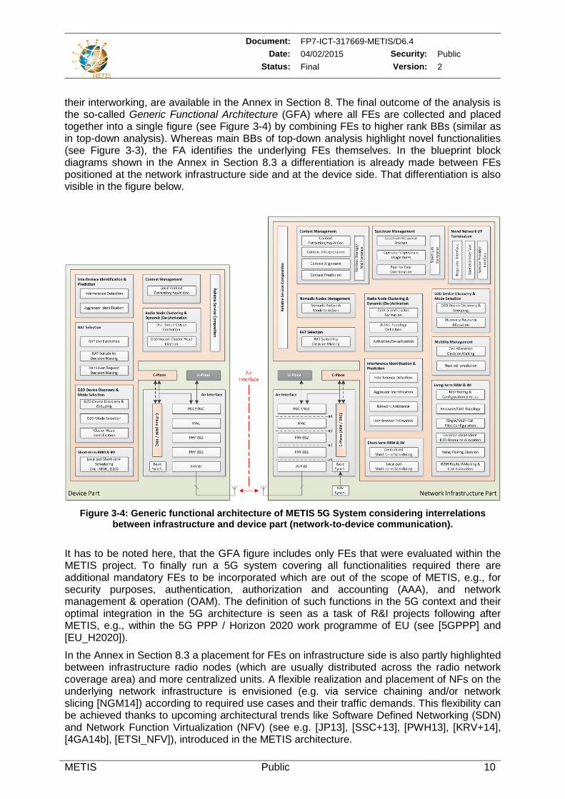
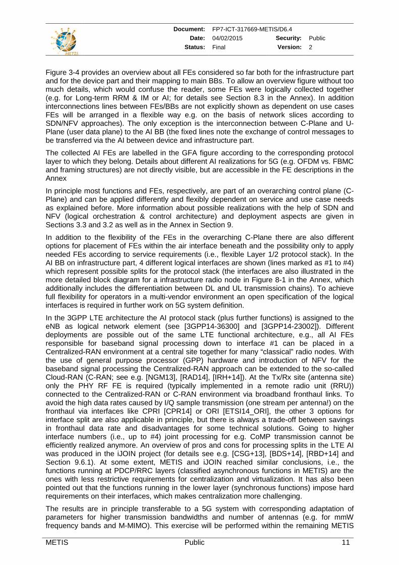
their interworking, are available in the Annex in Section 8. The final outcome of the analysis is the so-called Generic Functional Architecture (GFA) where all FEs are collected and placed together into a single figure (see Figure 3-4) by combining FEs to higher rank BBs (similar as in top-down analysis). Whereas main BBs of top-down analysis highlight novel functionalities (see Figure 3-3), the FA identifies the underlying FEs themselves. In the blueprint block diagrams shown in the Annex in Section 8.3 a differentiation is already made between FEs positioned at the network infrastructure side and at the device side. That differentiation is also visible in the figure below.
Figure 3-4: Generic functional architecture of METIS 5G System considering interrelations
between infrastructure and device part (network-to-device communication).
It has to be noted here, that the GFA figure includes only FEs that were evaluated within the METIS project. To finally run a 5G system covering all functionalities required there are additional mandatory FEs to be incorporated which are out of the scope of METIS, e.g., for security purposes, authentication, authorization and accounting (AAA), and network management & operation (OAM). The definition of such functions in the 5G context and their optimal integration in the 5G architecture is seen as a task of R&I projects following after METIS, e.g., within the 5G PPP / Horizon 2020 work programme of EU (see [5GPPP] and [EU_H2020]).
In the Annex in Section 8.3 a placement for FEs on infrastructure side is also partly highlighted between infrastructure radio nodes (which are usually distributed across the radio network coverage area) and more centralized units. A flexible realization and placement of NFs on the underlying network infrastructure is envisioned (e.g. via service chaining and/or network slicing [NGM14]) according to required use cases and their traffic demands. This flexibility can be achieved thanks to upcoming architectural trends like Software Defined Networking (SDN) and Network Function Virtualization (NFV) (see e.g. [JP13], [SSC+13], [PWH13], [KRV+14], [4GA14b], [ETSI_NFV]), introduced in the METIS architecture.
Document: FP7-ICT-317669-METIS/D6.4 Date: 04/02/2015 Security: Public
Status: Final Version: 2
METIS Public 11
Figure 3-4 provides an overview about all FEs considered so far both for the infrastructure part and for the device part and their mapping to main BBs. To allow an overview figure without too much details, which would confuse the reader, some FEs were logically collected together (e.g. for Long-term RRM & IM or AI; for details see Section 8.3 in the Annex). In addition interconnections lines between FEs/BBs are not explicitly shown as dependent on use cases FEs will be arranged in a flexible way e.g. on the basis of network slices according to SDN/NFV approaches). The only exception is the interconnection between C-Plane and U-Plane (user data plane) to the AI BB (the fixed lines note the exchange of control messages to be transferred via the AI between device and infrastructure part.
The collected AI FEs are labelled in the GFA figure according to the corresponding protocol layer to which they belong. Details about different AI realizations for 5G (e.g. OFDM vs. FBMC and framing structures) are not directly visible, but are accessible in the FE descriptions in the Annex
In principle most functions and FEs, respectively, are part of an overarching control plane (C-Plane) and can be applied differently and flexibly dependent on service and use case needs as explained before. More information about possible realizations with the help of SDN and NFV (logical orchestration & control architecture) and deployment aspects are given in Sections 3.3 and 3.2 as well as in the Annex in Section 9.
In addition to the flexibility of the FEs in the overarching C-Plane there are also different options for placement of FEs within the air interface beneath and the possibility only to apply needed FEs according to service requirements (i.e., flexible Layer 1/2 protocol stack). In the AI BB on infrastructure part, 4 different logical interfaces are shown (lines marked as #1 to #4) which represent possible splits for the protocol stack (the interfaces are also illustrated in the more detailed block diagram for a infrastructure radio node in Figure 8-1 in the Annex, which additionally includes the differentiation between DL and UL transmission chains). To achieve full flexibility for operators in a multi-vendor environment an open specification of the logical interfaces is required in further work on 5G system definition.
In the 3GPP LTE architecture the AI protocol stack (plus further functions) is assigned to the eNB as logical network element (see [3GPP14-36300] and [3GPP14-23002]). Different deployments are possible out of the same LTE functional architecture, e.g., all AI FEs responsible for baseband signal processing down to interface #1 can be placed in a Centralized-RAN environment at a central site together for many “classical” radio nodes. With the use of general purpose processor (GPP) hardware and introduction of NFV for the baseband signal processing the Centralized-RAN approach can be extended to the so-called Cloud-RAN (C-RAN; see e.g. [NGM13], [RAD14], [IRH+14]). At the Tx/Rx site (antenna site) only the PHY RF FE is required (typically implemented in a remote radio unit (RRU)) connected to the Centralized-RAN or C-RAN environment via broadband fronthaul links. To avoid the high data rates caused by I/Q sample transmission (one stream per antenna!) on the fronthaul via interfaces like CPRI [CPR14] or ORI [ETSI14_ORI], the other 3 options for interface split are also applicable in principle, but there is always a trade-off between savings in fronthaul data rate and disadvantages for some technical solutions. Going to higher interface numbers (i.e., up to #4) joint processing for e.g. CoMP transmission cannot be efficiently realized anymore. An overview of pros and cons for processing splits in the LTE AI was produced in the iJOIN project (for details see e.g. [CSG+13], [BDS+14], [RBD+14] and Section 9.6.1). At some extent, METIS and iJOIN reached similar conclusions, i.e., the functions running at PDCP/RRC layers (classified asynchronous functions in METIS) are the ones with less restrictive requirements for centralization and virtualization. It has also been pointed out that the functions running in the lower layer (synchronous functions) impose hard requirements on their interfaces, which makes centralization more challenging.
The results are in principle transferable to a 5G system with corresponding adaptation of parameters for higher transmission bandwidths and number of antennas (e.g. for mmW frequency bands and M-MIMO). This exercise will be performed within the remaining METIS
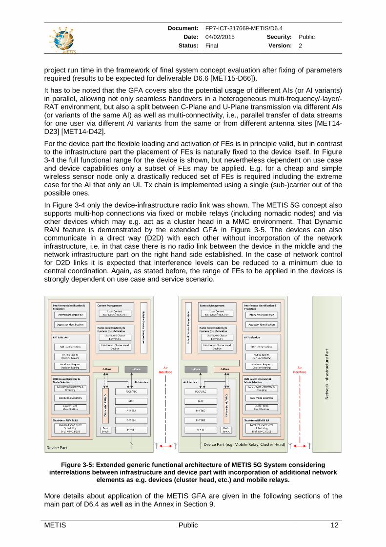
Document: FP7-ICT-317669-METIS/D6.4 Date: 04/02/2015 Security: Public
Status: Final Version: 2
METIS Public 12
project run time in the framework of final system concept evaluation after fixing of parameters required (results to be expected for deliverable D6.6 [MET15-D66]).
It has to be noted that the GFA covers also the potential usage of different AIs (or AI variants) in parallel, allowing not only seamless handovers in a heterogeneous multi-frequency/-layer/-RAT environment, but also a split between C-Plane and U-Plane transmission via different AIs (or variants of the same AI) as well as multi-connectivity, i.e., parallel transfer of data streams for one user via different AI variants from the same or from different antenna sites [MET14-D23] [MET14-D42].
For the device part the flexible loading and activation of FEs is in principle valid, but in contrast to the infrastructure part the placement of FEs is naturally fixed to the device itself. In Figure 3-4 the full functional range for the device is shown, but nevertheless dependent on use case and device capabilities only a subset of FEs may be applied. E.g. for a cheap and simple wireless sensor node only a drastically reduced set of FEs is required including the extreme case for the AI that only an UL Tx chain is implemented using a single (sub-)carrier out of the possible ones.
In Figure 3-4 only the device-infrastructure radio link was shown. The METIS 5G concept also supports multi-hop connections via fixed or mobile relays (including nomadic nodes) and via other devices which may e.g. act as a cluster head in a MMC environment. That Dynamic RAN feature is demonstrated by the extended GFA in Figure 3-5. The devices can also communicate in a direct way (D2D) with each other without incorporation of the network infrastructure, i.e. in that case there is no radio link between the device in the middle and the network infrastructure part on the right hand side established. In the case of network control for D2D links it is expected that interference levels can be reduced to a minimum due to central coordination. Again, as stated before, the range of FEs to be applied in the devices is strongly dependent on use case and service scenario.
Figure 3-5: Extended generic functional architecture of METIS 5G System considering interrelations between infrastructure and device part with incorporation of additional network
elements as e.g. devices (cluster head, etc.) and mobile relays. More details about application of the METIS GFA are given in the following sections of the main part of D6.4 as well as in the Annex in Section 9.
Document: FP7-ICT-317669-METIS/D6.4 Date: 04/02/2015 Security: Public
Status: Final Version: 2
METIS Public 13
3.2 Orchestration & Control Architecture The METIS 5G architecture development is driven by three key aspects; flexibility, scalability, and service-oriented management. These three aspects are complementary to each other such that the diverse set of TeCs accompanied with the broad range of service requirements can be efficiently supported. Flexibility is the core aspect to enable configuration of the necessary network functionalities for the realization of a given target service and use case. This can necessitate new or tailored functionalities that will be made available on-demand. Further, scalability will be assisted by flexibility to fulfil the contradicting requirements of different services, e.g., mMTC vs. xMBB. This fulfillment requires a diverse set of functionalities for different use cases (see analyses in Section 3.1). The anticipated flexibility and scalability will enable a future-proof architecture that can adapt to the requirements of the possibly emerging use cases that are unknown to date. Accordingly, the service-oriented management will make use of scalability and flexibility to provide the utmost in quality for a targeted service. In addition, METIS 5G architecture shall enable cost- and energy-efficient operation of mobile and wireless communications networks.
The NGMN Alliance has listed some design principles of a baseline 5G system, stating among other things that “a carrier-grade network cloud orchestration is needed” where “network / device functions and RAT configuration should be tailored for each use case, leveraging the NFV and SDN concepts.” At the same time, it has been warned that “flexible function allocation should not imply increased complexity on operations and management” [NGM14]. The logical orchestration & control architecture provides means to address these requirements.
The envisioned logical orchestration & control architecture, as depicted in Figure 3-6, is based on usage of upcoming architectural trends such as SDN and NFV including required extensions [MDB+14] [EBZ+14]. It will provide the necessary flexibility to realize efficient integration and cooperation of FEs as put forth by the FA according to the individual service and network function needs of the HTs as well as functions for future evolution of existing cellular and wireless networks [AIS+14] [NGM14].
In Figure 3-6 the high-level BBs for the METIS system (see Figure 3-2) are used for illustration purposes to link the logical orchestration & control architecture to the FA described in Section 3.1. The FA forms the basis of the function pool where the details of procedures and algorithms are defined. Further, the function pool can contain other FEs that are not investigated in METIS and, thus, not covered by METIS FA description. In what follows, the descriptions are provided in line with the depictions of Figure 3-6 and further details are given in Section 9.3.
The Service Flow Management, as depicted in Figure 3-6, has the task of analyzing the services and outlining the requirements for data flows of the target services through the network infrastructure. These analyses and requirements are communicated to the 5G Orchestrator and 5G-SDN Controller which are responsible of realizing the needed functions in the final functional deployment architecture. Application/service requirements (e.g., from a 3rd party service provider) can be taken into account by the service flow management, e.g., through dedicated Application Programming Interfaces (APIs). These requirements could be for instance the maximum delay and/or the minimum bandwidth required on the data flow path. The architecture enables on-demand set-up of customized virtual networks (VN) using shared resource pools and allowing effective service-adaptive decoupling of control and data plane in order to optimize routing and mobility management across the whole service transport chain.
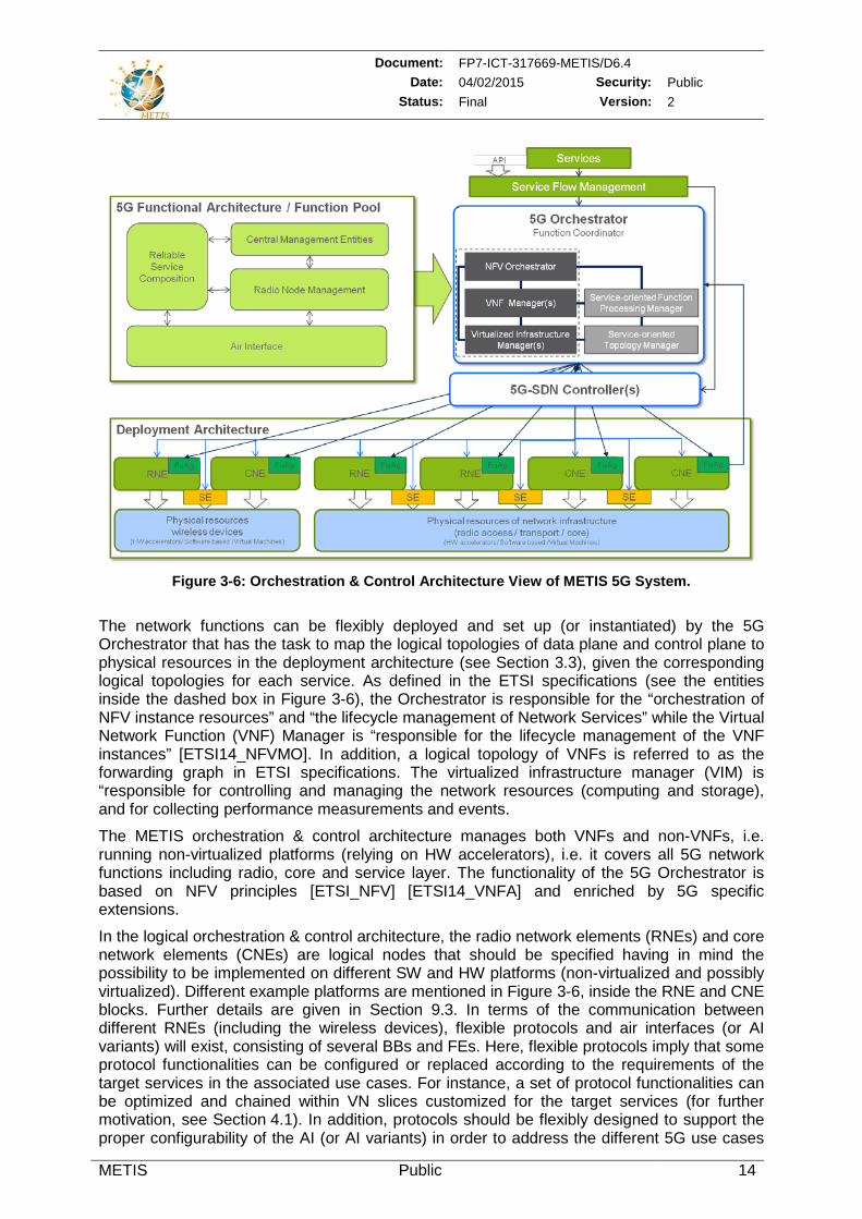
Document: FP7-ICT-317669-METIS/D6.4 Date: 04/02/2015 Security: Public
Status: Final Version: 2
METIS Public 14
Figure 3-6: Orchestration & Control Architecture View of METIS 5G System.
The network functions can be flexibly deployed and set up (or instantiated) by the 5G Orchestrator that has the task to map the logical topologies of data plane and control plane to physical resources in the deployment architecture (see Section 3.3), given the corresponding logical topologies for each service. As defined in the ETSI specifications (see the entities inside the dashed box in Figure 3-6), the Orchestrator is responsible for the “orchestration of NFV instance resources” and “the lifecycle management of Network Services” while the Virtual Network Function (VNF) Manager is “responsible for the lifecycle management of the VNF instances” [ETSI14_NFVMO]. In addition, a logical topology of VNFs is referred to as the forwarding graph in ETSI specifications. The virtualized infrastructure manager (VIM) is “responsible for controlling and managing the network resources (computing and storage), and for collecting performance measurements and events.
The METIS orchestration & control architecture manages both VNFs and non-VNFs, i.e. running non-virtualized platforms (relying on HW accelerators), i.e. it covers all 5G network functions including radio, core and service layer. The functionality of the 5G Orchestrator is based on NFV principles [ETSI_NFV] [ETSI14_VNFA] and enriched by 5G specific extensions.
In the logical orchestration & control architecture, the radio network elements (RNEs) and core network elements (CNEs) are logical nodes that should be specified having in mind the possibility to be implemented on different SW and HW platforms (non-virtualized and possibly virtualized). Different example platforms are mentioned in Figure 3-6, inside the RNE and CNE blocks. Further details are given in Section 9.3. In terms of the communication between different RNEs (including the wireless devices), flexible protocols and air interfaces (or AI variants) will exist, consisting of several BBs and FEs. Here, flexible protocols imply that some protocol functionalities can be configured or replaced according to the requirements of the target services in the associated use cases. For instance, a set of protocol functionalities can be optimized and chained within VN slices customized for the target services (for further motivation, see Section 4.1). In addition, protocols should be flexibly designed to support the proper configurability of the AI (or AI variants) in order to address the different 5G use cases
Document: FP7-ICT-317669-METIS/D6.4 Date: 04/02/2015 Security: Public
Status: Final Version: 2
METIS Public 15
e.g. with the help of some RRC signalling with the wireless devices. It is expected that increasingly, the hardware platforms designed to run RNEs will be capable of supporting virtualization to certain extent, but especially low cost equipment like small cell nodes for UDNs will probably be realized without or still limited function virtualization capabilities due to cost reasons. In contrast to that, the computing platforms designed to run NEs in the core area will allow fully flexible deployments of NFs based on virtualization concepts. In fact, this transition is already happening in the core part of 4G systems, where MME, S-GW and P-GW are being implemented as VNFs [4GA14b].
It is worth noting that conventionally Centralized-RAN infrastructure comprises BaseBand Units (BBUs). This corresponds to RNEs in the envisioned logical orchestration & control architecture. Nevertheless, thanks to the anticipated flexibility for 5G, some core functionalities can also be moved to the same physical nodes, where RNEs are implemented (e.g., deploying AAA and mobility management functions close to the access nodes to reduce latency).
The realization and management of the aforementioned service-customized VNs are handled by the two additional logical entities in the 5G Orchestrator, namely
The Service-oriented Topology Manager (STM) uses context information (e.g., service requirements and network status information) to determine which data plane and control plane functions are required to be deployed by the FA/Function Pool. Accordingly, the STM determines the placement of these functions in a logical topology and the logical interfaces between them, taking into account the underlying physical network resources and the physical network topology.
The Service-oriented function Processing Manager (SPM) instantiates data plane and control plane functions as decided by the STM. The chaining up of these functions is realized at CNEs and RNEs via Function Agents (FuAgs).10
Another element in this logical orchestration & control architecture is the 5G-SDN Controller that will set up the service chain on the physical network infrastructure taking into account the configurations orchestrated by the 5G Orchestrator. The Controller (implementation as VNF also possible) then constructs the data plane processing for the data flow, i.e., it builds up the connections for the service chain of CNEs and RNEs in the physical network. Accordingly, it configures the switching elements (SEs) (e.g., according to OpenFlow [ONF]) also by factoring in radio specific functionalities like mobility management.
The flexibility is restricted by the limitations of the physical network elements but also by the pre-coded accelerators implemented in certain nodes, e.g., hard coded physical layer procedures. This information and capabilities are reported by the FuAg at RNEs and CNEs and are taken into account by the 5G Orchestrator.
The 5G Orchestrator is not intended to run control plane functions, e.g., RRM, but rather to orchestrate and optimize their logical topologies and the regarding mappings onto the physical network resources. The data plane and control plane functions are provided by the FA. As discussed in Section 3.3, control plane functions can be optionally distributed or centralized. Further, the control and data plane functions can be flexibly orchestrated over RNEs and CNEs based on their categorization, i.e., synchronous or asynchronous control and data plane functions.
It is worth noting that details of 5G Orchestrator and 5G-SDN Controller components and functionalities along with further evaluations are to be performed by upcoming projects, e.g., in the context of 5G PPP / Horizon 2020 work programme of EU (see [5GPPP] and [EU_H2020]).
10 It is worth noting that the terms STM and SPM were, respectively, also referred to as software-defined topology
(SDT) manager and software-defined protocol (SDP) manager in some previous METIS publications.
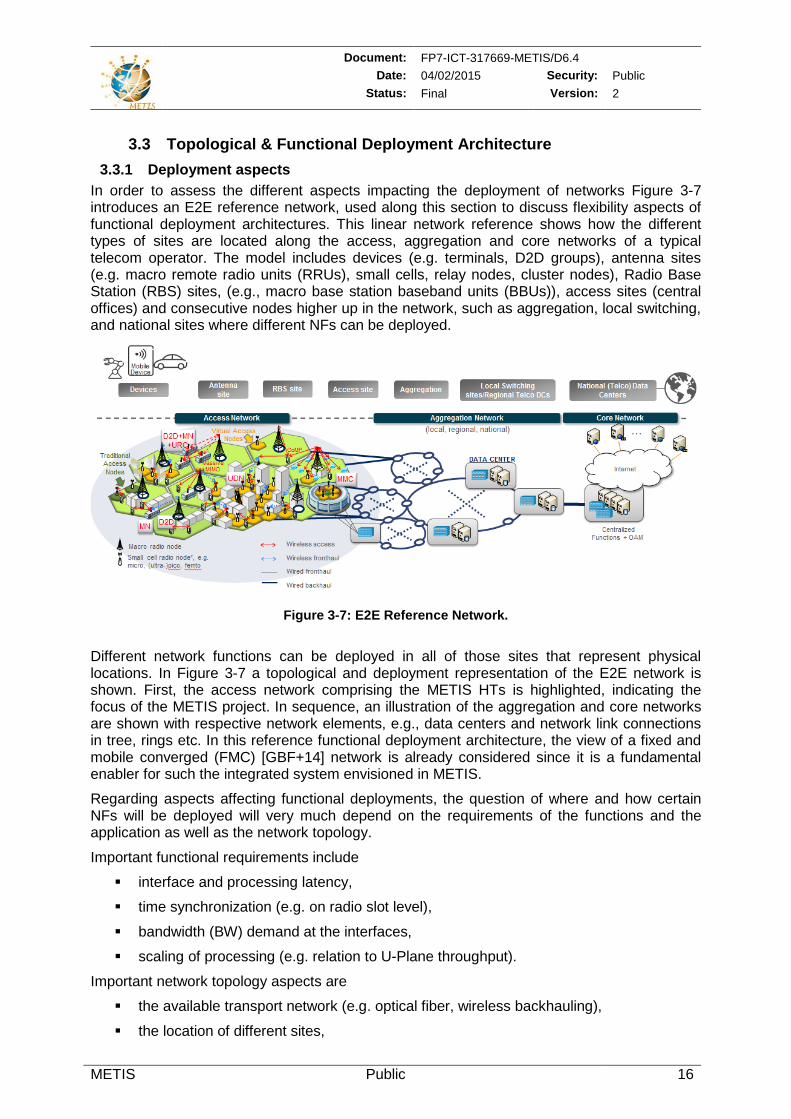
Document: FP7-ICT-317669-METIS/D6.4 Date: 04/02/2015 Security: Public
Status: Final Version: 2
METIS Public 16
3.3 Topological & Functional Deployment Architecture 3.3.1 Deployment aspects
In order to assess the different aspects impacting the deployment of networks Figure 3-7 introduces an E2E reference network, used along this section to discuss flexibility aspects of functional deployment architectures. This linear network reference shows how the different types of sites are located along the access, aggregation and core networks of a typical telecom operator. The model includes devices (e.g. terminals, D2D groups), antenna sites (e.g. macro remote radio units (RRUs), small cells, relay nodes, cluster nodes), Radio Base Station (RBS) sites, (e.g., macro base station baseband units (BBUs)), access sites (central offices) and consecutive nodes higher up in the network, such as aggregation, local switching, and national sites where different NFs can be deployed.
Figure 3-7: E2E Reference Network.
Different network functions can be deployed in all of those sites that represent physical locations. In Figure 3-7 a topological and deployment representation of the E2E network is shown. First, the access network comprising the METIS HTs is highlighted, indicating the focus of the METIS project. In sequence, an illustration of the aggregation and core networks are shown with respective network elements, e.g., data centers and network link connections in tree, rings etc. In this reference functional deployment architecture, the view of a fixed and mobile converged (FMC) [GBF+14] network is already considered since it is a fundamental enabler for such the integrated system envisioned in METIS.
Regarding aspects affecting functional deployments, the question of where and how certain NFs will be deployed will very much depend on the requirements of the functions and the application as well as the network topology.
Important functional requirements include
interface and processing latency,
time synchronization (e.g. on radio slot level),
bandwidth (BW) demand at the interfaces,
scaling of processing (e.g. relation to U-Plane throughput).
Important network topology aspects are
the available transport network (e.g. optical fiber, wireless backhauling),
the location of different sites,
Document: FP7-ICT-317669-METIS/D6.4 Date: 04/02/2015 Security: Public
Status: Final Version: 2
METIS Public 17
the equipment on those sites,
as well as the needs or benefits of centralization or decentralization in this scenario (e.g. trunking gains, enabling advanced coordination schemes, cost savings).
It is expected that 5G networks will need to meet many different functional requirements, as well as, different network topology and application specific requirements. In this way, the functional architecture should support flexible deployment of functions, when orchestrating new network services, and on demand e.g. for scaling up or down network resources. It is expected that the use of NFV and SDN will play a key role in enabling this flexibility (see Section 3.2).
3.3.2 Synchronous and asynchronous network functions In order to provide the basis for flexible E2E deployments, the classification of network functions related to the radio interface as synchronous or asynchronous is further described in the following, since for simplification purposes, in Sec 3.1.2, they were just related to the tight or relaxed latency requirements,
Focusing on the requirements defined by the radio functions and their interfaces, this classification intends to highlight the constraints for the placement of certain functions and simplify the analysis of different deployments considering, e.g., the centralized process of specific radio functions in a deployment site.
Synchronous: Radio network functions whose processing is time-synchronous to the radio interface (slots/frames). They typically require high data rates on their interfaces, which scales with the traffic, overall signal bandwidth and number of antennas (mainly for the user plane data). Processing typically happens on per packet level. Potential for centralization is limited (e.g. in the order of 10-20 km), since it would only work in case of low latency, high bandwidth transport. Potential for virtualization is limited because of the timing, real-time processing requirements and since they benefit a lot from hardware (HW) acceleration. Synchronous radio network functions can be classified into
Synchronous Radio Control plane functions (SRC)
Examples: Scheduling, link adaptation, power control, interference coordination, etc.
Synchronous Radio User plane functions (SRU)
Examples: retransmission / HARQ, coding/modulation, segmentation / concatenation to radio frames, etc.
Asynchronous: Radio network functions whose processing is time-asynchronous to the radio interface (slots/frames). They typically require low data rates on their interfaces and the processing requirements scale with the number of users, not the overall traffic. These functions can typically cope with tens of milliseconds of latency. These are good candidates to be deployed on more centralized and virtualized platforms. Asynchronous radio network functions can be classified into
Asynchronous Radio Control plane functions (ARC)
Examples: Inter-cell handover, RAT selection, etc.
Asynchronous Radio User plane functions (ARU)
Examples: Encryption, U-Plane aggregation (as in dual/multi-connectivity), etc.
As a complement to the function requirements analysis, core functions which are not synchronous to the radio interface can be also considered. Core network functions can be classified into
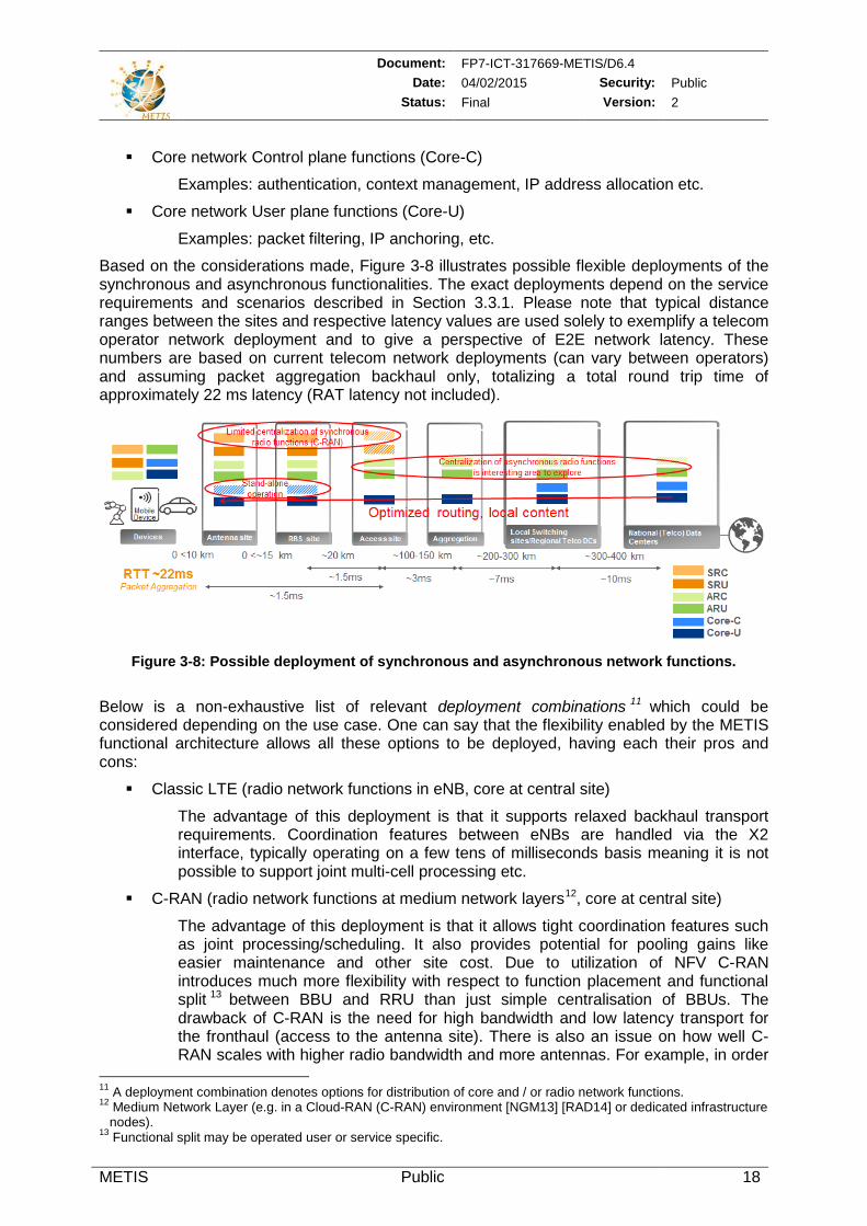
Document: FP7-ICT-317669-METIS/D6.4 Date: 04/02/2015 Security: Public
Status: Final Version: 2
METIS Public 18
Core network Control plane functions (Core-C)
Examples: authentication, context management, IP address allocation etc.
Core network User plane functions (Core-U)
Examples: packet filtering, IP anchoring, etc.
Based on the considerations made, Figure 3-8 illustrates possible flexible deployments of the synchronous and asynchronous functionalities. The exact deployments depend on the service requirements and scenarios described in Section 3.3.1. Please note that typical distance ranges between the sites and respective latency values are used solely to exemplify a telecom operator network deployment and to give a perspective of E2E network latency. These numbers are based on current telecom network deployments (can vary between operators) and assuming packet aggregation backhaul only, totalizing a total round trip time of approximately 22 ms latency (RAT latency not included).
Figure 3-8: Possible deployment of synchronous and asynchronous network functions.
Below is a non-exhaustive list of relevant deployment combinations 11 which could be considered depending on the use case. One can say that the flexibility enabled by the METIS functional architecture allows all these options to be deployed, having each their pros and cons:
Classic LTE (radio network functions in eNB, core at central site)
The advantage of this deployment is that it supports relaxed backhaul transport requirements. Coordination features between eNBs are handled via the X2 interface, typically operating on a few tens of milliseconds basis meaning it is not possible to support joint multi-cell processing etc.
C-RAN (radio network functions at medium network layers12, core at central site)
The advantage of this deployment is that it allows tight coordination features such as joint processing/scheduling. It also provides potential for pooling gains like easier maintenance and other site cost. Due to utilization of NFV C-RAN introduces much more flexibility with respect to function placement and functional split 13 between BBU and RRU than just simple centralisation of BBUs. The drawback of C-RAN is the need for high bandwidth and low latency transport for the fronthaul (access to the antenna site). There is also an issue on how well C-RAN scales with higher radio bandwidth and more antennas. For example, in order
11 A deployment combination denotes options for distribution of core and / or radio network functions. 12 Medium Network Layer (e.g. in a Cloud-RAN (C-RAN) environment [NGM13] [RAD14] or dedicated infrastructure
nodes). 13 Functional split may be operated user or service specific.
Document: FP7-ICT-317669-METIS/D6.4 Date: 04/02/2015 Security: Public
Status: Final Version: 2
METIS Public 19
to reduce number of RF chains in case of M-MIMO, a hybrid analogue beam forming in connection with digital pre-coding can be applied.
Distributed user plane core network functions (access, medium network layers14)
The advantage of this deployment is that it supports ultra-low latency and the potential to process and route traffic locally. Certain core network functions are moved closer to the access nodes e.g. to fulfil the service requirements as shown in [ITU14] [ETSI14_MEC] [WCT+14].
Centralized asynchronous radio control and user plane
The advantage of this deployment would be less complex radio nodes since they would be controlled from a central entity at higher structural levels (e.g. core network sites) responsible for asynchronous radio control as well as possible terminating interfaces to other nodes. The advantage compared to C-RAN, where the whole baseband processing is centralized, would be lower transport bitrate and latency requirements.
Distribute all radio (i.e. equivalent to D-RAN) and core network functions
The advantage of this deployment is that it can support stand-alone deployment of a complete network without the need for connectivity to central core. Possibly this could also provide enhancements for network resilience. On the other hand, coordination features would rely on inter-node interface.
It is expected that all these five functional deployment alternatives shall be supported by a 5G system, thanks to the flexibility of the METIS functional architecture. Following the same principle, possible functional deployments for chosen METIS concepts solutions and their architecture options are further explored in Section 4.
14 Medium network layer definition s. “List of definitions”
Document: FP7-ICT-317669-METIS/D6.4 Date: 04/02/2015 Security: Public
Status: Final Version: 2
METIS Public 20
4 5G Baseline System and Impact on Architecture
4.1 Comparison of 4G to 5G architecture There are significant differences between the monolithic 4G architecture defined by 3GPP [3GPP14-23002] [3GPP14-36300], primarily to support mobile broadband applications, and the 5G architecture proposed by METIS – that go far beyond the differences observed between subsequent generations’ architectures. 4G network architecture may be considered the final step in the evolution of the network concepts and technologies that were originally developed for ISDN, adapted to the mobile context in order to support mobility and roaming in GSM, and evolved in order to support a multiservice network in UMTS. This evolution has been dramatic in some areas; e.g., with LTE the transition from a circuit switched, voice-centric network to a packet switched, all-IP one is completed, while the network has evolved towards a “flatter” architecture. However, the design principles applied for the definition of the architecture have not changed so much, mainly due to the need to preserve backwards compatibility between systems and also due to technological limitations. The separation between radio access network (RAN) functionalities and core network (CN) functionalities (Access Stratum and Non Access Stratum) or the grouping of the core functionalities into call management, session management and mobility management are common characteristics of the different generations’ network architecture. The resulting architecture has a hierarchical structure that, although optimized and enhanced, has been preserved in each new generation and defines the set of interfaces and protocols that are being used.
The diversity of use cases necessarily requires a 5G architecture which is more flexible than the current 4G architecture. It also has to be more cost-efficient. New paradigms, such as NFV and SDN, coupled with advances in computing and storage provide an opportunity for a radical rethinking of 5G architecture design. Even though these new paradigms can be applied to make the 4G network architecture more flexible and less expensive to deploy [RAD14] [4GA14b], exploiting their full potential and to realize much greater flexibility requires moving away from the legacy principles upon which the 4G architecture is based [4GA14a].
Hence, METIS has not been limited to the constraint to start with the existing network architecture and looking for the modifications and adaptations required to support the new requirements. Rather, a combination of bottom-up and top-down analysis has been employed without major compatibility constraints. This approach (introduced in Section 2) results, in a first step, in the definition of common BBs that group functionalities that are widely required by several HTs, with others that are specific for a HT and a third set enabling specific radio interface functionalities. Complementary to this first step, in a second step the TeCs developed in METIS are analysed and FEs identified by functional decomposition are mapped to those common BBs. In this way similar FEs of different enablers can be detected and reused.
The resulting 5G architecture natively leverages SDN and NFV principles, clearly separating control from data, as well as, hardware from software. This means the resulting 5G architecture is extremely flexible and has the ability not only to support the diversity of use cases, but to do that potentially in an efficient and cost-effective manner.
Most significant 5G architecture key elements are:
1. Focus on network functions, rather than network entities/nodes – define functions, which can be implemented and applied where needed.
2. Separation of control and data plane.
3. Adaptation to use cases – not all network functions need to be used for different use cases. Functions can have variants, tailored for different use cases.
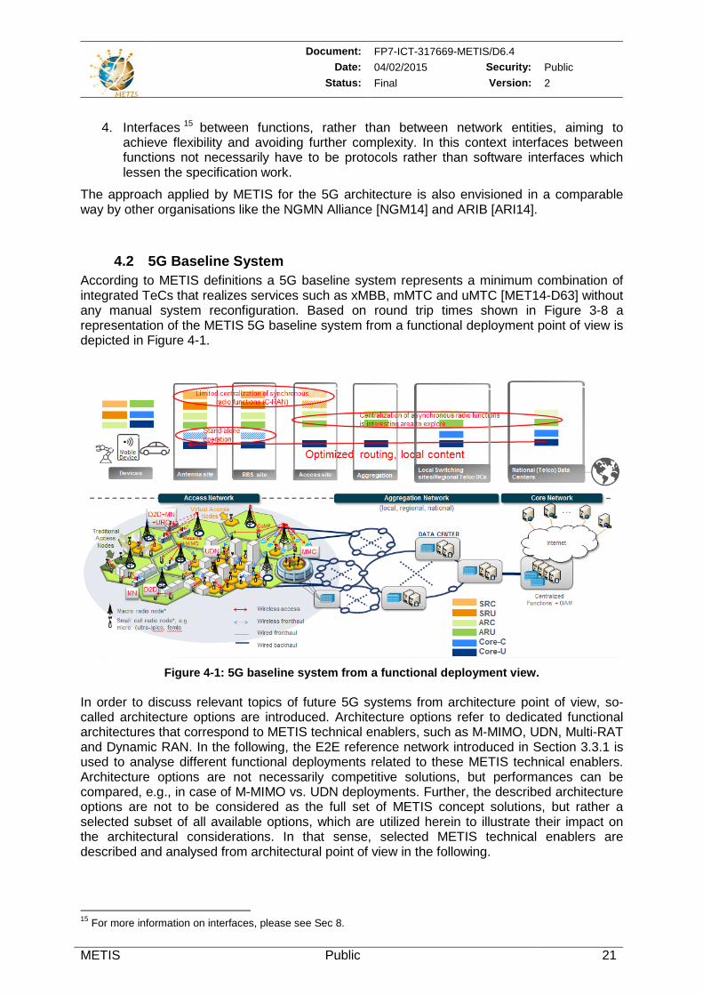
Document: FP7-ICT-317669-METIS/D6.4 Date: 04/02/2015 Security: Public
Status: Final Version: 2
METIS Public 21
4. Interfaces 15 between functions, rather than between network entities, aiming to achieve flexibility and avoiding further complexity. In this context interfaces between functions not necessarily have to be protocols rather than software interfaces which lessen the specification work.
The approach applied by METIS for the 5G architecture is also envisioned in a comparable way by other organisations like the NGMN Alliance [NGM14] and ARIB [ARI14].
4.2 5G Baseline System According to METIS definitions a 5G baseline system represents a minimum combination of integrated TeCs that realizes services such as xMBB, mMTC and uMTC [MET14-D63] without any manual system reconfiguration. Based on round trip times shown in Figure 3-8 a representation of the METIS 5G baseline system from a functional deployment point of view is depicted in Figure 4-1.
Figure 4-1: 5G baseline system from a functional deployment view.
In order to discuss relevant topics of future 5G systems from architecture point of view, so-called architecture options are introduced. Architecture options refer to dedicated functional architectures that correspond to METIS technical enablers, such as M-MIMO, UDN, Multi-RAT and Dynamic RAN. In the following, the E2E reference network introduced in Section 3.3.1 is used to analyse different functional deployments related to these METIS technical enablers. Architecture options are not necessarily competitive solutions, but performances can be compared, e.g., in case of M-MIMO vs. UDN deployments. Further, the described architecture options are not to be considered as the full set of METIS concept solutions, but rather a selected subset of all available options, which are utilized herein to illustrate their impact on the architectural considerations. In that sense, selected METIS technical enablers are described and analysed from architectural point of view in the following.
15 For more information on interfaces, please see Sec 8.
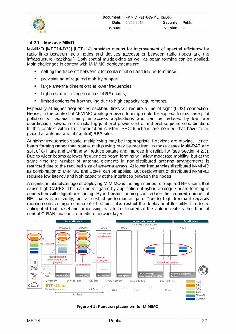
Document: FP7-ICT-317669-METIS/D6.4 Date: 04/02/2015 Security: Public
Status: Final Version: 2
METIS Public 22
4.2.1 Massive MIMO M-MIMO [MET14-D23] [LET+14] provides means for improvement of spectral efficiency for radio links between radio nodes and devices (access) or between radio nodes and the infrastructure (backhaul). Both spatial multiplexing as well as beam forming can be applied. Main challenges in context with M-MIMO deployments are
setting the trade-off between pilot contamination and link performance,
provisioning of required mobility support,
large antenna dimensions at lower frequencies,
high cost due to large number of RF chains,
limited options for fronthauling due to high capacity requirements.
Especially at higher frequencies backhaul links will require a line of sight (LOS) connection. Hence, in the context of M-MIMO analogue beam forming could be applied. In this case pilot pollution will appear mainly in access applications and can be reduced by low rate coordination between cells including joint pilot power control and pilot sequence coordination. In this context within the cooperation clusters SRC functions are needed that have to be placed at antenna and at (central) RBS sites.
At higher frequencies spatial multiplexing may be inappropriate if devices are moving. Hence, beam forming rather than spatial multiplexing may be required. In those cases Multi-RAT and split of C-Plane and U-Plane will reduce outage and improve link reliability (see Section 4.2.3). Due to wider beams at lower frequencies beam forming will allow moderate mobility, but at the same time the number of antenna elements in non-distributed antenna arrangements is restricted due to the required size of antenna arrays. At lower frequencies distributed M-MIMO as combination of M-MIMO and CoMP can be applied. But deployment of distributed M-MIMO requires low latency and high capacity at the interfaces between the nodes.
A significant disadvantage of deploying M-MIMO is the high number of required RF chains that cause high CAPEX. This can be mitigated by application of hybrid analogue beam forming in connection with digital pre-coding. Hybrid beam forming can reduce the required number of RF chains significantly, but at cost of performance gain. Due to high fronthaul capacity requirements, a large number of RF chains also restrict the deployment flexibility. It is to be anticipated that baseband processing has to be located at the antenna site rather than at central C-RAN locations at medium network layers.
Figure 4-2: Function placement for M-MIMO.
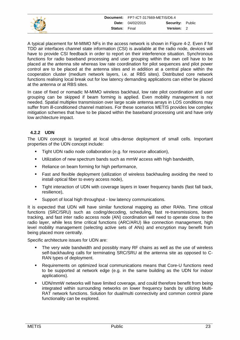
Document: FP7-ICT-317669-METIS/D6.4 Date: 04/02/2015 Security: Public
Status: Final Version: 2
METIS Public 23
A typical placement for M-MIMO NFs in the access network is shown in Figure 4-2. Even if for TDD air interfaces channel state information (CSI) is available at the radio node, devices will have to provide CSI feedback in order to report on their interference situation. Synchronous functions for radio baseband processing and user grouping within the own cell have to be placed at the antenna site whereas low rate coordination for pilot sequences and pilot power control are to be placed at the antenna sites and in addition at a central place within the cooperation cluster (medium network layers, i.e. at RBS sites). Distributed core network functions realising local break out for low latency demanding applications can either be placed at the antenna or at RBS sites.
In case of fixed or nomadic M-MIMO wireless backhaul, low rate pilot coordination and user grouping can be skipped if beam forming is applied. Even mobility management is not needed. Spatial multiplex transmission over large scale antenna arrays in LOS conditions may suffer from ill-conditioned channel matrixes. For these scenarios METIS provides low complex mitigation schemes that have to be placed within the baseband processing unit and have only low architecture impact.
4.2.2 UDN The UDN concept is targeted at local ultra-dense deployment of small cells. Important properties of the UDN concept include:
Tight UDN radio node collaboration (e.g. for resource allocation),
Utilization of new spectrum bands such as mmW access with high bandwidth,
Reliance on beam forming for high performance,
Fast and flexible deployment (utilization of wireless backhauling avoiding the need to install optical fiber to every access node),
Tight interaction of UDN with coverage layers in lower frequency bands (fast fall back, resilience),
Support of local high throughput - low latency communications.
It is expected that UDN will have similar functional mapping as other RANs. Time critical functions (SRC/SRU) such as coding/decoding, scheduling, fast re-transmissions, beam tracking, and fast inter radio access node (AN) coordination will need to operate close to the radio layer, while less time critical functions (ARC/ARU) like connection management, high level mobility management (selecting active sets of ANs) and encryption may benefit from being placed more centrally.
Specific architecture issues for UDN are:
The very wide bandwidth and possibly many RF chains as well as the use of wireless self-backhauling calls for terminating SRC/SRU at the antenna site as opposed to C-RAN types of deployment.
Requirements on optimized local communications means that Core-U functions need to be supported at network edge (e.g. in the same building as the UDN for indoor applications).
UDN/mmW networks will have limited coverage, and could therefore benefit from being integrated within surrounding networks on lower frequency bands by utilizing Multi-RAT network functions. Solution for dual/multi connectivity and common control plane functionality can be explored.
Document: FP7-ICT-317669-METIS/D6.4 Date: 04/02/2015 Security: Public
Status: Final Version: 2
METIS Public 24
Figure 4-3: Function placement for typical UDN deployment.
Figure 4-3 shows the function placement for typical UDN deployment. The synchronous radio network functions are placed directly at the antenna in order to support wireless backhauling16. C-RAN application might be limited in case of mmW UDNs. The asynchronous radio functionalities such as mobility control and encryption can be positioned more centrally at the RBS sites in order to simplify the UDN radio access node functionality. In addition it is possible to put Core-U functionality at the RBS sites in order to support optimized local routing and access to content, making it possible to achieve very high throughput and low latency in the UDN. Centralized services and OTT Internet services can still be supported with more centralized Core-U functionality.
Besides the typical UDN deployment described above, it is also possible to consider different UDN deployment options (e.g. including C-RAN or M-MIMO) depending on the scenario. Please read Section 9.2.2 for more information.
4.2.3 Multi-RAT The ambitious requirements of 5G use cases (e.g., very high data rates, very low latency, ultra-reliability, etc.) points to a direction of a tighter integration between a new 5G AI (or AI variants) and LTE Evolution fulfilling the 5G requirements beyond the interworking mechanisms that exist today between 4G, 3G, 2G and WLAN [3GPP14-23401] [3GPP14-23402] [SLS+14]. A tighter integration would also address different issues related to the existing interworking in legacy systems [KTH+14]. Such a tight integration would allow a new flexibility flavour to the 5G architecture and enable innovative features such as multi-connectivity for data rate aggregation, control plane diversity allowing control messages to be transmitted and/or received from multiple links from the multiple RATs, UL/DL split allowing optimized UL/DL allocation per RAT, etc. A 5G service that can obviously benefit from tight integration is xMBB, but likely also other 5G services as e.g. uMTC.
The advantages of an architecture with a tighter Multi-RAT integration are the following:
Possibility to perform radio resources pooling, similar to a radio control/user plane service chaining applied to introduce flexibility,
16 Wireless backhauling might be realized with support of M-MIMO. But even other interference mitigation schemes
may include synchronous radio functions.
Document: FP7-ICT-317669-METIS/D6.4 Date: 04/02/2015 Security: Public
Status: Final Version: 2
METIS Public 25
Better usage of processing/hardware/storage resources assuming that some of these RATs could share hardware resources, seamless/lossless mobility for non-collocated deployments,
Better service control when the same device is used for different 5G services (e.g. a smartphone used to support V2V communication and xMBB within the car, etc.).
LTE Evolution can be considered as a base WAN coverage layer in order to fulfil the high reliability requirement of some use cases, either during initial deployment/system migration or in later phases. 5G RATs (utilizing M-MIMO and/or UDNs) will likely be deployed in frequencies where radio propagation (in particular in the mmW bands) is characterized by high attenuation and high variability due to strong shadowing and weak diffraction. The high propagation loss can be compensated by using highly directional, high gain antennas. The difficult propagation conditions and narrow beam characteristics bring new challenges, e.g. in user mobility or interference management. Therefore, a common control plane for high frequency RATs and lower frequency RATs seems to be beneficial, also enabling a smoother re-farming.
Different applications of such architecture can be envisioned:
Cross-layer Cross-RAT signalling techniques
o Unified System Access: common system information for the multiple 5G air interface variants, addressing cross-air interface paging, random access and/or system information acquisition.
o High Resilience Mobility: potential of high-resilience mobility by integrating a beam forming-based RAT (especially in higher frequencies, spotty coverage) with a non-beam forming based RAT (e.g. LTE Evolution).
User Plane Aggregation
o Data Rate Aggregation: potential to achieve very high data rates by transmitting on the multiple links from the multiple RATs at the same time.
o Fast Link Switching: ultra-reliability can be achieved by having the possibility to transmit on multiple RATs alternately depending on the link conditions.
Common Control Plane
o Control Plane Diversity: also aims for ultra-reliability, where multiple control plane connections could be established (or a secondary connection can quickly be activated depending on the quality of the primary link).
o Common Resource Control: radio resource pooling gains can be achieved by a common pool of resources for the multiple RATs, eventually enabling some interaction with spectrum management network elements.
In such architecture, an important issue is defining which network functions should be RAT-specific or common to the multiple RATs. Based on the time constraints for processing, a level of integration at the higher layers of the user/control plane (CP/UP) would be simpler, where the asynchronous functions can be common while the synchronous functions should be distributed and RAT-specific (see the example in Figure 4-4 with 3 radio nodes supporting different RATs). In co-located deployments, where two or more RATs are implemented in the same node, some of the constraints can be relaxed and an even tighter integration would be possible, bringing additional benefits e.g. tighter interference coordination or cross-carrier scheduling [WS5G+15].
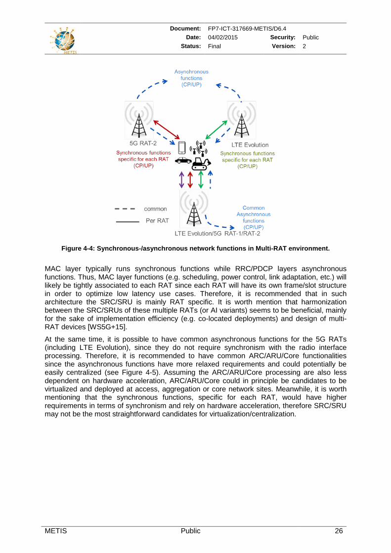
Document: FP7-ICT-317669-METIS/D6.4 Date: 04/02/2015 Security: Public
Status: Final Version: 2
METIS Public 26
Figure 4-4: Synchronous-/asynchronous network functions in Multi-RAT environment.
MAC layer typically runs synchronous functions while RRC/PDCP layers asynchronous functions. Thus, MAC layer functions (e.g. scheduling, power control, link adaptation, etc.) will likely be tightly associated to each RAT since each RAT will have its own frame/slot structure in order to optimize low latency use cases. Therefore, it is recommended that in such architecture the SRC/SRU is mainly RAT specific. It is worth mention that harmonization between the SRC/SRUs of these multiple RATs (or AI variants) seems to be beneficial, mainly for the sake of implementation efficiency (e.g. co-located deployments) and design of multi-RAT devices [WS5G+15].
At the same time, it is possible to have common asynchronous functions for the 5G RATs (including LTE Evolution), since they do not require synchronism with the radio interface processing. Therefore, it is recommended to have common ARC/ARU/Core functionalities since the asynchronous functions have more relaxed requirements and could potentially be easily centralized (see Figure 4-5). Assuming the ARC/ARU/Core processing are also less dependent on hardware acceleration, ARC/ARU/Core could in principle be candidates to be virtualized and deployed at access, aggregation or core network sites. Meanwhile, it is worth mentioning that the synchronous functions, specific for each RAT, would have higher requirements in terms of synchronism and rely on hardware acceleration, therefore SRC/SRU may not be the most straightforward candidates for virtualization/centralization.
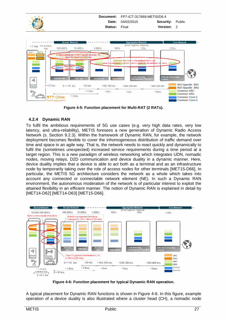
Document: FP7-ICT-317669-METIS/D6.4 Date: 04/02/2015 Security: Public
Status: Final Version: 2
METIS Public 27
Figure 4-5: Function placement for Multi-RAT (2 RATs).
4.2.4 Dynamic RAN To fulfil the ambitious requirements of 5G use cases (e.g. very high data rates, very low latency, and ultra-reliability), METIS foresees a new generation of Dynamic Radio Access Network (s. Section 9.2.3). Within the framework of Dynamic RAN, for example, the network deployment becomes flexible to cover the inhomogeneous distribution of traffic demand over time and space in an agile way. That is, the network needs to react quickly and dynamically to fulfil the (sometimes unexpected) increased service requirements during a time period at a target region. This is a new paradigm of wireless networking which integrates UDN, nomadic nodes, moving relays, D2D communication and device duality in a dynamic manner. Here, device duality implies that a device is able to act both as a terminal and as an infrastructure node by temporarily taking over the role of access nodes for other terminals [MET15-D66], In particular, the METIS 5G architecture considers the network as a whole which takes into account any connected or connectable network element (NE). In such a Dynamic RAN environment, the autonomous moderation of the network is of particular interest to exploit the attained flexibility in an efficient manner. The notion of Dynamic RAN is explained in detail by [MET14-D62] [MET14-D63] [MET15-D66].
Figure 4-6: Function placement for typical Dynamic RAN operation.
A typical placement for Dynamic RAN functions is shown in Figure 4-6. In this figure, example operation of a device duality is also illustrated where a cluster head (CH), a nomadic node
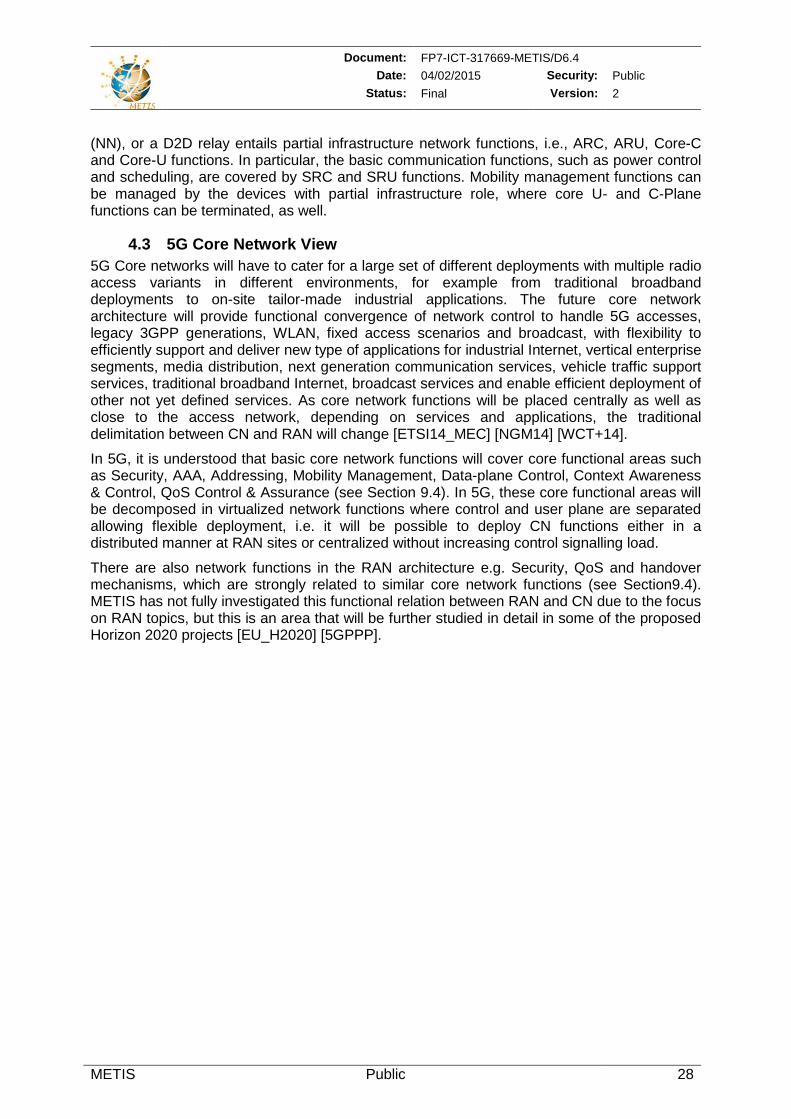
Document: FP7-ICT-317669-METIS/D6.4 Date: 04/02/2015 Security: Public
Status: Final Version: 2
METIS Public 28
(NN), or a D2D relay entails partial infrastructure network functions, i.e., ARC, ARU, Core-C and Core-U functions. In particular, the basic communication functions, such as power control and scheduling, are covered by SRC and SRU functions. Mobility management functions can be managed by the devices with partial infrastructure role, where core U- and C-Plane functions can be terminated, as well.
4.3 5G Core Network View 5G Core networks will have to cater for a large set of different deployments with multiple radio access variants in different environments, for example from traditional broadband deployments to on-site tailor-made industrial applications. The future core network architecture will provide functional convergence of network control to handle 5G accesses, legacy 3GPP generations, WLAN, fixed access scenarios and broadcast, with flexibility to efficiently support and deliver new type of applications for industrial Internet, vertical enterprise segments, media distribution, next generation communication services, vehicle traffic support services, traditional broadband Internet, broadcast services and enable efficient deployment of other not yet defined services. As core network functions will be placed centrally as well as close to the access network, depending on services and applications, the traditional delimitation between CN and RAN will change [ETSI14_MEC] [NGM14] [WCT+14].
In 5G, it is understood that basic core network functions will cover core functional areas such as Security, AAA, Addressing, Mobility Management, Data-plane Control, Context Awareness & Control, QoS Control & Assurance (see Section 9.4). In 5G, these core functional areas will be decomposed in virtualized network functions where control and user plane are separated allowing flexible deployment, i.e. it will be possible to deploy CN functions either in a distributed manner at RAN sites or centralized without increasing control signalling load.
There are also network functions in the RAN architecture e.g. Security, QoS and handover mechanisms, which are strongly related to similar core network functions (see Section9.4). METIS has not fully investigated this functional relation between RAN and CN due to the focus on RAN topics, but this is an area that will be further studied in detail in some of the proposed Horizon 2020 projects [EU_H2020] [5GPPP].
Document: FP7-ICT-317669-METIS/D6.4 Date: 04/02/2015 Security: Public
Status: Final Version: 2
METIS Public 29
5 Results of Architectural Investigations with Impact on System Development
5.1 Compilation of results – where to find what This deliverable provides a summary of the architecture development work done in METIS. By unification of the HT concepts and grouping of needed functionalities into BBs novel features of 5G systems have been identified. In Section 7.2 these functionalities are listed and an indication of the utilization by the different HTs is given. Commonalities and divergences between the different HTs from functional point of view are analysed in Section 7.4.
An in-depth Analysis of the most promising TeCs provided by METIS technical WPs is documented in Section 8 where in the tables in Section 8.3 FEs, their opportunities with respect to positioning in the network topology, input and output interfaces and most important parameters are compiled. A picture of a generic functional architecture of the METIS system is given in Section 3.1.2. More detailed building block related presentations can be found in Section 8.3. The results of this work may prepare the development of novel network functions in upcoming projects. As future requirements and services cannot be forecasted, the applied methodology as described in Section 2 may also serve as blueprint for future architecture developments. An identification of alternative or complementary TeCs gives hints whether these enablers may be alternatively applied depending on the use case or whether these enablers may be jointly applied for performance improvements.
The introduction of a topological E2E reference network in Section 3.3 enables investigations on network function placements and architectural deployment aspects. For this purpose architecture options that refer to functional architectures of METIS technical enablers are introduced. In order to make 5G more concrete, architecture stories in Section 9.2 play with this architecture options by selecting TeCs and describing concrete use cases. Conclusions evaluating these stories are given in Section 5.2 below.
An important outcome of METIS 5G architecture work is the development of a logical orchestration & control architecture which is based on upcoming architectural trends such as SDN and NFV. A flexible architecture including Service Flow Management, 5G Orchestration and SDN Control based on VNF pools is extending the ETSI state of the art concepts and will facilitate the flexibility, scalability and service-oriented management needed in order to fulfil apparently contradicting 5G requirements. More details of the logical orchestration & control architecture presented in Section 3.2 can be found in Section 9.3 together with an outlook how to manage those novel network architecture features in Section 9.5 (see also [UNI]).
5.2 Conclusion on architecture stories Opportunities for centralized or distributed deployment of NFs are mainly driven by scenarios, site constraints and hardware requirements. Synchronous radio NFs will have to be placed in the vicinity of the radio baseband processing whereas asynchronous NFs may be placed arbitrarily in the network topology. Combining NFV and SDN will open a lot of flexibility and hence new opportunities for load optimization and resilience by function repositioning according to network load, service requirements or operational reasons. Introduction of flexible functional split between BBU and RRU enables adequate adjustment of fronthaul requirements to scenario specific boundary conditions and hence open more space for C-RAN applications. Nevertheless it is envisaged that wide area D-RAN macro base station sites will be locations for so-called local centralization of synchronous NFs that are needed for UDNs, D2D, V2X and Dynamic RAN. In that sense the meaning of D-RAN and C-RAN will change over the time. WANs will be developed in an evolutional manner as LTE and its enhancements may play an important role. They can be integrated into 5G by means of Multi-RAT enablers. Driver for 5G WAN components could be a ubiquitous need for native integration of D2D and MMC into the WAN air interface.
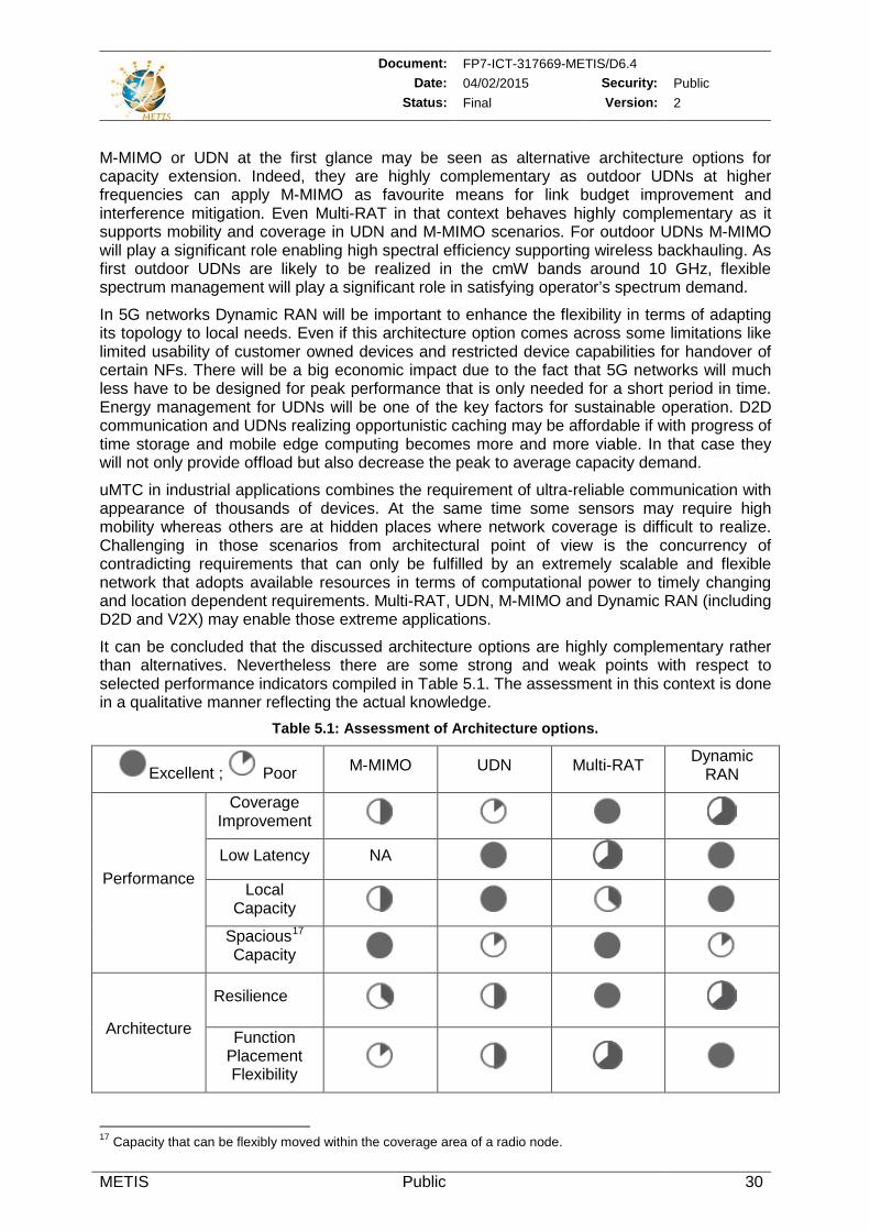
Document: FP7-ICT-317669-METIS/D6.4 Date: 04/02/2015 Security: Public
Status: Final Version: 2
METIS Public 30
M-MIMO or UDN at the first glance may be seen as alternative architecture options for capacity extension. Indeed, they are highly complementary as outdoor UDNs at higher frequencies can apply M-MIMO as favourite means for link budget improvement and interference mitigation. Even Multi-RAT in that context behaves highly complementary as it supports mobility and coverage in UDN and M-MIMO scenarios. For outdoor UDNs M-MIMO will play a significant role enabling high spectral efficiency supporting wireless backhauling. As first outdoor UDNs are likely to be realized in the cmW bands around 10 GHz, flexible spectrum management will play a significant role in satisfying operator’s spectrum demand.
In 5G networks Dynamic RAN will be important to enhance the flexibility in terms of adapting its topology to local needs. Even if this architecture option comes across some limitations like limited usability of customer owned devices and restricted device capabilities for handover of certain NFs. There will be a big economic impact due to the fact that 5G networks will much less have to be designed for peak performance that is only needed for a short period in time. Energy management for UDNs will be one of the key factors for sustainable operation. D2D communication and UDNs realizing opportunistic caching may be affordable if with progress of time storage and mobile edge computing becomes more and more viable. In that case they will not only provide offload but also decrease the peak to average capacity demand.
uMTC in industrial applications combines the requirement of ultra-reliable communication with appearance of thousands of devices. At the same time some sensors may require high mobility whereas others are at hidden places where network coverage is difficult to realize. Challenging in those scenarios from architectural point of view is the concurrency of contradicting requirements that can only be fulfilled by an extremely scalable and flexible network that adopts available resources in terms of computational power to timely changing and location dependent requirements. Multi-RAT, UDN, M-MIMO and Dynamic RAN (including D2D and V2X) may enable those extreme applications.
It can be concluded that the discussed architecture options are highly complementary rather than alternatives. Nevertheless there are some strong and weak points with respect to selected performance indicators compiled in Table 5.1. The assessment in this context is done in a qualitative manner reflecting the actual knowledge.
Table 5.1: Assessment of Architecture options.
Excellent ; Poor M-MIMO UDN Multi-RAT Dynamic RAN
Performance
Coverage Improvement
Low Latency NA Local
Capacity
Spacious17 Capacity
Architecture
Resilience
Function Placement Flexibility
17 Capacity that can be flexibly moved within the coverage area of a radio node.

Document: FP7-ICT-317669-METIS/D6.4 Date: 04/02/2015 Security: Public
Status: Final Version: 2
METIS Public 31
In order to guarantee minimum data rates everywhere in the network service area Multi-RAT will be an important enabler.
Low latency may be supported by standalone operations or local break outs and can be supported by all options. As Multi-RAT may include legacy RAN technologies there might be some limitations at the air interface performance compared to a single 5G RAT.
From architecture point of view resilience is an important KPI. Even here Multi-RAT can be seen as an important enabler to improve overarching network availability.
As the key functions of M-MIMO are to be categorised as synchronous and in addition fronthaul requirements are challenging the function placement flexibility for this option may be limited. On the other hand Dynamic RAN will contribute significantly to make 5G networks as flexible as needed in order to fulfil apparently contradiction requirements.
Further views on possible assessment metrics for a 5G system and architecture are describe in Sec 9.1.
5.3 Next Steps The main purpose of architectural work in METIS is to provide basic input for elaboration of the final METIS system concept to be described in deliverable D6.6 [MET15-D66]. Results of the architecture work together with conclusions on performance evaluation in [MET15-D65] will be applied completing the final METIS System Design.
Document: FP7-ICT-317669-METIS/D6.4 Date: 04/02/2015 Security: Public
Status: Final Version: 2
METIS Public 32
6 References [3GPP12-21905] 3GPP TR 21.905, “Vocabulary for 3GPP specifications”, Release 11,
V11.3.0, December 2012.
[3GPP14-23002] 3GPP TS 23.002, “Network architecture”, Release 12, V12.6.0, December 2014.
[3GPP14-23401] 3GPP TS 23.401, “General Packet Radio Service (GPRS) enhancements for Evolved Universal Terrestrial Radio Access Network (E-UTRAN) access”, Release 12, V12.7.0, December 2014.
[3GPP14-23402] 3GPP TS 23.402, “Architecture enhancements for non-3GPP accesses”, Release 12, V12.7.0, December 2014.
[3GPP14-36300] 3GPP TS 36.300, “E-UTRA/E-UTRAN overall description; Stage 2”, Release 12, V12.3.0, September 2014.
[4GA14a] 4G Americas, “Recommendations on 5G Requirements and Solutions”, White Paper, October 2014.
[4GA14b] 4G Americas, “Bringing Network Function Virtualization to LTE”, White Paper, November 2014.
[5GPPP] 5G PPP – The 5G Infrastructure Public-Private Partnership. http://5g-ppp.eu/
[AIS+14] P. Agyapong, M. Iwamura, D. Staehle, et al., “Design considerations for a 5G network architecture,” IEEE Commun. Mag., November 2014.
[ARI14] ARIB 2020 and Beyond Ad Hoc Group, “Mobile Communications Systems for 2020 and beyond”, White Paper, V1.0.0, October 2014.
[BDS+14] C. J. Bernados, A. De La Oliva, P. Serrano, et al., “An architecture for software defined wireless networking”, IEEE Wireless Commun. Mag., June 2014.
[COM13-D21] ICT-317762 COMBO Deliverable D2.1, “Framework reference for fixed and mobile convergence,” September 2013.
[CPR14] CPRI, “Common Public Radio Interface”, Specification V6.1, July 2014. http://www.cpri.info/spec.html
[CSG+13] X. Costa-Pérez, J. Swetina, T. Guo, et al., “Radio Access Network Virtualization for Future Mobile Carrier Networks,” IEEE Commun. Mag., July 2013.
[EBZ+14] J. Eichinger, Ö. Bulakci, G. Zimmermann, et al., “Building a New Multi-Facial Architecture of 5G,” IEEE MMTC E-Letter, September 2014.
[ETSI_NFV] ETSI Industry Network Functions Virtualisation Industry Specification Group (NFV ISG), Webpage with White Papers, Specifications, etc. http://www.etsi.org/technologies-clusters/technologies/nfv.
[ETSI12_NFV] ETSI ISG NFV (Operator Group), “Network Functions Virtualisation – An Introduction, Benefits, Enablers, Challenges & Call for Action”, White Paper, October 2012. http://portal.etsi.org/NFV/NFV_White_Paper.pdf
[ETSI13_NFV] ETSI ISG NFV (Operator Group), “Network Functions Virtualisation – Network Operator Perspectives on Industry Progress”, Updated White Paper, October 2013. http://portal.etsi.org/NFV/NFV_White_Paper2.pdf
[ETSI14_MEC] ETSI ISG MEC, “Mobile-Edge Computing”, Introductory Technical White Paper, September 2014.
Document: FP7-ICT-317669-METIS/D6.4 Date: 04/02/2015 Security: Public
Status: Final Version: 2
METIS Public 33
[ETSI14_NFV] ETSI ISG NFV (Operator Group), “Network Functions Virtualisation – Network Operator Perspectives on Industry Progress”, Updated White Paper, October 2014. http://portal.etsi.org/NFV/NFV_White_Paper3.pdf
[ETSI14_NFVMO] ETSI ISG NFV, “Network Functions Virtualisation (NFV); Management and Orchestration,” v1.1.1, December 2014.
[ETSI14_ORI] ETSI, “Open Radio equipment Interface”, Specifications, October 2014. http://www.etsi.org/technologies-clusters/technologies/ori
[ETSI14_VNFA] ETSI ISG NFV, “Network Functions Virtualisation (NFV); Virtual Network Functions Architecture,” v0.2.0, May 2014.
[EU_H2020] Horizon 2020 – The EU Framework Programme for Research and Innovation. http://ec.europa.eu/programmes/horizon2020/en
[GBF+14] S. Gosselin, J. De Biasio, M. Feknous, et al., “Fixed and Mobile Convergence: Needs and Solutions,” Proc. European Wireless Conference, May 2014.
[GPX+15] S. Gosselin, A. Pizzinat, X. Grall, et al., “Fixed and Mobile Convergence: Which role for Optical Networks?,” Approved for Optical Fiber Communication – OFC Conference 2015, March 2015.
[GPL+13] A. Gudipati, D. Perry, L. E. Li, et al., “SoftRAN: Software defined radio access network”, Proc. 2nd Workshop HotSDN at ACM SIGCOMM, August 2013.
[IEEE-SDN] IEEE Software Defined Networks. http://sdn.ieee.org/
[IETF] Internet Engineering Task Force (IETF). http://www.ietf.org/
[IETF-VNFP] IETF - virtual network function resource pooling (VNFpool). https://www.ietf.org/mailman/listinfo/vnfpool
[IETF-ACTN] IETF - Abstraction and Control of Transport Networks (ACTN). https://www.ietf.org/mailman/listinfo/actn
[IETF-NFVC] IETF - NFV (Network Function Virtualization) Configuration and Modeling (NFVCON). https://www.ietf.org/mailman/listinfo/nfvcon
[IJO13_D51] ICT-317941 iJOIN, Deliverable D5.1 “Revised definition of requirements and preliminary definition of the iJOIN architecture”, October 2013.
[IRH+14] C.-L. I, C. Rowell, S. Han, et al., “Toward Green and Soft: A 5G Perspective”, IEEE Commun. Mag., February 2014.
[IT10] W. Ikram, N. F. Thornhill, “Wireless Communication in Process Automation: A Survey of Opportunities, Requirements, Concerns and Challenges,” Proc. Control 2010, September 2010.
[ITU14] ITU-T, “The Tactile Internet”, Technology Watch Report, August 2014.
[ITU-SG11] ITU-T Study Group 11: Protocols and test specifications. http://www.itu.int/en/ITU-T/studygroups/2013-2016/11/Pages/default.aspx
[ITU-SG13] ITU-T Study Group 13: Future networks including cloud computing, mobile and next-generation networks. http://www.itu.int/en/ITU-T/studygroups/2013-2016/13/Pages/default.aspx
[ITU-JCA-SDN] ITU-T: Joint Coordination Activity on Software-Defined Networking (JCA-SDN). http://www.itu.int/en/ITU-T/jca/sdn/Pages/default.aspx
Document: FP7-ICT-317669-METIS/D6.4 Date: 04/02/2015 Security: Public
Status: Final Version: 2
METIS Public 34
[IWP14] IWPC (International Wireless Industry Consortium), “Evolutionary & Disruptive Visions Towards Ultra High Capacity Networks”, White Paper, April 2014.
[JEV+13] X. Jin, L. Erran Li, L. Vanbever, et al., “SoftCell: Scalable and Flexible Cellular Core Network Architecture”, Proc. 9th International conference on Emerging Networking Experiments and Technologies (CoNEXT), December 2013.
[JP13] R. Jain, S. Paul, “Network Virtualization and Software Defined Networking for Cloud Computing: A Survey”, IEEE Commun. Mag., November 2013.
[KRV+14] D. Kreutz, F. Ramos, P. Verissimo, et al., “Software-Defined Networking: A Comprehensive Survey”, Version 2.01, October 2014. http://arxiv.org/pdf/1406.0440.pdf
[KTH+14] R. Kudo, Y. Takatori, B. A. Hirantha Sithira Abeysekera, et al., “An Advanced Wi-Fi Data Service Platform Coupled with a Cellular Network for Future Wireless Access”, IEEE Commun. Mag., November 2014.
[LET+14] E. G. Larsson, O. Edfors, F. Tufvesson, et al., “Massive MIMO for Next Generation Wireless Systems”, IEEE Commun. Mag., February 2014.
[MDB+14] J. F. Monserrat, H. Droste, Ö. Bulakci, et al., “Rethinking the Mobile and Wireless Network Architecture – The METIS Research into 5G”, Proc. EuCNC, June 2014.
[MCM+14] T. Magedanz, M. Corici, J. Mueller, et al., Comprehensive NFV/SDN solutions are already available - Benefit from future-proof solutions today”, Fraunhofer Fokus White Paper , 2014. http://www.opensdncore.org/_files/Whitepaper_NFV-SDN-available-now.pdf
[MET13-D11] ICT-317669 METIS, Deliverable D1.1 Version 1 “Scenarios, requirements and KPIs for 5G mobile and wireless system”, April 2013.
[MET14-D23] ICT-317669 METIS, Deliverable D2.3 Version 1 “Components of a new air interface - building blocks and performance”, May 2014.
[MET14-D32] ICT-317669 METIS, Deliverable D3.2 Version 1 “First performance results for multi-node/multi-antenna transmission technologies”, May 2014.
[MET13-D41] ICT-317669 METIS, Deliverable D4.1 Version 1 “Summary on preliminary trade-off investigations and first set of potential network-level solutions”, November 2013.
[MET14-D42] ICT-317669 METIS, Deliverable D4.2 Version 1, “Final report on trade-off investigations”, September 2014.
[MET14-D52] ICT-317669 METIS, Deliverable D5.2 Version 1, “Intermediate description of the future spectrum system concept”, May 2014.
[MET14-D53] ICT-317669 METIS, Deliverable D5.3 Version 1, “Description of the spectrum needs and usage principles”, September 2014.
[MET13-D61] ICT-317669 METIS, Deliverable D6.1 Version 1 “Simulation guidelines”, October 2013.
[MET14-D62] ICT-317669 METIS, Deliverable D6.2 Version 1 “Initial report on horizontal topics, results and 5G system concept”, April 2014.
Document: FP7-ICT-317669-METIS/D6.4 Date: 04/02/2015 Security: Public
Status: Final Version: 2
METIS Public 35
[MET14-D63] ICT-317669 METIS, Deliverable D6.3 Version 1 “Intermediate system evaluation results”, July 2014.
[MET15-D65] ICT-317669 METIS, Deliverable D6.5 Version 1 “Report on simulation results and evaluations”, to be published in March 2015.
[MET15-D66] ICT-317669 METIS, Deliverable D6.6 Version 1 “Final report on the METIS system concept and technology roadmap”, to be published in May 2015.
[NET14] NetWorld2020 European Technology Platform (ETP) for Communications Networks and Services, “5G: Challenges, Research Priorities, and Recommendations”, Joint White Paper, September 2014.
[NGM13] NGMN Alliance, “Suggestions on potential solutions for C-RAN”, White Paper, January 2013.
[NGM14] NGMN Alliance, “5G White Paper - Executive Version”, White Paper, December 2014.
[ONF] Open Networking Foundation (ONF). White Papers, Specifications, etc. https://www.opennetworking.org/index.php
[ONF-14] Open Networking Foundation “Software-Defined Networking (SDN) Definition”. https://www.opennetworking.org/sdn-resources/sdn-definition
[PWH13] K. Pentikousis, Y. Wang, W. Hu, “MobileFlow: Toward Software-Defined Mobile Networks”, IEEE Commun. Mag., July 2013.
[RBD+14] P. Rost, C. J. Bernardos, A. De Domenico, et al., “Cloud Technologies for Flexible 5G Radio Access Networks”, IEEE Commun. Mag., May 2014.
[RAD14] Radisys, “Evaluating Cloud RAN Implementation Scenarios”, Whitepaper, June 2014.
[SLS+14] W. Sun, O. Lee, Y. Shinet, al., “Wi-Fi Could Be Much More”, IEEE Commun. Mag., November 2014.
[SSC+13] S. Sezer, S. Scott-Hayward, P.K. Chouhan, et al., “Are We Ready for SDN? Implementation Challenges for Software-Defined Networks”, IEEE Commun. Mag., July 2013.
[TAZ+13] A. Tzanakaki, M. Anastasopoulos, G. Zervas, et al., “Virtualization of heterogeneous wireless-optical network and IT infrastructures in support of cloud and mobile cloud services,” IEEE Commun. Mag., August 2013.
[UNI] EU FP7 UNIFY (Unified Cloud and Carrier Networks). https://www.fp7-unify.eu/
[WCT+14] X. Wang, M. Chen, T. Taleb, et al., “Cache in the Air: Exploiting Content Caching and Delivery Techniques for 5G Systems”, IEEE Commun. Mag., February 2014.
[WHG+14] C.-X. Wang, F. Haider, X. Gao, et al., “Cellular Architecture and Key Technologies for 5G Wireless Communication Networks”, IEEE Commun. Mag., February 2014.
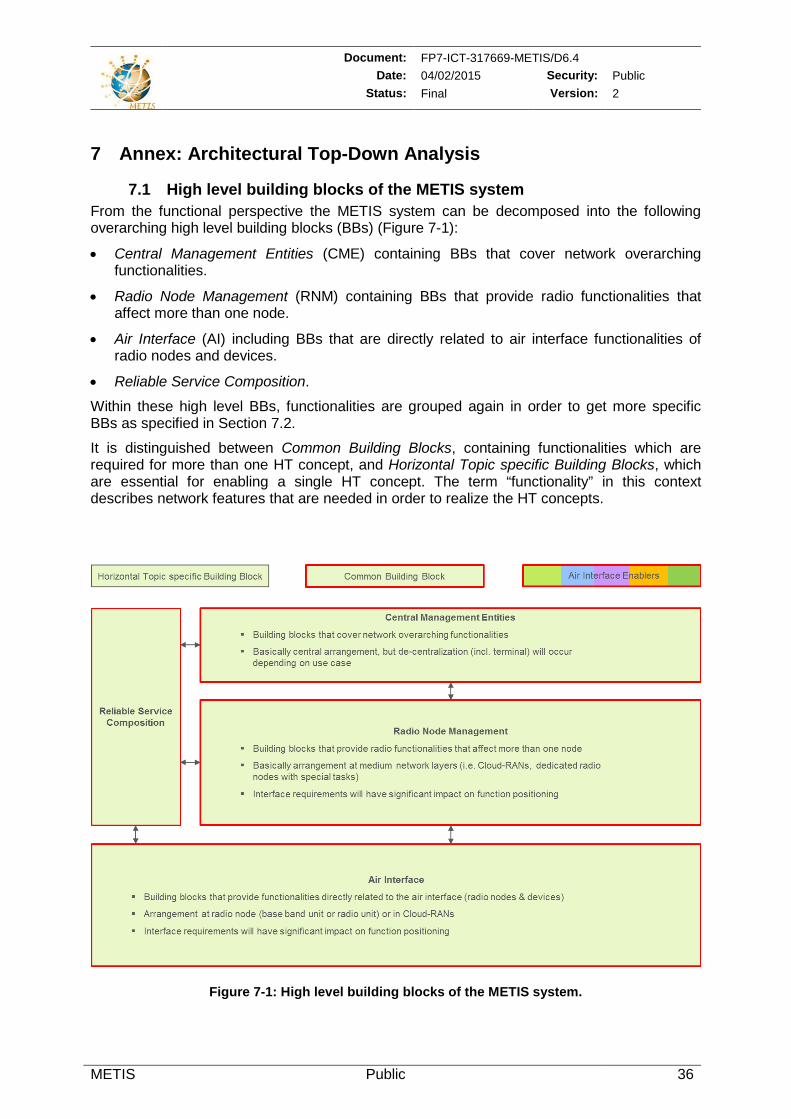
Document: FP7-ICT-317669-METIS/D6.4 Date: 04/02/2015 Security: Public
Status: Final Version: 2
METIS Public 36
7 Annex: Architectural Top-Down Analysis
7.1 High level building blocks of the METIS system From the functional perspective the METIS system can be decomposed into the following overarching high level building blocks (BBs) (Figure 7-1):
• Central Management Entities (CME) containing BBs that cover network overarching functionalities.
• Radio Node Management (RNM) containing BBs that provide radio functionalities that affect more than one node.
• Air Interface (AI) including BBs that are directly related to air interface functionalities of radio nodes and devices.
• Reliable Service Composition.
Within these high level BBs, functionalities are grouped again in order to get more specific BBs as specified in Section 7.2.
It is distinguished between Common Building Blocks, containing functionalities which are required for more than one HT concept, and Horizontal Topic specific Building Blocks, which are essential for enabling a single HT concept. The term “functionality” in this context describes network features that are needed in order to realize the HT concepts.
Figure 7-1: High level building blocks of the METIS system.
Document: FP7-ICT-317669-METIS/D6.4 Date: 04/02/2015 Security: Public
Status: Final Version: 2
METIS Public 37
7.2 Building blocks derived from HT concept descriptions From the analysis of the HT concept descriptions in [MET14-D62] a series of necessary functionalities can be derived. These functionalities have been organized and combined in order to define corresponding specific BBs within the high level functional architecture BBs.
7.2.1 Central Management Entities At CME level all BBs provide functionalities that are not explicitly HT specific.
The Context Management has to collect information from all over the network. Whether information has to be available at central network locations or more locally depends on latency requirements for updates and classification with respect to general relevance.
Novel Network Interface Terminations allow for
Information exchange with administrative entities (e.g., spectrum resource data base),
Information exchange between network operators,
Integrated wireless backhaul management based on context information.
These functionalities will enable network optimization for specific services or inter-operator spectrum sharing as well as backhaul optimizations. There will be a wide range of requirements with different flavours not only restricted to HTs.
Spectrum Management 18 includes functionalities to handle all types of spectrum authorizations, i.e., dedicated spectrum utilisation as well as new licensing methods like LSA or co-primary sharing [MET14-D52]. Also license exempt sharing and models using spectrum pools or mutual renting are supported.
From an architectural point of view, spectrum usage functionalities are implemented above the RRM functionalities as own functional unit called Spectrum Controller which communicates with the external Spectrum Coordination, and internally mainly with the RRM. It should be mentioned that the Spectrum Controller may integrate or trigger other network functions (e.g., Network Management and Network Planning tools) to transform and mediate spectrum resource information in the network. This includes spectrum resource definitions as well as spectrum resource control information.
The interface between the Spectrum Controller and the external Spectrum Coordination provides functions for authentication, authorization and exchange of spectrum resource information via a request-response mechanism.
7.2.1 Radio Node Management Also at RNM level all BBs provide functionalities that are not explicitly HT specific. Table 7.1 gives an overview of the RNM BBs, the functionalities assigned to them as well as the HT concepts benefiting from these BBs.
18 The METIS spectrum architecture is divided into a technical and a regulatory layer. While the technical layer
provides all functions to use spectrum resources in a network, the regulatory (administration) layer deals mainly with functions to plan spectrum usage, assign spectrum licenses and to enforce license conditions. As the administration layer is outside the MNO domain, only the technical layer functionalities are considered for the METIS system architecture.
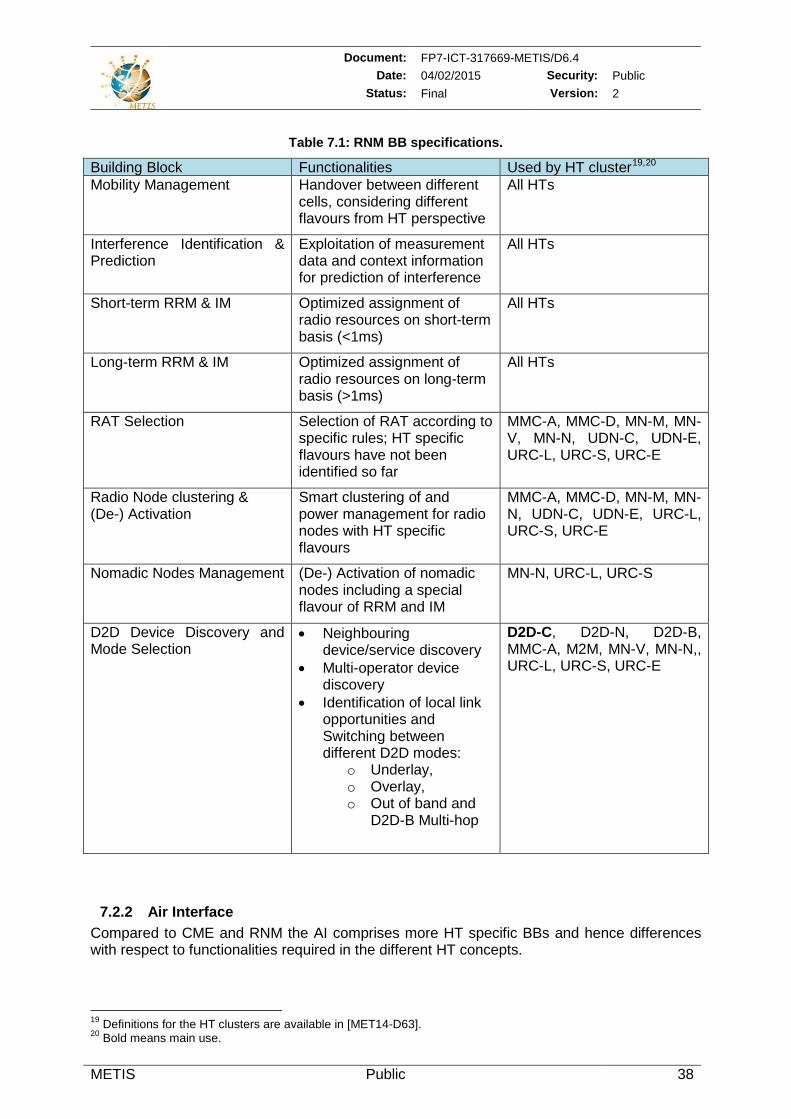
Document: FP7-ICT-317669-METIS/D6.4 Date: 04/02/2015 Security: Public
Status: Final Version: 2
METIS Public 38
Table 7.1: RNM BB specifications.
Building Block Functionalities Used by HT cluster19,20 Mobility Management Handover between different
cells, considering different flavours from HT perspective
All HTs
Interference Identification & Prediction
Exploitation of measurement data and context information for prediction of interference
All HTs
Short-term RRM & IM Optimized assignment of radio resources on short-term basis (<1ms)
All HTs
Long-term RRM & IM Optimized assignment of radio resources on long-term basis (>1ms)
All HTs
RAT Selection Selection of RAT according to specific rules; HT specific flavours have not been identified so far
MMC-A, MMC-D, MN-M, MN-V, MN-N, UDN-C, UDN-E, URC-L, URC-S, URC-E
Radio Node clustering & (De-) Activation
Smart clustering of and power management for radio nodes with HT specific flavours
MMC-A, MMC-D, MN-M, MN-N, UDN-C, UDN-E, URC-L, URC-S, URC-E
Nomadic Nodes Management (De-) Activation of nomadic nodes including a special flavour of RRM and IM
MN-N, URC-L, URC-S
D2D Device Discovery and Mode Selection
• Neighbouring device/service discovery
• Multi-operator device discovery
• Identification of local link opportunities and Switching between different D2D modes:
o Underlay, o Overlay, o Out of band and
D2D-B Multi-hop
D2D-C, D2D-N, D2D-B, MMC-A, M2M, MN-V, MN-N,, URC-L, URC-S, URC-E
7.2.2 Air Interface Compared to CME and RNM the AI comprises more HT specific BBs and hence differences with respect to functionalities required in the different HT concepts.
19 Definitions for the HT clusters are available in [MET14-D63]. 20 Bold means main use.
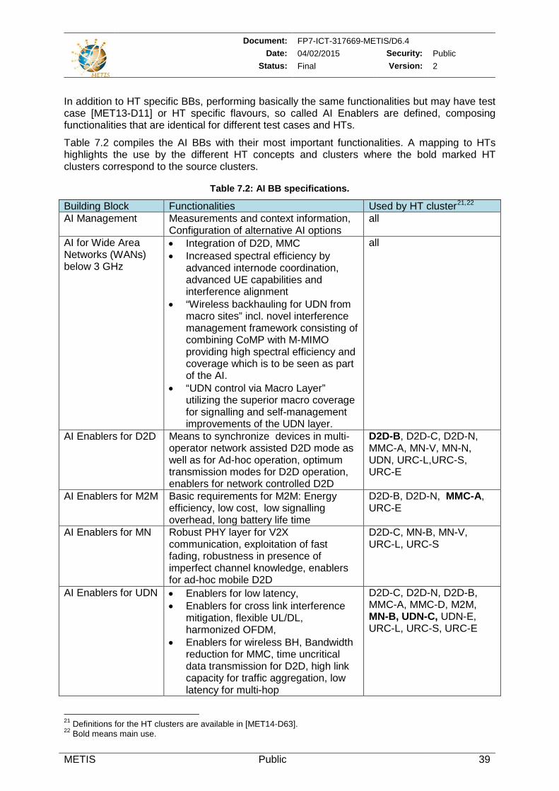
Document: FP7-ICT-317669-METIS/D6.4 Date: 04/02/2015 Security: Public
Status: Final Version: 2
METIS Public 39
In addition to HT specific BBs, performing basically the same functionalities but may have test case [MET13-D11] or HT specific flavours, so called AI Enablers are defined, composing functionalities that are identical for different test cases and HTs.
Table 7.2 compiles the AI BBs with their most important functionalities. A mapping to HTs highlights the use by the different HT concepts and clusters where the bold marked HT clusters correspond to the source clusters.
Table 7.2: AI BB specifications.
Building Block Functionalities Used by HT cluster21,22 AI Management Measurements and context information,
Configuration of alternative AI options all
AI for Wide Area Networks (WANs) below 3 GHz
• Integration of D2D, MMC • Increased spectral efficiency by
advanced internode coordination, advanced UE capabilities and interference alignment
• “Wireless backhauling for UDN from macro sites” incl. novel interference management framework consisting of combining CoMP with M-MIMO providing high spectral efficiency and coverage which is to be seen as part of the AI.
• “UDN control via Macro Layer” utilizing the superior macro coverage for signalling and self-management improvements of the UDN layer.
all
AI Enablers for D2D Means to synchronize devices in multi-operator network assisted D2D mode as well as for Ad-hoc operation, optimum transmission modes for D2D operation, enablers for network controlled D2D
D2D-B, D2D-C, D2D-N, MMC-A, MN-V, MN-N, UDN, URC-L,URC-S, URC-E
AI Enablers for M2M Basic requirements for M2M: Energy efficiency, low cost, low signalling overhead, long battery life time
D2D-B, D2D-N, MMC-A, URC-E
AI Enablers for MN Robust PHY layer for V2X communication, exploitation of fast fading, robustness in presence of imperfect channel knowledge, enablers for ad-hoc mobile D2D
D2D-C, MN-B, MN-V, URC-L, URC-S
AI Enablers for UDN
• Enablers for low latency, • Enablers for cross link interference
mitigation, flexible UL/DL, harmonized OFDM,
• Enablers for wireless BH, Bandwidth reduction for MMC, time uncritical data transmission for D2D, high link capacity for traffic aggregation, low latency for multi-hop
D2D-C, D2D-N, D2D-B, MMC-A, MMC-D, M2M, MN-B, UDN-C, UDN-E, URC-L, URC-S, URC-E
21 Definitions for the HT clusters are available in [MET14-D63]. 22 Bold means main use.
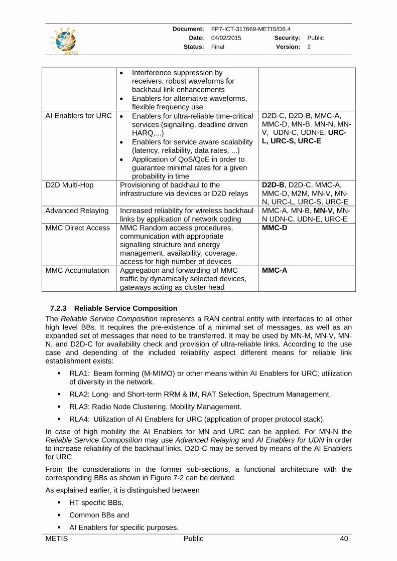
Document: FP7-ICT-317669-METIS/D6.4 Date: 04/02/2015 Security: Public
Status: Final Version: 2
METIS Public 40
• Interference suppression by receivers, robust waveforms for backhaul link enhancements
• Enablers for alternative waveforms, flexible frequency use
AI Enablers for URC • Enablers for ultra-reliable time-critical services (signalling, deadline driven HARQ,...)
• Enablers for service aware scalability (latency, reliability, data rates, ...)
• Application of QoS/QoE in order to guarantee minimal rates for a given probability in time
D2D-C, D2D-B, MMC-A, MMC-D, MN-B, MN-N, MN-V, UDN-C, UDN-E, URC-L, URC-S, URC-E
D2D Multi-Hop
Provisioning of backhaul to the infrastructure via devices or D2D relays
D2D-B, D2D-C, MMC-A, MMC-D, M2M, MN-V, MN-N, URC-L, URC-S, URC-E
Advanced Relaying Increased reliability for wireless backhaul links by application of network coding
MMC-A, MN-B, MN-V, MN-N UDN-C, UDN-E, URC-E
MMC Direct Access MMC Random access procedures, communication with appropriate signalling structure and energy management, availability, coverage, access for high number of devices
MMC-D
MMC Accumulation Aggregation and forwarding of MMC traffic by dynamically selected devices, gateways acting as cluster head
MMC-A
7.2.3 Reliable Service Composition The Reliable Service Composition represents a RAN central entity with interfaces to all other high level BBs. It requires the pre-existence of a minimal set of messages, as well as an expanded set of messages that need to be transferred. It may be used by MN-M, MN-V, MN-N, and D2D-C for availability check and provision of ultra-reliable links. According to the use case and depending of the included reliability aspect different means for reliable link establishment exists:
RLA1: Beam forming (M-MIMO) or other means within AI Enablers for URC; utilization of diversity in the network.
RLA2: Long- and Short-term RRM & IM, RAT Selection, Spectrum Management.
RLA3: Radio Node Clustering, Mobility Management.
RLA4: Utilization of AI Enablers for URC (application of proper protocol stack).
In case of high mobility the AI Enablers for MN and URC can be applied. For MN-N the Reliable Service Composition may use Advanced Relaying and AI Enablers for UDN in order to increase reliability of the backhaul links. D2D-C may be served by means of the AI Enablers for URC.
From the considerations in the former sub-sections, a functional architecture with the corresponding BBs as shown in Figure 7-2 can be derived.
As explained earlier, it is distinguished between
HT specific BBs,
Common BBs and
AI Enablers for specific purposes.
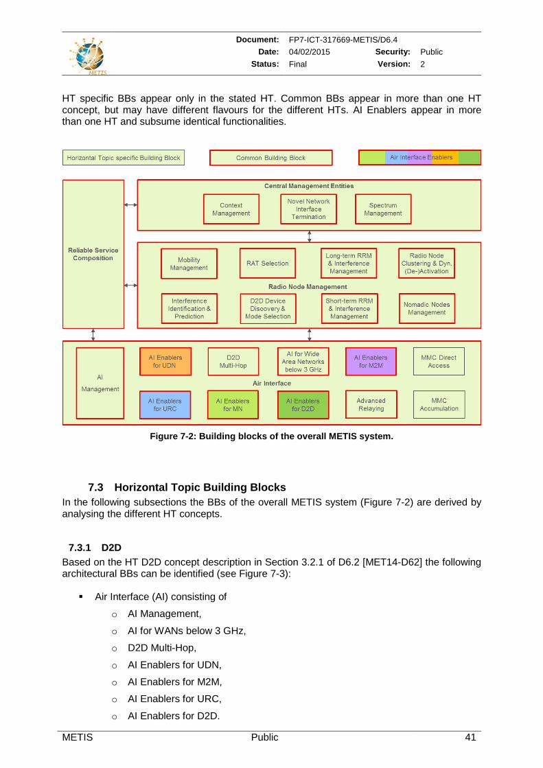
Document: FP7-ICT-317669-METIS/D6.4 Date: 04/02/2015 Security: Public
Status: Final Version: 2
METIS Public 41
HT specific BBs appear only in the stated HT. Common BBs appear in more than one HT concept, but may have different flavours for the different HTs. AI Enablers appear in more than one HT and subsume identical functionalities.
Figure 7-2: Building blocks of the overall METIS system.
7.3 Horizontal Topic Building Blocks In the following subsections the BBs of the overall METIS system (Figure 7-2) are derived by analysing the different HT concepts.
7.3.1 D2D Based on the HT D2D concept description in Section 3.2.1 of D6.2 [MET14-D62] the following architectural BBs can be identified (see Figure 7-3): Air Interface (AI) consisting of
o AI Management,
o AI for WANs below 3 GHz,
o D2D Multi-Hop,
o AI Enablers for UDN,
o AI Enablers for M2M,
o AI Enablers for URC,
o AI Enablers for D2D.
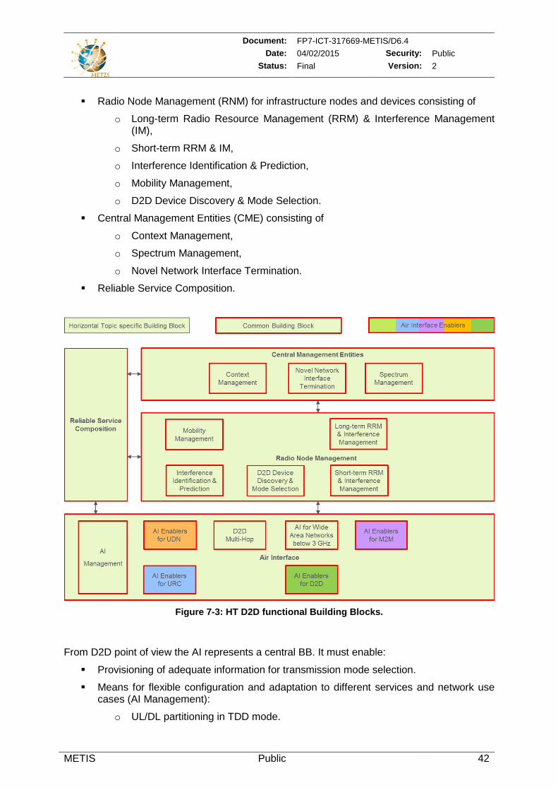
Document: FP7-ICT-317669-METIS/D6.4 Date: 04/02/2015 Security: Public
Status: Final Version: 2
METIS Public 42
Radio Node Management (RNM) for infrastructure nodes and devices consisting of
o Long-term Radio Resource Management (RRM) & Interference Management (IM),
o Short-term RRM & IM,
o Interference Identification & Prediction,
o Mobility Management,
o D2D Device Discovery & Mode Selection.
Central Management Entities (CME) consisting of
o Context Management,
o Spectrum Management,
o Novel Network Interface Termination.
Reliable Service Composition.
Figure 7-3: HT D2D functional Building Blocks.
From D2D point of view the AI represents a central BB. It must enable:
Provisioning of adequate information for transmission mode selection.
Means for flexible configuration and adaptation to different services and network use cases (AI Management):
o UL/DL partitioning in TDD mode.
Document: FP7-ICT-317669-METIS/D6.4 Date: 04/02/2015 Security: Public
Status: Final Version: 2
METIS Public 43
o Usage of FDD mode natively integrated into the AI for wide area communication even for D2D communication (according to [MET14-D62]).
o Mode dependent adequate transmission between the local peers coexisting (underlay or overlay D2D) or non-coexisting with cellular usage (out of band D2D).
Time uncritical services (noted as D2D-N for time uncritical services in [MET14-D63]).
Ultra-reliable services via D2D-C according to [MET14-D63] by using features provided by the AI Enablers for URC (URC-L, URC-S). D2D-C meaning robust PHY layer for V2X communication may be provided by the AI Enablers for MN with special emphasis on MN-V.
Interference suppression by receivers.
Network controlled D2D operation.
AI Enablers for M2M – communication with appropriate signalling structure and energy management.
AI Enablers for D2D – MAC and RRM functionalities at Layer 1/2, i.e., means to synchronize devices in multi-operator network assisted D2D mode as well as for Ad-hoc operation, optimum transmission modes for D2D operation, and enablers for network controlled D2D.
D2D Multi-Hop – providing backhaul to the infrastructure via other devices as well as supporting local D2D communication via D2D relays.
The D2D RNM represents the following common BBs:
Long- and Short-term RRM & IM are essential for coexistence of D2D with cellular networks. Interference Management is closely related to resource allocation. As most of the time imbalance between path loss to cellular and to local peers exists power control is a vital element for coexistence especially in case of underlay D2D. Input for IM has to be provided by the AI as well as by Interference Identification & Prediction algorithms. Main functionalities provided by these BBs are:
o Proper resource allocation based on AI interference measurements (centralized or decentralized).
o Adjustment of transmit powers.
o Interference suppression by receivers.
o Efficient spectrum sharing between D2D and cellular in overlay mode
D2D Device Discovery and Communication Mode Selection are important premises for better support of various D2D related services and applications. These are D2D specific BBs that have to provide functionalities such as:
o Neighbouring device/service discovery, with assistance from the control signalling from the infrastructure in order to attain latency/reliability goals
o Identification of local link opportunities and
o Switching between cellular network mode and different D2D modes:
Underlay, overlay, out of band;
D2D Multi-Hop.
Mobility Management has to support:
Document: FP7-ICT-317669-METIS/D6.4 Date: 04/02/2015 Security: Public
Status: Final Version: 2
METIS Public 44
o Handover between D2D and cellular (denoted here as mode selection) as well as inclusion of D2D relays or relayed D2D (denoted here as handover).
o Handover between cells if terminals stay in D2D mode.
Mode Selection and Mobility Management might be realized based on information provided by the AI, as for example location or channel state information (CSI) / large scale path loss, as well as by context information provided by the network. In case of multi-cell operation the D2D Mode Selection might be combined with IM.
Interference Identification & Prediction:
o Information delivery to Mobility Management and to RRM.
On CME level following BBs are to be noted:
Context Management has to collect relevant information from different parts of the network and to provide it wherever needed. The Context Management might be organized in centralized and/or distributed manner. In case of D2D with more than one cell affected there is a need for a component that is located at a hierarchical level exceeding the radio nodes in the network.
For D2D the Spectrum Management has to provide:
o Information on spectrum availability as well as network level assignment of frequency resources for overlay D2D to facilitate:
Adaptive spectrum sharing in network assisted D2D communication (e.g. D2D operation in MBB UL/DL or dedicated band).
Coexistence among D2D pair/groups.
Coexistence between D2D communication and regular cellular communication.
Novel Network Interface Termination to operator external entities to enable e.g. communication among devices from different operators.
7.3.2 MMC Based on the HT MMC concept description in Section 3.2.2 of [MET14-D62] the following architectural BBs can be identified (see Figure 7-4). AI consisting of
o AI Management,
o AI for WANs below 3 GHz,
o MMC Accumulation,
o MMC Direct Access,
o AI Enablers for M2M,
o AI Enablers for D2D,
o AI Enablers for UDN,
o D2D Multi-Hop,
o Advanced Relaying.
RNM consisting of
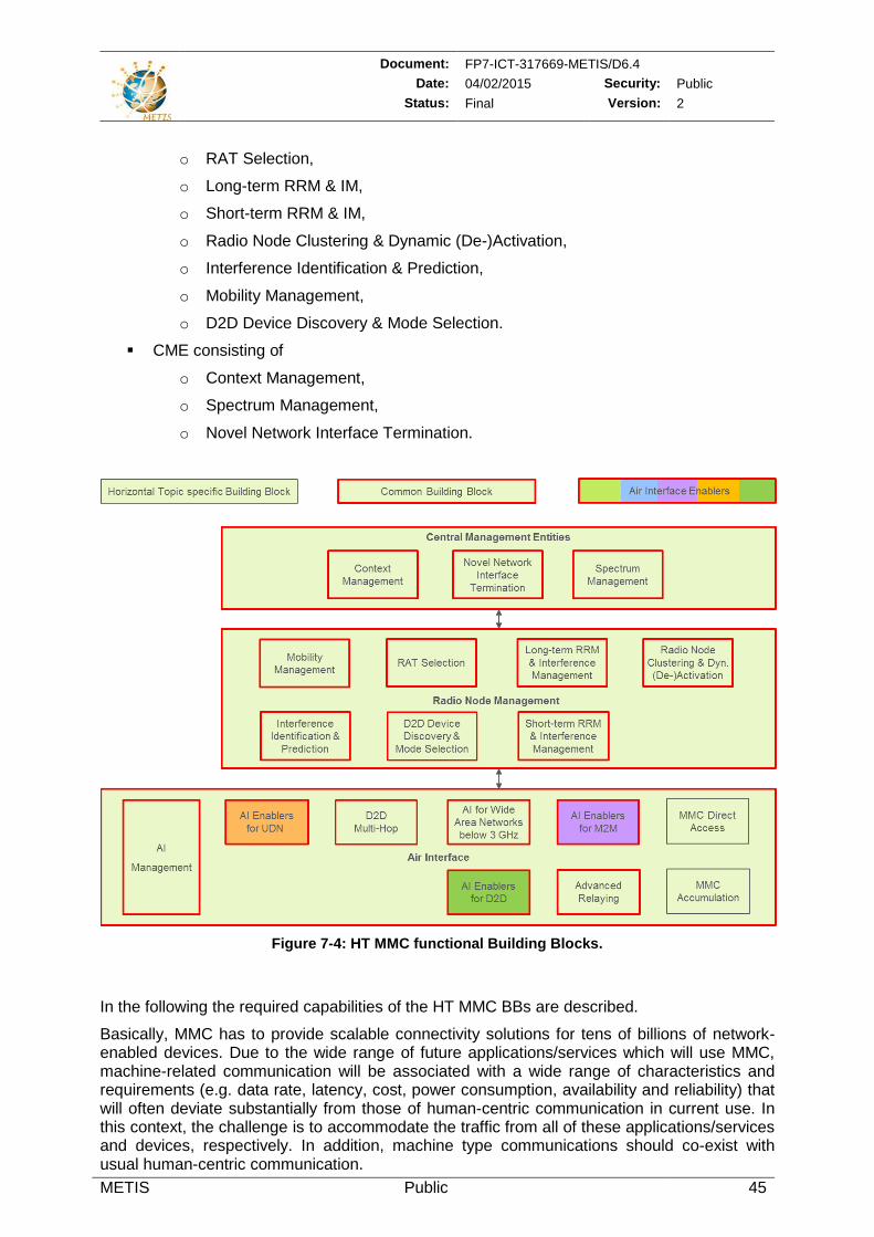
Document: FP7-ICT-317669-METIS/D6.4 Date: 04/02/2015 Security: Public
Status: Final Version: 2
METIS Public 45
o RAT Selection,
o Long-term RRM & IM,
o Short-term RRM & IM,
o Radio Node Clustering & Dynamic (De-)Activation,
o Interference Identification & Prediction,
o Mobility Management,
o D2D Device Discovery & Mode Selection.
CME consisting of
o Context Management,
o Spectrum Management,
o Novel Network Interface Termination.
Figure 7-4: HT MMC functional Building Blocks.
In the following the required capabilities of the HT MMC BBs are described.
Basically, MMC has to provide scalable connectivity solutions for tens of billions of network-enabled devices. Due to the wide range of future applications/services which will use MMC, machine-related communication will be associated with a wide range of characteristics and requirements (e.g. data rate, latency, cost, power consumption, availability and reliability) that will often deviate substantially from those of human-centric communication in current use. In this context, the challenge is to accommodate the traffic from all of these applications/services and devices, respectively. In addition, machine type communications should co-exist with usual human-centric communication.
Document: FP7-ICT-317669-METIS/D6.4 Date: 04/02/2015 Security: Public
Status: Final Version: 2
METIS Public 46
The MMC AI has to support:
Basic requirements, such as
o Low energy;
o Low cost;
o Availability, i.e. coverage;
o Low signalling overhead;
o Extremely high number of connected devices.
Accommodate efficiently traffic from applications/services of totally different nature in terms of data rates, latency and reliability requirements.
Three types of AI flavours, such as MMC-A, MMC-D and the AI Enablers for M2M.
The MMC AI BBs are given as:
MMC Direct Access:
o Devices transmit directly to a network infrastructure radio node (i.e. with base station functionality).
The benefit of this scheme is that it requires no planning when deploying devices, given that access nodes provide full coverage. Another advantage is the provided flexibility in terms of mobility management particularly for non-static devices.
The drawback might be the coverage aspect; for low-complexity devices with low output power constraints special attention is needed to reach the coverage KPI in UL direction.
MMC Accumulation:
o Traffic from devices in the proximity is accumulated in a local node before being sent to a radio node with base station functionality.
o The accumulation point can either be a relay, a service dedicated gateway, a smart phone connecting personal electronic devices, or a dynamically selected device acting temporarily as the group/cluster head.
o For this scheme, a varying range of data processing could be applied. From forwarding the data as it is (as a relay), to accumulating data (in order to have few but larger data bundle transmissions to the infrastructure radio node), or even doing processing in the accumulation point (in which case only the relevant and processed data is forwarded to the infrastructure radio node).
o Realisation of these functionalities will be complemented by D2D Multi-Hop functionalities (D2D-B).
AI Enablers for M2M (M2M access – direct M2M communication):
o Focus is on very low bit rates and delay tolerant traffic rather than very high bit rates and tight delay budgets.
o This type of AI inherits most technical solutions from the D2D communication.
o One key difference of M2M communication relative to “usual” D2D communication (e.g. for MBB services) is the requirement for very high protocol efficiency (i.e., very low signalling overhead) and the requirement for extremely long device battery life time.
Document: FP7-ICT-317669-METIS/D6.4 Date: 04/02/2015 Security: Public
Status: Final Version: 2
METIS Public 47
o For the latter requirement, M2M transmissions would be very beneficial in the case where the device is in bad or unstable coverage area and/or is power limited, i.e., when the device has reached the maximum transmit power level. In most other cases, the major factor on the device battery life is the required on-time and the base power consumption of the power amplifier. Because of these two reasons, the normal D2D setup process is not feasible for M2M communication, at least not for battery-operated devices. Therefore, more long-term and static setup would be required for M2M communication compared to D2D communication. That is, for each M2M transmission of very few bytes it is not feasible to repeat the full D2D setup procedure including 1) identifying whether the traffic is E2E, 2) device discovery and link quality analysis, 3) determining if the M2M link quality is good enough such that a direct M2M link would be favourable to routing the traffic via the infrastructure radio node, and 4) determining whether system resources should be reused locally or if dedicated resources should be used for the M2M link. Expressed differently, if M2M traffic is found not to be applicable in a certain case, the above procedures shall be designed in such a way that they only introduce an almost-negligible increase in signalling overhead and battery consumption.
AI Enablers for D2D:
o Synchronisation between devices in D2D mode.
o Optimum transmission modes for D2D operation.
o Enablers for network controlled D2D
AI Enablers for UDN:
o Self-configurable wireless backhaul, adaptive to changes in network topology and network load.
o Enablers for alternative waveforms, flexible frequency use, cross link interference mitigation, flexible UL/DL, harmonized OFDM, bandwidth reduction for MMC, time uncritical data transmission for D2D,
o High link capacity for traffic aggregation from several radio nodes.
o Low latency on physical layer to allow multi-hop connectivity.
D2D Multi-Hop
o MMC-A will make use of functionalities provided by D2D Multi-Hop
Advanced Relaying
o MMC-A can reuse features provided by Advanced relaying in order to improve reliability in UDNs
AI Management:
o AI Management and selection of the appropriate AI type (MMC Accumulation, MMC Direct Access, and the AI Enablers for M2M) according to the use case where the device is applied.
o Management and selection of AI based on information provided by RNM.
o Provisioning of adequate information for transmission mode selection.
AI for WANs below 3 GHz
o Integration of D2D, MMC. o Increased spectral efficiency by advanced internode coordination, advanced
UE capabilities and interference alignment.
Document: FP7-ICT-317669-METIS/D6.4 Date: 04/02/2015 Security: Public
Status: Final Version: 2
METIS Public 48
The MMC Radio Node Management BBs enable:
RAT Selection provides information to the AI Management in order to control the MMC AI. Selection of most suitable RAT is based on information provided by NM and RNM. Moreover, it also considers information provided by the AI itself.
Long- and Short-term RRM and IM are essential for coexistence of M2M (i.e. utilizing D2D transmission) with cellular networks. IM is closely related to resource allocation. In order to cope with time imbalance of path loss between cellular and local peers, control is a vital element for coexistence especially in case of underlay D2D. Input for IM has to be provided by the AI as well as by Interference Identification & Prediction algorithms. Main functionalities provided by these BBs are:
o Proper resource allocation based on AI interference measurements (centralized or decentralized).
o Adjustment of transmit powers.
o Spectrum sharing between MMC and cellular in overlay mode.
Radio Node Clustering & Dynamic (De-)Activation:
o Radio Node Clustering is needed for AI type MMC Accumulation. Depending on the use case the Radio Node Clustering has to setup a cluster consisting of several devices. The head of this cluster is led by the accumulation/aggregation point which is able to control and manage the links to the connected devices.
There are two types of accumulation/aggregation points:
Transparent accumulation/aggregation point:
• Devices communicate with nodes and/or services in the Internet directly.
Non-transparent accumulation/aggregation point:
• Devices communicate with nodes and/or services in the Internet via accumulation/aggregation point which is acting as a proxy.
• Addressing of the devices is of importance.
o Dynamic (De-)Activation is needed for MMC in general. One important aspect of this topic is the ability to improve battery life time of battery operated devices. Low energy consumption of the AI and low signalling overhead are of high importance.
Mobility Management:
o Handover among all three MMC AI types, such as MMC Direct Access, MMC Accumulation and AI Enablers for M2M. In the case of MMC-A the accumulation/aggregation point should be addressed by the Mobility Management while the connected devices are not touched by the Mobility Management. However, in certain cases the Mobility Management can decide to handover a device from an accumulation/aggregation point (MMC-A) to a radio node with base station functionality (MMC-D). Such a handover decisions can be performed based on information provided by the Context Management and/or Interference Identification & Prediction.
o In case of ultra-reliable MTC the AI management will support mobility management by collection respective context information.
Interference Identification & Prediction :
o Information delivery to Mobility Management and to RRM.
Document: FP7-ICT-317669-METIS/D6.4 Date: 04/02/2015 Security: Public
Status: Final Version: 2
METIS Public 49
On Central Management Entities level following BBs are to be noted for MMC:
Context Management:
o Collect relevant information from different parts of the network, incl. radio nodes and devices, in order to deliver use case related information to other BBs, such as RNM and Novel Network Interfaces.
In order to cover MMC aspects the Spectrum Management has to support:
o Flexible spectrum access for low complexity devices to:
Licensed spectrum for guaranteed service quality (i.e. controlled resource usage and interference management);
Unlicensed spectrum due to global harmonization giving the benefit of economy of scale plus no licensing costs.
The MMC Novel Network Interface Termination BB provides the ability to offer
and/or request information from the accumulation/aggregation point and devices which can be used, e.g., from other actors like other network operators, OTT providers and/or application/service providers.
7.3.3 MN Based on the concept descriptions for the three MN clusters in Section 3.2.3 of [MET14-D62] an integrated and unified MN system concept can be described consisting of the following architectural BBs (see Figure 7-5):
AI consisting of
o AI Enablers for MN (MN-M, MN-V),
o AI for WANs below 3 GHz,
o Advanced Relaying,
o AI Enablers for URC,
o AI Enablers for D2D,
o D2D Multi-Hop,
o AI Management.
RNM consisting of
o RAT Selection,
o Long-term RRM & IM,
o Short-term RRM & IM,
o Radio Node Clustering & Dynamic (De-)Activation,
o Nomadic Nodes Management,
o Interference Identification & Prediction,
o Mobility Management,
o D2D Device Discovery & Mode Selection.
CME consisting of
o Context Management,
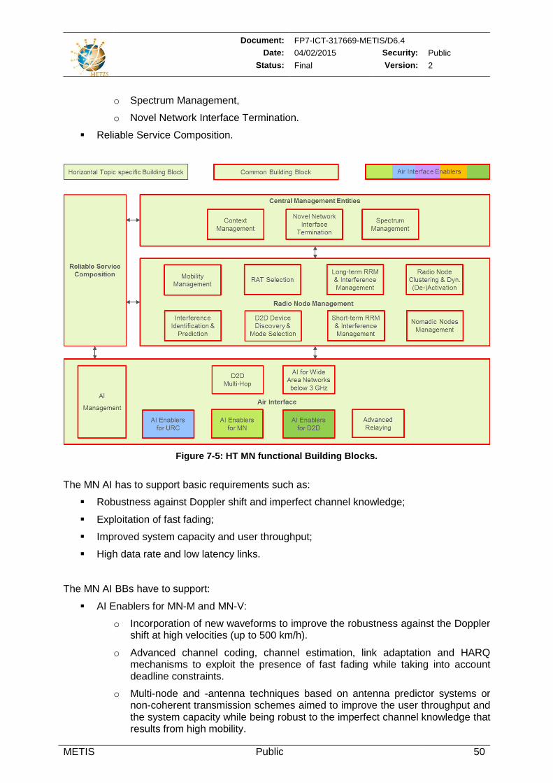
Document: FP7-ICT-317669-METIS/D6.4 Date: 04/02/2015 Security: Public
Status: Final Version: 2
METIS Public 50
o Spectrum Management,
o Novel Network Interface Termination.
Reliable Service Composition.
Figure 7-5: HT MN functional Building Blocks.
The MN AI has to support basic requirements such as:
Robustness against Doppler shift and imperfect channel knowledge;
Exploitation of fast fading;
Improved system capacity and user throughput;
High data rate and low latency links.
The MN AI BBs have to support:
AI Enablers for MN-M and MN-V:
o Incorporation of new waveforms to improve the robustness against the Doppler shift at high velocities (up to 500 km/h).
o Advanced channel coding, channel estimation, link adaptation and HARQ mechanisms to exploit the presence of fast fading while taking into account deadline constraints.
o Multi-node and -antenna techniques based on antenna predictor systems or non-coherent transmission schemes aimed to improve the user throughput and the system capacity while being robust to the imperfect channel knowledge that results from high mobility.
Document: FP7-ICT-317669-METIS/D6.4 Date: 04/02/2015 Security: Public
Status: Final Version: 2
METIS Public 51
o Non- and quasi-orthogonal multiple access schemes impervious to imperfect channel knowledge to increase the system capacity in the case of users travelling at high velocities.
o MAC for ad-hoc mobile D2D.
AI Enablers for URC:
o Availability indication of link reliability to enable the provision of dependable services and applications.
o Modelling and prediction of link reliability for improved availability indication.
o Techniques that explicitly consider deadlines, such as for example deadline-driven HARQ.
AI Enablers for D2D:
o Distributed network synchronisation across devices.
o Optimum transmission modes for D2D operation.
Medium access schemes for non-assisted (pure ad-hoc) D2D communications.
AI Management.
AI for WANs below 3 GHz
o Integration of D2D, MMC
o Increased spectral efficiency by advanced internode coordination, advanced UE capabilities and interference alignment
o Enhancement techniques for backhaul links are essential to leverage the gain of nomadic nodes. Those consist of interference suppression by receivers and robust waveforms
D2D Multi-Hop supporting MN-M and MN-N.
Advanced Relaying.
o Increased reliability and spectral efficiency for wireless backhaul links by application of network coding
The MN RNM BBs have to support:
RAT Selection.
o RAT selection depending on MN-cluster (MN-M, MN-N, MN-V).
Mobility Management:
o Handover prediction and optimization based on context information in order to guarantee seamless connectivity and improved quality of service of mobile users and backhaul links of moving cells.
o Cell reselection and handover management (i.e. in-bound/out-bound mobility) in order to cope with the challenges posed by the densification of moving and nomadic cells in the case of highly mobile users.
Long- and Short-term RRM & IM:
o RRM techniques optimized for highly mobile scenarios based on the exploitation of the synergies between RRM and HO as well as of interference identification and context awareness.
Document: FP7-ICT-317669-METIS/D6.4 Date: 04/02/2015 Security: Public
Status: Final Version: 2
METIS Public 52
o IM also has to consider the impact of activated nomadic nodes on the inter-cell interference levels.
o Smart resource allocation in order to decrease inter-cell interference.
Radio Node Clustering & Dynamic (De-)Activation:
o Device and service discovery schemes for (non-moving) radio nodes optimized for highly mobile devices by considering the time to discovery, the number of discoverable devices/services and the required signalling overhead.
Interference Identification & Prediction.
o De-)activation of nomadic nodes, RRM and HO mechanisms, as well as the backhaul link enhancement and clustering techniques rely on accurate interference information. Moreover, timely action of these schemes requires the prediction of interference.
Nomadic Nodes Management (MN-N):
o Dynamic (de-)activation of nomadic nodes (moving cells) to provide additional capabilities for energy saving and load balancing for the network. Decisions based on coverage and capacity demands of UEs.
o IM and advanced cooperative strategies as enablers to provide diversity and capacity enhancement to the network based on the use of nomadic nodes.
The MN Central Management Entities BBs have to support:
Context Management:
o Collect relevant information from different parts of the network, incl. radio nodes and devices, in order to deliver use case related information to other BBs, such as RNM and Novel Network interfaces.
Novel Network Interface Termination:
o Provide access to network information, e.g. predicted data, for other network entities, operators and service providers.
o Inter-Operator Support
Spectrum Management:
o In order to fulfil MN requirements (e.g. C-ITS, V2X, ...) the Spectrum Management has to facilitate:
Access to a sufficient amount of reliable (i.e., exclusively licensed) spectrum;
Preferably, dedicated spectrum should be available for safety-critical communication;
o Inter-operator Spectrum Management for mobile D2D.
o Smart spectrum coordination in order to decrease the inter-cell interference in the case of nomadic nodes and to allocate a sufficient amount of spectrum for the high-data rate backhaul links.
7.3.4 UDN The HT UDN has defined a core specific concept optimized for the potential stand-alone operation of a layer of ultra-densely deployed small cells (UDN-C) plus an extension part
Document: FP7-ICT-317669-METIS/D6.4 Date: 04/02/2015 Security: Public
Status: Final Version: 2
METIS Public 53
offering additional performance improvements (UDN-E). According to [MET14-D62] following main functional BBs can be identified for the overall HT UDN concept:
AI consisting of
o AI Management,
o AI for WANs below 3 GHz,
o AI Enablers for UDN,
o AI Enablers for D2D,
o AI Enablers for URC,
o Advanced Relaying.
RNM consisting of
o RAT Selection,
o Long-term RRM & IM,
o Short-term RRM & IM,
o Radio Node Clustering & Dynamic (De-)Activation,
o Interference Identification & Prediction,
o Mobility Management.
CME consisting of
o Context Management,
o Spectrum Management,
o Novel Network Interfaces.
Reliable Service Composition.
The interrelations between the BBs are shown in Figure 7-6 with BBs to be commonly applied by other HT concepts shown with red frames.
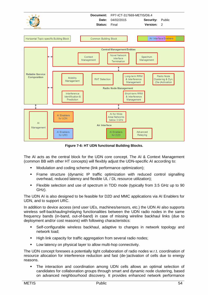
Document: FP7-ICT-317669-METIS/D6.4 Date: 04/02/2015 Security: Public
Status: Final Version: 2
METIS Public 54
Figure 7-6: HT UDN functional Building Blocks.
The AI acts as the central block for the UDN core concept. The AI & Context Management (common BB with other HT concepts) will flexibly adjust the UDN-specific AI according to:
Modulation and coding scheme (link performance optimization);
Frame structure (dynamic IP traffic optimization with reduced control signalling overhead, reduced latency and flexible UL / DL resource utilization);
Flexible selection and use of spectrum in TDD mode (typically from 3.5 GHz up to 90 GHz).
The UDN AI is also designed to be feasible for D2D and MMC applications via AI Enablers for UDN, and to support URC.
In addition to device access (end user UEs, machines/sensors, etc.) the UDN AI also supports wireless self-backhauling/relaying functionalities between the UDN radio nodes in the same frequency bands (in-band, out-of-band) in case of missing wireline backhaul links (due to deployment and/or cost reasons) with following characteristics:
Self-configurable wireless backhaul, adaptive to changes in network topology and network load;
High link capacity for traffic aggregation from several radio nodes;
Low latency on physical layer to allow multi-hop connectivity.
The UDN concept foresees a potentially tight collaboration of radio nodes w.r.t. coordination of resource allocation for interference reduction and fast (de-)activation of cells due to energy reasons.
The interaction and coordination among UDN cells allows an optimal selection of candidates for collaboration groups through smart and dynamic node clustering, based on advanced neighbourhood discovery. It provides enhanced network performance
Document: FP7-ICT-317669-METIS/D6.4 Date: 04/02/2015 Security: Public
Status: Final Version: 2
METIS Public 55
through Long- and Short-term RRM & IM, RAT selection, and inter-operator spectrum sharing algorithms. The latter avoids in-band/out-of-band coexistence problems through spectrum coordination configured via the on-top spectrum management procedures. These features described here with special emphasis to UDN are in principle common to other HT concepts.
The (de-)activation of UDN radio nodes allows a fast response for rapid changes in network topology or network failures, reduces the number of hand-over failures in dense deployment (optimized mobility, solving problem of holes in the UDN coverage), a power safety optimization of radio nodes depending on the traffic load in the area. Together with self-backhaul functionalities the network maintenance cost will be reduced via simplified network planning and automated tuning of parameters.
The extended UDN concept offers additional performance improvements by application of following BBs:
Context awareness for UDN mobility, resource and network management (especially to support the URC-L concept) to be integrated into a common BB for Context Management.
Inter-RAT/ inter-operator collaboration via common novel network interface terminations;
Tight interaction of a UDN layer with a macro layer holding superior role in control and management functions over common area (split of C- and U-Plane between macro and UDN layer);
Wireless backhaul including macro-layer as well as other radio relays for flexible and low-cost UDN deployments.
From UDN perspective the Spectrum Management BB has to enable:
Operation on different frequencies within a wide range of spectrum bands including mmW.
Fast spectrum aggregation and switching between available resources.
Efficient spectrum sharing techniques, including
o Inter-operator spectrum sharing with novel inter-network interfaces for flexible network management;
o Communication with a LSA manager/database to obtain regulatory operational requirements.
7.3.5 URC URC can be characterised as an overarching HT. In order to enable the generic mechanisms described in [MET14-D62] the following main BBs can be identified:
Reliable Service Composition.
AI consisting of
o AI Enablers for URC (related to URC-L (long-term), URC-S (short-term) and URC-E (emergency),
o D2D Multi-Hop,
o AI Enablers for MN,
o AI Enablers for D2D,
o AI Enablers for UDN,
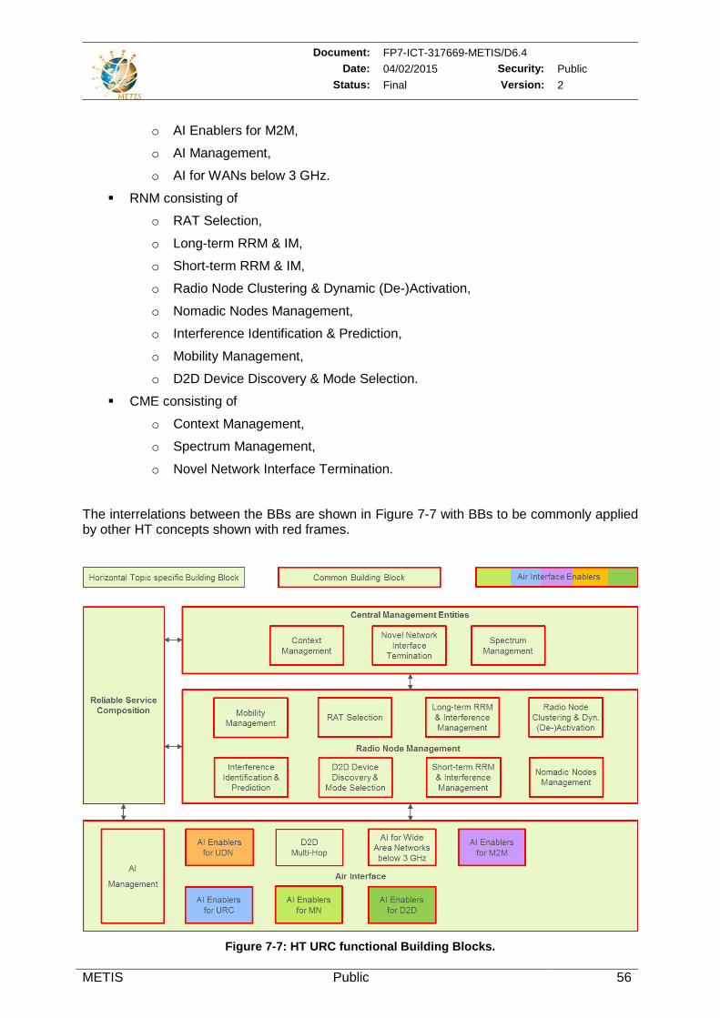
Document: FP7-ICT-317669-METIS/D6.4 Date: 04/02/2015 Security: Public
Status: Final Version: 2
METIS Public 56
o AI Enablers for M2M,
o AI Management,
o AI for WANs below 3 GHz.
RNM consisting of
o RAT Selection,
o Long-term RRM & IM,
o Short-term RRM & IM,
o Radio Node Clustering & Dynamic (De-)Activation,
o Nomadic Nodes Management,
o Interference Identification & Prediction,
o Mobility Management,
o D2D Device Discovery & Mode Selection.
CME consisting of
o Context Management,
o Spectrum Management,
o Novel Network Interface Termination.
The interrelations between the BBs are shown in Figure 7-7 with BBs to be commonly applied by other HT concepts shown with red frames.
Figure 7-7: HT URC functional Building Blocks.
Document: FP7-ICT-317669-METIS/D6.4 Date: 04/02/2015 Security: Public
Status: Final Version: 2
METIS Public 57
Reliable Service Composition represents the central BB for URC. It processes all information on abilities available from the lower layers, transforming it into respective actions that enable availability check and provision of ultra-reliable links in the network:
Evaluation of AI information on abilities and actual QoS/QoE resulting in respective control of AIs or multi-RAT functionalities.
Evaluation of context information resulting in appropriate control messages.
Decision on opportunities for providing reduced grade of service (graceful degradation).
Decision on the need to invest more resources at the PHY layer, both for signalling and data, in order to attain certain reliability level.
With respect to URC the most important functional element of the AI is the AI & context Management. It controls:
Signalling of AI abilities to higher layers (Reliable Service Composition).
Proper settings for robust PHY mechanisms.
Signalling of actual QoS/QoE to higher layers.
Mutual optimization of the requirements set by the higher layers and the adaptation of the AI.
Abilities of the AI consist – in addition to the AI Management and the AI for WANs below 3 GHz – of
AI Enablers for URC (URC-L, URC-S and URC-E):
o Application of QoS/QoE in order to guarantee minimal rates for a given probability in time.
o Application of deadline driven operations in order to guarantee maximal latencies for a given probability in time.
o Counters that documents actual service provisioning parameters.
o Flexibility in the robustness of the signalling information (metadata).
BBs also supporting URC:
o D2D Multi-Hop for infrastructure extension.
o AI Enablers for MN, especially provisioning of robust PHY transmissions.
o AI Enablers for D2D, supporting MAC and RRM functionalities like device synchronization and mode selection.
o AI Enablers for UDN (e.g. low latency, interference suppression, robust waveforms), also supporting D2D and MMC applications.
o AI Enablers for M2M for e.g. low signalling overhead.
Following BBs for the URC RNM have to be mentioned:
RAT Selection functionalities will enable:
o Load balancing between cells of different RATs;
o Smart device /service to RAT mapping;
Document: FP7-ICT-317669-METIS/D6.4 Date: 04/02/2015 Security: Public
Status: Final Version: 2
METIS Public 58
o Smart signalling using context information.
Long- and Short-term RRM & IM:
o May contribute in collaboration with user/service prioritisation especially to control RLA2 related topics [MET14-D62].
The URC CME BBs have to support:
Context Management:
o To collect relevant information from different parts of the network incl. devices and to provide it wherever needed.
Spectrum Management shall be capable to flexibly reallocate spectrum in order to achieve:
o Offloading to another frequency band, when the number of users increase and adherence of reliability is threatened (RLA3) [MET14-D62].
o Operation in a less-interfered spectrum chunk, when there is a significant interference and reliability is threatened (RLA2) [MET14-D62].
o Operation in a dedicated spectrum chunk to attain a specific KPI: for example, low-latency D2D operation or operation at a lower frequency in order to achieve larger coverage range (RLA1) [MET14-D62].
7.4 Divergences and Commonalities of Horizontal Topic Concepts In this section the functional composition of the different HT concepts is compared against each other. Required HT specific BBs are highlighted. In case of common BBs it has been analysed how much requirements and functionalities deviate.
To get an overview of the architecture big picture, in the previous sections the HTs have been broken down into well-defined BBs. Different display formats of the HT concepts as elaborated in [MET14-D62] have been harmonized.
First estimates of the arrangement of functionalities within the Radio Access Network (RAN) can already be done by assuming that
CME functions will be usually centrally positioned. But depending on certain use cases decentralization of functions may happen (e.g. use of local context information at devices).
RNM functions will be arranged at medium network layers23, e.g. at location of Cloud-RANs (C-RANs) [NGMA13] or dedicated radio nodes with special tasks. Especially in this case the performance of the network will heavily depend on the properties (throughput and latency) of the interfaces. Hence in this case careful investigation of the interface requirements is needed.
AI functionalities on network infrastructure side are located at radio nodes or in C-RANs. Even here the in-depth investigation of interface requirements is needed.
23 For definition of the term Medium Network Layer see “List of definitions” in this document.
Document: FP7-ICT-317669-METIS/D6.4 Date: 04/02/2015 Security: Public
Status: Final Version: 2
METIS Public 59
7.4.1 Air Interface Compared to the other main BBs of the overall system (CME and RNM) the AI shows most HT specific BBs and hence differences with respect to functionalities required in the different HT concepts.
The AI Management is a central control entity which is needed for all applications.
The AI Enablers for UDN is reused by most of the HTs. The four main functionalities given as Modulation & Coding Scheme (MCS) optimization, optimized frame structure, fast spectrum aggregation and efficient network sharing are utilized in all cases. Even self-configurable wireless backhaul, high link capacity and low latency on PHY layer allowing for multi-hop connectivity are common functionalities of all affected HTs.
The AI Enablers for URC basically enables configurations in the AI that allow for service aware scalability and time critical services as well as flexible robustness for Tx/Rx. It also provides information to the AI Management that is needed for the Reliable Service Composition (e.g. detection of reliable link availability). They may be reused when reliable links are to be established.
D2D Multi-Hop provides multi-hop backhaul and may be reused every time when getting access to the network via devices.
The AI Enablers for MN shall support all the functionalities that are related to an air interface for moving networks excluding URC.
The AI Enablers for D2D are located at PHY and MAC and support D2D operation.
The AI Enablers for M2M realizes functions needed for machine type D2D communication in context with low cost devices.
Regarding Advanced Relaying there exist different flavours between MN-N and UDN because besides increasing reliability and throughput of wireless backhaul links for UDN in case of MN-N, the techniques in addition need to be adaptive to network changes.
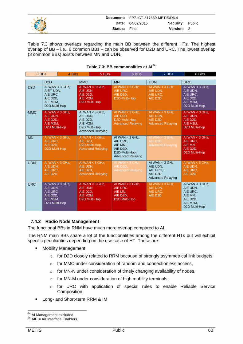
Document: FP7-ICT-317669-METIS/D6.4 Date: 04/02/2015 Security: Public
Status: Final Version: 2
METIS Public 60
Table 7.3 shows overlaps regarding the main BB between the different HTs. The highest overlap of BB – i.e., 6 common BBs – can be observed for D2D and URC. The lowest overlap (3 common BBs) exists between MN and UDN.
Table 7.3: BB commonalities at AI24.
3 BBs 4 BBs 5 BBs 6 BBs 7 BBs 8 BBs
D2D MMC MN UDN URC D2D AI WAN < 3 GHz,
AIE25 UDN, AIE URC, AIE D2D, AIE M2M, D2D Multi-Hop
AI WAN < 3 GHz, AIE UDN, AIE D2D, AIE M2M, D2D Multi-Hop
AI WAN < 3 GHz, AIE URC, AIE D2D, D2D-Multi-Hop
AI WAN < 3 GHz, AIE UDN, AIE URC, AIE D2D
AI WAN < 3 GHz, AIE UDN, AIE URC, AIE D2D, AIE M2M, D2D Multi-Hop
MMC AI WAN < 3 GHz, AIE UDN, AIE D2D, AIE M2M, D2D Multi-Hop
AI WAN < 3 GHz, AIE UDN, AIE D2D, AIE M2M, D2D Multi-Hop, Advanced Relaying
AI WAN < 3 GHz, AIE D2D, D2D-Multi-Hop, Advanced Relaying
AI WAN < 3 GHz, AIE UDN, AIE D2D, Advanced Relaying
AI WAN < 3 GHz, AIE UDN, AIE D2D, AIE M2M, D2D Multi-Hop
MN AI WAN < 3 GHz, AIE URC, AIE D2D, D2D-Multi-Hop
AI WAN < 3 GHz, AIE D2D, D2D-Multi-Hop, Advanced Relaying
AI WAN < 3 GHz, AIE URC, AIE MN, AIE D2D, D2D-Multi-Hop, Advanced Relaying
AI WAN < 3 GHz, AIE D2D, Advanced Relaying
AI WAN < 3 GHz, AIE URC, AIE MN, AIE D2D, D2D Multi-Hop
UDN AI WAN < 3 GHz, AIE UDN, AIE URC, AIE D2D
AI WAN < 3 GHz, AIE UDN, AIE D2D, Advanced Relaying
AI WAN < 3 GHz, AIE D2D, Advanced Relaying
AI WAN < 3 GHz, AIE UDN, AIE URC, AIE D2D, Advanced Relaying
AI WAN < 3 GHz, AIE UDN, AIE URC, AIE D2D
URC AI WAN < 3 GHz, AIE UDN, AIE URC, AIE D2D, AIE M2M, D2D Multi-Hop
AI WAN < 3 GHz, AIE UDN, AIE D2D, AIE M2M, D2D Multi-Hop
AI WAN < 3 GHz, AIE URC, AIE MN, AIE D2D, D2D Multi-Hop
AI WAN < 3 GHz, AIE UDN, AIE URC, AIE D2D
AI WAN < 3 GHz, AIE UDN, AIE URC, AIE MN, AIE D2D, AIE M2M, D2D Multi-Hop
7.4.2 Radio Node Management The functional BBs in RNM have much more overlap compared to AI.
The RNM main BBs share a lot of the functionalities among the different HTs but will exhibit specific peculiarities depending on the use case of HT. These are:
Mobility Management
o for D2D closely related to RRM because of strongly asymmetrical link budgets,
o for MMC under consideration of random and connectionless access,
o for MN-N under consideration of timely changing availability of nodes,
o for MN-M under consideration of high mobility terminals,
o for URC with application of special rules to enable Reliable Service Composition.
Long- and Short-term RRM & IM
24 AI Management excluded. 25 AIE = Air Interface Enablers
Document: FP7-ICT-317669-METIS/D6.4 Date: 04/02/2015 Security: Public
Status: Final Version: 2
METIS Public 61
o Here the flavours may be more test or use case specific, e.g., different requirements for access and wireless backhaul.
Radio Node Clustering & (De-)Activation
o for MMC with differences between connection less and connection oriented access,
o for MN with high flexibility for fast network changes,
o for URC as enabler for influencing the network QoS /QoE by Reliable Service Composition.
Nomadic Nodes Management
o for MN-N with different flavours to Radio Node Clustering with respect to flexibility for power and interference management because of third party involvement,
o for URC-L and URC-S as enabler for influencing network QoS /QoE by Reliable Service Composition.
RAT selection
o for URC and reused by all other HT Multi-RAT provides improved coverage and reliability utilizing similar functionalities but with different degree of impact.
D2D device discovery
o for D2D and M2M local information exchange between devices different sleep modes.
Interference Identification & Prediction
o Similar than to RRM.
Table 7.4 shows overlaps regarding the main BB between the different HTs. Compared to the air interface the overlap is much higher. Most overlap exists between MN and URC.
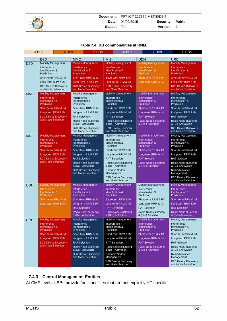
Document: FP7-ICT-317669-METIS/D6.4 Date: 04/02/2015 Security: Public
Status: Final Version: 2
METIS Public 62
Table 7.4: BB commonalities at RNM.
3 BBs 4 BBs 5 BBs 6 BBs 7 BBs 8 BBs
D2D MMC MN UDN URC D2D Mobility Management
Interference Identification & Prediction Short-term RRM & IM Long-term RRM & IM D2D Device Discovery and Mode Selection
Mobility Management Interference Identification & Prediction Short-term RRM & IM Long-term RRM & IM D2D Device Discovery and Mode Selection
Mobility Management Interference Identification & Prediction Short-term RRM & IM Long-term RRM & IM D2D Device Discovery and Mode Selection
Mobility Management Interference Identification & Prediction Short-term RRM & IM Long-term RRM & IM
Mobility Management Interference Identification & Prediction Short-term RRM & IM Long-term RRM & IM D2D Device Discovery and Mode Selection
MMC Mobility Management Interference Identification & Prediction Short-term RRM & IM Long-term RRM & IM D2D Device Discovery and Mode Selection
Mobility Management Interference Identification & Prediction Short-term RRM & IM Long-term RRM & IM RAT Selection Radio Node clustering & (De-) Activation D2D Device Discovery and Mode Selection
Mobility Management Interference Identification & Prediction Short-term RRM & IM Long-term RRM & IM RAT Selection Radio Node clustering & (De-) Activation D2D Device Discovery and Mode Selection
Mobility Management Interference Identification & Prediction Short-term RRM & IM Long-term RRM & IM RAT Selection Radio Node clustering & (De-) Activation
Mobility Management Interference Identification & Prediction Short-term RRM & IM Long-term RRM & IM RAT Selection Radio Node clustering & (De-) Activation D2D Device Discovery and Mode Selection
MN Mobility Management Interference Identification & Prediction Short-term RRM & IM Long-term RRM & IM D2D Device Discovery and Mode Selection
Mobility Management Interference Identification & Prediction Short-term RRM & IM Long-term RRM & IM RAT Selection Radio Node clustering & (De-) Activation D2D Device Discovery and Mode Selection
Mobility Management Interference Identification & Prediction Short-term RRM & IM Long-term RRM & IM RAT Selection Radio Node clustering & (De-) Activation Nomadic Nodes Management D2D Device Discovery and Mode Selection
Mobility Management Interference Identification & Prediction Short-term RRM & IM Long-term RRM & IM RAT Selection Radio Node clustering & (De-) Activation
Mobility Management Interference Identification & Prediction Short-term RRM & IM Long-term RRM & IM RAT Selection Radio Node clustering & (De-) Activation Nomadic Nodes Management D2D Device Discovery and Mode Selection
UDN Mobility Management Interference Identification & Prediction Short-term RRM & IM Long-term RRM & IM
Mobility Management Interference Identification & Prediction Short-term RRM & IM Long-term RRM & IM RAT Selection Radio Node clustering & (De-) Activation
Mobility Management Interference Identification & Prediction Short-term RRM & IM Long-term RRM & IM RAT Selection Radio Node clustering & (De-) Activation
Mobility Management Interference Identification & Prediction Short-term RRM & IM Long-term RRM & IM RAT Selection Radio Node clustering & (De-) Activation
Mobility Management Interference Identification & Prediction Short-term RRM & IM Long-term RRM & IM RAT Selection Radio Node clustering & (De-) Activation
URC Mobility Management Interference Identification & Prediction Short-term RRM & IM Long-term RRM & IM D2D Device Discovery and Mode Selection
Mobility Management Interference Identification & Prediction Short-term RRM & IM Long-term RRM & IM RAT Selection Radio Node clustering & (De-) Activation D2D Device Discovery and Mode Selection
Mobility Management Interference Identification & Prediction Short-term RRM & IM Long-term RRM & IM RAT Selection Radio Node clustering & (De-) Activation Nomadic Nodes Management D2D Device Discovery and Mode Selection
Mobility Management Interference Identification & Prediction Short-term RRM & IM Long-term RRM & IM RAT Selection Radio Node clustering & (De-) Activation
Mobility Management Interference Identification & Prediction Short-term RRM & IM Long-term RRM & IM RAT Selection Radio Node clustering & (De-) Activation Nomadic Nodes Management D2D Device Discovery and Mode Selection
7.4.3 Central Management Entities At CME level all BBs provide functionalities that are not explicitly HT specific.
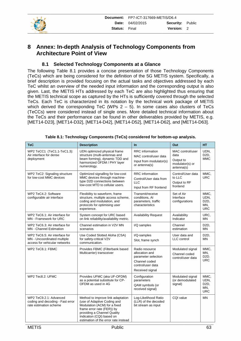
Document: FP7-ICT-317669-METIS/D6.4 Date: 04/02/2015 Security: Public
Status: Final Version: 2
METIS Public 63
8 Annex: In-depth Analysis of Technology Components from Architecture Point of View
8.1 Selected Technology Components at a Glance The following Table 8.1 provides a concise presentation of those Technology Components (TeCs) which are being considered for the definition of the 5G METIS system. Specifically, a brief description is provided focusing on the actual tasks and objectives addressed by each TeC whilst an overview of the needed input information and the corresponding output is also given. Last, the METIS HTs addressed by each TeC are also highlighted thus ensuring that the METIS technical scope as captured by the HTs is sufficiently covered through the selected TeCs. Each TeC is characterized in its notation by the technical work package of METIS which derived the corresponding TeC (WPs 2 – 5). In some cases also clusters of TeCs (TeCCs) were considered instead of single ones. More detailed technical information about the TeCs and their performance can be found in other deliverables provided by METIS, e.g. [MET14-D23], [MET14-D32], [MET14-D42], [MET14-D52], [MET14-D62], and [MET14-D63].
Table 8.1: Technology Components (TeCs) considered for bottom-up analysis.
TeC Description In Out HT
WP2 TeCC1 (TeC1.1-TeC1.3): Air interface for dense deployment
UDN optimized physical frame structure (multi-antennas and beam forming), dynamic TDD and harmonized OFDM / PHY layer numerology.
RRC information MAC control/user data Input from modulator(s) or antenna(s)
MAC control/user data Output to modulator(s) or antenna(s)
UDN, D2D, MMC
WP2 TeC2: Signaling structure for low-cost MMC devices
Optimized signalling for low-cost MMC devices through machine-type D2D connections between low-cost MTD to cellular users.
RRC information Control/User data from LLC Input from RF frontend
Control/User data to LLC Output to RF frontend
MMC, URC
WP2 TeC4.2: Software configurable air interface
Flexibility to waveform, frame structure, multiple access scheme, coding and modulation, and protocols for optimising user experience.
Transmit/receive conditions, AI parameters, traffic characteristics
Set of Air Interface configurations
MMC, UDN, D2D, MN, URC
WP2 TeC6.1: Air interface for MN - Framework for URC
System concept for URC based on link reliability/availability metric.
Availability Request Availability Indicator
URC, MN
WP2 TeC6.3: Air interface for MN - Channel Estimation
Channel estimation in V2V MN scenarios
I/Q samples Channel estimation
D2D, MN
WP2 TeC6.5: Air interface for MN - Uncoordinated multiple access for vehicular networks
Use Coded Slotted Aloha (CSA) for safety-critical V2V communication.
I/Q-samples Slot, frame synch
User data and LLC control
D2D, MN
WP2 TeC8.1: FBMC Provides FBMC (Filterbank based Multicarrier) transceiver
Radio resource allocation and parameter selection Channel coded control/user data Received signal
Modulated signal Channel coded control/user data
MMC, MN, D2D. URC
WP2 Tec8.2: UFMC Provides UFMC (aka UF-OFDM) as a potential substitute for CP-OFDM as used in 4G
Configuration parameters QAM symbols (or received signal)
Modulated signal (or demodulated signal)
MMC, UDN, D2D, MN, URC
WP2 TeC9.2.1: Advanced coding and decoding - Fast error rate estimation scheme
Method to improve link adaptation (use of Adaptive Coding and Modulation (ACM) for a fixed frame error rate (FER)) by providing a Channel Quality Indication (CQI) based on estimation of the error rate instead
Log-Likelihood Ratio (LLR) of the decoded bit stream as input
CQI value MN
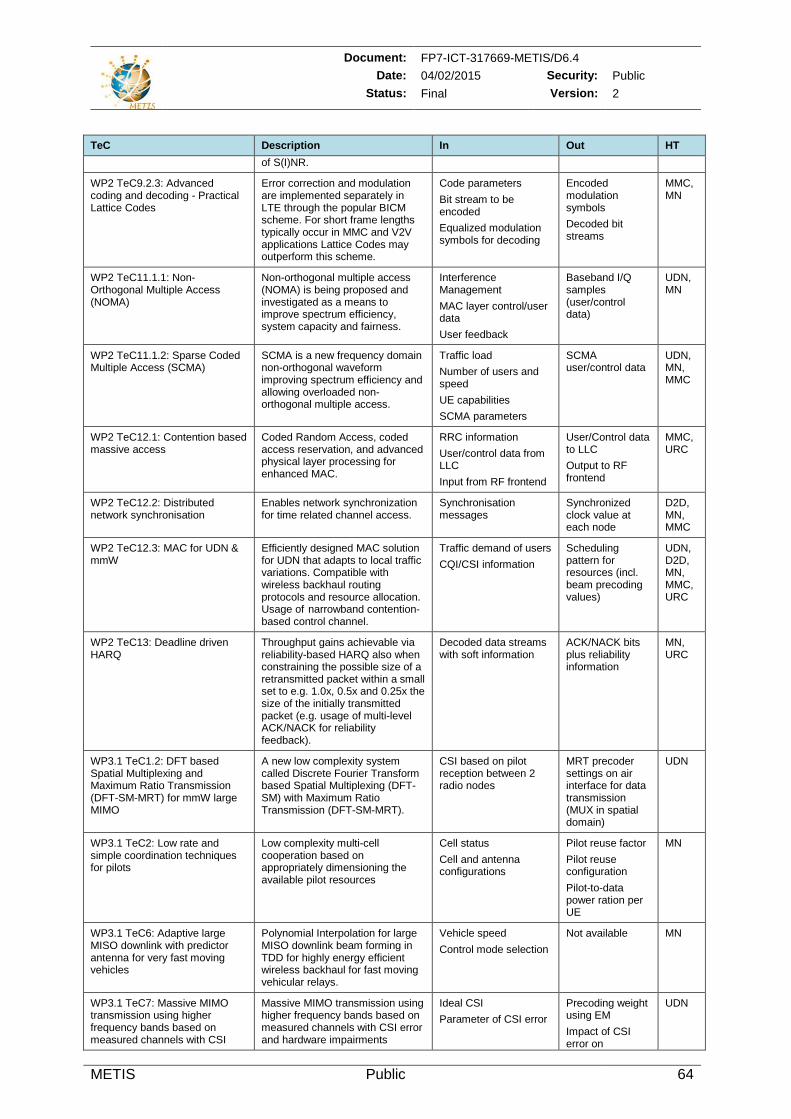
Document: FP7-ICT-317669-METIS/D6.4 Date: 04/02/2015 Security: Public
Status: Final Version: 2
METIS Public 64
TeC Description In Out HT of S(I)NR.
WP2 TeC9.2.3: Advanced coding and decoding - Practical Lattice Codes
Error correction and modulation are implemented separately in LTE through the popular BICM scheme. For short frame lengths typically occur in MMC and V2V applications Lattice Codes may outperform this scheme.
Code parameters Bit stream to be encoded Equalized modulation symbols for decoding
Encoded modulation symbols Decoded bit streams
MMC, MN
WP2 TeC11.1.1: Non-Orthogonal Multiple Access (NOMA)
Non-orthogonal multiple access (NOMA) is being proposed and investigated as a means to improve spectrum efficiency, system capacity and fairness.
Interference Management MAC layer control/user data User feedback
Baseband I/Q samples (user/control data)
UDN, MN
WP2 TeC11.1.2: Sparse Coded Multiple Access (SCMA)
SCMA is a new frequency domain non-orthogonal waveform improving spectrum efficiency and allowing overloaded non-orthogonal multiple access.
Traffic load Number of users and speed UE capabilities SCMA parameters
SCMA user/control data
UDN, MN, MMC
WP2 TeC12.1: Contention based massive access
Coded Random Access, coded access reservation, and advanced physical layer processing for enhanced MAC.
RRC information User/control data from LLC Input from RF frontend
User/Control data to LLC Output to RF frontend
MMC, URC
WP2 TeC12.2: Distributed network synchronisation
Enables network synchronization for time related channel access.
Synchronisation messages
Synchronized clock value at each node
D2D, MN, MMC
WP2 TeC12.3: MAC for UDN & mmW
Efficiently designed MAC solution for UDN that adapts to local traffic variations. Compatible with wireless backhaul routing protocols and resource allocation. Usage of narrowband contention-based control channel.
Traffic demand of users CQI/CSI information
Scheduling pattern for resources (incl. beam precoding values)
UDN, D2D, MN, MMC, URC
WP2 TeC13: Deadline driven HARQ
Throughput gains achievable via reliability-based HARQ also when constraining the possible size of a retransmitted packet within a small set to e.g. 1.0x, 0.5x and 0.25x the size of the initially transmitted packet (e.g. usage of multi-level ACK/NACK for reliability feedback).
Decoded data streams with soft information
ACK/NACK bits plus reliability information
MN, URC
WP3.1 TeC1.2: DFT based Spatial Multiplexing and Maximum Ratio Transmission (DFT-SM-MRT) for mmW large MIMO
A new low complexity system called Discrete Fourier Transform based Spatial Multiplexing (DFT-SM) with Maximum Ratio Transmission (DFT-SM-MRT).
CSI based on pilot reception between 2 radio nodes
MRT precoder settings on air interface for data transmission (MUX in spatial domain)
UDN
WP3.1 TeC2: Low rate and simple coordination techniques for pilots
Low complexity multi-cell cooperation based on appropriately dimensioning the available pilot resources
Cell status Cell and antenna configurations
Pilot reuse factor Pilot reuse configuration Pilot-to-data power ration per UE
MN
WP3.1 TeC6: Adaptive large MISO downlink with predictor antenna for very fast moving vehicles
Polynomial Interpolation for large MISO downlink beam forming in TDD for highly energy efficient wireless backhaul for fast moving vehicular relays.
Vehicle speed Control mode selection
Not available MN
WP3.1 TeC7: Massive MIMO transmission using higher frequency bands based on measured channels with CSI
Massive MIMO transmission using higher frequency bands based on measured channels with CSI error and hardware impairments
Ideal CSI Parameter of CSI error
Precoding weight using EM Impact of CSI error on
UDN
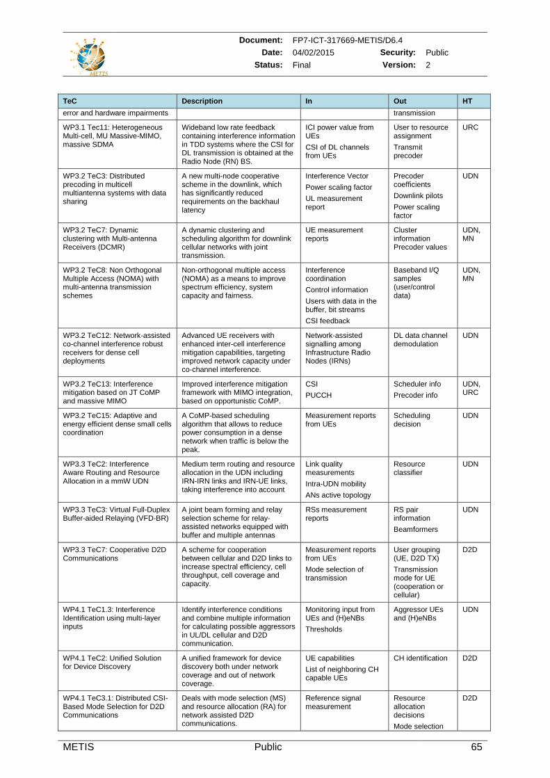
Document: FP7-ICT-317669-METIS/D6.4 Date: 04/02/2015 Security: Public
Status: Final Version: 2
METIS Public 65
TeC Description In Out HT error and hardware impairments transmission
WP3.1 Tec11: Heterogeneous Multi-cell, MU Massive-MIMO, massive SDMA
Wideband low rate feedback containing interference information in TDD systems where the CSI for DL transmission is obtained at the Radio Node (RN) BS.
ICI power value from UEs CSI of DL channels from UEs
User to resource assignment Transmit precoder
URC
WP3.2 TeC3: Distributed precoding in multicell multiantenna systems with data sharing
A new multi-node cooperative scheme in the downlink, which has significantly reduced requirements on the backhaul latency
Interference Vector Power scaling factor UL measurement report
Precoder coefficients Downlink pilots Power scaling factor
UDN
WP3.2 TeC7: Dynamic clustering with Multi-antenna Receivers (DCMR)
A dynamic clustering and scheduling algorithm for downlink cellular networks with joint transmission.
UE measurement reports
Cluster information Precoder values
UDN, MN
WP3.2 TeC8: Non Orthogonal Multiple Access (NOMA) with multi-antenna transmission schemes
Non-orthogonal multiple access (NOMA) as a means to improve spectrum efficiency, system capacity and fairness.
Interference coordination Control information Users with data in the buffer, bit streams CSI feedback
Baseband I/Q samples (user/control data)
UDN, MN
WP3.2 TeC12: Network-assisted co-channel interference robust receivers for dense cell deployments
Advanced UE receivers with enhanced inter-cell interference mitigation capabilities, targeting improved network capacity under co-channel interference.
Network-assisted signalling among Infrastructure Radio Nodes (IRNs)
DL data channel demodulation
UDN
WP3.2 TeC13: Interference mitigation based on JT CoMP and massive MIMO
Improved interference mitigation framework with MIMO integration, based on opportunistic CoMP.
CSI PUCCH
Scheduler info Precoder info
UDN, URC
WP3.2 TeC15: Adaptive and energy efficient dense small cells coordination
A CoMP-based scheduling algorithm that allows to reduce power consumption in a dense network when traffic is below the peak.
Measurement reports from UEs
Scheduling decision
UDN
WP3.3 TeC2: Interference Aware Routing and Resource Allocation in a mmW UDN
Medium term routing and resource allocation in the UDN including IRN-IRN links and IRN-UE links, taking interference into account
Link quality measurements Intra-UDN mobility ANs active topology
Resource classifier
UDN
WP3.3 TeC3: Virtual Full-Duplex Buffer-aided Relaying (VFD-BR)
A joint beam forming and relay selection scheme for relay-assisted networks equipped with buffer and multiple antennas
RSs measurement reports
RS pair information Beamformers
UDN
WP3.3 TeC7: Cooperative D2D Communications
A scheme for cooperation between cellular and D2D links to increase spectral efficiency, cell throughput, cell coverage and capacity.
Measurement reports from UEs Mode selection of transmission
User grouping (UE, D2D TX) Transmission mode for UE (cooperation or cellular)
D2D
WP4.1 TeC1.3: Interference Identification using multi-layer inputs
Identify interference conditions and combine multiple information for calculating possible aggressors in UL/DL cellular and D2D communication.
Monitoring input from UEs and (H)eNBs Thresholds
Aggressor UEs and (H)eNBs
UDN
WP4.1 TeC2: Unified Solution for Device Discovery
A unified framework for device discovery both under network coverage and out of network coverage.
UE capabilities List of neighboring CH capable UEs
CH identification D2D
WP4.1 TeC3.1: Distributed CSI-Based Mode Selection for D2D Communications
Deals with mode selection (MS) and resource allocation (RA) for network assisted D2D communications.
Reference signal measurement
Resource allocation decisions Mode selection
D2D
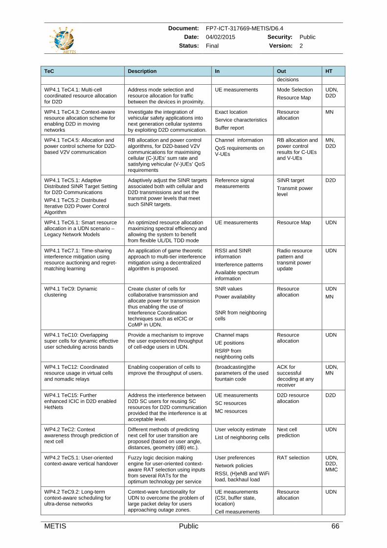
Document: FP7-ICT-317669-METIS/D6.4 Date: 04/02/2015 Security: Public
Status: Final Version: 2
METIS Public 66
TeC Description In Out HT decisions
WP4.1 TeC4.1: Multi-cell coordinated resource allocation for D2D
Address mode selection and resource allocation for traffic between the devices in proximity.
UE measurements Mode Selection Resource Map
UDN, D2D
WP4.1 TeC4.3: Context-aware resource allocation scheme for enabling D2D in moving networks
Investigate the integration of vehicular safety applications into next generation cellular systems by exploiting D2D communication.
Exact location Service characteristics Buffer report
Resource allocation
MN
WP4.1 TeC4.5: Allocation and power control scheme for D2D-based V2V communication
RB allocation and power control algorithms, for D2D-based V2V communications for maximising cellular (C-)UEs’ sum rate and satisfying vehicular (V-)UEs’ QoS requirements
Channel information QoS requirements on V-UEs
RB allocation and power control results for C-UEs and V-UEs
MN, D2D
WP4.1 TeC5.1: Adaptive Distributed SINR Target Setting for D2D Communications WP4.1 TeC5.2: Distributed Iterative D2D Power Control Algorithm
Adaptively adjust the SINR targets associated both with cellular and D2D transmissions and set the transmit power levels that meet such SINR targets.
Reference signal measurements
SINR target Transmit power level
D2D
WP4.1 TeC6.1: Smart resource allocation in a UDN scenario – Legacy Network Models
An optimized resource allocation maximizing spectral efficiency and allowing the system to benefit from flexible UL/DL TDD mode
UE measurements Resource Map UDN
WP4.1 TeC7.1: Time-sharing interference mitigation using resource auctioning and regret-matching learning
An application of game theoretic approach to multi-tier interference mitigation using a decentralized algorithm is proposed.
RSSI and SINR information Interference patterns Available spectrum information
Radio resource pattern and transmit power update
UDN
WP4.1 TeC9: Dynamic clustering
Create cluster of cells for collaborative transmission and allocate power for transmission thus enabling the use of Interference Coordination techniques such as eICIC or CoMP in UDN.
SNR values Power availability SNR from neighboring cells
Resource allocation
UDN MN
WP4.1 TeC10: Overlapping super cells for dynamic effective user scheduling across bands
Provide a mechanism to improve the user experienced throughput of cell-edge users in UDN.
Channel maps UE positions RSRP from neighboring cells
Resource allocation
UDN
WP4.1 TeC12: Coordinated resource usage in virtual cells and nomadic relays
Enabling cooperation of cells to improve the throughput of users.
(broadcasting)the parameters of the used fountain code
ACK for successful decoding at any receiver
UDN, MN
WP4.1 TeC15: Further enhanced ICIC in D2D enabled HetNets
Address the interference between D2D SC users for reusing SC resources for D2D communication provided that the interference is at acceptable level.
UE measurements SC resources MC resources
D2D resource allocation
D2D
WP4.2 TeC2: Context awareness through prediction of next cell
Different methods of predicting next cell for user transition are proposed (based on user angle, distances, geometry (dB) etc.).
User velocity estimate List of neighboring cells
Next cell prediction
UDN
WP4.2 TeC5.1: User-oriented context-aware vertical handover
Fuzzy logic decision making engine for user-oriented context-aware RAT selection using inputs from several RATs for the optimum technology per service
User preferences Network policies RSSI, (H)eNB and WiFi load, backhaul load
RAT selection UDN, D2D, MMC
WP4.2 TeC9.2: Long-term context-aware scheduling for ultra-dense networks
Context-ware functionality for UDN to overcome the problem of large packet delay for users approaching outage zones.
UE measurements (CSI, buffer state, location) Cell measurements
Resource allocation
UDN
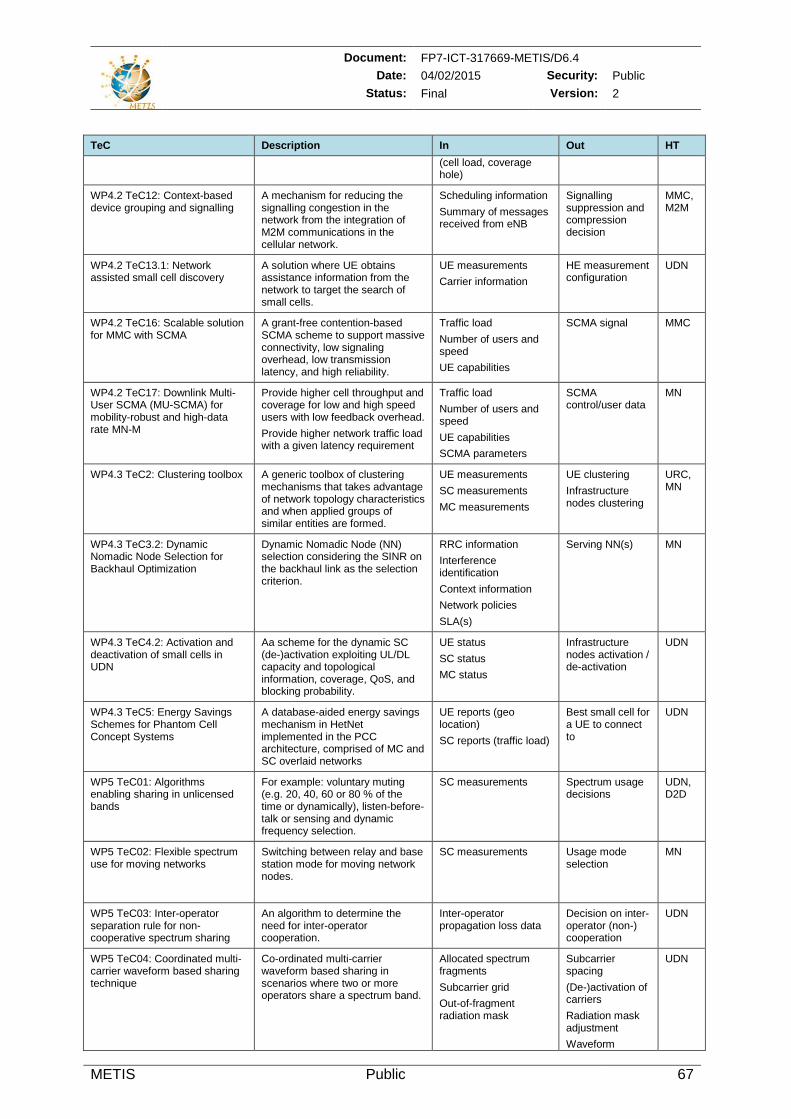
Document: FP7-ICT-317669-METIS/D6.4 Date: 04/02/2015 Security: Public
Status: Final Version: 2
METIS Public 67
TeC Description In Out HT (cell load, coverage hole)
WP4.2 TeC12: Context-based device grouping and signalling
A mechanism for reducing the signalling congestion in the network from the integration of M2M communications in the cellular network.
Scheduling information Summary of messages received from eNB
Signalling suppression and compression decision
MMC, M2M
WP4.2 TeC13.1: Network assisted small cell discovery
A solution where UE obtains assistance information from the network to target the search of small cells.
UE measurements Carrier information
HE measurement configuration
UDN
WP4.2 TeC16: Scalable solution for MMC with SCMA
A grant-free contention-based SCMA scheme to support massive connectivity, low signaling overhead, low transmission latency, and high reliability.
Traffic load Number of users and speed UE capabilities
SCMA signal MMC
WP4.2 TeC17: Downlink Multi-User SCMA (MU-SCMA) for mobility-robust and high-data rate MN-M
Provide higher cell throughput and coverage for low and high speed users with low feedback overhead. Provide higher network traffic load with a given latency requirement
Traffic load Number of users and speed UE capabilities SCMA parameters
SCMA control/user data
MN
WP4.3 TeC2: Clustering toolbox A generic toolbox of clustering mechanisms that takes advantage of network topology characteristics and when applied groups of similar entities are formed.
UE measurements SC measurements MC measurements
UE clustering Infrastructure nodes clustering
URC, MN
WP4.3 TeC3.2: Dynamic Nomadic Node Selection for Backhaul Optimization
Dynamic Nomadic Node (NN) selection considering the SINR on the backhaul link as the selection criterion.
RRC information Interference identification Context information Network policies SLA(s)
Serving NN(s) MN
WP4.3 TeC4.2: Activation and deactivation of small cells in UDN
Aa scheme for the dynamic SC (de-)activation exploiting UL/DL capacity and topological information, coverage, QoS, and blocking probability.
UE status SC status MC status
Infrastructure nodes activation / de-activation
UDN
WP4.3 TeC5: Energy Savings Schemes for Phantom Cell Concept Systems
A database-aided energy savings mechanism in HetNet implemented in the PCC architecture, comprised of MC and SC overlaid networks
UE reports (geo location) SC reports (traffic load)
Best small cell for a UE to connect to
UDN
WP5 TeC01: Algorithms enabling sharing in unlicensed bands
For example: voluntary muting (e.g. 20, 40, 60 or 80 % of the time or dynamically), listen-before-talk or sensing and dynamic frequency selection.
SC measurements Spectrum usage decisions
UDN, D2D
WP5 TeC02: Flexible spectrum use for moving networks
Switching between relay and base station mode for moving network nodes.
SC measurements Usage mode selection
MN
WP5 TeC03: Inter-operator separation rule for non-cooperative spectrum sharing
An algorithm to determine the need for inter-operator cooperation.
Inter-operator propagation loss data
Decision on inter-operator (non-) cooperation
UDN
WP5 TeC04: Coordinated multi-carrier waveform based sharing technique
Co-ordinated multi-carrier waveform based sharing in scenarios where two or more operators share a spectrum band.
Allocated spectrum fragments Subcarrier grid Out-of-fragment radiation mask
Subcarrier spacing (De-)activation of carriers Radiation mask adjustment Waveform
UDN
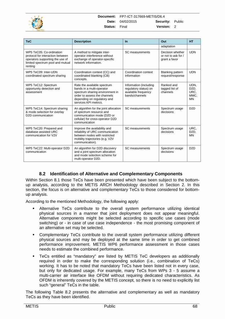
Document: FP7-ICT-317669-METIS/D6.4 Date: 04/02/2015 Security: Public
Status: Final Version: 2
METIS Public 68
TeC Description In Out HT adaptation
WP5 TeC05: Co-ordination protocol for interaction between operators supporting the use of limited spectrum pool and mutual renting
A method to mitigate inter-operator interference without exchange of operator-specific network information.
SC measurements Decision whether or not to ask for / grant a favor
UDN
WP5 TeC09: Inter-UDN coordinated spectrum sharing
Coordination context (CC) and coordinated blanking (CB) concepts.
Coordination context information
Blanking pattern request/response
UDN
WP5 TeC12: Spectrum opportunity detection and assessment
Rate the available spectrum bands in a multi-operator spectrum sharing environment in order to assess the channels depending on regulatory and services KPI metrics.
Information (including regulatory status) on available frequency bands/channels
Ranked and tagged list of channels
UDN, D2D, URC, MMC, MN
WP5 TeC14: Spectrum sharing & mode selection for overlay D2D communication
An algorithm for the joint allocation of spectrum resource and communication mode (D2D or cellular) for cross-operator D2D communication
SC measurements Spectrum usage decisions
D2D
WP5 TeC20: Prepared and database assisted URC communication for V2V
Improve the availability and reliability of URC communication between nodes with restricted mobility trajectories (e.g. V2V communication).
SC measurements Spectrum usage decisions
URC, D2D, MN
WP5 TeC22: Multi-operator D2D communication
An algorithm for D2D discovery and a joint spectrum allocation and mode selection scheme for multi-operator D2D.
SC measurements Spectrum usage decisions
D2D
8.2 Identification of Alternative and Complementary Components Within Section 8.1 those TeCs have been presented which have been subject to the bottom-up analysis, according to the METIS ARCH Methodology described in Section 2. In this section, the focus is on alternative and complementary TeCs to those considered for bottom-up analysis.
According to the mentioned Methodology, the following apply:
Alternative TeCs contribute to the overall system performance utilizing identical physical sources in a manner that joint deployment does not appear meaningful. Alternative components might be selected according to specific use cases (mode switching) or - in case of use case independence - the most promising component of an alternative set may be selected.
Complementary TeCs contribute to the overall system performance utilizing different physical sources and may be deployed at the same time in order to get combined performance improvement. METIS WP6 performance assessment in those cases needs to estimate the combined performance.
TeCs entitled as “mandatory” are listed by METIS TeC developers as additionally required in order to make the corresponding solution (i.e., combination of TeCs) working. It has to be noted that mandatory TeCs have been listed not in every case, but only for dedicated usage. For example, many TeCs from WPs 3 - 5 assume a multi-carrier air interface like OFDM without requiring dedicated characteristics. As OFDM is inherently covered by the METIS concept, so there is no need to explicitly list such “general” TeCs in the table.
The following Table 8.2 presents the alternative and complementary as well as mandatory TeCs as they have been identified.
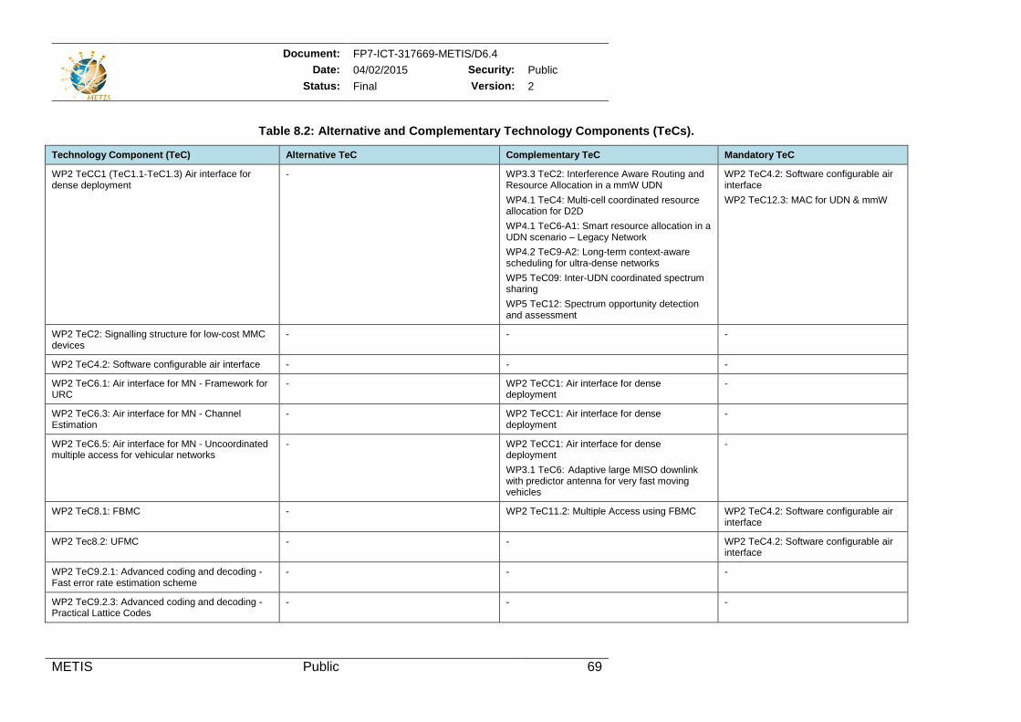
Document: FP7-ICT-317669-METIS/D6.4 Date: 04/02/2015 Security: Public
Status: Final Version: 2
METIS Public 69
Table 8.2: Alternative and Complementary Technology Components (TeCs).
Technology Component (TeC) Alternative TeC Complementary TeC Mandatory TeC
WP2 TeCC1 (TeC1.1-TeC1.3) Air interface for dense deployment
- WP3.3 TeC2: Interference Aware Routing and Resource Allocation in a mmW UDN WP4.1 TeC4: Multi-cell coordinated resource allocation for D2D WP4.1 TeC6-A1: Smart resource allocation in a UDN scenario – Legacy Network WP4.2 TeC9-A2: Long-term context-aware scheduling for ultra-dense networks WP5 TeC09: Inter-UDN coordinated spectrum sharing WP5 TeC12: Spectrum opportunity detection and assessment
WP2 TeC4.2: Software configurable air interface WP2 TeC12.3: MAC for UDN & mmW
WP2 TeC2: Signalling structure for low-cost MMC devices
- - -
WP2 TeC4.2: Software configurable air interface - - -
WP2 TeC6.1: Air interface for MN - Framework for URC
- WP2 TeCC1: Air interface for dense deployment
-
WP2 TeC6.3: Air interface for MN - Channel Estimation
- WP2 TeCC1: Air interface for dense deployment
-
WP2 TeC6.5: Air interface for MN - Uncoordinated multiple access for vehicular networks
- WP2 TeCC1: Air interface for dense deployment WP3.1 TeC6: Adaptive large MISO downlink with predictor antenna for very fast moving vehicles
-
WP2 TeC8.1: FBMC - WP2 TeC11.2: Multiple Access using FBMC WP2 TeC4.2: Software configurable air interface
WP2 Tec8.2: UFMC - - WP2 TeC4.2: Software configurable air interface
WP2 TeC9.2.1: Advanced coding and decoding - Fast error rate estimation scheme
- - -
WP2 TeC9.2.3: Advanced coding and decoding - Practical Lattice Codes
- - -
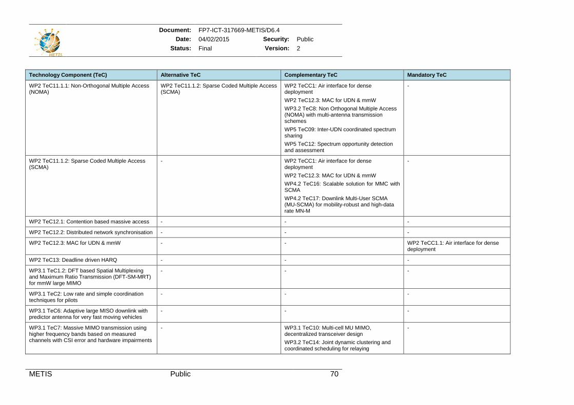
Document: FP7-ICT-317669-METIS/D6.4 Date: 04/02/2015 Security: Public
Status: Final Version: 2
METIS Public 70
Technology Component (TeC) Alternative TeC Complementary TeC Mandatory TeC
WP2 TeC11.1.1: Non-Orthogonal Multiple Access (NOMA)
WP2 TeC11.1.2: Sparse Coded Multiple Access (SCMA)
WP2 TeCC1: Air interface for dense deployment WP2 TeC12.3: MAC for UDN & mmW WP3.2 TeC8: Non Orthogonal Multiple Access (NOMA) with multi-antenna transmission schemes WP5 TeC09: Inter-UDN coordinated spectrum sharing WP5 TeC12: Spectrum opportunity detection and assessment
-
WP2 TeC11.1.2: Sparse Coded Multiple Access (SCMA)
- WP2 TeCC1: Air interface for dense deployment WP2 TeC12.3: MAC for UDN & mmW WP4.2 TeC16: Scalable solution for MMC with SCMA WP4.2 TeC17: Downlink Multi-User SCMA (MU-SCMA) for mobility-robust and high-data rate MN-M
-
WP2 TeC12.1: Contention based massive access - - -
WP2 TeC12.2: Distributed network synchronisation - - -
WP2 TeC12.3: MAC for UDN & mmW - - WP2 TeCC1.1: Air interface for dense deployment
WP2 TeC13: Deadline driven HARQ - - -
WP3.1 TeC1.2: DFT based Spatial Multiplexing and Maximum Ratio Transmission (DFT-SM-MRT) for mmW large MIMO
- - -
WP3.1 TeC2: Low rate and simple coordination techniques for pilots
- - -
WP3.1 TeC6: Adaptive large MISO downlink with predictor antenna for very fast moving vehicles
- - -
WP3.1 TeC7: Massive MIMO transmission using higher frequency bands based on measured channels with CSI error and hardware impairments
- WP3.1 TeC10: Multi-cell MU MIMO, decentralized transceiver design WP3.2 TeC14: Joint dynamic clustering and coordinated scheduling for relaying
-
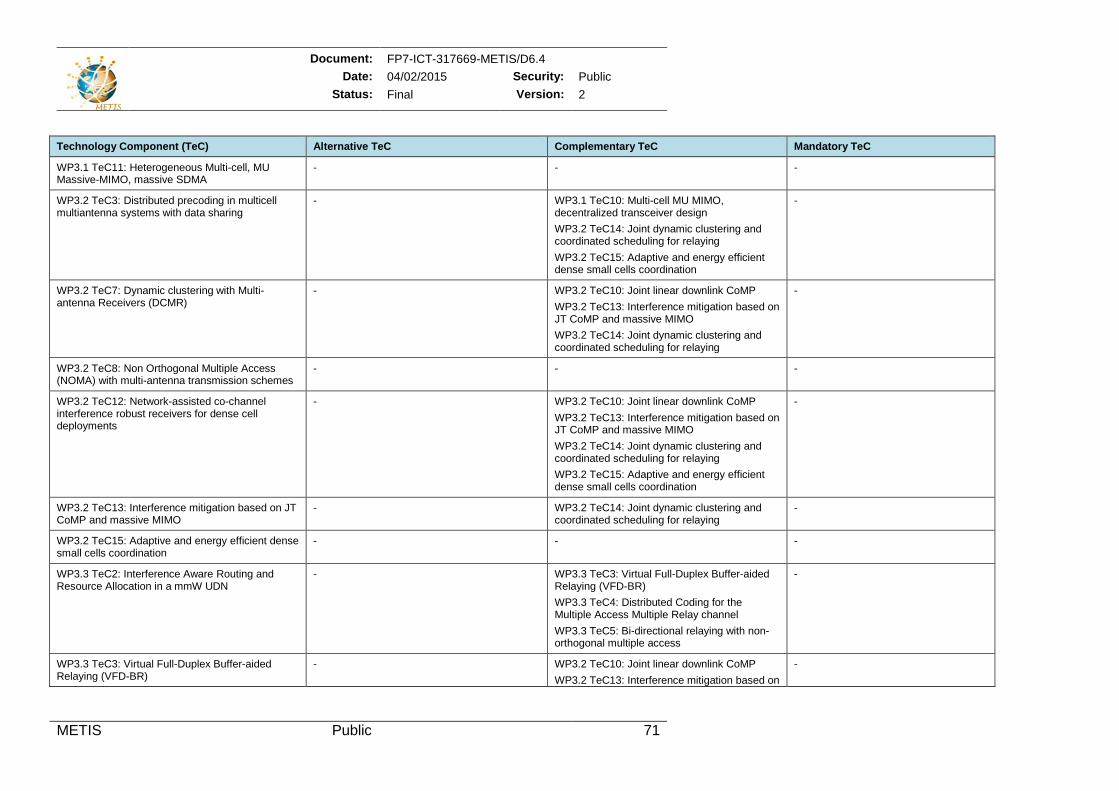
Document: FP7-ICT-317669-METIS/D6.4 Date: 04/02/2015 Security: Public
Status: Final Version: 2
METIS Public 71
Technology Component (TeC) Alternative TeC Complementary TeC Mandatory TeC
WP3.1 TeC11: Heterogeneous Multi-cell, MU Massive-MIMO, massive SDMA
- - -
WP3.2 TeC3: Distributed precoding in multicell multiantenna systems with data sharing
- WP3.1 TeC10: Multi-cell MU MIMO, decentralized transceiver design WP3.2 TeC14: Joint dynamic clustering and coordinated scheduling for relaying WP3.2 TeC15: Adaptive and energy efficient dense small cells coordination
-
WP3.2 TeC7: Dynamic clustering with Multi-antenna Receivers (DCMR)
- WP3.2 TeC10: Joint linear downlink CoMP WP3.2 TeC13: Interference mitigation based on JT CoMP and massive MIMO WP3.2 TeC14: Joint dynamic clustering and coordinated scheduling for relaying
-
WP3.2 TeC8: Non Orthogonal Multiple Access (NOMA) with multi-antenna transmission schemes
- - -
WP3.2 TeC12: Network-assisted co-channel interference robust receivers for dense cell deployments
- WP3.2 TeC10: Joint linear downlink CoMP WP3.2 TeC13: Interference mitigation based on JT CoMP and massive MIMO WP3.2 TeC14: Joint dynamic clustering and coordinated scheduling for relaying WP3.2 TeC15: Adaptive and energy efficient dense small cells coordination
-
WP3.2 TeC13: Interference mitigation based on JT CoMP and massive MIMO
- WP3.2 TeC14: Joint dynamic clustering and coordinated scheduling for relaying
-
WP3.2 TeC15: Adaptive and energy efficient dense small cells coordination
- - -
WP3.3 TeC2: Interference Aware Routing and Resource Allocation in a mmW UDN
- WP3.3 TeC3: Virtual Full-Duplex Buffer-aided Relaying (VFD-BR) WP3.3 TeC4: Distributed Coding for the Multiple Access Multiple Relay channel WP3.3 TeC5: Bi-directional relaying with non-orthogonal multiple access
-
WP3.3 TeC3: Virtual Full-Duplex Buffer-aided Relaying (VFD-BR)
- WP3.2 TeC10: Joint linear downlink CoMP WP3.2 TeC13: Interference mitigation based on
-
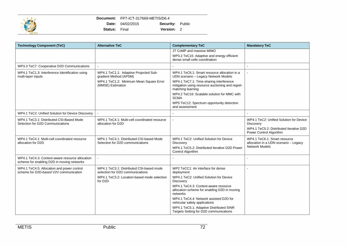
Document: FP7-ICT-317669-METIS/D6.4 Date: 04/02/2015 Security: Public
Status: Final Version: 2
METIS Public 72
Technology Component (TeC) Alternative TeC Complementary TeC Mandatory TeC JT CoMP and massive MIMO WP3.2 TeC15: Adaptive and energy efficient dense small cells coordination
WP3.3 TeC7: Cooperative D2D Communications - - -
WP4.1 TeC1.3: Interference Identification using multi-layer inputs
WP4.1 TeC1.1: Adaptive Projected Sub-gradient Method (APSM) WP4.1 TeC1.2: Minimum Mean Square Error (MMSE) Estimation
WP4.1 TeC6.1: Smart resource allocation in a UDN scenario – Legacy Network Models WP4.1 TeC7.1: Time-sharing interference mitigation using resource auctioning and regret-matching learning WP4.2 TeC16: Scalable solution for MMC with SCMA WP5 TeC12: Spectrum opportunity detection and assessment
-
WP4.1 TeC2: Unified Solution for Device Discovery - - -
WP4.1 TeC3.1: Distributed CSI-Based Mode Selection for D2D Communications
WP4.1 TeC4.1: Multi-cell coordinated resource allocation for D2D
- WP4.1 TeC2: Unified Solution for Device Discovery WP4.1 TeC5.2: Distributed Iterative D2D Power Control Algorithm
WP4.1 TeC4.1: Multi-cell coordinated resource allocation for D2D
WP4.1 TeC3.1: Distributed CSI-based Mode Selection for D2D communications
WP4.1 TeC2: Unified Solution for Device Discovery WP4.1 TeC5.2: Distributed Iterative D2D Power Control Algorithm
WP4.1 TeC6.1: Smart resource allocation in a UDN scenario – Legacy Network Models
WP4.1 TeC4.3: Context-aware resource allocation scheme for enabling D2D in moving networks
- - -
WP4.1 TeC4.5: Allocation and power control scheme for D2D-based V2V communication
WP4.1 TeC3.1: Distributed CSI-based mode selection for D2D communications WP4.1 TeC3.2: Location-based mode selection for D2D
WP2 TeCC1: Air interface for dense deployment WP4.1 TeC2: Unified Solution for Device Discovery WP4.1 TeC4.3: Context-aware resource allocation scheme for enabling D2D in moving networks WP4.1 TeC4.4: Network assisted D2D for vehicular safety applications WP4.1 TeC5.1: Adaptive Distributed SINR Targets Setting for D2D communications
-
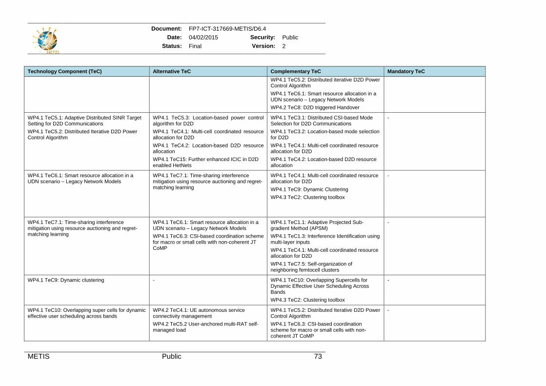
Document: FP7-ICT-317669-METIS/D6.4 Date: 04/02/2015 Security: Public
Status: Final Version: 2
METIS Public 73
Technology Component (TeC) Alternative TeC Complementary TeC Mandatory TeC WP4.1 TeC5.2: Distributed iterative D2D Power Control Algorithm WP4.1 TeC6.1: Smart resource allocation in a UDN scenario – Legacy Network Models WP4.2 TeC8: D2D triggered Handover
WP4.1 TeC5.1: Adaptive Distributed SINR Target Setting for D2D Communications WP4.1 TeC5.2: Distributed Iterative D2D Power Control Algorithm
WP4.1 TeC5.3: Location-based power control algorithm for D2D WP4.1 TeC4.1: Multi-cell coordinated resource allocation for D2D WP4.1 TeC4.2: Location-based D2D resource allocation WP4.1 TeC15: Further enhanced ICIC in D2D enabled HetNets
WP4.1 TeC3.1: Distributed CSI-based Mode Selection for D2D Communications WP4.1 TeC3.2: Location-based mode selection for D2D WP4.1 TeC4.1: Multi-cell coordinated resource allocation for D2D WP4.1 TeC4.2: Location-based D2D resource allocation
-
WP4.1 TeC6.1: Smart resource allocation in a UDN scenario – Legacy Network Models
WP4.1 TeC7.1: Time-sharing interference mitigation using resource auctioning and regret-matching learning
WP4.1 TeC4.1: Multi-cell coordinated resource allocation for D2D WP4.1 TeC9: Dynamic Clustering WP4.3 TeC2: Clustering toolbox
-
WP4.1 TeC7.1: Time-sharing interference mitigation using resource auctioning and regret-matching learning
WP4.1 TeC6.1: Smart resource allocation in a UDN scenario – Legacy Network Models WP4.1 TeC6.3: CSI-based coordination scheme for macro or small cells with non-coherent JT CoMP
WP4.1 TeC1.1: Adaptive Projected Sub-gradient Method (APSM) WP4.1 TeC1.3: Interference Identification using multi-layer inputs WP4.1 TeC4.1: Multi-cell coordinated resource allocation for D2D WP4.1 TeC7.5: Self-organization of neighboring femtocell clusters
-
WP4.1 TeC9: Dynamic clustering - WP4.1 TeC10: Overlapping Supercells for Dynamic Effective User Scheduling Across Bands WP4.3 TeC2: Clustering toolbox
-
WP4.1 TeC10: Overlapping super cells for dynamic effective user scheduling across bands
WP4.2 TeC4.1: UE autonomous service connectivity management WP4.2 TeC5.2 User-anchored multi-RAT self-managed load
WP4.1 TeC5.2: Distributed Iterative D2D Power Control Algorithm WP4.1 TeC6.3: CSI-based coordination scheme for macro or small cells with non-coherent JT CoMP
-
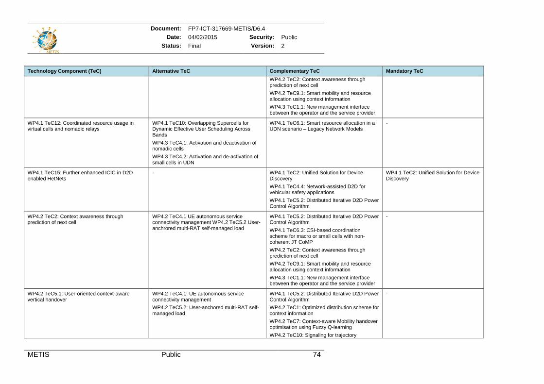
Document: FP7-ICT-317669-METIS/D6.4 Date: 04/02/2015 Security: Public
Status: Final Version: 2
METIS Public 74
Technology Component (TeC) Alternative TeC Complementary TeC Mandatory TeC WP4.2 TeC2: Context awareness through prediction of next cell WP4.2 TeC9.1: Smart mobility and resource allocation using context information WP4.3 TeC1.1: New management interface between the operator and the service provider
WP4.1 TeC12: Coordinated resource usage in virtual cells and nomadic relays
WP4.1 TeC10: Overlapping Supercells for Dynamic Effective User Scheduling Across Bands WP4.3 TeC4.1: Activation and deactivation of nomadic cells WP4.3 TeC4.2: Activation and de-activation of small cells in UDN
WP4.1 TeC6.1: Smart resource allocation in a UDN scenario – Legacy Network Models
-
WP4.1 TeC15: Further enhanced ICIC in D2D enabled HetNets
- WP4.1 TeC2: Unified Solution for Device Discovery WP4.1 TeC4.4: Network-assisted D2D for vehicular safety applications WP4.1 TeC5.2: Distributed Iterative D2D Power Control Algorithm
WP4.1 TeC2: Unified Solution for Device Discovery
WP4.2 TeC2: Context awareness through prediction of next cell
WP4.2 TeC4.1 UE autonomous service connectivity management WP4.2 TeC5.2 User-anchrored multi-RAT self-managed load
WP4.1 TeC5.2: Distributed Iterative D2D Power Control Algorithm WP4.1 TeC6.3: CSI-based coordination scheme for macro or small cells with non-coherent JT CoMP WP4.2 TeC2: Context awareness through prediction of next cell WP4.2 TeC9.1: Smart mobility and resource allocation using context information WP4.3 TeC1.1: New management interface between the operator and the service provider
-
WP4.2 TeC5.1: User-oriented context-aware vertical handover
WP4.2 TeC4.1: UE autonomous service connectivity management WP4.2 TeC5.2: User-anchored multi-RAT self-managed load
WP4.1 TeC5.2: Distributed Iterative D2D Power Control Algorithm WP4.2 TeC1: Optimized distribution scheme for context information WP4.2 TeC7: Context-aware Mobility handover optimisation using Fuzzy Q-learning WP4.2 TeC10: Signaling for trajectory
-
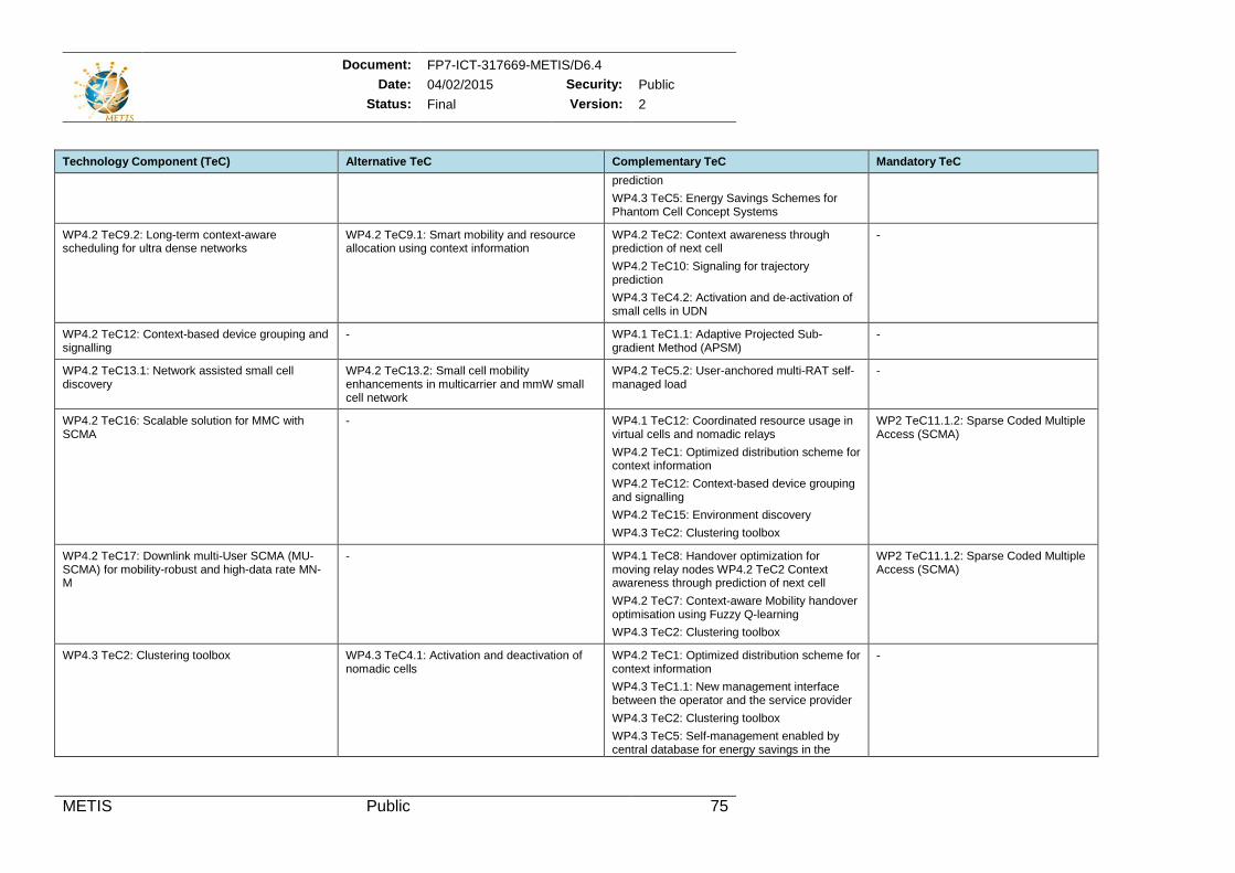
Document: FP7-ICT-317669-METIS/D6.4 Date: 04/02/2015 Security: Public
Status: Final Version: 2
METIS Public 75
Technology Component (TeC) Alternative TeC Complementary TeC Mandatory TeC prediction WP4.3 TeC5: Energy Savings Schemes for Phantom Cell Concept Systems
WP4.2 TeC9.2: Long-term context-aware scheduling for ultra dense networks
WP4.2 TeC9.1: Smart mobility and resource allocation using context information
WP4.2 TeC2: Context awareness through prediction of next cell WP4.2 TeC10: Signaling for trajectory prediction WP4.3 TeC4.2: Activation and de-activation of small cells in UDN
-
WP4.2 TeC12: Context-based device grouping and signalling
- WP4.1 TeC1.1: Adaptive Projected Sub-gradient Method (APSM)
-
WP4.2 TeC13.1: Network assisted small cell discovery
WP4.2 TeC13.2: Small cell mobility enhancements in multicarrier and mmW small cell network
WP4.2 TeC5.2: User-anchored multi-RAT self-managed load
-
WP4.2 TeC16: Scalable solution for MMC with SCMA
- WP4.1 TeC12: Coordinated resource usage in virtual cells and nomadic relays WP4.2 TeC1: Optimized distribution scheme for context information WP4.2 TeC12: Context-based device grouping and signalling WP4.2 TeC15: Environment discovery WP4.3 TeC2: Clustering toolbox
WP2 TeC11.1.2: Sparse Coded Multiple Access (SCMA)
WP4.2 TeC17: Downlink multi-User SCMA (MU-SCMA) for mobility-robust and high-data rate MN-M
- WP4.1 TeC8: Handover optimization for moving relay nodes WP4.2 TeC2 Context awareness through prediction of next cell WP4.2 TeC7: Context-aware Mobility handover optimisation using Fuzzy Q-learning WP4.3 TeC2: Clustering toolbox
WP2 TeC11.1.2: Sparse Coded Multiple Access (SCMA)
WP4.3 TeC2: Clustering toolbox WP4.3 TeC4.1: Activation and deactivation of nomadic cells
WP4.2 TeC1: Optimized distribution scheme for context information WP4.3 TeC1.1: New management interface between the operator and the service provider WP4.3 TeC2: Clustering toolbox WP4.3 TeC5: Self-management enabled by central database for energy savings in the
-
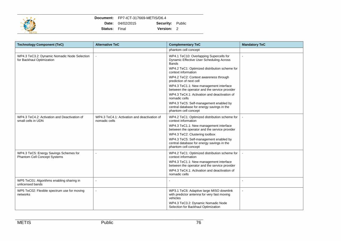
Document: FP7-ICT-317669-METIS/D6.4 Date: 04/02/2015 Security: Public
Status: Final Version: 2
METIS Public 76
Technology Component (TeC) Alternative TeC Complementary TeC Mandatory TeC phantom cell concept
WP4.3 TeC3.2: Dynamic Nomadic Node Selection for Backhaul Optimization
- WP4.1 TeC10: Overlapping Supercells for Dynamic Effective User Scheduling Across Bands WP4.2 TeC1: Optimized distribution scheme for context information WP4.2 TeC2: Context awareness through prediction of next cell WP4.3 TeC1.1: New management interface between the operator and the service provider WP4.3 TeC4.1: Activation and deactivation of nomadic cells WP4.3 TeC5: Self-management enabled by central database for energy savings in the phantom cell concept
-
WP4.3 TeC4.2: Activation and Deactivation of small cells in UDN
WP4.3 TeC4.1: Activation and deactivation of nomadic cells
WP4.2 TeC1: Optimized distribution scheme for context information WP4.3 TeC1.1: New management interface between the operator and the service provider WP4.3 TeC2: Clustering toolbox WP4.3 TeC5: Self-management enabled by central database for energy savings in the phantom cell concept
-
WP4.3 TeC5: Energy Savings Schemes for Phantom Cell Concept Systems
- WP4.2 TeC1: Optimized distribution scheme for context information WP4.3 TeC1.1: New management interface between the operator and the service provider WP4.3 TeC4.1: Activation and deactivation of nomadic cells
-
WP5 TeC01: Algorithms enabling sharing in unlicensed bands
- - -
WP5 TeC02: Flexible spectrum use for moving networks
- WP3.1 TeC6: Adaptive large MISO downlink with predictor antenna for very fast moving vehicles WP4.3 TeC3.2: Dynamic Nomadic Node Selection for Backhaul Optimization
-
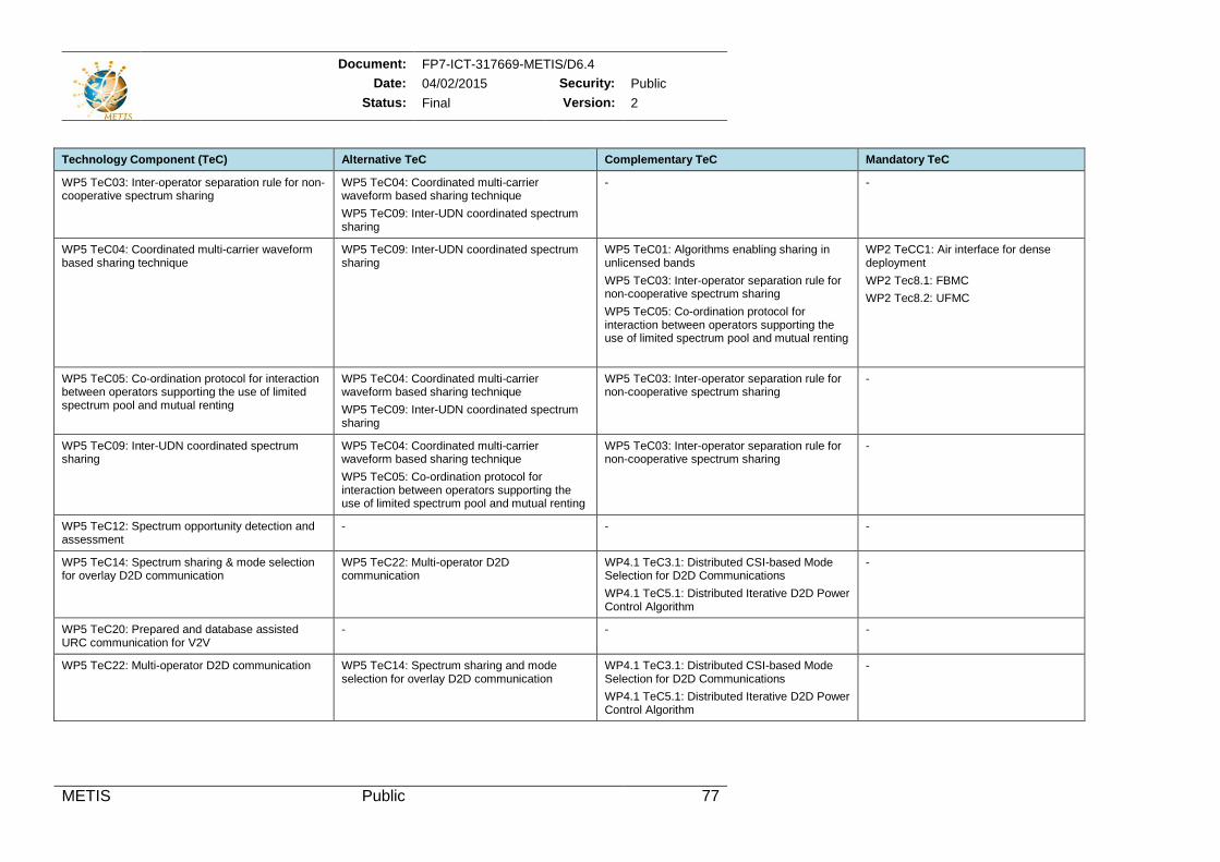
Document: FP7-ICT-317669-METIS/D6.4 Date: 04/02/2015 Security: Public
Status: Final Version: 2
METIS Public 77
Technology Component (TeC) Alternative TeC Complementary TeC Mandatory TeC
WP5 TeC03: Inter-operator separation rule for non-cooperative spectrum sharing
WP5 TeC04: Coordinated multi-carrier waveform based sharing technique WP5 TeC09: Inter-UDN coordinated spectrum sharing
- -
WP5 TeC04: Coordinated multi-carrier waveform based sharing technique
WP5 TeC09: Inter-UDN coordinated spectrum sharing
WP5 TeC01: Algorithms enabling sharing in unlicensed bands WP5 TeC03: Inter-operator separation rule for non-cooperative spectrum sharing WP5 TeC05: Co-ordination protocol for interaction between operators supporting the use of limited spectrum pool and mutual renting
WP2 TeCC1: Air interface for dense deployment WP2 Tec8.1: FBMC WP2 Tec8.2: UFMC
WP5 TeC05: Co-ordination protocol for interaction between operators supporting the use of limited spectrum pool and mutual renting
WP5 TeC04: Coordinated multi-carrier waveform based sharing technique WP5 TeC09: Inter-UDN coordinated spectrum sharing
WP5 TeC03: Inter-operator separation rule for non-cooperative spectrum sharing
-
WP5 TeC09: Inter-UDN coordinated spectrum sharing
WP5 TeC04: Coordinated multi-carrier waveform based sharing technique WP5 TeC05: Co-ordination protocol for interaction between operators supporting the use of limited spectrum pool and mutual renting
WP5 TeC03: Inter-operator separation rule for non-cooperative spectrum sharing
-
WP5 TeC12: Spectrum opportunity detection and assessment
- - -
WP5 TeC14: Spectrum sharing & mode selection for overlay D2D communication
WP5 TeC22: Multi-operator D2D communication
WP4.1 TeC3.1: Distributed CSI-based Mode Selection for D2D Communications WP4.1 TeC5.1: Distributed Iterative D2D Power Control Algorithm
-
WP5 TeC20: Prepared and database assisted URC communication for V2V
- - -
WP5 TeC22: Multi-operator D2D communication WP5 TeC14: Spectrum sharing and mode selection for overlay D2D communication
WP4.1 TeC3.1: Distributed CSI-based Mode Selection for D2D Communications WP4.1 TeC5.1: Distributed Iterative D2D Power Control Algorithm
-
Document: FP7-ICT-317669-METIS/D6.4 Date: 04/02/2015 Security: Public
Status: Final Version: 2
METIS Public 78
8.3 Description of Functional Elements In Section 8.3 the results of a functional decomposition are presented which was made on the basis of the TeCs listed in Section 8.1. For that functional decomposition process each TeC was split into smaller pieces with inherently consistent tasks, i.e., in BBs down to Functional Elements (FEs). In the next step those FEs with same or similar tasks were collected from different TeCs’ functional decomposition output and grouped into joint FEs. During the last step the finally defined FEs were mapped to the Main BBs as defined in Section 7 and their corresponding sub-blocks, namely:
Air Interface (BB AI).
Radio Node Management (BB RNM):
o Mobility Management (MM),
o RAT Selection (RATS),
o Long-term Radio Resource & Interference Management (LTRRIM),
o Short-term Radio Resource & Interference Management (STRRIM),
o Interference Identification & Prediction (IIP),
o D2D Device Discovery & Mode Selection (DDDMS),
o Radio Node Clustering & Dynamic (De-)Activation (RNCDD),
o Nomadic Nodes Management (NNM).
Central Management Entities (BB CME):
o Context Management (CM),
o Spectrum Management (SM),
o Novel Network Interface Termination (NNIT).
For all the BBs presented above a table is provided that gives a number of FEs capturing the functions supported by each BB, as identified through the bottom-up analysis part of the METIS ARCH methodology (see Section 2) and related overarching activities. Together with the FE tables, a blueprint is provided illustrating the split of FEs among different Network Elements (NEs), like Central Management Units (if any processing is required to be on a central position), Infrastructure Radio Nodes (IRNs) and User Equipment (UE), also denoted as Device Radio Nodes (DRN). Baseline interactions among FEs are also depicted.
It has to be noted that for BB AI the differentiation according to sub-blocks of Section 7 was not followed, as compared to other main BBs there was a much stronger grouping of FEs in joint ones. Thus, the description of characteristics of TeCs applied for sub-block identification during the top-down analysis is no more directly visible in the description of the AI functional architecture, because the characteristics are now fulfilled by the interworking of several FEs.
More specifically, the following information is provided for each of the BB’s functional structure in the different columns of the tables:
“Functional Element (FE)” provides the name and in the following column a concise description of the FEs which have been identified as forming the internal functional structure of a specific BB. The notation FE is used to name an entity in the METIS 5G architecture which is specified to perform a dedicated task. A FE consists of a logic function and one or more interfaces. In comparison to the notion BB, the FE has to be understood as more fine granular. A FE is always part of a BB.
“FE related function classification” provides an indication of important functional requirements which include latency and throughput on the input and output interfaces,
Document: FP7-ICT-317669-METIS/D6.4 Date: 04/02/2015 Security: Public
Status: Final Version: 2
METIS Public 79
time synchronization (e.g. on radio slot level) and scaling of processing (e.g. relation to user plane throughput). In this sense, the following options have been identified (more details in Section 9):
o Synchronous radio network functions for which processing is time-synchronous to the 5G air interface (slots/ frames) including control functions (SRC) and user plane functions (SRU);
o Asynchronous radio network functions for which processing is time-asynchronous to the 5G air interface (slots/ frames). They typically require low throughput on the interfaces and the processing requirements scale with the number of users but not the overall traffic load and they include control functions (ARC) and user plane functions (ARU).
“Parameterization” indicates possible differentiations related to an individual FE. This means, for example, that a specific task may target different NEs or resources, implement different protocols or algorithms, utilise different input parameters etc.
“Input (I/Fs) from FEs” provides an overview of possible inputs from another FE together with the corresponding FE or BB to provide that input.
“Output (I/Fs) from FEs” provides an overview of expected outputs to another FE together with the corresponding FE or BB where the output is to be provided.
The FEs presented in the following are finally collected and placed together into a single blueprint, the so-called Generic Functional Architecture (GFA), by combining FEs to higher rank BBs (similar as in top-down analysis). In contrast to top-down analysis where main BBs highlight novel functionalities, the GFA identifies the underlying FEs themselves. More details about the GFA can be found in Section 3.1.2.

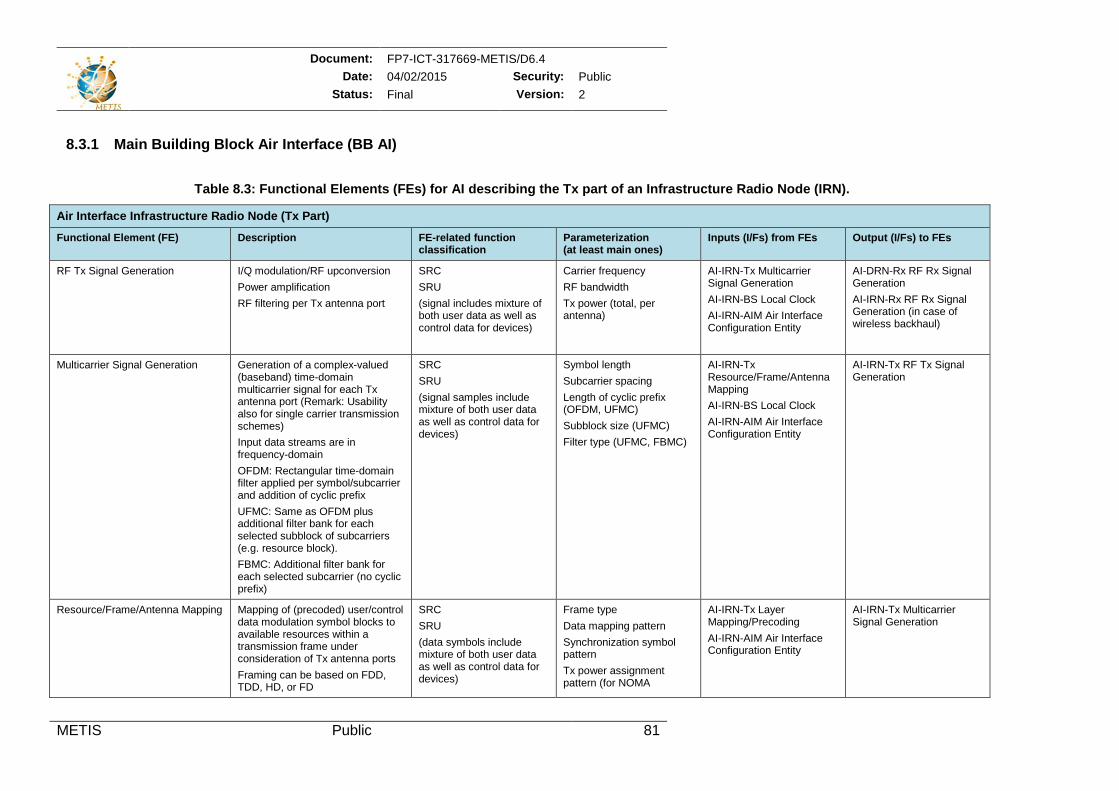
Document: FP7-ICT-317669-METIS/D6.4 Date: 04/02/2015 Security: Public
Status: Final Version: 2
METIS Public 81
8.3.1 Main Building Block Air Interface (BB AI)
Table 8.3: Functional Elements (FEs) for AI describing the Tx part of an Infrastructure Radio Node (IRN).
Air Interface Infrastructure Radio Node (Tx Part) Functional Element (FE) Description FE-related function
classification Parameterization (at least main ones)
Inputs (I/Fs) from FEs Output (I/Fs) to FEs
RF Tx Signal Generation I/Q modulation/RF upconversion Power amplification RF filtering per Tx antenna port
SRC SRU (signal includes mixture of both user data as well as control data for devices)
Carrier frequency RF bandwidth Tx power (total, per antenna)
AI-IRN-Tx Multicarrier Signal Generation AI-IRN-BS Local Clock AI-IRN-AIM Air Interface Configuration Entity
AI-DRN-Rx RF Rx Signal Generation AI-IRN-Rx RF Rx Signal Generation (in case of wireless backhaul)
Multicarrier Signal Generation Generation of a complex-valued (baseband) time-domain multicarrier signal for each Tx antenna port (Remark: Usability also for single carrier transmission schemes) Input data streams are in frequency-domain OFDM: Rectangular time-domain filter applied per symbol/subcarrier and addition of cyclic prefix UFMC: Same as OFDM plus additional filter bank for each selected subblock of subcarriers (e.g. resource block). FBMC: Additional filter bank for each selected subcarrier (no cyclic prefix)
SRC SRU (signal samples include mixture of both user data as well as control data for devices)
Symbol length Subcarrier spacing Length of cyclic prefix (OFDM, UFMC) Subblock size (UFMC) Filter type (UFMC, FBMC)
AI-IRN-Tx Resource/Frame/Antenna Mapping AI-IRN-BS Local Clock AI-IRN-AIM Air Interface Configuration Entity
AI-IRN-Tx RF Tx Signal Generation
Resource/Frame/Antenna Mapping Mapping of (precoded) user/control data modulation symbol blocks to available resources within a transmission frame under consideration of Tx antenna ports Framing can be based on FDD, TDD, HD, or FD
SRC SRU (data symbols include mixture of both user data as well as control data for devices)
Frame type Data mapping pattern Synchronization symbol pattern Tx power assignment pattern (for NOMA
AI-IRN-Tx Layer Mapping/Precoding AI-IRN-AIM Air Interface Configuration Entity
AI-IRN-Tx Multicarrier Signal Generation
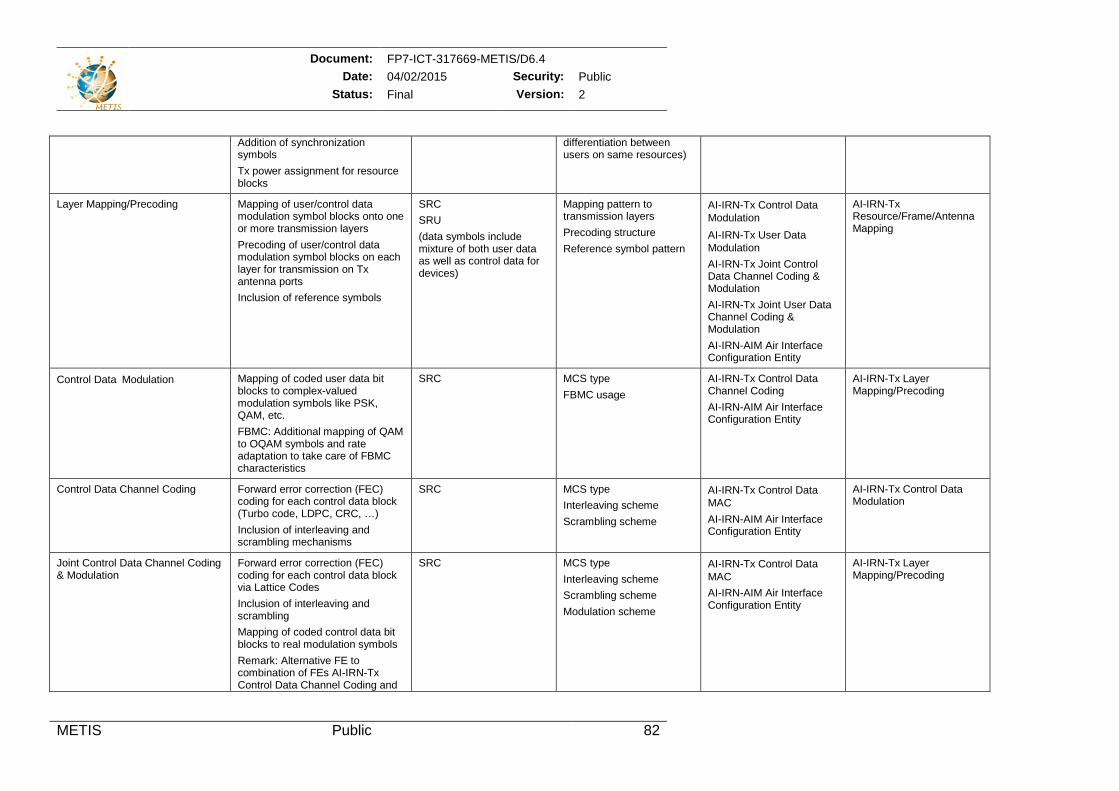
Document: FP7-ICT-317669-METIS/D6.4 Date: 04/02/2015 Security: Public
Status: Final Version: 2
METIS Public 82
Addition of synchronization symbols Tx power assignment for resource blocks
differentiation between users on same resources)
Layer Mapping/Precoding Mapping of user/control data modulation symbol blocks onto one or more transmission layers Precoding of user/control data modulation symbol blocks on each layer for transmission on Tx antenna ports Inclusion of reference symbols
SRC SRU (data symbols include mixture of both user data as well as control data for devices)
Mapping pattern to transmission layers Precoding structure Reference symbol pattern
AI-IRN-Tx Control DataModulation AI-IRN-Tx User DataModulation AI-IRN-Tx Joint Control Data Channel Coding & Modulation AI-IRN-Tx Joint User Data Channel Coding & Modulation AI-IRN-AIM Air Interface Configuration Entity
AI-IRN-Tx Resource/Frame/Antenna Mapping
Control DataModulation Mapping of coded user data bit blocks to complex-valued modulation symbols like PSK, QAM, etc. FBMC: Additional mapping of QAM to OQAM symbols and rate adaptation to take care of FBMC characteristics
SRC MCS type FBMC usage
AI-IRN-Tx Control Data Channel Coding AI-IRN-AIM Air Interface Configuration Entity
AI-IRN-Tx Layer Mapping/Precoding
Control Data Channel Coding Forward error correction (FEC) coding for each control data block (Turbo code, LDPC, CRC, …) Inclusion of interleaving and scrambling mechanisms
SRC MCS type Interleaving scheme Scrambling scheme
AI-IRN-Tx Control DataMAC AI-IRN-AIM Air Interface Configuration Entity
AI-IRN-Tx Control Data Modulation
Joint Control Data Channel Coding & Modulation
Forward error correction (FEC) coding for each control data block via Lattice Codes Inclusion of interleaving and scrambling Mapping of coded control data bit blocks to real modulation symbols Remark: Alternative FE to combination of FEs AI-IRN-Tx Control Data Channel Coding and
SRC MCS type Interleaving scheme Scrambling scheme Modulation scheme
AI-IRN-Tx Control DataMAC AI-IRN-AIM Air Interface Configuration Entity
AI-IRN-Tx Layer Mapping/Precoding
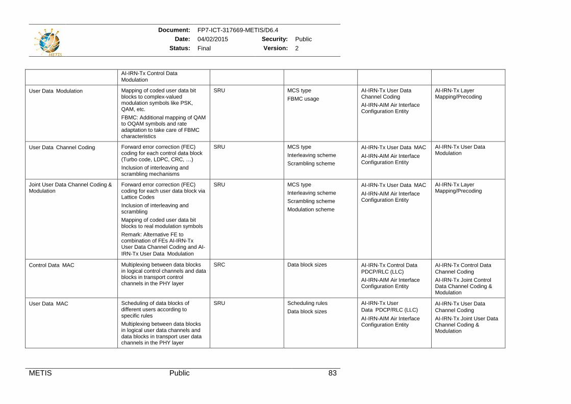
Document: FP7-ICT-317669-METIS/D6.4 Date: 04/02/2015 Security: Public
Status: Final Version: 2
METIS Public 83
AI-IRN-Tx Control DataModulation
User DataModulation Mapping of coded user data bit blocks to complex-valued modulation symbols like PSK, QAM, etc. FBMC: Additional mapping of QAM to OQAM symbols and rate adaptation to take care of FBMC characteristics
SRU MCS type FBMC usage
AI-IRN-Tx User Data Channel Coding AI-IRN-AIM Air Interface Configuration Entity
AI-IRN-Tx Layer Mapping/Precoding
User DataChannel Coding Forward error correction (FEC) coding for each control data block (Turbo code, LDPC, CRC, …) Inclusion of interleaving and scrambling mechanisms
SRU MCS type Interleaving scheme Scrambling scheme
AI-IRN-Tx User DataMAC AI-IRN-AIM Air Interface Configuration Entity
AI-IRN-Tx User Data Modulation
Joint User Data Channel Coding & Modulation
Forward error correction (FEC) coding for each user data block via Lattice Codes Inclusion of interleaving and scrambling Mapping of coded user data bit blocks to real modulation symbols Remark: Alternative FE to combination of FEs AI-IRN-Tx User Data Channel Coding and AI-IRN-Tx User DataModulation
SRU MCS type Interleaving scheme Scrambling scheme Modulation scheme
AI-IRN-Tx User DataMAC AI-IRN-AIM Air Interface Configuration Entity
AI-IRN-Tx Layer Mapping/Precoding
Control DataMAC Multiplexing between data blocks in logical control channels and data blocks in transport control channels in the PHY layer
SRC Data block sizes AI-IRN-Tx Control DataPDCP/RLC (LLC) AI-IRN-AIM Air Interface Configuration Entity
AI-IRN-Tx Control DataChannel Coding AI-IRN-Tx Joint Control Data Channel Coding & Modulation
User DataMAC Scheduling of data blocks of different users according to specific rules Multiplexing between data blocks in logical user data channels and data blocks in transport user data channels in the PHY layer
SRU Scheduling rules Data block sizes
AI-IRN-Tx User DataPDCP/RLC (LLC) AI-IRN-AIM Air Interface Configuration Entity
AI-IRN-Tx User DataChannel Coding AI-IRN-Tx Joint User Data Channel Coding & Modulation
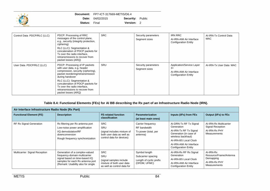
Document: FP7-ICT-317669-METIS/D6.4 Date: 04/02/2015 Security: Public
Status: Final Version: 2
METIS Public 84
Control DataPDCP/RLC (LLC) PDCP: Processing of RRC messages of the control plane, e.g., security (integrity protection, ciphering) RLC (LLC): Segmentation & concatenation of PDCP packets for Tx over the radio interface, retransmissions to recover from packet losses (ARQ)
SRC Security parameters Segment sizes
IRN RRC AI-IRN-AIM Air Interface Configuration Entity
AI-IRN-Tx Control DataMAC
User DataPDCP/RLC (LLC) PDCP: Processing of IP packets with user data, e.g. header compression, security (ciphering), packet reordering/retransmission during handover RLC (LLC): Segmentation & concatenation of PDCP packets for Tx over the radio interface, retransmissions to recover from packet losses (ARQ)
SRU Security parameters Segment sizes
Application/Service Layer 3+ AI-IRN-AIM Air Interface Configuration Entity
AI-IRN-Tx User DataMAC
Table 8.4: Functional Elements (FEs) for AI BB describing the Rx part of an Infrastructure Radio Node (IRN).
Air Interface Infrastructure Radio Node (Rx Part) Functional Element (FE) Description FE-related function
classification Parameterization (at least main ones)
Inputs (I/Fs) from FEs Output (I/Fs) to FEs
RF Rx Signal Generation Rx filtering per Rx antenna port Low-noise power amplification I/Q demodulation/RF downconversion Rough frequency synchronization
SRC SRU (signal includes mixture of both user data as well as control data for devices)
Carrier frequency RF bandwidth Tx power (total, per antenna)
AI-DRN-Tx RF Tx Signal Generation AI-IRN-Tx RF Tx Signal Generation (in case of wireless backhaul) AI-IRN-BS Local Clock AI-IRN-AIM Air Interface Configuration Entity
AI-IRN-Rx Multicarrier Signal Reception AI-IRN-Rx PHY Measurements
Multicarrier Signal Reception Generation of a complex-valued frequency-domain multicarrier signal based on time-based I/Q samples for each Rx antenna port (Remark: Usability also for single
SRC SRU (signal samples include mixture of both user data as well as control data for
Symbol length Subcarrier spacing Length of cyclic prefix (OFDM, UFMC)
AI-IRN-Rx RF Rx Signal Generation AI-IRN-BS Local Clock AI-IRN-AIM Air Interface Configuration Entity
AI-IRN-Rx Resource/Frame/Antenna Demapping AI-IRN-Rx PHY Measurements
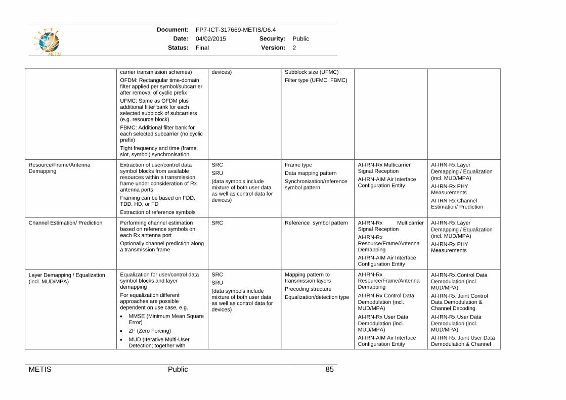
Document: FP7-ICT-317669-METIS/D6.4 Date: 04/02/2015 Security: Public
Status: Final Version: 2
METIS Public 85
carrier transmission schemes) OFDM: Rectangular time-domain filter applied per symbol/subcarrier after removal of cyclic prefix UFMC: Same as OFDM plus additional filter bank for each selected subblock of subcarriers (e.g. resource block) FBMC: Additional filter bank for each selected subcarrier (no cyclic prefix) Tight frequency and time (frame, slot, symbol) synchronisation
devices) Subblock size (UFMC) Filter type (UFMC, FBMC)
Resource/Frame/Antenna Demapping
Extraction of user/control data symbol blocks from available resources within a transmission frame under consideration of Rx antenna ports Framing can be based on FDD, TDD, HD, or FD Extraction of reference symbols
SRC SRU (data symbols include mixture of both user data as well as control data for devices)
Frame type Data mapping pattern Synchronization/reference symbol pattern
AI-IRN-Rx Multicarrier Signal Reception AI-IRN-AIM Air Interface Configuration Entity
AI-IRN-Rx Layer Demapping / Equalization(incl. MUD/MPA) AI-IRN-Rx PHY Measurements AI-IRN-Rx Channel Estimation/ Prediction
Channel Estimation/ Prediction Performing channel estimation based on reference symbols on each Rx antenna port Optionally channel prediction along a transmission frame
SRC Reference symbol pattern AI-IRN-Rx Multicarrier Signal Reception AI-IRN-Rx Resource/Frame/Antenna Demapping AI-IRN-AIM Air Interface Configuration Entity
AI-IRN-Rx Layer Demapping / Equalization(incl. MUD/MPA) AI-IRN-Rx PHY Measurements
Layer Demapping / Equalization(incl. MUD/MPA)
Equalization for user/control data symbol blocks and layer demapping For equalization different approaches are possible dependent on use case, e.g. • MMSE (Minimum Mean Square
Error) • ZF (Zero Forcing) • MUD (Iterative Multi-User
Detection; together with
SRC SRU (data symbols include mixture of both user data as well as control data for devices)
Mapping pattern to transmission layers Precoding structure Equalization/detection type
AI-IRN-Rx Resource/Frame/Antenna Demapping AI-IRN-Rx Control DataDemodulation (incl. MUD/MPA) AI-IRN-Rx User DataDemodulation (incl. MUD/MPA) AI-IRN-AIM Air Interface Configuration Entity
AI-IRN-Rx Control DataDemodulation (incl. MUD/MPA) AI-IRN-Rx Joint Control Data Demodulation & Channel Decoding AI-IRN-Rx User DataDemodulation (incl. MUD/MPA) AI-IRN-Rx Joint User Data Demodulation & Channel
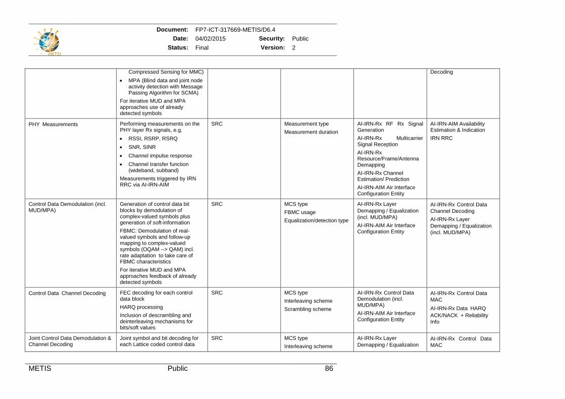
Document: FP7-ICT-317669-METIS/D6.4 Date: 04/02/2015 Security: Public
Status: Final Version: 2
METIS Public 86
Compressed Sensing for MMC) • MPA (Blind data and joint node
activity detection with Message Passing Algorithm for SCMA)
For iterative MUD and MPA approaches use of already detected symbols
Decoding
PHYMeasurements Performing measurements on the PHY layer Rx signals, e.g. • RSSI, RSRP, RSRQ • SNR, SINR • Channel impulse response • Channel transfer function
(wideband, subband) Measurements triggered by IRN RRC via AI-IRN-AIM
SRC Measurement type Measurement duration
AI-IRN-Rx RF Rx Signal Generation AI-IRN-Rx Multicarrier Signal Reception AI-IRN-Rx Resource/Frame/Antenna Demapping AI-IRN-Rx Channel Estimation/ Prediction AI-IRN-AIM Air Interface Configuration Entity
AI-IRN-AIM Availability Estimation & Indication IRN RRC
Control Data Demodulation (incl. MUD/MPA)
Generation of control data bit blocks by demodulation of complex-valued symbols plus generation of soft-information FBMC: Demodulation of real-valued symbols and follow-up mapping to complex-valued symbols (OQAM --> QAM) incl. rate adaptation to take care of FBMC characteristics For iterative MUD and MPA approaches feedback of already detected symbols
SRC MCS type FBMC usage Equalization/detection type
AI-IRN-Rx Layer Demapping / Equalization(incl. MUD/MPA) AI-IRN-AIM Air Interface Configuration Entity
AI-IRN-Rx Control DataChannel Decoding AI-IRN-Rx Layer Demapping / Equalization(incl. MUD/MPA)
Control DataChannel Decoding FEC decoding for each control data block HARQ processing Inclusion of descrambling and deinterleaving mechanisms for bits/soft values
SRC MCS type Interleaving scheme Scrambling scheme
AI-IRN-Rx Control Data Demodulation (incl. MUD/MPA) AI-IRN-AIM Air Interface Configuration Entity
AI-IRN-Rx Control DataMAC AI-IRN-Rx DataHARQ ACK/NACK+ Reliability Info
Joint Control Data Demodulation & Channel Decoding
Joint symbol and bit decoding for each Lattice coded control data
SRC MCS type Interleaving scheme
AI-IRN-Rx Layer Demapping / Equalization
AI-IRN-Rx Control Data MAC
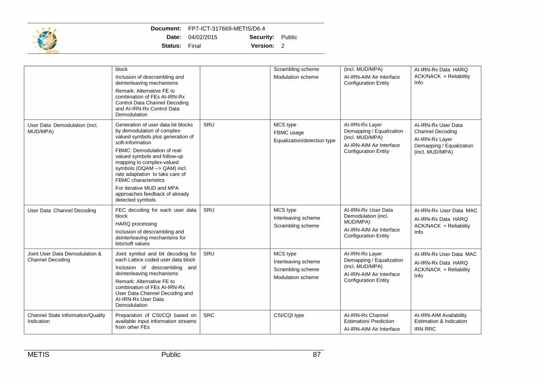
Document: FP7-ICT-317669-METIS/D6.4 Date: 04/02/2015 Security: Public
Status: Final Version: 2
METIS Public 87
block Inclusion of descrambling and deinterleaving mechanisms Remark: Alternative FE to combination of FEs AI-IRN-Rx Control Data Channel Decoding and AI-IRN-Rx Control Data Demodulation
Scrambling scheme Modulation scheme
(incl. MUD/MPA) AI-IRN-AIM Air Interface Configuration Entity
AI-IRN-Rx DataHARQ ACK/NACK+ Reliability Info
User DataDemodulation (incl. MUD/MPA)
Generation of user data bit blocks by demodulation of complex-valued symbols plus generation of soft-information FBMC: Demodulation of real-valued symbols and follow-up mapping to complex-valued symbols (OQAM --> QAM) incl. rate adaptation to take care of FBMC characteristics For iterative MUD and MPA approaches feedback of already detected symbols
SRU MCS type FBMC usage Equalization/detection type
AI-IRN-Rx Layer Demapping / Equalization(incl. MUD/MPA) AI-IRN-AIM Air Interface Configuration Entity
AI-IRN-Rx User DataChannel Decoding AI-IRN-Rx Layer Demapping / Equalization(incl. MUD/MPA)
User DataChannel Decoding FEC decoding for each user data block HARQ processing Inclusion of descrambling and deinterleaving mechanisms for bits/soft values
SRU MCS type Interleaving scheme Scrambling scheme
AI-IRN-Rx User Data Demodulation (incl. MUD/MPA) AI-IRN-AIM Air Interface Configuration Entity
AI-IRN-Rx User DataMAC AI-IRN-Rx DataHARQ ACK/NACK+ Reliability Info
Joint User Data Demodulation & Channel Decoding
Joint symbol and bit decoding for each Lattice coded user data block Inclusion of descrambling and deinterleaving mechanisms Remark: Alternative FE to combination of FEs AI-IRN-Rx User Data Channel Decoding and AI-IRN-Rx User Data Demodulation
SRU MCS type Interleaving scheme Scrambling scheme Modulation scheme
AI-IRN-Rx Layer Demapping / Equalization(incl. MUD/MPA) AI-IRN-AIM Air Interface Configuration Entity
AI-IRN-Rx User DataMAC
AI-IRN-Rx DataHARQ ACK/NACK+ Reliability Info
Channel State Information/Quality Indication
Preparation of CSI/CQI based on available input information streams from other FEs
SRC CSI/CQI type AI-IRN-Rx Channel Estimation/ Prediction AI-IRN-AIM Air Interface
AI-IRN-AIM Availability Estimation & Indication IRN RRC
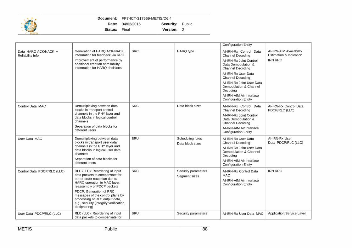
Document: FP7-ICT-317669-METIS/D6.4 Date: 04/02/2015 Security: Public
Status: Final Version: 2
METIS Public 88
Configuration Entity
DataHARQ ACK/NACK+ Reliability Info
Generation of HARQ ACK/NACK information for feedback via RRC Improvement of performance by additional creation of reliability information for HARQ decisions
SRC HARQ type AI-IRN-Rx Control Data Channel Decoding AI-IRN-Rx Joint Control Data Demodulation & Channel Decoding AI-IRN-Rx User DataChannel Decoding AI-IRN-Rx Joint User Data Demodulation & Channel Decoding AI-IRN-AIM Air Interface Configuration Entity
AI-IRN-AIM Availability Estimation & Indication IRN RRC
Control DataMAC Demultiplexing between data blocks in transport control channels in the PHY layer and data blocks in logical control channels Separation of data blocks for different users
SRC Data block sizes AI-IRN-Rx Control Data Channel Decoding AI-IRN-Rx Joint Control Data Demodulation & Channel Decoding AI-IRN-AIM Air Interface Configuration Entity
AI-IRN-Rx Control DataPDCP/RLC (LLC)
User DataMAC Demultiplexing between data blocks in transport user data channels in the PHY layer and data blocks in logical user data channels Separation of data blocks for different users
SRU Scheduling rules Data block sizes
AI-IRN-Rx User DataChannel Decoding AI-IRN-Rx Joint User Data Demodulation & Channel Decoding AI-IRN-AIM Air Interface Configuration Entity
AI-IRN-Rx User DataPDCP/RLC (LLC)
Control DataPDCP/RLC (LLC) RLC (LLC): Reordering of input data packets to compensate for out-of-order reception due to HARQ operation in MAC layer; reassembly of PDCP packets PDCP: Generation of RRC messages of the control plane by processing of RLC output data, e.g., security (integrity verification, deciphering)
SRC Security parameters Segment sizes
AI-IRN-Rx Control DataMAC AI-IRN-AIM Air Interface Configuration Entity
IRN RRC
User DataPDCP/RLC (LLC) RLC (LLC): Reordering of input data packets to compensate for
SRU Security parameters AI-IRN-Rx User DataMAC Application/Service Layer
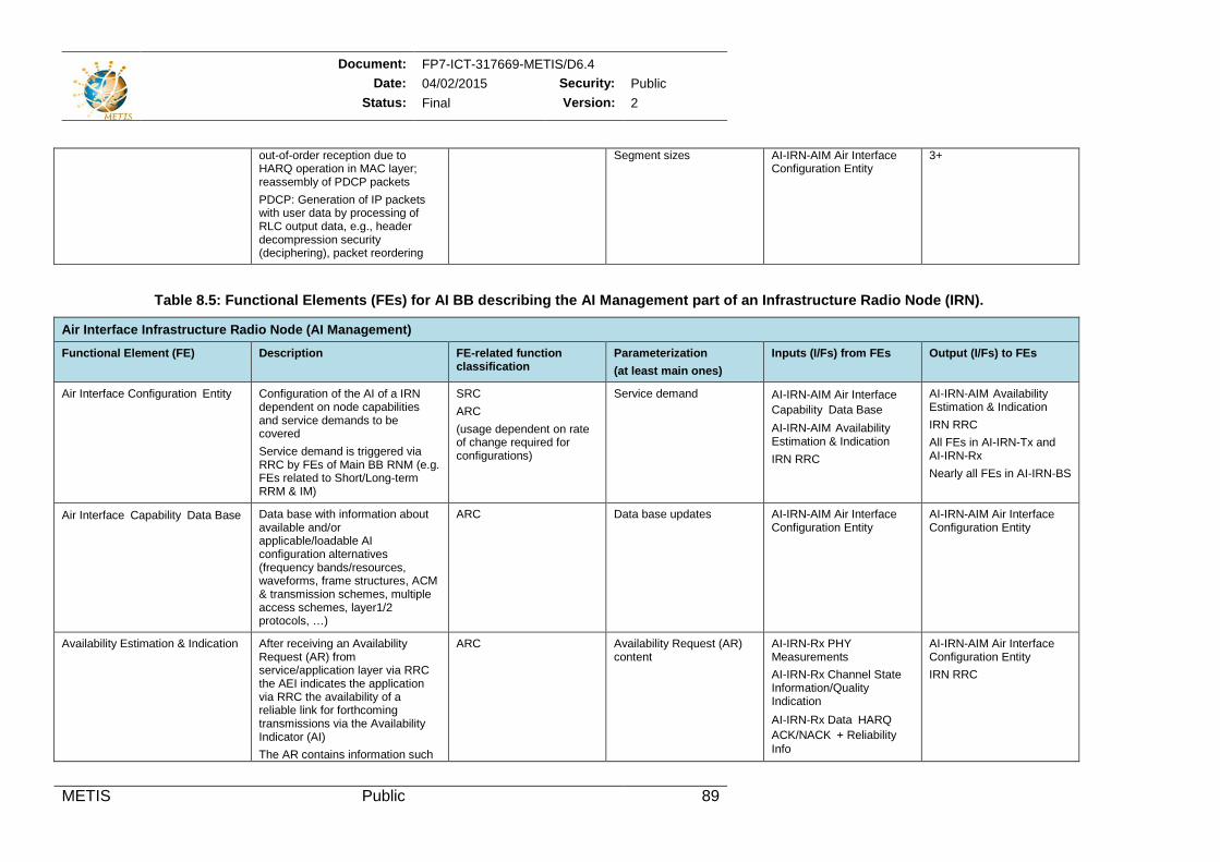
Document: FP7-ICT-317669-METIS/D6.4 Date: 04/02/2015 Security: Public
Status: Final Version: 2
METIS Public 89
out-of-order reception due to HARQ operation in MAC layer; reassembly of PDCP packets PDCP: Generation of IP packets with user data by processing of RLC output data, e.g., header decompression security (deciphering), packet reordering
Segment sizes AI-IRN-AIM Air Interface Configuration Entity
3+
Table 8.5: Functional Elements (FEs) for AI BB describing the AI Management part of an Infrastructure Radio Node (IRN).
Air Interface Infrastructure Radio Node (AI Management)
Functional Element (FE) Description FE-related function classification
Parameterization (at least main ones)
Inputs (I/Fs) from FEs Output (I/Fs) to FEs
Air Interface Configuration Entity Configuration of the AI of a IRN dependent on node capabilities and service demands to be covered Service demand is triggered via RRC by FEs of Main BB RNM (e.g. FEs related to Short/Long-term RRM & IM)
SRC ARC (usage dependent on rate of change required for configurations)
Service demand AI-IRN-AIM Air InterfaceCapabilityData Base AI-IRN-AIM Availability Estimation & Indication IRN RRC
AI-IRN-AIM Availability Estimation & Indication IRN RRC All FEs in AI-IRN-Tx and AI-IRN-Rx Nearly all FEs in AI-IRN-BS
Air InterfaceCapabilityData Base Data base with information about available and/or applicable/loadable AI configuration alternatives (frequency bands/resources, waveforms, frame structures, ACM & transmission schemes, multiple access schemes, layer1/2 protocols, …)
ARC Data base updates AI-IRN-AIM Air Interface Configuration Entity
AI-IRN-AIM Air Interface Configuration Entity
Availability Estimation & Indication After receiving an Availability Request (AR) from service/application layer via RRC the AEI indicates the application via RRC the availability of a reliable link for forthcoming transmissions via the Availability Indicator (AI) The AR contains information such
ARC Availability Request (AR) content
AI-IRN-Rx PHY Measurements AI-IRN-Rx Channel State Information/Quality Indication AI-IRN-Rx DataHARQ ACK/NACK+ Reliability Info
AI-IRN-AIM Air Interface Configuration Entity IRN RRC
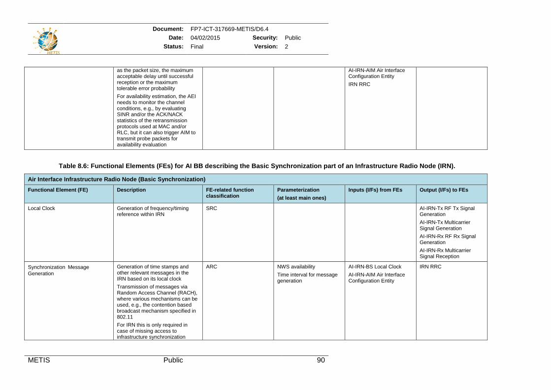
Document: FP7-ICT-317669-METIS/D6.4 Date: 04/02/2015 Security: Public
Status: Final Version: 2
METIS Public 90
as the packet size, the maximum acceptable delay until successful reception or the maximum tolerable error probability For availability estimation, the AEI needs to monitor the channel conditions, e.g., by evaluating SINR and/or the ACK/NACK statistics of the retransmission protocols used at MAC and/or RLC, but it can also trigger AIM to transmit probe packets for availability evaluation
AI-IRN-AIM Air Interface Configuration Entity IRN RRC
Table 8.6: Functional Elements (FEs) for AI BB describing the Basic Synchronization part of an Infrastructure Radio Node (IRN).
Air Interface Infrastructure Radio Node (Basic Synchronization)
Functional Element (FE) Description FE-related function classification
Parameterization (at least main ones)
Inputs (I/Fs) from FEs Output (I/Fs) to FEs
Local Clock Generation of frequency/timing reference within IRN
SRC AI-IRN-Tx RF Tx Signal Generation AI-IRN-Tx Multicarrier Signal Generation AI-IRN-Rx RF Rx Signal Generation AI-IRN-Rx Multicarrier Signal Reception
SynchronizationMessage Generation
Generation of time stamps and other relevant messages in the IRN based on its local clock Transmission of messages via Random Access Channel (RACH), where various mechanisms can be used, e.g., the contention based broadcast mechanism specified in 802.11 For IRN this is only required in case of missing access to infrastructure synchronization
ARC NWS availability Time interval for message generation
AI-IRN-BS Local Clock AI-IRN-AIM Air Interface Configuration Entity
IRN RRC
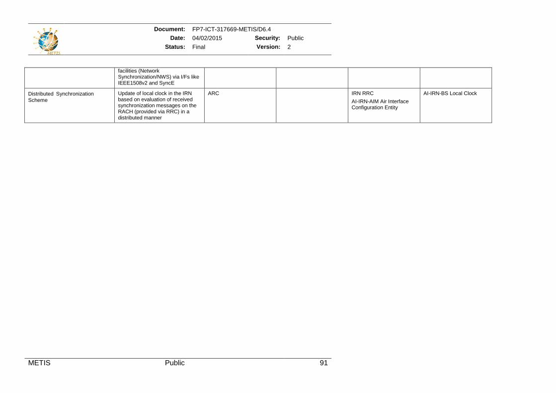
Document: FP7-ICT-317669-METIS/D6.4 Date: 04/02/2015 Security: Public
Status: Final Version: 2
METIS Public 91
facilities (Network Synchronization/NWS) via I/Fs like IEEE1508v2 and SyncE
DistributedSynchronizationScheme
Update of local clock in the IRN based on evaluation of received synchronization messages on the RACH (provided via RRC) in a distributed manner
ARC IRN RRC AI-IRN-AIM Air Interface Configuration Entity
AI-IRN-BS Local Clock
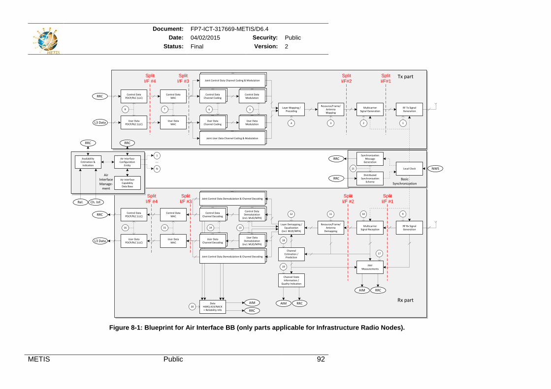
Document: FP7-ICT-317669-METIS/D6.4 Date: 04/02/2015 Security: Public
Status: Final Version: 2
METIS Public 92
Figure 8-1: Blueprint for Air Interface BB (only parts applicable for Infrastructure Radio Nodes).
... ...
Joint Control Data Demodulation & Channel Decoding
...
Joint User Data Channel Coding & Modulation
...
Joint Control Data Channel Coding & Modulation
Control DataChannel Coding
RF Tx Signal Generation
MulticarrierSignal Generation
Resource/Frame/AntennaMapping
Layer Mapping /Precoding
Control DataModulation
User DataChannel Coding
User DataModulation
Control DataChannel Decoding
RF Rx Signal Generation
MulticarrierSignal Reception
Resource/Frame/Antenna
Demapping
Layer Demapping /Equalization
(incl. MUD/MPA)
Control DataDemodulation
(incl. MUD/MPA)
User DataChannel Decoding
User DataDemodulation
(incl. MUD/MPA)
Channel Estimation /Prediction
Air Interface of Infrastructure Radio Node
Tx part
Rx part
... ...
... ...
... ...
Air InterfaceConfiguration
Entity
Air InterfaceCapabilityData Base
...
...
Joint Control Data Demodulation & Channel Decoding
...
Local Clock
DistributedSynchronization
Scheme
SynchronizationMessage
Generation
NWS
RRC
DataHARQ ACK/NACK+ Reliability Info RRC
... ...
PHYMeasurements
Ch. Inf.
Availability Estimation &
Indication
User DataMAC
Control DataMAC
User DataPDCP/RLC (LLC)
Control DataPDCP/RLC (LLC)
L3 Data
RRC
User DataMAC
Control DataMAC
User DataPDCP/RLC (LLC)
Control DataPDCP/RLC (LLC)
L3 Data
RRC
1
N
6 5
4 3 2
AIM
Rel.
AirInterfaceManage-
ment
Channel State Information /
Quality Indication
AIM RRC
1
78
12 11 10 9
1516 14 13
18
19
17
20
RRC
AIM RRC
RRC
RRC
21
BasicSynchronization
SplitI/F #4
SplitI/F #3
SplitI/F#1
SplitI/F#2
SplitI/F #4
SplitI/F #3
SplitI/F #1
SplitI/F #2
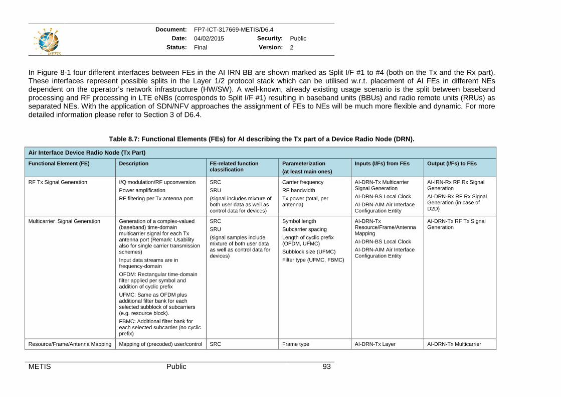
Document: FP7-ICT-317669-METIS/D6.4 Date: 04/02/2015 Security: Public
Status: Final Version: 2
METIS Public 93
In Figure 8-1 four different interfaces between FEs in the AI IRN BB are shown marked as Split I/F #1 to #4 (both on the Tx and the Rx part). These interfaces represent possible splits in the Layer 1/2 protocol stack which can be utilised w.r.t. placement of AI FEs in different NEs dependent on the operator’s network infrastructure (HW/SW). A well-known, already existing usage scenario is the split between baseband processing and RF processing in LTE eNBs (corresponds to Split I/F #1) resulting in baseband units (BBUs) and radio remote units (RRUs) as separated NEs. With the application of SDN/NFV approaches the assignment of FEs to NEs will be much more flexible and dynamic. For more detailed information please refer to Section 3 of D6.4.
Table 8.7: Functional Elements (FEs) for AI describing the Tx part of a Device Radio Node (DRN).
Air Interface Device Radio Node (Tx Part) Functional Element (FE) Description FE-related function
classification Parameterization (at least main ones)
Inputs (I/Fs) from FEs Output (I/Fs) to FEs
RF Tx Signal Generation I/Q modulation/RF upconversion Power amplification RF filtering per Tx antenna port
SRC SRU (signal includes mixture of both user data as well as control data for devices)
Carrier frequency RF bandwidth Tx power (total, per antenna)
AI-DRN-Tx Multicarrier Signal Generation AI-DRN-BS Local Clock AI-DRN-AIM Air Interface Configuration Entity
AI-IRN-Rx RF Rx Signal Generation AI-DRN-Rx RF Rx Signal Generation (in case of D2D)
Multicarrier Signal Generation Generation of a complex-valued (baseband) time-domain multicarrier signal for each Tx antenna port (Remark: Usability also for single carrier transmission schemes) Input data streams are in frequency-domain OFDM: Rectangular time-domain filter applied per symbol and addition of cyclic prefix UFMC: Same as OFDM plus additional filter bank for each selected subblock of subcarriers (e.g. resource block). FBMC: Additional filter bank for each selected subcarrier (no cyclic prefix)
SRC SRU (signal samples include mixture of both user data as well as control data for devices)
Symbol length Subcarrier spacing Length of cyclic prefix (OFDM, UFMC) Subblock size (UFMC) Filter type (UFMC, FBMC)
AI-DRN-Tx Resource/Frame/Antenna Mapping AI-DRN-BS Local Clock AI-DRN-AIM Air Interface Configuration Entity
AI-DRN-Tx RF Tx Signal Generation
Resource/Frame/Antenna Mapping Mapping of (precoded) user/control SRC Frame type AI-DRN-Tx Layer AI-DRN-Tx Multicarrier
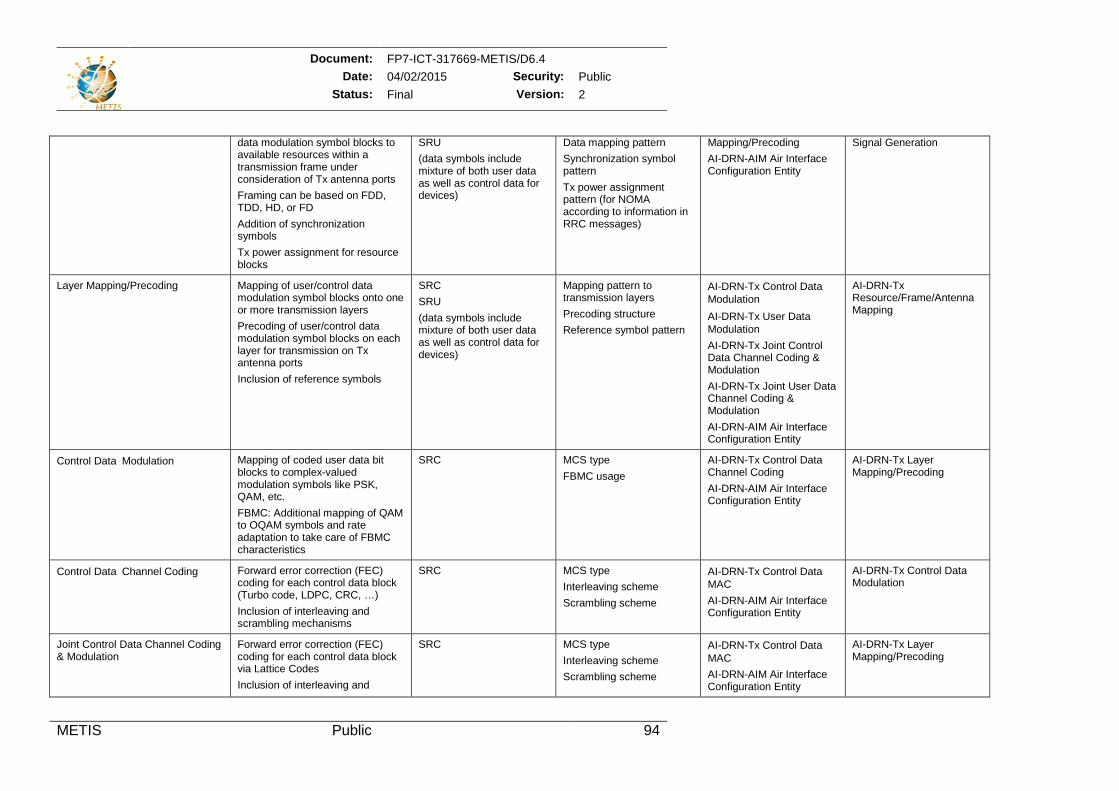
Document: FP7-ICT-317669-METIS/D6.4 Date: 04/02/2015 Security: Public
Status: Final Version: 2
METIS Public 94
data modulation symbol blocks to available resources within a transmission frame under consideration of Tx antenna ports Framing can be based on FDD, TDD, HD, or FD Addition of synchronization symbols Tx power assignment for resource blocks
SRU (data symbols include mixture of both user data as well as control data for devices)
Data mapping pattern Synchronization symbol pattern Tx power assignment pattern (for NOMA according to information in RRC messages)
Mapping/Precoding AI-DRN-AIM Air Interface Configuration Entity
Signal Generation
Layer Mapping/Precoding Mapping of user/control data modulation symbol blocks onto one or more transmission layers Precoding of user/control data modulation symbol blocks on each layer for transmission on Tx antenna ports Inclusion of reference symbols
SRC SRU (data symbols include mixture of both user data as well as control data for devices)
Mapping pattern to transmission layers Precoding structure Reference symbol pattern
AI-DRN-Tx Control DataModulation AI-DRN-Tx User DataModulation AI-DRN-Tx Joint Control Data Channel Coding & Modulation AI-DRN-Tx Joint User Data Channel Coding & Modulation AI-DRN-AIM Air Interface Configuration Entity
AI-DRN-Tx Resource/Frame/Antenna Mapping
Control DataModulation Mapping of coded user data bit blocks to complex-valued modulation symbols like PSK, QAM, etc. FBMC: Additional mapping of QAM to OQAM symbols and rate adaptation to take care of FBMC characteristics
SRC MCS type FBMC usage
AI-DRN-Tx Control Data Channel Coding AI-DRN-AIM Air Interface Configuration Entity
AI-DRN-Tx Layer Mapping/Precoding
Control DataChannel Coding Forward error correction (FEC) coding for each control data block (Turbo code, LDPC, CRC, …) Inclusion of interleaving and scrambling mechanisms
SRC MCS type Interleaving scheme Scrambling scheme
AI-DRN-Tx Control DataMAC AI-DRN-AIM Air Interface Configuration Entity
AI-DRN-Tx Control Data Modulation
Joint Control Data Channel Coding & Modulation
Forward error correction (FEC) coding for each control data block via Lattice Codes Inclusion of interleaving and
SRC MCS type Interleaving scheme Scrambling scheme
AI-DRN-Tx Control DataMAC AI-DRN-AIM Air Interface Configuration Entity
AI-DRN-Tx Layer Mapping/Precoding
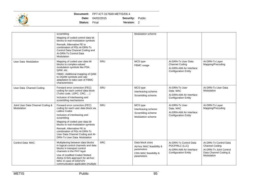
Document: FP7-ICT-317669-METIS/D6.4 Date: 04/02/2015 Security: Public
Status: Final Version: 2
METIS Public 95
scrambling Mapping of coded control data bit blocks to real modulation symbols Remark: Alternative FE to combination of FEs AI-DRN-Tx Control Data Channel Coding and AI-DRN-Tx Control DataModulation
Modulation scheme
User DataModulation Mapping of coded user data bit blocks to complex-valued modulation symbols like PSK, QAM, etc. FBMC: Additional mapping of QAM to OQAM symbols and rate adaptation to take care of FBMC characteristics
SRU MCS type FBMC usage
AI-DRN-Tx User Data Channel Coding AI-DRN-AIM Air Interface Configuration Entity
AI-DRN-Tx Layer Mapping/Precoding
User DataChannel Coding Forward error correction (FEC) coding for each control data block (Turbo code, LDPC, CRC, …) Inclusion of interleaving and scrambling mechanisms
SRU MCS type Interleaving scheme Scrambling scheme
AI-DRN-Tx User DataMAC AI-DRN-AIM Air Interface Configuration Entity
AI-DRN-Tx User Data Modulation
Joint User Data Channel Coding & Modulation
Forward error correction (FEC) coding for each user data block via Lattice Codes Inclusion of interleaving and scrambling Mapping of coded user data bit blocks to real modulation symbols Remark: Alternative FE to combination of FEs AI-DRN-Tx User Data Channel Coding and AI-DRN-Tx User DataModulation
SRU MCS type Interleaving scheme Scrambling scheme Modulation scheme
AI-DRN-Tx User DataMAC AI-DRN-AIM Air Interface Configuration Entity
AI-DRN-Tx Layer Mapping/Precoding
Control DataMAC Multiplexing between data blocks in logical control channels and data blocks in transport control channels in the PHY layer Use of modified Coded Slotted Aloha (CSA) approach for ad-hoc MAC in case of D2D/V2V communication applicable (multiple
SRC Data block sizes Ad-hoc MAC feasibility & parameters CRA MAC feasibility & parameters
AI-DRN-Tx Control DataPDCP/RLC (LLC) AI-DRN-AIM Air Interface Configuration Entity
AI-DRN-Tx Control DataChannel Coding AI-DRN-Tx Joint Control Data Channel Coding & Modulation
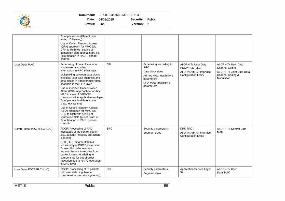
Document: FP7-ICT-317669-METIS/D6.4 Date: 04/02/2015 Security: Public
Status: Final Version: 2
METIS Public 96
Tx of packets in different time slots, HD framing) Use of Coded Random Access (CRA) approach for MMC (UL DRN to IRN) with setting of contention slots (period start, i.e. Tx of beacon in RACH; period control)
User DataMAC Scheduling of data blocks of a single user according to information in RRC messages Multiplexing between data blocks in logical user data channels and data blocks in transport user data channels in the PHY layer Use of modified Coded Slotted Aloha (CSA) approach for ad-hoc MAC in case of D2D/V2V communication applicable (multiple Tx of packets in different time slots, HD framing) Use of Coded Random Access (CRA) approach for MMC (UL DRN to IRN) with setting of contention slots (period start, i.e. Tx of beacon in RACH; period control)
SRU Scheduling according to RRC Data block sizes Ad-hoc MAC feasibility & parameters CRA MAC feasibility & parameters
AI-DRN-Tx User DataPDCP/RLC (LLC) AI-DRN-AIM Air Interface Configuration Entity
AI-DRN-Tx User DataChannel Coding AI-DRN-Tx Joint User Data Channel Coding & Modulation
Control DataPDCP/RLC (LLC) PDCP: Processing of RRC messages of the control plane, e.g., security (integrity protection, ciphering) RLC (LLC): Segmentation & reassembly of PDCP packets for Tx over the radio interface, retransmissions to recover from packet losses, reordering to compensate for out-of-order reception due to HARQ operation in MAC layer
SRC Security parameters Segment sizes
DRN RRC AI-DRN-AIM Air Interface Configuration Entity
AI-DRN-Tx Control DataMAC
User DataPDCP/RLC (LLC) PDCP: Processing of IP packets with user data, e.g. header compression, security (ciphering),
SRU Security parameters Segment sizes
Application/Service Layer 3+
AI-DRN-Tx User DataMAC
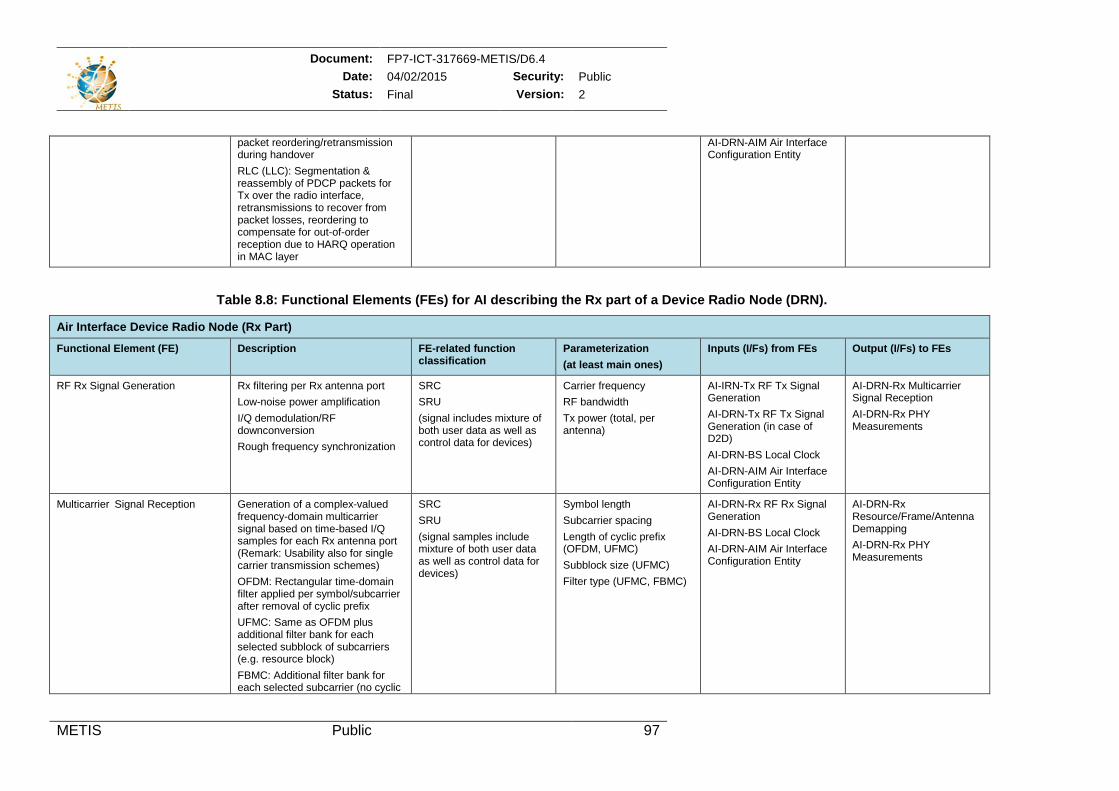
Document: FP7-ICT-317669-METIS/D6.4 Date: 04/02/2015 Security: Public
Status: Final Version: 2
METIS Public 97
packet reordering/retransmission during handover RLC (LLC): Segmentation & reassembly of PDCP packets for Tx over the radio interface, retransmissions to recover from packet losses, reordering to compensate for out-of-order reception due to HARQ operation in MAC layer
AI-DRN-AIM Air Interface Configuration Entity
Table 8.8: Functional Elements (FEs) for AI describing the Rx part of a Device Radio Node (DRN).
Air Interface Device Radio Node (Rx Part) Functional Element (FE) Description FE-related function
classification Parameterization (at least main ones)
Inputs (I/Fs) from FEs Output (I/Fs) to FEs
RF Rx Signal Generation Rx filtering per Rx antenna port Low-noise power amplification I/Q demodulation/RF downconversion Rough frequency synchronization
SRC SRU (signal includes mixture of both user data as well as control data for devices)
Carrier frequency RF bandwidth Tx power (total, per antenna)
AI-IRN-Tx RF Tx Signal Generation AI-DRN-Tx RF Tx Signal Generation (in case of D2D) AI-DRN-BS Local Clock AI-DRN-AIM Air Interface Configuration Entity
AI-DRN-Rx Multicarrier Signal Reception AI-DRN-Rx PHY Measurements
Multicarrier Signal Reception Generation of a complex-valued frequency-domain multicarrier signal based on time-based I/Q samples for each Rx antenna port (Remark: Usability also for single carrier transmission schemes) OFDM: Rectangular time-domain filter applied per symbol/subcarrier after removal of cyclic prefix UFMC: Same as OFDM plus additional filter bank for each selected subblock of subcarriers (e.g. resource block) FBMC: Additional filter bank for each selected subcarrier (no cyclic
SRC SRU (signal samples include mixture of both user data as well as control data for devices)
Symbol length Subcarrier spacing Length of cyclic prefix (OFDM, UFMC) Subblock size (UFMC) Filter type (UFMC, FBMC)
AI-DRN-Rx RF Rx Signal Generation AI-DRN-BS Local Clock AI-DRN-AIM Air Interface Configuration Entity
AI-DRN-Rx Resource/Frame/Antenna Demapping AI-DRN-Rx PHY Measurements
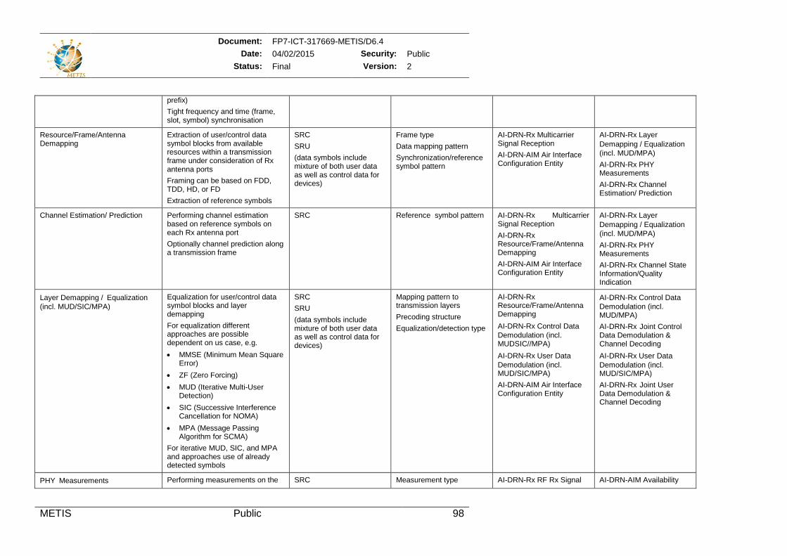
Document: FP7-ICT-317669-METIS/D6.4 Date: 04/02/2015 Security: Public
Status: Final Version: 2
METIS Public 98
prefix) Tight frequency and time (frame, slot, symbol) synchronisation
Resource/Frame/Antenna Demapping
Extraction of user/control data symbol blocks from available resources within a transmission frame under consideration of Rx antenna ports Framing can be based on FDD, TDD, HD, or FD Extraction of reference symbols
SRC SRU (data symbols include mixture of both user data as well as control data for devices)
Frame type Data mapping pattern Synchronization/reference symbol pattern
AI-DRN-Rx Multicarrier Signal Reception AI-DRN-AIM Air Interface Configuration Entity
AI-DRN-Rx Layer Demapping / Equalization(incl. MUD/MPA) AI-DRN-Rx PHY Measurements AI-DRN-Rx Channel Estimation/ Prediction
Channel Estimation/ Prediction Performing channel estimation based on reference symbols on each Rx antenna port Optionally channel prediction along a transmission frame
SRC Reference symbol pattern AI-DRN-Rx Multicarrier Signal Reception AI-DRN-Rx Resource/Frame/Antenna Demapping AI-DRN-AIM Air Interface Configuration Entity
AI-DRN-Rx Layer Demapping / Equalization(incl. MUD/MPA) AI-DRN-Rx PHY Measurements AI-DRN-Rx Channel State Information/Quality Indication
Layer Demapping /Equalization(incl. MUD/SIC/MPA)
Equalization for user/control data symbol blocks and layer demapping For equalization different approaches are possible dependent on us case, e.g. • MMSE (Minimum Mean Square
Error) • ZF (Zero Forcing) • MUD (Iterative Multi-User
Detection) • SIC (Successive Interference
Cancellation for NOMA) • MPA (Message Passing
Algorithm for SCMA) For iterative MUD, SIC, and MPA and approaches use of already detected symbols
SRC SRU (data symbols include mixture of both user data as well as control data for devices)
Mapping pattern to transmission layers Precoding structure Equalization/detection type
AI-DRN-Rx Resource/Frame/Antenna Demapping AI-DRN-Rx Control DataDemodulation (incl. MUDSIC//MPA) AI-DRN-Rx User DataDemodulation (incl. MUD/SIC/MPA) AI-DRN-AIM Air Interface Configuration Entity
AI-DRN-Rx Control DataDemodulation (incl. MUD/MPA) AI-DRN-Rx Joint Control Data Demodulation & Channel Decoding AI-DRN-Rx User DataDemodulation (incl. MUD/SIC/MPA) AI-DRN-Rx Joint User Data Demodulation & Channel Decoding
PHYMeasurements Performing measurements on the SRC Measurement type AI-DRN-Rx RF Rx Signal AI-DRN-AIM Availability
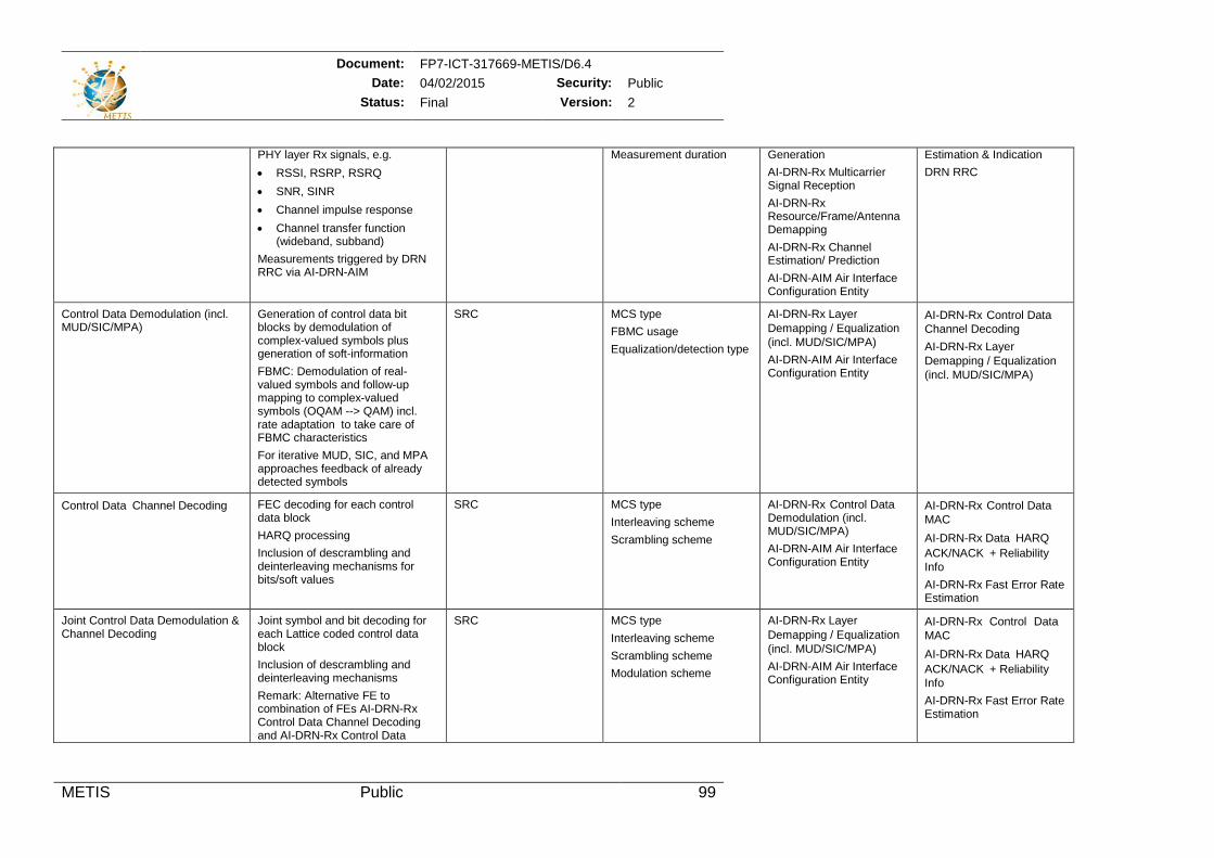
Document: FP7-ICT-317669-METIS/D6.4 Date: 04/02/2015 Security: Public
Status: Final Version: 2
METIS Public 99
PHY layer Rx signals, e.g. • RSSI, RSRP, RSRQ • SNR, SINR • Channel impulse response • Channel transfer function
(wideband, subband) Measurements triggered by DRN RRC via AI-DRN-AIM
Measurement duration Generation AI-DRN-Rx Multicarrier Signal Reception AI-DRN-Rx Resource/Frame/Antenna Demapping AI-DRN-Rx Channel Estimation/ Prediction AI-DRN-AIM Air Interface Configuration Entity
Estimation & Indication DRN RRC
Control Data Demodulation (incl. MUD/SIC/MPA)
Generation of control data bit blocks by demodulation of complex-valued symbols plus generation of soft-information FBMC: Demodulation of real-valued symbols and follow-up mapping to complex-valued symbols (OQAM --> QAM) incl. rate adaptation to take care of FBMC characteristics For iterative MUD, SIC, and MPA approaches feedback of already detected symbols
SRC MCS type FBMC usage Equalization/detection type
AI-DRN-Rx Layer Demapping / Equalization(incl. MUD/SIC/MPA) AI-DRN-AIM Air Interface Configuration Entity
AI-DRN-Rx Control DataChannel Decoding AI-DRN-Rx Layer Demapping / Equalization(incl. MUD/SIC/MPA)
Control DataChannel Decoding FEC decoding for each control data block HARQ processing Inclusion of descrambling and deinterleaving mechanisms for bits/soft values
SRC MCS type Interleaving scheme Scrambling scheme
AI-DRN-Rx Control Data Demodulation (incl. MUD/SIC/MPA) AI-DRN-AIM Air Interface Configuration Entity
AI-DRN-Rx Control DataMAC AI-DRN-Rx DataHARQ ACK/NACK+ Reliability Info AI-DRN-Rx Fast Error Rate Estimation
Joint Control Data Demodulation & Channel Decoding
Joint symbol and bit decoding for each Lattice coded control data block Inclusion of descrambling and deinterleaving mechanisms Remark: Alternative FE to combination of FEs AI-DRN-Rx Control Data Channel Decoding and AI-DRN-Rx Control Data
SRC MCS type Interleaving scheme Scrambling scheme Modulation scheme
AI-DRN-Rx Layer Demapping / Equalization(incl. MUD/SIC/MPA) AI-DRN-AIM Air Interface Configuration Entity
AI-DRN-Rx Control Data MAC AI-DRN-Rx DataHARQ ACK/NACK+ Reliability Info AI-DRN-Rx Fast Error Rate Estimation
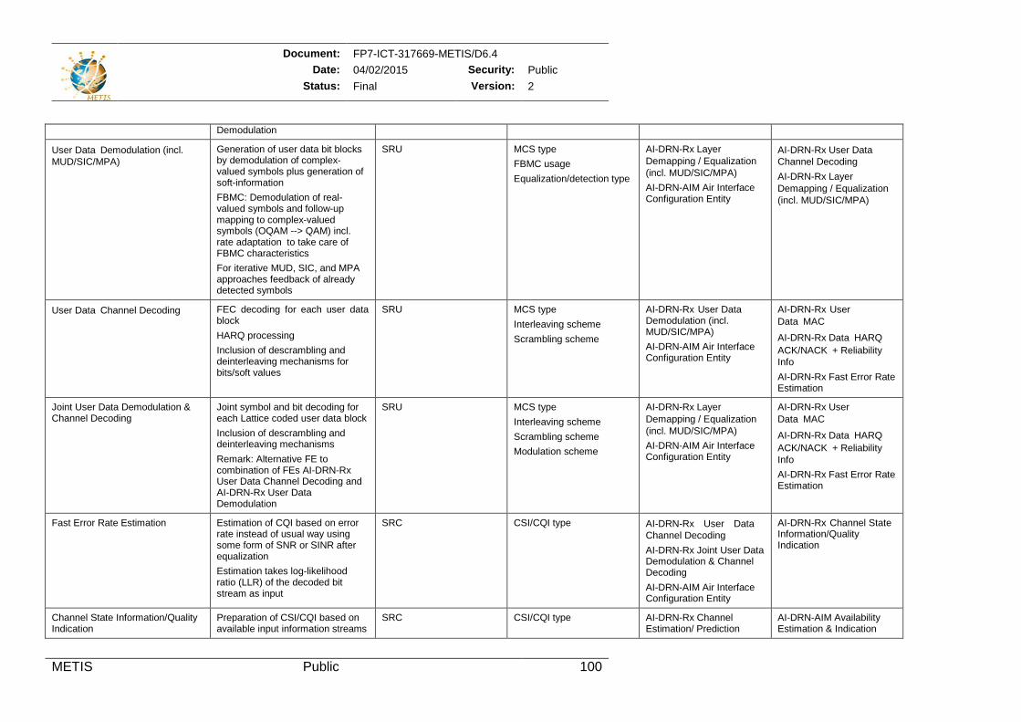
Document: FP7-ICT-317669-METIS/D6.4 Date: 04/02/2015 Security: Public
Status: Final Version: 2
METIS Public 100
Demodulation
User DataDemodulation (incl. MUD/SIC/MPA)
Generation of user data bit blocks by demodulation of complex-valued symbols plus generation of soft-information FBMC: Demodulation of real-valued symbols and follow-up mapping to complex-valued symbols (OQAM --> QAM) incl. rate adaptation to take care of FBMC characteristics For iterative MUD, SIC, and MPA approaches feedback of already detected symbols
SRU MCS type FBMC usage Equalization/detection type
AI-DRN-Rx Layer Demapping / Equalization(incl. MUD/SIC/MPA) AI-DRN-AIM Air Interface Configuration Entity
AI-DRN-Rx User DataChannel Decoding AI-DRN-Rx Layer Demapping / Equalization(incl. MUD/SIC/MPA)
User DataChannel Decoding FEC decoding for each user data block HARQ processing Inclusion of descrambling and deinterleaving mechanisms for bits/soft values
SRU MCS type Interleaving scheme Scrambling scheme
AI-DRN-Rx User Data Demodulation (incl. MUD/SIC/MPA) AI-DRN-AIM Air Interface Configuration Entity
AI-DRN-Rx User DataMAC AI-DRN-Rx DataHARQ ACK/NACK+ Reliability Info AI-DRN-Rx Fast Error Rate Estimation
Joint User Data Demodulation & Channel Decoding
Joint symbol and bit decoding for each Lattice coded user data block Inclusion of descrambling and deinterleaving mechanisms Remark: Alternative FE to combination of FEs AI-DRN-Rx User Data Channel Decoding and AI-DRN-Rx User Data Demodulation
SRU MCS type Interleaving scheme Scrambling scheme Modulation scheme
AI-DRN-Rx Layer Demapping / Equalization(incl. MUD/SIC/MPA) AI-DRN-AIM Air Interface Configuration Entity
AI-DRN-Rx User DataMAC
AI-DRN-Rx DataHARQ ACK/NACK+ Reliability Info AI-DRN-Rx Fast Error Rate Estimation
Fast Error Rate Estimation Estimation of CQI based on error rate instead of usual way using some form of SNR or SINR after equalization Estimation takes log-likelihood ratio (LLR) of the decoded bit stream as input
SRC CSI/CQI type AI-DRN-Rx User Data Channel Decoding AI-DRN-Rx Joint User Data Demodulation & Channel Decoding AI-DRN-AIM Air Interface Configuration Entity
AI-DRN-Rx Channel State Information/Quality Indication
Channel State Information/Quality Indication
Preparation of CSI/CQI based on available input information streams
SRC CSI/CQI type AI-DRN-Rx Channel Estimation/ Prediction
AI-DRN-AIM Availability Estimation & Indication
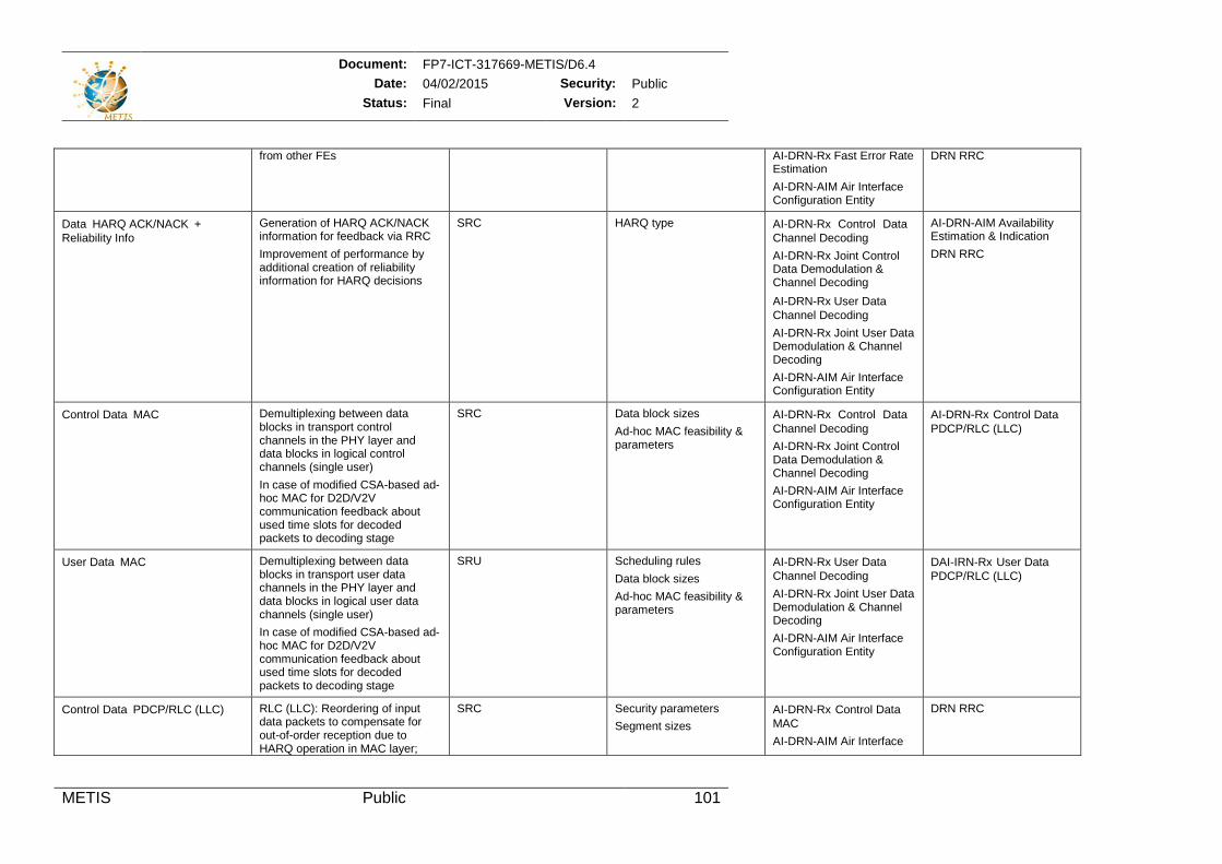
Document: FP7-ICT-317669-METIS/D6.4 Date: 04/02/2015 Security: Public
Status: Final Version: 2
METIS Public 101
from other FEs AI-DRN-Rx Fast Error Rate Estimation AI-DRN-AIM Air Interface Configuration Entity
DRN RRC
DataHARQ ACK/NACK+ Reliability Info
Generation of HARQ ACK/NACK information for feedback via RRC Improvement of performance by additional creation of reliability information for HARQ decisions
SRC HARQ type AI-DRN-Rx Control Data Channel Decoding AI-DRN-Rx Joint Control Data Demodulation & Channel Decoding AI-DRN-Rx User DataChannel Decoding AI-DRN-Rx Joint User Data Demodulation & Channel Decoding AI-DRN-AIM Air Interface Configuration Entity
AI-DRN-AIM Availability Estimation & Indication DRN RRC
Control DataMAC Demultiplexing between data blocks in transport control channels in the PHY layer and data blocks in logical control channels (single user) In case of modified CSA-based ad-hoc MAC for D2D/V2V communication feedback about used time slots for decoded packets to decoding stage
SRC Data block sizes Ad-hoc MAC feasibility & parameters
AI-DRN-Rx Control Data Channel Decoding AI-DRN-Rx Joint Control Data Demodulation & Channel Decoding AI-DRN-AIM Air Interface Configuration Entity
AI-DRN-Rx Control DataPDCP/RLC (LLC)
User DataMAC Demultiplexing between data blocks in transport user data channels in the PHY layer and data blocks in logical user data channels (single user) In case of modified CSA-based ad-hoc MAC for D2D/V2V communication feedback about used time slots for decoded packets to decoding stage
SRU Scheduling rules Data block sizes Ad-hoc MAC feasibility & parameters
AI-DRN-Rx User DataChannel Decoding AI-DRN-Rx Joint User Data Demodulation & Channel Decoding AI-DRN-AIM Air Interface Configuration Entity
DAI-IRN-Rx User DataPDCP/RLC (LLC)
Control DataPDCP/RLC (LLC) RLC (LLC): Reordering of input data packets to compensate for out-of-order reception due to HARQ operation in MAC layer;
SRC Security parameters Segment sizes
AI-DRN-Rx Control DataMAC AI-DRN-AIM Air Interface
DRN RRC
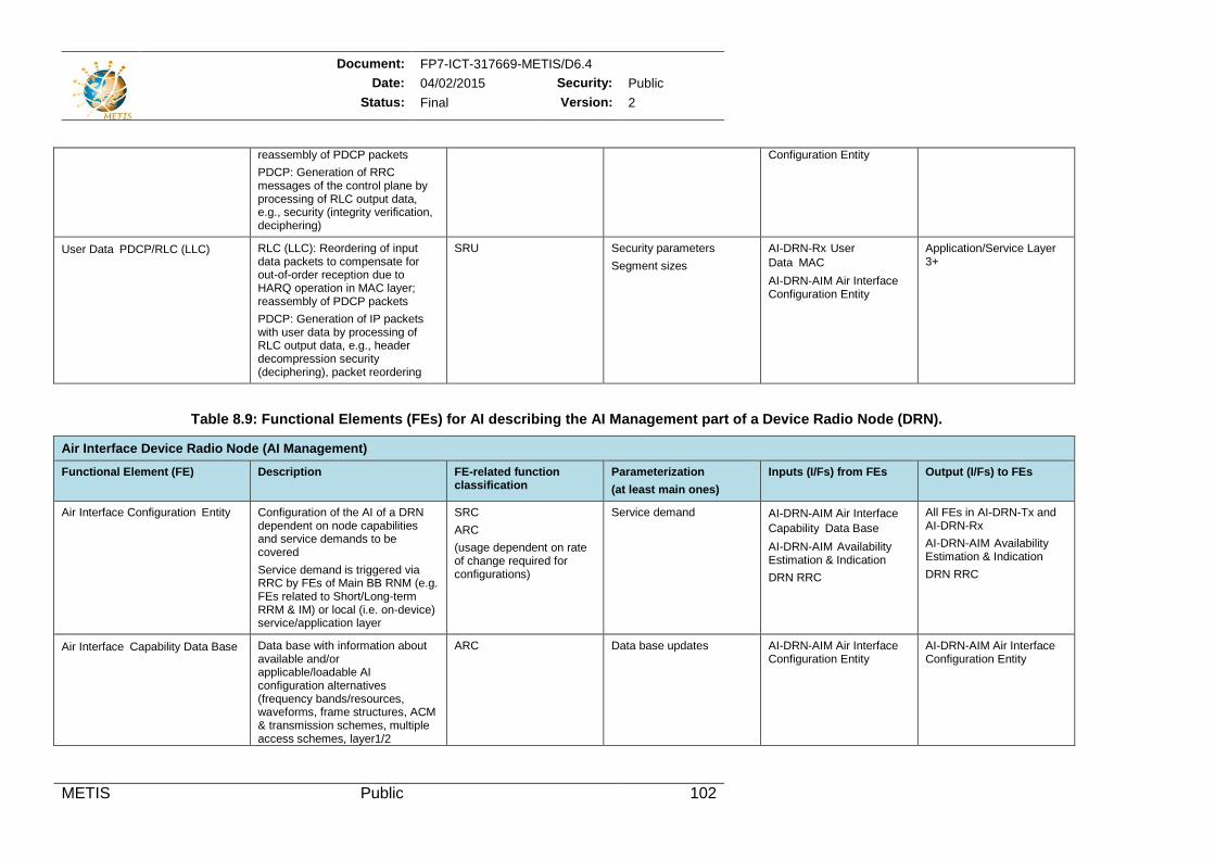
Document: FP7-ICT-317669-METIS/D6.4 Date: 04/02/2015 Security: Public
Status: Final Version: 2
METIS Public 102
reassembly of PDCP packets PDCP: Generation of RRC messages of the control plane by processing of RLC output data, e.g., security (integrity verification, deciphering)
Configuration Entity
User DataPDCP/RLC (LLC) RLC (LLC): Reordering of input data packets to compensate for out-of-order reception due to HARQ operation in MAC layer; reassembly of PDCP packets PDCP: Generation of IP packets with user data by processing of RLC output data, e.g., header decompression security (deciphering), packet reordering
SRU Security parameters Segment sizes
AI-DRN-Rx User DataMAC AI-DRN-AIM Air Interface Configuration Entity
Application/Service Layer 3+
Table 8.9: Functional Elements (FEs) for AI describing the AI Management part of a Device Radio Node (DRN).
Air Interface Device Radio Node (AI Management)
Functional Element (FE) Description FE-related function classification
Parameterization (at least main ones)
Inputs (I/Fs) from FEs Output (I/Fs) to FEs
Air Interface Configuration Entity Configuration of the AI of a DRN dependent on node capabilities and service demands to be covered Service demand is triggered via RRC by FEs of Main BB RNM (e.g. FEs related to Short/Long-term RRM & IM) or local (i.e. on-device) service/application layer
SRC ARC (usage dependent on rate of change required for configurations)
Service demand AI-DRN-AIM Air InterfaceCapabilityData Base AI-DRN-AIM Availability Estimation & Indication DRN RRC
All FEs in AI-DRN-Tx and AI-DRN-Rx AI-DRN-AIM Availability Estimation & Indication DRN RRC
Air InterfaceCapability Data Base Data base with information about available and/or applicable/loadable AI configuration alternatives (frequency bands/resources, waveforms, frame structures, ACM & transmission schemes, multiple access schemes, layer1/2
ARC Data base updates AI-DRN-AIM Air Interface Configuration Entity
AI-DRN-AIM Air Interface Configuration Entity
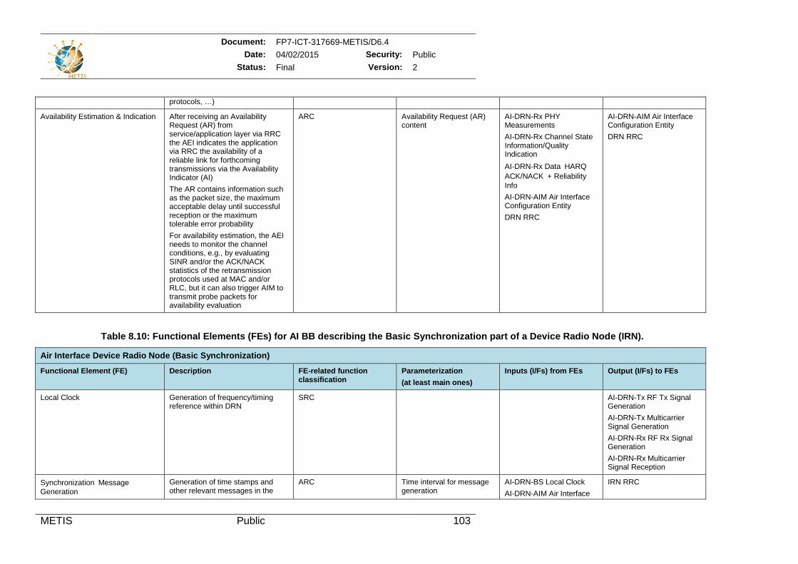
Document: FP7-ICT-317669-METIS/D6.4 Date: 04/02/2015 Security: Public
Status: Final Version: 2
METIS Public 103
protocols, …)
Availability Estimation & Indication After receiving an Availability Request (AR) from service/application layer via RRC the AEI indicates the application via RRC the availability of a reliable link for forthcoming transmissions via the Availability Indicator (AI) The AR contains information such as the packet size, the maximum acceptable delay until successful reception or the maximum tolerable error probability For availability estimation, the AEI needs to monitor the channel conditions, e.g., by evaluating SINR and/or the ACK/NACK statistics of the retransmission protocols used at MAC and/or RLC, but it can also trigger AIM to transmit probe packets for availability evaluation
ARC Availability Request (AR) content
AI-DRN-Rx PHY Measurements AI-DRN-Rx Channel State Information/Quality Indication AI-DRN-Rx DataHARQ ACK/NACK+ Reliability Info AI-DRN-AIM Air Interface Configuration Entity DRN RRC
AI-DRN-AIM Air Interface Configuration Entity DRN RRC
Table 8.10: Functional Elements (FEs) for AI BB describing the Basic Synchronization part of a Device Radio Node (IRN).
Air Interface Device Radio Node (Basic Synchronization)
Functional Element (FE) Description FE-related function classification
Parameterization (at least main ones)
Inputs (I/Fs) from FEs Output (I/Fs) to FEs
Local Clock Generation of frequency/timing reference within DRN
SRC AI-DRN-Tx RF Tx Signal Generation AI-DRN-Tx Multicarrier Signal Generation AI-DRN-Rx RF Rx Signal Generation AI-DRN-Rx Multicarrier Signal Reception
SynchronizationMessage Generation
Generation of time stamps and other relevant messages in the
ARC Time interval for message generation
AI-DRN-BS Local Clock AI-DRN-AIM Air Interface
IRN RRC
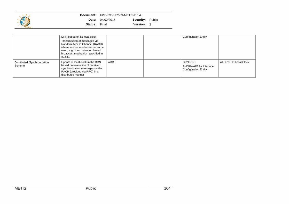
Document: FP7-ICT-317669-METIS/D6.4 Date: 04/02/2015 Security: Public
Status: Final Version: 2
METIS Public 104
DRN based on its local clock Transmission of messages via Random Access Channel (RACH), where various mechanisms can be used, e.g., the contention based broadcast mechanism specified in 802.11
Configuration Entity
DistributedSynchronizationScheme
Update of local clock in the DRN based on evaluation of received synchronization messages on the RACH (provided via RRC) in a distributed manner
ARC DRN RRC AI-DRN-AIM Air Interface Configuration Entity
AI-DRN-BS Local Clock
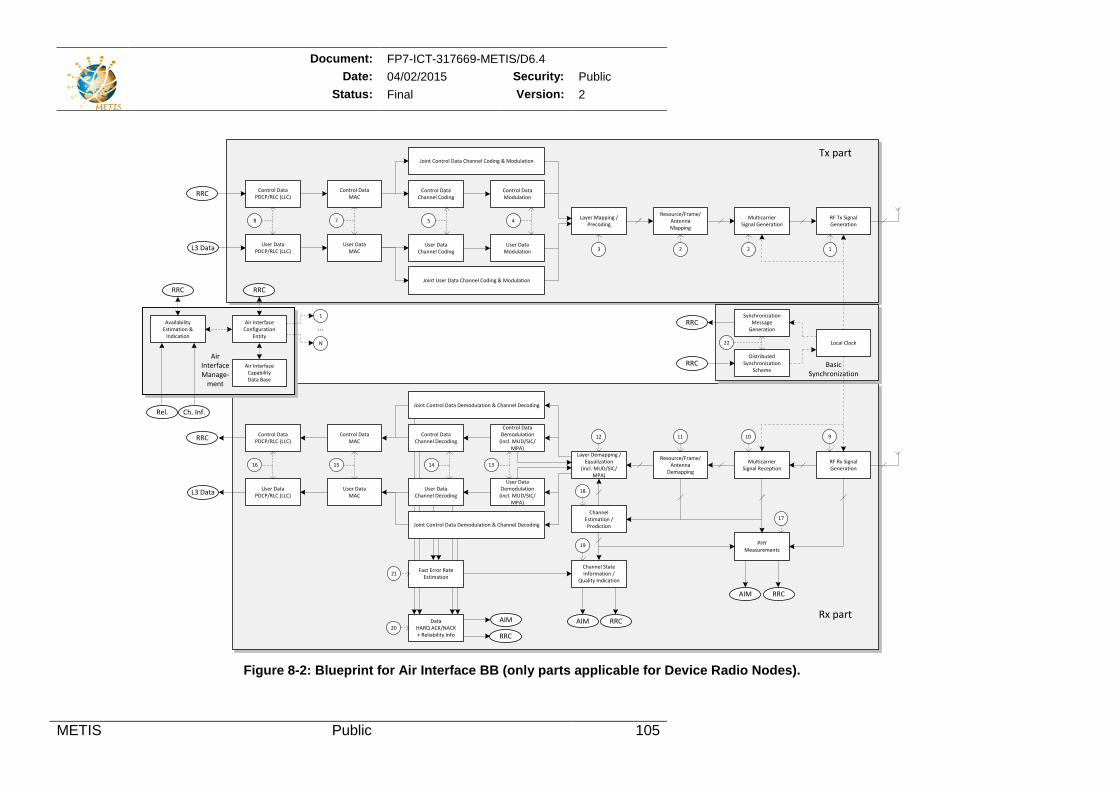
Document: FP7-ICT-317669-METIS/D6.4 Date: 04/02/2015 Security: Public
Status: Final Version: 2
METIS Public 105
Figure 8-2: Blueprint for Air Interface BB (only parts applicable for Device Radio Nodes).
Joint Control Data Channel Coding & Modulation
Joint User Data Channel Coding & Modulation
Control DataChannel Coding
RF Tx Signal Generation
MulticarrierSignal Generation
Resource/Frame/AntennaMapping
Layer Mapping /Precoding
Control DataModulation
User DataChannel Coding
User DataModulation
Control DataChannel Decoding
RF Rx Signal Generation
MulticarrierSignal Reception
Resource/Frame/Antenna
Demapping
Layer Demapping /Equalization
(incl. MUD/SIC/MPA)
Control DataDemodulation
(incl. MUD/SIC/MPA)
User DataChannel Decoding
User DataDemodulation
(incl. MUD/SIC/MPA)
Air Interface of evice Radio Node
Channel Estimation /Prediction
Channel State Information /
Quality Indication
Fast Error Rate Estimation
Joint Control Data Demodulation & Channel Decoding
Joint Control Data Demodulation & Channel Decoding
Local Clock
Data HARQ ACK/NACK+ Reliability Info
PHYMeasurements
User DataMAC
Control DataMAC
User DataPDCP/RLC (LLC)
Control DataPDCP/RLC (LLC)
L3 Data
RRC
User DataMAC
Control DataMAC
User DataPDCP/RLC (LLC)
Control DataPDCP/RLC (LLC)
L3 Data
RRC
5 4
3 2
RRC
AIM AIM RRC
78
1516 14 13
12 11 10 9
18
19
17
20
21
Air InterfaceConfiguration
Entity
Air InterfaceCapabilityData Base
...
Ch. Inf.
Availability Estimation &
Indication
1
N
Rel.
AirInterfaceManage-
ment
RRC
2 1
AIM RRC
RRC
DistributedSynchronization
Scheme
SynchronizationMessage
Generation
RRC
RRC
22
Tx part
Rx part
BasicSynchronization
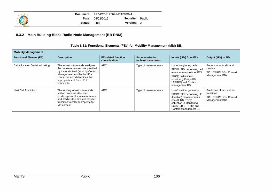
Document: FP7-ICT-317669-METIS/D6.4 Date: 04/02/2015 Security: Public
Status: Final Version: 2
METIS Public 106
8.3.2 Main Building Block Radio Node Management (BB RNM)
Table 8.11: Functional Elements (FEs) for Mobility Management (MM) BB.
Mobility Management
Functional Element (FE) Description FE-related function classification
Parameterization (at least main ones)
Inputs (I/Fs) from FEs Output (I/Fs) to FEs
Cell Allocation Decision Making The infrastructure node analyzes the measurement reports provided by the node itself (input by Context Management) and by the UEs connected and determines the appropriate cell for a UE to connect to.
ARC Type of measurements List of neigboring cells FROM: FEs performing cell measurements (via AI IRN RRC); collection in Monitoring Entity (BB LTRRIM) and Context Management BB
Reports about cells and carriers TO: LTRRIM BBs, Context Management BBs
Next Cell Prediction The serving infrastructure node station processes the user position/geometry measurements and predicts the next cell for user transition; mostly appropriate for MN context
ARC Type of measurements User/position geometry FROM: FEs performing UE (location) measurements (via AI IRN RRC); collection in Monitoring Entity (BB LTRRIM) and Context Management BB
Prediction of next cell for transition TO: LTRRIM BBs, Context Management BBs
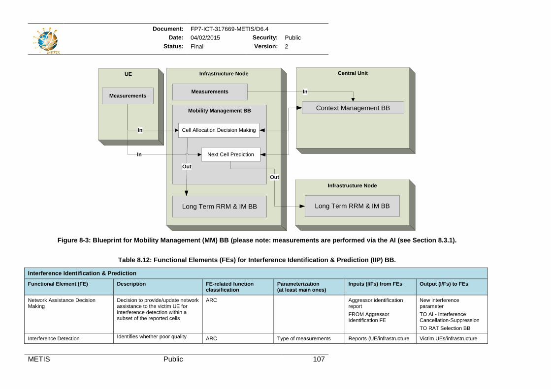
Document: FP7-ICT-317669-METIS/D6.4 Date: 04/02/2015 Security: Public
Status: Final Version: 2
METIS Public 107
Figure 8-3: Blueprint for Mobility Management (MM) BB (please note: measurements are performed via the AI (see Section 8.3.1).
Table 8.12: Functional Elements (FEs) for Interference Identification & Prediction (IIP) BB.
Interference Identification & Prediction
Functional Element (FE) Description FE-related function classification
Parameterization (at least main ones)
Inputs (I/Fs) from FEs Output (I/Fs) to FEs
Network Assistance Decision Making
Decision to provide/update network assistance to the victim UE for interference detection within a subset of the reported cells
ARC Aggressor identification report FROM Aggressor Identification FE
New interference parameter TO AI - Interference Cancellation-Suppression TO RAT Selection BB
Interference Detection Identifies whether poor quality ARC Type of measurements Reports (UE/infrastructure Victim UEs/infrastructure
Infrastructure NodeUE
Measurements
Central Unit
Mobility Management BB
Cell Allocation Decision Making
Out
Next Cell Prediction
MeasurementsIn
In
Context Management BB
In
Long Term RRM & IM BB
Infrastructure Node
Long Term RRM & IM BB
Out
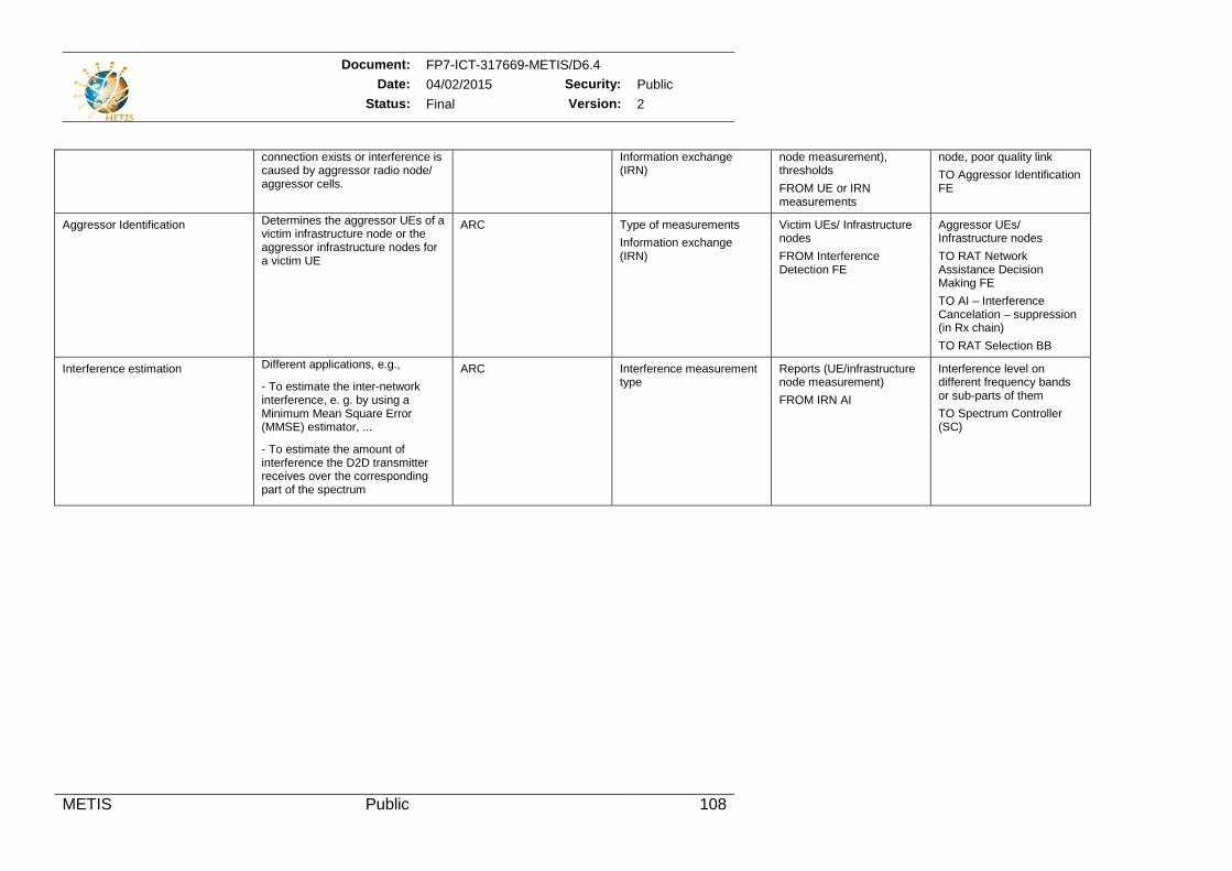
Document: FP7-ICT-317669-METIS/D6.4 Date: 04/02/2015 Security: Public
Status: Final Version: 2
METIS Public 108
connection exists or interference is caused by aggressor radio node/ aggressor cells.
Information exchange (IRN)
node measurement), thresholds FROM UE or IRN measurements
node, poor quality link TO Aggressor Identification FE
Aggressor Identification Determines the aggressor UEs of a victim infrastructure node or the aggressor infrastructure nodes for a victim UE
ARC Type of measurements Information exchange (IRN)
Victim UEs/ Infrastructure nodes FROM Interference Detection FE
Aggressor UEs/ Infrastructure nodes TO RAT Network Assistance Decision Making FE TO AI – Interference Cancelation – suppression (in Rx chain) TO RAT Selection BB
Interference estimation Different applications, e.g.,
- To estimate the inter-network interference, e. g. by using a Minimum Mean Square Error (MMSE) estimator, ...
- To estimate the amount of interference the D2D transmitter receives over the corresponding part of the spectrum
ARC Interference measurement type
Reports (UE/infrastructure node measurement) FROM IRN AI
Interference level on different frequency bands or sub-parts of them TO Spectrum Controller (SC)
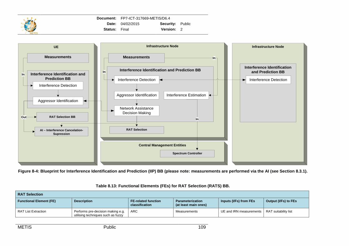
Document: FP7-ICT-317669-METIS/D6.4 Date: 04/02/2015 Security: Public
Status: Final Version: 2
METIS Public 109
Figure 8-4: Blueprint for Interference Identification and Prediction (IIP) BB (please note: measurements are performed via the AI (see Section 8.3.1).
Table 8.13: Functional Elements (FEs) for RAT Selection (RATS) BB.
RAT Selection
Functional Element (FE) Description FE-related function classification
Parameterization (at least main ones)
Inputs (I/Fs) from FEs Output (I/Fs) to FEs
RAT List Extraction Performs pre-decision making e.g. utilising techniques such as fuzzy
ARC Measurements UE and IRN measurements RAT suitability list
Infrastructure NodeUE
Interference Identification and Prediction BB
Interference Detection
Aggressor Identification
In
MeasurementsMeasurements
Interference Identification and Prediction BB
Network AssistanceDecision Making
Interference Detection
Aggressor Identification
RAT Selection BBOutOut
In
RAT SelectionAI – Interference Cancelation-Supression
Infrastructure Node
Interference Identification and Prediction BB
Interference Detection
Interference Estimation
In
Central Management Entities
Spectrum Controller
In
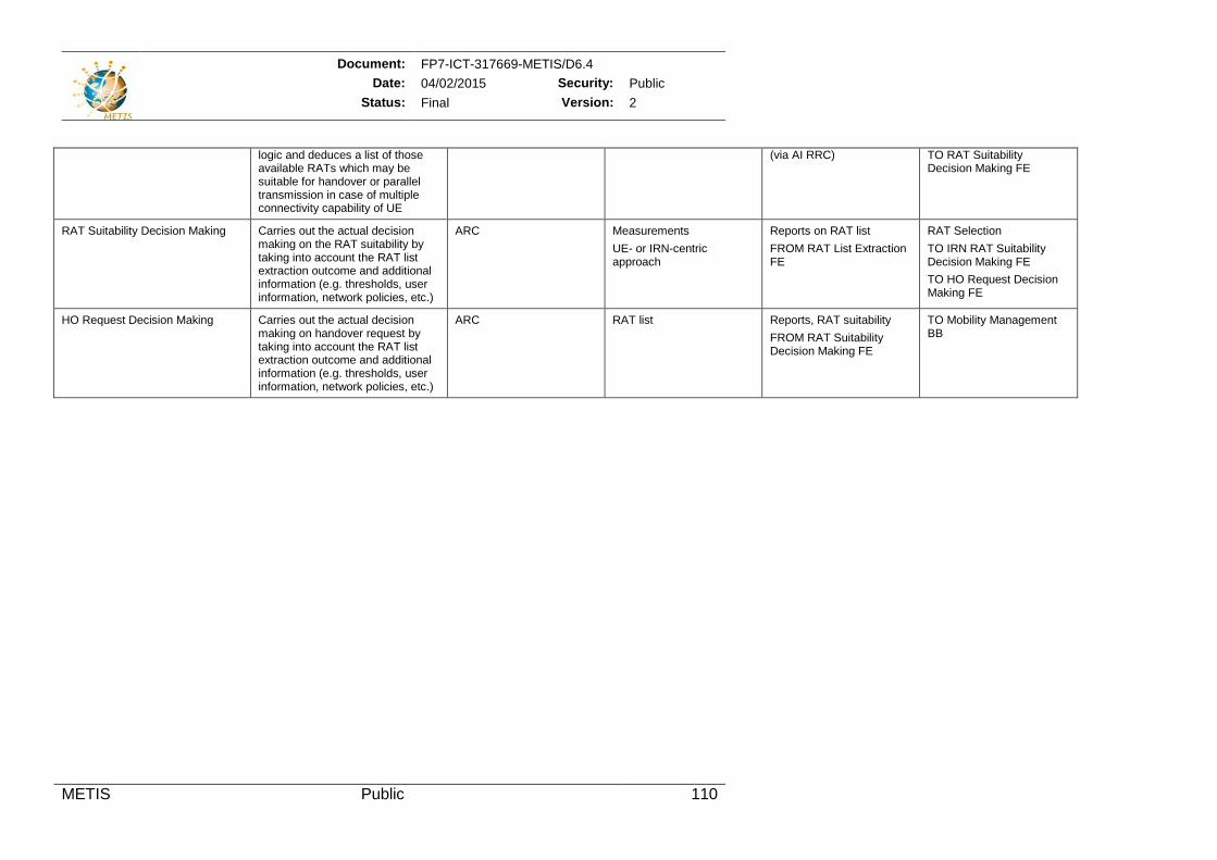
Document: FP7-ICT-317669-METIS/D6.4 Date: 04/02/2015 Security: Public
Status: Final Version: 2
METIS Public 110
logic and deduces a list of those available RATs which may be suitable for handover or parallel transmission in case of multiple connectivity capability of UE
(via AI RRC) TO RAT Suitability Decision Making FE
RAT Suitability Decision Making Carries out the actual decision making on the RAT suitability by taking into account the RAT list extraction outcome and additional information (e.g. thresholds, user information, network policies, etc.)
ARC Measurements UE- or IRN-centric approach
Reports on RAT list FROM RAT List Extraction FE
RAT Selection TO IRN RAT Suitability Decision Making FE TO HO Request Decision Making FE
HO Request Decision Making Carries out the actual decision making on handover request by taking into account the RAT list extraction outcome and additional information (e.g. thresholds, user information, network policies, etc.)
ARC RAT list Reports, RAT suitability FROM RAT Suitability Decision Making FE
TO Mobility Management BB
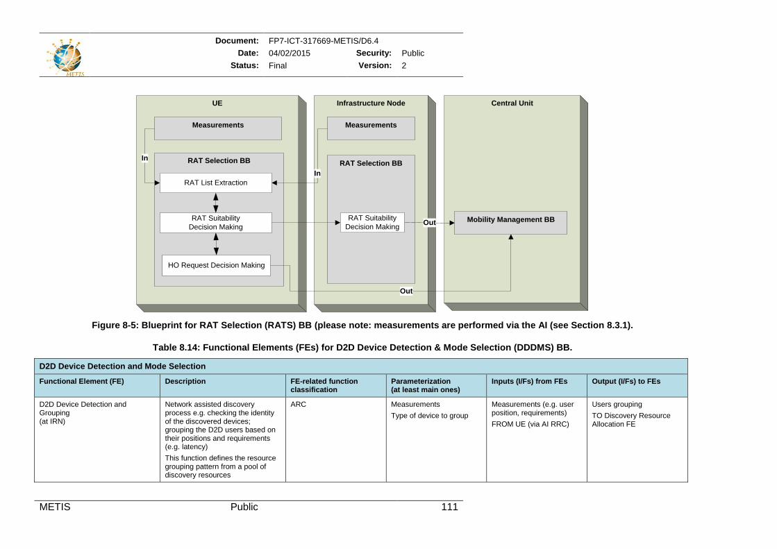
Document: FP7-ICT-317669-METIS/D6.4 Date: 04/02/2015 Security: Public
Status: Final Version: 2
METIS Public 111
Figure 8-5: Blueprint for RAT Selection (RATS) BB (please note: measurements are performed via the AI (see Section 8.3.1).
Table 8.14: Functional Elements (FEs) for D2D Device Detection & Mode Selection (DDDMS) BB.
D2D Device Detection and Mode Selection
Functional Element (FE) Description FE-related function classification
Parameterization (at least main ones)
Inputs (I/Fs) from FEs Output (I/Fs) to FEs
D2D Device Detection and Grouping (at IRN)
Network assisted discovery process e.g. checking the identity of the discovered devices; grouping the D2D users based on their positions and requirements (e.g. latency) This function defines the resource grouping pattern from a pool of discovery resources
ARC Measurements Type of device to group
Measurements (e.g. user position, requirements) FROM UE (via AI RRC)
Users grouping TO Discovery Resource Allocation FE
Infrastructure Node
RAT Selection BB
UE
RAT Selection BB
RAT List Extraction
RAT Suitability Decision Making
HO Request Decision Making
In
Measurements
In
Measurements
Central Unit
Mobility Management BBOut
Out
RAT Suitability Decision Making
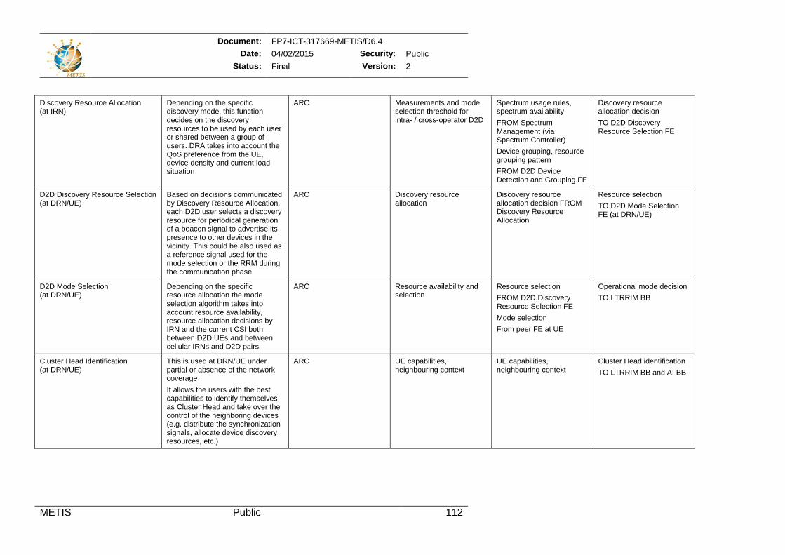
Document: FP7-ICT-317669-METIS/D6.4 Date: 04/02/2015 Security: Public
Status: Final Version: 2
METIS Public 112
Discovery Resource Allocation (at IRN)
Depending on the specific discovery mode, this function decides on the discovery resources to be used by each user or shared between a group of users. DRA takes into account the QoS preference from the UE, device density and current load situation
ARC Measurements and mode selection threshold for intra- / cross-operator D2D
Spectrum usage rules, spectrum availability FROM Spectrum Management (via Spectrum Controller) Device grouping, resource grouping pattern FROM D2D Device Detection and Grouping FE
Discovery resource allocation decision TO D2D Discovery Resource Selection FE
D2D Discovery Resource Selection (at DRN/UE)
Based on decisions communicated by Discovery Resource Allocation, each D2D user selects a discovery resource for periodical generation of a beacon signal to advertise its presence to other devices in the vicinity. This could be also used as a reference signal used for the mode selection or the RRM during the communication phase
ARC Discovery resource allocation
Discovery resource allocation decision FROM Discovery Resource Allocation
Resource selection TO D2D Mode Selection FE (at DRN/UE)
D2D Mode Selection (at DRN/UE)
Depending on the specific resource allocation the mode selection algorithm takes into account resource availability, resource allocation decisions by IRN and the current CSI both between D2D UEs and between cellular IRNs and D2D pairs
ARC Resource availability and selection
Resource selection FROM D2D Discovery Resource Selection FE Mode selection From peer FE at UE
Operational mode decision TO LTRRIM BB
Cluster Head Identification (at DRN/UE)
This is used at DRN/UE under partial or absence of the network coverage It allows the users with the best capabilities to identify themselves as Cluster Head and take over the control of the neighboring devices (e.g. distribute the synchronization signals, allocate device discovery resources, etc.)
ARC UE capabilities, neighbouring context
UE capabilities, neighbouring context
Cluster Head identification TO LTRRIM BB and AI BB
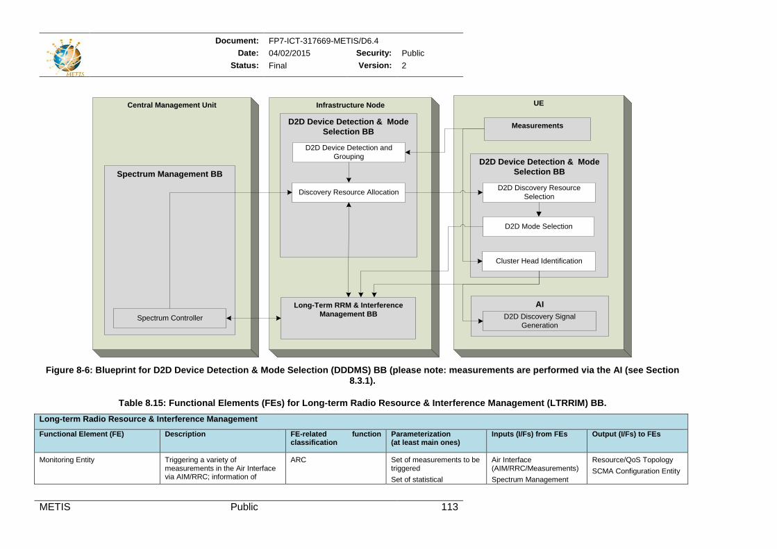
Document: FP7-ICT-317669-METIS/D6.4 Date: 04/02/2015 Security: Public
Status: Final Version: 2
METIS Public 113
Figure 8-6: Blueprint for D2D Device Detection & Mode Selection (DDDMS) BB (please note: measurements are performed via the AI (see Section
8.3.1).
Table 8.15: Functional Elements (FEs) for Long-term Radio Resource & Interference Management (LTRRIM) BB. Long-term Radio Resource & Interference Management
Functional Element (FE) Description FE-related function classification
Parameterization (at least main ones)
Inputs (I/Fs) from FEs Output (I/Fs) to FEs
Monitoring Entity Triggering a variety of measurements in the Air Interface via AIM/RRC; information of
ARC Set of measurements to be triggered Set of statistical
Air Interface (AIM/RRC/Measurements) Spectrum Management
Resource/QoS Topology SCMA Configuration Entity
Infrastructure Node
D2D Device Detection & Mode Selection BB
D2D Device Detection and Grouping
Discovery Resource Allocation
UE
Measurements
D2D Device Detection & Mode Selection BB
D2D Discovery Resource Selection
AI D2D Discovery Signal
Generation
D2D Mode Selection
Central Management Unit
Spectrum Management BB
Spectrum Controller
Cluster Head Identification
Long-Term RRM & Interference Management BB
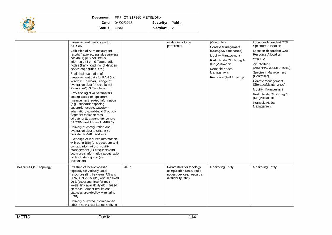
Document: FP7-ICT-317669-METIS/D6.4 Date: 04/02/2015 Security: Public
Status: Final Version: 2
METIS Public 114
measurement periods sent to STRRIM Collection of AI measurement results (radio access plus wireless backhaul) plus cell status information from different radio nodes (traffic load, no. of devices, device capabilities, etc.) Statistical evaluation of measurement data for RAN (incl. Wireless Backhaul); usage of evaluation data for creation of Resource/QoS Topology Provisioning of AI parameters setting based on spectrum management related information (e.g.; subcarrier spacing, subcarrier usage, waveform adaptation, guard-band & out-of-fragment radiation mask adjustment); parameters sent to STRRIM and AI (via AIM/RRC) Delivery of configuration and evaluation data to other BBs outside LRRRIM and FEs Exchange of required information with other BBs (e.g. spectrum and context information, mobility management (HO requests and decisions), information about radio node clustering and (de-)activation)
evaluations to be performed
(Controller) Context Management (Storage/Maintenance) Mobility Management Radio Node Clustering & (De-)Activation Nomadic Nodes Management Resource/QoS Topology
Location-dependent D2D Spectrum Allocation Location-dependent D2D Resource Allocation STRRIM Air Interface (AIM/RRC/Measurements) Spectrum Management (Controller) Context Management (Storage/Maintenance) Mobility Management Radio Node Clustering & (De-)Activation Nomadic Nodes Management
Resource/QoS Topology Creation of location-based topology for variably used resources (link between IRN and DRN, D2D/V2V,etc.) and achieved QoS (coverage, interference levels, link availability etc.) based on measurement results and statistics provided by Monitoring Entity Delivery of stored information to other FEs via Monitoring Entity in
ARC Parameters for topology computation (area, radio nodes, devices, resource availability, etc.)
Monitoring Entity Monitoring Entity
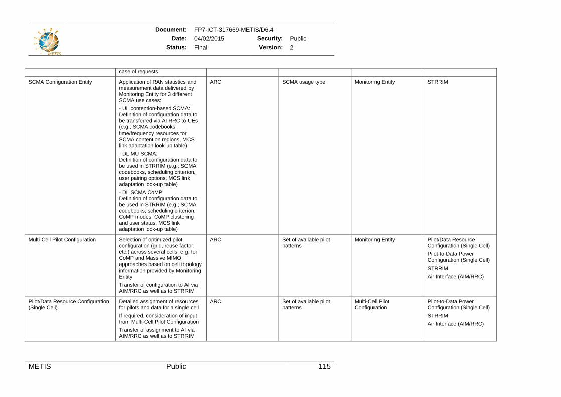
Document: FP7-ICT-317669-METIS/D6.4 Date: 04/02/2015 Security: Public
Status: Final Version: 2
METIS Public 115
case of requests
SCMA Configuration Entity Application of RAN statistics and measurement data delivered by Monitoring Entity for 3 different SCMA use cases: - UL contention-based SCMA: Definition of configuration data to be transferred via AI RRC to UEs (e.g.; SCMA codebooks, time/frequency resources for SCMA contention regions, MCS link adaptation look-up table) - DL MU-SCMA: Definition of configuration data to be used in STRRIM (e.g.; SCMA codebooks, scheduling criterion, user pairing options, MCS link adaptation look-up table) - DL SCMA CoMP: Definition of configuration data to be used in STRRIM (e.g.; SCMA codebooks, scheduling criterion, CoMP modes, CoMP clustering and user status, MCS link adaptation look-up table)
ARC SCMA usage type Monitoring Entity STRRIM
Multi-Cell Pilot Configuration Selection of optimized pilot configuration (grid, reuse factor, etc.) across several cells, e.g. for CoMP and Massive MIMO approaches based on cell topology information provided by Monitoring Entity Transfer of configuration to AI via AIM/RRC as well as to STRRIM
ARC Set of available pilot patterns
Monitoring Entity Pilot/Data Resource Configuration (Single Cell) Pilot-to-Data Power Configuration (Single Cell) STRRIM Air Interface (AIM/RRC)
Pilot/Data Resource Configuration (Single Cell)
Detailed assignment of resources for pilots and data for a single cell If required, consideration of input from Multi-Cell Pilot Configuration Transfer of assignment to AI via AIM/RRC as well as to STRRIM
ARC Set of available pilot patterns
Multi-Cell Pilot Configuration
Pilot-to-Data Power Configuration (Single Cell) STRRIM Air Interface (AIM/RRC)
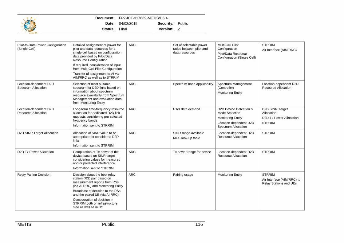
Document: FP7-ICT-317669-METIS/D6.4 Date: 04/02/2015 Security: Public
Status: Final Version: 2
METIS Public 116
Pilot-to-Data Power Configuration (Single Cell)
Detailed assignment of power for pilot and data resources for a single cell based on configuration data provided by Pilot/Data Resource Configuration If required, consideration of input from Multi-Cell Pilot Configuration Transfer of assignment to AI via AIM/RRC as well as to STRRIM
ARC Set of selectable power ratios between pilot and data resources
Multi-Cell Pilot Configuration Pilot/Data Resource Configuration (Single Cell)
STRRIM Air Interface (AIM/RRC)
Location-dependent D2D Spectrum Allocation
Selection of most suitable spectrum for D2D links based on information about spectrum resource availability from Spectrum Management and evaluation data from Monitoring Entity
ARC Spectrum band applicability
Spectrum Management (Controller) Monitoring Entity
Location-dependent D2D Resource Allocation
Location-dependent D2D Resource Allocation
Long-term time-frequency resource allocation for dedicated D2D link requests considering pre-selected frequency bands Information sent to STRRIM
ARC User data demand D2D Device Detection & Mode Selection Monitoring Entity Location-dependent D2D Spectrum Allocation
D2D SINR Target Allocation D2D Tx Power Allocation STRRIM
D2D SINR Target Allocation Allocation of SINR value to be appropriate for considered D2D links Information sent to STRRIM
ARC SINR range available MCS look-up table
Location-dependent D2D Resource Allocation
STRRIM
D2D Tx Power Allocation Computation of Tx power of the device based on SINR target considering values for measured and/or predicted interference Information sent to STRRIM
ARC Tx power range for device Location-dependent D2D Resource Allocation
STRRIM
Relay Pairing Decision Decision about the best relay station (RS) pair based on measurement reports from RSs (via AI RRC) and Monitoring Entity Broadcast of decision to the RSs and the paired UE (via AI RRC) Consideration of decision in STRRIM both on infrastructure side as well as in RS
ARC Pairing usage Monitoring Entity STRRIM Air Interface (AIM/RRC) to Relay Stations and UEs
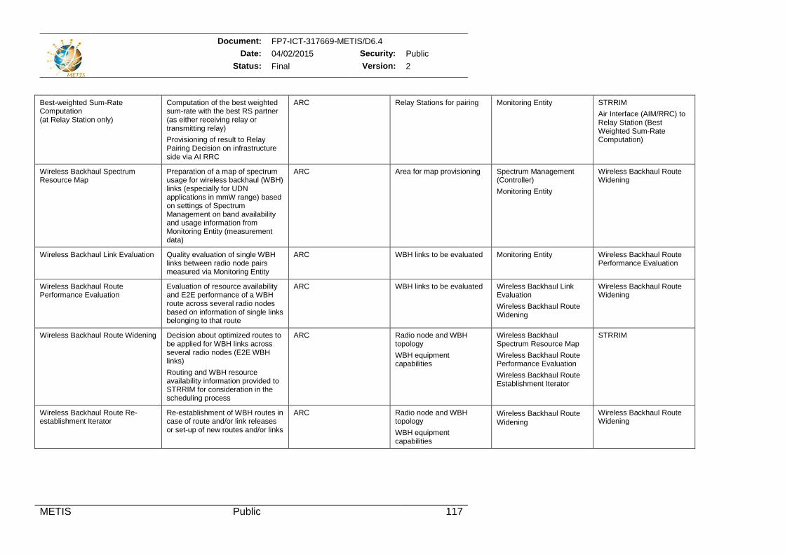
Document: FP7-ICT-317669-METIS/D6.4 Date: 04/02/2015 Security: Public
Status: Final Version: 2
METIS Public 117
Best-weighted Sum-Rate Computation (at Relay Station only)
Computation of the best weighted sum-rate with the best RS partner (as either receiving relay or transmitting relay) Provisioning of result to Relay Pairing Decision on infrastructure side via AI RRC
ARC Relay Stations for pairing Monitoring Entity STRRIM Air Interface (AIM/RRC) to Relay Station (Best Weighted Sum-Rate Computation)
Wireless Backhaul Spectrum Resource Map
Preparation of a map of spectrum usage for wireless backhaul (WBH) links (especially for UDN applications in mmW range) based on settings of Spectrum Management on band availability and usage information from Monitoring Entity (measurement data)
ARC Area for map provisioning Spectrum Management (Controller) Monitoring Entity
Wireless Backhaul Route Widening
Wireless Backhaul Link Evaluation Quality evaluation of single WBH links between radio node pairs measured via Monitoring Entity
ARC WBH links to be evaluated Monitoring Entity Wireless Backhaul Route Performance Evaluation
Wireless Backhaul Route Performance Evaluation
Evaluation of resource availability and E2E performance of a WBH route across several radio nodes based on information of single links belonging to that route
ARC WBH links to be evaluated Wireless Backhaul Link Evaluation Wireless Backhaul Route Widening
Wireless Backhaul Route Widening
Wireless Backhaul Route Widening Decision about optimized routes to be applied for WBH links across several radio nodes (E2E WBH links) Routing and WBH resource availability information provided to STRRIM for consideration in the scheduling process
ARC Radio node and WBH topology WBH equipment capabilities
Wireless Backhaul Spectrum Resource Map Wireless Backhaul Route Performance Evaluation Wireless Backhaul Route Establishment Iterator
STRRIM
Wireless Backhaul Route Re-establishment Iterator
Re-establishment of WBH routes in case of route and/or link releases or set-up of new routes and/or links
ARC Radio node and WBH topology WBH equipment capabilities
Wireless Backhaul RouteWidening
Wireless Backhaul Route Widening
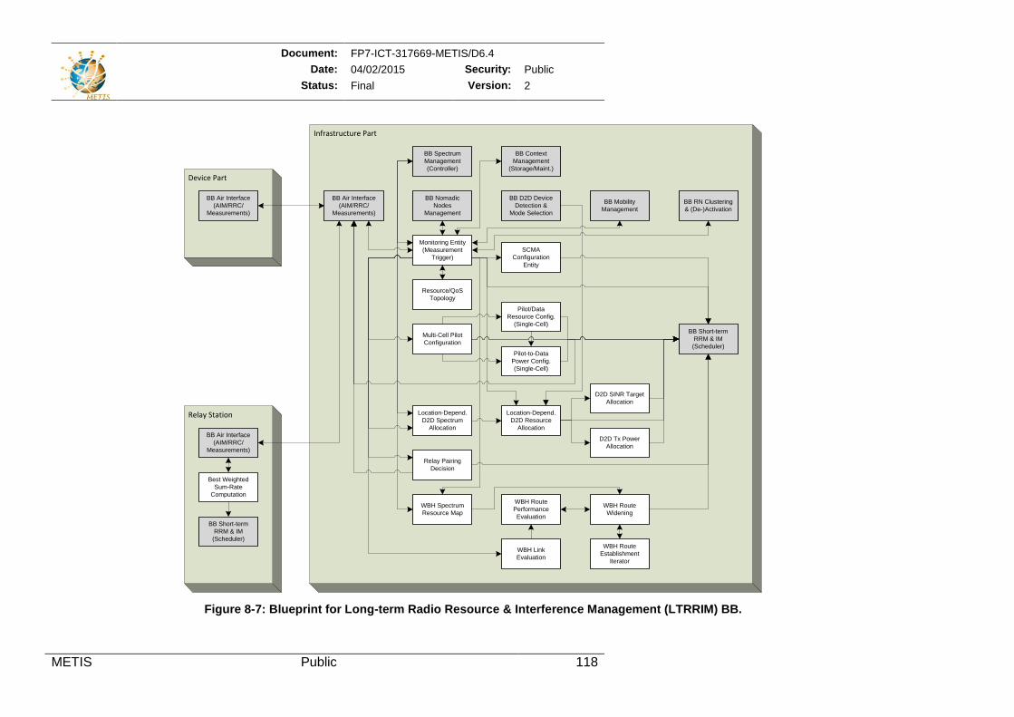
Document: FP7-ICT-317669-METIS/D6.4 Date: 04/02/2015 Security: Public
Status: Final Version: 2
METIS Public 118
Figure 8-7: Blueprint for Long-term Radio Resource & Interference Management (LTRRIM) BB.
Relay Station
Infrastructure Part
Device Part
WBH SpectrumResource Map
WBH Route Performance Evaluation
WBH RouteEstablishment
Iterator
WBH RouteWidening
WBH Link Evaluation
Pilot/Data Resource Config.
(Single-Cell)
Pilot-to-Data Power Config. (Single-Cell)
Multi-Cell Pilot Configuration
Monitoring Entity(Measurement
Trigger)SCMA
Configuration Entity
BB Air Interface(AIM/RRC/
Measurements)
BB Air Interface (AIM/RRC/
Measurements)
D2D Tx PowerAllocation
Location-Depend. D2D Resource
Allocation
D2D SINR TargetAllocation
Location-Depend. D2D Spectrum
Allocation
BB SpectrumManagement(Controller)
Relay PairingDecision
Best Weighted Sum-Rate
Computation
BB Short-termRRM & IM
(Scheduler)
BB Short-termRRM & IM
(Scheduler)
BB Air Interface(AIM/RRC/
Measurements)
Resource/QoS Topology
BB ContextManagement
(Storage/Maint.)
BB Mobility Management
BB RN Clustering & (De-)Activation
BB NomadicNodes
Management
BB D2D Device Detection &
Mode Selection
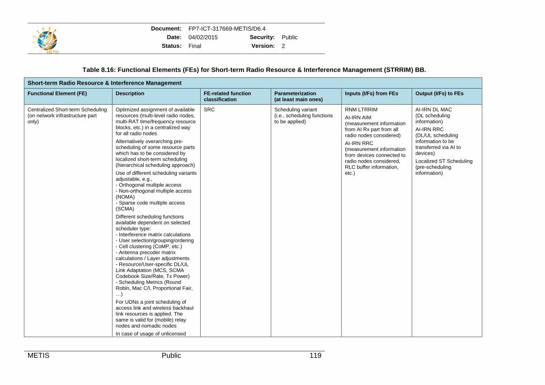
Document: FP7-ICT-317669-METIS/D6.4 Date: 04/02/2015 Security: Public
Status: Final Version: 2
METIS Public 119
Table 8.16: Functional Elements (FEs) for Short-term Radio Resource & Interference Management (STRRIM) BB.
Short-term Radio Resource & Interference Management
Functional Element (FE) Description FE-related function classification
Parameterization (at least main ones)
Inputs (I/Fs) from FEs Output (I/Fs) to FEs
Centralized Short-term Scheduling (on network infrastructure part only)
Optimized assignment of available resources (multi-level radio nodes, multi-RAT time/frequency resource blocks, etc.) in a centralized way for all radio nodes Alternatively overarching pre-scheduling of some resource parts which has to be considered by localized short-term scheduling (hierarchical scheduling approach) Use of different scheduling variants adjustable, e.g., - Orthogonal multiple access - Non-orthogonal multiple access (NOMA) - Sparse code multiple access (SCMA) Different scheduling functions available dependent on selected scheduler type: - Interference matrix calculations - User selection/grouping/ordering - Cell clustering (CoMP, etc.) - Antenna precoder matrix calculations / Layer adjustments - Resource/User-specific DL/UL Link Adaptation (MCS, SCMA Codebook Size/Rate, Tx Power) - Scheduling Metrics (Round Robin, Mac C/I, Proportional Fair, …) For UDNs a joint scheduling of access link and wireless backhaul link resources is applied. The same is valid for (mobile) relay nodes and nomadic nodes In case of usage of unlicensed
SRC Scheduling variant (i.e., scheduling functions to be applied)
RNM LTRRIM AI-IRN AIM (measurement information from AI Rx part from all radio nodes considered) AI-IRN RRC (measurement information from devices connected to radio nodes considered, RLC buffer information, etc.)
AI-IRN DL MAC (DL scheduling information) AI-IRN RRC (DL/UL scheduling information to be transferred via AI to devices) Localized ST Scheduling (pre-scheduling information)
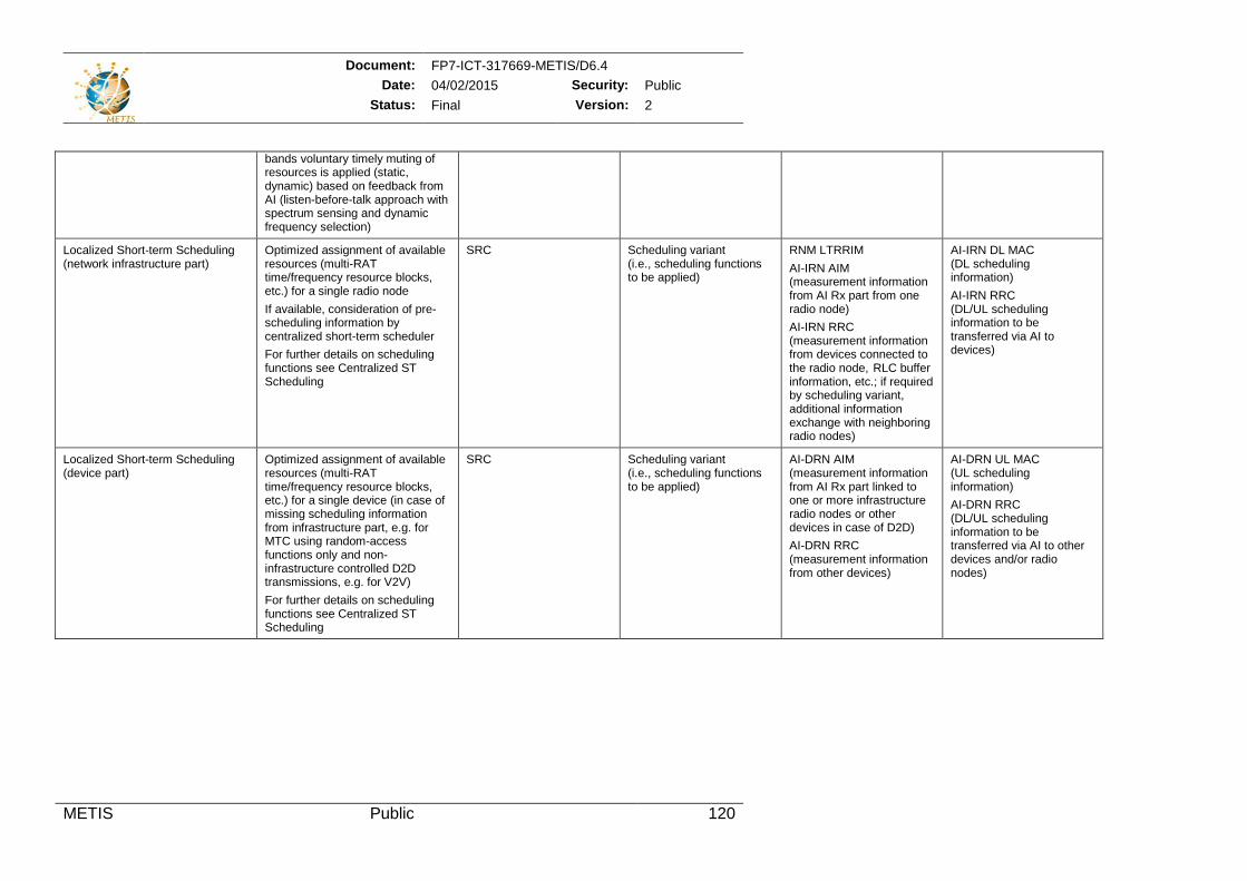
Document: FP7-ICT-317669-METIS/D6.4 Date: 04/02/2015 Security: Public
Status: Final Version: 2
METIS Public 120
bands voluntary timely muting of resources is applied (static, dynamic) based on feedback from AI (listen-before-talk approach with spectrum sensing and dynamic frequency selection)
Localized Short-term Scheduling (network infrastructure part)
Optimized assignment of available resources (multi-RAT time/frequency resource blocks, etc.) for a single radio node If available, consideration of pre-scheduling information by centralized short-term scheduler For further details on scheduling functions see Centralized ST Scheduling
SRC Scheduling variant (i.e., scheduling functions to be applied)
RNM LTRRIM AI-IRN AIM (measurement information from AI Rx part from one radio node) AI-IRN RRC (measurement information from devices connected to the radio node, RLC buffer information, etc.; if required by scheduling variant, additional information exchange with neighboring radio nodes)
AI-IRN DL MAC (DL scheduling information) AI-IRN RRC (DL/UL scheduling information to be transferred via AI to devices)
Localized Short-term Scheduling (device part)
Optimized assignment of available resources (multi-RAT time/frequency resource blocks, etc.) for a single device (in case of missing scheduling information from infrastructure part, e.g. for MTC using random-access functions only and non-infrastructure controlled D2D transmissions, e.g. for V2V) For further details on scheduling functions see Centralized ST Scheduling
SRC Scheduling variant (i.e., scheduling functions to be applied)
AI-DRN AIM (measurement information from AI Rx part linked to one or more infrastructure radio nodes or other devices in case of D2D) AI-DRN RRC (measurement information from other devices)
AI-DRN UL MAC (UL scheduling information) AI-DRN RRC (DL/UL scheduling information to be transferred via AI to other devices and/or radio nodes)
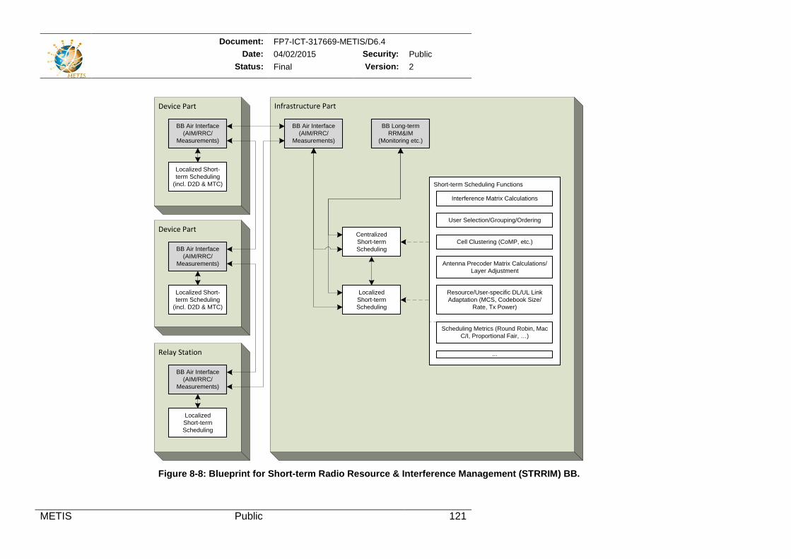
Document: FP7-ICT-317669-METIS/D6.4 Date: 04/02/2015 Security: Public
Status: Final Version: 2
METIS Public 121
Figure 8-8: Blueprint for Short-term Radio Resource & Interference Management (STRRIM) BB.
Infrastructure Part
Short-term Scheduling Functions
Relay Station
Device Part
Antenna Precoder Matrix Calculations/Layer Adjustment
BB Air Interface(AIM/RRC/
Measurements)
BB Air Interface (AIM/RRC/
Measurements)
BB Long-term RRM&IM
(Monitoring etc.)
LocalizedShort-term Scheduling
BB Air Interface(AIM/RRC/
Measurements)
User Selection/Grouping/Ordering
Interference Matrix Calculations
LocalizedShort-term Scheduling
Cell Clustering (CoMP, etc.)
Resource/User-specific DL/UL Link Adaptation (MCS, Codebook Size/
Rate, Tx Power)
...
CentralizedShort-termScheduling
Scheduling Metrics (Round Robin, Mac C/I, Proportional Fair, …)
Device Part
BB Air Interface(AIM/RRC/
Measurements)
Localized Short-term Scheduling
(incl. D2D & MTC)
Localized Short-term Scheduling
(incl. D2D & MTC)
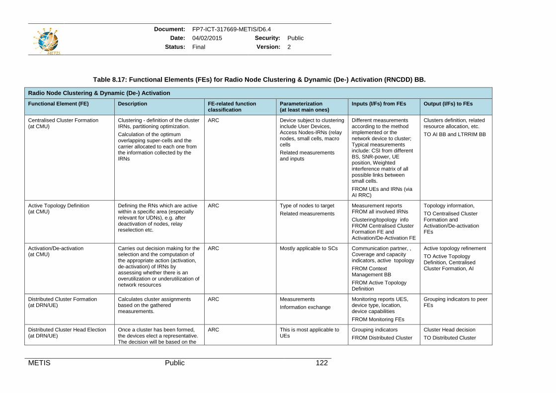
Document: FP7-ICT-317669-METIS/D6.4 Date: 04/02/2015 Security: Public
Status: Final Version: 2
METIS Public 122
Table 8.17: Functional Elements (FEs) for Radio Node Clustering & Dynamic (De-) Activation (RNCDD) BB.
Radio Node Clustering & Dynamic (De-) Activation
Functional Element (FE) Description FE-related function classification
Parameterization (at least main ones)
Inputs (I/Fs) from FEs Output (I/Fs) to FEs
Centralised Cluster Formation (at CMU)
Clustering - definition of the cluster IRNs, partitioning optimization. Calculation of the optimum overlapping super-cells and the carrier allocated to each one from the information collected by the IRNs
ARC Device subject to clustering include User Devices, Access Nodes-IRNs (relay nodes, small cells, macro cells Related measurements and inputs
Different measurements according to the method implemented or the network device to cluster; Typical measurements include: CSI from different BS, SNR-power, UE position, Weighted interference matrix of all possible links between small cells. FROM UEs and IRNs (via AI RRC)
Clusters definition, related resource allocation, etc. TO AI BB and LTRRIM BB
Active Topology Definition (at CMU)
Defining the RNs which are active within a specific area (especially relevant for UDNs), e.g. after deactivation of nodes, relay reselection etc.
ARC Type of nodes to target Related measurements
Measurement reports FROM all involved IRNs Clustering/topology info FROM Centralised Cluster Formation FE and Activation/De-Activation FE
Topology information, TO Centralised Cluster Formation and Activation/De-activation FEs
Activation/De-activation (at CMU)
Carries out decision making for the selection and the computation of the appropriate action (activation, de-activation) of IRNs by assessing whether there is an overutilization or underutilization of network resources
ARC Mostly applicable to SCs Communication partner, , Coverage and capacity indicators, active topology FROM Context Management BB FROM Active Topology Definition
Active topology refinement TO Active Topology Definition, Centralised Cluster Formation, AI
Distributed Cluster Formation (at DRN/UE)
Calculates cluster assignments based on the gathered measurements.
ARC Measurements Information exchange
Monitoring reports UES, device type, location, device capabilities FROM Monitoring FEs
Grouping indicators to peer FEs
Distributed Cluster Head Election (at DRN/UE)
Once a cluster has been formed, the devices elect a representative. The decision will be based on the
ARC This is most applicable to UEs
Grouping indicators FROM Distributed Cluster
Cluster Head decision TO Distributed Cluster
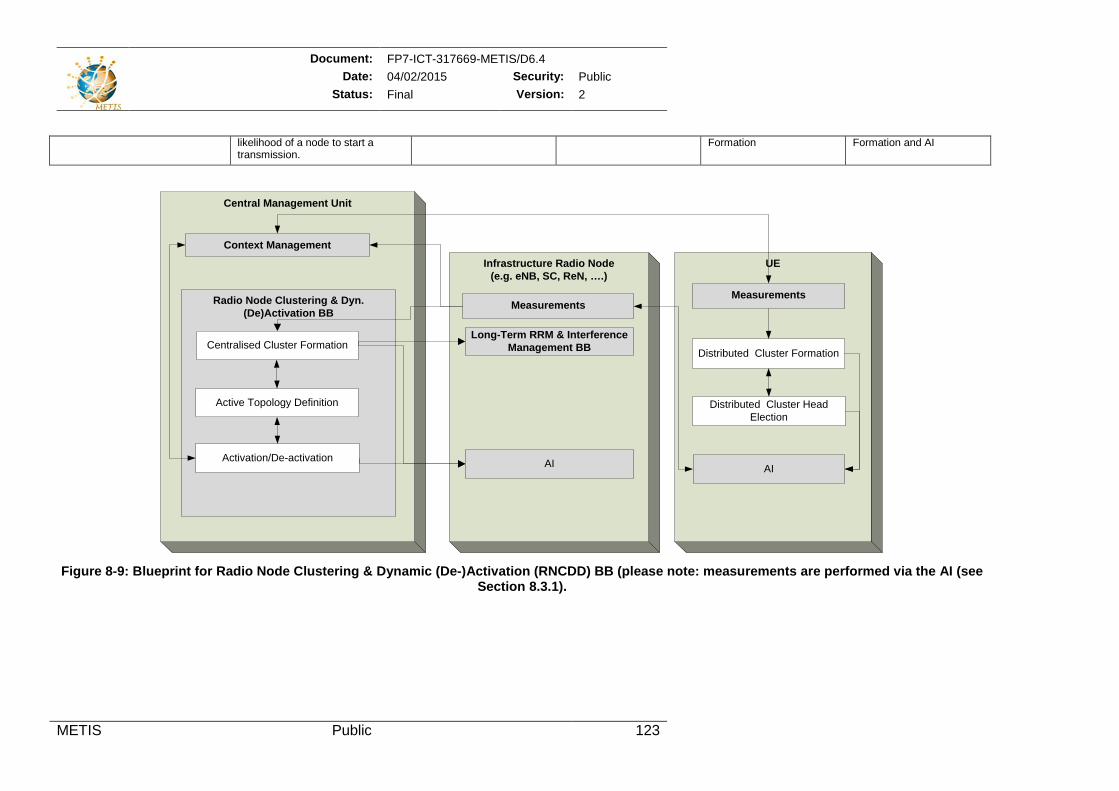
Document: FP7-ICT-317669-METIS/D6.4 Date: 04/02/2015 Security: Public
Status: Final Version: 2
METIS Public 123
likelihood of a node to start a transmission.
Formation Formation and AI
Figure 8-9: Blueprint for Radio Node Clustering & Dynamic (De-)Activation (RNCDD) BB (please note: measurements are performed via the AI (see
Section 8.3.1).
Infrastructure Radio Node (e.g. eNB, SC, ReN, ….)
Central Management Unit
Radio Node Clustering & Dyn. (De)Activation BB
Centralised Cluster Formation
Active Topology Definition
Measurements
Activation/De-activation
Long-Term RRM & Interference Management BB
AI
Context ManagementUE
Distributed Cluster Formation
Distributed Cluster Head Election
Measurements
AI
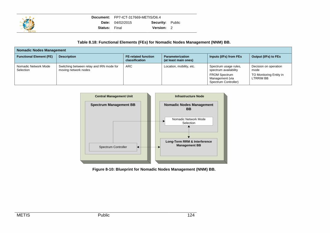
Document: FP7-ICT-317669-METIS/D6.4 Date: 04/02/2015 Security: Public
Status: Final Version: 2
METIS Public 124
Table 8.18: Functional Elements (FEs) for Nomadic Nodes Management (NNM) BB.
Nomadic Nodes Management
Functional Element (FE) Description FE-related function classification
Parameterization (at least main ones)
Inputs (I/Fs) from FEs Output (I/Fs) to FEs
Nomadic Network Mode Selection
Switching between relay and IRN mode for moving network nodes
ARC Location, mobility, etc. Spectrum usage rules, spectrum availability FROM Spectrum Management (via Spectrum Controller)
Decision on operation mode TO Monitoring Entity in LTRRIM BB
Figure 8-10: Blueprint for Nomadic Nodes Management (NNM) BB.
Infrastructure Node
Nomadic Nodes Management BB
Nomadic Network Mode Selection
Central Management Unit
Spectrum Management BB
Spectrum Controller
Long-Term RRM & Interference Management BB
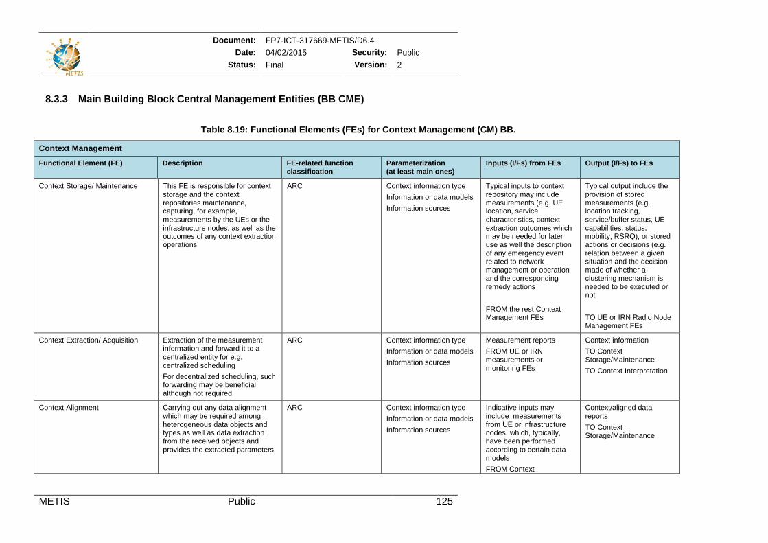
Document: FP7-ICT-317669-METIS/D6.4 Date: 04/02/2015 Security: Public
Status: Final Version: 2
METIS Public 125
8.3.3 Main Building Block Central Management Entities (BB CME)
Table 8.19: Functional Elements (FEs) for Context Management (CM) BB.
Context Management
Functional Element (FE) Description FE-related function classification
Parameterization (at least main ones)
Inputs (I/Fs) from FEs Output (I/Fs) to FEs
Context Storage/ Maintenance This FE is responsible for context storage and the context repositories maintenance, capturing, for example, measurements by the UEs or the infrastructure nodes, as well as the outcomes of any context extraction operations
ARC Context information type Information or data models Information sources
Typical inputs to context repository may include measurements (e.g. UE location, service characteristics, context extraction outcomes which may be needed for later use as well the description of any emergency event related to network management or operation and the corresponding remedy actions FROM the rest Context Management FEs
Typical output include the provision of stored measurements (e.g. location tracking, service/buffer status, UE capabilities, status, mobility, RSRQ), or stored actions or decisions (e.g. relation between a given situation and the decision made of whether a clustering mechanism is needed to be executed or not TO UE or IRN Radio Node Management FEs
Context Extraction/ Acquisition Extraction of the measurement information and forward it to a centralized entity for e.g. centralized scheduling For decentralized scheduling, such forwarding may be beneficial although not required
ARC Context information type Information or data models Information sources
Measurement reports FROM UE or IRN measurements or monitoring FEs
Context information TO Context Storage/Maintenance TO Context Interpretation
Context Alignment Carrying out any data alignment which may be required among heterogeneous data objects and types as well as data extraction from the received objects and provides the extracted parameters
ARC Context information type Information or data models Information sources
Indicative inputs may include measurements from UE or infrastructure nodes, which, typically, have been performed according to certain data models FROM Context
Context/aligned data reports TO Context Storage/Maintenance
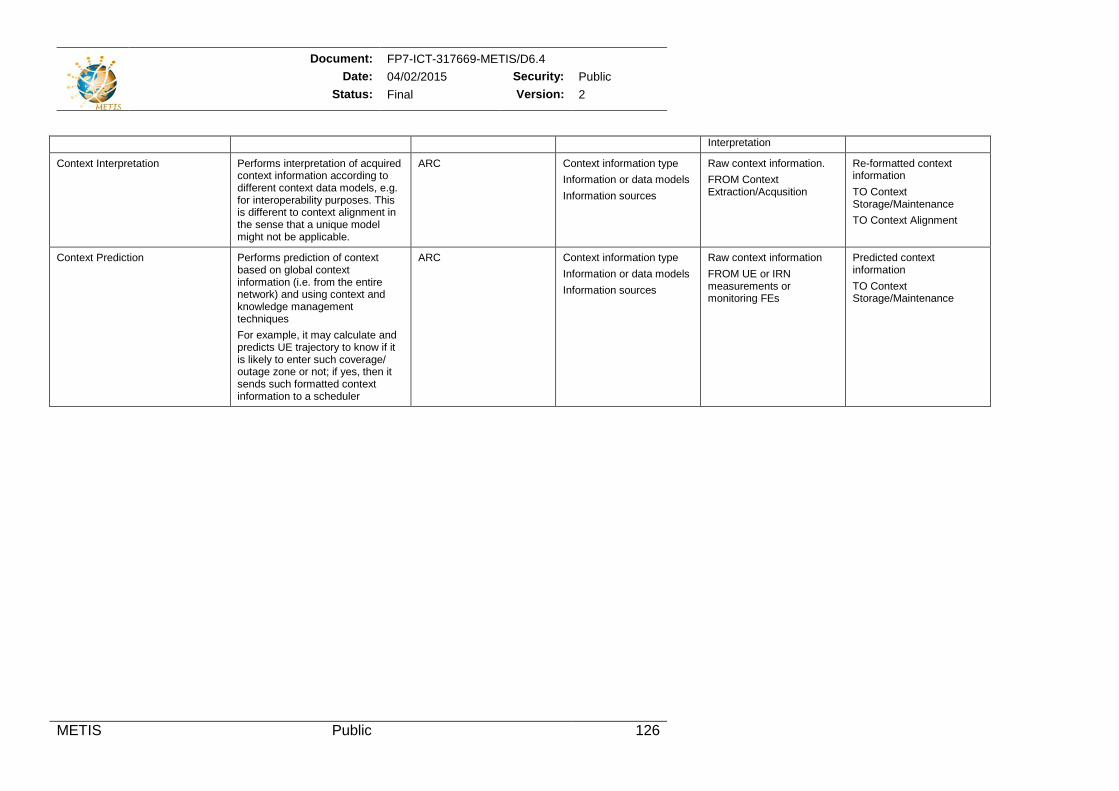
Document: FP7-ICT-317669-METIS/D6.4 Date: 04/02/2015 Security: Public
Status: Final Version: 2
METIS Public 126
Interpretation
Context Interpretation Performs interpretation of acquired context information according to different context data models, e.g. for interoperability purposes. This is different to context alignment in the sense that a unique model might not be applicable.
ARC Context information type Information or data models Information sources
Raw context information. FROM Context Extraction/Acqusition
Re-formatted context information TO Context Storage/Maintenance TO Context Alignment
Context Prediction Performs prediction of context based on global context information (i.e. from the entire network) and using context and knowledge management techniques For example, it may calculate and predicts UE trajectory to know if it is likely to enter such coverage/ outage zone or not; if yes, then it sends such formatted context information to a scheduler
ARC Context information type Information or data models Information sources
Raw context information FROM UE or IRN measurements or monitoring FEs
Predicted context information TO Context Storage/Maintenance
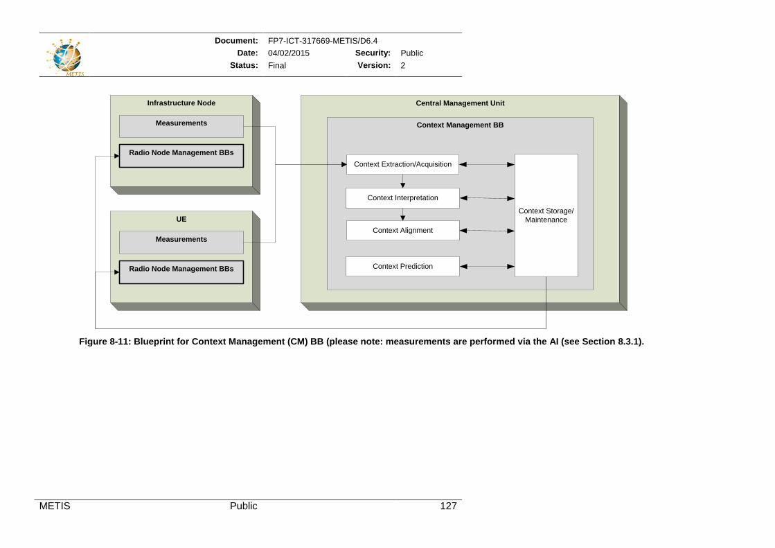
Document: FP7-ICT-317669-METIS/D6.4 Date: 04/02/2015 Security: Public
Status: Final Version: 2
METIS Public 127
Figure 8-11: Blueprint for Context Management (CM) BB (please note: measurements are performed via the AI (see Section 8.3.1).
Central Management Unit
Context Management BB
Context Extraction/Acquisition
Context Alignment
Context Interpretation
Context Prediction
Context Storage/Maintenance
Infrastructure Node
Measurements
Radio Node Management BBs
UE
Measurements
Radio Node Management BBs
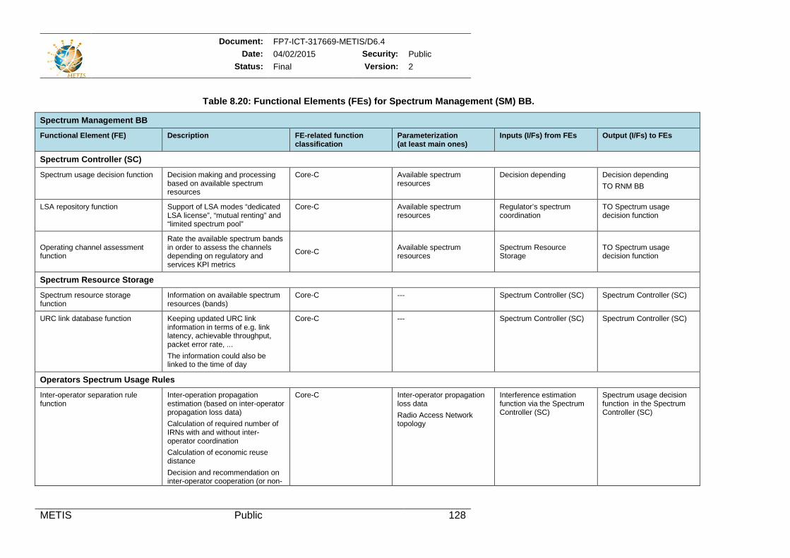
Document: FP7-ICT-317669-METIS/D6.4 Date: 04/02/2015 Security: Public
Status: Final Version: 2
METIS Public 128
Table 8.20: Functional Elements (FEs) for Spectrum Management (SM) BB.
Spectrum Management BB
Functional Element (FE) Description FE-related function classification
Parameterization (at least main ones)
Inputs (I/Fs) from FEs Output (I/Fs) to FEs
Spectrum Controller (SC)
Spectrum usage decision function Decision making and processing based on available spectrum resources
Core-C Available spectrum resources
Decision depending Decision depending TO RNM BB
LSA repository function Support of LSA modes “dedicated LSA license”, “mutual renting” and “limited spectrum pool”
Core-C Available spectrum resources
Regulator’s spectrum coordination
TO Spectrum usage decision function
Operating channel assessment function
Rate the available spectrum bands in order to assess the channels depending on regulatory and services KPI metrics
Core-C Available spectrum resources
Spectrum Resource Storage
TO Spectrum usage decision function
Spectrum Resource Storage
Spectrum resource storage function
Information on available spectrum resources (bands)
Core-C --- Spectrum Controller (SC) Spectrum Controller (SC)
URC link database function Keeping updated URC link information in terms of e.g. link latency, achievable throughput, packet error rate, ... The information could also be linked to the time of day
Core-C --- Spectrum Controller (SC) Spectrum Controller (SC)
Operators Spectrum Usage Rules
Inter-operator separation rule function
Inter-operation propagation estimation (based on inter-operator propagation loss data) Calculation of required number of IRNs with and without inter-operator coordination Calculation of economic reuse distance Decision and recommendation on inter-operator cooperation (or non-
Core-C Inter-operator propagation loss data Radio Access Network topology
Interference estimation function via the Spectrum Controller (SC)
Spectrum usage decision function in the Spectrum Controller (SC)
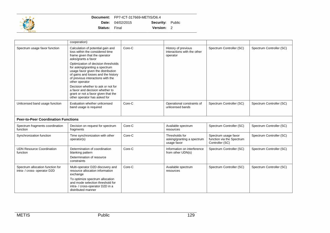
Document: FP7-ICT-317669-METIS/D6.4 Date: 04/02/2015 Security: Public
Status: Final Version: 2
METIS Public 129
cooperation)
Spectrum usage favor function Calculation of potential gain and loss within the considered time frame given that the operator asks/grants a favor Optimization of decision thresholds for asking/granting a spectrum usage favor given the distribution of gains and losses and the history of previous interactions with the other operator Decision whether to ask or not for a favor and decision whether to grant or not a favor given that the other operator has asked for
Core-C History of previous interactions with the other operator
Spectrum Controller (SC) Spectrum Controller (SC)
Unlicensed band usage function Evaluation whether unlicensed band usage is required
Core-C Operational constraints of unlicensed bands
Spectrum Controller (SC) Spectrum Controller (SC)
Peer-to-Peer Coordination Functions
Spectrum fragments coordination function
Decision on request for spectrum fragments
Core-C Available spectrum resources
Spectrum Controller (SC) Spectrum Controller (SC)
Synchronization function Time synchronization with other operator(s)
Core-C Thresholds for asking/granting a spectrum usage favor
Spectrum usage favor function via the Spectrum Controller (SC)
Spectrum Controller (SC)
UDN Resource Coordination function
Determination of coordination blanking pattern Determination of resource constraints
Core-C Information on interference from other UDN(s)
Spectrum Controller (SC) Spectrum Controller (SC)
Spectrum allocation function for intra- / cross- operator D2D
Multi-operator D2D discovery and resource allocation information exchange To optimize spectrum allocation and mode selection threshold for intra- / cross-operator D2D in a distributed manner
Core-C Available spectrum resources
Spectrum Controller (SC) Spectrum Controller (SC)
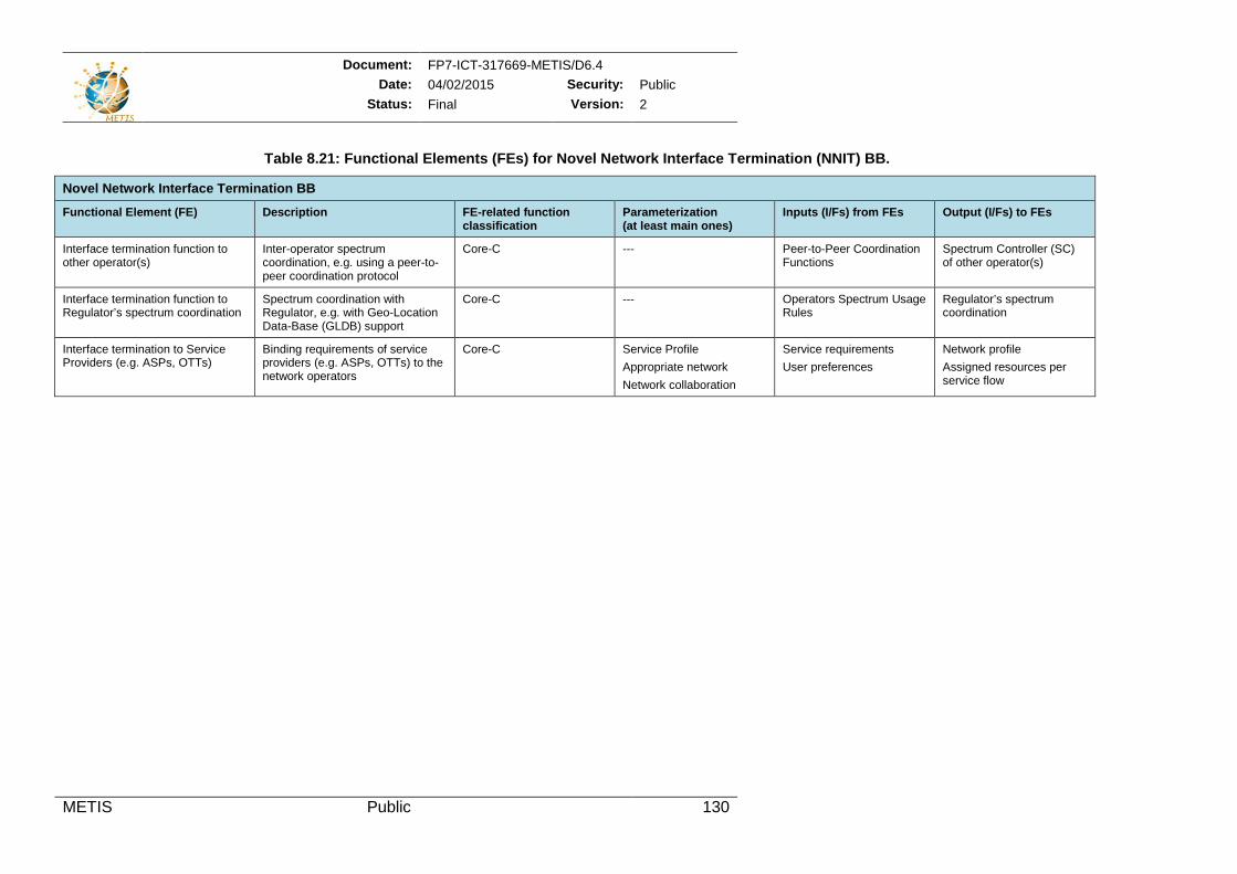
Document: FP7-ICT-317669-METIS/D6.4 Date: 04/02/2015 Security: Public
Status: Final Version: 2
METIS Public 130
Table 8.21: Functional Elements (FEs) for Novel Network Interface Termination (NNIT) BB.
Novel Network Interface Termination BB
Functional Element (FE) Description FE-related function classification
Parameterization (at least main ones)
Inputs (I/Fs) from FEs Output (I/Fs) to FEs
Interface termination function to other operator(s)
Inter-operator spectrum coordination, e.g. using a peer-to-peer coordination protocol
Core-C --- Peer-to-Peer Coordination Functions
Spectrum Controller (SC) of other operator(s)
Interface termination function to Regulator’s spectrum coordination
Spectrum coordination with Regulator, e.g. with Geo-Location Data-Base (GLDB) support
Core-C --- Operators Spectrum Usage Rules
Regulator’s spectrum coordination
Interface termination to Service Providers (e.g. ASPs, OTTs)
Binding requirements of service providers (e.g. ASPs, OTTs) to the network operators
Core-C Service Profile Appropriate network Network collaboration
Service requirements User preferences
Network profile Assigned resources per service flow
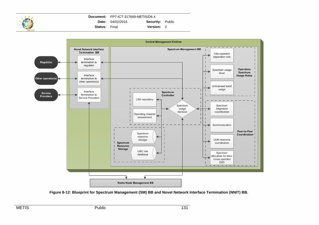
Document: FP7-ICT-317669-METIS/D6.4 Date: 04/02/2015 Security: Public
Status: Final Version: 2
METIS Public 131
Figure 8-12: Blueprint for Spectrum Management (SM) BB and Novel Network Interface Termination (NNIT) BB.
Document: FP7-ICT-317669-METIS/D6.4 Date: 04/02/2015 Security: Public
Status: Final Version: 2
METIS Public 132
9 Annex: Way towards an Optimized Overall System The aim of this section is to provide the foundations for a consolidated 5G system integration and assessment of architecture options investigated in METIS. This work is based on the architectural and technology components analysis developed in Section 7 and Section 8, respectively. The views of an optimized overall 5G system discussed here are going to be complemented by the upcoming deliverables D6.5 [MET15-D65] and D6.6 [MET15-D66].
9.1 Assessment Metrics In this section, for evaluation of system and architecture solutions, assessment metrics are defined based on the METIS system concept description initiated in [MET14-D62]. It is assumed that the “METIS system will respond to the requirements for improved: 1) efficiency in terms of energy, cost and resource utilization compared to today’s system 2) versatility to support a significant diversity of requirements, e.g. connections in Gbps from few devices vs. connections in kbps from many machine-type devices, inclusion of moving networks vs. statically deployed sensors, etc. 3) scalability in terms of number of connected devices, densely deployed access points, spectrum, energy and cost.”
9.1.1 Efficiency Related to meeting performance requirements, allowing for scenario specific optimizations, dynamic network adaptively, reducing OPEX/CAPEX and energy efficiency, the METIS system needs to answer the following questions concerning efficiency:
Performance: Does the solution meet the end user performance requirements with regards to bit-rates and latency?
Optimization: Does the solution support scenario specific performance optimization capabilities?
Adaptability: Is the solution capable of adjusting to changing mobility, congestion and traffic patterns?
Resource utilization: Does the solution enable efficient usage of available resources, e.g. radio spectrum?
OPEX: Does the solution address reduction of maintenance, transport, energy, storage, processing costs?
CAPEX: Does the solution support cost efficient radio, device, processing, switching, storage HW?
Energy: How the solution impacts on energy efficiency? Is it able to reduce energy consumption while increasing capacity?
9.1.2 Versatility Related to deployment flexibility, smooth migration, future-proof aptitude, auto configurability, flexibility to address new scenarios and diverse link types, the METIS system needs to answer the following questions concerning versatility:
Deployment: Can the solution be deployed re-using existing sites, transport network topologies and infrastructure?
Migration: Does the solution provide a smooth migration and inter-working with legacy systems? (If not, what are the main architectural changes?)
Future proofness: With the proposed solution is it easy to introduce new features or optimizations, to support new scenarios, use cases, or revenue streams?
Document: FP7-ICT-317669-METIS/D6.4 Date: 04/02/2015 Security: Public
Status: Final Version: 2
METIS Public 133
Auto configurability: Can new nodes be introduced without requiring any manual planning or re-configuration? Can also existing nodes apply self-configuration?
Reliability: Is the solution applicable to both normal and ultra-high reliability scenarios?
Radio Spectrum: Does the solution support the [simultaneous] utilization of numerous frequency bands, from UHF to EHF (mmW) spectrum.
Legacy services: Does the solution make it possible to support legacy services (e.g. SMS, voice) and existing regulatory requirements (e.g. emergency calls, legal interception)?
Sharing: Does the solution support various forms of network, resource and/or spectrum sharing?
9.1.3 Scalability Related to supporting high load, massive number of users, large and small scale deployments, varying bit-rates and traffic patterns, the METIS system needs to answer the following questions concerning scalability:
Capacity (traffic load): Is the solution efficient both in low and high load scenarios potentially during different times of day? Does the architecture allow easy capacity increase by future upgrades?
Capacity (number of devices): Does the solution support massive number of devices?
Deployment size: Is the solution efficient both for small scale and large scale deployments?
Data rates: Is the solution able to support both low and high bit-rates users with different traffic patterns in an efficient way?
9.2 Stories applying the architecture options In order to discuss relevant topics of future 5G systems from architecture point of view, so-called architecture options are introduced and described in Section 4.2. Architecture options refer to dedicated functional architectures that correspond to METIS technical enablers, such as M-MIMO, UDN, Multi-RAT and Dynamic RAN. They imply different deployment combinations concerning functional deployment within the network, such as the E2E network reference introduced in Section3.3. Architecture options are not necessarily competitive solutions, but performances can be compared, e.g., in the case of Massive MIMO vs. UDN deployments. Further, the described architecture options are not to be considered as the full set of METIS technical enablers, but rather a selected subset of all available options, which are utilized herein to illustrate their impact on the architectural considerations. In order to make 5G more concrete in this subsection stories applying the architecture options are introduced. These stories give practical examples and apply METIS TeCs.
9.2.1 Story I – Centralized vs. distributed operation of network functions 5G architecture can support flexible centralization of network functions using different architecture realizations such as: a) C-RAN architecture with centralized baseband where available high speed fiber backhaul is used for centralized baseband pooling algorithms e.g. CoMP, interference cancellation, etc. b) C-RAN architecture with centralized baseband along with pooling while using high speed fiber backhaul, c) a split control plane and data plane architecture with high speed fiber (ideal) backhaul and centralized baseband, such that control functions and data plane processing are done completely by the macro-cell while the
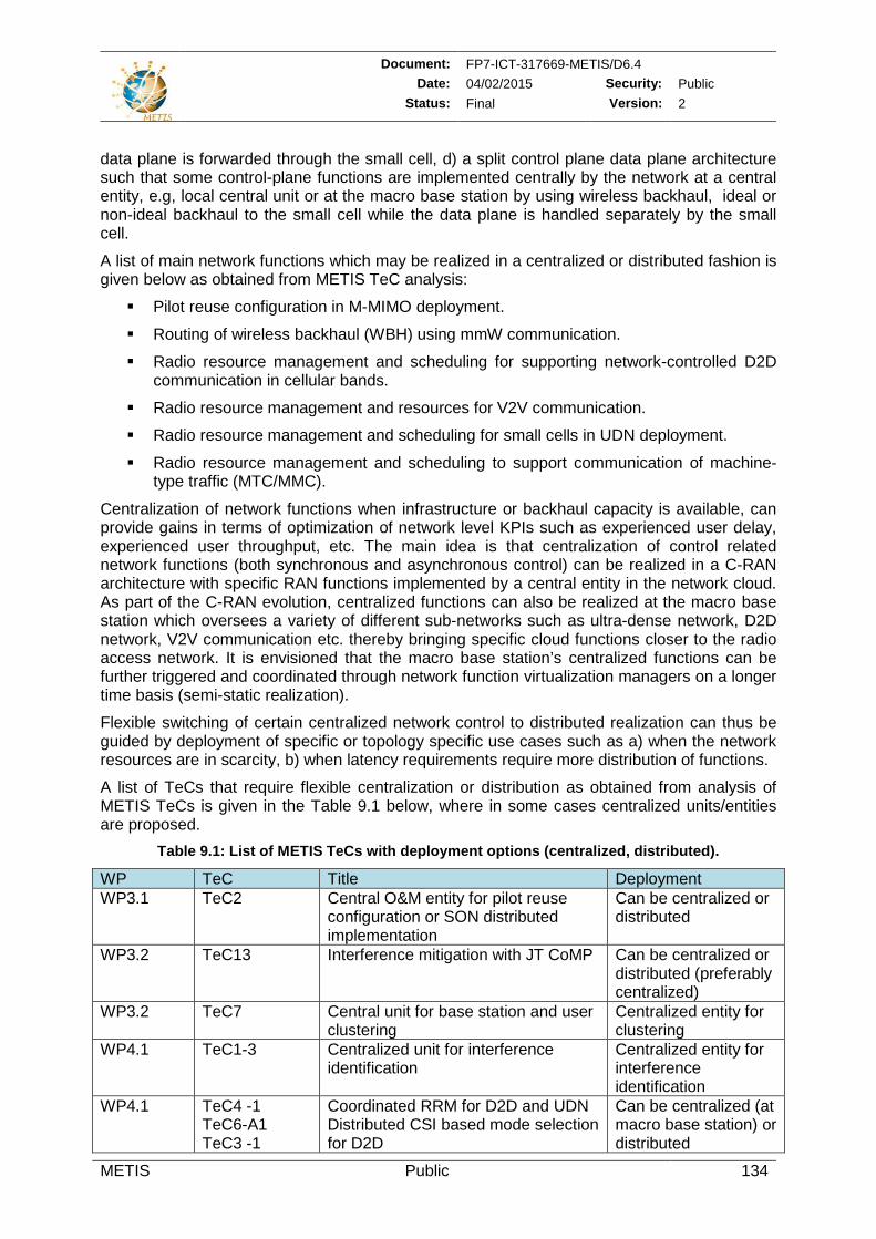
Document: FP7-ICT-317669-METIS/D6.4 Date: 04/02/2015 Security: Public
Status: Final Version: 2
METIS Public 134
data plane is forwarded through the small cell, d) a split control plane data plane architecture such that some control-plane functions are implemented centrally by the network at a central entity, e.g, local central unit or at the macro base station by using wireless backhaul, ideal or non-ideal backhaul to the small cell while the data plane is handled separately by the small cell.
A list of main network functions which may be realized in a centralized or distributed fashion is given below as obtained from METIS TeC analysis:
Pilot reuse configuration in M-MIMO deployment.
Routing of wireless backhaul (WBH) using mmW communication.
Radio resource management and scheduling for supporting network-controlled D2D communication in cellular bands.
Radio resource management and resources for V2V communication.
Radio resource management and scheduling for small cells in UDN deployment.
Radio resource management and scheduling to support communication of machine-type traffic (MTC/MMC).
Centralization of network functions when infrastructure or backhaul capacity is available, can provide gains in terms of optimization of network level KPIs such as experienced user delay, experienced user throughput, etc. The main idea is that centralization of control related network functions (both synchronous and asynchronous control) can be realized in a C-RAN architecture with specific RAN functions implemented by a central entity in the network cloud. As part of the C-RAN evolution, centralized functions can also be realized at the macro base station which oversees a variety of different sub-networks such as ultra-dense network, D2D network, V2V communication etc. thereby bringing specific cloud functions closer to the radio access network. It is envisioned that the macro base station’s centralized functions can be further triggered and coordinated through network function virtualization managers on a longer time basis (semi-static realization).
Flexible switching of certain centralized network control to distributed realization can thus be guided by deployment of specific or topology specific use cases such as a) when the network resources are in scarcity, b) when latency requirements require more distribution of functions.
A list of TeCs that require flexible centralization or distribution as obtained from analysis of METIS TeCs is given in the Table 9.1 below, where in some cases centralized units/entities are proposed.
Table 9.1: List of METIS TeCs with deployment options (centralized, distributed).
WP TeC Title Deployment WP3.1 TeC2 Central O&M entity for pilot reuse
configuration or SON distributed implementation
Can be centralized or distributed
WP3.2 TeC13 Interference mitigation with JT CoMP Can be centralized or distributed (preferably centralized)
WP3.2 TeC7 Central unit for base station and user clustering
Centralized entity for clustering
WP4.1 TeC1-3 Centralized unit for interference identification
Centralized entity for interference identification
WP4.1 TeC4 -1 TeC6-A1 TeC3 -1
Coordinated RRM for D2D and UDN Distributed CSI based mode selection for D2D
Can be centralized (at macro base station) or distributed
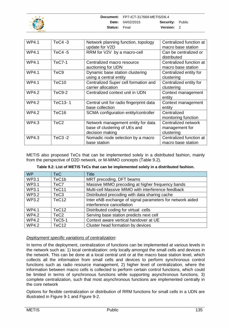
Document: FP7-ICT-317669-METIS/D6.4 Date: 04/02/2015 Security: Public
Status: Final Version: 2
METIS Public 135
METIS also proposed TeCs that can be implemented solely in a distributed fashion, mainly from the perspective of D2D network, or M-MIMO concepts (Table 9.2).
Table 9.2: List of METIS TeCs that can be implemented solely in a distributed fashion.
WP TeC Title WP3.1 TeC1b MRT precoding, DFT beams WP3.1 TeC7 Massive MIMO precoding at higher frequency bands WP3.1 TeC11 Multi-cell Massive MIMO with interference feedback WP3.2 TeC3 Distributed precoding with data sharing cache WP3.2 TeC12 Inter eNB exchange of signal parameters for network aided
interference cancellation WP4.1 TeC12 Distributed coding for virtual cells WP4.2 TeC2 Serving base station predicts next cell WP4.2 TeC5-1 Context aware vertical handover at UE WP4.2 TeC12 Cluster head formation by devices
Deployment specific variations of centralization:
In terms of the deployment, centralization of functions can be implemented at various levels in the network such as: 1) local centralization: only locally amongst the small cells and devices in the network. This can be done at a local central unit or at the macro base station level, which collects all the information from small cells and devices to perform synchronous control functions such as radio resource management, 2) higher level of centralization, where the information between macro cells is collected to perform certain control functions, which could be limited in terms of synchronous functions while supporting asynchronous functions, 3) complete centralization, such that most asynchronous functions are implemented centrally in the core network
Options for flexible centralization or distribution of RRM functions for small cells in a UDN are illustrated in Figure 9-1 and Figure 9-2.
WP4.1 TeC4 -3 Network planning function, topology update for V2D
Centralized function at macro base station
WP4.1 TeC4 -5 RRM for V2V by a macro-cell Can be centralized or distributed
WP4.1 TeC7-1 Centralized macro resource auctioning for UDN
Centralized function at macro base station
WP4.1 TeC9 Dynamic base station clustering using a central entity
Centralized entity for clustering
WP4.1 TeC10 Centralized Super cell formation and carrier allocation
Centralized entity for clustering
WP4.2 TeC9-2 Centralized context unit in UDN Context management entity
WP4.2 TeC13- 1 Central unit for radio fingerprint data base collection
Context management entity
WP4.2 TeC16 SCMA configuration entity/controller Centralized monitoring function
WP4.3 TeC2 Network management entity for data base of clustering of UEs and decision making
Centralized network management for clustering
WP4.3 TeC3 -2 Nomadic node selection by a macro base station
Centralized function at macro base station
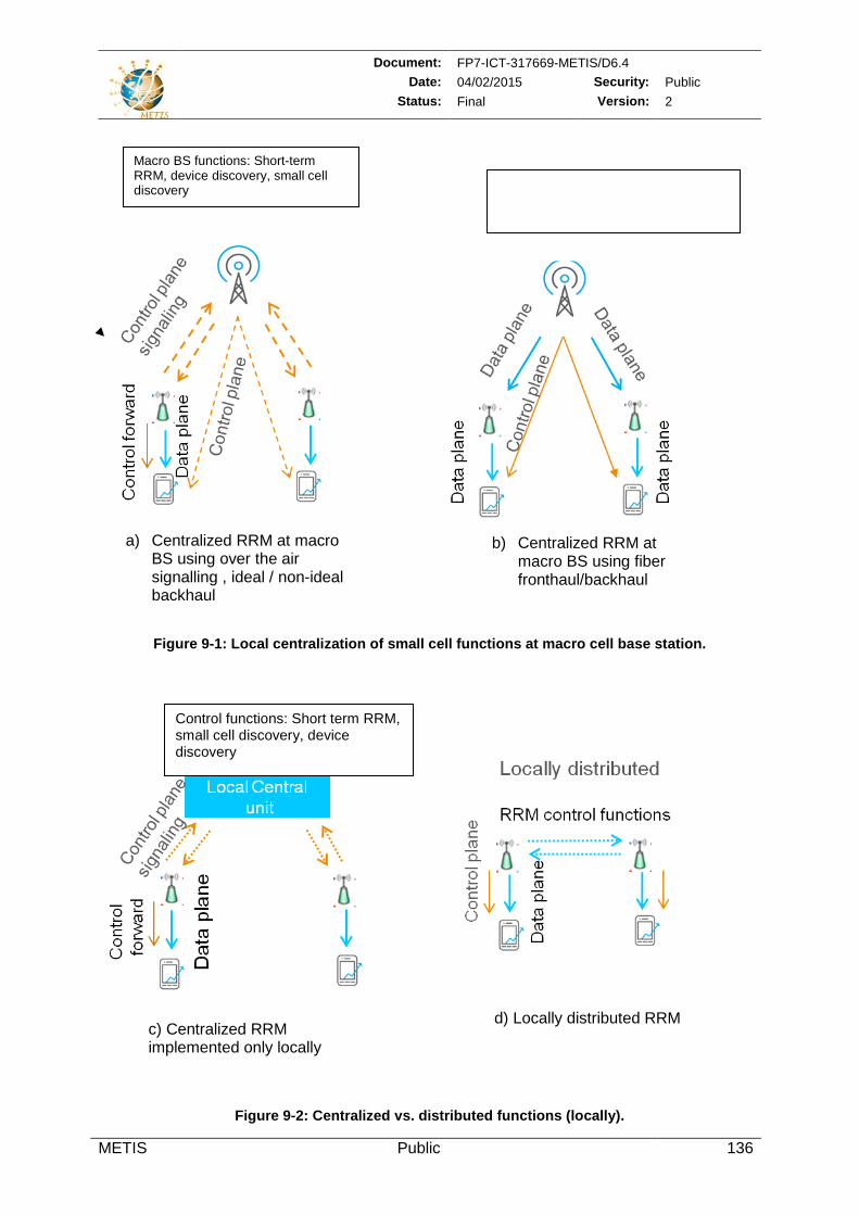
Document: FP7-ICT-317669-METIS/D6.4 Date: 04/02/2015 Security: Public
Status: Final Version: 2
METIS Public 136
Figure 9-1: Local centralization of small cell functions at macro cell base station.
Figure 9-2: Centralized vs. distributed functions (locally).
Macro BS functions: Short-term RRM, device discovery, small cell discovery
Control functions: Short term RRM, small cell discovery, device discovery
c) Centralized RRM implemented only locally
d) Locally distributed RRM
a) Centralized RRM at macro BS using over the air signalling , ideal / non-ideal backhaul
b) Centralized RRM at macro BS using fiber fronthaul/backhaul
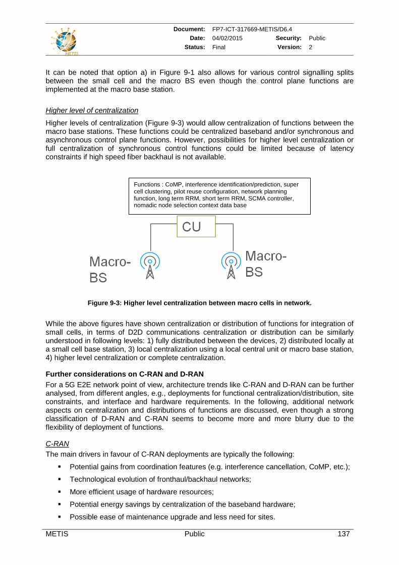
Document: FP7-ICT-317669-METIS/D6.4 Date: 04/02/2015 Security: Public
Status: Final Version: 2
METIS Public 137
It can be noted that option a) in Figure 9-1 also allows for various control signalling splits between the small cell and the macro BS even though the control plane functions are implemented at the macro base station.
Higher level of centralization
Higher levels of centralization (Figure 9-3) would allow centralization of functions between the macro base stations. These functions could be centralized baseband and/or synchronous and asynchronous control plane functions. However, possibilities for higher level centralization or full centralization of synchronous control functions could be limited because of latency constraints if high speed fiber backhaul is not available.
Figure 9-3: Higher level centralization between macro cells in network.
While the above figures have shown centralization or distribution of functions for integration of small cells, in terms of D2D communications centralization or distribution can be similarly understood in following levels: 1) fully distributed between the devices, 2) distributed locally at a small cell base station, 3) local centralization using a local central unit or macro base station, 4) higher level centralization or complete centralization.
Further considerations on C-RAN and D-RAN For a 5G E2E network point of view, architecture trends like C-RAN and D-RAN can be further analysed, from different angles, e.g., deployments for functional centralization/distribution, site constraints, and interface and hardware requirements. In the following, additional network aspects on centralization and distributions of functions are discussed, even though a strong classification of D-RAN and C-RAN seems to become more and more blurry due to the flexibility of deployment of functions.
C-RAN The main drivers in favour of C-RAN deployments are typically the following:
Potential gains from coordination features (e.g. interference cancellation, CoMP, etc.);
Technological evolution of fronthaul/backhaul networks;
More efficient usage of hardware resources;
Potential energy savings by centralization of the baseband hardware;
Possible ease of maintenance upgrade and less need for sites.
Functions : CoMP, interference identification/prediction, super cell clustering, pilot reuse configuration, network planning function, long term RRM, short term RRM, SCMA controller, nomadic node selection context data base
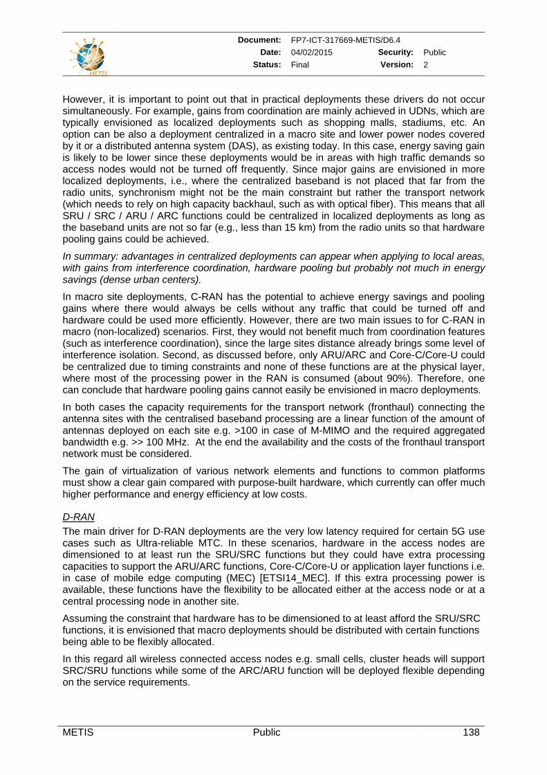
Document: FP7-ICT-317669-METIS/D6.4 Date: 04/02/2015 Security: Public
Status: Final Version: 2
METIS Public 138
However, it is important to point out that in practical deployments these drivers do not occur simultaneously. For example, gains from coordination are mainly achieved in UDNs, which are typically envisioned as localized deployments such as shopping malls, stadiums, etc. An option can be also a deployment centralized in a macro site and lower power nodes covered by it or a distributed antenna system (DAS), as existing today. In this case, energy saving gain is likely to be lower since these deployments would be in areas with high traffic demands so access nodes would not be turned off frequently. Since major gains are envisioned in more localized deployments, i.e., where the centralized baseband is not placed that far from the radio units, synchronism might not be the main constraint but rather the transport network (which needs to rely on high capacity backhaul, such as with optical fiber). This means that all SRU / SRC / ARU / ARC functions could be centralized in localized deployments as long as the baseband units are not so far (e.g., less than 15 km) from the radio units so that hardware pooling gains could be achieved.
In summary: advantages in centralized deployments can appear when applying to local areas, with gains from interference coordination, hardware pooling but probably not much in energy savings (dense urban centers).
In macro site deployments, C-RAN has the potential to achieve energy savings and pooling gains where there would always be cells without any traffic that could be turned off and hardware could be used more efficiently. However, there are two main issues to for C-RAN in macro (non-localized) scenarios. First, they would not benefit much from coordination features (such as interference coordination), since the large sites distance already brings some level of interference isolation. Second, as discussed before, only ARU/ARC and Core-C/Core-U could be centralized due to timing constraints and none of these functions are at the physical layer, where most of the processing power in the RAN is consumed (about 90%). Therefore, one can conclude that hardware pooling gains cannot easily be envisioned in macro deployments.
In both cases the capacity requirements for the transport network (fronthaul) connecting the antenna sites with the centralised baseband processing are a linear function of the amount of antennas deployed on each site e.g. >100 in case of M-MIMO and the required aggregated bandwidth e.g. >> 100 MHz. At the end the availability and the costs of the fronthaul transport network must be considered.
The gain of virtualization of various network elements and functions to common platforms must show a clear gain compared with purpose-built hardware, which currently can offer much higher performance and energy efficiency at low costs.
D-RAN The main driver for D-RAN deployments are the very low latency required for certain 5G use cases such as Ultra-reliable MTC. In these scenarios, hardware in the access nodes are dimensioned to at least run the SRU/SRC functions but they could have extra processing capacities to support the ARU/ARC functions, Core-C/Core-U or application layer functions i.e. in case of mobile edge computing (MEC) [ETSI14_MEC]. If this extra processing power is available, these functions have the flexibility to be allocated either at the access node or at a central processing node in another site.
Assuming the constraint that hardware has to be dimensioned to at least afford the SRU/SRC functions, it is envisioned that macro deployments should be distributed with certain functions being able to be flexibly allocated.
In this regard all wireless connected access nodes e.g. small cells, cluster heads will support SRC/SRU functions while some of the ARC/ARU function will be deployed flexible depending on the service requirements.
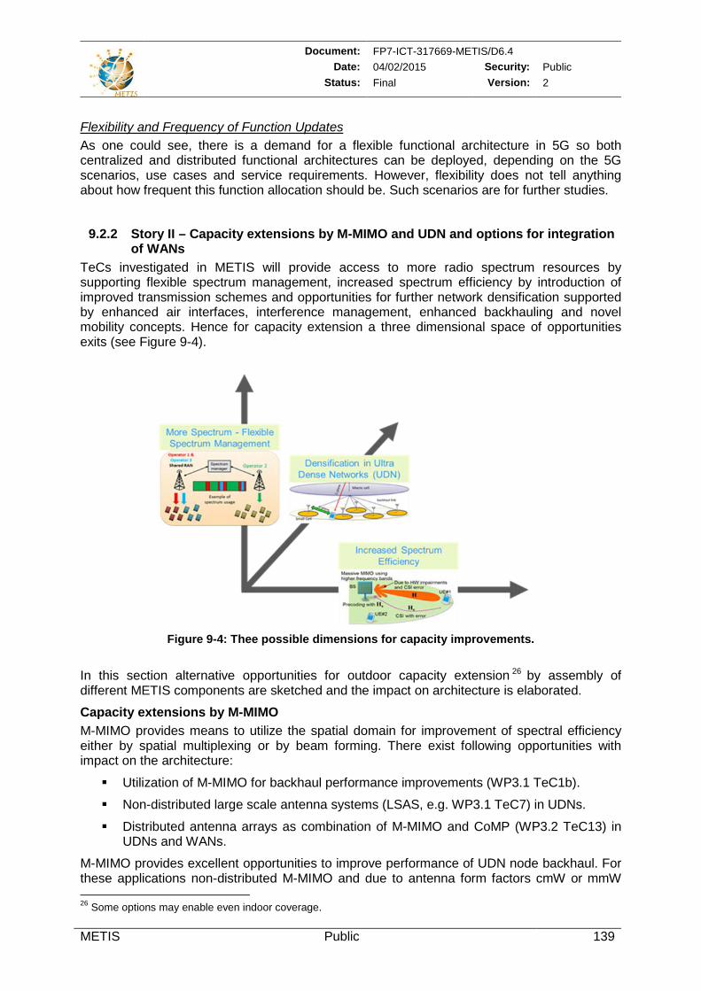
Document: FP7-ICT-317669-METIS/D6.4 Date: 04/02/2015 Security: Public
Status: Final Version: 2
METIS Public 139
Flexibility and Frequency of Function Updates As one could see, there is a demand for a flexible functional architecture in 5G so both centralized and distributed functional architectures can be deployed, depending on the 5G scenarios, use cases and service requirements. However, flexibility does not tell anything about how frequent this function allocation should be. Such scenarios are for further studies.
9.2.2 Story II – Capacity extensions by M-MIMO and UDN and options for integration of WANs
TeCs investigated in METIS will provide access to more radio spectrum resources by supporting flexible spectrum management, increased spectrum efficiency by introduction of improved transmission schemes and opportunities for further network densification supported by enhanced air interfaces, interference management, enhanced backhauling and novel mobility concepts. Hence for capacity extension a three dimensional space of opportunities exits (see Figure 9-4).
Figure 9-4: Thee possible dimensions for capacity improvements.
In this section alternative opportunities for outdoor capacity extension 26 by assembly of different METIS components are sketched and the impact on architecture is elaborated.
Capacity extensions by M-MIMO M-MIMO provides means to utilize the spatial domain for improvement of spectral efficiency either by spatial multiplexing or by beam forming. There exist following opportunities with impact on the architecture:
Utilization of M-MIMO for backhaul performance improvements (WP3.1 TeC1b).
Non-distributed large scale antenna systems (LSAS, e.g. WP3.1 TeC7) in UDNs.
Distributed antenna arrays as combination of M-MIMO and CoMP (WP3.2 TeC13) in UDNs and WANs.
M-MIMO provides excellent opportunities to improve performance of UDN node backhaul. For these applications non-distributed M-MIMO and due to antenna form factors cmW or mmW 26 Some options may enable even indoor coverage.
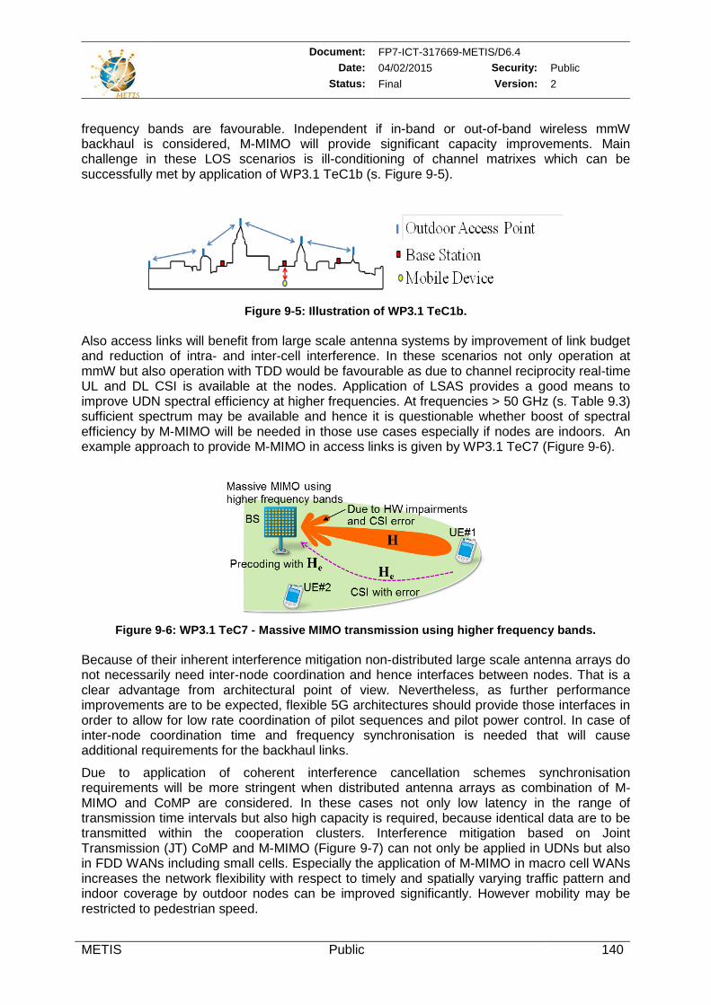
Document: FP7-ICT-317669-METIS/D6.4 Date: 04/02/2015 Security: Public
Status: Final Version: 2
METIS Public 140
frequency bands are favourable. Independent if in-band or out-of-band wireless mmW backhaul is considered, M-MIMO will provide significant capacity improvements. Main challenge in these LOS scenarios is ill-conditioning of channel matrixes which can be successfully met by application of WP3.1 TeC1b (s. Figure 9-5).
Figure 9-5: Illustration of WP3.1 TeC1b. Also access links will benefit from large scale antenna systems by improvement of link budget and reduction of intra- and inter-cell interference. In these scenarios not only operation at mmW but also operation with TDD would be favourable as due to channel reciprocity real-time UL and DL CSI is available at the nodes. Application of LSAS provides a good means to improve UDN spectral efficiency at higher frequencies. At frequencies > 50 GHz (s. Table 9.3) sufficient spectrum may be available and hence it is questionable whether boost of spectral efficiency by M-MIMO will be needed in those use cases especially if nodes are indoors. An example approach to provide M-MIMO in access links is given by WP3.1 TeC7 (Figure 9-6).
Figure 9-6: WP3.1 TeC7 - Massive MIMO transmission using higher frequency bands.
Because of their inherent interference mitigation non-distributed large scale antenna arrays do not necessarily need inter-node coordination and hence interfaces between nodes. That is a clear advantage from architectural point of view. Nevertheless, as further performance improvements are to be expected, flexible 5G architectures should provide those interfaces in order to allow for low rate coordination of pilot sequences and pilot power control. In case of inter-node coordination time and frequency synchronisation is needed that will cause additional requirements for the backhaul links.
Due to application of coherent interference cancellation schemes synchronisation requirements will be more stringent when distributed antenna arrays as combination of M-MIMO and CoMP are considered. In these cases not only low latency in the range of transmission time intervals but also high capacity is required, because identical data are to be transmitted within the cooperation clusters. Interference mitigation based on Joint Transmission (JT) CoMP and M-MIMO (Figure 9-7) can not only be applied in UDNs but also in FDD WANs including small cells. Especially the application of M-MIMO in macro cell WANs increases the network flexibility with respect to timely and spatially varying traffic pattern and indoor coverage by outdoor nodes can be improved significantly. However mobility may be restricted to pedestrian speed.
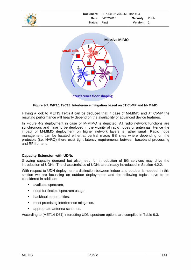
Document: FP7-ICT-317669-METIS/D6.4 Date: 04/02/2015 Security: Public
Status: Final Version: 2
METIS Public 141
Figure 9-7: WP3.1 TeC13: Interference mitigation based on JT CoMP and M- MIMO.
Having a look to METIS TeCs it can be deduced that in case of M-MIMO and JT CoMP the resulting performance will heavily depend on the availability of advanced device features.
In Figure 4-2 deployment in case of M-MIMO is depicted. All radio network functions are synchronous and have to be deployed in the vicinity of radio nodes or antennas. Hence the impact of M-MIMO deployment on higher network layers is rather small. Radio node management can be located either at central macro BS sites where depending on the protocols (i.e. HARQ) there exist tight latency requirements between baseband processing and RF frontend.
Capacity Extension with UDNs Growing capacity demand but also need for introduction of 5G services may drive the introduction of UDNs. The characteristics of UDNs are already introduced in Section 4.2.2.
With respect to UDN deployment a distinction between indoor and outdoor is needed. In this section we are focussing on outdoor deployments and the following topics have to be considered in addition:
available spectrum,
need for flexible spectrum usage,
backhaul opportunities,
most promising interference mitigation,
appropriate antenna schemes.
According to [MET14-D51] interesting UDN spectrum options are compiled in Table 9.3.
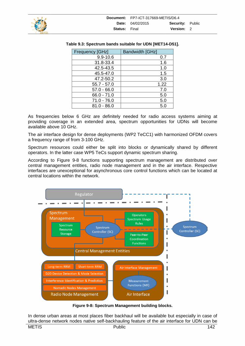
Document: FP7-ICT-317669-METIS/D6.4 Date: 04/02/2015 Security: Public
Status: Final Version: 2
METIS Public 142
Table 9.3: Spectrum bands suitable for UDN [MET14-D51].
Frequency [GHz] Bandwidth [GHz] 9.9-10.6 0.7
31.8-33.4 1.6 42.5-43.5 1.0 45.5-47.0 1.5 47.2-50.2 3.0
55.7 - 57.0 1.22 57.0 - 66.0 7.0 66.0 - 71.0 5.0 71.0 - 76.0 5.0 81.0 - 86.0 5.0
As frequencies below 6 GHz are definitely needed for radio access systems aiming at providing coverage in an extended area, spectrum opportunities for UDNs will become available above 10 GHz.
The air interface design for dense deployments (WP2 TeCC1) with harmonized OFDM covers a frequency range of from 3-100 GHz.
Spectrum resources could either be split into blocks or dynamically shared by different operators. In the latter case WP5 TeCs support dynamic spectrum sharing.
According to Figure 9-8 functions supporting spectrum management are distributed over central management entities, radio node management and in the air interface. Respective interfaces are unexceptional for asynchronous core control functions which can be located at central locations within the network.
Figure 9-8: Spectrum Management building blocks.
In dense urban areas at most places fiber backhaul will be available but especially in case of ultra-dense network nodes native self-backhauling feature of the air interface for UDN can be
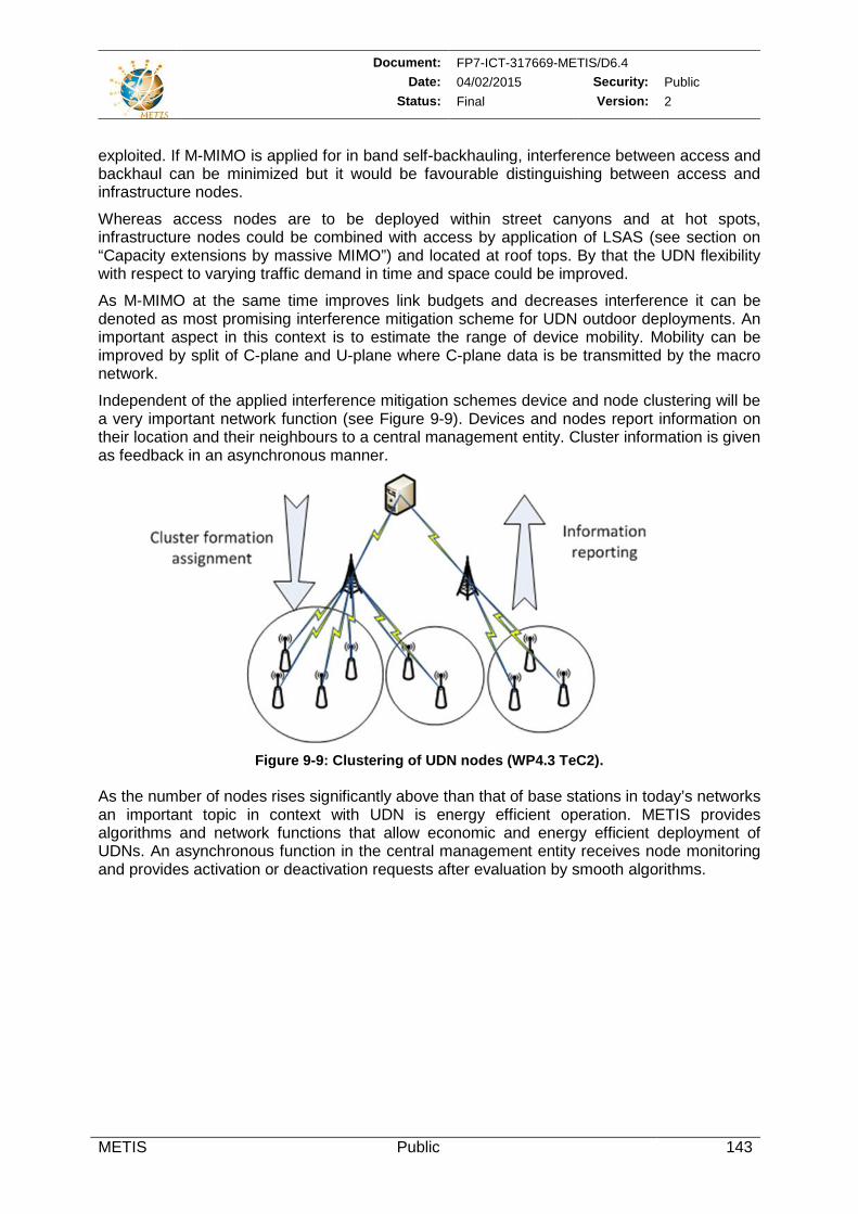
Document: FP7-ICT-317669-METIS/D6.4 Date: 04/02/2015 Security: Public
Status: Final Version: 2
METIS Public 143
exploited. If M-MIMO is applied for in band self-backhauling, interference between access and backhaul can be minimized but it would be favourable distinguishing between access and infrastructure nodes.
Whereas access nodes are to be deployed within street canyons and at hot spots, infrastructure nodes could be combined with access by application of LSAS (see section on “Capacity extensions by massive MIMO”) and located at roof tops. By that the UDN flexibility with respect to varying traffic demand in time and space could be improved.
As M-MIMO at the same time improves link budgets and decreases interference it can be denoted as most promising interference mitigation scheme for UDN outdoor deployments. An important aspect in this context is to estimate the range of device mobility. Mobility can be improved by split of C-plane and U-plane where C-plane data is be transmitted by the macro network.
Independent of the applied interference mitigation schemes device and node clustering will be a very important network function (see Figure 9-9). Devices and nodes report information on their location and their neighbours to a central management entity. Cluster information is given as feedback in an asynchronous manner.
Figure 9-9: Clustering of UDN nodes (WP4.3 TeC2).
As the number of nodes rises significantly above than that of base stations in today’s networks an important topic in context with UDN is energy efficient operation. METIS provides algorithms and network functions that allow economic and energy efficient deployment of UDNs. An asynchronous function in the central management entity receives node monitoring and provides activation or deactivation requests after evaluation by smooth algorithms.
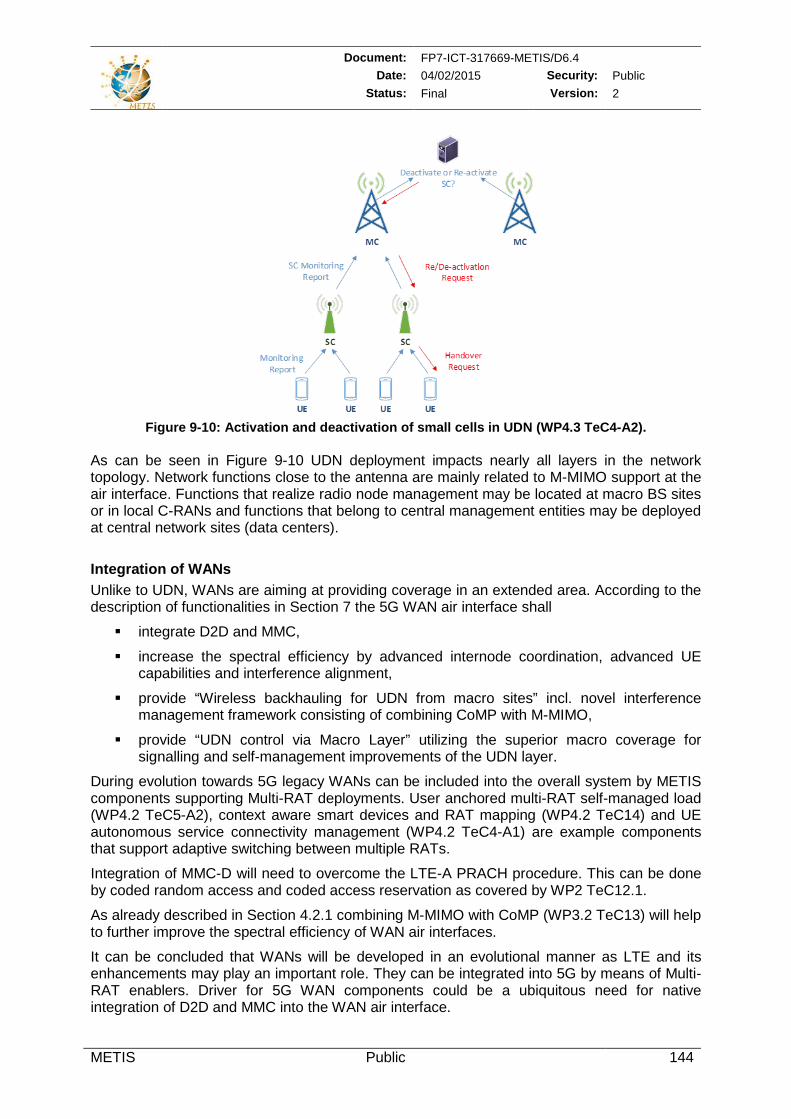
Document: FP7-ICT-317669-METIS/D6.4 Date: 04/02/2015 Security: Public
Status: Final Version: 2
METIS Public 144
Figure 9-10: Activation and deactivation of small cells in UDN (WP4.3 TeC4-A2).
As can be seen in Figure 9-10 UDN deployment impacts nearly all layers in the network topology. Network functions close to the antenna are mainly related to M-MIMO support at the air interface. Functions that realize radio node management may be located at macro BS sites or in local C-RANs and functions that belong to central management entities may be deployed at central network sites (data centers).
Integration of WANs Unlike to UDN, WANs are aiming at providing coverage in an extended area. According to the description of functionalities in Section 7 the 5G WAN air interface shall
integrate D2D and MMC,
increase the spectral efficiency by advanced internode coordination, advanced UE capabilities and interference alignment,
provide “Wireless backhauling for UDN from macro sites” incl. novel interference management framework consisting of combining CoMP with M-MIMO,
provide “UDN control via Macro Layer” utilizing the superior macro coverage for signalling and self-management improvements of the UDN layer.
During evolution towards 5G legacy WANs can be included into the overall system by METIS components supporting Multi-RAT deployments. User anchored multi-RAT self-managed load (WP4.2 TeC5-A2), context aware smart devices and RAT mapping (WP4.2 TeC14) and UE autonomous service connectivity management (WP4.2 TeC4-A1) are example components that support adaptive switching between multiple RATs.
Integration of MMC-D will need to overcome the LTE-A PRACH procedure. This can be done by coded random access and coded access reservation as covered by WP2 TeC12.1.
As already described in Section 4.2.1 combining M-MIMO with CoMP (WP3.2 TeC13) will help to further improve the spectral efficiency of WAN air interfaces.
It can be concluded that WANs will be developed in an evolutional manner as LTE and its enhancements may play an important role. They can be integrated into 5G by means of Multi-RAT enablers. Driver for 5G WAN components could be a ubiquitous need for native integration of D2D and MMC into the WAN air interface.
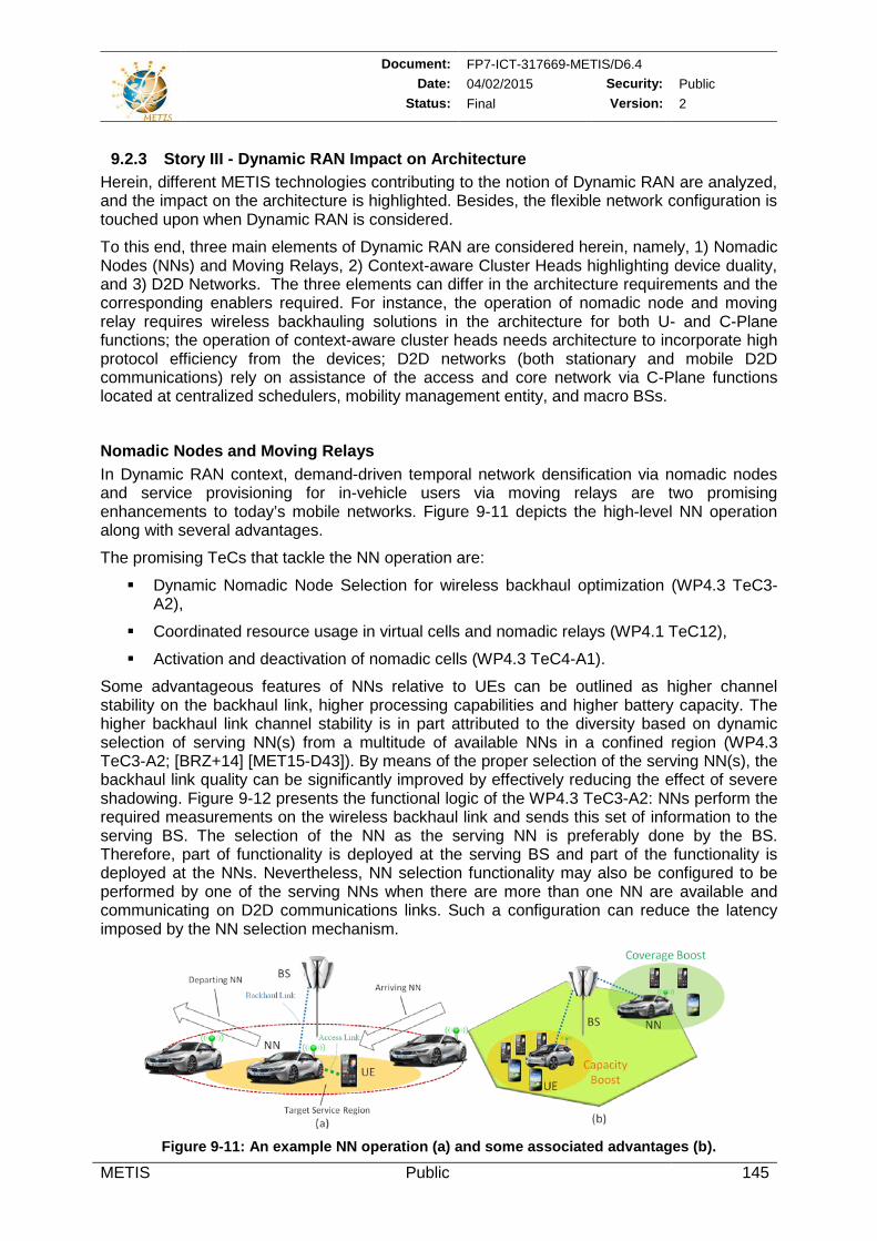
Document: FP7-ICT-317669-METIS/D6.4 Date: 04/02/2015 Security: Public
Status: Final Version: 2
METIS Public 145
9.2.3 Story III - Dynamic RAN Impact on Architecture Herein, different METIS technologies contributing to the notion of Dynamic RAN are analyzed, and the impact on the architecture is highlighted. Besides, the flexible network configuration is touched upon when Dynamic RAN is considered.
To this end, three main elements of Dynamic RAN are considered herein, namely, 1) Nomadic Nodes (NNs) and Moving Relays, 2) Context-aware Cluster Heads highlighting device duality, and 3) D2D Networks. The three elements can differ in the architecture requirements and the corresponding enablers required. For instance, the operation of nomadic node and moving relay requires wireless backhauling solutions in the architecture for both U- and C-Plane functions; the operation of context-aware cluster heads needs architecture to incorporate high protocol efficiency from the devices; D2D networks (both stationary and mobile D2D communications) rely on assistance of the access and core network via C-Plane functions located at centralized schedulers, mobility management entity, and macro BSs.
Nomadic Nodes and Moving Relays In Dynamic RAN context, demand-driven temporal network densification via nomadic nodes and service provisioning for in-vehicle users via moving relays are two promising enhancements to today’s mobile networks. Figure 9-11 depicts the high-level NN operation along with several advantages.
The promising TeCs that tackle the NN operation are:
Dynamic Nomadic Node Selection for wireless backhaul optimization (WP4.3 TeC3-A2),
Coordinated resource usage in virtual cells and nomadic relays (WP4.1 TeC12),
Activation and deactivation of nomadic cells (WP4.3 TeC4-A1).
Some advantageous features of NNs relative to UEs can be outlined as higher channel stability on the backhaul link, higher processing capabilities and higher battery capacity. The higher backhaul link channel stability is in part attributed to the diversity based on dynamic selection of serving NN(s) from a multitude of available NNs in a confined region (WP4.3 TeC3-A2; [BRZ+14] [MET15-D43]). By means of the proper selection of the serving NN(s), the backhaul link quality can be significantly improved by effectively reducing the effect of severe shadowing. Figure 9-12 presents the functional logic of the WP4.3 TeC3-A2: NNs perform the required measurements on the wireless backhaul link and sends this set of information to the serving BS. The selection of the NN as the serving NN is preferably done by the BS. Therefore, part of functionality is deployed at the serving BS and part of the functionality is deployed at the NNs. Nevertheless, NN selection functionality may also be configured to be performed by one of the serving NNs when there are more than one NN are available and communicating on D2D communications links. Such a configuration can reduce the latency imposed by the NN selection mechanism.
Figure 9-11: An example NN operation (a) and some associated advantages (b).
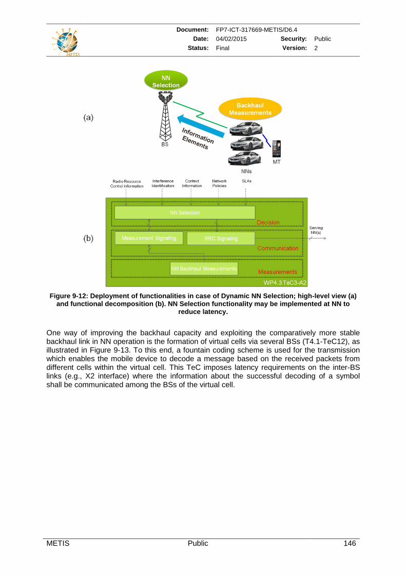
Document: FP7-ICT-317669-METIS/D6.4 Date: 04/02/2015 Security: Public
Status: Final Version: 2
METIS Public 146
Figure 9-12: Deployment of functionalities in case of Dynamic NN Selection; high-level view (a)
and functional decomposition (b). NN Selection functionality may be implemented at NN to reduce latency.
One way of improving the backhaul capacity and exploiting the comparatively more stable backhaul link in NN operation is the formation of virtual cells via several BSs (T4.1-TeC12), as illustrated in Figure 9-13. To this end, a fountain coding scheme is used for the transmission which enables the mobile device to decode a message based on the received packets from different cells within the virtual cell. This TeC imposes latency requirements on the inter-BS links (e.g., X2 interface) where the information about the successful decoding of a symbol shall be communicated among the BSs of the virtual cell.
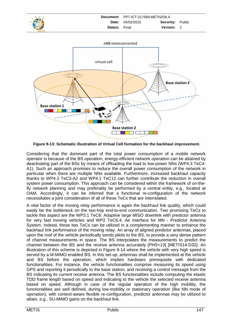
Document: FP7-ICT-317669-METIS/D6.4 Date: 04/02/2015 Security: Public
Status: Final Version: 2
METIS Public 147
Figure 9-13: Schematic illustration of Virtual Cell formation for the backhaul improvement.
Considering that the dominant part of the total power consumption of a mobile network operator is because of the BS operation, energy-efficient network operation can be attained by deactivating part of the BSs by means of offloading the load to low-power NNs (WP4.3 TeC4-A1). Such an approach promises to reduce the overall power consumption of the network in particular when there are multiple NNs available. Furthermore, increased backhaul capacity thanks to WP4.3 TeC3-A2 and WP4.1 TeC12 can further contribute the reduction in overall system power consumption. This approach can be considered within the framework of on-the-fly network planning and may preferably be performed by a central entity, e.g., located at OAM. Accordingly, it can be inferred that a functional re-configuration of the network necessitates a joint consideration of all of these TeCs that are interrelated.
A vital factor of the moving relay performance is again the backhaul link quality, which could easily be the bottleneck on the two-hop end-to-end communication. Two promising TeCs to tackle this aspect are the WP3.1 TeC6: Adaptive large MISO downlink with predictor antenna for very fast moving vehicles and WP2 TeC6.4: Air interface for MN - Predictor Antenna System. Indeed, these two TeCs can be utilized in a complementing manner to enhance the backhaul link performance of the moving relay. An array of aligned predictor antennas, placed upon the roof of the vehicle periodically sends pilots to the BS, to provide a very dense pattern of channel measurements in space. The BS interpolates the measurements to predict the channel between the BS and the receive antenna accurately [PHS+13] [METIS14-D32]. An illustration of this scheme is depicted in Figure 9-14 where the vehicle with very high speed is served by a M-MIMO enabled BS. In this set-up, antennas shall be implemented at the vehicle and BS before the operation, which implies hardware prerequisite with dedicated functionalities. For instance, the vehicle functionalities comprise measuring its speed using GPS and reporting it periodically to the base station, and receiving a control message from the BS indicating its current receive antenna. The BS functionalities include computing the elastic TDD frame length based on speed and indicating to the vehicle the selected receive antenna based on speed. Although in case of the regular operation of the high mobility, the functionalities are well defined, during low-mobility or stationary operation (like NN mode of operation), with context-aware flexible re-configuration, predictor antennas may be utilized to attain, e.g., SU-MIMO gains on the backhaul link.
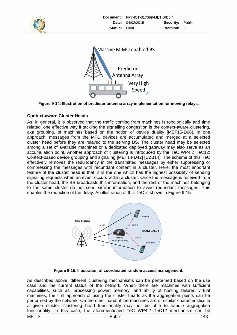
Document: FP7-ICT-317669-METIS/D6.4 Date: 04/02/2015 Security: Public
Status: Final Version: 2
METIS Public 148
Figure 9-14: Illustration of predictor antenna array implementation for moving relays.
Context-aware Cluster Heads As, in general, it is observed that the traffic coming from machines is topologically and time related, one effective way if tackling the signalling congestion is the context-aware clustering, aka grouping, of machines based on the notion of device duality [MET15-D66]. In one approach, messages from the MTC devices are accumulated and merged at a selected cluster head before they are relayed to the serving BS. The cluster head may be selected among a set of available machines or a dedicated deployed gateway may also serve as an accumulation point. Another approach of clustering is introduced by the TeC WP4.2 TeC12: Context-based device grouping and signaling [MET14-D42] [CZB14]. The scheme of this TeC effectively removes the redundancy in the transmitted messages by either suppressing or compressing the messages with redundant content in a cluster. Here, the most important feature of the cluster head is that, it is the one which has the highest possibility of sending signaling requests when an event occurs within a cluster. Once the message is received from the cluster head, the BS broadcasts this information, and the rest of the machines belonging to the same cluster do not send similar information to avoid redundant messages. This enables the reduction of the delay. An illustration of this TeC is shown in Figure 9-15.
Figure 9-15: Illustration of coordinated random access management.
As described above, different clustering mechanisms can be performed based on the use case and the current status of the network. When there are machines with sufficient capabilities, such as, processing power, memory, and ability of hosting tailored virtual machines, the first approach of using the cluster heads as the aggregation points can be performed by the network. On the other hand, if the machines are of similar characteristics in a given cluster, clustering head functionality may not be able to handle aggregation functionality. In this case, the aforementioned TeC WP4.2 TeC12 mechanism can be
Massive MIMO enabled BS
Very narrow BeamPredictor
Antenna ArrayVery High
Speed
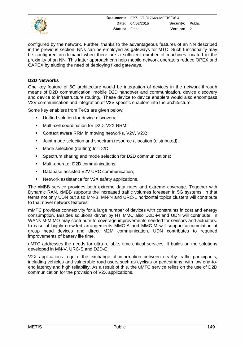
Document: FP7-ICT-317669-METIS/D6.4 Date: 04/02/2015 Security: Public
Status: Final Version: 2
METIS Public 149
configured by the network. Further, thanks to the advantageous features of an NN described in the previous section, NNs can be employed as gateways for MTC. Such functionality may be configured on-demand when there are a sufficient number of machines located in the proximity of an NN. This latter approach can help mobile network operators reduce OPEX and CAPEX by eluding the need of deploying fixed gateways.
D2D Networks One key feature of 5G architecture would be integration of devices in the network through means of D2D communication, mobile D2D handover and communication, device discovery and device to infrastructure routing. These device to device enablers would also encompass V2V communication and integration of V2V specific enablers into the architecture.
Some key enablers from TeCs are given below:
Unified solution for device discovery;
Multi-cell coordination for D2D, V2X RRM;
Context aware RRM in moving networks, V2V, V2X;
Joint mode selection and spectrum resource allocation (distributed);
Mode selection (routing) for D2D;
Spectrum sharing and mode selection for D2D communications;
Multi-operator D2D communications;
Database assisted V2V URC communication;
Network assistance for V2X safety applications.
The xMBB service provides both extreme data rates and extreme coverage. Together with Dynamic RAN, xMBB supports the increased traffic volumes foreseen in 5G systems. In that terms not only UDN but also MN-B, MN-N and URC-L horizontal topics clusters will contribute to that novel network features.
mMTC provides connectivity for a large number of devices with constraints in cost and energy consumption. Besides solutions driven by HT MMC also D2D-M and UDN will contribute. In WANs M-MIMO may contribute to coverage improvements needed for sensors and actuators. In case of highly crowded arrangements MMC-A and MMC-M will support accumulation at group head devices and direct M2M communication. UDN contributes to required improvements of battery life time.
uMTC addresses the needs for ultra-reliable, time-critical services. It builds on the solutions developed in MN-V, URC-S and D2D-C.
V2X applications require the exchange of information between nearby traffic participants, including vehicles and vulnerable road users such as cyclists or pedestrians, with low end-to-end latency and high reliability. As a result of this, the uMTC service relies on the use of D2D communication for the provision of V2X applications.
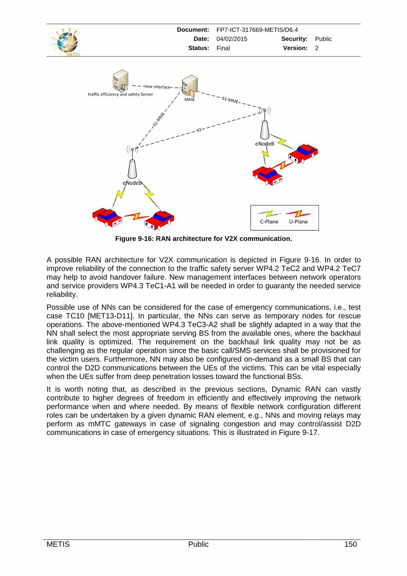
Document: FP7-ICT-317669-METIS/D6.4 Date: 04/02/2015 Security: Public
Status: Final Version: 2
METIS Public 150
Figure 9-16: RAN architecture for V2X communication.
A possible RAN architecture for V2X communication is depicted in Figure 9-16. In order to improve reliability of the connection to the traffic safety server WP4.2 TeC2 and WP4.2 TeC7 may help to avoid handover failure. New management interfaces between network operators and service providers WP4.3 TeC1-A1 will be needed in order to guaranty the needed service reliability.
Possible use of NNs can be considered for the case of emergency communications, i.e., test case TC10 [MET13-D11]. In particular, the NNs can serve as temporary nodes for rescue operations. The above-mentioned WP4.3 TeC3-A2 shall be slightly adapted in a way that the NN shall select the most appropriate serving BS from the available ones, where the backhaul link quality is optimized. The requirement on the backhaul link quality may not be as challenging as the regular operation since the basic call/SMS services shall be provisioned for the victim users. Furthermore, NN may also be configured on-demand as a small BS that can control the D2D communications between the UEs of the victims. This can be vital especially when the UEs suffer from deep penetration losses toward the functional BSs.
It is worth noting that, as described in the previous sections, Dynamic RAN can vastly contribute to higher degrees of freedom in efficiently and effectively improving the network performance when and where needed. By means of flexible network configuration different roles can be undertaken by a given dynamic RAN element, e.g., NNs and moving relays may perform as mMTC gateways in case of signaling congestion and may control/assist D2D communications in case of emergency situations. This is illustrated in Figure 9-17.
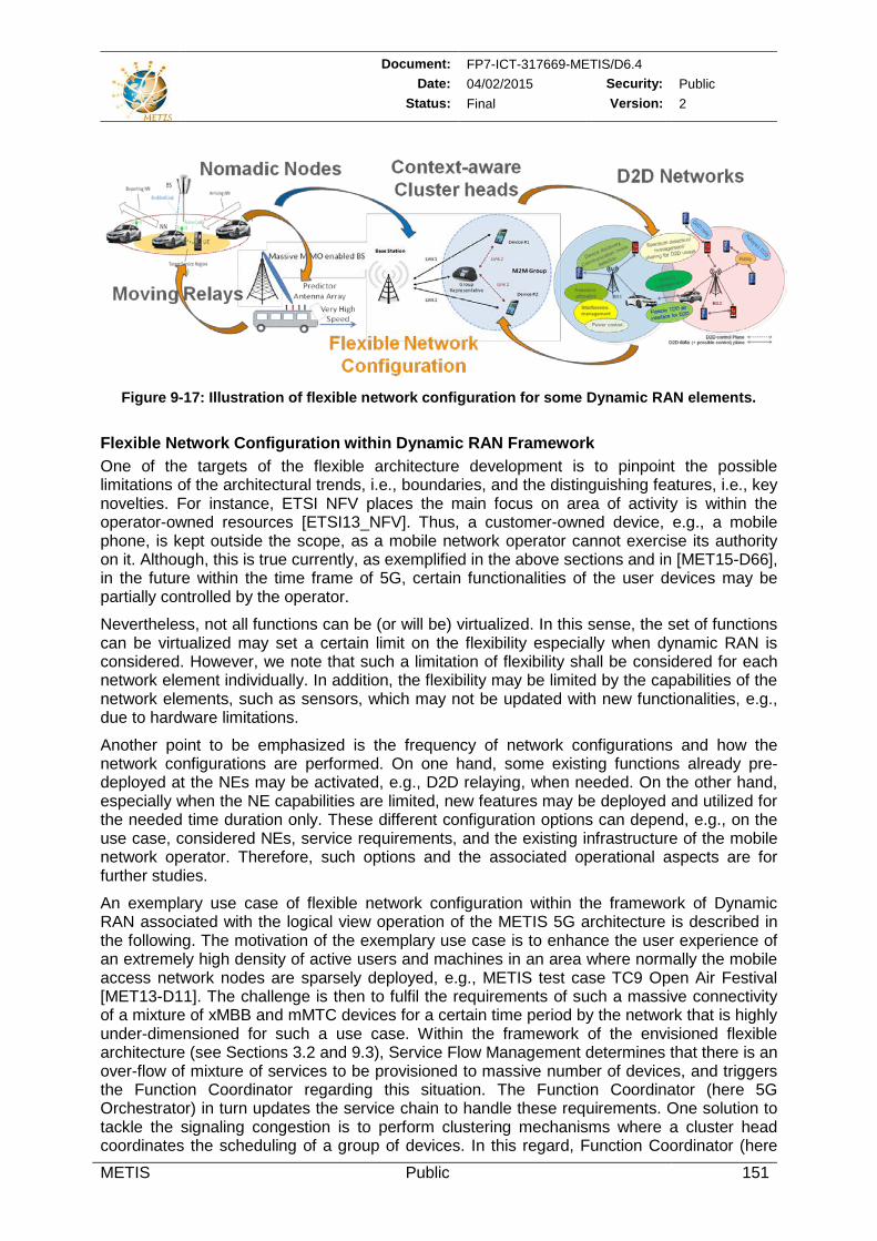
Document: FP7-ICT-317669-METIS/D6.4 Date: 04/02/2015 Security: Public
Status: Final Version: 2
METIS Public 151
Figure 9-17: Illustration of flexible network configuration for some Dynamic RAN elements.
Flexible Network Configuration within Dynamic RAN Framework One of the targets of the flexible architecture development is to pinpoint the possible limitations of the architectural trends, i.e., boundaries, and the distinguishing features, i.e., key novelties. For instance, ETSI NFV places the main focus on area of activity is within the operator-owned resources [ETSI13_NFV]. Thus, a customer-owned device, e.g., a mobile phone, is kept outside the scope, as a mobile network operator cannot exercise its authority on it. Although, this is true currently, as exemplified in the above sections and in [MET15-D66], in the future within the time frame of 5G, certain functionalities of the user devices may be partially controlled by the operator.
Nevertheless, not all functions can be (or will be) virtualized. In this sense, the set of functions can be virtualized may set a certain limit on the flexibility especially when dynamic RAN is considered. However, we note that such a limitation of flexibility shall be considered for each network element individually. In addition, the flexibility may be limited by the capabilities of the network elements, such as sensors, which may not be updated with new functionalities, e.g., due to hardware limitations.
Another point to be emphasized is the frequency of network configurations and how the network configurations are performed. On one hand, some existing functions already pre-deployed at the NEs may be activated, e.g., D2D relaying, when needed. On the other hand, especially when the NE capabilities are limited, new features may be deployed and utilized for the needed time duration only. These different configuration options can depend, e.g., on the use case, considered NEs, service requirements, and the existing infrastructure of the mobile network operator. Therefore, such options and the associated operational aspects are for further studies.
An exemplary use case of flexible network configuration within the framework of Dynamic RAN associated with the logical view operation of the METIS 5G architecture is described in the following. The motivation of the exemplary use case is to enhance the user experience of an extremely high density of active users and machines in an area where normally the mobile access network nodes are sparsely deployed, e.g., METIS test case TC9 Open Air Festival [MET13-D11]. The challenge is then to fulfil the requirements of such a massive connectivity of a mixture of xMBB and mMTC devices for a certain time period by the network that is highly under-dimensioned for such a use case. Within the framework of the envisioned flexible architecture (see Sections 3.2 and 9.3), Service Flow Management determines that there is an over-flow of mixture of services to be provisioned to massive number of devices, and triggers the Function Coordinator regarding this situation. The Function Coordinator (here 5G Orchestrator) in turn updates the service chain to handle these requirements. One solution to tackle the signaling congestion is to perform clustering mechanisms where a cluster head coordinates the scheduling of a group of devices. In this regard, Function Coordinator (here
Document: FP7-ICT-317669-METIS/D6.4 Date: 04/02/2015 Security: Public
Status: Final Version: 2
METIS Public 152
VNF Manager) commands the Function Agents of the selected cluster heads (selection can be performed by the Context Management Entity according to the collected context, e.g., device capabilities reported by Function Agents) in the target region to install or activate the cluster-head functionality in the RNEs of those selected cluster heads. The functionality definition is taken from the 5G Function Architecture via Function Coordinator (here 5G Orchestrator) and Function Agents. It is worth noting that the cluster head functionality may only utilized for a given time period when the service is required. Due to limited machine capabilities, e.g., small memory, such cluster head functionality may be removed depending on the service and energy efficiency requirements. Based on the input from Function Coordinator (here 5G Orchestrator), the 5G SDN controller can now perform the re-routing of the data flows according to service chain in line with the updated network topology.
9.2.4 Story IV - uMTC in industrial applications
The process industry can use wireless networks to improve operations, product quality, productivity, and reliability by e.g. gathering more data from processes, predicting equipment maintenance. Wireless technology eliminates or mitigates problems associated with wired networks. Some of the advantages of wireless networks compared to wired networks are [IT10]:
• Wear-and tear free data transfer.
• Lower installation and maintenance costs.
• Deployment opportunities in stationary, mobile, and rotating equipment.
• Fairly reliable communication without expensive connectors.
uMTC in industrial settings must be able to handle different kinds of traffic associated with periodic data, sporadic data and configuration messages.
Periodic data is associated with inputs and outputs of control algorithms. Periodic data must be delivered within a certain given time (maximum delay and jitter) and with a high reliability. Sporadic data, e.g. associated with alarms, must be delivered with a bounded latency (may differ depending on criticality of the alarm). Configuration messages are typically non-real-time and are not further considered here. In general the typical data packet is short and the bandwidth per node is low.
The message order is important since the information about in which order events occur is vital for decision-making applications. Hence the network needs mechanisms to ensure delivery in order or single-path routing. Single-path routing is undesirable since reliability is a key aspect in uMTC.
The availability of the network is obviously crucial, since the network is used to control a physical process. Active or passive redundancy measures and multiple paths (where possible) is desirable. At link level high reliability is necessary. Appropriate measures must be employed to ensure timely packed delivery. In some case (partial) retransmissions may be necessary and in other cases a single infrequent packet-loss may be acceptable.
The scalability of the network is very important since the network has to accommodate hundreds to even thousands of nodes.
Information security has to be considered in industrial applications. Since a physical process is controlled, the integrity and authenticity is important and the transmitted information should be encrypted. Intrusion detection where malicious packets are detected and discarded strengthens the system. Additionally, the transmitted information carries sensitive information about the workflow that need to be protected against eavesdropping. Hence appropriate security functions need to be in place.
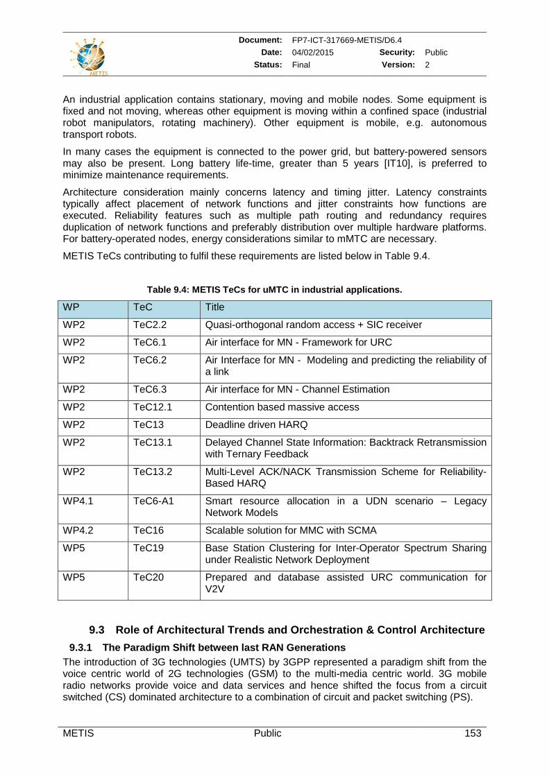
Document: FP7-ICT-317669-METIS/D6.4 Date: 04/02/2015 Security: Public
Status: Final Version: 2
METIS Public 153
An industrial application contains stationary, moving and mobile nodes. Some equipment is fixed and not moving, whereas other equipment is moving within a confined space (industrial robot manipulators, rotating machinery). Other equipment is mobile, e.g. autonomous transport robots.
In many cases the equipment is connected to the power grid, but battery-powered sensors may also be present. Long battery life-time, greater than 5 years [IT10], is preferred to minimize maintenance requirements.
Architecture consideration mainly concerns latency and timing jitter. Latency constraints typically affect placement of network functions and jitter constraints how functions are executed. Reliability features such as multiple path routing and redundancy requires duplication of network functions and preferably distribution over multiple hardware platforms. For battery-operated nodes, energy considerations similar to mMTC are necessary.
METIS TeCs contributing to fulfil these requirements are listed below in Table 9.4.
Table 9.4: METIS TeCs for uMTC in industrial applications.
WP TeC Title
WP2 TeC2.2 Quasi-orthogonal random access + SIC receiver
WP2 TeC6.1 Air interface for MN - Framework for URC
WP2 TeC6.2 Air Interface for MN - Modeling and predicting the reliability of a link
WP2 TeC6.3 Air interface for MN - Channel Estimation
WP2 TeC12.1 Contention based massive access
WP2 TeC13 Deadline driven HARQ
WP2 TeC13.1 Delayed Channel State Information: Backtrack Retransmission with Ternary Feedback
WP2 TeC13.2 Multi-Level ACK/NACK Transmission Scheme for Reliability-Based HARQ
WP4.1 TeC6-A1 Smart resource allocation in a UDN scenario – Legacy Network Models
WP4.2 TeC16 Scalable solution for MMC with SCMA
WP5 TeC19 Base Station Clustering for Inter-Operator Spectrum Sharing under Realistic Network Deployment
WP5 TeC20 Prepared and database assisted URC communication for V2V
9.3 Role of Architectural Trends and Orchestration & Control Architecture 9.3.1 The Paradigm Shift between last RAN Generations
The introduction of 3G technologies (UMTS) by 3GPP represented a paradigm shift from the voice centric world of 2G technologies (GSM) to the multi-media centric world. 3G mobile radio networks provide voice and data services and hence shifted the focus from a circuit switched (CS) dominated architecture to a combination of circuit and packet switching (PS).
Document: FP7-ICT-317669-METIS/D6.4 Date: 04/02/2015 Security: Public
Status: Final Version: 2
METIS Public 154
With 4G (LTE) a pure PS based architecture was introduced, but there are significant differences between the monolithic 4G architecture [3GPP14-23002] [3GPP14-36300], primarily to support mobile broadband applications, and the 5G architecture described in the following section – that go far beyond the differences observed between subsequent generations’ architectures. 4G network architecture may be considered the final step in the evolution of the network concepts and technologies that were originally developed for ISDN, adapted to the mobile context in order to support mobility and roaming in GSM, and evolved in order to support a multiservice network in UMTS. This evolution has been dramatic in some areas; e.g., with LTE the transition from a circuit switched, voice centric network to a packet switched all-IP one is completed, while the network has evolved towards a “flatter” architecture. However, the design principles applied for the definition of the architecture have not changed so much, mainly due to the need to preserve backwards compatibility between systems and also to technological limitations. The separation between radio access network (RAN) functionalities and core network (CN) functionalities (Access Stratum and Non Access Stratum) or the grouping of the core functionalities into call management, session management and mobility management are common characteristics of the different generations’ network architecture. The resulting architecture has a hierarchical structure that, although optimized and enhanced, has been preserved in each new generation and defines the set of interfaces and protocols that are being used.
The diversity of use cases necessarily requires a 5G architecture which is more flexible than the current flexibility that is provided. It has also to be more cost-efficient. New paradigms, such as NFV and SDN, coupled with advances in computing and storage provide an opportunity for a radical rethinking of 5G architecture design. Even though these new paradigms can be applied to make the 4G network architecture less expensive to deploy and more flexible [RAD14] [4GA14b], exploiting their full potential and to realize much greater flexibility requires a departure from the legacy principles upon which the 4G architecture is based [4GA14a].
The resulting 5G architecture breaks away from the rigidity of RAN and CN separation. It also breaks away from associating functions tightly with pre-defined entities. Finally, it natively leverages SDN and NFV principles, clearly separating control from data, as well as, hardware from software. This means the resulting 5G architecture is more flexible and has the ability not only to support the diversity of use cases, but to do that in an efficient and cost-effective manner.
Among various general infrastructure trends, SDN architecture [KRV+14] is a promising candidate to enable on-demand creation of customized virtual networks (VN) using a shared resource pool. VNs based on SDN architecture allow effective decoupling of control and data plane in order to optimize routing and mobility management. VNs can be customized according to the requirements of the target services and multiple VNs can co-exist.
Flexible combining and reloading of functional building blocks will also overcome the separation of radio access and radio core networks, making it possible to deploy core and service layer functions across the network sites depending on the requirements, for instance to better support content delivery networks (CDN) [WCT+14].
The realization of NFV via centralized software applications on general purpose cloud-based hardware will happen in medium term primarily for core network elements, partly in combination with integration of fixed-mobile network components (see [ETSI12_NFV]). The extension to the RAN part is a potential in the long term (e.g., via C-RAN) and therefore, it has particular relevance for METIS. Ongoing activities are promoted, e.g., by ETSI ISG NFV [ETSI12_NFV] [ETSI13_NFV]. NFV can be seen as highly complementary to SDN [SSC+13] [JP13], as it is relying on techniques currently in use in many data centers. Applying NVF together with the SDN approach of separation of control and data planes has the potential to improve the network flexibility addressing different use case and reduce the CAPEX and
Document: FP7-ICT-317669-METIS/D6.4 Date: 04/02/2015 Security: Public
Status: Final Version: 2
METIS Public 155
OPEX of the networks. Adapting the concept of NFV and SDN to radio networks also has a lot of technical challenges due to the strict performance requirements, latency requirement and impacts of available transport options [RBD+14] [BDS+14]. For this reason further research in this area is needed.
A set of advantages of the application of Wireless SDN (WSDN) with NFV (noted here as Radio Network Function Virtualization (RNFV) and Radio Function Virtualization (RFV), respectively) [PWH13] can be outlined as:
Extension of cloud service offerings (noted as Infrastructure as a Service (IaaS) or Platform as a Service (PaaS) from (fixed/) mobile core to RAN area (noted as RAN as a Service (RANaaS) [RBD+14]. Further elaboration of this scenario is subject to future research (see also operator requirements provided in [NGM14]).
Increased flexibility in E2E service offerings by on-demand adaptation of data transport on radio and back-/fronthaul layers according to service content and available resources (content and resource awareness). Further elaboration of this scenario is subject to future research.
More flexible clustering of cells for joint RRM (including carrier aggregation), interference coordination (including CoMP procedures) and context-/service-aware mobility management due to centralized processing and minimum delay among baseband processing units (realizable via virtual machines on general purpose processors, probably with support of HW accelerators for dedicated PHY computing tasks).
Potential for multi-operator network infrastructure and resource sharing (including also fixed network operators with respect to back-/fronthaul usage).
Flexible integration and adaptation of Operation, Accounting and Maintenance (OAM) and self-organizing/automation functionalities (enhanced SON).
The provisioning of suitable backhaul and – in case of C-RANs – fronthaul is a very important aspect especially for UDN. Even in mid-term future, it cannot be expected that fiber- or copper-based wired solutions (e.g., GPON or G.Fast) will be available everywhere. To avoid expensive cable construction, wireless back-/fronthaul solutions will play an important role in future mobile networks and will ideally be integrated into the radio nodes with access link provisioning based on the proposed flexible air interface (e.g., in-band and/or out-of-band solutions).
Implementation of radio network and service functions in C-RAN environments can simplify the mapping of SDN and NFV features (known from core function virtualization in data centers) to the RAN. It also increases flexibility with respect to integration of decentralized core functions in C-RAN processing units like local mobility management, local breakouts as well as CDN with caching capabilities [NGM13] [WCT+14]. Due to centralized processing and minimum delay among BaseBand processing Units (BBUs), C-RAN environments allow simplified clustering of cells for joint RRM and interference coordination (including CoMP). Dependent on network infrastructure availability of the mobile network operator and delay limitations set on back-/fronthaul links, e.g., by CoMP schemes, C-RANs can be deployed in a distributed or more centralized way, which differentiate especially in terms of the number of contained BBUs (realizable via virtual machines on general purpose processors, possibly with support of hardware accelerators for dedicated physical layer computing tasks). Nevertheless, the BBU number of a local C-RAN can be also high in case of UDN, e.g., for a stadium scenario.
In line with the aforementioned discussions, Figure 9-18 highlights various features helpful to develop new flexible, scalable, and efficient mobile and wireless radio network architectures in order to support all of the diverse requirements of the future radio network. Moreover, Figure
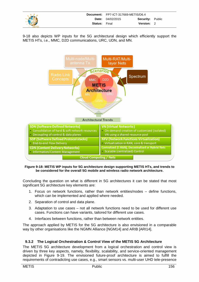
Document: FP7-ICT-317669-METIS/D6.4 Date: 04/02/2015 Security: Public
Status: Final Version: 2
METIS Public 156
9-18 also depicts WP inputs for the 5G architectural design which efficiently support the METIS HTs, i.e., MMC, D2D communications, URC, UDN, and MN.
Figure 9-18: METIS WP inputs for 5G architecture design supporting METIS HTs, and trends to
be considered for the overall 5G mobile and wireless radio network architecture.
Concluding the question on what is different in 5G architectures it can be stated that most significant 5G architecture key elements are:
1. Focus on network functions, rather than network entities/nodes – define functions, which can be implemented and applied where needed.
2. Separation of control and data plane.
3. Adaptation to use cases – not all network functions need to be used for different use cases. Functions can have variants, tailored for different use cases.
4. Interfaces between functions, rather than between network entities.
The approach applied by METIS for the 5G architecture is also envisioned in a comparable way by other organisations like the NGMN Alliance [NGM14] and ARIB [ARI14].
9.3.2 The Logical Orchestration & Control View of the METIS 5G Architecture The METIS 5G architecture development from a logical orchestration and control view is driven by three key aspects, namely, flexibility, scalability, and service-oriented management depicted in Figure 9-19. The envisioned future-proof architecture is aimed to fulfill the requirements of contradicting use cases, e.g., smart sensors vs. multi-user UHD tele-presence
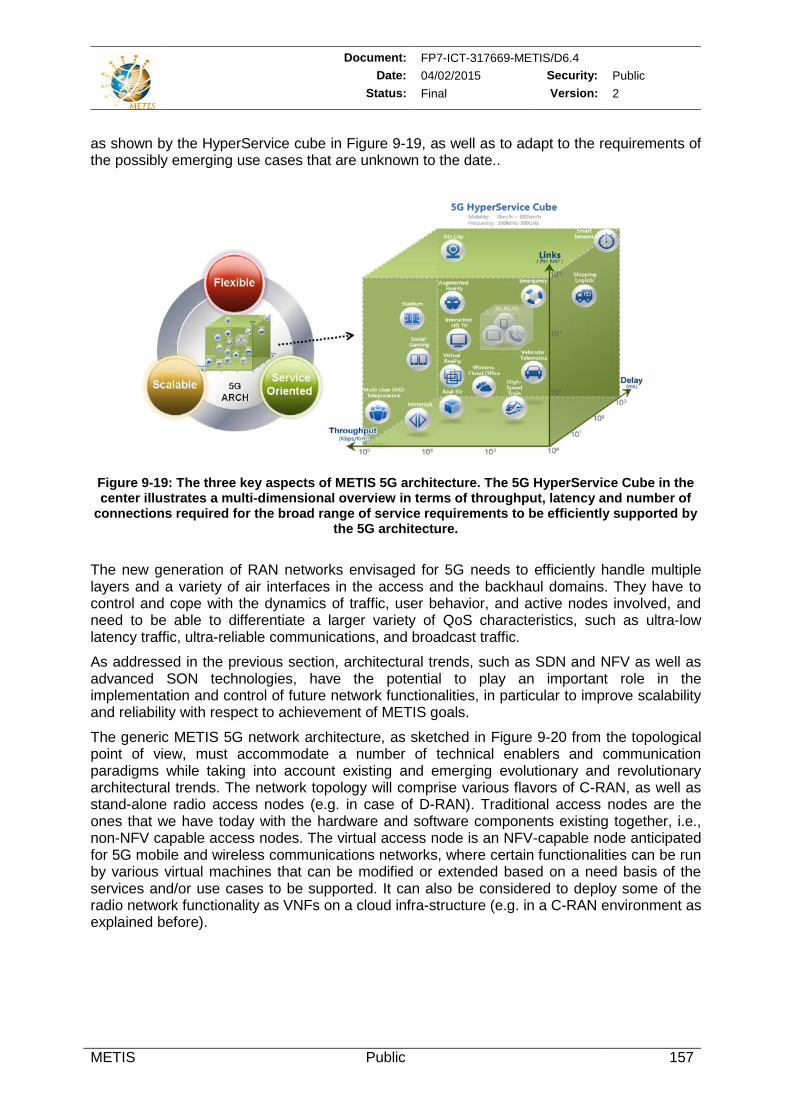
Document: FP7-ICT-317669-METIS/D6.4 Date: 04/02/2015 Security: Public
Status: Final Version: 2
METIS Public 157
as shown by the HyperService cube in Figure 9-19, as well as to adapt to the requirements of the possibly emerging use cases that are unknown to the date..
Figure 9-19: The three key aspects of METIS 5G architecture. The 5G HyperService Cube in the center illustrates a multi-dimensional overview in terms of throughput, latency and number of
connections required for the broad range of service requirements to be efficiently supported by the 5G architecture.
The new generation of RAN networks envisaged for 5G needs to efficiently handle multiple layers and a variety of air interfaces in the access and the backhaul domains. They have to control and cope with the dynamics of traffic, user behavior, and active nodes involved, and need to be able to differentiate a larger variety of QoS characteristics, such as ultra-low latency traffic, ultra-reliable communications, and broadcast traffic.
As addressed in the previous section, architectural trends, such as SDN and NFV as well as advanced SON technologies, have the potential to play an important role in the implementation and control of future network functionalities, in particular to improve scalability and reliability with respect to achievement of METIS goals.
The generic METIS 5G network architecture, as sketched in Figure 9-20 from the topological point of view, must accommodate a number of technical enablers and communication paradigms while taking into account existing and emerging evolutionary and revolutionary architectural trends. The network topology will comprise various flavors of C-RAN, as well as stand-alone radio access nodes (e.g. in case of D-RAN). Traditional access nodes are the ones that we have today with the hardware and software components existing together, i.e., non-NFV capable access nodes. The virtual access node is an NFV-capable node anticipated for 5G mobile and wireless communications networks, where certain functionalities can be run by various virtual machines that can be modified or extended based on a need basis of the services and/or use cases to be supported. It can also be considered to deploy some of the radio network functionality as VNFs on a cloud infra-structure (e.g. in a C-RAN environment as explained before).
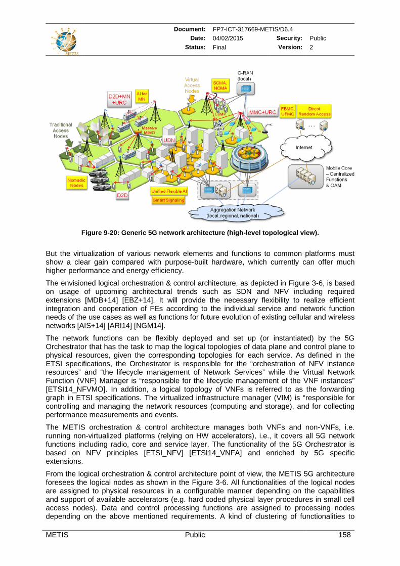
Document: FP7-ICT-317669-METIS/D6.4 Date: 04/02/2015 Security: Public
Status: Final Version: 2
METIS Public 158
Figure 9-20: Generic 5G network architecture (high-level topological view).
But the virtualization of various network elements and functions to common platforms must show a clear gain compared with purpose-built hardware, which currently can offer much higher performance and energy efficiency.
The envisioned logical orchestration & control architecture, as depicted in Figure 3-6, is based on usage of upcoming architectural trends such as SDN and NFV including required extensions [MDB+14] [EBZ+14]. It will provide the necessary flexibility to realize efficient integration and cooperation of FEs according to the individual service and network function needs of the use cases as well as functions for future evolution of existing cellular and wireless networks [AIS+14] [ARI14] [NGM14].
The network functions can be flexibly deployed and set up (or instantiated) by the 5G Orchestrator that has the task to map the logical topologies of data plane and control plane to physical resources, given the corresponding topologies for each service. As defined in the ETSI specifications, the Orchestrator is responsible for the “orchestration of NFV instance resources” and “the lifecycle management of Network Services” while the Virtual Network Function (VNF) Manager is “responsible for the lifecycle management of the VNF instances” [ETSI14_NFVMO]. In addition, a logical topology of VNFs is referred to as the forwarding graph in ETSI specifications. The virtualized infrastructure manager (VIM) is “responsible for controlling and managing the network resources (computing and storage), and for collecting performance measurements and events.
The METIS orchestration & control architecture manages both VNFs and non-VNFs, i.e. running non-virtualized platforms (relying on HW accelerators), i.e., it covers all 5G network functions including radio, core and service layer. The functionality of the 5G Orchestrator is based on NFV principles [ETSI_NFV] [ETSI14_VNFA] and enriched by 5G specific extensions.
From the logical orchestration & control architecture point of view, the METIS 5G architecture foresees the logical nodes as shown in the Figure 3-6. All functionalities of the logical nodes are assigned to physical resources in a configurable manner depending on the capabilities and support of available accelerators (e.g. hard coded physical layer procedures in small cell access nodes). Data and control processing functions are assigned to processing nodes depending on the above mentioned requirements. A kind of clustering of functionalities to
Document: FP7-ICT-317669-METIS/D6.4 Date: 04/02/2015 Security: Public
Status: Final Version: 2
METIS Public 159
certain nodes will occur because of the processing capabilities of it and the dependencies of the interfaces between functions with respect to the timing of the radio frame.
1. 5G Functional Architecture / Function Pool
The 5G Function Pool is a collection of data processing functions and control functions that have to be provided centrally. Network functions for example may be generated by combining FEs identified in Section 8. They are classified in asynchronous functions and synchronous functions with respect to their dependencies to the radio frame structure:
Synchronous Radio User Plane (SRU) functions,
Asynchronous Radio User Plane (ARU) functions,
Synchronous Radio Control Plane (SRC) functions,
Asynchronous Radio Control Plane (ARC) functions,
Core Control Plane functions,
Core User Plane functions.
2. 5G Orchestrator (Function Coordinator)
Data processing and forwarding nodes are in charge to process the data with respect to the baseband and core network processing schemes applied in order to deliver the data packets with the required latency and reliability to the next node.
The 5G Function Coordinator has the task to map the logical topologies of data plane and control plane to physical resources, given the corresponding topologies for each service. The functionality of the 5G Orchestrator is based on NFV principles [ETSI_NFV] [ETSI14_VNFA] and enriched by 5G specific extensions.
The flexibility is restricted by the limitations of the physical network elements but also by the pre-coded accelerators implemented in certain nodes e.g. hard coded physical layer procedures (s. Figure 9-21 below). This information and capabilities are reported by the Function Agent (FuAg) and are taken into account by the 5G Orchestrator assisted by the SPM and STM in order to define the optimized assignment of functions as described in Section 3.3.
3. 5G-SDN controller
The 5G-SDN controller sets up the service chain on the physical network infrastructure taking into account the configurations orchestrated by the 5G Orchestrator. The controller then constructs the communication path (control and user plane) by using typical SDN solutions (e.g. OpenFlow [ONF] in the CNE) or extended SDN like solutions for the RNE. Accordingly, it configures switching elements (SEs) also by factoring in radio specific functionalities like resource scheduling and mobility management [JEV+13].
Moreover, it is worth noting that 5G-SDN Controller can also be virtualized running as a VNF with its Element Management System (EMS) & VNF Manager [ETSI14_VNFA].
4. Radio Network Element and Core Network Element
RNEs provide all user plane processing functions with respect to the radio functions and included air interfaces, and CNEs are tailored to core network data processing and forwarding functions. Both logical nodes are connected to the 5G Orchestrator via the FuAg. On this
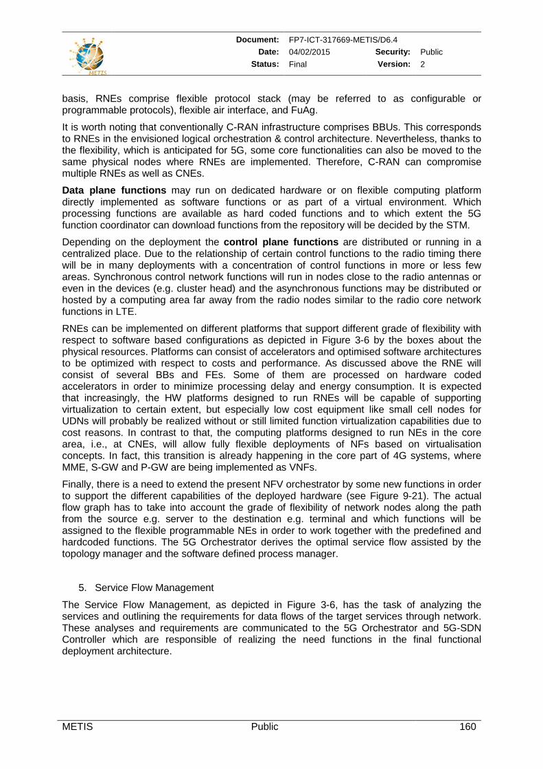
Document: FP7-ICT-317669-METIS/D6.4 Date: 04/02/2015 Security: Public
Status: Final Version: 2
METIS Public 160
basis, RNEs comprise flexible protocol stack (may be referred to as configurable or programmable protocols), flexible air interface, and FuAg.
It is worth noting that conventionally C-RAN infrastructure comprises BBUs. This corresponds to RNEs in the envisioned logical orchestration & control architecture. Nevertheless, thanks to the flexibility, which is anticipated for 5G, some core functionalities can also be moved to the same physical nodes where RNEs are implemented. Therefore, C-RAN can compromise multiple RNEs as well as CNEs.
Data plane functions may run on dedicated hardware or on flexible computing platform directly implemented as software functions or as part of a virtual environment. Which processing functions are available as hard coded functions and to which extent the 5G function coordinator can download functions from the repository will be decided by the STM.
Depending on the deployment the control plane functions are distributed or running in a centralized place. Due to the relationship of certain control functions to the radio timing there will be in many deployments with a concentration of control functions in more or less few areas. Synchronous control network functions will run in nodes close to the radio antennas or even in the devices (e.g. cluster head) and the asynchronous functions may be distributed or hosted by a computing area far away from the radio nodes similar to the radio core network functions in LTE.
RNEs can be implemented on different platforms that support different grade of flexibility with respect to software based configurations as depicted in Figure 3-6 by the boxes about the physical resources. Platforms can consist of accelerators and optimised software architectures to be optimized with respect to costs and performance. As discussed above the RNE will consist of several BBs and FEs. Some of them are processed on hardware coded accelerators in order to minimize processing delay and energy consumption. It is expected that increasingly, the HW platforms designed to run RNEs will be capable of supporting virtualization to certain extent, but especially low cost equipment like small cell nodes for UDNs will probably be realized without or still limited function virtualization capabilities due to cost reasons. In contrast to that, the computing platforms designed to run NEs in the core area, i.e., at CNEs, will allow fully flexible deployments of NFs based on virtualisation concepts. In fact, this transition is already happening in the core part of 4G systems, where MME, S-GW and P-GW are being implemented as VNFs.
Finally, there is a need to extend the present NFV orchestrator by some new functions in order to support the different capabilities of the deployed hardware (see Figure 9-21). The actual flow graph has to take into account the grade of flexibility of network nodes along the path from the source e.g. server to the destination e.g. terminal and which functions will be assigned to the flexible programmable NEs in order to work together with the predefined and hardcoded functions. The 5G Orchestrator derives the optimal service flow assisted by the topology manager and the software defined process manager.
5. Service Flow Management
The Service Flow Management, as depicted in Figure 3-6, has the task of analyzing the services and outlining the requirements for data flows of the target services through network. These analyses and requirements are communicated to the 5G Orchestrator and 5G-SDN Controller which are responsible of realizing the need functions in the final functional deployment architecture.
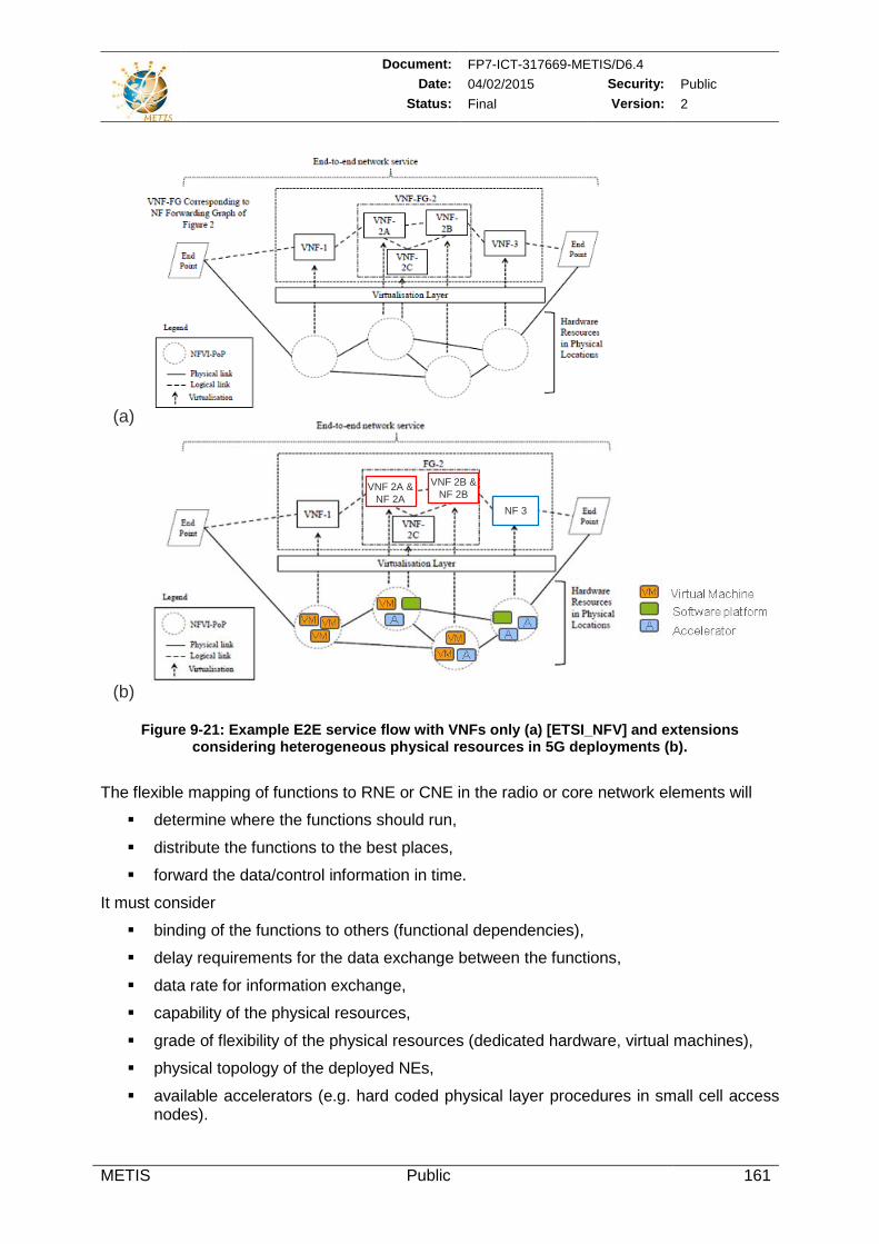
Document: FP7-ICT-317669-METIS/D6.4 Date: 04/02/2015 Security: Public
Status: Final Version: 2
METIS Public 161
Figure 9-21: Example E2E service flow with VNFs only (a) [ETSI_NFV] and extensions
considering heterogeneous physical resources in 5G deployments (b).
The flexible mapping of functions to RNE or CNE in the radio or core network elements will
determine where the functions should run,
distribute the functions to the best places,
forward the data/control information in time.
It must consider
binding of the functions to others (functional dependencies),
delay requirements for the data exchange between the functions,
data rate for information exchange,
capability of the physical resources,
grade of flexibility of the physical resources (dedicated hardware, virtual machines),
physical topology of the deployed NEs,
available accelerators (e.g. hard coded physical layer procedures in small cell access nodes).
VNF 2A & NF 2A
VNF 2B & NF 2B
NF 3
(a)
(b)
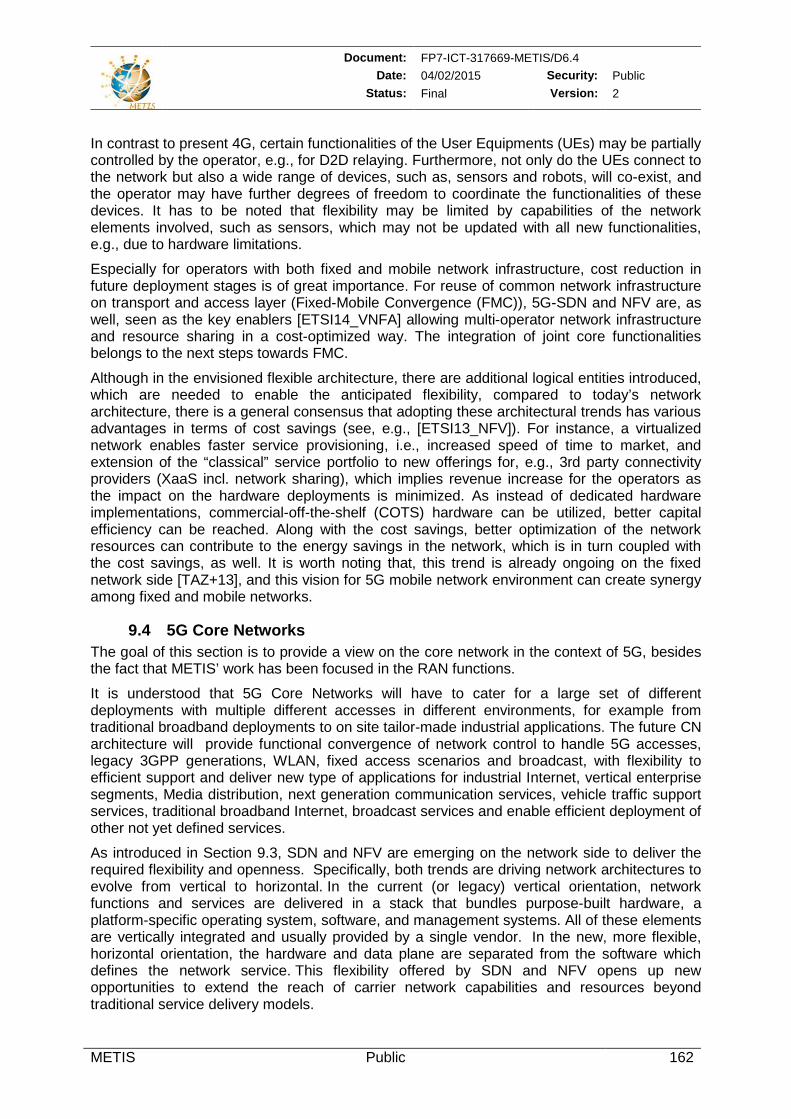
Document: FP7-ICT-317669-METIS/D6.4 Date: 04/02/2015 Security: Public
Status: Final Version: 2
METIS Public 162
In contrast to present 4G, certain functionalities of the User Equipments (UEs) may be partially controlled by the operator, e.g., for D2D relaying. Furthermore, not only do the UEs connect to the network but also a wide range of devices, such as, sensors and robots, will co-exist, and the operator may have further degrees of freedom to coordinate the functionalities of these devices. It has to be noted that flexibility may be limited by capabilities of the network elements involved, such as sensors, which may not be updated with all new functionalities, e.g., due to hardware limitations.
Especially for operators with both fixed and mobile network infrastructure, cost reduction in future deployment stages is of great importance. For reuse of common network infrastructure on transport and access layer (Fixed-Mobile Convergence (FMC)), 5G-SDN and NFV are, as well, seen as the key enablers [ETSI14_VNFA] allowing multi-operator network infrastructure and resource sharing in a cost-optimized way. The integration of joint core functionalities belongs to the next steps towards FMC.
Although in the envisioned flexible architecture, there are additional logical entities introduced, which are needed to enable the anticipated flexibility, compared to today’s network architecture, there is a general consensus that adopting these architectural trends has various advantages in terms of cost savings (see, e.g., [ETSI13_NFV]). For instance, a virtualized network enables faster service provisioning, i.e., increased speed of time to market, and extension of the “classical” service portfolio to new offerings for, e.g., 3rd party connectivity providers (XaaS incl. network sharing), which implies revenue increase for the operators as the impact on the hardware deployments is minimized. As instead of dedicated hardware implementations, commercial-off-the-shelf (COTS) hardware can be utilized, better capital efficiency can be reached. Along with the cost savings, better optimization of the network resources can contribute to the energy savings in the network, which is in turn coupled with the cost savings, as well. It is worth noting that, this trend is already ongoing on the fixed network side [TAZ+13], and this vision for 5G mobile network environment can create synergy among fixed and mobile networks.
9.4 5G Core Networks The goal of this section is to provide a view on the core network in the context of 5G, besides the fact that METIS’ work has been focused in the RAN functions.
It is understood that 5G Core Networks will have to cater for a large set of different deployments with multiple different accesses in different environments, for example from traditional broadband deployments to on site tailor-made industrial applications. The future CN architecture will provide functional convergence of network control to handle 5G accesses, legacy 3GPP generations, WLAN, fixed access scenarios and broadcast, with flexibility to efficient support and deliver new type of applications for industrial Internet, vertical enterprise segments, Media distribution, next generation communication services, vehicle traffic support services, traditional broadband Internet, broadcast services and enable efficient deployment of other not yet defined services.
As introduced in Section 9.3, SDN and NFV are emerging on the network side to deliver the required flexibility and openness. Specifically, both trends are driving network architectures to evolve from vertical to horizontal. In the current (or legacy) vertical orientation, network functions and services are delivered in a stack that bundles purpose-built hardware, a platform-specific operating system, software, and management systems. All of these elements are vertically integrated and usually provided by a single vendor. In the new, more flexible, horizontal orientation, the hardware and data plane are separated from the software which defines the network service. This flexibility offered by SDN and NFV opens up new opportunities to extend the reach of carrier network capabilities and resources beyond traditional service delivery models.
Document: FP7-ICT-317669-METIS/D6.4 Date: 04/02/2015 Security: Public
Status: Final Version: 2
METIS Public 163
An important part of the 5G network is the concept of network slicing giving the flexibility in service delivery creation allowing service composition for different applications spanning across different access networks (legacy LTE, LTE+, 5G RAN, wireline accesses, WLAN, satellite, and maybe the access stratum of 2G and 3G) with its unique network function procedures. The freedom of placing functions distributed in the network as decomposed abstract network service functions in combination of lower layer functions will call for an intelligent orchestration and control system.
Basic core network functions in 5G covers, Security AAA, Addressing, Mobility Management, Data-plane Control, Context Awareness & Control, QoS Control & Assurance. The Figure 9-22 summarizes the core network’s functional areas. In 5G those functional areas will be decomposed in virtualized network functions where control and user plane are separated allowing flexible deployment, i.e. CN functions, control plane or user plane, must be possible to be deployed in a flexible way (distributed to RAN sites or centralized) independent from each without driving control signalling load.
There are also related functions (not shown here) in the RAN architecture, e.g. Security, QoS and handover mechanisms in relation to the radio link, but in this section, the focus is on CN functions for control and user plane connectivity down to RAN nodes. The functional relation between RAN and CN has not been part of METIS but this is an area that will be further investigated in details in some of the proposed Horizon 2020 projects [EU_H2020] [5GPPP].
Figure 9-22: Core Network's functional areas.
The Security/AAA and Addressing in 5G systems is driven from mission-critical applications such as industrial control systems, public safety, telemedicine, smart grids, and automotive, that has strict security requirements to protect against intrusions and to ensure uninterrupted operations. For those new applications the Integrity and Confidentiality requirements are of high importance. Moreover the applications will have different Identities used for different rules in Authentication and Authorization when granting access to the network and to what level of access to information and/or control (e.g. based on location, device and/or time of day etc.).
In addition to mission critical services the convergence towards one access agnostic core network with multiple different access networks and device types will put new requirements to handle multiple identity structures and variants of authentication schemes. The large variants of applications and use cases in 5G [MET13-D11] will also increase requirements on flexibility in Accounting strategies how network resources are consumed with possibility to correlate billing and used resources with auditing functions. For example, in some cases billing is based on a fixed monthly fee, with conditions related to SLA fulfilments.
The Data-plane Control enables split of control and data plane (with an SDN interface type to the infrastructure) allowing optimal routing in user-plane separated from control plane, and
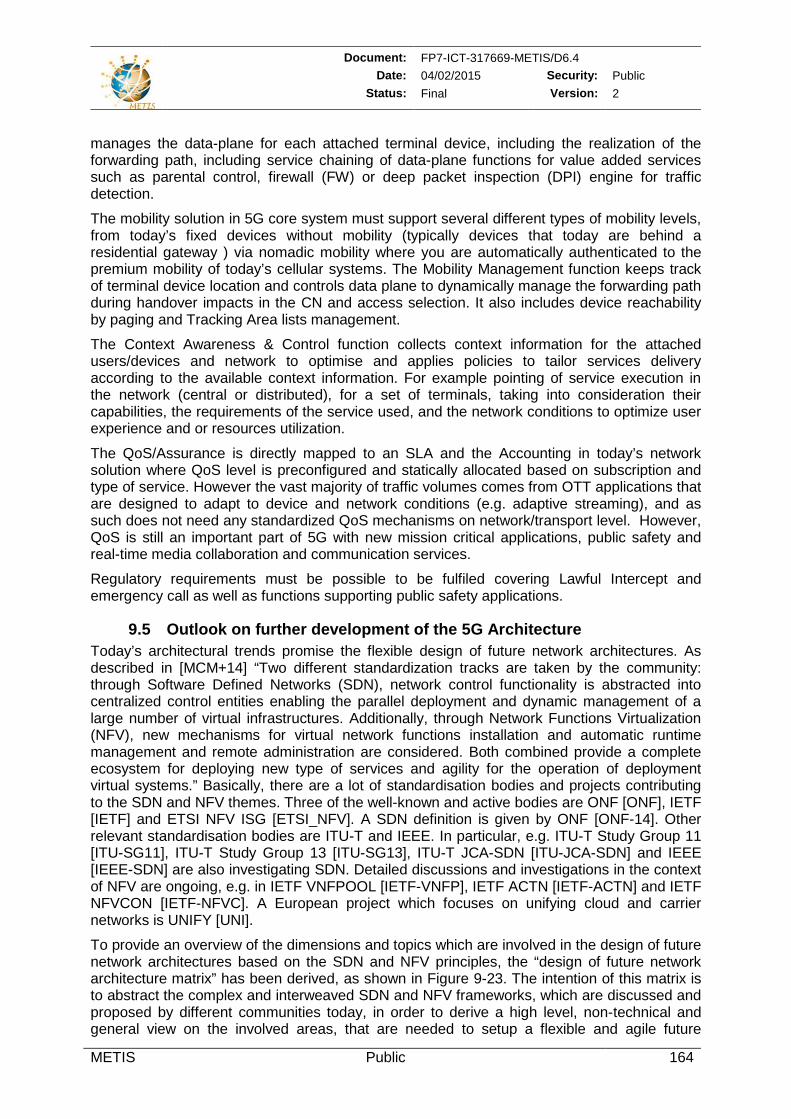
Document: FP7-ICT-317669-METIS/D6.4 Date: 04/02/2015 Security: Public
Status: Final Version: 2
METIS Public 164
manages the data-plane for each attached terminal device, including the realization of the forwarding path, including service chaining of data-plane functions for value added services such as parental control, firewall (FW) or deep packet inspection (DPI) engine for traffic detection.
The mobility solution in 5G core system must support several different types of mobility levels, from today’s fixed devices without mobility (typically devices that today are behind a residential gateway ) via nomadic mobility where you are automatically authenticated to the premium mobility of today’s cellular systems. The Mobility Management function keeps track of terminal device location and controls data plane to dynamically manage the forwarding path during handover impacts in the CN and access selection. It also includes device reachability by paging and Tracking Area lists management.
The Context Awareness & Control function collects context information for the attached users/devices and network to optimise and applies policies to tailor services delivery according to the available context information. For example pointing of service execution in the network (central or distributed), for a set of terminals, taking into consideration their capabilities, the requirements of the service used, and the network conditions to optimize user experience and or resources utilization.
The QoS/Assurance is directly mapped to an SLA and the Accounting in today’s network solution where QoS level is preconfigured and statically allocated based on subscription and type of service. However the vast majority of traffic volumes comes from OTT applications that are designed to adapt to device and network conditions (e.g. adaptive streaming), and as such does not need any standardized QoS mechanisms on network/transport level. However, QoS is still an important part of 5G with new mission critical applications, public safety and real-time media collaboration and communication services.
Regulatory requirements must be possible to be fulfiled covering Lawful Intercept and emergency call as well as functions supporting public safety applications.
9.5 Outlook on further development of the 5G Architecture Today’s architectural trends promise the flexible design of future network architectures. As described in [MCM+14] “Two different standardization tracks are taken by the community: through Software Defined Networks (SDN), network control functionality is abstracted into centralized control entities enabling the parallel deployment and dynamic management of a large number of virtual infrastructures. Additionally, through Network Functions Virtualization (NFV), new mechanisms for virtual network functions installation and automatic runtime management and remote administration are considered. Both combined provide a complete ecosystem for deploying new type of services and agility for the operation of deployment virtual systems.” Basically, there are a lot of standardisation bodies and projects contributing to the SDN and NFV themes. Three of the well-known and active bodies are ONF [ONF], IETF [IETF] and ETSI NFV ISG [ETSI_NFV]. A SDN definition is given by ONF [ONF-14]. Other relevant standardisation bodies are ITU-T and IEEE. In particular, e.g. ITU-T Study Group 11 [ITU-SG11], ITU-T Study Group 13 [ITU-SG13], ITU-T JCA-SDN [ITU-JCA-SDN] and IEEE [IEEE-SDN] are also investigating SDN. Detailed discussions and investigations in the context of NFV are ongoing, e.g. in IETF VNFPOOL [IETF-VNFP], IETF ACTN [IETF-ACTN] and IETF NFVCON [IETF-NFVC]. A European project which focuses on unifying cloud and carrier networks is UNIFY [UNI].
To provide an overview of the dimensions and topics which are involved in the design of future network architectures based on the SDN and NFV principles, the “design of future network architecture matrix” has been derived, as shown in Figure 9-23. The intention of this matrix is to abstract the complex and interweaved SDN and NFV frameworks, which are discussed and proposed by different communities today, in order to derive a high level, non-technical and general view on the involved areas, that are needed to setup a flexible and agile future
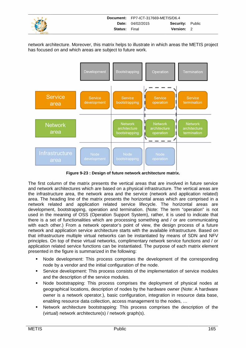
Document: FP7-ICT-317669-METIS/D6.4 Date: 04/02/2015 Security: Public
Status: Final Version: 2
METIS Public 165
network architecture. Moreover, this matrix helps to illustrate in which areas the METIS project has focused on and which areas are subject to future work.
Figure 9-23 : Design of future network architecture matrix.
The first column of the matrix presents the vertical areas that are involved in future service and network architectures which are based on a physical infrastructure. The vertical areas are the infrastructure area, the network area and the service (network and application related) area. The heading line of the matrix presents the horizontal areas which are comprised in a network related and application related service lifecycle. The horizontal areas are development, bootstrapping, operation and termination. (Note: The term “operation” is not used in the meaning of OSS (Operation Support System), rather, it is used to indicate that there is a set of functionalities which are processing something and / or are communicating with each other.) From a network operator’s point of view, the design process of a future network and application service architecture starts with the available infrastructure. Based on that infrastructure multiple virtual networks can be instantiated by means of SDN and NFV principles. On top of these virtual networks, complimentary network service functions and / or application related service functions can be instantiated. The purpose of each matrix element presented in the figure is summarized in the following:
Node development: This process comprises the development of the corresponding node by a vendor and the initial configuration of the node.
Service development: This process consists of the implementation of service modules and the description of the service modules.
Node bootstrapping: This process comprises the deployment of physical nodes at geographical locations, description of nodes by the hardware owner (Note: A hardware owner is a network operator.), basic configuration, integration in resource data base, enabling resource data collection, access management to the nodes, …
Network architecture bootstrapping: This process comprises the description of the (virtual) network architecture(s) / network graph(s).
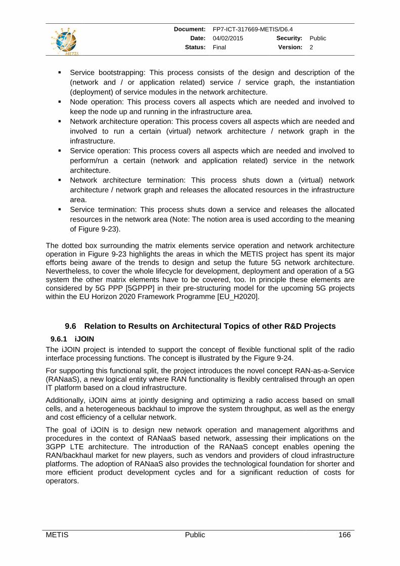
Document: FP7-ICT-317669-METIS/D6.4 Date: 04/02/2015 Security: Public
Status: Final Version: 2
METIS Public 166
Service bootstrapping: This process consists of the design and description of the (network and / or application related) service / service graph, the instantiation (deployment) of service modules in the network architecture.
Node operation: This process covers all aspects which are needed and involved to keep the node up and running in the infrastructure area.
Network architecture operation: This process covers all aspects which are needed and involved to run a certain (virtual) network architecture / network graph in the infrastructure.
Service operation: This process covers all aspects which are needed and involved to perform/run a certain (network and application related) service in the network architecture.
Network architecture termination: This process shuts down a (virtual) network architecture / network graph and releases the allocated resources in the infrastructure area.
Service termination: This process shuts down a service and releases the allocated resources in the network area (Note: The notion area is used according to the meaning of Figure 9-23).
The dotted box surrounding the matrix elements service operation and network architecture operation in Figure 9-23 highlights the areas in which the METIS project has spent its major efforts being aware of the trends to design and setup the future 5G network architecture. Nevertheless, to cover the whole lifecycle for development, deployment and operation of a 5G system the other matrix elements have to be covered, too. In principle these elements are considered by 5G PPP [5GPPP] in their pre-structuring model for the upcoming 5G projects within the EU Horizon 2020 Framework Programme [EU_H2020].
9.6 Relation to Results on Architectural Topics of other R&D Projects 9.6.1 iJOIN
The iJOIN project is intended to support the concept of flexible functional split of the radio interface processing functions. The concept is illustrated by the Figure 9-24.
For supporting this functional split, the project introduces the novel concept RAN-as-a-Service (RANaaS), a new logical entity where RAN functionality is flexibly centralised through an open IT platform based on a cloud infrastructure.
Additionally, iJOIN aims at jointly designing and optimizing a radio access based on small cells, and a heterogeneous backhaul to improve the system throughput, as well as the energy and cost efficiency of a cellular network.
The goal of iJOIN is to design new network operation and management algorithms and procedures in the context of RANaaS based network, assessing their implications on the 3GPP LTE architecture. The introduction of the RANaaS concept enables opening the RAN/backhaul market for new players, such as vendors and providers of cloud infrastructure platforms. The adoption of RANaaS also provides the technological foundation for shorter and more efficient product development cycles and for a significant reduction of costs for operators.
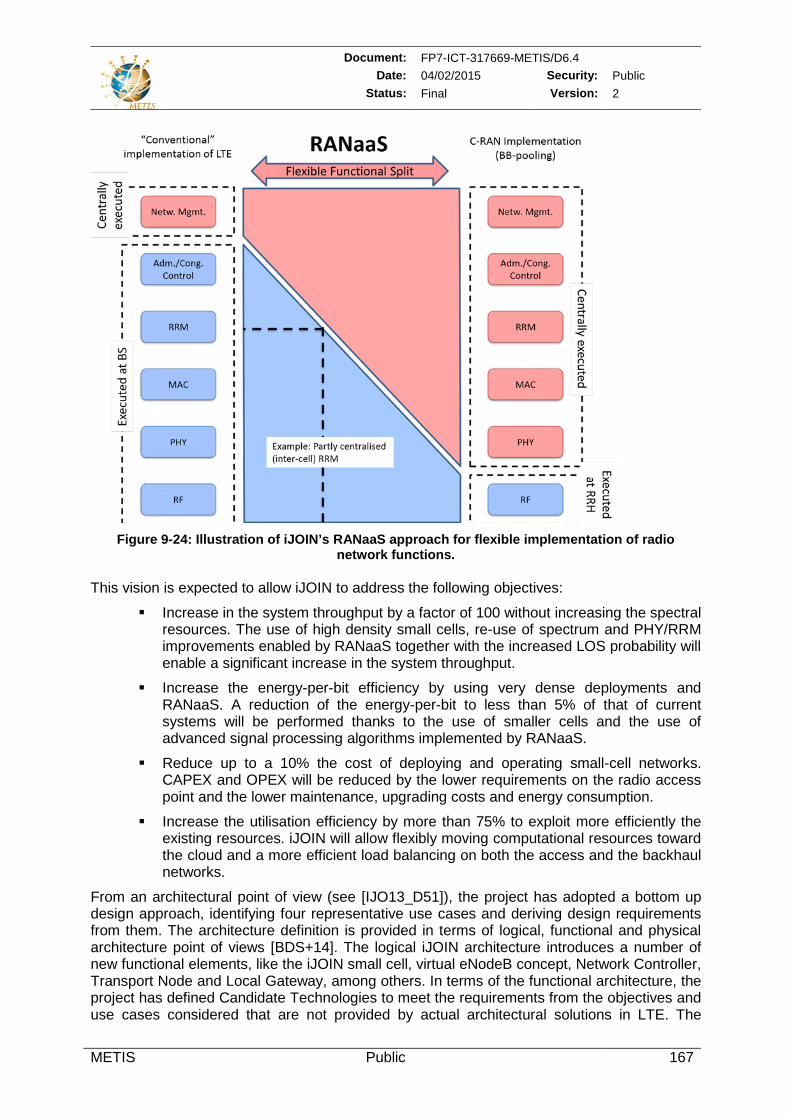
Document: FP7-ICT-317669-METIS/D6.4 Date: 04/02/2015 Security: Public
Status: Final Version: 2
METIS Public 167
Figure 9-24: Illustration of iJOIN’s RANaaS approach for flexible implementation of radio
network functions. This vision is expected to allow iJOIN to address the following objectives:
Increase in the system throughput by a factor of 100 without increasing the spectral resources. The use of high density small cells, re-use of spectrum and PHY/RRM improvements enabled by RANaaS together with the increased LOS probability will enable a significant increase in the system throughput.
Increase the energy-per-bit efficiency by using very dense deployments and RANaaS. A reduction of the energy-per-bit to less than 5% of that of current systems will be performed thanks to the use of smaller cells and the use of advanced signal processing algorithms implemented by RANaaS.
Reduce up to a 10% the cost of deploying and operating small-cell networks. CAPEX and OPEX will be reduced by the lower requirements on the radio access point and the lower maintenance, upgrading costs and energy consumption.
Increase the utilisation efficiency by more than 75% to exploit more efficiently the existing resources. iJOIN will allow flexibly moving computational resources toward the cloud and a more efficient load balancing on both the access and the backhaul networks.
From an architectural point of view (see [IJO13_D51]), the project has adopted a bottom up design approach, identifying four representative use cases and deriving design requirements from them. The architecture definition is provided in terms of logical, functional and physical architecture point of views [BDS+14]. The logical iJOIN architecture introduces a number of new functional elements, like the iJOIN small cell, virtual eNodeB concept, Network Controller, Transport Node and Local Gateway, among others. In terms of the functional architecture, the project has defined Candidate Technologies to meet the requirements from the objectives and use cases considered that are not provided by actual architectural solutions in LTE. The
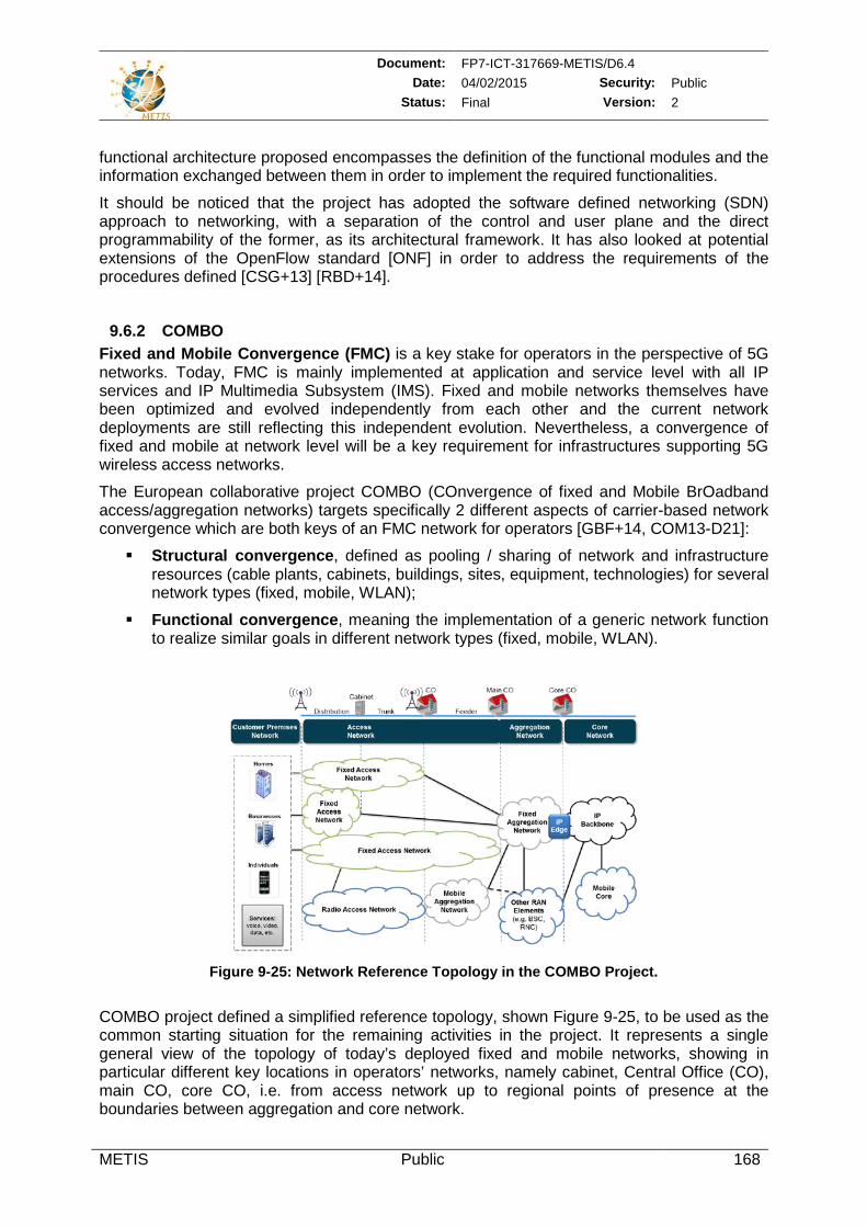
Document: FP7-ICT-317669-METIS/D6.4 Date: 04/02/2015 Security: Public
Status: Final Version: 2
METIS Public 168
functional architecture proposed encompasses the definition of the functional modules and the information exchanged between them in order to implement the required functionalities.
It should be noticed that the project has adopted the software defined networking (SDN) approach to networking, with a separation of the control and user plane and the direct programmability of the former, as its architectural framework. It has also looked at potential extensions of the OpenFlow standard [ONF] in order to address the requirements of the procedures defined [CSG+13] [RBD+14].
9.6.2 COMBO Fixed and Mobile Convergence (FMC) is a key stake for operators in the perspective of 5G networks. Today, FMC is mainly implemented at application and service level with all IP services and IP Multimedia Subsystem (IMS). Fixed and mobile networks themselves have been optimized and evolved independently from each other and the current network deployments are still reflecting this independent evolution. Nevertheless, a convergence of fixed and mobile at network level will be a key requirement for infrastructures supporting 5G wireless access networks.
The European collaborative project COMBO (COnvergence of fixed and Mobile BrOadband access/aggregation networks) targets specifically 2 different aspects of carrier-based network convergence which are both keys of an FMC network for operators [GBF+14, COM13-D21]:
Structural convergence, defined as pooling / sharing of network and infrastructure resources (cable plants, cabinets, buildings, sites, equipment, technologies) for several network types (fixed, mobile, WLAN);
Functional convergence, meaning the implementation of a generic network function to realize similar goals in different network types (fixed, mobile, WLAN).
Figure 9-25: Network Reference Topology in the COMBO Project.
COMBO project defined a simplified reference topology, shown Figure 9-25, to be used as the common starting situation for the remaining activities in the project. It represents a single general view of the topology of today’s deployed fixed and mobile networks, showing in particular different key locations in operators’ networks, namely cabinet, Central Office (CO), main CO, core CO, i.e. from access network up to regional points of presence at the boundaries between aggregation and core network.

Document: FP7-ICT-317669-METIS/D6.4 Date: 04/02/2015 Security: Public
Status: Final Version: 2
METIS Public 169
The current level of pooling between fixed and mobile infrastructures (structural convergence) is not sufficient to allow the most efficient use of network resources, whether fixed, mobile or WLAN. Structural convergence will be triggered by BBU hostelling and mobile fronthaul technologies, heterogeneous RAN and, most importantly, a unified optical access & aggregation network. COMBO European project is developing a FMC network scenario for structural convergence leveraging on the aforementioned technological triggers and in particular on evolution of optical access & aggregation technologies. Different flavors of this network scenario will be assessed and compared to derive the best architectural and technological solutions for achieving actual FMC [GPX+15].
Top Related
Copyright © 2022 FDOKUMEN

