


Bahasa
Halaman
Hukum


Revision 1.1
April 7, 2007
Cinelabs Flyback Installation Guide for
Atari’s Amplifone Vector Monitor
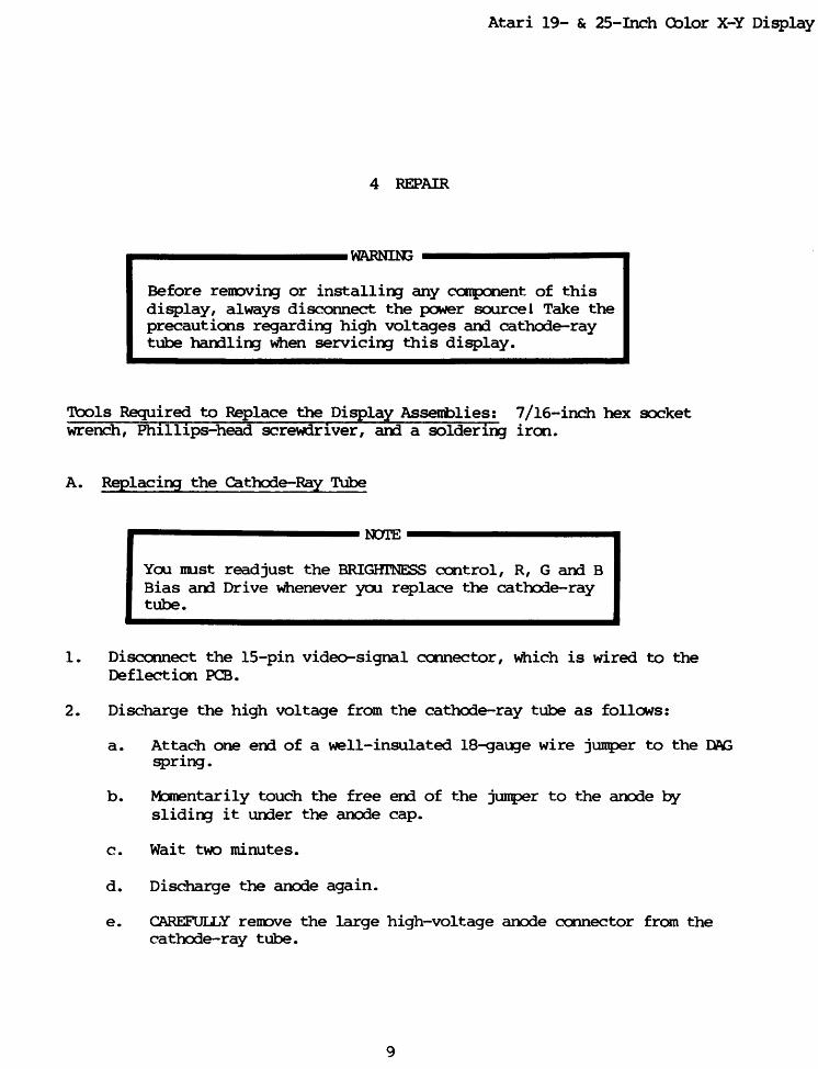
WARNING: CRT display monitors can produce lethal
voltages. Refer servicing to qualified service personnel.
PLEASE NOTE: This product is intended to be installed following the guidelines contained in
this document, by qualified service personnel. The manufacturer and distributors of this product
will not be held liable for any damage resulting from this product’s use. If you are uncomfortable
with this, you may return the product within seven (7) days, for a full refund.

Revision 1.1 : RELEASED Page 2 of 15
04/07/2007
Copyright © 2006-2007 Cinelabs, LLC
www.cinelabs.com
If properly installed by a qualified service person, this product will be warranted for a period of
one year. This period starts on the date of receipt of product, if ordered directly from Cinelabs,
or, from the purchase date on the original receipt, if purchased through an authorized distributor.
Should you ever have to use this warranty, the distributor you purchased your Flyback from will
repair or replace, at their option, the original part. The distributor’s and Cinelabs’ liability is
limited to replacement of the part, and neither party will be responsible for any damages
incidental or consequential to your game or person. This warranty does not cover “abuse”
(physical, environmental, or electrical), and is only valid for parts installed in a genuine
Amplifone High-Voltage board. Please contact Cinelabs in advance, regarding warranty terms
for components used in third party/aftermarket HV Boards.
Terms: By installing this part, you agree to take full responsibility for any damage caused to your
game and/or person, you may incur, due to lack of experience or expertise, lack of having the
correct tools, etc. You agree to read the complete installation manual, prior to installing the part,
and complying with all safety advisements and warnings.
Revision History:
Rev. Date Author Comments
0.1 11/10/2006 Shostak Initial edit of Amplifone Service manual
0.2 02/04/2007 Shostak Added Cine specific content
0.3 02/11/2007 Shostak Added pictures, incorporated comments
1.0 02/25/2007 Shostak Official Release
1.1 04/07/2007 Shostak Added Blue Board Specific Instructions
The most recent revision of this document can be found at:
http://www.cinelabs.com/docs/Amplifone_Install.pdf
Please send comments and/or corrections to: [email protected]
This guide is intended to assist in the replacement of the Flyback Transformer (“FBT”) of Atari
Amplifone 19” and 25” Color X-Y Vector monitors, when it has been determined the FBT is
defective. This guide is not intended to explain how to troubleshoot or diagnose these monitors.
Revision 1.1 : RELEASED Page 3 of 15
04/07/2007
Copyright © 2006-2007 Cinelabs, LLC
www.cinelabs.com
Be sure to read this entire document *before* working on your monitor.
CRT displays are dangerous and potentially lethal. There is risk of physical
injury from the glass CRT and danger of electrocution from high-voltage.
We advise always wearing safety glasses when working on CRT displays, as well
as keeping one hand behind your back when working on a CRT display, energized
or not. When working on Star Wars, keep both hands behind your back, and use
the force.
Remember, CRT picture tubes can store a High-Voltage charge for extended
periods of time. Always be sure to discharge the CRT prior to FBT replacement
and follow ALL industry safety practices and procedures, regardless of how
long the display has been turned off. Never make any assumptions.
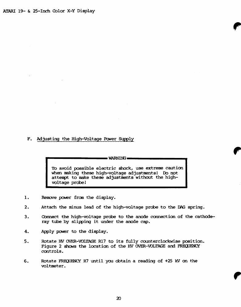
Be sure to perform the high-voltage adjustment and perform the high-voltage
safety shutdown adjustment.
If you are unsure of how to perform any safety related procedures, or are unsure of
how to safely perform this procedure, please contact a trained service technician to
perform the installation or return the never installed FBT, for a full refund.
Revision 1.1 : RELEASED Page 4 of 15
04/07/2007
Copyright © 2006-2007 Cinelabs, LLC
www.cinelabs.com
Helpful Hints:
� Cinelabs highly recommends installation of a cap kit when replacing the Flyback
transformer. The design of the Amplifone High Voltage unit is such that dry caps
can produce erratic behavior and cause poor performance.
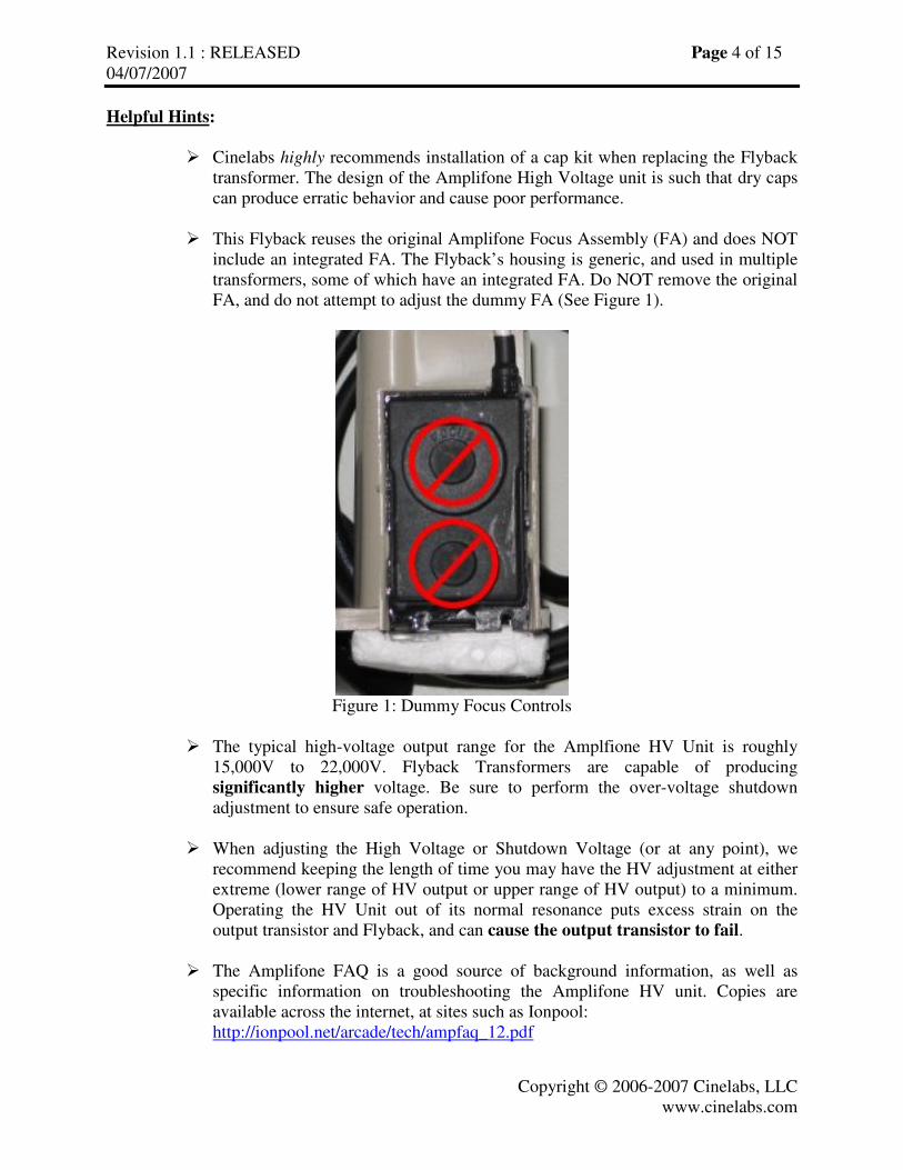
� This Flyback reuses the original Amplifone Focus Assembly (FA) and does NOT
include an integrated FA. The Flyback’s housing is generic, and used in multiple
transformers, some of which have an integrated FA. Do NOT remove the original
FA, and do not attempt to adjust the dummy FA (See Figure 1).
Figure 1: Dummy Focus Controls
� The typical high-voltage output range for the Amplfione HV Unit is roughly
15,000V to 22,000V. Flyback Transformers are capable of producing
significantly higher voltage. Be sure to perform the over-voltage shutdown
adjustment to ensure safe operation.
� When adjusting the High Voltage or Shutdown Voltage (or at any point), we
recommend keeping the length of time you may have the HV adjustment at either
extreme (lower range of HV output or upper range of HV output) to a minimum.
Operating the HV Unit out of its normal resonance puts excess strain on the
output transistor and Flyback, and can cause the output transistor to fail.
� The Amplifone FAQ is a good source of background information, as well as
specific information on troubleshooting the Amplifone HV unit. Copies are
available across the internet, at sites such as Ionpool:
http://ionpool.net/arcade/tech/ampfaq_12.pdf

Revision 1.1 : RELEASED Page 5 of 15
04/07/2007
Copyright © 2006-2007 Cinelabs, LLC
www.cinelabs.com
� If you have a Blue High-Voltage board, installation is slightly different. Be sure
to follow the specific instructions for your PCB.
� For further information on trouble-shooting the Amplifone Color Vector monitor,
the reader is directed to the RGVAC Usenet news group
(Rec.Games.Video.Arcade.Collecting), and to the Vectorlist archive, which is
located at http://www.vectorlist.org.
Cinelabs is a proud sponsor of the Vectorlist. :-)
Revision 1.1 : RELEASED Page 6 of 15
04/07/2007
Copyright © 2006-2007 Cinelabs, LLC
www.cinelabs.com
HV Cage Removal:
1. Determine FBT is defective.
2. Turn game off and unplug the AC power cord from the wall power outlet.
3. Discharge any residual energy from the CRT, following industry standard CRT
discharge procedures.
4. Disconnect the FBT anode cap from the CRT, following industry standard procedures
(we recommend, at minimum, keeping one hand behind your back).
5. Momentarily short the anode cap to the chassis, to ensure the FBT is discharged.
6. Disconnect HV Unit cable from the back of the neck of the CRT.
7. Disconnect HV Unit cable from Deflection Board.
8. Remove PCB retaining screws.
9. Remove HV Unit from monitor.
10. Installation is reverse of removal.
Green PCB Flyback Replacement:
(If you have a Blue PCB, use the Blue PCB Installation Instructions on page 9)
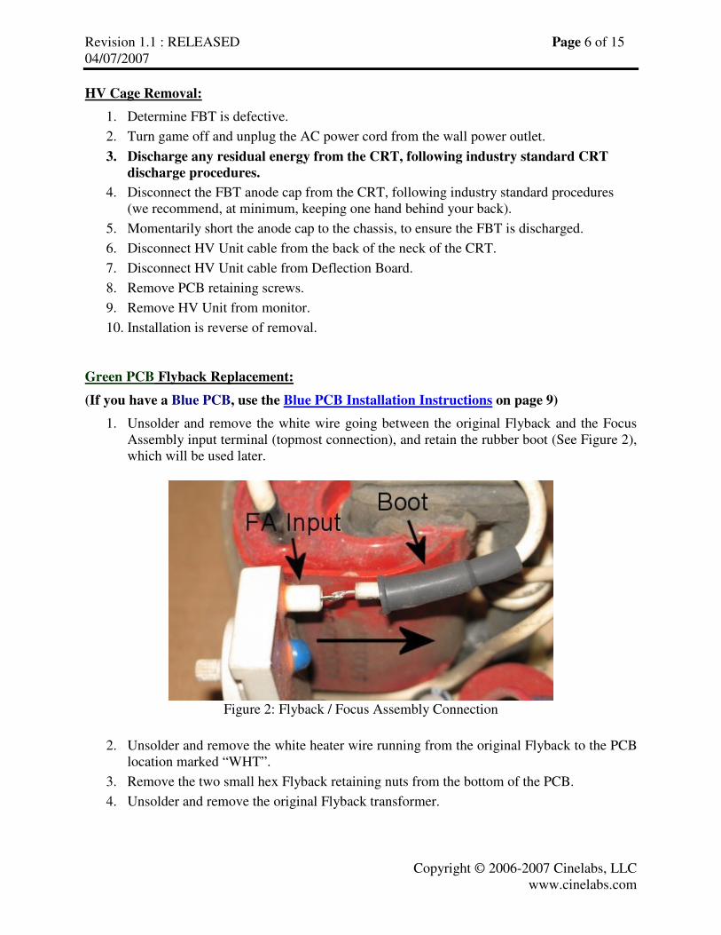
1. Unsolder and remove the white wire going between the original Flyback and the Focus
Assembly input terminal (topmost connection), and retain the rubber boot (See Figure 2),
which will be used later.
Figure 2: Flyback / Focus Assembly Connection
2. Unsolder and remove the white heater wire running from the original Flyback to the PCB
location marked “WHT”.
3. Remove the two small hex Flyback retaining nuts from the bottom of the PCB.
4. Unsolder and remove the original Flyback transformer.

Revision 1.1 : RELEASED Page 7 of 15
04/07/2007
Copyright © 2006-2007 Cinelabs, LLC
www.cinelabs.com
5. To begin installation of the new Flyback, first solder the (new) heater wire (the wire
wrapped around the core of the Flyback) to the hole in the PCB from which you removed
the original heater wire (marked “WHT” on the PCB).
6. Note the notch in the front of the Flyback,
towards the lower right (See Figure 3).
Figure 3: FBT Heater Wire Cutout
7. Install the Flyback into the PCB, being careful to route the heater wire installed in step 5,
through the notch in the bottom of the Flyback (See Figure 4). If the heater wire is not
routed through this notch, the Flyback will not sit flush with the PCB.
Figure 4: FBT Mounted Flush, Heater Wire Properly in Notch
8. Solder the new Flyback in place.
9. Slide the rubber boot you saved in step 1 onto the remaining wire coming from the new
Flyback (this white wire comes out of the top of the FBT).

Revision 1.1 : RELEASED Page 8 of 15
04/07/2007
Copyright © 2006-2007 Cinelabs, LLC
www.cinelabs.com
10. Solder this remaining Flyback wire to the input lug on the Focus Assembly (the lug you
disconnected in step 1) (See Figure 2).
11. After the solder cools, slide the rubber boot forward over the connection, so it contacts
the Focus Assembly.
The installation is complete. Please proceed to the High-Voltage Adjustment procedure.

Revision 1.1 : RELEASED Page 9 of 15
04/07/2007
Copyright © 2006-2007 Cinelabs, LLC
www.cinelabs.com
Blue PCB Flyback Replacement:
(If you have a Green PCB, use the Green PCB Installation Instructions on page 6)
1. Unsolder and remove the white wire going between the original Flyback and the Focus
Assembly input terminal (topmost connection), and retain the rubber boot (See Figure 5),
which will be used later.
Figure 5: Flyback / Focus Assembly Connection
2. Unsolder and remove the white heater wire running from the original Flyback to the PCB
location marked “HTR WHT”.
3. Remove the two small hex Flyback retaining nuts from the bottom of the PCB.
4. Unsolder and remove the original Flyback transformer.
Revision 1.1 : RELEASED Page 10 of 15
04/07/2007
Copyright © 2006-2007 Cinelabs, LLC
www.cinelabs.com
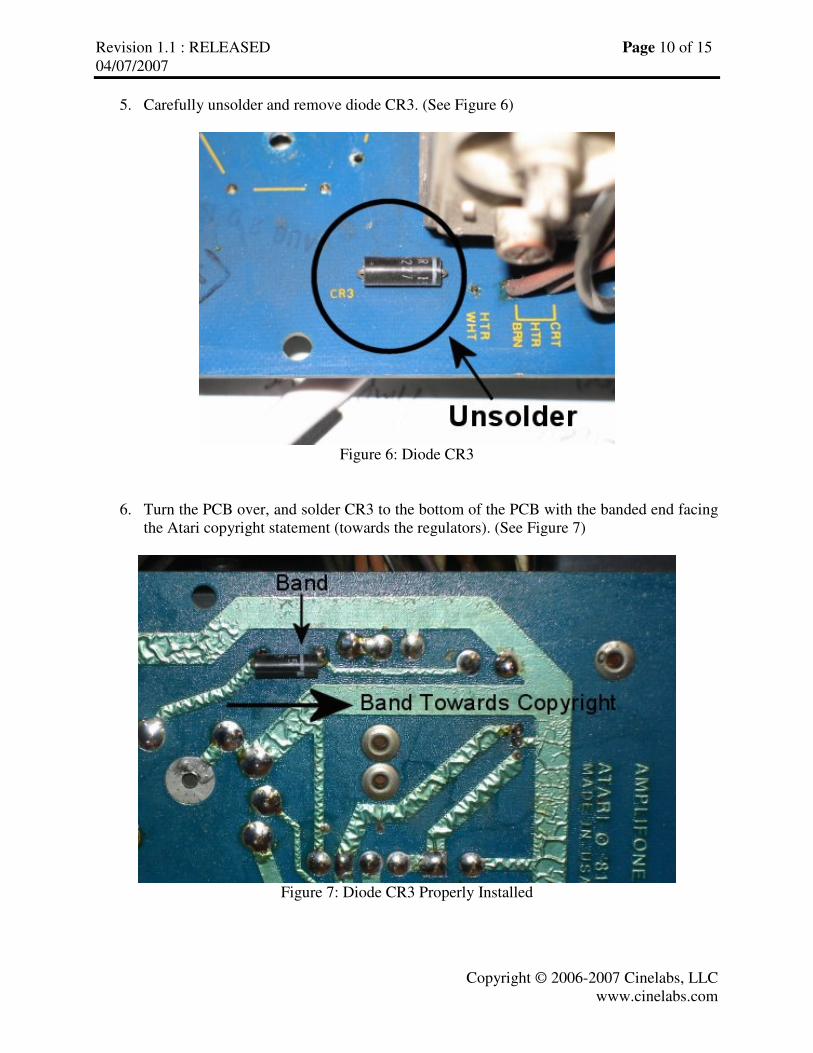
5. Carefully unsolder and remove diode CR3. (See Figure 6)
Figure 6: Diode CR3
6. Turn the PCB over, and solder CR3 to the bottom of the PCB with the banded end facing
the Atari copyright statement (towards the regulators). (See Figure 7)
Figure 7: Diode CR3 Properly Installed

Revision 1.1 : RELEASED Page 11 of 15
04/07/2007
Copyright © 2006-2007 Cinelabs, LLC
www.cinelabs.com
7. Turn the PCB right-side up, and solder the (new) heater wire (the wire wrapped around
the core of the Flyback) to the hole in the PCB from which you removed the original
heater wire (marked “HTR WHT” on the PCB).
8. Install the Flyback into the PCB and solder it in place.
9. Slide the rubber boot you saved in step 1 onto the remaining wire coming from the new
Flyback (this white wire comes out of the top of the FBT).
10. Solder this remaining Flyback wire to the input lug on the Focus Assembly (the lug you
disconnected in step 1) (See Figure 5).
11. After the solder cools, slide the rubber boot forward over the connection, so it contacts
the Focus Assembly.
The installation is complete. Please proceed to the High-Voltage Adjustment procedure.
Revision 1.1 : RELEASED Page 12 of 15
04/07/2007
Copyright © 2006-2007 Cinelabs, LLC
www.cinelabs.com
HV Adjustment:
The following adjustment should be performed with no video signal applied to the monitor.
DO NOT attempt to adjust the HV using the Video B+ supply as a reference, as many factors
influence this rather poorly regulated rail, and it will most likely result in a significant adjustment
error.
1. With power OFF
2. Find the center position of the HV output control (R7) by turning it to its extremes and
adjusting to the center of travel.
3. Connect a high-voltage probe to the monitor (following the probe’s manufactures’
instructions).
4. Apply power to monitor and allow it to warm up for at least 15 minutes.
5. Adjust the HV output control for a reading of 19.5KV.
6. Inject a video signal into the monitor.
7. Adjust the Screen and Focus controls to taste.
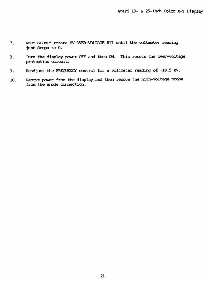
HV Shutdown Adjustment:
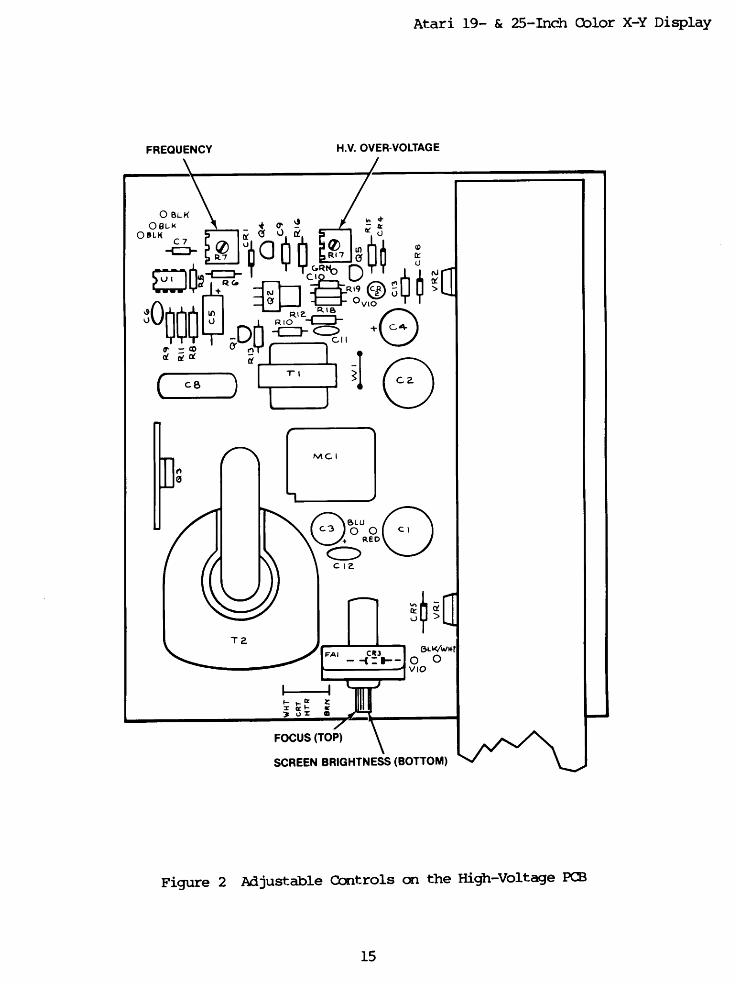
Turning the HV Over-Voltage control (R17) to its minimum position (fully counter-clockwise)
will set it for roughly 23KV, which is higher than it should ever reach during normal operation.
This procedure assumes the HV Cage is properly assembled and working correctly.
1. Set the HV Trip adjustment (R17) fully clockwise (Highest Trigger Voltage).
2. Adjust the HV output control (R7) to 24KV1
(SEE WARNING BELOW).
3. Rotate the HV Trip adjustment (R17) counter-clockwise, until the HV shuts down, and
the LED illuminates.
4. If you rotate R17 fully counter-clockwise, and the unit has not shutdown, you either have
a HV unit that does not produce a high enough voltage to trip the Over-Voltage circuit
(see note 1), or a fault in the HV unit which needs to be corrected before this procedure
can be completed and the unit returned to normal operation.
5. Center the HV output control (R7) (NOT the Trip adjustment), and perform the regular
19.5KV HV adjustment.
Note1 – Not all HV Cages will produce 24KV. In this case, adjust the unit to shutdown at the
minimum HV trigger point (i.e. fully counter-clockwise).
Note2 – If the Over-Voltage protection circuit triggers (i.e. LED illuminates), power must be
completely removed from the system in order to reset the protection circuit.
WARNING: When adjusting the High Voltage or Shutdown Voltage (or at any time), we
recommend keeping the length of time you may have the HV adjustment at either extreme (lower
range of HV output or upper range of HV output) to a minimum. Operating the HV Unit out of
its normal resonance puts excess strain on the output transistor and Flyback, and can cause the
output transistor to fail.
Congratulations, FBT Installation is complete!
Revision 1.1 : RELEASED Page 13 of 15
04/07/2007
Copyright © 2006-2007 Cinelabs, LLC
www.cinelabs.com
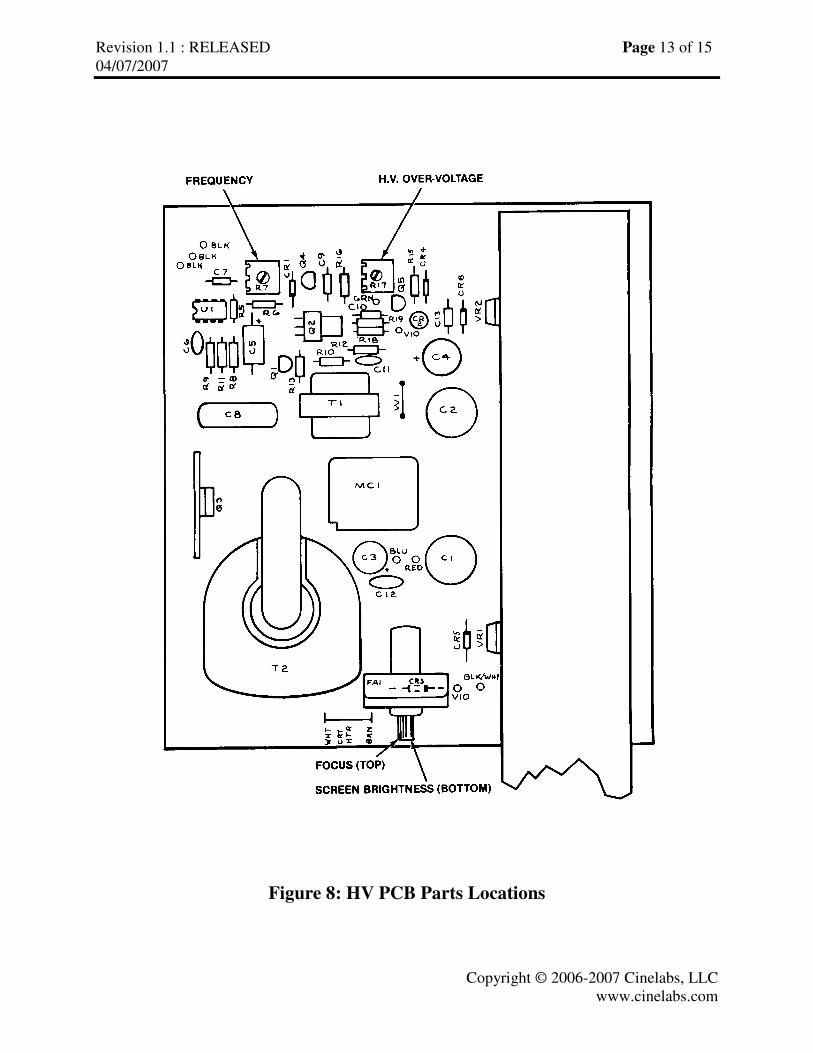
Figure 8: HV PCB Parts Locations
Revision 1.1 : RELEASED Page 14 of 15
04/07/2007
Copyright © 2006-2007 Cinelabs, LLC
www.cinelabs.com
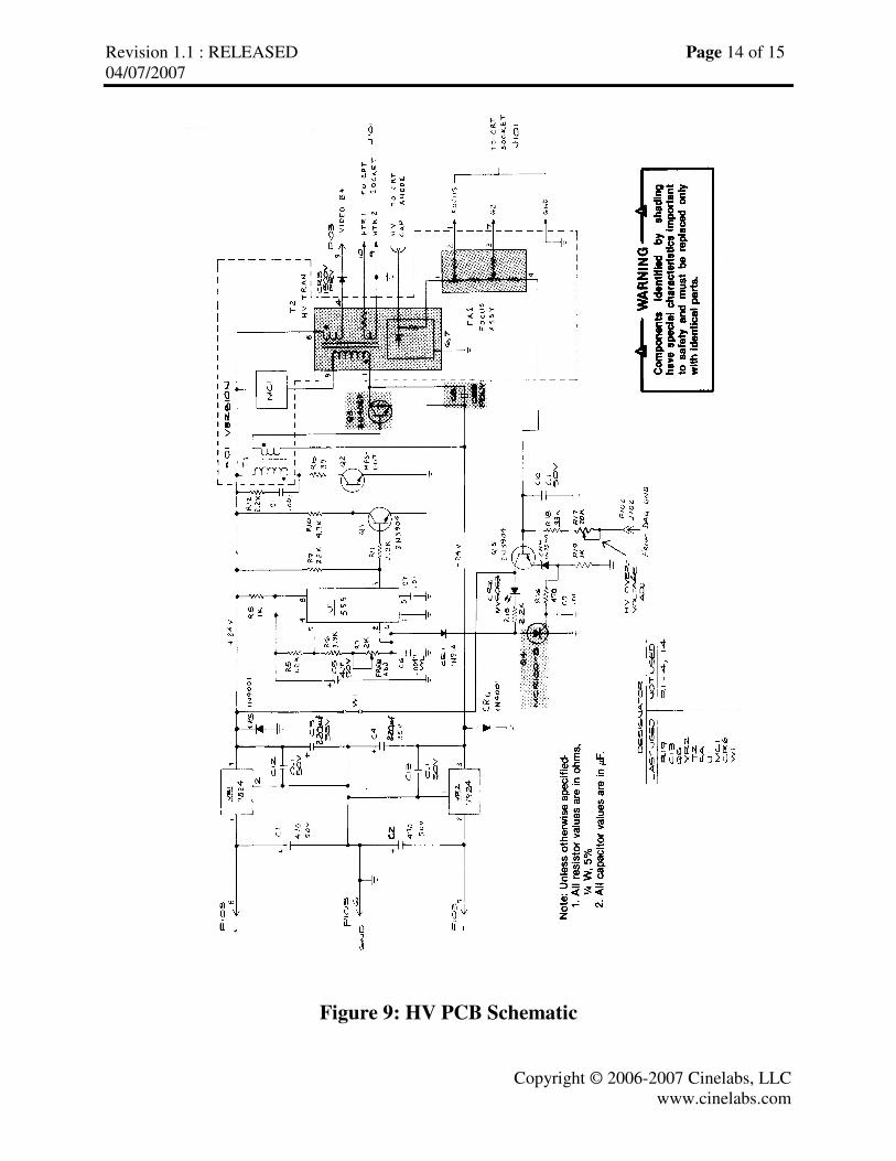
Figure 9: HV PCB Schematic
Revision 1.1 : RELEASED Page 15 of 15
04/07/2007
Copyright © 2006-2007 Cinelabs, LLC
www.cinelabs.com
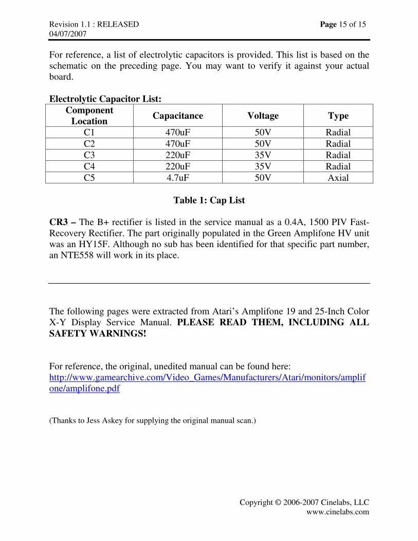
For reference, a list of electrolytic capacitors is provided. This list is based on the
schematic on the preceding page. You may want to verify it against your actual
board.
Electrolytic Capacitor List:
Component
Location Capacitance Voltage Type
C1 470uF 50V Radial
C2 470uF 50V Radial
C3 220uF 35V Radial
C4 220uF 35V Radial
C5 4.7uF 50V Axial
Table 1: Cap List
CR3 – The B+ rectifier is listed in the service manual as a 0.4A, 1500 PIV Fast-
Recovery Rectifier. The part originally populated in the Green Amplifone HV unit
was an HY15F. Although no sub has been identified for that specific part number,
an NTE558 will work in its place.
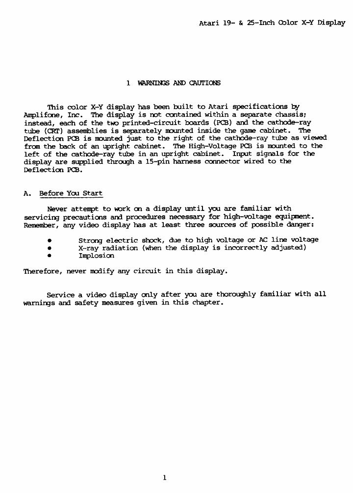
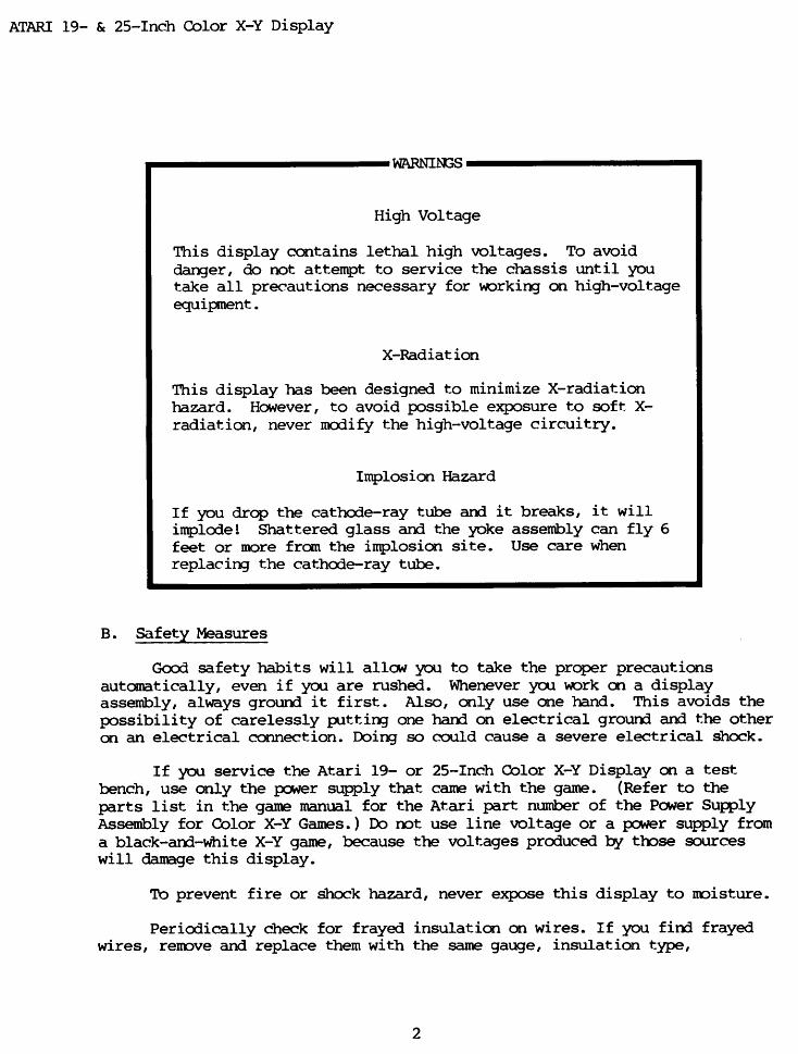
The following pages were extracted from Atari’s Amplifone 19 and 25-Inch Color
X-Y Display Service Manual. PLEASE READ THEM, INCLUDING ALL
SAFETY WARNINGS!
For reference, the original, unedited manual can be found here:
http://www.gamearchive.com/Video_Games/Manufacturers/Atari/monitors/amplif
one/amplifone.pdf
(Thanks to Jess Askey for supplying the original manual scan.)


Copyright © 2022 FDOKUMEN

