


Bahasa
Halaman
Hukum

Challenge for Ultimate Thermal Efficiency of Internal Combustion Engine by Low Temperature
Combustion Technology
Norimasa Iida Keio University
内燃机与燃料协同颠覆性创新国际工程科技论坛The International Summit on Breakout Technologies
of Engine and Fuel (ISEF2018)Aug 20th‐23rd 2018
天津香格里拉酒店, Tianjin
The “Innovative Combustion Technology” program a national project is established under the Cabinet Office , Government of Japan as a part of the “Cross‐ministerial Strategic Innovation Promotion Program (SIP) .””The Gasoline Combustion Team" is one of teams of the "Innovative Combustion Technology" program. This presentation is to introduce the research and development activities of the "Gasoline SI Combustion Team."
1
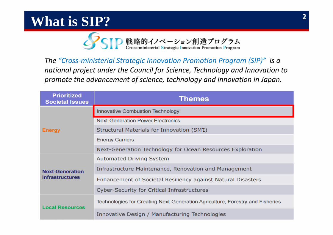
What is SIP?
The “Cross‐ministerial Strategic Innovation Promotion Program (SIP)” is a national project under the Council for Science, Technology and Innovation to promote the advancement of science, technology and innovation in Japan.
2
25
30
35
40
45
50
55
1990 2000 2010 2020
Thermal Efficien
cy(%
)
Year
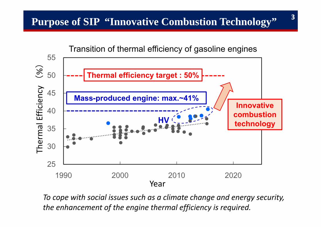
Purpose of SIP “Innovative Combustion Technology”
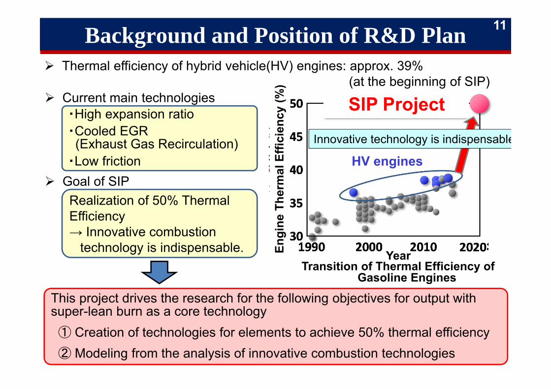
Transition of thermal efficiency of gasoline engines
HV
Thermal efficiency target : 50%
Innovative combustion technology
Mass-produced engine: max.~41%
To cope with social issues such as a climate change and energy security, the enhancement of the engine thermal efficiency is required.
3
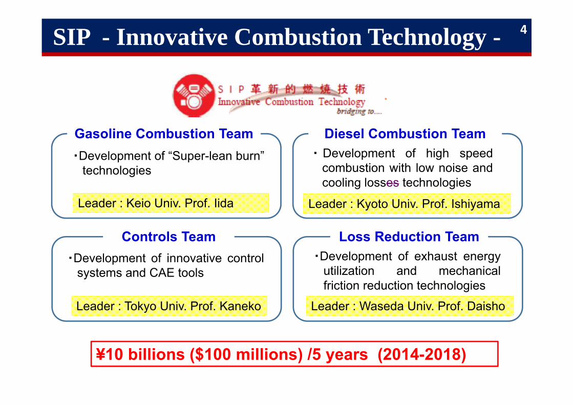
SIP - Innovative Combustion Technology -
・Development of “Super-lean burn”technologies
Leader : Keio Univ. Prof. Iida
Gasoline Combustion Team
・Development of innovative controlsystems and CAE tools
Leader : Tokyo Univ. Prof. Kaneko
Controls Team
・ Development of high speedcombustion with low noise andcooling losses technologies
Leader : Kyoto Univ. Prof. Ishiyama
Diesel Combustion Team
・Development of exhaust energyutilization and mechanicalfriction reduction technologies
Leader : Waseda Univ. Prof. Daisho
Loss Reduction Team
¥10 billions ($100 millions) /5 years (2014-2018)
4
University of TokyoShigehiko Kaneko
Diesel Combustion/Control SubcommitteeCAE/PM Subcommittee
Controls Team
Cluster of Universities
Kyoto UniversityTakuji Ishiyama
Diesel Combustion/Control Subcommittee
Diesel Combustion Team
Cluster of Universities
Keio UniversityNorimasa Iida
Gasoline Combustion Subcommittee
Gasoline Combustion Team
Cluster of Universities
Waseda UniversityYasuhiro Daisho
Exhaust Energy Utilization SubcommitteeFriction Loss Reduction Subcommittee
Loss Reduction Team
Cluster of Universities
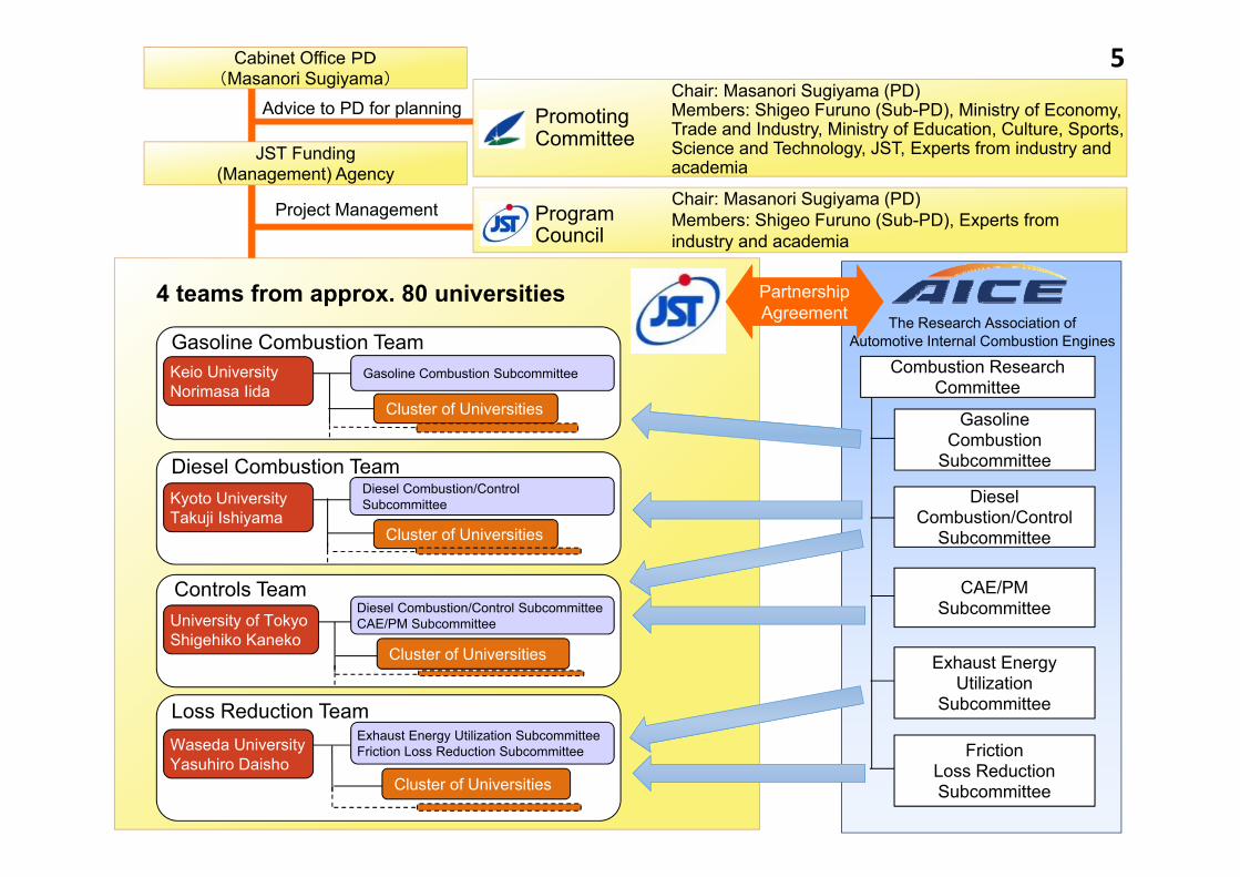
PartnershipAgreement
JST Funding(Management) Agency
Cabinet Office PD(Masanori Sugiyama)
PromotingCommittee
ProgramCouncil
Project Management
The Research Association ofAutomotive Internal Combustion Engines
Combustion Research Committee
DieselCombustion/Control
Subcommittee
FrictionLoss ReductionSubcommittee
Exhaust EnergyUtilization
Subcommittee
GasolineCombustion
Subcommittee
CAE/PMSubcommittee
Chair: Masanori Sugiyama (PD)Members: Shigeo Furuno (Sub-PD), Ministry of Economy, Trade and Industry, Ministry of Education, Culture, Sports, Science and Technology, JST, Experts from industry and academia
Chair: Masanori Sugiyama (PD)Members: Shigeo Furuno (Sub-PD), Experts from industry and academia
Advice to PD for planning
4 teams from approx. 80 universities
5
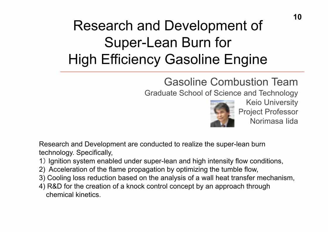
Research and Development ofSuper-Lean Burn for
High Efficiency Gasoline EngineGasoline Combustion Team
Graduate School of Science and TechnologyKeio University
Project ProfessorNorimasa Iida
Research and Development are conducted to realize the super-lean burn technology. Specifically,1) Ignition system enabled under super-lean and high intensity flow conditions, 2) Acceleration of the flame propagation by optimizing the tumble flow, 3) Cooling loss reduction based on the analysis of a wall heat transfer mechanism, 4) R&D for the creation of a knock control concept by an approach through
chemical kinetics.
10
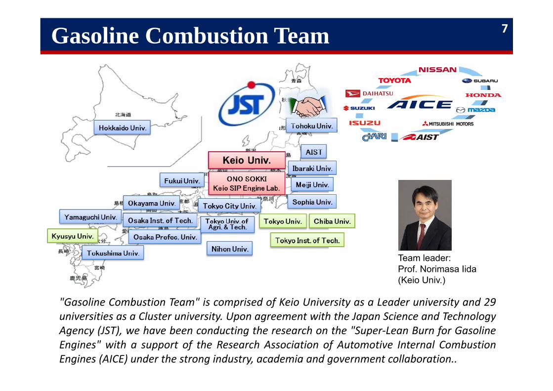
Gasoline Combustion Team
"Gasoline Combustion Team" is comprised of Keio University as a Leader university and 29universities as a Cluster university. Upon agreement with the Japan Science and TechnologyAgency (JST), we have been conducting the research on the "Super‐Lean Burn for GasolineEngines" with a support of the Research Association of Automotive Internal CombustionEngines (AICE) under the strong industry, academia and government collaboration..
Team leader:Prof. Norimasa Iida(Keio Univ.)
7
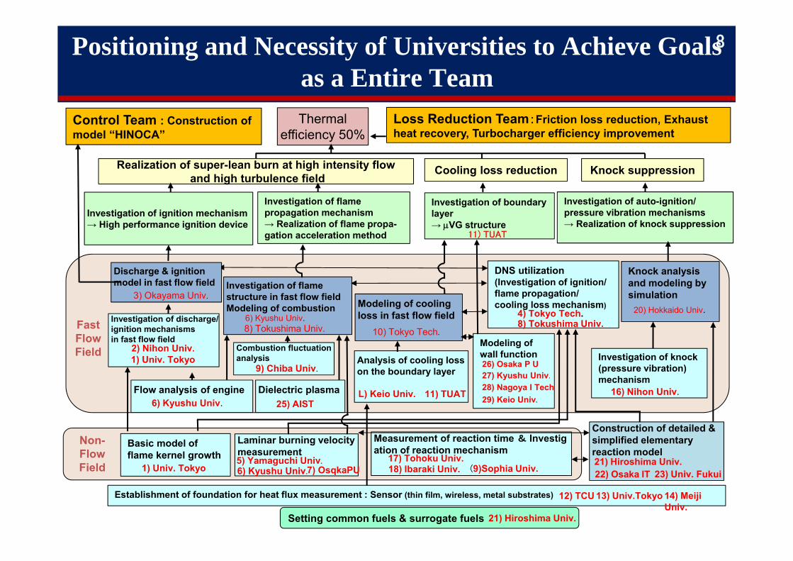
Positioning and Necessity of Universities to Achieve Goals as a Entire Team
8
Thermalefficiency 50%
Basic model of flame kernel growth
1) Univ. Tokyo
Realization of super-lean burn at high intensity flowand high turbulence field
Investigation of ignition mechanism→ High performance ignition device
Non-FlowField
Fast FlowField
Laminar burning velocity measurement
6) Kyushu Univ.7) OsqkaPU5) Yamaguchi Univ.
Investigation of flame structure in fast flow fieldModeling of combustion
6) Kyushu Univ.
Setting common fuels & surrogate fuels 21) Hiroshima Univ.
(6)Kyushu Univ.
Investigation of flame propagation mechanism→ Realization of flame propa-gation acceleration method
DNS utilization(Investigation of ignition/flame propagation/cooling loss mechanism)
4) Tokyo Tech.8) Tokushima Univ.
Establishment of foundation for heat flux measurement : Sensor (thin film, wireless, metal substrates) 12) TCU 13) Univ.Tokyo 14) Meiji Univ.
Cooling loss reduction
Investigation of boundary layer→ VG structure
Modeling of coolingloss in fast flow field
10) Tokyo Tech.
Analysis of cooling losson the boundary layer
L) Keio Univ. 11) TUAT
11) TUAT
Knock suppression
Measurement of reaction time & Investigation of reaction mechanism
17) Tohoku Univ.18) Ibaraki Univ. (9)Sophia Univ.
Construction of detailed & simplified elementary reaction model21) Hiroshima Univ. 22) Osaka IT 23) Univ. Fukui
Knock analysis and modeling by simulation
20) Hokkaido Univ.
Loss Reduction Team:Friction loss reduction, Exhaustheat recovery, Turbocharger efficiency improvement
Investigation of auto-ignition/pressure vibration mechanisms→ Realization of knock suppression
Control Team : Construction of model “HINOCA”
Combustion fluctuation analysis
9) Chiba Univ.
Flow analysis of engine
Investigation of discharge/ ignition mechanisms in fast flow field
2) Nihon Univ.1) Univ. Tokyo
Dielectric plasma
Modeling of wall function26) Osaka P U
Investigation of knock(pressure vibration)mechanism
16) Nihon Univ.
Discharge & ignition model in fast flow field
3) Okayama Univ.
8) Tokushima Univ.
6) Kyushu Univ. 25) AIST
27) Kyushu Univ.28) Nagoya I Tech29) Keio Univ.
SIP, “Innovative Combustion Technology”
9
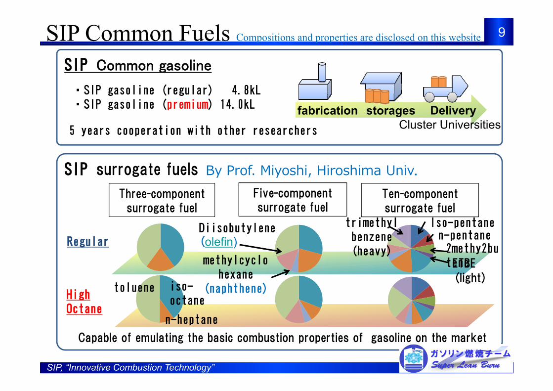
SIP Common gasoline
fabrication storages・SIP gasoline (regular) 4.8kL・SIP gasoline (premium) 14.0kL
5 years cooperation with other researchers
SIP surrogate fuels
Three-component surrogate fuel
Capable of emulating the basic combustion properties of gasoline on the market
Five-component surrogate fuel
Ten-component surrogate fuel
iso-octane
toluene
n-heptane
Diisobutylene(olefin)Regular
HighOctane
methylcyclohexane
(naphthene)
Iso-pentanen-pentane2methy2buteneETBE
trimethylbenzene(heavy)
(light)
By Prof. Miyoshi, Hiroshima Univ.
SIP Common Fuels Compositions and properties are disclosed on this website
DeliveryCluster Universities
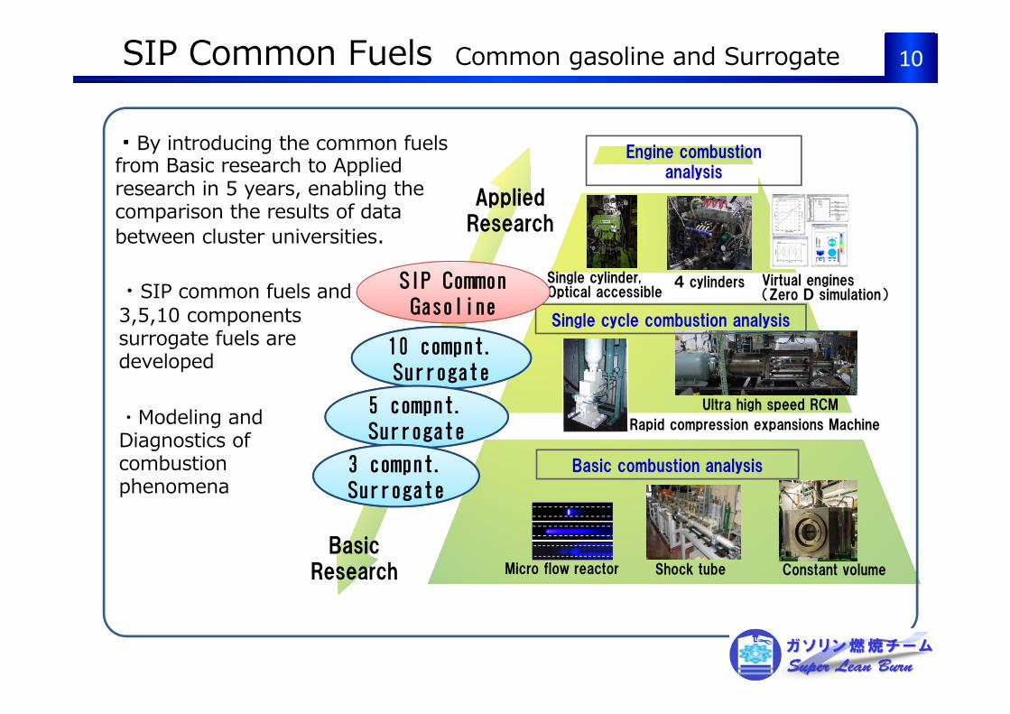
10
Single cylinder,Optical accessible
4 cylinders
Ultra high speed RCM
Shock tubeMicro flow reactor Constant volume
Rapid compression expansions Machine
Engine combustion analysis
Single cycle combustion analysis
Virtual engines(Zero D simulation)
Basic combustion analysis
Applied Research
Basic Research
・By introducing the common fuels from Basic research to Applied research in 5 years, enabling the comparison the results of data between cluster universities.
SIP Common Gasoline
. 10 compnt. Surrogate
5 compnt. Surrogate
. Surrogate3 compnt. Surrogate
・SIP common fuels and3,5,10 components surrogate fuels are developed
・Modeling and Diagnostics of combustion phenomena
SIP Common Fuels Common gasoline and Surrogate
YearEngi
ne T
herm
al E
ffici
ency
(%)
Background and Position of R&D Plan
・High expansion ratio・Cooled EGR(Exhaust Gas Recirculation)
・Low friction
Thermal efficiency of hybrid vehicle(HV) engines: approx. 39%(at the beginning of SIP)
This project drives the research for the following objectives for output with super-lean burn as a core technology① Creation of technologies for elements to achieve 50% thermal efficiency② Modeling from the analysis of innovative combustion technologies
Innovative technology is indispensable
Realization of 50% Thermal Efficiency→ Innovative combustion
technology is indispensable.
Current main technologies
Transition of Thermal Efficiency of Gasoline Engines
Goal of SIP
SIP ProjectSIP Project
HV engines
11
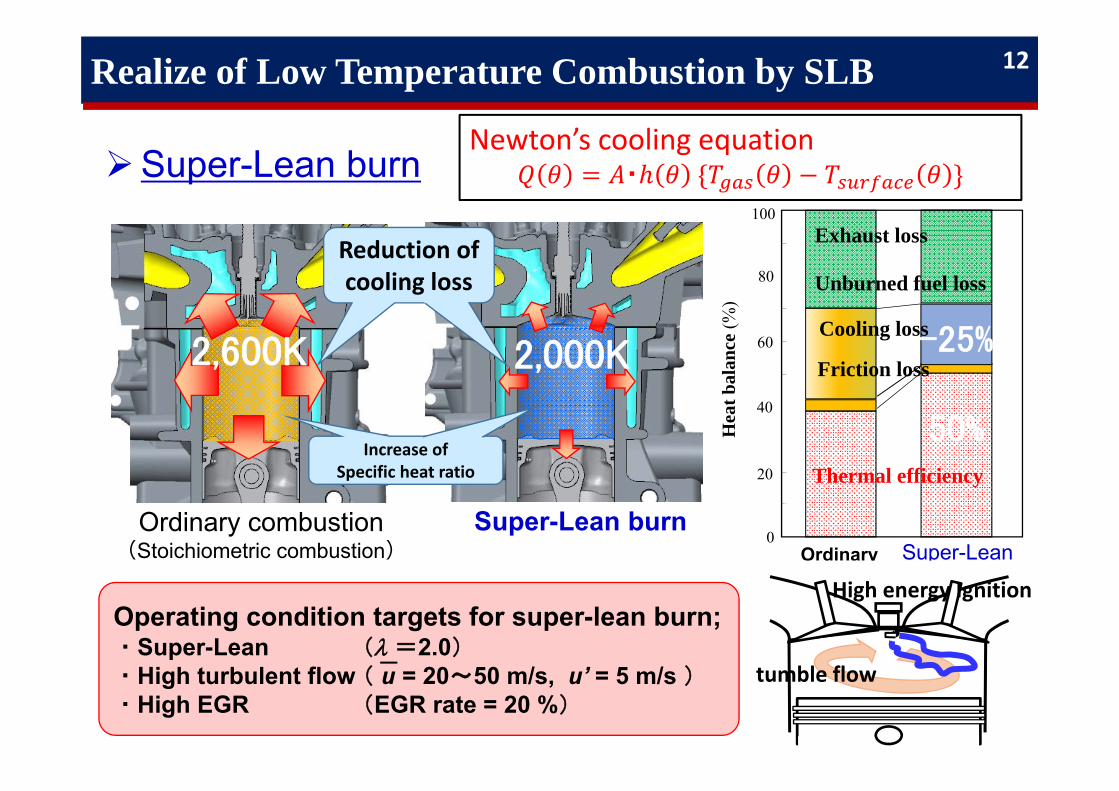
Realize of Low Temperature Combustion by SLB
Super-Lean burn
Super-Lean burn Ordinary combustion(Stoichiometric combustion)
Increase of Specific heat ratio
100
80
60
40
20
0
Hea
t bal
ance
(%)
Exhaust loss
Unburned fuel loss
Ordinary
Cooling loss
Friction loss
Thermal efficiency
Super-Lean
Reduction of cooling loss
Operating condition targets for super-lean burn;・Super-Lean ( =2.0)・High turbulent flow ( u = 20~50 m/s, u’ = 5 m/s )・High EGR (EGR rate = 20 %)
12
Newton’s cooling equation・
2,600K 2,000K -25%
50%
tumble flow
High energy Ignition
Flam
etic
knes
s[m
m]
Flam
ete
mpe
ratu
reT f
[K]
= 0.5
0.7
0.91.0
0.8
0.6
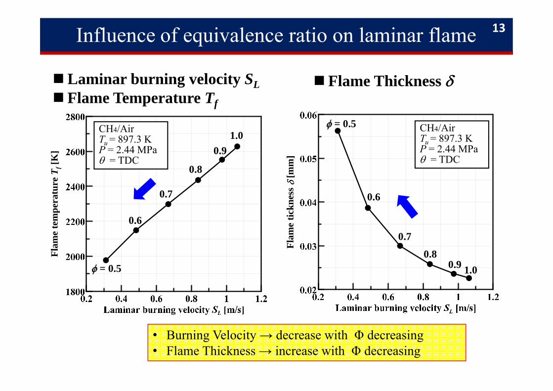
CH4/AirTu = 897.3 KP = 2.44 MPa= TDC
0.7
0.9 1.00.8
= 0.5
0.6
CH4/AirTu = 897.3 KP = 2.44 MPa= TDC
Laminar burning velocity SL Flame Temperature Tf
Flame Thickness
• Burning Velocity → decrease with Φ decreasing• Flame Thickness → increase with Φ decreasing
Influence of equivalence ratio on laminar flame 13
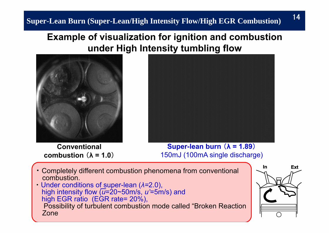
Super-Lean Burn (Super-Lean/High Intensity Flow/High EGR Combustion)
Example of visualization for ignition and combustionunder High Intensity tumbling flow
・Completely different combustion phenomena from conventional combustion.
・Under conditions of super-lean (λ=2.0),high intensity flow (u=20~50m/s, u’=5m/s) andhigh EGR ratio (EGR rate= 20%), Possibility of turbulent combustion mode called “Broken Reaction Zone
Super-lean burn (λ = 1.89)150mJ (100mA single discharge)
Conventional combustion (λ = 1.0)
In ExtIn Ext
14
Gasoline Combustion Team
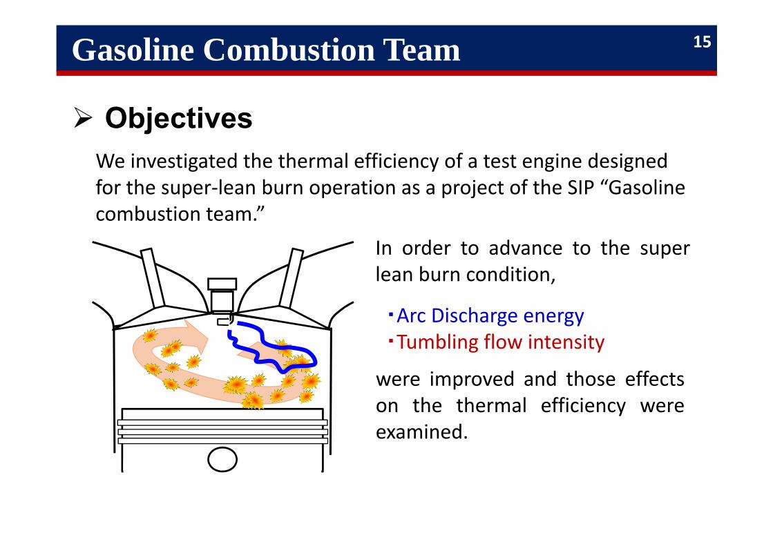
We investigated the thermal efficiency of a test engine designed for the super‐lean burn operation as a project of the SIP “Gasoline combustion team.”
In order to advance to the superlean burn condition,
・Arc Discharge energy・Tumbling flow intensity
were improved and those effectson the thermal efficiency wereexamined.
Objectives
15
Goal・Tasks and Solution Methods
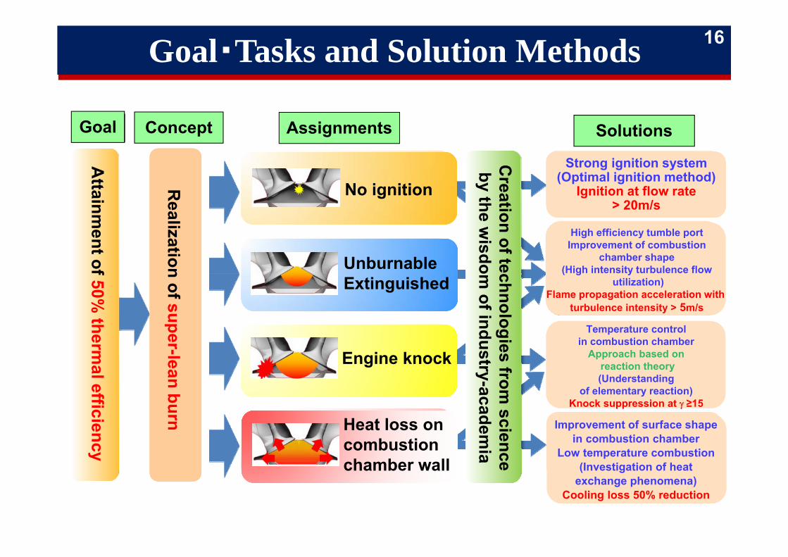
Goal Concept Assignments Solutions
Attainm
ent of 50% therm
al efficiency
Realization of super-lean burn
No ignition
Engine knock
Heat loss on combustion chamber wall
UnburnableExtinguished
Creation of technologies from
science by the w
isdom of industry-academ
ia
Strong ignition system(Optimal ignition method)
Ignition at flow rate> 20m/s
High efficiency tumble portImprovement of combustion
chamber shape(High intensity turbulence flow
utilization)Flame propagation acceleration with
turbulence intensity > 5m/s
Temperature controlin combustion chamber
Approach based onreaction theory(Understanding
of elementary reaction)Knock suppression at ≥15
Improvement of surface shapein combustion chamber
Low temperature combustion(Investigation of heat
exchange phenomena)Cooling loss 50% reduction
16
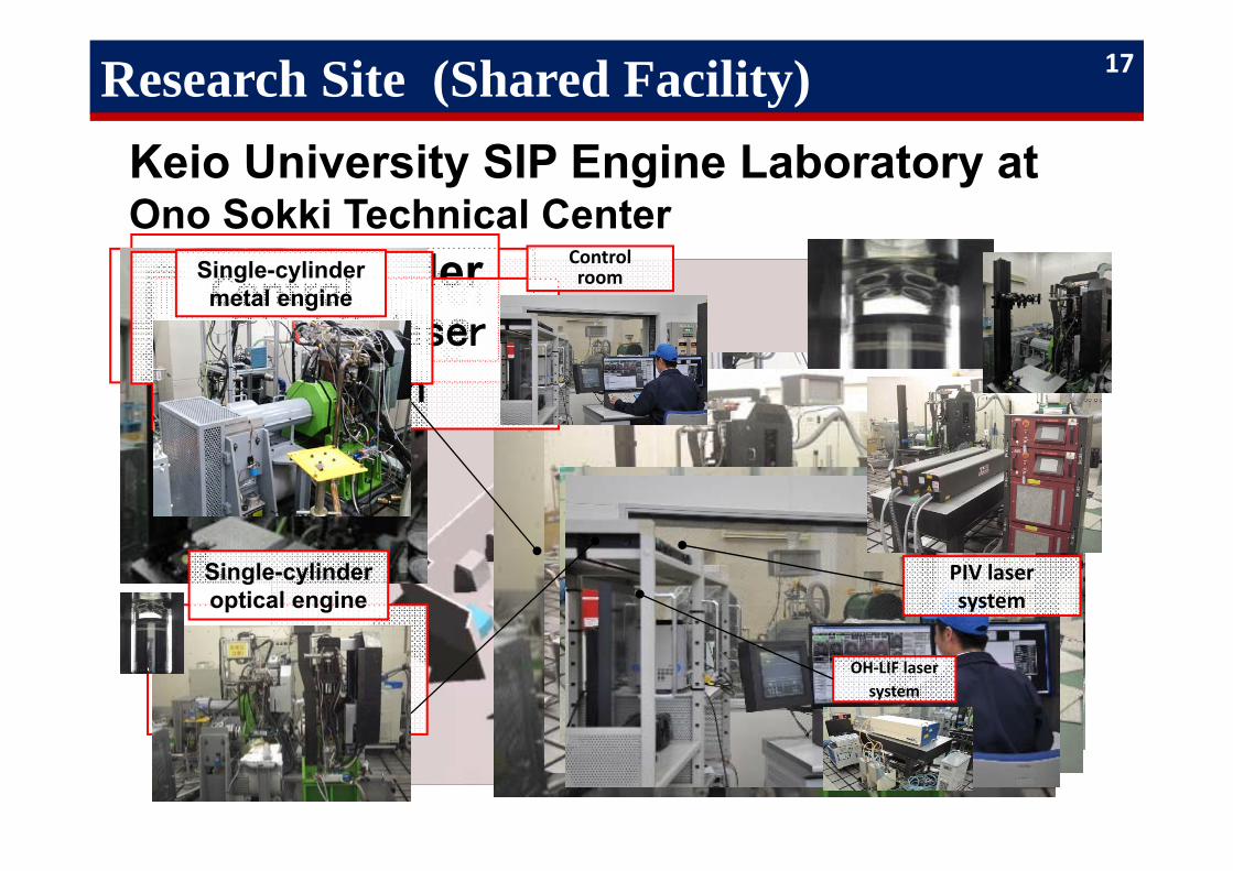
Research Site (Shared Facility)Keio University SIP Engine Laboratory at Ono Sokki Technical Center
Single-cylindermetal engine
Single-cylinder optical engine
PIV laser system
OH-LIF laser system
Controlroom
Single-cylinder optical engine
PIV laser system
Single-cylindermetal engine
OH‐LIF laser system
Controlroom
17
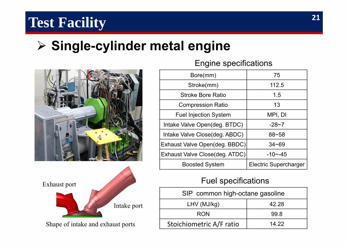
Test Facility Single-cylinder metal engine
Engine specifications Bore(mm) 75
Stroke(mm) 112.5
Stroke Bore Ratio 1.5
Compression Ratio 13
Fuel Injection System MPI, DI
Intake Valve Open(deg. BTDC) -28~7
Intake Valve Close(deg. ABDC) 88~58
Exhaust Valve Open(deg. BBDC) 34~69
Exhaust Valve Close(deg. ATDC) -10~-45
Boosted System Electric Supercharger
SIP common high-octane gasolineLHV (MJ/kg) 42.28
RON 99.8
Stoichiometric A/F ratio 14.22
Fuel specifications
Intake port
Exhaust port
Shape of intake and exhaust ports
21
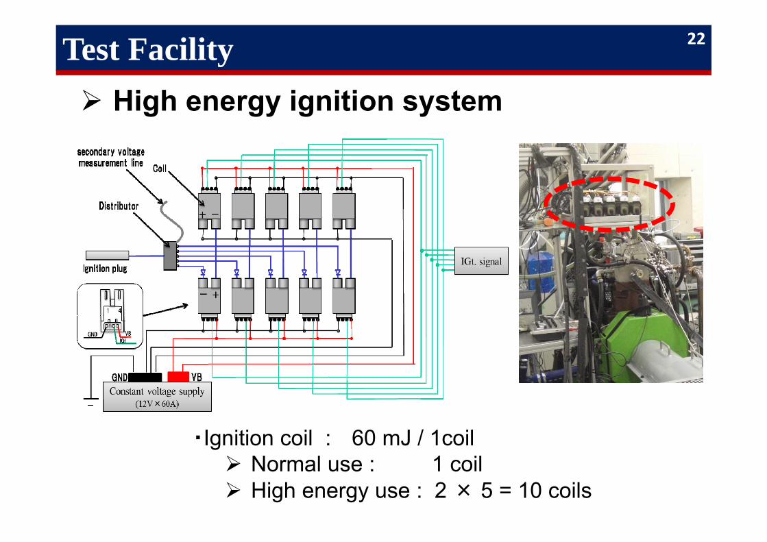
Test Facility High energy ignition system
・Ignition coil : 60 mJ / 1coil Normal use : 1 coil High energy use : 2 × 5 = 10 coils
22
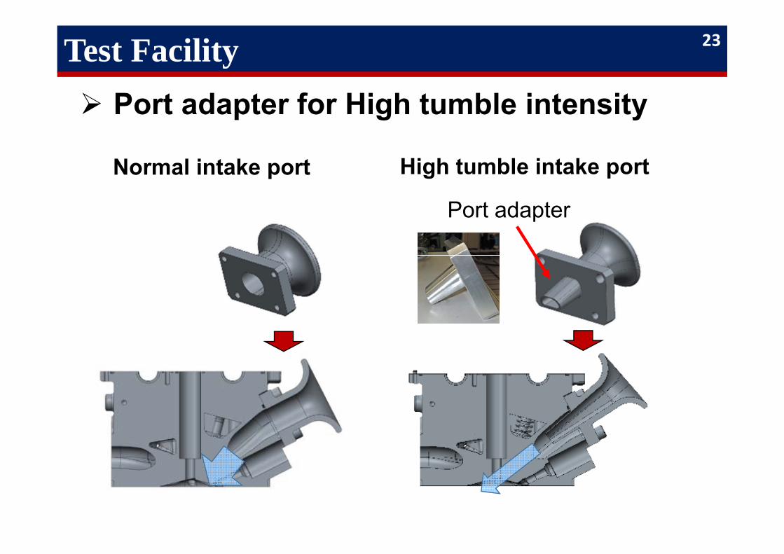
Test Facility Port adapter for High tumble intensity
Port adapter
Normal intake port High tumble intake port
23
-60
-40
-20
0
Ignitio
n t
imin
ig
[deg
ATDC]
10
20
30
40
0-1
0%
com
bust
ion
dura
tion [
CA
]
0
5
10
15
20
Impro
vem
ent
rate
of
indic
ate
d
ther
mal
effici
ency
[%]
10
20
30
40
0.8 1 1.2 1.4 1.6 1.8 2 2.210-9
0% c
om
bust
ion
dura
tion [
CA
]
Air Excess Ratio, λ [-]
0
5
10
15
IMEP C
OV [
%]
0.00
0.05
0.10
CO [
%]
0
500
1000
1500
2000
0.8 1 1.2 1.4 1.6 1.8 2 2.2
NOx [
ppm
]
Air Excess Ratio, λ [-]
2000rpm, IMEP=600kPa
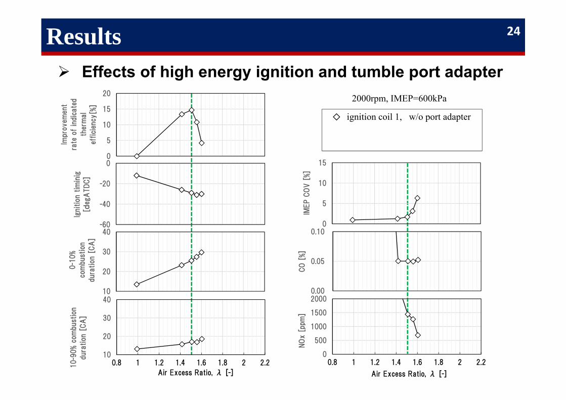
◇ ignition coil 1, w/o port adapter
Results Effects of high energy ignition and tumble port adapter
24
-60
-40
-20
0
Ignitio
n t
imin
ig
[deg
ATDC]
10
20
30
40
0-1
0%
com
bust
ion
dura
tion [
CA
]
0
5
10
15
20
Impro
vem
ent
rate
of
indic
ate
d
ther
mal
effici
ency
[%]
10
20
30
40
0.8 1 1.2 1.4 1.6 1.8 2 2.210-9
0% c
om
bust
ion
dura
tion [
CA
]
Air Excess Ratio, λ [-]
0
5
10
15
IMEP C
OV [
%]
0.00
0.05
0.10
CO [
%]
0
500
1000
1500
2000
0.8 1 1.2 1.4 1.6 1.8 2 2.2
NOx [
ppm
]
Air Excess Ratio, λ [-]
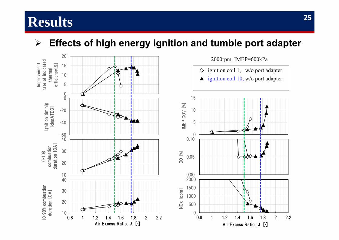
▲ ignition coil 10, w/o port adapter◇ ignition coil 1, w/o port adapter
2000rpm, IMEP=600kPa
Results Effects of high energy ignition and tumble port adapter
25
-60
-40
-20
0
Ignitio
n t
imin
ig
[deg
ATDC]
10
20
30
40
0-1
0%
com
bust
ion
dura
tion [
CA
]
0
5
10
15
20
Impro
vem
ent
rate
of
indic
ate
d
ther
mal
effici
ency
[%]
10
20
30
40
0.8 1 1.2 1.4 1.6 1.8 2 2.210-9
0% c
om
bust
ion
dura
tion [
CA
]
Air Excess Ratio, λ [-]
0
5
10
15
IMEP C
OV [
%]
0.00
0.05
0.10
CO [
%]
0
500
1000
1500
2000
0.8 1 1.2 1.4 1.6 1.8 2 2.2
NOx [
ppm
]
Air Excess Ratio, λ [-]
2000rpm, IMEP=600kPa
◇ ignition coil 1, w/o port adapter
Results Effects of high energy ignition and tumble port adapter
-60
-40
-20
0
Ignitio
n t
imin
ig
[deg
ATDC]
10
20
30
40
0-1
0%
com
bust
ion
dura
tion [
CA
]
0
5
10
15
20
Impro
vem
ent
rate
of
indic
ate
d
ther
mal
effici
ency
[%]
10
20
30
40
0.8 1 1.2 1.4 1.6 1.8 2 2.210-9
0% c
om
bust
ion
dura
tion [
CA
]
Air Excess Ratio, λ [-]
0
5
10
15
IMEP C
OV [
%]
0.00
0.05
0.10
CO [
%]
0
500
1000
1500
2000
0.8 1 1.2 1.4 1.6 1.8 2 2.2
NOx [
ppm
]
Air Excess Ratio, λ [-]
▲ ignition coil 10, w/o port adapter◇ ignition coil 1, w/o port adapter
2000rpm, IMEP=600kPa
-60
-40
-20
0
Ignitio
n t
imin
ig
[deg
ATDC]
10
20
30
40
0-1
0%
com
bust
ion
dura
tion [
CA
]
0
5
10
15
20
Impro
vem
ent
rate
of
indic
ate
d
ther
mal
effici
ency
[%]
10
20
30
40
0.8 1 1.2 1.4 1.6 1.8 2 2.210-9
0% c
om
bust
ion
dura
tion [
CA
]
Air Excess Ratio, λ [-]
0
5
10
15
IMEP C
OV [
%]
0.00
0.05
0.10
CO [
%]
0
500
1000
1500
2000
0.8 1 1.2 1.4 1.6 1.8 2 2.2
NOx [
ppm
]
Air Excess Ratio, λ [-]
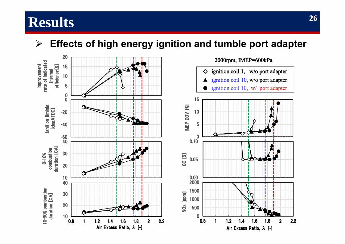
● ignition coil 10, w/ port adapter▲ ignition coil 10, w/o port adapter ◇ ignition coil 1, w/o port adapter
2000rpm, IMEP=600kPa
26
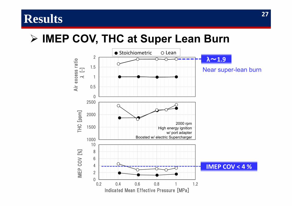
Results IMEP COV, THC at Super Lean Burn
0
0.5
1
1.5
2
Air
exce
ssra
tio
λ[-
]
1000
1500
2000
2500
THC [
ppm
]
0
2
4
6
8
10
0.2 0.4 0.6 0.8 1 1.2
IMEP C
OV [
%]
Indicated Mean Effective Pressure [MPa]
2000 rpmHigh energy ignition
w/ port adapterBoosted w/ electric Supercharger
● Stoichiometric ○ Leanλ~1.9
Near super-lean burn
IMEP COV < 4 %
27
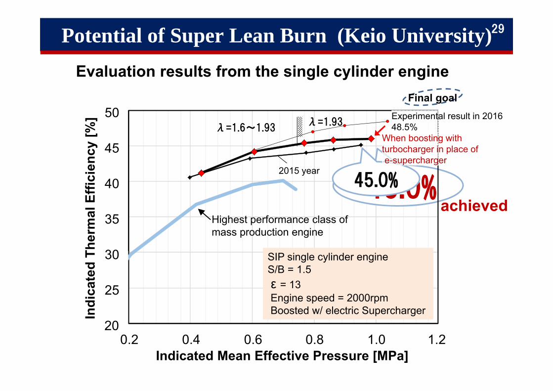
Potential of Super Lean Burn (Keio University)
λ=1.93
Highest performance class ofmass production engine
SIP single cylinder engineS/B = 1.5ε = 13Engine speed = 2000rpmBoosted w/ electric Supercharger
λ=1.6~1.93
46.0%achieved
2015 year
Final goal
35
40
45
50
0.2 0.4 0.6 0.8 1.0 1.2Indicated Mean Effective Pressure [MPa]
30
25
20
Indi
cate
d Th
erm
al E
ffici
ency
[%]
45.0%
Evaluation results from the single cylinder engine
29
Experimental result in 2016 48.5%
When boosting with turbocharger in place ofe-supercharger
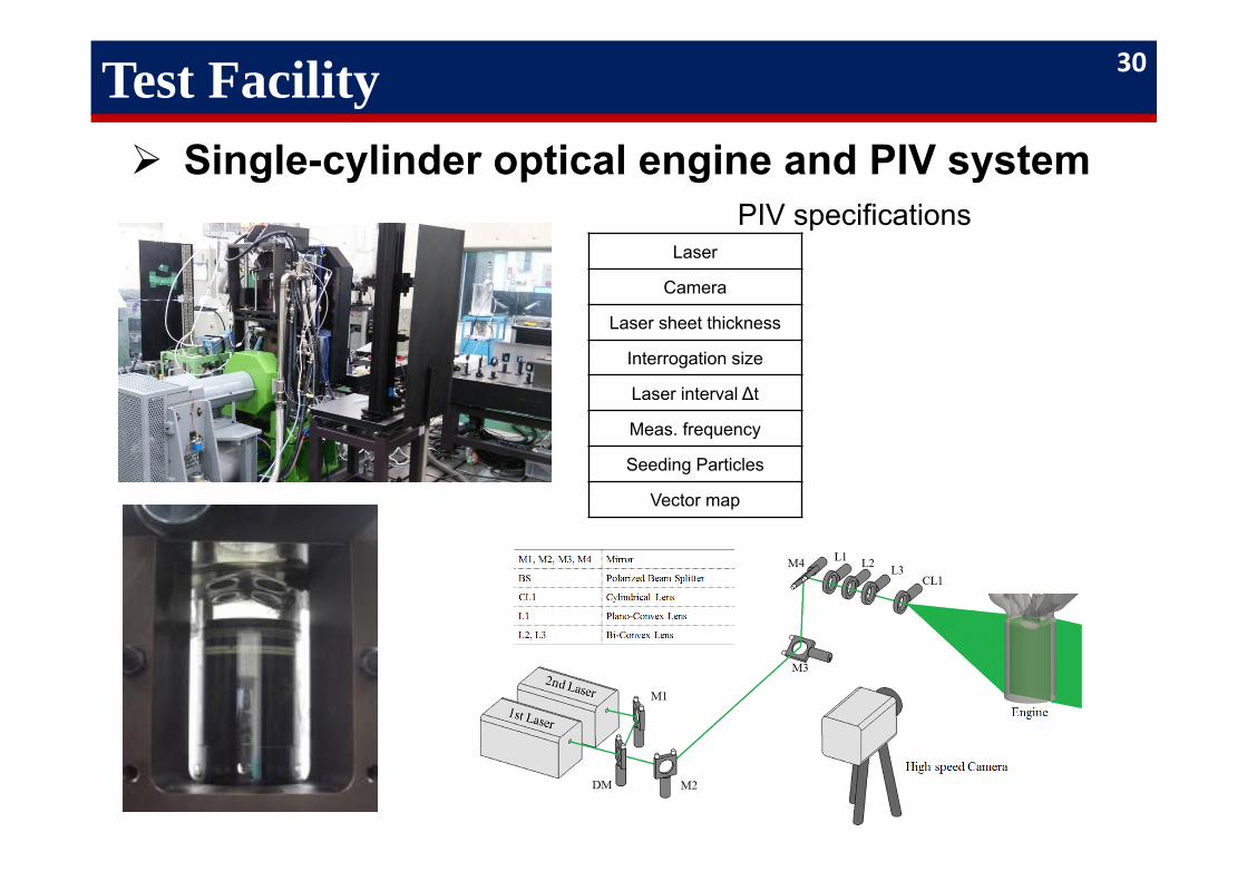
Test Facility Single-cylinder optical engine and PIV system
PIV specifications Laser
Camera
Laser sheet thickness
Interrogation size
Laser interval ∆t
Meas. frequency
Seeding Particles
Vector map
30
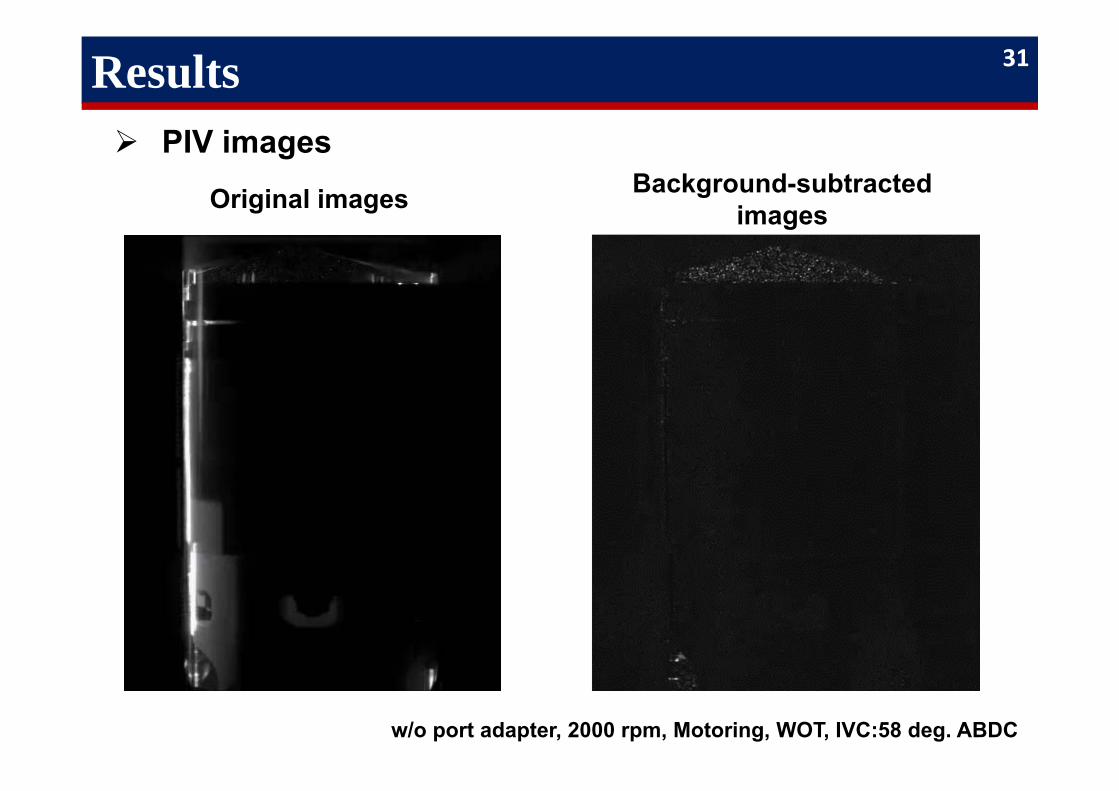
Results PIV images
Original images Background-subtracted images
w/o port adapter, 2000 rpm, Motoring, WOT, IVC:58 deg. ABDC
31
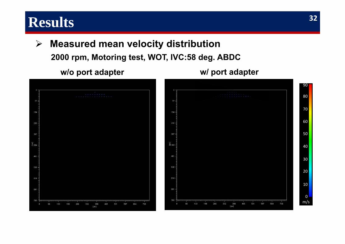
Results Measured mean velocity distribution
90
80
70
60
50
40
30
20
10
0m/s
2000 rpm, Motoring test, WOT, IVC:58 deg. ABDC
w/o port adapter w/ port adapter
32
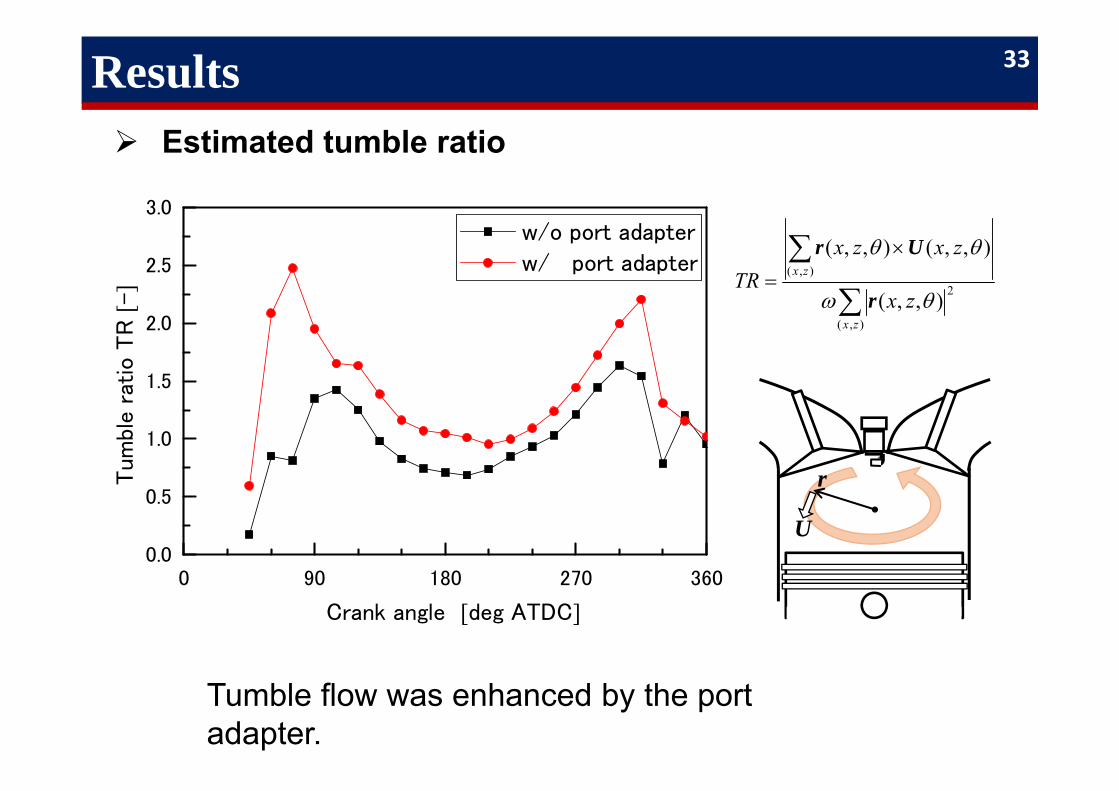
Results Estimated tumble ratio
0 90 180 270 3600.0
0.5
1.0
1.5
2.0
2.5
3.0
Tum
ble r
atio
TR
[-]
Crank angle [deg ATDC]
w/o port adapter
w/ port adapter
),(
2),(
),,(
),,(),,(
zx
zx
zx
zxzxTR
r
Ur
r
U
Tumble flow was enhanced by the port adapter.
33
0 90 180 270 3600
10
20
30
40
50
60
Mean
velo
city
[m/s]
Crank angle [deg ATDC]
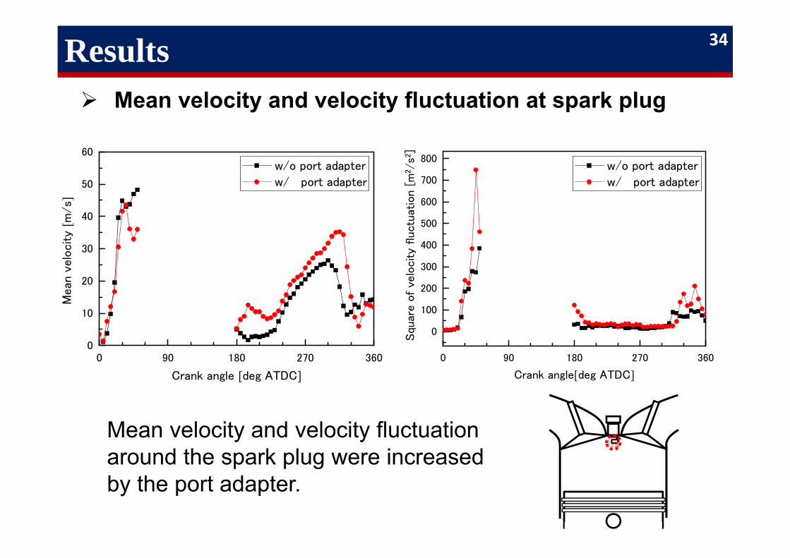
Results Mean velocity and velocity fluctuation at spark plug
w/o port adapter w/ port adapter
0 90 180 270 360
0
100
200
300
400
500
600
700
800
TKE [m
2/s2
]
Crank angle[deg ATDC]
Squ
are o
f ve
locity
fluctu
atio
n [
m2/s2
]
w/o port adapter w/ port adapter
Mean velocity and velocity fluctuation around the spark plug were increased by the port adapter.
34
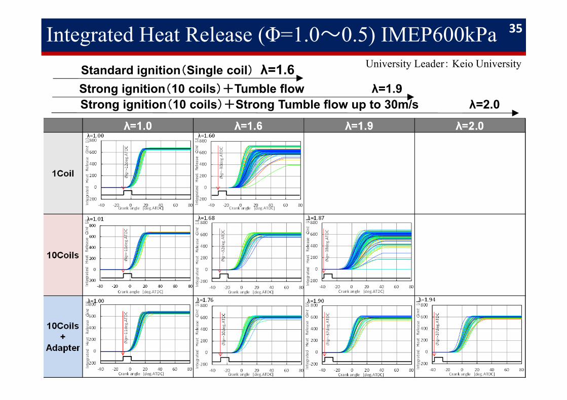
Integrated Heat Release (Φ=1.0〜0.5) IMEP600kPa 35
Strong ignition(10 coils)+Strong Tumble flow up to 30m/s λ=2.0Strong ignition(10 coils)+Tumble flow λ=1.9Standard ignition(Single coil) λ=1.6 University Leader: Keio University
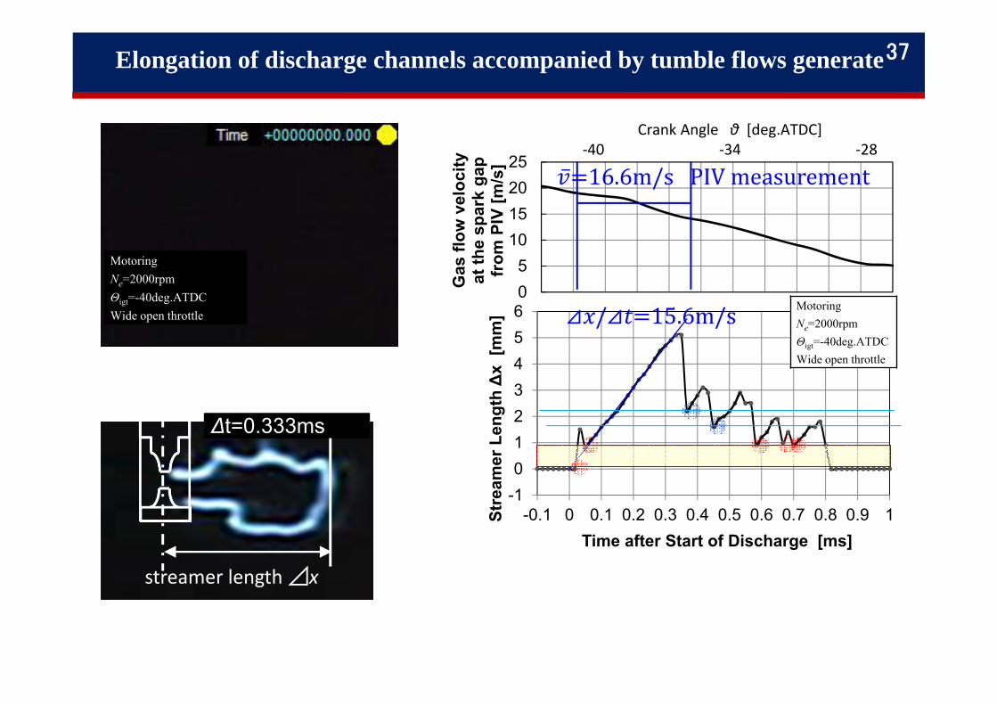
-10123456
-0.1 0 0.1 0.2 0.3 0.4 0.5 0.6 0.7 0.8 0.9 1Stre
amer
Len
gth ∆
x[m
m]
Time after Start of Discharge [ms]
⊿ /⊿ 15.6m/s MotoringNe=2000rpmΘigt=-40deg.ATDCWide open throttle
MotoringNe=2000rpmΘigt=-40deg.ATDCWide open throttle
05
10152025
Gas
flow
vel
ocity
at
the
spar
k ga
p fr
om P
IV [m
/s]
Crank Angle θ [deg.ATDC] ‐40 ‐34 ‐28
∆t=0.333ms
streamer length ⊿x
16.6m/sPIVmeasurement
Elongation of discharge channels accompanied by tumble flows generate37
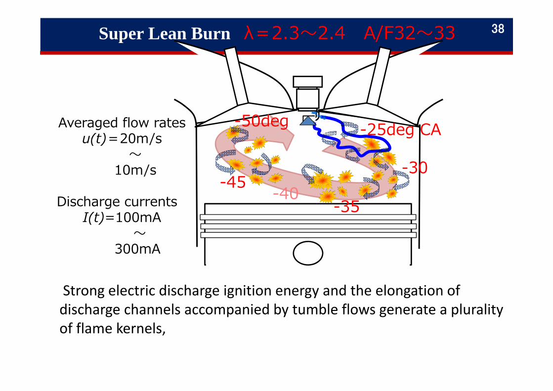
Super Lean Burn λ=2.3〜2.4 A/F32〜33 38
Averaged flow ratesu(t)=20m/s
〜10m/s
Discharge currentsI(t)=100mA
〜300mA
-50deg
-45 -40-35
-30
-25deg CA
Strong electric discharge ignition energy and the elongation of discharge channels accompanied by tumble flows generate a plurality of flame kernels,
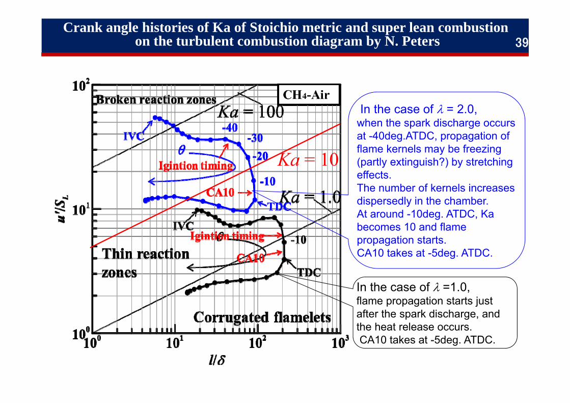
In the case of =1.0, flame propagation starts just after the spark discharge, and the heat release occurs.CA10 takes at -5deg. ATDC.
In the case of = 2.0, when the spark discharge occurs at -40deg.ATDC, propagation of flame kernels may be freezing (partly extinguish?) by stretching effects.The number of kernels increases dispersedly in the chamber.At around -10deg. ATDC, Ka becomes 10 and flame propagation starts.CA10 takes at -5deg. ATDC.
Crank angle histories of Ka of Stoichio metric and super lean combustion on the turbulent combustion diagram by N. Peters 39
Ka = 10
-0.001
-0.0005
0
0.0005
0.001
0.0015
0.002
Intake Compression(negative)
Compression(positive)
Expansion Exhaust Total
Am
ount
of H
eat F
lux
q[M
J/m
2 ]
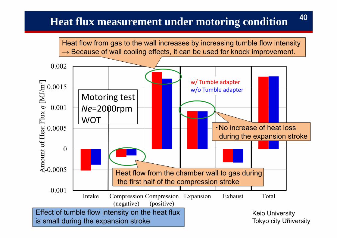
Motoring testNe=2000rpmWOT
Effect of tumble flow intensity on the heat flux is small during the expansion stroke 40
Keio UniversityTokyo city University
w/ Tumble adapterw/o Tumble adapter
Heat flow from gas to the wall increases by increasing tumble flow intensity→ Because of wall cooling effects, it can be used for knock improvement.
Heat flux measurement under motoring condition
Heat flow from the chamber wall to gas duringthe first half of the compression stroke
40
・No increase of heat loss during the expansion stroke
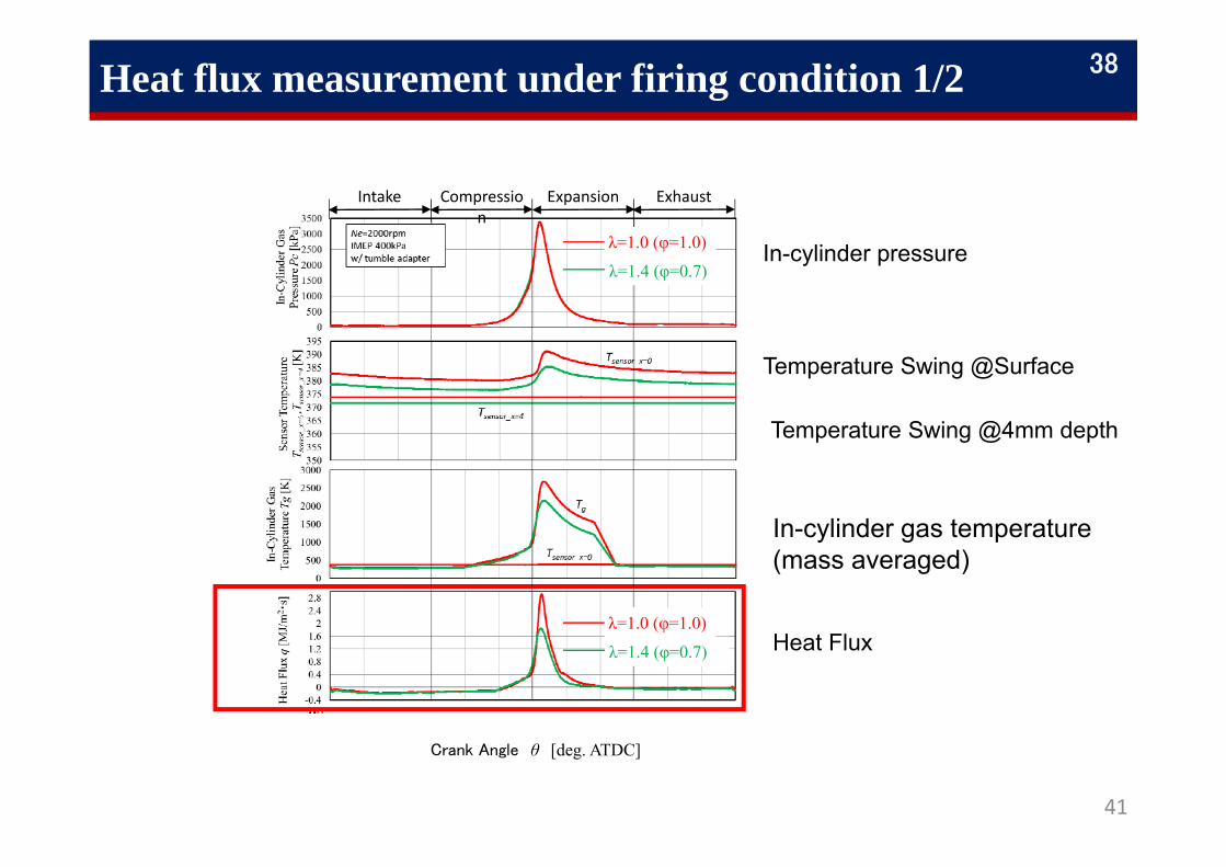
Heat flux measurement under firing condition 1/2
41
Intake Compression
Expansion Exhaust
λ=1.0 (φ=1.0)
λ=1.4 (φ=0.7)
Crank Angle θ [deg. ATDC]
λ=1.0 (φ=1.0)
λ=1.4 (φ=0.7)
In-cylinder pressure
Temperature Swing @Surface
In-cylinder gas temperature(mass averaged)
Heat Flux
Temperature Swing @4mm depth
38
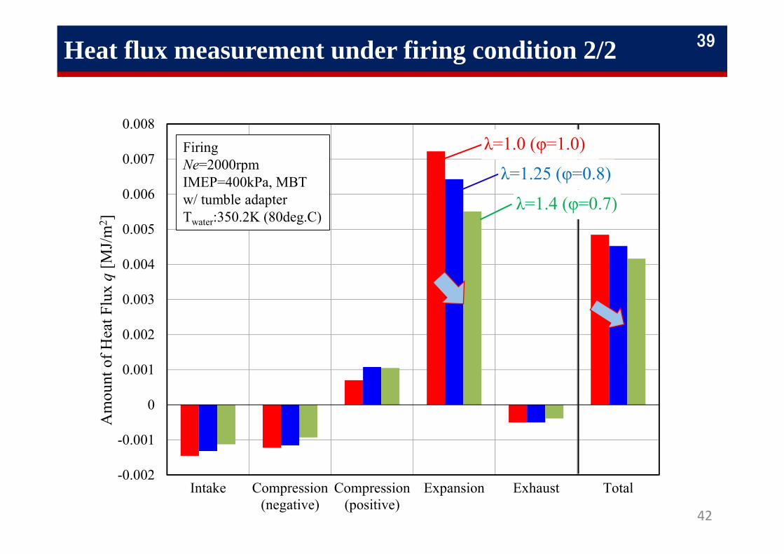
Heat flux measurement under firing condition 2/2
-0.002
-0.001
0
0.001
0.002
0.003
0.004
0.005
0.006
0.007
0.008
Intake Compression(negative)
Compression(positive)
Expansion Exhaust Total
Am
ount
of H
eat F
lux
q[M
J/m
2 ]
FiringNe=2000rpmIMEP=400kPa, MBT w/ tumble adapterTwater:350.2K (80deg.C)
λ=1.0 (φ=1.0)
λ=1.4 (φ=0.7)
λ=1.25 (φ=0.8)
42
39
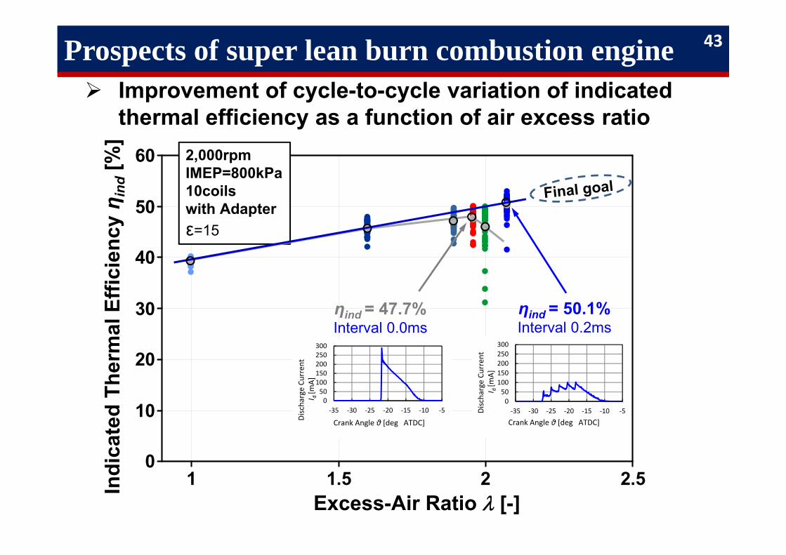
Prospects of super lean burn combustion engine Improvement of cycle-to-cycle variation of indicated
thermal efficiency as a function of air excess ratio
43
1 1.5 2 2.50
10
20
30
40
50
60
Excess-Air Ratio [-]
2,000rpmIMEP=800kPa10coilswith Adapterε=15
ηind = 47.7%Interval 0.0ms
ηind = 50.1%Interval 0.2ms
050
100150200250300
‐35 ‐30 ‐25 ‐20 ‐15 ‐10 ‐5
Discharge Cu
rren
t I d [m
A]
Crank Angle θ [deg ATDC]
050
100150200250300
‐35 ‐30 ‐25 ‐20 ‐15 ‐10 ‐5
Crank Angle θ [deg ATDC]
Discharge Cu
rren
tI d [m
A]
リーダ大学(00) 慶應大学飯田
Indi
cate
d Th
erm
al E
ffici
ency
ηin
d[%
]
SIP, “Innovative Combustion Technology”
Summary 41
Strong electric discharge ignition energy and the elongation of discharge channels accompanied by tumble flows generate a plurality of flame kernels, and Ka sharply falls by attenuation of the turbulence intensity at top dead center.
The super lean‐burn technology is considered as the combustion technology, which enables multipoint ignition and high speed combustion for gasoline SI engines.

Thank you for your attention
This project is supported by Council for Science, Technology and Innovation (CSTI), Cross‐ministerial Strategic Innovation Promotion Program (SIP) ‐“Innovative Combustion Technology” (Funding agency: JST).
47
Acknowledgment
Co-Author
28 clusters of SIP Gasoline Combustion Team
AICE Gasoline Combustion Committee
Collaborations
Prof. Takeshi Yokomori, Keio University
48
for more information
http://sip.st.keio.ac.jp/
45
You can down‐load> Gasoline surrogate detailed kinetic model revision 1.0 (SIP‐Gd1.02)
and reduced reaction mechanism revision 1.0 (SIP‐Gr1.0)> SIP common gasoline surrogate compositions and properties
Surrogate: S3H, S5R, S5H, S10R, S10H,SIP common gasoline; High Octane and Regular

Thank you for your attention
49
Top Related
Copyright © 2022 FDOKUMEN

