


Bahasa
Halaman
Hukum

" b
k'k _ "
NASA Technical Memorandum 100288
Ceramic Bearings for Use inGas Turbine Engines
([_A,SA-TM-1GG2f.8) CFBAI_IC £I'AElliG5 FOR USE11_ GAS _I_URE1//f. _1_C-11_E5 (I_Stt) 15 pCSCL 13I
G3/37
N88-18G67
Uncla_0125890
Erwin V. ZaretskyLewis Research Center
Cleveland, Ohio
Prepared for the
33rd International Gas Turbine and Aeroengine Congress and Exposition
sponsored by the American Society of Mechanical EngineersAmsterdam, The Netherlands, June 5-9, 1988

ORIGINAl; PAGE IS
OF POOR QUALITY
CERAMIC BEARINGS FOR USE IN GAS TURBINE ENGINES
Erwin V. Zaretsky*National Aeronautics and Space Administration
Lewis Research CenterCleveland, Ohio 44135
I
L.U
ABSTRACT
Three decades of research by U.S. industry andgovernment laboratories have produced a vast array ofdata related to the use of ceramic rolling-elementbearings and bearing components for aircraft gas tur-bine engines. Materials such as alumina, silicon car-bide, titanium carbide, silicon nitride, and acrystallized glass ceramic have been investigated.Rolling-element endurance tests and analysis of fu11-complement bearings have been performed. Materials andbearing design methods have continuously improved overthe years. This paper reviews a wide range of data andanalyses with emphasis on how early NASA contributionsas well as more recent data can enable the engineer ormetallurgist to determine just where ceramic bearingsare most applicable for gas turbines.
NOMENCLATURE
C dynamic load capacity, N(Ib)
e Neibu11 slope or modulus
1/3
K1 --]Nl/3Mll3(in.I/31b I/3)
K2 3 _R 2 /3(pstl )
life, hr, milllons of inner-race revolutions or
millions of stress cycles
*Fellow ASME.
relative life, hybrid bearingLHR
m temperature-life exponent
N 4(I - _2) M2N_l(psi_l)y
n stress-life exponent
P applied or equivalent bearing load, N(Ib)
Po normal load, N(Ib)
R radius of a sphere, m(in.)
r Hertzian contact radius, m(in,)
S Hertzian contact stress, N/m2(psi)
T temperature, K (°R)
V stressed volume, m3(in. 3)
Y Young's modulus of elasticity, N/m2(psi)
Z depth to maximum shear stress, m(in.)
8 Poisson's ratio
maximum shear stress, Nlm2(psi)
Subscripts
a,b bodies a and b
c ceramic material
H hybrid bearing
s steel material or steel bearing

:'_TRODUCTION
ORIGINAL PAGE IS
OF POOR QUALITY
Zeramic materials offer some _otentia] advantagesJet rol]ing-e]ement bearing components because of their:a_ability of operating over a wide temperature range_nd their :ow density relative to rolling-element bear-_g stee!s. The low density of ceramics _ay make them_ttractive as 0all or rotler materials for very high-:_eea cearings. This benefit is due to the fact that:he Fatigue life of very high-speed ball bearings canoe recuced as a result of excessive centrifugal force:n the 9al]s and subsequent increased stress at theouter _ace (Harris, 1968). Lower mass balts can dimin-ilh this fatigue life reduction.
Ceramic materials generally maintain theiricrength and corrosion resistance over a range of tem-peratures much greater than typical rolling-element_earing steels. Taylor et al. (1963) was the first toevaluate hot-pressed silicon carbide and hot-pressedalumina for rolling-element beartngs to temperaturesa_ove 811K (1000 °F).
A crystallized glass ceramic was examined inrolling-element fatigue by Carter and Zaretsky (1960)and Zaretsky and Anderson (1961) of NASA Lewis ResearchCenter. The results of these early tests showed thatthe failure mode of ceramics was similar to that in
bearing steels. That is, the failure was cyclicdependent and apparently of subsurface origin, occur-ring at the depth of the maximum shear stress. Thefailure manifested itself as a spa11 that was limited:o the depth of the maximum shear stress and in diame-ter to the width of the contact zone. The life of theceramic material was less than 10 percent that of atypical rolllng-element bearing steel under the sameconditions of stress. However, the scatter In I!fe(time to failure) was much less than that experiencedby bearing steels. Appledoorn and Royle (1965) con-firmed these results in a later study.
Parker et al. (1965) of NASA also conducted stud-
ies with three ceramics and one cermet for high-temperature, roiling-element bearlng appllcatlons, Theceramic materials were hot-pressed and cold-pressedalumlna, both 99 percent pure, and a two-phase slnteredsilicon carbide. Endurance tests were also conductedwith the hot-pressed alumlna to 1367 K (2000 °F). Thetime to failure for the ceramics was found to have lessscatter than for bearlng steels. The mode of failurewas a spall which was attributed to a surface condltlonrather than subsurface shear stresses. Hot-pressedalumina performed the best of the four materials. How-ever, the llfe of th_s material was only 7 percentthat of a typical bearing steel at the same condltlonof stress. It was concluded that the life of theserefractory ceramic materials was related to the poros-ity, surface finish, and homogeneity of the materlal(Parker et al., 1965),
Baughman and Bamberger (1963) performed unlubrl-rated high-temperature bearing studtes to 922 K(1200 °F) in the rolling-contact (R-C) tester andfull-scale needle bearings. They tested the followingmaterials: Star-J and Stellite 25 (super alloys) andsilicon carbide and alumina ceramics. The silicon car-bide was shown to be the most wear resistant material.However, the silicon carbide material lacked homogene-ity which resulted In nonuniform results.
In 1970, hot-pressed sllicon nitride was proposedfor ro111ng-element bearings as well as for journalbearings (Dee, 1970). Ro111ng-element fatigue testingof hot-pressed silicon nltrlde has resulted in seem-ingly contradfctory results, Poor results wereobtained in the ltmlted tests reported in Scott et al.
(1971) and Scott and Blackwe]l (1973). The resultsreported in Baumgartner (1973) and Baumgartner et al.(1973) showed the rolling-element fatigue !ife of hot-Dressed silicon nitride to exceed that of a typicalrolling-element bearing steel. Extrapolation of theexperimental resu]ts of Parker and Zaretsky (1975) tocontact loads which result in stress levels typical ofthose in rolling-element bearing applications indicatethat hot-pressed silicon nitride running agains_ steelmay be expected to yield fatigue l.ives comparable toor greater than those of bearing quality steel runningagainst steel.
Concurrent wlth the work of Dee (1970), Scott etal. (1971), Scott and Blackwell (1973), Baumgartner(1973), Baumgartner et al. (]973), and Parker andZaretsky (1975), hybrid bearings comprising siliconnitride rolllng-elements and steel races were manufac-tured and tested (Baumgartner eta]., 1973; Baumgartneret al., 1976; Baumgartner and Cowley, 1975; Reddecliffand Valorl, 1976; and Miner et al., 1981) as well assilicon nitrlde rolling-elements and rlngs (Baumgartneret al., 1973; M_ner et al., 1981; Hosang, 1987; andBailey, 1983).
In view of the aforementioned it is the objectiveof the work reported herein to summarize the data andanalyses related to ceramic bearings for use in gasturbine englnes. Emphasis is placed on how early NASAcontributlons as well as more recent data can enablethe engineer or metallurgist to determine just whereceramic bearings are most applicable for future gasturblne englnes.
EFFECT OF CONTACT STRESS
It has long been _stabllshed that the rolling-element fatigue llfe, L, of a ro111ng element isinversely proportional to stress, S, to a power, n,that is,
~ S-n (I)
For bearing steels the accepted value In the bearingIndustry for the stress-life exponent is 9 to 10. How-ever, varlatlons In thls value have been noted and maybe a function of material processing (Parker andZaretsky, 1972a). A summary of the stress-11fe expo-nents for the ceramic and cermet materials tested forrolling-element bearing application whlch were com-piled from Carter and Zaretsky (1960), Zaretsky andAnderson (1961), Parker et at. (1965), and Baumgartneret al. (1973) are summarized In Table I.
When steel and other meta111c materlals are testedat different stress levels, dlrect comparisons offatigue lives can be made only by adjustlng one of thelives using the proper stress-life exponent for thatmaterlal (glven In Table I), or by maklng a comparlson
on the basis of dynamic load capacity. The dynamicload capacity, contact load, and llfe are related bythe equation (Lundberg and Pa]mgren, 1947; Lundbergand Palmgren, ]949; and Lundberg and Palmgren, 1952),
C : P n/]/--_ (2)V
where
dynamic load capacity or load whlch will produce
fallure of 10 percent of test specimen in I millionstress cycles, N(Ib)
P applied or equivalent bearing load, N(Ib)
exponent relating stress and life, determined
experimenta]ly
life in millions of stress cycles which 90 percent
.off a group of specimens survive or within which time
10 percent fa]]
=or steels, n/3 is usually taken as 3 (based on a
stress-life exponent of 9). The values of n for eachof the materials can be obtained from Table I. The
re]ative dynamic capacities for each of the ceramic
materials are then given based upon typical bearing
steels. Knowing the dynamic capacity of an equivalent
steel bearing, the value of the stee] bearing can be
multiolied by the relative dynamic capacity of the
selected material from Table I. Using the resultant
_alue, the applicab]e stress-life exponent, n, and the
applied bearing load, P, in Eq. (1), an estimate of the
ceramic bearing life, L, in millions of inner-race rev-olutions can be obtained.
There is conflicting data with regard to the life
of the silicon nitride mater]al. Figure 1 (Parker and
Zaretsky, 1974) shows a comparison of life data for
hot-pressed silicon nitride and for typical bearing
steels, consumable-electrode vacuum melted (CVM) AISI
52100 and AISI M-50 (Parker and Zaretsky, 1972b) at a
maximum Hertz stress of 5.52xi09 N/m 2 (800 000 psi).
The ]O-percent fatigue life of the silicon nitride
balls was approximately one-eighth that of the AISI
52]00 balls and approximately one-fifth that of the
AiSI M-50 balls. Figure 2 (Baumgartner et al., 1973)
shows resu]ts from the rolling-contact fatigue (R-C)tester for silicon nitride and AISI M-50. These
results show that the life of the AISl M-50 material
was approximately one-eighth the life of the siliconnitride materia] at a maximum Hertz stress of
4.83xi09 N/m 2 (700 000 psi). However, the data for
Baumgartner eta]. (]973) and Parker and Zaretsky
(1974) show a stress-life exponent, n, of 16.2 and ]6,
respectively. Based upon both sets of data, the
dynamic capacity (or load carrying ability) of the si]-
icon nitride material would be signlficant]y less than
that off a typical bearing stee]. This ]s shown inTable I where relative C values have been calculated
and compared to a bearing steel.
EFFECT OF ELASTIC PROPERTIES
The physical and thermal properties of ceramic and
cermet materials considered for rolling-element bearing
application are given in Table II. The properties are
a compilation from (Carter and Zaretsky, 1960; Parker
et al., 1965; Parker and Zaretsky, 1974; Parker eta].,
:964a; Parker et al., 1964b; Sibley et al., 1960; and
Bhushan and Sib]ey, 1982). The elastic modulus of most
ceramics is much greater than that of a bearing steel.
Consequently, the resultant contact or Hertz stress
will be different for a given loading of ceramic onceramic, a ceram]c on steel or steel on steel. This
was first recognized by Carter and Zaretsky (]960) in
their work with a crystallized glass ceramic. For thecase of a ceramic on steel, it is assumed that the
ceramic material will have infinite life and that the
steel races will be the element to fail from roiling-
element fatigue. Since life is inversely proportional
to stress to a power, the life of a hybrid bearing
(ceramic to]ling element on steel races) will generally
be lower than that for a full compliment steel bearing.This can be i11ustrated as follows:
From Hertz theory for two spheres of radii Ra
and Rb in contact (Jones, 1946) the maximum compres-sive stress is
3Po
S = -- _3)max 2_r2
where
P normal load
r contact radius
For two spheres in contact the Hertzian contact area ;sa circle w]th radius r.
r =
3Po(Na + Nb)
i/3
For two spheres of equal radii
Ra = Rb = R
Then
r =
3PoR(N a ÷ Nb)32
I/3
(5)
where
40- 2a)N -
a Ya
4)Nb = Yb
and
Y modulus of elasticity
6 PoissonIs ratio
Then
r = K 1
1 - 6 2
Vb
I/3
K]
+ Ya(l - 8_)
YaYb
I/3
(6)
where
Substituting Eq. (6) into Eq. (3),
[ ]max 2)
where
_ : a-_JgR_
I/3
213
For steel on steel
[ 1'r!
Smaxs : K2 2(I 62s)
The relative life, .HR, for the same load on a steel
bearing and a hybrid bearing would be as follows:
(7)
- S nLHR [ maXs_
(8)
Letting [ : I and n : g and substltutlng Eq. (8) inEq. (9), s
:HR = ½ + 2Yc(1, 62S)
(9)
(I0)
Equation (I0) is a stress correction factor basedupon a ninth power of the ratio of the Hertz stress inthe contact of a ceramic or cermet ball or roller and
a steel race to that of a steel rolling element on a
steel race for identlcal contact load and geometry.
The factor LHR for various rolllng-element materials
is listed in Table II£. LHR can be multlplled by the
calculated life of a Full-complement or all steel roll-
ing element bearing to obtain the llfe of a hybridbearing using the applicable material In Table III as
the rolling elements. This simpllfled correction
neglects the effect of stressed volume on fatigue llfe.However, this effect is found to be small relative to
the stress effect. In fact, it Is easily shown thatthe small stressed volume effect is nearly offset bythe additlonal effect of the depth of the maxlmumshear stress (Parker and Zaretsky, 1975). From the
Lundberg-Palmgren analysis (Lundberg and Palmgren,
1947: Lundberg and Palmgren, 1949; and Lundberg andPalmgren, 1952),
(II)
where
[ contact life
Z depth to maximum shear stressV stressed volume
maximum shear stress
From the Hertzlan equations for line contact (Jones1946) where the elliptIcity ratio is 0 and from
Eq. (lO) letting
½ ]Ys (1 - 6C
E : + 2Yc(l, &2s)
then
_2
Z__HH= E2/3Z
s13
V___s= E-2/3VH
14
__s : E2/3
_H15
Substituting Eqs. (12) to (15) into Eq. (ll) and let-
ting Ls : l, then for llne contact,
LHR = +
For point contact where(Jones, 1946),
YS( l - 62)c 6.97
2Yc(l- 6_)
the elllpticity ratio is l
(16)
ZH I/3--=EZs
(17)
Vs= E-213VH
(18)
_s : E213
_H(19)
Equations (18) and (19)
and (15), respectively.(17) to (19) into Eq. (point contact,
are identical to Eqs. (14)
Substituting Eq_. (12) and
ll) and letting Ls = I, for
(20)
Using Eq. (lO) and the elastic properties listed
in Table If, the relative lives and dynamic capacitiesof a hybrld bearing comprising rolling elements of thematerials llsted are given In Table Ill.
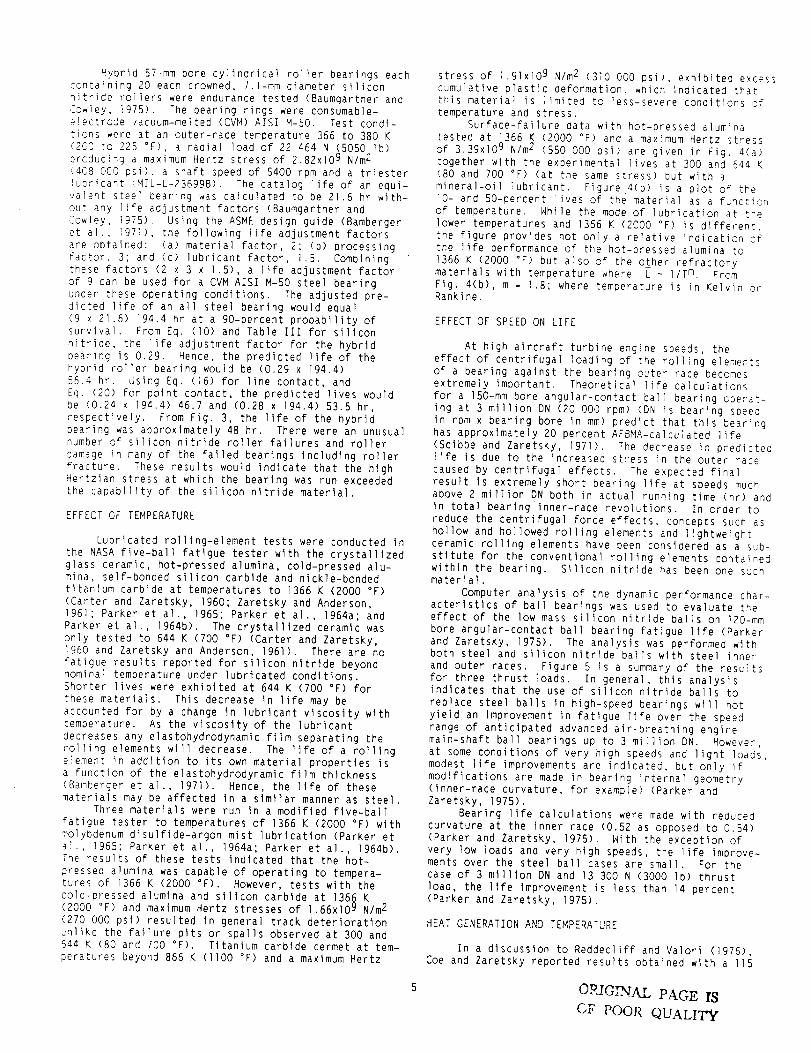
Hybrid 57-mm bore cylindrical roller bearings each_ontaining 20 each crowned, 7.1-mm diameter siliconnitride rollers were endurance tested (Baumgartner and:2owley, ]975). The bearing rings were consumable-e!ectrcCe vacuum-melted (CVM) AISI M-SO. Test condi-tions ,ere at an outer-race temperature 366 to 380 K(200 to 22S °F), a radial load of 22 464 N (5050 Ib);roducirg a maximum Hertz stress of 2.82xi09 N/m 2(dO8 @CO psi), a shaft speed of 5400 rpm and a triesterlubricant !MIL-L-23699B). The catalog life of an equi-valent steel bearing was calculated to be 21.6 hr with-out any life adjustment factors (Baumgartner andCowley, 1975). Using the ASME design guide (Bambergeret al., _971>, the followlng life adjustment factorsare obtained: (a) material factor, 2; (b) processingFactor, 3; and (c) lubricant factor, 1.5. Combiningthese factors (2 x 3 x 1.51, a life adjustment factorof 9 can be used for a CVM AISl M-50 steel bearingunder these operating conditions. The adjusted pre-dicted life of an all steel bearing would equal(9 x 21.6) 194.4 hr at a 90-percent probability ofsurvival. From Eq. (lO) and Table Ill for slllconnitride, the life adjustment factor for the hybrldeearing is 0.29. Hence, the predicted life of thehybrid roller bearing would be (0.29 x 194.4156.4 hr. Using Eq. (16) for line contact, andEq. (20) for point contact, the predicted lives wouldbe (0.24 x 194.41 46.7 and (0.28 x 194.4) 53.5 hr,respectively. From Fig. 3, the llfe of the hybridbearing was approximately 48 hr. There were an unusualnumber of silicon nitride roller failures and rollerdamage in many of the failed bearings Including rollerfracture. These results would indlcate that the hlghHertzian stress at which the bearing was run exceededthe capabillty of the sillcon nitride materlal.
EFFECT OF TEMPERATURE
Lubricated rolllng-element tests were conducted Inthe NASA five-ball fatigue tester wlth the crystalllzedglass ceramic, hot-pressed alumina, cold-pressed alu-mina, self-bonded silicon carbide and nickle-bondedtitanium carbide at temperatures to 1366 K (2000 °F)(Carter and Zaretsky, 1960; Zaretsky and Anderson,1961; Parker eta]., 1965; Parker et a1., 1964a; and
Parker etal., 1964b). The crystallized ceramic wasonly tested to 644 K (700 °F) (Carter and Zaretsky,1950 and Zaretsky and Anderson, 1961). There are nofatigue results reported for silicon nltride beyondnominal temperature under lubricated condltions.Shorter lives were exhibited at 644 K (700 °F) for
these materials. Thls decrease in life may beaccounted for by a change in lubrlcant viscosity withtemperature. As the vlscoslty of the lubricant
decreases any elastohydrodynamIc film separatlng therolling elements will decrease. The life of a ro111ngelement in addition to its own material properties isa function of the elastohydrodynamic film thickness
(Bamberger et al., 19711. Hence, the llfe of thesematerials may be affected in a similar manner as steel,
Three materials were run in a modified five-ball
fatigue tester to temperatures of 1366 K (2000 °F) with
molybdenum disulfide-argon mist lubrication (Parker etal., 1955; Parker et aI., 1964a; Parker et aI., 1964b),The results of these tests indicated that the hot-
pressed alumina was capable of operating to tempera-tures of 1366 K (2000 °F). However, tests with thecold-pressed alumina and slllcon carbide at 1366 K(2000 °F) and maximum Hertz stresses of 1.66xi09 N/m 2
(270 000 psi) resulted in general track deteriorationunlike the failure pits or spalls observed at 300 and544 K (80 and 700 °F). Titanium carblde cermet at tem-
peratures beyond 866 K (1100 °F) and a maxlmum Hertz
stress of 1.91xlO 9 N/m 2 (310 000 psi), exhibited excess
cumulative plastic deformation, which indicated thatthis material is limited to less-severe conditions of
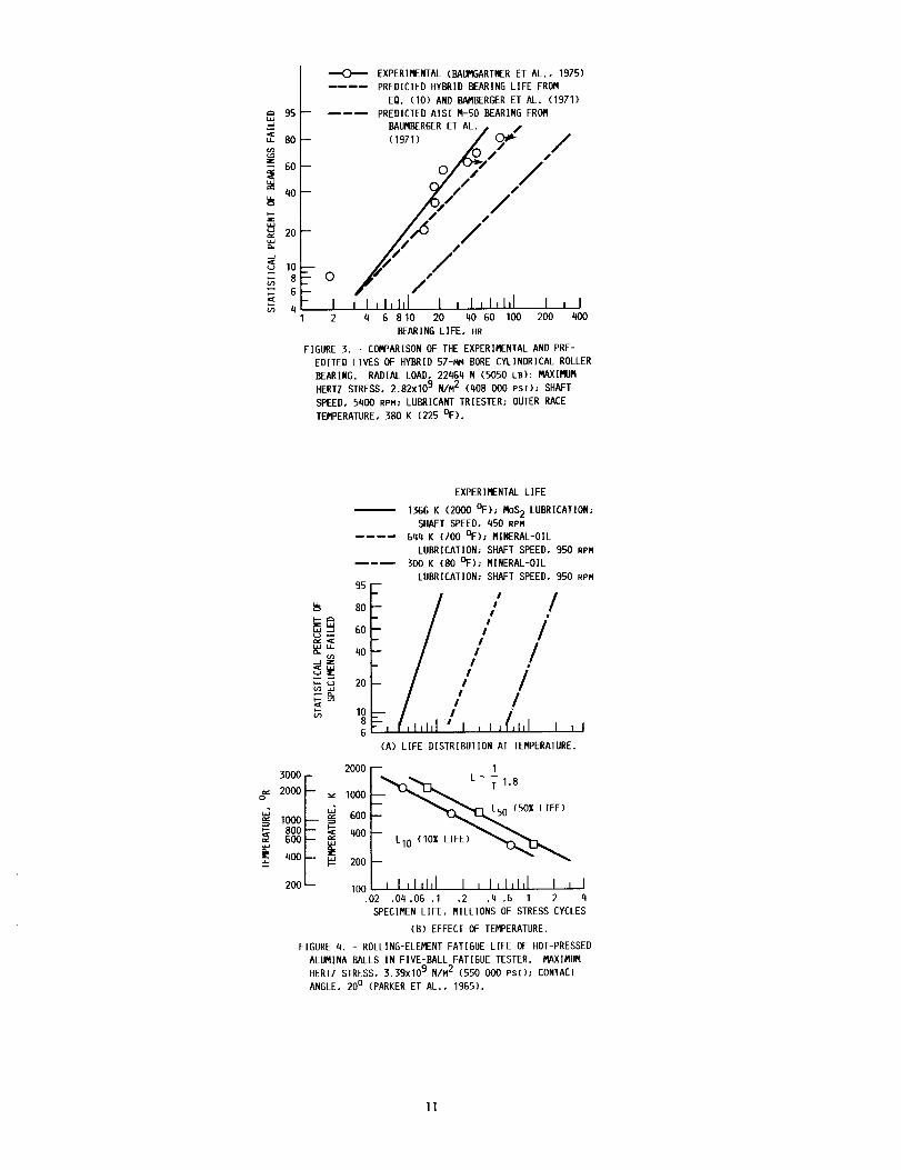
temperature and stress.Surface-failure data with hot-pressed alumina
tested at 1366 K (2000 °F) and a maximum Hertz stressof 3.39xi09 N/m 2 (550 000 psi) are given in Fig. a(a)together with the experimental lives at 300 and _44 K(80 and 700 °F) (at the same stress) but with a
mineral-oil lubricant. Figure 4(b) is a plot of theI0- and 50-percent lives of the material as a functionof temperature. Nhile the mode of lubrication at thelower temperatures and 1366 K (2000 °F) is different,the figure provides not only a relative indication ofthe life performance of the hot-pressed alumina to1366 K (2000 °F) but also of the other refractorymaterials with temperature where L ~ I/T m. FromFig. 4(b), m = 1.8; where temperature is in Kelvin orRanklne.
EFFECT OF SPEED ON LIFE
At high aircraft turbine engine speeds, theeffect of centrifugal loading of the rolling elementsof a bearing against the bearing outer race becomesextremely important. Theoretical life calculationsfor a 150-mm bore angular-contact ball bearing operat-ing at 3 million DN (20 000 rpm) (DN is bearing speedin rpm x bearing bore in mm) predict that this bearinghas approximately 20 percent AFBMA-caiculated life(Scibbe and Zaretsky, 19711. The decrease in predicted11fe is due to the increased stress in the outer race
caused by centrlfugal effects. The expected finalresult is extremely short bearing life at speeds muchabove 2 milllon DN both in actual running time (hr) andin total bearing Inner-race revolutions. In order toreduce the centrifugal force effects, concepts such ashollow and hollowed rolling elements and lightweightceramic ro111ng elements have been considered as a sub-stitute for the conventional rolllng elements containedwithin the bearing. Silicon nitrlde has been one s_chmaterla1.
Computer analysis of the dynamic performance char-acteristics of ball bearings was used to evaluate theeffect of the low mass sillcon nitride balls on 120-mm
bore angular-contact ball bearing fatigue life (Parkerand Zaretsky, 19751. The analysis was performed withboth steel and silicon nltride balls with steel innerand outer races. Figure 5 is a summary of the resultsfor three thrust loads. In general, this analysisindicates that the use of silicon nitride balls to
replace steel balls In high-speed bearings will notyield an Improvement in fatigue llfe over the speedrange of anticipated advanced air-breathing enginemain-shaft ball bearings up to 3 million DN. However,at some conditions of very high speeds and light loads,modest life improvements are indicated, but only ifmodifications are made in bearing internal geometry(inner-race curvature, for example) (Parker andZaretsky, 19751.
Bearlng life calculations were made with reducedcurvature at the inner race (0.52 as opposed to 0.54)(Parker and Zaretsky, 1975). Nith the exception ofvery low loads and very high speeds, the life improve-ments over the steel ball cases are small. For thecase of 3 mllllon DN and 13 300 N (3000 Ib) thrustload, the llfe Improvement is less than 14 percent(Parker and 2aretsky, 19751.
HEAT GENERATION AND TEMPERATURE
In a dlscussion to Reddecliff and Valori (19761,Coe and Zaretsky reported results obtained with a I15
OR!G]NA_L PAGE IS
GF POOR QUALITY

series, 75-mm bore ball bearing with steel ballsoperated at a 4400 N (I000 Ib) thrust load up toZ.©xl@ _ DN at NASA. The steel balls were then replacedwith silicon nitride balls and the test repeated.
Figure 6(a) is a comparison of the outer-race tem-perature for both bearings over a range of shaft speed.The outer-race temperature was almost the same forooth silicon nitride and the steel balls. However,Fig. 6(b) is a comparison of the bearing torque overthe same speed range, It is apparent that the bearingwith silicon nitride balls showed significantly highertorque than the same Dearing with steel balls. The
torque was measured directly by a force transducer con-nected to the periphery of the bearing housing. Thehigher torque with the silicon nitride balls can beexplained in part by the fact that the traction coeffl-cient of a lubricant is a function of the viscosity of
the oil under the contact pressure (Loewenthal andZaretsky, lgBs). Since for a given load, the contactstress with the silicon nitride balls are higher thanwith the steel balls, the vlscoslty of the oli in thecontact zone is higher. Because of the hlgher viscos-ity, the traction in the contact zone of the bearlngmust be accordingly higher.
It was reported by Reddecllff and Valorl (1976)that a 33-percent reduction In axial preload to preventskldding in a 35-mm bore angular-contact ball bearingwas achieved by substituting silicon nltride balls forsteel balls. This would tend to substantiate that ahigher traction force in the bearing may exlst wlth agiven load as a result of the higher viscosity withhigher contact stress. Nigher traction forces shouldresult in higher heat generation with the siliconnitride balls. However, data reported in Reddecliffand Valorl (1976) (Flg. 7) show that with the siliconnitride balls in the 35-mm bearing, the heat generationwas lower (Fig. 7(a)) even though the outer-race tem-peratures were almost identlcal (Fig, 7(b)).
There are possible explanatlons for the differencein these results. There could, of course, be an effectdue to bearing size. For example, the computer programused in Parker and Zaretsky (1975) Indlcates that about60 percent of the calculated heat generation was due toball spin for a 35-mm bore bearing, whereas it wasabout 50 percent for a ]20-mm bore bearing. Further,the oli used for the ?5-mm bearing tests was super-refined naphthenlc mineral oll wlth undoubtedly dlffer-ent viscosity cbaracterlstlcs from those of the oilused in Reddecllff and Valori (1976), Also, the 75-mmbearings were lubricated directly by oll jet, notthrough the race as those of Reddecliff and Valorl(1976). Finally, it should be noted that the diameterof the sillcon nitride balls used in the 75-mm bearingdiffered less than 0.5 um (20 pin.) from the steelballs, at room temperature. Therefore, at operatlngtemperature, the bearlngs were sllghtly different, dueto the lower coefflclent of expansion of the siliconnitrlde.
Data were reported for AISI M-50 35-mm rollerbearings (Baumgartner et al., 1976) comparing the heat
generated in a hybrid roller bearing with the same sizebearing having steel rollers and approximately the sameradial load. It was concluded In Baumgartner et al.
(1976) that the heat generation for the hybrid bearingwas comparable to that of the bearing with the steelrollers. It can be concluded that the bearing powerloss or heat generation is more a function of the indi-
vidual bearing design and operation than whether steelor ceramic rolling elements are used wlthln the bearlng.
UNLUBRICATED BEARINGS
It has been proposed that unlubricated ceramic
bearings offer an approach toward meeting operatingrequirements in excess of 578 K (600 °F) where bothconventional and nonconventional liquid iubricants are
not capable of sustaining these higher temperatures norof providing an elastohydrodynamic film. Tests of fullcomplement 17-mm bore silicon nitride cylindricai roil-er bearings were performed at 644 K (700 °r) <Bailey,1984). The test vehicle used to evaluate these _ear-
ings was a modified J402 Turbojet engine, The first
test resulted In a catastrophic bearing failure afterIf-I/2 min of operation due to fracture of the ceramic.The second test ran for a total time of 2 hr and 3 minof which 54 min were run unlubricated. In the unlubri-
rated condition, 30 min were run at shaft speeds between39 000 and 39 600 rpm or in excess of 660 000 DN.However, residual lubricant may nave been present to
sustain the bearing for the 54 min. A totally unIubri-rated endurance test was run with a Ren_ 41 gold-plated cage. A catastrophic failure was encounteredafter 30 min of operation due to fracture of theceramic.
Solld film lubrlcants applled in a manner similarto that reported in Parker et al. (1965) may be capable
of sustaining full complement ceramic roller bearingsat these hlgher temperatures for longer periods oftime. However, extensive work is required to bothprove and develop this concept for practical turbineengine appllcatlons.
BEARING MOUNTING
The use of full complement ceramic roll_ng-e!ementbearings presents unique mountlng problems. Referringto Table II, the thermal expansion of the refractorymaterials are less than that of steel. As a result,where a ceramic bearing is mounted on a steel shaft,large hoop stresses can be induced in the bearing innerring which can result in fracture of the ring. Hosang(1987) proposes the use of a corrugated liner inter-posed between the journal and the bore of the innerring. The corrugations run parallel to the bearlng andjournal axls. This is illustrated in Fig. 8. In prin-ciple, the liners diametral thermal expansion is lessthan that of the shaft Journal. The difference is
accommodated by stretching of the llner In the circum-ferential directlon. Accordlng to Hosang (1987), thisaction also reduces the envelope outer diameter of the
corrugations from that dictated by thermal expansion.The radial stiffness of the llner should also be as
hlgh as possible so as not to affect the stiffness of
the bearing. An alternate deslgn proposed by Hosang(1987) is the use of the corrugated liner and conicalretainers shown In Fig. 8(a).
Bailey (1983) reports the use of a collar for theinner ring and a spacer for the outer ring to accommo-date differences in thermal expansion (Fig. 9).
Baumgartner eta]. (1973), use a clamplng collaragainst the inner ring. The axial clamping force ismaintalned by the clamping collar with an angled faceto match the face angle of the inner ring. As theshaft expands axially, the radial expansion forces thecollar against the inner ring face, holdlng it inposition.
The use of full complement ceramic bearingsrequire special mounting design considerations not cur-rently used in turbomachlnery. Consequently, these

O_,J(;[:qt_.L PAGE I_
C'F POOR QUALITY
bearings cannot be substituted for steel bearings with-
out extensive design modifications of the rotating
shaft and housing.
_ANUFACTURING AND PROCESSING
It has long been recognized that voids or surface
defects iq ceramic or cermet roiling elements can be
the source of a subsurface or surface induced spall
<,Carter and Zaretsky, 1960; Zaretsky and Anderson,
:961; Parker eta]., 1965; Parker and Zaretsky, 1974;
:arKer eta]., 1964a: and Parker etal., !964b). As
critical flaw sizes are reduced, it is probable that
the '_alues of dynamic capacity summarized in Table I
and life can be increased. Thus, processing and
manufacturing methods can be critical to long life
functioning.
In recent years, a relatively large effort has
been devoted to the processing and manufacture of sili-
con nitride bearings (Bhushan and Sibley, 1982; Dalal
etal., 1977; Baumgartner and Cowley, 1976; and
Baumgartner and _heidon, 1973). The most commonly used
processing method is hot processing. In hot processing
the powder is sized, blended with hot-processing aids
and pressed in graphite dies using temperatures in the
1973 to 2173 K (3091 to 3451 °F) range and pressures
above 14 MPa. The most common sintering aid is the
addition of ] to 2 percent MgO (Bhushan and Sibley,1982).
Other processes include blending of silicon
nitride powder with a binder and then cold pressing to
near-net shape preforms. The cold-Dressed parts are
subsequently sintered at high temperature without
application of the high pressures present in hot pro-
cessing (8hushan and Sibley, 1982). Another processing
method is hot isostatic pressing or partial sintering
and then hot isostatic pressing (Bhushan and Sibley,
1982). Cold processing silicon and reaction sintering
in hot, high-pressure nitrogen called reaction bondingis still another method.
Silicon nitride Is hot pressed into billets in the
form of plates and then diamond machined, The materia]
can be hot pressed directly into blanks of the required
shape for bearing rings, balls, and rollers using suit-
able multiple cavity graphite molds (Bhushan and
Sibley, 1982).
The rolling-element fatigue life of silicon
nitride was found to be strongly influenced by finish-
ing procedures (Bhushan and Sibley, 1982; Baumgartner
and Cowley, 1976; and Baumgartner and Wheidon, 1973).
As with steels, improved rolllng-element fatigue life
was obtained with better surface finishes (Baumgartner
and Cowley, 1976 and Baumgartner and Wheidon, 1973).
The machining of silicon nitride for bearing applica-
tion begins with ultrasonic machining, followed by dia-
mond grinding, and then by lapping and polishing
(Bhushan and Sibley, 1982). Surface preparation should
insure that coarse grit grinding damage is removed dur-
ing final finish (Baumgartner and Nheidon, 1973).
It was recommended by Baumgartner and Cowley
(1976) that, for producing silicon nitride rollers with
a straight roller geometry, diamond grinding and honingbe used. The use of a formed silicon carbide wheel
after initial diamond wheel grinding was recommended
for shading crowned roller geometries (Baumgartner and
Cowley, 1976).
SUMMARY
For three decades research has been performed
into the use of nonmetallic and refractory materials
as rolling-element materials for use in gas turbine
engines. Materials and bearing design methods have
continuously improved over the years. Materials suchas alumina, silicon carbide, titanium carbide, sit:con
nitride, and a crystallized glass ceramic have been
investigated by NASA in the past. Rolling-element
endurance tests and analysis of full-complement bear-
]ngs were oerformed. The following resuits wereobtained:
I. Silicon nitride material Ùroduces the longest
life of the materials studied. 4owever, the dynamic
capacity of a fall complement si:_con nitride bear_qgwill be only 5 to 12 percent that io_ an all steel sear-
ing o _ slmilar geometr)'.
2. The use of bearings naving ceramic rolling ele-
ments and steel races can resuit in lives less than
full complement steel bearings where the elastic modu-
lus of the ceramic is greater than steel as in the case
of most ceramics.
3. Bearing power loss or heat generation is more a
function of the individual bearing design and operation
than whether steel or ceramic rolling e]ements are used
within the bearing.
4. The lives of ceramic rolling elements are an
inverse function of temperature. It is suggested based
upon endurance tests with alumina to !366 K (2000 °F)
that life is inversely proportional to temperature to
the 1.8 power,5. Unlubricated tests of a full-complement silicon
nitride bearing at 644 K (700 °F) resulted in cata-
strophic failure after 30 min suggesting the need for
lubrication at elevated temperatures.
6. Special design and mounting requirements are
needed to accommodate a full-complement ceramic bearing
into turbomachinery applications. Optimum designs nave
yet to be developed.
ACKNOWLEDGMENTS
The author wishes to acknowledge the technical
contributions of Richard J. Parker and Salvatore J.
Grisaffe who with his other colleagues at the NASALewis Research Center collaborated with him in con-
ducting the NASA nonmetallic bearing research over the
years which is reported herein. Also, the authorwishes to thank Mr. Grisaffe for his technical recom-
mendations and comments which have been incorporated
throughout this paper.
REFERENCES
Appeldoorn, O.K. and Royle, R.C., 1965, "Lubricant
Fatigue Testing with Ceramic Balls," Lubrication
Engineering, Vol. 21, No. 2, pp. 45-51.
Bailey, T.E., 1984, "Ceramic Roller Bearing DevelopmentProgram," NAPC-PE-I06-C. (Avail. NTIS, AD-BO86767L).
Bamberger, E.N., 1971, Life Adjustment Factors for Ball
and Roller Bearings - An Engineering Design Guide,ASME, New York.
Baughman, R.A. and Bamberger, E.N., 1963, "Unlubricated
High Temperature Bearing Studies," Journal of Basic
Engineering, Vol. 85, No. 2, pp. 265-272.
Baumgartner, H.R. and Cowley, P.E., 1975, "Silicon
Nitride in Rolling Contact Bearings," Norton Co.,
Norcester, MA. (Avail. NTIS, AO-AOI5990).
Baumgartner, H.R. and Cowley, P.E., 1976, "Finishing
Techniques for Silicon Nitride Bearings,"AMMRC-CTR-76-5..(Avail. NTIS, AD-A025350).

Baumgartner,H.R.andNhleldon,N.M.,1973,"RollingContaCtFatiguePerformanceof Hot-PressedSiliconNitride versusSurfacePreparationTechniques,"SurfaceandInterfacesof Glass and Ceramics, V.O. Frechette,
N.C. LaCourse, and V.L, Burdick, eds., Plenum Press,
New (OT'K, PP. 179-193.
5aumgartrer, H.R., 1973, "Eva]uat]on of Roller Bearings
Ccmtaining Hot PresseO Silicon Nitride Rolling
E_ements, '' Ceramics for High Performance Applications,
].J. Surke, _.E. Gorum, anO R.N. Katz, eds., Brook Hill
Publishing Co., Chestnut Hill, MA, pp. 7]3-727.
_umga,-t,qer, H.R., Calvert, G.S., and Cowley, P.E.,
!976, "Ceramic Materia]s in Rolling Contact Bearings "Norton C.3., Norcester, MA. (Avail. NTIS, AD-A031560).
Parker, R.J. and Zaretsky, E.V., 1975, "Fatigue Life of
High-Speed Ball Bearings with Silicon Nitride Balls,"Journal of Lubrication Technology, Vo]. 97, _o. 3,
DP. 350-357.
Parker, R.J. and Zaretsky, E.V., 1972, "Reevaluation of
the Stress-Life Relation in Rolling-Element Bearings,'
NASA TN D-6745.
_arker, R.J. and Zaretsky, E.V.., 1974, "Rolling-Elemer,_
_atigue Life of Silicon Nitride Balls," NASA TN D-7794.
Parker, R.J. and Zaretsky, E.V., ]972, "Rolling-Element
Fatigue Lives of Through-Hardened Bearing Materials,"
Journal of Lubrication Technology, Vol. 94, No. 2,
pp. 165-]73.
Baumgatner, H.R., Lundberg, D.V., and Whiedon, N.J.,
1973, "Silicon Nitride in Rolling Contact Bearings,"
Norton Co., Worcester, MA. (Avail. NTIS, AD-771393).
Bhushan, B. and Sibley, L.B., 1982, "Silicon Nitride
Rolling Bearings For Extreme Operating Conditions, ASLE
Transactions, Vo]. 25, NO. 4, pp. 4]7-428.
Carter, T.L. and Zaretsky, E.V., 1960, "Rolling Contact
Fatigue Life of a Crystallized Glass Ceramic," NASATN 0-259.
Dala], H.M., Roseniieb, O.N., and Slb]ey, L.B., 1977,
"Develo0ment of Basic Processing Technology for Bearing
Quality Silicon Nitride Balls," SKF-AL77T057, SKF
:ndus/ries, King of Prussia, PA. (Avail. NTIS,
AD A053330).
Dee, C.N., !970, "Silicon Nitride-Tribologica]
Appl cations of a Ceramic Material," Tribology,
Vo!. 3, NO. 2, pp. 89-92,
Harris, T.A., 1968, "On the Effectiveness of Hollow
Balls in High-Speed Thrust Bearings " ASLE
Transactions, Vol. li, NO. 4, pp. 290-294.
Hosang, G.N., 1987, "Results and Design Techniques from
the Application of Ceramic Ball Bearings to the
MERADCOI.I ]OKN Turbine," AIAA Paper 87-1844.
Jones, A.B., 1946, Analysis of Stresses and
Deflections, Vols. I and II, General Motors, New
Departure Division, Bristol, CT.
Loewenthal, S.H. and Zaretsky, EIV., 1985, "Traction
Drives," Mechanical Design and Systems Handbook, 2nd
Edition, H.A. Rothbart, ed., McGraw Hill, New York,
1985, pp. 34.1-34.56,
Lundberg, G. and Palmgren, A., 1947, "Dynamic Capacity
of Rolling Bearings," Acta Po]ytechnica, Mechanical
Engineering Series, Vol. l, No. 3, pp. 1-50.
Parker, R.J., Grisaffe, S.J., and Zaretsky, E.V., 1965,
"Rolling-Contact Studies Nith Four Refractory Materials
to 2000 °F," ASLE Transactions, VOl. 8, No. 3,
pp. 208-216.
Parker, R.J., Grisaffe, S.J., and Zaretsky, E.V., ;964,
"Surface Failure of Alumina Balls Due to Repeated
Stresses Applied in Rolling Contact at Temperatures of
2000 °F," NASA TN D-2274.
Parker, R.J., Grisaffe, S.J., and Zaretsky, E.V., 1964,
"Surface Failure of Titanium Carbide Cermet and Silicon
Carbide Balls in Rolling Contact at Temperatures to
2000 °F," NASA TN D-2459.
Reddecliff, J.M. and Valori, R., 1976, "The Performance
of a High-Speed Ball Thrust Bearing Using Silicon
Nitride Balls," Journa] of Lubrication Tecnnology,
Vol. 98, No. 4, pp. 553-563.
Scibbe, H.N. and Zaretsky, E.V., 1971, "Advan:ed Design
Concepts for High Speed Bearings," ASME Paper 7I-DE-EO.
(NASA TM X-52958).
Scott, D. and Blackwel], J., 1973, "Hot-Pressed Silicon
Nitride as a Rolling Bearing Material--A Pre]iminary
Assessment," Near, Vo]. 24, NO. l, pp. 61-67.
Scott, D., Balckwel], J., and McCullagh, P.J., 1971,
"Silicon Nitride as a Rolling Bearing Materia--A
Pre]iminary Assessment," Near, Vol. 17, No. I.
pp. 73-82.
Sibley, L.B., Mace, A.E., Grlesir, D.R., and
Allen, C.M,, 1960, "Characteristics Governing theFriction and Wear Behavior of Refractory Materials for
High-Temperature Seals and Bearings," NADD-TR-60-54.
Taylor, K.M., Sibley, L.B., and Lawrence, J.C., 1963,
"Development of a Ceramic Rolling Contact Bearing for
High Temperature Use," Near, Vol. 6, No. 3,
pp. 226-240.
Lundberg, G. and Palmgren, A., 1949, "Dynamic Capacity
of Rolling Bearings, Journal of Applied Mechanics,
VO1. 15, NO. 2, pp. 165-172.
Lundberg, G. and Palmgren, A., ]952, "Dynamic Capacity
of Roller Bearings," Acta Polytechnica, Mechanical
Engineering Series, Vol. 2, No. 4.
Zaretsky, E.V. and Anderson, N.J., 1961, "Rolling-
Contact Fatigue Studies with Four Tool Steels and a
Crystallized Glass Ceramic," Journal of Basic
Engineering, VoI. 83, No. 4, pp. 603-612.
Miner, J.R., Grace, N.A., and Valori, R., 1981, "A
Demonstration of High-Speed Gas Turbine Bearings Using
Silicon Nitride Ro111ng Elements," Lubrlcatlon
Engineering, Vo]. 37, No. 8, pp. 462-464, 473-478.
C':_> _':;;,L: PA'_E I8
OF, _OO__ QUALITY,

'q_"-:'-' :' _ PAGE 1,3- " L.
-:" _ !':. C:UALIT_
TABLE I. - STRESS-LIFE EXPONENT ,aND RELATIVE DYNAMIC CAPACITY OF
MATERIALS FOR ROLLING-ELEMENT BEARING APPLICATION
Material Stress-life exponent, Dynamic capacityn relative to steel
Crystali_zed glass ceramic a I0.5 to 13.8 0.07(Average value, TI.81
Hot-pressed alumina b 9.4 to 10.8 0.07(Average value, I0.6)
Cold-pressed alumina b 6.0 to 8.1
(Average value, 7)
0,0!
LSelf-bonded silicon 6.9 to 8.6 O.Ol
carbide b (Average value, 7.8)
Nickle-bonded titanium 9.7 to I0.5 0.03carbide b (Average value, I0.2)
Silicon nitride c 16 to 16.2 0.05 to 0.12(Average value, 16.1)
Bearing steel 9 to I0 1.00(Accepted value, 9)
aCarter, et al. (1960); Zaretsky, et al. (Ig61).bParker, et al. (1965).
CBaumgartner, et al. (1973); Parker, et al. (1975); Parker, et al. (1974).
Material
Crystalllzed
glass ceramic
TABLE II. - TYPICAL PHYSICAL AND THERMAL PROPERTIES OF MATERIALS FOR ROLLING-ELEMENT BEARING APPLICATION
[Carter, eta]. 1960); Zaretsky, et al. (1961); Parker, eta]. (1965); Baumgartner, et al. (1973);
Parker, et al (1975); Parker, et aI. (1974); Parker eta]. (1964); Bhushan, et al. (1982).]
Rockwell C Estlmated a
hardness at maxlmum
294 K usable
(70 °F) bearlng
temperature,K
(°F)
53 >644
(700)
Alumina 85 ~1367(2000)
Slllcon carbide 90 <1367(2000)
NIckle-bonded 67 <867
tltanlum carblde (1100)
Silicon nitrlde 78 ~1367(2000)
>589(600)
Denslty,
gmlcc
Bearing steel(AISI M-50)
2.5
3,9
3.2
6,3
3.11 to
3.24
7.6~63
abased primarily on hardness retantlon and test experlence.
bBased upon rolllng-element fatigue testing.
Elastic
modulus
at 294 K
(70 °F),
GPa
(106 psi),
Y
Poisson's
ratio,6
Thermal conductlvlty,wlmK (BTu ftlhr-ft2-F)
at
Coefficient of
thermal
expanslon,I0-6 K
(IO-6/°F)
273 to I073 K
(32 to 1471 °F)
294 K 1073 K
(70 °F) (1471 °F)
1.6 2.0(0.9) (1.2) at
873 K
(II12 °F)
7.2 1.7(4.2) (1.0)
35 12
(20) (6.9)
14 6.8(8.1) (3.9)
7.3 4.7
(4.2) (2.7)
13.4 .....(7.7)
87 0.25 0.4
(12.5) (0.2)
350 0.25 8.5
(51) (4.7)
410 0.25 5,0
(59) (2.8)
390 0.23 10.7
(57) (5.9)
310 0.26 2.9
(45) (1.6)
190 0.28 12.3(28) (6.8)
Welbull p
slope or
modulus,
e
3.3
2.7
2.1
1.4
1.7
I.I

TABLE Ill. - RELATIVE LIFE AND DYNAMIC CAPACITY OF
HYBRID BEARING WITH VARIOUS ROLLING-ELEMENT MATERIALS
Raceway Rolllng elementmaterial material
Steel
Relative
life from
Eq._(]O). a
LH R
Relative
dynamic
capac ityto steel
from
Eq. (2). a
n=9
CrystaIiized IB 2.6
glass ceramic
Alumina 0.22 0.6
Silicon carbide 0.16 0.5
Nickle-bonded 0.18 0.6
titanium carbide
Silicon nitrlde 0.29 0.7
Steel l 1
abased upon failure of steel raceway and assuming no
failure of roiling elements.
95 m
..a
BOR
40
1o8
4
HOT-PRESSED
SILICON NITRIDE _
(PARKER ET AL, f AISI M-50
1974) f (PARKER ET AL.,
/AISI 52100
(PARKER ET AL.,1972)
i I llll,l I2 4 6 8 10 20 40 GO 100 200
SPECIMEN LIFE. MILLIONS OF STRESS CYCLES
FIGURE I, - ROLLING-ELEMENT FATIGUE LIFE OF HOT-
PRESSED SILICON NITRIDE BALLS AND STEEL BALLS IN
FIVE-BALL FATIGUE TESTER. MAXIMUM HERTZ STRESS,
5.52xi09 N/M 2 (800 000 PSl): SHAFT SPEED, 9400 RPM_
RACE TEMPERATURE, 328 K (130 OF); CONTACT ANGLE,
30% LUBRICANT, SUPER-REFINED NAPHTHENIC MINERAL
OIL (PARKER ET AL., 1974).
Ct.
_0
95 B
8oHOT-PRESSED /60 SILICON NITRIDE
40 IS[ M-S_
20
10 .
8
6
4 I i I _lJlil I I I llll,l I2 4 6 8 10 20 40 60 100 200
SPECIMEN LIFE, MILLIONS OF STRESS CYCLES
FIGURE 2. - ROLLING-EL_NT FATIGUE LIFE OF HOT-
PRESSED SILICON NITRIDE ROLLERS IN ROLLING-CONTACT
(R-C) FATIGUE TESTER. MAXIMUM HERTZ STRESS,
q.83x109 N/M 2 (800 000 PSI): ROLLER SPEED,
10 000 RPM: TEMPERATURE, AMBIENT; LHBRICANT, TRI-
ESTER (MIL-L-23699B)(BAUMGARTNER ET AL., 1973).
lO
DRIG"INAE PAGE IS
OF POOR OLT_.T/T Y
95
u_ 80
Z
- 60
_w40
20
_ lO_ s_ 6_ 4
-'-C)-"- EXPERIMENTAL (BAUMGARTNER ET AL., 1975)
.... PREDICTED HYBRID BEARING LIFE FROM
EQ. (10) AND BAMBERGER ET AL. (1971)
-- _--_ PREDICTED AISI M-50 BEARING FROM
BAUMBERGER ET AL. p
-- (1971) / _, /
- j,7 /
_f p#"
-o /" //- I I Ill,Ill I I I_l,ld I , I
2 4 6 8 10 20 40 60 100 200 400
BEARING LIFE, HR
FIGURE 3. - COMPARISONOF THE EXPERIMENTALAND PRE-
EDITED LIVES OF HYBRID 57-MM BORE CYLINDRICAL ROLLER
BEARING. RADIAL LOAD, 22464 N (5050 LB): MAXIMUM
HERTZ STRESS, 2.82XI09 N/M2 (408 000 PSX); SHAFT
SPEED, 5400 RPM; LUBRICANT TRIESTER: OUTER-RACE
TEMPERATURE, 380 K (225 OF).
5000
20001000
8oo600
@" 4oo
EXPERIMENTAL LIFE
1366 K (2000 OF)- MoS2 LUBRICATION:SHAFT SPEED, 450 RPM
.... 644 K (700 OF)- MINERAL-OIL
LUBRICATION; SHAFT SPEED, 950 RPM
m--m 300 K (80 OF): MINERAL-OIL
LUBRICATION: SHAFT SPEED, 950 RPM
95 _'- *'
I_ _o
" 1o IG Iril,ll[' I , I, I,I , ,I
(A) LIFE DISTRIBUTION AT TEMPERATURE.
2000 -- 1
• 600 0% LIFE)
40O
-- LIO (I0% LIFE) _'_-- 200
, l,IIl,l I , I,I,I,I I , I.02 .04 .06 .I .2 .4 .6 I 2 4
SPECIMEN LIFE, MILLIONS OF STRESS CYCLES
(B) EFFECT OF TEMPERATURE.
FIGURE 4. - ROLLING-ELEMENT FATIGUE LIFE OF HOT-PRESSED
ALUMINA BALLS IN FIVE-BALL FATIGUE TESTER. MAXIMUM
HERTZ STRESS, 3.39xi09 N/M2 (550 000 PSI)" CONTACT
ANGLE, 200 (PARKER ET AL., 1965).
200-- 100
II

104
C=
E- 103
ZN
lo2
O
_dIE
-J
lo4¢¢
_ 103
lO2
STEEL BALLS, 0.54
- --:------ SILICON NITRIDE
BALLS, O.5q
THRUST_"- -----. ,..,. "'- -,,.,; LOAD,
N(LB)
4q50(1000)
13 300........ I (3000)
I 22 250(5O00)"-" .-- ---I-- "-- "J" -- -- "J-- -- "J
(A) STEEL BALLS AND SILICON N[-
TRIDE BALLS WITH INNER-RACE
CURVATURE OF 0.54.
__ I 4q50(1000)
-- _ STEEL BALLS, 0.54
.... SILICON NITRIDE
_.,,_._. BALLS, 0.52
(3000)
I I I I } 22(5ooo)5oo2.0 2.5 3.0 3.5 4.0
SHAFT SPEED, 106 DN
(B) STEEL BALLS AND SILICON NI-
TRIDE BALLS WITH INNER-RACE
CURVATURES OF 0.54 AND 0.52,
RESPECTIVELY.
FIGURE 5. - PREDICTED LIFE OF 120 MM BORE
ANGULAR CONTACT BALL BEARING WITH SILICON
NITRIDE BALLS BALL DIAMETER, 20.64 MM
(0.8125 ]N.) (PARKER ET AL., 1975).
2qO
23O
220
i 210
200
i 190i 370
36O
170 --
.8 --
.7 --
,G --
.q
350
t_ 0 AISl M-SO
I-1SILICON NITRIDE
I I I(A) OUTER-RACE TEMPERATURE.
1.0 --
E
u] .9 --[_ o o_
,G --
.5 I I I 116 20 2q 28x103
SHAFT SPEED, RPM
(B) BEARING TORQUE.
FIGURE 6, - PERFORMANCEOF 75 _ BORE ANGULAR-CONTACT
BALL BEARING AS FUNCTION OF SHAFT SPEED. THRUST LOAD,
4400 N (989 LB), OIL FLOW RATE, 0.9 KG/M|N (2 LB/MIN)
OIL INLET TEMPERATURE 316 K (109 OF).
12

ORIGINAL PAGE IS
BALLMATERIAL OF POOR QUALITY0 AISI M-50 /_STEEL HOUSING
f"l SILICON NITRIDE /
180 F 5000 --
1500 i
__ 60 1000
_: 40 50020
0 ] ' -
(A) MOUNTING ARRANGEMENT.
0
140 Fz _- =_ 70
.-°, 120V _. GO
<___< 1°°F _,_ so40
N _ 60 N 30
_ _o _ 20_,Lu _ 10__ 20
0 _ 0 J20 50 qo 50 60 70 80x103
SHAFT SPEED, RPM
(B) OUTER-RACE TEMPERATURE.
FIGURE 7. - PERFORMANCE OF 35 MM BORE ANGULAR-CONTACT
BALL BEARING AS A FUNCTION OF SHAFT SPEED. THRUST LOAD,
1200 N (270 LB) OIL FLOW RATE, 1.1KG/MIN (2.5 LB/MIN);
OIL INLET TEMPERATURE, 399 K (150 OF) (REDDECLIFF
ET AL., 1976).
SHAFT
(B) CORRUGATED LINER.
FIGURE 8. - MOUNTING ARRANGEMENT OF FULL-COMPLIMENT CERAMIC BEARING
ON A STEEL SHAFT, USING A CORRUGATED LINER (HOSANG, 1987).
CAGE_
r STEEL SPACERIIi /-STEEL HOUSINGI i
OUTER RING
CERAMIC ROLLER
,---CERAMIC INNER RINGI"
..... STEEL COLLAR
N-STEEL SHAFT
FIGURE 9. - MOUNTING ARRANGEMENT OF FULL-COMPLIMENT CERAMIC
ROLLER BEARING ON A STEEL SHAFT, USING A STEEL COLLAR AND
AND SPACER (BAILEY, 1983).
13
Report Documentation Page_,_l,l_mU A_uorlaut,_ ,, and
SI, I, *, Adm,m_tralK_n
1 Report No. 2. Government Accession No. 3 Recipient's Catalog No.
NASA TM-100288
4. Tille and Subtille 5. Report Date
Ceramic Bearings for Use in Gas Turbine Engines
7. Author(s)
Erwin V. Zaretsky
9 Performing Organization Name and Address
National Aeronautics and SpaceLewis Research CenterCleveland, Ohio 44135-3191
Administration
12. Sponsoring Agency Name and Address
National Aeronautics and SpaceWashington, D.C. 20546-0001
Administration
6. Performing Orgarlization Code
8, Performing Organization Report No.
E-3934
10 Work Unit No.
505-63-]B
1t. Contract or Grant No.
13, Type of Report and Period Covered
Technical Memorandum
14. Sponsoring Agency Code
15 Supplementa_ Notes
Prepared for the 33rd International Gas Turbine and Aeroengine Congress andExposition sponsored by the American Society of Mechanical Engineers, Amsterdam,The Netherlands, June 5-9, ]988.
Abstract
Three decades of research by U.S. industry and government laboratories have pro-duced a vast array of data related to the use of ceramic rolling-element bearingsand bearing components for aircraft gas turbine engines. Materials such asalumina, silicon carbide, titanium carbide, silicon nitride and a crystallizedglass ceramic have been investigated. Rolling-element endurance tests and analy-sis of full-complement bearings have been performed. Materials and bearingdesign methods have continuously improved over the years. This paper reviews awide range of data and analyses with emphasis on how early NASA contributions aswell as more recent data can enable the engineer or metallurgist to determinejust where ceramic bearings are most applicable for gas turbines.
OP, IGINAU PAGE 18
OF POOR QUALITY
17 Key Words (Suggested by Author(s))
Ceramics; Ceramic bearings;Rolling-element fatigue;Rot]ing bearings; Aircraftbearings
18. Distribution Statement
Unclassified - UnlimitedSubject Category 37
19, Security Classif (of this report) 20. Security Classif. (of this page) 21. No of pages 22. Price*
I
Unclassified Unclassified 14 A02
NASA FORM 1626 OCT 86 *For sale by the National Technical Information Service, Springfield, Virginia 22161
Copyright © 2022 FDOKUMEN

