


Bahasa
Halaman
Hukum


OSAPublished by
To be published in Optics Letters:
Title: Blind Multi-spectral Image Decomposition by 3D Nonnegative Tensor
Factorization
Authors: Ivica Kopriva and Andrzej Cichocki
Accepted: 21 June 2009
Posted: 25 June 2009
Doc. ID: 109250

OSAPublished by
1
Blind Multi-spectral Image Decomposition by
3D Nonnegative Tensor Factorization
Ivica Kopriva1,*
and Andrzej Cichocki2
1Division of Laser and Atomic Research and Development
Ruñer Bošković Institute, Bijenička cesta 54, HR-10000, Zagreb, Croatia
2Laboratory for Advanced Brain Signal Processing
Brain Science Institute, RIKEN 2-1Hirosawa, Wako-shi, Saitama, 351-0198, Japan
Abstract
α -divergence based nonnegative tensor factorization (NTF) is applied to blind multi-spectral
image (MSI) decomposition. Matrix of spectral profiles and matrix of spatial distributions of the
materials resident in the image are identified from the factors in Tucker3 and PARAFAC
models. NTF preserves local structure in the MSI that is lost, due to vectorization of the image,
with nonnegative matrix factorization (NMF)- or independent component analysis (ICA)-based
decompositions. Moreover, NTF based on PARAFAC model is unique up to permutation and
scale under mild conditions. To achieve this, NMF- and ICA-based factorizations respectively
require enforcement of sparseness (orthogonality) and statistical independence constraints on the
spatial distributions of the materials resident in the MSI, and that is not true. We demonstrate

OSAPublished by
2
efficiency of the NTF-based factorization in relation to NMF- and ICA-based factorizations on
blind decomposition of the experimental MSI with the known ground truth.
OCIS codes: 100.6890; 100.3190; 150.6910; 100.2960; 170.3880.
Blind or unsupervised multi-spectral and hyper-spectral image (HSI) decomposition attracts
increased attention due to its capability to discriminate materials resident in the MSI/HSI without
knowing their spectral profiles [1,2]. However, most of blind decomposition schemes rely on
two-dimensional (2D) representation of the MSI/HSI although it is inherently three-dimensional
(3D). In this letter we represent a MSI/HSI as a three-way array or a 3D tensor 1 2 3
0
I I I× ×+∈X ℝ with
elements 1 2 3i i i
x where i1=1,..., I1, i2=1,..., I2, i3=1, ..., I3 and 0+ℝ is a real manifold with nonnegative
elements. Each index is called way or mode and number of levels on one mode is called
dimension of that mode. MSI/HSI is a set of I3 spectral band images with the size of I1×I2 pixels.
Two ways of X are for rows and columns and one way is for spectral band. This is standard
notation that is adopted for use in multiway analysis, [3]. 2D representation of MSI has two
disadvantages: (i) 3D tensor X has to be mapped through 3-mode flattening, also called
unfolding and matricization, to matrix 3 1 2
(3) 0
I I I×+∈X ℝ whereas local structure of the image is lost;
(ii) matrix factorization (3) =X AS employed by linear mixing models [1,2] suffers from
indeterminacies because 1
(3)
− =ATT S X for any invertible T, i.e. infinitely many (A, S) pairs can
give rise to X(3). Meaningful solution of the factorization of X(3) is characterized with TT-1
=PΛΛΛΛ
where P is permutation matrix and ΛΛΛΛ is diagonal matrix. These permutation and scaling
indeterminacies are standard for blind decompositions and are obtained by imposing sparseness

OSAPublished by
3
(orthogonality) constraints on S by NMF algorithms [4] and statistical independence constraints
by ICA algorithms [1,5,6]. Orthogonality constraints imply that materials resident in the image
do not occupy the same pixel footprint that is not correct assumption especially in airborne and
spaceborne remote sensing. Statistical independence assumption is also not correct for MSI and
HSI data especially when materials are spectrally similar what occurs in the case of the low-
dimensional MSI with coarse spectral resolution [7]. Only very recently tensor factorization
methods were employed to MSI/HSI analysis for the purpose of dimensionality reduction, de-
noising, target detection and material identification [8-10]. For the purpose of MSI
decomposition we adopt two widely used 3D tensor models: Tucker3 model [11]
and
PARAFAC/CANDECOMP model [12,13]. The Tucker3 model is defined as
(1) (2) (3)
1 2 3≈ × × ×X G A A A (1)
where 1 2 3
0
J J J× ×+∈G ℝ is core tensor and { }3
( )
0 1
n nI Jn
n
×+ =
∈A ℝ are factors and ×n denotes n-mode product
of a tensor with a matrix A(n)
. The result of ( )n
n×G A is a tensor of the same order as G but the
size Jn replaced by In. PARAFAC model is a special case of Tucker3 model when G is
superdiagonal tensor with all elements zero except those for which all indices are the same.
Compared to PARAFAC, Tucker3 model is more flexible due to the core tensor G which allows
interaction between a factor with any factor in the other modes [14]. In PARAFAC model factors
in different mode can only interact factorwise. However, this restriction enables uniqueness of
tensor factorization based the PARAFAC model within the permutation and scaling
indeterminacies of the factors under very mild conditions [15,16] without need to impose any

OSAPublished by
4
special constraints on them such as sparseness or statistical independence. Assuming that
J1=J2=J3=J and 3J I≤ uniqueness condition is reduced to (1) (2 ) (3) 2 3k k k J+ + ≥ +A A A
, where
( )nkA
is Kruskal rank of factor A(n)
[15,16]. Due to interaction between the factors there is no such
theoretical guarantee on the uniqueness of tensor factorization based on Tucker3 model.
However despite of this, Tucker3 model has been used successfully in HSI analysis for
dimensionality reduction, de-noising and target detection [8,9]. To identify spatial distributions
of the materials resident in the MSI/HSI we refer to standard linear mixture model used in
MSI/HSI data analysis [1,2,10]:
(3) ≈X AS (2)
where columns of 3
0
I J×+∈A ℝ represent spectral profiles of the J materials resident in the image
while rows of 1 2
0
J I I×+∈S ℝ represent spatial distributions of the same materials. As already said,
without additional constraints there are infinitely many decompositions satisfying model (2).
From Tucker3 model (1) and linear mixture model (2) matrix of spectral profiles and tensor of
spatial distributions of the materials are identified as
(3)≈A A
( ) 1(1) (2) (3)
1 2 3
−≈ × × = ×S G A A X A (3)
where 1 2
0
I I J× ×+∈S ℝ . Second approximation for S in (3) is less sensitive to numerical errors than
first one due to the fact that only one reconstructed quantity, array factor A(3)
, takes places into
reconstruction of S . We can also express 3-mode flattened version of tensor X , this is matrix
X(3), in terms of 3-mode flattened core tensor G , this yields matrix (3) 0
J JJ×+∈G ℝ , and array
factors { }3( )
1
n
n=A as [17]:

OSAPublished by
5
T
(3) (2) (1)
(3) (3) ≈ ⊗ X A G A A (4)
where ⊗ denotes Kronecker's product. In direct comparison between (2) and (4) we arrive at:
(3)≈A A
( )T 1(2) (1) (3)
(3) (3)
− ≈ ⊗ = S G A A A X (5)
Again, numerically more accurate approximation of S is obtained from second part of (5).
Various cost functions can be used as discrepancy measure between tensor and its model. In this
letter we employed α-divergence because it is adaptable to noise statistics [17] and because it has
been demonstrated in [18] that it outperforms NTF based on least square error function [19]. We
refer to appendix and [17] for α-divergence based update NTF algorithms, eq.(13) to (15). We
have compared performance of α-NTF, second order NMF [20] and dependent component
analysis (DCA) algorithms on real world example: blind decomposition of the experimental
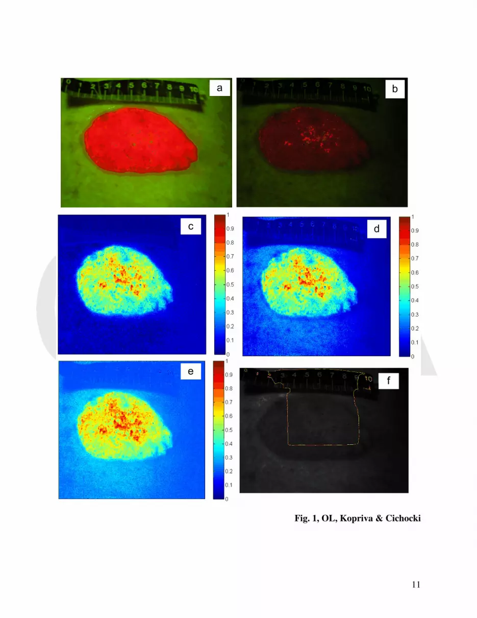
weak-intensity fluorescent red-green-blue (RGB) image of the skin tumor shown in Figure 1b.
For the purpose of tumor demarcation it is of interest to extract spatial map of the tumor as
accurately as possible. DCA algorithm combines JADE ICA algorithm [6] and innovation
transform based preprocessing [21] to enhance statistical independence among materials present
in the MSI and improve accuracy of the ICA. The MSI contains three spectral bands and three
materials: tumor, surrounding tissue and the ruler added to the scene to give perspective about
the size of the tumor. High-intensity image of the same tumor is shown in Figure 1a. It was used
for estimation of the binary spatial maps of tumor and surrounding tissue necessary for the
estimation of the receiver-operating-characteristic (ROC) curves. Spatial maps of the tumor
extracted from Figure 1b are shown in Figures 1c to 1e. Implementation of Tucker 3 α-NTF
algorithm was based on MATLAB Tensor Toolbox provided at [22]. Tensor of spatial

OSAPublished by
6
distributions of materials was identified by means of second part of (3). SO NMF and DCA
algorithms were based on 2D MSI representation (2). According to ROC curves shown in Figure
2 α-NTF algorithm exhibited best performance i.e. yielded largest area under the ROC curve.
State-of-the-art intensity based image segmentation algorithm, that is the level set method [23],
has been also applied to the gray scale version of Figure 1b. The result in Figure 1f shows
evolution curve after 1000 iterations. Due to weak boundaries the method failed to converge. α-
NTF, SO NMF and DCA algorithms were implemented in MATLAB on a 2.4 GHz Intel Core 2
Quad Processor Q6600 based desktop computer with 4GB RAM. Computation times are given
respectively as: 4783s, 30s and 3.6s. In the implementation of the innovation-based DCA
algorithm a 10th
order linear prediction filter has been used.
This work was partially supported through grant 098-0982903-2558 funded by the
Ministry of Science, Education and Sports, Republic of Croatia.
Appendix - elements of Tucker3 α-NTF algorithm
Multiplicative update rules for core tensor G and factors { }3( )
1
n
n=A in (1) are obtained by
minimizing α-divergence as:
( ) T T T
T T T
1.
.(1) (2) (3)
1 2 3
(1) (2) (3)
1 2 3
ˆ/α α × × × ←
× × ×
X X A A AG G
Ε A A A⊙ (A1)
( ) T
T
1.
.( )
( )( ) ( )
T ( )
ˆ/ n
nn n
n
α α
←
A
A
X X G
A A11 G
⊙ (A2)

OSAPublished by
7
where ⊙ denotes element-wise multiplication and / denotes element-wise division. In (A2) 1
denotes a vector whose every element is one. Numerator in (A2) is calculated as
( ) ( )T T. .( ) ( ) T
( )( )
ˆ ˆ/ /n m
m n nn n
α α
≠ = × AX X G X X A G
where ( )nG represents n-mode flattened version of the core tensor G . Denominator in (A2) is
computed as
T T
T ( ) T ( )
( )
n m
m nn
≠ = × A1 G G 1 A
where T ( )m
m n≠×G 1 A denotes m-mode products between core tensor G and matrices T ( )m1 A for
all m=1, ..., N and m n≠ .
References:
1. C.-I. Chang, S. -S. Chiang, J. A. Smith, and I. W. Ginsberg, "Linear spectral random mixture
analysis for hyperspectral imagery," IEEE Trans. Geosci. Remote Sens. 40, 375 (2002).
2. T. Tu," Unsupervised signature extraction and separation in hyperspectral images: A noise-
adjusted fast independent component analysis approach," Opt. Eng. 39, 897 (2000).
3. H. A. L. Kiers, "Towards a standardized notation and terminology in multiway analysis," J.
Chemometrics 14, 105 (2000).
4. A. Cichocki, R. Zdunek, and S. Amari," Nonnegative Matrix and Tensor Factorization," IEEE
Signal Proc. Mag. 25, 142 (2008).
5. A. Cichocki, and S. Amari, Adaptive Blind Signal and Image Processing (Wiley, 2002).

OSAPublished by
8
6. J. F. Cardoso, and A. Soulomniac, " Blind beamforming for non-Gaussian signals," Proc. IEE
F 140, 362 (1993).
7. J. M. P. Nascimento, and J. M. Dias Bioucas, " Does Independent Component Analysis Play a
Role in Unmixing Hyperspectral Data?," IEEE Trans. Geosci. Remote Sens. 43, 175 (2005).
8. N. Renard, S. Bourennane, and J. Blanc-Talon, "Denoising and Dimensionality Reduction
Using Multilinear Tools for Hyperspectral Images," IEEE Geosci. Remote Sens. Lett. 5, 138
(2008).
9. N. Renard, and S. Bourennane, "Improvement of Target Detection Methods by Multiway
Filtering," IEEE Trans. Geosci. Remote Sens. 46, 2407 (2008).
10. Q. Zhang, H. Wang, R. J. Plemons, and V. P. Pauca, "Tensor methods for hyperspectral data
analysis: a space object material identification study," J. Opt. Soc. Am. A 25, 3001 (2008).
11. L. R. Tucker, "Some mathematical notes on three-mode factor analysis," Psychometrika 31,
279 (1966).
12. J. D. Carrol, and J. J. Chang, "Analysis of individual differences in multidimensional scaling
via N-way generalization of Eckart-Young decomposition," Psychometrika 35, 283 (1970).
13. R. A. Harshman, "Foundations of the PARAFAC procedure: models and conditions for an
exploratory multi-mode factor analysis," UCLA Working Papers in Phonetics 16, 1 (1970).
14. E. Acar, and B. Yener, "Unsupervised Multiway Data Analysis: A Literature Survey," IEEE
Trans. Knowl. Data Eng. 21, 6 (2009).
15. J. B. Kruskal, "Three-way arrays: Rank and uniqueness of trilinear decompositions," Linear
Algebra Appl. 18, 95 (1977).
16. N. D. Sidiropoulos, and R. Bro, "On the uniqueness of multilinear decomposition of N-way
arrays," J. of Chemometrics 14, 229 (2000).

OSAPublished by
9
17. Y. D. Kim, A. Cichocki, and S. Choi, "Nonnegative Tucker Decomposition with Alpha-
Divergence," presented at the 2008 IEEE ICASSP International Conference on Acoustics,
Speech and Signal Processing, Las Vegas, NV, U.S.A., March 30-April 4, 2008, pp. 1829-1832.
18. A. H. Phan, and A. Cichocki, "Fast and Efficient Algorithms for Nonnegative Tucker
Decomposition," Lect. Notes Comput. Sci. 5264, 772 (2008).
19. C. A. Anderson, and R. Bro, "The N-way Toolbox for MATLAB," Chemometrics Intell. Lab.
Syst. 52, 1 (2000).
20. R. Zdunek, and A. Cichocki, "Nonnegative matrix factorization with constrained second-
order optimization," Sig. Proc. 87, 1904 (2007).
21. A. Hyvärinen, "Independent component analysis for time-dependent stochastic processes," in
Proc. Int. Conf. Art. Neural Net. (ICANN’98), Skovde, Sweden, 1998, pp. 541-546.
22. B. W. Bader, and T. G. Kolda, MATLAB Tensor Toolbox version 2.2.
http://csmr.ca.sandia.gov/~tkolda/TensorToolbox.
23. Ch. Li, Ch. Xu, Ch. Gui, and M.D. Fox, "Level Set Evolution Without Re-initilaization: A
New Variational Formulation," in: IEEE International Conference on Computer Vision and
Pattern Recognition, 2005, 430-436.

OSAPublished by
10
Figure Captions:
Figure 1 (color online). Experimental fluorescent MSI (RGB) image of skin tumor: a) high-
intensity version; b) weak-intensity version. Spatial maps of the tumor extracted from Figure 1b
by means of: c) α-NTF algorithm [18] with α=0.1; d) SO NMF algorithm [5]; e) DCA algorithm
[7 and 21]. f) evolution curve calculated by level set method on gray scale version of Figure 1b
after 1000 iterations. Dark red color indicates that tumor is present with probability 1, while dark
blue color indicates that tumor is present with probability 0.
Figure 2 (color online). ROC curves calculated for spatial maps of the tumor shown in Figures
1c to 1e: red squares - α-NTF algorithm based on Tucker3 model with α=0.1; blue stars - DCA
algorithm [12]; green triangles - SO NMF algorithm [43].
OSAPublished by
11
Fig. 1, OL, Kopriva & Cichocki

OSAPublished by
12
Fig. 2, OL, Kopriva & Cichoki
Top Related
Copyright © 2022 FDOKUMEN

