


Bahasa
Halaman
Hukum


WAVE AND OPTICS PAPERWAVE FUNCTION IN A MEMBRANE, CAVITY, AND HALL
Arrange to fill the Wave and Optics task
Arranged by :
Ardiana Hanatan K2310013
(Physics Education
SBI 2010)
SEBELAS MARET UNIVERSITY

SURAKARTA
2012
WAVE FUNCTION IN A MEMBRANE, CAVITY, AND HALL
1. Wave function in a membrane
The wave function in a membrane is include in two
dimensional wave function. Two-dimensional wave
propagation is a membrane vibrations or waves on the
surface of the water. In this case the rectangular
membrane. In order to solve the problem of the vibrating
membrane or vibrate, it must determine the solution Ψ (x,
y, t) at the point x, y and time t ³ 0.
In this case it will apply the following assumptions :
1. Membrane mass per unit area is constant (homogeneous
membrane). Perfect and flexible membrane so thin that
no resistance against bending.
2. The membrane was stretched and then set limits on the
xy plane. Voltage per unit length T caused by
stretching the membrane in all points and in all
directions are the same, and did not change during the
motion.

3. Deflection Ψ (x, y, t) during the motion of the
membrane is relatively small compared to the size of
the membrane, and all of the angle of inclination is
small.
To lower the differential equations that govern the
motion of this membrane, visible forces acting on the
membrane. Because the membrane deflection and angle
inklinasinya small, then the voltage is tangential or
offensive membranes. So that the forces acting on the
sides of the small part is equal to T and T Dx Dy.
In accordance with the above picture, in which the
vertical component of the force is along the side
parallel to the plane is:
and,
To obtain the wave equation in the form of partial
differential equations used Newton's second law is the
resultant force acting on an object is proportional to
mass and acceleration, which is calculated at a point

between y and y + Dy where r is the mass of extensive
membrane unity, while Dx and Dy is the widest part of the
membrane. So according to Newton's second law:
or
Then the second resultant vertical component is :
where y1 and has a value between and. Similarly, the
horizontal component of the resultant force acting on the
other two sides :
and,
According to Newton's second law is the resultant
force acting on an object is proportional to mass
and acceleration are calculated at a point
between x and x + Dx, where r is the union of broad
2.
2.
2.
2.

masses of the membrane, while Dx and Dy is the widest
part of the membrane. So according to Newton's second law
is :
or,
Then the horizontal components of the resultant force
acting on the other two sides are :
Where and lies between x and x + Dx. According to
Newton's second law, the number of the forces is given in
equation (2.4) and (2.8) together with mass and
acceleration , then:
2.
2.
2.
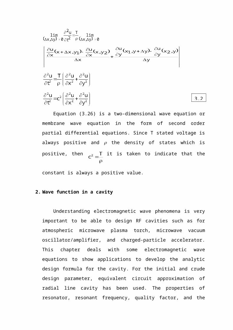
Equation (3.26) is a two-dimensional wave equation or
membrane wave equation in the form of second order
partial differential equations. Since T stated voltage is
always positive and r the density of states which is
positive, then it is taken to indicate that the
constant is always a positive value.
2. Wave function in a cavity
Understanding electromagnetic wave phenomena is very
important to be able to design RF cavities such as for
atmospheric microwave plasma torch, microwave vacuum
oscillator/amplifier, and charged-particle accelerator.
This chapter deals with some electromagnetic wave
equations to show applications to develop the analytic
design formula for the cavity. For the initial and crude
design parameter, equivalent circuit approximation of
radial line cavity has been used. The properties of
resonator, resonant frequency, quality factor, and the
3.2

parallel-electrodes gap distance have been considered as
design parameters.
The rectangular cavity is introduced for atmospheric
microwave plasma torch as a rectangular example, which
has uniform electromagnetic wave distribution to produce
wide area plasma in atmospheric pressure environment. The
annular cavity for klystrode is introduced for a
microwave vacuum oscillator as a circular example, which
adapted the grid structure and the electron beam as an
annular shape which gives high efficiency compared with
conventional klystrode. Some simulation result using the
commercial software such as HFSS and MAGIC is also
introduced for the comparison with the analytical
results.
Microwave circuits are built of resonators connected
by waveguides and coaxial lines rather than of coils and
condensers. Radiation losses are eliminated by the use of
such closed elements and ohmic loss is reduced because of
the large surface areas that are provided for the surface
currents. Radio-frequency energy is stored in the
resonator fields. The linear dimensions of the usual
resonator are of the order of magnitude of the free-space
wavelength corresponding to the frequency of excitation.
A simple cavity completely enclosed by metallic walls can
oscillate in any one of an infinite number of field
configurations. The free oscillations are characterized
by an infinite number of resonant frequencies
corresponding to specific field patterns of modes of

oscillation. Among these frequencies there is a smallest
one,
where the free-space wavelength is of the order of
magnitude of the linear dimensions of the cavity, and the
field pattern is unusually simple; for instance, there
are no internal nodes in the electric field and only one
surface node in the magnetic field.
The oscillations of such a cavity are damped by
energy lost to the walls in the form of heat. This heat
comes from the currents circulating in the walls and is
due to the finite conductivity of the metal of the walls.
The total energy of the oscillations is the integral over
the volume of the cavity of the energy density,
,where E and H are the electric and magnetic field
vectors, in volts/meter and ampereturns/ meter,
respectively. The cavity has been assumed to be empty.
The total energy W in a particular mode decreases
exponentially in time according to the expression,
,where and Q is a quality factor of the mode
which is defined by

The fields and currents decrease in time with the factor
,
The principle, or fundamental, mode of oscillation of
such cavity, and the one with the longest free-space
wavelength , has electric and magnetic fields that do not
depend on the azimuthal angle defining the half plane
though both the axis and the point at which the fields
are being considered. In addition, the electric field is
zero only at wall farthest apart from the gap and the
magnetic field is zero only at the gap. In this mode the
magnetic field is everywhere perpendicular to the plane
passing through the axis the electric field lies in that
plane. Lines of magnetic flux form circles about the axis
and lines of electric flux pass from the inner to the
outer surfaces.
In the principle mode of radial-line cavity only Ez ,
and Hz are different from zero and these quantities are
independent of φ . (see Fig. 2 for cylindrical
coordinates and dimensions of the cavity). The magnetic
field automatically satisfies the conditions of having no
normal component at the walls.

The cavities in which RF interaction phenomena
happens with charged particles almost always have a
narrow gap, that is, the depth of the gap d (see Fig. 2),
is small compared with the radius r0 of the post.If the
radius of the post is much less than onequarter of the
wavelength, and if the rest of the cavity is not small,
the electric field in the gap is relatively strong and
approximately uniform over the gap. It is directed
parallel to the axis and falls off only slightly as the
edge of the gap is approached. On the other hand, the
magnetic field increases from zero at the center of the
gap in such a manner that it is nearly linear with the
radius. In a radial-line cavity the electric field
outside the gap tends to remain parallel to the axis,
aside from some distortion of the field that is caused by
fringing near the gap; it is weaker than in the gap and
tends to become zero as the outer circular wall is
approached.
The magnetic field, on the other hand, increases from
its value at the edge of the gap and has its maximum
value at the outer circular wall. It is seen that,
whereas the gap is a region of very large electric field
and small magnetic field, the reentrant portion of the
cavity is a region of large magnetic field and small
electric field. The gap is the capacitive region of the
circuit, and the reenetrant portion is the inductive
region. Charge flows from the inner to the outer
conducting surface of the gap by passing along the inner

wall, across the outer end. The current links the
magnetic flux and the magnetic flux links the current, as
required by the laws of Faraday, Biot and Savart.
a. The capacitance in Cavity
b. The inductance in cavity
c. The resonance frequency in cavity
3. Wave function in a hall
The wave function in a hall is same with the three
dimensional wave mechanics. However, the generalization
to a particle moving in three dimensions is fairly
straightforward. A massive particle moving in three
dimensions has a complex wavefunction of the form :
(84
4)
where is a complex constant, and . Here, the
wavevector, k, and the angular frequency, , are related
to the particle momentum, P, and energy, T :

(84
5)
(84
6)
respectively, the three-dimensional version of
Schrödinger's equation is easily shown to take the form :
(84
7)
where the differential operator
(84
8)
is known as the Laplacian. The interpretation of a three-
dimensional wavefunction is that the probability of
finding the particle between x and x+dx, between y and
y+dy, and between z and z+dz, at time :
(84
9)
Moreover, the normalization condition for the
wavefunction becomes :
(85
0)
Incidentally, it is easily demonstrated that
Schrödinger's equation, preserves the normalization

condition, of a localized wavefunction. Heisenberg's
uncertainty principle generalizes to :
(85
1)
(85
2)
(85
3)
Finally, a stationary state of energy is written as :
(85
4)
Where the stationary wavefunction, , satisfies :
(85
5)
As an example of a three-dimensional problem in wave mechanics,
consider a particle trapped in a square potential well of
infinite depth which is such that
(85
)
Within the well, the stationary wavefunction, ,
satisfies
(85
7)
subject to the boundary conditions

(85
8)
and
(85
9)
Since outside the well. Let us try a seperable
wavefunction of the form
(86
0)This expression automatically satisfies the boundary
conditions. The remaining boundary conditions, aresatisfied provided
(86
1)(86
2)(86
3)Where nx, ny, and nz are (independent) positive integers.
Substitution of the wavefunction :
(86
4)
Thus, it follows from Equations that the particle energy
is quantized, and that the allowed energy levels are
(86

5)
The properly normalized stationary wavefunctions
corresponding to these energy levels are
As is the case for a particle trapped in a one-dimensional
potential well, the lowest energy level for a particle trapped
in a three-dimensional well is not zero, but rather
(86
7)
Here,
(86
8)
is the ground state (i.e., the lowest energy state) energy in
the one-dimensional case.
Now, it is clear, that distinct permutations of nx,
ny, and nz which do not alter the value of nx2+ny
2+nz2 also
do not alter the energy. In other words, in three
dimensions it is possible for distinct wavefunctions to
be associated with the same energy level. In this
situation, the energy level is said to be degenerate. The
ground state energy level, 3E1, is non-degenerate, since
the only combination of (nx, ny, nz) which gives this
energy is (1,1,1). However, the next highest energy
level, 6E1, is degenerate, since it is obtained when (nx,

ny, nz) take the values (2,1,1), or (1,2,1) or (1,1,2). In
fact, it is not difficult to see that a non-degenerate
energy level corresponds to a case where the three mode
numbers (i.e., nx, ny, nz) all have the same value, whereas a
three-fold degenerate energy level corresponds to a case
where only two of the mode numbers have the same value,
and, finally, a six-fold degenerate energy level
corresponds to a case where the mode numbers are all
different.
Top Related
Copyright © 2022 FDOKUMEN

