


Bahasa
Halaman
Hukum


Vol 10, Issue 12, DEC/ 2019
ISSN NO: 0377-9254
www.jespublication.com Page No:325
ANALYSIS AND SEISMIC DESIGN OF FLAT SLAB R.C.C.
STRUCTURES Mohammad Yusuf 1, Dr. Esar Ahmad2
1PG Scholar, Department of Civil Engineering, Mewar University, India
2Assistant Professor, Department of Civil Engineering, Mewar University, India Abstract— Latest earthquake in which many flat
slab concrete building have been badly destructed
or collapsed, have require the necessity to study
seismic analysis of flat slab structure. We can’t
repudiate upcoming earthquakes, but awareness
and not dangerous building construction execution
can positively diminish the level of destruction and
harm. Flat slab buildings are the building in
which slab without beam directly resting on the
column. These building provide decent aesthetic
view, flawless light visibility and much more
improvement as parallel to other building in terms
rapidity of construction, frugality etc. But these
types of buildings are generally avoided due to
their deprived performance during earthquake.
This dissertation presented herein can be
considered into two main aspects.
In the first aspect behavior of flat slab building is
compare with the conventional and a camouflage
model. Frequency analysis, response spectrum
analysis are compared with each other. Nonlinear
pushover analysis also performed in order to get
the performance of flat slab building and compare
the result with conventional and a camouflage
model. This dissertation also shows a relative
study on the base of cost of flat slab building,
conventional building and a camouflage model.
All the models are providing with identical floor
area and height. The charge per unit area for
finishing thing remain equal for all only concrete
volume and steel are assessed and lastly cost are
related.
In the second aspect the plot between the base
shear vs. displacement of the structure, so-called
pushover curves are implemented on the flat slab
structure by means of the most ordinary software
SAP 2000 after designing the flat slab by
different code such as IS 456, ACI 318, NZS
3101 etc. The pushover curves is plotted in both x
and y directions. By carry out this push over study,
we can recognize the weak regions in the building
and formerly we will adopt whether the specific
portion of the building is retrofitted or changed
according to the requirement. Time history analysis
is also performed on the flat slab building in order
to get the dynamic response which varies according
to the stated time function..
Keywords— Flat Slab, Concrete Strength,
R.C.C Column, SAP 2000
1.0 INTRODUCTION
Reinforced concrete flat slab building represent
decorous and easy to constructed floor system.
These kinds of structure are preferred by equally
architects and client for the reason that they
provide decent artistic view, flawless light visibility
and much new improvement as parallel to other
building in terms rapidity of construction, frugality
etc. Flat slab building are the building in which
slabs is directly supported by columns. The column
head is occasionally enlarges so as to reduce the
punching shear in the slab. The enlarged portion is
called column head. Moment in the slab is more
nearby the column. Hence the slab is thickened
nearby the columns by providing the drops so-
called as drop panel.
Flat slab are of following categories
(a) Slab without drop plus column with column
head
(b) Slab with drop plus column without column
head.
(c) Slab without drop plus column with column
head
(d) Slab without drop plus with column head.
(a) Slab without drop plus column with
column head

Vol 10, Issue 12, DEC/ 2019
ISSN NO: 0377-9254
www.jespublication.com Page No:326
(b) Slab with drop plus column without
column head
(c) Slab without drop plus column with
column head
(d) Slab without drop plus column head
1.1 BEHAVIOUR OF FLAT SLAB
BUILDING DURING EARTHQUAKE
The behavior of this kind of structure systems
with flat slab show significant drawbacks such as
the non-dissipative characteristics of their seismic
reaction. Enactment of the flat slab building during
earthquake is not acceptable. Due to their
flexibility flat slab structure shows large
displacement under lateral loading. The most
important determinant effect on the structure is
caused by lateral component of the earthquake on
the flat slab building. Earthquake loading effect on
structures are quite varying as compare to gravity
loading and it effect the structure more as the
height of the structure increases. Most of the low
and midrise structure having good structural system
carry earthquake loading while the structure having
not appropriate structural system fail. Stability of
the structure depends on the overturning moment
and hence depends upon the height of the building.
Hence Stability and rigidity of the structure gets
varies as height of the structure increases
.
Ancient practices show that the flat slab
buildings are subjected to abrupt failure when it is
acted upon by the earthquake loading. Flat slab
structure collapse due to punching shear failure is
shown in Fig 1.2 when it is subjected to Northridge
earthquake (1994)
Fig- Failure of flat slab building [Pipers’ row cark
park, Wolverhampton, UK, 1997]
1.2 MODES OF FAILURE OF FLAT SLAB
BUILDING.
There are some issues which are considered during
the failure of flat slab building one of the most
important issue is the brittle punching failure .In
case of flat slab building generally two kinds of
failure modes happens punching shear failure and
flexure failure. Flexure failure occurs is a yielding
way of failure which is always wanted for this type
of structure as related to punching shear failure
.But flat slab building generally fail in punching
shear failure which is brittle mode of failure .The
instant flat slab building are acted to gravity load
and lateral load then and there reaction are
condensed nearby the support. Punching shear
stress at the critical segment nearby the column
supports is produced due to transferal gravity load
and unbalanced moment on slab column joint.
Gravity load causes the even distribution of
punching shear stress at the critical sections. Some
portion of unbalanced moment is transmitted as
torsion in slab column junction. When obtained
punching shear stress exceed the permissible value
of punching shear stress of flat slab building then
failure of slab column junction takes place.
Vol 10, Issue 12, DEC/ 2019
ISSN NO: 0377-9254
www.jespublication.com Page No:327
1.3 OBJECTIVE OF THE STUDY
a) To study seismic performance of flat
building and compare the result with
conventional and a camouflage model.
Response spectrum analysis, Frequency
analysis is done in order to compare the
result.
b) To study the cost of flat slab building on
the basis of concrete volume and steel
requirement and compare the result with
other model.
c) To study the seismic behavior of flat slab
structure designed by different codes.
Nonlinear pushover analysis is performed
on flat slab building and computes the
target displacement.
To study the seismic performance of flat slab
building with or without edge beam.
2.0 MODELLING OF FLAT SLAB
BUILDINGS
The difference in behavior of flat slab structure
with the frame structure lies in the load transfer
mechanism At any column support in case of flat
slab at the junction of column and slab transfer of
part of moment which is unbalanced partially
through increase of non-even shear stresses in the
region of the column head. Total unbalanced part
of moment are resisted by column in fraction using
the relative stiffness’s over and underside
As per ATC 40 Clause 9.4.2.2 for a column-slab
frame element must be effectively detailed in order
to show the stiffness, strength, and deflection
capability of columns, slabs, slab-column joint, and
other constituent which may be considered as part
of the building frame.
Slab as well as column apparatuses must be
modeled by consider shear as well as flexural
rigidities, even though later might be ignored in
certain cases. Potential failure of splices AS well as
anchorages possibly will entail modeling of these
aspect as well. Column-slab joints which are
common in column and slab in terms of volume of
concrete together with column capital can be
considered to be rigid.
2.1 MODELLING APPROACHES
Different type of modelling approaches for
analyzing the flat slab is:
1. Finite element approach
2. Equivalent frame approach
a. Effective beam width procedure
b. Transverse torsional member
method
i. ACI equivalent frame
method
ii. Extended equivalent column
method
iii. Extended equivalent slab
method
iv. Explicit transverse torsional
member method
3.0 BUILDING DESCRIPTION
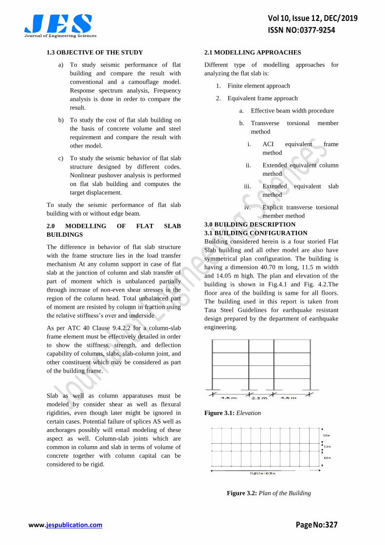
3.1 BUILDING CONFIGURATION
Building considered herein is a four storied Flat
Slab building and all other model are also have
symmetrical plan configuration. The building is
having a dimension 40.70 m long, 11.5 m width
and 14.05 m high. The plan and elevation of the
building is shown in Fig.4.1 and Fig. 4.2.The
floor area of the building is same for all floors.
The building used in this report is taken from
Tata Steel Guidelines for earthquake resistant
design prepared by the department of earthquake
engineering.
Figure 3.1: Elevation
Figure 3.2: Plan of the Building

Vol 10, Issue 12, DEC/ 2019
ISSN NO: 0377-9254
www.jespublication.com Page No:328
3.2 SITE PROPERTIES
Seismic Zone: IV
Soil condition = Medium soil
3.3 GEOMETRIC PROPERTIES OF
COMPONENTS
3.3.1 Model 1 Conventional Building
Slab Thickness = 120 mm
External wall thickness = 250 mm
Internal wall thickness = 150 mm
Ground storey height = 4.0 m
Floor to floor height = 3.35 m
Beam: 300 mm X 450 mm
Exterior Column: 300 X 530 mm
Interior Column: 300 X 300 mm
Figure 3.3.1: Conventional 3D model
3.3.2 Model 2: Camouflage
Slab Thickness = 120 mm External
wall thickness = 250 mm
Internal wall thickness = 150 mm Ground
storey height = 4.0 m
Floor to floor height = 3.35 m Beam: 300
mm X 120 mm
Exterior Column: 300 X 530 mm Interior
Column: 300 X 300 mm
Figure 3.3.2 Camouflage 3D model
3.3.3 Model 3: Flat slab
Slab Thickness = 250 mm, External wall thickness
= 250 mm.
Internal wall thickness = 150 mm Ground storey
height = 4.0 m
Floor to floor height = 3.35 m Exterior Column:
300 X 530 mm
Interior Column: 300 X 300 mm
Figure 3.3.3 : Flat Slab Building 3D model without
perimeter beam
3.3.4 Model 4: Flat slab with edge beam
Slab Thickness = 250 mm External wall thickness
= 250 mm
Internal wall thickness = 150 mm Ground storey
height = 4.0 m
Floor to floor height = 3.35 m Exterior Column:
300 X 450 mm
Interior Column: 300 X 300 mm Size of edge
beam=300 mm x 450 mm
Figure 3.3.4: Flat slab building with perimeter
beam
4.0 SUMMARY:
All the models are designed and analyse by using
the software SAP 2000.Firstly flat slab building is
compare with the two other model conventional
building and camouflage model. Modal analysis is
performed in order to compare the fundamental
period, base shear and other factor.

Vol 10, Issue 12, DEC/ 2019
ISSN NO: 0377-9254
www.jespublication.com Page No:329
Flat slab building is designed by using the different
codes and results are compared in order to
conclude that which code gives better result.
Nonlinear pushover analysis is performed in order
to get the performance of the structure.
Flat slab building is considered with or without
edge beam as flat slab building generally fail in
punching. So performance of flat slab building is
compare with or without edge beam.
5.0 RESULT AND DISCUSSION
In this unit seismic analysis of building is carried
out by considering the live load (L.L), dead load
(D.L) and the earthquake load in the both direction
i.e. sway to left (-EL) and sway to right (+EL) by
the software SAP 2000 vs.14.The various load
combination which are considered during the
analysis of building design by IS 456:2000 are
according to cls.6.3 of IS 1893 2001 and are given
as Table 5.1.This chapter include seismic behavior
of flat slab building design by different code IS 456
:2000,ACI 318-02,Eurocode 2:2004 and NZS 3101
.Pushover analysis of flat slab building is also
studied in this chapter.
5.1 DIFFERENT LOAD COMBINATION
Flat slab building is designed for different load
combination as per IS 456:2000 as shown in Table
5.1
Table 5.1: Load combination suggested by IS
456:2000
Load Case Load cases
1 1.5(DL+LL)
2 1.2(DL+LL+EL)
3 1.2(DL+LL-EL)
4 1.5(DL+EL)
5 1.5(DL-EL)
6 0.9DL+1.5 EL
7 0.9DL-1.5EL
5.2 DESCRIPTION FOR LOADING
The loading on the buildings is considered as per
following calculations
5.2.1 Calculation of Load
5.2.1.1 Dead Loads
External wall load = 0.25x (3.35-.45) x
20 = 14.5 kN/m
Internal wall load = 0.15x (3.35-.45) x
20 = 8.7 kN/m
Weight of the slab having thickness
120mm = 25 x 0.12 = 3 kN/m
Self-weight of building is
automatically considered by the SAP software.
5.5.2 Live Loads
The live load of 3.5 kN/m2 is considered on the
buildings.
5.5.3 Earthquake Forces Data
Earthquake loading for the different model have
been estimated as per IS-1893-2002:
Zone (Z) = II
Response reduction factor (RF) = 5 for SMRF. [IS-
1893 (Part I):2002] Table-7
Importance factor (I) = 1 [IS-1893 (Part I):2002
Table-6]
Sa/g = Average response acceleration coefficient
for various soil sites as given by Fig. 2 of IS-1893
(Part I): 2002 based on appropriate natural periods
and damping of structures.
Time period of the building from the code has
presented in Table-5.3
Table-5.3: Time period and horizontal seismic
coefficient
Directio
n
Heig
ht
(m)
Lateral
dimensio
n (m)
Time
perio
d
(Sec)
Sa/
g Ah
X 14.05 40.70 0.198 2.5 0.0
6
Y 14.05 11.50 0.373 2.5 0.0
6

Vol 10, Issue 12, DEC/ 2019
ISSN NO: 0377-9254
www.jespublication.com Page No:330
5.4 MODAL ANALYSIS OF FLAT SLAB
BUILDING
Table-5.4: Section details of different model
including flat slab building
Model no.
Slab
thicknes
s (mm)
Beam
(mm)
Column
Size(mm
)
Model-1
(Conventional
)
120 300 x
450
Interior
300 x300
Exterior
300 X
530
Model-2
(Camouflage) 120
300x12
0
Same as
above
Model-3 (Flat
Slab) 250 No
Same as
above
Modal analysis of flat slab building is
accomplished using the modal load cases in SAP
2000.
Table 5.5: Vibration characteristics of flat slab
building based on different code.
Fundamen
tal Period
IS
456:20
00
ACI
318
EUR
O
COD
E
NZS
COD
E
First mode 1.18313
3
1.2756
7
1.0567
8
1.2134
5
Second
mode
1.14030
1
1.1756
8
1.0135
6
1.1768
6
Third mode 0.98037
4
1.0356
6
0.9098
8
1.0076
5
Fourth
mode
0.35859
1
0.3980
7
0.3107
6
0.3876
5
fifth mode 0.33475 0.3609
8
0.2987
6
0.3478
9
Sixth mode 0.27893
5
0.2907
8
0.2234
6
0.2988
6
Table 5.6: Vibration characteristics of flat slab
building and flat slab building with edge beam
Fundamental
period
Flat slab
building
Flat slab
building with
edge beam
First mode 1.183133 1.04
Second mode 1.140301 0.87554
Third mode 0.980374 0.749447
Fourth mode 0.358591 0.340826
fifth mode 0.33475 0.27867
Sixth mode 0.278935 0.239352
Table 5.7: Comparison of base shear in flat slab
building with other model.
Parameter Flat slab
building
Conventional
building
Base shear 1110 kN 1290 Kn
Roof
displacement
28 mm 15mm
6.0 PUSHOVER CURVE OF FLAT SLAB
BUILDING DESIGNED BY DIFFERENT
CODE
6.1 PUSHOVER ANALYSIS FOR FLAT SLAB
BUILDING WITHOUT PERIMETER EDGE
BEAM AS PER BUILDING DESIGN BY IS
456:2000
Figure 6.1: Capacity curve in y direction for flat
slab without perimeter beam as per IS456 2000
Figure 6.1.1: Capacity curve in x direction for flat
slab without perimeter beam as per IS456 2000

Vol 10, Issue 12, DEC/ 2019
ISSN NO: 0377-9254
www.jespublication.com Page No:331
6.2 PUSHOVER ANALYSIS FOR FLAT SLAB
BUILDING WITHOUT PERIMETER EDGE
BEAM AS PER BUILDING DESIGN BY ACI
CODE
Figure 6.2: Capacity curve in x direction for flat
slab without perimeter beam as per ACI Code
Figure 6.2.1: Capacity curve in y direction for flat
slab without perimeter beam as per ACI Code
6.3 PUSHOVER ANALYSIS FOR FLAT SLAB
BUILDING WITHOUT PERIMETER EDGE
BEAM AS PER BUILDING DESIGN BY
EURO CODE
Figure 6.3: Capacity curve in x direction for flat
slab without perimeter beam as per Euro code
Figure 6.3.1: Capacity curve in x direction for flat
slab without perimeter beam as per Euro code
6.4 PUSHOVER ANALYSIS FOR FLAT SLAB
BUILDING WITHOUT PERIMETER EDGE
BEAM AS PER BUILDING DESIGN BY
EURO CODE
Figure 6.4: Capacity curve in x direction for flat
slab without perimeter beam as per NZS code
Figure 6.4.1: Capacity curve in Y direction for flat
slab without perimeter beam as per NZS code
7.0 COMPARISON OF CAPACITY CURVE
OF FLAT SLAB STRUCTURE BASED ON
DIFFERENT CODE:
Figure 7.0: Capacity curve in Y direction for flat
slab without perimeter beam designed by different
code
The above pushover curve is for G +3 flat slab
building without perimeter edge beam designed by
different codes shows that performance of building
designed by any codes is not good however a
building designed by euro code show more base
shear and can resist more roof displacement
.However from the Fig to Fig shows that all the G
+3 building shows that the designed building is
safe as it is lies within the CP range. but building
designed by different code shows that in all the LS
exist and after that there is no CP point is getting so
all the building does not show any collapse
prevention point and collapse of structure takes

Vol 10, Issue 12, DEC/ 2019
ISSN NO: 0377-9254
www.jespublication.com Page No:332
place which is avoided as in case of flat slab
building punching shear failure occurs.
Performance of the building design by the IS 456
lies within the Euro code and NZS code and hence
we conclude that a building design by Euro code is
better as relate to other code but still that building
is not safe as these building does not show any
collapse prevention (CP).
8.0 CONCLUSION
Seismic analysis of flat slab building has been
studied in this dissertation. Flat slab building,
Conventional building and a camouflage model has
been designed as per the provision of IS 456:2000
and the result of all the three model are compare.
Flat slab building with rectangular plan is
considered and designing the flat slab building is
done by using different code such as IS456:2000,
EC 2:2004, ACI 318-08 and NZS 3101 Part1 -
2006.And the result are compare base on different
codes .Flat slab building is designed by considering
the flat slab without perimeter beam and with
perimeter beam and different result are compare.
Behavior of building is compare based on the
nonlinear static pushover analysis for MCE peak
ground acceleration of 0.24 on soil type II as per IS
1893:2002 part 1.The three story flat slab building
is taken from guidelines for earthquake resistant
building prepared by the department of earthquake
engineering .Following are the main conclusion
from the study of seismic analysis of flat slab
building:
Flat slab building, conventional building
and a camouflage model with rectangular
plan have been considered. And it is found
that flat slab building is more flexible and
less resistant to lateral loading however
conventional building is the best one.
Camouflage is the good alternative if it is
required the building for good aesthetic
and light visibility point of view.
Fundamental period of flat slab building is
the maximum among all model considered
in this dissertation. However if a flat slab
building is designed by different code then
it is found that fundamental period
calculated by Euro code is having the
minimum value and ACI code has the
maximum ones. So it is found that a flat
slab building designed by Euro code gives
the good result for lateral loading as
compare to other code.
Based on the comparison of cost of flat
slab building with the other building it is
found that Flat slab building being the
good in aesthetic and other advantage in
terms of architecture point of view are
found to be less economical as compare to
other model .Camouflage model designed
by euro code serve the purpose if it is
require to designed the building which is
economical and looks like the flat slab.
Performance of flat slab building is found
to be unsatisfactory due to lateral loading
as it is generally fail in punching shear and
the failure propagate from the exterior
column to the interior ones. So flat slab
with perimeter beam is better as compare
to flat slab without beam. However it is
also not perform better during lateral
loading.
9.0 REFERENCES:
1. Alexander, S.D.B. and Simmonds, S.H. (1987),
"Ultimate Strength of Slab-Column Connections.”
ACI Structural Journal, V.84, No.3, pp.255-261.
2. Alexander, S.D.B. and Simmonds, S.H. (1992),
"Tests of Column-Flat Plate Connections", ACI
Structural Journal., V.89, No.5, pp.495-502
3. Agarwal, P., Shrikhande, M.,
(2006),“Earthquake Resistant Design of Structure”,
Fourth Edition, Prentice Hall.
4. ACI 318-08, “Building Code Requirements for
Structural Concrete.” ACI Committee 318,
American Concrete Institute, Farmington Hills.
5. Bhina, M.R., Banerjee, A., and Paul, D.K.
(2013), “Assessment of Different Aspect of R C
Flat Slab Building over Normal R C Frame
Building”, ICSECM, International Conference on
Structural Engineering & Construction
Management, Sri Lanka-2013
6. Cano, M. T., and Klingner, R.E. (1988).
“Comparison of Analysis Procedures for Two Way
Slabs.” ACI Structural Journal, 85(6), 597-608
7. Dovich, L.M., and Wight, J.K. (2005) “Effective
Slab Width Model for Seismic Analysis of Flat
Slab Frames.” ACI Structural Journal, 102(6), 868-
875.

Vol 10, Issue 12, DEC/ 2019
ISSN NO: 0377-9254
www.jespublication.com Page No:333
8. Eurocode 2 (2004). “Design of Concrete
Structures Part 1-1: General Rules and Rules for
Buildings.” European Committee for
standardization, Brussels
9. Eurocode 8 (2004). “Design of Concrete
Structures for Earthquake Resistance Part 1:
General Rules, “Seismic Actions and Rules for
Buildings.” European Committee for
standardization, Brussels
10. Fardis, M.N. (2009) “Seismic Design,
Assessment and Retrofitting of Concrete
Buildings.”Spinger, London.
11. Han, S.W., Park, Y.M., and Kee, S.H. (2009).
“Stiffness Reduction Factor for Flat Slab Structures
under Lateral Load.” Journal of Structural.
Engineering, ASCE. 135(6), 743-750.
12. IS 1893-2002(Part1), (2002), “Indian Standard
Criteria for Earthquake Resistant Design of
Structures, Part 1: General Provisions and
Buildings” Bureau of Indian Standards, New Delhi
13. IS 456:2000, “Indian Standard Plain and
Reinforced Concrete-Code of Practices”, Bureau of
Indian Standards, New Delhi
14. Kim, H. S., Lee, D. G., (2005), “Effective
Analysis of Flat Slab Structure Subjected to Lateral
Loads.”, Engineering Structure”, pp.27, 251-263
15. Kinnunen, S., and Nylander, H., “Punching of
Concrete Slabs Without Shear Reinforcement,”
Transactions of the Royal Institute of Technology,
No. 158, Stockholm, Sweden, 1960.
16. Megally, S. and Ghali, A. (2000), "Punching of
Concrete Slabs Due to Column Moment Transfer",
Journal of Structural. Engineering, ASCE, Vol.
126, No.2, pp. 180-188.
17. Menetrey, P. (2002), "Synthesis of Punching
Failure in Reinforced Concrete", Cement &
Concrete Composites, Vo1.24, pp.497-507
18. Menetrey, P., Walther, R., Zimmermann, T.,
William, K.J. and Regan, P.E. (1997),"Simulation
of Punching Failure in Reinforced-Concrete
Structures", Journal of Structural. Engineering,
ASCE, Vol. 123, No.5, pp.652-658
19. Navyashree K and Sahana T.S “Use of flat
slabs in multi-storey commercial building Situated
in high seismic zone” International Journal of
Research in Engineering and Technology Volume
3, Issue 08, Aug 2014
20. NZS 3101: Part 1. (2006) “Concrete Structures
Standard Part 1- The Design off Concrete
Structure.” Standards New Zealand, Wellington
21. NZS 1170.5.(2004) “ Structural Design
Actions Part 5 –Earthquake Actions.” Standards
New Zealand, Wellington
22. Park, Y.M., Hans, S.W., and Kee, S.H.(2009) .
“A Modified Equivalent Frame Method for Lateral
Load Analysis. “Magazine of Concrete Research,
61(5), 359-370
23. Pillia, S.U and Menon, D. (2010), “Reinforced
Concrete Design”. Tata McGraw-Hill, New Delhi
24. Patil, S.S and Sigi, R.A. (2014). “Flat Slab
Construction in India” International Journal of
Engineering and Innovative Technology (IJEIT)
Volume 3, Issue 10, April 2014.
25. Paul, D. K., Singh, Y. and Agarwal, P. “Tata
steel Guidelines for Earthquake resistant
buildings”. Department of earthquake engineering
IIT Roorkee ,Dec. 2011
26. Regan, P.E. (1981). “Behaviour of Reinforced
Concrete Flat Slabs.” Construction Industry
Research and Information Association , London
Top Related
Copyright © 2022 FDOKUMEN

