


Bahasa
Halaman
Hukum


Page 1 of 45
AFRO 4000 LOCOMOTIVES : INSPECTION AND VERIFICATION REPORT
REFERENCE
RSR/INSPECTION/AFRO 4000/MWC550
OPERATOR
PASSENGER RAIL AGENCY OF SOUTH AFRICA (PRASA)
INSPECTION AND
VERIFICATION
INSPECTIONS AND TESTS FOR THE AFRO 4000
LOCOMOTIVES
INSPECTION AND
VERIFICATION DATE
November 2015
INSPECTION AND
TEAM
COMPILED
TEAM MEMBERS
SIGNATURE
MR JOSEPH NETHATHE (Pr. Eng.)
(Head: Rolling Stock)
REVIEWED MS NTOMBIKAYISE NDAKI
(Human Factors Specialist)
REVIEWED Dr PEACEMAN SOPAZI
(Pr. TechEng)
(Head: Technology, Standards &
Training)
REVIEWED MR BONGANI MQOCO
(Pr. TechEng)
(Executive: Research &Technical
Services )
RECOMMENDED
MS TSHEPO KGARE
(COO)
APPROVED
MR NKULULEKO POYA
(CEO)
Page 2 of 45
Contents
Definitions ............................................................................................................... 4
Acronyms ................................................................................................................ 5
EXECUTIVE SUMMARY ............................................................................................ 6
1. INTRODUCTION ................................................................................................. 8
2. SOUTH AFRICAN RAIL NETWORK LAYOUT AND LIMITS ............................... 8
2.1. Problem statement ........................................................................................ 9
3. RAILWAY SAFETY REGULATOR PROCESSES ............................................... 9
4. THE REVIEW APPROACH ............................................................................... 11
5. INSPECTION OF AFRO 4000 LOCOMOTIVES ................................................ 12
5.1. General description of the locomotive: ........................................................ 12
5.2. Locomotive Communications ...................................................................... 12
5.3. Locomotive Inspection ................................................................................ 13
5.3.1. Inspection Findings ............................................................................... 13
6. HUMAN FACTORS AND DRIVER’S CAB ERGONOMICS ............................... 14
6.1. Human Factors Approach on Technical Reviews ........................................ 14
6.2. Assessment / Inspections ........................................................................... 15
6.2.1. Verification phase ................................................................................. 15
6.2.2. Validation phase ................................................................................... 18
7. LOCOMOTIVE AND INFRASTRUCTURE HEIGHT ASSESSMENT ................. 19
7.1. Locomotive Height Assessment .................................................................. 19
7.2. Infrastructure Height Assessment ............................................................... 20
8. IDENTIFICATION OF OPERATIONAL RISKS .................................................. 20
9. ANALYSIS OF LOCOMOTIVE HEIGHT IMPACT ............................................. 21
9.1. Vehicle Envelope ........................................................................................ 21
9.2. Overhead Traction Equipment installation height ........................................ 21
9.2.1. Contact wire installation height ............................................................. 21
Page 3 of 45
9.2.2. Contact Wire Maintenance Status ........................................................ 22
10. CONCLUSION ............................................................................................... 24
11. References .................................................................................................. 26
APPENDIX A: Modifications to EURO 4000 ......................................................... 27
APPENDIX B: Photographic evidence gallery....................................................... 28
APPENDIX C: RSR Locomotive Inspection Report .............................................. 34
APPENDIX D: Locomotive Clearance References ............................................... 36
APPENDIX E: Tests Conducted by PRASA.......................................................... 37
APPENDIX F: Human Factor Design considerations ............................................ 39
Page 4 of 45
Definitions
Abrasion: Means a wear due to contact between two surfaces;
Anthropometric: means a measurement of the human individual
Bogie: Means a structure underneath a locomotive frame to
which the wheels and axles are attached;
Cape gauge: Means a railway track where the distance between the
tracks is 1067 mm;
Derailment: Means a disturbance between wheel and rail interaction
which results in a train moving out of the track;
Flashover: Means the near-simultaneous ignition of directly exposed
material;
Hybrid/Dual locomotive: Means a locomotive with two propulsion systems i.e.
diesel and electric power or Direct Current (DC) and
Alternating Current (AC) power;
MINIPROF: Means a Wheel Profile Measuring System;
Rolling Stock: Means a locomotives, wagons or coaches that travel on
rail tracks;
Slack: Means a weak area on the track where the formation is
unbalanced;
Standard gauge: Means a railway track where the distance between the
tracks is 1435 mm;
Tamping: Means a packing of the track ballast under railway tracks
to make the track more durable;
Vehicle gauge: Means a structure indicating the tolerances allowed for
rolling stock operating in a network
Vossloh Espana: Means a Spanish locomotive manufacturer

Page 5 of 45
Acronyms
AC Alternating Current
CEO Chief Executive Officer
DC Direct Current
HL Hazard Log
kV kilovolts
LCM Life Cycle Management
MLPS Main Line Passenger Services
OHTE Overhead Traction Equipment
POC Point of Contract
PRASA Passenger Railway Agency of South Africa
Qr Flanged Gradient or flange toe Radius
RA Risk Assessment
RS Rolling Stock
RSR Act National Railway Safety Regulator Act 16 of 2002
as amended
RSR Railway Safety Regulator
SANS South African National Standards
SARCC South Africa Rail Commuter Corporation
TCO Train Control Officer
TE Transnet Engineering
TFR Transnet Freight Rail
TWR Train Working Rules
URS User Requirements Specification
YQ Trip Authorisation Certificate
Page 6 of 45
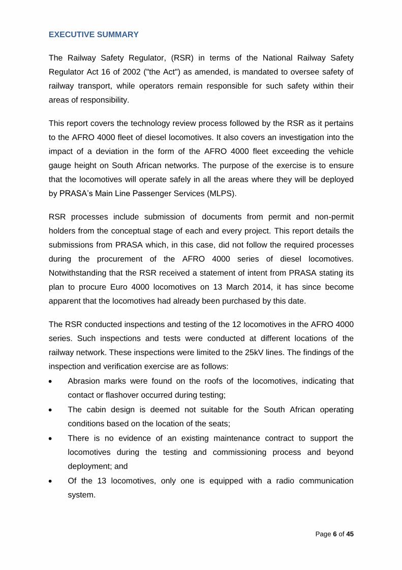
EXECUTIVE SUMMARY
The Railway Safety Regulator, (RSR) in terms of the National Railway Safety
Regulator Act 16 of 2002 ("the Act") as amended, is mandated to oversee safety of
railway transport, while operators remain responsible for such safety within their
areas of responsibility.
This report covers the technology review process followed by the RSR as it pertains
to the AFRO 4000 fleet of diesel locomotives. It also covers an investigation into the
impact of a deviation in the form of the AFRO 4000 fleet exceeding the vehicle
gauge height on South African networks. The purpose of the exercise is to ensure
that the locomotives will operate safely in all the areas where they will be deployed
by PRASA’s Main Line Passenger Services (MLPS).
RSR processes include submission of documents from permit and non-permit
holders from the conceptual stage of each and every project. This report details the
submissions from PRASA which, in this case, did not follow the required processes
during the procurement of the AFRO 4000 series of diesel locomotives.
Notwithstanding that the RSR received a statement of intent from PRASA stating its
plan to procure Euro 4000 locomotives on 13 March 2014, it has since become
apparent that the locomotives had already been purchased by this date.
The RSR conducted inspections and testing of the 12 locomotives in the AFRO 4000
series. Such inspections and tests were conducted at different locations of the
railway network. These inspections were limited to the 25kV lines. The findings of the
inspection and verification exercise are as follows:
Abrasion marks were found on the roofs of the locomotives, indicating that
contact or flashover occurred during testing;
The cabin design is deemed not suitable for the South African operating
conditions based on the location of the seats;
There is no evidence of an existing maintenance contract to support the
locomotives during the testing and commissioning process and beyond
deployment; and
Of the 13 locomotives, only one is equipped with a radio communication
system.

Page 7 of 45
The results of the inspection and assessment confirm that the AFRO 4000 series of
locomotives is designed and manufactured to a height of 4140mm above rail head.
This height exceeds the vehicle structure gauge height of 3965mm as required in the
Transnet Freight Rail track maintenance manual. The impact of this deviation is that
there is a greater risk of interference between Overhead Traction Equipment and the
locomotive.
Accordingly, the RSR approves the deployment of the AFRO 4000 series on the
25kV lines in the Free State, Northern Cape and Eastern Cape provided that the
conditions highlighted in the assessment are met. The RSR reiterates that all the
safety critical items identified and communicated with PRASA in this report must be
addressed before an operating licence can be granted for the locomotives to be
operated on the South African network. These include the successful completion of
the tunnel tests and the acceptance of the results by the RSR, cab ergonomics
analysis – all of which must be submitted to the RSR for evaluation and assessment
purposes.
With the exception of locomotive height limitations in certain areas of the network
and subject to the highlighted conditions in this report, the PRASA AFRO 4000
series locomotives posess acceptable performance capabilities to operate in the
South African network.

Page 8 of 45
1. INTRODUCTION
The AFRO 4000 series of diesel locomotives was purchased by the Passenger Rail
of South Africa (PRASA) from Vossloh Espana. The first locomotive arrived in South
Africa in December of 2014. To date, there are 13 AFRO 4000 locomotives that are
in the country and it is expected that seven more will be delivered before the end of
2015. The locomotives are manufactured to a height of 4140mm above rail with new
wheels and new springs. For this reason, the locomotives present a risk when
travelling in areas where there is reduced height of the contact wires, given that the
locomotives exceed the vehicle gauge height on South African railway networks.
2. SOUTH AFRICAN RAIL NETWORK LAYOUT AND LIMITS
The South African railway system comprises three main elements, namely the
network, station and train operators or any combination thereof. The railway network
comprises a total track distance of 30,400km according to the National Rail Policy
Green Paper and there are four conditions which determine the type of locomotive
required for haulage on that specific line. These conditions are broadly listed below
and depicted in figure1:
Non-electrified lines for use by diesel and hybrid locomotives only.
3kV DC electrified lines for use by 3kV DC electric locomotives, 3kV DC/25kV AC
dual locomotives, diesel and hybrid locomotives.
25kV AC electrified lines for use by 25kV AC locomotives, 3kV DC/25kV AC dual
locomotives, diesel and hybrid locomotives.
50kV AC electrified lines for use by 50kV AC locomotives, diesel locomotives and
hybrid locomotives.

Page 9 of 45
Figure 1: SA Rail Network (Transnet BBB8097)
2.1. Problem statement The AFRO 4000 series of locomotives is designed and manufactured to a height of
4140mm above rail head. This height exceeds the vehicle structure gauge height of
3965mm as required in the TFR track maintenance manual for diesel locomotives.
3. RAILWAY SAFETY REGULATOR PROCESSES
The RSR uses a life cycle management approach when conducting safety
assessments on new works and technology developments. It follows that the RSR
should evaluate this rolling stock acquisition project from concept phase to disposal.
Throughout the life cycle phases, the operator is required to inform the RSR of the
risks involved in moving from one phase to the next phase and how such risks will be
eliminated or mitigated, with the ultimate goal of ensuring safe railway operations.
The RSR must be satisfied that the operator has considered all risks involved in
moving from one phase to the next when evaluating the submissions, as stipulated in
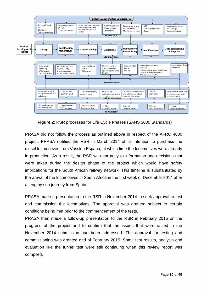
SANS 3000 series of standards. This process is presented in figure 2 below:
Page 10 of 45
Governance
Review Initiators
Life Cycle Phases
RSR SANS 3000-2 -2 RSR Regulatory & Compliance Review Process
Risk analysis
Hazard logURS changesCost optimisation
Engineering drawings
QA planOut source contract
Des ign philosophyURSStandardsSocio environment
Performance failure
Cost optimisationOps procedure failureRA & HL
Bus iness impactSafety
RA & HL
Statutory requirements
StandardsTechnology driven Cost optimisationChanges in Socio environmentRA & HL, incidents CAR's
Product development
request
Construction/Manufacture
Commissioning OperationsMaintenance & monitoring
ModificationsDecommissioning
& disposalDesign
Test & commissioning planIntegration acceptanceFunctional acceptance
cri teria
Risk assessment (RA)
Hazard log (HL)Cost optimisationStatutory requirements
Performance cri teria
Ops proceduresMaintenance contract
Statutory s tipulations
Detail design Economic l ife cycle
Performance criteria
Ops proceduresOps contract
URS
Statutory s tipulationsDes ign
Functional failureRA & HL
URS changes
Inappropriate designURS image
RSR Requirements
Noti fication of intent
Des ign documentation submission
RSR Response
Acknowledgement
Submittal review
Construction
permit requestTest & commissioning
permit request
SMSR change
noti fication/submission
Noti fication of maintenace
plan changes (schedules,
activi ties, procedures)
Changesubmission
Noti fication of intent and veri fiaction documents
upon completion
Compl iance check
Technical reviewCompl iance checkTechnical review
Review / acknowledgement
Review / acknowledgement
Review / acknowledgement
Review /
acknowledgement
Systemic Design Interface Considerations
Figure 2: RSR processes for Life Cycle Phases (SANS 3000 Standards)
PRASA did not follow the process as outlined above in respect of the AFRO 4000
project. PRASA notified the RSR in March 2014 of its intention to purchase the
diesel locomotives from Vossloh Espana, at which time the locomotives were already
in production. As a result, the RSR was not privy to information and decisions that
were taken during the design phase of the project which would have safety
implications for the South African railway network. This timeline is substantiated by
the arrival of the locomotives in South Africa in the first week of December 2014 after
a lengthy sea journey from Spain.
PRASA made a presentation to the RSR in November 2014 to seek approval to test
and commission the locomotives. The approval was granted subject to certain
conditions being met prior to the commencement of the tests.
PRASA then made a follow-up presentation to the RSR in February 2015 on the
progress of the project and to confirm that the issues that were raised in the
November 2014 submission had been addressed. The approval for testing and
commissioning was granted end of February 2015. Some test results, analysis and
evaluation like the tunnel test were still continuing when this review report was
compiled.

Page 11 of 45
4. THE REVIEW APPROACH
Sections 2 & 3 above outline the rail network and the RSR requirements for life cycle
management of new technology such as new rolling stock. Of critical importance to
the railway operator (network, station or train operator), when planning to introduce
the new rolling stock into the railway environment, is an understanding of overall
conditions in which the rolling stock will be operating. This implies that, at concept
phase, the operator must determine the areas where the rolling stock (RS) will be
operating in the SA rail network, who will be operating the RS, and how it will be
maintained. This will assist the RS operator to know what type of communication will
be required, as well as the required human/machine interface and deployment plan.
Figure 3 below highlights the various areas the operator must consider when
purchasing new rolling stock.
On this basis, audits and inspections were conducted on the AFRO 4000 series
locomotives which are currently undergoing testing and commissioning. The
assessment included physical inspections; measurements and compatibility
verification on other features of the railway network.
Railway System
Rail Technologies
Environment
Statutory
Built
Social
Natural
Business
Infrastructure
Rolling Stock
Information & communication
Train Control
Sustainability
Appropriate & sustainable technology over the
Business venture life cycle
Integrated, viable & complaint systemic
Solution addingvalue
ImperativesAuthoritiesCompliance
Economic viabilitySystemic performance impact
THE SYSTEMIC RAILWAY
ENVIRONMENT
Assets, human resources
and business processes
which form part of a logistic
chain in a bigger business
venture
Figure 3: Whole Systems Approach

Page 12 of 45
5. INSPECTION OF AFRO 4000 LOCOMOTIVES
5.1. General description of the locomotive:
The locomotives are provided with an EMD 16-710-G3B turbo-charged diesel
engines. The engine supplies the main generator with the mechanical power
necessary for generating electrical power for traction. The traction power is
distributed by the transmission system to each traction motor fitted on the bogies.
Each traction motor is directly geared to a number of driven wheels. There are two
cabs in the AFRO 4000 locomotive. The cab located next to the electrical cabinet is
considered to be the front cab. The AFRO 4000 is a modified version of the EURO
4000. It was modified to run on Cape track gauge (1067mm) as the EURO 4000
locomotive is based on the standard track gauge (1435mm).
The operational control of the locomotive system is performed by a computer
(EM2000 microprocessor). The computer detects and gives warnings of most
locomotive fault conditions through messages on the display (located on the desk)
and audible alarms. It also records failure messages and significant information in a
file memory.
5.2. Locomotive Communications
In accordance with train working rules, a radio communication system is required to
facilitate communication between the train driver and the train control officer (TCO)
as there may be instances where the driver is required to communicate with the
TCO.
Of the 13 locomotives, only one is equipped with a radio communication system. The
absence of an appropriate communication system results in the use of unreliable
communication methods and sometimes no communication at all. The picture below
shows where the radio communication system should have been fitted

Page 13 of 45
Picture 1: AFRO 4000 Cab Layout
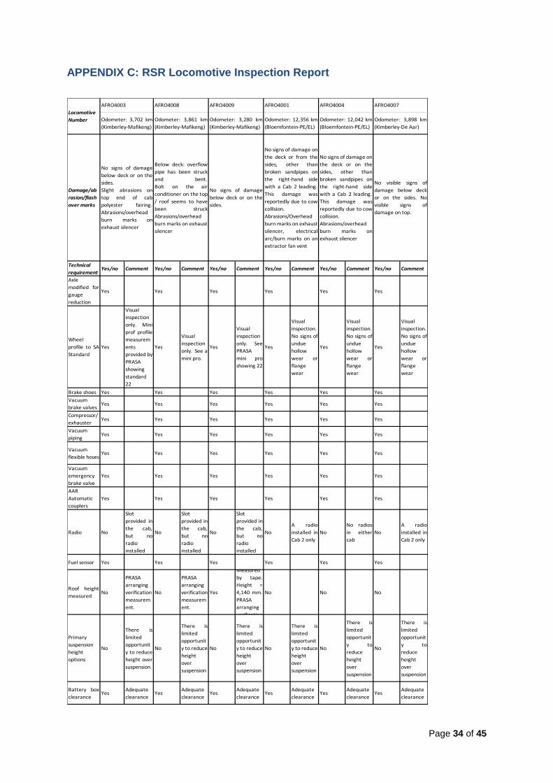
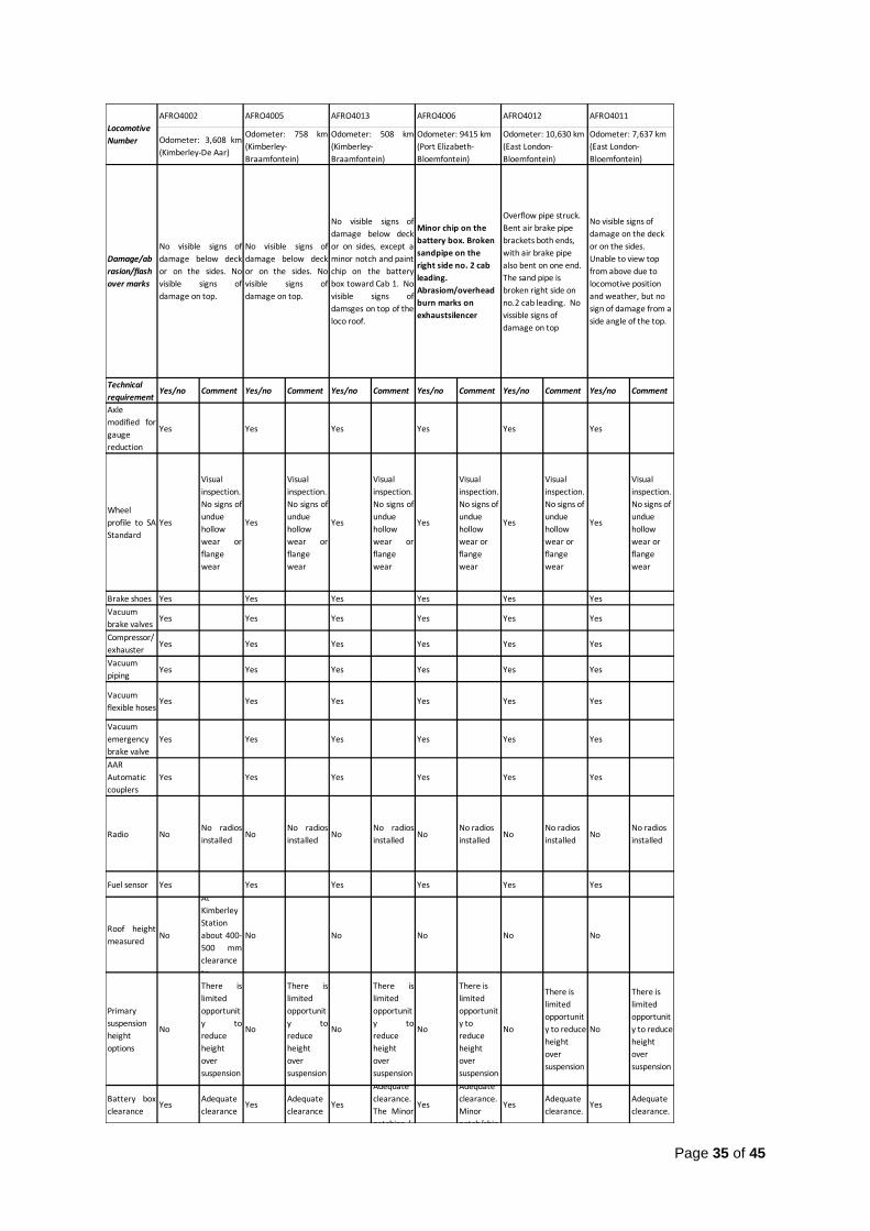
5.3. Locomotive Inspection A summary of the inspection report in tabular format was developed and a copy is
included in Appendix C of this report.
5.3.1. Inspection Findings
As part of the inspection, the locomotives’ heights were measured and found to be
4140mm from the highest point (over the exhaust) to the top of the rail. The
measurement was made by laser and straight edge so it may include a margin of
error of about 2mm. The diagram contained in the Vossloh manual for the AFRO
4000 confirms the height of 4140mm. Given that all the locomotives are built to the
same design and production specification, it was not necessary to measure all of the
locomotives.
A visual inspection confirmed that the locomotives have the following correct
equipment for South African operations:
I. Cape gauge bogies (1067mm)
II. The standard No. 22 wheel profile is used on the locomotives
III. Composition brake blocks are installed
IV. Air and vacuum brake equipment, including all piping, emergency valve in cab
and compressor/exhauster are installed
V. AAR automatic couplers are installed
VI. Vossloh fuel level sensor is installed
VII. Except in the AFRO 4001 Cab 2, communication radios are not installed in the
cab consoles of the other locomotives. Communication with the TCOs could
therefore be compromised.

Page 14 of 45
All the locomotives have already covered significant mileage, with AFRO 4001 and
AFRO 4004 having travelled the most at over 12000 km each.
What appears to be electrical burns from overhead traction equipment are present
on some locomotives on the exhaust silencer and the dust blower (see inspection
sheets in Appendix A for details). Photo evidence (see Appendix B) shows this to be
fairly minor at this stage.
There is minor damage to some of the locomotives components below deck, namely:
a. AFRO 4008 and AFRO 4012 have sustained damage on an overflow pipe. This
pipe protrudes beyond other equipment to the side of the locomotive. It is
recommended that the overflow pipe be shortened so that it does not protrude.
b. AFRO 4001, AFRO 4004, AFRO 4006 and AFRO 4012 have broken sand pipes
on the right-hand side with Cab 2 leading. AFRO 4012 has bent brackets
enclosing the air brake pipes on both ends of the locomotive. On the one end,
the actual air brake pipe is bent and the cock is broken.
6. HUMAN FACTORS AND DRIVER’S CAB ERGONOMICS
6.1. Human Factors Approach on Technical Reviews
The Human Factors Management Standard requires that human factors in design
(ergonomics) and the physical environment in which the task will be operated be
considered during the introduction of new designs. Ergonomics can be defined as
the study of human abilities and characteristics which affect the design of equipment,
systems and jobs, with the aim of improving efficiency, safety, and well-being (Clark
and Corlett, 1984). It is therefore essential to consider man’s limitations and abilities
when looking at the interface between people and machines in systems.
The human factors assessment process includes a verification and validation phase
as described by van der Weide et al, 2013. During the verification phase, it must be
confirmed, by examination and provision of objective evidence, that the specified
requirements have been fulfilled. The validation phase includes a confirmation by
examination and provision of objective evidence that the particular requirements for
a specific intended use have been fulfilled. Based on the Human Factors

Page 15 of 45
management standard, the assessment process for the AFRO 4000 considered the
following three elements:
Physical environmental factors
Human factors in design
Training and development
6.2. Assessment / Inspections
6.2.1. Verification phase
As explained earlier, the verification phase relies on two legs, mainly, examination
and the provision of objective evidence that a specific requirement has been met.
These were some of the observations that were made with regards to the cab as it
relates to the train driver during the examination by the RSR:
6.2.1.1. Access provisions
Several notable shortcomings were identified in the AFRO 4000 related to the ease
of entry into and exit from the locomotive cabin. The first shortcoming noted was the
distance between the rungs. Although the spacing between the rungs could not be
verified during the site visit, the RSR team observed that there were spatial
inconsistencies between the rungs of the ladder used to gain access into the cab.
While the AFRO 4000 is equipped with handrails for the driver to hold when moving
in and out of the cab, the driver may experience difficultly gripping the handrails in
wet conditions. An additional factor that could limit ease of exit from the locomotive
cabin is the potential change in platform height in relation to the last rung the driver
steps on when exiting. If the platform and the height of the first set of rungs are not
perfectly aligned, the driver would have to jump to reach the platform.
6.2.1.2. Seating
The seat for the train driver was found to be adjustable; the seat could move back
and forth and had an adjustable back rest. The driver also had a foot rest which was
within easy reach. The typical practice within the South African rail industry is for a
driver’s cab to include a driver’s assistant seat. In keeping with this practice, PRASA
included a driver’s assistant seat within the cab that was not originally part of the
AFRO 4000 design.

Page 16 of 45
No evidence was submitted to the RSR to indicate whether the addition of the
assistant’s seat would pose an additional risk. Since the assistant’s seat is placed in
a cab that was not originally designed to accommodate it, there is limited space
behind the seat at the back of the cab. Based on the activities that the train driver
and train assistants are required to execute, the RSR is of the view that the train
assistant’s seat was placed too close in proximity to the driver’s seat. The space
restriction caused by the placement of the assistant’s seat means that should an
emergency evacuation be necessary, the assistant would struggle to exit the cab
safely and quickly.
The seats on the AFRO 4000 series locomotives were also found to have insufficient
lumbar support and the backrests of both the train assistant and driver’s seats were
not vertically adjustable. The seat pan (seat base) on the train assistant’s seat was
tilted at an acute angle, resulting in the assistant sitting in a position where their hips
would not rest at a 90° angle.
PRASA had indicated that the train drivers and train assistants indicated that they
were happy with the current position of the seat. However, no formal report has been
submitted to the regulator to state how the responses from the drivers were
obtained. It is not clear whether the responses were gained through the use of
questionnaires or interviews. No information has also been provided detailing the
sample size as well as the percentage of drivers who actually preferred the layout of
the cab.
6.2.1.3. Body posture and orientation
It was found that both the train driver and train assistant adopted awkward body
postures to perform the required tasks safely, effectively and comfortably. This was
caused by the location of the controls in relation to the seat position; the current
design set up is likely to force some drivers (based on their anthropometric
dimensions) to sit forward in the seat, in order to comfortably reach the controls. Any
driver who is forced to sit forward in the seat would necessarily forgo the use of the
available back rest for support.

Page 17 of 45
6.2.1.4. Workspace
The legroom inside cab was found to be restrictive, especially for train assistant, due
to the cab size and layout.
6.2.1.5. Controls and displays
Control and display layout coding and stereotype were found to be inconsistently
applied to the design of the locomotives. Physical reach to controls and labelling
were also identified as deficiencies.
6.2.1.6. Visual access
While the train driver and the assistant had a clear view of the tracks, rear view was
not possible as the cab does not have mirrors.
6.2.1.7. Other hazards identified in the cab
The ashtray should be removed from the locomotive as the cab is not a designated
smoking area it is an accident hazard as its placement makes it possible for the
driver to bump against it when exiting and entering the cab.
The emergency hand brake next to the driver seat poses as a hazard, especially
when the driver seat has been adjusted to the forward position, and its placement
makes it likely for the driver to easily hit their leg against it. It advisable that a rubber
bracket is placed against the break to prevent accidental activation of the emergency
break.
6.2.1.8. Training and development
PRASA indicated that there have been some individuals who have been trained on
the new locomotive. A list of all the individuals who have been trained as well as the
depot where they are stationed has been made available to the RSR. Information
regarding the training for the AFRO 4000 was also provided to the RSR.

Page 18 of 45
6.2.2. Validation phase
The validation phase of the assessment has not been completed yet. This requires
that a proper task analysis of the tasks performed by the train drivers and train
assistants be conducted to determine whether particular requirements for a specific
intended use have been fulfilled.
PRASA is required to provide this results once this phase is completed.

Page 19 of 45
7. LOCOMOTIVE AND INFRASTRUCTURE HEIGHT ASSESSMENT
7.1. Locomotive Height Assessment
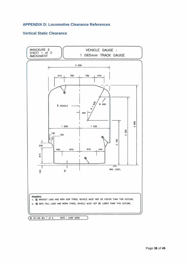
The height of the AFRO 4000 locomotive was measured at 4140mm which is
175mm higher than the track maintenance manual requirement of 3965mm. By
exceeding the vehicle gauge, the clearance safety margin between the top of the
vehicle and the Overhead Traction Equipment is reduced. Thus, any reduction in
height of the TFR contact wire height from its minimum allowed height as a result of
tamping actvities, will pose a greater risk of contact with this locomotive than any
other type of locomotive in the country. This also increases the likelihood of a
flashover.
As a result of the AFRO 4000’s deviation from TFR vehicle gauge height,a greater
risk of interference between Overhead Traction Equipment and the locomotive
exists. This risk is greater on DC overhead lines, as the minimum allowed height of
DC equipment is less than on AC overhead lines. The most critical height restriction
is the case of DC electrification lines, which, according to the TFR Infrastructure
Manual for Track Maintenance, Clause 8.2.1, may be a minimum of 4220 mm above
the rail top, and this minimum may occur in old tunnels and old bridges due to track
maintenance or due to construction standards.
Thus, in the worst case scenario, on DC lines, the clearance between locomotive
and overhead traction equipment could be 80mm. This is a static clearance. The
motion of the locomotive over vertical track geometric variations, variations due to
super-elevation in curves, or for whatever other reason, may cause dynamic
reduction of this clearance.
PRASA instituted an investigation in collaboration with Stellenbosch University in
August 2014. The investigation report, titled Calculation of Contact Wire Gap, states
that arcing occurs at 70mm gap under the worst conditions and with 25kV overhead.
The minimum gap at which arcing (flashover) occurs decreases approximately
linearly as voltage decreases, to below 20mm for 3kV. The report concludes that
“The data obtained is in no way a safe design value and the distances need to be
increased to allow for variances in height, altitude as well as other factors.”
Page 20 of 45
7.2. Infrastructure Height Assessment
The 25kV AC lines at Kimberley station and south of the station that were inspected
had no impact on the clearances of the locomotive(s). However, the evidence of
marks on top of the exhaust chamber suggests that the locomotive might have also
traversed the 3kV DC lines.
8. IDENTIFICATION OF OPERATIONAL RISKS
Operational risks exist where the AFRO 4000 series locomotives run on lines with
reduced Overhead Traction Equipment clearances. The risks are of contact with the
contact wire or flashover which can result in overhead power trips, with resultant
delays to train services and associated costs.
According to the Handbook of Vehicle Dynamics page 205, ‘Clearance is about risk
management. The larger the clearance provided, the smaller the risk, and thus the
need for control measures is minimised. Modern standards specify clearance
according to risk regime, where the available clearance dictates what control
measures are required.’
To mitigate against operational risk, there should be a full and detailed survey and
joint mitigation plan by PRASA and TFR to ensure that the contact wires are not
below minimum heights and to identify lines, if applicable, where the AFRO 4000 is
not permitted to travel due to an unacceptably small gap between the overhead and
the locomotive.
It is recommended that TFR and PRASA regularly measures overhead height, and
reviews these heights for new deviations on all electrified lines where AFRO 4000 is
granted permission to operate.


Page 22 of 45
Table: Clearance Requirements
9.2.2. Contact Wire Maintenance Status
The IM2000 contact wire height measurements as provided by PRASA dated June
2015 indicate that over 95% of both TFR and PRASA networks are above the
4500mm minimum height as indicated by the tables below.
The available clearance for the AFRO 4000 vehicle will vary depending on
mechanical vibrations, dynamics and track conditions.
Table: IM2000 – Summary Contact Wire height measurement categories for
Transnet Network
Nominal voltage UIC606-1:1987 EN50119
3 kV DC 160 mm
150 mm w/o pollution
150 mm
25 kV AC 320 mm 270 mm
50 kV AC 600 mm
Transnet
Category Description Counts Percentages
1 Out of tolerance (contact wire height less than 4220mm) 15 0,01%
2 Exceptional minimum height (contact wire height between item 1 & item 2) 3 052 1,32%
3 Normal minimum height (contact wire height equal or more 4500mm) 227 994 98,67%
231 061 100%

Page 23 of 45
Table: IM2000 – Summary Contact Wire height measurement categories for PRASA
Network
PRASA
Category Description Counts Percentages
1 Out of tolerance (contact wire height less than 4220mm) 10 0,02%
2 Exceptional minimum height (contact wire height between Item 1 & Item 2) 1 733 4,03%
3 Normal minimum height (contact wire height equal or more 4500mm) 41 290 95,95%
43 033 100%

Page 24 of 45
10. CONCLUSION
With the exception of locomotive height limitations in certain areas of the network
and subject to the highlighted conditions in this report, the PRASA AFRO 4000
series locomotives posess acceptable performance capabilities to operate in the
South African network.
At the measured height of 4140mm, the locomotives cannot always maintain the
required minimum vertical gap of 150mm between the roof and the contact wire.
This will lead to a higher risk of contact and flashover with the overhead traction
equipment and operational delays. There is evidence on some of the AFRO 4000
locomotives inspected that such contact/flashover has occurred during testing.
Despite being confined to the Cape gauge, PRASA has procured the locomotives
from an original locomotive supplier based in Europe where standard gauge
clearances apply. This would not constitute bad practice but does require the
following:
Careful design reviews of changes to the supplier’s standard product for
standard gauge to suit the more constrained Cape gauge track;
Diligent investigation of the network operator’s infrastructure requirements where
the locomotives will be deployed;
Identification and mitigation of risks of fouling between the rolling stock and the
dynamic structure gauge and/or overhead traction equipment;
A mutual agreement between the train operator and network operator on the
procurement of the locomotives; and
Suppliers to comply to the vehicle gauge and a mutual agreement between the
train operator and network operator concerned.
The RSR asserts that many of the risks could have been mitigated before the arrival
of the locomotives in South Africa had PRASA followed the technology review
process as set by the RSR.The conclusion of this investigation is that all the
requirements were met except for the following:

Page 25 of 45
Tunnel air quality tests report must be submitted to confirm that the locomotive
exhaust discharge has no impact on passengers.
Human factors assessments validation phase must be conducted and submitted.
Maintenance arrangements for the locomotives must be presented.

Page 26 of 45
11. References
1. Clark, T.S. and Corlett, E.N. (1984). The Ergonomics of Workspace and
Machines: A Design Manual. Taylor & Francis. London.
2. Conradie, P; Pieterse, P. (2014). Investigation Report:Calculation of Contact
Wire Gap.University of Stellenbosch. South Africa (August 2014).
3. Dadashi, N., Scott, A., Wilson, JR., and Mills, A. (2013). Rail Human Factors:
Supporting reliability, safety and cost reduction; pp. 270 - 279. Eds., Taylor &
Francis. London.
4. Department of Transport (DOT): National Rail Policy Green Paper 2015, URL:
www.transport.gov.za.
5. Muller, J., Rudich, R. and Yearwood K. (1998). Human Factors Guidelines for
locomotive cabs. U.S. Department of Transportation, Research and Special
Programs Administration. DOT-VNTSC-FRA-98-8.
6. Occupational Health and safety Act 85 of 1993 and Regulation, (Updated in
2015). JUTA Law. URL: www.jutalaw.co.za.
7. SANS 3000 series of standards (These documents were referred to in; 2015).
8. SARCC Track Maintenance Manual 2012 (This document was referred to in;
2015).
9. van der Weide. R., Frieling, H.F.L., Malle, F. and Miglianico, D. (2013).
Amsterdam Metro Cab: Ergonomics in the Design, Verification and Validation
Process.

Page 27 of 45
APPENDIX A: Modifications to EURO 4000
MODIFICATIONS LISTED ON PRASA SUBMISSION
I. Modifications on bogie for track gauge reduction from 1435mm to 1065mm
- Axle modified for gauge reduction
- Wheel profile modified to South African standard
- Brake shoes instead of brake discs
II. Vacuum brake
- Installation of vacuum brake valves
- Substitution of brake compressor by a double compressor & exhauster
- Addition of vacuum pipe throughout the locomotive
- Installation of vacuum flexible hoses on locomotive front end.
- Installation of vacuum emergency brake valve in the cab
III. Locomotive clearance diagram reduction
- Reduction of locomotive roofs height and primary suspension height
- New battery box structure for the reduced clearance diagram (same battery
elements)
IV. Automatic coupler
- Installation of the AAR automatic coupler instead of UIC coupler and buffers
V. Radio
- Pre-installation of trunk radio (complete installation of locomotive number 1)
VI. Fuel level sensor
- Substitution of the fuel level sensor to improve reliability, availability,
maintainability and precision

Page 28 of 45
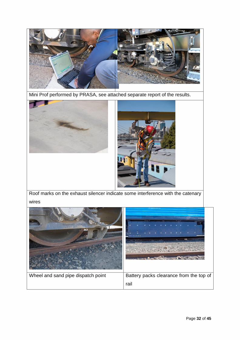
APPENDIX B: Photographic evidence gallery AFRO 4003
AFRO 4003 Side view of the wheels and the bottom clearance
Emergency brakes(both air and vacuum brakes)
Coupling details with vacuum brake pipes and hoses
Visible damage on the exhaust silencer on the top of the locomotive, possibly
caused by the OHTE contact wire.
Visible damage on the upper part of the locomotive, possibly caused by the OHTE contact wire. On the front of one cab, there is a scratch mark indicating either contact with the wire or structure.

Page 29 of 45
AFRO 4008
Side view
Some damage on the side, the air conditioning effluent pipe shows minor damage
from possibly hooking on something during motion.
The cab of the AFRO 4008 shOwing no damage or mark. According to PRASA,
no radio system will be installed, but instead a WIFI system will be used for
communication. This would require further equipment to be mounted on top of the
locomotives, thus increasing the height even further.

Page 30 of 45
The height above the rail of the battery pack on the locomotive is about 100mm,
which suggests that if the locomotives were loweredby changing the wheel size,
this would impact the clearance between the track and the battery pack.
This view of the bottom section of the locomotives shows the clearance between
the rail and the locomotive equipment.
General view on top of the locomotive.
Damage on top of the exhaust silencer, possibly caused by contact wire. Carbon
dust is also present, which suggests that some spark occurred during contact.

Page 31 of 45
AFRO 4009
View of the front of AFRO 4009 , showing brake pipes including vacuum pipes.
The diesel engine chamber with compressor/exhaust chamber
Brake system (both air and vacuum brakes in place)
Page 32 of 45
Mini Prof performed by PRASA, see attached separate report of the results.
Roof marks on the exhaust silencer indicate some interference with the catenary
wires
Wheel and sand pipe dispatch point Battery packs clearance from the top of
rail

Page 33 of 45
Front view Cab view with the locomotive mileage
indication
Engine room
Page 34 of 45
APPENDIX C: RSR Locomotive Inspection Report
Technical
requirementYes/no Comment Yes/no Comment Yes/no Comment Yes/no Comment Yes/no Comment Yes/no Comment
Axle
modified for
gauge
reduction
Yes Yes Yes Yes Yes Yes
Wheel
profile to SA
Standard
Yes
Visual
inspection
only. Mini
prof profile
measurem
ents
provided by
PRASA
showing
standard
22
Yes
Visual
inspection
only. See a
mini pro.
Yes
Visual
inspection
only. See
PRASA
mini pro
showing 22
Yes
Visual
inspection.
No signs of
undue
hollow
wear or
flange
wear
Yes
Visual
inspection.
No signs of
undue
hollow
wear or
flange
wear
Yes
Visual
inspection.
No signs of
undue
hollow
wear or
flange
wear
Brake shoes Yes Yes Yes Yes Yes Yes
Vacuum
brake valvesYes Yes Yes Yes Yes Yes
Compressor/
exhausterYes Yes Yes Yes Yes Yes
Vacuum
pipingYes Yes Yes Yes Yes Yes
Vacuum
flexible hosesYes Yes Yes Yes Yes Yes
Vacuum
emergency
brake valve
Yes Yes Yes Yes Yes Yes
AAR
Automatic
couplers
Yes Yes Yes Yes Yes Yes
Radio No
Slot
provided in
the cab,
but no
radio
installed
No
Slot
provided in
the cab,
but no
radio
installed
No
Slot
provided in
the cab,
but no
radio
installed
No
A radio
installed in
Cab 2 only
No
No radios
in either
cab
No
A radio
installed in
Cab 2 only
Fuel sensor Yes Yes Yes Yes Yes Yes
Roof height
measuredNo
PRASA
arranging
verification
measurem
ent.
No
PRASA
arranging
verification
measurem
ent.
Yes
Measured
by tape.
Height =
4,140 mm.
PRASA
arranging
verification
No No No
Primary
suspension
height
options
No
There is
limited
opportunit
y to reduce
height over
suspension
No
There is
limited
opportunit
y to reduce
height
over
suspension
No
There is
limited
opportunit
y to reduce
height
over
suspension
No
There is
limited
opportunit
y to reduce
height
over
suspension
No
There is
limited
opportunit
y to
reduce
height
over
suspension
No
There is
limited
opportunit
y to
reduce
height
over
suspension
Battery box
clearanceYes
Adequate
clearanceYes
Adequate
clearanceYes
Adequate
clearanceYes
Adequate
clearanceYes
Adequate
clearanceYes
Adequate
clearance
Locomotive
Number
AFRO4003
Odometer: 3,702 km
(Kimberley-Mafikeng)
Damage/ab
rasion/flash
over marks
No signs of damage
below deck or on the
sides.
Slight abrasions on
top end of cab
polyester fairing.
Abrasions/overhead
burn marks on
exhaust silencer
AFRO4008
Odometer: 3,861 km
(Kimberley-Mafikeng)
AFRO4009
Odometer: 3,280 km
(Kimberley-Mafikeng)
Below deck: overflow
pipe has been struck
and bent.
Bolt on the air
conditioner on the top
/ roof seems to have
been struck
Abrasions/overhead
burn marks on exhaust
silencer
No signs of damage
below deck or on the
sides.
AFRO4001
Odometer: 12,356 km
(Bloemfontein-PE/EL)
No visible signs of
damage below deck
or on the sides. No
visible signs of
damage on top.
AFRO4007
Odometer: 3,898 km
(Kimberley-De Aar)
AFRO4004
Odometer: 12,042 km
(Bloemfontein-PE/EL)
No signs of damage on
the deck or from the
sides, other than
broken sandpipes on
the right-hand side
with a Cab 2 leading.
This damage was
reportedly due to cow
collision.
Abrasions/Overhead
burn marks on exhaust
silencer, electrical
arc/burn marks on an
extractor fan vent
No signs of damage on
the deck or on the
sides, other than
broken sandpipes on
the right-hand side
with a Cab 2 leading.
This damage was
reportedly due to cow
collision.
Abrasions/overhead
burn marks on
exhaust silencer
Page 35 of 45
Technical
requirementYes/no Comment Yes/no Comment Yes/no Comment Yes/no Comment Yes/no Comment Yes/no Comment
Axle
modified for
gauge
reduction
Yes Yes Yes Yes Yes Yes
Wheel
profile to SA
Standard
Yes
Visual
inspection.
No signs of
undue
hollow
wear or
flange
wear
Yes
Visual
inspection.
No signs of
undue
hollow
wear or
flange
wear
Yes
Visual
inspection.
No signs of
undue
hollow
wear or
flange
wear
Yes
Visual
inspection.
No signs of
undue
hollow
wear or
flange
wear
Yes
Visual
inspection.
No signs of
undue
hollow
wear or
flange
wear
Yes
Visual
inspection.
No signs of
undue
hollow
wear or
flange
wear
Brake shoes Yes Yes Yes Yes Yes Yes
Vacuum
brake valvesYes Yes Yes Yes Yes Yes
Compressor/
exhausterYes Yes Yes Yes Yes Yes
Vacuum
pipingYes Yes Yes Yes Yes Yes
Vacuum
flexible hosesYes Yes Yes Yes Yes Yes
Vacuum
emergency
brake valve
Yes Yes Yes Yes Yes Yes
AAR
Automatic
couplers
Yes Yes Yes Yes Yes Yes
Radio NoNo radios
installedNo
No radios
installedNo
No radios
installedNo
No radios
installedNo
No radios
installedNo
No radios
installed
Fuel sensor Yes Yes Yes Yes Yes Yes
Roof height
measuredNo
At
Kimberley
Station
about 400-
500 mm
clearance
to
No No No No No
Primary
suspension
height
options
No
There is
limited
opportunit
y to
reduce
height
over
suspension
No
There is
limited
opportunit
y to
reduce
height
over
suspension
No
There is
limited
opportunit
y to
reduce
height
over
suspension
No
There is
limited
opportunit
y to
reduce
height
over
suspension
No
There is
limited
opportunit
y to reduce
height
over
suspension
No
There is
limited
opportunit
y to reduce
height
over
suspension
Battery box
clearanceYes
Adequate
clearanceYes
Adequate
clearanceYes
Adequate
clearance.
The Minor
notching /
Yes
Adequate
clearance.
Minor
notch/chip
YesAdequate
clearance. Yes
Adequate
clearance.
No visible signs of
damage below deck
or on the sides. No
visible signs of
damage on top.
No visible signs of
damage below deck
or on sides, except a
minor notch and paint
chip on the battery
box toward Cab 1. No
visible signs of
damsges on top of the
loco roof.
Minor chip on the
battery box. Broken
sandpipe on the
right side no. 2 cab
leading.
Abrasiom/overhead
burn marks on
exhaustsilencer
Overflow pipe struck.
Bent air brake pipe
brackets both ends,
with air brake pipe
also bent on one end.
The sand pipe is
broken right side on
no.2 cab leading. No
vissible signs of
damage on top
No visible signs of
damage on the deck
or on the sides.
Unable to view top
from above due to
locomotive position
and weather, but no
sign of damage from a
side angle of the top.
No visible signs of
damage below deck
or on the sides. No
visible signs of
damage on top.
AFRO4002
Damage/ab
rasion/flash
over marks
Locomotive
Number
AFRO4005
Odometer: 758 km
(Kimberley-
Braamfontein)
AFRO4013
Odometer: 508 km
(Kimberley-
Braamfontein)
Odometer: 3,608 km
(Kimberley-De Aar)
AFRO4011
Odometer: 7,637 km
(East London-
Bloemfontein)
AFRO4012
Odometer: 10,630 km
(East London-
Bloemfontein)
AFRO4006
Odometer: 9415 km
(Port Elizabeth-
Bloemfontein)
Page 36 of 45
APPENDIX D: Locomotive Clearance References Vertical Static Clearance

Page 37 of 45
APPENDIX E: Tests Conducted by PRASA
Static Test
Tests RegisterReport
ComfirmedTest Type Local Tests Comment Resolution Process Criteria Document Reference
Dimensional Test YType and
RoutineNot Done Physical Measurements
Vehicle Gauge Structure,
Loco GABB14601201001
Weighing tests YType and
RoutineNot Done Weigh Bridge tender Specification HC/CS QU1460000000
Water tests YType and
RoutineNot Done Water test procedure
As per the procedure
(Vosloh protocol used) QE14600000000
Slew Test YType and
RoutineNot Done
Traveser Test and 90m radius
curve
Vosloh report and Prasa
validationQI14600000000
Electromagnetic Compatibilty Test Y Type Done
Vossloh to provide the
report. PRASA to provide
the test results
Certificate and results
avaiable, see Ref
documentation
Testing and ReportingVosloh report and Prasa
validation
PRASA AFRO4000EMCReport;
PRASA AFRO4000RF Report;
PRASA_AFRO4000_EMC&RF_C
onformance Report
Electrical Insulation tests: Y Type Done
To be done at the end of the
Vossloh tests which will only
include the mission critical
components.
Physical Measurements and
validationAs per the procedure ET14600000000
Brake System (pneumatically) tests Y Routine DoneAwaiting raw data and
analysisOEM procedure As per the procedure TA40420/710 (EN14600000000)
Brake System (vacuum) tests Y Routine DoneAwaiting raw data and
analysisOEM procedure As per the procedure TA40420/711
Sanding tests Y Routine Done250ml in 20 sec and is
deemed to be acceptable.
There were issues that
were noted which will be
part of the design
improvements
OEM procedure 300 to 366ml/half a minute ET14600000000
Air system tests Y Routine Done
To be discussed with
Vossloh whether they are
done and when they are
going to be done.
OEM procedure As per the procedure HC/CS EM14600000000
Auxiliary power supply system tests Y Routine DoneIncluded as part of Pre
Commisioning testOEM procedure As per the procedure ET14600000000
Battery charging tests Y Routine DoneIncluded as part of Pre
Commisioning testET14600000000
EM2000 Y Routine Done ET14600000000
Electrical Functional tests (Cab1&2) Y Routine Done OEM procedure As per the procedure HC/CSER1461/2000000
Engine Tests Y Routine Done
Noise Tests Y Routine Done
Standard Routine tests.
Verification planned to be
done under controlled
condition at TE
Koedoespoort
To be Tested during
static testing at
Koedoespoort
Noise level meterBelow 75db in Cab and 105
db in Engine roomTo Be Developed
Safety related system (automatic
emergency brake, automatic vigilance
equipment, drivers safety device)
Y Routine Done
Vigilance and emergency
included in standard
Commitioning tests on all
locos
Design improvements Functional test: Dynamic and Static
Lifting Ability and procedure Y Type test Done Documentation available. Vosloh lifting procedure As per the procedure
RAMSNot part of
C&TNot Done
Normally not required as
part of T&C. Risk analysis
was done.
Prasa Maintenance Standards (incl
FMECA)As per MS
Visibility Test Y Type test Done Report submitted Signal visibility (driver and assistant) Signals to advice
Train Control System (Software EM
2000)Y Type test Done
The functionallity was
verified. PRASA do not
currently have the interface
software, but access is
available for through the
Driver display unit (DDU)
Demonstrate functionality
MetroRail do not have the
ability in the maintenece
facilities. Cape Town GO
contractors did not have the
ability/opertunity to do. Static
testing will be done in TE
Koedoespoort for 1st Sept
2015.
Request fro proposal
issued to Contractors to
provide the service. To
be completed by 20
September 2015
Included as part of Pre
Commisioning test
Page 38 of 45
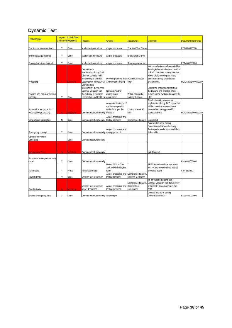
Dynamic Test
Tests RegisterReport
Confirmed
Local Test
Progress Process Criteria Acceptance Comment Document Reference
Traction performance tests Y Done Vosloh test procedure as per procedure Tractive Effort Curve ET14600000000
Braking tests (electrical) Y Done Vosloh test procedure as per procedure Brake Effort Curve
Braking tests (mechanical) Y Done Vosloh test procedure as per procedure Stopping distances EP14600000000
Wheel slip Y Not Done
Demonstrate
functionality, during final
Dinamic valuation with
the delivery of the last 7
Locomotives in Oct 2015
Prove slip control with
and without sanding
Povide full traction
effort
Not formally done and recorded but
the single Locomotive was used to
pull a 51 car train, proving that the
wheel slip is working within the
Shosholosa Meyl Operational
environment. HC/CS ET14600000000
Traction and Braking Thermal
capacity Y Done
Demonstrate
functionality, during final
Dinamic valuation with
the delivery of the last 7
Locomotives in Oct 2015
No brake 'fading'
during brake
applications
Within acceptabel
braking distance
During the final Dinamic testing,
the Braking and Traction effort
curves will be evaluated against the
URS
Automatic train protection
(Overspeed protection) N Not Done Demonstrate functionality
Automatic limitation of
maximum speed to
90 km/h as per SA
network
Limit to max of 90
km/h
This funtionallity was not yet
implimented during T&C phase but
will be done the moment these
locomotives are approved for
operational use. HC/CS ET14600000000
Vehicle/track interaction N Done Demonstrate functionality
As per procedure and
testing protocol Compliance to norm Completed
Emergency braking Y Done Demonstrate functionality
As per procedure and
testing protocol
Done as the norm during
Commission tests on loco only.
Test reports available on each loco
delivery file
Operation of wheel
lubricators Done Demonstrate functionality
Aerodynamic Tests N Not Done Demonstrate functionality Not Required
Air system - compressor duty
cycle Y Done Demonstrate functionality EM14600000000
Noise tests Y Prasa Noise level meter
Below 75db in Cab
and 105 db in Engine
room
PRASA confirmed that the noise
test results are submitted with all
loco data packs C/072397I2/1
Stability tests Y Done Vossloh test procedure
As per procedure and
testing protocol
Compliance to norm.
Certified to 90km/h
Stability tests N Not Done
Vossloh test procedure
as per IEC61133
As per procedure and
testing protocol
Compliance to norm.
Certificate of
compliance
To be validated during final
Dinamic valuation with the delivery
of the last 7 Locomotives in Oct
2015
Engine Emergency Stop Y Done Demonstrate functionality Stop engine
Done as the norm during
Commission tests. EM14600000000
Page 39 of 45
APPENDIX F: Human Factor Design considerations
In line with international practice (Muller et al., 1998) physical environmental
factors take the following into consideration:
CAB PHYSICAL ENVIRONMENT HEATING
If a heater is installed, the minimum temperature maintained should be 17.8˚C
at a point that is about 610mm above the center of each seat (in cabs which
can be occupied for more than 3 hours).
Glazing of the windows should be designed in order to reduce heat loss by
radiation, conduction and by air infiltration at poor seals.
Cab floors should be insulated to eliminate the loss of ambient heat and
conduction from feet when standing and the walls should be insulated to
reduce radiation.
Cabs should provide a means to add humidity to the heated air to improve
comfort, reduce skin and membrane drying and aid dust settling.
VENTILATION
Air from outside should be filtered to remove dust, insects and other debris.
The introduction of fumes and vapors must be eliminated.
The noise from the ventilation system should be controlled.
The cab pressure should be positive and should be maintained to reduce
infiltration of outside contaminants and drafts.
NOISE
A maximum continuous noise level of 75 dBA is a desirable goal.
VIBRATION
With regards to loss of comfort, the human body is sensitive to vibration in the
0.4 to 20 Hz range. With regard to vertical vibration, the area of greatest
Page 40 of 45
sensitivity is between 4 and 10 Hz. Very low frequency vertical motions (0.1 to
0.5 Hz) are not experienced as vibration but may result in motion sickness.
Active systems can provide greater vibration control than passive systems.
They can potentially be applied to locomotive suspension, cabs, or seat posts.
The Human Factors in Design considers the following factors:
CAB LAYOUT
GENERAL DESIGN
User population sizes should be used to design the cab with the male 95th
percentile dimensions used to set clearances and the female 50th percentile
dimensions used to set reach envelopes.
Enough space should be allocated for each cab occupant: 6 square meters is
a minimum amount of floor space. Comfort facilities (toilet, water cooler,
storage, refrigerator, etc.) should be located out of the main area of the cab
and not counted as crew space.
The height of the cab ceiling should be at least 1930mm (European designs
use 2006 mm).
Other items, such as first aid kits, flares and fire extinguishers, should be
mounted where they are accessible, but do not impede movement in the cab.
Changes in floor levels in the cab, e.g. raised seat platform, should be
minimised in order to prevent tripping hazards.
Interior surface finish should be light colored, of low reflectance and easy to
clean.
Designing for extremely large individuals is appropriate when a design feature
must accommodate most of the population (such as a doorway).
Designing for an adjustable range is permissible when features can be easily
tailored to the individuals who use them (such as seats, keyboards).
Page 41 of 45
Designing for the average individual is appropriate in noncritical situations,
where designing for an extreme is inappropriate and where adjustability is
impractical (such as a toilet seat).
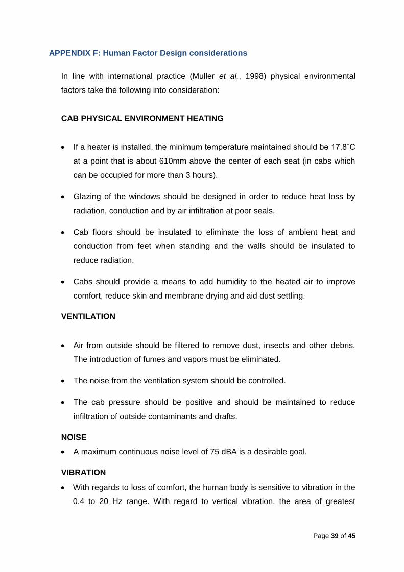
To provide good visibility while minimising fatigue due to poor neck and head
posture, regular viewing tasks should be within a 30-degree cone around the
normal line of sight (Grandjean, 1988). The normal line of sight is 10-15
degrees below the horizontal plane. Displays should be placed within a
viewing angle between 5 degrees above and 30 degrees below the horizontal
plane in establishing the height of the seat in relationship to the windows and
the visual displays in the cab.
CONTROLS AND DISPLAYS
Primary displays and controls should be placed so that the driver may view
them without having to change his/her eye or head position from the normal
line of sight.
Secondary controls and displays may be located so that eye movements are
necessary, but head movements are not.
Non-critical displays and controls may be located outside the normal line of
sight.

Page 42 of 45
Angled work surfaces should be considered when there are many controls
and displays to arrange in the workstation as the controls on an angled
surface allow for the placement of a greater number of controls within easy
reach.
Control size and spacing should permit the engineer to operate the controls
without accidentally activating neighboring controls.
WORK-SPACE ENVELOPE
Controls should be placed so that the operator’s hands do not have to reach
frequently or be elevated above the shoulder for substantial periods.
Padded forearm supports should be used to relieve pressure at the shoulder
and elbow.
The workstation should be designed such that the driver’s elbows remain
flexed (bent) and allow for control activation.
Sufficient clearance should be provided for the driver’s thighs under the work
surface.

Page 43 of 45
ACCESS
The placement of the doors should take accident scenarios into account, e.g.
cars piling on and around the locomotive may block some exits in some
circumstances
Doors should open outward to permit easier pre-accident exits. This also
eliminates the need for a clear area in the cab to allow an unobstructed inward
swing.
Door latches should be examined for potential hand pinch areas in their range of
motion.
The door should include a small sight glass to see if there is somebody that
could be struck when opening the door.
VISIBILITY
The windows should permit the operator to see a track level object as close as
15 m away and an overhead object (e.g. Signal Bridge) as close as 16 m away.
Lateral field-of-view should be at least 180˚ and preferably 220˚.
Too much window area can have drawbacks. Examples are radiant heat gain,
heat loss, glare, reflections, vulnerability to thrown rocks and gunshots.
SEATING
Locomotive seats should be cushioned at least 76 mm thick, use the buttocks for
primary support, exert little pressure on the thighs especially at the front edge,
support the lower back and have arm rests 101 mm wide and 330 mm long.
Seat height should be adjustable from 406 to 482 mm in steps no larger than 25
mm.
Page 44 of 45
Seat should adjust forward and back at least 101 mm from the 50th percentile
position.
The seat cushion should be contoured for buttocks and the back for spinal
curves in order to even pressure and provide support. It should provide
adjustable lumbar support to increase support and comfort level.
The seat's backrest should recline between 95 and 115 degrees, the seat pan
should tilt back between 1 and 5 degrees from horizontal, front edge higher.
A backrest curved on a radius of 457 609 mm or with lateral support will help
during side sway.
A rectangular seat pan with elevated sides is preferable to a round seat pan.
The ideal seat adjustment mechanism is easy to use, reliable, and wear
resistant. A swivel may be needed to access the seat and to accommodate the
need to turn to look to the back and sides.
The seat covering should be made of fabric or perforated leather to reduce
perspiration and heat buildup.
Non-seat characteristics can have a direct or indirect impact on the seated
position or use of the seat and need to be considered to determine seating
comfort.
Non-seat factors include: leg room, knee room, availability of footrests,
clearance from sidewall, vibration levels, ease of entry/exit, clearance when
swiveling, visibility, and reach-to-control distance.
WORKSTATION DESIGN
CONTROLS
Motion controls should be placed directly in front of the driver.
The radio hand control should be place on the left hand side to allow the driver
to operate the locomotive motion controls with his right hand while using the
radio with his left hand.
Page 45 of 45
Controls for the whistle, horn, headlights and radio should be located within the
zone of reach and preferably within the zone of comfort, if possible.
Controls should be consistent with normal limb motions. This means that where
arm motions are needed they should be forward and back, not sideways.
Controls that have a similar function or purpose should be grouped together.
AUDITORY DEVICES
A vigilance detector system with a time constant that varies based on both
speed and control activity should be installed.
Additional displays associated with a warning advisory panel that indicates
which locomotive in a multiple consist is experiencing a particular problem can
also be installed.
For the vigilance system, an audio alarm and visual alert should be placed near
the windshield as the drivers attention should be directed towards the outside.
The use of sounds that could be confused with operational or malfunction noises
(e.g., air brake releases, pump operations, sand discharges, etc.) should be
avoided.
Top Related
Copyright © 2022 FDOKUMEN

