


Bahasa
Halaman
Hukum

JID:AESCTE AID:2959 /FLA [m5Gv1.5; v 1.114; Prn:11/10/2013; 13:58] P.1 (1-14)
Aerospace Science and Technology ••• (••••) •••–•••
Contents lists available at ScienceDirect
Aerospace Science and Technology
www.elsevier.com/locate/aescte
A novel approach to night vision imaging systems development,integration and verification in military aircraft
Roberto Sabatini a,∗, Mark A. Richardson b, Maurizio Cantiello c, Mario Toscano c,Pietro Fiorini c
a RMIT University – School of Aerospace, Mechanical and Manufacturing Engineering, Melbourne, VIC 3000, Australiab Cranfield University – DAUK, Shrivenham, Swindon SN6 8LA, UKc Italian Ministry of Defense – Air Staff, Rome 00185, Italy
a r t i c l e i n f o a b s t r a c t
Article history:Received 9 December 2012Accepted 31 August 2013Available online xxxx
Keywords:Night vision imaging systemsNight vision gogglesNVG compatibilityMilitary avionics systems
This paper describes the research and experimental flight test activities conducted by the Italian AirForce Official Test Centre (RSV) in collaboration with industry (Alenia Aeronautica and Litton PrecisionProducts) and with Academia, in order to confer the Night Vision Imaging Systems (NVIS) capabilityto the Italian TORNADO IDS (Interdiction and Strike) and ECR (Electronic Combat and Reconnaissance)aircraft. The activities included various Design, Development, Test and Evaluation (DDT&E) activities,including Night Vision Goggles (NVG) integration, cockpit instruments and external lighting modifications,as well as various ground test sessions and a total of eighteen flight test sorties. RSV and LittonPrecision Products were responsible of coordinating and conducting the design and installation activitiesof the internal and external lights. Particularly, an iterative process was established, allowing an in-site rapid correction of the major deficiencies encountered during the ground and flight test sessions.Both single-ship (day/night) and formation (night) flights were performed, shared between the RSVand Alenia Test Crews involved in the activities, allowing for a redundant examination of the varioustest items by all participants. An innovative test matrix was developed and implemented by RSVfor assessing the operational suitability and effectiveness of the various modifications implemented.Also important was definition of test criteria for Pilot and Weapon Systems Officer (WSO) workloadassessment during the accomplishment of various operational tasks during NVG missions. Furthermore,the specific technical and operational elements required for evaluating the modified helmets wereidentified, allowing an exhaustive comparative evaluation of the two proposed solutions (i.e., HGU-55Pand HGU-55G modified helmets). The results of the activities were very satisfactory. The initialcompatibility problems encountered were progressively mitigated by incorporating modifications bothin the front and rear cockpits at the various stages of the test campaign. This process alloweda considerable enhancement of the TORNADO-NVIS configuration, giving a good medium-high levelNVG operational capability to the aircraft. Further developments also include the internal/externallighting for the Italian TORNADO “Mid Life Update” (MLU) and other programs, such as the AM-Xaircraft internal/external lights modification/testing and the activities addressing low-altitude NVGoperations with fast jets (e.g., TORNADO, AM-X, MB-339CD), a major issue being the safe ejectionof aircrew with NVG and NVG modified helmets. Two options have been identified for solving thisproblem: namely the modification of the current Gentex HGU-55 helmets and the design of a newhelmet incorporating a reliable NVG connection/disconnection device (i.e., a mechanical system fullyintegrated in the helmet frame), with embedded automatic disconnection capability in case of ejection.Other relevant issues to be accounted for in these new developments are the helmet dimensionsand weight, the NVG usable FOV as a function of eye-relief distance, and helmet centre of gravity(moment arms) with and without NVG (impact on aircrew fatigue during training and real operationalmissions).
© 2013 Elsevier Masson SAS. All rights reserved.
* Corresponding author. Tel.: +44 (0)1234 758290; fax: +44 (0)1234 758203.E-mail address: [email protected] (R. Sabatini).URL: http://www.cranfield.ac.uk (R. Sabatini).
1270-9638/$ – see front matter © 2013 Elsevier Masson SAS. All rights reserved.http://dx.doi.org/10.1016/j.ast.2013.08.021
1. Introduction
In recent years, the Italian Air Force (ITAF) set the requirementsfor Night Vision Imaging Systems (NVIS) to be integrated on TOR-NADO IDS (Interdiction and Strike version) and ECR (Electronic
JID:AESCTE AID:2959 /FLA [m5Gv1.5; v 1.114; Prn:11/10/2013; 13:58] P.2 (1-14)
2 R. Sabatini et al. / Aerospace Science and Technology ••• (••••) •••–•••
Combat and Reconnaissance version) aircraft for operational mis-sions at medium and high altitudes.
The initial operational capability (operational certification foremployment in peace-keeping operations) was achieved by RSVafter a ground and flight test campaign (three ground sessionsand six flight test sorties) conducted on modified aircraft interiorand external lighting configurations, using the AN/AVS/9 (F4949)NVG manufactured by ITT-Night Vision. Successively, the full tech-nical/formal process of avionics certification was undertaken underthe direction of the Italian Ministry of Defense Aeronautical Ar-maments Certification Authority (Armaereo). The related flight testactivities were conducted by the Italian Official Flight Test Cen-tre with participation of the Alenia S.p.A. Flight Test Department.During the activity, Cranfield University provided technical adviceregarding the mathematical models and analytical tools requiredfor NVIS performance prediction and evaluation. The specific ob-jectives of the TORNADO ground and flight test activities were thefollowing:
• Internal and external lighting day and night evaluation withand without N/AVS/9 NVG (F4949);
• Workload assessment in single-ship and formation flights;• Ergonomic and operational evaluation of the HGU-55P and
HGU-55G modified helmets;• N/AVS/9 NVG (F4949) cockpit stowage evaluation;• Determination of the TORNADO-NVIS combination resolution
characteristics;• Determination, by ground tests and analysis, of the TORNADO-
NVIS range performance.
After brief overview of NVIS technology, this paper describedthe DDT&E activities performed, with a special focus on cockpitdesign and ground/flight test methods developed and progressivelyrefined throughout the activity.
2. NVIS technology overview
The Image Intensifier (I2) is the core element of NVIS systems.I2 devices are electro-optic systems used to detect and intensifyreflected energy in the visible and near infrared regions of theelectromagnetic spectrum. They require some external illumina-tion in order to operate because the image quality is a functionof the reflective contrast. The performances of I2 devices are alsodependent on atmospheric and environmental conditions. Partic-ularly, penetration through moisture can be quite effective (espe-cially when compared to other Electro-Optic (EO) devices, like FLIRsystems), while smoke, haze and dust can significantly reduce I2
performance. Signal-to-Noise Ratio (SNR) is the parameter com-monly used to characterise I2 systems performance.
Generation I (GEN-I) NVG’s were introduced into service in themid 1960’s during the Vietnam War. They used starlight scopesbased on electron acceleration (i.e., no microchannel plates). There-fore, they were characterised by high power requirements and tubegains between 40 000 and 60 000. Multiple staging, required toincrease gain, often determined an increase of image distortion,and the overall systems were large/heavy (i.e., not suitable forhead mount). Furthermore, GEN-I systems were very susceptibleto booming and the MTBF of a typical GEN-I NVG was in the orderof about 10 000 hours.
Generation II (GEN-II) NVG’s were introduced in the late 1960’sand they were small enough to be head mounted. They used elec-tron multiplication (i.e., microchannel plate – MCP), with increasedtubes gain, reduced power requirements, and reduced size/weight.Furthermore, the new I2 technology reduced distortion and bloom-ing (confined to specific MCP tubules halos). Typical GEN-II sys-tems were the AN/PVS-5 ground system, and the AN/AVS-5A sys-
tem modified for aircraft usage. The MTBF of typical GEN-II sys-tems was in the order of about 2000–4000 hours (worst thanGEN-I), the tube gain was approximately 10 000, and there was noinherent resolution improvement with respect to GEN-I systems.
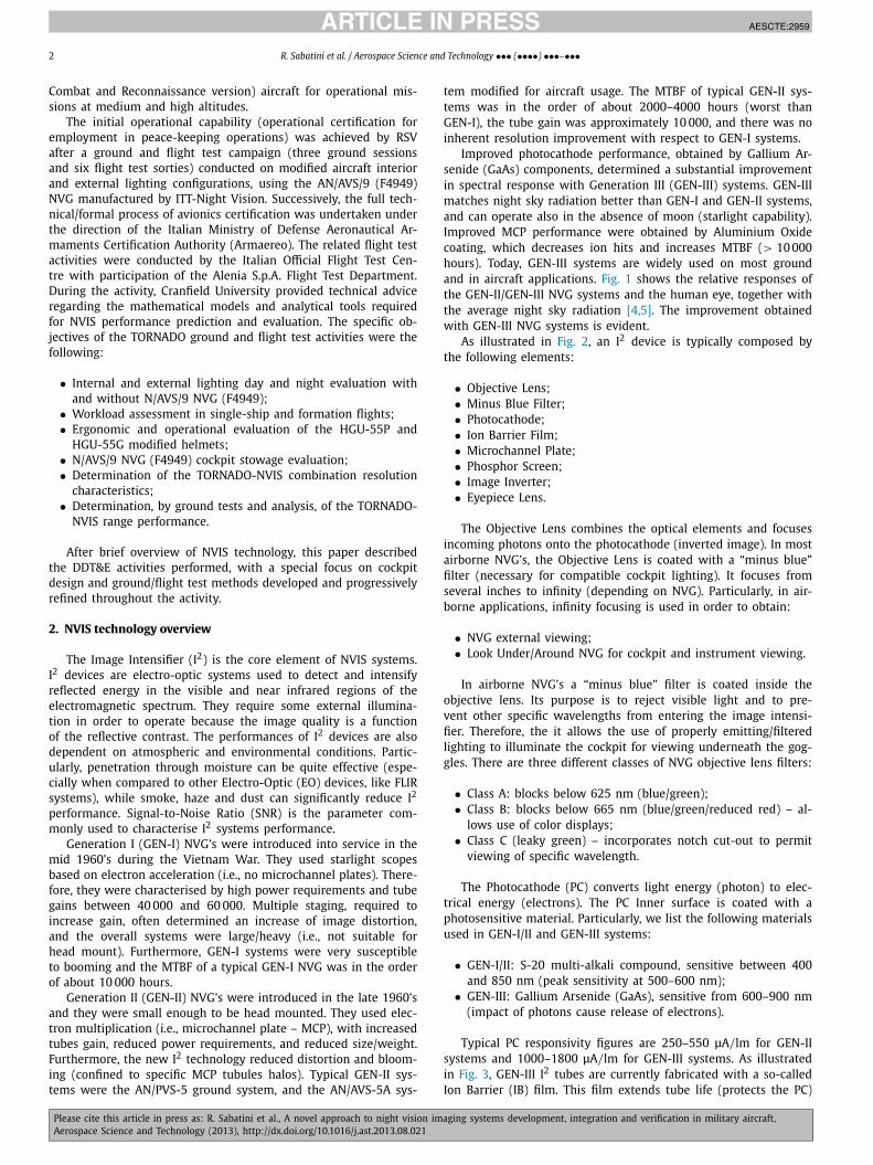
Improved photocathode performance, obtained by Gallium Ar-senide (GaAs) components, determined a substantial improvementin spectral response with Generation III (GEN-III) systems. GEN-IIImatches night sky radiation better than GEN-I and GEN-II systems,and can operate also in the absence of moon (starlight capability).Improved MCP performance were obtained by Aluminium Oxidecoating, which decreases ion hits and increases MTBF (> 10 000hours). Today, GEN-III systems are widely used on most groundand in aircraft applications. Fig. 1 shows the relative responses ofthe GEN-II/GEN-III NVG systems and the human eye, together withthe average night sky radiation [4,5]. The improvement obtainedwith GEN-III NVG systems is evident.
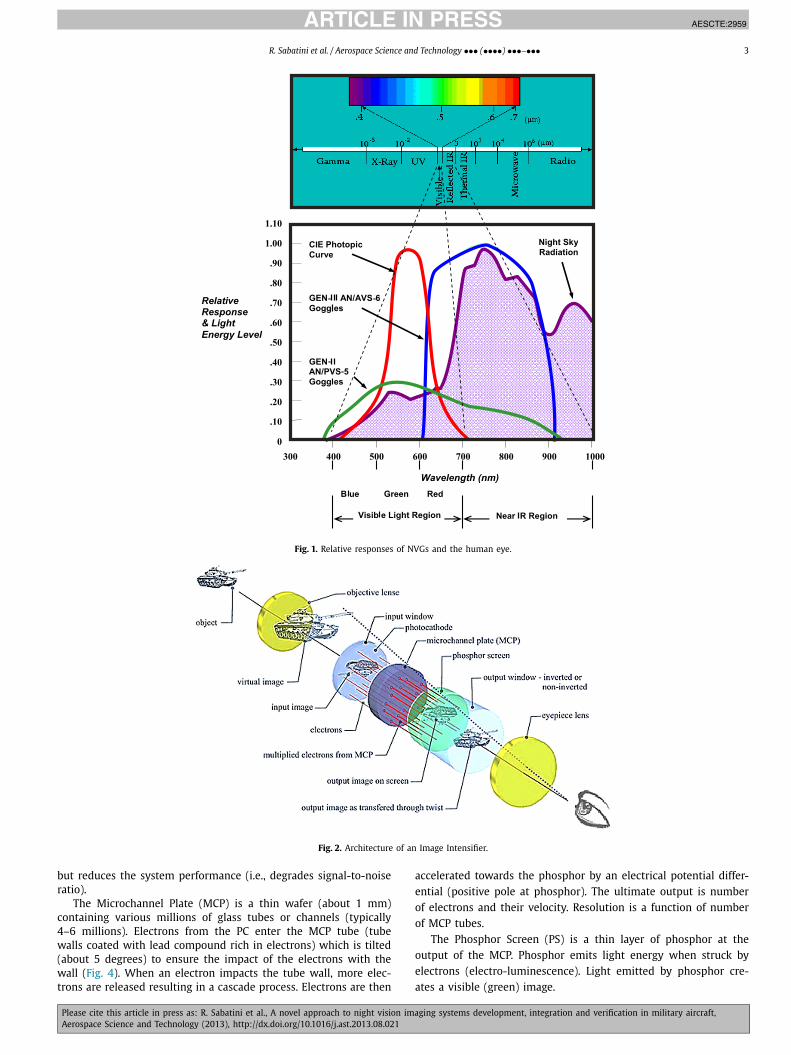
As illustrated in Fig. 2, an I2 device is typically composed bythe following elements:
• Objective Lens;• Minus Blue Filter;• Photocathode;• Ion Barrier Film;• Microchannel Plate;• Phosphor Screen;• Image Inverter;• Eyepiece Lens.
The Objective Lens combines the optical elements and focusesincoming photons onto the photocathode (inverted image). In mostairborne NVG’s, the Objective Lens is coated with a “minus blue”filter (necessary for compatible cockpit lighting). It focuses fromseveral inches to infinity (depending on NVG). Particularly, in air-borne applications, infinity focusing is used in order to obtain:
• NVG external viewing;• Look Under/Around NVG for cockpit and instrument viewing.
In airborne NVG’s a “minus blue” filter is coated inside theobjective lens. Its purpose is to reject visible light and to pre-vent other specific wavelengths from entering the image intensi-fier. Therefore, the it allows the use of properly emitting/filteredlighting to illuminate the cockpit for viewing underneath the gog-gles. There are three different classes of NVG objective lens filters:
• Class A: blocks below 625 nm (blue/green);• Class B: blocks below 665 nm (blue/green/reduced red) – al-
lows use of color displays;• Class C (leaky green) – incorporates notch cut-out to permit
viewing of specific wavelength.
The Photocathode (PC) converts light energy (photon) to elec-trical energy (electrons). The PC Inner surface is coated with aphotosensitive material. Particularly, we list the following materialsused in GEN-I/II and GEN-III systems:
• GEN-I/II: S-20 multi-alkali compound, sensitive between 400and 850 nm (peak sensitivity at 500–600 nm);
• GEN-III: Gallium Arsenide (GaAs), sensitive from 600–900 nm(impact of photons cause release of electrons).
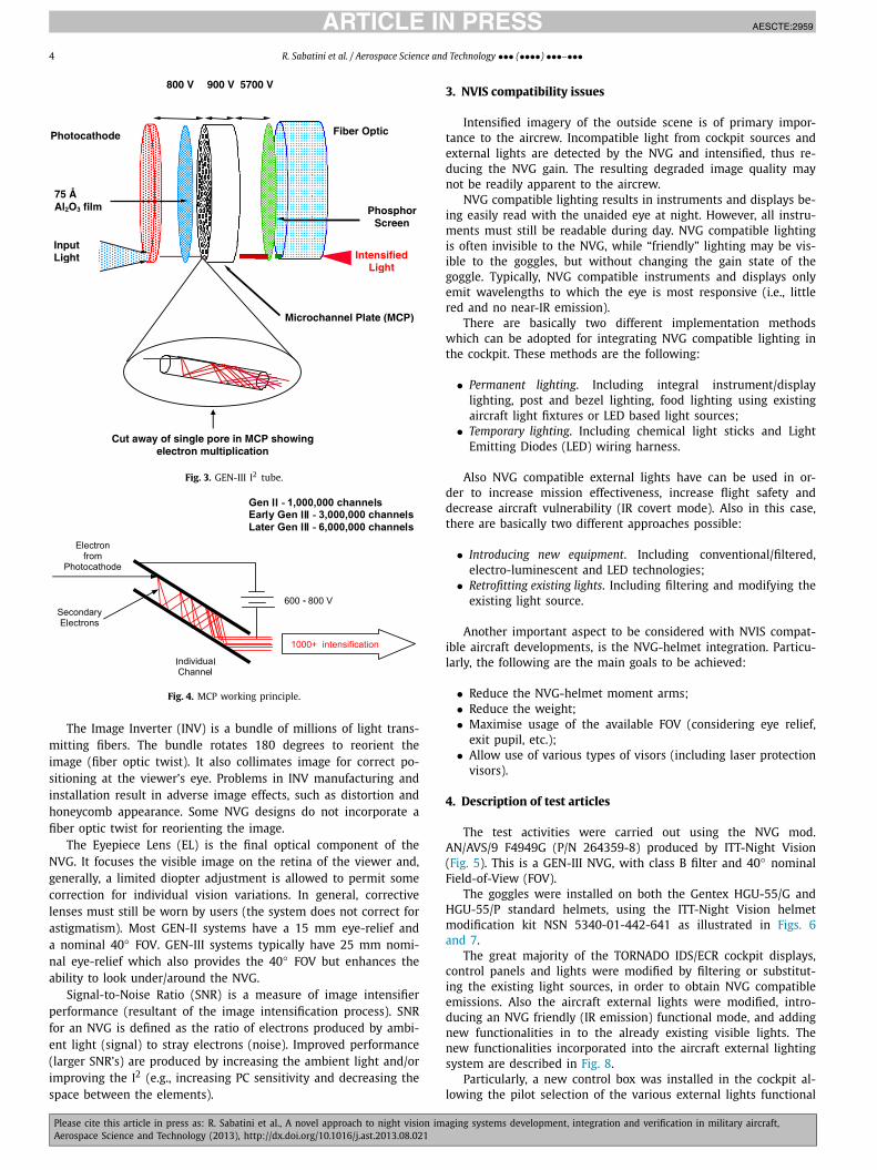
Typical PC responsivity figures are 250–550 μA/lm for GEN-IIsystems and 1000–1800 μA/lm for GEN-III systems. As illustratedin Fig. 3, GEN-III I2 tubes are currently fabricated with a so-calledIon Barrier (IB) film. This film extends tube life (protects the PC)
JID:AESCTE AID:2959 /FLA [m5Gv1.5; v 1.114; Prn:11/10/2013; 13:58] P.3 (1-14)
R. Sabatini et al. / Aerospace Science and Technology ••• (••••) •••–••• 3
Fig. 1. Relative responses of NVGs and the human eye.
Fig. 2. Architecture of an Image Intensifier.
but reduces the system performance (i.e., degrades signal-to-noiseratio).
The Microchannel Plate (MCP) is a thin wafer (about 1 mm)containing various millions of glass tubes or channels (typically4–6 millions). Electrons from the PC enter the MCP tube (tubewalls coated with lead compound rich in electrons) which is tilted(about 5 degrees) to ensure the impact of the electrons with thewall (Fig. 4). When an electron impacts the tube wall, more elec-trons are released resulting in a cascade process. Electrons are then
accelerated towards the phosphor by an electrical potential differ-ential (positive pole at phosphor). The ultimate output is numberof electrons and their velocity. Resolution is a function of numberof MCP tubes.
The Phosphor Screen (PS) is a thin layer of phosphor at theoutput of the MCP. Phosphor emits light energy when struck byelectrons (electro-luminescence). Light emitted by phosphor cre-ates a visible (green) image.
JID:AESCTE AID:2959 /FLA [m5Gv1.5; v 1.114; Prn:11/10/2013; 13:58] P.4 (1-14)
4 R. Sabatini et al. / Aerospace Science and Technology ••• (••••) •••–•••
Fig. 3. GEN-III I2 tube.
Fig. 4. MCP working principle.
The Image Inverter (INV) is a bundle of millions of light trans-mitting fibers. The bundle rotates 180 degrees to reorient theimage (fiber optic twist). It also collimates image for correct po-sitioning at the viewer’s eye. Problems in INV manufacturing andinstallation result in adverse image effects, such as distortion andhoneycomb appearance. Some NVG designs do not incorporate afiber optic twist for reorienting the image.
The Eyepiece Lens (EL) is the final optical component of theNVG. It focuses the visible image on the retina of the viewer and,generally, a limited diopter adjustment is allowed to permit somecorrection for individual vision variations. In general, correctivelenses must still be worn by users (the system does not correct forastigmatism). Most GEN-II systems have a 15 mm eye-relief anda nominal 40◦ FOV. GEN-III systems typically have 25 mm nomi-nal eye-relief which also provides the 40◦ FOV but enhances theability to look under/around the NVG.
Signal-to-Noise Ratio (SNR) is a measure of image intensifierperformance (resultant of the image intensification process). SNRfor an NVG is defined as the ratio of electrons produced by ambi-ent light (signal) to stray electrons (noise). Improved performance(larger SNR’s) are produced by increasing the ambient light and/orimproving the I2 (e.g., increasing PC sensitivity and decreasing thespace between the elements).
3. NVIS compatibility issues
Intensified imagery of the outside scene is of primary impor-tance to the aircrew. Incompatible light from cockpit sources andexternal lights are detected by the NVG and intensified, thus re-ducing the NVG gain. The resulting degraded image quality maynot be readily apparent to the aircrew.
NVG compatible lighting results in instruments and displays be-ing easily read with the unaided eye at night. However, all instru-ments must still be readable during day. NVG compatible lightingis often invisible to the NVG, while “friendly” lighting may be vis-ible to the goggles, but without changing the gain state of thegoggle. Typically, NVG compatible instruments and displays onlyemit wavelengths to which the eye is most responsive (i.e., littlered and no near-IR emission).
There are basically two different implementation methodswhich can be adopted for integrating NVG compatible lighting inthe cockpit. These methods are the following:
• Permanent lighting. Including integral instrument/displaylighting, post and bezel lighting, food lighting using existingaircraft light fixtures or LED based light sources;
• Temporary lighting. Including chemical light sticks and LightEmitting Diodes (LED) wiring harness.
Also NVG compatible external lights have can be used in or-der to increase mission effectiveness, increase flight safety anddecrease aircraft vulnerability (IR covert mode). Also in this case,there are basically two different approaches possible:
• Introducing new equipment. Including conventional/filtered,electro-luminescent and LED technologies;
• Retrofitting existing lights. Including filtering and modifying theexisting light source.
Another important aspect to be considered with NVIS compat-ible aircraft developments, is the NVG-helmet integration. Particu-larly, the following are the main goals to be achieved:
• Reduce the NVG-helmet moment arms;• Reduce the weight;• Maximise usage of the available FOV (considering eye relief,
exit pupil, etc.);• Allow use of various types of visors (including laser protection
visors).
4. Description of test articles
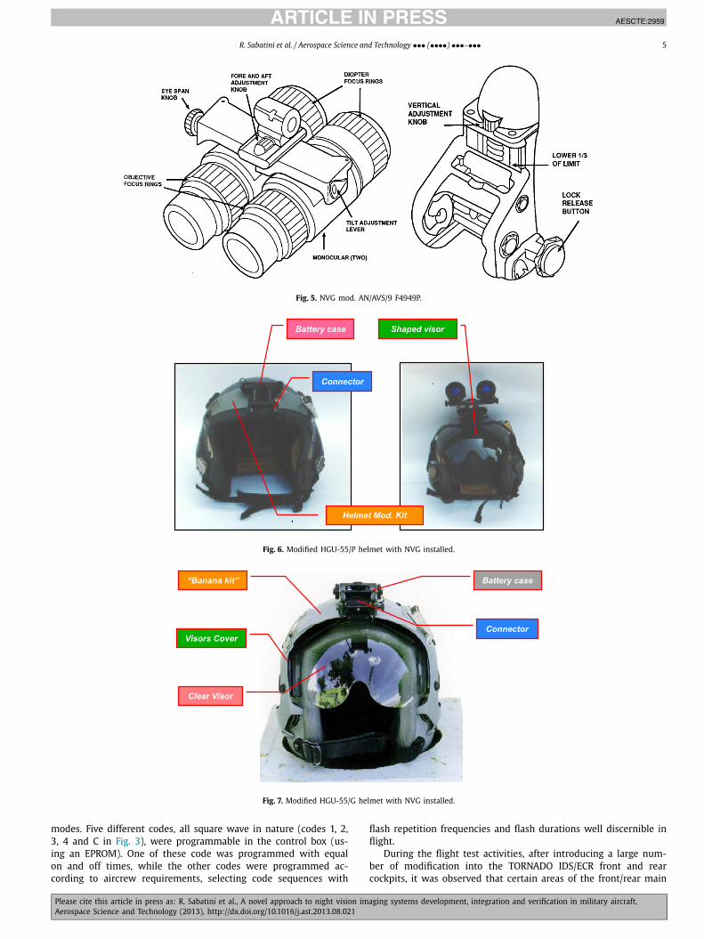
The test activities were carried out using the NVG mod.AN/AVS/9 F4949G (P/N 264359-8) produced by ITT-Night Vision(Fig. 5). This is a GEN-III NVG, with class B filter and 40◦ nominalField-of-View (FOV).
The goggles were installed on both the Gentex HGU-55/G andHGU-55/P standard helmets, using the ITT-Night Vision helmetmodification kit NSN 5340-01-442-641 as illustrated in Figs. 6and 7.
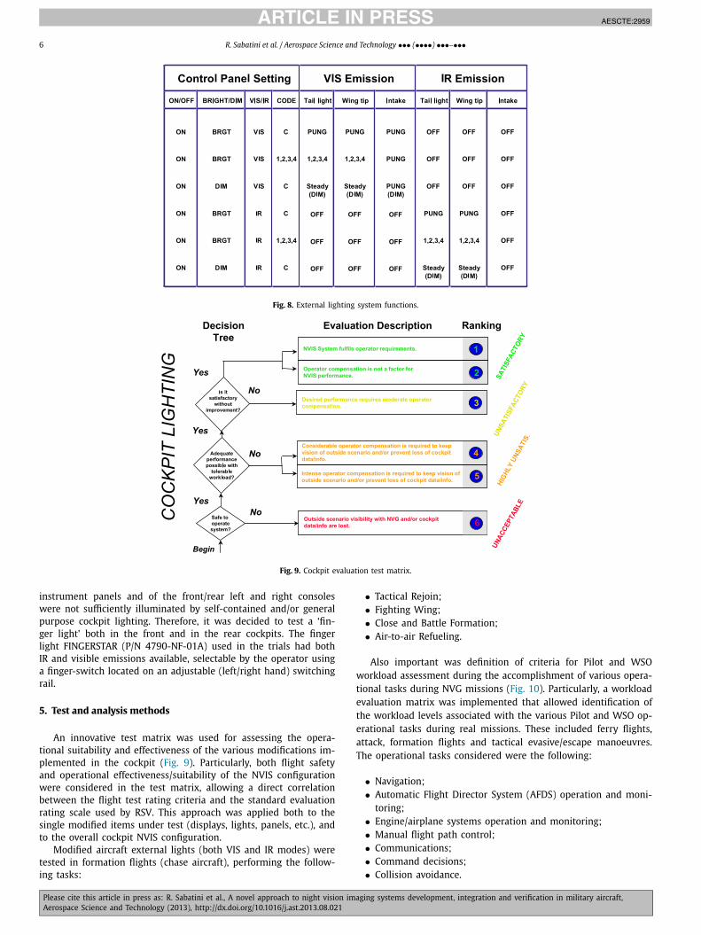
The great majority of the TORNADO IDS/ECR cockpit displays,control panels and lights were modified by filtering or substitut-ing the existing light sources, in order to obtain NVG compatibleemissions. Also the aircraft external lights were modified, intro-ducing an NVG friendly (IR emission) functional mode, and addingnew functionalities in to the already existing visible lights. Thenew functionalities incorporated into the aircraft external lightingsystem are described in Fig. 8.
Particularly, a new control box was installed in the cockpit al-lowing the pilot selection of the various external lights functional
JID:AESCTE AID:2959 /FLA [m5Gv1.5; v 1.114; Prn:11/10/2013; 13:58] P.5 (1-14)
R. Sabatini et al. / Aerospace Science and Technology ••• (••••) •••–••• 5
Fig. 5. NVG mod. AN/AVS/9 F4949P.
Fig. 6. Modified HGU-55/P helmet with NVG installed.
Fig. 7. Modified HGU-55/G helmet with NVG installed.
modes. Five different codes, all square wave in nature (codes 1, 2,3, 4 and C in Fig. 3), were programmable in the control box (us-ing an EPROM). One of these code was programmed with equalon and off times, while the other codes were programmed ac-cording to aircrew requirements, selecting code sequences with
flash repetition frequencies and flash durations well discernible inflight.
During the flight test activities, after introducing a large num-ber of modification into the TORNADO IDS/ECR front and rearcockpits, it was observed that certain areas of the front/rear main
JID:AESCTE AID:2959 /FLA [m5Gv1.5; v 1.114; Prn:11/10/2013; 13:58] P.6 (1-14)
6 R. Sabatini et al. / Aerospace Science and Technology ••• (••••) •••–•••
Fig. 8. External lighting system functions.
Fig. 9. Cockpit evaluation test matrix.
instrument panels and of the front/rear left and right consoleswere not sufficiently illuminated by self-contained and/or generalpurpose cockpit lighting. Therefore, it was decided to test a ‘fin-ger light’ both in the front and in the rear cockpits. The fingerlight FINGERSTAR (P/N 4790-NF-01A) used in the trials had bothIR and visible emissions available, selectable by the operator usinga finger-switch located on an adjustable (left/right hand) switchingrail.
5. Test and analysis methods
An innovative test matrix was used for assessing the opera-tional suitability and effectiveness of the various modifications im-plemented in the cockpit (Fig. 9). Particularly, both flight safetyand operational effectiveness/suitability of the NVIS configurationwere considered in the test matrix, allowing a direct correlationbetween the flight test rating criteria and the standard evaluationrating scale used by RSV. This approach was applied both to thesingle modified items under test (displays, lights, panels, etc.), andto the overall cockpit NVIS configuration.
Modified aircraft external lights (both VIS and IR modes) weretested in formation flights (chase aircraft), performing the follow-ing tasks:
• Tactical Rejoin;• Fighting Wing;• Close and Battle Formation;• Air-to-air Refueling.
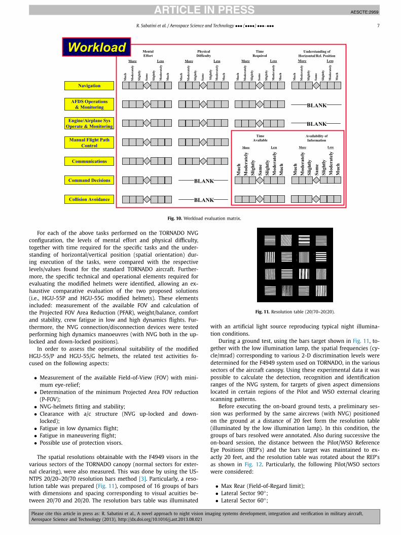
Also important was definition of criteria for Pilot and WSOworkload assessment during the accomplishment of various opera-tional tasks during NVG missions (Fig. 10). Particularly, a workloadevaluation matrix was implemented that allowed identification ofthe workload levels associated with the various Pilot and WSO op-erational tasks during real missions. These included ferry flights,attack, formation flights and tactical evasive/escape manoeuvres.The operational tasks considered were the following:
• Navigation;• Automatic Flight Director System (AFDS) operation and moni-
toring;• Engine/airplane systems operation and monitoring;• Manual flight path control;• Communications;• Command decisions;• Collision avoidance.
JID:AESCTE AID:2959 /FLA [m5Gv1.5; v 1.114; Prn:11/10/2013; 13:58] P.7 (1-14)
R. Sabatini et al. / Aerospace Science and Technology ••• (••••) •••–••• 7
Fig. 10. Workload evaluation matrix.
For each of the above tasks performed on the TORNADO NVGconfiguration, the levels of mental effort and physical difficulty,together with time required for the specific tasks and the under-standing of horizontal/vertical position (spatial orientation) dur-ing execution of the tasks, were compared with the respectivelevels/values found for the standard TORNADO aircraft. Further-more, the specific technical and operational elements required forevaluating the modified helmets were identified, allowing an ex-haustive comparative evaluation of the two proposed solutions(i.e., HGU-55P and HGU-55G modified helmets). These elementsincluded: measurement of the available FOV and calculation ofthe Projected FOV Area Reduction (PFAR), weight/balance, comfortand stability, crew fatigue in low and high dynamics flights. Fur-thermore, the NVG connection/disconnection devices were testedperforming high dynamics manoeuvres (with NVG both in the up-locked and down-locked positions).
In order to assess the operational suitability of the modifiedHGU-55/P and HGU-55/G helmets, the related test activities fo-cused on the following aspects:
• Measurement of the available Field-of-View (FOV) with mini-mum eye-relief;
• Determination of the minimum Projected Area FOV reduction(P-FOV);
• NVG-helmets fitting and stability;• Clearance with a/c structure (NVG up-locked and down-
locked);• Fatigue in low dynamics flight;• Fatigue in maneuvering flight;• Possible use of protection visors.
The spatial resolutions obtainable with the F4949 visors in thevarious sectors of the TORNADO canopy (normal sectors for exter-nal clearing), were also measured. This was done by using the US-NTPS 20/20–20/70 resolution bars method [3]. Particularly, a reso-lution table was prepared (Fig. 11), composed of 16 groups of barswith dimensions and spacing corresponding to visual acuities be-tween 20/70 and 20/20. The resolution bars table was illuminated
Fig. 11. Resolution table (20/70–20/20).
with an artificial light source reproducing typical night illumina-tion conditions.
During a ground test, using the bars target shown in Fig. 11, to-gether with the low illumination lamp, the spatial frequencies (cy-cle/mrad) corresponding to various 2-D discrimination levels weredetermined for the F4949 system used on TORNADO, in the varioussectors of the aircraft canopy. Using these experimental data it waspossible to calculate the detection, recognition and identificationranges of the NVG system, for targets of given aspect dimensionslocated in certain regions of the Pilot and WSO external clearingscanning patterns.
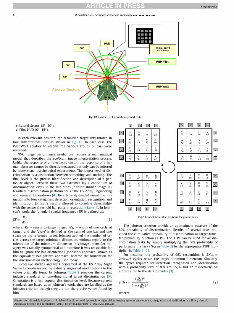
Before executing the on-board ground tests, a preliminary ses-sion was performed by the same aircrews (with NVG) positionedon the ground at a distance of 20 feet form the resolution table(illuminated by the low illumination lamp). In this condition, thegroups of bars resolved were annotated. Also during successive theon-board session, the distance between the Pilot/WSO ReferenceEye Positions (REP’s) and the bars target was maintained to ex-actly 20 feet, and the resolution table was rotated about the REP’sas shown in Fig. 12. Particularly, the following Pilot/WSO sectorswere considered:
• Max Rear (Field-of-Regard limit);• Lateral Sector 90◦;• Lateral Sector 60◦;
JID:AESCTE AID:2959 /FLA [m5Gv1.5; v 1.114; Prn:11/10/2013; 13:58] P.8 (1-14)
8 R. Sabatini et al. / Aerospace Science and Technology ••• (••••) •••–•••
Fig. 12. Geometry of resolution ground tests.
• Lateral Sector 15◦–30◦;• Pilot HUD (0◦–15◦).
In each relevant position, the resolution target was rotated infour different positions as shown in Fig. 13. In each case, thePilot/WSO abilities to resolve the various groups of bars wererecorded.
NVG range performance predictions require a mathematicalmodel that describes the eye/brain image interpretation process.Unlike the response of an electronic circuit, the response of a hu-man observer cannot be directly measured but only can be inferredby many visual psychological experiments. The lowest level of dis-crimination is a distinction between something and nothing. Thefinal level is the precise identification and description of a par-ticular object. Between these two extremes lay a continuum ofdiscrimination levels. In the late fifties, Johnson studied image in-tensifiers discrimination performance at the US Army Engineeringand Research Laboratories [4]. He arbitrarily divided visual discrim-ination into four categories: detection, orientation, recognition, andidentification. Johnson’s results allowed to correlate detectabilitywith the sensor threshold bar pattern resolution (Table 1). In John-son’s work, the (angular) spatial frequency (SF) is defined as:
SF = RT
W1c(1)
where: RT = sensor-to-target range; W1c = width of one cycle oftarget, and the ‘cycle’ is defined as the sum of one bar and onespace on the reference target. Johnson applied the number of cy-cles across the target minimum dimension, without regard to theorientation of the minimum dimension (his image intensifier im-agery was radially symmetrical and therefore it was reasonable forhim to ignore the bar orientation). Johnson’s approach, known asthe equivalent bar pattern approach, became the foundation forthe discrimination methodology used today.
Successive studies and tests performed at the US Army NightVision Laboratories and by industry suggested modifications to thevalues originally found by Johnson. Table 2 provides the currentindustry standard for one-dimensional target discrimination [5].Orientation is a less popular discrimination level. Because currentstandards are based upon Johnson’s work, they are labelled as theJohnson criterion though they are not the precise values found byhim.
Fig. 13. Resolution table positions for ground tests.
The Johnson criterion provide an approximate measure of the50% probability of discrimination. Results of several tests pro-vided the cumulative probability of discrimination or target trans-fer probability function (TTPF). The TTPF can be used for all dis-crimination tasks by simply multiplying the 50% probability ofperforming the task (N50 in Table 2) by the appropriate TTPF mul-tiplier in Table 3 [5].
For instance, the probability of 95% recognition is 2N50 =2(4) = 8 cycles across the target minimum dimension. Similarly,the cycles required for detection, recognition and identificationwith a probability level of 80% are 1.5, 6 and 12 respectively. Anempirical fit to the data provides [3]:
P (N) = ( NN50
)E
1 + ( NN50
)E(2)
where:
JID:AESCTE AID:2959 /FLA [m5Gv1.5; v 1.114; Prn:11/10/2013; 13:58] P.9 (1-14)
R. Sabatini et al. / Aerospace Science and Technology ••• (••••) •••–••• 9
Table 1Summary of Johnson’s experimental results.
Discrimination level Meaning Cycles across minimum dimension
Detection An object is present (object versus noise) 1.0 ± 0.025Orientation The object is approximately symmetrical or unsymmetrical and
its orientation may be discerned (side view versus front view)1.4 ± 0.35
Recognition The class to which the object belongs (e.g., tank, truck, man) 4.0 ± 0.80Identification The object is discerned with sufficient clarity to specify the type
(e.g., T-52 tank, friendly jeep)6.4 ± 1.50
Table 2Current industry criterion for 1-D discrimination (50% probability level).
Discrimination level Meaning Cycles across min. dimension (N50)
Detection An object is present 1.0Recognition The class to which the object belongs 4.0Identification The object is discerned with sufficient clarity to specify the type 8.0
Table 3Discrimination cumulative probability.
Probability of discrimination Multiplier Fm
1.00 3.00.95 2.00.80 1.50.50 1.00.30 0.750.10 0.500.02 0.250 0
E = 2.7 + 0.7 ·(
N
N50
)(3)
Visual psychophysical experiments suggest that the eye re-sponse follows a log-normal distribution [1]. The probability den-sity function follows:
p(N) = 1√2π · log(σ )
· e− 12 [ log(N)−log(N50)
log(σ )]2
(4)
where log(σ ) = 0.198. The cumulative probability is:
P (N) =log N∫0
p(N)d log(N) (5)
Both the empirical fit of Eq. (3) and the log-normal approach(based upon a physically plausible foundation) of Eq. (5) providesimilar numerical results. As clutter increases, the ability to discerna target decreases. To account for this reduced capability, N50 mustincrease. Most studies have broadly categorised clutter into high,moderate and low regions, and defined the signal-to-clutter ratio(SCR) as:
SCR = max target value − background mean
σclutter(6)
where:
σclutter =√√√√ 1
N
N∑i=1
σ 2i (7)
and σi is the rms value of the pixel values in a square cell thathas side dimensions of approximately twice the target minimumdimension. The scene is composed of N adjoining cells. The use ofadjoining cells introduces a spatial weighting factor that is similarto the spatial integration performed by the eye/brain process. Clut-ter sizes that are equal to the object size weigh more heavily inthis calculation.
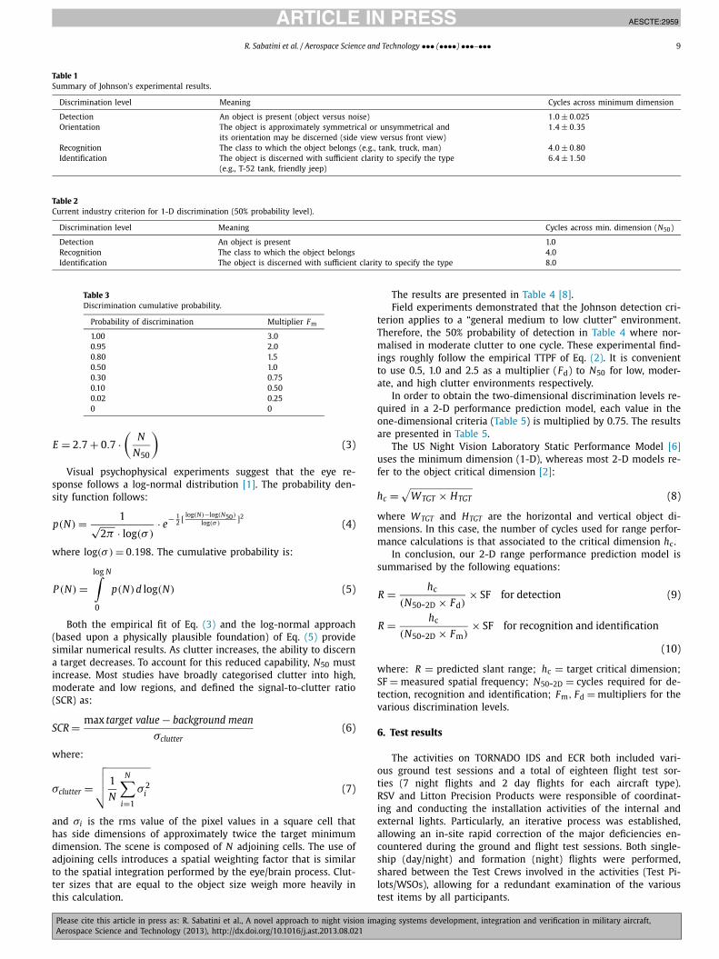
The results are presented in Table 4 [8].Field experiments demonstrated that the Johnson detection cri-
terion applies to a “general medium to low clutter” environment.Therefore, the 50% probability of detection in Table 4 where nor-malised in moderate clutter to one cycle. These experimental find-ings roughly follow the empirical TTPF of Eq. (2). It is convenientto use 0.5, 1.0 and 2.5 as a multiplier (Fd) to N50 for low, moder-ate, and high clutter environments respectively.
In order to obtain the two-dimensional discrimination levels re-quired in a 2-D performance prediction model, each value in theone-dimensional criteria (Table 5) is multiplied by 0.75. The resultsare presented in Table 5.
The US Night Vision Laboratory Static Performance Model [6]uses the minimum dimension (1-D), whereas most 2-D models re-fer to the object critical dimension [2]:
hc = √WTGT × HTGT (8)
where WTGT and HTGT are the horizontal and vertical object di-mensions. In this case, the number of cycles used for range perfor-mance calculations is that associated to the critical dimension hc.
In conclusion, our 2-D range performance prediction model issummarised by the following equations:
R = hc
(N50-2D × Fd)× SF for detection (9)
R = hc
(N50-2D × Fm)× SF for recognition and identification
(10)
where: R = predicted slant range; hc = target critical dimension;SF = measured spatial frequency; N50-2D = cycles required for de-tection, recognition and identification; Fm, Fd = multipliers for thevarious discrimination levels.
6. Test results
The activities on TORNADO IDS and ECR both included vari-ous ground test sessions and a total of eighteen flight test sor-ties (7 night flights and 2 day flights for each aircraft type).RSV and Litton Precision Products were responsible of coordinat-ing and conducting the installation activities of the internal andexternal lights. Particularly, an iterative process was established,allowing an in-site rapid correction of the major deficiencies en-countered during the ground and flight test sessions. Both single-ship (day/night) and formation (night) flights were performed,shared between the Test Crews involved in the activities (Test Pi-lots/WSOs), allowing for a redundant examination of the varioustest items by all participants.
JID:AESCTE AID:2959 /FLA [m5Gv1.5; v 1.114; Prn:11/10/2013; 13:58] P.10 (1-14)
10 R. Sabatini et al. / Aerospace Science and Technology ••• (••••) •••–•••
Table 4TTPF when clutter is present.
Probability ofdetection
Multiplier Fd
Low clutter SCR > 10 Moder. clutter 1 < SCR < 10 High clutter SCR < 1
1.0 1.7 2.8 **
0.95 1.0 1.9 **
0.90 0.90 1.7 7.0*
0.80 0.75 1.3 5.00.50 0.50 1.0 2.50.30 0.30 0.75 2.00.10 0.15 0.35 1.40.02 0.05 0.1 1.00 0.0 0.0 0.0
* No data available.** Estimated.
Table 5Discrimination levels for the 2-D model (50% probability level).
Discrimination level Meaning Cycles across minimum dimension (N50-2D)
Detection An object is present 0.75Recognition The class to which the object belongs 3.00Identification The object is discerned with sufficient clarity to specify the type 6.00
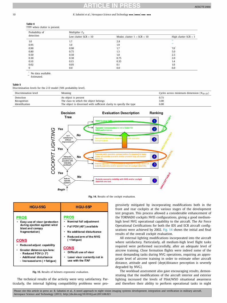
Fig. 14. Results of the cockpit evaluation.
Fig. 15. Results of helmets ergonomic evaluation.
The technical results of the activity were very satisfactory. Par-ticularly, the internal lighting compatibility problems were pro-
gressively mitigated by incorporating modifications both in thefront and rear cockpits at the various stages of the developmenttest program. This process allowed a considerable enhancement ofthe TORNADO cockpits NVIS configurations, giving a good medium-high level NVG operational capability to the aircraft. The Air ForceOperational Certifications for both the IDS and ECR aircraft config-urations were achieved by 2002. Fig. 14 shows the initial and finalresults of the overall cockpit evaluation.
All external lighting modifications incorporated into the aircraftwhere satisfactory. Particularly, all medium-high level flight tasksrequired were performed successfully, after an adequate level ofaircrew training. Close formation flights were indeed some of themost demanding tasks during NVG operations, requiring an appro-priate level of aircrew training in order to estimate other aircraftdistance, attitude and speed (dept/distance perception is severelydegraded by NVG).
The workload assessment also gave encouraging results, demon-strating that the modifications of the aircraft interior and exteriorlighting increased the levels of Pilot/WSO situational awarenessand therefore their ability to perform operational tasks in night
JID:AESCTE AID:2959 /FLA [m5Gv1.5; v 1.114; Prn:11/10/2013; 13:58] P.11 (1-14)
R. Sabatini et al. / Aerospace Science and Technology ••• (••••) •••–••• 11
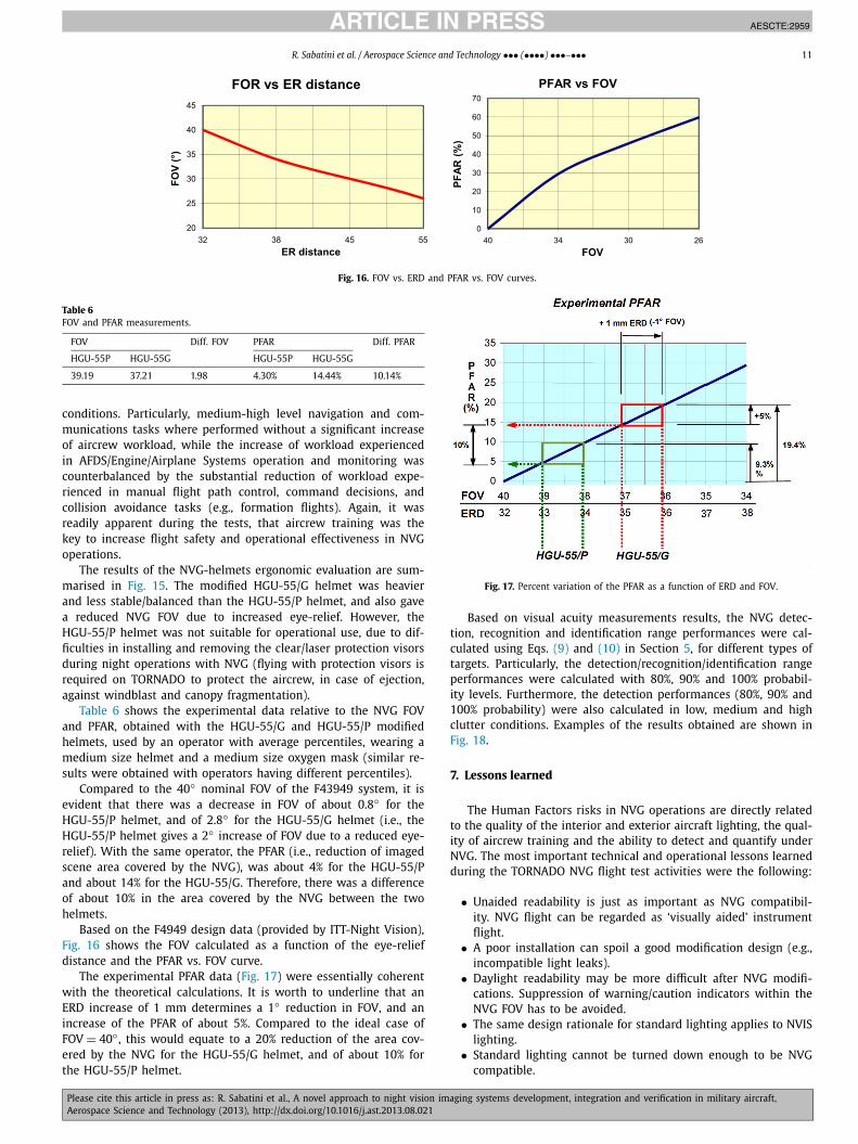
Fig. 16. FOV vs. ERD and PFAR vs. FOV curves.
Table 6FOV and PFAR measurements.
FOV Diff. FOV PFAR Diff. PFAR
HGU-55P HGU-55G HGU-55P HGU-55G
39.19 37.21 1.98 4.30% 14.44% 10.14%
conditions. Particularly, medium-high level navigation and com-munications tasks where performed without a significant increaseof aircrew workload, while the increase of workload experiencedin AFDS/Engine/Airplane Systems operation and monitoring wascounterbalanced by the substantial reduction of workload expe-rienced in manual flight path control, command decisions, andcollision avoidance tasks (e.g., formation flights). Again, it wasreadily apparent during the tests, that aircrew training was thekey to increase flight safety and operational effectiveness in NVGoperations.
The results of the NVG-helmets ergonomic evaluation are sum-marised in Fig. 15. The modified HGU-55/G helmet was heavierand less stable/balanced than the HGU-55/P helmet, and also gavea reduced NVG FOV due to increased eye-relief. However, theHGU-55/P helmet was not suitable for operational use, due to dif-ficulties in installing and removing the clear/laser protection visorsduring night operations with NVG (flying with protection visors isrequired on TORNADO to protect the aircrew, in case of ejection,against windblast and canopy fragmentation).
Table 6 shows the experimental data relative to the NVG FOVand PFAR, obtained with the HGU-55/G and HGU-55/P modifiedhelmets, used by an operator with average percentiles, wearing amedium size helmet and a medium size oxygen mask (similar re-sults were obtained with operators having different percentiles).
Compared to the 40◦ nominal FOV of the F43949 system, it isevident that there was a decrease in FOV of about 0.8◦ for theHGU-55/P helmet, and of 2.8◦ for the HGU-55/G helmet (i.e., theHGU-55/P helmet gives a 2◦ increase of FOV due to a reduced eye-relief). With the same operator, the PFAR (i.e., reduction of imagedscene area covered by the NVG), was about 4% for the HGU-55/Pand about 14% for the HGU-55/G. Therefore, there was a differenceof about 10% in the area covered by the NVG between the twohelmets.
Based on the F4949 design data (provided by ITT-Night Vision),Fig. 16 shows the FOV calculated as a function of the eye-reliefdistance and the PFAR vs. FOV curve.
The experimental PFAR data (Fig. 17) were essentially coherentwith the theoretical calculations. It is worth to underline that anERD increase of 1 mm determines a 1◦ reduction in FOV, and anincrease of the PFAR of about 5%. Compared to the ideal case ofFOV = 40◦ , this would equate to a 20% reduction of the area cov-ered by the NVG for the HGU-55/G helmet, and of about 10% forthe HGU-55/P helmet.
Fig. 17. Percent variation of the PFAR as a function of ERD and FOV.
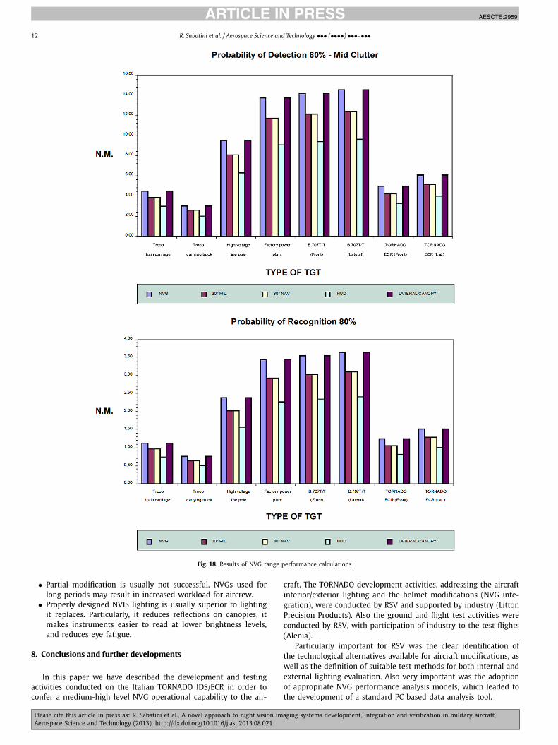
Based on visual acuity measurements results, the NVG detec-tion, recognition and identification range performances were cal-culated using Eqs. (9) and (10) in Section 5, for different types oftargets. Particularly, the detection/recognition/identification rangeperformances were calculated with 80%, 90% and 100% probabil-ity levels. Furthermore, the detection performances (80%, 90% and100% probability) were also calculated in low, medium and highclutter conditions. Examples of the results obtained are shown inFig. 18.
7. Lessons learned
The Human Factors risks in NVG operations are directly relatedto the quality of the interior and exterior aircraft lighting, the qual-ity of aircrew training and the ability to detect and quantify underNVG. The most important technical and operational lessons learnedduring the TORNADO NVG flight test activities were the following:
• Unaided readability is just as important as NVG compatibil-ity. NVG flight can be regarded as ‘visually aided’ instrumentflight.
• A poor installation can spoil a good modification design (e.g.,incompatible light leaks).
• Daylight readability may be more difficult after NVG modifi-cations. Suppression of warning/caution indicators within theNVG FOV has to be avoided.
• The same design rationale for standard lighting applies to NVISlighting.
• Standard lighting cannot be turned down enough to be NVGcompatible.
JID:AESCTE AID:2959 /FLA [m5Gv1.5; v 1.114; Prn:11/10/2013; 13:58] P.12 (1-14)
12 R. Sabatini et al. / Aerospace Science and Technology ••• (••••) •••–•••
Fig. 18. Results of NVG range performance calculations.
• Partial modification is usually not successful. NVGs used forlong periods may result in increased workload for aircrew.
• Properly designed NVIS lighting is usually superior to lightingit replaces. Particularly, it reduces reflections on canopies, itmakes instruments easier to read at lower brightness levels,and reduces eye fatigue.
8. Conclusions and further developments
In this paper we have described the development and testingactivities conducted on the Italian TORNADO IDS/ECR in order toconfer a medium-high level NVG operational capability to the air-
craft. The TORNADO development activities, addressing the aircraftinterior/exterior lighting and the helmet modifications (NVG inte-gration), were conducted by RSV and supported by industry (LittonPrecision Products). Also the ground and flight test activities wereconducted by RSV, with participation of industry to the test flights(Alenia).
Particularly important for RSV was the clear identification ofthe technological alternatives available for aircraft modifications, aswell as the definition of suitable test methods for both internal andexternal lighting evaluation. Also very important was the adoptionof appropriate NVG performance analysis models, which leaded tothe development of a standard PC based data analysis tool.
JID:AESCTE AID:2959 /FLA [m5Gv1.5; v 1.114; Prn:11/10/2013; 13:58] P.13 (1-14)
R. Sabatini et al. / Aerospace Science and Technology ••• (••••) •••–••• 13
The technical results of the TORNADO NVG activities were verysatisfactory. Particularly, the internal lighting compatibility prob-lems were progressively mitigated by incorporating modificationsboth in the front and rear cockpits at the various stages of thedevelopment test program. This process allowed a considerable en-hancement of the TORNADO cockpits NVIS configurations, giving agood medium-high level NVG operational capability to the aircraft.
The workload assessment also gave encouraging results, demon-strating that the modifications of the aircraft interior and exteriorlighting increased the levels of Pilot/WSO situational awarenessand therefore their ability to perform operational tasks in nightconditions. However, it was readily apparent during the tests, thataircrew training was the key to increase flight safety and opera-tional effectiveness in NVG operations.
The NVG-helmets tests allowed a comprehensive verificationof the ergonomic and technical elements in favor or against eachof the proposed solutions (i.e., modified HGU-55/G and HGU-55/Phelmets). Overall, the HGU-55/P helmet was rejected due to dif-ficulties in installing and removing the clear/laser protection vi-sors during night operations, while the modified HGU-55/G wasselected for TORDADO IDS/ECR operations (although not fully sat-isfactory).
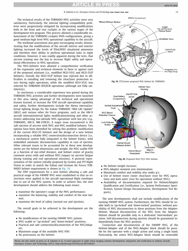
In conclusion, a considerable experience was gained during theTORNADO NVG activities and further developments were launchedin this area, taking advantage of the technical and operationallessons learned, to increase the ITAF aircraft operational capabilityand safety. Further developments include the Alenia internal/ex-ternal lighting design for the Italian TORNADO “Mid Life Update”(MLU) and various other Air Force programs, such as the AM-Xaircraft internal/external lights modification/testing and other ac-tivities addressing low-altitude NVG operations with fast jets (e.g.,TORNADO, AM-X, MB-339CD). A major issue encountered is thesafe ejection of aircrew with NVG and NVG modified helmets. Twooptions have been identified for solving this problem: modificationof the current HGU-55 helmets and the design of a new helmetincorporating a reliable NVG connection/disconnection device (i.e.,a mechanical system fully integrated in the helmet frame), withembedded automatic disconnection capability in case of ejection.Other relevant issues to be accounted for in these new develop-ments are the helmet dimensions and weight, the NVG usable FOVas a function of eye-relief distance, and helmet centre of gravity(moment arms) with and without NVG (impact on aircrew fatigueduring training and real operational missions). A pictorial repre-sentation of the system initially proposed by Gentex and ITT-NightVision in order to match the Italian and German Air Forces TOR-NADO helmet requirements is shown in Fig. 19.
The ITAF requirements for a new helmet allowing a safe andpractical usage of the F4949P NVG were established so that no re-strictions were applied to the aircraft operational flight envelopesdue to use of the NVG system. In order to achieve this, the newdevelopment should address the following main issues:
• maximise the operator’s usage of the NVG performance;• maximise the balancing, stability and comfort of the new hel-
met;• maximise the level of safety (normal use and ejection).
The overall goals to be achieved in the development are thefollowing:
• No modifications of the existing F4949P NVG system;• NVG usable in “up-locked” and “down-locked” positions;• Practical and safe connection/disconnection of the NVG/Adap-
ter;• Maximum usage of the available NVG FOV;• No protrusions on the helmet;
Fig. 19. ITT/Gentex proposed NVG helmet for TORNADO.
Fig. 20. Proposed HGU-55/G NVG helmet.
• No Helmet weight increase;• NVG-Adapter moment arm minimisation;• Maximum comfort and stability also under g’s;• Use of helmet visors (inner clear/laser visor for NVG opera-
tions and dark outer visor for operations without NVG);• Availability of documentation required for Helmet/Adaptor
Qualification and Certification (i.e., System Performance Speci-fication, System Design Documentation, Development Test Re-ports).
The new developments shall not include modifications of theexisting F4949P NVG system. Furthermore, the NVG should be us-able both in ‘up-locked’ and ‘down-locked’ positions, without pos-sibility of NVG disconnection in these positions from the Adapter-Helmet. Manual disconnection of the NVG from the Adapter-Helmet should be possible only in a dedicated ‘intermediate’ po-sition. Self-disconnection during ejection should be guaranteed in-dependently from the NVG position.
Connection and disconnection of the F4949P NVG, of theHelmet-Adapter and of the NVG-Adapter block should be possi-ble for the operator with a single action and using a single hand.Particularly, the entire NVG-Adapter block should be removable
JID:AESCTE AID:2959 /FLA [m5Gv1.5; v 1.114; Prn:11/10/2013; 13:58] P.14 (1-14)
14 R. Sabatini et al. / Aerospace Science and Technology ••• (••••) •••–•••
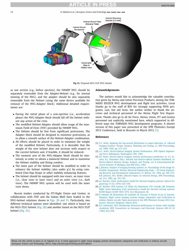
Fig. 21. Proposed HGU-55/P NVG helmet.
as one section (e.g., before ejection), the F4949P NVG should beseparately removable from the Adapter-Helmet (e.g., for normalstowing of the NVG), and the adapter should be also separatelyremovable from the Helmet (using the same device available forremoval of the NVG-Adapter block). Additional detailed require-ments are:
• During the initial phase of a seat-ejection (i.e., accelerationphase) the NVG-Adapter block should fall off the helmet with-out any action of the crew.
• The modified Helmet-Adapter should allow usage of the max-imum Field-of-View (FOV) provided by F4949P NVG.
• The Helmet should be free from significant protrusions. TheAdapter block should be designed to minimise protrusions, asto allow a smooth surface of the Helmet-Adapter combination.
• All efforts should be placed in order to minimise the weightof the modified Helmet. Particularly, it is desirable that theweight of the new helmet does not increase with respect tothe current helmets and, if feasible, it should be reduced.
• The moment arm of the NVG-Adapter block should be min-imised, in order to obtain a balanced Helmet and to maximisethe Helmet stability and fitting comfort.
• The inner part of the helmet should be modified in order toenhance the helmet stability (also under g’s) by using com-bined Chin-Nap Straps or other stability enhancing features.
• The helmet should be equipped with two visors: an inner visor(i.e., clear visor or laser visor) and an outer visor (i.e., darkvisor). The F4949P NVG system will be used with the innervisor down.
Recent studies conducted by ITT-Night Vision and Gentex, incollaboration with ITAF and the Italian MoD have leaded to theNVG-helmet solutions shown in Figs. 20 and 21. Particularly, twodifferent technical options were identified: one which is based onthe HGU-55/G helmet (Fig. 20) and another based on the HGU-55/Phelmet (Fig. 21).
Acknowledgements
The authors would like to acknowledge the valuable contribu-tion given by Alenia and Litton Precision Products, during the TOR-NADO IDS/ECR NVG development and flight test activities. Greatthanks go to the staff of RSV for strongly supporting NVIS pro-grams. Last, but not least, the author wishes to thank the air-crews and technical personnel of the Alenia Flight Test Depart-ment. Thanks also go to all Air Force, Alenia, Litton, ITT and Gentexpersonnel not explicitly mentioned here, which supported in dif-ferent ways the TORNADO NVG development programs. A shorterversion of this paper was presented at the SPIE Photonics Europe2012 Conference, held in Brussels in March 2012 [7].
References
[1] G.C. Holst, Applying the log-normal distribution to target detection, in: InfraredImaging Systems: Design, Analysis, Modeling and Testing, in: SPIE Proceedings,vol. 1689, 1992, pp. 213–216.
[2] G.C. Holst, Electro-Optical Imaging System Performance, SPIE Optical Engineer-ing Press, Bellingham, Washington, USA, 1995.
[3] J.D. Howe, Electro-optical imaging systems performance prediction, in: J.S. Ac-cetta, D.L. Shumaker (Eds.), Infrared and Electro-Optical Systems Handbook, in:Electro-Optical Systems Design, Analysis and Testing, vol. 4, Environmental Re-search Institute of Michigan and SPIE Press, 1993.
[4] J. Johnson, Analysis of imaging forming systems, in: Proceedings of the Image In-tensifier Symposium, Warfare Electrical Engineering Dept. – US Army Engineer-ing Research and Development Laboratories, Ft. Belvoir, VA, 1958, pp. 249–273;R.B. Johnson, W.L. Wolfe, Selected Papers on Infrared Design, SPIE Proceedings,vol. 513, 1985, pp. 761–781.
[5] J.A. Ratches, Static performance model for thermal imaging systems, Optical En-gineering 15 (6) (1976) 525–530.
[6] J.A. Ratches, W.R. Lawson, L.P. Orbet, R.J. Begemann, T.W. Cassidy, J.M. Swenson,Night vision laboratory static performance model for thermal viewing systems,ECOM Report ECOM-7043 1975, Fort Monmouth, NJ.
[7] R. Sabatini, M. Richardson, M. Cantiello, M. Toscano, P. Fiorini, H. Jia, D. Zammit-Mangion, Night vision imaging systems design, integration and verification inmilitary fighter aircraft, Paper presented at the SPIE Photonics Europe 2012 Con-ference, Brussels (Belgium), March 2012.
[8] D.E. Schmieder, M.R. Weathersby, Detection performance in clutter with variableresolution, IEEE Transactions on Aerospace and Electronic Systems AES-19 (4)(1983) 622–630.
Copyright © 2022 FDOKUMEN

